Molded Case Circuit Breaker - EandM · Siemens STEP 2000 Course Molded Case Circuit Breakers It's...
24
Siemens STEP 2000 Course Molded Case Circuit Breakers It's easy to get in STEP! Download any course. Hint: Make sure you download all parts for each course and the test answer form. Complete each chapter and its review section Print the test answer form, take the final exam and fill in the form. Hint: The final exam is always at the end of the last part. Send your test answer form to EandM for grading. If you achieve a score of 70% or better, we'll send you a certificate of completion! If you have any questions, contact EandM Training at 866.693.2636 or fax 707.473.3190 or [email protected] . Need more information? Contact EandM at 866.693.2636 or fax 707.473.3190 or [email protected] for product information, quotes, classroom training courses and more. STEP 2000 Courses distributed by www.eandm.com
-
Upload
phamnguyet -
Category
Documents
-
view
217 -
download
0
Transcript of Molded Case Circuit Breaker - EandM · Siemens STEP 2000 Course Molded Case Circuit Breakers It's...

Siemens STEP 2000 Course
Molded CaseCircuit Breakers
It's easy to get in STEP!
Download any course. Hint: Make sure you download all parts for each course and the test answer form.
Complete each chapter and its review section Print the test answer form, take the final exam and fill in the form.
Hint: The final exam is always at the end of the last part. Send your test answer form to EandM for grading. If you achieve a score of 70% or better, we'll
send you a certificate of completion! If you have any questions, contact EandM Training at 866.693.2636 or fax 707.473.3190 or [email protected].
Need more information? Contact EandM at 866.693.2636
or fax 707.473.3190 or [email protected]
for product information, quotes, classroom training courses and more.
STEP 2000 Courses distributed by www.eandm.com

1
Table of Contents
Introduction ..............................................................................2
Need for Circuit Protection .......................................................4
Types of Overcurrent Protective Devices ..................................8
Circuit Breaker Design ............................................................ 11
Types of Circuit Breakers ........................................................24
Circuit Breaker Ratings ...........................................................29
Time-Current Curves ...............................................................31
Selective Coordination ............................................................35
Series-Connected Systems ....................................................37
Catalog Numbers ....................................................................40
Residential and Commercial Circuit Breakers .........................42
Sentron™ Series Circuit Breakers ..........................................50
Sentron™ Series Digital Circuit Breakers ................................57
Internal Accessories ...............................................................68
External Accessories ..............................................................73
Insulated Case Circuit Breakers ..............................................79
ICCB Electronic Trip Unit .........................................................81
Review Answers .....................................................................88
Final Exam ..............................................................................89

2
Introduction
Welcome to another course in the STEP series, Siemens Technical Education Program, designed to prepare our distributors to sell Siemens Energy & Automation products more effectively. This course covers Molded Case Circuit Breakers and related products.
Upon completion of Molded Case Circuit Breakers you will be able to:
• Explain the need for circuit protection
• Identify various types of overcurrent protective devices
• Explain the basic electro-mechanical operation of a circuit breaker
• Identify various types of Siemens circuit breakers
• Identify circuit protection ratings for various types of Siemens circuit breakers
• Describe time-current characteristics on a time-current curve
• Explain the benefits and function of circuit breaker coordination
• Identify internal and external circuit breaker accessories
• Explain the difference between molded case circuit breakers and insulated case circuit breakers

3
This knowledge will help you better understand customer applications. In addition, you will be better able to describe products to customers and determine important differences between products. You should complete Basics of Electricity before attempting Molded Case Circuit Breakers. An understanding of many of the concepts covered in Basics of Electricity is required for Molded Case Circuit Breakers.
If you are an employee of a Siemens Energy & Automation authorized distributor, fill out the final exam tear-out card and mail in the card. We will mail you a certificate of completion if you score a passing grade. Good luck with your efforts.
I-T-E, Sensitrip, EQ, Telemand and Speedfax are registered trademarks of Siemens Energy & Automation, Inc.
Sentron and Max-Flex are trademarks of Siemens Energy & Automation, Inc.
National Electrical Code® and NEC® are registered trademarks of the National Fire Protection Association, Quincy, MA 02269. Portions of the National Electrical Code are reprinted with permission from NFPA 70-2005, National Electrical Code Copyright, 2004, National Fire Protection Association, Quincy, MA 02269. This reprinted material is not the complete and official position of the National Fire Protection Association on the referenced subject which is represented by the standard in its entirety.
Underwriters Laboratories Inc. is a registered trademark of Underwriters Laboratories Inc., Northbrook, IL 60062. The abbreviation “UL” shall be understood to mean Underwriters Laboratories Inc.
QO is a registered trademark of Square D Company.

4
Need for Circuit Protection
Current and Temperature Current flow in a conductor always generates heat. The greater the current flow, the hotter the conductor. Excess heat is damaging to electrical components. For that reason, conductors have a rated continuous current carrying capacity or ampacity. Overcurrent protection devices, such as circuit breakers, are used to protect conductors from excessive current flow. These protective devices are designed to keep the flow of current in a circuit at a safe level to prevent the circuit conductors from overheating.
Normal Current Flow
Excessive Current Flow
Excessive current is referred to as overcurrent. The National Electrical Code® (NEC®) defines overcurrent as any current in excess of the rated current of equipment or the ampacity of a conductor. It may result from overload, short circuit, or ground fault (Article 100-definitions).
NEC® and National Electrical Code® are registered trademarks of the National Fire Protection Association.

5
Overloads An overload occurs when too many devices are operated on a single circuit, or a piece of electrical equipment is made to work harder than it is designed for. For example, a motor rated for 10 amps may draw 20, 30, or more amps in an overload condition. In the following illustration, a package has become jammed on a conveyor, causing the motor to work harder and draw more current. Because the motor is drawing more current, it heats up. Damage will occur to the motor in a short time if the problem is not corrected or the circuit is shut down by the overcurrent protector.
Conductor Insulation Motors, of course, are not the only devices that require circuit protection for an overload condition. Every circuit requires some form of protection against overcurrent. Heat is one of the major causes of insulation failure of any electrical component. High levels of heat can cause the insulation to breakdown and flake off, exposing conductors.
Good Insulation
Insulation Affected by Heat

6
Short Circuits When two bare conductors touch, a short circuit occurs. When a short circuit occurs, resistance drops to almost zero. Short circuit current can be thousands of times higher than normal operating current.
Conductor
Insulation
Ohm’s Law demonstrates the relationship of current, voltage, and resistance. For example, a 240 volt motor with 24 Ω of resistance would normally draw 10 amps of current.
I = ER
I =
I = 10 Amps
24024
When a short circuit develops, resistance drops. If resistance drops to 24 milliohms, current will be 10,000 amps.
I =
I = 10,000 Amps
2400.024
The heat generated by this current will cause extensive damage to connected equipment and conductors. This dangerous current must be interrupted immediately when a short circuit occurs.
NEC® and National Electrical Code® are registered trademarks of the National Fire Protection Association. Reprinted with permission from NFPA 70-2005, the National Electrical Code®, Copyright© 2004, National Fire Protection Association, Quincy, MA 02269.
7
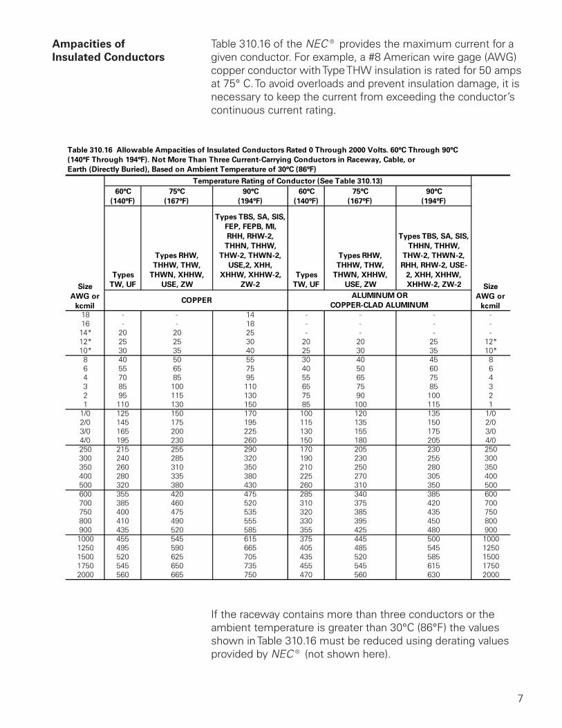
Ampacities of Table 310.16 of the NEC® provides the maximum current for aInsulated Conductors given conductor. For example, a #8 American wire gage (AWG)
copper conductor with Type THW insulation is rated for 50 amps at 75° C. To avoid overloads and prevent insulation damage, it is necessary to keep the current from exceeding the conductor’s continuous current rating.
If the raceway contains more than three conductors or the ambient temperature is greater than 30°C (86°F) the values shown in Table 310.16 must be reduced using derating values provided by NEC® (not shown here).

8
Types of Overcurrent Protective Devices
Circuit protection would be unnecessary if overloads and short circuits could be eliminated. Unfortunately, overloads and short circuits do occur. To protect a circuit against these currents, a protective device must determine when a fault condition develops and automatically disconnect the electrical equipment from the voltage source. An overcurrent protection device must be able to recognize the difference between overcurrents and short circuits and respond in the proper way. Slight overcurrents can be allowed to continue for some period of time, but as the current magnitude increases, the protection device must open faster. Short circuits must be interrupted instantly. Several devices are available to accomplish this.
Fuse A fuse is a one-shot device. The heat produced by overcurrent causes the current carrying element to melt open, disconnecting the load from the source voltage.
Good Element
Open Element
Nontime-Delay Fuse Nontime-delay fuses provide excellent short circuit protection. When an overcurrent occurs, heat builds up rapidly in the fuse. Nontime-delay fuses usually hold 500% of their rating for approximately one-fourth second, after which the current-carrying element melts. This means that these fuses cannot be used in motor circuits which often have inrush currents greater than 500%.

9
Time-Delay Fuses Time-delay fuses provide overload and short circuit protection. Time-delay fuses usually allow five times the rated current for up to ten seconds to allow motors to start.
Circuit Breaker The National Electrical Code® defines a circuit breaker as a device designed to open and close a circuit by nonautomatic means, and to open the circuit automatically on a predetermined overcurrent without damage to itself when properly applied within its rating.
Circuit breakers provide a manual means of energizing and de-energizing a circuit. In addition, circuit breakers provide automatic overcurrent protection of a circuit. A circuit breaker allows a circuit to be reactivated quickly after a short circuit or overload is cleared. Unlike fuses which must be replaced when they open, a simple flip of the breaker’s handle restores the circuit.
Circuit breakers:
• SENSE when an overcurrent occurs.
• MEASURE the amount of overcurrent.
• ACT by tripping the circuit breaker in a time frame necessary to prevent damage to itself and the associated load cables.
NEC® and National Electrical Code® are registered trademarks of the National Fire Protection Association. Reprinted with permission from NFPA 70-2005, the National Electrical Code®, Copyright© 2004, National Fire Protection Association, Quincy, MA 02269.

10
Circuit Breaker Operation In the following illustration an AC motor is connected through a circuit breaker to a voltage source. When the circuit breaker is closed, a complete path for current exists between the voltage source and the motor allowing the motor to run. Opening the circuit breaker breaks the path of current flow and the motor stops. The circuit breaker will open automatically during a fault, or can be manually opened. After the fault has been cleared, the breaker can be closed allowing the motor to operate.
Circuit Breaker
Note: Article 240 in the National Electrical Code® covers overcurrent protection. You are encouraged to become familiar with this material.
Review 11. With an increase in current, heat will
a. increase b. decrease c. remain the same
2. Two causes of overcurrent are ____________ and ____________ .
3. A ____________ ____________ occurs when two bare conductors touch.
4. An ____________ occurs when electrical equipment is required to work harder than it is rated.
5. The three functions of a circuit breaker are ____________ , ____________ , and ____________ .
NEC® and National Electrical Code® are registered trademarks of the National Fire Protection Association.

11
Circuit Breaker Design
The following section presents some basics of circuit breaker design. Variations to these design principles will be presented later in the course. Circuit breakers are constructed in five major components:
• Frame (Molded Case)
• Contacts
• Arc Chute Assembly
• Operating Mechanism
• Trip Unit
Frame The frame provides an insulated housing to mount the circuit breaker components. The construction material is usually a thermal set plastic such as glass-polymer. The construction material can be a factor in determining the interruption rating of the circuit breaker. Frame ratings indicate several pieces of important information such as; maximum voltage, ampere rating, interrupting rating, and physical size.

12
Straight-Through Contacts Circuit breakers use contacts to break the circuit and stop the flow of energy. Some conventional circuit breakers use a straight-through contact arrangement. The electrical path through the contacts is a straight line. As discussed in Basics of Electricity, a magnetic field is developed around a current-carrying conductor. The magnetic fields developed around the contact arms of a straight-through contact arrangement have little or no effect on the contacts arms. During a fault, the contacts are only opened by the mechanical operation of the circuit breaker spring.
Spring
Movable Contact Arm
Magnetic Field
Stationary Contact Arm
As mentioned earlier, current causes heat, which is destructive to electrical equipment. A rise in current causes a corresponding rise in heat. In reality, the thermal energy the circuit will see is proportional to the square of the current multiplied by the time the current flows (I
2T). This means that the higher the level
of current, the shorter the time it takes for heat to damage equipment. In the following illustration, IP represents the peak level the fault current rises to before the breaker contacts open.
Contacts Opened
Trip Activated
Overcurrent Sensed
T
IP

13
Blow-Apart Contacts Siemens developed the blow-apart contact design. With this design, the two contact arms are positioned parallel to each other as shown in the following illustration. As current flows through the contact arms, magnetic fields are set up around each arm. Because the current flow in one arm is opposite in direction to the current flow in the other arm, the two magnetic fields oppose each other. The strength of the magnetic field is directly proportional to the amount of current. During normal current conditions, the magnetic field is not strong enough to force the contacts apart.
Movable Contact Arm
Stationary Contact Arm
When a fault develops, current increases which increases the strength of the magnetic field. The increased strength of the opposing magnetic fields actually helps to open the contacts faster by forcing them apart.

14
In comparison, the blow-apart contact design helps to open the contacts faster than the straight-through arrangement. I2T is greatly reduced since arc extinguishment in less than 4
milliseconds is common with blow-apart contacts. This means that electrical equipment is exposed to less heat over a shorter period of time. The result is a higher degree of protection.
Contacts Opened
Overcurrent Sensed
Straight Through Contacts
Blow-Apart Contacts
T
IP

15
Arc Chute Assembly As the contacts open a live circuit, current continues to flow for a short time by jumping the air space between the contacts in the form of an arc. When the contacts open far enough the arc is extinguished and the current flow stops.
The arc can cause burning on the contacts. In addition, ionized gases form inside the molded case. If the arc isn’t extinguished quickly the pressure from the ionized gases could cause the molded case to rupture. An arc chute assembly is used to quench the arc. This assembly is made up of several “U” shaped steel plates that surround the contacts. As the arc is developed it is drawn into the arc chute where it is divided into smaller arcs, which are extinguished faster.
16
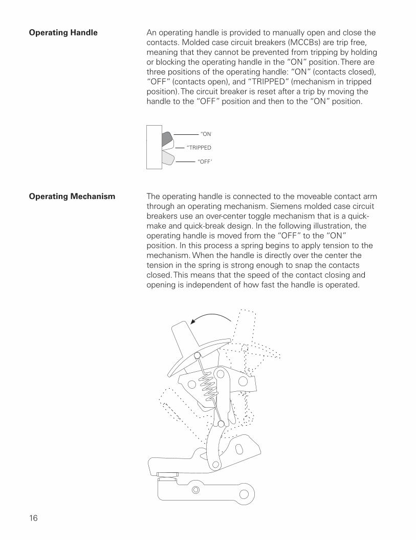
Operating Handle An operating handle is provided to manually open and close the contacts. Molded case circuit breakers (MCCBs) are trip free, meaning that they cannot be prevented from tripping by holding or blocking the operating handle in the “ON” position. There are three positions of the operating handle: “ON” (contacts closed), “OFF” (contacts open), and “TRIPPED” (mechanism in tripped position). The circuit breaker is reset after a trip by moving the handle to the “OFF” position and then to the “ON” position.
“ON”
“TRIPPED”
“OFF”
Operating Mechanism The operating handle is connected to the moveable contact arm through an operating mechanism. Siemens molded case circuit breakers use an over-center toggle mechanism that is a quick-make and quick-break design. In the following illustration, the operating handle is moved from the “OFF” to the “ON” position. In this process a spring begins to apply tension to the mechanism. When the handle is directly over the center the tension in the spring is strong enough to snap the contacts closed. This means that the speed of the contact closing and opening is independent of how fast the handle is operated.

17
To open the contacts, the operating handle is moved from the “ON” to the “OFF” position. In this process a spring begins to apply tension to the mechanism. When the handle is directly over the center the tension in the spring is strong enough to snap the contacts open. As in closing the circuit breaker contacts, contact opening speed is independent of how fast the handle is operated.

18
Trip Unit The trip unit is the “brain” of the circuit breaker. It consists of components that will automatically trip the circuit breaker when it senses an overload or short circuit. The tripper bar is moved by a manual “PUSH TO TRIP” button, a thermal overcurrent sensing element or an electromagnet.
Manual “PUSH TO TRIP” Button
Thermal OvercurrentSensing Element
Adjusting Screw
Tripper Bar
ElectromagnetShort CircuitSensing Element
Trip Mechanism A trip mechanism is held in place by the tripper bar. As long as the tripper bar holds the trip mechanism, the mechanism remains firmly locked in place.
Trip MechanismHeld by Tripper Bar
Trip Mechanism
Trip Mechanism Locked
Tripper Bar

19
The operating mechanism is held in “ON” position by the trip mechanism. When a trip is activated, the trip mechanism releases the operating mechanism, which opens the contacts.
Operating Mechanism Heldin Place by Trip Mechanism

20
Manual Trip MCCBs, heavy duty and above, can be manually tripped by pressing the red “PUSH TO TRIP” button on the face of the circuit breaker. When the button is pressed the tripper bar rotates up and to the right. This allows the trip mechanism to “unlock” releasing the operating mechanism. The operating mechanism opens the contacts. The “PUSH TO TRIP” button also serves as a safety device by not allowing access to the circuit breaker interior in the “ON” position. If an attempt is made to remove the circuit breaker cover while the contacts are in the closed (“ON”) position, a spring located under the pushbutton will cause the button to lift up. This action will also trip the breaker.
Operating MechanismReleased by Trip Mechanism
Trip Mechanism Unlocked

21
Overload Trip The overload trip unit senses and decides when to act by tripping the circuit breaker. Modern molded case circuit breakers have a lineage traceable to the Cutter Company, which came to be known as the I-T-E
® Circuit Breaker Company in the
late 1800s and early 1900s. The company introduced “Inverse Time Element” (I-T-E) circuit breakers in the United States. Simply stated, the higher the current, the shorter time it takes for the trip mechanism to activate. Modern thermal-magnetic circuit breakers generally employ a bimetal strip to sense overload conditions. When sufficient overcurrent flows through the circuit breaker’s current path, heat build up causes the bimetal strip to bend. After bending a predetermined distance the bimetal strip makes contact with the tripper bar activating the trip mechanism.
Bimetal Strip
A bimetal strip is made of two dissimilar metals bonded together. The two metals have different thermal expansion characteristics, so the bimetal bends when heated. As current rises, heat also rises. The hotter the bimetal becomes the more it bends, until the mechanism is released.

22
Short Circuit Trip Short circuit protection is accomplished with an electromagnet. This is referred to as the magnetic or instantaneous element. The electromagnet is connected in series with the overload bimetal strip. During normal current flow, or an overload, the magnetic field created by the electromagnet is not strong enough to attract the armature. When a short circuit current flows in the circuit, the magnetic field caused by the electromagnet attracts the electromagnet’s armature. The armature hits the tripper bar rotating it up and to the right. This releases the trip mechanism and operating mechanism, opening the contacts. Once the circuit breaker is tripped current no longer flows through the electromagnet and the armature is released.
Armature
Electromagnet

23
Review 21. Circuit breakers use ____________ to break the circuit
and stop the flow of energy.
2. Siemens developed ____________ - ____________ contacts that greatly reduce the amount of time it takes for breaker contacts to open when a fault occurs.
3. The ____________ ____________ assembly reduces contact damage by dividing the arc into smaller segments which can be extinguished faster.
4. Siemens circuit breakers use an ____________ - ____________ toggle mechanism that is a quick-make and quick-break design.
5. A ____________ strip uses two dissimilar metals bonded together.
6. An ____________ is used to sense a short circuit.