Modular multichannel measuring device for liquid analysis ...
34
Type 202580 and 202581 Modular multichannel measuring device for liquid analysis with integrated controller and paperless recorder Interface description PROFIBUS-DP 20258003T92Z001K999 V1.00/EN/00614120
Transcript of Modular multichannel measuring device for liquid analysis ...
Type 202580 and 202581Modular multichannel measuring device for
liquid analysis with integratedcontroller and paperless recorder
Interface descriptionPROFIBUS-DP
20258003T92Z001K999
V1.00/EN/00614120


Content
1 Introduction 31.1 Typographical conventions ............................................................................ 3
1.2 General information ....................................................................................... 4
2 PROFIBUS-DP description 52.1 General information ....................................................................................... 5
2.2 PROFIBUS types ........................................................................................... 5
2.3 RS485 transmission technology .................................................................... 6
2.4 PROFIBUS-DP ............................................................................................ 10
3 Configuring a PROFIBUS-DP system 133.1 The GSD file ................................................................................................ 13
3.2 Configuration ............................................................................................... 14
3.3 The GSD generator ..................................................................................... 153.3.1 General information ...................................................................................... 153.3.2 Operation ...................................................................................................... 153.3.3 Example report ............................................................................................. 173.3.4 Configuration of a GSD file ........................................................................... 18
3.4 Connection example .................................................................................... 213.4.1 Type 202580 ................................................................................................ 213.4.2 GSD generator ............................................................................................. 213.4.3 PLC configuration ......................................................................................... 23
4 Data format of the devices 254.1 Integer values .............................................................................................. 25
4.2 Floating-point values/real values ................................................................. 25
5 Device-specific information 275.1 Location of the interface .............................................................................. 275.1.1 Overview of connections .............................................................................. 285.1.2 PIN assignment - PROFIBUS-DP interface ................................................. 29
5.2 Configuring the interface ............................................................................. 30
5.3 Diagnostic and status messages ................................................................. 305.3.1 Behavior when malfunctions occur ............................................................... 30

Content
5.4 Timeframe for data processing .................................................................... 30

1 Introduction
1.1 Typographical conventions
CautionThis character is used if personal injury may result from failure to followinstructions correctly or not at all!
CautionThis symbol is used when damage to devices or data may occur if the instruc-tions are disregarded or not followed correctly.
ESDThis character is used if precautionary measures must be taken when han-dling electrostatically sensitive components.
NoteThis symbol is used to indicate particularly important information.
3

1 Introduction
1.2 General information
Electrostatic charge
CautionThis interface description is addressed to the system manufacturer withrelated technical expertise and knowledge of PCs.Read this interface description prior to starting operation with PROFIBUS-DP.Keep the interface description in a place accessible to all users at all times.All required settings are described in this interface description. Should prob-lems be encountered during commissioning/startup, please refrain from carry-ing out any actions that are not described in the operating manual. Such actions could void your warranty. Please contact your local manufactu-rers branch office or company headquarters.
ESDWhen accessing the interior of the device and when returning plug-in mod-ules, assemblies or components, please follow the procedures acc. to DINEN 61340-5-1 and DIN EN 61340-5-2 "Protection of electronic devices fromelectrostatic phenomena". Use only ESD packaging for shipment. Please note that we cannot accept any liability for damage caused by ESD(electrostatic charge).ESD=Electro Static Discharge
4

2 PROFIBUS-DP description
2.1 General informationPROFIBUS-DP is a manufacturer-independent, open fieldbus standard for awide range of applications in manufacturing, process and building automation. Manufacturer independence and openness are ensured by the internationalstandards IEC 61158 and IEC 61784.PROFIBUS-DP allows devices from different manufacturers can communicatewithout any special interface adaptation. PROFIBUS-DP can be employed forboth high-speed time-critical data transmission and extensive, complex com-munications tasks.
2.2 PROFIBUS types
PROFIBUS-DPThis PROFIBUS variant, which is optimized for speed and low connectioncosts, has been specially tailored for communication between automation con-trol systems (PLCs) and distributed field devices (typical access time < 10 ms). PROFIBUS-DP can be used to replace conventional, parallel signal transmis-sion using 24 V or 0(4) to 20 mA signals.DPV0:Cyclic data transfer:--> is supportedDPV1:Cyclic and acyclic data transfer:--> is no supportedDPV2:In addition to cyclic and acyclic data transfer, slave-to-slave communication occurs:--> is not supported
PROFIBUS-PAPROFIBUS-PA has been specially designed for process engineering and per-mits the linking of sensors and actuators to a common bus line, even in poten-tially explosive zones. PROFIBUS-PA allows data communication between andsupply of power to devices based on two-wire technology in acc. with MBP(Manchester Bus Powering) as specified in IEC 61158-2.
PROFIBUS-FMS
5

2 PROFIBUS-DP description
This is the universal solution for communication tasks at the cell level (typicalaccess time approx. 100 ms). The powerful FMS services open up a widerange of applications and provide a high degree of flexibility. FMS is also suit-able for extensive communication tasks.2.3 RS485 transmission technology
Transmission takes place according to the RS485 standard. It covers all areasin which a high transmission rate and simple, cost-effective installation technol-ogy is required. A shielded, twisted copper cable with one conductor pair isused.The bus structure permits addition and removal of stations or step-by-stepcommissioning of the system without affecting other stations. Subsequent ex-pansions have no influence on the stations already in operation.The transmission speed is selectable within a range of 9.6 Kbit/s to 12 Mbit/s.During system commissioning, one common transmission speed is selected forall devices on the bus.
Basic characteristics
StructureAll devices must be connected in a line structure (one after another). Up to 32stations (masters or slaves) can be linked within such a segment.Repeaters are required for more than 32 stations, for instance, to increase thenumber of devices further.
CautionWhen installing PROFIBUS systems, the installation guidelines of PNO(PROFIBUS NUTZERORGANISATION e. V.) must be observed.
Network- topology
Wiring of bus users is based on bus topology. Several bus segments can be connected by repeaters. Stub lines should be avoided.
Medium Shielded, twisted cable to EN 50 170 Part 8-2
Number of stations
32 stations in each segment without repeater (line amplifier); with repeaters, extension to 126 stations possible
Connector Preferably, 9-pin D-Sub connector
6

2 PROFIBUS-DP description
Cable lengthThe maximum cable length depends on the transmission speed. The cablelength specified can be extended by the use of repeaters. It is recommended tolimit the number of repeaters connected in series to a total of 3.
Bus terminationAt both ends of each segment the bus is terminated by terminating resistors.To ensure trouble-free operation, make sure that voltage is applied to both busterminations at all times. The terminating resistors are located in the PROFIBUS connectors and can beactivated by moving the slide switch to "On".
Baud rate (Kbit/s)
9.6 19.2 93.75 187.5 500 1500 12000
Range/segment
1200m
1200m
1200m
1000m
400 m 200 m 100 m
on
off
max. 31 devices
Repeater
30 devices
7

2 PROFIBUS-DP description
Cable dataThe cable length specifications refer to the cable type A described in the follow-ing: Characteristic impedance:135 to 165 ΩCapacitance per unit length:< 30 pf/mLoop resistance:110 Ω/kmCore diameter:0.64 mmCore cross-section:> 0.34 mm2
It is preferable to use a 9-pin D-Sub connector for PROFIBUS networks incor-porating RS485 transmission technology. The PIN assignment at the connectorand the wiring are shown at the end of this chapter.PROFIBUS-DP cables and connectors are offered by several manufacturers.Please refer to the PROFIBUS product catalog (www.profibus.com) for typesand addresses of suppliers.When connecting the devices, make sure that the data lines are not reversed.A shielded data line must be used! The braided shield and the shielding foil underneath (if present) should be con-nected to the protective ground at both ends; ensure good conductivity of theconnection.Route the data line separately from all high-voltage cables.The following type from Siemens is recommended as a suitable cable:Simatic Net PROFIBUS 6XV1 Item No.: 830-0AH10 * (UL) CMX 75 °C (Shielded) AWG 22 *
Data rateStub lines must be avoided for data rates ≥ 1.5 Mbit/s.
For important information on installation, please refer to the PROFIBUS-DPInstallation Guidelines, Item No. 2.111 from PNO. Address:PROFIBUS-Nutzerorganisation e. V.Haid- u. Neu-Strasse 776131 Karlsruhe
Internet: www.profibus.com
Recommendation: Please follow the installation recommendations given by PNO,especially for the simultaneous use of frequency converters.
8

2 PROFIBUS-DP description
Wiring and bus termination9

2 PROFIBUS-DP description
2.4 PROFIBUS-DPPROFIBUS-DP is designed for high-speed data exchange at the field level.The central control devices, PLC/PC for instance, communicate through a fastserial connection with distributed field devices such as I/O, paperless recordersand controllers. Data exchange with these distributed devices is mainly cyclic.Communication functions required for this purpose are defined by the basicPROFIBUS-DP functions in accordance with IEC 61158 and IEC 61784.
Basic functionsThe central control system (master) reads the input information from the slavescyclically and writes the output information to the slaves cyclically. The bus cy-cle time must be shorter than the program cycle time of the central PLC. In ad-dition to cyclic user data transmission, PROFIBUS-DP also provides powerfulfunctions for diagnostics and commissioning. Transmission technology:
• RS485, twisted pair cable
• Baud rates of 9.6 Kbit/s up to 12 Mbit/s
Bus access:
• Master and slave devices, max. 126 stations on one bus
Communication:
• Peer-to-peer (user data communication)
• Cyclic master-slave user data communication
Operating states:
• Operate: Cyclic transmission of input and output data
• Clear: Inputs are read, outputs remain in a secure state
• Stop: Only master-master data transfer is possible
Synchronization:
• Sync mode: is not supported
• Freeze mode: is not supported
Functions:
• Cyclic user data transfer between DP master and DP slave(s)
• Dynamic activation or deactivation of individual DP slaves
• Checking the configuration of the DP slaves
• Address assignment for the DP slaves via the bus (is not supported)
• Configuration of the DP master via the bus
• Maximum of 176 bytes of input/output data for each DP slave possible
10

2 PROFIBUS-DP description
Cyclic data transmissionThe data transmission between the DP master and the DP slaves is automati-cally carried out by the DP master in a defined, recurring order. During bus sys-tem configuration, the user defines the assignment of a DP slave to the DPmaster. The user also defines the DP slaves that are to be included in, or ex-cluded from, the cyclic user data transmission.Data transmission between the DP master and the DP slaves is divided intothree phases: parameterization, configuration, and data transfer. Prior to a DPslave entering the data transfer phase, the DP master checks in the parameter-ization and configuration phases whether or not the intended configurationmatches the actual device configuration. In the course of this check, the devicetype, format and length information as well as the number of inputs and outputsmust match. These checks provide the user with reliable protection against pa-rameterization errors. In addition to the user data transfer, which is automatical-ly performed by the DP master, new parameterization data can be sent to theDP slaves at the request of the user.
User data transmission in PROFIBUS-DP
Protective functions:
• Response monitoring for the DP slaves
• Access protection for inputs/outputs of the DP slaves
• Monitoring of the user data communication with adjustable monitoring timer in the DP master
Device types:
• DP master class 2, e. g. programming/project design devices
• DP master class 1, e. g. central automation devices (PLC, PC)
• DP slave, e. g. devices with binary or analog inputs/outputs, controllers, recorders
11

2 PROFIBUS-DP description
12

3 Configuring a PROFIBUS-DP system
3.1 The GSD fileDevice data (GSD) allow open project design.PROFIBUS-DP devices have different performance features. They differ withrespect to the available functionality (e. g. number of I/O signals, diagnosticmessages) or the possible bus parameters, such as baud rate and time moni-toring. These parameters vary individually for each device type and manufac-turer. To provide simple plug & play configuration for PROFIBUS-DP, the char-acteristic device features are defined in the form of an electronic data sheet de-vice database file (ddf = GSD file). The standardized GSD files expand opencommunication up to the operator level. Simple and user friendly integration ofdevices from different manufacturers in a bus system is possible by means ofthe project design tool, which is based on the GSD files. The GSD files provideclear and comprehensive description of the features of a device type in a pre-cisely defined format. GSD files are produced for the specific application. Thedefined file format permits the project design system simply to read in the de-vice data of any PROFIBUS-DP device and automatically use this informationfor the bus system configuration. As early as the project design phase, the proj-ect design system can automatically perform checks for input errors and theconsistency of data entered in relation to the overall system.The GSD files are subdivided into three sections.• General specifications
This section contains, among other items, information on manufacturer and device names, hardware and software release versions, and the supported baud rates
• DP master-referenced specificationsThis section is used to enter all parameters related solely to DP master de-vices, e. g. the maximum number of DP slaves that can be connected, or upload and download options; this section is not available for slave devices
• DP slave-referenced specificationsThis section contains all slave-related information, e. g. the number and type of I/O channels, specifications for diagnostic texts and information on the consistency of I/O data
The GSD file includes not only lists, such as information on the baud rate sup-ported by the device, but also the possibility of describing the modules avail-able in a modular device.
13

3 Configuring a PROFIBUS-DP system
3.2 ConfigurationPlug & Play
To simplify configuration of the PROFIBUS-DP system, the DP master (PLC) isconfigured with the aid of the PROFIBUS-DP configurator and the GSD files, orwith the hardware configurator in the PLC.
Sequence of a configuration
The GSD fileThe individual device features of a DP slave are specified clearly and compre-hensively in a precisely defined format in the GSD file by the manufacturer.
The PROFIBUS-DP configurator / hardware configurator (PLC)This software can read in the GSD files of PROFIBUS-DP devices of any man-ufacturer and integrate them for bus system configuration. As early as the proj-ect design phase, the PROFIBUS-DP configurator automatically checks the en-tered files for system consistency errors. The result of the configuration is readinto the DP master (PLC).
Step Action1 Creating a GSD file by means of the GSD generator2 Loading the GSD files of the PROFIBUS-DP slaves into the PROFI-
BUS-DP network configuration software3 Carry out configuration4 Loading the configuration into the system (e. g. PLC)
PC/Laptop
The PC is used forprogramming the PLC,and to test the PROFIBUS-D
PROFIBUS-DP
Device Data Base Files(GSD files)
PLC
14

3 Configuring a PROFIBUS-DP system
3.3 The GSD generator3.3.1 General information
The GSD generator allows the user to generate GSD files with a PROFIBUS-DP interface.The devices available with a PROFIBUS-DP interface are able to transmit orreceive a wide variety of measurands (parameters). However, since in most ap-plications only some of these measurands are to be transmitted via PROFI-BUS-DP, the GSD generator is used to select these measurands.Once the device is selected, all variables available appear in the„Parameterization“ window. Only when these have been copied either to the"Input" or "Output" window, will they later be contained in the GSD file for fur-ther processing or pre-processing by the DP master (PLC).
3.3.2 OperationFile menu Input window
(input for master/PLC)Window containing the available parameters
Output window (output for master/PLC)
Device name for hardware catalogIf different GSD files are requiredfor devices of the same type, thisstandard name has to be alteredin a way that allows unambigu-ous assignment of the PROFI-BUS master in the hardwareconfiguration.
Delete entry from input window
Delete entry from output window
Exitprogram
15

3 Configuring a PROFIBUS-DP system
File menuThe file menu can be opened by using the Alt-D key combination or by meansof the left mouse button. It provides the following options:
If SIMATIC S7 from SIEMENS is used for project design, the names in theGSD file must not be longer than 8 characters.GSD files with long file names cannot be entered into the PLC hardware cata-log!
New After the function for creating a new GSD file has beenopened, the available devices are selected. After the re-quired device has been selected, all available parame-ters are shown in the parameter window.
Open This function opens an existing GSD file.Save/Save as
This function is used to save the generated or editedGSD file.
Diagnosis This function can be used to test the GSD file in conjunc-tion with a PROFIBUS-DP master simulator from B+Wand the Profibus slave.
Print preview Shows a preview of a report1 that can be printed.
1 The report contains additional information for programming the PLC (e. g. data typeof the selected parameters).
Print Prints a report1.Standardsettings
The language to be used at the next restart of the pro-gram can be selected here.
End Exits the program.
See Chapter 3.3.3 "Sample report", page 17
16

3 Configuring a PROFIBUS-DP system
3.3.3 Example reportI/O REPORT
Instrument: T 202580
Length of inputs ( Bytes ): 13 Length of outputs ( Bytes ): 8
Inputs
Byte Description Type ---------------------------------------------------------------- [ 0] Interface-Status BYTE [ 1] Analog\Analoginp.\Temp 1 REAL [ 5] Analog\Analoginp.\Universal 1 uncomp. REAL [ 9] Analog\Analoginp.\Universal 1 comp. REAL
Outputs
Byte Description Type ---------------------------------------------------------------- [ 0] Setpoint value controller\controller 1 setpoint value 1 [ 4] Setpoint value controller\controller 2 setpoint value 1
17

3 Configuring a PROFIBUS-DP system
3.3.4 Configuration of a GSD file18

3 Configuring a PROFIBUS-DP system
The configuration of the GSD file is de-signed for installation on the SIMATIC S7 (SIEMENS).Should installation problems with othercontrols be encountered, delete allPreset = 1 entries.In this case, it is also necessary to setup the variables selected in the GSDgenerator in the correct order in thePLC process image.
19

3 Configuring a PROFIBUS-DP system
2
Parameter selectionWhen an existing file has been opened or a new file created, all available pa-rameters are shown in the parameter window.
Parameter addition or deletion
Using the arrow keys and , parameters can be moved from the inputwindow to the output window (and back).
Configuration data (user level)The device's user level parameters are kept in the Configuration folder. Theseparameters may not be written cyclically by the PLC without end, because thecorresponding memory modules of the multichannel measuring instrumenthave been designed for a limited number of write cycles (approx. 1 000 000).
Device name for hardware catalogIf different GSD files are required for de-vices of the same type, this standardname has to be altered in a way that al-lows unambiguous assignment of thePROFIBUS master in the hardware con-figuration.
List with availableparameters
The "Interface status" parameter automatically appears in the input windowand cannot be deleted.
0

3 Configuring a PROFIBUS-DP system
3.4 Connection example3.4.1 Type 202580
3.4.2 GSD generator
Step Action1 Connect the device to the PLC.2 Using the device keys or the setup program, set the device address.
Step Action1 Start the GSD generator (example: Start / Programs / Devices /
PROFIBUS / GSD generator).2 Select the device.
3 Select the variable to be transmitted to the DP master in the left win-dow and use the arrow key or drag & drop to move it into the right window.
21

3 Configuring a PROFIBUS-DP system
4 Save the GSD file in any folder. Step Action
If SIMATIC S7 from SIEMENS is used for project design, the names in theGSD file must not be longer than 8 characters.
22

3 Configuring a PROFIBUS-DP system
3.4.3 PLC configurationStep Action1 Start the PLC software.2 Open the hardware configuration and execute the menu command
"Install new GSD".
The new GSD file will be read in, processed, and the Type 202580 inserted into the hardware catalog.
3 Open the hardware catalog and place the new device on the work surface.
Via the GSD file of the slaves, the master receives information on which baud rates are supported.
PLC with itscomponents
Bus
23

3 Configuring a PROFIBUS-DP system
4 Load the configuration into the PLC (Target system / Load into mod-ule).
Step Action
If a device with PROFIBUS-DP interface is operated on a master system(PLC), suitable error analysis routines should be provided in the master sys-tem.In conjunction with a SIMATIC S7, installation of the OB86 in the PLC is rec-ommended, so that failure of a PROFIBUS-DP device can be detected andanalyzed.
The "Interface status" parameter automatically appears in the input windowand cannot be deleted.
24

4 Data format of the devices
4.1 Integer valuesInteger values are transmitted in the following format:
Big Endian Little Endianfirst the - High byte, - Low byte,then the - Low byte. - High byte.
4.2 Floating-point values/real valuesFloating-point values/real values are stored in the device in the IEEE-754 stan-dard format (32-bit).Single-precision floating-point format (32-bit) to Standard IEEE 754
S - Sign bit (Bit 31) E - Exponent in the twos complement (Bit 23 to Bit 30)M - 23-bit normalized mantissa (Bit 0 to Bit 22)Example: Calculation of the real number from the sign, exponent, and mantissa.Byte 1 = 40h, Byte 2 = F0, Byte 3 = 0, Byte 4 = 0 40F00000h = 0100 0000 1111 0000 0000 0000 0000 0000bS = 0E = 100 0000 1M = 111 0000 0000 0000 0000 0000
Value = -1S · 2Exponent-127 · (1 + Mb22·2-1 + Mb21·2-2 + Mb20·2-3 + Mb19·2-4 + …)
Value = -10 · 2129-127 · (1 + 1·2-1 + 1·2-2 + 1·2-3 + 0·2-4)
Value = 1 · 22 · (1 + 0.5 + 0.25 + 0.125 + 0)Value = 1 · 4 · 1.875Value = 7.5
^
When devices are used on a PROFIBUS-DP system, it is necessary to usethe correct data format!Two different data formats are available for selection:Little EndianBig EndianCommunication with a Siemens PLC usually uses the Big Endian format.
SEEEEEEE EMMMMMMM MMMMMMMM MMMMMMMMByte 1 Byte 2 Byte 3 Byte 4
25

4 Data format of the devices
Big Endian
Little Endian
The order in which the individual bytes are transmitted depends on the dataformat set in the configuration.After/before transmission from/to the device, the bytes for the floating-pointvalue must be interchanged accordingly.
SEEEEEEE EMMMMMMM MMMMMMMM MMMMMMMMByte 1 Byte 2 Byte 3 Byte 4
MMMMMMMM MMMMMMMM EMMMMMMM SEEEEEEEByte 4 Byte 3 Byte 2 Byte 1
26

5 Device-specific information
5.1 Location of the interfaceExpansion slot COM 2 is provided for the PROFIBUS-DP interface. If the multi-channel measuring instrument is to be equipped with a PROFIBUS-DP inter-face as standard, this must be stated in the order details.If your device is not equipped with a PROFIBUS-DP interface (part no.00581173), it can be retrofitted. vOperating manual B 202580.0
vInstallation instructions B 202580.4 or B 202581.4
vType sheet T 202580 or T 202581
NoteThe type designation on the nameplate of the device indicates which optionalinterfaces have been installed at the factory.Information regarding this can be found in the "Identifying the device version"chapter in operating manual B 202580.0 / B 202581.0 or installation instruc-tions B 202580.4 / B 202581.4 (the installation instructions are included in thescope of delivery of the device).
NoteAvailable interfaces can also be added by the user.Information regarding this can be found in the "Retrofitting optional boards"chapter in the operating manual B 202580.0 / B 202581.0 or the installationinstructions B 202580.4 / B 202581.4 (the installation instructions areincluded in the scope of delivery of the device).
27
5 Device-specific information
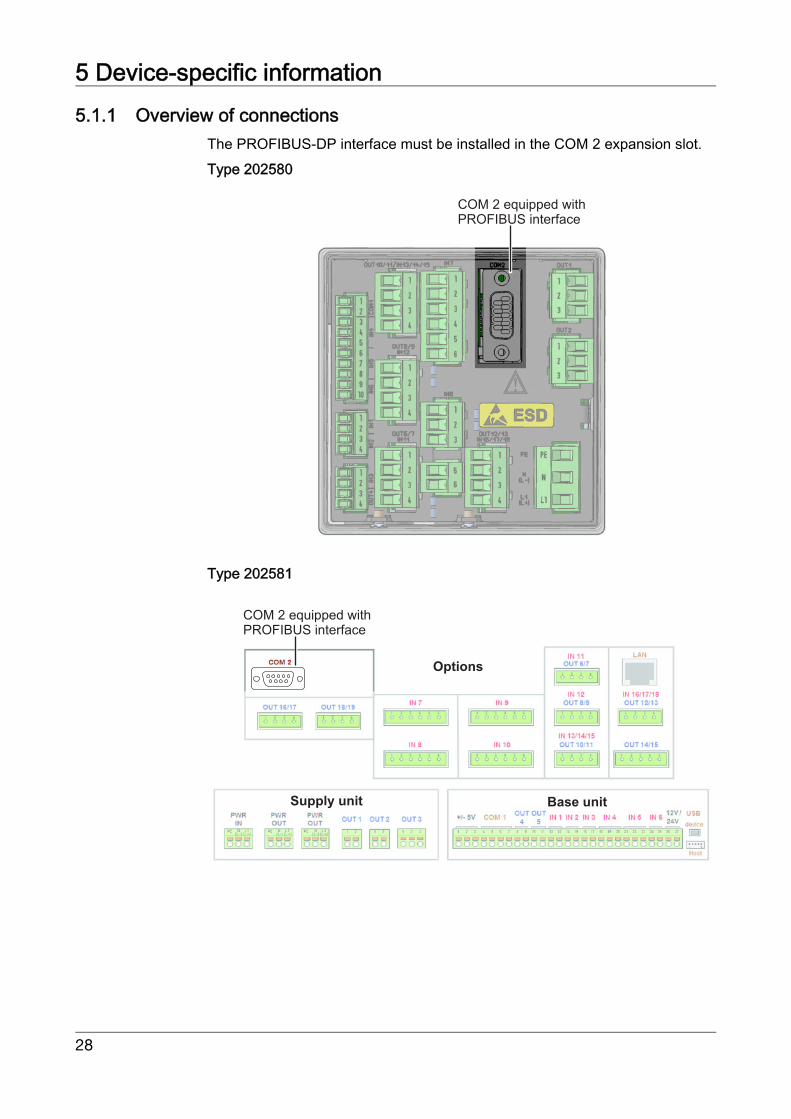
5.1.1 Overview of connectionsThe PROFIBUS-DP interface must be installed in the COM 2 expansion slot.Type 202580
Type 202581
COM 2 equipped withPROFIBUS interface
COM 2 equipped withPROFIBUS interface
Base unit
Options
Supply unit
28
5 Device-specific information
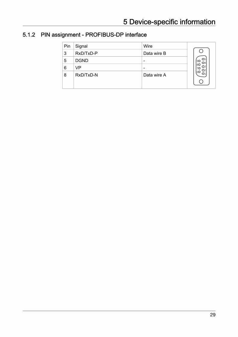
5.1.2 PIN assignment - PROFIBUS-DP interfacePin Signal Wire3 RxD/TxD-P Data wire B5 DGND -6 VP -8 RxD/TxD-N Data wire A
5
4
3
2
9
8
7
61
29

5 Device-specific information
5.2 Configuring the interfaceThe parameters of the PROFIBUS interface are set in the configuration:Open: Device menu -> Configuration -> PROFIBUS_DP
5.3 Diagnostic and status messagesIf faults occur during communication with the device, appropriate error messag-es appear on the display. In addition, the binary signal "PROFIBUS error" is setto true for the duration of the error. This binary signal is selected via:Binary selection -> Alarms & internal signals -> PROFIBUS errorWhen PROFIBUS errors occur, the wiring, device address, and operation ofthe PROFIBUS master (PLC) must be checked.
5.3.1 Behavior when malfunctions occurIf a fault occurs during communication, all values transmitted prior to the faultare retained in the device.
5.4 Timeframe for data processingThe device processes interface data cyclically in a timeframe of 250 ms.
Configuration Value range Default value Description
PROFIBUS active
YesNo
No Activation of the PROFI-BUS interface
Device address 1 to 125 1 Specification of the PRO-FIBUS user
Data format Big EndianLittle Endian
Big Endian Big EndianLittle Endian,see chapter 4 „Data for-mat of the devices“, page25.
Changing the device address via the bus is not supported by the device!The baud rate is determined automatically (max. 12 MBit/s).
30