Model 956A-201-S1 - Fluke Corporationassets.fluke.com/manuals/201_S1__omeng0000.pdfThe 956A-201-S1...
24
Model 956A-201-S1 Universal Digital Ratemeter Simulator Operators Manual March 2005 Manual No. 956A-201-S1-1 Rev. 1 ©2003, 2005 Fluke Corporation, All rights reserved. Printed in U.S.A. All product names are trademarks of their respective companies
-
Upload
nguyentruc -
Category
Documents
-
view
220 -
download
3
Transcript of Model 956A-201-S1 - Fluke Corporationassets.fluke.com/manuals/201_S1__omeng0000.pdfThe 956A-201-S1...

Model 956A-201-S1 Universal Digital Ratemeter Simulator
Operators Manual March 2005 Manual No. 956A-201-S1-1 Rev. 1 ©2003, 2005 Fluke Corporation, All rights reserved. Printed in U.S.A. All product names are trademarks of their respective companies

Fluke Biomedical Radiation Management Services 6045 Cochran Road Cleveland, Ohio 44139 440.498.2564 www.flukebiomedical.com/rms
i
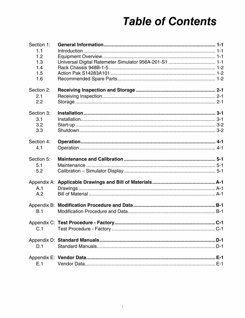
Table of Contents Section 1: General Information................................................................................... 1-1
1.1 Introduction .................................................................................................. 1-1 1.2 Equipment Overview.................................................................................... 1-1 1.3 Universal Digital Ratemeter Simulator 956A-201-S1 ................................... 1-1 1.4 Rack Chassis 948B-1-5 ............................................................................... 1-2 1.5 Action Pak S14283A101.............................................................................. 1-2 1.6 Recommended Spare Parts......................................................................... 1-2
Section 2: Receiving Inspection and Storage ........................................................... 2-1 2.1 Receiving Inspection.................................................................................... 2-1 2.2 Storage ........................................................................................................ 2-1
Section 3: Installation.................................................................................................. 3-1 3.1 Installation.................................................................................................... 3-1 3.2 Start-up ........................................................................................................ 3-2 3.3 Shutdown..................................................................................................... 3-2
Section 4: Operation.................................................................................................... 4-1 4.1 Operation ..................................................................................................... 4-1
Section 5: Maintenance and Calibration .................................................................... 5-1 5.1 Maintenance ................................................................................................ 5-1 5.2 Calibration – Simulator Display.................................................................... 5-1
Appendix A: Applicable Drawings and Bill of Materials...............................................A-1 A.1 Drawings...................................................................................................... A-1 A.2 Bill of Material .............................................................................................. A-1
Appendix B: Modification Procedure and Data.............................................................B-1 B.1 Modification Procedure and Data................................................................. B-1
Appendix C: Test Procedure - Factory...........................................................................C-1 C.1 Test Procedure - Factory .............................................................................C-1
Appendix D: Standard Manuals......................................................................................D-1 D.1 Standard Manuals........................................................................................D-1
Appendix E: Vendor Data................................................................................................ E-1 E.1 Vendor Data................................................................................................. E-1

(Blank Page)
General InformationIntroduction 1
1-1
Section 1 General Information
1.1 Introduction
The equipment described in this manual is designed for use at the Simulator Facility of Rochester Gas and Electric’s Ginna Nuclear Power Station. The simulator equipment provided mimics the redundant Control Room Air Intake Monitors identified as channels R45 and R46. These channels provide a continuous display of gamma radiation dose rate in the intake duct. The displayed units are mR/h.
The equipment comprising the simulator channels is listed below:
• Model 956A-201-S1, Universal Digital Ratemeter Simulator
• Model 948B-1-5 Rack Chassis, dual bay
• Model S14283A101, Action Pak, 4010 series
The 956A-201-S1 and 948B-1-5 are designed by Fluke Biomedical, Radiation Management Services. The S14283A101 is designed by Action Instruments.
1.2 Equipment Overview
This section is a brief overview of each piece of equipment utilized for each of the two simulator channels. A description of the equipment is contained in the following paragraphs. For further information on individual pieces of equipment, refer to the Standard Manual located in Appendix D.
1.3 Universal Digital Ratemeter Simulator 956A-201-S1
The model 956A-201-S1 is voltage or current driven device used to simulator the display and alarm function of the 956A-201 Ratemeter. The display range is five decades over a range of 1.0E-2 to 1.0E5 mR/h. The R45 and R46 monitors operate over a range of 1.0E-2 to 1.0E3 mR/h. Standard features include a floating decimal point display in mR/h, R/h or kR/h, a multicolor bargraph indicating channel status and dose rate, front panel pushbuttons for alarm setpoint display, alarm acknowledgement, check source and AC power. Unpower (dry) 5A relay contacts are provide for Fail, Warn and High radiation alarms. A powered contact is provided by the Check Source relay. All relays except Check Source are operated in the normally energized or “fail safe” mode.
The 956A-201-S1 is configured to operate with a 0-10 VDC input processed through the installed model 942-200-75 Analog Input Option circuit board. The 0 –10 VDC input voltage provides 255 steps over the selected range.

Model 956A-201-S1 Operators Manual
1-2
1.4 Rack Chassis 948B-1-5
The 948B-1-5 Rack Chassis is a two channel, 19” width chassis provided with front and rear attachment points for standard EIA mounting. The physical dimensions of the 948B-1-5 are provided in Appendix A.
1.5 Action Pak S14283A101
The S14283A101 is a factory configured signal converter/isolator powered by 120 VAC. The device installs in a standard surface mount octal relay socket (provided) and converts a bipolar –10 to +10 VDC input signal to a 0-10 VDC output. The S14283A101 is the interface between the Simulator’s computer driven output and the 956A-201-S1 UDR Simulator input.
1.6 Recommended Spare Parts
Part Number Description Qty.
92-7027-1A Fuse, 2A, 3AG 5
Receiving Inspection and StorageReceiving Inspection 2
2-1
Section 2 Receiving Inspection and Storage
2.1 Receiving Inspection Upon receipt of the unit:
1. Inspect the carton(s) and contents for damage. If damage is evident, file a claim with the carrier and notify Fluke Biomedical, Radiation Management Services at 440.248.9300.
2. Check that all items on the packing slip are present and in good condition. If any items are missing or damaged, contact Fluke Biomedical at 440.248.9300.
2.2 Storage Instruments storage must comply with Level B storage requirements as outlined in ANSI N45.2.2 (1972) Section 6.1.2(.2). The storage area shall comply with ANSI N45.2.2 (1972) Section 6.2 Storage Area, Paragraphs 6.2.1 through 6.2.5. Housekeeping shall conform to ANSI N45.2.3 (1972).
Level B components shall be stored within a fire resistant, tear resistant, weather tight enclosure, in a well-ventilated building or equivalent.
Instruments storage must comply with the following:
1. Inspection and examination of items in storage must be in accordance with ANSI N45.2.2 (1972) Section 6.4.1.
2. Requirements for proper storage must be documented and written procedures or instructions must be established.
3. In the event of fire, post-fire evaluation must be in accordance with ANSI N45.2.2 (1972), Section 6.4.3.
4. Removal of items from storage must be in accordance with ANSI N45.2.2 (1972), Sections 6.5 and

Model 956A-201-S1 Operators Manual
(Blank page)

InstallationInstallation 3
3-1
Section 3 Installation
3.1 Installation
Installation consists of mounting the 948B-1-5 Rack Chassis and the installation and termination of electrical connections to the 956A-201-S1 UDR Simulator and S14283A101 Action Pak signal converter. Refer to the standard manuals in Appendix D for connector assembly instructions and Loop Diagram S157033A-106 in Appendix A for electrical termination. Prior to connecting terminated cabling to the UDR Simulator or applying AC power, perform a point-to-point wiring verification per Loop Diagram S157033A-106. The 948B-1-5 Rack Chassis is designed to be installed in a cabinet equipped with standard EIA mounting frames or surface mounted through a solid panel of sufficient gauge to allow for tapping of the 10-32 mounting holes. It is recommended that the rear of the rack chassis also be supported. The 948B-1-5 Rack Chassis is supplied with mounting hardware consisting of #10-32 oval head screws and nylon washers with dress covers. Other equivalent mounting hardware may be used at the discretion of the Customer. Customer 120 VAC, 60 Hz power is connected to J3 of the 956A-201-S1 UDR Simulator and to terminals 1 through 3 of the S14283A101 signal converter. The nominal power requirements for UDR Simulator and signal converter are 30 watts per channel. Customer signal connections are made at J6 of the UDR simulator, signal converter terminals 5 and 6 (input) and signal converter terminals 7 and 8 (output) Relay contacts are available on UDR Simulator P1. Shielded, twisted pair 22-20 gauge cable is recommended for signal wiring. Refer to Loop Diagram S157003A-106 for details. A full complement of mating connectors is provided with the 956A-201-S1 UDR Simulator but not all of these will be required for installation. A pin extraction tool must be used when removing pins from the AMP connector used for AC power input. The P6 signal input plug for J6 is a 26 pin, solder type connector. It is recommended that heat shrinkable or other insulating tubing be used on the P6 connections after soldering due to the close spacing of the pins. Tool # 305183 is provided as part of the connector kit. Connection to the S14283A101 signal converter should be made using insulated barrel crimp type, 22-18 AWG lugs suitable for a #6 to #8 screw. When terminating UDR Simulator rear panel cables, allow sufficient service loops in these cables to allow the UDR Simulator to be withdrawn from the front of the rack chassis for cable disconnection.

Model 956A-201-S1 Operators Manual
3-2
3.2 Start – Up
Before apply AC power to the UDR Simulator, read the operation section of the 955A Standard Manual located in Appendix D.
1. After the equipment has been installed and all pre-power tests have, apply power by depressing
and releasing the front panel AC power switch on the UDR Simulator and energize the signal isolator by applying AC power.
2. Enter or verify the setpoints listed in the Table below and record. Setpoints are entered by placing the rotary function switch in the desired number position corresponding to the setpoint and depressing the “ENTER” pushbutton to display the current value. If the setpoint value is correct, depress the “ENTER” pushbutton a second time to accept the value, then move the rotary function switch to the next desired position. If the setpoint value is to be change, use the “VAUE” and “DIGIT” pushbuttons to edit the value, then depress “ENTER” to accept. Note that the “VALUE” pushbutton is used to alter the “E” or exponent to “-“ or negative when a value less than one is required.
Rotary Function Switch Position
Setpoint Normal Value R45/46 Sim.
Default Value (EPROM)
0 High Radiation Alarm in mR/h Customer Select 1.00E3
1 Warn Radiation Alarm in mR/h Customer Select 1.00E1
2 * Dead Time (Tau) 0.00E0 0.00E0
3 Analog Output F.S. in mR/h 1.00E3 1.00E6
4 Over Range in mR/h 1.00E3 1.00E6
5 Conversion Constant 6.25-1 1.00E1
6 Not Used 0.00E0 0.00E0
7 Analog Output L.S. in mR/h 1.00-2 1.00-2
8 * Count Time in Calibrate Mode 6.00E1 6.00E1
9 Under Range in mR/h 1.00-2 1.00-2
* These parameters are normally not altered from default values in the UDR Simulator application.
3.3 Shutdown
Shutdown of the simulator channel is accomplished by depressing and releasing the UDR Simulator front panel AC power pushbutton and de-energizing the signal isolator power source.
NOTE
OperationOperation 4
4-1
Section 4 Operation
4.1 Operation
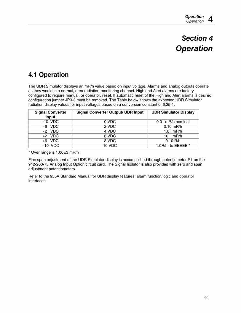
The UDR Simulator displays an mR/h value based on input voltage. Alarms and analog outputs operate as they would in a normal, area radiation-monitoring channel. High and Alert alarms are factory configured to require manual, or operator, reset. If automatic reset of the High and Alert alarms is desired, configuration jumper JP3-3 must be removed. The Table below shows the expected UDR Simulator radiation display values for input voltages based on a conversion constant of 6.25-1.
Signal Converter Input
Signal Converter Output/ UDR Input UDR Simulator Display
-10 VDC 0 VDC 0.01 mR/h nominal - 6 VDC 2 VDC 0.10 mR/h - 2 VDC 4 VDC 1.0 mR/h +2 VDC 6 VDC 10 mR/h +6 VDC 8 VDC 0.10 R/h +10 VDC 10 VDC 1.0R/hr to EEEEE *
* Over range is 1.00E3 mR/h
Fine span adjustment of the UDR Simulator display is accomplished through potentiometer R1 on the 942-200-75 Analog Input Option circuit card. The Signal Isolator is also provided with zero and span adjustment potentiometers.
Refer to the 955A Standard Manual for UDR display features, alarm function/logic and operator interfaces.

Model 956A-201-S1 Operators Manual
(Blank page)
Maintenance and CalibrationMaintenance 5
5-1
Section 5 Maintenance and Calibration
5.1 Maintenance
The UDR Simulator and signal converter are designed to operate for extended periods without scheduled maintenance. Yearly inspections of the UDR Simulator rear panel cable pigtails for chaffing is recommended.
The 948B-1-5 Rack Chassis should be periodically inspected for dust build-up on the ventilation screens. Adjust the frequency of cleaning as required to maintain good convection airflow through the chassis.
5.2 Calibration – Simulator Display
Calibration of the S14283A101 signal isolator is limited to the adjustment of the zero and span potentiometers. Refer to the Table in Section 4 for input vs. output voltages.
Calibration of the display of UDR Simulator is limited to the adjustment of span on the 942-200-75 Analog Input Option circuit card.
For additional calibration adjustments generic to the 956 series Ratemeter, refer to the 955A Standard Manual. Features covered include analog current loop output and voltage output zero and span. These features may or may not be required for simulator use.

Model 956A-201-S1 Operators Manual
(Blank page)
Appendix AApplicable Drawings and Bill of Materials A
A-1
Appendix A Applicable Drawings and Bill of Materials
A.1 Drawings
Drawing Number Description
S157033A-106 Loop Diagram, Simulator
948B-1-5 Rack Chassis, Dual
A.2 Bill of Material
Document Number Description
956A-201-S1 UDR Simulator
948B-1-5 Rack Chassis, Dual

Model 956A-201-S1 Operators Manual
(Blank page)

AppendixModification Procedure and Data B
B-1
Appendix B Modification Procedure and Data
B.1 Modification Procedure and Data
Document Number Description
956A-201-S1MS Modification Sheet, UDR Simulator

Model 956A-201-S1 Operators Manual
(Blank page)
AppendixTest Procedure-Factory C
C-1
Appendix C Test Procedure - Factory
C.1 Test Procedure - Factory
Document Number Description
TP956A-201-3 Electronic Factory test Procedure for Ratemeter

Model 956A-201-S1 Operators Manual
(Blank page)

AppendixStandard Manuals D
D-1
Appendix D Standard Manuals
D.1 Standard Manuals
Document Number Description
955A-1 Standard Manual for 956A-201 series Ratemeters
942-100-75D Standard Manual for Analog Input Option
956A-201-M1MS Modification Sheet for Model 956A-201

Model 956A-201-S1 Operators Manual
(Blank page)
AppendixVendor Data E
E-1
Appendix E Vendor Data
E.1 Vendor Data
Document Number Description
S14283A101 AP4010 Signal Converter

Fluke Biomedical Radiation Management Services 6045 Cochran Road Cleveland, Ohio 44139 440.498.2564 www.flukebiomedical.com/rms