
MKT and Media
6
126 HVD c TAPPI N G STATI O N: POW ER TAPPI NG FROMA DC TRAN SM SSI O N LI1 Z TO a LOCAL ACNETW ORK A Ekst romand P Lamell R oyal I nsti t ute of Techn ol ogy, EKC- El ectr i c Power Research Cen t er, Sw eden ABSTRACT Th e pape r descr i bes a new con cept f or t ap pi ng of f a small am ou nt of pow er f r oma hi gh v ol t age di r ect curr ent ( H VD C) transms- si on l i ne to a l ocal ne t w ork. The proposed new concept f or a seri es tapping i mpli es power conversi on i n t wo st eps f r om t he l i ne t o a l ocal ac network. Thi s w l l make i t possi bl e to the use a si ngle phase t rans- f orm er be wee n t he dc l i ne po t en t i al and grou nd. Th e convert er br i dge connect ed i n seri es i n the dc transmssi on i s of the cur- rent source l i ne- com mutat ed t ype, w hi l e t he other two converters are of t he vol tage- source f or ced- com m utated t ype. The ba si c f unct i on s o f t he conv ert er ar e d escri be d a nd i l l ustr at ed by t he resul t s fr om si mul ati ons w t h the EMTP program I N TRO D UC TI ON The H VD C t echni que has du r i ng t he 1970 t h an d 19 80 t h been w de l y accepted a s a val ua bl e com pl em en t and al ternat i ve t o t he AC tech- ni que f or el ectr i cal power transmssi on. How ev er, t he majori ty of t he appli cati on s have s o far bee n two-termnal or point to poi nt t ran sm ssi ons. The need f or and possi - bi l i ty t o bui l d mul t i t erm nal HVDC t r ansm s- si on have been d i scussed at l east si nce t he ea r l y si xt i es. St ud i es have been made r e- gardi ng the feasi bi l i t i es of seri es connec- ti on o r parall el connecti on of t he convert er st ati on s on the dc-si de. I t seem s to be a f ai rl y general consensus t hat a paral l el con ne ct i on or const ant dc- vol t age m ul t i t erm na l H VDC scheme i s t o be pr e- ferred, w hen the po w er r ati ngs of the di f- f er ent t erm nals are of t he sa me or der of m agni t ude. Tw o suc h schemes have been b ui l d or i s b ei ng com mssi oned, t he Sar di ni c scheme wth a third smaller termnal at Cor- si ca and t he Q ueb ec - New Engl and sc hemes w t h t hree ter m nal s ha vi ng al m ost the same power r ati ngs, 2000 - 2200 MW. There al so see mto be a need t o t ap- off a sm al l am ount of power at som e l ocat i on s l on g d i st ance over head l i ne tr ansmssi on syst em s. However , t he conventi on al t ech ni que w th l i ne- com m utat ed cur r en t - source convert - ers i n paral l el on t he dc-si de, i . e. con- nected between t he l i ne vol t ag e an d g r ound , doe s not seemto be very att r acti ve f or such appli cati ons. The cost per m eg aw att w l l be fairl y hi gh as the conve rter br i dge has to be desi gned for t he f ul l l i ne- vol t age. The local ac-network i s al so usual l y very weak for such cases requiri ng i nstal l at i ons of expensi ve synch ron ou s co m pe nsator . I t i s also mostl y n ot accep t ed that a m nor di s- turbance i n t he connected ac-network can di st urb t he operati on of the whol e HVDC sys- t em whi ch i s di f f i cul t t o avoi d as l ong as li ne- com m ut at ed con ver t ers conn ect ed be t w een l i ne and ground ar e used. Connect i on of a sm all tappi ng stati ons in seri es on t he dc-s i de seem s t o offer certain ad vant ag e compared w th p aral l el con nect i on, bot h w t h regard t o cost s an d per f orm ance. The f ast devel opment of new sem conductor devi ces havi ng t urn-of f capabi l i ti es w l l also make it i nteresti ng t o use choppers or f orced- com mutat i ng conv ert ers. Studi es of a new concept for a seri es t ap pi ng st ati on us- i ng t w o f orced - com m utat ed convert ers w th an i nt ermedi ate dc- st age w l l be pr ese nt ed i n t his paper. The general r equi r ement s on tapping stations wll first be treated and i t w l l be di scussed how t hese coul d be ful- f i l l ed w t h paral l el and seri es connected stati ons of di f f erent t ypes. GENW AL REO UI REMENTS ON SMALL TAPPI N G STATI O N S The tappi ng stati ons considered i n thi s pa- per are assum ed t o h ave a f ai rl y smal l power r ati ng of the order of 2-5% of t he p ow er r ati ng of t he m ai n HVD C l i ne. I t i s t ho ug ht t hat t he t appi ng st ati on s shal l f eed smal l com m un i t i es l ocated al on g the l i ne f or whi ch t he al t erna tive po wer suppl y i s l ocal gen- e at i on, e.g. through d i esel generators. The r equi r em ents on cost s, m ai ntenance and D er - f o & a nce have because' of that t o be f avbur- abl e a s c om pa r ed t o what can be of f er ed by al t erna t i ve power suppl i es. AS the l ocal po wer system-to be suppl i ed w th e l ect ri cal power can be an i sol ated syst emw t h n o ge n- erati on or conn ect i on t o ot he r pow er syst em s the t appi ng st ati on m gh t be the onl y power suppl y. Thi s mean s t ha t no synchronou s m a- chi nes m ust be conne ct ed an d t hat t he ac- f r eq uen cy a nd ac- vol t age m ght be con t rol l ed by t he t appi ng st ati on. How ever, coo perati on w th local generati on f acil i ti es, i f avai l - abl e, must of course al so be po ssi bl e. Short i nt err upti ons at t he power suppl i es can probab l y be tol erated i n conj uncti on w t h temporar y ea r th f au l t s on the m ai n over head HVDC l i ne. On the other han d, f aul t s in the local ac-network must not di s- t urb t he o pe r ati on of t he m ai n HVDC l i ne. Further the control of the tapping stati on shoul d basi cal l y b e p erf orm ed l ocal l y and not be dep en dent upon t el ecom m un i cat i on l i nks to the mai n stati ons. It i s al so to be preferred that the charac- teri sti cs of the feed in to the local ac- network through the tap pi ng st ati on are si m l ar t o these offered by a synchr onous generator wth regard to fault currents, as the st an dard protecti on and earth faul t l o- cat i on syst em s t hen can be used i n t he ac- networ k Finall y it i s to be preferred if the systems can b e ar r anged i n such a w ay t ha t t he power sup pl i ed t o the l ocal ac- network can be i n- dep end ent upo n t he p ow er t r an smtted on t he m ai n HVD C l i nk.
-
Upload
muhammad-awais -
Category
Documents
-
view
220 -
download
0
Transcript of MKT and Media

8/19/2019 MKT and Media
http://slidepdf.com/reader/full/mkt-and-media 1/6
126
HVDc
TAPPI NG STATI ON: POWER TAPPI NG FROMA DC TRANSM SSI ON
LI1 Z
TO
a LOCAL
ACNETWORK
A Ekst r omand P Lamel l
Royal I nsti t ute of Technol ogy, EKC- El ectr i c Power Research Cent er, Sweden
ABSTRACT
The paper descr i bes a new concept f or
t appi ng of f a smal l amount of power f r om a
hi gh vol t age di r ect cur r ent ( HVDC) tr ansm s-
si on l i ne t o a l ocal net work. The pr oposed
new concept f or a ser i es t appi ng i mpl i es
power conversi on i n t wo st eps f r om t he l i ne
t o a l ocal ac network. Thi s w l l make i t
possi bl e to t he use a si ngl e phase t r ans-
f ormer bet ween t he dc l i ne pot ent i al and
ground. The convert er br i dge connect ed i n
seri es i n t he dc t ransmssi on i s of t he cur-
r ent source l i ne- commutat ed t ype, whi l e t he
other t wo conver t ers are of t he vol t age-
source f orced-commutat ed t ype. The basi c
f unct i ons of t he convert er ar e descri bed and
i l l ustr at ed by t he resul t s fr om si mul ati ons
w th t he EMTP program
I NTRODUCTI ON
The HVDC techni que has dur i ng t he 1970t h and
1980t h been w del y accepted as a val uabl e
compl ement and al t ernat i ve t o t he AC tech-
ni que
f or
el ectr i cal power t ransmssi on.
However, t he maj ori t y of t he appl i cati ons
have
so
f ar been t wo-t erm nal or poi nt t o
poi nt t r ansm ssi ons. The need f or and possi -
bi l i ty t o bui l d mul t i t erm nal HVDC t r ansm s-
si on have been di scussed at l east si nce t he
ear l y si xt i es. St udi es have been made r e-
gardi ng the feasi bi l i t i es of seri es connec-
ti on o r paral l el connecti on of t he convert er
st ati ons on t he dc- si de. I t seems to be a
f ai rl y general consensus t hat a paral l el
connect i on
or
const ant dc- vol t age
mul t i t erm nal HVDC scheme i s t o be pre-
f err ed, when t he power r ati ngs of t he di f -
f er ent t erm nal s are of t he same or der of
magni t ude. Two such schemes have been bui l d
or
i s bei ng comm ssi oned, t he Sardi ni c
scheme w t h a t hi r d smal l er term nal at Cor-
si ca and t he Quebec - New Engl and schemes
w t h t hree ter m nal s havi ng al most t he same
power r ati ngs, 2000
-
2200
MW.
There al so seem t o be a need t o t ap- of f a
smal l amount of power at some l ocati ons
al ong t he rout e of t he mai n l i ne f or some
l ong di st ance over head l i ne tr ansm ssi on
syst ems. However , t he conventi onal t echni que
w t h l i ne- commutat ed cur r ent - sour ce convert -
ers i n paral l el on t he dc-si de, i . e. con-
nected between t he l i ne vol t age and gr ound,
does not seemto be ver y att r acti ve f or such
appl i cati ons. The cost per megawatt w l l be
f ai r l y hi gh as t he conver t er br i dge has t o
be desi gned f or t he
f ul l
l i ne- vol t age. The
l ocal ac-network i s al so usual l y very weak
f or such cases requi ri ng i nstal l at i ons of
expensi ve synchr onous compensator . I t i s
al so mostl y not accept ed t hat a m nor di s-
t urbance i n t he connect ed ac- net work can
di st urb t he oper at i on of t he whol e HVDC sys-
t em whi ch i s di f f i cul t t o avoi d as l ong as
l i ne-commutat ed conver t ers connect ed bet ween
l i ne and ground ar e used.
Connect i on of a smal l t appi ng st ati ons i n
seri es on t he dc-s i de seems t o of f er cert ai n
advant age compar ed w t h paral l el connect i on,
bot h w t h regar d t o cost s and per f ormance.
The f ast devel opment of new sem conduct or
devi ces havi ng t urn-of f capabi l i ti es w l l
al so make i t i nter esti ng t o use choppers or
f orced- commutat i ng convert ers. Studi es of a
new concept f or a seri es t appi ng st ati on
us-
i ng two f orced- commutated convert ers w t h an
i nt ermedi ate dc- st age w l l be pr esent ed i n
t hi s paper . The general r equi r ement s on
t appi ng stati ons w l l f i rst be t reat ed and
i t w l l be di scussed how t hese coul d be f u l -
f i l l ed w t h paral l el and seri es connected
stati ons of di f f erent t ypes.
GENWAL REOUI REMENTS ON SMALL TAPPI NG
STATI ONS
The tappi ng stati ons consi der ed i n thi s pa-
per are assumed t o have a f ai r l y smal l power
r ati ng of t he or der of 2-5% of t he power
r ati ng of t he mai n HVDC l i ne. I t i s t hought
t hat t he t appi ng st ati ons shal l f eed smal l
communi t i es l ocat ed al ong the l i ne f or whi ch
t he al t ernat i ve power suppl y i s l ocal gen-
er at i on, e.g. t hr ough di esel generators. The
r equi r ements on cost s, mai ntenance and Der -
fo&ance have because' of t hat t o be f avbur-
abl e as compar ed t o what can be of f ered by
al t ernat i ve power suppl i es. AS the l ocal
power syst em- t o be suppl i ed w t h el ect ri cal
power can be an i sol ated syst emw t h no gen-
erati on or connect i on t o other power syst ems
t he t appi ng st ati on m ght be t he onl y power
suppl y. Thi s means t hat no synchronous ma-
chi nes must be connect ed and that t he ac-
f r equency and ac- vol t age m ght be cont r ol l ed
by the t appi ng st at i on. However, cooperat i on
w th local generati on f ac i l i t i es, i f avai l -
abl e, must of course al so be possi bl e.
Short i nt err upt i ons at t he power suppl i es
can pr obabl y be tol erat ed i n conj uncti on
w t h temporary ear t h faul t s on the mai n
overhead
HVDC
l i ne. On t he other hand,
f aul t s i n t he l ocal ac-network must not di s-
t urb t he oper ati on of t he mai n HVDC l i ne.
Fur t her t he cont r ol of t he tappi ng st at i on
shoul d basi cal l y be perf ormed l ocal l y and
not be dependent upon t el ecommuni cat i on
l i nks t o the mai n stati ons.
I t i s al so t o be pref err ed that t he charac-
t eri sti cs of t he f eed i n t o t he l ocal ac-
net work t hrough t he t appi ng st ati on are
si m l ar t o these of f ered by a synchr onous
generator w t h regard t o f aul t current s, as
t he st andard protecti on and eart h faul t l o-
cat i on syst ems t hen can be used i n the ac-
network
Fi nal l y i t i s to be pref err ed i f t he systems
can be ar r anged i n such a way t hat t he power
suppl i ed t o t he l ocal ac- net work can be i n-
dependent upon t he power t ransm t t ed on t he
mai n HVDC l i nk.
8/19/2019 MKT and Media
http://slidepdf.com/reader/full/mkt-and-media 2/6
127
SERI ES
OR PAPAL
LEL CONNECTI ON OF THE TAPPI NG
3
TAT ONS
As
i l l ustrated i n f i gure 1 a tappi ng stati on
can be connected ei t her i n seri es
r
i n par-
al l el at t he dc-si de. I n the fi rst case t he
t appi ng stati on w l l cause a vol t age dr op
AUd i n t he
HVDC
syst emdeterm ned by
Wher e
P
i s t he power f ed t o the
t appi ng tsMa t r, n. I n t he paral l el case we
w l i get a reducti on i n ci rr ent AI d deter-
m ned by
The change i n di r ect vol t age of mai n HVDC
systemas i l l ust r ated i n equati on 1 i s a ma-
j or
dr awback for t he ser i es al t ernat i ve.
Thi s vol t age dr op has al so t o be speci al l y
l arge when t he t appi ng st ati on i s operati ng
at a power l evel cl ose t o i t s maxi mumval ue
at an i nstant when t he mai n l i ne i n oper at-
i ng w t h a reduced l oad. Cert ai n restr i c-
t i ons w t h regard t o power f eed i n at r e-
duced cur r ent on t he mai n tr ansm ssi on l i ne
have because of t hat t o be appl i ed f or t he
seri es tappi ng al t ernat i ve.
As
t he mai n tr ansm ssi on systembasi cal l y i s
a const ant vol t age system t he addi t i onal
vol t age dr op al ong the l i ne caused by
t appi ng st ati on connect ed i n seri es has t o
be l i m t ed, probabl y to about 10% A too
l arge vol t age dr op w l l i ncrease t he cost
f or t he mai n convert er st at i ons, gi vi ng i n-
cr eased t ap- changer ranges and need f or op-
erati on at l arge del ay angl es i n t he rect i -
f i er or commut ati on margi ns i n the i nver t er.
Because of t hat t he ser i es connect i on i s
mai nl y consi dered t o be an i nt eresti ng al -
t ernat i ve f or cases w t h l ow r ated powers of
t he t appi ng stat i ons. When t hi s i s not t he
case paral l el t appi ng shoul d f i rst be con-
si dered.
One maj or advantage w t h the seri es al t erna-
t i ve compared w t h the paral l el al t ernat i ve
i s that f aul t s and di st ur bance i n t he opera-
t i on of t he convert er equi pment i s supposed
t o mai nl y r esul t i n a br eakdown of t he vol t -
age
AU
For t he paral l el al t ernat i ve on the
other Rand i t al ways exi st s a cer t ai n ri sk
t hat t he cont rol of t he curr ent AI i s l ost
at f aul t or di st urbance i n t he stat?on. Thi s
gi ves t hat general l y t he seri es al t ernat i ve
l ead to l ess ri sk that a di sturbance i n the
operati on of t he tappi ng stati on w l l di s-
t urb t he oper ati on of t he whol e
HVDC
syst em
I n general i t seems al so that f or l ow power
l evel s of t he t appi ng st at i on t he seri es al -
t ernat i ve w l l gi ve cert ai n advant age w th
r egard t o t he cost s f or t he conver t er equi p-
ment . Thi s i s part l y due t o the f act t hat i t
i s easi er t o desi gn a sem conduct or f or hi gh
cur r ent s than f or hi gh vol t ages.
LI NE COMMUTATED AND FORCED COMMUTATED
ONVERTERS
Besi de the quest i on i f t he tappi ng shal l be
connect ed i n seri es or i n paral l el on t he
dc- si de as tr eat ed above, i t has al so t o be
deci ded, whi ch type of conver t er that i s t o
be pref err ed for t he conver si on f r ompower
i n the dc-ci rcui t t o ac-power t o be f ed t o
t he l ocal ac- network. I n the past mai nl y t he
same type of convert ers as used for t he mai n
HVDC t r ansm ssi on have been consi der ed, i . e.
l i ne- commutat ed cur r ent - sour ce conver t ers .
However , dur i ng t he l ast year s a number of
paper s have been publ i shed proposi ng t he use
of f orced- commutat ed convert ers bot h of t he
curr ent - sour ce and vol t age-sour ce t ype. The
di f f erent t ypes are f ur t her descr i bed by
Ekst r om ( 1) I t has al so been pr oposed t o use
chopper s f or t he vol t age tr ansf ormati on on
t he dc-si de.
The maj or advant age w t h the vol t age- source
f orced- commutat ed convert er i s t hat as seen
f r omt he l ocal ac- network t he vol t age-sour ce
f orced- commutat ed conver t er w l l have a be-
havi our f ai rl y si ml ar t o that of a synchro-
nous generator. I t w l l t hen be possi bl e t o
cont r ol bot h t he vol t age and fr equency of
t he ac- network w t hout assi st ance fr om any
r otat i ng machi ne i n the net work. The con-
ver t er i s f urt her not sensi t i ve t o smal l
di st urbance i n the ac- net work i n the same
way as a l i ne- commutated convert er, f or
whi ch a smal l di st ur bance m ght r esul t i n a
commutat i on f ai l ure.
The maj or di sadvantages w t h t he forced-
commutat ed convert ers i s t he costs, whi ch
sti l l are substanti al l y hi gher than for a
l i ne- commutat ed convert ers havi ng t he same
r ated power . I t i s however t o be expect ed
t hat t he cost s f or f orced- commutat ed con-
vert ers w l l decrease as a resul t of t he
f ast devel opment i n t he semconduct or t ech-
nol ogy. The f urt her devel opment of
thyri stors w th turn-off capabi l i ti es and
whi ch ar e sui t abl e f or connect i on i n ser i es
i n order t o obt ai n suf f i ci ent l y hi gh power
r ati ngs of t he conver t er br i dges i s of gr eat
i mpor t ance f or t he r educt i on of t he costs
for
t he conver t ers.
A NEWCONCEPT
FOR
A SERI ES CONNECTED TAPPI NG
STATI ON W TH FORCED
C O W
ATED C O W TER
General
A
new concept f or a ser i es connect ed t appi ng
st ati on based on the use of f orced
commutated conver t s has been st udi ed at t he
Royal i nst i t ut e of Technol ogy i n St ockhol m
The ci rcui t conf i gurati on i s f urt her i l l us-
t rated i n f i g.
2.
The power i s suppl i ed t o
t he l ocal AC- network w t h a vol t age-sour ce
f orced- commut at ed conver t er her e shown as a
si mpl e 6- pul se convert er. I n a real i nstal -
l at i on i t i s f oreseen t hat a hi gher pul se-
number has t o be used to r educe the magni -
t ude of t he harmoni cs. A
s
cal l ed NPC ( neu-
t ral poi nt cl ampi ng)
or
t hree l evel con-
ver t er mght al so be used.
By per f orm ng t hi s power conver si on f r omt he
dc-l i ne t o the l ocal ac-systemi n t wo steps
w t h an i nt ermedi ate dc- st age t he f ol l ow ng
advant ages can be obt ai ned.
A si ngl e phase tr ansf ormer can be used f or
t he conversi on bet ween hi gh dc-potent i al
and gr ound potent i al , whi ch w l l save
cost s f or t he tr ansf ormer, whi ch pr obabl y
i s t he most expensi ve i t emi n t he t appi ng
stati on.
A cur r ent - sour ce l i ne- commutat ed si ngl e
phase bri dge can be used on t he hi gh po-
tent i al .
8/19/2019 MKT and Media
http://slidepdf.com/reader/full/mkt-and-media 3/6
128
- The frequency of the single phase commuta-
tion voltage can be freely selected tak-
ing into account generation of harmonics,
cost and losses of t he transformer and
the tw o single-phase converter bridges.
-
The intermediate dc-stage will also make
it easy to connect a battery or some
other energy stor age element, which might
be required for starting up and short
time power supplies during disturbances
in either the local ac-system or the main
HVDC system.
One disadvantage of that conversion is per-
formed in two stages is that it gives
slightly increasing losses. This seems to be
of minor importance for this special appli-
cation for which the alternative pow er sup-
ply is local generation.
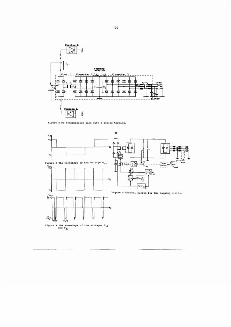
The function of the tapping station will be
further described based on the fig 2. The
converter
1
on DC line potential is a
current-source line-commutated conver ter and
the converters 2 and 3 voltage-source
forced-commutated converters.
The voltages between the ac-terminals of the
converters
2
and 3 are directly proportional
to t he voltage U across the capacitor con-
nected between tlfe converters. The relation-
ship between the voltage Vv3 and U can be
controlled by PWM (pulse wldth mo&lation)
but this is not considered in th is paper.
The waveshape of the voltage Uv 3 is further
illustrated in fig. 3, assuming completely
smoothed voltage Vc ,ac ross the capacitor C.
The voltage level in the local ac-network
will thus be directly controlled by the con-
trol of the voltage U and the frequency by
the switching
frequent
of the converter 3.
The commutation voltage for converter
1
will
also be directly determined by th e voltage
U and the turn ratio Nl : N2 of the trans-
fgrmer between the converters 1 and 2.
The voltage across the converter bridge
1
will have th e wave shape as illustrated in
figure 4 which also shows the voltage on
the ac-side of converter 2, Uv2. The angle
of overlap and the commutation margin y are
also shown in figure
4.
From this figure we
will also obtain the following relationship.
For th e angle of overlap we obtain
(3)
4 )
Where 012 s the angular frequency for the
converters, 1 and 2 and L is the commuta-
tion reactance for convertelr 1.
Inserting equation 4 in 3 gives
5 )
Inserting equation 3 in 6 gives
N
4 =
(l-
(7)
Regarding th e choice of a suitable value for
the commutation margin
y
at rated operation
it has to be considered that y must include
a sufficiently large control margin if it
requires to feed rated power to the local
ac-network also at a reduced current on the
dc-line.
The control sv st m
A
number of different control strategies
might be possible for the above presented
circuit for a tapping station. Below the
control scheme used at performed simulation
study with the EMTP program will be pre-
sented. The control system is further illus-
trated in figure 5. The frequency of the re-
ceiving ac-network is controlled by the
firing of converter 3. AS no PWM is assumed
for the converter 3 the internal voltage U
is directly determi ned by t he voltag e of tg
capacitor C.
The ac-voltage of the receiving ac-network
will be controlled by adjusting the refer-
ence value for the regulator controlling the
voltage of the capacitor C.
The difference between the current I and
Id3.wil l be equal to the current in t% ca-
pacitor. This gives
If we assume that both the ac-load and th us
I
and the
D C
current I dl are constant
ti% time derivativ e of th e capacit or voltage
is directly determined by an adjustment in
the commutation margin Ay The equation 7
and 8 give
The control of the capacitor voltage by con-
trol of y at constant values of I dl and
I
corresponds to the two upper control blocftla
in fig. 5. The value of yin steady state op-
eration with
Uc=
U can be calculated
from equation
7
whigegfves
Inserting the expression for u according to
equation 4 gives
The four lower blocks in fig. 5 correspond
to the calculation of y according to equa-
tion
11.
By having this direct control of y
from the measured direct current Idl in the
dc-system and the measured load current in
converter 3, I d3 ,, it is possible to avoid
that fast changes in the currents I
or
Id3
will give large tran sient chang es og'the ca-
pacitor voltage
Uc.
As
we here have neglected th e losses we will
for steady state operation obtain

8/19/2019 MKT and Media
http://slidepdf.com/reader/full/mkt-and-media 4/6
129
EMTP si mul at i ons
The f uncti on of t he tappi ng stati on bui l t up
of a ci r cui t accor di ng t o f i gure
2
has been
st udi ed by t he use of a di gi t al comput er
programcal l ed EMTP.
The f ol l ow ng i ni t i al val ue f or curr ent s and
vol t ages and data f or t he el ectr i cal ci rcui t
have been used.
P= 50
[MW]
I dl =
2000
[A]
L1( l - phase) = 1.64 [ m ] (ek 0.2
Vol t age rati o ( l - phase) N1 :N2=
1 . 6 2 : 1.0
c= 1000
[ .IF]
UCr ef = 25 [kVl
L3( 3-phase)= 12.35 [ml (ek=0.14)
Vol t age r at i o(3-phase)=N3:N4= 1.0:2.14
I n t he l ocal ac network ther e i s a 5t h, 7t h
and HP-f i l t er i nstal l ed t o r educe t he har-
moni cs. Each fi l t er i s generati ng reacti ve
power of
0 1 S
(S=
57.7
MVA).
Zac net work=
41.57
+
j.24.0
[ l
Cur rent st eD i n the dc- l i ne cur r ent . The re-
sponse t o a s t ep change w t h
? 2 0 ?
200 A)
i n the dc- l i ne curr ent has been studi ed.
Fi gur e 6 shows t he recordi ngs f r om a st ep
i ncrease of t he curr ent at t he t i me i nst ant
20 ms. The i ncreased cur r ent w l l cause a
i ncrease i n commutat i on margi n and i n the
angl e of overl ap and a decr eased di r ect
vol t age component i n Udl .
For t he mathemat i -
cal equat i on t her e have been assumed that
t he vol t age
Uc fs
s t i f f w thout r i ppl e, thi s
w l l gi ves a di f f er ence bet ween the cal cu-
l ated val ue and t he r esul t f r om t he EMTP
si mul at i on.
The vol t age Uc w l l be rather unaf f ect ed ex-
cept f or a i ncrease i n t he ri ppl e cont ent .
Thi s w l l cause a sl i ght decrease i n t he ac-
vol t age and cur r ent due t o a mnor def i -
ci ency i n t he cont rol . I n a real stati on
t here w l l be a 6t h harmoni c fi l ter at t he
i ntermedi ate dc- st age
A si mul ati on w t h a step change of 20
i s
gi vi ng a si ml ar resul t.
Steu l oad chancre i n t he l ocal ac- net work.
The network i mpedance i s di vi ded i nto t hree
di f f erent par t s t o make i t possi bl e to make
a l oad change of
f 2 O
. The data f or the i m
pedances
Z1= 249.5 + j.144.0
[R]
Z =
49.9 j.28.8 [Q]
Z3= 166.4 j.96.0
[R]
The i ni ti al val ue of t he i mpedance i s ob-
t ai ned by paral l el connect i on of
Z
and
Z ,
Z
//Z2=
41.6
+ j.24.0 [a]. The l oa& ri se sf
t ? O
i s obt ai ned by connect i on of t he t hree
i mpedance
Z
/ / Z / / Z
-
33.3
j.19.2
[Q] and
20
i s oktai sed % Z .
I n f i gure 7 t he
case w t h a st ep change % t he i mpedance of
t o 8 0 of t he i ni t i al val ue i s shown.
As
shown i n f i gur e 7d t he step change i n t he
i mpedance gi ves a corr espondi ng st ep change
i n the ac- cur r ent as expect ed.
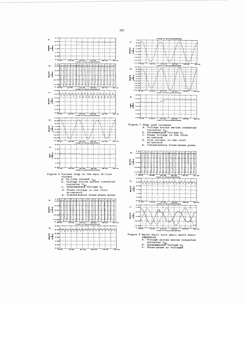
Si nal e-uhase t o eart h f aul t . The resul t f rom
t he si mul ati on of a si ngl e phase to ear t h
f aul t i s present ed in f i gure 8. The f aul t
i mpedance i s 48
[ Q ] .
The f aul t does not di s-
t urb t he operati on of t he conver t ers. I t
w l l gener ate a smal l second har moni c compo-
nent i n t he vol t age
Uc
The second har moni cs
component can al so be seen i n t he vari at i on
i n the commutat i on margi n y as t he cont r ol
system vi a t he cont r ol , accor di ng t o equa-
ti on 10, tr i es t o avoi d that f l uctuati on i n
the curr ent I d3 w l l af f ect t he vol tage Uc
CONCLUSION
As presented i n t he paper t appi ng st at i ons
connected i n ser i es i n t he dc-ci r cui t w t h a
vol t age-sour ce convert er f eedi ng t he l ocal
ac-network w l l of f er an i nt eresti ng sol u-
t i on when t he r ated power of t he t appi ng
st ati on i s onl y a f ew percent of t he rated
power of t he HVDC syst em However, t he cost
f or such st at i ons i s st i l l expected t o be
f ai r l y hi gh and comparabl e t o t he cost s f or
l ocal gener ati on of power. The most expen-
si ve i ndi vi dual i t em i s expected t o be the
cost s f or t he t r ansf ormer f or t he conversi on
of power f r om hi gh pot ent i al t o gr ound. A
sol ut i on w t h conver si on i n two st eps i s
pr esent ed, whi ch w l l make i t possi bl e to
use onl y one si ngl e phase t r ansf ormer.
EMTP si mul at i ons have shown t hat t he pr o-
posed ci r cui t can be expected t o of f er good
dynam c pr opert i es.
REF
E E
1. Ekstr om A . , Forced commutat ed convert er
fo r
HVDC
appl i cat i ons , EECPS, Capr i , May
89.
ACKNOWLEDGEMENTS
The present ed st udy i s part of a research
proj ect suppor t ed by Vatt enf al l ( Swedi sh
State Power Board) and
ABB
Power Syst ems
AB,
Sweden, whi ch i s grat ef ul l y acknow edged.
n P . ; . n e r a t o r poad q, Generator
Seri es
tapping
aral e
tapping
Fi gure 1 Ser i es and par al l el t appi ng
8/19/2019 MKT and Media
http://slidepdf.com/reader/full/mkt-and-media 5/6
130
Stat ion B
Station A
Figure 2 DC transmission line with a series tapping.
Figure
3
The waveshape of the voltage Uvg.
T
J
1
1
Figure
5
Control system for the tapping station.
Figure 4 The waveshape of the voltages Uv2
and Udl.
8/19/2019 MKT and Media
http://slidepdf.com/reader/full/mkt-and-media 6/6
131
I /
I I I I I I , , ,
I I I I I , , I I
0.0
I
I
I I
-.Om
.._e-
l l 0 0 ..PO
..eo .o.om
OO
_ _ _ - _ _ _ _ - _ _ _ _ _ _ _ _ _ - _ _ _ _ _ _ _ _ _ _ _ _
*. I I XeL.LLI..OD D.
Fi gur e
6
Cur r ent st ep i n t he mai n dc- l i ne
cur r ent
a. Dc-l i ne curr ent I dl
b. Vol t age across seri es connected
c. I nt ermedi ate vol t age Uc
d. Phase vol t age i n the l ocal
e. I nstant aneous t hree- phase power
conver t er Udl
ac- net work
5 . 0 0
a.
*.--
1.011
I'
I
i v a o _ m
1.00
- _ D o
Fi gur e
7
Step l oad i ncr ease
a. Vol t age acr oss seri es connect ed
b.
I ntermedi ate vol t age
U
c. Phase vol t age i n t he &a1
d. Li ne curr ent i n t he l ocal
e. I nstant aneous t hree- phase power
conver t er Udl
ac- net work
ac- net work
a.