Mini Strobe Controller20170801 - optmv.net · Continuous: for 12-24V, 2A OPT lights with two Pins;...
3
Controller 1 2 3 4 5 6 Mini Strobe Controller OPT OPT - SPM 20 24 - 1 Channel Output voltage:12~48V Maximum output current:2A Controller type: mini strobe controller Model No Product Features The input port is represented by four colors: white, brown, green, and yellow (as shown below). The white and brown lead wires are separately connected with the positive & negative ports of the power supply; The green and yellow lead wires are separately connected with the positive and negative ports of the trigger input signals. The opto coupler isolation. The input voltage 0~2V is internal contains input voltage 5~24V is high level. low level. And the See “Trigger Connection Reference” for details. Wire Colour White Brown Green Yellow Connection Ways Power+ Power- Trigger+ Trigger- Input Connection Small size, easy for operation High trigger frequency: up to 50KHz at max Short ≤10μs trigger response time: 6 trigger modes, adaptable for various work environment Wide input voltage range from 12 48V DC, easy for using the DC power supply on the machine, and lights can be overdriven to increase the intensity V DC to Wide trigger pulse width setting: 10 s ~1023ms can be set μ Interface Description No. 1 2 3 4 Input port Light connector 10 DIP switch S2 4 DIP switch S1 Including power input and trigger signal input port; See “Connection’’ section for details JST SMP-02V-B 2 Pin Pulse width setting ” for details ; See “Trigger Pulse Width Setting Trigger mode switching; See “Trigger Mode Setting” for details Panel & Connector Description 1. Input port 2. Light connector 3. 10 DIP switch S2 4. 4 DIP switch S1 Trigger Mode Specification 1. Rising edge trigger When the trigger signal is on the rising edge, the bright time of the light is consistent with the trigger pulse width. The trigger pulse width is set by the corresponding switch. See Chart 1.1, T1 is the OFF to ON response time; T2 is the trigger pulse width; T1≤10µs, T2 can be set in the range of 10µs ~1023ms 2. Falling edge trigger When the trigger signal is on the falling edge, the bright time of the light is consistent with the trigger pulse width. The trigger pulse width is set by the corresponding switch. See Chart 1.2, T1 is the OFF to ON response time; T2 is the trigger pulse width; T1≤10µs, T2 can be set in the range of 10µs ~1023ms TRIG Input Controller Output Chart 1.1 TRIG Input Controller Output 3. Real time positive trigger When the trigger signal is high, of the light the bright time is consistent with the high level pulse width of the trigger signal. See Chart 1.3, T1 is the OFF to ON response time; T2 is the trigger pulse width; T3 is the ON to OFF response time; T1≤ 10µs, T2 is the same as the high level pulse width, T3≤10 µs Chart 1.2
Transcript of Mini Strobe Controller20170801 - optmv.net · Continuous: for 12-24V, 2A OPT lights with two Pins;...

Controller
1
2
3
4
5
6
Mini Strobe Controller
OPT
OPT - SPM 20 24 - 1
Channel
Output voltage:12~48V
Maximum output current:2A
Controller type: mini strobe controller
Model No
Product Features
The input port is represented by four colors: white, brown, green, and yellow (as shown below). The white and brown lead wires are separately connected with the positive & negative ports of the power supply; The green and yellow lead wires are separately connected with the positive and negative ports of the trigger input signals. The opto coupler isolation. The input voltage 0~2V isinternal contains input voltage 5~24V is high level. low level. And the See “Trigger Connection Reference” for details.
Wire Colour
White
Brown
Green
Yellow
Connection Ways
Power+
Power-
Trigger+
Trigger-
Input Connection
Small size, easy for operation
High trigger frequency: up to 50KHz at max
Short ≤10μs trigger response time:
6 trigger modes, adaptable for various work environment
Wide input voltage range from 12 48V DC, easy for using the DC power supply on the machine, and lights can be overdriven to increase the intensity
V DC to
Wide trigger pulse width setting: 10 s ~1023ms can be set μ
Interface DescriptionNo.
1
2
3
4
Input port
Light connector
10 DIP switch S2
4 DIP switch S1
Including power input and trigger signal input port; See “Connection’’ section for details
JST SMP-02V-B 2 Pin
Pulse width setting ” for details ; See “Trigger Pulse Width Setting
Trigger mode switching; See “Trigger Mode Setting” for details
Panel & Connector Description
1. Input port 2. Light connector
3. 10 DIP switch S24. 4 DIP switch S1
Trigger Mode Specification
1. Rising edge trigger
When the trigger signal is on the rising edge, the bright time of the light is consistent with the trigger pulse width. The trigger pulse width is set by the corresponding switch. See Chart 1.1, T1 is the OFF to ON response time; T2 is the
trigger pulse width; T1≤10µs, T2 can be set in the range of10µs ~1023ms
2. Falling edge trigger
When the trigger signal is on the falling edge,
the bright time of the light is consistent with the trigger pulse width. The trigger pulse width is set by the corresponding switch.See Chart 1.2, T1 is the OFF to ON response time; T2 is the
trigger pulse width; T1≤10µs, T2 can be set in the range of10µs ~1023ms
TRIG Input
Controller Output
Chart 1.1
TRIG Input
Controller Output
3. Real time positive trigger
When the trigger signal is high, of the light the bright time isconsistent with the high level pulse width of the trigger signal.See Chart 1.3, T1 is the OFF to ON response time; T2 is the
trigger pulse width; T3 is the ON to OFF response time; T1≤10µs, T2 is the same as the high level pulse width, T3≤10 µs
Chart 1.2

TRIG Input
Controller Output
Chart 1.3
4 eal time negative trigger. R
When the trigger signal is low, the bright time of the light is consistent withthe low level pulse width of the trigger signal.See Chart 1.3, T1 is the OFF to ON response time; T2 is the trigger pulse width;
T3 is the ON to OFF response time; T1≤10µs, T2 is the same as the low level
pulse width, T3≤10µs
Chart 1.4
TRIG Input
Controller Output
When the trigger signal is high, if the high level pulse width of the trigger signal is less than the set trigger pulse width, the bright time of the light isconsistent with the high level pulse width of the trigger signal;See Chart 1.5, T1 is the OFF to ON response time; T2 is the trigger pulsewidth; T3 is the ON to OFF response time; T1≤10µs, T2 is the same asthe high level pulse width, T3≤10 µs
5. Time limited positive trigger
If the high level pulse width of the trigger signal is greater than or equal to the set trigger pulse width, the bright time of the light is consistent with theset trigger pulse width.See Chart 1.6, T1 is the OFF to ON response time; T2 is the trigger pulse width; T1≤10µs, T2 can be set in the range of 10µs ~1023ms
TRIG Input
Controller Output
Chart 1.5
TRIG Input
Controller Output
Chart 1.6
If the low level pulse width of the trigger signal is greater than orequal to the set trigger pulse width, the bright time of the light isconsistent with the set trigger pulse widthSee Chart 1.8, T1 is the OFF to ON response time; T2 is the triggerpulse width; T1≤10µs, T2 can be set in the range of 10µs ~1023ms
Chart 1.7
TRIG Input
Controller Output
TRIG Input
Controller Output
Chart 1.8
Performance Parameters
Details
The input polarity not cause controller damage
reverse will
Parameters
DC 12~48V
DC 12~48V
Yes
Yes
up to50KHz at max
10~1023µs or 1~1023ms
Low level:0~2V High level:5~24V
≤10μs
Maximum continuous output current: 2A
Maximum instantaneous output current: 4A
≤1W
-5 ~50℃ ℃
102.0*22.0*19.8
Set by switch
Switching time unit by switch
Refer to mechanical parameters
The average input current must be 0.5A much larger than the average output current
Continuous: for 12-24V, 2A OPT lights with two Pins;Strobe: for 12-48V, 4A instantaneous current OPT lights with two Pins
Item
Input voltage
Output voltage
Power polarity reverse connection protection
External trigger input
External triggerfrequency
Trigger mode
Trigger pulse width
Trigger level
Trigger response time
Output current
Suitable lights
Standby power consumption
Working temperature
Size (mm)
1. Rising edge trigger2. Falling edge trigger 3. Real time positive trigger4. Real time negative trigger5. Time limited positive trigger6. Time limited negative trigger
6. Time limited negative trigger
When the trigger signal is low, if the low level pulse
width of thetrigger signal is less than the set trigger pulse width, the bright timeof the light is consistent with the low level pulse width of thetrigger signal.See Chart 1.7, T1 is the OFF to ON response time; T2 is the triggerpulse width; T3 is the ON to OFF response time; T1≤10µs, T2 is thesame as the low level pulse width, T3≤10µs
.
Mini Strobe Controller
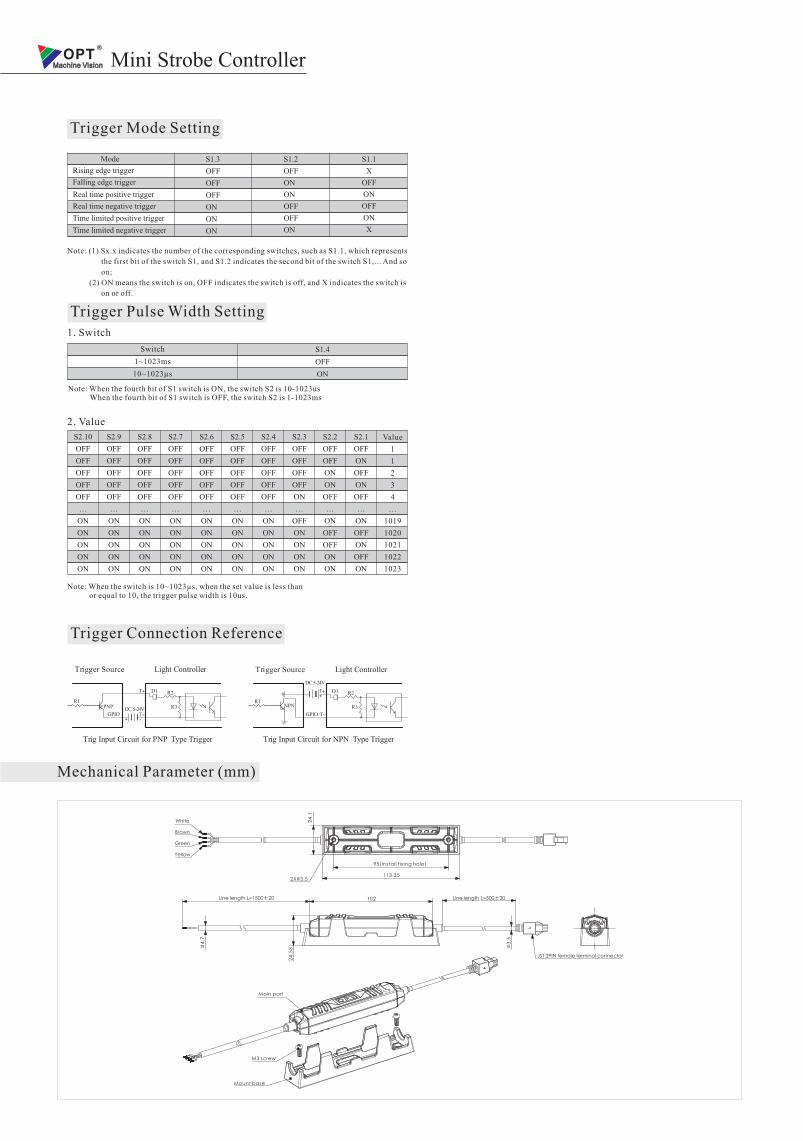
Trigger Mode Setting
S1.3
OFF
OFF
OFF
ON
ON
ON
Mode
Rising edge trigger
Falling edge trigger
Real time positive trigger
Real time negative trigger
Time limited positive trigger
Time limited negative trigger
S1.2
OFF
ON
ON
OFF
OFF
ON
S1.1
X
OFF
ON
OFF
ON
X
Note: (1) Sx.x indicates the number of the corresponding switches, such as S1.1, which represents
the first bit of the switch S1, and S1.2 indicates the second bit of the switch S1,... And so
on;
(2) ON means the switch is on, OFF indicates the switch is off, and X indicates the switch is
on or off.
Trigger Pulse Width Setting
Switch
1~1023ms
10~1023µs
S1.4
OFF
ON
1. Switch
2. Value
S2.10
OFF
OFF
OFF
OFF
OFF
…
ON
ON
ON
ON
ON
S2.9
OFF
OFF
OFF
OFF
OFF
…
ON
ON
ON
ON
ON
S2.8
OFF
OFF
OFF
OFF
OFF
…
ON
ON
ON
ON
ON
S2.7
OFF
OFF
OFF
OFF
OFF
…
ON
ON
ON
ON
ON
S2.6
OFF
OFF
OFF
OFF
OFF
…
ON
ON
ON
ON
ON
S2.5
OFF
OFF
OFF
OFF
OFF
…
ON
ON
ON
ON
ON
S2.4
OFF
OFF
OFF
OFF
OFF
…
ON
ON
ON
ON
ON
S2.3
OFF
OFF
OFF
OFF
ON
…
OFF
ON
ON
ON
ON
S2.2
OFF
OFF
ON
ON
OFF
…
ON
OFF
OFF
ON
ON
S2.1
OFF
ON
OFF
ON
OFF
…
ON
OFF
ON
OFF
ON
Value
1
1
2
3
4
…
1019
1020
1021
1022
1023
Note: 10~1023 , or equal to 10, the trigger pulse width is 10us.
When the switch is µs when the set value is less than
Trigger Connection Reference
Light ControllerTrigger Source
Mechanical Parameter (mm)
Trig Input Circuit for PN Type TriggerP
R2
PNP DC 5-24V
R1R3
+ -GPIO
Light ControllerTrigger Source
D1T+
T﹣
R2
NPN
DC 5-24V
R1R3
+-D1T+
T﹣GPIO
Trig Input Circuit for N Type TriggerPN
Note: When the fourth bit of S1 switch is ON, the switch S2 is 10-1023us When the fourth bit of S1 switch is OFF, the switch S2 is 1-1023ms
Main part
24
.1
95(Install fixing hole)
113.352X 3.5
102
JST 2PIN female terminal connector
24
.53
Line length L=1500±20 Line length L=500±20
4.7
3.5
White
Brown
Green
Yellow
M3 screw
Mount base
Mini Strobe Controller