Microstructure, deformation and cracking characteristics ... · Materials Science and Engineering...
14
Materials Science and Engineering A269 (1999) 152 – 165 Microstructure, deformation and cracking characteristics of thermal spray ferrous coatings A. Rabiei a, *, D.R. Mumm a , J.W. Hutchinson a , R. Schweinfest c , M. Ru ¨ hle c , A.G. Evans b a Di6ision of Engineering and Applied Sciences, Har6ard Uni6ersity, 40 Oxford Street, Cambridge, MA 02138, USA b Princeton Materials Institute, Bowen Hall, 70 Prospect A6enue, Princeton, NJ 08540, USA c Max Planck Institute, Stuttgart, Germany Received 16 December 1998; received in revised form 5 March 1999; accepted 8 March 1999 Abstract The microstructure and local mechanical characteristics of thermal spray ferrous coatings have been determined. The emphasis has been on coatings made by the high velocity oxyfuel (HVOF) process, especially the role of Al alloy additives. The oxide phase present in the material and preferred pathways for local cracking and separation have been determined. Thin intersplat oxide layers emerge as preferential sites. These oxides are amorphous and the cracks extend along the oxide/a –Fe interfaces with low local fracture toughness, in the range 0.2–1 MPam. These low toughness pathways govern coating deterioration. © 1999 Elsevier Science S.A. All rights reserved. Keywords: Thermal spray coating; Local fracture toughness; Indentation test; High velocity oxyfuel process; Plasma transfer wire arc process; Atomic force microscopy www.elsevier.com/locate/msea 1. Introduction Ferrous thermal spray coatings are of interest in various industry sectors for the protection of surfaces against elevated temperature degradation and wear [1–12]. The most prominent application is in the au- tomotive industry as protective bore coatings on cast Al alloy cylinder blocks. Traditionally, blocks have been made entirely of gray cast iron. It is estimated [13], however, that by the year 2000 nearly half of all engine blocks manufactured, worldwide, will be made of aluminum alloys. This change is brought about by the need to reduce vehicle weight in order to improve fuel economy. But, the sliding of a piston against an unprotected aluminum bore leads to unacceptable wear, degrading both the compression and emission characteristics of the engine. Currently, cast iron lin- ers are used to obviate these problems. However, these add weight and cost, as well as decrease cylin- der displacement. Thus, automotive companies world- wide are developing Fe-based wear-resistant coatings for the bores [1]. These thin ( 200 mm) coatings are prepared by a thermal spray process in which, typi- cally, Fe-alloy wire is melted and the droplets are sprayed onto the bore surface [2 – 5,12]. The resultant coating is a composite of the alloy with oxides result- ing from oxidation during deposition [12]. This coat- ing represents a tribological surface upon which much of the automotive industry will depend in the future. Despite their importance, few basic properties of these coatings have been measured [7]. One conse- quence is that the impact of microstructure and phase content on performance cannot be predicted. There are few open literature reports on the mi- crostructure and properties of these materials [1,12,14]. In this article, a range of such coatings have been investigated, some produced by the high velocity oxyfuel (HVOF) process [3,12] and others by the plasma transfer wire arc (PTWA) process [6]. The ob- jective is to establish some of the basic microstruc- * Corresponding author. Tel.: +1-617-495-8454; fax: +1-617-496- 9771. E-mail address: [email protected] (A. Rabiei) 0921-5093/99/$ - see front matter © 1999 Elsevier Science S.A. All rights reserved. PII:S0921-5093(99)00132-X
Transcript of Microstructure, deformation and cracking characteristics ... · Materials Science and Engineering...
Materials Science and Engineering A269 (1999) 152–165
Microstructure, deformation and cracking characteristics ofthermal spray ferrous coatings
A. Rabiei a,*, D.R. Mumm a, J.W. Hutchinson a, R. Schweinfest c, M. Ruhle c,A.G. Evans b
a Di6ision of Engineering and Applied Sciences, Har6ard Uni6ersity, 40 Oxford Street, Cambridge, MA 02138, USAb Princeton Materials Institute, Bowen Hall, 70 Prospect A6enue, Princeton, NJ 08540, USA
c Max Planck Institute, Stuttgart, Germany
Received 16 December 1998; received in revised form 5 March 1999; accepted 8 March 1999
Abstract
The microstructure and local mechanical characteristics of thermal spray ferrous coatings have been determined. The emphasishas been on coatings made by the high velocity oxyfuel (HVOF) process, especially the role of Al alloy additives. The oxide phasepresent in the material and preferred pathways for local cracking and separation have been determined. Thin intersplat oxidelayers emerge as preferential sites. These oxides are amorphous and the cracks extend along the oxide/a–Fe interfaces with lowlocal fracture toughness, in the range 0.2–1 MPam. These low toughness pathways govern coating deterioration. © 1999Elsevier Science S.A. All rights reserved.
Keywords: Thermal spray coating; Local fracture toughness; Indentation test; High velocity oxyfuel process; Plasma transfer wire arc process;Atomic force microscopy
www.elsevier.com/locate/msea
1. Introduction
Ferrous thermal spray coatings are of interest invarious industry sectors for the protection of surfacesagainst elevated temperature degradation and wear[1–12]. The most prominent application is in the au-tomotive industry as protective bore coatings on castAl alloy cylinder blocks. Traditionally, blocks havebeen made entirely of gray cast iron. It is estimated[13], however, that by the year 2000 nearly half of allengine blocks manufactured, worldwide, will be madeof aluminum alloys. This change is brought about bythe need to reduce vehicle weight in order to improvefuel economy. But, the sliding of a piston against anunprotected aluminum bore leads to unacceptablewear, degrading both the compression and emissioncharacteristics of the engine. Currently, cast iron lin-
ers are used to obviate these problems. However,these add weight and cost, as well as decrease cylin-der displacement. Thus, automotive companies world-wide are developing Fe-based wear-resistant coatingsfor the bores [1]. These thin (�200 mm) coatings areprepared by a thermal spray process in which, typi-cally, Fe-alloy wire is melted and the droplets aresprayed onto the bore surface [2–5,12]. The resultantcoating is a composite of the alloy with oxides result-ing from oxidation during deposition [12]. This coat-ing represents a tribological surface upon which muchof the automotive industry will depend in the future.Despite their importance, few basic properties ofthese coatings have been measured [7]. One conse-quence is that the impact of microstructure and phasecontent on performance cannot be predicted.
There are few open literature reports on the mi-crostructure and properties of these materials[1,12,14]. In this article, a range of such coatings havebeen investigated, some produced by the high velocityoxyfuel (HVOF) process [3,12] and others by theplasma transfer wire arc (PTWA) process [6]. The ob-jective is to establish some of the basic microstruc-
* Corresponding author. Tel.: +1-617-495-8454; fax: +1-617-496-9771.
E-mail address: [email protected] (A. Rabiei)
0921-5093/99/$ - see front matter © 1999 Elsevier Science S.A. All rights reserved.
PII: S0921 -5093 (99 )00132 -X
A. Rabiei et al. / Materials Science and Engineering A269 (1999) 152–165 153
Table 1Chemical compositions of coatings
Composition (wt.%)Material
Al Mg Si C Mn O2
0 1.0A 0.22 0 0 110.05 0.01 0.06B 0HVOF 0 123.7 1.05 0.44 0C 0 0.92.1 0.08 0.3D 0 0 42.6 0.12 0.2 0 0 2.7E0 0 0.01G 0.1PTWA 0.42 5.5– – – – – –F
PTWA material was acquired from Ford Motor. Theferrous wires comprised either conventional low alloysteels or specialty Fe/Al alloys (Table 1) with variableAl content.
2. Characterization procedures
Various microscopies and spectroscopies have beenused to characterize the microstructure of the coatings.Optical as well as scanning electron microscopies(SEM) have been performed on cross sections. Trans-mission electron microscopy (TEM) conducted on thinfoils has provided structural and analytic informationat resolutions relevant to local mechanical responses.The analytical mode in the SEM was used to providetural characteristics of these materials and to relate the
microstructure to those local mechanical responses thataffect their performance, particularly in wear and pull-out.
From an applications perspective, one of the factorsthat dictates utility is the ability of the coating to resistmaterial removal in a sliding wear situation. Such re-moval involves material pull-out from the coating sur-face, by a local microcracking mechanism occurring onthe scale of individual splats. The severity of this mech-anism is governed by the fracture toughness of thecoating at this small, physical scale. One goal of thisarticle is to probe the fracture toughness properties atthis level.
Most of the HVOF and PTWA coatings analyzed inthis investigation were deposited on wrought Al alloysusing the deposition systems at General Motors. One
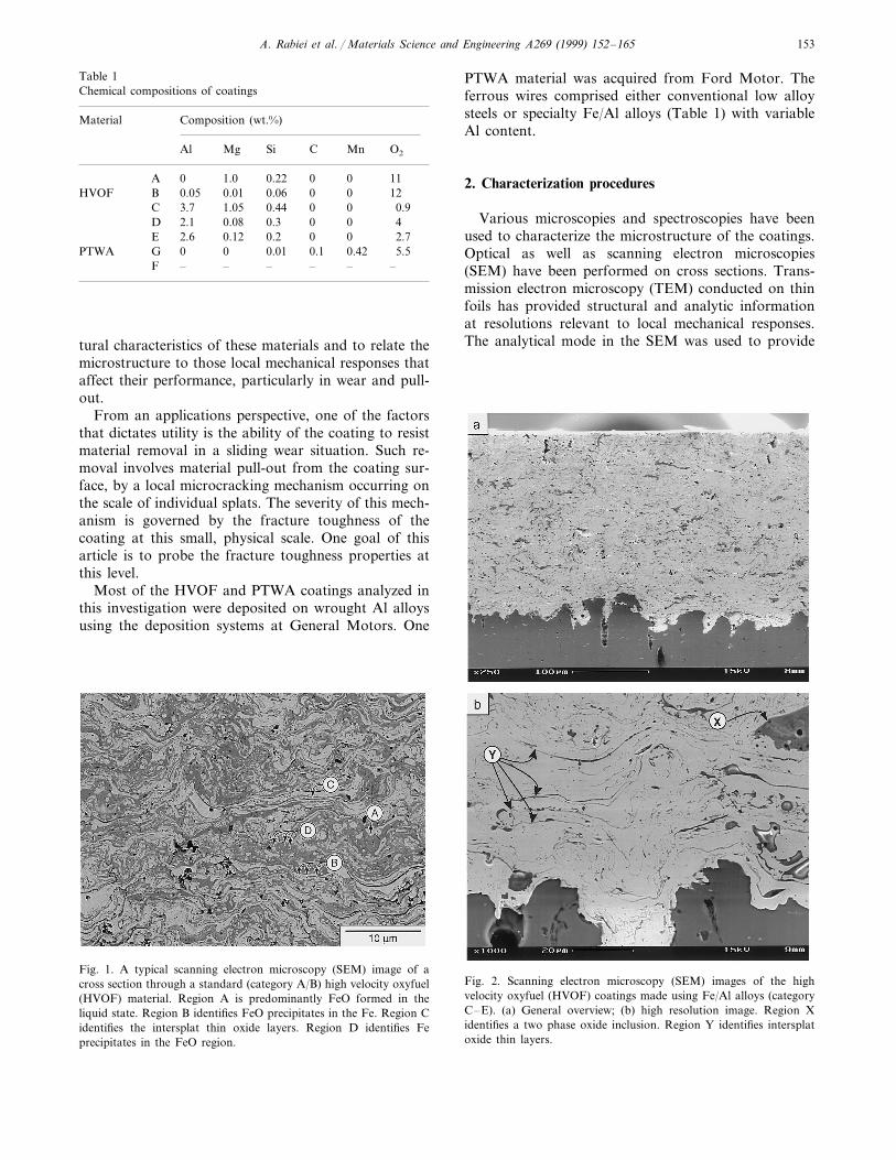
Fig. 2. Scanning electron microscopy (SEM) images of the highvelocity oxyfuel (HVOF) coatings made using Fe/Al alloys (categoryC–E). (a) General overview; (b) high resolution image. Region Xidentifies a two phase oxide inclusion. Region Y identifies intersplatoxide thin layers.
Fig. 1. A typical scanning electron microscopy (SEM) image of across section through a standard (category A/B) high velocity oxyfuel(HVOF) material. Region A is predominantly FeO formed in theliquid state. Region B identifies FeO precipitates in the Fe. Region Cidentifies the intersplat thin oxide layers. Region D identifies Feprecipitates in the FeO region.
A. Rabiei et al. / Materials Science and Engineering A269 (1999) 152–165154
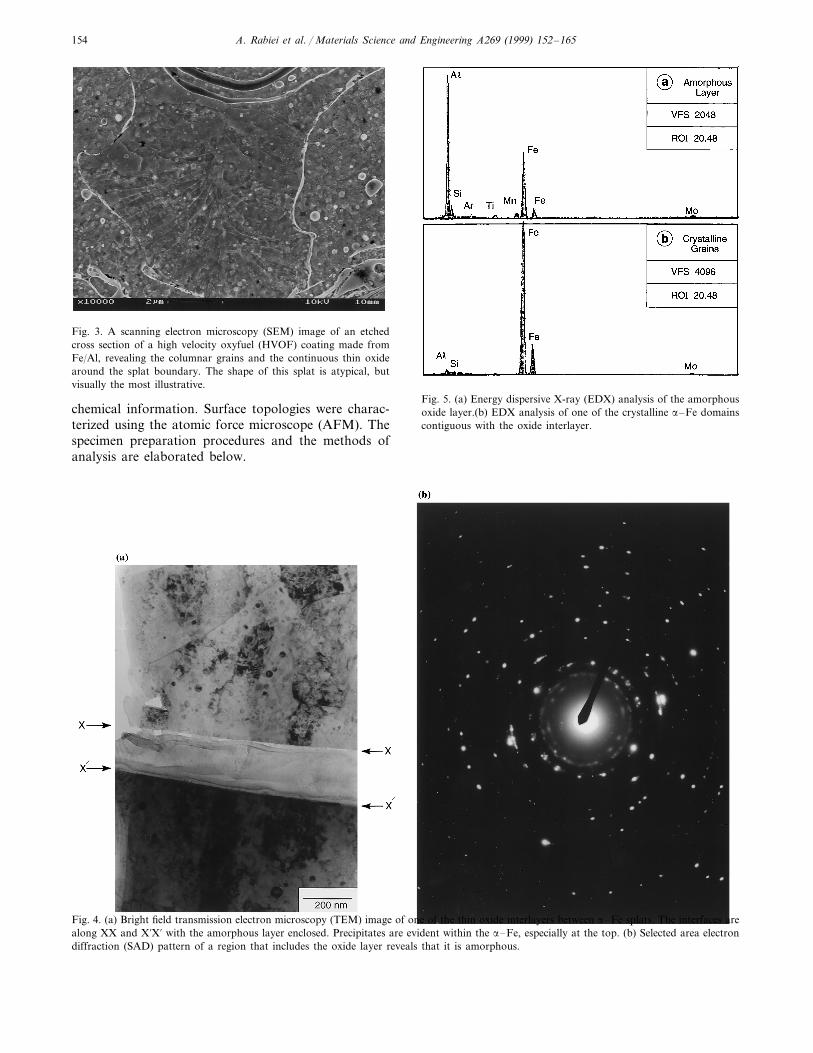
Fig. 3. A scanning electron microscopy (SEM) image of an etchedcross section of a high velocity oxyfuel (HVOF) coating made fromFe/Al, revealing the columnar grains and the continuous thin oxidearound the splat boundary. The shape of this splat is atypical, butvisually the most illustrative.
Fig. 5. (a) Energy dispersive X-ray (EDX) analysis of the amorphousoxide layer.(b) EDX analysis of one of the crystalline a–Fe domainscontiguous with the oxide interlayer.
chemical information. Surface topologies were charac-terized using the atomic force microscope (AFM). Thespecimen preparation procedures and the methods ofanalysis are elaborated below.
Fig. 4. (a) Bright field transmission electron microscopy (TEM) image of one of the thin oxide interlayers between a–Fe splats. The interfaces arealong XX and X%X% with the amorphous layer enclosed. Precipitates are evident within the a–Fe, especially at the top. (b) Selected area electrondiffraction (SAD) pattern of a region that includes the oxide layer reveals that it is amorphous.
A. Rabiei et al. / Materials Science and Engineering A269 (1999) 152–165 155
2.1. Cross sections
Cross sections were prepared by mechanical polish-ing. The sections were cut by electro-discharge machin-ing, in order to minimize damage. One side waspolished with sequential mechanical media comprising6, 3 and 1 mm diamond pastes, with a finish achieved bysubmicron diamond suspension embedded in a softdisk. This procedure provided an optical qualitysurface.
In some cases, the surfaces were etched in order toreveal the grain structure of the metallic phases. Forthis purpose, 2% Nital solution has been used with anetching time of 80 s.
2.2. Thin foils
TEM provides crucial details regarding those mi-crostructural features responsible for the mechanicalperformance at the requisite resolution. For this pur-pose, thin sections have been produced by mechanicaldimpling, followed by ion beam thinning. Microstruc-
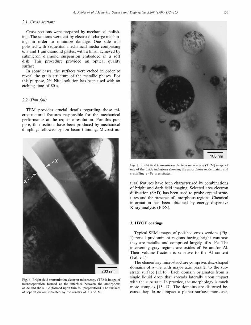
Fig. 7. Bright field transmission electron microscopy (TEM) image ofone of the oxide inclusions showing the amorphous oxide matrix andcrystalline a–Fe precipitates.
Fig. 6. Bright field transmission electron microscopy (TEM) image ofmicroseparation formed at the interface between the amorphousoxide and the a–Fe (formed upon thin foil preparation). The surfacesof separation are indicated by the arrows of X and X%.
tural features have been characterized by combinationsof bright and dark field imaging. Selected area electrondiffraction (SAD) has been used to probe crystal struc-tures and the presence of amorphous regions. Chemicalinformation has been obtained by energy dispersiveX-ray analysis (EDX).
3. HVOF coatings
Typical SEM images of polished cross sections (Fig.1) reveal predominant regions having bright contrast:they are metallic and comprised largely of a–Fe. Theintervening gray regions are oxides of Fe and/or Al.Their volume fraction is sensitive to the Al content(Table 1).
The elementary microstructure comprises disc-shapeddomains of a–Fe with major axis parallel to the sub-strate surface [15,16]. Each domain originates from asingle liquid drop that spreads laterally upon impactwith the substrate. In practice, the morphology is muchmore complex [15–17]. The domains are distorted be-cause they do not impact a planar surface; moreover,
A. Rabiei et al. / Materials Science and Engineering A269 (1999) 152–165156
some drops fragment upon impact into smaller, moreequiaxed zones. Additionally, various oxidation prod-ucts form [12]. The oxide phases exert a critical influ-ence on coating performance. One of the major goals isto characterize these oxides and establish their effect onproperties.
3.1. Standard materials
Basic HVOF materials (without Al: categories A/B,Table 1) contain a substantial fraction of oxide (Fig. 1),which exhibits several characteristic morphologies [12].These morphologies, referred to the SEM image (Fig.1), are essentially the same as those reported elsewhere[12].1. Large oxide domains form in the liquid state and,
during impact with the substrate, distort compatiblywith the Fe: region A in Fig. 1.
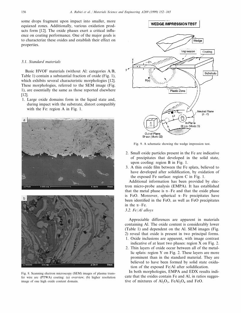
Fig. 9. A schematic showing the wedge impression test.
Fig. 8. Scanning electron microscopy (SEM) images of plasma trans-fer wire arc (PTWA) coating: (a) overview; (b) higher resolutionimage of one high oxide content domain.
2. Small oxide particles present in the Fe are indicativeof precipitates that developed in the solid state,upon cooling: region B in Fig. 1.
3. A thin oxide film between the Fe splats, believed tohave developed after solidification, by oxidation ofthe exposed Fe surface: region C in Fig. 1.
Additional information has been provided by elec-tron micro-probe analysis (EMPA). It has establishedthat the metal phase is a–Fe and that the oxide phaseis FeO. Moreover, spherical a–Fe precipitates havebeen identified in the FeO, as well as FeO precipitatesin the a–Fe.3.2. Fe/Al alloys
Appreciable differences are apparent in materialscontaining Al. The oxide content is considerably lower(Table 1) and dependent on the Al. SEM images (Fig.2) reveal that oxide is present in two principal forms.1. Oxide inclusions are apparent, with image contrast
indicative of at least two phases: region X on Fig. 2.2. Thin layers of oxide occur between all of the metal-
lic splats: region Y on Fig. 2. These layers are moreprominent than in the standard material. They arebelieved to have been formed by solid state oxida-tion of the exposed Fe/Al after solidification.
In both morphologies, EMPA and EDX results indi-cate that the oxides contain Fe and Al, in ratios sugges-tive of mixtures of Al2O3, FeAl2O4 and FeO.
A. Rabiei et al. / Materials Science and Engineering A269 (1999) 152–165 157
Upon etching to reveal the microstructure of theferrous domains, columnar grains are apparent (Fig. 3).Generally, the grain axes are oriented normal to thesplat boundaries [17]. Etching also enhances the visibil-ity of the thin oxide layers between splats, illustrated onFig. 3. Note that the layer is continuous and has athickness of about 0.1–0.2 mm.
The TEM measurements have established that thethin oxide layers between splats are all amorphous (Fig.4a), as evident from the SAD patterns (Fig. 4b). More-over, the layers have quite uniform thickness of about200 nm, consistent with SEM observations (Fig. 3).Chemical analysis by EDX (Fig. 5) indicates that Fe, Aland O are present in all cases, with variable quantitiesof Si and S, as well as other trace elements. Theadjoining material is crystalline, comprising either a–Fe or a–Fe(Al). Precipitates are also evident within thegrain. These are either oxides or carbides (both O andC exist in the grains), but not intermetallics.
In several instances, microseparations form duringthin foil preparation. These are invariably located at
the interface between the amorphous layer and the Fe(Fig. 6).
The inclusions are found to comprise an amorphousoxide matrix containing crystalline a–Fe particles (Fig.7). The chemical composition of the oxide is similar tothat of the thin interlayers.
4. PTWA coatings
Coatings made by the PTWA process are qualita-tively different (Fig. 8a). There are two key differences.Domains having high oxide volume fraction exist andoccur with a periodicity of about 0.2–0.3 mm (Fig. 8b).These domains are related to a periodicity inherent inthe PTWA deposition process [6]. Between these do-mains, the microstructure is similar to that found inHVOF coatings having low oxygen concentrations(those made from Fe/Al alloys) except that the splatsare appreciably larger.
Thin oxide layers again exist between the splats,about 0.1–0.2 mm in thickness. TEM indicates that theyare amorphous. They contain Fe, Si, O and S, withother trace elements, but are devoid of Al. Amorphousoxide inclusions containing Fe precipitates are alsopresent.
5. Testing and analysis
5.1. Concept
The objectives of the measurements are to character-ize quantitatively the deformation and cracking re-sponses of the ferrous coatings, while attached to theircylindrical Al alloy substrates. For this purpose, meth-ods have been developed that introduce strains into thecoatings by controlled deformation of the substrate.While several configurations were tried, the most con-sistent and informative results have been obtained byusing wedge impression tests. The configuration is de-picted on Fig. 9. Circumferential specimens with 5 mmwidth and 15 mm length are cut from an aluminumcylinder with 5 mm thickness and 200 mm coating on it.This specimen, with sides and bottom polished in themanner described in Section 2, was attached to a baseplate within a servohydraulic test frame. A WC wedgeindenter with an included angle of 90° was locatedwithin an alignment figure that assured line contactalong the apex of the wedge. Displacements were mea-sured by means of a linear variable differential trans-former (LVDT). Loads were applied at constantdisplacement-rate up to penetrations of about 200 mm.Images of the same region taken before and afterimpressing allow determination of displacement vec-tors, strains and various damage parameters.
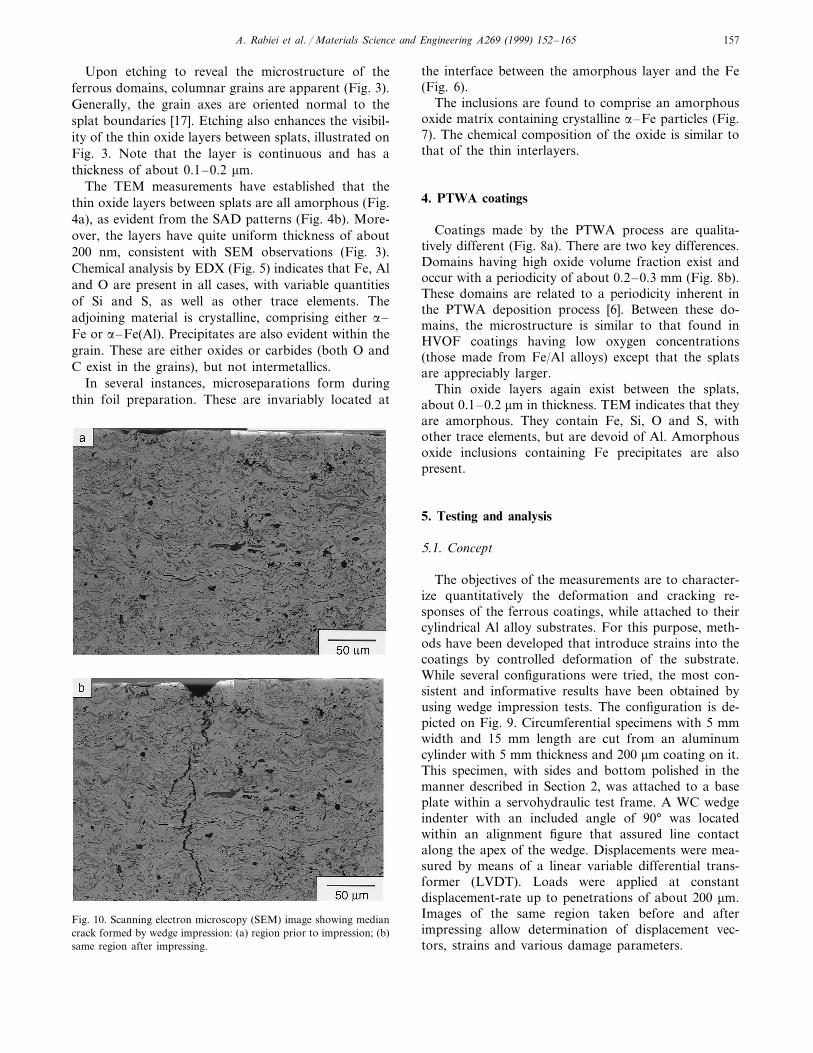
Fig. 10. Scanning electron microscopy (SEM) image showing mediancrack formed by wedge impression: (a) region prior to impression; (b)same region after impressing.
A. Rabiei et al. / Materials Science and Engineering A269 (1999) 152–165158
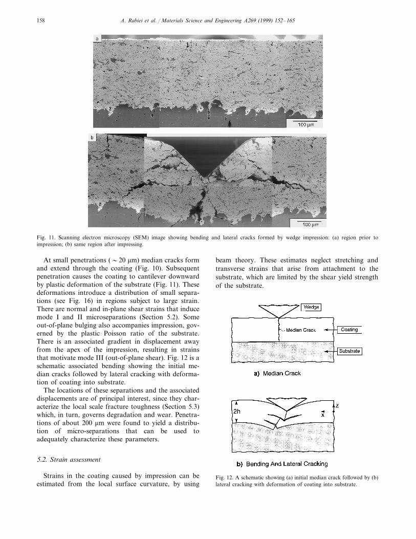
Fig. 11. Scanning electron microscopy (SEM) image showing bending and lateral cracks formed by wedge impression: (a) region prior toimpression; (b) same region after impressing.
At small penetrations (�20 mm) median cracks formand extend through the coating (Fig. 10). Subsequentpenetration causes the coating to cantilever downwardby plastic deformation of the substrate (Fig. 11). Thesedeformations introduce a distribution of small separa-tions (see Fig. 16) in regions subject to large strain.There are normal and in-plane shear strains that inducemode I and II microseparations (Section 5.2). Someout-of-plane bulging also accompanies impression, gov-erned by the plastic Poisson ratio of the substrate.There is an associated gradient in displacement awayfrom the apex of the impression, resulting in strainsthat motivate mode III (out-of-plane shear). Fig. 12 is aschematic associated bending showing the initial me-dian cracks followed by lateral cracking with deforma-tion of coating into substrate.
The locations of these separations and the associateddisplacements are of principal interest, since they char-acterize the local scale fracture toughness (Section 5.3)which, in turn, governs degradation and wear. Penetra-tions of about 200 mm were found to yield a distribu-tion of micro-separations that can be used toadequately characterize these parameters.
5.2. Strain assessment
Strains in the coating caused by impression can beestimated from the local surface curvature, by using
beam theory. These estimates neglect stretching andtransverse strains that arise from attachment to thesubstrate, which are limited by the shear yield strengthof the substrate.
Fig. 12. A schematic showing (a) initial median crack followed by (b)lateral cracking with deformation of coating into substrate.
A. Rabiei et al. / Materials Science and Engineering A269 (1999) 152–165 159
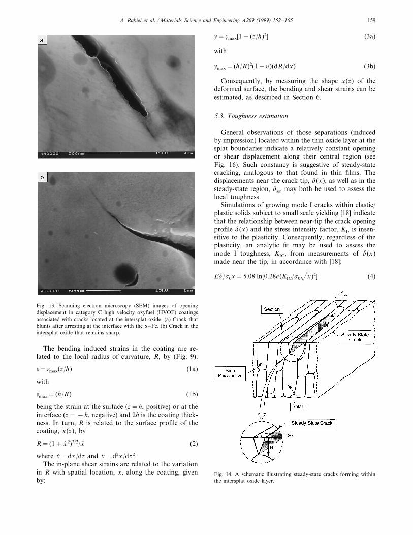
Fig. 13. Scanning electron microscopy (SEM) images of openingdisplacement in category C high velocity oxyfuel (HVOF) coatingsassociated with cracks located at the intersplat oxide. (a) Crack thatblunts after arresting at the interface with the a–Fe. (b) Crack in theintersplat oxide that remains sharp.
g=gmax[1− (z/h)2] (3a)
with
gmax= (h/R)2(1−y)(dR/dx) (3b)
Consequently, by measuring the shape x(z) of thedeformed surface, the bending and shear strains can beestimated, as described in Section 6.
5.3. Toughness estimation
General observations of those separations (inducedby impression) located within the thin oxide layer at thesplat boundaries indicate a relatively constant openingor shear displacement along their central region (seeFig. 16). Such constancy is suggestive of steady-statecracking, analogous to that found in thin films. Thedisplacements near the crack tip, d(x), as well as in thesteady-state region, dss, may both be used to assess thelocal toughness.
Simulations of growing mode I cracks within elastic/plastic solids subject to small scale yielding [18] indicatethat the relationship between near-tip the crack openingprofile d(x) and the stress intensity factor, KI, is insen-sitive to the plasticity. Consequently, regardless of theplasticity, an analytic fit may be used to assess themode I toughness, KIC, from measurements of d(x)made near the tip, in accordance with [18]:
Ed/s0x=5.08 ln[0.28e(KIC/s0x)2] (4)
Fig. 14. A schematic illustrating steady-state cracks forming withinthe intersplat oxide layer.
The bending induced strains in the coating are re-lated to the local radius of curvature, R, by (Fig. 9):
o=omax(z/h) (1a)
with
omax= (h/R) (1b)
being the strain at the surface (z=h, positive) or at theinterface (z= −h, negative) and 2h is the coating thick-ness. In turn, R is related to the surface profile of thecoating, x(z), by
R= (1+x; 2)3/2/x (2)
where x; =dx/dz and x=d2x/dz2.The in-plane shear strains are related to the variation
in R with spatial location, x, along the coating, givenby:
A. Rabiei et al. / Materials Science and Engineering A269 (1999) 152–165160
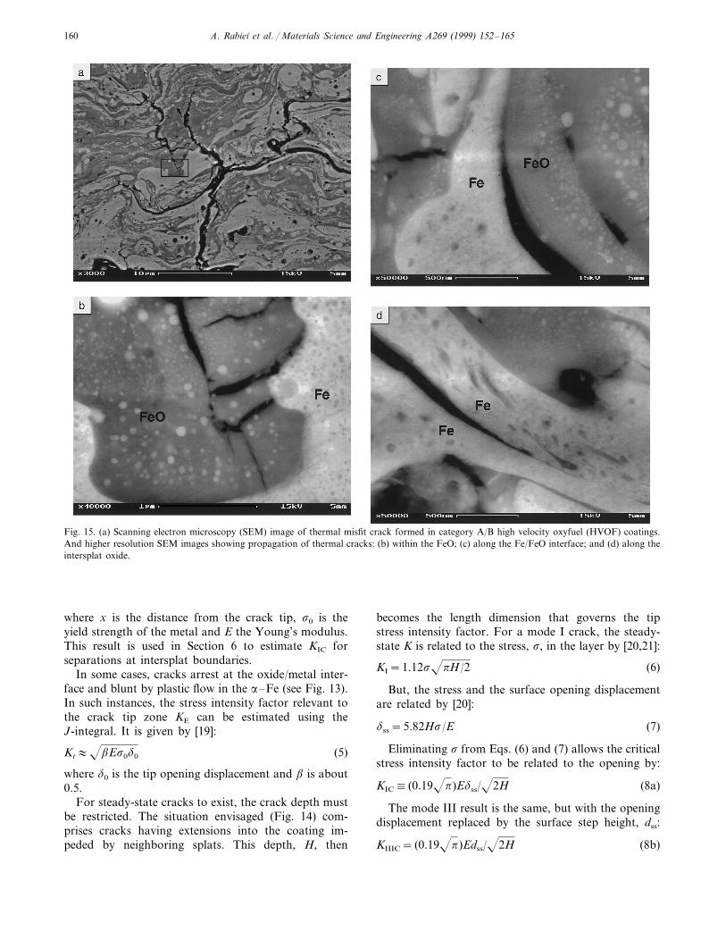
Fig. 15. (a) Scanning electron microscopy (SEM) image of thermal misfit crack formed in category A/B high velocity oxyfuel (HVOF) coatings.And higher resolution SEM images showing propagation of thermal cracks: (b) within the FeO; (c) along the Fe/FeO interface; and (d) along theintersplat oxide.
where x is the distance from the crack tip, s0 is theyield strength of the metal and E the Young’s modulus.This result is used in Section 6 to estimate KIC forseparations at intersplat boundaries.
In some cases, cracks arrest at the oxide/metal inter-face and blunt by plastic flow in the a–Fe (see Fig. 13).In such instances, the stress intensity factor relevant tothe crack tip zone KE can be estimated using theJ-integral. It is given by [19]:
Kt:bEs0d0 (5)
where d0 is the tip opening displacement and b is about0.5.
For steady-state cracks to exist, the crack depth mustbe restricted. The situation envisaged (Fig. 14) com-prises cracks having extensions into the coating im-peded by neighboring splats. This depth, H, then
becomes the length dimension that governs the tipstress intensity factor. For a mode I crack, the steady-state K is related to the stress, s, in the layer by [20,21]:
KI=1.12spH/2 (6)
But, the stress and the surface opening displacementare related by [20]:
dss=5.82Hs/E (7)
Eliminating s from Eqs. (6) and (7) allows the criticalstress intensity factor to be related to the opening by:
KIC (0.19p)Edss/2H (8a)
The mode III result is the same, but with the openingdisplacement replaced by the surface step height, dss:
KIIIC= (0.19p)Edss/2H (8b)
A. Rabiei et al. / Materials Science and Engineering A269 (1999) 152–165 161
6. Measurements and observations
6.1. Misfit cracks
The category A/B HVOF materials (Table 1) allexhibited periodic cracking when thin annular sectionswere made by electron discharge machine EDM. Thecracks are typically separated by 0.3–0.5 mm and ex-tend partially through the thickness (Fig. 15a). Locally,the cracks bifurcate and extend parallel to the sub-strate, often over considerable distances. Higher resolu-tion images of these cracks reveal importantcharacteristics (Fig. 15b–d). (i) The cracks are locatedprimarily within the oxide, but at some sites, appear tobe along the Fe/FeO interface. (ii) Cracks never pene-trate the Fe, but instead, blunt plastically, indicative ofductility in the metal (Fig. 15c). Near the tip, within theoxide, the crack opening displacements are small (Fig.
15b), signifying a low toughness (Eq. (4)). Given thepresence of these cracks, impression tests are notrequired.
6.2. Impression induced cracks
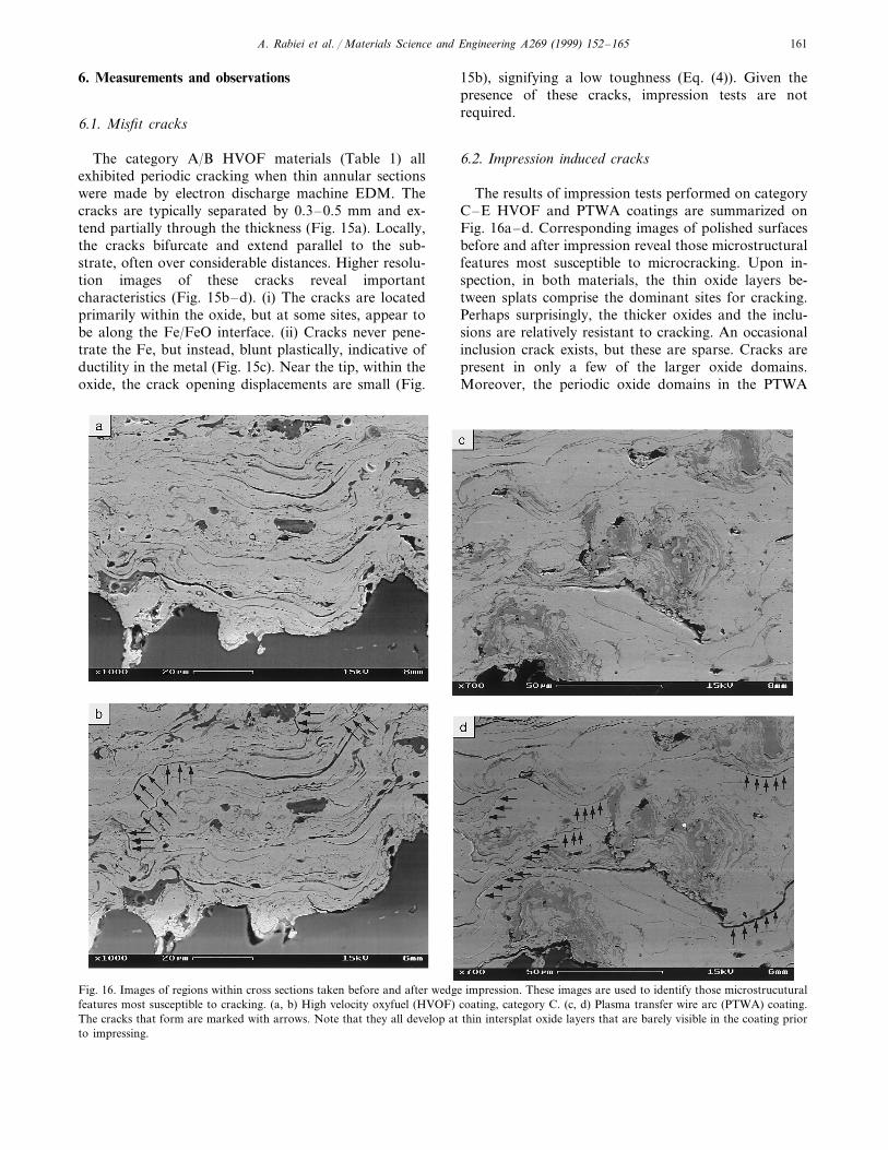
The results of impression tests performed on categoryC–E HVOF and PTWA coatings are summarized onFig. 16a–d. Corresponding images of polished surfacesbefore and after impression reveal those microstructuralfeatures most susceptible to microcracking. Upon in-spection, in both materials, the thin oxide layers be-tween splats comprise the dominant sites for cracking.Perhaps surprisingly, the thicker oxides and the inclu-sions are relatively resistant to cracking. An occasionalinclusion crack exists, but these are sparse. Cracks arepresent in only a few of the larger oxide domains.Moreover, the periodic oxide domains in the PTWA
Fig. 16. Images of regions within cross sections taken before and after wedge impression. These images are used to identify those microstrucuturalfeatures most susceptible to cracking. (a, b) High velocity oxyfuel (HVOF) coating, category C. (c, d) Plasma transfer wire arc (PTWA) coating.The cracks that form are marked with arrows. Note that they all develop at thin intersplat oxide layers that are barely visible in the coating priorto impressing.
A. Rabiei et al. / Materials Science and Engineering A269 (1999) 152–165162
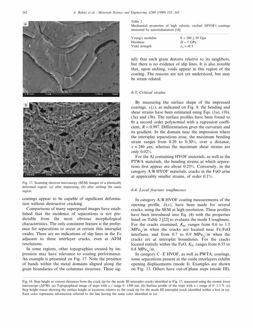
Fig. 17. Scanning electron microscopy (SEM) images of a plasticallydeformed region: (a) after impressing, (b) after etching the sameregion.
Table 2Mechanical properties of high velocity oxyfuel (HVOF) coatingsmeasured by nanoindentation [14]
E=200950 GpaYoung’s modulusH=3 GPaHardness
Yield strength s0:H/3
nify that each grain distorts relative to its neighbors,but there is no evidence of slip lines. It is also notablethat, upon etching, voids appear in this region of thecoating. The reasons are not yet understood, but maybe strain related.
6.3. Critical strains
By measuring the surface shape of the impressedcoatings, x(z), as indicated on Fig. 9, the bending andshear strains have been estimated using Eqs. (1a), (1b),(3a) and (3b). The surface profiles have been found tofit a second order polynomial with a regression coeffi-cient, R=0.997. Differentiation gives the curvature andits gradient. In the domain near the impression wherethe intersplat separations arise, the maximum bendingstrain ranges from 0.20 to 0.30%, over a distance,x:240 mm; whereas the maximum shear strains areonly 0.02%.
For the Al containing HVOF materials, as well as thePTWA materials, the bending strains at which separa-tions first appear are about 0.25%. Conversely, in thecategory A/B HVOF materials, cracks in the FeO ariseat appreciably smaller strains, of order 0.1%.
6.4. Local fracture toughnesses
In category A/B HVOF coating measurements of theopening profile, d(x), have been made for severalcracks, using the SEM at high resolution. These profileshave been introduced into Eq. (4) with the propertieslisted on Table 2 [22] to evaluate the mode I toughness.For the cracks examined, KIC ranges from 0.6 to 1.5MPam when the cracks are located near Fe/FeOinterfaces, and from 0.7 to 0.9 MPam when thecracks are at intersplat boundaries. For the crackslocated entirely within the FeO, KIC ranges from 0.55 to0.8 MPam.
In category C–E HVOF, as well as PWTA, coatings,some separations present at the oxide interlayers exhibitopening displacements (mode I). Examples are shownon Fig. 13. Others have out-of-plane steps (mode III),
coatings appear to be capable of significant deforma-tion without destructive cracking.
Comparisons of many superposed images have estab-lished that the incidence of separations is not pre-dictable from the most obvious morphologicalcharacteristics. The only consistent feature is the prefer-ence for separations to occur at certain thin intersplatoxides. There are no indications of slip lines in the Feadjacent to these interlayer cracks, even at AFMresolutions.
In some regions, other topographies created by im-pression may have relevance to coating performance.An example is presented on Fig. 17. Note the presenceof bands within the metal domains aligned along thegrain boundaries of the columnar structure. These sig-
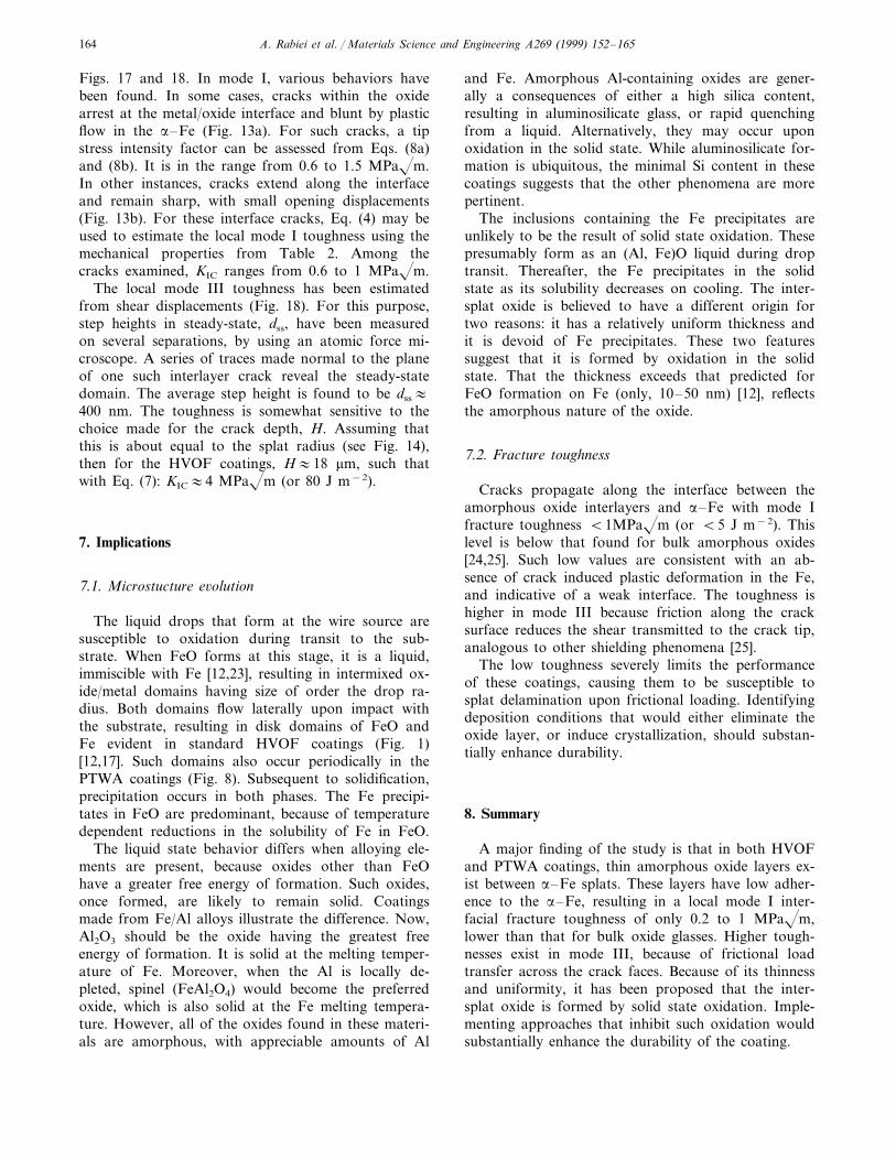
Fig. 18. Step height at various distances from the crack tip for the mode III intersplat cracks identified in Fig. 17, measured using the atomic forcemicroscope (AFM). (a) Topographical image of steps with a z range 0–1500 nm. (b) Surface profile of the steps with a z range of 0–1.5 V. (c)Step height traces showing the surface height at locations relative to the crack tip for the mode III intersplat crack identified within a box in (a).Each color represents information referred to the line having the same color identified in (a).
A. Rabiei et al. / Materials Science and Engineering A269 (1999) 152–165 163
Fig. 18.
A. Rabiei et al. / Materials Science and Engineering A269 (1999) 152–165164
Figs. 17 and 18. In mode I, various behaviors havebeen found. In some cases, cracks within the oxidearrest at the metal/oxide interface and blunt by plasticflow in the a–Fe (Fig. 13a). For such cracks, a tipstress intensity factor can be assessed from Eqs. (8a)and (8b). It is in the range from 0.6 to 1.5 MPam.In other instances, cracks extend along the interfaceand remain sharp, with small opening displacements(Fig. 13b). For these interface cracks, Eq. (4) may beused to estimate the local mode I toughness using themechanical properties from Table 2. Among thecracks examined, KIC ranges from 0.6 to 1 MPam.
The local mode III toughness has been estimatedfrom shear displacements (Fig. 18). For this purpose,step heights in steady-state, dss, have been measuredon several separations, by using an atomic force mi-croscope. A series of traces made normal to the planeof one such interlayer crack reveal the steady-statedomain. The average step height is found to be dss:400 nm. The toughness is somewhat sensitive to thechoice made for the crack depth, H. Assuming thatthis is about equal to the splat radius (see Fig. 14),then for the HVOF coatings, H:18 mm, such thatwith Eq. (7): KIC:4 MPam (or 80 J m−2).
7. Implications
7.1. Microstucture e6olution
The liquid drops that form at the wire source aresusceptible to oxidation during transit to the sub-strate. When FeO forms at this stage, it is a liquid,immiscible with Fe [12,23], resulting in intermixed ox-ide/metal domains having size of order the drop ra-dius. Both domains flow laterally upon impact withthe substrate, resulting in disk domains of FeO andFe evident in standard HVOF coatings (Fig. 1)[12,17]. Such domains also occur periodically in thePTWA coatings (Fig. 8). Subsequent to solidification,precipitation occurs in both phases. The Fe precipi-tates in FeO are predominant, because of temperaturedependent reductions in the solubility of Fe in FeO.
The liquid state behavior differs when alloying ele-ments are present, because oxides other than FeOhave a greater free energy of formation. Such oxides,once formed, are likely to remain solid. Coatingsmade from Fe/Al alloys illustrate the difference. Now,Al2O3 should be the oxide having the greatest freeenergy of formation. It is solid at the melting temper-ature of Fe. Moreover, when the Al is locally de-pleted, spinel (FeAl2O4) would become the preferredoxide, which is also solid at the Fe melting tempera-ture. However, all of the oxides found in these materi-als are amorphous, with appreciable amounts of Al
and Fe. Amorphous Al-containing oxides are gener-ally a consequences of either a high silica content,resulting in aluminosilicate glass, or rapid quenchingfrom a liquid. Alternatively, they may occur uponoxidation in the solid state. While aluminosilicate for-mation is ubiquitous, the minimal Si content in thesecoatings suggests that the other phenomena are morepertinent.
The inclusions containing the Fe precipitates areunlikely to be the result of solid state oxidation. Thesepresumably form as an (Al, Fe)O liquid during droptransit. Thereafter, the Fe precipitates in the solidstate as its solubility decreases on cooling. The inter-splat oxide is believed to have a different origin fortwo reasons: it has a relatively uniform thickness andit is devoid of Fe precipitates. These two featuressuggest that it is formed by oxidation in the solidstate. That the thickness exceeds that predicted forFeO formation on Fe (only, 10–50 nm) [12], reflectsthe amorphous nature of the oxide.
7.2. Fracture toughness
Cracks propagate along the interface between theamorphous oxide interlayers and a–Fe with mode Ifracture toughness B1MPam (or B5 J m−2). Thislevel is below that found for bulk amorphous oxides[24,25]. Such low values are consistent with an ab-sence of crack induced plastic deformation in the Fe,and indicative of a weak interface. The toughness ishigher in mode III because friction along the cracksurface reduces the shear transmitted to the crack tip,analogous to other shielding phenomena [25].
The low toughness severely limits the performanceof these coatings, causing them to be susceptible tosplat delamination upon frictional loading. Identifyingdeposition conditions that would either eliminate theoxide layer, or induce crystallization, should substan-tially enhance durability.
8. Summary
A major finding of the study is that in both HVOFand PTWA coatings, thin amorphous oxide layers ex-ist between a–Fe splats. These layers have low adher-ence to the a–Fe, resulting in a local mode I inter-facial fracture toughness of only 0.2 to 1 MPam,lower than that for bulk oxide glasses. Higher tough-nesses exist in mode III, because of frictional loadtransfer across the crack faces. Because of its thinnessand uniformity, it has been proposed that the inter-splat oxide is formed by solid state oxidation. Imple-menting approaches that inhibit such oxidation wouldsubstantially enhance the durability of the coating.
A. Rabiei et al. / Materials Science and Engineering A269 (1999) 152–165 165
References
[1] R.C. McCune, Weld. J. 24 (1995) 41–47.[2] M.R. Kim, R.W. Smith, R.C. McCune, in: C.C. Berndt, S.
Sampath (Eds.), Proc. 7th National Thermal Spray Conference,ASM International, Materials Park, OH, 1994, p. 43.
[3] M.S. Kramer, L.E. Burns, G.L. Holmes, Method and apparatusfor application of thermal spray coatings to engine blocks. USPatent 5,271,967, 1993.
[4] M.S. Kramer, C.J. Rivard, F.A. Koltuniak, Thermally sprayedaluminum bronze coatings on aluminum engine bores. USPatent 5,080,056, 1992.
[5] D.R. Marantz, K.A Kowalsky, High velocity electric arc sprayapparatus and method of forming materials. US Patent5,296,667, 1994.
[6] J.A. Browing, Double arc prevention for a transferred-arc flamespray system. US Patent 4,762,977, August 9, 1988.
[7] S.E. Hartfield-Wunsch, S.C. Tung, in: C.C. Berndt, S. Sampath(Eds.), Thermal Spray Industrial Applications, ASM Interna-tional, Metals Park, OH, 1994, pp. 19–24.
[8] K. Korpiola, J.-P. Hirvonen, H. Jalkanen, L. Lasts, F. Ross, in:C.C. Berndt, S. Sampath (Eds.), Thermal Spray Science andTechnology, ASM International, Metals Park, OH, 1995, pp.181–185.
[9] A. Vardelle, P. Fauchais, N.J. Themelis, in: C.C. Berndt, S.Sampath (Eds.), Thermal Spray Science and Technology, ASMInternational, Metals Park, OH, 1995, pp. 170–180.
[10] R.A. Neiser, J.E. Brockman, T.J. O’Hearn, R.C. Dykhulzen,M.F. Smith, T.J. Roemer, R.W. Teets, in: C.C. Berndt, S.Sampath (Eds.), Thermal Spray Science and Technology, ASMInternational, Metals Park, OH, 1995, pp. 99–104.
[11] C.M. Hackett, G.S. Settles, in: C.C. Berndt, S.S. Sampath (Eds.),Thermal Spray Science and Technology, ASM International,Metals Park, OH, 1995, pp. 21–29.
[12] R.A. Neiser, M.F. Smith, R.C. Dykhulzen, J. Thermal SprayTechnol. 7 (1998) 537–545.
[13] Automotive News Market Data Book.[14] D.R. Marantz, K.A. Kowalsy, J.R. Baughman, D. Cook, M.J.
Zaluzec, Proc. Materials for Energy Efficient Vehicles Confer-ence, 20th Int. Symp. on Automotive Technology and Automa-tion, Florence, Italy, June, 1996.
[15] S. Fantasi, M. Vardelle, A. Vardelle, P Fauchais, in: C.C.Berndt, T.F. Bernecki (Eds.), Thermal Spray Research, Designand Application, ASM International, Metals Park, OH, 1993,pp. 1–6.
[16] C. Moreau, P. Cielo, M. Lamontagne, in: C.C. Berndt (Ed.),Thermal Spray: International Advances in Coatings Technology,ASM International, Metals Park, OH, 1992, pp. 761–766.
[17] S. Sampath, H. Herman, J. Thermal Spray Technol. 5 (1996)445.
[18] R.H. Dean, J.W. Hutchinson, ASTM STP 700 (1980) 383–405.[19] J.W. Hutchinson, Non Linear Fracture Mechanics, Technical
University, Denmark, 1980.[20] H. Tada, P. Paris, G. Irwin, Handbook of Stress Intensity
Factors, Dell Research, 1985.[21] J.W. Hutchinson, Z. Suo, Adv. Appl. Mech. 29 (1991) 63.[22] J.W. Meng, G.M. Research (1998), private communication.[23] G.J. Shubat, M.B. Bever, T. Lyman (Eds.), Metals Handbook,
8th edition, vol. 8, ASM International, Metals Park, OH, 1973,p. 304.
[24] S.M. Wiederhorn, J. Am. Ceram. Soc. 50 (1967) 407–414.[25] J.B. Wachtman, Mechanical Properties of Ceramics, Wiley, New
York, 1996.
.