
Microbox T Operating Microbox 420-T - Siemens AG · Microbox T Operating Microbox 420-T Operating...
158
SIMATIC Microbox T Operating Microbox 420-T _ _____________ _ _____________ _ _____________ _ _____________ _ _____________ _ _____________ _ _____________ _ _____________ _ _____________ _ _____________ _ _____________ _ _____________ Product overview 1 Fundamentals of the PC-based controller 2 Programming 3 Operation and functions of the controller 4 Setting of the operational performance 5 Connecting WinLC T with the SIMATIC NET OPC server 6 Memory concept 7 Communication 8 Cycle and response times 9 Reference information 10 ESD guidelines A List of abbreviations/acronyms B SIMATIC Microbox T Operating Microbox 420-T Operating Instructions 06/2006 A5E00495967-01
-
Upload
duonghuong -
Category
Documents
-
view
234 -
download
1
Transcript of Microbox T Operating Microbox 420-T - Siemens AG · Microbox T Operating Microbox 420-T Operating...
SIMATIC Microbox T Operating Microbox 420-T ____________________________________________________________________________________
____________________________________________________________________________________
Product overview 1
Fundamentals of the PC-based controller
2
Programming 3
Operation and functions of the controller
4Setting of the operational performance
5Connecting WinLC T with the SIMATIC NET OPC server
6
Memory concept 7
Communication 8
Cycle and response times 9
Reference information 10
ESD guidelines A
List of abbreviations/acronyms
B
SIMATIC
Microbox T Operating Microbox 420-T
Operating Instructions
06/2006 A5E00495967-01
Safety Guidelines This manual contains notices you have to observe in order to ensure your personal safety, as well as to prevent damage to property. The notices referring to your personal safety are highlighted in the manual by a safety alert symbol, notices referring only to property damage have no safety alert symbol. These notices shown below are graded according to the degree of danger.
Danger
indicates that death or severe personal injury will result if proper precautions are not taken.
Warning
indicates that death or severe personal injury may result if proper precautions are not taken.
Caution
with a safety alert symbol, indicates that minor personal injury can result if proper precautions are not taken.
Caution
without a safety alert symbol, indicates that property damage can result if proper precautions are not taken.
Notice
indicates that an unintended result or situation can occur if the corresponding information is not taken into account.
If more than one degree of danger is present, the warning notice representing the highest degree of danger will be used. A notice warning of injury to persons with a safety alert symbol may also include a warning relating to property damage.
Qualified Personnel The device/system may only be set up and used in conjunction with this documentation. Commissioning and operation of a device/system may only be performed by qualified personnel. Within the context of the safety notes in this documentation qualified persons are defined as persons who are authorized to commission, ground and label devices, systems and circuits in accordance with established safety practices and standards.
Prescribed Usage Note the following:
Warning
This device may only be used for the applications described in the catalog or the technical description and only in connection with devices or components from other manufacturers which have been approved or recommended by Siemens. Correct, reliable operation of the product requires proper transport, storage, positioning and assembly as well as careful operation and maintenance.
Trademarks All names identified by ® are registered trademarks of the Siemens AG. The remaining trademarks in this publication may be trademarks whose use by third parties for their own purposes could violate the rights of the owner.
Disclaimer of Liability We have reviewed the contents of this publication to ensure consistency with the hardware and software described. Since variance cannot be precluded entirely, we cannot guarantee full consistency. However, the information in this publication is reviewed regularly and any necessary corrections are included in subsequent editions.
Siemens AG Automation and Drives Postfach 48 48 90437 NÜRNBERG GERMANY
Order No.: A5E00495967-01 Edition 06/2006
Copyright © Siemens AG 2006. Technical data subject to change
이 기기는 업무용(A급) 전자파 적합기기로서 판매자 또는 사용자는 이 점을 주의하시기 바라며 가정 외의 지역에서 사용하는 것을 목적으로 합니다.

Operating Microbox 420-T Operating Instructions, 06/2006, A5E00495967-01 iii
Table of contents 1 Product overview .................................................................................................................................... 1-1
1.1 Introduction ................................................................................................................................ 1-1
1.2 System architecture ................................................................................................................... 1-3
1.3 Functions of WinLC T ................................................................................................................ 1-4
1.4 Integrated technology ................................................................................................................ 1-5
2 Fundamentals of the PC-based controller............................................................................................... 2-1
2.1 Overview .................................................................................................................................... 2-1
2.2 Explanation of the terms ............................................................................................................ 2-2 2.2.1 PC station................................................................................................................................... 2-2 2.2.2 Communication interface ........................................................................................................... 2-4 2.2.3 Index .......................................................................................................................................... 2-5
3 Programming .......................................................................................................................................... 3-1
3.1 Use of STEP 7 with the controller .............................................................................................. 3-1
3.2 Creating a project with STEP 7.................................................................................................. 3-4
3.3 Configuring the operating parameters for the controller ............................................................ 3-6
3.4 Code blocks supported by WinLC T .......................................................................................... 3-7
3.5 S7 communication functions ...................................................................................................... 3-8
3.6 PROFIBUS DPV1 ...................................................................................................................... 3-9
3.7 Organization blocks (OBs) ....................................................................................................... 3-10 3.7.1 General information on OBs .................................................................................................... 3-10 3.7.2 Interrupt OBs............................................................................................................................ 3-12
3.8 System functions (SFCs) ......................................................................................................... 3-15
3.9 System function blocks (SFBs) ................................................................................................ 3-19
3.10 Technology functions ............................................................................................................... 3-20
3.11 System clock and run-time meter ............................................................................................ 3-22
3.12 Porting STEP 7 programs ........................................................................................................ 3-23 3.12.1 Porting a STEP 7 program for WinAC RTX............................................................................. 3-23 3.12.2 Porting a STEP 7 program for CPU317T................................................................................. 3-23
3.13 Using WinAC ODK on the Microbox T..................................................................................... 3-24
3.14 Operation of WinLC T with a Windows malfunction................................................................. 3-27
3.15 Operation of WinLC T with a technology malfunction.............................................................. 3-29
3.16 Restart of WinLC T after malfunction of WinLC T.................................................................... 3-30
Table of contents
Operating Microbox 420-T iv Operating Instructions, 06/2006, A5E00495967-01
4 Operation and functions of the controller ................................................................................................ 4-1
4.1 Overview .................................................................................................................................... 4-1
4.2 Control elements of the controller .............................................................................................. 4-3 4.2.1 Control panel.............................................................................................................................. 4-3 4.2.2 Mode selector............................................................................................................................. 4-5 4.2.3 Status displays ........................................................................................................................... 4-6 4.2.4 MRES button.............................................................................................................................. 4-8
4.3 Functions of the controller.......................................................................................................... 4-9 4.3.1 Starting and closing the controller.............................................................................................. 4-9 4.3.2 Tuning panel ............................................................................................................................ 4-10 4.3.3 Displaying diagnostics information........................................................................................... 4-13 4.3.4 Archiving and restoring STEP 7 user programs....................................................................... 4-15 4.3.5 Options for the configuration.................................................................................................... 4-16 4.3.5.1 Overview .................................................................................................................................. 4-16 4.3.5.2 Selecting the language............................................................................................................. 4-17 4.3.5.3 Activation of the autostart function........................................................................................... 4-17 4.3.6 Options for the access protection ............................................................................................ 4-19 4.3.6.1 Configuring the options for the access protection.................................................................... 4-19 4.3.6.2 Changing the password ........................................................................................................... 4-20 4.3.7 Startup options for the controller.............................................................................................. 4-21
5 Setting of the operational performance ................................................................................................... 5-1
5.1 Optimizing the technology system cycle clocks......................................................................... 5-1
5.2 Functions under Windows XP Embedded ................................................................................. 5-2 5.2.1 Monitoring functions ................................................................................................................... 5-2 5.2.2 Enhanced Write Filter (EWF) ..................................................................................................... 5-3
6 Connecting WinLC T with the SIMATIC NET OPC server ...................................................................... 6-1
6.1 Overview .................................................................................................................................... 6-1
6.2 Step 1: Add the OPC server to the PC station........................................................................... 6-2
6.3 Step 2: Add the OPC server to the hardware configuration....................................................... 6-4
6.4 Step 3: Add a S7 connection for the OPC server to NetPro ...................................................... 6-5
6.5 Step 4: Load the configuration into the WinLC T controller ....................................................... 6-9
6.6 Step 5: Connect the controller with the OPC server ................................................................ 6-10
7 Memory concept ..................................................................................................................................... 7-1
7.1 Saving Controller Information..................................................................................................... 7-1
7.2 Loading memory areas during startup ....................................................................................... 7-4
7.3 Buffering of Data with SFCs....................................................................................................... 7-7
7.4 Retentive data in the SRAM....................................................................................................... 7-9
7.5 Power failure ............................................................................................................................ 7-10
7.6 Uninterruptible power supply (UPS)......................................................................................... 7-10
7.7 Backing up data ....................................................................................................................... 7-11
7.8 Restoring the factory settings (Restore) .................................................................................. 7-11
Table of contents
Operating Microbox 420-T Operating Instructions, 06/2006, A5E00495967-01 v
8 Communication....................................................................................................................................... 8-1
8.1 Ports........................................................................................................................................... 8-1 8.1.1 Overview .................................................................................................................................... 8-1 8.1.2 Ethernet interfaces..................................................................................................................... 8-1 8.1.3 PROFIBUS DP interface (X1) .................................................................................................... 8-3 8.1.4 PROFIBUS DP(DRIVE) interface (X2) ...................................................................................... 8-4 8.1.5 I/O interface (X11)...................................................................................................................... 8-5
8.2 Communication services............................................................................................................ 8-6 8.2.1 Overview of communication services ........................................................................................ 8-6 8.2.2 PG communication..................................................................................................................... 8-6 8.2.3 OP communication..................................................................................................................... 8-7 8.2.4 Setting PG/OP communication .................................................................................................. 8-7 8.2.5 Routing for test and diagnostic functions................................................................................... 8-8 8.2.6 Data consistency........................................................................................................................ 8-9
8.3 S7 communication structure .................................................................................................... 8-10 8.3.1 Communication path of an S7 connection ............................................................................... 8-10 8.3.2 Assignment of S7 connections................................................................................................. 8-11 8.3.3 Distribution and availability of S7 connection resources ......................................................... 8-12
9 Cycle and response times....................................................................................................................... 9-1
9.1 WinLC T time model .................................................................................................................. 9-1
10 Reference information .......................................................................................................................... 10-1
10.1 Technical data.......................................................................................................................... 10-1
10.2 System status list ..................................................................................................................... 10-9 10.2.1 Reading the SSL using SFC51................................................................................................ 10-9 10.2.2 SSL_ID 0x11 (module identification)...................................................................................... 10-11 10.2.3 SSL_ID 0x12 (CPU properties) .............................................................................................. 10-11 10.2.4 SSL_ID 0x13 (memory areas)................................................................................................ 10-11 10.2.5 SSL_ID 0x14 (system areas) ................................................................................................. 10-12 10.2.6 SSL_ID 0x15 (block types)..................................................................................................... 10-12 10.2.7 SSL_ID 0x19 (LED status local module)................................................................................ 10-12 10.2.8 SSL_ID 0x1C (component identification) ............................................................................... 10-13 10.2.9 SSL_ID 0x22 (alarm condition) .............................................................................................. 10-13 10.2.10 SSL_ID 0x25 (process image partitions) ............................................................................... 10-14 10.2.11 SSL_ID 0x32 (communications status).................................................................................. 10-14 10.2.12 SSL_ID 0x74 (LED status) ..................................................................................................... 10-15 10.2.13 SSL_ID 0x90 (DP master system) ......................................................................................... 10-15 10.2.14 SSL_ID 0x91 (module status) ................................................................................................ 10-16 10.2.15 SSL_ID 0x92 (module rack and station status)...................................................................... 10-16 10.2.16 SSL_ID 0x95 (extended DP master system) ......................................................................... 10-17 10.2.17 SSL_ID 0xA0 (diagnostic buffer)............................................................................................ 10-17 10.2.18 SSL_ID 00B1, 00B3 and 00B4 (module diagnosis) ............................................................... 10-18
Table of contents
Operating Microbox 420-T vi Operating Instructions, 06/2006, A5E00495967-01
A ESD guidelines .......................................................................................................................................A-1
A.1 ESD Guidelines..........................................................................................................................A-1
B List of abbreviations/acronyms ...............................................................................................................B-1
B.1 Abbreviations .............................................................................................................................B-1
Glossary ..................................................................................................................................... Glossary-1
Index................................................................................................................................................ Index-1
Tables
Table 8-1 Distribution of the S7 connections ........................................................................................... 8-12
Table 8-2 Availability of the S7 connections ............................................................................................ 8-13
Operating Microbox 420-T Operating Instructions, 06/2006, A5E00495967-01 1-1
Product overview 11.1 1.1 Introduction
Introduction The Microbox T consists of an industrial PC system microbox with integrated DP-PCI-104 expansion board on which a PC-based software controller is installed with integrated technology functions. The software controller is also referred to as controller in this document.
Purpose of the operating instructions These operating instructions contain all information about the following topics:
• Use of STEP 7 for the programming
• Operation and functions of the controller
• Setting of the operational performance
• Memory concept
• Communication with connected devices
Requirements These operating instructions are intended for engineers, programmers and service personnel with general knowledge of automation systems.
Knowledge of the following is required to understand these operating instructions:
• Windows XP Embedded operating system
• Drive technology
• STEP 7 basic software For further information, refer to the Programming with STEP 7 V5.3 manual.
• Technology functions For further information, refer to the S7-Technology manual.
Scope of the operating instructions The operating instructions are valid for the WinLC T software installed on the Microbox 420-T and describes the delivery status from Version 1.0.
Product overview 1.1 Introduction
Operating Microbox 420-T 1-2 Operating Instructions, 06/2006, A5E00495967-01
Conventions Within the manual and the online help, the abbreviations Microbox 420-T, Microbox T or device are also used for the product designation SIMATIC Microbox 420-T.
Position in the information landscape Information about the hardware, the installation and the connections of the Microbox 420-T are contained in the Microbox 420-T Installation hardware manual.
Information for commissioning the Microbox T is contained in Getting Started With Microbox 420-T.
Information about the STEP 7 basic software can be found in the Programming with STEP 7 V5.3 manual.
Information about the programming and the technology functions can be found in the S7-Technology manual.
Information about the communication via Industrial Ethernet can be found in the SIMATIC NET - Twisted-Pair and Fiber-Optic Networks manual.
A description of the SOFTNET communication software can be found in the SIMATIC NET - Introduction of SOFTNET for Industrial Ethernet manual. The manuals for SIMATIC NET can be found as PDF documents on the CD contained in the Microbox T scope of delivery.
Product overview 1.2 System architecture
Operating Microbox 420-T Operating Instructions, 06/2006, A5E00495967-01 1-3
1.2 1.2 System architecture
System structure The Microbox T is a hardware/software package comprising the following components:
• Industrial PC system microbox
• WinLC T PC-based controller with integrated motion control
WinLC T PC-based controller WinLC T is a programmable software controller that provides a functionality similar to that of a SIMATIC S7 CPU with integrated motion control. The software is installed on the industrial PC system microbox and is executed on this. In this document, the term controller is also used instead of WinLC T for the software controller.
The controller integrates motion control functions and technological configurations (technology objects, axis configurations, tools).
WinLC T supports several networks and establishes a connection to the distributed I/O via the DP interfaces of the Microbox T.
A PROFIBUS DP(DRIVE) interface and digital outputs are available for the control of drive systems.
As part of the SIMATIC automation product range, WinLC T can also communicate with STEP 7 or other SIMATIC products, e.g. with WinCC, via PROFIBUS or Industrial Ethernet networks.
Using STEP 7 You can use the same programming languages, program structure and programming interface (STEP 7) as for S7-300/400 target systems in order to develop your process control. Programs that have been written for S7 automation systems can be used on PC-based controllers and vice versa.
Configuration The Microbox T has been preconfigured. You can start immediately with the operation of the controller. You operate the controller via the control panel which is displayed on a monitor.
Notice Hot-plug I/O devices (USB) may not be connected while the WinLC T controller is in operation. Monitor, keyboard and mouse are not included in this restriction.
If, for example, you want to connect a USB memory to store data, you must first shut down the WinLC T controller.
Product overview 1.3 Functions of WinLC T
Operating Microbox 420-T 1-4 Operating Instructions, 06/2006, A5E00495967-01
Customer-specific software
Caution To ensure a high-quality, correctly functioning complete system, the SIMOTION P motion control component comes configured and ready to run. For this purpose, the system components used are subject to a certification procedure at SIEMENS as the system manufacturer. The certification process establishes and documents the real-time features of the entire configuration.
If PC components (hardware or software) are modified or expanded by a third party, compliance with product features cannot be guaranteed. The OEM or user involved must assume sole responsibility for such components.
Certification of expansions The PC is basically an open system. In some cases, software or hardware expansions or modifications are necessary to attain a particular functionality.
Please contact your local SIEMENS sales representative in this respect.
1.3 1.3 Functions of WinLC T
SIMATIC functionality supported by WinLC T WinLC T provides the following functions:
• Contains a large number of S7 code blocks of SIMATIC controllers: Organization blocks (OBs), system function blocks (SFBs) and system functions (SFCs)
• Uses S7 communication services and provides compatibility with STEP 7 for tasks such as programming, testing and monitoring.
• WinLC T has a tuning panel for the display and setting of the system operational performance.
• Can be connected to a SIMATIC NET OPC server, which allows OPC client applications to access process data.
Product overview 1.4 Integrated technology
Operating Microbox 420-T Operating Instructions, 06/2006, A5E00495967-01 1-5
1.4 1.4 Integrated technology
Technology functions Technology functions for the control of drive systems are integrated in the WinLC T software controller.
A detailed list can be found under "Technology functions".
Evaluation of technology data blocks The integrated technology of WinLC T provides current information on the status and on the values of the technology objects via the technology data blocks. To achieve short response times, the technology data blocks can be evaluated in OB 65.
Reference Further information about the technology functions that can be used under WinLC T and the technology data blocks can be found in the S7-Technology manual.

Product overview 1.4 Integrated technology
Operating Microbox 420-T 1-6 Operating Instructions, 06/2006, A5E00495967-01
Operating Microbox 420-T Operating Instructions, 06/2006, A5E00495967-01 2-1
Fundamentals of the PC-based controller 22.1 2.1 Overview
The Microbox T contains the WinLC T PC-based controller. This is always installed and is executed on the Microbox T. The WinLC T PC-based controller is also referred to as controller in this document.
The "Fundamentals of the PC-based controller" section explains the basic terms in order to understand the WinLC T PC-based controller:
• PC station
• Communication interface
• Index
Fundamentals of the PC-based controller 2.2 Explanation of the terms
Operating Microbox 420-T 2-2 Operating Instructions, 06/2006, A5E00495967-01
2.2 2.2 Explanation of the terms
2.2.1 PC station
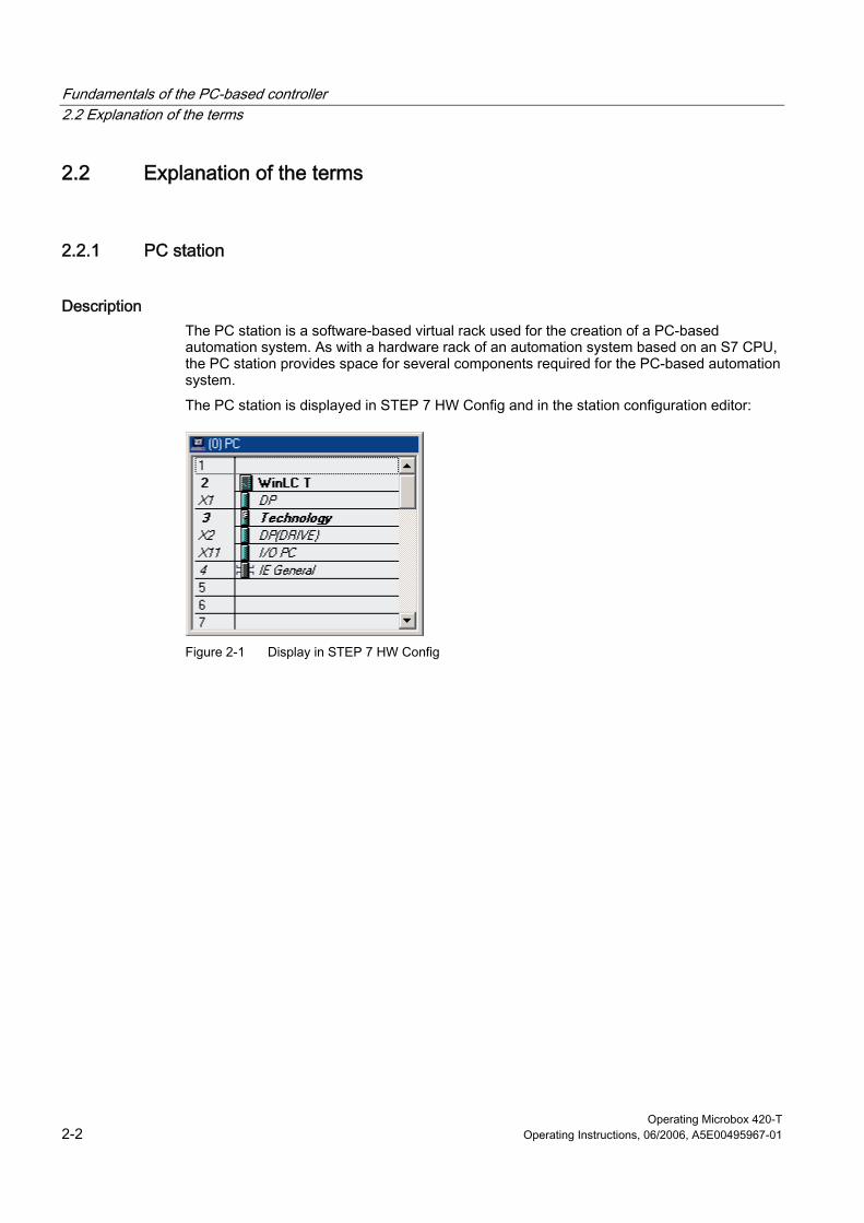
Description The PC station is a software-based virtual rack used for the creation of a PC-based automation system. As with a hardware rack of an automation system based on an S7 CPU, the PC station provides space for several components required for the PC-based automation system.
The PC station is displayed in STEP 7 HW Config and in the station configuration editor:
Figure 2-1 Display in STEP 7 HW Config
Fundamentals of the PC-based controller 2.2 Explanation of the terms
Operating Microbox 420-T Operating Instructions, 06/2006, A5E00495967-01 2-3
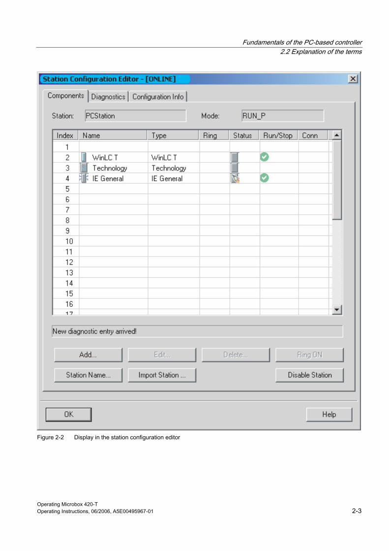
Figure 2-2 Display in the station configuration editor
Fundamentals of the PC-based controller 2.2 Explanation of the terms
Operating Microbox 420-T 2-4 Operating Instructions, 06/2006, A5E00495967-01
When you work with the Microbox T, the following components are available in the PC station:
• WinLC T controller The controller is part of the Microbox T. It is configured with STEP 7.
• Technology The technology is parameterized with S7T Config.
• Communication interfaces The Microbox T contains two PROFIBUS interfaces configured as DP interfaces and two integrated Ethernet interfaces for use with Industrial Ethernet.
• I/O PC (I/O interface, digital outputs) The Microbox T has eight digital outputs with switching times below 1 ms.
• Further applications (optional)
• OPC server (optional)
• Station manager The station manager is part of the Microbox T.
2.2.2 Communication interface
Description A communication interface is a CP, an integrated PROFIBUS interface or an Industrial Ethernet interface.
The following communications interfaces exist for WinLC T on the Microbox 420-T:
• DP interface
WinLC T can use the DP interface not only for communication with STEP 7 or other S7 applications, but also for communication with the distributed I/O via PROFIBUS DP.
• DP(DRIVE) interface
The DP(DRIVE) interface is used for the communication with drive systems.
• Ethernet interfaces
The Microbox T contains two integrated Ethernet interfaces for use with Industrial Ethernet. These can be used for the communication between STEP 7 or other S7 applications and the WinLC T controller.
Fundamentals of the PC-based controller 2.2 Explanation of the terms
Operating Microbox 420-T Operating Instructions, 06/2006, A5E00495967-01 2-5
2.2.3 Index
Description An index is a numbered slot on the virtual rack of the PC station.
When you work with the Microbox 420-T, you are provided with following configuration:
• The WinLC T controller has been assigned to Index 2.
• The integrated technology has been assigned to Index 3.
• IE general has been assigned to Index 4.
• The station manager has been assigned to Index 125.
In addition to the previously configured slots, you can add your own applications (e.g. C programs or Visual Basic programs) or an OPC server.

Fundamentals of the PC-based controller 2.2 Explanation of the terms
Operating Microbox 420-T 2-6 Operating Instructions, 06/2006, A5E00495967-01
Operating Microbox 420-T Operating Instructions, 06/2006, A5E00495967-01 3-1
Programming 33.1 3.1 Use of STEP 7 with the controller
Description STEP 7 with the S7-Technology option package provides programming and configuration tools for the work with WinLC T. They perform the following operations in STEP 7:
• Definition of the controller, DP, DP(DRIVE) and IE configuration using STEP 7 HW Config and configuration of the operating parameters and I/O addresses for the controller
• Development of a STEP 7 user program with one of the STEP 7 programming languages
• Definition of the drive technology with the tools of the S7-Technology option package
The definition is performed with the S7T Config tool. The technology object data are stored in data blocks for use by the STEP 7 user program.
S7-Technology also includes a library containing PLCopen-compliant function blocks which are used to program the actual motion control tasks. You call these FBs in your STEP 7 user program.
• Loading of the configuration and the STEP 7 user program to the controller
The STEP 7 languages LAD, FBD and STL and all the engineering tools, e.g. S7-SCL or S7-GRAPH, are available for the creation of the STEP 7 user program (incl. the motion control tasks).
Further information can be found in the STEP 7 documentation and in the documentation for the S7-Technology option package.
Note on the initialization of the integrated technology through overloading of the SDBs You cannot re-initialize the integrated technology of the Microbox 420-T by reloading the unchanged SDBs to the Microbox 420-T. The system variables and configuration data retain their last valid value and are not reset to the initial value as with the CPU31xT.
If you want to reset the integrated technology of the Microbox T to the configured values, you must first execute the MRES command (overall reset) on the Microbox T and then reload the project.
Programming 3.1 Use of STEP 7 with the controller
Operating Microbox 420-T 3-2 Operating Instructions, 06/2006, A5E00495967-01
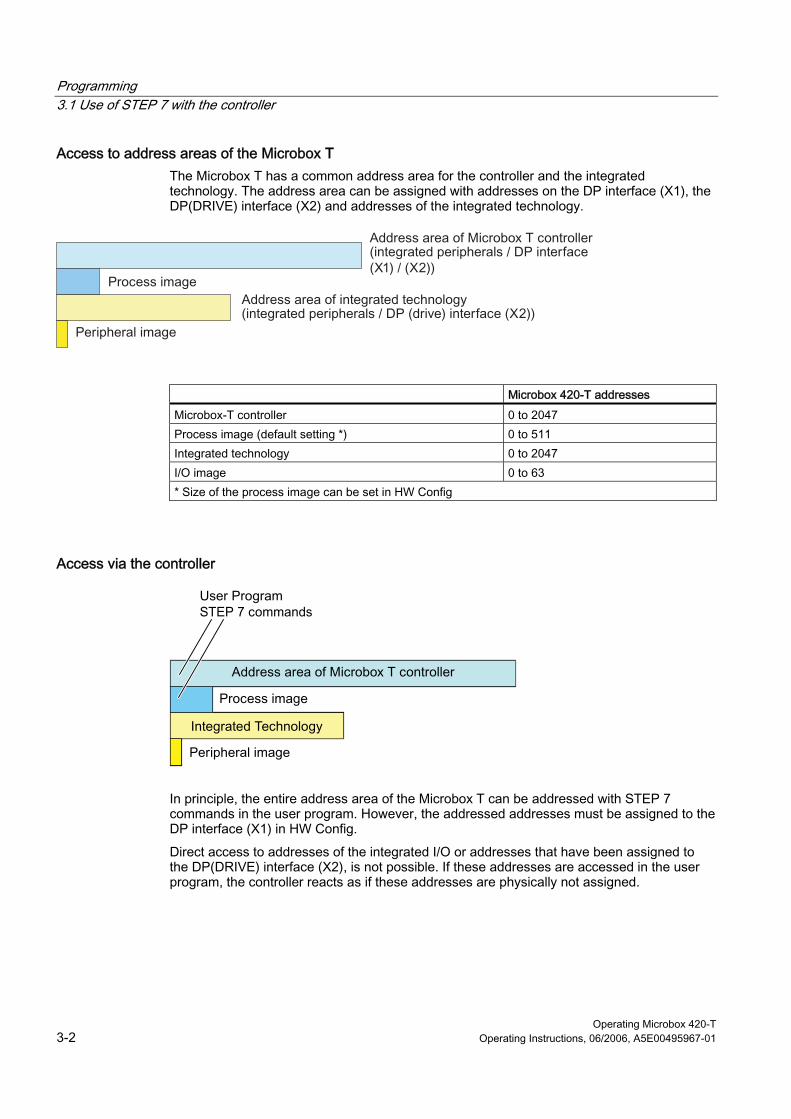
Access to address areas of the Microbox T The Microbox T has a common address area for the controller and the integrated technology. The address area can be assigned with addresses on the DP interface (X1), the DP(DRIVE) interface (X2) and addresses of the integrated technology.
Microbox 420-T addresses
Microbox-T controller 0 to 2047 Process image (default setting *) 0 to 511 Integrated technology 0 to 2047 I/O image 0 to 63 * Size of the process image can be set in HW Config
Access via the controller
integrierte Technologie
In principle, the entire address area of the Microbox T can be addressed with STEP 7 commands in the user program. However, the addressed addresses must be assigned to the DP interface (X1) in HW Config.
Direct access to addresses of the integrated I/O or addresses that have been assigned to the DP(DRIVE) interface (X2), is not possible. If these addresses are accessed in the user program, the controller reacts as if these addresses are physically not assigned.
Programming 3.1 Use of STEP 7 with the controller
Operating Microbox 420-T Operating Instructions, 06/2006, A5E00495967-01 3-3
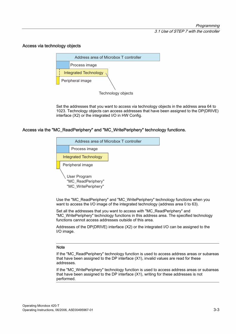
Access via technology objects
Set the addresses that you want to access via technology objects in the address area 64 to 1023. Technology objects can access addresses that have been assigned to the DP(DRIVE) interface (X2) or the integrated I/O in HW Config.
Access via the "MC_ReadPeriphery" and "MC_WritePeriphery" technology functions.
integrierte Technologie
Use the "MC_ReadPeriphery" and "MC_WritePeriphery" technology functions when you want to access the I/O image of the integrated technology (address area 0 to 63).
Set all the addresses that you want to access with "MC_ReadPeriphery" and "MC_WritePeriphery" technology functions in this address area. The specified technology functions cannot access addresses outside of this area.
Addresses of the DP(DRIVE) interface (X2) or the integrated I/O can be assigned to the I/O image.
Note If the "MC_ReadPeriphery" technology function is used to access address areas or subareas that have been assigned to the DP interface (X1), invalid values are read for these addresses.
If the "MC_WritePeriphery" technology function is used to access address areas or subareas that have been assigned to the DP interface (X1), writing for these addresses is not performed.
Programming 3.2 Creating a project with STEP 7
Operating Microbox 420-T 3-4 Operating Instructions, 06/2006, A5E00495967-01
3.2 3.2 Creating a project with STEP 7
Introduction You configure the STEP 7 project for a PC station with a PC-based controller in STEP 7 in exactly the same way as for an S7 hardware controller. Detailed information on this subject can be found in the help and in the documentation for STEP 7.
Creating a project and PC station with the SIMATIC Manager Proceed as follows to create a project and PC station:
1. In the SIMATIC Manager, select File > New to create a new project.
2. Enter a name for the new project.
3. Select Insert new object > SIMATIC PC station to insert a PC station in the project.
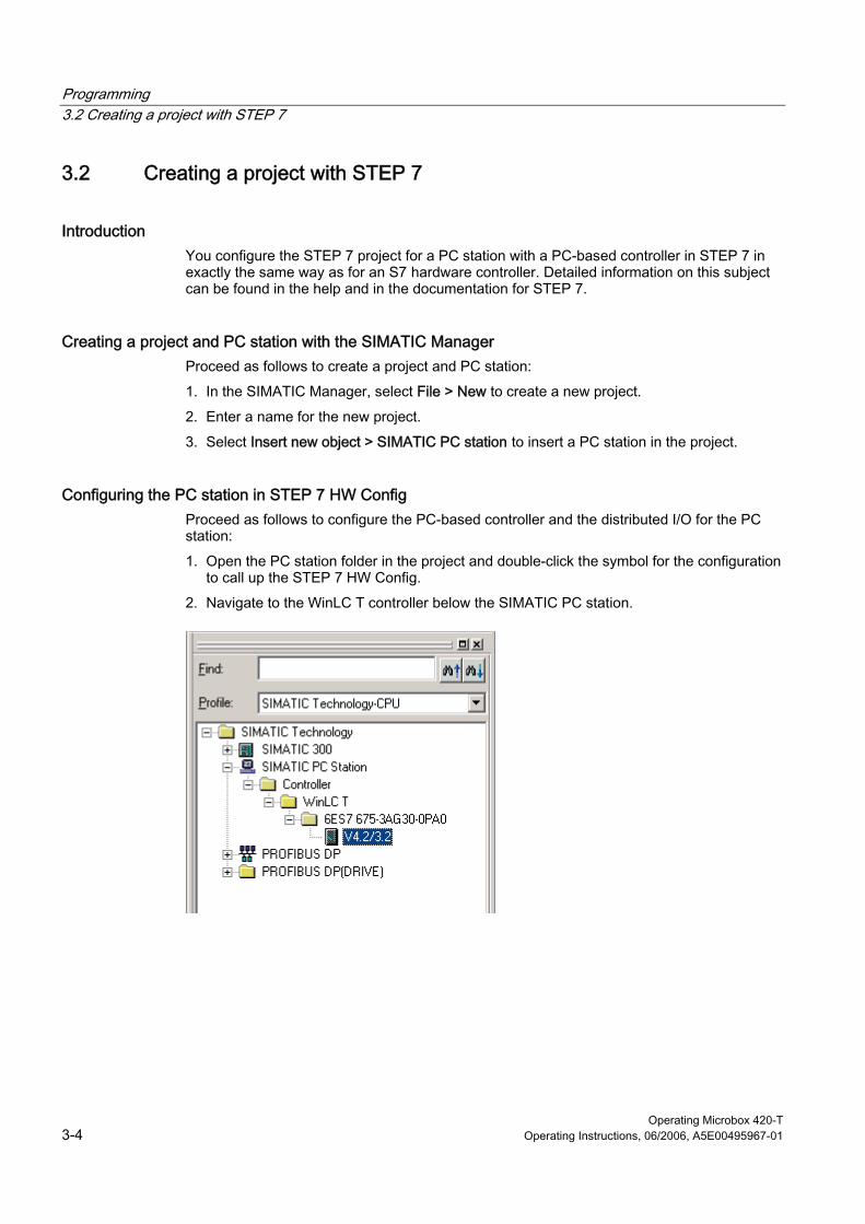
Configuring the PC station in STEP 7 HW Config Proceed as follows to configure the PC-based controller and the distributed I/O for the PC station:
1. Open the PC station folder in the project and double-click the symbol for the configuration to call up the STEP 7 HW Config.
2. Navigate to the WinLC T controller below the SIMATIC PC station.

Programming 3.2 Creating a project with STEP 7
Operating Microbox 420-T Operating Instructions, 06/2006, A5E00495967-01 3-5
3. Drag the controller to the slot with Index 2. WinLC T is configured in Index 2. The technology is then automatically configured on Slot 3 and IE general on Slot 4.
The technology on Slot 3 and IE general on Slot 4 cannot be removed separately. However, you can change the object properties and perform the clock synchronization.
Further options in the hardware configuration The following operations are optional and depend on the specific application:
1. Insert all HMI devices, e.g. Runtime ProTool or Runtime WinCC flexible.
2. Parameterize the WinLC T, Technology, IE General modules and their interfaces.
3. Configure WinLC T for the S7 communication:
– In SIMATIC Manager, select the name of the controller.
– In the right-hand window pane, double-click the symbol for connections.
– Configure the network with NetPro.
4. Configure the drives to be used in HW Config.
After you have configured WinLC T, you can develop and load your STEP 7 user program in the SIMATIC Manager.
Caution If you load a STEP 7 user program that is too large for the computer memory, the computer may crash or the operation of WinLC T may become unstable. This may result in material damage and/or violations.
Even when STEP 7 and WinLC T do not limit the number of blocks and the size of the STEP 7 user program, the Microbox T has a limit, which depends on the memory available on the Compact Flash card and in the RAM. The limit for the size of the STEP 7 user program and the number of blocks for your Microbox T can only be determined when you test a system for the requirements of your control application.
After you have loaded your program to the controller, you can start the controller and monitor and change the process variables with STEP 7.
Programming 3.3 Configuring the operating parameters for the controller
Operating Microbox 420-T 3-6 Operating Instructions, 06/2006, A5E00495967-01
3.3 3.3 Configuring the operating parameters for the controller
Introduction HW Config and S7T Config are available for configuring the operating parameters of the controller in STEP 7 with the S7-Technology option package. This configuration is saved to the SDBs of the system data container.
After you have loaded the system data, the controller uses the configured parameters:
• When the controller starts up
• During the transition to the RUN mode (if you have changed the hardware configuration online while the controller was in the STOP mode)
• During operation, the drive configuration controls the behavior of the technology objects.
To configure the operating parameters in STEP 7 HW Config, right-click the controller entry in the station window and select "Object properties". Configure the operating parameters in the "Properties" dialog box.
Use the S7T Config tool to configure the technology objects. More detailed information on this can be found in the documentation for the S7-Technology option package.
Accessing operating parameters To configure these operating parameters in STEP 7, open the SIMATIC Manager and proceed as follows:
1. In the SIMATIC Manager, select the PC station.
2. Double-click the configuration icon to open HW Config.
3. In the station window, right-click the module or submodule whose properties you want to change, and select "Object properties".
4. Open the tab with the name of the parameter that you want to configure (e.g. time interrupt), and enter the appropriate values.
5. Confirm your configuration with "OK".
Further information about the configuration of the controller properties and the operating parameters can be found in the STEP 7 documentation.
Programming 3.4 Code blocks supported by WinLC T
Operating Microbox 420-T Operating Instructions, 06/2006, A5E00495967-01 3-7
3.4 3.4 Code blocks supported by WinLC T
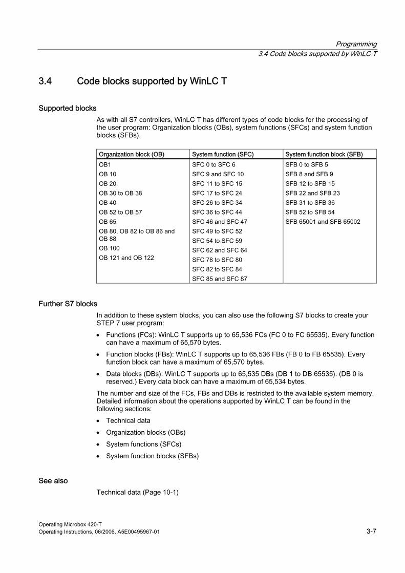
Supported blocks As with all S7 controllers, WinLC T has different types of code blocks for the processing of the user program: Organization blocks (OBs), system functions (SFCs) and system function blocks (SFBs).
Organization block (OB) System function (SFC) System function block (SFB)
OB1 OB 10 OB 20 OB 30 to OB 38 OB 40 OB 52 to OB 57 OB 65 OB 80, OB 82 to OB 86 and OB 88 OB 100 OB 121 and OB 122
SFC 0 to SFC 6 SFC 9 and SFC 10 SFC 11 to SFC 15 SFC 17 to SFC 24 SFC 26 to SFC 34 SFC 36 to SFC 44 SFC 46 and SFC 47 SFC 49 to SFC 52 SFC 54 to SFC 59 SFC 62 and SFC 64 SFC 78 to SFC 80 SFC 82 to SFC 84 SFC 85 and SFC 87
SFB 0 to SFB 5 SFB 8 and SFB 9 SFB 12 to SFB 15 SFB 22 and SFB 23 SFB 31 to SFB 36 SFB 52 to SFB 54 SFB 65001 and SFB 65002
Further S7 blocks In addition to these system blocks, you can also use the following S7 blocks to create your STEP 7 user program:
• Functions (FCs): WinLC T supports up to 65,536 FCs (FC 0 to FC 65535). Every function can have a maximum of 65,570 bytes.
• Function blocks (FBs): WinLC T supports up to 65,536 FBs (FB 0 to FB 65535). Every function block can have a maximum of 65,570 bytes.
• Data blocks (DBs): WinLC T supports up to 65,535 DBs (DB 1 to DB 65535). (DB 0 is reserved.) Every data block can have a maximum of 65,534 bytes.
The number and size of the FCs, FBs and DBs is restricted to the available system memory. Detailed information about the operations supported by WinLC T can be found in the following sections:
• Technical data
• Organization blocks (OBs)
• System functions (SFCs)
• System function blocks (SFBs)
See also Technical data (Page 10-1)
Programming 3.5 S7 communication functions
Operating Microbox 420-T 3-8 Operating Instructions, 06/2006, A5E00495967-01
3.5 3.5 S7 communication functions
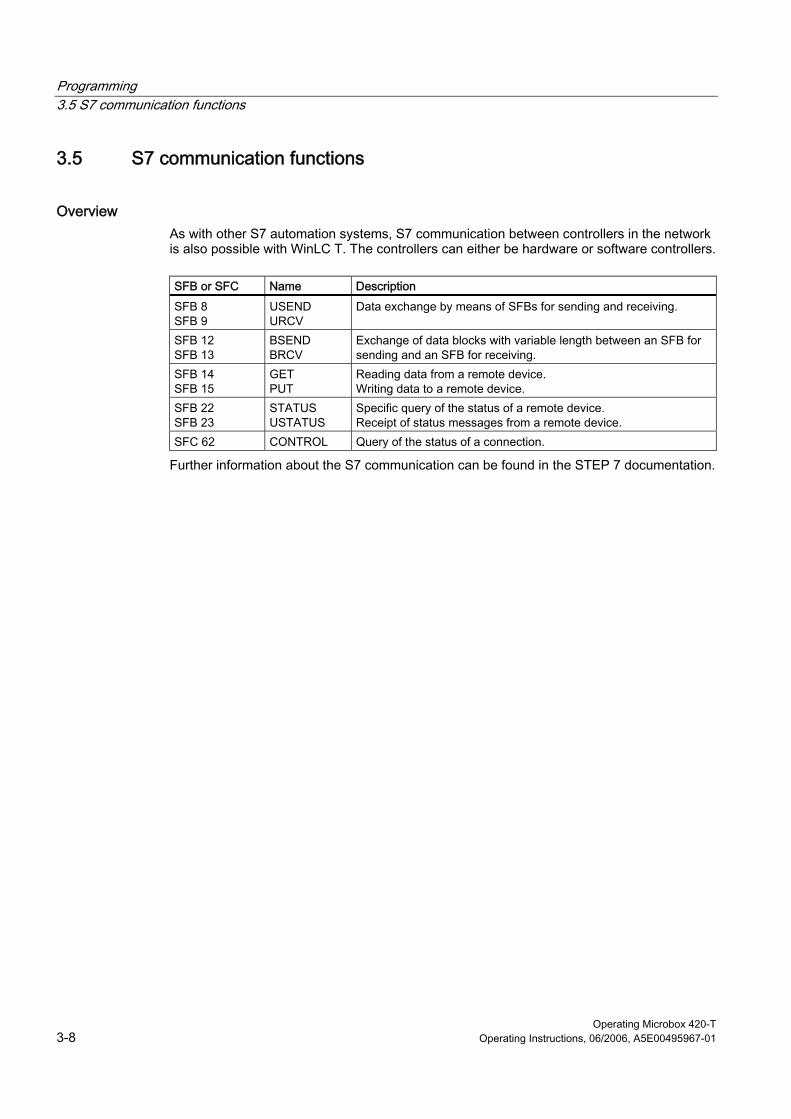
Overview As with other S7 automation systems, S7 communication between controllers in the network is also possible with WinLC T. The controllers can either be hardware or software controllers.
SFB or SFC Name Description
SFB 8 SFB 9
USEND URCV
Data exchange by means of SFBs for sending and receiving.
SFB 12 SFB 13
BSEND BRCV
Exchange of data blocks with variable length between an SFB for sending and an SFB for receiving.
SFB 14 SFB 15
GET PUT
Reading data from a remote device. Writing data to a remote device.
SFB 22 SFB 23
STATUS USTATUS
Specific query of the status of a remote device. Receipt of status messages from a remote device.
SFC 62 CONTROL Query of the status of a connection.
Further information about the S7 communication can be found in the STEP 7 documentation.

Programming 3.6 PROFIBUS DPV1
Operating Microbox 420-T Operating Instructions, 06/2006, A5E00495967-01 3-9
3.6 3.6 PROFIBUS DPV1
Description DPV1 extensions for PROFIBUS DP enable the extended communication required by complex slave devices. This extended communication includes acyclic data exchange, alarm and status messages and the transfer of complex data types.
WinLC T supports the following DPV1 functionality:
• DP standard and DPV1
• Interrupt and status OBs for the processing of DPV1-defined events including:
– OB 40 (process interrupt)
– OB 55 (status interrupt)
– OB 56 (update interrupt)
– OB 57 (manufacturer-specific interrupt)
– OB 82 (diagnostic interrupt)
– OB 83 (Insert/remove module interrupt)
• Function blocks for reading and writing data sets:
– SFB 52 (RDREC), Read data set
– SFB 53 (WRREC), Write data set
– Execution of SFB 54 (RALRM), Read interrupt data, in the context of the triggering interrupt
• Station and interface address
• Buffering of interrupts that have been received in the DP mode CLEAR
Programming 3.7 Organization blocks (OBs)
Operating Microbox 420-T 3-10 Operating Instructions, 06/2006, A5E00495967-01
3.7 3.7 Organization blocks (OBs)
3.7.1 General information on OBs
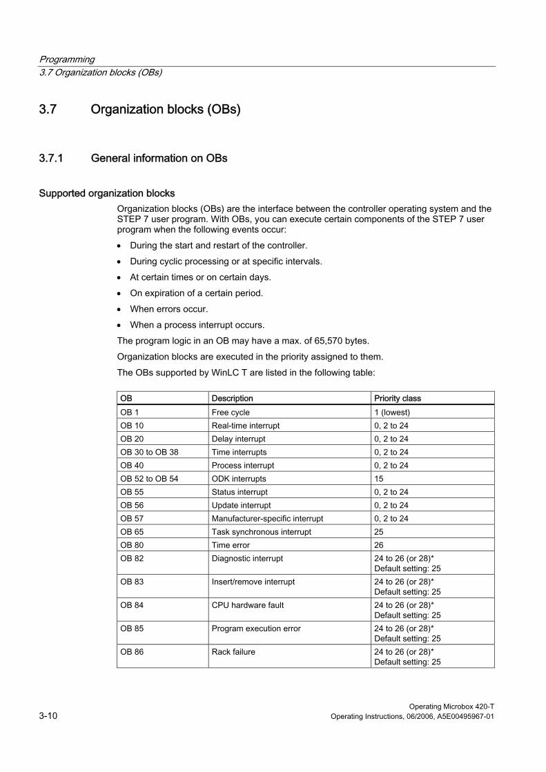
Supported organization blocks Organization blocks (OBs) are the interface between the controller operating system and the STEP 7 user program. With OBs, you can execute certain components of the STEP 7 user program when the following events occur:
• During the start and restart of the controller.
• During cyclic processing or at specific intervals.
• At certain times or on certain days.
• On expiration of a certain period.
• When errors occur.
• When a process interrupt occurs.
The program logic in an OB may have a max. of 65,570 bytes.
Organization blocks are executed in the priority assigned to them.
The OBs supported by WinLC T are listed in the following table:
OB Description Priority class
OB 1 Free cycle 1 (lowest) OB 10 Real-time interrupt 0, 2 to 24 OB 20 Delay interrupt 0, 2 to 24 OB 30 to OB 38 Time interrupts 0, 2 to 24 OB 40 Process interrupt 0, 2 to 24 OB 52 to OB 54 ODK interrupts 15 OB 55 Status interrupt 0, 2 to 24 OB 56 Update interrupt 0, 2 to 24 OB 57 Manufacturer-specific interrupt 0, 2 to 24 OB 65 Task synchronous interrupt 25 OB 80 Time error 26 OB 82 Diagnostic interrupt 24 to 26 (or 28)*
Default setting: 25 OB 83 Insert/remove interrupt 24 to 26 (or 28)*
Default setting: 25 OB 84 CPU hardware fault 24 to 26 (or 28)*
Default setting: 25 OB 85 Program execution error 24 to 26 (or 28)*
Default setting: 25 OB 86 Rack failure 24 to 26 (or 28)*
Default setting: 25
Programming 3.7 Organization blocks (OBs)
Operating Microbox 420-T Operating Instructions, 06/2006, A5E00495967-01 3-11
OB Description Priority class
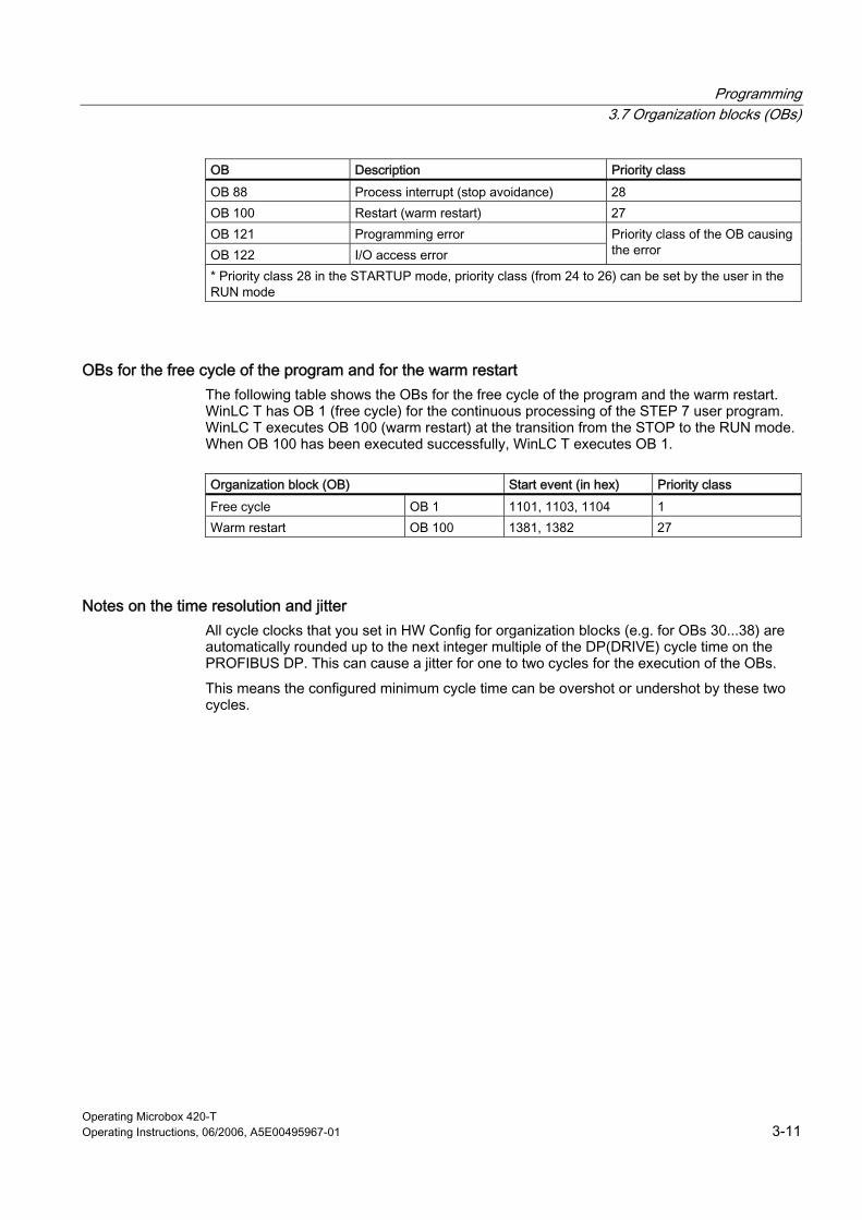
OB 88 Process interrupt (stop avoidance) 28 OB 100 Restart (warm restart) 27 OB 121 Programming error OB 122 I/O access error
Priority class of the OB causing the error
* Priority class 28 in the STARTUP mode, priority class (from 24 to 26) can be set by the user in the RUN mode
OBs for the free cycle of the program and for the warm restart The following table shows the OBs for the free cycle of the program and the warm restart. WinLC T has OB 1 (free cycle) for the continuous processing of the STEP 7 user program. WinLC T executes OB 100 (warm restart) at the transition from the STOP to the RUN mode. When OB 100 has been executed successfully, WinLC T executes OB 1.
Organization block (OB) Start event (in hex) Priority class
Free cycle OB 1 1101, 1103, 1104 1 Warm restart OB 100 1381, 1382 27
Notes on the time resolution and jitter All cycle clocks that you set in HW Config for organization blocks (e.g. for OBs 30...38) are automatically rounded up to the next integer multiple of the DP(DRIVE) cycle time on the PROFIBUS DP. This can cause a jitter for one to two cycles for the execution of the OBs.
This means the configured minimum cycle time can be overshot or undershot by these two cycles.
Programming 3.7 Organization blocks (OBs)
Operating Microbox 420-T 3-12 Operating Instructions, 06/2006, A5E00495967-01
3.7.2 Interrupt OBs
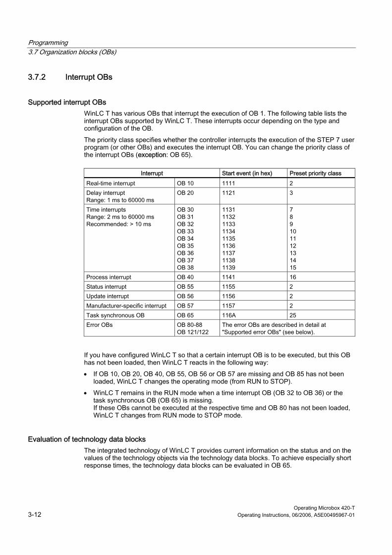
Supported interrupt OBs WinLC T has various OBs that interrupt the execution of OB 1. The following table lists the interrupt OBs supported by WinLC T. These interrupts occur depending on the type and configuration of the OB.
The priority class specifies whether the controller interrupts the execution of the STEP 7 user program (or other OBs) and executes the interrupt OB. You can change the priority class of the interrupt OBs (exception: OB 65).
Interrupt Start event (in hex) Preset priority class
Real-time interrupt OB 10 1111 2 Delay interrupt Range: 1 ms to 60000 ms
OB 20 1121 3
Time interrupts Range: 2 ms to 60000 ms Recommended: > 10 ms
OB 30 OB 31 OB 32 OB 33 OB 34 OB 35 OB 36 OB 37 OB 38
1131 1132 1133 1134 1135 1136 1137 1138 1139
7 8 9 10 11 12 13 14 15
Process interrupt OB 40 1141 16 Status interrupt OB 55 1155 2 Update interrupt OB 56 1156 2 Manufacturer-specific interrupt OB 57 1157 2 Task synchronous OB OB 65 116A 25 Error OBs OB 80-88
OB 121/122 The error OBs are described in detail at "Supported error OBs" (see below).
If you have configured WinLC T so that a certain interrupt OB is to be executed, but this OB has not been loaded, then WinLC T reacts in the following way:
• If OB 10, OB 20, OB 40, OB 55, OB 56 or OB 57 are missing and OB 85 has not been loaded, WinLC T changes the operating mode (from RUN to STOP).
• WinLC T remains in the RUN mode when a time interrupt OB (OB 32 to OB 36) or the task synchronous OB (OB 65) is missing. If these OBs cannot be executed at the respective time and OB 80 has not been loaded, WinLC T changes from RUN mode to STOP mode.
Evaluation of technology data blocks The integrated technology of WinLC T provides current information on the status and on the values of the technology objects via the technology data blocks. To achieve especially short response times, the technology data blocks can be evaluated in OB 65.

Programming 3.7 Organization blocks (OBs)
Operating Microbox 420-T Operating Instructions, 06/2006, A5E00495967-01 3-13
Notes on time interrupt OBs Depending on the interval parameterized for the time interrupt by means of the operating parameters, WinLC T starts the execution of the time interrupt OB at the appropriate time. The optimum interval for your application depends on the processing speed of your computer and the execution time of the cyclic OB. For the Microbox T, we recommend a minimum cycle time for time interrupts of 2 ms or the same as the DP cycle clock.
Jitter can occasionally override the start event for a cyclic OB, whereby WinLC T may change to STOP mode. Note the remarks on time resolution and jitter in the "General information on OBs" section. The following situations illustrate other factors that can influence the execution of the OB:
• The execution of the program in the OB needs longer than the permitted interval. If the execution of the program continually overrides the start event of the cyclic OB, WinLC T may change to STOP mode (if OB 80 has not been loaded).
• Programs in other priority classes often cause interruptions or have a long execution time and the controller cannot execute the cyclic OB at the specified time. If this occasionally causes an overload, WinLC T starts the cyclic OB after the first OB is completed.
• STEP 7 executes a task or function which prevents the controller executing the cyclic OB at the specified time.
If you configure a time interrupt OB (OB 30 to OB 38) so that it is to be executed at certain intervals, you must ensure that the program can be executed within this time and that your STEP 7 user program can also execute the OB within the assigned time.
Supported error OBs WinLC T has a number of error OBs. Some of these error OBs have a configured (assigned by the user) priority class, while other OBs (OB 121 and OB 122) take over the priority class of the block in which the error occurs.
The local variables for OB 121 and OB 122 receive the following information, which can be used by the STEP 7 user program to react to the error:
• The block type (Byte 4) and the number (Bytes 8 and 9) of the block causing the error.
• The address within the block (Bytes 10 and 11), in which the error has occurred.

Programming 3.7 Organization blocks (OBs)
Operating Microbox 420-T 3-14 Operating Instructions, 06/2006, A5E00495967-01
If the start event occurs for a certain error OB that has not been loaded, WinLC T changes the operating mode (from RUN to STOP).
Error Start event (in hex) Preset priority class
Time error OB 80 3501, 3502, 3505, 3507 26 Diagnostic interrupt OB 82 3842, 3942 26 Insert/remove interrupt OB 83 3861, 3863, 3864, 3865,
3961 26
CPU hardware fault (Windows malfunction)
OB 84 3585 26 (or 28)
Program execution error: • The start occurs for an
OB that has not been loaded.
• During the I/O cycle, WinLC T attempts to access a module or a DP slave that is defective or not connected.
OB 85 35A1, 35A2, 39B1, 39B2 26
Rack failure (distributed I/O): A node in the PROFIBUS DP network has failed or been restored.
OB 86 38C4, 38C5, 38C7, 38C8, 39C4, 39C5
26 (or 28)
Process interrupt: The execution of a program block has been aborted.
OB 88 3571, 3572, 3573, 3575, 3576, 3578, 357A
28
Programming error (Example: The user program attempts to address a time which is not available.)
OB 121 2521, 2522, 2523, 2524, 2525, 2526, 2527, 2528, 2529, 2530, 2531, 2532, 2533, 2534, 2535, 253A, 253C, 253E
I/O access error (Example: The user program attempts to access a defective module or a module that is not connected.)
OB 122 2942, 2943
Same priority class as the OB causing the error.
Detailed information about the OBs can be found in the STEP 7 online help or in the System Software for S7-300/400 System and Standard Functions reference manual.

Programming 3.8 System functions (SFCs)
Operating Microbox 420-T Operating Instructions, 06/2006, A5E00495967-01 3-15
3.8 3.8 System functions (SFCs)
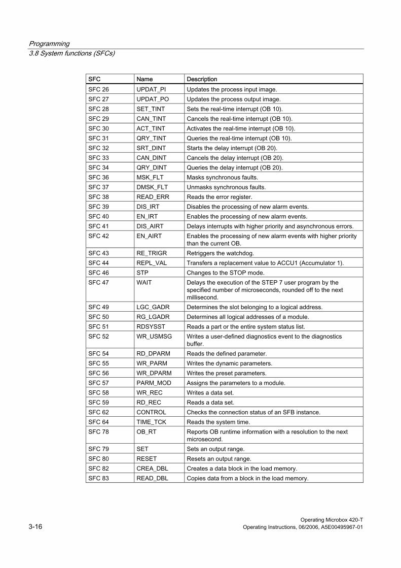
Supported system functions WinLC T contains system functions that can execute various tasks. The STEP 7 user program calls the SFC and transfers the required parameters. The SFC then performs the task and outputs the result. The SFCs supported by WinLC T are listed in the following table:
SFC Name Description
SFC 0 SET_CLK Sets the system clock. SFC 1 READ_CLK Reads the system clock. SFC 2 SET_RTM Sets the run-time meter. SFC 3 CTRL_RTM Starts or stops the run-time meter. SFC 4 READ_RTM Reads the run-time meter. SFC 5 GADR_LGC Determines the logical address of a channel. SFC 6 RD_SINFO Reads the start information of an OB. SFC 9 EN_MSG Enables block-related and symbol-related messages as well as
group status messages. SFC 10 DIS_MSG Disables block-related and symbol-related messages as well as
group status messages. SFC 11 DPSYNC_FR Synchronized groups of DP slaves. SFC 12 D_ACT_DP Disables and enables DP slaves. SFC 13 DP_NRM Reads the diagnostics data of a DP slave
Tested DP configuration: An ET 200M slave with a module with 8 inputs and 8 outputs and a module with 16 outputs.
SFC 14 DPRD_DAT Reads the consistent data of a DP slave. SFC 15 DPWR_DAT Writes the consistent data to a DP slave. SFC 17 ALARM_SQ Generates a block-related message that can be acknowledged. SFC 18 ALARM_S Generates a block-related message that can be permanently
acknowledged. SFC 19 ALARM_SC Queries the acknowledgement status of the last message
(SFC 17 or SFC 18). SFC 20 BLKMOV Copies variables. SFC 21 FILL Initializes a memory area.
1 word 50 words 100 words
SFC 22 CREAT_DB Creates a retentive data block in the working memory. The current values of the DB are saved after a warm restart.
SFC 23 DEL_DB Deletes a data block. WinLC T allows an application to delete a data block which is not relevant for the execution.
SFC 24 TEST_DB Provides information on a data block. In WinLC T, SFC 24 can output the DB length and write protection flags for data blocks that are not relevant for the execution. In spite of this, error code 80B2 is output for data blocks that are not relevant for the execution.
Programming 3.8 System functions (SFCs)
Operating Microbox 420-T 3-16 Operating Instructions, 06/2006, A5E00495967-01
SFC Name Description
SFC 26 UPDAT_PI Updates the process input image. SFC 27 UPDAT_PO Updates the process output image. SFC 28 SET_TINT Sets the real-time interrupt (OB 10). SFC 29 CAN_TINT Cancels the real-time interrupt (OB 10). SFC 30 ACT_TINT Activates the real-time interrupt (OB 10). SFC 31 QRY_TINT Queries the real-time interrupt (OB 10). SFC 32 SRT_DINT Starts the delay interrupt (OB 20). SFC 33 CAN_DINT Cancels the delay interrupt (OB 20). SFC 34 QRY_DINT Queries the delay interrupt (OB 20). SFC 36 MSK_FLT Masks synchronous faults. SFC 37 DMSK_FLT Unmasks synchronous faults. SFC 38 READ_ERR Reads the error register. SFC 39 DIS_IRT Disables the processing of new alarm events. SFC 40 EN_IRT Enables the processing of new alarm events. SFC 41 DIS_AIRT Delays interrupts with higher priority and asynchronous errors. SFC 42 EN_AIRT Enables the processing of new alarm events with higher priority
than the current OB. SFC 43 RE_TRIGR Retriggers the watchdog. SFC 44 REPL_VAL Transfers a replacement value to ACCU1 (Accumulator 1). SFC 46 STP Changes to the STOP mode. SFC 47 WAIT Delays the execution of the STEP 7 user program by the
specified number of microseconds, rounded off to the next millisecond.
SFC 49 LGC_GADR Determines the slot belonging to a logical address. SFC 50 RG_LGADR Determines all logical addresses of a module. SFC 51 RDSYSST Reads a part or the entire system status list. SFC 52 WR_USMSG Writes a user-defined diagnostics event to the diagnostics
buffer. SFC 54 RD_DPARM Reads the defined parameter. SFC 55 WR_PARM Writes the dynamic parameters. SFC 56 WR_DPARM Writes the preset parameters. SFC 57 PARM_MOD Assigns the parameters to a module. SFC 58 WR_REC Writes a data set. SFC 59 RD_REC Reads a data set. SFC 62 CONTROL Checks the connection status of an SFB instance. SFC 64 TIME_TCK Reads the system time. SFC 78 OB_RT Reports OB runtime information with a resolution to the next
microsecond. SFC 79 SET Sets an output range. SFC 80 RESET Resets an output range. SFC 82 CREA_DBL Creates a data block in the load memory. SFC 83 READ_DBL Copies data from a block in the load memory.

Programming 3.8 System functions (SFCs)
Operating Microbox 420-T Operating Instructions, 06/2006, A5E00495967-01 3-17
SFC Name Description
SFC 84 WRIT_DBL Writes a block in the load memory, so that the data is stored immediately. Blocks in the load memory, which are used for the restoration after incorrect program abort, can be updated during the program execution. Only use SFC 84 for larger segments of a database, not for frequent variable processing.
SFC 85 CREA_DB Creates a retentive or non-retentive DB, depending on the input parameter: • With a retentive DB, the current values of the DB are saved
after a warm restart (OB 100). • With a non-retentive DB, the current values of the DB are not
saved after a warm restart (OB 100). SFC 87 C_DIAG Determines the current status of all S7 connections.
Detailed information about the SFCs can be found in the STEP 7 online help or in the System Software for S7-300/400 System and Standard Functions reference manual.
Note Some SFCs require special consideration with respect to a possible Windows malfunction. Further information on this can be found under "Effects of SFC 22, SFC 23, SFC 82, SFC 83, SFC 84 or SFC 85" in the "Operation of WinLC T with a Windows malfunction" section.
Simultaneous execution of asynchronous SFCs The number of asynchronous OBs that may run simultaneously in WinLC T, is restricted according to the following rules:
• A maximum of five instances of the asynchronous system function SFC 51 (Index B1, B3) may run in WinLC T.
• A maximum of 20 asynchronous SFCs of the following SFCs may run in WinLC T: SFC 13, SFC 55, SFC 56, SFC 57, SFC 58 and SFC 59.
• A maximum of 32 asynchronous SFCs in any combination of the following SFCs may run in WinLC T: SFC 82, SFC 83 and SFC 84.
SFCs that can cause deviations in the cycle The following SFCs that can cause deviations in the cycle ("jitter"):
• SFC 22 (CREAT_DB)
• SFC 23 (DEL_DB)
• SFC 52 (WR_USMG)
• SFC 85 (CREA_DB)

Programming 3.8 System functions (SFCs)
Operating Microbox 420-T 3-18 Operating Instructions, 06/2006, A5E00495967-01
Notes for SFC 82, SFC 83 and SFC 84 In contrast to the S7-300, WinLC T supports a synchronous interface for SFC 82, SFC 83 and SFC 84 during STARTUP. WinLC T permits the first call (with REQ = 1) and the second call (with REQ = 0) in STARTUP mode, so that the processing can be completed during STARTUP.
The normal STEP 7 error codes are valid for SFC 82, SFC 83 and SFC 84. The error code 80C3 is also output. These SFCs output the error code 80C3, if WinLC T exceeds the limit of 32 SFC 82, SFC 83 and SFC 84 jobs that have not been executed.
Programming 3.9 System function blocks (SFBs)
Operating Microbox 420-T Operating Instructions, 06/2006, A5E00495967-01 3-19
3.9 3.9 System function blocks (SFBs)
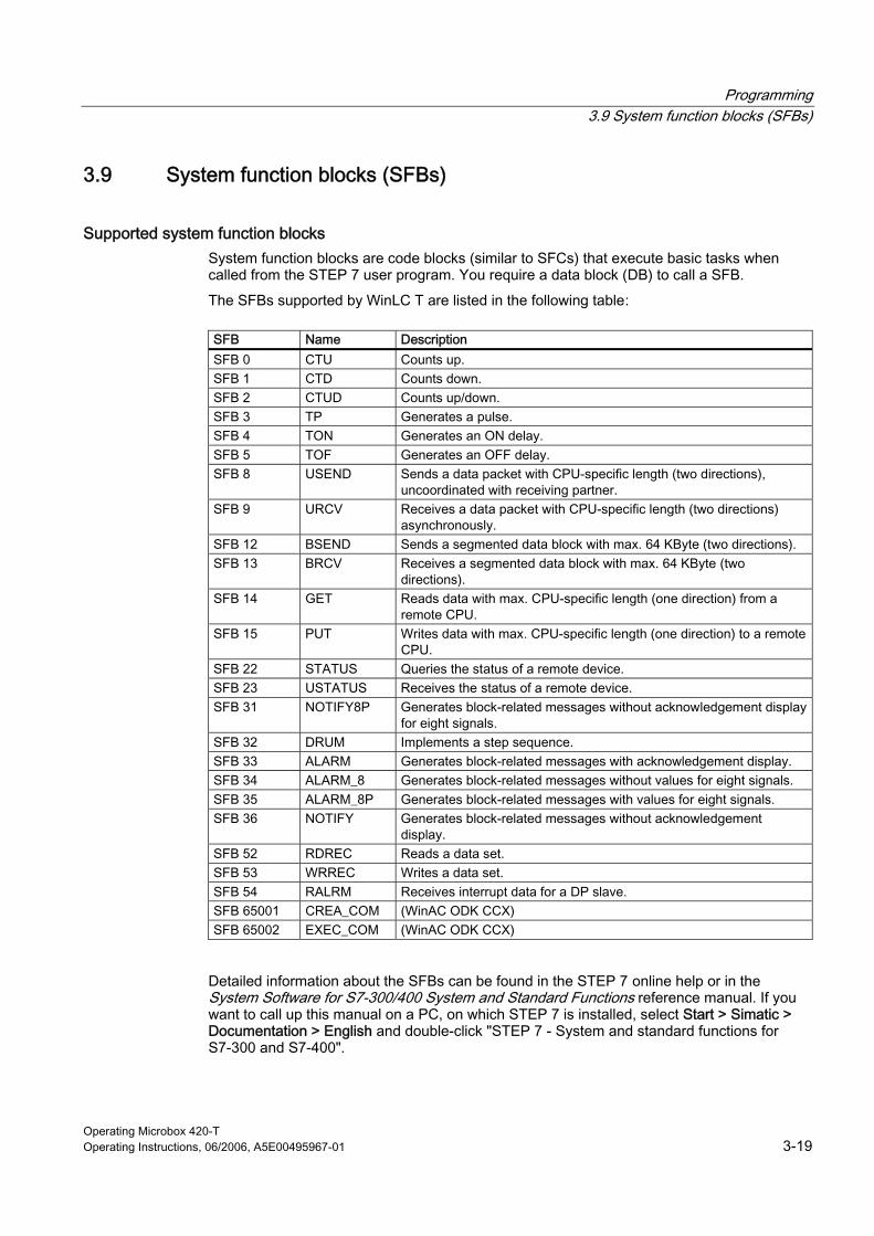
Supported system function blocks System function blocks are code blocks (similar to SFCs) that execute basic tasks when called from the STEP 7 user program. You require a data block (DB) to call a SFB.
The SFBs supported by WinLC T are listed in the following table:
SFB Name Description SFB 0 CTU Counts up. SFB 1 CTD Counts down. SFB 2 CTUD Counts up/down. SFB 3 TP Generates a pulse. SFB 4 TON Generates an ON delay. SFB 5 TOF Generates an OFF delay. SFB 8 USEND Sends a data packet with CPU-specific length (two directions),
uncoordinated with receiving partner. SFB 9 URCV Receives a data packet with CPU-specific length (two directions)
asynchronously. SFB 12 BSEND Sends a segmented data block with max. 64 KByte (two directions). SFB 13 BRCV Receives a segmented data block with max. 64 KByte (two
directions). SFB 14 GET Reads data with max. CPU-specific length (one direction) from a
remote CPU. SFB 15 PUT Writes data with max. CPU-specific length (one direction) to a remote
CPU. SFB 22 STATUS Queries the status of a remote device. SFB 23 USTATUS Receives the status of a remote device. SFB 31 NOTIFY8P Generates block-related messages without acknowledgement display
for eight signals. SFB 32 DRUM Implements a step sequence. SFB 33 ALARM Generates block-related messages with acknowledgement display. SFB 34 ALARM_8 Generates block-related messages without values for eight signals. SFB 35 ALARM_8P Generates block-related messages with values for eight signals. SFB 36 NOTIFY Generates block-related messages without acknowledgement
display. SFB 52 RDREC Reads a data set. SFB 53 WRREC Writes a data set. SFB 54 RALRM Receives interrupt data for a DP slave. SFB 65001 CREA_COM (WinAC ODK CCX) SFB 65002 EXEC_COM (WinAC ODK CCX)
Detailed information about the SFBs can be found in the STEP 7 online help or in the System Software for S7-300/400 System and Standard Functions reference manual. If you want to call up this manual on a PC, on which STEP 7 is installed, select Start > Simatic > Documentation > English and double-click "STEP 7 - System and standard functions for S7-300 and S7-400".
Programming 3.10 Technology functions
Operating Microbox 420-T 3-20 Operating Instructions, 06/2006, A5E00495967-01
3.10 3.10 Technology functions
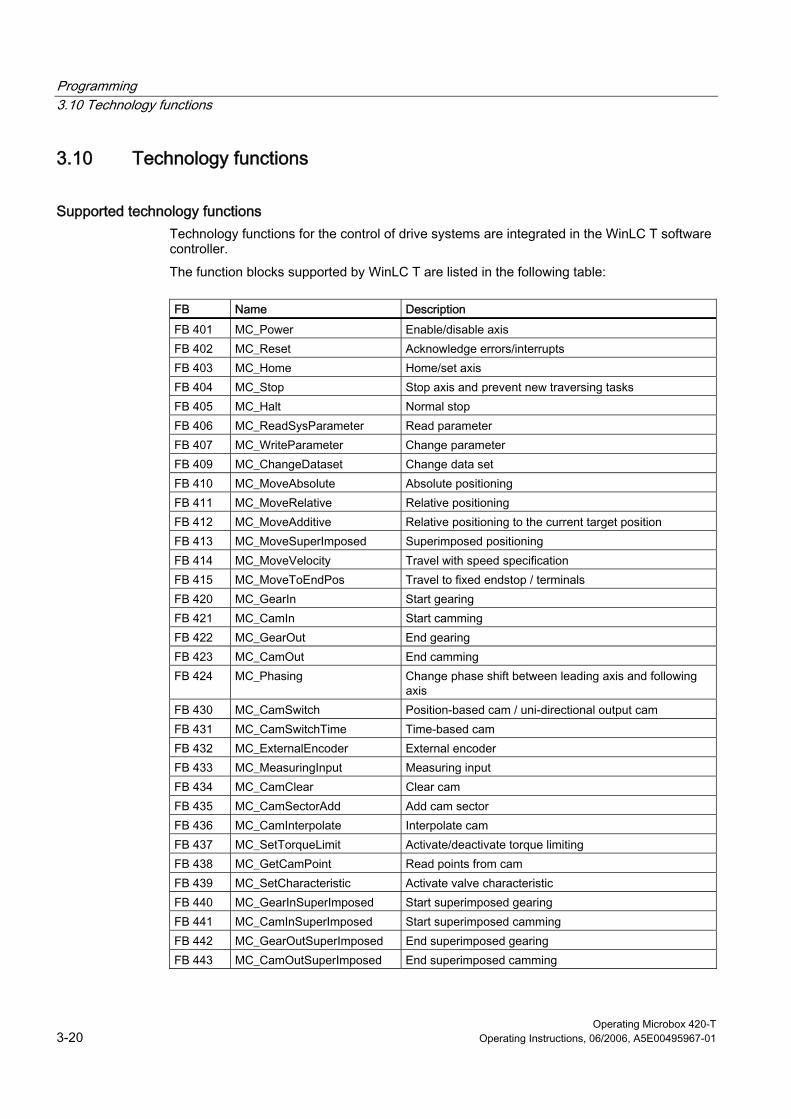
Supported technology functions Technology functions for the control of drive systems are integrated in the WinLC T software controller.
The function blocks supported by WinLC T are listed in the following table:
FB Name Description
FB 401 MC_Power Enable/disable axis FB 402 MC_Reset Acknowledge errors/interrupts FB 403 MC_Home Home/set axis FB 404 MC_Stop Stop axis and prevent new traversing tasks FB 405 MC_Halt Normal stop FB 406 MC_ReadSysParameter Read parameter FB 407 MC_WriteParameter Change parameter FB 409 MC_ChangeDataset Change data set FB 410 MC_MoveAbsolute Absolute positioning FB 411 MC_MoveRelative Relative positioning FB 412 MC_MoveAdditive Relative positioning to the current target position FB 413 MC_MoveSuperImposed Superimposed positioning FB 414 MC_MoveVelocity Travel with speed specification FB 415 MC_MoveToEndPos Travel to fixed endstop / terminals FB 420 MC_GearIn Start gearing FB 421 MC_CamIn Start camming FB 422 MC_GearOut End gearing FB 423 MC_CamOut End camming FB 424 MC_Phasing Change phase shift between leading axis and following
axis FB 430 MC_CamSwitch Position-based cam / uni-directional output cam FB 431 MC_CamSwitchTime Time-based cam FB 432 MC_ExternalEncoder External encoder FB 433 MC_MeasuringInput Measuring input FB 434 MC_CamClear Clear cam FB 435 MC_CamSectorAdd Add cam sector FB 436 MC_CamInterpolate Interpolate cam FB 437 MC_SetTorqueLimit Activate/deactivate torque limiting FB 438 MC_GetCamPoint Read points from cam FB 439 MC_SetCharacteristic Activate valve characteristic FB 440 MC_GearInSuperImposed Start superimposed gearing FB 441 MC_CamInSuperImposed Start superimposed camming FB 442 MC_GearOutSuperImposed End superimposed gearing FB 443 MC_CamOutSuperImposed End superimposed camming
Programming 3.10 Technology functions
Operating Microbox 420-T Operating Instructions, 06/2006, A5E00495967-01 3-21
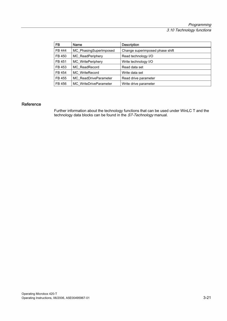
FB Name Description
FB 444 MC_PhasingSuperImposed Change superimposed phase shift FB 450 MC_ReadPeriphery Read technology I/O FB 451 MC_WritePeriphery Write technology I/O FB 453 MC_ReadRecord Read data set FB 454 MC_WriteRecord Write data set FB 455 MC_ReadDriveParameter Read drive parameter FB 456 MC_WriteDriveParameter Write drive parameter
Reference Further information about the technology functions that can be used under WinLC T and the technology data blocks can be found in the S7-Technology manual.
Programming 3.11 System clock and run-time meter
Operating Microbox 420-T 3-22 Operating Instructions, 06/2006, A5E00495967-01
3.11 3.11 System clock and run-time meter
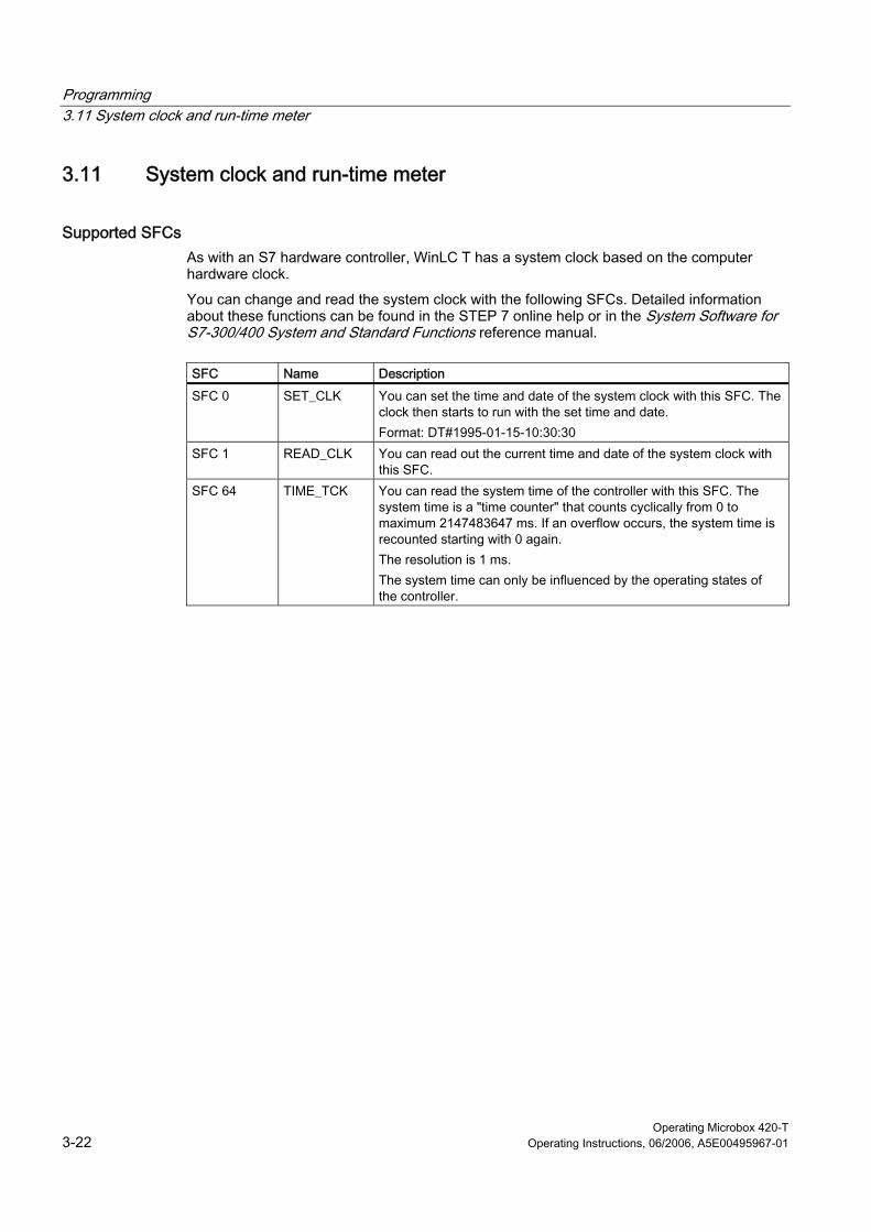
Supported SFCs As with an S7 hardware controller, WinLC T has a system clock based on the computer hardware clock.
You can change and read the system clock with the following SFCs. Detailed information about these functions can be found in the STEP 7 online help or in the System Software for S7-300/400 System and Standard Functions reference manual.
SFC Name Description
SFC 0 SET_CLK You can set the time and date of the system clock with this SFC. The clock then starts to run with the set time and date. Format: DT#1995-01-15-10:30:30
SFC 1 READ_CLK You can read out the current time and date of the system clock with this SFC.
SFC 64 TIME_TCK You can read the system time of the controller with this SFC. The system time is a "time counter" that counts cyclically from 0 to maximum 2147483647 ms. If an overflow occurs, the system time is recounted starting with 0 again. The resolution is 1 ms. The system time can only be influenced by the operating states of the controller.

Programming 3.12 Porting STEP 7 programs
Operating Microbox 420-T Operating Instructions, 06/2006, A5E00495967-01 3-23
3.12 3.12 Porting STEP 7 programs
3.12.1 Porting a STEP 7 program for WinAC RTX
Introduction You can execute a STEP 7 program, which was written for WinAC RTX, on the Microbox T in WinLC T. However, there are some restrictions.
Code blocks supported by WinLC T WinLC T supports the same code blocks for the processing of a program as WinAC RTX V4.2, with the following exceptions:
• OB 61, OB 62, OB 63 and OB 64 are not supported by WinLC T.
• No cold start: WinLC T does not support OB 102.
• SFC 103, SFC 112, SFC 113, SFC 114, SFC 126 and SFC 127 are not supported by WinLC T.
Restrictions Take the following restrictions into account:
• The program execution on the Microbox T can be different than that under WinAC RTX on a PC.
• The maximum size of the WinLC T address area is 2 KByte.
3.12.2 Porting a STEP 7 program for CPU317T
Introduction You can execute a STEP 7 program, which was written for a CPU317T, on the Microbox T.
Restrictions Take the following restrictions into account:
• The program execution on the Microbox T can be different than that on the CPU317T.
• The maximum size of the WinLC T address area is 2 KByte.
• In contrast to a SIMATIC CPU-300, the size of the process image can be set. During the porting, the size must be set as for the CPU317T.
• In contrast to the CPU317T, the devices connected to the DP and the DP(DRIVE) interface have a common address area. Any resulting address conflicts must be resolved during the porting.
Programming 3.13 Using WinAC ODK on the Microbox T
Operating Microbox 420-T 3-24 Operating Instructions, 06/2006, A5E00495967-01
3.13 3.13 Using WinAC ODK on the Microbox T
WinAC ODK interfaces under WinLC T
Note WinAC ODK is not part of WinLC T. It can be purchased as an option package.
The following user-specific applications can be implemented in your control jobs with the WinAC Open Development Kit (ODK) interfaces:
• Custom Code Extension (CCX): Enables your control program to call user-specific DLLs directly from the control program being executed by the PLC.
• Shared Memory Extension (SMX): Enables a very fast and efficient data exchange between the PLC and an application via direct access to a specified PI/PO area (via dual-port RAM).
• Controller Management Interface (CMI): Enables the functionality of the WinLC control panel to be embedded in a user-specific application.
Restrictions If you use WinAC ODK with WinLC T, you must take the following restrictions into account:
• You can only implement applications that run under Windows with the Custom Code Extension (CCX) interface.
WinLC T does not support the implementation of real-time applications with this interface.
• Modifications have been made in WinLC T for the Controller Management Interface (CMI).
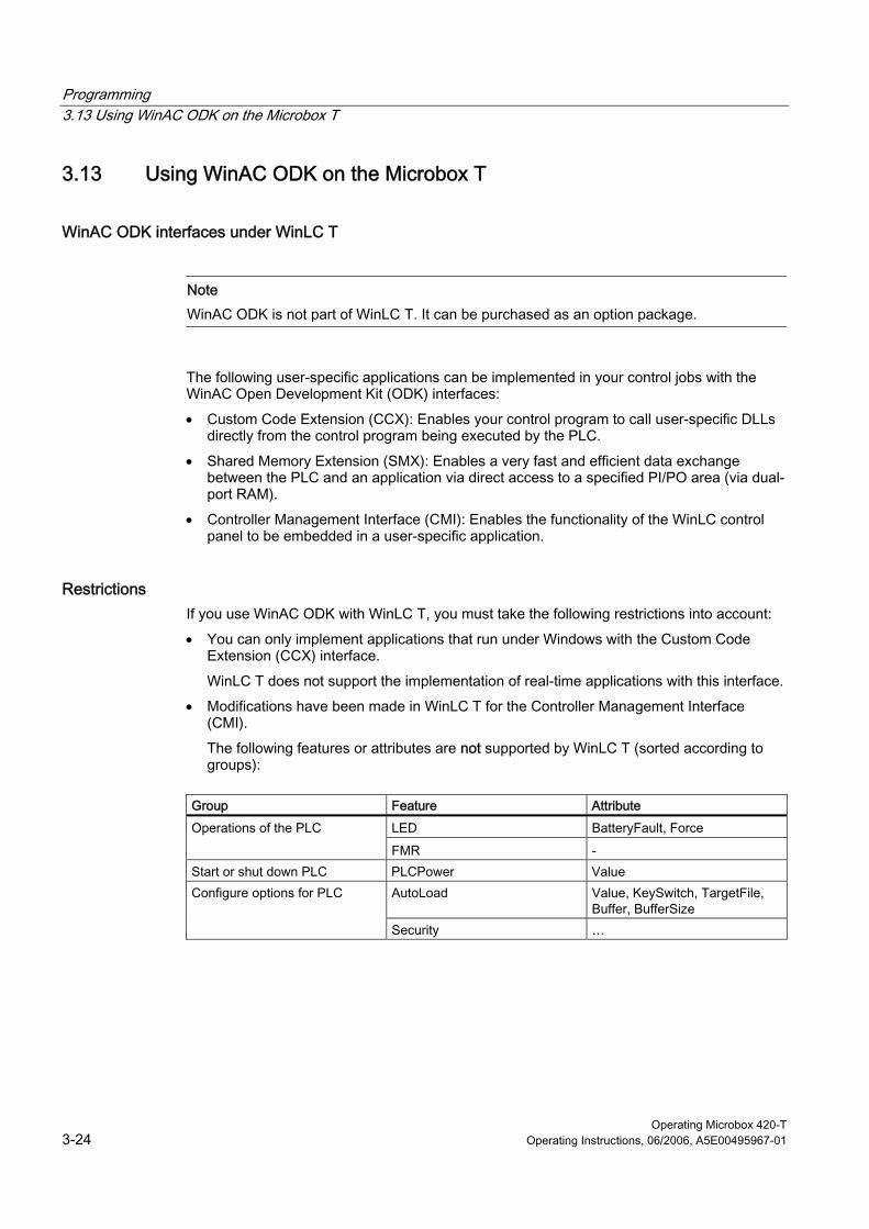
The following features or attributes are not supported by WinLC T (sorted according to groups):
Group Feature Attribute
LED BatteryFault, Force Operations of the PLC
FMR - Start or shut down PLC PLCPower Value
AutoLoad Value, KeySwitch, TargetFile, Buffer, BufferSize
Configure options for PLC
Security …
Programming 3.13 Using WinAC ODK on the Microbox T
Operating Microbox 420-T Operating Instructions, 06/2006, A5E00495967-01 3-25
Group Feature Attribute
Priority Value, LowerLimit, UpperLimit, Normal, Critical
MinCycleTime Value, LowerLimit, UpperLimit MinSleepTime Value, LowerLimit, UpperLimit OBExecution WakeInterval, SleepInterval,
DefaultWakeInterval, DefaultSleepInterval, UpperLimit, LowerLimit
Timing ExecTimeMin, ExecTimeMax, ExecTimeAverage, ExecTimeLast, SleepIntervalCounter
Tune performance of WinLC controller
Usage PC, PLC, CPUCount, CPU_
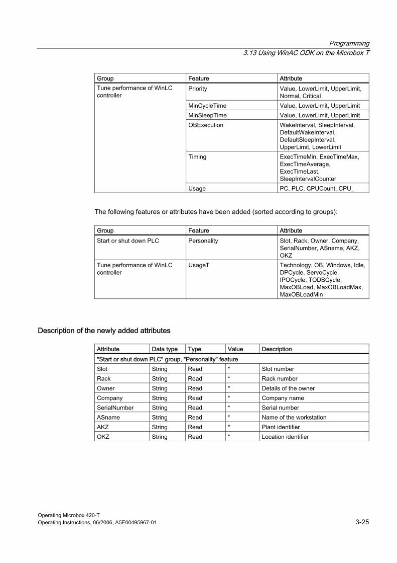
The following features or attributes have been added (sorted according to groups):
Group Feature Attribute
Start or shut down PLC Personality Slot, Rack, Owner, Company, SerialNumber, ASname, AKZ, OKZ
Tune performance of WinLC controller
UsageT Technology, OB, Windows, Idle, DPCycle, ServoCycle, IPOCycle, TODBCycle, MaxOBLoad, MaxOBLoadMax, MaxOBLoadMin
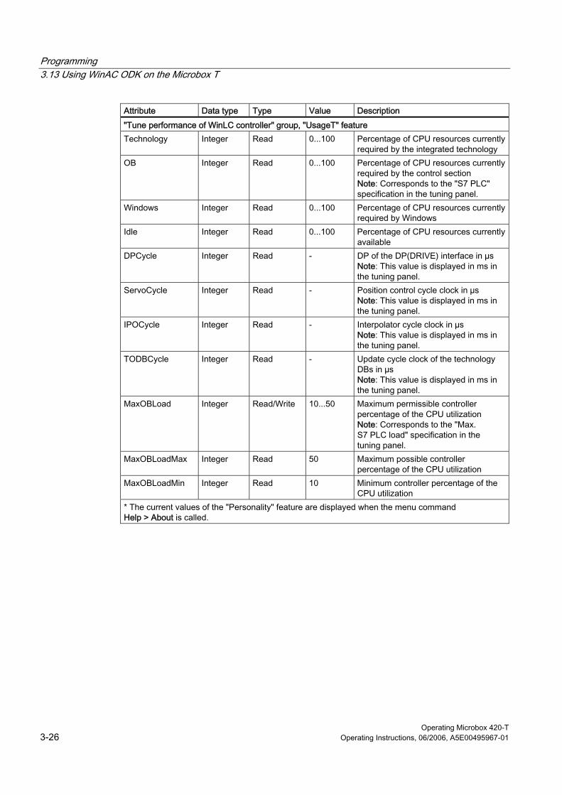
Description of the newly added attributes
Attribute Data type Type Value Description
"Start or shut down PLC" group, "Personality" feature Slot String Read * Slot number Rack String Read * Rack number Owner String Read * Details of the owner Company String Read * Company name SerialNumber String Read * Serial number ASname String Read * Name of the workstation AKZ String Read * Plant identifier OKZ String Read * Location identifier
Programming 3.13 Using WinAC ODK on the Microbox T
Operating Microbox 420-T 3-26 Operating Instructions, 06/2006, A5E00495967-01
Attribute Data type Type Value Description
"Tune performance of WinLC controller" group, "UsageT" feature Technology Integer Read 0...100 Percentage of CPU resources currently
required by the integrated technology OB Integer Read 0...100 Percentage of CPU resources currently
required by the control section Note: Corresponds to the "S7 PLC" specification in the tuning panel.
Windows Integer Read 0...100 Percentage of CPU resources currently required by Windows
Idle Integer Read 0...100 Percentage of CPU resources currently available
DPCycle Integer Read - DP of the DP(DRIVE) interface in µs Note: This value is displayed in ms in the tuning panel.
ServoCycle Integer Read - Position control cycle clock in µs Note: This value is displayed in ms in the tuning panel.
IPOCycle Integer Read - Interpolator cycle clock in µs Note: This value is displayed in ms in the tuning panel.
TODBCycle Integer Read - Update cycle clock of the technology DBs in µs Note: This value is displayed in ms in the tuning panel.
MaxOBLoad Integer Read/Write 10...50 Maximum permissible controller percentage of the CPU utilization Note: Corresponds to the "Max. S7 PLC load" specification in the tuning panel.
MaxOBLoadMax Integer Read 50 Maximum possible controller percentage of the CPU utilization
MaxOBLoadMin Integer Read 10 Minimum controller percentage of the CPU utilization
* The current values of the "Personality" feature are displayed when the menu command Help > About is called.
Programming 3.14 Operation of WinLC T with a Windows malfunction
Operating Microbox 420-T Operating Instructions, 06/2006, A5E00495967-01 3-27
3.14 3.14 Operation of WinLC T with a Windows malfunction
Description WinLC T supports OB 84 (CPU hardware fault), with which you can correctly shut down your process, if a Windows malfunction occurs while WinLC T is in operation. Then one of the following situations occurs:
• If WinLC T is in RUN mode and the user program receives OB 84, WinLC T starts OB 84 and remains in RUN mode until the controller is switched to STOP mode. Windows only completes the shutdown of the system after WinLC T has changed to STOP mode, either by calling SFC 46 or by changing to STOP mode.
• If WinLC T is in RUN mode and the user program does not receive an OB 84, WinLC T changes to STOP mode and Windows then completes the shutdown of the system.
• If WinLC T in STOP mode, Windows is closed completely.
The operation of WinLC T with a Windows malfunction can be influenced by SFC 22, SFC 82, SFC 83, SFC 84 or SFC 85.
You can configure Windows and WinLC T for an automatic restart after a Windows malfunction.
Restrictions The following restrictions apply if Windows shuts down:
• The WinLC T control panel is not available.
• Some system functions are deactivated, including SFC 22, SFC 82, SFC 83, SFC 84 and SFC 85.
• Block operations are unsuccessful and an error code is output.
• Communication with Windows applications is not available.
• It may not be possible to send alarm messages.
• PG/OP communication via the Ethernet interface no longer functions.
• WinAC ODK can no longer be used.
• The connection to the integrated technology is interrupted. This also means that no diagnosis of the integrated technology is possible.
Programming 3.14 Operation of WinLC T with a Windows malfunction
Operating Microbox 420-T 3-28 Operating Instructions, 06/2006, A5E00495967-01
Effects of SFC 22, SFC 23, SFC 82, SFC 83, SFC 84 or SFC 85 on WinLC T If a Windows malfunction occurs while WinLC T is in RUN mode, WinLC T tries to stay in RUN mode and starts OB 84. However, the operation of WinLC T during a Windows malfunction can be adversely affected by SFC 22, SFC 23, SFC 82, SFC 83, SFC 84 or SFC 85.
In most cases, SFC 22, SFC 23, SFC 82, SFC 83, SFC 84 and SFC 85 output error code 8092 for a Windows malfunction. Applications that must continue to run after a Windows malfunction can query on this error code. If, however, one of these SFCs is called during the Windows malfunction, the SFC cannot output error code 8092 and WinLC T cannot start OB 84.
Warning Certain SFCs, if they are active at the time of the malfunction, can cause the WinLC T to no longer react:
• If SFC 22, SFC 23 or SFC 85 are in the call of a Windows function at the time of the malfunction, the SFC cannot return from the SFC call and WinLC T cannot maintain the control of the process. In this case, the I/O time monitoring deactivates the inputs and outputs.
• If SFC 82, SFC 83 or SFC 84 are in the call of a Windows function at the time of the malfunction, WinLC T tries to remain in the RUN mode (and maintain the control of the process), but background functions, including some communication functions, may crash. If you switch WinLC T to the STOP mode, whether program-controlled or via user access from a remote system, this can affect the shutdown operation of the computers.
A Windows malfunction that causes the controller or the background functions to crash, can damage process devices or injure personnel. You can prevent this through appropriate safety precautions during the development of your STEP 7 user program.
If your process application has to survive a Windows malfunction, only call these SFCs (SFC 22, SFC 23, SFC 82, SFC 83, SFC 84 or SFC 85) during the initialization (during the execution of OB 100) or in uncritical parts of the control process.
Automatic restart of WinLC T after a Windows malfunction If Windows is configured so that it automatically restarts after a Windows malfunction, WinLC T will restart automatically if it has been configured for startup after PC start. (You can set up Windows accordingly by opening the "System Properties" dialog box with Start > Control panel > System. In the "Start and Recovery" section of the "Advanced" tab, click "Settings" to open the "Startup and Recovery" dialog box. You can activate the "Automatically restart" option in the "System failure" section. This option is activated per default.)
When WinLC T is restarted, it works with the program loaded last and executes OB 100 if it is present. WinLC T starts OB 100 with event 1382 (hex). The current/last startup type is specified in the diagnostics buffer as "Automatic restart (warm restart) after unbuffered POWER ON (with overall reset of the system)".
You can program OB 100 so that it reacts to event 1382. Detailed information can be found in the STEP 7 online help or in the System Software for S7-300/400 System and Standard Functions reference manual.
Programming 3.15 Operation of WinLC T with a technology malfunction
Operating Microbox 420-T Operating Instructions, 06/2006, A5E00495967-01 3-29
3.15 3.15 Operation of WinLC T with a technology malfunction
Response of WinLC T With a malfunction of the technology, the control panel can no longer be used for the operation of WinLC T.
The error messages generated by the malfunction are written to the Eventlog file.
Caution If the EWF (Enhanced Write Filter) is active, the Eventlog file will be deleted when the Microbox T is switched off.
The applications running under Windows will continue to be executed with a technology malfunction.
Reaction to a technology malfunction To find the error source, proceed as follows:
1. Read the error messages in the Eventlog file.
2. Look at the diagnostics information in the diagnostics buffer of the technology with S7T Config.
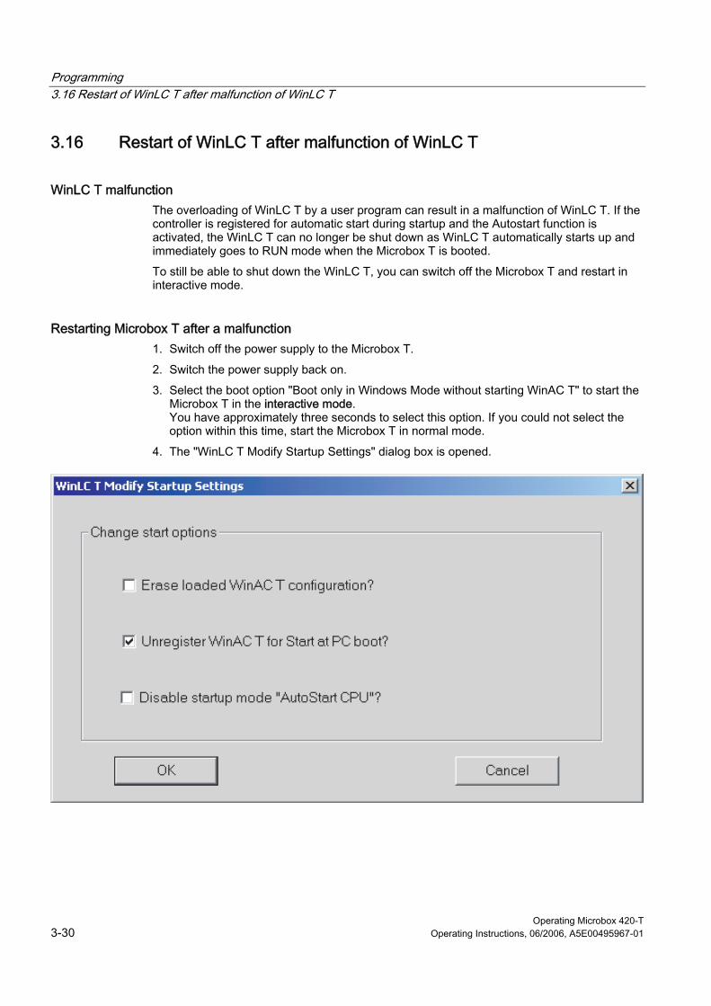
Programming 3.16 Restart of WinLC T after malfunction of WinLC T
Operating Microbox 420-T 3-30 Operating Instructions, 06/2006, A5E00495967-01
3.16 3.16 Restart of WinLC T after malfunction of WinLC T
WinLC T malfunction The overloading of WinLC T by a user program can result in a malfunction of WinLC T. If the controller is registered for automatic start during startup and the Autostart function is activated, the WinLC T can no longer be shut down as WinLC T automatically starts up and immediately goes to RUN mode when the Microbox T is booted.
To still be able to shut down the WinLC T, you can switch off the Microbox T and restart in interactive mode.
Restarting Microbox T after a malfunction 1. Switch off the power supply to the Microbox T.
2. Switch the power supply back on.
3. Select the boot option "Boot only in Windows Mode without starting WinAC T" to start the Microbox T in the interactive mode. You have approximately three seconds to select this option. If you could not select the option within this time, start the Microbox T in normal mode.
4. The "WinLC T Modify Startup Settings" dialog box is opened.

Programming 3.16 Restart of WinLC T after malfunction of WinLC T
Operating Microbox 420-T Operating Instructions, 06/2006, A5E00495967-01 3-31
1. Change the start options according to your requirements. You can reset the registration of the controller for automatic start during startup and deactivate the Autostart function.
2. Click "OK" to confirm the changes.
Result: The Microbox T starts with the settings you changed.

Programming 3.16 Restart of WinLC T after malfunction of WinLC T
Operating Microbox 420-T 3-32 Operating Instructions, 06/2006, A5E00495967-01
Operating Microbox 420-T Operating Instructions, 06/2006, A5E00495967-01 4-1
Operation and functions of the controller 44.1 4.1 Overview
Panel structure The user interface of the WinLC T software control (controller) essentially consists of three components:
• Control panel for the operation of the controller
• Tuning panel to display and set the operational performance of the controller
• Diagnostics buffer for the display of the diagnostics information
The tuning panel and the diagnostics buffer are called from the control panel.
Note The following shows the panel after being switched to the "German" language selection.
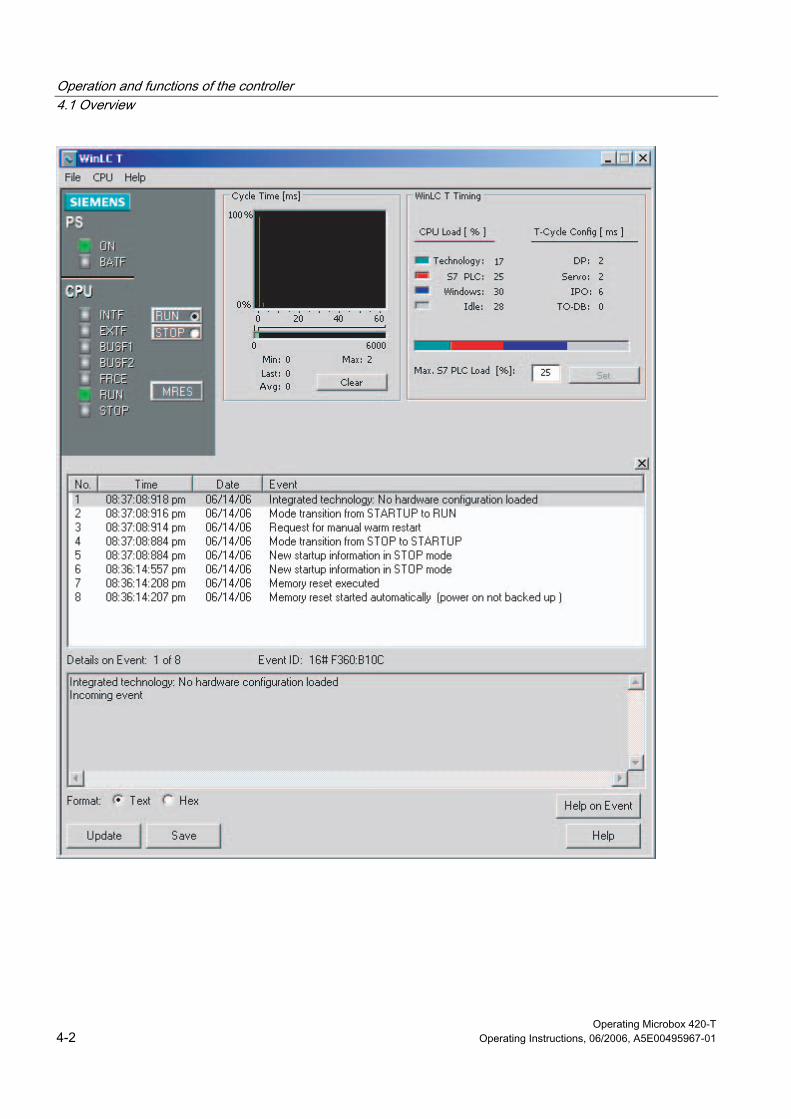
Operation and functions of the controller 4.1 Overview
Operating Microbox 420-T 4-2 Operating Instructions, 06/2006, A5E00495967-01
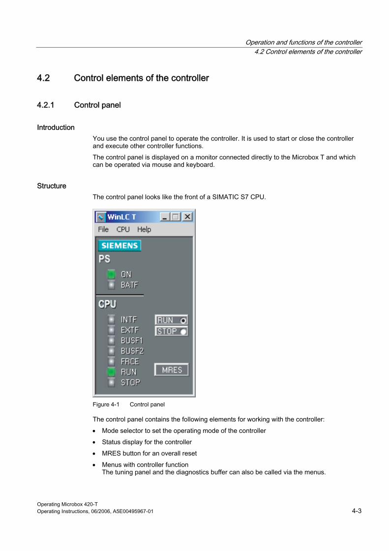
Operation and functions of the controller 4.2 Control elements of the controller
Operating Microbox 420-T Operating Instructions, 06/2006, A5E00495967-01 4-3
4.2 4.2 Control elements of the controller
4.2.1 Control panel
Introduction You use the control panel to operate the controller. It is used to start or close the controller and execute other controller functions.
The control panel is displayed on a monitor connected directly to the Microbox T and which can be operated via mouse and keyboard.
Structure The control panel looks like the front of a SIMATIC S7 CPU.
Figure 4-1 Control panel
The control panel contains the following elements for working with the controller:
• Mode selector to set the operating mode of the controller
• Status display for the controller
• MRES button for an overall reset
• Menus with controller function The tuning panel and the diagnostics buffer can also be called via the menus.

Operation and functions of the controller 4.2 Control elements of the controller
Operating Microbox 420-T 4-4 Operating Instructions, 06/2006, A5E00495967-01
Icon for WinLC T in the Windows taskbar The icon is displayed in the Windows taskbar when the controller is in operation. If the controller is in operation and the control panel is closed, you can double-click this icon to open the control panel.
The icon will be displayed with a colored frame that depends on the controller mode:
• A green frame indicates that the controller is in the RUN mode.
• A yellow frame indicates that the controller is in the STOP mode.
• A red frame indicates that the controller is in the fault state.
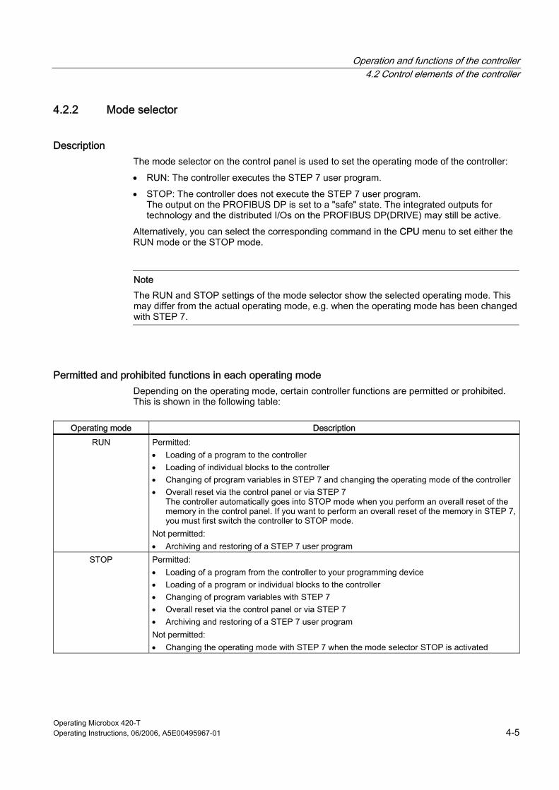
Operation and functions of the controller 4.2 Control elements of the controller
Operating Microbox 420-T Operating Instructions, 06/2006, A5E00495967-01 4-5
4.2.2 Mode selector
Description The mode selector on the control panel is used to set the operating mode of the controller:
• RUN: The controller executes the STEP 7 user program.
• STOP: The controller does not execute the STEP 7 user program. The output on the PROFIBUS DP is set to a "safe" state. The integrated outputs for technology and the distributed I/Os on the PROFIBUS DP(DRIVE) may still be active.
Alternatively, you can select the corresponding command in the CPU menu to set either the RUN mode or the STOP mode.
Note The RUN and STOP settings of the mode selector show the selected operating mode. This may differ from the actual operating mode, e.g. when the operating mode has been changed with STEP 7.
Permitted and prohibited functions in each operating mode Depending on the operating mode, certain controller functions are permitted or prohibited. This is shown in the following table:
Operating mode Description
RUN Permitted: • Loading of a program to the controller • Loading of individual blocks to the controller • Changing of program variables in STEP 7 and changing the operating mode of the controller • Overall reset via the control panel or via STEP 7
The controller automatically goes into STOP mode when you perform an overall reset of the memory in the control panel. If you want to perform an overall reset of the memory in STEP 7, you must first switch the controller to STOP mode.
Not permitted: • Archiving and restoring of a STEP 7 user program
STOP Permitted: • Loading of a program from the controller to your programming device • Loading of a program or individual blocks to the controller • Changing of program variables with STEP 7 • Overall reset via the control panel or via STEP 7 • Archiving and restoring of a STEP 7 user program Not permitted: • Changing the operating mode with STEP 7 when the mode selector STOP is activated
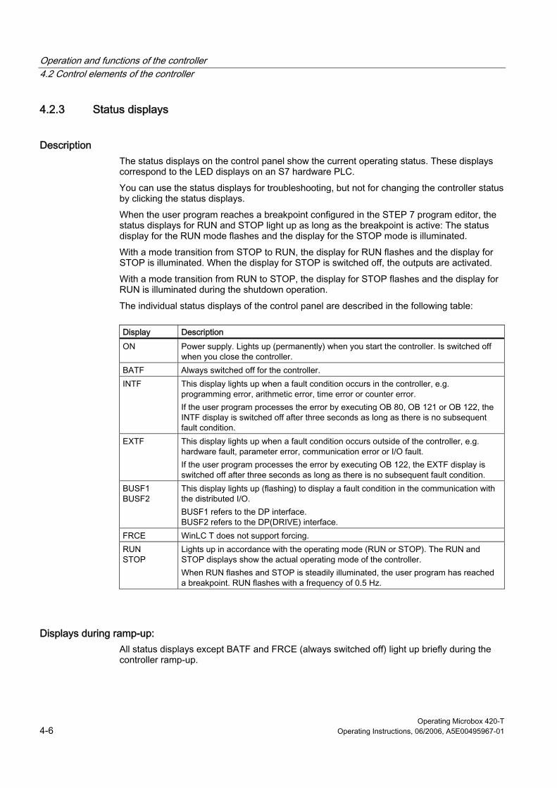
Operation and functions of the controller 4.2 Control elements of the controller
Operating Microbox 420-T 4-6 Operating Instructions, 06/2006, A5E00495967-01
4.2.3 Status displays
Description The status displays on the control panel show the current operating status. These displays correspond to the LED displays on an S7 hardware PLC.
You can use the status displays for troubleshooting, but not for changing the controller status by clicking the status displays.
When the user program reaches a breakpoint configured in the STEP 7 program editor, the status displays for RUN and STOP light up as long as the breakpoint is active: The status display for the RUN mode flashes and the display for the STOP mode is illuminated.
With a mode transition from STOP to RUN, the display for RUN flashes and the display for STOP is illuminated. When the display for STOP is switched off, the outputs are activated.
With a mode transition from RUN to STOP, the display for STOP flashes and the display for RUN is illuminated during the shutdown operation.
The individual status displays of the control panel are described in the following table:
Display Description
ON Power supply. Lights up (permanently) when you start the controller. Is switched off when you close the controller.
BATF Always switched off for the controller. INTF This display lights up when a fault condition occurs in the controller, e.g.
programming error, arithmetic error, time error or counter error. If the user program processes the error by executing OB 80, OB 121 or OB 122, the INTF display is switched off after three seconds as long as there is no subsequent fault condition.
EXTF This display lights up when a fault condition occurs outside of the controller, e.g. hardware fault, parameter error, communication error or I/O fault. If the user program processes the error by executing OB 122, the EXTF display is switched off after three seconds as long as there is no subsequent fault condition.
BUSF1 BUSF2
This display lights up (flashing) to display a fault condition in the communication with the distributed I/O. BUSF1 refers to the DP interface. BUSF2 refers to the DP(DRIVE) interface.
FRCE WinLC T does not support forcing. RUN STOP
Lights up in accordance with the operating mode (RUN or STOP). The RUN and STOP displays show the actual operating mode of the controller. When RUN flashes and STOP is steadily illuminated, the user program has reached a breakpoint. RUN flashes with a frequency of 0.5 Hz.
Displays during ramp-up: All status displays except BATF and FRCE (always switched off) light up briefly during the controller ramp-up.

Operation and functions of the controller 4.2 Control elements of the controller
Operating Microbox 420-T Operating Instructions, 06/2006, A5E00495967-01 4-7
Flashing displays Flashing patterns of the RUN and STOP displays provide further information about the controller or the STEP 7 user program:
Display
RUN STOP Description
Flashing, 2 Hz
Flashing, 2 Hz The controller is defective. All status displays flash.
Flashing, 0.5 Hz
On The STEP 7 user program has stopped at a breakpoint.
Flashing, 2 Hz
On A warm restart is being executed. The RUN display flashes until the restart is completed. The time required for the warm restart depends on the time the startup OB requires for the execution.
Off Flashing, 0.5 Hz An overall reset of the controller must be performed. Off Flashing, 2 Hz An overall reset (MRES) is being performed. On Flashing, 2 Hz The controller is in the "Shutdown" state. Flashing, 0.5 Hz
Flashing, 2 Hz The STEP 7 user program has stopped at a breakpoint. The integrated technology is in the "Shutdown" state.
Shutdown The following happens during shutdown:
1. The control section of the controller is already in STOP mode. The outputs of the distributed I/Os on DP are deactivated. The STOP display flashes at 2 Hz. The RUN display is illuminated.
2. The outputs for the integrated technology and the distributed I/Os on the DP(DRIVE) are still active.
3. The integrated technology shuts down the drives on the DP(DRIVE) in a controlled manner.
4. The integrated technology then also switches to STOP. The outputs for the integrated technology and the distributed I/Os on the DP(DRIVE) are deactivated. The STOP display is illuminated.
The maximum duration of shutdown depends on your configuration in S7T Config.
Warning The distributed I/Os on DP(DRIVE) cannot be controlled from the user program during "shutdown". The outputs that can be controlled with MC_WritePeriphery retain their last current value.
Operation and functions of the controller 4.2 Control elements of the controller
Operating Microbox 420-T 4-8 Operating Instructions, 06/2006, A5E00495967-01
Measure when the STOP display flashes slowly When the STOP display flashes slowly, you must perform an overall reset of the controller with the MRES command.
Measure when all status displays flash If all status displays flash simultaneously, the controller is in the fault state and has detected a fault condition, which cannot be corrected by an overall reset of the memory with the MRES menu command. You must perform the following steps to correct this state: 1. Close the controller. 2. Restart the controller. The STOP display flashes and the RUN display is switched off. 3. Perform an overall reset of the memory with the MRES command. 4. Load the user program and the system configuration with STEP 7 or restore an archived
user program.
If the problem cannot be corrected by closing and restarting the controller, you may have to restart your Microbox T.
4.2.4 MRES button
MRES (overall reset) command The MRES (overall reset) command resets the controller to the default settings. To do this, select the MRES button on the control panel. Alternatively, you can select the CPU > MRES menu command.
If required, the MRES command switches the controller to the STOP mode and then performs the following tasks: • The entire STEP 7 user program (OBs, DBs, FCs, FBs) and the system data (the
configuration) are deleted not only in the working memory but also in the load memory. • The memory areas (I, O, M, T and C) are reset to 0. • The preset system configuration, e.g. the size of the areas in the process image and the
size of the diagnostics buffer, are reloaded. • All active communication jobs, e.g. TIS, and the open communication are deleted. In
addition, all online connections are disconnected, e.g. STEP 7, WinCC, PROFIBUS or S7 communication.
The network address and the set baud rate of the IE module as well as the contents of the diagnostics buffer are retained during the overall reset.
The STOP display flashes during the overall reset. After the memory has been reset, the preset size is reset for the diagnostics buffer. The memory areas of the inputs (I) and outputs (O) are also reset to the preset sizes. You must then configure your specific values for these values again after the overall reset.
Usually you perform the MRES before you load a new program to the controller. You must perform an overall reset when the STOP display on the control panel flashes slowly and this notifies you of one of the following conditions: • Errors have been detected in the working memory, e.g. the size of the user program is
greater than that of the working memory. • The controller has been switched off and then on again as response to a fault state.

Operation and functions of the controller 4.3 Functions of the controller
Operating Microbox 420-T Operating Instructions, 06/2006, A5E00495967-01 4-9
4.3 4.3 Functions of the controller
4.3.1 Starting and closing the controller
Settings The following settings affect the starting and closing of the controller:
• Activation of the autostart function
• Configuration of the controller for start at PC start
Starting WinLC T If the control panel is not open, proceed in one of the following ways to start the control panel and WinLC T:
• Select Start > All programs > Simatic > PC-based control. Then select the name of your WinLC T controller. After you have loaded the user program in WinLC T, the name in the menu corresponds to the name in STEP 7.
• Double-click the WinLC T icon on the desktop:
If the control panel is open, but WinLC T not in operation, select CPU > Start controller.
Closing WinLC T Select CPU > Close controller to close down the controller. This command does not close the control panel. The command is only available on the control panel when the controller is in operation. After you have closed down the controller, you can still change the options.
Closing the control panel The File > Exit menu command closes the control panel.
Caution Closing the control panel does not close down the controller ("closed"). The state of the switches and the status displays are stored in the controller.
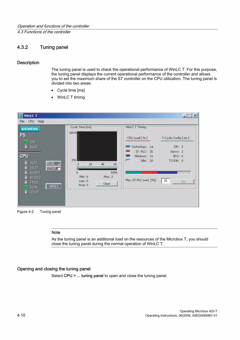
Operation and functions of the controller 4.3 Functions of the controller
Operating Microbox 420-T 4-10 Operating Instructions, 06/2006, A5E00495967-01
4.3.2 Tuning panel
Description The tuning panel is used to check the operational performance of WinLC T. For this purpose, the tuning panel displays the current operational performance of the controller and allows you to set the maximum share of the S7 controller on the CPU utilization. The tuning panel is divided into two areas:
• Cycle time [ms]
• WinLC T timing
Figure 4-2 Tuning panel
Note As the tuning panel is an additional load on the resources of the Microbox T, you should close the tuning panel during the normal operation of WinLC T.
Opening and closing the tuning panel Select CPU > ... tuning panel to open and close the tuning panel.
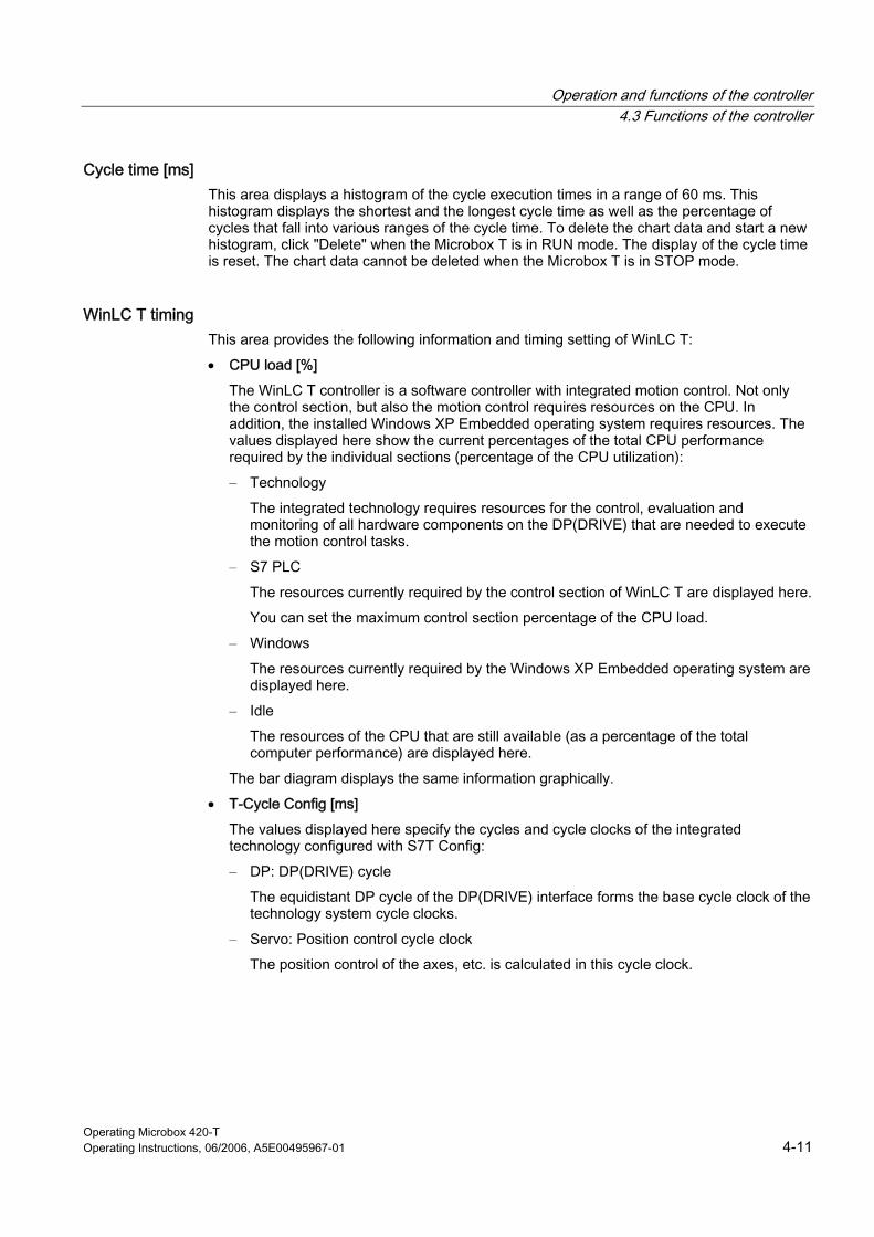
Operation and functions of the controller 4.3 Functions of the controller
Operating Microbox 420-T Operating Instructions, 06/2006, A5E00495967-01 4-11
Cycle time [ms] This area displays a histogram of the cycle execution times in a range of 60 ms. This histogram displays the shortest and the longest cycle time as well as the percentage of cycles that fall into various ranges of the cycle time. To delete the chart data and start a new histogram, click "Delete" when the Microbox T is in RUN mode. The display of the cycle time is reset. The chart data cannot be deleted when the Microbox T is in STOP mode.
WinLC T timing This area provides the following information and timing setting of WinLC T:
• CPU load [%]
The WinLC T controller is a software controller with integrated motion control. Not only the control section, but also the motion control requires resources on the CPU. In addition, the installed Windows XP Embedded operating system requires resources. The values displayed here show the current percentages of the total CPU performance required by the individual sections (percentage of the CPU utilization):
– Technology
The integrated technology requires resources for the control, evaluation and monitoring of all hardware components on the DP(DRIVE) that are needed to execute the motion control tasks.
– S7 PLC
The resources currently required by the control section of WinLC T are displayed here.
You can set the maximum control section percentage of the CPU load.
– Windows
The resources currently required by the Windows XP Embedded operating system are displayed here.
– Idle
The resources of the CPU that are still available (as a percentage of the total computer performance) are displayed here.
The bar diagram displays the same information graphically.
• T-Cycle Config [ms]
The values displayed here specify the cycles and cycle clocks of the integrated technology configured with S7T Config:
– DP: DP(DRIVE) cycle
The equidistant DP cycle of the DP(DRIVE) interface forms the base cycle clock of the technology system cycle clocks.
– Servo: Position control cycle clock
The position control of the axes, etc. is calculated in this cycle clock.

Operation and functions of the controller 4.3 Functions of the controller
Operating Microbox 420-T 4-12 Operating Instructions, 06/2006, A5E00495967-01
– IPO: Interpolator cycle clock
The motion control of the axes is calculated in the "interpolator cycle clock".
– TO-DB: Update cycle clock of the technology DBs
The "Update cycle clock of the technology DBs" specifies the intervals in which the integrated technology is to update the technology data blocks.
• Max. S7 PLC load [%]
The control section of the WinLC T software controller has to share the resources on the CPU with the motion control and the operating system. With this value, you define the maximum percentage of the total CPU performance required by the control section (without technology functionality) (maximum permissible control section percentage of the CPU load).
The default value is 25%. The minimum value is 10% and the maximum value 50%.
To change the set value, overwrite the displayed value and click "Set". The controller must be in the STOP mode for this. The value set by you is accepted at the next transition from STOP to RUN.
Warning
Changing the value can cause an overload of the integrated technology. In an overload situation, the controller enters the STOP mode and cannot be returned to the RUN mode by changing the value again. In this case, you must reload your project.
Warning
Variations in the execution time or in the response time of the user program can possibly lead to a situation in which the controlled devices or the controlled process display an unpredictable behavior, which may result in personal injury or material damage.
If the controller does not have sufficient idle time in which other applications can be executed, this may result in a malfunction of the Microbox T or the controller and other applications may react unexpectedly. The execution of the user program may also display a non-deterministic behavior (jitter), so that execution times vary and start events are delayed.
Always make sure there is an EMERGENCY STOP circuit. In addition, always set the idle time and manage the operational performance of the controller in such a way that your user program is executed consistently.
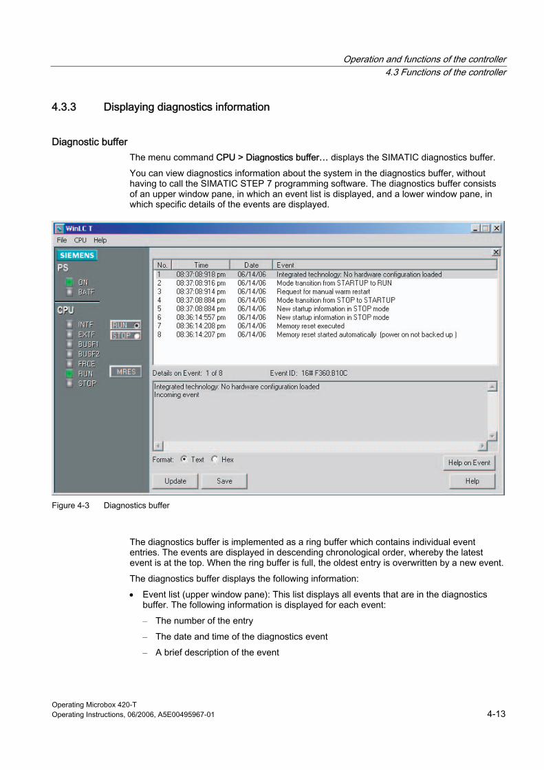
Operation and functions of the controller 4.3 Functions of the controller
Operating Microbox 420-T Operating Instructions, 06/2006, A5E00495967-01 4-13
4.3.3 Displaying diagnostics information
Diagnostic buffer The menu command CPU > Diagnostics buffer… displays the SIMATIC diagnostics buffer.
You can view diagnostics information about the system in the diagnostics buffer, without having to call the SIMATIC STEP 7 programming software. The diagnostics buffer consists of an upper window pane, in which an event list is displayed, and a lower window pane, in which specific details of the events are displayed.
Figure 4-3 Diagnostics buffer
The diagnostics buffer is implemented as a ring buffer which contains individual event entries. The events are displayed in descending chronological order, whereby the latest event is at the top. When the ring buffer is full, the oldest entry is overwritten by a new event.
The diagnostics buffer displays the following information:
• Event list (upper window pane): This list displays all events that are in the diagnostics buffer. The following information is displayed for each event:
– The number of the entry
– The date and time of the diagnostics event
– A brief description of the event
Operation and functions of the controller 4.3 Functions of the controller
Operating Microbox 420-T 4-14 Operating Instructions, 06/2006, A5E00495967-01
• Event ID (between the upper and lower window panes): Displays the ID number of a certain event.
• Details of the event (lower window pane): Displays details of the event in text or hexadecimal format.
If you have set Text format, the following details of the selected event are displayed in the lower window pane:
– A brief description
– Depending on the event, further information, e.g. the address of the operation which triggered the event, and the operating state change that has been caused by the event
– The status of the event (incoming or outgoing)
If an individual text parameter cannot be identified, the diagnostics buffer displays the character string "###". If no text is available for new modules or new events, event numbers and parameters are displayed in hexadecimal values.
If you have set Hexadecimal format, the hexadecimal values of the selected event are displayed in the lower window pane
Sorting of events (upper window pane) You can sort the events listed in the upper window pane by clicking on the required column header:
• Number (defined by time and date)
• Event description
Selecting the format (lower window pane) You can display the diagnostics information in the lower window pane in text or hexadecimal format. In hexadecimal format, the hexadecimal values of the 20 bytes of the selected event are displayed. To select the format:
• Click "Text" to display the details of the events in text format.
• Click "Hex" to display the hexadecimal values of the event.
Saving the diagnostics buffer Click "Save" to save a text file containing the list of the events and the details of the events. The text file contains the information either in text or in hexadecimal format.

Operation and functions of the controller 4.3 Functions of the controller
Operating Microbox 420-T Operating Instructions, 06/2006, A5E00495967-01 4-15
4.3.4 Archiving and restoring STEP 7 user programs
Archive file With the archive command you can save the configuration and the STEP 7 user program in an archive file (*.wld). You can quickly restore the configuration and the STEP 7 user program for the controller with the aid of the archive file.
You can only archive or restore a STEP 7 user program when the mode selector is in the STOP position and the controller is in STOP mode. You cannot archive or restore a STEP 7 user program when the controller is in the RUN mode.
The archive file functions like a plug-in memory card of an S7-CPU. However, the difference is that the controller does not automatically restore the archive file after an overall reset (MRES). You must restore the archive file manually.
Creating an archive file An archive file stores the current STEP 7 user program, the current system configuration and the current values of the DBs. The archive file does not store the configuration of the PC station.
To create and archive file, select File > Archiving of CPU. This command calls up the "Save as" dialog box in which you can assign a name to the file. The controller then creates the archive file with the extension *.wld
You can also create an archive file in the SIMATIC Manager of STEP 7. Select File > Memory card file > New.
Restoring an archive file When you restore an archive file, you reload the STEP 7 user program and the configuration for the controller. You can only restore archive data with the extension *.wld
Before you can restore an archive file, you must switch the controller to the STOP mode. Proceed as follows to load an archived configuration and an archived STEP 7 user program:
1. Click the "STOP" button to switch the controller to the STOP mode.
2. Select File > Load to CPU.
3. Select the archive file that you want to restore and confirm with "OK".
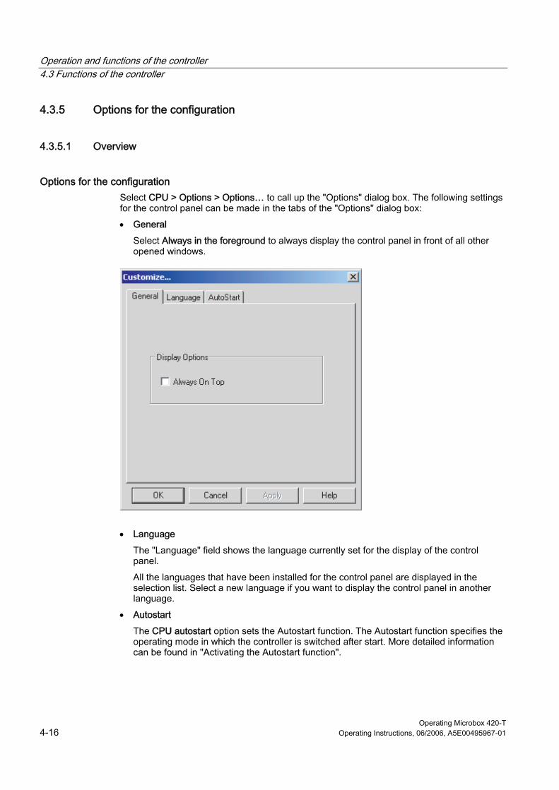
Operation and functions of the controller 4.3 Functions of the controller
Operating Microbox 420-T 4-16 Operating Instructions, 06/2006, A5E00495967-01
4.3.5 Options for the configuration
4.3.5.1 Overview
Options for the configuration Select CPU > Options > Options… to call up the "Options" dialog box. The following settings for the control panel can be made in the tabs of the "Options" dialog box:
• General
Select Always in the foreground to always display the control panel in front of all other opened windows.
• Language
The "Language" field shows the language currently set for the display of the control panel.
All the languages that have been installed for the control panel are displayed in the selection list. Select a new language if you want to display the control panel in another language.
• Autostart
The CPU autostart option sets the Autostart function. The Autostart function specifies the operating mode in which the controller is switched after start. More detailed information can be found in "Activating the Autostart function".
Operation and functions of the controller 4.3 Functions of the controller
Operating Microbox 420-T Operating Instructions, 06/2006, A5E00495967-01 4-17
4.3.5.2 Selecting the language You can change the language displayed in the menus and the online help of the control panel.
Procedure Proceed as follows to change the language:
1. Select CPU > Options > Options… to call up the "Options" dialog box.
2. Open the "Language" tab in the "Options" dialog box.
3. Select the language for the control panel.
4. Click the "Apply" button to change the language.
5. Click "OK" to close the "Options" dialog box.
Result The control panel sets the selected language.
4.3.5.3 Activation of the autostart function
Description The control panel has an autostart function which allows the controller to start up in the same operating mode that it was in before it was closed down. When the autostart function is activated:
• If the controller was in the RUN mode before it was closed down, it starts up in the RUN mode.
• If the controller was in the STOP mode before it was closed down, it starts up in the STOP mode.
When the autostart function is not activated, the controller always starts up in the STOP mode.
To ensure that the controller starts automatically during the Microbox T startup, you must register the controller to start during the Microbox T startup. The procedure for making this setting is described in "Startup Options for the Controller".
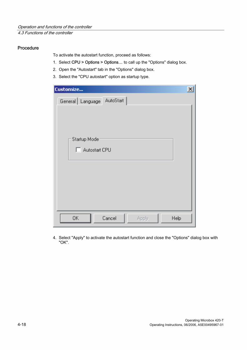
Operation and functions of the controller 4.3 Functions of the controller
Operating Microbox 420-T 4-18 Operating Instructions, 06/2006, A5E00495967-01
Procedure To activate the autostart function, proceed as follows:
1. Select CPU > Options > Options… to call up the "Options" dialog box.
2. Open the "Autostart" tab in the "Options" dialog box.
3. Select the "CPU autostart" option as startup type.
4. Select "Apply" to activate the autostart function and close the "Options" dialog box with "OK".
Operation and functions of the controller 4.3 Functions of the controller
Operating Microbox 420-T Operating Instructions, 06/2006, A5E00495967-01 4-19
4.3.6 Options for the access protection
4.3.6.1 Configuring the options for the access protection
Description The CPU > Options > Access protection menu command changes the options for the access protection. The control panel displays the "Access Authorization" dialog box. You must enter your password in this dialog box so that you can change the settings for the access protection of the controller.
Note The preset password is an empty field without characters. To enter the password, press the Enter key.
Protection level You can configure the protection levels for the password in the "Access Authorization" dialog box, which restrict the access to the controller. The following access restrictions are possible:
• Password
If you select a password, it is necessary that you enter a password for certain functions in the control panel, e.g. to set the operating mode, to archive and restore user programs and to open the tuning panel.
• Confirmation
If you select "Confirmation", the user must acknowledge a confirmation when changing the operating mode.
• Without
If you select "Without", neither a confirmation nor a password is required.
Note If you configure a password and select the option "Without" for the protection level (this deactivates the password), you must still enter the configured password in order to be able to call up the "Access Authorization" dialog box again.
Operation and functions of the controller 4.3 Functions of the controller
Operating Microbox 420-T 4-20 Operating Instructions, 06/2006, A5E00495967-01
Warning If you operate the controller without confirmation and without password, you increase the risk that the operating mode of the controller be changed unintentionally. This can lead to unpredictable behavior of the process or machine, which may result in death, severe personal injury and/or material damage.
Proceed with caution and make sure that you do not change the operating mode. Only allow qualified personnel access to machines and processes. Install a physical EMERGENCY STOP circuit for the machine and the process.
Validity of the password You can enter any value between 0 and maximum 23 hours, 59 minutes for the query interval of the password. After you have entered your password, you are prompted to enter the password again after the interval has expired. The default setting 0 means that you must enter the password for each password-protected function.
Closing and starting the controller does not affect the query interval for the password. The query interval is not reset every time the controller is closed. At the next start of the control panel, you must enter the password when you want to call up a password-protected function.
4.3.6.2 Changing the password In the "Access Authorization" dialog box, click the "Change password" button to call up the "Change Password" dialog box. You can then change the current password in this dialog box.
Note The preset password is an empty field without characters. To enter the password, press the Enter key.
Procedure To change the password, proceed as follows:
1. Enter the old password in the "Old password" field.
2. Enter the new password in the "New password" field (maximum length of 12 characters).
3. Enter the new password again in the "Confirm new password" field.
4. Confirm all the changes made in this dialog box with "OK" or discard all the changes with "Cancel".
If you then want to edit the options for the access protection, you must enter the password in the "Access Authorization" dialog box.
Operation and functions of the controller 4.3 Functions of the controller
Operating Microbox 420-T Operating Instructions, 06/2006, A5E00495967-01 4-21
4.3.7 Startup options for the controller
Starting the controller during startup Per default, you must start the controller manually after the Microbox T has started. However, you can register the controller that it is started automatically during startup.
Note If you want to configure the controller so that it starts in the same operating mode (STOP or RUN) as it was when closed down, select the autostart function.
Registering the controller for start during startup To register the controller for the automatic start, proceed as follows:
1. Close down the controller with the CPU > Close controller menu command.
2. Select CPU > Register controller for start during PC startup.
WinLC T is now started automatically when you start your Microbox T.
Canceling the registration of the controller for start during startup To cancel the registration of a controller for the automatic start, proceed as follows:
1. Close the controller.
2. Select CPU > Cancel registration of the controller for start during PC startup.
WinLC T is now not started during the startup sequence. To start WinLC T, you must start the controller manually.
Startup mode You set the startup mode for the controller in STEP 7. WinLC T only supports the startup mode "Warm restart" (OB 100).
The set startup mode is saved in the configuration (in the system data) of the controller, which you load with the control program.
Warm restart The controller executes OB 100 before the free cycle (OB 1) is started. The warm restart clears the inputs of the distributed I/O (PI) and sets the outputs of the distributed I/O (PO) in a predefined safe state (default setting is 0). A warm restart saves the current values of the retentive memory areas of flags (F), timers (T), counters (C) and data blocks (DBs).
If you left-click the RUN button on the panel to switch from STOP mode to RUN mode, WinLC T performs a warm restart.

Operation and functions of the controller 4.3 Functions of the controller
Operating Microbox 420-T 4-22 Operating Instructions, 06/2006, A5E00495967-01
Operating Microbox 420-T Operating Instructions, 06/2006, A5E00495967-01 5-1
Setting of the operational performance 55.1 5.1 Optimizing the technology system cycle clocks
Executing the user program After you have created your user program with STEP 7 and loaded it to the controller, the controller starts to execute the user program as soon as it is switched to RUN. As with every other S7 automation system, the controller executes your STEP 7 user program cyclically.
Operational performance During the execution of the STEP 7 user program, a variation in the execution time or the response time of the process may occur in WinLC T, whereby the cycle times change and a non-deterministic behavior ("jitter") occurs.
To set the operational performance of WinLC T, optimize the technology system cycle clocks. You set these cycle clocks in S7T Config.
Further information about the system cycle clocks can be found in the "Time model of the Microbox T" section in the S7-Technology manual.
Detailed specifications for the setting of the technology system cycle clocks can be found in the "Setting technology system cycle clocks" section in the same manual.
Tuning panel The values for the cycle times and the execution times are displayed in the tuning panel. Here you set the maximum control section percentage of the CPU load of the controller.
Setting of the operational performance 5.2 Functions under Windows XP Embedded
Operating Microbox 420-T 5-2 Operating Instructions, 06/2006, A5E00495967-01
5.2 5.2 Functions under Windows XP Embedded
5.2.1 Monitoring functions
The following individual functions are implemented:
• Temperature monitoring
• Watchdog
Messages from the monitoring modules can be passed on to applications.
The SOM software (Safecard On Motherboard) is available on the devices for Windows XP Embedded.
Safecard on Motherboard (SOM) This application is used for monitoring the hardware of the Microbox T (temperature and watchdog). The current temperatures and the limits are displayed here.
Caution The application is used on the Microbox T only for diagnostic purposes. Do not make any settings on the application!
Response when the maximum temperature is reached When the maximum temperature is reached, the Microbox T enters the STOP mode. You can return the Microbox T to the RUN mode only when the temperature threshold is undershot and you have closed the controller again.
Setting of the operational performance 5.2 Functions under Windows XP Embedded
Operating Microbox 420-T Operating Instructions, 06/2006, A5E00495967-01 5-3
5.2.2 Enhanced Write Filter (EWF)
Task and function The EWF (Enhanced Write Filter) is a function that is available under the Windows XP Embedded operating system.
It represents a write filter that can be configured by the user, which, when required, can prevent changes to the Compact Flash card. In this way, the system can be maintained in a clearly defined, functional state after a power failure.
EWF can be used to minimize write access to Compact Flash cards. This is important because the write cycles on Compact Flash cards are limited due to technical reasons. We therefore recommend that the EWF be enabled.
Note Per default, the EWF is disabled on the Microbox T so that you can load your configuration to the Compact Flash card.
Enable the EWF after you have loaded your configuration to minimize write access to the Compact Flash card.
The enabling/disabling of the EWF only takes effect after a restart of the Microbox T.
The EWF is disabled on partition D: of the Compact Flash card. The WinAC T project file (WAF file) is stored on this partition. This file is still available after a reboot or an operating system crash.
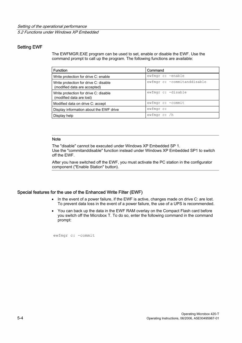
Setting of the operational performance 5.2 Functions under Windows XP Embedded
Operating Microbox 420-T 5-4 Operating Instructions, 06/2006, A5E00495967-01
Setting EWF The EWFMGR.EXE program can be used to set, enable or disable the EWF. Use the command prompt to call up the program. The following functions are available:
Function Command
Write protection for drive C: enable ewfmgr c: -enable
Write protection for drive C: disable (modified data are accepted)
ewfmgr c: -commitanddisable
Write protection for drive C: disable (modified data are lost)
ewfmgr c: -disable
Modified data on drive C: accept ewfmgr c: -commit
Display information about the EWF drive ewfmgr c:
Display help ewfmgr c: /h
Note The "disable" cannot be executed under Windows XP Embedded SP 1. Use the "commitanddisable" function instead under Windows XP Embedded SP1 to switch off the EWF.
After you have switched off the EWF, you must activate the PC station in the configurator component ("Enable Station" button).
Special features for the use of the Enhanced Write Filter (EWF) • In the event of a power failure, if the EWF is active, changes made on drive C: are lost.
To prevent data loss in the event of a power failure, the use of a UPS is recommended.
• You can back up the data in the EWF RAM overlay on the Compact Flash card before you switch off the Microbox T. To do so, enter the following command in the command prompt:
ewfmgr c: -commit
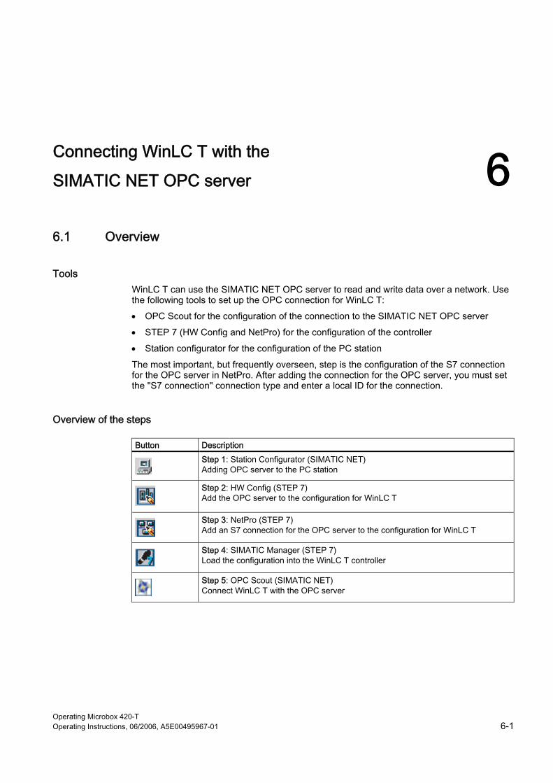
Operating Microbox 420-T Operating Instructions, 06/2006, A5E00495967-01 6-1
Connecting WinLC T with the
SIMATIC NET OPC server 66.1 6.1 Overview
Tools WinLC T can use the SIMATIC NET OPC server to read and write data over a network. Use the following tools to set up the OPC connection for WinLC T:
• OPC Scout for the configuration of the connection to the SIMATIC NET OPC server
• STEP 7 (HW Config and NetPro) for the configuration of the controller
• Station configurator for the configuration of the PC station
The most important, but frequently overseen, step is the configuration of the S7 connection for the OPC server in NetPro. After adding the connection for the OPC server, you must set the "S7 connection" connection type and enter a local ID for the connection.
Overview of the steps
Button Description
Step 1: Station Configurator (SIMATIC NET) Adding OPC server to the PC station
Step 2: HW Config (STEP 7) Add the OPC server to the configuration for WinLC T
Step 3: NetPro (STEP 7) Add an S7 connection for the OPC server to the configuration for WinLC T
Step 4: SIMATIC Manager (STEP 7) Load the configuration into the WinLC T controller
Step 5: OPC Scout (SIMATIC NET) Connect WinLC T with the OPC server
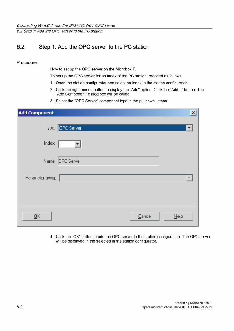
Connecting WinLC T with the SIMATIC NET OPC server 6.2 Step 1: Add the OPC server to the PC station
Operating Microbox 420-T 6-2 Operating Instructions, 06/2006, A5E00495967-01
6.2 6.2 Step 1: Add the OPC server to the PC station
Procedure How to set up the OPC server on the Microbox T.
To set up the OPC server for an index of the PC station, proceed as follows:
1. Open the station configurator and select an index in the station configurator.
2. Click the right mouse button to display the "Add" option. Click the "Add..." button. The "Add Component" dialog box will be called.
3. Select the "OPC Server" component type in the pulldown listbox.
4. Click the "OK" button to add the OPC server to the station configuration. The OPC server will be displayed in the selected in the station configurator.

Connecting WinLC T with the SIMATIC NET OPC server 6.2 Step 1: Add the OPC server to the PC station
Operating Microbox 420-T Operating Instructions, 06/2006, A5E00495967-01 6-3
5. Click "OK" to save the configuration of the PC station.
Connecting WinLC T with the SIMATIC NET OPC server 6.3 Step 2: Add the OPC server to the hardware configuration
Operating Microbox 420-T 6-4 Operating Instructions, 06/2006, A5E00495967-01
6.3 6.3 Step 2: Add the OPC server to the hardware configuration
Introduction How you set up WinLC T with STEP 7 on your PC for the OPC server.
To set up WinLC T for the OPC server, proceed as follows:
• Create a STEP 7 project for a PC station with WinLC T.
• Add the OPC server to the hardware configuration.
• Configure the OPC server.
Procedure 1. Open STEP 7 and create a project.
2. Add a SIMATIC PC station with the same name as in the component configurator. Double-click the configuration icon of the PC station to open HW Config.
3. Add the WinLC T controller in the same index as in the station configurator.
4. Open the "User application" folder in the catalog.
5. Open the "OPC server" folder and select the "SW V6.3" component.
6. Drag the component with the mouse to the same index that you created in the station configurator.
7. Double-click the OPC server entry (index 1) to open the "Properties" dialog box.
8. Optional: Open the "S7" tab and select the "Activate" option (under "Access protection").
9. If you want to use STEP 7 icons for configuring the connections in OPC Scout, select the "All" option (or "Selected" to use specific icon table entries) in the "Use icons" field.
10. Click “OK” to close the “Properties” dialog box.
11. Select the "Save and compile" button to create the hardware configuration for the PC station.
Result Once you have compiled the configuration in the STEP 7 project, you can close the HW Config and return to the SIMATIC Manager.

Connecting WinLC T with the SIMATIC NET OPC server 6.4 Step 3: Add a S7 connection for the OPC server to NetPro
Operating Microbox 420-T Operating Instructions, 06/2006, A5E00495967-01 6-5
6.4 6.4 Step 3: Add a S7 connection for the OPC server to NetPro
Introduction Adding the OPC server with STEP 7 on your PC to the configuration for WinLC T.
To add the OPC server to the configuration for WinLC T, proceed as follows:
• Add a connection for the OPC server to the WinLC T configuration.
• Create the connection of the OPC server as S7 connection.
• Assign a local ID to the OPC server connection.
Procedure 1. Search for the OPC server in the SIMATIC Manager and double-click the "Connections"
icon to open NetPro.
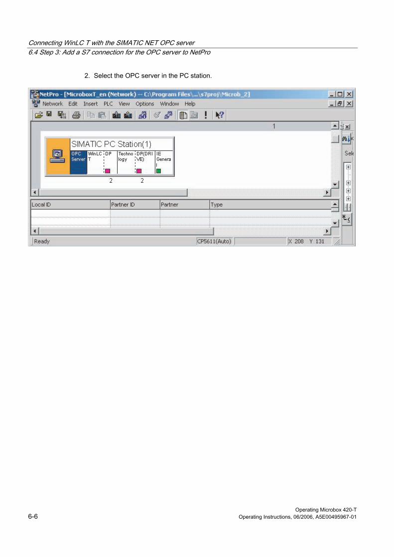
Connecting WinLC T with the SIMATIC NET OPC server 6.4 Step 3: Add a S7 connection for the OPC server to NetPro
Operating Microbox 420-T 6-6 Operating Instructions, 06/2006, A5E00495967-01
2. Select the OPC server in the PC station.
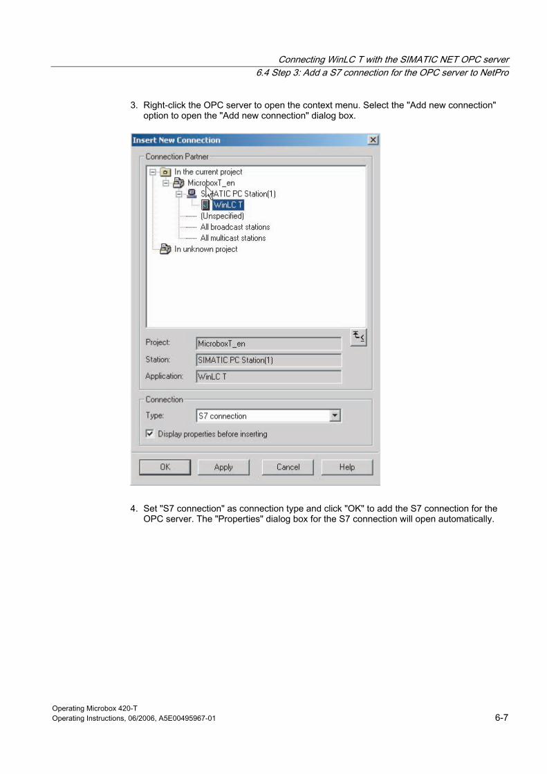
Connecting WinLC T with the SIMATIC NET OPC server 6.4 Step 3: Add a S7 connection for the OPC server to NetPro
Operating Microbox 420-T Operating Instructions, 06/2006, A5E00495967-01 6-7
3. Right-click the OPC server to open the context menu. Select the "Add new connection" option to open the "Add new connection" dialog box.
4. Set "S7 connection" as connection type and click "OK" to add the S7 connection for the OPC server. The "Properties" dialog box for the S7 connection will open automatically.

Connecting WinLC T with the SIMATIC NET OPC server 6.4 Step 3: Add a S7 connection for the OPC server to NetPro
Operating Microbox 420-T 6-8 Operating Instructions, 06/2006, A5E00495967-01
5. Enter the local ID for the S7 connection.
6. Click "OK" to add the S7 connection to NetPro.
7. Click the "Save and compile" button to save and compile the changes in the STEP 7 project.
Result Once you have compiled the S7 connection for the OPC server in the STEP 7 project, you can close NetPro and return to the SIMATIC Manager.
Connecting WinLC T with the SIMATIC NET OPC server 6.5 Step 4: Load the configuration into the WinLC T controller
Operating Microbox 420-T Operating Instructions, 06/2006, A5E00495967-01 6-9
6.5 6.5 Step 4: Load the configuration into the WinLC T controller
Introduction Loading the configuration with STEP 7 on your PC into the controller.
To load the configuration into the controller, proceed as follows:
• Start the controller.
• Load the configuration.
Requirement The controller must be operating in order to load the configuration. To start the controller, select the Start > SIMATIC > PC-based control > WinLC T menu command of double-click the icon for WinLC T on the desktop.
Procedure Once the controller has been started, you can load the configuration:
1. In the SIMATIC Manager, select the PC station icon.
2. Select the Target system > Load menu command or click the "Load" button in the task bar.
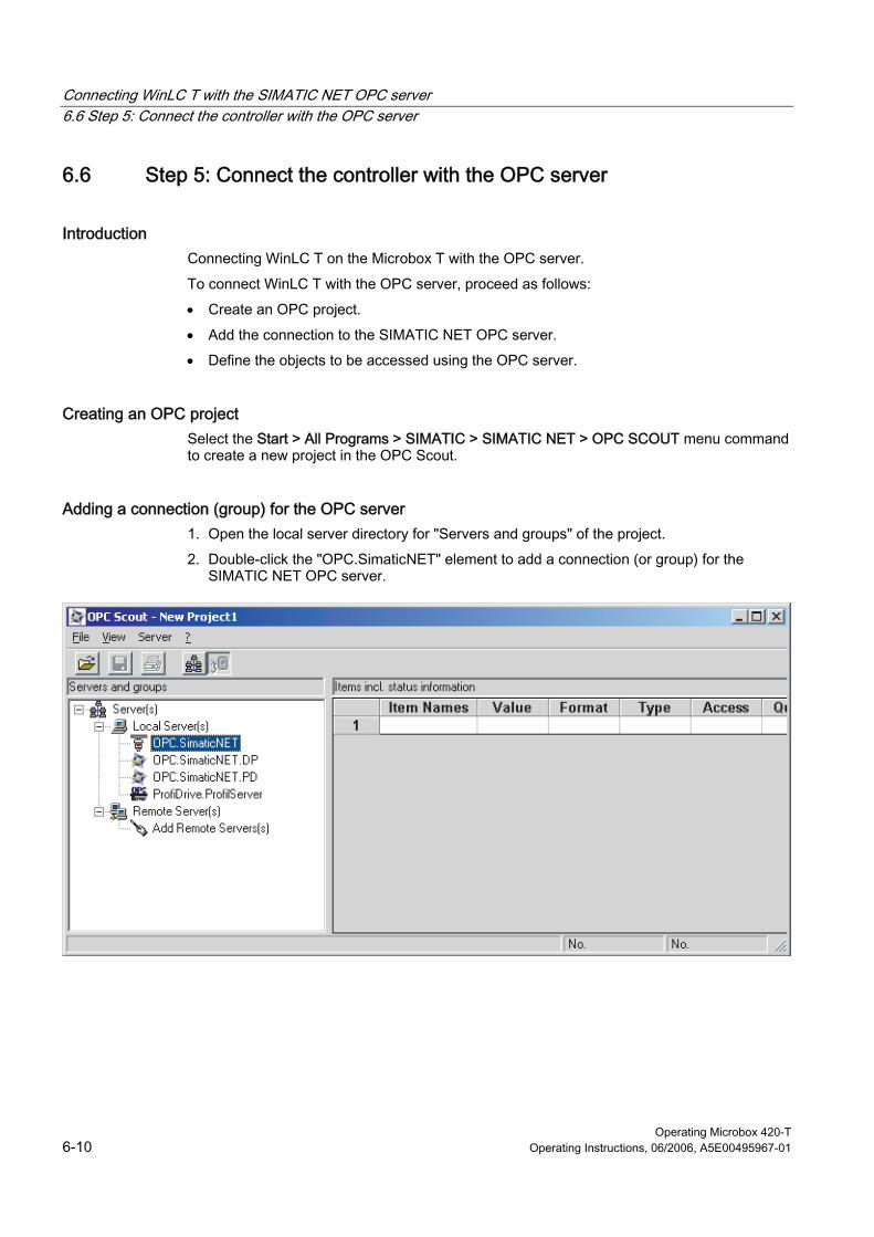
Connecting WinLC T with the SIMATIC NET OPC server 6.6 Step 5: Connect the controller with the OPC server
Operating Microbox 420-T 6-10 Operating Instructions, 06/2006, A5E00495967-01
6.6 6.6 Step 5: Connect the controller with the OPC server
Introduction Connecting WinLC T on the Microbox T with the OPC server.
To connect WinLC T with the OPC server, proceed as follows:
• Create an OPC project.
• Add the connection to the SIMATIC NET OPC server.
• Define the objects to be accessed using the OPC server.
Creating an OPC project Select the Start > All Programs > SIMATIC > SIMATIC NET > OPC SCOUT menu command to create a new project in the OPC Scout.
Adding a connection (group) for the OPC server 1. Open the local server directory for "Servers and groups" of the project.
2. Double-click the "OPC.SimaticNET" element to add a connection (or group) for the SIMATIC NET OPC server.
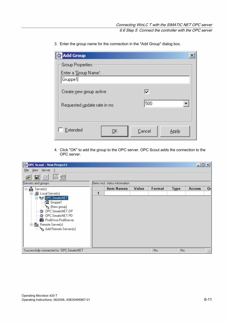
Connecting WinLC T with the SIMATIC NET OPC server 6.6 Step 5: Connect the controller with the OPC server
Operating Microbox 420-T Operating Instructions, 06/2006, A5E00495967-01 6-11
3. Enter the group name for the connection in the "Add Group" dialog box.
4. Click "OK" to add the group to the OPC server. OPC Scout adds the connection to the OPC server.
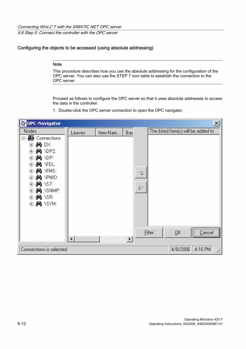
Connecting WinLC T with the SIMATIC NET OPC server 6.6 Step 5: Connect the controller with the OPC server
Operating Microbox 420-T 6-12 Operating Instructions, 06/2006, A5E00495967-01
Configuring the objects to be accessed (using absolute addressing)
Note This procedure describes how you use the absolute addressing for the configuration of the OPC server. You can also use the STEP 7 icon table to establish the connection to the OPC server.
Proceed as follows to configure the OPC server so that it uses absolute addresses to access the data in the controller:
1. Double-click the OPC server connection to open the OPC navigator.
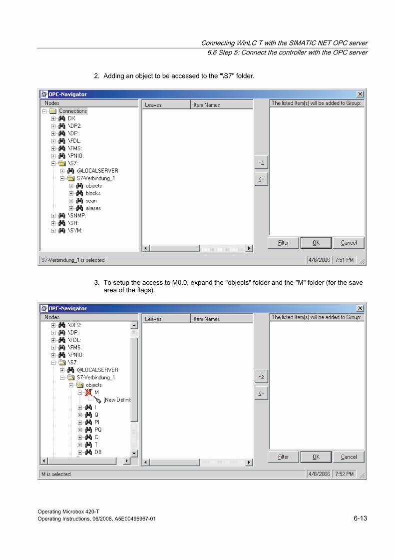
Connecting WinLC T with the SIMATIC NET OPC server 6.6 Step 5: Connect the controller with the OPC server
Operating Microbox 420-T Operating Instructions, 06/2006, A5E00495967-01 6-13
2. Adding an object to be accessed to the "\S7" folder.
3. To setup the access to M0.0, expand the "objects" folder and the "M" folder (for the save area of the flags).
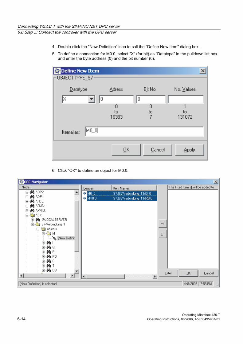
Connecting WinLC T with the SIMATIC NET OPC server 6.6 Step 5: Connect the controller with the OPC server
Operating Microbox 420-T 6-14 Operating Instructions, 06/2006, A5E00495967-01
4. Double-click the "New Definition" icon to call the "Define New Item" dialog box.
5. To define a connection for M0.0, select "X" (for bit) as "Datatype" in the pulldown list box and enter the byte address (0) and the bit number (0).
6. Click "OK" to define an object for M0.0.
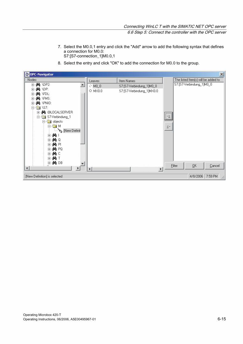
Connecting WinLC T with the SIMATIC NET OPC server 6.6 Step 5: Connect the controller with the OPC server
Operating Microbox 420-T Operating Instructions, 06/2006, A5E00495967-01 6-15
7. Select the M0.0,1 entry and click the "Add" arrow to add the following syntax that defines a connection for M0.0: S7:[S7-connection_1]M0.0,1
8. Select the entry and click "OK" to add the connection for M0.0 to the group.
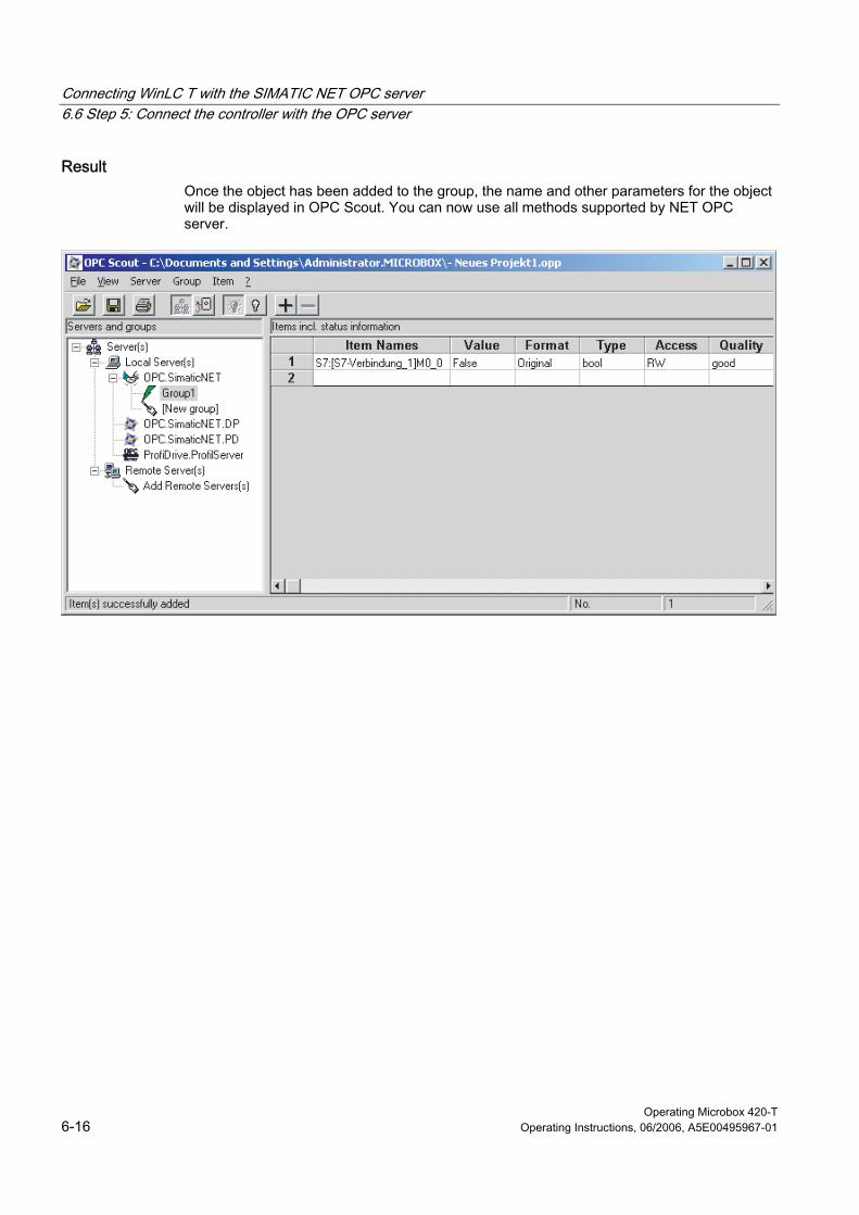
Connecting WinLC T with the SIMATIC NET OPC server 6.6 Step 5: Connect the controller with the OPC server
Operating Microbox 420-T 6-16 Operating Instructions, 06/2006, A5E00495967-01
Result Once the object has been added to the group, the name and other parameters for the object will be displayed in OPC Scout. You can now use all methods supported by NET OPC server.

Connecting WinLC T with the SIMATIC NET OPC server 6.6 Step 5: Connect the controller with the OPC server
Operating Microbox 420-T Operating Instructions, 06/2006, A5E00495967-01 6-17
Configuring the objects to be accessed (using the STEP 7 icon table) If you have created an icon table for the STEP 7 program that you have loaded into the target system, you can use the icons to connect the OPC server with the data in the controller.
1. Double-click the OPC server connection to open the OPC navigator.
2. Search the controller folder to display the icons that have been loaded into the controller.
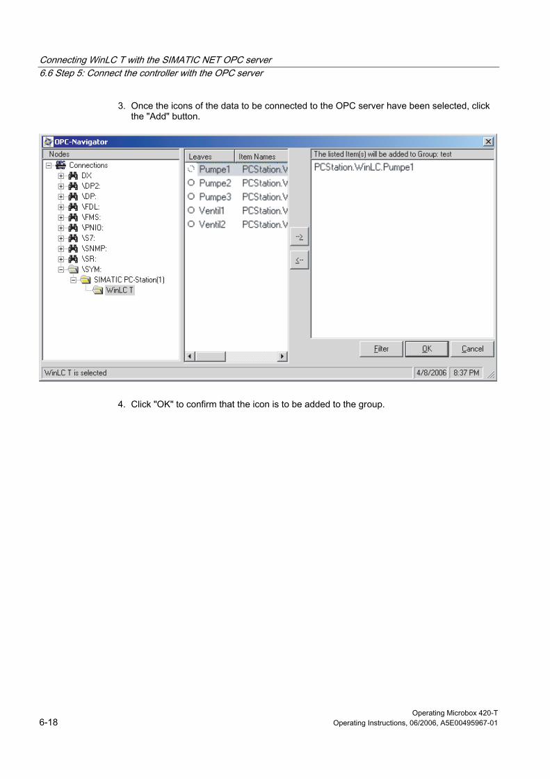
Connecting WinLC T with the SIMATIC NET OPC server 6.6 Step 5: Connect the controller with the OPC server
Operating Microbox 420-T 6-18 Operating Instructions, 06/2006, A5E00495967-01
3. Once the icons of the data to be connected to the OPC server have been selected, click the "Add" button.
4. Click "OK" to confirm that the icon is to be added to the group.

Connecting WinLC T with the SIMATIC NET OPC server 6.6 Step 5: Connect the controller with the OPC server
Operating Microbox 420-T Operating Instructions, 06/2006, A5E00495967-01 6-19
Result Once the object has been added to the group, OPC Scout shows the icon name and other parameters for the STEP 7 icon.

Connecting WinLC T with the SIMATIC NET OPC server 6.6 Step 5: Connect the controller with the OPC server
Operating Microbox 420-T 6-20 Operating Instructions, 06/2006, A5E00495967-01
Operating Microbox 420-T Operating Instructions, 06/2006, A5E00495967-01 7-1
Memory concept 77.1 7.1 Saving Controller Information
Saved information WinLC T saves the following operational data on your Microbox T:
• The load memory contains the system data (configuration of the controller) and the initial values of the modules in the STEP 7 user program.
• The load memory contains the controller status. This includes the last change of the operational status (STOP, RUN, or STARTUP) of the controller and the setting of the mode selector (STOP or RUN).
• When the controller is closed, WinLC T creates the switched-off status of the controller. The switched-off status includes the contents of the diagnostic buffer, the current values of the non-volatile memory areas of the controller (e.g. timers, counters and flag bits) and the current values of the non-volatile data blocks.
WinLC T updates these areas during operation and uses this information for the controller start up.
Loading memory When you load the STEP 7 user program, WinLC T saves the program blocks and the system data in the load memory. The blocks include the initial values for the process variables used by the STEP 7 user program.
You can use SFC 82 (CREA_DBL) to create new blocks in the load memory while the STEP 7 user program is executing. You can use SFC 84 (WRIT_DBL) to change the blocks. The blocks created by SFC 82 are saved in the load memory while the SFC 82 is running.
Note Data blocks (DBs) created by SFC 22 (CREAT_DB) and SFC 85 (CREA_DB) are not saved in the load memory. These DBs are only saved in the work memory.
Memory concept 7.1 Saving Controller Information
Operating Microbox 420-T 7-2 Operating Instructions, 06/2006, A5E00495967-01
Work memory The work memory is used to run the code and process the STEP 7 user program data. Programs only run in RAM and system memory.
Note Note that the work memory (RAM) of the Microbox T is shared by the PLC, motion and Windows applications. A memory bottleneck can cause instability of the Microbox T. In these special situations, you should change or optimize the memory for your PLC, motion and Windows applications.
System memory The system memory contains the following data:
• The address areas for address area memory bits, timers and counters
• The process image of the I/Os
• The local data
Memory areas for access to inputs and outputs When you configure the distributed I/Os in STEP 7, you assign an area in the PE or PA memory to each I/O module. You also assign a diagnostic address for the I/O modules in the PE memory. The size of the PE and PA memory areas is determined by the configuration of the distributed I/Os, although the maximum size of the memory for the distributed I/Os is 2 KByte.
Note on the memory of the integrated technology Siemens recommends a maximum memory utilization of 80% in the integrated technology.

Memory concept 7.1 Saving Controller Information
Operating Microbox 420-T Operating Instructions, 06/2006, A5E00495967-01 7-3
Retentive data When you set up WinLC T in STEP 7, you can define the areas of the non-volatile data for timers (T), counters (ZC), flag bits (F) and data blocks (DBs).
WinLC T saves the non-volatile memory areas, the diagnostic buffer and the current values of the non-volatile data blocks as well as data of the integrated technology in the battery-buffered RAM. If the switched-off state has been saved and the controller performs a restart (OB 100), WinLC T restores the non-volatile memory areas.
Controller state WinLC T saves the current operating state of the controller and updates the state for the following events:
• Each time the controller changes the operating state (RUN to STOP, STOP to STARTUP or STARTUP to RUN), WinLC T updates the controller state to indicate the last change.
• Each time the mode selector on the control panel is changed (STOP or RUN), WinLC T updates the state of the mode selector to indicate the last change.
Switched-off state Under normal conditions, WinLC T saves the current state of the controller and the non-volatile data, when you shutdown the controller. WinLC T saves the following information from the work memory:
• The values for the non-volatile data in the S7 memory areas (e.g. B. T, Z, M and DB)
• Diagnostic buffer
The switched-off state is saved when WinLC T is set inoperable. Once WinLC T has started, the switched-off state is loaded to WinLC T and then deleted (to prevent problems for abnormal termination of the controller).
Memory concept 7.2 Loading memory areas during startup
Operating Microbox 420-T 7-4 Operating Instructions, 06/2006, A5E00495967-01
7.2 7.2 Loading memory areas during startup
Principle During the startup, WinLC T determines whether the controller was shutdown correctly. The following tasks are performed:
• The loaded modules of the STEP 7 user program will be loaded from the load memory.
• When the switched-off state is found (this indicates that the controller was shutdown correctly), the work memory will be updated with the switched-off state and the values saved when the controller was shutdown are loaded into the non-volatile data.
• When losing non-volatile data the work memory is reset to the initial state using the load memory (as loaded from STEP 7).
• The controller state is restored in accordance with the saved operating state and the autostart configuration, and the setting of the mode selector in the control panel is reset.
If WinLC T cannot read an element in the load memory, the state of the controller or the switched-off state, WinLC T starts an unconfigured (empty) controller.
Loading memory after a successful closing of the controller If the switched-off state when the controller was shutdown has been saved successfully, WinLC T restores the operational data of the controller:
• WinLC T reloads during startup the data saved in the switched-off state. This includes the non-volatile S7 memory areas, the current values of the non-volatile data blocks and the contents of the diagnostic buffer.
• Depending on the autostart settings, WinLC T sets the controller status to the STOP or RUN mode. In case of a Windows crash, WinLC T restores the controller status prior to the Windows crash. Although the controller performs a "normal" transition from RUN to STOP, WinLC T cannot save the controller status during a Windows crash.
Note If the controller has been configured for autostart, WinLC T produces a startup event that specifies the startup type: buffered or unbuffered. You can program OB 100 to read this start event. For an unbuffered startup, the OB100_STOP variable at address LW6 is set to W#16#4309.
• WinLC T sets for the mode selector the controller state that was last saved.
Memory concept 7.2 Loading memory areas during startup
Operating Microbox 420-T Operating Instructions, 06/2006, A5E00495967-01 7-5
Problems during the controller start up If WinLC T cannot read an element of the non-volatile memory (load memory, the state of the controller or the switched-off state), or an error occurs, WinLC T starts an unconfigured (empty) controller. In this case, the controller is placed in the STOP mode and the button for the mode set to STOP, and the system data and the user program are deleted.
Possible causes for this problem include a hardware error in your Microbox T or a sub-block in the load memory caused by an error when WinLC T wrote a block in the load memory.
To eliminate this error state, you must reload the user program and the system data from STEP 7.
Note The mode selector of the controller is set to STOP. Although you can load the user program and the system data from a remote computer, you cannot use this remote computer to set the RUN mode for the controller. You must set the mode selector to RUN on the local computer for WinLC T in order that the controller is placed in the RUN mode.
Memory concept 7.2 Loading memory areas during startup
Operating Microbox 420-T 7-6 Operating Instructions, 06/2006, A5E00495967-01
Starting the controller after a Windows crash If the controller during closing was in the RUN mode and is configured for autostart, WinLC T starts in the RUN mode. If OB 84 (CPU hardware error) responds to a Windows crash and prior to closing places the controller in the STOP mode, WinLC T starts in the RUN mode because WinLC T cannot save the controller state on the Compact Flash card during the close action caused by the Windows crash.
If you do not want the controller to start in the RUN mode after a Windows crash, you must add the code in the startup OB (OB 100) so that it can be detected that WinLC T was shutdown without the switched-off state being saved and thus the controller will not be placed in the STOP mode at a restart.

Memory concept 7.3 Buffering of Data with SFCs
Operating Microbox 420-T Operating Instructions, 06/2006, A5E00495967-01 7-7
7.3 7.3 Buffering of Data with SFCs
Principle You can use SFC 82 (CREA_DBL), SFC 83 (READ_DBL) and SFC 84 (WRIT_DBL) to save data for significant events in the process. If, for example, when you change a recipe, you want to store the recipe values in the load memory without loading new blocks for the user program into the CPU.
SFC 82 and SFC 84 change the data for the user program stored in the load memory. When you store blocks in the load memory, you must ensure that these blocks are available, even when WinLC T cannot save the status during the controller shutdown.
Note When you use SFC 22, SFC 23, SFC 82, SFC 83, SFC 84 or SFC 85, you must cater for the possibility of a Windows crash.
During the execution in the STEP 7 user program, create and update the SFC 82 (CREA_DBL), SFC 83 (READ_DBL) and SFC 84 (WRIT_DBL) blocks that are stored as part of your STEP 7 user program in load memory.
SFC 82, SFC 83 and SFC 84 are asynchronous SFCs that run in the background.
Note If you call SFC 82, SFC 83 or SFC 84 from the startup OB (OB 100), WinLC T executes these SFCs synchronously. This differs from the operation of a hardware automation system.
Note Do not use any polling loops that wait for the completion of an asynchronous SFC. This is the case, in particular, for SFC 82, SFC 83 and SFC 84.
The asynchronous SFCs are executed in the background. If the user program contains loops, the execution of the OB that executes the polling loop will be extended until the end of the SFC. This can cause jitter.

Memory concept 7.3 Buffering of Data with SFCs
Operating Microbox 420-T 7-8 Operating Instructions, 06/2006, A5E00495967-01
Caution When the user program calls SFC 82, SFC 83 or SFC 84, the SFC reads or writes data on the Compact Flash card. If you call these SFCs in each cycle (e.g. from OB 1) or from a cyclical OB that executes fast, the constant reading and writing on the Compact Flash card causes the card to be damaged or the occurrence of jitter.
You should only call SFC 82, SFC 83 or SFC 84 to record an important process event, e.g. a changed recipe.
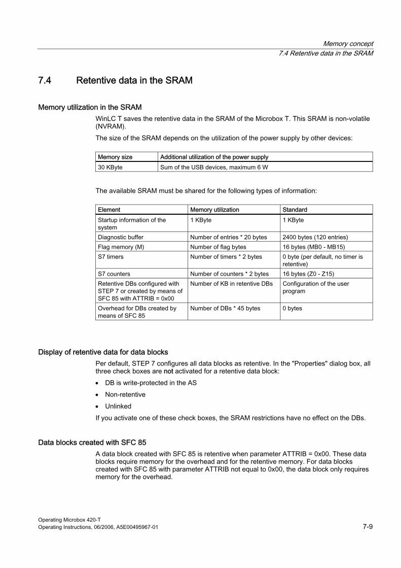
Memory concept 7.4 Retentive data in the SRAM
Operating Microbox 420-T Operating Instructions, 06/2006, A5E00495967-01 7-9
7.4 7.4 Retentive data in the SRAM
Memory utilization in the SRAM WinLC T saves the retentive data in the SRAM of the Microbox T. This SRAM is non-volatile (NVRAM).
The size of the SRAM depends on the utilization of the power supply by other devices:
Memory size Additional utilization of the power supply
30 KByte Sum of the USB devices, maximum 6 W
The available SRAM must be shared for the following types of information:
Element Memory utilization Standard
Startup information of the system
1 KByte 1 KByte
Diagnostic buffer Number of entries * 20 bytes 2400 bytes (120 entries) Flag memory (M) Number of flag bytes 16 bytes (MB0 - MB15) S7 timers Number of timers * 2 bytes 0 byte (per default, no timer is
retentive) S7 counters Number of counters * 2 bytes 16 bytes (Z0 - Z15) Retentive DBs configured with STEP 7 or created by means of SFC 85 with ATTRIB = 0x00
Number of KB in retentive DBs Configuration of the user program
Overhead for DBs created by means of SFC 85
Number of DBs * 45 bytes 0 bytes
Display of retentive data for data blocks Per default, STEP 7 configures all data blocks as retentive. In the "Properties" dialog box, all three check boxes are not activated for a retentive data block:
• DB is write-protected in the AS
• Non-retentive
• Unlinked
If you activate one of these check boxes, the SRAM restrictions have no effect on the DBs.
Data blocks created with SFC 85 A data block created with SFC 85 is retentive when parameter ATTRIB = 0x00. These data blocks require memory for the overhead and for the retentive memory. For data blocks created with SFC 85 with parameter ATTRIB not equal to 0x00, the data block only requires memory for the overhead.
Memory concept 7.5 Power failure
Operating Microbox 420-T 7-10 Operating Instructions, 06/2006, A5E00495967-01
7.5 7.5 Power failure
Retentive data If a power failure occurs, the non-volatile data is saved in the battery-buffered RAM. The backed up data is available at the next ramp up of the Microbox T. The Microbox T is ready for operation immediately.
Windows applications If the Microbox T is shut down during operation and while the write protection is disabled, the Windows installation may be affected.
The data consistency of Windows applications cannot be guaranteed during a power loss.
In these cases, Siemens strongly recommends the use of a UPS system.
Caution The data consistency can only be guaranteed after a power failure when the supply voltage of the Microbox T is at least 24 V.
7.6 7.6 Uninterruptible power supply (UPS)
Note You can use an uninterruptible power supply (UPS) to supply your Microbox T with power in an emergency. The UPS system can ensure that the system shuts down correctly and the switch-off state is saved in the event of a power failure.
The manufacturer's documentation for the UPS system provides further information.
Microsoft Windows provides a dialog box to configure the UPS for your computer:
1. Select the Start > Settings > Control Panel menu command to display the control panel.
2. Select "Performance and Maintenance".
3. Double-click the "Power Options" icon to open the "Power Options Properties" dialog box.
4. Open the "UPS" tab and enter the parameters for your UPS system.
5. Click "Apply" or "OK" to set the UPS properties.
Memory concept 7.7 Backing up data
Operating Microbox 420-T Operating Instructions, 06/2006, A5E00495967-01 7-11
7.7 7.7 Backing up data
Data backup under Windows XP Embedded For the data backup under Windows XP Embedded, you create an image of the installation. We recommend the " Image & Partition Creator V1.1" software tool for this purpose. This tool enables you to easily back up and restore the full content of Compact Flash card and individual partitions (images).
The software can be ordered from the Siemens A&D online ordering system (order number 6ES7-6AA02-0YX0). For detailed information about Image Creator, refer to the corresponding product information.
7.8 7.8 Restoring the factory settings (Restore)
Restore You can restore the original factory software using the Restore CD (supplied with the Microbox T). The CD contains the required images and the tool for transferring the delivered state to the Compact Flash card of the Microbox T. You have the following possibilities for the restore:
• You can restore the entire Compact Flash card with drive C: (system) and drive D:
• or only drive C:. This allows you to retain any user data on drive D:.
Caution With the option "Restore system partitions only", all data on drive C: (System) will be deleted. All data, user settings and all authorizations and license keys on drive C: will be lost in the process. All data on drive C: on the Compact Flash card will be deleted and rewritten with the original factory software.
When you select the "Restore entire hard disk" option, all data, user settings and authorizations or license keys will be lost on the Compact Flash card. Also on drive D: the installed programs will be deleted.
Note Ensure that the correct boot drive is selected for the startup. You select the boot drive in the boot menu of the BIOS setup.

Memory concept 7.8 Restoring the factory settings (Restore)
Operating Microbox 420-T 7-12 Operating Instructions, 06/2006, A5E00495967-01
Reference The restore CD contains a text file ("README.txt") that provides a detailed description for the procedure for restoring the delivered state. Follow the instructions in this file.

Memory concept 7.8 Restoring the factory settings (Restore)
Operating Microbox 420-T Operating Instructions, 06/2006, A5E00495967-01 7-13

Operating Microbox 420-T Operating Instructions, 06/2006, A5E00495967-01 8-1
Communication 88.1 8.1 Ports
8.1.1 Overview
Overview The Microbox T has four interfaces for communication with other devices:
• Ethernet interface for communication with PG, OP
• PROFIBUS DP interface (X1) for the communication with PG, OP, distributed I/O
• PROFIBUS DP(DRIVE) interface (X2) for the communication with drive systems.
• I/O interface (X11) with eight digital outputs for controlling output signals, e.g. output cam switching signals
8.1.2 Ethernet interfaces
Ethernet subnet Industrial Ethernet is a communication network with a transmission rate of 10/100 Mbit/s. The Ethernet interfaces used in the Microbox T support the IEEE-Standard 802.3.
Properties of the Ethernet interface You can use the Ethernet interface to communicate with STEP 7 and SIMATIC NET OPC using a PG/PC. You cannot, however, use the Ethernet interface for the communication from WinLC T with the distributed I/Os.
The Ethernet interface supports the following protocols / communication types:
• Industrial Ethernet
– PG/OP communication
– S7 communication
– S7 routing

Communication 8.1 Ports
Operating Microbox 420-T 8-2 Operating Instructions, 06/2006, A5E00495967-01
The SOFTNET-PG communications software is used for communication using Industrial Ethernet.
Note In order to be able to use the full Ethernet functionality of the Microbox T, you must load the entire station from the SIMATIC Manager to the controller as data for the station manager must also be loaded. These data are not contained in the SDBs for the CPU. It is therefore not sufficient to only load the block folder.
Note The S7 communication cannot be used with the SOFTNET-PG communications software. To use the S7 communication, a SOFTNET-S7 license must be transferred to the system.
Reference A detailed description of the Industrial Ethernet can be found in the SIMATIC NET - Twisted-Pair and Fiber-Optic Networks manual.
A description of the SOFTNET communication software can be found in the SIMATIC NET - Introduction of SOFTNET for Industrial Ethernet manual.
See also Setting PG/OP communication (Page 8-7)
Communication 8.1 Ports
Operating Microbox 420-T Operating Instructions, 06/2006, A5E00495967-01 8-3
8.1.3 PROFIBUS DP interface (X1)
Availability The Microbox T has a PROFIBUS DP interface (X1). PROFIBUS DP is an international, open field bus standard specified in the European field bus Standard EN 50170 Part 2.
The DP interface has DPV1 functionality.
The following protocols / communication types are supported:
• PROFIBUS
– PG/OP communication
– S7 communication
– S7 routing
– DP
Restrictions The following restrictions apply
• Note that when setting up a DP network, the Microbox T does not support the "Isochronous mode" system function.
• In contrast to hardware automation systems, a loading operation (L) or a transfer operation (T) cannot access bytes from several modules with PC-based controllers. Let us consider, for example, a configuration with two output modules, each module with five bytes. Module 1 is addressed from 10 to 14 and Module 2 is addressed from 15 to 19. OB 1 contains the following operations: L 5 T PAW 14 In this example OB 122 is called because an attempt is made to access bytes of different modules. A word operation at Address 14 attempts to access Addresses 14 and 15, which is prevented as the addresses do not belong to one module.
See also PROFIBUS DPV1 (Page 3-9)
Setting PG/OP communication (Page 8-7)

Communication 8.1 Ports
Operating Microbox 420-T 8-4 Operating Instructions, 06/2006, A5E00495967-01
8.1.4 PROFIBUS DP(DRIVE) interface (X2)
Features The PROFIBUS DP(DRIVE) interface is used to connect to drive systems. You can connect drive systems in accordance with the PROFIdrive V3.0 profile.
The PROFIBUS DP(DRIVE) interface can be configured as master and provides a maximum transmission rate of 12 Mbit/s (the transmission rate should always be set to 12 Mbit/s).
The DP(DRIVE) interface is controlled isochronously by the integrated technology (and therefore also equidistant). The integrated technology only permits an equidistant bus cycle in the range from 1 ms to 8 ms.
The controller sends its bus parameter settings (e.g. baud rate) via the PROFIBUS DP(DRIVE) interface. In your configuration you can specify to disable bus parameter broadcasting.
Using the "Routing" function, you can access the drive parameters of the slaves in the DP(DRIVE) line for the purposes of commissioning and diagnostics. However, diagnostics cannot be performed via PROFIBUS DP(DRIVE) from the STEP 7 user program.
Restrictions If you deselect "Startup with different target / actual configurations" in the Microbox T properties in STEP 7, then the Microbox T will boot even if the stations configured on DP(DRIVE) are missing.
Connectable devices You can connect drives to PROFIBUS DP(DRIVE), e.g.:
• MICROMASTER 420/430/440 and COMBIMASTER 411
• SIMODRIVE 611 universal
• SIMODRIVE POSMO CD/SI/CA
• MASTERDRIVES MC/VC
• SINAMICS S120/150 and G130/150
• ADI4 (analog drive interface)
You can also connect, for example, the following devices:
• ET 200M with IM 153-2 and SM 322 for additional cam output
• ET 200S with IM151-1
The components supported by Microbox T can be found in the HW Config hardware catalog in the "SIMATIC Technology CPU" profile.
Non-connectable devices Do not operate any PG, PC, OP, TD, ... on PROFIBUS DP(DRIVE).
Reason: If you connect a PG; PC, OP, TD, ... to DP(DRIVE), the properties of DP(DRIVE) change (e.g. isochronism), and the synchronism between drives may be lost as a result.
Communication 8.1 Ports
Operating Microbox 420-T Operating Instructions, 06/2006, A5E00495967-01 8-5
8.1.5 I/O interface (X11)
Integrated outputs for technology The I/O interface provides eight isolated digital outputs. You can use these integrated technology outputs for technology objects that you configure using S7T Config (included in the optional package S7-Technology).
The digital outputs are provided for high-speed camming functions. They can be programmed with technology functions in the STEP 7 user program.
You use the integrated outputs for applications in which rapid technological processing is of prime importance.

Communication 8.2 Communication services
Operating Microbox 420-T 8-6 Operating Instructions, 06/2006, A5E00495967-01
8.2 8.2 Communication services
8.2.1 Overview of communication services
Selecting the communication service You need to decide on a communication service, based on functionality requirements. Your choice of communication service will have no effect on:
• the available functionality
• the necessity of an S7 connection
• the time when the connection is established
The user interface can vary considerably (SFC, SFB, ...), and is also determined by the associated hardware.
8.2.2 PG communication
Properties You use the PG communication to implement the data exchange between engineering stations (e.g. PG, PC) and WinLC T. The service is possible using PROFIBUS and Industrial Ethernet subnets. Routing between subnets is also supported.
PG communication provides the functions needed to download/upload programs and configuration data, to run tests and to evaluate diagnostic information. These functions are integrated in WinLC T.
WinLC T can maintain several simultaneous online connections to one or more PGs.
Reference Further Information
• on SFCs can be found in the Instruction list, for more details refer to the STEP 7 online help or to the System and Standard Functions reference manual.
• on communication are found in the Communication with SIMATIC Manual.
Communication 8.2 Communication services
Operating Microbox 420-T Operating Instructions, 06/2006, A5E00495967-01 8-7
8.2.3 OP communication
Properties You use the OP communication to implement the data exchange between operator stations (e.g. OP, TD) and WinLC T. The service is possible using PROFIBUS and Industrial Ethernet subnetworks.
OP communication provides functions you require for monitoring and modifying. These functions are integrated in WinLC T.
WinLC T can maintain several simultaneous connections to one or more OPs.
Reference Further Information
• on SFCs can be found in the Instruction list, for more details refer to the STEP 7 online help or to the System and Standard Functions reference manual.
• on communication are found in the Communication with SIMATIC Manual.
8.2.4 Setting PG/OP communication
Introduction The controller can be connected with STEP 7 in one of the following ways:
• Using the DP communications interface with STEP 7 on a different computer
• Using the IE communications interface with STEP 7 on a different computer
To configure the communication between the controller and STEP 7 on a different computer or programming device, set the specific communications interface and the type of the communication as access point for the PG/PC interface.
Setting the communication using the DP interface The PROFIBUS communications type is supported for the communication using the integrated DP interface.
If you select the communication using the DP interface, no further settings need to be made on the Microbox T. Use the default settings of the DP interface:
• Address: 2
• Transmission rate: 1.5 Mbit/s
Communication 8.2 Communication services
Operating Microbox 420-T 8-8 Operating Instructions, 06/2006, A5E00495967-01
Setting the communication using the Ethernet interface The Industrial Ethernet communications type is supported for the communication using the Industrial Ethernet.
Static or dynamic IP address assignment is possible.
For the static address assignment, you must observe the following:
• The "Local Area Connection 2" is used for the Ethernet interface.
• The IP address for "Local Area Connection 2" is 192.186.0.1.
• The subnet mask is 255.255.255.0.
If necessary, correct the IP addresses. To do this, open the "Local Area Connection 2 Status" dialog box with the Start > Control Panel > Network Connections > Local Area Connection 2 command and click "Properties" to open the "Local Area Connection 2 Properties" dialog box.
For the dynamic address assignment, create a DHCP connection.
Note Use a DHCP connection only when the DHCP server always supplies the same IP address for a specified MAC address.
8.2.5 Routing for test and diagnostic functions
Reference Further Information
• about routing can be found in the Programming with STEP 7 manual, or directly to the STEP 7 online help.
• about configuring with STEP 7 can be found in the Configuring Hardware and Connections in STEP 7 manual
• of a basic nature is contained in the Communication with SIMATIC manual.
• about the TeleService adapter is available in the Internet at http://www.ad.siemens.de/support. You can download the documentation in "Search" input field using the A5E00078070 search term.
• on SFCs can be found in the Instruction list, for more details refer to the STEP 7 online help or to the System and Standard Functions reference manual.
• on communication are found in the Communication with SIMATIC manual.
Communication 8.2 Communication services
Operating Microbox 420-T Operating Instructions, 06/2006, A5E00495967-01 8-9
8.2.6 Data consistency
Definition: Data consistency A data area is consistent if it can be read or written to from the operating system as a consistent block. Data exchanged collectively between the stations should belong together and originate from a single processing cycle, that is, be consistent.
With PUT/GET functions For S7 communication functions, such as PUT/GET or write/read via OP communication, which do not require a block in the user program on the CPU (operating in server mode), allowances must be made in the program for the extent of the data consistency.
The PUT/GET functions for S7 communication, or for reading/writing variables via OP communication, are executed at the CPU's scan cycle checkpoint.
Communication 8.3 S7 communication structure
Operating Microbox 420-T 8-10 Operating Instructions, 06/2006, A5E00495967-01
8.3 8.3 S7 communication structure
8.3.1 Communication path of an S7 connection
Communication path An S7 connection is established when S7 modules communicate with one another. This connection is the communication path.
S7 connection resources Every communication link requires S7 connection resources on the CPU for the entire duration of this connection.
Thus, every S7 CPU provides a specific number of S7 connection resources. These are used by various communication services (PG/OP communication, S7 communication or S7 basic communication).
Connection points An S7 connection between modules with communication capability is established between connection points. The S7 connection always has two connection points: The active and passive connection points:
• The active connection point is assigned to the module that establishes the S7 connection.
• The passive connection point is assigned to the module that accepts the S7 connection.
Any module that is capable of communication can thus act as an S7 connection point. At the connection point, the established communication link always uses one S7 connection of the module concerned.
Transition point If you use the routing functionality, the S7 connection between two modules capable of communication is established across a number of subnets. These subnets are interconnected via a network transition. The module that implements this network transition is known as a router. The router is thus the point through which an S7 connection passes.
Communication 8.3 S7 communication structure
Operating Microbox 420-T Operating Instructions, 06/2006, A5E00495967-01 8-11
8.3.2 Assignment of S7 connections
Assignment of S7 connections There are several ways to allocate S7 connections on a communication-capable module:
• Reservation during configuration
• Allocating connections during commissioning, testing and diagnostics routines
• Allocating connection resources to OCMS services
Reservation during configuration • If a CPU is inserted when the hardware is configured with STEP 7, two S7 connections,
one for PG and one for OP communication, are automatically reserved on the CPU.
• It is possible to reserve S7 connections in STEP 7 for PG / OP communication and S7 basic communication.
Using connections for commissioning, testing and diagnostics An active online function on the engineering station (PG/PC with STEP 7) occupies S7 connections for PG communication:
• An S7 connection resource for PG communication which was reserved in your CPU hardware configuration is assigned to the engineering station, that is, it only needs to be allocated.
• If all reserved S7 connection resources for PG communication are allocated, the operating system assigns a free S7 connection resource which has not yet been reserved. If no more connection resources are available, the engineering station cannot go online to the CPU.
Allocating connection resources to OCMS services An online function of the OCM station (OP/TD/... with ProTool) allocates S7 connection resources for OP communication:
• An S7 connection resource for OP communication you have reserved in your CPU hardware configuration is therefore assigned to the OCM engineering station, that is, it only needs to be allocated.
• If all reserved S7 connection resources for OP communication are allocated, the operating system assigns a free S7 connection resource which has not yet been reserved. If no more connection resources are available, the OCM station cannot go online to the CPU.
Communication 8.3 S7 communication structure
Operating Microbox 420-T 8-12 Operating Instructions, 06/2006, A5E00495967-01
Time sequence for allocation of S7 connection resources When you program your project in STEP 7, the system generates parameter assignment blocks which are read by the modules in the startup phase. This allows the module's operating system to reserve or allocate the relevant S7 connection resources. That is, for instance, OPs cannot access a reserved S7 connection resource for PG communication.
The module's (CPU) S7 connection resources which were not reserved can be used freely. These S7 connection resources are allocated in the order they are requested.
Example
If there is only one free S7 connection left on the CPU, you can still connect a PG to the bus. The PG can then communicate with the CPU. The S7 connection is only used, however, when the PG is communicating with the CPU.
If you connect an OP to the bus while the PG is not communicating, the OP can establish a connection to the CPU. Since an OP maintains its communication link at all times, in contrast to the PG, you cannot subsequently establish another connection via the PG.
8.3.3 Distribution and availability of S7 connection resources
Distribution of the S7 connections The distribution of the S7 connections of the CPUs can be found in the following table:
Table 8-1 Distribution of the S7 connections
Communication service Distribution
PG communication OP communication
In order to avoid allocation of the S7 connections being dependent only on the chronological sequence in which various communication services are requested, S7 connections can be reserved for these services. At least one S7 connection is reserved by default for the PG and OP communication respectively. In the table below, and in the technical data of the CPUs, you can find the configurable S7 connection resources and the default configuration for each CPU. You "redistribute“ the S7 connections by setting the relevant CPU parameters in STEP 7.
S7 communication Other communications connections
Here you allocate S7 connections which are still available and not reserved for a specific service (PG/OP communication, S7-based communication).
Routing PG functions The CPU provides a maximum of 62 connections for the routing of PG functions. These connections are available in addition to the S7 connections.
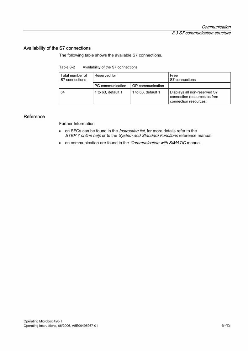
Communication 8.3 S7 communication structure
Operating Microbox 420-T Operating Instructions, 06/2006, A5E00495967-01 8-13
Availability of the S7 connections The following table shows the available S7 connections.
Table 8-2 Availability of the S7 connections
Reserved for Free S7 connections
Total number of S7 connections
PG communication OP communication
64 1 to 63, default 1 1 to 63, default 1 Displays all non-reserved S7 connection resources as free connection resources.
Reference Further Information
• on SFCs can be found in the Instruction list, for more details refer to the STEP 7 online help or to the System and Standard Functions reference manual.
• on communication are found in the Communication with SIMATIC manual.

Communication 8.3 S7 communication structure
Operating Microbox 420-T 8-14 Operating Instructions, 06/2006, A5E00495967-01
Operating Microbox 420-T Operating Instructions, 06/2006, A5E00495967-01 9-1
Cycle and response times 99.1 9.1 WinLC T time model
Time model The integrated technology processes your tasks in single processing cycles. The cycles of the integrated technology affect the task processing of the technology objects for WinLC T. This means the WinLC T time model must be considered for the programming of your user program.
Note for the minimum cycle time The minimum cycle time is initialized to 0 ms. To better utilize the computing power of the Microbox T, the minimum cycle time, however, should be set to a value ≠ 0 ms.
Reference Detailed information for the WinLC T time model is contained in the S7-Technology online help and in the "Time model of the WinLC T (Microbox T)" section of the S7-Technology manual.
Further details for setting the technology system cycle clocks are contained in the "Setting technology system cycle clocks" section of the same manual or in the specified online help.

Cycle and response times 9.1 WinLC T time model
Operating Microbox 420-T 9-2 Operating Instructions, 06/2006, A5E00495967-01

Operating Microbox 420-T Operating Instructions, 06/2006, A5E00495967-01 10-1
Reference information 1010.1 10.1 Technical data
General technical data of WinLC T on Microbox 420-T
General technical data
Order No.: 6ES7 675-3AG30-0PA0 Product version Firmware version (integrated technology) V3.2 Firmware version (CPU) V4.2 Blocks DBs • Number 64k - 1 (from DB1 to DB65535) • Size 64 KByte FBs • Number 64k (from FB0 to FB65535) • Size 64 KByte FCs • Number 64k (from FC0 to FC65535) • Size 64 KByte OBs • Number 30 • Size 64 KByte • Number of free cycle OBs 1 • Number of time-of-day-interrupt OBs 1 • Number of delay interrupt OBs 1 • Number of time interrupts 9 • Number of process interrupt OBs 1 • Number of startup OBs 1 • Number of asynchronous error OBs 7 • Number of synchronous error OBs 2 • Number of diagnostic interrupts 1 • Nesting depth
– Per priority class – Additional nesting depth within an error OB
24 2
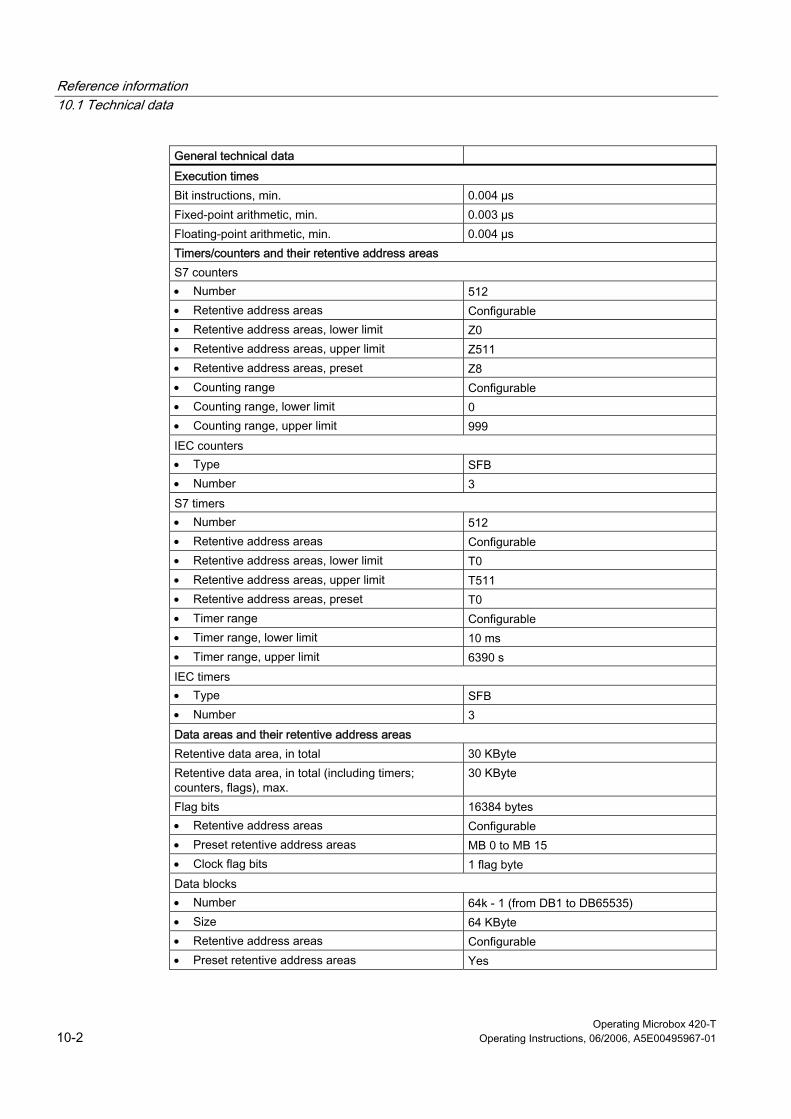
Reference information 10.1 Technical data
Operating Microbox 420-T 10-2 Operating Instructions, 06/2006, A5E00495967-01
General technical data
Execution times Bit instructions, min. 0.004 µs Fixed-point arithmetic, min. 0.003 µs Floating-point arithmetic, min. 0.004 µs Timers/counters and their retentive address areas S7 counters • Number 512 • Retentive address areas Configurable • Retentive address areas, lower limit Z0 • Retentive address areas, upper limit Z511 • Retentive address areas, preset Z8 • Counting range Configurable • Counting range, lower limit 0 • Counting range, upper limit 999 IEC counters • Type SFB • Number 3 S7 timers • Number 512 • Retentive address areas Configurable • Retentive address areas, lower limit T0 • Retentive address areas, upper limit T511 • Retentive address areas, preset T0 • Timer range Configurable • Timer range, lower limit 10 ms • Timer range, upper limit 6390 s IEC timers • Type SFB • Number 3 Data areas and their retentive address areas Retentive data area, in total 30 KByte Retentive data area, in total (including timers; counters, flags), max.
30 KByte
Flag bits 16384 bytes • Retentive address areas Configurable • Preset retentive address areas MB 0 to MB 15 • Clock flag bits 1 flag byte Data blocks • Number 64k - 1 (from DB1 to DB65535) • Size 64 KByte • Retentive address areas Configurable • Preset retentive address areas Yes

Reference information 10.1 Technical data
Operating Microbox 420-T Operating Instructions, 06/2006, A5E00495967-01 10-3
General technical data
Local data • Configurable Max. 16 KByte • Default 256 bytes • Per priority class Min. 20 bytes Address areas (I/O) Total I/O address area 2048 bytes • Inputs 2000 bytes • Outputs 2048 bytes I/O process image • Inputs 2048 bytes • Outputs 2048 bytes • Inputs, configurable 2048 bytes • Outputs, configurable 2048 bytes • Inputs, default 512 bytes • Outputs, default 512 bytes Partial process images Max. 15 Digital channels 65536/65536 • Integrated channels (DI) 0 • Integrated channels (DO) 8 • Inputs 16000 • Outputs 16384 • Inputs/outputs, central 0 Analog channels 4096/4096 • Integrated channels (AI) 0 • Integrated channels (AO) 0 • Inputs 1000 • Outputs 1024 • Inputs/outputs, central 0 Addressing range • Inputs 2048 bytes • Outputs 2048 bytes Address space per module Max. 244 bytes Address areas (I/O) of the integrated technology Total I/O address area Max. 2048 bytes / 2048 bytes
(can be freely addressed) I/O image DP (DRIVE) 64/64 Expansion Connectable PGs/PCs Yes Number of DP masters, integrated 2
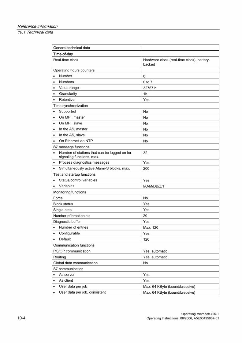
Reference information 10.1 Technical data
Operating Microbox 420-T 10-4 Operating Instructions, 06/2006, A5E00495967-01
General technical data
Time-of-day Real-time clock Hardware clock (real-time clock), battery-
backed Operating hours counters • Number 8 • Numbers 0 to 7 • Value range 32767 h • Granularity 1h • Retentive Yes Time synchronization • Supported No • On MPI, master No • On MPI, slave No • In the AS, master No • In the AS, slave No • On Ethernet via NTP No S7 message functions • Number of stations that can be logged on for
signaling functions, max. 32
• Process diagnostics messages Yes • Simultaneously active Alarm-S blocks, max. 200 Test and startup functions • Status/control variables Yes • Variables I/O/M/DB/Z/T Monitoring functions Force No Block status Yes Single-step Yes Number of breakpoints 20 Diagnostic buffer Yes • Number of entries Max. 120 • Configurable Yes • Default 120 Communication functions PG/OP communication Yes, automatic Routing Yes, automatic Global data communication No S7 communication • As server Yes • As client Yes • User data per job Max. 64 KByte (bsend/breceive) • User data per job, consistent Max. 64 KByte (bsend/breceive)
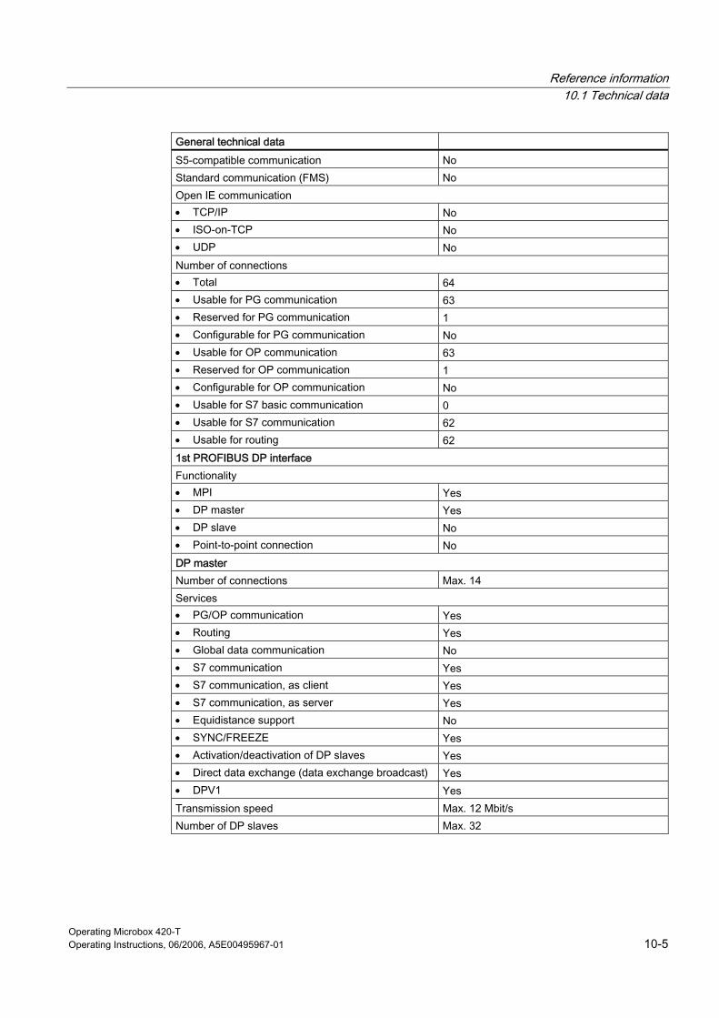
Reference information 10.1 Technical data
Operating Microbox 420-T Operating Instructions, 06/2006, A5E00495967-01 10-5
General technical data
S5-compatible communication No Standard communication (FMS) No Open IE communication • TCP/IP No • ISO-on-TCP No • UDP No Number of connections • Total 64 • Usable for PG communication 63 • Reserved for PG communication 1 • Configurable for PG communication No • Usable for OP communication 63 • Reserved for OP communication 1 • Configurable for OP communication No • Usable for S7 basic communication 0 • Usable for S7 communication 62 • Usable for routing 62 1st PROFIBUS DP interface Functionality • MPI Yes • DP master Yes • DP slave No • Point-to-point connection No DP master Number of connections Max. 14 Services • PG/OP communication Yes • Routing Yes • Global data communication No • S7 communication Yes • S7 communication, as client Yes • S7 communication, as server Yes • Equidistance support No • SYNC/FREEZE Yes • Activation/deactivation of DP slaves Yes • Direct data exchange (data exchange broadcast) Yes • DPV1 Yes Transmission speed Max. 12 Mbit/s Number of DP slaves Max. 32

Reference information 10.1 Technical data
Operating Microbox 420-T 10-6 Operating Instructions, 06/2006, A5E00495967-01
General technical data
User data per DP slave • User data per DP slave Max. 244 bytes • Inputs Max. 244 bytes • Outputs Max. 244 bytes 2nd PROFIBUS DP(DRIVE) interface Automatic determination of transmission rate Yes Number of connection resources 0 Functionality • MPI No • DP master Yes, DP (DRIVE) • DP slave No • Point-to-point connection No • PROFINET CBA No • PROFINET IO-controlled No DP master Number of connections 0 Services • PG/OP communication No • Routing Yes, e.g. to drives • Global data communication No • S7 communication No • S7 communication, as client No • S7 communication, as server No • Equidistance support Yes • SYNC/FREEZE No • Activation/deactivation of DP slaves No • Direct data exchange (data exchange broadcast) No • DPV1 Yes Transmission speed Max. 12 Mbit/s Number of DP slaves Max. 32 User data per DP slave • User data per DP slave Max. 244 bytes • Inputs Max. 244 bytes • Outputs Max. 244 bytes
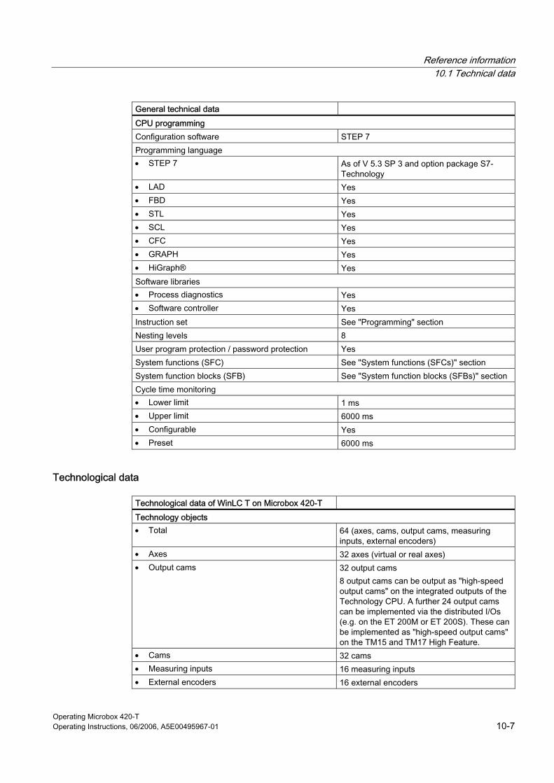
Reference information 10.1 Technical data
Operating Microbox 420-T Operating Instructions, 06/2006, A5E00495967-01 10-7
General technical data
CPU programming Configuration software STEP 7 Programming language • STEP 7 As of V 5.3 SP 3 and option package S7-
Technology • LAD Yes • FBD Yes • STL Yes • SCL Yes • CFC Yes • GRAPH Yes • HiGraph® Yes Software libraries • Process diagnostics Yes • Software controller Yes Instruction set See "Programming" section Nesting levels 8 User program protection / password protection Yes System functions (SFC) See "System functions (SFCs)" section System function blocks (SFB) See "System function blocks (SFBs)" section Cycle time monitoring • Lower limit 1 ms • Upper limit 6000 ms • Configurable Yes • Preset 6000 ms
Technological data
Technological data of WinLC T on Microbox 420-T
Technology objects • Total 64 (axes, cams, output cams, measuring
inputs, external encoders) • Axes 32 axes (virtual or real axes) • Output cams 32 output cams
8 output cams can be output as "high-speed output cams" on the integrated outputs of the Technology CPU. A further 24 output cams can be implemented via the distributed I/Os (e.g. on the ET 200M or ET 200S). These can be implemented as "high-speed output cams" on the TM15 and TM17 High Feature.
• Cams 32 cams • Measuring inputs 16 measuring inputs • External encoders 16 external encoders

Reference information 10.1 Technical data
Operating Microbox 420-T 10-8 Operating Instructions, 06/2006, A5E00495967-01
Technological data of WinLC T on Microbox 420-T
Technology functions • Maximum number of simultaneously active jobs 210 • Maximum number of simultaneously assigned job
data compartments 100 The following technology functions each occupy (as long as they are active) one job data compartment: • "MC_ReadPeriphery" • "MC_WritePeriphery" • "MC_ReadRecord" • "MC_WriteRecord" • "MC_ReadDriveParameter" • "MC_WriteDriveParameter" • "MC_CamSectorAdd"
See also System functions (SFCs) (Page 3-15)
System function blocks (SFBs) (Page 3-19)
Code blocks supported by WinLC T (Page 3-7)
Reference information 10.2 System status list
Operating Microbox 420-T Operating Instructions, 06/2006, A5E00495967-01 10-9
10.2 10.2 System status list
10.2.1 Reading the SSL using SFC51
Description STEP 7 saves write-protected the information about the controller in the system status list (SSL) which is a set of sublists.
Use the SFC 51 (RDSYSST) to access entries in the SSL. You specify the SSL_ID input parameters and the index to access the data records in the sublist. The SFC 51 outputs a header consisting of two words and a sublist or a part of a sublist. The header provides the following information for the sublist:
• The first word defines the length (in bytes) of a data record of the sublist.
• The second word defines the number of data records in the sublist.
The requested information follows the header. The size of the sublist in bytes is data record length multiplied by the number of data records.
Note The SSL ID and the index values are represented as hexadecimal numbers.
Detailed information about the system status list can be found in the STEP 7 online help or in the System Software for S7-300/400 System and Standard Functions reference manual.
WinLC T supports the following SSL entries:
• Module code: 011, 0111, 0F11
• CPU properties: 0012, 0112, 0F12
• Memory areas: 0013
• System areas: 0014, 0F14
• Block types: 0015, 0115, 0F15
• LED status local module: 0019, 0F19
• Component identification: 001C, 011C, 0F1C
• Alarm status: 0222
• Process image partitions: 0025, 0125, 0225, 0F25
• Communications status: 0132. 0232
• LED status: 0174
• DP master system: 0090, 0190, 0F90
• Module status: 0A91, 0C91, 0D91, 0F91
• Module rack and station status: 0092, 0192, 0292, 0692

Reference information 10.2 System status list
Operating Microbox 420-T 10-10 Operating Instructions, 06/2006, A5E00495967-01
• Extended DP master: 0195, 0F95
• Diagnostics buffer: 00A0, 01A0, 0FA0
• Module diagnostics: 00B1, 00B3, 00B4
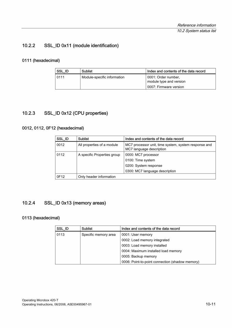
Reference information 10.2 System status list
Operating Microbox 420-T Operating Instructions, 06/2006, A5E00495967-01 10-11
10.2.2 SSL_ID 0x11 (module identification)
0111 (hexadecimal)
SSL_ID Sublist Index and contents of the data record
0111 Module-specific information 0001: Order number, module type and version 0007: Firmware version
10.2.3 SSL_ID 0x12 (CPU properties)
0012, 0112, 0F12 (hexadecimal)
SSL_ID Sublist Index and contents of the data record
0012 All properties of a module MC7 processor unit, time system, system response and MC7 language description
0112 A specific Properties group 0000: MC7 processor 0100: Time system 0200: System response 0300: MC7 language description
0F12 Only header information
10.2.4 SSL_ID 0x13 (memory areas)
0113 (hexadecimal)
SSL_ID Sublist Index and contents of the data record
0113 Specific memory area 0001: User memory 0002: Load memory integrated 0003: Load memory installed 0004: Maximum installed load memory 0005: Backup memory 0006: Point-to-point connection (shadow memory)
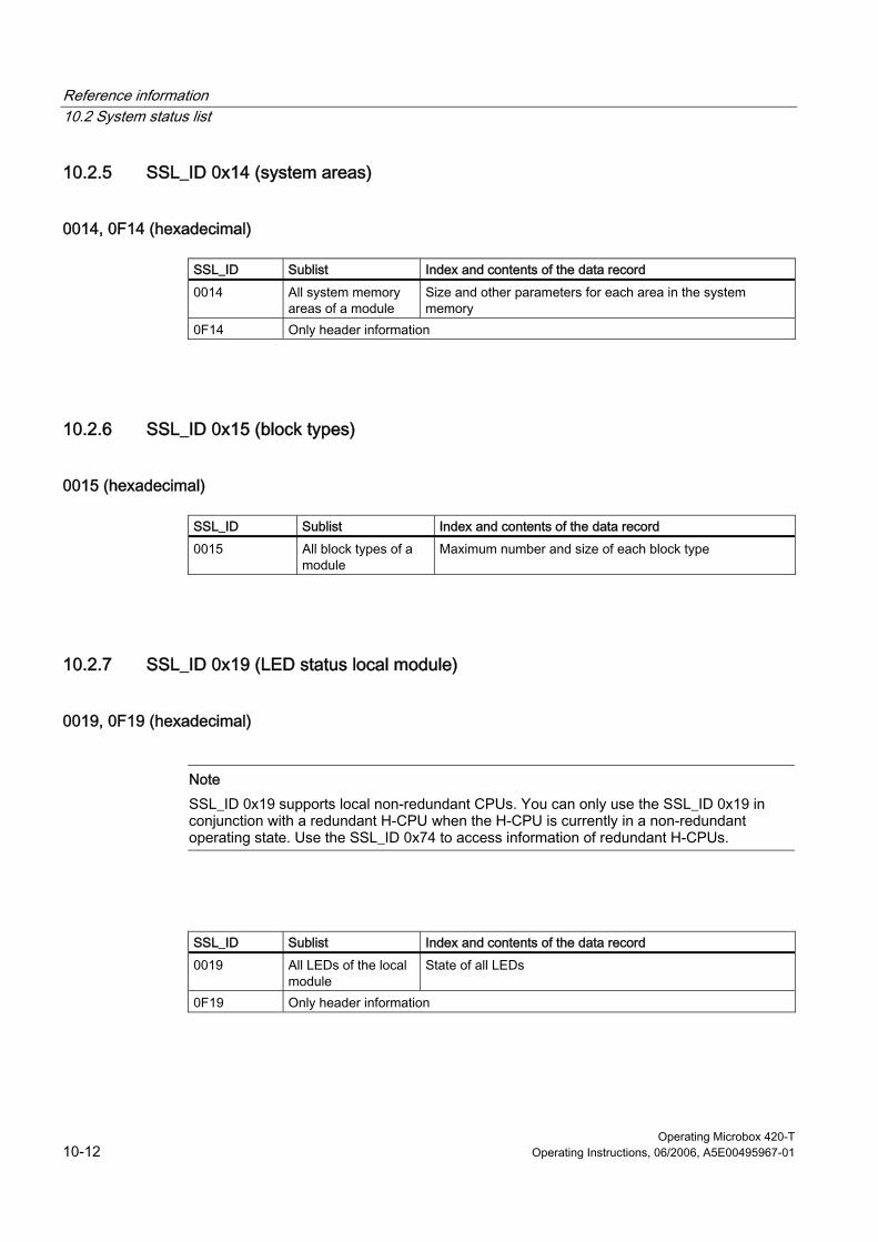
Reference information 10.2 System status list
Operating Microbox 420-T 10-12 Operating Instructions, 06/2006, A5E00495967-01
10.2.5 SSL_ID 0x14 (system areas)
0014, 0F14 (hexadecimal)
SSL_ID Sublist Index and contents of the data record
0014 All system memory areas of a module
Size and other parameters for each area in the system memory
0F14 Only header information
10.2.6 SSL_ID 0x15 (block types)
0015 (hexadecimal)
SSL_ID Sublist Index and contents of the data record
0015 All block types of a module
Maximum number and size of each block type
10.2.7 SSL_ID 0x19 (LED status local module)
0019, 0F19 (hexadecimal)
Note SSL_ID 0x19 supports local non-redundant CPUs. You can only use the SSL_ID 0x19 in conjunction with a redundant H-CPU when the H-CPU is currently in a non-redundant operating state. Use the SSL_ID 0x74 to access information of redundant H-CPUs.
SSL_ID Sublist Index and contents of the data record
0019 All LEDs of the local module
State of all LEDs
0F19 Only header information
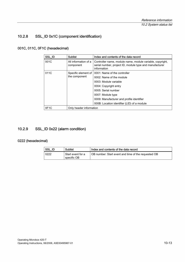
Reference information 10.2 System status list
Operating Microbox 420-T Operating Instructions, 06/2006, A5E00495967-01 10-13
10.2.8 SSL_ID 0x1C (component identification)
001C, 011C, 0F1C (hexadecimal)
SSL_ID Sublist Index and contents of the data record
001C All information of a component
Controller name, module name, module variable, copyright, serial number, project ID, module type and manufacturer information
011C Specific element of the component
0001: Name of the controller 0002: Name of the module 0003: Module variable 0004: Copyright entry 0005: Serial number 0007: Module type 0009: Manufacturer and profile identifier 000B: Location identifier (LID) of a module
0F1C Only header information
10.2.9 SSL_ID 0x22 (alarm condition)
0222 (hexadecimal)
SSL_ID Sublist Index and contents of the data record
0222 Start event for a specific OB
OB number: Start event and time of the requested OB
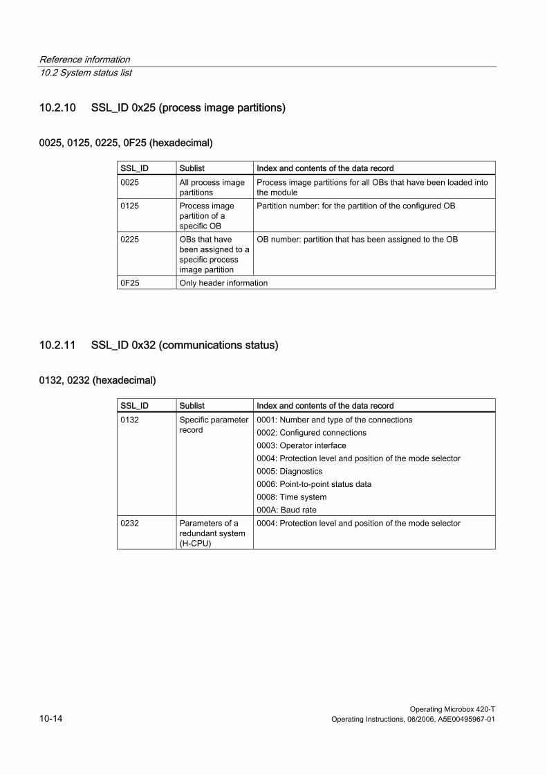
Reference information 10.2 System status list
Operating Microbox 420-T 10-14 Operating Instructions, 06/2006, A5E00495967-01
10.2.10 SSL_ID 0x25 (process image partitions)
0025, 0125, 0225, 0F25 (hexadecimal)
SSL_ID Sublist Index and contents of the data record
0025 All process image partitions
Process image partitions for all OBs that have been loaded into the module
0125 Process image partition of a specific OB
Partition number: for the partition of the configured OB
0225 OBs that have been assigned to a specific process image partition
OB number: partition that has been assigned to the OB
0F25 Only header information
10.2.11 SSL_ID 0x32 (communications status)
0132, 0232 (hexadecimal)
SSL_ID Sublist Index and contents of the data record
0132 Specific parameter record
0001: Number and type of the connections 0002: Configured connections 0003: Operator interface 0004: Protection level and position of the mode selector 0005: Diagnostics 0006: Point-to-point status data 0008: Time system 000A: Baud rate
0232 Parameters of a redundant system (H-CPU)
0004: Protection level and position of the mode selector

Reference information 10.2 System status list
Operating Microbox 420-T Operating Instructions, 06/2006, A5E00495967-01 10-15
10.2.12 SSL_ID 0x74 (LED status)
0174 (hexadecimal)
Note The SSL_ID 0x74 is used to access information for the LEDs of all modules, including redundant H-CPUs. Also refer to SSL_ID 0x19.
SSL_ID Sublist Index and contents of the data record
0174 Specific LED 0002: INTF (internal error) 0003: EXTF (external error) 0004: RUN (run) 0005: STOP (stop) 0006: FRCE (force) 0008: BATF (battery failure) 000B: BUSF1 (fault interface 1) 000C: BUSF2 (fault interface 2) 0012: BUSF3 (fault interface 3) 0013: BUSF4 (fault interface 4)
10.2.13 SSL_ID 0x90 (DP master system)
0090, 0190, 0F90 (hexadecimal)
SSL_ID Sublist Index and contents of the data record
0090 All DP masters configured in the network and loaded into the module
DP master identification, address and attributes of all DP masters
0190 Specific DP master DP master identification: Address and attributes 0F90 Only header information
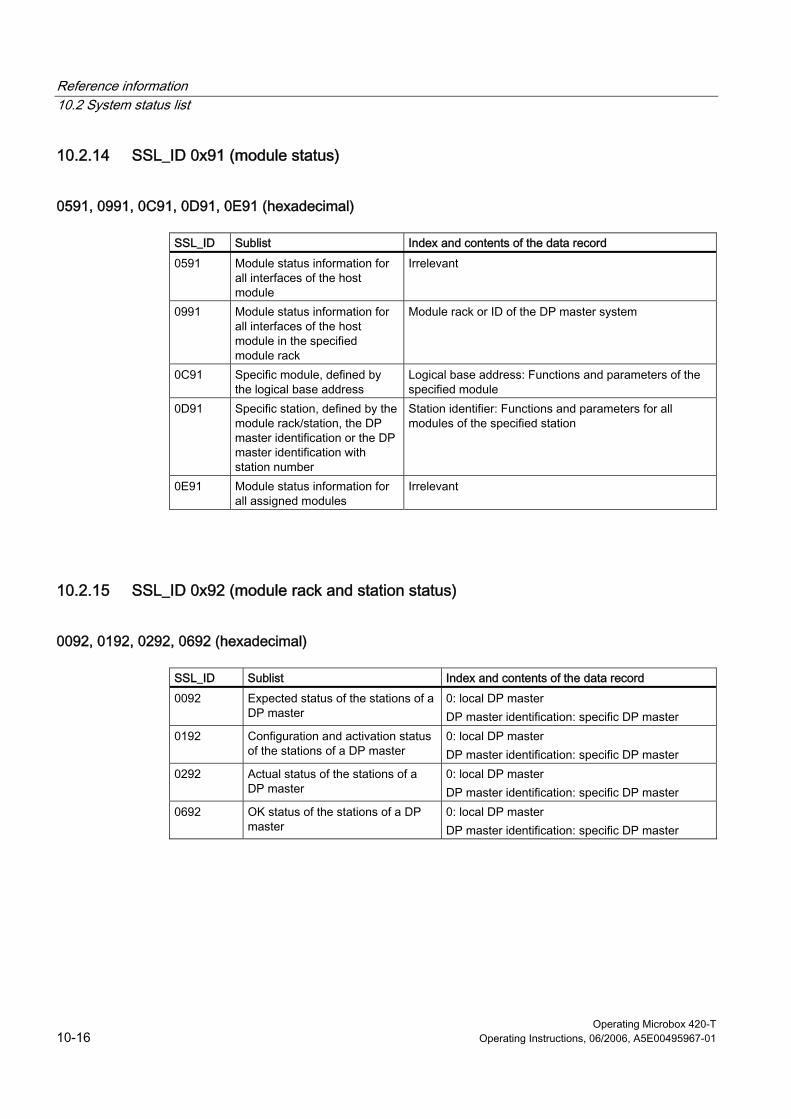
Reference information 10.2 System status list
Operating Microbox 420-T 10-16 Operating Instructions, 06/2006, A5E00495967-01
10.2.14 SSL_ID 0x91 (module status)
0591, 0991, 0C91, 0D91, 0E91 (hexadecimal)
SSL_ID Sublist Index and contents of the data record
0591 Module status information for all interfaces of the host module
Irrelevant
0991 Module status information for all interfaces of the host module in the specified module rack
Module rack or ID of the DP master system
0C91 Specific module, defined by the logical base address
Logical base address: Functions and parameters of the specified module
0D91 Specific station, defined by the module rack/station, the DP master identification or the DP master identification with station number
Station identifier: Functions and parameters for all modules of the specified station
0E91 Module status information for all assigned modules
Irrelevant
10.2.15 SSL_ID 0x92 (module rack and station status)
0092, 0192, 0292, 0692 (hexadecimal)
SSL_ID Sublist Index and contents of the data record
0092 Expected status of the stations of a DP master
0: local DP master DP master identification: specific DP master
0192 Configuration and activation status of the stations of a DP master
0: local DP master DP master identification: specific DP master
0292 Actual status of the stations of a DP master
0: local DP master DP master identification: specific DP master
0692 OK status of the stations of a DP master
0: local DP master DP master identification: specific DP master
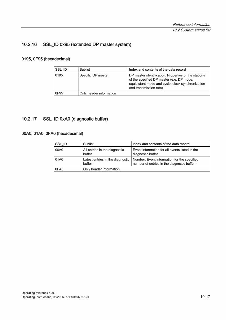
Reference information 10.2 System status list
Operating Microbox 420-T Operating Instructions, 06/2006, A5E00495967-01 10-17
10.2.16 SSL_ID 0x95 (extended DP master system)
0195, 0F95 (hexadecimal)
SSL_ID Sublist Index and contents of the data record
0195 Specific DP master DP master identification: Properties of the stations of the specified DP master (e.g. DP mode, equidistant mode and cycle, clock synchronization and transmission rate)
0F95 Only header information
10.2.17 SSL_ID 0xA0 (diagnostic buffer)
00A0, 01A0, 0FA0 (hexadecimal)
SSL_ID Sublist Index and contents of the data record
00A0 All entries in the diagnostic buffer
Event information for all events listed in the diagnostic buffer
01A0 Latest entries in the diagnostic buffer
Number: Event information for the specified number of entries in the diagnostic buffer
0FA0 Only header information
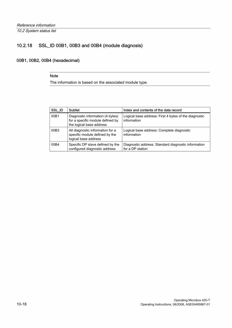
Reference information 10.2 System status list
Operating Microbox 420-T 10-18 Operating Instructions, 06/2006, A5E00495967-01
10.2.18 SSL_ID 00B1, 00B3 and 00B4 (module diagnosis)
00B1, 00B2, 00B4 (hexadecimal)
Note The information is based on the associated module type.
SSL_ID Sublist Index and contents of the data record
00B1 Diagnostic information (4 bytes) for a specific module defined by the logical base address
Logical base address: First 4 bytes of the diagnostic information
00B3 All diagnostic information for a specific module defined by the logical base address
Logical base address: Complete diagnostic information
00B4 Specific DP slave defined by the configured diagnostic address
Diagnostic address: Standard diagnostic information for a DP station
Operating Microbox 420-T Operating Instructions, 06/2006, A5E00495967-01 A-1
A ESD guidelines AA.1 A.1 ESD Guidelines
What does ESD mean? All electronic modules are equipped with highly integrated modules or components. Based on their design, these electronic components are highly sensitive to overvoltage and thus to discharge of static electricity.
The electrostatic sensitive components/modules are commonly referred to as ESD devices. You can also find the commonly used international designation ESD for electrostatic sensitive device.
Electrostatic sensitive modules are identified by the following symbol:
Caution Electrostatic sensitive devices may be destroyed by voltages and energies that are undetectable to a human. Voltages of this kind occur as soon as a component or an assembly is touched by a person who is not grounded against static electricity. The damage to a module as a result of overvoltage cannot usually be detected immediately. It may only become apparent after a long period of operation.
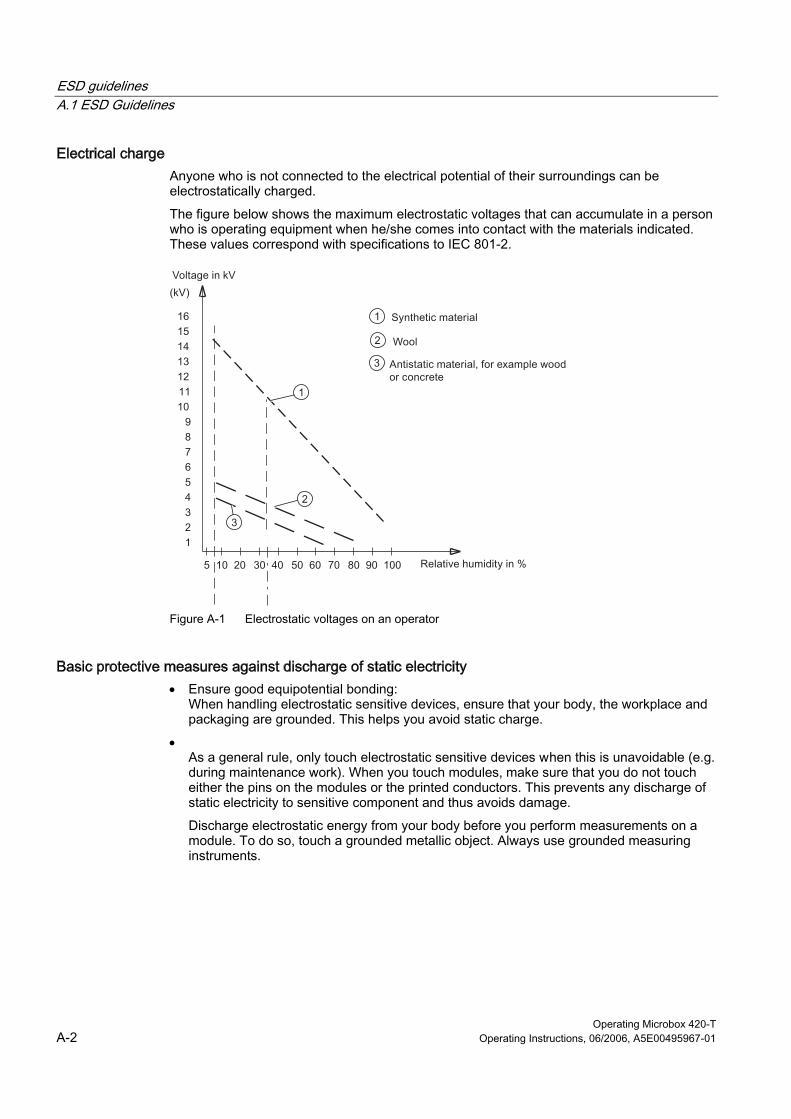
ESD guidelines A.1 ESD Guidelines
Operating Microbox 420-T A-2 Operating Instructions, 06/2006, A5E00495967-01
Electrical charge Anyone who is not connected to the electrical potential of their surroundings can be electrostatically charged.
The figure below shows the maximum electrostatic voltages that can accumulate in a person who is operating equipment when he/she comes into contact with the materials indicated. These values correspond with specifications to IEC 801-2.
Figure A-1 Electrostatic voltages on an operator
Basic protective measures against discharge of static electricity • Ensure good equipotential bonding:
When handling electrostatic sensitive devices, ensure that your body, the workplace and packaging are grounded. This helps you avoid static charge.
• As a general rule, only touch electrostatic sensitive devices when this is unavoidable (e.g. during maintenance work). When you touch modules, make sure that you do not touch either the pins on the modules or the printed conductors. This prevents any discharge of static electricity to sensitive component and thus avoids damage.
Discharge electrostatic energy from your body before you perform measurements on a module. To do so, touch a grounded metallic object. Always use grounded measuring instruments.
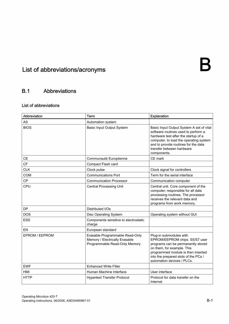
Operating Microbox 420-T Operating Instructions, 06/2006, A5E00495967-01 B-1
B List of abbreviations/acronyms BB.1 B.1 Abbreviations
List of abbreviations Abbreviation Term Explanation
AS Automation system BIOS Basic Input Output System Basic Input Output System A set of vital
software routines used to perform a hardware test after the startup of a computer, to load the operating system and to provide routines for the data transfer between hardware components.
CE Communauté Européenne CE mark CF Compact Flash card CLK Clock pulse Clock signal for controllers COM Communications Port Term for the serial interface CP Communication Processor Communication computer CPU Central Processing Unit Central unit. Core component of the
computer; responsible for all data processing routines. The processor receives the relevant data and programs from work memory.
DP Distributed I/Os DOS Disc Operating System Operating system without GUI ESD Components sensitive to electrostatic
charge
EN European standard EPROM / EEPROM Erasable Programmable Read-Only
Memory / Electrically Erasable Programmable Read-Only Memory
Plug-in submodules with EPROM/EEPROM chips. S5/S7 user programs can be permanently stored on them, for example. This programmed module is then inserted into the prepared slots of the PCs / automation devices / PLCs.
EWF Enhanced Write Filter HMI Human Machine Interface User interface HTTP Hypertext Transfer Protocol Protocol for data transfer on the
Internet
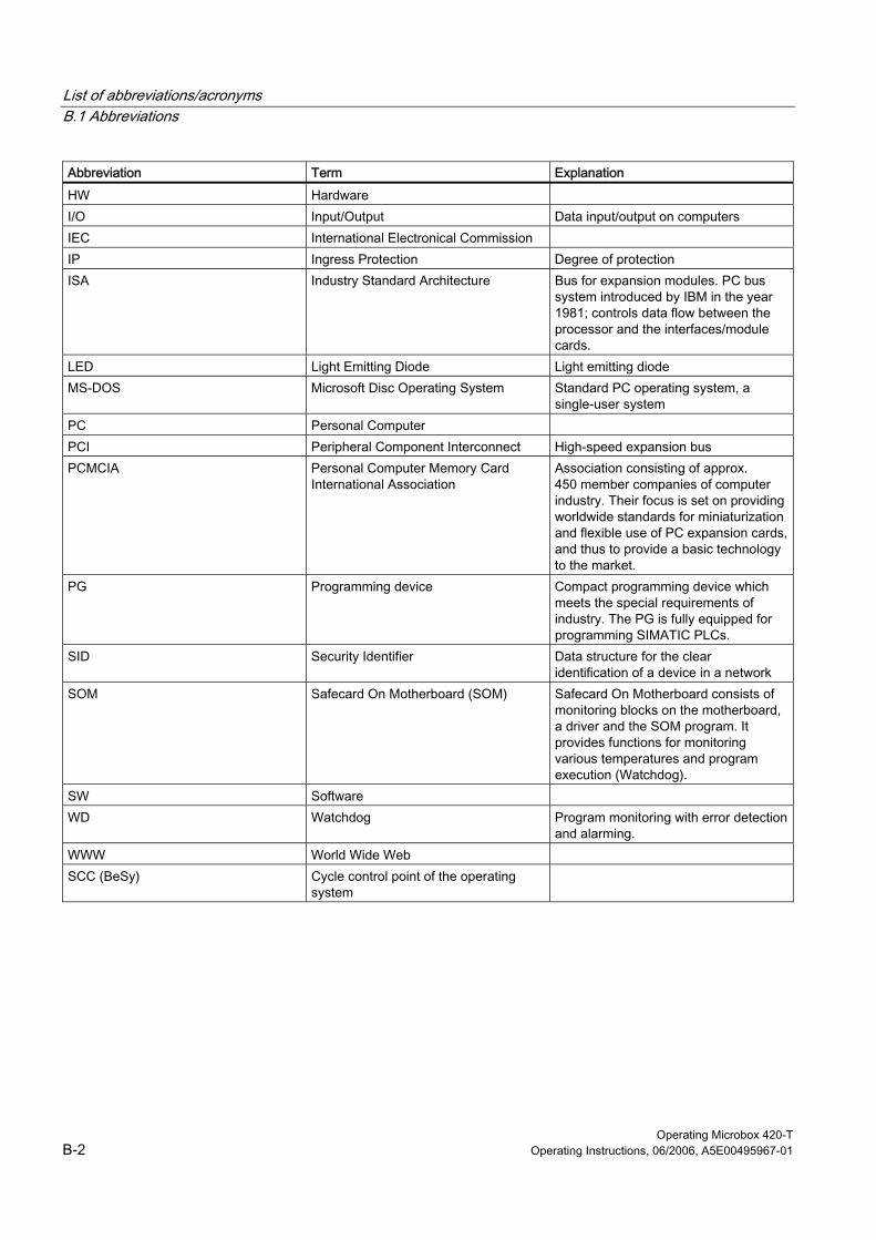
List of abbreviations/acronyms B.1 Abbreviations
Operating Microbox 420-T B-2 Operating Instructions, 06/2006, A5E00495967-01
Abbreviation Term Explanation
HW Hardware I/O Input/Output Data input/output on computers IEC International Electronical Commission IP Ingress Protection Degree of protection ISA Industry Standard Architecture Bus for expansion modules. PC bus
system introduced by IBM in the year 1981; controls data flow between the processor and the interfaces/module cards.
LED Light Emitting Diode Light emitting diode MS-DOS Microsoft Disc Operating System Standard PC operating system, a
single-user system PC Personal Computer PCI Peripheral Component Interconnect High-speed expansion bus PCMCIA Personal Computer Memory Card
International Association Association consisting of approx. 450 member companies of computer industry. Their focus is set on providing worldwide standards for miniaturization and flexible use of PC expansion cards, and thus to provide a basic technology to the market.
PG Programming device Compact programming device which meets the special requirements of industry. The PG is fully equipped for programming SIMATIC PLCs.
SID Security Identifier Data structure for the clear identification of a device in a network
SOM Safecard On Motherboard (SOM) Safecard On Motherboard consists of monitoring blocks on the motherboard, a driver and the SOM program. It provides functions for monitoring various temperatures and program execution (Watchdog).
SW Software WD Watchdog Program monitoring with error detection
and alarming. WWW World Wide Web SCC (BeSy) Cycle control point of the operating
system

Operating Microbox 420-T Operating Instructions, 06/2006, A5E00495967-01 Glossary-1
Glossary
Application An application is a program that runs directly on the MS-DOS / Windows operating system. Applications on your PG or PC, for example, are STEP 7, STEP 7-Micro/WIN.
Backup Duplicate of a program, data carrier or database, used either for archiving purposes or for the protection of vital and non-replaceable data against loss when the working copy is corrupted. Some applications automatically generate backup copies of data files, and manage both the current and the previous versions on the hard disk.
Baud Physical unit for the stepping rate in signal transmission. Defines the number of transferred signal states per second. With only two states, one baud is equivalent to a transmission rate of 1 bps.
Cache High-speed access buffer for interim storage (buffering) of requested data.
CE Marking Communauté Européene (EC label of goods)
Cold start A start sequence, starting when the computer is switched on. The system usually performs some basic hardware checks within the cold start sequence, and then loads the operating system from the hard disk to work memory -> boot
Communication interface The PROFIBUS interface or Industrial Ethernet interface integrated in the Microbox T that WinLC T uses for the communication.
Cycle The cycle includes the writing to the outputs, the reading from the inputs, the execution of the OB 1 and all other OBs and the satisfying of the rest period requirement.
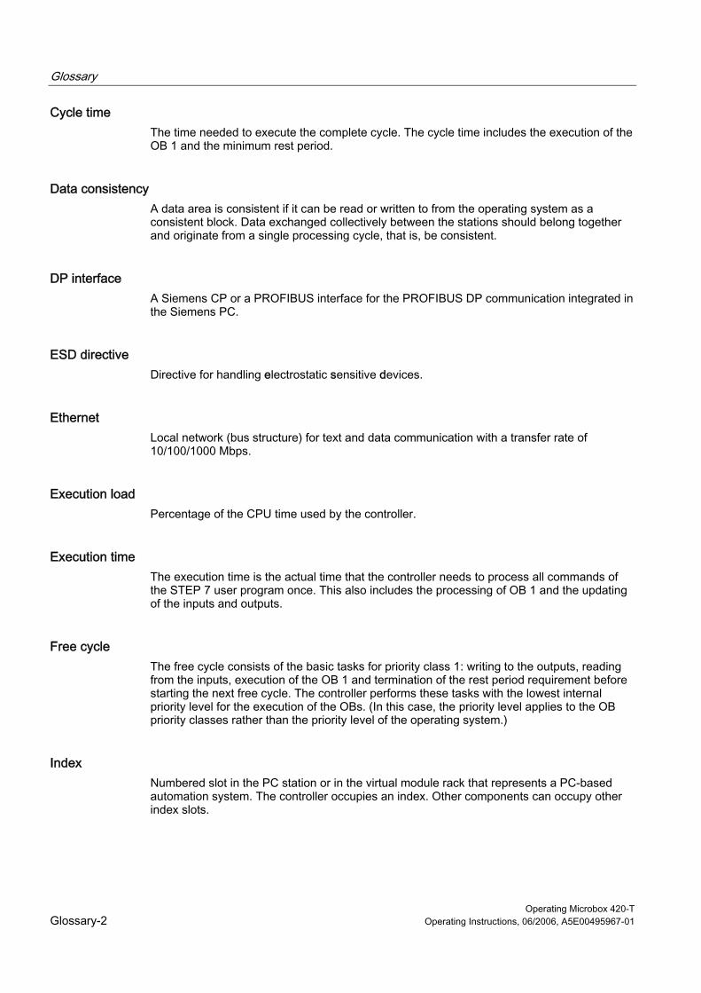
Glossary
Operating Microbox 420-T Glossary-2 Operating Instructions, 06/2006, A5E00495967-01
Cycle time The time needed to execute the complete cycle. The cycle time includes the execution of the OB 1 and the minimum rest period.
Data consistency A data area is consistent if it can be read or written to from the operating system as a consistent block. Data exchanged collectively between the stations should belong together and originate from a single processing cycle, that is, be consistent.
DP interface A Siemens CP or a PROFIBUS interface for the PROFIBUS DP communication integrated in the Siemens PC.
ESD directive Directive for handling electrostatic sensitive devices.
Ethernet Local network (bus structure) for text and data communication with a transfer rate of 10/100/1000 Mbps.
Execution load Percentage of the CPU time used by the controller.
Execution time The execution time is the actual time that the controller needs to process all commands of the STEP 7 user program once. This also includes the processing of OB 1 and the updating of the inputs and outputs.
Free cycle The free cycle consists of the basic tasks for priority class 1: writing to the outputs, reading from the inputs, execution of the OB 1 and termination of the rest period requirement before starting the next free cycle. The controller performs these tasks with the lowest internal priority level for the execution of the OBs. (In this case, the priority level applies to the OB priority classes rather than the priority level of the operating system.)
Index Numbered slot in the PC station or in the virtual module rack that represents a PC-based automation system. The controller occupies an index. Other components can occupy other index slots.

Glossary
Operating Microbox 420-T Operating Instructions, 06/2006, A5E00495967-01 Glossary-3
Industrial Ethernet Physical communications layer for the communication with STEP 7, S7 CPUs, PGs, OPs and S7 applications.
Interface The connection between individual hardware elements such as PLCs, programming devices, printers or monitors via physical connections (cables).
Interface The connection between individual hardware elements such as PLCs, programming devices, printers or monitors via physical connections (cables).
Operating system Summarizing term describing all functions for program execution, allocation of system resources to the various user programs, and for controlling and monitoring consistency of the operating mode in cooperation with the hardware (e.g. Windows Embedded).
Organization block (OB) Interface between the operating system and the STEP 7 user program. The organization blocks are called from the operating system and control the cyclical and alarm-controlled program execution, the startup behavior of the controller and the error processing.
Password Unique sequence of characters that is entered for user identification.
PC station Representation of a software-based virtual module rack that defines a PC-based automation system.
PCMCIA Personal Computer Memory Card International Association Association consisting of approx. 450 member companies of the computer industry. Their focus is set on providing worldwide standards for miniaturization and flexible use of PC expansion cards, and thus to provide a basic technology to the market.
PG/OP communication The communication between WinLC T and other S7 applications, such as programming devices, operator panels and S7 automation systems. WinLC RTX supports PROFIBUS and Industrial Ethernet for the PG/OP communication.
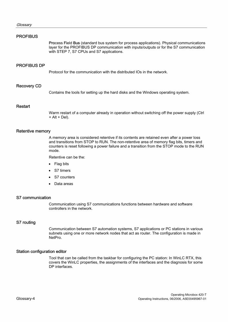
Glossary
Operating Microbox 420-T Glossary-4 Operating Instructions, 06/2006, A5E00495967-01
PROFIBUS Process Field Bus (standard bus system for process applications). Physical communications layer for the PROFIBUS DP communication with inputs/outputs or for the S7 communication with STEP 7, S7 CPUs and S7 applications.
PROFIBUS DP Protocol for the communication with the distributed IOs in the network.
Recovery CD Contains the tools for setting up the hard disks and the Windows operating system.
Restart Warm restart of a computer already in operation without switching off the power supply (Ctrl + Alt + Del).
Retentive memory A memory area is considered retentive if its contents are retained even after a power loss and transitions from STOP to RUN. The non-retentive area of memory flag bits, timers and counters is reset following a power failure and a transition from the STOP mode to the RUN mode.
Retentive can be the:
• Flag bits
• S7 timers
• S7 counters
• Data areas
S7 communication Communication using S7 communications functions between hardware and software controllers in the network.
S7 routing Communication between S7 automation systems, S7 applications or PC stations in various subnets using one or more network nodes that act as router. The configuration is made in NetPro.
Station configuration editor Tool that can be called from the taskbar for configuring the PC station: In WinLC RTX, this covers the WinLC properties, the assignments of the interfaces and the diagnosis for some DP interfaces.
Glossary
Operating Microbox 420-T Operating Instructions, 06/2006, A5E00495967-01 Glossary-5
STEP 7 Programming software for the creation of user programs for SIMATIC S7 controllers.
STEP 7 user program An application program created with STEP 7 and for execution is loaded into the controller. It includes all organization blocks (e.g. OB 1 or OB 35) and the other code blocks that are called, including functions (FCs), system functions (SFCs), function blocks (FBs) and system function blocks (SFBs).
System function (SFC) Preprogrammed function integrated as part of the operating system of the controller and not loaded as part of the STEP 7 user program. You can call an SFC in your STEP 7 user program. Like a function (FC), an SFC is a block "without memory".
System function block (SFB) Function block integrated as part of the operating system of the controller and not loaded as part of the STEP 7 user program. Like a function block (FB), an SFB is a block "with memory". You must also create an instance data block (DB) for the SFB. The instance DB is then loaded as part of the STEP 7 user program into the controller.
Time synchronization The capability to transfer a standard system time from a single source to all devices in the system so that their clocks can be set to conform to the standard time.
User program The user program contains all instructions and declarations, as well as signal processing data that can be controlled by the plant or the process. It is assigned to a programmed module and can be structured in smaller units (blocks).
Warm restart The restart of a computer after a program was aborted. The operating system is loaded and restarted again. The hot key Ctrl + Alt + Del can be used to perform a warm start.
Windows Microsoft Windows is a multitasking graphical user interface. Windows provides a standard graphical interface based on drop-down menus, windowed regions on the screen, and allows operation with a pointer device such as a mouse.
Windows crash Failure of the Windows operating system where the severe error is displayed with blue background on the screen. Such a Windows crash is also called a "blue screen".
Work memory This is a RAM area in the CPU which is accessed by the processor during user program execution.

Glossary
Operating Microbox 420-T Glossary-6 Operating Instructions, 06/2006, A5E00495967-01
Operating Microbox 420-T Operating Instructions, 06/2006, A5E00495967-01 Index-1
Index
A Abbreviations, B-1 Access security, 4-19 ADI4
Analog drive interface, 8-4 Alarm state, 10-13 Analog drive interface
ADI4, 8-4 Archive file, 4-15 Archiving user programs, 4-15 Assignment
S7 connection, 8-11 Asynchronous SFCs, 3-17 Autostart function, 4-17 Availability
S7 connection, 8-13
B Back up
For data, 7-11 Backing up data, 7-11 Block types, 10-12 Buffering
For data, 7-7 Buffering data, 7-7
C Closing the control panel, 4-9 Closing the controller, 4-9 Closing WinLC T, 4-9 Code blocks
Supported by WinLC T, 3-7 COMBIMASTER, 8-4 Communication, 8-1
Data consistency, 8-9 Communication interface, 2-4 Communication path
S7 connection, 8-10
Communication services, 8-6 OP communication, 8-7 PG communication, 8-6
Communication status, 10-14 Component identification, 10-13 Configuration of the Microbox 420-T, 1-3 Configuring hardware in STEP 7, 3-4 Connectable devices, 8-4 Connection point, 8-10 Control panel, 4-3
Access security, 4-19 Language setting, 4-17 Options for the configuration, 4-16
Controller Functions, 4-1 Operator control, 4-1
Controller startup, 7-4 CPU load, 4-11 CPU memory reset, 4-8 CPU properties, 10-11 Customer-specific software, 1-4 Cycle time
Histogram, 4-11
D Data consistency, 8-9 Design
S7 communication, 8-10 Devices
connectable, 8-4 non-connectable, 8-4
Diagnostic buffer, 4-13, 10-17 Diagnostic information, 4-13 Diagnostics, 8-4
SOM (Safecard On Motherboard), 5-2 Distribution
S7 connection, 8-12 DP interface, 8-3 DP master system, 10-15 DPV1 functionality, 3-9 Drive interface
Analog, 8-4
Index
Operating Microbox 420-T Index-2 Operating Instructions, 06/2006, A5E00495967-01
E Electrostatically sensitive devices, A-1 Enhanced Write Filter, 5-4 Error OBs
Supported by WinLC T, 3-13 ESD Guidelines, A-1 ET 200M, 8-4 Ethernet interfaces, 8-1 EWF (Enhanced Write Filter), 5-4 Expansions, 1-4 Extended DP master system, 10-17
F Factory state
Restoring, 7-11 Failure of the Motion Control
Operation of WinLC T, 3-29
G General technical data, 10-1 Guidelines
ESD Guidelines, A-1
H Hardware catalog, 8-4
I I/O interface, 8-5 Index, 2-5 Initialization of the integrated technology, 3-1 Integrated technology, 1-5 Interfaces, 8-1
DP, 8-3 DP(DRIVE), 8-4 Ethernet, 8-1 I/O, 8-5
Interrupt OBs Supported by WinLC T, 3-12
Introduction, 1-2
J Jitter, 3-11
L Language setting, 4-17 LED status, 10-15 LED status for local module, 10-12 Loading memory, 7-1, 7-4
M MASTERDRIVES, 8-4 Max. S7 PLC load, 4-12 Memory areas, 10-11 Memory areas for inputs/outputs, 7-2 Minimum cycle time, 9-1 Mode, 4-5 Mode selector, 4-5 Module diagnostics, 10-18 Module identification, 10-11 Module rack and station status, 10-16 Module state, 10-16 Monitoring functions, 5-2 Motion Control
Failure, 3-29 MRES, 4-8
N Non-connectable devices, 8-4
O OBs
For free cycle, 3-11 For warm restart, 3-11 Supported by WinLC T, 3-10
OP communication, 8-7 OPC server, 6-1
Add to the PC station, 6-2 Adding to the configuration for WinLC T, 6-5 Adding to the hardware configuration, 6-4 Connect with the controller, 6-10 Loading the configuration into the controller, 6-9
Operating hours counter, 3-22 Operating parameters, 3-6 Organization blocks (OBs)
For free cycle, 3-11 For warm restart, 3-11 Supported by WinLC T, 3-10
Index
Operating Microbox 420-T Operating Instructions, 06/2006, A5E00495967-01 Index-3
P Panel, 4-1 Password
Applicability, 4-20 Changing, 4-20
PC station, 2-2 Configuring in HW Config, 3-4
PC-based control, 1-3 PG communication, 8-6 Porting
STEP 7 program for CPU317T, 3-23 Step 7 program for WinAC RTX, 3-23
Power failure Retentive data, 7-10 Windows applications, 7-10
Process image partitions, 10-14 Process interrupt
Response time, 8-9 Processing sequence
Data block, 1-5 PROFIBUS DP (DRIVE), 8-4 PROFIBUS DPV1, 3-9 PROFIdrive, 8-4 PUT/GET function, 8-9
R Reading the SSL, 10-9 Reservation
S7 connection, 8-11 Restore, 7-11 Restoring an archive file, 4-15 Retentive data, 7-3 RUN
Permitted functions, 4-5 Prohibited functions, 4-5
S S7 blocks, 3-7 S7 communication
Design, 8-10 S7 communication functions, 3-8 S7 connection
Assignment, 8-11 Availability, 8-13 Communication path, 8-10 Distribution, 8-12 Reservation, 8-11
S7 connections Time sequence for allocation, 8-12
Safecard on Motherboard (SOM), 5-2
Setting PG/OP communication, 8-7 SFBs
Supported by WinLC T, 3-19 SFC 82, 3-18 SFC 83, 3-18 SFC 84, 3-18 SFCs
Asynchronous, 3-17 Deviations in the cycle, 3-17 Operating hours counter, 3-22 Supported by WinLC T, 3-15 System clock, 3-22
SIMATIC functionality Supported by WinLC T, 1-4
SIMODRIVE 611 universal, 8-4 SIMODRIVE POSMO, 8-4 SINAMICS, 8-4 SOM, 5-2 Starting the controller, 4-9 Starting WinLC T, 4-9 Status display
BATF, 4-6 BUSF1, 4-6 BUSF2, 4-6 EXTF, 4-6 FRCE, 4-6 INTF, 4-6 ON, 4-6 RUN, 4-6 STOP, 4-6
Status displays, 4-6 During startup, 4-6 Flashing, 4-7
STEP 7 Configuring the hardware, 3-4
STOP Permitted functions, 4-5
System areas, 10-12 System clock, 3-22 System Cycle Clocks
Technology, 5-1 System function blocks (SFBs)
Supported by WinLC T, 3-19 System functions (SFCs)
Supported by WinLC T, 3-15 System memory, 7-2 System status list (SSL), 10-9 System structure, 1-3
Index
Operating Microbox 420-T Index-4 Operating Instructions, 06/2006, A5E00495967-01
T T-Cycle config, 4-11 Technical data, 10-1
CPU 315T-2 DP, 10-8 WinLC T on Microbox 420-T, 10-1
Technology data block Processing sequence, 1-5
Technology data blocks, 3-12 Technology functions, 10-8
Supported by WinLC T, 3-20 Technology objects, 10-7 Technology system cycle clocks, 5-1 Time interrupt OBs, 3-13 Time model, 9-1 Time resolution, 3-11 Transition point, 8-10 Tuning panel, 4-10
U Uninterruptible power supply (UPS), 7-10 UPS, 7-10 Using STEP 7, 3-1
W WinAC ODK
Interfaces for WinLC T, 3-24 Windows crash
Operation of WinLC T, 3-27 Restart of WinLC T, 3-28 Starting the controller, 7-6
Windows taskbar Icon for WinLC T, 4-4
WinLC T Icon in Windows taskbar, 4-4
WinLC T timing, 4-11 Work memory, 7-2
X X1, 8-3 X11, 8-5 X2, 8-4


![BA Komp Microbox Enu en-US[1]](https://static.fdocuments.net/doc/165x107/577d1d911a28ab4e1e8c89d0/ba-komp-microbox-enu-en-us1.jpg)
![iBOT - Robotics Practical Book for IPST-MicroBOX [SE]](https://static.fdocuments.net/doc/165x107/579091101a28ab7b278f5eba/ibot-robotics-practical-book-for-ipst-microbox-se.jpg)


