Microalloyed Steels - University of Strathclyde features including atom clusters, ... titanium...
179
Microalloyed Steels [an invited review for Ironmaking and Steelmaking ] T.N. Baker Metallurgy and Engineering Materials Research Group Department of Mechanical and Aerospace Engineering University of Strathclyde Glasgow G1 1XJ. 21 September 2015 Abstract This review considers the compositions, the main process routes, microstructure, and structural properties of microalloyed steels. The background and brief history are followed by sections dealing with aspects of precipitation which control grain size and dispersion strengthening in ferrite- pearlite steels, the approaches to modelling thermomechanical processing and the influence of multiple additions of transition metals on properties. High strength acicular ferrite/bainite steels used for linepipe are included and lead to super bainite steels. Around 12% of the world strip production is processed by the thin slab direct charging route, which is considered in some detail. The weldability of microalloyed steels now embraces joining using friction stir welding, which is discussed.
-
Upload
trinhnguyet -
Category
Documents
-
view
229 -
download
9
Transcript of Microalloyed Steels - University of Strathclyde features including atom clusters, ... titanium...
Microalloyed Steels
[an invited review for Ironmaking and Steelmaking ]
T.N. Baker
Metallurgy and Engineering Materials Research Group
Department of Mechanical and Aerospace Engineering
University of Strathclyde
Glasgow
G1 1XJ.
21 September 2015
Abstract
This review considers the compositions, the main process routes,
microstructure, and structural properties of microalloyed steels. The
background and brief history are followed by sections dealing with aspects of
precipitation which control grain size and dispersion strengthening in ferrite-
pearlite steels, the approaches to modelling thermomechanical processing and
the influence of multiple additions of transition metals on properties. High
strength acicular ferrite/bainite steels used for linepipe are included and lead to
super bainite steels. Around 12% of the world strip production is processed by
the thin slab direct charging route, which is considered in some detail. The
weldability of microalloyed steels now embraces joining using friction stir
welding, which is discussed.
Over the years, many approaches have been developed to predict the structural
properties of microalloyed steels. They comprise several quantifiable
microstructural features including atom clusters, relatively recently identified
through atom probe tomography. A comprehensive collection of references is
provided.
Keywords Niobium, vanadium, titanium steels ;Thermomechanical Processing;
Microstructure; Structural properties; Acicular ferrite and bainitic steels; Thin slab direct
charging; Friction stir welding; Components of strengthening; Reviews.
1 Introduction
This review follows two previous reviews by the present author on
‘microalloyed steels’.1,2
Since the second of these was published in 1992, an
excellent book by Gladman 3
and
several reviews closely related to
microalloyed steels have appeared.4-7
Also, reviews on specific elements in
microalloyed steels have been published. These include the influence of
additions in microalloyed steels of niobium by DeArdo8, an overview of
titanium microalloyed steels by Pickering9 and reviews of vanadium by
Langneborg et al10, 11
and Baker12
, and of zirconium by Baker 13
, together with
the effects of aluminium nitride in steel by Wilson and Gladman14
. In the main,
these publications deal with microalloyed steels having a ferrite-pearlite (FP)
microstructure.
What therefore is new and justifies yet another review? In the intervening years,
there has been a continual drive to produce high strength structural steels at a
lower cost. Therefore microalloyed steels have progressed in several directions.
A better understanding of the role of both the microalloying additions and the
deformation processes, usually hot rolling, has been sought. Thermomechanical
processing has been refined through a better understanding of the relationships
between processing parameters, especially those involving controlled rolling,
and microstructure and properties. Direct charged thin slab processing of
microalloyed steels is an example of a developing route, (by 2007, 12% of the
World’s strip), which for some products, is more economic and has
environmental advantages over conventional processes. The extension of high
strength microalloyed steels into non-F-P microstructures, having yield
strengths (σy ) >500MPa, for such applications as pipe-line and automobiles is
well advanced. However, the application of friction stir welding to
microalloyed steels, which reduces residual stresses associated with the fusion
welding processes, is at much earlier stage of commercial exploitation. At a
fundamental level, the strength contributions from nano-precipitates is being
investigated, which, in some cases, may change the way estimates of
contributions to strength based on microstructure are summated. The modelling
of hot working processes involving microalloyed steels is a work still in
progress. All these areas will be included in this review. However, with
~130,000 hits on Google for ‘microalloyed steels’, the work reviewed is
inevitably selective. It is based on well-cited papers that the author has been
aware of for some time, and recent papers that make a novel contribution to the
field from the many research groups world-wide, that I follow.
2. Background
The estimated world production of steels of all classes for 2014 is about
1.65 billion tonnes, of which 50% is accounted for from China.15
Of this
total, an ~12%, equal to some 200 million tonnes, a substantial component,
is made up of microalloyed steels.16
Compared to mild steel, with a lower yield strength, σy, of 150-200 MPa,
current microalloyed steels have σy values in the range of 350 to 800MPa,
with the potential to exceed 1000MPa. 17
Microalloyed (MA) or High Strength Low Alloy (HSLA) steels prior to the
1980’s, contained typically, 0.07 to 0.12% carbon, up to 2% manganese and
small additions of niobium, vanadium, titanium, (all usually max. 0.1%) in
various combinations.18
(The steel compositions are given in wt.-%, throughout
the paper, unless stated otherwise.) Other elements which might be present
include molybdenum, zirconium, boron, aluminium, nitrogen and rare-earth
metals.
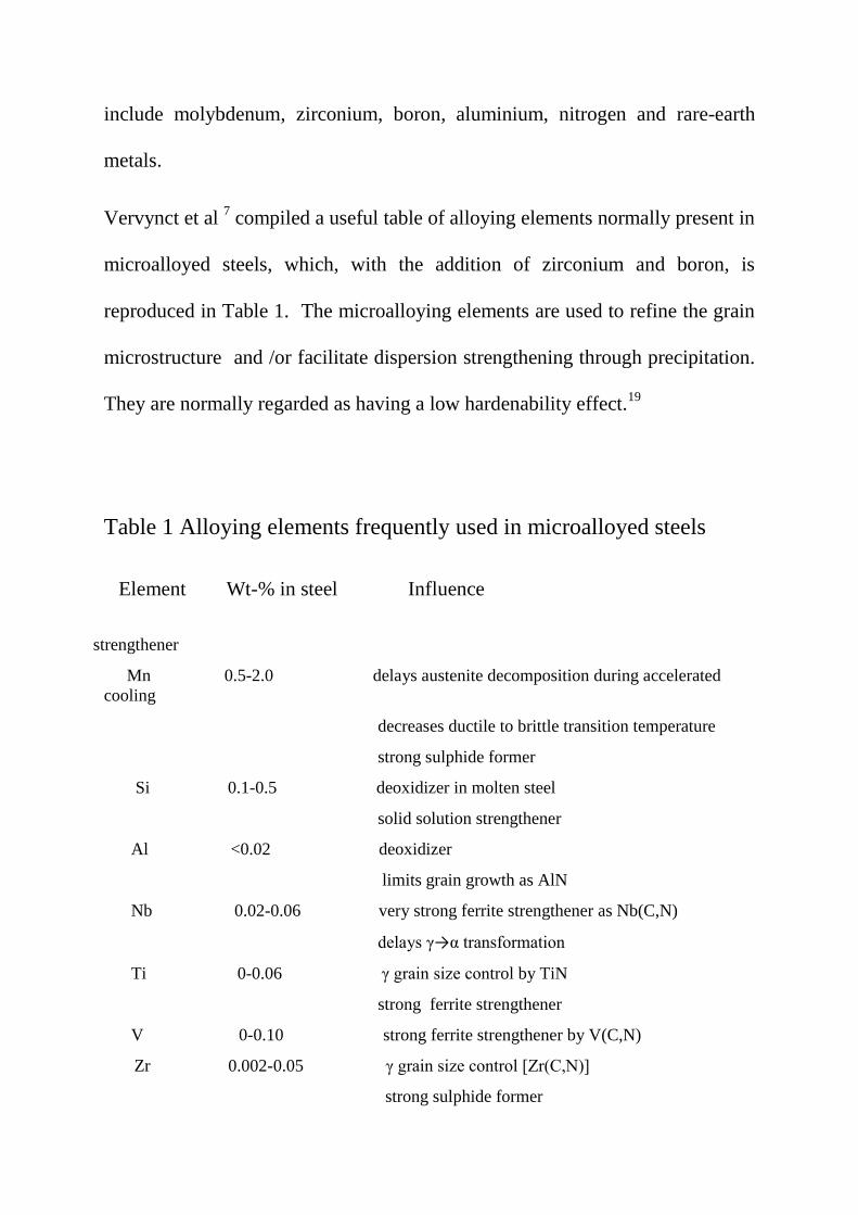
Vervynct et al 7 compiled a useful table of alloying elements normally present in
microalloyed steels, which, with the addition of zirconium and boron, is
reproduced in Table 1. The microalloying elements are used to refine the grain
microstructure and /or facilitate dispersion strengthening through precipitation.
They are normally regarded as having a low hardenability effect.19
Table 1 Alloying elements frequently used in microalloyed steels
Element Wt-% in steel Influence
C <0.25 strengthener
Mn 0.5-2.0 delays austenite decomposition during accelerated
cooling
decreases ductile to brittle transition temperature
strong sulphide former
Si 0.1-0.5 deoxidizer in molten steel
solid solution strengthener
Al <0.02 deoxidizer
limits grain growth as AlN
Nb 0.02-0.06 very strong ferrite strengthener as Nb(C,N)
delays γ→α transformation
Ti 0-0.06 γ grain size control by TiN
strong ferrite strengthener
V 0-0.10 strong ferrite strengthener by V(C,N)
Zr 0.002-0.05 γ grain size control [Zr(C,N)]
strong sulphide former
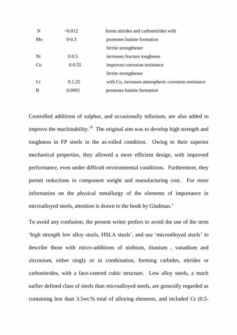
N <0.012 forms nitrides and carbonitrides with
Mo 0-0.3 promotes bainite formation
ferrite strengthener
Ni 0.0.5 increases fracture toughness
Cu 0-0.55 improves corrosion resistance
ferrite strengthener
Cr 0.1.25 with Cu, increases atmospheric corrosion resistance
B 0.0005 promotes bainite formation
Controlled additions of sulphur, and occasionally tellurium, are also added to
improve the machinability.19
The original aim was to develop high strength and
toughness in FP steels in the as-rolled condition. Owing to their superior
mechanical properties, they allowed a more efficient design, with improved
performance, even under difficult environmental conditions. Furthermore, they
permit reductions in component weight and manufacturing cost. For more
information on the physical metallurgy of the elements of importance in
microalloyed steels, attention is drawn to the book by Gladman.3
To avoid any confusion, the present writer prefers to avoid the use of the term
‘high strength low alloy steels, HSLA steels’, and use ‘microalloyed steels’ to
describe those with micro-additions of niobium, titanium , vanadium and
zirconium, either singly or in combination, forming carbides, nitrides or
carbonitrides, with a face-centred cubic structure. Low alloy steels, a much
earlier defined class of steels than microalloyed steels, are generally regarded as
containing less than 3.5wt.% total of alloying elements, and included Cr (0.5-
2.5%),Mo ≤ 3% and V ~1%. These steels were developed as creep resistant
steels, but had an upper temperature limitation < 400°C, with applications, as
discussed by Oakes and Barroclough20
, in the earlier British aero gas turbines,
and by Robertson21
, in coal power energy producing plants. The Cr Mo grades
were normalised, while the Cr Mo V types were used in the normalised and
tempered condition, to develop the alloy carbides in a bainitic microstructure,
which conferred their particular properties. While the earlier microalloyed
steels sought to avoid transformation to acicular ferrite and bainite, modern
microalloyed steels, built upon a sounder understanding of the processing routes
and the development of microstructure than was available prior to the 1980’s,
embrace these phases17
.
In microalloyed steels, FeNb consumption has grown threefold during the last
25 years and the most part of this growth has been noticeable over the past ten
years. Fig 1 shows the trend in ferro-niobium production. Also, the
development of microalloyed steels was far greater and far quicker for flat
products than for long products. 22
The material is produced preferably by a thermomechanical rolling process, also
known as controlled rolling, possibly with accelerated cooling, which maximize
grain refinement as a basis for improved mechanical properties. Prior to
thermomechanical processing, the steel was heated into the austenite
temperature range for all of the precipitates to be taken into solution; after
forming, the material must be quickly cooled to 600°C to 540 °C.18
Medium
carbon directly quenched (DC) microalloyed steels, avoiding FP
microstructures, can also be forged. 23
Microalloyed steels lie, in terms of performance and cost, between carbon steel,
or mild steels and low alloy steels mentioned above. Until around 1980, low
alloy steels were designed to have a yield strength between 500 and 750 MPa
without heat treatment. The weldability is at least equal to that of mild steel,
and can be improved by reducing carbon content while maintaining strength.
Fatigue life and wear resistance are superior to similar heat-treated steels. The
disadvantages are that ductility and toughness are not as good as quenched and
tempered (Q&T) steels.18
Cold-worked microalloyed steels do not require as much cold working to
achieve the same strength as other carbon steels; this also leads to greater
ductility. Hot-worked microalloyed steels can be used from the air-cooled state.
If controlled cooling is used, the material can produce mechanical properties
similar to Q&T steels. Their machinability is better than Q&T steels because of
their more uniform hardness and their FP microstructure.18
Because FP
microalloyed steels are not quenched and tempered, they are not susceptible to
quench cracking, nor do they need to be straightened or stress relieved.
However, because of this, they are through-hardened and do not have a softer
and tougher core like Q&T steels.18

Current UK standards which contain specifications for microalloyed steel
grades are BS EN 10025-3:2004 & BS EN 10025-4: 2004 (UK/EU). Industry-
specific grades include: C38, C38 Modified (includes Tellurium), C42, C42
Modified (includes Tellurium), 49MnVS6, VanardTM
series and HypressTM
series (for narrow strip products).18
Table 2 gives the mechanical properties for
various grades of pipeline steels discussed throughout this paper.
Table 2
Mechanical properties for pipeline steels
Grade YS (MPa) TS (MPa) YR (%) El%
X65 ≥448 ≥ 530 ≤90 ≥ 24
X70 ≥482 ≥565 ≤ 90 ≥ 23
X80 ≥551 620- 827 ≤93 ≥ 22
X100 ≥690 ≥760 90
X120 ≥883 ≥ 1023 90
3. History of microalloyed steels
The main development of microalloyed steels has taken place over the past 50
years, and was initially concentrated on niobium additions. The term
microalloying, as applied to steels, is generally accepted as emanating from the
paper by Beiser 24
published in 1959, which reported the results of small
additions of niobium to commercial heats of a carbon steel. However, it has not
been recognized that microalloying as such, first occurred some 35 years earlier,
when small additions of zirconium were added to plain carbon steels, and the
effects reported by Field 25,26
and by Beckett 27
. Like many other scientific and
engineering innovations, military conflict was also the driving force in the case
of the development of zirconium steels. During the period of a few years
immediately preceding the entry of the United States into the First World War
in 1918, the US War Industries Board decided upon an intensive experimental
programme with the aim of possible large scale production of zirconium steels
suitable for light armour. However, this appeared to be discontinued when the
conflict ended, and interest moved to low alloy Q&T steels, normally
containing chromium, molybdenum and vanadium additions of 0.5 to 3%.
Much of the early work on the niobium microalloyed steels, which re-emerged
in the late 1950’s and early1960’s, was concentrated in the USA and UK. In the
UK, the University of Sheffield, BISRA (British Iron and Steel Association)
based in Sheffield and Swinden Laboratories of the United Steel Corporation,
based nearby in Rotherham, all made significant contributions. The history of
this development has been well documented in an excellent review by Morrison,
5 who
28, together with Woodhead,
29 played a major part in understanding the
role of niobium carbide in contributing to dispersion strengthening and grain
refining of ferrite, leading to greater strength than found in mild steels. His
initial paragraph, which is quoted here, sets the scene: ‘In 1958, it was
announced in the Journal of Metals that the Great Lakes Steel Corporation, a
division of the National Steel Corporation of the USA, had entered the
market with its GLX-W series of niobium–treated steels, the first steel
company in the world to do so. What made this development so special was
the very small, relatively low cost addition of niobium used, 0.005 to 0.03%,
and the relatively large resultant strengthening effect, combined with good
toughness. Also, the niobium was added to an ordinary semi-killed C–Mn
steel (mild steel or mild carbon steel) and changed its strength level from a
low yield strength of around 300 MPa to a high yield strength of up to 415
MPa for the GLX-60-W grade, equivalent to a conventional alloy steel.’
History has shown that some of the major advances owe their success to the
chance simultaneous appearance several, apparently disparate, facets. This was
certainly the case with microalloyed steels. The marketing by the Great Lakes
Steel Corporation in the USA occurred in the same decade as the series
of publications by Hall 30
, Petch 31
and Cottrell 32
, which provided the
first real understanding of the factors which control the strength, and to
some extent, the toughness of crystalline material.
The Hall–Petch equation conveniently allows σy, the lower yield stress, (or
often, in practice, the 0.2% proof stress) to be related to the ferrite grain size, d:
σy = σo + kyd-1/2
(1)
where σo and ky are experimental constants. The Hall–Petch equation as a
basis for assessing the components of strengthening will be considered
later.
Over the same period, the first high resolution (0.8nm) transmission
electron microscope [TEM], the Siemens Elmiskop I, became available,
and in the UK, precipitation in Q&T low alloy steels was one of the first
areas studied using this new equipment. Electron micrographs had
appeared in a number of papers emanating from the USA prior to this
time. These were mainly concerned with steels, but apart from utilizing
the higher resolution then available compared with the optical
microscope, little attempt was made to extend the interpretation; this was
due mainly to the studies being based on surface replicas. Following the
pioneering work of Heidenreich33
in 1949, Hirsch, Horne and Whelan34
at Cambridge, successfully prepared thin foils of a number of alloys,
including steels. The theories of kinetic and dynamic diffraction contrast
were developed over a period of years, which allowed the details of
features observed in foil TEM specimens, such as grain boundaries,
dislocations and precipitates, to be interpreted.35
This is well described
by Hirsch36
.
Over the past two decades, the electron back scattering diffraction
(ESBD) technique, originally devised for the TEM, has been widely
used with an SEM to obtain information on details of grains and sub-

grains and particularly their boundaries 37
, through the availability of
versatile software. This has provided opportunities to quantify what
were regarded formerly as difficult phases, such as bainite and MA
(martensite/austenite) phase, which are important constituents in some
modern high strength/high toughness microalloyed steels.
A fourth factor was the developments associated with steelmaking and hot
rolling, the latter to be the main route for producing microalloyed steels. New
stricter procedures were needed to ensure niobium steels in particular, achieved
their potential properties. These involved a knowledge of the solubility limits of
niobium carbide and nitride 3,8
, to ensure that the precipitates which formed
during casting, were taken into solution prior to rolling. This often involved
running soaking pits at higher temperatures than normal practice. Also, it soon
became apparent that the number of rolling passes and their temperature needed
to be controlled, and hence the birth of ‘controlled rolling’ 38-40
. Within a short
time, this led to the introduction of computer control in many other aspects of
steel-making, and later the application of the results of academic computer
modelling to aid the whole complex process of achieving a small, < 10 µm,
homogeneously distributed ferrite grains.41- 43
Fig 2 shows schematically how the microstructure and properties of plate
steels changed over time with advances in alloy design and processing.7,44
It is obvious from Fig. 2 , that the accelerated cooling after rolling was largely
responsible for the very high strengths attainable, practically independent of
composition. With suitable cooling practices, σy levels >690 MPa (X100) can
be achieved in low C steels containing less than 2 wt-%Mn and with carbon
equivalent and weld cracking parameter near 0.5 and 0.2 respectively.6
4. Chemical compositions and precipitation in microalloyed steels
DeArdo et al 6 posed the question ‘what is the role of the microalloying element
(MAE) in obtaining strength levels in these steels?’ It is answered by
considering ‘the early steels (pre-1980), where air cooling of plate and high
coiling temperatures of strip were used. As noted above, these were the FP
steels with strengths up to ~420 MPa (X60) for gauges up to 18 mm. The
most obvious contributor to strength was grain refinement, as was clearly
shown by quantitative optical microscopy. There is no doubt that the MAE
was responsible for this contribution through its effect on austenite
conditioning. Other contributions included solid solution strengthening by
the Mn, Si and others, including the MAE, when retained in solution.
Equations have been published quantifying these effects.3 The other
contribution to strength, claimed by researchers studying these early steels,
was dispersion hardening by transition metal carbides and nitrides.5

The precipitation of carbides and nitrides occur at three different stages during
the processing of microalloyed steels 2,3
. Type 1 precipitates are formed during
the liquid phase and during or after solidification, on the liquid-solid interface
and in delta ferrite. These precipitates are very stable, and while they are
normally too large to influence recrystallization of austenite, the smallest may
effectively retard coarsening in austenite during reheating or during a welding
cycle.45
Type 11 particles are precipitated in austenite after solution treatment and
during hot deformation, such as controlled rolling, as the temperature is
decreasing.46
The precipitates are strain induced, and can retard the
recrystallization of austenite. Grain refinement of microalloyed steels is mainly
due to this group of particles. 47-49
Finally, Type 111 particles are formed during or after the austenite to ferrite
phase transformation, nucleating on the austenite/ferrite interface and in ferrite
50. Dispersion strengthening in ferrite normally occurs through these changes
and a fine precipitate dispersion is usually observed.
The carbides and nitrides of the transition metals, which precipitate in
microalloyed steels, are B1 NaCl (Fm3m) type compounds. Several precipitate
nucleation processes have been recognized in microalloyed steels. These
include homogeneous precipitation, resulting in coherent precipitates with strain
fields, leading to semi-coherent and incoherent precipitates, interphase
precipitation, heterogeneous precipitation on grain boundaries and dislocations,
where the latter is often referred to as strain induced precipitation (SIP).
A pre-precipitation grouping of atoms, nano-precipitates, known as GP zones in
non-ferrous alloys and also described as ‘clusters’ in microalloyed steels, has
received increased attention over the past decade ,due to the development of
atom probe tomography(APT). Several APT studies on niobium microalloyed
steels have reported.51-56
These nano-precipitates are assuming importance, due
to the claim that they provide a significant contribution to the yield strength. 57
Following a 1250ºC homogenization, water quenching, and tempering at 600 ºC
in a salt bath for 300s,in a steel containing controlled atomic concentrations of
500ppm Nb and 250ppm C and N, monolayer GP zones were detected by
Danoix et al 53
. These were platelets comprised of niobium and nitrogen atoms,
~ 4 x 4nm in size, lying on {100}α planes. The amount of iron and carbon in the
GP zone was ~ nil. They53
also claimed that the homogeneous nucleation
mechanism for the nitrides, which nucleated heterogeneously on dislocations,
was completely different from that of carbides. However, different results were
obtained by Breen et al55
, who used APT to study a steel containing 0.03 C-
0.007N- 0.084Nb, finish rolled at 879 ºC and coiled at 567 ºC. Samples were
aged to investigate the Nb (C, N) precipitation in ferrite. Table 3 compares the
nano-precipitate composition following three ageing treatments. It can be seen
that the longer ageing results in more C and N atoms being trapped within the
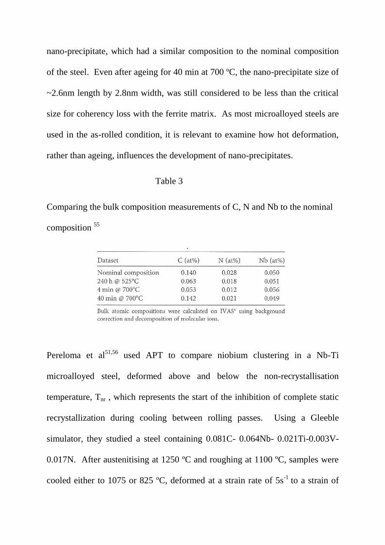
nano-precipitate, which had a similar composition to the nominal composition
of the steel. Even after ageing for 40 min at 700 ºC, the nano-precipitate size of
~2.6nm length by 2.8nm width, was still considered to be less than the critical
size for coherency loss with the ferrite matrix. As most microalloyed steels are
used in the as-rolled condition, it is relevant to examine how hot deformation,
rather than ageing, influences the development of nano-precipitates.
Table 3
Comparing the bulk composition measurements of C, N and Nb to the nominal
composition 55
Pereloma et al51,56
used APT to compare niobium clustering in a Nb-Ti
microalloyed steel, deformed above and below the non-recrystallisation
temperature, Tnr , which represents the start of the inhibition of complete static
recrystallization during cooling between rolling passes. Using a Gleeble
simulator, they studied a steel containing 0.081C- 0.064Nb- 0.021Ti-0.003V-
0.017N. After austenitising at 1250 ºC and roughing at 1100 ºC, samples were
cooled either to 1075 or 825 ºC, deformed at a strain rate of 5s-1
to a strain of
0.75, before cooling. Similar distributions of >70nm TiN and (Ti, Nb)(C,N)
were found in all specimens. 1075 ºC was too high for Nb-C clusters to form,
and therefore strain induced precipitation of NbC did not occur. However, after
825 ºC deformation, a relatively high number density of Nb-C clusters occurred,
as did SIP of NbC. This implies that the lower deformation temperature of 825
ºC resulted in a higher dislocation density, leading to an increase in the number
of nucleation sites for Nb-C clusters. These clusters might be considered as
precursors to SIP via heterogenous nucleation of NbC. The above work was
extended by Kostryzhev et al54
, to include aspects of the strengthening of the
steel through the possibility of clusters being cut, which is discussed below.
Coherent precipitates are cut by dislocations, leading to a different strength
mechanism than incoherent precipitates. This distinction becomes very
important when estimating yield strength from microstructure.
Few observations of coherent precipitates in microalloyed steels have been
verified. This is in part, due to the very small size at which they lose coherency.
Coherency strain fields associated with transition metal carbides and nitrides
have very rarely been reported for precipitates in microalloyed steels, vanadium
carbonitride 2 being an exception, Fig 3. Fig 4 shows that the calculated misfit
of vanadium carbide and nitride in austenite is much less than for niobium
carbide and nitride 58, 59
. Estimates of the limiting size of some coherent
carbides and nitrides if they precipitated in ferrite are given in Table 4, which
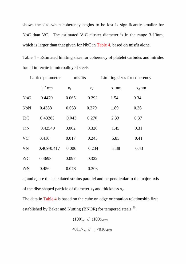
shows the size when coherency begins to be lost is significantly smaller for
NbC than VC. The estimated V-C cluster diameter is in the range 3-13nm,
which is larger than that given for NbC in Table 4, based on misfit alone.
Table 4 – Estimated limiting sizes for coherency of platelet carbides and nitrides
found in ferrite in microalloyed steels
Lattice parameter misfits Limiting sizes for coherency
‘a’ nm ε1 ε2 x1 nm x2 nm
NbC 0.4470 0.065 0.292 1.54 0.34
NbN 0.4388 0.053 0.279 1.89 0.36
TiC 0.43285 0.043 0.270 2.33 0.37
TiN 0.42540 0.062 0.326 1.45 0.31
VC 0.416 0.017 0.245 5.85 0.41
VN 0.409-0.417 0.006 0.234 8.38 0.43
ZrC 0.4698 0.097 0.322
ZrN 0.456 0.078 0.303
ε1 and ε2 are the calculated strains parallel and perpendicular to the major axis
of the disc shaped particle of diameter x1 and thickness x2.
The data in Table 4 is based on the cube on edge orientation relationship first
established by Baker and Nutting (BNOR) for tempered steels 60
:
(100)α // (100)MCN
<011> α // α <010MCN
and on the condition that coherency starts to breakdown when the strain at the
particle matrix interface equals the Burgers vector magnitude of a dislocation.
This is shown schematically 36
in Fig 5. The interfacial energy of B1 carbides
and nitrides having the B-N orientation relationship have been studied in detail
by Yang and Enomoto.58, 59
How this affects coherency is still unclear.
Incoherent disc precipitates of VN are seen in Fig 6, where strain fields are no
longer present. The fine NbC particles in Fig7, present on a replica, would
provide dispersion strengthening.
Interphase precipitation occurs during the transformation of austenite to ferrite
and is found, with the possible exception of ZrC and ZrN, for all the transition
metal carbides and nitrides, 50
as well as silver61
and copper 62
precipitates in
steels. Dunne 62
pointed out that the many studies by Honeycombe and co-
workers 50
, usually with highly alloyed ternary or quaternary laboratory steels,
and often in the isothermally treated condition, producing high volume fractions
of precipitates, were undertaken to elucidate the fundamental mechanisms of
interphase precipitation. These are summarized in terms of the morphologies
which have been established:
1. interphase precipitation (planar)
2. interphase precipitation (curved)
3. continuous fibre/lath growth
4. precipitation from supersaturated ferrite.
Planar interphase precipitation is typified by parallel sheets of densely
populated sheets, related to ferrite by the Baker and Nutting orientation
relationship 60
, and appear to have a regular spacing, Fig 8. Continuous fibres
comprise parallel laths, akin to a very fine pearlite. Details of the mechanisms
have been reported in many publications, including refs.1-5, 11, 50, 61, 62.
While interphase precipitation is well established in isothermally transformed
steels, it appears to be less important in commercially processed Nb and Ti-Nb
as-rolled microalloyed steels. For these steels, this leaves heterogeneously
nucleated precipitation associated with grain boundaries, leading to grain
refining, and precipitation associated with dislocations (SIP) as the main classes
of precipitates. However, compared to the other microalloying elements,
vanadium has a much greater solubility in austenite, and therefore remains in
solution to a much greater extent during processing in the austenite range.
Vanadium–Carbonitride interphase precipitates which form above 700 ºC are
recognized as making an important contribution to strengthening, which
becomes general V(C, N) precipitation below 700 ºC. The fibrous morphology
of V(C, N) is sparse and is never a dominant microstructure. 11
Vervynct et al 7 considered the principal function of alloying elements in F-P
microalloy steels to be ferrite strengthening by grain refinement, dispersion
strengthening and solid solution strengthening, all implied by Petch 31
. Solid
solution strengthening is closely related to the alloy content, while grain
refinement and dispersion strengthening depend on the complex interaction of

alloy composition and thermomechanical processing. For example, the
strengthening effect of niobium, the most widely studied element in
microalloyed steels, occurs mainly by three microstructural mechanisms: ferrite
grain refinement due to austenite grain boundary pinning, retardation of
recrystallization, and dispersion strengthening 6. Each of these mechanisms will
be considered more fully below. In addition, alloying elements are selected to
influence the reduction in the temperature at which austenite transforms to
ferrite and pearlite during cooling. In this way, a fine grained product is
produced, which is a major source of strengthening and toughness.
DeArdo et. al,6 consider that ‘the year 1980 represents a bench mark in the
strength of microalloyed (MA) steels. From the early days of the 1960s to
approximately 1980, the steels being micro-alloyed were low hardenability
steels with FP microstructures and σy ≤ 420 MPa. These steels were used to
develop the principles and interrelationships of microalloying, controlled
rolling and air cooling. They were characterised by relatively higher carbon
contents and moderate manganese levels, and exhibited FP microstructures
after air cooling. Around 1980, both the line-pipe and the automotive
industries desired strengths >420 MPa, that could be readily supplied with fine
grained FP steels. Clearly, higher strength microstructures were required. The
obvious choices were the lower temperature transformation products:
matrices comprised of non-polygonal ferrite, acicular ferrite, the bainites and
martensite, either as monoliths or as mixtures. To achieve these
microstructures, the combination of higher hardenability and high cooling
rates was required. Furthermore, much additional research was needed to
reach the required goals consistently and with uniform results. From the
processing side, the solution to this dilemma was using water cooling after hot
rolling. This was accomplished in the mid-1980s for plate processing by
interrupted accelerated cooling (IAC) 63,64
and interrupted direct quenching
(IDQ)65
in plate mills, Fig 9. Runout table water spray cooling to the coiling
temperature in hot strip mills had been in practice since the 1960s, but not
as a microstructural control tool for increasing strength. This was because
of the higher carbon contents of the steels of that era. The benefits of faster
rates of cooling and lower coiling temperatures were exploited for achieving
higher strengths later with steels of lower carbon contents’.
5. Controlled rolling and controlled cooling
The importance of developing a small grain size in terms of increases in both
strength and toughness is evident from the initial work of Hall 30
and Petch31
mentioned above. As stated by Llewellyn 66
, ‘the traditional route (prior to the
1970’s) to a fine grain size in ferrite–pearlite structural steels has been to
incorporate grain refining elements, such as aluminium, and then to normalize
the materials from about 920°C after rolling.’ He also comments on the fact

that ‘when normalizing was carried out on a niobium treated steel to improve
the impact properties, the strength advantage was forfeited. There was therefore
a need for an alternative route to a fine grain size in structural steel plate which
would overcome both the cost and strength penalties associated with traditional
normalizing. As described by Morrison5 'the key to obtaining a fine grain size
in a low niobium steel (~0.02wt%) is the low finishing rolling temperature,
which occurs naturally in thin plates and cross-country mills. Mackenzie 67, 68
collected data from 68 plates, finished rolled from 11 to 38mm, using 14 to 36
passes, which took between 3 and 6 mins in the mill, with finishing
temperatures between 800 and 1100°C. He found that finishing temperatures
below ~900°C gave acceptable notch ductility, equating to as-rolled plates
≤13mm in thickness. Fig. 10 shows that much greater thicknesses could be
tolerated in sections due to their lower rolling rate. As far back as 1958,
Vanderbeck 69
reported that ‘European steel producers were adopting lower than
normal finishing temperatures during rolling, in order to refine the
microstructure and improve properties’. The idea of using a rolling schedule to
produce a fine grain size may have originated from so-called cross-country
mills, a versatile ‘jobbing’ finishing mill, often used for producing sections or
bar in a steel works,where the work-piece usually passed only once through a
set of rolls, which were spread over a large area, with the final set some distance
from the starting point. Thus the rolling master was always dealing with a loss

of heat, and often the steel was black on reaching the finishing stand. However,
at Round Oak Steelworks in Staffordshire, it was noted that when the steel was
black at the finish of rolling, the strength and toughness properties were always
superior to when the steel finished red. It was on this mill that the writer
undertook some of his first controlled rolling trials in 1963.
‘Controlled rolling or rolling over a deliberately lowered temperature range
compared with conventional hot rolling, is now a widely accepted technique for
the production of microalloyed steels.’ This statement by Kozasu 70, 71
is as true
today as when it was first made in 1968, when the aim of controlled rolling was
to produce a steel with a fine polygonal ferrite grain size. Today, this is
extended to include acicular and bainitic microstructures. 17
In his review of controlled rolling, Tamura 40
states that ‘the fundamental
difference between conventionally hot-rolled and controlled- rolled steels lies in
the fact that the nucleation of ferrite occurs exclusively at austenite grain
boundaries in the former, while it occurs in the grain interior, as well in the
latter, leading to a more refined grain structure.’
Conventional controlled rolling is an example of a TMPT which manage the
temperature and deformation during hot rolling, to control the austenite
microstructure at the start of transformation. Here, it is essential that
recrystallization of austenite is avoided. The original approach was to introduce

a high density of nucleation sites into austenite grains for nucleation of ferrite
grains, by hot rolling in the austenite phase field,
After transformation to ferrite and subsequent recrystallization, as first
described by Hanemann and Lücke 72
, this leads to a refined microstructure.
Ferrite grain refinement is due to two mechanisms: (i) fine recrystallized
austenite grains formed by hot rolling at intermediate temperatures, and (ii)
austenite deformation below the recrystallization temperature, which enhances
the nucleation of ferrite.70
The first step in the controlled rolling process is to control the austenite grain
size during the soaking stage. This is set by the temperature which is necessary
to take into solution the microalloying particles, which have formed during
cooling following solidification during casting. As is well established, the
austenite grain size is related exponentially to the soaking temperature.
Therefore a balance exists between the temperature necessary to dissolve the
particles, the resultant austenite grain size and the economics of high soaking pit
temperatures.7,70
The importance of the correct soaking temperature for a given
steel is well illustrated by Lagneborg et al 8 for Ti-V-N steels. Reducing the
soaking temperature from 1250ºC to 1100 ºC reduced σy by ~40MPa and the
ductile-brittle transition temperature by 15 ºC, due to a reduction in the
dissolved amount of titanium and vanadium.

Kozasu et al 70
divided the controlled rolling process into three ranges,
associated with changes in the austenite and ferrite grain structures.
1 Deformation in the austenite recrystallization temperature range.
Deformation above 1000°C normally develops coarse recrystallized austenite
grains, which transform to a relatively coarse ferrite and upper bainite. The size
of the austenite grain size obtained by recrystallization, decreases with
increasing strain, which is introduced by the rolling reduction, and eventually
reaches a limiting value.73
2. Deformation in the unrecrystallized range.
Deformation in the intermediate temperature range from 1000°C to 900°C
refines austenite by repeated recrystallization, leading to fine grained ferrite.
The austenite grains are elongated (pancaked)and deformation structures
result.74
A build-up of strain is often associated with the formation of twins or
deformation bands, which increase the number of potential sites for ferrite
nucleation and this, as mentioned above, is regarded as one of the most
important aspects of controlled rolling.40,75
3. Deformation in the (γ+α) two phase region.
Deformation below the recrystallization temperature produces ‘warm worked’
austenite, which leads to a finer ferrite grained microstructure. The third stage
deformation has a much larger influence on the final mechanical properties than
the first two stages. Rolling to just above the Ar3 temperature, can result in
equiaxed ferrite grains and a substructure, produced by deformation of the

recently formed grains. The transition temperature was shown to decrease in a
linear manner with an increase in total reduction in ranges 2 and 3.76
Kozasu et al 70
, do not consider rolling below Ar1, or the changes in
microstructure in terms of the role of dislocations. This has been addressed
more recently Vervynckt et al 7.
An important concept, is the non-recrystallisation temperature, Tnr, which
represents the start of the inhibition of complete static recrystallization during
cooling between rolling passes. The most common method of determining Tnr,
consists of simulating successive rolling passes and representing the mean flow
stress (MFS) versus the inverse of the absolute temperature graphically for each
of the simulated passes, 7
as seen in Fig 11. Here Tnr, appears as a change in
slope of the MFS curve. Vervynckt et al 7, 75
proposed extending the controlled
rolling process to four regions, as defined in Fig 11. Data was obtained for a
microalloyed steel containing 20ppm Ti and 18ppm N, based on a simulation of
a 23 plate rolling pass schedule, with fixed interpass times of 20s and a cooling
rate of 1°Cs-1
. In Fig. 11 (a), the flow stress increases with decreasing
temperature in Region 1, while the curves change their shape entering
Region11. As strain increases and temperature decreases in Region 111, the
flow stress decreases, before increasing again in Region 1V. These are better
interpreted in Fig. 11(b) , where the mean flow stress (MFS) is plotted against
the inverse absolute temperature.
Region I corresponds to deformation at high temperature. Austenite
recrystallizes completely between passes and there is no accumulation of
dislocations. The increase in flow stress is solely due to the decrease in
temperature.
In Region II, the change in slope indicates that dislocations are being
accumulated. The flow stress increases more rapidly because of the inhibition
of recrystallization between passes.
Region III is characterised by a significant decrease in MFS, and corresponds to
the start of the γ→α transformation. Here the intercritical two–phase rolling
takes place.
Region IV corresponds to warm rolling in ferrite.
The intersection of the straight regression lines fitted to regions I and II defines
Tnr, that fitted to regions II and III defines Ar3, and that fitted to regions III and
IV defines Ar1. These are only for the conditions used here; i.e. fixed interpass
times of 20s and a cooling rate of 1°Cs-1
.
Hot rolling takes place on a falling temperature gradient, and the influence of
the recrystallized state of austenite on the transformation behaviour and CCT
curves of microalloyed steels was first investigated by Smith and Siebert.77
They showed that the ferrite start line, Ar3, was shifted to shorter times when
austenite was in the unrecrystallised state. Mixed ferrite grain sizes were found
when large strains were introduced in a temperature range in which only a
fraction of the austenite grains recrystallized. The regions where
unrecrystallized grains transformed, i.e. <Tnr, usually lead to ferrite of a
different grain size, from the ferrite originating from the recrystallized austenite
in adjacent regions.
The state, or condition of the austenite prior to transformation, is therefore one
of the major factors that determines the ferrite grain size. In addition to the
grain size of austenite, the potential ferrite nucleation sites must be taken into
account in any relationship with the ultimate ferrite grain size. Priestner and de
los Rios 78
introduced the term Sv, which is the grain boundary surface area per
unit volume of austenite, also described as the ʻeffective grain size’, to account
for the elongated grains. Sv is now often used to include boundary and
intragranular nucleation sites.71
Austenite which has a large value of Sv would,
by definition, have a large capacity for nucleation of ferrite, and as has been
pointed out by De Ardo 79
, a low hardenability, and would be expected to
develop a fine ferrite-pearlite microstructure. This concept is supported by
experimental data, 78
Fig 12.
Final deformation in the low temperature austenite is the temperature range
within which complete static recrystallization no longer takes place between
rolling passes, leading to the retention of work hardening.
6. Basis of modelling thermomechanical controlled processing
(TMCP)
Jonas and Sellars, 43 explain succinctly that ‘thermomechanical controlled
processing in industrial practice involves the production of specific
microstructures, which are associated with particular mechanical and physical
properties. In this way, TMCP differs from traditional deformation processing,
which is generally concerned with reductions in thickness and with developing
desirable changes in shape. TMCP involves the control and interaction of the
following fundamental mechanisms: dislocation glide and climb,
recrystallization, grain growth, phase transformation, precipitation, particle
coarsening, particle pinning and solute drag. The interest in many of these
structural changes is whether they take place dynamically (i.e. during
deformation) or statically (i.e. after deformation). TMCP is concerned with the
synthesis of these fundamental mechanisms. Of particular interest to
microalloyed steels, is the TMCP operation concerned with grain refinement for
high strength and toughness. Two contrasting, but complementary approaches
have been taken; laboratory simulation and computer modelling. The former
involve compression, tensile or torsion testing. Compression testers are useful
for the determination of the kinetics of recrystallization or precipitation, while
tensile machines are used to measure hot ductility, leading to the determination
of the temperature and strain rate ranges associated with optimum workability.
Computer modelling aims to quantify the fundamental mechanisms involved in
TMCP, in terms of the variables of temperature, strain, strain rate and time, and
to incorporate them within an overall mathematical description of industrial
forming processes. The inclusion of the parameters of microstructural features
is now widely accepted as essential, both for off-line optimization of processing
conditions, and for on-line control. In the case of hot rolling of steels, the
modelling process involves sequential deformation passes taking place over a
range of temperatures, rolling speeds, and interpass times.’
As explained by Sellars42
, ‘during the hot deformation process itself, e.g. a
rolling pass, work hardening takes place but it is balanced by the dynamic
softening processes (i.e. during deformation) of recovery and recrystallization.
These processes, which are thermally activated, lead to a flow stress that
depends on strain rate and temperature, as well as strain. The microstructural
changes taking place within the material result in an increase in dislocation
density with strain, causing dynamic recrystallization, which takes place
repeatedly as new recrystallized grains are themselves work hardened. These
dynamic microstructural changes leave the metal in an unstable state and
provide the driving force for static recovery and static recrystallization to take
place after the deformation pass. Static recrystallization may be followed by
grain growth, if the temperature is sufficiently high. Sellars 42
poses two
important questions, which must be answered to apply the above principles to
commercial practices: ‘(a) how long does recrystallization take after a
deformation pass; and (b) what grain size is produced by recrystallization and
grain growth? The answers determine the microstructure of the material
entering the next and subsequent passes and hence influence the flow stress of
the material and the working forces required. Eventually they determine the
microstructure and properties of hot worked products.’ Details of the
application of this approach is given by Sellars 40
and in a shorter form by Jonas
and Sellars 43
.
Depending on the eventual product, after casting and solidifying into an ingot,
the steel is further processed by rolling (or forging). The rolling process
requires the ingot to be reheated (soaked) before primary rolling to a smaller
intermediate size (billet), which is cooled to ambient temperature. Normally,
the steel is finish rolled in a different mill at a later time, and it is at this stage
that the controlled rolling process is undertaken.
To make the forming process easier, relatively high soaking temperatures are
traditionally employed for primary rolling, which causes considerable grain
growth. Therefore the first step in controlled rolling is to control the austenite
grain size, which increases exponentially with temperature, during reheating.
The temperature should be sufficient to take into solution the microalloying
elements, as discussed in detail in a later section.
From a commercial aspect, the modelling must relate to (a) the stock soaking
temperature and time (b) the rolling schedule in terms of rolling velocity,
deformation per pass, temperature at entry of rolling stock to each pass, interval
between passes, and final rolling temperature, and (c) the cooling rate following
rolling.
Vervynckt et al 7 describe Tnr, the non-recrystallization temperature, as
representing the start of the inhibition of complete static recrystallization,
during cooling between rolling passes. They also considered the experimental
methods for the determination of Tnr, and note that most measurements of this
parameter relate to plate mill schedules, which are easier to simulate by
laboratory test methods due to their long interpass times of 10-20s, compared to
strip mills. They consider that new experimental methods are essential to
determine Tnr for strip mills, with their short (1s) interpass times. In
microalloyed steels, the initiation of strain induced precipitation, (SIP), which is
the normally considered as the nucleation of carbides, nitrides and/or
carbonitrides on dislocations introduced by deformation, has the ability to
suspend both static and dynamic recrystallization. In other words, SIP, strongly
influences Tnr. He also points out that continuing deformation also leads to
coarsening of existing precipitates, and that ‘fresh’ precipitates are generally
considered to be necessary for preventing recrystallization. This effect is
important in modelling of rolling operations, because the interruption of both
static and dynamic recrystallization leads to increases in rolling loads, whereas
the initiation of dynamic recrystallization in the absence of precipitation, results
in a sudden decrease in rolling load. It should be noted that the models
developed for controlled rolling processes which involve precipitation, normally
do not include coherent precipitation or interphase precipitation, but only
heterogeneous nucleation of particles on dislocations (SIP).
A different approach has been adopted by Matlock and Speer.
80 They started
from the product, in their example, long bars, and then developed a
microalloying and processing strategy for their manufacture. In this way, they
considered that it was more likely that strategies which are less successful could
be avoided. While this is a far less rigorous approach than the modelling
described above, it does have the merit of being applicable to a very wide range
of steel compositions and processes, associated with microalloying. These
include thermomechanical processing of steel bars, which involves forging, and
the production of reinforcing bars. Matlock and Speer 80
also considered the
process route of a range of products, such as automotive springs and
components for automotive engines and transmission systems, which require
quenching and tempering, and high temperature carburising.
7. Solubility of particles which control grain size and
provide dispersion hardening.
As mentioned earlier, the soaking temperature, prior to rough rolling, must be
sufficient to take into solution the microalloying elements. In microalloyed
steels, the most important particles are carbides and nitrides, of the transition
metals, niobium, titanium, vanadium and to a considerably lesser extent,
zirconium. These are often present as carbonitrides. In certain cases, oxides of
titanium and sulphides are of importance, as are aluminium nitride precipitates.
During processing, the lowest temperature for taking into solution the particles
precipitated on casting, which are later to control grain size and dispersion
strengthening, is determined by their solubility in iron as a function of
temperature and time. Matlock and Speer 80
, in defining a strategy for the
application of microalloying to a range of products, summarised the main
objectives of adding niobium, titanium and vanadium to steels with a spectrum
of carbon contents, relevant to long products. For example, they considered that
the main precipitates were likely to be NbC, V(C,N) or TiN. NbC precipitates,
which are expected at reaustenitising temperatures in virtually all heating
treating applications. Solute niobium, remaining in solution in austenite, may
also contribute to subsequent formation of nano-precipitates or clusters 51-57
, and
finer dispersion strengthening precipitates in ferrite. As discussed below,
vanadium exhibits considerably greater solubility in austenite than niobium or
titanium, and carbonitrides are only expected to form at the lowest austenite
temperatures in alloys containing relatively high levels of vanadium, carbon
and/or nitrogen. Austenite grain refinement is therefore less likely to occur in
leaner alloys, but vanadium is available to precipitate in ferrite over a wide
variety of steels, across the entire spectrum of carbon concentrations and
processing temperatures. TiN is very stable and usually precipitates at high
temperatures in the austenite phase and may be useful in resisting subsequent
austenite grain coarsening, when added as a small addition.80
The basis for
most of the conclusions made by Matlock and Speer 80
lay with the solubility
equations appropriate for carbides and nitrides of niobium, titanium and
vanadium in austenite.
Solubility equations allowing the temperature of compounds in a solvent
to be estimated, for example, zirconium carbide in austenite 13
, are
normally described in the form of an Arrhenius equation. This gives the
dependence of the rate constant K of chemical reactions on the
temperature T (in absolute temperature, kelvins) and activation energy
Ea, as shown below
K=A- Ea
/RT (2)
where A is the pre-exponential factor and R is the Universal gas constant.
In microalloyed steels, the microalloying element, M is often combined
with an interstitial X, to give a compound, MX, some or all of which,
dissolves in austenite as the temperature is raised.
[M]+[X] =MX] (3)
The rate constant K in equation (2) is now described as an equilibrium
constant for the reaction given by equation [3].In practice, the
concentrations of M and X are normally low, being less than 1% and
therefore may be considered as having an ideal solution behaviour. M
and X are expressed in terms of the weight percentage of the alloying
element present in the steel chemical composition. This allows equation
(1) to be expressed as
log10 [M][X] =ks= -Q/RT +C (4)
Empirical Arrhenius equations have been determined for many of the important
refractory carbides and nitrides known to form in steels, but similar equations
for sulphides have not been found. Unlike the solubility equations of transition
metal carbides and nitrides of niobium, titanium or vanadium in austenite, the
corresponding equations of zirconium are almost entirely due to one source, and
have some shortcomings.
Table 4, summarises selected Q and C values, collated from the literature, for
the relevant grain boundary pinning and dispersion hardening compounds found
in microalloyed steel. Taylor 81
has calculated values for carbides in ferrite.
Examples of solubility diagrams for (a) NbC,(b)VN and (c)VN in austenite over
the temperature range relevant to TMP, and based on the data in Table 5, are
given in Fig.12, taken from Matlock and Speer. 80
For more details of the
solubilities, the reader is referred to the reviews on the role of individual
elements in microalloyed steels 8-14
, and the book by Gladman3
,which also
provides examples of some mutually soluble carbonitrides.
A comparison of these carbide and nitride solubilities is shown in Fig 13. Here,
it can be seen that while zirconium carbides and nitrides show little solubility in

austenite, and often nucleate while the steel is still molten, both zirconium and
titanium precipitate in austenite, as do niobium and vanadium, both as carbides
and nitrides
Table 5
Selected solubility parameters in austenite of carbides and nitrides found in
microalloyed steels
Q C Reference
AlN -6770 1.03 Leslie et al 82
NbC -6770 2.26 Irvine et al49
NbN -8500 2.80 Narita83
TiC -10,475 5.33 Narita83
TiN -8000 0.332 S. Matsuda and N.Okumura84
VC -9500 6.72 Narita83
VN -8330 3.46 Irvine et al49
ZrC -8464 4.26 * Narita83
ZrN -16000 4.38 Narita83
* use with caution13

In general, nitrides are more soluble in austenite than carbides, zirconium and
titanium nitrides are the least soluble, while vanadium carbide is the most
soluble. In ferrite, vanadium carbide is the most soluble, followed by titanium
carbide and then niobium carbide, all of which, with high carbon/nitrogen
ratios, could be important sources of dispersion hardening.
Narita83
has given data on the recovery of the elements in Groups IVA and VA,
which are reproduced in Table 6. Both niobium and vanadium can be seen to
have a higher percent recovery than titanium and zirconium.
Table 6
Recovery of the elements in Groups IVA and VA
V: 90-100% Ti: 50-80% Y: 35-60%
Nb: 80-100% Zr: 50-80% La: 20-50%
Ta: 70-90% Hf: 40-80% U 20-50%
Vervynckt et al 7 considered that ‘for most steel grades, Tnr is determined by the
niobium and carbon contents. One the other hand, titanium forms a very stable
compound, TiN, which may remain undissolved in austenite. This compound
consequently limits austenite grain growth at relatively high soaking
temperatures and also restricts nitrogen from forming Nb (C, N), enabling
dissolution of NbC to occur more readily.’
A term of importance in discussing particle pinning of grain boundaries
is the austenite grain coarsening temperature, Tc, which is the
temperature where the pinning effect becomes ineffective. This condition
considerably restricts grain growth. As would be expected, Tc is
significantly lower than the solution temperature of the precipitate. There
have been several studies 49, 84-87
of the effect of carbides and nitrides on
Tc. Fig14, taken from Cuddy and Raley 86
illustrates some results which
clearly show the importance of NbCN and AlN compared with VC,
which is confirmed in more recent work 3
. As a result of experimental
studies, linear relations were obtained between Tc and the temperature for
complete solution of the microalloying carbide or nitride, T. This lead to
the relationship;
Tc = A+B (Q/C-log (M.I) -273), °C (5)
M and I are the metal and interstitial, A and B are the intercept and slope
of the line segments in Fig 14, while Q and C are constants, such as those
given in Table 5.
Using this data for Q and C for AlN and NbC, the latter labelled NbCN
by Cuddy and Raley86
, who give the respective constants A and B as
285°C, 460°C and 0.535,0.569, to allow the calculation of Tc. From the
work of Hall 30
and Petch 31
, and Zener 88
, it is evident that ferrite grain
size and the size and volume fraction of precipitated particles, are of
seminal importance in determining the mechanical properties of
polycrystals. The volume fraction of particles is initially controlled by

their solubility in austenite, where most of the deformation, which
determines the final size and shape of the steel, is scheduled.
As acknowledged by Martin89
, it is well established that dispersed, hard,
incoherent particles can either retard or accelerate recrystallization of a metallic
matrix, and this was affirmed by the work of Docherty and Martin 90
. Zener 88
was the first to devise a relationship involving a dispersion of particles and the
retarding force which they exerted on a grain boundary. This effect is known as
the Zener drag after his original analysis, and was first published by Smith,
Zener proposed that the driving pressure for grain growth due the curvature of
the grain boundary would be counteracted by a pinning (drag) pressure exerted
by the particles on the boundary. Consequently, normal grain growth would be
completely inhibited when the average grain size reached a critical maximum
grain radius, also known as the Zener limit, RRc), is given by:
Rc =4r/3f (6)
where f is the particle volume fraction and r the radius of the pinning particles.
He considered that both grains and particles could be approximated to spheres,
particle volume fraction and r the radius
In its general form the Zener Equation is given as:
R c= Kgr/f m (7)
where Kg is a dimensionless constant and m an index for f. Several other
models have been produced, collated and critically reviewed. 91-93
The model
by Zener 88
the model has been shown to overestimate R when compared with

experimental data overestimate R c 1
when compared with other data. 91-93
. The
most extensive consideration of the many modifications proposed to the Zener
equation has been undertaken by Manohar et al 93
, who examined in detail some
32 models published up to 1987. In general, the pinning of sub-grain and high-
angle grain boundaries has been shown to occur when the particle radius, r, is
the size range 30-800nm, and particle volume fraction (f) less than 0.01. While
data for Rc and to some extent r are available, no reliable data on volume
fraction of precipitates in these steels has been published. 13
Figs 16 and 17
show the effect of particles pinning grain boundaries. There also exists a body
of experimental evidence to show that in steels, particles, particularly oxides
and carbides greater than 0.5μm in length, with interparticle spacings, also
greater than 0.5μm, can lead to acceleration of recrystallization due to
nucleation of new grains at carbide particles 94, 95
and oxide slag inclusions 96
These particles are assumed to create lattice curvature at particle–matrix
interfaces in the deformed matrix, which enhances recrystallization and gives
rise to accelerated recrystallization, also known as particle stimulated nucleation
(PSN).91
8. Precipitation and recrystallization
As mentioned above, while restriction of grain growth by particle pinning
initially takes place during the soaking stage of the rolling schedule, an equally
important aspect of precipitation is that during the rolling, most of which occurs
in the austenite phase in niobium steels. In vanadium steels, precipitation in
ferrite, also is important, Fig 18. The inter-relationship between hot
deformation and concurrent precipitation has been conveniently summarized by
Pandit et al 97
, reproduced in part here: ‘The presence of precipitates increases
the non-recrystallisation temperatures (Tnr), which is of significance in deciding
the reheating temperature for hot rolling.98
The presence of precipitates in
austenite, increases the flow stress of the material and hence the rolling loads.
Niobium is the most potent of the microalloying elements in retarding austenite
recrystallization through solute drag 98
and/or by strain induced precipitation. 99,
100 Fig 19 shows that only NbC can have high supersaturations over a large
portion of the typical hot rolling range.8
It is well established that the onset of
precipitation is greatly enhanced by prior deformation. A comparison of the
precipitation kinetics of strain induced NbC particles with those in undeformed
austenite, reveals that at least two orders of magnitude difference occurs
between the two, over a given temperature range.101
This may be attributed to
the presence of dislocations, deformation bands, sub-grain structure and twins,
the well-known potent sites for nucleation which accelerate the precipitation
process in the deformed microstructure.101, 102
The kinetics of SIP of niobium in
microalloyed steels has been extensively investigated for over 25 years by the
Sellars’s group, who have compared their experimental data with modelling
predictions with increasing success.41,42,101-106
Recently, Nöhrer et al107
,using a
quenching dilatometer and TEM and APT techniques, considered in detail the
influence of deformation on the behaviour of niobium precipitation in a
microalloyed steel containing: 0.20C-1.29Mn-0.029Nb-0.035Al,-0.004N, and
found that this was different in the austenite and ferrite regions. The steels were
solution treated at 1250ºC, cooled to a deformation temperature of 700 ºC in the
austenite and ferrite region, held for 7mins to partially transform to ferrite,
before being deformed to true strains of 0.7,0.2 or 0.05, at a strain rate of 0.1s-1
.
After a second hold, the samples were gas-quenched to RT within 5s. It was
found that the niobium precipitates nucleated as carbonitrides, taking up the
total available nitrogen. Following deformation, with longer dwell times,
increasing carbon levels were detected in the niobium precipitates. A higher
volume fraction of precipitates, with a higher carbon content, was found in
ferrite compared to austenite. With increasing strain, the dislocation density
increased, resulting in a higher volume fraction of strain induced niobium
precipitates, not through accelerated precipitate growth.
While an abundance of research has been reported on the SIP behaviour of
Nb(C,N), less consideration has been given to the SIP of TiN and V(C,N) in
austenite. The evolution of SIP of vanadium precipitates in an 0.20% C steel at
600 and 700ºC was considered by Nohrer et al 108
using the same techniques
mentioned above107
. They observed that the initial V(C,N) precipitates were
higher in nitrogen than carbon, and this changed with increasing dwell time and
occurred faster at 700 ºC, as in their niobium steel study.107
Gomez et al109
considered a more complex additions in the microalloyed steels: (a) 0.034Nb-
0.004N, (b) 0.092V-0.0065N, (c) 0.018Ti-0.008N and (d) 0.037Al-0.010N, on
recrystallization/precipitation interactions, by using hot torsion tests. Their
results showed that steels (a) and (b) exhibited long inhibition plateaux, while
steel (d) displayed a very short plateau; the steel (c) did not show any plateau.
This was interpreted as indicating that niobium and vanadium precipitates
(nitrides and carbides) can inhibit the static recrystallization, but this does not
occur for the aluminium and titanium steels, which formed only nitrides.
Recrystallization-precipitation-time-temperature diagrams showed the
interaction between both phenomena, along with the SIP kinetics and precipitate
coarsening. TEM studies, based on the average precipitate size, found that AlN
particles (87nm) nucleated and grew faster than NbCN (22nm) or VN (10.5nm).
TiN (1250nm) in this work had a size dependent only on the solution
temperature of 1300ºC. The effect of a titanium addition on SIP of NbC in
simulated deformed 0.047% Nb and 0.043%Nb-0.016%Ti steels was explored
by Hong et al 110
using two stage interrupted compression tests. They found that
the size of NbC formed in the Nb-Ti steel was smaller than in the Nb steel, and
that the precipitation start time in the Nb-Ti steel was delayed compared to that
of the Nb steel. After reheating the Nb-Ti steel at 1250ºC,undissolved Ti-rich
(Ti,Nb)(C,N) particles were located at prior austenite grain boundaries, resulting
in a finer austenite grain size of 130µm, compared with 180 µm for the Nb steel.

Medina111
studied the influence of strain on precipitate nucleation in austenite
comparing three Nb-V-N microalloyed steels. Precipitation start-time-
temperature diagrams were determined by hot torsion tests, while corresponding
increases in dislocation density, and the driving force for precipitation, ΔGv ,
were calculated from established equations. The results show that SIP in
austenite is transformed from heterogeneous nucleation on dislocation nodes,
when ΔGv is small, (-1.8 x 10⁻⁹
Jm-3
) to homogeneous nucleation as the
microalloying content and therefore ΔGv both increased (-2.48 x 10⁻⁹
Jm-3
).
ΔGv was obtained by considering that niobium forms as carbonitrides and
vanadium as nitrides. However, in many cases, (Nb,V)(C,N), of varying
composition, after removing from different stages in a process, have been
characterised. In this case, no such work was undertaken by Medina111
. It is
important that the assumption that Nb(C, N) and VN have separate roles in this
work, is confirmed experimentally.
Two more complex steels of compositions:
Nb-V 0.19C-1.5Mn- 0.44Si-0.1Cr-0.125V-0.035Nb-88ppm N- 0.008 Al
Ti-V 0.18C-1.5Mn-0.44Si-0.09Cr-0.13V-0.036Ti- 80ppmN- 0.008Al
were compared by Pandit et al 97
, who carried out mechanical relaxation tests
using a Gleeble 1500 thermomechanical simulator. Holding specimens at the
reheating temperature of 1200°C for 5min. was sufficient to dissolve all the
niobium, but only part of the titanium. Deformation was carried out in
austenite, between 1090°C and 900 °C. Both Datta and Sellars 102
and Liu and
Jonas 112
suggested that SIP in deformed austenite occurs mostly on dislocations
and sub-boundaries, which implies that the austenite grain size per sae, is not a
dominant factor in influencing precipitation kinetics., Pandit et al 97
were able to
show from their data, Fig 20, that the precipitation kinetics of the Ti-V steel was
more sluggish than the Nb-V steel.
9. Multiple additions of niobium, titanium, vanadium zirconium
and nitrogen in microalloyed steels
The year 1980 was considered by DeArdo et al113
to be a watershed for
microalloyed steels. Prior to 1980, microalloyed steels were of low
hardenability with F-P microstructures, and after air cooling following hot
rolling, had σy values of ~420MPa. Around 1980, both the line-pipe and
automotive industries required steels with higher strengths than could readily be
obtained with F-P microstructures. Increasing the microalloying content to
enhance the dispersion strengthening contribution from the range 50-80 MPa,
recorded for F-P steels, seemed limited. This magnitude is comparable to the
strengthening conferred by solid solution strengthening, but significantly below
of 100-480MPa levels which can be obtained from dislocation
strengthening.1,2,114,115
One of the main developments which has occurred over the past 25 years to
raise the yield strength, is the increasing tendency for steel-makers to alloy with
more than one of the niobium, titanium, vanadium trio of transition metals,
often with a deliberate higher nitrogen levels than the normal range of 0.003-
0.005%N. This has given rise fine ferrite grain sizes of <10µm, and to complex
particles, which may precipitate in either or both the austenite and ferrite
phases, depending on the chemical composition of the steel and the details of
the TMP route adopted. However, multiple additions are not a recent move, as
they were considered over 45 years ago by, for example, Heisterkamp et al.116
They investigated 19 steels, 14 of which contained zirconium, with either single
additions at levels of nominally 0.043%, 0.057%, 0.072%, or in combination
with two levels of niobium, 0.020% or 0.035%. These steels were compared
with five vanadium-zirconium steels arranged in two groups, one of three steels
based on 0.030% V containing respectively, 0.019%, 0.035% and 0.057%Zr,
and a second of two steels with 0.049%V, and 0.053%Zr or 0.092%Zr. The
steels were examined in the as-rolled and normalised conditions. Little effect of
zirconium additions were found on the strength of the niobium–zirconium
steels, the as- rolled strip having σy of ~500MPa, which is ~20% greater than the
420 MPa, mentioned above. Furthermore, a decrease from 460MPa to ~420
MPa was found when a zirconium addition was present with 0.030-0.050%
vanadium.
In controlled rolled microalloyed steels, some attention has been paid to the
combination of additions of titanium and vanadium, titanium and niobium or
titanium and niobium and vanadium, with the expectation that the potential of
each element will be fully exploited. Most of the work discussed below
emphases that titanium additions are normally made as hypo-stoichiometric
relative to nitrogen, i.e. < 3.4. This ratio is discussed by Crowther and Morrison
117, who explained the effect that titanium additions were observed to have with
Al-V and Al-Nb microalloyed steels, particularly with regard to loss of strength.
This was purported to be due to changes in the dispersion strengthening
associated with modifications to niobium precipitates.
Strid and Easterling 118
used STEM-EDX microanalysis to understand the
influence on microstructure, of precipitate compositions, morphologies and
sizes in hot-rolled microalloyed steels containing, Ti, Ti-V, Ti-Nb, with
different levels of nitrogen. They found that the median ferrite grain sizes in the
Ti-Nb steels, 29µm and 32.5 µm, was greater than in the Ti (~16 µm) and Ti-V
(13 µm) steels. Also, the median particle size, 19nm, of an Ti-Nb -0.010N steel
containing predominantly nitrides, showed a coarser size distribution than in a
Ti-Nb- 0.006N steel, where the median particle size of predominantly carbides,
decreased to 10nm. Increasing the aluminium content of their Ti and Ti-V
steels from 0.022 to 0.072 wt-%, resulted in an increase in the particle size from
~8nm to ~12 nm. These changes had only a minor influence on the yield
strength, which reached 377MPa for the steels Ti and Ti-V additions, but was
not given for those with Ti-Nb. Strid and Easterling 118
were unable to quantify
the C or N levels in this work, and therefore details of the chemical

compositions of the particles was restricted to the transition metals. This
problem was overcome to some extent by He and Baker 119
, who were perhaps
the first to use both TEM- EDX, in an EM400, and EELS in an HB5 instrument,
to characterize their carbo-nitride precipitates present in a microalloyed steel.
They attempted to elucidate the problems associated with additions of titanium
in microalloyed steels, which had been reported to have differing effects when
used with additions of niobium compared to vanadium. Following controlled
rolling, three steels containing nominally 0.10C-1.4Mn -0.005N-0.017Nb, with
respectively <0.005, 0.010, or 0.022Ti, were examined. For the different
titanium additions, giving different Ti/N ratios, a distinct size variation of the
Ti-Nb carbides and nitrides was observed, especially for the coarser particles.
Fig 21(a) includes large Ti-Nb particles in an 0.01%Ti-Nb steel, with many
smaller Nb-rich spheroids, while an EELS spectrum, Fig 21(b) collected from
the centre of a ~20nm Nb-rich spheroid, shows the niobium, carbon, nitrogen
and titanium edges.119
Using a similar range of techniques to He and Baker119
,
Subramanian and Weatherly 120
investigated the precipitation behaviour in Ti-V
and Ti-Nb steels, but containing a higher carbon level of 0.426. The presence
of complex precipitates in as-cast blooms was confirmed; in the Ti-V steel
nitrides (TixV1-x)N, were observed followed at lower temperatures by carbides
(V4C3); in the Ti-Nb line-pipe steel processed from slabs, dense well dispersed
mixed nitrides (TixNb1-x), on which epitaxial growth of Nb-rich mixed carbides
were observed. The authors considered that epitaxial growth obviated the need
for SIP of mixed carbides. Here, the increase in the volume fraction of
precipitates increased the Zener drag force on boundary mobility, thereby
retarding recrystallization. Similar results were found by He and Baker 121-124
studying controlled rolled ~ 0.10 C steels containing additions of Nb-Ti-N or
Nb-Ti-Zr-N. They observed NbC or Nb(C,N) caps or coatings to nucleate on
(Ti, Nb)N core particles, Fig 22, which reduced the niobium available for both
grain refinement and dispersion strengthening. A 0.016 Zr addition resulted in
complex nitrides >100nm size, of Ti-Zr and Ti-Nb-Zr, which appeared to have
no effect on <100nm Ti-Nb carbonitrides, also present. All the steels had σy
values ~400MPa with 50J IIT of -80 to 100ºC. The presence of caps nucleating
on more stable core precipitates has been reported more recently. Caps of Nb-
rich (Nb,Ti)C were also observed to nucleate heterogeneously on undissolved
(Ti, Nb)(C,N) core particles by Hong et al110
and by Grajcar125
.
In other work, Beres etal 126
found a 0.03C-0.08Nb-0.01Ti 20mm thick plate
steel, ‘produced complex agglomerates with a cubic TiN seed crystal overgrown
by a cubic NbC particle.’ In some of the studies where core/caps particles were
observed, the choice of reheating temperature prior to processing has been too
low to take all of the core precipitate, normally titanium or zirconium based,
into solution. While the resultant conglomerate may affect the rate of grain
growth, in general, these particles should be avoided through relating the steel
composition to higher reheating temperatures.
Courtois etal 127
,who studied model Fe-(Nb,C) and Fe-(Nb,C,N) ferritic alloys,
showed that ‘the addition of nitrogen lead to a complex precipitation sequence,
with the co-existence of two populations of particles, pure nitrides and
homogeneous carbonitrides, respectively.’ In other work, a comparison of
precipitates in Nb-Ti and Nb-Ti-V microalloyed X80 pipeline steels produced
as 18.4mm thick strip was undertaken by Li et al 128
. Their microstructures
consisted of quasi-acicular ferrite (A-F).
Perhaps the first researchers to consider moving from F-P to A-F
microstructures were Smith and Coldren 129
, who investigated the
microstructure and properties of thirty six laboratory steels. Among the most
successful, were steels based on a composition of 0.4C-1.6Mn-0.09Nb-0.2Mo,
FR at 870 ºC, spray cooled at ~22º C s-1
to a simulated-coiling temperature of
635 ºC, the approximate temperature for AF formation. This schedule resulted
in a yield strength of ~570MPa and ½ size Charpy transition temperature of -
60ºC.
Some of the more recent work, which lead to the gradual raising of the yield
strength by controlled rolling microalloyed steels, was summarized by Ji et al.130
Campos et al131, 132
developed yield stress of 530-608MPa respectively, using
nominal chemical compositions in of 0.12C-0.057Nb-0.049Ti and 0.11C-
0.04Nb-0.11Ti. In addition, the precipitation behaviour in an 0.07C-0.086Nb-
0.047Ti steel was investigated by Charleux et al, 133
who obtained σy levels of
650MPa in plate. Misra etal 134
developed a steel with σy of 770MPa, from a

complex steel composition of 0.06C- 0.07 to 0.09Nb- 0.065= 0.085Ti, 0.1 -
0.2Mo and 0.0005- 0.001B.
As pointed out by Ji et al 130
, these highly alloyed steels detailed above,
achieved their yield strength at a relatively high cost. The recent approach of Ji
et al 130
compared two laboratory steels of compositions based on 0.09C-0.11Ti
and 0.05C-0.025Nb-0.11Ti.Both steels reached σy values of >700MPa with
>20% elongation and good toughness; it should be pointed out that one steel
was without a niobium addition. The plate finishing rolling temperature was
controlled to 910ºC and then cooled at 80 ºCs-1
to the coiling temperature of 620
ºC, using an ultra-fast cooling technique, producing a microstructure that was
predominantly of massive ferrite and acicular ferrite, with ~3.2nm TiC
precipitates in the Ti steel and ~5.0nm (Ti, Nb) C particles in the Ti-Nb steel.
This kind of microstructure has been further considered in a series of papers
involving Shan and co-workers135-138
, who explored the acicular ferrite (AF)
route to achieving X60 to X100 pipeline steels. The laboratory developed AF
pipeline steel was based on their continuous cooling transformation(CCT)
diagrams of an experimental steel which was vacuum melted, reheated at 1150
◦C for 50 min, started rolling (Ts), at 1050 ºC and finished rolling (Tf ) at
750ºC,starting from a thickness of 70 mm and reducing in seven steps to 7mm,
then cooled to a finish cooling temperature (Tc) of 600ºC at a cooling rate (Vc )
of 20ºC s-1
in order to obtain the AF microstructure. The steel was finally held
at 600ºC for1 h and furnace cooled to room temperature, to simulate the coiling

process. The commercial AF pipeline steel was reheated at 1180 ºC for 230
min, and then rolled in two stages, rough-rolling and finish rolling. The rough-
rolling stage for the steel reduced from a thickness of 230 to 40mm, in seven
steps with Ts 1130 ºC; then the finish-rolling stage started at 1020ºC with Tf at
840ºC, reducing from 40 to 7mm in another seven steps. Finally the steel was
cooled to 600ºC at 20ºC s-1
for coiling and then air cooled to room temperature.
With the laboratory steel 134
, which had a nominal composition of 0.07C-
0.9Mn- 0.04Nb-0.04V-0.015 Ti-0.004N, they found that the properties were
dependent on Ts, Tf, Tc and Vc. Optimum mechanical properties were obtained
when Ts was approximately 1100 °C, Tf 890 °C, Tc 520 °C and Vc 30 °C s−1
.
Niobium in the steel was considered to have a stronger influence on Ts
compared with vanadium and titanium, in controlling mechanical properties; Nb
carbonitrides form in the range close to Ts of 1070–1120°C, V carbonitrides will
mostly dissolve in γ-Fe ~900 °C while the formation temperature of Ti
carbonitrides is far higher than Ts. Thus, an increase of Ts will mainly place
more niobium in solution, which raises σy to a maximum of 561 MPa.
Regression equations, which described the relationships between σy and El,
elongation, and the processing parameters, were produced from the data
obtained from the laboratory steels.
σy =0.508 Ts -0.231 Tf – 0.334 Tc + 1.905Vc +323.6 (8)
R=0.94
El = 0.002 Ts -0.064 Tf – 0.086 Tc + 0.325Vc +121.8 (9)
R=0.98
Equations (8) and (9) can be used be used to predict σy and El of commercially
produced pipeline steels.135
A comparison made between the same laboratory X90 grade acicular ferrite
steel, containing 0.025C-0.058Nb/Ti and 0.0062N, with a commercial x70
grade containing 0.08C-0.095Nb/Ti and 0.005N. It was concluded that the
higher σy (626MPa /530MPa) and better toughness (at -100ºC, 137J/ 108J) in
the acicular steel resulted from its finer grain size and higher dislocation density
and sub-boundary content.138
The above laboratory X90 grade steel was
processed to produce either an acicular ferrite or an ultrafine grain
microstructure, which allowed a comparison to be made of the two
microstructures and properties. The dispersed (Ti,Nb)(C,N) precipitates,
together with a high density of tangled dislocations and the finer cleavage facet
size-ferrite bundle, in the acicular ferrite steel was considered to be a better
candidate microstructure for oil and gas pipeline steels than the ultrafine ferrite
steel. 136
In their review, Beladi et al139
have also considered alternative
methods to develop high strength steels at a lower cost. Their most promising
route to achieving this goal was by reducing the alloy content of the steel and
relying on a reduction in the grain size to provide higher strength and toughness.
It is pointed out139
that the Hall-Petch equation, eqn. (1), predicts that a
reduction in the average grain size from 5 to 1 µm will increase σy by ~350MPa.
However, using conventional industrial approaches, the level of ferrite

refinement has been found historically, to be limited to 5–10 µm. Nowadays,
several thermomechanical processes have been developed to produce ferrite
grain sizes of ≤1–3µm, ranging from extreme thermal and deformation cycles to
more typical thermomechanical processes. Of a number of routes established to
achieve a fine grain size in the laboratory, dynamic strain induced
transformation (DSIT) was considered by Beladi et al 139
, as the most promising
method for adapting to commercial practice. DSIT is based on the discovery,
by Hodgson et al 140
, for the formation of ultrafine grains during the hot
deformation of thin strip. This development requires deformation to large
strains within the Ae3 to Ar1 temperature range for a given alloy, followed by
rapid cooling.141, 142
The formation of ultrafine ferrite involves the dynamic
transformation of a significant volume fraction of austenite to ferrite, which
initially occurred at an early stage of deformation, at prior austenite grain
boundaries. This was followed by intragranular nucleation, as in controlled
rolling.139
However, DSIT arises from the introduction of extensive extra
intragranular nucleation sites, that are not present in conventional controlled
rolling, They were found in an 0.17C-1.5Mn-0.02V steel.143
Priestner and de
los Rios 78
,144
were among the first to recognise that extra grain refinement may
be possible if the transformation could be induced during the deformation
process. The final microstructure of DSIT low carbon steels usually consists of
fine equiaxed ferrite grains (< 2 µm) and cementite (typically 0.05-0.2 µm) in
the grain interiors and at the grain boundaries, Fig 23. Most of the yield

strength values in Fig 24, collated by Beladi et al 139
, lie within the 400 to
700MPa range, the upper end being beyond what most F-P microalloyed steels
achieve. However, the commercial exploitation of the DSIT route is still a work
in progress.142, 145
Recently, a guide to industrial production of ultrafine grain
microalloyed steel was published. 146
It is based on DSIT, using experimental
data to aid the development of a multiscale computer model, which predicted
the mechanical response of the microstructure in a hot rolling process. Two
steel grades were examined: 0.07C-1.36Mn-0.06Nb-0.03Ti-0.098N-0.003B and
0.08C-1.67Mn-0.06Nb-0.018Ti-0.0316N-0.26Mo. Niobium was the principal
alloying element used to control the dynamic transformation of austenite, while
the additions of B or Mo increased significantly the hardenability, thereby
expanding the thermomechanical processing window. However, while these
steels can achieve higher σy levels than F-P microalloyed steels, they still rely
on expensive alloy additions. Others claim that it is possible to obtain an
ultrafine grain microstructure without such alloying147
, but it is not known if this
is route is used commercially. As mentioned above, small amounts of boron
when added to ultralow carbon steels, promoted bainite by suppressing the
formation of polygonal ferrite.
Tamehiro et al 148
, in studying TMP with accelerated cooling, considered the
effect of a combined addition of boron and a grain-refining element such as
niobium, titanium or vanadium in very low carbon steels, in terms of
mechanical properties and microstructures. They found that, although boron, as

a single addition, has little effect on the properties, the combined addition with
niobium improves the balance of strength and toughness. Niobium additions to
boron steels suppressed the precipitation of Fe23 (C, B)6 and strongly retarded
the γ-α transformation, forming a fine-grained bainitic structure. Titanium has
been found to have the same effect as that of niobium, but vanadium does not.
The strengthening and toughening mechanism by the combined addition of
niobium and boron was also investigated by examining the effect of alloying
elements on the minimum recrystallization temperature of austenite during
rolling, and γ-α transformation behaviour.148
10. High strength / bainitic/martensitic microalloyed steels
Acicular ferrite (AF) and conventional bainite (CB) have been mentioned in the
previous section, but the difference between these two phases needs to be
clarified.149,150
Fig 25 shows a large austenite grain size containing a relatively
high number density of intragranular nucleation sites, that leads to a
microstructure consisting predominantly of AF. By comparison, a small
austenite grain size, containing a relatively high number density of grain
boundary nucleation sites, leads to a microstructure consisting predominantly of
CB.149
As indicated by Zhang and Boyd 150
‘CB nucleates at prior austenite
boundaries and grows as packets of parallel ferrite plates, appearing as laths in
2D, which have similar crystallographic orientation and a high uniform
dislocation density. The length of the ferrite laths is limited by impingement
with other packets, and carbon-enriched interlath austenite becomes a
martensite-austenite (M/A) constituent. By contrast, AF can be nucleated by
inclusions, grows as randomly oriented ferrite laths, or groups of laths, which
contain a high dislocation density, and the MA usually occurs as discrete
particles. This less organised aspect, provides the potential for AF combining
high strength with high toughness, and is the reason of some, for developing
acicular ferrite microstructures. 151
A crack therefore has to follow a more
tortuous path through an AF microstructure, thereby leading to an improvement
in toughness without compromising strength.151,
152
Bainite has traditionally
been separated into two groups, Fig 26, granular bainite, (GB), often described
as lower bainite, which consists of sheaves of elongated ferrite crystals with low
misorientations and a high dislocation density, containing roughly equiaxed
islands of M/A micro-constituent; and lath bainite (LB), often described as
upper bainite, which consists of packets of parallel ferrite laths (or plates)
separated by low-angle boundaries and containing very high dislocation
densities. In contrast to GB, the M/A particles retained between the ferrite
crystals in LB have an acicular morphology.153
M/A particles can significantly affect fracture toughness, due to the brittle
nature of martensite. Not only is the phase fraction of importance, but also the
M/A morphology, Fig 27. Most of the detailed studies of the morphology of
M/A phase have been conducted on weld HAZ microstructures, for example

refs.154-156. Li and Baker 155
reported four different morphologies of M/A
particles, including blocky-like particles, or islands ,connected or nearly
connected particles along prior austenite grain boundaries, elongated stringer
particles along bainitic ferrite laths and M/A-C particles, consisting of M/A and
a second phase, i.e. carbide and ferrite. M/A islands were reported with sizes
between 0.5 and 5 μm and elongated particles were found with a length of up to
10 μm and a width between 0.2 to 2 μm. 155, 156
In addition to cracks initiated by
M/A constituents, it is also reported that M/A particles can delay the growth of
cracks.156
This observation indicates a very complex behaviour of the influence
of M/A particles on fracture. More recently, Reichert et al156
have investigated
the formation of M/A in X80 linepipe steel using a Gleeble simulator.
While it is accepted that bainite grows via a displacive mechanism, there is still
much discussion on the diffusion or diffusionless nature of bainite. Caballero et
al157
used APT to track the atom distributions during the bainite reaction in
steels with different carbon and silicon contents. The steels were transformed
over a wide range of temperatures (200–525ºC) to elucidate the role of reaction
rate and diffusion in the formation of bainite with and without cementite
precipitation. From their studies, they concluded that the transformation is
diffusionless, but carbon atoms partition and form clusters in the residual
austenite (or precipitate as carbides), shortly after growth is arrested. The
precipitation of carbides is therefore a secondary event.
The means of achieving these bainitic/martensitic microstructures in
microalloyed steels, is by water cooling after hot rolling. For processing plate,
interrupted accelerated cooling (IAC) and interrupted direct quenching (IDQ)
were introduced in plate mills. 63-65
As recounted by DeArdo et al 6, ‘run-out
table water spray, cooling to the coiling temperature, had been in practice in
strip mills since the 1960’s, but not as a microstructural control tool for
increasing strength.’ To achieve a yield strength ~700MPa, steels should have
an adequate hardenability (carbon equivalent, C.E.>0.50, Pcm >0.20) and be
controlled rolled, followed by IDQ to below the bainite start, Bs, temperature of
the pancaked austenite. With controlled rolled F-P steels having a maximum
yield strength of <700MPa, the way forward to higher strengths lay with steels
having lower transformation microstructures, such as non-polygonal ferrite,
acicular ferrite, the bainites (B) and martensite (M), either individually or in
combination, DeArdo et al.6
While processing using accelerated cooling after controlled rolling, normally
had the aim of developing acicular ferrite/bainitic microstructures, other studies
have been conducted on steels having sufficient alloy content to produce
martensitic microstructures following DQ. Two papers published in the early
1990’s provide good descriptions, and a collection of references pertinent to this
route, for achieving proof stress levels of up to 1100MPa. Taylor and Hansen158
studied the structure and mechanical properties of a series of TMP-DQ
martensitic laboratory steels, 0.1C-1.4Mn-0.5Mo-0.035Ti-0.0096N-B
containing 0 to 0.24V. Titanium was added to stabilize the nitrogen as TiN.
Fig 28 shows schematically the three processing routes investigated, together
with reheated and quenched samples, to simulate the standard production
practice for quenched-and-tempered steels. This latter process involved
austenitizing at 920 ºC for 1 hr and WQ as for the DQ samples. The average
cooling rate, between, 800ºC and 500ºC, at the plate centre during cooling,
varied from 45 ºC/s and 52 ºCs-1
.
Fig29 shows that after tempering at 620 ºC for hrs, the vanadium containing
steels exhibited markedly higher strengths than their vanadium free
counterparts, while overall, the CR+DQ steels produced the best combination of
strength and toughness. This was attributed to the precipitation during
tempering of mainly spherical 2 to 4nm dia (46%V, 52% Mo, 3%Ti)carbides,
providing an estimated 100MPa/0.1wt.%V, over the range of vanadium
additions investigated.
The effect of variations in process route and processing variables is also well
illustrated in the paper by Weiss and Thompson159
, who studied similar steels to
Taylor and Hansen158
, with either 0.12 C or 0.19C and Mn1.4- Mo 0.3-B~0.002-
Ti 0.02 to 0.03-N 0.006 with and without 0.06V. Their goal was to vary the
condition of the austenite phase prior to quenching by changing the process
route, in a similar manner to Taylor and Hansen 158
, except the cooling rate
during DQ, at~25 ºCs-1
, was lower. Fig 29 compares both sets of data in terms
of strength and toughness, which clearly show the advantage of the CR+DQ
process. Here the precipitates in the 625ºC tempered state were characterized
by SAED as cementite and Ti(C,N), considered to be remaining out of solution,
following heating prior to rolling. As no EDX analysis was undertaken, the
Ti(C,N) was probably what Taylor and Hansen158
analysed as (V, Mo, Ti) C, as
these particles in both papers, are the same size order of ~5nm. More recently,
with a steel microstructure of martensite and a little acicular ferrite, Xie et al 17
obtained a yield stress of 1144MPa combined with an impact absorbed energy
of ¼ size Charpy specimen of 17J at -20ºC. The laboratory steel containing
0.08 to 0.11C-0.4Si-1.0 to 1.9Mn-0.8Cr-0.12 (Nb+V+Ti)-0.0013B, was soaked
at 1200ºC, air cooled to 950ºC,rolled to 6mm, FR at 840 ºC, water cooled at 80
ºC/s to ~260-280ºC, followed by furnace cooling to RT.
However, while martensitic steels achieve significantly higher strengths, but
with some loss of toughness, than F-P steels, the additional alloying costs,
together with those associated with processing via controlled rolling followed
by quenching and tempering, which is not an on-line process for most plate
thicknesses, has significant economic demerits.
The advantages of a bainitic microstructure on toughness have been discussed
by Edmonds and Cochrane160
. Over the past two decades, the formation of
bainite has been recognized as a diffusion assisted, shear type (displacive)
transformation, with excess carbon partitioning by diffusion to highly
concentrated islands of austenite, A, in the B-F microstructure, either within the
ferrite grains or between the grains. In addition, a second form of MA is caused
by incomplete transformation of A to B, but with a lower carbon content.
Therefore there are two sources of MA in direct-quenched (DQ) steels; that
from carbon partitioning during the B-F formation, and that associated with
untransformed austenite. Due to the enrichment factor, one might expect the
former to be of higher carbon content than the latter. These islands would
subsequently transform to a high carbon martensite on cooling.11, 150
Such
microstructures are also known to show improved toughness.152, 160
The early work at BISRA, Sheffield, circa 1970, reported the advantages of
superior strength, while maintaining good impact resistance, of microalloyed
steels that were rapidly cooled immediately after hot deformation compared
with the same steels which had been air cooled after rolling. 161-163
This change
in processing route produced a different microstructure from the F-P associated
with conventional controlled rolling. 63-65
These non-F-P steels were originally
developed as laboratory experimental steels, at a time when both nitrogen
additions ≥0.005 and the development of bainitic microstructures were
generally regarded as deleterious to toughness. Tither et al 163
concluded that by
utilizing the direct-quenching process, the near maximum secondary hardening
potential of steels could be achieved.
More recently, several research groups have sought to raise the yield strength of
microalloyed steels without producing deleterious effects on toughness and
ductility. Steels containing separate additions of microalloyed steels containing
vanadium and nitrogen, were investigated by Lagneborg et al 10, 11, 164, 165
, who
explored the effect of both nitrogen and cooling rate on properties. They
considered a process based on a repeated recrystallization of austenite (RCR
processing.) Fig 30 shows ‘the steel with higher nitrogen content is
significantly stronger than that with a low nitrogen processed in the same
manner, although with some sacrifice of toughness. It can be seen that the
strengthening potential of vanadium can be effectively utilised only at higher
levels of nitrogen and that increased cooling rates have a profound effect,
especially at these higher levels’.11
In these steels, the titanium addition
forming TiN, will influence the austenite grain size, while the remaining
nitrogen combines with vanadium to form V(C, N), which is designed to
nucleate in ferrite during cooling after rolling. The finishing accelerated
cooling temperature (FACT) and cooling rate have a significant influence on the
properties of microalloyed steels, normally increasing yield strength when
FACT decreased to 500 ºC or lower. In Ti-V-N and Ti-V-Nb steels, as the
cooling rate increased from 5ºC/s to 15 ºC/s, a greater volume fraction of both
bainite and small particles with a reduced particle spacing were observed, the
latter producing an increased dispersion strengthening contribution to the yield
strength. 11, 166
Further exploratory laboratory work by Siwecki et al 167
, was
centered on dilatometry, with the aim of producing yield strengths >600MPa in
8mm strip, directly in the mill. To stimulate bainite formation and
simultaneously avoid ferrite/pearlite, a composition based on 1.4Mn-1.0Cr-
0.25Mo was chosen to provide adequate hardenability combined with a cooling
rate of 30 ºC s-1
between 600-400 ºC. Satisfying these conditions for a steel
with 0.08V and 0.010-0.020N, gave yield strengths between 740 and 790MPa
by the simulations. Raising the chromium level from 1% to 2%, with the same
compositions, increased the yield strengths to 848-880MPa, or alternatively
allowed a lower cooling rate of 20 ºCs-1
, which is associated with 12mm thick
strip production in commercial mills, to give yield strengths reaching 780MPa.
These strengths developed due to the arresting of the normal softening effect
due to tempering of bainite during coiling, resulting in a ferrite lath width of
0.5 to 1.0µm, in which a high dislocation density was retained by a dense
precipitation of V(C,N) in the ferrite. A recent paper from the same group 168
,
extended these laboratory simulations further in the full scale commercial hot
rolling of 8mm thick strip to give yield/proof strengths >700MPa. These targets
were all met or exceeded for the selected single trial steel composition: 0.042 C-
1.55 Mn-1.0 Cr-0.30Mo-0.024Al-0.012N-0.079V. The additional requirements
of good ductility (total El >11%), toughness down to ≤ -40 ºC and adequate
weldability, were achieved.
A series of papers by Misra et al 17, 134, 169, 170
have made significant
contributions to understanding the development of microstructures essential to
attain yield strengths eventually reaching >1000MPa. This σy permits the use of
a reduced strip thickness in automotive weight reduction applications and in
pipeline. Microalloyed steels134
in the composition range 0.05C-1.5Mn-(0.1-
0.2)Mo-(0.07-0.09)Nb-(0.065-0.085)Ti-(0.0005-0.0010)B were reheated at
~1325ºC, finished rolled at ~900 ºC and coiled at ~600 ºC to give a ferrite-
bainite microstructure. The precipitates in the final state which were
characterised from foils and replicas included 120-400nm (Ti,Nb) N, 10-120nm,
spherical or plates (Nb,Ti)C and 3-5nm needle-like (Nb,Ti)C. It is quite
possible that the precipitates were carbonitrides, as PEELS analysis was not
available to analyse carbon and nitrogen in the particles. The high yield
strengths of ~770MPa were attributed to the presence of a fine grain size in a
mixed ferrite ~10% bainite microstructure containing an estimated dislocation
density of 1014
m-2
retained by a fine dispersion of (Nb,Ti)C precipitates. The
observed good toughness, of 50 J at−40 ºC, was believed to be a consequence of
the fine grain sizes of 3–5 µm and a bainitic low temperature-transformation
product. Another study of steels for pipelines, with similar carbon and niobium
levels, a slightly lower titanium, and with 0.3-0.4Cr replacing molybdenum,
included an examination of the welded steel.169
The type and size range of
precipitates was comparable to that above, 134
and found in the parent plate,
HAZ and weld metal, together with small areas of degenerate pearlite/upper
bainite, M and MA, all as microphases, which contributed to the yield strength
of ~700MPa.
Achieving even higher yield strengths, ~1000MPa, is possible, but at an increased cost
in both alloying and processing.170
A steel with a nominal composition of 0.12C-
0.5Si-1.4Mn-0.45(Mo+Nb+Ti+V)-0.00015B, was hot rolled to 6mm thick strip and
coiled at 600ºC. It was then subjected to high frequency induction tempering at 600
ºC, following quenching at ~40ºCs-1
from 900 ºC. This produced a duplex
microstructure of lath M and CB laths. <10nm (Nb, V) C and ~5nmVC particles were
identified by FEG-TEM-EDX, the latter considered to precipitate in ferrite, obeying
the Baker-Nutting orientation relationship. 60
Recently, a novel low carbon Nb-V-Ti-
Cr microalloyed bainitic steel with yield strength of 1000 MPa and excellent low
temperature toughness was successfully processed. The experimental results obtained
by Xie et al 17
indicated that the steel subjected to a cooling rate of 65 ºC s-1
and a
coiling temperature of 380-400° C (above Ms of 372 ºC), and finally furnace cooling
to RT, resulted in superior mechanical properties. The ultra-high yield strength of
1058MPa was attributed to the transformation strengthening from CB and precipitation
hardening from nano-scale (Nb,Ti)C precipitates. The Charpy impact absorbed energy
of 24J at -20 ºC, was associated with CB and AF, together with a high fraction of large
misorientation grain boundaries, obtained by controlling the coiling temperature.
Similar laboratory steels to Misra et al170
, investigated by Yi et al 171-174
, who
achieved σy of 700MPa in bainitic high strength steel containing 0.15C-0.18Ti
through conventional rolling 171
, and in a steels with 0.08C and 0.06 to 0.08
Nb+ V+ Ti, rolling to 4mm strip, FRT 800ºC and cooling at 40 ºC s-1
to a
coiling temperature between 560 ºC and 350 ºC. The authors claimed that
coherent precipitation occurred during coiling, which, along with a ferrite grain
size of 2-6µm contributed to the strength. The Nb-Ti precipitates were
identified by EDX.172
However, it is unlikely that these particles were coherent,
and their method of identification was not given. Later work by Yi et al 173
,
using a steel containing 0.04C-0.09Ti-0.2Mo, raised the yield strength to
~800MPa, through dispersion strengthening by nanometre carbides.
The quest for stronger and tougher steels has resulted in the recent application
of both APT and EBSD techniques to further the understanding of non-
polygonal transformation products. The transformation behaviour of a low-
carbon Mo-Nb linepipe steel and the corresponding transformation product
microstructures have been investigated by Cizek et al 175
using deformation
dilatometry. They found that heavy deformation of the parent austenite caused
a significant expansion of the polygonal ferrite transformation field in the CCT
diagram, as well as a shift in the non-equilibrium ferrite transformation fields,
toward higher cooling rates. Also, the austenite deformation resulted in a
pronounced refinement in both the effective grain (sheaf/packet) size and
substructure unit size of the non-equilibrium ferrite microstructures. This was
confirmed in recent research investigating a 0.01Ti-0.039Nb-0.0046N steel by
Liang and DeArdo176 who used EBSD images to quantify grain and subgrain
morphology.
11. Super-bainitic (SB) steel
A development of the bainite story which, however, is marginal but pertinent to
microalloyed steels, is the development of ‘super bainitic’ microstructures,
which can also result in strength levels of ~1000MPa. According to Garcia-
Mateo et al 177
, the bainite obtained by transformation at very low temperatures,
is the hardest ever, has considerable ductility (almost all of it uniform), does not
require mechanical processing, and does not require rapid cooling. Therefore,
the steel after heat treatment, does not have long range residual stresses.
Nominally, it is very cheap to produce and has uniform properties in large
sections. Steel transformed into carbide free bainite can meet these criteria. SB
steel comprises 50 % to 90 % bainite, the rest being austenite. The excess
carbon remains within the bainitic ferrite at a concentration beyond that
consistent with equilibrium; there is also partial partitioning of carbon into the
residual austenite. The microstructure has very fine bainite platelets with an
average bainite platelet thickness < 40nm. One composition is: 0.6-1.1C, 1.5-
2.0Si, 0.5-1.8Mn, ≤ 3 Ni, 1.0 -1.5 Cr, 0.2 - 0.5Mo, 0.1-0.2V, balance iron, save
for incidental impurities. The content of silicon and or aluminium, is to
sufficient to render the bainite substantially carbide free. Of the various
processes used, one includes the fast cooling from austenite to avoid
transformation to pearlite, and transforming the steel to bainite at a temperature
in the range 190°C to 250°C, by holding between ~8 hours and 3 days. Due to
the combination of ultra- high hardness and ductility, a major application for
super bainite is armour, which is included in the patent. Friction stir welding is
one means being explored to join SB steel plates and to other steels of other
compositions. The topic of SB steels is discussed in more detail by Bhadeshia
178 and recently extended by Caballero et al
179 and Avishan et al
180, who
explored and detailed the microstructures of high carbon steels, some with
microalloying additions of niobium or vanadium to produce nanocrystalline
bainitic ferrite, with plates a few tens of nanometers in thickness.
12. Thin slab direct charge processing
The background to the TSDC processes, also known as Thin Slab Direct
Rolling (TSDR) and Compact Strip Production (CSP), which originated in 1989
in Crawfordsville, Indiana, U.S.A, has been very well described by
Glodowski181
. ‘It appears that the commercial (TSDR) process preceded any
academic research, and steady progress has been made over the past 25 years.
Initially, the emphasis was on the obvious economic and ecological benefits
gained by retaining part of the heat of casting in the slabs through to the rolling
process, and casting to a “near net shape,” thereby reducing the amount of hot
working necessary to reduce the material to final gauge. Conventional

microalloying approaches for high-strength, low-alloy (HSLA) strip steels
presented some processing complications that were new and required some
alternative solutions. For many mills, the vanadium and nitrogen alloying
system has proven to be highly effective and compatible with the processing
peculiarities of the thin-slab-casting and direct-charging process. The thin-slab-
casting, direct-charging and finish-rolling process has a number of
characteristics that vary from conventional blast-furnace / BOF / slab-cast /
slab-reheat / roughing-mill / finishing-mill routings. Fig. 31 shows these, plus
the metallurgical mechanisms that operate at different stages of the TSDR
process and ASP process.181
First, steelmaking often uses electric-arc-furnace
(EAF) melting from predominately scrap charges, and the refining process takes
place in separate ladle-furnace operations. Second, the casting process involves
rapid cooling, necessary for high-volume production in thin slabs from 50 to100
mm in thickness. Third, the slab is directly charged into a tunnel holding
furnace without undergoing a γ → α phase transformation. Fourth, the tunnel
furnace is limited in reheating capabilities, typically from to 1100 to 1150°C
maximum. Finally, the 50-mm slab will enter directly into a 5- or 6-stand
finishing mill without undergoing a roughing mill reduction. When processing
thicker slabs, 80-to 100-mm slab casters will have one or two roughing mills
prior to a 5-stand finishing mill. In those cases, a transfer system of coil boxes
or holding furnaces will be installed after the roughing mills to equalize
temperatures before entering the finishing-mill stands. This step provides a

speed “break” between the start and finish rolling speeds, to allow more
reasonable entry speeds in the first reduction pass. The remainder of the
process, from finish rolling through a run-out table usually equipped with
significant accelerated-cooling capability and into a down coiling system, will
be similar to existing modern strip mills. Many of the mills have the capability
to approach 1-mm final thickness, although most commonly the final gauge will
be 1.5-mm or larger’. The changes in the TSDR technology over a period of 20
years to 2010, has been recounted by Klinkenberg et al 183
, who also list the
wide variety of steels now produced by this route.
The TSDR route has attracted a plethora of research activity over the past 15
years. Much of this has been concerned with optimizing production parameters
and relating to them properties through microstructure. In particular, the
evolution to precipitates associated with the various stages of the process have
been investigated, and the development of coarse grained austenite received
attention. These topics are considered in more detail below.
A particular theme running through an excellent review of 52 papers, published
up to 2005, which are considered in some depth by Rodriguez-Ibabe184
, is the
dependence on microstructure of the production parameters of TSDR
technology route. He considered this route particularly attractive to
microalloyed steels. This is because the microstructural development during
TSDR and the mechanical properties of the final coil, differ from equivalent
steels conventionally rolled (CCR).
In TSDR, slabs are thinner, compared with
200-250mm in CCR, while casting speeds are higher at 3.5-6.0m min-1
,
compared with 0.75-1.25 m min-1
. Consequently, the thin slabs solidify much
quicker, show less segregation, smaller inclusion sizes and a more
homogeneous microstructure. Also, when scrap based electric arc furnace
routes are used, thin slabs will have a very coarse as-cast γ grain size prior to
hot rolling, experience a smaller total reduction during rolling, and higher
nitrogen and residual element concentrations. Some of these aspects can result
in a loss of microalloying efficiency as a consequence of premature
precipitation before rolling. This is especially the case with titanium additions,
and niobium steels must be considered with care. However, a different view
was expressed by Bruns and Kasper185
, who together with Priestner and Zhou
186, published some of the earliest studies describing the laboratory simulation
which resulted in the TSDR microstructural evolution of Nb-Ti microalloyed
steels. The former 185
found that direct charging resulted in a greater dissolution
of niobium and titanium compared with cold charging, leading to more
precipitation of (Nb, Ti)(C,N), with a consequential greater strength in the final
product.
A series of papers associated with Li 187-191
, also used laboratory simulation to
study several vanadium based microalloyed steels which were vacuum melted,
cast into moulds and controlled cooled at 3.5°Cs-1
, transferred to an equalisation

furnace and held at 1050, 1100 or 1200°C for between 30 and 65 min, prior to
rolling to 7mm strip with 5 passes. After rolling, the strip was cooled under
water sprays to simulate run-out table cooling, with a cooling rate of 18°Cs-1
and the aim-end water temperature was 600°C. Following cooling, the strip was
immediately transferred to a furnace set at 600°C and slow cooled to simulate
coiling. Samples were quenched after casting, after equalisation, after the
fourth rolling pass and after coiling, to follow the evolution of both precipitation
and mechanical and impact properties. Using this TSDR simulation in an
investigation of the effect of a 0.008Ti addition to a 0.10Vsteel, Li et al 187
reported that for both V and V-Ti steels, the average austenite grain size in the
¼ thickness position of the as-cast ingot was about 1mm. This was reduced to a
ferrite grain size of 4.8-7.2µm in the final strip. After equalisation at 1050ºC,
precipitation of VN in austenite in the V steel was replaced by (V, Ti)N in the
V-Ti steel. Both types of precipitates, which were in the range 2-10nm, made a
contribution of >90MPa to dispersion strengthening. However, the yield
strength of the V-Ti steel was lowered by the removal of a significant fraction
of vanadium and nitrogen to form (V,Ti)N in austenite, thereby reducing the
volume fraction of V(C,N) particles precipitated in ferrite. A similar situation
occurred with V-Nb-Ti steels, with the addition of Ti resulting in a reduction of
the yield strength due to precipitation in austenite of nanosized particles of (V,
Nb, Ti) N, as characterized by both EDX and PEELS.190,191
These transition
metal nitrides did not coarsen during the final stages of processing, retaining a
size of ~7nm.
More recently, a TSDR process, similar to that described by Glodowski181
,
called the Angang Strip Production (ASP) process, 182
has been used with
medium thin slab of 170mm, by installing a roughing mill after the reheating
furnace and before the finishing mill. Sha and Sun 182, 192-194
studied commercial
sized slabs of an 0.04C- 0.06Nb-0.30V-0.014Ti-0.23Mo-0.0032N microalloyed
steel in the as-cast condition. The slower cooling rate of the 170mm slab
influenced the secondary dendrite arm spacing and the austenite grain sizes
(320-2200µm) which were slightly larger compared to the microstructure of
specimens taken from a corresponding TSDC route processing of 53mm thick
slab (150-2000 µm). Dendritic precipitates were mainly niobium rich
carbonitrides, while large cubic (150-600nm) and fine cubic (10-40nm) particles
were characterized as titanium rich carbonitrides. The authors considered that
vanadium was not detected in the complex precipitates due to the low nitrogen
level in the steel. The refinement of the coarse grained austenite in the same
steel, during roughing rolling after simulated equalisation, and more recently,
after preliminary rolling in a roughing mill installed between the reheating
furnace and the finishing mill, was also examined by Sha et al. 182
The
microstructural homogeneity using the ASP route was found to be better than
the TDSR route without additional rolling, due to a higher reheating and entry
temperatures and a larger reduction with the thicker slab. The coarse–grained
austenite (~1mm) which developed during equalisation, (compared with,
~250µm in as reheated) in the Nb-V-Ti steels was modelled by Sha et al. 194
This followed the austenite grain size distribution method used by Gao and
Baker 195,196
and Zhang and Baker 197
, who considered abnormal austenite grain
growth, an approach also developed by Uranga et al198
for their model, which
they later expanded to include the carbon and nitrogen content of microalloyed
steels.199
The modelling, involving the same processes discussed previously,
97-
106 was used to alleviate microstructural heterogeneities in the final product.
These heterogeneities are thought to be associated with the coarse austenite
grains which developed through the processing parameters not perfectly
matching, leading to un-recrystallized regions after the rolling process,
particularly in niobium steels. All these authors184, 195-199
concluded that their
models highlighted production pit-falls which could be avoided, supporting the
view that strict control of grain size at each stage of the TDSR process is
essential.
The application of the TDSR process for thin slab production for pipeline
microalloyed steels, reducing 50-90mm slab to 6 to 12.5 mm thick strip, was
reported by Reip et al.200
Two steels containing nominally 0.06C-1.35Mn-
0.074V-0.04Nb-0.0065N with Steel(a) 0.01Ti, and Steel(b) 0.002Ti, were
processed in a commercial caster. After processing, both steels exhibited very
good notch toughness of 200-400J/cm2 at -40ºC and Steel (a) had σy of 680MPa,
which was 100MPa higher than Steel (b). The excellent toughness of both
steels was attributed to the fine grain sizes of 2.6µm and 6µm, respectively.
It has been showed by Lee et al 151
, that increasing the dislocation density
opposed the formation of acicular ferrite and bainite through a mechanical
stabilization effect. The results of Reip et al200
, suggest that the exclusion of
titanium in Steel (b) favours the formation of acicular ferrite and bainite. This
maybe be due to the higher percentage of dissolved niobium which supports the
formation of acicular ferrite and bainite, because titanium, precipitated as TiN,
may provide nucleation sites for precipitation of Nb(C,N), during the final
phase of rolling.201
Further work was devoted to comparing fine scale
precipitates in high strength industrially processed trial steels containing Ti-Nb
and Ti-Nb-Mo-V additions. This focussed on the precipitate characterisation
based on crystallography, through some careful analysis of electron diffraction
patterns gained from thin foils.202
As the nitrogen content of the steels was not
given, it seems that, based on lattice parameter determination, they were all
considered to be carbides.
An investigation was undertaken by Nagata et al 203
to assess the potential of
obtaining and utilizing titanium nitride refinement, primarily for austenite grain
size control, through the increased post solidification cooling rates associated
with the TSDC process. They comparing eight commercially TSDC cast steels
with a conventionally cast (CC) steel. The steels had titanium contents in the
range 0.009% to 0.048% and Ti/N ratios between 0.6 and 6. The precipitation
behaviour was explored, with extensive TiN particle size distributions evaluated
by TEM. Despite designing the steels to prevent precipitation in the liquid
state, TiN cubic particles of ~1µm were found in some steels after casting.
The hyperstoichiometric steels (excess titanium) exhibited cubic TiN particles
of mean size <40nm after casting and soaking, but showing dramatic coarsening
to >90nm after hot rolling. Hypostoichiometric steels, which contain excess
carbon and/or nitrogen, exhibited no coarsening in the end product. Also,
comparison of the particle sizes of the TSDR and CC steels, showed a shift to
larger sizes and greater relative frequency for the particles in the CC steel.
13. Weldability of microalloyed steels
The weldability of microalloyed steels is an extensive topic in its own right, and
has been addressed in many publications, including several of the reviews
discussed here 4, 8, 9, 11, 13
and parts of the book by Easterling 204
. As expressed
by Hart 205
‘the opportunities that microalloying gives for improving weldability
of microalloyed steels, by reducing carbon content was fairly quickly
recognised and became another major driving force for the development and
understanding.’ Also, many modern steels have low sulphur, and generally
nitrogen is < 4ppm.However, rapid cooling of regions adjacent to the weld
(HAZ) frequently produce martensitic hard zones leading to local increases in
hardness, which can result in lower toughness. It is common practice to specify
a maximum hardness that can be tolerated in the HAZ. As the hardness of
martensite is related to the carbon content of the steel, this has a profound
influence on hardenability. Other elements affecting hardenability are
considered in the carbon equivalent (CE) equations deduced from multiple
regression analysis, such as:
CE=C+Mn/6+ (Cr+Mo+V)/5 +(Ni+Cu)/15 (9)
As pointed out by Lagneborg et al 11
, ‘nitrogen levels in plain C-Mn steels show
a strong correlation with coarse-grained HAZ toughness, where higher N-levels
are clearly deleterious, showing a marked increase in Charpy Tc, which is
reflected in maximum permitted contents of nitrogen in various steels
specifications. However, the presence of the nitride forming elements Al, Ti,
Zr, Nb, V, can mitigate considerably the negative effect of nitrogen, indicated
by the relaxation of the limit of nitrogen in the presence of these elements.’
Much attention has been paid to steels containing titanium and nitrogen and
how these elements interact in combination with vanadium, niobium and
zirconium.
In a review on the status of microalloying elements in plate used for the
construction of naval ships, by McPherson206
, it is recognized that the potential
problem area tends to be the HAZ toughness. A tentative relationship exists
between the HAZ toughness effect of the microalloying element and its effect
on the susceptibility to induce transverse slab cracking. Overall, it was found
that the benefits improve in the order of niobium, vanadium and titanium. If
cost is factored into these effects, then the microalloying element with the most
potentially positive benefits is titanium. 206
In titanium microalloyed steels, the effects of Ti and N contents in improving
the HAZ toughness through the pinning of austenite grains by TiN particles has
been mentioned earlier and is well established.207-210
TiN particle size and
volume fraction both influence toughness.211,212
With hyperstoichiometric
titanium additions, coarse TiN particles (side length>0.5µm), form in the liquid
state, and above a critical number density can act as fracture initiation sites
when ferrite grain sizes are >9 µm.212
It is recommended that the contents of Ti
and N should be kept close to the stoichiometric ratio Ti/N=3.42. Another view
is that soluble nitrogen should be minimized. Mixed additions of Nb-Ti-V in
microalloyed steels were considered by Adrian and Pickering 213
and by
Hamada et al 214
, as a function of nitrogen content. Both concluded that high
nitrogen, 0.018% and 0.0084%, respectively, was advantageous, resulting in the
substantial refinement of austenite grains 213, 214
, and in the case of HAZ
simulation, an austenite grain size of ~30µm was produced by ~10nm (Nb, Ti)N
precipitates. The effects of zirconium, along with those of titanium and
vanadium, on submerged arc deposits were compared by Koukabi et al 215
, who
concluded that vanadium had a greater effect on increasing toughness in both
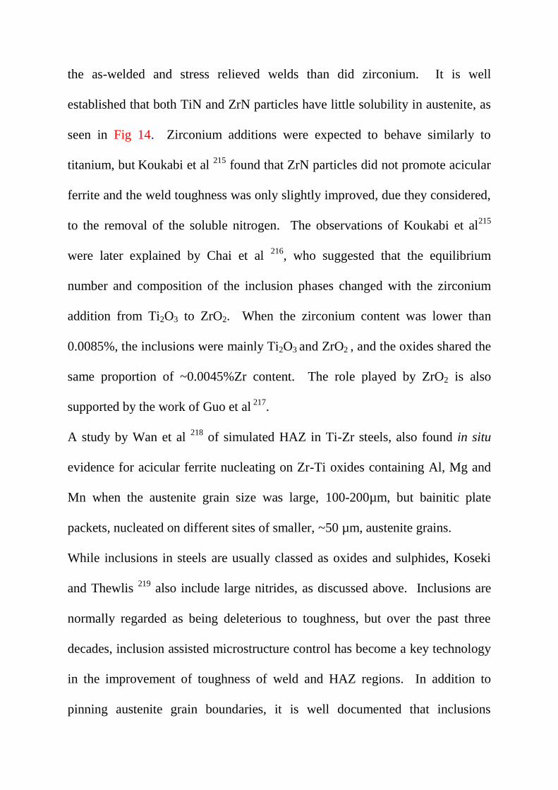
the as-welded and stress relieved welds than did zirconium. It is well
established that both TiN and ZrN particles have little solubility in austenite, as
seen in Fig 14. Zirconium additions were expected to behave similarly to
titanium, but Koukabi et al 215
found that ZrN particles did not promote acicular
ferrite and the weld toughness was only slightly improved, due they considered,
to the removal of the soluble nitrogen. The observations of Koukabi et al215
were later explained by Chai et al 216
, who suggested that the equilibrium
number and composition of the inclusion phases changed with the zirconium
addition from Ti2O3 to ZrO2. When the zirconium content was lower than
0.0085%, the inclusions were mainly Ti2O3 and ZrO2 , and the oxides shared the
same proportion of ~0.0045%Zr content. The role played by ZrO2 is also
supported by the work of Guo et al 217
.
A study by Wan et al 218
of simulated HAZ in Ti-Zr steels, also found in situ
evidence for acicular ferrite nucleating on Zr-Ti oxides containing Al, Mg and
Mn when the austenite grain size was large, 100-200µm, but bainitic plate
packets, nucleated on different sites of smaller, ~50 µm, austenite grains.
While inclusions in steels are usually classed as oxides and sulphides, Koseki
and Thewlis 219
also include large nitrides, as discussed above. Inclusions are
normally regarded as being deleterious to toughness, but over the past three
decades, inclusion assisted microstructure control has become a key technology
in the improvement of toughness of weld and HAZ regions. In addition to
pinning austenite grain boundaries, it is well documented that inclusions

nucleate intragranular acicular ferrite (AF).219-221 As discussed previously, the
development of a microstructure with a high proportion of AF is recognised as
means of generating steels with high strength and good toughness. This
approach had its birth in attempts to improve the microstructure of welds, where
toughness problems were mitigated by inclusion nucleated AF. The formation
of AF is closely related to oxygen content of the weld metal and the type,
volume fraction, and size distribution of the inclusions.221, 222
It has been
reported that TiO and TiN, if oriented correctly, have good coherency with
ferrite, when the two lattices exhibit a low misfit, δ.223
Mills et al 222
identified a titanium rich phase, which they considered to be a
mixture of TiO and TiN with other phases, on the surface of a glassy manganese
silicate and on galaxite (Al2O3,MnO). Both TiO and galaxite have a low δ,
~3%, with ferrite, which is considered the reason these phases nucleate AF.
Several other phases have been collected by Koseki and Thewlis 219
showing
low δ values, with <5% mismatch. In addition to low misfit, the number density
of inclusions, NAF, which act as AF nucleation is important.
More recently, the AF formation potency of Ti-Rare earth metal (REM)-Zr
(TRZ) complex oxides have been investigated in the simulated HAZ of low
carbon steel studied by Nako et al 224. The TRZ complex oxide shows a higher
AF formation potency than either titanium or aluminium oxides. AF crystals
nucleate on the interface between austenite and the Zr-rich oxide phase. Good
lattice coherency through the orientation relationship:
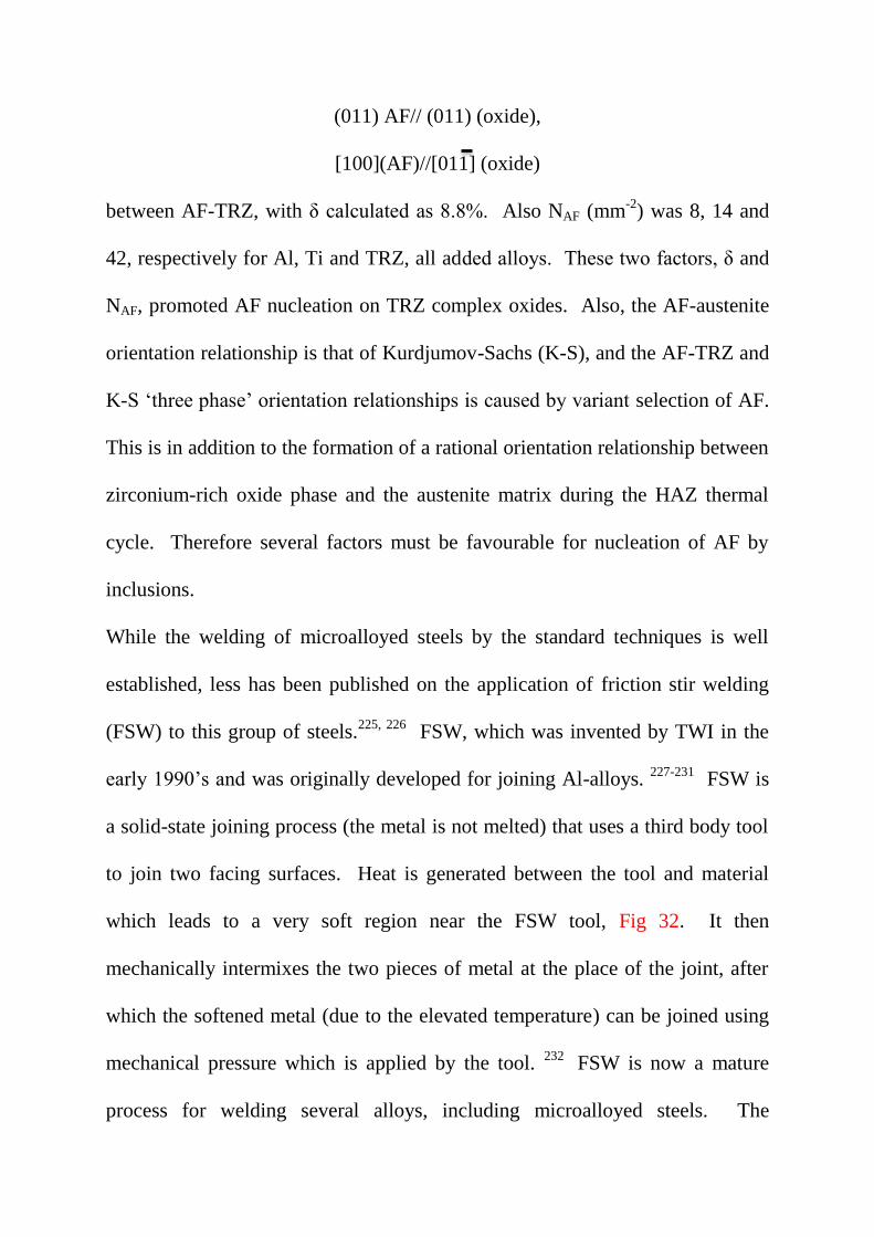
(011) AF// (011) (oxide),
[100](AF)//[011] (oxide)
between AF-TRZ, with δ calculated as 8.8%. Also NAF (mm-2
) was 8, 14 and
42, respectively for Al, Ti and TRZ, all added alloys. These two factors, δ and
NAF, promoted AF nucleation on TRZ complex oxides. Also, the AF-austenite
orientation relationship is that of Kurdjumov-Sachs (K-S), and the AF-TRZ and
K-S ‘three phase’ orientation relationships is caused by variant selection of AF.
This is in addition to the formation of a rational orientation relationship between
zirconium-rich oxide phase and the austenite matrix during the HAZ thermal
cycle. Therefore several factors must be favourable for nucleation of AF by
inclusions.
While the welding of microalloyed steels by the standard techniques is well
established, less has been published on the application of friction stir welding
(FSW) to this group of steels.225, 226
FSW, which was invented by TWI in the
early 1990’s and was originally developed for joining Al-alloys. 227-231
FSW is
a solid-state joining process (the metal is not melted) that uses a third body tool
to join two facing surfaces. Heat is generated between the tool and material
which leads to a very soft region near the FSW tool, Fig 32. It then
mechanically intermixes the two pieces of metal at the place of the joint, after
which the softened metal (due to the elevated temperature) can be joined using
mechanical pressure which is applied by the tool. 232
FSW is now a mature
process for welding several alloys, including microalloyed steels. The
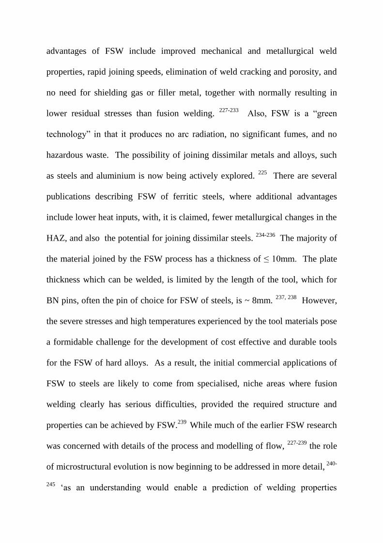
advantages of FSW include improved mechanical and metallurgical weld
properties, rapid joining speeds, elimination of weld cracking and porosity, and
no need for shielding gas or filler metal, together with normally resulting in
lower residual stresses than fusion welding. 227-233
Also, FSW is a “green
technology” in that it produces no arc radiation, no significant fumes, and no
hazardous waste. The possibility of joining dissimilar metals and alloys, such
as steels and aluminium is now being actively explored. 225
There are several
publications describing FSW of ferritic steels, where additional advantages
include lower heat inputs, with, it is claimed, fewer metallurgical changes in the
HAZ, and also the potential for joining dissimilar steels. 234-236
The majority of
the material joined by the FSW process has a thickness of ≤ 10mm. The plate
thickness which can be welded, is limited by the length of the tool, which for
BN pins, often the pin of choice for FSW of steels, is ~ 8mm. 237, 238
However,
the severe stresses and high temperatures experienced by the tool materials pose
a formidable challenge for the development of cost effective and durable tools
for the FSW of hard alloys. As a result, the initial commercial applications of
FSW to steels are likely to come from specialised, niche areas where fusion
welding clearly has serious difficulties, provided the required structure and
properties can be achieved by FSW.239
While much of the earlier FSW research
was concerned with details of the process and modelling of flow, 227-239
the role
of microstructural evolution is now beginning to be addressed in more detail, 240-
245 ‘as an understanding would enable a prediction of welding properties

resulting from the microstructures’. 243
As detailed by De et al, 239
compared to
fusion welding, microstructure is affected by several factors. The peak
temperatures for FSW are lower, and therefore the grain size of austenite that
forms in the HAZ is often smaller than after fusion welding. Also, severe
deformation and flow of plasticised steel alter the stability of austenite in the
TMAZ because of the stored energy, which affects its decomposition to
daughter phases. In contrast, the austenite formed during cooling of molten
weld metal in fusion welding is hardly affected by any stored energy. Because
deformation in the stir zone (SZ) varies with position, this influences the local
austenite transformation kinetics, as in thermomechanically processed
microalloyed steels, the modelling of which was considered earlier. 239
Therefore microstructures are expected, and found, to vary considerably in
different parts of the SZ.
EBSD produces orientation maps which provide vital information on grain
misorientation and grain size from the base metal (BM), HAZ,
thermomechanically affected zone (TMAZ) and the SZ of FSW. This
application of EBSD has been used to good effect by Davies et al 246
, studying
deformation textures in FSW Ti-6Al-4V alloy, who showed that the texture of
the Ti α hcp fully lamellar microstructure was inherited from the shear texture
of the high temperature β phase. This does not yet appear to have been
investigated for the γ→ α transformation in FSW microalloyed steels. Cho et al
243 were among the first to apply EBSD obtained with a FE-SEM, to study the
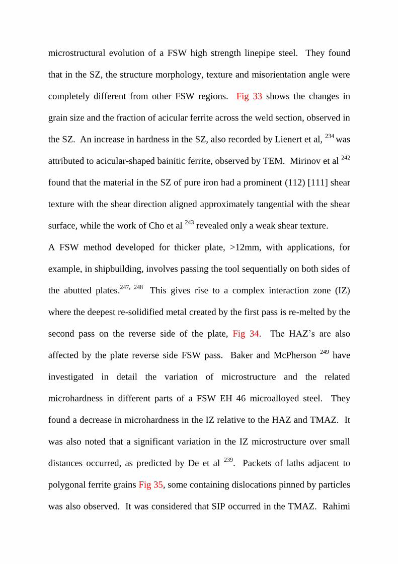
microstructural evolution of a FSW high strength linepipe steel. They found
that in the SZ, the structure morphology, texture and misorientation angle were
completely different from other FSW regions. Fig 33 shows the changes in
grain size and the fraction of acicular ferrite across the weld section, observed in
the SZ. An increase in hardness in the SZ, also recorded by Lienert et al, 234
was
attributed to acicular-shaped bainitic ferrite, observed by TEM. Mirinov et al 242
found that the material in the SZ of pure iron had a prominent (112) [111] shear
texture with the shear direction aligned approximately tangential with the shear
surface, while the work of Cho et al 243
revealed only a weak shear texture.
A FSW method developed for thicker plate, >12mm, with applications, for
example, in shipbuilding, involves passing the tool sequentially on both sides of
the abutted plates.247, 248
This gives rise to a complex interaction zone (IZ)
where the deepest re-solidified metal created by the first pass is re-melted by the
second pass on the reverse side of the plate, Fig 34. The HAZ’s are also
affected by the plate reverse side FSW pass. Baker and McPherson 249
have
investigated in detail the variation of microstructure and the related
microhardness in different parts of a FSW EH 46 microalloyed steel. They
found a decrease in microhardness in the IZ relative to the HAZ and TMAZ. It
was also noted that a significant variation in the IZ microstructure over small
distances occurred, as predicted by De et al 239
. Packets of laths adjacent to
polygonal ferrite grains Fig 35, some containing dislocations pinned by particles
was also observed. It was considered that SIP occurred in the TMAZ. Rahimi
et al 250
used EBSD, after the manner of Gourgues et al 251
to assess the
crystallographic features of the EN46 steel. Their EBSD data 250
show that the
IZ underwent deformation in ferrite, since the pole figure shows bcc shear
texture. Also, the IZ has ultra-fine grain size (i.e. ≤1µm) in which the
misorientation distribution fits in well with the MacKenzie distribution,
implying that the ultra-fine grain ferrite is recrystallized. TEM data collected
from the IZ shows dislocation cell structures which agrees well with the EBSD
data. However, in the TMAZ the EBSD data show (111) pole figures in the bcc
ferrite similar to (011) fcc shear texture, implying that the deformation during
FSW occurred in austenite. The data also show a significantly high fraction of
sub-structures that are scattered from MacKenzie distribution. These can be due
mainly to low angle grain boundaries between ferrite grains that are originating
from the same austenite grain. 250
The study of microstructure using TEM and
related EBSD is at a relatively early stage, and it is expected more will be
forthcoming in the future.
14. Strength, toughness and ductility
14.1Components of strength
For many years, the possibility of improving the properties of polycrystalline
materials through understanding and quantifying the microstructural
components which determine the properties, has been a major goal of materials
scientists.30,31
This topic has been explored to a much greater depth in the case
of microalloyed steels than in perhaps, any other material. One of the main
reasons, has been the challenge posed by such a complex microstructure, which
involves contributions from solid solution hardening, precipitate dispersion
strengthening, dislocation densities, grain and sub-grain size, the Peierls-
Nabarro stress and a possible texture contribution.2, 28, 29, 252-257
In addition, the
effect of the interaction of some of these components, giving rise to
superposition, which is considered below, must be addressed. 114, 257
It has long been appreciated that a fine grain size is associated with superior
properties. In the 18thC, separately Reaumur,
258 and Grignon,
259 noted that, as
revealed on fracture surfaces, excellent metals were distinguished from
mediocre ones by the fineness of their grains. This historical background was
initially described by Desch 260
more recently by Armstrong. 261
The measurement of a fine grain size necessitated optical microscopy, which
lead to the study of microstructure normally described as ‘metallography’. The
earliest systematic study is generally attributed to H.C. Sorby, who in 1849,
extended a technique to geological specimens of meteorites, taught to him by a
Manchester surgeon, W.G.Williamson. 262
Sorby adapted his techniques to the
examination of iron and steel products of his native city, Sheffield. Many years
later, W.L. Bragg, who had long held the view that grain size influenced the

strength of polycrystals,set Orowan in the late 1940’s, with two research
fellows, Hall and Petch, to systematically study this effect in mild steels. 263
The Hall-Petch relationship, which was initially concerned with FP
steels, conveniently allows σy, the lower yield stress, (or often in
practice, the 0.2% proof stress) to be related to individual components of
strengthening.
σy = σo + kyd-1/2
(10)
As can be seen in Fig 36, based on the work of Morrison 264
, when σy is plotted
against a function of the grain size, d-1/2
, a straight line relationship is obtained
over a range carbon contents in steels. The intercept on the ordinate axis, σo,
and the slope of the straight line, ky, are experimental constants. Hall and Petch
proved that strengthening was therefore due to a reduction of grain size together
with an increase in the factors which determined σo. The latter, which is often
referred to as the friction stress, 29
results from the features which arrested the
motion of dislocations across the grains. Problems associated with the
determination of σo have been discussed in detail by Baker 255
. These included
strain fields from misfitting solute atoms in solid solution (σss) precipitates (σp)
and other ‘forest’ dislocations (σd). Other factors are sub-grain sizes (σsg) and
texture (σt) plus the basic lattice Peierls-Nabarro component, (σi).
The linear summation of these components leads to the relationship:
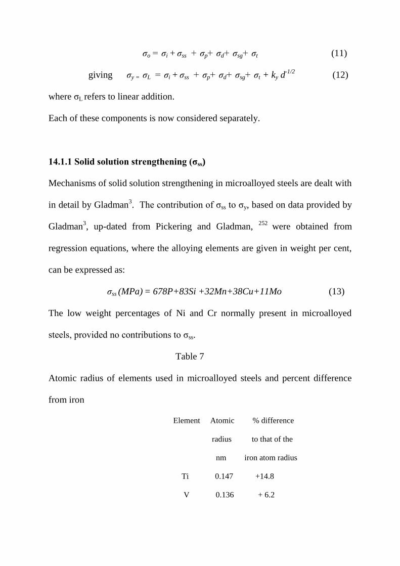
σo = σi + σss + σp+ σd+ σsg+ σt (11)
giving σy = σL = σi + σss + σp+ σd+ σsg+ σt + ky d-1/2
(12)
where σL refers to linear addition.
Each of these components is now considered separately.
14.1.1 Solid solution strengthening (σss)
Mechanisms of solid solution strengthening in microalloyed steels are dealt with
in detail by Gladman3. The contribution of σss to σy, based on data provided by
Gladman3, up-dated from Pickering and Gladman,
252 were obtained from
regression equations, where the alloying elements are given in weight per cent,
can be expressed as:
σss (MPa) = 678P+83Si +32Mn+38Cu+11Mo (13)
The low weight percentages of Ni and Cr normally present in microalloyed
steels, provided no contributions to σss.
Table 7
Atomic radius of elements used in microalloyed steels and percent difference
from iron
Element Atomic % difference
radius to that of the
nm iron atom radius
Ti 0.147 +14.8
V 0.136 + 6.2
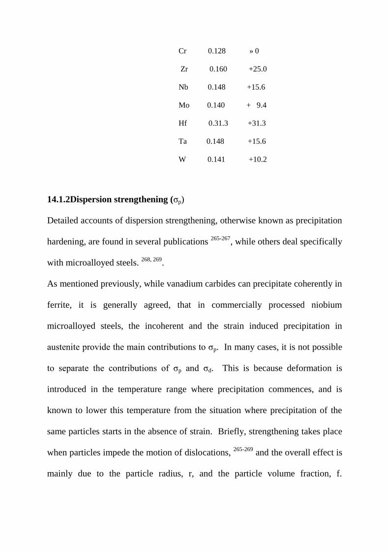
Cr 0.128 » 0
Zr 0.160 +25.0
Nb 0.148 +15.6
Mo 0.140 + 9.4
Hf 0.31.3 +31.3
Ta 0.148 +15.6
W 0.141 +10.2
14.1.2Dispersion strengthening (σp)
Detailed accounts of dispersion strengthening, otherwise known as precipitation
hardening, are found in several publications 265-267
, while others deal specifically
with microalloyed steels. 268, 269
.
As mentioned previously, while vanadium carbides can precipitate coherently in
ferrite, it is generally agreed, that in commercially processed niobium
microalloyed steels, the incoherent and the strain induced precipitation in
austenite provide the main contributions to σp. In many cases, it is not possible
to separate the contributions of σp and σd. This is because deformation is
introduced in the temperature range where precipitation commences, and is
known to lower this temperature from the situation where precipitation of the
same particles starts in the absence of strain. Briefly, strengthening takes place
when particles impede the motion of dislocations, 265-269
and the overall effect is
mainly due to the particle radius, r, and the particle volume fraction, f.

Dislocations can shear coherent (soft) particles, and σp ≈ (fr)1/2
, or dislocations
can loop around the incoherent (hard) particles, where σp ≈ f 1/2
/r.
Goldschmidt 270
found extensive mutual solubility of all the carbides and
nitrides collated in Table 5, which formed carbonitrides. Examples are the TiN-
NbN system 122
and the ZrC and ZrN system. 123
The exception is VC and VN
with ZrC and ZrN, attributed to the difference in the sizes of the Zr and V
atoms, which are given in Table 7. This also has implications for ternary
systems such as TiN-ZrN-VN and ZrN-NbN-VN, where a miscibility bay
should occur, in contrast to complete solution systems such as TiN-VN-NbN, or
similar mixed carbides or carbides and nitrides. Therefore in most microalloyed
steels, which contain both carbon and nitrogen in their chemical composition,
the strengthening precipitates will be carbonitrides of varying C/N ratios.
The Baker-Nutting orientation relationship (BNOR) was not found in the
detailed and careful crystallographic study undertaken by Epicer et al. 271
They
used a model Fe-V-C alloy, and found the V6C5 precipitates, which exhibited an
ordered monoclinic form, also characterised by Hollox et al. 272
Furthermore,
their survey of the literature found no conclusive evidence for the existence of
precipitates with the V4C3 structure. 271
This is surprising, as many publications
have included SAED patterns, matching the fcc:bcc BNOR 60
for transition
metal carbides and nitrides, sometimes described as the Bain orientation, with
the correct lattice parameters.273-278, 280
BNOR has been shown apply to
incoherent Nb, V, Ti carbides, nitrides and carbonitrides precipitated in ferrite,

including interphase precipitation. 277-284
It should be pointed out that both the
composition of the model alloy studied by Epicer et al 271
, and the heat
treatment conditions are unrepresentative of microalloyed steels. It would be
edifying if these authors applied the same rigour to vanadium carbonitrides
precipitated in commercial controlled rolled microalloyed steels. Here,
however, the main point is to confirm whether the V6C5 precipitates are sheared
or looped by dislocations, as this leads to different estimates of strengthening.
There is still disagreement on the subject on the role of solute atoms,
particularly niobium, versus SIP of nitrides and carbonitrides, on the kinetics of
austenite recrystallization, discussed previously, and also whether or not
carbides, nitrides or carbonitrides form coherently or incoherently in ferrite. 51-
57, 131-133 Almost invariably, particles characterised in microalloyed steels are
incoherent. This is supported in a recent APT study on vanadium steels, which
found 5-20nm size, randomly distributed V(C,N) precipitates, with a BNOR, in
ferrite. Interphase precipitates formed in a region of higher carbon. 280
A more detailed expression derived from the initial work of Orowan, 285
developed by Ashby 286
and others, 4 leads to an expression which allows
quantification of σp:
σp (MPa) =(0.538 Gbf 1/2
/X) ln (X/2b) (13)
where G is the shear modulus of the matrix, b is the Burgers vector of the
dislocation (mm), and X the real spatial diameter of the particles (mm). The

expression assumes the particles are spherical, and geometrical factors must be
introduced for plate or needle shaped particles.
For microalloyed steels, with G=80,300MPa, b=2.5 x 10⁻⁴
µm, Gladman4
produced
σp (MPa) =( 10.8f 1/2
/X) ln (X / 6.12510-4
) (14)
with X in µm.
σp values of 50-100MPa are typical of niobium steels of the 1980’s. Kostryzhev
et al 54
have collated σp values from eight sources, reporting on Nb and NbTi
microalloyed steels, which range from 20 to 230MPa, and point out that for the
same steel using different TMP routes, variations up to 4.5 times have been
found. However, some of this data may include a contribution from dislocation
strengthening. Recently, Yen et al 281
studying interphase precipitation of TiC,
estimated σp values to be ~300MPa, in steels with σy of 780MPa.
One of the main difficulties in calculating σp, is the estimation, based on
experimental determination of the volume fraction, f, of precipitates involved.
Often, extraction carbon replicas have been employed. The problem is to
determine the depth of steel which has been etched to provide on the replica in
2D, the particle volume fraction distributed in 3D. A solution to the problem
was given by Ubhi and Baker 287
, and discussed further by Baker. 255,288
Using
the extraction carbon replica technique, one study noted that few particles ≤
4nm was recorded. 124
MacKenzie et al 289
repeated the work using a focussed
ion lift out technique, followed by low ion energy milling. This allowed the

quantitative analysis of ~1nm particles of VN. How much the loss of particles
between extraction carbon replicas and the above technique, in terms of volume
fraction and influence on σp, is not known, as this work is probably the only
record of this observation.
14.1.3 Dislocation strengthening (σd)
Motion of dislocations (mobile) is impeded by interaction with both other
mobile dislocations and with immobile dislocations already present in the
grains, usually described as forest dislocations. These may be present along
with precipitates, as often in the case of as rolled microalloyed steels. In the
former case, σd, can be calculated based on the equation first derived by Taylor
290
σd=αGbρ1/2
(15)
where α is a constant and ρ the dislocation density. Several values of α have
been derived experimentally and collated by Baker. 255
The value 0.88,
obtained by Roberts et al 291
is recommended.
Based on the modifications to the Hall–Petch equation, many methods have
been developed to estimate the lower yield stress, σy, from microstructure
measurements of particle size and dislocation density. These have met with
some success in microalloyed steels when dislocation densities where relatively
low. Modifications to Eqn. 11 have been proposed when dislocation densities
are high, >1015
m-2
, due to the strong precipitate-dislocation interaction resulting
in super-positioning, discussed below.
14.1.4 Grain size component
Fig 36 can be used as a guide to the possible strengthening routes for
microalloyed steels with a ferrite-pearlite microstructure. Thus for a grain size
of 50µm, tested at 300K, the data give a corresponding σy of ~160MPa. For a
small ferrite grain size of 5µm, σy increases to 350MPa, emphasising the
importance of grain size as a method of increasing strength in polycrystals. Fig
36 also shows that strength can be increased by displacing σo to the dotted line
A-B. For a grain size of 5µm, σy increases to 600MPa. This is achievable by
controlled rolled microalloy steels. In theory, changing the slope, ky, as shown
in Fig 36 for the dashed line σo-C, will also increase σy, although this is not
normally a practicable route. The Hall–Petch relation has been found
experimentally, to hold for materials with grain sizes ranging from 1 mm to 1
µm. However, experiments on many nanocrystalline materials demonstrated
that if the grains reached the critical grain size, which is typically around10 nm,
σy would either remain constant or decrease with decreasing grains size.292
A number of different mechanisms have been proposed for this relation which
fall into four categories: (1) dislocation-based, (2) diffusion-based, (3) grain-
boundary shearing-based, (4) two-phase-based. 293
Manufacturing engineering
materials, such as microalloyed steels, with this ideal grain size is difficult,
because only thin films can be reliably produced with grains of this size.
However, microalloyed steels comprising of sub-grains, having misorientations,
θ of < 8º are well documented, and include acicular ferrite and bainitic
microstructures. De Ardo et al
6 comment that ‘as there are relatively few high
angle boundaries, beyond the prior austenite boundaries, Hall-Petch
strengthening will not be important.’ However, the friction stress term σo,
envisaged by Petch31
, included a contribution from dislocations, as seen in
Eqns. 11 and 12. Equations dealing with substructures, sometimes described as
cells, are available and discussed in detail by Embury294
and Thompson295
.
Both provide a comprehensive list of references to relevant early research,
extended by Castrofernandez and Sellars.296
σsg is usually related to the sub-grain size, l, by:
σsg =ks l –m
(16)
and for iron alloys 255
,when m is often taken as 1:
ks (Nmm-3/2
) =2.1√θ (17)
θ is the sub-grain boundary misorientation in degrees. The Hall-Petch equation
is just as applicable to acicular ferrite and bainitic microstructures as to ferrite-
pearlite. Fig 37 from Gladman and Pickering 255
obtained from their multiple
regression equation:
σy (MPa) = -191 +17d-1/2
+14.9n1/4
(18)
where d is the mean linear intercept of bainitic ferrite laths and n, the number of
carbide particles per unit planar section of microstructure. The carbide inter
particle spacing, λ, is related to n through:
λ -1/2
=0.94n1/4
(19)
The results from Eqn.18 are presented in Fig.37, which shows that carbide
strengthening only becomes significant at finer bainitic ferrite lath sizes.
14.2 Summation of strengthening components
One of the earliest examples of successful linear additive strengthening of
microalloyed steels comprising grain, subgrains and precipitation was by
Mangonon and Heitmann 297
, extended more recently by Morales et al 298
, who
considered the same method for their linepipe steel which was comprised of AF
and PF microstructures.
The summation of these components leads to the relationship:
σy = σLy = σi + σss + σp+ σd+ σsb+ σt + kyd-1/2
(12a)
where σi has values between 40 and 74MPa at 273K.264,299
In a reassessment of results obtained during research on niobium steels for
microstructures containing high dislocation densities, the initial comparison of
the estimated, σLy,, by linear addition, and experimental data, σM, was poor 256
.
With a second approach, taking into account superposition, 114,256
the
components were divided into two groups, σA and σd, and then used in a
relationship based on the square root of the sum of the squares of σA and σd,
σy = σR = √ (σA )2 + (σd)
2 (20)
where σA= σi + σss + σp+ kyd-1/2
(21)
This procedure followed the theoretical approaches combining weak and strong
obstacles, described by Foreman and Makin 300
and by Kocks et al 301
, who
considered that in an alloy containing both forest dislocations and precipitates;
these obstacles would not be distinguished by mobile dislocations. This
assumes that precipitates, nucleating and growing on dislocations, would offer
the same resistance to mobile dislocations, as interacting forest dislocations.
Equation 20 avoids adding the contributions from both σp and σd components in
a linear manner when the interaction involves superposition. A summation
equation was also devised by Li et al 302
, giving the yield strength, σC , as
σC = σi + σss + (σd.σp) (22)
Table 8 gives data comparing σy determined experimentally σM 114
and
calculated from microstructure 114
, σL -linear addition, σR - square root of the
sum of the squares, σC–Li et al 302
Table 8
A comparison of σy determined experimentally σM 114
and calculated from
microstructure 114
Steel σM kyd-1/2
σd σp (σd.σp) 1/2
σi + σss σR σL σC
MPa Nmm-3/2
MPa MPa MPa MPa MPa MPa MPa
S1 510 294 116 85 99 118 510 613 511
S2 559 340 145 51 86 118 543 654 544
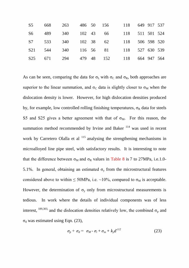
S5 668 263 486 50 156 118 649 917 537
S6 489 340 102 43 66 118 511 501 524
S7 533 340 102 38 62 118 506 598 520
S21 544 340 116 56 81 118 527 630 539
S25 671 294 479 48 152 118 664 947 564
As can be seen, comparing the data for σL with σC and σR, both approaches are
superior to the linear summation, and σC data is slightly closer to σM when the
dislocation density is lower. However, for high dislocation densities produced
by, for example, low controlled rolling finishing temperatures, σR data for steels
S5 and S25 gives a better agreement with that of σM. For this reason, the
summation method recommended by Irvine and Baker 114
was used in recent
work by Carretero Olalla et al 115
analysing the strengthening mechanisms in
microalloyed line pipe steel, with satisfactory results. It is interesting to note
that the difference between σM and σR values in Table 8 is 7 to 27MPa, i.e.1.0-
5.1%. In general, obtaining an estimated σy from the microstructural features
considered above to within ≤ 50MPa, i.e. ~10%, compared to σM is acceptable.
However, the determination of σy only from microstructural measurements is
tedious. In work where the details of individual components was of less
interest, 189,303,
and the dislocation densities relatively low, the combined σp and
σd was estimated using Eqn. (23),
σp + σd = σM - σi + σss + kyd-1/2
(23)
There are alternative ways of determining strengthening components, other than
by microstructural measurements. 304
Speich 305
used resistivity measurements
to follow precipitation in alloy steels during tempering treatments to good
effect. The same approach was used by Hall and Baker 306
studying
precipitation of vanadium carbide in controlled rolled steels. The accuracy of ±
10 %, Fig 38, was similar to that obtained based on microstructural estimates,
but no less tedious, and an example of the summation of the components is
given in Fig.39.
Hornbogen and Staniek 253
,307
pointed out that, whereas the breakdown of
coherency to develop incoherent precipitates via partially coherent precipitates,
308 may involve the generation of dislocations, the presence of coherent
precipitates alone does not. This led them to conclude that a superposition of
coherent particles and dislocations was not relevant, and that linear addition of
estimated strengthening components gave a satisfactory agreement with the
measured yield strength.
Recently, a 3-D analytical model of precipitate strengthening with superposition
laws was developed, and characterization parameters were obtained by local-
electrode atom-probe (LEAP) tomography. 309
This allowed a detailed
calculation of yield strength of secondary hardening at different stages of ageing
due to multiple precipitates of Cu and M2 C in a BA160 steel, to be made. The
model predicted σy as a function of aging time at 450°C within ±13% of σM.
The authors state that this is the first time that the prediction of the yield
strength directly from the microstructure of a multiphase steel was shown to be
feasible.
Another recent study systematically investigated the stress–strain behavior of
ferrite and bainite with nano-sized vanadium carbides in low carbon steels. 310
The ferrite samples were obtained through austenite/ferrite transformation
accompanied with interphase precipitation and the bainite samples were via
austenite/bainite transformation with subsequent aging. The contributions from
solute atoms and grain boundaries were simply added, whereas those from
dislocations and precipitates were treated by taking the square root of the sum
of the squares of two values, giving σN. This is a different approach from that
given by Eqns(20) and (21). From the data they give, σL compares well with σM
for ferrite, ≤ 9.6% over estimate, while comparison with σN is 9.6%-19.2%
under estimated. For bainite, σN ≤ 9.4% under estimate is superior to σL
summation, which is 19-37% over estimated.310
Kostryzev et al 311
, who used a
linear addition of components to quantify the strengthening components of Nb-
Ti FP thermomechanicaly processed Nb-Ti steels, also obtained disagreements
between measured and calculated σy values, which could reach 54%. These
were attributed to overestimates in solid solution and precipitation
contributions, and the errors increased with decreasing deformation
temperature.

Despite the detailed consideration of the models used in calculating the
individual components strengthening and the care taken to ensure the highest
accuracy from microstructural parameters 115, 256, 288, 309-311
such as the foil
thickness required for dislocation density, determination for σd and precipitate
volume fraction, f, needed for estimates of σp, no improvement on the accuracy
of the estimate in σy from microstructural measurements has been achieved. It
is apparent that the calculated σy has, at best, a ±90% accuracy compared with
σM. The error is often due to the inhomogeneous microstructure and the high
magnifications required to image small particles and dislocations. This has
implications for the determination of ρ and f.
14.2Toughness
For many commercial applications of microalloyed steels, good toughness is the
over- riding property requirement. The development of a small grain size is the
only means of making a simultaneous improvement in strength and toughness.
Toughness is normally considered in terms of the energy absorbed during
deformation by impact, and in microalloyed steels is defined by the temperature
at which the fracture mode undergoes a ductile to brittle transition, or some
fixed value of absorbed energy, for example 55J, for a Charpy test-specimen of
given cross-sectional area. In 1947 Barr and Tipper,312,313
working at Colvilles
in Scotland on the Liberty ships facture problems, 314
showed that the ductile-
brittle transition temperature was raised by an increase in the ferrite grain size.
Influenced by this work, Petch, 315, 316
after dealing with yield and cleavage
strength-grain size relationships, turned his attention to fracture toughness, and
in an initial study found a similar relationship with grain size to that of strength,
T c =To –Kyd-1/2
(24)
where Tc and Ky are constants.
This classic work did not take into account the influence of carbide films which
are normally present at grain boundaries. It is generally agreed that McMahon
and Cohen 317
were among the first to appreciate the importance of the role of
carbide films at grain boundaries in the fracture process in carbon steels.
Detailed measurements on carbide film parameters were undertaken by Mintz et
al 318, 319
to obtain statistically significant quantitative data to test the models of
Smith 320
, Almond et al 321
and Knott and Curry.322
This data showed that over
the grain size range 1-14mm-1/2
(d=10 µm to 500µm), the change in Tc was
160°C, whereas the greatest change that can be produced by changes in carbide
thickness alone was 60°C. This data provided support for the conclusions of
Almond et al.321
The above publications were among those which included
ideas leading Petch 323
to revisit the topic some 25 years later than his earlier
work, and to incorporate both grain size and carbide thickness into his model.
The results in Fig 40, where the cleavage strength for fracture, σc, is plotted
against d-1/2
, for a range of carbide thicknesses, t.
The line OA in Fig 41 shows
that σc is directly proportional to d-1/2
and unaffected by carbide. At the other
extreme, with a fine grain size and a coarse carbide, where t equals 5µm, the

carbide has a dominant influence on σc. The region between these two extremes
shows the strong influence of grain size. Petch pointed out that over the grain
size range of 3 to 10mm-1/2
, i.e.100-10µm, and with some carbide refinement
concurrent with grain refinement, equation (3) can normally be used. However,
when the grain size is finer, (as is sometimes the case in microalloyed steels),
then the equation:
5.5Tc =770-46 d-1/2
- σc (25)
gives a more accurate estimate. Using this modified Petch approach, Bingley
and Siwecki 324
analysed the data from three carbon steels. They obtained a
good relationship between d20-1/2
, which is for the average grain size of the
highest 20% in a grain size distribution, and between tmax, the maximum carbide
thickness and d20. Furthermore, they suggested that to give the best fit for their
extensive set of experimental data, Harding’s formula used by Petch to calculate
σc, should be modified to:
σc =520-2.5T +20.2 d-1/2
(26)
Bingley 325
in a more extensive paper, studying both laboratory and
commercial microalloyed steels, confirmed the earlier d20 analysis. 324
14.3 Ductility
Ductility at ambient temperatures is normally recorded following tensile
testing, as elongation percentage and reduction of area. A multiple
regression analysis of 60 casts of carbon steels containing ≤0.25%C,
some with Nb and Al additions, was undertaken by Pickering and
Gladman 252
to quantify the factors which control the properties,
including RA%. This analysis resulted equation 27,
RA% =7.85 +5.4(%Mn) -0.53(%pearlite) - 210 d (27)
where d is the ferrite grain size in µm.
Fig42 shows the calculated RA% plotted against the observed RA%. The
correlation factor is 78%.
A more recent regression analysis by Mintz et al 326
from tensile tests
undertaken over a range of temperatures and strain rates, produced equation 28.
This predicted a min. RA% with an accuracy of ±12% (95% confidence limit).
Min. RA (%) = 700d-l/2
(1 - 4·3 s -1/2
) + 20 (log ε + 2.5) (28)
d is the austenite grain size in µm, s interparticle spacing and ε strain rate.
The importance of a small ferrite grain size and limiting the grain boundary
carbide thickness are well established means of controlling the toughness to
acceptable levels in microalloyed steels from +100 to -100ºC. These parameters
can also influence hot ductility, which is important in processing microalloyed
steels. Hot ductility testing was originally undertaken by torsion testing, 327-329
as this method was considered to provide a good simulation of hot rolling. For
investigating continuous casting failures and to predict the likelihood of
transverse cracking during the unbending operation, hot tensile testing, often
using a Gleeble machine, is the preferred method.326, 330-335
The sample is
cooled at the rate experienced by the surface of the strand during the continuous
casting operation, ~60 K min -1
and is strained at rates between 10-3
and 10-4
s –l
,
which are chosen to simulate those associated with straightening.326
The
variation in hot ductility with temperature is obtained by plotting reduction in
area, RA%, versus test temperature, as in Fig 43. For both the cast and wrought
states, a decrease in hot ductility, described as a ductility trough, occurs
between 700ºC and ~1200ºC; intergranular fracture is observed. The ductility
trough has implications both for normal continuous cast, and for thin slab cast
steels. 326, 329-334
Several explanations have been suggested for the ductility
trough, including failure within a thin film of ferrite at the austenite grain
boundaries, or strain induced precipitation of carbonitrides, which pin austenite
grain boundaries and therefore reduce boundary mobility, and in niobium steels,
precipitate free zones. 329
Fig 43 taken the work of Crowther and Mintz 331
,
shows that refining the austenite grain size is generally beneficial to hot
ductility, as it reduces the width of the trough and increases the minimum RA%.
They showed that decreasing the austenite grain size from 350µm to 70 µm
increased the RA by 20%.
Over many years, Mintz and co-workers have conducted extensive
investigations to understand the role of the transition metals, Nb, Ti and
V, together with Al, N and C, on hot ductility of steels. 326, 331, 333, 334
It is
well established, that increasing the aluminium content of carbon-
manganese steels causes a progressive deterioration in hot ductility.14
During the γ→α transformation, precipitation of AlN occurs
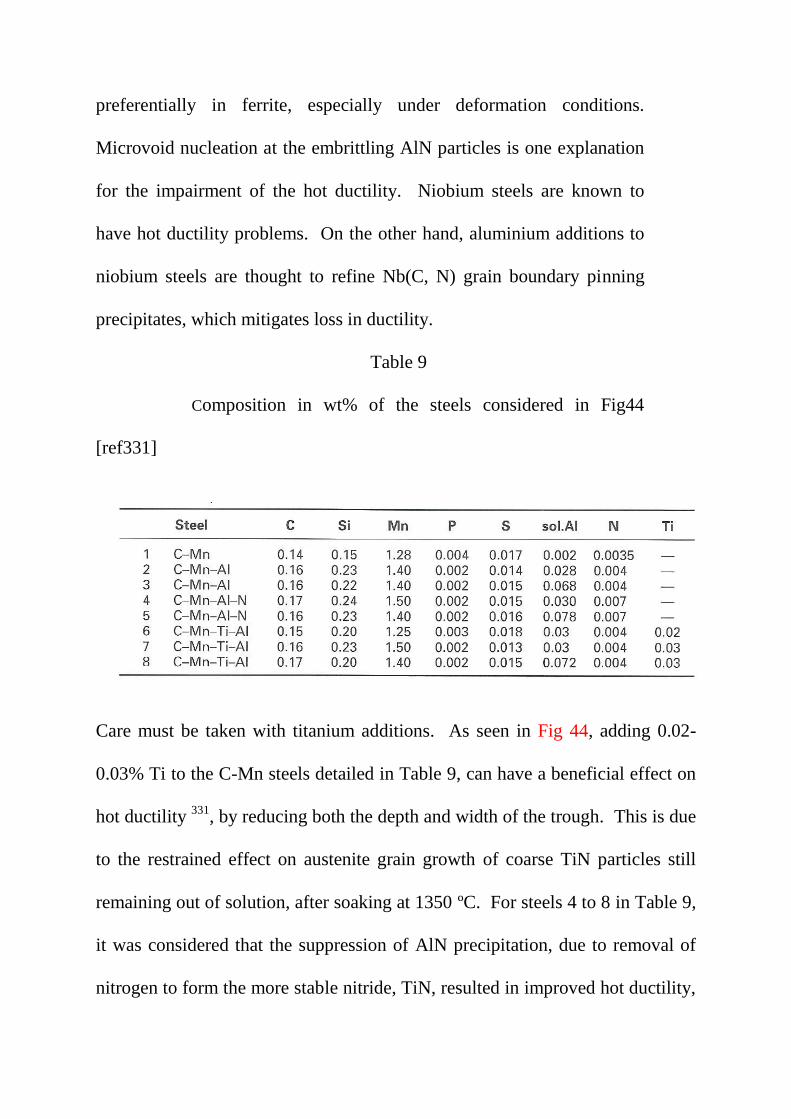
preferentially in ferrite, especially under deformation conditions.
Microvoid nucleation at the embrittling AlN particles is one explanation
for the impairment of the hot ductility. Niobium steels are known to
have hot ductility problems. On the other hand, aluminium additions to
niobium steels are thought to refine Nb(C, N) grain boundary pinning
precipitates, which mitigates loss in ductility.
Table 9
Composition in wt% of the steels considered in Fig44
[ref331]
Care must be taken with titanium additions. As seen in Fig 44, adding 0.02-
0.03% Ti to the C-Mn steels detailed in Table 9, can have a beneficial effect on
hot ductility 331
, by reducing both the depth and width of the trough. This is due
to the restrained effect on austenite grain growth of coarse TiN particles still
remaining out of solution, after soaking at 1350 ºC. For steels 4 to 8 in Table 9,
it was considered that the suppression of AlN precipitation, due to removal of
nitrogen to form the more stable nitride, TiN, resulted in improved hot ductility,
Fig44. However, if due to increased cooling rates during the simulation, fine
TiN particles precipitate restricting particle growth, the beneficial influence of
the titanium addition is lost. Therefore, variation in cooling rates during hot
tensile testing, to simulate as close as possible the conditions pertaining to the
continuous casting operation, have been an important objective in this
research.326, 335
A major concern in simulating the continuous casting process
with a Gleeble machine is in deciding the thermal programme which will ensure
that the appropriate RA% is recorded. 336, 337
Introducing a cooling regime
similar to that undergone by the strand during commercial continuous casting
has been shown for low C low Ti containing C-Mn-Nb steels, always to result
in an improvement in hot ductility below 900 ºC. When the test RA% is >40%,
the steel should not be susceptible to this cracking problem.335
The addition of
zirconium can also reduce transverse cracking, but cannot be added to niobium
grades to be used in the as-rolled or normalized conditions, since strength and
toughness are impaired. However, zirconium has been successfully added to
quenched and tempered grades. 338
A general requirement of continuous cast microalloyed steels, is that
while the composition is important for avoiding cracking following
processing, the choice of alloying elements must be such that the strength
and toughness of the final product meets specification. Where the as cast
slab is to be cooled to ambient prior to reheating for controlled rolling,
then many of the precipitates formed during casting will be taken into
solution, and the microstructure controlled as discussed in the previous
sections. However, if the TSDC route is to be followed, where the
reheating temperature and time are limited, then steel compositions may
require modification. Vanadium steels, with the lowest solution
temperatures of carbides, nitrides and carbonitrides of the conventional
alloy transition metals used for microalloying, may have advantages over
niobium steels.11
Roy et al 339
modelled the effect of segregation on the
stability of microalloy precipitates and on the size distributions at
different regions (solute rich and solute depleted), which is not well
understood. They compared of two as-cast slabs:
(A) 0.09C-1.42Mn-0.035Al-0.050Nb-0.019Ti-0.05V and
(B) 0.07C-1.20Mn-0.-034Al-0.041Ti. The nitrogen level was not given.
Cuboidal TiN, cruciform and cuboidal (Nb, Ti) (C,N), and spherical NbC
and VC, precipitates, which had the greatest volume fraction, were
characterised, and varied with position in slab (A). TiN precipitates,
with various morphologies and sizes, were found in slab (B). The model
proposed for micro-segregation, which was a feature of the slabs
microstructure, gave a satisfactory agreement between experimental
observations and predictions for precipitate size distribution and the
amount of precipitates in the interdendritic and dendrite centre regions of
segregated slabs. It was concluded that this type of model may help, (1)
to avoid hot cracking, (2) in the selection of soaking time and

temperature and predicting austenite grain size during soaking and (3) in
designing the rolling schedule for achieving maximum benefit from the
microalloying precipitates. 339
While problems deriving from residual elements is not specific to microalloyed
steels, it should be touched upon. A significant proportion of recycled steel
(scrap) is now part of the normal charge load during steel making, and it is
accepted that the level of residuals in steels is increasing. Basic oxygen steel
uses around 10-12% scrap only, while electric arc ~75% recycled scrap.
Residual elements, such as copper, nickel, tin, antimony and arsenic, at
trace levels have long been recognised as leading to potential hot
shortness problems. They are known to concentrate in the layer of metal
immediately adjacent to the oxide scale. These are of particular concern
in tube-making and forging of carbon steels. This subscale enrichment
can eventually lead to the precipitation of a phase which is molten at
temperatures > 950ºC.
As explained in a survey by Melford340
, it is more often the interaction
between a combination of trace elements which has to be understood if
their net influence on high temperature mechanical properties is to be
evaluated. An earlier paper 341
, Melford produced a useful guide to the
limiting residual contents that could be tolerated in the form of the
expression:
Cu+6(Sn+Sb) ≤ 9/E (29)
where E, the enrichment factor is defined by E= average concentration of
residual in then subscale/ bulk residual concentration. A literature search
has not produced any extension of this work to microalloyed steels.
15. Summary.
Over the 56 years, since the first publication by Beiser 24
, generally
acknowledged to bring niobium steels to the attention of the world, much
progress has been made. The yield strength of mild steels ~250MPa was raised
up to 400MPa with an addition of 0.03% Nb. The introduction of controlled
rolling made these strength levels possible, together with good toughness in
weldable steels. Many of the ideas of using accelerated cooling and modifying
steels compositions, to produce bainitic and acicular, with strengths above
600MPa, were known from laboratory research in the 1970’s. Since this time,
the expansion of line-pipe production, and the automobile industry requiring
high strength and toughness in thinner sheet, to name due two examples,
transferred these possibilities to the production line. The use of multiple
additions of niobium, titanium and vanadium, sometimes with a high nitrogen
content, is now commonplace, while processing of microalloyed steels using
thin slab direct charging technology is on the increase, as is the application of
friction stir welding. The recognition of the role of microstructure in achieving
these improved properties, has been at the root of many of these advances.
Electron microscopes, coupled with an array of analytical equipment, now
allows far more detailed information to be processed quicker and with user
friendly software, than even a decade ago, but at an increasing cost. While
ferrite-pearlite microalloyed steels are expected to provide the bulk production,
the future may see the development of a spectrum of microalloyed steels,
dictated by economics, but also tailor made for the processing route. This could
well be the case for both thin slab cast direct charge steels, with their restricted
reheating and rolling passes, and friction stir welded steels, with very
inhomogeneous microstructures in the stir zone, especially for thicker plate,
where a double pass is used.
16 Postcript
The author has been involved with Microalloyed Steels for over 50 years, and
been associated with many of those who have made major contributions to this
field. Initially this was during time at Hinxton Hall, the Tube Investments
Research Laboratory, when we were involved in 30 Oak, a steel produced by
Round Oak Steelworks and purported to have a lower yield stress of 30tsi
(~400MPa), which was true, at ≤ 10mm thickness. As an undergraduate at
Sheffield University, E.O. Hall taught me physics, and J.H. Woodhead and Prof.
(later Sir) R.W.K. Honeycombe, metallurgy. The latter later invited me to write
a review for Science Progress, (ref.1), and I was included in those who

presented work at a celebration of his 70th birthday (ref.2). I met W.B.
Morrison at Colvilles Steelworks in the mid 1960’s, having previously visited
Swinden Laboratories of United Steels, to talk with Prof. T. Gladman and Prof.
F.B. Pickering about AlN precipitation, which I had been taught to SAED index
by Prof. D.W. Pashley, who with Sir J.W. Menter, introduced me to TEM. Prof.
N.J. Petch joined the Metallurgy Department of Strathclyde University in the
early 1970’s. We had many discussions, and he became a firm friend. Dr. N.A.
McPherson, undertook PhD work with me, as did Drs N. Gao, K. He and Y. Li,
who continued in the Group as post-doctoral research fellows. All of us
benefited from many years of collaboration with Prof. A.J. Craven, University
of Glasgow, through PEELS analysis of nanoparticles.
16. References
1. T.N. Baker: ‘Microalloyed steels’, Si. Prog., 1978, 65, 493-542. 2. T.N. Baker: ‘Microalloyed steels’, in ‘Future developments of metals and ceramics, (eds.
J.A. Charles, G.W. Greenwood and G.C. Smith), 75-119, 1992, London, Inst. Mater.
3. T. Gladman: ‘Microalloyed Steels’, 1997, London, Inst. Mater.
4. T. Gladman: ‘The physical metallurgy of microalloyed steels’, Mater. Sci. Technol., 1999,
15, 30-36.
5. W.B. Morrison: ‘Microalloy steels – the beginning’, Mater. Sci. Technol, 2009, 25, 1068 -
1073.
6. A.J. De Ardo: ‘Metallurgical basis for thermomechanical processing of microalloyed
steels’, Ironmaking and Steelmaking, 2001, 28, 138-144.
7. S. Vervynckt, K. Verbeken, B. Lopez and J.J. Jonas: ‘Modern HSLA steels and role of
non-recrystallisation temperature’, Inter. Mater. Revs, 2012, 57, 187-207.
8 A.J. DeArdo: ‘Niobium in modern steels’, Inter. Mater. Revs., 2003, 48, 371-402.
9. F.B. Pickering: ‘Overview of titanium in microalloyed steels’ in ‘Titanium Technology in
Microalloyed Steels’, (ed. T.N. Baker), 10-43, 1997, London, Institute of Materials.
10. R. Lagneborg, T. Siwecki, S. Zajac and B. Hutchinson: ‘The role of vanadium in
microalloyed steels’, Scand. J. Met., 1999, 28, 186-241.
11. R. Lagneborg, B. Hutchinson, T. Siwecki and S. Zajac: ‘The role of vanadium in
microalloyed steels’, Michael Korchynsky Symposium, MS&T Conference, pp 1-95, October
2014, Vanitec publication.
12. T.N. Baker: ‘Processes, Microstructure and Properties of Vanadium Microalloyed Steels’,
Mater. Sci. Technol., 2009, 25, 1083-1107.
13. T.N. Baker: ‘Role of zirconium in microalloyed steels: a review’, Mater. Sci. Technol., 2015,
31, 265-294.
14. F.G. Wilson and T. Gladman: ‘Aluminium nitride in steel’, Inter. Mater. Revs., 1988, 33,
221-286.
15. World Steel Production Report August 2014
16. http://www.keytometals. Total Materia.
17. H. Xie, L-X. Du, J. Hu and R.D.K. Misra: ‘Microstructure and mechanical properties of a
novel 1000 MPa grade TMCP low carbon microalloyed steel with combination of high
strength and excellent toughness’, Mater. Sci. Eng., 2014, A612, 123-130.
18. http://en.wikipedia.org/wiki/Microalloyed steel
19. http://www.tatasteeleurope.com
20. G. Oakes and K.C. Barraclough: ‘Steels’, in ‘The development of gas turbine materials’, (ed.
G.W. Meetham) 31-61, 1981, London, Applied Science Publishers.
21. D.G. Robertson: ‘Traditional low alloy steels in power plant’, in. ‘Coal power plant materials
and life assessment’, (ed. A. Shibli): 107-126, 2014, Cambridge, Woodhead Publishing,
22. http://www.metal.citic.com/iwcm/Rofes.pdf. Shanghai, November, 2006.
23. D.K. Matlock , G. Krauss, J.G. Speer: ‘Microstructures and properties of direct-cooled
microalloy forging steels’, J. Mater. Proc. Technol., 2001, 117, 324-328.
24. C.A. Beiser: ‘The effect of small columbium additions to semi killed, medium carbon steels’,
ASM preprint no138, 1959, Metals Park, OH, Am. Soc. Met.
25. A.L. Feild: ‘Some effects of zirconium in steel’, Trans. Am. Inst. Mining Met. Engrs., 1923,
69, 848-894.
26. A.L. Feild: ‘Effect of zirconium on hot-rolling properties of high-sulfur steels and the
occurrence of zirconium sulfide’ Trans. Am . Inst. Mining Met. Engrs., 1924, 70, 201-223.
27. F.M. Becket: ‘Some effects of zirconium in steel’, Trans. Amer. Electrochem. Soc., 1923, 43,
261-269.
28. W.B. Morrison: ‘Influence of small niobium additions on properties of carbon-manganese
steels’, J. Iron Steel Inst., 1963, 201, 317-325
29. W. B. Morrison and J.H. Woodhead: ‘Influence of small niobium additions on mechanical
properties of commercial mild steels’, J. Iron Steel Inst., 1963, 201, 43-46.
30. E.O. Hall: ‘The deformation and ageing of mild steel. 3 discussion of results’, Proc. Phys. Soc,
1951, 64B, 747-753.
31. N.J. Petch: ‘ The cleavage strength of polycrystals’, J. Iron Steel Inst., 1953, 174, 25-28.

32. A.H. Cottrell: ‘Dislocations and Plastic flow in crystals’, 1964, Oxford, Clarendon Press.
33. R.D. Heidenreich: ‘ Electron microscopy and diffraction study of metal crystal textures by
means of thin sections’, J. Appl. Phys., 1949, 20, 993-1010.
34. P.B. Hirsch, R.W. Horne and M.J. Whelan: ‘Direct observations of the arrangements and
motion of dislocations in aluminium’, Philos. Mag., 1956, 1, 677- 684.
35. P.B. Hirsch: ‘Direct observations of moving dislocations: Reflections. Mater. Sci. Eng., 1986,
84, 1-10.
36. P.B. Hirsch, A. Howie, R.B. Nicholson , D.W. Pashley and M.J. Whelan: ‘Electron
microscopy of thin crystals’, 1971, London, Butterworths.
37. V. Randle: ‘Microtexture determination and its applications’, 2nd
edn., 2008, London, Maney
Publications.
38. R. Phillips and J.A. Chapman: ‘Influence of finish rolling temperature on mechanical
properties of some commercial steels rolled to 13/16in. diameter bars’, J. Iron Steel Inst.,
1966, 204, 615- 622.
39. H. Matsubara, T. Osuka, I. Kozasu and K. Tsukada: ‘Optimization of metallurgical factors for
the production of high strength, high toughness steel plate by controlled rolling’ Trans. Iron
Steel Inst. Jpn., 1972, 12, 435-443.
40. I. Tamura, C. Ouchi, T. Tanaka and H. Sekine: ‘Thermomechanical processing of high
strength low alloy steel’ 1988, London, Butterworths.
41. C.M. Sellars and J.A. Whiteman: ‘Recrystallization and grain growth in hot rolling’, Met. Sci.
1979, 13, 187-194.
42. C.M. Sellars: ‘The physical metallurgy of hot rolling’ in ‘Hot working and forming processes’
(eds. C.M. Sellars and G.J. Davies) 3-15, 1990, London, Institute of Materials.
43. J.J. Jonas and C.M. Sellars: ‘Thermomechanical Processing’ in ‘Future developments of
metals and ceramics, (eds. J.A. Charles, G.W. Greenwood and G.C. Smith), 147-177, 1992,
London Institute of Materials.
44. K.Hulka:// www.cbmm.com.br.
45.D.C. Houghton, G.C. Weatherly and J.D. Embury: ‘Characterization of carbonitrides in Ti
bearing HSLA steels’, in ‘Thermomechanical Processing of microalloyed austenite’, ed A.J.
DeArdo, G.A. Ratz and P.J. Wray, 267-292, 1982 Metall. Soc. AIME.
46. J.M. Gray, D. Webster and J.H. Woodhead: ‘Precipitation in mild steels containing small
additions of niobium’, J. Iron Steel Inst., 1965, 203, 812-818.
47. J.W. Halley, ‘Grain-growth inhibitors in steel’ Trans. AIME, 1946, 167, 224-234.
48. D. Webster: ‘Effect of precipitates in grain refining microalloyed steels’, Rpt.MG/C/18/62,
1962, BISRA, Sheffield.
49. K.J. Irvine, F.B. Pickering and T. Gladman: ‘Grain-refined C-Mn steels ‘, JISI, 1967, 205,
161-182.
50. D.V. Edmonds and R.W.K. Honeycombe: ‘Precipitation in iron-based alloys’, in
‘Precipitation processes in solids’, (eds. K.C. Russell and H.I. Aaronson), 1978, 121-160.
51. E.V. Pereloma, I.B. Timokhina, K.F. Russell and M.K. Miller: ‘Characterization of clusters
and ultrafine precipitates in Nb-containing C–Mn–Si steels ’ Scripta Mater, 2006, 54, 471–
476.
52. A. Deschamps, F. Danoix, F. De Geuser, T. Epicier, H. Leitner and M. Perez: ‘Low
temperature precipitation kinetics of niobium nitride platelets in Fe ’, Mater. Lett, 2011, 65,
2265–2268.
53. F. Danoix, T. Epicier, F. Vurpillot and D. Blavette: ‘Atomic scale imaging and analysis of
single layer GP zones in a model steel’. J. Mater. Sci., 2012, 47, 1567–1571.
54. G. Kostryzhev, A. Al Shahrani, C. Zhu. J.M. Cairney, S.P. Ringer, C.R. Killmore and E.V.
Pereloma: ‘Effect of niobium clustering and precipitation on strength of an NbTi-
microalloyed ferritic steel’, Mater. Sci. Eng. A, 2014, 607, 226-235.
55. A.J. Breen, K.Y. Xie, M.P. Moody, B. Gault, H-W. Yen, C.C. Wong, J.M. Cairney, and S.P.
Ringer: ‘Resolving the Morphology of Niobium Carbonitride Nano-Precipitates in Steel
Using Atom Probe Tomography’, Microsc. Microanal., 2014, 20, 1100–1110.
56. E.V. Pereloma, A.G. Kostryzhev, A. Al Shahrani, C. Zhu, J.M. Cairney, C.R. Killmore and
S.P. Ringer: ‘Effect of austenite deformation temperature on Nb clustering and precipitation
in microalloyed steel’, Scripta Mater., 2014, 75, 74-77.
57. K.Y. Xie, T. Zheng, J.M. Cairney, H. Kaul, J.G. Williams, F.J. Barbaro, C.R. Killmore and
S.P. Ringer: ‘Strengthening from Nb-rich clusters in a Nb-microalloyed steel’, Scripta Mater.,
2012, 66, 710–713.
58. Z-G Yang and M. Enomoto: ‘Calculation of the interfacial energy of B1-type carbides and
nitrides with austenite’, Metall. Mater. Trans. A, 2001, 32A, 267-274
59. Z-G Yang and M. Enomoto: ‘Discrete lattice plane analysis of Baker-Nutting related B1
compound/ferrite interfacial energy’, Mater. Sci. Eng. A, 2002, A332, 184-192.
60. R.G. Baker and J. Nutting: ‘The tempering of a Cr-Mo-V-W and a Mo-V steel’ in
‘Precipitation processes in steels’, Special report 64, 1-22, 1959, London, Iron and Steel
Institute.
61. W.B. Morrison: ‘Influence of silver on structure and properties of low-carbon steel’, Mater.
Sci. Technol., 1985, 1, 954-960
62. D.P. Dunne: ‘Interaction of precipitation and phase transformation in low alloy steels’, Mater.
Sci. Technol., 2010, 26, 410-420.
63. Proc. ‘Accelerated cooling of steel’ (ed. by P.D Southwick), 1986, Warrendale, PA,
Metallurgical Society of AIME.
64. Proc. Int. Symp. ‘Accelerated Cooling of Rolled Steel,’ (eds. G.E. Ruddle and A.F. Crawley),
1988, 1st edn. New York: Pergamon Press.
65. ‘Physical metallurgy of direct-quenched steels’, (eds. K.A. Taylor, S.W. Thompson and F.B.
Fletcher), 1993, Warrendale, Penn, Minerals, Metals, Materials Soc.
66. D.T. Llewellyn: ‘Steels: Metallurgy and Applications’, p 73, 1992, Oxford, Butterworth-
Heinemann, Ltd.
67. I.M. Mackenzie: ‘Notch ductility of mild steel ship quality plate’, J. West Scotland Iron Steel
Inst., 1952-53, 60, 224-258.
68. I.M. Mackenzie: ‘Niobium treated carbon steels’, in ‘Metallurgical developments in carbon
steels’, Sp. Report 81, ISI, London, UK, 1963, 30-35.
69. R.W. Vanderbeck: Weld J., 1958, 37, 114S-1I6S.
70. I. Kozasu, T. Shimizu and H. Kubota: ‘Recrystallization of austenite of Si-Mn steels with
minor elements after hot -rolling’, Trans. Iron Steel Inst. Jpn., 1971, 11, 367-375.
71. I. Kozasu, C. Ouchi, T. Sampei and T. Okita: ‘Hot rolling as high temperature
thermomechnical process’ in ‘Microalloying ‘75’, 120-134, 1977, New York, Union Carbide
Corporation.
72. H. Hanemann and K. Lücke: ‘Rekristallisation nach warmverformung’, Stahl u Eisen 1925,
45, 1117-1125
73. R. Priestner, C.C. Earley and J.H. Rendall: Observations on behaviour of austenite during hot
working of some low-carbon steels’, JISI, 1968, 206, 1252- 1262.
74. T. Tanaka, N Tabata, T. Hatomura and C. Shiga: ‘Three stages of controlled-rolling process’,
in ‘Microalloying ‘75’, 107-118, 1977, New York, Union Carbide Corp.
75. S. Vervynckt: ‘Control of non-recrystallisation temperature in high strength low alloy (HSLA)
steels’, PhD thesis, Ghent University, Ghent, Belgium, 2010.
76. H. Matsubara, T. Osuka, I. Kozasu and K. Tsukada: ‘Optimization of metallurgical factors for
production of high-strength, high toughness steel plate by controlled rolling’, Trans. Iron
Steel Inst. Jpn., 1972, 12, 435-443.
77. Y.E. Smith and C.A. Siebert: ‘Continuous cooling transformation kinetics of
thermomechanically worked low-carbon austenite’, Met. Trans., 1971, 2, 1711-1725.
78. R. Priestner and E. de los Rios:‘Ferrite grain refinement by controlled rolling of low carbon
and microalloyed steel’, Met, Technol., 1980, 7, 309-316.
79. A.J. DeArdo: ‘Accelerated cooling: a physical metallurgy perspectuve’, 1st edn. Proc. Int.
Symp. ‘Accelerated Cooling of Rolled Steel,’ (ed. G.E. Ruddle and A.F. Crawley), 3-27,
1988, New York, Pergamon Press.
80. D.K. Matlock and J.G. Speer: ‘Microalloying concepts and applications in long products’,
Mater. Sci. Technol., 2009, 25, 1118-1125.
81. K.A. Taylor: ‘Solubilty products of titanium carbide, vanadium carbide and niobium carbide
in ferrite’, Scripta Met. Mater. 1995, 32, 7-12.
82. W.C. Leslie, R.L. Rickett, C.L. Dodson and C.S. Walton: ‘Solution and precipitation of
aluminium nitride in relation to the structure of low carbon steels’ Trans. Am. Soc. Met.
1954, 46, 1470-1499.
83. K. Narita: ‘Physical chemistry of group-IVA (Ti, Zr ), Group-VA(V, Nb, Ta) and rare earths
in steel’, Trans. Iron Steel Inst. Jpn, 1975, 15, 145-152.
84. S. Matsuda and N. Okumura: ‘Effect of distribution of TiN precipitate particles on austenite
grain size of low-carbon steels’, Trans. Iron Steel Inst. Japan, 1978, 18, 198- 205.
85. R.K. Amin and F.B. Pickering: ‘Austenite grain coarsening and the effect of
thermomechanical processing of austenite recrystallization’, in ‘Thermomechanical
processing of microalloyed austenite’ (eds. A.J. DeArdo, G.A. Ratz and P.J. Wray), 1-30,
1982, Warrendale, Penn., Metallurgical. Society, AIME.
86. L.J. Cuddy and J.C. Raley: ‘Austenite grain coarsening in microalloyed steels Metall. Trans,
A, 1983, 14A, 1989-1995.
87. G.R. Speich, L.J. Cuddy, C.R. Gordon and A.J. DeArdo: Phase transformations in ferrous
alloys, (eds. A.R. Marder and J.I. Goldstein), 523, 1984, Warrendale, PA, TMS-AIME.
88. C. Zener in C.S. Smith: ‘Grains, phases and interfaces-an interpretation of microstructure’,
Trans AIME. 1948, 175, 15-51.
89. J.W. Martin: ‘Micromechanisms in particle-hardened alloys’, 150, 1980, Cambridge,
Cambridge University Press.
90. R.D. Doherty and J.W. Martin: ‘Effect of a dispersed second phase on recrystallization of
aluminium-copper alloys’, J. Inst. Metals, 1962-3, 91, 332-338.
91. F.J. Humphreys and M. Hatherly: ‘Recrystallization and related annealing phenomena’, 2nd
edn, 2004, Oxford, Elsevier Ltd.
92. R.D. Doherty, D.A. Hughes, F.J. Humphreys, J.J. Jonas, D. Juul Jensen, M.E. Kassner, W.E.
King, T.R. McNelly, H.J. McQueen and A.D. Rollett: ‘Current issues in recrystallization: a
review’, Mater. Sci. Eng. A, 1997, 238, 219-274.
93. P.A. Manohar, M. Ferry and T. Chandra: ‘Five decades of the Zener equation’ ISIJ Int., 1998,
38, 913-924.
94. D.T. Gawne and G.T. Higgins: ‘Secondary recrystallization in a steel containing coarse
carbides and its relation to primary recrystallization structure’, J Iron Steel Inst., 1971, 209,
562-566.
95. C. Kamma and E. Hornbogen: ‘Effect of carbide particle-size on initiation of recrystallization
of a hypoeutecoid steel’, J Mater. Sci., 1976, 11, 2340-2344.
96. D.T. Gawne and G.T. Higgins: ‘Associations between spherical particles of two dissimilar
phases’, J Mater. Sci., 1971, 6, 403-412.
97. A. Pandit, A. Murugaiyan, A. Saha Podder, A. Halder, D. Bhattacharjee, S. Chandra and R.K.
Ray: ‘Strain induced precipitation of complex carbonitrides in Nb-V and Ti-V microalloyed
steels’, Scr. Mater., 2005, 53, 1309-1314.
98. E. J. Palmiere, C.I. Garcia and A.J. DeArdo: ‘Compositional and microstructural changes
which attend reheating and grain coarsening in steels containing niobium’ Metall. Mater.
Trans., A, 1994, 25A, 277-286.
99. J.J. Jonas and I. Weiss: ‘Effect of precipitation on recrystallization in microalloyed steels’,
Metal. Sci., 1979, 13, 238-245.
100. A. LeBon, J. Rofes-Vernis and C. Rossard: ‘Recrystallization and precipitation during hot
working of a Nb-bearing HSLA steel’, Met. Sci., 1975, 9, 36-40.
101. B. Datta, A. Valdes and C.M. Sellars: ‘Mechanism and kinetics of strain induced
precipitation of Nb(C, N) in austenite’ Acta Metall., 1992, 40, 653-662.
102. B. Datta and C.M. Sellars: ‘Effect of composition and process variables on Nb(C,N)
precipitation in niobium microalloyed austenite’, Mater. Sci. Technol., 1987, 3, 197-206.
103. B. Datta and C.M. Sellars: ‘Strengthening of austenite by niobium during hot rolling of
microalloyed steel’, Mater. Sci. Technol. 1986, 2, 146-153.

104. B. Datta, E.J. Palmiere and C.M. Sellars: ‘Modelling the kinetics of strain induced
precipitation in Nb microalloyed steels’, Acta Mater. 2001, 49, 785-794.
105. V. Nagarajan, E.J. Palmiere and C.M. Sellars: ‘New approach for modelling strain induced
precipitation of Nb(C,N) in HSLA steels during multipass hot deformation in austenite’,
Mater. Sci. Technol., 2009, 25, 1168-1174.
106. C.M. Sellars: ‘From trial and error to computer modelling of thermomechanical processing ’,
Ironmaking and Steelmaking, 2011, 38, 250-257
107. M. Nöhrer, W. Mayer, S. Primig, S. Zamberger, E. Kozeschnik and H. Leitner: ‘Influence of
deformation on the precipitation behaviour of Nb(C,N) in austenite and ferrite’, Metall.
Mater. Technol. A, 2014, 45A, 4210-4219.
108. M. Nöhrer, W. Mayer, S. Zamberger, E. Kozeschnik and H. Leitner: ‘Precipitation of strain
induced V precipitates at different temperatures in a 0.2 wt% C steel’, Steel Res. Int. 2014,
85, 679-688.
109. M. Gómez, L. Rancel and S.F. Medina: ‘Effects of Nb, V, Ti and Al on recrystallization /
precipitation interaction in microalloyed steels’, Mater. Sci. Forum, 2010, 638-642, 3388-
3393.
110. S.G. Hong, K.B. Kang and C.G. Park: ‘Strain induced precipitation of NbC in Nb and Nb-Ti
microalloyed HSLA steels’, Scr. Mater., 2002, 46, 163-168.
111. S.F. Medina: ‘From heterogeneous to homogeneous nucleation for precipitation in austenite
of microalloyed steels’, Acta Mater., 2015, 84, 202–207.
112. W.J. Liu and J.J. Jonas: ‘A stress relaxation method for following carbonitride precipitation
in austenite at hot working temperatures’, Metall. Trans. A, 1988, 19A, 1403- 1413.
113. A.J. DeArdo, M.J. Hua, K.G. Cho and C.I. Garcia: ‘On strength of microalloyed steels: an
interpretative review’, Met. Sci Technol., 2009, 25, 1074-1082.
114. J. Irvine and T.N. Baker: ‘The influence of rolling variables on the strengthening of niobium
steels’, Mater. Sci. Eng., 1984, 64, 123-134.
115. V. Carretero Olalla, V. Bliznuk, N. Sanchez, P. Thibaux, L.A.I. Kestens and R.H. Petrov:
‘Analysis of the strengthening mechanisms in pipeline steels as a function of the hot rolling
parameters’, Mater. Sci. Eng. A, 2014, 60, 46-56.
116. F. Heisterkamp, D. Lauderbod. L. Meyer C. Straussburger: ‘Effect of zirconium on
toughness of weldable high strength structural steels containing niobium or vanadium’, Stahl
Eisen, 1970, 90, 1255-1262.
117. D.N. Crowther and W.B. Morrison: ‘Influence of hypo-stoichiometric additions of titanium
on the properties of microalloyed structural steels’, in ‘Titanium Technology in
microalloyed steels’, (ed. T.N. Baker), 44-64, 1997, London, Institute of Materials.
118. J. Strid and K.E. Easterling: On the chemistry and stability of complex carbides and nitrides
in microalloyed steels’, Acta Metall., 1985, 33, 2057-2074.
119. K. He and T.N. Baker: ‘The effects of small titanium additions on the mechanical properties
and the microstructures of controlled rolled niobium-bearing HSLA plate steels’, Mater.
Sci. Eng. A,1993, A169, 53-65.
120. S.V. Subramanian and G.C. Weatherly: ‘Precipitation behaviour of Ti-V and Ti-Nb
microalloyed steels’, in ‘Titanium technology in microalloyed steels’, (ed. T.N. Baker),
133-149, 1997, London, Institute of Materials.
121. K. He and T.N. Baker: ‘Complex carbonitrides in multi-microalloyed Ti-containing HSLA
steel and their influence on the mechanical properties’, in ‘Titanium technology in
microalloyed steels’, (ed. T.N. Baker), 115-132, 1997, London, Institute of Materials.
122. K. He and T.N. Baker: ‘Zr-containing precipitates in a Ti-Nb microalloyed HSLA steel
containing 0.016wt% Zr addition’, Mater. Sci. Eng., 1996, A215, 57-66.
123. K. He and T.N. Baker: ‘Effect of zirconium additions on austenite grain coarsening of C-Mn
and microalloyed steels’, Mater. Sci. Eng. A, 1998, A256, 111-119.
124. T.N. Baker, Y. Li, J.A. Wilson, A.J. Craven and D.N. Crowther: ‘Evolution of precipitates,
in particular cruciform and cuboidal particles, during simulated direct charging of thin slab
cast vanadium microalloyed steels’, Mater. Sci. Technol., 2004, 20, 720-730.
125. A. Grajcar: ‘Thermodynamic analysis of precipitation processes in Nb-Ti microalloyed Si-Al
TRIP steels’, J. Therm. Anal. Calorim. 2014, 118, 1011-1020.
126. M. Beres, T.E. Weich, K. Hulka and J. Meyer: ‘TEM investigations of fine niobium
precipitates in HSLA steel’, Steel Res. Int. 2004, 75, 753-758.
127. E. Courtois, T. Epicier and C. Scott, ‘EELS study of niobium carbo-nitride nano-precipitates
in ferrite’, Micron, 2006, 37, 492-502.
128. Z. Li, D. Liu, J. Zhang and W. Tian: ‘Precipitates in Nb and Nb-V microalloyed X80
pipeline steel’, Micros. Microanal., 2013, 19, 62-65.
129. Y.E. Smith, A.P. Coldren, R.L. Cryderman: ‘Manganese-molybdenum-niobium acicular
ferrite steels with high strength and toughness, in ‘Towards Improved Ductility and
Toughness’, 119-142, 1971 Climax Molybdenum Development Company (Japan) Ltd.
130. F.Q. Ji, C.N. Li, S. Tang, Z.Y. Liu and G.D. Wang: ‘Effects of carbon and niobium on
microstructure and properties for Ti bearing Steels’, Mater. Sci. Technol. 2015, 69, 695-
702.
131. S.S. Campos, E.V. Morales and H.-J. Kestenbach: ‘On strengthening mechanisms in
commercial Nb-Ti hot strip steels’, Metall. Mater. Trans. A, 2001, 32A, 1245–1248.
132. S.S. Campos, E.V. Morales and H.-J. Kestenbach: ‘A quantitative study of interphase
precipitation in a commercial microalloyed steel’, Mater. Sci. Forum, 2003, 426–432, 1517–
1522.
133. M. Charleux, W.J. Poole, M. Militzer and A. Deschamps: ‘Precipitation behavior and its
effect on strengthening of an HSLA-Nb/Ti steel’, Metall. Mater. Trans. A, 2001, 32A, 1635–
1647.
134. R.D.K. Misra, H. Nathani, J.E. Hartmann and F. Siciliano: ‘Microstructural evolution in a
new 770MPa hot rolled Nb-Ti microalloyed steel’, Mater. Sci. Eng. A, 2005, A394, 339–352.
135. M-C. Zhao, K. Yang and Y. Shan: ‘The effects of thermo-mechanical control process on
microstructures and mechanical properties of a commercial pipeline steel’, Mater. Sci. Eng.
A, 2002, A335, 14–20.
136. M-C. Zhao, K. Yang and Y. Shan: ‘Comparison on strength and toughness behaviors of
microalloyed pipeline steels with acicular and ultrafine ferrite’, Mater. Lett., 2003, 57,
1496-1500.
137. F-R. Xiao, B. Liao, Y-Y. Shan, G-Y. Qiao, Y. Zhong, C. Zhang and K. Yang: ‘Challenge of
mechanical properties of an acicular ferrite pipeline steel’, Mater. Sci. Eng.A, 2006, A431,
41-52.
138. W. Wang, Y-Y. Shan and K Yang: ‘Study of high strength pipeline steels with different
microstructures’, Mater. Sci Eng. A, 2009, A502, 38–44.
139. H. Beladi, G.L. Kelly and P.D. Hodgson: ‘Ultrafine grained structure in steels using dynamic
strain induced transformation processing,’ Inter. Mater. Revs., 2007, 52, 14-28.
140. P.D. Hodgson, M.R. Hickson and R.K. Gibbs: United States Patent No. 6, 027, 587, 20
February 2000.
141. P.D. Hodgson, M.R. Hickson, R.K. Gibbs and: ‘Ultrafine ferrite in low carbon steel’, Scripta
Mater., 1999, 40, 1179-1184.
142. J-K Choi, D-H Seo, J-S Lee, K-K Um and W-Y Choo: ‘Formation of ultrafine ferrite by
strain-induced dynamic transformation in plain low carbon steel’, ISIJ Int., 2003, 43, 746–
754.
143. H. Beladi, G.L. Kelly, A. Shokouhi and P.D. Hodgson: ‘The evolution of ultrafine ferrite
formation through dynamic strain-induced transformation’, Mater. Sci. Eng. A, 2004, A371,
343–352.
144. R. Priestner: ‘Origin of fine-grained ferrite in steels rolled under controlled rolled
conditions’, Rev. Metall. 1975, 72, 285-296.
145. Z. Yang and R. Wang: ‘Formation of ultra-fine grain structure of plain low carbon steel
through deformation induced ferrite transformation’, ISIJ Int. 2003, 43, 761-766
146. K. Muszka, D. Dziedzic, L. Madej, J. Majta, P.D. Hodgson and E.J. Palmiere: ‘The
development of ultrafine-grained hot rolling products using advanced thermomechanical
processing’. Mater. Sci. Eng. A, 2014, A610, 290–296.
147. H. Yada, Y. Matsumura and K. Nakajima: United States Patent No. 4,466,842, 1984.
148. H. Tamerhiro, M. Murata, R. Habu and M. Nagumo: ‘Optimum microalloying of niobium
and boron in HSLA steel for thermomechanical processing’, Trans. Iron Steel. Inst. Jpn.,
1987, 27, 120-129.
149. H.K.D.H. Bhadeshia: ‘Bainite is steels’, 1992, London, The Institute of Materials.
150. R.Y. Zhang and J.D. Boyd: ‘Bainite Transformation in Deformed Austenite’, Metall. Mater.
Trans. A 2010, 41A, 1448-1459.
151. C. Lee, H.K.D.H. Bhadeshia and H. Lee: ‘ffect of plastic deformation on the formation of
acicular ferrite’, Mater. Sci. Eng. A, 2003, A360, 249-257.
152. O. Grong and D.K. Matlock: ‘Microstructural development in mild and low-alloy steel weld
metals’, Int. Met. Rev., 1986, 31, 27-48.
153. C.L. Davis and J.E. King: ‘Cleavage initiation in the intercritically reheated coarse-grained
heat-affected zone: Part I. fractographic evidence’, Metall. Mater. Trans., 1994, 25, 5663-
5673.
154. Y. Li, D.N. Crowther, M.J.W. Green, P.S. Mitchell and T.N. Baker: ‘The effect of vanadium
and niobium on the properties and microstructure of the intercritically reheated coarse
grained heat affected zone in low carbon microalloyed steels’, ISIJ Int., 2001, 41, 46-55.
155. Y. Li and T.N. Baker: ‘Effect of morphology of martensite-austenite phase on fracture
of weld heat affected zone in vanadium and niobium microalloyed steels’, Mater. Sci.
Technol., 2010, 26, 1029-1040.
156. M. Reichert, T. Garcin, M. Militzer, W.J. Poole: Formation of martensite/austenite (M/A) in
X80 linepipe steel’, Proc. of 9th International Pipeline Conference, IPC2012, Calgary,
Alberta, Canada, 2012, ASME, 1-7.
157. F.G. Caballero, M.K. Miller and C. Garcia-Mateo ‘Opening previously impossible avenues for
phase transformation in innovative steels by atom probe tomography’, Mater. Sci. Technol.,
2014, 30, 1034-1039
158. K.A. Taylor and S.S. Hansen: Effects of vanadium and processing parameters on the
structures and properties of a direct-quenched low- carbon Mo-B steel’, Metall. Trans., A,
1991, 22A, 2359-2374.
159. R.K. Weiss and S.W. Thompson: ‘Strength differences between direct-quenched and reheated-
and-quenched plate steels’, in ‘Physical metallurgy of direct-quenched steels’, (eds. K.A.
Taylor, S.W. Thompson and F.B. Fletcher), 107-138, 1993, Warrendale, PA, Minerals,
Metals, Materials Society.
160. D.V. Edmonds and R.C. Cochrane: ‘Structure-property relationships in bainitic steels’, Metall.
Trans. A 1990, 21A, 1527-1540.
161. G. Tither and J. Kewell: ‘Properties of directly quenched and tempered structural steel plate’,
J. Iron Steel Inst., 1970, 208, 686-694.
162. G. Tither and J. Kewell: ‘Microstructure and mechanical properties of some direct-quenched
and tempered low- carbon steel’, J. Iron Steel Inst., 1971, 209, 482-484.
163. G. Tither, J. Kewell and M.G. Frost: ‘Improved properties of directly quenching’, ‘Effects of
second-phase particles on the mechanical properties of steel’, 157-165, 1971, London, The
Iron and Steel Institute.
164. T. Siwecki, A. Sandberg, W. Roberts and R. Lagneborg: ‘The influence of processing route
and nitrogen content on microstructure development and precipitation hardening in vanadium
microalloyed steels’, in ‘Thermomechanical processing of microalloyed austenite’, (eds. A.J.
DeArdo, G.A. Ratz and P.J. Wray), 163-192, 1982, Warrendale, PA., The Metallurgical
Society of AIME.
165. S. Zajac, T. Siwecki, B. Hutchinson and M. Attlegård: ‘Recrystallization controlled rolling
and accelerated cooling for high strength and toughness in V-Ti-N steels’, Metall. Trans. A.
1991, 22A, 2681-2694.
166. T. Siwecki, B. Hutchinson and S. Zajac: ‘Recrystallization controlled rolling of HSLA steels’
in ‘Proc. Microalloying -95’, 1995, 197 211, Warrendale, PA, ISS-AIME.
167. T. Siwecki, J. Eliasson, R. Lagneborg and B. Hutchinson: ‘Vanadium Microalloyed Bainitic
Hot Strip Steels’, ISIJ Int., 2010, 50, 760-767.
168. B. Hutchinson, T. Siwecki, J. Komenda, J. Hagström, R. Langneborg, J.-E. Hedlin and M.
Glagh: ‘New vanadium-microalloyed bainitic 700MPa strip steel product’, Ironmaking
and Steelmaking, 2014, 41, 1-6.
169. S. Shanmugam, N.K Ramisetti, R.D.K. Misra, J. Hartmann and S.G. Jansto: ‘Microstructure
and high strength-toughness combination of a new 700 MPa Nb-microalloyed pipeline
steel’, Mater. Sci. Eng., 2008, 478, 26-37.
170. Z.J. Xie, Y.P. Fang, G. Han, H. Guo, R.D.K. Misra and C.J. Shang: ‘Structure–
property relationship in a 960 MPa grade ultrahigh strength low carbon
niobium–vanadium microalloyed steel: the significance of high frequency
induction tempering’ Mater. Sci. Eng. A, 2014, A618, 112-117.
171. H.L. Yi, L.X. Du, G.D. Wang and X.H. Liu: ‘New Ti-bearing high strengthened steel’, J.
Mech. Eng., 2008, 44, 50–54.
172. H.L. Yi, L.X. Du, G.D. Wang and X.H. Liu: ‘Development of Nb-V-Ti hot-rolled high
strength steel with fine ferrite and precipitation strengthening’, J. Iron Steel Res. Int.,
2009, 16, 72-77.
173. H.L. Yi, Y. Xu, Z.G. Xu, Z.Y. Liu and G.D. Wang: ‘Microstructure and properties of low
cost 780 MPa hot-rolled high- strength steel’, Mater. Mech. Eng., 2010, 34, 37–39.
174. H.L. Yi, Z.Y. Liu, G. D. Wang and D.I. Wu: ‘Development of Ti-microalloyed 600
MPa hot rolled high strength steel’, J. Iron Steel Res. Int., 2010, 17, 54-58.
175. P. Cizek, B.P. Wynne, C.H.J. Davies and P.D. Hodgson: ‘The effect of simulated
thermomechanical processing on the transformation behavior and microstructure of a low-
carbon Mo-Nb linepipe steel’, Metall. Mater. Trans. A, 2015, 46A, 407–425.
176. X. Liang and A.J. DeArdo: A study of the influence of thermomechanical controlled
processing on the microstructure of bainite in high strength plate steel’, Metall. Mater.
Trans. A, 2014, 45A, 5173-5184.
177. C. Garcia-Mateo, F.G. Caballero and H.K.D.H. Bhadeshia: ‘Development of Hard Bainite’,
ISIJ Int., 2003, 43, 1238–1243.
178. H.K.D.H. Bhadeshia: ‘Large chunks of very strong steel’, Mater. Sci. Technol. 2005, 21,
1293-1302.
179. F.G. Caballero, C. Garcia-Mateo and M.K. Miller: ‘Modern steels at atomic and nanometre
scales’, Mater. Sci. Technol., 2015, 31, 764-772.
180. B. Avishan, S. Yazdani, F.G. Caballero, T.S. Wang and C. Garcia-Mateo: ‘Characterisation
of microstructure and mechanical properties in two different nanostructured bainitic steels’,
Mater. Sci. Technol., 2015, 31, 1508-1520.
181. R.J. Glodowski: ‘Experience in Producing Vanadium Microalloyed Steels Thin-Slab-Casting
Steel Technology’, in International. Symp. ‘Thin-Slab Casting and Rolling’, Guangzhou,
China, December 3-5, 2002, 329-339, Chinese Society for Metals.
182. Q.Y. Sha, Z.Q. Sun and L.F. Li: ‘Refinement of coarse grained austenite in Nb-V-Ti
microalloyed steels during roughing rolling’, Ironmaking and Steelmaking, 2015, 42, 74-80.
183. C. Klinkenberg, C. Bilgen, T. Boecher and J. Schlüter: ‘20 years of experience in thin slab
casting and rolling state of the art and future developments’, Mater. Sci. Forum, 2010, 638-
642, 3610-3615.
184. J.M. Rodriguez-Ibabe: ‘Thin Slab Direct Rolling of Microalloyed Steels’, Mater. Sci. Forum,
2005, 500-501, 49-62.
185. H. Bruns and R. Kaspar: ‘Direct charging of thin slabs of a cold formable HSLA steel’, Steel
Res. 1997, 68, 215-219.
186. R. Priestner and C. Zhou: ‘Simulation of microstructural evolution in Nb-Ti microalloyed steel
during hot direct rolling’, Ironmaking Steelmaking, 1995, 22, 326-332.
187. Y. Li, D.N. Crowther, P.S. Mitchell, and T.N. Baker: ‘The evolution of microstructure during
thin slab direct rolling processing in vanadium microalloyed steels’, ISIJ Int., 2002, 42, 636-
644.
188. Y. Li, J.A. Wilson, D.N. Crowther, P.S. Mitchell, A.J. Craven and T.N. Baker: ‘The effects of
vanadium, niobium, titanium and zirconium on the microstructure and mechanical properties
of thin slab cast steels’, ISIJ Int., 2004, 44, 1092-1102.
189. T.N. Baker, Y. Li, J.A. Wilson, A.J. Craven and D.N. Crowther: ‘Evolution of precipitates, in
particular cruciform and cuboid particles, during simulated direct charging of thin slab cast
vanadium microalloyed steels’, Mater. Sci. Technol., 2004, 20, 720-730.
190. Y. Li, J.A. Wilson, A.J. Craven, and T.N. Baker: ‘Dispersion strengthening in vanadium
microalloyed steels processed by simulated thin slab casting and direct charging - Part 1 -
processing parameters, mechanical properties and microstructure’, Mater. Sci. Technol.,
2007, 23, 509-518.
191. J.A. Wilson, A.J. Craven, Y. Li, and T.N. Baker: ‘ Dispersion strengthening in vanadium
microalloyed steels processed by simulated thin slab casting and direct charging - Part 2 -
chemical characterisation of dispersion strengthening precipitates’, Mater. Sci. Technol.,
2007, 23, 519-527.
192. Q.Y. Sha and Z.Q Sun: ‘Grain growth behaviour of coarse-grained austenite in a Nb-V-Ti
microalloyed steel’, Mater. Sci. Eng. A, 2009, A523, 77-84.
193. Q.Y. Sha and Z.Q Sun: ‘Microstructure and precipitation in as cast low carbon Nb-V-Ti
microalloyed medium thin slab’, Ironmaking and Steelmaking, 2010, 37, 320-325.
194. Q.Y. Sha and Z.Q. Sun: ‘Prediction of grain growth of coarse-grained austenite in Nb-V-Ti
microalloyed steel’, Mater. Sci. Technol., 2011, 27, 1408-1411.
195. N. Gao and T.N. Baker: ‘Austenite grain growth behaviour of microalloyed Al-V-N and Al-V-
Ti-N steels’, ISIJ Int., 1988, 38, 744-751.
196. N. Gao and T.N. Baker: ‘The evaluation of austenite grain size and particle size of microalloyed
steels’, in ‘Proc. Conf. HSLA Steels 2000’, (eds. G. Li, F. Wang, Z. Wang, and H. Zhang),
187-194, 2000, Beijing, The Metallurgical Press.
197. J. Zhang and T.N. Baker: ‘Effect of equalisation time on the austenite grain size of simulated
thin slab direct charged (TSDC) vanadium microalloyed steels’ ISIJ Int., 2003, 43, 2015-
2022.
198. P. Uranga, A.I. Fernández, B. López and J.M. Rodriguez-Ibabe: ‘Modeling of austenite grain
size distribution in Nb microalloyed steels processed by thin slab casting and direct rolling
(TSDR) route’, ISIJ Int., 2004, 44, 1416-1425.
199. P. Uranga, B. López and J.M. Rodriguez-Ibabe: ‘Role of carbon and nitrogen content on
microstructural homogeneity in thin slab direct rolled microalloyed steels’, Ironmaking and
Steel Making, 2009, 36, 162-169.
200. C.P. Reip, S. Shanmugam and R.D.K. Misra: ‘High strength microalloyed C Mn(V-Nb_Ti) and
CMn(V-Nb) pipeline steels processed through CPS thin-slab technology: microstructure,
precipitation and mechanical properties,’ Mater. Sci. Eng. A, 2006, A424, 307-317.
201. C. Klinkenberg, K. Hulka and W. Bleck: ‘Niobium carbide precipitation in microalloyed steel’,
Steel Res. Int., 2003, 75, 744-752.
202. Z. Jia, R.D.K. Misra, R. O’Malley and S.J. Jansto: ‘Fine-scale precipitation and mechanical
properties of thin slab processed titanium-niobium bearing high strength steels’, Mater. Sci.
Eng. A, 2011, A528, 7077-7083.
203. M.T. Nagata, J.G. Speer and D.K. Matlock: ‘Titanium nitride precipitation in thin-slab cast
high-strength low-alloy steel’, Metall. Mater. Trans., 2002, 33A, 3099-3110.
204. K. Easterling: ‘The introduction to the physical metallurgy of welding’, 2nd. edn, 1992, Oxford,
Butterworth Heinemenn Ltd.
205. P.H.M. Hart: ‘The influence of vanadium-microalloying on the weldability of steels’, Welding
Cutting, 2003, 55, 204-210.
206. N.A. McPherson: ‘Through process considerations for microalloyed steels used in naval ship
construction’, Ironmaking and Steelmaking, 2009, 36, 193-200.
207. T.J. George and J.J. Irani: ‘Control of austenite grain size by additions of titanium’, J. Aust.
Inst. Met., 1968, 13, 94-106.
208. S. Kanazawa, A. Nakashima, K. Okamota and K. Kanaya: ‘Improvement of weld fusion zone
toughness by fine TiN’, Trans. Iron Steel Inst. Jpn, 1976, 16, 486-495.
209. S. Matsuda and N. Okumura: ‘Effect of distribution of TiN precipitate particles on the austenite
grain size of low carbon low alloy steels’, Trans. Iron Steel Inst. Jpn, 1978, 18, 198-205.
210 P.H.M. Hart and G. Ferguson: ‘The role of titanium on the weldability of microalloyed
structural steels’, in ‘Titanium Technology in Microalloyed Steels’, (ed. T.N. Baker), 169-
179, 1997, London, Institute of Materials.
211. S.F. Medina, M.I. Vega, M. Gómez and P.P. Gómez: Influence of the size and volume fraction
of TiN particles on hot strength and dynamic recrystallization in structural steels’, ISIJ Int.,
2005, 45, 1307-1315.
212. J. Du, M. Strangewood and C.L. Davis: ‘Effect of TiN particles and grain size on the Charpy
impact transition temperature in steels’, J. Mater. Sci. Technol, 2012, 28, 878-888.
213. H. Adrian and F.B. Pickering: ‘Effect of titanium additions on austenite grain growth kinetics of
medium carbon V-Nb steels containing 0.008-0.018%N’, Mater. Sci. Technol., 1991, 7,176-
182.
214. M. Hamada, Y. Fukada and Y-I Komizo: Microstructure and precipitation behaviour in heat
affected zones of C-Mn microalloyed steel containing Nb, V and Ti.’, ISIJ Int.1995, 35,
1196-1202.
215. A.H. Koukabi, T.H. North and H.B. Bell: ‘Properties of submerged arc deposits – effects of
zirconium, vanadium and titanium-boron’, Met. Constr. 1979, 7, 639-642.
216. F. Chai, C.F. Yang, H. Su, Y.Q. Zhang, Z. Xu and Y.H. Yang: ‘Effect of Zr addition to Ti-
killed steel on inclusion formation and microstructural evolution in welding induced coarse-
grained heat affected zone’, Acta Metall. Sin. (Eng. Lett.), 2008, 21, 220-226.
217. A. M. Guo, S.R. Li, J. Guo, Q.F. Ding, K.M. Wu and X.L. He: ‘Effect of zirconium addition
on the impact toughness of the heat affected zone in a high strength low alloy pipeline steel’,
Mater. Charact., 2008, 59, 134-139.
218. X.L. Wan, K.M. Wu, K. C. Nune, Y. Li and L. Chung: ‘In situ observation of acicular ferrite
formation and grain refinement in simulated heat affected zone of high strength low alloy
steel’, Sci. Technol. Weld Join., 2015, 20, 254-263.
219. T. Koseki and G. Thewlis: ‘Inclusion assisted microstructure control in C–Mn and low alloy
steel welds’, Mater. Sci. Technol., 2005, 21, 869-879.
220. J.R. Garland and P.R. Kirkwood: ‘Towards improved submerged arc weld metal’, Met.
Constr., 1975, 7, 275-283 and 320-330.
221. G.S. Barritte and D.V. Edmonds: ‘Microstructure and toughness of HSLA steel weld
metals’, Proc. Int. Conf. on Advances in the physical metallurgy and applications of steel',
126-135; 1982, London, The Metals Society.
222. A.R. Mills, G. Thewlis and J.A. Whiteman: ‘Nature of inclusions in steel weld metals and
their influence on formation of acicular ferrite’, Mater. Sci. Techno., 1987, 3, 1051-1061.
223. N. Mori, H. Homm, S. Okita, and K. Asano: 'The behaviour of B and N in notch toughness
improvement of Ti-B bearing weld metals', IIW Document IX-1158-80, Internal. Inst. Weld.,
London, 1980.
224. H. Nako, Y. Okazaki and J.G. Speer: ‘Acicular ferrite formation on Ti-rare earth metal–Zr
complex oxides’, ISIJ Int., 2015, 55, 250-256.
225 Stir Welding of Dissimilar Alloys, Sci. Technol. Weld Join., 2010, 15, 266-336.
226 Friction stir welding of steels, Sci. Technol. Weld Join., 2010, 15, 646-711.
227. W.M. Thomas, E.D. Nicholas, J.C. Needham, M.G. Murch, P. Temple- Smith and C.J.
Dawes: ‘Improvements relating to friction stir welding’, International Patent application no.
PCT/GB92/02203 and GB Patent application No. 9125978·8 and US Patent application no.
5,460,317, December 1991
228. W.M. Thomas, C.J. Dawes: ‘Friction stir process welds aluminum alloys’, Weld. J., 1996,
75, 41-45.
229. G. Cam: ‘Friction stir welded structural materials: beyond Al-alloys’, Internl. Met. Revs.,
2011, 56, 1-48.
230. Y.S. Sato, T.W. Nelson, C.J. Sterling: ‘Recrystallization in type 304L stainless steel during
friction stirring’, Acta Mater, 2005, 53, 637-645.
231. M. Root, D.P. Field, T.W. Nelson: ‘Crystallographic texture in the friction-stir-welded metal
matrix composite Al6061 with 10 Vol Pct Al2O3’, Metall. Mater. Trans. A., 2009, 40A,
2109-2014.
232. http://en.wikipedia.org/wiki/Friction_stir
_welding
233. W.M. Thomas, P.L. Threadgill and E.D. Nicholas: ‘Feasibility of friction stir welding steel’,
Sci. Technol. Weld Join., 1999, 4, 365-372.
234. T.J. Lienert, W.L. Stellwag, B.B. Grimmett and R.W. Warke: ‘Friction stir welding studies
on mild steel- process results, microstructures, and mechanical properties are reported’,
Weld. J, 2003, 82, 1S-9S.
235. M. Gosh, K. Kumar, R.S. Mishra: ‘Analysis of microstructural evolution during friction stir
welding of ultrahigh strength steels’, Scr. Mater., 2010, 63, 851-854.
236. J. Young, D.P. Field and T.W. Nelson: ‘Material flow during friction stir welding of HSLA
65 steel’, Metall. Mater. Trans. A, 2013, 44A, 3167-3175.
237. P.J. Konol, J.A. Mathers, R. Johnson and J.R. Pickens: ‘Friction stir welding of HSLA-65
steel for shipbuilding’, J. Ship Prod., 2003, 19, 159-164.
238. A.I. Toumpis, A.M. Galloway, L. Arbaoui and N. Poletz: ‘Thermomechanical deformation
behaviour of DH36 steel during friction stir welding by experimental validation and
modelling’, Sci. Technol. Weld Join., 2014, 19, 653-663.
239. A. De, H.K.D.H. Bhadeshia and T. DebRoy: ‘Friction stir welding of mild steel: tool
durability and steel microstructure’, Mater. Sci. Technol., 2014, 30, 1050-1055
240. Y. Morisada, T. Imaizumi and H. Fujii: ‘Clarification of material flow and defect formation
during friction stir welding’, Sci. Technol. Weld. Join. 2015, 20, 130-137.
241. A. Ozekcin, H.W. Jin, J.Y. Koo, N.V. Bangaru, R. Ayer, G. Vaugn, R. Steel and S. Packer:
‘A microstructural study of friction stir welded joints of carbon steels’, Inter. J. Offshore
Polar Eng., 2004, 14, 284-288.
242. S. Mironov, Y.S. Sato and H. Kokawa: ‘Microstructural evolution during friction stir-
processing of pure iron’ Acta Mater. 2008, 56, 2602–2614
243. H-H. Cho, S.H. Kang, S-H. Kim, K.H. Oh, H.J. Kim, W-S. Chang and H.N. Han:
‘Microstructural evolution in friction stir welding of high-strength linepipe steel’, Mater. Des.
2012, 34, 258–267.
244. H. Aydin: ‘Relationship between a bainitic structure and the hardness in the weld zone of the
friction-stir welded X80 API-grade pipe-line steel’, Mater. Technol., 2014, 48, 15-22.
245. X. Yu, B. Mazumder, M.K. Miller, S.A. David and Z. Feng: ‘Stability of Y–Ti–O
precipitates in friction stir welded nanostructured ferritic alloys’, Sci. Technol. Weld. Join.
2015 20, 236-241.
246. P.S. Davies, B.P. Wynne, W.M. Rainforth, M.J. Thomas and P.LO. Threadgill:
‘Development of microstructure and crystallographic texture during stationary shoulder
friction stir welding of Ti-6Al-4V’, Metall. Mater. Trans. A 2011, 42A, 2278-2289.
247. S.J. Barnes, A. Steuwer, S. Mahawish, R. Johnson and P.J. Withers: ‘Residual strains and
microstructure development in single and sequential double sided friction stir welds in RQT-
701 steel’, Mater. Sci. Eng. A, 2008, A492, 35-44.
248. N.A. McPherson, A.M. Galloway, S.R. Cater, M.M. Osman: ‘A comparison between single
and double sided friction stir welded 8mm thick DN36 steel plate, in ‘Trends in welding
research’, Proc. 19th
Int. Conf., 2013, 284-290.
249. T.N. Baker and N.A. McPherson: ‘Microstructure and Properties of Double-side Friction
Stir Welded EN46 Ship Steel’, Mater. Sci. Technol., 2015, in press.
250. S. Rahimi, B.P. Wynne and T.N. Baker: ‘Evolution of Microstructure of Friction Stir
double- sided welded EH46 steel’, Scr. Mater. 2015, in press.
251. A-F Gourgues, H.M. Flower and T.C. Lindley: ‘Electron backscattering diffraction study of
acicular, bainite and martensite steel microstructures’, Mater. Sci. Technol., 2000, 16, 26-
39.
252. F.B. Pickering and T. Gladman: ‘An investigation into some factors which control the
strength of carbon steels’, in ‘Metallurgical developments in carbon steels’, Sp. Report 81,
ISI, London, UK, 1963, 11-20.
253. E. Hornbogen and G. Staniek: ‘Grain-size dependence of the mechanical properties of an
age-hardening Fe-1 % Cu-alloy’, J. Mater. Sci., 1974, 9, 879-886.
254. T. Gladman and F.B. Pickering: ‘The effect of grain size on mechanical properties of ferrous
materials’ in ‘Yield, Flow and Fracture of Polycrystals’, (ed. T.N. Baker),141-198, 1983,
London, Applied Science Publishers.
255. T.N. Baker: ‘Determination of the friction stress from microstructural measurements’, in
‘Yield, Flow and Fracture of Polycrystals’, (ed. T.N. Baker), 235-273, 1983, London,
Applied Science Publishers.
256. T.N. Baker: ‘Subgrain and dislocation strengthening in controlled-rolled microalloyed
steels’, in ‘Hot working and forming processes’ (eds. C.M. Sellars and G.J. Davies) 32-37,
1990, London, Institute of Materials.
257. W.B. Morrison, R.C. Cochrane and P.S. Mitchell: ‘The influence of precipitation mode and
dislocation substructure on the properties of vanadium- treated steels’, ISIJ Int. 1993, 33,
1095-1103.
258. R.A.F. de Reaumur: ‘On methods of recognizing defects and good quality in steel and on
several ways of comparing different grades of steel’, in ‘L’Art de Convertir le Fer Forge en
Acier, (Paris, 1722) 63-106; transl. A.G. Sisco (Chicago, 1956)’, 176-204.
259. P.C. Grignon: ‘On the metamorphoses of iron’, in ‘Memoires de Physique sur l’Art de
Fabriquer de Fer’ (Paris. 1775), 56-90, transl. P. Boucher and C.S. Smith, in ‘Sources for the
history of the science of steel’ 1532-1786 (The Society for the History of Technology and the
M.I.T. Press, Cambridge, MA, 1968) pp. 125-164.
260. C.H. Desch: ‘Metallography’, 3rd
edn, 1-9, 1922, London, Longman, Green and Co.
261. R.W. Armstrong: ‘Engineering Science Aspects of the Hall-Petch Relation’, Acta Mech.,
2014, 225, 1013-1028.
262. A.G. Quarrell: ‘Metallography – a hundred years after Sorby’, ‘Metallography 1963’, Spec.
rept. 80, 1-36, 1963, Iron and Steel Institute.
263. R.W. Armstrong: ‘60 Years of Hall-Petch: past to present nano-scale connections’, Mater.
Trans. 2014, 55, 2-12.
264. W.B. Morrison: ‘Effect of grain size on stress-strain relationship in low- carbon steel’,
Amer. Soc. Q., 1966, 59, 824-829.
265. A. Kelly and R.B. Nicholson: ‘Precipitation hardening’, Progress in Mater Sci.,1963, 10,
149-391.
266. L.M. Brown and R.K. Ham: ‘Dislocation-particle interactions’, in ‘ Strengthening methods
in crystals’,(eds. A. Kelly and R.B. Nicholson), 12-135, 1971, London, Applied Science
Publishers.
267. V. Gerold: ‘Precipitation hardening’ in ‘Dislocations in solids’, (ed. F.R.N. Nabarro), 219-
260, 1979, Amsterdam, North-Holland Publishing Company.
268. T. Gladman, B. Holmes and I.D. McIvor: ‘Effects of second-phase particles on strength,
toughness and ductility’, in ‘Effects of second-phase particles on the mechanical properties of
steel’, 68-78, 1971, London, The Iron and Steel Institute.
269. T. Gladman: ‘Precipitation hardening in metals’, Mater. Sci. Technol., 1999, 15, 30-36.
270. H.J. Goldschmidt: ‘Interstitial Alloys’, 238-239, 1957, London, Butterworths.
271. T. Epicier, D. Acevedo and M. Perez: ‘Crystallographic structure of vanadium carbide
precipitates in a model Fe-V-C steel’, Philos. Mag., 2008, 88, 31-45.

272. G.E. Hollox, J.W. Edington and R.B. Scarlin: ‘Indentity of vanadium carbide precipitates in
Fe-1V-0.02Nb-0.2C and Ni-4V-0.4C alloys’, JISI,. 1971, 209, 839-841.
273. E. Tekin and P.M. Kelly: ‘Secondary hardening of vanadium steels’, JISI, 1965, 203, 715-
720.
274. E. Smith: ‘An investigation of secondary hardening of a 1 percent vanadium-0.2 percent
carbon steel’, Acta Metall. 1966, 14, 583-593.
275. A.T. Davenport: ‘Occurrence of ‘arced’ reflections in diffraction patterns from a vanadium
steel’, JISI, 1968, 206, 499-501.
276. A.T. Davenport and R.W.K. Honeycombe: ‘Precipitation of carbides at gamma-alpha
boundaries of alloyed steels’, Proc. Roy. Soc. A, 1971, A332, 191-205.
277. F.A. Khalid and D.V. Edmonds: ‘Interphase precipitation in microalloyed engineering steels
and model alloy’, Mater. Sci. Technol., 1993, 9, 384-396.
278. E.V. Morales, J. Gallego and H-J Kiestenbach ‘On coherent carbonitride precipitation in
commercial microalloyed steels’, Philos. Mag. Lett., 2003, 83, 79-87.
279. H-J Kiestenbach, S.S. Campos and E.V. Morales: ‘Role of interface precipitation in
microalloyed hot strip steels’, Mater. Sci. Technol., 2006, 22, 615-626.
280. M. Nöhrer, S. Zamberger, S. Primig and H. Leitner: ‘Atom probe study of vanadium
interphase precipitates and randomly distributed vanadium precipitates in ferrite’, Micron,
2013, 54-55, & 57-64.
281. H.W. Yen, C.Y. Chen, T.Y. Wang, C.Y. Huang and J.R. Yang: ‘Orientation relationship
transition of nanometre sized interphase precipitated TiC carbides in Ti bearing steel’, Met.
Sci. Technol., 2010, 26, 421-430.
282. Y.-J. Zhang, G. Miyamoto, K. Shinbo and T. Furuhara: ‘Effects of α / γ orientation
relationship on VC interphase precipitation in low-carbon steels’, Scr. Mater. 2013, 69, 17-
20.
283. M.-Y. Chen, M. Gouné, M. Verdier, Y. Bréchet and J.-R. Yang: ‘Interphase precipitation in
vanadium-alloyed steels: strengthening contribution and morphological variability with
austenite to ferrite transformation,’ Acta Mater., 2014, 64, 78–92.
284. S. Freeman: ‘Interphase precipitation in a titanium steel’, in ‘Effects of second-phase particles
on the mechanical properties of steel’, 152-156, 1971, London, The Iron and Steel Institute.
285. E. Orowan: ‘Internal stresses in metals and alloys ’, Inst. Met. 1948, 451-457.
286. M.F. Ashby: ‘The hardening of metals by non-deforming particles’, Zeit. Metallkd., 1964, 55,
5-17.
287.H.S. Ubhi and T.N. Baker: ‘Artefacts and their influence on the analysis of small particles in
extraction replicas’, Analytical Electron Microscopy With High Spatial Resolution, 135-145,
1988, Institute of Metals, London.
288. T.N. Baker: ‘Quantitative metallography using transmission electron microscopy’, in
‘Quantitative microscopy of high temperature materials’ (ed., A. Strang and J.Crawley), 161-
189, 2001, London, IOM Communications Ltd.
289. M. Mackenzie, A.J. Craven and C.L. Collins: ‘Nanoanalysis of very fine VN precipitates in
steel’, Scr. Mater. 2006, 54, 1-5.
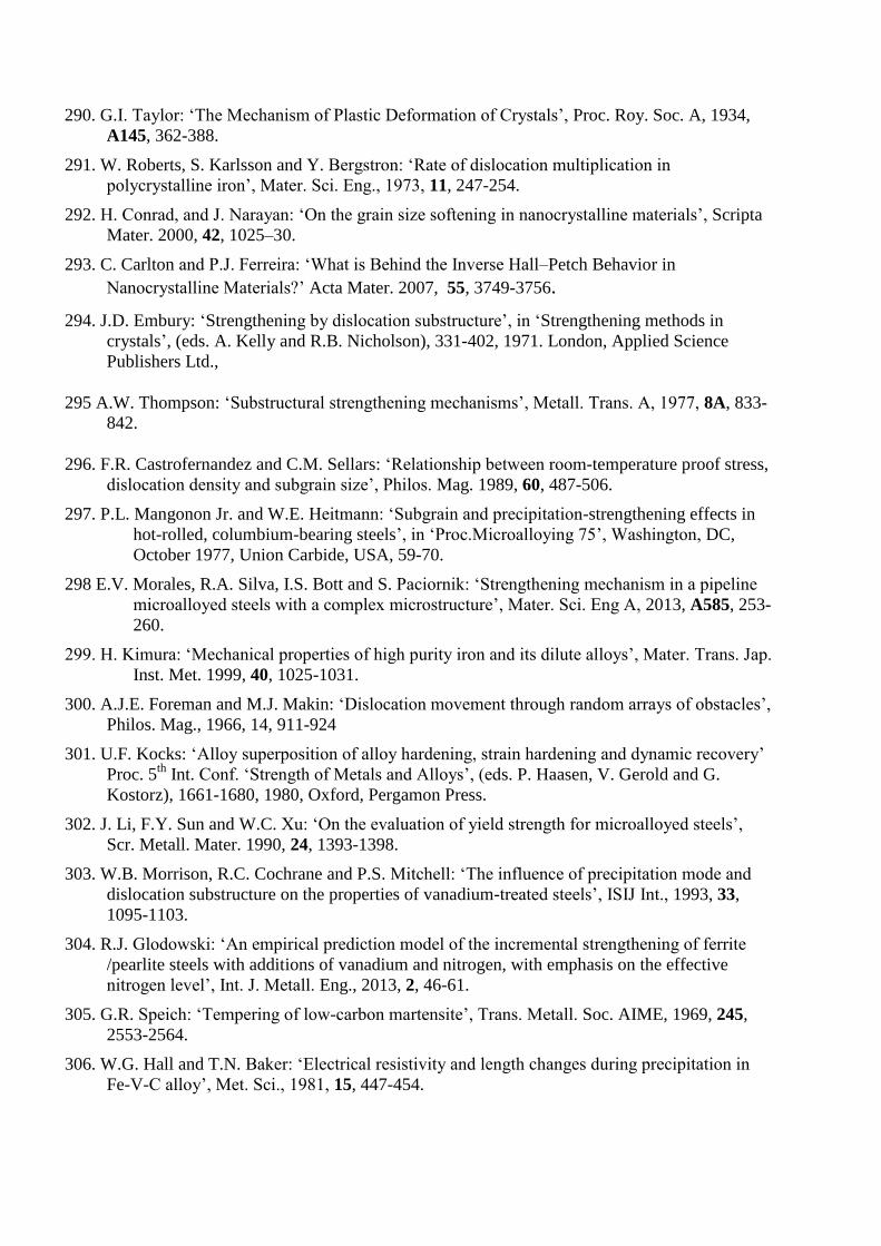
290. G.I. Taylor: ‘The Mechanism of Plastic Deformation of Crystals’, Proc. Roy. Soc. A, 1934,
A145, 362-388.
291. W. Roberts, S. Karlsson and Y. Bergstron: ‘Rate of dislocation multiplication in
polycrystalline iron’, Mater. Sci. Eng., 1973, 11, 247-254.
292. H. Conrad, and J. Narayan: ‘On the grain size softening in nanocrystalline materials’, Scripta
Mater. 2000, 42, 1025–30.
293. C. Carlton and P.J. Ferreira: ‘What is Behind the Inverse Hall–Petch Behavior in
Nanocrystalline Materials?’ Acta Mater. 2007, 55, 3749-3756.
294. J.D. Embury: ‘Strengthening by dislocation substructure’, in ‘Strengthening methods in
crystals’, (eds. A. Kelly and R.B. Nicholson), 331-402, 1971. London, Applied Science
Publishers Ltd.,
295 A.W. Thompson: ‘Substructural strengthening mechanisms’, Metall. Trans. A, 1977, 8A, 833-
842.
296. F.R. Castrofernandez and C.M. Sellars: ‘Relationship between room-temperature proof stress,
dislocation density and subgrain size’, Philos. Mag. 1989, 60, 487-506.
297. P.L. Mangonon Jr. and W.E. Heitmann: ‘Subgrain and precipitation-strengthening effects in
hot-rolled, columbium-bearing steels’, in ‘Proc.Microalloying 75’, Washington, DC,
October 1977, Union Carbide, USA, 59-70.
298 E.V. Morales, R.A. Silva, I.S. Bott and S. Paciornik: ‘Strengthening mechanism in a pipeline
microalloyed steels with a complex microstructure’, Mater. Sci. Eng A, 2013, A585, 253-
260.
299. H. Kimura: ‘Mechanical properties of high purity iron and its dilute alloys’, Mater. Trans. Jap.
Inst. Met. 1999, 40, 1025-1031.
300. A.J.E. Foreman and M.J. Makin: ‘Dislocation movement through random arrays of obstacles’,
Philos. Mag., 1966, 14, 911-924
301. U.F. Kocks: ‘Alloy superposition of alloy hardening, strain hardening and dynamic recovery’
Proc. 5th
Int. Conf. ‘Strength of Metals and Alloys’, (eds. P. Haasen, V. Gerold and G.
Kostorz), 1661-1680, 1980, Oxford, Pergamon Press.
302. J. Li, F.Y. Sun and W.C. Xu: ‘On the evaluation of yield strength for microalloyed steels’,
Scr. Metall. Mater. 1990, 24, 1393-1398.
303. W.B. Morrison, R.C. Cochrane and P.S. Mitchell: ‘The influence of precipitation mode and
dislocation substructure on the properties of vanadium-treated steels’, ISIJ Int., 1993, 33,
1095-1103.
304. R.J. Glodowski: ‘An empirical prediction model of the incremental strengthening of ferrite
/pearlite steels with additions of vanadium and nitrogen, with emphasis on the effective
nitrogen level’, Int. J. Metall. Eng., 2013, 2, 46-61.
305. G.R. Speich: ‘Tempering of low-carbon martensite’, Trans. Metall. Soc. AIME, 1969, 245,
2553-2564.
306. W.G. Hall and T.N. Baker: ‘Electrical resistivity and length changes during precipitation in
Fe-V-C alloy’, Met. Sci., 1981, 15, 447-454.
307. G. Staniek and E.Hornbogen: ‘Combination of precipitation and grain boundary hardening’,
Scr. Metall. 1973, 7, 615-619.
308. G.C. Weatherly: ‘Loss of coherency of growing particles by prismatic punching of dislocation
loops’, Philos. Mag. 1968, 17, 791-799.
309. J.-S. Wang, M.D. Mulholland, G.B. Olson and D.N. Seidman: ‘Prediction of the yield strength
of a secondary-hardening steel’, Acta Mater., 2013, 61, 4939-4952.
310. N. Kamikawa, K. Sato, G. Miyamoto, M. Murayama, N. Sekido, K. Tsuzaki and T. Furuhara:
‘Stress strain behavior of ferrite and bainite with nano-precipitation in low carbon steels’,
Acta Mater. 2015, 83, 383-396.
311. A.G. Kostryzhev, O.O. Marenych, C.R. Killmore and E.V. Pereloma: ‘Strengthening
mechanisms in thermomechanically processed NbTi-microalloyed steel’, Metall. Mater.
Trans. A, 2015, 46A, 3470-3480.
312 W. Barr and C.F. Tipper: ‘Brittle fracture in mild steel plates’, J. Iron Steel Inst., 1947, 157,
223-238.
313. M. Militzer: ‘Thermomechanical Processed Steels’, in ‘Comprehensive Materials Processing,
Vol 1, Conventional and specialized materials’, (ed. S. Hashmi), 191-216, 2014, Oxford,
Elsevier.
314. https://en.wikipedia.org/wiki/Liberty-ship
315. N.J. Petch: ‘The fracture of metals’, Prog. Met. Phys., 1954, 5, 1-52.
316. N.J. Petch: The ductile-cleavage transition in alpha iron’, in Proc. Swampscott Conf. on
‘Fracture’ (eds. B.L. Averback, D.K. Felbeck, G.T. Hahn and D.A, Thomas), 54- 64,1959,
New York, Wiley.
317. C.J. McMahon and M. Cohen:‘Initiation of cleavage in polycrystalline iron ’Acta Metall.,
1965, 13, 591-604.
318. B. Mintz, W.B. Morrison and R.C. Cochrane: ‘Influence of grain boundary carbide thickness
and grain size on the impact properties of steel’, Proc. Conf. Advances in Physical
Metallurgy and Applications in Steels, 222-228, 1981, Metals Soc., London.
319. B. Mintz, W.B. Morrison and A. Jones: Influence of carbide thickness on impact transition-
temperature of ferritic steels’, Met. Technol., 1979, 6, 252-260.
320. E. Smith: ‘The nucleation and growth of cleavage microcracks in mild steel’ in Conf. Proc.
‘Physical Basis of Yield and Fracture’ 36-46, 1966, Oxford, UK, Institute of Physics.
321. E.A. Almond, D. Timbres and J.D. Embury: Proc. 2nd
Internal Conf. on Fracture (ed. P.L.
Pratt), 253,1969, New York, Chapman and Hall.
322. D.A. Curry and J.F. Knott: ‘Effects of microstructure on cleavage fracture stress in steel’, Met.
Sci., 1978, 12, 511-514.
323. N.J. Petch: ‘The influence of grain-boundary carbide and grain-size on the cleavage strength
and impact transition temperature of steel’, Acta Metall. 1986, 34, 1387-1393.
324. M.S. Bingley and T. Siewecki: in Proc.8 th
Int. Conf. Strength of Metals and Alloys (eds. P.O.
Kettunen, T.K. Lepisto and M.E. Leohtonon) Pergamon Press, Oxford, 1988, 1191-1196.
325. M.S. Bingley: ‘Effect of grain size and carbide thickness on impact transition temperature of
low carbon structural steels’, Mater. Sci. Technol., 2001, 17, 700-714.
326. B. Mintz, S. Vue, and J.J. Jonas: ‘Hot ductility of steels and its relationship to the problem of
transverse cracking during continuous casting’, Int. Mater. Revs. 1991, 36, 187-217.
327. R.L. Robbins, O.C. Shepard, O.D. Sherby: ‘Role of crystal structure on the ductility of pure
iron at elevated temperature’ JISI, 1961, 199, 175-180.
328. C. Rossard and P. Blain: ‘A method of simulation by torsion to determine the influence of hot
rolling conditions on the structure of steel’, Rev. Métall. 1962, 59, 223-236.
329. R.L. Robbins, O.C. Shepard, O.D. Sherby: ‘Torsional ductility and strength of iron-carbon
alloys at elevated temperature’, ASM Trans. Quart., 1967, 60, 205
330. B. Mintz and J.M. Arrowsmith: Hot ductility behaviour of C-Mn-Mn-Al steel and its
relationship to crack propagation during straightening of continuously cast strand’, Met.
Technol., 1979, 6, 24-32.
331. D.N. Crowther and B. Mintz: ‘Influence of grain size on hot ductility of plain C-Mn steels’,
Met. Sci. Technol., 1986, 2, 951-955.
332. B. Mintz and J.M. Arrowsmith: ‘Influence of microalloying additions on hot ductility of
steels’, in ‘Hot working and forming processes’ (eds. C.M. Sellars and G.J. Davies), 99-103,
1990, London, Institute of Materials.
333. J.R. Wilcox and R.W.K. Honeycombe: ‘Influence of prior precipitation on hot ductility of C-
Mn-Nb-Al steels’, in ‘Hot working and forming processes’ (eds. C.M. Sellars and G.J.
Davies), 108-112, 1990, London, Institute of Materials.
334. B. Mintz and D.N. Crowther: ‘The influence of small additions of Ti on the hot ductility of
steels’, in ‘Titanium technology in microalloyed steels’, (ed. T.N. Baker), 98-114, 1997,
London, Institute of Materials.
335. K.M. Banks, A. Tuling, C. Klinkenberg and B. Mintz: ‘Influence of Ti on hot ductility of Nb
containing HSLA steels’, Mat. Sci. Technol., 2011, 27, 737-545.
336. A.M. El-Wazri, F. Hassani, S. Yue, E. Es-Sadiqui, L.E. Collins and K. Iqual: ‘The effect of
thermal history on the hot ductility of microalloyed steels’, ISIJ Int., 1999, 39, 256-262.
337.C. Spanbury and B. Mintz ‘Influence of undercooling thermal cycle on hot ductility of C–
Mn–Al–Ti and C–Mn–Al–Nb–Ti steels’, Ironmaking and Steelmaking, 2005, 32, 319-324.
338. T.H. Coleman and J.R. Wilcox: ‘Transverse cracking in continuously cast HSLA slabs –
influence of composition’, Mater. Sci. Technol., 1985, 1, 80-83.
339. S. Roy, S. Patra, S. Neogy, A. Laik, S.K. Choudharey and D. Chakrabarti: ‘Prediction of
inhomogeneous distribution of microalloy precipitates in continuously cast high strength low
alloy steel slab’, Met. Mater. Trans. A, 2012, 43A, 1845-1860.
340. D.A. Melford: ‘The Influence of Residual and Trace Elements on Hot Shortness and High
Temperature Embrittlement’, Philos.Trans., 1980, 295, 89-103.
341. D.A. Melford: ‘Influence of antimony and arsenic on surface hot shortness in copper-
containing mild steels’, JISI, 1966, 204, 495-496.
Fig 1 Ferro-Niobium (FeNb) consumption in West Europe (EU15)
CBMM-NPC data.15
0
2
4
6
8
10
12
14
16
1975 1980 1985 1990 1995 2000 2005 2010 2015
Tho
usa
nd
s o
f m
etr
ic t
on
s
Year

Fig 2 Development of pipeline steels as an example of HSLA steel
research (TMPC: themomechanical controlled processing; ACC:
accelerated cooling; DQ: direct quench) 7, 44
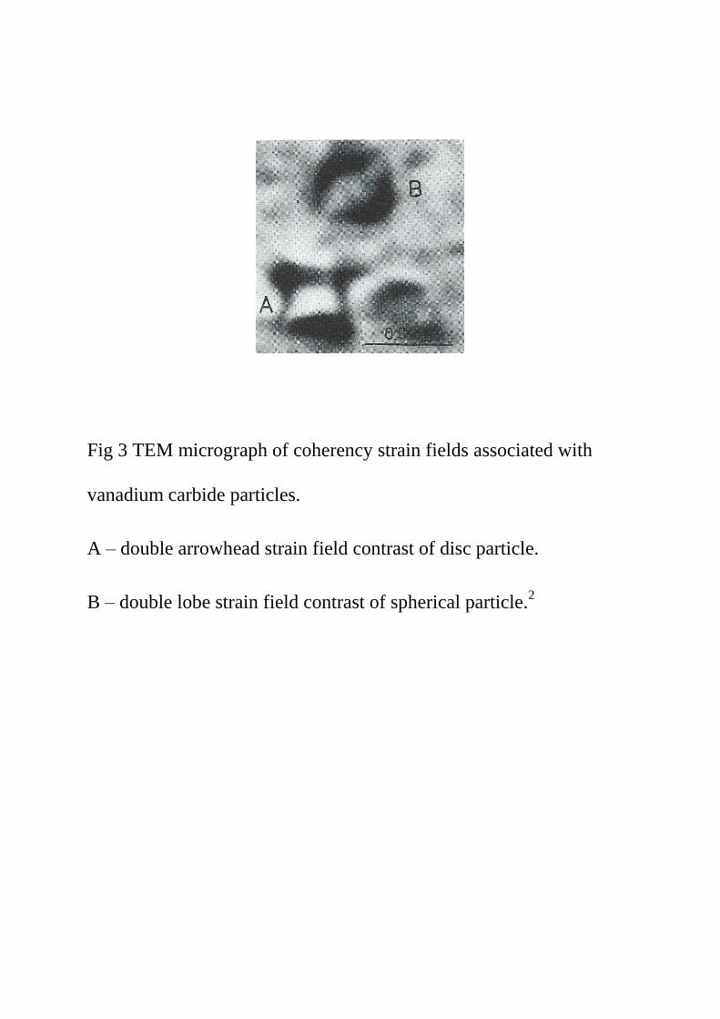
Fig 3 TEM micrograph of coherency strain fields associated with
vanadium carbide particles.
A – double arrowhead strain field contrast of disc particle.
B – double lobe strain field contrast of spherical particle.2
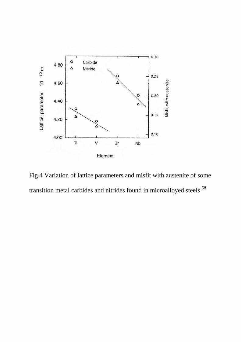
Fig 4 Variation of lattice parameters and misfit with austenite of some
transition metal carbides and nitrides found in microalloyed steels 58

(a)
(b) (c)
Fig 5 (a) Cross section of disc-shaped coherent particle with small
negative mismatch, (b) cross section of disc-shaped coherent particle
with small positive mismatch, (c) cross section of disc-shaped with
positive misfit normal to the plane of the disc.36

Fig 6 Incoherent vanadium nitride disc precipitates mainly in section.1
300nm

Fig 7 TEM micrograph of carbon replica which has extracted ~ 2nm
particles.114
10nm

Fig 8 Interphase precipitation in a vanadium microalloy steel 1
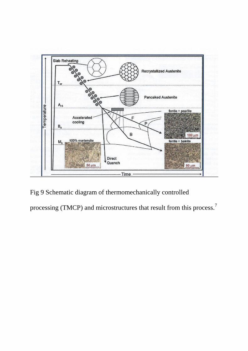
Fig 9 Schematic diagram of thermomechanically controlled
processing (TMCP) and microstructures that result from this process.7

Fig 10 General relationship between thickness and finishing
temperature of rolling for plates and sections 5, 67, 68
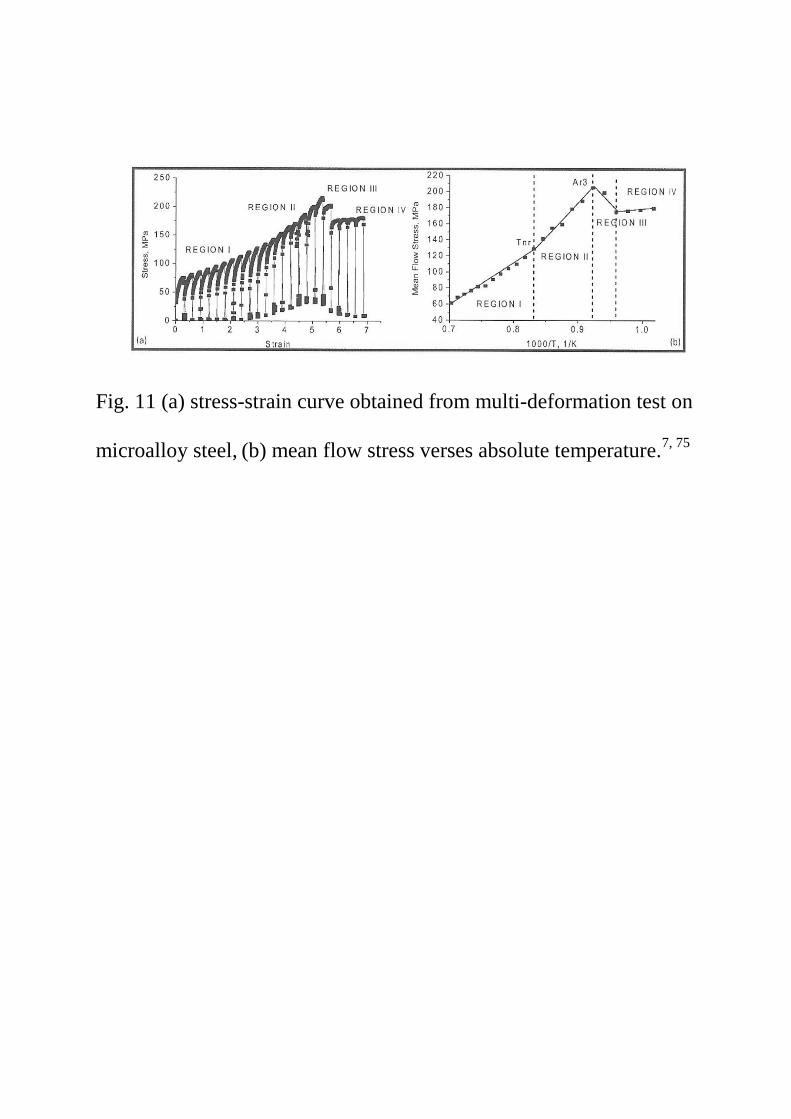
Fig. 11 (a) stress-strain curve obtained from multi-deformation test on
microalloy steel, (b) mean flow stress verses absolute temperature.7, 75
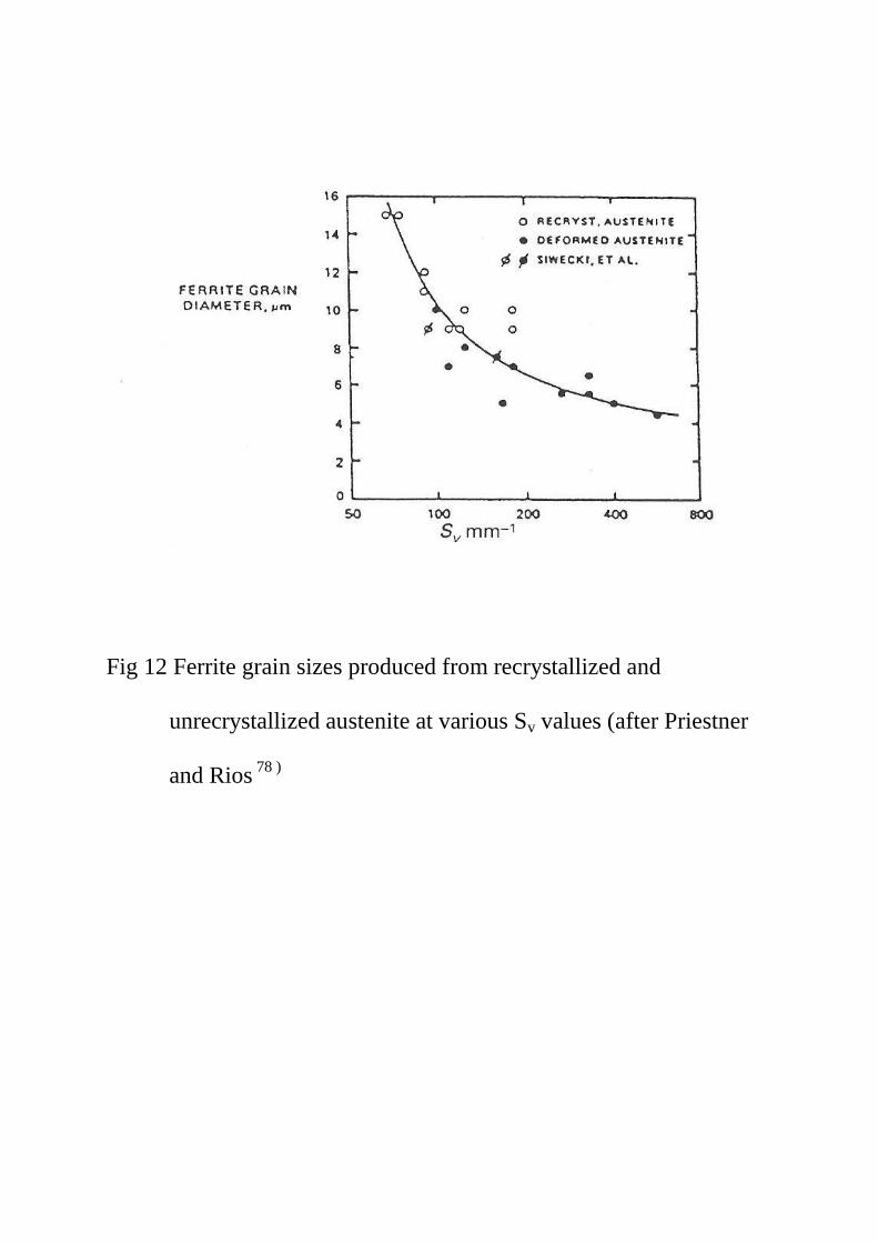
Fig 12 Ferrite grain sizes produced from recrystallized and
unrecrystallized austenite at various Sv values (after Priestner
and Rios 78 )

Fig.13 Calculated solubility curves at temperatures associated
with thermomechanical processing for a NbC, b VC
and c VN.80
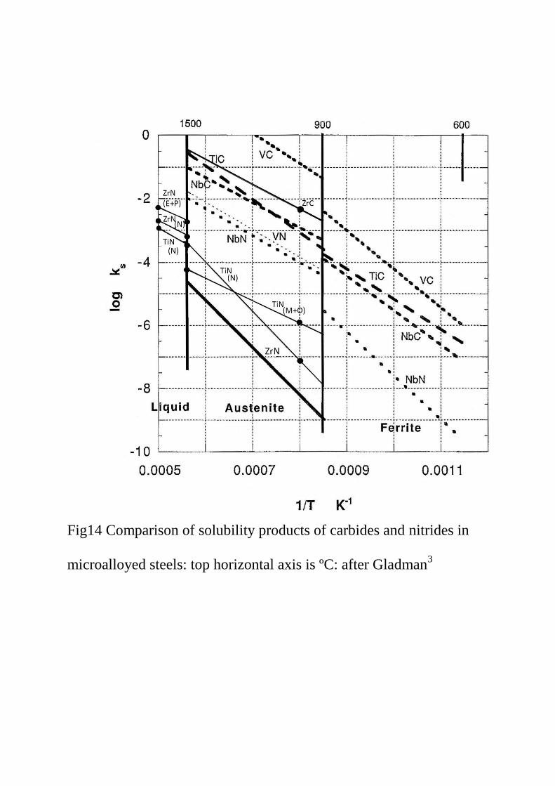
Fig14 Comparison of solubility products of carbides and nitrides in
microalloyed steels: top horizontal axis is ºC: after Gladman3
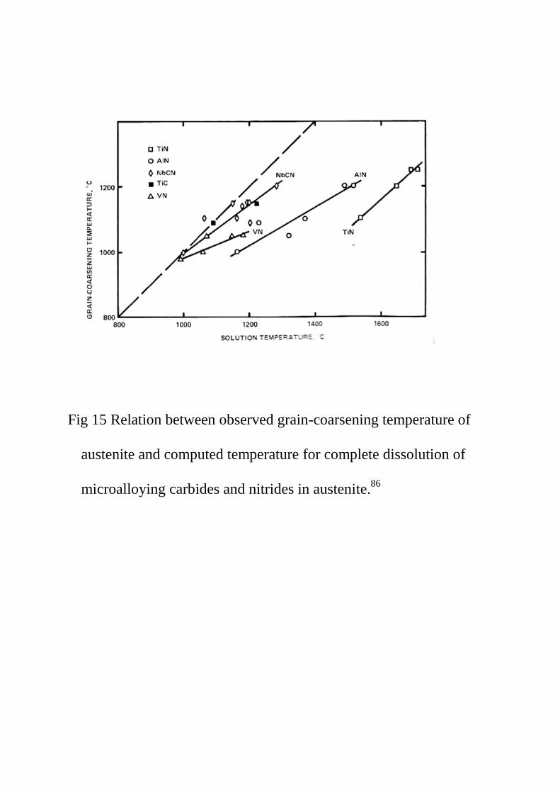
Fig 15 Relation between observed grain-coarsening temperature of
austenite and computed temperature for complete dissolution of
microalloying carbides and nitrides in austenite.86
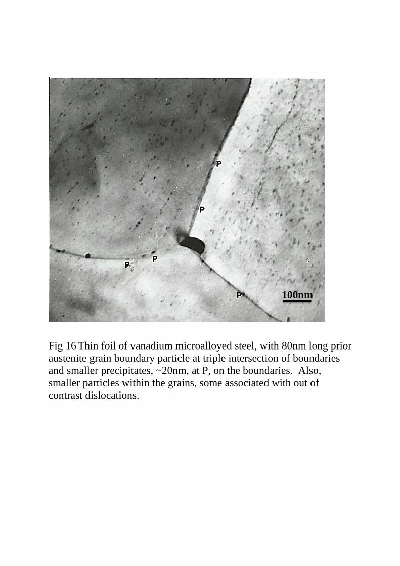
Fig 16 Thin foil of vanadium microalloyed steel, with 80nm long prior
austenite grain boundary particle at triple intersection of boundaries
and smaller precipitates, ~20nm, at P, on the boundaries. Also,
smaller particles within the grains, some associated with out of
contrast dislocations.
100nm
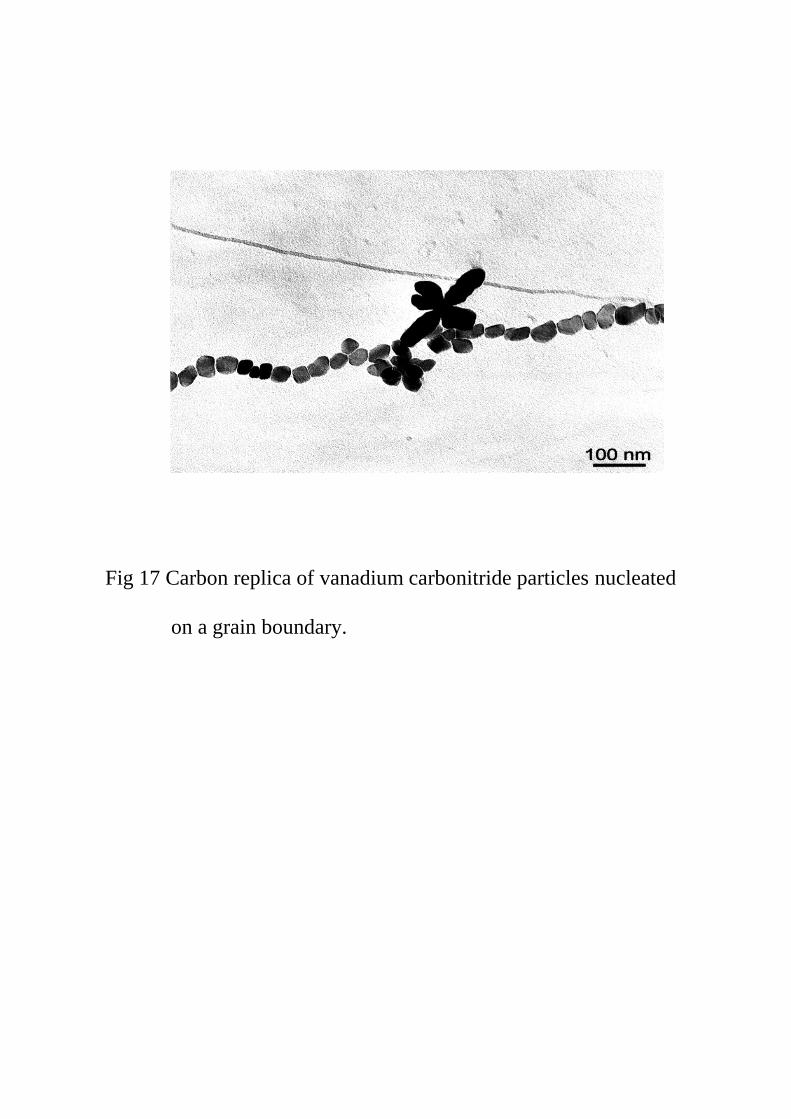
Fig 17 Carbon replica of vanadium carbonitride particles nucleated
on a grain boundary.
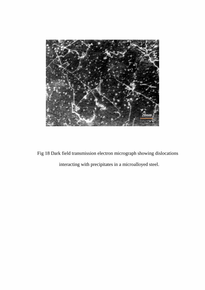
Fig 18 Dark field transmission electron micrograph showing dislocations
interacting with precipitates in a microalloyed steel.
20nm
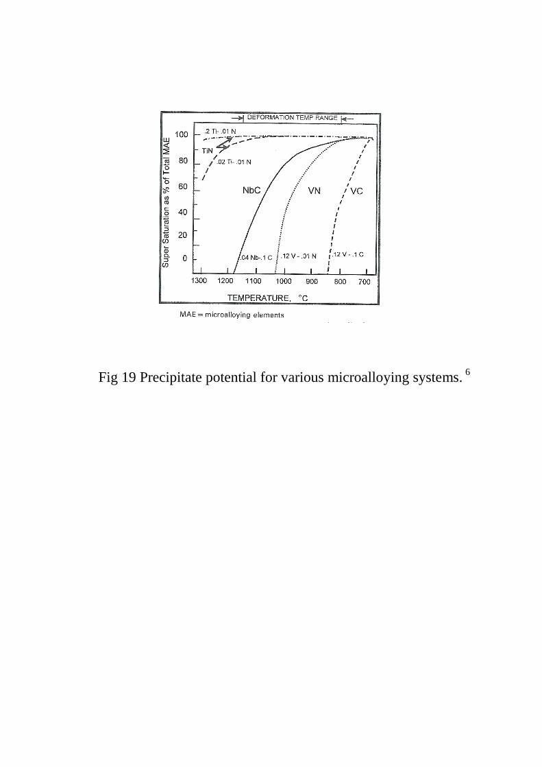
Fig 19 Precipitate potential for various microalloying systems. 6

Fig 20 Comparison of precipitation kinetics for Nb-V and Ti-V
steels. 97
(ps -precipitate start, pf-precipitate finish)

(a) (b)
Fig 21 (a) Ti-Nb particles in 0.01%Ti-Nb steel, with smaller Nb-rich spheroids.
(b) An EELS spectrum collected from the centre of a ~20nm Nb-rich
spheroid showing the niobium, carbon, nitrogen and titanium
edges.119
0.2µm

(a)
(b)
Fig 22 (a) Four caps formed on the sides of a cuboid core with the
probability that there are also caps on the top and bottom
faces.
(b) Cruciform particle with four arms nucleating and growing
from a core.
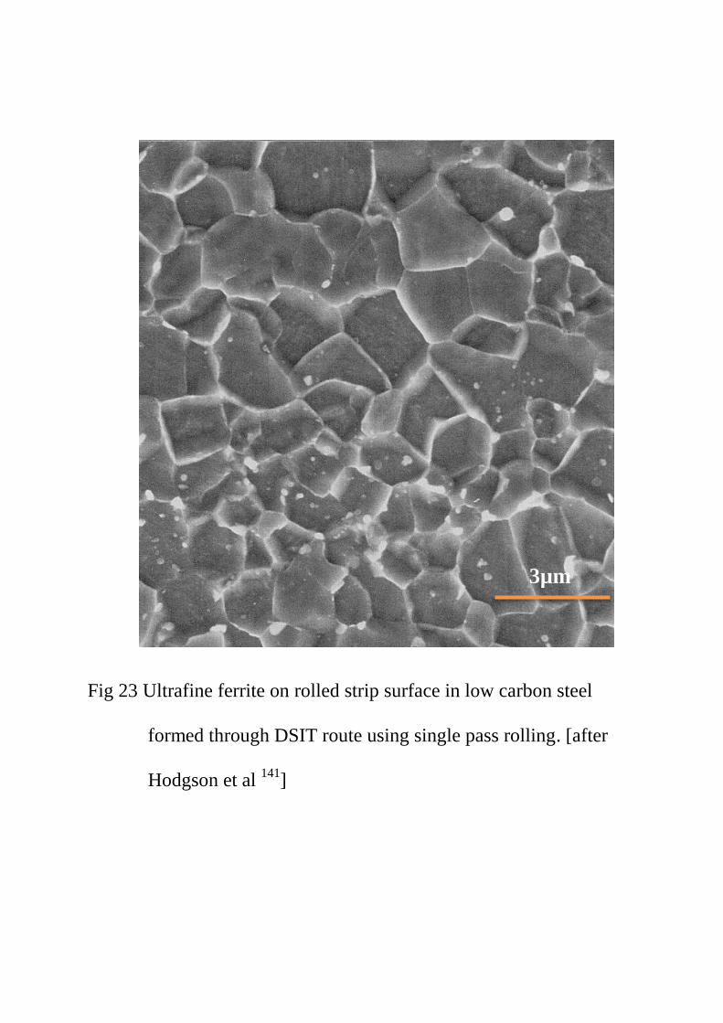
Fig 23 Ultrafine ferrite on rolled strip surface in low carbon steel
formed through DSIT route using single pass rolling. [after
Hodgson et al 141
]
3µm
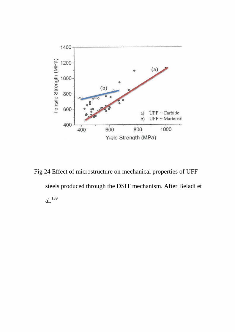
Fig 24 Effect of microstructure on mechanical properties of UFF
steels produced through the DSIT mechanism. After Beladi et
al.139
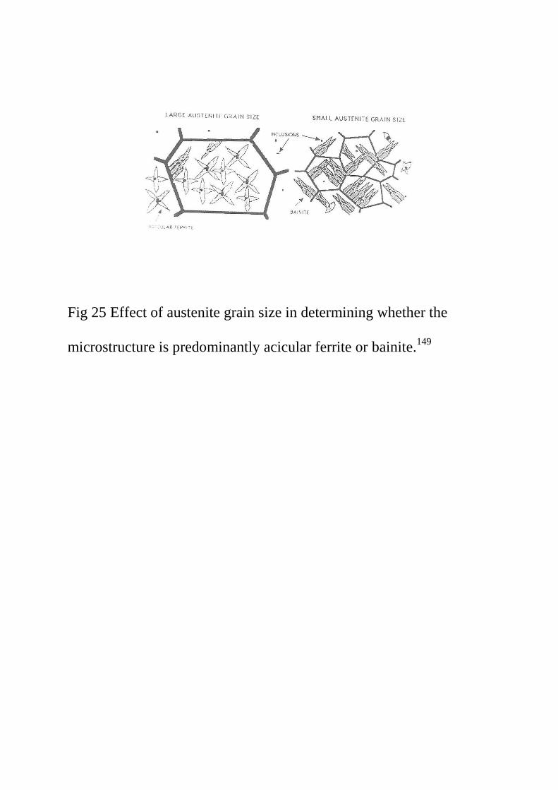
Fig 25 Effect of austenite grain size in determining whether the
microstructure is predominantly acicular ferrite or bainite.149
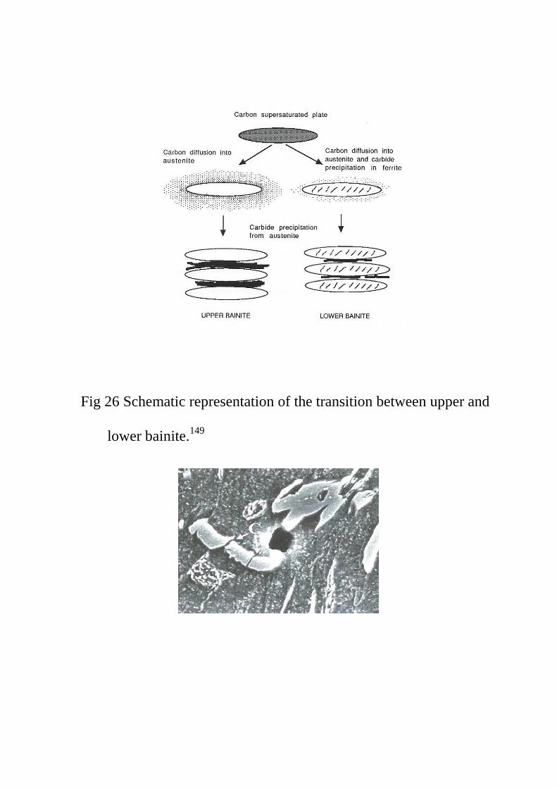
Fig 26 Schematic representation of the transition between upper and
lower bainite.149
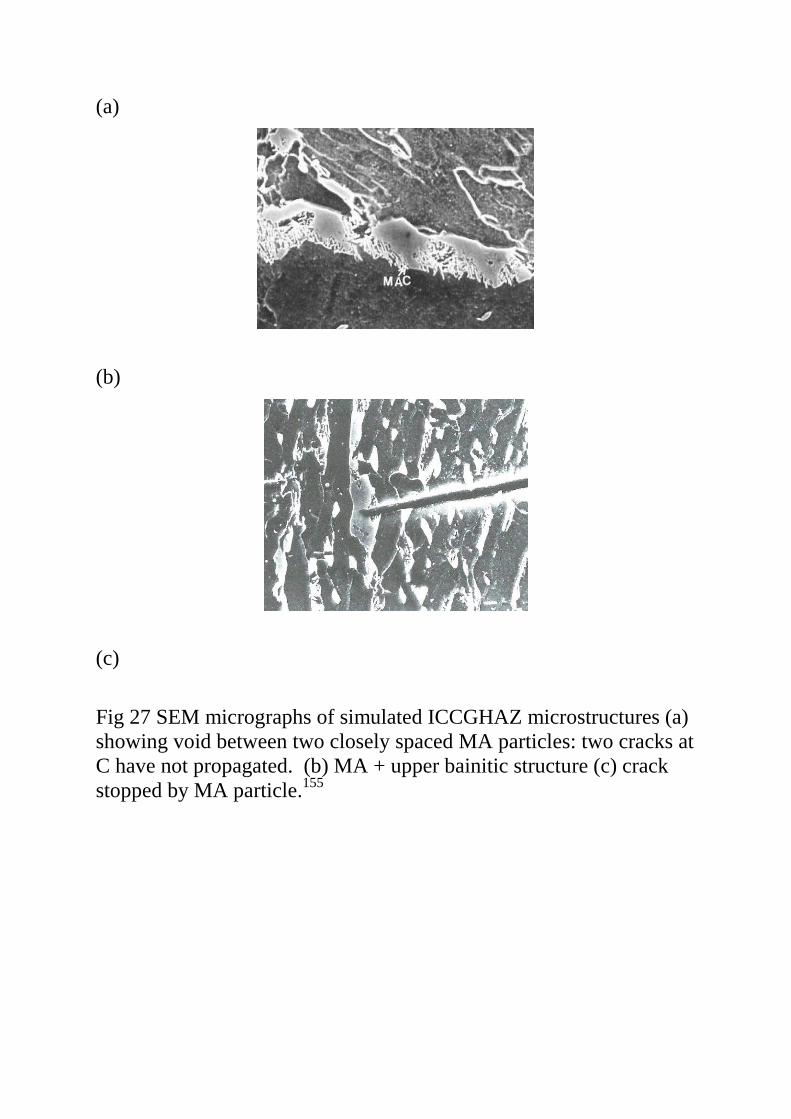
(a)
(b)
(c)
Fig 27 SEM micrographs of simulated ICCGHAZ microstructures (a)
showing void between two closely spaced MA particles: two cracks at
C have not propagated. (b) MA + upper bainitic structure (c) crack
stopped by MA particle.155
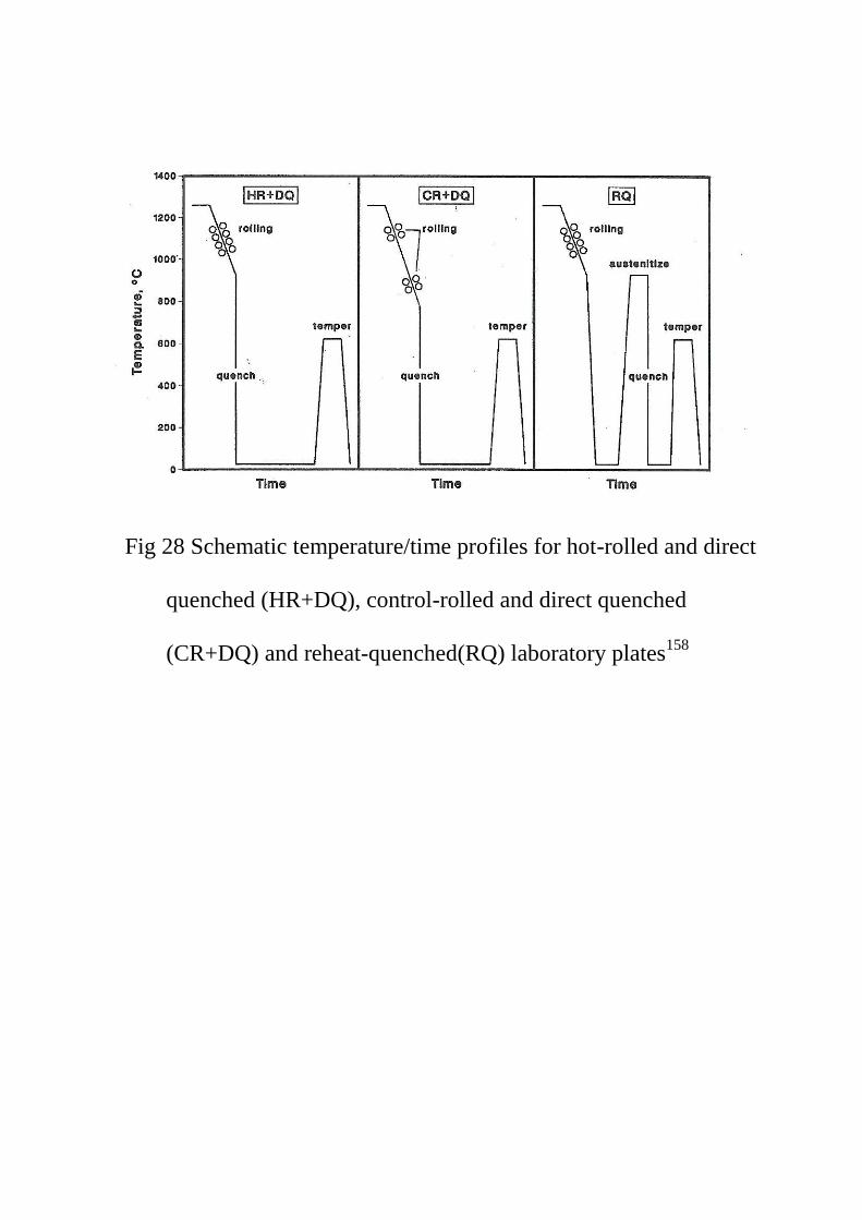
Fig 28 Schematic temperature/time profiles for hot-rolled and direct
quenched (HR+DQ), control-rolled and direct quenched
(CR+DQ) and reheat-quenched(RQ) laboratory plates158
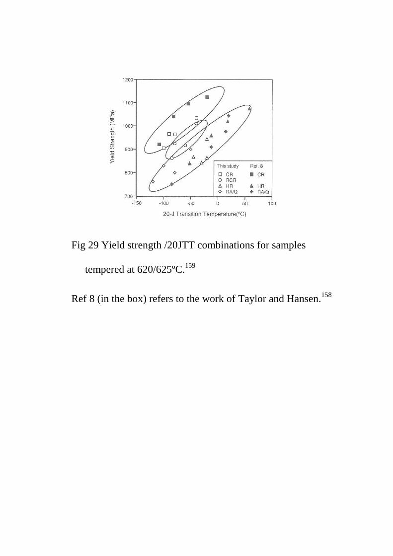
Fig 29 Yield strength /20JTT combinations for samples
tempered at 620/625ºC.159
Ref 8 (in the box) refers to the work of Taylor and Hansen.158

Fig 30 Effect of nitrogen, vanadium and cooling rate on the yield
stress and impact toughness of Ti-V-Nb-N steels after rapid
cooling process.11
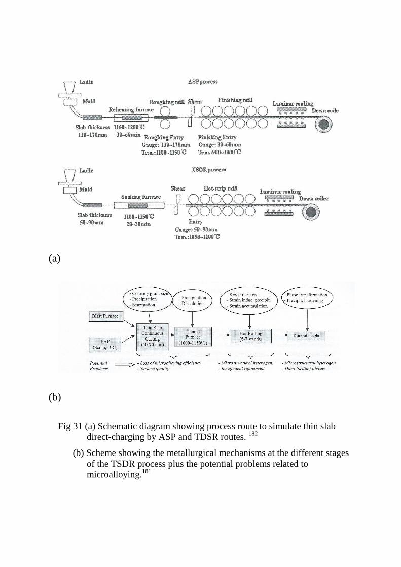
(a)
(b)
Fig 31 (a) Schematic diagram showing process route to simulate thin slab
direct-charging by ASP and TDSR routes. 182
(b) Scheme showing the metallurgical mechanisms at the different stages
of the TSDR process plus the potential problems related to
microalloying.181
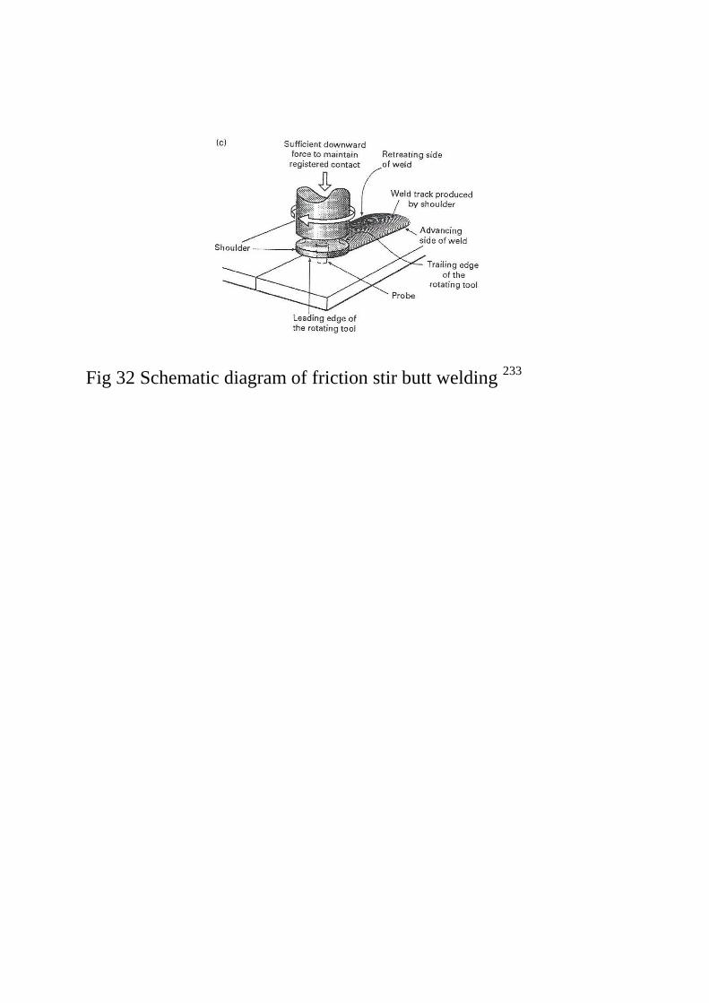
Fig 32 Schematic diagram of friction stir butt welding 233
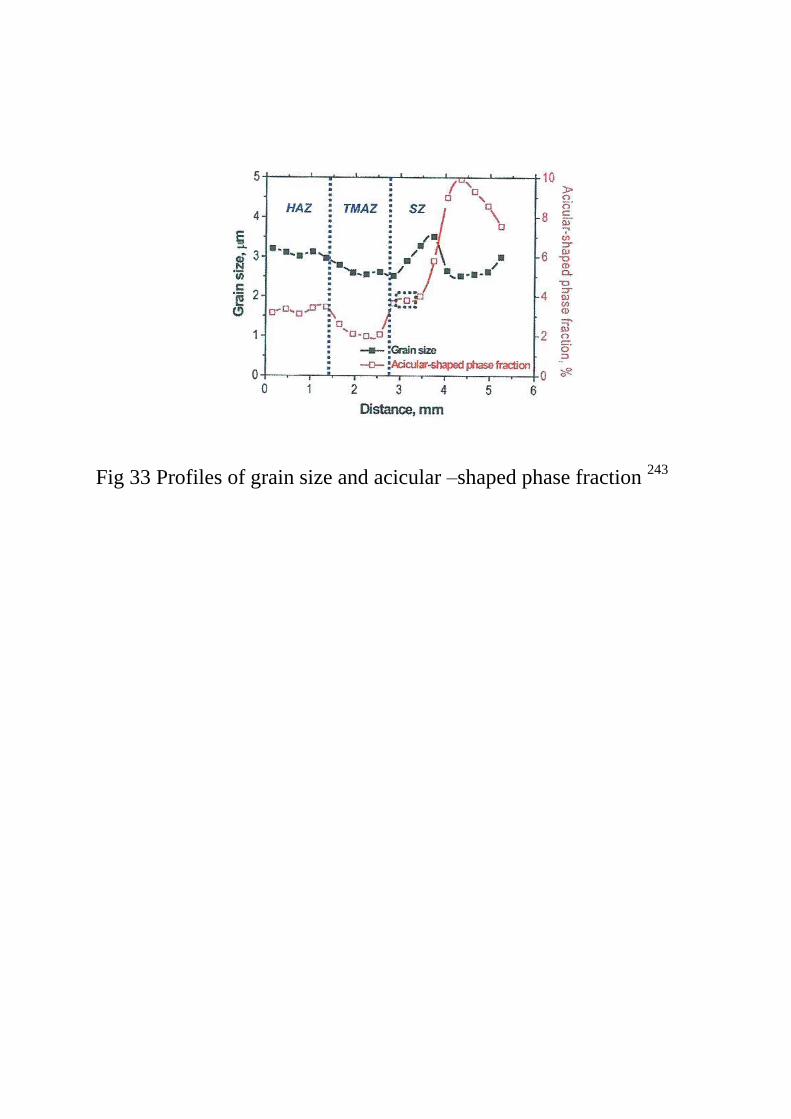
Fig 33 Profiles of grain size and acicular –shaped phase fraction 243

(a)
(b)
Fig 34 Macrographs of transverse sections of FSW
(a) single pass DH36 steel238
(b) double pass EH 46 steel 249
BM-base metal, TMAZ – thermomechanical additive zone, IZ –
interference zone
TMAZ 1
TMAZ 2
IZ BM BM
5 mm
BM
TMAZ
SZ
BM
2mm
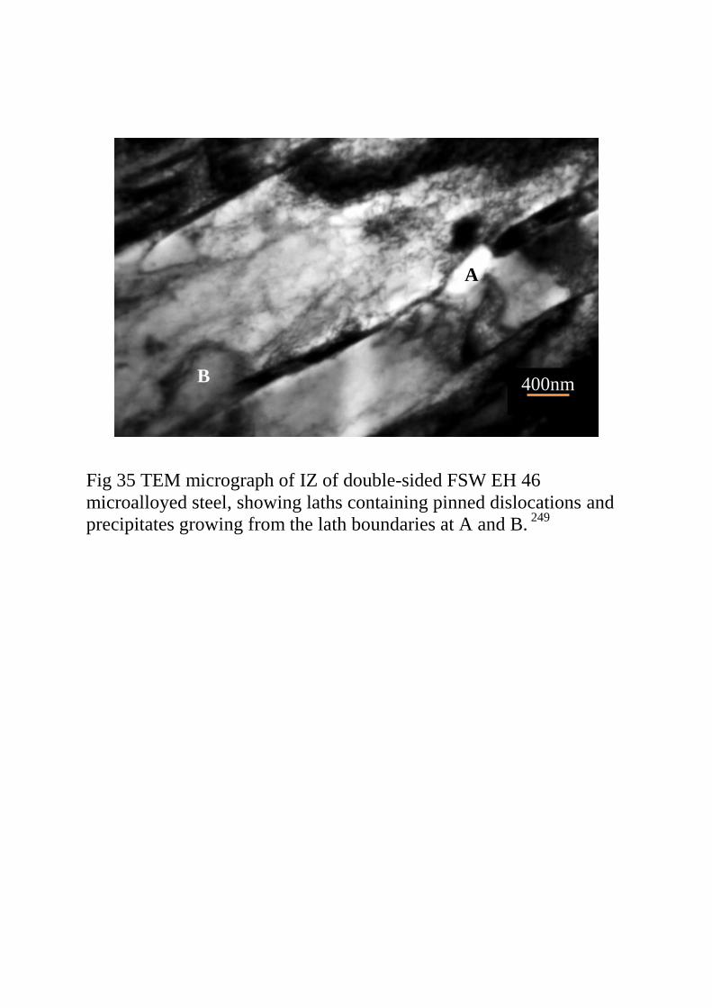
Fig 35 TEM micrograph of IZ of double-sided FSW EH 46
microalloyed steel, showing laths containing pinned dislocations and
precipitates growing from the lath boundaries at A and B. 249
400nm
A
B
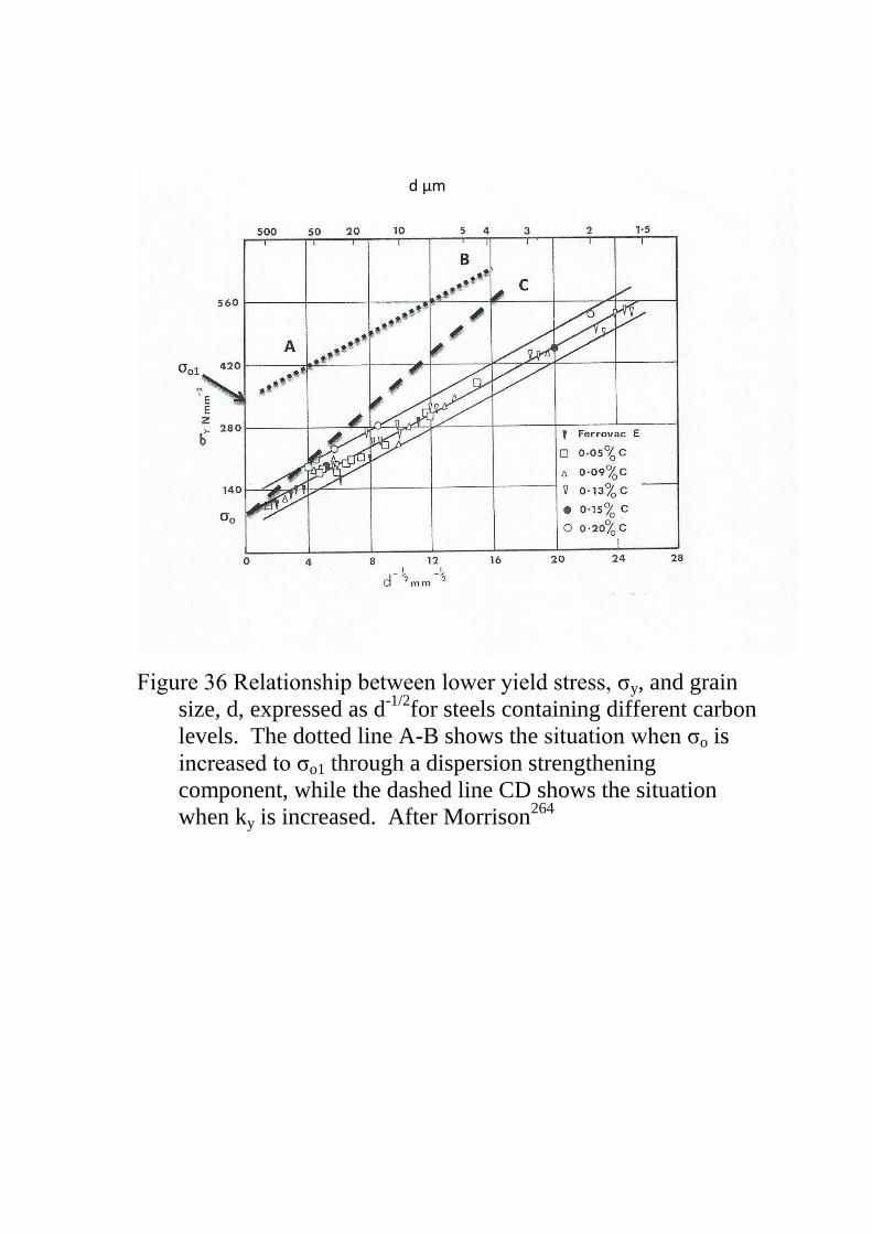
Figure 36 Relationship between lower yield stress, σy, and grain
size, d, expressed as d-1/2
for steels containing different carbon
levels. The dotted line A-B shows the situation when σo is
increased to σo1 through a dispersion strengthening
component, while the dashed line CD shows the situation
when ky is increased. After Morrison264
d µm
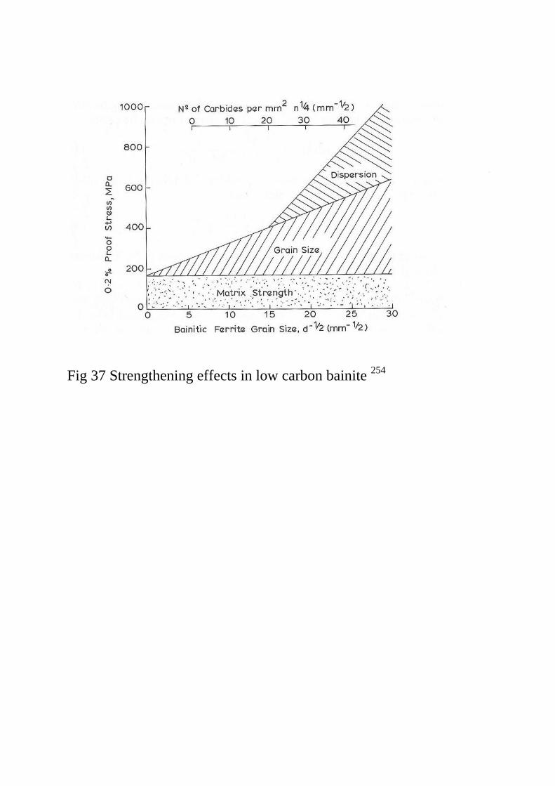
Fig 37 Strengthening effects in low carbon bainite 254
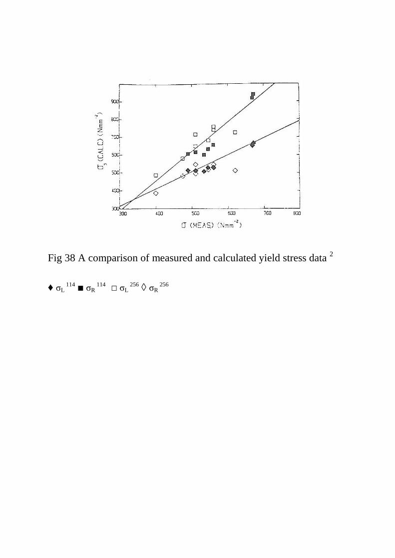
Fig 38 A comparison of measured and calculated yield stress data 2
♦ σL 114
■ σR 114
□ σL 256
◊ σR 256
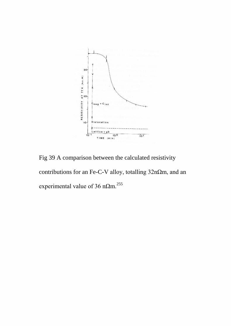
Fig 39 A comparison between the calculated resistivity
contributions for an Fe-C-V alloy, totalling 32nΩm, and an
experimental value of 36 nΩm.255

Fig 40 The cleavage strength for fracture at yield, σc, versus d-1/2
for
various carbide thicknesses, t, µm. 323
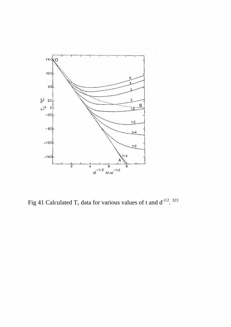
Fig 41 Calculated Tc data for various values of t and d-1/2
. 323

Fig 42 Observed and calculated reduction of area. 252
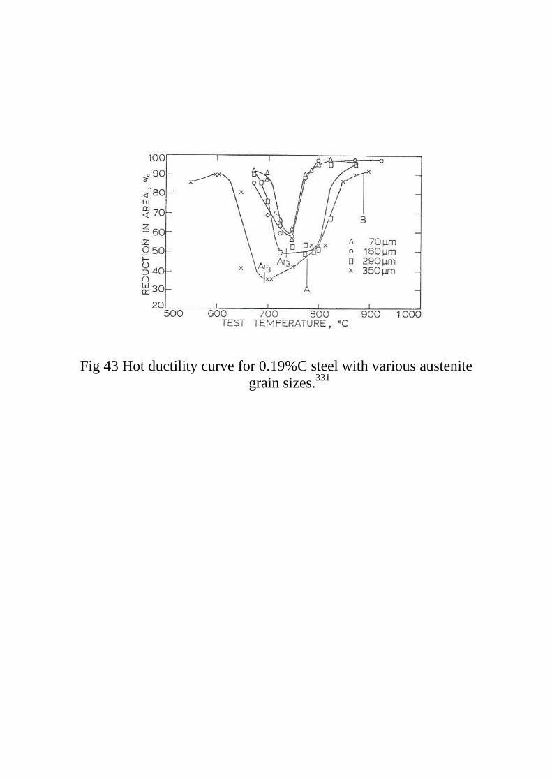
Fig 43 Hot ductility curve for 0.19%C steel with various austenite
grain sizes.331
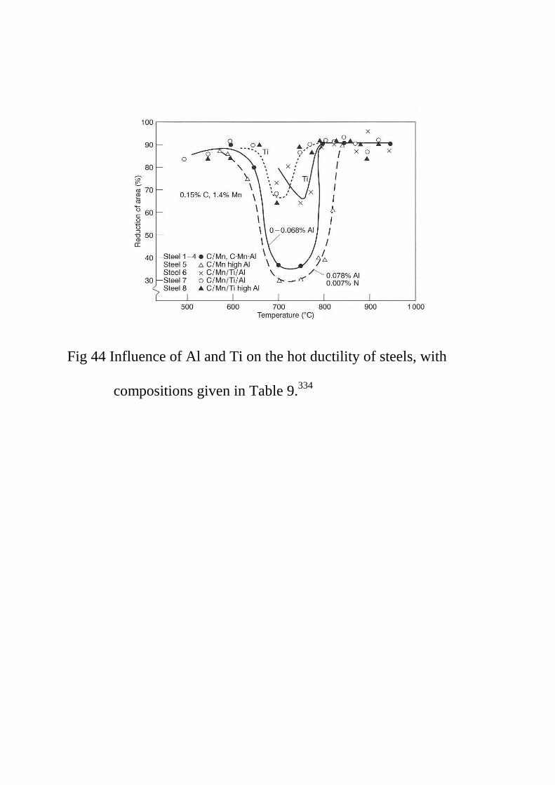
Fig 44 Influence of Al and Ti on the hot ductility of steels, with
compositions given in Table 9.334