
Selection and Welding of Niobium Bearing Structural Steels ...
13
SELECTION AND WELDING OF NIOBIUM BEARING STRUCTURAL STEELS IN SOME RECENT UK SHIPBUILDING CONTRACTS Norman A. McPherson BVT Surface Fleet, 1048 Govan Road, Glasgow, G51 4XP Scotland, UK Keywords: Arc Welding, Laser Welding, Microalloys, Shipbuilding Abstract Within the UK shipbuilding sector the use of niobium (Nb) bearing steels tend to have been limited to high stress areas, where minimum strengths of 350MPa were commonly applied. As thicker gauge steels were used in these areas, the steel always contained Nb to develop the desired strength/toughness combinations. In traditional naval contracts strengths of 270MPa were the norm, but recent vessel designs have been very sensitive, which has resulted in these steels being displaced by the higher strength/superior toughness steel grades. The reasons of which are discussed in this paper, as is the chemical composition of the steels used. The paper presents some of the recent Nb-bearing steels that have been used in the build and fabrication recent naval vessels. The welding of these, predominantly Nb-bearing, steels is also described particularly with reference to the heat affected zone toughness. An evaluation of laser welding these steels is described, as a significant proportion of these steels used have been thin plate (<8mm). The selection of a 460MPa strength steel for the flight deck and hanger of an upcoming aircraft carrier contract is described as is the evaluation of the submerged arc welding of steel processed by two different manufacturing routes. Introduction During the last 20 years the shipbuilding industry in the UK has contracted significantly. It now consists of two build sites concentrating on naval ship contracts, one build site on submarines, and the remainder of the build sites on smaller specialised craft. There are a number of other sites which concentrate on the ship repair sector. The two sites of BVT Surface Fleet are at Portsmouth on the south coast of England and the other is at Glasgow on the River Clyde on the west coast of Scotland. Although commercial build has largely disappeared from these sites, the vessels built there are now constructed to standards which more resemble commercial build requirements. Naval contracts completed about 10 years ago mainly used relatively low strength / low toughness steels such as the Lloyds Grade A and some Lloyds Grade D shown in Table 1. This 319
Transcript of Selection and Welding of Niobium Bearing Structural Steels ...

SELECTION AND WELDING OF NIOBIUM BEARING STRUCTURAL
STEELS IN SOME RECENT UK SHIPBUILDING CONTRACTS
Norman A. McPherson
BVT Surface Fleet,
1048 Govan Road,
Glasgow, G51 4XP
Scotland, UK
Keywords: Arc Welding, Laser Welding, Microalloys, Shipbuilding
Abstract
Within the UK shipbuilding sector the use of niobium (Nb) bearing steels tend to have been
limited to high stress areas, where minimum strengths of 350MPa were commonly applied. As
thicker gauge steels were used in these areas, the steel always contained Nb to develop the
desired strength/toughness combinations. In traditional naval contracts strengths of 270MPa
were the norm, but recent vessel designs have been very sensitive, which has resulted in these
steels being displaced by the higher strength/superior toughness steel grades. The reasons of
which are discussed in this paper, as is the chemical composition of the steels used.
The paper presents some of the recent Nb-bearing steels that have been used in the build and
fabrication recent naval vessels. The welding of these, predominantly Nb-bearing, steels is also
described particularly with reference to the heat affected zone toughness. An evaluation of laser
welding these steels is described, as a significant proportion of these steels used have been thin
plate (<8mm). The selection of a 460MPa strength steel for the flight deck and hanger of an
upcoming aircraft carrier contract is described as is the evaluation of the submerged arc welding
of steel processed by two different manufacturing routes.
Introduction
During the last 20 years the shipbuilding industry in the UK has contracted significantly. It now
consists of two build sites concentrating on naval ship contracts, one build site on submarines,
and the remainder of the build sites on smaller specialised craft. There are a number of other sites
which concentrate on the ship repair sector. The two sites of BVT Surface Fleet are at
Portsmouth on the south coast of England and the other is at Glasgow on the River Clyde on the
west coast of Scotland. Although commercial build has largely disappeared from these sites, the
vessels built there are now constructed to standards which more resemble commercial build
requirements.
Naval contracts completed about 10 years ago mainly used relatively low strength / low
toughness steels such as the Lloyds Grade A and some Lloyds Grade D shown in Table 1. This
319

was typical of the steels used on frigates such as the Type 23 shown in Figure 1. Other offshore
patrol vessels and frigates for far eastern naval contracts used the same steel type combinations.
Table 1. Comparison of Lloyds Grade A and Grade D steels.
Steel grade %C %Si %S %P %Mn %Al %N2 YS
MPa
UTS
MPa
Toughness
J at XoC
XoC
Plate
Thickness (mm)
Lloyds Grade A 0.15 0.20 0.015 0.018 0.82 0.035 0.0055 290 450 170 20 12
Lloyds Grade D 0.11 0.23 0.005 0.011 0.64 0.039 0.0050 298 428 204 -20 11.5
Figure 1. HMS Argyll – a Type 23 Frigate.
The most recent UK naval contract for six destroyers was initially based on the use of Lloyds
Grade D steel, a typical analysis of which is shown in Table 1. This had a higher toughness
requirement but the same strength as the Grade A steel. Failure to meet the build weight
requirements at this stage of design meant that a decrease in plate thickness had to be obtained
without compromising structural integrity.
The option of using aluminium in the superstructure was not considered to be viable, as the UK
Royal Navy had concerns related to fire resistance of the material, based on previous
experiences. At this stage superstructures produced from composite materials are not an option,
but will probably materialise in the future, based on work being carried out in USA. The option
of replacing areas of the D grade steel with higher strength, thinner DH36 was adopted. As a
result, 82% of the plates used in the design were Lloyds Grade DH36, and this resulted in a
significant amount of 4 and 5mm thick plate being used. The first ship of the class, HMS Daring
is shown in Figure 2, preparing for sea trials.
320
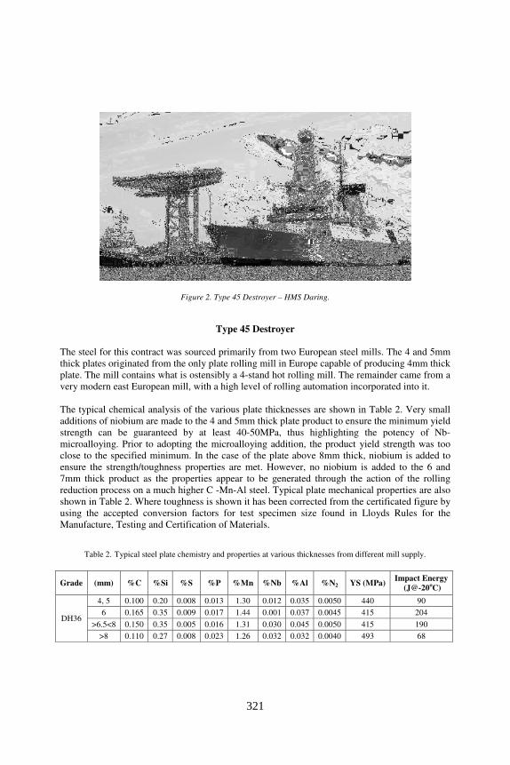
Figure 2. Type 45 Destroyer – HMS Daring.
Type 45 Destroyer
The steel for this contract was sourced primarily from two European steel mills. The 4 and 5mm
thick plates originated from the only plate rolling mill in Europe capable of producing 4mm thick
plate. The mill contains what is ostensibly a 4-stand hot rolling mill. The remainder came from a
very modern east European mill, with a high level of rolling automation incorporated into it.
The typical chemical analysis of the various plate thicknesses are shown in Table 2. Very small
additions of niobium are made to the 4 and 5mm thick plate product to ensure the minimum yield
strength can be guaranteed by at least 40-50MPa, thus highlighting the potency of Nb-
microalloying. Prior to adopting the microalloying addition, the product yield strength was too
close to the specified minimum. In the case of the plate above 8mm thick, niobium is added to
ensure the strength/toughness properties are met. However, no niobium is added to the 6 and
7mm thick product as the properties appear to be generated through the action of the rolling
reduction process on a much higher C -Mn-Al steel. Typical plate mechanical properties are also
shown in Table 2. Where toughness is shown it has been corrected from the certificated figure by
using the accepted conversion factors for test specimen size found in Lloyds Rules for the
Manufacture, Testing and Certification of Materials.
Table 2. Typical steel plate chemistry and properties at various thicknesses from different mill supply.
Grade (mm) %C %Si %S %P %Mn %Nb %Al %N2 YS (MPa) Impact Energy
(J@-20oC)
DH36
4, 5 0.100 0.20 0.008 0.013 1.30 0.012 0.035 0.0050 440 90
6 0.165 0.35 0.009 0.017 1.44 0.001 0.037 0.0045 415 204
>6.5<8 0.150 0.35 0.005 0.016 1.31 0.030 0.045 0.0050 415 190
>8 0.110 0.27 0.008 0.023 1.26 0.032 0.032 0.0040 493 68
321
The proportion of thin plates (<8mm thick) in this vessel was 63%, and the main concern in the
fabrication of thin plate structures is to ensure that distortion is minimised. As a result, practices
such as minimising cutting heat and welding heat input were put in place. In addition a number
of other critical factors were identified as contributing to thin plate distortion [1-3].
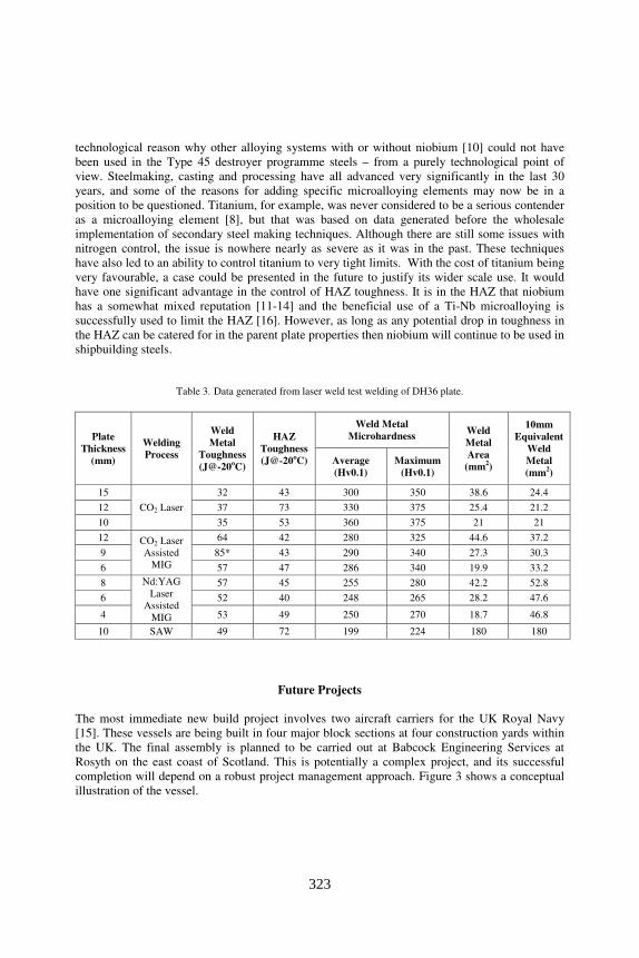
One of the possible process routes to reduce thin plate distortion is to apply some form of laser
welding to the structure. Therefore an investigation was carried out into the capability of welding
DH36 plate over a range of thicknesses. This work has been reported in detail elsewhere [4], but
Table 3 summarises the outcome of the work carried out. The chemical analysis of the steel used
was a 0.013%C-0.42%Si-0.006%S-0.013%P-1.35%Mn-0.025%Nb-0.035%Al-0.005%N2-
0.017%Ti, which was common to all plate thickness. It is generally accepted that the potential
for thin plate distortion to occur will increase in the process order; autogenous CO2 laser - CO2
laser assisted MIG – Nd-YAG laser assisted MIG – SAW. As can be seen in Table 3, this is
related to the increase in the 10mm thick equivalent weld metal volume for the welding process.
Also shown in Table 3 is the beneficial effect of using an assisted MIG process compared to the
autogenous laser process on the weld metal toughness. There is a tendency for the autogenous
laser welding process to generate high hardness areas in the weld metal, which relates to the
poorer toughness seen here.
The best option for a shipyard would be a laser assisted MIG process, to allow variations in the
weld joint fit up to be accommodated, plus the ability to alter the weld metal chemistry. The
secondary option would probably involve adopting the fibre optic technology of the Nd-YAG
process over the CO2 process. For this specific situation, there is obviously scope to further fine
tune the laser assisted process to build in improvements in weld metal toughness. While it would
be highly desirable to be able to apply this type of technology, a financial justification to install a
laser welding facility could not be sustained on the basis of reduction in distortion rework
reduction.
Friction stir welding may also hold some promise, where maximum temperatures of around
930oC were measured [5] about 4mm from the centre of the weld. Microhardnesses were less
than 200 on HSLA steel. However, there are a significant number of issues related to tool wear
[6] and achievable plate thicknesses that need to be resolved before this technology can be
considered as being suitable for shipbuilding.
The outcome was to tackle the problem of distortion at what were known to be its root causes
using the current arc welding processes [1-3]. One of the outcomes of a study [7,8] using
Artificial Neural Networks (ANN) was that higher tensile, less ductile steel was less susceptible
to distortion or buckling. It was generally regarded that the inherent stiffness of the higher
strength steel was a dominant factor in resisting distortion/buckling. From this work it is hoped
to develop a study to consider higher strength thin plate steels (probably of Hot Strip Mill
origin), with ductility at the lower end of the acceptable range. This type of steel would
obviously be niobium treated. The level could be around 0.05%. Some similar work has been
reported [9] in Australia using X80 type Hot Strip Mill steel, with some very positive effects.
From the initial discussion it should be noted that niobium is present in a number of shipbuilding
steels possibly by default, and in some instances an unwillingness to change. There is no specific
322
technological reason why other alloying systems with or without niobium [10] could not have
been used in the Type 45 destroyer programme steels – from a purely technological point of
view. Steelmaking, casting and processing have all advanced very significantly in the last 30
years, and some of the reasons for adding specific microalloying elements may now be in a
position to be questioned. Titanium, for example, was never considered to be a serious contender
as a microalloying element [8], but that was based on data generated before the wholesale
implementation of secondary steel making techniques. Although there are still some issues with
nitrogen control, the issue is nowhere nearly as severe as it was in the past. These techniques
have also led to an ability to control titanium to very tight limits. With the cost of titanium being
very favourable, a case could be presented in the future to justify its wider scale use. It would
have one significant advantage in the control of HAZ toughness. It is in the HAZ that niobium
has a somewhat mixed reputation [11-14] and the beneficial use of a Ti-Nb microalloying is
successfully used to limit the HAZ [16]. However, as long as any potential drop in toughness in
the HAZ can be catered for in the parent plate properties then niobium will continue to be used in
shipbuilding steels.
Table 3. Data generated from laser weld test welding of DH36 plate.
Plate
Thickness
(mm)
Welding
Process
Weld
Metal
Toughness
(J@-20oC)
HAZ
Toughness
(J@-20oC)
Weld Metal
Microhardness Weld
Metal
Area
(mm2)
10mm
Equivalent
Weld
Metal
(mm2)
Average
(Hv0.1)
Maximum
(Hv0.1)
15
CO2 Laser
32 43 300 350 38.6 24.4
12 37 73 330 375 25.4 21.2
10 35 53 360 375 21 21
12 CO2 Laser
Assisted
MIG
64 42 280 325 44.6 37.2
9 85* 43 290 340 27.3 30.3
6 57 47 286 340 19.9 33.2
8 Nd:YAG
Laser
Assisted
MIG
57 45 255 280 42.2 52.8
6 52 40 248 265 28.2 47.6
4 53 49 250 270 18.7 46.8
10 SAW 49 72 199 224 180 180
Future Projects
The most immediate new build project involves two aircraft carriers for the UK Royal Navy
[15]. These vessels are being built in four major block sections at four construction yards within
the UK. The final assembly is planned to be carried out at Babcock Engineering Services at
Rosyth on the east coast of Scotland. This is potentially a complex project, and its successful
completion will depend on a robust project management approach. Figure 3 shows a conceptual
illustration of the vessel.
323

Figure 3. An artist’s impression of the future aircraft carrier.
In terms of thickness this project is diametrically opposed to the work on the destroyer
programme, although the bulk of the steel is DH36 grade. However, within the build there is a
sizeable tonnage of EH46 steel, which will be used on the flight deck and the hanger deck.
Although the initial design plate thickness was around 35mm maximum, through various
iterations areas of the flight deck were decreased to about 22mm thick by the use of EH46 plate.
This was developed from a base case which originally had EH36 grade designed into the flight
and hanger decks. There are two potential basic plate processing routes for the EH46. One was a
quench and temper (QT) process route and the other was a thermo-mechanical-control-process
(TMCP) plate. The overall assessment using EH36, as the base case for these areas is shown in
Table 4.
Table 4. Material route assessment for flight deck steel.
Steel Grade EH36 EH46 (QT) EH46 (TMCP)
Tonnage 3,051 2,593 2,593
Unit cost index 85 100 91
Overall cost index 259,335 259,300 235,963
Welding Time Baseline Approx. 27% shorter Approx. 27% shorter
Consumable cost index Baseline 17% higher 17% higher
Consumable usage Baseline 29% lower 29% lower
Welding overall Baseline Cheaper Cheaper
Weldability Baseline More complex Baseline
OVERALL ASSESSMENT BEST OPTION
What this showed was that the desired plate thickness/weight reductions could be achieved
through the use of the higher strength steel. The QT plate had a number of drawbacks, such as
preheat requirements, cost, and availability. Overall the use of EH46 – TMCP generated the best
combination benefits for the project, and also cost savings.
324
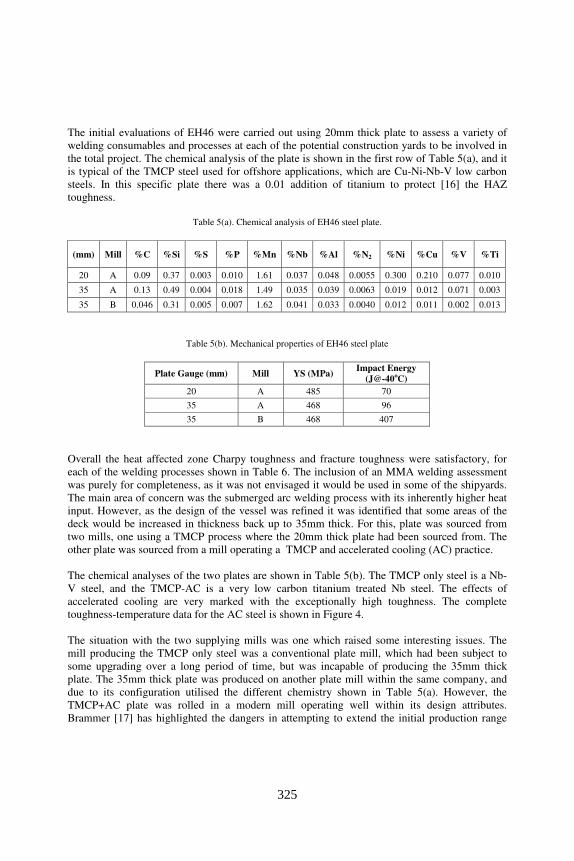
The initial evaluations of EH46 were carried out using 20mm thick plate to assess a variety of
welding consumables and processes at each of the potential construction yards to be involved in
the total project. The chemical analysis of the plate is shown in the first row of Table 5(a), and it
is typical of the TMCP steel used for offshore applications, which are Cu-Ni-Nb-V low carbon
steels. In this specific plate there was a 0.01 addition of titanium to protect [16] the HAZ
toughness.
Table 5(a). Chemical analysis of EH46 steel plate.
(mm) Mill %C %Si %S %P %Mn %Nb %Al %N2 %Ni %Cu %V %Ti
20 A 0.09 0.37 0.003 0.010 1.61 0.037 0.048 0.0055 0.300 0.210 0.077 0.010
35 A 0.13 0.49 0.004 0.018 1.49 0.035 0.039 0.0063 0.019 0.012 0.071 0.003
35 B 0.046 0.31 0.005 0.007 1.62 0.041 0.033 0.0040 0.012 0.011 0.002 0.013
Table 5(b). Mechanical properties of EH46 steel plate
Plate Gauge (mm) Mill YS (MPa) Impact Energy
(J@-40oC)
20 A 485 70
35 A 468 96
35 B 468 407
Overall the heat affected zone Charpy toughness and fracture toughness were satisfactory, for
each of the welding processes shown in Table 6. The inclusion of an MMA welding assessment
was purely for completeness, as it was not envisaged it would be used in some of the shipyards.
The main area of concern was the submerged arc welding process with its inherently higher heat
input. However, as the design of the vessel was refined it was identified that some areas of the
deck would be increased in thickness back up to 35mm thick. For this, plate was sourced from
two mills, one using a TMCP process where the 20mm thick plate had been sourced from. The
other plate was sourced from a mill operating a TMCP and accelerated cooling (AC) practice.
The chemical analyses of the two plates are shown in Table 5(b). The TMCP only steel is a Nb-
V steel, and the TMCP-AC is a very low carbon titanium treated Nb steel. The effects of
accelerated cooling are very marked with the exceptionally high toughness. The complete
toughness-temperature data for the AC steel is shown in Figure 4.
The situation with the two supplying mills was one which raised some interesting issues. The
mill producing the TMCP only steel was a conventional plate mill, which had been subject to
some upgrading over a long period of time, but was incapable of producing the 35mm thick
plate. The 35mm thick plate was produced on another plate mill within the same company, and
due to its configuration utilised the different chemistry shown in Table 5(a). However, the
TMCP+AC plate was rolled in a modern mill operating well within its design attributes.
Brammer [17] has highlighted the dangers in attempting to extend the initial production range
325

beyond the attribute levels. This can lead to inconsistencies in geometric control and mechanical
properties of the product being produced.
Welded test plates from the two rolling processes for the 35mm thick steel were produced using
identical welding passes as the plates were lined up together to produce the macrograph shown in
Figure 5.
Figure 5. Submerged arc weld of 35mm thick EH 46 plate.
The results of the HAZ toughness tests at -40oC are shown in Table 6. This shows the effects of
the welding process on heat affected area of the parent plate. It also demonstrates the need to
maintain parent plate toughness significantly in excess of the actual specified requirement.
Additionally some fracture toughness testing was also carried out, although not a contractual
requirement. This data is shown for the HAZ in Table 6.
Table 6. Heat affected zone (HAZ) properties for submerged arc welded EH46 plates.
20mm thick plate (TMCP) 25mm thick plate (TMCP) 35mm thick plate (TMCP+AC)
Welding
Process
Toughness
(J@-40oC)
Maximum
Hardness
CTOD
at
-10oC
Toughness
(J@-40oC)
Maximum
Hardness
CTOD
at
-10oC
Toughness
(J@-40oC)
Maximum
Hardness
CTOD
at
-10oC
SAW 120 256 0.365 58 266 0.44 201 218 0.72
FCAW 134 285 0.61 - - - - - -
MCAW 113 301 0.61 - - - - - -
MMA 154 270 0.66 - - - - - -
Representative optical micrographs of the two 35mm thick plate parent plates are shown in
Figures 6 (a) and (c). The very fine grain structure of the AC steel in Figure 6 (c) is in contrast to
the banded structure of the higher carbon TMCP only steel, and also demonstrates the beneficial
effect of the reduction in the carbon content of the steel from 0.13% to 0.046%, which would
also have a positive benefit on toughness.
326

(a) (b)
Figure 6. Optical microstructures of 35mm thick EH46 TMCP plate.
(c) (d)
Figure 6. Optical microstructures of 35mm thick EH 46 TMCP+AC plate.
The HAZ show some differences too, as would be expected from the toughness data shown in
Table 6. Both HAZ samples show ferrite outlinement of the prior austenite grain boundaries, and
probably more evidence of ferrite side plate development in the material that had been
accelerated cooled. The remainder of the structure was dominated by acicular ferrite. The HAZ
hardness increased by 36% for the TMCP steel and by 18% for the TMCP+AC steel. There was
327

evidence of Type II pop-in delamination on the TMCP only CTOD test fracture faces. This was
not present on the TMCP+AC test pieces. Examples are shown in Figure 7. According to
Wiesner and Piskarski [18], the pop-ins are caused by splits in a plane perpendicular to the
fatigue pre-crack.
(a) (b)
Figure 7. Fracture faces of HAZ CTOD test pieces. (a) TMCP only showing
Type II pop-ins in parent plate section of sample (b) TMCP + AC showing no
evidence of Type II pop-ins.
In such cases it is acceptable to ignore Type II pop-ins. It is now generally accepted that such
delaminations are related to crystallographic texture to and can be typical of TMCP steel. At the
final rolling temperatures there is a tendency for recrystallisation to be suppressed, creating a
flattened and elongated austenite grain structure parallel to the plate surface. Thereafter, the
phase transformation from oriented austenite to ferrite, develops a situation where the ferrite
grains have a preferred orientation to the plate surface too. Through thickness reduction in area
testing of the 35mm thick parent plates gave 85% reduction in area for the TMCP + AC, and
67% for the TMCP only plates. Clearly the delaminations did not create planes of weakness
within the plates, and were related to grain structure and not related to previously identified
sources such as steel cleanliness and segregation.
328
Cost Considerations
There has been a move in specific sectors of naval shipbuilding to reduce plate weight. This is
primarily achieved through a reduction in plate thickness and other weight and control measures.
As stated earlier the weight reduction is achieved through reducing the plate thickness and in
turn increasing the strength of the plate.
As an example an 8mm thick plate of D grade steel can be replaced with a 7mm thick plate of
DH36 grade steel, i.e.12.5% reduction in weight. It has been established that the cost differential
between the grades is that DH36 steel is £50/tonne more expensive. This is equivalent to a 7%
increase in cost. It is therefore a cost effective action for this particular situation, as it was in the
case of the carrier. In addition the thickness reduction could lead to some decreases in the
welding time. The effect of this from a microalloying viewpoint is that there is a predominant
need for elements such as niobium to generate the required higher strength of the thinner plate.
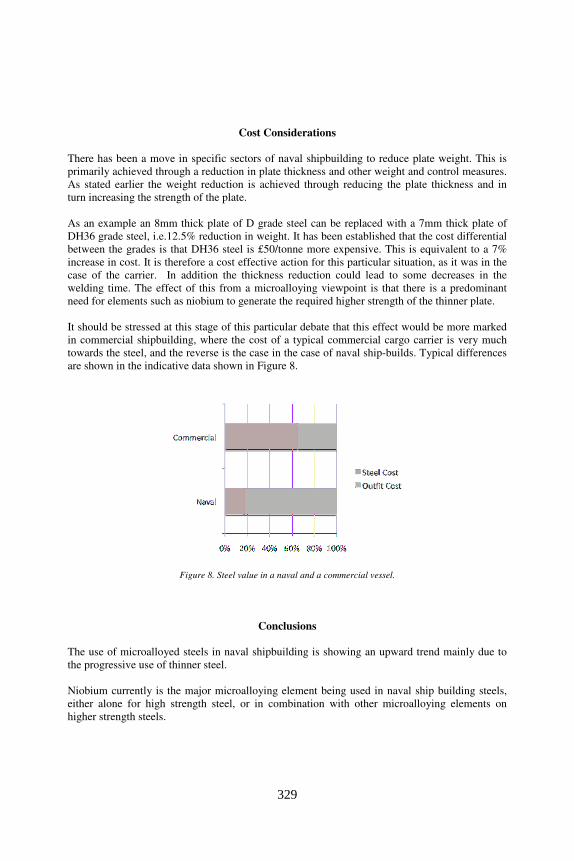
It should be stressed at this stage of this particular debate that this effect would be more marked
in commercial shipbuilding, where the cost of a typical commercial cargo carrier is very much
towards the steel, and the reverse is the case in the case of naval ship-builds. Typical differences
are shown in the indicative data shown in Figure 8.
Figure 8. Steel value in a naval and a commercial vessel.
Conclusions
The use of microalloyed steels in naval shipbuilding is showing an upward trend mainly due to
the progressive use of thinner steel.
Niobium currently is the major microalloying element being used in naval ship building steels,
either alone for high strength steel, or in combination with other microalloying elements on
higher strength steels.
329

There is still an issue with the variability of toughness effects seen in the heat affected zone of
niobium microalloyed steels.
Acknowledgements
The author wishes to acknowledge the permission of BVT Surface Fleet to publish this paper.
References
[1] N.A.McPherson,’The management of thin plate distortion’ Presented at Joint 3 Conference,
Lapeennranta, Finland, August 2007.
[2] N.A.McPherson, ‘Thin plate distortion – the ongoing problem in shipbuilding’, Journal of
Ship Production, 2007, Vol.23, No.2, p.94-117.
[3] N.A.McPherson, ‘A vékony lemez deformáciό csökkentése vezetési (menedzsment) vagy
technolόgiai feledat?’, Hegesztés-Technika, 2007, XVIII, évfolyam 2007/1, 9-15.
[4] N.A.McPherson, N.Suarez-Fernandez, D.W.Moon, H.C.P.Tan , C.K.Lee and T.N.Baker,
‘Laser and laser assisted arc welding processes for DH 36 steel microalloyed steel ship plate’
Science and Technology of Welding and Joining, 2005. Vol.10, p.460-467.
[5] D.Forrest, J.Nguyen, M.Posada, J.DeLoach, D.Boyce, J.Cho and P.Dawson, ‘Simulation of
HSLA-65 friction stir welding’, Proceedings of the 7th
International Conference on Trends in
Welding Research, 2005, Georgia, USA, p.279-286.
[6] T.J.Lienert, L.Stellwag,Jr., B.B.Grimmett and R.W.Warke, ‘Friction stir welding studies on
mild steel’ Welding Journal, 2003, January, p.1-9.
[7] M.P.Lightfoot, G.J.Bruce, N.A.McPherson and K.Woods, ‘The application of artificial neural
networks to weld induced deformation in ship plate’, Welding Journal, 2005. Vol. 84, 23s-30s.
[8] G.Bruce and M.P.Lightfoot, Lightfoot, ‘The use of artificial neural networks to model
distortion caused by welding’. International Journal of Modeling and Simulation, 2007, 27(1),
p.4341-4351.
[9] B.Phillips, J.Ritter, J.Donato, C.Chiperfield, F.Barbaro, D.O’Brien, I.Brown, G.Powell,
J.Norrish, M.Jones, G.Goetz and C.Lau, ‘Assessment of X80 grade steel as a demonstrator deck
panel in ANZAC ship 10’, DSTO Australia presentation, 2003.
[10] N.A.McPherson, ‘Through process considerations for microalloyed steels used in naval ship
construction’, to be published in Ironmaking and Steelmaking, 2008.
330

[11] V.P.Deshmukh, S.B.Yadav, A.K.Shah and D.K.Biswas, ‘Influence of niobium on
structure/property relationships in C-Mn shipbuilding steel’ Journal of Materials Engineering and
Performance, 1995, Vol. 4, p.532-542.
[12]R.E.Dolby, ‘The effect of niobium on the HAZ toughness of high heat input welds in C-Mn
steels’, Welding of HSLA [Microalloyed] Structural Steels Conference, Rome, 1976, p.212-234.
[13] Y.Li, D.N.Crowther, M.J.Green, P.S.Mitchell and T.N.Baker, ‘The effect of vanadium and
niobium on the properties and microstructure of the intercritically reheated coarse grained heat
affected zone in low carbon microalloyed steels.’, ISIJ International, 2001, Vol.41, No.1, p.46-
55.
[14] G.R.Wang, T.H.North and K.G.Leewis, ‘Microalloying additions and HAZ fracture
toughness in HSLA steels’, Welding Journal, 1990, 14s-22s.
[15] Anon., ‘Aspects of the design of the UK’s future aircraft carrier’, Warship Technology,
2008, January, p.11-13.
[16] F.B.Pickering, ‘Overview of titanium microalloyed steels’, Titanium Technology in
Microalloyed Steels, Ed. T.N.Baker, Institute of Materials, 1997.
[17] M.Brammer, ‘Steelplant upgrades for higher strength products’, Microalloyed Steels:
Production, Properties, Applications Conference, London, November, 2007.
[18] C.S.Wiesner and H.G.Pisarski, ‘The significance of pop-ins during initiation fracture
toughness tests’, 3R International, 1996, Vol.35, No.10/11, p.638-643.
331