Microstructural Evolution in Microalloyed Steels with High-Speed ... · Microstructural Evolution...
7
Proceedings of International Federation of Heat Treating and Surface Engineering , ASM, April 18-21, 2016, Savannah, GA Microstructural Evolution in Microalloyed Steels with High-Speed Thermomechanical Bar and Rod Rolling Robert Cryderman, Blake Whitely, and John Speer Advanced Steel Processing and Products Research Center, George S. Ansell Department of Metallurgical and Materials Engineering, Colorado School of Mines, Golden Colorado, USA Abstract Bars and rods are rolled at high total deformations, high strain rates, and short inter-pass times compared to products such as plates or structural sections where extensive studies have been conducted to understand the effects of microalloying and the limited range of thermomechanical process parameters. Data are presented to illustrate how microalloying and high-speed thermomechanical processing affect the as hot-rolled microstructures for a variety of steel grades and applications. Simulations on a Gleeble®3500 using torsional deformation and controlled time-temperature schedules as well as interrupted quenching have allowed examination of the evolution of prior austenite grain size and morphology. The austenite condition, in combination with the final cooling schedule, influence final hot-rolled microstructures and can lead to significant effects on microstructures and mechanical properties after subsequent heat treatment. Introduction There have been many studies leading to models of austenite grain development in flat rolled plates and strip where deformation essentially occurs in two dimensions (plane strain) such that the thickness is reduced and the length is increased. In contrast, rolling to long products such as bars and rods provides deformation in three dimensions and increased total deformation. For example rolling a 250 mm slab to 16 mm plate achieves an elongation of about 16:1 as compared to rolling a 200 mm square billet to a 40 mm round bar for an elongation of 32:1. Smaller finished sizes are also possible using the same semi-finished sections to produce light gauge strip at 1.5 mm for an elongation of 167:1 or to produce 5.5 mm diameter rod for an elongation of 1680:1. Average actual strains in long products are further increased by the redundant deformation that occurs during the bar forming process. A simplified analysis by Lee et al demonstrates that actual strain per pass is 1.7 – 2.0 times the area reduction for oval passes and 2.0 – 2.5 times the area reduction for round passes in the oval-round pass sequences commonly utilized for bar and rod rolling. [1] Consequently, total strains in bar rolling are on the order of 4 times higher than plates and 20 times higher in rod as compared to light gauge strip. Figure 1: Bar speed increases exponentially as size is reduced through in-line rolling stands. Example shown is for rounds at 150 ton/hour rolling rate. Modern bar and rod mills are typically designed to utilize in- line rolling stand arrangements that necessitate a constant mass throughput rate for all rolling stands. Consequently, the linear speed through consecutive rolling stands increases as the size becomes smaller as illustrated in Figure 1. Figure 2: Inter-pass times and strain rates (initial-final passes) for wire rod and thin strip compared to Gleeble ® 3800 capability above and left of the dashed line. [2]
Transcript of Microstructural Evolution in Microalloyed Steels with High-Speed ... · Microstructural Evolution...

Proceedings of International Federation of Heat Treating and Surface Engineering, ASM, April 18-21, 2016, Savannah, GA
Microstructural Evolution in Microalloyed Steels with High-Speed
Thermomechanical Bar and Rod Rolling
Robert Cryderman, Blake Whitely, and John Speer
Advanced Steel Processing and Products Research Center, George S. Ansell Department of Metallurgical and Materials Engineering, Colorado School of Mines, Golden Colorado, USA
Abstract Bars and rods are rolled at high total deformations, high strain
rates, and short inter-pass times compared to products such as
plates or structural sections where extensive studies have been
conducted to understand the effects of microalloying and the
limited range of thermomechanical process parameters. Data
are presented to illustrate how microalloying and high-speed
thermomechanical processing affect the as hot-rolled
microstructures for a variety of steel grades and applications.
Simulations on a Gleeble®3500 using torsional deformation
and controlled time-temperature schedules as well as
interrupted quenching have allowed examination of the
evolution of prior austenite grain size and morphology. The
austenite condition, in combination with the final cooling
schedule, influence final hot-rolled microstructures and can
lead to significant effects on microstructures and mechanical
properties after subsequent heat treatment.
Introduction
There have been many studies leading to models of austenite
grain development in flat rolled plates and strip where
deformation essentially occurs in two dimensions (plane strain)
such that the thickness is reduced and the length is increased.
In contrast, rolling to long products such as bars and rods
provides deformation in three dimensions and increased total
deformation. For example rolling a 250 mm slab to 16 mm
plate achieves an elongation of about 16:1 as compared to
rolling a 200 mm square billet to a 40 mm round bar for an
elongation of 32:1. Smaller finished sizes are also possible
using the same semi-finished sections to produce light gauge
strip at 1.5 mm for an elongation of 167:1 or to produce
5.5 mm diameter rod for an elongation of 1680:1. Average
actual strains in long products are further increased by the
redundant deformation that occurs during the bar forming
process. A simplified analysis by Lee et al demonstrates that
actual strain per pass is 1.7 – 2.0 times the area reduction for
oval passes and 2.0 – 2.5 times the area reduction for round
passes in the oval-round pass sequences commonly utilized for
bar and rod rolling. [1] Consequently, total strains in bar
rolling are on the order of 4 times higher than plates and 20
times higher in rod as compared to light gauge strip.
Figure 1: Bar speed increases exponentially as size is reduced
through in-line rolling stands. Example shown is for rounds at
150 ton/hour rolling rate.
Modern bar and rod mills are typically designed to utilize in-
line rolling stand arrangements that necessitate a constant mass
throughput rate for all rolling stands. Consequently, the linear
speed through consecutive rolling stands increases as the size
becomes smaller as illustrated in Figure 1.
Figure 2: Inter-pass times and strain rates (initial-final
passes) for wire rod and thin strip compared to Gleeble®
3800
capability above and left of the dashed line. [2]
Proceedings of International Federation of Heat Treating and Surface Engineering, ASM, April 18-21, 2016, Savannah, GA
As the rolling speed increases, the inter-pass time is reduced
and the strain rate is increased as illustrated by Kuziak in
Figure 2. [2]
Development of Gleeble® and similar systems equipped with
hot torsional deformation capability has allowed simulation of
the pass strains, inter-pass times, and strain rates for hot rolling
bars and thin plates. However, the limitations of the electro-
mechanical torsion equipment prevent replication of the strain
rate and interpass times encountered in the high speed rolling
of small diameter rods as illustrated in Figure 2. [2]
Strains, strain rates, and inter-pass times determine the
characteristics of austenite grains (austenite “condition”) at the
completion of hot rolling. As shown in Figure 3, large
equiaxed austenite grains created during heating prior to
rolling are deformed to a distorted shape during deformation at
each rolling pass. After a single rolling pass, the distorted
grains recrystallize and then begin to grow. The amount of
strain, strain rate, and temperature affect the rates of
recrystallization and grain growth. [3] At high strains, strain
rates, and temperatures recrystallization occurs dynamically
(DRx) during the rolling pass. At lower strains, strain rates,
and temperatures the recrystallization occurs statically (SRx)
after the rolling pass. Recrystallization can be completely
suppressed at temperatures below a critical value (Tnr) with
limited strains and strain rates. [4] Tnr can be affected by the
strain and strain rates. Short inter-pass times limit the amount
of recrystallization and grain growth between stands – or
increase Tnr as multiple passes are applied before
recrystallization occurs. [5] Tnr is heavily affected by the
addition of small amounts of V, Nb, and Ti as these additions
slow grain boundary movement by solute drag and by
combining with C and N to form precipitates that limit
recrystallization and grain growth kinetics. [6 - 8]
Figure 3: Schematic diagram showing deformation, dynamic
recrystallization, static recrystallization, and growth of
austenite grains during multi-pass hot rolling.
Steels with different chemical compositions have been tested
using the Gleeble or similar equipment to establish the effects
of strain and strain rates at various temperatures on
recrystallization and grain growth rates. The test data have
been assembled into kinetic equations that allow calculation of
grain sizes at the entry and exit of each rolling pass. [5, 9, 10]
These equations can be used to show that lowering the
temperature during the final few rolling passes decreases the
austenite grain size and can change the shape of austenite
grains for a given steel chemical composition. [5] Additional
investigations have been conducted on low carbon plate steels
to show that the prior austenite grain size and shape modifies
the microstructure that is formed during subsequent cooling.
[11] Generally, the increased grain boundary area associated
with smaller deformed austenite grains increases the rate of
nucleation of small ferrite grains and reduces the time for
ferrite nucleation as illustrated in Figure 4. [11]
Figure 4: Comparison of CCT diagrams for transformation
from recrystallized and un-recrystallized austenite in a
0.06% C- 1.20% Mn-0.0062% Nb-0.053% V plate steel. [11]
Similar effects are anticipated in bar steels with higher carbon
and alloy contents compared to the amounts common in plate
steels. For example, reducing the austenite grain size has been
shown to reduce the size of ferrite grains and increase the
amount of ferrite formed in a series of 0.4% C steels
containing about 1% Mn and 0.1-0.2% V. [12]
The following sections describe experiments that were
conducted to illustrate the effects of thermomechanical rolling
of bars on the microstructures, and the influence of these
microstructures on subsequent heat treatment.
Thermomechanically Rolled Bars
Bars of chemical compositions listed in Table 1 were hot
rolled from 152 mm square billets in a rolling mill described
schematically in Figure 5. The rolling mill consists of a reheat
furnace, eight roughing stands in H-V arrangement, water
cooling boxes for cooling before finish rolling, space to allow
temperature equalization in the bar cross section, an eight
Proceedings of International Federation of Heat Treating and Surface Engineering, ASM, April 18-21, 2016, Savannah, GA
stand 3-roll type reducing mill, and a three stand 3-roll type
precision sizing block. [13] The bars were cooled in air as
straight bars on a walking beam cooling bed after rolling.
Initial heating temperatures were 1150-1200 oC for the 1045
Steels and 1080-1125 oC for the 16MnCr5 steel. The final
rolling temperatures were adjusted to the desired levels by
utilizing the water cooling boxes located immediately after the
rough rolling stands.
Table 1: Chemical Compositions of Test Steels in wt. pct.
Steel C Mn Si Ni Cr Mo
16MnCr5 0.18 1.13 0.21 0.10 1.05 0.04
1045 Al 0.45 0.72 0.24 0.08 0.12 0.04
10V45 0.45 0.82 0.28 0.07 0.15 0.03
10V45Nb 0.46 0.85 0.27 0.08 0.14 0.03
Steel Al V Nb Ti B
(ppm)
N
(ppm)
16MnCr5 0.029 NA* NA NA NA
1045 Al 0.021 0.003 0.001 0.001 NA 97
10V45 0.000 0.084 0.001 0.001 NA 127
10V45Nb 0.000 0.092 0.020 0.001 NA 124
*NA = none added
Figure 5: Schematic diagram of rolling mill for evaluating
effects of final rolling temperature. [13]
Steel 16MnCr5 is a low carbon hardenable steel commonly
utilized to produce driveline components by forging and
machining followed by carburizing and hardening. The
chemical composition includes controlled amounts of Mn and
Cr to achieve the hardenability required for hardening after
carburizing. Conventional rolling without intermediate cooling
resulted in a final rolling temperature of 1018 oC for 38 mm
diameter bars. The addition of intermediate water cooling
lowered the final rolling temperature to 886 oC. Calculated Tnr
for Steel 16MnCr5 according to the Boratto equation is
estimated to be about 906 oC. [14] Prior austenite grain size is
expected to be considerably smaller with the lower final
rolling temperature.
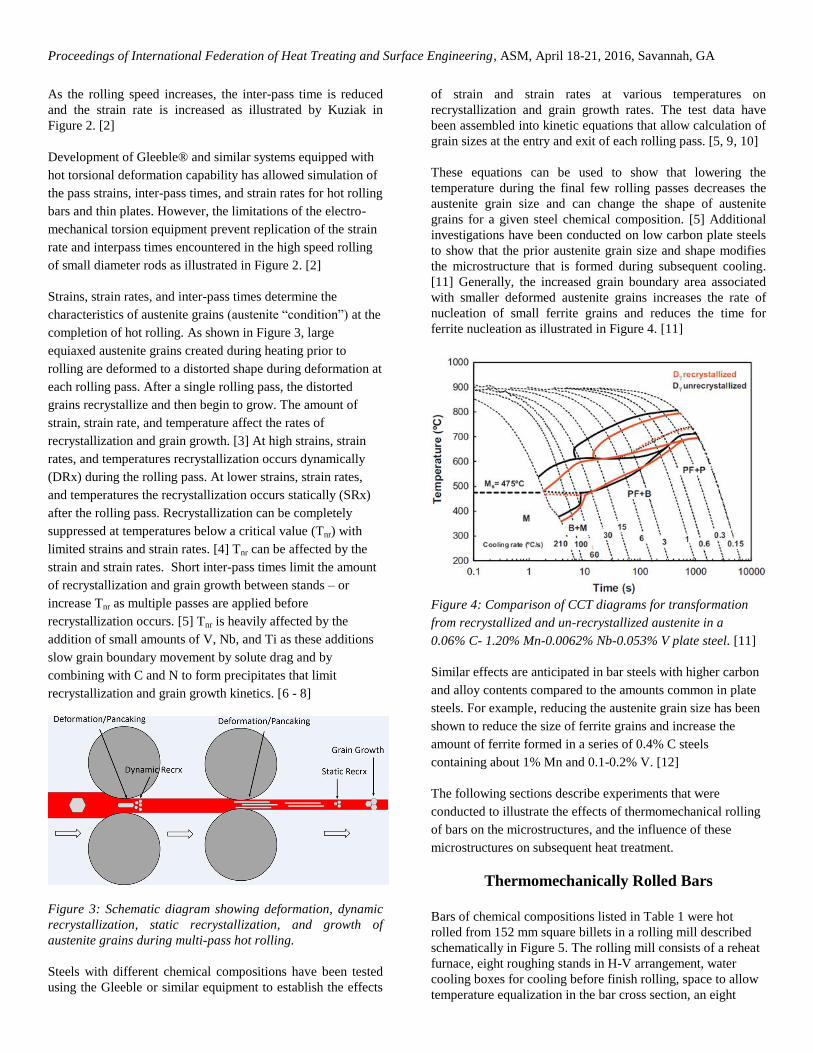
The microstructures from cross sections at the mid radius of
the 38 mm diameter bars after air cooling are shown in
Figure 6. [15] The higher, conventional finish rolling
temperature resulted in a microstructure consisting of
proeutectoid ferrite at prior austenite grain boundaries and
bainite as shown in Figure 6(a). The lower finish rolling
temperature resulted in a microstructure consisting of ferrite
and pearlite with well dispersed pearlite colonies as shown in
Figure 6(b). The area fraction of free ferrite increased from
16% to 48% with the lower final rolling temperature.
Examination by scanning electron microscopy, Figures 6(c, d)
confirmed the change from dispersed carbides to fine lamellar
pearlite.
(a) (b)
(c) (d)
Figure 6: Microstructures of 16MnCr5 hot rolled bars finish
rolled at 1018 oC (a, c) and 886
oC (b, d) as revealed by light
optical (a, b) and scanning electron(c, d) microscopy. (2%
picral etch) [15]
Figure 7: Effect of austenitizing temperature (solid line
1050 oC and dashed line 870
oC) on the continuous cooling
transformation of 16MnCr5 steel. [16]
The effects of 16MnCr5 prior austenite grain size, ( as
determined by austenitizing temperature) on continuous
cooling transformation kinetics are illustrated in Figure 7
which was redrawn to provide a direct comparison of the CCT
Proceedings of International Federation of Heat Treating and Surface Engineering, ASM, April 18-21, 2016, Savannah, GA
diagrams for austenitizing temperatures of 870 oC and
1050 oC. [16] The cooling curve shown in Figure 7 is for air
cooling 38 mm bars after finish rolling. The finer austenite
grain size accelerated the formation of grain boundary ferrite,
leading to a higher ferrite fraction, and increased the size of
the pearlite transformation field so that pearlite was formed
rather than bainite.
SAE 1045 steels are commonly used for production of shafts
that are induction hardened to resist fatigue at high torsional
and bending loads. Attainment of the desired final
microstructures and properties with the short reheating times
for induction surface hardening is highly influenced by the
starting microstructure. It has been shown that a finer ferrite-
pearlite microstructure is more readily hardened than coarse
ferrite-pearlite microstructures. [17]
10
45
Al
(a) (b)
10
V4
5
(c) (d)
10
V4
5 N
b
(e) (f)
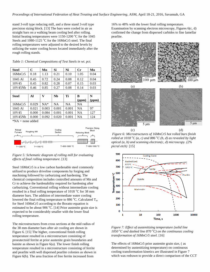
Figure 8: Microstructures of SAE 1045 as- rolled bars after
finish rolling at 1000 oC (a, c, e) and 800
oC (b, d, f) as
revealed by light optical microscopy (2% nital etch). [13]
The effects of microalloy additions (Table 1) and low
temperature thermomechanical rolling (TMR) on the
microstructures of 1045 steel are illustrated in Figure 8. In all
three 1045 steels, the grain size was substantially reduced by
lowering the final rolling temperature from 1000 oC (HR) to
800 oC (TMR). The lower rolling temperature also increased
the amount of free ferrite.
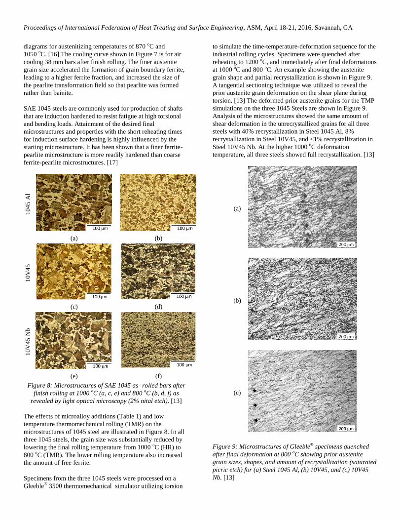
Specimens from the three 1045 steels were processed on a
Gleeble® 3500 thermomechanical simulator utilizing torsion
to simulate the time-temperature-deformation sequence for the
industrial rolling cycles. Specimens were quenched after
reheating to 1200 oC, and immediately after final deformations
at 1000 oC and 800
oC. An example showing the austenite
grain shape and partial recrystallization is shown in Figure 9.
A tangential sectioning technique was utilized to reveal the
prior austenite grain deformation on the shear plane during
torsion. [13] The deformed prior austenite grains for the TMP
simulations on the three 1045 Steels are shown in Figure 9.
Analysis of the microstructures showed the same amount of
shear deformation in the unrecrystallized grains for all three
steels with 40% recrystallization in Steel 1045 Al, 8%
recrystallization in Steel 10V45, and <1% recrystallization in
Steel 10V45 Nb. At the higher 1000 oC deformation
temperature, all three steels showed full recrystallization. [13]
(a)
(b)
(c)
Figure 9: Microstructures of Gleeble®
specimens quenched
after final deformation at 800 oC showing prior austenite
grain sizes, shapes, and amount of recrystallization (saturated
picric etch) for (a) Steel 1045 Al, (b) 10V45, and (c) 10V45
Nb. [13]

Proceedings of International Federation of Heat Treating and Surface Engineering, ASM, April 18-21, 2016, Savannah, GA
The quenched Gleeble® specimens were re-sectioned to show
the equiaxed cross-sections of the prior austenite grains for all
three test conditions and facilitate measurement of the grain
diameters. As shown in Figure 10, the large prior austenite
grains present after heating to 1200 oC were refined by the HR
simulation and further refined by the TMR simulation. After
the rolling simulations, Steel 1045 Al consistently exhibited
the largest prior austenite grain size and Steel 10V45 Nb
exhibited the smallest prior austenite grains. Compared to the
HR simulation, the TMR simulation provided reductions in
grain size of about 30% for Steel 1045 Al and 50% for the two
microalloyed steels.
Figure 10: Prior austenite grain sizes measured on Gleeble ®
torsion simulation specimens quenched after reheating
(austenitizing), HR deformation (1000 oC) and TMP
deformation (800 oC). [13]
Heat Treatment of Thermomechanically Rolled
Bars
The following examples show that the as- rolled
microstructure can substantially influence the resulting
microstructure after final heat treatment. The 16MnCr5 steels
in the two rolling conditions from Figure 6 were sub-critically
annealed at 692 oC for 6 hours and the resulting
microstructures are shown in Figure 11.
After 6 hours of annealing, the carbides for both prior rolling
conditions were fully spheroidized as shown Figure 11 (c, d).
However, the distribution of the spheroidized carbides within
the overall microstructure was substantially different as shown
in Figures 11 (a, b). These microstructural differences could be
expected to have an influence on microstructures and
properties after the final carburizing and hardening of the
finished parts.
The response of the 1045 steels as-rolled microstructures to
supercritical heat treatments varied depending on the
(a) (b)
(c) (d)
Figure 11: Microstructures of 16MnCr5 specimens annealed
at 692 oC for 6 hours; (a, c) finish rolled at 1018
oC, (b, d)
finish rolled at 886 oC, (a, b) light optical micrographs, (c, d)
scanning electron micrographs. (2% picral etch) [15]
(a) (b)
(c) (d)
Figure 12: Effects of lamellar pearlite (LP) annealing on the
microstructures of 1045 steel specimens: (a) Steel 1045 Al HR
at 1000 oC, (b) Steel 1045 Al HR and LP annealed, (c) Steel
10V45 Nb TMR at 800 oC, and (d) Steel 10V45 Nb TMR and
LP annealed.
microalloys, the prior rolling conditions, and the type of heat
treatment. Two examples are illustrated in Figure 12 for Steel
1045 Al that was initially HR at 1000 oC and for Steel
10V45Nb that was TMR at 800 oC. After rolling, specimens of
each steel were lamellar pearlite (LP) annealed by heating to
Proceedings of International Federation of Heat Treating and Surface Engineering, ASM, April 18-21, 2016, Savannah, GA
805 oC (Ac3 + 50
oC) for 1 hour followed by furnace cooling at
0.06 oC/s (in the range of 800 – 300
oC). Comparison of HR
Steel 1045 Al in Figure 12 (a) and (b) shows that the LP
anneal reduced the pearlite colony size and introduced a
banded structure parallel to the rolling direction (vertical in
(b)). LP annealing of TMR Steel 10V45 Nb imparted a limited
effect on the microstructure after the LP anneal as shown in
Figures 12 (c) and (d). The overall result is that the LP
annealed microstructure is substantially modified by the initial
microstructure and the addition of micro alloys (Figures 12 (b)
and (d).
As noted previously, 1045 steel is commonly utilized to
produce induction hardened shafts. Specimens obtained from
the three 1045 steels (Table1) were heat treated to simulate an
induction hardening thermal cycle on a Gleeble® 3500. The
thermal cycle, calculated using Elta 2-D, is shown in Figure 13
and was developed to simulate a 2 mm deep case depth on a
38 mm diameter shaft using a 2-turn coil. [18] The heating
portion of the cycle shows an interruption at about 700 oC
which reflects the space between the first and second turn
during scan hardening. The cooling after heating was first
accelerated with forced air to simulate heat transfer to the core
and then water quenched at a rate of 3500 oC/s. Gleeble®
specimens processed to the HR and TMP conditions were
subsequently heat treated to the simulated induction hardening
schedule in Figure 13.
Figure 13: Thermal profile for a Gleenle
® 3500 simulation of
induction hardening a 38 mm diameter shaft to a 2 mm case
depth showing modeled (solid line) and experimental (dashed
line) time-temperature profiles.
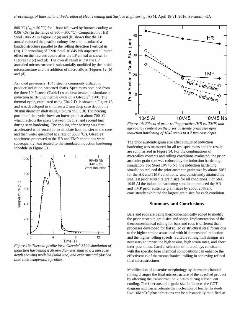
Figure 14: Effects of prior rolling practice (HR vs. TMP) and
microalloy content on the prior austenite grain size after
induction hardening of 1045 steels to a 2 mm case depth.
The prior austenite grain size after simulated induction
hardening was measured for all test specimens and the results
are summarized in Figure 14. For the combinations of
microalloy contents and rolling conditions evaluated, the prior
austenite grain size was reduced by the induction hardening
simulation. For Steel 10V45 Nb, the induction hardening
simulation reduced the prior austenite grain size by about 50%
for the HR and TMP conditions, and consistently attained the
smallest prior austenite grain size for all conditions. For Steel
1045 Al the induction hardening simulation reduced the HR
and TMP prior austenite grain sizes by about 20% and
consistently exhibited the largest grain size for each condition.
Summary and Conclusions
Bars and rods are being thermomechanically rolled to modify
the prior austenite grain size and shape. Implementation of the
thermomechanical rolling for bars and rods is different than
processes developed for flat rolled or structural steel forms due
to the higher strains associated with bi-dimensional reduction
and the higher rolling speeds. Suitable rolling mill designs are
necessary to impart the high strains, high strain rates, and short
inter-pass times. Careful selection of microalloys consistent
with the specific base chemical compositions can enhance the
effectiveness of thermomechanical rolling in achieving refined
final microstructures.
Modification of austenite morphology by thermomechanical
rolling changes the final microstructure of the as rolled product
by affecting the transformation kinetics during subsequent
cooling. The finer austenite grain size influences the CCT
diagram and can accelerate the nucleation of ferrite. In steels
like 16MnCr5 phase fractions can be substantially modified so

Proceedings of International Federation of Heat Treating and Surface Engineering, ASM, April 18-21, 2016, Savannah, GA
that bainite is suppressed in favor of pearlite formation. In
steels like 1045 that readily transform to ferrite and pearlite,
the finer austenite grain size leads to finer ferrite-pearlite
microstructures and an increased fraction of free ferrite.
The effects of thermomechanical rolling on microstructures
after subsequent heat treatment are not well documented in the
literature. For subcritical annealing, the long range (>100-200
microns) microstructural features are relatively unaffected by
the heat treatment, even though the short range features (<20
microns) may be modified. The microstructure after
supercritical heating such as normalizing or LP annealing is
heavily influenced by the microstructure in the bars after hot
rolling. A similar effect occurs during the short time higher
austenitizing temperatures attained during induction heating.
Fine prior austenite grain sizes like the 10 micron sizes
observed for the 10V45 Nb after TMP and induction
hardening have been shown to increase the fatigue strength of
case hardened components. [19]
An understanding of the prior microstructural effects from
TMP on the microstructures after final heat treatment is
needed to optimize the heat treatment process parameters and
the performance of the finished parts.
Acknowledgements
The authors gratefully acknowledge the continued support of
the sponsors of the Advanced Steel Processing and Products
Research Center, an industry/university cooperative research
center at the Colorado School of Mines.
References
[1] Lee, Y. Choi, S., and Hodgson, P.D., “Analytical Model
of Pass-by-Pass Strain in Rod (or Bar) Rolling and its
Applications to Predictions of Austenite Grain Size,”
Materials Science and Engineering, A336 (2002), pp.
177-189.
[2] Kuziak, R., “Physical Simulation of Thermomechanical
Treatment Employing Gleeble 3800 Simulator,” Metal
2006, Hradek Nad Moravici.
[3] Bianchi, J. H. and Karjalainen, “Modelling of Dynamic
and Metadynamic Recrystallization During Bar Rolling of
Medium Carbon Bar Steel,” Journal of Materials
Processing Technology, Vol 160 (2005) pp. 267-277.
[4] Kozasu, I., Shimuzu, I. T. and Kubota, H., Trans. Iron
and Steel Institute of Japan, Vol. 11 (1971), pp. 367.
[5] Maccagno, T.M.,Jonas, J.J., and Hodgson, P.D.,
“Spreadsheet Modelling of Grain Size Evolution during
Rod Rolling,” ISIJ International, Vol. 36 (1996), No. 6,
pp.720-728.
[6] Homsher, C.N. and Van Tyne, C.J., “Empirical Equations
for the No-Recrystallization Temperature in Hot Rolled
Steel Plates,” Proceedings Materials Science and
Technology Conference, Montreal Quebec, Canada, Oct
27-31, 2013, pp. 1815-1822.
[7] Speer, J. G. and Hansen, S. S. “Austenite
Recrystallization and Carbonitride Precipitation in
Niobium Microalloyed Steels,” Metall. Trans. A, vol. 20,
(1989), pp. 25–38,.
[8] Vervynckt, S., Verbeken, K., Thibaux, P. and Houbaert
Y., “Recrystallization-Precipitation Interaction during
Austenite Hot Deformation of a Nb Microalloyed Steel,”
Materials Science and Engineering A, Vol. 528 (2011),
pp. 5519-5528.
[9] El Mehtedi, F. et al., “Predicition Models of the Final
Properties of Steel Rods Obtained by Thermomechanical
Rolling Process,” La Metallurgia Italiana, n. 3 (2013),
pp. 31-37.
[10] Kruse, M., Schwarz, M., Schuck, M., “Kocks
Microstructure Simulator (KMS) – New Technical Tool
for Process Simulation of Long Products,” La Metallurgia
Italiana, n. 1 (2014), pp. 5-10.
[11] Olasolo, M., Uranga, P., Rodriguez-Ibabe, J.M., and
López, B., “Effect of Austenite Microstructure and
Cooling Rate on Transformation Characteristics in a low
carbon Nb-V Microalloyed Steel,” Materials Science and
Engineering, A 528 (2011), pp. 2559-2569.
[12] Cryderman, R.L. et al. “Effects of Chemical Composition,
Heat Treatment, and Microstructure in Splittable Forged
Steel Connecting Rods,” SAE Int. J. Mater. Manf.
8(3):2015, doi:10.4271/2015-01-0522
[13] Whitley, B. M., Easter, C. T., Cryderman, R. L., and
Speer, J. G., “Thermomechanical Simulation and
Microstructural Analysis of Microalloyed Medium
Carbon Bar Steels,” Proceedings of International
Conference on Advances in Metallurgy of Long and
Forged Products, AIST, July 12-15, 2015, Vail Colorado,
USA.
[14] Barbosa, R., Boratto, F., Yue, S., and Jonas, J.J., “The
Influence of Chemical Composition on the
Recrystallization Behavior of Microalloyed Steels,”
Processing, Microstructure and Properties of HSLA
Steels, (1988), pp. 51-61.
[15] Schaneman, R.A., “The Effects of Prior Microstructure on
Spheroidizing Kinetics and Cold Workability in Bar
Steels,” M. S. Thesis, Colorado School of Mines, (2009).
[16] Totten, G.E. and Howes, M.A.H., Steel Heat Treatment
Handbook, New York, NY: Marcel Dekker, 1997, pp.
540.
[17] Matlock, D.K. “Metallurgy of Induction Hardening of
Steel,” ASM Handbook, Vol. 4C, 2014, pp 45-57.
[18] Goldstein, R, Fluxtrol, Auburn Hills, MI 48326, private
communication, July 27, 2015.
[19] Hyde R.S., Matlock, D.K. and Krauss, G "Quench
Embrittlement: Intergranular Fracture Due to Cementite
and Phosphorous in Quenched Carbon and Alloy Steels",
Proceedings of the 40th Mechanical Working and Steel
Processing Conference, 1998, pp. 921-928.