MFG12197 On Milling, turning and mill turn...
39
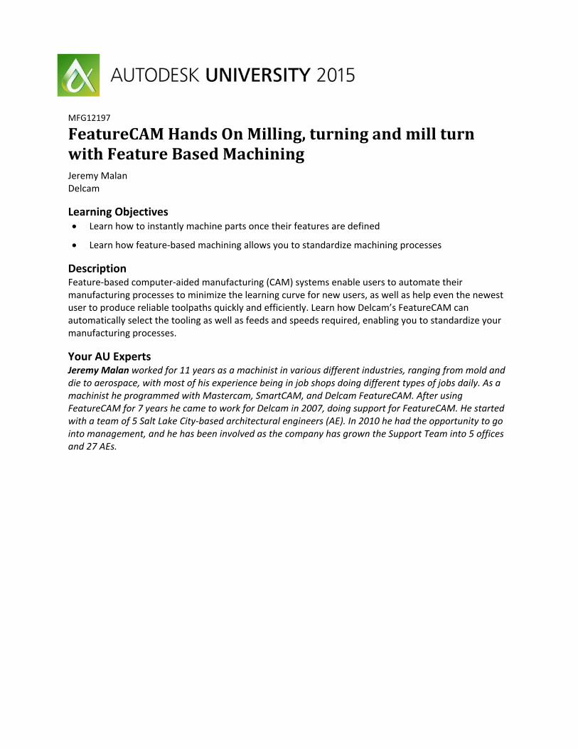
MFG12197 FeatureCAM Hands On Milling, turning and mill turn with Feature Based Machining Jeremy Malan Delcam Learning Objectives Learn how to instantly machine parts once their features are defined Learn how feature‐based machining allows you to standardize machining processes Description Feature‐based computer‐aided manufacturing (CAM) systems enable users to automate their manufacturing processes to minimize the learning curve for new users, as well as help even the newest user to produce reliable toolpaths quickly and efficiently. Learn how Delcam’s FeatureCAM can automatically select the tooling as well as feeds and speeds required, enabling you to standardize your manufacturing processes. Your AU Experts Jeremy Malan worked for 11 years as a machinist in various different industries, ranging from mold and die to aerospace, with most of his experience being in job shops doing different types of jobs daily. As a machinist he programmed with Mastercam, SmartCAM, and Delcam FeatureCAM. After using FeatureCAM for 7 years he came to work for Delcam in 2007, doing support for FeatureCAM. He started with a team of 5 Salt Lake City‐based architectural engineers (AE). In 2010 he had the opportunity to go into management, and he has been involved as the company has grown the Support Team into 5 offices and 27 AEs.
Transcript of MFG12197 On Milling, turning and mill turn...
MFG12197
FeatureCAMHandsOnMilling,turningandmillturnwithFeatureBasedMachiningJeremy Malan Delcam
Learning Objectives Learn how to instantly machine parts once their features are defined
Learn how feature‐based machining allows you to standardize machining processes
Description Feature‐based computer‐aided manufacturing (CAM) systems enable users to automate their manufacturing processes to minimize the learning curve for new users, as well as help even the newest user to produce reliable toolpaths quickly and efficiently. Learn how Delcam’s FeatureCAM can automatically select the tooling as well as feeds and speeds required, enabling you to standardize your manufacturing processes.
Your AU Experts Jeremy Malan worked for 11 years as a machinist in various different industries, ranging from mold and die to aerospace, with most of his experience being in job shops doing different types of jobs daily. As a machinist he programmed with Mastercam, SmartCAM, and Delcam FeatureCAM. After using FeatureCAM for 7 years he came to work for Delcam in 2007, doing support for FeatureCAM. He started with a team of 5 Salt Lake City‐based architectural engineers (AE). In 2010 he had the opportunity to go into management, and he has been involved as the company has grown the Support Team into 5 offices and 27 AEs.
FeatureCAM Hands On Milling, Turning, and Mill/Turn With Feature Based Machining
2
Defining Features in FeatureCAM
Advantage of Feature Based Machining Feature based machining allows users of FeatureCAM to define areas to be machined based on objects they already know and understand, features. Feature based program greatly increased the programming speed over traditional process based CAM system because it utilizes automation built into the features to define operation specific cutting parameters that otherwise would need to be defined by the user.
Traditional CAM approachTraditional CAM systems are Operation Based and require you to program every operation, one at a time, to create your part. All the manufacturing details are left to the machinist. That means that you must specify the details for every Spot Drill, Drill, Ream, and Roughing pass of your part.
FeatureCAM feature based machiningWith FeatureCAM you generate your part using features such as tapped hole, boss, pocket, or turned groove and the operations are automatically created. FeatureCAM also manages the details of the manufacturing process such as Tool selection, Speed and Feed Rates, and Toolpaths. To modify any element of the part program, just change a few settings on a feature and a whole new set of operations are generated to reflect your changes.
Ease of Use Ease of Use comes naturally for FeatureCAM because it was originally developed as a graphical Windows‐based program. FeatureCAM is full of graphical feedback, Step‐by‐Step wizards and tutorial‐style animations that run directly in the program dialog boxes. Ease of use has always been a FeatureCAM advantage and we continue to study ways to make our system even easier to learn and use.
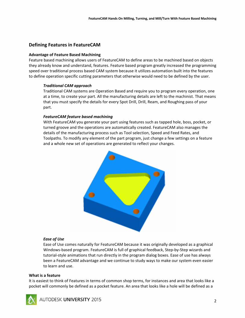
What is a feature It is easiest to think of Features in terms of common shop terms, for instances and area that looks like a pocket will commonly be defined as a pocket feature. An area that looks like a hole will be defined as a
FeatureCAM Hands On Milling, Turning, and Mill/Turn With Feature Based Machining
3
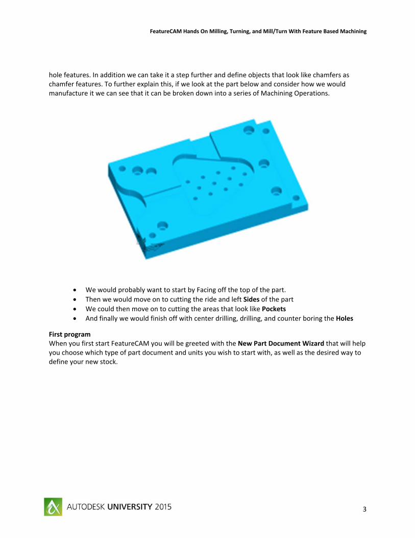
hole features. In addition we can take it a step further and define objects that look like chamfers as chamfer features. To further explain this, if we look at the part below and consider how we would manufacture it we can see that it can be broken down into a series of Machining Operations.
We would probably want to start by Facing off the top of the part.
Then we would move on to cutting the ride and left Sides of the part
We could then move on to cutting the areas that look like Pockets
And finally we would finish off with center drilling, drilling, and counter boring the Holes
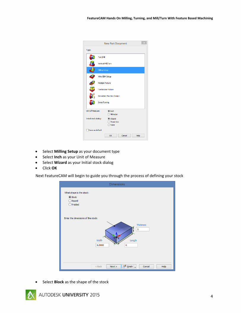
First program When you first start FeatureCAM you will be greeted with the New Part Document Wizard that will help you choose which type of part document and units you wish to start with, as well as the desired way to define your new stock.
FeatureCAM Hands On Milling, Turning, and Mill/Turn With Feature Based Machining
4
Select Milling Setup as your document type
Select Inch as your Unit of Measure
Select Wizard as your Initial stock dialog
Click OK
Next FeatureCAM will begin to guide you through the process of defining your stock
Select Block as the shape of the stock
FeatureCAM Hands On Milling, Turning, and Mill/Turn With Feature Based Machining
5
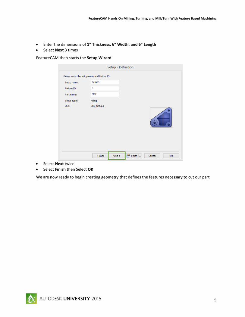
Enter the dimensions of 1” Thickness, 6” Width, and 6” Length
Select Next 3 times
FeatureCAM then starts the Setup Wizard
Select Next twice
Select Finish then Select OK
We are now ready to begin creating geometry that defines the features necessary to cut our part
FeatureCAM Hands On Milling, Turning, and Mill/Turn With Feature Based Machining
6
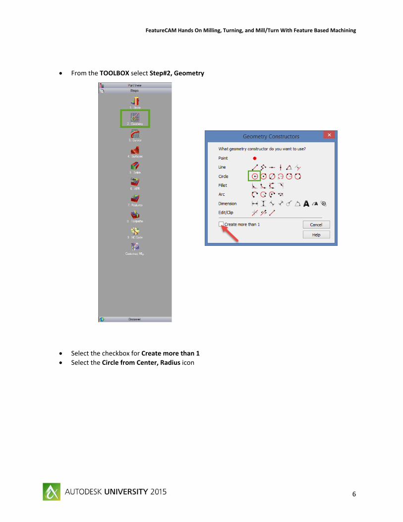
From the TOOLBOX select Step#2, Geometry
Select the checkbox for Create more than 1
Select the Circle from Center, Radius icon
FeatureCAM Hands On Milling, Turning, and Mill/Turn With Feature Based Machining
7
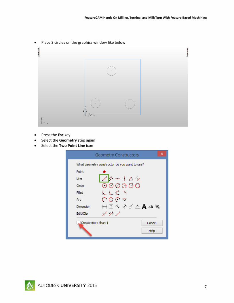
Place 3 circles on the graphics window like below
Press the Esc key
Select the Geometry step again
Select the Two Point Line icon
FeatureCAM Hands On Milling, Turning, and Mill/Turn With Feature Based Machining
8
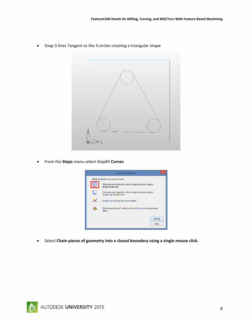
Snap 3 lines Tangent to the 3 circles creating a triangular shape
From the Steps menu select Step#3 Curves
Select Chain pieces of geometry into a closed boundary using a single mouse click.
FeatureCAM Hands On Milling, Turning, and Mill/Turn With Feature Based Machining
9
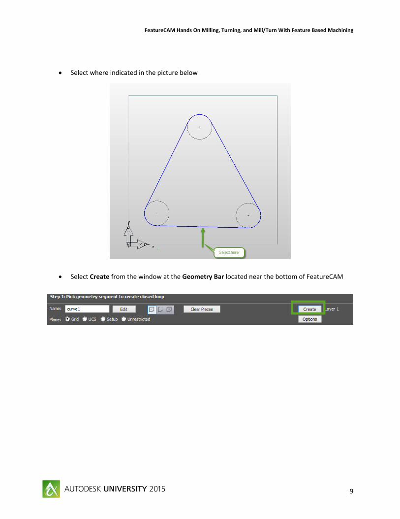
Select where indicated in the picture below
Select Create from the window at the Geometry Bar located near the bottom of FeatureCAM
FeatureCAM Hands On Milling, Turning, and Mill/Turn With Feature Based Machining
10
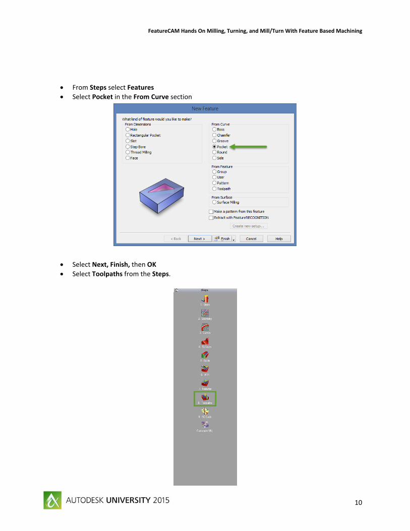
From Steps select Features
Select Pocket in the From Curve section
Select Next, Finish, then OK
Select Toolpaths from the Steps.
FeatureCAM Hands On Milling, Turning, and Mill/Turn With Feature Based Machining
11
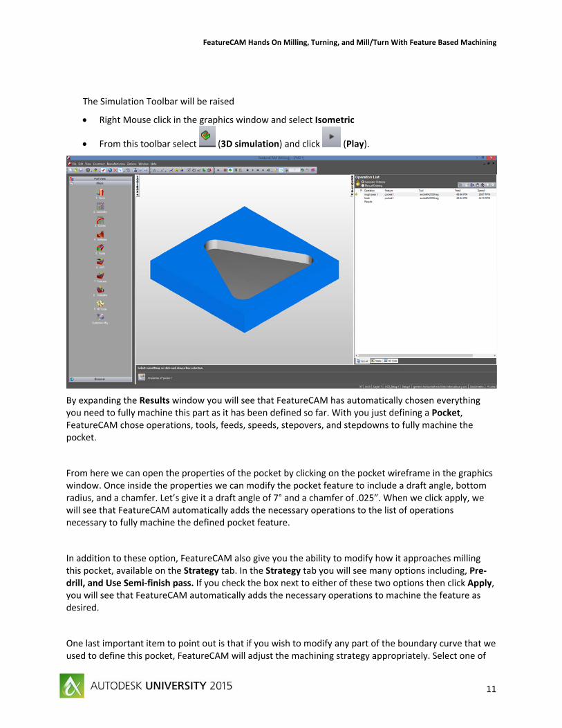
The Simulation Toolbar will be raised
Right Mouse click in the graphics window and select Isometric
From this toolbar select (3D simulation) and click (Play).
By expanding the Results window you will see that FeatureCAM has automatically chosen everything you need to fully machine this part as it has been defined so far. With you just defining a Pocket, FeatureCAM chose operations, tools, feeds, speeds, stepovers, and stepdowns to fully machine the pocket.
From here we can open the properties of the pocket by clicking on the pocket wireframe in the graphics window. Once inside the properties we can modify the pocket feature to include a draft angle, bottom radius, and a chamfer. Let’s give it a draft angle of 7° and a chamfer of .025”. When we click apply, we will see that FeatureCAM automatically adds the necessary operations to the list of operations necessary to fully machine the defined pocket feature.
In addition to these option, FeatureCAM also give you the ability to modify how it approaches milling this pocket, available on the Strategy tab. In the Strategy tab you will see many options including, Pre‐drill, and Use Semi‐finish pass. If you check the box next to either of these two options then click Apply, you will see that FeatureCAM automatically adds the necessary operations to machine the feature as desired.
One last important item to point out is that if you wish to modify any part of the boundary curve that we used to define this pocket, FeatureCAM will adjust the machining strategy appropriately. Select one of
FeatureCAM Hands On Milling, Turning, and Mill/Turn With Feature Based Machining
12
the three circles by single clicking on it in the graphics window. Modify the radius of the circle to .25, the click the Modify button. Notice that FeatureCAM updates the 3D wireframe view of the pocket feature, more than that it will also update the tools diameters that are necessary to machine the feature. A simulation of this feature will show that FeatureCAM also updates the toolpath as necessary.
All of this knowledge comes from customizable Machining Attributes and Configurations. You can set all of these configurations and attributes that can make FeatureCAM machine your parts the way you want them to be machined.
Feature Recognition
FeatureCAM comes with an option called feature recognition. Feature recognition is simply the ability of FeatureCAM to recognize these normal machining features from surface and solid models. This, coupled with FeatureCAM’s automation allows for faster programming times than can be achieved with traditional CAM programs. There is two types of feature recognition available in FeatureCAM, Automatic Feature Recognition, and, Interactive Feature Recognition. In the next section, we will look at the differences and benefits to each of these feature recognition types.
Programming using Automatic Feature Recognition in FeatureCAM Automatic Feature Recognition is an option in FeatureCAM that allows the user to automatically recognize features from a solid model. If a user has already customized a toolcrib, material type with feeds and speeds, and machining configurations for their desired cutting conditions (i.e. machine and material combination) the programming of parts using Automatic Feature Recognition will greatly reduce programming time. This allows the part to get to the machine faster, which reduces the overall cost of producing the part. Following is a tutorial on using Automatic Feature Recognition (AFR).
Import a solid model and set up the part document for machining, including defining stock and setup. For this tutorial we are going to open a part file that already has a solid model imported as well as the stock and setup defined (FM2D_AFR_F.fm).
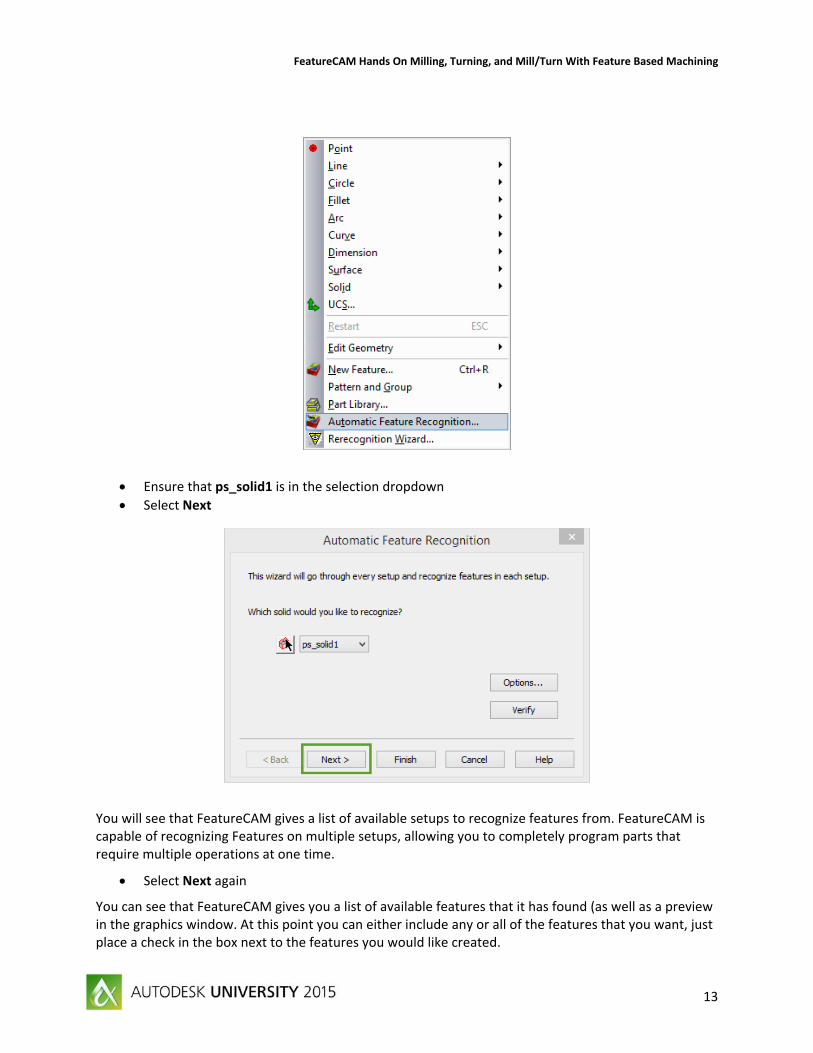
Navigate to the Construct menu.
Select Automatic Feature Recognition
FeatureCAM Hands On Milling, Turning, and Mill/Turn With Feature Based Machining
13
Ensure that ps_solid1 is in the selection dropdown
Select Next
You will see that FeatureCAM gives a list of available setups to recognize features from. FeatureCAM is capable of recognizing Features on multiple setups, allowing you to completely program parts that require multiple operations at one time.
Select Next again
You can see that FeatureCAM gives you a list of available features that it has found (as well as a preview in the graphics window. At this point you can either include any or all of the features that you want, just place a check in the box next to the features you would like created.
FeatureCAM Hands On Milling, Turning, and Mill/Turn With Feature Based Machining
14
Select Finish
Expand the Results window and select the Op List tab
FeatureCAM Hands On Milling, Turning, and Mill/Turn With Feature Based Machining
15
You can now run a 3D simulation and see that the part is fully programmed. What is important is that the part may not be programmed in the most efficient way possible or in the way that you would like to see it run on the machine. For Example: when cutting around the outside of the part, you will see that we make 3 different features that end up cutting the outside at some point, two of these features also cut into the triangular shaped pocket on the inside and include the slots that run to the outside of the part. Ideally we would cut the triangular pocket in one feature from top to bottom, then do the same for all of the outside features and the grooves, and finally we would drill all of the holes. This is where the second type of Feature Recognition (Interactive Feature Recognition, or IFR) come in.
Click on the Details tab and notice at the top that we have a total estimated machining time of approximately 21 minutes. Next we will look at programming the same part using Interactive Feature Recognition and compare the machining times.
Programming using Interactive Feature Recognition (IFR) with FeatureCAM Interactive Feature Recognition is FeatureCAM’s tool that allows users to interactively recognize features from surfaces or solid models during the programming process. Rather than just allowing FeatureCAM to fully recognize and create the features on its own, the user assists FeatureCAM in programming by defining what type of features they want cut and the surfaces that they want to make up these features. FeatureCAM then uses that information to create the feature, including any boundaries, tool selections, feeds and speeds, stepovers, stepdowns, etc. necessary for successful machining of the Feature.
For this Tutorial we will utilize the same part file that we have already programmed using AFR, simply close the file and re‐open it.
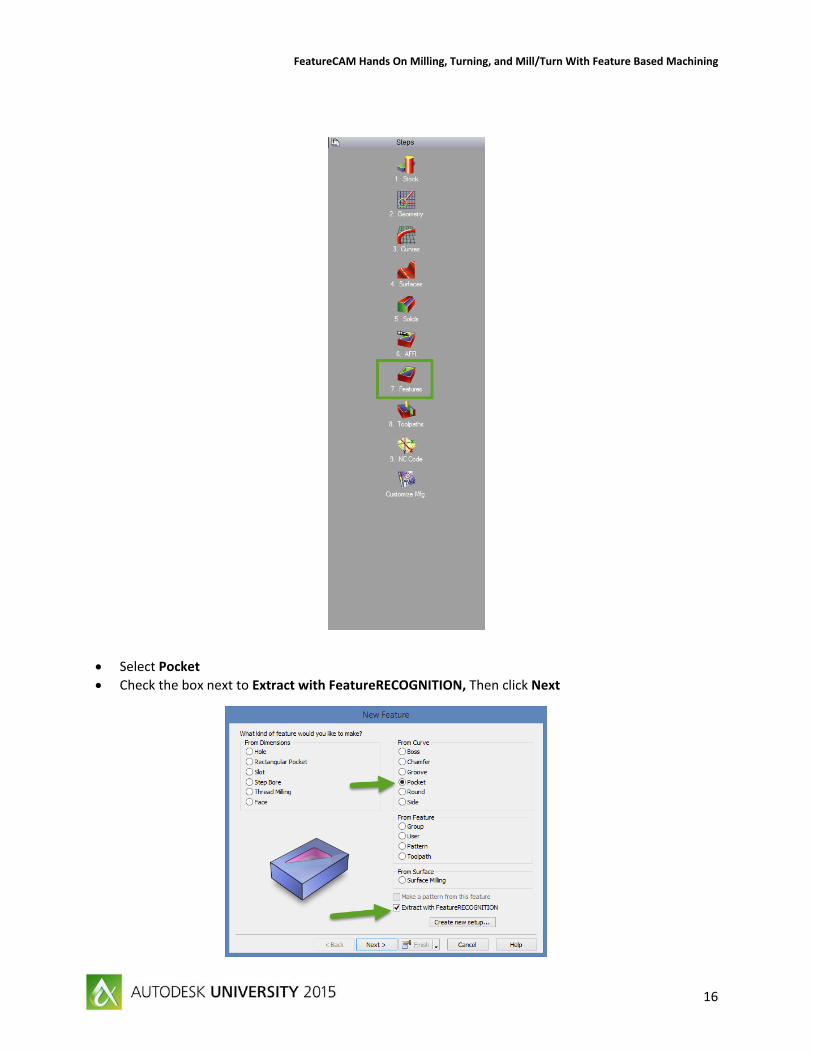
From the Steps menu select the Features step
FeatureCAM Hands On Milling, Turning, and Mill/Turn With Feature Based Machining
16
Select Pocket
Check the box next to Extract with FeatureRECOGNITION, Then click Next
FeatureCAM Hands On Milling, Turning, and Mill/Turn With Feature Based Machining
17
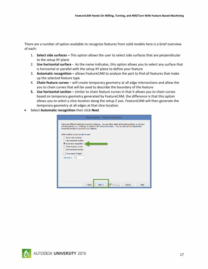
There are a number of option available to recognize features from solid models here is a brief overview of each:
1. Select side surfaces – This option allows the user to select side surfaces that are perpendicular to the setup XY plane
2. Use horizontal surface ‐ As the name indicates, this option allows you to select any surface that is horizontal or parallel with the setup XY plane to define your feature
3. Automatic recognition – allows FeatureCAM to analyze the part to find all features that make up the selected feature type
4. Chain feature curves – will create temporary geometry at all edge intersections and allow the you to chain curves that will be used to describe the boundary of the feature
5. Use horizontal section – similar to chain feature curves in that it allows you to chain curves based on temporary geometry generated by FeatureCAM, the difference is that this option allows you to select a slice location along the setup Z axis. FeatureCAM will then generate the temporary geometry at all edges at that slice location.
Select Automatic recognition then click Next
FeatureCAM Hands On Milling, Turning, and Mill/Turn With Feature Based Machining
18
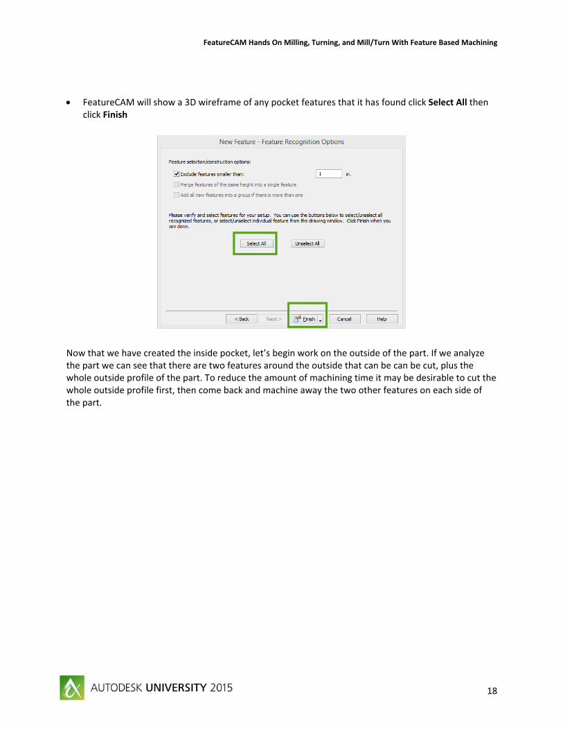
FeatureCAM will show a 3D wireframe of any pocket features that it has found click Select All then click Finish
Now that we have created the inside pocket, let’s begin work on the outside of the part. If we analyze the part we can see that there are two features around the outside that can be can be cut, plus the whole outside profile of the part. To reduce the amount of machining time it may be desirable to cut the whole outside profile first, then come back and machine away the two other features on each side of the part.
FeatureCAM Hands On Milling, Turning, and Mill/Turn With Feature Based Machining
19
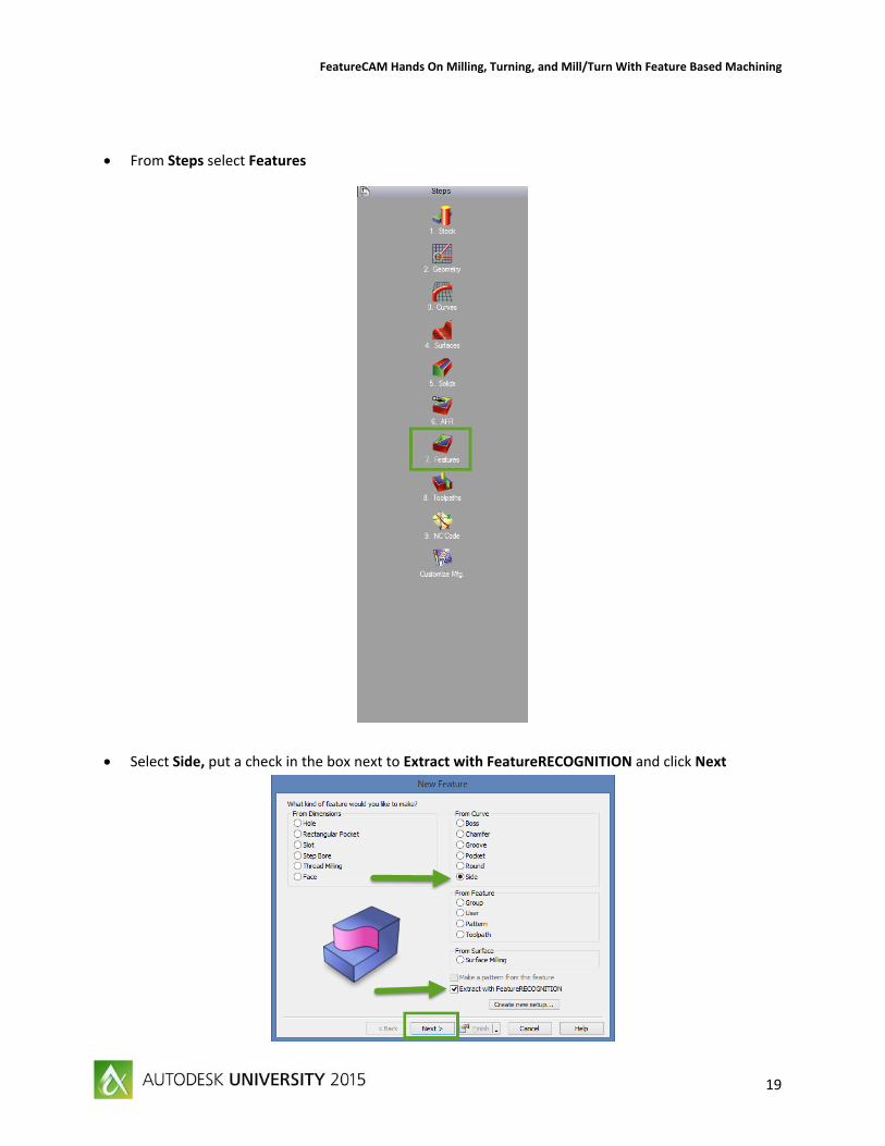
From Steps select Features
Select Side, put a check in the box next to Extract with FeatureRECOGNITION and click Next
FeatureCAM Hands On Milling, Turning, and Mill/Turn With Feature Based Machining
20
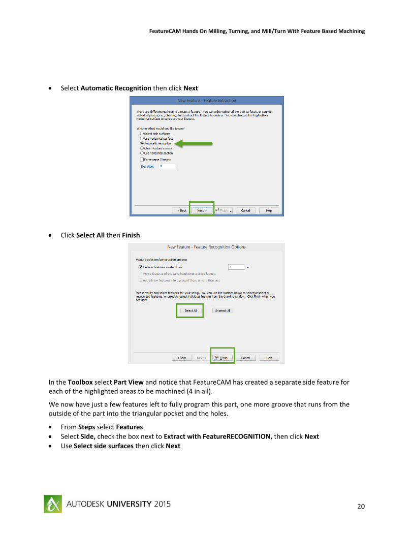
Select Automatic Recognition then click Next
Click Select All then Finish
In the Toolbox select Part View and notice that FeatureCAM has created a separate side feature for each of the highlighted areas to be machined (4 in all).
We now have just a few features left to fully program this part, one more groove that runs from the outside of the part into the triangular pocket and the holes.
From Steps select Features
Select Side, check the box next to Extract with FeatureRECOGNITION, then click Next
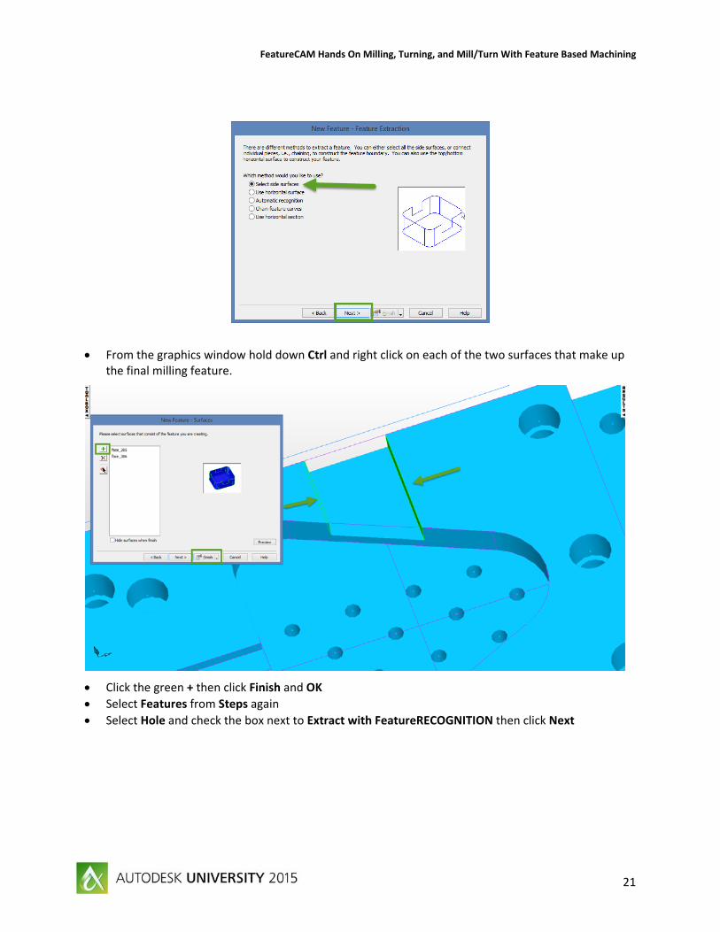
Use Select side surfaces then click Next
FeatureCAM Hands On Milling, Turning, and Mill/Turn With Feature Based Machining
21
From the graphics window hold down Ctrl and right click on each of the two surfaces that make up the final milling feature.
Click the green + then click Finish and OK
Select Features from Steps again
Select Hole and check the box next to Extract with FeatureRECOGNITION then click Next
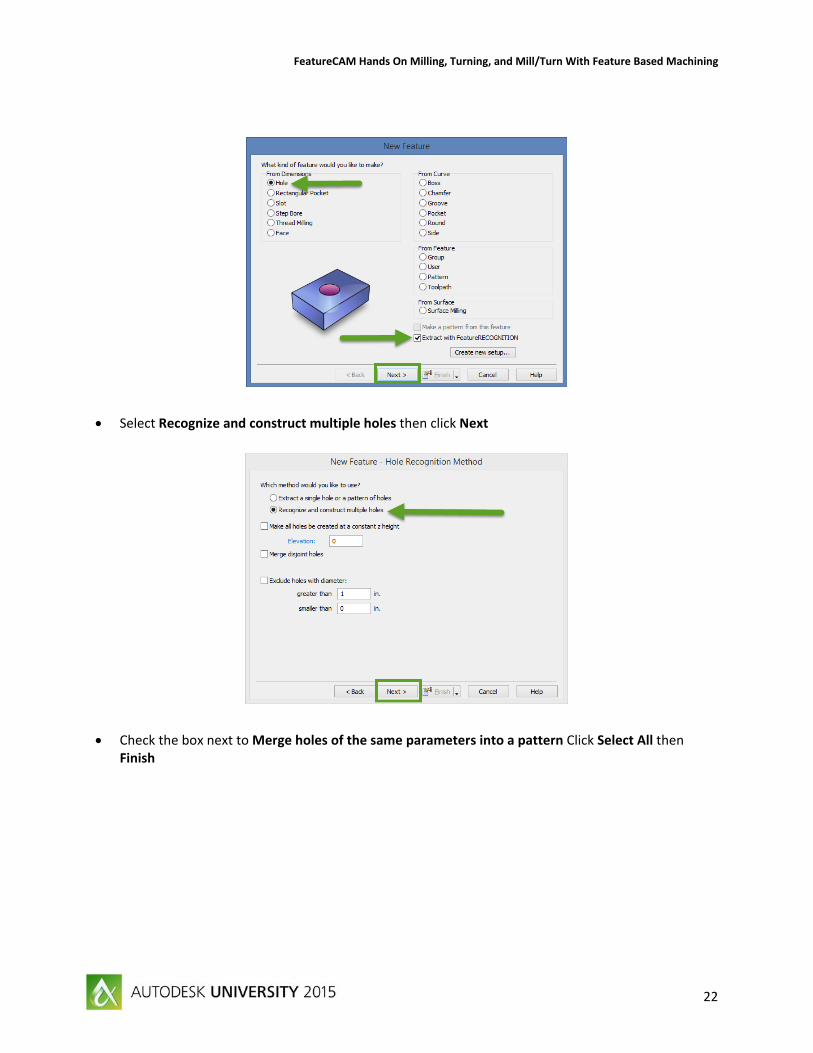
FeatureCAM Hands On Milling, Turning, and Mill/Turn With Feature Based Machining
22
Select Recognize and construct multiple holes then click Next
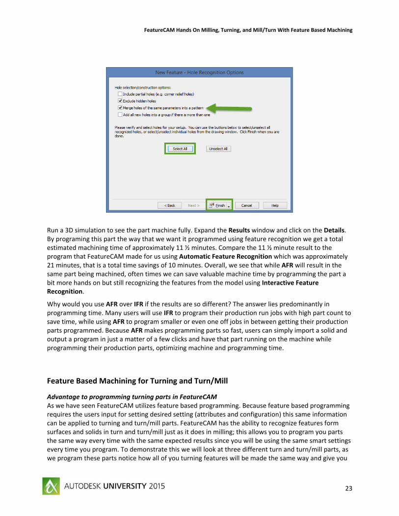
Check the box next to Merge holes of the same parameters into a pattern Click Select All then Finish
FeatureCAM Hands On Milling, Turning, and Mill/Turn With Feature Based Machining
23
Run a 3D simulation to see the part machine fully. Expand the Results window and click on the Details. By programing this part the way that we want it programmed using feature recognition we get a total estimated machining time of approximately 11 ½ minutes. Compare the 11 ½ minute result to the program that FeatureCAM made for us using Automatic Feature Recognition which was approximately 21 minutes, that is a total time savings of 10 minutes. Overall, we see that while AFR will result in the same part being machined, often times we can save valuable machine time by programming the part a bit more hands on but still recognizing the features from the model using Interactive Feature Recognition.
Why would you use AFR over IFR if the results are so different? The answer lies predominantly in programming time. Many users will use IFR to program their production run jobs with high part count to save time, while using AFR to program smaller or even one off jobs in between getting their production parts programmed. Because AFR makes programming parts so fast, users can simply import a solid and output a program in just a matter of a few clicks and have that part running on the machine while programming their production parts, optimizing machine and programming time.
Feature Based Machining for Turning and Turn/Mill
Advantage to programming turning parts in FeatureCAM As we have seen FeatureCAM utilizes feature based programming. Because feature based programming requires the users input for setting desired setting (attributes and configuration) this same information can be applied to turning and turn/mill parts. FeatureCAM has the ability to recognize features form surfaces and solids in turn and turn/mill just as it does in milling; this allows you to program you parts the same way every time with the same expected results since you will be using the same smart settings every time you program. To demonstrate this we will look at three different turn and turn/mill parts, as we program these parts notice how all of you turning features will be made the same way and give you
FeatureCAM Hands On Milling, Turning, and Mill/Turn With Feature Based Machining
24
the same expected results. Also notice that when we programming milling features for use on a turn/mill application, those milling features will give you the same expected results that you have been seeing in the milling examples.
Turning part in FeatureCAM For this tutorial we will utilize a FeatureCAM file with a solid model already imported into it (AFR From Solid.fm). All we have done is imported a solid model into a new Turn/Mill document, defined our stock from a cylinder and set out setup on the face of the part, leaving some stock in front of the part for a facing operation.
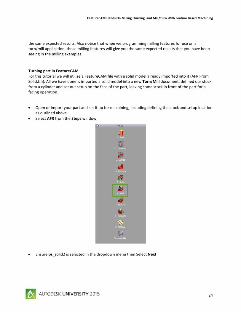
Open or import your part and set it up for machining, including defining the stock and setup location as outlined above
Select AFR from the Steps window
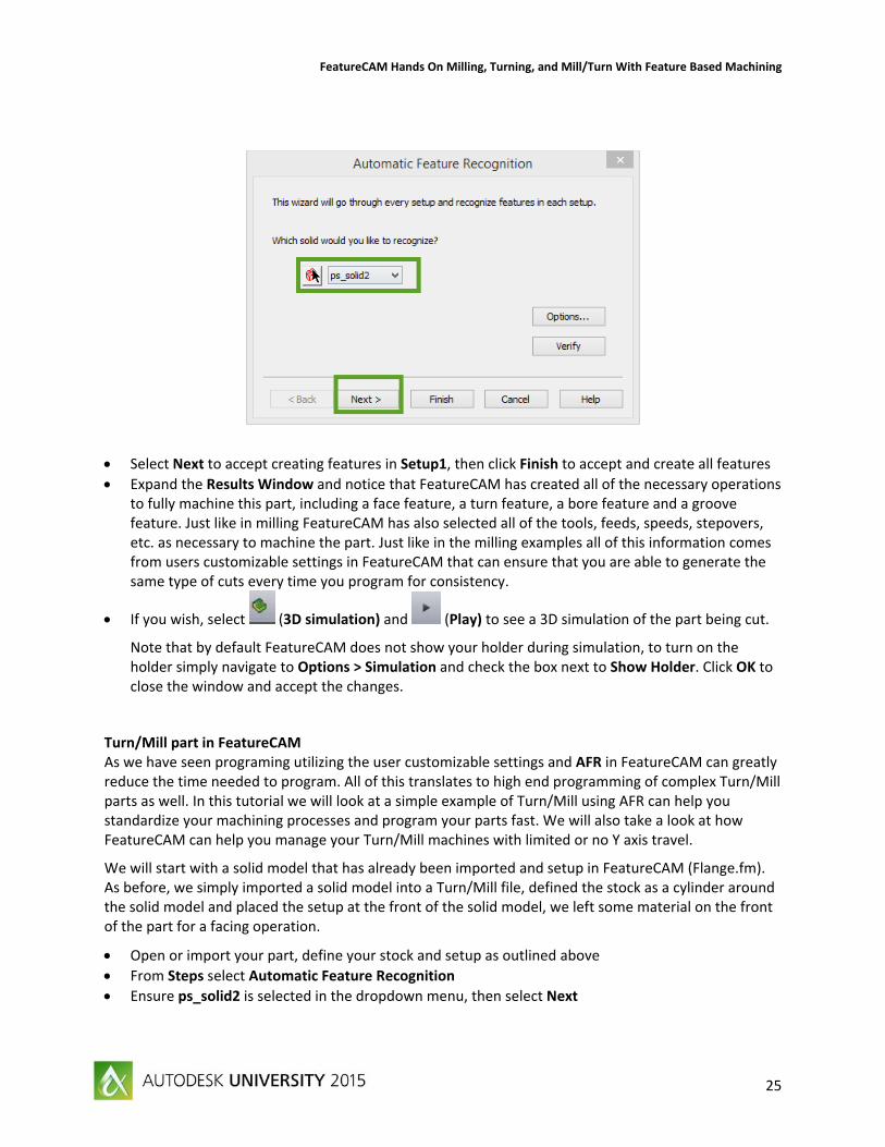
Ensure ps_solid2 is selected in the dropdown menu then Select Next
FeatureCAM Hands On Milling, Turning, and Mill/Turn With Feature Based Machining
25
Select Next to accept creating features in Setup1, then click Finish to accept and create all features
Expand the Results Window and notice that FeatureCAM has created all of the necessary operations to fully machine this part, including a face feature, a turn feature, a bore feature and a groove feature. Just like in milling FeatureCAM has also selected all of the tools, feeds, speeds, stepovers, etc. as necessary to machine the part. Just like in the milling examples all of this information comes from users customizable settings in FeatureCAM that can ensure that you are able to generate the same type of cuts every time you program for consistency.
If you wish, select (3D simulation) and (Play) to see a 3D simulation of the part being cut.
Note that by default FeatureCAM does not show your holder during simulation, to turn on the holder simply navigate to Options > Simulation and check the box next to Show Holder. Click OK to close the window and accept the changes.
Turn/Mill part in FeatureCAM As we have seen programing utilizing the user customizable settings and AFR in FeatureCAM can greatly reduce the time needed to program. All of this translates to high end programming of complex Turn/Mill parts as well. In this tutorial we will look at a simple example of Turn/Mill using AFR can help you standardize your machining processes and program your parts fast. We will also take a look at how FeatureCAM can help you manage your Turn/Mill machines with limited or no Y axis travel.
We will start with a solid model that has already been imported and setup in FeatureCAM (Flange.fm). As before, we simply imported a solid model into a Turn/Mill file, defined the stock as a cylinder around the solid model and placed the setup at the front of the solid model, we left some material on the front of the part for a facing operation.
Open or import your part, define your stock and setup as outlined above
From Steps select Automatic Feature Recognition
Ensure ps_solid2 is selected in the dropdown menu, then select Next
FeatureCAM Hands On Milling, Turning, and Mill/Turn With Feature Based Machining
26
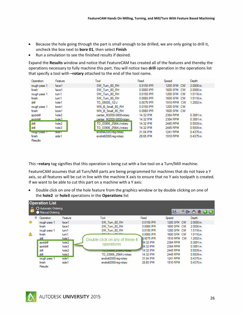
Because the hole going through the part is small enough to be drilled, we are only going to drill it, uncheck the box next to bore 01, then select Finish
Run a simulation to see the finished results if desired.
Expand the Results window and notice that FeatureCAM has created all of the features and thereby the operations necessary to fully machine this part. You will notice two drill operation in the operations list that specify a tool with –rotary attached to the end of the tool name.
This –rotary tag signifies that this operation is being cut with a live tool on a Turn/Mill machine.
FeatureCAM assumes that all Turn/Mill parts are being programmed for machines that do not have a Y axis, so all features will be cut in line with the machine X axis to ensure that no Y axis toolpath is created. If we want to be able to cut this part on a machine with a Y axis:
Double click on one of the hole feature from the graphics window or by double clicking on one of the hole2 or hole3 operations in the Operations list
FeatureCAM Hands On Milling, Turning, and Mill/Turn With Feature Based Machining
27
On the Dimensions tab check the box next to Cut feature using Y Axis coordinate
This will activate the option to specify a C Angle. The angle that you specify is the angle that FeatureCAM will lock the C axis at prior to machining the feature, then use Y axis to position the tool correctly to drill the hole in the correct location. All milling features have this ability so you can use your machines Y axis and orient the part in the machine to account for the limited travel generally associated with Y axis on Turn/Mill machines.
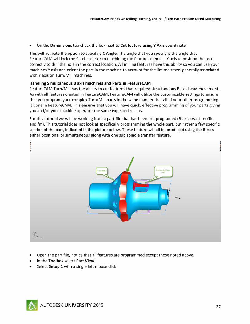
Handling Simultaneous B axis machines and Parts in FeatureCAM FeatureCAM Turn/Mill has the ability to cut features that required simultaneous B axis head movement. As with all features created in FeatureCAM, FeatureCAM will utilize the customizable settings to ensure that you program your complex Turn/Mill parts in the same manner that all of your other programming is done in FeatureCAM. This ensures that you will have quick, effective programming of your parts giving you and/or your machine operator the same expected results.
For this tutorial we will be working from a part file that has been pre‐programed (B‐axis swarf profile end.fm). This tutorial does not look at specifically programming the whole part, but rather a few specific section of the part, indicated in the picture below. These feature will all be produced using the B‐Axis either positional or simultaneous along with one sub spindle transfer feature.
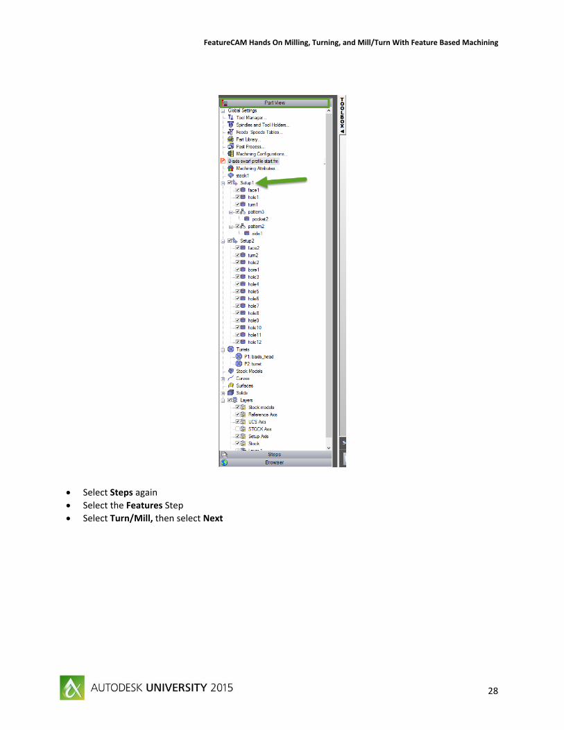
Open the part file, notice that all features are programmed except those noted above.
In the Toolbox select Part View
Select Setup 1 with a single left mouse click
FeatureCAM Hands On Milling, Turning, and Mill/Turn With Feature Based Machining
28
Select Steps again
Select the Features Step
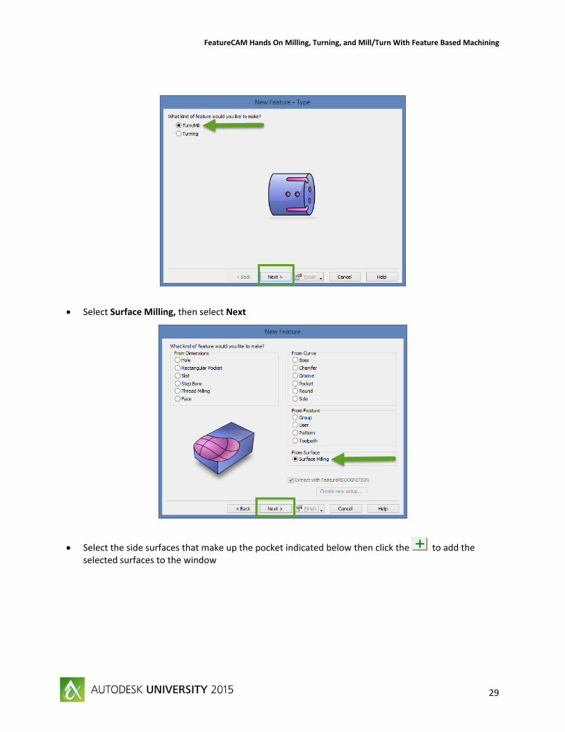
Select Turn/Mill, then select Next
FeatureCAM Hands On Milling, Turning, and Mill/Turn With Feature Based Machining
29
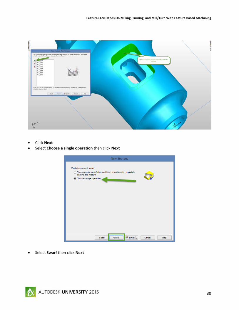
Select Surface Milling, then select Next
Select the side surfaces that make up the pocket indicated below then click the to add the selected surfaces to the window
FeatureCAM Hands On Milling, Turning, and Mill/Turn With Feature Based Machining
30
Click Next
Select Choose a single operation then click Next
Select Swarf then click Next
FeatureCAM Hands On Milling, Turning, and Mill/Turn With Feature Based Machining
31
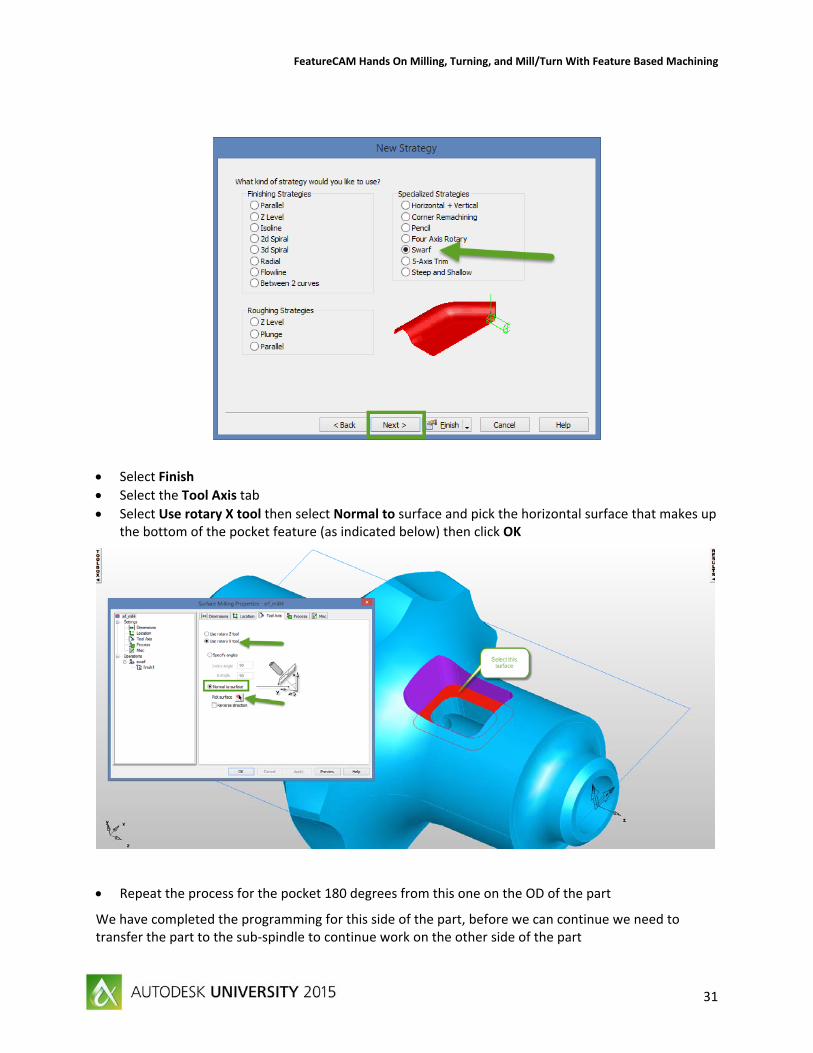
Select Finish
Select the Tool Axis tab
Select Use rotary X tool then select Normal to surface and pick the horizontal surface that makes up the bottom of the pocket feature (as indicated below) then click OK
Repeat the process for the pocket 180 degrees from this one on the OD of the part
We have completed the programming for this side of the part, before we can continue we need to transfer the part to the sub‐spindle to continue work on the other side of the part
FeatureCAM Hands On Milling, Turning, and Mill/Turn With Feature Based Machining
32
From Steps select Features
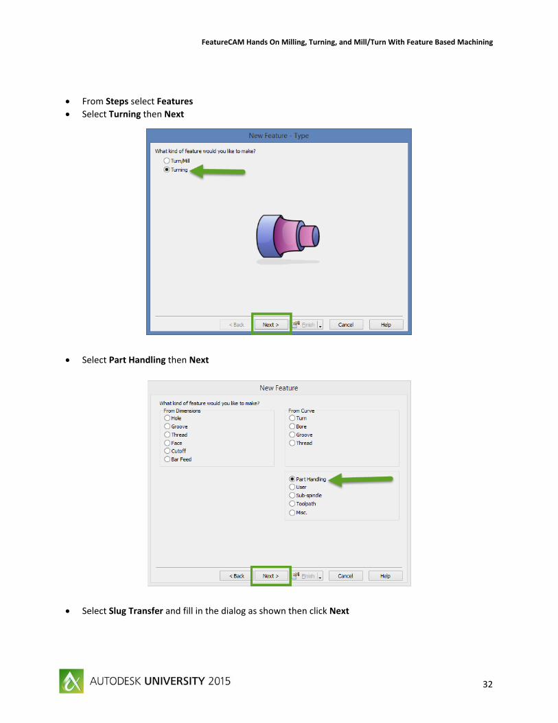
Select Turning then Next
Select Part Handling then Next
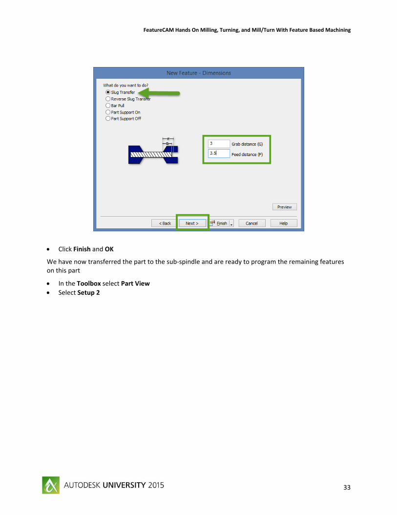
Select Slug Transfer and fill in the dialog as shown then click Next
FeatureCAM Hands On Milling, Turning, and Mill/Turn With Feature Based Machining
33
Click Finish and OK
We have now transferred the part to the sub‐spindle and are ready to program the remaining features on this part
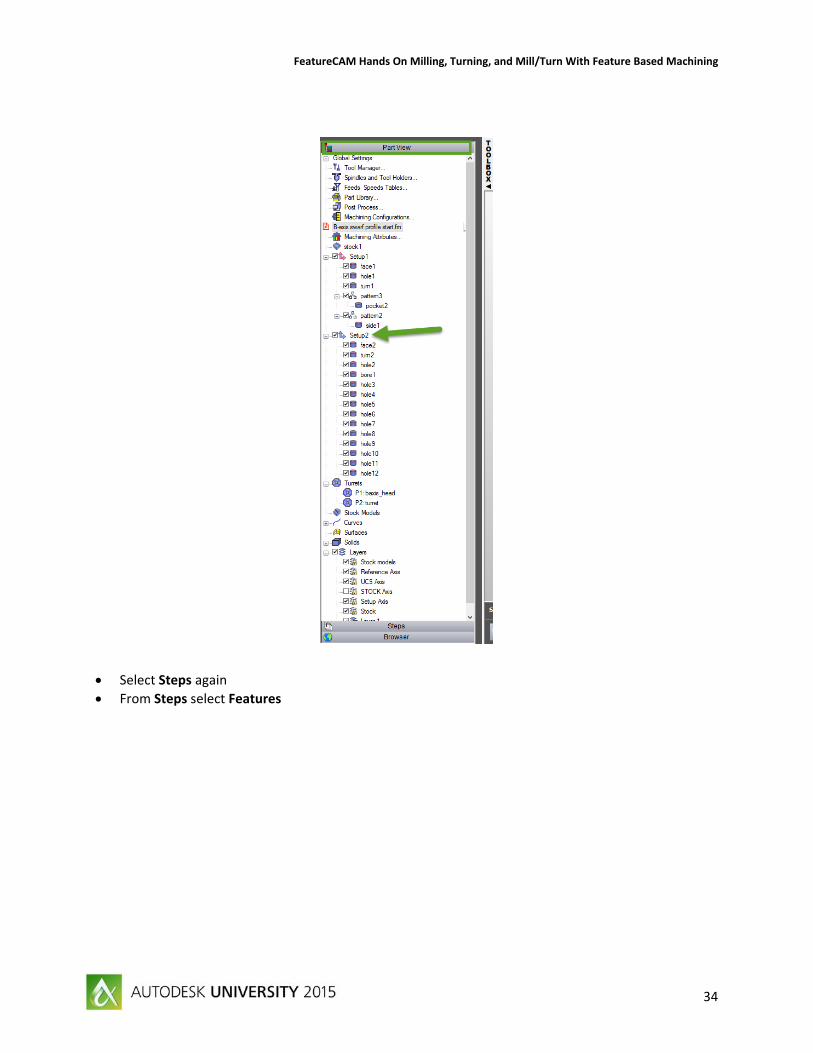
In the Toolbox select Part View
Select Setup 2
FeatureCAM Hands On Milling, Turning, and Mill/Turn With Feature Based Machining
34
Select Steps again
From Steps select Features
FeatureCAM Hands On Milling, Turning, and Mill/Turn With Feature Based Machining
35
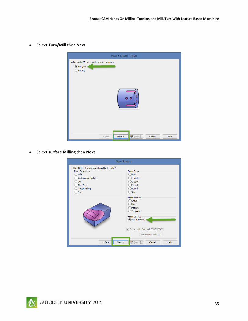
Select Turn/Mill then Next
Select surface Milling then Next
FeatureCAM Hands On Milling, Turning, and Mill/Turn With Feature Based Machining
36
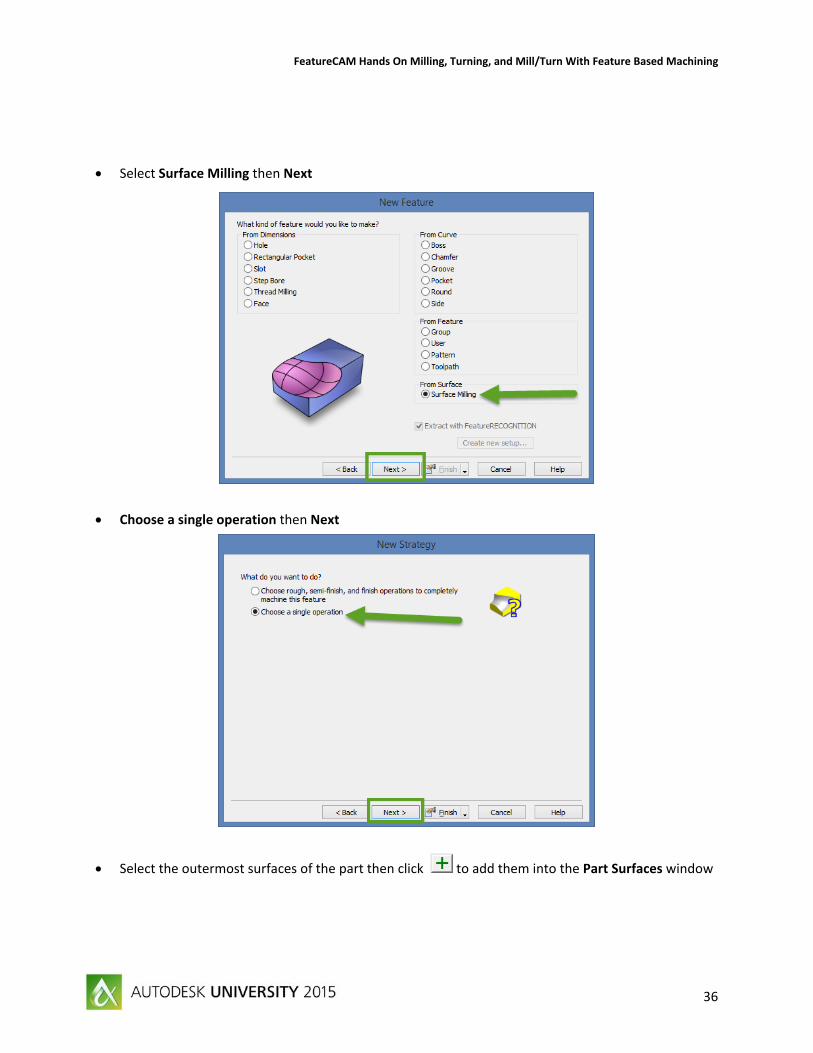
Select Surface Milling then Next
Choose a single operation then Next
Select the outermost surfaces of the part then click to add them into the Part Surfaces window
FeatureCAM Hands On Milling, Turning, and Mill/Turn With Feature Based Machining
37
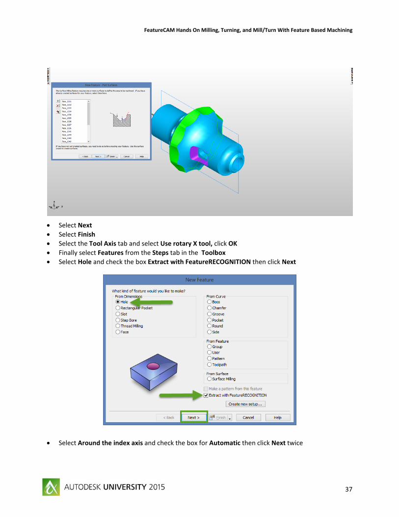
Select Next
Select Finish
Select the Tool Axis tab and select Use rotary X tool, click OK
Finally select Features from the Steps tab in the Toolbox
Select Hole and check the box Extract with FeatureRECOGNITION then click Next
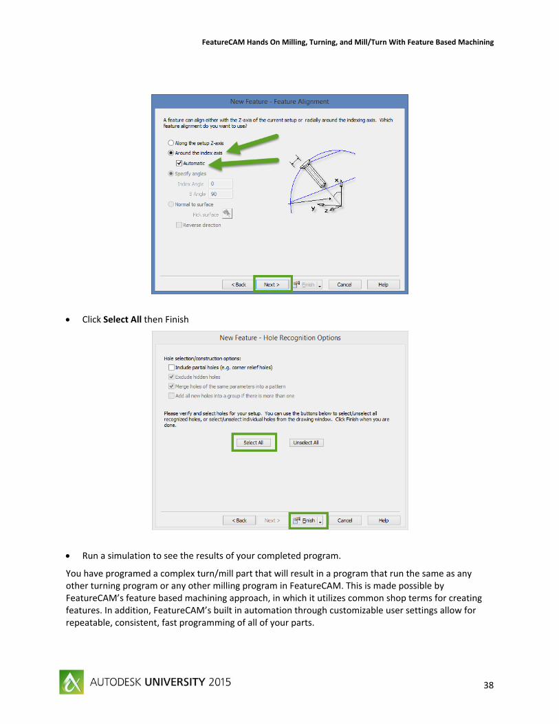
Select Around the index axis and check the box for Automatic then click Next twice
FeatureCAM Hands On Milling, Turning, and Mill/Turn With Feature Based Machining
38
Click Select All then Finish
Run a simulation to see the results of your completed program.
You have programed a complex turn/mill part that will result in a program that run the same as any other turning program or any other milling program in FeatureCAM. This is made possible by FeatureCAM’s feature based machining approach, in which it utilizes common shop terms for creating features. In addition, FeatureCAM’s built in automation through customizable user settings allow for repeatable, consistent, fast programming of all of your parts.
FeatureCAM Hands On Milling, Turning, and Mill/Turn With Feature Based Machining
39
Conclusion
FeatureCAM’s unique feature based programming system utilizes a combination of known shop terms and smart user customizable settings to make programing your parts easy and fast. You will always get the consistent results that you require from FeatureCAM because of the automation. Changes to programs are easy and quick with just the click of a few buttons, you can add, remove, and customize your cutting operations to suite the cutting style that you need for your parts, your machines, and your shop.