Edition 01 Shop Floor Programming Turning And Milling · Shop Floor Programming Turning And Milling...
222
Rexroth IndraMotion MTX Shop Floor Programming Turning And Milling R911318600 Edition 01 Electric Drives and Controls Pneumatics Service Linear Motion and Assembly Technologies Hydraulics
Transcript of Edition 01 Shop Floor Programming Turning And Milling · Shop Floor Programming Turning And Milling...

Rexroth IndraMotion MTXShop Floor ProgrammingTurning And Milling
R911318600Edition 01
Operating and Programming Instructions
Electric Drivesand Controls Pneumatics Service
Linear Motion and Assembly TechnologiesHydraulics

Rexroth IndraMotion MTXShop Floor ProgrammingTurning and Milling
Operating and Programming Instructions
DOK-MTX***-SF*PROG*V06-AW01-EN-P
RS-55058b320a6846ac0046a787b69784a7-1-en-US-3
Edition Release Date Notes
120-2500-B342-01/EN 11/2006 First edition for 06VRS
© 2006 Bosch Rexroth AGCopying this document, giving it to others and the use or communication of thecontents therof without express authourity, are forbidden. Offenders are liablefor the payment of damages. All rights are reserved in the event of the grant ofa patent or the registration of a utility model or design (DIN 34-1).The specified data is for product description purposes only and may not bedeemed to be guaranteed unless expressly confirmed in the contract. All rightsare reserved with respect to the content of this documentation and the availa‐bility of the product.Bosch Rexroth AGBgm.-Dr.-Nebel-Str. 2 ■ D-97816 Lohr a. MainTelefon +49 (0)93 52/ 40-0 ■ Fax +49 (0)93 52/ 40-48 85http://www.boschrexroth.com/Dept. BRC/ESM2(JAD), BRC/ESM6 (DiLe)This document has been printed on chlorine-free bleached paper.
Title
Type of Documentation
Document Typecode
Internal File Reference
Record of Revision
Copyright
Validity
Published by
Note
Bosch Rexroth AG | Electric Drivesand Controls
Rexroth IndraMotion MTX | Operating and Programming Instruc‐tions

Table of ContentsPage
1 Important Instructions for Use........................................................................................ 11.1 Appropriate Use...................................................................................................................................... 11.1.1 Introduction.......................................................................................................................................... 11.1.2 Areas of Use and Application ............................................................................................................. 11.2 Inappropriate Use................................................................................................................................... 2
2 Safety Instructions for Electric Drives and Controls ...................................................... 32.1 Safety Instructions - General Information............................................................................................... 32.1.1 Using the Safety Instructions and Passing them on to Others............................................................ 32.1.2 How to Employ the Safety Instructions................................................................................................ 32.1.3 Explanation of Warning Symbols and Degrees of Hazard Seriousness.............................................. 42.1.4 Hazards by Improper Use.................................................................................................................... 52.2 Instructions with Regard to Specific Dangers......................................................................................... 62.2.1 Protection Against Contact with Electrical Parts and Housings........................................................... 62.2.2 Protection Against Electric Shock by Protective Extra-Low Voltage................................................... 72.2.3 Protection Against Dangerous Movements......................................................................................... 72.2.4 Protection Against Magnetic and Electromagnetic Fields During Operation and Mounting.............. 102.2.5 Protection Against Contact with Hot Parts......................................................................................... 102.2.6 Protection During Handling and Mounting......................................................................................... 102.2.7 Battery Safety.................................................................................................................................... 112.2.8 Protection Against Pressurized Systems........................................................................................... 11
3 Graphical NC Programming (Operating)...................................................................... 133.1 Basics................................................................................................................................................... 133.1.1 General Information Regarding Graphic NC Programming............................................................... 133.1.2 Requirements ................................................................................................................................... 143.1.3 GNP startup....................................................................................................................................... 153.1.4 Methods of Collecting GNP Instructions............................................................................................ 163.1.5 Grouping of GNP Instructions............................................................................................................ 163.2 Fundamental Information on Operation and Layout of the GNP Dialogs............................................. 173.2.1 Editing Actions................................................................................................................................... 17
Inserting a new GNP instruction..................................................................................................... 17Correcting a GNP instruction.......................................................................................................... 17Deleting a GNP instruction............................................................................................................. 17
3.2.2 Screen Structure................................................................................................................................ 173.2.3 Operating the Graphic....................................................................................................................... 19
Zooming.......................................................................................................................................... 19Moving ........................................................................................................................................... 19
3.2.4 GNP Options..................................................................................................................................... 20General........................................................................................................................................... 20Colors tab....................................................................................................................................... 20DCS tab.......................................................................................................................................... 21Turning tab..................................................................................................................................... 24
Operating and Programming Instructions | Rexroth IndraMotionMTX
Electric Drivesand Controls
| Bosch Rexroth AG I/VII
Table of Contents

Page
Turn oversize tab............................................................................................................................ 25Drilling tab....................................................................................................................................... 25Milling tab....................................................................................................................................... 26“General” tab.................................................................................................................................. 27
3.3 Geometry Definitions ........................................................................................................................... 283.3.1 Inserting a New Contour (Train of Contour Elements)...................................................................... 28
Example contour............................................................................................................................. 28Calling the contour definition and assigning it to a description coordinate system (DCS).............. 29Starting point ................................................................................................................................. 30Following element straight line 1 ................................................................................................... 31Rounding R5................................................................................................................................... 32Following element: straight line 2................................................................................................... 33Following element circle................................................................................................................. 33Following element: straight line 3................................................................................................... 34Contour definition result.................................................................................................................. 35Correcting contour elements.......................................................................................................... 35Applying the contour to the NC program........................................................................................ 36
3.3.2 Changing/Extending a Contour (Train of Contour Elements or Contour Definition).......................... 373.3.3 Inserting A Contour Consisting of a Form Element .......................................................................... 38
Form element example................................................................................................................... 38Calling the contour definition and assigning it to a description coordinate system (DCS).............. 39Defining the form element.............................................................................................................. 39Applying the contour to the NC program........................................................................................ 40
3.3.4 Changing/Extending a Contour Consisting of Form Elements.......................................................... 41Changing a form element............................................................................................................... 41Adding and inserting further form elements.................................................................................... 41
3.3.5 Inserting a Point Set.......................................................................................................................... 41Point set - example......................................................................................................................... 41Calling the contour definition and assigning it to a description coordinate system (DCS).............. 42Defining a point pattern.................................................................................................................. 43Applying the point pattern to the NC program................................................................................ 43
3.3.6 Changing a Point Pattern or Expanding the Point Set....................................................................... 44Changing a point pattern................................................................................................................ 44Insertion of more point patterns...................................................................................................... 44
3.3.7 Inserting a Geometry That is Based on an Existing Geometry and is Created by Mirroring, Turning orMoving (Manipulation Instruction)...................................................................................................... 45
Example of a turned contour.......................................................................................................... 45Calling the contour definition and assigning it to a description coordinate system (DCS).............. 45Defining the manipulation............................................................................................................... 46Applying the contour to the NC program........................................................................................ 47
3.3.8 Changing/Extending a Contour Consisting of Manipulations............................................................ 48Changing a manipulation instruction.............................................................................................. 48Inserting further manipulation instructions...................................................................................... 48
3.3.9 Inserting/changing a stock description as a bar section (turning)...................................................... 48Stock definition in GNP and simulation.......................................................................................... 48Example: bar section...................................................................................................................... 49
II/VII Bosch Rexroth AG | Electric Drivesand Controls
Rexroth IndraMotion MTX | Operating and Programming Instruc‐tions
Table of Contents

Page
Changing/deleting non-contour-related stock descriptions............................................................. 523.3.10 Applying the stock contour from a previous clamping position (turning)........................................... 52
To apply a stock ............................................................................................................................ 52Example for applying a stock.......................................................................................................... 53Changing/deleting contour-related stock descriptions.................................................................... 55
3.4 GNP Cycle ........................................................................................................................................... 553.4.1 Inserting a New Turning - Milling - Drilling Cycle............................................................................... 55
Example: lathing cycle “Rough cutting” ......................................................................................... 55Calling the cycle definition and selecting the DCS and the contour............................................... 55Entering cycle parameters.............................................................................................................. 58
3.4.2 Changing a Cycle.............................................................................................................................. 593.5 Enclosure 'Configuration files of the GNP' ........................................................................................... 603.5.1 General Rules.................................................................................................................................... 603.5.2 Relevant Configuration Parameters ................................................................................................. 60
System and channel parameters.................................................................................................... 60Axis................................................................................................................................................. 61Ident information of the parameter set............................................................................................ 61
3.5.3 Options and User Settings................................................................................................................. 61DCS................................................................................................................................................ 61Technical and technological data – presettings.............................................................................. 62Color settings.................................................................................................................................. 64General Settings............................................................................................................................. 65
4 Grafical NC Programming (Programming)................................................................... 674.1 Geometry Definitions............................................................................................................................ 674.1.1 Basic Information on Geometry Definitions....................................................................................... 67
General........................................................................................................................................... 67Geometry head instruction CONT(...), PATT(...) ........................................................................... 68Geometry end instruction END_CONT, END_PATT ..................................................................... 70
4.1.2 Programming Trains of Contour Elements........................................................................................ 70Elementary information on trains of contour elements .................................................................. 70Starting point SPT(....) ................................................................................................................... 71Line LIN(...) .................................................................................................................................... 71Arc CW(...), CCW(...) ..................................................................................................................... 73Transition element chamfer CHF(...) ............................................................................................. 75Transitional element: rounding RND(...) ........................................................................................ 76Transition element undercut RF1(...) ............................................................................................. 76Transition element thread undercut RF2(...) .................................................................................. 76Example of a train of contour elements.......................................................................................... 77
4.1.3 Programming Form Elements ........................................................................................................... 78Elementary information on form elements...................................................................................... 78Circular pocket CIR(...) .................................................................................................................. 78Rectangular pocket REC(...) .......................................................................................................... 78Groove, round GRR(...) ................................................................................................................. 79Groove, straight GRL(...) ............................................................................................................... 80Polygon PLG(...) ............................................................................................................................ 81
Operating and Programming Instructions | Rexroth IndraMotionMTX
Electric Drivesand Controls
| Bosch Rexroth AG III/VII
Table of Contents

Page
4.1.4 Programming Manipulations (Mirroring, Turning, and Moving)......................................................... 81Elementary information on manipulations...................................................................................... 81Mirroring MRR(...) .......................................................................................................................... 82Turning RTE(...) ............................................................................................................................. 83Moving and merging TRA(...) ........................................................................................................ 83
4.1.5 Programming Point Sets ................................................................................................................... 84Elementary information on point sets............................................................................................. 84Drilling position POS(...) ................................................................................................................ 84Partial circle PCI(...) ....................................................................................................................... 85Matrix PMA(...) ............................................................................................................................... 86Frame PFR(...) ............................................................................................................................... 86Point pattern line (PLI(...) ............................................................................................................... 87
4.1.6 Stock Contour for Simulation ............................................................................................................ 884.2 Machining Cycles.................................................................................................................................. 884.2.1 Fundamental Information on GNP Cycles......................................................................................... 884.2.2 Turning Cycles................................................................................................................................... 90
Contour turning – rough cutting G710(...)....................................................................................... 90Contour turning – finish cutting G711(...)........................................................................................ 95Grooving cycle – rough-cutting G720(...)........................................................................................ 98Grooving cycle – finish-cutting G721(...)....................................................................................... 101Simple grooving G722(...)............................................................................................................. 104Center drilling G781(...)................................................................................................................ 106Center reaming G782(...).............................................................................................................. 107Center tapping with compensating chuck G784(...)...................................................................... 108Center tapping without compensating chuck G785(...)................................................................. 109Turning cylindrical threads G760(...)............................................................................................ 110Taper threads turning G761(...).................................................................................................... 112Thread sequence turning G762(...).............................................................................................. 115
4.2.3 Drilling Cycles.................................................................................................................................. 119Center drilling G801(...)................................................................................................................ 119Reaming G802(...)........................................................................................................................ 120Drilling with multi-chamfer step drill G803(...)............................................................................... 121Deep-hole drilling with chip removal G830(...).............................................................................. 123Deep-hole drilling with chip breakage G831(...)........................................................................... 124Floating tapping G840(...)............................................................................................................. 125Rigid tapping G841(...)................................................................................................................. 126Boring G851(...)............................................................................................................................ 127Reverse boring G852(…)............................................................................................................. 128
4.2.4 Milling Cycles................................................................................................................................... 129Contour milling G910(...).............................................................................................................. 129Pocket milling with islands G920(...)............................................................................................. 132
5 Simulation.................................................................................................................. 1355.1 Basics................................................................................................................................................. 1355.1.1 General Information on Simulation.................................................................................................. 1355.1.2 Requirements and Conditions of Use.............................................................................................. 135
IV/VII Bosch Rexroth AG | Electric Drivesand Controls
Rexroth IndraMotion MTX | Operating and Programming Instruc‐tions
Table of Contents

Page
5.1.3 Simulation Input Data...................................................................................................................... 1355.1.4 Syntactic and Other Restrictions..................................................................................................... 1365.2 Additional Information in the Parts Program for Simulation................................................................ 1385.2.1 Stock Description............................................................................................................................. 138
General information...................................................................................................................... 138Bar section (turning)..................................................................................................................... 138Preformed stock (turning the stock contour)................................................................................. 139Reclamping (turning).................................................................................................................... 141Cuboidal stock (milling) ............................................................................................................... 142Cylindrical raw part (milling) ........................................................................................................ 143
5.2.2 Values for Zero Offsets ................................................................................................................... 1455.2.3 Tool description............................................................................................................................... 147
General information...................................................................................................................... 147Single-edged turning tools (contour cutting tool).......................................................................... 147Moil chisel..................................................................................................................................... 148Double-edged turning tools (grooving tool).................................................................................. 149Thread turning tool....................................................................................................................... 153Twist drills, counterbores, reamers, taps...................................................................................... 153Center drills and step drills........................................................................................................... 154Insert Tip Drills.............................................................................................................................. 155Boring bar and backward counterbore......................................................................................... 157Cylindrical, angular and convex milling tools................................................................................ 158Engraving mills and milling tools with a chamfer.......................................................................... 159
5.2.4 Influencing the milling radius correction ......................................................................................... 1605.2.5 Manipulation of the Program Run for Simulation............................................................................. 161
General information...................................................................................................................... 161Showing and hiding of instructions............................................................................................... 161Showing and hiding of instructions in the main program.............................................................. 162Program start position.................................................................................................................. 163Repeating of the animation........................................................................................................... 163Fast preparation of CAM programs ............................................................................................. 163
5.3 Preparation for Simulation ................................................................................................................. 1645.3.1 Using the emulation......................................................................................................................... 1645.3.2 Startup of the Simulation................................................................................................................. 166
License......................................................................................................................................... 166Setting up the background emulation........................................................................................... 166Adapting the tool change subprogram for the simulation............................................................. 167Adapt the simulation to the machine tool design.......................................................................... 168
5.3.3 Preparatory Steps............................................................................................................................ 168General......................................................................................................................................... 168Resolving GNP cycles and stock descriptions............................................................................. 169Excluding or inserting NC blocks for the simulation..................................................................... 169Resolving CPL and Subprogram Jumps by the emulation .......................................................... 169Inserting tool descriptions............................................................................................................. 169Interpretation and image processing by the simulator.................................................................. 170
5.4 Performance and Structure of the Simulation..................................................................................... 170
Operating and Programming Instructions | Rexroth IndraMotionMTX
Electric Drivesand Controls
| Bosch Rexroth AG V/VII
Table of Contents
Page
5.4.1 Calling the Simulation...................................................................................................................... 1705.4.2 Simulation Performance.................................................................................................................. 171
Overview of performance and method of operation .................................................................... 1715.4.3 Screen Structure.............................................................................................................................. 1745.5 Operating the Simulation.................................................................................................................... 1765.5.1 F-Key Bar........................................................................................................................................ 176
F-Key bar of the graphic windows................................................................................................ 176F-Key level of the NC program window........................................................................................ 178
5.5.2 Menu Bar......................................................................................................................................... 1795.5.3 Popup Menu.................................................................................................................................... 179
Popup menu of the graphic windows............................................................................................ 179Popup menu of the NC program window...................................................................................... 180
5.5.4 Shortcuts......................................................................................................................................... 1805.5.5 Zooming........................................................................................................................................... 1815.5.6 Shifting............................................................................................................................................. 1825.5.7 Twisting........................................................................................................................................... 1825.5.8 Determine Cut................................................................................................................................. 183
General information on sectional views........................................................................................ 183Cut radial...................................................................................................................................... 183Cut lengthwise.............................................................................................................................. 183Cut vertical.................................................................................................................................... 184Cut lengthwise with the mouse..................................................................................................... 185Cut vertical with the mouse.......................................................................................................... 186
5.5.9 Circular Table Position.................................................................................................................... 1875.5.10 Options Simulation ......................................................................................................................... 188
General......................................................................................................................................... 188Colors tab..................................................................................................................................... 189Layout/mode tab........................................................................................................................... 190Graphics tab................................................................................................................................. 191Machine tab.................................................................................................................................. 192Preparation tab............................................................................................................................. 193
5.5.11 Simulation Error Messages............................................................................................................. 194Errors and warnings .................................................................................................................... 194Could not calculate the equidistant arc......................................................................................... 195Instruction in simulation not realized............................................................................................ 195Faulty tool description //TOOL/..................................................................................................... 195Internal error................................................................................................................................. 195
5.6 Enclosure 'Configuration files of the simulation'................................................................................. 1955.6.1 MTXSimConfig_xxx_yyy.INI............................................................................................................ 195
File meaning and origin................................................................................................................ 195Content ........................................................................................................................................ 195Example........................................................................................................................................ 198
5.6.2 MTXCompiler.INI............................................................................................................................. 199File meaning and origin................................................................................................................ 199Content......................................................................................................................................... 199Example........................................................................................................................................ 203
VI/VII Bosch Rexroth AG | Electric Drivesand Controls
Rexroth IndraMotion MTX | Operating and Programming Instruc‐tions
Table of Contents

Page
6 Service & Support...................................................................................................... 2056.1 Helpdesk............................................................................................................................................. 2056.2 Service Hotline.................................................................................................................................... 2056.3 Internet................................................................................................................................................ 2056.4 Helpful Information.............................................................................................................................. 205
Index.......................................................................................................................... 207
Operating and Programming Instructions | Rexroth IndraMotionMTX
Electric Drivesand Controls
| Bosch Rexroth AG VII/VII
Table of Contents

Bosch Rexroth AG | Electric Drivesand Controls
Rexroth IndraMotion MTX | Operating and Programming Instruc‐tions

1 Important Instructions for Use1.1 Appropriate Use1.1.1 Introduction
Bosch Rexroth products represent state-of-the-art developments and manu‐facturing. They are tested prior to delivery to ensure operating safety andreliability.The products may only be used in the manner that is defined as appropriate. Ifthey are used in an inappropriate manner, then situations can develop that maylead to property damage or injury of personnel.
Bosch Rexroth, as manufacturer, is not liable for any damages re‐sulting from inappropriate use. In such cases, the guarantee andthe right to payment of damages resulting from inappropriate useare forefeited. The user alone carries all responsibility of the risks.
Before using Bosch Rexroth products, make sure that all the pre-requisites forappropriate use of the products are satisfied:● Personnel that in a way, shape or form uses our products must first read
and understand the relevant safety instructions and be familiar with ap‐propriate use.
● If the product takes the form of hardware, then they must remain in theoriginal state, in other words, no structural changes are permitted. It its notpermitted to decompile software products or alter source codes.
● Do not mount damaged or faulty products or use them in operation.● Make sure that the products have been installed in the manner described
in the relevant documentation.
1.1.2 Areas of Use and Application The Rexroth IndraMotion MTX control is used to● Programming contour and machining technology (feedrate, spindle
speed, tool change) or a workpiece.● Guiding a machining tool along a programmed bath.Feed drives, spindles and auxiliary axes of a machine tool are activated viaSERCOS interface.
This additionally requires I/O components for the integrated PLCwhich, in combination with the actual CNC, controls the machiningprocess as a whole and also monitors this process with regard totechnical safety.The unit may be operated only with the explicitly specified hardwarecomponent configurations and combinations and only with the soft‐ware and firmware specified in the appropriate documentations andfunctional descriptions.
The Rexroth IndraMotion MTX has been developed for control tasks in multi-axis installations.Typical applications are:● lathes● milling machines
Operating and Programming Instructions | Rexroth IndraMotionMTX
Electric Drivesand Controls
| Bosch Rexroth AG 1/209
Important Instructions for Use

● machining centers
1.2 Inappropriate UseUsing the Rexroth IndraMotion MTX outside of the above-referenced areas ofapplication or under operating conditions other than described in the documentand the technical data specified is defined as "inappropriate use".The Rexroth IndraMotion MTX may not be used if● they are subject to operating conditions that do not meet the above speci‐
fied ambient conditions. This includes, for example, operation under wa‐ter, in the case of extreme temperature fluctuations or extreme maximumtemperatures or if
● Bosch Rexroth has not specifically released Rexroth IndraMotion MTX forthat intended purpose. Please note the specifications outlined in the gen‐eral safety instructions!
2/209 Bosch Rexroth AG | Electric Drivesand Controls
Rexroth IndraMotion MTX | Operating and Programming Instruc‐tions
Important Instructions for Use

2 Safety Instructions for Electric Drives and Controls 2.1 Safety Instructions - General Information2.1.1 Using the Safety Instructions and Passing them on to Others
Do not attempt to install or commission this device without first reading all doc‐umentation provided with the product. Read and understand these safetyinstructions and all user documentation prior to working with the device. If youdo not have the user documentation for the device, contact your responsibleBosch Rexroth sales representative. Ask for these documents to be sent im‐mediately to the person or persons responsible for the safe operation of thedevice.If the device is resold, rented and/or passed on to others in any other form,these safety instructions must be delivered with the device in the official lan‐guage of the user's country.
WARNING
Improper use of these devices, failure to follow the safety instructions inthis document or tampering with the product, including disabling of safe‐ty devices, may result in material damage, bodily harm, electric shockor even death!Observe the safety instructions!
2.1.2 How to Employ the Safety InstructionsRead these instructions before initial commissioning of the equipment in orderto eliminate the risk of bodily harm and/or material damage. Follow these safetyinstructions at all times.● Bosch Rexroth AG is not liable for damages resulting from failure to ob‐
serve the warnings provided in this documentation.● Read the operating, maintenance and safety instructions in your language
before commissioning the machine. If you find that you cannot completelyunderstand the documentation for your product, please ask your supplierto clarify.
● Proper and correct transport, storage, assembly and installation, as wellas care in operation and maintenance, are prerequisites for optimal andsafe operation of this device.
● Only assign trained and qualified persons to work with electrical installa‐tions:– Only persons who are trained and qualified for the use and operation
of the device may work on this device or within its proximity. Thepersons are qualified if they have sufficient knowledge of the assem‐bly, installation and operation of the product, as well as an under‐standing of all warnings and precautionary measures noted in theseinstructions.
– Furthermore, they must be trained, instructed and qualified to switchelectrical circuits and devices on and off in accordance with technicalsafety regulations, to ground them and to mark them according to therequirements of safe work practices. They must have adequate safe‐ty equipment and be trained in first aid.
● Only use spare parts and accessories approved by the manufacturer.
Operating and Programming Instructions | Rexroth IndraMotionMTX
Electric Drivesand Controls
| Bosch Rexroth AG 3/209
Safety Instructions for Electric Drives and Controls

● Follow all safety regulations and requirements for the specific applicationas practiced in the country of use.
● The devices have been designed for installation in industrial machinery.● The ambient conditions given in the product documentation must be ob‐
served.● Only use safety-relevant applications that are clearly and explicitly ap‐
proved in the Project Planning Manual. If this is not the case, they areexcluded. Safety-relevant are all such applications which can cause dan‐ger to persons and material damage.
● The information given in the documentation of the product with regard tothe use of the delivered components contains only examples of applica‐tions and suggestions.The machine and installation manufacturer must– make sure that the delivered components are suited for his individual
application and check the information given in this documentationwith regard to the use of the components,
– make sure that his application complies with the applicable safetyregulations and standards and carry out the required measures,modifications and complements.
● Commissioning of the delivered components is only permitted once it issure that the machine or installation in which they are installed complieswith the national regulations, safety specifications and standards of theapplication.
● Operation is only permitted if the national EMC regulations for the appli‐cation are met.
● The instructions for installation in accordance with EMC requirements canbe found in the section on EMC in the respective documentation (ProjectPlanning Manuals of components and system).The machine or installation manufacturer is responsible for compliancewith the limiting values as prescribed in the national regulations.
● Technical data, connection and installation conditions are specified in theproduct documentation and must be followed at all times.
National regulations which the user must take into account● European countries: according to European EN standards● United States of America (USA):
– National Electrical Code (NEC)– National Electrical Manufacturers Association (NEMA), as well as
local engineering regulations– regulations of the National Fire Protection Association (NFPA)
● Canada: Canadian Standards Association (CSA)● Other countries:
– International Organization for Standardization (ISO)– International Electrotechnical Commission (IEC)
2.1.3 Explanation of Warning Symbols and Degrees of Hazard SeriousnessThe safety instructions describe the following degrees of hazard seriousness.The degree of hazard seriousness informs about the consequences resultingfrom non-compliance with the safety instructions:
4/209 Bosch Rexroth AG | Electric Drivesand Controls
Rexroth IndraMotion MTX | Operating and Programming Instruc‐tions
Safety Instructions for Electric Drives and Controls

Warning symbolSignal wordDegree of hazard seriousness acc. to ANSI Z 535.4-2002
Danger Death or severe bodily harm will occur.
Warning Death or severe bodily harm may occur.
Caution Minor or moderate bodily harm or material damage mayoccur.
Fig.2-1: Hazard classification (according to ANSI Z 535)
2.1.4 Hazards by Improper Use
DANGER
High electric voltage and high working current! Risk of death or severebodily injury by electric shock!Observe the safety instructions!
DANGER
Dangerous movements! Danger to life, severe bodily harm or materialdamage by unintentional motor movements!Observe the safety instructions!
WARNING
High electric voltage because of incorrect connection! Risk of death orbodily injury by electric shock!Observe the safety instructions!
WARNING
Health hazard for persons with heart pacemakers, metal implants andhearing aids in proximity to electrical equipment!Observe the safety instructions!
CAUTION
Hot surfaces on device housing! Danger of injury! Danger of burns!Observe the safety instructions!
CAUTION
Risk of injury by improper handling! Risk of bodily injury by bruising,shearing, cutting, hitting or improper handling of pressurized lines!Observe the safety instructions!
Operating and Programming Instructions | Rexroth IndraMotionMTX
Electric Drivesand Controls
| Bosch Rexroth AG 5/209
Safety Instructions for Electric Drives and Controls

CAUTION
Risk of injury by improper handling of batteries!Observe the safety instructions!
2.2 Instructions with Regard to Specific Dangers2.2.1 Protection Against Contact with Electrical Parts and Housings
This section concerns devices and drive components with voltagesof more than 50 volts.
Contact with parts conducting voltages above 50 volts can cause personaldanger and electric shock. When operating electrical equipment, it is unavoid‐able that some parts of the units conduct dangerous voltage.
DANGER
High electrical voltage! Danger to life, electric shock and severe bodilyinjury!● Only those trained and qualified to work with or on electrical equipment
are permitted to operate, maintain and repair this equipment.● Follow general construction and safety regulations when working on elec‐
trical power installations.● Before switching on the device, the equipment grounding conductor must
have been permanently connected to all electrical equipment in accord‐ance with the connection diagram.
● Do not operate electrical equipment at any time, even for brief measure‐ments or tests, if the equipment grounding conductor is not permanentlyconnected to the mounting points of the components provided for thispurpose.
● Before working with electrical parts with voltage potentials higher than50 V, the device must be disconnected from the mains voltage or powersupply unit. Provide a safeguard to prevent reconnection.
● For electrical drive and filter components, observe the following:Wait 30 minutes after switching off power to allow capacitors to dis‐charge before beginning to work. Measure the electrical voltage on thecapacitors before beginning to work to make sure that the equipment issafe to touch.
● Never touch the electrical connection points of a component while poweris turned on.
● Install the covers and guards provided with the equipment properly beforeswitching the device on. Before switching the equipment on, cover andsafeguard live parts safely to prevent contact with those parts.
● A residual-current-operated circuit-breaker or r.c.d. cannot be used forelectric drives! Indirect contact must be prevented by other means, forexample, by an overcurrent protective device according to the relevantstandards.
● Secure built-in devices from direct touching of electrical parts by providingan external housing, for example a control cabinet.
6/209 Bosch Rexroth AG | Electric Drivesand Controls
Rexroth IndraMotion MTX | Operating and Programming Instruc‐tions
Safety Instructions for Electric Drives and Controls

For electrical drive and filter components with voltages of more than50 volts, observe the following additional safety instructions.
DANGER
High housing voltage and high leakage current! Risk of death or bodilyinjury by electric shock!● Before switching on, the housings of all electrical equipment and motors
must be connected or grounded with the equipment grounding conductorto the grounding points. This is also applicable before short tests.
● The equipment grounding conductor of the electrical equipment and thedevices must be non-detachably and permanently connected to the powersupply unit at all times. The leakage current is greater than 3.5 mA.
● Over the total length, use copper wire of a cross section of a minimum of10 mm2 for this equipment grounding connection!
● Before commissioning, also in trial runs, always attach the equipmentgrounding conductor or connect to the ground wire. Otherwise, high vol‐tages may occur at the housing causing electric shock.
2.2.2 Protection Against Electric Shock by Protective Extra-Low VoltageProtective extra-low voltage is used to allow connecting devices with basic in‐sulation to extra-low voltage circuits.All connections and terminals with voltages between 5 and 50 volts at Rexrothproducts are PELV systems. 1) It is therefore allowed to connect devicesequipped with basic insulation (such as programming devices, PCs, notebooks,display units) to these connections and terminals.
WARNING
High electric voltage by incorrect connection! Risk of death or bodilyinjury by electric shock!If extra-low voltage circuits of devices containing voltages and circuits of morethan 50 volts (e.g. the mains connection) are connected to Rexroth products,the connected extra-low voltage circuits must comply with the requirements forPELV. 2)
2.2.3 Protection Against Dangerous MovementsDangerous movements can be caused by faulty control of connected motors.Some common examples are:● improper or wrong wiring of cable connections● incorrect operation of the equipment components● wrong input of parameters before operation● malfunction of sensors, encoders and monitoring devices● defective components● software or firmware errorsThese errors can occur immediately after equipment is switched on or evenafter an unspecified time of trouble-free operation.
1) “Protective Extra-Low Voltage”2) “Protective Extra-Low Voltage”
Operating and Programming Instructions | Rexroth IndraMotionMTX
Electric Drivesand Controls
| Bosch Rexroth AG 7/209
Safety Instructions for Electric Drives and Controls

The monitoring in the drive components will normally be sufficient to avoid faultyoperation in the connected drives. Regarding personal safety, especially thedanger of bodily harm and/or material damage, this alone cannot be relied uponto ensure complete safety. Until the integrated monitoring functions becomeeffective, it must be assumed in any case that faulty drive movements will occur.The extent of faulty drive movements depends upon the type of control and thestate of operation.
8/209 Bosch Rexroth AG | Electric Drivesand Controls
Rexroth IndraMotion MTX | Operating and Programming Instruc‐tions
Safety Instructions for Electric Drives and Controls

DANGER
Dangerous movements! Danger to life, risk of injury, severe bodily harmor material damage!● For the above reasons, ensure personal safety by means of qualified and
tested higher-level monitoring devices or measures integrated in the in‐stallation.They have to be provided for by the user according to the specific condi‐tions within the installation and a hazard and fault analysis. The safetyregulations applicable for the installation have to be taken into consider‐ation. Unintended machine motion or other malfunction is possible if safetydevices are disabled, bypassed or not activated.
To avoid accidents, bodily harm and/or material damage:● Keep free and clear of the machine’s range of motion and moving parts.
Possible measures to prevent people from accidentally entering themachine’s range of motion:– use safety fences– use safety guards– use protective coverings– install light curtains or light barriers
● Fences and coverings must be strong enough to resist maximum possiblemomentum.
● Mount the emergency stop switch in the immediate reach of the operator.Verify that the emergency stop works before commissioning. Do not op‐erate the device if the emergency stop switch is not working.
● Isolate the drive power connection by means of an emergency stop circuitor use a safety related starting lockout to prevent unintentional start.
● Make sure that the drives are brought to a safe standstill before accessingor entering the danger zone.
● Additionally secure vertical axes against falling or dropping after switchingoff the motor power by, for example:– mechanically securing the vertical axes,– adding an external braking/arrester/clamping mechanism or– ensuring sufficient equilibration of the vertical axes.
● The standard equipment motor brake or an external brake controlled bythe drive controller are not sufficient to guarantee personal safety!
● Disconnect electrical power to the equipment using a master switch andsecure the switch against reconnection for:– maintenance and repair work– cleaning of equipment– long periods of discontinued equipment use
● Prevent the operation of high-frequency, remote control and radio equip‐ment near electronics circuits and supply leads. If the use of such devicescannot be avoided, verify the system and the installation for possible mal‐functions in all possible positions of normal use before initial commission‐ing. If necessary, perform a special electromagnetic compatibility (EMC)test on the installation.
Operating and Programming Instructions | Rexroth IndraMotionMTX
Electric Drivesand Controls
| Bosch Rexroth AG 9/209
Safety Instructions for Electric Drives and Controls

2.2.4 Protection Against Magnetic and Electromagnetic Fields During Oper‐ation and Mounting
Magnetic and electromagnetic fields generated by current-carrying conductorsand permanent magnets in motors represent a serious personal danger tothose with heart pacemakers, metal implants and hearing aids.
WARNING
Health hazard for persons with heart pacemakers, metal implants andhearing aids in proximity to electrical equipment!● Persons with heart pacemakers and metal implants are not permitted to
enter following areas:– Areas in which electrical equipment and parts are mounted, being
operated or commissioned.– Areas in which parts of motors with permanent magnets are being
stored, repaired or mounted.● If it is necessary for somebody with a pacemaker to enter such an area,
a doctor must be consulted prior to doing so. The noise immunity of pres‐ent or future implanted heart pacemakers differs greatly so that no generalrules can be given.
● Those with metal implants or metal pieces, as well as with hearing aids,must consult a doctor before they enter the areas described above. Oth‐erwise health hazards may occur.
2.2.5 Protection Against Contact with Hot Parts
CAUTION
Hot surfaces at motor housings, on drive controllers or chokes! Dangerof injury! Danger of burns!● Do not touch surfaces of device housings and chokes in the proximity of
heat sources! Danger of burns!● Do not touch housing surfaces of motors! Danger of burns!● According to the operating conditions, temperatures can be higher than
60 °C, 140 °F during or after operation.● Before accessing motors after having switched them off, let them cool
down for a sufficiently long time. Cooling down can require up to 140 mi‐nutes! Roughly estimated, the time required for cooling down is five timesthe thermal time constant specified in the Technical Data.
● After switching drive controllers or chokes off, wait 15 minutes to allowthem to cool down before touching them.
● Wear safety gloves or do not work at hot surfaces.● For certain applications, the manufacturer of the end product, machine or
installation, according to the respective safety regulations, has to takemeasures to avoid injuries caused by burns in the end application. Thesemeasures can be, for example: warnings, guards (shielding or barrier),technical documentation.
2.2.6 Protection During Handling and MountingIn unfavorable conditions, handling and mounting certain parts and compo‐nents in an improper way can cause injuries.
10/209 Bosch Rexroth AG | Electric Drivesand Controls
Rexroth IndraMotion MTX | Operating and Programming Instruc‐tions
Safety Instructions for Electric Drives and Controls

CAUTION
Risk of injury by improper handling! Bodily injury by bruising, shearing,cutting, hitting!● Observe the general construction and safety regulations on handling and
mounting.● Use suitable devices for mounting and transport.● Avoid jamming and bruising by appropriate measures.● Always use suitable tools. Use special tools if specified.● Use lifting equipment and tools in the correct manner.● If necessary, use suitable protective equipment (for example safety gog‐
gles, safety shoes, safety gloves).● Do not stand under hanging loads.● Immediately clean up any spilled liquids because of the danger of skidding.
2.2.7 Battery SafetyBatteries consist of active chemicals enclosed in a solid housing. Therefore,improper handling can cause injury or material damage.
CAUTION
Risk of injury by improper handling!● Do not attempt to reactivate low batteries by heating or other methods (risk
of explosion and cauterization).● Do not recharge the batteries as this may cause leakage or explosion.● Do not throw batteries into open flames.● Do not dismantle batteries.● When replacing the battery/batteries do not damage electrical parts in‐
stalled in the devices.● Only use the battery types specified by the manufacturer.
Environmental protection and disposal! The batteries contained inthe product are considered dangerous goods during land, air, andsea transport (risk of explosion) in the sense of the legal regulations.Dispose of used batteries separate from other waste. Observe thelocal regulations in the country of assembly.
2.2.8 Protection Against Pressurized SystemsAccording to the information given in the Project Planning Manuals, motorscooled with liquid and compressed air, as well as drive controllers, can be par‐tially supplied with externally fed, pressurized media, such as compressed air,hydraulics oil, cooling liquids and cooling lubricating agents. Improper handlingof the connected supply systems, supply lines or connections can cause injuriesor material damage.
Operating and Programming Instructions | Rexroth IndraMotionMTX
Electric Drivesand Controls
| Bosch Rexroth AG 11/209
Safety Instructions for Electric Drives and Controls

CAUTION
Risk of injury by improper handling of pressurized lines!● Do not attempt to disconnect, open or cut pressurized lines (risk of explo‐
sion).● Observe the respective manufacturer's operating instructions.● Before dismounting lines, relieve pressure and empty medium.● Use suitable protective equipment (for example safety goggles, safety
shoes, safety gloves).● Immediately clean up any spilled liquids from the floor.
Environmental protection and disposal! The agents used to operatethe product might not be economically friendly. Dispose of ecolog‐ically harmful agents separately from other waste. Observe the localregulations in the country of assembly.
12/209 Bosch Rexroth AG | Electric Drivesand Controls
Rexroth IndraMotion MTX | Operating and Programming Instruc‐tions
Safety Instructions for Electric Drives and Controls

3 Graphical NC Programming (Operating)3.1 Basics3.1.1 General Information Regarding Graphic NC Programming
The Graphic NC Programming (GNP) function is an efficient tool for NC work‐piece programming. It allows the user to define geometric elements, such ascontours, without the help of external software. The definition also includes ed‐iting or machining of these contours for turning and milling in the 2½ D range.Programmers are supported by extensive dialogs with graphics. The resultingtraversing instructions are an integral part of the NC program.The availability of these graphics-based dialogs depends on the licenses ac‐quired for GNP software options.
The present main chapter is primarily intended for applicationswhich are provided with graphics-based dialogs, i.e. shop floor pro‐gramming.
Using cycles (GNP cycles), the GNP internally generates an NC code in theDIN and CPL syntax defined for the MTX (see Rexroth IndraMotion MTX Pro‐gramming Manual DOK-MTX***-NC**PRO*V05-AW0x-EN-P).
CAUTION
⇒ Since the number of possible combinations of geometry and machining var‐iance is very great, the NC programmer has to take the necessary care whenhe checks and incorporates the results. A recommended tool for this check isthe NC simulation.
The GNP is an optional part of the Rexroth IndraMotion MTX CNC control. Thelicenses for the individual parts of the GNP are applicable to the machiningmethods and to two versions each. The combination of machining method andversion result in four software options and, thus, four licenses.The following machining methods are covered:● Turning (including center drilling) and● milling/drilling (including driven tools in case of turning machines).As regards the versions, there are the following options:● Basic package:
Programming is possible only for a limited number of GNP cycles of themachining technology concerned. Programming is carried out directly inthe NC Program Editor, exclusively without user guide in the form of dia‐logs and without graphic support.
● Additional shop floor programming package:It is possible to use the entire scope of GNP cycles assigned to the ma‐chining method concerned. In addition to the NC Program Editor, con‐venient dialogs with graphic support are also available. The additionalpackage can only be acquired if the basic package for the machiningtechnology concerned is already available.
The following table provides an overview of the performance scope and theordering information for the various software options. The performance scopespecified relates only to the GNP, i.e. further functionalities may be assignedto the various options (e.g. the simulation function).
Function
Method of operation
Ordering information
Operating and Programming Instructions | Rexroth IndraMotionMTX
Electric Drivesand Controls
| Bosch Rexroth AG 13/209
Graphical NC Programming (Operating)
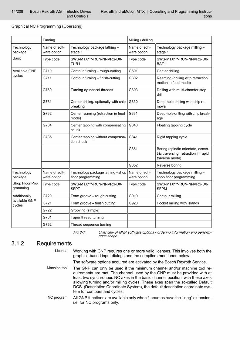
Turning Milling / drilling
Technologypackage
Basic
Name of soft‐ware option
Technology package lathing –stage 1
Name of soft‐ware option
Technology package milling –stage 1
Type code SWS-MTX***-RUN-NNVRS-D0-TUR1
Type code SWS-MTX***-RUN-NNVRS-D0-BAZ1
Available GNPcycles
G710 Contour turning – rough-cutting G801 Center drilling
G711 Contour turning – finish-cutting G802 Reaming (drilling with retractionmotion in feed mode)
G760 Turning cylindrical threads G803 Drilling with multi-chamfer stepdrill
G781 Center drilling, optionally with chipbreaking
G830 Deep-hole drilling with chip re‐moval
G782 Center reaming (retraction in feedmode)
G831 Deep-hole drilling with chip break‐age
G784 Center tapping with compensatingchuck
G840 Floating tapping cycle
G785 Center tapping without compensa‐tion chuck
G841 Rigid tapping cycle
G851 Boring (spindle orientate, eccen‐tric traversing, retraction in rapidtraverse mode)
G852 Reverse boring
Technologypackage
Shop Floor Pro‐gramming
Name of soft‐ware option
Technology package lathing – shopfloor programming
Name of soft‐ware option
Technology package milling –shop floor programming
Type code SWS-MTX***-RUN-NNVRS-D0-SFPT
Type code SWS-MTX***-RUN-NNVRS-D0-SFPM
Additionallyavailable GNPcycles
G720 Form groove – rough cutting G910 Contour milling
G721 Form groove – finish cutting G920 Pocket milling with islands
G722 Grooving (simple)
G761 Taper thread turning
G762 Thread sequence turning
Fig.3-1: Overview of GNP software options - ordering information and perform‐ance scope
3.1.2 Requirements Working with GNP requires one or more valid licenses. This involves both thegraphics-based input dialogs and the compilers mentioned below.The software options acquired are activated by the Bosch Rexroth Service.The GNP can only be used if the minimum channel and/or machine tool re‐quirements are met. The channel used by the GNP must be provided with atleast two synchronous NC axes in the basic channel position, with these axesallowing turning and/or milling cycles. These axes span the so-called DefaultDCS (Description Coordinate System), the default description coordinate sys‐tem for contours and cycles.All GNP functions are available only when filenames have the “.npg” extension,i.e. for NC programs only.
License
Machine tool
NC program
14/209 Bosch Rexroth AG | Electric Drivesand Controls
Rexroth IndraMotion MTX | Operating and Programming Instruc‐tions
Graphical NC Programming (Operating)

Every NC program with GNP cycles is adjusted to comply with the conditionsin a specific channel. To this end, there are a number of GNP options whichare defined with reference to a specific channel (settings/adjustments).Within the scope of the GNP, an NC program without channel identification isautomatically assigned to channel 1. If it is intended to run the program in adifferent channel, a channel identification code must be added to the first Lineprogram line (see Rexroth IndraMotion MTX Programming Manual DOK-MTX***-NC**PRO*V04-AW0x-EN-P, Section “Channel Identification”).Any editing steps in the GNP dialogs and compiling actions are always carriedout for the channel assigned to the NC program according to the rule above,irrespective of the channel currently active on the user interface.The compiler serves to generate a sequence of DIN and CPL blocks from theGNP cycles. An NC program which contains GNP cycles must first be compiledbefore it can be selected for processing on the CNC.To achieve this, the program to be compiled must be selected from the “Pro‐gram” operating area of the Navigator. Press <F8> “NC program functions”and then <F3> “Compiler” . Information on the progress of the compiling proc‐ess is displayed in the status bar.It is also possible to compile the main program implicitly on program selection.To activate the compiler during program selection, press <F3> “NC programfunctions” . If the key <F4> “Compile” does not have a checkmark, please press<F4> once.If the compiler emits error and warning messages, a message will be displayed.Compiling can be interrupted at any time with the Escape key.
Whenever it has been altered, the NC program must be re-com‐piled. If this requirement is neglected and the code is adjusted, theappropriate CNC error message is generated during runtime or onprogram selection.Compiling is carried out automatically only after the “Active NC pro‐gram” function has been altered (correction of the active NC pro‐gram).Re-compiling is also required after GNP options have been alteredand in case of relevant changes to the machine configuration (MA‐CODA).
Operation of the compiler is recursive.
The subprograms with GNP instructions called by the compiledprogram are automatically included in the compilation provided it isa constant subprogram jump, i.e. if the subprogram name is no CPLstring variable.
If relevant configuration data is changed (MACODA), if description coordinatesystems other than the default DCS are used, of if there are special conditionsin the channel, then the appropriate adjustments must be made via the GNPOptions dialog (see chapter 3.2.4 "GNP Options" on page 20).
3.1.3 GNP startupThe GNP is dependent on the respective application only to a very limited de‐gree. Accordingly, setting up the GNP requires only very little work.To operate the GNP, you first need a license for the respective version (ac‐quired software options) of the user system. It is activated by the Bosch RexrothService.
Channel assignment
Compiler
Options°
License
Operating and Programming Instructions | Rexroth IndraMotionMTX
Electric Drivesand Controls
| Bosch Rexroth AG 15/209
Graphical NC Programming (Operating)

For setting up the GNP, option dialogs are available. A large number of thesettings available there can also be made with a programmer's user rights, sothat the adjustment in the framework of startup is largely limited to setting upthe Description Coordinate Systems (DCS).The CDS are the basis for defining geometries and implementing motional se‐quences within the GNP cycles. They are dependent on machine- and user-specific conditions as e.g. axis names, interpolation level etc.; accordingly, theymust be declared during startup.The default DCS is the description coordinate system which corresponds to thestate of the control after channel reset. It is generated automatically on the basisof the current configuration parameters. For this reason, the configuration pa‐rameters should be fully adjusted to the target system before beginning GNPstartup.
The GNP adjustment must be performed separately for each chan‐nel to be simulated.
Open an NC program (extension “.npg”) with the NC editor. Now, enter“$<Channel number>” in the first line and go to the GNP Options (<F7> “Ex‐tras...” --> <F8> “Options...” --> <F4> “Options GNP...” ).In the Options dialog, activate tabpage “DCS ”. Now, add new description co‐ordinate systems or adjust the existing ones. See also"GNP Options",page20.If the GNP cannot be used in several channels, repeat the adjustment by re‐placing the channel number in the first line and then continuing to use the GNPoptions.
3.1.4 Methods of Collecting GNP InstructionsGNP instructions can be collected either by editing single characters in the NCEditor or by means of an input or edit dialog.GNP instructions are collected or corrected according to the syntax requiredand by means of the NC Editor. This type of collection is possible with anycombination of available GNP software options.GNP dialogs are called from the NC Editor. Graphics and dialog elements aredisplayed over the NC Editor. Graphics-based dialogs are available only if atleast one license of the “shop floor programming” version has been acquired.
3.1.5 Grouping of GNP InstructionsGNP instructions are assigned to two main groups:Geometry definitions determine the location of the machining process (con‐tours, form elements, manipulations, point sets). Within the NC program, theygenerally are only of defining character. In other words, these instructions donot alter the NC program and do not trigger any motion of the CNC. They donot have any effect on the program sequence (similar to a comment). The actualmachining sequence will only result in connection with a cycle. Geometry def‐initions can be defined at any point of the NC program, irrespective of thecontext, but they must always be defined before they are used in a cycle orother geometry definitions.The GNP instructions on geometry definitions are once again subdivided asfollows:● Header and end instructions for contour and point set definitions;● contour element instruction (lines, arcs, and transition elements, with the
sequence forming a train of contour elements),
Options°
Setting up the DCS
Collection of single characters
Graphical supported recording viadialogs
Geometry Definitions
16/209 Bosch Rexroth AG | Electric Drivesand Controls
Rexroth IndraMotion MTX | Operating and Programming Instruc‐tions
Graphical NC Programming (Operating)

● form element (schematic contour definition, mostly consisting of severalcontour elements, e.g. rectangular pocket);
● manipulation instructions (turning, moving, mirroring and merging prede‐fined contours and point sets); and
● Point set instruction (drilling positions).GNP cycles are technology subprograms (e.g. call of a rough-cutting cyclealong a contour) used to implement the actual machining process. Most of thecycles refer to an existing geometry definition. The complete sequence of mo‐tions at the NC machine will not be initiated until the cycle is called.
3.2 Fundamental Information on Operation and Layout of the GNPDialogs
3.2.1 Editing ActionsInserting a new GNP instruction
The GNP dialogs can only be called up in the NC editor.
To insert new instructions, place the cursor on that line in the parts programthat follows the position where you wish to add the new instruction. Then clickon <F5> "Insert…". On the new F-key level that will be displayed thereafter,select either <F4> “GNP Contour” or <F5> “GNP Cycle” according to the de‐sired group of instructions.Then the NC Editor switches to the graphic view mode. Enter the new instruc‐tion in the dialog and exit the graphic view by clicking <F9> “Apply” (also “Applycontour”, “Save stock” etc.) or <F8> “Abort dialog”/“Cancel” .After the system has returned to the NC program view, the new content is addedin front of the current line position of the cursor.
Correcting a GNP instructionFor correction , the cursor is pointed at the line to be changed. If contours con‐sisting of a sequence of “contour elements” are concerned, select any line ofthe contour description. Then select the contour element to be corrected fromthe graphics. Use <F8> “GNP Correction” to make the dialog-based correc‐tion . Correct the appropriate instruction in the dialog and exit the graphic viewby clicking <F9> “Apply” or <F8> “Abort dialog”/“Cancel” .After “Apply” has returned the system to the NC program view, the instructionto be corrected is replaced by the content edited.
Deleting a GNP instructionUsually, GNP instructions are deleted in the NC Editor. Please note that ge‐ometry definitions (contours, form elements, …) still having reference to a cycleor a contour manipulation may only be deleted if all instructions having refer‐ence to the contour to be deleted are also deleted. Otherwise, an error will begenerated when you continue work with the GNP dialogs at a later point or whenyou are compiling.The dialog for the geometry definition provides additional delete functions forcontour elements, entire contours and point sets.
3.2.2 Screen StructureThe basic structure of the screen of the GNP dialog is as follows:
GNP cycles
Call-up
Result
Call-up
Result
Operating and Programming Instructions | Rexroth IndraMotionMTX
Electric Drivesand Controls
| Bosch Rexroth AG 17/209
Graphical NC Programming (Operating)

(1) Header(2) Title bar (hidden by default)(3) Menu bar (hidden by default)(4) Graphic window(5) Dialog area(6) Help graphic(7) Entry fields(8) Selection menu(9) Desktop status bar(10) M Keys(11) F-keys(12) OP-keysFig.3-2: Simulation screen structureThe graphic window is that area of the display where the inputs with regard togeometry definitions and machining parameters are visible.Depending on the current conditions, the graphic can contain the elements lis‐ted below. Separate colors are assigned to each element.● Axis scales with axis name● Grid (facilitates reading of coordinates)● Geometry definitions (with separate colors for selected and non-selected
definitions)● Design help lines
Graphic window
Graphic elements
18/209 Bosch Rexroth AG | Electric Drivesand Controls
Rexroth IndraMotion MTX | Operating and Programming Instruc‐tions
Graphical NC Programming (Operating)

● Tool path for active motions (complete line),● Tool path for rapid traverse motions (broken line)● Hatching of the surface that has been end-milled (set of circles with tool
diameter), and● Tool (symbolic).The dialog area provides branches via selection menus and input masks forparameter values, supported by an auxiliary graphic. The branches that startfrom a selection menu either open a new selection menu or an input mask withan auxiliary screen or they open a modal dialog.The status bar provides information on the current cursor coordinates, the cur‐rent edit mode, i.e. insertion or correction, and instructions on operation.The assignment of the F-keys will be described in connection with the operatorsteps for selected examples on pages 28 ff. For general situation-spanningoperating actions like operating the graphics and the options, see the followingsequences ("chapter 3.2.3 "Operating the Graphic" on page 19" and"chapter3.2.4 "GNP Options" on page 20").
3.2.3 Operating the GraphicZooming
Zooming is primarily possible with F-keys. On cycle input, the associated keysare on the first level. On contour input, they are accessible only after <F7>“Zoom/Options” has been clicked ("Menu Zoom - Options").F key <F3> “Zoom Window” is available for contour definition only. This keychanges the cursor type for the definition of an image detail (rectangular cur‐sor). This cursor type is always present on cycle input, except in case of valuesapplied by means of the mouse/cursor position.The function which defines an image detail used for zooming-in can only beexecuted with the mouse. Place the cursor on that corner of the imaginary rec‐tangle which should form the limits the new image detail. While holding the leftmouse button, drag the cursor to the opposite corner of the image detail.Release the mouse button. The magnified image detail will be displayed.<F4> “Zoom +” magnifies the current screen centrically.<F5> “Zoom – ” reduces the current image centrically.<F6> “Zoom out” restores the original non-magnified image. On cycle input, thisis an image detail which displays the entire graphic in full-screen size. On con‐tour input, there are two conditions which can be toggled by repeatedly clickingon <F6>: the full-screen representation of that part of the contour that has beendefined so far and the image detail that encloses the standard window coordi‐nates of the current DCS in full-screen size.
MovingPress the <ALT> and <cursor keys> to move the graphic up, down, to the leftand to the right.The contour definition function also enables the graphic to be moved with themouse. The associated F-keys are accessible on a second F-key level onlyafter <F7> “Zoom/Options” has been clicked (“Menu Zoom - Options ”).Click <F8> "Drag mode on/off" to activate the cursor type required for moving(four arrows arranged in the form of a cross). While holding the left mousebutton, you can now move the graphic as desired.
Dialog area
Status bar
F-keys
F-key level
Defining the image detail <F3>Zoom window
<F4> Zoom +
<F5> Zoom -
<F6> Zoom out
Move with mouse
Operating and Programming Instructions | Rexroth IndraMotionMTX
Electric Drivesand Controls
| Bosch Rexroth AG 19/209
Graphical NC Programming (Operating)
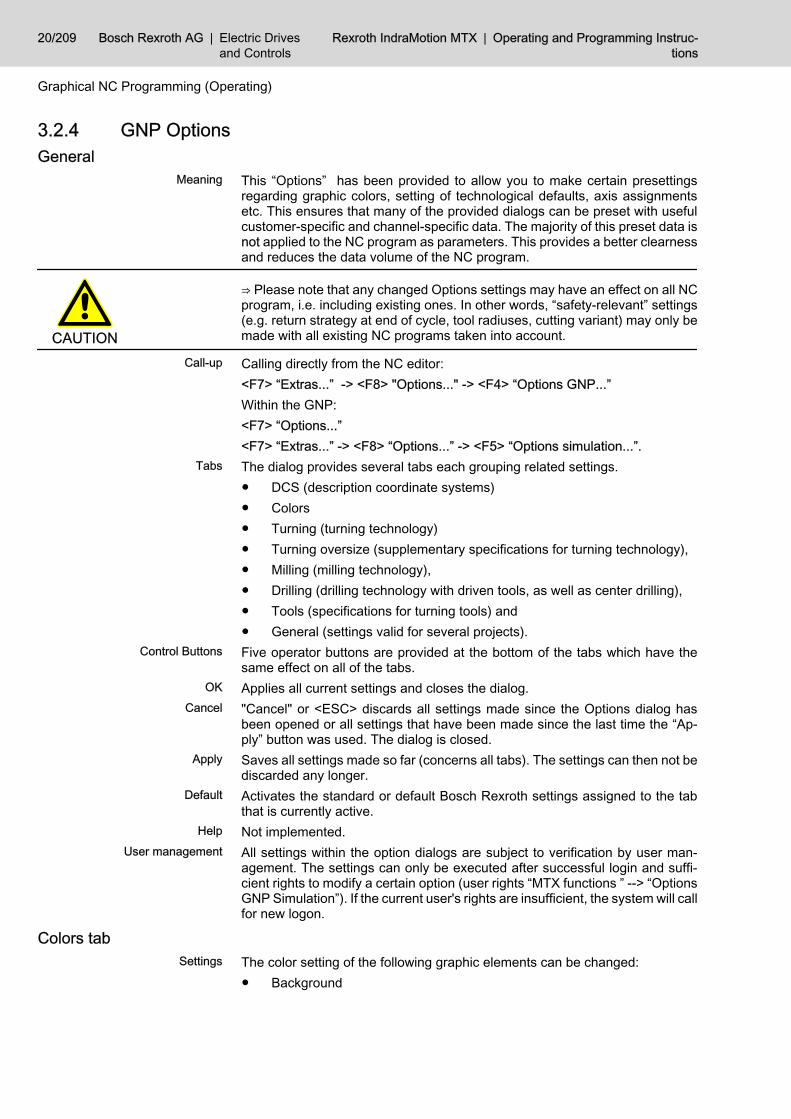
3.2.4 GNP OptionsGeneral
This “Options” has been provided to allow you to make certain presettingsregarding graphic colors, setting of technological defaults, axis assignmentsetc. This ensures that many of the provided dialogs can be preset with usefulcustomer-specific and channel-specific data. The majority of this preset data isnot applied to the NC program as parameters. This provides a better clearnessand reduces the data volume of the NC program.
CAUTION
⇒ Please note that any changed Options settings may have an effect on all NCprogram, i.e. including existing ones. In other words, “safety-relevant” settings(e.g. return strategy at end of cycle, tool radiuses, cutting variant) may only bemade with all existing NC programs taken into account.
Calling directly from the NC editor:<F7> “Extras...” -> <F8> "Options..." -> <F4> “Options GNP...”Within the GNP:<F7> “Options...”<F7> “Extras...” -> <F8> “Options...” -> <F5> “Options simulation...”.The dialog provides several tabs each grouping related settings.● DCS (description coordinate systems)● Colors● Turning (turning technology)● Turning oversize (supplementary specifications for turning technology),● Milling (milling technology),● Drilling (drilling technology with driven tools, as well as center drilling),● Tools (specifications for turning tools) and● General (settings valid for several projects).Five operator buttons are provided at the bottom of the tabs which have thesame effect on all of the tabs.Applies all current settings and closes the dialog."Cancel" or <ESC> discards all settings made since the Options dialog hasbeen opened or all settings that have been made since the last time the “Ap‐ply” button was used. The dialog is closed.Saves all settings made so far (concerns all tabs). The settings can then not bediscarded any longer.Activates the standard or default Bosch Rexroth settings assigned to the tabthat is currently active.Not implemented.All settings within the option dialogs are subject to verification by user man‐agement. The settings can only be executed after successful login and suffi‐cient rights to modify a certain option (user rights “MTX functions ” --> “OptionsGNP Simulation”). If the current user's rights are insufficient, the system will callfor new logon.
Colors tabThe color setting of the following graphic elements can be changed:● Background
Meaning
Call-up
Tabs
Control Buttons
OK
Cancel
Apply
Default
Help
User management
Settings
20/209 Bosch Rexroth AG | Electric Drivesand Controls
Rexroth IndraMotion MTX | Operating and Programming Instruc‐tions
Graphical NC Programming (Operating)

● Scale (coordinate system) ,● Polyline for feed motions (Feed)● Polyline for rapid traverse motions (Rapid traverse)● Tool (edge)● Hatching for surfaces that have been end-milled,● Stock (under preparation),● Design help lines● Active (selected) contour● Inactive (non-selected) contour, and● Active contour element (currently machined).
Fig.3-3: Options – Colors tabClick on the desired color button to open a dialog where you can select a basiccolor, a userdefined color or a new color and activate the color selected with“OK”.The current combination of colors can be assessed by means of the test image.
To modify the colors, the user right “MTX functions” --> “OptionsGNP Simulation” --> “Layout” is sufficient.
The new colors are applied immediately after the dialog is closed. They areeffective across channels and projects only for the GNP graphics.If “Apply for simulation” is checked, the colors defined also apply to the simu‐lation.
DCS tabThe DCS tab allows to define, edit and delete description coordinate systems.
Operation
Applicable settings
Settings
Operating and Programming Instructions | Rexroth IndraMotionMTX
Electric Drivesand Controls
| Bosch Rexroth AG 21/209
Graphical NC Programming (Operating)

By means of the determination of axis names, interpolation level, diameter/radius programming and other characteristics and information, a descriptioncoordinate system defines the basis for the description of geometries and thegeneration of GNP cycles. Each description coordinate system is only applica‐ble to the channel under consideration ("Requirements ", page 14).
Fig.3-4: Description coordinate systems DCSThe “Designation” field provides a list containing all names of the DCS alreadydefined. You can select the DCS with the cursor keys or the mouse. The fieldsand buttons described below will refer to that particular DCS. The “Default/Standard” option shows the name of the default DCS. The default DCS is de‐rived from the configuration parameters and can, therefore, be edited onlywithin certain limits. The default DCS is assigned to those geometries which donot contain any DCS declaration in the geometry head instruction.The “Declaration” field displays the definition of the DCS currently selected.This declaration according to the DIN code is used to identify the DCS, e.g. ifit is mentioned in a contour definition.
Inserting, deleting and modifying the declaration requires at leastthe user right “MTX functions” --> “Options GNP Simulation” -->“Application”. Renaming a DCS and changing the default windowcan also be done by the “Program” right.
Click the “Paste...” button to create a new DCS before the current cursor posi‐tion in the “Designation” list. This opens a dialog where you should enter thedesignation. Initially, the declaration of the default DCS is assigned to the newDCS. Then change the declaration with the “Declaration” function.The “Rename” function permits to change the name of a DCS at any time. Thedesignation should be unique in spite of the fact that it does not have any sig‐nificance beyond the display function.
Operation
Insert...
Rename...
22/209 Bosch Rexroth AG | Electric Drivesand Controls
Rexroth IndraMotion MTX | Operating and Programming Instruc‐tions
Graphical NC Programming (Operating)

Click the “Declaration…” button to change the definition of a DCS. The decla‐ration has a direct effect on the declaration of geometries and comprises thefollowing definitions:● Diameter/radius programming● Interpolation level, i.e. interpolation plane● Two to three axis names (to be entered with reference to the axis func‐
tionality; the axis perpendicular to the interpolation plane may be missing) ,● cylinder coordinate transformation (involute) yes/no and● each one command to clamp and close the workpiece spindle. The latter
are added pairwise and will be called before or after part operationsaround the C axis/spindle (application on lathe).
The declaration of the default DCS must not be changed, with the exceptoin ofthe axis designations. If logic axis designations are available in addition tophysical axis designations, then either can be used.
Fig.3-5: Input DCS declarationIf you click on the “ ....... Selection/Deselection ” button, an additional dialog willbe opened, where you can file NC block sequences of any contents for activa‐tion and deactivation of the DCS. This option is particularly provided for acti‐vating and deactivating axis transformations, as it has been taken into accountin the submission of proposals (key functions). Please take note of the wildcard“%RI%” which stands for the current reference radius. If you do not file theblock sequences for selecting and deselecting the transformation, you will haveto manually program the appropriate sequences yourself before and after thecycle. Use the “Proposal” support function to get a basic framework for thesequences.Use the “View” function to enter the window coordinates which are to take effectin the contour dialog with “Zoom out” in image dimensioning.
Declaration...
Standard window...
Operating and Programming Instructions | Rexroth IndraMotionMTX
Electric Drivesand Controls
| Bosch Rexroth AG 23/209
Graphical NC Programming (Operating)

Clicking the “Delete” button will remove the selected DCS after a safety prompt.The default DCS does not provide this function.
By means of the buttons next to the “Designation” list (identified by and
), the selected DCS can be moved up or down in the sequence. The se‐quence of the DCS in the list affects the selection sequence in the GNP dialogs.The settings are effective across channels and projects. They will take effectwhen the GNP dialogs are opened next, or after the next compilation process.
Turning tabThis tab allows you to set default data for turning cycles. Most of these settingsexist as cycle parameters. The settings you make here will be provided as pre‐settings when you call up the GNP cycle dialog. In the dialog, the values notmodified in contrast to the presettings are omitted as parameter in cycle call.Some of the settings are no cycle parameters, but do still have an effect in thecycles. You can change these settings only on this tab (e.g. tool edge radiuscorrection).
Fig.3-6: Options – Turning tabNumeric values can be modified directly via the keyboard. When you set theinput focus, the figure will be replaced. Other settings must be made in sub‐dialogs which will open after you have clicked on the buttons representing thesettings in question.
Modifying this options requires the user right “MTX functions” -->“Options GNP Simulation” --> “Program”.
The settings are effective across channels and projects. They will take effectwhen the GNP dialogs are opened next, or after the next compilation process.
Delete
Shifting
Applicable settings
Settings
Operation
Applicable settings
24/209 Bosch Rexroth AG | Electric Drivesand Controls
Rexroth IndraMotion MTX | Operating and Programming Instruc‐tions
Graphical NC Programming (Operating)

Turn oversize tabThis tab is assigned to the turning technology. These settings are intended toexclude short contour elements (lines only) from being subjected to an oversize.These contour elements whose length does not exceed the particularly speci‐fied numeric value are always turned to their final size, irrespective of thecontour oversizes that have been programmed. For example, this is often de‐sired in case of undercuts. Enter the values separately for vertical and planesurfaces and for ascending contour sections and undercuts.
Fig.3-7: Options – turning oversize tabUse the keyboard for entries.
Modifying this options requires the user right “MTX functions” -->“Options GNP Simulation” --> “Program”.
The settings are effective across channels and projects. They will take effectwhen the GNP dialogs are opened next, or after the next compilation process.
Drilling tabThis tab allows you to adjust the presettings of the drilling parameters (driventools and center drilling).
Settings
Operation
Applicable settings
Settings
Operating and Programming Instructions | Rexroth IndraMotionMTX
Electric Drivesand Controls
| Bosch Rexroth AG 25/209
Graphical NC Programming (Operating)

Fig.3-8: Options – Drilling tabUse the keyboard for entries: The explanatory images are replaced in thecourse of change of focus.
Modifying this options requires the user right “MTX functions” -->“Options GNP Simulation” --> “Program”.
The settings are effective across channels and projects. They will take effectwhen the GNP dialogs are opened next, or when a new drilling cycle is added.
Milling tabThis tab allows you to set default data for milling cycles. It is a default parameter.This setting can only be made here (no cycle parameter).
Operation
Applicable settings
Settings
26/209 Bosch Rexroth AG | Electric Drivesand Controls
Rexroth IndraMotion MTX | Operating and Programming Instruc‐tions
Graphical NC Programming (Operating)
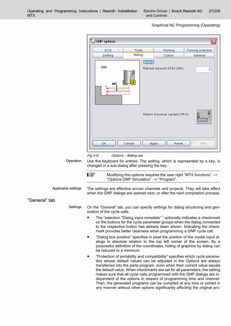
Fig.3-9: Options – Milling tabUse the keyboard for entries: The setting, which is represented by a key, ischanged in a sub-dialog after pressing the key.
Modifying this options requires the user right “MTX functions” -->“Options GNP Simulation” --> “Program”.
The settings are effective across channels and projects. They will take effectwhen the GNP dialogs are opened next, or after the next compilation process.
“General” tabOn the “General” tab, you can specify settings for dialog structuring and gen‐eration of the cycle calls.● The “selection “Dialog input complete” ” optionally indicates a checkmark
on the buttons for the cycle parameter groups when the dialog connectedto the respective button has already been shown. Indicating the check‐mark provides better clearness when programming a GNP cycle call.
● “Dialog box position” specifies in pixel the position of the modal input di‐alogs in absolute relation to the top left corner of the screen. By apurposeful definition of the coordinates, hiding of graphics by dialog canbe reduced to a minimum.
● “Protection of portability and compatibility” specifies which cycle parame‐ters whose default values can be adjusted in the Options are alwaystransferred into the parts program, even when their current value equalsthe default value. When checkmarks are set for all parameters, the settingmakes sure that all cycle calls programmed with the GNP dialogs are in‐dependent of the options in respect of programming time and channel.Then, the generated programs can be compiled at any time or ported inany manner without other options significantly affecting the original pro‐
Operation
Applicable settings
Settings
Operating and Programming Instructions | Rexroth IndraMotionMTX
Electric Drivesand Controls
| Bosch Rexroth AG 27/209
Graphical NC Programming (Operating)

gram run (dimensional accuracy, collisions). (The function is under prep‐aration.)
Fig.3-10: Options – General tabUse the keyboard for entries.
Modifying this options requires the user right “MTX functions” -->“Options GNP Simulation” --> “Program”. The “Application” right isrequested during “Protection of portability and compatibility”.
The settings are valid globally in all projects. They will take effect when the GNPdialogs are opened next.
3.3 Geometry Definitions3.3.1 Inserting a New Contour (Train of Contour Elements)Example contour
Since geometric problems are manifold, examples will be used be‐low to illustrate the operator steps required for defining the toolgeometry.
Operation
Applicable settings
28/209 Bosch Rexroth AG | Electric Drivesand Controls
Rexroth IndraMotion MTX | Operating and Programming Instruc‐tions
Graphical NC Programming (Operating)

Fig.3-11: Example contour of a turned part
Calling the contour definition and assigning it to a description coordinate system (DCS)To insert a new contour definition , position the cursor on that line in the NCProgram Editor that follows the position where you wish to insert the new con‐tour, e.g.:Program:
G0 G18 X200 Z200 T1 M6 G96 S1=270 M104 ; <-cursor position
Click <F5> “Insert…” and, thereafter, on the new F-key level that opens, clickon <F4> “GNP contour...” .If the GNP configuration provides several description coordinate systems(DCS), you can change into the further available DCS by clicking on the F-key<F4> “Next DCS” . For example, this is necessary for turning machines withdriven tools, where either a turning contour definition or a milling contour defi‐nition (end face/jacket face) can be selected. This is visually indicated by theaxis names next to the coordinate system and the DCS name that is shown tothe upper right. At the same time, all geometry elements (contours/form ele‐ments/point sets) that have been programmed previously and that are assignedto the particular description coordinate system indicated are displayed.For the example, select a DCS with the axis names Z and X; specify X in itsdiameter (diameter symbol at the vertical axis).Using the cursor keys, select the contour definition desired, i.e. train of contourelements (1), manipulation (turning/mirroring/moving) (2) and a form element(3), as well as the definition of point sets (4) and their manipulation (5); confirmby pressing the <enter> key or clicking the left mouse button. With active defaultDCS, an additional button each is provided for milling stocks (6) and turningstocks (7). To define a train of contour elements, select the “Contour” (1) sym‐bol.
Call-up
Description coordinate system
Selecting the type of geometry def‐inition
Operating and Programming Instructions | Rexroth IndraMotionMTX
Electric Drivesand Controls
| Bosch Rexroth AG 29/209
Graphical NC Programming (Operating)

Fig.3-12: Selecting the type of geometry definition: Train of contour elementsIf the description coordinate system is an involute, then the dialog prompts youto enter the reference radius RI first. If not - as in this example -, the query isomitted.
Starting point
Fig.3-13: Starting point input maskThen follows the input mask for specification of the starting point. Enter thecoordinates of the starting point of the contour in either axis direction of theplane of the description coordinate system. In the example, these are Z = 0 andX = 40. You can also enter arithmetic expressions (+; -; /; *; (; ); and the constantPI) in the input field. Complete the entry of a value with <ENTER>, <TAB>, or<Shift>+<TAB>. Once you completed the entry of both coordinates, the startingpoint is displayed in the form of a cross (+) for visual verification purposes. Youcan still edit the input fields as you desire.The following F-keys are available in the "input menu":Using the <F2> key, you can show or hide the code developing for the NCprogram for learning or verification purposes.
Fig.3-14: Display of the code of the contour definition<F7> “Zoom/Options....” branches to a second F-key level for zooming, movingand GNP options.
Involute radius
Input of determinants
<F2> “Code on/off”
<F7> “Zoom/Options...”
30/209 Bosch Rexroth AG | Electric Drivesand Controls
Rexroth IndraMotion MTX | Operating and Programming Instruc‐tions
Graphical NC Programming (Operating)

Using <F8> “Cancel Contour”, you can cancel the contour definition without thecontour being inserted in the NC program. A safety prompt will be displayedbefore you exit the GNP.Click <F9> “Apply Element” to confirm the contour element defined. The colorof the contour element changes to the color of the contour definition. You cannow continue by defining a following element.You can use the <F9> “Apply Element ” key only if you have entered the datafully and with the proper syntax.<F9> applies the starting point.Then the F-key level moves to the “Menu following element”. The last contourentered will remain visible for information purposes until you have selected thenext element or a correction is necessary. This F-key level provides the follow‐ing additional functions:Click <F3> “Correction” to enter the correction mode. The correction mode pro‐vides the possibility of correcting any element of the contour or of subsequentlyinserting and/or deleting transitional elements (chamfers, roundings, under‐cuts).Correction mode can be recognized with the abbreviation “CORR” in the statusbar instead of “INS” in the insert mode.Click <F4> “Append Straight Line...” to define addition of a straight line (line)after the last contour element.Click <F5> “Append Circle...” to define addition of a circle (circular arc) after thelast contour element.Click <F6> “Append Transition...” to define transitional elements (chamfers,rounding radiuses, undercuts). This function is not available immediately afterthe starting point; therefore, it is disabled.Since the next element in the example is a straight line (line), click <F4> “Ap‐pend Straight Line...” to move to the function of defining straight lines.
Following element straight line 1 After you have called the straight line definition function, the next F-key level“Menu course of straight line” is opened. This menu provides the following F-keys:<F3> “LIN (inclined)” defines that the straight line may extend in any directiondesired.<F4> “LIN TG (inclined)” defines that the straight line follows at the end of thepreceding element in tangential direction. The preceding elements must not bea transitional element. This function is disabled since a tangential direction isnot or cannot be determined immediately after the starting point.<F5> “LIN (axially parallel vertical)” defines that the straight line extends in par‐allel to the vertical axis.<F6> “LIN (axially parallel horizontal)” defines that the straight line extends inparallel to the horizontal axis.In the example, the straight line extends at an angle of 125 degrees up to adiameter of 60. This requires that the function <F3> “LIN (inclined)” be called.Enter X = 60 and AA = 125 in the input mask for the straight line definitionselected. Whenever you have entered a value, implicitly defined determinantsare calculated; the corresponding values are displayed in the input fields thecolor of which has now changed to gray. This prevents too many inputs and,thus, excessive geometric determinants. In the example, Z and L are calculatedautomatically. After you have entered the values, help lines will be displayed,
<F8> “Cancel contour”
“Apply Element” <F9>
<F3> “Correction”
<F4> “Append straight line...”
<F5> “Append Circle....”
<F6> “Append Transition...”
Selecting the following element
Selecting the course of the straightline
<F3> “LIN (inclined)”
<F4> “LIN TG (inclined)”
<F5> “LIN (axially parallel vertical)”
<F6> “LIN (axially parallel horizon‐tal)”
Input of determinants
Operating and Programming Instructions | Rexroth IndraMotionMTX
Electric Drivesand Controls
| Bosch Rexroth AG 31/209
Graphical NC Programming (Operating)

depending on the geometric determination that has been achieved. When a linehas been completely defined, the graphic indicates the final shape.
Fig.3-15: Input mask for first straight lineThe following F-keys are provided during input of the determinants (“inputmenu”):If a definition allows several solutions, click <F3 “Another Solution” to selectone of one of these solutions. In the present example, the solution is unique sothat the function remains disabled.Click <F8> “Delete element” to delete the current element, i.e. the straight linein the example. Then the F-key level moves to the “Menu following element”.Click <F9> “Apply Element” to apply the straight line and to return to the “Menufollowing element”. The color of the contour element changes to that of thecontour definition.After input of all known data, click <F9> “Apply Element ” to complete input ofthe line definition. The graphic shows the shape of the contour up to the straightline. The F-keys are now on the “Menu following element” level. This menucontains an additional function for appending following elements.If you wish to complete the contour you have defined at this point, you can addit to the NC program by using the new function <F9> “Apply Contour”. This Fkey once more brings you to the “Selecting the type of geometry definition”where you can define further geometries. Click <F8> “Abort Dialog” to quit theGNP.
Rounding R5The next element to be programmed is a rounding radius. This means that youhave to click on the F key <F6> “Append Transition...” in the menu “Selectingthe following element”.Transitional elements (roundings, chamfers, undercuts) describe a specialshape of the connection between two contour elements.There are four different types of transitional elements that can be selected.These are available via the following F-keys in the “Menu transition ele‐ments”:<F3> “RND” inserts a rounding radius .<F4> “CHF” inserts a symmetrical chamfer .<F5> “RF1 E/F” inserts an undercut according to DIN 509 .<F6> “RF2” inserts a thread undercut according to DIN 76509 .In the example, a 5-mm rounding radius has to be programmed via <F3>“RND” .
<F3> “Another solution”
<F8> “Delete element”
“Apply Element” <F9>
<F9> “Apply Contour”
Selecting a transitional element
<F3> “RND”
<F4> “CHF”
<F5> “RF1 E/F”
<F6> “RF2”
32/209 Bosch Rexroth AG | Electric Drivesand Controls
Rexroth IndraMotion MTX | Operating and Programming Instruc‐tions
Graphical NC Programming (Operating)

Fig.3-16: Input mask for rounding radiusUse <F9> “Apply Element” to complete input of the rounding radius. Since thefollowing element is not defined yet, the graphic remains unchanged. The F-key level moves to the “Menu following element”.
Following element: straight line 2In the example program, the following element is a straight line extending inparallel to the horizontal axis Z (cylinder). The end point is not known, since thestraight line ends in a circle in tangential direction. The circle with the radius of12 mm, in turn, ends at the diameter 80 and the length Z = 85.Click <F4> “Append Straight Line...” to define the type of following element andthen <F6> “LIN (horizontal)” to define the axially parallel direction.
Fig.3-17: Input mask for the second straight line (without values)Since additional data is not known, values do not have to be entered here. Thedirection can be turned by 180 degrees by clicking <F3> “Another Solution” .Since the initial direction is the usual one for turning contours, click <F9> “ApplyElement” to complete your input of the straight line.
Following element circleClick <F5> “Append Circle” on the “Menu following element” F-key level toselect a circle.After you have called the circle definition function, the next F-key level “Menushape of the circle” is opened. This menu provides the following F-keys:Click <F3> “CW” to define an arc that follows the previously defined contourelement in clockwise direction and with any transitional angle.Click <F4> “CW TG” to define an arc that follows the previously defined contourelement in clockwise direction and with tangential transition.Click <F5> “CCW” to define an arc that follows the previously defined contourelement in counterclockwise direction and with any transitional angle.
Input of determinants
Selecting the following element
Input of determinants
Selecting the following element
Selecting the shape of the circle
<F3> “CW”
<F4> “CW TG”
<F5> “CCW”
Operating and Programming Instructions | Rexroth IndraMotionMTX
Electric Drivesand Controls
| Bosch Rexroth AG 33/209
Graphical NC Programming (Operating)

Click <F6> “CCW TG” to define an arc that follows the previously defined con‐tour element in counterclockwise direction and with tangential transition.<F7> “CW TR” defines an arc in clockwise direction with tangentially oppositedirection of transition from the previously defined contour element (reverse tan‐gent).<F8> “CW TR” defines an arc in counterclockwise direction with tangentiallyopposite direction of transition from the previously defined contour element (re‐verse tangent).In the example, proceed with <F4> “CW TG” .
Fig.3-18: Input mask for circular arcsEnter Z = 85, X = 80, and R = 12 for the radius. The graphic shows the desiredcircular arc. If you wish to select a different solution, click <F3> “Another Sol‐ution” . This is not necessary in the example, since the solution first shown isthe proper one. Click <F9> “Apply Element” to apply the circle.
Following element: straight line 3Click <F4> “Append Straight Line...” and <F6> “LIN (horizontal)” to define thenext straight line and the last straight line respectively that are running in parallelto the axis.
Fig.3-19: Input mask for the third straight lineIt ends at U = –100. Click <F9> “Apply Element” to apply the straight line. Thegraphic shows the complete contour.
<F6> “CCW TG”
<F7> “CW TR”
<F8> “CCW TR”
Input of determinants
Selecting the following element
Input of determinants
34/209 Bosch Rexroth AG | Electric Drivesand Controls
Rexroth IndraMotion MTX | Operating and Programming Instruc‐tions
Graphical NC Programming (Operating)

Contour definition result
Fig.3-20: Completed train of contour elementsAt this point, the contour has the following contents:Program:
CONT (ID1) SPT (Z0, X40) LIN (X60, AA125) RND (RD5) LIN (AA180) CW (TG, Z-85, X80, R12) LIN (Z-100, AA180) END_CONT
Click <F2> “Code On” to display and, if you wish so, click <F9> “Apply Con‐tour” to save the contour code. The NC program becomes visible later after youclick <F8> “Abort Dialog”.
Correcting contour elementsThe contour creation function provides the possibility of correcting contour el‐ementsthat have already been defined. The correction, however, refers only tothe existing “design rule”. That means that, if a circle comprising radius and X-end point has been defined, only these values can be changed. If not, theelements including the incorrect element must be deleted element by element.
Restrictions
Operating and Programming Instructions | Rexroth IndraMotionMTX
Electric Drivesand Controls
| Bosch Rexroth AG 35/209
Graphical NC Programming (Operating)
In contrast to that, transitional elements (chamfers, roundings, undercuts) cannot only be corrected, but also added between two elements or deleted.Start correction by clicking on <F3> “Correction...” in the “Menu following ele‐ment”. The dialog moves from the insertion to the correction mode. This is alsoindicated in the status bar (“CORR”).The next F-key level, “Correction Menu”, provides the following functions.Click <F3> “Delete Element” to remove the contour element currently selected.This function is available for the last contour element and for all transitionalelements.Click <F4> “Next Element” to navigate towards the end of the contour and tothe following contour element. This is then displayed in a selection color, andall of its determinants are displayed or provided for editing.Click <F5> “Previous Element” to select the following contour element that ispositioned towards the starting point of the contour for correction.
If you have a mouse available, you can optionally select the contourelement to be corrected by double-clicking it directly.
Click <F6> “Inserting a transition...” to add a transitional element (rounding,chamfer, undercut) after the contour element selected. This function is notavailable if a transitional element has already been defined at this point.Click <F8> “Delete Contour” to delete the entire contour after confirmation of asafety prompt and return to the NC Program Editor.Example:
Example 1:
The angle of the first straight line in the example program is to be changed from125 degrees to 125.1 degrees.Click <F5> “Previous Element” until you have selected the straight line to beedited and the associated input values are displayed.Then change the value AA125 to 125.1 and confirm with <ENTER>. Then youcan make other corrections.
Example:
Example 2:
A 1-mm rounding radius is to be inserted between the circle and the followingstraight line in the example program.Click <F5> “Previous Element” until you have selected the circle with radius12. Then, click <F6> “Inserting a transition...” and <F3> “RND” . Enter 1 in the“RD” input field and confirm with <ENTER>. Then confirm the contour elementyou have added by clicking <F9> “Apply Element”.
Applying the contour to the NC programAs the contour is now defined with all changes made, it is saved to the NCprogram with <F9> “Apply Contour” . Then, click <F8> “Abort Dialog” to quit theGNP.Program:
G0 G18 X200 Z200 T1 M6 CONT ( ID1) SPT (Z0, X40)
Switching to the correction mode
Selecting the correction mode
<F3> “Delete element”
<F4> “Append straight line”
<F5> “Previous element”
<F6> “Inserting a transition...”
<F8> “Delete contour”
Contour end
Result
36/209 Bosch Rexroth AG | Electric Drivesand Controls
Rexroth IndraMotion MTX | Operating and Programming Instruc‐tions
Graphical NC Programming (Operating)
LIN (X60, AA125.1) ; correction example 1 RND (RD5) LIN (AA180) CW (TG, Z-85, X80, R12) RND (RD1) ; correction example 2 LIN (Z-100, AA180) END_CONT G96 S1=270 M104
3.3.2 Changing/Extending a Contour (Train of Contour Elements or ContourDefinition)
To correct a contour definition (train of contour elements) , position the cursorof the Editor either on the element to be corrected or to any place within thecontour.Program:
GG0 G18 X200 Z200 T1 M6 CONT ( ID1) SPT (Z0, X40) LIN (X60, AA125.1) ; correction example 1 RND (RD5) LIN (AA180) CW (TG, Z-85, X80, R12) <- cursor position! RND (RD1) ; correction example 2 LIN (Z-100, AA180) END_CONT G96 S1=270 M104
Start the dialog-based correction process by clicking on “<F8> GNP Correc‐tion...” . This displays the contour graphically and provides the contour elementfor correction, on which the cursor is positioned.
Call-up
Operating and Programming Instructions | Rexroth IndraMotionMTX
Electric Drivesand Controls
| Bosch Rexroth AG 37/209
Graphical NC Programming (Operating)

Fig.3-21: Correcting a contourFrom that point, the contour is corrected analogously to the correction of a newcontour ("Correcting contour elements", p. 35).Of course, you can also make your changes in the NC Editor provided you arefamiliar with its syntax.
3.3.3 Inserting A Contour Consisting of a Form ElementForm element example
Create a hexagon on the end face (turning machine), that is D = 6 in diameterand the center point of which is at X = 0 and Y = 15.
Fig.3-22: Example of a hexagon form element
38/209 Bosch Rexroth AG | Electric Drivesand Controls
Rexroth IndraMotion MTX | Operating and Programming Instruc‐tions
Graphical NC Programming (Operating)

Calling the contour definition and assigning it to a description coordinate system (DCS)To insert a new contour , place the cursor on the position in the parts programover which you wish to insert the new contour. In this process, there is no dif‐ference between the train of contour elements and the form element.Example:
Inserting a New ContourG0 G18 X200 Z200T1 M6CONT ( ID1)SPT (Z0, X40)LIN (X60, AA125.1) ; correction example 1LIN (AA180)CW (TG, Z-85, X80, R12)RND (RD1) ; correction example 2LIN (Z-100, AA180)END_CONTG96 S1=270 M104 <- cursor position
Click <F5> “Insert…” and, thereafter, on the new F-key level that opens, clickon <F4> “GNP contour...” .Click <F4> “Next DCS” to move to the description coordinate system for theend face. This is visually indicated by the axis addresses X and Y.
Defining the form element
Fig.3-23: Selecting the type of geometry definition: form element -> polygonUsing the cursor keys, you can either select contour (contour definition), ormanipulation (turning/mirroring/moving), or form element (selected in the ex‐ample). Confirm your selection pressing the <ENTER> key or clicking themouse. You can select from various form elements: full circle, rectangular cor‐
Call-up
Description coordinate system
Selecting the type of geometry def‐inition
Operating and Programming Instructions | Rexroth IndraMotionMTX
Electric Drivesand Controls
| Bosch Rexroth AG 39/209
Graphical NC Programming (Operating)

ner dimension, rectangular center dimension, round groove, straight groove,polygon (selected).Confirm again with (<ENTER> / mouse button) to branch into the input maskfor the polygon definition .Enter the values of the center point, i.e. X = 0 and X = 15, the diameter D = 6,and the number of corner point NR = 6. The polygon is displayed on the screenfor visual verification purposes. You can still edit the input fields as you desire.
Fig.3-24: Input mask for polygonIf the contour is to consist of several form elements, continue with clicking >F5>“Append Form Element...” . Now, once more select the type of geometry defi‐nition, and then input the determinants.Stringing together several form elements usually creates an interrupted con‐tour. Its partial contours (here: the form elements) are assigned to one identonly.
Applying the contour to the NC programAfter collection of form element is complete, terminate the input by clicking <F9>“Apply Contour” . If you do not wish to make any other definitions, quit the GNPwith <F8> “Abort Dialog”.The result of the definition is transferred to the NC program.Program:
G0 G18 X200 Z200 T1 M6 CONT ( ID1) SPT (Z0, X40) LIN (X60, AA125.1) ; correction example 1 LIN (AA180) CW (TG, Z-85, X80, R12) RND (RD1) ; correction example 2 LIN (Z-100, AA180) END_CONT CONT ( ID2, RAD G17(X,Y,Z)) PLG (X0, Y15, D6, NR6) END_CONT G96 S1=270 M104
Input of determinants
Appending further form elements
Result
40/209 Bosch Rexroth AG | Electric Drivesand Controls
Rexroth IndraMotion MTX | Operating and Programming Instruc‐tions
Graphical NC Programming (Operating)
3.3.4 Changing/Extending a Contour Consisting of Form ElementsChanging a form element
To correct a form element , position the cursor of the editor on the element tobe corrected, e.g. PLG (X0, Y15, D6, NR6),; then, click <F8> “GNP correc‐tion” .This will display the hexagon graphically. You can now make your changes onthe input mask and complete the correction with <F9> “Apply Contour” .For contours comprising several form elements, you can optionally place thecursor on any form element within the contour declaration and click <F4> “NextElement” or <F5> “Previous Element” for graphical selection of the form ele‐ment to be corrected.
If a mouse is available, you can also select the form element to becorrected by double-clicking directly on the element.
Adding and inserting further form elementsYou can only add form elements to contours which do not consist of a train ofcontour elements.To insert a form element from the NC editor, place the cursor on the line in thecontour description which follows the position where you wish to insert the newform element. To add a form element, position the cursor on the END_CONTinstruction. Click <F5> “Insert…” and, thereafter, on the new F-key level thatopens, click on <F4> “GNP Contour...” . The GNP dialog is opened in insertmode.Alternatively, you can insert a form element through <F8> “GNP Correc‐tion...” . The GNP dialog opens in correction mode. Click <F4> “Next Ele‐ment” or <F5> “Previous Element” to change the insert position. Whenselecting the insert position, ensure that the new form element is inserted afterthe marked form element. Once you have found the insert position, click <F9>“Complete Correction” to switch to insert mode, and introduce the definition byclicking <F5> “Append Form Element...” .This will open the menu for selecting the type of the definition to be inserted.Since a train of contour elements is not permitted here, this function is disabled.Since you wish to insert a form element, activate the “form element” function.From the following menu, select, e.g., the form element “Straight groove”.Enter the determinants of the form element to be inserted analogously to theinsertion of a new contour with a form element ("Defining the form element", p.39).
3.3.5 Inserting a Point SetPoint set - example
The point set consists of a “partial circle” point pattern with the center X20, Y60,the radius 40, with an angular pitch of 45 degrees, starting with a starting angleof 45 degrees. It comprises a total of 6 drilling positions.
Call-up
Call-up
Selecting the type of geometry def‐inition
Input of determinants
Operating and Programming Instructions | Rexroth IndraMotionMTX
Electric Drivesand Controls
| Bosch Rexroth AG 41/209
Graphical NC Programming (Operating)

Fig.3-25: Example for drilling positions on partial circle, radius 40
Calling the contour definition and assigning it to a description coordinate system (DCS)To insert a new point pattern , place the cursor on the position in the partsprogram over which you wish to insert the new contour.Example:
Inserting a New Point PatternT2 M6G97 S2=2700 M203G0 G17 X20 Y0 Z10 <- cursor position
Click <F5> “Insert…” and, thereafter, on the new F-key level that opens, clickon <F4> “GNP contour...” .If the GNP configuration provides several description coordinate systems(DCS), you can change into the available DCS by clicking on the F-key <F4>“Next DCS” . For example, this is necessary for turning machines with driventools, where either a turning contour definition or a milling contour definition(end face/jacket face) can be selected. This is visually indicated by the axisnames next to the coordinate system and the DCS name that is shown to theupper right. At the same time, all geometry elements (contours/form elements/point pattern) that have been programmed previously and that are assigned tothe particular description coordinate system indicated are displayed.For the example, a DCS with the axis names X and Y has been selected.
Call-up
Description coordinate system
42/209 Bosch Rexroth AG | Electric Drivesand Controls
Rexroth IndraMotion MTX | Operating and Programming Instruc‐tions
Graphical NC Programming (Operating)

Defining a point pattern
Fig.3-26: Selecting the type of geometry definition: Point pattern -> partial circleUsing the cursor keys, you can either select contour (contour definition), ormanipulation (turning/mirroring/moving) of contours, form element, point pat‐ters (selected in the example) and manipulation of point patterns. Confirm yourselection pressing the <ENTER> key or clicking the mouse. Then, select drillingpositions, partial circle (selected in the example), matrix, frame and line withinthe point patterns.Confirm again with (<ENTER> / mouse button) to branch to the input mask forthe partial circle definition .Here, the values of the center coordinates X=20 and Y=60, of the radius R=40,the starting angle SA=45 and the angular pitch A=45 must be entered. The endangle EA is omitted. Finally, the number of positions is entered as NR=6. Thepartial circle is displayed on the screen for visual verification purposes. You canstill edit the input fields as you desire.
Fig.3-27: Input mask partial circle
Applying the point pattern to the NC programIf the data is o.k., click <F9> “Apply Element” and then <F9> "Apply Point Set"to complete input of the point pattern, as no other point patterns are to be addedto this point set.The result of the definition is transferred to the NC program.T2 M6G97 S2=2700 M203PATT (ID1, RAD G17 (X,Y,Z))
Selecting the type of geometry def‐inition
Input of determinants
Result
Operating and Programming Instructions | Rexroth IndraMotionMTX
Electric Drivesand Controls
| Bosch Rexroth AG 43/209
Graphical NC Programming (Operating)

PCI (X20, Y60, R40, SA45, NR6, A45)END_PATTG0 G17 X20 Y0 Z10
3.3.6 Changing a Point Pattern or Expanding the Point SetChanging a point pattern
To correct a point pattern , position the cursor of the editor on the element tobe corrected, e.g. PCI (X20, Y60, R40, SA45, NR6, A45); then, click <F8>“GNP Correction...” .This will display the partial circle graphically. You can now make your changeson the input mask and complete the correction with <F9> “Complete Correc‐tion” and “Apply Contour” .For point sets comprising several point patterns, you can optionally place thecursor on any point pattern within the point set declaration and click <F4> “NextElement” or <F5> “Previous Element” for graphical selection of the point setto be corrected.
If a mouse is available, you can also select the point set to be cor‐rected by double-clicking directly on a point within the respectiveset.
Insertion of more point patternsPoint sets may comprise several paint patterns. For example, to the existingpoint set “PATT (ID1, RAD G17 (X,Y,Z))” , a matrix is to be inserted after thepartial circle “PCI (X20, Y60, R40, SA45, NR6, A45)” .To insert the matrix , position the cursor of the editor on the line after the partialcircle - in this example, the instruction “END_PATT” (if the matrix were to beinserted in front of the partial circle “PCI (X20, Y60, R40, SA45, NR6, A45)” ,the cursor would have to be positioned directly on this instruction).Program:
T2 M6 G97 S1=2700 M103 PATT (ID1, RAD G17 (X,Y,Z)) PCI (X20, Y60, R40, SA45, NR6, A45) END_PATT <- cursor position G0 G17 X20 Y0 Z10
Click <F5> “Insert…” and, thereafter, on the new F-key level that opens, clickon <F4> “GNP Contour...” .Alternatively, you can insert a point pattern through <F8> “GNPCorrection...” . The GNP dialog opens in correction mode. Click <F4> “NextElement” or <F5> “Previous Element” to change the insert position if there areseveral point patterns. When selecting the insert position, ensure that the newpoint pattern is inserted after the marked point pattern. Once you have foundthe insert position, click <F9> “Complete Correction” to switch to insert mode,and introduce the definition by clicking <F5> “Append Point Set...” .This will open the menu for selecting the type of the definition to be inserted.Using the cursor keys, you can either select drilling positions (selected in theexample) or manipulation (turning/mirroring/moving). In the following menu,the “Matrix” point pattern is selected.Enter the determinants of the manipulation instruction to be inserted analo‐gously to the insertion of a new manipulation.
Call-up
Call-up
Selecting the type of geometry def‐inition
Input of determinants
44/209 Bosch Rexroth AG | Electric Drivesand Controls
Rexroth IndraMotion MTX | Operating and Programming Instruc‐tions
Graphical NC Programming (Operating)

Enter the determinants of the point pattern to be inserted analogously to theinsertion of a new point pattern.The result of the definition is transferred to the NC program. This means thatthe point set “ID1” now consists of a partial circle and a matrix.Program:
G97 S1=2700 M103 PATT (ID1, RAD G17 (X,Y,Z)) PCI (X20, Y60, R40, SA45, NR6, A45) PMA (X0, Y0, DS10, NS4, DL12, NL4, A0) END_PATT G0 G17 X20 Y0 Z10
3.3.7 Inserting a Geometry That is Based on an Existing Geometry and isCreated by Mirroring, Turning or Moving (Manipulation Instruction)
Example of a turned contourThe already defined hexagon form element on the end face is to be turnedseven times at an angle of 45 degrees. The new geometry is to include thebasic element (original hexagon).
Fig.3-28: Example: hexagon that has been turned seven times
Calling the contour definition and assigning it to a description coordinate system (DCS)The instructions of mirroring, turning, moving and merging contours or pointsets are called manipulation instructions.To insert a manipulation instruction , place the cursor on that line in the partsprogram that follows the position where you wish to add the new instruction.Program:
G0 G18 X200 Z200 T1 M6 CONT ( ID1) SPT (Z0, X40) LIN (X60, AA125.1) ; correction example 1 RND (RD5) LIN (AA180) CW (TG, Z-85, X80, R12) RND (RD1) ; correction example 2 LIN (Z-100, AA180) END_CONT CONT ( ID2, RAD G17(X,Y,Z)) PLG (X0, Y15, D6, NR6) END_CONT G96 S1=270 M104; <- cursor position
Click <F5> “Insert…” and, thereafter, on the new F-key level that opens, click<F4> to select “GNP Contour....” .Click <F4> “Next DCS” to move to the description coordinate system for theend face. All geometric elements that have already been defined are displayedgraphically within this description system (hexagon in the example).
Input of determinants
Result
Call-up
Description coordinate system
Operating and Programming Instructions | Rexroth IndraMotionMTX
Electric Drivesand Controls
| Bosch Rexroth AG 45/209
Graphical NC Programming (Operating)

Defining the manipulation
Fig.3-29: Selecting the type of geometry definition: manipulationOn the following F-key level, select the basic contour to be manipulated (shownflashing). To achieve this, the following functions are available:Click <F3> “Next Element” to move to the next geometry in the order of defini‐tions and change its color to that indicating an active geometry definition.Click <F4> “Previous Element” to move to the previous geometry in the orderof definitions and change its color to that indicating an active geometry defini‐tion.
When a mouse is available, you can optionally select the startinggeometry by double-clicking the respective graphic.
Click <F8> “Cancel Contour” to exit the GNP and return to the NC ProgramEditor without having inserted a geometry.Click <F9> “Apply Contour” to confirm the active contour/point set as basis ofthe manipulation and move to the selection list of manipulation instructions.In the example, select the hexagon contour and confirm with <F9> “Apply Con‐tour” .
Selecting the type of geometry def‐inition
Selecting the basic geometry
<F3> “Next element”
<F4> “Previous element”
<F8> “Cancel contour”
<F9> “Apply Contour”
46/209 Bosch Rexroth AG | Electric Drivesand Controls
Rexroth IndraMotion MTX | Operating and Programming Instruc‐tions
Graphical NC Programming (Operating)

Fig.3-30: Selection menu for turning (rotating) a preselected geometryUsing the cursor keys, select the “turning” manipulation (selected) from thefollowing menu and confirm with <ENTER>. You can also select the manipu‐lation clicking the left mouse button.
Fig.3-31: Input mask for turning (rotating)In the input mask that follows, enter the values of the rotational center point X= 0 and Y = 0, the rotational angle Y = 45, and the number of repetitions NR =7. You can still edit the input fields as you desire.Click the function key <F3> “Another Solution” to define whether the basiccontour is also included in the new contour. This is displayed on the screen forvisual verification purposes. In the example, the basic contour is to form anintegral part of the new contour. In this case, the basic contour and the contourstransformed have the same color.
Applying the contour to the NC programClick <F9> “Apply Contour” to complete the definition and to transfer it into theNC program. Click <F8> “Abort Dialog” to quit the GNP. Then, the followingcode becomes visible.
Selecting the manipulation instruc‐tion
Input of determinants
<F2> “Another solution”
Operating and Programming Instructions | Rexroth IndraMotionMTX
Electric Drivesand Controls
| Bosch Rexroth AG 47/209
Graphical NC Programming (Operating)

Program:
G0 G18 X200 Z200 T1 M6 CONT ( ID1) SPT (Z0, X40) LIN (X60, AA125.1) ; correction example 1 RND (RD5) LIN (AA180) CW (TG, Z-85, X80, R12) RND (RD1) ; correction example 2 LIN (Z-100, AA180) END_CONT CONT ( ID2, RAD G17(X,Y,Z)) PLG (X0, Y15, D6, NR6) END_CONT CONT ( ID4, RAD G17(X,Y,Z)) RTE (ID2, X0, Y0, A45, MD2, NR7) END_CONT G96 S1=270 M104
3.3.8 Changing/Extending a Contour Consisting of ManipulationsChanging a manipulation instruction
To correct a manipulation , position the cursor of the editor on the element tobe corrected, e.g. “RTE (ID2, X0, Y0, A45, MD2, NR7)” ; then, click <F8> “GNPcorrection...” key.This will display the manipulation graphically. You can now make your changeson the input mask and complete the correction with <F9> “Apply Contour” .
Inserting further manipulation instructionsYou can only add manipulation instructions to geometry definitions which donot consist of a train of contour elements.To insert a manipulation instruction from the NC editor, place the cursor on theline in the contour description which follows the position where you wish to insertthe manipulation. To add a manipulation instruction, position the cursor on theEND_CONT instruction. Click <F5> “Insert…” and, thereafter, on the new F-key level that opens, click on <F4> “GNP Contour...” .This will open the menu for selecting the type of the definition to be inserted.Since a train of contour elements is not permitted here, this function is disabled.Since you wish to insert a manipulation instruction, activate the "manipulation"function. From the following menus, select the basic geometry and the manip‐ulation instruction.Enter the determinants of the manipulation instruction to be inserted analo‐gously to the insertion of a new manipulation.Inserting a Geometry That is Based on an Existing Geometry and is Createdby Mirroring, Turning or Moving, see chapter 3.3.7 "Inserting a Geometry Thatis Based on an Existing Geometry and is Created by Mirroring, Turning or Mov‐ing (Manipulation Instruction)" on page 45
3.3.9 Inserting/changing a stock description as a bar section (turning)Stock definition in GNP and simulation
Stock descriptions take an exceptional position within the geometry definitionsand are an important link between GNP and simulation.A stock definition has the following tasks:● Definition of the original body for modeling the cutting process in the sim‐
ulation. For this purpose, the GNP geometry dialog provides appropriate
Result
Call-up
Call-up
Selecting the type of geometry def‐inition
Input of determinants
Result
Tasks of the stock definition
48/209 Bosch Rexroth AG | Electric Drivesand Controls
Rexroth IndraMotion MTX | Operating and Programming Instruc‐tions
Graphical NC Programming (Operating)

input masks and user prompting for inserting and changing. For furtherinformation seechapter 5.2.1 "Stock Description" on page 138
● Definition of contours which relate to the shape of the stock and a part ofwhich is generated implicitly with the stock definition. This function is re‐stricted to turning and also affects the input graphic.
The menu design in respect of stock definitions is divided into two groups an‐alog to the main machining method which should be in the appropriate channelin relation to the used simulation variant.● Stocks for milling:
– Cuboid stock.Is significant only for simulation.
– Cylindrical stock.Is significant only for simulation.
● Stocks for turning:– Bar section.
Implicitly generates a visible contour in default DCS with the fixedident “ID999” for further use as a rough contour in turning cycles.
– Preformed stock.– Direct definition via a contour ('New' or 'Determination of an al‐
ready existing contour as stock contour').– Applying a stock; this is to say that the generated workpiece
shape from another program is applied as a stock contour for anext clamping position. This also generates a contour definitionin the parts program.
The stock contour is a full GNP contour definition and can be usedas such as you desire, for example as a rough contour in turningcycles.
– Reclamping in the program.Results in a change of image in the simulation; only the workpiece isshown in the reclamped position. Currently, significant only for sim‐ulation. (Under preparation: All contours belonging to the defaultDCS, i.e. all turning contours, are mirrored or shifted according to thenew clamping position and the new workpiece zero.)
Stock definition via GNP dialog is permitted only in the default DCS. The inputoption are restricted in accordance with the current program content or state ofthe clipboard to avoid any errors, double assignments and contradictions in thestock specification.
Example: bar sectionThe following example stands for all stock variants which are to be describedwith a single-line instruction, i.e. are not contour-related.A turning stock of a length of 101 mm and an outside diameter of 82 mm is tobe input. The workpiece zero is to be located 1 mm to the left of the right endface.
Main Machining Method and StockVariants
Availability of the menu items
Operating and Programming Instructions | Rexroth IndraMotionMTX
Electric Drivesand Controls
| Bosch Rexroth AG 49/209
Graphical NC Programming (Operating)

Fig.3-32: Example: bar section stockTo insert a new stock description , place the cursor on the position in the partsprogram over which you wish to insert the new contour. Click <F5> “Insert…”and, thereafter, on the new F-key level that opens, click on <F4> “GNP Con‐tour...” .Click <F4> “Next DCS” to select the default DCS. A stock can only be definedhere.
Fig.3-33: Selecting the type of geometry definition: Turning stockIn this menu, you can select cutting (1) or turning stocks (2) in addition to theknown contour and point set definitions. Confirm your selection pressing the<ENTER> key or clicking the mouse.The menu for the stock variant follows.
Call-up
Description coordinate system
Selecting the type of geometry def‐inition
50/209 Bosch Rexroth AG | Electric Drivesand Controls
Rexroth IndraMotion MTX | Operating and Programming Instruc‐tions
Graphical NC Programming (Operating)

Fig.3-34: Selecting the type of geometry definition: Stock variants for turningThe following stock variants are available for turning:(1)Bar section (selected in this example).(2)Rough contour. Results in the definition of a new contour under utilization ofthe contour train dialog. The contour which is generated is automatically usedas a stock description.(3)Selection of the rough contour. As with (2) above, this results in a preformedstock; a predefined contour is used.(4)Reclamping. Used for reclamping within a parts program, mainly for transferringa workpiece on turning machines with counter-spindle.(5)Applying a stock. Results in insertion of a preformed stock; the stock status isapplied from a previously simulated turning program. Also see "Applying thestock contour from a previous clamping position (turning)", page 52 chapter3.3.10 "Applying the stock contour from a previous clamping position (turning)"on page 52.
The selection of a stock variant cannot be undone within the GNPdialog. Click >F8>“Abort Dialog” .
The stock dimensions are input in a modal dialog.Input of determinants
Operating and Programming Instructions | Rexroth IndraMotionMTX
Electric Drivesand Controls
| Bosch Rexroth AG 51/209
Graphical NC Programming (Operating)

Fig.3-35: Input mask stock bar sectionAfter quitting the dialog by clicking “OK” , the ongoing stock input is terminatedand the contour “ID999” is indicated.After clicking the button for the ongoing stock variant, the dimensions can bechanged.Click <F9> “Save Stock” to complete the definition and to transfer it into theNC program. Contrary to other geometry definitions, the GNP are left immedi‐ately, and you can see the following code.//STOCK/101,82,0,-1\\ [""+NCF("G90")] The inline CPL instruction at the end of the insertion is not part of the stockdescription. It ensures that the stock description takes effect in the simulationif the NC program is used as a subprogram.
Changing/deleting non-contour-related stock descriptionsAfter the stock has been saved, you can only change it from the NC editor. Todo so, place the cursor on the line of the stock description to be changed andclick <F8>“GNP Correction...” . The ensuing dialog is identical with the dialogfor inserting after completed selection of the stock variant.To delete through the dialog, click <F8>“Delete Stock” .
3.3.10 Applying the stock contour from a previous clamping position (turning)To apply a stock
'Applying a stock' is a type of reclamping during the turning process. For eachclamping position, a separate, independent NC program is generated.The applied stock only comprises the turned shape. Any non-centric boringsand milled surfaces are omitted.As a precondition for applying the stock, programming of the previous clampingposition must be complete. The program for the previous clamping position issimulated in solid mode until the end (simulation for turning machines). Afterreaching the end of program, the future rough contour is copied to the clipboard.To do so, either click <F7> “>>” and then <F2> “Copy Workpiece” , or use theshortcut >CTRL>+C.
Change
Applying the stock to the NC pro‐gram
Result
Change
Delete
Preparation: Copying the stockcontour after simulation
52/209 Bosch Rexroth AG | Electric Drivesand Controls
Rexroth IndraMotion MTX | Operating and Programming Instruc‐tions
Graphical NC Programming (Operating)
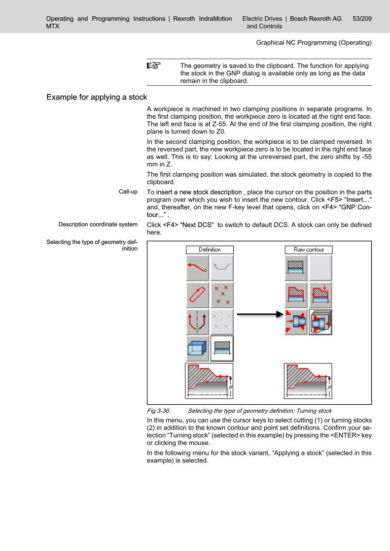
The geometry is saved to the clipboard. The function for applyingthe stock in the GNP dialog is available only as long as the dataremain in the clipboard.
Example for applying a stockA workpiece is machined in two clamping positions in separate programs. Inthe first clamping position, the workpiece zero is located at the right end face.The left end face is at Z-55. At the end of the first clamping position, the rightplane is turned down to Z0.In the second clamping position, the workpiece is to be clamped reversed. Inthe reversed part, the new workpiece zero is to be located in the right end faceas well. This is to say: Looking at the unreversed part, the zero shifts by -55mm in Z.The first clamping position was simulated, the stock geometry is copied to theclipboard.To insert a new stock description , place the cursor on the position in the partsprogram over which you wish to insert the new contour. Click <F5> “Insert…”and, thereafter, on the new F-key level that opens, click on <F4> “GNP Con‐tour...” .Click <F4> “Next DCS” to switch to default DCS. A stock can only be definedhere.
Fig.3-36: Selecting the type of geometry definition: Turning stockIn this menu, you can use the cursor keys to select cutting (1) or turning stocks(2) in addition to the known contour and point set definitions. Confirm your se‐lection “Turning stock” (selected in this example) by pressing the <ENTER> keyor clicking the mouse.In the following menu for the stock variant, “Applying a stock” (selected in thisexample) is selected.
Call-up
Description coordinate system
Selecting the type of geometry def‐inition
Operating and Programming Instructions | Rexroth IndraMotionMTX
Electric Drivesand Controls
| Bosch Rexroth AG 53/209
Graphical NC Programming (Operating)

Fig.3-37: Input mask 'Applying a stock'The modal dialog below allows you to reverse the contour and to shift the work‐piece zero vis-a-vis its position in the previous clamping position. For visualverification, the stock limits are indicated in Z as they were in the old clampingposition. In the example, put a checkmark for “Reverse” and enter the Z shift-55.Click the “DIN Code” key to go to a less compact output variant which addi‐tionally contains the information on already machined surfaces for graphicrealization by the simulation.Use “View” to see the rough contour immediately without aborting the dialog.Abort the dialog by clicking “OK” to complete the current stock input and tosee the rough contour with the last inputs.After clicking the button for the ongoing stock variant again, the position pa‐rameters can be changed as desired.Click <F9> “Save Stock” to complete the definition and to transfer it into theNC program. Contrary to other geometry definitions, the GNP are left immedi‐ately, and you can see the following code.Without “DIN Code”, the stock description is as follows:Program:
CONT (ID10) SPT (Z0, X20) LIN (Z0, X80) LIN (Z-14.8, X80) LIN (Z-15, X79.6) LIN (Z-15, X49) CW (Z-15.8, X47.4, K-15.8) LIN (Z-16.27506, X47.4) CW (Z-16.48212, X47.45452, I49) LIN (Z-17.5, X48) LIN (Z-43, X48) CCW (Z-45, X44, I44) LIN (Z-45, X42.8) CW (Z-45.4, X42, K-45.4) LIN (Z-55, X42) LIN (Z-55, X20) LIN (Z0, X20) END_CONT //STOCK/ID10\\ [""+NCF("G90")]
Input of determinants
Change
Applying the stock to the NC pro‐gram
Result
54/209 Bosch Rexroth AG | Electric Drivesand Controls
Rexroth IndraMotion MTX | Operating and Programming Instruc‐tions
Graphical NC Programming (Operating)

When you have used DIN code output, the following stock description will beindicated:Program:
CONT (ID10) .....; see above END_CONT //S_TOCK/ID10\\ [""+NCF("G90")] 0 DIM MDLF$(8,6) : MDLF$(1)=NCF("G90") : MDLF$(2)=NCF("G17") : MDLF$(3)=NCF("DIA") G18 DIA //STOCK/BEGIN\\ G90 // G0 Z0 X20 G90 // G1 X80 G90 // G1 Z-14.8 F1 G90 // G1 Z-15 X79.6 G90 // G1 X49 G90 // G2 Z-15.8 X47.4 K-0.8 G90 // G1 Z-16.27506 G90 // G2 Z-16.48212 X47.45452 I0.8 G90 // G1 Z-17.5 X48 G90 // G1 Z-43 G90 // G3 Z-45 X44 I-2 G90 // G1 X42.8 G90 // G2 Z-45.4 X42 K-0.4 G90 // G1 Z-55 G90 // G1 X20 G90 // G1 Z0 [MDLF$(1)] [MDLF$(2)] [MDLF$(3)] //STOCK/END\\
Changing/deleting contour-related stock descriptionsContour-related stock definitions consist of two parts: the contour definition andthe stock definition to which the contour relates.To change the contour definition, see "Changing/Extending a Contour (Train ofContour Elements or Contour Definition)", page 37.You should delete a contour definition preferably in the NC editor. Alternatively,a contour declaration can also be deleted by clicking <F8>“GNP Correc‐tion...” ; however, this must be checked visually.The only change to the actual stock declaration “//STOCK/ID...” that is possiblethrough GNP correction is the selection of a different pre-defined contour.To change a stock applied from another clamping position, we recommend todelete the contour definition and the stock definition in the NC editor and to re-insert the stock.
3.4 GNP Cycle3.4.1 Inserting a New Turning - Milling - Drilling CycleExample: lathing cycle “Rough cutting”
The already defined contour “ID1” is to be created by lathing with a rough cuttingcycle ("Example contour", page 28).
Calling the cycle definition and selecting the DCS and the contourTo insert a new cycle , place the cursor on that line in the parts program thatfollows the position where you wish to add the new instruction. Please ensurethat you loaded the tool for the cycle in the NC program beforehand. In additionto the spindle commands, a safe initial position must be approached in the NCprogram.NC program content:
Call-up
Operating and Programming Instructions | Rexroth IndraMotionMTX
Electric Drivesand Controls
| Bosch Rexroth AG 55/209
Graphical NC Programming (Operating)

Calling a rough-cutting cycle for the defined contour “ID1”.Program:
//STOCK/101,82,0,-1\\ [""+NCF("G90")] G0 G18 X200 Z200 ; safe initial position T1 M6 ; tool change ; contour definition CONT ( ID1) SPT (Z0, X40) LIN (X60, AA125.1) RND (RD5) LIN (AA180) CW (TG, Z-85, X80, R12) RND (RD1) LIN (Z-100, AA180) END_CONT ...... G96 S1=270 M104; <- cursor position for inserting a cycle
Click <F5> “Insert” and, thereafter, on the new F-key level that opens, click<F4> to select “GNP Cycle...” .Provided that more description coordination systems than one have been de‐fined in the GNP configuration, the DCS must be changed if necessary.Click <F7> “Next DCS” until the desired description coordinate system with thegeometries already defined is displayed.Depending on whether contours are present in the various DCS, this operatorstep may also be carried out after a cycle has been selected.
Description coordinate system
<F7> “Next DCS”
56/209 Bosch Rexroth AG | Electric Drivesand Controls
Rexroth IndraMotion MTX | Operating and Programming Instruc‐tions
Graphical NC Programming (Operating)
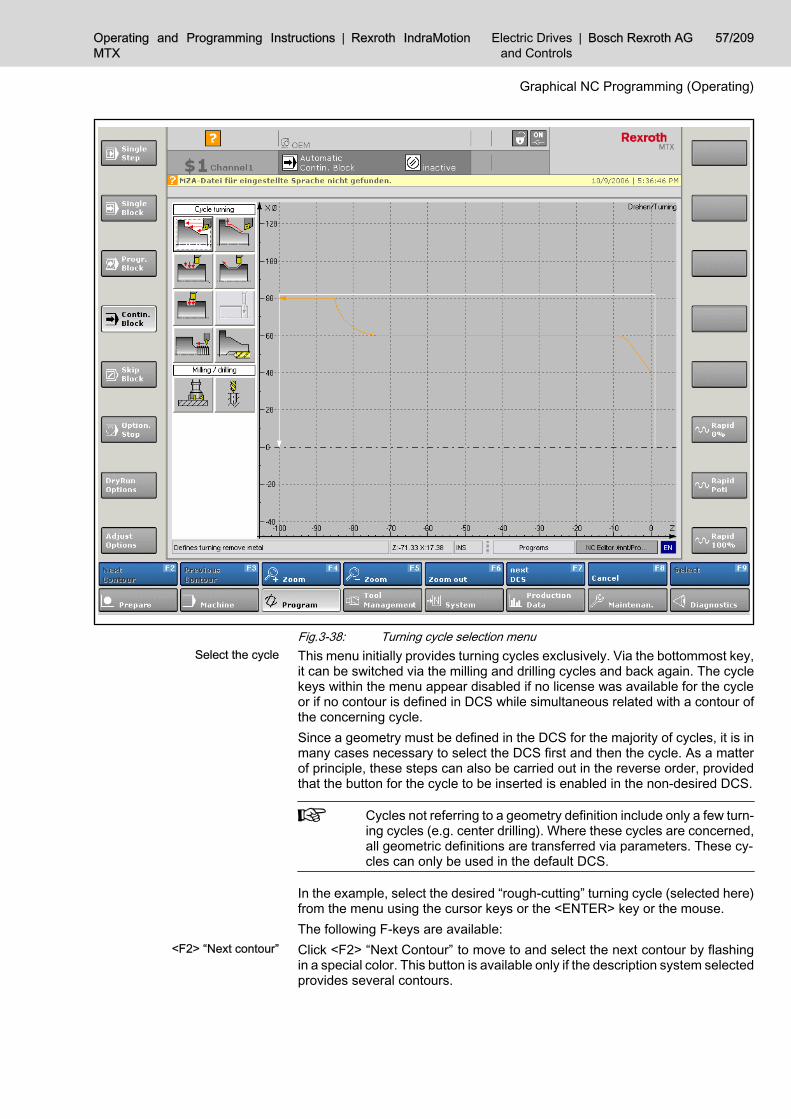
Fig.3-38: Turning cycle selection menuThis menu initially provides turning cycles exclusively. Via the bottommost key,it can be switched via the milling and drilling cycles and back again. The cyclekeys within the menu appear disabled if no license was available for the cycleor if no contour is defined in DCS while simultaneous related with a contour ofthe concerning cycle.Since a geometry must be defined in the DCS for the majority of cycles, it is inmany cases necessary to select the DCS first and then the cycle. As a matterof principle, these steps can also be carried out in the reverse order, providedthat the button for the cycle to be inserted is enabled in the non-desired DCS.
Cycles not referring to a geometry definition include only a few turn‐ing cycles (e.g. center drilling). Where these cycles are concerned,all geometric definitions are transferred via parameters. These cy‐cles can only be used in the default DCS.
In the example, select the desired “rough-cutting” turning cycle (selected here)from the menu using the cursor keys or the <ENTER> key or the mouse.The following F-keys are available:Click <F2> “Next Contour” to move to and select the next contour by flashingin a special color. This button is available only if the description system selectedprovides several contours.
Select the cycle
<F2> “Next contour”
Operating and Programming Instructions | Rexroth IndraMotionMTX
Electric Drivesand Controls
| Bosch Rexroth AG 57/209
Graphical NC Programming (Operating)

Click <F3> “Previous Contour” to move to and select the previously definedcontour. This button is available only if the description system selected providesseveral contours.
When a mouse is available, you can optionally select the contourto be machined by double-clicking the contour graphic.
The <F7> “Next DCS” F-key allows you to move to a different description co‐ordinate system subsequently. This is visually indicated by the axis addressesand the graphical representation of the geometric elements positioned on thislevel. This button is available only if there are more description systems thanone.Click <F8> “Cancel” to cancel the cycle definition and to exit the GNP.
Entering cycle parametersOnce you have completed the selection of the cycle and the contour as descri‐bed above, the system branches to the menu G710 “Turning cycle – rough-cutting” and cutting process is represented by means of preset data.
Fig.3-39: Selection menu for the contour rough-cutting cycleBy selecting the various menu items, all data associated with the cycle can beadjusted to technological conditions and the associated graphical representa‐tion can be checked visually at once. The symbols on the menu buttons indicatethe parameter or parameter group that can be assigned in the opening dialog
<F3> “Previous Contour”
<F7> “Next DCS”
<F8> “Cancel”
58/209 Bosch Rexroth AG | Electric Drivesand Controls
Rexroth IndraMotion MTX | Operating and Programming Instruc‐tions
Graphical NC Programming (Operating)

if necessary. Boolean parameters are negated while their effect on machiningis immediately represented graphically.
Click the button to abort the definition of the cycle call and discard allinputs. You can continue for example with another cycle. This function is notimplemented in all cycles.
Click the button to branch into parallel menus. This button is availablein long menus which are divided into several menus of the same order.Parameters which cannot be assigned reasonably by presetting (e.g. feed, cut‐ting depth) are prompted for mandatory input. Some of these mandatory dialogsappear immediately after the cycle has been selected. Others appear in appli‐cation into the NC program, provided the parameters have not yet been defined.The majority of the existing presettings can be edited by means of the <F7>“Options” ("chapter 3.2.4 "GNP Options" on page 20") F key.There are three basic variants for saving the result to the NC program.<F9> “Apply” completes the cycle definition. The GNP is exited. The result isincorporated in the NC program as cycle call G710 including all parameters:Program:
G96 S1=270 M104 ; as a cycle G710 ( ID1, IFV-999, CD3, F0.15)
<F2> “Apply and continue” likewise completes the cycle definition and transfersit into the NC program. The output does not differ from <F9> “Apply”. However,the GNP view remains intact here, and another cycle call can be programmed.<F3> “Apply DIN Code” also completes the cycle definition and exits the GNP.The result is included in the NC program as a sequence of DIN and CPL blocks.They are preceded by the cycle call in a separate comment line. If you removethe semicolon, you can repeat the DIN code output via the correction mode atany time. Please ensure that you do not forget to delete the “old” DIN outputs.Program:
G96 S1=270 M104 ; G710 ( ID1, IFV-999, CD3, F0.15) .....excerpt of DIN blocks G90 G18 DIA G95 F0.15 G0 G40 Z=3 X=76 G1 Z=-84.70097 X=76 G1 Z=-84.63026 X=76 .... etc.
Use the DIN output as rarely as possible. Make use of the DIN out‐put particularly if you have to adjust the cycle to special conditionssubsequently, e.g. in case of changing feeds or changing tool cor‐rections.
3.4.2 Changing a CycleTo correct a cycle , position the cursor of the editor on the cycle to be corrected,e.g. “G710(ID1, F0.1, CD6, TR0.8)” ; then, click <F8> “GNP Correction...” Fkey.
One level back
Next Menu
Mandatory dialogs
Presettings
Output variants
“Apply” <F9>
<F2> “Apply and continue”
<F3> “Apply DIN Code”
Result as DIN blocks
Call-up
Operating and Programming Instructions | Rexroth IndraMotionMTX
Electric Drivesand Controls
| Bosch Rexroth AG 59/209
Graphical NC Programming (Operating)

Thereafter, the cycle will be represented graphically in relation to the parame‐ters. You can now make your changes in the input fields and complete the cyclewith <F9> “Apply” .Selection of another machining geometry via dialog is not intended.
3.5 Enclosure 'Configuration files of the GNP'3.5.1 General Rules
The compiler and the dialogs are strongly dependent on the particular config‐uration parameters of the channel for which the NC program is being created(MACODA).The relevant machine parameters are automatically made available in an INIfile.In addition, user settings can be saved to the configuration file (e.g. descriptioncoordinate systems or default parameters assignments). To change the usersettings, please mainly use the options dialog of the GNP ("chapter 3.2.4 "GNPOptions" on page 20"). But you can also use any ASCII text editor to do this.A separate INI file is created for each channel. This is to be found in a file belowthe IndraWorks project directory.Name assignment: MTXGnpConfig_XXX_YYY.ini. XXX is reserved for devicenames ("000" at present); YYY is the three-digit channel number with leadingzeros.
3.5.2 Relevant Configuration Parameters System and channel parameters
Number of synchronous NC axes with basic channel positionSection [PARAMETER]Value address: MaxIndexAxesValues: 2 or 3Default system of units for programming For example, this datum can be required for default parameters that have beengenerated internally, such as retracting movements etc.
Please note that all contour definitions and all NC blocks generatedare expected and/or output in the underlying measurement unit.
7060 00020, G70 or G71, G71 is the defaultSection [PARAMETER]Value address: BasicUnitValues: mm / inchDefault interpolation plane7060 00020, G17, G18 or G19, G17 is the defaultSection [PARAMETER]Value address: BasicPlaneValues: G17/G18/G19Underlying radius / diameter programming7060 00020, RAD or DIA, RAD is the defaultSection [PARAMETER]
Parameters in the configuration file
MTX parameters
Parameters in the configuration file
MTX parameters
Parameters in the configuration file
MTX parameters:
Parameters in the configuration file
60/209 Bosch Rexroth AG | Electric Drivesand Controls
Rexroth IndraMotion MTX | Operating and Programming Instruc‐tions
Graphical NC Programming (Operating)

Value address: BasicXScalValues: DIA/RAD
AxisMention is made of all axes which are assigned to the channel in its basic po‐sition and which are synchronous axes.The MACODA parameters 1001 00001 and 1003 00002 are evaluated for de‐termining the assignment.Physical axis name1003 00001, 8 bytesSection [AXIS_XXX] XXX = Index of the axis in the configuration fileValue address: NameValues: Axis designationCoordinate meaning (axis meaning, axis functions)7010 00030 = 1...999Section [AXIS_XXX] XXX = Index of the axis in the configuration fileValue address: FunctionValues: X, Y, ZLogic axis designation7010 00010, 8 bytesSection [AXIS_XXX] XXX = Index of the axis in the configuration fileValue address: NameLogicalValues: Axis designation
Ident information of the parameter setThis information serves to test compliance with the active configuration dataset.Sektion [PARAMID]Value addresses and values:Date Date of the last time configuration were applied [DD.MM.YY]Time Time of the last time configuration were applied [HH:MM:SS]
3.5.3 Options and User SettingsDCS
This option defines the possible description coordinate systems which are pro‐vided for selection in the dialogs. The default DCS is automatically updated onchanges of configuration parameters:Section: [AxisGroups]● Number of DCS
ValueAddress Max_Index_DataValue number
● Index of default DCS Value address IndexDefaultValue index (>=1)
● Before/behind the turning centerWhere turning contours and turning cycles are concerned, the view andthe dialog guide (auxiliary screens for defining the train of contour ele‐
MTX parameters:
Parameters in the configuration file
MTX parameters:
Parameters in the configuration file
MTX parameters
Parameters in the configuration file
Operating and Programming Instructions | Rexroth IndraMotionMTX
Electric Drivesand Controls
| Bosch Rexroth AG 61/209
Graphical NC Programming (Operating)

ments) can be re-set to “before the turning center” (positive X-axis down‐ward).Applicable only to the default DCS.Not implemented in the present version.Value address InFrontOfCentreValues 0=behind/ 1=before turning center
● DCS declaration (NC code)Description of the DCS with NC commandsValue address Settings_XXX (XXX is the index of the DCS)Value strings e. g. RAD G17(X,Y,Z)See description for axis groups
● Name of the DCS (displayed to the upper right of the graphic window)Value address Comment_XXX (XXX is the index of the DCS)Values any unique string
● Standard window Filed default window coordinates for DCS when not geometry for this DCShas been defined yet.Value address Window_XXXValues left, bottom, right, top (coordinates) e. g. -200,-100,200,100
● Transformation selectionFiles a block sequence for selecting an axis transformation.Value addresses Activate_XXX_Ye.g.,Activate_001_1 = SpindleToAxis(SC)Activate_001_2 = WaitAxis(SC,C)Activate_001_3 = Coord(2) TRFOPT(%RI%)Activate_001_Nr= 3
● Transformation selectionFiles a block sequence for deselecting an axis transformation.Value addresses Deactivate_XXX_Ye.g.,Deactivate_001_1 = Coord(0,2)Deactivate_001_2 = RemAxis(C)Deactivate_001_3 =AxisToSpindle(SC)Deactivate_001_Nr= 3
Technical and technological data – presettingsThis option is intended for filing technological data which modify the machiningprocess such that it meets the requirements of the particular channel or speci‐fied by the user. Usually, these are default parameter values for cycles.Section: [Tech_Settings]● Tangential safety distance / approach in [mm] for lathing
Value address Siabst_TanValues >= 0
● Tool retract for turning, with the exception of center drilling
62/209 Bosch Rexroth AG | Electric Drivesand Controls
Rexroth IndraMotion MTX | Operating and Programming Instruc‐tions
Graphical NC Programming (Operating)

Value address Tool_Rev_T_OutValues 0..0.3
● Cutting variant contour turning G710Value address Cut_VarValues 1..0.7
● Rectract amount at cutting end during turning [mm]Value address Cut_Rev_PathValues >0
● Retract angle at cutting end during turning [dgr]Value address Cut_Rev_AngValues 0..0.90
● Angle distance for G710, G711 [grd]Value address Cut_Dc_AngValues 0..0.30
● Cutting depth for machining cycle G710 in [mm]Value address Cutting_depthValues >0
● Cutting optimized during turningThe last infeed is increased by no more than CD_MaxEnlargement % ifthis can prevent additional cutting.Value address CD_MaxEnlargementValues 0...50
● Default tool radius for turning G710, G711 in [mm]Value address Tool_R_TValues >0
● Default tool radius for grooving G720, G721 in [mm]Value address Tool_R_TValues >0
● Cutting variant for thread turning cycles G760..G762Value address Thread_VarValues 1, 2, 3 for radial, flank and alternate infeed
● Retract distance during milling G910 and CV1 in [mm]Value address Mill_SDISTValues >0
● Maximum length of plane lines in monotonously ascending contour areasthat are not to be subjected to the oversize for plane surfaces RSF [mm].Value address Remaining_LVIValues >= 0
● Maximum length of vertical lines (cylinder surfaces) in monotonously as‐cending contour areas that are not to be subjected to the oversize forvertical surfaces RSL [mm].Value address Remaining_LHIValues >= 0
Operating and Programming Instructions | Rexroth IndraMotionMTX
Electric Drivesand Controls
| Bosch Rexroth AG 63/209
Graphical NC Programming (Operating)

● Maximum length of plane lines in relief cuts that are not to be subjectedto the oversize for horizontal surfaces RSF [mm].Value address Remaining_LVIIValues >= 0
● Maximum length of vertical lines (cylinder surfaces) in undercuts that arenot to be subjected to the oversize for vertical surfaces RSL [mm].Value address Remaining_LHIIValues >= 0
● Tool edge radius correction for turningValue address Edge_Korr (at present, only “0” has been realized)Values:0=without;1=only for contour cut;2=machining and contour cut
● Edge radius comparison (Delta) (irrelevant at present)Value address Edge_DeltaValue Permissible difference between actualand programmed tool radius.
Color settingsThe colors for lines, surfaces and labels to be effective in the graphic windoware set in the color settings option.Section: [Opt_Settings]The colors can be specified as a numeric value (integer, >= 0) or with their red-green-blue components (syntax RGB(<red>,<green>,<blue>), strongest illu‐mination per color component at 256).● Background color
Value address BackColor● Colour for selected contour
Value address ColorConturActiv● Colour for deselected contours
Value address ColorConturInactiv● Color for active contour element
Value address ColorElementActiv● Color for tool (edge)
Value address ColorEdge● Color for machining
Value address ColorFeed● Color for rapid traverse mode
Value address ColorRapidfeed● Color for hatched area of the surface traced by the milling tool
Value address ColorTrace● Color for helplines
Value address ColorHelp● Color for coordinate axes and DCS designation
64/209 Bosch Rexroth AG | Electric Drivesand Controls
Rexroth IndraMotion MTX | Operating and Programming Instruc‐tions
Graphical NC Programming (Operating)

Value address ForeColorCoord● Color for lattice
Value address ColorLattice● Color for stock contour (not implemented yet)
Value address ColorStock
If you define your own colours, the file MTXGnpSimColor.ini will begenerated in IndraWorks\User\Config. In this file, the color infor‐mation for the GNP is saved in the [GNP] section under the speci‐fied addresses.
General SettingsThe general settings affect the dialogs and protects portability and compatibilityof the GNP cycle calls (the latter feature has not been implemented yet).Section: [View]● “Dialog input complete”is indicated by a small checkmark on the buttons
for the cycle parameter groupsValue address OkViewValues:0=without mark;1=show checkmark;
● Horizontal position of the modal dialogs [Pixel]Value address FormLeftValues >= 0
● Vertical position of the modal dialogs [Pixel]Value address FormTopValues >= 0
● Protecting portability and compatibility: Cutting variant for turningValue address ForceCV0=for default value: do not include in parameter list;1=always in the parameter list;
● Protecting portability and compatibility: Tool radius on turningValue address ForceTR0=for default value: do not include in parameter list;1=always in the parameter list;
● Protecting portability and compatibility: Tool retract variant on turning andmillingValue address ForceTRV0=for default value: do not include in parameter list;1=always in the parameter list;
● Protecting portability and compatibility: DCS declarationValue address ForceDCS0=Omit declaration of the standard DCS in the geometry head instruction;1=List each DCS declaration in the geometry head instruction;
Operating and Programming Instructions | Rexroth IndraMotionMTX
Electric Drivesand Controls
| Bosch Rexroth AG 65/209
Graphical NC Programming (Operating)

If other global settings are made with the Options dialog than thedefault settings, the file 'MTXGnpSimColor.ini' will be generatedunder IndraWorks\User\Config. It saves the settings in the [View]section under the named addresses.
66/209 Bosch Rexroth AG | Electric Drivesand Controls
Rexroth IndraMotion MTX | Operating and Programming Instruc‐tions
Graphical NC Programming (Operating)

4 Grafical NC Programming (Programming)4.1 Geometry Definitions4.1.1 Basic Information on Geometry DefinitionsGeneral
“Geometry definitions” determine the location and, in most cases, also the finalform of machining processes. These are two-dimensional descriptions of con‐tours and drilling positions (points sets) which, by themselves, do not triggermotions on the CNC. They do not have any effect in the program similar to thatof a comment.The motional sequence only develops in conjunction with a GNP cycle that hasreference to a geometry definition. To achieve this, an ident or numeric “ID” thatis unique in the entire NC program is assigned to each geometry definition. Thereference of the GNP cycles to a geometry definition permits to reuse a geom‐etry definition in cycles as often as desired for various machining steps (e.g.rough-cutting and finish-cutting).There are two main groups of GNP instructions:● Geometry definitions, and● GNP cycles.A geometry can be defined at any point in the NC program. The definition isindependent of the context in the program. But it must be noted that the defi‐nition must always be placed at a position preceding its first utilization.Geometry definitions are multi-line instructions. They always consist of● a header instruction,● one or more geometric elements, and● an end instruction.This order must be kept in the NC program. It must not be disturbed by DIN andCPL instructions. Comments must be avoided in a geometry definition.There are two geometry header instructions:● CONT for contour definitions, and● PATT for point set definitions.The header information contains the unique ident of the definition, limits thepossible sequence of geometric elements (contour or drilling position) and as‐signs the definition to a description coordinate system (DCS).The geometric elements are the actual components of each definition. They aresubdivided as follows:● contour element instruction (lines, arcs, and transition elements, with the
sequence forming a train of contour elements);● form element (schematic contour definition, mostly consisting of several
contour elements, e.g. rectangular pocket);● manipulation instruction (turning, shifting, mirroring and merging prede‐
fined contours and point sets);● Point set instruction (drilling positions).The geometry definition is completed with an end instruction. In this manner,header and end instructions form a “bracket” around the geometric elements.● END_CONT - end of a contour● END_PATT – end of a point set definition.
Function
Application
Main groups of GNP Instructions
Position in the NC program
Structure of geometry definitions
Geometry header instruction
Geometric elements
End of a geometry definition
Operating and Programming Instructions | Rexroth IndraMotionMTX
Electric Drivesand Controls
| Bosch Rexroth AG 67/209
Grafical NC Programming (Programming)

The GNP instructions are based on a high-level language syntax. They consistof● function names (no long and short forms),● opening round bracket for parameter list,● parameter list (parameter address followed by its value, with several pa‐
rameters being separated by a comma), and● closing round bracket.If parameter lists are empty, the brackets are not necessary.
In this manual, we mark optional parameters with curly brackets. Incontrast, the obligatory parameter is displayed without curly brack‐ets.Wildcards for the values to be programmed will be identified by an‐gle brackets. Curly and angle brackets are not programmed.Example: FKT (PA<pa> {, PB<pb>}).In this manual, we mark existing parameters that cannot be usedsimultaneously (alternative parameters) with the “|” symbol be‐tween the two alternatives. The “|” symbol is not programmed.Example: FKT (PA<pa>|PB<pb>).If a parameter is an axis name which ends with a figure, the pa‐rameter name must be separated from the value by a blank or “=”.Example: FKT (X1 75, Y1=44).
As a matter of principle, the function names and parameters are only effectiveby sets, i.e. even equal parameters and keywords must be repeatedly pro‐grammed in the following block. All parameters must be constants, i.e. theymust not contain any expressions or inline CPL.Coordinate values must always be specified as absolute values. The applicablelinear measuring unit (mm/inch) is always the measurement unit that is activeafter the basic channel position or mm, i.e. the basic programming unit. Coor‐dinates with the X axis meaning can be specified in the diameter size, ifnecessary. Angles are always measured in degrees.
Geometry head instruction CONT(...), PATT(...)Each geometry definition starts with a header instruction. On selecting thefunction, it is also determined whether it is a contour or a train of drilling posi‐tions.The header information contains the unique ident of the definition (applicablewithin the program file) and assigns the definition to a specific description co‐ordinate system.Contour:CONT (ID<id> {, <dcs>})Point set:PATT (ID<id> {, <dcs>})including:is the unique ident number (>0), andis the description coordinate system.The description coordinate system assigned to the definition (called DCS, De‐scription Coordinate System below) essentially defines the axis identifiers andthe plane to be applicable to the two-dimensional definition.
High-level language syntax
Non-modal parameters
Dimensional reference, unit
Effect
Syntax
ID<id>
<dcs>
DCS
68/209 Bosch Rexroth AG | Electric Drivesand Controls
Rexroth IndraMotion MTX | Operating and Programming Instruc‐tions
Grafical NC Programming (Programming)

The DCS has the following characteristics:● Radius/diameter programming (RAD/DIA); has an effect only on the NC
axis with the X functionality.● Plane (G17, G18, G19, G20, A17 or A19).● Axis identifier (z. B. X Y Z C1) or spindle name (S1).● Reference radius for cylinder jacket transformation (RI).The DCS declaration must satisfy the following syntax:{<Xsc>} {<plane> {({<axis1>}, {<axis2>} {, {<axis3>}})} {RI<ri>}including:defines whether the axis with the X functionality is programmed in the radius ordiameter size, with the possible words being RAD and DIA. If <Xsc> is notprogrammed, the condition after the basic channel position or RAD is applica‐ble.Plane or interpolation plane. Possible interplation planes are G17, G18, G19,and G20. It is also possible to assign asynchronous axes or spindles to a de‐scription coordinate system. A17 and A19 are provided therefor. Applicationpreferably on lathes. A17 is used to face machining, A19 to radial machining.If no plane is specified, the plane activated after the basic channel position orG17 is applicable.stands for the name of the axis with the X function.Name of axis with function Y or function C (planes A19 and A19).stands for the name of the axis with the Z function.The definition of the plane is linked to the axis identifiers according to the NCsyntax for the extended plane conversion (see Rexroth IndraMotion MTX Pro‐gramming Manual DOK-MTX***-NC**PRO*V05-AW0x-EN-P, Section “Exten‐ded Plane Conversion”).The feed axis for the particular interpolation plane (applicate) may be omitted.In this case, it will not be addressed by the GNP cycle (e.g. G18(X,,Z)). At thesame time, a non-defined feed axis restricts the scope of usable GNP cycles(e.g. drilling not possible).If the list of axis names is not programmed, the logic axis names of the syn‐chronous axes in the basic channel position are applicable. If logic axis namesare not available, the appropriate physical axis names are applicable.The DCS corresponding to the basic position in all of its parameters is the de‐fault DCS. If the default DCS is used, the DCS declaration may be completelyomitted in the header information.
In plane A19 for face machining, the rotary axis with C function isprogrammed like a carthesian coordinate (here Y, ordinate). Notuntil the processing cycle is reached, a diameter/radius (X coordi‐nate) is calculated from the vector amount to a movement end pointand a C angle is calculated from the vector direction.The axis with the C function is transferred to an abscissa in the A19plane. The axis scaling corresponds to the one of a carthesian, justthe coordinates will be interpreted directly as angle during imple‐mentation (no conversion).The planes A17 and A19 are exclusively intended for drilling withthe drived tools.
Reference radius for a cylinder jacket transformation. The RI specificationqualifies the DCS to be a cylinder jacket transformation, usually an involute.
<Xsc>
<plane>
<axis1>
<axis2>
<axis3>
RI<ri>
Operating and Programming Instructions | Rexroth IndraMotionMTX
Electric Drivesand Controls
| Bosch Rexroth AG 69/209
Grafical NC Programming (Programming)

Example:
Examples of contour header information
Header information of contour number 100 for milling in the G19 plane:CONT(ID100, RAD G19(X,Y,Z))Header information of point set number 101 in the default DCS:PATT(ID101)Header information of contour number 102 for milling in the G18 plane of amilling machine (in their basic position, the axes X, Y and Z to be used are tobe available as synchronous axes; radius programming in basic position):CONT(ID102, G18)Definition of a contour as involute with a reference radius of 40:CONT(ID103, G19(x,y,z) RI40)Header information of point set number 104 for face machining drilling with Xin diameter and S1 as part angle:PATT(ID104, DIA A17(X,S1,Z))
Geometry end instruction END_CONT, END_PATTCompletes the definition of a geometry. This instruction can be followed by anyDIN and CPL instructions desired.Contour:END_CONTPoint set:END_PATTExample:
Contour:CONT(ID1, G17(X,Y,Z)); geometric elements (contour)END_CONTPoint set:PATT(ID2); geometric elements (drilling positions)END_PATT
4.1.2 Programming Trains of Contour ElementsElementary information on trains of contour elements
A workpiece drawing that is suitable for “NC purposes” must contain all thecoordinates required for programming linear patterns and circles. Since draw‐ings often reflect design requirements rather than technical production require‐ments, the determination of coordinates often require extensive mathematicalcalculations. This is essentially facilitated by the function of programming trainsof contour elements.A train of contour elements is the definition of a contour of any shape. It has abeginning (starting point) and ends with the last contour element beforeEND_CONT. There are no interruptions in-between.
Function
Syntax
Function
70/209 Bosch Rexroth AG | Electric Drivesand Controls
Rexroth IndraMotion MTX | Operating and Programming Instruc‐tions
Grafical NC Programming (Programming)

Trains of contour elements are subdivided in open and closed contours. Thestarting and end points of the latter are identical.The definition of a train of contour elements consists of a starting point and anynumber of contour elements (lines and arcs) as well as transitional elements.That means that the following elements are available for describing a contour:● Starting point● Straight line (line)● Circle (arc)● Transitional elements between two lines or arcs:
– Chamfer,– rounding,– undercut, and– thread undercut.
The given parameters of a contour element are used for calculating the contourelement. If these are not sufficient, the previous and subsequent elements areincluded in the calculation. Then, the definition can attain its geometric deter‐mination by re-calculating up to two contour elements before the last (transi‐tional elements are not included here). An excess determination is impermis‐sible and will cause error messages.
Starting point SPT(....) The starting point of the train of contour elements is defined in the two mainaxes of the DCS.The SPT instruction follows immediately after CONT; it may be written onlyonce per contour definition.SPT ({<SP>})including:stands for the starting point coordinates. They define the start point in the firstaxis of the plane (horizontal axis, abscissa) and/or the second one (vertical axis,ordinate). The axis name must be specified for each axis, followed by the co‐ordinate value. The parameters are separated by a comma.Example:
The starting point of the contour is at X20 and Z0.SPT (X20, Z0)
Line LIN(...) A contour element is defined as a line.LIN {({<trs>} {,<EP>} {, AA<aa>} {, R<r>} {MD<md>})}including:defines the angle of lead via the tangential connection to the preceding ele‐ment. “TG” stands for tangent, “TR” for the reverse tangent and as defaultcorner transition.stands for the end point coordinates, which define the end point in the first axisof the plane (horizontal axis, abscissa) and/or the second one (vertical axis,ordinate). The axis name must be specified for each axis, followed by the co‐ordinate value. Two coordinate value parameters must be separated by acomma.stands for the lead angle in absolute relation to the positive horizontal axis.
Contour elements
Geometric definition
Function
Syntax
<SP>
Function
Syntax
<trs>
<EP>
AA<aa>
Operating and Programming Instructions | Rexroth IndraMotionMTX
Electric Drivesand Controls
| Bosch Rexroth AG 71/209
Grafical NC Programming (Programming)

stands for the length (radius).stands for the possibility of selection from several solutions (MD1 or MD2; MD1is the default value).
Fig.4-1: LIN geometryOwing to the constellation of parameters, there may be several mathematicalsolutions for the definition of trains of contour elements.
The alternative solution must be programmed for the line causingthe alternative.
The alternative solutions for lines are categorized according to the followingcriteria:Angle criterion:● Small angle = “MD1” (is the default and can be omitted)● Large angle = “MD2” (must be programmed)
Fig.4-2: Selecting a solution with the line-circle angle criterionIf the angle criterion does not provide an alternative (same angle), the lengthcriterion must be used.Length criterion:● Short line = “MD1” (is the default and can be omitted)● Long line = “MD2” (must be programmed)
R<r>
MD<md>
Selection of solutions
72/209 Bosch Rexroth AG | Electric Drivesand Controls
Rexroth IndraMotion MTX | Operating and Programming Instruc‐tions
Grafical NC Programming (Programming)

Fig.4-3: Selecting a solution with the line-circle length criterionExample:
Line defined by the end point at X = 100 and an angle of 135 degrees:LIN (X100, AA135)Line defined by a tangential transition and a length of 140 (radius):LIN (TG, R140)
Arc CW(...), CCW(...) A contour element is defined as an arc. The direction of rotation is defined bythe function name:● CW = turning to the right, i.e. in clockwise direction● CCW = turning to the left, i.e. in counterclockwise directionClockwise:CW {({<trs>} {,<EP>} {, <IP>} {, AA<aa>} {, EA<ea>} {, OA<oa>}{, R<r>} {MD<md>})}Counterclockwise:CCW {({<trs>} {,<EP>} {, <IP>} {, AA<aa>} {, EA<ea>} {, OA<oa>}{, R<r>} {MD<md>})}including:defines the tangential angle at the start of the arc via the tangential connectionto the preceding element. “TG” stands for tangent, “TR” for the reverse tangentand as default corner transition.stands for the end point coordinates, which define the end point in the first axisof the plane (horizontal axis, abscissa) and/or the second one (vertical axis,ordinate). The axis name must be specified for each axis, followed by the co‐ordinate value. Two coordinate value parameters must be separated by acomma.Interpolation parameters “I”, “J” and “K”. They define the center point in theplane. Depending on the interpolation plane, a maximum of two coordinatescan be specified. They are always programmed absolutely; if necessary, “I”must be programmed in the diameter unit. The parameter address must bespecified for each parameter, followed by the coordinate value. Two interpola‐tion parameters must be separated by a comma.
Function
Syntax
<trs>
<EP>
<IP>
Operating and Programming Instructions | Rexroth IndraMotionMTX
Electric Drivesand Controls
| Bosch Rexroth AG 73/209
Grafical NC Programming (Programming)

stands for the tangential angle at the beginning of the arc in absolute relationto the positive horizontal axis.stands for the tangential angle at the end of the arc in absolute relation to thepositive horizontal axis.stands for the opening angle of the arc.stands for the radius.stands for the possibility of selection from several solutions (MD1 or MD2; MD1is the default value).
Fig.4-4: Arc turning to the right, CWOwing to the constellation of parameters, there may be several mathematicalsolutions for the definition of trains of contour elements.
The alternative solution must be programmed for the arc causingthe alternative.
The alternative solutions for arcs are categorized according to the followingcriteria:Arc criterion:● Small arc = “MD1” (is the default and can be omitted)● Large arc = “MD2” (must be programmed)For example, a train of contour elements consists of an arc, followed by a line:● The position and radius of the arc are defined by the center point coordi‐
nates “I” and “K” and the starting point “P0”.● The contour end point is given by the end point coordinates “X” and “Z”.The starting point of the line is on a circle with the radius “R”.
AA<aa>
EA<ea>
OA<oa>
R<r>
MD<md>
Selection of solutions
74/209 Bosch Rexroth AG | Electric Drivesand Controls
Rexroth IndraMotion MTX | Operating and Programming Instruc‐tions
Grafical NC Programming (Programming)

Fig.4-5: Selecting a solution with the line-circle arc criterionExample:
clockwise arc in the G18 plane, center point in I = 23 in K = 28, radius = 16, endangle = 45 degrees:
CW (I0, K-28, R16, EA45)
In addition to the documented alternatives MD1 and MD2, other alternativesmay occur in the dialog during programming, specifically if alternative circlecenter point positions exist.
Transition element chamfer CHF(...) Inserts a symmetric chamfer between two successive contour elements (linesor arcs only) without tangential transition.CHF (CF<cf>)including:stands for the width of the chamfer.
Fig.4-6: Chamfer CHF (between lines)Example:
Chamfer between a line and an arc, 5 mm in width:
LIN (X...)
Function
Syntax
CF<cf>
Operating and Programming Instructions | Rexroth IndraMotionMTX
Electric Drivesand Controls
| Bosch Rexroth AG 75/209
Grafical NC Programming (Programming)

CHF (CF5)CCW (X...)
Transitional element: rounding RND(...) Inserts a rounding between two successive contour elements (lines or arcs on‐ly), provided that the two elements intersect or touch each other (reversetangent).RND (RD<rd>)including:stands for the radius of the rounding.Example:
Rounding between two lines with a radius of 0.5 mm:
LIN (X...)RND (RD0.5)LIN (X...)
Transition element undercut RF1(...) Inserts an undercut according to DIN 509 between two contour elements. Pref‐erably, the two adjacent contour elements are horizontal and vertical lines(cylinder and plane surfaces during turning).
Undercuts are always aligned such that the longitudinal axis is rep‐resented by the main axis of the interpolation plane (abscissa). Thesecondary axis (ordinate) forms the plane axis.
RF1 (RF <rf>)including:stands for the form of undercut:E Undercut in cylinder andF undercut/relief cut in both surfacesExample:
Undercut according to DIN 509, form F:
LIN (X...)RF1 (RF F)LIN (X...)
Transition element thread undercut RF2(...) Inserts a thread undercut according to DIN 76509 between two contour ele‐ments. Preferably, the two adjacent contour elements are horizontal and verti‐cal lines (cylinder and plane surfaces during turning).
Thread undercuts are always aligned such that the longitudinal axisis represented by the main axis of the interpolation plane (abscissa).The secondary axis (ordinate) forms the plane axis.
RF2 (RF <rf>, P<p>)including:
Function
Syntax
<rd>
Function
Syntax
RF<rf>
Function
Syntax
76/209 Bosch Rexroth AG | Electric Drivesand Controls
Rexroth IndraMotion MTX | Operating and Programming Instruc‐tions
Grafical NC Programming (Programming)

stands for the form of undercut:A External thread regular,B External thread short,C External thread long,D Internal thread regular,E Internal thread short, andF Internal thread long.Thread pitchExample:
Thread undercut according to DIN 76509, form A, 2 mm pitch:
LIN (X...)RF2 (RF A, P2)LIN (X...)
Example of a train of contour elementsThe following turning contour illustrates the definition of a train of contour ele‐ments by way of an example.Example:
Bolt
Fig.4-7: "Bolt" contourCONT (ID3) ; name of contour "ID3", default DCSSPT (Z0, X20) ; Start point of the contour definitionLIN (Z-30, X20) ; line, X, ZLIN (AA150, L25) ; line radius, angleRND (RD5) ; rounding radiusLIN (Z-100, AA180) ; line, Z, angleCW (R20, EA100, TG) ; circle, tangential, end angle, radiusLIN (X110, TG) ; line, tangential, XCHF (CF6) ; chamfer, widthLIN (Z-150, AA180) ; line, Z, angle
RF<rf>
P<p>
Operating and Programming Instructions | Rexroth IndraMotionMTX
Electric Drivesand Controls
| Bosch Rexroth AG 77/209
Grafical NC Programming (Programming)

END_CONT ; end of contour definition
4.1.3 Programming Form ElementsElementary information on form elements
Form elements are geometric elements belonging to the group of contours.Herein, these contours comply with a form pattern that recurs with many work‐pieces.The definition of a form element must always start with “CONT” and end with“END_CONT”.A contour definition may contain any number of successive form elements. Inthis case, the contour comprises interruptions. Generally, it is also possible tocombine form elements and manipulations of contours in a contour definition.
In milling cycles, non-coherent contour segments are treated asseparately programmed contours with regard to approach, run-out,infeed, “closedness”, etc. In turning cycles, interrupted contourscannot be processed.
Circular pocket CIR(...)Defines a form element consisting of a full circle.CIR (<RP>, D<d>)including:stands for the coordinates of the reference point. They define the center pointof the circle in the first axis of the plane (horizontal axis, abscissa) and thesecond one (vertical axis, ordinate). The axis name must be specified for eachaxis, followed by the coordinate value. The parameters are separated by acomma.stands for the diameter.
Fig.4-8: Circular pocket form element CIRExample:
Definition of a circle with a diameter of 100 and a center point at X20 Y10.
CONT (ID78)CIR (D100, X20, Y10)END_CONT
Rectangular pocket REC(...)Defines a form element consisting of a rectangle the corners of which may berounded.REC (<RP>, L<l>, W<w> {, R<r>} {, A<a>} {,MD<md>})including:
Function
Programming
Function
Syntax
<RP>
D<d>
Function
Syntax
78/209 Bosch Rexroth AG | Electric Drivesand Controls
Rexroth IndraMotion MTX | Operating and Programming Instruc‐tions
Grafical NC Programming (Programming)

stands for the coordinates of the reference point. They define the referencepoint of the circle in the first axis of the plane (horizontal axis, abscissa) and thesecond one (vertical axis, ordinate). The axis name must be specified for eachaxis, followed by the coordinate value. The parameters are separated by acomma.stands for the length of the rectangle.stands for the width of the rectangle.stands for the rounding radius; default = 0.stands for the angle of the longitudinal edges to the main axis (abscissa); default= 0.stands for the dimensioning variant of the reference point:MD1 corner point dimensioning (default setting),MD2 center point dimensioning.
Fig.4-9: Rectangular pocket form element RECExample:
Definition of a rectangle: width 40, length 60, corner radius 6, center point ofthe rectangle at X10 Y10.
CONT (ID79)REC (W40, L60, R6, X20, Y10, MD2)END_CONT
Groove, round GRR(...)Defines a form element in the shape of a bent groove or bent elongated hole.GRR (<RP>, SA<sa>, EA<ea>, W<w>, R<r>)including:stands for the coordinates of the reference point. They define the center pointof the circle in the first axis of the plane (horizontal axis, abscissa) and thesecond one (vertical axis, ordinate). The axis name must be specified for eachaxis, followed by the coordinate value. The parameters are separated by acomma.stands for the starting angle to the main axis (abscissa).stands for the end angle to the main axis (abscissa).stands for the width of the groove.stands for the radius.
<RP>
L<l>
W<w>
R<r>
A<a>
MD<md>
Function
Syntax
<RP>
SA<sa>
EA<ea>
W<w>
R<r>
Operating and Programming Instructions | Rexroth IndraMotionMTX
Electric Drivesand Controls
| Bosch Rexroth AG 79/209
Grafical NC Programming (Programming)

Fig.4-10: Round groove form element GRR.Example:
Definition of a round groove: width 10, starting angle 90, end angle 180, centerpoint at X200 Y100 and radius 45.
CONT (ID80)GRR (W10, SA90, EA180, X200, Y100, R45)END_CONT
Groove, straight GRL(...)Defines a form element in the shape of a straight groove or elongated hole.GRL (<RP>, L<l>, W<w> {, A<a>})including:stands for the coordinates of the reference point. They define the center pointof the circle in the first axis of the plane (horizontal axis, abscissa) and thesecond one (vertical axis, ordinate). The axis name must be specified for eachaxis, followed by the coordinate value. The parameters are separated by acomma.stands for the length of the groove.stands for the width of the groove.stands for the orientation angle of the groove to the main axis (abscissa); default= 0.
Fig.4-11: Straight groove form element GRLExample:
Definition of a straight groove: width 10, length 100, angle 45, reference pointat X200 Y10.
CONT (ID81)GRL (W10, L100, A45, X200, Y10)END_CONT
Function
Syntax
<RP>
L<l>
W<w>
A<a>
80/209 Bosch Rexroth AG | Electric Drivesand Controls
Rexroth IndraMotion MTX | Operating and Programming Instruc‐tions
Grafical NC Programming (Programming)

Polygon PLG(...)Defines a form element as a centrosymmetric polygon.PLG (<RP>, D<d>, NR<nr> {, A<a>})including:stands for the coordinates of the reference point. They define the center pointof the circle in the first axis of the plane (horizontal axis, abscissa) and thesecond one (vertical axis, ordinate). The axis name must be specified for eachaxis, followed by the coordinate value. The parameters are separated by acomma.stands for the inside diameter.stands for the number of records (>2).stands for the angle of an edge to the main axis (abscissa); default = 0.
Fig.4-12: Polygon form element PLGExample:
Definition of a polygon: inside diameter 100, angle 45, center point at X200 Y10.
CONT (ID82)PLG (D100, A45, NR6, X200, Y10)END_CONT
4.1.4 Programming Manipulations (Mirroring, Turning, and Moving)Elementary information on manipulations
Manipulation instructions serve to define a new contour or point set by mirroringan already programmed geometry or by turning or moving it n times. Thatmeans that manipulations are transformations.Several successive manipulation instructions are permitted in one and thesame geometry definition. The resulting geometry is then considered to be thesummation of several starting geometries which have, in turn, originated fromtransformations.
The DCS of transformed geometries must comply with the DCS ofthe starting geometries.
Depending on the parameters specified and on the transformation function, theresulting contour may consist of several non-coherent single contours. The al‐gorithm of the transformations is designed such that priority is given to mergingresulting contours (starting and/or end points are brought together). If neces‐sary, the direction of contour pieces is reversed (mirroring function).If merging is not possible, the resulting contour comprises interruptions.
Function
Syntax
<RP>
D<d>
NR<nr>
A<a>
Function
Programming
Particular features of contours
Operating and Programming Instructions | Rexroth IndraMotionMTX
Electric Drivesand Controls
| Bosch Rexroth AG 81/209
Grafical NC Programming (Programming)

Contour manipulations can be combined with the form elements in a contourdefinition.
In milling cycles, non-coherent contour segments are treated asseparately programmed contours with regard to approach, run-out,infeed, “closedness”, etc. In turning cycles, interrupted contourscannot be processed.
Manipulations of point sets may be combined with point set definitions.
Mirroring MRR(...) The starting geometry is mirrored about the straight line defined by a point/angle. In addition, it can be defined whether or not the target geometry shouldinclude the source geometry. Herein, the direction of definition is, at the sametime, reversed internally for the partial result mirrored. Mirrored contours canthen be machined with the same radius correction direction as the starting con‐tours (milling).MRR (ID<id>, A<a> {,<RP>} {, MD<md>})including:stands for the ident of the starting geometry.stands for the angle of a mirroring line to the main axis (abscissa).stands for the reference point of the mirroring line. The point can be defined inthe first axis of the plane (horizontal axis, abscissa) and the second one (verticalaxis, ordinate). The axis name must be specified for each axis, followed by thecoordinate value. The parameters are separated by a comma. If an axis is notspecified, the 0 coordinate is applicable.specifies whether or not the source contour should be an integral part (as copy)of the target contour.MD1 target contour does not include the source contour (default).MD2 target contour includes the source contour.
Fig.4-13: Mirroring MRRExample:
The contour ID12 is to be mirrored about the straight line which is described bythe point at X10 Y20 and by an angle of 45 degrees. The result is to include thesource contour.
CONT (ID22)MRR (ID12, X10, Y20, A45, MD2)END_CONT
Particular features of point sets
Function
Syntax
ID<id>
A<a>
<RP>
MD<md>
82/209 Bosch Rexroth AG | Electric Drivesand Controls
Rexroth IndraMotion MTX | Operating and Programming Instruc‐tions
Grafical NC Programming (Programming)

Turning RTE(...) The starting geometry is turned about an angle as often as desired. In addition,it can be defined whether or not the target contour should include the sourcecontour.RTE (ID<id>, A<a> {,<RP>} {,NR<nr>} {, MD<md>})including:stands for the ident of the starting geometry.stands for the angle of rotation.stands for the coordinates of the turning center. The point can be defined in thefirst axis of the plane (horizontal axis, abscissa) and the second one (verticalaxis, ordinate). The axis name must be specified for each axis, followed by thecoordinate value. The parameters are separated by a comma. If an axis is notspecified, the 0 coordinate is applicable.stands for the number of rotations (default = 1).specifies whether or not the source contour should be an integral part (as copy)of the target contour.MD1 target contour does not include the source contour (default).MD2 target contour includes the source contour.
Fig.4-14: Turning RTEExample:
The contour ID13 is to be turned 7 times about the point at X0 Y0 and by anangle of 45 degrees. The result is to include the source contour.
CONT (ID23)RTE(ID13, X0, Y0, A45, MD2, NR7)END_CONT
Moving and merging TRA(...) The starting geometry is moved n times in horizontal and/or vertical direction.In addition, it can be defined whether or not the target geometry should includethe source geometry. The TRA instruction can also be used for copying (merg‐ing) several starting geometries such that they form a new geometry.TRA (ID<id> {,<VEC>} {,NR<nr>} {, MD<md>})including:stands for the ident of the starting geometry.stands for the moving vector. The moving amount can be defined in the firstaxis of the plane (horizontal axis, abscissa) and the second one (vertical axis,ordinate). The axis name must be specified for each axis, followed by the co‐ordinate value. The parameters are separated by a comma. If an axis is notspecified, the geometry is not moved in the particular direction.stands for the number of moves (default = 1).
Function
Syntax
ID<id>
A<a>
<RP>
NR<nr>
MD<md>
Function
Syntax
ID<id>
<VEC>
NR<nr>
Operating and Programming Instructions | Rexroth IndraMotionMTX
Electric Drivesand Controls
| Bosch Rexroth AG 83/209
Grafical NC Programming (Programming)

specifies whether or not the source contour should be an integral part (as copy)of the target contour.MD1 target contour does not include the source contour (default).MD2 target contour includes the source contour.
Fig.4-15: Moving TRAExample:
The contour ID14 is to be copied three times by the values X100 Y200. Theresult is not to include the source contour.
CONT (ID24)TRA (ID14, X100, Y200, NR3)END_CONT
Example:
Three islands already defined as contour ID3, ID19 and ID55 are positionedinside a milling pocket. These contours are to be merged to form a new “islandcontour” ID77.
CONT (ID77)TRA (ID13)TRA (ID19)TRA (ID55)END_CONT
4.1.5 Programming Point SetsElementary information on point sets
Point sets (also consisting of single points) are the geometry definitions fordrilling cycles (except for center drilling). They represent the drilling pattern tomachine.The definition of a point set must start with “PATT” and end with“END_PATT”.It is possible to merge several point definitions (point patterns) in one and thesame point set. These may also be manipulation instructions referring to pre‐defined point sets.
Drilling position POS(...) Defines a point pattern consisting of a single drilling position.POS (<DP>)including:stands for the coordinates of the drilling position. The point is defined in the firstaxis of the plane (horizontal axis, abscissa) and the second one (vertical axis,
MD<md>
Function
Programming
Function
Syntax
<DP>
84/209 Bosch Rexroth AG | Electric Drivesand Controls
Rexroth IndraMotion MTX | Operating and Programming Instruc‐tions
Grafical NC Programming (Programming)

ordinate). The axis name must be specified for each axis, followed by the co‐ordinate value. The parameters are separated by a comma.Example:
There are two drilling positions at X20 Y0 and X-55 Y60.
PATT (ID20)POS (X20, Y0)POS (X-55, Y60)END_PATT
Partial circle PCI(...) Defines a point pattern the points of which are arranged uniformly along a circle.The points are aligned in counterclockwise direction.PCI (<RP>, R<r>, NR<nr> {, EA<ea>|A<a>} {,SA<sa>})including:stands for the coordinates of the reference point. The center point is defined inthe first axis of the plane (horizontal axis, abscissa) and the second one (verticalaxis, ordinate). The axis name must be specified for each axis, followed by thecoordinate value. The parameters are separated by a comma.stands for the radius of the partial circle.stands for the number of points.stands for the angle of the last point to the main axis. To be specified as analternative of A.stands for the angular pitch. To be specified as an alternative of EA.stands for the angle of the first point to the main axis (default = 0).
Fig.4-16: Partial circle PCIExample:
Partial circle with its center point at X0 Y20, with a radius of 75 and its firstdrilling hole at 60 degrees, with a total of 3 drilling holes distributed uniformlyalong the full perimeter.
PATT (ID21)PCI (X0, Y20, R75, NR3, SA60)END_PATT
Function
Syntax
<RP>
R<r>
NR<nr>
EA<ea>
A<a>
SA<sa>
Operating and Programming Instructions | Rexroth IndraMotionMTX
Electric Drivesand Controls
| Bosch Rexroth AG 85/209
Grafical NC Programming (Programming)

Matrix PMA(...) Defines a point pattern in the form of a matrix (grid of holes). The sequence ofthe points starts at the reference point and continues along the first line. Theirdirection reverses on each further line (meander-like).PMA (<RP>, DS<ds>, NS<ns>, DL<dl>, NL<nl> {,A<a>})including:stands for the coordinates of the reference point. The first point of the matrix isdefined in the first axis of the plane (horizontal axis, abscissa) and the secondone (vertical axis, ordinate). The axis name must be specified for each axis,followed by the coordinate value. The parameters are separated by a comma.stands for the distance between columns.stands for the number of columns.stands for the distance between lines.stands for the number of lines.stands for the angle of the lines to the main axis (default = 0).
Fig.4-17: Matrix PMAExample:
Axially parallel matrix at the reference point X100 Y100 with 4 lines and 5 col‐umns. The column spacing is 20 and the line spacing is 22.5.
PATT (ID22)PMA (X100, Y100, DS20, NS5, DL22.5, NL4)END_PATT
Frame PFR(...) Defines a point pattern in the form of a frame (matrix without internal points).The sequence of the points starts at the reference point and continues in coun‐terclockwise direction.PFR (<RP>, DS<ds>, NS<ns>, DL<dl>, NL<nl> {,A<a>})including:stands for the coordinates of the reference point. The first point of the frame isdefined in the first axis of the plane (horizontal axis, abscissa) and the secondone (vertical axis, ordinate). The axis name must be specified for each axis,followed by the coordinate value. The parameters are separated by a comma.
Function
Syntax
<RP>
DS<ds>
NS<ns>
DL<dl>
NL<nl>
A<a>
Function
Syntax
<RP>
86/209 Bosch Rexroth AG | Electric Drivesand Controls
Rexroth IndraMotion MTX | Operating and Programming Instruc‐tions
Grafical NC Programming (Programming)

stands for the distance between columns.stands for the number of columns.stands for the distance between lines.stands for the number of lines.stands for the angle of the lines to the main axis (default = 0).
Fig.4-18: Frame PFRExample:
Axially parallel frame at the reference point X80 Y0 with 4 lines and 4 columns.Both the line and the column spacing is 50.
PATT (ID23)PFR (X80, Y0, DS50, NS4, DL50, NL3)END_PATT
Point pattern line (PLI(...) Defines a point pattern where the points are arranged at equal spacings on astraight line.PLI (<RP>, DI<di>, NR<nr> {,A<a>})including:stands for the coordinates of the reference point. The first point of the line isdefined in the first axis of the plane (horizontal axis, abscissa) and the secondone (vertical axis, ordinate). The axis name must be specified for each axis,followed by the coordinate value. The parameters are separated by a comma.stands for the distance between points.stands for the number of points.stands for the angle of the line to the main axis (default = 0).
DS<ds>
NS<ns>
DL<dl>
NL<nl>
A<a>
Function
Syntax
<RP>
DI<di>
NR<nr>
A<a>
Operating and Programming Instructions | Rexroth IndraMotionMTX
Electric Drivesand Controls
| Bosch Rexroth AG 87/209
Grafical NC Programming (Programming)

Fig.4-19: Line point pattern PLIExample:
Five drilling positions are arranged on a straight line (45-degree ascend) at aspacing of 25. The first point is positioned at X50 Y50.
PATT (ID22)PLI (X50, Y50, DI25, NR5, A45)END_PATT
4.1.6 Stock Contour for Simulation The definition of a stock contour for the simulation of turning operations withthe syntax mentioned below permits to use a predefined contour for describingthe shape of the stock directly in the simulation and, thus, to easily describepreformed stock. This type of stock definition forms a link between the GNPand the simulation.The contour must have been described in a DCS of plane G18 with diameterprogramming. The contour must not comprise any self-intersections or loops.It does not have to be closed. A non-closed stock contour is closed internallyby a connection line.The stock definition should be inserted near the program start (main program).//STOCK/ID<id> including:stands for the ident number of the contour.Example:
The predefined contour number 2 serves as the stock description.
//STOCK/ID2
4.2 Machining Cycles4.2.1 Fundamental Information on GNP Cycles
Machining cycles are technological subprograms which can be used to imple‐ment a machining process. The actual machining sequence results from theparameters of the cycle. There are three groups of GNP cycles:● turning (including center drilling),
Function
Programming
Syntax
ID<id>
Function
88/209 Bosch Rexroth AG | Electric Drivesand Controls
Rexroth IndraMotion MTX | Operating and Programming Instruc‐tions
Grafical NC Programming (Programming)

● milling, and● drilling (driven tools).A cycle is called up by specifying the appropriate G-code. This code is followedby the necessary parameters in parentheses.Before the cycle can be called up, the machining tool, the appropriate spindlespeed or constant cutting speed, the direction of rotation and, if necessary, thegear stage must be programmed in the NC program. Where turning cycles anddrilling cycles with one feed being effective per spindle revolution are con‐cerned, the feed spindle must be defined beforehand with “MainSp”/“MSP”.All GNP cycles preselect the appropriate description coordinate system priorto machining and deselect it again after machining. This is applicable, withoutany limits, for setting the radius / diameter programming and the interpolationplane. Transformation functions and free plane definitions can be activated anddeactivated optionally in the cycle. This requires that additional block sequen‐ces be declared in the DCS (“DCS”, p. 1-47).The DCS assigned to the cycle is the coordinate system which was filed in theheader information of the geometry definition to be machined or edited. (Turn‐ing) cycles not using any contours or point sets always use the default DCS.Before the cycle is started, a safe starting position must be approached, fromwhere it is possible to move the tool to the starting position of the motionalsequence without any collisions. At the end of the cycle, the “tool retract” pa‐rameter can be used in various versions to move back to the starting positionbefore the cycle. Where milling cycles are concerned, the return motion is limi‐ted to the drilling or feed axis (applicate).At the end of the cycle, the conditions regarding the previously programmed G-groups and M-groups having been applicable before the cycle has been calledare present. In other words, they will be set again internally at the end of thecycle.The actual NC control blocks representing the cycle are formed in a compilerrun and are internally provided as a subprogram.All parameters are provided with their own parameter address, thus allowingany order of parameters in the NC block. Several parameters are separated bya comma. Decimal places are separated by a “point”. Mathematical expressionsin the form of arithmetic operations and variables are not permitted as param‐eter values.
Individual cycle parameters demonstrate absolute coordinates. Ac‐cording to DCS and axis names, such parameters must be pro‐grammed in diameter dimension if necessary. Parameter whichrepresent distances, must always be preselected as radius.
It is not possible to represent all parameter constellations includingtheir effects which are theoretically conceivable. For that reason,only those circumstances with regard to parameters and cycleswhich are the most frequent in practice will be described in the sec‐tions below.
CAUTION
Since the number of possible combinations of geometry and machining var‐iance is very great, the NC programmer has to take the necessary care whenhe checks and incorporates the results. Among others, a recommended tool forthis check is the NC simulation.
Call-up
Requirements
DCS
Contour reference
Starting position
Return conditions
Internal processing
Parameter
Operating and Programming Instructions | Rexroth IndraMotionMTX
Electric Drivesand Controls
| Bosch Rexroth AG 89/209
Grafical NC Programming (Programming)

Prior to cycle processing, default values are assigned to the parameters whichare no mandatory parameters of the cycle and which have not been program‐med explicitly. Some of these default values can be adjusted via “Options”;others cannot be changed. This is indicated under “Standard Settings” in theparameter description.
DANGER
Copying NC programs from other channels / devices with possibly deviatingdefault parameter settings causes the risk of collision!⇒ When transferring NC programs, please check whether the cycles still complywith the possibly different standard settings made at the time of programming.
4.2.2 Turning CyclesContour turning – rough cutting G710(...)
The “rough-cutting cycle G710” can be used to machine a predefined contourin several steps (cut segmentation) and in different technological variants.The cycle supports machining of contours with a single (single-edged) contourturning tool.G710 (ID<id>, CD<cd>, F<f> {, RSG<rsg>} {, RSF<rsf>} {, RSL<rsl>}{, TRV<trv>} {, CV<cv>} {, IFV<ifv>}{, WHT<wht>, WHD<whd>, WVR<wvr>, WVL<wvl>}{,UCV<ucv} {, TEP<tep>} {, TR<tr>} {, TAL<tal>} {, TAC<tac>}{, RTV<rtv>} {, CBD<cbd>, CBT<cbt>|CBR<cbr>}{, AT<at>} {, AN<an>} {, RO<ro>})including:stands for the contour to be machined. Mandatory parameter.stands for the maximum cutting depth for each cut. Mandatory parameter.stands for the machining feed in the basic programming unit/revolution. Man‐datory parameter.stands for the general oversize which must remain after machining, for furthermachining steps on the contour if necessary. It is applicable to the entire con‐tour, unless an additionally programmed oversize for vertical or plane surfacesbecomes effective with individual contour elements (>=0).stands for plane oversize, i.e. the oversize which must remain after machining,for further machining steps on plane surfaces if necessary. It must always ex‐ceed the general oversize “RSG”. It is assumed that the tool angles permit a“relief cut” that is “RSF” in size on the plane surface.stands for the vertical oversize which must remain after machining, for furthermachining steps on vertical surfaces (cylinders) if necessary. It must alwaysexceed the general oversize “RSG”.
Additional oversizes for vertical and plane surfaces must alwaysexceed the general oversize RSG because, otherwise, the generaloversize will be implemented on these vertical and plane surfaces.The Options dialog can be used to exclude lines (contour elements)up to a specifiable length from being subjected to an axially paralleloversize. These specifications can be defined separately for verticaland plane lines in ascending contours and in undercuts / relief cuts.For example, this setting can be used to finish undercuts with asimultaneous vertical oversize on the other vertical surfaces.
Default values for parameters
Function
Syntax
ID<id>
CD<cd>
F<f>
RSG<rsg>
RSF<rsf>
RSL<rsl>
90/209 Bosch Rexroth AG | Electric Drivesand Controls
Rexroth IndraMotion MTX | Operating and Programming Instruc‐tions
Grafical NC Programming (Programming)

stands for tool retract. At the end of the cutting process, there are four toolretract versions. They differ in whether and how the starting position that wasprogrammed prior to the cycle should be reached again at the end of the cycle.The default value can be defined in “Options”.TRV0 The tool does not move to the starting position, but stops with the lastcut.TRV1 The tool moves to the starting position simultaneously in both axes.TRV2 The tool moves to the starting position first along the plane axis and thenalong the longitudinal axis.TRV3 The tool moves to the starting position first along the longitudinal axisand then along the plane axis.stands for the cutting variant which defines the technological cutting sequence.The default setting must be made in “Options”. The following seven variantsare available:CV1 Axially parallel in longitudinal direction and with contour tracing. After eachcut, the contour is followed until the “cutting step” resulting from cutting depthand contour shape is included in machining.CV2 Axially parallel in longitudinal direction.CV3 Axially parallel in plane direction with contour cut. At the end of the axiallyparallel cuts, a cut eliminating the “cutting steps” is carried out.CV4 Cutting in parallel to the contour.CV5 Axially parallel in longitudinal direction with contour cut. At the end of theaxially parallel cuts, a cut eliminating the “cutting steps” is carried out.CV6 Axially parallel in plane direction with contour tracing. After each cut, thecontour is followed until the “cutting step” resulting from cutting depth and con‐tour shape is included in machining.CV7 Axially parallel in plane direction.stands for the starting variant which specifies the relation between the stockcontour and the finished contour. The following three variants are available:IFV0 (Default setting) The stock results from a cylinder-shaped “jacket” of thefinished contour including possible machining allowances.IFV>0 The stock is defined by a machining allowance that is parallel to thecontour (e.g. forged part).IFV<0 The rough contour is specified by an additionally defined contour. TheID number of this contour with negative sign is to be used as value of the IFVparameter (see the example below).
TRV<trv>
CV<cv>
IFV<ifv>
Operating and Programming Instructions | Rexroth IndraMotionMTX
Electric Drivesand Controls
| Bosch Rexroth AG 91/209
Grafical NC Programming (Programming)

Fig.4-20: "Bolt" contour with stock contourStock contour definition:CONT (ID30)SPT (X50, Z0)LIN (X130, Z-80)LIN (X130, Z-150)END_CONT; cycle cutout:G710 (.......IFV-30) ;with negative signstands for the upper horizontal limit of the edit window. The edit window limitsor extends the machining space between the stock contour and the finishedcontour. If the window is extended, the machining contour and, if necessary,the stock contour is extended tangentially up to the window limit in the appro‐priate direction. The window limits must be programmed analogously to thecontour used during radius and/or diameter dimensioning.stands for the lower horizontal limit of the edit window. The edit window limitsor extends the machining space between the stock contour and the finishedcontour. If the window is extended, the machining contour and, if necessary,the stock contour is extended tangentially up to the window limit in the appro‐priate direction. The window limits must be programmed analogously to thecontour used during radius and/or diameter dimensioning.stands for the vertical limit to the right. The edit window limits or extends themachining space between the stock contour and the finished contour. If thewindow is extended, the machining contour and, if necessary, the stock contouris extended tangentially up to the window limit in the appropriate direction.stands for the vertical limit to the left. The edit window limits or extends themachining space between the stock contour and the finished contour. If thewindow is extended, the machining contour and, if necessary, the stock contouris extended tangentially up to the window limit in the appropriate direction.
WHT<wht>
WHD<whd>
WVR<wvr>
WVL<wvl>
92/209 Bosch Rexroth AG | Electric Drivesand Controls
Rexroth IndraMotion MTX | Operating and Programming Instruc‐tions
Grafical NC Programming (Programming)

Example:
Fig.4-21: Rough-cutting machining window
stands for the undercut variant which defines whether or not undercuts or reliefcuts are to be included in machining.UCV0 (Default setting) Machining is carried out with undercuts and with reliefcuts.UCV1 Machining is carried out without undercuts and with relief cuts.UCV2 Machining is carried out without undercuts and without relief cuts.UCV3 Machining is carried out with undercuts and without relief cuts.stands for the tool edge position of the machining tool according to the tool edgeposition code of the CNC (default = 3).
Fig.4-22: Tool edge position code "behind the turning center"stands for the tool edge radius of the machining tool. The default setting mustbe made in “Options”.stands for the tool setting angle. The dimensioning basis of the setting angledepends on the position of the tool edge. Based on the preferential cutting di‐rection (axially parallel), the angle is measured up to the main tool edge. Thedefault setting depends on the tool edge position programmed.stands for the corner angle. The corner angle is measured from the main tooledge to the secondary tool edge. The default setting depends on the tool edgeposition programmed.
UCV<ucv>
TEP<tep>
TR<tr>
TAL<tal>
TAC<tac>
Operating and Programming Instructions | Rexroth IndraMotionMTX
Electric Drivesand Controls
| Bosch Rexroth AG 93/209
Grafical NC Programming (Programming)

Fig.4-23: Tool angle with tool edge position 3stands for the retract variant, which defines whether or not the tool is retractedat the end of a cut.RTV0 A retract motion is always carried out at the end of each cut (default).RTV1 A retract motion is not carried out at the end of each cut.RTV2 One retract motion is carried out at the end of each cut – except in caseof a contour cut.RTV3 No retract motion is carried out at the end of each cut – except in caseof a contour cut.stands for chip breaking. Position data on where the cut is to be interrupted.stands for chip breaking. Time data (seconds) on how long the cut is to beinterrupted. To be specified as an alternative of “CBR”.stands for chip breaking. Number of dwell revolutions for the cut interruption.To be specified as an alternative of “CBT”.stands for tangential approach. Tangential approach can be used to influencethe machining starting point, in addition to the edit window. “AT” does not cor‐respond to the travel distance, but to the approach distance. The default valuecan be defined in "Options".stands for normal approach. Normal approach can be used to influence the toolstarting point, in addition to the edit window.
Fig.4-24: Tangential and normal approachUsing Runout variant “RO”, the machining end point can be influenced in ad‐dition to the machining window.RO>0 Distance by which the tool is moved on in tangential direction at the endof the contour or the edit window (run-out).RO0 At the end of the contour or the edit window, the tool is moved on by theamount of the tool edge radius. The contour or edit window is machined oredited respectively without “remainder” (default setting).RO-1 The end of the contour or the end limit of the edit window is not crossedby the tool edge radius. This specification is only reasonable for tools with atool edge position code of 1.0.4.
RTV<rtv>
CBD<cbd>
CBT<cbt>
CBR<cbr>
AT<at>
AN<an>
RO<ro>
94/209 Bosch Rexroth AG | Electric Drivesand Controls
Rexroth IndraMotion MTX | Operating and Programming Instruc‐tions
Grafical NC Programming (Programming)

Fig.4-25: Run-out variants
Contour turning – finish cutting G711(...)The “finish-cutting cycle G711” can be used to machine a previously definedcontour by a single retraction in various technological variants.The cycle supports machining of contours with a single (single-edged) contourturning tool.G711 (ID<id>, F<f> {, RSG<rsg>} {, RSF<rsf>} {, RSL<rsl>}{, TRV<trv>} {, CR<cr>}{, WHT<wht>, WHD<whd>, WVR<wvr>, WVL<wvl>}{,UCV<ucv>} {, TEP<tep>} {, TR<tr>} {, TAL<tal>} {, TAC<tac>}{, RTV<rtv>}{, AT<at>} {, AN<an>}, {RO<ro>})including:stands for the contour to be machined. Mandatory parameter.stands for the machining feed in the basic programming unit/revolution. Man‐datory parameter.stands for the general oversize which must remain after machining, for furthermachining steps on the contour if necessary. It is applicable to the entire con‐tour, unless an additionally programmed oversize for vertical or plane surfacesbecomes effective with individual contour elements (>=0).stands for plane oversize, i.e. the oversize which must remain after machining,for further machining steps on plane surfaces if necessary. It must always ex‐ceed the general oversize “RSG”. It is assumed that the tool angles permit a“relief cut” that is “RSF” in size on the plane surface.stands for plane oversize, i.e. the oversize which must remain after machining,for further machining steps on vertical surfaces (cylinders) if necessary. It mustalways exceed the general oversize “RSG”.
Additional oversizes for vertical and plane surfaces must alwaysexceed the general oversize “RSG” because, otherwise, the gen‐eral oversize will be implemented on these vertical and planesurfaces.The Options dialog can be used to exclude lines (contour elements)up to a specifiable length from being subjected to an axially paralleloversize. These specifications can be defined separately for verticaland plane lines in ascending contours and in undercuts / relief cuts.For example, this setting can be used to finish undercuts with asimultaneous vertical oversize on the other vertical surfaces.
stands for tool retract. At the end of the cutting process, there are four toolretract versions. They differ in whether and how the starting position that was
Function
Syntax
ID<id>
F<f>
RSG<rsg>
RSF<rsf>
RSL<rsl>
TRV<trv>
Operating and Programming Instructions | Rexroth IndraMotionMTX
Electric Drivesand Controls
| Bosch Rexroth AG 95/209
Grafical NC Programming (Programming)

programmed prior to the cycle should be reached again at the end of the cycle.The default value can be defined in “Options”.TRV0 The tool does not move to the starting position, but stops with the lastcut.TRV1 The tool moves to the starting position simultaneously in both axes.TRV2 The tool moves to the starting position first along the plane axis and thenalong the longitudinal axis.TRV3 The tool moves to the starting position first along the longitudinal axisand then along the plane axis.defines the machining direction.CR0 Machining in contour definition direction (default setting).CR1 Machining opposite to the contour definition direction.stands for the upper horizontal limit of the edit window. The edit window limitsor extends the machining space between the stock contour and the finishedcontour. If the window is extended, the machining contour and, if necessary,the stock contour is extended tangentially up to the window limit in the appro‐priate direction. The window limits must be programmed analogously to thecontour used during radius and/or diameter dimensioning.stands for the lower horizontal limit of the edit window. The edit window limitsor extends the machining space between the stock contour and the finishedcontour. If the window is extended, the machining contour and, if necessary,the stock contour is extended tangentially up to the window limit in the appro‐priate direction. The window limits must be programmed analogously to thecontour used during radius and/or diameter dimensioning.stands for the vertical limit to the right. The edit window limits or extends themachining space between the stock contour and the finished contour. If thewindow is extended, the machining contour and, if necessary, the stock contouris extended tangentially up to the window limit in the appropriate direction.stands for the vertical limit to the left. The edit window limits or extends themachining space between the stock contour and the finished contour. If thewindow is extended, the machining contour and, if necessary, the stock contouris extended tangentially up to the window limit in the appropriate direction.Example:
Fig.4-26: Finish-cutting edit window
stands for the tool edge position of the machining tool according to the tool edgeposition code of the CNC (default = 3).
CR<cr>
WHT<wht>
WHD<whd>
WVR<wvr>
WVL<wvl>
TEP<tep>
96/209 Bosch Rexroth AG | Electric Drivesand Controls
Rexroth IndraMotion MTX | Operating and Programming Instruc‐tions
Grafical NC Programming (Programming)

Fig.4-27: Tool edge position code behind the turning centerstands for the tool edge radius of the machining tool. The default setting mustbe made in “Options”.stands for the tool setting angle. The dimensioning basis of the setting angledepends on the position of the tool edge. Based on the preferential cutting di‐rection (axially parallel), the angle is measured up to the main tool edge. Thedefault setting depends on the tool edge position programmed.stands for the corner angle. The corner angle is measured from the main tooledge to the secondary tool edge. The default setting depends on the tool edgeposition programmed.
Fig.4-28: Tool angle with tool edge position 3stands for the retract variant, which defines whether or not the tool is retractedat the end of a cut.RTV0 A retract motion is always carried out at the end of each cut (default).RTV1 A retract motion is not carried out at the end of each cut.RTV2 One retract motion is carried out at the end of each cut – except in caseof the last cut.RTV3 No retract motion is carried out at the end of each cut – except in caseof the last cut.stands for tangential approach. Tangential approach can be used to influencethe tool starting point, in addition to the edit window. “AT” does not correspondto the travel distance, but to the approach distance. The default value can bedefined in "Options".stands for normal approach. Normal approach can be used to influence the toolstarting point, in addition to the edit window.
Fig.4-29: Tangential and normal approachUsing Runout variant “RO”, the machining end point can be influenced in ad‐dition to the machining window.
TR<tr>
TAL<tal>
TAC<tac>
RTV<rtv>
AT<at>
AN<an>
RO<ro>
Operating and Programming Instructions | Rexroth IndraMotionMTX
Electric Drivesand Controls
| Bosch Rexroth AG 97/209
Grafical NC Programming (Programming)

RO>0 Distance by which the tool is moved on in tangential direction at the endof the contour or the edit window (run-out).RO0 At the end of the contour or the edit window, the tool is moved on by theamount of the tool edge radius. The contour or edit window is machined oredited respectively without “remainder” (default setting).RO-1 The end of the contour or the end limit of the edit window is not crossedby the tool edge radius. This specification is only reasonable for tools with atool edge position code of 1.0.4.
Fig.4-30: Run-out variants
Grooving cycle – rough-cutting G720(...)The rough-cutting grooving cycle G720 can be used to machine a predefinedcontour in several steps and in different technological variants.This cycle particularly supports machining of grooves of any shape with the helpof plunging tools (double-edged turning plunge-cutters and single-edged cir‐cular cutting tools).G720 (ID<id>, F<f> ,TW<tw> {, CD<cd>}{, RSG<rsg>} {, RSF<rsf>} {, RSL<rsl>}{, TRV<trv>} {, CV<cv>}{, WHT<wht>, WHD<whd>, WVR<wvr>, WVL<wvl>}{,UCV<ucv} {, TEP<tep>} {, TR<tr>} {, TL<tl>}{, TEA<tea> {, TEB<teb>}} {, SPA<spa>, SPI<spi>}{, AT<at>} {, CG<cg>} {, CR<cr>})including:stands for the contour to be machined. Mandatory parameter.stands for the machining feed in the basic programming unit/revolution. Man‐datory parameter.stands for the width of the grooving tool (mandatory parameter). “TW-1” mustbe programmed for a circular cutting tool.stands for the maximum infeed depth for each cut.The default setting for CV1xx (grooving) is: the cutting depth is limited only bythe tool edge length “TL”.The default setting for CV2xx (rough-cutting) is: CD =0.7*tool edge width.stands for the general oversize which must remain after machining, for furthermachining steps on the contour if necessary. It is applicable to the entire con‐tour, unless an additionally programmed oversize for vertical or plane surfacesbecomes effective with individual contour elements (>=0).stands for plane oversize, i.e. the oversize which must remain after machining,for further machining steps on plane surfaces if necessary. It must always ex‐ceed the general oversize “RSG”. It is assumed that the tool angles permit a“relief cut” that is “RSF” in size on the plane surface.
Function
Syntax
ID<id>
F<f>
TW<tw>
CD<cd>
RSG<rsg>
RSF<rsf>
98/209 Bosch Rexroth AG | Electric Drivesand Controls
Rexroth IndraMotion MTX | Operating and Programming Instruc‐tions
Grafical NC Programming (Programming)

stands for the vertical oversize which must remain after machining, for furthermachining steps on vertical surfaces (cylinders) if necessary. It must alwaysexceed the general oversize “RSG”.
Additional oversizes for vertical and plane surfaces must alwaysexceed the general oversize “RSG” because, otherwise, the gen‐eral oversize will be implemented on these vertical and planesurfaces.The Options dialog can be used to exclude lines (contour elements)up to a specifiable length from being subjected to an axially paralleloversize. These specifications can be defined separately for verticaland plane lines in ascending contours and in undercuts / relief cuts.For example, this setting can be used to finish undercuts with asimultaneous vertical oversize on the other vertical surfaces.
stands for tool retract. At the end of the cutting process, there are four toolretract versions. They differ in whether and how the starting position that wasprogrammed prior to the cycle should be reached again at the end of the cycle.The default value can be defined in “Options”.TRV0 The tool does not move to the starting position, but stops with the lastcut.TRV1 The tool moves to the starting position simultaneously in both axes.TRV2 The tool moves to the starting position first along the plane axis and thenalong the longitudinal axis.TRV3 The tool moves to the starting position first along the longitudinal axisand then along the plane axis.stands for the cutting variant which defines the technological cutting sequence.The following eight variants are available:CV100 Grooving only; in one machining direction.CV110 Grooving only; alternate machining directions.CV111 Grooving only; alternate machining directions, contour cut.CV101 Grooving in one machining direction; contour cut (default setting).CV200 Rough-cutting (grooving to depth CD, turning diagonally to the groovingdirection), one machining direction.CV210 Rough-cutting (grooving to depth CD, turning diagonally to the groovingdirection), alternating machining directions.CV211 Rough-cutting (grooving to depth CD, turning diagonally to the groovingdirection), alternating machining directions, contour cut.CV201 Rough-cutting (grooving to depth CD, turning diagonally to the groovingdirection), one machining direction, contour cut.stands for the upper horizontal limit of the edit window. The edit window limitsor extends the machining space between the finished contour and the cylinder-shaped jacket. If the window is extended, the machining contour is extendedtangentially up to the window limit in the appropriate direction. The window limitsmust be programmed analogously to the contour used during radius and/ordiameter dimensioning.stands for the lower horizontal limit of the edit window. The edit window limitsor extends the machining space between the finished contour and the cylinder-shaped jacket. If the window is extended, the machining contour is extendedtangentially up to the window limit in the appropriate direction. The window limitsmust be programmed analogously to the contour used during radius and/ordiameter dimensioning.
RSL<rsl>
TRV<trv>
CV<cv>
WHT<wht>
WHD<whd>
Operating and Programming Instructions | Rexroth IndraMotionMTX
Electric Drivesand Controls
| Bosch Rexroth AG 99/209
Grafical NC Programming (Programming)

stands for the vertical limit to the right. The edit window limits or extends themachining space between the finished contour and the cylinder-shaped jacket.If the window is extended, the machining contour is extended tangentially upto the window limit in the appropriate direction.stands for the vertical limit to the left. The edit window limits or extends themachining space between the finished contour and the cylinder-shaped jacket.If the window is extended, the machining contour is extended tangentially upto the window limit in the appropriate direction.
Fig.4-31: Edit window for rough-cutting grooving cyclestands for undercut variant. This parameter defines whether all of the “val‐leys” are to be machined as a whole or whether only one “valley” is to bemachined first.UCV0 Machine all “valleys” jointly.UCV1 Machine each “valley” separately.Tool orientation. If a grooving tool is used, the tool edge position code must beprogrammed under TEP in the same manner as with a circular cutting tool withthe same orientation. If a circular cutting tool is used, its actual tool edge positioncode must be specified. Value range: 5 to 8 (default = 8, radially outward).
Fig.4-32: Tool orientation behind the turning centerstands for the tool edge radius. Where double-edged plunging tools are con‐cerned, the radius is applicable to either cutting edge corner. The default valueis defined in “Options”.stands for the tool edge length. Limits the grooving depth per stroke, or standsfor the cutting depth for the cutting variants with turning diagonal to the groovingdirection (CV2xx). Default: 4*TW, with TW = –1 => 8*TR.Edge number “A”. TEA is the number of the left or radially outer cutting edgecorner of a double-edged tool. It is called up for grooving operations and, ifcontour cutting is necessary, for the left (with TEP 6+8) or radially outer (withTEP 5+7) contour flank. TEA must be specified for double-edged groovingtools, if the cycle contains a contour cut (CV111, CV101, CV211, CV201). Witha circular cutting tool, TEA is active over the whole machining sequence.Edge number “B”. Is useful for contour cuts to final size only (CV111, CV101,CV211, CV201). It is the number for the right (with TEP6+8) or radially inner
WVR<wvr>
WVL<wvl>
UCV<ucv>
TEP<tep>
TR<tr>
TL<tl>
TEA<tea>
TEB<teb>
100/209 Bosch Rexroth AG | Electric Drivesand Controls
Rexroth IndraMotion MTX | Operating and Programming Instruc‐tions
Grafical NC Programming (Programming)

(with TEP5+7) tool edge. and is called up for the right or radially inner contourflank, if contour cutting is necessary. It is not possible to specify TEB for circularcutting tools.
Fig.4-33: Grooving tool datastands for the outer limit of the diameter range within which an axial tool (TEP5 or 7) is suitable for grooving. Machining will start at the diameter specified ora smaller diameter.stands for the inner limit of the diameter range within which an axial tool (TEP5 or 7) is suitable for grooving. Machining will start at the diameter specified ora greater diameter.
Fig.4-34: Diameter range for axial groovingstands for tangential approach which can be used to influence the tool startingpoint for each cut, in addition to the edit window. The default value can bedefined in “Options”.stands for the contact ratio during grooving in percent (100 = without overlap).Default value 70%.stands for the direction of machining. This parameter permits reversing of themachining direction. CR0 means grooving from right to left or from within out‐ward. If necessary, the flanks are then machined in the same order. CR1reverses the machining direction.
Grooving cycle – finish-cutting G721(...)The “finish-cutting grooving cycle G721” can be used to finish-cut a previouslydefined contour by means of a grooving or circular cutting tool.G721 (ID<id>, F<f> ,TW<tw>{, RSG<rsg>} {, RSF<rsf>} {, RSL<rsl>} {, TRV<trv>}{, WHT<wht>, WHD<whd>, WVR<wvr>, WVL<wvl>}{, TEP<tep>} {, TR<tr>} {, TL<tl>}{, TEA<tea> {, TEB<teb>}} {, AT<at>} {, CR<cr>})including:stands for the contour to be machined. Mandatory parameter.
SPA<spa>
SPI<spi>
AT<at>
CG<cg>
CR<cr>
Function
Syntax
ID<id>
Operating and Programming Instructions | Rexroth IndraMotionMTX
Electric Drivesand Controls
| Bosch Rexroth AG 101/209
Grafical NC Programming (Programming)

stands for the machining feed in the basic programming unit/revolution. Man‐datory parameter.stands for the width of the grooving tool (mandatory parameter). “TW-1” mustbe programmed for a circular cutting tool.stands for the general oversize which must remain after machining, for furthermachining steps on the contour if necessary. It is applicable to the entire con‐tour, unless an additionally programmed oversize for vertical or plane surfacesbecomes effective with individual contour elements (>=0).stands for plane oversize, i.e. the oversize which must remain after machining,for further machining steps on plane surfaces if necessary. It must always ex‐ceed the general oversize “RSG”. It is assumed that the tool angles permit a“relief cut” that is “RSF” in size on the plane surface.stands for plane oversize, i.e. the oversize which must remain after machining,for further machining steps on vertical surfaces (cylinders) if necessary. It mustalways exceed the general oversize “RSG”.
Additional oversizes for vertical and plane surfaces must alwaysexceed the general oversize “RSG” because, otherwise, the gen‐eral oversize will be implemented on these vertical and planesurfaces.The Options dialog can be used to exclude lines (contour elements)up to a specifiable length from being subjected to an axially paralleloversize. These specifications can be defined separately for verticaland plane lines in ascending contours and in undercuts / relief cuts.For example, this setting can be used to finish undercuts with asimultaneous vertical oversize on the other vertical surfaces.
stands for tool retract. At the end of the cutting process, there are four toolretract versions. They differ in whether and how the starting position that wasprogrammed prior to the cycle should be reached again at the end of the cycle.The default value can be defined in “Options”.TRV0 The tool does not move to the starting position, but stops with the lastcut.TRV1 The tool moves to the starting position simultaneously in both axes.TRV2 The tool moves to the starting position first along the plane axis and thenalong the longitudinal axis.TRV3 The tool moves to the starting position first along the longitudinal axisand then along the plane axis.stands for the upper horizontal limit of the edit window. The edit window limitsor extends the machining space between the finished contour and the cylinder-shaped jacket. If the window is extended, the machining contour is extendedtangentially up to the window limit in the appropriate direction. The window limitsmust be programmed analogously to the contour used during radius and/ordiameter dimensioning.stands for the lower horizontal limit of the edit window. The edit window limitsor extends the machining space between the finished contour and the cylinder-shaped jacket. If the window is extended, the machining contour is extendedtangentially up to the window limit in the appropriate direction. The window limitsmust be programmed analogously to the contour used during radius and/ordiameter dimensioning.stands for the vertical limit to the right. The edit window limits or extends themachining space between the finished contour and the cylinder-shaped jacket.
F<f>
TW<tw>
RSG<rsg>
RSF<rsf>
RSL<rsl>
TRV<trv>
WHT<wht>
WHD<whd>
WVR<wvr>
102/209 Bosch Rexroth AG | Electric Drivesand Controls
Rexroth IndraMotion MTX | Operating and Programming Instruc‐tions
Grafical NC Programming (Programming)

If the window is extended, the machining contour is extended tangentially upto the window limit in the appropriate direction.stands for the vertical limit to the left. The edit window limits or extends themachining space between the finished contour and the cylinder-shaped jacket.If the window is extended, the machining contour is extended tangentially upto the window limit in the appropriate direction.
Fig.4-35: Edit window for finish-cutting grooving cyclesTool orientation. If a grooving tool is used, the tool edge position code must beprogrammed under TEP in the same manner as with a circular cutting tool withthe same orientation. If a circular cutting tool is used, its actual tool edge positioncode must be specified. Value range: 5 to 8 (default = 8, radially outward).
Fig.4-36: Tool orientation "behind the turning center"stands for the tool edge radius. Where double-edged plunging tools are con‐cerned, the radius is applicable to either cutting edge corner. The default valueis defined in “Options”.stands for the tool edge length. Default: 4*TW, with TW = –1 => 8*TR.Edge number “A”. TEA is the number of the left or radially outer cutting edgecorner of a double-edged tool. It is called up for the left (with TEP 6+8) or radiallyouter (with TEP 5+7) contour flank. For a circular cutting tool, TEA is active overthe whole machining sequence.Edge number “B”. It is the number for the right (with TEP6+8) or radially inner(with TEP5+7) tool edge. It is not possible to specify TEB for circular cuttingtools.
Fig.4-37: Grooving tool data
WVL<wvl>
TEP<tep>
TR<tr>
TL<tl>
TEA<tea>
TEB<teb>
Operating and Programming Instructions | Rexroth IndraMotionMTX
Electric Drivesand Controls
| Bosch Rexroth AG 103/209
Grafical NC Programming (Programming)

stands for tangential approach which can be used to influence the machiningstarting point for each cut, in addition to the edit window. The default value canbe defined in “Options”.stands for the direction of machining. This parameter permits reversing of themachining direction. CR0 means grooving from right to left or from within out‐ward. CR1 reverses the machining direction.
Simple grooving G722(...)The “simple grooving cycle G722” can be used to machine grooves which arerectangular in cross-section in various variants.Procedure:The tool is approached in X and Z at the start position plus the “AT” approachpath for the first machining cut. The tool edge position specified by “TEP” de‐fines whether an internal or an external groove is necessary. This is followedby machining cuts (grooving) in the feed mode. After the groove base has beenreached, a waiting time (dwell time/dwell revolutions) may elapse until the toolretracts to position “AT” for a possible further grooving cut. If necessary, this isfollowed by further grooving cuts for machining the entire width of the groove.If a chamfer width “CF” is specified, the outer grooving strokes are shortenedaccordingly, and the 45 degrees inclinations are integrated into the motionalsequence after the next approach.If the “RSF” parameter has been programmed, the groove base is turned di‐agonally after the grooving cuts (which, in this case, have only generated adepth reduced by “RSF”) and the production of the chamfers. At the end ofcycle, the tool is moved back to “RP” or “AT”.Where radial grooves are concerned, this machining sequence can be repeatedseveral times (offset “DZ”, repeat factor “NR”). Finally, the tool moves back asspecified by parameter “TRV”.At the transition from one to the next groove flank, the cycle works without edgeradius correction and without change of cutting edges.G722 (SX<sx>, SZ<sz>, W<w>, DT<dt>, F<f>, TW<tw>{, CF<cf>} {, NR<nr>, DZ<dz>} {, RP<rp>}{, TEP<tep>} {, TR<tr>} {, SPA<spa>, SPI<spi>}{, DWT<dwt>|DWR<dwr>} {, CR<cr>} {, CG<cg>} {, RSF<rsf>})including:stands for the starting point of the groove in X-direction. The dimension mustbe specified as absolute value depending on the DCS, if necessary as diameter.Mandatory parameter.stands for the starting point of the groove in Z-direction. The dimension isspecified as absolute value. Mandatory parameter.stands for the width of the groove. Mandatory parameter.stands for the depth of the groove. Mandatory parameter.stands for the machining feed in the basic programming unit/revolution. Man‐datory parameter.stands for the width of the grooving tool. The tool edge width must be less thanor equal to the groove width; otherwise, the grooving cycle will not be carriedout. Mandatory parameter.stands for the chamfer width of the groove (CF < TW; default: no chamfer).
AT<at>
CR<cr>
Function
Syntax
SX<sx>
SZ<sz>
W<w>
DT<dt>
F<f>
TW<tw>
CF<cf>
104/209 Bosch Rexroth AG | Electric Drivesand Controls
Rexroth IndraMotion MTX | Operating and Programming Instruc‐tions
Grafical NC Programming (Programming)

stands for the number of repetitions. If more than one radial grooves with thesame geometry and the same diameter must be produced, this parameter de‐fines the number of repetitions.stands for the spacing of repetitions in Z-direction. If more than one radialgrooves with the same geometry and the same diameter must be produced,this parameter defines the moving amount between the repetitions.stands for the return position. If "RP" is programmed, the tool retracts to thisvalue with “G0” at the end of the groove. If the “RP” parameter is unassigned,the tool will be retracted to a position resulting from “AT”.is a parameter which defines an additional approach and retract amount, meas‐ured at the beginning of the groove. The default value can be defined in“Options”.Tool retract. stands for tool retract. At the end of the cutting process, there arefour tool retract versions. They differ in whether and how the starting positionthat was programmed prior to the cycle should be reached again at the end ofthe cycle. The default value can be defined in “Options”.TRV0 The tool does not move to the starting position, but stops with the lastcut.TRV1 The tool moves to the starting position simultaneously in both axes.TRV2 The tool moves to the starting position first along the plane axis and thenalong the longitudinal axis.TRV3 The tool moves to the starting position first along the longitudinal axisand then along the plane axis.Tool orientation. TEP is to be used for programming the tool edge position codeanalogously to a circular cutting tool of equal orientation. Value range: 5 to 8(default = 8, radially outward). The tool orientation forms the basis of derivingthe position of the groove. (radial/axial, inner/outer/right/left)
Fig.4-38: Tool orientation "behind the turning center"stands for the radius of both cutting edge corners. The default value is definedin “Options”.stands for the outer limit of the diameter range within which an axial tool (TEP5 or 7) is suitable for grooving. Machining will start at the diameter specified ora smaller diameter.stands for the inner limit of the diameter range within which an axial tool (TEP5 or 7) is suitable for grooving. Machining will start at the diameter specified ora greater diameter.
NR<nr>
DZ<dz>
RP<rp>
AT<at>
TRV<trv>
TEP<tep>
TR<tr>
SPA<spa>
SPI<spi>
Operating and Programming Instructions | Rexroth IndraMotionMTX
Electric Drivesand Controls
| Bosch Rexroth AG 105/209
Grafical NC Programming (Programming)

Fig.4-39: Diameter range for axial groovingStands for the dwell time (seconds) at the groove base for chip breaking. To bespecified as an alternative of “DWR”.stands for the number of dwell revolutions at the groove base for chip breaking.To be specified as an alternative of “DWT”.stands for the direction of machining. This parameter permits reversing of themachining direction. CR0 means grooving from right to left or from within out‐ward. CR1 reverses the machining direction. Use is always made of the tooledge that is positioned in the machining direction.
Before calling up G722, activate the tool edge corresponding withparameter “CR”.
Contact ratio during grooving in percent (100 = without overlap). Default value70%.stands for the oversize for subsequent turning of the groove base. Turning im‐proves the surface quality in cases where several grooving strokes have beenexecuted per groove. Default setting 0 - no turning of the groove base.
Fig.4-40: Simple grooving G722
Center drilling G781(...)The “center drilling cycle G781” implements the entire motional sequence in‐cluding auxiliary motions, which is required for center drilling.Procedure:In the rapid traverse mode, the tool is positioned from the previously approach‐ed position to the turning center and then to the safety distance “SD”. From thispoint, drilling by the amount of chip depth “CD” proceeds with feed “F” (if CD is
DWT<dwt>
DWR<dwr>
CR<cr>
CG<cg>
RSF<rsf>
Function
106/209 Bosch Rexroth AG | Electric Drivesand Controls
Rexroth IndraMotion MTX | Operating and Programming Instruc‐tions
Grafical NC Programming (Programming)

not programmed, movement to the final depth occurs immediately). After in‐feed, the chip breaking stroke “AD” is carried out in the rapid traverse mode. Inthe final cut, the tool drills down to the depth “DT”. Then the dwell time“DWT”/“DWR” is processed and, thereafter, the tool is again approached to theapproach position (safety distance “SD”).G781 (SD<sd>, DT<dt>, F<f>{, CD<cd>} {, AD<ad>} {, DWT<dwt>|DWR<dwr>} {, D<d>} {, TAC<tac>})including:stands for the safety distance which defines the position where drilling starts.This position is approached in the rapid traverse mode. The dimension is speci‐fied as absolute value. Mandatory parameter.stands for the depth where drilling is finished. The dimension is specified asabsolute value. Mandatory parameter.stands for the machining feed in the basic programming unit/revolution. Man‐datory parameter.Stands for the infeed depth – as an increment – for the first and every furthercut, until the end depth DT is reached. If CD is not programmed, the tool drillsto the end depth at once.Stands for the retract amount – as an increment – for chip breakage.stands for the dwell time (seconds) at the drilling base. To be specified as analternative of “DWR”.stands for the dwell revolutions at the drilling base. To be specified as an al‐ternative of “DWT”.stands for the diameter of the drilling hole (default setting: 0).stands for the tip angle in degrees (0<TAC<=180, default 118).
To activate an insert tip drill with G781 cycle in the simulation thatshould be used to inside turning directly after drilling, TAC180 mustbe programmed. 1, 2,3 or 4 must be entered as tool edge positioncode TED in the subsequent controur turn cycle G710/G711-Please do not forget the change of cutting edges before turning withG47 ED<no>!
Fig.4-41: Center drilling G781
Center reaming G782(...)The center reaming cycle G782 implements the entire motional sequence in‐cluding auxiliary motions, which is required for machining the center drillinghole. In this cycle, the tool is withdrawn from the drilling hole in the feed mode.
Syntax
SD<sd>
DT<dt>
F<f>
CD<cd>
AD<ad>
DWT<dwt>
DWR<dwr>
D<d>
TAC<tac>
Function
Operating and Programming Instructions | Rexroth IndraMotionMTX
Electric Drivesand Controls
| Bosch Rexroth AG 107/209
Grafical NC Programming (Programming)

Procedure:In the rapid traverse mode, the tool is positioned from the previously approach‐ed position to the turning center and then to the safety distance “SD”. In thenext step, the tool reams to the depth “DT” with feed “F” and then the dwell time“DWT”/“DWR” is processed. Thereafter, the tool is moved back to the safetydistance with feed “FR”.G782 (SD<sd>, DT<dt>, F<f>{, FR<fr>} {, DWT<dwt>|DWR<dwr>} {, D<d>})including:stands for the safety distance which defines the position where drilling starts.This position is approached in the rapid traverse mode. The dimension is speci‐fied as absolute value. Mandatory parameter.stands for the depth where drilling is finished. The dimension is specified asabsolute value. Mandatory parameter.stands for the machining feed in the basic programming unit/revolution. Man‐datory parameter.stands for the feed for the return motion. Default value: FR = 2*F.stands for the dwell time (seconds) at the drilling base. To be specified as analternative of “DWR”.stands for the dwell revolutions at the drilling base. To be specified as an al‐ternative of “DWT”.stands for the diameter of the drilling hole (default setting: 0).
Fig.4-42: Center reaming G782
Center tapping with compensating chuck G784(...)The “center tapping with compensating chuck cycle G784” implements theentire motional sequence including auxiliary motions, which is required for pro‐ducing a threaded hole.Procedure:In the rapid traverse mode, the tool is positioned from the previously approach‐ed position to the turning center and then to the safety distance “SD”. In thenext step, the tool drills to the depth “ST” in the feed mode. Thereafter, the toolis again positioned to the safety distance “SD” with contrarotating spindle in thefeed mode and with the factor “FFR” being considered for the move-out speed.Then the tool is again approached to the approach position (safety distance) inthe rapid traverse mode.G784 (SD<sd>, DT<dt>, P<p> {, FFR<ffr>} {, D<d>})including:
Syntax
SD<sd>
DT<dt>
F<f>
FR<fr>
DWT<dwt>
DWR<dwr>
D<d>
Function
Syntax
108/209 Bosch Rexroth AG | Electric Drivesand Controls
Rexroth IndraMotion MTX | Operating and Programming Instruc‐tions
Grafical NC Programming (Programming)

stands for the safety distance which defines the position where drilling starts.This position is approached in the rapid traverse mode. The dimension is speci‐fied as absolute value. Mandatory parameter.stands for the depth where drilling is finished. The dimension is specified asabsolute value. Mandatory parameter.stands for the pitch. Mandatory parameter.stands for the speed factor for the return motion. Default value: FFR = 2.stands for the diameter of the drilling hole (default setting: 0).
Fig.4-43: Center tapping with compensating chuck G784(...)
Center tapping without compensating chuck G785(...)The “center tapping without compensating chuck cycle G785” implements theentire motional sequence including auxiliary motions, which is required for pro‐ducing a threaded hole.Procedure:In the rapid traverse mode, the tool is positioned from the previously approach‐ed position to the turning center and then to the safety distance “SD”. In thenext step, the tool drills to the depth “ST” in the feed mode. Thereafter, the toolis again positioned to the safety distance “SD” with contrarotating spindle in thefeed mode and with the factor “FFR” being considered for the move-out speed.Then the tool is again approached to the approach position (safety distance) inthe rapid traverse mode.G785 (SD<sd>, DT<dt>, P<p> {, FFR<ffr>} {, D<d>})including:stands for the safety distance which defines the position where drilling starts.This position is approached in the rapid traverse mode. The dimension is speci‐fied as absolute value. Mandatory parameter.stands for the depth where drilling is finished. The dimension is specified asabsolute value. Mandatory parameter.stands for the pitch. Mandatory parameter.stands for the speed factor for the return motion. Default value: FFR = 2.stands for the diameter of the drilling hole (default setting: 0).
SD<sd>
DT<dt>
P<p>
FFR<ffr>
D<d>
Function
Syntax
SD<sd>
DT<dt>
P<p>
FFR<ffr>
D<d>
Operating and Programming Instructions | Rexroth IndraMotionMTX
Electric Drivesand Controls
| Bosch Rexroth AG 109/209
Grafical NC Programming (Programming)
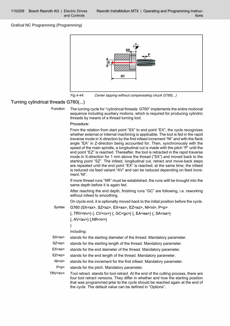
Fig.4-44: Center tapping without compensating chuck G785(...)
Turning cylindrical threads G760(...)The turning cycle for “cylindrical threads G760” implements the entire motionalsequence including auxiliary motions, which is required for producing cylindricthreads by means of a thread turning tool.Procedure:From the relation from start point “SX” to end point “EX”, the cycle recognizeswhether external or internal machining is applicable. The tool is fed in the rapidtraverse mode in X-direction by the first infeed increment “NI” and with the flankangle “EA” in Z-direction being accounted for. Then, synchronously with thespeed of the main spindle, a longitudinal cut is made with the pitch “P” until theend point “EZ” is reached. Thereafter, the tool is retracted in the rapid traversemode in X-direction for 1 mm above the thread (“SX”) and moved back to thestarting point “SZ”. The infeed, longitudinal cut, retract and move-back stepsare repeated until the end point “EX” is reached; at the same time, the infeedis reduced via feed variant “AV” and can be reduced depending on feed incre‐ment.“NI”.If more thread runs “NR” must be established, the runs willl be brought into thesame depth before it is again fed.After reaching the end depth, finishing runs “GC” are following, i.e. reworkingwithout infeed to smoothing.On clycle end, it is optionally moved back to the initial position before the cycle.G760 (SX<sx>, SZ<sz>, EX<ex>, EZ<ez>, NI<ni>, P<p>{, TRV<trv>} {, CV<cv>} {, GC<gc>} {, EA<ea>} {, SA<sa>}{, AV<av>} {,NR<nr>})including:stands for the starting diameter of the thread. Mandatory parameter.stands for the starting length of the thread. Mandatory parameter.stands for the end diameter of the thread. Mandatory parameter.stands for the end length of the thread. Mandatory parameter.stands for the increment for the first infeed. Mandatory parameter.stands for the pitch. Mandatory parameter.Tool retract. stands for tool retract. At the end of the cutting process, there arefour tool retract versions. They differ in whether and how the starting positionthat was programmed prior to the cycle should be reached again at the end ofthe cycle. The default value can be defined in “Options”.
Function
Syntax
SX<sx>
SZ<sz>
EX<ex>
EZ<ez>
NI<ni>
P<p>
TRV<trv>
110/209 Bosch Rexroth AG | Electric Drivesand Controls
Rexroth IndraMotion MTX | Operating and Programming Instruc‐tions
Grafical NC Programming (Programming)

TRV0 The tool does not move to the starting position, but stops after lifting thelast cut.TRV1 The tool moves to the starting position simultaneously in both axes.TRV2 The tool moves to the starting position first along the plane axis and thenalong the longitudinal axis.TRV3 The tool moves to the starting position first along the longitudinal axisand then along the plane axis.stands for the cutting variant. The default value can be defined in “Options”.CV1 Axially parallel (here radial) infeed.CV2 Flankwise infeed.CV3 Alternate infeed.
Fig.4-45: Thread turning cut variantsFeed variant. The feed variant contains the factor for the reduced infeed as ofthe second step.AV0 any feed depth: NI multiples with the square root of any feed. Realizes aconstant chip cross-section for norm thread. Default setting.AV1 any feed depth: 2NI multiples with the square root of any feed. Utilizationof norm threads if the number of steps was reduced or a small feed depth shouldbe avoided before reaching the thread depth.AV2 any feed depth: NI multiples with any feed. Utilization of trapezoid thread.
Fig.4-46: Thread turning feed variantsNumber of glaze cuts (noncuts). Default: 1.Edge angle (0<=EA<180). Default 60 degree.Number of thread runs. Default: 1.Thread start angle in degrees. Default: 0.The true thread start angle results from the intended approach in relation tothread pitch P.
CV<cv>
AV<av>
GC<gc>
EA<ea>
NR<nr>
SA<sa>
Operating and Programming Instructions | Rexroth IndraMotionMTX
Electric Drivesand Controls
| Bosch Rexroth AG 111/209
Grafical NC Programming (Programming)

Fig.4-47: Thread turning G760, external thread
Fig.4-48: Thread turning G760, internal thread
Taper threads turning G761(...)The turning cycle for “Taper threads G761” implements the entire motionalsequence including auxiliary motions, which is required for producing taperthreads by means of a thread turning tool. It is also suited for face threads.It must be considered that the lead is indicated axially parallel (as a rule K) andthat the edges are measured symmetric to axis in its angle (as a rule symmetricto X axis, radial setting of tool). As of a taper angle larger than 90 degree, thelead is interpreted as plane lead. The tool is afterwards set axially.Definition of thread runs occurs via specifying start and end point of the pathwhich the future thread including entering and exiting path touches on the ma‐terial-free side. With the sign of thread depth “DT” it is recognized in whichdirection the depth infeed is executed. A negative thread depth means infeedin negative axis direction and is utilized for external threads or face threads innormal conditions.
Procedure:The cycle starts with positioning on a start point which results from the “SX/SZ” shifted via the first infeed increment “NI” considering the edge angle “EA”cone inclination. Then, synchronously with the speed of the main spindle, a cutis made with the pitch “P” until the end point “EX/EZ” is reached. Thereafter,the tool is retracted in the rapid traverse mode for 1 mm above the thread andmoved back to the starting point “SX/SZ”. The infeed, cut, retract and move-back steps are repeated until the thread depth “DT” is reached; at the sametime, the infeed is reduced via feed variant “AV” and can be reduced dependingon feed increment.“NI”.If more thread runs “NR” must be established, the runs willl be brought into thesame depth before it is again fed.After reaching the end depth, finishing runs “GC” are following, i.e. reworkingwithout infeed to smoothing.
Function
112/209 Bosch Rexroth AG | Electric Drivesand Controls
Rexroth IndraMotion MTX | Operating and Programming Instruc‐tions
Grafical NC Programming (Programming)

On clycle end, it is optionally moved back to the initial position before the cycle.G761 (SX<sx>, SZ<sz>, EX<ex>, EZ<ez>, NI<ni>, P<p>, DT<dt>{, TRV<trv>} {, CV<cv>} {, GC<gc>} {, EA<ea>} {, SA<sa>}{, AV<av>} {,NR<nr>})including:stands for the starting diameter of the thread. Mandatory parameter.stands for the starting length of the thread. Mandatory parameter.stands for the end diameter of the thread. Mandatory parameter.stands for the end length of the thread. Mandatory parameter.stands for the increment for the first infeed. Mandatory parameter.stands for the pitch. Mandatory parameter.Thread depth. Exception: The sign of thread depth indicates the direction ofdepth infeed. A negative indicated thread depth means outside machining, apositive indicated thread depth means inside machining. Mandatory parameter.Tool retract. stands for tool retract. At the end of the cutting process, there arefour tool retract versions. They differ in whether and how the starting positionthat was programmed prior to the cycle should be reached again at the end ofthe cycle. The default value can be defined in “Options”.TRV0 The tool does not move to the starting position, but stops after lifting thelast cut.TRV1 The tool moves to the starting position simultaneously in both axes.TRV2 The tool moves to the starting position first along the plane axis and thenalong the longitudinal axis.TRV3 The tool moves to the starting position first along the longitudinal axisand then along the plane axis.stands for the cutting variant. The default value can be defined in “Options”.CV1 Infeed parallel to the axis.CV2 Flankwise infeed.CV3 Alternate infeed.
Fig.4-49: Thread turning cut variants
The alternate infeed for a tapered thread run does not make senseas there are variations in the chip cross-section.
Feed variant. The feed variant contains the factor for the reduced infeed as ofthe second step.AV0 any feed depth: NI multiples with the square root of any feed. Realizes aconstant chip cross-section for norm thread. Default setting.
Syntax
SX<sx>
SZ<sz>
EX<ex>
EZ<ez>
NI<ni>
P<p>
DT<dt>
TRV<trv>
CV<cv>
AV<av>
Operating and Programming Instructions | Rexroth IndraMotionMTX
Electric Drivesand Controls
| Bosch Rexroth AG 113/209
Grafical NC Programming (Programming)

AV1 any feed depth: 2NI multiples with the square root of any feed. Utilizationof norm threads if the number of steps was reduced or a small feed depth shouldbe avoided before reaching the thread depth.AV2 any feed depth: NI multiples with any feed. Utilization of trapezoid thread.
Fig.4-50: Thread turning feed variantsNumber of glaze cuts (noncuts). Default: 1.Edge angle (0<=EA<180). Default 60 degree.Number of thread runs. Default: 1.Thread start angle in degrees. Default: 0.The true thread start angle results from the intended approach in relation tothread pitch P.
Fig.4-51: Thread turning G761, external thread
Fig.4-52: Thread turning G761, internal thread
GC<gc>
EA<ea>
NR<nr>
SA<sa>
114/209 Bosch Rexroth AG | Electric Drivesand Controls
Rexroth IndraMotion MTX | Operating and Programming Instruc‐tions
Grafical NC Programming (Programming)

Example:
Tapered outside thread
Thread according to illustration, should be created by edge infeed. Startup andend should each be 5 mm.
Fig.4-53: Example for a tapered outside threadG761(SX15.5, SZ5, EX20.5, EZ-25, NI0.5, P1.5, DT-0.92,CV2)
Thread sequence turning G762(...)A thread sequence is a line path from up to three subsequent threads. Themiddle thread is indicated as main thread. The first thread is indicated as startupthe third as end, whereas the thread can also be on the machining forms on thefinish part.Thread sequences will mainly be utilized if necessary startup and end for ma‐chining can not directly be tangentially connected to the thread (condition oflocation, thread undercut not available etc.).The turning cycle for “Thread sequence G762” implements the entire motionalsequence including auxiliary motions, which is required for producing threadsequences by means of a thread turning tool. Thread startup and/or end canthere be omitted optionally. If both are omitted, G762 corresponds to the cylcleG761 Tapered thread turning.It must be consideres that the ptich must be indicated axis-parallel (as a ruleK). As of taper angle larger than 90 degree (where each thread of sequencemust be considered individually), the pitch is indicated as plane pitch I.For a taper angle of main thread, the edge angles are located up to 90 degreesymmetric to X axis (radial setting of tools), for a larger edge angle symmetricto Z axis (axial tool).
Function
Operating and Programming Instructions | Rexroth IndraMotionMTX
Electric Drivesand Controls
| Bosch Rexroth AG 115/209
Grafical NC Programming (Programming)

Thread run definition is executed via specifying the interpolation points of thecorresponding line path which touches the future thread sequence on the ma‐terial-free side. With the sign of thread depth “DT” it is recognized in whichdirection the depth infeed is executed. A negative thread depth means infeedin negative axis direction and is utilized for external threads or face threads innormal conditions.Procedure:The cycle starts with positioning on the start point of startup which results fromthe “SAX/SAZ” shifted via the first infeed increment “NI” considering the edgeangle “EA” cone inclination of startup. It is cut synchronously for the appliedmain spindle speed with pitch “PA” of thread sequence startup up to start pointof main thread “SX/SZ”, than the main thread up to end point “EX/EZ” with pitch“P” and afterwards the cut to end point of thread end “ERX/ERZ” with pitch“PR” is executed. Rapid traverse with 1mm above the thread occurs and thestart point startup“SAX/SAZ” is retracted. The infeed, cut, retract and move-back steps are repeated until the thread depth “DT” is reached; at the sametime, the infeed is reduced via feed variant “AV” and can be reduced dependingon feed increment.“NI”.If more thread runs “NR” must be established, the runs willl be brought into thesame depth before it is again fed.After reaching the end depth, finishing runs “GC” are following, i.e. reworkingwithout infeed to smoothing.On clycle end, it is optionally moved back to the initial position before the cycle.G762 (SX<sx>, SZ<sz>, EX<ex>, EZ<ez>, NI<ni>, P<p>, DT<dt>{, TRV<trv>} {, CV<cv>} {, GC<gc>} {, EA<ea>} {, SA<sa>}{, AV<av>} {,NR<nr>} {, SAX<sax>, SAZ<saz> {, PA<pa>}}{,ERX<erx>, ERZ<erz> {, PR<pr>}})including:Starting diameter of the thread startup. Indicating SAZ mandatory parameter.Starting length of the thread startup. Indicating SAX mandatory parameter.Starting diameter of the main thread. Mandatory parameter.Starting length of the main thread. Mandatory parameter.End diameter of the main thread. Mandatory parameter.End length of the main thread. Mandatory parameter.End diameter of the thread end. Indicating ERZ mandatory parameter.End length of the thread end. Indicating ERX mandatory parameter.stands for the increment for the first infeed. Mandatory parameter.Thread lead of main thread. Mandatory parameter.Thread lead of startup thread. Default P.Thread lead of end thread. Default P.Thread depth. Exception: The sign of thread depth indicates the direction ofdepth infeed. A negative indicated thread depth means outside machining, apositive indicated thread depth means inside machining. Mandatory parameter.Tool retract. stands for tool retract. At the end of the cutting process, there arefour tool retract versions. They differ in whether and how the starting positionthat was programmed prior to the cycle should be reached again at the end ofthe cycle. The default value can be defined in “Options”.
Syntax
SAX<sax>
SAZ<saz>
SX<sx>
SZ<sz>
EX<ex>
EZ<ez>
ERX<erx>
ERZ<erz>
NI<ni>
P<p>
PA<pa>
PR<pr>
DT<dt>
TRV<trv>
116/209 Bosch Rexroth AG | Electric Drivesand Controls
Rexroth IndraMotion MTX | Operating and Programming Instruc‐tions
Grafical NC Programming (Programming)

TRV0 The tool does not move to the starting position, but stops after lifting thelast cut.TRV1 The tool moves to the starting position simultaneously in both axes.TRV2 The tool moves to the starting position first along the plane axis and thenalong the longitudinal axis.TRV3 The tool moves to the starting position first along the longitudinal axisand then along the plane axis.stands for the cutting variant. The default value can be defined in “Options”.CV1 Infeed parallel to the axis.CV2 Flankwise infeed.CV3 Alternate infeed.
Fig.4-54: Thread turning cut variants
The alternate infeed for a tapered thread run does not make senseas there are variations in the chip cross-section.Only an axis-parallel infeed can be utilized for different pitches ofthe single thread segments.
Feed variant. The feed variant contains the factor for the reduced infeed as ofthe second step.AV0 any feed depth: NI multiples with the square root of any feed. Realizes aconstant chip cross-section for norm thread. Default setting.AV1 any feed depth: 2NI multiples with the square root of any feed. Utilizationof norm threads if the number of steps was reduced or a small feed depth shouldbe avoided before reaching the thread depth.AV2 any feed depth: NI multiples with any feed. Utilization of trapezoid thread.
Fig.4-55: Thread turning feed variantsNumber of glaze cuts (noncuts). Default: 1.Edge angle (0<=EA<180). Default 60 degree.Number of thread runs. Default: 1.Thread start angle in degrees. Default: 0.The true thread start angle results from the intended approach in relation tothread pitch P.
CV<cv>
AV<av>
GC<gc>
EA<ea>
NR<nr>
SA<sa>
Operating and Programming Instructions | Rexroth IndraMotionMTX
Electric Drivesand Controls
| Bosch Rexroth AG 117/209
Grafical NC Programming (Programming)

Fig.4-56: Thread turning G762, external thread
Fig.4-57: Thread turning G762, internal threadExample:
Thread sequence
Thread according to illustration should be machined because of missing loca‐tion for a tangential startup and missing of a thread undercut at the end of thecylce for thread sequences.
118/209 Bosch Rexroth AG | Electric Drivesand Controls
Rexroth IndraMotion MTX | Operating and Programming Instruc‐tions
Grafical NC Programming (Programming)

Fig.4-58:G762 (SAX37.84, SAZ-5, SX37.84, SZ-10, EX32.84, EZ-35,ERX30.84, ERZ-40, NI0.5, CV1, P2, DT1.08)
4.2.3 Drilling CyclesCenter drilling G801(...)
The “center drilling cycle G801” implements the entire motional sequence re‐quired for drilling at predefined points with a single drilling stroke. The tool isretracted from the drilling hole in rapid traverse mode.Procedure:In rapid traverse mode, the tool is positioned to the first drilling point in the planeand then from the previously approached position to the safety distance “SD”.Then drilling is carried out to the depth “DT” in the feed mode “F”/“FV”; finally,the dwell time “DWT”/“DWR” is processed and then the tool is moved to thereturn position “RP” in rapid traverse mode.This sequence is repeated whenever a drilling motion follows.G801 (ID<id>, SD<sd>, DT<dt>, F<f>|FV<fv> {, RP<rp>}{, DWT<dwt>|DWR<dwr>} {, CR<cr>} {, D<d>} {, TAC<tac>})including:stands for the ident of the drilling point set. Mandatory parameter.stands for the safety distance which defines the position where drilling starts.This position is approached in the rapid traverse mode. The dimension is speci‐fied as absolute value. Mandatory parameter.stands for the depth where drilling is finished. The dimension is specified asabsolute value. Mandatory parameter.
Function
Syntax
ID<id>
SD<sd>
DT<dt>
Operating and Programming Instructions | Rexroth IndraMotionMTX
Electric Drivesand Controls
| Bosch Rexroth AG 119/209
Grafical NC Programming (Programming)

stands for the machining feed in the basic programming unit/revolution. Man‐datory parameter, but to be specified as an alternative of “FV”.stands for the machining feed in the basic programming unit/min. Mandatoryparameter, but to be specified as an alternative of “F”.stands for the return position. If none is specified, the tool will return to “SD”.stands for the dwell time (seconds) at the drilling base. To be specified as analternative of “DWR”.stands for the dwell revolutions at the drilling base. To be specified as an al‐ternative of “DWT”.Machining direction with regard to the definition of the drilling point set.CR0 Machining in contour definition direction (default setting).CR1 Machining opposite to the defined direction.stands for the diameter of the drilling hole (default setting: 0).stands for the tip angle in degrees (0<TAC<=180, default 118).
Fig.4-59: Center drilling G801
Reaming G802(...)The “reaming cycle G802” implements the entire motional sequence for ream‐ing at predefined points. This cycle is particular in that the tool is retracted fromthe drilling hole in the feed mode.Procedure:In rapid traverse mode, the tool is positioned to the first drilling point in the planeand then from the previously approached position to the safety distance “SD”.In the next step, the tool reams to the depth “DT” with feed “F”/“FV”. Finally, thedwell time “DWT”/“DWR” is processed. Thereafter, the tool is positioned to thesafety distance with feed “FR”. If a return position “RP” has been programmed,then the tool is moved to that position in the rapid traverse mode.This sequence is repeated whenever a drilling motion follows.G802 (ID<id>, SD<sd>, DT<dt>, F<f>|FV<fv> {, FR<fr>} {, RP<rp>}{, DWT<dwt>|DWR<dwr>} {, CR<cr>} {, D<d>})including:stands for the ident of the drilling point set. Mandatory parameter.stands for the safety distance which defines the position where drilling starts.This position is approached in the rapid traverse mode. The dimension is speci‐fied as absolute value. Mandatory parameter.
F<f>
FV<fv>
RP<rp>
DWT<dwt>
DWR<dwr>
CR<cr>
D<d>
TAC<tac>
Function
Syntax
ID<id>
SD<sd>
120/209 Bosch Rexroth AG | Electric Drivesand Controls
Rexroth IndraMotion MTX | Operating and Programming Instruc‐tions
Grafical NC Programming (Programming)

stands for the depth where drilling is finished. The dimension is specified asabsolute value. Mandatory parameter.stands for the machining feed in the basic programming unit/revolution. Man‐datory parameter, but to be specified as an alternative of "FV".stands for the machining feed in the basic programming unit/min. Mandatoryparameter, but to be specified as an alternative of “F”.stands for the feed for the return motion. The unit is equal to that selected viathe feed specification parameter. Default setting: FR = 2*F/FV.stands for the return position. If none is specified, the tool will return to “SD”.stands for the dwell time (seconds) at the drilling base. To be specified as analternative of “DWR”.stands for the dwell revolutions at the drilling base. To be specified as an al‐ternative of “DWT”.Machining direction with regard to the definition of the drilling point set.CR0 Machining in contour definition direction (default setting).CR1 Machining opposite to the defined direction.stands for the diameter of the drilling hole (default setting: 0).
Fig.4-60: Reaming G802
Drilling with multi-chamfer step drill G803(...)The “drilling with multi-chamfer step drill G803 cycle” implements the entiremotional sequence for drilling with step drills. It is suitable for other drilling op‐erations requiring two speeds and/or feeds, e.g.:● Drilling with preceding centering (drilling a point with low feed), or● countersinking with a counterbore.This requires that the tool be measured at the large diameter. It is also possibleto use two cutting edge corners: Cutting edge A (chamfer A) is related to thelarge diameter; cutting edge B (chamfer B) is related to the tool tip.Procedure:In rapid traverse mode, the tool is positioned to the first drilling point in the planeand then, with its tip, from the previously approached position to the safetydistance “SD”. If a specific speed has been programmed for step B (SB), or if“DA” and “DB” are specified, then the speed “SB” or a speed that has beenincreased by the ratio of DA to DB is activated (aiming at a constant cuttingspeed). Drilling to “LB” depth is performed at this speed or the starting speed(feed “FB” or “F”. If only “FV” is defined, it will be adjusted in relation to thespeed). Then the starting speed is used again. Thereafter, the tool drills to“DT” with chamfer A (large diameter) with feed “F”/“FV”; finally, the dwelling
DT<dt>
F<f>
FV<fv>
FR<fr>
RP<rp>
DWT<dwt>
DWR<dwr>
CR<cr>
D<d>
Function
Operating and Programming Instructions | Rexroth IndraMotionMTX
Electric Drivesand Controls
| Bosch Rexroth AG 121/209
Grafical NC Programming (Programming)

time “DWT”/“DWR” is processed, and then the tool is moved with its tip to thereturn position “RP” or to “SD” in rapid traverse mode.This sequence is repeated whenever a drilling motion follows.G803 (ID<id>, SD<sd>, DT<dt>, F<f>|FV<fv>,LB<lb> {, FB<fb>} {,SB<sb>}{, DA<da>} {, DB<db>} {, TEA<tea>, TEB<teb>}{, RP<rp>} {, DWT<dwt>|DWR<dwr>} {, CR<cr>})including:stands for the ident of the drilling point set. Mandatory parameter.stands for the safety distance which defines the position where drilling starts.This position is approached in the rapid traverse mode from the tool tip. Thedimension is specified as absolute value. Mandatory parameter.stands for the depth where drilling is finished. This is the absolute end coordi‐nate to be reached by the tool edge “TEA” or the large diameter. Mandatorydiameter.stands for the machining feed in the basic programming unit/revolution. Man‐datory parameter, but to be specified as an alternative of “FV”.stands for the machining feed in the basic programming unit/min. Mandatoryparameter, but to be specified as an alternative of “F”.stands for the length of the first phase, i.e. of the small diameter. Mandatoryparameter. If the tool edge change with “TEA” and “TEB” is used, it is sufficientto specify an approximate value. Then, “LB” is not directly incorporated in thecoordinates of the motional sequence, but indirectly through the tool lengthcorrection.stands for the machining feed for the phase with the small diameter. The unitis specified by the utilized parameter “F” or “FV”. If “FB” is not programmed, thesame feed is realized for both phases in the basic programming unit / revolution.stands for the spindle speed for the phase with the small diameter. Standard:SB = starting speed * DA / DB or starting speed.Large diameter (default setting 0)Small diameter (default setting “DA”).Number of the tool edge in which the length correction amount for the tool stageis stored. To be specified only together with “TEB”. By default, no change ofcutting edges is effected, i.e. it is presupposed that the active length correctionrefers to the tool stage.Number of the tool tip in which the length correction amount for the tool stageis stored. To be specified only together with “TEA”. By default, no change ofcutting edges is effected, i.e. the phase length “FB” is taken into considerationin the traversing path.stands for the return position. If none is specified, the tool tip return to “SD”.stands for the dwell time (seconds) at the drilling base. To be specified as analternative of “DWR”.stands for the dwell revolutions at the drilling base. To be specified as an al‐ternative of “DWT”.Machining direction with regard to the definition of the drilling point set.CR0 Machining in contour definition direction (default setting).CR1 Machining opposite to the defined direction.
Syntax
ID<id>
SD<sd>
DT<dt>
F<f>
FV<fv>
LB<lb>
FB<fb>
SB<fb>
DA<da>
DB<db>
TEA<tea>
TEB<teb>
RP<rp>
DWT<dwt>
DWR<dwr>
CR<cr>
122/209 Bosch Rexroth AG | Electric Drivesand Controls
Rexroth IndraMotion MTX | Operating and Programming Instruc‐tions
Grafical NC Programming (Programming)

Fig.4-61: Drilling with multi-chamfer step drill G803
Deep-hole drilling with chip removal G830(...)The “deep-hole drilling with chip removal cycle G830” implements the entiremotional sequence for drilling at predefined points.Procedure:In the rapid traverse mode, the tool is positioned from the previously approach‐ed position to the safety distance “SD”. From there, the tool always drills downby the cutting depth “CD” with feed “F”. Whenever a drilling stroke is completed,the tool retracts to SD in rapid traverse mode. Then, in rapid traverse mode,the tool moves to the drilling depth reached, minus the approach distance“AD”. In the last cut, the tool drills to the depth “DT”. Finally, the dwelling time“DWT” or the dwelling revolutions “DWR” is/are processed, and then the tool ismoved to the return position “RP”.This sequence is repeated whenever a drilling motion follows.G830 (ID<id>, SD<sd>, DT<dt>, CD<cd>, F<f>|FV<fv> {, RP<rp>}{, AD<ad} {, DWT<dwt>|DWR<dwr>} {, CR<cr>} {, D<d>} {, TAC<tac>})including:stands for the ident of the drilling point set. Mandatory parameter.stands for the safety distance which defines the position where drilling starts.This position is approached in the rapid traverse mode. The dimension is speci‐fied as absolute value. Mandatory parameter.stands for the depth where drilling is finished. The dimension is specified asabsolute value. Mandatory parameter.stands for the infeed depth for the first drilling stroke. Mandatory parameter.stands for the machining feed in the basic programming unit/revolution. Man‐datory parameter, but to be specified as an alternative of “FV”.stands for the machining feed in the basic programming unit/min. Mandatoryparameter, but to be specified as an alternative of “F”.stands for the return position. If none is specified, the tool will return to “SD”.stands for the approach distance with each following stroke (default setting: 0).
Function
Syntax
ID<id>
SD<sd>
DT<dt>
CD<cd>
F<f>
FV<fv>
RP<rp>
AD<ad>
Operating and Programming Instructions | Rexroth IndraMotionMTX
Electric Drivesand Controls
| Bosch Rexroth AG 123/209
Grafical NC Programming (Programming)

stands for the dwell time (seconds) at the drilling base. To be specified as analternative of “DWR”.stands for the dwell revolutions at the drilling base. To be specified as an al‐ternative of “DWT”.Machining direction with regard to the definition of the drilling point set.CR0 Machining in contour definition direction (default setting).CR1 Machining opposite to the defined direction.stands for the diameter of the drilling hole (default setting: 0).stands for the tip angle in degrees (0<TAC<=180, default 118).
Fig.4-62: Deep-hole drilling with chip removal G830
Deep-hole drilling with chip breakage G831(...)The “deep-hole drilling with chip breaking cycle G831” implements the entiremotional sequence for drilling at predefined points.Procedure:In rapid traverse mode, the tool is positioned to the first drilling point in the planeand then from the previously approached position to the safety distance “SD”.From there, the tool always drills down by the cutting depth “CD” with feed“F”. After infeed, the chip breaking stroke “AD”, if specified, is carried out in therapid traverse mode. In the last cut, the tool drills to the depth “DT”. Finally, thedwelling time “DWT”/“"DWR” is processed, and then the tool is moved to thereturn position “RP” in rapid traverse mode.This sequence is repeated whenever a drilling motion follows.G831 (ID<id>, SD<sd>, DT<dt>, CD<cd>, {F<f>|FV<fv>} {, RP<rp>}{, AD<ad>} {, DWT<dwt>|DWR<dwr>} {, CR<cr>} {, D<d>} {, TAC<tac>})including:stands for the ident of the drilling point set. Mandatory parameter.stands for the safety distance which defines the position where drilling starts.This position is approached in the rapid traverse mode. The dimension is speci‐fied as absolute value. Mandatory parameter.stands for the depth where drilling is finished. The dimension is specified asabsolute value. Mandatory parameter.stands for the infeed depth for the first drilling stroke. Mandatory parameter.stands for the machining feed in the basic programming unit/revolution. Man‐datory parameter, but to be specified as an alternative of “FV”.
DWT<dwt>
DWR<dwr>
CR<cr>
D<d>
TAC<tac>
Function
Syntax
ID<id>
SD<sd>
DT<dt>
CD<cd>
F<f>
124/209 Bosch Rexroth AG | Electric Drivesand Controls
Rexroth IndraMotion MTX | Operating and Programming Instruc‐tions
Grafical NC Programming (Programming)

stands for the machining feed in the basic programming unit/min. Mandatoryparameter, but to be specified as an alternative of “F”.stands for the return position. If none is specified, the tool will return to “SD”.stands for the retract amount for chip breakage (default setting: 0).stands for the dwell time (seconds) at the drilling base. To be specified as analternative of “DWR”.stands for the dwell revolutions at the drilling base. To be specified as an al‐ternative of “DWT”.Machining direction with regard to the definition of the drilling point set.CR0 Machining in contour definition direction (default setting).CR1 Machining opposite to the defined direction.stands for the diameter of the drilling hole (default setting: 0).stands for the tip angle in degrees (0<TAC<=180, default 118).
Fig.4-63: Deep-hole drilling with chip breakage G831
Floating tapping G840(...)The “floating tapping cycle G840” implements the entire motional sequence forthread drilling at predefined points.Procedure:In the rapid traverse mode, the tool is positioned from the previously approach‐ed position to the safety distance “SD”. In the next step, the tool drills to thedepth “ST” in the feed mode. Thereafter, the tool is again positioned to thesafety distance “SD” with contrarotating spindle in the feed mode and with thefactor “FFR” being considered (speed factor for the travel-out speed) or, if pro‐grammed, to the return position “RP”. Then the direction of rotation and speedfor traveling out are set.This sequence is repeated whenever a drilling motion follows.G840 (ID<id>, SD<sd>, DT<dt>, P<p>{, FFR<ffr>} {, RP<rp>} {, CR<cr>} {, D<d>})including:stands for the ident of the drilling point set. Mandatory parameter.stands for the safety distance which defines the position where drilling starts.This position is approached in the rapid traverse mode. The dimension is speci‐fied as absolute value. Mandatory parameter.
FV<fv>
RP<rp>
AD<ad>
DWT<dwt>
DWR<dwr>
CR<cr>
D<d>
TAC<tac>
Function
Syntax
ID<id>
SD<sd>
Operating and Programming Instructions | Rexroth IndraMotionMTX
Electric Drivesand Controls
| Bosch Rexroth AG 125/209
Grafical NC Programming (Programming)

stands for the depth where drilling is finished. The dimension is specified asabsolute value. Mandatory parameter.stands for the pitch. Mandatory parameter.stands for the increase in speed and feed for traveling out (default setting: 2).stands for the return position. If none is specified, the tool will return to “SD”.Machining direction with regard to the definition of the drilling point set.CR0 Machining in contour definition direction (default setting).CR1 Machining opposite to the defined direction.stands for the diameter of the drilling hole (default setting: 0).
Fig.4-64: Foating tapping G840
Rigid tapping G841(...)The “rigid tapping cycle G841” implements the entire motional sequence forthread drilling at predefined points.Procedure:In the rapid traverse mode, the tool is positioned from the previously approach‐ed position to the safety distance “SD”. In the next step, the tool drills to thedepth “ST” in the feed mode. Thereafter, the tool is again positioned to thesafety distance “SD” with contrarotating spindle in the feed mode and with thefactor “FFR” being considered (speed factor for the travel-out speed) or, if pro‐grammed, to the return position “RP”. Then the direction of rotation and speedfor traveling out are set.This sequence is repeated whenever a drilling motion follows.G841 (ID<id>, SD<sd>, DT<dt>, P<p>{, FFR<ffr>} {, RP<rp>} {, CR<cr>} {, D<d>})including:stands for the ident of the drilling point set. Mandatory parameter.stands for the safety distance which defines the position where drilling starts.This position is approached in the rapid traverse mode. The dimension is speci‐fied as absolute value. Mandatory parameter.stands for the depth where drilling is finished. The dimension is specified asabsolute value. Mandatory parameter.stands for the pitch. Mandatory parameter.stands for the increase in speed and feed for traveling out (default setting: 2).stands for the return position. If none is specified, the tool will return to “SD”.
DT<dt>
P<p>
FFR<ffr>
RP<rp>
CR<cr>
D<d>
Function
Syntax
ID<id>
SD<sd>
DT<dt>
P<p>
FFR<ffr>
RP<rp>
126/209 Bosch Rexroth AG | Electric Drivesand Controls
Rexroth IndraMotion MTX | Operating and Programming Instruc‐tions
Grafical NC Programming (Programming)

Machining direction with regard to the definition of the drilling point set.CR0 Machining in contour definition direction (default setting).CR1 Machining opposite to the defined direction.stands for the diameter of the drilling hole (default setting: 0).
Fig.4-65: Rigid tapping G841
Boring G851(...)The “boring cycle G851” implements the entire motional sequence for boringwith a boring tool (boring bar, boring rod). The tool is orientated for traveling outand put to an eccentric position.Procedure:In rapid traverse mode, the tool is positioned to the first drilling point in the planeand then to the safety distance “SD”. In the next step, the tool drills to the depth“DT” with feed “F”. Finally, the dwell time “DWT”/“DWR” is processed. Then thespindle, orientated at 0 degree, is stopped, and the tool edge is moved to aneccentric position by the amount “DI” in rapid traverse mode. Then the tool ismoved to the return position “RP” in rapid traverse mode. The rotational motionof the spindle is restarted.This sequence is repeated whenever a drilling motion follows.G851 (ID<id>, SD<sd>, DT<dt>, F<f>|FV<fv> {, RP<rp>}{, DI<di>} {, TA<ta>} {, DWT<dwt>|DWR<dwr>}{, CR<cr>} {, D<d>})including:stands for the ident of the drilling point set. Mandatory parameter.stands for the safety distance which defines the position where drilling starts.This position is approached in the rapid traverse mode. The dimension is speci‐fied as absolute value. Mandatory parameter.stands for the depth where drilling is finished. The dimension is specified asabsolute value. Mandatory parameter.stands for the machining feed in the basic programming unit/revolution. Man‐datory parameter, but to be specified as an alternative of “FV”.stands for the machining feed in the basic programming unit/min. Mandatoryparameter, but to be specified as an alternative of “F”.stands for the return position. If none is specified, the tool will return to “SD”.stands for the amount for retracting from the drilling hole wall. Default setting:0.01*D.
CR<cr>
D<d>
Function
Syntax
ID<id>
SD<sd>
DT<dt>
F<f>
FV<fv>
RP<rp>
DI<di>
Operating and Programming Instructions | Rexroth IndraMotionMTX
Electric Drivesand Controls
| Bosch Rexroth AG 127/209
Grafical NC Programming (Programming)
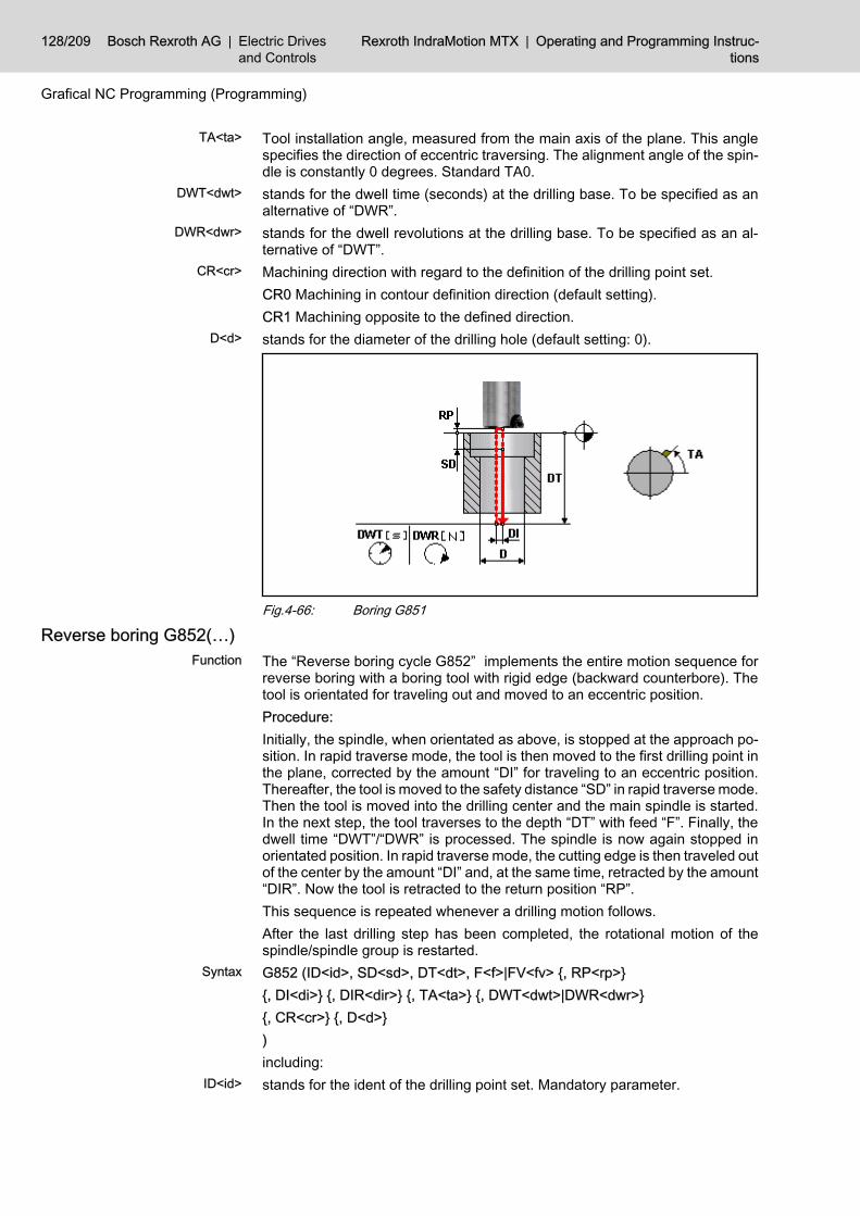
Tool installation angle, measured from the main axis of the plane. This anglespecifies the direction of eccentric traversing. The alignment angle of the spin‐dle is constantly 0 degrees. Standard TA0.stands for the dwell time (seconds) at the drilling base. To be specified as analternative of “DWR”.stands for the dwell revolutions at the drilling base. To be specified as an al‐ternative of “DWT”.Machining direction with regard to the definition of the drilling point set.CR0 Machining in contour definition direction (default setting).CR1 Machining opposite to the defined direction.stands for the diameter of the drilling hole (default setting: 0).
Fig.4-66: Boring G851
Reverse boring G852(…)The “Reverse boring cycle G852” implements the entire motion sequence forreverse boring with a boring tool with rigid edge (backward counterbore). Thetool is orientated for traveling out and moved to an eccentric position.Procedure:Initially, the spindle, when orientated as above, is stopped at the approach po‐sition. In rapid traverse mode, the tool is then moved to the first drilling point inthe plane, corrected by the amount “DI” for traveling to an eccentric position.Thereafter, the tool is moved to the safety distance “SD” in rapid traverse mode.Then the tool is moved into the drilling center and the main spindle is started.In the next step, the tool traverses to the depth “DT” with feed “F”. Finally, thedwell time “DWT”/“DWR” is processed. The spindle is now again stopped inorientated position. In rapid traverse mode, the cutting edge is then traveled outof the center by the amount “DI” and, at the same time, retracted by the amount“DIR”. Now the tool is retracted to the return position “RP”.This sequence is repeated whenever a drilling motion follows.After the last drilling step has been completed, the rotational motion of thespindle/spindle group is restarted.G852 (ID<id>, SD<sd>, DT<dt>, F<f>|FV<fv> {, RP<rp>}{, DI<di>} {, DIR<dir>} {, TA<ta>} {, DWT<dwt>|DWR<dwr>}{, CR<cr>} {, D<d>})including:stands for the ident of the drilling point set. Mandatory parameter.
TA<ta>
DWT<dwt>
DWR<dwr>
CR<cr>
D<d>
Function
Syntax
ID<id>
128/209 Bosch Rexroth AG | Electric Drivesand Controls
Rexroth IndraMotion MTX | Operating and Programming Instruc‐tions
Grafical NC Programming (Programming)

stands for the safety distance which defines the position where drilling starts.This position is approached in the rapid traverse mode. The dimension is speci‐fied as absolute value. Mandatory parameter.stands for the depth where drilling is finished. The dimension is specified asabsolute value. Mandatory parameter.stands for the machining feed in the basic programming unit/revolution. Man‐datory parameter, but to be specified as an alternative of “FV”.stands for the machining feed in the basic programming unit/min. Mandatoryparameter, but to be specified as an alternative of “F”.stands for the return position. If it is not specified, the tool moves back to thestarting position before the cycle.stands for the amount for retracting from the drilling hole wall. Default setting:0.01*D.stands for the amount for retracting from the drilling hole base. Default setting:0.01*D.Tool installation angle, measured from the main axis of the plane. This anglespecifies the direction of eccentric traversing. The alignment angle of the spin‐dle is constantly 0 degrees. Standard TA0.stands for the dwell time (seconds) at the drilling base. To be specified as analternative of “DWR”.stands for the dwell revolutions at the drilling base. To be specified as an al‐ternative of “DWT”.Machining direction with regard to the definition of the drilling point set.CR0 Machining in contour definition direction (default setting).CR1 Machining opposite to the defined direction.stands for the diameter of the drilling hole (default setting: 0).
Fig.4-67: Reverse boring G852
4.2.4 Milling CyclesContour milling G910(...)
The “contour milling cycle G910” implements the milling process along a pre‐defined contour.It is possible to approach and run-out paths in addition to the contour program‐med. They consist of no more than three components (tangential path, arc,normal path) which can be combined with each other as desired. If a contour
SD<sd>
DT<dt>
F<f>
FV<fv>
RP<rp>
DI<di>
DIR<di>
TA<ta>
DWT<dwt>
DWR<dwr>
CR<cr>
D<d>
Function
Operating and Programming Instructions | Rexroth IndraMotionMTX
Electric Drivesand Controls
| Bosch Rexroth AG 129/209
Grafical NC Programming (Programming)

consists of several partial contours (e.g. by mirroring, rotating, moving), theapproach and overtravel paths are applicable at each “coherent” partial contour.G910 (ID<id>, F<f>, DT<dt>, TD<td>{, RSG<rsg>} {, TRV<trv>} {, CV<cv>}{, FP<fp>} {, FA<fa>} {, SD<sd>} {, CD<cd>} {, RP<rp>}{, AT<at>} {, AN<an>} {, AR<ar>}{, RT<rt>} {, RN<rn>} {, RR<rr>}{, CR<cr>} {, PS<ps>} {, SPH<sph>, SPV<spv>})including:stands for the contour to be machined. Mandatory parameter.Machining feed for the entire cycle in basic programming unit/revolution. To bespecified as an alternative of “FV”. The selection of the parameter also definesthe unit of the “FP” and “FA” parameters. Mandatory parameter.Machining feed for the entire cycle in basic programming unit/min. To be speci‐fied as an alternative of “F”. The selection of the parameter also defines the unitof the “FP” and “FA” parameters. Mandatory parameter.stands for the absolute dimension of the “milling base” in infeed direction. Man‐datory parameter.
G910 is the only milling cycle where the feed axis of the DCS maybe omitted. In this case, DT0 must be programmed and any non-relevant parameters be omitted.
stands for the tool diameter. Mandatory parameter.stands for the oversize of the entire contour. Defines the dimension which mustremain equidistant to the contour after machining, for further machining stepson the contour if necessary. Default: 0.stands for tool retract. At the end of the cutting process, the tool can move backin infeed direction to the “starting position” programmed prior to the cycle.TRV0 The tool does not move to the starting position, but stops with the lastcut.TRV3 The tool moves to the starting position in the direction of the feed axisstands for cutting variant. Defines the type of machining of the contour in casethere are more cuts than one (cutting depth CD). The number of cuts resultsfrom the difference between “SD” and “DT”, divided by the cutting depth “CD”.CV0 After each cut, the cutting edge is retracted up to SD or RP (default setting).CV1 The tool retracts by a defined amount. This amount can be defined in“Options”.CV2 Without retract motion – alternate machining. The contour is scanned inopposite direction on every second cut. The in-geometry becomes the out-ge‐ometry. The tool correction direction also reverses.stands for immersion feed. Machining feed for immersion. Default: FP = 0.5*F.“FP-1” means immersion in rapid traverse mode.stands for approach feed. Machining feed for a possible approach. Default: FA= F.stands for the safety distance in infeed direction. This absolute coordinate isthe starting point for immersion in the immersion feed mode. If SD is not pro‐
Syntax
ID<id>
F<f>
FV<fv>
DT<dt>
TD<td>
RSG<rsg>
TRV<trv>
CV<cv>
FP<fp>
FA<fa>
SD<sd>
130/209 Bosch Rexroth AG | Electric Drivesand Controls
Rexroth IndraMotion MTX | Operating and Programming Instruc‐tions
Grafical NC Programming (Programming)

grammed, the tool moves down to the entire depth in rapid traverse mode(default setting).Maximum cutting depth. Depth for each cut in infeed direction. The total “al‐lowance” results from the difference between the safety distance “SD” and thedepth “DT”. The remaining machining allowance for the last two cuts is subdi‐vided in equal parts. Default setting “Without cut segmentation”.stands for the return position. The return position “RP” supports overcoming ofprojecting obstacles or accounting for projecting studs on the tool, wheneverthe tool is fed to a subsequent step (only “VD0”) or changes to the next partialcontour (interrupted contour). If “RP” is not specified, the tool will only return to“SD”. “RP” becomes also effective at the end of machining, provided that thetool retract parameter “TRV0” has not been activated.stands for tangential approach. Is measured from the machining starting pointin tangential extension of the contour opposite to the machining direction.stands for normal approach. Is measured from the machining starting point inequidistant perpendicular direction to the position of the tool. AN is effectivewith G41/G42 only.stands for the starting arc. Additional starting path on an arc with the radius“AR”. The opening angle of the arc is influenced by “AN”. Without “AN”, thestarting angle is 90 degrees. “AR” is effective with G41/G42 only. AR >= TD/2or 0.stands for tangential run-out. Is measured from the machining end point in tan‐gential extension of the contour in machining direction.stands for normal run-out. Is measured from the machining end point in equi‐distant perpendicular direction to the position of the tool. “RN” is effective withG41/G42 only.stands for run-out arc. Additional run-out path on an arc with the radius “RR”.The opening angle of the arc is influenced by “RN”. Without “RN”, the run-outangle is 90 degrees. “RN” is effective with G41/G42 only. RR >= TD/2 or 0
Fig.4-68: Run-in and run-out when contours are milleddefines the machining direction.CR0 Machining in contour definition direction (default setting).
CD<cd>
RP<rp>
AT<at>
AN<an>
AR<ar>
RT<rt>
RN<rn>
RR<rr>
CR<cr>
Operating and Programming Instructions | Rexroth IndraMotionMTX
Electric Drivesand Controls
| Bosch Rexroth AG 131/209
Grafical NC Programming (Programming)

CR1 Machining opposite to the contour definition direction.stands for the tool machining position. Defines the position of the tool in relationto the machining direction along the contour. It must be noted that, with CV2and PS<>0, the opposite position becomes effective with every cut with an un‐even number.PS-1 The tool is positioned to the left of the contour in machining direction(G41).PS1 The tool is positioned to the right of the contour in machining direction(G42).PS0 The tool is positioned on the contour (G40, default setting).Starting Point Horizontal coordinate of a point used to calculate the contourpoint which is the starting point of machining and, at the same time, the endpoint. The specified starting point is effective with closed contour only. Startingfrom the defined point with the coordinates SPH and SPV, the contour pointthat is positioned nearest to this point is declared as the starting point (solderroot point).stands for starting point. Vertical coordinate of a point used to calculate thecontour point which is the starting point of machining and, at the same time, theend point. The specified starting point is effective with closed contour only.Starting from the defined point with the coordinates “SPH” and “SPV”, the con‐tour point that is positioned nearest to this point is declared as the starting point(solder root point).
Fig.4-69: Specified starting point for a closed contour
Pocket milling with islands G920(...)The “pocket milling cycle G920” implements the entire motional sequence in‐cluding auxiliary motions, which are required for milling a pocket with anyoutside contour including possibly existing island contours.G920 (ID<id>, F<f>|FV<fv>, DT<dt>, TD<td> {, IDI<idi>} {, IDH<idh>}{, RSG<rsg>} {, TRV<trv>} {, CV<cv>}{, FP<fp>} {, SD<sd>} {, CD<cd>} {, RP<rp>}{, CR<cr>} {, CG<cg>} {, IDP<idp>})including:stands for the ident of the outside contour of the pocket. Mandatory parameter.
PS<ps>
SPH<sph>
SPV<spv>
Function
Syntax
ID<id>
132/209 Bosch Rexroth AG | Electric Drivesand Controls
Rexroth IndraMotion MTX | Operating and Programming Instruc‐tions
Grafical NC Programming (Programming)

Machining feed for the entire cycle in basic programming unit/revolution. To bespecified as an alternative of “FV”. The selection of the parameter also definesthe unit of the “FP” parameter. Mandatory parameter.Machining feed for the entire cycle in basic programming unit/min. To be speci‐fied as an alternative of F. The selection of the parameter also defines the unitof the “FP” parameter. Mandatory parameter.stands for the absolute dimension of the “milling base” in infeed direction. Man‐datory parameter.stands for the tool diameter. Mandatory parameter.stands for an island contour. The island contour may consist of any number ofsingle island contours.stands for the ident of a hole contour. It describes one or more holes existingin the pocket, through which the tool can be moved in rapid traverse mode.stands for the oversize of the entire contour. Defines the dimension which mustremain equidistant to the contour after machining, for further machining stepson the contour if necessary. Default: 0.stands for tool retract. At the end of the cutting process, the tool can move backin infeed direction to the “starting position” programmed prior to the cycle.TRV0 The tool does not move to the starting position, but stops with the lastcut.TRV3 The tool moves to the starting position in the direction of the feed axis(default setting).stands for cutting variant.:CV1000 Cut in parallel to the contour (default setting).CV0..360 Meanderlike cut layout. Specifies the angle to the main axis.stands for immersion feed. Default: FP = 0.5*F. “FP-1” means immersion inrapid traverse mode.stands for the safety distance in infeed direction. This absolute coordinate isthe starting point for immersion in the immersion feed mode. If SD is not pro‐grammed, the tool moves down to the entire depth in rapid traverse mode(default setting).Maximum cutting depth. Depth for each cut in infeed direction. The total "al‐lowance" results from the difference between the safety distance “SD” and thedepth “DT”. The remaining machining allowance for the last two cuts is subdi‐vided in equal parts. Default setting “Without cut segmentation”.stands for the return position. The return position “RP” supports overcoming ofprojecting obstacles whenever the tool is fed to a subsequent step or changesto the area to be machined next. If “RP” is not specified, the tool will only returnto “SD”. “RP” becomes also effective at the end of machining, provided that thetool retract parameter “TRV0” has not been activated.defines the machining direction.CR0 Machining direction “Synchronous” with the tool turning clockwise. Ma‐chining direction “Asynchronous” with the tool turning anti-clockwise (defaultsetting).CR1 Machining direction “Asynchronous” with clockwise tool. “Synchronous”machining direction with the tool turning counter-clockwise.stands for the contact ratio (in %) of the tool. Default setting 80%, i.e. cut seg‐mentation is calculated such that, with a parallel cut already existing, a width ofcontact of 80% of the milling tool diameter becomes effective.
F<f>
FV<fv>
DT<dt>
TD<td>
IDI<idi>
IDH<idh>
RSG<rsg>
TRV<trv>
CV<cv>
FP<fp>
SD<sd>
CD<cd>
RP<rp>
CR<cr>
CG<cg>
Operating and Programming Instructions | Rexroth IndraMotionMTX
Electric Drivesand Controls
| Bosch Rexroth AG 133/209
Grafical NC Programming (Programming)

stands for immersion holes which allow the tool to immerse without any prob‐lems in rapid traverse mode. The specification is permitted as ident of a pointset definition.
IDP<idp>
134/209 Bosch Rexroth AG | Electric Drivesand Controls
Rexroth IndraMotion MTX | Operating and Programming Instruc‐tions
Grafical NC Programming (Programming)
5 Simulation5.1 Basics5.1.1 General Information on Simulation
The simulation is an effective graphical means for the visual check of partsprograms and focuses on geometric aspects, such as the dimensional accuracyof the workpiece, the possibility of collisions, the contact conditions of the tool,etc. In other words, the simulation involves workpieces.The simulation presented here is based on the interpretation of the parts pro‐gram outside of the CNC and is independent of the latter's operating state to alarge extent. The motion instructions are animated, i.e. the workpiece in itsparticular machining state, the cutting edge part of the workpiece and, if nec‐essary, line graphics corresponding to the traversing instructions are visible onthe screen.The simulation is an optional part of the Rexroth IndraMotion MTX. It is availablein two versions, corresponding to the main machining method of the machinetools under consideration. The simulation is an integral part of the followingtechnology package for shop floor programming (software options):● Simulation for turning machines:
including driven tools:Technology package “Workshop programming turning”,Typenschlüssel SWS-MTX***-RUN-NNVRS-D0-SFPT.
● Simulation for milling machines:Technology package “Workshop programming milling”,type code SWS-MTX***-RUN-NNVRS-D0-SFPM.
5.1.2 Requirements and Conditions of UseThe simulation is an optional components and requires a license. It is activatedby the Bosch Rexroth Service.The simulation can only be used for milling and turning machines. It is basedon 2½D programming and supports the simulation of turning operations and ofdrilling and milling operations including driven tools on turning machines. Asregards the axis transformation, only the face transformation and the cylinderjacket transformation (involute) type) for turning machines are provided. The simulation for milling machines also takes rotary axes with the meaningsA, B, and C. These rotary axes rotate the workpiece (circular table, dividingunit).The simulation is based on a partial simulation of the CNC.The NC program is syntactically edited by the interpreter of the simulator andconverted into motions. Almost all instructions which are usually used in work‐piece programs are implemented in the interpreter of the simulator. The re‐strictions of the NC program (syntax and special program runs) will be treatedin more detail in a further section.Using the simulation requires some operations that must be carried out once(see "Startup of the Simulation", page 166).
5.1.3 Simulation Input DataThe NC program the user has selected for simulation (main program) as wellas the subprograms called represent the only input data for the simulator.
Function
Method of operation
Ordering information
License
Machine tool
NC program
Startup
Parts program
Operating and Programming Instructions | Rexroth IndraMotionMTX
Electric Drivesand Controls
| Bosch Rexroth AG 135/209
Simulation

Further NC data, such as zero offset lists, D-corrections, etc. are not consideredin the graphics. As a result, it may be necessary to add additional informationto the NC program for the simulation, or the simulation quality may be restricted.On the other hand, however, this approach allows the programmer to test hisNC program practically in any stage of the programming process without havingto prepare all of the NC data beforehand, such as tool and zero offset lists.
During simulation, NC data must be available on which it can bereferred in NC program (e.g. via ZoTSel/ZOS instruction). If thisdata can not be accessed, a corresponding error status is reached.Anyhow, the contents of this NC data do not have an influence onthe simulation result.
The programmer can insert additional information for simulation in the controlprogram. Such information will improve the graphical quality of the simulation.However, this is not mandatory.This additional information allows for example description of● the stock,● the tool forms, and● zero offsets.To achieve this, a special syntax is used in NC comments (to be started with“//”) (see "Additional Information in the Parts Program for Simulation", p. 138).
5.1.4 Syntactic and Other RestrictionsThere are a number of instructions that have not been implemented or are notpermitted. The list below (which is not complete) contains the most importantDIN instructions that are typically used in parts programs for the target appli‐cations of turning, drilling and milling with 2½°D programming which are notconsidered in the simulation:● Local incremental and absolute dimension programming IC/AC (currently
under preparation),● spline interpolation,● tangential circle entry G5● conversion of length measurement unit G70/G71 (currently under prepa‐
ration)● diameter programming DIA for any axis except X (currently under prepa‐
ration),● D corrections,● 3D radius compensation G140…G142,● Placements (“Inclined plane”) G153...G159.5● Axis transformations except face transformation and cylinder jacket trans‐
formation (involute),● area monitoring,● collision monitoring Collision/CLN.
Non-implemented instructions usually result in incorrect graphicswhich do not correspond to reality.
The simulation converts only those synchronous axes into graphical represen‐tation the names of which are X, Y or Z, maybe extended by a numeral (1..9).The graphic axis orientation is fixedly associated with the name of the axis.
NC data
Additional information in the partsprogram
Syntactic or geometric restrictions
Names of the NC axes, graphic axismeaning
136/209 Bosch Rexroth AG | Electric Drivesand Controls
Rexroth IndraMotion MTX | Operating and Programming Instruc‐tions
Simulation

Rotary axes considered are additionally those with the names A, B and C,maybe also extended by a numeral. A rotates about the X-axis; B rotates aboutY-axis, etc.
Names reflecting the spatial orientation of the NC axes should beused for their graphical representation. If necessary, the appropri‐ate physical or optional axis names can be used.If there are several NC axes assigned by the simulation to one sin‐gle graphic axis meaning (e.g. Z and Z2), the coordinate last speci‐fied in an NC block is simulated to an axis meaning. Please notethe consequential regulation when programming auxiliary axeswhich should be programmed before the main axes in the block.
Where turning machines are concerned, orientation of the main spindle can beachieved in the same manner as positioning of the C-axis. The pertinent M-command must be declared with Mx19 (x = 0...9) in the configuration parame‐ters.For the simulation, an NC program must satisfy the following and other criteria:● Start requirements specified from without the NC program should be avoi‐
ded. In other words, permanent variables may only be used in expressionsand conditions if they have been initialized beforehand in the NC program.Depending in the respective case, there may exist a similar restriction forthe starting position of the NC axes.
● Feedbacks from the real process into the program run (e.g. measuring)must be avoided. Such program runs must be skipped by implementingprogram branches for the simulation, or simulated by appropriate replace‐ment programming.
● The NC program must not comprise any endless loops.● NC programs which are not parts programs, i.e. do not contain any motion
instructions, cannot be simulated. A program must comprise at least onemotion starting at a fully defined starting point (axis directions).
Very long NC programs take relatively long to prepare the simulation to openthe simulation, and to calculate the model (zooming, changing the view). Thesimulation is only moderately suitable for this program range, which is usuallythe product of CAD/CAM systems.If a parts program is not suitable for simulation for syntactic or other reasons,or if the simulation result deviates from the real program run, then there arethree possible solutions:● By means of a program branch (on the condition that there is a CPL system
variable), critical program parts are omitted during the simulation, or si‐mulated in a suitable manner. Preferred solution.
● Suppress/insert NC blocks for simulation by NC instructions with a specialsyntax. Recommended only during program development, or as a tem‐porary solution to the problem.
● Copy the NC program and simplify or remove the instructions concerned.Recommended only during program development, or as a temporary sol‐ution to the problem.
Spindles and spindle commands
Program structure
Very long NC programs
Solution for programs that are un‐suitable for simulation
Operating and Programming Instructions | Rexroth IndraMotionMTX
Electric Drivesand Controls
| Bosch Rexroth AG 137/209
Simulation

5.2 Additional Information in the Parts Program for Simulation5.2.1 Stock DescriptionGeneral information
Using the stock description , the simulation can create a three-dimensionalmodel of the workpiece and simulate the cutting process as a removal of vol‐ume. The stock description is used for image dimensioning. The particularprocessing state is used for collision monitoring. The 3D model is also neces‐sary for calculation of sectional views (full section, half section, any othersectional views).Preferably, the stock description should be inserted before the motion instruc‐tions after the main program has been started.
Stock descriptions in a subprogram do not have any effect if theyare placed in a block without any DIN instructions. In this case, atleast one DIN instruction must be added.e.g. G90 //STOCK/...
If a parts program contains more stock descriptions than one, usually only thefirst stock definition is applicable.Especially with simulation for milling machines, an individual stock can be de‐fined for each rotary axis position. The particular stock, including its machiningstate, is redisplayed whenever it returns to this position. Workpiece sides with‐out corresponding stock definition can only be simulated in a wire model.With turning machines, the stock definition can be repeated for reclampingwithin the program with a specific syntax.Without a stock description, it is not possible to simulate the cutting process,but only the traversing motions. In this case, image dimensioning is based onthe space enclosed by all motions.There are input dialogs in the GNP for all stock variants. see chapter 3.3.9 "Inserting/changing a stock description as a bar section (turning)" on page 48
Bar section (turning)The stock variant “Bar section” is provided for the simulation type “Turning ma‐chine”. It describes a cylindrical workpiece which may, optionally, also comprisea continuous inside drilling hole.
The stock definition “Bar section” also generates a GNP contourdefinition with the fixed ident “ID999” which can for example be usedas a rough contour in cycles.
Objective
Multiple stock description
Missing stock description
Input dialogs
Intended use
138/209 Bosch Rexroth AG | Electric Drivesand Controls
Rexroth IndraMotion MTX | Operating and Programming Instruc‐tions
Simulation

Fig.5-1: Cylinder-shaped stock with drilling hole (Turning)//STOCK/<L>,<D1>,<D2>,<Z>including:stands for the length.stands for the outside diameter.stands for the inside diameter. If the stock concerned is without an inside drillinghole, zero must be specified for D2.stands for the zero shift to the end face.//STOCK/125,80,30,-5
Preformed stock (turning the stock contour)Usually, it is reasonable to define a preformed stock in case of cast, forged orpre-turned workpieces. This definition can only be used for the “turning ma‐chine” simulation type.DIN variant:The stock contour is defined with motion blocks by means of the known DINsyntax of the Rexroth IndraMotion MTX for G1, G2 and G3. Each contour cornerpoint is described with its own block. It is started with two slashes (comment).It must be ensured that the contour is closed. If this requirement is not met, thelast point of the contour is internally connected to the starting point by a straightline.//STOCK/BEGIN//G1 Z<spz> X<spx>//.. ; One/more with G1, G2 or G3//.. ; Mark already machines surfaces with F<f>.//STOCK/ENDincluding:Z-coordinate of the starting point of the stock contour.X-coordinate of the starting point of the stock contour (diameter or radius).Parts of the stock contour are identified as already machined. Becomes visiblein the color of the stock.F1 machinedF<>1 rough (default setting).It is also possible to define the stock by means of a predefined GNP contour://STOCK/ID<id>
Syntax
<L>
<D1>
<D2>
<Z>
Example
Intended use
Syntax
<spz>
<spx>
F<f>
Operating and Programming Instructions | Rexroth IndraMotionMTX
Electric Drivesand Controls
| Bosch Rexroth AG 139/209
Simulation

including:stands for the ident number of the predefined contour (id >= 1).Example:
Stock contour
Fig.5-2: Example of a stock contourMachining of the outside diameter 85 and the left plane surface is completed.//STOCK/BEGIN//G1 Z80 X20//Z80 X40//Z40 X40//G2 Z30 X60 R10//G1 Z30 X85//Z0 X85 F1//Z0 X20//Z80 X20 F0.1//STOCK/END– or (DIN, in main programs only !) -CONT ( ID1)STP (Z80, X20)LIN (Z80, X40)LIN (Z30, X40)RND (RD10)LIN (Z30, X60)LIN (Z30, X85)LIN (Z0, X85)LIN (Z0, X20)LIN (Z80, X20)END_CONT
ID<id>
140/209 Bosch Rexroth AG | Electric Drivesand Controls
Rexroth IndraMotion MTX | Operating and Programming Instruc‐tions
Simulation

//STOCK/ID1
Reclamping (turning)The definition of a stock via reclamping allows for a simple stock definition whenseveral clamping positions are combined in one NC program. The definition ofthe stock via re-clamping can only be used for the “turning machine” simulationtype. The main application for this instruction is the transfer of parts on turningmachines with counter-spindle.The definition replaces the simulation graphic generated up to then by a newstock. This may be the result of reversing of the workpiece, and/or shifting thezero from the machining state reached in the previous clamping position.In preparation: In the framework of the GNP, all turning contours (comprised inthe default DCS) are to be shifted or mirrored in accordance with the reclamingparameters.
Fig. 1 First clamping positionFig. 2 Second clamping position unreversed, zero shifted to left end face.Fig. 3 Second clamping position, workpiece reversed additionallyFig.5-3: Stock definition by reclamping (turning)//STOCK/RECLAMP,<Z> {, <Rev>}including:Z coordinate of the new zero, relative to the zero in the previous clamping po‐sition. Reversing, if applicable, does not influence the dimension.The workpiece is reversed vis-à-vis the previous clamping position.-1 reversing.0 No reversing (default setting).
After reclamping without reversing, the typical case for a partstransfer between workpiece spindles, a new output point for thesubsequent movements with “//FROM/...” is requested because thetool is moved from another side relatively to the workpiece. Also see"Manipulation of the Program Run for Simulation", page 161.
Intended use
Syntax
<Z>
<Rev>
Operating and Programming Instructions | Rexroth IndraMotionMTX
Electric Drivesand Controls
| Bosch Rexroth AG 141/209
Simulation

Example:
A workpiece with a stock length of 104 mm and a front end oversize of 2 mmon both sides is to be machined first on the right side, and then after reversingon the left side. The zero is to lie in each of the front ends to be manufactured.
//STOCK/104,75,0,-2G54 ...; machining of 1. sideM0 (MSG reverse workpiece)//STOCK/RECLAMP,-100,-1G55 ...; machining of 2. side
Cuboidal stock (milling) The definition of a cuboidal stock is intended for the “milling machine” simulationtype.
Fig.5-4: Cuboid raw part//STOCK/BLOCK,<L>,<W>,<H>,<X>,<Y>,<Z> {, <V>}including:stands for the length (X-direction).stands for the width (Y-direction).stands for the height (Z-direction).stands for the zero shift in X-direction.stands for the zero shift in Y-direction.stands for the zero shift in Z-direction.Stock variant. Specifies whether a stock is defined for each, or if it can be si‐mulated in solid mode.0 For each rotary axis position, there is an individual stock definition.Simulation in solid mode possible. Default setting.1 For each rotary axis position, there is an individual stock definition.Simulation in solid mode possible.10 For each rotary axis position, there is an individual stock definition.Simulation of this side is only possible in toolpath mode.11 For each rotary axis position, there is an individual stock definition.Simulation possible in toolpath mode only.
Intended use
Syntax
<L>
<W>
<H>
<X>
<Y>
<Z>
<V>
142/209 Bosch Rexroth AG | Electric Drivesand Controls
Rexroth IndraMotion MTX | Operating and Programming Instruc‐tions
Simulation

The individual stock variants are recommendable for the followingconditions:● The stock variants 10 and 11 (only toolpath) for utilization with
intricately formed stocks which do not allow for collision-freesimulation with a cuboidal stock.
● The stock variants 0 and 10 (one stock specification per rotaryaxis position), if a different workpiece is really machined foreach rotary axis position (e.g. tower tension), in case of devi‐ations from the kinematic tree A->B->C, if rotary axes swivelthe workpiece, or if only few rotary axis movements have beenprogrammed (plan time required for changing of image). Withthese variants, it is not possible to view all workpiece sidessimultaneously. For all sides, the same viewing angle applies.
● The stock variants 1 and 11 (one stock for all rotary axis po‐sitions), if only one workpiece is really machined, if the kine‐matic tree has the structure A->B->C (axes may be non-existent), and the rotary axes swivel only the workpiece. Thesevariants are also recommendable if numerous rotary axismovements have been programmed. The workpiece can besimulated as a whole, including the rotary movement and themutual influencing of the machining of individual sides of theworkpiece (e.g. drilling of two sides or penetration of bores).With these variants, the simulation is effected while the work‐piece is stationary.
Example:
Cuboid, 100 in length, 70 in width and 30 in height. The origin of the workpiececoordinate system is positioned in the center of the upper side.
//STOCK/BLOCK,100,70,30,50,35,30
Cylindrical raw part (milling) This definition for cylinder-shaped stock (optionally with inside drilling hole) isintended for the “milling machine” simulation type. The rotary axis of the cylinderis always oriented in Z-direction.
Intended use
Operating and Programming Instructions | Rexroth IndraMotionMTX
Electric Drivesand Controls
| Bosch Rexroth AG 143/209
Simulation

Fig.5-5: Cylinder-shaped stock with drilling hole (milling)//STOCK/CYLINDER,<D1>,<D2>,<H>,<X>,<Y>,<Z> {, <V>}including:stands for the outside diameter.stands for the inside diameter. If the stock concerned is without an inside drillinghole, zero must be specified for D2.stands for the height (Z-direction).stands for the zero shift in X-direction.stands for the zero shift in Y-direction.stands for the zero shift in Z-direction.Stock variant. Specifies whether a stock is defined for each, or if it can be si‐mulated in solid mode.0 For each rotary axis position, there is an individual stock definition.Simulation in solid mode possible. Default setting.1 For each rotary axis position, there is an individual stock definition.Simulation in solid mode possible.10 For each rotary axis position, there is an individual stock definition.Simulation of this side is only possible in toolpath mode.11 For each rotary axis position, there is an individual stock definition.Simulation possible in toolpath mode only.
Syntax
<D1>
<D2>
<H>
<X>
<Y>
<Z>
<V>
144/209 Bosch Rexroth AG | Electric Drivesand Controls
Rexroth IndraMotion MTX | Operating and Programming Instruc‐tions
Simulation

The individual stock variants are recommendable for the followingconditions:● The stock variants 10 and 11 (only toolpath) for utilization with
intricately formed stocks which do not allow for collision-freesimulation with a cylinder-shaped stock.
● The stock variants 0 and 10 (one stock specification per rotaryaxis position), if a different workpiece is really machined foreach rotary axis position (e.g. tower tension), in case of devi‐ations from the kinematic tree A->B->C, if rotary axes swivelthe workpiece, or if only few rotary axis movements have beenprogrammed (plan time required for changing of image). Withthese variants, it is not possible to view all workpiece sidessimultaneously. For all sides, the same viewing angle applies.
● The stock variants 1 and 11 (one stock for all rotary axis po‐sitions), if only one workpiece is really machined, if the kine‐matic tree has the structure A->B->C (axes may be non-existent), and the rotary axes swivel only the workpiece. Thesevariants are also recommendable if numerous rotary axismovements have been programmed. The workpiece can besimulated as a whole, including the rotary movement and themutual influencing of the machining of individual sides of theworkpiece (e.g. drilling of two sides or penetration of bores).With these variants, the simulation is effected while the work‐piece is stationary.
Example:
Cylinder with an outside diameter of 100, an inside diameter of 40 and a heightof 30. The origin of the workpiece coordinate system is positioned in the centerof the upper side.
//STOCK/CYLINDER,100,40,30,0,0,30
5.2.2 Values for Zero OffsetsFiling of offset amounts in the linear main axes X, Y, and Z replace zero offsetlists which are not evaluated in the simulation. While the offset to machine zerois defined in the latter, the definition explained here specifies the position of aworkpiece coordinate system in relation to the zero of the stock definition.The graphic implementation of zero offsets is regulated by means of the filingof offset amounts. If the zero offsets directly affect machining, it is recommen‐ded or even necessary to file the offset amounts. But if they take machine-specific offsets into account (e.g. shifts between tool carriers), they usually donot have to be indicated.The moving vector for each zero shift is identified once in the NC program andtakes effect when the respective zero offset is selected. The shift amounts canbe declared anywhere in the NC program, but not later than in the NC blockwhere they are used for the first time.If no moving vector is assigned to a zero shift, the zero position of the stockdefinition automatically applies for this zero shift.As the zero of the stock definition usually does not coincide with the machinezero, a shift is also provided for G53.If rotary axes are used (simulation type “milling machine”), and if the programis to be simulated completely in one image, it is reasonable to view the zero ofthe stock definition as assumed center of motion. The shift amounts result from
Intended use
Programming rules
Operating and Programming Instructions | Rexroth IndraMotionMTX
Electric Drivesand Controls
| Bosch Rexroth AG 145/209
Simulation

the position of the individual workpiece zeros in relation to the zero of the stockdefinition in the reversed workpiece position.
Values specified for zero shifts in a subprogram do not have anyeffect if they are placed in a block without any DIN instructions. Inthis case, at least a DIN instruction must be added, usually the callof the shift itself.e.g. G54.2 //OFFSET/G...
Generally, shifts from several zero bases can be added.//OFFSET/G<g>{.<b>},<X>{,<Y>{, <Z>}}including:G instruction of zero shift. Value range 53.0.59.Zero base or zero group. Value range 1..5. Default setting 1. Zero base cannotbe specified with G53.Shift amounts in the axis directions X, Y, and Z. Default setting 0. The radiusdimension generally applies.Example:
Processing of a box-shaped workpiece with a B axis
A cuboidal workpiece with the dimensions length=200, width=160, anddepth=120 is to be machined on a horizontal milling machine in the B axis po‐sitions 0 and 90 degrees. The assumed rotary axis is to push through the centerof the area (200x120). The 0 degree side is to be set to zero at the bottom left,the 90 degree side on the bottom right. Each Z0 is to lie on the stock surface.Simulation of all sides in one imageThe tool change point is to be identical with the machine zero, which is movedapprox. 400 mm in Y over the table and 300 mm in Z opposite the center of theround table.
Fig.5-6: Example for the offset definition//STOCK/BLOCK,200,160,120,100,0,60,1//OFFSET/G53,0,400,300G0 G53 G48 X0 Y0 Z0T1 M6
Syntax
<g>
<b>
<X>, <Y>, <Z>
146/209 Bosch Rexroth AG | Electric Drivesand Controls
Rexroth IndraMotion MTX | Operating and Programming Instruc‐tions
Simulation

G0 G54 B0 //OFFSET/G54,-100,0,60; machining first side B0G0 G53 G48 X0 Y0 Z0T2 M6G0 G55 B90 //OFFSET/G55,60,0,100; machining second side B90G0 G54 B0; continued machining of first side B0
5.2.3 Tool descriptionGeneral information
The tool description only describes the tool edge part. In combination with themotion, the shape of the cutting edge part defines the volume removed and,thus, the form of the workpiece. The description of the cutting edge, thus, formsa further requirement for workpiece modeling, but also for the collision aspectwhich is, however, only limited to the cutting edge part described (collision ofthe tool cutting edge with the workpiece in rapid traverse blocks). The specifi‐cation of the cutting edge radius or of the tool diameter is additionally includedin the tool radius correction as equidistant path.
Manual insertion of tool descriptions is an optional function. Butthere is also an automatic function associated with programming ofGNP cycles and supplementing missing tool descriptions during thesimulation preparation phase.
The tool information should be added immediately after the tool change in theNC program. If the tool form (double tool) is also changed when the cutting edgeis changed (G47 ED <cutting edge no.>) or if sides are changed when groovingtools with more than two cutting edges ED are used, the tool description mustbe repeated at the appropriate place.
Tool descriptions in a subprogram do not have any effect if they areplaced in a block without any DIN instructions. In this case, at leastone DIN instruction must be added. It is not sufficient to jump to thetool change subprogram.e.g. G90 //TOOL/...
Single-edged turning tools (contour cutting tool)The contour cutting tool description form is used for single-edged tools withrhombic or triangular tool insert, but also for special tools. The basic shape ofthe cutting edge is always based on a rhombic tool tip.
Objective
Position in the NC program
Intended use
Operating and Programming Instructions | Rexroth IndraMotionMTX
Electric Drivesand Controls
| Bosch Rexroth AG 147/209
Simulation

Fig.5-7: Contour turning tool (external)Internal tools are dimensioned analogously to external tools.
Fig.5-8: Contour turning tool (internal)//TOOL/STANDARD,<BA>,<A>,<R>,<IC>,<ITP>including:stands for the cutting edge angle. BA and FA represent the tool setting angleand the tool setting supplementary angle in a figurative sense.stands for the tool corner angle.stands for the tool edge radius.stands for the tool tip size.stands for the tool edge position code (0..9). The effect of 0 and 9 is identical.Example:
Left radial outer turning tool//TOOL/STANDARD,10,75,0.8,10,3Left axial inner turning tool//TOOL/STANDARD,350,75,0.8,10,2
Moil chiselThe description of tools with a circular tool tip is the subject of the sectionsbelow. These are always single-edged tools. If a circular turning tool is providedwith two cutting edges, then the grooving tool description form must be used.
Syntax
<BA>
<A>
<R>
<IC>
<ITP>
Intended use
148/209 Bosch Rexroth AG | Electric Drivesand Controls
Rexroth IndraMotion MTX | Operating and Programming Instruc‐tions
Simulation

Fig.5-9: Circular cutting tool (external and internal)//TOOL/BUTTON,<R>,<L>,<W>,<OA>,<ITP>including:stands for the tool edge radius.stands for the length.stands for the width of the holder.stands for the orientation angle.stands for the tool edge position code (0..9). 0 and 9 are identical.Example:
External tool//TOOL/BUTTON,6,30,10,90,8Internal tool//TOOL/BUTTON,6,30,10,270,6
Double-edged turning tools (grooving tool)The grooving tool description form must be used for all double-edged turningtools.These may include:● Grooving tool● Double-edged circular cutting tools● Parting-off tools● Double-edged contour cutting tools.The tool description is related to one of the two possible cutting edges. It ismarked with “R1” and “+” (center point of cutting edge radius) in the picturesbelow. The first cutting edge of the tool description is active after the tool de‐scription. The relation to an ED command is only established in the firstfollowing motion block. The opposite cutting edge becomes operative only afterthe cutting edge conversion (new ED command that is different from the lastone), with the assignment to one cutting edge ED again being made only withthe following motion block. Now the two cutting edges can be changed as oftenas desired, with the two ED commands being used.If more than two cutting edges ED are used between two tool changes, the tooldescription must be repeated with the third ED command, unless the third andany further yet unused cutting edge ED are to refer to the first cutting edge of
Syntax
<R>
<L>
<W>
<OA>
<ITP>
Intended use
Cutting edge assignment
More than two cutting edges ED
Operating and Programming Instructions | Rexroth IndraMotionMTX
Electric Drivesand Controls
| Bosch Rexroth AG 149/209
Simulation

the description rule. After the repeated tool description, the rules for cuttingedge assignment are applicable again. These facts are illustrated in more detailby means of the following examples.
If more than two cutting edges ED are used under a single tool de‐scription, then the first cutting edge of the description rule willalways be the one addressed with the third and any further new EDwords.The tool description must also be repeated if a following new secondED word should address the already active cutting edge.
Fig.5-10: Grooving tool (internal and external)//TOOL/GROOVE,<R1>,<R2>,<L>,<W>,<A1>,<A2>,<OA>,<ITP>including:stand for the tool edge radiuses.stands for the length.stands for the grooving width.stand for the relief angle. They always refer relatively to the orientation angleOA.stands for the orientation angle.stands for the tool edge position code of the first cutting edge according to thedescription rule (0..9, marked with a cross “+”). 0 and 9 have the same effect.The tool definition is always analogous for all installation positions. To achievethis, the dimension sketch must be turned to the desired installation position inthe description plane.If the respectively other cutting edge of the description rule must be declaredin relation to the first description rule, the width W must be specified with anegative sign. In this case, the tool edge position code of the new first cuttingedge must be specified by ITP. The positions of the tool edge radiuses andrelief angles remain the same. In other words, R2 is still used to program theradius of the right cutting edge, as shown in the diagram.//TOOL/GROOVE,<R1>,<R2>,<L>,-<W>,<A1>,<A2>,<OA>,<ITP2>including:stands for the position code of the cutting edge specified with R2.
Syntax
<R1>, <R2>
<L>
<W>
<A1>, <A2>
<OA>
<ITP>
Changing the direction of tool de‐scription
<ITP2>
150/209 Bosch Rexroth AG | Electric Drivesand Controls
Rexroth IndraMotion MTX | Operating and Programming Instruc‐tions
Simulation

Example:
Radial grooving tool of width 8; the first cutting edge is the left one.//TOOL/GROOVE,0.4,0.4,25,8,3,3,90,3Radial grooving tool of width 8; the first cutting edge is the right one.//TOOL/GROOVE,0.4,0.4,25,-8,3,3,90,4Internal grooving tool of width 2; the first cutting edge is the right one.//TOOL/GROOVE,0,0,7,2,3,3,270,1Axial grooving tool of width 6; the first cutting edge is the internal one.//TOOL/GROOVE,0.4,0.4,20,-6,3,3,0,3Radial parting-off tool of width 5; the first cutting edge is the right one.The cutting edge is set to an inclination of 4 degrees.//TOOL/GROOVE,0.4,0.4,20,-5,-1,7,86,4
Example:
Grooving with more than two cutting edges ED
Programming with more than two cutting edges ED is illustrated by means ofthe example below.Task:A radial grooving tool (external) is to turn the left flank of a groove 1 with ED2and then the right flank with ED3. As a result of this order, the grooving widthW is to be specified with a positive sign.Then a further groove is to be turned with the command ED4 which, in turn, isto address the right corner. Since the third (and any further) ED command isassigned to the first corner of the description rule in the simulation, a new tooldescription becomes necessary; this time, however, the cutting edge widthmust be specified with a negative sign.Finally, the same right corner is to be used to machine a third groove. To ensurethat certain tolerances are kept, now the cutting edge ED1 is to be used. Sincethe second ED command ED1 is assigned to the opposite left cutting edge, anew tool description is again necessary.
Operating and Programming Instructions | Rexroth IndraMotionMTX
Electric Drivesand Controls
| Bosch Rexroth AG 151/209
Simulation

Fig.5-11: Example with more than two cutting edges EDT3 M6 ; ED1 is active//TOOL/GROOVE,0,0,20,6,3,3,90,3;the left cutting edge is the first cutting edge of the tool description.G47 ED2 S1 = 200 M104G0 X64 Z-80; 1. Motion block: ED2 is assigned to the left cutting edge.G1 X50 F0.2; grooving of the left flank of the first groove.G0 X64G47 Z-70 ED3; the second ED command ED3 is assigned to the right cuttingedge.G1 X50; grooving of the right flank of the first groove.G0 X64//TOOL/GROOVE,0,0,20,-6,3,3,90,3G47 ED4 Z-40; change to ED4 .; ED4 is assigned to the 1st cutting edge of the description which is now theright one.G1 X50; grooving of the second grooveG0 X64; to avoid that the second ED command ED1 is now assigned; to the left cutting edge, the tool description; is repeated.//TOOL/GROOVE,0,0,20,-6,3,3,90,3G47 ED1 Z-10; the second ED command ED1 is assigned to the right cutting edge.G1 X50; grooving of the third groove
152/209 Bosch Rexroth AG | Electric Drivesand Controls
Rexroth IndraMotion MTX | Operating and Programming Instruc‐tions
Simulation

G0 X64
Thread turning toolThe thread turning tool description form covers simple thread turning tools fortapered, plane and vertical threads. If necessary, this form must be used fortrapezoidal threads and special thread turning tools.
Fig.5-12: Thread cutting tool (external and internal)//TOOL/THREAD,<A>,<L>,<W>,<OA>including:stands for the flank angle.stands for the length.stands for the width.stands for the orientation angle.The tool definition is always analogous for all installation positions.Example:
Thread turning tool (external)//TOOL/THREAD,60,20,5,90Thread turning tool (internal)//TOOL/THREAD,60,20,5,270Tool for plane threads//TOOL/THREAD,60,20,5,0
Twist drills, counterbores, reamers, tapsThis description form is suitable for all drilling tools with one tip and one chamferand all merely cylindrical drilling tools :● Twist drills, center drills and tool insert drills● Twist counterbores, end face cutting counterbores and piloted counter‐
bores● Reamer● TapAs regards the syntax, there is no difference between stationary centric toolsand driven tools.
Intended use
Syntax
<A>
<L>
<W>
<OA>
Intended use
Centric and driven tools
Operating and Programming Instructions | Rexroth IndraMotionMTX
Electric Drivesand Controls
| Bosch Rexroth AG 153/209
Simulation

While the orientation of the drilling and cutting tools is generally set vertical tothe current interpolation level (or, to put it more exactly: the tool tip points to thenegative direction of the axis which is vertical to the plane), the DRILL tool canalso be used for center drilling in plane G18 (simulation for turning machines).For center drilling into the left face (multi-spindle turning machine) in the G18plane, the reverse working direction must be specified by a negative L. In allother cases, L must be specified positively. This also applies to driven tools withopposite orientation (the tip points to the positive direction of the drilling axis).Where the longitudinal correction direction for L3 is negative (e.g. G47(,,-Z) isactive), the simulator automatically reverses the tool orientation.
Fig.5-13: Simple drilling tool//TOOL/DRILL,<D>,<A>,<H>including:stands for the diameter.stands for the tip angle.stands for the length.
The zero point of the tool is always positioned at the tip of the tool.
Example:
Twist drill, diameter 10//TOOL/DRILL,10,118,40Center twist drill diameter 20, working direction in Z+//TOOL/DRILL,20,118,-80Twist counterbore, diameter 26//TOOL/DRILL,26,180,100
Center drills and step drillsThis description form is intended for multi-stage drilling tools which are, how‐ever, always set to zero at their tip.
The “CDRILL” description for multi-stage tools is not available forcenter drilling in plane G18. In this case, please use the DRILL form.
Syntax
<D>
<A>
<H>
Intended use
154/209 Bosch Rexroth AG | Electric Drivesand Controls
Rexroth IndraMotion MTX | Operating and Programming Instruc‐tions
Simulation

Fig.5-14: Two-stage drilling tool//TOOL/CDRILL,<D1>,<A1>,<L>,<D2>,<A2>,<H>including:stands for the small diameter.stands for the tip angle.stands for the length at the small diameter.stands for the large diameter.stands for the taper angle at the large diameter.stands for the total length.Example:
Center drill, diameter 2.5//TOOL/CDRILL,2.5,118,4,8,60,30Step drill, diameter 7x13//TOOL/CDRILL,7,118,15,13,180,70
Insert Tip DrillsWithin insert tip drill , all turning tools are summarized which are prober for thecentric drilling and also for turning (subsequent inside turning as a rule). Thisconcerns tools with a double function which are only displaye in the simulationfor lathes and can be utilized in the G18 level.Tool description “DRILL” is recommended for a pure drilling operation with sucha tool.The tool zero point can optionally be on the tool top (drilling center) or outsidelike in a turning tool. It can be indicated in the tool description which of bothreference points houd be used as first tool zero point. The tool form also pro‐vides a change of tool zero point from the drilling center to the outer cuttingedge if this is programmed with G47 ED<no>.
Syntax
<D1>
<A1>
<L>
<D2>
<A2>
<H>
Intended use
Cutting edge assignment
Operating and Programming Instructions | Rexroth IndraMotionMTX
Electric Drivesand Controls
| Bosch Rexroth AG 155/209
Simulation

Fig.5-15: Insert Tip Drills//TOOL/IDRILL,<D>,<R>,<L>,<A>,<ITP>{, <CP>}including:stands for the diameter.stands for the tool edge radius.stands for the length.stands for the relief angle (A>=0) should be selected small. Recommendationapprox. 3 degree.stands for the tool edge position code (1.0.4). The tool edge position code de‐termines the tool orientation along the Z axis. 2 and 3 define an insert tip drillwhich drills into negative Z direction. 1 and 4 define a tool with dril direction Zpositive.Position of the first tool zero point.CP0 First tool zero point equal to outside edge corner. Default setting.CP1 First tool zero point equal to drilling center (tool tip).Example:
Drilling with the drilling center
It must be pre-bored with a insert tip drill diameter 30 and afterwards it must beskimmed inside. The tool in set drilling center is set to zero (edge 1) duringdrilling. Before inside turning, it must be switched to cutting edge 2.//TOOL/IDRILL,30,0.8,100,5,2,1G18 G47 G97 DIA S1=1100 ED1 M103G0 X0 Z5; approaching drill centerG1 G95 Z-50 F0.18 ; drillingG0 Z5G96 G47 X36 S1=150 ED2 ; tool zero point outsideG1 Z-45 ; turning...
Example:
Drilling with outer edge
The previous example was modified so that the outer edge corner 2 can beutilized for drilling and for inside turning.//TOOL/IDRILL,30,0.8,100,5,1,0G18 G47 G96 DIA S1=105 ED2 M103G0 X30 Z-5; approaching diameter in eccentric positionG1 G95 Z50 F0.18 ; drilling
Syntax
<D>
<R>
<L>
<A>
<ITP>
<CP>
156/209 Bosch Rexroth AG | Electric Drivesand Controls
Rexroth IndraMotion MTX | Operating and Programming Instruc‐tions
Simulation

G0 Z-5X36 S1=150G1 Z-45 ; turning...
Boring bar and backward counterboreBoring bars (also called boring rods) and backward counterbores are single-edged boring tools where the tool rotates. In the simulation, they are subject toa separate treatment with regard to volume removal and collision aspect. If thespindle is orientated (command Mx19), only the tool shank is included in colli‐sion monitoring and workpiece modeling. If the spindle is not orientated or isrotating, the entire tool body including the flying circle of the rotating cuttingedge is included. This permits the tool to be traveled in and out eccentricallyand without collisions, in the simulation as well.
In the scope of the simulation, the tool description for boring barsand backward counterbores can only be used for milling machines.
Fig. 1 Boring barFig. 2 Backward counterboresred cross Tool zero pointFig.5-16: Boring bar and backward counterbore//TOOL/BBAR,<D1>,<W>,<D2>,<H>{,<L>}including:stands for the drilling diameter.stands for the width of the cutting edge (with negative sign in case of backwardcounterbores)stands for the diameter of the shank.stands for the length of the shank.Loss length (optional,default setting 0 with boring bars and-W with backward counterbores).Example:
Boring bar, diameter 40, without lost length//TOOL/BBAR,40,3,32,120Backward counterbore with a lost length of 25
Syntax
<D1>
<W>
<D2>
<H>
<L>
Operating and Programming Instructions | Rexroth IndraMotionMTX
Electric Drivesand Controls
| Bosch Rexroth AG 157/209
Simulation

//TOOL/BBAR,40,-3,32,120,25
Cylindrical, angular and convex milling toolsThe following tool description is intended for cylindrical and tapered millingtools which may, optionally, also be provided with a rounding or a ball at theirend face.This tool description covers the following tools:● End milling cutters, drilling groove cutters● Plain milling cutters and shell end mills● Angle milling cutter, dove tail cutter● Side milling cutters and circular saw blades● T groove milling cutter● Diesinking cutter● Right-angle cutter heads● ProbeThis description form is not intended for several cutting edges ED.
Fig. 1 r=0: The tool zero point is the tool tip.Fig. 2 r<D/2: The tool zero point is the tool tip.Fig. 3 r=D/2: The tool zero point is the tool tip.Fig. 4 r=-D/2: The tool zero point is the ball center.red cross Tool zero pointFig.5-17: Cylindrical, angular and convex milling tools//TOOL/MILL,<D>,<r>,<H>,<A>including:stands for the diameter.stands for the corner radius.Which one of the shapes shown in Figs. 1–4 is concerned, is decided by meansof the specified corner radius “r”.stands for the length.stands for the taper angle.A must be indicated negative for a dove tail cutter.
Intended use
Syntax
<D>
<r>
<H>
<A>
158/209 Bosch Rexroth AG | Electric Drivesand Controls
Rexroth IndraMotion MTX | Operating and Programming Instruc‐tions
Simulation

Fig.5-18: Dove tail cutter
The milling tool radius correction is normally based on the half thediameter D. If another milling radius should be effective, this can beindicated with instruction “TAB” chapter 5.2.4 "Influencing the mill‐ing radius correction " on page 160.
Example:
End milling cutter, diameter 20//TOOL/MILL,20,0,80,0Dove tail cutter diameter 32 with taper angle 60 degree//TOOL/MILL,32,0,12,-30Convex milling tool, diameter 10, set to zero at its tip//TOOL/MILL,10,5,50,0
Engraving mills and milling tools with a chamferThis tool form is intended for milling tools with a tip (engraving mills) and millingtools with a chamfer (e.g. facing tool head).
Fig.5-19: Milling tool with tip or chamfer//TOOL/CHAMFER,<D>,<A>,<H>{,<L>}including:stands for the diameter.stands for the taper angle.stands for the length.
Intended use
Syntax
<D>
<A>
<H>
Operating and Programming Instructions | Rexroth IndraMotionMTX
Electric Drivesand Controls
| Bosch Rexroth AG 159/209
Simulation

stands for the chamfer length (optional; default setting: tool with tip).
The milling tool radius correction is normally based on the half thediameter D. If another milling radius should be effective, this can beindicated with instruction “TAB” chapter 5.2.4 "Influencing the mill‐ing radius correction " on page 160.
Example:
Facing tool head, diameter 250//TOOL/CHAMFER,250,90,70,12Engraving mill with a tip, diameter 6//TOOL/CHAMFER,6,90,40
5.2.4 Influencing the milling radius correction The equidistant radius effective in the simulation, is normally taken from the tooldescription. For milling tools (CHAMFER and MILL) the distance is equal to thehalf diameter D (STANDARD, BUTTON, GROOVE) equal to edge radius R.Under circumstances, it is requested to utilize equidistant distances which de‐viate from this rule. A typical application for this is milling with an angle millingcutter which is used for example to produce a chamfer along a contour, whereasthe milling radius as equidistant distance is smaller than the half outside diam‐eter of the tool.//REGISTER/<R>including:Milling radius (R>=0).
“TAB” instruction must be subsequent to the tool description. Thenext following tool description exceeds the previous equidistantdistance “R”.
<L>
Objective
Syntax
<R>
160/209 Bosch Rexroth AG | Electric Drivesand Controls
Rexroth IndraMotion MTX | Operating and Programming Instruc‐tions
Simulation

Example:
Drilling diameter 50 should have a chamfer 2x45 degree on the upper side. Theutilized angle milling cutter has an outside diameter of 40mm. A radius of 15should be effective for the cutter compensation.
Fig.5-20: Program example milling a chamfer with "TAB"T1 M6 //TOOL/CHAMFER,40,90,60,12G0 G17 G97 RAD X0 Y0 S1=1000 M103Z-9G1 G42 G94 X25 F500 //REGISTER/15G2 I-25G0 G40 X0Z100 M105
5.2.5 Manipulation of the Program Run for SimulationGeneral information
Some of the parts programs may contain instructions which cannot be pro‐cessed by the simulation. If necessary, it may also be desired or necessary thatthe program be simplified, for example if auxiliary axes are to be excluded fromthe simulation.In other cases, it may be necessary to create defined program start conditionsfor the simulation, including the starting positions of the NC axes.Alternatively, the simulation can be run with an automatic re-start of animationafter the end of program has been reached.In all of these cases, the instructions mentioned below can be used to manip‐ulate the program run in the simulation (compiler directive).
Showing and hiding of instructionsThis is a generally available option for influencing the program run for simula‐tion. It can be used in the main program and the sub-programs and uses CPL
Objective
Intended use
Operating and Programming Instructions | Rexroth IndraMotionMTX
Electric Drivesand Controls
| Bosch Rexroth AG 161/209
Simulation

for program jumping. A channel-related Boolean system variable which getsthe value “TRUE” only in simulation is utilized as jump condition.SD.Sys_SimulationTRUE during simulation preparationFALSE remaining program run time
Use of this program branch is especially recommendable in sub-programs for tool change. A de-coupling from the tool list and areduction of the simulation preparation time can be achieved.
Example:
In the simulation, a sub-program for tool change is to be quitted as fast aspossible. To this end, a program branch is to be implemented which only con‐tains 'travel to tool change point' and 'deselection of length correction'.
1 IF SD.Sys_Simulation=TRUE THEN; reduced tool change time for the simulationN600 G0 G53 G48 RAD X0 Y200 Z330 M105 (### Label Tool Change###)N610 M302 ENDIF; tool change at normal program runtime
Showing and hiding of instructions in the main programThere is another comfortable option for exclusion of one or more DIN / CPLblocks from the simulation or to execute a DIN / CPL block in addition to thesimulation. However, this is available only in the main program; thus, it shouldbe used only temporarily (program generation and tests).Deactivation of the simulation://SIMULATION/OFFActivation of the simulation://SIMULATION/ONBlock to be executed in the simulation only://SIMULATION/<any DIN or CPL block>
The instructions mentioned are effective only in the main programselected for the simulation.
Example:
Skipping a subprogram call://SIMULATION/OFF1 CALL MEASUR ; measurement, result to @DIMX!//SIMULATION/ON//SIMULATION/1 @DIMX!=10.234G0 X[@DIMX!+2]Setting of a program starting position://SIMULATION/G0 DIA X250 Z200
Variable
Intended use
Syntax
162/209 Bosch Rexroth AG | Electric Drivesand Controls
Rexroth IndraMotion MTX | Operating and Programming Instruc‐tions
Simulation

Program start positionNormally, program start position is random. Only starting with the NC block inwhich the position in the three directions in space is specified, the simulationwill indicate the initial position in a graphic.Via setting the program start position, it is make sure that already the first pro‐grammed movement is shown, and a potential collision at the start of programis avoided.
Setting of program start point does not influence the state of theemulation. If a program starts with reading out an axis position, thestart point should be programmed with //SIMULATION/ G0 ….Utilize setting of program start position also after parts transfer froma spindle to the opposite spindle (lathe), to archive that the tool ap‐proaches from tonother side of workpiece.
//FROM/<X>,<Y>,<Z>including:Start positions in the axis directions X, Y, and Z.Example:
A program starts with opening of the radius correction. Approaching should startfrom position X-50 Y200 Z300.
//FROM/-50,200,300G0 G17 G42 X12 Y45Z-30G1 X-102
Repeating of the animationRe-running the animation in sequential mode after reaching the end of program(endless loop until the stop key is pressed) is achieved by means of the in‐struction described in the following.Insert the instruction in the position where the backwards jump is to take place.The instruction replaces the endless loops not permissible for endless loops(formulated with DIN or CPL).//SIMULATION/AUTOREPEATExample:
Automatic backwards jump at end of program.N9999 M2 //SIMULATION/AUTOREPEAT
Fast preparation of CAM programsSpecifically in mold making, very long NC programs are used which only containsimple DIN code, no program jumps, no GNP cycles, and no sub-program calls.These programs are usually generated by the post-processor of a CAD/CAMsystem.Because of their simplicity and the long time required for preparing the simu‐lation, it is possible to specify already in the NC program that the actualcompilation process is to be omitted.//SIMULATION/CAM
Intended use
Syntax
<X>,<Y>,<Z>
Intended use
Syntax
Intended use
Syntax
Operating and Programming Instructions | Rexroth IndraMotionMTX
Electric Drivesand Controls
| Bosch Rexroth AG 163/209
Simulation

The instruction must be written in the first line of the program.Then, the compiler will provide no services at all. No emulation isused.In case of NC programs of a length of 256 KByte or more which arenot comprised in this directive, a dialog box is displayed after startof simulation which asks whether reduced preparation is to takeplace.
5.3 Preparation for Simulation5.3.1 Using the emulation
The emulation is a software-based simulation of the NC (also described asvirtual NC). It is used for an important step in the preparation of the simulation.There are three different application options for the emulation, which differ sig‐nificantly on startup:1. Use at a Real NC:
Operation of the simulation with a real NC is the normal case. The appli‐cation is characterized by the existence of a real NC control (connectedwith the user interface), and the parallel operation of the emulation (back‐ground emulation) as a second control when the NC program is preparedfor the simulation.
2. Application with an emulation:The user interface of the IndraMotion MTX is operated with an emulation.This is a typical case of application in the work preparation or the devel‐opment phase.2.1. Using the running emulation:
The running emulation which is connected with the user inter‐face is used to prepare the simulation (standard case). Thesimulation will have an effect on the operating mode, the NCprogram selected and the process indicators.
2.2. Using a second emulation in the background:For preparation of the simulation, a second emulation is startedin the background; this emulation is not connected to the userinterface. This simulation does not affect the operating state ofthe currently running emulation.
Both application cases of the background emulation simultaneously use twodifferent controls which must work with the same data to ensure identical be‐havior. For this reason, you must ensure that● access to the NC program and to the subprograms it uses is ensured for
the background emulation;● the emulation is operated with the same configuration (MACODA) as the
foreground NC; and● the background emulation uses the same NC data (or other NC data if it
is not relevant for the simulation result).To provide identical data to both NC controls, compliance must be ensured asthe two controls do not have a shared data storage area. There are two possi‐bilities of adjustment which are both used simultaneously in practice:1. The foreground NC transfers the data to the background emulation (copy‐
ing), and
Conditions of use
Preconditions for successful utiliza‐tion of the background emulation
Compliance methods
164/209 Bosch Rexroth AG | Electric Drivesand Controls
Rexroth IndraMotion MTX | Operating and Programming Instruc‐tions
Simulation

2. both controls realize access to the same directories of the Windows filesystem (mounting). Here, ensuring compliance is limited to the generationof identical file accesses.
Compliance can be ensured manually by means of an operating step, or auto‐matically.It must be completed not later than at the start of the preparation step in whichthe background emulation is used.Activation of same data (e.g. anwperm.dat, wmhperm.dat machdef.dat) re‐quires the restart of the emulation. This leads to further delays during adjust‐ment procedure if modifications are in this data.Automatic ensuring of compliance is carried out at every start of the backgroundemulation in the frame of the preparation of a program for simulation whenAutomatic compliance is intended in the Options (see chapter "Preparation tab"on page 193). It is furthermore carried out once in a mandatory process afterinstallation.Automatic ensuring of compliance is a simple compliance in one direction, i.e.new or changed data are transferred to the background emulation. Data deletedor moved in the real NC are not deleted in the background emulation.Manual ensuring of compliance, on the contrary, can be done at any time. Todo so, navigate to any folder in the “Programs” operating area and select aprogram with the extension “.npg” in Listview. If necessary, create a new NCprogram. Then, click <F8> “NC Program Functions”, followed by <F7> “Com‐pliance Simulation”.The dialog which opens has the following functions:● Ensuring compliance (simple):
As 'Automatic ensuring of compliance', simple compliance is carried outin one direction, i.e. only new or changed data are copied to the back‐ground emulation. Data deleted or moved in the foreground NC are notdeleted in the background emulation. This compliance variant is quickerbut may cause malfunctions if the background emulation continues to usedata deleted in the foreground NC. An error is to be expected also if newmount directories are created. Only use this function if you did nothing elsethan adding or changing files.
● Initializing and ensuring compliance:This function always carries out the full process of ensuring compliance,also in respect of deleted or shifted data. When you have deleted or shifteddata, modified/added mount directories, in case of problems and generallyin case of doubt, it is always preferable to ensure compliance with 'Initial‐ize'.
● Options:By means of “Options...”, working with the background emulation can beconfigured. After installation or for a new project, you should first checkthe options and adjust them if applicable ("Options Simulation ", page188).
Ensuring compliance
Automatic compliance
Manual compliance
Operating and Programming Instructions | Rexroth IndraMotionMTX
Electric Drivesand Controls
| Bosch Rexroth AG 165/209
Simulation

Fig.5-21: Manual ensuring of compliance of the background emulation
5.3.2 Startup of the SimulationLicense
The simulation is an optional component which requires a license. It is activatedby the Bosch Rexroth Service.
Setting up the background emulation
Must only be carried out once. The settings are effective acrosschannels.
Start the user interface, navigate to a mount directory in the “Program” operat‐ing area. In Listview, select a program with the extension “.npg”. If necessary,create a new NC program. Then, click <F8> “NC Program Functions”, in thenavigator, followed by <F7> “Compliance Simulation”In the ensuing dialog, go to “Options...”. The Options side “Preparation” whichopens now can generally also be reached via the NC editor (<F7> “Extras...”--> <F8> “Options...” --> <F5> “Options Simulation...” --> Tab “Preparation”).There, activate or check the settings for “Utilization of background emulation”and “Automatic data compliance”("Preparation tab", page 193).Configuring compliance of NC data
Must only be carried out once. The settings are effective acrosschannels.
NC data and sub-programs which are not on a mount directory can be providedto the emulation only by copying into the emulation's file system.The files and directories for which compliance is to be ensured are specified inthe Options of the simulation, tab “Preparation” ("Preparation tab", page 193).
To improve performance, keep the scope of the compliance checkas small as possible.For purposes of efficiency, NC data should preferably be saved toa common mount directory. In this case, data calibration is not nec‐essary.
Specify the utilization of the back‐ground emulation
Configuring compliance
166/209 Bosch Rexroth AG | Electric Drivesand Controls
Rexroth IndraMotion MTX | Operating and Programming Instruc‐tions
Simulation

Go to a mount directory in the “Programs” operating area. In Listview, select aprogram with the extension “.npg” or create a new NC program if applicable.Then, click <F8> “NC Program Functions” , followed by <F7> “ComplianceSimulation” .In the ensuing dialog, click “Initializing and ensuring compliance”. A box is nowdisplayed: “If modifications are executed on the mount file system, an NC restartcan be executed automatically. Adjustment must be repeated after connectioninterrupt. Is NC restart allowed after all running applications are exited? <Yes>/<No>”. When it is normally worked exclusively with the installed and setupmount directory on “C:\mnt”, the request can always be acknowledged withoutconsequences with “Yes”. You can see the progress of the compliance checkfrom the status bar.
This sequence has only an effect if you wish to use additional orother mount points beyond the default mount directory “C:\mnt”.If the foreground NC is an emulation, this step is also omitted.Remounting from emulation is an automated and in the adjustmentintegrated procedure. It is only exeuctd once after installation andafter each modification of mount directories.
Before adjusting, the new/modified mount directory must be determined viacontrol panel of real NC (also several mount directories possible). During re‐mounting, a restart of the real NC is executed. This procedure closes all runningapplications and must therefore be specially confirmed.After restoring the connection by the user, adjustment must be repeated likedescribed because mounting stands at the beginning of adjustment proce‐dures. The remainind adjustment operations will occur. The attention of the useris drawn to this request by the corresponding message.
Adapting the tool change subprogram for the simulationThe startup step de-couples the simulation from the tool administration (here:tool list) and allows the compiler to generate tool descriptions from GNP cycleparameters.In case of simulation, it is possible to quit the tool change subprogram imme‐diately (performance profit). Before the end of program, an unambiguouslyidentifiable DIN instruction, possibly combined with a comment in round brack‐ets, should be integrated in the program run; it marks the insert position for tooldescriptions for the compiler. Alternatively, a modal M function is appropriateas a text mark (e.g. “M6”). The text mark is located outside of the change sub‐program. Subprogram names, M30 and Inline-CPL are not suitable as textmarks.
If there are several tool change subprograms, possibly also for eachchannel, all subprograms must be adapted accordingly. The textmark must be uniform.
Example:
The following example code shows a possible program branching in a toolchange subprogram.
1 IF SD.Sys_Simulation=TRUE THEN; reduced tool change time for the simulationN600 G0 G53 G48 RAD X0 Y200 Z330 M105 (### Label Tool Change###)N610 M30
Executing 'Ensuring compliance'
Adding/changing mount directories
Individual program branch for sim‐ulation
Operating and Programming Instructions | Rexroth IndraMotionMTX
Electric Drivesand Controls
| Bosch Rexroth AG 167/209
Simulation

2 ENDIF; tool change at normal program runtime
The label for tool change is to be determined only once and is ef‐fective across channels.
The character string “M105 (### Label Tool Change###)” from the above ex‐ample is suitable as label for tool change. To determine this text label forsimulation, open an NC program (extension “.npg”) in the NC editor and go tothe simulation Options (<F7> “Extras...” --> <F8> “Options...” --> <F5> “Op‐tions Simulation...” ). Activate the “Machine” tab in the Options dialog. Now,enter the character string “M105 (### Label Tool Change###)” under “Label fortool change”.
Adapt the simulation to the machine tool design
This adaptation has to be carried out separately for each channelto be simulated.
Open an NC program (extension “.npg”) with the NC editor. Now, enter“$<Channel number>” in the first line and go to the simulation Options (<F7>“Extras...” --> <F8> “Options...” --> <F5> “Options Simulation...” ). Activate the“Machine” tab in the Options dialog.Adapt the main machining method and the arrangement of the NC axes of therespective machine tool.
To change the “Spindle position/orientation of the main view”, clickon the button with the graphic.
If the simulation is effective in several channels, repeat the adaptation by re‐placing the channel number in the first line; then, continue the simulationOptions.Also see "Options Simulation ", page 188.
5.3.3 Preparatory StepsGeneral
The following chapter provides more detailed information on therole of the compiler in the simulation. This knowledge is no precon‐dition for starting and using the simulation.
To prepare an NC program for the simulation, a number of steps must be carriedout once before the graphic is displayed. These steps provide all input data tothe simulator in the form expected. The NC program is processed by a com‐piler. This requires the following steps:● Resolving GNP cycles and stock descriptions,● Exclude or insert NC blocks for the simulation.● Resolve CPL and subprogram jumps by using the emulation (Hostlib).● Insert missing tool descriptions,● The simulator interprets and processes images.With simple, long DIN programs, a reduced preparation can save a lot of timewithout any loss of simulation quality. Compilation is skipped when the NC pro‐
Determine label for tool change
List
Skipping of the compiler
168/209 Bosch Rexroth AG | Electric Drivesand Controls
Rexroth IndraMotion MTX | Operating and Programming Instruc‐tions
Simulation

gram contains the “//SIMULATION/CAM” directive, or when the a reduction ofpreparation for NC programs of 256 KByte or larger has been selected.
In case of reduced preparation, the steps listed in the following arenot performed.
Resolving GNP cycles and stock descriptionsIn this step, compilation is achieved with the GNP compiler stage. Using “//STOCK/ID<id>”, create a subprogram file for each GNP cycle of the main pro‐gram and the stock description. Please note that a temporary main program iscreated for the simulation. This temporary main program is deleted at the endof the simulation and ensures that - at least from the side of the main program- there are no correlations between the simulation and the processing of pre‐selected or active NC programs.When the main program calls subprograms with GNP contents, these subpro‐grams are included in the compilation by the GNP stage, provided there are noGNP cycle files analog to the current change status of the subprogram or theoptions.
Excluding or inserting NC blocks for the simulationThis step converts all NC blocks of the main program, which are present be‐tween the “//SIMULATION/OFF” and “//SIMULATION/ON” NC instructions, intocomment lines. Comments with “//SIMULATION/<instructions>” will becomegenuine DIN and/or CPL blocks.
Resolving CPL and Subprogram Jumps by the emulation The following step is intended to resolve the CPL contents in the program, suchas subprogram jumps and program control structures.After it has been created, the temporary main program is preselected and star‐ted by the emulation (automatic block search mode).The progress of the program is displayed in the status bar. If occurring, runtimeerrors and warnings are displayed after completion of the preparatory steps.
Inserting tool descriptionsTool descriptions should be added immediately after the tool has beenchanged, i.e. before the first subsequent motion block. Unless he has alreadydone this manually, the programmer is supported when using GNP cycles.However, there is the additional precondition that one or more tool changestake place in the parts program and that the text feature described in the fol‐lowing is defined and realized in the tool change sub-program.The tool change is detected by means of the instruction declared as tool changefeature in the “MTXCompiler.INI” file in the [SIMCOMPILER.DLL] section underthe parameter “ToolChange” ("MTXCompiler.INI", p. 199).If there is no tool description between two successive tool changes or betweena tool change and the program end, then the simulation preparation functionitself attempts to insert tool descriptions immediately after the tool change. Inthis process, the tool type and dimensions are derived from the GNP cycleparameters.
The automated insertion of tool description is only intended to sup‐port the NC programmer and is not limited to the main program. Ifnecessary (wrong tool type or inappropriate dimensions), the man‐ual specification must be used for the tool description.
Conditions
Identificator for tool change
Basic principle
Operating and Programming Instructions | Rexroth IndraMotionMTX
Electric Drivesand Controls
| Bosch Rexroth AG 169/209
Simulation

If GNP cycles (Graphical NC Programming) are called up, the information onthe particular tool that is provided by the cycle parameters is converted in a tooldescription and is inserted immediately after the tool change. Any descriptionparameters not contained in the cycle are supplemented by reasonable as‐sumptions.Tool descriptions that are specified manually after the tool change suppressthe automatic insertion of the description for this tool.
The generation of tool descriptions from GNP cycle parameters canalso be used if “Apply DIN Code” has been selected from the GNPcycle dialog. This can be done only if the comment “//_TOOL/…” isnot deleted or changed in an impermissible manner.
Interpretation and image processing by the simulatorIn the last step, the NC program is interpreted by the simulator. The motioninstructions including offset calculation are processed to form a sequencewhich, e.g., also allows backward and stepwise simulation.Preparation is completed by creating a 3D model and calculating the imagedimensions (scale for a full-screen workpiece).
5.4 Performance and Structure of the Simulation5.4.1 Calling the Simulation
As a rule, the simulation is related with the channel activated on the interface.If the main program contains a channel ID in the first line, then the channel filedthere is considered to be the target channel for the simulation (see RexrothIndraMotion MTX Programming Manual DOK-MTX***-NC**PRO*V05-AW0x-EN-P, Section “Channel ID”).If the program does not contain any channel ID, the desired channel must beactivated on the user interface if necessary (channel selection).The simulation can be started in two ways:● from the project navigator, and● from the NC editor.The simulation can only be started from the list view in the “Program” operatingarea. To achieve this, select the parts program to be simulated (cursor keys ormouse). Please note that the NC program must have the “.npg” extension forNC programs.Once an NC program has been selected, then an additional F-key <F8> “NCProgram Functions” becomes visible. After <F8> has been clicked, the screenswitches to a second F-key level providing the key <F2> “Simulation”.
Generating tool descriptions fromGNP cycle parameters
Channel assignment
Options for Starting the Simulation
Selection in the project navigator
<F2> Simulation
170/209 Bosch Rexroth AG | Electric Drivesand Controls
Rexroth IndraMotion MTX | Operating and Programming Instruc‐tions
Simulation

Fig.5-22: Starting the Simulation in the Project NavigatorIf a program with the extension “.npg” is open in the NC editor, the simulationcan be started directly from the editor. Click <F7> “Extras...” and then <F7>“Simulation” .When the NC editor has been opened through simulation, the simulation canbe activated in the same manner, irrespective of the extension of the currentlyedited program.<F7> “Simulation” saves the NC program and starts simulation. The editor re‐mains open.When the editor has been started from the simulation, the main program of thelast simulation is activated for another simulation (changing a subprogram).
5.4.2 Simulation PerformanceOverview of performance and method of operation
Essentially, the simulation provides the performance features described below.These performance features as well as the particular and associated featuresdescribed here will be referred to in the following chapters.Up to 4 different simulation views are possible at the same time. There are 6orthogonal views and one 3D view with parallel projection (ISO).The simulation can be run in the sequential mode , that is a method of operationcomparable to the automatic mode of the CNC, and in the step mode .
NC Editor
<F7> Simulation
Views
Sequential mode and step mode
Operating and Programming Instructions | Rexroth IndraMotionMTX
Electric Drivesand Controls
| Bosch Rexroth AG 171/209
Simulation

The step mode cannot be directly compared with the CNC mode "automaticsingle block". The simulation only allows a stepwise approach where a step isalways a motion.The step mode can be used in forward and backward directions.In the step mode, a box showing the from and to coordinates per block is dis‐played.
Fig.5-23: Simulation in step mode with displayed coordinate box (turning ma‐chine)
Use the solid mode to generate a three-dimensional model of the workpiece.This mode provides collision monitoring and the representation of sectionalviews. This mode requires the presence of a stock description.The tool path mode does not provide 3D modeling. The screen only shows theprogrammed path as a polyline. This mode is the only one provided if there isno stock description.These two modes can only be toggled via the options dialog (see "OptionsSimulation ", p. 188).The cutting edge and the tool are monitored for possible collisions while rapidtraverse motions are made. If a collision is detected, the simulation is stoppedand a box showing the from and to coordinates and an appropriate messagewill appear. Any portions of the workpiece surface that are involved in the col‐lision are shown in a separate color.
Solid and tool path modes
Collision monitoring
172/209 Bosch Rexroth AG | Electric Drivesand Controls
Rexroth IndraMotion MTX | Operating and Programming Instruc‐tions
Simulation

The collision monitoring function is only provided in the solid mode and can bedeactivated if necessary (see "Options Simulation ", p. 188).Depending on the current velocity setting , the velocity behavior of the animationis in accordance with the programmed feeds or speeds. Feeds of asynchronousaxes as well as the times for machine auxiliary functions and axis and spindleaccelerations (also limits) are left unconsidered. Accordingly, the real programruntime will always be a bit longer than the runtime in the simulation.The current velocity setting can be read from the status bar in the right cornerof the simulation. Above it, the calculated program runtime with 100% of theprogrammed feed is indicated in minutes.The velocity of the animation can be changed with the number keys 1 (0%, stop)through 7 (100%) to 8 (200% of feedrate).Number key 9 sets maximum velocity. Then, every motion block is representedin one line.
Animation stops when no feed is programmed. This program posi‐tion can be skipped with maximum velocity (number key 9).If you have problems starting the animation, please also check thecurrent velocity factor.
The image detail of every view can be changed by means of the zoom function.The move function is the second possibility of changing the visible image detail.The image detail can be easily moved by pressing the <ALT>+<cursor> keysat any time.In addition, the workpiece can be rotated about almost any angle in a 3D view.The graphic can also be rotated by pressing the <CTRL>+<cursor> keys.During simulation, any other views can be defined, for instance, in order topermit approved evaluation of the geometry of inside forms:● Lengthwise cuts (axially parallel sectional views)● Radial cuts (“Pie slice”, turning machine only) and● Vertical cuts (Z-parallel cutting plane, defined by two X-Y coordinates;
milling machine only).This cuts have an effect in the just focussed graphic window and remain avail‐able up to another NC program is simulated for this channel (see "DetermineCut", page 183).The rotation simulation provides the following further sectional views which canbe selected separately for each graphic window and which will be maintainedpermanently:● Half section X+● Half section X- and● full section.The simulation covers a great variety of configurations/types of turning ma‐chines. These include driven tools as well as multi-spindle turning machines(spindle and counter-spindle).The orientation of the views can be adjusted to the machine type.
Velocity behavior
Zooming
Shifting
Twisting
Sectional views
Machine type
Operating and Programming Instructions | Rexroth IndraMotionMTX
Electric Drivesand Controls
| Bosch Rexroth AG 173/209
Simulation

Fig.5-24: Simulation for milling machinesDepending on the particular conditions, the graphic of each view can containthe elements listed below. Separate colors are assigned to each element.● Axis scales with axis name● Name of the current view● Tool (wire-frame model)● Workpiece (3D, as volume model or wire-frame model)● Tool path for feed motions (full line),● Tool path for rapid traverse motions (broken line)● Hatching of the surface that has been end-milled in the tool path mode
(set of circles with tool diameter).
5.4.3 Screen StructureThe basic structure of the screen of the simulation is as follows:
Graphic elements
174/209 Bosch Rexroth AG | Electric Drivesand Controls
Rexroth IndraMotion MTX | Operating and Programming Instruc‐tions
Simulation

(1) Header(2) Title bar (hidden by default)(3) Menu bar (hidden by default)(4) Graphic window(5) NC program window(6) Popup Menu(7) Status bar of simulation(8) Desktop status bar(9) M Keys(10) F-keys(11) OP-keysFig.5-25: Simulation screen structureThe graphic windows are the graphical output areas for simulation, i.e. theviews. Up to four different views can be represented at the same time. Thewindow with the focus is identified by blue borders.The NC program window displays the NC program and the subprograms calledby the NC program. During the simulation, the cursor is always positioned onthe current NC block. The NC program window can also be used for interactions(e.g. searching).The status bar provides information on current conditions, such as coordinates,feed and spindle value. The coordinates are superimposed by the cursor po‐sition. It additionally indicates the total program runtime and the current velocitysetting in per cent.
Graphic window
NC program window
Status bar
Operating and Programming Instructions | Rexroth IndraMotionMTX
Electric Drivesand Controls
| Bosch Rexroth AG 175/209
Simulation

The popup menus provide the possibility of making or executing window-relatedsettings or functions respectively. There are separate menus for each graphicwindow and for the NC program window.
5.5 Operating the Simulation5.5.1 F-Key BarF-Key bar of the graphic windows
The graphic windows F-key bar is provided as long as a graphic window isfocused. It is different from the F-key bar of the NC program window in its num‐ber of levels and scope of functions, since it particularly provides functions forediting the graphic.The following overview represents the structure of the various F-key levels andthe relations among these levels.
Start/stop
Reset Step For‐ward
StepBack
Edit active° >> ExitSimula‐tion
Fig.5-26: Basic F-key level "Run menu"<F8> key lead to a parallel-sorted (“right”) menu, the zoom menu.
CircularTable Po‐sition...
and/or
PasteWork‐piece
ZoomwithKeys...
Zoom + Zoom - Zoomout
Addi‐tionalfunc‐tions...
<<
Fig.5-27: Second F-key level "Zoom menu"The <F7> key branches to the next menu level, the “Further Functions”.<F8> key displays the first menu of basic level again (the run menu or the“left” half of menu of basic level).
Move... Turn... Deter‐mineCut....
Meas‐ure...
Menu... active° Op‐tions...
Zurück
Fig.5-28: Second F-key level "Further Functions"<F9> branches back to the basic level.The F2 key starts and stops the simulation in the sequential mode. The labelingchanges according to the particular state. This function is not available at theend of the program.The reset function returns the simulation back to the first block. This also en‐sures that, on the next restart, the previously plotted graphic is not displayedany longer and that the original stock is visible instead, so that the simulationcan start from the beginning.
Popup Menu
<F8> >>
<F7> Additonal functions...
<F8> <<
<F9> Back
<F2> Start/Stop
<F3> Reset
176/209 Bosch Rexroth AG | Electric Drivesand Controls
Rexroth IndraMotion MTX | Operating and Programming Instruc‐tions
Simulation

<F4> “Step Forward” simulates and stops the next motion (step mode). At thesame time, a box showing the from and to coordinates of the step is displayed.<F4> “Step Back” simulates and stops the previous motion in reverse direction(step mode). “Step Back” does not update the workpiece. A box showing thefrom and to coordinates of the step is displayed.<F6> “Edit” exits the simulation and opens the NC Program Editor with the NCprogram just simulated. The cursor is positioned on the current NC block.<F7> “Active” moves the focus from one the graphic window to the next and tothe NC program window in a loop. The focus is identified by blue borders.
When moving the focus to the NC program window, please notethat the F-key levels of the graphic windows are maintained, exceptwhen the basic level, the “Run menu”, is activated. Menu functionswhich can only be applied to a graphic window are not available inthis state.That means that the active F-key level is always maintained duringnavigation.
<F2> “Circular Table Position....” opens a dialog box where the workpiece side(rotary axis position) to be simulated can be selected. It can also be switchedback to basic setting (the complete simulation of all sides). The “Circular TablePosition” function is only provided by the simulation for milling machines (see"Circular Table Position", p. 187).<F2> “Copying Workpiece” transfers the current workpiece status as stockcontour for a next clamping position into the clipboard. In the GNP dialog, thecontent of the clipboard can be transformed into a contour definition and inser‐ted into an NC program. The “Copying Workpiece” function allows you to dividethe machining of a workpiece into several NC programs. It can be used only inthe simulation for turning machines. As a preconditions, simulation in solidmode must be selected (see chapter 3.3.10 "Applying the stock contour froma previous clamping position (turning)" on page 52).Magnifying. <F3> “Zoom with Keys...” branches to a further F-key level whichallows to define a rectangle for the image detail to be magnified.
To theleft
Upward Down‐ward
To theright
Confirmcornerpoint°
Zurück
Fig.5-29: F-key level "Zoom with Keys"Using <F3> through <F6>, first move the cross-hair to the first corner point ofthe image detail to be magnified and confirm with <F8>. Repeat this step forthe second corner point. Click <F9> to return to the zoom menu.<F4> “Zoom +” magnifies the current screen centrically.<F5> “Zoom – ” reduces the current image centrically.<F6> “Zoom out” restores the original non-magnified image.<F2> “Move...” branches to a new F-key level where the image detail can bemoved in any direction with the function keys. In addition, the “move” cursor(cross with arrows) appears, indicating the new function of the mouse pointer.<F7> “Move reset” undoes all moves.
<F4> Step Forward
<F5> Step Back
<F6> Edit
<F7> Active
<F2> Circular Table Position...
<F2> Copying Workpiece
<F3> Zoom with Keys...
<F4> Zoom +
<F5> Zoom -
<F6> Zoom out
<F2> Move...
Operating and Programming Instructions | Rexroth IndraMotionMTX
Electric Drivesand Controls
| Bosch Rexroth AG 177/209
Simulation

Move tothe left
Move up‐ward
Movedown‐ward
Move tothe right
active° Move Re‐set
Zurück
Fig.5-30: F-key level "Move with Keys"<F3> “Turn....” opens a new F-key level where the graphic, if represented in a3D view, can be turned to any position with the function keys. In addition, the“turn” cursor (cross with arrows on spherical surface) appears, indicating thenew function of the mouse pointer.<F8> “Turn reset” restores the initial position of the graphic.
Turn tothe left
Turn up‐wards
Turndown‐wards
Turn tothe right
active° Resetturn
Zurück
Fig.5-31: F-key level "Turn with Keys"The keys F3 through F6 are active only if the focus is on an ISO view.<F4> “Determine cut...” opens a further F-key level where either lengthwise cutsor radial or vertical cuts can be selected. Dialog boxes are displayed by utilizingthe mouse to define the single cut developing outside of cuts. “Reset cuts” un‐does the cuts defined (see "Determine Cut", p. 183).
Cut Radi‐al...
Cut Hor‐izontal...
Cut Verti‐cal...
Cutlength‐wisewith themouse
Cut verti‐cal withthemouse
active° ResetCuts
Zurück
Fig.5-32: F-key level "Determine Cut”The function <F7> “Measuring...” is in the preparation phase. It permits inter‐active measurement of surfaces and distances on the 3D model (not imple‐mented yet).<F6> “Menu...” opens the popup menu associated with the graphic or NC pro‐gram window having the focus. For instance, the view of graphic windows canbe changed in that menu.<F8> “Options...” opens a dialog box where settings for the simulation can bemade (see "Options Simulation ", p. 188).
F-Key level of the NC program windowThe NC program window F-key bar is provided as long as the NC programwindow is focused. It comprises only one level the functions of which are, to alarge extent, described in the sections treating the F-key bar for graphic win‐dows.
<F3> Turn...
<F4> Determine cut...
<F5> Measuring...
<F6> Menu...
<F8> Options...
178/209 Bosch Rexroth AG | Electric Drivesand Controls
Rexroth IndraMotion MTX | Operating and Programming Instruc‐tions
Simulation

Start/stop
Reset Step For‐ward
StepBack
Edit active° Stop inCursorPosition
ExitSimula‐tion
Fig.5-33: Basic F-key level "Run menu"<F7> “Stop at Cursor Position” starts the simulation in the sequential mode andstops it again once the block on which the cursor is currently positioned isreached. This function allows to test selected parts of the NC program.
5.5.2 Menu BarThe present version of the simulation is not provided with its own menu barfunctions.The menu bar is hidden by default and can be shown and hidden with <ALT>+M.
5.5.3 Popup MenuPopup menu of the graphic windows
The popup menu assigned to the graphic windows can be opened by clickingthe right mouse button, by pressing <shift>+<F10> or by clicking <F6>“Menu”. To achieve this, the focus must always be on a graphic window.The popup menu for graphic windows provides the possibility of making win‐dow-related settings.Seven views are available, with the currently selected view being disabled:● X-Y,● Z-X,● Y-Z,● X-Y back,● Z-X back,● Y-Z back,● ISO (3D view in parallel projection).The “Sectional view” menu item provides a submenu permitting selection fromthe following items:● Full screen,● Half section X+,● Half section X- and● full section.The settings made here will take effect in the solid mode only.The “Sectional view” menu is available only for the simulation of turning ma‐chines.The “Tool path” menu item activates and deactivates the output of the linegraphics for the tool path. The current state is indicated by the checkmark atthe menu item.Irrespective of the setting, the tool path is always visible if the parts programdoes not contain a stock description or if the parts program is simulated in thetool path mode.The “Tool” menu item activates and deactivates the output of the tool graphics.The current state is indicated by the checkmark at the menu item.
<F8> Stop at Cursor Position
View
Sectional view
Tool path
Tool
Operating and Programming Instructions | Rexroth IndraMotionMTX
Electric Drivesand Controls
| Bosch Rexroth AG 179/209
Simulation

The “Scale” menu item allows to show and hide the axis scale. Please note thatthe “ISO” view does not display any scale.
Popup menu of the NC program windowTo open the popup menu of the NC program window, click the right mousebutton or press the <Shift>+<F10> keys. To achieve this, the focus must alwaysbe on a NC program window.The “Find” function permits to find a specific text in the NC program.“Start up to cursor position” starts the simulation and stops it again at the currentcursor position.
5.5.4 ShortcutsThe following shortcuts are available for the simulation functions:
Shortcuts Simulation function
<N> Start/stop
<DEL> Reset
<Shift>+<F10> Opens the popup menu
<Ctrl>+<ALT>+<R> Defines radial cuts
<Ctrl>+>ALT>+<P> Defines lengthwise cuts
<Ctrl>+<F> Searches the NC program window
<CTRL>+<C> Copy to clipboard:
● Graphic window focused:
Copy workpiece, apply the workpiece shape as roughcontour for a next clamping position.
● NC program window focused:
Copies the selected text to the clipboard.
<TAB> Moves the focus to the next window
<Shift>+<TAB> Moves the focus to the previous window
<ALT>+<up> Moves the image detail up
<ALT>+<down> Moves the image detail down
<ALT>+<left> Moves the image detail to the left
<ALT>+<right> Moves the image detail to the right
<Ctrl>+<up> Rotates the graphic upwards (in ISO view only)
<Ctrl>+<down> Rotates the graphic downwards (in ISO view only)
<Ctrl>+<left> Rotates the graphic to the left (in ISO view only)
<Ctrl>+<right> Rotates the graphic to the right (in ISO view only)
<Ctrl>+<E> Zoom in (Zoom +)
<Ctrl>+<D> Zoom out (Zoom -)
<Ctrl>+<G> Original image (zoom out)
Scale
Find
Start up to cursor position
180/209 Bosch Rexroth AG | Electric Drivesand Controls
Rexroth IndraMotion MTX | Operating and Programming Instruc‐tions
Simulation

Shortcuts Simulation function
<ESC> “Cross-hair” cursor type
Using shortcuts to return to solid mode after turning the ISOview,
Display auxiliary rectacle to cut definition per mouse.
<1>...<9> Velocity (stop...slow...fast...maximum)
<ALT>+<F4> Exits IndraWorks
Fig.5-34: Shortscuts – simulation functions
Shortcuts Navigation command in the NC program window
<Cursor right> Moves the cursor to the right
<Cursor left> Moves the cursor to the left
<Cursor down> Moves the cursor down
<Cursor up> Moves the cursor up
<Home> Moves the cursor to the beginning of the line
<End> Moves the cursor to the end of the line
<Page down> Moves the cursor down by one page
<Page up> Moves the cursor up by one page
Fig.5-35: Shortcuts – navigation commands in the NC program window
Shortcuts Selection command in the NC program window
<Shift>+<Page up> Extends the selection upwards by one page
<Shift>+<Page down> Extends the selection downwards by one page
<Shift>+<up> Extends the selection upwards by one line
<Shift>+<down> Extends the selection downwards by one line
<Shift>+<left> Extends the selection by one symbol to the left
<Shift>+<right> Extends the selection by one symbol to the right
<Ctrl>+<A> Selects all
Fig.5-36: Shortcuts – selection commands in the NC program window
5.5.5 Zooming“Zooming” is the function for magnifying or reducing the image. Zooming hasdifferent effects in the solid and the tool path modes.In the “solid mode”, zooming is based on the magnification of the model that iscut off at the zoom limits. This becomes clear when the model is moved sub‐sequently.Zooming results in a complicated recalculation of the solid model and requirescalculating time.The “tool path mode” provides extremely quick zooming of the views.The graphic windows provide three different functions which are executed withthe mouse and change the graphics. Each of these functions is represented byits own cursor type. The zoom function is the default function and is activatedwhenever a “cross-hair” is visible.
Solid mode
Toolpath mode
Cross-hair cursor type
Operating and Programming Instructions | Rexroth IndraMotionMTX
Electric Drivesand Controls
| Bosch Rexroth AG 181/209
Simulation

“Zooming with the mouse” is the first option of magnifying an image detail. Movethe cursor to the first corner point of the desired image detail (rectangle) and,while holding the left mouse button, drag it to the second corner point. Releasethe mouse button. The new image will be calculated.“Zooming with keys” has the same function as zooming with the mouse and canbe used if a mouse is not available. This function is described in the section onthe graphic windows F-key bar.“Zoom +” and “– ”efficiently magnifies or reduces the image in relation to thecenter of the image. These F-key functions are recommended for zooming if amouse is not available.Key combinations <Ctrl> with E, D or G are available for the “Zoom +”, “Zoom-” uand “Zoom out” functions.
5.5.6 ShiftingThe “moving function” allows to change the visible image detail without chang‐ing the scale.Moving is a further function of the mouse pointer which is indicated by its own“Move” cursor type, i.e. a cross with arrows.The “Move” cursor type is visible whenever <F2> “Move...” has been selected.Move the mouse pointer to move the detail in the same direction. Press <ESC>or click <F9> to reset the cursor type to the cross-hair cursor.Moving with function keys is also possible by clicking <F2> “Move”. The openingF-key level “Move with keys” provides a separate key for every direction.“Moving with shortcuts” allows to move the image detail irrespective of the cur‐rent cursor type. To achieve this, use the cursor keys in combination with the<ALT> key.
5.5.7 TwistingThe “turning” function allows to rotate a 3D view to any position. To acceleratethe graphical representation, the tool path mode is temporarily activated. If thesolid model was active before twisting, it will be reactivated on start of anima‐tion, or when ESC or the <F9> key is pressed.
To improve orientation in a cuboidal stock, the three body edgesfollowing at the left, bottom, and rear corner (X, Y, and Z minimum)are shown in a separate color during twisting.
Turning is the third function of the mouse pointer in the graphic windows whichis indicated by its own “Turn” cursor type. This type is identified by a cross witharrows on a spherical surface.The “Turn” cursor type is visible whenever <F3> “Turn” has been selected.Move the mouse pointer to turn the workpiece. Press <ESC> or click <F9> toreset the cursor type to the cross-hair cursor.Turning with function keys is also possible by clicking <F3> “Turn”. The openingF-key level “Turn with keys” provides a separate key for every direction.Turning with shortcuts allows to move the graphics irrespective of the currentcursor type. To achieve this, use the cursor keys in combination with the<CTRL> key.
Zooming with the mouse
Zooming with keys
Zoom +/-
Zooming with shortcuts
Move cursor type
Move with mouse
Moving with keys
Moving with shortcuts
"Turn" cursor type
Turning with the mouse
Turning with keys
Turning with shortcuts
182/209 Bosch Rexroth AG | Electric Drivesand Controls
Rexroth IndraMotion MTX | Operating and Programming Instruc‐tions
Simulation

5.5.8 Determine CutGeneral information on sectional views
The freely definable cuts treated here are not the same as those of the “Sec‐tional view” setting of the popup menu. While only fixed set cutting shapes likehalf or full section can be entered, cutting planes can be defined freely via en‐tering the coordinates or via the mouse. All cutting conditions apply for a graphicwindow. Cutting conditions per mouse apply up to exiting the simulation, thecutting conditions per coordination input apply up to simulation of another pro‐gram in the current channel. The freely definable cuts overlap with the“Sectional view” settings of the popup menu.
Sectional views can only be indicated in Solid mode.
Cut radialA radial cut removes an angular segment of the workpiece (specified by theangle about the vertical axis).
Fig.5-37: Dialog for defining radial cutsEA and SA are the input fields for the cutting angles.Clicking the Ok button or pressing the <enter> key confirms the angle specifi‐cations and closes the dialog.Clicking “Cancel” or pressing <ESC> closes the dialog without any changes tothe cuts.Clicking “View” displays changed settings immediately without closing the dia‐log.“Reset” deletes all cuts.
Cut lengthwiseLengthwise cuts are axially parallel cuts. In other words, the cutting planes mustbe defined by coordinates in the axes X, Y and/or Z. Since each of the threecuts cuts the workpiece in two parts, the part to be visible must be defined.
EA, SA
Ok
Cancel
View
Reset
Operating and Programming Instructions | Rexroth IndraMotionMTX
Electric Drivesand Controls
| Bosch Rexroth AG 183/209
Simulation

Fig.5-38: Dialog for defining lengthwise cutsX, Y and Z are the input fields for the coordinates of the axially parallel cuttingplanes. The cuts are made only in those planes in which the associated coor‐dinate has been defined. The toggle buttons allow to select the respectivelyother part for display. The symbol to the right illustrates the perspective of thecutting plane becoming visible after a part has been eliminated.Clicking the Ok button or pressing the <enter> key confirms the plain cuts andcloses the dialog.Clicking “Cancel” or pressing <ESC> closes the dialog without any changes tothe cuts.Clicking “View” displays changed settings immediately without closing the dia‐log.“Reset” deletes all cuts.
Cut verticalA “vertical cut” always runs vertically to the XY plane and is defined by twopoints. The cutting plane is defined by two coordinate pairs X and Y, but it mustbe decided which of the resulting parts of the workpiece should be visible.
X, Y, Z
Ok
Cancel
View
Reset
184/209 Bosch Rexroth AG | Electric Drivesand Controls
Rexroth IndraMotion MTX | Operating and Programming Instruc‐tions
Simulation

Fig.5-39: Dialog for defining vertical cuts“X1” and “Y1” define the first point of the vertical cutting plane.“X2” and “Y2” define the second point for defining the vertical cutting plane.The toggle button defines the part to be eliminated with the perspective from[X1,Y1] to [X2,Y2]. The graphic illustrates the state selected.Clicking the “Ok button” or pressing the <enter> key confirms the plain cuts andcloses the dialog.Clicking “Cancel” or pressing <ESC> closes the dialog without any changes tothe cuts.Clicking “View” displays changed settings immediately without closing the dia‐log.“Reset” deletes all cuts.
Cut lengthwise with the mouse
Function “Cut lengthwise with mouse” is only available in the sim‐ulation for milling machines and only in the views X-Y, X-Y backside and ISO.
For defining the cutting planes, a rectangle is temporarily displayed that showsthe projects of stock limitations in X and Y on the stock upper side or shows thedeveloping of the 4 Z-parallel cutting planes. With a parallel offset of the fourlimitations (left mouse button) the cutting planes can be moved into any posi‐tion.It is recommended to assume a not zoomed out graphic to see the referredauxiliary rectangle. If necessary, call the function “Zoom out” previously.The sides of the rectangle will be moved via pressed left mouse key into thedesired positions. The cut is calculated after pressing the right mouse buttonor <ENTER>.The cutting plane definition can be cancelled with <ESC>. The auxiliary rec‐tangle is again hidden.If an X-Y view is active during definition of cutting planes, the cutting planes canonly be considered after changing to another view.While the cut is determined, a text to user guidance is displayed in the statusbar.
X1, Y1
X2, Y2
Part on the right side
Ok
Cancel
View
Reset
Principle
Procedure
Operating and Programming Instructions | Rexroth IndraMotionMTX
Electric Drivesand Controls
| Bosch Rexroth AG 185/209
Simulation

Fig.5-40: Determine lengthwise cuts with the mouse
Cut vertical with the mouse
Function “Cut vertical with mouse” is only available in the simulationfor milling machines and only in the views X-Y, X-Y back side andISO.
A rectangle which displays projectin of stock limitations in X and Y on the stockupper side, is showed temporarily to define the interfaces. The mouse marks aline which cutting points determine the developing of the Z-parallel cutting planewith the sides of the auxiliary rectangle.It is recommended to assume a not zoomed out graphic to see the referredauxiliary rectangle. If necessary, call the function “Zoom out” previously.A line is drawn with pressed left mouse key. The end points of the line can bemoved into any position with pressed left mouse key. If the requested cut de‐veloping is reached, the mouse must be moved to the separate part of theworkpiece. The cut is calculated after pressing the right mouse button or <EN‐TER>.The cutting plane definition can be cancelled with <ESC>. Thereby, the auxili‐ary rectangle and the marked cut developing are again hidden.If an X-Y view is active during definition of cutting planes, the cutting plane canonly be considered after changing to another view.While the cut is determined, a text to user guidance is displayed in the statusbar.
Principle
Procedure
186/209 Bosch Rexroth AG | Electric Drivesand Controls
Rexroth IndraMotion MTX | Operating and Programming Instruc‐tions
Simulation

1 Left mouse click on start point of cut straight line2 Mark the cut developing with pressed left mouse button.3 Right mouse click or <ENTER> on the part to cutFig.5-41: Defining a cut by two points (vertical cut) with the mouse
5.5.9 Circular Table PositionThe “Circular Table Position” dialog permits the simulation to be run for a spe‐cific position of the rotary axes only (turning the workpiece around A, B and/orC) or completely across all positions. The dialog guide is mainly designed fora B-axis (circular table), but also allows any combination of A, B and C positions.
The “Circular Table Position” function is only available for the sim‐ulation of milling machines.
Fig.5-42: "Circular Table Position" dialog
Operating and Programming Instructions | Rexroth IndraMotionMTX
Electric Drivesand Controls
| Bosch Rexroth AG 187/209
Simulation

The four upper buttons can be used to select the 0-degree, 90-degree, 180-degree and 270-degree sides (either A, B or C position, other angles 0). Thesides include the appropriate multiples of 360 degrees.Only those buttons are provided for which a corresponding rotary axis positionA or B occurs in the NC program.If positions different from multiples of 90 degrees or any combinations of A, Band C angles occur in the NC program, then the position desired can be se‐lected from a list. This is achieved by clicking the button to the lower left.The button to the lower right (“∑”) allows to simulate the program in its entirety.Here, it must be noted for the stock variants 0 and 10 that a separate graphicis displayed for each position of the rotary axis, i.e. the correlation among sev‐eral sides cannot be tracked visually (see "Cuboidal stock (milling) ", p. 142).The simulation of all sides is the default setting.Clicking “Cancel” or pressing <ESC> closes the dialog without any changes tothe settings.
5.5.10 Options SimulationGeneral
The “Options simulation” dialog permits to make general and global (applicableto all windows) as well as window-related settings for the simulation.Calling from the simulation:● Set focus to a graphic window.● <F8> “>>” -> <F7> “Additional functions...” -> <F8> “Options...”Calling from the NC editor:<F7> “Extras...” -> <F8> “Options...” -> <F8> “Options simulation...”The dialog provides several tabs each grouping related settings.● Colors● Layout/mode● Graphic,● Machine, and● Preparation.Five operator buttons are provided at the bottom of the tabs which have thesame effect on all of the tabs.Applies all current settings and closes the dialog."Cancel" or <ESC> discards all settings made since the Options dialog hasbeen opened or all settings that have been made since the last time the “Ap‐ply” button was used. The dialog is closed.Saves all settings made so far (concerns all tabs). The settings can then not bediscarded any longer.Activates the standard or default Bosch Rexroth settings assigned to the tabthat is currently active.Not implemented.All settings within the option dialogs are subject to verification by user man‐agement. The settings can only be executed after successful login and suffi‐cient rights to modify a certain option (user rights “MTX functions ” --> “OptionsGNP Simulation”). If the current user's rights are insufficient, the system will callfor new logon.
Main sides
Other rotary axis positions…
Simulation all pages
Cancel
Call-up
Tabs
Control Buttons
OK
Cancel
Apply
Default
Help
User management
188/209 Bosch Rexroth AG | Electric Drivesand Controls
Rexroth IndraMotion MTX | Operating and Programming Instruc‐tions
Simulation

Colors tabThe color setting of the following graphic elements/surfaces can be changed:● Background● Unmachined surfaces● Machined surfaces● Polyline for feed motions (Feed)● Polyline for rapid traverse motions (Rapid traverse)● Cutting planes● Tool● Surfaces involved in collision● Coordinate system● Hatching for surfaces that have been end-milled in toolpath mode and● ausiliary frame for cut definition per mouse.
Fig.5-43: Options – Colors tabClick on the desired color button to open a color dialog where you can select abasic color, a userdefined color or a new color and activate the color selectedwith “OK”.The current combination of colors can be assessed by means of the test image.
To modify the colors, the user right “MTX functions” --> “OptionsGNP Simulation” --> “Layout” is sufficient.
The new colors are applied immediately after the dialog is closed. They areeffective across channels and projects only for the simulation.
Settings
Operation
Applicable settings
Operating and Programming Instructions | Rexroth IndraMotionMTX
Electric Drivesand Controls
| Bosch Rexroth AG 189/209
Simulation

If “"apply for GNP” is checked, the colors defined also apply to graphical NCprogramming.
Layout/mode tabThis tab defines the screen layout and the simulation mode.The layout can be specified as follows:● Number of graphic windows (1, 2 or 4 views)● Number of visible NC program lines in the program window (1 through 10).The simulation mode can be set as follows:● Solid mode (3D modeling image dimensioning of the workpiece). The col‐
lision monitoring function can additionally be activated. (not available forthe simulation of milling machines).
● Tool path mode (only tool paths are displayed).● Hatching for milled surfaces on/off (visible only in toolpath mode).● Accuracy of the model 0..100% (relevant only for SolidMode). A coarser
model improves performance and deteriorates the graphic quality. Acoarser model more often indicates collisions which are not real and areonly due to the inaccuracy.
The NC program display can be modified as follows:● Display of the source program (normal case, checkbox checked).● Display of the compiled program (no CPL portion; GNP cycles resolved;
for test purposes only; checkbox unchecked).
Fig.5-44: Options – Layout/mode tab
To modify the layout and mode, the user right “MTX functions” -->“Options GNP Simulation” --> “Layout” is sufficient.
Settings
190/209 Bosch Rexroth AG | Electric Drivesand Controls
Rexroth IndraMotion MTX | Operating and Programming Instruc‐tions
Simulation

The settings are only made for the channel simulated and are immediately ap‐plied after the dialog is closed, except for the display of the source program.The last change will be active only after the simulation is restarted.Solid mode and collision monitoring are not effective until a stock and the ap‐propriate tools have been defined in the parts program.
Graphics tabThe “Graphics” tab defines the settings of the individual graphic windows:● View, ● Sectional view, ● Tool path,● Tool● Scale (coordinate system)It is not possible to make any settings for the windows that are not visible.
Fig.5-45: Options – Graphics tab
To modify the graphical settings, the user right “MTX functions”--> “Options GNP Simulation” --> “Layout” is sufficient.
The settings are only made for the channel simulated and are immediately ap‐plied after the dialog is closed.The sectional view will not be active in the tool path mode.In the ISO view, no coordinate axis can be shown.The settings of the graphic windows are overlaid by the settings which can bemade in the popup menu . The settings defined in the Options dialog will againbe effective on simulation of a new NC program.
Applicable settings
Settings
Applicable settings
Operating and Programming Instructions | Rexroth IndraMotionMTX
Electric Drivesand Controls
| Bosch Rexroth AG 191/209
Simulation

Machine tabThe “Machine” tab allows to adjust the simulation to the conditions of the ma‐chine tool. Accordingly, it is a part of simulation startup. The following settingscan be made:● Main processing, i.e. main machining method -> turning or milling/drilling● Orientation of NC axes. In this setting, the arrangement of the NC axis on
the screen is adjusted to the design of the machine. Select the design in“Spindle position / Orientation of main view”. Additionally for turning ma‐chines: Orientation of the NC axes and “before” or “behind the turningcenter”. This setting only specifies the starting observation angle of theISO view.
● Feature for tool change. Input field for a text feature used for generatingtool descriptions from GNP cycle parameters (see "Inserting tool descrip‐tions", p. 169).
Fig.5-46: Options – Machine tabTo perform adjustment for a machine, proceed from top to bottom: Main ma‐chining procedure (behind/before the turning center), and finally orientation ofthe main view. Use the mouse/<Enter> to click the button with the graphic andto open the selection dialog.
The setting of the main machining method depends on the li‐cense. Changing the main machining method ("Main processing")is possible only if both licenses (for turning and milling) have beenacquired.To modify the settings to the machine, the user right “MTX func‐tions” --> “Options GNP Simulation” --> “Application” is sufficient.The “Program” right can only change the orientation of the NC axes.
Settings
Operation
192/209 Bosch Rexroth AG | Electric Drivesand Controls
Rexroth IndraMotion MTX | Operating and Programming Instruc‐tions
Simulation

The main machining method ("Main processing") is applicable only to the chan‐nel simulated. If the main machining method is changed, the simulation is exitedand the user is prompted to restart the program.The settings for “Orientation of main axes” are only made for the channel si‐mulated and are immediately applied after the dialog is closed.The tool change command will be applied only after the simulation is exited andthen restarted. It is applicable to all channels.
Preparation tabThis tab combines all settings which are connected to the use of the emulationduring preparation.The following changes can be made in view of the preparation:● Using the background emulation. Defines if and for how long a background
emulation is started or runs parallel to the user interface for preparing forsimulation. When selecting a setting, please note that the emulation willuse up approx. 20% of the CPU resources. On the other hand, each startof emulation takes up time for making the connection and completing theadjustment procedures, provided the option “Automatic data compli‐ance” - Yes is active.– Yes, exit immediately. The emulation is re-started for every prepa‐
ration (takes up much time for connecting and adjusting).– Yes, exit after (min). The emulation will be exited after the specified
number of minutes after the last preparation unless preparation hasbeen used once again in the meantime (compromise between high-performance preparation and CPU load).
– Yes, exit with OperationDesktop. The background emulation remainsin the memory until the user interface is exited (best performance forworking with a real NC).
– No, use running emulation. No background emulation is started.Available only when working with a foreground emulation (best per‐formance).
● Automatic data compliance: When a checkmark is set for the toggle but‐ton, compliance check of the machine configuration and the file system iscarried out each time the background emulation is started (takes up time).When the checkmark is not set, the compliance check is carried out onlyon the operator's command (recommended).
● Communication to background emulation: The port ID and the timeout forthe connection can be set.
● Compliance of file. The file and directory names (full names, one entry perline) are listed which are required for an adjustment between the file sys‐tem of the real NC and the background emulation. Not available for Mountdirectories and /feprom. The root and /usrfep and the sub-directories be‐low /usrfep are adjusted automatically and cannot be deselected. Use the“SubProgPath” wildcard to include all the search strategy for subprogramsin the adjustment. (MACODA parameter 3080 00001 “Search path forsubprograms”. The parameter can be reached in IndraWorks Configuratorvia path NCO -> FileOrg -> SubProgPath.)
● Test. Various test modes not intended for the end user.– Test mode with debug window. The emulation runs in a Windows
window.– Automatic mode: The preparation runs in programmed feed.
Applicable settings
Settings
Operating and Programming Instructions | Rexroth IndraMotionMTX
Electric Drivesand Controls
| Bosch Rexroth AG 193/209
Simulation

Fig.5-47: Options – Preparation tab
Modifying this options for preparation requires at least the user right“MTX functions” --> “Options GNP Simulation” --> “Program”.
The settings are effective across channels and project-related. They take effectonly after re-start of the background emulation, i.e. at the latest after user in‐terface restart (exceptions: immediate effect in case of automatic mode and ofchange to background emulation when foreground emulation is running).
Reduce the entries for data adjustment as far as possible. Deletedirectories and files from the list if no relevant changes are to beexpected for a longer period of time.
5.5.11 Simulation Error MessagesErrors and warnings
Simulation error messages may have two causes:● Preparation:
These messages are generated by the compiler and mainly contain errorsrelated with the GNP and runtime errors. Error messages output by theNC which are not directly related to the abortion of preparation are de‐clared as warnings. The warnings may contain valuable information on thecause of the error and should be considered in trouble shooting.
● Simulation start:The simulation error messages are always displayed on start of the sim‐ulation and after completion of the preparation by the compiler. They aredetected on syntactic and geometric preparation by the simulator.
Applicable settings
Operation
Error messages
194/209 Bosch Rexroth AG | Electric Drivesand Controls
Rexroth IndraMotion MTX | Operating and Programming Instruc‐tions
Simulation

After an error has been detected, the NC program must be corrected and/or theerror cause be eliminated.“Warnings” can be output by the emulation, or they occur only during animation.The most important warning is the collision warning.
Could not calculate the equidistant arcThe tool edge radius of an internal arc travelled with tool edge radius correctionis greater than the circle radius. Correct the preceding tool description (see"Tool description", p. 147).
Instruction in simulation not realizedA DIN instruction that is not implemented in the simulator occurs in the NCprogram. If possible, simplify the NC program (see "Manipulation of the Pro‐gram Run for Simulation", p. 161).
Faulty tool description //TOOL/...There is an error in the tool description. When correcting the NC program, ob‐serve the explanatory text (see "Tool description", p. 147).
Internal errorAn exception caused premature termination. This error cannot be eliminated.If necessary, the user interface must be exited and restarted.
5.6 Enclosure 'Configuration files of the simulation'5.6.1 MTXSimConfig_xxx_yyy.INIFile meaning and origin
The file described below contains all options of the simulation. The user inter‐face automatically creates this file when the simulation is started and fills it witha number of presettings. Since a few assumptions are made when the file iscreated, it must be manually revised or edited with the Options dialog of thesimulation, if so required in case of certain machine configurations.This is to be found in a file below the IndraWorks project directory. File name“MTXSimConfig_xxx_yyy.INI” (where xxx equals the device name (currently al‐ways “000”) and yyy equals the channel number).
Content
Only the relevant information is listed in the following. The otherinformation to be found in the file saves the statuses after the lastsimulation; it is irrelevant for the adaptation.
ColorsMeaning:These settings save the colors to be used in the graphic windows by default.Section [Opt_Settings]Addresses BackColor Background colorColorCollison Surface involved in collisionColorCut Cutting planeColorEdge Tool edgeColorFeed Feed motionsColorFinish Finished surface
Warnings
Meaning and origin
Path
Operating and Programming Instructions | Rexroth IndraMotionMTX
Electric Drivesand Controls
| Bosch Rexroth AG 195/209
Simulation
ColorHatch Hatching for surface that has been end-milled.ColorRapidfeed Rapid traverse motionsColorSurface Unmachined surfaceForeColorCoord Coordinate axesColorAuxFrame auxiliary frame for cut definitionValues: Integers >= 0.Alternatively, colors can be specified by red-green-blue components: RGB(<red>,<green>,<blue>) with a color value of 0..255
If you define your own colors, the file MTXGnpSimColor.ini will begenerated in “MTXGnpSimColor.ini”. In this file, the color informa‐tion for the simulation is saved in the [Simulation] section under thespecified addresses.
Simulation layoutMeaning:Sets the number of NC program lines visible in the NC program window. Thedefault setting is 5.SimConfig-File:Section [LINE]Address NumberValues >0Meaning:Defines the number of graphic windows. The default setting is 2.SimConfig-File:Section [VIEW]Address NumberValues 1, 2 or 4MachineSelects the simulation variant from turning or milling-drilling.SimConfig-File:Section [PARAMETER]Address TechnologyValues Lathe (turning) / Mill (milling-drilling)Meaning:This setting displays the orientation of the first axis in top view. In case of turningmachines, this is the positive direction of the Z-axis; in case of milling machines,this is the positive direction of the X-axis. This setting permits adjustment of thesimulation to various machine types (horizontal/vertical machine, etc.).SimConfig-File:Section [AxisOrientation]Addresse DirectionValues 0, 1 or 3 (3 only for turning)0 to the right; 1 up; 3 downMeaning:
Number of lines in the NC programwindow
Number of graphic windows
Main processing
Orientation of axes
Before the turning center
196/209 Bosch Rexroth AG | Electric Drivesand Controls
Rexroth IndraMotion MTX | Operating and Programming Instruc‐tions
Simulation

This setting specifies whether the turning machine concerned is a machine“before the turning center”. In this case, the orientation of the second axis isoffset by 180 degrees in top view. (only for turning machines.)SimConfig-File:Section [AxisOrientation]Address SiteValues 0 behind turning center, 1 before turning centerSimulation modeMeaning:Toggles between Toolpath and Solid mode.SimConfig-File:Sektion [View]Address SolidValues On/OffMeaning:Activates/deactivates the collision monitoring function in solid mode.SimConfig-File:Sektion [View]Address CheckCollisionValues On/OffIndicates the resolution of the solid model in mm.SimConfig-File:Sektion [View]Address AccuracyValues >0Indicates the priority for the background calculations.SimConfig-File:Sektion [View]Address ThreadPriorityValues 1..6 (idle..real)Settings of graphic windowsMeaning:Saves the sectional view active after the simulation has been started (is effec‐tive only in the simulation of turning machines).SimConfig-File:Section [VIEWx] with x being the graphic window index 0..3Address SectioningWerte NoSection/HalfSection/HalfSectionNeg/FullSectionMeaning:Saves the state of representation of the scales (on/off) which is active after startof the simulation.SimConfig-File:Section [VIEWx] with x being the graphic window index 0..3Address ShowScale
Solid / tool path mode
Collision monitoring
Accuracy of the model
Thread priority
Sectional view
Scale representation
Operating and Programming Instructions | Rexroth IndraMotionMTX
Electric Drivesand Controls
| Bosch Rexroth AG 197/209
Simulation

Values On/OffMeaning:Saves the state of representation of the tool (on/off) which is active after startof the simulation.SimConfig-File:Section [VIEWx] with x being the graphic window index 0..3Address ShowToolValues On/OffMeaning:Saves the state of representation of the tool path (on/off) which is active afterstart of the simulation.SimConfig-File:Section [VIEWx] with x being the graphic window index 0..3Address ShowToolPathValues On/OffMeaning:Saves the image dimensioning view which is active after start of the simulation.SimConfig-File:Section [VIEWx] with x being the graphic window index 0..3Address ViewValues XY+, ZX+, YZ+, XY-, ZX-, YZ-, ISOMeaning:Saves the name of the NC program simulated last. If the same program is si‐mulated repeatedly, the last view settings saved in the [°_VIEW] sections takeeffect.SimConfig-File:Section [VIEWx] with x being the graphic window index 0..3Address SectioningValues NoSection/HalfSection/FullSection
ExampleExample:
MTXSimConfig_000_001.ini
[PARAMETER]Technology = Lathe[LINE]Number = 3[VIEW]Number = 2CheckCollision = OnSolid = OnAccuracy = 0.05ThreadPriority = 3[AxisOrientation]
Tool representation
Tool path representation
Representation of the view
Sectional view
198/209 Bosch Rexroth AG | Electric Drivesand Controls
Rexroth IndraMotion MTX | Operating and Programming Instruc‐tions
Simulation

Direction = 0Site = 0[VIEW0]Sectioning = HalfSectionShowScale = OnShowTool = OnShowToolPath = OnView = ZX+[VIEW1]Sectioning = NoSectionShowScale = OffShowTool = OnShowToolPath = OffView = ISO[VIEW2]Sectioning = NoSectionShowScale = OnShowTool = OnShowToolPath = OnView = YZ+[VIEW3]Sectioning = NoSectionShowScale = OnShowTool = OnShowToolPath = OnView = XY
5.6.2 MTXCompiler.INIFile meaning and origin
The file described below contains settings which are relevant for compilation(GNP) and for simulation preparation (e.g. basic tool data). The file is createdduring various processes/operations in the NC programming system.This is to be found in a file below the IndraWorks project directory. File name“MTXCompiler.INI.”
Content
The sections below only describe the settings relevant for the sim‐ulation.
Using the emulation for simulation preparationMeaning:If the interface is operated with an emulation, then it is possible to use the cur‐rently running or a background emulation for preparing the simulation.MTXCompiler.INI:Section [SIMCOMPILER.DLL]
Meaning and origin
Path
Using the current emulation
Operating and Programming Instructions | Rexroth IndraMotionMTX
Electric Drivesand Controls
| Bosch Rexroth AG 199/209
Simulation

Address UseRunningEmuValue 1/0Meaning:Connection parameter on calling the emulation in the compiling process.MTXCompiler.INI:Section [SIMCOMPILER.DLL]Address Typ3NameValue localhost
Meaning:Port address on calling the emulation in the compiling process.MTXCompiler.INI:Section [SIMCOMPILER.DLL]Address PortIDValue 10098
Meaning:Timeout time [s]MTXCompiler.INI:Section [SIMCOMPILER.DLL]Address TimeoutValue 10Meaning:Lists all file names of NC data (system data) which should be copied from theroot /usrfep or subroutine of /usrfep to the file system of the emulation when thesimulation is operated with a real NC. When activating this data, a restart of theemulation is required.Separate several file names by a semicolon.MTXCompiler.INI:Section [SIMCOMPILER.DLL]Address FilesToSynchronizeValue anwperm.dat;wmhperm.dat;machdef.dat;SDDef.xml;SDDefMTB.xml;SDDefUsr.xml
Meaning:Files and directories to be adjustedSeparate several file names by a semicolon.MTXCompiler.INI:Section [SIMCOMPILER.DLL]Address AdditionalToSynchronizeValue: any; SubProgPath for subprogram search strategyMeaning:In case of simulation with a background emulation , it is possible to specify howlong the connection is to be maintained. This setting allows to define an opti‐mum value between the time requirements per connection process and the lossof performance caused by the background emulation that is running at the sametime.
Connection to the emulation
Compliance of NC data
Time of connection to the back‐ground emulation
200/209 Bosch Rexroth AG | Electric Drivesand Controls
Rexroth IndraMotion MTX | Operating and Programming Instruc‐tions
Simulation

MTXCompiler.INI:Section [SIMCOMPILER.DLL]Address HoldConnectionToHostlib0 = for an unlimited time,-1 = interrupt immediately after compilation>0 = number of minutes to elapse until the connection is disconnected after thelast compilation process.
Meaning:Setting for tests. The emulation runs in a Windows window.MTXCompiler.INI:Section [SIMCOMPILER.DLL]Address TestModeValue 0=no test mode,2=test mode.Meaning:Defines whether the simulation preparation is to be carried out with the blocksearch rate or in realtime.Section [SIMCOMPILER.DLL]Address UseSearchRunValue 0=realtime, i.e. automatic mode1=block search modeMeaning:Specifies whether an automatic compliance check of the configuration param‐eters and the file system is to be carried out at each start of the backgroundemulation.Section [SIMCOMPILER.DLL]Address AutoAdjustValue 0/1Meaning:Defines whether the simulation is already to be started before compilation iscompleted (minor time advantage).Section [SIMCOMPILER.DLL]Address StartSimAheadValue 0/1Identificator for tool changeMeaning:The entry of a tool change feature is essential for the automatic insertion oftool descriptions.MTXCompiler.INI:Section [SIMCOMPILER.DLL]Address ToolChangeValue DIN instruction for tool change (e.g. M6)Tool default dimensions
Block search mode
Automatic compliance
Time optimization on simulationstart
Tool change command
Operating and Programming Instructions | Rexroth IndraMotionMTX
Electric Drivesand Controls
| Bosch Rexroth AG 201/209
Simulation

The tool default dimensions and the dimensional limits are applicable wherevera tool dimension is not contained in the GNP cycle parameters or restrictionsare necessary. The default values on delivery are also specified below. Thelength measurement unit is always mm.Section [SIMCOMPILER.DLL] (for all following values)Meaning: Tool tip size for external turning tools [mm]Address STANDARD__ICValue 10
Meaning: Tool tip size for internal turning tools [mm]Address STANDARD_IC_INValue 6
Meaning: Cutting edge radius of a single-edged contour cutting tool from whichon the tool is represented as a circular cutting tool.Address STANDARD_R_MAXValue 3
Meaning: Maximum cutting edge length of an internal thread turning tool [mm]Address THREAD_L_MAXValue 10
Meaning: Maximum cutting edge length of a grooving tool for internal machining[mm]Address GROOVE_L_MAXValue 10Meaning: Diameter for drills not having any defined diameter [mm]Address DRILL_DValue 10
Meaning: Diameter for milling tools with a programmed diameter of 0 (acutemilling tool) [mm]Address MILL_DValue 1
Meaning: Maximum shank length for milling tools [mm]Address MILL_L_MAXValue 100NC program displayMeaning:Influences the representation of the program code in the NC program window.MTXCompiler.INI:Section [SIMCOMPILER.DLL]Address SourceCodeValue 1=source program)/0 =compiled program
Tool dimensions
Source program
202/209 Bosch Rexroth AG | Electric Drivesand Controls
Rexroth IndraMotion MTX | Operating and Programming Instruc‐tions
Simulation

ExampleExample:
MTXCompiler.ini
[GNPCOMPILER.DLL]ConfigFile = MTXGnpConfig_%s_%03d.ini;??? To be replaced by “Gnp” resp. “Sim”PrefixFile = MTX???Prefix.iniLogFile = \MTXCompiler.logVerbose = 0; if 1 and using EMU at GUI, same EMU will be used for compilingUseRunningEmu = 1; Settings for Hostlib in compilation, if UseRunningEmu == 0Typ3Name = localhostPortID = 10098Timeout = 10; File that have to be synchronized by restart of hostlibFilesToSynchronize = anwperm.dat;wmhperm.dat;machdef.dat;SDDef.xml;SDDefMTB.xml;SDDefUsr.xml; Files and Folders that have to be synchronizedAdditionalToSynchronize = /database;SubProgPath; How long should the connection to the hostlib be maintained? 0 no limits; >0time in minutes; -1 disconnect immediatelyHoldConnectionToHostlib = 30; Operation in block search mode?UseSearchRun = 1; Start simulation before compiler end?StartSimAhead = 0; bit samples for test modes, i.A. =2TestMode = 0[SIMCOMPILER.DLL]ToolChange = M6;IC for tool edge positions 0, 3, 4, 5 ,7,8 [mm]STANDARD_IC = 10;IC for tool edge positions 1, 2, 6 (inside tool) [mm]STANDARD_IC_IN = 6;maximum of tool nose radius, if STANDARD should be changed to BUTTON[mm]STANDARD_R_MAX = 3;maximum of length for inside THREAD tool, unit mmTHREAD_L_MAX = 10;maximum of length for inside GROOVE tool, unit mmGROOVE_L_MAX = 10; Default diameter for DRILL tool [mm]
Operating and Programming Instructions | Rexroth IndraMotionMTX
Electric Drivesand Controls
| Bosch Rexroth AG 203/209
Simulation

DRILL_D = 10; Default diameter for MILL tool [mm]MILL_D = 10; Maximum length of MILL tool [mm]MILL_L_MAX = 100; Display source codeSourceCode = 1
204/209 Bosch Rexroth AG | Electric Drivesand Controls
Rexroth IndraMotion MTX | Operating and Programming Instruc‐tions
Simulation

6 Service & Support6.1 Helpdesk
Our service helpdesk at our headquarters in Lohr, Germany, will assist you withall kinds of enquiries.Contact us:● By phone through the Service Call Entry Center,
Mo - Fr 7:00 am - 6:00 pm CET+49 (0) 9352 40 50 60
● By Fax+49 (0) 9352 40 49 41
● By email: [email protected]
6.2 Service HotlineOut of helpdesk hours please contact our German service department directly:+49 (0) 171 333 88 26or+49 (0) 172 660 04 06Hotline numbers for other countries can be found in the addresses of eachregion (see below).
6.3 InternetAdditional notes regarding service, maintenance and training, as well as thecurrent addresses of our sales and service offices can be found onhttp://www.boschrexroth.comOutwith Germany please contact our sales/service office in your area first.
6.4 Helpful InformationFor quick and efficient help please have the following information ready:● detailed description of the fault and the circumstances● information on the type plate of the affected products, especially type co‐
des and serial numbers● your phone / fax numbers and e-mail address so we can contact you in
case of questions
Operating and Programming Instructions | Rexroth IndraMotionMTX
Electric Drivesand Controls
| Bosch Rexroth AG 205/209
Service & Support

Bosch Rexroth AG | Electric Drivesand Controls
Rexroth IndraMotion MTX | Operating and Programming Instruc‐tions

IndexSymbols3D model 138, 172, 190
AAdditional information 136Applying a stock 49, 52Appropriate use
Areas of application 1Introduction 1
Appropriate UseAreas of use 1
Automatic compliance 165, 193, 201
BBackground emulation 164, 193, 199, 200Backward counterbore 128, 157Basic programming unit 60, 68BBAR 157BLOCK 142Block search mode 169, 201Boring 127Boring bar 127, 157BUTTON 148
CCAM 137, 163CCW 73CDRLL 154Center drill 154Center drilling 106, 119Center reaming 107Center tapping with compensating chuck 108Center tapping without compensating chuck 109Chamfer 32, 75CHAMFER 159Channel assignment 15, 170CHF 32, 75CIR 78Circle 73Circular arc 73Circular cutting tool 202Circular pocket 78Circular table 135, 187Circular turning tool 148Collision monitoring 147Collision monitoring function 190, 195, 197Compiler 15, 89, 168Compiler error messages 15, 169Compliance of configuration parameters 164Compliance of NC data 164, 166, 193, 200Configuration parameters 60CONT 68Contour element 17Contour milling 129Contour turning - finish cutting 95
Contour turning - rough cutting 58, 90Correcting a GNP instruction 37, 41, 48, 59Correcting a GNP Instruction 44Correcting a GNP instructions 17Correcting contour elements 35Cutting variant 91, 99, 130, 133CW 73CYLINDER 143Cylinder jacket transformation 69, 135, 136Cylindrical threads turning 110
DD corrections 136DCS 21, 29, 42, 61, 68, 89Deep-hole drilling with chip breaking 124Deep-hole drilling with chip removal 123Default DCS 14, 22, 61, 69, 89Default parameter values for cycles 24, 62, 90Default window 19Deleting a GNP instruction 17Description coordinate system21, 29, 42, 61, 68, 89DIN code output 54, 59Drag mode 19DRILL 153Drilling position 84Drilling tool 153Drilling with multi-chamfer step drill 121
EEdit window 92Emulation 169END_CONT 70END_PATT 70Engraving mill 159
FFace transformation 135, 136Facing tool head 159Floating tapping 125Form element 17, 38, 78Frame 86FROM 163
GG710 58, 90G711 95G720 98G721 101G722 104G760 110G761 112G762 115G781 106G782 107
Operating and Programming Instructions | Rexroth IndraMotionMTX
Electric Drivesand Controls
| Bosch Rexroth AG 207/209
Index

G784 108G785 109G801 119G802 120G811 121G830 123G831 124G840 125G841 126G851 127G852 128G910 129G920 132Geometry definition 16, 28Geometry definitions 67Geometry head instruction 68Geomety end instruction 70GNP 13GNP cycle 17, 55, 168, 170GNP cycles 147GNP options 20GNP startup 15Graphic axis meaning 136Graphic NC Programming 13GRL 80GROOVE 149Groove, round 79Groove, straight 80Grooving
Finish-cutting 101Simple 104
Grooving cycleRough cutting 98
Grooving tool 149GRR 79
IIDRILL 155Image dimensioning 23, 62, 170Inappropriate use, 2
Consequences, disclaimer of liability 1Insert GNP instructions 17Inserting a GNP instruction29, 39, 41, 44, 45, 50, 53, 55Inserting a GNP Instruction 42, 48Insert tip drill 107, 155Involute 69, 135, 136Involute radius 23, 30, 69
LLicense 15, 57, 135, 166, 192Licenses 13, 14LIN 31, 71Line 31, 71Long NC program 137, 163
MMachining cycle 88Machining methods 13MACODA Parameters 60Main machining method 135Main processing 168, 192, 196Manipulation instruction 17, 45Manual compliance 165Matrix 86Merging 83MILL 158Milling radius correction 160Milling tool 158Mirroring 82Moving 19, 83MRR 82Multi-chamfer step drill 121, 154
NNC comments 136
OOFFSET 146Options simulation 188, 195
PPartial circle 43, 85PATT 68PCI 85PFR 86PLG 40, 81PLI 43, 87PMA 86Pocket milling with islands 132Point pattern line 87Point set 84Point set instruction 17Polygon 40, 81Popup menu 176, 179, 183, 191POS 84Preconditions for simulation 135Preparing the NC program for simulation 164Preparing the NC program for the simulation 168Principle of simulation 135Programming manipulations 81Program start position 162
RReaming 120REC 78Reclaming 177Reclamping 49, 52, 138Rectangular pocket 78Requirements for GNP 14Reset function 176Reverse boring 128Reverse tangent 71
208/209 Bosch Rexroth AG | Electric Drivesand Controls
Rexroth IndraMotion MTX | Operating and Programming Instruc‐tions
Index
RF1 32, 76RF2 32, 76RI 23, 30, 69Rigid tapping 126RND 32, 76Rotary 137Rotary axis 135, 187rotary axis position 142, 144Rotary axis position 138Rough contour 91Rounding 32, 76RTE 47, 83
Ssafety instructions for electric drives and controls 3SD.Sys_Simulation 162Sectional view 179, 183, 191, 197Sectional views 173Selecting a solution 32Selection of solutions 72, 74Sequential mode 171Shop floor programming 13, 16, 135Shortcuts 180Simulation 88, 135SIMULATION/... 162Simulation error messages 194Simulation function 13Simulation input data 135Simulation startup 192Solid mode 142, 144, 172, 183, 190, 191, 197STANDARD 147Standard window 62Standard windows 23Starting point 30, 71, 132Starting variant 91Startup of the simulation 166Step mode 171STOCK 52, 88, 138Stock contour 49, 52, 88, 139, 177stock description 168Stock description 48, 138STP 30, 71Straight line 31, 71
TTAB 160Tangential transition 31, 71Taper threads turning 112Technology package 135TG 31, 71THREAD 153Thread sequence turning 115Thread turning tool 153Thread undercut according to DIN 76 32, 76TOOL 147Tool change 162, 167, 169, 192, 193, 201Tool default dimensions 170, 202Tool description 147, 167, 168, 169, 201Tool path 179, 191, 198Toolpath mode 142, 144, 172, 190, 197Tool retract 91, 105, 110, 113, 116, 130, 133TR 71TRA 83Train of contour elements 16, 28, 70Transformation selection/deselection 62Transformation selection and deselection 89Transitional element 32Transition element 75Turning 47, 83Turning tool 147
UUndercut according to DIN 509 32, 76Undercut variant 93, 100
VVelocity behavior 173View 191Views 179, 198
ZZero offset 145Zero offset list 136Zooming 19, 173, 181
Operating and Programming Instructions | Rexroth IndraMotionMTX
Electric Drivesand Controls
| Bosch Rexroth AG 209/209
Index

Bosch Rexroth AG | Electric Drivesand Controls
Rexroth IndraMotion MTX | Operating and Programming Instruc‐tions

Notes
Operating and Programming Instructions | Rexroth IndraMotionMTX
Electric Drivesand Controls
| Bosch Rexroth AG

Bosch Rexroth AGElectric Drives and ControlsP.O. Box 13 5797803 Lohr, GermanyBgm.-Dr.-Nebel-Str. 297816 Lohr, GermanyPhone +49 (0)93 52-40-50 60Fax +49 (0)93 52-40-49 [email protected]
Printed in GermanyDOK-MTX***-SF*PROG*V06-AW01-EN-PR911318600