MEDIA CABINET WITH CANE WEBBING PANELS
13
MEDIA CABINET WITH CANE WEBBING PANELS PROJECT PLAN BUILD QUESTIONS? Go to www.rockler.com or call 800-279-4441 MCONFIG812 Conventional Weave Cane 18" x 16" (2) 41129 Reed Spline for 5/16" x 5/16" spline groove (1) 45876 White Oak Edge Banding (1) 32894 Blum Full-Overlay Soft Close Hinges (2 pairs) 53420 JIG IT Concealed Hinge Drilling system 35151 JIG IT Shelf Pin Jig 22898 5mm Shelf Pin Supports 28431 Magnetic Touch Latch - Brown All items subject to changes in availability. Stock # Item 54318 Beadlock Pro Jig (3/8") 68022 #8 x 1-1/4" Wood Screws 64208 #6 x 5/8" Truss Head Screws 65390 #8 x 2-1/2" Wood Screws 82321 Satin Polyurethane 35877 Milk Paint, Snow White (back panel) Rift Sawn White Oak plywood - 3/4" x 48" x 96" Rift Sawn White Oak - 3/4" x 6" x 8' (7) Hardboard - 1/4 x 48" x 96" BUILD IT WITH
Transcript of MEDIA CABINET WITH CANE WEBBING PANELS

MEDIA CABINET WITH CANE WEBBING PANELS
PROJECT PLAN
BUILD QUESTIONS? Go to www.rockler.com or call 800-279-4441
MCONFIG812 Conventional Weave Cane 18" x 16" (2) 41129 Reed Spline for 5/16" x 5/16" spline groove
(1) 45876 White Oak Edge Banding (1)32894 Blum Full-Overlay Soft Close Hinges (2 pairs)53420 JIG IT Concealed Hinge Drilling system35151 JIG IT Shelf Pin Jig22898 5mm Shelf Pin Supports28431 Magnetic Touch Latch - BrownAll items subject to changes in availability.
Stock # Item54318 Beadlock Pro Jig (3/8")68022 #8 x 1-1/4" Wood Screws64208 #6 x 5/8" Truss Head Screws65390 #8 x 2-1/2" Wood Screws82321 Satin Polyurethane35877 Milk Paint, Snow White (back panel)Rift Sawn White Oak plywood - 3/4" x 48" x 96"Rift Sawn White Oak - 3/4" x 6" x 8' (7)Hardboard - 1/4 x 48" x 96"
BUILD IT WITH

ADJUSTABLE LAPTOP DESK
MATERIAL LISTT x W x L
1 Top (1) 1" x 18-1/2" x 55"2 Cabinet Top and Bottom (2) 3/4" x 17" x 52-1/2"3 Cabinet Sides (2) 3/4" x 17-1/4" x 15"4 Cabinet dividers (2) 3/4" x 13-1/2" x 17"5 Door Rails (4) 3/4" x 2-3/8 x 13-1/4"6 Door Stiles (4) 3/4" x 2-3/8" x 14-7/8"7 Center Shelf (1) 3/4" x 16-3/4" x 17-3/4"8 Side Shelves (2) 3/4" x 16-3/4" x 17"9 Back (1) 3/4" x 15" x 53-1/4"10 Legs (4) 1-1/2" x 1-1/2" x 8"11 Base Rails (2) 3/4"2-1/4" x 14-1/2"12 Base Stretchers (2) 3/4" x 2" x 53-1/4"
Exploded View

PART DETAILS
Base Parts
Spline Groove in Door Frame

Cut the cabinet top, bottom, dividers and sides to size. Apply edge banding to the front edges of all panels. In this case we use peel-and-stick edge banding (#45876).
Drill the shelf pin holes on inside faces of the side panels, and both faces of the dividers. The JIG IT Shelving Jig with Self-Centering Bit (#35151) perfectly aligns the pin holes on each panel and prevents drilling through the panel.
3. DRILL SHELF PIN HOLES
1. CUT CABINET PANELS
Cut a 1/4"-wide x 1/4"-deep rabbet on the back inside edge of each side panel. We made multiple passes on the table saw set up with a single blade.
2. CUT BACK RABBET IN SIDE PANELS

4. CUT BISCUIT SLOTS IN TOP, BOTTOM AND DIVIDER PANELS
Position one of the dividers on the bottom panel and mark the biscuit locations. Keeping the divider in position on the bottom panel, tilt the divider flat on the bottom panel. Secure the divider in position with clamps. Cut the biscuit slots in the bottom edge of the divider and face of the bottom. Repeat this process for the bottom and top slots in the dividers and top and bottom.
Position one of the sides against the bottom panel and mark the biscuit locations. Remove the side panels and cut the biscuit slots in the edge of the bottom. Then stand up the side panel, register the biscuit joiner against the workbench and cut the biscuit slots in the side. Apply glue to edges of the dividers and biscuit slots. Clamp the dividers between the top and bottom. Then apply glue to the edges of the top and bottom and clamp the sides to the top and bottom.
5. CUT BISCUIT SLOTS IN THE SIDES, TOP AND BOTTOM

Cut the door rails and stiles to length. Use the Beadlock Pro Jig (54318) to form the mortises for Beadlock floating tenons. This jig creates an overlapping series of holes that perfectly fits the fluted tenons. Apply glue to the mortises, insert Beadlock tenons and clamp the door frames, making sure they are square.
Set up the JIG IT Hinge Drilling System (53420) to form the hinge mortises. The centers of the hinges are located 2-1/2" from the top and bottom of the door frame.
7. BORE THE HINGE MORTISES
6. MAKE THE DOOR FRAMES

Install a 5/16" straight bit in your router table. Set the bit height to 5/16" and position the fence 1-3/4" from the edge of the bit. Mark the left and right edges of the router table on the fence. Place tape on the back face of the door frame and mark 1-13/16” from the outside edges of the door frame. These mark the start and stop points of each groove cut. This will prevent us from overcutting past the adjacent groove.
8. ROUT THE CANE WEBBING GROOVES
Start the router and line up one of the left end marks on the door frame with the left router bit line on the fence. Carefully plunge the door frame down on the bit and feed the frame from right to left along the router table fence.
9. MAKE THE PLUNGE CUT
Stop the cut when the mark on the right end of the door frame reaches the right router bit mark. Stop the cut and turn off the router. Once the router stops spinning, lift the frame off the bit and repeat this process to cut the grooves in the remaining three sides. Use a chisel to square off the corners of the groove.
10. FINISH THE GROOVE PLUNGE CUT

Submerge the cane webbing pieces and reed spline pieces in water. The cane webbing and reed spline are installed when they are damp. The cane webbing shrinks as it dries, which creates a tight panel. Remove the cane webbing and reed spline from the water after 30 minutes and pad it dry.
Hold the reed spline over the groove and mark the outside miter length. Miter cut the reed spline to length. We made a plywood jig to hold the spline and guide the saw through the miter cut.
12. CUT THE REED SPLINE TO LENGTH
11. PRE-SOAK THE CANE WEBBING

Apply a bead of hide glue in the bottom of the channel on one side of the door frame. The benefit of the hide glue is that it can be reactivated with water if the cane webbing ever needs to be repaired.
Center the cane webbing over the door opening, being careful to align it so that the pattern is square to the door. Use wedges to force the cane webbing down into the channel. LRemove the wedges and line up a reed spline over the cane webbing and channel. Use mallet to tap the spline into the channel, working back and forth along the spline. The spline with sometimes pop out of the channel as you move along. Keep working back and forth until the spline starts to wedge itself in the channel. Then use a board and mallet to pound the spline all the way down to the bottom of the channel. Repeat this process for the remaining reed splines on each side of the cane webbing.
14. INSTALL THE CANE WEBBING
13. APPLY GLUE IN THE SPLINE GROOVE
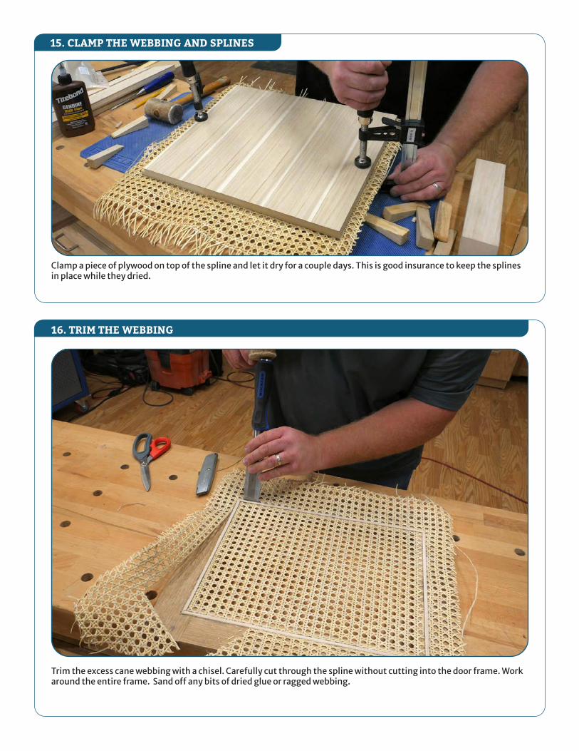
Clamp a piece of plywood on top of the spline and let it dry for a couple days. This is good insurance to keep the splines in place while they dried.
Trim the excess cane webbing with a chisel. Carefully cut through the spline without cutting into the door frame. Work around the entire frame. Sand off any bits of dried glue or ragged webbing.
16. TRIM THE WEBBING
15. CLAMP THE WEBBING AND SPLINES

Use the Beadlock Pro Jig to form Beadlock mortises in the legs and base rails.
Install a 3/4"-wide dado set in the table saw. Set the blade height to 1/2". Attach a stand-off block to the fence. For the base rails, position the face of the block 1-1/4" from the dado set. For the base stretchers, position the block 4" from the dado set.
18. CUT CROSSLAPS IN BASE RAILS AND BASE STRETCHERS
17. FORM THE BEADLOCK MORTISES IN THE BASE PARTS

Rout an 1/8"-radius roundover along all long edges and the top edges of the legs. Apply glue to the Beadlock mortises in the legs and base rails. Install Beadlock tenons and clamp the legs and base rails. Then apply glue to the crosslaps and clamp the base stretchers to the base rails.
Drill pilot holes through the base stretcher and attach the base to the cabinet bottom with #8 x 2-1/2" wood screws.
20. ATTACH THE BASE TO THE CABINET
19. ASSEMBLE THE BASE

22. MOUNT THE HINGES AND DOORS TO THE CABINET
Mount the hinge brackets to the cabinet and long arm component to the door. Clip the long arm to the cabinet bracket and adjust the hinges to center the door and operate smoothly.
Install a 5/16" straight bit in a router table. Set the bit height to 1". Fit the bit through the left hole in the Adjustable Post and position the cut the slot, feeding the board to cut from the left hole to the right hole.
23. INSTALL TOUCH LATCHES TO THE DIVIDERS
21. TOP, ADJUSTABLE SHELVES, FINISH AND BACK PANEL
Glue up the solid white oak pieces to make the top and adjustable shelf panels. Cut them to finished size. Then rout a 1/8"-radius roundover on all edges.
Next, finish sand all surfaces. Then apply satin water-base polyurethane finish to all surfaces. Lightly sand surfaces between coats of finish to smooth raised grain.
Finally, cut the back panel to size and paint the inside face white. Attach the back panel with #6x5/8" wood screws.