
IS 15041 (2001): Textiles - Flat Woven Webbing Slings Made ... · sling by stitching of the webbing...
17
Disclosure to Promote the Right To Information Whereas the Parliament of India has set out to provide a practical regime of right to information for citizens to secure access to information under the control of public authorities, in order to promote transparency and accountability in the working of every public authority, and whereas the attached publication of the Bureau of Indian Standards is of particular interest to the public, particularly disadvantaged communities and those engaged in the pursuit of education and knowledge, the attached public safety standard is made available to promote the timely dissemination of this information in an accurate manner to the public. इंटरनेट मानक “!ान $ एक न’ भारत का +नम-ण” Satyanarayan Gangaram Pitroda “Invent a New India Using Knowledge” “प0रा1 को छोड न’ 5 तरफ” Jawaharlal Nehru “Step Out From the Old to the New” “जान1 का अ+धकार, जी1 का अ+धकार” Mazdoor Kisan Shakti Sangathan “The Right to Information, The Right to Live” “!ान एक ऐसा खजाना > जो कभी च0राया नहB जा सकता ह ै” Bhartṛhari—Nītiśatakam “Knowledge is such a treasure which cannot be stolen” IS 15041 (2001): Textiles - Flat Woven Webbing Slings Made of Man-Made Fibres for General Services [TXD 12: Narrow Fabrics, Webbings and Braids]
Transcript of IS 15041 (2001): Textiles - Flat Woven Webbing Slings Made ... · sling by stitching of the webbing...

Disclosure to Promote the Right To Information
Whereas the Parliament of India has set out to provide a practical regime of right to information for citizens to secure access to information under the control of public authorities, in order to promote transparency and accountability in the working of every public authority, and whereas the attached publication of the Bureau of Indian Standards is of particular interest to the public, particularly disadvantaged communities and those engaged in the pursuit of education and knowledge, the attached public safety standard is made available to promote the timely dissemination of this information in an accurate manner to the public.
इंटरनेट मानक
“!ान $ एक न' भारत का +नम-ण”Satyanarayan Gangaram Pitroda
“Invent a New India Using Knowledge”
“प0रा1 को छोड न' 5 तरफ”Jawaharlal Nehru
“Step Out From the Old to the New”
“जान1 का अ+धकार, जी1 का अ+धकार”Mazdoor Kisan Shakti Sangathan
“The Right to Information, The Right to Live”
“!ान एक ऐसा खजाना > जो कभी च0राया नहB जा सकता है”Bhartṛhari—Nītiśatakam
“Knowledge is such a treasure which cannot be stolen”
“Invent a New India Using Knowledge”
है”ह”ह
IS 15041 (2001): Textiles - Flat Woven Webbing Slings Madeof Man-Made Fibres for General Services [TXD 12: NarrowFabrics, Webbings and Braids]

*“?%—.—-
1s15041:2001- .-
%’Tmwm-
m—1-R-mml-@ *laqmm--Fkrt?iTi@fit@i-zmRiRlw-l
Indian Standard
TEXTILES — FLAT WOVEN WEBBING SLINGSMADE OF MAN-MADE FIBRES FOR
GENERAL SERVICES
ICS 59.060.20 ;59.080.50
0 BIS 2001
BUREAU OF INDIAN STANDARDSMANAK BHAVAN, 9 BAHADUR SHAH ZAFAR MARC
NEW DELHI 110002
December 2001 Price Group 6
Narrow Fabrics, Webbings and Braids Sectional Committee, TX 12
FOREWORD
This Indian Standard was adopted by the Bureau of Indian Standards, after the draft finalized by the NarrowFabrics, Webbings and Braids Sectional Committee had been approved by the Textile Division Council.
While preparing this standard considerable assistance has been derived from BS 3481: Part 2:1983, ‘Flat liftingslings: Part 2: Specification for flat woven webbing slings made of man-made fibre for general service’.
The type of sling referred in this standard comprises man-made fibre webbing of any required length and of25 to 320 mm width that is wrapped with a smooth contact surface around the load so as to offer support acrossthe whole webbing width and to distribute the pressure evenly. For certain loads a stronger, wider sling than isnecessary to lift the load maybe useful. However, the possibility of uneven loading increases with increase ofwidth and it may be inadvisable to rate a very wide sling as highly as a narrower one. For this reason thisstandard is only applicable to slings of width up to 320 mm.
The slings are of three types, namely, single sling with soft eyes, single sling with metal end fittings and endlesssling. They normally lift loads with the sling reeved around the load (choke hitch), or on two parts of the sling(basket hitch). They are tested in straight pull.
In order to ensure that webbings produced from man-made fibres meet the requirements for flat woven slings,materials are specified [high tenacity polyamide (nylon), polyester or polypropylene continuous multifilament]that have a high wet and dry strength, selective resistance to chemical and microbiological attack and highresistance to abrasion.
The extensible nature of the materials provides a high degree of energy absorption. The increase in lengthresulting from the application of a load is not entirely lost when the load is removed. Furthermore, sometime mayelapse before the sling recovers to a fixed length. This characteristic does not affect the usefulness of the slingin most applications, but it makes it necessary to measure the effective length of the sling before the firstapplication of load.
The Composition of the Committee responsible for formulation of this standard is given in Annex D.
For the purpose of deciding whether a particular requirement of this standard is complied with, the final value,observed or calculated, expressing the result of a test, shall be rounded off in accordance with IS 2:1960 ‘Rulesfor rounding off numerical values (revised)’. The number of significant places retained in the rounded off valueshould be the same as that of the specified value in this standard.
d
IS 15041:2001
.’$<——
-. .-.+
Indian Standard
TEXTILES — FLAT WOVEN WEBBING SLINGSMADE OF MAN-MADE FIBRES FOR
GENERAL SERVICES1 SCOPE
1.1 This standard specifies the basic characteristicsof flat woven webbing slings made of cettain man-madefibres [Polyamide (nylon), Polyester andPolypropylene] used for lifting purpose or handlingloads and the tests and procedures needed to verifythese characteristics.
1.2 In addition this standard specifies the method ofmanufacture, identification and marking of these slingsas well as the means of recording their characteristics.It does not specify working load limits but insteadspecifies a test for verifying the working load limitchosen.
13 This standard also specifies the modes of assemblyof single and endless slings and the mode factors to beused with each, together with related maximum safeworking loads.
2 REFERENCES
The following Indian Standards contain provisionswhich through reference in this text, constituteprovisions of this standard. At the time of publication,the editions indicated were valid. All standards aresubject to revision and parties to agreements based onthis standard are encouraged to investigate the possi-bility of applying the most recent editions of thestandards indicated below:
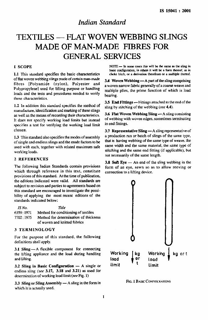
NOTE- In some cases this willbe thesameas ttwsling inlxzic configuration. in others it wilt be a formthereof, as inchoke hitch, or a derivation therefrom or a multiple thereof.
3.4 Woven Webbing —A part of the sling comprisinga woven narrow fabric generally of a coarse weave andmultiple plies, the prime function of which is loadbearing.
3.5 End Fittings —Fittings attached to the end of thesling by stitching of the webbing (see 4.4).
3.6 Flat Woven Webbing Sling —A sling consistingof webbing with woven edges, sometimes terminatingin end fittings.
3.7 Representative Sling —A sling representative ofa production run or batch of slings of the same type,that is having webbing of the same type of weave, thesame width and the same material, the same type ofstitching and the same end fitting (if applicable), butnot necessarily of the same length.
3.8 Soft Eye — An end of the sling webbing in theform of an eye, sewn so as to allow reeving orconnection to a lifting device.
IS No. lltle6359:1971 Method for conditioning of textiles7702:1975 Method for determination of thickness
of woven and knitted fabrics I3 TERMINOLOGY
IFor the purpose of this standard, the followingdefinitions shall apply. o
3.1 Sling —A flexible component for connectingthe lifting appliance and the load during handling Workingand lifting. load
3.2 Sling in Basic Configuration — A single orendless sling (see 3.17, 3.18 and 3.21) as used fordetermination of working load limit (see Fig. 1)
Iworking kgload or
limit t limit
1kg or t
FIG. 1BASICCONFIGURATIONS3.3 Sling or Sling Assembly — A sling in the form inwhich it is actually used.
IS 15041 :2001
NOTES
,.:,,. ,1’”
.4 *’,
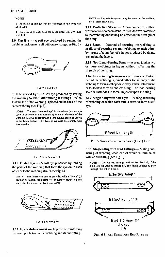
1 The inside ofthis eye can bereinforced inthe same wayas in 3.12.
2 Three types of soft eyes are recognized (see 3.9,3.10and 3.11)
3.9 Flat Eye — A soft eye produced by sewing thewebbing back onto itself without twisting (see Fig, 2).
FIG.2 FLATEYE
3.10 Reversed Eye — A sofi eye produced by sewingthe webbing to itself after turning it through 180° sothat the top of the webbing is placed on the back of thesame webbing (see Fig. 3).
NOTE — The term ‘reversed eye’ is sometimes (incorrectly)used to describe an eye formed by dividing the ends of thewebbing into two equal parts in a longitudinal sense, as shownin the figure below. This type of eye does not comply withthis standard.
FIG. 3 REVERSEDEYE
3.11 Folded Eye — A soft eye produced by foldingthe parts of the webbing that form the eye on to eachother or to the webbing itself (see Fig. 4).
NOTE —The folded eye can be provided with a ‘sleeve’ (ofleather or fabric, for example) for further protection andnlay also be a reversed type (see 3.10).
FIG. 4 FOLDEDEYE
3.12 Eye Reinforcement — A piece of reinforcingmaterial put between the webbing and its end fitting.
NOTE— The reinforcement may be sewn to the webbingby a seam (see 3.14).
3.13 Protective Sleeve — A component of leather,woven fabricor other material toprovide extra protectionto the webbing but having no effect on the strength ofthe sling.
3.14 Seam — Method of securing the webbing toitself, or of securing several webbings to each other,by means of a number of stitches produced by threadtraversing the layers.
3.15 Non-Load-Bearing Seam — A seamjoining twoor more webbings in layers without affecting thestrength of the sling.
3.16 Load-Bearing Seam-A seambymeansofwbichend of the webbing is joined either to the body of thewebbing to forma sofl eye or to carry a metal attachmentor to itself to form an endless sling. The load-bearingseam withstands the force imposed upon the sling.
3.17 Single Sling with Soft Eyes — A sling consistingof webbing of which each end is sewn to form a softeye.
Effective length
FIG. 5 SINGLESLING WITHSOFT (FLAT) EYES
3.18 Single Sling with End Fittings — A sling con-sisting of webbing, each end of which is terminatedwith an end fitting (see Fig. 6).
NOTE — The two end fittings need not be identical; if thesling is to be used in choked Iiit, one fitting is made to passthrough the other fitting.
Effective length
Effective length
End fittings forchoked
lift
FIG. 6 SINGLE SLING WITHEND FITTINGS
$
2
I
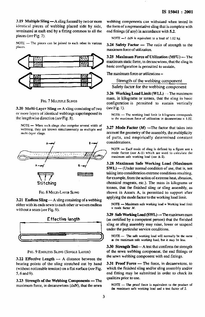
319 Multiple Sling —A sling formed by two or moreidentical pieces of webbing placed side by side,terminated at each end by a fitting common to all thepieces (see Fig. 7).
NOTE — The pieces can be joined to each other in variousplaces.
FIG.7 MULTIPLESLINGS
3.20 Multi-Layer Sling — A sling consisting of twoor more layers of identical webbings superimposed inthe lengthwise direction (see Fig. 8).
NOTE — When such slings also comprise several width ofwebbing, they are known simultaneously as multiple andmulti-layer slings.
A-+ 04
IS 15041:2001
webbing components can withstand when tested inthe form of a representative sling that is complete withend fittings (if any) in accordance with 5.2.
NOTE —t daN is equivalent to a Ioad of 1,02 kg.
3.24 Safety Factor — The ratio of strength to themaximum force of utilization.
3.25 Maximum Force of Utilization (MFU) — Themaximum static force, in decanewtons, that the sling inbasic configuration is permitted to sustain,
The maximum force or utilizations=
Strength of the webbing component
Safety factor for the webbing component
3.26 Working Load Limit (WLL) — The maximummass, in kilograms or tonnes, that the sling in basicconfiguration is permitted to sustain vertically(see Fig. 1).
NOTE — The working load limit in kilograms correspondsto the maximum force of utilization in decanewtons x 1.02.
3.27 Mode Factor (M) —The factor that takes intoaccount the geometry of the assembly, the multiplicityof parts, and empirically determined constantconsiderations.
- NOTE — Eacli mode of sling is defined by a figure and amode factor (see A-1) which are used to calculate the
..— _ ---- —-.maximum safe working load (see A-2),
A+ B+
‘m @“i”-a
Stitching
Fm. 8 MULT1-LAYERSLING
3.21 Endless Sling — A sling consisting of a webbingeither with its ends sewn to each other or woven endlesswithout a seam (see Fig. 9).
=
Fm. 9 ENDLESS SLING (SINGLE LAYER)
3.22 Effective Length — A distance between thebearing points of the sling stretched out by hand(without noticeable tension) on a flat surface (see Fig.5,6 and 9).
3.23 Strength of the Webbing Components — Themaximum force, in decanewtons (daN), that the sewn
3
3.28 Maximum Safe Workhsg Load (MaximumSWL) — (Under normal condition of use, that is, nottaking into consideration extreme conditions resulting,for example, from the action of extreme heat, abrasion,chemical reagents, etc.). The mass in kilograms ortonnes, that the finished sling or sling assembly, asshown in Annex A, is permitted to support afterapplying the mode factor to the working load limit.
NOTE — Maximumsafeworking load = Workhrg load limitx mode factor M.
3.29 Safe Working Load (SWL) —The maximummass(as certified by a competent person) that the finishedsling or sling assembly may raise, lower or suspendunder the particular service conditions.
NOTE— The safe working load will normally be the samem the maximum safe working load, but it may be less.
3.30 Strength Test— A test that confirms the strengthof the sewn webbing component, the end fittings orthe sewn webbing component with end fittings.
3.31 Proof Force — The force, in decanewtons, towhich the finished sling and/or sling assembly and/orend fitting may be submitted in order to check itsqualities prior to use.
NOTE — The proof force is equivalent to the product ofthe maximum safe working load and a test factor of 2.
1-~,
I
Is 15041:2001
3.32 Proof Load —The mass, in kilograms or tonnes,that submits the finished sling and/or sling assemblyandor end fittings to a force equivalent to the proofforce ($ee 3.31).
4 REQUIREMENTS
4.1 Webbing
4.1.1 Materials
The webbing shall be woveri wholly from yarns of oneof the following:
a)Polyamide (nylon) high tenacity continuousmultifilament
b)Polyester high tenacity continuousmultifilament and
c) Polypropylene high tenacity continuousmultifilament.
NOTE—Resistanceof man-madefibres to chemical,microbiotngical and physical attack is summarized below(see dw B-8):
Polyamide is virtually immune to the effects of alkatk. It isattackedby moderate-strengthacids (a modemte- stte.ngthon asling becomes progressively stronger by evaporation). User’sattention is drawn to the loss of strength of polyamides onwetting, which may be of the order of 15 percent.
Polyester is resistant to moderate strength acid but isdamaged by atkali.
.
Polypropylene is little affected by acids and atkalis and issuitable for applications where the highest resistance tochemicals (other than certain solvents) is required. Careshould be taken to ensure that polypropylene is adequatelystabilized against ultraviolet degradation.
All these fibres are highly resistant to mildew and othermicrobiological attacks.
4.1.2 Weaving
4.1.2.1 The webbing shall be uniformly woven, freefrom any significant defect. All yarns shall be of thesame material. The edges shall not be such that theycan be ‘unpicked’ when one of the yarns breaks.
4.1.2.2 The method of weaving shall be such that thewidth of the finished webbing decreases by no morethan 10 percent when submitted to a force equal to themaximum force of utilization.
4.1.3 Width
The following tolerances shall be permitted on nominalwidth:
a) *1O percent for widths less than or equal to100 m, and
b) *8 percent for widths greater than 100 mm.
NOTE — Preferred widths are 25, 35, 50, 75, 100, 150,200 and 300 mm.
4.1.4 Thickness
When tested in accordance with 53, webbing shall beof minimum thickness 1,2 mm. When the sling consistsof several assembled webbings, these shall be identical.
NOTE — The surfaces of the webbing may be covered withsuitable protection.
4.L5 Dyeing
The webbing may be supplied either dyed or undyed.The dyestuff or the dyed product shall not prove toxicto human being (see Note under 4.1.6).
4,1.6 Other Treatments, Afiertreatments or Coverings
w, . 4,.,
*’A
..
——.
.,. - -,,
$,
1,
The treatments and products used shall not prove toxicto human beings.
NOTE — Any effects of dyeing or other treatments on thewebbing should be taken into account when assessing thestrength of the sling. i
.’4.2 Sewing of Slings
!4.2.1 Non-load taring seams and load bearing seamsshall be made from good quality thread in the same
!material as the webbing. To facilitate inspection of thestitching, thread of a different colour from that of the ~
rest of the sling may be used. The load-bearing seamsg3
shall be made in such a way that, when finished, they ihave a strength as near as possible to that of thewebbing.
4.22 The seams shall be made on a machine with alock stitch; the damage caused by the stitching shall beminimal (for example, no overheated needles.)
4.2.3 The stitches shall traverse the parts of thewebbing to be sewn togethe~ the seams shall be flatand penetrate the surface of the webbing in such awaythat no part of the thread (with the exception of the endstitches) stands proud of the surface; the locking of thestitches shall not be visible on either side of the webbing.
4.2.3.1 The stitches shall not touch or affect the edgeand shall cover at least the full width of the portionlying between 2 mm and4 mm tim eachedge for webbingup to 10 mm thick and between 4 mm and 8 mm fromeach edge for thicker webbing.
4.2.4 The stitches shall begin and end with backstitching of at least 25 mm length.
. .
4.2.4.1 There shall be no more than one fault (a missedstitch, broken thread, etc) in a seam length of 100 mm;each fault shall be compensated for by back stitching.
4.2.5 The ends of cut webbing shall be treated in sucha way as to avoid unraveling (for example, fused byheating) unless the webbing has previously beenthoroughly impregnated to prevent thread slippage, inwhich case the ends may simply be oversewn.
4
4.2.5.1 Treatment of cut ends by heating shall notdamage adjacent stitching and ends so treated shallnot be oversewn.
4.3 Soft Eyes
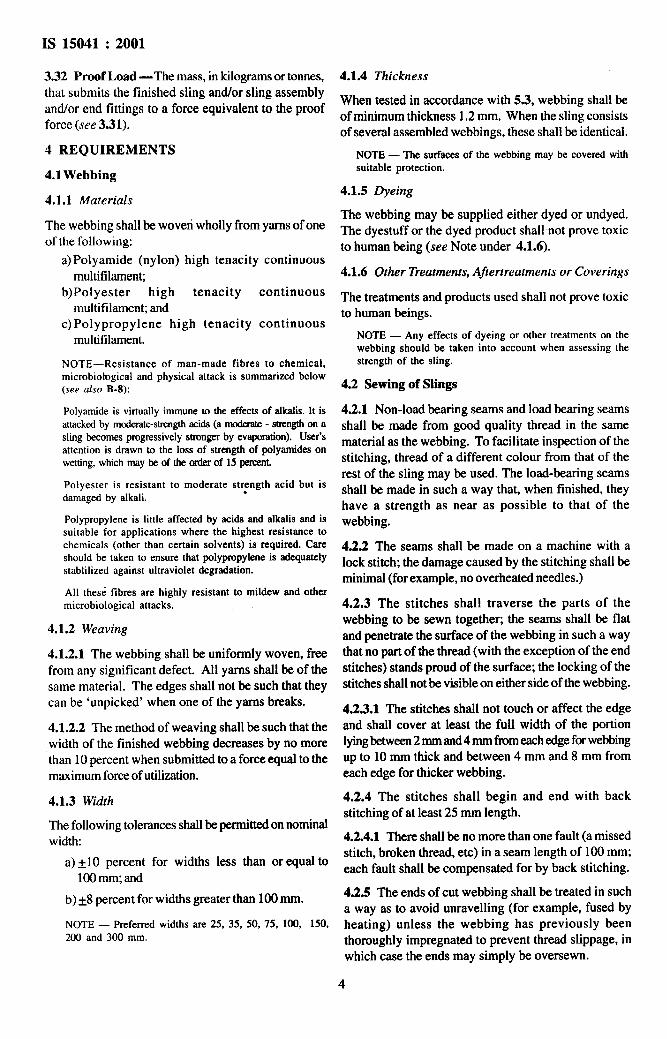
4.3.1 Whatever their types, sofl eyes should be madewith care so as not to diminish the load-bearingcapabilities. The inside length, L, of the eyes (seeFig. 10) when measured flat shall be of the followingminimum dimensions:
a) 100mm for webbing of widths from 25 to 35 mm;b) Three times the width of the webbing for widths
from 36 to 150mm, and
c) Two and a half times the width of the webbing forwebbing of width greater than 150 mm.
GQ-FIG. 10 INSIDE LENGTHOFEYE
4.3.2 When connecting a sling with soft eyes to alifting device the part of the lifting device which bearson the sling shall :
a) have a diameter of not more than one-third ofthe inside length of the eye and;
b) be essentially straight unless the bearingwidth of the sling is not more than 75 mm, inwhich case the bearing part of the liftingdevicemay be curved but the radius of curvatureshall be atleast 0.75 times the bearing width ofthe sling.
NOTE — Direct attachment to a lifting device of slingswith soft eyes of a bearing width at the lifting device ofmore than 75 mm is not recommended.
4.4 End Fittings
4.4.1 General
End fittings if required shall be inserted in an eye formedby a fold of webbing, which shall then be sewn in themanner specified in 4.2. The inside length of the eyeshall be not less than 2.5 times and not more than fourtimes the thickness (or diameter) of that part of the endfitting that passes through the eye.
4.4.2 Material
End fittings shall be of metal, but not case they shallbe shock resistant. They shall have a breaking load ofat least four times the maximum safe working load ofthe sewn webbing component.
NOTE—They should have good resistance to ageing, fatigueand mechanical stress and to normal temperature rangesfrom –30C to + 800C.
IS 15041 :2001
4.4.3 Finish
All surfaces shall be finished with ‘no sharp edges.The part through which the sling passes shall befinished in such a way as to cause no damage to thewebbing, The seating of the end fitting where thewebbing rests during lifting shall be well rounded.
4.4.4 Form
The junction between the webbing and seating of theend fitting shall allow a uniform spread of force acrossthe whole width of the webbing. The seating, on whichthe webbing bears, shall be essentially straight unlessthe bearing width of the sling is not more than 75 mm,in which case the seating or rings or links, if used, maybe curved but the radius of curvature shall be at least0.75 times the bearing width of the sling.
NOTE — Rings or links should not be used for slings ofbearingwidthgreaterthan75 mm.
4.4.5 Proof Testing
End fittings shall be proof tested in accordance with5.4 and shall be free from permanent deformation,cracks, flaws or other defects examined after testing,
NOTE — The proof testing of end fittings may be carriedout prior to the assembly of the fittings into the finishedsling.
4.4.6 Re-use by the Manufacturer of End FittingsReturned by the User
A complete end fitting, transferred from a damagedsling to a new sling, shall be examined by a competentperson. The fitting shall only be re-used it
a) it complies with all the requirements of thisstandard, and
b) it is found to be free from damage or fault.
NOTE — The competent person may, at his discretion,request a new proof test.
4.4.6.1 An end fitting that has been subjected to aload greater than twice its maximum safe working loadshall not be re-used.
4.5 Working Load Limit
The working load limit for each sling in basicconfiguration (see Fig. 1) shall be verified by use of thestrength test given in 5.2.
NOTE — It is preferred that the working load limits forslings in basic configuration be chosen from following valueseither in kilograms or tonnes, taken from the R10 series ofpreferred numbers:160, 200, 250, 315, 400, 500, 630, 800 kg1, 1.25, 1.6, 2, 2.5, 3.1, 4.5, 6.3, 8, 10, t
4.6 Maximum Safe Working Load
The maximum safe working load for a sling or slingassembly shall be the product of the working load limitof the sling in basic configuration and the mode factor
.
-.
--.!
i
5
Is 15041:2001
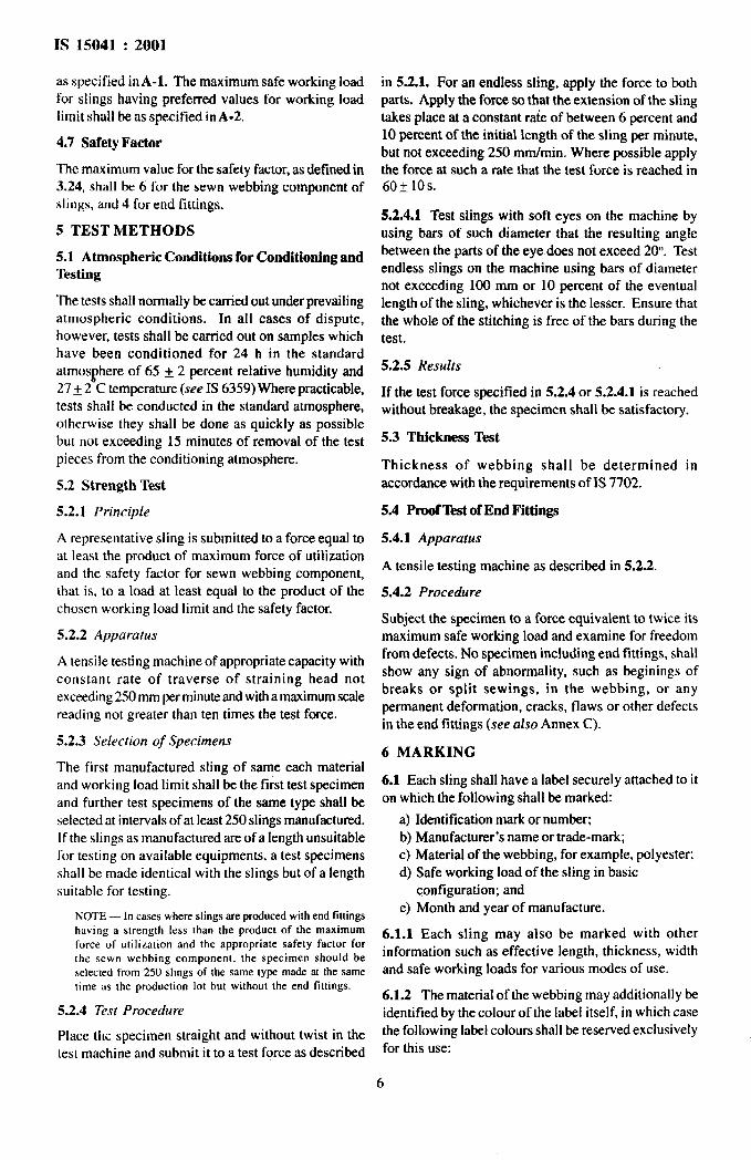
as specified inA-1. The maximum safe working loadfor slings having preferred values for working loadlimit shall be.as specified in A-2.
4.7 Safety Factor
The maximum value for the safety factor, as defined in3.24, shall be 6 for the sewn webbing component ofslings, and 4 for end fittings.
5 TEST METHODS
5.1 Atmospheric Conditions for Conditioning andTesting
The tests shall normally be carried out under prevailingatmospheric conditions. In all cases of dispute,however, tests shall be carried out on samples whichhave been conditioned for 24 h in the standardatmosphere of 65 ~ 2 percent relative humidity and27 ~ 2 C temperature (see IS 6359) Where practicable,tests shall be conducted in the standard atmosphere,otherwise they shall be done as quickly as possiblebut not exceeding 15 minutes of removal of the testpieces from the conditioning atmosphere.
5.2 Strength Test
5.2.1 Principle
A representative sling is submitted to a force equal toat least the product of maximum force of utdizationand the safety factor for sewn webbing component,that is, to a load at least equal to the product of thechosen working load limit and the safety factor.
5.2.2 Apparatus
A tensile testing machine of appropriate capacity withconstant rate of traverse of straining head notexceeding250 mm per minuteand witha maximumscalereading not greater than ten times the test force.
5.2.3 Selection of Specimens
The first manufactured sling of same each materialand working load limit shall be the first test specimenand further test specimens of the same type shall beselected at intervals of at least 250 slings manufactumd.If the slings as manufactured are of a length unsuitablefor testing on available equipments, a test specimensshall be made identical with the slings but of a lengthsuitable for testing.
NOTE — In cases where slings are produced with end fittingshaving a strength less than the product of the maximumforce of utilization and the appropriate safety factor forthe sewn webbing component. the specimen should beselected from 250 slings of the same type made at the sametime as the production lot but without the end fittings.
5.2.4 Test Procedure
Place the specimen straight and without twist in thetest machine and submit it to a test force as described
in 5.2.1. For an endless sling, apply the force to bothparts. Apply the force so that the extension of the slingtakes place at a constant rate of between 6 percent and10 percent of the initial length of the sling per minute,but not exceeding 250 mrn/min. Where possible applythe force at such a rate that the test force is reached in60f 10s.
5.2.4.1 Test slings with soft eyes on the machine byusing bars of such diameter that the resulting anglebetween the parts of the eye does not exceed 20. Testendless slings on the machine using bars of diameternot exceeding 100 mm or 10 percent of the eventuallength of the sling, whichever is the lesser. Ensure thatthe whole of the stitching is free of the bars during thetest.
5.2.5 Results
If the test force specified in 5.2.4 or 5.2.4.1 is reachedwithout breakage, the specimen shall be satisfactory.
5.3 Thickness Test
Thickness of webbing shall be determined inaccordance with the requirements of IS 7702.
5.4 Proof Test of End Fittings
5.4.1 Apparatus
A tensile testing machine as described in 5.2.2.
5.4.2 Procedure
Subject the specimen to a force equivalent to twice itsmaximum safe working load and examine for freedomfrom defects. No specimen including end fittings, shallshow any sign of abnormality, such as beginings ofbreaks or split sewings, in the webbing, or anypermanent deformation, cracks, flaws or other defectsin the end fittings (see also Annex C).
6 MARKING
6.1 Each sling shall have a label securely attached to iton which the following shall be marked:
a) Identification mark or number;b) Manufacturer’s name or trade-mark;c) Material of the webbing, for example, polyester;d) Safe working load of the sling in basic
configuration; ande) Month and year of manufacture.
6.1.1 Each sling may also be marked with otherinformation such as effective length, thickness, widthand safe working loads for various modes of use.
6.1.2 The material of the webbing may additionally beidentified by the colour of the label itself, in which casethe following label colours shall be reserved exclusivelyfor this use:
6
----

Is 15041 :2001
Polyamide (nylon) = Green c) constituent materials of the webbing and endPolyester = Blue fittings;Polypropylene = Brown d)either maximum safe working load or safe working
6.1.3 End fittings shall be individually marked orload;
numbered so as to identify them with the test reporte) requiredsafetyfactor if it isother than the minimum
referred to in 7.3.value specified;
O dyeing of the webbing if any, and6.2 BIS Certification Marking g) further treatment given, if any.
Each sling may also be marked with the Standard Mark.
6.2.1 The use of the Standard Mark is governed bythe provisions of the Bureau of Indian Standards Act,1986 and the Rules and Regulations made thereunder.Details of conditions under which a licence for the useof the Standard Mark maybe granted to manufacturersor producers maybe obtained from the Bureau of IndianStandards.
7 DESIGNATION, STATEMENT OFCONFORMITY AND INFORMATION TO BESUPPLIED WITH ENQUIRY OR ORDER
7.1 Designation
The following information shall comprise the fulldesignation of a flat woven webbing sling in accordancewith this standard required when making an enquiry orplacing an order:
a)the expression ‘FLAT WOVEN WEBBINGSLfNG’;
b)type, including end fitting details and effectivelength and width;
72 Statement of Conformity
The supplier shall submit to the buyer, upon request, astatement of conformity, dated, signed and certifyingthat the items detailed thereon have been inspectedand tested and comply in all respects with therequirements of this standard, alongwith the followinginformation:
a) Name and address of supplier;b)Identification mark or number of the sling; andc) Designation of the sling (see 8.1).
7.2.1 When a transaction concerns a batch of slingsof the same designation the supplier shall submit onlyone overall statement.
73 Test Report for End Fittings
If the sling is provided with end fittings, a report of theproof test and examination carried out in accordancewith 5.4 shall be provided.
8 USE, MAINTENANCE AND INSPECTION
Guidelines for the use, maintenance and inspection ofslings are given in Annexes B and C.

,’*“A
Is 15041:2001
ANNEX A
(Clauses 3.27,3.28 and 4.6)
MODES OF ASSEMBLY, MODE FACTORS AND MAXIMUM SAFE WORKINGLOADS FOR SINGLE AND ENDLESS SLINGS
A-1 MODES OF ASSEMBLYFACTORS
For single and endless slings shallFig. 11.
AND MODE A-2 MAXIMUM SAFE WORKING LOAD
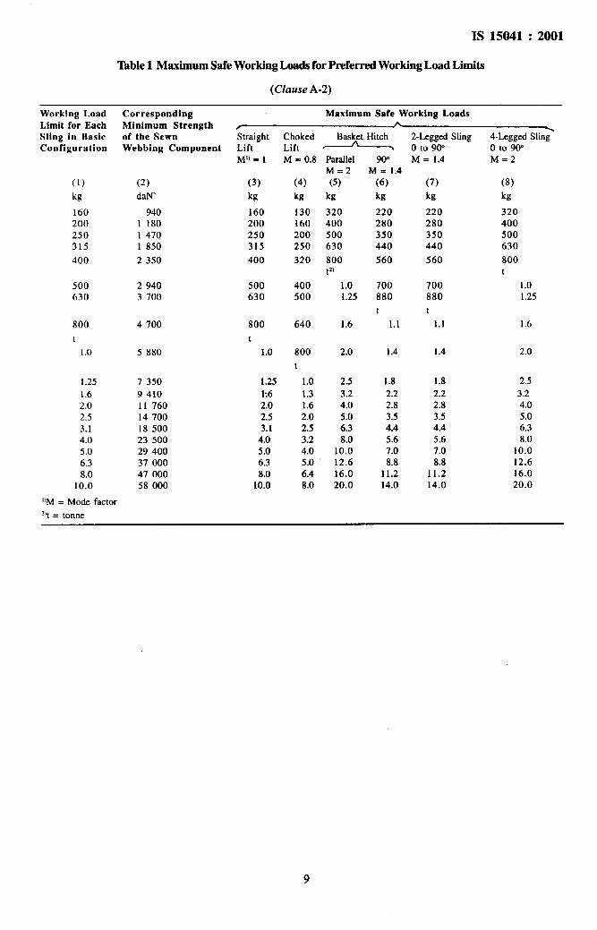
The maximum safe working loads for slings having thebe as shown in preferred values for working load limit (see 4.5) shall be
‘wgiven in Table 1.
Single sling
Straight liftMode factor = 1
Choked liftMode foctor .0.8
Basket hitch, parallelMode factor .2
Basket hitch, SOONode factor z 14
Two-legged s4ingj00 to goe
Mode factor= 14
Four–legged sling,00t0900*
Modefactor*2
1(!)uda
A
ii
i
FIG, 11 MODESOFASSEMBLYFORSINGLEANDENDLESSSLINGS
‘.’ A.—.
IS 15041:2001
‘lhble 1 Maximum Safe Working Loads for Preferred Working Load Liita
(ClauseA-2)
Working LoadLimit for EachSling in BasicConfiguration
Corresponding Maximum Safe Working LoadsMinimum Strength / A \of the SewnWebbing Component
StraightLiftMUc 1
Choked Basket Hitch~ %% “ing
4-Legged Sling”Lift o to 9@M = 0.8 Parallel
M=2(5)
kg
320400500630
800tz)
1.01.25
9(PM = 1.4
(6)
kg
220280350440
560
700880
t
1.1
1.4
1.82.22.83.54.45.67.08.8
11.214.0
M = 1.4 M=2
(7)
kg
220280350440
560
(8)
kg
320400500630
800t
1.01.25
(1)
kg
160200250315
400
(2)
daN
940I 18014701 850
2350
(3)
kg
160200250315
400
(4)
kg
130160200250
320
500630
29403700
500630
400500
700880
t1.1800
t
1.0
4700 800
t
1.0
640 1.6 1.6 I
5880 800
t
1.01.31.62.02.53.24.05.06.48.0
2.0 1.4 2.0
2.53.24.05.06.38.0
10.012.616.020.0
1.251.62.02.53.14.05.06.38.0
10.0
735094101176014700185002350029400370004700058000
1.25E.62.02.53.1
4.05.06.38.0
10.0
2.53.24.05.06.38.0
10.012.616.020.0
1.82.22.83.54.45.67.08.8
11.214.0
I)M = Mode factor
% = tonne
9
Is 15041 :2001
ANNEX B
(C2ause 8. 1)
PRACTICAL ADVICE FOR THE USE AND MAINTENANCEOF FLAT WOVEN SLINGS
B-1 Use only identified slings (see 6).
B-2 Do not use a damaged sling. Damage observedon the surface is the most noticeable cause of weakness,particularly if a new undamaged sling is available forcomparison. In extreme cases the faces of the webbingbecome so worn that outer yams of the weave areseverely damaged.
B-3 Observe the mode factor (see Annex A).
B-4 Do not use choked lift for intensive use withoutprotection of the eye. The angle of the choke shouldform naturally and not be forced.
B-5 Never engage a soft eye with anything that maydamage it, The lifting device engaged by the eye shouldbe:
a) smooth, without any sharp edges; and
b) of such dimensions and shape as not to tear thesewn joints apart or overload the webbing(see 4.3).
B-6 Observe the following precautions:
a) ensure that the load and sling are suited each tothe other;
b) when moving the sling and load, do not drag;
c) do not make knots;
d) do not lift with twisted sling;e) do not use the sling for a load with sharp edges
without protective sleeves, especially on the partsof the webbing where abrasion or cuts couldoccur;
f) do not allow the sling to remain under load if thiscould cause damage;
g) do not pull the sling out from under the loadwhen the load is resting on the sling;
h) avoid snatch or shock loading;
j) avoid eye opening angles in excess of 20°; andk) ensure that angles for two-~egged and four-
Iegged sling do not exceed 90 (see Fig. 11).
B-7 Carry out lifting so that the load is stable. If thelength of the load is such that several slings have to beused. Use equipment so that the slings hang nearlyvertically and the effect of the load is as nearly aspossible equally divided between the legs of the slings.
B-8 If slings are used to handle chemicals or are usedat high temperature. Observe the manufacturer’sinstructions for such occasions (see Note under 4.1).If slings are intended to be used in such abnormalenvironments, it is recommended that the advice of thesling manufacturer or supplier be sought.
B-9 Slings are subject to degradation by ultravioletlight, so store them away from sunlight and othersources of ultra violet radiation.
B-10 Do not store or dry a sling near a source of heat.
B-n Inspect each sling before every period of use( see Annex C ).
B-12 Never repair a damaged sling. Always seek theadvice of the manufacturer or supplier.
B-13 Store slings on a suitably designed rack whennot in use.
ANNEX C
(Clauses 5.4.2 and 8.1)
RECOMMENDATIONS FOR INSPECTION OF SLINGS( FOR DETECTION OF DAMAGE )
C-1 Slings should be examined throughout their length C-3 Chemical attack is indicated by local weakeningto surface chafe, cross or longitudinal cuts in webbing, or softening of the material in the webbing so thatcuts or chafe damage to the selvedges, or any damage surface fibres can be plucked or rubbed off, as a powderto the stitching, eyes or end fittings. in extreme cases.
C-2 The effect of the chafe on the fabric surface is C-4 Cuts, particularly at the selvedge, will result in avariable but some loss of strength should be expected. serious loss of strength. A sling so affected should beAny substantial chafe, particularly localized, should taken out of service immediate y.be viewed critically. Local abrasion, as distinct fromgeneral wear, may because by the passage of the sling C-5 Seams should not be allowed to deteriorate.
over sharp edges whilst under tension and may causea serious loss of strength.
10
f.<-.“4%
Is 15041:2001
ANNEX D
(Fotewottf)
COMMITTEE COMPOSITION
Narrow Fabrics, Webbings and Braids Sectional Committee, TX 12
Organization Representative(s)
Ministry of Defence (DGQA), Ncw Delhi SHRtA. K. BANOYOPADHYAY(Chairman)SHRtD. K. SRWASTAVA(Alternate1)SHRtS. K. CHAKRABGRTY(Alternate 11)
Bharat Heavy Electticals Ltd. Bhopal SHRtG. 1.ANANDStrraS. C. DUBEY(Ahemate)
Directorate General of Supplies & Disposals (Inspection SHRtD. S. MAtrIWYAWing), New Delhi SHIUT. K. MUKHERtEE(Alternate)
Garware-Wall Ropes Ltd, Pune SHRtR. R. SARDESAISHruS, J. CHrtNtS(Alternate)
M, Best Cotton Rope Mfg Co, Mumbai SHRtHEMALM. THANAWALA
Ministry of Defence (R&D), Kanpur SHruANURAGSRtVASrAVASHRIR. lNDUSHEKHAR(Alternate)
Motilal Dulichand Pvt Ltd, Kanpur SHRI!%Jtwr_ptrAHMoraSHRtRAWNSMANI(Alternate)
Natrow Elastic Manufacturers’ Association of India, Mumtil SHtrrHiRALALARCMA
,Newtex Insulations Pvt Ltd. Nasik
office of the Textile Commissioner, Mumbai
Southern Group Industries (Pvt) Ltd, New Delhi
Spica Plastic, Pune
Textiles Committee, Mumbai
The Bombay Textile Research Association, Mumbai
The Silk & Art Silk Mills’ Research Aaaociation, Mumtit
The South India Textile Research Association, Coimbatore
Todi Industries Ltd, Mumbai
Zebra Weblift Pvt Ltd, Mumbai
BIS Dkctorate General
SHRtsANtiZVK.AUSHIK
SHKtS. P. KALASHRtS. CHAKRAnARTV(Alternate)
SHRtBtMALE MAHESHWAtGSHRtK. B. SRINIVASLOO(Alrerrrate)
SHIUR. C. JAtTHASHRtS. K. JAttWA(Alternate)
SHRtN.JEEVASHrrtA. K. SEN(Alternate)
SHRtU. K.GAtWOWWYAYSHstR.N. BHAtrAn(Alternate)
SHRtV.J. GAROSHruB. V. DtrcroR(Alternate)
Urr S. S. RAMASAMY
SHRtS. B. TootSHrrrN. B. Ttxn (Alternate)
SHRIAaoummsrr A. f_OtGWWWAtASHRtKmss A. LOKHANDWALA(Alternate)
SHRIR. K. DUA,Director and Head (TXD)[Representing Director General (E@jjcio)]
Member-Secretary
SHst M. S. VERMADirector (TXD), BIS
11
T----4Bureau of Indian Standards
BIS is a statutory institution established under the Bureau of Indian Standards Act, 1986 to promoteharmonious development of the activities of standardization, marking and quality certification of goodsand attending to connected matters in the country.
Copyright
BIS has the copyright of all its publications. No part of these publications may be reproduced in any formwithout the prior permission in writing of BIS. This does not preclude the free use, in the course ofimplementing the standard, of necessary details, such as symbols and sizes, type or grade designations.Enquiries relating to copyright be addressed to the Director (Publications), BIS.
Review of Indian Standards
Amendments are issued to standards as the need arises on the basis of comments. Standards are also reviewedperiodically; a standard along with amendments is reaffirmed when such review indicates that no changes areneeded; if the review indicates that changes are needed, it is taken up for revision. Users of Indian Standardsshould ascertain that they are in possession of the latest amendments or edition by referring to the latest issue of‘BIS Catalogue’ and ‘Standards: Monthly Additions’.
This Indian Standard has been developed from Doc : No. TX 12( 0406).
Amendments Issued Since Publication
Amend No. Date of Issue Text Affected
BUREAU OF INDIAN STANDARDS
Headquarters :
Manak Bhavan, 9 Bahadur Shah Zafar Marg, New Delhi 110002 Telegrams : ManaksansthaTelephones :3230131,3233375,323 9402 (Common to all offices)
Regional Offices: Telephone
Central : Manak Bhavan, 9 Bahadur Shah Zafar Marg
{
3237617NEW DELHI 110002 3233841
Eastern : 1/14 C.I.T. Scheme VII M, V. I. P. Road, Kankurgachi
{
3378499,3378561KOLKATA 700054 3378626,3379120
Northern : SCO 335-336, Sector 34-A, CHANDIGARH 160022
{
603843602025
Southern : C.I.T. Campus, IV Cross Road, CHENNAI 600113
{
2541216,25414422542519,2541315
Western : Manakalaya, E9 MIDC, Marol, Andheri (East)
{
8329295,8327858MUMBAI 400093 8327891, 8327892
Branches : AHMEDABAD. BANGALORE. BHOPAL. BHUBANESHWAR. COIMBATORE.FARIDABAD. GHAZIABAD. GUWAHATI. HYDERABAD. JAIPUR. KANPUR.LUCKNOW. NAGPUR. NALAGARH. PATNA. PUNE. RAJKOT. THIRUVANANTHAPURAM.
Printed at Pmbhat Offset Press, New Delhi-2
l-;


![WEBBING SLINGS [FLAT] - · PDF fileuse: suitable for lifting final finished weights 100% PES WEBBING SLING [FLAT] - ENDLESS, SINGLE LAYER Standard device for lifting applications -](https://static.fdocuments.net/doc/165x107/5aa313827f8b9a84398ddff1/webbing-slings-flat-suitable-for-lifting-final-finished-weights-100-pes-webbing.jpg)