Mechanical Properties of Ceramics - NONMET...1 Materials Science &Technology Materials Science II -...
17
1 Materials Science &Technology Materials Science II - 2010, Ceramic Materials, Chapter 6, Part 1 Mechanical Properties of Ceramics Jakob Kübler or Mechanical Behavior of Brittle Materials & Prof. L.J. Gauckler 1 Kübler Empa-HPC, ETHZ MW-II Ceramics-6.1, 2010 Jakob Kübler Empa, Materials Science & Technology Lab for High Performance Ceramics Überlandstrasse 129, CH-8600 Dübendorf +41-44-823 4223 [email protected] & Prof. L.J. Gauckler ETH Zürich, Materials Department References • Munz and Fett, Ceramics, Springer, 1999 • Barsoum, Fundamentals of Ceramics, IoP, 2003 • Askeland & Phulé: Science and Engineering of Materials, 2003 Lit t di • Literature, diverse • ISO, CEN, ASTM standards 2 Kübler Empa-HPC, ETHZ MW-II Ceramics-6.1, 2010
Transcript of Mechanical Properties of Ceramics - NONMET...1 Materials Science &Technology Materials Science II -...
1
Materials Science & Technology
Materials Science II - 2010, Ceramic Materials, Chapter 6, Part 1
Mechanical Properties of Ceramics
Jakob Kübler
orMechanical Behavior of Brittle Materials
& Prof. L.J. Gauckler
1Kübler Empa-HPC, ETHZ MW-II Ceramics-6.1, 2010
Jakob Kübler Empa, Materials Science & Technology
Lab for High Performance Ceramics Überlandstrasse 129, CH-8600 Dübendorf
+41-44-823 [email protected]
& Prof. L.J. Gauckler ETH Zürich, Materials Department
References• Munz and Fett, Ceramics, Springer, 1999
• Barsoum, Fundamentals of Ceramics, IoP, 2003
• Askeland & Phulé: Science and Engineering of Materials, 2003
Lit t di• Literature, diverse
• ISO, CEN, ASTM standards
2Kübler Empa-HPC, ETHZ MW-II Ceramics-6.1, 2010
2
Aim of chapter & Learning targets 1. Introduction2. Stresses at a crack tip3. Griffith law4. KI and KIc
5 R
part
1C
rack
tip
th
lear
ning
ta
rget
s 1“Why mechanical testing …”
“Higher than you’d assume …”“Conditions for failure …”
“Stress intensity & critical stress intensity …”
g 2
“I i t h ”5. R-curve6. Properties7. Strength
8. Statistic9. Proof testing10. Fractography
part
2St
reng
tpa
rt 3
Stat
istic
s
lear
ning
targ
ets “Improving toughness …”
“Knowing what you measure …”“Just a value …”
lear
ning
ta
rget
s 3“Weibull, a name you’ll never should forget …”
“Make it or …”“Reading fracture surfaces …”
3Kübler Empa-HPC, ETHZ MW-II Ceramics-6.1, 2010
11. Thermal shock12. Slow crack growth13. SPT diagrams14. Creep15. Failure maps
part
4Ti
me&
Tem
p
lear
ning
ta
rget
s 4
“Temperature, time and geometry …” “After several years …”
“Combining strength, lifetime & statistics …”“Temperature makes it move …”
“Finding your way …”
part 5 - Case Study: Lifetime of All-Ceramic Dental Bridges
Introduction (1)
Deformation of …
Ceramics:
500
400
500
400
Al2O3 failure
C steel
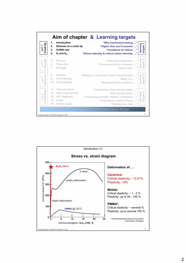
Stress vs. strain diagram
Ceramics:Critical elasticity: ~ 0.01%Plasticity: ~0%
Metals:Critical elasticity: ~ 1 - 2 %Plasticity: up to 50 - 100 %
300
200
nom
inal
stre
ss F
/A (
MPa
)
300
200
elastic deformation
plastic deformation
4Kübler Empa-HPC, ETHZ MW-II Ceramics-6.1, 2010
PMMA*:Critical elasticity: ~ several %Plasticity: up to several 100 %
100
0
ΔL/L0 x100, %
0 5 10 15 20 25
100
0
nominal elongation ΔL/L0 x100, %
0 5 10 15 20 25
PMMA @ 122°C
* Polymethylmethacrylate (acrylic glass) Trade Name „Plexiglas“

3
Introduction (2)
Ceramic structure for optics Mounting of IR camera
5Kübler Empa-HPC, ETHZ MW-II Ceramics-6.1, 2010© Carl Zeiss Optronics GmbH & FCT Ingenieurkeramik
Why Si3N4 ?
Introduction (3)
What’s that?
6Kübler Empa-HPC, ETHZ MW-II Ceramics-6.1, 2010

4
LifetimePrediction
AdvancedNDE
ComponentTesting
Fabrication
......
MaterialDevelopment
Introduction (4)
Why do we need mechanical properties?
ine:
Sou
rce
Wik
iped
ia
Prediction
MaterialsTesting and
Charact.Structural
Design
StatisticalModeling
σ < 100 MPaT > 1100°C
Corrosion
Creep & FatigueTu
rbof
an E
ngi
7Kübler Empa-HPC, ETHZ MW-II Ceramics-6.1, 2010
σ < 250 MPaT > 900°C
σ < 350 MPaT > 800°C
Brittle fracture
Slow crack growth
Mechanical properties needed for the design of components.
Material properties→ Design: E, KIc , (σm), ...
Technological properties→ Comparison: Hardness, ...
Proof testingG d / N t d
Introduction (5)
Aim of mechanical testing
• temperature
→ Good / Not good
• micro structure• surface
• strength• elasticity• fracture
toughness• creep• scg
8Kübler Empa-HPC, ETHZ MW-II Ceramics-6.1, 2010
• environment
• time• static• cyclic
• hardness• thermal
shock resistance

5
Introduction (6)
Vickers hardness
HV = 0.102 (2·F·sin[136/2]) d-2
= 1.891·F·d-2 [N mm-2]:
Technological testsF
[ ]
Exam
ple
650 HV 100 / 30
Duration 30 sLoad level 100 kp
Vickers procedureHardness value
9Kübler Empa-HPC, ETHZ MW-II Ceramics-6.1, 2010
• No materials constant• Comparison of materials under exactly defined conditions • Relative values or statements (e.g. „good“ or „not good“)
other technological tests:Charpy V-notch, Jominy test, wear tests, crash test, ….
Stresses at crack tip (1)
Determination of design relevantmechanical properties
Creep
Relation between creep rate and
Crack growth /Lifetime
static dynamic
Fracturetoughness
Relation between defect size and
strength
Strength
Relation between strength and
10Kübler Empa-HPC, ETHZ MW-II Ceramics-6.1, 2010
creep rate and load.
Relation between crack growth rate
and load.
strength. probability of failure.
6
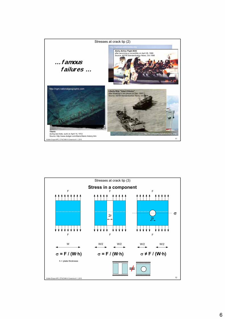
Stresses at crack tip (2)
… famous failures …
Aloha Airline Flight #243after becoming a convertible on April 28, 1988Source: ASTM Standardization News, Oct.1998
http://upload.wikimedia.org
Liberty Ship "Valeri Chkolov"after breaking in two pieces on Dec. 1943Source: ASTM Standardization News, Oct.1998
http://ngm.nationalgeographic.com
11Kübler Empa-HPC, ETHZ MW-II Ceramics-6.1, 2010
http://en.wikipedia.org/wiki/Liberty_shipTitanic during sea trials, sunk on April 14, 1912Source: http://www.dodger.com/titanic/titanic-history.htm
FStress in a component
Stresses at crack tip (3)
FF
F
W/2 W/2
2r σ
F
W/2 W/2
2r
F
W
12Kübler Empa-HPC, ETHZ MW-II Ceramics-6.1, 2010
σ = F / (W·h) σ = F / (W·h) σ ≠ F / (W·h)h = plate thickness

7
Stresses at crack tip (4)
Stress concentration around a hole
X X
Strain distribution around h l i h l
13Kübler Empa-HPC, ETHZ MW-II Ceramics-6.1, 2010
large stress gradient along x-x
a hole in a open hole tensile coupon by FEA
Source: NPL, Teddington, UK
■ tension ■ compression
The mechanical stress around a hole is significantly higher than the stress simply calculated from the macroscopically available cross section and applied load.
Stresses at crack tip (5)
“.. the smaller the hole the higher Kt ..”
Stress concentration factor for holes and notches
w2r co
ncen
trat
ion
fact
or K
t
g t
“.. the sharper the notch the higher Kt ”
stre
ss f
2r/w
w h
b
ss c
once
ntra
tion
fact
or K
t b/r=4
b/r=1
14Kübler Empa-HPC, ETHZ MW-II Ceramics-6.1, 2010
Predictions are in good agreement with numerous experimental observations.
notch the higher Kt ..
2r
b
stre
s
r/h
b/r=0.5
possible source: Pilkey, Walter D., Peterson's Stress Concentration Factors (2nd Edition), John Wiley & Sons, 1997

8
Stresses at crack tip (6)
Radius of curvature at tip of a defect FF “round hole := special
case of defect
F
W/2 W/2
2a
F
W/2 W/2
2a
ρt ρt
15Kübler Empa-HPC, ETHZ MW-II Ceramics-6.1, 2010
σm (1) σm (2)
σm (1) < σm (2)
… sharpness of defect (or crack)
Stresses at crack tip (7)
σm
ss
Concept of stress superelevationat tip of a defect σ0 nominal stress
σm stress at crack tipa ½ crack widthρt radius of
curvature at crack tip
σ0
stre
s
The mechanical stress σm at a tip of a defect is by factors larger than
the stress simply calculated from the
macroscopically available cross section
and applied load.x1-x2 → σ = 0 x1 x2
16Kübler Empa-HPC, ETHZ MW-II Ceramics-6.1, 2010
⎟⎟⎠
⎞⎜⎜⎝
⎛+=
tm
aρ
σσ 210
Calculating σm is rather complicated and is a function of the type of - crack geometry - loading (uniaxial, biaxial, …)- sample size
Here only the final result:
Question: Factor X for a very small hole?

9
tm
aρ
σσ ⋅⋅= 20
Stresses at crack tip (8)
For a >> ρt this reduces to:
Stress concentration factor
= sharp crack
Measure of how much an
factor
30
40
50
60
70
σm
ax /
σ0
3 (hole)
17Kübler Empa-HPC, ETHZ MW-II Ceramics-6.1, 2010
f mexternal stress is amplified (superelevated) at the crack tip.
From this it follows that large, sharp cracks are more deleterious than small, blunt cracks.
0
10
20
1 10 100 1000
log (a/pt)
σ
log (a/ρt)
Griffith law (1)
1. All materials have defects.(sometimes very small ones)
2. Small defects weaken brittle materials.( t l t d b G iffith i 1920)
Stress superelevation
(postulated by Griffith in 1920) 3. Ductile materials can diminish the stress superelevation.
(by plastic deformation at the crack tip and are therefore endangered far less than brittle materials)
4. All (not only) brittle materials exhibit a natural defect population.(due to production. Defects differ in size, form and orientation. Proposed by Griffith.)
18Kübler Empa-HPC, ETHZ MW-II Ceramics-6.1, 2010
5. Brittle materials (and all others) fail if nominal strength is overcome by a defect related stress peak.
Remark: This was examined on whiskers made of glass, on which fracture strains near the theoretical one (binding strength of atoms) have been measured.

10
Griffith law (2)
Energy Criteria for Fracture(= condition for fast failure of brittle materials)
Portrait of Alan Arnold Griffithand the centre-cracked panel used to derive his fracture concept in 1920.
ESIS Newsletter nr. 40-2004
19Kübler Empa-HPC, ETHZ MW-II Ceramics-6.1, 2010
Griffith’s basic idea was to balance the energy consumed in forming new surfaces as a crack propagates against the elastic energy
released.The critical condition for fracture occurs when the rate at which energy is
released is greater than the rate at which it is consumed.
Definition of crack dimensionsfor rest of today’s lecture:
bird eyes view
Attention: In literature “c” and “a”
are often used vise versa.
Griffith law (3)
2 a
σ2 a → ∞
σ
20Kübler Empa-HPC, ETHZ MW-II Ceramics-6.1, 2010
c
σ
c
σ

11
Griffith law (4)Remember:Griffith’s basic idea was to balance the energy consumed in forming new surfaces as a crack propagates against the elastic energy released.
2uniformly stressed
solid
1 3 relaxed volume
Total energy change Utot of system upon introduction of a crack
solid 4 two surfaces created
crackScrackVVotot UUUUU −− +−+= 0
21Kübler Empa-HPC, ETHZ MW-II Ceramics-6.1, 2010
1 2 3 4
1 Free energy in absence of “external” stress2 Energy introduced into volume V0 by applying a stress (avg stress)3 Released energy in shaded volume of size π·c2·½ ·t (= Elastic energy term)4 Energy needed to create new surface area of size 2 · c · t (= Surface energy term)
γσπσ
⋅⋅⋅+⎥⎤
⎢⎡ ⋅⋅
−⋅
+= tctcVUU appapp 2
2220
0
crackScrackVVotot UUUUU −− +−+= 0
Griffith law (5)Total energy change of system upon introduction of a crack
U - residual stress
U - applied stress
U -released by crack
U – needed to create 2 crack surfaces
γ+⋅⎥
⎦⎢⎣⋅
+ tcEE
UUtot 22220
with:Vo volumeσapp applied stress (avg stress)E Y ’ d l
if the applied stress is increased and a crack is created (or growing)
22Kübler Empa-HPC, ETHZ MW-II Ceramics-6.1, 2010
Eappσ
ε =
E Young’s modulusc depth of crackt width of crack2 two surfaces createdγ intrinsic surface
energy of material
with

12
Critical crack length ccrit at which fast fracture will occur corresponds to U*maxccrit respectively equilibrium reached at
dU* / dc = 0 U*
tc ⋅⋅⋅γ2
Griffith law (6)
- differentiation of equation to c- equating it to zero - replacing σapp by σf - rearranging
leads to:
Ec γπσ 2
Elastic energy(release) term
⎥⎦
⎤⎢⎣
⎡ ⋅⋅⋅
−22
22 tcE
app πσ
23Kübler Empa-HPC, ETHZ MW-II Ceramics-6.1, 2010
Plot of equation terms - surface energy (top curve)- elastic energy (bottom curve)as a function of c and sum ofthe two curves ( U* )
Eccritf ⋅⋅=⋅⋅ γπσ 2
K ≥ Kcstress intensity
factor
criticalstress intensity
factor than fast fracture occurs
if
Griffith law (7)
With the help of the Griffith law it is possible to estimate the theoretical strength of a material
critcritf c
Eσσ ⋅
⋅⋅==
πγ2
Griffith - equation
theoretical strength of a materialif for the minimal possible defect size the distance c between 2 atoms is used and
the theoretical strength depends only on the forces between the atoms.
c = 2·dei ~ 424 pm { dei= r0Mg2+ + r0
O2- = 86 pm+126 pm} 1
E ~ 250 GPa 2
γ ~ 1.15 J/m2 (100) Surface, air, RT 3 Barsoum1p82, 2p364, 3p103
Example MgO:(rock salt, CN 6) equilibrium interatomic distance
24Kübler Empa-HPC, ETHZ MW-II Ceramics-6.1, 2010
σf, theor ~ 20.8 GPa 1/12 Ethis confirms with data given in 1st part of Materials Science II, Ceramic Materials
c
c
The theoretically possible tensile strength (~E/10) has never been observed …

13
20
25
800
1000
… in reality rather 1/100 to 1/1000 of E → Why?
[GPa]
1 nm 1 µm
Griffith law (8)
10 nm 100 nm
5
10
15
20
200
400
600
800
E / σf
21
2⎟⎠⎞
⎜⎝⎛
⋅⋅⋅
=c
Ef π
γσ
25Kübler Empa-HPC, ETHZ MW-II Ceramics-6.1, 2010
0-1 0 1 2 3 4
0
defect size [log(c)] … c in nmσf,theoretical of MgO
σf,MgO polycrystall = 90 MPa → E / σf = 2’700 !!NIST - SCD Citation Number: Z00176
Modes of failure
Mode I: opening mode (tensile load in a right angle to the crack)
Mode II: sliding mode (shear in the direction of the crack)
26Kübler Empa-HPC, ETHZ MW-II Ceramics-6.1, 2010
(shear in the direction of the crack)
Mode III: tearing mode (shear at a right angle of the direction of the crack)
Mode I is by far the most pertinent to crack propagation in brittle materials(… so this is the only one we are going to discuss)

14
Irwin (1)
Stress field in accordance to Irwinat the tip of a crack with a coordinate system
Pσyy
Wc B
One-sided pre-chracked body= model for Griffith-concept
Stress at a point P in relation to its distance and direction from the crack tip leads to a stress matrix.
Pσxx
σxy
31 i iP P Pθ θ θ⎡ ⎤⎧ ⎫⎛ ⎞ ⎛ ⎞ ⎛ ⎞⎨ ⎬⎢ ⎥
27Kübler Empa-HPC, ETHZ MW-II Ceramics-6.1, 2010
312 2 2
312 2 22
32 2 2
cos sin sin
cos sin sin
sin cos cos
P P P
xxI P P P
yy
xy PP P P
Kr
θ θ θ
σθ θ θσ
πσθ θ θ
⎡ ⎤⎧ ⎫⎛ ⎞ ⎛ ⎞ ⎛ ⎞⋅ −⎨ ⎬⎢ ⎥⎜ ⎟ ⎜ ⎟ ⎜ ⎟⎝ ⎠ ⎝ ⎠ ⎝ ⎠⎩ ⎭⎢ ⎥⎡ ⎤ ⎢ ⎥⎧ ⎫⎢ ⎥ ⎛ ⎞ ⎛ ⎞ ⎛ ⎞⎢ ⎥= ⋅ +⎨ ⎬⎜ ⎟ ⎜ ⎟ ⎜ ⎟⎢ ⎥ ⎢ ⎥⎝ ⎠ ⎝ ⎠ ⎝ ⎠⎩ ⎭⎢ ⎥ ⎢ ⎥⎣ ⎦
⎛ ⎞ ⎛ ⎞ ⎛ ⎞⎢ ⎥⋅ ⋅⎜ ⎟ ⎜ ⎟ ⎜ ⎟⎢ ⎥⎝ ⎠ ⎝ ⎠ ⎝ ⎠⎣ ⎦
rpP
Stress (elevation) in accordance to Irwin at an angel θ and at distance or rp
θ
Irwin (2)rP
1 00“ 0 10“
28Kübler Empa-HPC, ETHZ MW-II Ceramics-6.1, 2010
rp = „1.00“ rp = „0.10“
rp = „0.01“σxx
σyy
σxy
Which of the stresses is the most important one and why ?
point P
-3, 0, 3, 6 x “nominal” stresscrack

15
Irwin (3)
The rate at which the energy is released while a crack is formed, can be obtained from the energy difference at the beginning and end of
the crack (= Δx), respectively.
Energy release rate G
dxux
G yx yy
x∫
Δ= Δ
→Δ0
0 22lim
σ 0=Θforyyσπ=Θforyu
uy half of the opening of the crack
for purely brittle solids = 2 γ !!
29Kübler Empa-HPC, ETHZ MW-II Ceramics-6.1, 2010
Irwin showed that this simple relation exists between the
stress intensity factorand energy release rate
EKG I
2
=
Irwin (4)
whereas isvalid, too: dc
dUG M=G energy release rateUM mechanical energyUE released energy
Irvin correlation
EKG I
2
=
⎤⎡ 22and if the load
is constant:
combining theequations: YcK I ⋅⋅= σdc
Etcd
EK I
]22
[22
2⋅⋅
⋅⋅⋅
=
πσ
⎥⎦
⎤⎢⎣
⎡ ⋅⋅⋅
==22
22 tcE
UU EMπσ
andsolving it:
30Kübler Empa-HPC, ETHZ MW-II Ceramics-6.1, 2010
• externally applied stress • size of the crack • Y-factor defined by geometry of crack
Y-factor predicts intensity and distribution of a stress field around a defect in the material of a component caused by an external load.
Therefore, KI depends on

16
Crack (flaw) shape correction factorsY depends on whether the crack is intersected by the surface or is in the bulk of the
component. For the surface connected crack, the value at the centre is different from that where the crack intersects the surface.
Irwin (5)
CEN TS 843-6, 2004 → c and a have changed to be in line with definition.
31Kübler Empa-HPC, ETHZ MW-II Ceramics-6.1, 2010
Factors for intermediate shapes of a flaw can be computed using the equations given by Newman, C.R., Raju, I.S., Eng. Fract. Mech. 1981, 15 [1-2], 185-92
This table should be used only as a guide if computing the stress or crack size at failure, respectively. If you don’t have Y for your specific problem chose 1.5 and
as 1.1 ≤ Y ≤ 2.0 in the worst case you’re of by less than 30 %.
YcK cIc ⋅⋅= σAs the fracture toughness is a materials
property …
Strength of ceramics[ ]IcK MPa m=[σc] = MPa
[Y] = -[c] = m
Irwin & Griffith
… is the (failure) strength “only” a characteristic of a sample,
part or component ! YcKIc
c⋅
=σ
… and as no material and component is free of defects due to the purity and homogeneity of raw materials, processing, machining, handling, etc. …
volume: pores, large grains, inclusions, … surface: cracks, pits, chipped edges, machining marks, …
32Kübler Empa-HPC, ETHZ MW-II Ceramics-6.1, 2010
part, or component ! Yc ⋅Conclusion• KIc indicates how well a specific material under stress is able to withstand the
extension of a crack (… design relevant property). • The higher the KIc, the more difficult it is for a crack to advance in a material. • The strength at failure σc is a characteristic of a component.
17
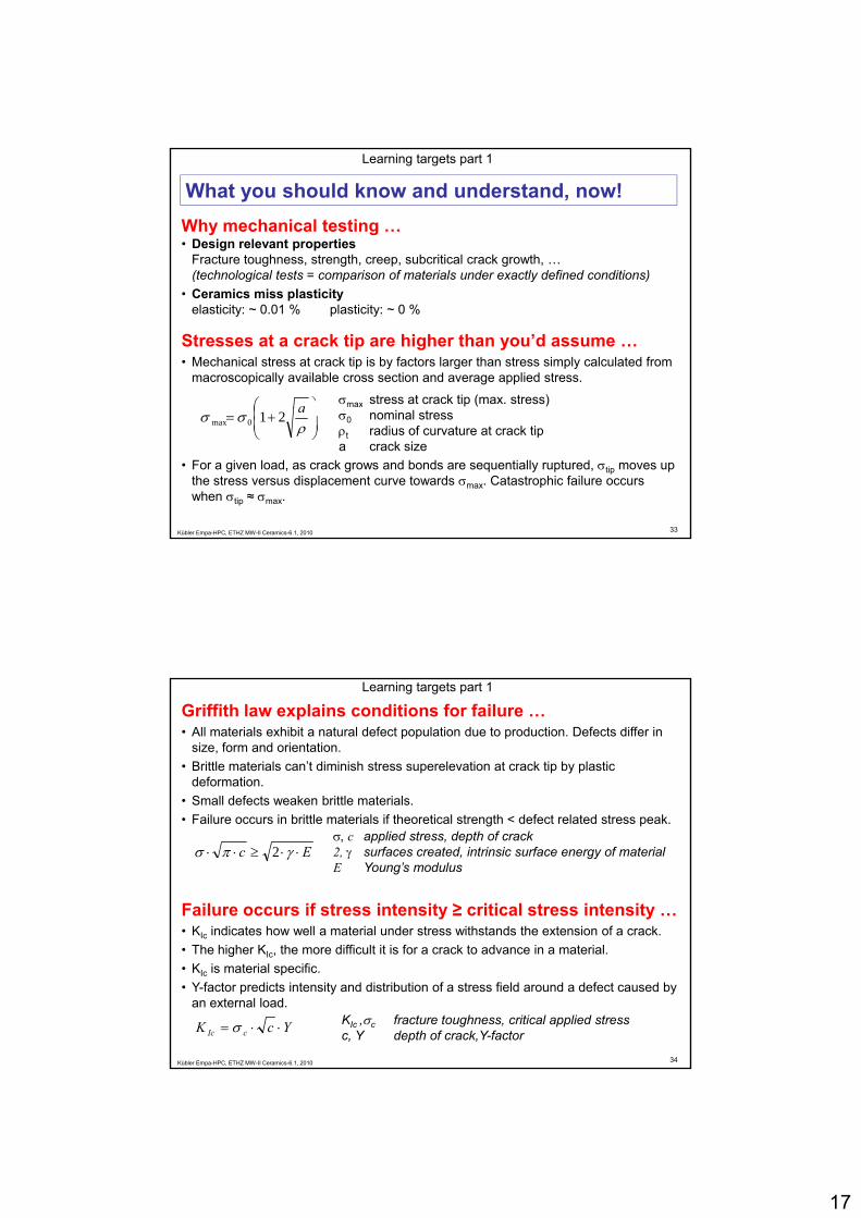
What you should know and understand, now! Learning targets part 1
Why mechanical testing …• Design relevant properties
Fracture toughness, strength, creep, subcritical crack growth, …(technological tests = comparison of materials under exactly defined conditions)(technological tests comparison of materials under exactly defined conditions)
• Ceramics miss plasticityelasticity: ~ 0.01 % plasticity: ~ 0 %
Stresses at a crack tip are higher than you’d assume …• Mechanical stress at crack tip is by factors larger than stress simply calculated from
macroscopically available cross section and average applied stress.
⎟⎞
⎜⎛ a σmax stress at crack tip (max. stress)
33Kübler Empa-HPC, ETHZ MW-II Ceramics-6.1, 2010
• For a given load, as crack grows and bonds are sequentially ruptured, σtip moves up the stress versus displacement curve towards σmax. Catastrophic failure occurs when σtip ≈ σmax.
⎟⎟⎠
⎞⎜⎜⎝
⎛+=
ρσσ a210max
σ0 nominal stressρt radius of curvature at crack tipa crack size
Griffith law explains conditions for failure …• All materials exhibit a natural defect population due to production. Defects differ in
size, form and orientation. • Brittle materials can’t diminish stress superelevation at crack tip by plastic
deformation.• Small defects weaken brittle materials.
Learning targets part 1
• Failure occurs in brittle materials if theoretical strength < defect related stress peak.
Ec ⋅⋅≥⋅⋅ γπσ 2σ, c applied stress, depth of crack2, γ surfaces created, intrinsic surface energy of materialE Young’s modulus
Failure occurs if stress intensity ≥ critical stress intensity … • KIc indicates how well a material under stress withstands the extension of a crack.
34Kübler Empa-HPC, ETHZ MW-II Ceramics-6.1, 2010
c
• The higher KIc, the more difficult it is for a crack to advance in a material. • KIc is material specific.• Y-factor predicts intensity and distribution of a stress field around a defect caused by
an external load.
YcK cIc ⋅⋅= σ KIc ,σc fracture toughness, critical applied stressc, Y depth of crack,Y-factor