Chapter 11: Structural Materials Metals, Ceramics, and Glasses

www.nabertherm.com
Advanced Materials
Furnaces and Heat Treatment Systems for
Powder MetallurgyTechnical CeramicsBio CeramicsMLCC, LTCC, HTCCMIM, CIMLighting/LED IndustryFuel Cell/Battery ManufacturingWafer ProductionPhotovoltaicsCrystal GrowthPolymerizationEnergy Efficiency Technology Made
inGermany

Made in GermanyNabertherm with 350 employees worldwide have been developing and producing industrial furnaces for many different applications for over 60 years. As a manufacturer, Nabertherm offers the widest and deepest range of furnaces worldwide. 150,000 satisfied customers in more than 100 countries offer proof of our commitment to excellent design, quality and cost efficiency. Short delivery times are ensured due to our complete inhouse production and our wide variety of standard furnaces.
Setting Standards in Quality and ReliabilityNabertherm does not only offer the widest range of standard furnaces. Professional engineering in combination with inhouse manufacturing provide for individual project planning and construction of tailor-made thermal process systems with material handling and charging systems. Complete thermal processes are realized by customized system solutions.
Innovative Nabertherm control technology provides for precise control as well as full documentation and remote monitoring of your processes. Our engineers apply state-of-the-art technology to improve the temperature uniformity, energy efficiency, reliability and durability of our systems with the goal of enhancing your competitive edge.
Global Sales and Service Network – Close to youCentralized engineering and manufacturing and decentralized sales and service define our strategy to live up to your needs. Long term sales and distribution partners in all important world markets ensure individual on-site customer service and consultation. There are various reference customers in your neighborhood who have similar furnaces or systems.
Large Customers Test CenterWhat furnace is the right choice for this specific process? This question cannot always be answered easily. Therefore, we have set up our modern test center which is unique in respect to size and variety. A representative number of furnaces is available for tests for our customers.
Customer Service and Spare PartsOur professional service engineers are available for you world-wide. Due to our complete inhouse production, we can despatch most spare parts from stock over night or produce with short delivery time.
Experience in Many Fields of Thermal ProcessingIn addition to furnaces for Advanced Materials, Nabertherm offers a wide range of standard furnaces and systems for many other thermal processing applications. The modular design of our products provides for customized solutions to your individual needs without expensive modifications.
2

Table of Contents Page
Which Furnace for Which Process? ....................................................................................................... 4
Matrix Debinding Technology ............................................................................................................... 6
Heat Recovery Systems for Energy Savings Purposes .......................................................................... 7
Air Circulation FurnacesAir circulation chamber furnaces for debinding in air up to 650 °C ................................................................. 8Air circulation bogie hearth furnaces for debinding in air up to 600 °C ........................................................... 9Air circulation chamber furnaces/ovens with safety technology for solvent-containing charges according to EN 1539 or NFPA 68 ........................................................................................................10Air circulation chamber furnaces for clean room processes, electrically heated .............................................11Ovens, also with safety technology accorging to EN 1539 ..........................................................................12Chamber dryer, electrically heated or gas-fired .........................................................................................14
Dewaxing Furnaces, Electrically Heated or Gas-Fired .........................................................................16
Furnaces with Radiation Heating up to 1400 °CBogie hearth furnaces, also as combi furnaces for debinding and sintering in one process ............................. 18Pit-type and top-loading furnaces with or without air circulation, electrically heated or gas-fired ......................21Lift-top or lift-bottom furnaces, also as combi furnaces for debinding and sintering in one process ................. 22Combi chamber furnaces for debinding and sintering in one process .......................................................... 24Chamber furnaces ............................................................................................................................... 26
Gas-Fired Chamber Furnaces up to 1300 °CGas-fired chamber furnaces, also as combi furnaces for debinding and sintering in one process ..................... 28Gas-fired bogie hearth furnaces for firing or sintering or as combi furnace for debinding and sintering in one process.. ......................................................................................... 29
High-Temperature Furnaces up to 1800 °CHigh-temperature bogie hearth furnaces with SiC rod heating .................................................................... 30High-temperature chamber furnaces with SiC rod heating ..........................................................................31High-temperature chamber furnaces with fiber insulation .......................................................................... 32High-temperature chamber furnaces with refractory insulation ................................................................... 35Lift-top and lift-bottom furnaces ............................................................................................................ 36Gas-fired chamber furnaces.................................................................................................................. 40
Catalytic and Thermal Afterburning Systems, Exhaust Gas Washer .....................................................41
Continuous Furnaces, Electrically Heated or Gas-Fired...................................................................... 42
Retort Furnaces up to 1100 °C resp. 2400 °CHot-wall retort furnaces ....................................................................................................................... 44Cold-wall retort furnaces ...................................................................................................................... 48Lift-bottom -retort furnace ..................................................................................................................... 52Pit-type cold-wall retort furnaces ........................................................................................................... 53Chamber retort furnaces for catalytic debinding ....................................................................................... 54
Fast-Firing Furnaces .......................................................................................................................... 55
Gradient or Lab Strand Annealing Furnaces ........................................................................................ 55
Laboratory FurnacesProfessional chamber furnaces with brick or fiber insulation ...................................................................... 56High-temperature chamber furnaces with SiC rod heating ......................................................................... 58High-temperature chamber furnaces with MoSi2 heating elements as table-top model .................................. 59High-temperature lift-bottom furnaces.................................................................................................... 60High-temperature furnaces with scale for determination of combustion loss and thermogravimetric analysis (TGA) ....................................................................................................61
Tube Furnaces up to 1800 °C .............................................................................................................. 62
Temperature Uniformity and System Accuracy .................................................................................... 80
Process Control and Documentation ...................................................................................................813

Which Furnace for Which Process?
Debinding, Drying, Vaporizing, Dewaxing
Bogie hearth furnaces with gas-supply boxes,
W .., page 18
Chamber retort furnaces,NRA .. CDB,
page 54
Air circulation bogie hearth furnaces,
W .. HACDB, page 9
Cold-wall retort furnaces, VHT ..,
page 48
Hot-wall retort furnaces,NR and NRA .. IDB,
page 46
Air circulation chamber furnaces,
N .. HACDB, page 8
HT lift-bottom furnaces with fresh air preheating,
HT .. LBDB, page 36
HT lift-top furnaces with fresh air preheating,HT .. LTDB, page 36
High-temperature chamber furnaces with fresh air
preheating, HT .. DB, page 32
Lift-top furnaces with fresh air preheating,
H .. HDB, page 22
Bogie hearth furnaces with fresh air preheating,W .. HDB, page 18
Chamber furnaces with fresh air preheating,N .. HDB, page 24
Chamber furnaces with fresh air preheating,N .. HDB, page 24
Catalytic
in Air under Protective Gas, Reaction Gas or Vacuum
Thermal
in Air Debinding in Air, Sintering under Protective Gas
Debinding + SinteringPyrolysis
Dewaxing furnaces,gas-fired
NB .. WAX, page 17
Dewaxing furnaces,electrically heatedN .. WAX, page 16
Ovens,TR ..,
page 12
Air circulation chamber furnaces/ovens according to
EN 1539, N .. HACLS, page 10
Combi chamber furnace N 650/HDB for debinding and sintering in air see page 24
Tube furnace for hydrogen operation see page 77
Chamber dryer,KTR..,
page 14
Lift-bottom -retort furnaces, LBVHT ..,page 52
High-temperature bogie hearth furnaces with SiC rod heating, WHTC .., page 30
High-temperature chamber furnaces with SiC Rod
Heating, HTC .., page 31
4

Lift-top and lift-bottom furnaces,H ..LT/LB, page 22
Bogie hearth furnaces,W ..,
page 18
Chamber furnaces,N ..,
page 26
Hot-wall retort furnaces,NR .. and NRA ..,
page 44
Sealed high-temperature furnaces,
HT .., page 32
Sealed lift-top and lift-bottom furnaces,
H .., page 22
Bogie hearth furnaces with gas-supply boxes,
W .., page 18
Sealed chamber furnaces,N ..,
page 26
Continuous furnaces,D ..,
page 42
High-temperature chamber furnaces, gas-fired,
HTB .., page 40
High-temperature chamber furnaces, brick-insulated,
HFL .., page 35
High-temperature lift-top furnaces,
HT ..LT, page 36
High-temperature lift-bottom furnaces,
HT .. LB, page 36
High-temperature chamber furnaces,
HT .., page 32
Gas-fired bogie hearth furnaces,
WB .., page 29
Gas-fired chamber furnaces,
NB .., page 28
Pit-type and top-loading furnaces,
S .., page 21
Exhaust CleaningLaboratory FurnacesSintering, Calcinating,Drying, Preheating
under Protective Gas, Reaction Gas or in Vacuum
in Air
High-temperature chamber furnace, SiC,
HTC .., page 58
High-temperature lift-bottom furnaces,LHT .. LB, page 60
High-temperature chamber furnaces,
LHT .., page 59
High-temperature furnaces for TGA tests,
LHT/SW, page 61
Fast-firing furnaces,LS ..,
page 55
Gradient furnace,GR ..,
page 55
Chamber furnaces,LH ..,
page 56
Tube furnaces,R ..,
page 62
Cold-wall retort furnacesVHT ..,
page 48
Catalytic afterburning,page 41
Thermal afterburning,page 41
Retort furnace with safety technology, models NRA .. for sintering under hydrogen atmosphere see page 46
Lift-bottom -retort furnaces, LBVHT ..,page 52
High-temperature bogie hearth furnaces with SiC rod heating, WHTC .., page 30
High-temperature chamber furnaces with SiC Rod
heating, HTC .., page 31
5

Matrix Debinding Technology
Debinding of technical ceramics is both a critical process due to the released hydrocarbons and a technical challenge due to the necessary precise temperature control. Nabertherm offers professional solutions for the different debinding methods.
Debinding Methods
I. Debinding in Air
1. Debinding (and Sintering) in Directly Gas-Fired FurnacesCompared with electrically heated furnaces, gas-fired furnaces have the advantage that the released hydrocarbons are almost completely burned immediately during the firing process. Therefore, gas-fired furnaces are especially used when the vaporization process is difficult to manage e.g. due to high vaporization dynamics. Hence, unavoidable erratic releases of hydrocarbons do not necessitate any elaborate process control or long process times. If, on the other hand, the debinding process requires precise temperature control or a good temperature uniformity, in particular at low temperatures, this challenge can be met only with the employment of electrically heated debinding furnaces.
2. Debinding (and Sintering) in Electrically Heated FurnacesFor debinding in air with electrical heating, Nabertherm offers different debinding packages for different process requirements. All debinding packages comprise a professional, integrated safety technology. Depending on the process a passive or active safety concept can be chosen.
a) Passive Safety ConceptBasically, all Nabertherm debinding furnaces are equipped with a passive safety concept. The electrically heated furnaces operate according to the dilution principle by means of fresh air injection, in order to reduce the gas emissions from the load to a noncombustible atmosphere in the furnace. It is the customer's responsibility to ensure that the maximum permissible vaporization rate is not exceeded, i.e. that the furnace is not overloaded with organic substances and the executable thermal profiles are appropriately defined. The monitoring of all safety-related process parameters, e.g. volume flow, and a corresponding emergency program in case of failure ensures a safe operation. In practice the passive safety concept has prevailed based on the good cost/performance ratio. Subject to process requirements, there are two different debinding packages available as described below.
Debinding Package IThis package represents the basic version for safe debinding and is ideally suited for recurring processes with defined vaporization rates. The furnace is equipped with a fresh air fan and an exhaust gas fan. Both units are firmly mounted on the furnace and factory-adjusted so that the volume of fresh air required for the debinding process is injected in a controlled mode to assure a certain underpressure in the furnace chamber, so that the exhaust gases are discharged exclusively through the exhaust gas outlet and not into the production hall. The fresh air required for the process is indirectly preheated via inlet channels. Monitoring of the furnace underpressure ensures a safe operation.
In addition, an independent ramp monitor is installed, where the customer sets the maximum permissible heating gradient during the debinding process. If in case of faulty operation or a control failure this gradient is exceeded or another safety-related fault is detected, an emergency program ensures that the furnace is transferred into a safe mode. As additional equipment, debinding package I can be expanded with active fresh air preheating and/or controlled cooling.
Debinding and sinteringin combi furnaces
Debinding in air circulation furnaces
Debinding and sintering in gas furnaces
Electrical heatingGas-fired
Debinding in air
Debinding in retort furnaces
Debinding and sinteringin high-temperature
vacuum furnaces
Electrical heating
Debinding in non-flammable or flammable protective or
reaction gases
6

Debinding Package IIDebinding package II is the convenient solution for the variable ceramics production, since there is ample flexibility to accommodate different or frequently changing debinding processes. The basic differences and advantages compared with debinding package I are:
� Program adjustable fresh air volume depending on the vaporization rate of the product � Fresh air preheating with separate air preheater. The fresh air temperature (up to max. 500 °C) is controlled as additional heat source depending on the furnace temperature. This results in a very good heat transfer and improved temperature uniformity. � Automatic control of the exhaust gas fan depending on the preselected fresh air volume provides for advantages in temperature control (temperature uniformity) and adapted discharge of the exhaust gases � Differentiated emergency program: Depending on the fault different emergency programs are automatically executed � Perforated injection tubes in the furnace chamber depening on furnace model for uniform distribution of the preheated fresh air through the horizontal charging layers � Display at the furnace for underpressure and volume flow � PLC controls with touch panel H 1700 see page 82 � Controlled cooling as standard
b) Active Safety ConceptAlternatively, an active safety concept is also available as additional equipment on request. The actually vaporized organic volume in the furnace chamber is monitored by means of the flame-thermal analysis (FTA). The fresh air and exhaust gas fans are automatically reconciled accordingly. In case of unsafe condition in the furnace e.g. from overloading, a heating gradient that is too fast or inadequate fresh air supply, the necessary emergency program is immediately initiated depending on the process step.
2.1. Debinding in Air Circulation FurnacesAir circulation furnaces are generally the right choice when debinding is the only process. Depending on the raw materials or temperature requirements, the green compacts can also be presintered. Air circulation furnaces convince by their good temperature uniformity even with dense loads, their accelerated heat transfer and their better charge penetration. Debinding and sintering in two process steps is always advisable if a better capacity utilization of the different furnaces and a reduced overall investment volume can be achieved.
2.2. Debinding and Sintering in Combi FurnacesCombi furnaces provide for debinding and subsequent sintering in just one furnace system. Debinding and sintering or pre-sintering in one process step offer the following advantages:
� Shortened process times: cooling, transfer, no second heating process required � Energetic advantages � Reduced scrap risk
The use of combi furnaces is always advisable when charging takes a longer a period of time or if the debindered green/brown compacts are sensitive to cooling and transfer due to their material properties or parts geometry. Nabertherm combi furnaces have successfully proven their reliability in the market for years. Equipped with mature system modules, these furnaces are the right choice for sophisticated processes. For example, the controlled air-preheating provides – besides the conventional furnace heating – for an optimum temperature uniformity up to 500 °C and, therefore, for excellent quality results.
II. Debinding in non-flammable or flammable protective or reaction gases
Besides debinding in air, debinding processes in technical ceramics or powder metallurgy are also executed under non-flammable or flammable protective or reaction gases to achieve other process or quality requirements. Also, for these applications Nabertherm offers standard as well as customized furnace solutions, explained in detail on following catalog pages. The safety technology varies subject to the specific process requirements.
Heat Recovery Systems for Energy Savings Purposes
With rising energy costs, but also for environmental reasons, the integration of heat recovery systems is paying off more and more. Depending on the furnace size and process, there is always a certain potential for energy recovery through heat exchangers from the released process exhaust gases or warm disposal air of the furnace system. Especially for large furnace systems or long process times the achieven energy savings will pay back the additional investment in just a short time. We would be glad to advise you on whether an additional heat recovery module would be a useful addition to your furnace system.
7

Air Circulation Chamber Furnaces for Debinding in Air up to 650 °C
N 120/65 HACDB - N 500/65 HACDBThe air circulation chamber furnaces N 120/65 HACDB - N 500/65 HACDB are perfectly suited for debinding processes that require a good temperature uniformity due to the parts geometry or characteristics of the binder. The powerful, horizontal air circulation with high air flow rate provides for full utilization of the furnace in different charging layers. Uniform process results are ensured even for small components, such as CIM manufactured parts. On request, the furnaces can be equipped with catalytic or thermal afterburning to clean the exhaust gases. Following the debinding the components are transferred to the sintering furnace.
� Tmax 650 °C � Powerful, horizontal air circulation provides for a temperature uniformity of ΔT 8 K according to DIN 17052 see page 80 � Debinding package I with passive safety package and monitoring of the underpressure in the furnace chamber, exhaust gas fan, fresh air fan, preset underpressure in the furnace chamber, controlled by Nabertherm controller P 300 see page 6 � Connection port for further piping behind the exhaust fan �Welded inside housing of the furnace made of stainless steel 1.4301 � Holders for removable trays for charging in multiple layers � 3 removable trays included with delivery � Heating switched with low-wear semiconductor relay � Over-temperature limiter with manual reset for thermal protection class 2 in accordance with EN 60519-2 as temperature limiter to protect the furnace and load
Additional equipment � Additional trays � Controlled cooling including PLC control of the heating and cooling air fan � Fresh air preheating and controlled fan cooling, including PLC control of the furnace heating as well as the fresh air preheating as a second heat source � Debinding package II with passive safety concept see page 7 � Thermal or catalytic exhaust cleaning systems see page 41 � Heat recovery systems see page 7 � Emergency purging with nitrogen � Commissioning of the furnace with test firing and temperature uniformity measurement (also with load) for the purpose of process optimization � Process documentation and control with Controltherm MV software package, NTLog and NTGraph for the basic furnace or Nabertherm Control Center (NCC) for monitoring, documentation and control for use of debinding package II see page 83
Charging cart with pull-out trays
Debinding line with integrated heat recovery system for utilizing the exhaust heat for fresh air preheating
N 250/65HACDB with debinding package I
8

W 3300/85A
Air Circulation Bogie Hearth Furnaces for Debinding in Air up to 600 °C
W 1000/60 HACDB - W 8100/60 HACDBThe air circulation bogie hearth furnaces W 1000/60 HACDB - W 8100/60 HACDB are designed for debinding large volumes of material. The functionality corresponds to air circulation chamber furnaces for debinding. These powerful production furnaces are equipped with a passive safety package providing for a reliable process control. On request the furnaces can be equipped with catalytic or thermal afterburning to clean the exhaust gases.
� Tmax 600 °C � Powerful, horizontal air circulation provides for a temperature uniformity of ΔT 8 K according to DIN 17052 see page 80 � Debinding package I with passive safety package and monitoring underpressure in the furnace chamber, exhaust gas fan, fresh air fan, preset underpressure in the furnace chamber, controlled by Nabertherm controller P 300 see page 6 � Connection port for further piping behind the exhaust fan � Inside sheets of the furnace made of stainless steel 1.4301 fully cover the insulation � Heating switched with low-wear semiconductor relay � Over-temperature limiter with manual reset for thermal protection class 2 in accordance with EN 60519-2 as temperature limiter to protect the furnace and load
Additional equipment � Controlled cooling including PLC control of the heating and cooling air fan � Fresh air preheating and controlled fan cooling, including PLC control of the furnace heating as well as the fresh air preheating as a second heat source � Debinding package II with passive safety concept see page 7 � Thermal or catalytic exhaust cleaning systems see page 41 � Heat recovery systems see page 7 � Emergency purging with nitrogen � Additional bogie, rail operation, cross-traversal system see page 19 � Commissioning of the furnace with test firing and temperature uniformity measurement (also with load) for the purpose of process optimization � Process documentation and control with Controltherm MV software package, NTLog and NTGraph for the basic furnace or Nabertherm Control Center (NCC) for monitoring, documentation and control for use of debinding package II see page 83
Furnace chamber with air baffle plates
Bogie hearth furnace system for debinding with cross sliding device
9

Drying oven KTR 1500 for drying of foundry cores with an alcohol-based binder
Air Circulation Chamber Furnaces/Ovens with Safety Technology for Solvent-Containing Charges according to EN 1539 or NFPA 68
Guide-in tracks for furnaces with bottom insulation
Exhaust port and powerful exhaust fan mounted on the furnace
Ship-lock type furnace N 560/26HACLS with safety technology, front charging and rear unloading
Safety Technology for Air Circulation Chamber FurnacesCertain processes release and vaporize solvents or other flammable vapors. The concentration of these vapors must be kept below a certain limit to prevent ignition. European Norm EN 1539 and NFPA 68 in the USA prescribe the required safety equipment for these processes.
For these applications and processes, all air circirculation furnaces of the KTR and N ..HACLS product lines are suited with safety technology for protection of a potentional ignition in the furnace chamber.
To avoid an ignition in the furnace, flammable vapors must be diluted with air. Special care must be taken so high concentrations of flammable materials do not accumulate in “dead” areas within the furnace. For this purpose, the furnaces are equipped with an exhaust gas fan providing for a defined suction flow. A measurement system monitors this flow, while fresh air is simultaneously resupplied. In parallel, the furnace atmosphere is diluted by the inflow of fresh air. The air circulation is also monitored by the measurement system.
� Furnace sizes between 120 and 10,000 liters � Powerful exhaust fan capable of maintaining negative furnace pressure � Defined and monitored air circulation flow and exhaust air � Visual and audible emergency signals � Overtemperature selection limiter with adjustable cutout temperature for thermal protection class 2 in accordance with EN 60519-2 as temperature limiter for the furnace and the product � Controls description see page 81
10

NAC 250/65
NAC 120/65
Industrial oven N 250/65 HAC with particle-free oven chamber. For charging, furnace door is located in cleanroom, class 100, furnace chamber in greyroom behind.
Model Tmax Inner dimensions in mm Outer dimensions in mm Connected Electrical°C w d h W D H load/kW connection*
NAC 120/65 650 450 600 450 900 + 255 1600 1600 9.6 3-phaseNAC 250/65 650 600 750 600 1050 + 255 1750 1750 18.6 3-phaseNAC 500/65 650 750 900 750 1120 + 255 1900 1900 27.6 3-phase
Rights to change technical data, especially with respect to outer dimensions reserved*Please see page 81 for more information about supply voltage
KTR 8000 designed as a production furnace in clean room environments with filters for air recirculation
NAC 120/65 - NAC 500/65Specific heat treatment processes require the reduction of particle contamination in the furnace chamber and on the work floor down to a minimum. For these applications the NAC air circulation chamber furnaces are recommended. The inner chamber is made of stainless steel and offers best possible protection against impurities from the insulation. Depending on design and required clean room class these furnaces can be equipped accordingly.
� Tmax 650 °C � Standard sizes between 120 and 500 liters furnace volume � Customized dimensions, also available as production-scale furnaces up to 10000 l (KTR models) see page 14 � Dual shell housing provides for low surface temperatures � Insulation made of mineral wool with aluminum protection cover provides for low emissions to the outside �Welded inner housing made of stainless steel 1.4301 � Door with silicone sealing � Horizontal airflow incl. air-guiding box provides for optimum temperature uniformity � Tubular heating elements positioned behind the air-guiding box � One shelf included in the delivery
Additional equipment � Silicone-free design with door sealing made of Viton � Electro-polished inner box � Electrically driven air inlet and exhaust air flaps � Cooling system for reduction of process times � Observation window in the door � Manual or automatic gas supply systems � Speed control for air circulation fan � Additional shelves � Process control and documentation with Controltherm MV software package see page 83 � Filters for fresh air or air recirculation, filter class appropriate for individual requirements
Air Circulation Chamber Furnaces for Clean Room Processes Electrically Heated
11

TR 240
Ovens, also with Safety Technology accorging to EN 1539
TR 60 - TR 1050With their maximum working temperature of up to 300 °C and forced air circulation, the ovens achieve a perfect temperature uniformity which is much better than in ovens of most competitors. They can be used for various applications such as e.g. drying, sterilizing or warm storing. Ample warehousing of standard models provides for short delivery times.
� Tmax 300 °C �Working range: + 5 °C above room temperature up to 300 °C � Models TR 60 - TR 240 designed as tabletop models � Models TR 450 and TR 1050 designed as floor standing models � Horizontal, forced air circulation results in temperature uniformity better than ΔT 8 K see page 80 � Stainless steel chamber, alloy 304 (AISI)/(DIN material no. 1.4301), rust-resistant and easy to clean � Large handle to open and close the door � Charging in multiple layers possible using removeable grids (number of removeable grids included, see table to the right) � Large, wide-opening swing door, hinged on the right with quick release for models TR 60 - TR 450 � Double swing door with quick release for TR 1050 � TR 1050 equipped transport rollers � Infinitely adjustable exhaust at the rear wall with operation from the front � PID microprocessor control with self-diagnosis system � Solid state relays provide for low noise operation � Controls description see page 81
Additional equipment � Over-temperature limiter with manual reset for thermal protection class 2 in accordance with EN 60519-2 as temperature limiter to protect the furnace and load � Infinitely adjustable fan speed of the air circulation fan �Window for charge observing
Extricable metal grids to load the oven in different layers
Electrical rotating device as additional equipment
TR 60 with adjustable fan speed
12

TR 240
TR 1050 with double door
� Further removeable grids with rails � Side inlet � Stainless steel collecting pan to protect the furnace chamber � Safety Technology according to EN 1539 for charges containing liquid solvents up to model TR 240, achievable temperature uniformity ΔT 16 K see page 80 � Transport costors for model TR 450 � Various modifications available for individual needs � Upgrading available to meet the quality requirements of AMS 2750 D or FDA � Process control and documentation with Controltherm MV software package see page 83
Model Tmax Inner dimensions in mm Volume Outer dimensions in mm Connected Electrical Weight Grids in- Grids Max.°C w d h in l W D H load kW² connection* in kg cluded max. total load¹
TR 60 300 450 380 350 60 700 650 690 3.0 single-phase 90 1 4 120TR 120 300 650 380 500 120 900 650 840 3.1 single-phase 120 2 7 150TR 240 300 750 550 600 240 1000 820 940 3.1 single-phase 165 2 8 150TR 450 300 750 550 1100 450 1000 820 1440 6.3 3-phase 235 3 15 180TR 1050 300 1200 630 1400 1050 1470 955 1920 9.3 3-phase 450 4 14 250¹Max load per layer 30 kg *Please see page 81 for more information about supply voltage²If EN 1539 is ordered power rating will increase
TR 60 with observation window
TR 450 with observation window
13
KTR 8000
Chamber Dryer Electrically Heated or Gas-Fired
The chamber dryers of the KTR range can be used for complex drying processes and heat treatment of charges of normal weight and packing density to an application temperature of 260 °C. The high-performance air circulation enables optimum temperature uniformity throughout the usable space. A wide range of accessories allow the furnace to be modified to meet specific process requirements. The design for the heat treatment of flammable materials in conformance with EN 1539 is available for all sizes.
� Tmax 260 °C � Electrically heated (via a heating register with integrated chrome steel heating elements) or gas-fired (direct gas heating including injection of the hot air into the intake duct) � Temperature uniformity up to ΔT 6 K according to DIN 17052-1 (for design wihout track cutouts) see page 80
Motor-driven rotary rack with baskets for moving the charge during heat treatment
Standard models
14

KTR 6125
KTR 8000
KTR 3100/S for curing of composites in vacuum bags incl. pump and necessary connections in the oven chamber
� High-quality mineral wool insulation provides for outer temperatures of < 20 °C above room temperature � High air exchange for fast drying processes � Double-wing door for furnaces KTR 3100 and larger � Over-temperature limiter with manual reset for thermal protection class 2 in accordance with EN 60519-2 as temperature limiter to protect the dryer and load � Incl. floor insulation � For control systems see page 81
Additional equipment � Entry ramp for pallet trucks or track cutouts for charging cart � Optimal air circulation for individual charges by means of adjustable air outlets � Fan system for faster cooling with manual or motor-driven control � Programmed opening and closing of exhaust air flaps � Observation window and furnace chamber lighting � Safety technology according to EN 1539 for charges containing solvents see page 10 � Charging cart with or without rack system � Custom-built sizes � Design for clean heat treatment processes see page 11 � Process control and documentation with Controltherm MV software package see page 83
Model Tmax Inner dimensions in mm Volume Outer dimensions in mm Connected Electrical°C w d h in l W D H load kW connection*
KTR 1500 260 1000 1000 1500 1500 1930 1430 2315 21,0 3-phaseKTR 3100 260 1250 1250 2000 3100 2160 1680 2880 30,0 3-phaseKTR 4500 260 1500 1500 2000 4500 2410 1930 2880 48,0 3-phaseKTR 6125 260 1750 1750 2000 6125 2660 2180 3000 50,0 3-phaseKTR 8000 260 2000 2000 2000 8000 2910 2430 3000 59,0 3-phase
*Please see page 81 for more information about supply voltageAir circulation in the chamber dryer
KTR 1500 with charging cart
15
N 150/WAX N 660/WAX
Dewaxing FurnacesElectrically Heated (N../WAX) or Gas-Fired (NB../WAX)
N 100/WAX - N 2200/WAX with Electrical HeatingThe N and NB chamber furnaces are especially designed for dewaxing and subsequent firing of the ceramic form. The electrically heated models are operated below the ignition point of the wax during dewaxing. The furnaces have a heated stainless steel drain in the bottom of the furnace chamber, formed as a funnel with the discharge near the center of the furnace. The drainage is made of stainless steel. The stainless steel grids in the bottom can be removed for cleaning . To prevent draining wax from ignition, there is a tight stainless steel container under the furnace with a removable drawer for wax collection as a safety feature. After the dewaxing process is finished the furnace continues heating in order to sinter the molds.
Standard equipment N../WAX, electrically heated � Chamber furnace with wide-opening swinging door � Tmax 850 °C � Four side heating with freely radiating heating elements on ceramic carrier tubes � Heated drainage in floor, controlled by a separate controller up to a maximum of 200 °C, to reliably prevent freezing of the draining wax - Release of furnace heating only possible after drain temperature is reached, to prevent clogging � Stainless steel floor pan with grid bottom for level loading � Rugged self-supporting, vaulted arch construction � Exhaust gas vent in furnace ceiling for connection with ductwork (starting with N 440 manual exhaust air flap) � Air inlet openings for reliable air exchange � Dual shell furnace housing for low exterior temperatures � Removable base included in delivery (fixed base for models N 440 and larger) � First over-temperature limiter which must be set below the ignition point of the wax and prevents the wax from igniting during dewaxing. It is customers responsibility to set the required time interwal for dewaxing. After this time has elapsed the over-temperature limiter will be deactivated to make sure that the furnace can continue with the sintering process. � Second over-temperature limiter with manual reset for thermal protection class 2 in accordance with EN 60519-2 as temperature limiter to protect the furnace and load
Grid bottom
Drain pan in floor
16

NB 1000/WAX
NB 660/WAX - NB 1000/WAX with Directly Gas-FiredThese furnaces can be operated above the flash point of wax without further safety equipment. They are used if large amounts of wax have to be molten or the wax flash point is unknown. The molten wax drains off in a stainless steel container through an outlet in the furnace bottom. Additionally, a part of the wax is already vaporized inside the furnace.
Standard equipment NB../WAX, directly gas-fired � Features like N../WAX, except: � Furnace volumes 660 liters and 1000 liters � Directly gas-fired using burners with fully automatic temperature regulation � Gas fittings with safety system � Automatic ignition with monitor � Gas types: city gas, natural gas, or propane gas � Special positioning of the gas burner for optimum temperature uniformity � Exhaust hood with exit connection 150 mm
Additional equipment for N and NB � Catalytic or thermal afterburning systems see page 41
Drawer for collection of liquid wax
Gas-fired NB 660/WAX
Model Tmax Inner dimensions in mm Volume Outer dimensions in mm Max. drain-off volume
Con-nected
Electrical Weight
°C w d h in l W D H in l load kW connection* in kgNB 660/WAX 850 550 700 780 300 860 1340 1750 20 36.0 - 430NB 1000/WAX 850 600 1100 1000 650 1000 1820 1820 25 105.0 3-phase 850
N 100/WAX 850 400 530 460 100 660 1045 1430 5 7.5 3-phase 340N 150/WAX 850 450 530 590 150 710 1045 1560 8 9.5 3-phase 360N 200/WAX 850 500 530 720 200 760 1045 1690 10 11.5 3-phase 440N 300/WAX 850 550 700 780 300 810 1215 1750 15 15.5 3-phase 480N 440/WAX 850 600 750 1000 450 1010 1440 1815 17 20.5 3-phase 885N 660/WAX 850 700 850 1100 650 1120 1540 1925 20 26.5 3-phase 1000N 1000/WAX 850 800 1000 1250 1000 1290 1730 1830 25 40.5 3-phase 1870N 1500/WAX 850 900 1200 1400 1500 1390 1930 1990 35 57.5 3-phase 2570N 2200/WAX 850 1000 1400 1600 2200 1490 2130 2190 50 75.5 3-phase 3170
*Please see page 81 for more information about supply voltage
Gas burner for NB 660/WAX model.
17

W 1500/H
Bogie Hearth Furnaces up to 1400 °Calso as Combi Furnaces for Debinding and Sintering in one Process or with Gas-Supply Box for Intert Debinding
Bogie hearth furnace W 2060/S, customized without bogie heating for preheating fusion molds
W 8250/S in customized dimen-sions for tempering quartz glass
Bogie hearth furnace W 3300 for glazing melting crucibles for the solar industry
W 1000 - W 10000/14, W 1000/DB - W 10000/14DBBogie hearth furnaces offer a whole series of advantages in firing, sintering and tempering in production. The bogie can be loaded outside the furnace. If multiple bogies are used, one bogie can be loaded while the other is in use in the furnace. Useful accessories like multi-zone control to optimize the temperature uniformity, controlled cooling systems to shorten process times to the fully automatic system with motorized bogies and bogie exchange provide for the perfect adaptation of these furnaces to production process. A combi furnace version with debinding package for debinding and sintering in a single process is also possible.
� Tmax 1280 °C, 1340 °C or 1400 °C � Dual shell housing with rear ventilation, provides for low shell temperatures � Swing door hinged on the right side � Heating from five sides (four sides and bogie) provides for an optimum temperature uniformity � Bogie heating receives power via blade contacts when driven in � Heating elements mounted on support tubes provide for free radiation and long service life � Bottom heating protected by SiC tiles on the bogie providing level stacking surface � Multi-layer insulation consisting of lightweight refractory bricks backed by microporus silica insulation � Self-supporting and long-life ceiling construction with bricks laid in arched construction, for models up to 1340 °C or as fiber insulation � Roof made of high-quality fiber material for models with Tmax 1400 °C � Bogies freely movable with rubber tires � Adjustable air inlet damper � Manual exhaust air flap on the furnace roof
18

� Over-temperature limiter with manual reset for thermal protection class 2 in accordance with EN 60519-2 as temperature limiter to protect the furnace and load
Additional equipment � Customized dimensions � Fiber insulation for short heating time requirements � Bogies with flanged wheels running on rails for easy and precise movement of high loads or complex kiln furniture � Electric chain-driven bogie in combination with rail operation for smooth movement of heavy loads � Bogie running on steel wheels with gear rack drive, no rails in front of the furnace necessary � Different possibilities for an extension to a bogie hearth furnace system:
- Additional bogies - Bogie transfer system with parking rails to exchange bogies running on rails or to connect multiples furnaces - Motor-driven bogies and cross-traversal system - Fully automatic control of the bogie exchange
� Electro-hydraulic lift door � Customized kiln furniture � Motor-driven exhaust air flap, switchable via the program � Controlled cooling system with frequency-controlled cooling fan and motorized exhaust air flap � Multi-zone control adapted to the particular furnace provides model for optimal the temperature uniformity � IDB design with gas supply system and safety technology for debinding in non-flammable protective gases � Commissioning of the furnace with test firing and temperature uniformity measurement (also with load) for the purpose of process optimization � Debinding packages with passive safety concept see page 6 � Thermal or catalytic exhaust cleaning systems see page 41 � Process documentation and control with Controltherm MV software package, NTLog and NTGraph for the basic furnace or Nabertherm Control Center (NCC) for monitoring, documentation and control for use of debinding package II see page 83
W 2200/14 DB with debinding package and catalytical afterburning system
Furnace system for debinding and sintering consisting of three furnaces W 17000/DB and a bogie transfer system
Furnace system with W 17000/DB in work in progress
19

Bogie Hearth Furnaces up to 1400 °Calso as Combi Furnaces for Debinding and Sintering in one Process or with Gas-Supply Box for Intert Debinding
Combi furnace system consisting of two furnaces W 5000/H and two additional bogies incl. bogie transfer system and incl. necessary park rails
Bogie hearth furnace in IDB-version with gas box for debinding and sintering under non-flammable protective or reaction gases
Model Tmax Inner dimensions in mm Volume Outer dimensions in mm Connected Electrical Weight°C w d h in l W D H load kW connection* in kg
W 1000 1280 800 1600 800 1000 1470 2400 1820 57 3-phase 3000W 1500 1280 900 1900 900 1500 1570 2700 2010 75 3-phase 3500W 2200 1280 1000 2200 1000 2200 1670 3000 2120 110 3-phase 4000W 3300 1280 1000 2800 1200 3300 1670 3600 2320 140 3-phase 5300W 5000 1280 1000 3600 1400 5000 1670 4400 2520 185 3-phase 7500W 7500 1280 1000 5400 1400 7500 1670 6200 2520 235 3-phase 9100W 10000 1280 1000 7100 1400 10000 1670 7900 2520 300 3-phase 11000
W 1000/H 1340 800 1600 800 1000 1470 2400 1820 75 3-phase 3500W 1500/H 1340 900 1900 900 1500 1570 2700 2010 110 3-phase 4000W 2200/H 1340 1000 2200 1000 2200 1670 3000 2120 140 3-phase 5000W 3300/H 1340 1000 2800 1200 3300 1670 3600 2320 185 3-phase 6000W 5000/H 1340 1000 3600 1400 5000 1670 4400 2520 235 3-phase 8000W 7500/H 1340 1000 5400 1400 7500 1670 6200 2520 370 3-phase 11300W 10000/H 1340 1000 7100 1400 10000 1670 7900 2520 440 3-phase 13800
W 1000/14 1400 800 1600 800 1000 1470 2400 1820 75 3-phase 3300W 1500/14 1400 900 1900 900 1500 1570 2700 2010 110 3-phase 3800W 2200/14 1400 1000 2200 1000 2200 1670 3000 2120 140 3-phase 4800W 3300/14 1400 1000 2800 1200 3300 1670 3600 2320 185 3-phase 5700W 5000/14 1400 1000 3600 1400 5000 1670 4400 2520 235 3-phase 7700W 7500/14 1400 1000 5400 1400 7500 1670 6200 2520 370 3-phase 10900W 10000/14 1400 1000 7100 1400 10000 1670 7900 2520 440 3-phase 13300
*Please see page 81 for more information about supply voltage
20

Pit-Type and Top-Loading Furnaces with or without Air CirculationElectrically Heated or Gas-Fired
Our top-loading furnaces are perfectly suited for firing, sintering or tempering of long, heavy products. The furnace is usually charged with a factory crane. Due to their high-performance air recirculation system, the furnaces provide for excellent temperature uniformity up to a maximum temperature of 850 °C. The top-loading furnaces for the temperature range up to 1280 °C provide for very good temperature uniformity due to their five-side heating. Alternatively, these furnaces can also be provided with gas heating. Customized dimensions are designed and produced to accomodate the size and weight of the components to be treated.
� Tmax 260 °C, 450 °C, 600 °C or 850 °C for furnaces with air recirculation � Tmax 900 °C or 1280 °C for furnaces with radiant heating � Electrically heated or gas-fired � Heating from both long sides for furnaces with air recirculation � Heating from all four sides and the floor with SiC plates in the floor as level stacking support for models to bis 900 °C or 1280 °C � Hight-quality insulation, adapted to the specific maximum temperature � Electrohydraulic opening system of the lid with two-hand operation � Closable air supply vents in the lower area of the furnace chamber � Closable exhaust air vents in the lid � Over-temperature limiter with manual reset for thermal protection class 2 in accordance with EN 60519-2 as temperature limiter to protect the furnace and load
Additional equipment � Automatic exhaust air flaps for faster cooling � Controlled fan cooling with electrically driven exhaust air flaps � Multi-zone control of the heating provides for optimum temperature uniformity � Furnace chamber can be devided in length for short workparts, partitions can be controlled separately � Customized dimensions � Customized charging racks � Designed for Tmax 950 °C, fan blade driven indirectly via a belt to protect the air recirculation motor against over-heating � Process control and documentation with Controltherm MV software package see page 83
S 5120/GS1 with individual customized dimensions, furnace chamber divided in two sections, split cover
S 1512/85HAS with customized charging rack
Furnace chamber S 5120/GS with recepta-cle for an insulating plate in order to devide the furnace chamber
S 4100/S with customized dimensions for sintering of high parts21

H 1000/S
Lift-Top or Lift-Bottom Furnaces up to 1400 °C also as Combi Furnaces for Debinding and Sintering in One Process
H 125/LB or LT - H 3000/LB or LTIn production lift-top and lift-bottom furnaces have the advantage in comparison with chamber furnaces that even complex charge loads can be clearly arranged. The basic furnace is equipped with a table fixed in place under the hood. The system can be expanded to include one or more changeable tables, either manually or motor driven. Depending on process conditions, a lift-top- or lift-bottom version is advisable. Further additional equipment like a multi-zone control to optimize the temperature uniformity or controlled cooling systems for shorter processes provide for customized solution with respect to the process requirements. A combi furnace version with debinding package I or II for debinding and sintering in a single process is also available. The furnaces are moreover perfectly
suited for special applications like sintering fuel cells, in which auxiliary fittings must be introduced in the furnace from below or above.
� Tmax 1280 °C � Dual shell housing with rear ventilation for low shell temperatures � Electrohydraulically driven hood with fixed table � Five-sided heating from all four sides and from the table provides for a good temperature uniformity
Lift-top furnace H 3630/LTHDB for debinding and sintering
Customized furnace H 1600/14DB
� Heating elements mounted on support tubes provide for free radiation and long service life of the heating wire � Bottom heating protected by SiC tiles which provide for a level stacking surface � Multi-layer insulation consisting of lightweight refractory bricks backed by special insulation � Long-life ceiling design with fiber insulation � Manual exhaust air flap on the furnace roof � Over-temperature limiter with manual reset for thermal protection class 2 in accordance with EN 60519-2 as temperature limiter to protect the furnace and load
22

Additional equipment � Customized dimensions � Tmax to 1400 °C � Lift-bottom furnace version with driven table and fixed hood � Controlled cooling system with frequency-controlled cooling fan and motor-driven exhaust air flap � Protective gas connection as well as sealing of the furnace housing for purging the furnace with non-flammable protective or reaction gases � Manual or automatic gas supply systems � Multi-zone control adapted to the particular furnace provides model for optimal the temperature uniformity � Commissioning of the furnace with test firing and temperature uniformity measurement (also with load) for the purpose of process optimization � Additional tables, table changing system, also motor-driven � Motor-driven exhaust air flap, switchable via the program � Debinding package I with passive safety package and monitoring of the underpressure in the furnace chamber, exhaust gas fan, fresh air fan, preset underpressure in the furnace chamber, controlled by Nabertherm controller P 300 see page 6 � Debinding package II with passive safety concept see page 7 � Exhaust air and exhaust gas piping � Thermal or catalytic exhaust cleaning systems see page 41 � Heat recovery systems see page 7 � Emergency purging with nitrogen � Process documentation and control with Controltherm MV software package, NTLog and NTGraph for the basic furnace or Nabertherm Control Center (NCC) for monitoring, documentation and control for use of debinding package II see page 83
Lift-top system H 245/LTS customized with cooling station and table changing system
Measurement setup for determination of temperature uniformity in the useful dimen-sions of the furnace
Model Tmax Inner dimensions in mm Volume Outer dimensions in mm Connected Electrical Weight°C w d h in l W D H load kW connection* in kg
H 125/LB, LT 1280 800 400 400 125 1330 1280 1900 12 3-phase 1250H 250/LB, LT 1280 1000 500 500 250 1530 1380 2100 18 3-phase 1400H 500/LB, LT 1280 1200 600 600 500 1730 1480 2300 36 3-phase 1800H 1000/LB, LT 1280 1600 800 800 1000 2200 1950 2900 48 3-phase 2800H 1350/LB, LT 1280 2800 620 780 1360 3690 1700 2750 75 3-phase 3500H 3000/LB, LT 1280 3000 1000 1000 3000 4000 2100 3200 140 3-phase 6200
*Please see page 81 for more information about supply voltage
Lift-top furnace system with three exchangeable tables and protective gas boxes for sintering in non-flammable protective and reaction gas
23

N 200/HDB N 650/HDBS
Combi Chamber Furnaces up to 1400 °C for Debinding and Sintering in one Process
Injection of preheated air through perfora-ted ceramic tubes
N 200/DB - N 1000/14HDBThe combi chamber furnaces N 200/DB - N 1000/14HDB are specially developed for debinding and sintering in one process. The furnaces have a fresh air supply providing for dilution of the exhaust gases produced during debinding, for safe prevention of an inflammable atmosphere in the furnace chamber. The standard version of the furnaces includes debinding package I, with fresh air injected at room temperature in the furnace and with a factory pre-set volume flow with respect to the organic volume to be vaporized. In addition, the furnaces have an exhaust gas fan that is also factory pre-set and provides for a safe underpressure in the furnace. This system prevents exhaust gases from escaping into the production area. The passive safety package immediately intervenes when the underpressure in the furnace chamber drops. This system is recommended for reproducible processes in which the load does not change.
If the furnace is to be used flexibly with changing loads, we recommend debinding package II. The furnace then includes fresh air preheating with variable fan speed and injection of the warm fresh air through air distribution tubes. The exhaust gas fan also operates at variable speed. The PLC control system automatically adjusts the underpressure in the furnace chamber.
� Tmax 1280 °C, 1340 °C or 1400 °C � Five-sided heating from all four sides and from the floor for a good temperature uniformity � Heating elements mounted on support tubes provide for free radiation and long service life of the heating wire � Bottom heating protected by SiC tiles on the table to provide a level stacking surface � Multi-layer insulation consisting of lightweight refractory bricks backed by special insulation � Self-supporting and long-life ceiling construction, with bricks laid in arched construction � Motor-driven exhaust air flap on the furnace roof
Pressure and flow rate displayed as part of debinding package II
24

� Debinding package I with passive safety package and monitoring of the underpressure in the furnace chamber, exhaust gas fan, fresh air fan, preset underpressure in the furnace chamber, controlled by Nabertherm controller P 300 see page 6 � Over-temperature limiter with manual reset for thermal protection class 2 in accordance with EN 60519-2 as temperature limiter to protect the furnace and load
Additional equipment � Customized dimensions � Multi-zone control adapted to the particular furnace model for optimizing the temperature uniformity � Commissioning of the furnace with test firing and temperature uniformity measurement (also with load) for the purpose of process optimization see page 23 � Debinding package II with passive safety concept see page 7 � Exhaust air and exhaust gas tubing � Thermal or catalytic exhaust cleaning systems see page 41 � Emergency purging with nitrogen � Process documentation and control with Controltherm MV software package, NTLog and NTGraph for the basic furnace or Nabertherm Control Center (NCC) for monitoring, documentation and control for use of debinding package II see page 83
N 697/HDS with debinding package II for debinding and sintering of standing filter products
Production system consisting of five combi chamber furnaces N 300/HDB with debin-ding package II with catalytic afterburning
Model Tmax Inner dimensions in mm Volume Outer dimensions in mm Connected Electrical Weight°C w d h in l W D H load kW connection* in kg
N 200/DB 1280 370 530 720 140 760 1045 1690 26 3-phase 370N 300/DB 1280 420 700 780 230 810 1215 1750 36 3-phase 410N 450/DB 1280 470 750 1000 350 1010 1440 1815 43 3-phase 815N 650/DB 1280 650 850 1100 610 1600 1750 2650 68 3-phase 1350N 1000/DB 1280 750 1000 1250 940 1900 2250 2400 94 3-phase 2100
N 200/HDB 1340 370 530 720 140 760 1045 1690 31 3-phase 420N 300/HDB 1340 420 700 780 230 810 1215 1750 43 3-phase 500N 450/HDB 1340 470 750 1000 350 1010 1440 1815 53 3-phase 1040N 650/HDB 1340 650 850 1100 610 1600 1750 2650 68 3-phase 1550N 1000/HDB 1340 750 1000 1250 940 1900 2250 2400 94 3-phase 2500
N 200/14HDB 1400 370 530 720 140 760 1045 1690 33 3-phase 450N 300/14HDB 1400 420 700 780 230 810 1215 1750 46 3-phase 550N 450/14HDB 1400 470 750 1000 350 1010 1440 1815 53 3-phase 1320N 650/14HDB 1400 650 850 1100 610 1600 1750 2650 68 3-phase 1750N 1000/14HDB 1400 750 1000 1250 940 1900 2250 2400 94 3-phase 2700
*Please see page 81 for more information about supply voltage
25

Chamber Furnaces up to 1400 °C
N 100 - N 2200/14These high-quality chamber furnaces for firing, sintering and tempering have qualified themselves with the reliability for many years in daily use. Thanks to their five-side heating, the furnaces provide for a very good temperature uniformity. A wide range of additional equipment perfectly adapt these models to the process requirements.
� Tmax 1300 °C, 1340 °C or 1400 °C � Five-side heating provide for good temperature uniformity � Heating elements on support tubes provide for free heat radiation and long service life � Vapour vent in the middle of the roof (excellent ventilation) � Smoothly adjustable and easy-to-operate air inlet flap or sliding damper � Self-supporting and long-life ceiling construction, with bricks laid in arched construction � Special door lock for easy handling � Multi-layer insulation consisting of lightweight refractory bricks and backed by special fiber insulation � Models up to N 300/.. with removable standN 12900/S in customized dimensions
� Bottom heating elements protected by SiC tiles for level stacking surface � Controls description see page 81
Additional equipment � Motor-driven exhaust air flap � Fan system for faster cooling with manual or automatic control � Protective gas connection as well as sealing of the furnace housing for purging the furnace with non-flammable protective or reaction gases
Chamber furnaces N 200/14 for sintering semiconductors
Customized furnace N 2900
26

Chamber furnace with fiber insulation for shorter cycle times
N 1680/S with customized dimensions for long parts
Charging trolley for N 2200
Model Tmax Inner dimensions in mm Volume Outer dimensions in mm Connected Electrical Weight°C w d h in l W D H load kW connection* in kg
N 100 1300 400 530 460 100 710 1150 1430 9 3-phase 270N 150 1300 450 530 590 150 760 1150 1560 11 3-phase 305N 200 1300 500 530 720 200 810 1150 1690 15 3-phase 345N 300 1300 550 700 780 300 860 1340 1750 20 3-phase 430N 440 1300 600 750 1000 450 1000 1450 1820 30 3-phase 700N 660 1300 600 1100 1000 660 1000 1800 1820 40 3-phase 850N 1000 1300 800 1000 1250 1000 1450 1850 2000 57 3-phase 1800N 1500 1300 900 1200 1400 1500 1550 2050 2160 75 3-phase 2500N 2200 1300 1000 1400 1600 2200 1650 2250 2360 110 3-phase 3100
N 100/H 1340 400 530 460 100 710 1150 1430 11 3-phase 315N 150/H 1340 450 530 590 150 760 1150 1560 15 3-phase 350N 200/H 1340 500 530 720 200 810 1150 1690 20 3-phase 420N 300/H 1340 550 700 780 300 860 1340 1750 27 3-phase 500N 440/H 1340 600 750 1000 450 1000 1450 1820 40 3-phase 1040N 660/H 1340 600 1100 1000 660 1000 1800 1820 57 3-phase 1260N 1000/H 1340 800 1000 1250 1000 1450 1850 2000 75 3-phase 2320N 1500/H 1340 900 1200 1400 1500 1550 2050 2160 110 3-phase 2700N 2200/H 1340 1000 1400 1600 2200 1650 2250 2360 140 3-phase 3600
N 100/14 1400 400 530 460 100 710 1150 1430 15 3-phase 345N 150/14 1400 450 530 590 150 760 1150 1560 20 3-phase 400N 200/14 1400 500 530 720 200 810 1150 1690 22 3-phase 450N 300/14 1400 550 700 780 300 860 1340 1750 30 3-phase 550N 440/14 1400 600 750 1000 450 1000 1450 1820 40 3-phase 1320N 660/14 1400 600 1100 1000 660 1000 1800 1820 57 3-phase 1560N 1000/14 1400 800 1000 1250 1000 1450 1850 2000 75 3-phase 2500N 1500/14 1400 900 1200 1400 1500 1550 2050 2160 110 3-phase 3000N 2200/14 1400 1000 1400 1600 2200 1650 2250 2360 140 3-phase 3900
*Please see page 81 for more information about supply voltage
� Manual or automatic gas supply systems � Fiber-insulation for shorter cycle times, especially cooling periods � Multi-zone control for optimal temperature uniformity in the useful chamber � Over-temperature limiter with manual reset for thermal protection class 2 in accordance with EN 60519-2 as temperature limiter to protect the furnace and load
27

NB 660 NB 4330/S
NB 2880/S
Gas-Fired Chamber Furnaces up to 1300 °Calso as Combi Furnaces for Debinding and Sintering in one Process
Certain firing or sintering processes require a gas-fired chamber furnace. Short heating times due to the high power are a convincing argument. The chamber furnaces with powerful gas burners cover a wide variety of these pro-cesses. In the basic version the burners are manually ignited once at the start of the process. The automatic control system then takes over control of the temperature curve. At program end, the burners are automatically switched off. Depending on the process, the furnaces can be equipped with automatically controlled fan burners and safety technology for debinding. Especially in case of larger binder concentrations, gas furnaces have the advantage that the exhaust quantity can be significantly reduced as the binders are burnt off in the furnace, providing for downsi-zing of the exhaust cleaning.
� Tmax 1300 °C � Powerful, atmospheric burners for operation with liquified gas or natural gas � Special positioning of the gas burners with flame guide top-down provides for good temperature uniformity � Fully automatic temperature control � Gas fittings with flame control and safety valve in accordance with DVGW (German Technical and Scientific Association for Gas and Water) � Multi-layer, reduction-proof insulation with light-weight refractory bricks and special back-up insulation result in low gas consumption � Self-supporting and rugged ceiling, bricks laid in arched construction or as fiber insulation � Dual shell housing, side panels made of stainless steel (NB 300), for low outside temperatures � Solid, dual shell door � Exhaust hood with 150 mm (NB 300) and 00 mm (NB 400, NB 600) diameter connection � Over-temperature limiter with manual reset for thermal protection class 2 in accordance with EN 60519-2 as temperature limiter to protect the furnace and load
Additional equipment � Customized furnace dimensions � Fan burner with fully automatic control and ignition � Debinding technology see page 7 � Exhaust air and exhaust gas piping � Thermal or catalytic exhaust cleaning systems see page 41 � Recuperator technology for heat recovery � Process documentation and control with Controltherm MV software package, NTLog and NTGraph for the basic furnace or Nabertherm Control Center (NCC) for monitoring, documentation and control for use of debinding package II see page 83
Compact burners for standard models up to NB 600
28

Gas-Fired Bogie Hearth Furnaces up to 1300 °C for Firing or Sintering or as Combi Furnace for Debinding and Sintering in one Process
Gas-fired bogie hearth furnaces distinguish by their unique efficiency. The use of high-speed burners allows for short heating times. The burners are arranged according to the furnace geometry providing for a optimum temperature uniformity. Depending on the furnace dimensions, the burners can alternatively be equipped with recuperator technology to save energy. The high-quality, long-life fiber insulation with storage capacity provides for short heating and cooling times.
� Tmax 1300 °C � Powerful, sturdy high-speed burner with pulse control and special flame control in the furnace chamber provide for optimum temperature uniformity � Operation with city gas, natural gas or liquified gas � Fully automatic PLC control of the temperature as well as monitoring of the burner function � Reduction-resistant fiber insulation with low heat storage provides for short heating and cooling times � Dual shell housing provides for low outside temperatures � Exhaust hood with fittings for further discharge of the exhaust gases � Over-temperature limiter with manual reset for thermal protection class 2 in accordance with EN 60519-2 as temperature limiter to protect the furnace and load
Additional equipment � Customized furnace dimensions � Automatic lambda control to set the furnace atmosphere � Debinding package for debinding and sintering with corresponding safety technology see page 6 � Exhaust air and exhaust gas piping � Recuperator burners utilizing part of the waste heat in the exhaust tract to preheat the combustion air and considerably contribute to energy saving � Thermal or catalytic exhaust cleaning systems � Process documentation and control with Controltherm MV software package, NTLog and NTGraph or Nabertherm Control Center (NCC) for monitoring, documentation and control see page 81 � Other additional equipment for bogie hearth furnaces see page 19
Bogie hearth furnace WB 14880S
Combi furnace system consisting of one gas-fired furnace WB 11000HS and two additional bogies incl. bogie transfer system and incl. necessary park rails
Furnace chamber with eight high-speed burners
29

WHTC 3300/15
High-Temperature Bogie Hearth Furnaces with SiC Rod Heating up to 1550 °C
Bogie hearth furnaces equipped with SiC rod heating can be used in the production of technical ceramics, especially for sintering at working temperatures up to 1550 °C. The WHTC product line with especially robust design can hold heavy charges including kiln furniture. The furnace chamber is equipped with a high-quality insulation made of high-temperature fiber blocks. The bogie insulation is structured in several layers of lightweight refractory bricks on the heating chamber side.
The furnace is heated along both sides by vertically installed SiC heating rods. This heating technology permits processes requiring working temperatures above 1350 °C which cannot achieved with wire heating elements. The SiC rods are controlled by thyristor controller which counteract the aging of the heating elements by means of automatic power compensation.
� Tmax 1550 °C � Dual shell housing with rear ventilation, provides for low shell temperatures � Swing door hinged on the right side
WHTC 4000/15 with bogie on rails and fan cooling
SiC rod elements on both sides of the furnace
Design with two doors and two bogies, on rails, allows for rapid bogie changes
� Heating from both sides via vertically mounted SiC rods � Thyristor controllers with automatic output compensation counteract the aging of SiC rods � Multi-layered insulation with high-quality fiber modules on the heating chamber side � Bogie for heavy loads lined with lightweight refractory bricks � Bogie hand driven on rubber tires � Motor-driven exhaust air flap on the furnace roof � Over-temperature limiter with manual reset for thermal protection class 2, as defined in EN 60519-2, to protect the furnace and charge
Additional equipmentThe WHTC bogie hearth furnaces can be equipped with extensive additional equipment to be optimally adapted to individual processes. For additional equipment see page 19.
30

HTC 276/16 HTC 160/16
Vertically mounted SiC rods
Exhaust-air flap and charge thermocouple including a stand as additional equipment
High-Temperature Chamber Furnaces with SiC Rod Heating up to 1550 °C
Model Tmax Inner dimensions in mm Volume Outer dimensions in mm Connected Electrical Weight°C w d h in l W D H load kW connection* in kg
HTC 16/16 1550 200 300 260 16 710 650 1500 12,0 3-phase¹ 270HTC 40/16 1550 300 350 350 40 810 710 1610 12,0 3-phase 380HTC 64/16 1550 400 400 400 64 1020 840 1700 18,0 3-phase 550HTC 128/16 1550 400 800 400 128 1020 1250 1700 26,0 3-phase 750HTC 160/16 1550 500 550 550 160 1140 1020 1900 21,0 3-phase 800HTC 276/16 1550 500 1000 550 276 1140 1470 1900 36,0 3-phase 1100HTC 450/16 1550 500 1150 780 450 1200 1620 2060 64,0 3-phase 1500¹Heating only between two phases *Please see page 81 for more information about supply voltage
HTC 16/16 - HTC 450/16The high-temperature chamber furnaces HTC 16/16 - HTC 450/16 are heated by vertically hung SiC rods, which makes them especially suitable for sintering processes up to a maximum operating temperature of 1550 °C. For some processes, e.g. for sintering zirconium oxide, the absence of interactivity between the charge and the SiC rods, these models are more suitable than the alternatives heated with molybdenum-disilicide elements. The basic construction of these furnaces make them comparable with the already familiar models in the HT product line and they can be upgraded with the same additional equipment.
� Tmax 1550 °C � Dual shell housing with fan cooling for low shell temperatures � Heating from both sides via vertically mounted SiC rods � High-quality fiber insulation backed by special insulation � Side insulation constructed with tongue and groove blocks provides for low heat loss to the outside � Long-life roof insulation with special suspension � Chain-guided parallel swivel door for defined opening and closing of the door without destroying the insulation � Labyrinth sealing ensures the least possible temperature loss in the door area � Specially reinforced furnace floor for accommodating high charge weights for model HTC 16 and above � Exhaust air opening in the furnace roof � Heating elements switched via SCR‘s � Over-temperature limiter with manual reset for thermal protection class 2 in accordance with EN 60519-2 as temperature limiter to protect the furnace and load � Controls description see page 81
For additional equipment see models HT 04/16 - HT 450/18
31

HT 16/17
High-Temperature Chamber Furnaces with Fiber Insulation up to 1800 °C
HT 04/16 - HT 450/18The high-temperature chamber furnaces HT 04/16 - HT 450/18 have proven reliable over many years in the lab and in the production of technical ceramics. Whether for bioceramics, for sintering CIM components or for other processes up to a maximum temperature of 1800 °C, these furnaces afford the optimal solution for the sintering process.
High-temperature chamber furnaces can either be insulated with fiber material or lightweight refractory bricks. Furnaces with fiber insulation achieve significantly shorter heating up times because of the low thermal mass. An insulation made of lightweight refractory bricks (see HFL models on page 35), on the other hand, has the advantage of better chemical stability.
These furnaces can also be tailored to specific processes by means of a wide range of additional equipment. The addition of a debinding package, for example, allows the use of these models as combi furnaces for debinding and sintering in one process. Thermal or catalytic exhaust cleaning equipment round up the system.
� Tmax 1600 °C, 1750 °C or 1800 °C � Dual shell housing with fan cooling for low shell temperatures � Heating from both sides via molybdenum disilicide heating elements � High-quality fiber insulation backed by special insulation � Side insulation constructed with tongue and groove blocks provides for low heat loss to the outside � Long-life roof insulation with special suspension � Chain-guided parallel swivel door for defined opening and closing of the door without destroying the insulation � Labyrinth sealing ensures the least possible temperature loss in the door area � Specially reinforced furnace floor for accommodating high charge weights for model HT 40 and above � Exhaust air opening in the furnace roof � Heating elements switched via SCR‘s � Over-temperature limiter with manual reset for thermal protection class 2 in accordance with EN 60519-2 as temperature limiter to protect the furnace and load
HT 160/17 with catalytic afterburning system
Protection of heating elements against mechanical damage
32
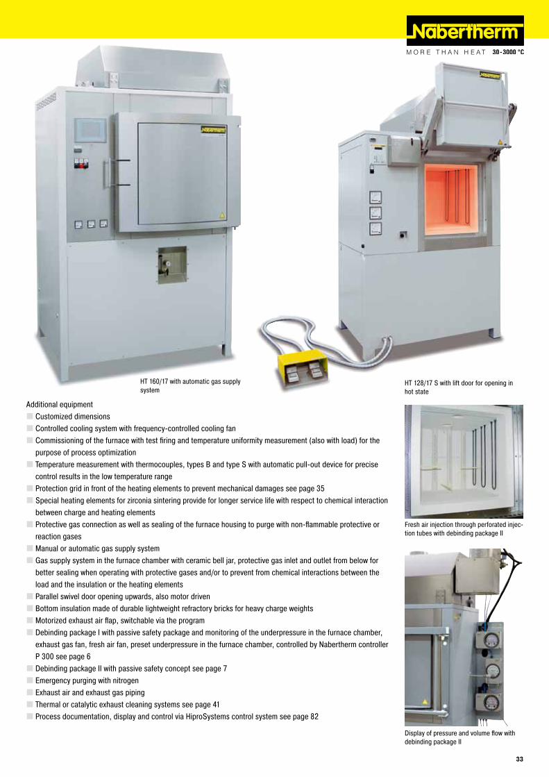
Additional equipment � Customized dimensions � Controlled cooling system with frequency-controlled cooling fan � Commissioning of the furnace with test firing and temperature uniformity measurement (also with load) for the purpose of process optimization � Temperature measurement with thermocouples, types B and type S with automatic pull-out device for precise control results in the low temperature range � Protection grid in front of the heating elements to prevent mechanical damages see page 35 � Special heating elements for zirconia sintering provide for longer service life with respect to chemical interaction between charge and heating elements � Protective gas connection as well as sealing of the furnace housing to purge with non-flammable protective or reaction gases � Manual or automatic gas supply system � Gas supply system in the furnace chamber with ceramic bell jar, protective gas inlet and outlet from below for better sealing when operating with protective gases and/or to prevent from chemical interactions between the load and the insulation or the heating elements � Parallel swivel door opening upwards, also motor driven � Bottom insulation made of durable lightweight refractory bricks for heavy charge weights � Motorized exhaust air flap, switchable via the program � Debinding package I with passive safety package and monitoring of the underpressure in the furnace chamber, exhaust gas fan, fresh air fan, preset underpressure in the furnace chamber, controlled by Nabertherm controller P 300 see page 6 � Debinding package II with passive safety concept see page 7 � Emergency purging with nitrogen � Exhaust air and exhaust gas piping � Thermal or catalytic exhaust cleaning systems see page 41 � Process documentation, display and control via HiproSystems control system see page 82
Fresh air injection through perforated injec-tion tubes with debinding package II
Display of pressure and volume flow with debinding package II
HT 128/17 S with lift door for opening in hot state
HT 160/17 with automatic gas supply system
33

High-Temperature Chamber Furnaces with Fiber Insulation up to 1800 °C
Inner process hood with gas injection through the furnace bottom protects the furnace chamber against contamination and/or prevents chemical interaction bet-ween the charge and heating elements
HT 1000/17 with two movable door segments and fourside heating for sintering hanging ceramic tubes up to 1700 °C
Gas supply system for non-flammable protective or reaction gases
Model Tmax Inner dimensions in mm Volume Outer dimensions in mm Connected Electrical Weight°C w d h in l W D H load kW connection* in kg
HT 04/16 1600 150 150 150 4 610 470 1400 5.2 3-phase¹ 150HT 08/16 1600 150 300 150 8 610 610 1400 8.0 3-phase¹ 200HT 16/16 1600 200 300 260 16 810 700 1490 12.0 3-phase¹ 270HT 40/16 1600 300 350 350 40 810 710 1610 12.0 3-phase 380HT 64/16 1600 400 400 400 64 1145 900 1670 18.0 3-phase 550HT 128/16 1600 400 800 400 128 1020 1250 1700 26.0 3-phase 750HT 160/16 1600 500 550 550 160 1260 1070 1900 21.0 3-phase 800HT 276/16 1600 500 1000 550 276 1140 1470 1900 36.0 3-phase 1100HT 450/16 1600 500 1150 780 450 1200 1620 2060 64.0 3-phase 1500
HT 04/17 1750 150 150 150 4 610 470 1400 5.2 3-phase¹ 150HT 08/17 1750 150 300 150 8 610 610 1400 8.0 3-phase¹ 200HT 16/17 1750 200 300 260 16 810 700 1490 12.0 3-phase¹ 270HT 40/17 1750 300 350 350 40 810 710 1610 12.0 3-phase 380HT 64/17 1750 400 400 400 64 1145 900 1670 18.0 3-phase 550HT 128/17 1750 400 800 400 128 1020 1250 1700 26.0 3-phase 750HT 160/17 1750 500 550 550 160 1260 1070 1900 21.0 3-phase 800HT 276/17 1750 500 1000 550 276 1140 1470 1900 36.0 3-phase 1100HT 450/17 1750 500 1150 780 450 1200 1620 2060 64.0 3-phase 1500
HT 04/18 1800 150 150 150 4 610 470 1400 5.2 3-phase¹ 150HT 08/18 1800 150 300 150 8 610 610 1400 9.0 3-phase¹ 200HT 16/18 1800 200 300 260 16 810 700 1490 12.0 3-phase¹ 270HT 40/18 1800 300 350 350 40 810 710 1610 12.0 3-phase 380HT 64/18 1800 400 400 400 64 1145 900 1670 18.0 3-phase 550HT 128/18 1800 400 800 400 128 1020 1250 1700 26.0 3-phase 750HT 160/18 1800 500 550 550 160 1260 1070 1900 21.0 3-phase 800HT 276/18 1800 500 1000 550 276 1140 1470 1900 36.0 3-phase 1100HT 450/18 1800 500 1150 780 450 1200 1620 2060 64.0 3-phase 1500¹Heating only between two phases *Please see page 81 for more information about supply voltage
34

Chamber Furnaces with Refractory Insulation up to 1700 °C
HFL 295/13 with lift door and transformer in stand, customer-specific design
Protection grid in front of heating elements prevent against mechanical damages
HFL 160/17 with gas supply system
Gas supply system for HFL 160/17
HFL 16/16 - HFL 160/17The HFL 16/16 HFL 160/17 product line is characterized by its lining with robust light weight refractory bricks. Compared with the fiber-insulated models of the HT product line, these furnaces are recommended when high charge weights have to be sintered. In most cases lightweight refractory brick insulation is also significantly more resistant to gas emissions occurring during heat treatment.
Standard equipment like HT models, except: � Tmax 1600 °C or 1700 °C � Sturdy lightweight refractory bricks and special backing insulation � Furnace floor made of lightweight refractory bricks accommodates high charge weights
Additional equipment like HT models
Model Tmax Inner dimensions in mm Volume Outer dimensions in mm Connected Electrical Weight°C w d h in l W D H load kW connection* in kg
HFL 16/16 1600 200 300 260 16 770 830 1550 12 3-phase¹ 500HFL 40/16 1600 300 350 350 40 880 880 1710 12 3-phase 660HFL 64/16 1600 400 400 400 64 980 930 1830 18 3-phase 880HFL 160/16 1600 500 550 550 160 1090 1080 2030 21 3-phase 1140
HFL 16/17 1700 200 300 260 16 770 830 1550 12 3-phase¹ 530HFL 40/17 1700 300 350 350 40 880 880 1710 12 3-phase 690HFL 64/17 1700 400 400 400 64 980 930 1830 18 3-phase 920HFL 160/17 1700 500 550 550 160 1090 1080 2030 21 3-phase 1190¹Heating only between two phases *Please see page 81 for more information about supply voltage
35

HT 64/17 LT
Lift-Top and Lift-Bottom Furnaces up to 1800 °C
HT 680/17 LTS2 with table exchange system HTC 64/14 LB or LT - HT 1440/17 LB
For charging complex settings we recommend lift-top or lift-bottom furnaces. Also small workparts can be conveniently loaded on different layers. Up to an application temperature of 1500 °C the furnaces are heated by SiC rods (HTC models). For sintering temperatures above 1500 °C these furnaces with molybdenum disilicide heating elements (HT models). Possible potential chemical interaction between the charge and the heating method can also affect the selection of heating system.
The basic furnace comes with one table. Depending on the technical requirements are equipped, a lift-top or lift-bottom version will be the choice. The system can be expanded with one or more changeable tables, either manually or electrically driven. Other additional equipment, like controlled cooling systems to short process cycles or the addition of a debinding package for debinding and sintering in one process provide for tailored solution for individual needs.
� Tmax 1400 °C or 1500 °C (HTC models with SiC rod heating) � Tmax 1600 °C, 1750 °C or 1800 °C (HT models with molybdenum disilicide heating elements) � Dual shell housing with fan cooling provides for low shell temperatures � Designed as lift-top furnace with driven hood (LT) or lift-bottom furnace � Gently running, low-vibration spindle drive or electrohydraulic drive for larger models � Safe and tight closing of the furnace due to labyrinth seal and sand cup � Heating from all four sides provides for good temperature uniformity � High-quality fiber insulation backed by special insulation � Side insulation constructed with tongue and groove blocks provides for low heat dissipation to the outside � Long-life roof insulation with special suspension � Furnace table with special bottom reinforcement to accommodate high charge weights � Motor-driven exhaust air flap in the furnace roof, switchable at the program � PLC controls with state-of-the-art touch panel as user interface see page 82 � Over-temperature limiter with manual reset for thermal protection class 2 in accordance with EN 60519-2 as temperature limiter to protect the furnace and load
Heat from all sides and between the stack to optimize temperature uniformity
Heating elements arranged one above the other for tall structures
36

Additional equipment � Customized dimensions � Controlled cooling system with frequency-controlled cooling fan � Commissioning of the furnace with test firing and temperature uniformity measurement (also with load) for the purpose of process optimization � Temperature measurement with thermocouples, types B and type S with automatic pull-out device for precise control results in the low temperature range � Heat from all sides and between the stack to optimize temperature uniformity � Protective gas connection as well as sealing of the furnace housing to purge with non-flammable protective or reaction gases � Manual or automatic gas supply systems � Gas supply system in the furnace chamber with ceramic bell jar, protective gas inlet and outlet from below for better sealing when operating with protective gases and/or to prevent from chemical interactions between the load and the insulation or the heating elements � Alternative table changing systems � Debinding package I with passive safety package and monitoring of the underpressure in the furnace chamber, exhaust gas fan, fresh air fan, preset underpressure in the furnace chamber, controlled by Nabertherm controller P 300 see page 6 � Debinding package II with passive safety concept see page 7 � Emergency purging with nitrogen � Exhaust air and exhaust gas piping � Automatic changing system for thermocouple type S/B for precise measurement and control quality at lowes temperatures, e.g. in combination with a debinding package � Thermal or catalytic exhaust cleaning systems see page 41 � Process documentation, display and control via HiproSystems control system see page 82
Gas supply system for non-flammable protective or reaction gas
HT 276/17 LT HDB with manual table changing system and debinding package II
HT 276/18 LTS with two inner process hoods for sintering under non-flammable protective or reaction gases
37

Lift-Top and Lift-Bottom Furnaces up to 1800 °C
Combi high-temperature system HT 1440/17 LBS with catalytic afterburning system for debinding and sintering in one process
Measurement setup to determine the temperature uniformity in a high-temperature lift-bottom furnace
Production system consisting of a bogie hearth furnace for debinding and a high-temperature furnace for residual debinding and sintering with shared catalytic afterburning system
38

High-temperature furnace HT 273/17S with table by transportable fork lift
Customized furnace HT 750/18 LTS
Model Tmax Inner dimensions in mm Volume Outer dimensions in mm Connected Electrical Weight°C w d h in l W D H load kW connection* in kg
HT 64/16 LB, LT 1600 400 400 400 64 950 1750 2350 36 3-phase 1000HT 166/16 LB, LT 1600 550 550 550 166 1100 2060 2500 42 3-phase 1600HT 276/16 LB, LT 1600 1000 500 550 276 1550 2090 2600 50 3-phase 2000HT 400/16 LB, LT 1600 1200 600 550 400 1750 2200 2600 72 3-phase 2200HT 1000/16 LB, LT 1600 1000 1000 1000 1000 1550 2600 3200 146 3-phase 3000HT 1030/16 LB, LT 1600 2200 600 780 1030 2800 2500 3000 163 3-phase 3000HT 1440/16 LB, LT 1600 1800 800 1000 1440 3000 2800 3700 330 3-phase 4000
HT 64/17 LB, LT 1750 400 400 400 64 950 1750 2350 36 3-phase 1000HT 166/17 LB, LT 1750 550 550 550 166 1100 2060 2500 42 3-phase 1600HT 276/17 LB, LT 1750 1000 500 550 276 1550 2090 2600 50 3-phase 2000HT 400/17 LB, LT 1750 1200 600 550 400 1750 2200 2600 72 3-phase 2200HT 1000/17 LB, LT 1750 1000 1000 1000 1000 1550 2600 3200 146 3-phase 3000HT 1030/17 LB, LT 1750 2200 600 780 1030 2800 2500 3000 163 3-phase 3000HT 1440/17 LB, LT 1750 1800 800 1000 1440 3000 2800 3700 330 3-phase 4000
HT 64/18 LB, LT 1800 400 400 400 64 950 1750 2350 on request 3-phase 1000HT 166/18 LB, LT 1800 550 550 550 166 1100 2060 2500 on request 3-phase 1600HT 276/18 LB, LT 1800 1000 500 550 276 1550 2090 2600 on request 3-phase 2000HT 400/18 LB, LT 1800 1200 600 550 400 1750 2200 2600 on request 3-phase 2200HT 1000/18 LB, LT 1800 1000 1000 1000 1000 1550 2600 3200 on request 3-phase 3000HT 1030/18 LB, LT 1800 2200 600 780 1030 2800 2500 3000 on request 3-phase 3000HT 1440/18 LB, LT 1800 1800 800 1000 1440 3000 2800 3700 on request 3-phase 4000
*Please see page 81 for more information about supply voltage
39

HTB 645/17
HTB 940/17S
Gas-Fired Chamber Furnaces up to 1600 °C
The gas-fired high-temperature furnaces of the HTB product line are specially developed for applications requiring fast heating up ramps. Gas-fired furnaces are preferred also if inflammable gases are produced in large amounts during the process. A large content of the gas emissions are already burned in the furnace chamber, so that downstream equipment like thermal and catalytic exhaust cleaners can accordingly be downsized. The furnaces are insulated with highly heat-resistant and long-life lightweight refractory brick insulation or fiber materials.
� Tmax 1600 °C � Customized furnace dimensions � Powerful, sturdy high-speed burners with pulse control and special flame guidance in the furnace chamber provide for good temperature uniformity � Operation with natural gas, propane or liquified gas � Fully automatic PLC control of the temperature, including monitoring of the burner function � Gas fittings according to DVGW (German Technical and Scientific Association for Gas and Water) with flame monitoring and safety valve � Reduction-resistant fiber insulation with low heat storage provides for short heating and cooling times � Dual shell housing provides for low outside temperatures � Exhaust hood with fittings for further discharge of the exhaust gases � PLC control with touch panel as user interface see page 82
Gas line for natural gas
Additional equipment � Automatic lambda control to set the furnace atmosphere � Debinding package for debinding and sintering with corresponding safety technology see page 6 � Exhaust air and exhaust gas piping � Recuperator burners � Thermal or catalytic exhaust cleaning systems see page 41 � Process display and documentation via Nabertherm Control Center (NCC) see page 82
40

Catalytic and Thermal Afterburning Systems, Exhaust Gas Washer
Catalytic and Thermal Afterburning Systems (KNV and TNV), Exhaust Gas WasherFor exhaust gas cleaning, in particular in debinding, Nabertherm offers exhaust gas cleaning systems tailored to the process. The afterburning system is permanently connected to the exhaust gas fitting of the furnace and accordingly integral part of the control system and the safety matrix of the furnace. For existing furnaces, independent exhaust gas cleaning systems are also available that can be separately controlled and operated.
Catalytic exhaust cleaning is especially recommended due to energetic reasons when only pure hydrocarbon compounds must be cleaned during the debinding process in air. Thermal afterburning systems are used if large volumes of exhaust gas from the debinding process in air must be cleaned and/or if there is a risk that the exhaust gases might damage the catalyst. Thermal afterburning is also used for debinding applications under non-flammable or flammable protective or reaction gases.
An exhaust gas washer is often used if large amounts of exhaust gases are generated respectively, if the gases cannot be treated with a thermal afterburner system or with a torch. The gases will be lead through a water shower and fall out as condensate.
Catalytic afterburning systems (KNV) � Perfectly suited for debinding processes in air with only organic exhaust gases � Catalytic conversion of the unburned hydrocarbons to their nontoxic, natural components � Integrated in a compact stainless steel housing � Electric heating provides for preheating of the exhaust gas to the optimal reaction temperature for catalytic treatment � Cleaning in different layers of catalytic honeycombs within the system � Thermocouples for measuring the temperatures of raw gas, reaction honeycombs and discharge � Over-temperature limiter with adjustable cutout temperature protects the catalyst � Tight connection between the exhaust gas outlet of the debinding furnace and the exhaust gas fan with corresponding integration into the overall system with respect to control and safety technology � Catalyst dimensioned in reletion to the exhaust gas flow � Measuring port for clean gas measurements (FID)
Thermal afterburning systems (TNV) � Optimally suited for debinding processes in air with large exhaust gas flow, erratic large exhaust gas volumes, large volume flow or for debinding processes under non-flammable or flammable protective or reaction gases � Burn-off at temperatures up to 850 °C provides for thermal decomposition of the exhaust gases � Heating with compact gas burner with automatic firing device � Thermocouples in the combustion chamber and in the raw gas inlet � Over-temperature limiter for protecting the thermal afterburning � Design depending on the exhaust gas flow � Measuring port for clean gas measurements (FID)
Thermal afterburning system
Chamber furnace N 150/14 with catalytic afterburning system
Catalytic afterburning system independent from furnace model for refitting on existing systems
Exhaust gas washer to clean generated process gases by washing out
41

Continuous furnace D 700/10000/300/45S with chain conveyor for 950 °C, gas-fired
Continuous FurnacesElectrically Heated or Gas-Fired
Service door at furnace side
Discharge of D 650/S
Roller conveyor furnace N 650/45 AS for heat treatment of heavy workparts
Continuous belt furnace for bulk materials in baskets
Continuous furnaces are the right choice for processes with fixed cycle times such as drying or pre-heating, curing or degassing, etc.. The furnaces are available for various temperatures up to a maximum of 1000 °C. The furnace design depends on the required throughput, the process requirements for heat treatment and the required cycle time. The conveyor technology (e.g. belt, rollers) is tailored to the required working temperature and the geometry of the charge. The conveyor speed and the number of control zones are defined by the process specifications.
Alternative furnace design subject to process specifications:
Conveyor concepts � Conveyor belt � Metal conveyor belt with adjusted mesh gauges � Drive chain � Roller conveyors � Pusher-type furnace
42

Heating systems � Electric heating, radiant or convection � Direct or indirect gas-firing � Infrared heating � Heating with the use of external heat sources
Temperature cycles � Control of working temperature across the whole length of the furnace, such as for drying or pre-heating � Automatic control of a process curve applying defined heat-up, dwell and cooling time � Control of a temperature curve including a final quenching of the charge
Process atmosphere � In air � In non-flammable protective or reactive gases such as nitrogen, argon or forming gas � In flammable protective or reactive gases such as hydrogen incl. the necessary safety technology
Basic configuration criteria � Conveyor speed � Temperature uniformity � Operating temperature � Process curve � Charge space width � Charge weights � Cycle time or throughput � Length of charge and discharge zone � Generated exhaust gases � Specific industry standards such as AMS, CQI-9, FDA etc. � Other individual customer requirements
Continuous belt furnace for the heat treatment of rivets with quenching tank compliant with AMS 2750 D
Visualization of process data on the PC
Drop bottom for quenching within 5 seconds
Continuous belt furnace for bulk charges incl. water bath for quenching
43
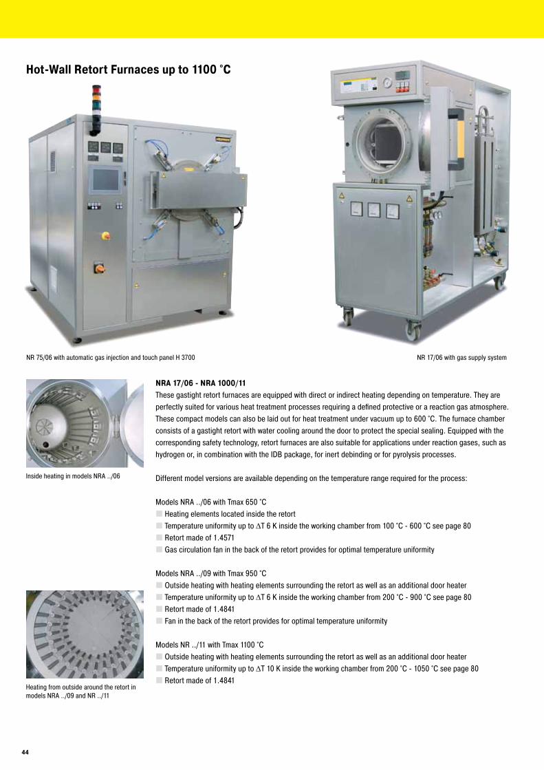
Heating from outside around the retort in models NRA ../09 and NR ../11
NR 75/06 with automatic gas injection and touch panel H 3700
NRA 17/06 - NRA 1000/11These gastight retort furnaces are equipped with direct or indirect heating depending on temperature. They are perfectly suited for various heat treatment processes requiring a defined protective or a reaction gas atmosphere. These compact models can also be laid out for heat treatment under vacuum up to 600 °C. The furnace chamber consists of a gastight retort with water cooling around the door to protect the special sealing. Equipped with the corresponding safety technology, retort furnaces are also suitable for applications under reaction gases, such as hydrogen or, in combination with the IDB package, for inert debinding or for pyrolysis processes.
Different model versions are available depending on the temperature range required for the process:
Models NRA ../06 with Tmax 650 °C � Heating elements located inside the retort � Temperature uniformity up to ΔT 6 K inside the working chamber from 100 °C - 600 °C see page 80 � Retort made of 1.4571 � Gas circulation fan in the back of the retort provides for optimal temperature uniformity
Models NRA ../09 with Tmax 950 °C � Outside heating with heating elements surrounding the retort as well as an additional door heater � Temperature uniformity up to ΔT 6 K inside the working chamber from 200 °C - 900 °C see page 80 � Retort made of 1.4841 � Fan in the back of the retort provides for optimal temperature uniformity
Models NR ../11 with Tmax 1100 °C � Outside heating with heating elements surrounding the retort as well as an additional door heater � Temperature uniformity up to ΔT 10 K inside the working chamber from 200 °C - 1050 °C see page 80 � Retort made of 1.4841
Hot-Wall Retort Furnaces up to 1100 °C
Inside heating in models NRA ../06
NR 17/06 with gas supply system
44

NRA 50/09 H2
Vacuum pump for cold evacuation of the retort
Touchpanel H 3700 for automatic version
Customized furnace NRA 480/04
Basic version � Compact housing in frame design with removable stainless steel sheets � Controls and gas supply integrated in the furnace housing �Welded charging supports in the retort or air-baffle box in the furnace with air circulation � Swivel door hinged on right side with open cooling water system � Multi-zone control for 950 °C and 1100 °C version, separated by furnace chamber and door. Depending on furnace chamber additionally subdivided into one or several heating zones � Temperature control as charge control with temperature measurement inside and outside the retort � Gas supply system for one non-flammable protective or reaction gas with flow meter and solenoid valve, switchable via the control system � Operation under vacuum up to 600 °C with optional single-stage rotary vane pump � Port for vacuum pump for cold evacuation � PLC controls with touch panel H 700 for data input (resp. P 300 for 650 °C-version) see page 82
Additional equipment � Upgrade for other non-flammable gases � Automatic gas injection, including MFC flow controller for alternating volume flow, PLC controlled with touch panel H 3700 � Vacuum pump for evacuating of the retort up to 600 °C, attainable vacuum up to 10-5 mbar subject to selected pump � Cooling system for shortening process times � Heat exchanger with closed-loop cooling water circuit for door cooling � Measuring device for residual oxygen content
45

Bayonet quick-lock for the retort, also with electric drive as additional equipment
NR 200/11 H2 for heat treatment under hydrogen
H2 Version for Operation under HydrogenWhen hydrogen is used as a process gas, the furnace is additionally equipped with the required safety technology. Only certified and industry proven safety sensors are used. The furnace is controlled by a fail-safe PLC control system (S7- 300F/safety controller).
� H2 supply at controlled overpressure of 50 mbar relative � Certified safety concept � PLC controls with graphic touch panel H 3700 for data input � Redundant gas inlet valves for hydrogen � Monitored pre-pressures of all process gases � Bypass for safe flushing of furnace chamber with inert gas � Torch for thermal afterburning of exhaust gases � Emergency flood container for purging the furnace in case of failore
Charging of the NR 300/06 furnace with a pallet truck
IDB Version for Debinding under Non-flammable Protective or Reactive Gases or for Pyrolysis ProcessesThe retort furnaces of the NR and NRA product line are perfectly suited for debinding under protective gases or for pyrolysis processes. The IDB version of the furnaces implements a safety concept by controlled purging the furnace chamber with a protective gas. Exhaust gases are burned in an exhaust torch. Both the purging and the torch function are monitored to ensure a safe operation.
� Process control under monitored and controlled overpressure of 50 mbar relative � Certified safety concept � PLC controls with graphic touch panel H 1700 for data input � Monitored gas pre-pressure of the process gas � Bypass for safe flushing of furnace chamber with inert gas � Torch for thermal afterburning of exhaust gases
Blueing of drills in water steam atmosphere in a furnace of the NRA range
Model Tmax Model Tmax Working chamber dimensions in mm Useful volume Electrical°C °C w d h in l connection*
NRA 17/.. 650 or 950 NR 17/11 1100 225 350 225 17 3-phaseNRA 25/.. 650 or 950 NR 25/11 1100 225 500 225 25 3-phaseNRA 50/.. 650 or 950 NR 50/11 1100 325 475 325 50 3-phaseNRA 75/.. 650 or 950 NR 75/11 1100 325 700 325 75 3-phaseNRA 150/.. 650 or 950 NR 150/11 1100 450 750 450 150 3-phaseNRA 200/.. 650 or 950 NR 200/11 1100 450 1000 450 200 3-phaseNRA 300/.. 650 or 950 NR 300/11 1100 570 900 570 300 3-phaseNRA 400/.. 650 or 950 NR 400/11 1100 570 1250 570 400 3-phaseNRA 500/.. 650 or 950 NR 500/11 1100 720 1000 720 500 3-phaseNRA 700/.. 650 or 950 NR 700/11 1100 720 1350 720 700 3-phaseNRA 1000/.. 650 or 950 NR 1000/11 1100 870 1350 870 1000 3-phase
*Please see page 81 for more information about supply46

SRA 17/.. - SR 1500The retort furnaces SR and SRA (with gas circulation) are designed for operation with non-flammable or flammable protective or reaction gases. The furnace is loaded from above by crane or other lifting equipment provided by the customer. In this way, even large charge weights can be loaded into the furnace chamber. The SR furnaces are available in different versions.
Depending on the temperature range in which the furnace be used, the following models are available:
Models SR .../11 with Tmax 1100 °C � Heating from all sides outside the retort � Temperature uniformity up to ΔT 14 K according to DIN 17052-1 within the working chamber of 500 °C - 1100 °C see page 80 � Retort made of 1.4841 � Top down multi-zone control of the furnace heating
Models SRA ../09 with Tmax 950 °CDesign like models SR…/11 with following differences:
� Atmosphere circulation with powerful fan in the furnace lid provides for temperature uniformity up to ΔT 8 K according to DIN 17052-1 within the working chamber of 200 °C - 900 °C see page 80
Models SRA ../06 with Tmax 600 °CDesign like models SRA…/09 with following differences:
� Heating inside the retort � Temperature uniformity up to ΔT 14 K according to DIN 17052-1 within the working chamber of 100 °C - 600 °C see page 80 � Single-zone control � Retort made of 1.4841
Standard Equipment (all models)Design like standard equipment of models NR and NRA with following differences:
� Charging from above with crane or other lifting equipment from customer � Hinged lid with opening to the side
Additional equipment, H2 version or IDB version see models NR and NRA
Retort furnace SRA 200/09
SR 600/11 basic version
Overhead view into the retort
Model Tmax Inside dimensions of alloy retort Volume Outer dimensions in mm Connected load/kW Electrical Weight°C Ø in mm h in mm in l W D H 600 °C 950 °C connection* in kg
SRA 17/.. 250 350 17 1300 1700 1800 15 20 3-phase 600SRA 25/.. 250 500 25 1300 1900 1800 20 25 3-phase 800SRA 50/.. 400 450 50 1400 2000 1800 36 35 3-phase 1300SRA 100/.. 600 400 800 100 1400 2000 2100 45 65 3-phase 1500SRA 200/.. or 600 700 200 1600 2200 2200 60 90 3-phase 2100SRA 300/.. 950 600 1000 300 1600 2200 2500 75 120 3-phase 2400SRA 500/.. 800 1000 500 1800 2400 2700 70 170 3-phase 2800SRA 600/.. 800 1200 600 1800 2400 2900 90 190 3-phase 3000SRA 800/.. 1000 1000 800 2000 2600 2800 105 220 3-phase 3100SRA 1000/.. 1000 1300 1000 2000 2600 3100 120 250 3-phase 3300SRA 1500/.. 1200 1300 1500 2200 2800 3300 150 300 3-phase 3500
SR 17/11 1100 250 350 17 1300 1700 1800 22 3-phase 600SR 25/11 1100 250 500 25 1300 1900 1800 27 3-phase 800SR 50/11 1100 400 450 50 1400 2000 1800 40 3-phase 1300SR 100/11 1100 400 800 100 1400 2000 2100 73 3-phase 1500SR 200/11 1100 600 700 200 1600 2200 2200 98 3-phase 2100SR 300/11 1100 600 1000 300 1600 2200 2500 132 3-phase 2400SR 500/11 1100 800 1000 500 1800 2400 2700 182 3-phase 2800SR 600/11 1100 800 1200 600 1800 2400 2900 205 3-phase 3000SR 800/11 1100 1000 1000 800 2000 2600 2800 235 3-phase 3100SR 1000/11 1100 1000 1300 1000 2000 2600 3100 268 3-phase 3300SR 1500/11 1100 1200 1300 1500 2200 2800 3300 315 3-phase 3500
*Please see page 81 for more information about supply47

VHT 8/18-GR - VHT 100/18-KEThe compact furnaces of the VHT product line are available as electrically heated chamber furnaces with graphite, molybdenum or MoSi2 heating. A wide variety of heating designs as well as a complete range of accessories provide for optimal furnace configurations even for sophisticated applications.
The vacuum-tight retort allows heat treatment processes either in protective and reaction gas atmospheres or in a vacuum, subject to the individual furnace specs to 10-5 mbar. The basic furnace is suited for operation with non-flammable protective or reactive gases or under vacuum.
The H2 version provides for operation under hydrogen or other flammable gases. Key of the specification up is a certified safety package providing for a safe operation at all times and triggers an appropriate emergency program in case of failure.
If you intend to debind in an inert atmosphere, we recommend the use of a process box. The exhaust gases are vented directly from the box to the exhaust gas torch.
Alternative Heating SpecificationsThe following heating systems are available for the different application temperatures:
VHT ../GR with Graphite Insulation and Heating � Suitable for processes under protective and reaction gases or under vacuum � Tmax 1800 °C or 2200 °C � Max. vacuum up to 10-2 mbar depending on pump type used � Graphite felt insulation � Temperature measurement using type B thermocouple (version to 1800 °C) � Temperature measurement using optical pyrometer (version to 2200 °C)
Cold-Wall Retort Furnaces up to 2400 °C
VHT 8/22-KE with fiber insulation and molybdenum disilicide heating elements
VHT 500/22-GR H2 with extension package for operation under vacuum and CFC-process box
Heat treatment of copper bars under hydro-gen in VHT 08/16 MO
48

Graphite heating chamber
Ceramic fiber insulation
Molybdenum or tungsten heating chamber
VHT ../MO or ../W with Molybdenum or Tungsten Heating � Suitable for high-purity processes under protective and reaction gases or under high vacuum � Tmax 1200 °C, 1600 °C or 1800 °C (see table) � Max. vacuum up to 5 x10⁻⁵ mbar depending on pump type used � Insulation made of Molybdenum steel sheets � Temperature measurement with thermocouple, type S for models with 1200 °C � Temperature measurement with thermocouple, type B for models with 1600 °C and 1800 °C
VHT ../KE with Fiber Insulation and Heating through Molybdenum Disilicide Heating Elements � Suitable for processes under protective and reaction gases, in air or under vacuum � Tmax 1800 °C � Max. vacuum up to 10-2 mbar (up to 1300 °C) depending on pump type � Insulation made of high purity aluminum oxide fiber � Temperature measurement by thermocouple type B
VHT ...-../GR VHT ...-16/MO VHT ...-18/W VHT ...-18/KEInert gas Air to 400 °C - - Hydrogen ¹Rough vacuum and fine vacuum (>10-3 mbar) ²High vacuum (<10-5 mbar) - -Oxygen - - -
¹up to 1400 °C ²depending on Tmax
Standard Equipment for all Models
Basic version � Standard furnace sizes 8, 40 and 100 liters � A water-cooled stainless steel process reactor sealed with temperature-resistant o-rings � Frame made of stable steel profiles, easy to service due to easily removable stainless steel panels � Housing of the VHT 8 model on castors for easy repositioning of furnace � Cooling water manifold with manual stopcocks in supply and return lines, automatic flowmeter monitoring, openloop cooling water system � Adjustable cooling water circuits with flowmeter and temperature indicator and overtemperature fuses � Switchgear and controller integrated in furnace housing � H 700 PLC control with clearly laid out 5.7“ touchpanel control for program entry and display, 10 programs each with 20 segments � Over-temperature limiter with manual reset for thermal protection class in accordance with EN 60519-2 � Manual operation of the process gas and vacuum functions � Manual gas supply for one process gas (N2 or Ar) with adjustable flow � Bypass with manual valve for rapid filling or flooding of furnace chamber � Manual gas outlet with overflow valve (20 mbar relative) � Single-stage rotary vane pump with ball valve for pre-evacuating and heat treatment in a rough vacuum to 5 mbar � Pressure gauge for visual pressure monitoring
Additional equipment � Tmax 2400 °C � Housing, optionally divisible, for passing through narrow door frames (VHT 08) � Manual gas supply for second process gas (N2 or Ar) with adjustable flow and bypass � Inner process box made of molybdenum or CFC, especially recommended for debinding processes. The box is installed in the furnace with direct gas inlet and outlet and provides for better temperature uniformity. Due to a change in gas supply direction after debinding a clean process atmosphere for sintering is achieved.
Thermocouple, type S with automatic pull-out device for precise control results in the low temperature range
Model Inner dimensions of retort in mm Volumew d h in l
VHT 8/.. 120 210 150 4VHT 40/.. 280 430 250 30VHT 100/.. 430 530 400 91
� Charge thermocouple with display � Two-stage rotary vane pump with ball valve for pre-evacuating and heat-treating in a vacuum to 10-2 mbar 49

VHT 40/16MOH2
Single-stage rotary vane pump for heat treatment in a rough vacuum to 20 mbar
Two-stage rotary vane pump for heat treatment in a vacuum to 10-2 mbar
Turbo-molecular pump with booster pump for heat treatment in a vacuum to 10-5 mbar
� Temperature measurement at 2200 °C with pyrometer and thermocouple, type S with automatic pull-out device for precise control results in the low temperature range (VHT 40 and larger) � Turbo molecular pump with slide valve for pre-evacuation and for heat treatment in a vacuum to 10-5 mbar including electric pressure transducer and booster pump (only VHT…/MO) � Heat exchanger with closed-loop cooling water circuit � Automation package with graphic touch panel H 3700
- 12" graphic touch panel H 3700 - Input of all process data like temperatures, heating rates, gas injection, vacuum at the touch panel - Display of all process-relevant data on a process control diagram - Automatic gas supply for one process gas (N2 , argon or forming gas) with adjustable flow - Bypass for flooding and filling the chamber with process gas controlled by the program - Automatic pre- and post programs, including leak test for safe furnace operation - Automatic gas outlet with bellows valve and overflow valve (20 mbar) - Transducer for absolute and relative pressure
� MFC flow controller for alternating volume flow and generation of gas mixtures with second process gas (only with automation package) � Partial pressure operation: protective gas flushing at controlled underpressure (only with automation package) � PC control via NCC with corresponding optional documentation and connection to customer PC networks
Continuation of additional equipment
Turbo-molecular pump
VHT 40/22 GR with motor-driven lift door
50

VHT 08/16 MO with hydrogen extension package as automatic version
H2 Version VHT…/MO-H2 or VHT…/GR-H2 for Operation with Hydrogen or other Reaction GasesIn the H2 version the furnaces of the VHT…/MO or VHT…/GR product line can be operated under hydrogen or other reaction gases. For these applications, the systems are additionally equipped with the required safety technology. Only certified and industry proven safety sensors are used. The furnaces are controlled by a fail-safe PLC control system (S7-300F/safety controller).
� Certified safety concept � Automation package (see additional equipment above) � Redundant gas inlet valves for hydrogen � Monitored pre-pressures of all process gases � Bypass for safe purging of furnace chamber with inert gas � Pressure-monitored emergency flooding with automated solenoid valve opening � Electric or gas-heated exhaust gas torch for H2 post-combustion � Atmospheric operation: H2-purging of process reactor starting from room temperature at controlled over pressure (50 mbar relative)
Additional equipment � Partial pressure operation: H2 flushing at underpressure in the process reactor starting from 750 °C furnace chamber temperature � Retort in the process chamber for debinding under hydrogen
VHT gas supply diagram, debinding and sintering
Process Box for Debinding in Inert GasCertain processes require charges to be debinded in non-flammable protective or reactive gases. For these processes we fundamentally recommend a hot-wall retort furnace (see models NR… or SR…). These furnaces can ensure that the formation of condensation will be avoided as throughly as possible.
If there is no way to avoid the escape of small amounts of residual binder during the process, even in the VHT furnace, the furnace should be designed to meet this contingency.
The furnace chamber is equipped with an additional process box that has a direct outlet to the exhaust gas torch through which the exhaust gas can be directly vented. This system enables a substantial reduction in the amount of furnace chamber contamination caused by the exhaust gases generated during debinding.
Depending on the exhaust gas composition the exhaust gas line can be designed to include various options.
� Exhaust gas torch for burning off the exhaust gas � Condensation trap for separating out binding agents � Exhaust gas post-treatment, depending on the process, via scrubbers � Heated exhaust gas outlet to avoid condensation deposits in the exhaust gas line
Model Tmax Inner dimensions in mm Volume Outer dimensions in mm Connected Electrical Weight Material heater/°C w d h in l W D H load kW� connection* in kg insulation
VHT 8/..-GR 1800 170 240 200 8 1250 (800)¹ 1100 2000 27 3-phase² 1200 Graphite/graphite feltVHT 40/..-GR or 300 450 300 40 1600 2100 2300 83/103³ 3-phase 2000 Graphite/graphite feltVHT 70/..-GR 2200 375 500 375 70 1700 2500 2400 105/125³ 3-phase 2400 Graphite/graphite feltVHT 100/..-GR 450 550 450 100 1900 2600 2500 135/155³ 3-phase 2800 Graphite/graphite feltVHT 8/..-MO 1200 170 240 200 8 1250 (800)¹ 1100 2700 15/344 3-phase² 1200 MolybdenumVHT 40/..-MO or 300 450 300 40 1600 2600 2300 50/1104 3-phase 3000 MolybdenumVHT 70/..-MO 1600 375 500 375 70 1700 2800 2400 70/1404 3-phase 3500 MolybdenumVHT 100/..-MO 450 550 450 100 1900 3000 2500 90/1804 3-phase 4000 MolybdenumVHT 8/18-W 1800 170 240 200 8 1250 (800)¹ 1100 2700 50 3-phase² 1700 Tungsten/molybdenumVHT 40/18-W 1800 300 450 300 40 1600 2600 2300 130 3-phase 3500 Tungsten/molybdenumVHT 70/18-W 1800 375 500 375 70 1700 2800 2400 160 3-phase 4000 Tungsten/molybdenumVHT 100/18-W 1800 450 550 450 100 1900 3000 2500 210 3-phase 4500 Tungsten/molybdenumVHT 8/18-KE 1800 170 240 200 8 1250 (800)¹ 1100 2000 12 3-phase² 1200 MoSi2/ceramic fiberVHT 40/18-KE 1800 300 450 300 40 1600 2100 2300 30 3-phase 2000 MoSi2/ceramic fiberVHT 70/18-KE 1800 375 500 375 70 1700 2500 2400 55 3-phase 2400 MoSi2/ceramic fiberVHT 100/18-KE 1800 450 550 450 100 1900 2600 2500 85 3-phase 2800 MoSi2/ceramic fiber¹With the switching system unit removed *Please see page 81 for more information about supply.²Only heating between two phases 41200 °C/1600 °C³1800 °C/2200 °C �For operation under hydrogen a higher power rating has to be considered
51

LBVHT 600/24 GR
LBVHT 100/16 - LBVHT 600/24The LBVHT product line with lift-bottom specification are especially suitable for production processes which require either protective or reaction gase atmosphere or a vacuum. The basic performance specifications of these models are similar to the VHT models. Their size and design with electro-hydraulically driven table facilitate charging during production. The furnaces are available in various sizes and designs. Similar like the VHT models, these furnaces can be equipped with different heating concepts.
� Standard furnace sizes between 100 and 600 liters � Designed as lift-bottom retort furnace with electro-hydraulically driven table for easy and well-arranged charging � Prepared to carry heavy charge weights � Different heating concepts using
- Graphite heating chamber up to Tmax 2400 °C - Molybdenum heating chamber up to Tmax 1600 °C - Tungsten heating chamber up to Tmax 1800 °C
� Frame structure filled with textured stainless steel sheets � Standard design with gassing system for non-flammable protective or reaction gases � Automatic gas supply system which also allows for operation with several process gases as additional equipment � Gas supply systems for operating with hydrogen or other flammable reaction gases incl. safety package as additional equipment � Switchgear and control box as well as gassing system integrated into the furnace housing � Further product characteristics of the standard furnace as well as possible additional equipment can be found in the description of the VHT furnaces from Page 48
Lift-Bottom -Retort Furnace up to 2400 °C for Production
LBVHT 250/18 WO with tungsten heating chamber
LBVHT with graphite heating chamber
Model Tmax Model Tmax Model Tmax Inner dimensions in mm Volume Electrical°C °C °C Ø h in l connection*
LBVHT 100/16-MO 1600 LBVHT 100/18-WO 1800 LBVHT 100/24-GR 2400 450 700 100 3-phaseLBVHT 250/16-MO 1600 LBVHT 250/18-WO 1800 LBVHT 250/24-GR 2400 600 900 250 3-phaseLBVHT 600/16-MO 1600 LBVHT 600/18-WO 1800 LBVHT 600/24-GR 2400 800 1200 600 3-phase
*Please see page 81 for more information about supply52

Model Tmax Working chamber dimensions
Useful volume Outer dimensions in mm Connected Electrical
°C Ø x h in mm in l W D H load KW connection*SVHT 2/24-W 2400 150 x 150 2,5 1400 2500 2100 55 3-phaseSVHT 9/24-W 2400 230 x 230 9,5 1500 2750 2100 95 3-phase
SVHT 2/30-GR 3000 150 x 150 2,5 1400 2500 2100 55 3-phaseSVHT 9/30-GR 3000 230 x 230 9,5 1500 2750 2100 95 3-phase
*Please see page 81 for more information about supply
Pit-Type Cold-Wall Retort Furnaces up to 2400 °C or up to 3000 °C
SVHT 2/24-W - SVHT 9/30-GRCompared with the VHT models (page 48), the furnaces of the SVHT product line offer improved performance data with regard to achievable vacuum and maximum temperature. Due to the design as pit-type furnace with tungsten heating, processes up to max. 2400 °C even in high vacuum can be implemented with models of the SVHT..-W product line. Models of the SVHT..-GR product line with graphite heating, also in pit-type design, can be operated in an inert gas atmosphere even up to max. 3000 °C.
� Standard sizes with a furnace chamber of 2 or 9 liters � Designed as pit-type furnace, charged from above � Frame construction with inserted sheets of textured stainless steel � Double-walled water-cooled stainless steel container � Manual operation of process gas and vacuum functions � Manual gas supply for non-flammable process gas � A step in front of the furnace for an ergonomic charging height � Retort lid with gas-charged shock absorbers � Controls and switchgear as well as gas supply integrated in furnace housing � Further standard product characteristics see description for standard design of VHT models page 48
Heating options
SVHT ..-GR � Applicable for processes:
- under protective or reactive gases or in the vacuum up to 2200 °C - under inert gases (argon, helium) up to 3000 °C
� Max. vacuum up to 10-³ mbar depending on the type of pump used � Heating: graphite heating elements in cylindrical arrangement � Insulation: graphite felt insulation � Temperature measurement by means of an optical pyrometer
SVHT ..-W � Applicable for processes under protective or reaction gases or in vacuum up to 2400 °C � Max. vacuum up to 10-� mbar depending on the type of pump used � Heating: cylindrical tungsten heating module � Insulation: tungsten and molybdenum radiant plates � Temperature measurement with optical pyrometer
Additional equipment such as automatic process gas control or design for the operation with flammable gases incl. safety system see VHT models page 48.
SVHT 9/24-W with tungsten heating
Cylindrical retort with tungsten heating
Graphite heating module
Water-cooling controls
53

NRA 150/02 CDB
NRA 40/02 CDB
Chamber Retort Furnaces for Catalytic Debinding
NRA 40/02 CDB and NRA 150/02 CDBThe chamber furnaces NRA 40/02 CDB and NRA 150/02 CDB are specially developed for debinding of ceramics and metallic powder injection molded parts according to the BASF CATAMOLD®-method. They are equipped with a gastight retort with inside heating and
air circulation. During catalytic debinding, the polyacetal-containing (POM) binder chemically decomposes in the oven under nitric acid and is carried out of the oven by a nitrogen carrier gas and burned in an exhaust gas torch. Both
furnaces have a comprehensive safety package to protect the operator and the surrounding.
Model NRA 40/02 CDB is very compact and excels with its excellent cost-performance ratio. This model is pefectly suited for repeating lab processes and in production. As a professional production furnace, model NRA 150/02 CDB is also designed for frequent charge changes. The furnace has an automatic torch control that detects the end of the process measuring the torch temperature.
� Tmax 200 °C � Process retort made of acid-resistant stainless steel 1.4571 with large swiveling door � Four-side heating inside the retort through chromium steel tube heating elements for good temperature uniformity � Horizontal air circulation for uniform distribution of the process gas � Acid pump and acid vessel (to be provided by the customer) accommodated in the furnace frame � Gas-fired exhaust gas torch with flame monitoring � Non-wearing ceramic cup for uniform evaporation of the nitric acid
Version NRA 40/02 CDB � Gas supply system with fixed values � Safety package provides for safe shut-down and floods of the furnace with nitrogen in case of a failure � Controller P 300 for setting the temperature curve
Version NRA 150/02 CDB � Extensive safety package with redundantly operating safety PLC for safe operation with nitric acid � Automatic gas supply system for nitrogen with mass flow controller � Large, graphic touch panel H 3700 for entering data and for process visualization � Adjustable acid volume and correspondingly adjusted gas spply volumes
Additional equipment � Scale for the nitric acid vessel, connected to the PLC monitors the acid consumption and visualizes the fill level of the acid vessel (NRA 150/02 CDB) � NCC software package for visualization, control and charge documentation of the process (NRA 150/02 CDB) � Lift truck for easy loading of the furnace
Acid pump for nitric acid
Process chamber with internal heating
Model Tmax Inner dimensions in mm Volume Outer dimensions in mm Connected Electrical Weight Acidic quantity Nitrogen°C w d h in l W D H load kW connection* in kg (HNO3) (N2)
NRA 40/02 CDB 200 300 450 300 40 1100 1250 2450 5 3-phase¹ 350 30 ml/h 500 l/hNRA 150/02 CDB 200 450 700 450 150 1650 1960 2850 23 3-phase¹ 1650 max. 180 ml/h max. 4000 l/h¹Heating only between two phases *Please see page 77 for more information about supply voltage
54

LS 12/13
GR 1300/13
Fast-Firing FurnacesLS 12/13 and LS 25/13These models are ideal for simulation of typical fast-firing processes up to a maximum firing temperature of 1300 °C. The combination of high performance, low thermal mass and powerful cooling fans provides for cycle times fromcold to cold of under 35 minutes.
� Tmax 1300 °C � Very compact design � Ceramic grid tubes as charge support � Floor and lid heating � Two-zone control, bottom and lid � Integrated cooling fans, programmable to speed up charge cooling including housing cooling � Programmable lid opening of approximately 20 mm for faster cooling without activating the fan � Thermocouple PtRh-Pt, type S for top and bottom zone � Castors for easy furnace moving � Controls description see page 81
Model Tmax Inner dimensions in mm Volume Outer dimensions in mm Connected Electrical Weight°C w d h in l W D H load kW connection* in kg
LS 12/13 1300 350 350 40 12 600 800 985 15 3-phase 130LS 25/13 1300 500 500 100 25 750 985 1150 22 3-phase 160
*Please see page 81 for more information about supply voltage
Firing curves LS 12/13 and LS 25/13
Gradient or Lab Strand Annealing Furnaces
Furnace chamber of the GR 1300/13 with second door as additional equipment
GR 1300/13The furnace chamber of the gradient furnace GR 1300/13 is divided in six control zones of equallength. The temperature in each of the six heating zones is separately controlled. The furnace isusually charged from the side through the parallel swivel door. A maximum temperature gradient of400 °C can then be stabilized over the heated length of 1300 mm. On request the furnace also isdesigned as a strand furnace with a second door on the opposite side. Other available additionalequipment consists of fiber chamber separators dividing the furnace chamber into six equally sizedchambers. Charging then occurs from above by opening the large lid.
� Tmax 1300 °C � Heated length: 1300 mm � Heating elements on support tubes providing for free heat radiation in the kiln chamber � Charging from the top or through the right side door � Gas damper suspension of the lid � 6-zone control � Separate control of heating zones (each 160 mm long) � Temperature gradient of 400 °C over the entire length of the kiln chamber, each zone can individually be controlled � Controls description see page 81
Additional equipment � Up to ten control zones � Fiber separators dividing the chamber in six equally sized chambers � Second parallel swivel door for use as strand furnace � Vertical instead of horizontal strand furnace
Model Tmax Inner dimensions in mm Outer dimensions in mm Connected Electrical Weight°C w d h W D H load kW connection* in kg
GR 1300/13 1300 1300 100 60 1660 740 1345 18 3-phase 300*Please see page 81 for more information about supply voltage
55

Professional Chamber Furnaces with Brick Insulation or Fiber Insulation
LH 15/12 - LF 120/14The LH 15/12 - LF 120/14 laboratory furnaces have been trusted for many years as professional chamber furnaces for the laboratory. These furnaces are available with either a robust insulation of light refractory bricks (LH models) or with a combination insulation of refractory bricks in the corners and low heat storage, quickly cooling fiber material (LF models). With a wide variety of optional equipment, these models can be optimally adapted to your processes.
� Tmax 1200 °C, 1300 °C, or 1400 °C � Five-sided heating for very good temperature uniformity � Heating elements on support tubes ensure free heat radiation and a long service life � Protection of bottom heating and flat stacking surface provided by embedded SiC plate in the floor � LH models: multi-layered, fiber-free insulation of light refractory bricks and special backup insulation
Cooling fan in combination with motor-driven exhaust air flap to reduce cooling time
LH 15/12 with brick insulation LH 60/12 with scale to measure weight reduction during annealing
LH 120/12S process box made of quartz glass
� LF models: high-quality fiber insulation with corner bricks for shorter heating and cooling times � Door with brick-on-brick seal, hand fitted � Short heating times due to high installed power � Side vent with bypass connection for exhaust pipe � Self-supporting arch for high stability and greatest possible protection against dust � Quick lock on door � Freely adjustable air slide intake in furnace floor � Stand included � Controls description see page 81
Additional equipment � Parallel swinging door, pivots away from operator, for opening when hot � Lift door with electro-mechanic linear drive � Separate wall-mounting or floor standing cabinet for switchgear
56

Parallel swinging door for opening whenhot
LH 216/12SW with scale to measure weight reduction during annealing
Model Tmax Inner dimensions in mm Volume Outer dimensions in mm Connected Electrical Weight°C w d h in l W D H load kW connection* in kg
LH 15/12 1200 250 250 250 15 570 790 1170 5.0 3-phase¹ 150LH 30/12 1200 320 320 320 30 640 860 1240 7.0 3-phase¹ 170LH 60/12 1200 400 400 400 60 720 1010 1320 8.0 3-phase 260LH 120/12 1200 500 500 500 120 820 1110 1420 12.0 3-phase 340LH 216/12 1200 600 600 600 216 900 1210 1530 20,0 3-phase 400
LH 15/13 1300 250 250 250 15 570 790 1170 7.0 3-phase¹ 150LH 30/13 1300 320 320 320 30 640 860 1240 8.0 3-phase¹ 170LH 60/13 1300 400 400 400 60 720 1010 1320 11.0 3-phase 260LH 120/13 1300 500 500 500 120 820 1110 1420 15.0 3-phase 340LH 216/13 1300 600 600 600 216 900 1210 1530 22,0 3-phase 400
LH 15/14 1400 250 250 250 15 570 790 1170 8.0 3-phase¹ 150LH 30/14 1400 320 320 320 30 640 860 1240 10.0 3-phase¹ 170LH 60/14 1400 400 400 400 60 720 1010 1320 12.0 3-phase 260LH 120/14 1400 500 500 500 120 820 1110 1420 18.0 3-phase 340LH 216/14 1400 600 600 600 216 900 1210 1530 26,0 3-phase 400
LF 15/13 1300 250 250 250 15 570 790 1170 7.0 3-phase¹ 130LF 30/13 1300 320 320 320 30 640 860 1240 8.0 3-phase¹ 150LF 60/13 1300 400 400 400 60 720 1010 1320 11.0 3-phase 230LF 120/13 1300 500 500 500 120 820 1110 1420 15.0 3-phase 300
LF 15/14 1400 250 250 250 15 570 790 1170 8.0 3-phase¹ 130LF 30/14 1400 320 320 320 30 640 860 1240 10.0 3-phase¹ 150LF 60/14 1400 400 400 400 60 720 1010 1320 12.0 3-phase 230LF 120/14 1400 500 500 500 120 820 1110 1420 18.0 3-phase 300¹Heating only between two phases *Please see page 81 for more information about supply voltage
Gas supply system
LH 60/12 with manual lift door and gas supply box for non-flammable protective or reactive gases
� Automatic exhaust air flap � Cooling fan for shorter cycle times � Protective gas connection as well as sealing of the furnace housing to purge with non-flammable protective or reaction gases � Process box made of quartz glass for very clean atmosphere, quartz glass covered door with lid function � Manual or automatic gas supply system � Scale to measure weight reduction during annealing
57

HTCT 01/16HTC 08/15
High-Temperature Chamber Furnaces with SiC Rod Heating
HTCT 01/14 - HTCT 08/16These powerful laboratory muffle furnaces are available for temperatures up to 1400 °C, 1500 °C, or 1600 °C. The durability of the SiC rods in periodic use, in combination with their high heating speed, make these furnaces to all-rounders in the laboratory. Heating times of 40 minutes to 1400 °C can be achieved, depending on the furnace model and the conditions of use.
� Tmax 1400 °C, 1500 °C, or 1600 °C �Working Temperature 1550 °C (for models HTC ../16), increased wear and tear of heating elements must be expected in case of working at higher temperatures � Model HTCT 01/16 with single phase connection � High-quality fiber material, selected for the working temperature � Housing made of sheets of textured stainless steel � Dual shell housing for low external temperatures and high stability � Optional flap door (HTC) which can be used as work platform or lift door (HTCT) with hot surface facing away from the operator (HTCT 01/.. only with lift door) � Switching system with solid-state-relays, power tuned to the SiC rods � Easy replacement of heating rods � Controls description see page 81
Additional equipment � Over-temperature limit controller with manual reset for thermal protection class 2 in accordance with EN 60519-2 as temperature limiter to protect the oven and load � Square saggar for charging of up to three layers � Lid for top saggar � Manual or automatic gas supply system � Adjustable air intake opening in the furnace door, exhaust air opening in the roof
Furnace chamber with high-quality fiber materials and SiC heating rods on both sides of the furnace
Model Tmax Inner dimensions in mm Volume Outer dimensions in mm Connected Electrical Weight Minutes°C w d h in l W D H² load kW connection* in kg to Tmax³
HTCT 01/14 1400 110 120 120 1.5 340 300 460 3.5 single-phase 18 40HTC, HTCT 03/14 1400 120 210 120 3.0 400 535 530 9.0 3-phase¹ 30 40HTC, HTCT 08/14 1400 170 290 170 8.0 450 620 570 13.0 3-phase 40 40
HTCT 01/15 1500 110 120 120 1.5 340 300 460 3.5 single-phase 18 40HTC, HTCT 03/15 1500 120 210 120 3.0 400 535 530 9.0 3-phase¹ 30 50HTC, HTCT 08/15 1500 170 290 170 8.0 450 620 570 13.0 3-phase 40 50
HTCT 01/16 1600 110 120 120 1.5 340 300 460 3.5 single-phase 18 40HTC, HTCT 03/16 1600 120 210 120 3.0 400 535 530 9.0 3-phase¹ 30 60HTC, HTCT 08/16 1600 170 290 170 8.0 450 620 570 13.0 3-phase 40 60¹Heating only between two phases *Please see page 81 for more information about supply voltage²Plus maximum 270 mm for models HTCT when open ³If connected at 230 V 1/N/PE rsp. 400 V 3/N/PE
Over-temperature limit controller
Saggars with top lid
58

LHT 08/17
High-Temperature Chamber Furnaces with MoSi2 Heating Elements as Table-Top Model
LHT 02/16 - LHT 08/18Designed as tabletop models, these compact high-temperature chamber furnaces have a variety of advantages. The first-class workmanship using high-quality materials, combined with ease of operation, make these furnaces all-rounders in research and the laboratory. These furnaces are also perfectly suited for the sintering of technical ceramics, such as zirconium oxide dental bridges.
� Tmax 1600 °C, 1750 °C, or 1800 °C � High-quality molybdenum disilicide heating elements � Furnace chamber lined with first-class, durable fiber material � Housing made of sheets of textured stainless steel � Dual shell housing with additional fan cooling for low surface temperature � Furnace sizes of 2, 4, or 8 liters � Compact design with lift-door, opening upwards � Adjustable air inlet � Exhaust air opening in the roof � Type B thermocouple � Switching system with phase-angle firing thyristors (SCRs) � Controls description see page 81
Additional equipment � Over-temperature limit controller with manual reset for thermal protection class 2 in accordance with EN 60519-2 as temperature limiter to protect the oven and load � Square saggar for charging of up to three layers � Process control and documentation with Controltherm MV software package see page 83 � Protective gas connection for non-flammable protective or reaction gases � Manual or automatic gas supply system
Model Tmax Inner dimensions in mm Volume Outer dimensions in mm Connected Electrical Weight Minutes°C w d h in l W D H³ load kW connection* in kg to Tmax²
LHT 02/16 1600 90 150 150 2 470 700 750+350 3.0 single-phase 75 30LHT 04/16 1600 150 150 150 4 470 700 750+350 5.2 3-phase¹ 85 25LHT 08/16 1600 150 300 150 8 470 850 750+350 8.0 3-phase¹ 100 25
LHT 02/17 1750 90 150 150 2 470 700 750+350 3.0 single-phase 75 60LHT 04/17 1750 150 150 150 4 470 700 750+350 5.2 3-phase¹ 85 40LHT 08/17 1750 150 300 150 8 470 850 750+350 8.0 3-phase¹ 100 40
LHT 02/18 1800 90 150 150 2 470 700 750+350 3.6 single-phase 75 75LHT 04/18 1800 150 150 150 4 470 700 750+350 5.2 3-phase¹ 85 60LHT 08/18 1800 150 300 150 8 470 850 750+350 9.0 3-phase¹ 100 60¹Heating only between two phases *Please see page 81 for more information about supply voltage²If connected at 230 V 1/N/PE rsp. 400 V 3/N/PE ³Including opened lift door
Over-temperature limit controller
Saggars with top lid
LHT 02/18 with gas supply system for four gases
59

LHT 16/17 LB
High-Temperature Lift-Bottom Furnaces
LHT/LBThe electrically driven lift-bottom considerably allows for proper charging of the LHT/LB furnaces. The heating all around the cylindrical furnace chamber provides for an opitimal temperature uniformity. For model LHT 02/17 LB the charge can be placed in charge saggars made of technical ceramics. Up to three charge saggars can be stacked on top of each other resulting in a high productivity. Due to its volume model LHT 16/17 LB can also be used for applications in production.
� Tmax 1650 °C � High-quality molybdenum disilicide heating elements � Furnace chamber lined with first-class, durable fiber materials � Outstanding temperature uniformity due to all-round furnace chamber heating � Furnace chamber with a volume of 2 or 16 liters, table with large footprint � Spacers to lift-up the saggars already installed in the table � Precise, electric spindle drive with push button operation � Housing made of sheets of textured stainless steel � Exhaust air vent in the roof � Type S thermocouple � Switchgear with thyristor � Controls description see page 81
Electrically driven lift-bottom
LHT 02/17 LB with a set of saggars
Saggar
60
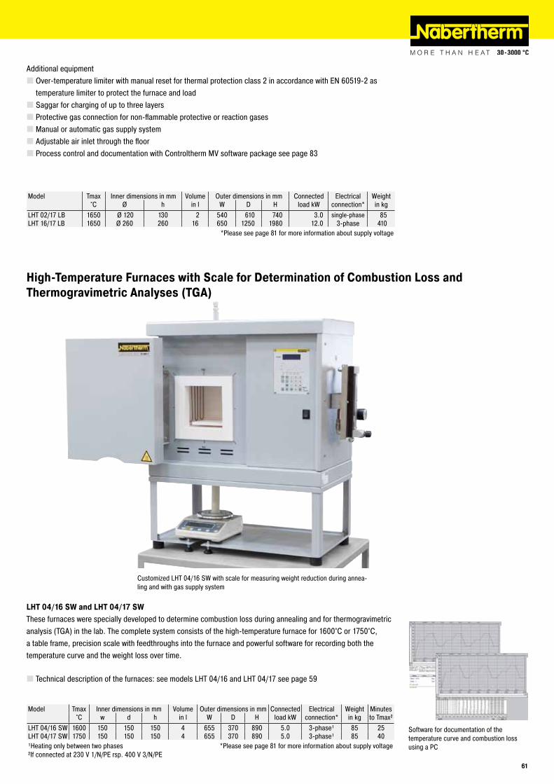
LHT 16/17 LB
Model Tmax Inner dimensions in mm Volume Outer dimensions in mm Connected Electrical Weight°C Ø h in l W D H load kW connection* in kg
LHT 02/17 LB 1650 Ø 120 130 2 540 610 740 3.0 single-phase 85LHT 16/17 LB 1650 Ø 260 260 16 650 1250 1980 12.0 3-phase 410 *Please see page 81 for more information about supply voltage
Additional equipment � Over-temperature limiter with manual reset for thermal protection class 2 in accordance with EN 60519-2 as temperature limiter to protect the furnace and load � Saggar for charging of up to three layers � Protective gas connection for non-flammable protective or reaction gases � Manual or automatic gas supply system � Adjustable air inlet through the floor � Process control and documentation with Controltherm MV software package see page 83
Customized LHT 04/16 SW with scale for measuring weight reduction during annea-ling and with gas supply system
Software for documentation of the temperature curve and combustion loss using a PC
High-Temperature Furnaces with Scale for Determination of Combustion Loss and Thermogravimetric Analyses (TGA)
LHT 04/16 SW and LHT 04/17 SWThese furnaces were specially developed to determine combustion loss during annealing and for thermogravimetric analysis (TGA) in the lab. The complete system consists of the high-temperature furnace for 1600°C or 1750°C, a table frame, precision scale with feedthroughs into the furnace and powerful software for recording both the temperature curve and the weight loss over time.
� Technical description of the furnaces: see models LHT 04/16 and LHT 04/17 see page 59
Model Tmax Inner dimensions in mm Volume Outer dimensions in mm Connected Electrical Weight Minutes°C w d h in l W D H load kW connection* in kg to Tmax²
LHT 04/16 SW 1600 150 150 150 4 655 370 890 5.0 3-phase¹ 85 25LHT 04/17 SW 1750 150 150 150 4 655 370 890 5.0 3-phase¹ 85 40¹Heating only between two phases *Please see page 81 for more information about supply voltage²If connected at 230 V 1/N/PE rsp. 400 V 3/N/PE
61

RD 15/150/13 RD 30/200/11
Compact Tube Furnaces
Over-temperature limiter
Model Tmax Outer dimensions in mm Inner tube Ø Heated Length constant Connected Minutes Electrical Weight°C ¹ B T H mm length/mm temperature ΔT 10 K load/kW to Tmax² connection* in kg
RD 15/150/11 1100 300 170 320 15 150 50 1.0 20 single-phase 10RD 30/200/11 1100 350 200 350 30 200 65 1.5 20 single-phase 12
RD 15/150/13 1300 300 170 320 15 150 50 1.0 25 single-phase 10RD 30/200/13 1300 350 200 350 30 200 65 1.5 25 single-phase 12¹Tmax is reached outside the tube. Realistic working temperature inside the tube is approx. 50 °C lower. *Please see page 81 for more information about supply voltage²If connected at 230 V 1/N/PE rsp. 400 V 3/N/PE
RD 15/150/11 - RD 30/200/13The RD product line furnaces convince with their unbeatable price-performance ratio, very compact outer dimensions and their low weight. These all-rounders are equipped with a working tube which also serves as support for the heating wires. Thus, the working tube is part of the furnace heating which has the advantage that the furnaces achieve very high heat-up rates. The furnaces can be supplied for 1100 °C or 1300 °C.
All models are designed for horizontal application. If the customer requires protective gas atmosphere, a separate working tube, e.g. made of quartz glass, must be inserted in the working tube.
� Tmax 1100 °C or 1300 °C � Housing made of sheets of textured stainless steel � Outer diameter of the tube: 15mm or 30mm, heated length: 150mm or 200mm �Working tube made of C530 material including two fiber plugs as standard � Thermocouple type K (1100 °C) or type S (1300 °C) � Solid state relays provide for low-noise operation of the heating � Heating wires wound directly around the working tube resulting in very fast heat-up rates � Controls description see page 81
Additional equipment � Over-temperature limiter with adjustable shut-off temperature for thermal protection class 2 according to EN 60519-2 as over-temperature protection for furnace and load � Additional working tube, inserted in the integrated tube, e.g. for protective gas operation � Gas supply system for non-flammable protective or reactive gas � Version as thermocouple test furnace see page 74
62

R 50/250/12 R 100/750/13
R 50/250/12 - R 120/1000/13These compact tabletop tube furnaces with integrated control systems can be used universally for many processes. Equipped with a standard working tube of C 530 ceramic and two fiber plugs, these furnaces have an unbeatable price/performance ratio.
� Tmax 1200 °C or 1300 °C � Housing made of sheets of textured stainless steel � Outer tube diameter of 50 to 120 mm, heated length from 250 to 1000 mm �Working tube of C 530 ceramic including two fiber plugs as standard equipment � Type S thermocouple � Solid state relays provide for low noise operation � Standard working tube see chart on page 79 � Controls description see page 81
Additional equipment � Over-temperature limiter with manual reset for thermal protection class 2 in accordance with EN 60519-2 as temperature limiter to protect the oven and load � Charge control with temperature measurement in the working tube and in the oven chamber behind the tube see page 75 � Three-zoned design with HiProSystem control (heated length from 750 mm, for 1300 °C models) � Alternative working tubes see chart on page 79 � Please see page 76 for additional equipment � Alternative gas supply systems for protective gas or vacuum operation see page 76 � Process control and documentation with Controltherm MV software package see page 83
Model Tmax Outer dimensions in mm Outer tube Ø Heated Length constant Tube length Connected Electrical Weight°C³ W D H /mm length mm temperature ΔT 10 K in mm load kW connection* in kg
R 50/250/12 1200 400 240 490 50 250 80 450 1.2 single-phase 20R 50/500/12 1200 650 240 490 50 500 170 700 1.8 single-phase 25R 100/750/12 1200 1000 360 640 90 750 250 1070 3.6 single-phase 80R 120/1000/12 1200 1300 420 730 120 1000 330 1400 6.0 3-phase² 170
R 50/250/13 1300 400 240 490 50 250 80 450 1.3 single-phase 35R 50/500/13 1300 650 240 490 50 500 170 700 2.4 single-phase 48R 100/750/13¹ 1300 1000 360 640 90 750 250 1070 4.4 3-phase² 120R 120/1000/13¹ 1300 1300 420 730 120 1000 330 1400 6.5 3-phase² 230¹These models also available with three-zones *Please see page 81 for more information about supply voltage²Heating only between two phases ³Tmax is reached outside the tube. Realistic working temperature inside the tube is approx. 50 °C lower.
R 50/250/13 with gas supply system
63

RT 50-250/13
Universal Tube Furnaces with Stand for Horizontal or Vertical Operation
RT 50-250/11 - RT 30-200/15These compact tube furnaces are used when laboratory experiments must be performed horizontally, vertically, or at specific angles. The ability to configure the angle of tilt and the working height, and their compact design, also make these furnaces suitable for integration into existing process systems.
� Tmax 1100 °C, 1300 °C, or 1500 °C � Compact design � Vertical or horizontal operation freely adjustable �Working height freely adjustable �Working tube made of C 530 ceramic � Type S thermocouple � Operation also possible separate from stand if safety guidelines are observed � Control system integrated in furnace base � Please see page 76 for additional equipment � Controls description see page 81
Model Tmax Outer dimensions in mm Inner tube Ø Heated Length constant Tube length Connected Electrical Weight°C W D H /mm length mm temperature ΔT 10 K in mm load kW connection* in kg
RT 50-250/11 1100 350 380 740 50 250 80 360 1.8 single-phase 25RT 50-250/13 1300 350 380 740 50 250 80 360 1.8 single-phase 25RT 30-200/15 1500 445 475 740 30 200 70 360 1.8 single-phase 45
*Please see page 81 for more information about supply voltage
RT 50-250/11 with gas supply system for nitrogen
RT 80-250/11S in split-type version
64

RHTC 80-230
Universal High-Temperature Tube Furnaces with Silicon Carbide Rod Heating Gas Atmosphere or Vacuum
RHTC 80-230/15 - RHTC 80-710/15These compact tube furnaces with SiC rod heating and integrated switchgear and controller can be used universally for many processes. With an easy to replace working tube as well as additional standard equipment options, these furnaces are flexible and can be used for a wide range of applications. The high-quality fiber insulation ensures fast heating and cooling times. The SiC heating rods installed parallel to the working tube ensure excellent temperature uniformity. The price-performance ratio for this temperature range is unbeatable.
� Tmax 1500 °C � Housing made of sheets of textured stainless steel � High-quality fiber insulation � Active cooling of housing for low surface temperatures � Type S thermocouple � Solid state relays provide for low-noise operation � Prepared for assembly of working tubes with water-cooled flanges � Ceramic tube, C 799 quality � Standard working tube see chart on page 79 � Controls description see page 81
Additional equipment � Over-temperature limiter with manual reset for thermal protection class 2 in accordance with EN 60519-2 as temperature limiter to protect furnace and load � Charge control with temperature measurement in the working tube and in the oven chamber behind the tube see page 75 � Fiber plugs � Check valve at gas outlet avoids intrusion of false air �Working tubes for operation with water-cooled flanges � Display of inner tube temperature with additional thermocouple � Alternative gas supply systems for protective gas or vacuum operation see page 76 � Alternative working tubes see chart on page 79
SiC rod heating
Model Tmax Outer dimensions in mm Outer tube Ø Heated Length constant Tube length Connected Electrical Weight°C³ W D H /mm length/mm temperature ΔT 10 K in mm load kW connection* in kg
RHTC 80-230/15 1500 600 430 580 80 230 80 600 6.3 3-phase² 50RHTC 80-450/15 1500 820 430 580 80 450 150 830 9.5 3-phase¹ 70RHTC 80-710/15 1500 1070 430 580 80 710 235 1080 11.7 3-phase¹ 90¹Heating only between two phases *Please see page 81 for more information about supply voltage²Heating only on one phase ³Tmax is reached outside the tube. Realistic working temperature inside the tube is approx. 50 °C lower.
RHTC 80-450/15 with manual gas supply system
65

Hinged Tube Furnaces for Horizontal or Vertical Operation up to 1300 °CGas Atmosphere or Vacuum
RS 80/500/11 with gas supply system 1
RS 80/750/13 with stand as additio-nal equipment for vertical operation
RS 80/300/11 - RS 170/1000/13The RS tube furnaces can be used for either horizontal or vertical operation. Using a variety of accessories, these professional tube furnaces can be optimally laid out for your process. By using different gas supply systems, operations can be performed under non-flammable or flammable protective or reactive gases or under vacuum.
� Tmax 1100 °C or 1300 °C � Housing made of sheets of textured stainless steel � Tmax 1100 °C: Type K thermocouple � Tmax 1300 °C: Type S thermocouple � Frame for vertical operation, which can also be retrofitted as additional equipment � Hinged design for simple insertion of the working tube �Working tube made of ceramic C 530 for operation in air included in scope of delivery � Switchgear and control unit separate from furnace in own wall or standing cabinet � Standard working tube see chart on page 79 � Controls description see page 81
Model Tmax Outer dimensions³ in mm Max. outer tube Ø
Heated Length constant Tube length Connected Electrical Weight
°C5 W² D H /mm length mm temperature ΔT 10 K in mm load kW connection* in kgRS 80/300/11 1100 555 475 390 80 300 100 650 1.8 single-phase 80RS 80/500/11 1100 755 475 390 80 500 170 850 3.4 single-phase 90RS 80/750/11 1100 1005 475 390 80 750 250 1100 4.6 3-phase4 105RS 120/500/11 1100 755 525 440 120 500 170 850 4.8 3-phase4 95RS 120/750/11 1100 1005 525 440 120 750 250 1100 6.3 3-phase¹ 110RS 120/1000/11 1100 1255 525 440 120 1000 330 1350 9.0 3-phase¹ 125RS 170/750/11 1100 1005 575 490 170 750 250 1100 7.07 3-phase¹ 115RS 170/1000/11 1100 1255 575 490 170 1000 330 1350 9.07 3-phase¹ 130
RS 80/300/13 1300 555 475 390 80 300 100 650 3.6 single-phase 80RS 80/500/13 1300 755 475 390 80 500 170 850 6.0 3-phase¹ 90RS 80/750/13 1300 1005 475 390 80 750 250 1100 9.3 3-phase¹ 105RS 120/500/13 1300 755 525 440 120 500 170 850 7.8 3-phase¹ 95RS 120/750/13 1300 1005 525 440 120 750 250 1100 12.6 3-phase¹ 110RS 120/1000/13 1300 1255 525 440 120 1000 330 1350 12.6 3-phase¹ 125RS 170/750/13 1300 1005 575 490 170 750 250 1100 12.6 3-phase¹ 115RS 170/1000/13 1300 1255 575 490 170 1000 330 1350 12.6 3-phase¹ 130¹Heating only between two phases 4Heating only on one phase²Without tube 5Tmax is reached outside the tube. Realistic working temperature inside the tube is approx. 50 °C lower.³Outer dimensions for vertical operation upon request 7Only valid for single-zone version
*Please see page 81 for more information about supply voltage
Gas supply system for non-flammable pro-tective or reactive gas with shutoff valve and flow meter with regulator valve, piped and ready to connect
66

RS 120/1000/13S with gastight tube, char-ge control and check valve at gas outlet
Quartz glass and flanges for protective gas operation as optional equipment
The RS tube furnace product line can be custom-fit to your needs with a variety of extras. Starting with various working tubes of different materials to protective gas or vacuum operation. For optimum temperature uniformity, all RS furnaces are also available as three-zone tube furnaces with modern PLC controls. The heat loss at the ends of the tube is compensated using this three-zoned control, and a longer uniform zone is the result. An overview of the complete line of accessories can be found starting on page 76.
Additional equipment � Charge control with temperature measurement in the working tube and in the oven chamber behind the tube see page 75 �Working tubes designed for process requirements � Display of inner tube temperature with additional thermocouple � Different gas supply systems (page 76) for non-flammable or flammable protective or reactive gases and vacuum operation � Three-zone control for optimization of temperature uniformity � Check valve at gas outlet avoids intrusion of false air � Ceramic half pipe for heating elements and/or as support surface for the load � Optical temperature measurement for the use as contiuously working furnace � Stand for vertical operation � Base frame with integrated switchgear and controller � Alternative working tubes see chart on page 79 � Please see page 76 for more additional equipment
RS 120/750/13 with gas supply system 4, hydrogen applications
Optical temperature measurement for the use as contiuously working furnace
67

Rotary Tube Furnaces for Continuous Processes and/or Batch Operation
Adapters for alternative operation with working tube or process reactor
Connection set for vacuum operation
RSR-U 120/500/11 for batch operation with tilting mechanism for easy charging and discharging of the reactor
RSR-B 80/300/11 as tabletop version for batch operation
RSR 80-500/11 - RSR 120-1000/13, RSR-B 80-500/11 - RSR-B 120-1000/11If, for example, the focus lies on maintaining the individual grain characteristics of the material such as in drying or calcination, rotary tube furnaces of the RSR product line are the optimal solution. The permanently rotating working tube allows for the continuous movement of the charge.
These models can basically be designed for continuous processes and/or batch operation. Depending on process, charge and required maximum temperature, different working tubes made of silica glass, ceramics or metals are used.
Depending on the application, these models can be upgraded with additional accessories such as charging funnel, electric screw-conveyor for materials supply, or gas supply systems into a small production plant. Rotary tube furnaces can be operated at ambient air, under non-flammable protective or reactive gas and even in vacuum. The necessary features can also be supplied as additional equipment.
Standard design of all models � Housing made of textured stainless steel sheets � Beltless drive and hinged furnace housing provide for very easy removal of working tube or reactor � Adjustable drive of approx. 1-20 rpm � Controls description see page 81
Additional equipment for all models � Different tube diameters or heated lengths � Manual or automatic gas supply systems � Gas tight rotary device for the connection to gas supply systems � Check valve at gas outlet avoids intrusion of false air � Three-zone control for the optimization of temperature uniformity � Temperature display unit in the working tube with measurement by means of an additional thermocouple � Charge control by means of an additional thermocouple in the working tube
68

Standard design for batch operation � Tmax 1100 °C � Thermocouple type K � Furnace designed as tabletop model with quartz glass reactor open at both sides � Reactor is removed from the furnace for discharging
Additional equipment for batch operation � Different gas supply systems � Vacuum design, up to 10-² mbar depending on the applied pump � Reactor made of quartz glass, open at both sides, with burling for better conveyance of the charge in the tube � Information on the different working tubes see page 71 � Package for improved charging and discharging of the working tube in the following design:
- Reactor made of quartz glass or stainless steel 1.4841, closed at one side, with integrated blade for a better mixing of the charge - Tilting mechanism to the left/to the right. For charging and heat treatment, the furnace is tilted towards the right side until the stop so that the load is charged into the furnace. For discharge, the furnace is tilted towards the other side to discharge the powder from the reactor. - Removal of reactor not necessary - Furnace mounted on the base - Base running on casters
� Base with manual spindle for tilting angle adjustment for charging, during heat treatment and for discharging the tube � Digital display for the tilting angle of the furnace
Standard design for continuous processes � Tmax 1100 °C
- Thermocouple type K - Working tube made of quartz glass open at both sides
Screw-conveyor with adjustable speed
RSR 120/1000/13 with charging funnel and collection bottle at the outlet
Screw-conveyors with different pitches for the adaption to the charge
Vibration generator at the charging funnel for improved powder supply
69

� Tmax 1300 °C - Thermocouple type S - Working tube made of C530 ceramics, open at both sides, not gas tight
� Compact design with switchgear and controller, mounted in the base, including transport casters � Furnace mounted on base, including manual spindle drive with crank for pre-adjustment of the tilting angle � Base running on casters
Additional equipment for continuous processes �Working tube made of quartz glass with burling for optimized transportation of the charge up to Tmax 1100 °C � Gas tight working tube made of C610 ceramics up to Tmax 1300 °C � Information on the different working tubes see page 71 � Different gas supply systems which cause process gas to flow around the charge due to inlet on the one and outlet on the other side of the tube (only in combination with an electrically driven screw-conveyor, see below) � Charging funnel made of stainless steel with lockable powder outlet, as additional equipment also available as gas tight funnel � Electric vibration generator at the charging funnel for the optimization of material supply into the working tube � Electrically driven screw-conveyor at the inlet of the working tube with 20mm pitch and adjustable speed between 0.28 and 6 revolutions per minute - Screw-conveyor with adjusted pitch for adjustment to the charge as requested - Different gear transmissions for other speeds on request
� Discharge blade at the outlet of the working tube � Collecting bottle made of laboratory glass at the outlet of the working tube � Digital display unit for the tilting angle of the furnace � Electric linear drive for the adjustment of the tilting angle � Alternating design for continuous processes or batch operation. The furnace can be tilted on the frame towards both sides. The customer can mount a working tube open at both sides for flow processes as well as a process reactor (Tmax 1100 °C) closed at one side for batch operation. � PLC controls for temperature control and the control of connected aggregates such as gearshift and speed of the screw-conveyor, speed of the working tube, switching of the vibration generator, etc.
RSR-U 120/750/11 with electrically adjustable tilting angle for continuous processes or batch operation
RSR-U 120/500/11with reactor closed at one side for batch operation
Gas tight closing plug for tubes made of silica glass closed at one side
70

Model Tmax Outer dimensions in mm Length constant Tube dimensions in mm Connected Electrical WeightRotary tube furnace Temperature Total length Length working Ø Outer Ø Terminal end� load connection*
°C³ W D H ΔT 10 K zone� kW in kgContinuous operationRSR 80-500/11 1100 2260 1045 1480 170 1540 76 3.4 single-phase 555RSR 80-750/11 1100 2510 1045 1480 250 1790 76 4.6 3-phase² 570RSR 120-500/11 1100 2260 1045 1700 170 1540 106 4.8 3-phase² 585RSR 120-750/11 1100 2510 1045 1700 250 1790 106 6.3 3-phase¹ 600RSR 120-1000/11 1100 2715 1045 1700 330 2040 106 9.0 3-phase¹ 605RSR 80-500/13 1300 2260 1045 1480 170 1540 76 6.0 3-phase¹ 555RSR 80-750/13 1300 2510 1045 1480 250 1790 76 9.3 3-phase¹ 570RSR 120-500/13 1300 2260 1045 1700 170 1540 106 7.8 3-phase¹ 585RSR 120-750/13 1300 2510 1045 1700 250 1790 106 12.6 3-phase¹ 600RSR 120-1000/13 1300 2760 1045 1700 330 2040 106 12.6 3-phase¹ 605
Batch operationRSR-B 80-500/11 1100 10754 475 390 170 1140 500 76 34 3.4 single-phase 100RSR-B 80-750/11 1100 13254 475 390 250 1390 750 76 34 4.6 3-phase² 115RSR-B 120-500/11 1100 10754 525 440 170 1140 500 106 34 4.8 3-phase² 105RSR-B 120-750/11 1100 13254 525 440 250 1390 750 106 34 6.3 3-phase¹ 120RSR-B 120-1000/11 1100 15754 525 440 330 1640 1000 106 34 9.0 3-phase¹ 125¹Heating only between two phases *Please see page 81 for more information about supply voltage²Heating only between phase 1 and neutral 4Without tube³Tmax is reached outside the tube. Realistic working temperature inside the tube is approx. 50 °C lower. �Only for reactors (see below)
Measurements Article No.¹ Rotary tube furnace, continuous operation Batch operation Universal operationouter Ø x inner Ø x length work tube spare tube RSR RSR-B RSR-U
1100 °C 1300 °C 1100 °C 1100 °C, 1300 °C
80-5
00
80-7
50
120-
500
120-
750
120-
1000
80-5
00
80-7
50
120-
500
120-
750
120-
1000
80-5
00
80-7
50
120-
500
120-
750
120-
1000
80-5
00
80-7
50
120-
500
120-
750
120-
1000
Ceramic tube C 53080 x 65 x1540 mm 601404699 691404536 ¡ l ¡80 x 65 x 1790 mm 601404700 691404537 ¡ ¡ l ¡ ¡ ¡80 x 65 x 2040 mm 601404701 691404538 ¡ ¡ ¡110 x 95 x 1540 mm 601404702 691404539 ¡ l ¡110 x 95 x 1790 mm 601404703 691403376 ¡ l ¡110 x 95 x 2040 mm 601404704 691404540 ¡ l ¡
Ceramic tube C 61080 x 65 x1540 mm 601404705 691404541 ¡ ¡ ¡80 x 65 x 1790 mm 601404706 691404542 ¡ ¡ ¡ ¡ ¡ ¡80 x 65 x 2040 mm 601404707 691404543 ¡ ¡ ¡110 x 95 x 1540 mm 601404708 691404544 ¡ ¡ ¡110 x 95 x 1790 mm 601404709 691404561 ¡ ¡ ¡110 x 95 x 2040 mm 601404710 691403437 ¡ ¡ ¡
Quartz glass tube76 x 70 x 1540 mm 601404711 691404545 l ¡ ¡ ¡76 x 70 x 1790 mm 601404712 691404546 l ¡ ¡ ¡ ¡ ¡76 x 70 x 2040 mm 601404713 691404547 ¡ ¡ ¡106 x 100 x 1540 mm 601404714 691403519 l ¡ ¡106 x 100 x 1790 mm 601404715 691403305 l ¡ ¡106 x 100 x 2040 mm 601404716 691404548 l ¡ ¡
Quarz glass tube with pimple76 x 70 x 1540 mm 601404717 691404549 ¡ ¡ ¡76 x 70 x 1790 mm 601404718 691404550 ¡ ¡ ¡ ¡ ¡ ¡76 x 70 x 2040 mm 601404719 691404551 ¡ ¡ ¡106 x 100 x 1540 mm 601404720 691404552 ¡ ¡ ¡106 x 100 x 1790 mm 601404721 691403442 ¡ ¡ ¡106 x 100 x 2040 mm 601404722 691404553 ¡ ¡ ¡
Quartz glas reactor76 x 70 x 1140 mm 601402746 691402548 l l76 x 70 x 1390 mm 601402747 691402272 l l106 x 100 x 1140 mm 601402748 691402629 l106 x 100 x 1390 mm 601402749 691402638 lQuartz glass reactor with pimples76 x 70 x 1140 mm 601404723 691402804 ¡ ¡76 x 70 x 1390 mm 601404724 691403429 ¡ ¡106 x 100 x 1140 mm 601404725 691403355 ¡106 x 100 x 1390 mm 601404726 691403296 ¡
Quarz glass mixing reactor76 x 70 x 1140 mm 601404727 691403407 ¡76 x 70 x 1390 mm 601404728 691404554 ¡ ¡76 x 70 x 1540 mm 601404729 691404555 ¡ ¡76 x 70 x 1790 mm 601404730 691404562 ¡ ¡76 x 70 x 2040 mm 601404731 691404556 ¡106 x 100 x 1140 mm 601404732 691404557 ¡106 x 100 x 1390 mm 601404733 691404558 ¡106 x 100 x 1540 mm 601404734 691404559 ¡106 x 100 x 1790 mm 601404735 691403451 ¡106 x 100 x 2040 mm 601404736 691404560 ¡
l Standard working tube ¹Tubes/reactors incl. mounted sleeves for connection to the rotary drive. Spare tubes come without sleeves.¡ Working tube available as an option
Working Tubes for Rotary Tube Furnaces: Standard (l) and Options (¡)
71
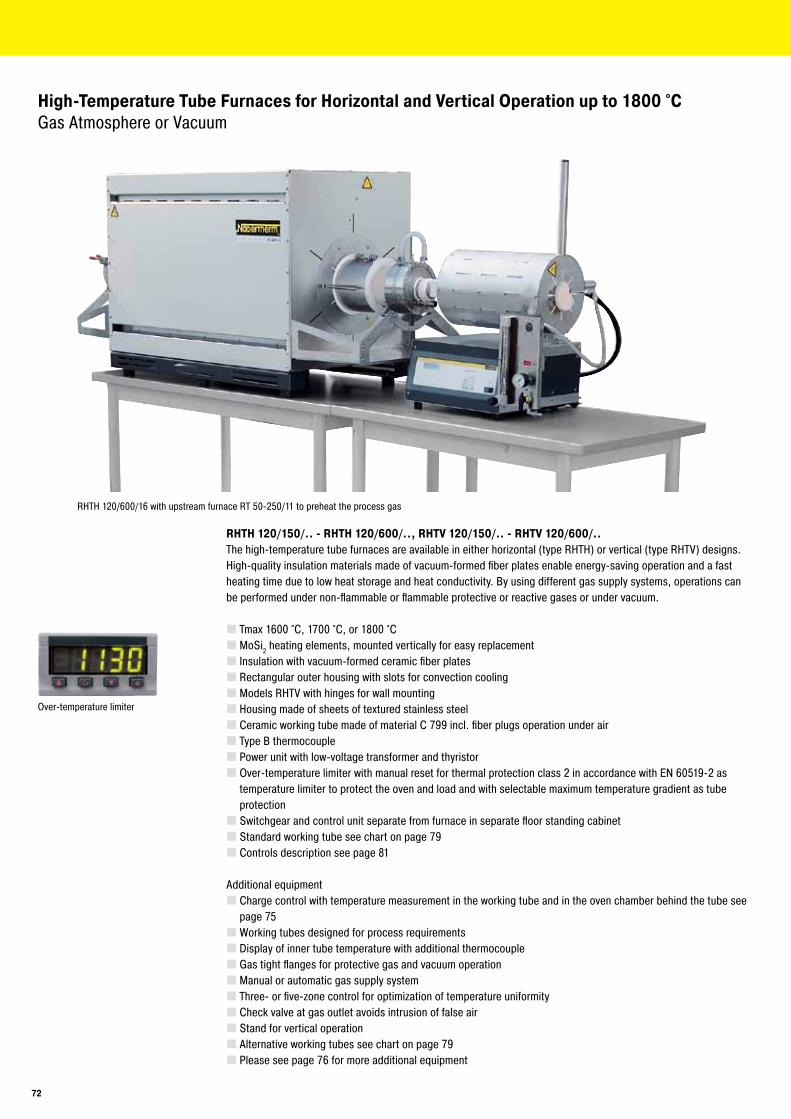
High-Temperature Tube Furnaces for Horizontal and Vertical Operation up to 1800 °C Gas Atmosphere or Vacuum
RHTH 120/150/.. - RHTH 120/600/.., RHTV 120/150/.. - RHTV 120/600/..The high-temperature tube furnaces are available in either horizontal (type RHTH) or vertical (type RHTV) designs. High-quality insulation materials made of vacuum-formed fiber plates enable energy-saving operation and a fast heating time due to low heat storage and heat conductivity. By using different gas supply systems, operations can be performed under non-flammable or flammable protective or reactive gases or under vacuum.
� Tmax 1600 °C, 1700 °C, or 1800 °C � MoSi2 heating elements, mounted vertically for easy replacement � Insulation with vacuum-formed ceramic fiber plates � Rectangular outer housing with slots for convection cooling � Models RHTV with hinges for wall mounting � Housing made of sheets of textured stainless steel � Ceramic working tube made of material C 799 incl. fiber plugs operation under air � Type B thermocouple � Power unit with low-voltage transformer and thyristor � Over-temperature limiter with manual reset for thermal protection class 2 in accordance with EN 60519-2 as temperature limiter to protect the oven and load and with selectable maximum temperature gradient as tube protection � Switchgear and control unit separate from furnace in separate floor standing cabinet � Standard working tube see chart on page 79 � Controls description see page 81
Additional equipment � Charge control with temperature measurement in the working tube and in the oven chamber behind the tube see page 75 �Working tubes designed for process requirements � Display of inner tube temperature with additional thermocouple � Gas tight flanges for protective gas and vacuum operation � Manual or automatic gas supply system � Three- or five-zone control for optimization of temperature uniformity � Check valve at gas outlet avoids intrusion of false air � Stand for vertical operation � Alternative working tubes see chart on page 79 � Please see page 76 for more additional equipment
Over-temperature limiter
RHTH 120/600/16 with upstream furnace RT 50-250/11 to preheat the process gas
72

RHTV 120/150/17 vertical tube furnace with stand and gas supply system 2 as additional equipment
Model Tmax Outer dimensions in mm Max. outer tube Ø
Heated Length constant Tube length Connected Electrical Weight
Horizontal design °C³ W² D H /mm length mm temperature ΔT 10 K in mm load kW connection* in kgRHTH 120/150/.. 1600 or 470 550 640 50 150 50 380 5.4 3-phase¹ 70RHTH 120/300/.. 1700 or 620 550 640 80 300 100 530 9.0 3-phase¹ 90RHTH 120/600/.. 1800 920 550 640 120 600 200 830 14.4 3-phase¹ 110
Model Tmax Outer dimensions in mm Max. outer tube Ø
Heated Length constant Tube length Connected Electrical Weight
Vertical design °C³ W D H² /mm length mm temperature ΔT 10 K in mm load kW connection* in kgRHTV 120/150/.. 1600 or 570 650 510 50 150 30 380 5.4 3-phase¹ 70RHTV 120/300/.. 1700 or 570 650 660 80 300 80 530 10.3 3-phase¹ 90RHTV 120/600/.. 1800 570 650 960 120 600 170 830 19.0 3-phase¹ 110¹Heating only between two phases *Please see page 81 for more information about supply voltage²Without tube ³Tmax is reached outside the tube. Realistic working temperature inside the tube is approx. 50 °C lower.
RHTV 120/300/15 integrated in a tensile strength testing machine
RHTV 120/480/16 LB in customer-specific design with working tube closed at one side, protective gas and vacuum option as well as with electric screw drive of the lift table
73

+
Thermocouple Calibration Set
For heat treatment processes, continuous quality can only be ensured by the regular calibration of control or charge thermocouples. The illustrated calibration set can be used with every tube furnace for the professional calibration of thermocouples.
The thermocouple calibration set is mounted in a compact housing and consists of a temperature display unit for two thermocouples, a reference thermocouple with compensation wire and a plug connection for different types of thermocouples. Both the display unit and the whole measuring circuit to the reference thermocouple are calibrated ex works and are supplied with a calibration certificate.
The set is used with a tube furnace, e.g. model RD 30/200/11. For calibration, the furnace is set for one temperature. From one side, the reference thermocouple is inserted into the working tube. From the other side, the thermocouple to be tested is positioned in the tube. The measuring points of both thermocouples must face as close as possible to each another. Depending on the furnace model, a ceramic temperature compensation block can be offered for the positioning of both thermocouples. After a defined period of time, the temperature of both thermocouples can be read off from the display unit of the thermocouple calibration set and be compared.
� Compact housing � Single-phase connection see page 81 � Digital display unit for the test thermocouple and the reference thermocouple, with calibration certificate in steps of 100 °C � Reference thermocouple, type N, with calibration certificate (for 3 temperatures) � Thermocouple inputs type K, S, N for test thermocouples. Only one input per measurement is possible. � Furnace (RD or R model) has to be ordered separately
Additional equipment � Reference thermocouple type K or type S � Further thermocouple inputs for specimen, e.g. type B, type J or type R � Fiber plug with passages and ceramic temperature compensation block for the support of the thermocouples in the test furnace
Calibrated thermocouples in various designs
Thermocouple calibration set, consisting of calibrated temperature display, calibrated reference thermocouple and tube furnace (RD and R models can be used)
74

Furnace Chamber Control with temperature measurement in furnace chamber outside the working tube.
� Advantages: Thermocouple protected against damage and aggressive load, very even control, attractive price � Disadvantage: Process-dependent temperature difference between displayed temperature on the controller and inside the tube
Extension Package for Furnace Chamber Control with additional temperature measurement in the working tube and display of the measured temperature
Charge Control with temperature measurement both in the furnace chamber outside the working tube as well as in the working tube.
� Advantages: Very precise and rapid control adjustment � Disadvantage: Costs
Furnace Chamber vs. Charge Control Comparison
Furnace Chamber ControlOnly the furnace chamber temperature is measured and controlled. Regulation is carried out slowly to avoid out-of-range values. As the charge temperature is not measured and controlled, it may vary a few degrees from the chamber temperature.
Charge ControlIf the charge control is switched on, both the charge temperature and furnace chamber temperature are measured. By setting different parameters the heat-up and cooling processes can be individually adapted. This results in a more precise temperature control at the charge.
1. Charge setpoint value2. Furnace setpoint value3. Actual value furnace chamber4. Actual value load/bath/muffle/retort
Furnace control
Charge control
Thermocouple for charge control in the RHTH 120/600/18 furnace
Control Alternatives for Tube Furnaces
Sintering under hydrogen in a tube furnace of RHTH product line
75

Gas Supply Systems/Vacuum Operation for Tube Furnaces R, RT, RS, RHTC, RHTH and RHTV
When equipped with various equipment packages, the tube furnace product lines RS, RHTC, RHTH, and RHTV can be adapted for operation with non-flammable or flammable gasses or for vacuum operation. The different equipment packages can be delivered together with the furnace, or later as needed.
Gas Supply System 1 for non-flammable protective or reactive gases (no vacuum operation)This package represents a basic version sufficient for many applications, for operation with non-flammable protective or reactive gasses. The standard working tube made of ceramic C 530 delivered with the furnace can still be used.
� Standard working tube can be used � 2 plugs of ceramic fiber with protective gas connections � Gas supply system for non-flammable protective gas (Ar, N2, forming gas) with shutoff valve and flow meter with control valve (volume 50-500 l/hr), piped and ready to connect (gas intake pressure at 300 mbar to be provided by customer)
Additional equipment � Extension of gas supply system with a second or third non-flammable type of gas � Bottle pressure regulator for use with bottled gas � Automatically controlled gas supply with solenoid valves on the gas supply system, which can be switched on and off through a controller with programmable extra functions (e.g. P 330)
Gas Supply System 2 for non-flammable protective or reactive gases/vacuum operationFor increased atmospheric purity requirements in the working tube, we recommend this gas supply system. The standard working tube is replaced by a dense working tube of ceramic C 610 or C 799 in a gas tight design. Besides the longer working tube, the scope of delivery also includes gas tight flanges and a corresponding bracket system in the furnace. The system can also be equipped for vacuum operation.
� Longer, gas tight working tube of ceramic C 610 for furnaces to 1300 °C or of C 799 for temperatures above 1300 °C � 2 vacuum-tight, water-cooled stainless steel flanges with fittings on the outlet side (cooling water supply with NW9 hose connector to be provided by the customer) � Mounting system on furnace for the flanges � Gas supply system for non-flammable protective gas (Ar, N2, forming gas) with shutoff valve and flow meter with control valve (volume 50-500 l/hr), gas outlet valve, piped and ready to connect (gas intake pressure at 300 mbar to be provided by customer)
Additional equipment � Extension of gas supply system with a second or third non-flammable type of gas � Bottle pressure regulator for use with bottled gas � Automatically controlled gas supply with solenoid valves on the gas supply system, which can be switched on and off through a controller with programmable extra functions (e.g. P 330) �Water-cooled end flange with quick connectors � Cooling unit for closed loop water circuit �Window for charge observation in combination with gastight flanges
Vacuum Operation � Vacuum package for evacuation of the working tube, consisting of connector for the gas outlet, 1 ball valve, manometer, 1-stage manually operated rotary vane vacuum pump with corrugated stainless steel hose connected to the gas outlet, max. attainable end pressure in working tube about 10-2 mbar � Alternative pumps for max. final pressure of up to 10-5 mbar on request see page 77
Gas supply system for non-flammable pro-tective or reactive gas with shutoff valve and flow meter with regulator valve, piped and ready to connect
Gas supply system 1: Fiber plugs with protective gas connection, suitable for many laboratory applications
Observation window as additional equip-ment for gastight flanges
76

Gas tight design with water-cooled flanges
Vacuum pump stand for operation up to 10-5 mbar
RHTH 120-600/18 with gas supply system 4 for hydrogen operation
Vacuum Pumps
With respect to the final pressure different pumps are available see page 50: � Single-step rotary piston pump for a max. final pressure of approx. 20 mbar. � Two-step rotary piston pump for a max. final pressure of approx. 10-2 mbar. � Pump system PT70 Dry (rotary vane pump with following turbomolecular pump for a max. final pressure of 10-5 mbar.
Information:For protection of the vacuum pump only cold stage evacuation is allowed. The reduction of working tube strengthness limits the max. possible working temperature under vacuum see page 78.
Gas Supply System 3 for flammable protective or reactive gases, manual operation in supervised modeAdding gas supply system 3 to the tube furnace allows operation under a hydrogen atmosphere. During hydrogen operation, a safety pressure of approx. 30 mbar is ensured in the working tube. Surplus hydrogen is burnt off in an exhaust gas torch. The operator manually takes care of inerting the working chamber before process start, after process end, and in case of default.
� Safety system for operation with flammable gases including torch function and tube breakage monitoring (checking overpressure) � Longer, gas tight working tube � 2 vacuum-tight, water-cooled stainless steel flanges (cooling water supply to be provided by customer via hose connector) � Exhaust gas torch � Pressure switch for monitoring the safety pressure � Gas supply system for H2 and N2. Volume adjustment is carried out by hand (the customer provides an H2 supply at 1 bar, an N2 supply at 10 bar, an O2 supply at 6-8 bar and a propan supply at 300 mbar)
Gas Supply System 4 for flammable protective or reactive gases, fully-automatic, unattended operationWith extended safety logic and an integrated nitrogen purge container, the system can be used for fully-automatic, unattended operation. Equipped with a Safety-PLC control system, pre-purging, hydrogen inlet, operation, fault monitoring and purging at the end of the process are carried out automatically. In case of default, the tube is immediately purged with nitrogen and the system is automatically switched to a safe status.
Equipment in Addition to System 3 � Extended safety control system with emergency tube purging in case of default � Emergency purge container � Safety-PLC control system with touchpanel for data input
Additional equipment for systems 3 - 4 � Simplified safety package for operation when purging with hydrogen above 800 °C
- Tube can be opened at working temperature above 800 °C - Pilot flame at tube outlet - Purging with hydrogen below 800 °C not possible, locked - Available for models RS
� Gas supply system extension for additional non-flammable gas types � Bottle pressure reducer for use with bottled gas � Cooling unit for closed loop water circuit � Vacuum packages (with hydrogen operation, this package can only be used for pre-evacuation) � PLC control system (as standard with gas supply system 4) � Gas supply via program-dependent, controllable mass flow controllers (with PLC control system only)
Water-cooled end flange with quick connectors as additional equipment
77

Tube Furnaces for Integration into Customized Systems
With their high level of flexibility and innovation, Nabertherm offers the optimal solution for customer-specific applications.
Based on our standard models, we develop individual solutions for integration in overriding process systems. The solutions shown on this page are just a few examples of what is feasible. From working under vacuum or protective gas via innovative control and automation technology for a wide selection of temperatures, sizes, lenghts and other properties of tube furnace systems – we will find the appropriate solution for a suitable process optimization.
RS 100-250/11S in split-type design for integration into a test stand
Tube furnace with five-zone control for optimal temperature uniformity
Bolts for connection of two separated half furnaces
RS 120/1000/11-S in divided version. Both half furnaces are manufactured identically and will be integrated in an extisting gas-heating system with space-saving design
Various working tubes as option
Working Tubes
Material Tube outside Ømm
Max. heat-up rampK/h
Tmax in air*°C
Tmax in vacuum operation°C
Gas tight
C 530 (Sillimantin) < 120 unlimited 1300 not possible nofrom 120 200
C 610 (Pytagoras) < 120 300 1400 1200 yesfrom 120 200
C 799 (99.7 % Al2O3)< 120 300 1800 1400 yesfrom 120 200
Quartz glass all unlimited 1100 950 yesCrFeAl-Alloy all unlimited 1300 1100 yes
*The max. allowed temperature might be reduced operating under aggressive atmospheres
There are various working tubes available, depending on application and temperatures. The technical specifications of the different working tubes are presented in the following table:
Working tube closed at one end with gastight flanges as additional equipment
78

Working Tubes: Standard (l) and Options (¡)
Working tube Article No. Modelouter Ø x inner Ø x length R RS RHTC RHTH RHTV
50-2
50
50-5
00
100-
750
120-
1000
80-3
00
80-5
00
80-7
50
120-
500
120-
750
120-
1000
170-
750
170-
1000
80-2
30
80-4
50
80-7
10
120-
150
120-
300
120-
600
120-
150
120-
300
120-
600
C 53040 x 30 x 450 mm 692070274 ¡40 x 30 x 700 mm 692070276 ¡ ¡50 x 40 x 450 mm 692070275 l50 x 40 x 700 mm 692070277 l60 x 50 x 650 mm 692070106 ¡60 x 50 x 850 mm 692070305 ¡ ¡60 x 50 x 1100 mm 692070101 ¡ ¡ ¡ ¡70 x 60 x 1070 mm 692070048 ¡ ¡ ¡ ¡80 x 70 x 650 mm 692070036 l80 x 70 x 850 mm 692070108 l ¡80 x 70 x 1100 mm 692070109 ¡ l ¡ ¡95 x 80 x 1070 mm 692070049 l ¡ ¡120 x 100 x 850 mm 692070110 l120 x 100 x 1100 mm 692070111 l ¡120 x 100 x 1350 mm 692070131 l ¡120 x 100 x 1400 mm 692070279 l170 x 150 x 1100 mm 692071659 l170 x 150 x 1350 mm 692071660 lVacuum tube¹ C 61060 x 50 x 1030 mm 692070179 ¡60 x 50 x 1230 mm 692070180 ¡ ¡60 x 50 x 1480 mm 692070181 ¡ ¡ ¡80 x 70 x 1230 mm 692070182 ¡ ¡80 x 70 x 1480 mm 692070183 ¡ ¡ ¡120 x 100 x 1230 mm 692070184 ¡120 x 100 x 1480 mm 692070185 ¡ ¡120 x 100 x 1730 mm 692070186 ¡ ¡170 x 150 x 1480 mm 692070187 ¡170 x 150 x 1730 mm 692070188 ¡C 79950 x 40 x 380 mm 692071664 l l50 x 40 x 530 mm 692071665 ¡ ¡50 x 40 x 830 mm 692070163 ¡ ¡80 x 70 x 600 mm 692070600 l80 x 70 x 830 mm 692071670 l ¡ ¡80 x 70 x 530 mm 692071669 l l80 x 70 x 1080 mm 692071647 l120 x 105 x 830 mm 692071713 l lVacuum tube¹ C 79950 x 40 x 990 mm 692070149 ¡ ¡50 x 40 x 1140 mm 692070176 ¡ ¡50 x 40 x 1440 mm 692070177 ¡ ¡80 x 70 x 990 mm 692070190 ¡80 x 70 x 1140 mm 692070148 ¡ ¡80 x 70 x 1210 mm 692070191 ¡80 x 70 x 1470 mm 692070192 ¡80 x 70 x 1440 mm 692070178 ¡ ¡120 x 105 x 1440 mm 692070147 ¡ ¡Vacuum tube² APM75 x 66 x 1090 mm 691402564 ¡75 x 66 x 1290 mm 691402565 ¡75 x 66 x 1540 mm 691400835 ¡115 x 104 x 1290 mm 691402566 ¡115 x 104 x 1540 mm 691402567 ¡115 x 104 x 1790 mm 691402568 ¡164 x 152 x 1540 mm 691402569 ¡164 x 152 x 1790 mm 691402570 ¡Vacuum quartz glass tube60 x 54 x 1030 mm 691404422 ¡60 x 54 x 1230 mm 691404423 ¡ ¡60 x 54 x 1480 mm 691404424 ¡ ¡ ¡80 x 74 x 1230 mm 691404425 ¡ ¡80 x 74 x 1480 mm 691404426 ¡ ¡ ¡120 x 114 x 1230 mm 691404427 ¡120 x 114 x 1480 mm 691404428 ¡ ¡120 x 114 x 1730 mm 691404429 ¡ ¡170 x 162 x 1480 mm 691404430 ¡170 x 162 x 1730 mm 691404431 ¡
¹With grinded tube ends for the use with water-cooled end flanges l Standard working tube²With attached holder for gas tight flange ¡ Working tube available as an option³Tubes/reactors incl. mounted sleeves for connection to the rotary drive. Spare tubes come without sleeves.
79

Temperature Uniformity and System Accuracy
Holding frame for measurement of tempe-rature uniformity
Temperature uniformity is defined as the maximum temperature deviation in the useful space of the furnace. There is a general difference between the furnace chamber and the useful space. The furnace chamber is the total volume available in the furnace. The useful space is smaller than the furnace chamber and describes the volume which can be used for charging.
Specification of Temperature Uniformity in Δ K in the Standard FurnaceIn the standard design the temperature uniformity is specified as the relative, maximum deviation from a defined reference temperature within the useful space in the empty furnace at dwell time. Temperature uniformity is defined as ΔT in K. If, for example, a standard temperature uniformity of ΔT 10 K at 750 °C is specified, it means that the actual temperature in the furnace can vary between 740 °C and 750 °C or between 750 °C and 760 °C.
Specification of the Temperature Uniformity in +/- °C as Additional FeatureIf an absolute temperature uniformity at a reference temperature or at a defined reference temperature range is required, the furnace must be calibrated appropriately. If, for example, a temperature uniformity of +/- 5 °C at a set temperature of 750 °C is required, it means that measured temperatures may range from a minimum of 745 °C to a maximum of 755 °C in the useful space.
System AccuracyTolerances may occur not only in the useful space, they also exist with respect to the thermocouple and in the controls. If an absolute temperature uniformity in +/- °C at a defined set temperature or within a defined reference temperature range is required, the following measures have to be taken:
� Measurement of total temperature deviation of the measurement line from the controls to the thermocouple � Measurement of temperature uniformity within the useful space at the reference temperature or within the reference temperature range � If necessary, an offset is set at the controls to adjust the displayed temperature at the controller to the real temperature in the furnace � Documentation of the measurement results in a protocol
Temperature Uniformity in the Useful Space incl. ProtocolIn standard furnaces a temperature uniformity is guaranteed as ΔT without measurement of temperature uniformity. However, as additional feature, a temperature uniformity measurement at a reference temperature in the useful space compliant with DIN 17052-1 can be ordered. Depending on the furnace model, a holding frame which is equivalent in size to the charge space is inserted into the furnace. This frame holds thermocouples at 11 defined measurement positions. The measurement of the temperature uniformity is performed at a reference temperature specified by the customer at a pre-defined dwell time. If necessary, different reference temperatures or a defined reference working temperature range can also be calibrated.
For the configuration of furnace and control system to meet specific industry standards such as AMS 2750 D, CQI-9, or FDA, Naber-therm offers adapted solutions. See our catalog „Thermal Process Technology“
The system accuracy is defined by adding the tolerances of the controls, the thermo-couple and the useful space
Deviation from measuring point to the average temperature in the useful chamber +/-3 °C
Deviation of thermocouple, e.g. +/- 1.5 °CPrecision of the controls, e.g. +/- 2 °C
80

Assignment of Standard Controllers to Furnace Families
Functionality of the Standard ControllersP 300 P 310 R 6 B 130 B 150 B 180 P 330 C 40/42 3504 H 700 H 1700 H 3700
Number of programs 9 9 1 2 1 1 9 9 1-50 10 10 10Segments 40 40 1 3 2 2 40 18 up to 500 20 20 20Extra functions (e.g. fan or autom. flaps) 2² 2² 2 2 2-8 ¡ 6 8Maximum number of control zones 1 1 1 1 1 1 1 1 2² ¡ 8 8Graphic color display 5,7" 5,7" 12"Status messages in clear text l l l l l l l l l l lStart time configurable (e.g. to use night power rates) l l l l l l l l l lOperating hour counter l l l l l l l l l lAuto tune l l l l l l lProgram entry in steps of 1 °C or 1 min. l l l l l l l l l l l lKeypad lock l lSkip-button for segment jump l l l ¡ l lDrive of manual zone regulation lUSB extension module for recording of process data on an USB flash drive with NTLog see page 82
¡ ¡ ¡ ¡ ¡ l l
Interface for MV software ¡ ¡ ¡ ¡ ¡ ¡ ¡
Programmable power outlet lkWh meter l l l l l lReal-time clock l l l l lBath control/charge control ¡ ¡ ¡ ¡
Data entry via touchpanel l l lData input via number pad l l l l ll Standard¡ Option¹ standard controller depending on design² as an extra feature in ovens with air circulation
N ../
65 H
ACDB
W ..
/60
HACD
B
NAC
120/
65 -
NAC
500/
65
TR KTR
N 10
0/W
AX -
N 22
00/W
AX
NB 6
60/W
AX -
NB 1
000/
WAX
W ..
+ W
.../D
B
H ../
LB o
der L
T
N 20
0/DB
- N
1000
/HDB
N 10
0 - N
220
0/14
NB 3
00 -
NB 6
00
WB
WHT
C
HTC
16/1
6 - H
TC 4
50/1
6
HT HFL
HTC
../LB
ode
r LT
HTB
NRA
17/0
6 - N
RA 1
000/
11
NRA
.. H 2 v
ersi
on
NRA
.. ID
B ve
rsio
n
SRA
500
- SR
1000
VHT
LBVH
T
SVHT
NRA
..CDB
LS GR
LH HTC(
T)
LHT
LHT/
LB
RD R RT RHTC
RS RSR
RHTH
/RHT
V
Catalog page 8 9 11 12 14 16 17 18 22 24 26 28 29 30 31 32 35 36 40 44 46 46 47 48 52 53 54 80 80 56 58 59 60 62 63 64 65 66 68 72ControllerP 300 l1 l1 ¡ l l l l l1 l ¡ l l ¡ ¡ ¡
P 310 l1 l1 l1 l1 l1 l l lC 6/3208 ¡ ¡
R 6 l lB 130 lB 150 l l l l lB 180 ¡ l l l lP 330 ¡ ¡ ¡ ¡ ¡ ¡
C 40/42 l l3504 ¡ ¡ ¡ ¡ l ¡ ¡ ¡ ¡ ¡ ¡ ¡
H 700/PLC l1 l1 l1 l1 l1 l1 l l lH 1700/PLC l1 l1 ¡ ¡ ¡ ¡ l ¡ l1 ¡ l1 ¡ ¡ l ¡ l ¡ ¡ ¡ ¡
H 3700/PLC ¡ ¡ ¡ ¡ ¡ ¡ ¡ ¡ ¡ ¡ ¡ ¡ l ¡ ¡ ¡ ¡ ¡ ¡ ¡ ¡
NCC ¡ ¡ ¡ ¡ ¡ ¡ ¡ ¡ ¡ ¡ ¡ ¡ ¡ ¡ ¡ ¡ ¡ ¡ ¡ ¡ ¡ ¡ ¡ ¡ ¡ ¡ ¡
Process Control and DocumentationNabertherm has many years of experience in the design and construction of both standard and custom control system. All controls are remarkable for their ease of use and even in the basic version have a wide variety of functions.
Standard ControllersOur extensive line of standard controllers satisfies most customer requirements. Based on the specific furnace model, the controller regulates the furnace temperature reliably. The standard controllers are developed and fabricated within the Nabertherm group. When developing controllers, our focus is on ease of use. From a technical standpoint, these devices are custom-fit for each furnace model or the associated application. From the simple controller with an adjustable temperature to the control unit with freely configurable control parameters, stored programs, PID microprocessor control with self-diagnosis system and a computer interface, we have a solution to meet your requirements.
Mains Voltages for Nabertherm FurnacesSingle-phase: all furnaces are available for mains voltages from 110 V - 240 V at 50 or 60 Hz.3-phase: all furnaces are available for mains voltages from 200 V - 240 V or 380 V - 480 V, at 50 or 60 Hz.
81

PC for HiProSystems control in a separate cabinet
H 3700 with colored graphic presentation of data
H 1700 with colored, tabular depiction of the data
Temperature recorder
HiProSystems Control and DocumentationThis professional control system for single and multi-zone furnaces is based on Siemens hardware and can be adapted and upgraded extensively. HiProSystems control is used when more than two process-dependent functions, such as exhaust air flaps, cooling fans, automatic movements, etc., have to be handled during a cycle, when furnaces with more than one zone have to be controlled, when special documentation of each batch is required and when remote telediagnostic service is required. It is flexible and is easily tailored to your process or documentation needs.
Alternative User InterfacesTouch panel H 700This basic panel accommodates most basic needs and is very easy to use.Touch panel H 1700Firing cycle data and the extra functions activated are clearly displayed in a table. Messages appear as text.Touch panel H 3700All functions and process data are stored and displayed in easy to read charts. The data can be exported through various interfaces (Ethernet TCP/IP, MPI, Profibus) to a local PC or your company network for further processing. A CF card also gives the opportunity for data storage and transfer to a PC with a card reader.
For Control, Visualisation and DocumentationNabertherm Control Center NCCUpgrading the HiProSystems-Control individually into an NCC provides for additional interfaces, operating documentation, and service benefits in particular for controlling furnace groups including charge beyond the furnace itself (quenching tank, cooling station etc.):
� Recommended for heat treatment processes with extensive requirements in respect to documentation e.g. for metals, technical ceramics or in the medicine field � Software can be used also in accordance with the AMS 2750 D (NADCAP) � Documentation according to the requirements of Food and Drug Administration (FDA), Part 11, EGV 1642/03 possible � Charge data can be read in via barcodes � Interface for connection to existing Enterprise Database systems (e.g. SAP, Oracle) � Connection to mobile phone network for alarm message transmission via SMS � Control from various locations over the network � Calibration of each measuring point for a specific temperature possible � Extendable for calibration of a polygonal line with up to 18 temperatures per measuring point for use at different temperatures e.g for AMS 2750 D applications
For DocumentationNabertherm Documentation Center NDC and data recording via NT LogIf the process data of the HiProSystems control unit only need to be recorded, this can be done using a personalcomputer (PC) with the high-performance NDC software. The data are documented, forgery-proof, and can beevaluated both in the form of a table or a chart. Individual charge data can be entered by the customer and arearchived together with the process data. A low-cost alternative which can be used is the NT Log package. The datais recorded on a USB stick during the firing. After the heat treatment has been completed, the recorded value canbe read out on the PC with the free analysis software.
Temperature RecorderBesides the documentation via the software which is connected to the controls, Nabertherm offers different temperature recorders which can be used with respect to the application.
Model 6100e Model 6100a Model 6180aData input using touch panel x x xSize of colour display in inch 5,5 5,5 12,1Number of thermocouple inputs 3 18 48Data read-out via USB-stick x x xInput of charge data x xEvaluation software included x x xApplicable for TUS-measurements acc. to AMS 2750 D x
82

Controltherm MV Software for Control, Visualisation and DocumentationDocumentation and reproducibility gain increased attention with steadily rising quality standards. The powerful Nabertherm software Controltherm MV provides for an optimum solution for the control and documentation of one or more furnaces as well as charge data on basis of Nabertherm controllers.
In the basic version one furnace can be connected to the MV-software. The system can be extended to four, eight or even 16 multi-zone controlled furnaces. Up to 400 different heat treatment programs can be stored. The process will be documented and filed. Process data can be read-out graphically or in table format. A data transfer to MS-Excel is also possible.
For furnaces which are not controlled via a Nabertherm controller, the furnace temperature can be documented with the MV-software. We deliver an extension package as optional equipment. With respect to the individual version, three, six or even nine independent thermocouples can be connected. Independent of the control system, the values of each thermocouple will be read-out and evaluated by the MV-software.
Features � Simple installation without specific knowledge � All Nabertherm controllers with interface connectable � Manipulation protected storage of temperature curves of up to one, four, eight or 16 furnaces (also multizone-controlled), depending on the version of MV-software � Redundant storage on a network server possible � Programming, archiving and printing of programs and graphics � Free input of descriptive charge data text with comfortable search function � Data exportable into Excel format for further evaluation � Start/stop of the controller from the local PC (only with Nabertherm controllers mit interface) � Selectable languages: German, English, French, Italian or Spanish � 400 additional programs storable (only with Nabertherm controllers with interface)
Extension Package II for Connection of one Additional Temperature Measuring Point, Independent of the Controller
� Connection of an independent thermocouple, type K or S with display of the measured temperature on the included controller C 6 D, e.g. for documentation of charge temperature � Conversion and transmission of measured data to the MV-software � For data evaluation, please see MV-software features
Extension Package II for Connection Three, Six or Nine Temperature Measuring Points, Independent of the Controller
� Connection of three thermocouples, type K, S, N or B to the supplied connection box � Extendable to two or three connection boxes for up to nine temperature measuring points � Conversion and transmission of measured data to the MV-software � For data evaluation, please see MV-software features
Controltherm MV Software for Control, Visualisation and Documentation
Data input in table format if used together with Nabertherm controllers
Graphical display of set and actual tempe-rature curve
Extendable for connection of up to 16 furnaces
83

www.nabertherm.com
Please visit our website www.nabertherm.com and find out all you want to know about us - and especially about our products.
Besides news and our current calendar of trade fairs, there is also the opportunity to get in touch directly with your local sales office or nearest dealer worldwide.
Professional Solutions for: � Arts & Crafts � Glass � Advanced Materials � Laboratory/Dental � Thermal Process Technology for Metals, Plastics and Surface Finishing � Foundry
The whole World of Nabertherm: www.nabertherm.com
Reg
No. C
2.1
/05.
12 (e
nglis
ch),
info
rmat
ion
here
in is
sub
ject
to c
hang
e wi
thou
t not
ice.
Nab
erth
erm
ass
umes
no
liabi
lity
for a
ny e
rrors
that
may
app
ear i
n th
is d
ocum
ent.
[email protected]: (+49) 4298 922-0Fax: (+49) 4298 922-129
[email protected]: (+86) 21 6490 2960Fax: (+86) 21 6490 3107
[email protected]: (+33) 1 5356 1800Fax: (+33) 1 5356 1809
[email protected]: (+39) 348 3820278Fax: (+39) 055 480835
[email protected]: (+41) 62 209 6070Fax: (+41) 62 209 6071
[email protected]: (+44) 1922 455 521Fax: (+44) 1922 455 277
[email protected]: (+1) 302 322 3665Fax: (+1) 302 322 3215
[email protected]: (+34) 93 474 47 16Fax: (+34) 93 474 53 03
Headquarters:
Nabertherm GmbHBahnhofstr. 2028865 Lilienthal, Germany
Sales and Service Subsidiaries
Nabertherm Shanghai Ltd.150 Lane, No. 158 Pingbei Road, Minhang District201109 Shanghai, China
Nabertherm S.A.S51 Rue de Presles93531 Aubervilliers, France
Nabertherm Italiavia Trento N° 1750139 Florence, Italy
Nabertherm Schweiz AG Batterieweg 64614 Hägendorf, Switzerland
Nabertherm Ltd.Vigo Place, AldridgeWest Midlands WS9 8YB, United Kingdom
Nabertherm Inc.54 Read‘s WayNew Castle, DE 19720, USA
Nabertherm Españac/Martí i Julià, 8 Bajos 7a08940 Cornellà de Llobregat, Spain