MCset 17.5 kV - Schneider...
71
Medium Voltage Distribution Installation instruction April 2012 Air insulated switchboard Withdrawable switchgear SF6 or vaccum technology MCset 17.5 kV
Transcript of MCset 17.5 kV - Schneider...
Medium Voltage Distribution
Installation instructionApril 2012
Air insulated switchboard Withdrawable switchgear SF6 or vaccum technology
MCset 17.5 kV

version 0707897301EN.indd 1
Contents
General 2Glossary 2Earthing switch control symbols 2Moving part control symbols 3Recommendations 3Standard tightening torques 4List of bags and accessories 4Packaging 5
Dimensionsandweights 6AD, CL-GL, VT cubicles 6Cubicle fitted with IPX1/IPX2 roofs 9DI2 cubicle 9RHB, RHC cubicles 10Transition enclosure MTP 11
Handlinginstructions 12Land packaging 12Ocean shipment packaging 12Handling using a sling 12Handling by rolling 13Storage 13
Installationandoperationrecommendation 14
Floorfinishingandcubiclefastening 15Surface condition 15Floor quality 15Description of irons and accessories 15Placing and adjusting on non earthquake resistant civil engineering works 15Placing and adjusting on earthquake resistant civil engineering works 17
Installationinstructions 19Unpacking cubicles 19Placing cubicles in a switchboard 19Coupling of cubicles 22Rack-in check 24Removing the mobile part transport fixations 24Installing the main earth connection 25Installing the electric connections of the busbars and MV cables 27Installing busbars 29Installing busbars between MTP and the MOTORPACT cubicle 33Placing MV cables on AD cubicle 36Placing MV cables on RHC cubicle 42MV cable screen earthing 46LV cable routing and connection 47Installing the tunnel 49Installing the IPX1/IPX2 roofs or anti arc IPx1/IPx2 tunnels 52Installing the tunnel end sheets 58Installing the end sheets 60Installing fans on versions 3600 A / 4000 A 63
InstallationofaFUequippedwithelectromagneticlockingoptions 64Earthing switch with electromagnetic locking 64Rack-in prevention with electromagnetic locking 65Prior to installing the front panels 65
Stepstobetakenfortestsandinspection 66Power frequency dielectric test 66
Testsonsite 67Checking and setting up the internal arcing detector 67
Index 68
2 07897301EN.inddversion 07
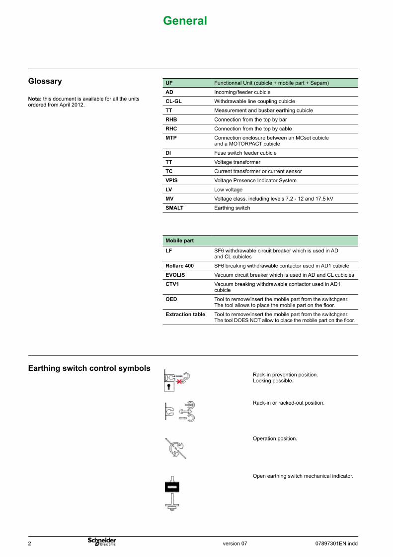
Open earthing switch mechanical indicator.
Operation position.
Rack-in or racked-out position.
Rack-in prevention position. Locking possible.
General
Earthingswitchcontrolsymbols
Nota:this document is available for all the units ordered from April 2012.
Glossary UF Functionnal Unit (cubicle + mobile part + Sepam)
AD Incoming / feeder cubicle
CL-GL Withdrawable line coupling cubicle
TT Measurement and busbar earthing cubicle
RHB Connection from the top by bar
RHC Connection from the top by cable
MTP Connection enclosure between an MCset cubicle and a MOTORPACT cubicle
DI Fuse switch feeder cubicle
TT Voltage transformer
TC Current transformer or current sensor
VPIS Voltage Presence Indicator System
LV Low voltage
MV Voltage class, including levels 7.2 - 12 and 17.5 kV
SMALT Earthing switch
Mobilepart
LF SF6 withdrawable circuit breaker which is used in AD and CL cubicles
Rollarc400 SF6 breaking withdrawable contactor used in AD1 cubicle
EVOLIS Vacuum circuit breaker which is used in AD and CL cubicles
CTV1 Vacuum breaking withdrawable contactor used in AD1 cubicle
OED Tool to remove/insert the mobile part from the switchgear. The tool allows to place the mobile part on the floor.
Extractiontable Tool to remove/insert the mobile part from the switchgear. The tool DOES NOT allow to place the mobile part on the floor.
version 0707897301EN.indd 3
Marking
All type of equipment installation such as lamp or light are forbidden.Installationabovetheswitchboard
Recommendations
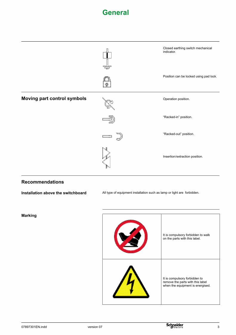
Insertion / extraction position.
“Racked-out” position.
“Racked-in” position.
Operation position.
Position can be locked using pad lock.
Closed earthing switch mechanical indicator.
General
It is compulsory forbidden to walk on the parts with this label.
It is compulsory forbidden to remove the parts with this label when the equipment is energised.
Movingpartcontrolsymbols
4 07897301EN.inddversion 07
Switchboardpackaging
Listofbagsandaccessories
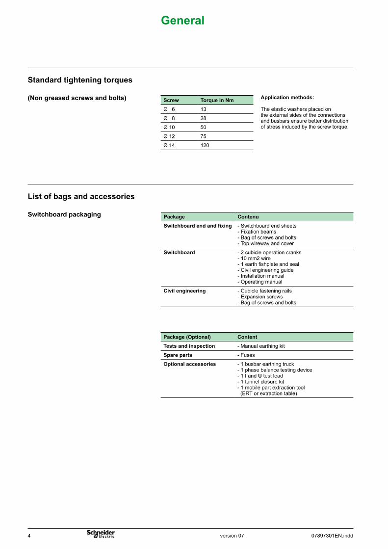
General
Applicationmethods:
The elastic washers placed on the external sides of the connections and busbars ensure better distribution of stress induced by the screw torque.
Screw TorqueinNmØ 6 13
Ø 8 28
Ø 10 50
Ø 12 75
Ø 14 120
(Nongreasedscrewsandbolts)
Standardtighteningtorques
Package(Optional) ContentTestsandinspection - Manual earthing kit
Spareparts - Fuses
Optionalaccessories - 1 busbar earthing truck- 1 phase balance testing device- 1 I and U test lead- 1 tunnel closure kit- 1 mobile part extraction tool (ERT or extraction table)
Package ContenuSwitchboardendandfixing - Switchboard end sheets
- Fixation beams- Bag of screws and bolts - Top wireway and cover
Switchboard - 2 cubicle operation cranks- 10 mm2 wire- 1 earth fishplate and seal- Civil engineering guide- Installation manual- Operating manual
Civilengineering - Cubicle fastening rails- Expansion screws- Bag of screws and bolts
version 0707897301EN.indd 5
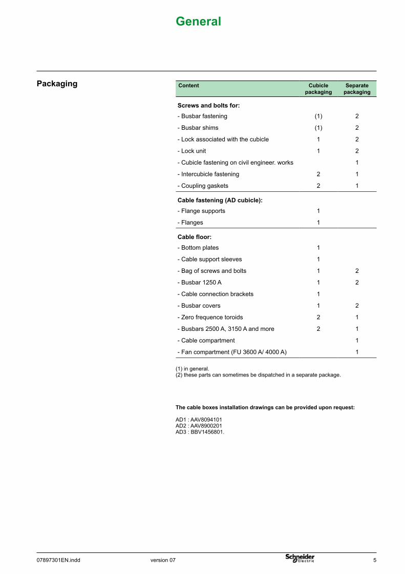
Packaging
General
Content Cubiclepackaging
Separatepackaging
Screwsandboltsfor:- Busbar fastening (1) 2
- Busbar shims (1) 2
- Lock associated with the cubicle 1 2
- Lock unit 1 2
- Cubicle fastening on civil engineer. works 1
- Intercubicle fastening 2 1
- Coupling gaskets 2 1
Cablefastening(ADcubicle):- Flange supports 1
- Flanges 1
Cablefloor:- Bottom plates 1
- Cable support sleeves 1
- Bag of screws and bolts 1 2
- Busbar 1250 A 1 2
- Cable connection brackets 1
- Busbar covers 1 2
- Zero frequence toroids 2 1
- Busbars 2500 A, 3150 A and more 2 1
- Cable compartment 1
- Fan compartment (FU 3600 A/ 4000 A) 1
(1) in general.(2) these parts can sometimes be dispatched in a separate package.
Thecableboxesinstallationdrawingscanbeprovideduponrequest:
AD1 : AAV8094101AD2 : AAV8900201AD3 : BBV1456801.
6 07897301EN.inddversion 07
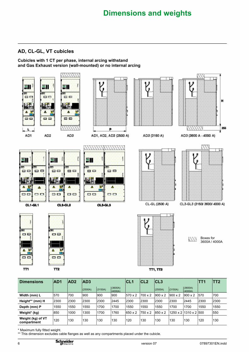
Dimensionsandweights
Dimensions AD1 AD2 AD3 CL1 CL2 CL3 TT1 TT2(2500A) (3150A)
(3600A)(4000A)
(2500A) (3150A)(3600A)(4000A)
Width(mm)L 570 700 900 900 900 570 x 2 700 x 2 900 x 2 900 x 2 900 x 2 570 700
Height**(mm)H 2300 2300 2300 2300 2445 2300 2300 2300 2300 2445 2300 2300
Depth(mm)P 1550 1550 1550 1700 1700 1550 1550 1550 1700 1700 1550 1550
Weight*(kg) 850 1000 1300 1700 1760 650 x 2 750 x 2 850 x 2 1250 x 2 1310 x 2 500 550
Weight(kg)ofVTcompartment 120 130 130 130 130 120 130 130 130 130 120 130
* Maximum fully fitted weight.** This dimension excludes cable flanges as well as any compartments placed under the cubicle.
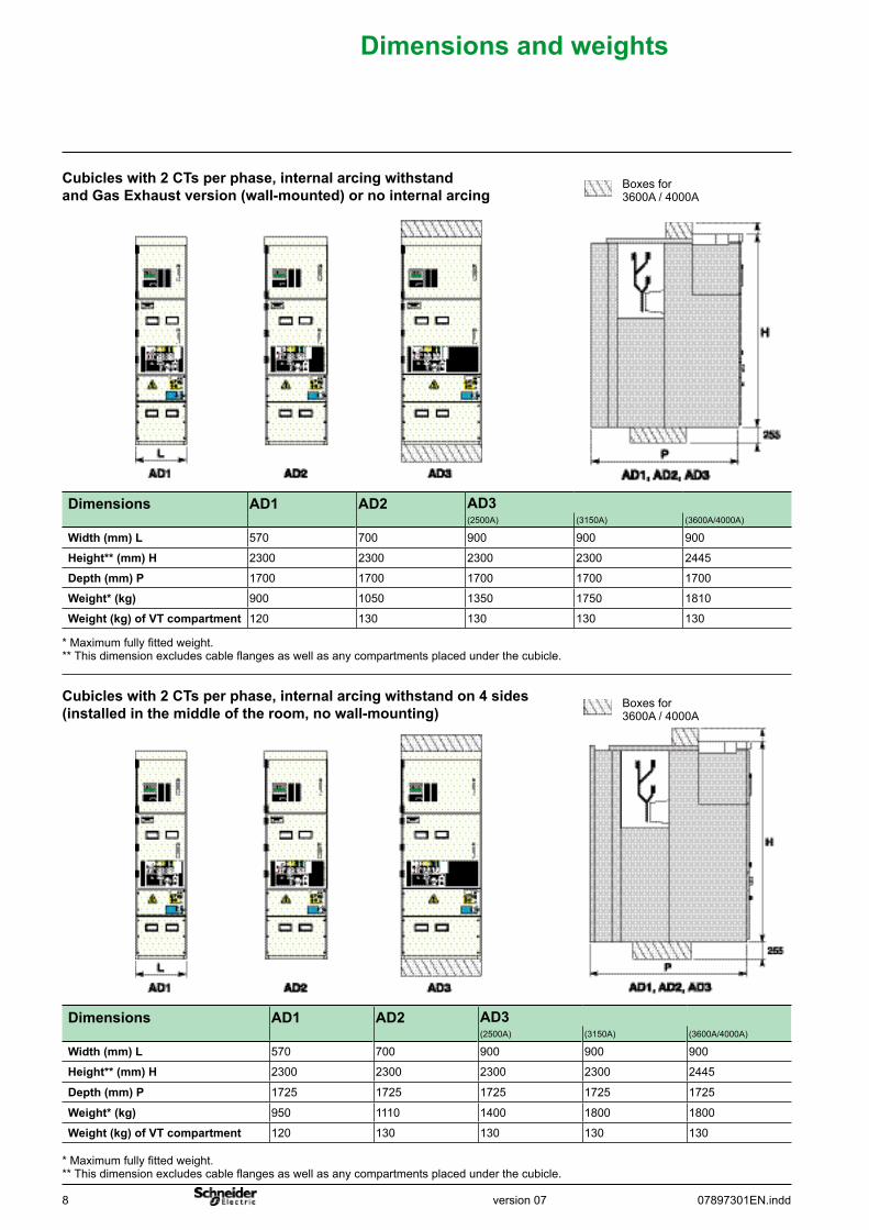
AD,CL-GL,VTcubicles
Cubicleswith1CTperphase,internalarcingwithstandandGasExhaustversion(wall-mounted)ornointernalarcing
Boxes for 3600A / 4000A
version 0707897301EN.indd 7
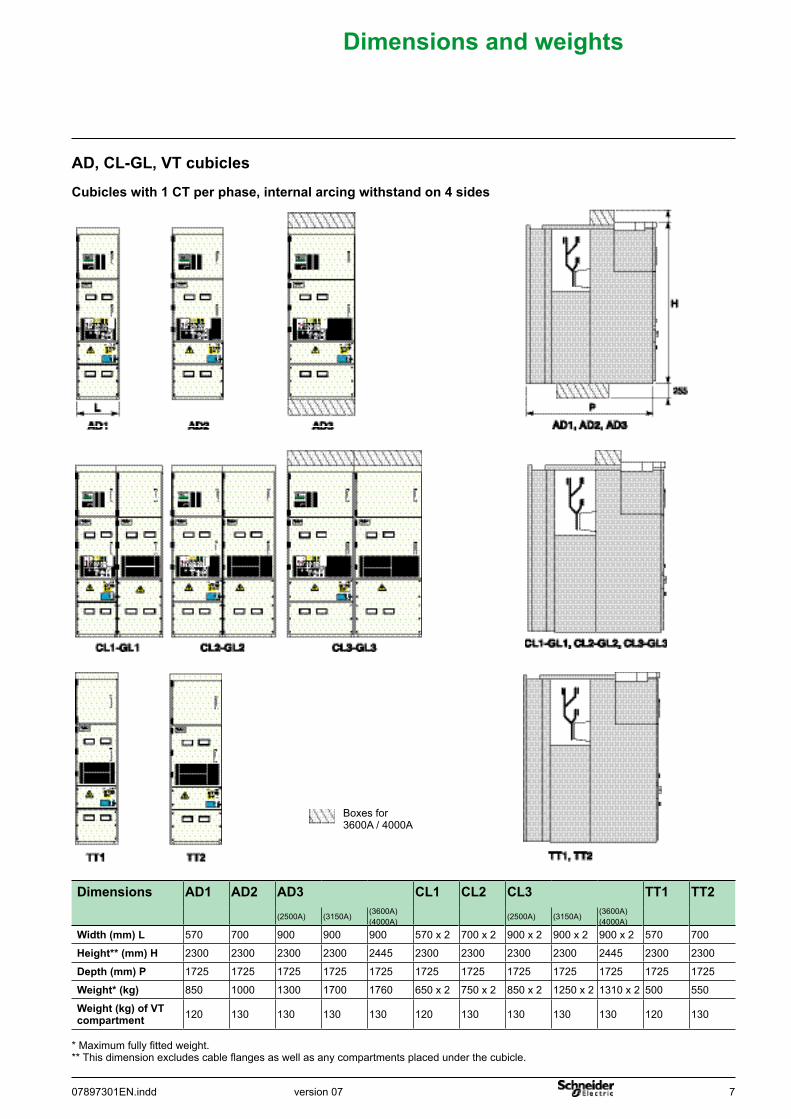
Dimensionsandweights
Boxes for 3600A / 4000A
Dimensions AD1 AD2 AD3 CL1 CL2 CL3 TT1 TT2(2500A) (3150A)
(3600A)(4000A)
(2500A) (3150A)(3600A)(4000A)
Width(mm)L 570 700 900 900 900 570 x 2 700 x 2 900 x 2 900 x 2 900 x 2 570 700
Height**(mm)H 2300 2300 2300 2300 2445 2300 2300 2300 2300 2445 2300 2300
Depth(mm)P 1725 1725 1725 1725 1725 1725 1725 1725 1725 1725 1725 1725
Weight*(kg) 850 1000 1300 1700 1760 650 x 2 750 x 2 850 x 2 1250 x 2 1310 x 2 500 550
Weight(kg)ofVTcompartment 120 130 130 130 130 120 130 130 130 130 120 130
* Maximum fully fitted weight.** This dimension excludes cable flanges as well as any compartments placed under the cubicle.
AD,CL-GL,VTcubicles
Cubicleswith1CTperphase,internalarcingwithstandon4sides
8 07897301EN.inddversion 07
Dimensionsandweights
Boxes for 3600A / 4000A
Dimensions AD1 AD2 AD3(2500A) (3150A) (3600A/4000A)
Width(mm)L 570 700 900 900 900
Height**(mm)H 2300 2300 2300 2300 2445
Depth(mm)P 1725 1725 1725 1725 1725
Weight*(kg) 950 1110 1400 1800 1800
Weight(kg)ofVTcompartment 120 130 130 130 130
* Maximum fully fitted weight.** This dimension excludes cable flanges as well as any compartments placed under the cubicle.
Boxes for 3600A / 4000A
Cubicleswith2CTsperphase,internalarcingwithstandon4sides(installedinthemiddleoftheroom,nowall-mounting)
Dimensions AD1 AD2 AD3(2500A) (3150A) (3600A/4000A)
Width(mm)L 570 700 900 900 900
Height**(mm)H 2300 2300 2300 2300 2445
Depth(mm)P 1700 1700 1700 1700 1700
Weight*(kg) 900 1050 1350 1750 1810
Weight(kg)ofVTcompartment 120 130 130 130 130
* Maximum fully fitted weight.** This dimension excludes cable flanges as well as any compartments placed under the cubicle.
Cubicleswith2CTsperphase,internalarcingwithstandandGasExhaustversion(wall-mounted)ornointernalarcing
version 0707897301EN.indd 9
Dimensionsandweights
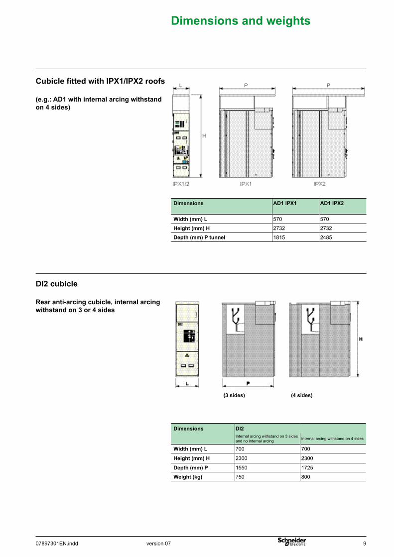
(e.g.:AD1withinternalarcingwithstandon4sides)
Rearanti-arcingcubicle,internalarcingwithstandon3or4sides
DI2cubicle
(3sides) (4sides)
Cubicle fitted with IPX1/IPX2 roofs
Dimensions DI2Internal arcing withstand on 3 sidesand no internal arcing Internal arcing withstand on 4 sides
Width(mm)L 700 700
Height(mm)H 2300 2300
Depth(mm)P 1550 1725
Weight(kg) 750 800
Dimensions AD1 IPX1 AD1 IPX2
Width(mm)L 570 570
Height(mm)H 2732 2732
Depth(mm)Ptunnel 1815 2485
10 07897301EN.inddversion 07
Dimensionsandweights
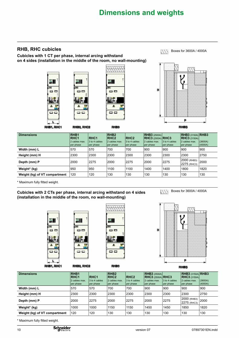
RHB,RHCcubicles Boxes for 3600A / 4000A
Cubicleswith2CTsperphase,internalarcingwithstandon4sides(installationinthemiddleoftheroom,nowall-mounting)
Boxes for 3600A / 4000A
Cubicleswith1CTperphase,internalarcingwithstandon4sides(installationinthemiddleoftheroom,nowall-mounting)
Dimensions RHB1 RHB2 RHB3(2500A) RHB3(3150A) RHB3RHC1 RHC1 RHC2 RHC2 RHC3(2500A) RHC3 RHC3(3150A)2 cables max.per phase
3 to 4 cablesper phase
2 cables max.per phase
3 to 4 cablesper phase
2 cables max.per phase
3 to 4 cablesper phase
2 cables max.per phase
(3600A)(4000A)
Width(mm)L 570 570 700 700 900 900 900 900
Height(mm)H 2300 2300 2300 2300 2300 2300 2300 2750
Depth(mm)P 2000 2275 2000 2275 2000 2275 2000 (RHB3)2275 (RHC3)
2000
Weight*(kg) 1000 1000 1150 1150 1450 1450 1850 1820
Weight(kg)ofVTcompartment 120 120 130 130 130 130 130 130
* Maximum fully fitted weight.
Dimensions RHB1 RHB2 RHB3(2500A) RHB3(3150A) RHB3RHC1 RHC1 RHC2 RHC2 RHC3(2500A) RHC3 RHC3(3150A)2 cables max.per phase
3 to 4 cablesper phase
2 cables max.per phase
3 to 4 cablesper phase
2 cables max.per phase
3 to 4 cablesper phase
2 cables max.per phase
(3600A)(4000A)
Width(mm)L 570 570 700 700 900 900 900 900
Height(mm)H 2300 2300 2300 2300 2300 2300 2300 2750
Depth(mm)P 2000 2275 2000 2275 2000 2275 2000 (RHB3)2275 (RHC3)
2000
Weight*(kg) 950 950 1100 1100 1400 1400 1800 1820
Weight(kg)ofVTcompartment 120 120 130 130 130 130 130 130
* Maximum fully fitted weight.
version 0707897301EN.indd 11
Dimensionsandweights
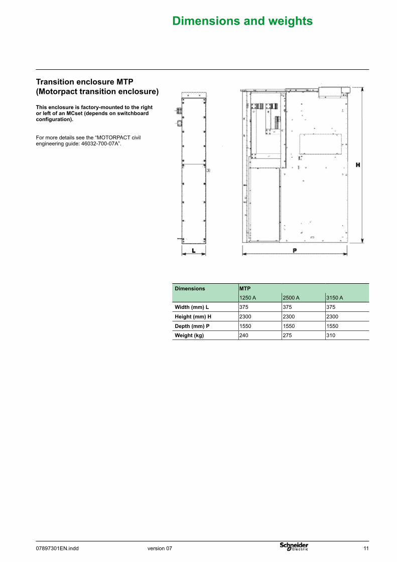
Thisenclosureisfactory-mountedtotherightorleftofanMCset(dependsonswitchboardconfiguration).
Dimensions MTP1250 A 2500 A 3150 A
Width(mm)L 375 375 375
Height(mm)H 2300 2300 2300
Depth(mm)P 1550 1550 1550
Weight(kg) 240 275 310
For more details see the “MOTORPACT civil engineering guide: 46032-700-07A”.
TransitionenclosureMTP(Motorpacttransitionenclosure)
12 07897301EN.inddversion 07
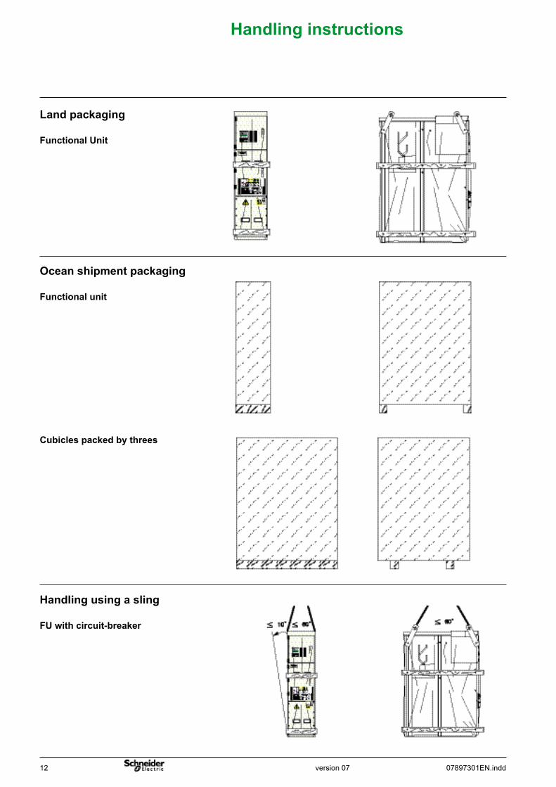
Landpackaging
FunctionalUnit
Oceanshipmentpackaging
Functionalunit
Handlinginstructions
Cubiclespackedbythrees
Handlingusingasling
FUwithcircuit-breaker
version 0707897301EN.indd 13
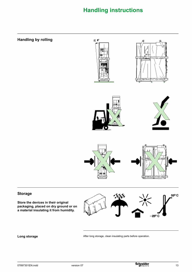
Storage
Longstorage
Storethedevicesintheiroriginalpackaging,placedondrygroundoronamaterialinsulatingitfromhumidity.
Handlingbyrolling
After long storage, clean insulating parts before operation.
Handlinginstructions
14 07897301EN.inddversion 07
Installationandoperationrecommendation
Itisstronglyadvisedtoperiodicallycarryout, (minimun every 2 years approximately),afewoperationcyclesonoperatingdevices.
Outsidenormalconditionsofuse,(between-5°Cand40°C,absenceofdust,corrosivegas,etc.),itisrecommendedtoexamine,withourSchneiderElectricservicescenter,thestepstobetaken,inordertoensurecorrectoperationoftheinstallation.
After 6 to 12 month operations, we recommend you to check the busbars and MV cable connection torque.It should be done with a calibrated torque wrench, adjust to lower torque compare to values indicated in page 4.If no issues are detected and if the busbars and cable connections haven’t been modified, it will not be necessary to do again this check.
Operationandmaintenance
1/ The necessity of correct implementationofconnections:New cold retractable or slip-on technology offers ease of installation that favours resistance over time.Their design allows them to used in polluted environments with harsh climatic conditions.
2/ Impact of the relative humidity factor:Installing a heating device is essential in climates with high relative humidity levels and major temperature differences.Ensure that draughts and / or thermal shocks are avoided in all cubicle compartments in order to avoid the creation of dew points (sources of partial discharges).
Theswitchgear’sresistancetoageinginanMVsubstationdependson3mainfactors:
The equipment must be installed in conformity with the relevant IEC standard. Outside of these normal usage conditions, we recommend contacting Schneider Electric to determine the operations to be carried out as well as their frequency according to the actual service conditions.
3/ Electrical room ventilation control:Grid size must be suited to the power dissipated in the substation. These grids must be placed exclusively in the vicinity of the transformer, in order to avoid air circulation on the LV switchboard.
In case of disassembly, the elastic contact washers must be changed and replaced by new ones supplied by Schneider Electric.
Ourservicecentreisatyourdisposalatanytime:bto diagnose the installation,bto offer, suitable maintenance operations,bto offer maintenance contracts,bto offer adaptations.
An MCset 17.5 kV Maintenance and Services guide is available. It gives practical information on:b maintaining the equipment in good operation,b ensuring that the equipment is safe during all installation, repair and service operations.DEAI03EN/ART833121DEAI03FR/ART833120
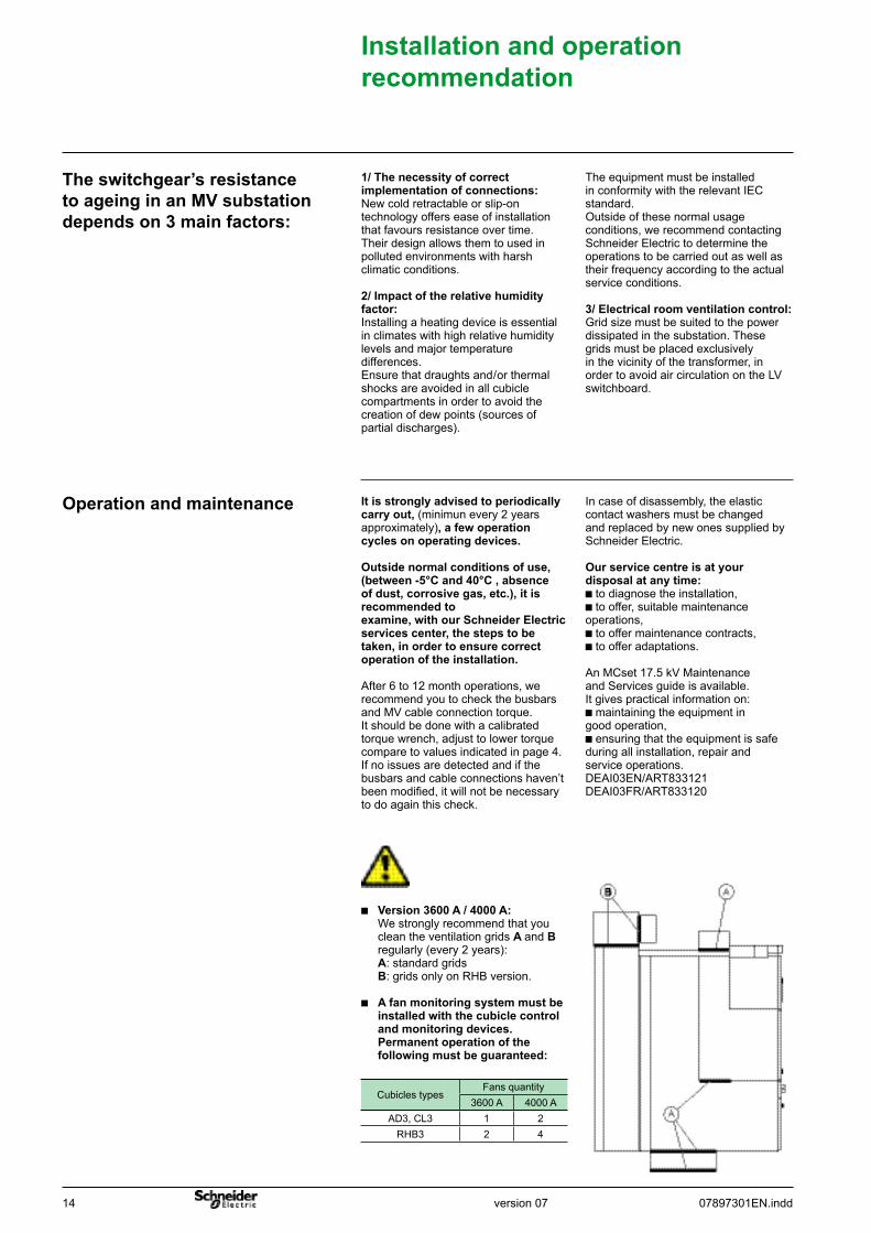
b Version 3600 A / 4000 A: We strongly recommend that you clean the ventilation grids Aand B regularly (every 2 years): A: standard grids B: grids only on RHB version.
b Afanmonitoringsystemmustbe installedwiththecubiclecontrol andmonitoringdevices. Permanentoperationofthe followingmustbeguaranteed:
Cubicles typesFans quantity
3600 A 4000 AAD3, CL3 1 2
RHB3 2 4
version 0707897301EN.indd 15
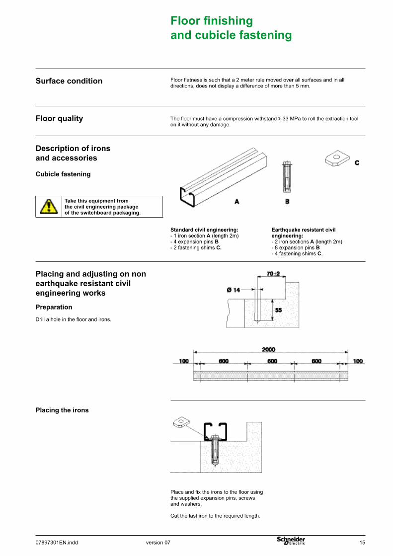
Descriptionofironsandaccessories
The floor must have a compression withstand u 33 MPa to roll the extraction tool on it without any damage.
Floorquality
Floor flatness is such that a 2 meter rule moved over all surfaces and in all directions, does not display a difference of more than 5 mm.
Surfacecondition
Placingandadjustingonnonearthquakeresistantcivilengineeringworks
Earthquakeresistantcivilengineering:- 2 iron sectionsA (length 2m) - 8 expansion pins B - 4 fastening shims C.
Standardcivilengineering:- 1 iron section A (length 2m)- 4 expansion pins B - 2 fastening shims C.
Cubiclefastening
Preparation
Drill a hole in the floor and irons.
Floor finishing andcubiclefastening
Place and fix the irons to the floor using the supplied expansion pins, screws and washers.
Cut the last iron to the required length.
Placingtheirons
Takethisequipmentfromthecivilengineeringpackageoftheswitchboardpackaging.
16 07897301EN.inddversion 07
Floor finishing andcubiclefastening
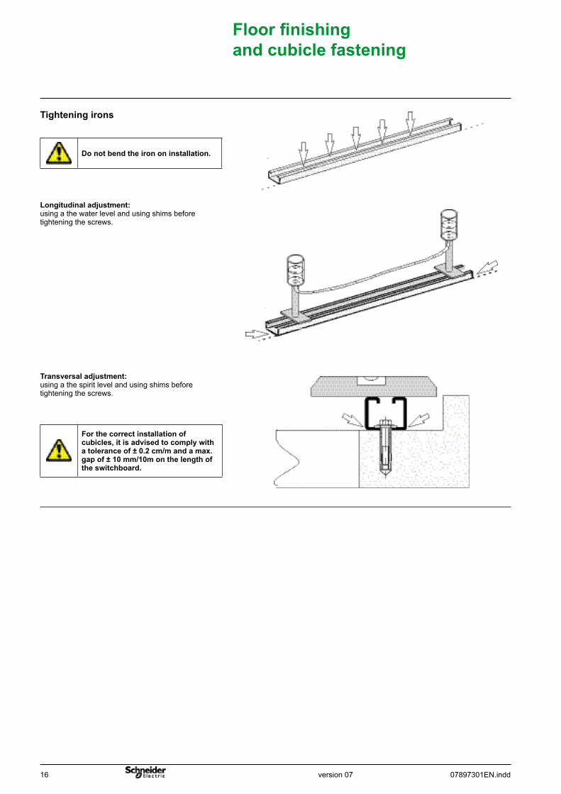
Transversaladjustment: using a the spirit level and using shims before tightening the screws.
Longitudinaladjustment: using a the water level and using shims before tightening the screws.
Tighteningirons
Donotbendtheirononinstallation.
Forthecorrectinstallationofcubicles,itisadvisedtocomplywitha tolerance of ± 0.2 cm/m and a max. gap of ± 10 mm/10m on the length of theswitchboard.
version 0707897301EN.indd 17
Floor finishing andcubiclefastening
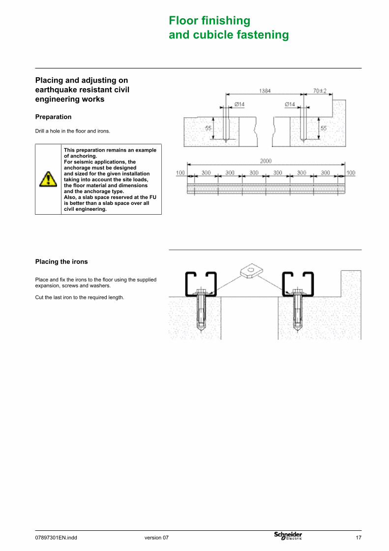
Place and fix the irons to the floor using the supplied expansion, screws and washers.
Cut the last iron to the required length.
Placingtheirons
Preparation
Drill a hole in the floor and irons.
Placingandadjustingonearthquakeresistantcivilengineeringworks
Thispreparationremainsanexampleofanchoring.Forseismicapplications,theanchoragemustbedesignedandsizedforthegiveninstallationtakingintoaccountthesiteloads,thefloormaterialanddimensionsandtheanchoragetype.Also,aslabspacereservedattheFUisbetterthanaslabspaceoverallcivilengineering.
18 07897301EN.inddversion 07
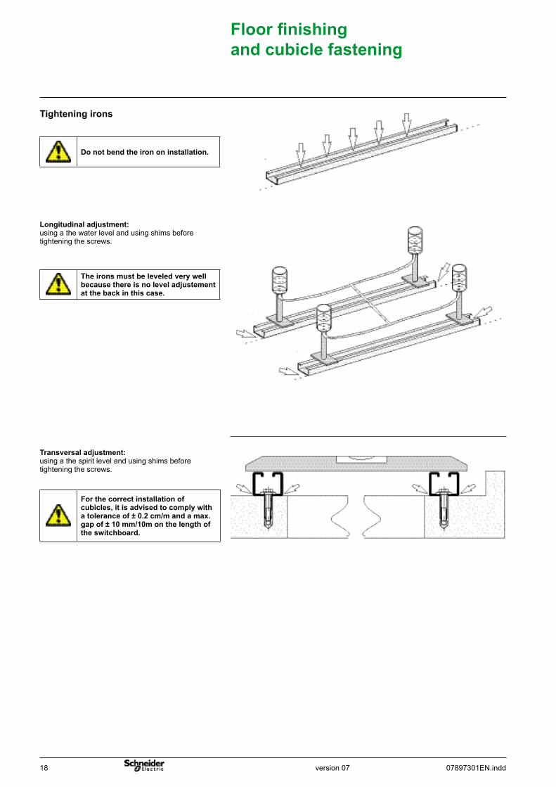
Transversaladjustment: using a the spirit level and using shims before tightening the screws.
Longitudinaladjustment: using a the water level and using shims before tightening the screws.
Tighteningirons
Floor finishing andcubiclefastening
Donotbendtheirononinstallation.
Forthecorrectinstallationofcubicles,itisadvisedtocomplywitha tolerance of ± 0.2 cm/m and a max. gap of ± 10 mm/10m on the length of theswitchboard.
Theironsmustbeleveledverywellbecausethereisnoleveladjustementatthebackinthiscase.
version 0707897301EN.indd 19
Installationinstructions
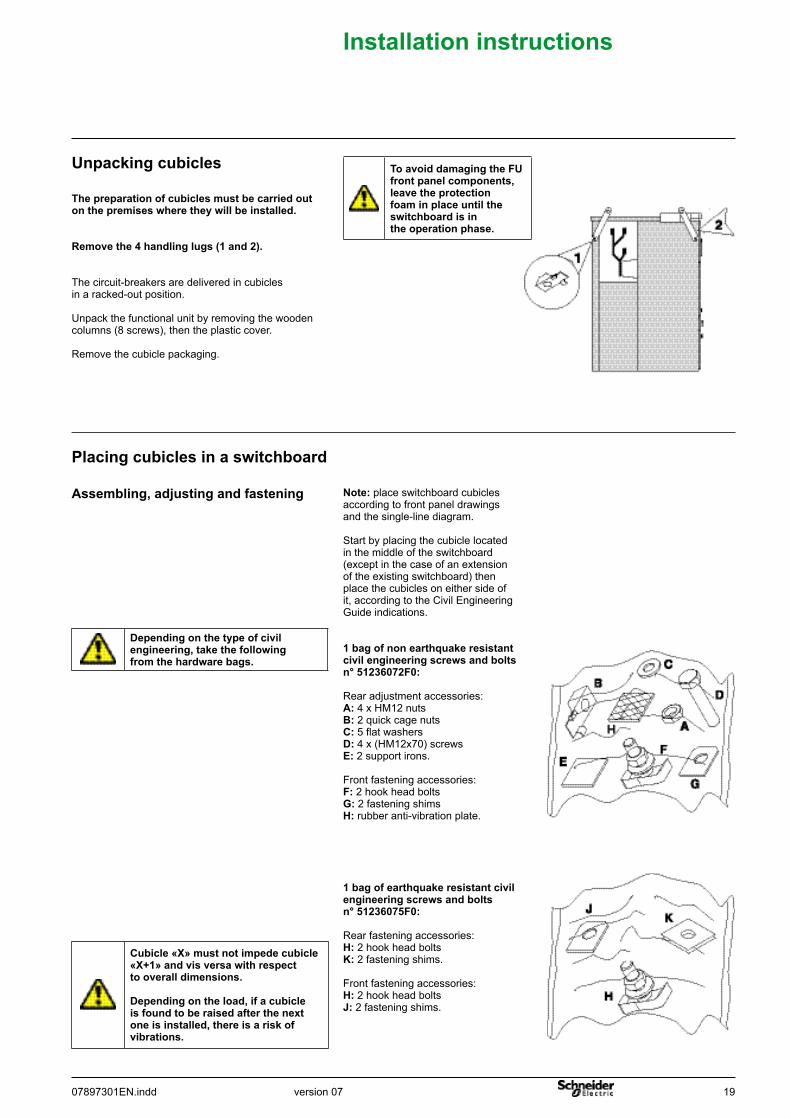
Assembling,adjustingandfastening
Placingcubiclesinaswitchboard
Thepreparationofcubiclesmustbecarriedoutonthepremiseswheretheywillbeinstalled.
Removethe4handlinglugs(1and2).
The circuit-breakers are delivered in cubicles in a racked-out position.
Unpack the functional unit by removing the wooden columns (8 screws), then the plastic cover.
Remove the cubicle packaging.
Unpackingcubicles
Note: place switchboard cubicles according to front panel drawings and the single-line diagram.
Start by placing the cubicle located in the middle of the switchboard (except in the case of an extension of the existing switchboard) then place the cubicles on either side of it, according to the Civil Engineering Guide indications.
1bagofnonearthquakeresistantcivilengineeringscrewsandboltsn°51236072F0:
Rear adjustment accessories:A: 4 x HM12 nuts B: 2 quick cage nuts C: 5 flat washers D: 4 x (HM12x70) screws E: 2 support irons.
Front fastening accessories:F: 2 hook head bolts G: 2 fastening shimsH: rubber anti-vibration plate.
1bagofearthquakeresistantcivilengineeringscrewsandboltsn°51236075F0:
Rear fastening accessories:H: 2 hook head bolts K: 2 fastening shims.
Front fastening accessories:H: 2 hook head bolts J: 2 fastening shims.
ToavoiddamagingtheFUfrontpanelcomponents,leavetheprotectionfoaminplaceuntiltheswitchboardisintheoperationphase.
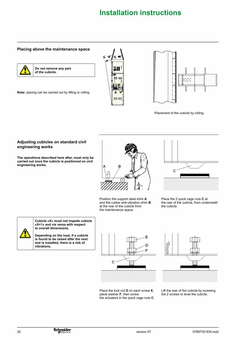
Cubicle «X» must not impede cubicle «X+1» and vis versa with respect tooveralldimensions.
Dependingontheload,ifacubicleisfoundtoberaisedafterthenextoneisinstalled,thereisariskofvibrations.
Dependingonthetypeofcivilengineering,takethefollowingfromthehardwarebags.
20 07897301EN.inddversion 07
Lift the rear of the cubicle by screwing the 2 screws to level the cubicle.
Place the lock nut D on each screw E,place washer F, then screw the actuators in the quick cage nuts C.
Place the 2 quick cage nuts C at the rear of the cubicle, from underneath the cubicle.
Position the support steel shim A and the rubber anti-vibration shimBat the rear of the cubicle from the maintenance space.
Theoperationsdescribedhereafter,mustonlybecarriedoutoncethecubicleispositionedoncivilengineeringworks.
Adjustingcubiclesonstandardcivilengineeringworks
Placement of the cubicle by rolling.
Note: placing can be carried out by lifting or rolling.
Placingabovethemaintenancespace
Installationinstructions
Donotremoveanypartofthecubicle.
Cubicle «X» must not impede cubicle «X+1» and vis versa with respect tooveralldimensions.
Dependingontheload,ifacubicleisfoundtoberaisedafterthenextoneisinstalled,thereisariskofvibrations.
version 0707897301EN.indd 21
Installationinstructions
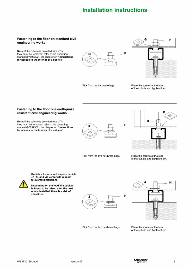
Place the screws at the front of the cubicle and tighten them.
Pick from the two hardware bags.
Place the screws at the rear of the cubicle and tighten them.
Pick from the two hardware bags.
Note: if the cubicle is provided with VT’s, they must be removed, refer to the operating manual (07897302), the chapter on “Instructionsforaccesstotheinteriorofacubicle”.
Fasteningtotheflooroneearthquakeresistantcivilengineeringworks
Place the screws at the front of the cubicle and tighten them.
Pick from the hardware bag.
Note: if the cubicle is provided with VT’s, they must be removed, refer to the operating manual (07897302), the chapter on “Instructionsforaccesstotheinteriorofacubicle”.
Fasteningtotheflooronstandardcivilengineeringworks
Cubicle «X» must not impede cubicle «X+1» and vis versa with respect tooveralldimensions.
Dependingontheload,ifacubicleisfoundtoberaisedafterthenextoneisinstalled,thereisariskofvibrations.
22 07897301EN.inddversion 07
Installationinstructions
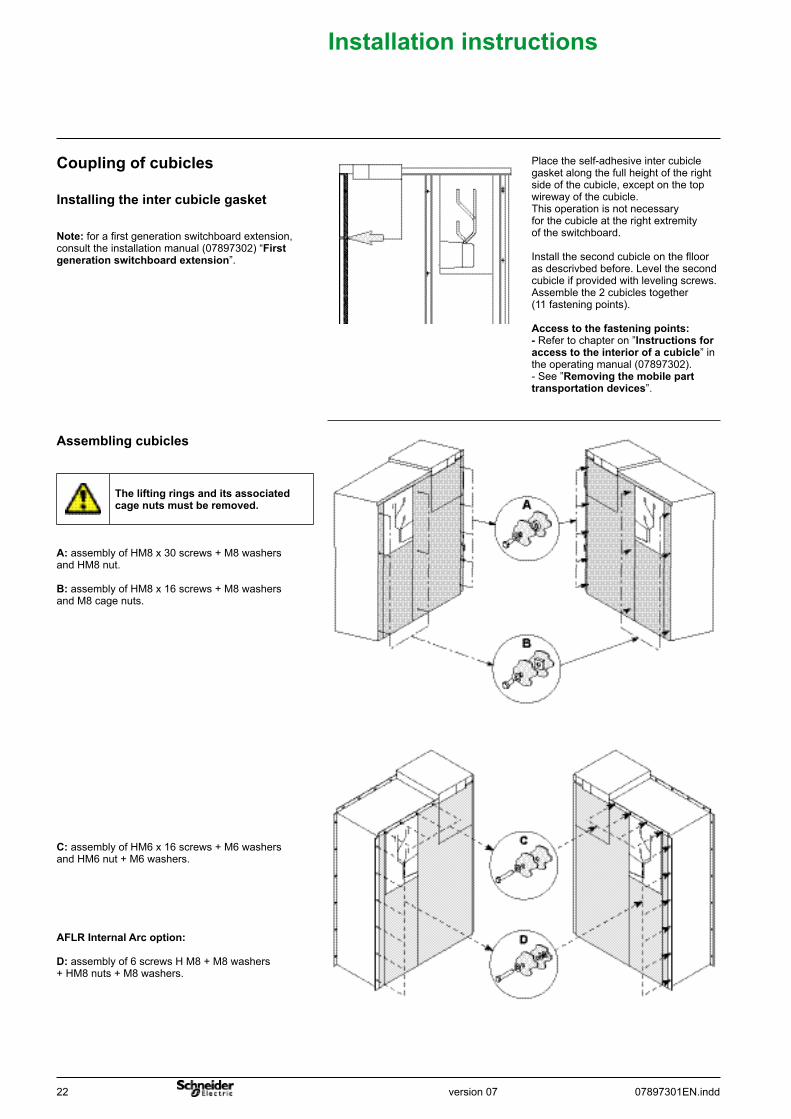
Assemblingcubicles
Place the self-adhesive inter cubicle gasket along the full height of the right side of the cubicle, except on the top wireway of the cubicle.This operation is not necessary for the cubicle at the right extremity of the switchboard.
Install the second cubicle on the flloor as descrivbed before. Level the second cubicle if provided with leveling screws. Assemble the 2 cubicles together (11 fastening points).
Accesstothefasteningpoints:-Refer to chapter on ”Instructionsforaccesstotheinteriorofacubicle” in the operating manual (07897302).- See ”Removingthemobileparttransportationdevices”.
Note: for a first generation switchboard extension, consult the installation manual (07897302) “Firstgenerationswitchboardextension”.
Installingtheintercubiclegasket
Couplingofcubicles
C: assembly of HM6 x 16 screws + M6 washers and HM6 nut + M6 washers.
A: assembly of HM8 x 30 screws + M8 washers and HM8 nut.
B:assembly of HM8 x 16 screws + M8 washers and M8 cage nuts.
Theliftingringsanditsassociatedcagenutsmustberemoved.
AFLRInternalArcoption:
D: assembly of 6 screws H M8 + M8 washers + HM8 nuts + M8 washers.
version 0707897301EN.indd 23
Installationinstructions
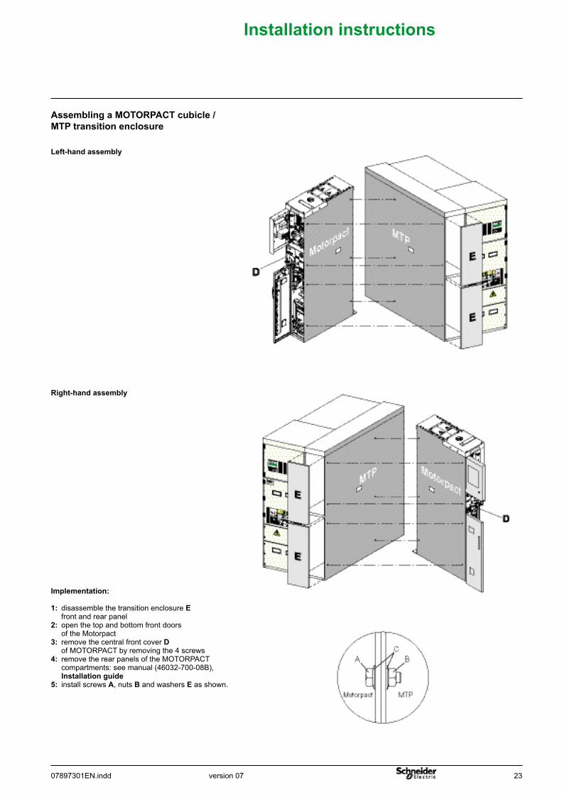
Assembling a MOTORPACT cubicle / MTPtransitionenclosure
Left-handassembly
Right-handassembly
Implementation:
1: disassemble the transition enclosure E front and rear panel2: open the top and bottom front doors of the Motorpact3: remove the central front cover D of MOTORPACT by removing the 4 screws4: remove the rear panels of the MOTORPACT compartments: see manual (46032-700-08B), Installationguide5: install screws A, nuts B and washers E as shown.
24 07897301EN.inddversion 07
Installationinstructions
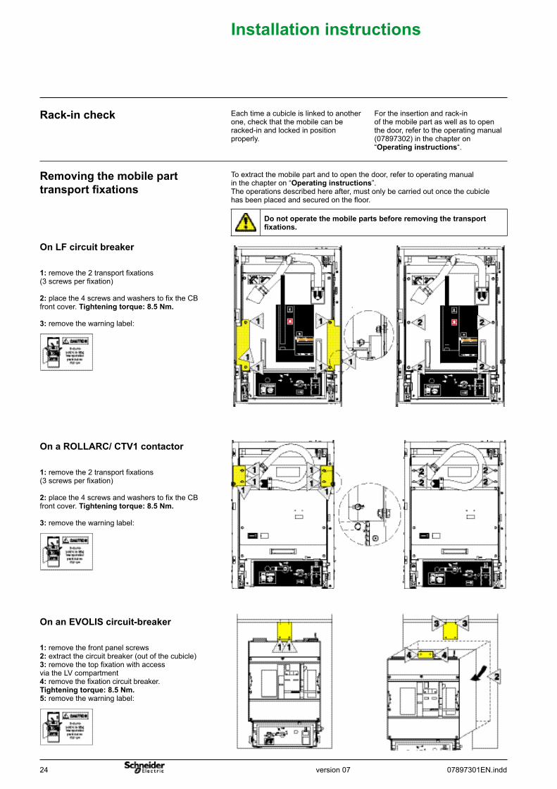
1: remove the 2 transport fixations(3 screws per fixation)
2: place the 4 screws and washers to fix the CB front cover. Tighteningtorque:8.5Nm.
3: remove the warning label:
To extract the mobile part and to open the door, refer to operating manual in the chapter on “Operatinginstructions”.The operations described here after, must only be carried out once the cubicle has been placed and secured on the floor.
Removingthemobileparttransport fixations
1: remove the 2 transport fixations(3 screws per fixation)
2: place the 4 screws and washers to fix the CB front cover. Tighteningtorque:8.5Nm.
3: remove the warning label:
1: remove the front panel screws2: extract the circuit breaker (out of the cubicle)3: remove the top fixation with access via the LV compartment4: remove the fixation circuit breaker.Tighteningtorque:8.5Nm.5: remove the warning label:
For the insertion and rack-in of the mobile part as well as to open the door, refer to the operating manual (07897302) in the chapter on“Operatinginstructions“.
Each time a cubicle is linked to another one, check that the mobile can beracked-in and locked in position properly.
Rack-incheck
Donotoperatethemobilepartsbeforeremovingthetransportfixations.
OnLFcircuitbreaker
On a ROLLARC/ CTV1 contactor
OnanEVOLIScircuit-breaker
version 0707897301EN.indd 25
Installingthemainearthconnection
Installationinstructions
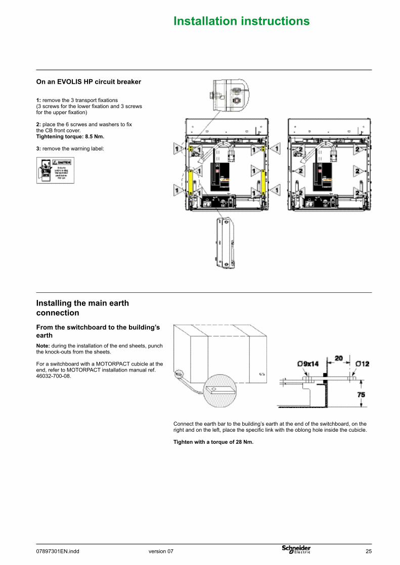
1: remove the 3 transport fixations (3 screws for the lower fixation and 3 screws for the upper fixation)
2: place the 6 scrwes and washers to fix the CB front cover.Tighteningtorque:8.5Nm.
3: remove the warning label:
OnanEVOLISHPcircuitbreaker
Connect the earth bar to the building’s earth at the end of the switchboard, on the right and on the left, place the specific link with the oblong hole inside the cubicle. Tightenwithatorqueof28Nm.
Note: during the installation of the end sheets, punch the knock-outs from the sheets.
For a switchboard with a MOTORPACT cubicle at the end, refer to MOTORPACT installation manual ref. 46032-700-08.
Fromtheswitchboardtothebuilding’searth
26 07897301EN.inddversion 07
Installationinstructions
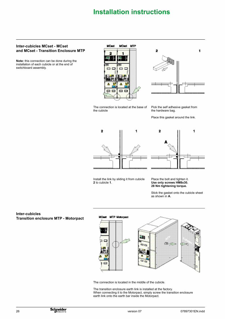
Place the bolt and tighten it. UseonlyscrewsHM8x30. 28Nmtighteningtorque.
Stick the gasket onto the cubicle sheet as shown in A.
Install the link by sliding it from cubicle 2 to cubicle 1.
Pick the self adhesive gasket from the hardware bag.
Place this gasket around the link.
The connection is located at the base of the cubicle
Note: this connection can be done during the installation of each cubicle or at the end of switchboard assembly.
Inter-cubiclesMCset-MCsetandMCset-TransitionEnclosureMTP
Inter-cubiclesTransitionenclosureMTP-Motorpact
The connection is located in the middle of the cubicle.
The transition enclosure earth link is installed at the factory. When connecting it to the Motorpact, simply screw the transition enclosure earth link onto the earth bar inside the Motorpact.
version 0707897301EN.indd 27
Installationinstructions
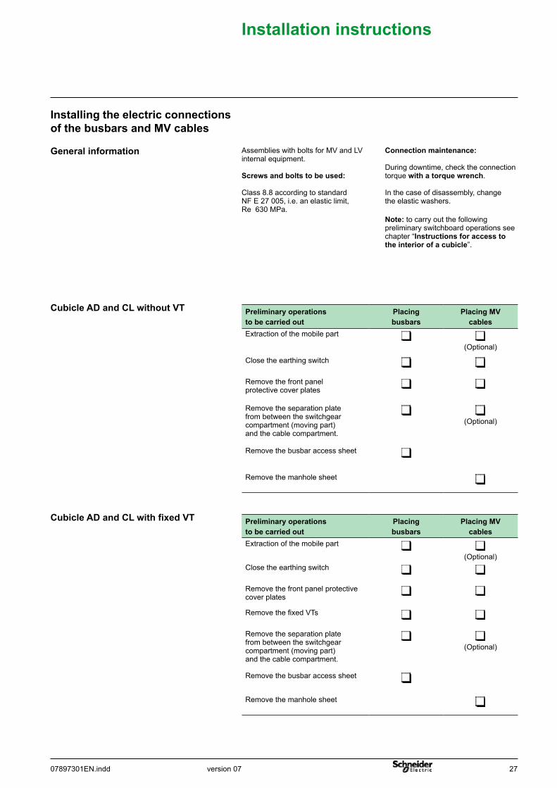
CubicleADandCLwithoutVT
Note: to carry out the following preliminary switchboard operations see chapter “Instructionsforaccesstotheinteriorofacubicle”.
Connectionmaintenance:
During downtime, check the connection torquewithatorquewrench.
In the case of disassembly, change the elastic washers.
Assemblies with bolts for MV and LV internal equipment.
Screwsandboltstobeused:
Class 8.8 according to standard NF E 27 005, i.e. an elastic limit, Re 630 MPa.
Generalinformation
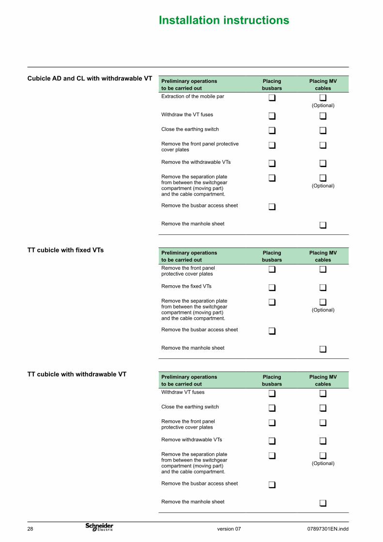
InstallingtheelectricconnectionsofthebusbarsandMVcables
Preliminaryoperationstobecarriedout
Placingbusbars
PlacingMVcables
Extraction of the mobile part (Optional)
Close the earthing switch
Remove the front panel protective cover plates
Remove the separation plate from between the switchgear compartment (moving part) and the cable compartment.
(Optional)
Remove the busbar access sheet
Remove the manhole sheet
Preliminaryoperationstobecarriedout
Placingbusbars
PlacingMVcables
Extraction of the mobile part (Optional)
Close the earthing switch
Remove the front panel protective cover plates
Remove the fixed VTs
Remove the separation plate from between the switchgear compartment (moving part) and the cable compartment.
(Optional)
Remove the busbar access sheet
Remove the manhole sheet
CubicleADandCLwithfixedVT
28 07897301EN.inddversion 07
Installationinstructions
TTcubiclewithwithdrawableVT
TTcubiclewithfixedVTs
CubicleADandCLwithwithdrawableVT Preliminaryoperationstobecarriedout
Placingbusbars
PlacingMVcables
Extraction of the mobile par (Optional)
Withdraw the VT fuses
Close the earthing switch
Remove the front panel protective cover plates
Remove the withdrawable VTs
Remove the separation plate from between the switchgear compartment (moving part) and the cable compartment.
(Optional)
Remove the busbar access sheet
Remove the manhole sheet
Preliminaryoperationstobecarriedout
Placingbusbars
PlacingMVcables
Remove the front panel protective cover plates
Remove the fixed VTs
Remove the separation plate from between the switchgear compartment (moving part) and the cable compartment.
(Optional)
Remove the busbar access sheet
Remove the manhole sheet
Preliminaryoperationstobecarriedout
Placingbusbars
PlacingMVcables
Withdraw VT fuses
Close the earthing switch
Remove the front panel protective cover plates
Remove withdrawable VTs
Remove the separation plate from between the switchgear compartment (moving part) and the cable compartment.
(Optional)
Remove the busbar access sheet
Remove the manhole sheet
version 0707897301EN.indd 29
Installationinstructions
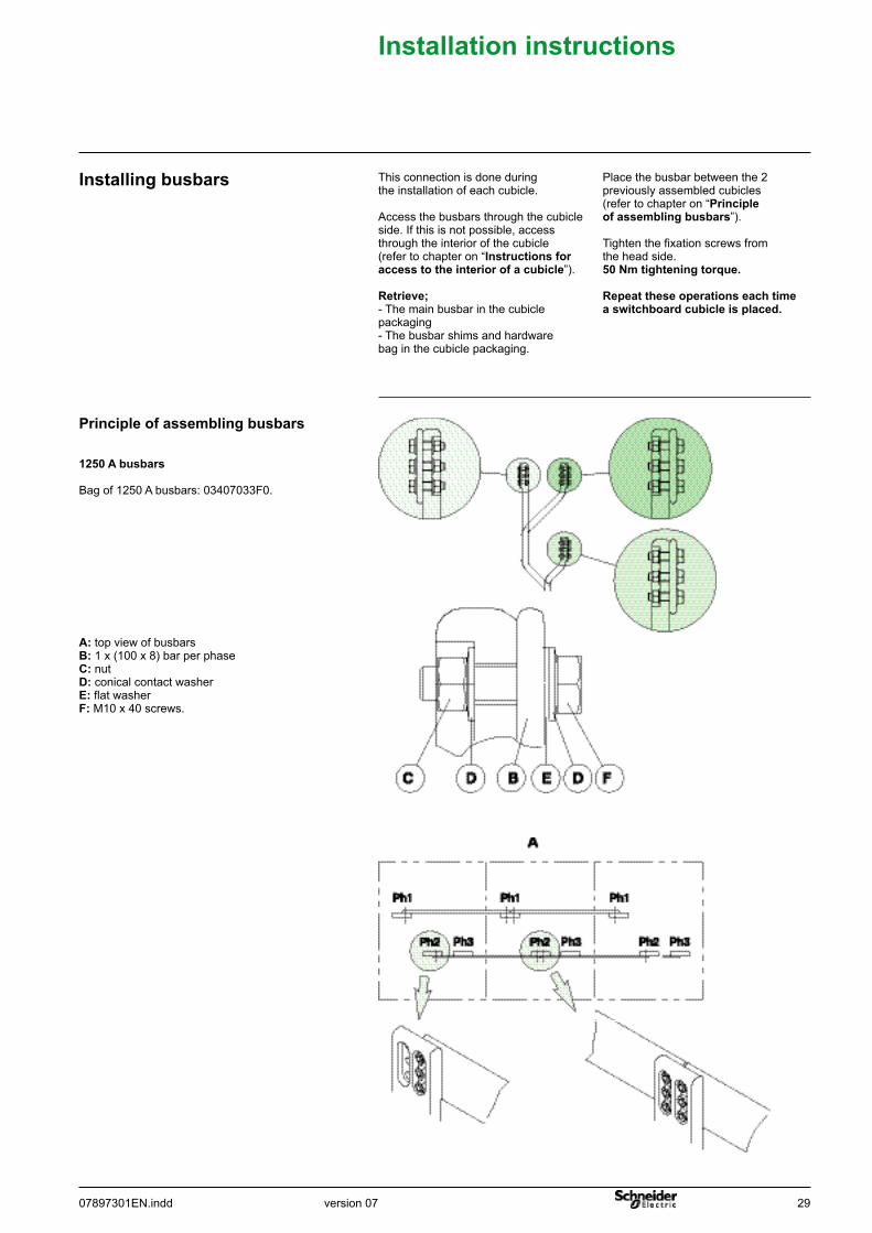
A: top view of busbarsB: 1 x (100 x 8) bar per phase C: nutD: conical contact washerE: flat washer F: M10 x 40 screws.
1250Abusbars
Bag of 1250 A busbars: 03407033F0.
Principleofassemblingbusbars
Place the busbar between the 2 previously assembled cubicles (refer to chapter on “Principleofassemblingbusbars”).
Tighten the fixation screws from the head side.50Nmtighteningtorque.
Repeattheseoperationseachtimeaswitchboardcubicleisplaced.
This connection is done during the installation of each cubicle.
Access the busbars through the cubicle side. If this is not possible, access through the interior of the cubicle (refer to chapter on “Instructionsforaccesstotheinteriorofacubicle”).
Retrieve; - The main busbar in the cubicle packaging- The busbar shims and hardware bag in the cubicle packaging.
Installingbusbars
30 07897301EN.inddversion 07
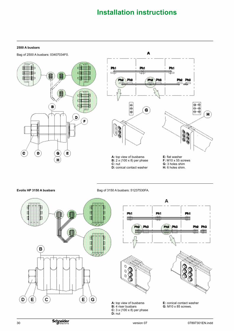
E: flat washerF: M10 x 55 screwsG: 3 holes shim H: 6 holes shim.
A:top view of busbarssB: 2 x (100 x 8) per phaseC: nut D: conical contact washer
2500Abusbars
Bag of 2500 A busbars: 03407034F0.
Installationinstructions
E: conical contact washerG: M10 x 85 screws.
A:top view of busbarssB: 4 riser busbarsC: 3 x (100 x 8) per phase D: nut
EvolisHP3150Abusbars Bag of 3150 A busbars: 51237530FA.
version 0707897301EN.indd 31
Installationinstructions
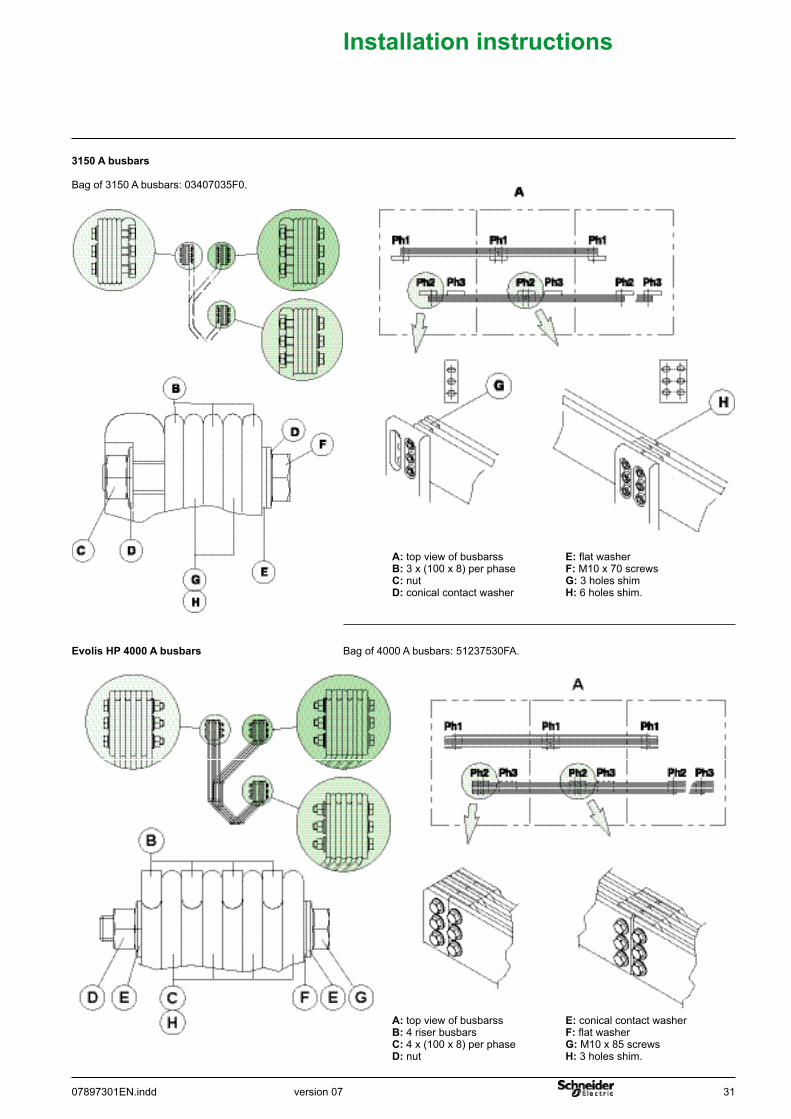
3150Abusbars
Bag of 3150 A busbars: 03407035F0.
E: flat washerF: M10 x 70 screwsG: 3 holes shim H: 6 holes shim.
A:top view of busbarssB: 3 x (100 x 8) per phaseC: nut D: conical contact washer
E: conical contact washerF: flat washerG: M10 x 85 screwsH: 3 holes shim.
A:top view of busbarssB: 4 riser busbarsC: 4 x (100 x 8) per phase D: nut
EvolisHP4000Abusbars Bag of 4000 A busbars: 51237530FA.
32 07897301EN.inddversion 07
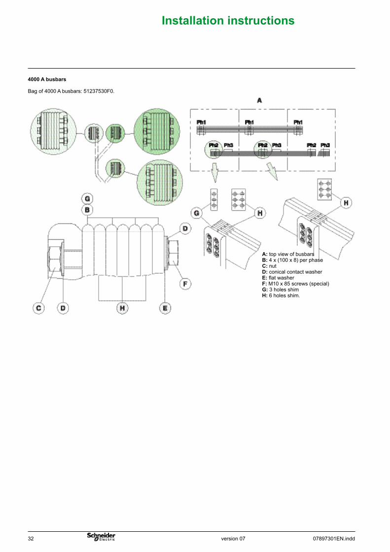
A:top view of busbarsB: 4 x (100 x 8) per phaseC: nut D: conical contact washerE: flat washerF: M10 x 85 screws (special)G: 3 holes shim H: 6 holes shim.
4000Abusbars
Bag of 4000 A busbars: 51237530F0.
Installationinstructions
version 0707897301EN.indd 33
Installationinstructions
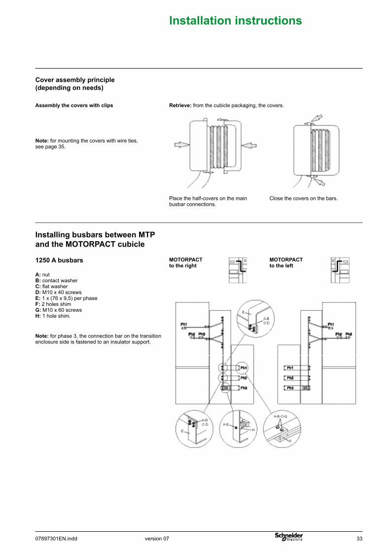
Retrieve: from the cubicle packaging, the covers.
Coverassemblyprinciple(dependingonneeds)
Close the covers on the bars.Place the half-covers on the main busbar connections.
Assemblythecoverswithclips
Note: for mounting the covers with wire ties, see page 35.
InstallingbusbarsbetweenMTPandtheMOTORPACTcubicle
1250Abusbars MOTORPACTtotheright
MOTORPACTtotheleft
A: nutB: contact washerC: flat washerD: M10 x 40 screwsE: 1 x (76 x 9,5) per phaseF: 2 holes shimG: M10 x 60 screwsH: 1 hole shim.
Note: for phase 3, the connection bar on the transition enclosure side is fastened to an insulator support.
34 07897301EN.inddversion 07
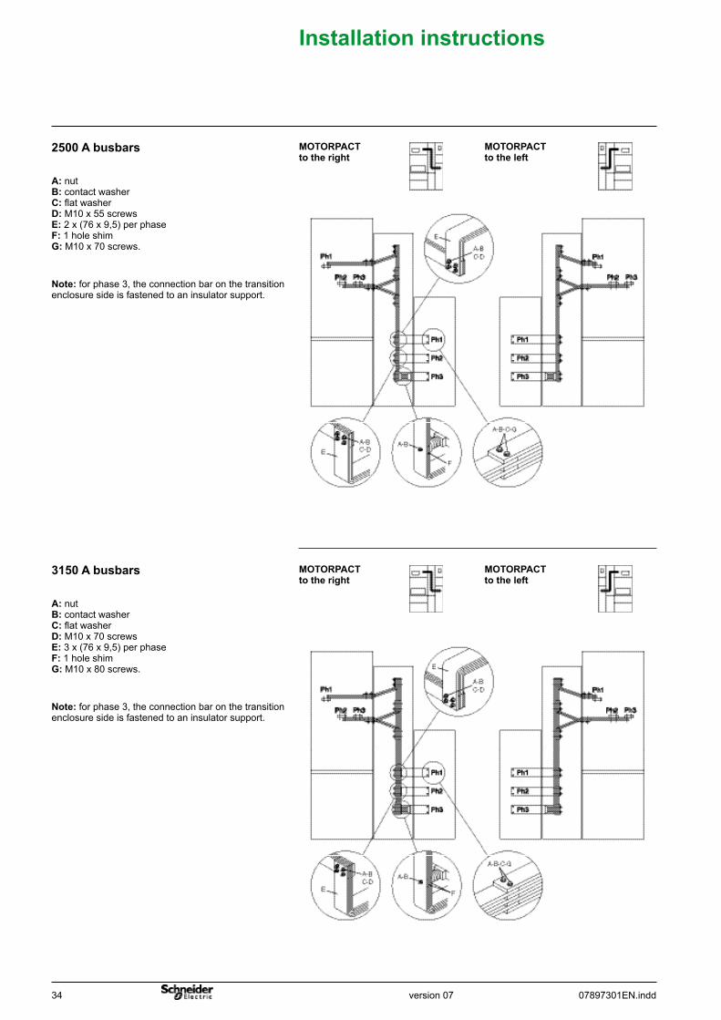
2500Abusbars
Installationinstructions
A: nutB: contact washerC: flat washerD: M10 x 55 screwsE: 2 x (76 x 9,5) per phaseF: 1 hole shimG: M10 x 70 screws.
Note: for phase 3, the connection bar on the transition enclosure side is fastened to an insulator support.
MOTORPACTtotheright
MOTORPACTtotheleft
3150Abusbars
A: nutB: contact washerC: flat washerD: M10 x 70 screwsE: 3 x (76 x 9,5) per phaseF: 1 hole shimG: M10 x 80 screws.
Note: for phase 3, the connection bar on the transition enclosure side is fastened to an insulator support.
MOTORPACTtotheright
MOTORPACTtotheleft
version 0707897301EN.indd 35
Installationinstructions
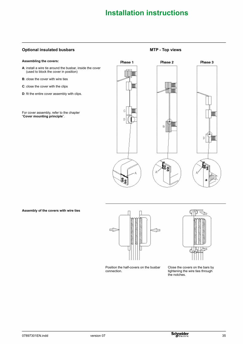
Optionalinsulatedbusbars
For cover assembly, refer to the chapter “Covermountingprinciple”.
MTP-Topviews
Assemblingthecovers:
A: install a wire tie around the busbar, inside the cover (used to block the cover in position)
B: close the cover with wire ties
C: close the cover with the clips
D: fit the entire cover assembly with clips.
Close the covers on the bars by tightening the wire ties through the notches.
Assemblyofthecoverswithwireties
Position the half-covers on the busbar connection.
36 07897301EN.inddversion 07
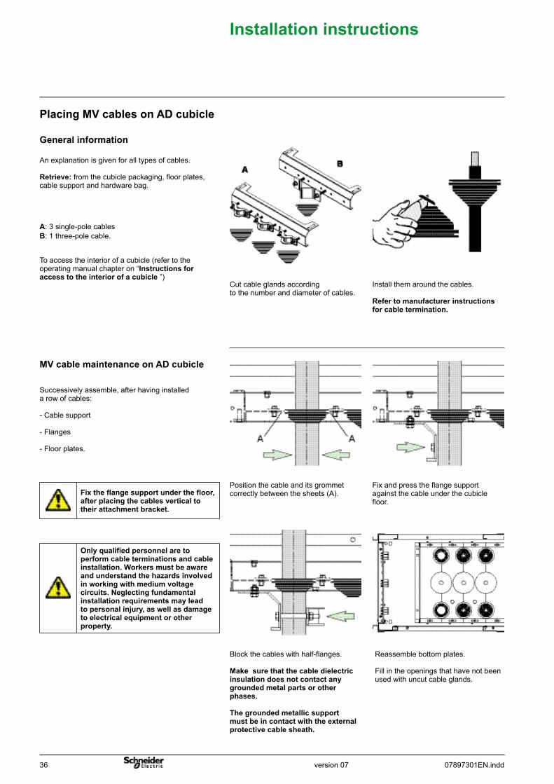
Successively assemble, after having installed a row of cables:
- Cable support
- Flanges
- Floor plates.
MVcablemaintenanceonADcubicle
To access the interior of a cubicle (refer to the operating manual chapter on “Instructionsforaccesstotheinteriorofacubicle ”)
A: 3 single-pole cablesB: 1 three-pole cable.
An explanation is given for all types of cables.
Retrieve: from the cubicle packaging, floor plates, cable support and hardware bag.
Generalinformation
PlacingMVcablesonADcubicle
Install them around the cables.
Refertomanufacturerinstructionsforcabletermination.
Cut cable glands according to the number and diameter of cables.
Installationinstructions
Fixtheflangesupportunderthefloor,afterplacingthecablesverticaltotheirattachmentbracket.
Reassemble bottom plates.
Fill in the openings that have not been used with uncut cable glands.
Position the cable and its grommet correctly between the sheets (A).
Fix and press the flange support against the cable under the cubicle floor.
Block the cables with half-flanges.
Makesurethatthecabledielectricinsulationdoesnotcontactanygroundedmetalpartsorotherphases.
Thegroundedmetallicsupportmustbeincontactwiththeexternalprotectivecablesheath.
Onlyqualifiedpersonnelaretoperformcableterminationsandcableinstallation.Workersmustbeawareandunderstandthehazardsinvolvedinworkingwithmediumvoltagecircuits.Neglectingfundamentalinstallationrequirementsmayleadtopersonalinjury,aswellasdamagetoelectricalequipmentorotherproperty.
version 0707897301EN.indd 37
Installationinstructions
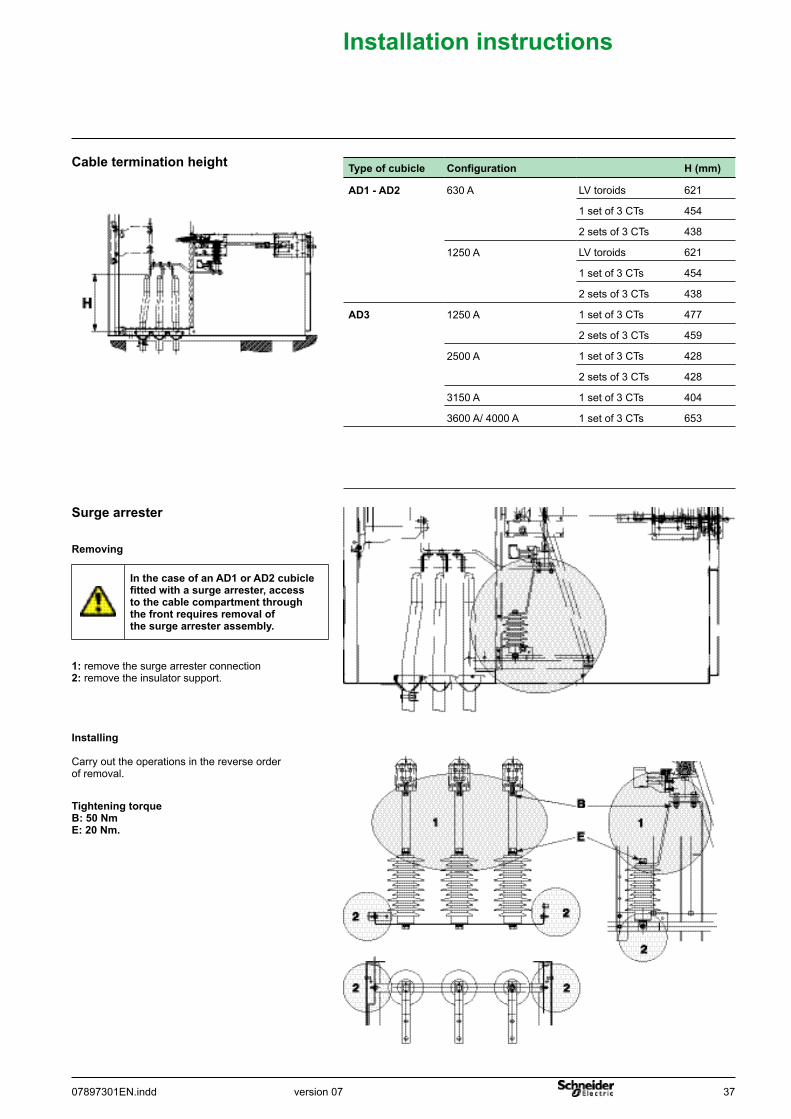
TighteningtorqueB:50NmE:20Nm.
Removing
Surgearrester
Cableterminationheight
Installing
Carry out the operations in the reverse order of removal.
Typeofcubicle Configuration H(mm)
AD1-AD2 630 A LV toroids 621
1 set of 3 CTs 454
2 sets of 3 CTs 438
1250 A LV toroids 621
1 set of 3 CTs 454
2 sets of 3 CTs 438
AD3 1250 A 1 set of 3 CTs 477
2 sets of 3 CTs 459
2500 A 1 set of 3 CTs 428
2 sets of 3 CTs 428
3150 A 1 set of 3 CTs 404
3600 A/ 4000 A 1 set of 3 CTs 653
1: remove the surge arrester connection2: remove the insulator support.
InthecaseofanAD1orAD2cubiclefittedwithasurgearrester,accesstothecablecompartmentthroughthefrontrequiresremovalofthesurgearresterassembly.
38 07897301EN.inddversion 07
Installationinstructions
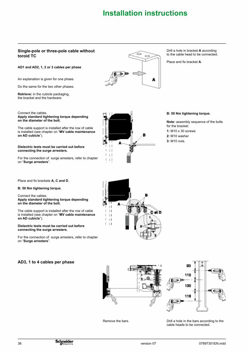
Drill a hole in the bars according to the cable heads to be connected.
Remove the bars.
AD3,1to4cablesperphase
B:50Nmtighteningtorque.
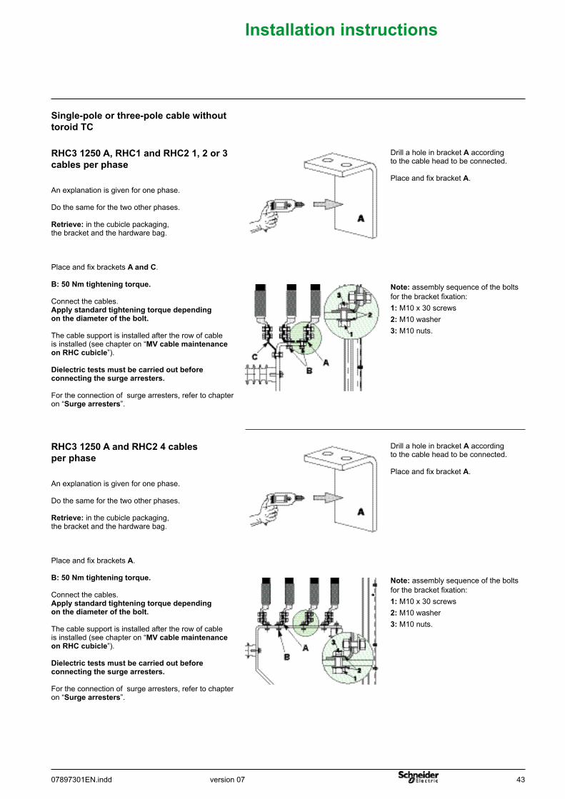
Note: assembly sequence of the bolts for the bracket: 1: M10 x 30 screws2: M10 washer 3: M10 nuts.
Drill a hole in bracket A according to the cable head to be connected.
Place and fix bracket A.
An explanation is given for one phase.
Do the same for the two other phases.
Retrieve: in the cubicle packaging, the bracket and the hardware.
Connect the cables.Applystandardtighteningtorquedependingonthediameterofthebolt.
The cable support is installed after the row of cable is installed (see chapter on “MVcablemaintenanceonADcubicle”).
Dielectrictestsmustbecarriedoutbeforeconnectingthesurgearresters.
For the connection of surge arresters, refer to chapter on “Surgearresters”.
Place and fix brackets A,CandD.
B:50Nmtighteningtorque.
Connect the cables.Applystandardtighteningtorquedependingonthediameterofthebolt.
The cable support is installed after the row of cable is installed (see chapter on “MVcablemaintenanceonADcubicle”).
Dielectrictestsmustbecarriedoutbeforeconnectingthesurgearresters.
For the connection of surge arresters, refer to chapter on “Surgearresters”.
AD1andAD2,1,2or3cablesperphase
Single-poleorthree-polecablewithouttoroidTC
version 0707897301EN.indd 39
Installationinstructions
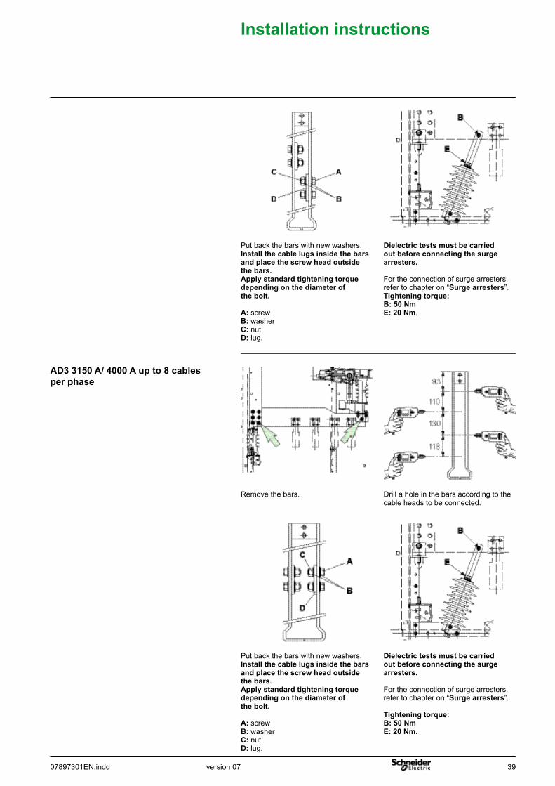
Put back the bars with new washers. Installthecablelugsinsidethebarsandplacethescrewheadoutsidethebars.Applystandardtighteningtorquedependingonthediameterofthebolt.
A: screwB: washerC: nutD: lug.
Dielectrictestsmustbecarriedoutbeforeconnectingthesurgearresters.
For the connection of surge arresters, refer to chapter on “Surgearresters”.Tighteningtorque:B:50NmE:20Nm.
Put back the bars with new washers. Installthecablelugsinsidethebarsandplacethescrewheadoutsidethebars.Applystandardtighteningtorquedependingonthediameterofthebolt.
A: screwB: washerC: nutD: lug.
Dielectrictestsmustbecarriedoutbeforeconnectingthesurgearresters.
For the connection of surge arresters, refer to chapter on “Surgearresters”.
Tighteningtorque:B:50NmE:20Nm.
Drill a hole in the bars according to the cable heads to be connected.
Remove the bars.
AD3 3150 A/ 4000 A up to 8 cables perphase
40 07897301EN.inddversion 07
Installationinstructions
Connect the cables on the link.
Applystandardtighteningtorquedependingonthediameterofthebolt.
The cable support is installed after the row of cable is installed (see chapter on “MVcablemaintenanceonADcubicle”).
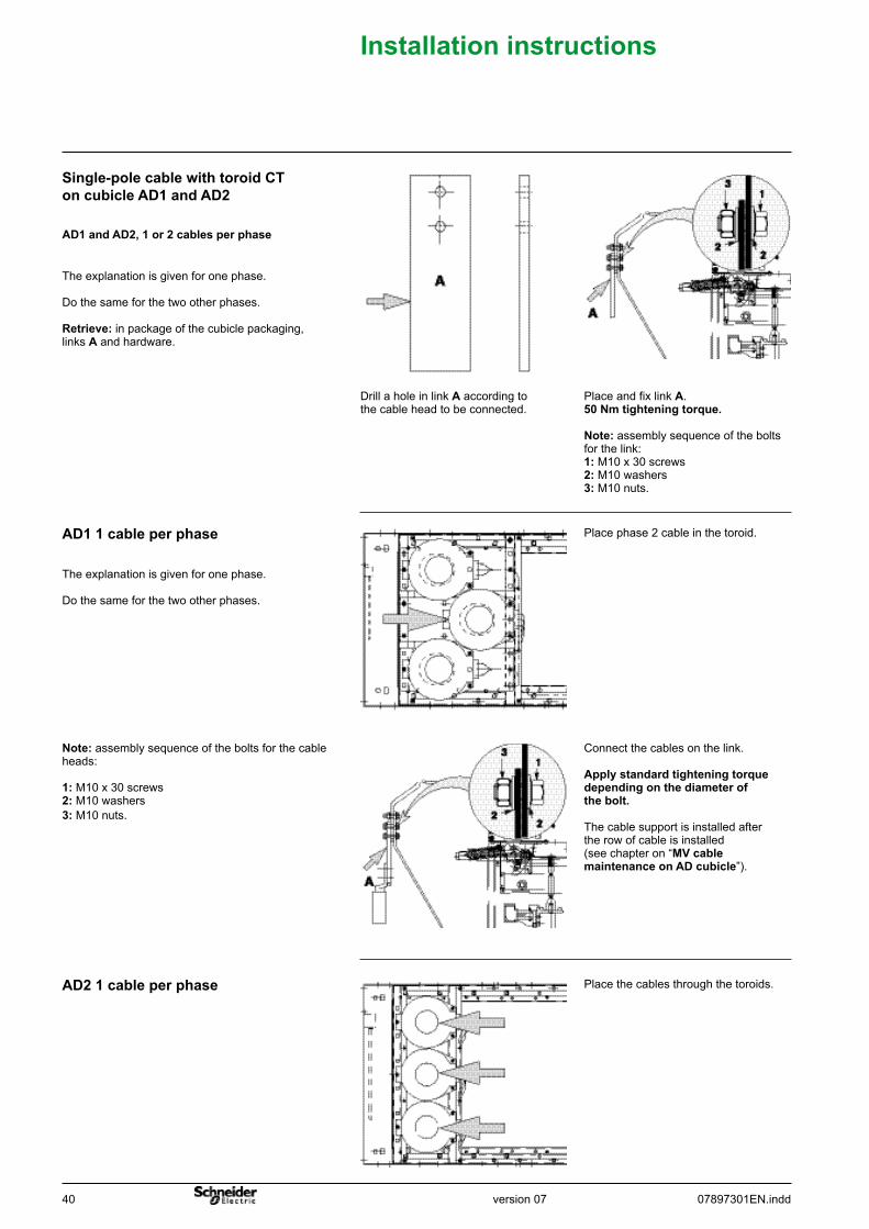
Note:assembly sequence of the bolts for the cable heads:
1: M10 x 30 screws2: M10 washers3: M10 nuts.
Place phase 2 cable in the toroid.
The explanation is given for one phase.
Do the same for the two other phases.
AD11cableperphase
Place and fix link A. 50Nmtighteningtorque.
Note: assembly sequence of the bolts for the link:1: M10 x 30 screws2: M10 washers3: M10 nuts.
Drill a hole in link A according to the cable head to be connected.
The explanation is given for one phase.
Do the same for the two other phases.
Retrieve: in package of the cubicle packaging,links A and hardware.
AD1andAD2,1or2cablesperphase
Single-polecablewithtoroidCToncubicleAD1andAD2
Place the cables through the toroids.AD21cableperphase
version 0707897301EN.indd 41
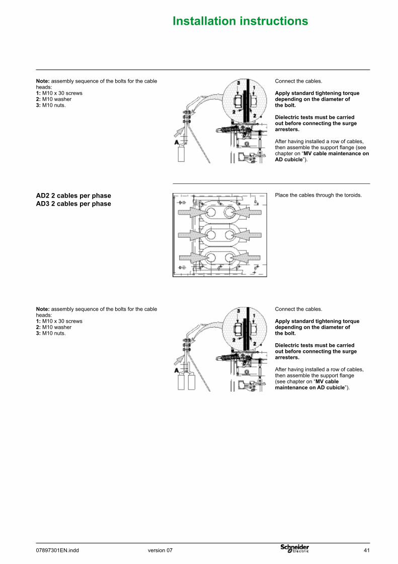
Note: assembly sequence of the bolts for the cable heads:1: M10 x 30 screws2: M10 washer3: M10 nuts.
Connect the cables.
Applystandardtighteningtorquedependingonthediameterofthebolt.
Dielectrictestsmustbecarriedoutbeforeconnectingthesurgearresters.
After having installed a row of cables, then assemble the support flange (see chapter on “MVcablemaintenanceonADcubicle”).
Installationinstructions
Place the cables through the toroids.AD22cablesperphaseAD32cablesperphase
Note: assembly sequence of the bolts for the cable heads:1: M10 x 30 screws2: M10 washer3: M10 nuts.
Connect the cables.
Applystandardtighteningtorquedependingonthediameterofthebolt.
Dielectrictestsmustbecarriedoutbeforeconnectingthesurgearresters.
After having installed a row of cables, then assemble the support flange (see chapter on “MVcablemaintenanceonADcubicle”).
42 07897301EN.inddversion 07
Installationinstructions
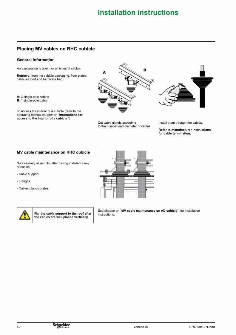
Successively assemble, after having installed a row of cables:
- Cable support
- Flanges
- Cables glands plates.
MVcablemaintenanceonRHCcubicle
To access the interior of a cubicle (refer to the operating manual chapter on “Instructionsforaccesstotheinteriorofacubicle ”)
A: 3 single-pole cablesB: 1 single-pole cable.
An explanation is given for all types of cables.
Retrieve: from the cubicle packaging, floor plates, cable support and hardware bag.
Generalinformation
PlacingMVcablesonRHCcubicle
Install them through the cables.
Refertomanufacturerinstructionsforcabletermination.
Cut cable glands according to the number and diameter of cables.
Fixthecablesupporttotheroofafterthecablesarewellplacedvertically.
See chapter on “MVcablemaintenanceonADcubicle”) for installation instructions.
version 0707897301EN.indd 43
Installationinstructions
Note: assembly sequence of the bolts for the bracket fixation: 1: M10 x 30 screws2: M10 washer 3: M10 nuts.
Drill a hole in bracket A according to the cable head to be connected.
Place and fix bracket A.An explanation is given for one phase.
Do the same for the two other phases.
Retrieve: in the cubicle packaging, the bracket and the hardware bag.
Place and fix brackets AandC.
B:50Nmtighteningtorque.
Connect the cables.Applystandardtighteningtorquedependingonthediameterofthebolt.
The cable support is installed after the row of cable is installed (see chapter on “MVcablemaintenanceonRHCcubicle”).
Dielectrictestsmustbecarriedoutbeforeconnectingthesurgearresters.
For the connection of surge arresters, refer to chapter on “Surgearresters”.
Single-poleorthree-polecablewithouttoroidTC
RHC31250A,RHC1andRHC21,2or3cablesperphase
An explanation is given for one phase.
Do the same for the two other phases.
Retrieve: in the cubicle packaging, the bracket and the hardware bag.
Place and fix brackets A.
B:50Nmtighteningtorque.
Connect the cables.Applystandardtighteningtorquedependingonthediameterofthebolt.
The cable support is installed after the row of cable is installed (see chapter on “MVcablemaintenanceonRHCcubicle”).
Dielectrictestsmustbecarriedoutbeforeconnectingthesurgearresters.
For the connection of surge arresters, refer to chapter on “Surgearresters”.
RHC31250AandRHC24cablesperphase
Note: assembly sequence of the bolts for the bracket fixation: 1: M10 x 30 screws2: M10 washer 3: M10 nuts.
Drill a hole in bracket A according to the cable head to be connected.
Place and fix bracket A.
44 07897301EN.inddversion 07
Installationinstructions
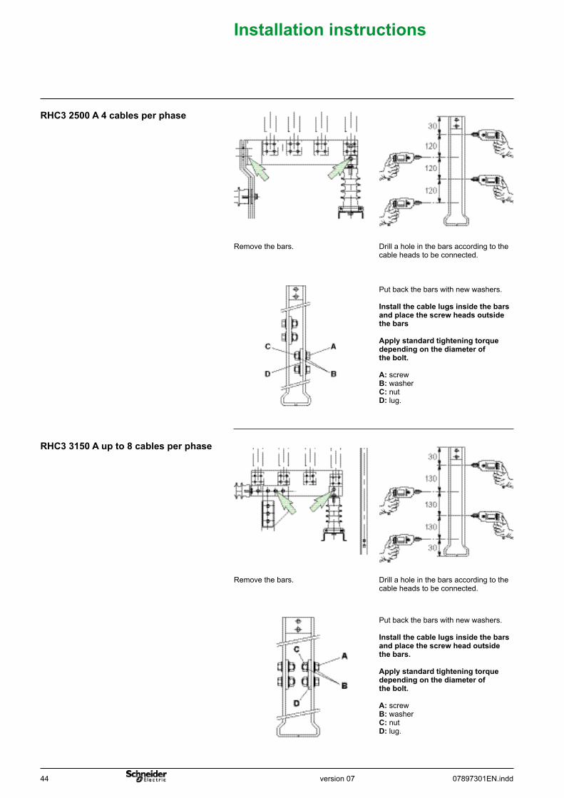
Put back the bars with new washers.
Installthecablelugsinsidethebarsandplacethescrewheadsoutsidethebars
Applystandardtighteningtorquedependingonthediameterofthebolt.
A: screwB: washerC: nutD: lug.
Drill a hole in the bars according to the cable heads to be connected.
Remove the bars.
RHC32500A4cablesperphase
RHC33150Aupto8cablesperphase
Put back the bars with new washers.
Installthecablelugsinsidethebarsandplacethescrewheadoutsidethebars.
Applystandardtighteningtorquedependingonthediameterofthebolt.
A: screwB: washerC: nutD: lug.
Drill a hole in the bars according to the cable heads to be connected.
Remove the bars.
version 0707897301EN.indd 45
Installationinstructions
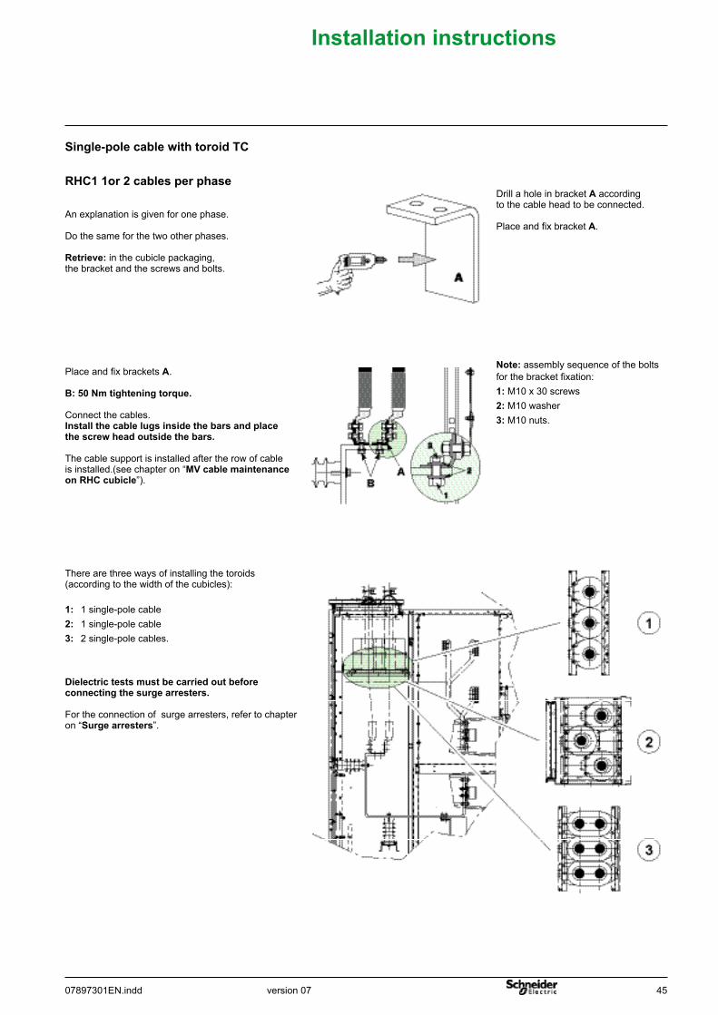
Note: assembly sequence of the bolts for the bracket fixation: 1: M10 x 30 screws2: M10 washer 3: M10 nuts.
Drill a hole in bracket A according to the cable head to be connected.
Place and fix bracket A.An explanation is given for one phase.
Do the same for the two other phases.
Retrieve: in the cubicle packaging, the bracket and the screws and bolts.
Single-polecablewithtoroidTC
RHC11or2cablesperphase
Place and fix brackets A.
B:50Nmtighteningtorque.
Connect the cables.Installthecablelugsinsidethebarsandplacethescrewheadoutsidethebars.
The cable support is installed after the row of cable is installed.(see chapter on “MVcablemaintenanceonRHCcubicle”).
There are three ways of installing the toroids (according to the width of the cubicles):
1: 1 single-pole cable2: 1 single-pole cable3: 2 single-pole cables.
Dielectrictestsmustbecarriedoutbeforeconnectingthesurgearresters.
For the connection of surge arresters, refer to chapter on “Surgearresters”.
46 07897301EN.inddversion 07
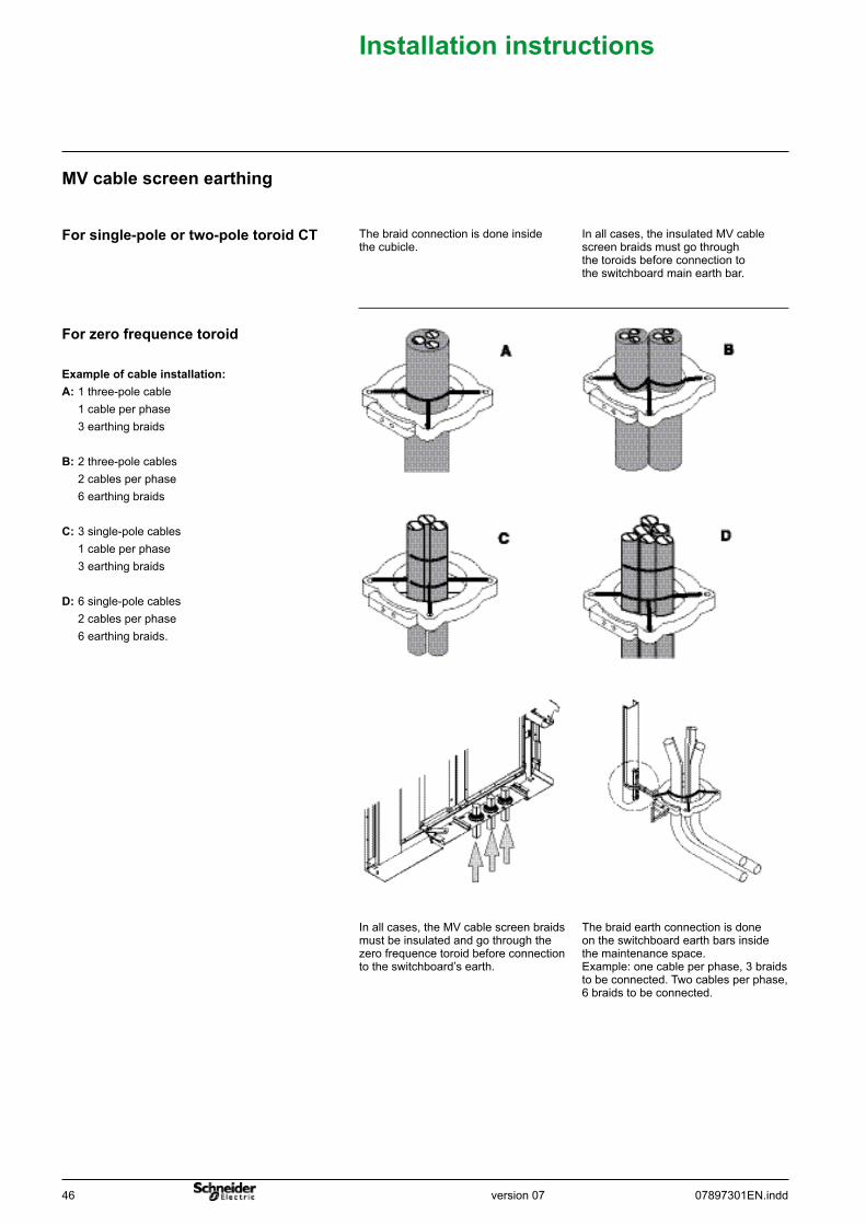
The braid earth connection is done on the switchboard earth bars inside the maintenance space.Example: one cable per phase, 3 braids to be connected. Two cables per phase,6 braids to be connected.
In all cases, the MV cable screen braids must be insulated and go through the zero frequence toroid before connection to the switchboard’s earth.
Exampleofcableinstallation:A: 1 three-pole cable 1 cable per phase 3 earthing braids
B: 2 three-pole cables 2 cables per phase 6 earthing braids
C: 3 single-pole cables 1 cable per phase 3 earthing braids D: 6 single-pole cables 2 cables per phase 6 earthing braids.
Forzerofrequencetoroid
In all cases, the insulated MV cable screen braids must go through the toroids before connection to the switchboard main earth bar.
The braid connection is done inside the cubicle.
Forsingle-poleortwo-poletoroidCT
MVcablescreenearthing
Installationinstructions
version 0707897301EN.indd 47
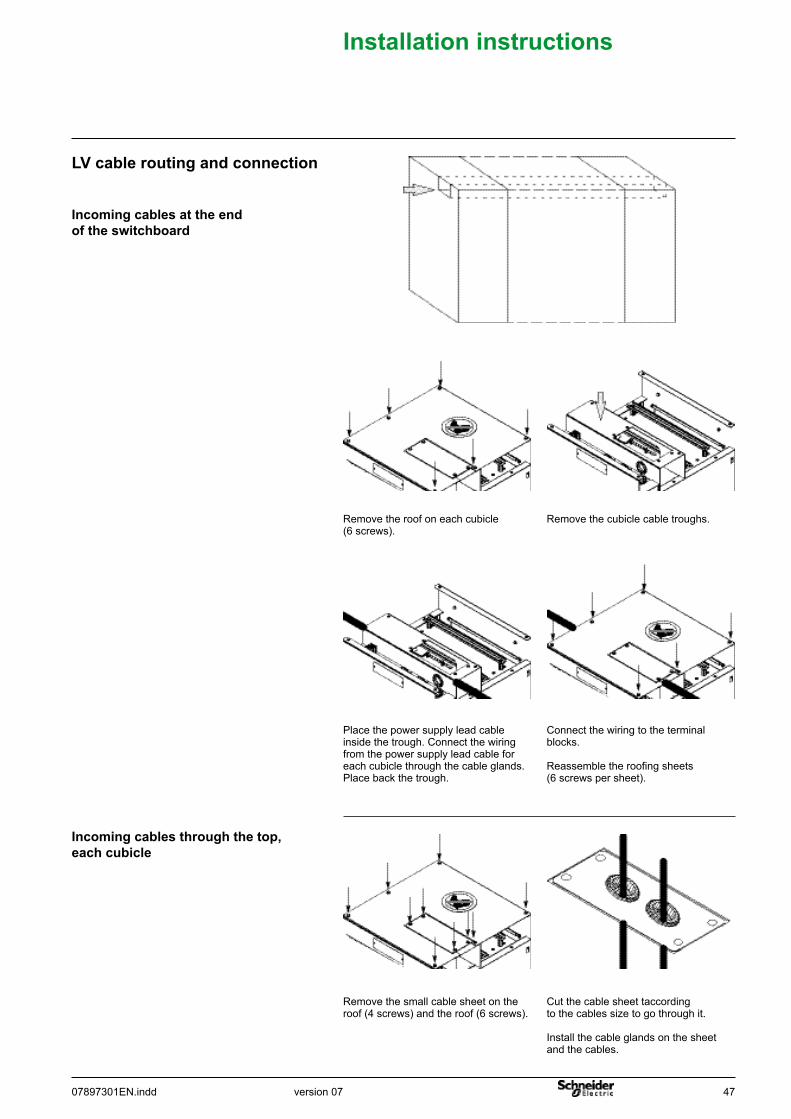
Cut the cable sheet taccording to the cables size to go through it.
Install the cable glands on the sheet and the cables.
Remove the small cable sheet on the roof (4 screws) and the roof (6 screws).
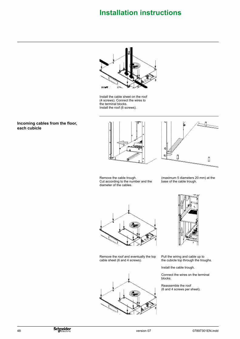
Incomingcablesthroughthetop,eachcubicle
Connect the wiring to the terminal blocks.
Reassemble the roofing sheets (6 screws per sheet).
Place the power supply lead cable inside the trough. Connect the wiring from the power supply lead cable for each cubicle through the cable glands.Place back the trough.
Remove the cubicle cable troughs.Remove the roof on each cubicle (6 screws).
Incomingcablesattheendoftheswitchboard
LVcableroutingandconnection
Installationinstructions
48 07897301EN.inddversion 07
Installationinstructions
Pull the wiring and cable up to the cubicle top through the troughs.
Install the cable trough.
Connect the wires on the terminal blocks.
Reassemble the roof (6 and 4 screws per sheet).
Remove the roof and eventually the top cable sheet (6 and 4 screws).
(maximum 5 diameters 20 mm) at the base of the cable trough.
Remove the cable trough.Cut according to the number and the diameter of the cables.
Incomingcablesfromthefloor,eachcubicle
Install the cable sheet on the roof (4 screws). Connect the wires to the terminal blocks.Install the roof (6 screws).
version 0707897301EN.indd 49
Installationinstructions
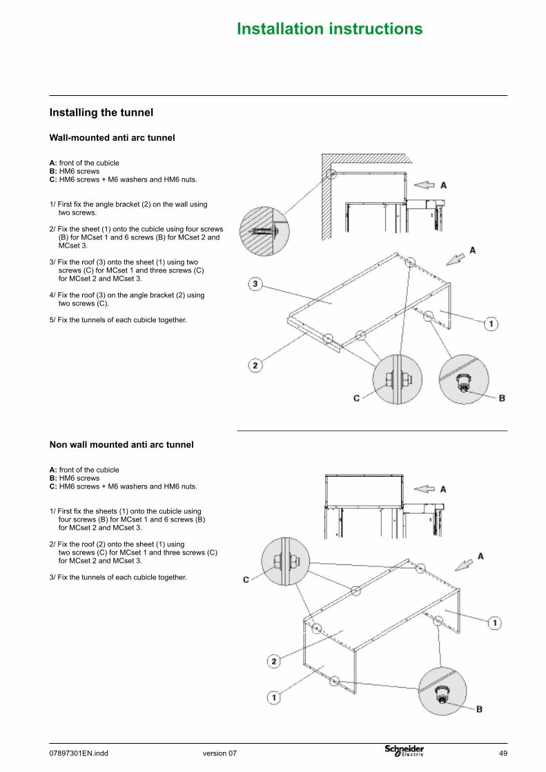
Nonwallmountedantiarctunnel
Wall-mountedantiarctunnel
Installingthetunnel
A: front of the cubicleB: HM6 screwsC: HM6 screws + M6 washers and HM6 nuts.
1/ First fix the angle bracket (2) on the wall using two screws.
2/ Fix the sheet (1) onto the cubicle using four screws (B) for MCset 1 and 6 screws (B) for MCset 2 and MCset 3.
3/ Fix the roof (3) onto the sheet (1) using two screws (C) for MCset 1 and three screws (C) for MCset 2 and MCset 3.
4/ Fix the roof (3) on the angle bracket (2) using two screws (C).
5/ Fix the tunnels of each cubicle together.
A: front of the cubicleB: HM6 screwsC: HM6 screws + M6 washers and HM6 nuts.
1/ First fix the sheets (1) onto the cubicle using four screws (B) for MCset 1 and 6 screws (B) for MCset 2 and MCset 3.
2/ Fix the roof (2) onto the sheet (1) using two screws (C) for MCset 1 and three screws (C) for MCset 2 and MCset 3.
3/ Fix the tunnels of each cubicle together.
50 07897301EN.inddversion 07
Installationinstructions
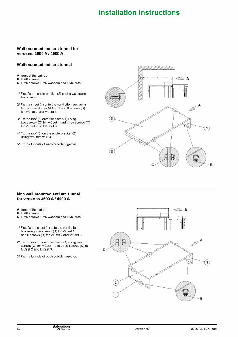
Wall-mountedantiarctunnelforversions 3600 A / 4000 A
Nonwallmountedantiarctunnelfor versions 3600 A / 4000 A
Wall-mountedantiarctunnel
A: front of the cubicleB: HM6 screwsC: HM6 screws + M6 washers and HM6 nuts.
1/ First fix the angle bracket (2) on the wall using two screws.
2/ Fix the sheet (1) onto the ventilation box using four screws (B) for MCset 1 and 6 screws (B) for MCset 2 and MCset 3.
3/ Fix the roof (3) onto the sheet (1) using two screws (C) for MCset 1 and three screws (C) for MCset 2 and MCset 3.
4/ Fix the roof (3) on the angle bracket (2) using two screws (C).
5/ Fix the tunnels of each cubicle together.
A: front of the cubicleB: HM6 screwsC: HM6 screws + M6 washers and HM6 nuts.
1/ First fix the sheet (1) onto the ventilation box using four screws (B) for MCset 1 and 6 screws (B) for MCset 2 and MCset 3.
2/ Fix the roof (2) onto the sheet (1) using two screws (C) for MCset 1 and three screws (C) for MCset 2 and MCset 3.
3/ Fix the tunnels of each cubicle together.
version 0707897301EN.indd 51
Installationinstructions
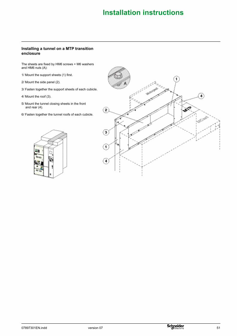
InstallingatunnelonaMTPtransitionenclosure
The sheets are fixed by HM6 screws + M6 washersand HM6 nuts (A):
1/ Mount the support sheets (1) first.
2/ Mount the side panel (2).
3/ Fasten together the support sheets of each cubicle.
4/ Mount the roof (3).
5/ Mount the tunnel closing sheets in the front and rear (4).
6/ Fasten together the tunnel roofs of each cubicle.
52 07897301EN.inddversion 07
Installationinstructions
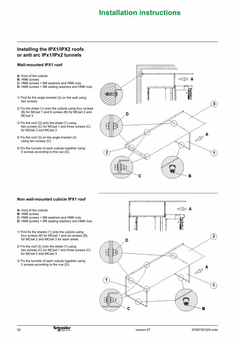
Installing the IPX1/IPX2 roofsor anti arc IPx1/IPx2 tunnels
Wall-mounted IPX1 roof
Non wall-mounted cubicle IPX1 roof
A: front of the cubicleB: HM6 screwsC: HM6 screws + M6 washers and HM6 nuts.D: HM6 screws + M6 sealing washers and HM6 nuts.
1/ First fix the angle bracket (2) on the wall using two screws.
2/ Fix the sheet (1) onto the cubicle using four screws (B) for MCset 1 and 6 screws (B) for MCset 2 and MCset 3.
3/ Fix the roof (3) onto the sheet (1) using two screws (C) for MCset 1 and three screws (C) for MCset 2 and MCset 3.
4/ Fix the roof (3) on the angle bracket (2) using two screws (C).
5/ Fix the tunnels of each cubicle together using 5 screws according to the vue (D).
A: front of the cubicleB: HM6 screwsC: HM6 screws + M6 washers and HM6 nuts.D: HM6 screws + M6 sealing washers and HM6 nuts.
1/ First fix the sheets (1) onto the cubicle using four screws (B) for MCset 1 and six screws (B) for MCset 2 and MCset 3 for each sheet.
2/ Fix the roof (2) onto the sheet (1) using two screws (C) for MCset 1 and three screws (C) for MCset 2 and MCset 3.
3/ Fix the tunnels of each cubicle together using 5 screws according to the vue (D).
version 0707897301EN.indd 53
Installationinstructions
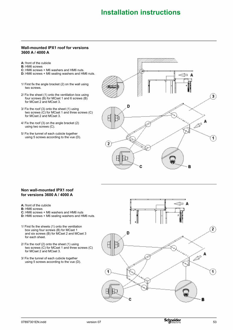
Wall-mounted IPX1 roof for versions 3600 A / 4000 A
Non wall-mounted IPX1 roof for versions 3600 A / 4000 A
A: front of the cubicleB: HM6 screwsC: HM6 screws + M6 washers and HM6 nuts.D: HM6 screws + M6 sealing washers and HM6 nuts.
1/ First fix the angle bracket (2) on the wall using two screws.
2/ Fix the sheet (1) onto the ventilation box using four screws (B) for MCset 1 and 6 screws (B) for MCset 2 and MCset 3.
3/ Fix the roof (3) onto the sheet (1) using two screws (C) for MCset 1 and three screws (C) for MCset 2 and MCset 3.
4/ Fix the roof (3) on the angle bracket (2) using two screws (C).
5/ Fix the tunnel of each cubicle together using 5 screws according to the vue (D).
A: front of the cubicleB: HM6 screwsC: HM6 screws + M6 washers and HM6 nutsD: HM6 screws + M6 sealing washers and HM6 nuts.
1/ First fix the sheets (1) onto the ventilation box using four screws (B) for MCset 1 and six screws (B) for MCset 2 and MCset 3 for each sheet.
2/ Fix the roof (2) onto the sheet (1) using two screws (C) for MCset 1 and three screws (C) for MCset 2 and MCset 3.
3/ Fix the tunnel of each cubicle together using 5 screws according to the vue (D).
54 07897301EN.inddversion 07
Installationinstructions
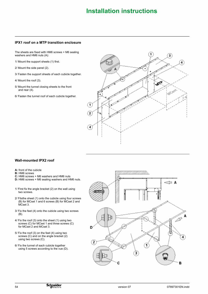
IPX1 roof on a MTP transition enclosure
The sheets are fixed with HM6 screws + M6 sealing washers and HM6 nuts (A):
1/ Mount the support sheets (1) first.
2/ Mount the side panel (2).
3/ Fasten the support sheets of each cubicle together.
4/ Mount the roof (3).
5/ Mount the tunnel closing sheets to the front and rear (4).
6/ Fasten the tunnel roof of each cubicle together.
Wall-mounted IPX2 roof
A: front of the cubicleB: HM6 screwsC: HM6 screws + M6 washers and HM6 nutsD: HM6 screws + M6 sealing washers and HM6 nuts.
1/ First fix the angle bracket (2) on the wall using two screws.
2/ Fitxthe sheet (1) onto the cubicle using four screws (B) for MCset 1 and 6 screws (B) for MCset 2 and MCset 3.
3/ Fix the feet (4) onto the cubicle using two screws (B).
4/ Fix the roof (3) onto the sheet (1) using two screws (C) for MCset 1 and three screws (C) for MCset 2 and MCset 3.
5/ Fix the roof (3) on the feet (4) using two screws (C) and on the angle bracket (2) using two screws (C).
6/ Fix the tunnel of each cubicle together using 5 screws according to the vue (D).
version 0707897301EN.indd 55
Installationinstructions
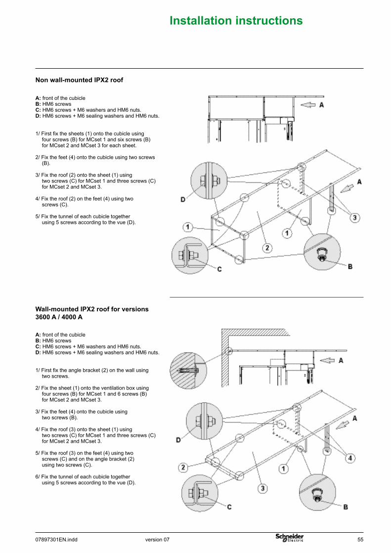
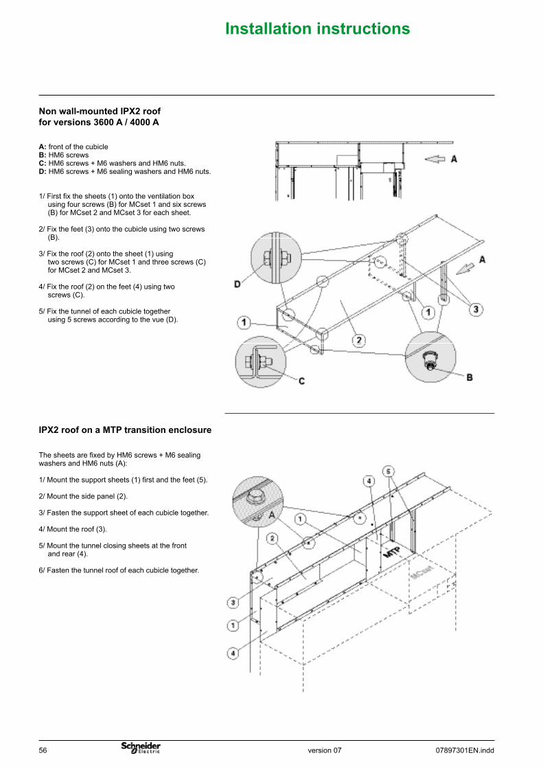
Non wall-mounted IPX2 roof
A: front of the cubicleB: HM6 screwsC: HM6 screws + M6 washers and HM6 nuts.D: HM6 screws + M6 sealing washers and HM6 nuts.
1/ First fix the sheets (1) onto the cubicle using four screws (B) for MCset 1 and six screws (B) for MCset 2 and MCset 3 for each sheet.
2/ Fix the feet (4) onto the cubicle using two screws (B).
3/ Fix the roof (2) onto the sheet (1) using two screws (C) for MCset 1 and three screws (C) for MCset 2 and MCset 3.
4/ Fix the roof (2) on the feet (4) using two screws (C).
5/ Fix the tunnel of each cubicle together using 5 screws according to the vue (D).
Wall-mounted IPX2 roof for versions 3600 A / 4000 A
A: front of the cubicleB: HM6 screwsC: HM6 screws + M6 washers and HM6 nuts.D: HM6 screws + M6 sealing washers and HM6 nuts.
1/ First fix the angle bracket (2) on the wall using two screws.
2/ Fix the sheet (1) onto the ventilation box using four screws (B) for MCset 1 and 6 screws (B) for MCset 2 and MCset 3.
3/ Fix the feet (4) onto the cubicle using two screws (B).
4/ Fix the roof (3) onto the sheet (1) using two screws (C) for MCset 1 and three screws (C) for MCset 2 and MCset 3.
5/ Fix the roof (3) on the feet (4) using two screws (C) and on the angle bracket (2) using two screws (C).
6/ Fix the tunnel of each cubicle together using 5 screws according to the vue (D).
56 07897301EN.inddversion 07
Installationinstructions
IPX2 roof on a MTP transition enclosure
The sheets are fixed by HM6 screws + M6 sealing washers and HM6 nuts (A):
1/ Mount the support sheets (1) first and the feet (5).
2/ Mount the side panel (2).
3/ Fasten the support sheet of each cubicle together.
4/ Mount the roof (3).
5/ Mount the tunnel closing sheets at the front and rear (4).
6/ Fasten the tunnel roof of each cubicle together.
Non wall-mounted IPX2 roof for versions 3600 A / 4000 A
A: front of the cubicleB: HM6 screwsC: HM6 screws + M6 washers and HM6 nuts.D: HM6 screws + M6 sealing washers and HM6 nuts.
1/ First fix the sheets (1) onto the ventilation box using four screws (B) for MCset 1 and six screws (B) for MCset 2 and MCset 3 for each sheet.
2/ Fix the feet (3) onto the cubicle using two screws (B).
3/ Fix the roof (2) onto the sheet (1) using two screws (C) for MCset 1 and three screws (C) for MCset 2 and MCset 3.
4/ Fix the roof (2) on the feet (4) using two screws (C).
5/ Fix the tunnel of each cubicle together using 5 screws according to the vue (D).
version 0707897301EN.indd 57
Installationinstructions
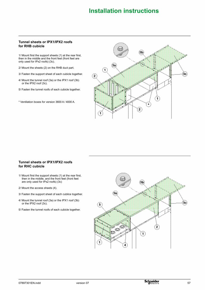
Tunnel sheets or IPX1/IPX2 roofs forRHBcubicle
1/ Mount first the support sheets (1) at the rear first, then in the middle and the front feet (front feet are only used for IPx2 roofs) (3c).
2/ Mount the sheets (2) on the RHB duct part.
3/ Fasten the support sheet of each cubicle together.
4/ Mount the tunnel roof (3a) or the IPX1 roof (3b) or the IPX2 roof (3c).
5/ Fasten the tunnel roofs of each cubicle together.
* Ventilation boxes for version 3600 A / 4000 A.
Tunnel sheets or IPX1/IPX2 roofs forRHCcubicle
1/ Mount first the support sheets (1) at the rear first, then in the middle, and the front feet (front feet are only used for IPx2 roofs) (3c)
2/ Mount the access sheets (4).
3/ Fasten the support sheet of each cubilce together.
4/ Mount the tunnel roof (3a) or the IPX1 roof (3b) or the IPX2 roof (3c).
5/ Fasten the tunnel roofs of each cubicle together.
58 07897301EN.inddversion 07
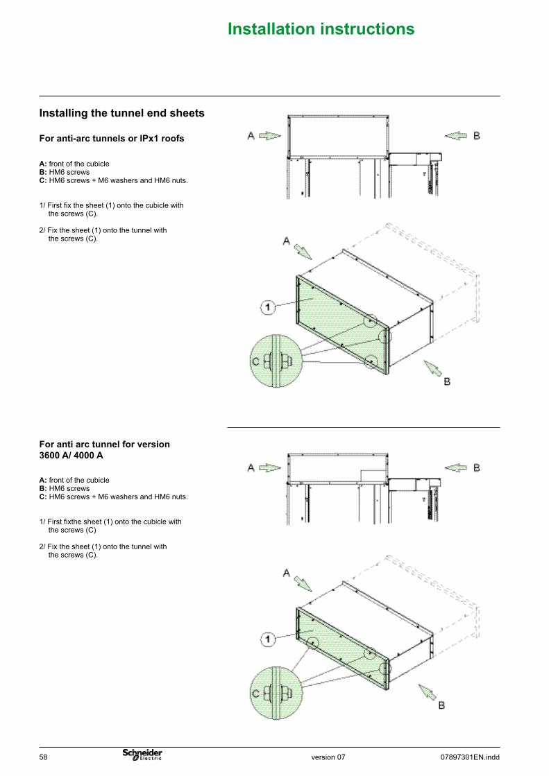
Installationinstructions
Foranti-arctunnelsorIPx1roofs
Installingthetunnelendsheets
A: front of the cubicleB: HM6 screwsC: HM6 screws + M6 washers and HM6 nuts.
1/ First fix the sheet (1) onto the cubicle with the screws (C).
2/ Fix the sheet (1) onto the tunnel with the screws (C).
Forantiarctunnelforversion3600 A/ 4000 A
A: front of the cubicleB: HM6 screwsC: HM6 screws + M6 washers and HM6 nuts.
1/ First fixthe sheet (1) onto the cubicle with the screws (C)
2/ Fix the sheet (1) onto the tunnel with the screws (C).
version 0707897301EN.indd 59
Installationinstructions
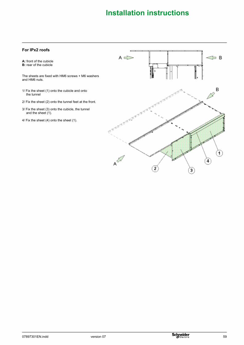
ForIPx2roofs
A: front of the cubicleB: rear of the cubicle
The sheets are fixed with HM6 screws + M6 washersand HM6 nuts.
1/ Fix the sheet (1) onto the cubicle and onto the tunnel
2/ Fix the sheet (2) onto the tunnel feet at the front.
3/ Fix the sheet (3) onto the cubicle, the tunnel and the sheet (1).
4/ Fix the sheet (4) onto the sheet (1).
60 07897301EN.inddversion 07
Installationinstructions
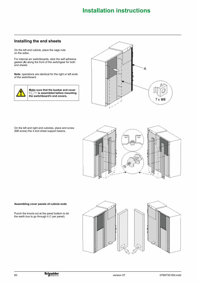
Installingtheendsheets
Punch the knock-out at the panel bottom to let the earth bus to go through it (1 per panel).
Assemblingcoverpanelsofcubicleends
On the left and right end cubicles, place and screw (M8 screw) the 4 end sheet support beams.
On the left end cubicle, place the cage nuts on the sides.
For internal arc switchboards, stick the self adhesive gasket (A) along the front of the switchgear for both end sheets
Note: operations are identical for the right or left ends of the switchboard.
Makesurethatthebusbarendcoverisassembledbeforemounting
theswitchboard’sendcovers.
version 0707897301EN.indd 61
Installationinstructions
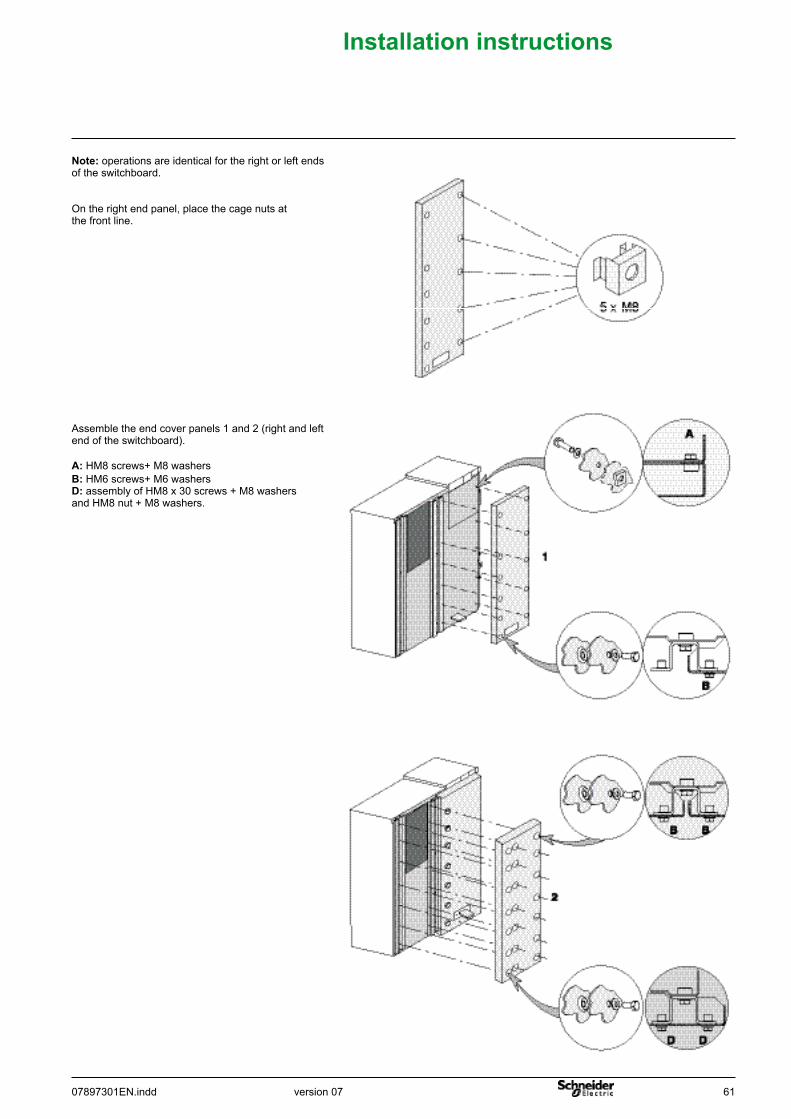
Assemble the end cover panels 1 and 2 (right and left end of the switchboard).
A: HM8 screws+ M8 washersB: HM6 screws+ M6 washers D: assembly of HM8 x 30 screws + M8 washers and HM8 nut + M8 washers.
Note: operations are identical for the right or left ends of the switchboard.
On the right end panel, place the cage nuts at the front line.
62 07897301EN.inddversion 07
Installationinstructions
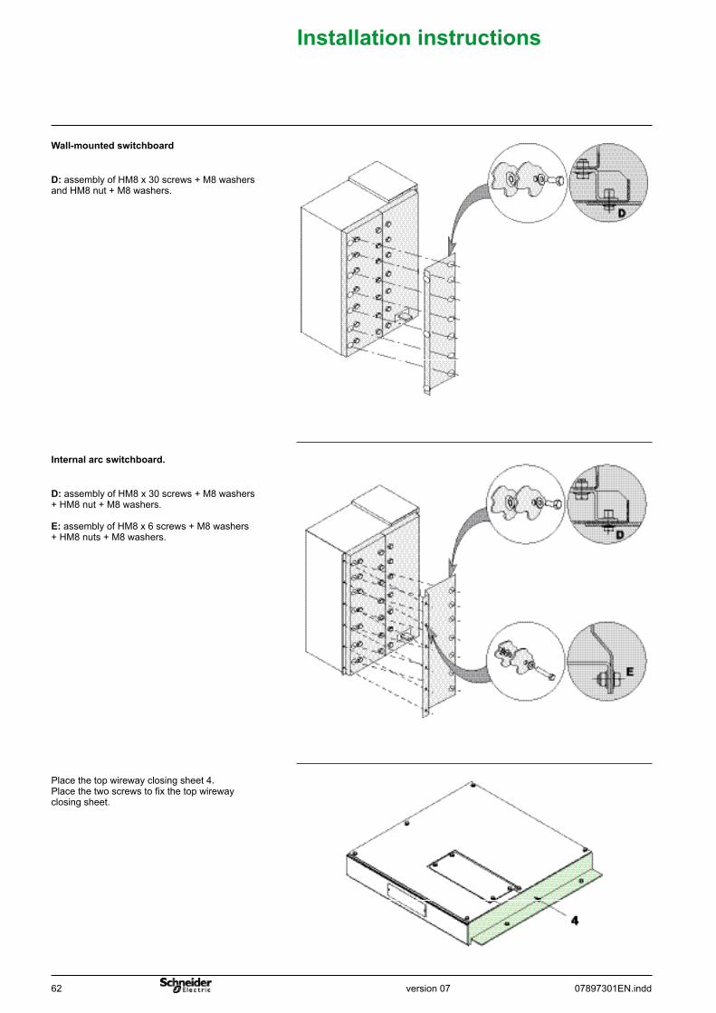
D: assembly of HM8 x 30 screws + M8 washers and HM8 nut + M8 washers.
Place the top wireway closing sheet 4.Place the two screws to fix the top wireway closing sheet.
Wall-mountedswitchboard
D: assembly of HM8 x 30 screws + M8 washers + HM8 nut + M8 washers.
E: assembly of HM8 x 6 screws + M8 washers + HM8 nuts + M8 washers.
Internalarcswitchboard.
RHB
version 0707897301EN.indd 63
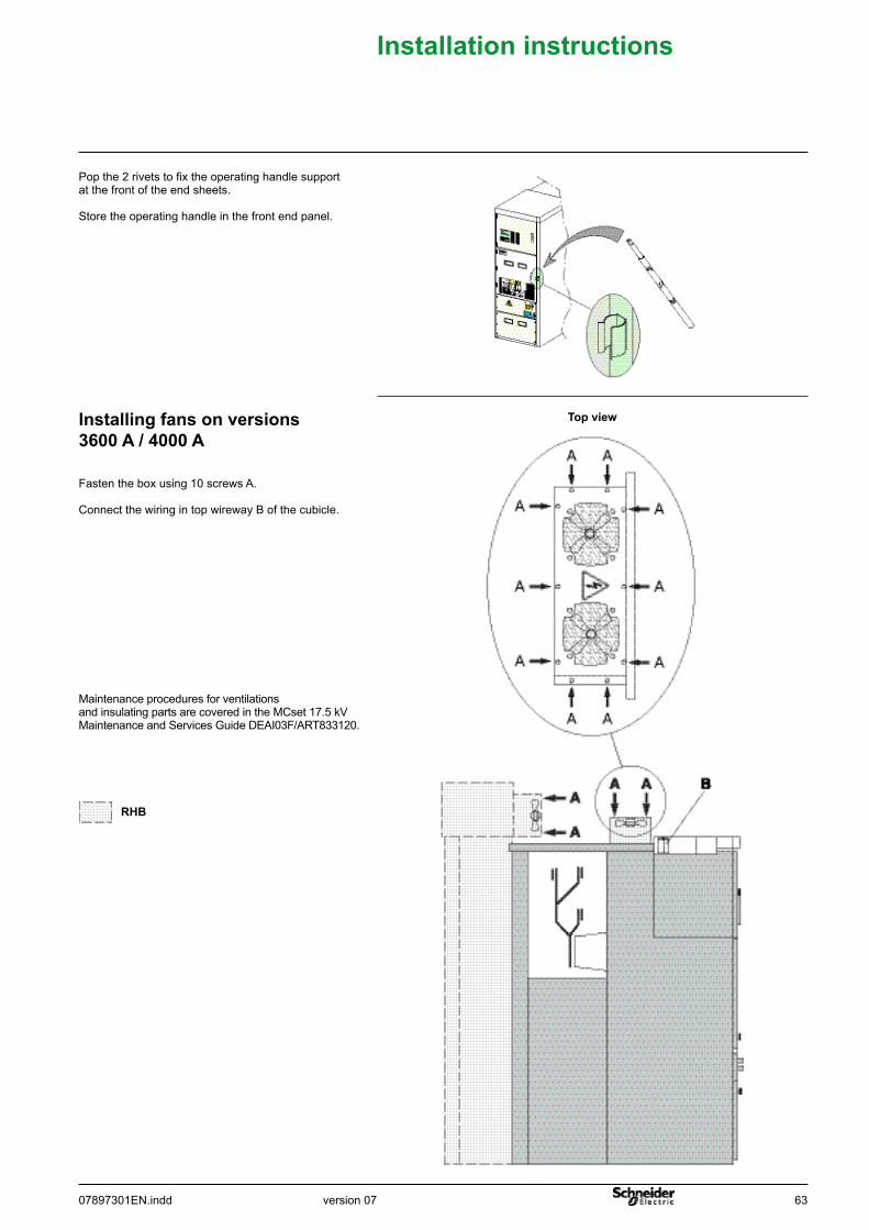
Installationinstructions
Installingfansonversions3600 A / 4000 A
Fasten the box using 10 screws A.
Connect the wiring in top wireway B of the cubicle.
Topview
Maintenance procedures for ventilations and insulating parts are covered in the MCset 17.5 kV Maintenance and Services Guide DEAI03F/ART833120.
Pop the 2 rivets to fix the operating handle support at the front of the end sheets.
Store the operating handle in the front end panel.
64 07897301EN.inddversion 07
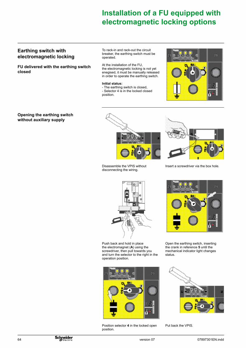
FUdeliveredwiththeearthingswitchclosed
Earthingswitchwithelectromagneticlocking
Openingtheearthingswitchwithoutauxiliarysupply
InstallationofaFUequippedwithelectromagneticlockingoptions
To rack-in and rack-out the circuit breaker, the earthing switch must be operated.
At the installation of the FU, the electromagnetic locking is not yet enegised, it must be manually released in order to operate the earthing switch.
Initialstatus: - The earthing switch is closed,- Selector 4 is in the locked closed position.
Insert a screwdriver via the box hole.Disassemble the VPIS without disconnecting the wiring.
Open the earthing switch, inserting the crank in reference 5 until the mechanical indicator light changes status.
Push back and hold in place the electromagnet (A) using the screwdriver, then pull towards you and turn the selector to the right in the operation position.
Put back the VPIS.Position selector 4 in the locked open position.
version 0707897301EN.indd 65
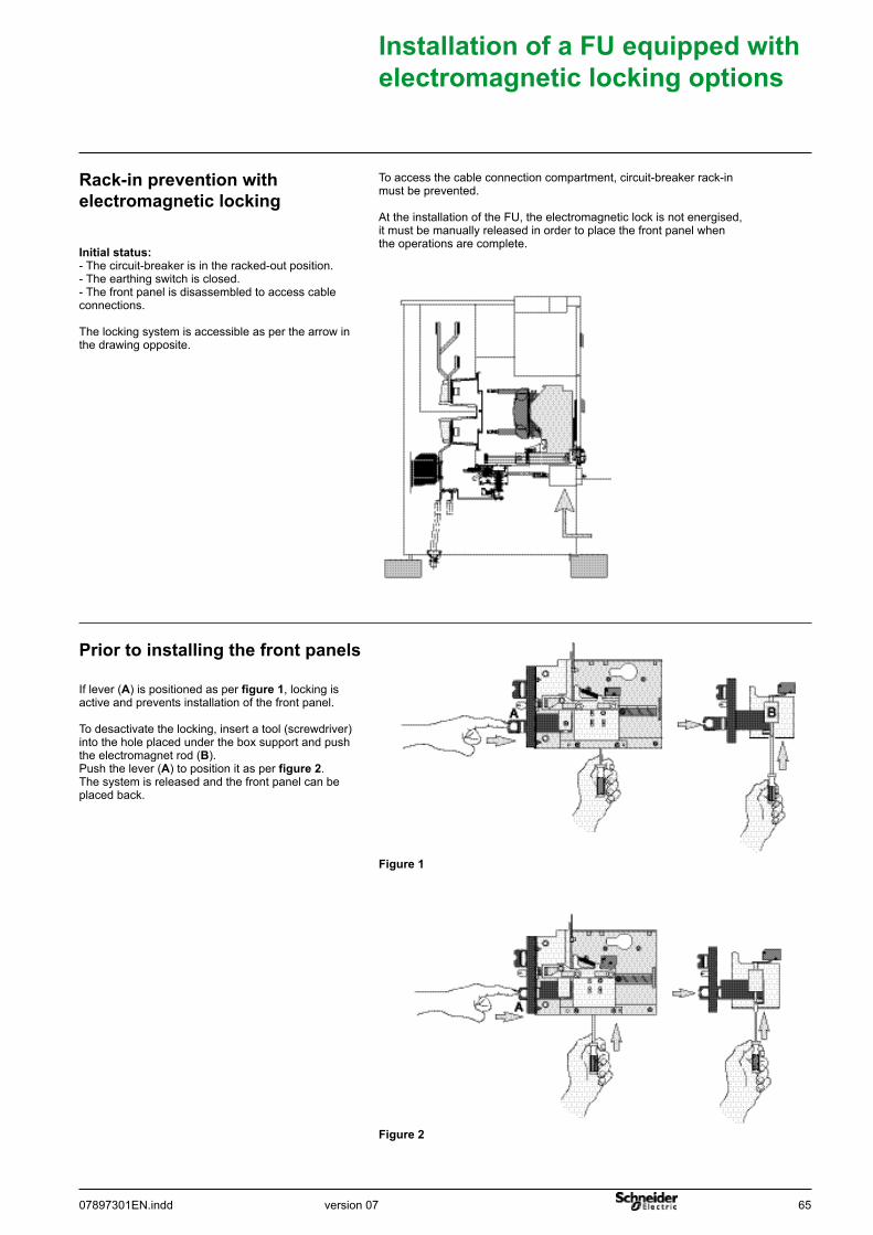
Initialstatus:- The circuit-breaker is in the racked-out position.- The earthing switch is closed.- The front panel is disassembled to access cable connections.
The locking system is accessible as per the arrow in the drawing opposite.
Rack-inpreventionwithelectromagneticlocking
To access the cable connection compartment, circuit-breaker rack-in must be prevented.
At the installation of the FU, the electromagnetic lock is not energised, it must be manually released in order to place the front panel when the operations are complete.
Priortoinstallingthefrontpanels
If lever (A) is positioned as per figure1, locking is active and prevents installation of the front panel.
To desactivate the locking, insert a tool (screwdriver) into the hole placed under the box support and push the electromagnet rod (B).Push the lever (A) to position it as per figure2.The system is released and the front panel can be placed back.
Figure1
Figure2
InstallationofaFUequippedwithelectromagneticlockingoptions
66 07897301EN.inddversion 07
Stepstobetakenfortestsandinspection
Surgearresterconnection
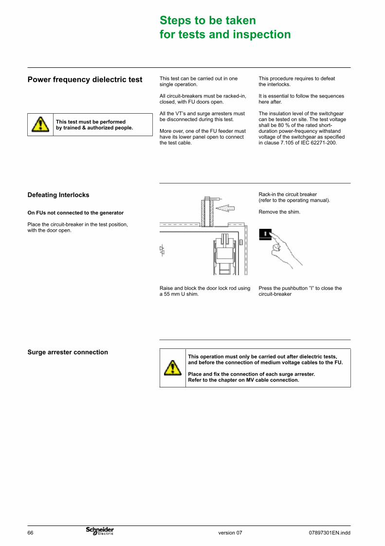
Press the pushbutton ”I” to close the circuit-breaker
Rack-in the circuit breaker(refer to the operating manual).
Remove the shim.
Raise and block the door lock rod using a 55 mm U shim.
OnFUsnotconnectedtothegenerator
Place the circuit-breaker in the test position, with the door open.
DefeatingInterlocks
This procedure requires to defeat the interlocks.
It is essential to follow the sequences here after.
The insulation level of the switchgear can be tested on site. The test voltage shall be 80 % of the rated short-duration power-frequency withstand voltage of the switchgear as specified in clause 7.105 of IEC 62271-200.
This test can be carried out in one single operation.
All circuit-breakers must be racked-in, closed, with FU doors open.
All the VT’s and surge arresters must be disconnected during this test.
More over, one of the FU feeder must have its lower panel open to connect the test cable.
Powerfrequencydielectrictest
Thistestmustbeperformedbytrained&authorizedpeople.
Thisoperationmustonlybecarriedoutafterdielectrictests,andbeforetheconnectionofmediumvoltagecablestotheFU.
Placeandfixtheconnectionofeachsurgearrester.RefertothechapteronMVcableconnection.
version 0707897301EN.indd 67
Testsonsite
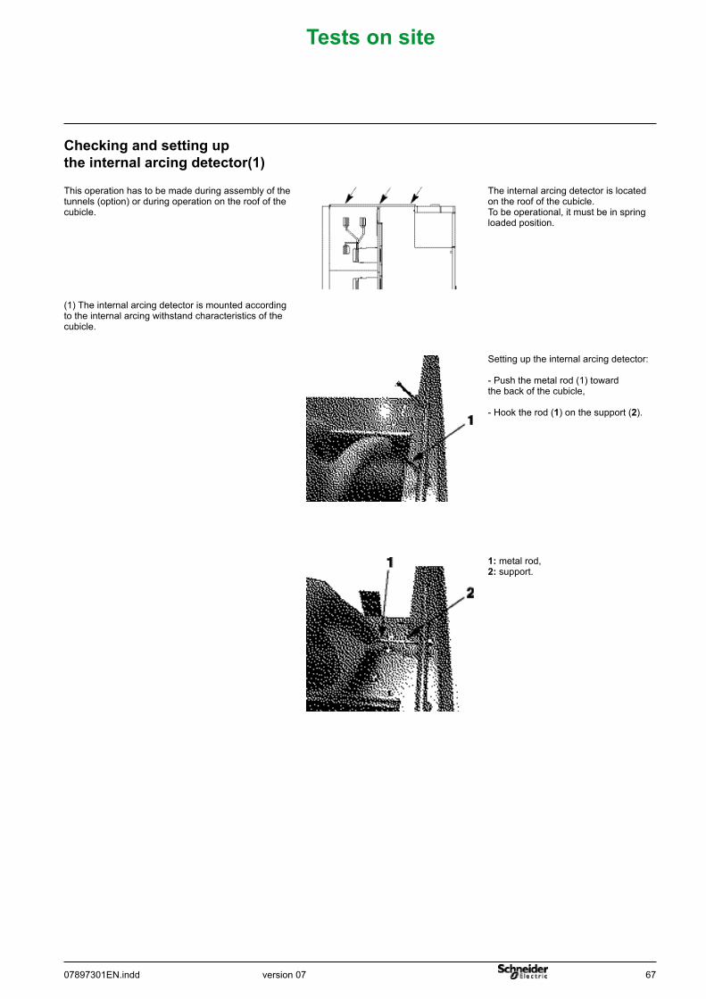
Checkingandsettinguptheinternalarcingdetector(1)
This operation has to be made during assembly of the tunnels (option) or during operation on the roof of the cubicle.
The internal arcing detector is located on the roof of the cubicle.To be operational, it must be in spring loaded position.
Setting up the internal arcing detector:
- Push the metal rod (1) toward the back of the cubicle,
- Hook the rod (1) on the support (2).
1: metal rod,2: support.
(1) The internal arcing detector is mounted according to the internal arcing withstand characteristics of the cubicle.
68 07897301EN.inddversion 07
Index
AAD, CL-GL, VT cubicles 6
CChecking and setting up the internal arcing detector 67Coupling of cubicles 22Cubicle fitted with IPX1/IPX2 roofs 9
DDescription of irons and accessories 15DI2 cubicle 9
EEarthing switch control symbols 2Earthing switch with electromagnetic locking 64
FFloor quality 15
GGlossary 2
HHandling by rolling 13Handling using a sling 12
IInstalling busbars 29Installing busbars between MTP and the MOTORPACT cubicle 33Installing fans on versions 3600 A / 4000 A 63Installing the end sheets 60Installing the electric connections of the busbars and MV cables 27Installing the IPX1/IPX2 roofs or anti arc IPx1/IPx2 tunnels 52Installing the main earth connection 25Installing the tunnel 49Installing the tunnel end sheets 58
LLand packaging 12List of bags and accessories 4LV cable routing and connection 47
MMoving part control symbols 3MV cable screen earthing 46
OOcean shipment packaging 12
PPackaging 5Placing and adjusting on non earthquake resistant civil engineering works 15Placing and adjusting on earthquake resistant civil engineering works 17Placing cubicles in a switchboard 19Placing MV cables on AD cubicle 36Placing MV cables on RHC cubicle 42Power frequency dielectric test 66Prior to installing the front panels 65
RRack-in check 24Rack-in prevention with electromagnetic locking 65Recommendations 3Removing the mobile part transport fixations 24RHB, RHC cubicles 10
SStandard tightening torques 4Storage 13Surface condition 15
TTransition enclosure MTP 11
UUnpacking cubicles 19
07897301EN - REV. 07
SchneiderElectricIndustriesS.A.S35 rue Joseph MonierCS 30323 92506 Rueil Malmaison Cedexwww.schneider-electric.com
954 503 439 RCS NanterreCapital social : 896 313 776 €
04/2012
0789
7301
EN
- R
EV.
07
a S
chne
ider
Ele
ctric
Indu
strie
s S
AS
– A
ll rig
hts
rese
rved
.
As standards, specifications and designs change from time to time, please ask for confirmation of the information given in this publication. Thisdocumenthasbeenprinted onecologicalpaper.
Publishing: Schneider Electric Industries SAS.Design: Profil.Printing:
SchneiderElectricgroupservicecentersaretheretoprovide:- engineering and technical assistance,- commissioning,- training,- preventive and corrective maintenance,- adaptation work,- spare parts.
CallyoursalesrepresentativewhowillputyouintouchwithyournearestSchneiderElectricgroupservicecenterordirectlycallthefollowingtelephonenumber: +33 (0)4 76 57 60 60 Grenoble France.