Cluster Retention Kits for Masterpact NW Circuit Breakers ...
Upload
hoangduongCategory
view
222download
1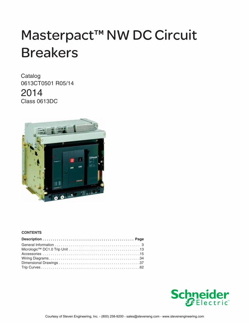
Masterpact™ NW DC Circuit Breakers Catalog0613CT0501 R05/14
2014Class 0613DC
CONTENTS
Description . . . . . . . . . . . . . . . . . . . . . . . . . . . . . . . . . . . . . . . . . . . . . Page
General Information . . . . . . . . . . . . . . . . . . . . . . . . . . . . . . . . . . . . . . . . . . 3Micrologic™ DC1.0 Trip Unit . . . . . . . . . . . . . . . . . . . . . . . . . . . . . . . . . . .13Accessories . . . . . . . . . . . . . . . . . . . . . . . . . . . . . . . . . . . . . . . . . . . . . . . .15Wiring Diagrams. . . . . . . . . . . . . . . . . . . . . . . . . . . . . . . . . . . . . . . . . . . . .34Dimensional Drawings . . . . . . . . . . . . . . . . . . . . . . . . . . . . . . . . . . . . . . . .37Trip Curves. . . . . . . . . . . . . . . . . . . . . . . . . . . . . . . . . . . . . . . . . . . . . . . . .62
Courtesy of Steven Engineering, Inc. - (800) 258-9200 - [email protected] - www.stevenengineering.com

Courtesy of Steven Engineering, Inc. - (800) 258-9200 - [email protected] - www.stevenengineering.com
Masterpact™ NW DC Circuit Breakers General Information
306/2014 © 2007–2014 Schneider Electric
All Rights Reserved
Section 1—General Information
Introduction
Masterpact™ NW Circuit Breakers are designed to protect electrical systems from damage caused by short circuits. All Masterpact circuit breakers are designed to open and close a circuit manually, and to open the circuit automatically at a predetermined overcurrent setting.
Selection of a dc circuit breaker is based on the type of dc system, the rated voltage, and the maximum short-circuit current at the point of installation. UL® Listed circuit breakers are for use on ungrounded systems rated 500 Vdc (600 Vdc unloaded) or less. IEC Rated circuit breakers are for use on ungrounded, grounded middle point, or grounded negative systems up to 750 Vdc.
Codes and Standards
Masterpact circuit breakers are manufactured and tested in accordance with the following standards:
Circuit breakers should be applied according to guidelines detailed in the National Electrical Code (NEC®) and other local wiring codes.
Masterpact circuit breakers are available in Square D™ or Schneider Electric™ brands.
UL File Numbers:
Masterpact NW: E63335, Vol. 4, Sec. 1
Features and Benefits
100% Rated Circuit Breaker: Masterpact circuit breakers are designed for continuous operation at 100% of their current rating.
True Two-Step Stored Energy Mechanism: Masterpact circuit breakers are operated via a stored-energy mechanism which can be manually or motor charged. The closing time is less than five cycles. Closing and opening operations can be initiated by remote control or by push buttons on the circuit breaker front cover. An O–C–O cycle is possible without recharging.
Drawout or Fixed Mount, 3-Pole (3P) or 4-Pole (4P) Construction: UL Listed (3P only) and IEC Rated (3P or 4P) Masterpact circuit breakers are available in drawout or fixed mounts.
Field-Installable Accessories: Most accessories are field installable with only the aid of a screwdriver and without adjusting the circuit breaker. The uniform design of the circuit breaker line allows most accessories to be common for the whole line.
Reinforced Insulation: Two insulation barriers separate the circuit breaker front from the current path.
Isolation Function by Positive Indication of Contact Status: The mechanical indicator is truly representative of the status of all the main contacts.
Segregated Compartment: Once the accessory cover has been removed to provide access to the accessory compartment, the main contacts remain fully isolated. Furthermore, interphase partitioning allows full insulation between each pole even if the accessory cover has been removed.
Front Connection of Secondary Circuits: All accessory terminals (ring terminals are available as an option) are located on a connecting block which is accessible from the front in the connected, test and disconnected positions. This is particularly useful for field inspection and modification.
Insulated Case Circuit Breaker IEC Rated Circuit Breaker IEC Extreme Atmospheric Conditions
UL 489 (UL Listed to Supplement SC)
NEMA AB1
CSA C22.2 No. 5
IEC 60947-2
IEC 68-2-1: Dry cold at –55°C
IEC 68-2-2: Dry heat at +85°C
IEC 68-2-30: Damp heat (temp. +55°C, rel. humidity 95%)
IEC 68-2-52 Level 2: Salt mist
Courtesy of Steven Engineering, Inc. - (800) 258-9200 - [email protected] - www.stevenengineering.com
Masterpact™ NW DC Circuit Breakers General Information
406/2014© 2007–2014 Schneider Electric
All Rights Reserved
Anti-Pumping Feature: All Masterpact NW circuit breakers are designed with an anti-pumping feature that causes an opening order to always takes priority over a closing order. Specifically, if opening and closing orders occur simultaneously, the charged mechanism discharges without any movement of the main contacts keeping the circuit breaker in the open (OFF) position.
In the event that opening and closing orders are simultaneously maintained, the standard mechanism provides an anti-pumping function which continues to keep the main contacts in the open position.
In addition, after fault tripping or opening the circuit breaker intentionally (using the manual or electrical controls and with the closing coil continuously energized) the circuit breaker cannot be closed until the power supply to the closing coil is discontinued and then reactivated.
NOTE: When the automatic reset after fault trip (RAR) option is installed, the automatic control system must take into account the information supplied by the circuit breaker before issuing a new closing order or before blocking the circuit breaker in the open position.
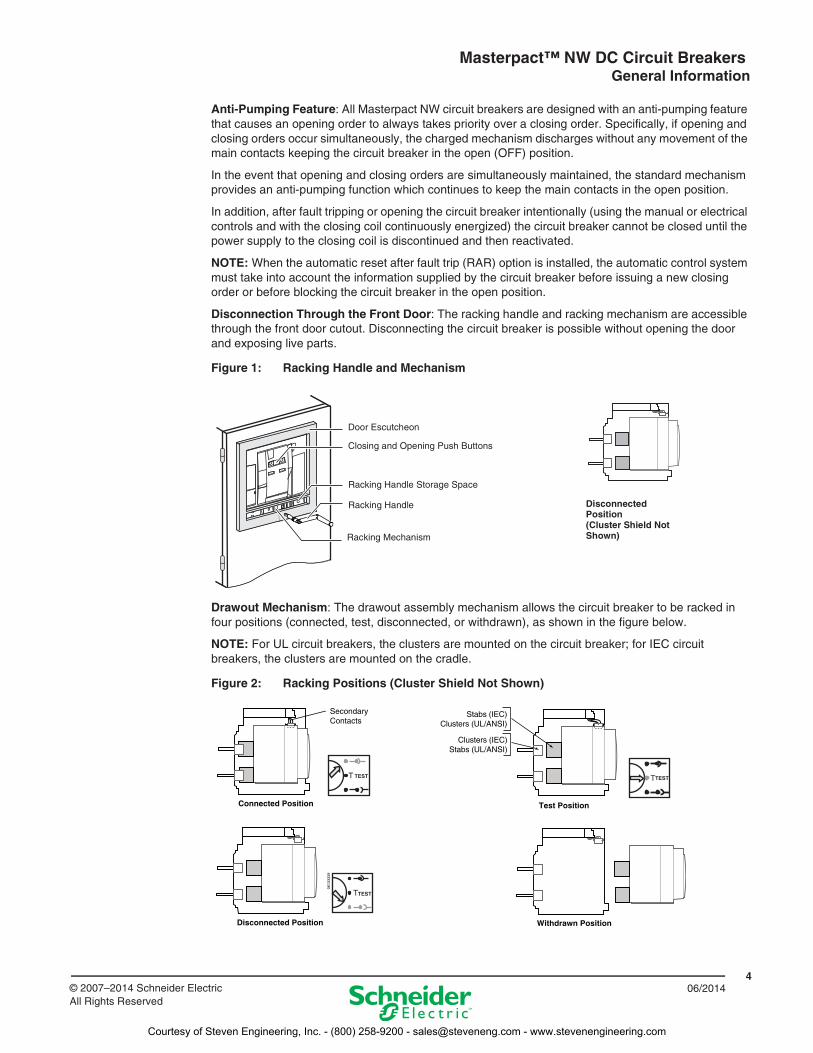
Disconnection Through the Front Door: The racking handle and racking mechanism are accessible through the front door cutout. Disconnecting the circuit breaker is possible without opening the door and exposing live parts.
Drawout Mechanism: The drawout assembly mechanism allows the circuit breaker to be racked in four positions (connected, test, disconnected, or withdrawn), as shown in the figure below.
NOTE: For UL circuit breakers, the clusters are mounted on the circuit breaker; for IEC circuit breakers, the clusters are mounted on the cradle.
Figure 1: Racking Handle and Mechanism
Figure 2: Racking Positions (Cluster Shield Not Shown)
Disconnected Position(Cluster Shield Not Shown)
Closing and Opening Push Buttons
Racking Handle Storage Space
Racking Handle
Racking Mechanism
Door Escutcheon
T TEST TESTT
T
0613
3339
Connected Position
Disconnected Position Withdrawn Position
Test Position
Secondary Contacts
Stabs (IEC)Clusters (UL/ANSI)
Clusters (IEC)Stabs (UL/ANSI)
TEST
Courtesy of Steven Engineering, Inc. - (800) 258-9200 - [email protected] - www.stevenengineering.com
Masterpact™ NW DC Circuit Breakers General Information
506/2014 © 2007–2014 Schneider Electric
All Rights Reserved
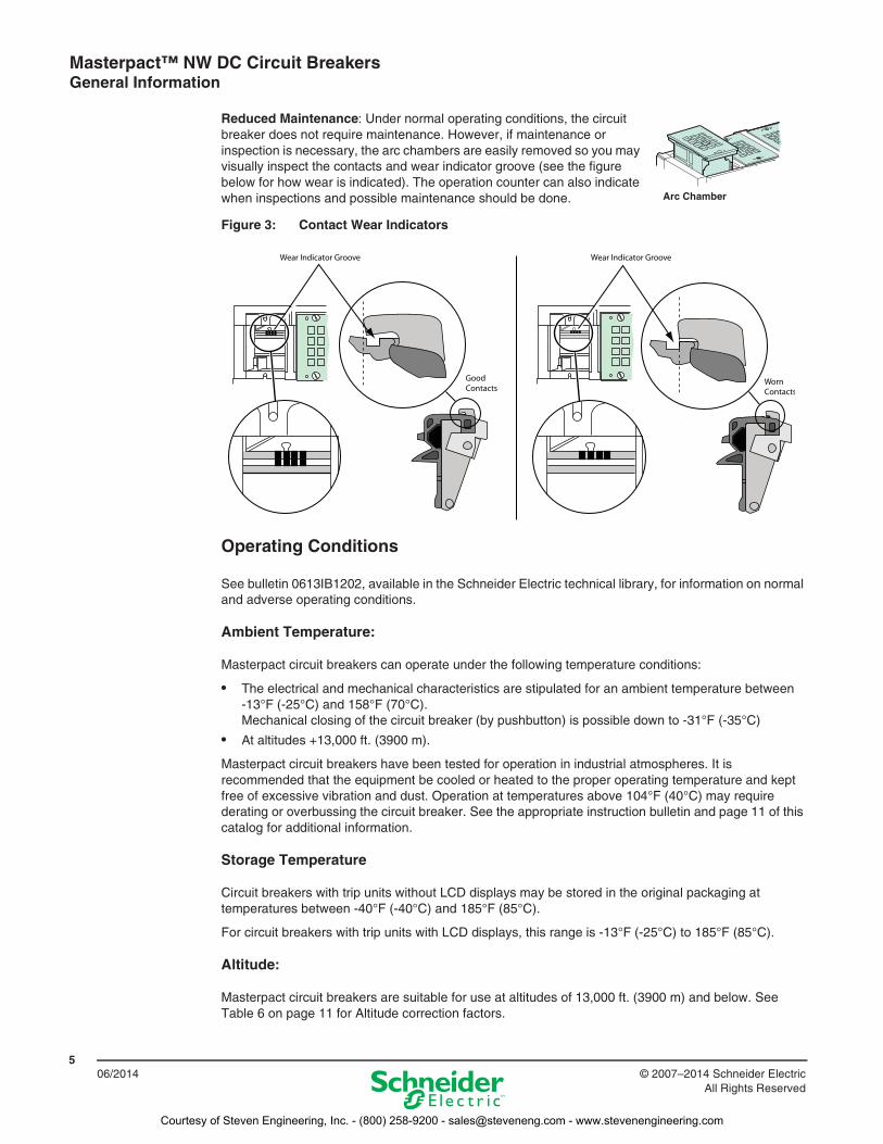
Reduced Maintenance: Under normal operating conditions, the circuit breaker does not require maintenance. However, if maintenance or inspection is necessary, the arc chambers are easily removed so you may visually inspect the contacts and wear indicator groove (see the figure below for how wear is indicated). The operation counter can also indicate when inspections and possible maintenance should be done.
Operating Conditions
See bulletin 0613IB1202, available in the Schneider Electric technical library, for information on normal and adverse operating conditions.
Ambient Temperature:
Masterpact circuit breakers can operate under the following temperature conditions:
• The electrical and mechanical characteristics are stipulated for an ambient temperature between -13°F (-25°C) and 158°F (70°C).Mechanical closing of the circuit breaker (by pushbutton) is possible down to -31°F (-35°C)
• At altitudes +13,000 ft. (3900 m).
Masterpact circuit breakers have been tested for operation in industrial atmospheres. It is recommended that the equipment be cooled or heated to the proper operating temperature and kept free of excessive vibration and dust. Operation at temperatures above 104°F (40°C) may require derating or overbussing the circuit breaker. See the appropriate instruction bulletin and page 11 of this catalog for additional information.
Storage Temperature
Circuit breakers with trip units without LCD displays may be stored in the original packaging at temperatures between -40°F (-40°C) and 185°F (85°C).
For circuit breakers with trip units with LCD displays, this range is -13°F (-25°C) to 185°F (85°C).
Altitude:
Masterpact circuit breakers are suitable for use at altitudes of 13,000 ft. (3900 m) and below. See Table 6 on page 11 for Altitude correction factors.
Figure 3: Contact Wear Indicators
Arc Chamber
Courtesy of Steven Engineering, Inc. - (800) 258-9200 - [email protected] - www.stevenengineering.com
Masterpact™ NW DC Circuit Breakers General Information
606/2014 © 2007–2014 Schneider Electric
All Rights Reserved
Vibration:
Masterpact circuit breakers meet IEC 60068-2-6 Standards for vibration.
• 2 to 13.2 Hz and amplitude 0.039 in. (1 mm)
• 13.2 to 100 Hz constant acceleration 0.024 oz. (0.7 g)
Humidity:
Masterpact circuit breakers have been tested to the following:
• IEC68-2-30—damp heat (temperature +55°C and relative humidity of 95%)
• IEC 68-2-52 level 2—salt mist
The materials used in Masterpact NT and NW circuit breakers will not support the growth of fungus and mold.
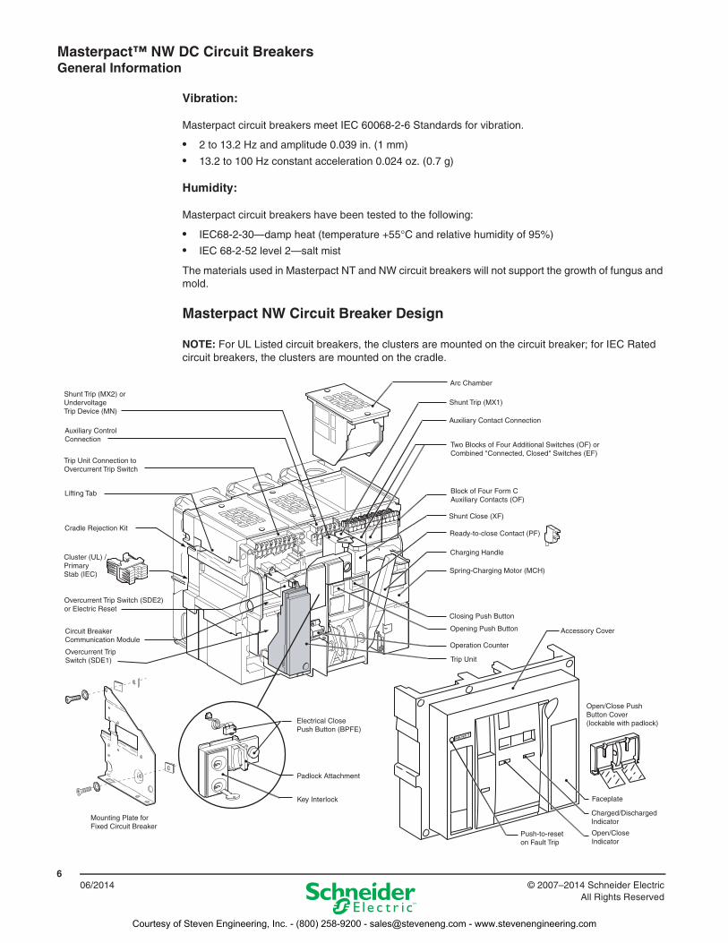
Masterpact NW Circuit Breaker Design
NOTE: For UL Listed circuit breakers, the clusters are mounted on the circuit breaker; for IEC Rated circuit breakers, the clusters are mounted on the cradle.
RESET
Shunt Trip (MX2) or Undervoltage Trip Device (MN)
Auxiliary Control Connection
Trip Unit Connection to Overcurrent Trip Switch
Cradle Rejection Kit
Cluster (UL) /Primary Stab (IEC)
Overcurrent Trip Switch (SDE2) or Electric Reset
Overcurrent Trip Switch (SDE1)
Mounting Plate forFixed Circuit Breaker
Lifting Tab
Trip Unit
Circuit Breaker Communication Module
Key Interlock
Padlock Attachment
Push-to-reset on Fault Trip
Open/CloseIndicator
Charged/DischargedIndicator
Faceplate
Operation Counter
Opening Push Button
Closing Push Button
Spring-Charging Motor (MCH)
Charging Handle
Ready-to-close Contact (PF)
Shunt Close (XF)
Block of Four Form CAuxiliary Contacts (OF)
Two Blocks of Four Additional Switches (OF) or Combined "Connected, Closed" Switches (EF)
Auxiliary Contact Connection
Shunt Trip (MX1)
Arc Chamber
Open/Close Push Button Cover (lockable with padlock)Electrical Close
Push Button (BPFE)
Accessory Cover
Courtesy of Steven Engineering, Inc. - (800) 258-9200 - [email protected] - www.stevenengineering.com
Masterpact™ NW DC Circuit Breakers General Information
706/2014© 2007–2014 Schneider Electric
All Rights Reserved
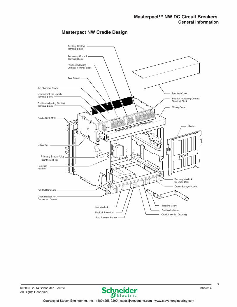
Masterpact NW Cradle Design
FRONTPrimary Stabs (UL)Clusters (IEC)
Courtesy of Steven Engineering, Inc. - (800) 258-9200 - [email protected] - www.stevenengineering.com
Masterpact™ NW DC Circuit Breakers General Information
806/2014 © 2007–2014 Schneider Electric
All Rights Reserved
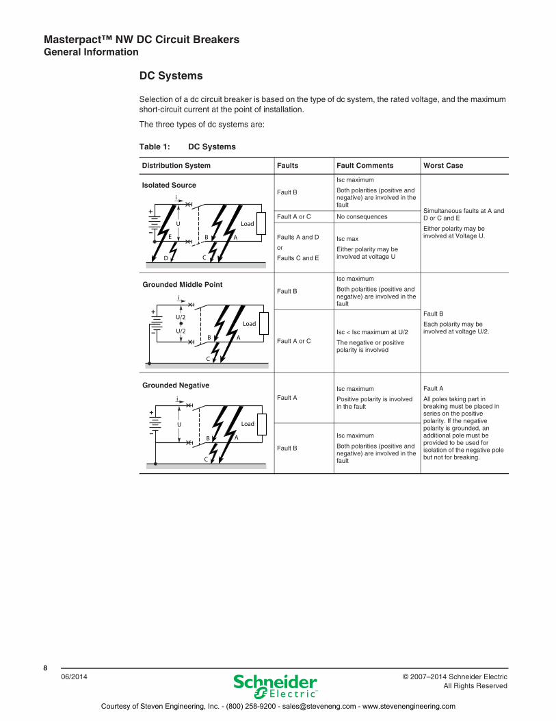
DC Systems
Selection of a dc circuit breaker is based on the type of dc system, the rated voltage, and the maximum short-circuit current at the point of installation.
The three types of dc systems are:
Table 1: DC Systems
Distribution System Faults Fault Comments Worst Case
Fault B
Isc maximum
Both polarities (positive and negative) are involved in the fault
Simultaneous faults at A and D or C and E
Either polarity may be involved at Voltage U.
Fault A or C No consequences
Faults A and D
or
Faults C and E
Isc max
Either polarity may be involved at voltage U
Fault B
Isc maximum
Both polarities (positive and negative) are involved in the fault
Fault B
Each polarity may be involved at voltage U/2.
Fault A or CIsc < Isc maximum at U/2
The negative or positive polarity is involved
Fault AIsc maximum
Positive polarity is involved in the fault
Fault A
All poles taking part in breaking must be placed in series on the positive polarity. If the negative polarity is grounded, an additional pole must be provided to be used for isolation of the negative pole but not for breaking.
Fault B
Isc maximum
Both polarities (positive and negative) are involved in the fault
Isolated Source
Grounded Middle Point
Grounded Negative
Courtesy of Steven Engineering, Inc. - (800) 258-9200 - [email protected] - www.stevenengineering.com
Masterpact™ NW DC Circuit Breakers General Information
906/2014© 2007–2014 Schneider Electric
All Rights Reserved
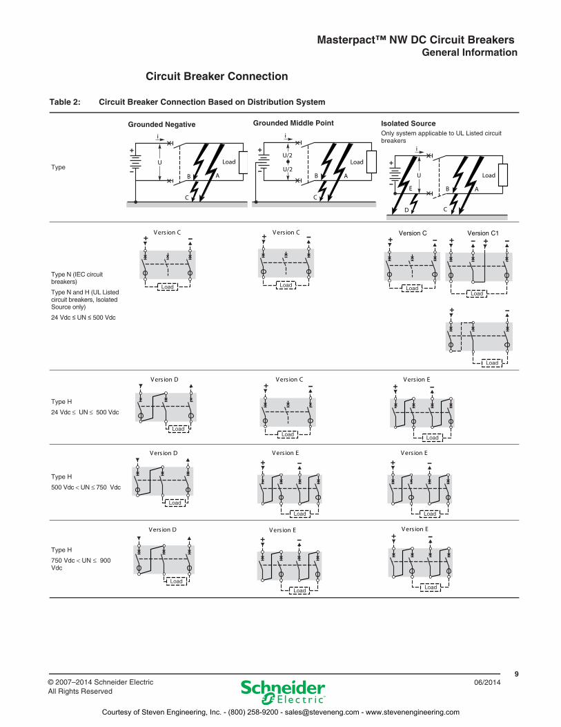
Circuit Breaker Connection
Table 2: Circuit Breaker Connection Based on Distribution System
Type
Type N (IEC circuit breakers)
Type N and H (UL Listed circuit breakers, Isolated Source only)
24 Vdc UN 500 Vdc
Type H
24 Vdc ≤ UN ≤ 500 Vdc
Type H
500 Vdc < UN ≤ 750 Vdc
Type H
750 Vdc < UN ≤ 900 Vdc
Grounded Negative Grounded Middle Point Isolated SourceOnly system applicable to UL Listed circuit breakers
C noisreV C noisreV C1 noisreV
Courtesy of Steven Engineering, Inc. - (800) 258-9200 - [email protected] - www.stevenengineering.com
Masterpact™ NW DC Circuit Breakers General Information
1006/2014 © 2007–2014 Schneider Electric
All Rights Reserved
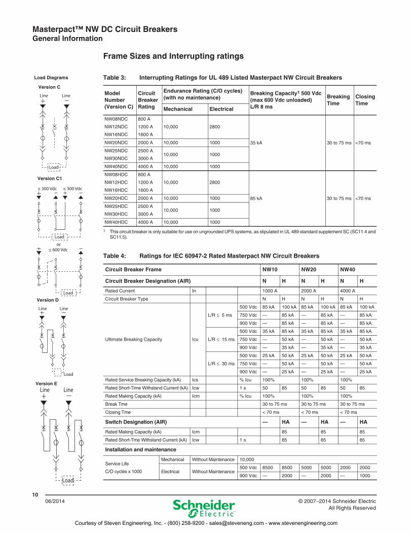
Frame Sizes and Interrupting ratings
Line Line
Load
LineLine
Load
≤ 300 Vdc
Load
or
Load
≤ 300 Vdc
≤ 600 Vdc
Version C
Version D
Version E
Load Diagrams
Version C1
Table 3: Interrupting Ratings for UL 489 Listed Masterpact NW Circuit Breakers
Model Number (Version C)
Circuit Breaker Rating
Endurance Rating (C/O cycles)(with no maintenance)
Breaking Capacity1 500 Vdc(max 600 Vdc unloaded) L/R 8 ms
1 This circuit breaker is only suitable for use on ungrounded UPS systems, as stipulated in UL 489 standard supplement SC (SC11.4 and SC11.5).
Breaking Time
Closing Time
Mechanical Electrical
NW08NDC
NW12NDC
NW16NDC
800 A
1200 A
1600 A
10,000 2800
35 kA 30 to 75 ms <70 msNW20NDC 2000 A 10,000 1000
NW25NDC
NW30NDC
2500 A
3000 A10,000 1000
NW40NDC 4000 A 10,000 1000
NW08HDC
NW12HDC
NW16HDC
800 A
1200 A
1600 A
10,000 2800
85 kA 30 to 75 ms <70 msNW20HDC 2000 A 10,000 1000
NW25HDC
NW30HDC
2500 A
3000 A10,000 1000
NW40HDC 4000 A 10,000 1000
Table 4: Ratings for IEC 60947-2 Rated Masterpact NW Circuit Breakers
Circuit Breaker Frame NW10 NW20 NW40
Circuit Breaker Designation (AIR) N H N H N H
Rated Current In 1000 A 2000 A 4000 A
Circuit Breaker Type N H N H N H
Ultimate Breaking Capacity Icu
L/R ≤ 5 ms
500 Vdc 85 kA 100 kA 85 kA 100 kA 85 kA 100 kA
750 Vdc — 85 kA — 85 kA — 85 kA
900 Vdc — 85 kA — 85 kA — 85 kA
L/R ≤ 15 ms
500 Vdc 35 kA 85 kA 35 kA 85 kA 35 kA 85 kA
750 Vdc — 50 kA — 50 kA — 50 kA
900 Vdc — 35 kA — 35 kA — 35 kA
L/R ≤ 30 ms
500 Vdc 25 kA 50 kA 25 kA 50 kA 25 kA 50 kA
750 Vdc — 50 kA — 50 kA — 50 kA
900 Vdc — 25 kA — 25 kA — 25 kA
Rated Service Breaking Capacity (kA) Ics % Icu 100% 100% 100%
Rated Short-Time Withstand Current (kA) Icw 1 s 50 85 50 85 50 85
Rated Making Capacity (kA) Icm % Icu 100% 100% 100%
Break Tme 30 to 75 ms 30 to 75 ms 30 to 75 ms
Closing Tme < 70 ms < 70 ms < 70 ms
Switch Designation (AIR) — HA — HA — HA
Rated Making Capacity (kA) Icm 85 85 85
Rated Short-Tme Withstand Current (kA) Icw 1 s 85 85 85
Installation and maintenance
Service Life
C/O cycles x 1000
Mechanical Without Maintenance 10,000
Electrical Without Maintenance500 Vdc 8500 8500 5000 5000 2000 2000
900 Vdc — 2000 — 2000 — 1000
Courtesy of Steven Engineering, Inc. - (800) 258-9200 - [email protected] - www.stevenengineering.com
Masterpact™ NW DC Circuit Breakers General Information
1106/2014© 2007–2014 Schneider Electric
All Rights Reserved
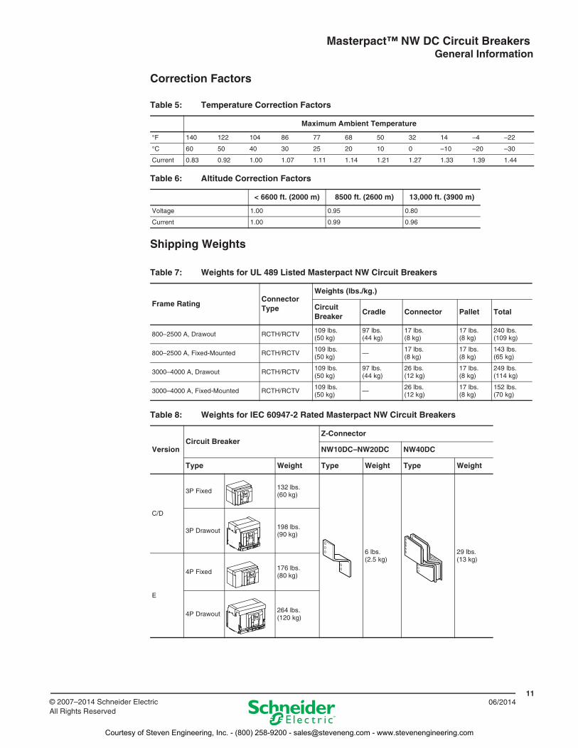
Correction Factors
Shipping Weights
Table 5: Temperature Correction Factors
Maximum Ambient Temperature
°F 140 122 104 86 77 68 50 32 14 –4 –22
°C 60 50 40 30 25 20 10 0 –10 –20 –30
Current 0.83 0.92 1.00 1.07 1.11 1.14 1.21 1.27 1.33 1.39 1.44
Table 6: Altitude Correction Factors
< 6600 ft. (2000 m) 8500 ft. (2600 m) 13,000 ft. (3900 m)
Voltage 1.00 0.95 0.80
Current 1.00 0.99 0.96
Table 7: Weights for UL 489 Listed Masterpact NW Circuit Breakers
Frame RatingConnector Type
Weights (lbs./kg.)
Circuit Breaker
Cradle Connector Pallet Total
800–2500 A, Drawout RCTH/RCTV 109 lbs.(50 kg)
97 lbs.(44 kg)
17 lbs.(8 kg)
17 lbs.(8 kg)
240 lbs.(109 kg)
800–2500 A, Fixed-Mounted RCTH/RCTV109 lbs.(50 kg) —
17 lbs.(8 kg)
17 lbs.(8 kg)
143 lbs.(65 kg)
3000–4000 A, Drawout RCTH/RCTV 109 lbs.(50 kg)
97 lbs.(44 kg)
26 lbs.(12 kg)
17 lbs.(8 kg)
249 lbs.(114 kg)
3000–4000 A, Fixed-Mounted RCTH/RCTV 109 lbs.(50 kg) — 26 lbs.
(12 kg)17 lbs.(8 kg)
152 lbs.(70 kg)
Table 8: Weights for IEC 60947-2 Rated Masterpact NW Circuit Breakers
VersionCircuit Breaker
Z-Connector
NW10DC–NW20DC NW40DC
Type Weight Type Weight Type Weight
C/D
3P Fixed 132 lbs.(60 kg)
6 lbs.(2.5 kg)
29 lbs.(13 kg)
3P Drawout 198 lbs.(90 kg)
E
4P Fixed176 lbs.(80 kg)
4P Drawout264 lbs.(120 kg)
Courtesy of Steven Engineering, Inc. - (800) 258-9200 - [email protected] - www.stevenengineering.com
Masterpact™ NW DC Circuit Breakers General Information
1206/2014 © 2007–2014 Schneider Electric
All Rights Reserved
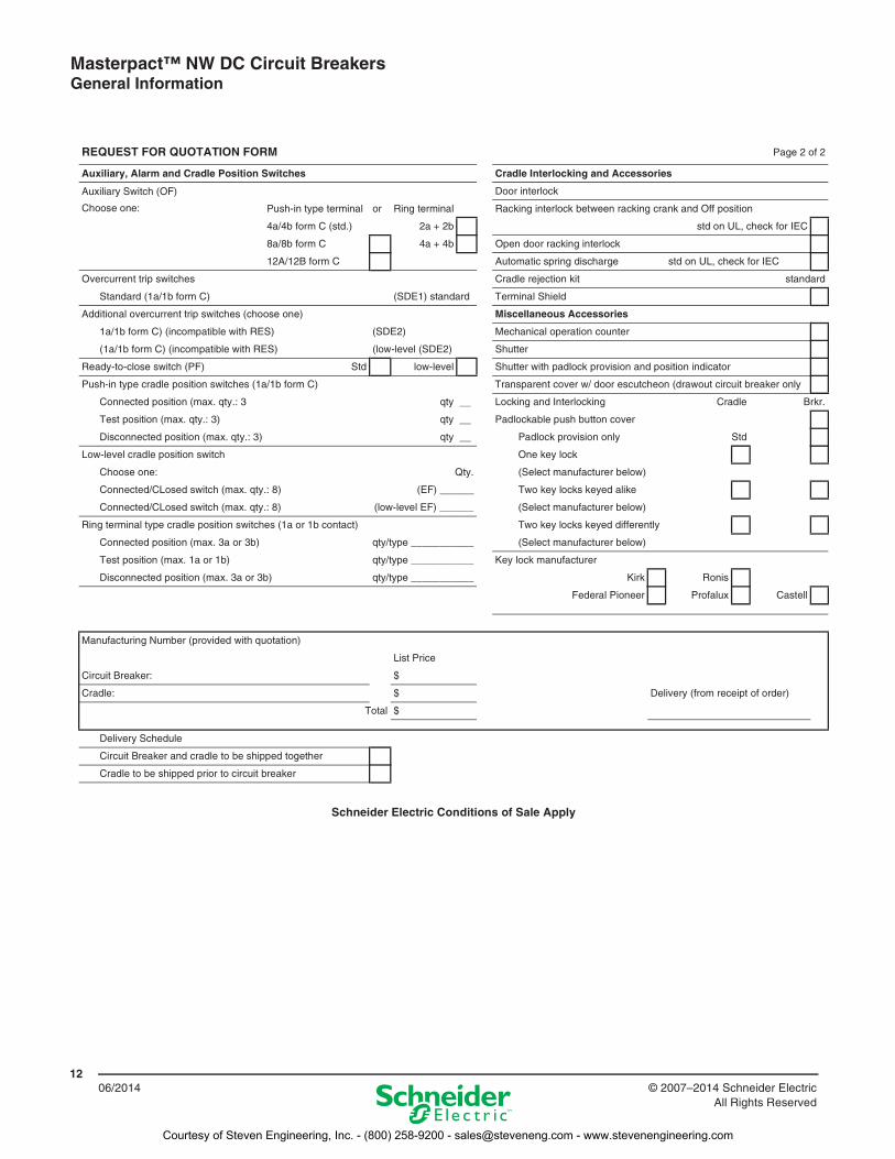
REQUEST FOR QUOTATION FORM Page 2 of 2
Auxiliary, Alarm and Cradle Position Switches Cradle Interlocking and Accessories
Auxiliary Switch (OF)
Choose one:
Door interlock
Push-in type terminal or Ring terminal Racking interlock between racking crank and Off position
4a/4b form C (std.) 2a + 2b std on UL, check for IEC
8a/8b form C 4a + 4b Open door racking interlock
12A/12B form C Automatic spring discharge std on UL, check for IEC
Overcurrent trip switches Cradle rejection kit standard
Standard (1a/1b form C) (SDE1) standard Terminal Shield
Additional overcurrent trip switches (choose one) Miscellaneous Accessories
1a/1b form C) (incompatible with RES) (SDE2) Mechanical operation counter
(1a/1b form C) (incompatible with RES) (low-level (SDE2) Shutter
Ready-to-close switch (PF) Std low-level Shutter with padlock provision and position indicator
Push-in type cradle position switches (1a/1b form C) Transparent cover w/ door escutcheon (drawout circuit breaker only
Connected position (max. qty.: 3 qty __ Locking and Interlocking Cradle Brkr.
Test position (max. qty.: 3) qty __ Padlockable push button cover
Disconnected position (max. qty.: 3) qty __ Padlock provision only Std
Low-level cradle position switch One key lock
Choose one: Qty. (Select manufacturer below)
Connected/CLosed switch (max. qty.: 8) (EF) ______ Two key locks keyed alike
Connected/CLosed switch (max. qty.: 8) (low-level EF) ______ (Select manufacturer below)
Ring terminal type cradle position switches (1a or 1b contact) Two key locks keyed differently
Connected position (max. 3a or 3b) qty/type ___________ (Select manufacturer below)
Test position (max. 1a or 1b) qty/type ___________ Key lock manufacturer
Disconnected position (max. 3a or 3b) qty/type ___________ Kirk Ronis
Federal Pioneer Profalux Castell
Manufacturing Number (provided with quotation)
List Price
Circuit Breaker: $
Cradle: $ Delivery (from receipt of order)
Total $
Delivery Schedule
Circuit Breaker and cradle to be shipped together
Cradle to be shipped prior to circuit breaker
Schneider Electric Conditions of Sale Apply
Courtesy of Steven Engineering, Inc. - (800) 258-9200 - [email protected] - www.stevenengineering.com
Masterpact™ NW DC Circuit Breakers Micrologic™ DC1.0 Trip Unit
1306/2014© 2007–2014 Schneider Electric
All Rights Reserved
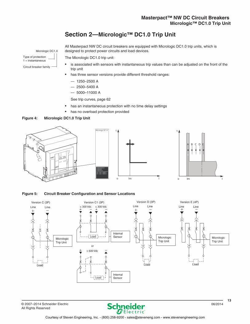
Section 2—Micrologic™ DC1.0 Trip Unit
All Masterpact NW DC circuit breakers are equipped with Micrologic DC1.0 trip units, which is designed to protect power circuits and load devices.
The Micrologic DC1.0 trip unit:
• is associated with sensors with instantaneous trip values than can be adjusted on the front of the trip unit
• has three sensor versions provide different threshold ranges:
— 1250–2500 A
— 2500–5400 A
— 5000–11000 A
See trip curves, page 62
• has an instantaneous protection with no time delay settings
• has no overload protection provided
Micrologic DC1.0
Circuit breaker family
Type of protection1 = instantaneous
Figure 4: Micrologic DC1.0 Trip Unit
Test
RESET
E1 = E2 = 5400 AA1 = A2 = 2500 A
instantaneousinstantaninstantan o
Figure 5: Circuit Breaker Configuration and Sensor Locations
≤ 300 Vdc
Load
or
Load
≤ 300 Vdc
≤ 600 Vdc
MicrologicTrip Unit
MicrologicTrip Unit
MicrologicTrip Unit
Line Line Line Line Line Line
Load Load Load
Version C (3P) Version D (3P) Version E (4P)Version C1 (3P)
InternalSensor
InternalSensor
Courtesy of Steven Engineering, Inc. - (800) 258-9200 - [email protected] - www.stevenengineering.com
Masterpact™ NW DC Circuit Breakers Micrologic™ DC1.0 Trip Unit
1406/2014 © 2007–2014 Schneider Electric
All Rights Reserved
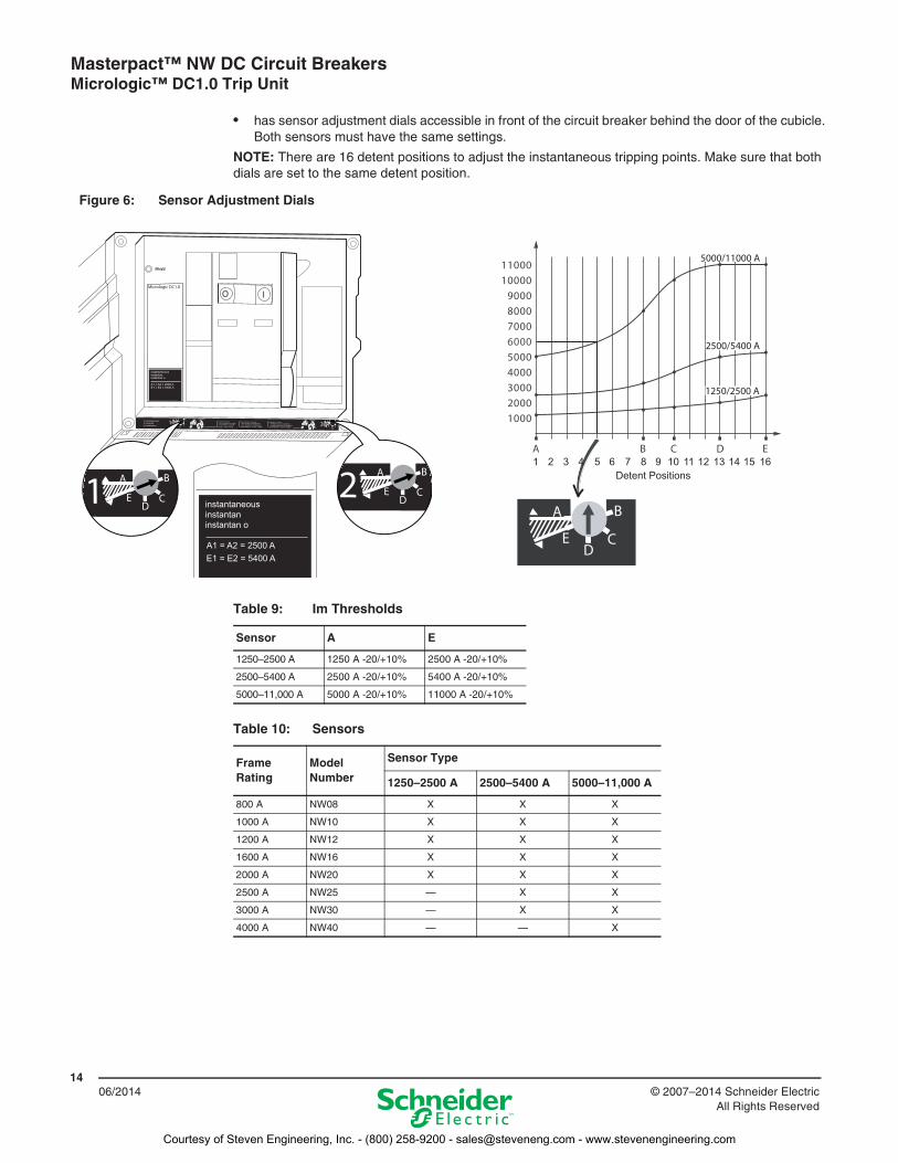
• has sensor adjustment dials accessible in front of the circuit breaker behind the door of the cubicle. Both sensors must have the same settings.
NOTE: There are 16 detent positions to adjust the instantaneous tripping points. Make sure that both dials are set to the same detent position.
Figure 6: Sensor Adjustment Dials
E1 = E2 = 5400 AA1 = A2 = 2500 A
instantaneousinstantaninstantan o
E1 = E2 = 5400 AA1 = A2 = 2500 A
instantaneousinstantaninstantan o
Detent Positions1 10 11 16157 8 94 5 62 3 141312
Table 9: Im Thresholds
Sensor A E
1250–2500 A 1250 A -20/+10% 2500 A -20/+10%
2500–5400 A 2500 A -20/+10% 5400 A -20/+10%
5000–11,000 A 5000 A -20/+10% 11000 A -20/+10%
Table 10: Sensors
Frame Rating
Model Number
Sensor Type
1250–2500 A 2500–5400 A 5000–11,000 A
800 A NW08 X X X
1000 A NW10 X X X
1200 A NW12 X X X
1600 A NW16 X X X
2000 A NW20 X X X
2500 A NW25 — X X
3000 A NW30 — X X
4000 A NW40 — — X
Courtesy of Steven Engineering, Inc. - (800) 258-9200 - [email protected] - www.stevenengineering.com
Masterpact™ NW DC Circuit Breakers Accessories
1506/2014© 2007–2014 Schneider Electric
All Rights Reserved
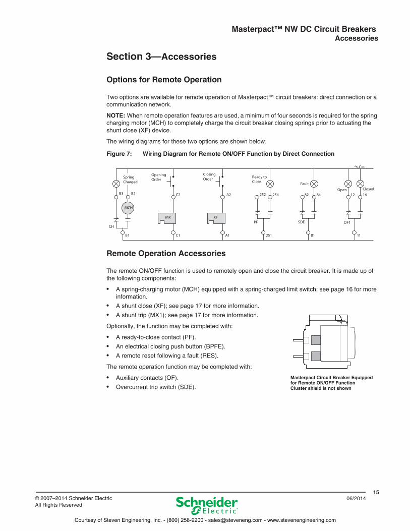
Section 3—Accessories
Options for Remote Operation
Two options are available for remote operation of Masterpact™ circuit breakers: direct connection or a communication network.
NOTE: When remote operation features are used, a minimum of four seconds is required for the spring charging motor (MCH) to completely charge the circuit breaker closing springs prior to actuating the shunt close (XF) device.
The wiring diagrams for these two options are shown below.
Remote Operation Accessories
The remote ON/OFF function is used to remotely open and close the circuit breaker. It is made up of the following components:
• A spring-charging motor (MCH) equipped with a spring-charged limit switch; see page 16 for more information.
• A shunt close (XF); see page 17 for more information.
• A shunt trip (MX1); see page 17 for more information.
Optionally, the function may be completed with:
• A ready-to-close contact (PF).
• An electrical closing push button (BPFE).
• A remote reset following a fault (RES).
The remote operation function may be completed with:
• Auxiliary contacts (OF).
• Overcurrent trip switch (SDE).
Figure 7: Wiring Diagram for Remote ON/OFF Function by Direct Connection
Masterpact Circuit Breaker Equipped for Remote ON/OFF FunctionCluster shield is not shown
Courtesy of Steven Engineering, Inc. - (800) 258-9200 - [email protected] - www.stevenengineering.com
Masterpact™ NW DC Circuit Breakers Accessories
1606/2014 © 2007–2014 Schneider Electric
All Rights Reserved
Terminals
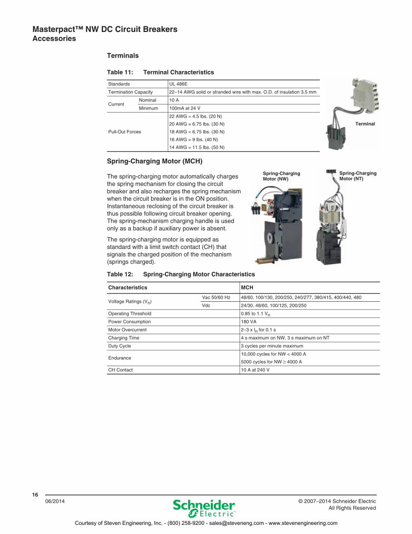
Spring-Charging Motor (MCH)
The spring-charging motor automatically charges the spring mechanism for closing the circuit breaker and also recharges the spring mechanism when the circuit breaker is in the ON position. Instantaneous reclosing of the circuit breaker is thus possible following circuit breaker opening. The spring-mechanism charging handle is used only as a backup if auxiliary power is absent.
The spring-charging motor is equipped as standard with a limit switch contact (CH) that signals the charged position of the mechanism (springs charged).
Table 11: Terminal Characteristics
Standards UL 486E
Termination Capacity 22–14 AWG solid or stranded wire with max. O.D. of insulation 3.5 mm
CurrentNominal 10 A
Minimum 100mA at 24 V
Pull-Out Forces
22 AWG = 4.5 lbs. (20 N)
20 AWG = 6.75 lbs. (30 N)
18 AWG = 6.75 lbs. (30 N)
16 AWG = 9 lbs. (40 N)
14 AWG = 11.5 lbs. (50 N)
Table 12: Spring-Charging Motor Characteristics
Characteristics MCH
Voltage Ratings (Vn)Vac 50/60 Hz 48/60, 100/130, 200/250, 240/277, 380/415, 400/440, 480
Vdc 24/30, 48/60, 100/125, 200/250
Operating Threshold 0.85 to 1.1 Vn
Power Consumption 180 VA
Motor Overcurrent 2–3 x In for 0.1 s
Charging Time 4 s maximum on NW, 3 s maximum on NT
Duty Cycle 3 cycles per minute maximum
Endurance10,000 cycles for NW < 4000 A
5000 cycles for NW ≥ 4000 A
CH Contact 10 A at 240 V
Terminal
Spring-Charging Motor (NW)
Spring-Charging Motor (NT)
Courtesy of Steven Engineering, Inc. - (800) 258-9200 - [email protected] - www.stevenengineering.com
Masterpact™ NW DC Circuit Breakers Accessories
1706/2014© 2007–2014 Schneider Electric
All Rights Reserved
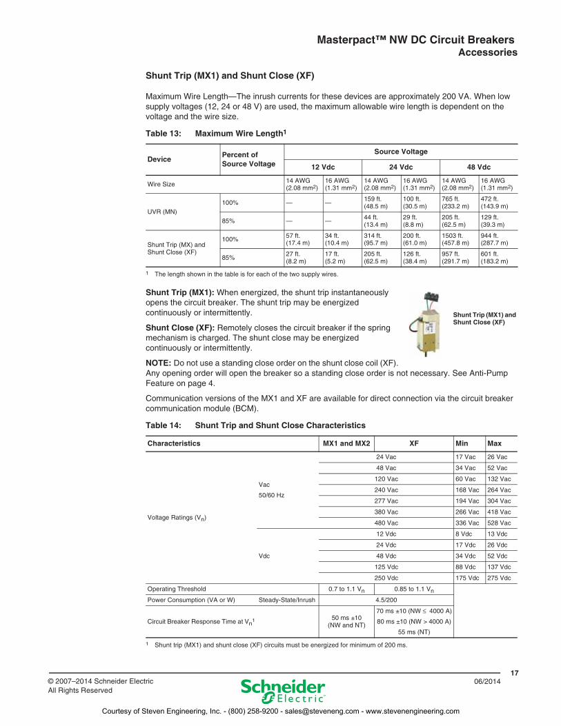
Shunt Trip (MX1) and Shunt Close (XF)
Maximum Wire Length—The inrush currents for these devices are approximately 200 VA. When low supply voltages (12, 24 or 48 V) are used, the maximum allowable wire length is dependent on the voltage and the wire size.
Shunt Trip (MX1): When energized, the shunt trip instantaneously opens the circuit breaker. The shunt trip may be energized continuously or intermittently.
Shunt Close (XF): Remotely closes the circuit breaker if the spring mechanism is charged. The shunt close may be energized continuously or intermittently.
NOTE: Do not use a standing close order on the shunt close coil (XF). Any opening order will open the breaker so a standing close order is not necessary. See Anti-Pump Feature on page 4.
Communication versions of the MX1 and XF are available for direct connection via the circuit breaker communication module (BCM).
Table 13: Maximum Wire Length1
1 The length shown in the table is for each of the two supply wires.
DevicePercent of Source Voltage
Source Voltage
12 Vdc 24 Vdc 48 Vdc
Wire Size 14 AWG (2.08 mm2)
16 AWG (1.31 mm2)
14 AWG (2.08 mm2)
16 AWG (1.31 mm2)
14 AWG (2.08 mm2)
16 AWG (1.31 mm2)
UVR (MN)100% — —
159 ft. (48.5 m)
100 ft. (30.5 m)
765 ft. (233.2 m)
472 ft. (143.9 m)
85% — — 44 ft. (13.4 m)
29 ft. (8.8 m)
205 ft. (62.5 m)
129 ft. (39.3 m)
Shunt Trip (MX) and Shunt Close (XF)
100% 57 ft. (17.4 m)
34 ft. (10.4 m)
314 ft. (95.7 m)
200 ft. (61.0 m)
1503 ft. (457.8 m)
944 ft. (287.7 m)
85%27 ft. (8.2 m)
17 ft. (5.2 m)
205 ft. (62.5 m)
126 ft. (38.4 m)
957 ft. (291.7 m)
601 ft. (183.2 m)
Table 14: Shunt Trip and Shunt Close Characteristics
Characteristics MX1 and MX2 XF Min Max
Voltage Ratings (Vn)
Vac
50/60 Hz
24 Vac 17 Vac 26 Vac
48 Vac 34 Vac 52 Vac
120 Vac 60 Vac 132 Vac
240 Vac 168 Vac 264 Vac
277 Vac 194 Vac 304 Vac
380 Vac 266 Vac 418 Vac
480 Vac 336 Vac 528 Vac
Vdc
12 Vdc 8 Vdc 13 Vdc
24 Vdc 17 Vdc 26 Vdc
48 Vdc 34 Vdc 52 Vdc
125 Vdc 88 Vdc 137 Vdc
250 Vdc 175 Vdc 275 Vdc
Operating Threshold 0.7 to 1.1 Vn 0.85 to 1.1 Vn
Power Consumption (VA or W) Steady-State/Inrush 4.5/200
Circuit Breaker Response Time at Vn1
1 Shunt trip (MX1) and shunt close (XF) circuits must be energized for minimum of 200 ms.
50 ms ±10 (NW and NT)
70 ms ±10 (NW ≤ 4000 A)
80 ms ±10 (NW > 4000 A)
55 ms (NT)
Shunt Trip (MX1) and Shunt Close (XF)
Courtesy of Steven Engineering, Inc. - (800) 258-9200 - [email protected] - www.stevenengineering.com
Masterpact™ NW DC Circuit Breakers Accessories
1806/2014 © 2007–2014 Schneider Electric
All Rights Reserved
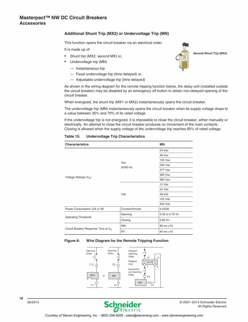
Additional Shunt Trip (MX2) or Undervoltage Trip (MN)
This function opens the circuit breaker via an electrical order.
It is made up of:
• Shunt trip (MX2, second MX) or,
• Undervoltage trip (MN)
— Instantaneous trip
— Fixed undervoltage trip (time delayed) or,
— Adjustable undervoltage trip (time delayed)
As shown in the wiring diagram for the remote tripping function below, the delay unit (installed outside the circuit breaker) may be disabled by an emergency off button to obtain non-delayed opening of the circuit breaker.
When energized, the shunt trip (MX1 or MX2) instantaneously opens the circuit breaker.
The undervoltage trip (MN) instantaneously opens the circuit breaker when its supply voltage drops to a value between 35% and 70% of its rated voltage.
If the undervoltage trip is not energized, it is impossible to close the circuit breaker, either manually or electrically. An attempt to close the circuit breaker produces no movement of the main contacts. Closing is allowed when the supply voltage of the undervoltage trip reaches 85% of rated voltage.
Table 15: Undervoltage Trip Characteristics
Characteristics MN
Voltage Ratings (Vn)
Vac
50/60 Hz
24 Vac
48 Vac
120 Vac
240 Vac
277 Vac
380 Vac
480 Vac
Vdc
12 Vdc
24 Vdc
48 Vdc
125 Vdc
250 Vdc
Power Consumption (VA or W) Constant/Inrush 4.5/200
Operating ThresholdOpening 0.35 to 0.70 Vn
Closing 0.85 Vn
Circuit Breaker Response Time at VnNW 90 ms ±10
NT 40 ms ±10
Figure 8: Wire Diagram for the Remote Tripping Function
Second Shunt Trip (MX2)
Courtesy of Steven Engineering, Inc. - (800) 258-9200 - [email protected] - www.stevenengineering.com
Masterpact™ NW DC Circuit Breakers Accessories
1906/2014© 2007–2014 Schneider Electric
All Rights Reserved
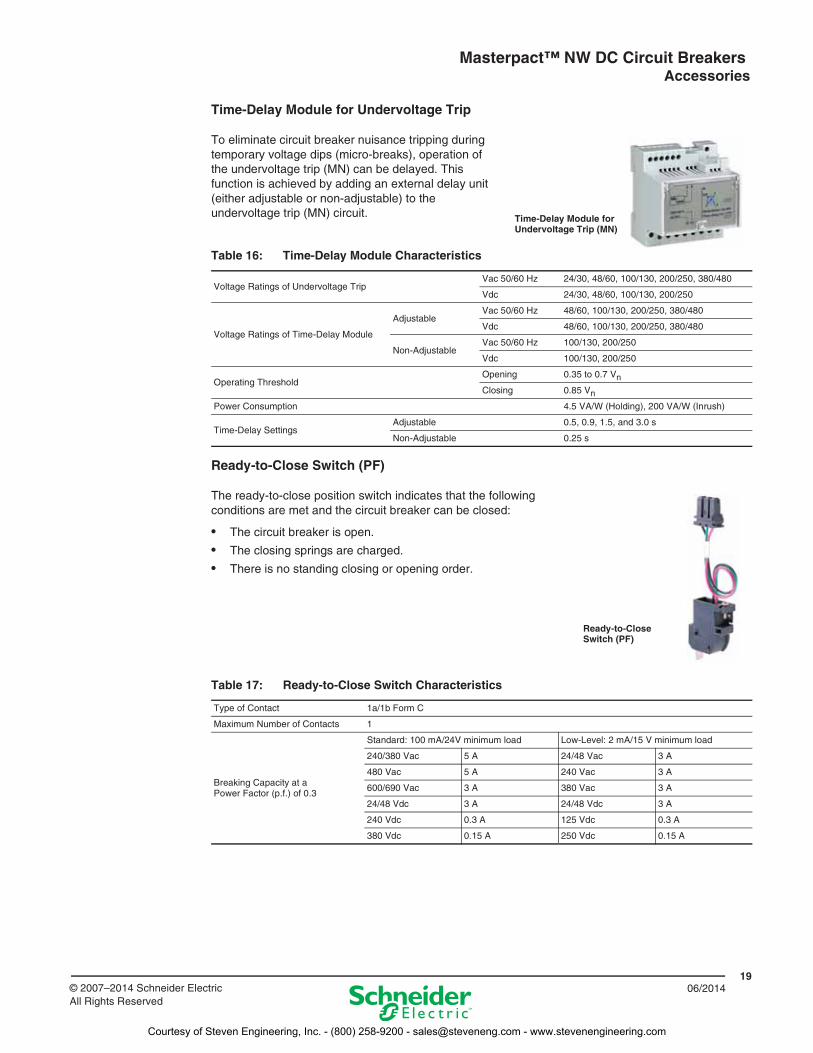
Time-Delay Module for Undervoltage Trip
To eliminate circuit breaker nuisance tripping during temporary voltage dips (micro-breaks), operation of the undervoltage trip (MN) can be delayed. This function is achieved by adding an external delay unit (either adjustable or non-adjustable) to the undervoltage trip (MN) circuit.
Ready-to-Close Switch (PF)
The ready-to-close position switch indicates that the following conditions are met and the circuit breaker can be closed:
• The circuit breaker is open.
• The closing springs are charged.
• There is no standing closing or opening order.
Table 16: Time-Delay Module Characteristics
Voltage Ratings of Undervoltage TripVac 50/60 Hz 24/30, 48/60, 100/130, 200/250, 380/480
Vdc 24/30, 48/60, 100/130, 200/250
Voltage Ratings of Time-Delay Module
AdjustableVac 50/60 Hz 48/60, 100/130, 200/250, 380/480
Vdc 48/60, 100/130, 200/250, 380/480
Non-AdjustableVac 50/60 Hz 100/130, 200/250
Vdc 100/130, 200/250
Operating ThresholdOpening 0.35 to 0.7 Vn
Closing 0.85 Vn
Power Consumption 4.5 VA/W (Holding), 200 VA/W (Inrush)
Time-Delay SettingsAdjustable 0.5, 0.9, 1.5, and 3.0 s
Non-Adjustable 0.25 s
Time-Delay Module for Undervoltage Trip (MN)
Ready-to-Close Switch (PF)
Table 17: Ready-to-Close Switch Characteristics
Type of Contact 1a/1b Form C
Maximum Number of Contacts 1
Breaking Capacity at a Power Factor (p.f.) of 0.3
Standard: 100 mA/24V minimum load Low-Level: 2 mA/15 V minimum load
240/380 Vac 5 A 24/48 Vac 3 A
480 Vac 5 A 240 Vac 3 A
600/690 Vac 3 A 380 Vac 3 A
24/48 Vdc 3 A 24/48 Vdc 3 A
240 Vdc 0.3 A 125 Vdc 0.3 A
380 Vdc 0.15 A 250 Vdc 0.15 A
Courtesy of Steven Engineering, Inc. - (800) 258-9200 - [email protected] - www.stevenengineering.com
Masterpact™ NW DC Circuit Breakers Accessories
2006/2014 © 2007–2014 Schneider Electric
All Rights Reserved
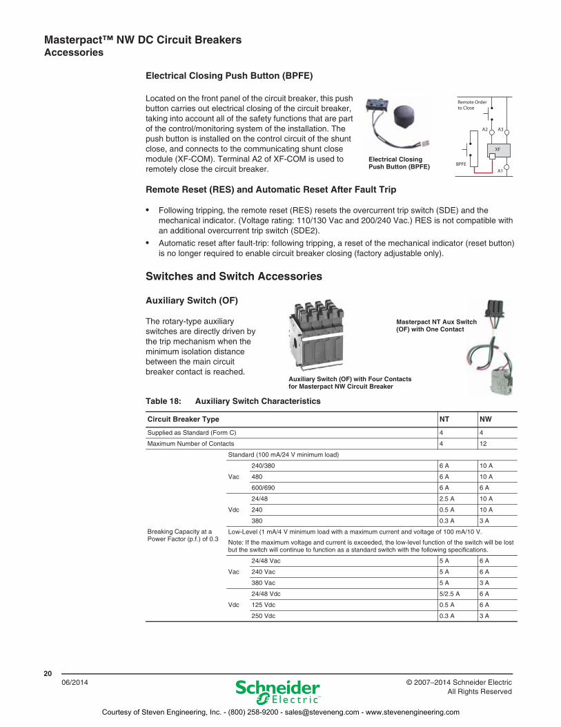
Electrical Closing Push Button (BPFE)
Located on the front panel of the circuit breaker, this push button carries out electrical closing of the circuit breaker, taking into account all of the safety functions that are part of the control/monitoring system of the installation. The push button is installed on the control circuit of the shunt close, and connects to the communicating shunt close module (XF-COM). Terminal A2 of XF-COM is used to remotely close the circuit breaker.
Remote Reset (RES) and Automatic Reset After Fault Trip
• Following tripping, the remote reset (RES) resets the overcurrent trip switch (SDE) and the mechanical indicator. (Voltage rating: 110/130 Vac and 200/240 Vac.) RES is not compatible with an additional overcurrent trip switch (SDE2).
• Automatic reset after fault-trip: following tripping, a reset of the mechanical indicator (reset button) is no longer required to enable circuit breaker closing (factory adjustable only).
Switches and Switch Accessories
Auxiliary Switch (OF)
The rotary-type auxiliary switches are directly driven by the trip mechanism when the minimum isolation distance between the main circuit breaker contact is reached.
Table 18: Auxiliary Switch Characteristics
Circuit Breaker Type NT NW
Supplied as Standard (Form C) 4 4
Maximum Number of Contacts 4 12
Breaking Capacity at a Power Factor (p.f.) of 0.3
Standard (100 mA/24 V minimum load)
Vac
240/380 6 A 10 A
480 6 A 10 A
600/690 6 A 6 A
Vdc
24/48 2.5 A 10 A
240 0.5 A 10 A
380 0.3 A 3 A
Low-Level (1 mA/4 V minimum load with a maximum current and voltage of 100 mA/10 V.
Note: If the maximum voltage and current is exceeded, the low-level function of the switch will be lost but the switch will continue to function as a standard switch with the following specifications.
Vac
24/48 Vac 5 A 6 A
240 Vac 5 A 6 A
380 Vac 5 A 3 A
Vdc
24/48 Vdc 5/2.5 A 6 A
125 Vdc 0.5 A 6 A
250 Vdc 0.3 A 3 A
Electrical Closing Push Button (BPFE)
Auxiliary Switch (OF) with Four Contacts for Masterpact NW Circuit Breaker
Masterpact NT Aux Switch (OF) with One Contact
Courtesy of Steven Engineering, Inc. - (800) 258-9200 - [email protected] - www.stevenengineering.com
Masterpact™ NW DC Circuit Breakers Accessories
2106/2014© 2007–2014 Schneider Electric
All Rights Reserved
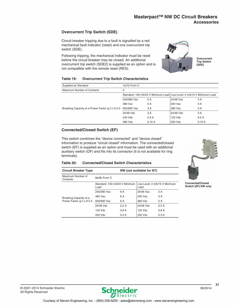
Overcurrent Trip Switch (SDE)
Circuit breaker tripping due to a fault is signalled by a red mechanical fault indicator (reset) and one overcurrent trip switch (SDE).
Following tripping, the mechanical indicator must be reset before the circuit breaker may be closed. An additional overcurrent trip switch (SDE2) is supplied as an option and is not compatible with the remote reset (RES).
Connected/Closed Switch (EF)
This switch combines the “device connected” and “device closed” information to produce “circuit closed” information. The connected/closed switch (EF) is supplied as an option and must be used with an additional auxiliary switch (OF) and fits into its connector (it is not available for ring terminals).
Table 19: Overcurrent Trip Switch Characteristics
Supplied as Standard 1a/1b Form C
Maximum Number of Contacts 2
Breaking Capacity at a Power Factor (p.f.) of 0.3
Standard: 100 mA/24 V Minimum Load Low-Level: 2 mA/15 V Minimum Load
240/380 Vac
480 Vac
600/690 Vac
5 A
5 A
3 A
24/48 Vac
240 Vac
380 Vac
3 A
3 A
3 A
24/48 Vdc
240 Vdc
380 Vdc
3 A
0.3 A
0.15 A
24/48 Vdc
125 Vdc
250 Vdc
3 A
0.3 A
0.15 A
Table 20: Connected/Closed Switch Characteristics
Circuit Breaker Type NW (not available for NT)
Maximum Number of Contacts 8a/8b Form C
Breaking Capacity at aPower Factor (p.f.) of 0.3
Standard: 100 mA/24 V Minimum Load
Low-Level: 2 mA/15 V Minimum Load
240/380 Vac 6 A 24/48 Vac 5 A
480 Vac 6 A 240 Vac 5 A
600/690 Vac 6 A 380 Vac 5 A
24/48 Vdc 2.5 A 24/48 Vdc 2.5 A
125 Vdc 0.8 A 125 Vdc 0.8 A
250 Vdc 0.3 A 250 Vdc 0.3 A
Overcurrent Trip Switch (SDE)
Connected/Closed Switch (EF) NW only
Courtesy of Steven Engineering, Inc. - (800) 258-9200 - [email protected] - www.stevenengineering.com
Masterpact™ NW DC Circuit Breakers Accessories
2206/2014 © 2007–2014 Schneider Electric
All Rights Reserved
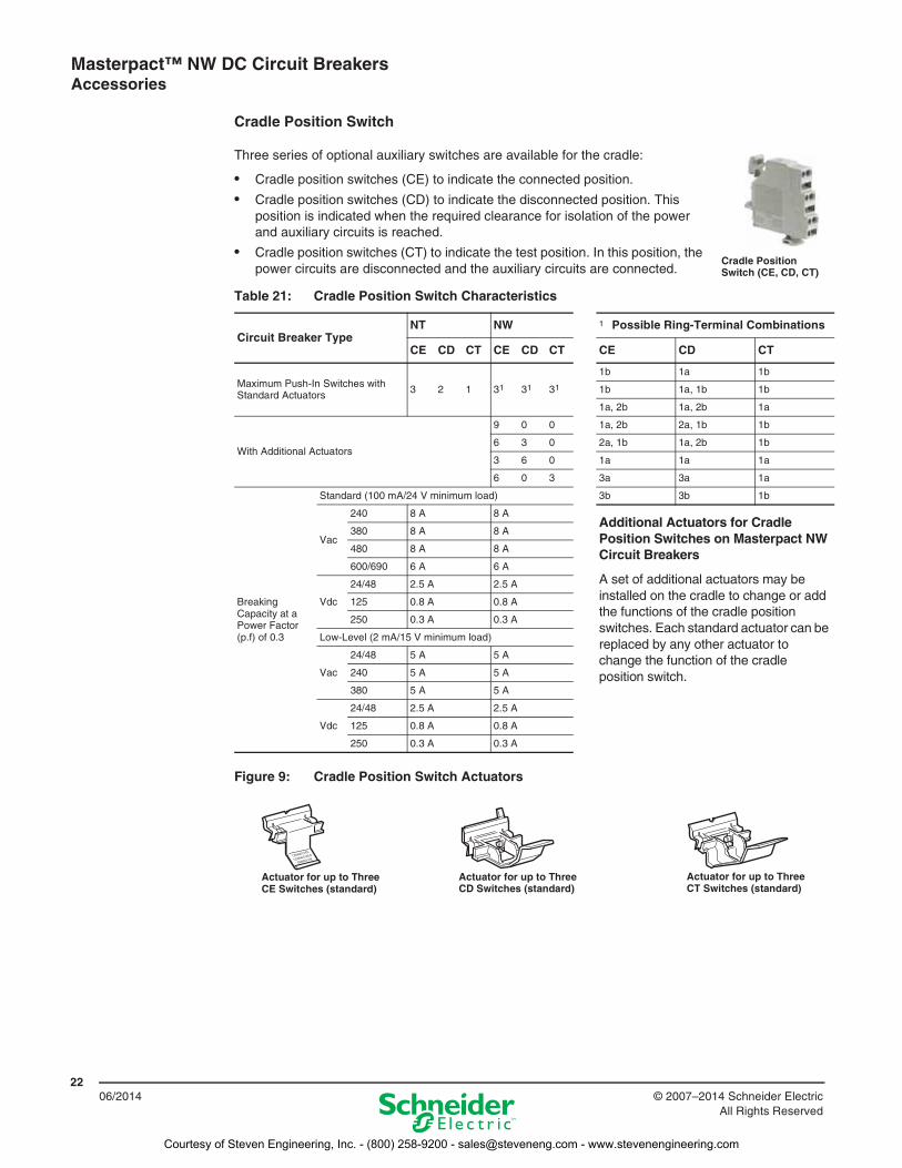
Cradle Position Switch
Three series of optional auxiliary switches are available for the cradle:
• Cradle position switches (CE) to indicate the connected position.
• Cradle position switches (CD) to indicate the disconnected position. This position is indicated when the required clearance for isolation of the power and auxiliary circuits is reached.
• Cradle position switches (CT) to indicate the test position. In this position, the power circuits are disconnected and the auxiliary circuits are connected.
Table 21: Cradle Position Switch Characteristics
Circuit Breaker TypeNT NW 1 Possible Ring-Terminal Combinations
CE CD CT CE CD CT CE CD CT
Maximum Push-In Switches with Standard Actuators 3 2 1 31 31 31
1b 1a 1b
1b 1a, 1b 1b
1a, 2b 1a, 2b 1a
With Additional Actuators
9 0 0 1a, 2b 2a, 1b 1b
6 3 0 2a, 1b 1a, 2b 1b
3 6 0 1a 1a 1a
6 0 3 3a 3a 1a
Breaking Capacity at a Power Factor (p.f) of 0.3
Standard (100 mA/24 V minimum load) 3b 3b 1b
Vac
240 8 A 8 AAdditional Actuators for Cradle Position Switches on Masterpact NW Circuit Breakers
A set of additional actuators may be installed on the cradle to change or add the functions of the cradle position switches. Each standard actuator can be replaced by any other actuator to change the function of the cradle position switch.
380 8 A 8 A
480 8 A 8 A
600/690 6 A 6 A
Vdc
24/48 2.5 A 2.5 A
125 0.8 A 0.8 A
250 0.3 A 0.3 A
Low-Level (2 mA/15 V minimum load)
Vac
24/48 5 A 5 A
240 5 A 5 A
380 5 A 5 A
Vdc
24/48 2.5 A 2.5 A
125 0.8 A 0.8 A
250 0.3 A 0.3 A
Figure 9: Cradle Position Switch Actuators
Cradle Position Switch (CE, CD, CT)
Actuator for up to Three CE Switches (standard)
Actuator for up to Three CD Switches (standard)
Actuator for up to Three CT Switches (standard)
Courtesy of Steven Engineering, Inc. - (800) 258-9200 - [email protected] - www.stevenengineering.com
Masterpact™ NW DC Circuit Breakers Accessories
2306/2014© 2007–2014 Schneider Electric
All Rights Reserved
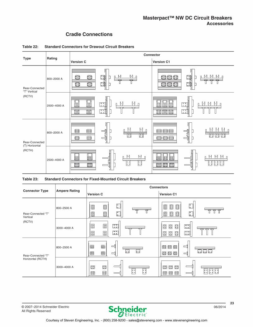
Cradle Connections
Table 22: Standard Connectors for Drawout Circuit Breakers
Type RatingConnector
Version C Version C1
Rear-Connected “T” Vertical
(RCTV)
800–2000 A
2500–4000 A
Rear-Connected (T) Horizontal
(RCTH)
800–2000 A
2500–4000 A
Table 23: Standard Connectors for Fixed-Mounted Circuit Breakers
Connector Type Ampere RatingConnectors
Version C Version C1
Rear-Connected “T” Vertical
(RCTV)
800–2500 A
3000–4000 A
Rear-Connected “T” Horizontal (RCTH)
800–2500 A
3000–4000 A
Courtesy of Steven Engineering, Inc. - (800) 258-9200 - [email protected] - www.stevenengineering.com
Masterpact™ NW DC Circuit Breakers Accessories
2406/2014 © 2007–2014 Schneider Electric
All Rights Reserved
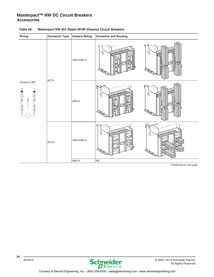
Table 24: Masterpact NW IEC Rated 3P/4P Drawout Circuit Breakers
Wiring Connector Type Ampere Rating Connector and Bussing
Version C (3P)RCTV
1000–2000 A
4000 A
RCTH1000–2000 A
4000 A NA
Continued on next page
1
Courtesy of Steven Engineering, Inc. - (800) 258-9200 - [email protected] - www.stevenengineering.com
Masterpact™ NW DC Circuit Breakers Accessories
2506/2014© 2007–2014 Schneider Electric
All Rights Reserved
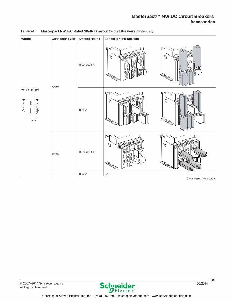
Version D (3P)RCTV
1000–2000 A
4000 A
RCTH1000–2000 A
4000 A NA
Continued on next page
Table 24: Masterpact NW IEC Rated 3P/4P Drawout Circuit Breakers (continued)
Wiring Connector Type Ampere Rating Connector and Bussing
Courtesy of Steven Engineering, Inc. - (800) 258-9200 - [email protected] - www.stevenengineering.com
Masterpact™ NW DC Circuit Breakers Accessories
2606/2014 © 2007–2014 Schneider Electric
All Rights Reserved
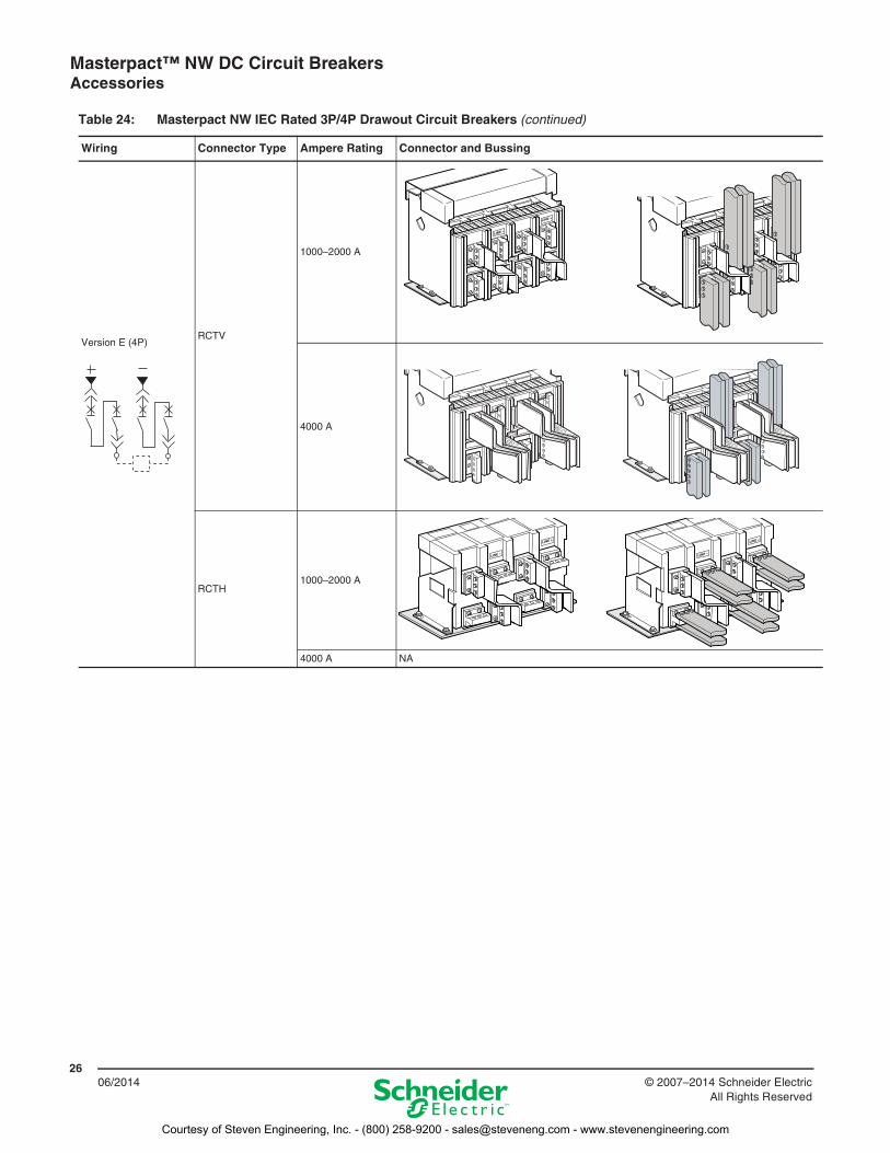
Version E (4P)RCTV
1000–2000 A
4000 A
RCTH1000–2000 A
4000 A NA
Table 24: Masterpact NW IEC Rated 3P/4P Drawout Circuit Breakers (continued)
Wiring Connector Type Ampere Rating Connector and Bussing
Courtesy of Steven Engineering, Inc. - (800) 258-9200 - [email protected] - www.stevenengineering.com
Masterpact™ NW DC Circuit Breakers Accessories
2706/2014© 2007–2014 Schneider Electric
All Rights Reserved
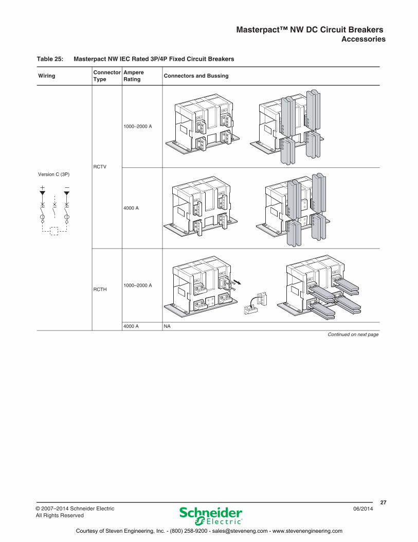
Table 25: Masterpact NW IEC Rated 3P/4P Fixed Circuit Breakers
WiringConnector Type
Ampere Rating
Connectors and Bussing
Version C (3P)
RCTV
1000–2000 A
4000 A
RCTH1000–2000 A
4000 A NA
Continued on next page
Courtesy of Steven Engineering, Inc. - (800) 258-9200 - [email protected] - www.stevenengineering.com
Masterpact™ NW DC Circuit Breakers Accessories
2806/2014 © 2007–2014 Schneider Electric
All Rights Reserved
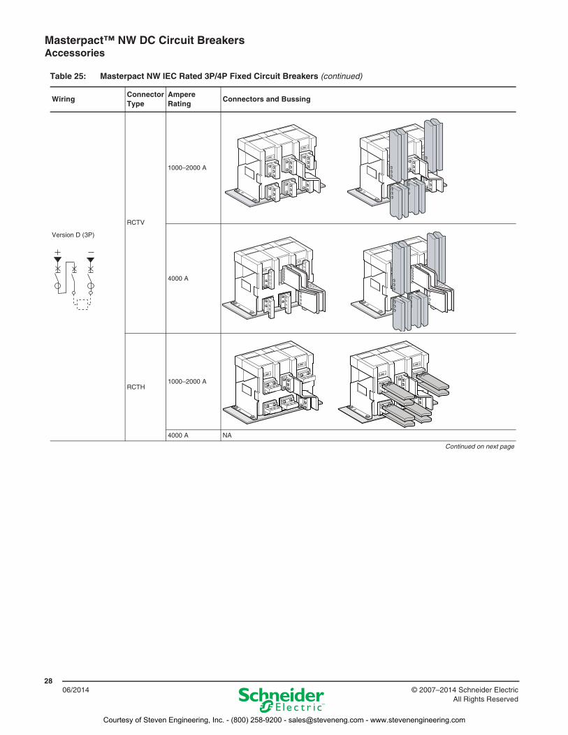
Version D (3P)
RCTV
1000–2000 A
4000 A
RCTH1000–2000 A
4000 A NA
Continued on next page
Table 25: Masterpact NW IEC Rated 3P/4P Fixed Circuit Breakers (continued)
WiringConnector Type
Ampere Rating
Connectors and Bussing
Courtesy of Steven Engineering, Inc. - (800) 258-9200 - [email protected] - www.stevenengineering.com

Masterpact™ NW DC Circuit Breakers Accessories
2906/2014© 2007–2014 Schneider Electric
All Rights Reserved
Version E (4P)
RCTV
1000–2000 A
4000 A
RCTH1000–2000 A
4000 A NA
Table 25: Masterpact NW IEC Rated 3P/4P Fixed Circuit Breakers (continued)
WiringConnector Type
Ampere Rating
Connectors and Bussing
Courtesy of Steven Engineering, Inc. - (800) 258-9200 - [email protected] - www.stevenengineering.com
Masterpact™ NW DC Circuit Breakers Accessories
3006/2014 © 2007–2014 Schneider Electric
All Rights Reserved
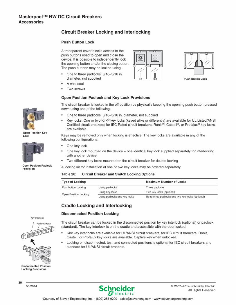
Circuit Breaker Locking and Interlocking
Push Button Lock
A transparent cover blocks access to the push buttons used to open and close the device. It is possible to independently lock the opening button and/or the closing button. The push buttons may be locked using:
• One to three padlocks: 3/16–5/16 in. diameter, not supplied
• A wire seal
• Two screws
Open Position Padlock and Key Lock Provisions
The circuit breaker is locked in the off position by physically keeping the opening push button pressed down using one of the following:
• One to three padlocks: 3/16–5/16 in. diameter, not supplied
• Key locks: One or two Kirk® key locks (keyed alike or differently) are available for UL Listed/ANSI Certified circuit breakers; for IEC Rated circuit breakers, Ronis®, Castell®, or Profalux® key locks are available
Keys may be removed only when locking is effective. The key locks are available in any of the following configurations:
• One key lock
• One key lock mounted on the device + one identical key lock supplied separately for interlocking with another device
• Two different key locks mounted on the circuit breaker for double locking
A locking kit for installation of one or two key locks may be ordered separately.
Cradle Locking and Interlocking
Disconnected Position Locking
The circuit breaker can be locked in the disconnected position by key interlock (optional) or padlock (standard). The key interlock is on the cradle and accessible with the door locked.
• Kirk key interlocks are available for UL/ANSI circuit breakers; for IEC circuit breakers, Ronis, Castell, or Profalux key locks are available. Captive key when unlocked.
• Locking on disconnected, test, and connected positions is optional for IEC circuit breakers and standard for UL/ANSI circuit breakers.
push OFF
O Ipush ON
Push Button Lock
Open Position Key Lock
Open Position Padlock Provision
Table 26: Circuit Breaker and Switch Locking Options
Type of Locking Maximum Number of Locks
Pushbutton Locking Using padlocks Three padlocks
Open Position LockingUsing key locks Two key locks (optional)
Using padlocks and key locks Up to three padlocks and two key locks (optional)
Test
Key Interlock
Padlock Hasp
Disconnected Position Locking Provisions
Courtesy of Steven Engineering, Inc. - (800) 258-9200 - [email protected] - www.stevenengineering.com
Masterpact™ NW DC Circuit Breakers Accessories
3106/2014© 2007–2014 Schneider Electric
All Rights Reserved
Door Interlock
The door interlock prevents the compartment door from being opened when the circuit breaker is in the connected or test position. If the circuit breaker is put into the connected position with the door open, the door can be closed without disconnecting the circuit breaker. For greater protection, this interlock can be used in conjunction with the open door racking interlock.
Racking Interlock Between Racking Crank and Off Position
The racking interlock is standard for UL and ANSI circuit breakers, and optional for IEC circuit breakers. It prevents insertion of the racking crank unless the OFF push button is pressed.
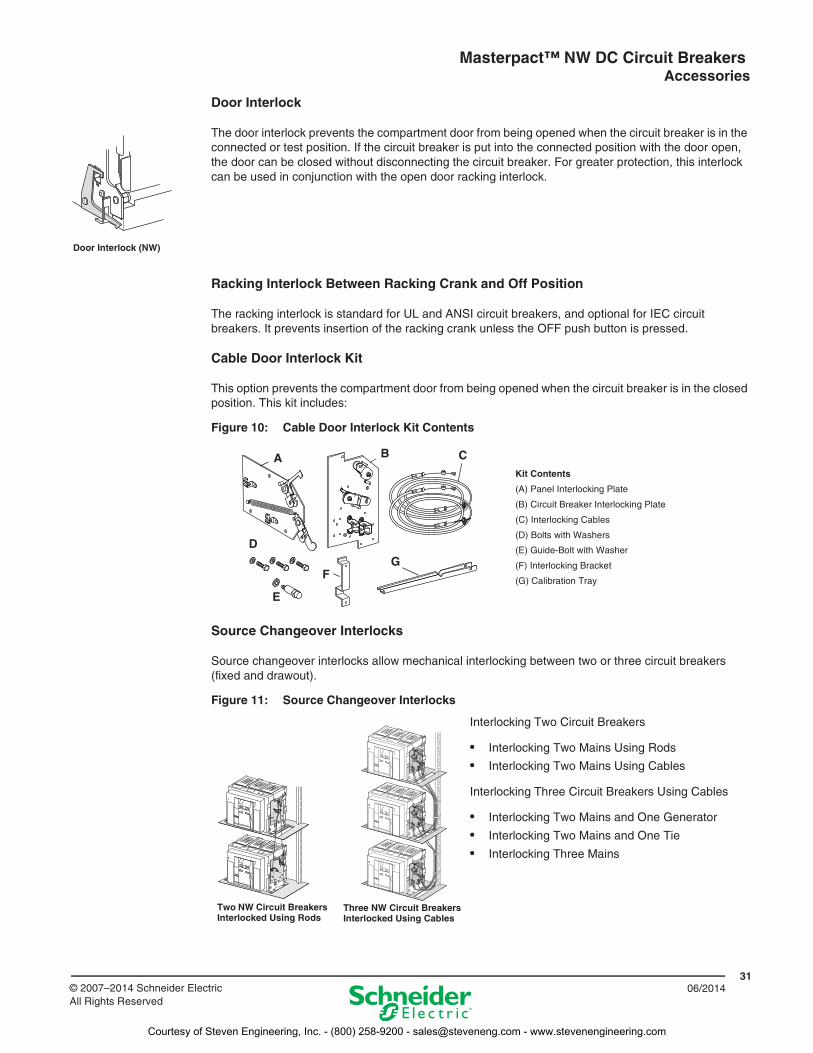
Cable Door Interlock Kit
This option prevents the compartment door from being opened when the circuit breaker is in the closed position. This kit includes:
Source Changeover Interlocks
Source changeover interlocks allow mechanical interlocking between two or three circuit breakers (fixed and drawout).
Door Interlock (NW)
Figure 10: Cable Door Interlock Kit Contents
Kit Contents
(A) Panel Interlocking Plate
(B) Circuit Breaker Interlocking Plate
(C) Interlocking Cables
(D) Bolts with Washers
(E) Guide-Bolt with Washer
(F) Interlocking Bracket
(G) Calibration Tray
Figure 11: Source Changeover Interlocks
Interlocking Two Circuit Breakers
• Interlocking Two Mains Using Rods
• Interlocking Two Mains Using Cables
Interlocking Three Circuit Breakers Using Cables
• Interlocking Two Mains and One Generator
• Interlocking Two Mains and One Tie
• Interlocking Three Mains
A B C
E
FG
D
Two NW Circuit Breakers Interlocked Using Rods
Three NW Circuit Breakers Interlocked Using Cables
Courtesy of Steven Engineering, Inc. - (800) 258-9200 - [email protected] - www.stevenengineering.com
Masterpact™ NW DC Circuit Breakers Accessories
3206/2014 © 2007–2014 Schneider Electric
All Rights Reserved
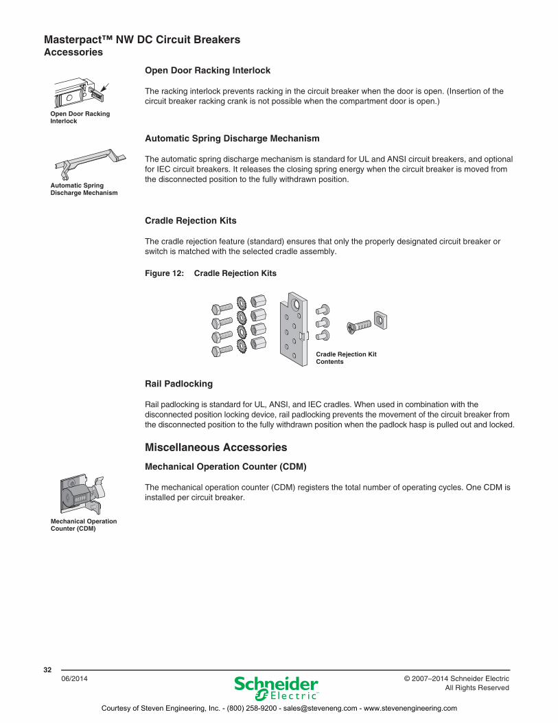
Open Door Racking Interlock
The racking interlock prevents racking in the circuit breaker when the door is open. (Insertion of the circuit breaker racking crank is not possible when the compartment door is open.)
Automatic Spring Discharge Mechanism
The automatic spring discharge mechanism is standard for UL and ANSI circuit breakers, and optional for IEC circuit breakers. It releases the closing spring energy when the circuit breaker is moved from the disconnected position to the fully withdrawn position.
Cradle Rejection Kits
The cradle rejection feature (standard) ensures that only the properly designated circuit breaker or switch is matched with the selected cradle assembly.
Rail Padlocking
Rail padlocking is standard for UL, ANSI, and IEC cradles. When used in combination with the disconnected position locking device, rail padlocking prevents the movement of the circuit breaker from the disconnected position to the fully withdrawn position when the padlock hasp is pulled out and locked.
Miscellaneous Accessories
Mechanical Operation Counter (CDM)
The mechanical operation counter (CDM) registers the total number of operating cycles. One CDM is installed per circuit breaker.
Open Door Racking Interlock
Automatic Spring Discharge Mechanism
Figure 12: Cradle Rejection Kits
Cradle Rejection Kit Contents
Mechanical Operation Counter (CDM)
Courtesy of Steven Engineering, Inc. - (800) 258-9200 - [email protected] - www.stevenengineering.com
Masterpact™ NW DC Circuit Breakers Accessories
3306/2014© 2007–2014 Schneider Electric
All Rights Reserved
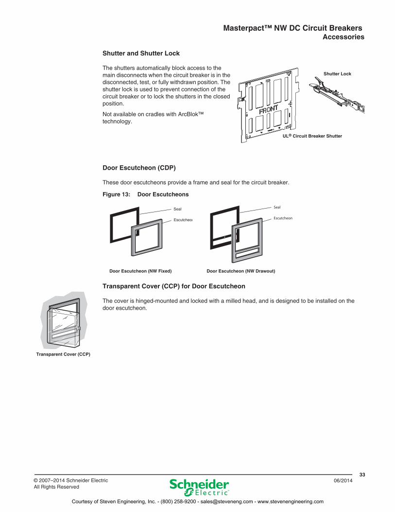
Shutter and Shutter Lock
The shutters automatically block access to the main disconnects when the circuit breaker is in the disconnected, test, or fully withdrawn position. The shutter lock is used to prevent connection of the circuit breaker or to lock the shutters in the closed position.
Not available on cradles with ArcBlok™ technology.
Door Escutcheon (CDP)
These door escutcheons provide a frame and seal for the circuit breaker.
Transparent Cover (CCP) for Door Escutcheon
The cover is hinged-mounted and locked with a milled head, and is designed to be installed on the door escutcheon.
Figure 13: Door Escutcheons
Shutter Lock
UL® Circuit Breaker Shutter
Escutcheon
Seal
Door Escutcheon (NW Drawout)Door Escutcheon (NW Fixed)
Transparent Cover (CCP)
Courtesy of Steven Engineering, Inc. - (800) 258-9200 - [email protected] - www.stevenengineering.com
Masterpact™ NW DC Circuit Breakers Wiring Diagrams
3406/2014 © 2007–2014 Schneider Electric
All Rights Reserved
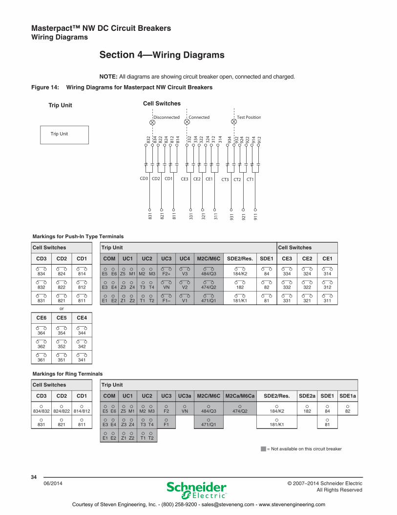
Section 4—Wiring Diagrams
NOTE: All diagrams are showing circuit breaker open, connected and charged.
Figure 14: Wiring Diagrams for Masterpact NW Circuit Breakers
Markings for Push-In Type Terminals
Cell Switches Trip Unit Cell Switches
CD3 CD2 CD1 COM UC1 UC2 UC3 UC4 M2C/M6C SDE2/Res. SDE1 CE3 CE2 CE1
834 824 814 E5 E6 Z5 M1 M2 M3 F2+ V3 484/Q3 184/K2 84 334 324 314
832 822 812 E3 E4 Z3 Z4 T3 T4 VN V2 474/Q2 182 82 332 322 312
831 821 811 E1 E2 Z1 Z2 T1 T2 F1– V1 471/Q1 181/K1 81 331 321 311
or
CE6 CE5 CE4
364 354 344
362 352 342
361 351 341
Markings for Ring Terminals
Cell Switches Trip Unit
CD3 CD2 CD1 COM UC1 UC2 UC3 UC3a M2C/M6C M2Ca/M6Ca SDE2/Res. SDE2a SDE1 SDE1a
834/832 824/822 814/812 E5 E6 Z5 M1 M2 M3 F2 VN 484/Q3 474/Q2 184/K2 182 84 82
831 821 811 E3 E4 Z3 Z4 T3 T4 F1 471/Q1 181/K1 81
E1 E2 Z1 Z2 T1 T2
Trip Unit Cell Switches
Trip Unit
= Not available on this circuit breaker
Courtesy of Steven Engineering, Inc. - (800) 258-9200 - [email protected] - www.stevenengineering.com
Masterpact™ NW DC Circuit Breakers Wiring Diagrams
3506/2014© 2007–2014 Schneider Electric
All Rights Reserved
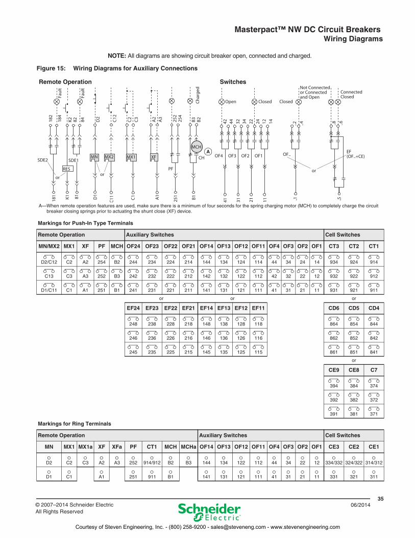
NOTE: All diagrams are showing circuit breaker open, connected and charged.
Figure 15: Wiring Diagrams for Auxiliary Connections
Markings for Push-In Type Terminals
Remote Operation Auxiliary Switches Cell Switches
MN/MX2 MX1 XF PF MCH OF24 OF23 OF22 OF21 OF14 OF13 OF12 OF11 OF4 OF3 OF2 OF1 CT3 CT2 CT1
D2/C12 C2 A2 254 B2 244 234 224 214 144 134 124 114 44 34 24 14 934 924 914
C13 C3 A3 252 B3 242 232 222 212 142 132 122 112 42 32 22 12 932 922 912
D1/C11 C1 A1 251 B1 241 231 221 211 141 131 121 111 41 31 21 11 931 921 911
or or or
EF24 EF23 EF22 EF21 EF14 EF13 EF12 EF11 CD6 CD5 CD4
248 238 228 218 148 138 128 118 864 854 844
246 236 226 216 146 136 126 116 862 852 842
245 235 225 215 145 135 125 115 861 851 841
or
CE9 CE8 C7
394 384 374
392 382 372
391 381 371
Markings for Ring Terminals
Remote Operation Auxiliary Switches Cell Switches
MN MX1 MX1a XF XFa PF CT1 MCH MCHa OF14 OF13 OF12 OF11 OF4 OF3 OF2 OF1 CE3 CE2 CE1
D2 C2 C3 A2 A3 252 914/912 B2 B3 144 134 122 112 44 34 22 12 334/332 324/322 314/312
D1 C1 A1 251 911 B1 141 131 121 111 41 31 21 11 331 321 311
SwitchesRemote Operation
A
A—When remote operation features are used, make sure there is a minimum of four seconds for the spring charging motor (MCH) to completely charge the circuit breaker closing springs prior to actuating the shunt close (XF) device.
Courtesy of Steven Engineering, Inc. - (800) 258-9200 - [email protected] - www.stevenengineering.com
Masterpact™ NW DC Circuit Breakers Wiring Diagrams
3606/2014 © 2007–2014 Schneider Electric
All Rights Reserved
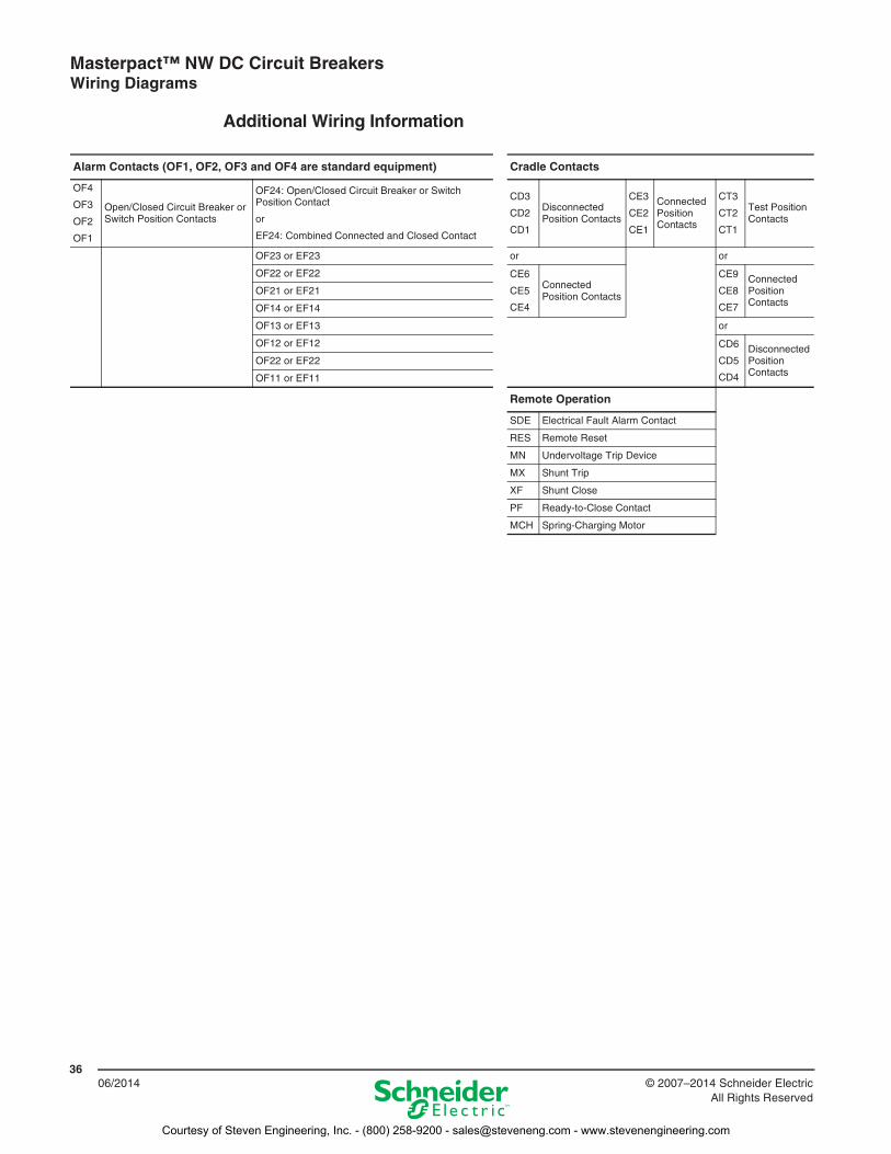
Additional Wiring Information
Alarm Contacts (OF1, OF2, OF3 and OF4 are standard equipment) Cradle Contacts
OF4
OF3
OF2
OF1
Open/Closed Circuit Breaker or Switch Position Contacts
OF24: Open/Closed Circuit Breaker or Switch Position Contact
or
EF24: Combined Connected and Closed Contact
CD3
CD2
CD1
Disconnected Position Contacts
CE3
CE2
CE1
Connected Position Contacts
CT3
CT2
CT1
Test Position Contacts
OF23 or EF23 or or
OF22 or EF22 CE6
CE5
CE4
Connected Position Contacts
CE9
CE8
CE7
Connected Position Contacts
OF21 or EF21
OF14 or EF14
OF13 or EF13 or
OF12 or EF12 CD6
CD5
CD4
Disconnected Position Contacts
OF22 or EF22
OF11 or EF11
Remote Operation
SDE Electrical Fault Alarm Contact
RES Remote Reset
MN Undervoltage Trip Device
MX Shunt Trip
XF Shunt Close
PF Ready-to-Close Contact
MCH Spring-Charging Motor
Courtesy of Steven Engineering, Inc. - (800) 258-9200 - [email protected] - www.stevenengineering.com
Masterpact™ NW DC Circuit Breakers Dimensional Drawings
3706/2014© 2007–2014 Schneider Electric
All Rights Reserved
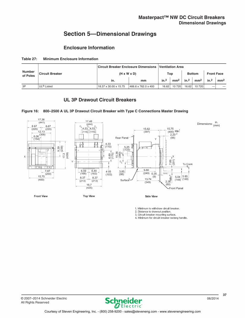
Section 5—Dimensional Drawings
Enclosure Information
UL 3P Drawout Circuit Breakers
Table 27: Minimum Enclosure Information
Number of Poles
Circuit Breaker
Circuit Breaker Enclosure Dimensions Ventilation Area
(H x W x D) Top Bottom Front Face
in. mm in.2 mm2 in.2 mm2 in.2 mm2
3P UL® Listed 18.37 x 30.00 x 15.75 466.6 x 762.0 x 400 16.62 10 720 16.62 10 720 — —
Figure 16: 800–2500 A UL 3P Drawout Circuit Breaker with Type C Connections Master Drawing
Dimensions: in.(mm)
Courtesy of Steven Engineering, Inc. - (800) 258-9200 - [email protected] - www.stevenengineering.com
Masterpact™ NW DC Circuit Breakers Dimensional Drawings
3806/2014 © 2007–2014 Schneider Electric
All Rights Reserved
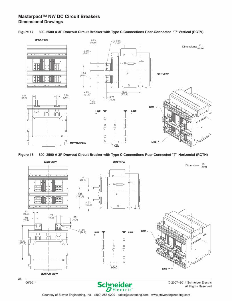
Figure 17: 800–2500 A 3P Drawout Circuit Breaker with Type C Connections Rear-Connected "T" Vertical (RCTV)
Figure 18: 800–2500 A 3P Drawout Circuit Breaker with Type C Connections Rear Connected "T" Horizontal (RCTH)
1.47(37,2)
0.79(20,1)
0.63(16,0)
0.56(14,2)
3.00(76,2)
10.4(255,1)
4.79(121,7)
1.75(44,5)
0.75(19,1)
15.09(383,2)
Dimensions: in.(mm)
.62(15,7)
1.02(25,9)
1.75(44,5) .75
(19,1)
.56(14,2)
15.09(383,2)
.79(20,1)
9.48(240,8)
4.23(107,5)
Dimensions: in.(mm)
Courtesy of Steven Engineering, Inc. - (800) 258-9200 - [email protected] - www.stevenengineering.com
Masterpact™ NW DC Circuit Breakers Dimensional Drawings
3906/2014© 2007–2014 Schneider Electric
All Rights Reserved
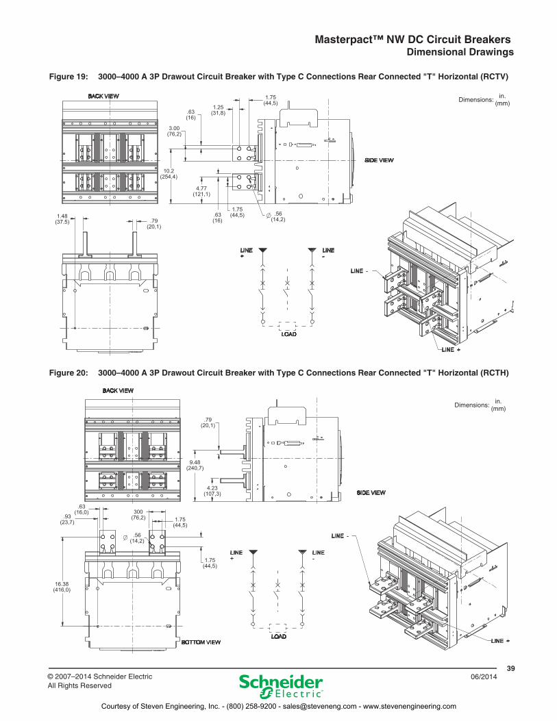
Figure 19: 3000–4000 A 3P Drawout Circuit Breaker with Type C Connections Rear Connected "T" Horizontal (RCTV)
1.48(37.5) .79
(20,1)
.63(16)
3.00(76,2)
.63(16)
10.2(254,4)
4.77(121,1)
1.25(31,8)
1.75(44,5)
1.75(44,5)
.56(14,2)
Dimensions:in.
(mm)
Figure 20: 3000–4000 A 3P Drawout Circuit Breaker with Type C Connections Rear Connected "T" Horizontal (RCTH)
.63(16,0)
.93(23,7)
16.38(416,0)
300(76,2) 1.75
(44,5)
.56(14,2)
1.75(44,5)
.79(20,1)
9.48(240,7)
4.23(107,3)
Dimensions:in.
(mm)
Courtesy of Steven Engineering, Inc. - (800) 258-9200 - [email protected] - www.stevenengineering.com
Masterpact™ NW DC Circuit Breakers Dimensional Drawings
4006/2014 © 2007–2014 Schneider Electric
All Rights Reserved
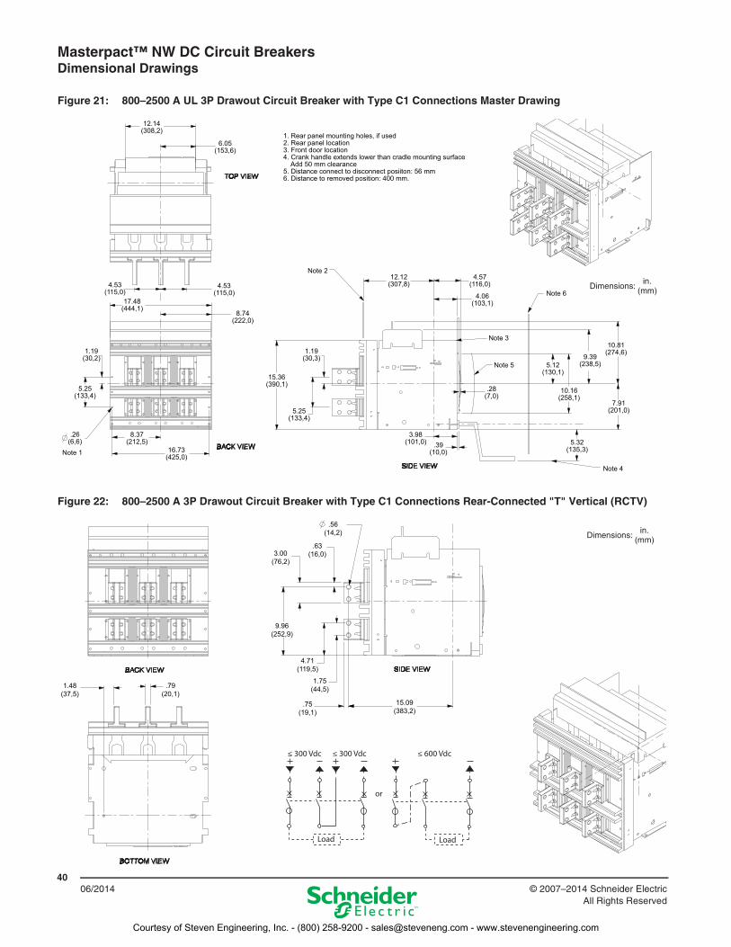
Figure 21: 800–2500 A UL 3P Drawout Circuit Breaker with Type C1 Connections Master Drawing
12.14(308,2)
6.05(153,6)
4.53(115,0)
4.53(115,0)
1.19(30,2)
5.25(133,4)
.26(6,6)
17.48(444,1)
8.74(222,0)
8.37(212,5)
16.73(425,0)
15.36(390,1)
1.19(30,3)
5.25(133,4)
12.12(307,8)
4.57(116,0)
4.06(103,1)
3.98(101,0) .39
(10,0)
.28(7,0)
5.12(130,1)
9.39(238,5)
10.81(274,6)
10.16(258,1)
7.91(201,0)
5.32(135,3)
1. Rear panel mounting holes, if used 2. Rear panel location3. Front door location4. Crank handle extends lower than cradle mounting surface Add 50 mm clearance5. Distance connect to disconnect posiiton: 56 mm6. Distance to removed position: 400 mm.
Note 1
Note 2
Note 3
Note 4
Note 5
Note 6Dimensions:
in.(mm)
Figure 22: 800–2500 A 3P Drawout Circuit Breaker with Type C1 Connections Rear-Connected "T" Vertical (RCTV)
1.48(37,5)
.79(20,1)
.56(14,2)
.63(16,0)3.00
(76,2)
9.96(252,9)
4.71(119,5)
1.75(44,5)
.75(19,1)
15.09(383,2)
≤ 300 Vdc
Load
or
Load
≤ 300 Vdc ≤ 600 Vdc
Dimensions:in.
(mm)
Courtesy of Steven Engineering, Inc. - (800) 258-9200 - [email protected] - www.stevenengineering.com
Masterpact™ NW DC Circuit Breakers Dimensional Drawings
4106/2014© 2007–2014 Schneider Electric
All Rights Reserved
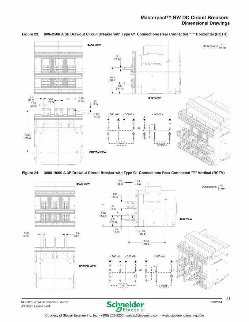
Figure 23: 800–2500 A 3P Drawout Circuit Breaker with Type C1 Connections Rear Connected "T" Horizontal (RCTH)
Figure 24: 3000–4000 A 3P Drawout Circuit Breaker with Type C1 Connections Rear Connected "T" Vertical (RCTV)
.79(20,1)
9.48(240,7)
4.23(107,4)
.63(16,0)
1.00(25,3)
15.09(383,2)
3.00(76,2)
1.75(44,5) .75
(19,1)
.56(14,2)
≤ 300 Vdc
Load
or
Load
≤ 300 Vdc ≤ 600 Vdc
Dimensions: in.(mm)
1.48(37,5)
.79(20,1)
1.25(31,8)
1.75(44,5)
3.00(76,2)
9.98(253,4)
.63(16,0)
4.73(120,0)
1.75(44,5) .56
(14,2)
16.34(415,0)
≤ 300 Vdc
Load
or
Load
≤ 300 Vdc ≤ 600 Vdc
Dimensions: in.(mm)
Courtesy of Steven Engineering, Inc. - (800) 258-9200 - [email protected] - www.stevenengineering.com
Masterpact™ NW DC Circuit Breakers Dimensional Drawings
4206/2014 © 2007–2014 Schneider Electric
All Rights Reserved
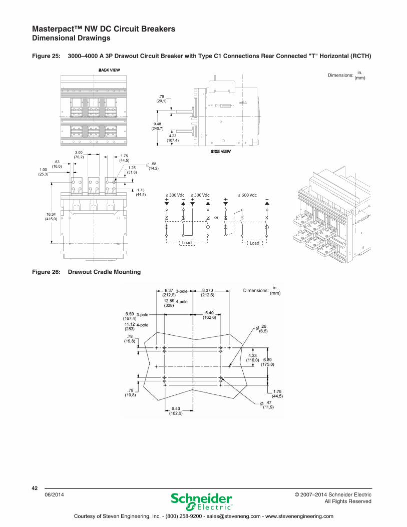
Figure 25: 3000–4000 A 3P Drawout Circuit Breaker with Type C1 Connections Rear Connected "T" Horizontal (RCTH)
Figure 26: Drawout Cradle Mounting
.79(20,1)
9.48(240,7)
4.23(107,4)
1.00(25.3)
.63(16,0)
3.00(76,2)
16.34(415,0)
.58(14,2)
1.75(44,5)
1.25(31,8)
1.75(44,5) ≤ 300 Vdc
Load
or
Load
≤ 300 Vdc ≤ 600 Vdc
Dimensions: in.(mm)
Dimensions:in.
(mm)
Courtesy of Steven Engineering, Inc. - (800) 258-9200 - [email protected] - www.stevenengineering.com
Masterpact™ NW DC Circuit Breakers Dimensional Drawings
4306/2014© 2007–2014 Schneider Electric
All Rights Reserved
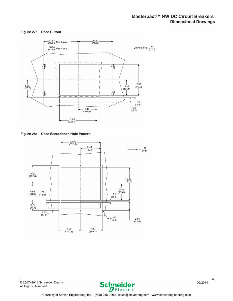
Figure 27: Door Cutout
Figure 28: Door Escutcheon Hole Pattern
Dimensions: in.(mm)
Dimensions:in.
(mm)
Courtesy of Steven Engineering, Inc. - (800) 258-9200 - [email protected] - www.stevenengineering.com
Masterpact™ NW DC Circuit Breakers Dimensional Drawings
4406/2014 © 2007–2014 Schneider Electric
All Rights Reserved
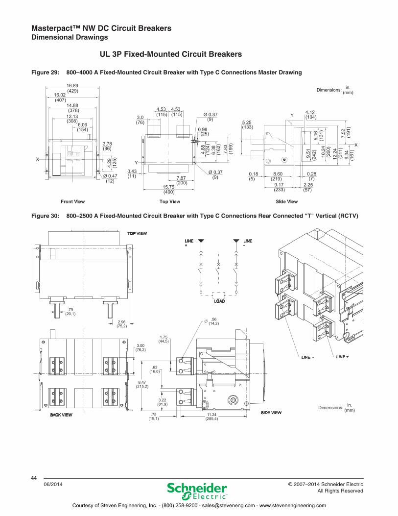
UL 3P Fixed-Mounted Circuit Breakers
Figure 29: 800–4000 A Fixed-Mounted Circuit Breaker with Type C Connections Master Drawing
Dimensions: in.(mm)
Figure 30: 800–2500 A Fixed-Mounted Circuit Breaker with Type C Connections Rear Connected "T" Vertical (RCTV)
1.75(44,5)
.79(20,1)
2.96(75,2)
3.00(76,2)
.56(14,2)
.63(16,0)
8.47(215,2)
3.22(81,9)
.75(19,1)
11.24(285,4)
Dimensions: in.(mm)
Courtesy of Steven Engineering, Inc. - (800) 258-9200 - [email protected] - www.stevenengineering.com
Masterpact™ NW DC Circuit Breakers Dimensional Drawings
4506/2014© 2007–2014 Schneider Electric
All Rights Reserved
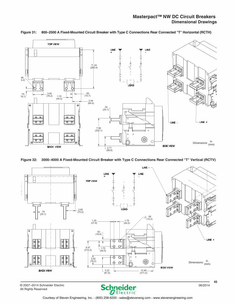
Figure 31: 800–2500 A Fixed-Mounted Circuit Breaker with Type C Connections Rear Connected "T" Horizontal (RCTH)
11.24(285,4)
564,2)
.7519,1)
3.00(76,2) 1.75
(44,5)
.62(15,7)
2.54(64,4)
.79(20,1)
2.71(68,8)
7.96(202,1)
Dimensions:in.
(mm)
Figure 32: 3000–4000 A Fixed-Mounted Circuit Breaker with Type C Connections Rear Connected "T" Vertical (RCTV)
.79(20,1)
2.95(75,0)
1.25(31,8)
1.75(44,5)
.56(14,2)
.63(16,0)
8.47(215,2)
1.75(44,5)
3.00(76,2)
3.22(81,9)
12.49(317,2)
Dimensions: in.(mm)
Courtesy of Steven Engineering, Inc. - (800) 258-9200 - [email protected] - www.stevenengineering.com
Masterpact™ NW DC Circuit Breakers Dimensional Drawings
4606/2014 © 2007–2014 Schneider Electric
All Rights Reserved
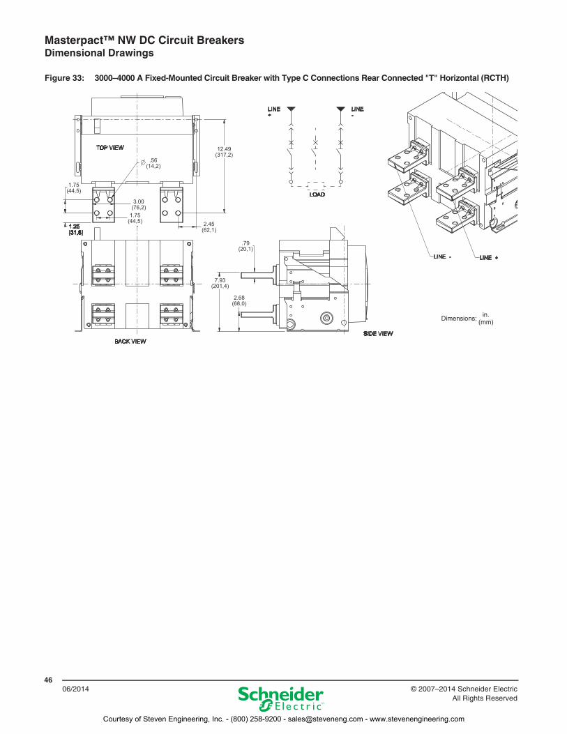
Figure 33: 3000–4000 A Fixed-Mounted Circuit Breaker with Type C Connections Rear Connected "T" Horizontal (RCTH)
2.68(68,0)
7.93(201,4)
.79(20,1)
2.45(62,1)
3.00(76,2)
1.75(44,5)
1.75(44,5)
.56(14,2)
12.49(317,2)
Dimensions:in.
(mm)
Courtesy of Steven Engineering, Inc. - (800) 258-9200 - [email protected] - www.stevenengineering.com
Masterpact™ NW DC Circuit Breakers Dimensional Drawings
4706/2014© 2007–2014 Schneider Electric
All Rights Reserved
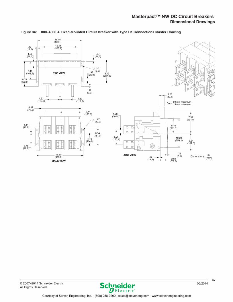
Figure 34: 800–4000 A Fixed-Mounted Circuit Breaker with Type C1 Connections Master Drawing
15.75(400,1)
12.14(308,2).43
(11,0)
1.50(38,2)
8.78(223,0)
6.40(162,5)
.57(14,5)
.37(9,5)
8.15(207,0)
.98(25,0)
.12(3,0)
4.53(115,0)
4.53(115,0)
14.87(377,8)
1.14(29,0)
3.78(96,0)
16.50(419,0)
7.44(188,9)
.47(12,0)
1.20(30,5)
4.49(114,0)
6.34(161,0) 5.25
(133,4)
2.00(50,8)
7.52(191,0)
5.16(131,1)
10.20(259,2) 6.34
(161,0)
.28(7,0)
2.84(72,2)
.57(14,5)
Door 60 mm maximum15 mm minimum
Dimensions: in.(mm)
Courtesy of Steven Engineering, Inc. - (800) 258-9200 - [email protected] - www.stevenengineering.com
Masterpact™ NW DC Circuit Breakers Dimensional Drawings
4806/2014 © 2007–2014 Schneider Electric
All Rights Reserved
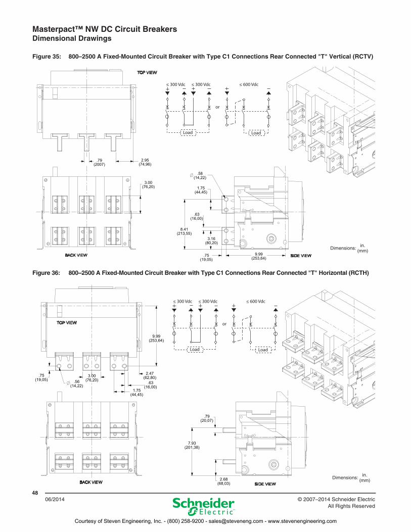
Figure 35: 800–2500 A Fixed-Mounted Circuit Breaker with Type C1 Connections Rear Connected "T" Vertical (RCTV)
.79(2007)
2.95(74,96)
3.00(76,20)
.58(14,22)
1.75(44,45)
.63(16,00)
8.41(213,55)
3.16(80,20)
.75(19,05)
9.99(253,64)
≤ 300 Vdc
Load
or
Load
≤ 300 Vdc ≤ 600 Vdc
Dimensions: in.(mm)
Figure 36: 800–2500 A Fixed-Mounted Circuit Breaker with Type C1 Connections Rear Connected "T" Horizontal (RCTH)
9.99(253,64)
.75(19,05) .56
(14,22)
3.00(76,20)
2.47(62,80)
.63(16,00)
1.75(44,45)
.79(20,07)
7.93(201,38)
2.68(68,03)
≤ 300 Vdc
Load
or
Load
≤ 300 Vdc ≤ 600 Vdc
Dimensions: in.(mm)
Courtesy of Steven Engineering, Inc. - (800) 258-9200 - [email protected] - www.stevenengineering.com
Masterpact™ NW DC Circuit Breakers Dimensional Drawings
4906/2014© 2007–2014 Schneider Electric
All Rights Reserved
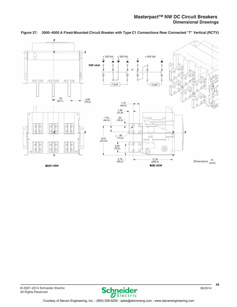
Figure 37: 3000–4000 A Fixed-Mounted Circuit Breaker with Type C1 Connections Rear Connected "T" Vertical (RCTV)
1.75(44,5)
.79(20,1) 2.95
(75,0)
1.85(31,8)
1.75(44,5)
8.41(213,5)
.63(16,0)
.56(14,2)
3.00(76,2)
3.16(80,2)
11.24(285,5)
≤ 300 Vdc
Load
or
Load
≤ 300 Vdc ≤ 600 Vdc
Dimensions: in.(mm)
Courtesy of Steven Engineering, Inc. - (800) 258-9200 - [email protected] - www.stevenengineering.com
Masterpact™ NW DC Circuit Breakers Dimensional Drawings
5006/2014 © 2007–2014 Schneider Electric
All Rights Reserved
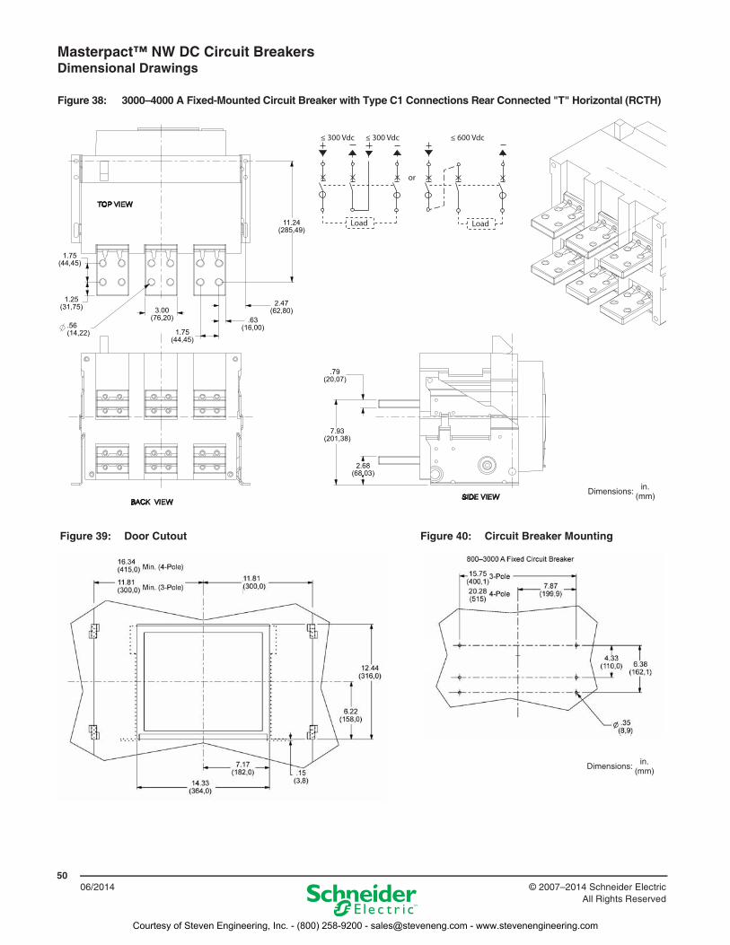
Figure 38: 3000–4000 A Fixed-Mounted Circuit Breaker with Type C1 Connections Rear Connected "T" Horizontal (RCTH)
11.24(285,49)
1.75(44,45)
1.25(31,75)
.56(14,22)
3.00(76,20)
2.47(62,80)
.63(16,00)1.75
(44,45)
.79(20,07)
7.93(201,38)
2.68(68,03)
≤ 300 Vdc
Load
or
Load
≤ 300 Vdc ≤ 600 Vdc
Dimensions: in.(mm)
Figure 39: Door Cutout Figure 40: Circuit Breaker Mounting
Dimensions: in.(mm)
Courtesy of Steven Engineering, Inc. - (800) 258-9200 - [email protected] - www.stevenengineering.com
Masterpact™ NW DC Circuit Breakers Dimensional Drawings
5106/2014© 2007–2014 Schneider Electric
All Rights Reserved
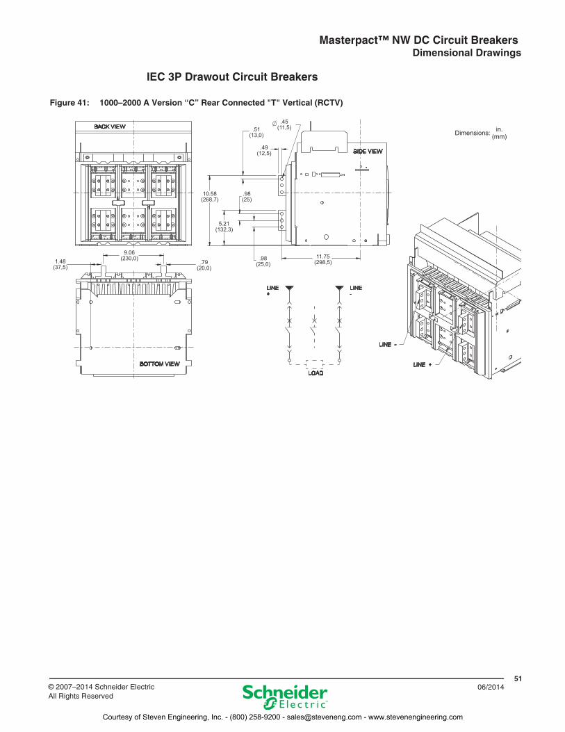
IEC 3P Drawout Circuit Breakers
Figure 41: 1000–2000 A Version “C” Rear Connected "T" Vertical (RCTV)
1.48(37,5)
9.06(230,0)
.79(20,0)
.98(25,0)
11.75(298,5)
.51(13,0)
.49(12,5)
.45(11,5)
10.58(268,7)
.98(25)
5.21(132,3)
Dimensions: in.(mm)
Courtesy of Steven Engineering, Inc. - (800) 258-9200 - [email protected] - www.stevenengineering.com
Masterpact™ NW DC Circuit Breakers Dimensional Drawings
5206/2014 © 2007–2014 Schneider Electric
All Rights Reserved
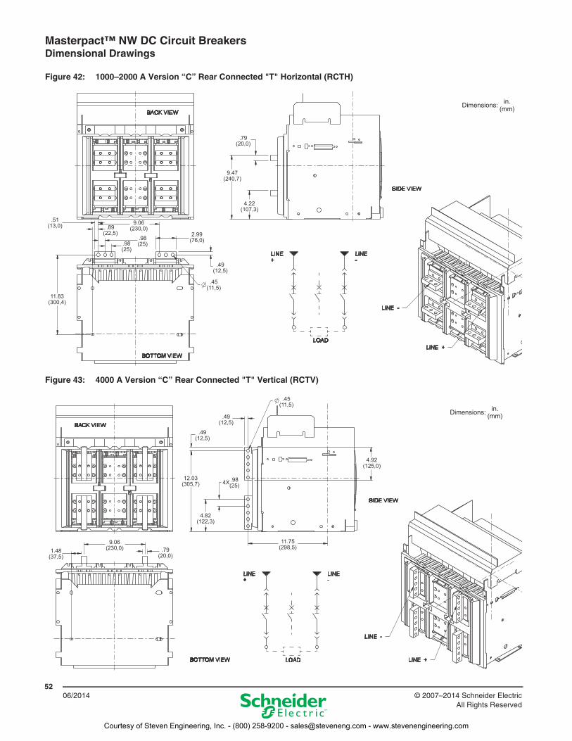
Figure 42: 1000–2000 A Version “C” Rear Connected "T" Horizontal (RCTH)
Figure 43: 4000 A Version “C” Rear Connected "T" Vertical (RCTV)
.45(11,5)
.51(13,0)
11.83(300,4)
.89(22,5)
9.06(230,0)
.98(25).98
(25)
2.99(76,0)
.49(12,5)
.79(20,0)
9.47(240,7)
4.22(107,3)
Dimensions: in.(mm)
1.48(37,5)
9.06(230,0) .79
(20,0)
11.75(298,5)
.49(12,5)
12.03(305,7) 4X .98
(25)
.49(12,5)
4.82(122,3)
4.92(125,0)
.45(11,5)
Dimensions: in.(mm)
Courtesy of Steven Engineering, Inc. - (800) 258-9200 - [email protected] - www.stevenengineering.com
Masterpact™ NW DC Circuit Breakers Dimensional Drawings
5306/2014© 2007–2014 Schneider Electric
All Rights Reserved
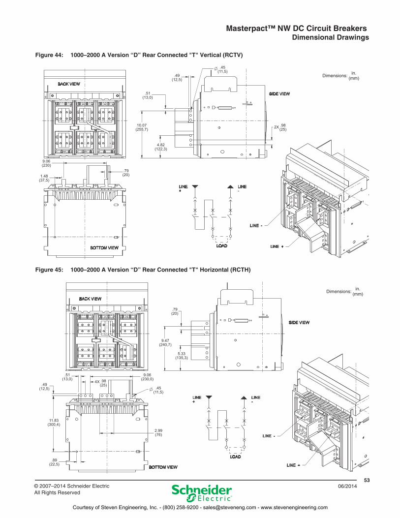
Figure 44: 1000–2000 A Version “D” Rear Connected "T" Vertical (RCTV)
Figure 45: 1000–2000 A Version “D” Rear Connected "T" Horizontal (RCTH)
.79(20)
9.06(230)
1.48(37,5)
4.82(122,3)
10.07(255,7)
.51(13,0)
.49(12,5)
.45(11,5)
2X .98(25)
Dimensions: in.(mm)
.49(12,5)
.51(13,0)
11.83(300,4)
.89(22,5)
4X .98(25)
9.06(230,0)
.45(11,5)
2.99(76)
.79(20)
9.47(240,7)
5.33(135,3)
Dimensions:in.
(mm)
Courtesy of Steven Engineering, Inc. - (800) 258-9200 - [email protected] - www.stevenengineering.com
Masterpact™ NW DC Circuit Breakers Dimensional Drawings
5406/2014 © 2007–2014 Schneider Electric
All Rights Reserved
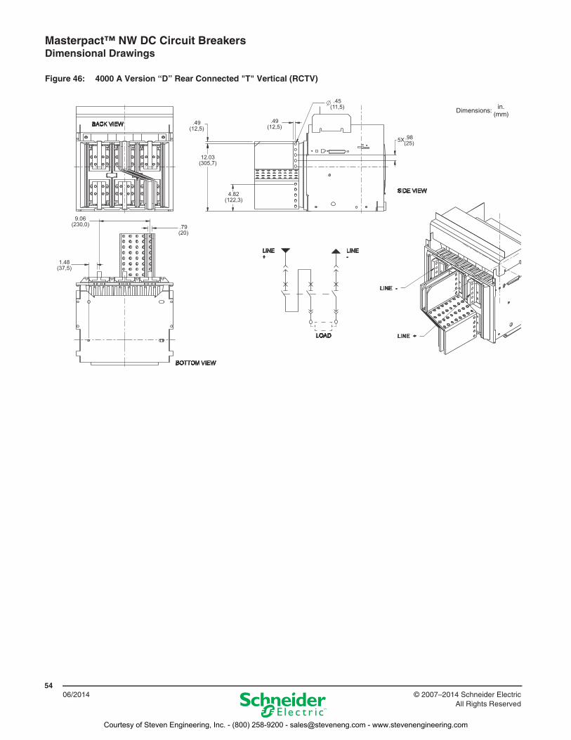
Figure 46: 4000 A Version “D” Rear Connected "T" Vertical (RCTV)
1.48(37,5)
9.06(230,0) .79
(20)
.49(12,5)
12.03(305,7)
.49(12,5)
4.82(122,3)
.45(11,5)
5X .98(25)
Dimensions:in.
(mm)
Courtesy of Steven Engineering, Inc. - (800) 258-9200 - [email protected] - www.stevenengineering.com
Masterpact™ NW DC Circuit Breakers Dimensional Drawings
5506/2014© 2007–2014 Schneider Electric
All Rights Reserved
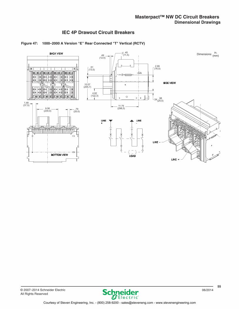
IEC 4P Drawout Circuit Breakers
Figure 47: 1000–2000 A Version “E” Rear Connected "T" Vertical (RCTV)
1.48(37,5)
9.06(230,0)
.79(20,0)
.49(12,5)
.51(13,0)
10.07(255,7)
4.82(122,3)
.45(11,5)
2.99(76,0)
11.75(298,5)
3X .98(25,0)
Dimensions: in.(mm)
Courtesy of Steven Engineering, Inc. - (800) 258-9200 - [email protected] - www.stevenengineering.com
Masterpact™ NW DC Circuit Breakers Dimensional Drawings
5606/2014 © 2007–2014 Schneider Electric
All Rights Reserved
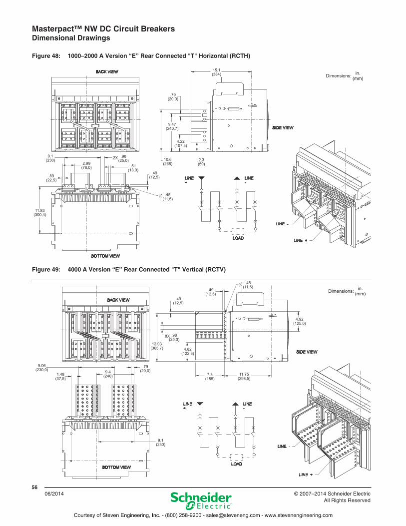
Figure 48: 1000–2000 A Version “E” Rear Connected "T" Horizontal (RCTH)
Figure 49: 4000 A Version “E” Rear Connected "T" Vertical (RCTV)
.45(11,5)
11.83(300,4)
.89(22,5)
9.1(230)
2.99(76,0)
2X .98(25,0)
.51(13,0)
.49(12,5)
15.1(384)
.79(20,0)
9.47(240,7)
10.6(268)
4.22(107,3)
2.3(59)
Dimensions:in.
(mm)
9.06(230,0)
1.48(37,5)
9.1(230)
9.4(240)
.79(20,0)
.45(11,5)
4.92(125,0)
.49(12,5)
.49(12,5)
12.03(305,7)
7.3(185)
11.75(298,5)
8X .98(25,0)
4.82(122,3)
Dimensions:in.
(mm)
Courtesy of Steven Engineering, Inc. - (800) 258-9200 - [email protected] - www.stevenengineering.com
Masterpact™ NW DC Circuit Breakers Dimensional Drawings
5706/2014© 2007–2014 Schneider Electric
All Rights Reserved
IEC 3P Fixed Circuit Breakers
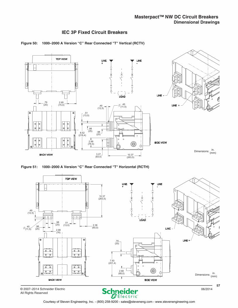
Figure 50: 1000–2000 A Version “C” Rear Connected "T" Vertical (RCTV)
Figure 51: 1000–2000 A Version “C” Rear Connected "T" Horizontal (RCTH)
.79(20)
2.95(75,0) .49
(12,5)
.51(13,0)
.45(11,5)
.98(25) .98
(25)8.52
(216,4)
2.99(76,0)
3.27(83,0)
10.37(263,5)
Dimensions: in.(mm)
2.68(68,0)
.79(20)
7.93(201,4)
10.37(263,5)
2.36(60,0)
.51(13,0)
.98(25)
.49(12,5)
45(11,5)
.98(25) 2.99
(76)
Dimensions: in.(mm)
Courtesy of Steven Engineering, Inc. - (800) 258-9200 - [email protected] - www.stevenengineering.com
Masterpact™ NW DC Circuit Breakers Dimensional Drawings
5806/2014 © 2007–2014 Schneider Electric
All Rights Reserved
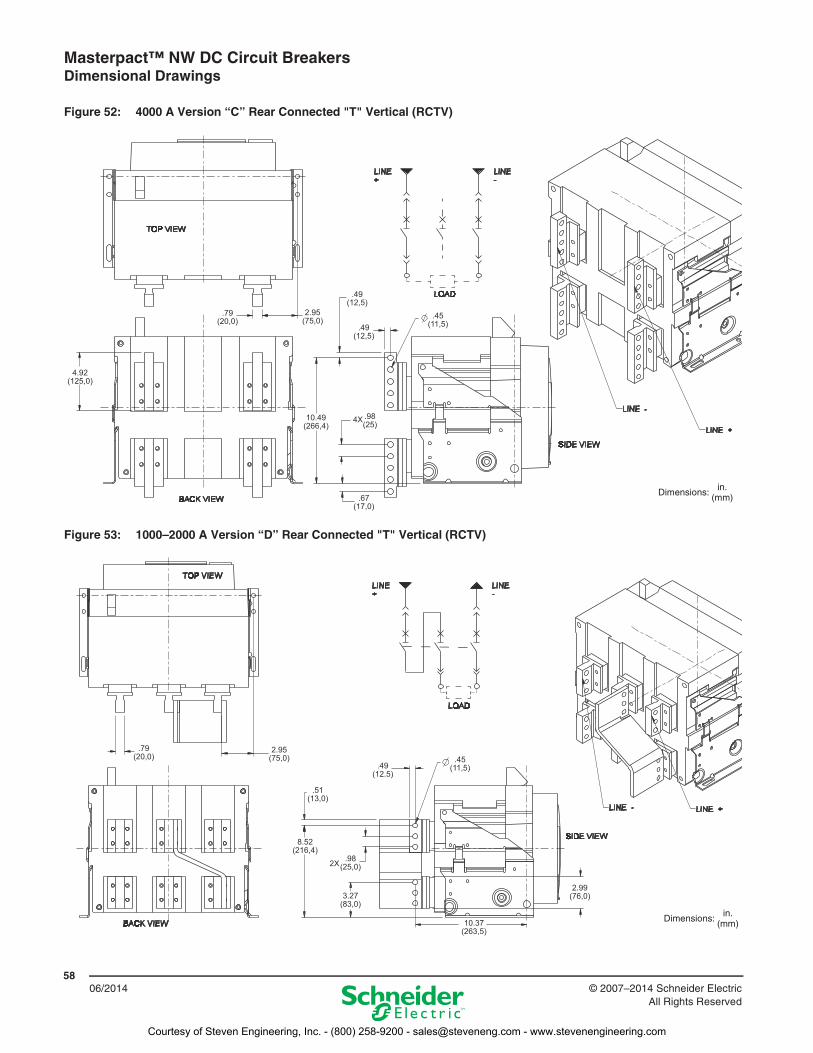
Figure 52: 4000 A Version “C” Rear Connected "T" Vertical (RCTV)
Figure 53: 1000–2000 A Version “D” Rear Connected "T" Vertical (RCTV)
4.92(125,0)
.67(17,0)
10.49(266,4)
4X .98(25)
.79(20,0)
2.95(75,0)
.49(12,5)
.49(12,5)
.45(11,5)
Dimensions: in.(mm)
.79(20,0)
2.95(75,0)
.49(12.5)
.45(11,5)
.51(13,0)
8.52(216,4)
2X .98(25,0)
3.27(83,0)
2.99(76,0)
10.37(263,5)
Dimensions: in.(mm)
Courtesy of Steven Engineering, Inc. - (800) 258-9200 - [email protected] - www.stevenengineering.com
Masterpact™ NW DC Circuit Breakers Dimensional Drawings
5906/2014© 2007–2014 Schneider Electric
All Rights Reserved
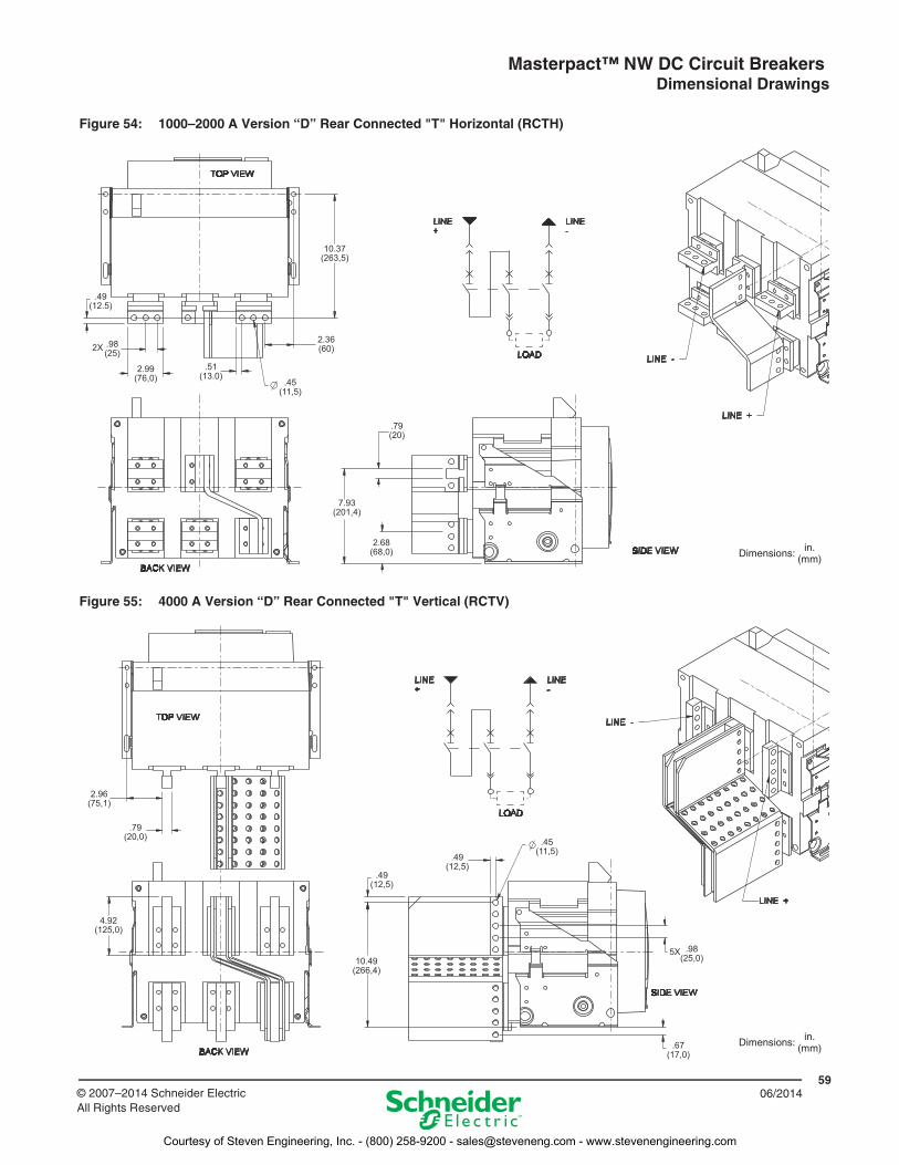
Figure 54: 1000–2000 A Version “D” Rear Connected "T" Horizontal (RCTH)
Figure 55: 4000 A Version “D” Rear Connected "T" Vertical (RCTV)
.79(20)
7.93(201,4)
2.68(68,0)
10.37(263,5)
2.36(60)2X .98
(25)
.49(12.5)
2.99(76,0)
.51(13.0)
.45(11,5)
Dimensions: in.(mm)
2.96(75,1)
.79(20,0)
4.92(125,0)
10.49(266,4)
.49(12,5)
.49(12,5)
.45(11,5)
5X .98(25,0)
.67(17,0)
Dimensions: in.(mm)
Courtesy of Steven Engineering, Inc. - (800) 258-9200 - [email protected] - www.stevenengineering.com
Masterpact™ NW DC Circuit Breakers Dimensional Drawings
6006/2014 © 2007–2014 Schneider Electric
All Rights Reserved
IEC 4P Fixed Circuit Breakers
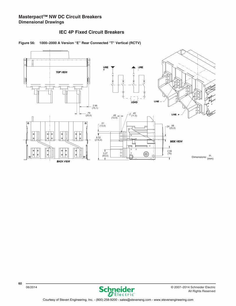
Figure 56: 1000–2000 A Version “E” Rear Connected "T" Vertical (RCTV)
2.96(75,1)
.79(20,0) .49
(12,5)
.45(11,5)
.51(13,0)
8.52(216,4)
3.27(83,0)
2X .98(25,0)
2.99(76)
Dimensions: in.(mm)
Courtesy of Steven Engineering, Inc. - (800) 258-9200 - [email protected] - www.stevenengineering.com
Masterpact™ NW DC Circuit Breakers Dimensional Drawings
6106/2014© 2007–2014 Schneider Electric
All Rights Reserved
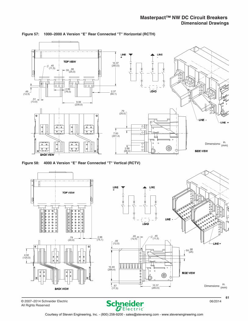
Figure 57: 1000–2000 A Version “E” Rear Connected "T" Horizontal (RCTH)
Figure 58: 4000 A Version “E” Rear Connected "T" Vertical (RCTV)
2.37(60,1)
.49(12,5)
.51(13,0)
.45(11,5)
3X .98(25,0)
2.99(76,0)
9.06(230,0)
10.37(263,5)
.79(20,0)
7.93(201,4)
2.68(68,0)
Dimensions: in.(mm)
4.92(125,0)
.79(20,0)
2.96(75,1)
10.49(266,4)
.49(12,5)
.49(12,5)
.67(17,0)
10.37(263,5)
.45(11,5)
5X .98(25)
Dimensions:in.
(mm)
Courtesy of Steven Engineering, Inc. - (800) 258-9200 - [email protected] - www.stevenengineering.com
Masterpact™ NW DC Circuit Breakers Trip Curves
6206/2014 © 2007–2014 Schneider Electric
All Rights Reserved
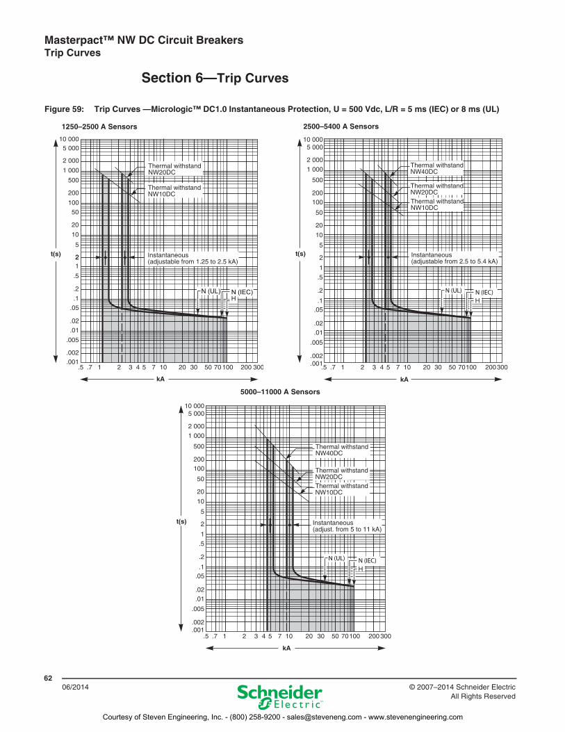
Section 6—Trip Curves
Figure 59: Trip Curves —Micrologic™ DC1.0 Instantaneous Protection, U = 500 Vdc, L/R = 5 ms (IEC) or 8 ms (UL)
N (IEC)N (UL)
1250–2500 A Sensors 2500–5400 A Sensors
5000–11000 A Sensors
Courtesy of Steven Engineering, Inc. - (800) 258-9200 - [email protected] - www.stevenengineering.com
Masterpact™ NW DC Circuit Breakers Trip Curves
6306/2014© 2007–2014 Schneider Electric
All Rights Reserved
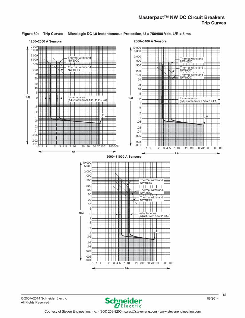
Figure 60: Trip Curves —Micrologic DC1.0 Instantaneous Protection, U = 750/900 Vdc, L/R = 5 ms
1250–2500 A Sensors 2500–5400 A Sensors
5000–11000 A Sensors
Courtesy of Steven Engineering, Inc. - (800) 258-9200 - [email protected] - www.stevenengineering.com
Masterpact™ NW DC Circuit Breakers Trip Curves
6406/2014 © 2007–2014 Schneider Electric
All Rights Reserved
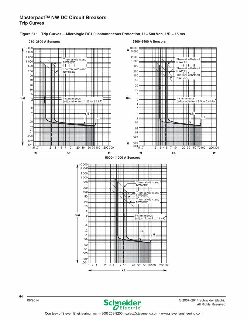
Figure 61: Trip Curves —Micrologic DC1.0 Instantaneous Protection, U = 500 Vdc, L/R = 15 ms
1250–2500 A Sensors 2500–5400 A Sensors
5000–11000 A Sensors
Courtesy of Steven Engineering, Inc. - (800) 258-9200 - [email protected] - www.stevenengineering.com
Masterpact™ NW DC Circuit Breakers Trip Curves
6506/2014© 2007–2014 Schneider Electric
All Rights Reserved
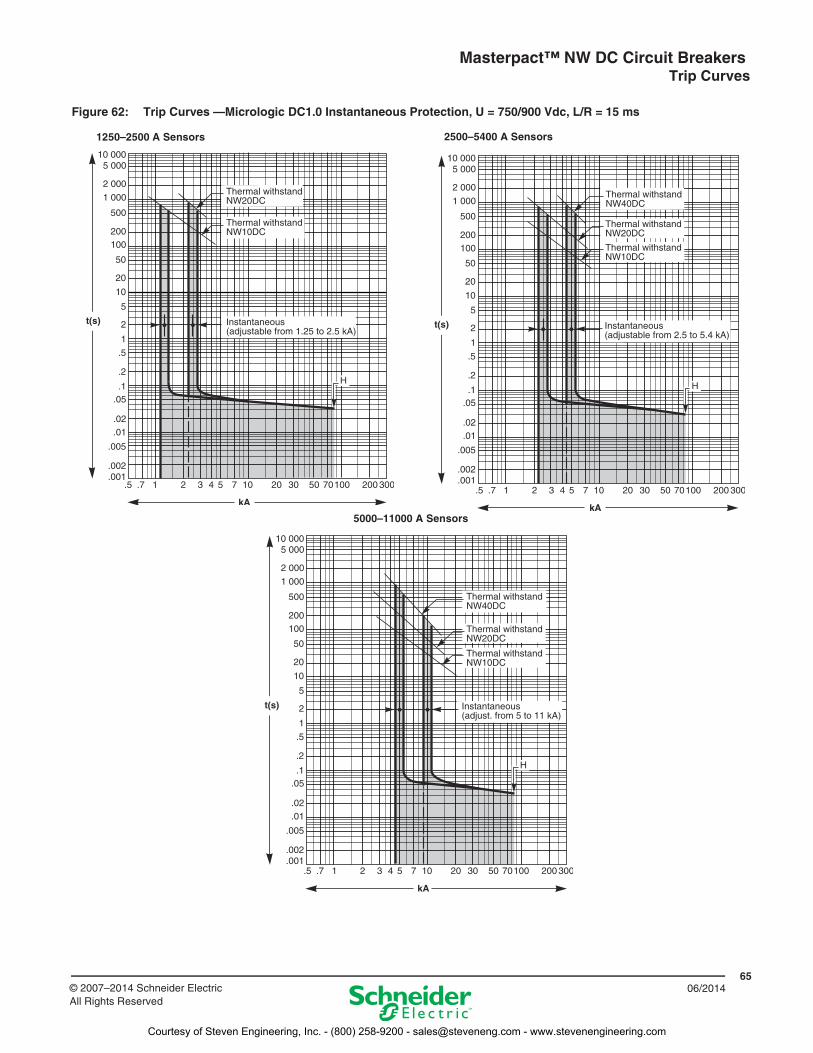
Figure 62: Trip Curves —Micrologic DC1.0 Instantaneous Protection, U = 750/900 Vdc, L/R = 15 ms
1250–2500 A Sensors 2500–5400 A Sensors
5000–11000 A Sensors
Courtesy of Steven Engineering, Inc. - (800) 258-9200 - [email protected] - www.stevenengineering.com
Masterpact™ NW DC Circuit Breakers Trip Curves
6606/2014 © 2007–2014 Schneider Electric
All Rights Reserved
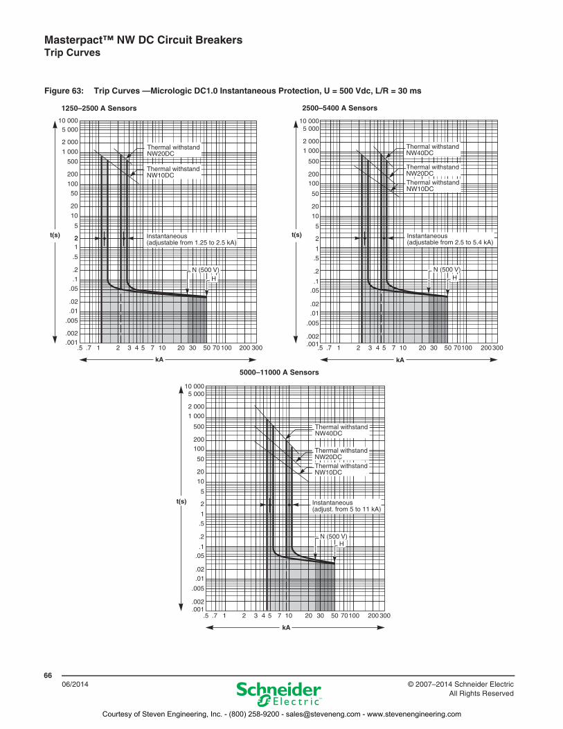
Figure 63: Trip Curves —Micrologic DC1.0 Instantaneous Protection, U = 500 Vdc, L/R = 30 ms
1250–2500 A Sensors 2500–5400 A Sensors
5000–11000 A Sensors
Courtesy of Steven Engineering, Inc. - (800) 258-9200 - [email protected] - www.stevenengineering.com
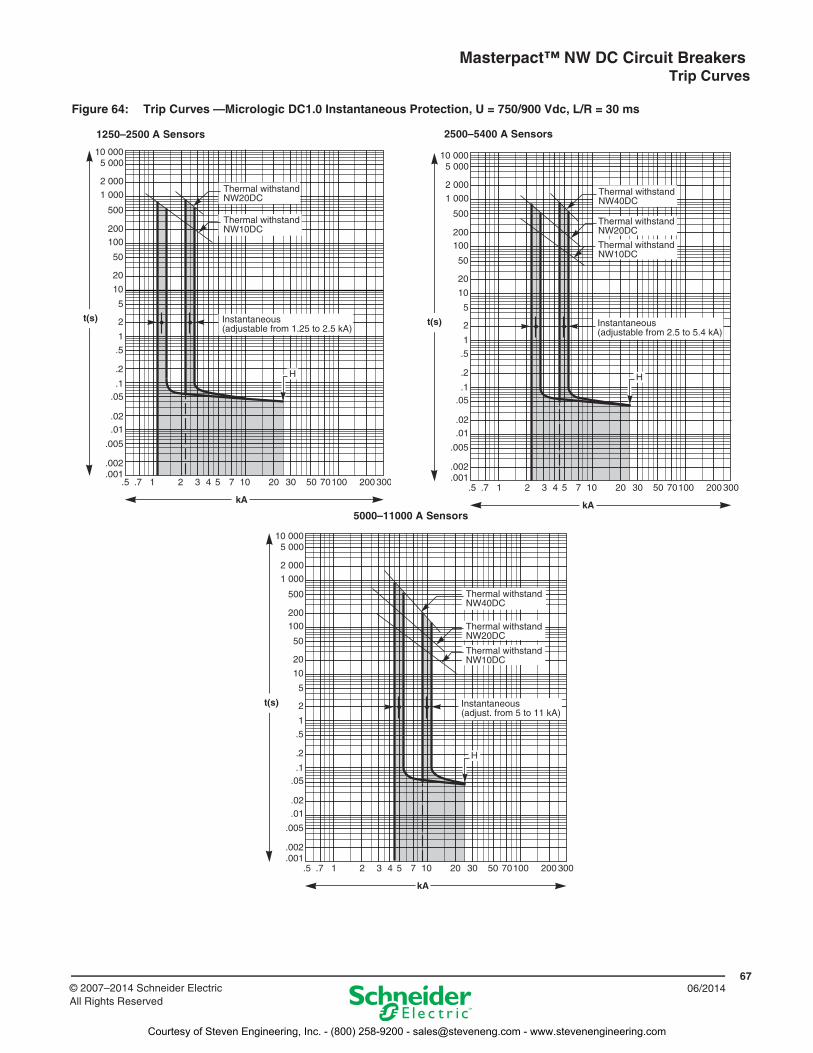
Masterpact™ NW DC Circuit Breakers Trip Curves
6706/2014© 2007–2014 Schneider Electric
All Rights Reserved
Figure 64: Trip Curves —Micrologic DC1.0 Instantaneous Protection, U = 750/900 Vdc, L/R = 30 ms
1250–2500 A Sensors 2500–5400 A Sensors
5000–11000 A Sensors
Courtesy of Steven Engineering, Inc. - (800) 258-9200 - [email protected] - www.stevenengineering.com

06/2014
Schneider Electric USA, Inc.1415 S. Roselle RoadPalatine, IL 60067 USA1-888-778-2733www.us.SquareD.com
© 2007–2014 Schneider Electric All Rights ReservedSchneider Electric and Square D are trademarks owned by Schneider Electric Industries SAS or its affiliated companies. All other trademarks are the property of their respective owners.
0613CT0501 R05/14 Replaced 0613CT0501 R06/13
Courtesy of Steven Engineering, Inc. - (800) 258-9200 - [email protected] - www.stevenengineering.com