DC TRACK CIRCUIT MAINTENANCE - Indian Railwaysrdso.indianrailways.gov.in/works/uploads/File/Pamphlet...
8
GOVERNMENT OF INDIA MINISTRY OF RAILWAYS (For Official Use) DC TRACK CIRCUIT MAINTENANCE CAMTECH/S&T/S/2009/P/DCTC/2.0 March 2009 Contact address: Director (S&T) Indian Railways, Centre for Advanced Maintenance Technology , Maharajpur, Gwalior – 474 005 : 0751-2470185, FAX: 0751-2470841 e-mail: [email protected] Please purchase PDFcamp Printer on http://www.verypdf.com/ to remove this watermark.
Transcript of DC TRACK CIRCUIT MAINTENANCE - Indian Railwaysrdso.indianrailways.gov.in/works/uploads/File/Pamphlet...
GOVERNMENT OF INDIA MINISTRY OF RAILWAYS
(For Official Use)
DC TRACK CIRCUIT MAINTENANCE
CAMTECH/S&T/S/2009/P/DCTC/2.0 March 2009
Contact address: Director (S&T) Indian Railways, Centre for Advanced Maintenance
Technology , Maharajpur, Gwalior – 474 005 : 0751-2470185, FAX: 0751-2470841 e-mail: [email protected]
Please purchase PDFcamp Printer on http://www.verypdf.com/ to remove this watermark.
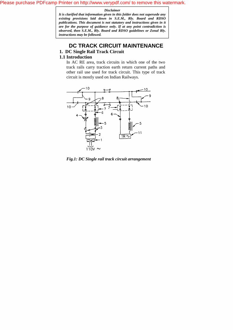
DC TRACK CIRCUIT MAINTENANCE 1. DC Single Rail Track Circuit 1.1 Introduction
In AC RE area, track circuits in which one of the two track rails carry traction earth return current paths and other rail use used for track circuit. This type of track circuit is mostly used on Indian Railways.
Fig.1: DC Single rail track circuit arrangement
Disclaimer It is clarified that information given in this folder does not supersede any existing provisions laid down in S.E.M., Rly. Board and RDSO publications. This document is not statutory and instructions given in it are for the purpose of guidance only. If at any point contradiction is observed, then S.E.M., Rly. Board and RDSO guidelines or Zonal Rly. instructions may be followed.
Please purchase PDFcamp Printer on http://www.verypdf.com/ to remove this watermark.
1.2 Components 1. Battery charger 110 V/2-10 V DC. 2. Feed battery (1 to 4 cells). 3. Fuse and link. 4. Regulating resistance (adjustable) 0-30 Ohm. 5. Type ‘B’ choke (R=3 Ohms & Z=120 Ohm). 6. Track lead cable (2X2.5 sq. mm. copper). 7. Track lead J.B. 8. Track lead steel wire ropes. 9. Transverse bonds. 10. Block joints. 11. Track Relay (ACI).
2. Precautionary measures for a DC track Circuit in RE area • Only AC immunized Track relay (shelf type, QTA2
type or QBAT type) shall be used. • QSPA1 relay only shall be used as repeater for
QTA2 or QBAT track relay. For shelf type relay any AC immunized relay can be used as repeater.
• With shelf type ACI track relay, track feeding shall not be done directly from a rectifier, without a battery in parallel. Whenever battery is disconnected, rectifier shall also be automatically be isolated from the track.
• A 'B' Type protection chock of (3 ohm resistance and 120 ohm impedance for 50Hz) shall be connected in series with track feed to the un-insulated rail.
Please purchase PDFcamp Printer on http://www.verypdf.com/ to remove this watermark.
• A similar choke shall be connected in series with the relay also for its protection.
• A 5A 250V rated fuse and a 0-30 Ohm Regulating resistance for minor adjustments in track feed voltage are also provided at the feed end.
• Before starting any maintenance work, a surge discharge shall be connected across the track at the site of work.
3. Maintenance Instructions
• Note down the track relay voltage on each visit. Specified value: For shelf type relay <= 250% of pick-up voltage. For plug-in-type relay <=300% of pick-up-voltage. • Check the condition of following bonds on every
visit: Cross bond, Transverse bond, Structure bond and
Longitudinal bond. If found loose / broken missing, take remedial
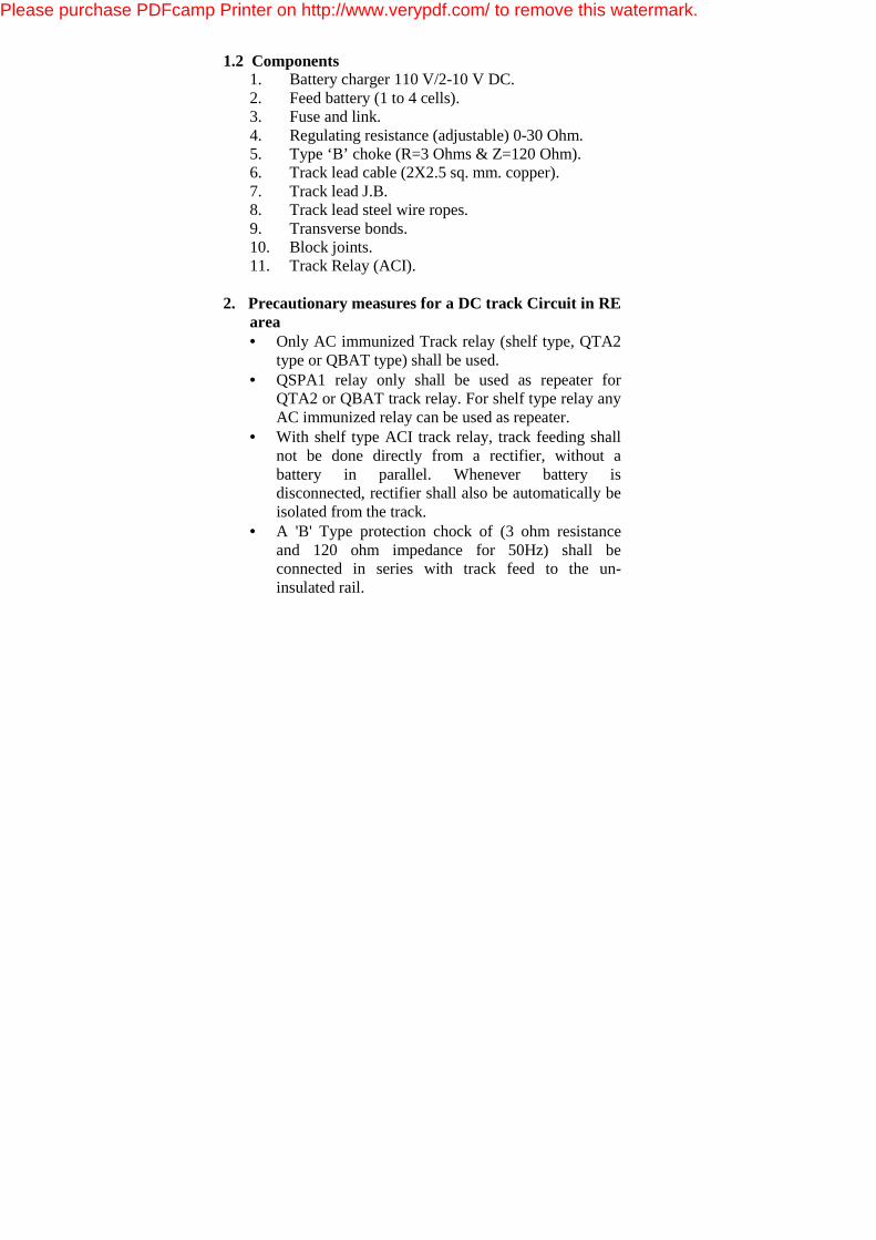
action/inform OHE deptt. • Clean the insulation joint with
a brush to remove iron filing/powder.
• Check the point rodding, stretcher and gauge tie plate insulation, once in three months.
• Check the battery condition regularly. Measure the voltage of each cell after switching off the charger.
Please purchase PDFcamp Printer on http://www.verypdf.com/ to remove this watermark.
• Check the operating characteristics of track relay once in two years.
• Check the intactness of jumper connections. If found loose / broken missing, take remedial action.
• Check the sudden voltage drop on a portion of failed track circuit to find the most likely fault around there.
• Ensure the proper drainage of water and mud for improving the ballast resistance and reliability of track circuit.
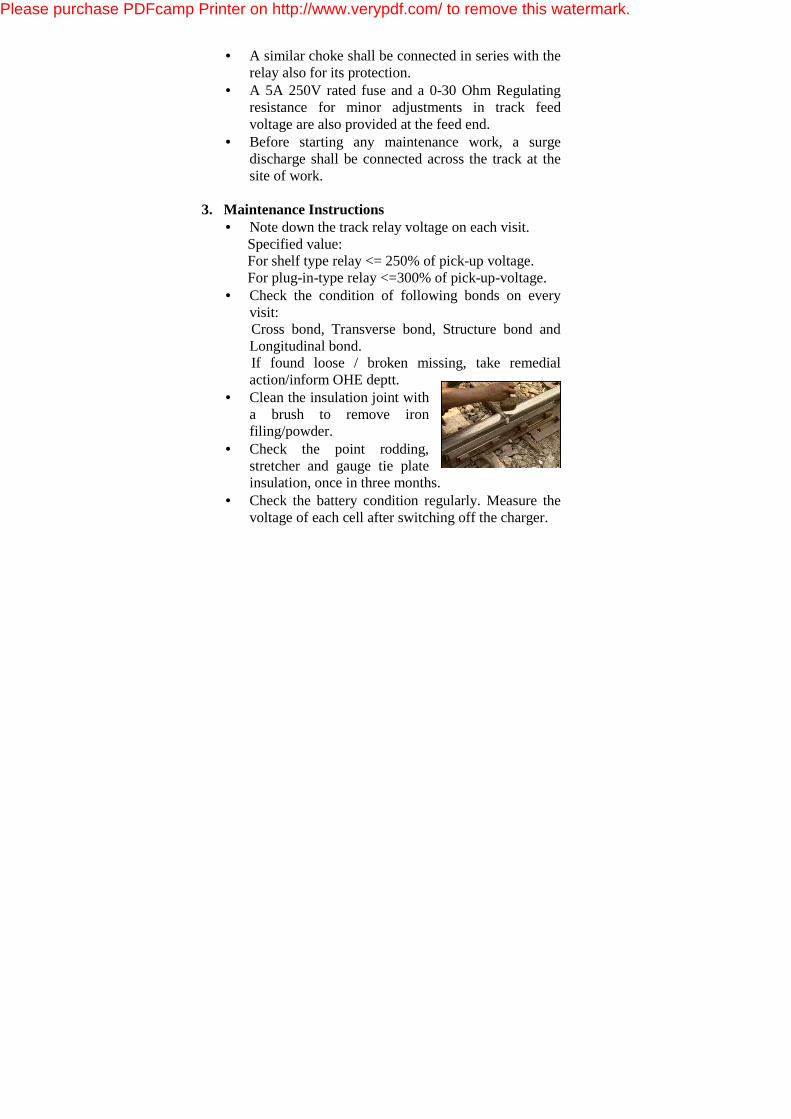
• Check the resistance between Fish plate-rail, Fish plate-
bolt and Fish plate-fish plate regularly.
• Check the conditions of track leads of feed/relay end and +ve jumper.
4. Precautions
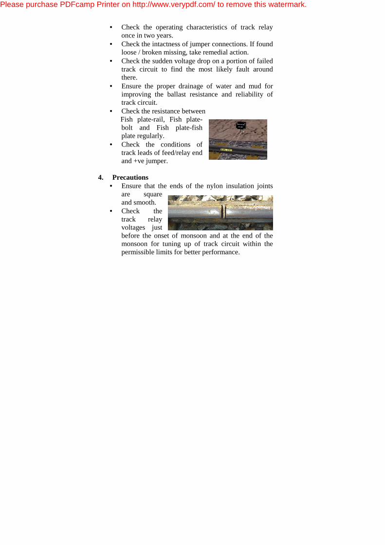
• Ensure that the ends of the nylon insulation joints are square and smooth.
• Check the track relay voltages just before the onset of monsoon and at the end of the monsoon for tuning up of track circuit within the permissible limits for better performance.
Please purchase PDFcamp Printer on http://www.verypdf.com/ to remove this watermark.
• Ensure that anti-tilting arrangement is provided with the shelf type track relay.
• Fish plate holes/rail holes in nylon insulation joint should not be staggered so that longer bolts can be easily inserted. Steel bushes must be used to prevent puncturing of nylon bushes.
• Ensure that better drainage is maintained for maximum ballast resistance.
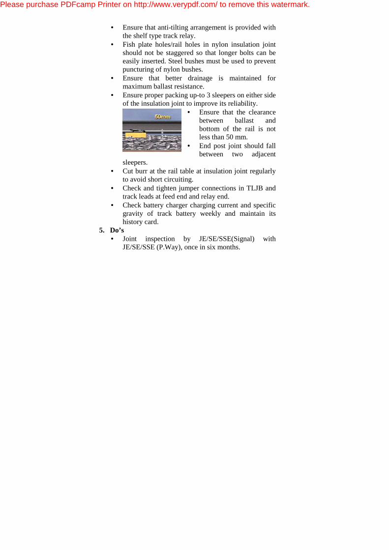
• Ensure proper packing up-to 3 sleepers on either side of the insulation joint to improve its reliability.
• Ensure that the clearance between ballast and bottom of the rail is not less than 50 mm.
• End post joint should fall between two adjacent
sleepers. • Cut burr at the rail table at insulation joint regularly
to avoid short circuiting. • Check and tighten jumper connections in TLJB and
track leads at feed end and relay end. • Check battery charger charging current and specific
gravity of track battery weekly and maintain its history card.
5. Do’s • Joint inspection by JE/SE/SSE(Signal) with
JE/SE/SSE (P.Way), once in six months.
Please purchase PDFcamp Printer on http://www.verypdf.com/ to remove this watermark.
• Carry out track shunt test every quarter and every time the track circuit is adjusted or any alteration is made.
• Keep the track circuit history card up-to-date. Record the readings every six months.
• Megger the tail cables once in six months. Replace if the insulation resistance is less than 1 mega ohm.
• Prefer to provide track lead junction box vertically to avoid water accumulation in the junction box.
• Apply glue/epoxy on the rail and fish plate of those joints, which are shorting due to iron filings and iron powder.
• At the time of replacing the insulation joint apply quick drier paint on the rail and fish plate.
• Replace the insulation joint on age cum condition basis.
• Use J Pandrol clip to avoid touching of pandrol clip with the fish plates.
6. Don'ts • Bypass the regulating resistance at any time. • Tamper with the track relay at the time of track
circuit failure. • Disturb the anti-tilting arrangement of track relay. • Forget to give disconnection memo to on-duty
ASM/CASM at the time of attending failure. • Adjust the track circuit beyond the limit of track
circuit parameters given earlier. • Forget to clean the insulation joint on every visit.
Please purchase PDFcamp Printer on http://www.verypdf.com/ to remove this watermark.
• Permit relay end voltage to be lesser than 125 % of pick up voltage of relay.
• Forget to replace rack relay before its overhauling date.
7. Testing of track circuit • Relay end voltage, should be less than 250% of its P.U.
value at min. ballast resistance and not less than 125% of its rated P.U. value with min. ballast resistance.
• Shunt the track at F/E and R/E with 0.5 Ohm TSR and ensure that relay voltage is less than 85% of its D.A. value.
• In case of point track circuits, shunt the track at F/E, R/E and at relay terminals and ensure track locking is effective.
• Shunt the adjacent track circuit at the time of measuring voltage and if any variation is observed, then replace the block joints.
Important parameters for DC Track Circuits Minimum permissible T.S.R 0.5 Ω with wooden sleeper & 0.25 Ω with concrete sleeper Minimum permissible ballast resistance for wooden sleeper track circuits. (i) 2 Ω per km track length within station section; and (ii) 4 Ω per km track length - outside the station section. Minimum permissible ballast resistance for concrete sleeper track circuits. (i) 1Ω per km - in Non-RE areas (both within and outside station sections) (ii) 0.6 Ω per km - in RE areas (both within and outside station sections). Minimum permissible resistance of a concrete sleeper. In Non - RE and AC RE area (i) 500Ω after 6 months from the date of manufacture, and (ii) 200 Ω at the manufactures shop within 15 days of its manufacture. Glued Joints Insulation Resistance : In dry condition: >/=25 Megohms and in wet condition >/=3 kilo Ohms when a meggering with 100V DC megger.
Please purchase PDFcamp Printer on http://www.verypdf.com/ to remove this watermark.