MAMMOUTH - storage.ua.prom.st
16
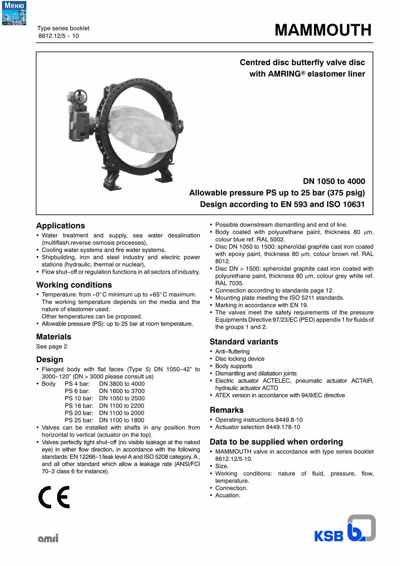
Type series booklet MAMMOUTH 8612.12/5 -- 10 DN 1050 to 4000 Allowable pressure PS up to 25 bar (375 psig) Design according to EN 593 and ISO 10631 Centred disc butterfly valve disc with AMRING elastomer liner Applications • Water treatment and supply, sea water desalination (multiflash,reverse osmosis processes), • Cooling water systems and fire water systems, • Shipbuilding, iron and steel industry and electric power stations (hydraulic, thermal or nuclear), • Flow shut--off or regulation functions in all sectors of industry. Working conditions • Temperature: from --0° C minimum up to +65° C maximum. The working temperature depends on the media and the nature of elastomer used. Other temperatures can be proposed. • Allowable pressure (PS): up to 25 bar at room temperature. Materials See page 2. Design • Flanged body with flat faces (Type 5) DN 1050--42” to 3000--120” (DN > 3000 please consult us) • Body PS 4 bar: DN 3800 to 4000 PS 6 bar: DN 1600 to 3700 PS 10 bar: DN 1050 to 2500 PS 16 bar: DN 1100 to 2200 PS 20 bar: DN 1100 to 2000 PS 25 bar: DN 1100 to 1800 • Valves can be installed with shafts in any position from horizontal to vertical (actuator on the top). • Valves perfectly tight shut--off (no visible leakage at the naked eye) in either flow direction, in accordance with the following standards: EN 12266--1/leak level A and ISO 5208 category. A , and all other standard which allow a leakage rate (ANSI/FCI 70--2 class 6 for instance). • Possible downstream dismantling and end of line. • Body coated with polyurethane paint, thickness 80 µm, colour blue ref. RAL 5002. • Disc DN 1050 to 1500: spheroïdal graphite cast iron coated with epoxy paint, thickness 80 µm, colour brown ref. RAL 8012. • Disc DN > 1500: spheroïdal graphite cast iron coated with polyurethane paint, thickness 80 µm, colour grey white ref. RAL 7035. • Connection according to standards page 12. • Mounting plate meeting the ISO 5211 standards. • Marking in accordance with EN 19. • The valves meet the safety requirements of the pressure Equipments Directive 97/23/EC (PED) appendix 1 for fluids of the groups 1 and 2. Standard variants • Anti--fluttering • Disc locking device • Body supports • Dismantling and dilatiation joints • Electric actuator ACTELEC, pneumatic actuator ACTAIR, hydraulic actuator ACTO • ATEX version in accordance with 94/9/EC directive Remarks • Operating instructions 8449.8-10 • Actiuator selection 8449.178-10 Data to be supplied when ordering • MAMMOUTH valve in accordance with type series booklet 8612.12/5-10. • Size. • Working conditions: nature of fluid, pressure, flow, temperature. • Connection. • Acuation.
Transcript of MAMMOUTH - storage.ua.prom.st
Type series booklet MAMMOUTH8612.12/5 -- 10
DN 1050 to 4000Allowable pressure PS up to 25 bar (375 psig)
Design according to EN 593 and ISO 10631
Centred disc butterfly valve discwith AMRING elastomer liner
Applications• Water treatment and supply, sea water desalination(multiflash,reverse osmosis processes),
• Cooling water systems and fire water systems,• Shipbuilding, iron and steel industry and electric powerstations (hydraulic, thermal or nuclear),
• Flow shut--off or regulation functions in all sectors of industry.
Working conditions• Temperature: from --0°C minimum up to +65°C maximum.The working temperature depends on the media and thenature of elastomer used.Other temperatures can be proposed.
• Allowable pressure (PS): up to 25 bar at room temperature.
MaterialsSee page 2.
Design• Flanged body with flat faces (Type 5) DN 1050--42” to3000--120” (DN > 3000 please consult us)
• Body PS 4 bar: DN 3800 to 4000PS 6 bar: DN 1600 to 3700PS 10 bar: DN 1050 to 2500PS 16 bar: DN 1100 to 2200PS 20 bar: DN 1100 to 2000PS 25 bar: DN 1100 to 1800
• Valves can be installed with shafts in any position fromhorizontal to vertical (actuator on the top).
• Valves perfectly tight shut--off (no visible leakage at the nakedeye) in either flow direction, in accordance with the followingstandards: EN 12266--1/leak level A and ISO 5208 category. A ,and all other standard which allow a leakage rate (ANSI/FCI70--2 class 6 for instance).
• Possible downstream dismantling and end of line.• Body coated with polyurethane paint, thickness 80 µm,colour blue ref. RAL 5002.
• Disc DN 1050 to 1500: spheroïdal graphite cast iron coatedwith epoxy paint, thickness 80 µm, colour brown ref. RAL8012.
• Disc DN > 1500: spheroïdal graphite cast iron coated withpolyurethane paint, thickness 80 µm, colour grey white ref.RAL 7035.
• Connection according to standards page 12.• Mounting plate meeting the ISO 5211 standards.• Marking in accordance with EN 19.• The valves meet the safety requirements of the pressureEquipmentsDirective 97/23/EC (PED)appendix 1 for fluidsofthe groups 1 and 2.
Standard variants• Anti--fluttering• Disc locking device• Body supports• Dismantling and dilatiation joints• Electric actuator ACTELEC, pneumatic actuator ACTAIR,hydraulic actuator ACTO
• ATEX version in accordance with 94/9/EC directive
Remarks• Operating instructions 8449.8-10• Actiuator selection 8449.178-10
Data to be supplied when ordering• MAMMOUTH valve in accordance with type series booklet8612.12/5-10.
• Size.• Working conditions: nature of fluid, pressure, flow,temperature.
• Connection.• Acuation.

MAMMOUTH
2
Materials
Body KSB code
Spheroïdal graphite cast iron JS 1030 / ASTM A536 gr. 60.40.18 3g
Shafts KSB code
Stainless steel 1.4029 / 1.4028 (13% Cr)Stainless steel ASTM A276 gr. 420
6k6k
Disc KSB code
Spheroïdal graphite cast iron JS 1030 / ASTM A536 gr. 60.40.18Spheroïdal graphite cast iron JS 1030 / ASTM A536 gr. 60.40.18 eboniteStainless steel Type 1.4408 / ASTM A351 gr. CF8MAluminium--bronze ASTM B148 gr. C95800
3g3p62
AMRING liner KSB code
E.P.D.MHigh content nitrile
XCK
Other materials are possible, please consult us.
Vacuum limits
Liners are sticked in the following cases:
• DN 1050 to 1200 for pressure classes 6 bar and 10 bar, application lower to 0,3 bar absolut.• All other DN and all other pressure classes for valves with face to face 280, in case of application lower than the atmosphericpressure.
For valves liner sticked, the maximum working pressure is equal to pressure class of the valve.

MAMMOUTH
3
Construction
554
901.1
412.1
310.1
970
561
100
310.2
413
213
940.1
550
210
940.2
553
310.3
414
560
310.4
412.2
901.2
176
904
920
540
932.1
412.1
310.1
970
561
100
310.2
413
213
940
550
210
486
176
310.3
412.3
412.2
932.2
920
904
916
DN 1050 to 1200 PS 10 bar
Spare parts included in the liner kitSpare parts included in the disc kitSpare parts included in the shaft kit
DN 3800 to 4000 PS 4 barDN 1600 to 3700 PS 6 barDN 1350 to 2500 PS 10 barDN 1100 to 2200 PS 16 barDN 1100 to 2000 PS 20 barDN 1100 to 1800 PS 25 bar
MAMMOUTH
4
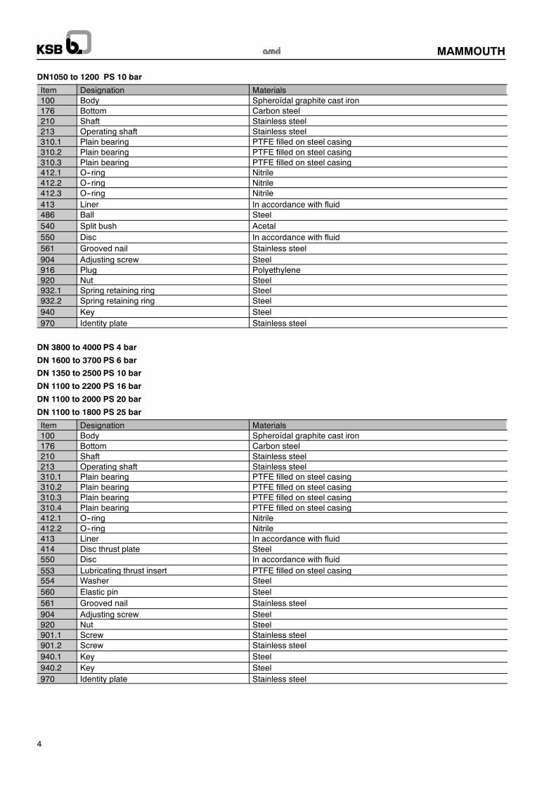
DN1050 to 1200 PS 10 bar
Item Designation Materials100 Body Spheroïdal graphite cast iron176 Bottom Carbon steel210 Shaft Stainless steel213 Operating shaft Stainless steel310.1 Plain bearing PTFE filled on steel casing310.2 Plain bearing PTFE filled on steel casing310.3 Plain bearing PTFE filled on steel casing412.1 O--ring Nitrile412.2 O--ring Nitrile412.3 O--ring Nitrile413 Liner In accordance with fluid486 Ball Steel540 Split bush Acetal550 Disc In accordance with fluid561 Grooved nail Stainless steel904 Adjusting screw Steel916 Plug Polyethylene920 Nut Steel932.1 Spring retaining ring Steel932.2 Spring retaining ring Steel940 Key Steel970 Identity plate Stainless steel
DN 3800 to 4000 PS 4 bar
DN 1600 to 3700 PS 6 bar
DN 1350 to 2500 PS 10 bar
DN 1100 to 2200 PS 16 bar
DN 1100 to 2000 PS 20 bar
DN 1100 to 1800 PS 25 bar
Item Designation Materials100 Body Spheroïdal graphite cast iron176 Bottom Carbon steel210 Shaft Stainless steel213 Operating shaft Stainless steel310.1 Plain bearing PTFE filled on steel casing310.2 Plain bearing PTFE filled on steel casing310.3 Plain bearing PTFE filled on steel casing310.4 Plain bearing PTFE filled on steel casing412.1 O--ring Nitrile412.2 O--ring Nitrile413 Liner In accordance with fluid414 Disc thrust plate Steel550 Disc In accordance with fluid553 Lubricating thrust insert PTFE filled on steel casing554 Washer Steel560 Elastic pin Steel561 Grooved nail Stainless steel904 Adjusting screw Steel920 Nut Steel901.1 Screw Stainless steel901.2 Screw Stainless steel940.1 Key Steel940.2 Key Steel970 Identity plate Stainless steel

MAMMOUTH
5
Dimensions
x1 x1
x2 x2
h1
h2
Ød2 *Ød1
x1
x1
x2
x2
l1 e2
e1
h3s
h4
DN NPS Pressure Connection Ød1
Facetoface h1 h2
Mountingplate
ISO 5211Shaft output Disc clearance
x1 x2 WeightdaN
l1 n h4 s h3 e1 e2daN
42” 10 AWWA cl. D 1 332 216 765 674 F25 30 60 80 1 006 405 383 545 850
1100 10 EN 1092 PN10 1 340 216 790 703 F25 30 60 80 1 057 430 386 548 900
44” 10 AWWA cl. D 1 340 216 790 703 F25 30 60 80 1 057 430 403 566 960
1100 16 EN 1092 PN 16 1 355 280 867 843 F30 40 90 90 1 035 396 333 590 1 400
44” 16 AWWA cl. E 1 405 280 867 843 F30 40 90 90 1 035 396 382 590 1 400
1100 44” 20 PN 20 / Cl. 150 1 405 280 867 843 F30 40 90 90 1 035 396 382 590 1 600
1100 25 EN 1092 PN 25 1 420 280 867 843 F30 40 90 90 1 035 396 395 590 1 878
1200 10 EN 1092 PN10 1 455 254 840 756 F25 30 60 80 1 152 461 428 588 1 090
48” 10 AWWA cl. D 1 497 254 840 756 F25 30 60 80 1 152 461 444 602 1 150
1200 16 EN 1092 PN 16 1 485 280 917 893 F30 40 90 90 1 137 447 450 625 1 538
48” 16 AWWA cl. E 1 511 280 917 893 F30 40 90 90 1 137 447 450 625 1 538
1200 48” 20 PN 20 / Cl. 150 1 511 280 917 893 F30 40 90 90 1 137 447 450 625 1 761
1200 25 EN 1092 PN 25 1 530 280 917 893 F30 40 90 90 1 137 447 450 625 2 031
1300 16 EN 1092 PN 16 1 585 280 967 943 F30 40 90 90 1 240 497 470 680 1 620
52” 16 AWWA cl. E 1 626 280 967 943 F30 40 90 90 1 240 497 470 680 1 620
1300 52” 20 PN 20 / Cl. 150 1 626 280 967 943 F30 40 90 90 1 240 497 470 680 1 915
1300 25 EN 1092 PN 25 1 645 280 967 943 F35 40 90 90 1 240 497 470 680 2 185
54” 10 AWWA cl. D 1 683 280 992 968 F30 40 90 90 1 293 522 480 700 1 500
54” 16 AWWA cl. E 1 683 280 992 968 F30 40 90 90 1 293 522 480 700 1 680
1350 20 -- 25 Not standardized Please consult us
1400 10 EN 1092 PN10 1 675 280 1 017 993 F30 40 90 90 1 343 547 480 725 1 600
1400 16 EN 1092 PN 16 1 685 280 1 017 993 F30 40 90 90 1 343 547 480 725 1 744
1400 56” 20 PN 20 / Cl. 150 1 745 280 1 017 993 F35 40 90 90 1 343 547 480 725 2 068
1400 25 EN 1092 PN 25 1 755 400 1 055 1 018 F35 40 90 90 1 303 481 485 735 2 622
1500 10 EN 1092 PN10 1 785 280 1 067 1 043 F30 40 90 90 1 455 600 530 765 1 800
60” 10 AWWA cl. D 1 854 280 1 067 1 043 F30 40 90 90 1 455 600 530 765 1 800
1500 16 EN 1092 PN 16 1 820 280 1 067 1 043 F30 40 90 90 1 455 600 530 765 1 950
60” 16 AWWA cl. E 1 854 280 1 067 1 043 F30 40 90 90 1 455 600 530 765 1 950
1500 60” 20 PN 20 / Cl. 150 1 854 400 1 105 1 068 F35 40 90 90 1 407 531 520 775 3 085
1500 25 EN 1092 PN 25 1 865 400 1 105 1 068 F35 40 90 90 1 407 531 520 775 3 210

MAMMOUTH
6
DN NPS Pressure Connection Ød1
Facetoface h1 h2
Mountingplate
ISO 5211Shaft output Disc clearance
x1 x2 WeightdaN
l1 n h4 s h3 e1 e2daN
1600 6 PN 6 1 830 280 1 115 1093 F30 40 90 90 1 540 644 560 790 2 160
1600 10 PN 10 1 915 280 1 115 1093 F30 40 90 90 1 540 644 560 790 2 440
1600 16 PN 16 1 930 280 1 115 1093 F35 40 90 90 1 540 644 560 790 2 658
1600 20 Not standardized Please consult us
1600 25 PN 25 1 975 400 1 155 1118 F40 45 110 110 1 512 582 565 810 3 320
66” 6 AWWA cl. B 2 032 280 1 147 1123 F30 40 90 90 1 608 677 580 835 2 251
66” 10 AWWA cl. D 2 032 280 1 147 1123 F30 40 90 90 1 608 677 580 835 2 531
66” 16 AWWA cl. E 2 032 280 1 147 1123 F35 40 90 90 1 608 677 580 835 3 048
66” 20 -- 25 Not standardized Please consult us
1800 6 PN 6 2 045 280 1 217 1193 F30 40 90 90 1 748 747 620 860 2 281
1800 10 PN 10 2 115 280 1 217 1193 F35 40 90 90 1 748 747 620 860 2 716
1800 16 PN 16 2 130 400 1 255 1218 F35 40 90 90 1 718 682 650 890 3 295
1800 20 Not standardized Please consult us
1800 25 PN 25 2 195 400 1 255 1218 F40 45 110 110 1 718 682 650 890 3 895
72” 6 AWWA cl. B 2 197 280 1 217 1193 F30 40 90 90 1 748 747 650 890 2 698
72” 10 AWWA cl. D 2 197 280 1217 1193 F35 40 90 90 1 748 747 650 890 2 956
72” 16 AWWA cl. E 2 197 400 1255 1218 F35 40 90 90 1 718 682 650 890 3 753
72” 20 --25 Not standardized Please consult us
78” 6 AWWA cl. B 2 362 280 1297 1273 F35 40 90 90 1 911 826 720 940 2 795
78” 10 AWWA cl. D 2 362 280 1297 1273 F35 40 90 90 1 911 826 720 950 3 073
78” 16 AWWA cl. E 2 362 400 1335 1298 F40 45 110 110 1 881 762 720 950 4 880
78” 20 Not standardized Please consult us
2000 6 PN 6 2 265 280 1 319 1 295 F35 40 90 90 1 952 847 690 940 2 885
2000 10 PN 10 2 325 400 1 355 1 318 F40 45 110 110 1 922 780 710 940 3 956
2000 16 PN 16 2 345 400 1 355 1 318 F40 45 110 110 1 922 780 710 940 5 304
2000 20 Not standardized Please consult us
84” 6 AWWA cl. B 2 534 280 1 372 1 348 F35 40 90 90 2 060 900 770 1 010 3 064
84” 10 AWWA cl. D 2 534 400 1 410 1 373 F40 45 110 110 2 035 836 770 1 010 4 831
84” 16 AWWA cl. E 2 534 400 1 410 1 373 F40 45 110 110 2 035 836 770 1 010 6 445
2200 6 PN 6 2 475 280 1 419 1 395 F35 40 90 90 2 154 948 750 980 3 245
2200 10 PN 10 2 550 400 1 460 1 423 F40 45 110 110 2 135 885 770 1 020 4 220
90” 6 AWWA cl. B 2 705 400 1 505 1 468 F40 45 110 110 2 227 931 830 1 020 3 835
90” 10 AWWA cl. D 2 705 400 1 505 1 468 F40 45 110 110 2 227 931 830 1 070 4 447
2400 6 PN 6 2 685 400 1 560 1 523 F40 45 110 110 2 338 986 830 1 070 4 140
2400 10 PN 10 2 760 400 1 560 1 523 F40 45 110 110 2 338 986 830 1 090 5 025
96” 6 AWWA cl. B 2 877 400 1 560 1 523 F40 45 110 110 2 338 986 830 1 090 4 910
96” 10 AWWA cl. D 2 877 400 1 560 1 523 F40 45 110 110 2 338 986 830 1 130 5 320
2500 6 -- 10 Not standardized Please consult us
102” 6 AWWA cl. B 3 048 400 1 660 1 623 F40 45 110 110 2 526 1 078 950 1 190 5 110
2600 6 PN 6 2 905 400 1 660 1 623 F40 45 110 110 2 526 1 078 900 1 140 4 980
108” 6 AWWA cl. B 3 220 400 1 735 1 698 F48 45 140 140 2 641 1 136 1 020 1 250 5 710
2800 6 PN 6 3 115 400 1 760 1 723 F48 45 140 140 2 738 1 184 980 1 210 5 826
114” 6 AWWA cl. B 3 391 400 1 810 1 773 F48 45 140 140 2 843 1 236 1 080 1 310 6 720
3000 6 PN 6 3 315 400 1 860 1 823 F48 45 140 140 2 945 1 286 1 050 1 280 6 670
120” 6 AWWA cl. B 3 562 400 1 865 1 828 F48 45 140 140 2 950 1 291 1 130 1 370 7 698
3100
to
4000
Not standardized -- Please, consult us
Dimensions are given for information and can be modified.
∗ φ d2 : See bolting table
MAMMOUTH
7
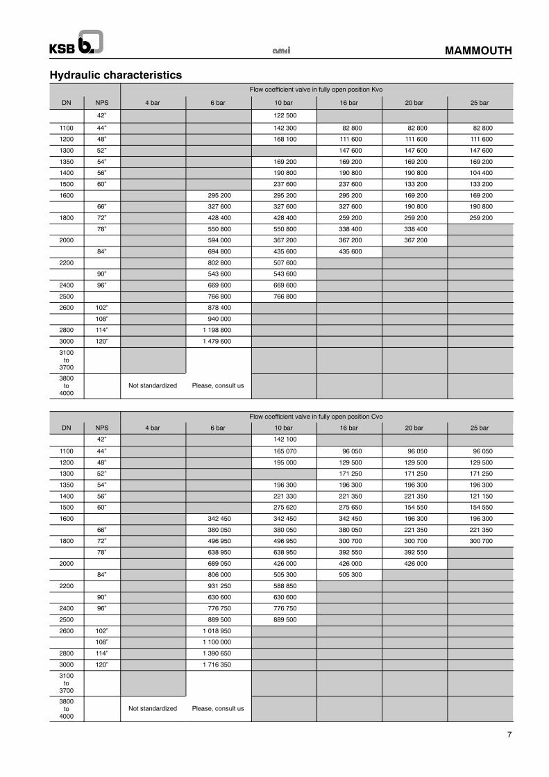
Hydraulic characteristicsFlow coefficient valve in fully open position Kvo
DN NPS 4 bar 6 bar 10 bar 16 bar 20 bar 25 bar
42” 122 500
1100 44” 142 300 82 800 82 800 82 800
1200 48” 168 100 111 600 111 600 111 600
1300 52” 147 600 147 600 147 600
1350 54” 169 200 169 200 169 200 169 200
1400 56” 190 800 190 800 190 800 104 400
1500 60” 237 600 237 600 133 200 133 200
1600 295 200 295 200 295 200 169 200 169 200
66” 327 600 327 600 327 600 190 800 190 800
1800 72” 428 400 428 400 259 200 259 200 259 200
78” 550 800 550 800 338 400 338 400
2000 594 000 367 200 367 200 367 200
84” 694 800 435 600 435 600
2200 802 800 507 600
90” 543 600 543 600
2400 96” 669 600 669 600
2500 766 800 766 800
2600 102” 878 400
108” 940 000
2800 114” 1 198 800
3000 120” 1 479 600
3100to
3700
3800to
4000Not standardized Please, consult us
Flow coefficient valve in fully open position Cvo
DN NPS 4 bar 6 bar 10 bar 16 bar 20 bar 25 bar
42” 142 100
1100 44” 165 070 96 050 96 050 96 050
1200 48” 195 000 129 500 129 500 129 500
1300 52” 171 250 171 250 171 250
1350 54” 196 300 196 300 196 300 196 300
1400 56” 221 330 221 350 221 350 121 150
1500 60” 275 620 275 650 154 550 154 550
1600 342 450 342 450 342 450 196 300 196 300
66” 380 050 380 050 380 050 221 350 221 350
1800 72” 496 950 496 950 300 700 300 700 300 700
78” 638 950 638 950 392 550 392 550
2000 689 050 426 000 426 000 426 000
84” 806 000 505 300 505 300
2200 931 250 588 850
90” 630 600 630 600
2400 96” 776 750 776 750
2500 889 500 889 500
2600 102” 1 018 950
108” 1 100 000
2800 114” 1 390 650
3000 120” 1 716 350
3100to
3700
3800to
4000Not standardized Please, consult us

MAMMOUTH
8
Motorization
For large sizes valves, the torque depends on hydraulic characteristics.
The table below shows recommended actuators on lubricated media with a maximum fluid velocity of 2m/s (6.5ft/s).According to the working conditions and the hydraulic characteristics, higher fluid velocities can be allowed, therefore otheractuator recommendations can be proposed : please consult us.
Manual control: Reducer
A
C
G h5
øJ
F
E
DN NPS Pressure Reducer A C E F G øJ h5 Weightkg*
1050 42” 10 MR 600 511 405 245 140 155 600 1174 105
1100 44” 10 MR 600 511 405 245 140 155 600 1199 105
1100 44” 16 and 20 MR 1200 661 555 318 180 180 800 1397 175
1100 44” 25 MR 1600 447 348 318 180 180 800 1264 183
1200 48” 10 MR 600 397 298 245 140 155 350 1174 105
1200 48” 16 MR 1200 661 555 318 180 180 800 1447 175
1200 48” 20 and 25 MR 1600 447 348 318 180 180 350 1314 183
1300 52” 16 and 20 MR 1600 447 348 318 180 180 350 1314 183
1300 25 GS250.3+GZ250.3 585 402 365 250 268 800 max. 1483 308
1350 54” 10 MR 1200 661 555 318 250 268 800 1522 175
1350 54” 16 MR 1600 447 348 318 180 180 350 1389 183
1350 20 MR 1600 447 348 318 180 180 350 ** 183
1350 25 GS250.3+GZ250.3 585 402 365 250 268 800 max. ** 308
1400 56” 10 MR 1200 661 555 318 180 180 800 1547 175
1400 56” 16 MR 1600 447 348 318 180 180 350 1414 183
1400 20 and 25 GS250.3+GZ250.3 585 402 365 250 268 800 max. 1595 308
1500 60” 10 MR 1600 447 348 318 180 180 350 1464 183
1500 60” 16 GS250.3+GZ250.3 585 402 365 250 268 800 max. 1607308
1500 60” 20 and 25 GS250.3+GZ250.3 585 402 365 250 268 800 max. 1645308

MAMMOUTH
9
DN NPS Pressure Reducer A C E F G øJ h5 Weight kg*
1600 6 MR 1200 661 555 318 180 180 350 1645 175
1600 10 MR 1600 447 348 318 180 180 800 1512 183
1600 16 GS250.3+GZ250.3 585 402 365 250 268 800 max. 1655 308
1600 20 GS250.3+GZ250.3 585 402 365 250 268 800 max. ** 308
1600 25 GS250.3+GZ250.3 585 402 365 250 268 800 max. 1695 308
66” 6 MR 1200 661 555
555
318 180 180 350 1688 175
66” 10 MR 1600 447 348 318 180 180 800 1463 183
66” 16 GS250.3+GZ250.3 585 402 365 250 268 800 max. 1697 308
66” 20 GS250.3+GZ250.3 585 402 365 250 268 800 max. ** 308
66” 25 GS315+GZ30 848 550 555 315 340 800 max. ** 630
1800 72” 6 MR 1600 447 348 318 180 180 800 1463 183
1800 72” 10 GS250.3+GZ250.3 585 402 365 250 268 800 max. 1757 308
1800 72” 16 GS250.3+GZ250.3 585 402 365 250 268 800 max. 1795 308
1800 72” 20 GS250.3+GZ250.3 585 402 365 250 268 800 max. ** 308
1800 72” 25 GS315+GZ30 848 550 555 315 340 800 max. 1807 630
78” 6 and 10 GS250.3+GZ250.3 585 402 365 250 268 800 max. 1837 308
78” 16 GS250.3+GZ250.3 585 402 365 250 268 800 max. 1875 308
78” 20 GS315+GZ30 848 550 555 315 340 800 max. ** 630
2000 6 GS250.3+GZ250.3 585 402 365 250 268 800 max. 1859 308
2000 10 and 16 GS250.3+GZ250.3 585 402 365 250 268 800 max. 1895 308
2000 20 GS315+GZ30 848 550 555 315 340 800 max. ** 630
84” 6 GS250.3+GZ250.3 585 402 365 250 268 800 max. 1912 308
84” 10 GS250.3+GZ250.3 585 402 365 250 268 800 max. 1950 308
84” 16 GS315+GZ30 848 550 555 315 340 800 max. 1962 630
2200 6 GS250.3+GZ250.3 585 402 365 250 268 800 max. 1959 308
2200 10 GS250.3+GZ250.3 585 402 365 250 268 800 max. 2000 308
90 6 and 10 GS250.3+GZ250.3 585 402 365 250 268 800 max. 2045 308
2400 96 6 GS250.3+GZ250.3 585 402 365 250 268 800 max. 2100 308
2400 96 10 GS315 + GZ30 848 550 555 315 340 800 max. 2112 630
2500 6 and 10 GS315 + GZ30 848 550 555 315 340 800 max. ** 630
102” 6 GS315 + GZ30 848 550 555 315 340 800 max. 2212 630
2600 6 GS315 + GZ30 848 550 555 315 340 800 max. 2212 630
108” 6 GS315 + GZ30 848 550 555 315 340 800 max. 2287 630
2800 6 GS315 + GZ30 848 550 555 315 340 800 max. 2312 630
114” 6 GS315 + GZ30 848 550 555 315 340 800 max. 2362 630
3000 6 GS315 + GZ30 848 550 555 315 340 800 max. 2412 630
120 6 GS315 + GZ30 848 550 555 315 340 800 max. 2417 630
3100
to
4000
Not standardized -- Please, consult us
* Weight of gear box only ** Please consult us
MAMMOUTH
10
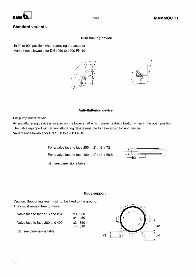
Standard variants
Anti--fluttering device
For pump outlet valves
An anti--fluttering device is located on the lower shaft which prevents disc vibration when in the open position.
The valve equipped with an anti--fluttering device must be to have a disc locking device.
Variant not allowable for DN 1050 to 1200 PN 10.
For a valve face to face 280 : h2’ : h2 + 72
For a valve face to face 400 : h2’ : h2 + 65.5
h2 : see dimensions table
h2’
Disc locking device
In 0° or 90° position when removing the actuatorVariant not allowable for DN 1050 to 1200 PN 10
Body support
Caution: Supporting legs must not be fixed to the ground.
They must remain free to move.
x2
x4x3
Valve face to face 216 and 254 : x3 : 330x4 : 450
Valve face to face 280 and 400 : x3 : 350x4 : 510
x2 : see dimensions table

MAMMOUTH
11
Standard variants
Dismantling joint (flanged) Dilatation joint
Electric actuator ACTELEC Pneumatic actuator ACTAIR
Hydraulic actuator ACTO Counterweight

MAMMOUTH
12
ConnectionsUnless as otherwise specified, the normal flange connection for a MAMMOUTH valve is the one corresponding to its maximumallowable pressure (PS).Flange dimensions are in accordance with appropriate standards, mainly:-- ISO 7005 PN 6, 10, 16, 20 and 25 ; NF EN 1092--2 ; AWWA C207 cl.B, D and E eddition 94 ; ASME B16--47 series A Class 150On request, other connections are possible.
End of line and downstream dismantlingUse as end of line and downstream dismantling of the standard valves at room temperature for DN and the differential pressure(∆PS) defined hereafter:
Gas or liquids Liquids*
hazardous** non hazardous** hazardous** non hazardous**
All DN : not allowed on requestAll DN
∆PS = 0.7 PS limited to 10 bar max.∆PS higher: on request
All DN∆PS = 0.7 PS limited to 10 bar max.
∆PS higher: on request
* Liquids having a vapour pressure at themaximumallowable temperature of notmore than 0,5 bar above normal atmospheric pressure1013 mbar.
** Fluids hazardous and not hazardous according to PED.Nota : A valve fitted at the end of a pipe with a blind flange downstream is not to be considered as an end of pipe service.
Downstream dismantling End of line mounting

MAMMOUTH
13
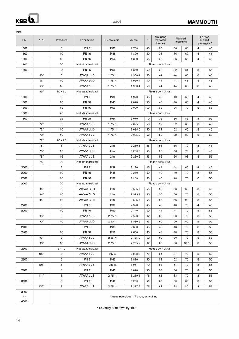
Bolting
L = l1 + 2e + 2f A = e + x
A
x e
A = e + l2 + f
A
l2f ee ff e
L
l1
Ød2
Mounting between flanges Flanged mounting Mounting at shaft passages
L : Mini length of tie--rods
l1 : Face to face of the valve
e : Flange thickness
(customer specification)
f : Nut thickness
+ overlength of the tie--rod
Mini length of screws
l2 : Thickness of the valve
e : Flange thickness
(customer specification)
f : Nut thickness
+ overlength of the screw
A : Mini length of screws
X : Maxi implantation of screws
Threaded length B > A--e
e : Flange thickness
(customer specification)
NB: We do not supply the bolting.
mm
DN NPS Pressure Connection Screws dia. d2 dia. f
Mountingbetweenflanges
Flangedmounting
Screwsat shaftpassages
Nb Nb * l2 Nb * x
42” 10 AWWA C207 1.5 in. 1 257 45 32 32 42 4 33
1100 10 PN 10 M33 1 270 45 28 28 43 4 40
44” 10 AWWA C207 1.5 in. 1 314 45 36 36 43 4 38
1100 16 PN 16 M39 1 270 45 24 24 60 8 45
44” 16 AWWA cl. E 1.5 in. 1 314 45 32 32 69 8 45
1100 44” 20 PN 20 / Cl. 150 M39 / 1.5 in. 1 314 45 32 32 69 8 45
1100 25 PN 25 M52 1 310 65 24 24 69 8 45
1200 10 PN 10 M36 1 380 45 28 28 60 4 54
48” 10 AWWA C207 1.5 in. 1 422 45 40 40 45 4 45
1200 16 PN 16 M45 1 390 50 40 40 69 4 45
48” 16 AWWA cl. E 1.5 in. 1 422 45 36 36 69 8 45
1200 48” 20 PN 20 / Cl. 150 M39 / 1.5 in. 1 422 45 36 36 69 8 45
25 PN 25 M52 1 420 65 28 28 69 4 45
1300 16 PN 16 M45 1 490 50 28 28 60 4 45
52” 16 AWWA cl. E 1.75 in. 1 537 50 36 36 74 8 45
1300 52” 20 PN 20 / Cl. 150 M45 / 1.75 in. 1 537 50 36 36 74 8 45
1300 25 PN 25 M56 1 530 60 28 28 74 4 45
54” 10 AWWA cl. D 1.75 in. 1 593,8 50 36 36 60 8 45
54” 16 AWWA cl. E 1.75 in. 1 593,8 50 36 36 76 8 45
1350 20 -- 25 Not standardized Please consult us
1400 16 PN 16 M45 1 590 50 32 32 60 4 45
1400 56” 20 PN 20 / Cl. 150 M45 / 1.75 in. 1 651 50 40 40 78 8 45
1400 25 PN 25 M56 1 640 60 28 28 74 8 55
1500 10 PN 10 M39 1 700 45 32 32 60 4 45
1500 16 PN 16 M52 1 710 65 32 32 63 4 45
60” 16 AWWA cl. E 1.75 in. 1 759 50 44 44 80 8 45
1500 60” 20 PN 20 / Cl. 150 M45 / 1.75 in. 1 759 50 44 44 80 8 55
1500 25 PN 25 M56 1 750 60 32 32 80 4 55
MAMMOUTH
14
mm
DN NPS Pressure Connection Screws dia. d2 dia. fMountingbetweenflanges
Flangedmounting
Screwsat shaft
passages *
1600 6 PN 6 M33 1 760 40 36 36 60 4 45
1600 10 PN 10 M45 1 820 50 36 36 60 4 45
1600 16 PN 16 M52 1 820 65 36 36 65 4 45
1600 20 Not standardized Please consult us
1600 25 PN 25 M56 1 860 60 32 32 81 8 55
66” 6 AWWA cl. B 1.75 in. 1 930.4 50 44 44 65 8 45
66” 10 AWWA cl. D 1.75 in. 1 930.4 50 44 44 65 8 45
66” 16 AWWA cl. E 1.75 in. 1 930.4 50 44 44 85 8 45
66” 20 -- 25 Not standardized Please consult us
1800 6 PN 6 M36 1 970 45 40 40 60 4 45
1800 10 PN 10 M45 2 020 50 40 40 66 4 45
1800 16 PN 16 M52 2 020 60 36 36 70 8 55
1800 20 Not standardized Please consult us
1800 25 PN 25 M64 2 070 70 36 36 89 8 55
72” 6 AWWA cl. B 1.75 in. 2 095.5 50 52 52 66 8 45
72” 10 AWWA cl. D 1.75 in. 2 095.5 50 52 52 66 8 45
72” 16 AWWA cl. E 1.75 in. 2 095.5 50 52 52 89 8 55
72” 20 -- 25 Not standardized Please consult us
78” 6 AWWA cl. B 2 in. 2 260.6 55 56 56 70 8 45
78” 10 AWWA cl. D 2 in. 2 260.6 55 56 56 70 8 45
78” 16 AWWA cl. E 2 in. 2 260.6 55 56 56 98 8 55
78” 20 Not standardized Please consult us
2000 6 PN 6 M39 2 180 45 44 44 60 4 45
2000 10 PN 10 M45 2 230 50 40 40 70 8 55
2000 16 PN 16 M56 2 230 60 40 40 75 8 55
2000 20 Not standardized Please consult us
84” 6 AWWA Cl. B 2 in. 2 525.7 55 56 56 60 8 45
84” 10 AWWA Cl. D 2 in. 2 525.7 55 56 56 75 8 55
84” 16 AWWA Cl. E 2 in. 2 525.7 55 56 56 98 8 55
2200 6 PN 6 M39 2 390 45 48 48 70 4 45
2200 10 PN 10 M52 2 440 60 44 44 70 8 55
90” 6 AWWA cl. B 2.25 in. 2 590.8 62 60 60 70 8 55
90” 10 AWWA cl. D 2.25 in. 2 590.8 62 60 60 80 8 55
2400 6 PN 6 M39 2 600 45 48 48 70 8 55
2400 10 PN 10 M52 2 650 60 48 48 70 8 55
96” 6 AWWA cl. B 2.25 in. 2 755.9 62 60 60 70 8 55
96” 10 AWWA cl. D 2.25 in. 2 755.9 62 60 60 82.5 8 55
2500 6 -- 10 Not standardized Please consult us
102” 6 AWWA cl. B 2.5 in. 2 908.3 70 64 64 70 8 55
2600 6 PN 6 M45 2 810 50 52 52 70 8 55
108” 6 AWWA cl. B 2.5 in. 3 067 70 64 64 70 8 55
2800 6 PN 6 M45 3 020 50 56 56 70 8 55
114” 6 AWWA cl. B 2.75 in. 3 219.5 75 68 68 70 8 55
3000 6 PN 6 M45 3 220 50 60 60 80 8 55
120” 6 AWWA cl. B 2.75 in. 3 317.9 75 68 68 80 8 55
3100
to
4000
Not standardized -- Please, consult us
* Quantity of screws by face

MAMMOUTH
15
Flanging dimensions
MAMMOUTH valves are designed to be installed between any type of flange (without any flange gasket) and standard connectioncurrently used.The elastomer liner ensures complete tightness at the flanges.It is necessary to verify the general compatibility of the connection by checking against the dimensions shown in the table below.
1020
ø5 ø4 ø6
* Face to face l1 : see dimensions table
Max dia. tolerated on the supporting area of the flange face : ø2Min dia. tolerated on the supporting area of the flange face : ø3
Max dia. toleratedø2
Min dia. toleratedø3
Min dia.10 mmfrom face of flange
ø4
Min dia. 20 mmfrom face of flange
ø5
Min. dia. tolerated ofshoulder of raised faceø2 ø3
ø4 ø5 shoulder of raised faceflange
DN NPS face to face l1 * face to face l1 * face to face l1 * face to face l1 * flangeDN NPS
216 254 216 254 216 254 216 254 ø6
42” 1067 1010 1006 1001 1135
1100 44” 1117 1063 1058 1053 1187
1200 48” 1222 1158 1152 1147 1307
DN NPSface to face l1 * face to face l1 * face to face l1 * face to face l1 *
DN NPS280 400 280 400 280 480 280 400 ø6
1100 44” 1130 1053 1045 1039 1220
1200 48” 1226 1152 1148 1143 1320
1300 52” 1330 1259 1252 1247 1420
1350 54” 1380 1310 1303 1298 1470
1400 56” 1430 1430 1361 1320 1354 1312 1349 1305 1530
1500 60” 1530 1530 1463 1424 1459 1416 1454 1410 1630
1600 1625 1560 1556 1552 1730
66” 1690 1626 1623 1619 1810
1800 72” 1830 1830 1768 1734 1765 1730 1761 1722 1930
78” 1990 1990 1930 1898 1926 1894 1923 1889 2090
2000 2034 2034 1974 1943 1971 1935 1968 1931 2130
84” 2140 2140 2081 2051 2078 2047 2075 2043 2240
2200 2234 2234 2176 2147 2173 2149 2171 2145 2340
90” 2330 2244 2224 2240 2221 2235 2430
2400 96” 2440 2356 2355 2351 2540
2500 2540 2456 2456 2453 2640
2600 102” 2640 2564 2555 2552 2740
108” 2740 2665 2658 2654 2890
2800 2840 2766 2760 2756 2940
114” 2940 2867 2860 2856 3040
3000 3040 2968 2962 2959 3140
120” 3060 2988 2972 2967 3160
3100to
4000Not standardized -- Please, consult us
Dilatation joint Rubber coated flange
NB:Direct fitting on rubber coated flange andwith dilatation joint is not authorized.Please, consult us.

KSB S.A.S.4, allée des Barbanniers • 92635 Gennevilliers Cedex (France)Tel.: +33 1 41 47 75 00 • Fax: +33 1 41 47 75 10 • www.ksb.com
MAMMOUTH
Product features -- to our customers’ benefit
Lubricating thrust insert forsupporting the weight of thedisc in case of installation invertical axis
Face to face according to ISO 5752 andEN 558 standards for DN ≤ 1200
•
••
••
•
•
Disc position index
Mounting plate according toISO 5211 standard
Preserved external internaltightness when the actuatoris taken off
Downstream/upstreamtightnessDisc machined spherical forensuring a perfect tightnessdownstream/upstream
Shaft passage tightnessPerfect tightness at shaftpassage obtained by thecompression of the liner collaron the disc spherical
Driving shaft/disc by keys:without contact with the fluid
Flanges tightness:Special design to obtain atotale tightness at flanges bycompression
Disc locking device (in option)
Bearing in reinforcedPTFE on steel support
Anti--Fluttering device(in option)
Lugs for slinging
Body support (in option)
••
••
•
•
27.10.05
Thisleafletisnotcontractual
andmay
beam
endedwithoutnotice.
8612.12/5--10