HYDRAULIC MOTORS MP - storage.ua.prom.st
24
HYDRAULIC MOTORS MP 13 APPLICATION » » » » » » Conveyors Feeding mechanism of robots and manipulators Metal working machines Textile machines Food industries » Agricultural machines etc. Grass cutting machinery Specification data ...................14÷17 Function diagrams ..................18÷24 Dimensions and mounting ...... 25÷26 Wheel motor ................................. 27 Shaft extensions ........................... 28 Permissible shaft loads ................ 29 Permissible shaft Seal Pressure ... 30 Order code .................................... 31 CONTENTS OPTIONS » » » » » » » » » Model - Spool valve, gerotor Flange and wheel mount Motor with needle bearing Side and rear ports Shafts - straight, splined and tapered Shaft seal for high and low pressure Metric and BSPP ports Speed sensoring Other special features Pressure Losses 2,5 .660 1,8 .476 3,5 .925 2,8 .740 [ ] [ ] [ ] [ ] Oil flow in drain line 623,6 38.05 [ ] 1815 cont.:50 [ ] 4415 int.: 64 [5565] 12,8 [17.1] cont.:140 2030 int.:[175 [2540] [ ] 75 [ ] 19.8 10 Mineral based- HLP(DIN 51524) or HM(ISO 6743/4) -40÷140 [-40÷284] 20÷75 98÷347 [ ] ISO code 20/16 (Min. recommended fluid filtration of 25 microns) GENERAL 70 20 60 50 40 30 10 0 Q, lpm 0 2 8 4 10 6 12 Q, GPM 80 0 100 200 400 300 0 5 10 15 20 25 p bar p PSI 14 16 18 20 30 100 [1450] 140 2030 [ ] Pressure drop [ ] bar PSI Viscosity [ ] mm /s SUS 2 Oil flow in drain line [ ] lpm GPM 20 98 35 164 20 [98] 35 [164] [ ] [ ] Max. Displacement, Max. Speed, Max. Torque, Max. Output, Max. Pressure Drop, Max. Oil Flow, Min. Speed, Pressure fluid Temperature range, Optimal Viscosity range, Filtration cm /rev [in /rev] [RPM] daNm [lb-in] kW [HP] bar [PSI] lpm [GPM] [RPM] C [ F] mm /s [SUS] 3 3 O O 2
Transcript of HYDRAULIC MOTORS MP - storage.ua.prom.st

HYDRAULIC MOTORS MP
13
APPLICATION
»
»
»
»
»
»
Conveyors
Feeding mechanism of robots andmanipulators
Metal working machines
Textile machines
Food industries
» Agricultural machines
etc.Grass cutting machinery
Specification data ...................14÷17
Function diagrams ..................18÷24
Dimensions and mounting ...... 25÷26
Wheel motor ................................. 27
Shaft extensions ........................... 28
Permissible shaft loads ................ 29
Permissible shaft Seal Pressure ... 30
Order code .................................... 31
CONTENTS OPTIONS
»
»
»
»
»
»
»
»
»
Model - Spool valve, gerotor
Flange and wheel mount
Motor with needle bearing
Side and rear ports
Shafts - straight, splined and tapered
Shaft seal for high and low pressure
Metric and BSPP ports
Speed sensoring
Other special features
Pressure Losses
2,5 .660
1,8 .476
3,5 .925
2,8 .740
[ ]
[ ]
[ ]
[ ]
Oil flow in drain line
623,6 38.05[ ]
1815
cont.:50 [ ]4415 int.: 64 [5565]
12,8 [17.1]
cont.:140 2030 int.:[175 [2540][ ]
75 [ ]19.8
10
Mineral based- HLP(DIN 51524) or HM(ISO 6743/4)
-40÷140 [-40÷284]
20÷75 98÷347[ ]
ISO code 20/16 (Min. recommended fluid filtration of 25 microns)
GENERAL
7020 60504030100 Q, lpm
0 2 84 106 12 Q, GPM
80
0
100
200
400
300
0
5
10
15
20
25
pbar
pPSI
14 16 18 20
30
100 [1450]
140 2030[ ]
Pressure drop
[ ]bar PSI
Viscosity
[ ]mm /s SUS2
Oil flow indrain line
[ ]lpm GPM
20 98
35 164
20 [98]
35 [164]
[ ]
[ ]
Max. Displacement,
Max. Speed,
Max. Torque,
Max. Output,
Max. Pressure Drop,
Max. Oil Flow,
Min. Speed,
Pressure fluid
Temperature range,
Optimal Viscosity range,
Filtration
cm /rev [in /rev]
[RPM]
daNm [lb-in]
kW [HP]
bar [PSI]
lpm [GPM]
[RPM]
C [ F]
mm /s [SUS]
3 3
O O
2

14
MOTORS
MP
Specification Data for MP... motors with , , , and shafts.C CO SH K SA
(ø28,56 sealing diameter)
SPECIFICATION DATA
* Intermittent operation: the permissible values may occur for max. 10% of every minute.
** Peak load: the permissible values may occur for max. 1% of every minute.
*** For speeds lower than given, consult factory or your regional manager.
1. Intermittent speed and intermittent pressure must not occur simultaneously.
2. Recommended filtration is per ISO cleanliness code 20/16. A nominal f ltration of 25 micron or better.
3. Recommend using a premium quality, anti-wear type mineral based hydraulic oil HM ( ISO 6743/4).If using synthetic fluids consult the factory for alternative seal materials.
4. Recommended minimum oil viscosity 13 mm²/s [70 SUS] at 50°C [122°F].
5. Recommended maximum system operating temperature is 82°C [180°F].
6. To assure optimum motor life fill with fluid prior to loading and run at moderate load and speed for 10-15 minutes.
i
HLP(DIN51524) or
Type
Cont.
Int.*
Cont.
Int.*
Peak**
Cont.
Int.*
Cont.
Int.*
Peak**
Cont.
Int.*
Cont.
Int.*
Peak**
Cont.
Int.*
Peak**
At max.press. drop Cont.
At max.press. drop Int.*
MP(F)(N)
MPW(N)
MPQ(N)
MP
40
MP
32
MP
25
49,5 3.02
9,4 835
11,9 1050
14,3 1285
10,1 13.5
12,2 16.1
140 2030
175 2540
225 3260
60 [15.9]
75 19.8
175 [2540]
200 [2900]
225 [3260]
175 [2540]
200 [2900]
225 [3260]
10 [145]
7,8 690
10 885
5,8 12.8
5,5 12.1
5,2 11.5
[ ]
1210
1515
[ ]
[ ]
[ ]
[ ]
[ ]
[ ]
[ ]
[ ]
[ ]
[ ]
[ ]
10
[ ]
[ ]
[ ]
40 2.4
6,2 550
8,2 730
10,7 950
8,4 11.5
11,6 15.5
120 1750
155 2250
225 3260
60 1
70 18.5
175 [2540]
200 [2900]
225 [3260]
175 [2540]
200 [2900]
225 [3260]
10 [145]
5,4 480
6,8 600
5,7 12.6
5,4 11.9
5,1 11.2
,5 7[ ]
1
[ ]
[ ]
[ ]
[ ]
[ ]
[ ]
[ ]
[ ]
[ 5.9]
[ ]
[ ]
[ ]
10
[ ]
[ ]
[ ]
1480
555
[ ]
[ ]
[ ]
[ ]
[ ]
[ ]
[ ]
[ ]
[ ]
[ ]
[ ]
[ ]
[ ]
[ ]
[ ]
[ ]
[ ]
[ ]
[ ]
20
[ ]
[ ]
[ ]
28,4 731.
3,3 290
4,7 415
6,7 595
4,5 6.0
6,1 8.2
100 1450
140 2030
225 3260
40 10.5
45 11.9
175 2540
200 2900
225 3260
175 2540
200 2900
225 3260
10 [145]
3,0 265
4,2 370
5,6 12.3
5,3 11.7
5,0 11.1
1408
1584
[ ]
[ ]
[ ]
[ ]
[ ]
[ ]
[ ]
[ ]
[ ]
[ ]
15
3
4,3 380
6,1 540
8,6 760
5,8 7.8
7,8 10.5
100 [1450]
140 [2030]
225 [3260]
50 13.2
55 14.5
175 [2540]
200 [2900]
225 [3260]
175 [2540]
200 [2900]
225 [3260]
10 [145]
4,0 355
5,6 500
5,6 [12.3]
5,3 [11.7]
5,0 [11.1]
4,5 2,1
1450
1594
MP
80
79,2 4.83
15,1 1340
19,5 1725
22,4 1985
10,2 13.7
12,5 16.8
140 [2030]
175 [2540]
225 [3260]
60 [15.9]
75 [19.8]
175 [2540]
200 [2900]
225 [3260]
175 [2540]
200 [2900]
225 [3260]
10 [145]
13,2 1170
16,8 1490
5,9 13.2
5,6 12.4
5,3 11.7
[ ]
755
945
[ ]
[ ]
[ ]
[ ]
[ ]
[ ]
[ ]
10
[ ]
[ ]
[ ]
MP
50
MP
100
99 6.04
19,3 1710
23,7 2100
27,5 2435
10,5 14.1
12,8 17.1
140 [2030]
175 [2540]
225 [3260]
60 [15.9]
75 [19.8]
175 [2540]
200 [2900]
225 [3260]
175 [2540]
200 [2900]
225 [3260]
10 [145]
16,6 1470
21 1860
6,1 13.5
5,8 12.8
5,5 12.1
[ ]
605
755
[ ]
[ ]
[ ]
[ ]
[ ]
[ ]
[ ]
10
[ ]
[ ]
[ ]
MP
125
123,8 7.55
23,7 2100
29,8 2640
36,5 3235
10,2 13.7
12 16.1
9 131
20,7 1830
26,6 2360
6,2 13 7
5,9 13
5,6 12.3
[ ]
48
6
[ ]
[ ]
[ ]
[ ]
[ ]
[ ]
[ ]
[ ]
10
[ . ]
[ ]
[ ]
6
05
140 [2030]
175 [2540]
225 [3260]
60 [15.9]
75 [19.8]
175 [2540]
200 [2900]
225 [3260]
175 [2540]
200 [2900]
225 [3260]
Displacement, [ ]
Max. Speed,
[RPM]
Max. Torque
[ ]
Max. Output
[ ]
Max. Pressure Drop
[ ]
Max. Oil Flow
[ ]
Max. Inlet Pressure
[ ]
Max. Return Pressure
with Drain Line
[ ]
Max. Starting Pressure with
Unloaded Shaft, [ ]
Min. Starting Torque
[ ]
Min. Speed***, [RPM]
Weight, [ ]
cm³/rev in³/rev
daNm lb-in
kW HP
bar PSI
lpm GPM
bar PSI
bar PSI
bar PSI
daNm lb-in
kg lb
For rear ports
+0,450 [.992]

MOTORS
MP
SPECIFICATION DATA (continued)
15
* Intermittent operation: the permissible values may occur for max. 10% of every minute.
** Peak load: the permissible values may occur for max. 1% of every minute.
*** For speeds lower than given, consult factory or your regional manager.
1. Intermittent speed and intermittent pressure must not occur simultaneously.
2. Recommended filtration is per ISO cleanliness code 20/16. A nominal f ltration of 25 micron or better.
3. Recommend using a premium quality, anti-wear type mineral based hydraulic oil HM ( ISO 6743/4).If using synthetic fluids consult the factory for alternative seal materials.
4. Recommended minimum oil viscosity 13 mm²/s [70 SUS] at 50°C [122°F].
5. Recommended maximum system operating temperature is 82°C [180°F].
6. To assure optimum motor life fill with fluid prior to loading and run at moderate load and speed for 10-15 minutes.
i
HLP(DIN51524) or
Specification Data for MP... motors with , , , and shafts.C CO SH K SA
(ø28,56 sealing diameter)
Type
Cont.
Int.*
Cont.
Int.*
Peak**
Cont.
Int.*
Cont.
Int.*
Peak**
Cont.
Int.*
Cont.
Int.*
Peak**
Cont.
Int.*
Peak**
At max.press. drop Cont.
At max.press. drop Int.*
MP(F)(N)
MPW(N)
MPQ(N)
MP
160
158,4 9.66
31,3 2770
37,8 3345
43,8 3880
10,1 13.5
12,1 16.2
8 116
28,2 2500
35,5 3140
6,4 14.1
6,1 13.5
5,8 12.8
[ ]
378
472
[ ]
[ ]
[ ]
[ ]
[ ]
[ ]
[ ]
[ ]
10
[ ]
[ ]
[ ]
140 [2030]
175 [2540]
225 [3260]
60 [15.9]
75 [19.8]
175 [2540]
200 [2900]
225 [3260]
175 [2540]
200 [2900]
225 [3260]
MP
200
198 12.1
36,6 3240
45,6 4035
55 4870
10 13.5
12 16.1
7 100
33,5 2950
42,6 3770
6,6 14.6
6,3 13.9
6 13.2
[ ]
303
378
[ ]
[ ]
[ ]
[ ]
[ ]
[ ]
[ ]
[ ]
10
[ ]
[ ]
[ ]
140 [2030]
175 [2540]
225 [3260]
60 [15.9]
75 [19.8]
175 [2540]
200 [2900]
225 [3260]
175 [2540]
200 [2900]
225 [3260]
MP
250
247,5 15.1
38 3360
58,3 5160
68,5 6060
7,5 10
12 16.1
110 1600
6 87
33,6 2970
54,2 4795
6,8 15
6,5 14.3
6,2 13.7
[ ]
242
303
[ ]
[ ]
[ ]
[ ]
[ ]
[ ]
[ ]
[ ]
[ ]
10
[ ]
[ ]
[ ]
175 [2540]
225 [3260]
60 [15.9]
75 [19.8]
175 [2540]
200 [2900]
225 [3260]
175 [2540]
200 [2900]
225 [3260]
MP
315
316,8 19.3
38 3360
56 4960
85 7505
5,8 7.9
9 12.1
90 1300
140 2030
5 73
34,4 3045
61,9 5480
7,1 15.6
6,8 15
6,5 14.3
[ ]
190
236
[ ]
[ ]
[ ]
[ ]
[ ]
[ ]
[ ]
[ ]
[ ]
[ ]
10
[ ]
[ ]
[ ]
225 [3260]
60 [15.9]
75 [19.8]
175 [2540]
200 [2900]
225 [3260]
175 [2540]
200 [2900]
225 [3260]
MP
400
396 24.16
36 3190
59 5240
85,4 7560
4,6 6.2
7,8 10.5
70 1015
115 1665
180 2610
5 [73]
34,5 3050
60,8 5390
7,6 16.8
7,2 15.9
6,8 15
[ ]
150
189
[ ]
[ ]
[ ]
[ ]
[ ]
[ ]
[ ]
[ ]
]
[ ]
[ ]
10
[ ]
[ ]
[ ]
60 [15.9]
75 [19.8]
175 [2540]
200 [2900]
225 [3260]
175 [2540]
200 [2900]
225 [3260]
MP
500
495 30.2
39 3452
57 5045
78 6903
3,5 4.7
7,2 9 7
60 870
90 1305
130 1885
140 2030
175 2540
225 3260
140 [2030]
175 [2540]
225 [3260]
5 [73]
36 3180
54 4780
8,9 20
8,6 19
8,3 18.3
[ ]
120
150
[ ]
[ ]
[ ]
[ ]
[ . ]
[ ]
[ ]
[ ]
[ ]
[ ]
[ ]
[ ]
[ ]
10
[ ]
[ ]
[ ]
60 [15.9]
75 [19.8]
MP
630
623,6 38.05
44 3895
64 5665
82 7257
3,3 4.4
5,6 7.5
55 800
80 1160
110 1740
140 [2030]
175 [2540]
225 [3260]
140 [2030]
175 [2540]
225 [3260]
5 [73]
41,5 3670
62 5480
9,5 21.4
9,2 20.3
9 19.8
[ ]
95
120
[ ]
[ ]
[ ]
[ ]
[ ]
[ ]
[ ]
[ ]
[ ]
[ ]
10
[ ]
[ ]
[ ]
60 [15.9]
75 [19.8]
Displacement, [ ]
Max. Speed,
[RPM]
Max. Torque
[ ]
Max. Output
[ ]
Max. Pressure Drop
[ ]
Max. Oil Flow
[ ]
Max. Inlet Pressure
[ ]
Max. Return Pressure
with Drain Line
[ ]
Max. Starting Pressure with
Unloaded Shaft, [ ]
Min. Starting Torque
[ ]
Min. Speed***, [RPM]
Weight, [ ]
cm³/rev in³/rev
daNm lb-in
kW HP
bar PSI
lpm GPM
bar PSI
bar PSI
bar PSI
daNm lb-in
kg lb
For rear ports
+0,450 [.992]

16
SPECIFICATION DATA (continued)
MOTORS
MP
Specification Data for MP... motors with , , and shafts.CB KB OB HB
(ø35 sealing diameter)
* Intermittent operation: the permissible values may occur for max. 10% of every minute.
** Peak load: the permissible values may occur for max. 1% of every minute.
*** For speeds lower than given, consult factory or your regional manager.
1. Intermittent speed and intermittent pressure must not occur simultaneously.
2. Recommended filtration is per ISO cleanliness code 20/16. A nominal f ltration of 25 micron or better.
3. Recommend using a premium quality, anti-wear type mineral based hydraulic oil HM ( ISO 6743/4).If using synthetic fluids consult the factory for alternative seal materials.
4. Recommended minimum oil viscosity 13 mm²/s [70 SUS] at 50°C [122°F].
5. Recommended maximum system operating temperature is 82°C [180°F].
6. To assure optimum motor life fill with fluid prior to loading and run at moderate load and speed for 10-15 minutes.
i
HLP(DIN51524) or
Type
Cont.
Int.*
Cont.
Int.*
Peak**
Cont.
Int.*
Cont.
Int.*
Peak**
Cont.
Int.*
Cont.
Int.*
Peak**
Cont.
Int.*
Peak**
At max.press. drop Cont.
At max.press. drop Int.*
MP(F)...B
MP
40
MP
32
MP
25MP100
MP
125
MP50
MP80
Displacement, [ ]
Max. Speed,
[RPM]
Max. Torque
[ ]
Max. Output
[ ]
Max. Pressure Drop
[ ]
Max. Oil Flow
[ ]
Max. Inlet Pressure
[ ]
Max. Return Pressure
with Drain Line
[ ]
Max. Starting Pressure with
Unloaded Shaft, [ ]
Min. Starting Torque
[ ]
Min. Speed***, [RPM]
Weight, [ ]
cm³/rev in³/rev
daNm lb-in
kW HP
bar PSI
lpm GPM
bar PSI
bar PSI
bar PSI
daNm lb-in
kg lb
For rear ports +0,450 [.992]
[ ]
[ ]
[ ]
[ ]
[ ]
[ ]
[ ]
[ ]
[ ]
[ ]
[ ]
[ ]
[ ]
[ ]
[ ]
[ ]
[ ]
20
[ ]
3,3 290
4,7 415
6,7 595
4,5 6.0
6,1 8.2
100 1450
140 2030
225 3260
40 10.5
45 [11.9]
175 2540
200 2900
225 3260
175 2540
200 2900
225 3260
10 [145]
3,0 265
4,2 370
5,6 12.3
28,4 73
1408
1584
[1. ]
[ ]
[ ]
[ ]
[ ]
[ ]
[ ]
[ ]
[ ]
[ ]
15
4,3 380
6,1 540
8,6 760
5,8 7.8
7,8 10.5
100 [1450]
140 [2030]
225 [3260]
50 13.2
55 14.5
175 [2540]
200 [2900]
225 [3260]
175 [2540]
200 [2900]
225 [3260]
10 [145]
4,0 355
5,6 500
5,6 [12.3]
3 [ ]4,5 2,1
1450
1594
40 [2.4 ]
1
,5 7
1480
555
[ ]
[ ]
[ ]
[ ]
[ ]
[ ]
[ ]
[ ]
[ 5.9]
[ ]
[ ]
[ ]
10
[ ]
6,2 550
8,2 730
10,7 950
8,4 11.5
11,6 15.5
120 1750
155 2250
225 3260
60 1
70 18.5
175 [2540]
200 [2900]
225 [3260]
175 [2540]
200 [2900]
225 [3260]
10 [145]
5,4 480
6,8 600
5,7 12.6
49,5 3.02
9,4 835
11,9 1050
14,3 1285
10,1 13.5
12,2 16.1
140 2030
175 2540
225 3260
60 [15.9]
75 19.8
175 [2540]
200 [2900]
225 [3260]
175 [2540]
200 [2900]
225 [3260]
10 [145]
7,8 690
10 885
5, 1
[ ]
1210
1515
[ ]
[ ]
[ ]
[ ]
[ ]
[ ]
[ ]
[ ]
[ ]
[ ]
[ ]
10
9 [ 3]
79,2 4.83
15,1 1340
19,5 1725
22,4 1985
10,2 13.7
12,5 16.8
140 [2030]
175 [2540]
225 [3260]
60 [15.9]
75 [19.8]
175 [2540]
200 [2900]
225 [3260]
175 [2540]
200 [2900]
225 [3260]
10 [145]
13,2 1170
16,8 1490
13.2
[ ]
755
945
[ ]
[ ]
[ ]
[ ]
[ ]
[ ]
[ ]
10
6 [ ]
99 6.04
19,3 1710
23,7 2100
27,5 2435
10,5 14.1
12,8 17.1
140 [2030]
175 [2540]
225 [3260]
60 [15.9]
75 [19.8]
175 [2540]
200 [2900]
225 [3260]
175 [2540]
200 [2900]
225 [3260]
10 [145]
16,6 1470
21 1860
6, 13.
[ ]
605
755
[ ]
[ ]
[ ]
[ ]
[ ]
[ ]
[ ]
10
2 [ 7]
123,8 7.55
23,7 2100
29,8 2640
36,5 3235
10,2 13.7
12 16.1
9 131
20,7 1830
26,6 2360
6, 13
[ ]
48
6
[ ]
[ ]
[ ]
[ ]
[ ]
[ ]
[ ]
[ ]
10
3 [ .9]
6
05
140 [2030]
175 [2540]
225 [3260]
60 [15.9]
75 [19.8]
175 [2540]
200 [2900]
225 [3260]
175 [2540]
200 [2900]
225 [3260]

SPECIFICATION DATA (continued)
17
MOTORS
MP
* Intermittent operation: the permissible values may occur for max. 10% of every minute.
** Peak load: the permissible values may occur for max. 1% of every minute.
*** For speeds lower than given, consult factory or your regional manager.
1. Intermittent speed and intermittent pressure must not occur simultaneously.
2. Recommended filtration is per ISO cleanliness code 20/16. A nominal f ltration of 25 micron or better.
3. Recommend using a premium quality, anti-wear type mineral based hydraulic oil HM ( ISO 6743/4).If using synthetic fluids consult the factory for alternative seal materials.
4. Recommended minimum oil viscosity 13 mm²/s [70 SUS] at 50°C [122°F].
5. Recommended maximum system operating temperature is 82°C [180°F].
6. To assure optimum motor life fill with fluid prior to loading and run at moderate load and speed for 10-15 minutes.
i
HLP(DIN51524) or
Type
Cont.
Int.*
Cont.
Int.*
Peak**
Cont.
Int.*
Cont.
Int.*
Peak**
Cont.
Int.*
Cont.
Int.*
Peak**
Cont.
Int.*
Peak**
At max.press. drop Cont.
At max.press. drop Int.*
MP(F)...B
MP
160
MP
200
247,5 [15.1]
242
303
47 4160
58,3 5160
68,5 6060
9 12.1
12 16.1
6 87
42,8 3790
54,2 4795
6,9 15.2
[ ]
[ ]
[ ]
[ ]
[ ]
[ ]
[ ]
[ ]
10
[ ]
140 [2030]
175 [2540]
225 [3260]
60 [15.9]
75 [19.8]
175 [2540]
200 [2900]
225 [3260]
175 [2540]
200 [2900]
225 [3260]
MP
250
MP
315
316,8 [19.3]
190
236
48 4360
56 4960
85 7505
7,6 10.2
9 12.1
120 1740
140 2030
225 3260
5 73
7,2 15.9
[ ]
[ ]
[ ]
[ ]
[ ]
[ ]
[ ]
[ ]
[ ]
4050 [45,8]
5480 [61,9]
10
[ ]
60 [15.9]
75 [19.8]
175 [2540]
200 [2900]
225 [3260]
175 [2540]
200 [2900]
225 [3260]
396 [24.16]
150
189
50 4415
59 5240
85,4 7560
6,2 8.3
7,8 10.5
95 1400
115 1670
180 2610
5 [73]
46,8 4140
60,8 5390
7,7 17
[ ]
[ ]
[ ]
[ ]
[ ]
[ ]
[ ]
[ ]
[ ]
[ ]
10
[ ]
60 [15.9]
75 [19.8]
175 [2540]
200 [2900]
225 [3260]
175 [2540]
200 [2900]
225 [3260]
MP
400
MP
500
MP
630
Specification Data for MP... motors with , , and shafts.CB KB OB HB
(ø35 sealing diameter)
Displacement, [ ]
Max. Speed,
[RPM]
Max. Torque
[ ]
Max. Output
[ ]
Max. Pressure Drop
[ ]
Max. Oil Flow
[ ]
Max. Inlet Pressure
[ ]
Max. Return Pressure
with Drain Line
[ ]
Max. Starting Pressure with
Unloaded Shaft, [ ]
Min. Starting Torque
[ ]
Min. Speed***, [RPM]
Weight, [ ]
cm³/rev in³/rev
daNm lb-in
kW HP
bar PSI
lpm GPM
bar PSI
bar PSI
bar PSI
daNm lb-in
kg lb
For rear ports +0,450 [.992]
158,4 9.66
31,3 2770
37,8 3345
43,8 3880
10,1 13.5
12,1 16.2
8 116
28,2 2500
35,5 3140
6, 14.
[ ]
378
472
[ ]
[ ]
[ ]
[ ]
[ ]
[ ]
[ ]
[ ]
10
5 [ 3]
140 [2030]
175 [2540]
225 [3260]
60 [15.9]
75 [19.8]
175 [2540]
200 [2900]
225 [3260]
175 [2540]
200 [2900]
225 [3260]
198 12.1
36,6 3240
45,6 4035
55 4870
10 13.5
12 16.1
7 100
33,5 2950
42,6 3770
6, 14.
[ ]
303
378
[ ]
[ ]
[ ]
[ ]
[ ]
[ ]
[ ]
[ ]
10
7 [ 8]
140 [2030]
175 [2540]
225 [3260]
60 [15.9]
75 [19.8]
175 [2540]
200 [2900]
225 [3260]
175 [2540]
200 [2900]
225 [3260]
495 30.2
39 3452
57 5045
78 6903
3,5 4.7
7,2 9 7
60 870
90 1305
130 1885
140 2030
175 2540
225 3260
140 [2030]
175 [2540]
225 [3260]
5 [73]
36 3180
54 4780
[ ]
120
150
[ ]
[ ]
[ ]
[ ]
[ . ]
[ ]
[ ]
[ ]
[ ]
[ ]
[ ]
[ ]
[ ]
10
9,0 [19.9]
60 [15.9]
75 [19.8]
623,6 38.05
44 3895
64 5665
82 7257
3,3 4.4
5,6 7.5
55 800
80 1160
110 1740
140 [2030]
175 [2540]
225 [3260]
140 [2030]
175 [2540]
225 [3260]
5 [73]
41,5 3670
62 5480
9, 21.
[ ]
95
120
[ ]
[ ]
[ ]
[ ]
[ ]
[ ]
[ ]
[ ]
[ ]
[ ]
10
6 [ 2]
60 [15.9]
75 [19.8]

The function diagrams data is for average performance of randomly selected motors at back pressure5÷10 bar [72.5÷145 PSI] and oil with viscosity of 32 mm²/s [150 SUS] at 50°C [122 F].
o
MOTORS
MP
MP 32
MP 25
18
FUNCTION DIAGRAMS
20 l/m
in5.3
GP
M
30 l/m
in7.9
GP
M
40 l/m
in10.6
GP
M
35 l/m
in9.2
GP
M
10 l/m
in2.6
GP
M
Q=
5 l/m
in1.3
GP
M
45 l/m
in11.9
GP
M
MdaNm
0
0 1000 RPM
n
cont.
int.
1
2
3
cont. int.
0.5 kW
=73%t
65%
50%
4 kW
6 kW4
5
1200400
0
50
100
150
Mlb-in
200
120 bar1740 PSI
p=140 bar2030 PSI
250
300
450
1600200
350
400
80 bar1160 PSI
600 800 1400
60 bar870 PSI
30 bar430 PSI
100 bar1450 PSI
1800
25 l/m
in6.6
GP
M
15 l/m
in4.0
GP
M
2 kW
N=0.25 kW
1 kW
20 l/m
in5.3
GP
M
30 l/m
in7.9
GP
M
40 l/m
in10.6
GP
M
35 l/m
in9.2
GP
M
10 l/m
in2.6
GP
M
50 l/m
in13.2
GP
M
Q=
5 l/m
in1.3
GP
M
45 l/m
in11.9
GP
M
MdaNm
0
0 1000 RPM
n
cont.
int.
1
2
3
cont. int.
=78%t
65%75%
4 kW
6 kW
4
5
1200400
0
50
100
150
Mlb-in
200
120 bar1740 PSI
p=140 bar2030 PSI
250
300
450
1600200
350
400
80 bar1160 PSI
600 800 1400
60 bar870 PSI
30 bar430 PSI
100 bar1450 PSI
1800
25 l/m
in6.6
GP
M
15 l/m
in4.0
GP
M
2 kW
N=0.5 kW 1 kW
6550
500
600
55 l/m
in14.5
GP
M
50%

MOTORS
MP
MP 50
MP 40
19
FUNCTION DIAGRAMS
The function diagrams data is for average performance of randomly selected motors at back pressure5÷10 bar [72.5÷145 PSI] and oil with viscosity of 32 mm²/s [150 SUS] at 50°C [122 F].
o
20 l/m
in5.3
GP
M
30 l/m
in7.9
GP
M
40 l/m
in10.6
GP
M
10 l/m
in2.6
GP
M
50 l/m
in13.2
GP
M
70 l/m
in18.5
GP
M
MdaNm
0
0 1000 RPM
n
cont.
int.
1
2
3
cont. int.
=78%t
60%
75%
4 kW
6 kW
4
5
1200400
0
50
100
150
Mlb-in
200
120 bar1740 PSI
p=155 bar2250 PSI
250
300
450
1600200
350
400
80 bar1160 PSI
600 800 1400
60 bar870 PSI
30 bar430 PSI
100 bar1450 PSI
1800
2 kW
N=0.5 kW
1 kW
6550
500
60 l/m
in15.9
GP
M
50%
140 bar2030 PSI
7
8
650
600
750
700
Q=
5 l/m
in1.3
GP
M
8 kW
10 kW
70%
MdaNm
0
0 1000 RPM
n
cont.
int.
1
2
3
cont. int.
=75%t
60%
70%
4 kW
6 kW
4
5
1200400
0
100
Mlb-in
200
120 bar1740 PSI
p=175 bar2540 PSI
300
200
40080 bar
1160 PSI
600 800 1400
60 bar870 PSI
30 bar430 PSI
100 bar1450 PSI
2 kWN=1 kW
6500
600
50%
7
8
9
10
11
12
700
800
900
1000
1100
8 kW 10 kW
12 kW
140 bar2030 PSI
160 bar2320 PSI
20 l/m
in5.3
GP
M
30 l/m
in7.9
GP
M
40 l/m
in10.6
GP
M
10 l/m
in2.6
GP
M
50 l/m
in13.2
GP
M
70 l/m
in18.5
GP
M
60 l/m
in15.9
GP
M
Q=
5 l/m
in1.3
GP
M
75 l/m
in19.8
GP
M

MOTORS
MP
MP 100
20
FUNCTION DIAGRAMS
MP 80
The function diagrams data is for average performance of randomly selected motors at back pressure5÷10 bar [72.5÷145 PSI] and oil with viscosity of 32 mm²/s [150 SUS] at 50°C [122 F].
o
MdaNm
0
0 RPM
n
cont.
int.
2
cont. int.
=75%t
60%
70% 4 kW6 kW
4
400
120 bar1740 PSI
p=175 bar2540 PSI
200
80 bar1160 PSI
600 800
60 bar870 PSI
30 bar430 PSI
100 bar1450 PSI
2 kW
N=1 kW6
50%
8
10
12
8 kW
10 kW
12 kW
140 bar2030 PSI
160 bar2320 PSI
20 l/m
in5.3
GP
M
30 l/m
in7.9
GP
M
40 l/m
in10.6
GP
M
10 l/m
in2.6
GP
M
50 l/m
in13.2
GP
M
70 l/m
in18.5
GP
M
60 l/m
in15.9
GP
M
Q=
5 l/m
in1.3
GP
M
75 l/m
in19.8
GP
M
700 900100 300 500
14
16
18
20
0
Mlb-in
200
400
600
800
1600
1000
1200
1400
1800
MdaNm
0
0 RPM
n
cont.
int.
2
cont. int.
=78%t
60%
70%
4 kW
6 kW
4
400
120 bar1740 PSI
p=175 bar2540 PSI
200
80 bar1160 PSI
600
60 bar870 PSI
30 bar430 PSI
100 bar1450 PSI
2 kWN=1 kW6
50%
8
10
128 kW
10 kW
12 kW
140 bar2030 PSI
160 bar2320 PSI
20 l/m
in5.3
GP
M
30 l/m
in7.9
GP
M
40 l/m
in10.6
GP
M
10 l/m
in2.6
GP
M
50 l/m
in13.2
GP
M
70 l/m
in18.5
GP
M
60 l/m
in15.9
GP
M
Q=
5 l/m
in1.3
GP
M
75 l/m
in19.8
GP
M
700100 300 500
14
16
18
20
0
Mlb-in
200
400
600
800
1600
1000
1200
1400
1800
75%
22
24
2000
2200

MdaNm
0
0 RPM
n
cont.
int.
cont. int.
=78%t
60%
70%
4 kW
6 kW
4
400
120 bar1740 PSI
p=175 bar2540 PSI
200
80 bar1160 PSI
600
60 bar870 PSI
30 bar430 PSI
100 bar1450 PSI
2 kW
N=1 kW
50%
8
12
8 kW 10 kW
140 bar2030 PSI
160 bar2320 PSI
20 l/m
in5.3
GP
M
30 l/m
in7.9
GP
M
40 l/m
in10.6
GP
M
10 l/m
in2.6
GP
M
50 l/m
in13.2
GP
M
70 l/m
in18.5
GP
M
60 l/m
in15.9
GP
M
Q=
5 l/m
in1.3
GP
M
75 l/m
in19.8
GP
M
100 300 500
16
20
0
Mlb-in
500
1000
1500 75%
242000
MOTORS
MP
MP 160
21
FUNCTION DIAGRAMS
MP 125
The function diagrams data is for average performance of randomly selected motors at back pressure5÷10 bar [72.5÷145 PSI] and oil with viscosity of 32 mm²/s [150 SUS] at 50°C [122 F].
o
282500
MdaNm
0
0 RPM
n
cont.
int.
cont. int.
=78%t
60%
70%
4 kW
6 kW
4
400
120 bar1740 PSI
p=175 bar2540 PSI
200
80 bar1160 PSI
60 bar870 PSI
30 bar430 PSI
100 bar1450 PSI
2 kW
N=1 kW
50%
8
12
8 kW
12 kW
140 bar2030 PSI
160 bar2320 PSI
20 l/m
in5.3
GP
M
30 l/m
in7.9
GP
M
40 l/m
in10.6
GP
M
10 l/m
in2.6
GP
M
50 l/m
in13.2
GP
M
70 l/m
in18.5
GP
M
60 l/m
in15.9
GP
M
Q=
5 l/m
in1.3
GP
M
75 l/m
in19.8
GP
M
100 300 500
16
20
0
Mlb-in
800
1200
160075%
242000
282400
450250150 35050
10 kW
32
36
400
2800
3200
3600

MOTORS
MP
MP 250
22
MP 200
FUNCTION DIAGRAMS
The function diagrams data is for average performance of randomly selected motors at back pressure5÷10 bar [72.5÷145 PSI] and oil with viscosity of 32 mm²/s [150 SUS] at 50°C [122 F].
o
MdaNm
0
0 RPM
n
cont.
int.
cont. int.
=77%t
60%
70%
4 kW
6 kW
5
115 bar1670 PSI
p=175 bar2540 PSI
200
80 bar1160 PSI
60 bar870 PSI
30 bar430 PSI
100 bar1450 PSI
2 kW
N=1 kW
50%
10
15
8 kW
140 bar2030 PSI
160 bar2320 PSI
20 l/m
in5.3
GP
M
30 l/m
in7.9
GP
M
40 l/m
in10.6
GP
M
10 l/m
in2.6
GP
M
50 l/m
in13.2
GP
M
70 l/m
in18.5
GP
M
60 l/m
in15.9
GP
M
Q=
5 l/m
in1.3
GP
M
75 l/m
in19.8
GP
M
100 300
20
25
0
Mlb-in
1000
1500
200075%
302500
353000
250150 35050
10 kW
40
45
500
3500
4000
4500
MdaNm
0
0 RPM
n
cont.
int.
cont. int.
=80%t
60%
70%
4 kW
6 kW
5
125 bar1810 PSI
p=175 bar2540 PSI
200
85 bar1230 PSI
60 bar870 PSI
30 bar430 PSI
100 bar1450 PSI
2 kW
N=1 kW
50%
10
15
8 kW
140 bar2030 PSI
160 bar2320 PSI
20 l/m
in5.3
GP
M
30 l/m
in7.9
GP
M
40 l/m
in10.6
GP
M
10 l/m
in2.6
GP
M
50 l/m
in13.2
GP
M
70 l/m
in18.5
GP
M
60 l/m
in15.9
GP
M
Q=
5 l/m
in1.3
GP
M
75 l/m
in19.8
GP
M
100
20
25
0
Mlb-in
1000
1500
2000
75%30
2500
353000
25015050
10 kW
40
45
500
3500
4000
4500
300
50
55
60
5000
5500

MP 400
MP 315
MOTORS
MP
23
FUNCTION DIAGRAMS
The function diagrams data is for average performance of randomly selected motors at back pressure5÷10 bar [72.5÷145 PSI] and oil with viscosity of 32 mm²/s [150 SUS] at 50°C [122 F].
o
MdaNm
0
0 RPM
n
cont.
int.
cont. int.
=73%t
60%
70%
4 kW
6 kW120 bar
1740 PSI
200
70 bar1020 PSI
50 bar730 PSI
30 bar430 PSI
100 bar1450 PSI
2 kWN=1 kW
50%
8
16
8 kW
140 bar2030 PSI
p=160 bar2320 PSI
20 l/m
in5.3
GP
M
30 l/m
in7.9
GP
M
40 l/m
in10.6
GP
M
10 l/m
in2.6
GP
M
50 l/m
in13.2
GP
M
70 l/m
in18.5
GP
M
60 l/m
in15.9
GP
M
Q=
5 l/m
in1.3
GP
M
75 l/m
in19.8
GP
M
100
24
0
Mlb-in
1000
1500
2000
32
2500
3000
22515050
40
48
500
3500
4000
4500
56
64
5000
5500
MdaNm
0
RPM
n
cont.
int.
cont. int.
=80%t
60%
70%
4 kW
6 kW
5
p=125 bar1810 PSI
65 bar940 PSI
45 bar650 PSI
30 bar430 PSI
80 bar1160 PSI
2 kW
N=1 kW
50%
10
15
95 bar1380 PSI
110 bar1600 PSI
20 l/m
in5.3
GP
M
30 l/m
in7.9
GP
M
40 l/m
in10.6
GP
M
10 l/m
in2.6
GP
M
50 l/m
in13.2
GP
M
70 l/m
in18.5
GP
M
60 l/m
in15.9
GP
M
Q=
5 l/m
in1.3
GP
M
75 l/m
in19.8
GP
M
20
25
0
Mlb-in
1000
1500
2000
75%
302500
353000
40
45
500
3500
4000
4500 50
55
60
5000
5500
25 75 125 175 250
6000
85 bar1230 PSI
0 200100 1505025 75 125 175
65
6000
55 bar800 PSI

MP 630
MP 500
MOTORS
MP
24
FUNCTION DIAGRAMS
The function diagrams data is for average performance of randomly selected motors at back pressure5÷10 bar [72.5÷145 PSI] and oil with viscosity of 32 mm²/s [150 SUS] at 50°C [122 F].
o
N=0,5kW80%
75%1kW
2kW
3kW
4kW 5kW
6kW
70%
60%
65% 50%
MdaNm
Mlb-in
0
5
10
15
20
25
30
35
40
45
50
55
60
65
70
75
MdaNm
Mlb-in
RPM
n
100 20 30 5040 60 70 9080 100 110 120
N=0,5kW80%
75%1kW
2kW
3kW 4kW
5kW
70%65%
60%50%
0
5
10
15
20
25
30
35
40
45
50
55
60
65
70
RPM
ncont. int.
60 bar870 PSI
45 bar650 PSI
30 bar430 PSI
75 bar1090 PSI
90 bar1300 PSI
p=110 bar1600 PSI
15 bar220 PSI
20 l/m
in5.3
GP
M
30 l/m
in7.9
GP
M
40 l/m
in10.6
GP
M
10 l/m
in2.6
GP
M
50 l/m
in13.2
GP
M
70 l/m
in18.5
GP
M
60 l/m
in15.9
GP
M
Q=
5 l/m
in1.3
GP
M
75 l/m
in19.8
GP
M
cont. int.
45 bar650 PSI
30 bar430 PSI
15 bar220 PSI
55 bar800 PSI
p=80 bar
1160 PSI
70 bar1020 PSI
20 l/m
in5.3
GP
M
30 l/m
in7.9
GP
M
40 l/m
in10.6
GP
M
10 l/m
in2.6
GP
M
70 l/m
in18.5
GP
M
60 l/m
in15.9
GP
M
Q=
5 l/m
in1.3
GP
M
75 l/m
in19.8
GP
M
50 l/m
in13.2
GP
M
0
1000
1500
2000
2500
3000
500
3500
4000
4500
5000
5500
6000
6500
0
1000
1500
2000
2500
3000
500
3500
4000
4500
5000
5500
6000
6500
7000
100 20 30 5040 60 70 9080 100 110 120 130 140 150

25
DIMENSIONS AND MOUNTING DATA
C
P
T
: 4xM8 - 13 mm depth
: 2xG1/2 or 2xM22x1,5 - 15 mm [.59 in] depth
: G1/4 or M14x1,5 - 12 mm [.47 in] depth (plugged)
[.51 in]
(A, B)
MOTORS
MP
Standard Rotation
A CWB CCW
Viewed from Shaft EndPort Pressurized -Port Pressurized -
Reverse Rotation
A CCWB CW
Viewed from Shaft EndPort Pressurized -Port Pressurized -
SA Shaft K ShaftSH Shaft C Shaft CO Shaft
Shaft Dim.See Page 28
Flange Dim.See Page 26
Port Dim.See Page 26
ma
x L
L1
max ø91
[3.54]
SA Shaft K ShaftSH Shaft C Shaft CO Shaft
38
±0
,15
ma
x 5
5
ma
x L
L1
74
±0
,3 44
±0
,15
80
±0
,3
ma
x 5
5
ma
x 4
9
ma
x L
max ø91
[3.54]
[2.1
65
]
[2.1
65
]
[1.9
29
]
ma
x 4
9
[1.9
29
]
[1.4
96
±.0
05
9]
[2.9
13
±.0
11
8]
[1.7
32
±.0
05
9]
[3.1
49
±.0
11
8]
E Rear ports
mm [in]
C
T
P(A,B) P(A,B)
Port B
Port A
SB Shaft
OB Shaft CB Shaft HB Shaft
ma
x 1
4
ma
x 6
8,3
[2.6
89
]
[.5
51
]ma
x 7
0
[2.7
56
]
KB Shaft
C
Port BPort B
Port APort A
L, mm [in] L , mm1 [in]
134,0
135,0
136,5
135,5
139,5
142,0
145,5
150,0
155,5
162,0
171,5
182,0
195,5
213,0
140,5
141,5
142,5
142,0
146,0
148,5
152,0
156,5
162,0
168,5
178,0
188,5
202,0
219,0
156,5 [6.16]
157,5 [6.20]
158,5 [6.24]
158,0 [6.22]
162,0 [6.38]
164,5 [6.48]
168,0 [6.61]
172,5 [6.79]
178,0 [7.01]
184,5 [7.26]
194,0 [7.64]
204,5 [8.05]
218,0 [8.58]
235,0 [9.25]
5,20
6,30
7,40
6,67
10,67
13,33
16,67
21,33
26,67
33,33
42,67
53,33
66,63
84,00
Type
MP(F) 25
MP(F) 32
MP(F) 40
MP(F) 50
MP(F) 80
MP(F) 100
MP(F) 125
MP(F) 160
MP(F) 200
MP(F) 250
MP(F) 315
MP(F) 400
MP(F) 500
MP(F) 630
MP(F)E 25
MP(F)E 32
MP(F)E 40
MP(F)E 50
MP(F)E 80
MP(F)E 100
MP(F)E 125
MP(F)E 160
MP(F)E 200
MP(F)E 250
MP(F)E 315
MP(F)E 400
MP(F)E 500
MP(F)E 630
Type Type
MP
MPQ 50
MPQ 80
MPQ 100
MPQ 125
MPQ 160
MPQ 200
MPQ 250
MPQ 315
MPQ 400
MPQ 500
MPQ 630
Q 25
MPQ 32
MPQ 40
Type
MP
MPQE 50
MPQE 80
MPQE 100
MPQE 125
MPQE 160
MPQE 200
MPQE 250
MPQE 315
MPQE 400
MPQE 500
MPQE 630
QE 25
MPQE 32
MPQE 40
[5.28]
[5.31]
[5.37]
[5.33]
[5.49]
[5.59]
[5.73]
[5.91]
[6.12]
[6.38]
[6.75]
[7.17]
[7.70]
[8.39]
L, mm [in] L, mm [in] L, mm [in]
[5.53]
[5.57]
[5.61]
[5.59]
[5.75]
[5.85]
[5.98]
[6.16]
[6.38]
[6.63]
[7.01]
[7.42]
[7.95]
[8.62]
[.21]
[.25]
[.29]
[.26]
[.42]
[.52]
[.66]
[.84]
[1.05]
[1.31]
[1.68]
[2.10]
[2.62]
[3.31]
150,0 [5.91]
151,5 [5.96]
152,5 [6.00]
151,5 [5.96]
155,5 [6.12]
158,5 [6.24]
161,5 [6.36]
166,5 [6.56]
171,5 [6.75]
178,5 [7.03]
187,5 [7.38]
198,5 [7.81]
211,5 [8.33]
229,0 [9.02]

26
MOTORS
MP
MOUNTING
mm [in]
PORTS
E Rear PortsSide Ports
Oval Mount (2 Holes)
F - Oval Mount (4 Holes)
C
P
T
: 4xM8 - 13 mm depth
: 2xG1/2 or 2xM22x1,5 - 15 mm [.59 in] depth
: G1/4 or M14x1,5 - 12 mm [.47 in] depth (plugged)
[.51 in]
(A, B)
Standard Rotation
A CWB CCW
Viewed from Shaft EndPort Pressurized -Port Pressurized -
Reverse Rotation
A CCWB CW
Viewed from Shaft EndPort Pressurized -Port Pressurized -
ø8
2,5
±0
,05
[3.2
48
±.0
01
9]
16
[.63]
2xø13,35 +0,4
+.016[.525 ]
55±0,1
[2.165±.0039]max 101
[3.976]
13
0
[5.1
18
]
8±0,3
[.315±.0118]
[4.1
89
±.0
07
9]
ø1
06
,4±
0,2
Q - Square Mount (4 Bolts)
55±0,1
[2.165±.0039]
max 101
[3.976]
ø82,55±0,1 min 15 deep
[.59]
2,3±0,3
[.098±.0118]
ø4
4,4
±0
,05
[1.7
48
±.0
01
9]
[3.25±.0039]
82
[3.228]
82
[3.2
28
]
4xM
10
max 101[3.976]
55±0,1
[2.165±.0039]
[4.189±.0079]
ø106,4±0,2
4xø13,35+0,4
+.016[.525 ]
450
13
0
[5.1
18
]
ø8
2,5
±0
,05
[3.2
48
±.0
01
9]
16
8±0,3
[.63]
18
±0
,1
[.7
08
±.0
03
9]
P(A,B)
20±0,3
[.787±.0118]
20±0,3
[.787±.0118]
20±0,3
[.787±.0118]
20±0,3
[.787±.0118]
18
±0
,1
[.7
08
±.0
03
9]
55±0,1
[2.165±.0039]
max 101[3.976]
Port AC
T
55±0,1
[2.165±.0039]
20
[.787]
28,8
[1.134]
25
[.9
84
]
13
,9
[.5
47
]
TP(A,B)
max L
Port A
Port B
[.315±.0118]
5
[. ]197
Port B

27
DIMENSIONS AND MOUNTING DATA - MPW
W - Wheel Mount
77,0
78,0
79,5
82,5
85,0
88,5
93,0
98,5
105,0
114,5
125,0
138,5
156,0
78,5
MOTORS
MP
T
P(A,B)P(A,B)
Port A Port B
: 2xG1/2 or 2xM22x1,5 - 15 mm [.59 in] depth
: G1/4 or M14x1,5 - 12 mm [.47 in] depth (plugged)
P
T(A, B)
Standard Rotation
A CWB CCW
Viewed from Shaft EndPort Pressurized -Port Pressurized -
Reverse Rotation
A CCWB CW
Viewed from Shaft EndPort Pressurized -Port Pressurized -
mm [in]
MP 25
MP 32
MP
W
W
W 40
MPW 50
MPW 80
MPW 100
MPW 125
MPW 160
MPW 200
MPW 250
MPW 315
MPW 400
MPW 500
MPW 630
L , mm1 [in]
5,20
6,30
7,40
6,67
10,67
13,33
16,67
21,33
26,67
33,33
42,67
53,33
66,63
84,00
L, mm [in]
[.21]
[.25]
[.29]
[.26]
[.42]
[.52]
[.66]
[.84]
[1.05]
[1.31]
[1.68]
[2.10]
[2.62]
[3.31]
Type
[3.03]
[3.07]
[3.13]
[3.09]
[3.25]
[3.35]
[3.48]
[3.66]
[3.88]
[4.13]
[4.51]
[4.92]
[5.45]
[6.14]
PERMISSIBLE SHAFT LOADS
1. Max. radial shaft load2. n=300 RPM3. n=500 RPM4. n=800 RPM
1. Max. radial shaft load2. n= 50 RPM3. n=200 RPM4. n=800 RPM
MPWN MPW
The curves apply to a B10 bearing life of 2000 hours.
lbs
01234 in
500
1000
1500
2000
2500
3000
3600
2
3
4
20406080100120 mm
daN
0
200
400
600
800
1000
1200
1400
16003500
1
PradPrad
2
3
4
1
max 105
[4.134]
55±0,1
[2.165±.0039]
min
20
[.7
87
]
ma
x 1
00
[3.9
37
]
4xM10
[3.11±.0079]
ø79±0,2
20
±0
,1
[.7
87
±.0
03
9]
40
±0
,5
[1.5
75
±.0
19
6]
18,5±0,1
[.728±.0039]
18,5±0,1
[.728±.0039]
65
,4±
0,1
5
[2.5
74
±.0
05
9]
78±1
[3.071±.039]
[3.386±.0079]
ø86±0,2
ø103±0,1
[4.055±.0039]
ø80 -0,046
-.0018[3.149 ]
ma
x L
L1
ma
x 1
12
,4
[4.4
25
7+
0,5
+.0
19
6[.
27
5
]
5
0
P[ ]
max=150 daN330 lbs
a
P[ ]
max=200 daN440 lbs
a -+
lbs
01234 in
500
1000
1500
2000
2500
3000
3600
20406080100120 mm
daN
0
200
400
600
800
1000
1200
1400
16003500
PradPrad
5
0
P[ ]
max=150 daN330 lbs
a
P[ ]
max=200 daN440 lbs
a -+

28
SHAFT EXTENSIONS FOR MP AND MR MOTORSMOTORS
MP+MR
CB ø32 straight, Parallel key A10x8x45 DIN 6885Max. Torque 77 daNm [6815 lb-in]
-
SB - splined A25x22xH10 DIN 5482Max. Torque 34 daNm [3010 lb-in]
KB - tapered 1:10, key B6x6x20 DIN 6885Max. Torque 77 daNm
Parallel[6815 lb-in]
C ø25 straight, key A8x7x32 DIN 6885Max. Torque 34 daNm [3010 lb-in]
- Parallel
CO ø1" straight, key ¼"x¼"x1¼" BS46Max. Torque 34 daNm
- Parallel[3010 lb-in]
SH - splined, BS 2059 (SAE 6B)Max. Torque 40 daNm 3540[ lb-in]
K tapered 1:10, key B5x5x14 DIN 6885Max. Torque
- Parallel40 daNm [3540 lb-in]
SA splined, B25x22h9 DIN 5482Max. Torque-
40 daNm [3540 lb-in]HB 1¼" splined , ANSI B92.1-1976 Norm
Max. Torque 77 daNm [6815 lb-in]- ø 14T
OB tapered 1:8 , key "x "x1¼" BS46Max. Torque 77 daNm
- SAEJ 501 Parallel[6815 lb-in]
516
ø25±0,21
56,5
[2.224 ]
10 -0,036
ø3
5
[1.3
78
]
ø3
2
35
-0,2
[1.3
78 ]
-.0
07
9
[.394 ]-.0014
M8
min 1 deep8 [.71]
+.0
00
1
+0
,00
2+
0,0
18
[1.2
6 ]
+.0
00
7
S=41Tightening torque
20±1 daNm[1770±88 lb-in]
58±0,4
5
ø4,5
ø3
5±
0,0
1
19
,1-0
,1
6 -0,03
[.236 ]-.0011
+.0
03
9[.
75
1 ]
[1.3
78
±.0
88
]36±0,7
1:10
[.196]
[.177]
[2.283 .016]±
ø4
4
[1.7
32
]
M2
0x1
,5
A-A
A
mm [in]
-.039
-1,0+0,4
+.016
ø2
5
+.0
00
1
+0
,00
2+
0,0
15
[.9
84 ]
+.0
00
7
28
-0,3
[1.1
02 ]
-.0
11
88 -0,036
[.315 ]-.0014
M8
min 1 deep8 [.71]43,2 5±0,
[1.7±.0197]
ø2
8,5
6
[1.1
24
]
ø3
5[1
.37
8]
43,2 5±0,
[1.7±.0197]
ø2
5,4 -.
00
08
-0,0
2
[1.0
]
22±0,4
[.866±.016]
18,5
[.728]
ø2
6+
0,2
[1.0
24 ]
+.0
07
9
60
0
A-A A
A
ø22 13±0,
[.866±.0051]
[.984±.0083]
ø2
8,5
6
[1.1
24
]
28
,1
-.0
05
1
-0,1
3+
0,1
[1.1
06 ]
+.0
03
9
6,4 -0,05
[.252 ]-.0019
min 1 deep8 [.71]
M8[1.417±.0275]
min 26,4
[1.039]
A4
[.157]
M2
0x1
,5
ø4
4
[1.7
32
]
S=30Tightening torque
10±1 daNm[885±88 lb-in]
24±0,4
[.945 .016]±
1:10A-AA-A
ma
x 1
5,4
[.6
06
]
ø4,5
[.177]
20,5
[.807]
A
A
ø2
8,5
6
[1.1
24
]
6,25 -0,05
[.246 ]-.0019
ø21,47±0,07
[.845±.0027]
43,2 5±0,
[1.7±.0197]
ø2
5,3
2±
0,0
3
[.9
97
±.0
01
2
+0,025
+.001
ø2
8,5
6±
0,0
1
[1.1
24
±.0
88
]
5 -0,03
[.197 ]-.0011
S=1 7/16"Tightening torque
20±1 daNm[1770±88 lb-in]
5
[.196]
ø4[.157]
35±0,6
[1.377±.0236]
56,5
[2.224 ]-.039
-1,0+0,4
+.016
56,5
[2.224 ]-.039
-1,0+0,4
+.016
ø3
5
[1.3
78
]
ø3
5
[1.3
78
]
min 1 deep8 [.71]
M8
54
[2.126 ]-.0114
-0,29+0,31
+.0122
1-2
0 U
NE
F
A
A
7,96-0,02
[.313 ]-.0008
17
-0,0
6
+.0
06
3[.
66
9 ]
+0
,16
-.0
02
4
ø3
1,7
75
-0,0
5
[1.2
5 ]
-.0
01
9
ø3
1,7
5-0
,02
5
[1.2
5 ]
-.0
01
36+2
[1.417 ]+.079
13
[.512]
M8
min 1 deep8 [.71]
516
43,2 5±0,
[1.7±.0197]
min 1 deep8 [.71]
M8
ø2
8,5
6
[1.1
24
]
ø2
4,5 -.
00
51
-0,1
3
[.9
64 ]
26,4±1
[1.039±.039]

29
PERMISSIBLE SHAFT LOADS FOR MP AND MR MOTORS
Radial Shaft Load P for C, CO Shaft Extensions by L=30 mm [1.18 in] (24 [.94 in])rad mm
MOTORS
MP+MR
Mounting Flange
Shaft Versioncylindrical - C, COtapered - K, splined - SH
cylindrical - C, COsplined - HBcylindrical - CB
Radial Shaft Load Prad,in mm x , daN*800n
2500095+L
x , daN*800n
1875095+L
x , daN*800n
25000101+L
Oval Mount
Square Mount
The permissible radial shaft load depends on the speed RPM distance from the point of loadto the mounting flange and shaft version.
P Lrad n, ,
* n < 200 RPM; max Prad=800 daN [1800 lbs]
n >200 RPM; L < 55 mm [2.2 in]
L= [ ]30 1.18
L= [ ]24 .94
The curves apply to a B10 bearing life of 2000 hours.
800 1660x ,lbs
RPM 3.74+L*
800 2215x ,lbs
RPM 3.74+L*
800 2215x ,lbs
RPM 3.98+L*
1. Max. radial shaft load2. n= 50 RPM3. n=200 RPM4. n=800 RPM
MPN AND MRN
MP AND MR
_
Prad
200
400
600
0
400
800
1200
1600
Prad
daN
Prad
lbs
200 400 600 800
2000
RPM
800
900
0
Radial Shaft Load Prad,in inch
P =[ ]
max 150 daN330 lbs
P =[ ]
max 200 daN440 lbs
_
daN
0
200
400
600
800
1000
1200
1400
1600
3 2 1 in
204060 0 mm-20
lbs
0
500
1000
1500
2000
2500
3000
3500
80
0 -1
1
2
3
4
PradPrad
P[ ]
max=150 daN330 lbs
a
P[ ]
max=200 daN440 lbs
a
-+

30
MOTORS
MAX. PERMISSIBLE SHAFT SEAL PRESSUREFOR MP AND MR MOTORS
1: Drawing for Low Pressure Seal
2: Drawing for Standard Shaft Seal
for "...B" shafts
3: Drawing for Standard Shaft Seal ("D" Seal)
4: Drawing for High Pressure Seal ("U" Seal)
MP/MR...U1 motors with high pressure sealand without drain connection:
The shaft seal pressure equals the averageof input pressure and return pressure.
MP/MR...U motors with high pressure sealand drain connection:
The shaft seal pressure equals the pressurein the drain line.
MP/MR...1 motors with low pressure sealor standard shaft sealand without drain connection:
The shaft seal pressure never exceedsthe pressure in the return line.
The shaft seal pressure equals the pressurein the drain line.
MP+MR
MP/MR... motors with low pressure sealor standard shaft sealand with drain connection:
P = P +Pseal
input return
2
- continuous operations
- intermittent operations
0
50
100
150
200
0 200 400 600 800 1000 n, RPM100
1
2
Pbar
4
0
500
1000
2000
PPSI
1500
2500
3000
10 145
3

31
MOTORS
MP
M P
ORDER CODE
Pos.1
Pos.2
Pos.3
Pos.4
1 2 3 4 5 6 7 8 10
omit
N
omit
E
Pos. 5
omit
F
Q
W
The following combinations are not allowed:
The hydraulic motors are mangano-phosphatized as standard.
9
C
VC
CO
VCO
SHVSH
K
SA
VSA
CB
KB
SB
OB
HB
omit
M
Pos. 8
omit
1
Pos. 7
Pos.10
omit
Pos. 6
omit
D
U
Pos. 9
***
25*
32*
40*
50
80
100
125
160
200
250
315
400
500
630
- 25,0 cm /rev [1.52 in /rev]
- 32,0 cm /rev [1.95 in /rev]
- 40,0 cm /rev [2.44 in /rev]
- 49,5 cm /rev [3.02 in /rev]
- 79,2 cm /rev [4.83 in /rev]
- 99,0 cm /rev [6.04 in /rev]
- 123,8 cm /rev [7.55 in /rev]
- 158,4 cm /rev [9.66 in /rev]
- 198,0 cm /rev [12.10 in /rev]
- 247,5 cm /rev [15.10 in /rev]
- 316,8 cm /rev [19.30 in /rev]
- 396,0 cm /rev [24.16 in /rev]
- 495,0 cm /rev [30.20 in /rev]
- 623,6 cm /rev [38.05 in /rev]
3 3
3 3
3 3
3 3
3 3
3 3
3 3
3 3
3 3
3 3
3 3
3 3
3 3
3 3
- Mounting Flange
- Oval mount
- Oval mount
- S
, two holes
, four holes
quare mount, four bolts
- Wheel mount
- (needle bearings)Option
- none
- needle bearingswith
- Side ports
- Rear ports
- Port type
- 25,0 cm /rev [ 1.52 in /rev]
- 32,0 cm /rev [ 1.95 in /rev]
- 40,0 cm /rev [ 2.44 in /rev]
- 49,5 cm /rev [ 3.02 in /rev]
- 79,2 cm /rev [ 4.83 in /rev]
- 99,0 cm /rev [ 6.04 in /rev]
- 123,8 cm /rev [ 7.55 in /rev]
- 158,4 cm /rev [ 9.66 in /rev]
- 198,0 cm /rev [12.10 in /rev]
- 247,5 cm /rev [15.10 in /rev]
- 316,8 cm /rev [19.30 in /rev]
- 396,0 cm /rev [24.16 in /rev]
- 495,0 cm /rev [30.20 in /rev]
- 623,6 cm /rev [38.05 in /rev]
3 3
3 3
3 3
3 3
3 3
3 3
3 3
3 3
3 3
3 3
3 3
3 3
3 3
3 3
- Displacement code
- Design Series
- **Shaft Extensions (see page 28)
- ø25 straight, Parallel key A8x7x32 DIN6885
- ø25 straight, Parallel key A8x7x32 DIN6885
with corrosion resistant bushing
- ø1" straight, Parallel key ¼"x¼"x1¼" BS46
- ø1" straight, Parallel key ¼"x¼"x1¼" BS46
with corrosion resistant bushing
- ø25,32 splined BS 2059 (SAE 6B)- ø25,32 splined BS 2059 (SAE 6B)
with corrosion resistant bushing
- ø28,56 tapered 1:10, Parallel key B5x5x14 DIN6885
- ø24,5 splined B 25x22 DIN 5482
- ø24,5 splined B 25x22 DIN 5482
with corrosion resistant bushing
- ø32 straight, Parallel key A10x8x45 DIN6885
- ø35 tapered 1:10, Parallel key B6x6x20 DIN6885
- splined A 25x22 DIN 5482
- ø1¼" tapered1:8, Parallel key / "x / "x1¼" BS46
- ø1¼" splined 14T ANSI B92.1 - 1976
5 5
16 16
- Shaft Seal Version (see page 30)
- Low pressure shaft seal or Standard shaft seal
for “... ” shaft
- Standard shaft seal
- High pressure shaft seal (without check valves)
B
- with drain port
- without drain port
- Drain Port
- BSPP (ISO 228)
- Metric (ISO 262)
- Ports
- Special Features (see page 119)
- Factory specified
Not with Low Pressure SealThe permissible output torque for shafts must not be exceeded!
- flange with “ ” shafts;
- flange with “ ” shafts or rear ports;
- option with “ ” shafts, Low Pressure Seal or option;
- “ ” shafts with and shaft seals.
Q ...B
W ...B E
N ...B U
...B D U
NOTES:
mgadjanova
Highlight
mgadjanova
Highlight
mgadjanova
Highlight
mgadjanova
Highlight
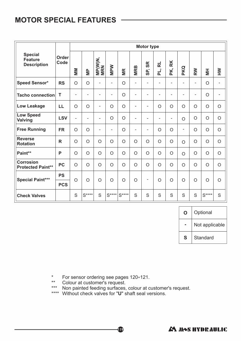
MOTOR SPECIAL FEATURES
119
**********
For sensor ordering see pages 120 121.Colour at customer's request.Non painted feeding surfaces, colour at customer's request.Without check valves for " " shaft seal versions.
÷
U
O Optional
- Not applicable
S Standard
SpecialFeatureDescription
OrderCode
LSV
MM
MP
MP
(W)N
MR
N,
MP
W
MR
MR
B
O O O O
O O O O
O O
O O O O
O O O O O O O
O O O O O O O
O O O O O O O
- - -
- -
- -
Motor type
O
O
- -
MH
S S**** S S**** S
--
S****S****
PL
, R
L
PK
, R
K
RW
O
O
O O O
O O O
O O O
- -
O
O
SS
-
S
O
O
O
Speed Sensor*
Low Leakage
Low SpeedValving
Free Running
ReverseRotation
Paint**
CorrosionProtected Paint**
Check Valves
Tacho connection
RS
LL
FR
R
P
PC
T O- - - - --- -
- -
O
O
O
O
O
O
HW
S
-
-
PK
Q
-
-
O
O
-
O
O
O
S
O
O O O O O O OO O OSpecial Paint*** OOPS
PCS
-
SP,
SR
O
O
O
-
-
-
-
S
-
-

MOTORS WITH SPEED SENSOR
MM...RS
180
M12x1
36 [1.42]42 [1.65]
for Q-flange
390
MP...RS and MR...RS
43,7
max 1
03
M12x1
MH...RS
max
3.6
2
[92]
26,51.04[ ]
95,53.76[
]
[4.0
55
]
[1.72]
M12x1
mm [in]
120

Motor type
Pulses per revolution
MM MP MR MH
30 36 36 42
MOTORS
SPEED
SENSOR
121
TECHNICAL DATA OF THE SPEED SENSOR
Output signal
Load max.:I =I <50mAhigh low
Technical data
f =f ±10%1 2
U
ff1 f2
U >U -2Vhigh d.c.
U <2Vlow
Wiring diagrams
Stick type
1 2
34Terminal
No. Connection
1
2
3
4
Ud.c.
No connection
0V
Output signal
Order Code for Speed Sensor
SensorCode
Outputtype
RSN NPN
RSP
RSNL5
RSPL5
NPN
PNP
PNP
Electric connection
Connector BINDER 713 series
Cable output 3x0,25; [ ] long5 m 196 in
NOTE: *- The speed sensor is not fitted at the factory, but is supplied in a plastic bag with the motor.For installation see enclosed instructions.
Cable output 3x0,25; 5 m [196 in] long
Connector BINDER 713 series
CableOutput
Black
Blue
White
Brown
Frequency rangeOutputPower supplyCurrent inputAmbient TemperatureProtectionPlug connectorMounting principle
0...15 000 HzPNP, NPN10...36 VDC20 mA (@24 VDC)-40...+125 C [-40...+257 F]IP 67M12-SeriesISO 6149
0 0
NPNPNP
R =U /I [mA]Load d.c. max[k [V]Ω]

APPLICATION CALCULATION
VEHICLE DRIVE CALCULATIONS
122
4. Acceleration force: FA,
FA
v t
t-
5.Tractive effort: DP
6.Total tractive effort: TE,
TE
RR -
GR-
FA-
DP-
7.Motor Torque moment: M,
N-
Force necessary for acceleration from 0 to maximum
speed and time can be calculated with a formula:
time, [s].
,
Tractive effort DP is the additional force of trailer. This value
will be established as follows:
-acc.to constructor's assessment;
-as calculating forces in items 2, 3 and 4 of trailer; the
calculated sum corresponds to the tractive effort requested.
Total tractive effort is total effort necessary for vehicle
motion; that the sum of forces calculated in items from 2 to 5
and increased with 10 % because of air resistance.
force acquired to overcome the rolling resistance;
force acquired to slope upwards;
force acquired to accelerate (acceleration force);
additional tractive effort (trailer).
Necessary torque moment for every hydraulic motor:
motor numbers;
mechanical gear efficiency (if it is available).
To avoid wheel slipping,
M > M
- frictional factor;
total weight over the wheels, .
daN [lbs]
daN [lbs]
daN [lbs]
daN [lbs]
daN [lbs]
FA- acceleration force, ;
the following condition should be
observed
daNm [in-lb]
daNm in-lb
�M-
f
-
8.Cohesion between tire and road covering: M , [ ]W
W
GW
�M-
f
-
W
GW
1.Motor speed: n,
v -
R -
i-
2.Rolling resistance: RR,
-
RPM
vehicle speed, km/h;
wheel rolling radius, m;
gear ratio between motor and wheels.
If no gearbox, use i=1.
[ ]
The resistance force resulted in wheels contact with
different surfaces:
rolling resistance coefficient (Table 1).
km
m
v -
R -
G-
ml
in
vehicle speed, mil/h;
wheel rolling radius, in;
daN lbs
total weight loaded on vehicle, daN [lbs];
�
n=2,65 v i
R
x xkm
m
n=168 v i
R
x xml
in
RR=G x �
Table 1
Concrete- faultless
Concrete- good
Concrete- bad
Asphalt- faultless
Asphalt- good
Asphalt- bad
Macadam- faultless
Macadam- good
Macadam- bad
Snow- 5 cm
Snow- 10 cm
Polluted covering- smooth
Polluted covering- sandy
Mud
Sand- Gravel
Sand- loose
0.010
0.015
0.020
0.012
0.017
0.022
0.015
0.022
0.037
0.025
0.037
0.025
0.040
0.037÷0.150
0.060÷0.150
0.160÷0.300
Surface
Rolling resistance coefficientIn case of rubber tire rolling on different surfaces
�
TE=1,1 (RR + GR + FA + DP)x
M=TE
N
x R [R ]
i
in m
x x hMhM
M =W
G fxW R [R ]
i
x
x
in m
hM
W
hM
Table 3
0.15 ÷ 0.20
0.5 ÷ 0.7
0.8 ÷ 1.0
0.8 ÷ 1.0
0.4
Frictional factorf
Steel on steel
Rubber tire on polluted surface
Rubber tire on asphalt
Rubber tire on concrete
Rubber tire on grass
Surface
3.Grade resistance: GR,
- gradient negotiation angle (Table 2)
daN [lbs]
�
1%
2
5
6
8
10
%
%
%
%
%
12
15
20
25
32
60%
%
%
%
%
%
Table 2
Degrees Degrees
0º 35'
1º 9'
2º 51'
3º 26'
4º 35'
5º 43'
6º 5'
8º 31'
11º 19'
14º 3'
18º
31º
Grade%
Grade%
FA= , ;[lbs]v G
22
ml x
txFA= , [daN]
v G
3,6
km x
tx
MOTORS
HYDRAULIC
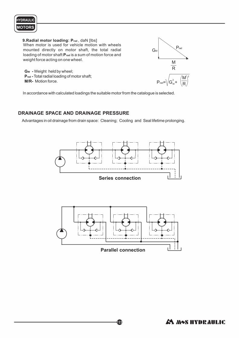
9.Radial motor loading: P
P
, [ ]When motor is used for vehicle motion with wheels
mounted directly on motor shaft, the total radial
loading of motor shaft is a sum of motion force and
weight force acting on one wheel.
rad
rad
daN lbs
M
R
PradGW
P = G +rad
M
R2
W
2
G -W Weight held by wheel;
P -
M/R-
rad Total radial loading of motor shaft;
Motion force.
In accordance with calculated loadings the suitable motor from the catalogue is selected.
DRAINAGE SPACE AND DRAINAGE PRESSURE
Advantages in oil drainage from drain space: Cleaning; Cooling and Seal lifetime prolonging.
Parallel connection
Series connection
123