
Make Flexitallic Your Global...
52
Transcript of Make Flexitallic Your Global...


Make Flexitallic Your Global Provider We’re a worldwide organization specializing in local service and meeting each customer’s needs. Visit us at Flexitallic.com to browse our comprehensive product range, for all your major industrial sealing applications and solutions.

1Y O U R G L O B A L G A S K E T P R O V I D E R
Page
CONTENTSMANUFACTURING UNITS 2
INTRODUCTION 3
GASKET IDENTIFICATION 4
AVAILABLE GASKET MATERIALS 5
GASKET SELECTION 6
DIMENSIONAL DATA 7TABLE 1 - STYLE CG & CGI TO ASME B16.20 TO SUIT ASME B16.5 FLG - IMPERIAL SIZES 8TABLE 2 - STYLE CG & CGI TO ASME B16.2O TO SUIT ASME B16.5 FLG - METRIC SIZES 9TABLE 3 - INNER RING DIMENSIONS FOR STYLE CGI TO ASME B16.20 10TABLE 4 - STYLE CG & CGI TO SUIT SMALL DIA SCREWED OR SLIP-ON FLG 10TABLE 5 - MAXIMUM BORE OF ASME B16.5 FLG 11TABLE 6 - STYLE CG & CGI TO ASME B16.20 TO SUIT LARGE DIA ASME B16.47 SERIES B FLG - IMPERIAL SIZES 12TABLE 7 - STYLE CG & CGI TO ASME B16.20 TO SUIT LARGE DIA ASME B16.47 SERIES B FLG - METRIC SIZES 14TABLE 7 - STYLE CG & CGI TO ASME B16.20 TO SUIT LARGE DIA ASME B16.47 SERIES A AND BS 3293 FLG 15TABLE 8 - STYLE CG & CGI TO SUIT LARGE DIA FLG - IMPERIAL SIZES 16TABLE 9 - STYLE CG & CGI TO SUIT LARGE DIA FLG - METRIC SIZES 18TABLE 10 - STYLE CG & CGI TO SUIT LARGE DIA FLG 20TABLE 11 - STYLE CG & CGI TO BS 3381 TO SUIT BS 1560 & ASME B16.5 FLG - IMPERIAL SIZES 22TABLE 12 - STYLE CG & CGI TO BS 3381 TO SUIT BS 1560 & ASME B16.5 FLG - METRIC SIZES 23TABLE 13 - STYLE CG & CGI TO SUIT BS10 FLG 24TABLE 14 - STYLE CG & CGI TO BS 4865 PART 2 TO SUIT BS 4504 FLG 25TABLE 15 - STYLE CG & CGI TO SUIT DIN FLANGES 26TABLE 16 - STYLE R TO SUIT ASME B16.5 AND BS 1560 FLG 27TABLE 17 - STYLE RIR TO SUIT ASME B16.5 AND BS 1560 FLG 28TABLE 18 - STYLE CG & CGI TO SUIT JIS FLG 29TABLE 19 - STYLE CG & CGI TO SUIT JIS FLG 29TABLE 20 - STYLE CG-RJ & CGI-RJ REPLACEMENTS FOR RING JOINT GASKETS 30TABLE 21 - STYLE 625 FOR CLAMP-TYPE AND OTHER NON-STANDARD FLANGE ASSEMBLIES 31
USEFUL TECHNICAL DATA 32ASSEMBLY TECHNIQUES 32TABLE 22 - RECOMMENDED TORQUE CG SPIRAL WOUND GASKETS 33TABLE 23 - RECOMMENDED TORQUE CGI SPIRAL WOUND GASKETS 34TABLE 24 - BOLTING DATA FOR ASME B16.5 AND BS1560 FLG 35TABLE 25 - FACING DIMENSIONS FOR ASME B16.5 AND BS 1560 FLG 36
SPECIAL APPLICATION GASKETS 37SPECIAL CGI WITH SPIRAL WOUND OUTER RING GASKETS FOR HEAT EXCHANGERS 37CARRIER RING GASKETS 38STYLE LS & LSI LOW STRESS GASKETS 39BOILER CAP AND MANHOLE COVER GASKETS 40TABLE 26 - STYLE M, MC & MCS 41TABLE 27 - STYLE T 42THERMICULITE 835 HEAT TREATED INCONEL X-750 SPIRAL WOUND GASKETS 43 MULTI-CLASS SPIRAL WOUND GASKETS 44BAKER GASKETS 45
spiralWoundBrochure_060614_inside 3/24/2016 1:08 PM Page 1
Y O U R G L O B A L G A S K E T P R O V I D E R2
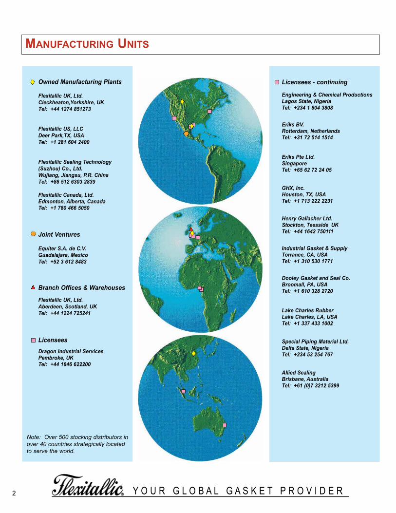
Manufacturing units
Note: Over 500 stocking distributors inover 40 countries strategically locatedto serve the world.
Owned Manufacturing Plants
Flexitallic UK, Ltd.Cleckheaton,Yorkshire, UKTel: +44 1274 851273
Flexitallic US, LLCDeer Park,TX, USATel: +1 281 604 2400
Flexitallic Sealing Technology(Suzhou) Co., Ltd.Wujiang, Jiangsu, P.R. ChinaTel: +86 512 6303 2839
Flexitallic Canada, Ltd.Edmonton, Alberta, CanadaTel: +1 780 466 5050
Joint Ventures
Equiter S.A. de C.V. Guadalajara, MexicoTel: +52 3 612 8483
Branch Offices & Warehouses
Flexitallic UK, Ltd.Aberdeen, Scotland, UKTel: +44 1224 725241
LicenseesDragon Industrial Services Pembroke, UKTel: +44 1646 622200
Licensees - continuing
Engineering & Chemical ProductionsLagos State, NigeriaTel: +234 1 804 3808
Eriks BV. Rotterdam, NetherlandsTel: +31 72 514 1514
Eriks Pte Ltd.SingaporeTel: +65 62 72 24 05
GHX, Inc. Houston, TX, USATel: +1 713 222 2231
Henry Gallacher Ltd. Stockton, Teesside UKTel: +44 1642 750111
Industrial Gasket & Supply Torrance, CA, USATel: +1 310 530 1771
Dooley Gasket and Seal Co. Broomall, PA, USATel: +1 610 328 2720
Lake Charles RubberLake Charles, LA, USATel: +1 337 433 1002
Special Piping Material Ltd.Delta State, NigeriaTel: +234 53 254 767
Allied Sealing Brisbane, AustraliaTel: +61 (0)7 3212 5399
spiralWoundBrochure_060614_inside 3/24/2016 1:08 PM Page 2

3Y O U R G L O B A L G A S K E T P R O V I D E R
introductionFIRST AND FOREMOST
The concept of spiral wound gasket construction wasoriginated by Flexitallic in 1912, inaugurating the begin-ning of a new era in safe, effective sealing. The primarypurpose for this development was the increasinglysevere temperatures and pressures used by U.S. refin-ery operators in the first half of the century.
The necessity for a gasket to have the ability to recovercannot be over emphasized. The effects of pressureand temperature fluctuations, the temperature differen-tial across the flange face, together with bolt stressrelaxation and creep, demand a gasket with adequateflexibility and recovery to maintain a seal even underthese varying service conditions. The Flexitallic SpiralWound Gasket is the precision engineered solution tosuch problems, meeting the most exacting conditions ofboth temperature and pressure in flanged joints andsimilar assemblies and against virtually every knowncorrosive and toxic media.
This publication is designed to facilitate the specificationand ordering of standard Flexitallic Spiral WoundGaskets. Dimensional data for the basic styles - StyleCG, Style CGI, Style R and Style RIR are detailed onrespective tables.
Metal Strip
Filler Material
spiralWoundBrochure_060614_inside 3/24/2016 1:08 PM Page 3
4 Y O U R G L O B A L G A S K E T P R O V I D E R
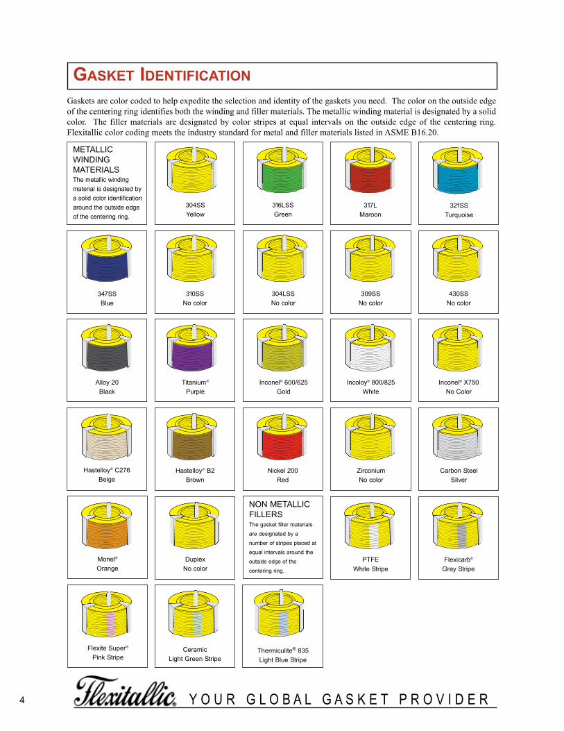
Gaskets are color coded to help expedite the selection and identity of the gaskets you need. The color on the outside edgeof the centering ring identifies both the winding and filler materials. The metallic winding material is designated by a solidcolor. The filler materials are designated by color stripes at equal intervals on the outside edge of the centering ring.Flexitallic color coding meets the industry standard for metal and filler materials listed in ASME B16.20.
METALLIC WINDINGMATERIALSThe metallic winding material is designated by a solid color identificationaround the outside edgeof the centering ring.
NON METALLICFILLERSThe gasket filler materials
are designated by a
number of stripes placed at
equal intervals around the
outside edge of the
centering ring.
304SSYellow
347SS Blue
321SSTurquoise
316LSS Green
304LSSNo color
317LMaroon
430SSNo color
309SSNo color
310SSNo color
Titanium®
PurpleInconel® X750
No ColorIncoloy® 800/825
WhiteInconel® 600/625
GoldAlloy 20
Black
Nickel 200 Red
Hastelloy® C276 Beige
Carbon Steel Silver
Zirconium No color
Hastelloy® B2 Brown
Monel®
Orange
Flexite Super®
Pink Stripe
Flexicarb®
Gray StripePTFE
White Stripe
Ceramic Light Green Stripe
Thermiculite® 835Light Blue Stripe
Duplex No color
gasket identification
spiralWoundBrochure_060614_inside 3/24/2016 1:08 PM Page 4

5Y O U R G L O B A L G A S K E T P R O V I D E R
availaBle gasket Materials
METAL WINDING STRIPAS STANDARDStainless Steel type 304
316L
OTHERSStainless Steel type 304L
309310316Ti317L32134743017-7PH
ALLOY 20MONEL®
TITANIUM®
NICKEL® 200INCONEL® type 600
625X-750
HASTELLOY® type B-2B-3C276
INCOLOY® type 800825
DUPLEXZIRCONIUM®
TANTALUM®
COPPERPHOS-BRONZE
FILLER MATERIALFlexicarb® flexible graphiteThermiculite® 835Flexite Super®
PTFEMicaCeramicNon-sintered PTFE
Thermiculite®, FLEXITALLIC’S pro-prietary high-temperature, sealingmaterial is comprised of chemicallyexfoliated and thermally exfoliatedvermiculite.This revolutionary patented prod-uct simulates the structure of exfo-liated graphite but with one notableexception … gaskets made withThermiculite® maintain their integri-ty, even at extreme temperatures.Thermiculite is thermally stable,ensuring against thermal oxidation,at temperatures in excess of1800ºF (Thermiculite® 835).
GUIDE RING MATERIALAS STANDARDCarbon Steel
OTHERSStainless Steel type 304
304L316316L316Ti310321347410
INCONEL® 600625
MONEL®
TITANIUM®
NICKELINCOLOY® type 800
825ALLOY 20HASTELLOY® type B-2
B-3C276
NOTES:
Selected materials should be compatible with operating temperature and chemicals. If in doubt, contact FlexitallicTechnical Department.
If PTFE is subjected to temperatures above 250°C (500°F) decomposition starts to occur slowly, increasing rapidly above 400°C (750°F). Care should be taken to avoid inhaling the resultant fumes, which may produce hazardous effects.
identification reQuireMents
inner ring material stampedon inner ring of outer ring
inner ring metal, windingmetal and filler material
outer ring material when other than cs
Manufactured to asMe B16.20latest edition or applicable dimensional
and quality specifications
nominal pipe size and pressure class.not shown when gasket is
manufactured to special dimensions
spiralWoundBrochure_060614_inside 3/24/2016 1:08 PM Page 5
6 Y O U R G L O B A L G A S K E T P R O V I D E R
gasket selection
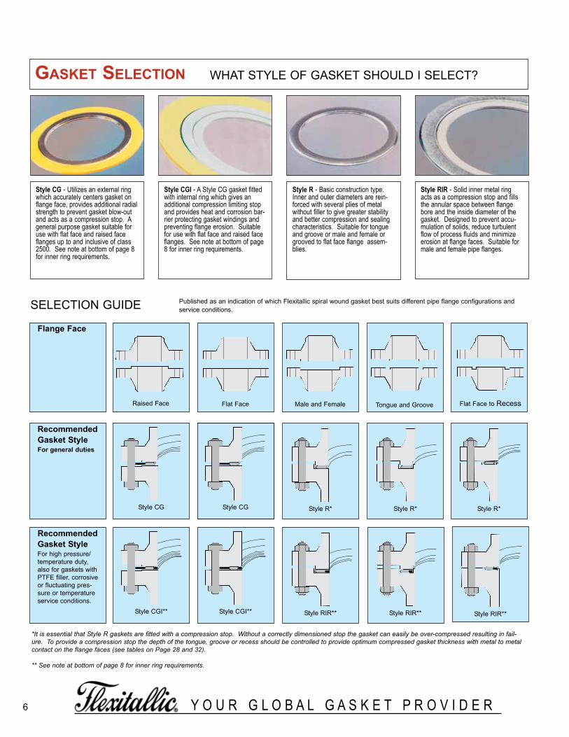
Style CG - Utilizes an external ringwhich accurately centers gasket onflange face, provides additional radialstrength to prevent gasket blow-outand acts as a compression stop. Ageneral purpose gasket suitable foruse with flat face and raised faceflanges up to and inclusive of class2500. See note at bottom of page 8for inner ring requirements.
Style RIR - Solid inner metal ringacts as a compression stop and fillsthe annular space between flangebore and the inside diameter of thegasket. Designed to prevent accu-mulation of solids, reduce turbulentflow of process fluids and minimizeerosion at flange faces. Suitable formale and female pipe flanges.
Style R - Basic construction type.Inner and outer diameters are rein-forced with several plies of metalwithout filler to give greater stabilityand better compression and sealingcharacteristics. Suitable for tongueand groove or male and female orgrooved to flat face flange assem-blies.
Style CGI - A Style CG gasket fittedwith internal ring which gives anadditional compression limiting stopand provides heat and corrosion bar-rier protecting gasket windings andpreventing flange erosion. Suitablefor use with flat face and raised faceflanges. See note at bottom of page8 for inner ring requirements.
SELECTION GUIDE Published as an indication of which Flexitallic spiral wound gasket best suits different pipe flange configurations andservice conditions.
Style RIR**Style CGI**
Raised Face Flat Face Male and Female Tongue and Groove
Style CG Style R*
Flat Face to Recess
flange face
recommendedgasket stylefor general duties
recommendedgasket styleFor high pressure/temperature duty,also for gaskets withPTFE filler, corrosiveor fluctuating pres-sure or temperatureservice conditions.
Style CG
Style CGI**
Style R* Style R*
*It is essential that Style R gaskets are fitted with a compression stop. Without a correctly dimensioned stop the gasket can easily be over-compressed resulting in fail-ure. To provide a compression stop the depth of the tongue, groove or recess should be controlled to provide optimum compressed gasket thickness with metal to metalcontact on the flange faces (see tables on Page 28 and 32).
** See note at bottom of page 8 for inner ring requirements.
Style RIR** Style RIR**
WHAT STYLE OF GASKET SHOULD I SELECT?
spiralWoundBrochure_060614_inside 3/24/2016 1:08 PM Page 6

7Y O U R G L O B A L G A S K E T P R O V I D E R
SPECIAL GASKETS
Gaskets of special design can beengineered and fabricated usingthe same basic fundamentals ofFlexitallic Spiral Wound Gasketdesign and construction to cover awide range of applications ininstallations for which there areno industry-wide standards.Special gaskets have beendesigned for valves, pumps, com-pressors, turbines, boilers, heatexchangers, etc. Consult withFlexitallic engineers as early inthe design stage as possible.
GOVERNMENT SPECI-FICATIONS
Flexitallic Spiral Wound Gasketsare available in accordance withMilitary Specifications MIL-G-24716, and MIL-G-15342, latest revisions. When making an inquiry, refer to the properGovernment Specification num-ber.
diMensional data
All CG and CGI Gaskets for these standard flanges are 0.175 in (4.5mm) thick, fitted with0.125 in (3.2mm) thick solid metal rings, unless otherwise stated.
Note: Please select correct gasket style for your particular application. See page 6 “Gasket Selection”.
*Style CG *Style CGI
WHen ordering Please sPecifY eXaMPleGASKET STYLE FLEXITALLIC STYLE “CGI” SPIRAL WOUND GASKET
NOMINAL PIPE SIZE (NPS) 4”
PRESSURE RATING CLASS 900
GASKET STANDARD ASME B16.20
WINDING MATERIALS 316L/FLEXICARB (FG)
OUTER RING MATERIAL CARBON STEEL
INNER RING MATERIAL 316L
stYle cg & cgi gaskets TO SUIT STANDARD RAISED FACE AND FLAT FACEFLANGES
Flexitallic style CG and CGI SpiralWound gaskets can be manufacturedin accordance with all relevant gasketstandards to suit the following flangedesignations.
Please note that gaskets for non-stan-dard flanges are also readily available.
ASME B16.5BS 1560BS 10ASME B16.47 SERIES B (API 605)ASME B16.47 SERIES A (MSS SP 44)BS 4504DIN FLANGESJIS FLANGES
spiralWoundBrochure_060614_inside 3/24/2016 1:08 PM Page 7

8 Y O U R G L O B A L G A S K E T P R O V I D E R
stYle cg & cgi* to asMe B16.20TO SUIT ASME B16.5 FLANGES
DIMENSIONS IN INCHES.
*For Style CGI - see Table 3 for Inner Ring dimensions
Gasket sizes 1/4” to 3” Class 300, 400 & 600 as well as sizes 1/2” to 2-1/2” Class 900 & 1500 are identical within their respective nominal pipe sizes,therefore inventories need not be duplicated.
in accordance with asMe B16.20, inner rings are mandatory for the following flange designations (see table 3).class 900 - nPs 24 to 48 class 1500 - nPs 12 to nPs 24class 2500 - nPs 4 to nPs 12all Ptfe filled gasketsall flexible graphite gaskets unless otherwise requested by the customer
asMe B16.20 does not include dimensions for nPs 1/4, 3-1/2, or 4-1/2, or class 400 flanges up to nPs 3 and class 900 flanges up tonPs 2-1/2.
TABLE1
NOMPIPESIZE
OUTSIDE DIAMETEROF SEALING
ELEMENTINNER DIAMETER OF SEALING ELEMENT OUTER DIAMETER OF CENTERING RING
CLASS150, 300,400, 600
CLASS900, 1500,
2500
CLASS150
CLASS300
CLASS400
CLASS600
CLASS900
CLASS1500
CLASS2500
CLASS150
CLASS300
CLASS400
CLASS600
CLASS900
CLASS1500
CLASS2500
1/4 7/8 - 1/2 1/2 1/2 1/2 - - - 1-3/4 1-3/4 1-3/4 1-3/4 - - -
1/2 1-1/4 1-1/4 3/4 3/4 3/4 3/4 3/4 3/4 3/4 1-7/8 2-1/8 2-1/8 2-1/8 2-1/2 2-1/2 2-3/4
3/4 1-9/16 1-9/16 1 1 1 1 1 1 1 2-1/4 2-5/8 2-5/8 2-5/8 2-3/4 2-3/4 3
1 1-7/8 1-7/8 1-1/4 1-1/4 1-1/4 1-1/4 1-1/4 1-1/4 1-1/4 2-5/8 2-7/8 2-7/8 2-7/8 3-1/8 3-1/8 3-3/8
1-1/4 2-3/8 2-3/8 1-7/8 1-7/8 1-7/8 1-7/8 1-9/16 1-9/16 1-9/16 3 3-1/4 3-1/4 3-1/4 3-1/2 3-1/2 4-1/8
1-1/2 2-3/4 2-3/4 2-1/8 2-1/8 2-1/8 2-1/8 1-7/8 1-7/8 1-7/8 3-3/8 3-3/4 3-3/4 3-3/4 3-7/8 3-7/8 4-5/8
2 3-3/8 3-3/8 2-3/4 2-3/4 2-3/4 2-3/4 2-5/16 2-5/16 2-5/16 4-1/8 4-3/8 4-3/8 4-3/8 5-5/8 5-5/8 5-3/4
2-1/2 3-7/8 3-7/8 3-1/4 3-1/4 3-1/4 3-1/4 2-3/4 2-3/4 2-3/4 4-7/8 5-1/8 5-1/8 5-1/8 6-1/2 6-1/2 6-5/8
3 4-3/4 4-3/4 4 4 4 4 3-3/4 3-5/8 3-5/8 5-3/8 5-7/8 5-7/8 5-7/8 6-5/8 6-7/8 7-3/4
3-1/2 5-1/4 5-1/4 4-1/2 4-1/2 4-1/8 4-1/8 4-1/8 4-1/8 - 6-3/8 6-1/2 6-3/8 6-3/8 7-1/2 7-3/8 -
4 5-7/8 5-7/8 5 5 4-3/4 4-3/4 4-3/4 4-5/8 4-5/8 6-7/8 7-1/8 7 7-5/8 8-1/8 8-1/4 9-1/4
4-1/2 6-1/2 6-1/2 5-1/2 5-1/2 5-5/16 5-5/16 5-5/16 5-5/16 - 7 7-3/4 7-5/8 8-1/4 9-3/8 9-1/8 -
5 7 7 6-1/8 6-1/8 5-13/16 5-13/16 5-13/16 5-5/8 5-5/8 7-3/4 8-1/2 8-3/8 9-1/2 9-3/4 10 11
6 8-1/4 8-1/4 7-3/16 7-3/16 6-7/8 6-7/8 6-7/8 6-3/4 6-3/4 8-3/4 9-7/8 9-3/4 10-1/2 11-3/8 11-1/8 12-1/2
8 10-3/8 10-1/8 9-3/16 9-3/16 8-7/8 8-7/8 8-3/4 8-1/2 8-1/2 11 12-1/8 12 12-5/8 14-1/8 13-7/8 15-1/4
10 12-1/2 12-1/4 11-5/16 11-5/16 10-13/16 10-13/16 10-7/8 10-1/2 10-5/8 13-3/8 14-1/4 14-1/8 15-3/4 17-1/8 17-1/8 18-3/4
12 14-3/4 14-1/2 13-3/8 13-3/8 12-7/8 12-7/8 12-3/4 12-3/4 12-1/2 16-1/8 16-5/8 16-1/2 18 19-5/8 20-1/2 21-5/8
14 16 15-3/4 14-5/8 14-5/8 14-1/4 14-1/4 14 14-1/4 - 17-3/4 19-1/8 19 19-3/8 20-1/2 22-3/4 -
16 18-1/4 18 16-5/8 16-5/8 16-1/4 16-1/4 16-1/4 16 - 20-1/4 21-1/4 21-1/8 22-1/4 22-5/8 25-1/4 -
18 20-3/4 20-1/2 18-11/16 18-11/16 18-1/2 18-1/2 18-1/4 18-1/4 - 21-5/8 23-1/2 23-3/8 24-1/8 25-1/8 27-3/4 -
20 22-3/4 22-1/2 20-11/16 20-11/16 20-1/2 20-1/2 20-1/2 20-1/4 - 23-7/8 25-3/4 25-1/2 26-7/8 27-1/2 29-3/4 -
24 27 26 3/4 24-3/4 24-3/4 24-3/4 24-3/4 24-3/4 24-1/4 - 28-1/4 30-1/2 30-1/4 31-1/8 33 35-1/2 -
spiralWoundBrochure_060614_inside 3/24/2016 1:08 PM Page 8

NOMPIPESIZE
OUTSIDE DIAMETEROF SEALING
ELEMENTINNER DIAMETER OF SEALING ELEMENT OUTER DIAMETER OF CENTERING RING
CLASS150, 300,400, 600
CLASS900, 1500,
2500
CLASS150
CLASS300
CLASS400
CLASS600
CLASS900
CLASS1500
CLASS2500
CLASS150
CLASS300
CLASS400
CLASS600
CLASS900
CLASS1500
CLASS2500
1/4 22.2 - 12.7 12.7 12.7 12.7 - - - 44.5 44.5 44.5 44.5 - - -
1/2 31.8 31.8 19.1 19.1 19.1 19.1 19.1 19.1 19.1 47.8 54.1 54.1 54.1 63.5 63.5 69.9
3/4 39.6 39.6 25.4 25.4 25.4 25.4 25.4 25.4 25.4 57.2 66.8 66.8 66.8 69.9 69.9 76.2
1 47.8 47.8 31.8 31.8 31.8 31.8 31.8 31.8 31.8 66.8 73.2 73.2 73.2 79.5 79.5 85.9
1-1/4 60.5 60.5 47.8 47.8 47.8 47.8 39.6 39.6 39.6 76.2 82.6 82.6 82.6 88.9 88.9 104.9
1-1/2 69.9 69.9 54.1 54.1 54.1 54.1 47.8 47.8 47.8 85.9 95.3 95.3 95.3 98.6 98.6 117.6
2 85.9 85.9 69.9 69.9 69.9 69.9 58.7 58.7 58.7 104.9 111.3 111.3 111.3 143.0 143.0 146.1
2-1/2 98.6 98.6 82.6 82.6 82.6 82.6 69.9 69.9 69.9 124.0 130.3 130.3 130.3 165.1 165.1 168.4
3 120.7 120.7 101.6 101.6 101.6 101.6 95.3 92.2 92.2 136.7 149.4 149.4 149.4 168.4 174.8 196.9
3-1/2 133.4 133.4 114.3 114.3 104.8 104.8 104.8 104.8 - 161.9 165.1 161.9 161.9 190.5 187.3 -
4 149.4 149.4 127.0 127.0 120.7 120.7 120.7 117.6 117.6 174.8 181.1 177.8 193.8 206.5 209.6 235.0
4-1/2 165.1 165.1 139.7 139.7 134.9 134.9 134.9 134.9 - 177.8 196.9 193.7 209.6 238.1 231.8 -
5 177.8 177.8 155.7 155.7 147.6 147.6 147.6 143.0 143.0 196.9 215.9 212.9 241.3 247.7 254.0 279.4
6 209.6 209.6 182.6 182.6 174.8 174.8 174.8 171.5 171.5 222.3 251.0 247.7 266.7 289.1 282.7 317.5
8 263.7 257.3 233.4 233.4 225.6 225.6 222.3 215.9 215.9 279.4 308.1 304.8. 320.8 358.9 352.6 387.4
10 317.5 311.2 287.3 287.3 274.6 274.6 276.4 266.7 270.0 339.9 362.0 358.9 400.1 435.1 435.1 476.3
12 374.7 368.3 339.9 339.9 327.2 327.2 323.9 323.9 317.5 409.7 422.4 419.1 457.2 498.6 520.7 549.4
14 406.4 400.1 371.6 371.6 362.0 362.0 355.6 362.0 - 450.9 485.9 482.6 492.3 520.7 577.9 -
16 463.6 457.2 422.4 422.4 412.8 412.8 412.8 406.4 - 514.4 539.8 536.7 565.2 574.8 641.4 -
18 527.1 520.7 474.7 474.7 469.9 469.9 463.6 463.6 - 549.4 596.9 593.9 612.9 638.3 704.9 -
20 577.9 571.5 525.5 525.5 520.7 520.7 520.7 514.4 - 606.6 654.1 647.7 682.8 698.5 755.7 -
24 685.8 679.5 628.7 628.7 628.7 628.7 628.7 616.0 - 717.6 774.7 768.4 790.7 838.2 901.7 -
stYle cg & cgi* to asMe B16.20TO SUIT ASME B16.5 FLANGES
9Y O U R G L O B A L G A S K E T P R O V I D E R
DIMENSIONS IN MILLIMETERS.
*For Style CGI - see Table 3 for Inner Ring dimensions.
Gasket sizes 1/4” to 3” Class 300, 400 & 600 as well as sizes 1/2” to 2-1/2” Class 900 & 1500 are identical within their respective nominal pipe sizes,therefore inventories need not be duplicated.
in accordance with asMe B16.20, inner rings are mandatory for the following flange designations (see table 3).class 900 - nPs 24 to 48class 1500 - nPs 12 to nPs 24class 2500 - nPs 4 to nPs 12all Ptfe filled gasketsall flexible graphite gaskets unless otherwise requested by the customer
asMe B16.20 does not include dimensions for nPs 1/4, 3-1/2, or 4-1/2, or class 400 flanges up to nPs 3 and class 900 flanges up tonPs 2-1/2.
TABLE2
spiralWoundBrochure_060614_inside 3/24/2016 1:08 PM Page 9

Y O U R G L O B A L G A S K E T P R O V I D E R10
standard inside diaMeters of inner rings for stYle cgigaskets TO ASME B16.20 TO SUIT ASME B16.5 FLANGES
stYle cg & cgi TO SUIT ASME B16.5 & BS 1560 SMALL DIAMETERSCREWED OR SLIP-ON FLANGES
DIMENSIONS IN INCHES & MILLIMETERS.
NOTE: The above style CG & CGI spiral wound gaskets are dimensioned to suit existing screwed or slip-on flanges for NPS 1/4 to 1-1/2 ASMEB16.5 & BS 1560 flanges.
DIMENSIONS IN INCHES & MILLIMETERS.
in accordance with asMe B16.20, inner rings are mandatory for the following flange designations (see table 3).class 900 - nPs 24 to 48 class 1500 - nPs 12 to nPs 24class 2500 - nPs 4 to nPs 12all Ptfe filled gasketsall flexible graphite gaskets unless otherwise requested by the customer
asMe B16.20 does not include dimensions for nPs 1/4, 3-1/2, or 4-1/2, or class 400 flanges up to nPs 3 and class 900 flanges up tonPs 2-1/2.
NONPIPESIZE
PRESSURE CLASS
150 300 400 600 900 1500 2500
1/2 0.56 14.22 0.56 14.22 0.56 14.22 0.56 14.22 0.56 14.22 0.56 14.22 0.56 14.223/4 0.81 20.57 0.81 20.57 0.81 20.57 0.81 20.57 0.81 20.57 0.81 20.57 0.81 20.571 1.06 26.92 1.06 26.92 1.06 26.92 1.06 26.92 1.06 26.92 1.06 26.92 1.06 26.92
1-1/4 1.50 38.10 1.50 38.10 1.50 38.10 1.50 38.10 1.31 33.27 1.31 33.27 1.31 33.271-1/2 1.75 44.45 1.75 44.45 1.75 44.45 1.75 44.45 1.63 41.40 1.63 41.40 1.63 41.40
2 2.19 55.63 2.19 55.63 2.19 55.63 2.19 55.63 2.06 52.32 2.06 52.32 2.06 52.522-1/2 2.62 66.55 2.62 66.55 2.62 66.55 2.62 66.55 2.50 63.60 2.50 63.50 2.50 63.50
3 3.19 81.03 3.19 81.03 3.19 81.03 3.19 81.03 3.10 78.74 3.10 78.74 3.10 78.744 4.19 106.43 4.19 106.43 4.04 102.62 4.04 102.62 4.04 102.62 3.85 97.79 3.85 97.795 5.19 131.83 5.19 131.63 5.05 128.27 5.05 128.27 5.05 128.27 4.90 124.46 4.90 124.466 6.19 157.23 6.19 157.23 6.10 154.64 6.10 154.94 6.10 154.95 5.80 147.32 5.80 147.328 8.50 215.90 8.50 215.90 8.10 205.74 8.10 205.74 7.75 196.85 7.75 196.85 7.75 196.85
10 10.56 288.22 10.56 268.22 10.05 255.27 10.05 255.27 9.69 246.13 9.69 246.13 9.69 246.1312 12.50 317.50 12.50 317.50 12.10 307.34 12.10 307.34 11.50 292.10 11.50 292.10 11.50 292.1014 13.75 349.28 13.75 349.25 13.50 342.80 13.50 342.90 12.63 320.80 12.63 320.80 - -16 15.75 400.05 15.75 400.05 15.35 389.89 15.35 389.89 14.75 374.65 14.50 388.30 - -18 17.69 449.33 17.69 449.33 17.25 438.15 17.25 438.15 16.75 425.45 16.75 425.45 - -20 19.69 500.13 19.69 500.13 19.25 488.95 19.25 488.95 19.00 482.60 18.75 476.25 - -24 23.75 603.25 23.75 603.25 23.25 590.55 23.25 590.65 23.25 590.55 22.75 577.85 - -
TABLE3
1/4 - - 9/16 14.3 7/8 22.2 1-3/4 44.5 1-3/4 44.5 1-3/4 44.5 1-3/4 44.5 - - - -
1/2 9/16 14.3 15/16 23.8 1-1/4 31.8 1-7/8 47.6 2-1/8 54.0 2-1/8 54.0 2-1/8 54.0 2-1/2 63.5 2-1/2 63.5
3/4 13/16 20.6 1-3/16 30.2 1-9/16 39.7 2-1/4 57.2 2-5/8 66.7 2-5/8 66.7 2-5/8 66.7 2-3/4 69.9 2-3/4 69.9
1 1-1/16 27.0 1-7/16 36.5 1-7/8 47.6 2-5/8 66.7 2-7/8 73.0 2-7/8 73.0 2-7/8 73.0 3-1/8 79.4 3-1/8 79.4
1-1/4 1-3/8 34.9 1-7/8 47.6 2-3/8 60.3 3 76.2 3-1/4 82.6 3-1/4 82.6 3-1/4 82.6 3-1/2 88.9 3-1/2 88.9
1-1/2 1-5/8 41.3 2-1/8 54.0 2-3/4 69.9 3-3/8 85.7 3-3/4 95.3 3-3/4 95.3 3-3/4 95.3 3-7/8 98.4 3-7/8 98.4
Nom. InnerPipe RingSize Inside Dia.
Sealing Element Guide Ring Outside Diameter
Inside Outside Class Class Class Class Class ClassDia. Dia. 150 300 400 600 900 1500
TABLE4
See Table 4 for small diameter screwed and slip-on flanges.
spiralWoundBrochure_060614_inside 3/24/2016 1:09 PM Page 10
Y O U R G L O B A L G A S K E T P R O V I D E R 11
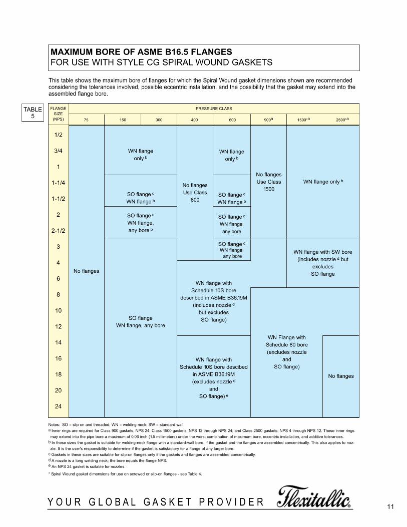
MaXiMuM Bore of asMe B16.5 flangesFOR USE WITH STYLE CG SPIRAL WOUND GASKETS
Notes: SO = slip on and threaded; WN = welding neck; SW = standard wall.a Inner rings are required for Class 900 gaskets, NPS 24; Class 1500 gaskets, NPS 12 through NPS 24; and Class 2500 gaskets; NPS 4 through NPS 12. These inner ringsmay extend into the pipe bore a maximum of 0.06 inch (1.5 millimeters) under the worst combination of maximum bore, eccentric installation, and additive tolerances.
b In these sizes the gasket is suitable for welding-neck flange with a standard-wall bore, if the gasket and the flanges are assembled concentrically. This also applies to noz-zle. It is the user's responsibility to determine if the gasket is satisfactory for a flange of any larger bore.
c Gaskets in these sizes are suitable for slip-on flanges only if the gaskets and flanges are assembled concentrically.d A nozzle is a long welding neck; the bore equals the flange NPS.e An NPS 24 gasket is suitable for nozzles.
* Spiral Wound gasket dimensions for use on screwed or slip-on flanges - see Table 4.
This table shows the maximum bore of flanges for which the Spiral Wound gasket dimensions shown are recommendedconsidering the tolerances involved, possible eccentric installation, and the possibility that the gasket may extend into theassembled flange bore.
No flanges
No flangesUse Class
1500WN flange only b
No flanges
WN flange with SW bore(includes nozzle d but
excludes SO flange
WN Flange withSchedule 80 bore(excludes nozzle
and SO flange)
WN flangeonly b
SO flange c
WN flange b
SO flange c
WN flange, any bore
SO flange c
WN flange,any bore
No flangesUse Class
600
WN flange with Schedule 10S bore
described in ASME B36.19M(includes nozzle d
but excludes SO flange)
WN flange with Schedule 10S bore descibed
in ASME B36.19M(excludes nozzle d
and SO flange) e
WN flangeonly b
SO flange c
WN flange b
SO flange c
WN flange,any bore b
SO flangeWN flange, any bore
1/2
3/4
1
1-1/4
1-1/2
2
2-1/2
3
4
6
8
10
12
14
16
18
20
24
FLANGESIZE (NPS)
PRESSURE CLASS
75 150 300 400 600 900a 1500*a 2500*a
TABLE5
spiralWoundBrochure_060614_inside 3/24/2016 1:09 PM Page 11

stYle cg & cgi to asMe B16.20TO SUIT LARGE DIAMETER ASME B16.47 SERIES B FLANGESCLASS 75-300
TABLE6
DIMENSIONS IN INCHES.
Note: Gasket dimensions to suit Class 75 flanges are not specified in ASME B16.20. These gaskets have been dimensioned to suit the flanges.
NOMPIPESIZE
CLASS 75 CLASS 150 CLASS 300
SEALINGELEMENT CENTERING
RINGOUTSIDE
DIA.
INNERRING
INSIDEDIA.
SEALINGELEMENT CENTERING
RINGOUTSIDE
DIA.
INNERRING
INSIDEDIA.
SEALINGELEMENT
CENTERINGRING
OUTSIDEDIA.
ELEMENTINSIDE
DIA.OUTSIDE
DIA.INSIDE
DIA.OUTSIDE
DIA.INSIDE
DIA.OUTSIDE
DIA.
26 26-1/4 27 27-7/8 25-3/4 26-1/2 27-1/2 28-9/16 25-3/4 26-1/2 28 30-3/8
28 28-1/4 29-1/8 29-7/8 27-3/4 28-1/2 29-1/2 30-9/16 27-3/4 28-1/2 30 32-1/2
30 30-1/4 31-1/8 31-7/8 29-3/4 30-1/2 31-1/2 32-9/16 29-3/4 30-1/2 32 34-7/8
32 32-1/4 33-1/8 33-7/8 31-3/4 32-1/2 33-1/2 34-11/16 31-3/4 32-1/2 34 37
34 34-1/4 35-1/8 35-7/8 33-3/4 34-1/2 35-3/4 36-13/16 33-3/4 34-1/2 36 39-1/8
36 36-1/4 37-1/4 38-5/16 35-3/4 36-1/2 37-3/4 38-7/8 35-3/4 36-1/2 38 41-1/4
38 - - - 37-3/4 38-3/8 39-3/4 41-1/8 38-1/4 39-3/4 41-1/4 43-1/4
40 - - - 39-3/4 40-1/4 41-7/8 43-1/8 40-1/4 41-3/4 43-1/4 45-1/4
42 42-1/4 43-1/4 44-5/16 41-3/4 42-1/2 43-7/8 45-1/8 42-3/4 43-3/4 45-1/4 47-1/4
44 - - - 43-3/4 44-1/4 45-7/8 47-1/8 44-1/4 45-3/4 47-1/4 49-1/4
46 - - - 45-3/4 46-1/2 48-3/16 49-7/16 46-3/8 47-7/8 49-3/8 51-7/8
48 48-3/8 49-1/2 50-1/2 47-3/4 48-1/2 50 51-7/16 48-1/2 49-3/4 51-5/8 53-7/8
50 - - - 49-3/4 50-1/2 52-3/16 53-7/16 49-7/8 51-7/8 53-3/8 55-7/8
52 - - - 51-3/4 52-1/2 54-3/16 55-7/16 51-7/8 53-7/8 55-3/8 57-7/8
54 54 3/8 55-5/8 56-5/8 53-3/4 54-1/2 56 57-5/8 53-3/4 55-1/4 57-1/4 60-1/4
56 - - - 56 56-7/8 58-3/16 59-5/8 56-1/4 58-1/4 60 62-3/4
58 - - - 58-3/16 59-1/16 60-3/16 62-3/16 58-7/16 60-7/16 61-15/16 65-3/16
60 60-1/2 61-3/4 62-7/8 60-7/16 61-5/16 62-7/16 64-3/16 61-5/16 62-9/16 64-3/16 67-3/16
12 Y O U R G L O B A L G A S K E T P R O V I D E R
spiralWoundBrochure_060614_inside 3/24/2016 1:09 PM Page 12

stYle cg & cgi to asMe B16.20TO SUIT LARGE DIAMETER ASME B16.47 SERIES B FLANGESCLASS 400-900
TABLE6.1
DIMENSIONS IN INCHES.
*Inner rings are mandatory for Class 900 flanges, NPS 26 to 48.
Note: Gasket dimensions to suit Class 75 flanges are not specified in ASME B16.20. These gaskets have been dimensioned to suit the flanges.
NOMPIPESIZE
CLASS 400 CLASS 600 CLASS 900*
INNERRING
INSIDEDIA.
SEALINGELEMENT CENTERING
RINGOUTSIDE
DIA.
INNERRING
INSIDEDIA.
SEALINGELEMENT CENTERING
RINGOUTSIDE
DIA.
INNERRING
INSIDEDIA.
SEALINGELEMENT CENTERING
RINGOUTSIDE
DIA.ELEMENTINSIDE
DIA.OUTSIDE
DIA.INSIDE
DIA.OUTSIDE
DIA.INSIDE
DIA.OUTSIDE
DIA.
26 25-3/4 26-1/4 27-1/2 29-3/8 25-3/8 26-1/8 28-1/8 30-1/8 26-1/4 27-1/4 29-1/2 33
28 27-5/8 28-1/8 29-1/2 31-1/2 27 27-3/4 29-3/4 32-1/4 28-1/4 29-1/4 31-1/2 35-1/2
30 29-5/8 30-1/8 31-3/4 33-3/4 29-5/8 30-5/8 32-5/8 34-5/8 30-3/4 31 -3/4 33-3/4 37-3/4
32 31-1/2 32 33-7/8 35-7/8 31-1/4 32-3/4 34-3/4 36-3/4 33 34 36 40
34 33-1/2 34-1/8 35-7/8 37-7/8 33-1/2 35 37 39-1/4 35-1/4 36-1/4 38-1/4 42-1/4
36 35-3/8 36-1/8 38 40-1/4 35-1/2 37 39 41-1/4 36-1/4 37-1/4 39-1/4 44-1/4
38 37-1/2 38-1/4 40-1/4 42-1/4 37-1/2 39 41 43-1/2 39-3/4 40-3/4 42-3/4 47-1/4
40 39-3/8 40-3/8 42-3/8 44-3/8 39-3/4 41-1/4 43-1/4 45-1/2 41-3/4 43-1/4 45-1/4 49-1/4
42 41-3/8 42-3/8 44-3/8 46-3/8 42 43-1/2 45-1/2 48 43-3/4 45-1/4 47-1/4 51-1/4
44 43-1/2 44-1/2 46-1/2 48-1/2 43-3/4 45-3/4 47-3/4 50 45-1/2 47-1/2 49-1/2 53-7/8
46 46 47 49 50-3/4 45-3/4 47-3/4 49-3/4 52-1/4 48 50 52 56-1/2
48 47-1/2 49 51 53 48 50 52 54-3/4 50 52 54 58-1/2
50 49-1/2 51 53 55-1/4 50 52 54 57 - - - -
52 51-1/2 53 55 57-1/4 52 54 56 59 - - - -
54 53-1/4 55-1/4 57-1/4 59-3/4 54-1/4 56-1/4 58-1/4 61-1/4 - - - -
56 55-1/4 57-1/4 59-1/4 61-3/4 56-1/4 58-1/4 60-1/4 63-1/2 - - - -
58 57-1/4 59-1/4 61-1/4 63-3/4 58 60-1/2 62-1/2 65-1/2 - - - -
60 59-3/4 61-3/4 63-3/4 66-1/4 60-1/4 62-3/4 64-3/4 68-1/4 - - - -
13Y O U R G L O B A L G A S K E T P R O V I D E R
spiralWoundBrochure_060614_inside 3/24/2016 1:09 PM Page 13

14 Y O U R G L O B A L G A S K E T P R O V I D E R
stYle cg & cgi to asMe B16.20TO SUIT LARGE DIAMETER ASME B16.47 SERIES B FLANGESCLASS 150-300
TABLE7
DIMENSIONS IN MILLIMETERS.
Note: Gasket dimensions to suit Class 75 flanges are not specified in ASME B16.20. These gaskets have been dimensioned to suit the flanges.
NOMPIPESIZE
CLASS 150 CLASS 300
INNERRING
INSIDEDIA.
SEALINGELEMENT CENTERING
RINGOUTSIDE
DIA.
INNERRING
INSIDEDIA.
SEALINGELEMENT
CENTERINGRING
OUTSIDEDIA.
ELEMENTINSIDE
DIA.OUTSIDE
DIA.INSIDE
DIA.OUTSIDE
DIA.
26 654.1 673.1 698.5 725.4 654.1 673.1 711.2 771.7
28 704.9 723.9 749.3 776.2 704.9 723.9 762.0 825.5
30 755.7 774.7 800.1 827.0 755.7 774.7 812.8 886.0
32 806.5 825.5 850.9 881.1 806.5 825.5 863.6 939.8
34 857.3 876.3 908.1 935.0 857.3 876.3 914.4 993.9
36 908.1 927.1 958.9 987.6 908.1 927.1 965.2 1047.8
38 958.9 974.9 1009.7 1044.7 971.6 1009.7 1047.8 1098.6
40 1009.7 1022.4 1063.8 1095.5 1022.4 1060.5 1098.6 1149.4
42 1060.5 1079.5 1114.6 1146.3 1085.9 1111.3 1149.4 1200.2
44 1111.3 1124.0 1165.4 1197.1 1124.0 1162.1 1200.2 1251.0
46 1162.1 1181.1 1224.0 1255.8 1178.1 1216.2 1254.3 1317.8
48 1212.9 1231.9 1270.0 1306.6 1231.9 1263.7 1311.4 1368.6
50 1263.7 1282.7 1325.6 1357.4 1267.0 1317.8 1355.9 1419.4
52 1314.5 1333.5 1376.4 1408.2 1317.8 1368.6 1406.7 1470.2
54 1365.3 1384.3 1422.4 1463.8 1365.3 1403.4 1454.2 1530.4
56 1422.4 1444.8 1478.0 1514.6 1428.8 1479.6 1524.0 1593.9
58 1478.0 1500.0 1528.8 1579.6 1484.4 1535.2 1573.3 1655.8
60 1535.2 1557.3 1586.0 1630.4 1557.3 1589.0 1630.4 1706.6
spiralWoundBrochure_060614_inside 3/24/2016 1:09 PM Page 14
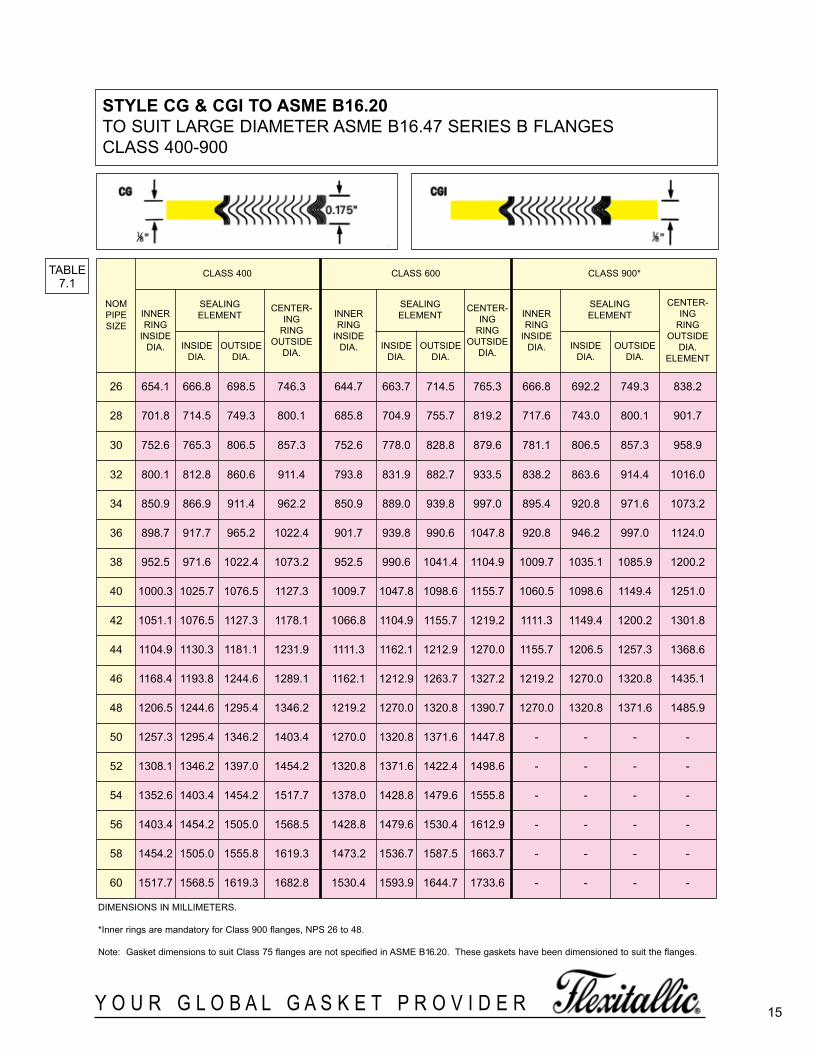
15Y O U R G L O B A L G A S K E T P R O V I D E R
stYle cg & cgi to asMe B16.20TO SUIT LARGE DIAMETER ASME B16.47 SERIES B FLANGESCLASS 400-900
TABLE7.1
DIMENSIONS IN MILLIMETERS.
*Inner rings are mandatory for Class 900 flanges, NPS 26 to 48.
Note: Gasket dimensions to suit Class 75 flanges are not specified in ASME B16.20. These gaskets have been dimensioned to suit the flanges.
NOMPIPESIZE
CLASS 400 CLASS 600 CLASS 900*
INNERRING
INSIDEDIA.
SEALINGELEMENT
CENTER-ING
RINGOUTSIDE
DIA.
INNERRING
INSIDEDIA.
SEALINGELEMENT
CENTER-ING
RINGOUTSIDE
DIA.
INNERRING
INSIDEDIA.
SEALINGELEMENT
CENTER-ING
RINGOUTSIDE
DIA.ELEMENT
INSIDEDIA.
OUTSIDEDIA.
INSIDEDIA.
OUTSIDEDIA.
INSIDEDIA.
OUTSIDEDIA.
26 654.1 666.8 698.5 746.3 644.7 663.7 714.5 765.3 666.8 692.2 749.3 838.2
28 701.8 714.5 749.3 800.1 685.8 704.9 755.7 819.2 717.6 743.0 800.1 901.7
30 752.6 765.3 806.5 857.3 752.6 778.0 828.8 879.6 781.1 806.5 857.3 958.9
32 800.1 812.8 860.6 911.4 793.8 831.9 882.7 933.5 838.2 863.6 914.4 1016.0
34 850.9 866.9 911.4 962.2 850.9 889.0 939.8 997.0 895.4 920.8 971.6 1073.2
36 898.7 917.7 965.2 1022.4 901.7 939.8 990.6 1047.8 920.8 946.2 997.0 1124.0
38 952.5 971.6 1022.4 1073.2 952.5 990.6 1041.4 1104.9 1009.7 1035.1 1085.9 1200.2
40 1000.3 1025.7 1076.5 1127.3 1009.7 1047.8 1098.6 1155.7 1060.5 1098.6 1149.4 1251.0
42 1051.1 1076.5 1127.3 1178.1 1066.8 1104.9 1155.7 1219.2 1111.3 1149.4 1200.2 1301.8
44 1104.9 1130.3 1181.1 1231.9 1111.3 1162.1 1212.9 1270.0 1155.7 1206.5 1257.3 1368.6
46 1168.4 1193.8 1244.6 1289.1 1162.1 1212.9 1263.7 1327.2 1219.2 1270.0 1320.8 1435.1
48 1206.5 1244.6 1295.4 1346.2 1219.2 1270.0 1320.8 1390.7 1270.0 1320.8 1371.6 1485.9
50 1257.3 1295.4 1346.2 1403.4 1270.0 1320.8 1371.6 1447.8 - - - -
52 1308.1 1346.2 1397.0 1454.2 1320.8 1371.6 1422.4 1498.6 - - - -
54 1352.6 1403.4 1454.2 1517.7 1378.0 1428.8 1479.6 1555.8 - - - -
56 1403.4 1454.2 1505.0 1568.5 1428.8 1479.6 1530.4 1612.9 - - - -
58 1454.2 1505.0 1555.8 1619.3 1473.2 1536.7 1587.5 1663.7 - - - -
60 1517.7 1568.5 1619.3 1682.8 1530.4 1593.9 1644.7 1733.6 - - - -
spiralWoundBrochure_060614_inside 3/24/2016 1:09 PM Page 15

Y O U R G L O B A L G A S K E T P R O V I D E R16
stYle cg & cgi to asMe B16.20TO SUIT LARGE DIAMETER ASME B16.47 SERIES A FLANGESCLASS 150-300
DIMENSIONS IN INCHESThe above style CG gasket dimensions are also suitable tar NPS 26 to 48 class 150 and NPS 26 to 36 class 300 BS 3293 flanges.
TABLE8
NOMPIPESIZE
CLASS 150 CLASS 300
INNERRING
INSIDEDIA.
SEALINGELEMENT CENTERING
RINGOUTSIDE
DIA.
INNERRING
INSIDEDIA.
SEALINGELEMENT
CENTERINGRING
OUTSIDEDIA.
ELEMENTINSIDE
DIA.OUTSIDE
DIA.INSIDE
DIA.OUTSIDE
DIA.
22 - 22-3/4 24 26 - 22-3/4 24-3/4 27-3/4
26 25-3/4 26-1/2 27-3/4 30-1/2 25-3/4 27 29 32-7/8
28 27-3/4 28-1/2 29-3/4 32-3/4 27-3/4 29 31 35-3/8
30 29-3/4 30-1/2 31-3/4 34-3/4 29-3/4 31-1/4 33-1/4 37-1/2
32 31-3/4 32-1/2 33-7/8 37 31-3/4 33-1/2 35-1/2 39-5/8
34 33-3/4 34-1/2 35-7/8 39 33-3/4 35-1/2 37-1/2 41-5/8
36 35-3/4 36-1/2 38-1/8 41-1/4 35-3/4 37-5/8 39-5/8 44
38 37-3/4 38-1/2 40-1/8 43-3/4 37-1/2 38-1/2 40 41-1/2
40 39-3/4 40-1/2 42-1/8 45-3/4 39-1/2 40-1/4 42-1/8 43-7/8
42 41-3/4 42-1/2 44-1/4 48 41-1/2 42-1/4 44-1/8 45-7/8
44 43-3/4 44-1/2 46-3/8 50-1/4 43-1/2 44-1/2 46-1/2 48
46 45-3/4 46-1/2 48-3/8 52-1/4 45-5/8 46-3/8 48-3/8 50-1/8
48 47-3/4 48-1/2 50-3/8 54-1/2 47-5/8 48-5/8 50-5/8 52-1/8
50 49-3/4 50-1/2 52-1/2 56-1/2 49 51 53 54-1/4
52 51-3/4 52-1/2 54-1/2 58-3/4 52 53 55 56-1/4
54 53-1/2 54-1/2 56-1/2 61 53-1/4 55-1/4 57-1/4 58-3/4
56 55-1/2 56-1/2 58-1/2 63-1/4 55-1/4 57-1/4 59-1/4 60-3/4
58 57-1/2 58-1/2 60-1/2 65-1/2 57 59-1/2 61-1/2 62-3/4
60 59-1/2 60-1/2 62-1/2 67-1/2 60 61-1/2 63-1/2 64-3/4
spiralWoundBrochure_060614_inside 3/24/2016 1:09 PM Page 16

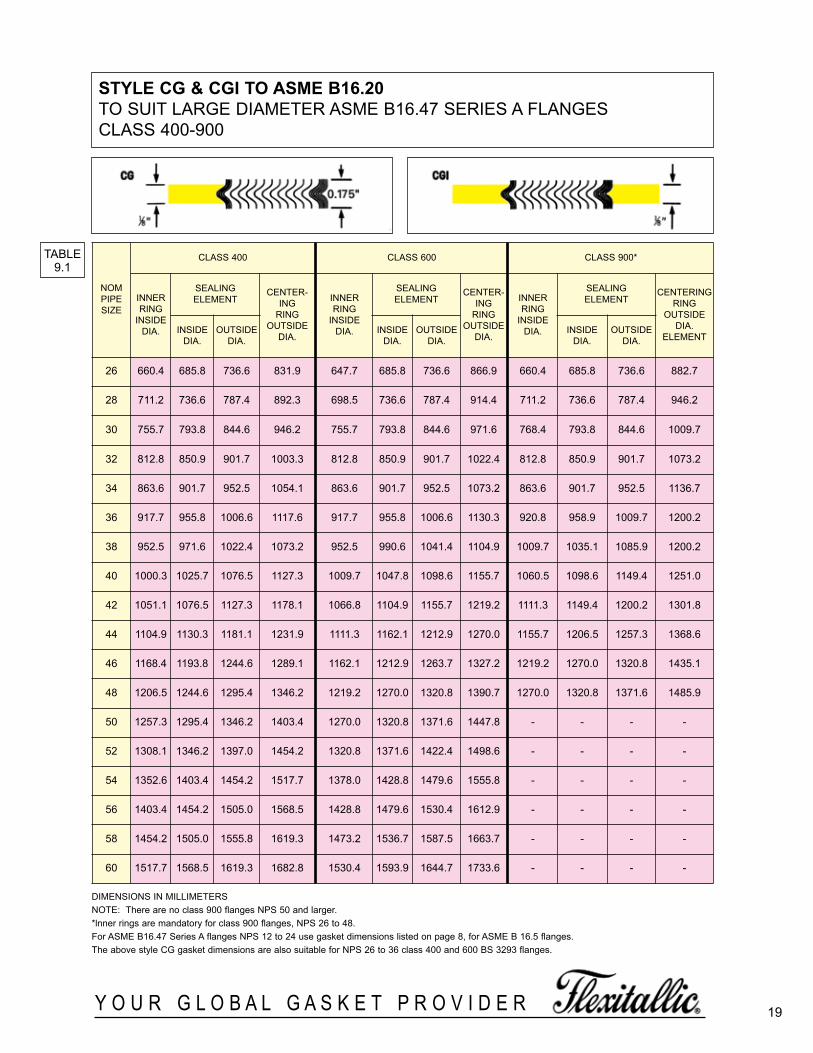
Y O U R G L O B A L G A S K E T P R O V I D E R 17
stYle cg & cgi to asMe B16.20TO SUIT LARGE DIAMETER ASME B16.47 SERIES A FLANGESCLASS 400-900
DIMENSIONS IN INCHESNOTE: There are no class 900 flanges NPS 50 and larger.*lnner rings are mandatory for class 900 flanges, NPS 26 to 48.For ASME B16.47 Series A flanges NPS 12 to 24 use gasket dimensions listed on page 8, for ASME B 16.5 flanges. The above style CG gasket dimensions are also suitable for NPS 26 to 36 class 400 and 600 BS 3293 flanges.
TABLE8.1
NOMPIPESIZE
CLASS 400 CLASS 600 CLASS 900*
INNERRING
INSIDEDIA.
SEALINGELEMENT CENTERING
RINGOUTSIDE
DIA.
INNERRING
INSIDEDIA.
SEALINGELEMENT
CENTER-ING
RINGOUTSIDE
DIA.
INNERRING
INSIDEDIA.
SEALINGELEMENT
CENTERINGRING
OUTSIDEDIA.
ELEMENTINSIDE
DIA.OUTSIDE
DIA.INSIDE
DIA.OUTSIDE
DIA.INSIDE
DIA.OUTSIDE
DIA.
22 - 22-3/4 24-3/4 27-5/8 - 22-3/4 24-3/4 28-7/8 - - - -
26 26 27 29 32-3/4 25-1/2 27 29 34-1/8 26 27 29 34-3/4
28 28 29 31 35-1/8 27-1/2 29 31 36 28 29 31 37-1/4
30 29-3/4 31-1/4 33-1/4 37-1/4 29-3/4 31-1/4 33-1/4 38-1/4 30-1/4 31-1/4 33-1/4 39-3/4
32 32 33-1/2 35-1/2 39-1/2 32 33-1/2 35-1/2 40-1/4 32 33-1/2 35-1/2 42-1/4
34 34 35-1/2 37-1/2 41-1/2 34 35-1/2 37-1/2 42-1/4 34 35-1/2 37-1/2 44-3/4
36 36-1/8 37-5/8 39-5/8 44 36-1/8 37-5/8 39-5/8 44-1/2 36-1/4 37-3/4 39-3/4 47-1/4
38 37-1/2 38-1/4 40-1/4 42-1/4 37-1/2 39 41 43-1/2 39-3/4 40-3/4 42-3/4 47-1/4
40 39-3/8 40-3/8 42-3/8 44-3/8 39-3/4 41-1/4 43-1/4 45-1/2 41-3/4 43-1/4 45-1/4 49-1/4
42 41-3/8 42-3/8 44-3/8 46-3/8 42 43-1/2 45-1/2 48 43-3/4 45-1/4 47-1/4 51-1/4
44 43-1/2 44-1/2 46-1/2 48-1/2 43-3/4 45-3/4 47-3/4 50 45-1/2 47-1/2 49-1/2 53-7/8
46 46 47 49 50-3/4 45-3/4 47-3/4 49-3/4 52-1/4 48 50 52 56-1/2
48 47-1/2 49 51 53 48 50 52 54-3/4 50 52 54 58-1/2
50 49-1/2 51 53 55-1/4 50 52 54 57 - - - -
52 51-1/2 53 55 57-1/4 52 54 56 59 - - - -
54 53-1/4 55-1/4 57-1/4 59-3/4 54-1/4 56-1/4 58-1/4 61-1/4 - - - -
56 55-1/4 57-1/4 59-1/4 61-3/4 56-1/4 58-1/4 60-1/4 63-1/2 - - - -
58 57-1/4 59-1/4 61-1/4 63-3/4 58 60-1/2 62-1/2 65-1/2 - - - -
60 59-3/4 61-3/4 63-3/4 66-1/4 60-1/4 62-3/4 64-3/4 68-1/4 - - - -
spiralWoundBrochure_060614_inside 3/24/2016 1:09 PM Page 17
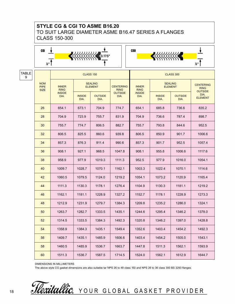
18 Y O U R G L O B A L G A S K E T P R O V I D E R
TABLE9
NOMPIPESIZE
CLASS 150 CLASS 300
INNERRING
INSIDEDIA.
SEALINGELEMENT CENTERING
RINGOUTSIDE
DIA.
INNERRING
INSIDEDIA.
SEALINGELEMENT
CENTERINGRING
OUTSIDEDIA.
ELEMENTINSIDE
DIA.OUTSIDE
DIA.INSIDE
DIA.OUTSIDE
DIA.
26 654.1 673.1 704.9 774.7 654.1 685.8 736.6 835.2
28 704.9 723.9 755.7 831.9 704.9 736.6 787.4 898.7
30 755.7 774.7 806.5 882.7 755.7 793.8 844.6 952.5
32 806.5 825.5 860.6 939.8 806.5 850.9 901.7 1006.6
34 857.3 876.3 911.4 990.6 857.3 901.7 952.5 1057.4
36 908.1 927.1 968.5 1047.8 908.1 955.8 1006.6 1117.6
38 958.9 977.9 1019.3 1111.3 952.5 977.9 1016.0 1054.1
40 1009.7 1028.7 1070.1 1162.1 1003.3 1022.4 1070.1 1114.6
42 1060.5 1079.5 1124.0 1219.2 1054.1 1073.2 1120.9 1165.4
44 1111.3 1130.3 1178.1 1276.4 1104.9 1130.3 1181.1 1219.2
46 1162.1 1181.1 1228.9 1327.2 1152.7 1178.1 1228.9 1273.3
48 1212.9 1231.9 1279.7 1384.3 1209.8 1235.2 1286.0 1324.1
50 1263.7 1282.7 1333.5 1435.1 1244.6 1295.4 1346.2 1378.0
52 1314.5 1333.5 1384.3 1492.3 1320.8 1346.2 1397.0 1428.8
54 1358.9 1384.3 1435.1 1549.4 1352.6 1403.4 1454.2 1492.3
56 1409.7 1435.1 1485.9 1606.6 1403.4 1454.2 1505.0 1543.1
58 1460.5 1485.9 1536.7 1663.7 1447.8 1511.3 1562.1 1593.9
60 1511.3 1536.7 1587.5 1714.5 1524.0 1562.1 1612.9 1644.7
stYle cg & cgi to asMe B16.20TO SUIT LARGE DIAMETER ASME B16.47 SERIES A FLANGESCLASS 150-300
DIMENSIONS IN MILLIMETERSThe above style CG gasket dimensions are also suitable tar NPS 26 to 48 class 150 and NPS 26 to 36 class 300 BS 3293 flanges.
spiralWoundBrochure_060614_inside 3/24/2016 1:09 PM Page 18
19Y O U R G L O B A L G A S K E T P R O V I D E R
TABLE9.1
NOMPIPESIZE
CLASS 400 CLASS 600 CLASS 900*
INNERRING
INSIDEDIA.
SEALINGELEMENT
CENTER-ING
RINGOUTSIDE
DIA.
INNERRING
INSIDEDIA.
SEALINGELEMENT
CENTER-ING
RINGOUTSIDE
DIA.
INNERRING
INSIDEDIA.
SEALINGELEMENT
CENTERINGRING
OUTSIDEDIA.
ELEMENTINSIDE
DIA.OUTSIDE
DIA.INSIDE
DIA.OUTSIDE
DIA.INSIDE
DIA.OUTSIDE
DIA.
26 660.4 685.8 736.6 831.9 647.7 685.8 736.6 866.9 660.4 685.8 736.6 882.7
28 711.2 736.6 787.4 892.3 698.5 736.6 787.4 914.4 711.2 736.6 787.4 946.2
30 755.7 793.8 844.6 946.2 755.7 793.8 844.6 971.6 768.4 793.8 844.6 1009.7
32 812.8 850.9 901.7 1003.3 812.8 850.9 901.7 1022.4 812.8 850.9 901.7 1073.2
34 863.6 901.7 952.5 1054.1 863.6 901.7 952.5 1073.2 863.6 901.7 952.5 1136.7
36 917.7 955.8 1006.6 1117.6 917.7 955.8 1006.6 1130.3 920.8 958.9 1009.7 1200.2
38 952.5 971.6 1022.4 1073.2 952.5 990.6 1041.4 1104.9 1009.7 1035.1 1085.9 1200.2
40 1000.3 1025.7 1076.5 1127.3 1009.7 1047.8 1098.6 1155.7 1060.5 1098.6 1149.4 1251.0
42 1051.1 1076.5 1127.3 1178.1 1066.8 1104.9 1155.7 1219.2 1111.3 1149.4 1200.2 1301.8
44 1104.9 1130.3 1181.1 1231.9 1111.3 1162.1 1212.9 1270.0 1155.7 1206.5 1257.3 1368.6
46 1168.4 1193.8 1244.6 1289.1 1162.1 1212.9 1263.7 1327.2 1219.2 1270.0 1320.8 1435.1
48 1206.5 1244.6 1295.4 1346.2 1219.2 1270.0 1320.8 1390.7 1270.0 1320.8 1371.6 1485.9
50 1257.3 1295.4 1346.2 1403.4 1270.0 1320.8 1371.6 1447.8 - - - -
52 1308.1 1346.2 1397.0 1454.2 1320.8 1371.6 1422.4 1498.6 - - - -
54 1352.6 1403.4 1454.2 1517.7 1378.0 1428.8 1479.6 1555.8 - - - -
56 1403.4 1454.2 1505.0 1568.5 1428.8 1479.6 1530.4 1612.9 - - - -
58 1454.2 1505.0 1555.8 1619.3 1473.2 1536.7 1587.5 1663.7 - - - -
60 1517.7 1568.5 1619.3 1682.8 1530.4 1593.9 1644.7 1733.6 - - - -
stYle cg & cgi to asMe B16.20TO SUIT LARGE DIAMETER ASME B16.47 SERIES A FLANGESCLASS 400-900
DIMENSIONS IN MILLIMETERSNOTE: There are no class 900 flanges NPS 50 and larger.*lnner rings are mandatory for class 900 flanges, NPS 26 to 48.For ASME B16.47 Series A flanges NPS 12 to 24 use gasket dimensions listed on page 8, for ASME B 16.5 flanges. The above style CG gasket dimensions are also suitable for NPS 26 to 36 class 400 and 600 BS 3293 flanges.
spiralWoundBrochure_060614_inside 3/24/2016 1:09 PM Page 19
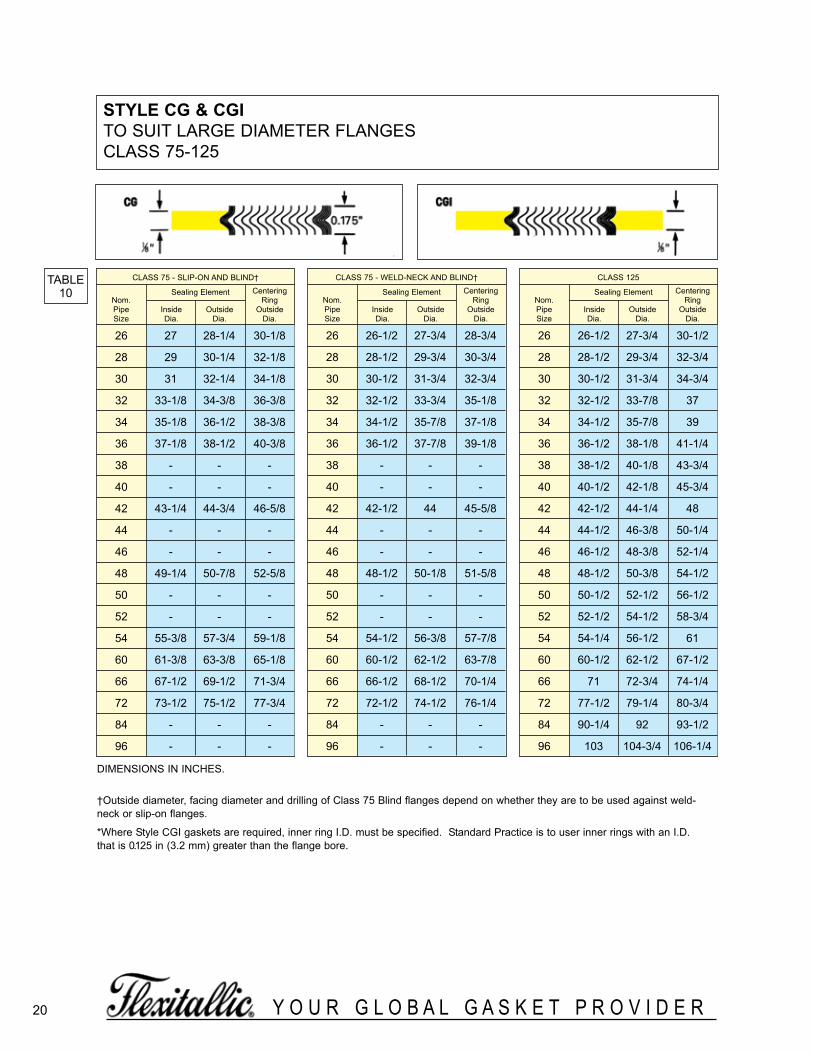
20 Y O U R G L O B A L G A S K E T P R O V I D E R
stYle cg & cgi TO SUIT LARGE DIAMETER FLANGESCLASS 75-125
TABLE10
CLASS 75 - SLIP-ON AND BLIND†
Sealing Element CenteringNom. RingPipe Inside Outside OutsideSize Dia. Dia. Dia.
26 27 28-1/4 30-1/8
28 29 30-1/4 32-1/8
30 31 32-1/4 34-1/8
32 33-1/8 34-3/8 36-3/8
34 35-1/8 36-1/2 38-3/8
36 37-1/8 38-1/2 40-3/8
38 - - -
40 - - -
42 43-1/4 44-3/4 46-5/8
44 - - -
46 - - -
48 49-1/4 50-7/8 52-5/8
50 - - -
52 - - -
54 55-3/8 57-3/4 59-1/8
60 61-3/8 63-3/8 65-1/8
66 67-1/2 69-1/2 71-3/4
72 73-1/2 75-1/2 77-3/4
84 - - -
96 - - -
DIMENSIONS IN INCHES.
†Outside diameter, facing diameter and drilling of Class 75 Blind flanges depend on whether they are to be used against weld-neck or slip-on flanges.
*Where Style CGI gaskets are required, inner ring I.D. must be specified. Standard Practice is to user inner rings with an I.D.that is 0.125 in (3.2 mm) greater than the flange bore.
CLASS 125
Sealing Element CenteringNom. RingPipe Inside Outside OutsideSize Dia. Dia. Dia.
26 26-1/2 27-3/4 30-1/2
28 28-1/2 29-3/4 32-3/4
30 30-1/2 31-3/4 34-3/4
32 32-1/2 33-7/8 37
34 34-1/2 35-7/8 39
36 36-1/2 38-1/8 41-1/4
38 38-1/2 40-1/8 43-3/4
40 40-1/2 42-1/8 45-3/4
42 42-1/2 44-1/4 48
44 44-1/2 46-3/8 50-1/4
46 46-1/2 48-3/8 52-1/4
48 48-1/2 50-3/8 54-1/2
50 50-1/2 52-1/2 56-1/2
52 52-1/2 54-1/2 58-3/4
54 54-1/4 56-1/2 61
60 60-1/2 62-1/2 67-1/2
66 71 72-3/4 74-1/4
72 77-1/2 79-1/4 80-3/4
84 90-1/4 92 93-1/2
96 103 104-3/4 106-1/4
CLASS 75 - WELD-NECK AND BLIND†
Sealing Element CenteringNom. RingPipe Inside Outside OutsideSize Dia. Dia. Dia.
26 26-1/2 27-3/4 28-3/4
28 28-1/2 29-3/4 30-3/4
30 30-1/2 31-3/4 32-3/4
32 32-1/2 33-3/4 35-1/8
34 34-1/2 35-7/8 37-1/8
36 36-1/2 37-7/8 39-1/8
38 - - -
40 - - -
42 42-1/2 44 45-5/8
44 - - -
46 - - -
48 48-1/2 50-1/8 51-5/8
50 - - -
52 - - -
54 54-1/2 56-3/8 57-7/8
60 60-1/2 62-1/2 63-7/8
66 66-1/2 68-1/2 70-1/4
72 72-1/2 74-1/2 76-1/4
84 - - -
96 - - -
spiralWoundBrochure_060614_inside 3/24/2016 1:09 PM Page 20

21Y O U R G L O B A L G A S K E T P R O V I D E R
stYle cg & cgi TO SUIT LARGE DIAMETER FLANGESCLASS 175-350
TABLE10.1
CLASS 175Sealing Element Centering
Nom. RingPipe Inside Outside OutsideSize Dia. Dia. Dia.
26 26-1/2 27-3/4 29-1/8
28 28-1/2 29-3/4 31-1/8
30 30-1/2 31-3/4 33-3/8
32 32-1/2 33-3/4 35-3/8
34 34 -1/2 35-7/8 37-1/2
36 36-1/2 37-7/8 39-1/2
38 38-1/2 39-7/8 41-1/2
40 40-1/2 42 43-1/2
42 42-1/2 44 45-7/8
44 44-1/2 46 47-7/8
46 46-1/2 48 49-7/8
48 48-1/2 50-1/8 51-7/8
50 50-1/2 52-1/4 53-7/8
52 52-1/2 54-3/8 56-1/8
54 54-1/2 56-3/8 58-1/8
60 60-1/2 62-1/2 64-1/8
66 67-1/8 68-7/8 70-1/8
72 73-3/8 75-1/8 76-5/8
84 87 88-3/4 90-1/4
96 99 100-3/4 102-1/4
DIMENSIONS IN INCHES.
CLASS 350Sealing Element Centering
Nom. RingPipe Inside Outside OutsideSize Dia. Dia. Dia.
26 26-1/2 27-3/4 29-5/8
28 28-1/2 29-3/4 31-5/8
30 30-1/2 31-3/4 33-7/8
32 32-1/2 33-7/8 35-7/8
34 34-1/2 35-7/8 37-7/8
36 36-1/2 38-1/8 40-3/8
38 38-1/2 40-1/8 42-3/8
40 40-1/2 42-1/8 44-3/8
42 42-1/2 44-1/4 46-5/8
44 44-1/2 46-3/8 49
46 46-1/2 48-3/8 51
48 48-1/2 50-3/8 53
50 - - -
52 52-1/2 54-1/4 57-3/8
54 54-1/2 56-1/2 59-3/8
60 60-1/2 62-1/2 65-3/8
66 66-1/2 68-1/2 72-1/2
72 75-1/4 77 78-1/2
84 88-3/8 90-1/8 91-5/8
96 100-3/4 102-1/2 104
CLASS 250Sealing Element Centering
Nom. RingPipe Inside Outside OutsideSize Dia. Dia. Dia.
26 26-1/2 27-3/4 32-3/4
28 28-1/2 29-3/4 35-1/4
30 30-1/2 31-3/4 37-1/2
32 32-1/2 33-7/8 39-3/4
34 34-1/2 35-7/8 41-3/4
36 36-1/2 38-1/8 44
38 38-1/2 40-1/8 46
40 40-1/2 42-1/8 48-1/4
42 42-1/2 44-1/4 50-3/4
44 44-1/2 46-3/8 53
46 46-1/2 48-3/8 55-1/4
48 48-1/2 50-3/8 58-3/4
50 - - -
52 - - -
54 - - -
60 - - -
66 - - -
72 - - -
84 - - -
96 - - -
spiralWoundBrochure_060614_inside 3/24/2016 1:09 PM Page 21

22 Y O U R G L O B A L G A S K E T P R O V I D E R
stYle cg & cgi to Bs3381 TO SUIT BS1560 & ASME B16.5 FLANGES
TABLE11
DIMENSIONS IN INCHES.
*These gasket dimensions are not suitable for use with threaded or slip on flanges. See Table 4 for special sizes.
In accordance with BS 3381 all class 900, 1500 ond 2500 gaskets and all gaskets containing PTFE filler material shall have aninner ring.
INNERRINGNOM
PIPESIZE
CLASS 150 CLASS 300 to 1500 CLASS 300
CLASS 400
CLASS 600
CLASS 900
CLASS 1500
CENTERING RING
CLASS 2500
SEALING ELEMENT
CENTER-ING RING
OUTSIDEDIA.
INSIDEDIA.
OUTSIDEDIA.OUTSIDE DIAMETERINSIDE
DIA.OUTSIDE
DIA.INSIDE
DIA.INSIDE
DIA.OUTSIDE
DIA.OUTSIDE
DIA.
SEALING ELEMENT
CENTER-ING RING
SEALING ELEMENT
1/4 - 1/2* 7/8 1-3/4 1/2* 7/8 1-3/4 1-3/4 1-3/4 - - - - -
1/2 9/16 3/4* 1-1/4 1-7/8 3/4* 1-1/4 2-1/8 2-1/8 2-1/8 2-1/2 2-1/2 3/4 1-1/4 2-3/4
3/4 13/16 1-1/16* 1-9/16 2-1/4 1* 1-9/16 2-5/8 2-5/8 2-5/8 2-3/4 2-3/4 1 1-9/16 3
1 1-1/16 1-5/16* 1-7/8 2-5/8 1-1/4 1-7/8 2-7/8 2-7/8 2-7/8 3-1/8 3-1/8 1-1/4 1-7/8 3-3/8
1-1/4 1-3/8 1-13/16* 2-3/8 3 1-3/4 2-3/8 3-1/4 3-1/4 3-1/4 3-1/2 3-1/2 1-9/16 2-3/8 4-1/8
1-1/2 1-5/8 2-1/8 2-3/4 3-3/8 2* 2-3/4 3-3/4 3-3/4 3-3/4 3-7/8 3-7/8 1-7/8 2-3/4 4-5/8
2 2-1/16 2-3/4 3-3/8 4-1/8 2-5/8 3-3/8 4-3/8 4-3/8 4-3/8 5-5/8 5-5/8 2-5/16 3-3/8 5-3/4
2-1/2 2-1/2 3-1/4 3-7/8 4-7/8 3-1/8 3-7/8 5-1/8 5-1/8 5-1/8 6-1/2 6-1/2 2-3/4 3-7/8 6-5/8
3 3-1/16 4 4-3/4 5-3/8 3-3/4 4-3/4 5-7/8 5-7/8 5-7/8 6-5/8 6-7/8 3-5/8 4-3/4 7-3/4
3-1/2 3-9/16 4-1/2 5-1/4 6-3/8 4-1/4 5-1/4 6-1/2 6-3/8 6-3/8 - - - - -
4 4-1/16 5 5-7/8 6-7/8 4-3/4 5-7/8 7-1/8 7 7-5/8 8-1/8 8-1/4 4-3/4 5-7/8 9-1/4
4-1/2 4-9/16 5-9/16 6-1/2 7 5-5/16 6-1/2 7-3/4 - - - - - - -
5 5-1/16 6-1/16 7 7-3/4 5-13/16 7 8-1/2 8-3/8 9-1/2 9-3/4 10 5-13/16 7 11
6 6-1/16 7-1/8 8-1/4 8-3/4 6-7/8 8-1/4 9-7/8 9-3/4 10-1/2 11-3/8 11-1/8 6-7/8 8-1/4 12-1/2
8 8 9-1/8 10-3/8 11 8-7/8 10-3/8 12-1/8 12 12-5/8 14-1/8 13-7/8 8-7/8 10-3/8 15-1/4
10 10 11-5/16 12-1/2 13-3/8 11-1/16 12-1/2 14-1/4 14-1/8 15-3/4 17-1/8 17-1/8 11-1/16 12-1/2 18-3/4
12 11-15/16 13-3/8 14-3/4 16-1/8 13-1/8 14-3/4 16-5/8 16-1/2 18 19-5/8 20-1/2 13-1/8 14-3/4 21-5/8
14 13-1/2 14-5/8 16 17-3/4 14-3/8 16 19-1/8 19 19-3/8 20-1/2 22-3/4 - - -
16 15-1/2 16-5/8 18-1/4 20-1/4 16-3/8 18-1/4 21-1/4 21-1/8 22-1/4 22-5/8 25-1/4 - - -
18 17-1/2 18-3/4 20-3/4 21-5/8 18-1/2 20-3/4 23-1/2 23-3/8 24-1/8 25-1/8 27-3/4 - - -
20 19-1/2 20-3/4 22-3/4 23-7/8 20-1/2 22-3/4 25-3/4 25-1/2 26-7/8 27-1/2 29-3/4 - - -
24 23-1/2 24-7/8 27 28-1/4 24-5/8 27 30-1/2 30-1/4 31-1/8 33 35-1/2 - - -
spiralWoundBrochure_060614_inside 3/24/2016 1:09 PM Page 22

23Y O U R G L O B A L G A S K E T P R O V I D E R
stYle cg & cgi to Bs3381TO SUIT BS1560 & ASME B16.5 FLANGES
TABLE12
DIMENSIONS IN MILLIMETERS.
*These gasket dimensions are not suitable for use with threaded or slip on flanges. See Table 4 for special sizes.
In accordance with BS 3381 all class 900, 1500 ond 2500 gaskets and all gaskets containing PTFE filler material shall have aninner ring.
INNERRINGNOM
PIPESIZE
CLASS 150 CLASS 300 to 1500 CLASS 300
CLASS 400
CLASS 600
CLASS 900
CLASS 1500
CENTERING RING
CLASS 2500
SEALING ELEMENT
CENTER-ING RING
OUTSIDEDIA.
INSIDEDIA.
OUTSIDEDIA.OUTSIDE DIAMETERINSIDE
DIA.OUTSIDE
DIA.INSIDE
DIA.INSIDE
DIA.OUTSIDE
DIA.OUTSIDE
DIA.
SEALING ELEMENT
CENTER-ING RING
SEALING ELEMENT
1/4 - 12.7* 22.2 44.5 12.7* 22.2 44.5 44.5 44.5 - - - - -1/2 14.3 19.1* 31.8 47.6 19.1* 31.8 54.0 54.0 54.0 63.5 63.5 19.1 31.8 69.93/4 20.6 27.0* 39.7 57.2 25.4* 39.7 66.7 66.7 66.7 69.9 69.9 25.4 39.7 76.2
1 27.0 33.3* 47.6 66.7 31.8* 47.6 73.0 73.0 73.0 79.4 79.4 31.8 47.6 85.7
11/4 34.9 46.0* 60.3 76.2 44.5* 60.3 82.6 82.6 82.6 88.9 88.9 39.7 60.3 104.8
11/2 41.3 54.0 69.9 85.7 50.8* 69.9 95.3 95.3 95.3 98.4 98.4 47.6 69.9 117.5
2 52.4 69.9 85.7 104.8 66.7 85.7 111.1 111.1 111.1 142.9 142.9 58.7 85.7 146.1
21/2 63.5 82.6 98.4 123.8 79.4 98.4 130.2 1302 130.2 165.1 165.1 69.9 98.4 168.3
3 77.8 101.6 120.7 136.5 95.3 120.7 149.2 149.2 149.2 168.3 174.6 92.1 120.7 196.9
31/2 90.5 114.3 133.4 161.9 108.0 133.4 165.1 161.9 161.9 - - - - -
4 103.2 127.0 149.2 174.6 120.7 149.2 181.0 177.8 193.7 206.4 209.6 120.7 149.2 235.0
4 115.9 141.3 165.1 177.8 134.9 165.1 196.9 - - - - - - -
5 128.6 154.0 177.8 196.9 147.6 177.8 215.9 212.7 241.3 247.7 254.0 147.6 177.8 279.4
6 154.0 181.0 209.6 222.3 174.6 209.6 250.8 247.7 266.7 288.9 282.6 174.6 209.6 317.5
8 203.2 231.8 263.5 279.4 225.4 263.5 308.0 304.8 320.7 358.8 352.4 225.4 263.5 387.4
10 254.0 287.3 317.5 339.7 281.0 317.5 362.0 358.8 400.1 435.0 435.0 281.0 317.5 476.3
12 303.2 339.7 374.7 409.6 333.4 374.7 422.3 419.1 457.2 498.5 520.7 333.4 374.7 549.3
14 342.9 371.5 406.4 450.9 365.1 406.4 485.8 482.6 492.1 520.7 577.9 - - -
16 393.7 422.3 463.6 514.4 415.9 463.6 539.8 536.6 565.2 574.7 641.4 - - -
18 444.5 476.3 527.1 549.3 469.9 527.1 596.9 593.7 612.8 638.2 704.9 - - -
20 495.3 527.1 577.9 606.4 520.7 577.9 654.1 647.7 682.6 698.5 755.7 - - -
24 596.9 631.8 685.8 717.6 625.5 685.8 774.7 768.4 790.6 838.2 901.7 - - -
spiralWoundBrochure_060614_inside 3/24/2016 1:09 PM Page 23

INNERRING
NOMPIPESIZE
1/2 9/16 1-1/32 1-15/32 2-1/8 2-1/8 1-1/32 1-17/32 2-1/8 2-5/8 2-5/8 2 -5/8 2-5/8 3/4 1-1/4 2-3/4 3/4 1-1/4 3-1/4
3/4 13/16 1-1/4 1-11/16 2-3/8 2-3/8 1-1/4 1-3/4 2-3/8 2-5/8 2-5/8 2-5/8 2-5/8 1 1-9/16 2-3/4 1 1-9/16 3-1/4
1 1-1/16 1-9/16 2-1/16 2-3/4 2-3/4 1-9/16 2-3/16 2-13/16 2-13/16 2-13/16 3-1/8 3-1/8 1-1/4 1-7/8 3-1/4 1-1/4 1-7/8 3-1/2
1-1/4 1-5/16 1-7/8 2-3/8 2-15/16 2-15/16 1-7/8 2-1/2 3-1/4 3-1/4 3-1/4 3-1/4 3-1/4 1-1/2 2-3/16 3-1/2 1-5/8 2-5/16 3-7/8
1-1/2 1-9/16 2-1/8 2-5/8 3-3/8 3-3/8 2-1/8 2-3/4 3-1/2 3-1/2 3-1/2 3-3/4 3-3/4 1-3/4 2-1/2 4 1-7/8 2-5/8 4-1/2
2 2-1/16 2-5/8 3-1/8 3-7/8 3-7/8 2-5/8 3-1/4 4-3/8 4-3/8 4-1/4 4-3/8 4-3/8 2-1/4 3-1/8 4-1/2 2-3/8 3-1/4 5
2-1/2 2-9/16 3-1/4 3-7/8 4-3/8 4-3/8 3-1/4 4 5-1/8 5-1/8 5 5 5 2-7/8 3-3/4 5 3 3-7/8 5-5/8
3 3-1/16 3-13/16 4-7/16 5-1/8 5-1/8 3-13/16 4-9/16 5-7/8 5-7/8 5-3/4 5-3/4 5-3/4 3-3/8 4-1/4 5-5/8 3-1/2 4-1/2 6-1/2
3-1/2 3-9/16 4-5/16 4-15/16 5-7/8 5-7/8 4-5/16 5-1/16 6-3/8 6-3/8 6-1/4 6-3/8 6-3/8 3-7/8 4-3/4 6-5/8 4 5-1/8 7-3/8
4 4-1/16 4 -7/8 5-1/2 6-3/8 6-3/8 4-7/8 5-5/8 6-7/8 6-7/8 6-3/4 6-7/8 6-7/8 4-3/8 5-3/8 7 4-1/2 5-5/8 8-1/8
4-1/2 4-9/16 5-3/8 6 6-7/8 6-7/8 5-3/8 6 -1/4 7-1/2 7-1/2 7-3/8 7-3/8 7-3/8 4-7/8 5-7/8 7-1/2 5 6-1/4 9
5 5-1/16 5-7/8 6-1/2 7-5/8 7-5/8 5-7/8 6-3/4 8-1/2 8-1/2 8-3/8 8-3/8 8-3/8 5-3/8 6-3/8 8-3/8 5-1/2 6-3/4 9-5/8
6 6-1/16 6-7/8 7-1/2 8-5/8 8-1/2 6-7/8 7-3/4 9-1/2 9-1/2 9-3/8 9-3/8 9-3/8 6-3/8 7-3/8 9-3/4 6-1/2 7-3/4 11-1/4
7 7-1/16 7-7/8 8-5/8 9-5/8 9-1/2 7-7/8 8-7/8 10-3/4 10-3/4 10-5/8 10-1/2 10-1/2 7-3/8 8-5/8 11-3/8 7-1/2 9 13-1/8
8 8-1/16 8-7/8 9-5/8 10-7/8 10-3/4 8-7/8 9-7/8 12 12 11-7/8 11-1/2 11-3/4 8-3/8 9-5/8 12-3/4 8-1/2 10 14-1/2
9 9-1/16 9-7/8 10-5/8 12-1/8 12 9-7/8 10-7/8 13-1/8 13-1/8 13 13 13 9-1/2 10-3/4 14-1/8 9-5/8 11-1/4 16-1/8
10 10-1/16 10-7/8 11-5/8 13-1/4 13-1/4 11 12 14-1/8 14-1/8 14 14 14-1/4 10-1/2 11-7/8 15-1/2 10-5/8 12-1/4 17-3/4
11 11-1/16 11-7/8 12-5/8 14-1/4 14-1/4 12 13 15-1/8 15-1/8 15 15-1/8 15-7/8 11-1/2 12-7/8 17-1/8 11-5/8 13-1/4 19-1/4
12 12-1/16 12-7/8 13-3/4 15-1/4 15-1/8 13 14-1/8 16-3/8 16-3/8 16-1/4 15 7/8 16-7/8 12-5/8 14 18-1/2 12-3/4 14-1/2 20-3/4
13 13-1/16 14-1/2 15-3/8 16-1/2 16-3/8 14-1/4 15-3/8 17-1/2 17-1/2 17-3/8 17 3/4 18-1/4 13-5/8 15-1/8 19 3/4 13 3/4 15- -1/2 22
14 14-1/16 15-1/2 16-3/8 17-5/8 17-5/8 15-1/4 16-3/8 18-1/2 18-1/2 18-3/8 18-3/4 19-1/2 14-5/8 16-1/8 21-1/4 - - -
15 15-1/16 16-1/2 17-3/8 18-5/8 18-5/8 16-1/4 17-3/8 19-1/2 19-1/2 19-3/8 20 20-1/2 15-3/4 17-1/4 22-7/8 - - -
16 16-1/16 17-1/2 18-3/8 19-5/8 19-5/8 17-1/2 18-3/4 20-3/4 20-3/4 20-5/8 21 21-3/4 16-3/4 18-3/8 24-1/4 - - -
17 17-1/16 18-5/8 19-5/8 20-7/8 20-3/4 18-1/2 19-7/8 22 22 21-7/8 22-1/4 22-3/4 - - - - - -
18 18-1/16 19-5/8 20-5/8 22-1/8 22-1/8 19-1/2 20-7/8 22-7/8 22-7/8 22-3/4 24-3/8 25-1/8 - - - - - -
19 19-1/16 20-5/8 21-5/8 23-1/8 23-1/8 20-5/8 22-1/8 24-1/8 24-1/8 24 - - - - - - - -
20 20-1/16 21-5/8 22-5/8 24-3/8 24-3/8 21-5/8 23-1/8 25-3/8 25-3/8 25-1/4 26-1/2 27-1/4 - - - - - -
21 21-1/16 22-5/8 23-3/4 25-5/8 25-1/2 22-5/8 24-3/8 26-3/8 26-3/8 26-1/4 - - - - - - - -
22 22-1/16 23-5/8 24-3/4 26-1/2 26-1/2 23-5/8 25-3/8 27-3/8 27-3/8 27-1/4 28-3/4 29-3/4 - - - - - -
23 23-1/16 24-5/8 25-3/4 27-1/2 27-1/2 24-5/8 26-3/8 28-1/2 28-1/2 28-3/8 - - - - - - - -
24 24-1/16 25-5/8 26-3/4 28-3/4 28-5/8 25-5/8 27-3/8 29-1/2 29-1/2 29-3/8 - - - - - - - -
TABLE D & E TABLE F to R TABLEF
TABLEH
TABLEJ TABLE S
CENTERING RING
TABLE T
SEALING ELEMENT
CENTERING RING
OUTSIDE DIAMETERID ODID ID ODOD
SEALING ELEMENT
CENTERING RING
SEALING ELEMENT
24 Y O U R G L O B A L G A S K E T P R O V I D E R
stYle cg & cgiTO SUIT BS1O FLANGES
TABLE13
DIMENSIONS IN INCHES.
NOTE: Special gasket dimensions are required when an inner ring is fitted to gaskets for Tables S and T. Please request details.
TABLED-R
TABLED
TABLEE
OD
TABLEK
TABLER
ID OD
SEALING ELEMENT
CENTERING RING
OD ODODID
spiralWoundBrochure_060614_inside 3/24/2016 1:09 PM Page 24
25Y O U R G L O B A L G A S K E T P R O V I D E R
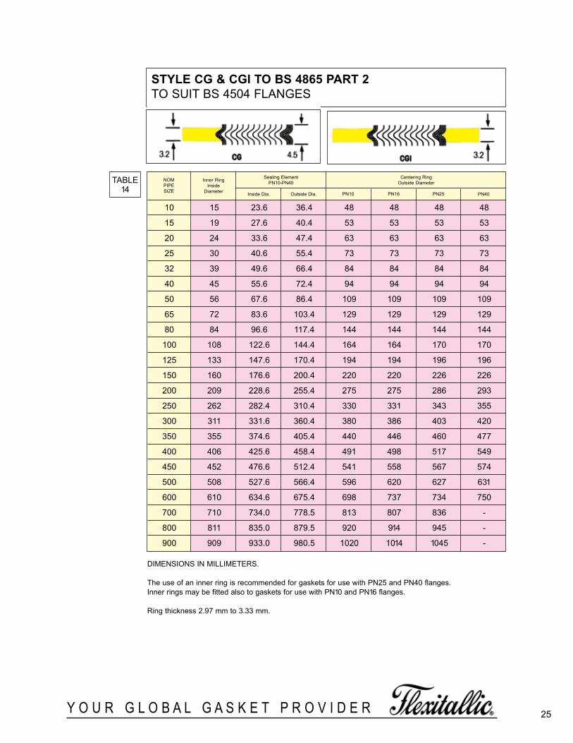
stYle cg & cgi to Bs 4865 Part 2TO SUIT BS 4504 FLANGES
TABLE14
10 15 23.6 36.4 48 48 48 48
15 19 27.6 40.4 53 53 53 53
20 24 33.6 47.4 63 63 63 63
25 30 40.6 55.4 73 73 73 73
32 39 49.6 66.4 84 84 84 84
40 45 55.6 72.4 94 94 94 94
50 56 67.6 86.4 109 109 109 109
65 72 83.6 103.4 129 129 129 129
80 84 96.6 117.4 144 144 144 144
100 108 122.6 144.4 164 164 170 170
125 133 147.6 170.4 194 194 196 196
150 160 176.6 200.4 220 220 226 226
200 209 228.6 255.4 275 275 286 293
250 262 282.4 310.4 330 331 343 355
300 311 331.6 360.4 380 386 403 420
350 355 374.6 405.4 440 446 460 477
400 406 425.6 458.4 491 498 517 549
450 452 476.6 512.4 541 558 567 574
500 508 527.6 566.4 596 620 627 631
600 610 634.6 675.4 698 737 734 750
700 710 734.0 778.5 813 807 836 -
800 811 835.0 879.5 920 914 945 -
900 909 933.0 980.5 1020 1014 1045 -
NOMPIPESIZE
Inner RingInside
Diameter
Sealing Element PN10-PN40
Centering RingOutside Diameter
Inside Dia. Outside Dia. PN10 PN16 PN25 PN40
DIMENSIONS IN MILLIMETERS.
The use of an inner ring is recommended for gaskets for use with PN25 and PN40 flanges. Inner rings may be fitted also to gaskets for use with PN10 and PN16 flanges.
Ring thickness 2.97 mm to 3.33 mm.
spiralWoundBrochure_060614_inside 3/24/2016 1:09 PM Page 25
26 Y O U R G L O B A L G A S K E T P R O V I D E R
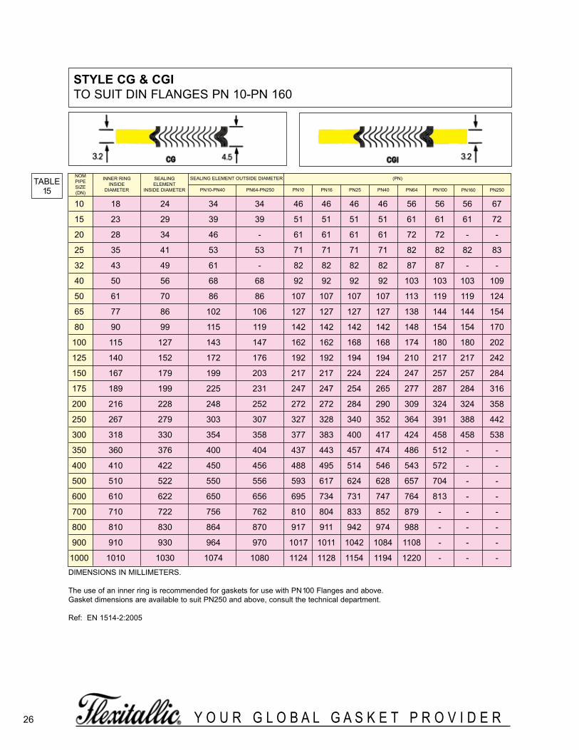
stYle cg & cgiTO SUIT DIN FLANGES PN 10-PN 160
TABLE15
DIMENSIONS IN MILLIMETERS.
The use of an inner ring is recommended for gaskets for use with PN100 Flanges and above. Gasket dimensions are available to suit PN250 and above, consult the technical department.
Ref: EN 1514-2:2005
10 18 24 34 34 46 46 46 46 56 56 56 67
15 23 29 39 39 51 51 51 51 61 61 61 72
20 28 34 46 - 61 61 61 61 72 72 - -
25 35 41 53 53 71 71 71 71 82 82 82 83
32 43 49 61 - 82 82 82 82 87 87 - -
40 50 56 68 68 92 92 92 92 103 103 103 109
50 61 70 86 86 107 107 107 107 113 119 119 124
65 77 86 102 106 127 127 127 127 138 144 144 154
80 90 99 115 119 142 142 142 142 148 154 154 170
100 115 127 143 147 162 162 168 168 174 180 180 202
125 140 152 172 176 192 192 194 194 210 217 217 242
150 167 179 199 203 217 217 224 224 247 257 257 284
175 189 199 225 231 247 247 254 265 277 287 284 316
200 216 228 248 252 272 272 284 290 309 324 324 358
250 267 279 303 307 327 328 340 352 364 391 388 442
300 318 330 354 358 377 383 400 417 424 458 458 538
350 360 376 400 404 437 443 457 474 486 512 - -
400 410 422 450 456 488 495 514 546 543 572 - -
500 510 522 550 556 593 617 624 628 657 704 - -
600 610 622 650 656 695 734 731 747 764 813 - -
700 710 722 756 762 810 804 833 852 879 - - -
800 810 830 864 870 917 911 942 974 988 - - -
900 910 930 964 970 1017 1011 1042 1084 1108 - - -
1000 1010 1030 1074 1080 1124 1128 1154 1194 1220 - - -
NOMPIPESIZE(DN)
INNER RINGINSIDE
DIAMETER
SEALING ELEMENT
INSIDE DIAMETER
SEALING ELEMENT OUTSIDE DIAMETER
PN10-PN40 PN64-PN250 PN10 PN16 PN25 PN40
(PN)
PN64 PN100 PN160 PN250
spiralWoundBrochure_060614_inside 3/24/2016 1:09 PM Page 26

NOMPIPESIZE
Sealing ElementClass 150 -1500
Style R1 for Large Male and Female Style R3 for Large Tongue and Groove Style R4 for Small Tongue and Groove
Sealing ElementClass 2500
Sealing ElementClass 150 - 2500
Sealing ElementClass 150 - 2500
ID OD ID OD ID OD ID OD
27Y O U R G L O B A L G A S K E T P R O V I D E R
stYle rFOR USE WITH MALE & FEMALE AND TONGUE & GROOVE ASME B16.5 & BS 1560 FLANGES
Standard Style R gasketsembody all the exclusive fea-tures of Flexitallic design forkeeping compression values inbalance with bolting and provid-ing adequate resilience to com-pensate for variable stressesencountered in service.Standard Style R gaskets aremanufactured to a nominal thick-ness of .125" (3.2mm). Optimumcompression is in the range of.090" to .100" (2.3mm to 2.5mm)thick.There are three types of Style R gaskets:(a) Style R-1 indicates gaskets for use with large male and female flanges.*(b) Style R-3 indicates gaskets for use with large tongue and groove flanges.(c) Style R-4 indicates gaskets for use with small tongue and groove flanges.
*As a general rule, the use of Flexitallic Spiral Wound gaskets with small male andfemale flange facings is not recommended.
Dimensional limitations established by the proportions of the small tongue and groovefacings limit the possibility of increasing gasket dimensions to improve the load carry-ing capacity in the higher pressure series. For this reason, it is suggested that largetongue and groove facings be selected for new construction when class 900, 1500 and2500 flanges are to be used. Style R-4 gaskets may be compressed an additionalamount when exposed to the higher bolt loads, but not to the degree that the gasketwill be crushed due to the radial support provided by the confining groove.
Special Style R gaskets are adaptable to non-standard flanges and can be designedand manufactured according to specifications for high and low pressure applicationsand for severe corrosive conditions.When ordering special Style R gaskets for non-standard flanges and for special appli-cations, furnish complete data on Flexitalllc Gasket Engineering Data Form.
NOTE - The following Style R gaskets are interchangeable:
Style R-1 and R-3 gasketsn 1/4” sizes - Classes 150, 300, 400 and 600 are interchangeable.n 1/2” s izes - Classes 150, 300, 400, 600, 900, 1500 and 2500 (R-3 only) are
interchangeable.n All R-1 and R-3 gaskets in Classes 300, 400 and 600 are interchangeable
within their size category.n All R-1 and R-3 gaskets in Classes 900 and 1500 are interchangeable within
their size category.
Style R-4 gasketsn 1/2” sizes - interchangeable with all NPS 1/2” R-1 and R-3 gaskets within the
same pressure rating.n 3/4” interchangeable with all 3/4” R-1 and R-3 gaskets within the same pressure
rating.n All R-4 gaskets in Classes 300 through 2500 are interchangeable within their
size category.
TABLE16
DIMENSIONS IN INCHES & MILLIMETERS.
*It is essential that Style R gaskets are fitted with a compression stop. Without a correctly dimensioned stop the gasket can easily be over-compressed resultingin failure. To provide a compression stop the depth of the tongue, groove or recess should be controlled to provide optimum compressed gasket thickness withmetal to metal contact on the flange faces (see tables on Page 28 and 32).
Note: Style R3 for NPS 1/4 are for class 150 to 600 only. Style R3 for NPS 4-1/2 are for class 150 to 1500 only.
1/4 1/2 12.7 1 25.4 - - - - 1/2 12.7 1 25.4 - - - -
1/2 1 25.4 1-3/8 34.9 13/16 20.6 1-3/8 34.9 1 25.4 1-3/8 34.9 1 25.4 1-3/8 34.9
3/4 1-5/16 33.3 1-11/16 42.9 1-1/16 27.0 1-11/16 42.9 1-5/16 33.3 1-11/16 42.9 1-5/16 33.3 1-11/16 42.9
1 1-1/2 38.1 2 50.8 1-1/4 31.8 2 50.8 1-1/2 38.1 2 50.8 1-1/2 38.1 1-7/8 47.6
1- 1/4 1-7/8 47.6 2-1/2 63.5 1-5/8 41.3 2-1/2 63.5 1-7/8 47.6 2-1/2 63.5 1-7/8 47.6 2-1/4 57.2
1-1/2 2-1/8 54.0 2-7/8 73.0 1-7/8 47.6 2-7/8 73.0 2-1/8 54.0 2-7/8 73.0 2-1/8 54.0 2-1/2 63.5
2 2-7/8 73.0 3-5/8 91.1 2-3/8 60.3 3-5/8 92.1 2-7/8 73.0 3-5/8 92.1 2-7/8 73.0 3-1/4 82.6
2-1/2 3-3/8 85.7 4-1/8 104.8 3 76.2 4-1/8 104.8 3-3/8 85.7 4-1/8 104.8 3-3/8 85.7 3-3/4 95.3
3 4-1/4 108.0 5 127.0 3-3/4 95.3 5 127.0 4-1/4 108.0 5 127.0 4-1/4 108.0 4-5/8 117.5
3-1/2 4-3/4 120.7 5-1/2 139.7 - - - - 4-3/4 120.7 5-1/2 139.7 4-3/4 120.7 5-1/8 130.2
4 5-3/16 131.8 6-3/16 157.2 4-3/4 120.7 6-3/16 157.2 5-3/16 131.8 6-3/16 157.2 5-3/16 131.8 5-11/16 144.5
4-1/2 5-11/16 144.5 6-3/4 171.5 - - - - 5-11/16 144.5 6-3/4 171.5 - - - -
5 6-5/16 160.3 7-5/16 185.7 5-3/4 146.1 7-5/16 185.7 6-5/16 160.3 7-5/16 185.7 6-5/16 160.3 6-13/16 173.0
6 7-1/2 190.5 8-1/2 215.9 6-3/4 171.5 8-1/2 215.9 7-1/2 190.5 8-1/2 215.9 7-1/2 190.5 8 203.2
8 9-3/8 238.1 10-5/8 269.9 8-3/4 222.3 10-5/8 269.9 9-3/8 238.1 10-5/8 269.9 9-3/8 238.1 10 254.0
10 11-1/4 285.8 12-3/4 323.9 10-3/4 273.1 12-3/4 323.9 11-1/4 285.8 12-3/4 323.9 11-1/4 285.8 12 304.8
12 13-1/2 342.9 15 381.0 13 330.2 15 381.0 13-1/2 342.9 15 381.0 13-1/2 342.9 14-1/4 362.0
14 14-3/4 374.7 16-1/4 412.8 - - - - 14-3/4 374.7 16-1/4 412.8 14-3/4 374.7 15-1/2 393.7
16 17 425.5 18-1/2 469.9 - - - - 17 425.5 18-1/2 469.9 16-3/4 425.5 17-5/8 447.7
18 19-1/4 489.0 21 533.4 - - - - 19-1/4 489.0 21 533.4 19-1/4 489.0 20-1/8 511.2
20 21 533.4 23 584.2 - - - - 21 533.4 23 584.2 21 533.4 22 558.2
24 25-1/4 641.4 27-1/4 692.2 - - - - 25-1/4 641.4 27-1/4 692.2 25-1/4 641.4 26-1/4 666.8
spiralWoundBrochure_060614_inside 3/24/2016 1:09 PM Page 27
Y O U R G L O B A L G A S K E T P R O V I D E R
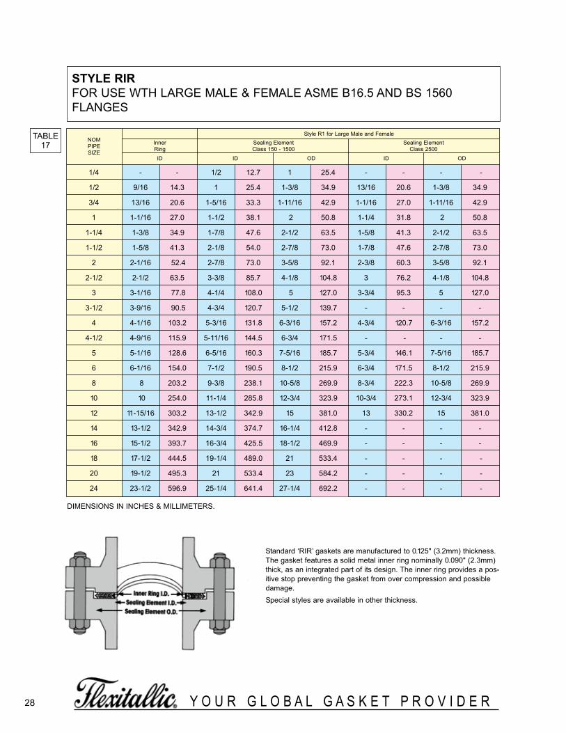
stYle rirFOR USE WTH LARGE MALE & FEMALE ASME B16.5 AND BS 1560FLANGES
TABLE17
Standard ‘RIR’ gaskets are manufactured to 0.125" (3.2mm) thickness. The gasket features a solid metal inner ring nominally 0.090" (2.3mm)thick, as an integrated part of its design. The inner ring provides a pos-itive stop preventing the gasket from over compression and possibledamage. Special styles are available in other thickness.
NOMPIPESIZE
Style R1 for Large Male and FemaleInner Sealing Element Sealing ElementRing Class 150 - 1500 Class 2500
ID ID OD ID OD
1/4 - - 1/2 12.7 1 25.4 - - - -
1/2 9/16 14.3 1 25.4 1-3/8 34.9 13/16 20.6 1-3/8 34.9
3/4 13/16 20.6 1-5/16 33.3 1-11/16 42.9 1-1/16 27.0 1-11/16 42.9
1 1-1/16 27.0 1-1/2 38.1 2 50.8 1-1/4 31.8 2 50.8
1-1/4 1-3/8 34.9 1-7/8 47.6 2-1/2 63.5 1-5/8 41.3 2-1/2 63.5
1-1/2 1-5/8 41.3 2-1/8 54.0 2-7/8 73.0 1-7/8 47.6 2-7/8 73.0
2 2-1/16 52.4 2-7/8 73.0 3-5/8 92.1 2-3/8 60.3 3-5/8 92.1
2-1/2 2-1/2 63.5 3-3/8 85.7 4-1/8 104.8 3 76.2 4-1/8 104.8
3 3-1/16 77.8 4-1/4 108.0 5 127.0 3-3/4 95.3 5 127.0
3-1/2 3-9/16 90.5 4-3/4 120.7 5-1/2 139.7 - - - -
4 4-1/16 103.2 5-3/16 131.8 6-3/16 157.2 4-3/4 120.7 6-3/16 157.2
4-1/2 4-9/16 115.9 5-11/16 144.5 6-3/4 171.5 - - - -
5 5-1/16 128.6 6-5/16 160.3 7-5/16 185.7 5-3/4 146.1 7-5/16 185.7
6 6-1/16 154.0 7-1/2 190.5 8-1/2 215.9 6-3/4 171.5 8-1/2 215.9
8 8 203.2 9-3/8 238.1 10-5/8 269.9 8-3/4 222.3 10-5/8 269.9
10 10 254.0 11-1/4 285.8 12-3/4 323.9 10-3/4 273.1 12-3/4 323.9
12 11-15/16 303.2 13-1/2 342.9 15 381.0 13 330.2 15 381.0
14 13-1/2 342.9 14-3/4 374.7 16-1/4 412.8 - - - -
16 15-1/2 393.7 16-3/4 425.5 18-1/2 469.9 - - - -
18 17-1/2 444.5 19-1/4 489.0 21 533.4 - - - -
20 19-1/2 495.3 21 533.4 23 584.2 - - - -
24 23-1/2 596.9 25-1/4 641.4 27-1/4 692.2 - - - -
DIMENSIONS IN INCHES & MILLI METERS.
28
spiralWoundBrochure_060614_inside 3/24/2016 1:09 PM Page 28

Y O U R G L O B A L G A S K E T P R O V I D E R29
TABLE18
DIMENSIONS IN MILLIMETERS.
PRESSURE RATING 10Kgf/cm2
Inner Sealing Element CenteringNom. Ring RingPipe Inside Inside Outside OutsideSize Dia. Dia. Dia. Dia.
10 - 24 37 5215 - 28 41 5720 - 34 47 6225 - 40 53 7432 - 51 67 8440 - 57 73 8950 - 69 89 10465 - 87 107 12480 - 98 118 13490 - 110 130 144
100 - 123 143 159125 - 148 173 190150 - 174 199 220175 - 201 226 245200 - 227 252 270225 - 252 277 290250 - 278 310 332300 - 329 361 377350 - 366 406 422400 - 417 457 484450 - 468 518 539500 - 518 568 594550 - 569 619 650600 - 620 670 700
PRESSURE RATING 16 to 20Kgf/cm2
Inner Sealing Element CenteringNom. Ring RingPipe Inside Inside Outside OutsideSize Dia. Dia. Dia. Dia.
10 18 24 37 5215 22 28 41 5720 28 34 47 6225 34 40 53 7432 43 51 67 8440 49 57 73 8950 61 69 89 10465 77 87 107 12480 89 99 119 14090 102 114 139 150
100 115 127 152 165125 140 152 177 202150 166 182 214 237175 - - - -200 217 233 265 282225 - - - -250 268 288 328 354300 319 339 379 404350 356 376 416 450400 407 432 482 508450 458 483 533 573500 508 533 583 628550 559 584 634 684600 610 635 685 734
STYLE CG & CGI TO SUIT JIS FLANGES PRESSURE RATING 30Kgf/cm2 - 63Kgf/cm2
TABLE19
DIMENSIONS IN MILLIMETERS.
PRESSURE RATING 40Kgf/cm2
Inner Sealing Element CenteringNom. Ring RingPipe Inside Inside Outside OutsideSize Dia. Dia. Dia. Dia.
10 15 21 34 5915 18 24 37 6420 23 29 42 6925 29 35 48 7932 38 44 60 8940 43 51 67 10050 55 63 79 11465 68 78 98 14080 80 90 110 15090 92 102 127 162
100 104 116 141 182125 128 140 165 224150 153 165 197 265200 202 218 250 315250 251 271 311 378300 300 320 360 434350 336 356 396 479400 383 403 453 531
PRESSURE RATING 63Kgf/cm2
Inner Sealing Element CenteringNom. Ring RingPipe Inside Inside Outside OutsideSize Dia. Dia. Dia. Dia.
10 15 21 34 6415 18 24 37 6920 23 29 42 7525 29 35 48 8032 38 44 60 9040 43 51 67 10750 55 63 79 12565 68 78 98 15280 80 90 110 16290 92 102 127 179
100 104 116 141 194125 128 140 165 235150 153 165 197 275200 202 218 250 328250 251 271 311 394300 300 320 360 446350 336 356 396 488400 383 403 453 545
PRESSURE RATING 30Kgl/cm2
Inner Sealing Element CenteringNom. Ring RingPipe Inside Inside Outside OutsideSize Dia. Dia. Dia. Dia.
10 18 24 37 5915 22 28 41 6420 28 34 47 6925 34 40 53 7932 43 51 67 8940 49 57 73 10050 61 69 89 11465 68 78 98 14080 80 90 110 15090 92 102 127 162
100 104 116 141 172125 128 140 165 207150 153 165 197 249200 202 218 250 294250 251 271 311 360300 300 320 360 418350 336 356 396 463400 383 403 453 524
STYLE CG & CGI TO SUIT JIS FLANGES PRESSURE RATING 10Kgf/cm2 - 20Kgf/cm2
spiralWoundBrochure_060614_inside 3/24/2016 1:09 PM Page 29
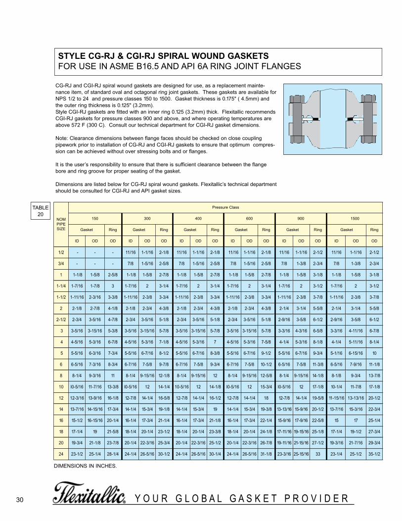
30 Y O U R G L O B A L G A S K E T P R O V I D E R
CG-RJ and CGI-RJ spiral wound gaskets are designed for use, as a replacement mainte-nance item, of standard oval and octagonal ring joint gaskets. These gaskets are available forNPS 1/2 to 24 and pressure classes 150 to 1500. Gasket thickness is 0.175" ( 4.5mm) andthe outer ring thickness is 0.125" (3.2mm).Style CGI-RJ gaskets are fitted with an inner ring 0.125 (3.2mm) thick. Flexitallic recommendsCGI-RJ gaskets for pressure classes 900 and above, and where operating temperatures areabove 572 F (300 C). Consult our technical department for CGI-RJ gasket dimensions.
Note: Clearance dimensions between flange faces should be checked on close couplingpipework prior to installation of CG-RJ and CGI-RJ gaskets to ensure that optimum compres-sion can be achieved without over stressing bolts and or flanges.
It is the user’s responsibility to ensure that there is sufficient clearance between the flangebore and ring groove for proper seating of the gasket.
Dimensions are listed below for CG-RJ spiral wound gaskets. Flexitallic’s technical departmentshould be consulted for CGI-RJ and API gasket sizes.
TABLE20
DIMENSIONS IN INCHES.
stYle cg-rJ & cgi-rJ sPiral Wound gasketsFOR USE IN ASME B16.5 AND API 6A RING JOINT FLANGES
NOMPIPESIZE
Pressure Class
150 300 400 600 900 1500
Gasket Ring Gasket Ring Gasket Ring Gasket Ring Gasket Ring Gasket Ring
ID OD OD ID OD OD ID OD OD ID OD OD ID OD OD ID OD OD
1/2 - - - 11/16 1-1/16 2-1/8 11/16 1-1/16 2-1/8 11/16 1-1/16 2-1/8 11/16 1-1/16 2-1/2 11/16 1-1/16 2-1/2
3/4 - - - 7/8 1-5/16 2-5/8 7/8 1-5/16 2-5/8 7/8 1-5/16 2-5/8 7/8 1-3/8 2-3/4 7/8 1-3/8 2-3/4
1 1-1/8 1-5/8 2-5/8 1-1/8 1-5/8 2-7/8 1-1/8 1-5/8 2-7/8 1-1/8 1-5/8 2-7/8 1-1/8 1-5/8 3-1/8 1-1/8 1-5/8 3-1/8
1-1/4 1-7/16 1-7/8 3 1-7/16 2 3-1/4 1-7/16 2 3-1/4 1-7/16 2 3-1/4 1-7/16 2 3-1/2 1-7/16 2 3-1/2
1-1/2 1-11/16 2-3/16 3-3/8 1-11/16 2-3/8 3-3/4 1-11/16 2-3/8 3-3/4 1-11/16 2-3/8 3-3/4 1-11/16 2-3/8 3-7/8 1-11/16 2-3/8 3-7/8
2 2-1/8 2-7/8 4-1/8 2-1/8 2-3/4 4-3/8 2-1/8 2-3/4 4-3/8 2-1/8 2-3/4 4-3/8 2-1/4 3-1/4 5-5/8 2-1/4 3-1/4 5-5/8
2-1/2 2-3/4 3-5/16 4-7/8 2-3/4 3-5/16 5-1/8 2-3/4 3-5/16 5-1/8 2-3/4 3-5/16 5-1/8 2-9/16 3-5/8 6-1/2 2-9/16 3-5/8 6-1/2
3 3-5/16 3-15/16 5-3/8 3-5/16 3-15/16 5-7/8 3-5/16 3-15/16 5-7/8 3-5/16 3-15/16 5-7/8 3-3/16 4-3/16 6-5/8 3-3/16 4-11/16 6-7/8
4 4-5/16 5-3/16 6-7/8 4-5/16 5-3/16 7-1/8 4-5/16 5-3/16 7 4-5/16 5-3/16 7-5/8 4-1/4 5-3/16 8-1/8 4-1/4 5-11/16 8-1/4
5 5-5/16 6-3/16 7-3/4 5-5/16 6-7/16 8-1/2 5-5/16 6-7/16 8-3/8 5-5/16 6-7/16 9-1/2 5-5/16 6-7/16 9-3/4 5-1/16 6-15/16 10
6 6-5/16 7-3/16 8-3/4 6-7/16 7-5/8 9-7/8 6-7/16 7-5/8 9-3/4 6-7/16 7-5/8 10-1/2 6-5/16 7-5/8 11-3/8 6-5/16 7-9/16 11-1/8
8 8-1/4 9-3/16 11 8-1/4 9-15/16 12-1/8 8-1/4 9-15/16 12 8-1/4 9-15/16 12-5/8 8-1/4 9-15/16 14-1/8 8-1/8 9-3/4 13-7/8
10 l0-5/16 11-7/16 13-3/8 l0-5/16 12 14-1/4 10-5/16 12 14-1/8 l0-5/16 12 15-3/4 l0-5/16 12 17-1/8 10-1/4 11-7/8 17-1/8
12 12-3/16 13-9/16 16-1/8 12-7/8 14-1/4 16-5/8 12-7/8 14-1/4 16-1/2 12-7/8 14-1/4 18 12-7/8 14-1/4 19-5/8 11-15/16 13-13/16 20-1/2
14 13-7/16 14-15/16 17-3/4 14-1/4 15-3/4 19-1/8 14-1/4 15-3/4 19 14-1/4 15-3/4 19-3/8 13-13/16 15-9/16 20-1/2 13-7/16 15-3/16 22-3/4
16 15-1/2 16-15/16 20-1/4 16-1/4 17-3/4 21-1/4 16-1/4 17-3/4 21-1/8 16-1/4 17-3/4 22-1/4 15-9/16 17-9/16 22-5/8 15 17 25-1/4
18 17-1/4 19 21-5/8 18-1/4 20-1/4 23-1/2 18-1/4 20-1/4 23-3/8 18-1/4 20-1/4 24-1/8 17-11/16 19-15/16 25-1/8 17-1/4 19-1/2 27-3/4
20 19-3/4 21-1/8 23-7/8 20-1/4 22-3/16 25-3/4 20-1/4 22-3/16 25-1/2 20-1/4 22-3/16 26-7/8 19-11/16 21-15/16 27-1/2 19-3/16 21-7/16 29-3/4
24 23-1/2 25-1/4 28-1/4 24-1/4 26-5/16 30-1/2 24-1/4 26-5/16 30-1/4 24-1/4 26-5/16 31-1/8 23-3/16 25-15/16 33 23-1/4 25-1/2 35-1/2
spiralWoundBrochure_060614_inside 3/24/2016 1:09 PM Page 30

stYle 625 gaskets - FOR CLAMP-TYPE AND OTHERNON-STANDARD FLANGE ASSEMBLIES
TABLE21
Style 625 gaskets were originally designed by Flexitallic for clamp-type closures in aircraft, but are now widely used wherever spacelimitations indicate the need for a wafer-thin or narrow spiralwound gasket.
Style 625 gaskets are manufactured to a nominal thickness of.0625", with compression to .050" - .055".
Style 625 gaskets embody all of the exclusive features of Flexitallicdesign for keeping compression values in balance with bolting andproviding correct resiliency to compensate for variable stressesencountered in service.
Style 625 gaskets can be manufactured from any combination ofmaterials shown on page 5. Please check with Flexitallic for manu-facturing limitations on Style 625 gasket larger than 8" l.D. or 3/8"radial width.
GASKET GASKET GASKET ORIGINALI.D. 0.D. IDENTIFICATION PART
(Inches) (Inches) NUMBER NUMBER
1-1/8 1-5/8 VC-06-1.00 750244-3
1-3/8 1-7/8 VC-06-1.25 750244-4
1-5/8 2-1/8 VC-06-1.50 750244-5
1-7/8 2-3/8 VC-06-1.75 750244-6
2-1/8 2-5/8 VC-06-2.00 750244-7
2-3/8 2-7/8 VC-06-2.25 750244-8
2-5/8 3-1/8 VC-06-2.50 750244-9
2-7/8 3-3/8 VC-06-2.75 750244-10
3-1/8 3-5/8 VC-06-3.00 750244-11
3-1/4 3-3/4 VC-06-3.15 750244-12
3-3/8 3-7/8 VC-06-3.25 750244-13
3-5/8 4-1/8 VC-06-3.50 750244-14
3-7/8 4-3/8 VC-06-3.75 750244-15
4-1/8 4-5/8 VC-06-4.00 750244-16
4-5/8 5-1/8 VC-06-4.50 750244-17
5-1/8 5-5/8 VC-06-5.00 750244-18
5-5/8 6-1/8 VC-06-5.50 750244-19
6-1/8 6-5/8 VC-06-6.00 750244-20
31Y O U R G L O B A L G A S K E T P R O V I D E R
DIMENSIONS IN INCHES.
spiralWoundBrochure_060614_inside 3/24/2016 1:09 PM Page 31

32 Y O U R G L O B A L G A S K E T P R O V I D E R
Gasket Style Selection
Ensure that the correct style of gasket has been selected for the appropriate application.
note:See note at bottom of page 8 for inner ring requirements.All PTFE filled Spiral Wound Gaskets for raised face and flat face flanges should utilize an inner and outer guide ring.When using Style ‘R’ Spiral Wound Gaskets ensure that a compression stop is incorporated into the flange arrangement.
required gasket compressionFor optimum sealing performance Flexitallic Spiral Wound Gaskets should be compressed to the following thicknesses:
Check that the flange faces are clean, in good condition and with a turned surface finish within the following range Ra 3.2 to 6.3 micrometres (125 to 250 micro inches).
BoltingEnsure that the correct bolting material is utilized to suit the operating conditions, taking into account the limitation of low yield strengthbolts.Ensure that the use of bolt lubrication is employed. For torque tightening methods Flexitallic recommends the use of molybdenum disul-phide bolt lubrication or similar nickel based compound. Do not apply any lubricants when using PTFE coated fasteners. Consult with thecoating manufacturers for product specific friction coefficients.
tightening ProceduresControlled tightening procedures should be used when installing spiral wound gaskets. Flexitallicrecommends that the use of hydraulic tensioning equipment be considered where possible for bolt diameters 1-1/4" and above.Please refer to Flexitallic's Design Criteria for futher technical information.
INITIAL GASKET THICKNESS RECOMMENDED COMPRESSED THICKNESS
0.0625in (1.6mm) 0.050in/0.055in (1.3/1.4mm)
0.100in (2.5mm) 0.075in/0.080in (1.9/2.0mm)
0.125in (3.2mm) 0.090in/0.100in (2.3/2.5mm)
0.175in (4.5mm) 0.125in/0.135in (3.2/3.4mm)
0.250in (6.4mm) 0.180in/0.200in (4.6/5.1mm)
0.285in (7.2mm) 0.200in/0.220in (5.1/5.6mm)
useful tecHnical data
Flanges
100
75
50
25
0212 392 572 752 932 1112 1292
Carbon SteelB7
B8M
B16
B80A
B17/660
B8
0
Temperature °F
Res
idua
l Stre
ss (%
of i
nitia
l stre
ss re
tain
edaf
ter 1
000
hour
s)
1472
stress relaxation of Bolt steels and alloysat upper temperature limits
100 (10)
80 (8)
60 (6)
40 (4)
20 (2)
54 (40) 81 (60) 108 (80) 136 (100) 163 (120)
Dry bolt withno lubrication
As receivedcondition frommanufacturer
Lubricated withmolybdenumdisulphide
27 (20)
Torque Nm (lbft)
Load
KN
(ton
s)
the importance of Bolt lubrication
ASSEMBLY TECHNIQUES
spiralWoundBrochure_060614_inside 3/24/2016 1:09 PM Page 32
Spiral Wound Gaskets with internal or external guide ringsi.e. Style CG and CGI, should be fully compressed to theguide ring. This will not damage the gasket or affect thesealing performance, since the rings are provided as acompression limiting stop.

33Y O U R G L O B A L G A S K E T P R O V I D E R
TABLE22
RECOMMENDED TORQUE
Torque Table for CG Spiral Wound Gaskets
Notes:Torque Values are in ft.-lbs., and assume Alloy Steel Bolts (A193 B7 w/ 2H Nuts) with oil/graphite lubrication.(Nut factors used on these charts are within .15 to .19)Flexitallic does not generally recommend a bolt stress above 60,000 PSI.Torque values limit minimum and maximum gasket seating stresses based upon pressure class and certain operating conditions.(i.e: maximum pressure ratings forgiven pressure class,not hydrotest pressure), Extreme operating conditions such as high temperature may reduce bolt yield strength. Caution should be used inthese applications. The above torque values are for general use only. For critical or extreme applications (high temperature/pressure) consult with Flexitallic engi-neering.Flexitallic does not accept responsibility for the misuse of this information.
nPs (in.)class 150 class 300 class 400 class 600
Min torque Max torque Min torque Max torque Min torque Max torque Min torque Max torque0.5 30 40 30 40 30 40 30 40
0.75 30 40 60 70 60 70 60 701 30 40 60 70 60 70 60 70
1.25 30 40 60 70 60 70 60 701.5 30 60 100 120 100 120 100 1202 60 90 60 70 60 70 60 70
2.5 60 110 100 120 100 120 100 1203 90 120 100 120 100 120 100 120
3.5 60 90 100 120 160 190 170 2104 70 120 100 140 160 200 190 2405 100 160 110 160 210 260 280 3606 130 200 110 160 190 240 260 3308 180 200 180 260 310 400 400 510
10 170 320 250 290 340 440 500 59012 240 320 360 420 510 640 500 61014 300 490 360 420 500 890 680 80016 310 490 500 590 680 800 800 94018 500 710 500 680 680 810 1100 129020 430 710 500 740 800 940 1100 129024 620 1000 800 1030 1500 1750 2000 2340
nPs (in.)class 900 class 1500 class 2500
Min torque Max torque Min torque Max torque Min torque Max torque0.5 70 120 70 100 50 100
0.75 70 120 70 100 70 1001 110 190 110 160 110 160
1.25 110 190 135 170 210 2501.5 170 290 200 250 310 3602 110 190 130 170 220 250
2.5 170 290 190 250 300 3603 140 230 265 360 460 5004 255 420 415 520
Not Applicable Use CGI
5 360 600 585 8006 300 500 530 6808 485 800 845 1100
10 505 800 1565 200012 570 850
Not Applicable Use CGI
14 630 94016 910 129018 1570 234020 1745 257024 Not Applicable Use CGI
spiralWoundBrochure_060614_inside 3/24/2016 1:09 PM Page 33
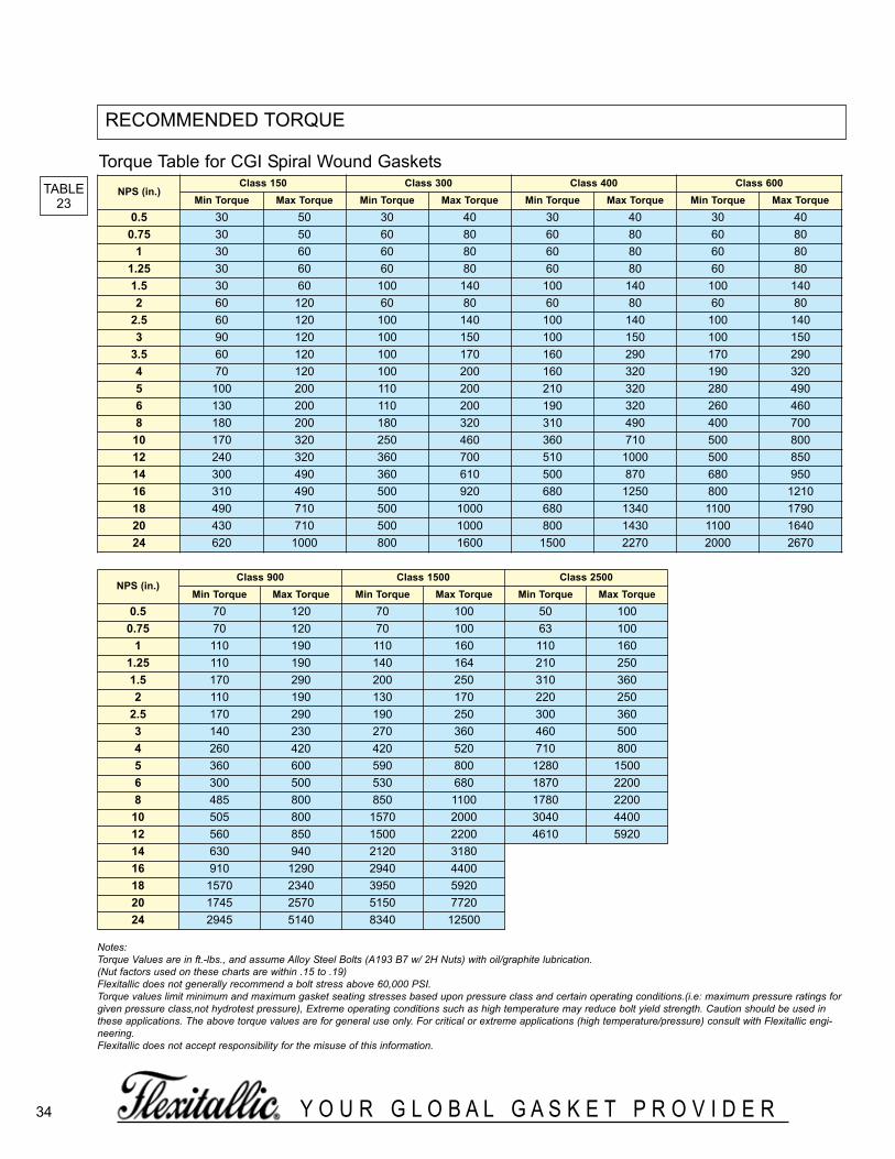
34 Y O U R G L O B A L G A S K E T P R O V I D E R
Torque Table for CGI Spiral Wound Gaskets
Notes:Torque Values are in ft.-lbs., and assume Alloy Steel Bolts (A193 B7 w/ 2H Nuts) with oil/graphite lubrication.(Nut factors used on these charts are within .15 to .19)Flexitallic does not generally recommend a bolt stress above 60,000 PSI.Torque values limit minimum and maximum gasket seating stresses based upon pressure class and certain operating conditions.(i.e: maximum pressure ratings forgiven pressure class,not hydrotest pressure), Extreme operating conditions such as high temperature may reduce bolt yield strength. Caution should be used inthese applications. The above torque values are for general use only. For critical or extreme applications (high temperature/pressure) consult with Flexitallic engi-neering.Flexitallic does not accept responsibility for the misuse of this information.
nPs (in.)class 150 class 300 class 400 class 600
Min torque Max torque Min torque Max torque Min torque Max torque Min torque Max torque0.5 30 50 30 40 30 40 30 40
0.75 30 50 60 80 60 80 60 801 30 60 60 80 60 80 60 80
1.25 30 60 60 80 60 80 60 801.5 30 60 100 140 100 140 100 1402 60 120 60 80 60 80 60 80
2.5 60 120 100 140 100 140 100 1403 90 120 100 150 100 150 100 150
3.5 60 120 100 170 160 290 170 2904 70 120 100 200 160 320 190 3205 100 200 110 200 210 320 280 4906 130 200 110 200 190 320 260 4608 180 200 180 320 310 490 400 700
10 170 320 250 460 360 710 500 80012 240 320 360 700 510 1000 500 85014 300 490 360 610 500 870 680 95016 310 490 500 920 680 1250 800 121018 490 710 500 1000 680 1340 1100 179020 430 710 500 1000 800 1430 1100 164024 620 1000 800 1600 1500 2270 2000 2670
nPs (in.)class 900 class 1500 class 2500
Min torque Max torque Min torque Max torque Min torque Max torque0.5 70 120 70 100 50 100
0.75 70 120 70 100 63 1001 110 190 110 160 110 160
1.25 110 190 140 164 210 2501.5 170 290 200 250 310 3602 110 190 130 170 220 250
2.5 170 290 190 250 300 3603 140 230 270 360 460 5004 260 420 420 520 710 8005 360 600 590 800 1280 15006 300 500 530 680 1870 22008 485 800 850 1100 1780 2200
10 505 800 1570 2000 3040 440012 560 850 1500 2200 4610 592014 630 940 2120 318016 910 1290 2940 440018 1570 2340 3950 592020 1745 2570 5150 772024 2945 5140 8340 12500
TABLE23
RECOMMENDED TORQUE
spiralWoundBrochure_060614_inside 3/24/2016 1:09 PM Page 34

35Y O U R G L O B A L G A S K E T P R O V I D E R
BOLTING DATA FOR ASME B16.5 & BS 1560 FLANGES
NOM PIPE SIZE
CLASS 150 CLASS 300 CLASS 400 CLASS 600
FLANGE NO. BOLT B.C. FLANGE NO. BOLT B.C. FLANGE NO. BOLT B.C. FLANGE NO. BOLT B.C.DIA. OF DiA. DIA. DIA. OF DIA. DIA. DIA. OF DIA. DIA. DIA. OF DIA. DIA.
BOLTS BOLTS BOLTS BOLTS
1/4 3-3/8 4 1/2 2-1/4 3-3/8 4 1/2 2-1/4 3-3/8 4 1/2 2-1/4 3-3/8 4 1/2 2-1/41/2 3-1/2 4 1/2 2-3/8 3-3/4 4 1/2 2-5/8 3-3/4 4 1/2 2-5/8 3-3/4 4 1/2 2-5/83/4 3-7/8 4 1/2 2-3/4 4-5/8 4 5/8 3-1/4 4-5/8 4 5/8 3-1/4 4-5/8 4 5/8 3-1/41 4-1/4 4 1/2 3-1/8 4-7/8 4 5/8 3-1/2 4-7/8 4 5/8 3-1/2 4-7/8 4 5/8 3-1/2
1-1/4 4-5/8 4 1/2 3-1/2 5-1/4 4 5/8 3-7/8 5-1/4 4 5/8 3-7/8 5-1/4 4 5/8 3-7/81-1/2 5 4 1/2 3-7/8 6-1/8 4 3/4 4-1/2 6-1/8 4 3/4 4-1/2 6-1/8 4 3/4 4-1/2
2 6 4 5/8 4-3/4 6-1/2 8 5/8 5 6-1/2 8 5/8 5 6-1/2 8 5/8 52-1/2 7 4 5/8 5-1/2 7-1/2 8 3/4 5-7/8 7-1/2 8 3/4 5-7/8 7-1/2 8 3/4 5-7/8
3 7-1/2 4 5/8 6 8-1/4 8 3/4 6-5/8 8-1/4 8 3/4 6-5/8 8-1/4 8 3/4 6-5/83-1/2 8-1/2 8 5/8 7 9 8 3/4 7-1/4 9 8 7/8 7-1/4 9 8 7/8 7-1/4
4 9 8 5/8 7-1/2 10 8 3/4 7-7/8 10 8 7/8 7-7/8 10-3/4 8 7/8 8-1/25 10 8 3/4 8-1/2 11 8 3/4 9-1/4 11 8 7/8 9-1/4 13 8 1 10-1/26 11 8 3/4 9-1/2 12-1/2 12 3/4 10-5/8 12-1/2 12 7/8 10-5/8 14 12 1 11-1/28 13-1/2 8 3/4 11-3/4 15 12 7/8 13 15 12 1 13 16-1/2 12 1-1/8 13-3/410 16 12 7/8 14-1/4 17-1/2 16 1 15-1/4 17-1/2 16 1-1/8 15-1/4 20 16 1-1/4 1712 19 12 7/8 17 20-1/2 16 1-1/8 17 3/4 20-1/2 16 1-1/4 17-3/4 22 20 1-1/4 19-1/414 21 12 1 18-3/4 23 20 1-1/8 20-1/4 23 20 1-1/4 20-1/4 23-3/4 20 1-3/8 20-3/416 23-1/2 16 1 21-1/4 25-1/2 20 1-1/4 22-1/2 25-1/2 20 1-3/8 22-1/2 27 20 1-1/2 23-3/418 25 16 1-1/8 22-3/4 28 24 1-1/4 24-3/4 28 24 1-3/8 24-3/4 29-1/4 20 1-5/8 25-3/420 27-1/2 20 1-1/8 25 30-1/2 24 1-1/4 27 30-1/2 24 1-1/2 27 32 24 1-5/8 28-1/224 32 20 1-1/4 29-1/2 36 24 1-1/2 32 36 24 1-3/4 32 37 24 1-7/8 33
NOM PIPE SIZE
CLASS 900 CLASS 1500 CLASS 2500
FLANGE NO. BOLT B.C. FLANGE NO. BOLT B.C. FLANGE NO. BOLT B.C.DIA. OF DiA. DIA. DIA. OF DIA. DIA. DIA. OF DIA. DIA.
BOLTS BOLTS BOLTS
1/2 4-3/4 4 3/4 3-1/4 4-3/4 4 3/4 3-1/4 5-1/4 4 3/4 3-1/2
3/4 5-1/8 4 3/4 3-1/2 5-1/8 4 3/4 3-1/2 5-1/2 4 3/4 3-3/4
1 5-7/8 4 7/8 4 5-7/8 4 7/8 4 6-1/4 4 7/8 4-1/4
1-1/4 6-1/4 4 7/8 4-3/8 6-1/4 4 7/8 4-3/8 7-1/4 4 1 5-1/8
1-1/2 7 4 1 4-7/8 7 4 1 4-7/8 8 4 1-1/8 5-3/4
2 8-1/2 8 7/8 6-1/2 8-1/2 8 7/8 6-1/2 9-1/4 8 1 6-3/4
2-1/2 9-5/8 8 1 7-1/2 9-5/8 8 1 7-1/2 10-1/2 8 1-1/8 7-3/4
3 9-1/2 8 7/8 7-1/2 10-1/2 8 1-1/8 8 12 8 1-1/4 9
4 11-1/2 8 1-1/8 9-1/4 12-1/4 8 1-1/4 9-1/2 14 8 1-1/2 10-3/4
5 13-3/4 8 1-1/4 11 14-3/4 8 1-1/2 11-1/2 16-1/2 8 1-3/4 12-3/4
6 15 12 1-1/8 12-1/2 15-1/2 12 1-3/8 12-1/2 19 8 2 14-1/2
8 18-1/2 12 1-3/8 15-1/2 19 12 1-5/8 15-1/2 21-3/4 12 2 17-1/4
10 21-1/2 16 1-3/8 18-1/2 23 12 1 7/8 19 26-1/2 12 2-1/2 21-1/4
12 24 20 1-3/8 21 26-1/2 16 2 22-1/2 30 12 2-3/4 24-3/8
14 25-1/4 20 1-1/2 22 29-1/2 16 2-1/4 25 - - - -
16 27-3/4 20 1-5/8 24-1/4 32-1/2 16 2-1/2 27-3/4 - - - -
18 31 20 1-7/8 27 36 16 2-3/4 30-1/2 - - - -
20 33-3/4 20 2 29-1/2 38-3/4 16 3 32-3/4 - - - -
24 41 20 2-1/2 35-1/2 46 16 3-1/2 39 - - - -
DIMENSIONS IN INCHES.
TABLE24
TABLE24.1
DIMENSIONS IN INCHES.
spiralWoundBrochure_060614_inside 3/24/2016 1:09 PM Page 35

36 Y O U R G L O B A L G A S K E T P R O V I D E R
FACING DIMENSIONS FOR ASME B16.5 & BS 1560 FLANGESCLASS 150, 300, 400, 600, 900, 1500 AND 2500
NOM PIPE SIZE
1/2 1-3/8 22/32 1-3/8 1 1-7/16 25/32 1-7/16 15/16 1/16 1/4 3/16
3/4 1-11/16 15/16 1-11/16 1-5/16 1-3/4 1 1-3/4 1-1/4 1/16 1/4 3/16
1 2 1-3/16 1-7/8 1-1/2 2-1/16 1-1/4 1-15/16 1-7/16 1/16 1/4 3/16
1-1/4 2-1/2 1-1/2 2-1/4 1-7/8 2-9/16 1-9/16 2-5/16 1-13/16 1/16 1/4 3/16
1-1/2 2-7/8 1-3/4 2-1/2 2-1/8 2-15/16 1-13/16 2-9/16 2-1/16 1/16 1/4 3/16
2 3-5/8 2-1/4 3-1/4 2-7/8 3-11/16 2-5/16 3-5/16 2-13/16 1/16 1/4 3/16
2-1/2 4-1/8 2-11/16 3-3/4 3-3/8 4-3/16 2-3/4 3-13/16 3-5/16 1/16 1/4 3/16
3 5 3-5/16 4-5/8 4-1/4 5-1/16 3-3/8 4-11/16 4-3/16 1/16 1/4 3/16
3-1/2 5-1/2 3-13/16 5-1/8 4-3/4 5-9/16 3-7/8 5-3/16 4-11/16 1/16 1/4 3/16
4 6-3/16 4-5/16 5-11/16 5-3/16 6-1/4 4-3/8 5-3/4 5-1/8 1/16 1/4 3/16
5 7-5/16 5-3/8 6-13/16 6-5/16 7-3/8 5-7/16 6-7/8 6-1/4 1/16 1/4 3/16
6 8-1/2 6-3/8 8 7-1/2 8-9/16 6-7/16 8-1/16 7-7/16 1/16 1/4 3/16
8 10-5/8 8-3/8 10 9-3/8 10-11/16 8-7/16 10-1/16 9-5/16 1/16 1/4 3/16
10 12-3/4 10-1/2 12 11-1/4 12-13/16 10-9/16 12-1/16 11-3/16 1/16 1/4 3/16
12 15 12-1/2 14-1/4 13-1/2 15-1/16 12-9/16 14-5/16 13-7/16 1/16 1/4 3/16
14 16-1/4 13-3/4 15-1/2 14-3/4 16-5/16 13-13/16 15-9/16 14 -1/16 1/16 1/4 3/16
16 18-1/2 15-3/4 17-5/8 16-3/4 18-9/16 15-13/16 17-11/16 16-11/16 1/16 1/4 3/16
18 21 17-3/4 20-1/8 19-1/4 21-1/16 17-13/16 20-3/16 19-3/16 1/16 1/4 3/16
20 23 19-3/4 22 21 23-1/16 19-13/16 22-1/16 20-15/16 1/16 1/4 3/16
24 27-1/4 23-3/4 26-1/4 25-1/4 27-5/16 23-13/16 26-5/16 25-3/16 1/16 1/4 3/16
RAISED FACE, LAPPED,
LARGE MALE, & LARGE
TONGUES See Note 5
R
OUTSIDE DIAMETER See Note 3 OUTSIDE DIAMETER See Note 3 HEIGHT
SMALL MALE
See Notes4&5S
SMALL TONGUE
See Note 5
T
RAISED FACELARGE &
SMALL MALE & TONGUE
CLASS 400,600,9001500 & 2500 See Note 2
RAISED FACECLASS
150 & 300
See Note 1
I.D. OFLARGE &SMALL
GROOVE See Note 3 See Note 5
Z
SMALLGROOVE
See Note 5
V
LARGE FEMALE &
LARGE GROOVE
See Note 5
w
I.D. OF LARGE
& SMALLTONGUE
See Notes 3 & 5
U
DEPTH OFGROOVE OR
FEMALE
SMALLFEMALE
See Note 4 See Note 5
X
DIMENSIONS IN INCHES.
notes1. Regular facing for class 150 and 300 steel flanged fittingsand companion flange standards is a 1/16” raised face includedin the minimum flange thickness dimensions. A 1/16” raisedface may be supplied also on the class 400, 600, 900, 1500,and 2500 flange standards, but it must be added to the mini-mum flange thickness.2. Regular facing for class 400, 600, 900, 1500, and 2500 flange thickness dimensions.3. Tolerance of plus or minus 0.016 in. (1/64”) is allowed on theinside and outside diameters of all facings.4. For small male and female joints care should be taken in theuse of these dimensions to insure that pipe used is thick
enough to permit sufficient bearing surface to prevent thecrushing of the gasket. The dimensions apply particularly onlines where the joint is made on the end of the pipe. Screwedcompanion flanges for small male and female joints are fur-nished with plain face and are threaded with AmericanStandard Locknut Thread.5. Gaskets for male-female and tongue-groove joints shallcover the bottom of the recess with minimum clearances takinginto account the tolerances prescribed in Note 3.
TABLE25
spiralWoundBrochure_060614_inside 3/24/2016 1:09 PM Page 36
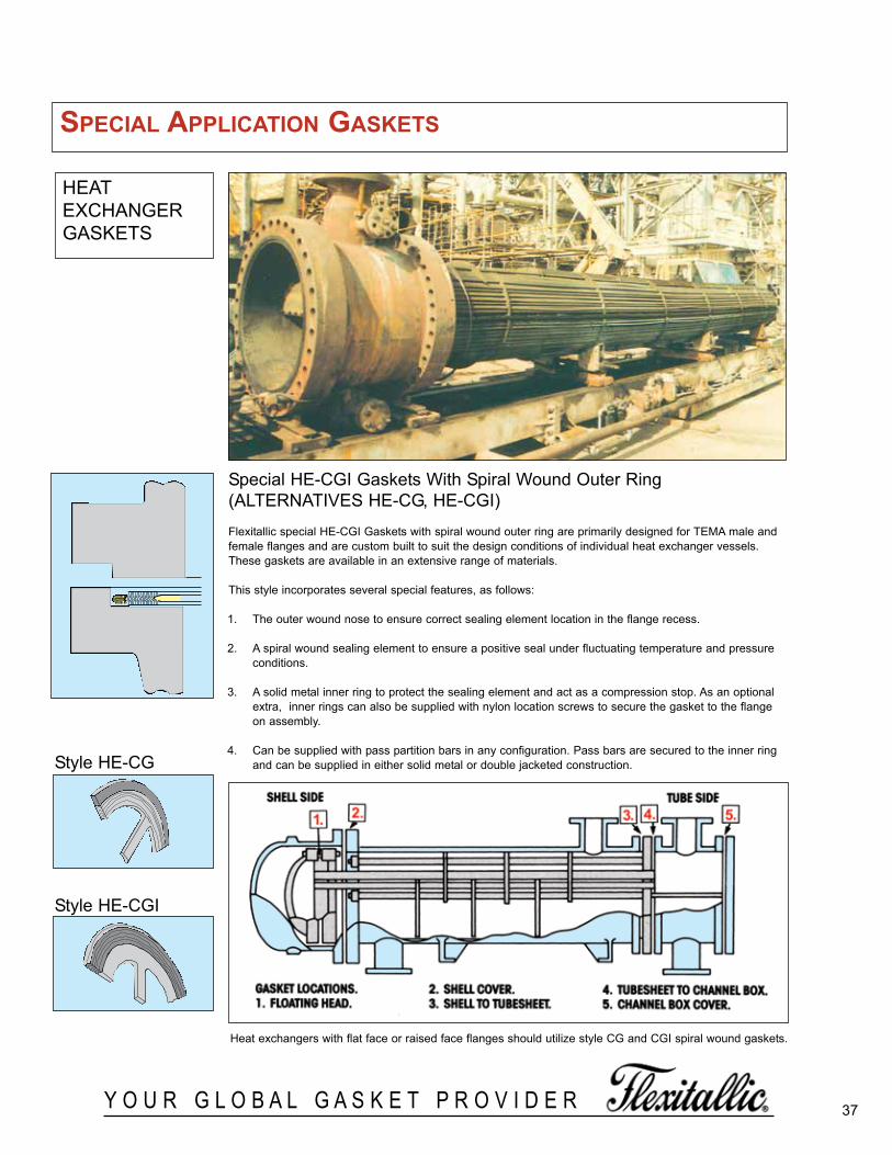
37Y O U R G L O B A L G A S K E T P R O V I D E R
HEATEXCHANGERGASKETS
Special HE-CGI Gaskets With Spiral Wound Outer Ring(ALTERNATIVES HE-CG, HE-CGI)
Flexitallic special HE-CGI Gaskets with spiral wound outer ring are primarily designed for TEMA male andfemale flanges and are custom built to suit the design conditions of individual heat exchanger vessels.These gaskets are available in an extensive range of materials.
This style incorporates several special features, as follows:
1. The outer wound nose to ensure correct sealing element location in the flange recess.
2. A spiral wound sealing element to ensure a positive seal under fluctuating temperature and pressureconditions.
3. A solid metal inner ring to protect the sealing element and act as a compression stop. As an optionalextra, inner rings can also be supplied with nylon location screws to secure the gasket to the flangeon assembly.
4. Can be supplied with pass partition bars in any configuration. Pass bars are secured to the inner ringand can be supplied in either solid metal or double jacketed construction.
Heat exchangers with flat face or raised face flanges should utilize style CG and CGI spiral wound gaskets.
Style HE-CG
Style HE-CGI
sPecial aPPlication gaskets
spiralWoundBrochure_060614_inside 3/24/2016 1:09 PM Page 37
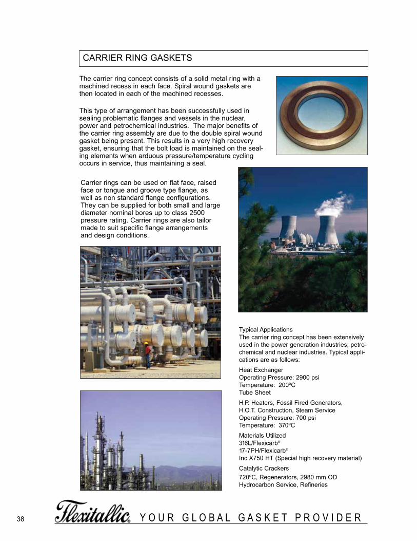
38 Y O U R G L O B A L G A S K E T P R O V I D E R
The carrier ring concept consists of a solid metal ring with amachined recess in each face. Spiral wound gaskets arethen located in each of the machined recesses.
This type of arrangement has been successfully used insealing problematic flanges and vessels in the nuclear,power and petrochemical industries. The major benefits ofthe carrier ring assembly are due to the double spiral woundgasket being present. This results in a very high recoverygasket, ensuring that the bolt load is maintained on the seal-ing elements when arduous pressure/temperature cyclingoccurs in service, thus maintaining a seal.
Typical ApplicationsThe carrier ring concept has been extensivelyused in the power generation industries, petro-chemical and nuclear industries. Typical appli-cations are as follows:
Heat ExchangerOperating Pressure: 2900 psiTemperature: 200ºCTube Sheet
H.P. Heaters, Fossil Fired Generators, H.O.T. Construction, Steam ServiceOperating Pressure: 700 psiTemperature: 370ºC
Materials Utilized316L/Flexicarb®
17-7PH/Flexicarb®
Inc X750 HT (Special high recovery material)
Catalytic Crackers720ºC, Regenerators, 2980 mm ODHydrocarbon Service, Refineries
CARRIER RING GASKETS
Carrier rings can be used on flat face, raisedface or tongue and groove type flange, aswell as non standard flange configurations.They can be supplied for both small and largediameter nominal bores up to class 2500pressure rating. Carrier rings are also tailormade to suit specific flange arrangementsand design conditions.
spiralWoundBrochure_060614_inside 3/24/2016 1:09 PM Page 38
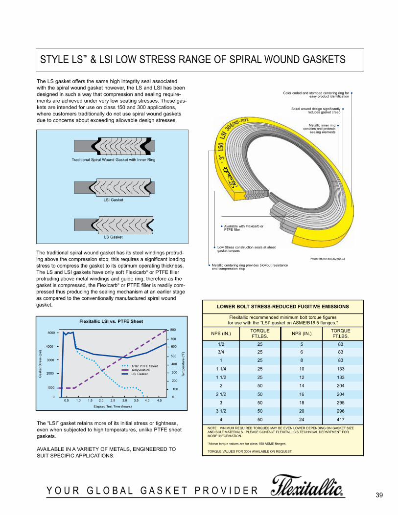
39Y O U R G L O B A L G A S K E T P R O V I D E R
STYLE LS™ & LSI LOW STRESS RANGE OF SPIRAL WOUND GASKETS
The LS gasket offers the same high integrity seal associatedwith the spiral wound gasket however, the LS and LSI has beendesigned in such a way that compression and sealing require-ments are achieved under very low seating stresses. These gas-kets are intended for use on class 150 and 300 applications,where customers traditionally do not use spiral wound gasketsdue to concerns about exceeding allowable design stresses.
The traditional spiral wound gasket has its steel windings protrud-ing above the compression stop; this requires a significant loadingstress to compress the gasket to its optimum operating thickness.The LS and LSI gaskets have only soft Flexicarb® or PTFE fillerprotruding above metal windings and guide ring; therefore as thegasket is compressed, the Flexicarb® or PTFE filler is readily com-pressed thus producing the sealing mechanism at an earlier stageas compared to the conventionally manufactured spiral woundgasket.
The “LSI” gasket retains more of its initial stress or tightness,even when subjected to high temperatures, unlike PTFE sheetgaskets.
AVAILABLE IN A VARIETY OF METALS, ENGINEERED TOSUIT SPECIFIC APPLICATIONS.
Available with Flexicarb orPTFE filler
Low Stress construction seals at sheetgasket torques
Metallic centering ring provides blowout resistanceand compression stop
Color coded and stamped centering ring foreasy product identification
Spiral wound design significantlyreduces gasket creep
Metallic inner ring contains and protects
sealing elements
•
•
•
Patent #5161807/5275423
Traditional Spiral Wound Gasket with Inner Ring
LSI Gasket
LS Gasket
5000
4000
3000
2000
1000
0.5 1.0 1.5 2.0 2.5 3.0 3.5
1/16” PTFE SheetTemperatureLSI Gasket
Elapsed Test Time (hours)
Gas
ket S
tress
(psi
)
4.0
flexitallic lsi vs. Ptfe sheet
700
600
500
400
4.5
Tem
pera
ture
(°F)
300
200
100
00
800
loWer Bolt stress-reduced fugitive eMissions
Flexitallic recommended mini mum bolt torque figuresfor use with the “LSI” gasket on ASME/B16.5 flanges.*
NPS (IN.) TORQUEFT.LBS. NPS (IN.) TORQUE
FT.LBS.
1/2 25 5 83
3/4 25 6 83
1 25 8 83
1 1/4 25 10 133
1 1/2 25 12 133
2 50 14 204
2 1/2 50 16 204
3 50 18 295
3 1/2 50 20 296
4 50 24 417
NOTE: MINIMUM REQUIRED TORQUES MAY BE EVEN LOWER DEPENDING ON GASKET SIZEAND BOLT MATERIALS. PLEASE CONTACT FLEXITALLIC’S TECHNICAL DEPARTMENT FORMORE INFORMATION.
“Above torque values are for class 150 ASME flanges.
TORQUE VALUES FOR 300# AVAILABLE ON REQUEST.
•
•
•
spiralWoundBrochure_060614_inside 3/24/2016 1:09 PM Page 39

40 Y O U R G L O B A L G A S K E T P R O V I D E R
MaterialsStandard materials are Type 304 Stainless Steel andFlexicarb windings. Special materials to suit specificoperating conditions are available.
StyIe M & MC & MCSSpiral Wound Gaskets for Boiler Manhole Cover Assemblies
The Flexitallic manhole gasket spiral constructions incorporate modified compression values to provide seating loads within the normal range of cover assemblies.
Size/Range SpecificationAvailable in circular, obround, and oval shapes to suit standard manhole plate configurations.
SPIRAL WOUND GASKETS FOR BOILER CAP AND MANHOLECOVER ASSEMBLIES
Gaskets for boiler handhole, tubecap and manhole covers incorporating the unique Flexitallic Spiral Woundprofile and specially manufactured with Flexicarb® filler, are ideal for corrosive, high pressure or temperatureduties. Flexitallic’s anticipation of developments in modern steam generating and engineering equipment andability to design to specific requirements are the guarantee of the perfect seal at minimum maintenance costwith consistently high standards of performance.
• High safety factor related to specific operating conditions• Compression loadings proportional to safe stresses of cover assemblies• Resilient under concentrated and fluctuating loads• Prolonged trouble-free service• Reduced seat cleaning time
To OrderWith all orders or inquiries please submit follow-ing:a) Name of boiler or equipment manufacturerb) Gasket stylec) Dimensions of gasketd) Gasket thicknesse) Flange width of gasketf) Pressure service ratingg) Gasket material preference
Style TSpiral Wound Gaskets for Boiler Handhole andTubecap Assemblies
The design features of the basic Flexitallic spiralwound construction alleviate the need for sealingcompound. Particularly suitable where old and pit-ted faces have rendered other gaskets ineffective.
Size/Range SpecificationAvailable in several standard shapes:-
Supplied in thicknesses of 3.2mm (0.125in.) or4.5mm (0.175 in.). The standard thickness of 4.5mm (0.175in.) is recommended for use in assemblieswhere the seat is relatively broad and bolting load islow.
spiralWoundBrochure_060614_inside 3/24/2016 1:09 PM Page 40

Style MCS
NOMINALl.D. FLANGE
STYLE DIMENSIONS THICKNESS WIDTH(inches) (inches) (inches)
M-OvaI 10 x 15 .250 15/16M-Ovai 10 x 16 .250 15/16M-Oval 11 x 15 .250 15/16
MC-Oval 11 x 15 .250 13/16M-Oval 11 x 15 .175 3/4M-Oval 11 x 15 .175 15/16M-Oval 11 x 15 .175 1/2M-Oval 11 x 15 .175 1-1/4M-Oval 11 x 15 .250 1-1/4
M-Obround 11-1/16 x 14-7/8 .250 15/16M-Obround 11-7/16 x 15-1/16 .250 15/16
M-Oval 12 x 16 .250 15/16MC-Oval 12 x 16 .250 13/16MOval 12 x 16 .175 1/2M-Oval 12 x 16 .175 3/4M-Oval 12 x 16 .175 15/16M-Oval 12 x 16 .175 1-1/4M-OvaI 12 x 16 .250 1-1/4
M-Obround 12 x 16 .250 15/16M-Obraund 12 x 16 .250 1-1/4MC-Oval 12-1/8 x 16-1/8 .250 13/16
M-Obround 14 x 16 .175 3/4M-Round 14 .175 3/4M-Round 16-1/16 .175 3/4
NOTE: When ordering gaskets specify operating pressure and temperature and type of steel desired.
FLEXITALLIC STYLE MCS SPIRAL WOUND GASKETSIn keeping with our tradition of taking a leadership role in the gasket industry we are pleased to introducethe Flexitallic style MCS spiral wound gasket for use on boiler manhole cover assemblies. The style MCSgasket is an exclusive Flexitallic design, consisting of a Flexitallic spiral wound gasket with an integral solidmetal inner ring. The spiral wound sealing element provides resilience, strength, blowout resistance andsuperior sealability. The solid metal ring prevents over-compression of the gasket, which is especiallyimportant on high pressure boilers. In addition, the rings provide stability and facilitate proper positioning ofthe gasket on the cover which prevents pinching, shouldering, and other gasket damage resulting frommisalignment, irregular plate contours and fillets.Flexitallic style MCS spiral wound gaskets are available in a wide range of materials for standard, as wellas special design manhole cover assemblies, in pressure classes of 0-499 psi, 0-999 psi, and 1000 psi andhigher. For additional information on Flexitallic style MCS spiral wound gaskets, contact the Flexitallicplant nearest you.
TABLE26
Style M Style MC
41Y O U R G L O B A L G A S K E T P R O V I D E R
STYLES M & MC FOR MANHOLE COVER ASSEMBLIES
spiralWoundBrochure_060614_inside 3/24/2016 1:09 PM Page 41

42 Y O U R G L O B A L G A S K E T P R O V I D E R
STYLE T FOR BOILER HANDHOLE AND TUBECAP ASSEMBLIES0-499 lbs, 0-999 lbs, 1000 lbs and above. Specify operating temperature, pressure and type of steel.
NOMINAL FLANGEIDENTIFICATION SHAPE I.D. WIDTH
(inches) (inches)
NOMINAL FLANGEIDENTIFICATION SHAPE I.D. WIDTH
(inches) (inches)
Foster Wheeler (con’t.) Round 3-1/8 or 3-1/16 3/8Round 4-1/8 or 4-1/16 3/8Rect. 4-15/16 x 5-3/16 7/32
Geary31/2” Obround 3-13/16 x 4-5/8 3/84” Obround 4-1/4 x 5-1/4 7/164” (.285" Thick) Obround 4-1/4 x 5 1/4 7/16
Heine Obround 3-5/8 x 4-5/8 3/8Round 3-5/8 3/8
International Oval 2-19/32 x 3-19/32 7/16Keeler Diamond 4-1/4 x 5-1/4 3/8
Round 4-1/4 3/8Obround 3 x 4 3/8
Murray Obround 3-5/8 x 4-9/16 3/8Obround 3-5/8 x 4-9/16 7/16Obround 4-1/32 X 4-29/32 3/8
Oil Field Obround 2-1/2 x 3-1/2 3/8Oval 3 x 4 3/8Oval 3-1/2 x 4-1/2 3/8Oval 4-1/16 x 5-1/16 7/16
Orr & Sembower Oval 2-23/32 x 3-21/32 3/8Oval 3-13/32 x 4-13/32 3/8
Pacific Round 1-1/2 1/2Round 2 1/2Round 2-1/2 1/2
PageLarrabee Oval 2-27/32 x 3-29/32 3/8Junior Oval 3-1/8 x 4-1/8 3/8Page Oval 3-1/8 x 4-1/4 3/8P-B Oval 3-5/16 x 4-5/16 3/8Drum Oval 3-25/32 x 5-13/32 5/8Consol Round 2-3/16 3/8
Riley StokerW-C22 Oval 3-17/32 x 4-17/32 5/16W-C2 Obround 3-23/32 x 5-23/32 11/32W-C16 Round 1-31/32 3/8W-C6 Round 3-9/32 5/16W-C9 Square 4 x 4 11/32
Square 5-1/2 x 5-1/2 3/8Springfield Oval 3-17/32 x 4-17/32 5/16
Oval 4-1/16 x 5-1/16 3/8Square 5-1/2 x 5-1/2 3/8Square 7-3/8 x 7-3/8 5/8
Superheater Obround 2-21/32 x 3-9/32 15/64Obround 3-3/32 x 4-3/32 1/4Obround 3-11/32 x 3-23/32 3/16Obround 3-3/8 x 3-3/8 1/4Round 15/16 3/16Round 3-3/32 1/4
Union3 1/4” Pear 3-7/16 x 4-7/16 3/8
Pear 3-1/2 x 4-1/2 3/8Pear 4-1/4 x 5-1/4 3/8
(.285” Thick) Pear 4-1/4 x 5-1/4 3/8Oval 3-1/2 x 4-1/2 3/8Oval 3 x 4 3/8
Vogt Oval 3 x 4 5/16Oval 3-3/8 x 4-1/4 7/32Oval 3-1/4 x 4-1/2 5/16Oval 3-3/4 x 5 3/8Oval 4 x 5 5/16Oval 4 x 6 3/8Oval 4-1/4 x 5-1/8 7/32 (new)Oval 4-1/4 x 5-1/8 5/16 (old)Oval 4-9/32 X 5-5/32 7/32
31/2” Round 3-19/32 3/8Round 4-1/8 3/8
Ward Square 4-7/8 x 4-7/8 1/4Wickes Pear 4-1/8 x 5-1/8 9/32
Pear 4-1/4 x 5-1/8 3/8D2300 Oval 3 x 4 5/16D2301 Oval 3-1/2 x 4-1/2 5/16D2361 Oval 4 x 5 5/16D2724 Oval 4 x 6 5/16
Round 4-1/8 3/8Round 4-1/4 3/8
American Engineering Obround 3-5/16 x 3-11/16 3/16Round 3-5/16 3/16
Babcock and WilcoxNo.41 Obround 2-9/64 x 2-33/64 5/32No.40 Diamond 3-3/8 x 3-3/4 3/16No.48 Oval 3-13/16 x 4-3/4 7/32No.79 Obround 4-5/32 x 4-25/32 1/4No.24 Oval 4-1/2 x 5-1/2 7/32No.76 Oval 5-1/32 x 5-31/32 1/42” Econ. Round 1-5/8 1/4No.47 Round 2-1/32 3/16No.32 Round 3 1/4No.70 Round 3-9/32 3/16No.89 Round 3-7/16 5/32No.92 Round 4-1/32 1/4No.28 Rect. 4-13/16 x 5 7/32
Badenhausen (See Riley Stoker)
BrosHB-5 and HB-10 Round 2-1/4 1/4HB-6 and HB-11 Round 3-3/8 1/4HB-12 Round 4-1/4 1/4HB-8 and HB-13 Obround 3-3/8 x 4-1/4 1/4HB-14 Obround 4-1/4 x 5 1/4
Bucyrus-ErieQ227 Obround 3 x 4-1/2 3/80260 Oval 4 x 6 7/160208 Round 2-1/2 1/4
Casey-Hedges Obround 4-1/4 x 5-1/8 3/8Cleaver-Brooks Obround 2-27/32 x 3-19/32 5/16
Obround 3-9/32 x 4-17/32 3/8Obround 4 x 6 3/8
Combustion Engineering24N-L1206 Diamond 3 x 3-7/8 1/429N-L839 Diamond 3-3/8 x 4-1/4 1/430N-L866 Diamond 3-5/8 x 4-1/2 1/433N-L1205 Diamond 3-3/4 x 4-5/8 1/431N-L579 Diamond 4-1/4 x 5-1/8 1/421N-L1291 Obround 2-1/8 x 2-1/2 5/3222N Oval 2-1/8 x 2-5/8 7/3223N Obround 2-25/32 x 3-13/32 7/3225N-L1 278 Obround 3-1/8 x 4-1/8 3/1627N Diamond 3-3/8 x 3-3/4 3/1628N-L1277 Obround 3-3/8 x 3-7/8 3/1632N Oval 4-1/2 x 5-1/2 7/321N-L1272 Round 1-1/2 3/167N-L1131 Round 1-3/4 3/163N-L1274 Round 2-5/8 7/324N-L740 Round 3-1/8 1/4L741 Round 3-3/8 1/45N-L902 Round 3-5/8 1/45N-L744 Round 4-1/8 1/451N Rect. 4-13/16 x 5 7/3252N-L1117 Rect. 4-7/8 x 5-3/16 7/32PB9474 Obround 4-1/8 x 4-7/8 3/16PB9474 Round 3-1/2 3/16
Connelly Obround 3 x 3-15/16 3/8Edge Moor Oval 4-1/8 x 5-1/4 3/8
Round 2-1/2 1/2Round 4-1/16 15/32
Erie City Pear 3-1/2 x 4-5/8 3/8Obround 3 x 4-1/2 3/8
Oval 3-1/32 x 4-1/32 5/16Oval 3-17/32 x 4-17/32 5/16Oval 4-1/32 x 5-1/32 5/16Oval 4-1/32 x 6-1/32 3/8
Round 3-1/2 3/8Foster Wheeler Diamond 4 x 5 3/823/4” Obround 2-25/32 x 3-13/32 7/32
Obround 3 x 4 3/8315/16” Obround 3-11/32 x 3-31/32 7/32
Oval 4-3/16 x 5-3/16 5/16Round 15/16 5/32Round 2-1/32 13/64Round 2-1/32 15/64Round 2-1/8 or 2-1/16 3/8
TABLE27
spiralWoundBrochure_060614_inside 3/24/2016 1:09 PM Page 42
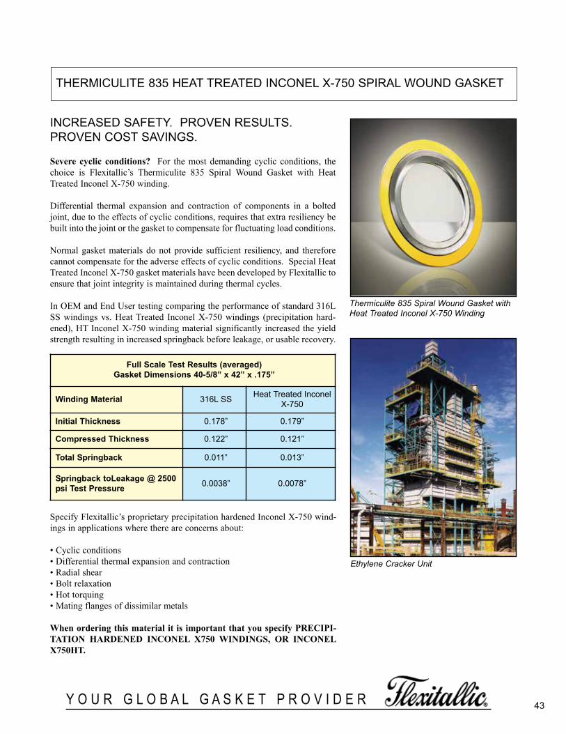
43Y O U R G L O B A L G A S K E T P R O V I D E R
THERMICULITE 835 HEAT TREATED INCONEL X-750 SPIRAL WOUND GASKET
INCREASED SAFETY. PROVEN RESULTS.PROVEN COST SAVINGS.
Severe cyclic conditions? For the most demanding cyclic conditions, thechoice is Flexitallic’s Thermiculite 835 Spiral Wound Gasket with HeatTreated Inconel X-750 winding.
Differential thermal expansion and contraction of components in a boltedjoint, due to the effects of cyclic conditions, requires that extra resiliency bebuilt into the joint or the gasket to compensate for fluctuating load conditions.
Normal gasket materials do not provide sufficient resiliency, and thereforecannot compensate for the adverse effects of cyclic conditions. Special HeatTreated Inconel X-750 gasket materials have been developed by Flexitallic toensure that joint integrity is maintained during thermal cycles.
In OEM and End User testing comparing the performance of standard 316LSS windings vs. Heat Treated Inconel X-750 windings (precipitation hard-ened), HT Inconel X-750 winding material significantly increased the yieldstrength resulting in increased springback before leakage, or usable recovery.
Thermiculite 835 Spiral Wound Gasket withHeat Treated Inconel X-750 Winding
Ethylene Cracker Unit
full scale test results (averaged)gasket dimensions 40-5/8” x 42” x .175”
Winding Material 316L SS Heat Treated InconelX-750
initial thickness 0.178” 0.179”
compressed thickness 0.122” 0.121”
total springback 0.011” 0.013”
springback toleakage @ 2500psi test Pressure 0.0038” 0.0078”
Specify Flexitallic’s proprietary precipitation hardened Inconel X-750 wind-ings in applications where there are concerns about:
• Cyclic conditions• Differential thermal expansion and contraction• Radial shear• Bolt relaxation• Hot torquing• Mating flanges of dissimilar metals
When ordering this material it is important that you specify PRECIPI-TATION HARDENED INCONEL X750 WINDINGS, OR INCONELX750HT.
spiralWoundBrochure_060614_inside 3/24/2016 1:09 PM Page 43
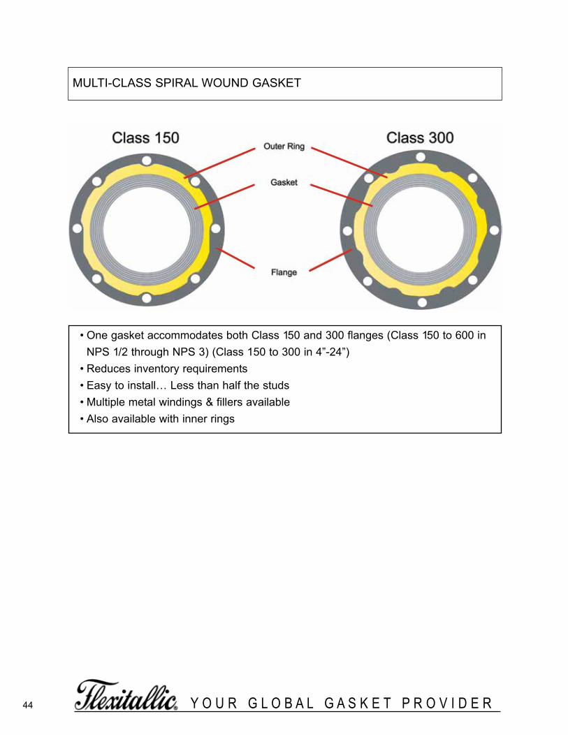
44 Y O U R G L O B A L G A S K E T P R O V I D E R
• One gasket accommodates both Class 150 and 300 flanges (Class 150 to 600 inNPS 1/2 through NPS 3) (Class 150 to 300 in 4”-24”)
• Reduces inventory requirements• Easy to install… Less than half the studs• Multiple metal windings & fillers available• Also available with inner rings
MULTI-CLASS SPIRAL WOUND GASKET
spiralWoundBrochure_060614_inside 3/24/2016 1:09 PM Page 44

45Y O U R G L O B A L G A S K E T P R O V I D E R
ProblemA leak occurs on HF service
• HF can attack the bolts causing bolt failure.
• A small emission goes undetected.
Solution
• Prevents HF attacking the bolts.
• Early detection of small leaks.
• Containment of HF emissions.
• Improves maintenance (detect & repair).
• Requires no modification to the flanges.
• Designed to suit Class 150 & 300 flanges.
• Contains no respirable fibers.
What are the benefits?The Baker gasket offers the user the reliabilityof a spiral wound gasket with the additionalback-up of an emissions containment systemshould a leak occur. Reduced maintenancecosts through an improved ‘Detect & Repair’program. Improvements in plant operatorsHealth & Safety profile.
Any HF emissions are focused to the tagged area where a reaction with the detectorpaint can be easily observed. This concept has
been successfully field tested.
*Patent Pending
A PTFE ring is attached to the external guide ring. Any emissions will be confined within the flange arrangement.
PTFE Channel Ring
Spiral Wound Gasketutilizing PTFE orFlexicarb filler materials
THE BAKER* GASKETFOR HF ACID & OTHER HAZARDOUS CHEMICALAPPLICATIONS
spiralWoundBrochure_060614_inside 3/24/2016 1:09 PM Page 45

46 Y O U R G L O B A L G A S K E T P R O V I D E R
spiralWoundBrochure_060614_inside 3/24/2016 1:09 PM Page 46
47Y O U R G L O B A L G A S K E T P R O V I D E R
spiralWoundBrochure_060614_inside 3/24/2016 1:09 PM Page 47

48 Y O U R G L O B A L G A S K E T P R O V I D E R
spiralWoundBrochure_060614_inside 3/24/2016 1:09 PM Page 48