Maintenance Manual - Cameron Balloons Modific… · · 2017-06-12This Maintenance Manual is EASA...
30
Maintenance Manual Hotair-Airship AS 105 GD Version GD/4 and GD/6 GEFA-FLUG GmbH An der Glashuette 8 D-52074 Aachen Germany www.gefa-flug.de This Maintenance Manual is EASA approved under the Approval Number: 10029984 Date of initial Approval: 28.05.2010 Revision: 4 - 05. May 2014
Transcript of Maintenance Manual - Cameron Balloons Modific… · · 2017-06-12This Maintenance Manual is EASA...

Maintenance Manual
Hotair-Airship AS 105 GD Version GD/4 and GD/6
GEFA-FLUG GmbH An der Glashuette 8
D-52074 Aachen Germany
www.gefa-flug.de
This Maintenance Manual is EASA approved under the Approval Number: 10029984
Date of initial Approval: 28.05.2010
Revision: 4 - 05. May 2014
Maintenance Manual AS 105 GD
Issue 1 Rev. 4 05. May 2014 Chapter 0 Page 2 of 5
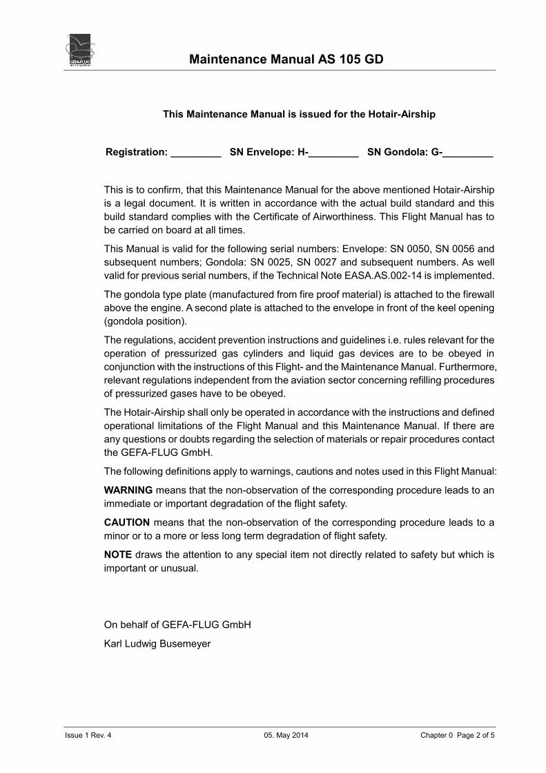
This Maintenance Manual is issued for the Hotair-Airship
Registration: _________ SN Envelope: H-_________ SN Gondola: G-_________
This is to confirm, that this Maintenance Manual for the above mentioned Hotair-Airship
is a legal document. It is written in accordance with the actual build standard and this
build standard complies with the Certificate of Airworthiness. This Flight Manual has to
be carried on board at all times.
This Manual is valid for the following serial numbers: Envelope: SN 0050, SN 0056 and
subsequent numbers; Gondola: SN 0025, SN 0027 and subsequent numbers. As well
valid for previous serial numbers, if the Technical Note EASA.AS.002-14 is implemented.
The gondola type plate (manufactured from fire proof material) is attached to the firewall
above the engine. A second plate is attached to the envelope in front of the keel opening
(gondola position).
The regulations, accident prevention instructions and guidelines i.e. rules relevant for the
operation of pressurized gas cylinders and liquid gas devices are to be obeyed in
conjunction with the instructions of this Flight- and the Maintenance Manual. Furthermore,
relevant regulations independent from the aviation sector concerning refilling procedures
of pressurized gases have to be obeyed.
The Hotair-Airship shall only be operated in accordance with the instructions and defined
operational limitations of the Flight Manual and this Maintenance Manual. If there are
any questions or doubts regarding the selection of materials or repair procedures contact
the GEFA-FLUG GmbH.
The following definitions apply to warnings, cautions and notes used in this Flight Manual:
WARNING means that the non-observation of the corresponding procedure leads to an
immediate or important degradation of the flight safety.
CAUTION means that the non-observation of the corresponding procedure leads to a
minor or to a more or less long term degradation of flight safety.
NOTE draws the attention to any special item not directly related to safety but which is
important or unusual.
On behalf of GEFA-FLUG GmbH
Karl Ludwig Busemeyer

Maintenance Manual AS 105 GD
Issue 1 Rev. 4 05. May 2014 Chapter 0 Page 3 of 5
Table of Contents
A: Supplement and Revision Status
B: Abbreviations
1 Periodical Inspections and Maintenance (EASA Approved)
1.1 12½ -Hour-Inspection
1.2 25- Hour-Inspection
1.3 50-Hour-Inspection / Annual Inspection
1.3.1 Grab-Test
1.4 100-Hour-Inspection
1.5 300-Hour-Inspection
2 Non-Scheduled Inspections
2.1 Inspection After Overheating Of Envelope
2.2 Inspection After Suspected Exceeding Of Envelope Pressure Limitations
2.3 Inspection Of The Gondola After A Hard Landing
3 Repair Instructions
3.1 Envelope
3.1.1 Minor Repairs on Envelope and Fins
3.1.2 Loadtape Repair
3.1.3 Repair of Lines and Ropes
3.1.4 Replacement of Flying Wires and Karabiners
3.2 Gondola Frame
3.3 Propulsion Engine
3.4 Propeller
3.5 Envelope Pressurisation System
3.6 Burner
3.6.1 Cleaning Of Liquid Pilot Light System
3.7 Propane System
3.8 Petrol System
3.9 Electric System And Wiring Diagram
3.10 Instrumentation
Maintenance Manual AS 105 GD
Issue 1 Rev. 4 05. May 2014 Chapter 0 Page 4 of 5
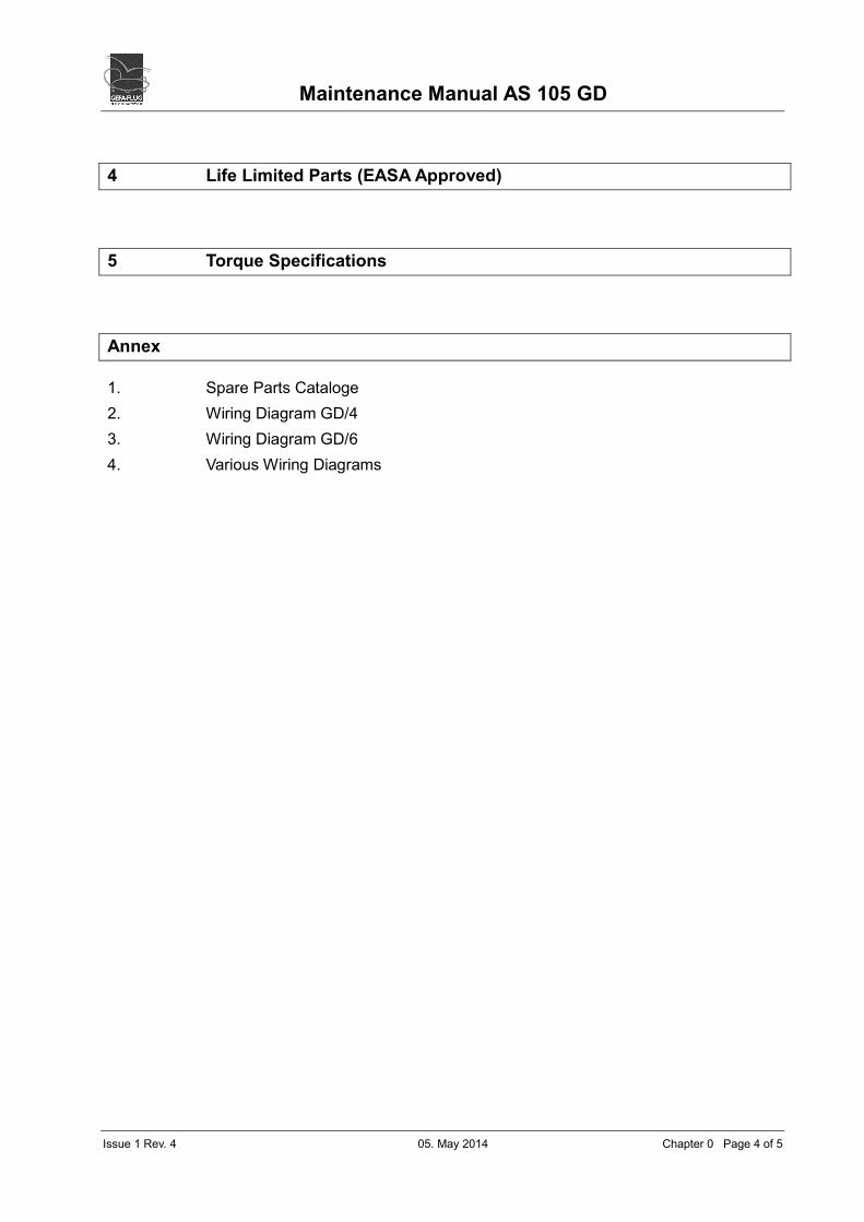
4 Life Limited Parts (EASA Approved)
5 Torque Specifications
Annex
1. Spare Parts Cataloge
2. Wiring Diagram GD/4
3. Wiring Diagram GD/6
4. Various Wiring Diagrams
Maintenance Manual AS 105 GD
Issue 1 Rev. 4 05. May 2014 Chapter 0 Page 5 of 5
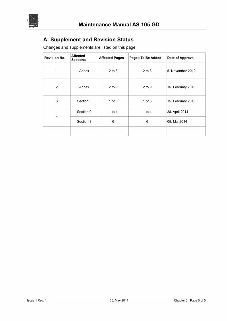
A: Supplement and Revision Status
Changes and supplements are listed on this page.
Revision No. Affected Sections
Affected Pages Pages To Be Added Date of Approval
1 Annex 2 to 8 2 to 8 5. November 2012
2 Annex 2 to 9 2 to 9 15. February 2013
3 Section 3 1 of 6 1 of 6 15. February 2013
4
Section 0 1 to 4 1 to 4 28. April 2014
Section 3 6 6 05. Mai 2014
Maintenance Manual AS 105 GD
Issue 1 Rev. 4 05. May 2014 Chapter 0 Page 6 of 5
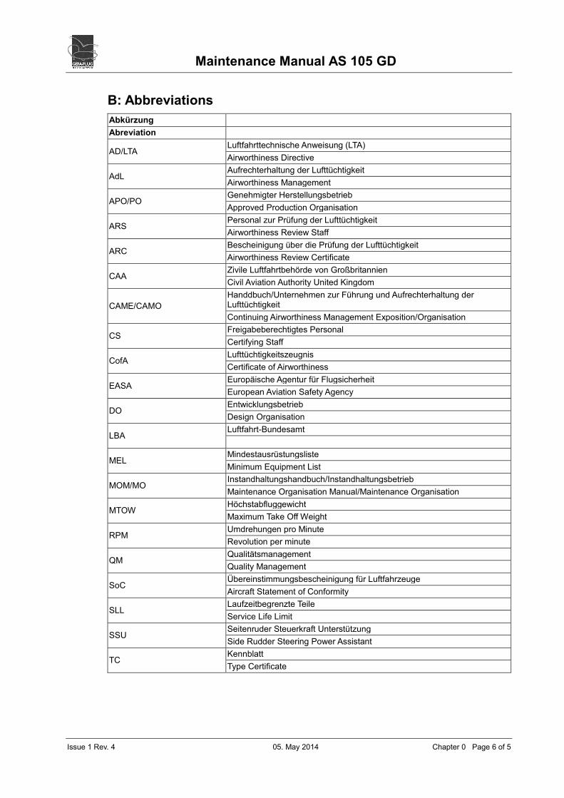
B: Abbreviations
Abkürzung
Abreviation
AD/LTA Luftfahrttechnische Anweisung (LTA)
Airworthiness Directive
AdL Aufrechterhaltung der Lufttüchtigkeit
Airworthiness Management
APO/PO Genehmigter Herstellungsbetrieb
Approved Production Organisation
ARS Personal zur Prüfung der Lufttüchtigkeit
Airworthiness Review Staff
ARC Bescheinigung über die Prüfung der Lufttüchtigkeit
Airworthiness Review Certificate
CAA Zivile Luftfahrtbehörde von Großbritannien
Civil Aviation Authority United Kingdom
CAME/CAMO
Handdbuch/Unternehmen zur Führung und Aufrechterhaltung der Lufttüchtigkeit
Continuing Airworthiness Management Exposition/Organisation
CS Freigabeberechtigtes Personal
Certifying Staff
CofA Lufttüchtigkeitszeugnis
Certificate of Airworthiness
EASA Europäische Agentur für Flugsicherheit
European Aviation Safety Agency
DO Entwicklungsbetrieb
Design Organisation
LBA Luftfahrt-Bundesamt
MEL Mindestausrüstungsliste
Minimum Equipment List
MOM/MO Instandhaltungshandbuch/Instandhaltungsbetrieb
Maintenance Organisation Manual/Maintenance Organisation
MTOW Höchstabfluggewicht
Maximum Take Off Weight
RPM Umdrehungen pro Minute
Revolution per minute
QM Qualitätsmanagement
Quality Management
SoC Übereinstimmungsbescheinigung für Luftfahrzeuge
Aircraft Statement of Conformity
SLL Laufzeitbegrenzte Teile
Service Life Limit
SSU Seitenruder Steuerkraft Unterstützung
Side Rudder Steering Power Assistant
TC Kennblatt
Type Certificate

Maintenance Manual AS 105 GD Chapter 1
Issue 1 Rev. 4 05. May 2014 Page 1 of 5
1 Periodical Inspections and Maintenance (EASA Approved)
The regular scheduled inspections after each 12½ and 25 operational hours (minor
inspections) can be performed by the operator according to the manufacturers’
maintenance program specified in the sections 1.1 and 1.2.
See ROTAX Maintenance Manual for inspection instructions on the engine. The actual
operation time is determinant for all work on the propulsion engine. Inspection
instructions for the propeller are specified in the Helix Maintenance Manual.
For the amount of torsional moments of the different screws please refer to Chapter 5 or
to the manufacturers manuals.
There are two aircraft logbooks; one records envelope hours and the other one engine
hours.
The inspections to be carried out after each 50, 100 and 300 operational hours (major
inspections) are specified in sections 1.3, 1.4, 1.5 and include the checks of the minor
inspections.
The major inspections are to be carried out by the manufacturer or by a certified
maintenance & repair station. The envelope grab test has to be carried out by a qualified
person.
1.1 12½ -Hour-Inspection
Envelope / Fins
• Check envelope, fins and rudder for visible damage
• Check gear belt of Side Rudder Steering Power Assistant (SSU) for signs of wear
(if fitted)
• Steering lines run free and no damage on knots (Overhand double Loop)
Gondola
• The instructions for the inspection of the propulsion engine are specified in the
ROTAX Operating- and/or Maintenance manual
• Check anti-vibration mounts of the engine and the exhaust for security
• Check spark plugs on sediments and electrode gap (0.4 – 0.5 mm)
• Check reduction gearbox oil level
• Check petrol fuel filter for contamination
• Check air filter mounting for security
• Check O-rings of the propane fuel fittings for sealing and lubricate with silicone
grease
• Check propeller for damage
• Check burner function (incl. AutoHeat, if fitted)
• Siderudder Steering Power Assistant (if fitted)
• Propulsion engine for proper function

Maintenance Manual AS 105 GD Chapter 1
Issue 1 Rev. 4 05. May 2014 Page 2 of 5
1.2 25- Hour-Inspection
Envelope / Fins
• Perform 12½ hour inspection as detailed in section 1.1
• Check catenary curtains, rigging lines, rudder lines and eyelets for signs of wear
• Check temperature labels (bow, amidships and stern), the max. permitted
temperature is 127 °C
• Check all Velcro's and locks on the rip panel and fins for correct function
• Check fabric membrane for damage
Gondola
• The instructions for the inspection of the propulsion engine are specified in the
ROTAX Maintenance Manual.
• Perform 12½ -hours-inspection as detailed in section 1.1
• Inspect frame for visible damage
• Check and re-tighten nuts and bolts of the engine mountings
• Check propane hoses for signs of wear
• Check burner mounting for safe fixing and no slackness
• Check function: envelope temperature gauge, variometer and altimeter
• Check tyres for damage and correct pressure
• Check radiator and radiator hoses for leaks
• Check anti-vibration mounts of the engine mountings and the exhaust for security
• Check wires and wire connections
1.3 50-Hour-Inspection / Annual Inspection
Envelope/Fins
• Perform 25-hours-inspection as detailed in section 1.2
• Inspect fabric membrane attachments to the envelope
• Check that rip panel locks close properly
• Check the 4 karabiners of the envelope suspension for closing properly
• Check pressure relief valves for damage and brittleness of bungee cords
• Check all seams and load tapes of the air intake scoop for signs of wear
• Perform grab test of the top area of the envelope and of areas which are notedly
discoloured (ref. 1.3.1)
Gondola
Perform 25-hours-inspection as detailed in section 1.2
Maintenance Manual AS 105 GD Chapter 1
Issue 1 Rev. 4 05. May 2014 Page 3 of 5
A. Engine
The instructions for the inspection of the propulsion engine are specified in the ROTAX
Operating- and/or Maintenance Manual. The most common screwing torques are
specified in Chapter 5.
• Check fasten tight of engine mounting bolts
• Check anti-vibration mounts for signs of wear or damage
• Replace spark plugs
• Check propeller mounting bolts and locking wire
• Check battery connections and wiring for of abrasion or corrosion
• Check function of battery: run electric fan system for about 10 minutes.
• Actuate the engine starter without ignition for 30 seconds. If the battery fails,
inspect and replace if necessary )
B. Electric Pressurisation System
• Check for vibrations
• Check fan blades for damage (cracks)
C. Burner, Propane System and Liquid Pilot Lights
• Check propane cylinders for leaks
• Check burner coils for damage
• Check electronic ignition and pilot lights
• Check and re-tighten the main jets of the burner
• Check pressure gauge
• Check function of solenoid valves
• Check burner for leaks using a leak detecting spray
• Check propane hoses for leaks under operating pressure
• Check liquid pilot light system for proper function; if either of the flames has
become weak, clean the vaporisers and the jets/filters or if appropriate replace
• Replace both 9 Volt batteries situated in housing below the burner plate
D. Petrol System
• Check seal of fuel tank cap
• Check petrol fuel lines and fuel stop for signs of wear and leaks
E. Fire Extinguishers
• Check fire extinguishers for valid maintenance tag

Maintenance Manual AS 105 GD Chapter 1
Issue 1 Rev. 4 05. May 2014 Page 4 of 5
1.3.1 Grab-Test
The envelope fabric is to be fixed between two mounting clamps (2.5 cm /1 inch wide)
parallel to the fibres. The distance between the clamps should be 7.5 cm. The fabric has
to be stretched in the warp and afterwards in the weft direction. The minimum stress
values are given in the chart below. If the envelope fabric resists the minimum stress
values given in the chart below it is airworthy.
Envelope Fabric AS 105 GD/4 AS 105 GD/6
warp 15 kg 23 kg
weft 30 kg 46 kg
If the fabric in the top part of the envelope is made of different colours each of the colours
must be tested (Top means the longitudinal gores between the catenary load tapes
visible from inside and outside the envelope).
Maintenance Manual AS 105 GD Chapter 1
Issue 1 Rev. 4 05. May 2014 Page 5 of 5
1.4 100-Hour-Inspection
• Perform 50-hour inspection as detailed in section 1.3
1.5 300-Hour-Inspection
Envelope
• Perform 50-hour inspection as detailed in section 1.3
Gondola
• Perform 50-hour inspection as detailed in section 1.3
• Overhaul engine and propeller by manufacturer or an authorised workshop
• Check and calibrate flight instruments (envelope pressure gauge, altimeter and
variometer) by an authorised workshop

Maintenance Manual AS 105 GD Chapter 2
Issue 1 Rev. 4 05. May 2013 Page 1 of 3
2 Non-Scheduled Inspections
2.1 Inspection After Overheating Of Envelope
If it is suspected that the temperature limit has been exceeded, the temperature
indicating tags (tempi labels) inside the top of the envelope must be examined bow,
amidship and stern.
These tags have silver coloured “windows” with temperature marks. When the respective
temperature has been reached the windows turn black. These tags register the maximum
temperature that the envelope skin has ever reached.
NOTE: The temperature inside the envelope is always higher than the
indicated temperature on the tags showing the temperature of the envelope
skin.
That means that usually the maximum envelope fabric temperature permitted has not
been reached when the flight instrument indicates so. For the thermal stress of the
envelope, the temperature indicator tags are the relevant reference.
• If one of the tags shows 127°C or above, or if the envelope shows notedly
discoloured fabric parts: perform grab test as detailed in section 1.3.1 and enter
the result in the log book
• Stitch new temperature indicator tag on the envelope next to the existing one
Figure 1: Temperatur Indicator Tags

Maintenance Manual AS 105 GD Chapter 2
Issue 1 Rev. 4 05. May 2014 Page 2 of 2
2.2 Inspection After Suspected Exceeding Of Envelope Pressure Limitations
Envelope pressure above 15 mm H2O (150 Pa) can lead to a dangerous overexpansion
of the fabric. Exceeding of limitations can be caused by one or more of the following
incidents:
• Exceeding the maximum take off weight (MTOW)
• Wrong adjustment of envelope overpressure valves
• Overheating the envelope (too much burning)
• Exceeding max. permitted engine rpm
• Over-pressurisation of the envelope (above 15 mm H2O /150 Pa)
The envelope must be closely examined then for signs of overstress like enlarged stitch
holes or stress marks of the envelope seams and seams covered by load tapes.
The longitudinal sewn-on load tapes (inside and outside the top of the envelope
(Catenary load tapes) are subject to the highest loads and have to be inspected over the
whole length.
If the envelope shows signs of overstressing, perform a grab test as detailed in section
1.3.1.
2.3 Inspection Of The Gondola After A Hard Landing
Depending on the force of the touch-down the gondola may be visibly damaged.
In any case the gondola has to be checked for damages:
• The frame work for cracking paint, visible cracks in the welded seams
• The front and rear gear (tyres, wheels and axes)
• Seats (damages and tears)
• The wooden floor plates in the foot-, cylinder- and battery-compartment
• The propeller and the propeller protection guard (the distance between propeller
and guard at least 2.5 cm)
• Visible tears in the shock mounts of the engine
• Distortion in the burner frame and/or retainers
WARNING: If there is any doubt about findings on the gondola the
manufacturer should be contacted.
Maintenance Manual AS 105 GD Chapter 3
Issue 1 Rev. 4 05. May 2014 Page 1 of 6
3 Repair Instructions
All work carried out on the airship must be entered in the log book and signed by the
person responsible for the work. All repair work on pressurised systems has to be
released to service by CS / ARS for hotair airships. (The change of O-rings is not
classified as a repair.)
WARNING: The manufacturer should be contacted if there is any doubt about
material choice or working procedures.
Any damage which could directly impair the airworthiness of the airship (major repair) or
work on the pressurised gas system has to be repaired or carried out by the manufacturer
or an authorised maintenance and repair workshop. These repairs have to be approved
by CS-Personal or comparable licensed staff for Hotair-Airships.
3.1 Envelope
The envelope is maintained following standard procedures for Hot-Air-Balloons. All
seams are French felled seams and stitched appropriately with a twin needle machine
using a chain stitch 8 mm apart and a stitching length of 6 to 8 stitches per 2.5 cm.
• The thread is a metric 40 polyester continuous filament
• The end of a seam is locked by 2 cm reverse sewing
• Only materials specified by the GEFA-FLUG are to be used for repairs. The
materials are listed in the spare parts catalogue
• The load tapes are to be folded back by 2 cm at the end and to be lock-stitched
to avoid the ends fraying
• Load tape joints have to have a minimum overlapping length of 25 cm
• For replacing loops, pulleys and lines always copy the original attachment
method
WARNING: Any repairs of the envelope have to be done with fabric of the
same specification.
3.1.1 Minor Repairs on Envelope and Fins
The airship is of a non-rigid construction and the envelope is completely pressurised
when in operation. For repairs, the French felled seam is to be used wherever the
manufacturer used it originally. No distortion or creases are permitted as they could
cause the envelope to rip.
Adhesive patches may only be used on the fins because this fabric is polyurethan coated.
The damaged section is to be overlapped by 2.5 cm from all edges and the fabric has to
be cleaned with a fat solvent. The sticky patches are to be used on both sides of the
fabric.
Maintenance Manual AS 105 GD Chapter 3
Issue 1 Rev. 4 05. May 2014 Page 2 of 6
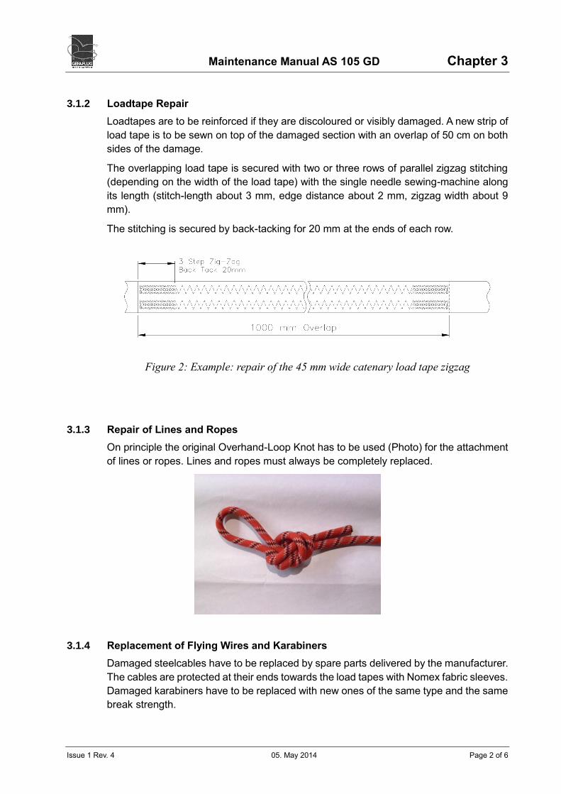
3.1.2 Loadtape Repair
Loadtapes are to be reinforced if they are discoloured or visibly damaged. A new strip of
load tape is to be sewn on top of the damaged section with an overlap of 50 cm on both
sides of the damage.
The overlapping load tape is secured with two or three rows of parallel zigzag stitching
(depending on the width of the load tape) with the single needle sewing-machine along
its length (stitch-length about 3 mm, edge distance about 2 mm, zigzag width about 9
mm).
The stitching is secured by back-tacking for 20 mm at the ends of each row.
3.1.3 Repair of Lines and Ropes
On principle the original Overhand-Loop Knot has to be used (Photo) for the attachment
of lines or ropes. Lines and ropes must always be completely replaced.
3.1.4 Replacement of Flying Wires and Karabiners
Damaged steelcables have to be replaced by spare parts delivered by the manufacturer.
The cables are protected at their ends towards the load tapes with Nomex fabric sleeves.
Damaged karabiners have to be replaced with new ones of the same type and the same
break strength.
Figure 2: Example: repair of the 45 mm wide catenary load tape zigzag
Maintenance Manual AS 105 GD Chapter 3
Issue 1 Rev. 4 05. May 2014 Page 3 of 6
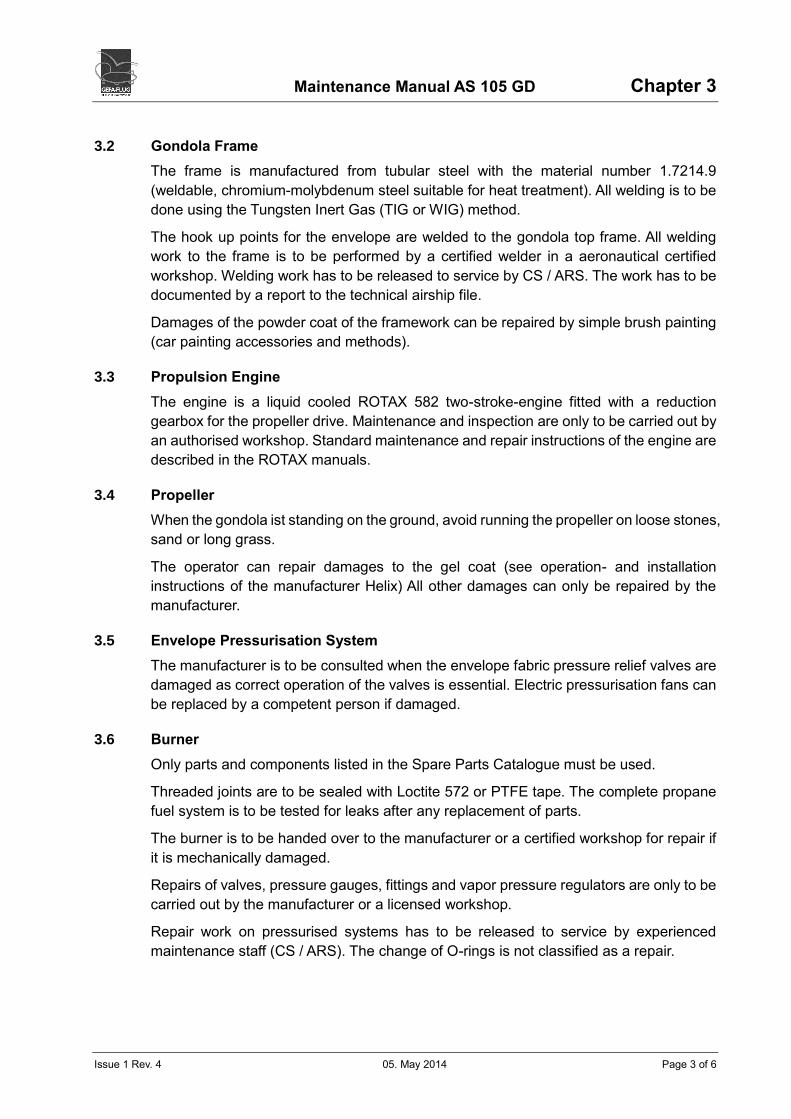
3.2 Gondola Frame
The frame is manufactured from tubular steel with the material number 1.7214.9
(weldable, chromium-molybdenum steel suitable for heat treatment). All welding is to be
done using the Tungsten Inert Gas (TIG or WIG) method.
The hook up points for the envelope are welded to the gondola top frame. All welding
work to the frame is to be performed by a certified welder in a aeronautical certified
workshop. Welding work has to be released to service by CS / ARS. The work has to be
documented by a report to the technical airship file.
Damages of the powder coat of the framework can be repaired by simple brush painting
(car painting accessories and methods).
3.3 Propulsion Engine
The engine is a liquid cooled ROTAX 582 two-stroke-engine fitted with a reduction
gearbox for the propeller drive. Maintenance and inspection are only to be carried out by
an authorised workshop. Standard maintenance and repair instructions of the engine are
described in the ROTAX manuals.
3.4 Propeller
When the gondola ist standing on the ground, avoid running the propeller on loose stones,
sand or long grass.
The operator can repair damages to the gel coat (see operation- and installation
instructions of the manufacturer Helix) All other damages can only be repaired by the
manufacturer.
3.5 Envelope Pressurisation System
The manufacturer is to be consulted when the envelope fabric pressure relief valves are
damaged as correct operation of the valves is essential. Electric pressurisation fans can
be replaced by a competent person if damaged.
3.6 Burner
Only parts and components listed in the Spare Parts Catalogue must be used.
Threaded joints are to be sealed with Loctite 572 or PTFE tape. The complete propane
fuel system is to be tested for leaks after any replacement of parts.
The burner is to be handed over to the manufacturer or a certified workshop for repair if
it is mechanically damaged.
Repairs of valves, pressure gauges, fittings and vapor pressure regulators are only to be
carried out by the manufacturer or a licensed workshop.
Repair work on pressurised systems has to be released to service by experienced
maintenance staff (CS / ARS). The change of O-rings is not classified as a repair.
Maintenance Manual AS 105 GD Chapter 3
Issue 1 Rev. 4 05. May 2014 Page 4 of 6
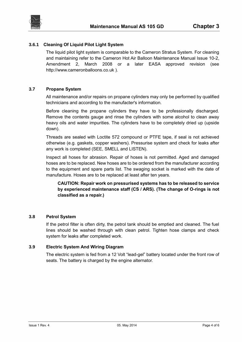
3.6.1 Cleaning Of Liquid Pilot Light System
The liquid pilot light system is comparable to the Cameron Stratus System. For cleaning
and maintaining refer to the Cameron Hot Air Balloon Maintenance Manual Issue 10-2,
Amendment 2, March 2008 or a later EASA approved revision (see
http://www.cameronballoons.co.uk ).
3.7 Propane System
All maintenance and/or repairs on propane cylinders may only be performed by qualified
technicians and according to the manufacter's information.
Before cleaning the propane cylinders they have to be professionally discharged.
Remove the contents gauge and rinse the cylinders with some alcohol to clean away
heavy oils and water impurities. The cylinders have to be completely dried up (upside
down).
Threads are sealed with Loctite 572 compound or PTFE tape, if seal is not achieved
otherwise (e.g. gaskets, copper washers). Pressurise system and check for leaks after
any work is completed (SEE, SMELL and LISTEN).
Inspect all hoses for abrasion. Repair of hoses is not permitted. Aged and damaged
hoses are to be replaced. New hoses are to be ordered from the manufacturer according
to the equipment and spare parts list. The swaging socket is marked with the date of
manufacture. Hoses are to be replaced at least after ten years.
CAUTION: Repair work on pressurised systems has to be released to service
by experienced maintenance staff (CS / ARS). (The change of O-rings is not
classified as a repair.)
3.8 Petrol System
If the petrol filter is often dirty, the petrol tank should be emptied and cleaned. The fuel
lines should be washed through with clean petrol. Tighten hose clamps and check
system for leaks after completed work.
3.9 Electric System And Wiring Diagram
The electric system is fed from a 12 Volt “lead-gel” battery located under the front row of
seats. The battery is charged by the engine alternator.

Maintenance Manual AS 105 GD Chapter 3
Issue 1 Rev. 4 05. May 2014 Page 5 of 6
The following components consume electricity from the starter battery:
• Pressurisation fan system
• Solenoid blast valves
• Electronic pilot light ignition
• Starter motor (propulsion engine)
• VHF Radio
• Transponder (if fitted)
• Altimeter
• Variometer
• Envelope temperature gauge
• Engine temperature gauge
• Engine revolution counter
• Petrol fuel tank contents gauge
• Petrol fuel pump
• Side Rudder Steering Power Assistant (SSU) (if fitted)
• AutoHeat (if fitted)
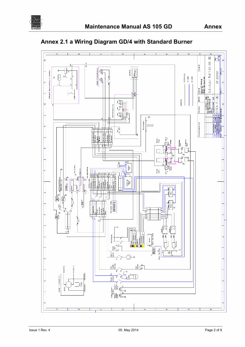
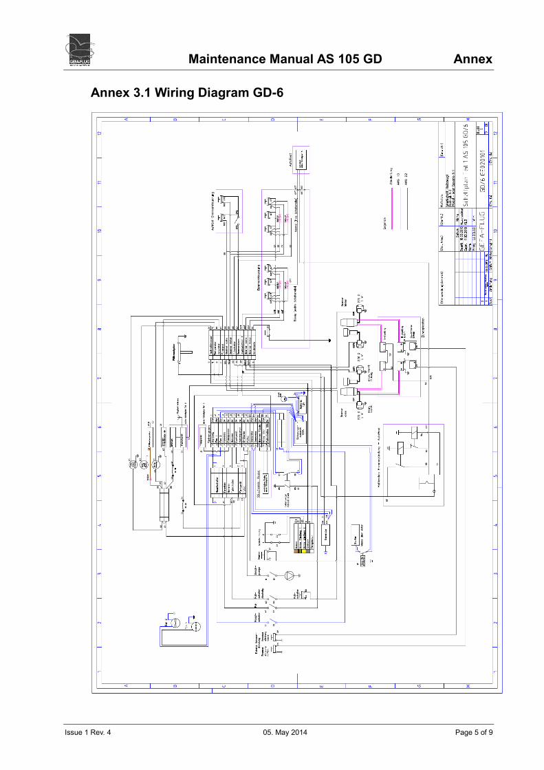
The wiring diagrams of the version AS 105 GD/4 are included in Annex 2.1 – 2.2. The
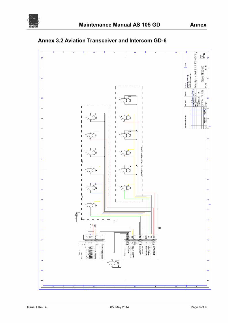
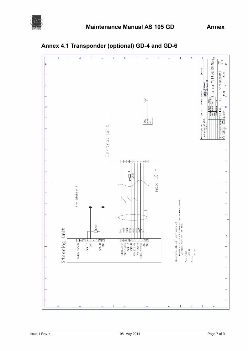
wiring diagrams of the version AS 105 GD/6 are included in Annex 3.1 – 3.2. Annex 4.1
shows the transponder installation of the GD/4 and GD/6.The diagram of the Side
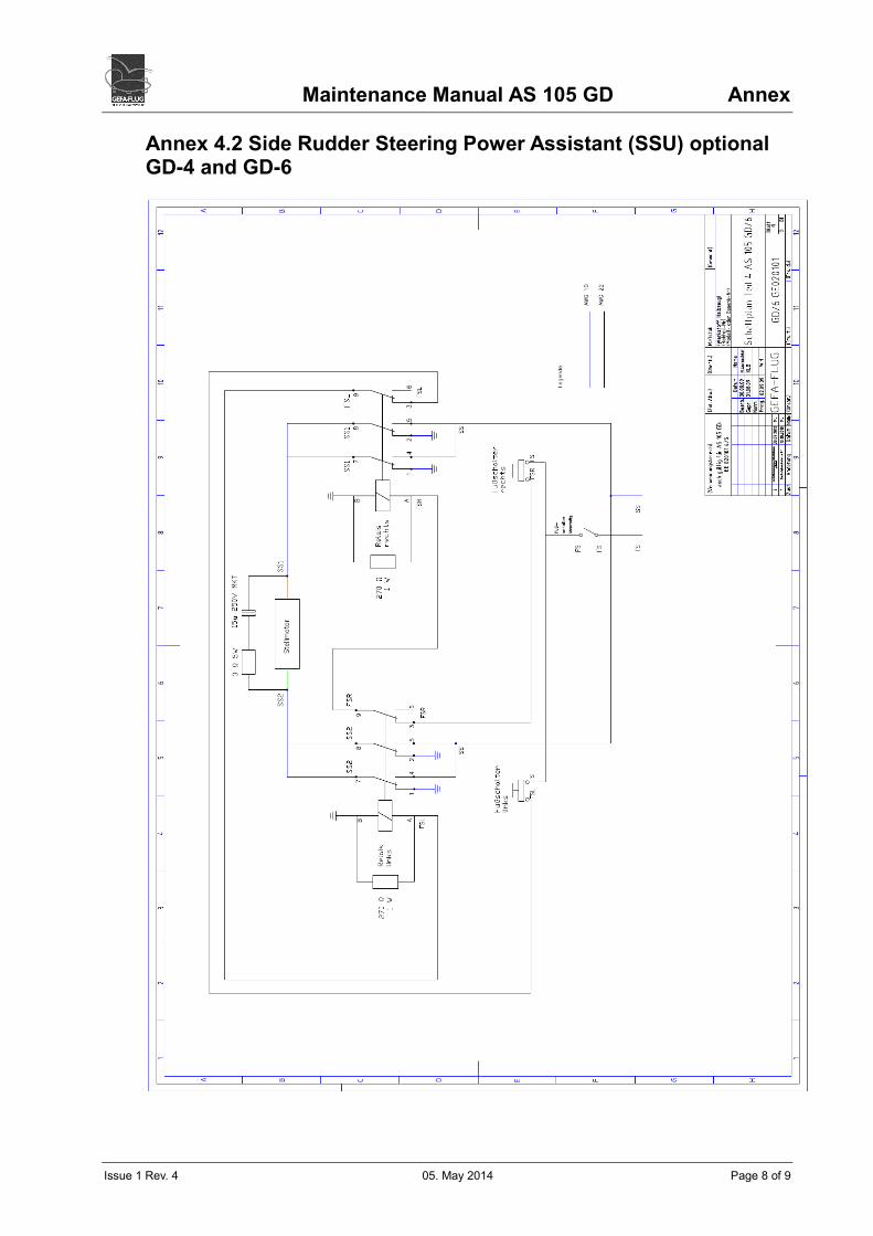
Rudder Steering Power Assistant (SSU) is included in Annex 4.2 (if fitted), the diagram
of the AutoHeat (if fitted) in Annex 4.3.
Maintenance Manual AS 105 GD Chapter 3
Issue 1 Rev. 4 05. May 2014 Page 6 of 6
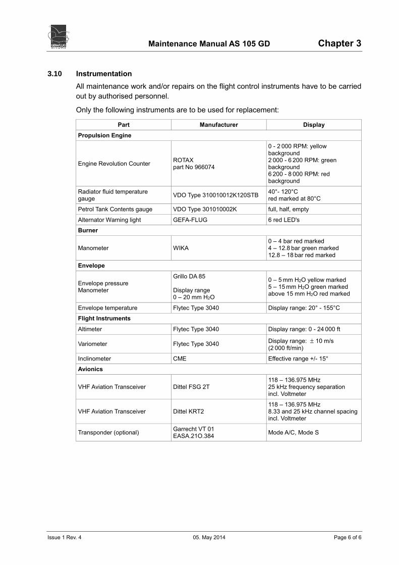
3.10 Instrumentation
All maintenance work and/or repairs on the flight control instruments have to be carried
out by authorised personnel.
Only the following instruments are to be used for replacement:
Part Manufacturer Display
Propulsion Engine
Engine Revolution Counter ROTAX part No 966074
0 - 2 000 RPM: yellow background 2 000 - 6 200 RPM: green background 6 200 - 8 000 RPM: red background
Radiator fluid temperature gauge
VDO Type 310010012K120STB 40°- 120°C red marked at 80°C
Petrol Tank Contents gauge VDO Type 301010002K full, half, empty
Alternator Warning light GEFA-FLUG 6 red LED's
Burner
Manometer WIKA 0 – 4 bar red marked 4 – 12.8 bar green marked 12.8 – 18 bar red marked
Envelope
Envelope pressure Manometer
Grillo DA 85 Display range 0 – 20 mm H2O
0 – 5 mm H2O yellow marked 5 – 15 mm H2O green marked above 15 mm H2O red marked
Envelope temperature Flytec Type 3040 Display range: 20° - 155°C
Flight Instruments
Altimeter Flytec Type 3040 Display range: 0 - 24 000 ft
Variometer Flytec Type 3040 Display range: 10 m/s
(2 000 ft/min)
Inclinometer CME Effective range +/- 15°
Avionics
VHF Aviation Transceiver Dittel FSG 2T 118 – 136.975 MHz 25 kHz frequency separation incl. Voltmeter
VHF Aviation Transceiver Dittel KRT2 118 – 136.975 MHz 8.33 and 25 kHz channel spacing incl. Voltmeter
Transponder (optional) Garrecht VT 01 EASA.21O.384
Mode A/C, Mode S
Maintenance Manual AS 105 GD Chapter 4
Issue 1 Rev. 4 05. May 2014 Page 1 of 1
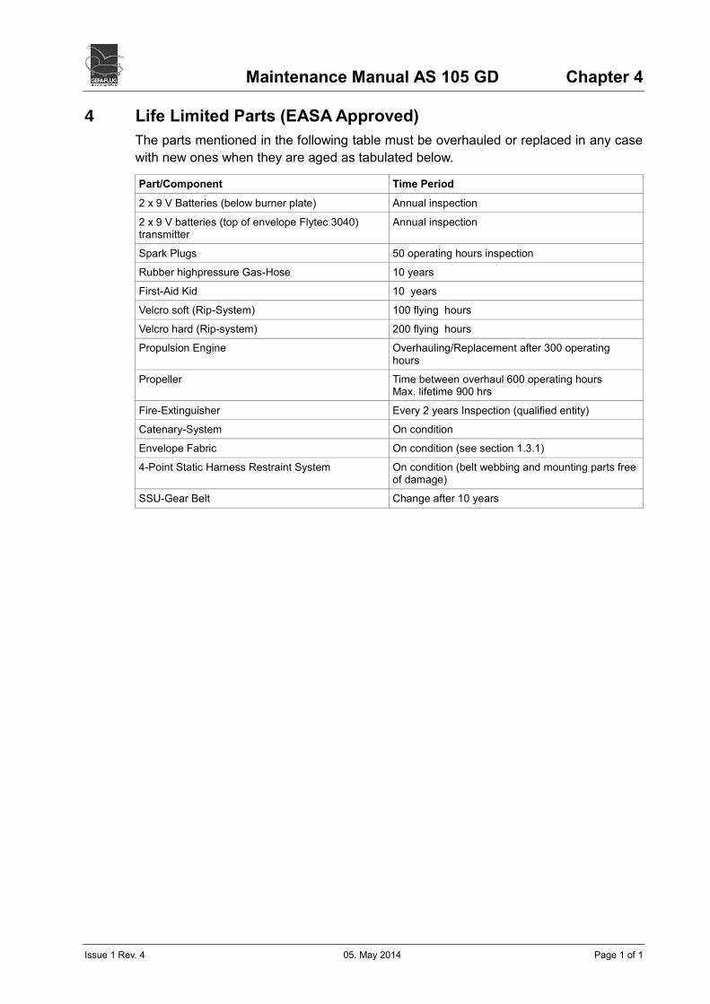
4 Life Limited Parts (EASA Approved)
The parts mentioned in the following table must be overhauled or replaced in any case
with new ones when they are aged as tabulated below.
Part/Component Time Period
2 x 9 V Batteries (below burner plate) Annual inspection
2 x 9 V batteries (top of envelope Flytec 3040) transmitter
Annual inspection
Spark Plugs 50 operating hours inspection
Rubber highpressure Gas-Hose 10 years
First-Aid Kid 10 years
Velcro soft (Rip-System) 100 flying hours
Velcro hard (Rip-system) 200 flying hours
Propulsion Engine Overhauling/Replacement after 300 operating hours
Propeller Time between overhaul 600 operating hours Max. lifetime 900 hrs
Fire-Extinguisher Every 2 years Inspection (qualified entity)
Catenary-System On condition
Envelope Fabric On condition (see section 1.3.1)
4-Point Static Harness Restraint System On condition (belt webbing and mounting parts free of damage)
SSU-Gear Belt Change after 10 years

Maintenance Manual AS 105 GD Chapter 5
Issue 1 Rev. 4 05. May 2014 Page 1 of 1
5 Torque Specifications
The most common screwing torques are specified in this table. For other torque
specifications refer to the manufacturers manuals.
Component Size Torque Nm
GD/4 GD/6
Rear Axle M 10 45 45
Front Axle M 6 45 12
Bottom and Top Clamp M 6 n.a. 10
Engine Strut M 6 12 12
Engine Bolts M 10 38 38
Bracket for Shockmount M 10 45 45
Contact shock mount – frame M 7 12 12
Sparkplugs (cold engine, thread greased) Elektrode Distance 0,4 – 0,5 mm
n.a. 27 27
Exhaust System M 8 24 24
Propeller Driving Pulley M 8 25 25
Main Burner Jets (thread greased) n.a. 16 16
Pilot Light Jets hand-tight

Maintenance Manual AS 105 GD Annex
Issue 1 Rev. 4 05. May 2014 Page 1 of 9
Intentionally Left Free!
Maintenance Manual AS 105 GD Annex
Issue 1 Rev. 4 05. May 2014 Page 2 of 9
Annex 2.1 a Wiring Diagram GD/4 with Standard Burner

Maintenance Manual AS 105 GD Annex
Issue 1 Rev. 4 05. May 2014 Page 3 of 9
Annex 2.1 b Wiring Diagram GD/4 with Burner „Liquid Fire“

Maintenance Manual AS 105 GD Annex
Issue 1 Rev. 4 05. May 2014 Page 4 of 9
Annex 2.2 Aviation Transceiver and Intercom GD-4
Maintenance Manual AS 105 GD Annex
Issue 1 Rev. 4 05. May 2014 Page 5 of 9
Annex 3.1 Wiring Diagram GD-6
Maintenance Manual AS 105 GD Annex
Issue 1 Rev. 4 05. May 2014 Page 6 of 9
Annex 3.2 Aviation Transceiver and Intercom GD-6
Maintenance Manual AS 105 GD Annex
Issue 1 Rev. 4 05. May 2014 Page 7 of 9
Annex 4.1 Transponder (optional) GD-4 and GD-6
Maintenance Manual AS 105 GD Annex
Issue 1 Rev. 4 05. May 2014 Page 8 of 9
Annex 4.2 Side Rudder Steering Power Assistant (SSU) optional GD-4 and GD-6

Maintenance Manual AS 105 GD Annex
Issue 1 Rev. 4 05. May 2014 Page 9 of 9
Annex 4.3 Burntime Sequencer „AutoHeat“ (optional) GD-4 and GD-6