OPERATOR'S MANUAL MAINTENANCE AND ENGINE...
184
OPERATOR'S MANUAL MAINTENANCE AND ENGINE VN, VHD New Roads. TM
Transcript of OPERATOR'S MANUAL MAINTENANCE AND ENGINE...

OPERATOR'S MANUALMAINTENANCE AND ENGINE
VN, VHD
New Roads.TM

ForewordThis manual contains information concerning the safe operation of yourvehicle. It is extremely important that this information is read andunderstood before the vehicle is operated. This manual also containsa considerable amount of information concerning the vehicle, such asvehicle identification, Preventive Maintenance recommendations and alog for your service records. Please keep this in the vehicle at all times.Information from other component manufacturers is supplied in separatemanuals in the Owner’s Package.
Note: It is important that this manual stays with the vehicle when itis sold. Important safety information must be passed on to the newcustomer. The service information contained in this manual gives theowner important information about maintaining the vehicle but is notintended as a substitute for the Preventive Maintenance Service Manualand must not be regarded as such.
The National Highway Traffic Safety Administration (NHTSA) andVolvo Trucks North America, Inc. should be informed immediately ifyou believe that the vehicle has a defect that could cause a crash, injuryor death.
Contact NHTSA by calling the Auto Safety Hotline at 1 (888) 327–4236or by writing to: NHTSA, U.S. Department of Transportation,Washington, DC 20590.
Volvo Trucks North America, Inc.Greensboro, NC USA
Order number: PV776-20707967
© 2004 Volvo Trucks North America, Inc., Greensboro, NC USA
All rights reserved. No part of this publication may be reproduced,stored in retrieval system, or transmitted in any forms by any means,electronic, mechanical, photocopying, recording or otherwise, withoutthe prior written permission of Volvo Trucks North America, Inc..

ContentsGeneral Information .............................. 1
Information For the Owner .................... 1
Safety Information ................................. 3Proper Maintenance Procedure ............. 3Injury Prevention ................................... 6Engine Damage Prevention ................. 15Electric System Damage Prevention ... 17Reporting Safety Defects ..................... 19Speed Restrictive Tires ........................ 20
General Engine Design Information .. 21Engine Overview, VN D12D (VolvoV-Pulse)Right Hand View ................... 21Engine Overview, VN D12D (VolvoV-Pulse)Left Hand View ..................... 22Engine Overview, VHD D12D(Volvo V-Pulse)Right Hand View ....... 23Engine Overview, VHD D12D(Volvo V-Pulse)Left Hand View ......... 24Engine Features ................................... 25Engine Features Continued ................. 26VECTRO III Customer ParameterValues, D12D ....................................... 27Engine Variants, D12D ........................ 30Engine Data ......................................... 32
Engine Storage ..................................... 33Engine Storage .................................... 33
Cooling System ..................................... 35General Coolant Information ............... 35Water Specification .............................. 42Additives .............................................. 43Antifreeze ............................................ 44
Fuel System ........................................... 52
Fuel Safety Reminders ........................ 52Diesel Fuel Specification ..................... 53Fuel Additives ..................................... 57Alternative Fuels ................................. 59
Oil System ............................................. 60Engine Oil ............................................ 60
Service Schedules VN, VHD ............... 68............................................................. 68
Maintenance ......................................... 73Exhaust and Noise Emissions .............. 73Flushing Cooling System, D12D ......... 96Turbo and Charge Air Cooler .............. 98Replacing Fuel Filters ....................... 100Fuel System Service .......................... 101Transmission and Rear AxleMaintenance ...................................... 108Steering and Brakes Maintenance ..... 112Electrical System Maintenance ......... 120Tires, Wheels and Hub Maintenance . 126Chassis Maintenance ......................... 131Cab Maintenance ............................... 133Lubrication VN, VHD ....................... 139Viscosity and Capacity Tables ........... 142
Literature ............................................ 147Service Assistance and Manuals ....... 147
Service Charts .................................... 149Scheduled Services ............................ 149Repair Record .................................... 152Tire Record ........................................ 157Fuel and Oil Record .......................... 168
Index .................................................... 177

Warning Label InformationIMPORTANT
Before driving this vehicle, be certain that you have read and thatyou fully understand each and every step of the driving and handlinginformation in this Operator’s Manual. Be certain that you fullyunderstand and follow all safety warnings.
IT IS IMPORTANT THAT THEFOLLOWING INFORMATIONCONCERNING LABELS IS READ,UNDERSTOOD AND ALWAYSFOLLOWED.
The following types of labels are usedthroughout this manual:
Note: A note defines an operating procedure,practice, condition, etc., which is essential tothe proper operation of the vehicle.
DANGER
A danger label directs the operator’sattention to unsafe practices which couldresult in serious personal injury or death.The danger label is in white type on ablack background with a black border.
WARNING
A warning label directs the operator’sattention to unsafe practices which couldresult in personal injury or severe damageto the vehicle. The warning label is inblack type on a gray background with ablack border.
CAUTION
A caution label directs the operator’sattention to unsafe practices wherepersonal injury is not likely but propertydamage could occur. The caution label isin black type on a white background witha black border.

General Information 1
Information For the OwnerIf there are questions on the maintenance andperformance of your vehicle, please discussthem with your Volvo Truck dealer. Yourauthorized dealer is required to have trainedmechanics, special tools and spare partsto fully service your vehicle. If necessary,your dealer will contact Volvo Trucks NorthAmerica or other manufacturers for anyassistance.
In addition to this Maintenance Manual, theremay be additional instruction/operator’smanuals supplied by componentmanufacturers. These manuals areplaced in the Owner’s Package and placedin the cab. Be sure to read all the manualsthoroughly before operating the vehicle.
Also, various safety labels may be placed oncomponents by the component manufacturer.Be sure to read and follow these labels toprevent damage to the vehicle, personalinjury or even death.
Information in this manual refers to Volvocomponents and Volvo drivetrain. Thereis also certain information regarding theCummins engine. For detailed informationon the Cummins engine or non-Volvoengines and/or drivetrains contact therespective manufacturer.
Establish a Preventive Maintenance Programwith the help of your local Volvo Truckdealer. A Preventive Maintenance Programmakes it possible to maximize the amount oftime your vehicle is up and running, resultingin longer component life. This makes for asafer vehicle by reducing any mechanicalfailures due to poor maintenance practices.
Note: Federal law requires manufacturers tonotify owners of its products in the event of aFederal Motor Vehicle Safety Standard or if asafety related defect is discovered. If you arenot the original owner of this vehicle, pleasenotify us about the change in ownership atthe address below or through an authorizedVolvo Truck dealer. This is the only way wewill be able to contact you if necessary.
Volvo Trucks North America, Inc.
P. O. Box 26115
Greensboro, NC 27402–6115
United States of America

2 General Information
DO NOT Remove this manual from thevehicle. It contains important operationaland safety information that is needed by alldrivers and owners of this vehicle.
This Maintenance Manual covers allVolvo vehicles manufactured by VolvoTrucks North America, Inc., including thewhole chassis and all Volvo manufacturedcomponents. For specific maintenanceinformation on vendor components,manufactured by, for example: Cummins,Fuller, Meritor, etc., see the respectivemanufacturer’s service and maintenanceliterature.
This manual, together with manualsfor specific components (for example,Volvo engine, Cummins engine, Eatontransmission, etc.,) contain importantinformation to be able to operate this vehiclesafely. They contain advice and instructionswhich will enable you to get the operatingeconomy and performance that you expectfrom this quality vehicle.
All information, illustrations andspecifications contained in this manual arebased upon the latest product informationavailable at the time of publication. If anyquestions arise concerning the current statusof Federal or state laws, the appropriateFederal or state agency should be contacted.
Note: Illustrations are used for referenceonly and may differ slightly from theactual vehicle, however, key componentsaddressed in this manual are representedas accurately as possible.
Volvo Trucks North America, Inc. reservesthe right to make changes at any time orto change specifications or design withoutnotice and without incurring obligation.
Safety Information 3
Proper Maintenance ProcedureDuring MaintenanceWhenever performing maintenance or repair,attach a DO NOT OPERATE or similarwarning label or sign to the ignition key ormake sure the label or sign is prominentlydisplayed on the instrument panel.
DO NOT allow unauthorized personnelon, around or in the vehicle whenmaintenance or repair is being performed.
WARNING
DO NOT attempt to repair or service thisvehicle without having sufficient training,correct service literature and the propertools. Failure to follow this could lead topersonal injury or making your vehicleunsafe.
WARNING
Diesel engine exhaust and some of itsconstituents are known to the state ofCalifornia to cause cancer, birth defectsand other reproductive harm.
• When operating the engine in anenclosed area, vent the exhaust to theoutside.
DANGER
Exhaust gases contain carbon monoxide.Always run the engine outdoors or use aproperly vented exhaust hose. Prolongedor excessive exposure may cause seriousillness or death.
• Before servicing your vehicle, applythe parking brakes and adequatelychock the wheels in order to preventunintended vehicle movement. If theservice procedure requires the parkingbrakes to be released — recheck toensure that the wheels are adequatelychocked to prevent any forward and/orrearward movement.
DANGER
Before working on a vehicle, set theparking brakes, place the transmission inneutral, and block the wheels. Failure todo so can result in unexpected vehiclemovement and can cause serious personalinjury or death.
• DO NOT use combustible substancesin or around the engine either duringrepair or maintenance or when runningthe engine.
DANGER
Never operate the engine in an areawhere hydrocarbon vapors (gasoline, forexample) are present or are suspected tobe present. Hydrocarbon vapors can enterthe air intake and over speed the engine,causing severe engine damage and/oran explosion and fire. Serious personalinjury or death could occur.

4 Safety Information
• DO NOT wear loose clothing or jewelrythat can catch or get snagged by partsor moving components on the engine.Also wear all protective equipmentrequired by the job conditions, such asprotective glasses, hearing protection,etc.
• Make certain that all protective coversand guards are in place and secured.
• Never put maintenance fluids into glasscontainers since glass containers canbreak.
• Report all problems in a timely mannerbefore they threaten the safety ofoperating the vehicle.
• DO NOT work on the engine while itis running.
• Make sure protective locks and coversare in their proper place.
• DO NOT use high amperage electronicstarting devices for jump-starting theengine. Rely on conventional batterycharging for charging the batteriesor jump-start with the help of a startbattery.
• DO NOT attempt repairs you do notunderstand or have the proper tools for.
• When starting an engine after repairshave been made to the fuel or injectionsystem, prepare equipment for shuttingoff the engine intake air and/or fuelsupply (to stop the engine), in case thereis an over speed on start-up.
• Start the engine only from the driverseat. Never operate the starter motoracross the starter terminals or thebatteries as this could Bypass the engineneutral-start system as well as causingdamage to the electrical or electronicsystems.
DANGER
Never try to operate or work on thisvehicle while under the influence ofalcohol. Your reflexes can be affected byeven a small amount of alcohol. Drinkingand operating this vehicle can lead to anaccident, causing serious personal injuryor death.

Safety Information 5
Compressed Air and Water
DANGER
Compressed air can cause personal injury.When using compressed air for cleaning,wear a protective face shield, protectiveclothing and protective shoes. Pressurizedwater could cause particles and/or hotwater to be sprayed in your direction andcause personal injury. The maximum airpressure must be below 30 psi (200 kPa)for cleaning purposes.
Asbestos InformationNote: The Volvo engine and replacementparts for it shipped from the factory areasbestos free. Volvo recommends the use ofonly genuine Volvo spare parts.Never use any parts that contain or arethought to contain asbestos. Exposure toasbestos fibers can create serious healthrisks, including death.
Fluid Penetration
DANGER
Always use a piece of paper or cardboardwhen checking for a leak. Escaping fluidunder high pressure, even a pin-hole sizedleak, can penetrate body tissue, causingserious injury or death. If fluid is injectedinto your skin, immediate treatment mustbe administered by a doctor familiar withthis type of injury.

6 Safety Information
Injury PreventionBurn Prevention
Engine Parts
WARNING
Hot engine. Keep yourself clear of all hotengine parts and/or fluids. A hot engineand/or fluid can cause serious burns.
DO NOT touch any part of the engine whileit is hot. Allow the engine to cool before anyrepair or maintenance is performed on theengine.
WARNING
DO NOT raise the engine hood or cab ifyou see or hear steam or coolant escapingfrom the engine compartment. Wait untilsteam or coolant cannot be seen or heardany longer before raising the hood or cab.DO NOT remove the coolant fill cap ifthe coolant in the surge tank is boiling.Also, do not remove the cap while theengine and radiator are still hot. Scaldingfluid and steam may be blown out underpressure if the cap is taken off too soon.
Relieve all pressure in air, oil, fuel or coolingsystems before any lines, fittings or relateditems are disconnected or removed.
W0001525

Safety Information 7
CoolantTo prevent personal injury, do not climbup on the engine to remove the filler cap.Use a suitable, properly positioned ladderto reach up to the cap. At normal operatingtemperature, the engine coolant is very hotand under pressure. If pressure is relievedrapidly in a hot cooling system, the hotcoolant can turn into steam. Any contactwith hot coolant or steam can cause severeburns. The radiator and all heating systemand radiator lines and hoses contain hotcoolant.
WARNING
Coolant may be combustible. Coolantleaked or spilled onto hot surfaces orelectrical components can cause a fire.Clean up coolant spills immediately.
Verify coolant level only by the markings onthe expansion tank. Open the filler cap onlyafter the engine is stopped and cooled down.Remove the filler cap slowly to relievepressure.
W0001527

8 Safety Information
Oils
WARNING
Hot engine. Keep yourself clear of all hotengine parts and/or fluids. A hot engineand/or fluid can cause serious burns.
Hot oil can cause severe burns. DO NOTallow hot oil to contact the skin. Whenchanging oil, wear protective gloves.
Batteries
WARNING
Always wear eye protection whenworking around batteries to prevent therisk of injury due to contact with sulfuricacid or an explosion.
WARNING
Battery posts, terminals and relatedaccessories contain lead and leadcompounds, chemicals known to theState of California to cause cancer andreproductive harm. Wash hands afterhandling.
Battery electrolyte contains acid and cancause injury. Avoid contact with the skinand eyes. Wash hands after touchingbatteries and connectors. Use of glovesis recommended. Always wear protectiveglasses when working with batteries.

Safety Information 9
Fire or Explosion Prevention
DANGER
The diesel engine will operate on any fuelwhich enters the cylinder, whether it isfrom the injectors or from the air intakesystem. Therefore, if any solvent is usedto flush out the air cleaner element, theengine may over speed during start-up.Engine damage and severe injury and/ordeath from burns or explosion can occur.
The engine should not be operated in an areawhere combustible gases are suspected tobe in the air. These could be drawn into theengine through the engine air intake systemand could cause the engine to over speedwith possible serious damage to the engineand bodily injury or property damage.
W0001526
DANGER
Excessive heat may cause the pressurizedcomponents of the air conditioned systemto explode. Never weld, solder, steamclean or use a gas torch near any part ofthe air conditioning system. Severe injuryor death may occur from an explosion.
DO NOT pressure or leak test R134arefrigerant for air conditioning or servicingequipment using compressed air. Somemixtures of air and R134a refrigeranthave proven to be combustible at elevatedpressures. These mixtures, if ignited, cancause injury or property damage. Consult theR134a Material Safety Data Sheet (MSDS)for additional information.

10 Safety Information
DANGER
DO NOT service any part of the fuelsystem while smoking or in the presenceof flames, sparks or hot surfaces. Failureto follow these precautions can result infire, which can cause serious injury ordeath.
All fuels, most lubricants and some coolantmixtures are flammable. Diesel fuel isflammable. Gasoline is flammable. Themixture of diesel and gasoline fumes isextremely explosive. DO NOT smoke whilerefueling or when in a refueling area.
WARNING
DO NOT store fuel containers in thevehicle. They may leak, explode andcause or feed a fire. Empty or full, theypresent a hazard that may lead to burns inthe event of a fire.
Keep all fuels and lubricants stored inproperly marked containers and away fromall unauthorized personnel. Store oily ragsor other flammable material in a protectivecontainer, in a safe place.
Remove all flammable material such asfuel, oil and other substances before theyaccumulate on the engine.
DO NOT expose the engine to flames,driving over burning ground, etc., if at allpossible.
DO NOT weld or flame cut on or aroundpipes or tubes that contain flammable fluids.
W0001527

Safety Information 11
Exhaust heat shields may be installed toprotect oil or fuel carrying lines and pipesfrom hot exhaust parts. To protect from pipeor seal failure, install heat shields correctly.
Provide adequate and proper waste oildisposal. Always dispose of waste liquidsaccording to Federal and local regulations.Oil and fuel filters should be properlyinstalled and housing covers tightened to theproper torque when being changed.
Starting Aids
DANGER
DO NOT use ether or other combustiblestarting aids on any Volvo engine. TheVolvo engine is equipped with a preheater,introduction of ether or similar startingaids could cause a fire or explosionresulting in severe property damage,serious personal injury or death.
DO NOT use ether or other combustiblestarting aids on engines that have a heaterelement or other heating devices installedin the intake manifold for heating intakeair at cold-starts.
W0001484
Fire ExtinguisherAnytime work is being done to the fuelsystem or any other area where flammablesubstances are being used, have a fireextinguisher available and know how touse it. Inspect and have it serviced asrecommended on its instruction label.

12 Safety Information
Respiratory Hazard Prevention
DANGER
Exhaust gases contain carbon monoxide.Always run the engine outdoors or use aproperly vented exhaust hose. Prolongedor excessive exposure may cause seriousillness or death.
WARNING
Diesel engine exhaust and some of itsconstituents are known to the state ofCalifornia to cause cancer, birth defectsand other reproductive harm.
Always work in a well ventilated space if theengine needs to be running and use a hose toroute the exhaust to the outside.
W0001523
Poisonous Substances
DANGER
Coolant is toxic; risk of poisoning.DO NOT drink coolant. Use proper handprotection when handling. Keep coolantout of reach of children and animals.Failure to follow these precautions cancause serious illness or death.
Cooling system supplemental additivecontains alkali. To prevent personal injury,avoid contact with the skin and eyes.
DO NOT drink coolant of any concentration.

Safety Information 13
Crushing or Cutting Prevention
DANGER
Before working on a vehicle, set theparking brakes, place the transmission inneutral and block the wheels. Failure todo so can result in unexpected vehiclemovement and can cause serious personalinjury or death.
WARNING
DO NOT work near the fan with theengine running or the ignition in the ONposition. The engine fan can engage atany time without warning. Anyone nearthe fan when it turns on could be seriouslyinjured.
Support equipment and components properlywhen working beneath them. Never attemptadjustments while the engine is runningunless otherwise specified for the serviceprocedure. To help prevent an accidentcaused by moving parts, work carefullyaround them. Guards, covers and shieldsshould be in place whenever maintenanceis not being performed. Keep objects awayfrom moving fan blades. They will throw orcut any object or tool that falls or is pushedinto them.
Inspect the fan blade assembly before servicefor cracks or loose mounting before startingthe engine. Never stand alongside a rotatingfan assembly, particularly at high fan speeds.
W0001524

14 Safety Information
Wear protective glasses when striking objectsto avoid injury to your eyes. Chips or otherdebris can fly off objects that are struck.Make sure no one can be injured by flyingdebris before striking any object.
W0001528
Climbing Up and Down
DANGER
Always have three limbs (one foot and twohands or two feet and one hand) in contactwith the vehicle at all times when enteringor exiting the cab or the area behind thecab. Failure to follow this warning canresult in serious personal injury or death.
DO NOT climb up on or jump off from theengine or stand on components that cannotsupport your weight. Use an adequate ladderor scaffolding, suitably situated.
DO NOT use top of engine or cowling ledgeas foothold when reaching on top of cab.Clean steps, handholds and areas of thevehicle you will be working on or around.Refer to the Operator’s Manual for properentry and exit procedures.
Always use a three-point stance (twohands and one foot or one hand and twofeet) whenever climbing up or down.
Safety Information 15
Engine Damage PreventionBefore Starting the Engine
DANGER
Before working on a vehicle, set theparking brakes, place the transmission inneutral and block the wheels. Failure todo so can result in unexpected vehiclemovement and can cause serious personalinjury or death.
Inspect engine for potential hazards. Makesure all protective guards and covers areproperly installed if an engine needs to bestarted to make adjustments or checks. Tohelp prevent an accident by moving parts,work carefully around them.
DO NOT disable or bypass automaticalarm/shutoff circuits. They are provided toprevent personal injury and engine damage.
DANGER
The diesel engine will operate on any fuelwhich enters the cylinder, whether it isfrom the injectors or from the air intakesystem. Therefore, if any solvent is usedto flush out the air cleaner element, theengine may over speed during start-up.Engine damage and severe injury and/ordeath from burns or explosion can occur.
Make provisions for shutting off the engineintake air or fuel supply to stop the engineif there is an over speed on start-up afterperforming repair or maintenance on it.
Always consult the proper Volvo ServiceManual before any repair is attempted.

16 Safety Information
Engine StartingDO NOT start the engine or move any ofthe controls or disengage the parking brakeif the warning tag “DO NOT OPERATE” isattached to the ignition key or located on thedash. Check with the person who attachedthe tag before starting.
Make sure no one is working on or closeto the engine or components driven by theengine before starting it. Always make aninspection of the engine before and afterstarting.
Diesel engine exhaust contains productsof combustion which may be harmful toyour health. Always start and operate theengine in a well-ventilated area, and if in anenclosed area, vent the exhaust to the outside.
Start the engine only from the driver seat inthe cab. Never start the engine by shortingacross the starter motor terminals or batteriesto start the engine as this could bypass theengine neutral-start system as well as damagethe electrical and electronic system. Alwaysstart the engine according to the requiredengine starting procedure described in thisoperator’s manual to prevent major enginecomponent damage and personal injury.
Starting Aids
DANGER
DO NOT use ether or other combustiblestarting aids on any Volvo engine. TheVolvo engine is equipped with a preheater,introduction of ether or similar startingaids could cause a fire or explosionresulting in severe property damage,serious personal injury or death.
W0001484
Safety Information 17
Electric System Damage PreventionElectric and Electronic SystemsNever disconnect any charging unit circuitor battery circuit cable from the batterywhen the charging unit is operating. A sparkcan cause the flammable vapor mixture ofhydrogen and oxygen to explode.
To prevent potential sparks from ignitingcombustible gases produced by somebatteries, attach the negative (—) terminallast when hooking up and remove thenegative terminal first after the engine hasstarted. Check regularly around the engineand engine compartment for loose or frayedwires. Have all loose or frayed electricalwires tightened, repaired or replaced beforeoperating the vehicle.
W0001526
WARNING
Always wear eye protection whenworking around batteries to prevent therisk of injury due to contact with sulfuricacid or an explosion.
Grounding PracticesProper grounding for vehicle and engineelectrical and electronic systems is necessaryfor proper vehicle and engine performanceand reliability. Improper grounding willresult in uncontrolled and unreliableelectrical paths.
Uncontrolled engine electrical circuit pathscan result in damage to main bearings,crankshaft journals surfaces and aluminumcomponents. Uncontrolled electrical circuitpaths can also cause electrical noise whichmay degrade vehicle and radio performance.
Operating engines without theengine-to-frame ground strap installedcan cause damage to the engine. To preventelectrical discharge damage, check to makesure the engine’s electrical system has anengine-to-frame ground strap. All groundconnections should be tight and free ofcorrosion.
18 Safety Information
Electronic Engine Control SystemTampering with the electronic systeminstallation can be dangerous and couldresult in personal injury or death and/orengine damage. It is very important to takethe proper precautions with the electricaland electronic system when charging thebatteries, jump-starting or performingelectric welding on the vehicle. See thevehicle Operator’s Manual for correctprocedures.
DANGER
The Volvo D12D engine uses high voltageto the electronic unit injectors.DO NOT come in contact with the unitinjector terminals while the engine isrunning. An electric shock can causean involuntary muscle spasm and causebalance loss and falls leading to severepersonal injury or death.
This engine is equipped with monitoringfeatures that may cause reduced power orshutdown under certain conditions. Thepower output, monitoring and idling featurescan only be programmed and/or changedwith electronic service tools and passwords.
Certain features, such as low oil pressure,high coolant temperature or low coolantlevel could cause the engine power and/orvehicle speed to be limited and the enginemay also shut down. The shutdown will takeapproximately 30 seconds from the time thewarning feature is activated. See the vehicleOperator’s Manual for more information.
W0001522

Safety Information 19
Reporting Safety DefectsUSAThe National Highway Traffic SafetyAdministration (NHTSA) and VolvoTrucks North America should be informedimmediately if you believe that the vehiclehas a defect that could cause a crash, injuryor death.
Contact NHTSA by calling the Auto SafetyHotline at 1 (800) 424-9393 or by writingto: NHTSA, U. S. Department of Transport,Washington, DC 20590.
1 (800) 424-9393or
1 (888) 327-4236
CanadaRefer customer complaints to Volvo TrucksCanada, Inc. or to Transport Canada, DefectInvestigations and Recalls.Canadian customers who wish to reporta safety-related defect to TransportCanada, Defect Investigations and Recalls,may telephone the toll free hotline1-800-333-0510, or contact TransportCanada by mail at: Transport Canada,ASFAD, Place de Ville Tower C, 330 SparksStreet, Ottawa ON K1A 0N5.
For additional road safety information,please visit the Road Safety website at:http://www.tc.gc.ca/roadsafety/menu.htm
1 (905) 795-15551 (800) 333-0510
(Bottom number within Canada only)
MexicoVolvo Trucks de Mexico, S.A. de C.V. shouldbe informed immediately if you believe thevehicle has a defect that could cause a crash,injury or death. Contact Volvo Trucks deMexico by calling 9-011 52-50-81-68-50 orby writing to: Volvo Trucks de Mexico, S.A.de C.V., Prol. Paseo de la Reforma 600, 1er.Piso — 121, Col. Santa Fe Peña Blanca, C.P.01210, México, D.F.
01 (800) 90 94 900(Within Mexico only)
Note: For Roadside assistance informationsee “Service Assistance and Manuals” page147.

20 Safety Information
Speed Restrictive Tires
DANGER
Operating a vehicle equipped with SpeedRestrictive Tires in excess of their statedrating may result in tread separationand/or blowout resulting in the loss ofsteering control and possible collision.Serious personal injury or death couldoccur. Always maintain proper airpressure and never exceed the tire ratings.
When a vehicle is equipped with SpeedRestrictive Tires it is extremely importantthat the vehicle is not operated in excess ofthe indicated speeds.
If your vehicle is equipped with such tires,the speed restrictions will be stated onthe sidewall of the tires. The operator ofthis vehicle is urged to check the tires ofthe vehicle to determine if there are anylimitations.

General Engine Design Information 21
Engine Overview, VN D12D (Volvo V-Pulse)Right Hand View
W2004343
1. EPG Air Supply Line2. EGR Pipes3. Wiring Harness Rail4. EGR Cooler5. Vibration Damper6. Reed Valve Housing7. Mixing Chamber8. Pre-Heater (Optional)9. EGR Valves 1 and 2
10. Shutter Housing11. Block Heater12. Air Compressor13. Oil Filter Bypass14. Oil Filter Full Flow15. Oil Pan Heater (Optional)16. Fast Lube Oil Change System
(FLOCS) Optional (VN only)17. Coolant Filter18. Oil Pan (Plastic, VN Only)

22 General Engine Design Information
Engine Overview, VN D12D (Volvo V-Pulse)Left Hand View
W2004380
19. Preheat Relay20. Engine Breather Tube
Crankcase Ventilation21. Intake Manifold
Pressure/Temperature Sensor22. Fuel Pressure Inlet
(injector fuel supply)23. Coolant Temperature Sensor24. Air Valve Unit (AVU)25. Engine Speed Sensor26. Fuel Return Connection27. Fuel Filter Housing28 Electrical Fuel Priming Pump
(Inside Housing)
29 Secondary Fuel Filter30 Fuel Drain Screw31 Fuel Inlet32 Oil Level Sensor33 Engine Electronic Control Unit
(EECU)34 Crankcase Pressure Sensor35 Oil Pressure Temperature Sensor36 Engine Breather Tube (Crankcase
Ventilation)37 Engine Position Sensor (CAM)

General Engine Design Information 23
Engine Overview, VHD D12D (Volvo V-Pulse)Right Hand View
W2004344
1. EPG Air Supply Line2. EGR Pipes3. Wiring Harness Rail4. EGR Cooler5. Vibration Damper6. Reed Valve Housing7. Mixing Chamber8. Pre-Heater (Optional)9. EGR Valves 1 and 2
10. Shutter Housing11. Block Heater12. Air Compressor13. Oil Filter Bypass14. Oil Filter Full flow15. Coolant Filter

24 General Engine Design Information
Engine Overview, VHD D12D (Volvo V-Pulse)Left Hand View
W2004381
16. Preheat Relay17. Engine Breather Tube Crankcase
Ventilation18. Intake Manifold
Pressure/Temperature Sensor19. Fuel Pressure Inlet (injector fuel
supply20. Coolant Temperature Sensor21. Air Valve Unit (AVU)22. Engine Speed Sensor23. Fuel Return Connection24. Fuel Filter Housing25 Electrical Fuel Priming Pump
(Inside Housing)
26 Secondary Fuel Filter27 Fuel Drain Screw28 Fuel Inlet29 Oil Level Sensor30 Engine Electronic Control Unit
(EECU)31 Side Engine Power Take Off
(PTO) Pump32 Crankcase Pressure Sensor33 Oil Pressure Temperature Sensor34 Front Power Take Off (PTO)
Drive35 Engine Position Sensor (CAM)

General Engine Design Information 25
Engine FeaturesFeature Benefit
• VECTRO III - Volvo EngineElectronics System
• Engine Brake Control• Coolant Warmhold Temperature• Differentiated Speed Control• Road Speed Limiter• RPM Limiter• PTO Speed Setting• Engine Protection• Cruise Control• Idle Speed Setting• Idle Shutdown• Performance Bonus
• VECTRO III Diagnostics • Ease of Troubleshooting
• Air-to-Air Charge Air Cooler • Superior Fuel Economy• Peak Performance• Low Process Temperature
• Two-Piece Piston and OptimizedCompression Ratio
• Minimum White Smoke• Low Internal Friction
• Standard Exhaust Brake • Efficient Braking on Grades• Superior Temperature Control at Idle• Quick Warm-Up
• Optional Volvo Engine Brake (VEB) • Exceptional Engine Braking also atLow Engine Speed

26 General Engine Design Information
Engine Features ContinuedFeature Benefit
• Optional Pre-Heater • Excellent Startability down to as Lowas -15 F (-25 C)
• Minimum Smoke and Odor After Start• No Fuel Dilution of Oil in Cylinder
Due to Complete Combustion• Less Engine Wear
• Cylinder Liners with Plateau Honing • Optimized Oil Consumption
• Engine-Mounted Fan Ring • Efficient Cooling with Low ParasiticLosses
• Electronically Controlled Fuel Injection • Precise Control of Combustion• Centrally Located Vertical Unit
Injectors• Maximum Fuel Efficiency
• Side—Mounted Engine Power Take-Off• Rear-Mounted Engine Power Take-Off
(REPTO)
• Clutch-Independent PTO’s

General Engine Design Information 27
VECTRO III Customer Parameter Values, D12DParameter Parameter
CodeDefault Value Range
Customer Password DX 000000 1–10 Alphanumericcharacters
Road Speed Limit (RSL) DP 68 30-87
Gear-Down ProtectionEnabled
AJ NO Yes/No
• Gear Down VehicleSpeed (mph)
DV RSL-5 (RSL-10)-(RSL-3)
Cruise Control Enabled AG YES Yes/No
• Max. Cruise ControlSpeed (mph)
AI 65 Yes/No
• Min. Cruise ControlSpeed (mph)
BK 30 30-87
• Engine Brake withCruise
AF No Yes/No
RPM Limits in Top Gears AZP YES Yes/No
Max. Engine Speed (rpm)@ 0 mph
AU 1900 1200-2100
PTO Enabled QP YES Yes/No
• PTO Maz. EngineSpeed (rpm)
AA 670 600-2100
• PTO Resume EngineSpeed (rpm)
AB 670 600-2100

28 General Engine Design Information
VECTRO III Customer Parameter Values, D12D(Continued)
Parameter ParameterCode
Default Value Range
Idle Shutdown Enabled AL YES Yes/No
• Idle Shutdown Timer(minutes)
AM 5 1-40
• Engine Load in PTO forIdle Shutdown (%)
CMM 20 0–100
• Allow Permanent IdleShutdown Override
CMQ No Yes/No
• Minimum Ambient forIdle Shutdown (%)
CMN No 0–60
• Maximum Ambient forIdle Shutdown (%)
CMO 120 70–120

General Engine Design Information 29
Parameter ParameterCode
Default Value Range
Engine Protection Enabled AMQ YES Yes/No
Coolant Warmhold Temp (�F) AZN 158 158 - 176
Performance Bonus Enabled ADZ No Yes/No
• Maximum SpeedBonus (mph)
AEB 3 1–5
• Number of SpeedBonus Steps
BTR 3 1, 2 or 3
• Consider Fuel EconomyAEA Yes Yes/No
• Fuel Economy Target (mpg)ADX 7.0 5.0–10.0
• Consider Idle TimeAEA Yes Yes/No
• Idle Time Target (%)ADY 25 5–50
• Running Interval (miles)ADV 3000 100–10000
Note: This parameter listing is not complete. Contact your Volvo Truck dealer fora complete listing.
Customer Parameters can be changed with VCADS Pro or VCADS Elite. See yourVolvo Truck dealer.

30 General Engine Design Information
Engine Variants, D12DPower Output Options
D12D-365 D12D-385 D12D-425 1 D12D-435 D12D-465
Output, net 2@1,800 rpm
365 hp 395 hp 425 hp 435 hp 465 hp
Torque, net, @1,200 rpm
1,350 lb-ft(1,830 Nm)
1,450 lb-ft(1,965 Nm)
1,450 lb-ft(1,965 Nm)
1,550 lb-ft(2,101Nm)
1,650 lb-ft(2,237 Nm)
Governedspeed
1,900 rpm2,000 rpm2,100 rpm
1,900 rpm2,000 rpm2,100 rpm
1,900 rpm2,000 rpm2,100 rpm
1,900 rpm2,000 rpm2,100 rpm
1,900 rpm2,000 rpm2,100 rpm
Customer Programmable1 For Automatic Transmissions only.2 Net output according to ISO 1585 and SAE J1349.
Engine Standard Equipment• Air-to-air charge air cooler
• Frame-mounted Primary fuel filter andVolvo spin-on secondary fuel filter
• Exhaust pressure governor (EPG)
• Electronically controlled fuel injection
• Double Volvo full-flow and one Volvobypass oil filters
• Overhead camshaft
• Electronic engine diagnostics system
• Thermostatically — Controlled Viscousfan clutch
• 110 Amp alternator
• Base Warranty: 2 years or 250,000miles; parts and labor (For coveredcomponents, see the warrantycertificate)
• Side mounted oil fill/check
• Electronic oil level sensor
• Single Cylinder air compressor
• Gear reduction starter
• Automatic tensioners on drive belts

General Engine Design Information 31
Engine Optional Equipment• Volvo Engine Brake — 350 hp braking
power @ 2,300 rpm.
• Side-mounted engine PTO — output upto 60 hp or 300 ft-lb
• Rear-Mounted engine PTO-outputup to 250 hp or 610 ft-lb
• Twin cylinder air compressor
• Intake air preheater
• Engine block heater for coolant
• Engine oil pan heater
• 85 or 135 Amp alternator
• Thermostatically-controlled ON/OFFfan clutch
• Fast Lube Oil Change System (FLOCS)(VN only)

32 General Engine Design Information
Engine DataFill in the blanks for future reference:
Vehicle Identification Number (VIN) [ ................................................................................ ]
Engine Model [ .................................................................................................................... ]
Engine Serial Number [ ....................................................................................................... ]
Engine Power Output [ ........................................................................................................ ]
Engine Low Idle Speed [ ...................................................................................................... ]
Engine Full Load Speed [ .................................................................................................... ]
Engine Full Torque [ ............................................................................................................ ]
Primary Fuel Filter P/N [ ..................................................................................................... ]
Secondary Fuel Filter P/N [ ................................................................................................. ]
Oil Filter P/N, Full Flow [ ................................................................................................... ]
Oil Filter P/N, By-pass [ ...................................................................................................... ]
Air Cleaner Element P/N [ ................................................................................................... ]
Coolant Filter P/N [ .............................................................................................................. ]
Fan Drive Belt Set P/N [ ...................................................................................................... ]
Alternator Belt P/N [ ............................................................................................................ ]

Engine Storage 33
Engine StorageIf the vehicle must be parked for a period(more than 30 days), protect it as follows:
1 Drain the engine oil.
2 Fill up to the proper level with oil of therecommended quality and viscosity.
3 Fill up the fuel tanks with therecommended grade of fuel.
4 Run the engine for two minutes around1000 rpm. Shut the engine down. DONOT drain the oil after this run.
5 Check the engine air filter and, ifnecessary, change it.
6 Check the coolant for proper levelsof antifreeze and inhibitor (SCA)protection. Service as necessary.
7 Clean the exterior of the engine.
8 Seal all engine openings using awaterproof, vaporproof and strong tape.
To return an engine preserved in this mannercan be done in a short time by removing theseals and checking all engine fluids: coolant,fuel, crankcase oil. Also check all othercomponent fluid levels on the vehicle.

34 Engine Storage
Starting Engine After an Extended Shutdown
DANGER
Before working on a vehicle, set theparking brakes, place the transmission inneutral and block the wheels. Failure todo so can result in unexpected vehiclemovement and can cause serious personalinjury or death.
If an engine has been sitting unused formore than a week or if an oil change hasbeen performed, it is recommended that theoil pressure is established before startingthe engine. This can be done by crankingthe engine without fuel delivered to thecylinders. Let an experienced techniciancarry out the following:
1 Separate the in-line fuse feeding theengine electronic control unit. The fuseis located in the battery box.
2 Use the starter to turn the engine overfor 15 seconds.
CAUTION
DO NOT crank the engine for more than30 seconds at a time; wait two minutesafter each try to allow the starter to cool.Failure to follow these instructions couldcause starter damage.
3 Reconnect the fuse.4 Start the engine.
Note: This procedure will load a fault inthe diagnostic message display but will notinterfere with running the engine.
W3002417

Cooling System 35
General Coolant InformationGeneral
WARNING
DO NOT raise the engine hood or cab ifyou see or hear steam or coolant escapingfrom the engine compartment. Wait untilsteam or coolant cannot be seen or heardbefore raising the hood or cab.DO NOT remove the coolant fill cap ifthe coolant in the surge tank is boiling.Also, DO NOT remove the cap while theengine and radiator are still hot. Scaldingfluid and steam may be blown out underpressure if the cap is taken off too soon. W2002056

36 Cooling System
Many engine failures can be traced back toa problem in the cooling system. Alwaysmake sure that the coolant level is above themin. mark on the surge tank. If the coolantlevel is allowed to go below the bottom of thetank, there is the risk of the engine shuttingdown. See the Operator’s Manual for moreinformation on the warning functions. Forinformation on how to change the coolant,see “Flushing Cooling System, D12D” page96.
DANGER
Coolant is toxic; risk of poisoning. DONOT drink coolant. Use proper handprotection when handling. Keep coolantout of reach of children and animals.Failure to follow these precautions cancause serious illness or death.
Note: Always dispose of coolant accordingto Federal or local regulations. Take all usedcoolant to a recycling or waste collectioncenter.
Note: The VN tank has only one MIN linelocated on the Right hand side, this sideshould be completely filled to the top withcoolant. The Left hand side of the tankshould NOT be filled.
W2004470
VN (Left hand side)(DO NOT FILL)
W2004469
VHD (Right hand side)
1 Minimum2 Maximum
Cooling System 37
Recommended coolant consists of a 50/50mixture of antifreeze and clean water. Neverrun the engine with water only. Regardless ofthe season, the coolant should always containat least 40 to 60 percent ethylene glycol(antifreeze). The antifreeze also containsanti-corrosion agents that the cooling systemneeds to stay functional.
Note: DO NOT use a winterfront for thecooling system. See the Operator’s Manual,Engine Start and Operation, for moreinformation.
Note: DO NOT mix regular antifreeze intocoolant mixed with extended life antifreeze.The extended life properties can not bemaintained, with much reduced serviceinterval as a result.
Engine design requires the thermostat in theengine during summer and winter. Correctengine temperature should be a minimum of165 F (75 C) with a properly functioningthermostat.
WARNING
Coolant may be combustible. Coolantleaked or spilled onto hot surfaces orelectrical components can cause a fire.Clean up coolant spills immediately.
DO NOT add cold coolant to an overheatedengine because a cracked cylinder headand/or block may result.
W2003082

38 Cooling System
Keep the radiator (including charge aircooler) and the frontal area free from bugs,dirt, leaves, etc. (see page 99 for cleaninginformation). Always keep the coolantlevel above the min. mark on the coolantexpansion tank.
Inspection of the whole cooling system isimportant. Check for swollen or deterioratedheater and radiator hoses, loose hose clampsand connections, and radiator leaks.
DANGER
DO NOT work near the fan with theengine running. The engine fan canengage at any time without warning.Anyone near the fan when it turns oncould be seriously injured. Before turningon the ignition, be sure that no one is nearthe fan.
Note: The VN tank has only one MIN linelocated on the Right hand side, this sideshould be completely filled to the top withcoolant. The Left hand side of the tankshould NOT be filled.
W2004470
VN (Left hand side)(DO NOT FILL)
W2004469
VHD (Right hand side)
1 Minimum2 Maximum

Cooling System 39
W2004361
1. To Transmission Cooler2. EGR Cooler3. Thermostat Housing4 Expansion or Surge Tank5. Coolant Cap
6. Level Sensor7. Radiator8. Coolant Filter9. Coolant Pump
A well functioning and maintained coolingsystem is as important to the engine asperforming regular oil changes or using goodfuel. To get the best result it is very importantto use quality products and to service thesystem at the right intervals. Please read thissection carefully.
The cooling system consists of a liquid thatis pumped by a gear driven coolant pumpthat keeps the flow through the engine to theradiator. The radiator gives off heat to the airas it passes through and air flow is helpedby the engine fan. For a quick warm-up ofthe engine, a thermostat regulates the flowof coolant.
DANGER
Coolant is toxic; risk of poisoning. DONOT drink coolant. Use proper handprotection when handling. Keep coolantout of reach of children and animals.Failure to follow these precautions cancause serious illness or death.
CAUTION
Never add coolant to a hot or overheatedengine. Engine damage can result. Allowthe engine to cool first.

40 Cooling System
Coolant consists of clean water andantifreeze. This mixture should never be lessthan 40% antifreeze and 60% clean water ormore than 60% antifreeze and 40% cleanwater. Mix the antifreeze and water to therequired concentration before adding to thecooling system.
Note: DO NOT mix different products,such as regular antifreeze and extended lifeantifreeze.
Note: Volvo Trucks North America, Inc.does not recommend the use of antifreezebased on propylene glycol.
W2003082
Coolant, consisting of an antifreeze solutionin water, should be used year-round toprovide freeze and boil-over protection aswell as providing a stable environment forseals and hoses. The solution needs to betested for proper additive levels at regularintervals (see page 47 for testing SCAlevels), unless extended life antifreeze isused. Adjust additive concentration if not atthe proper levels.
Note: DO NOT use antifreeze formulatedfor automobile gasoline engines. These havea very high silicate content that will clog theradiator and leave unwanted deposits in theengine.

Cooling System 41
The main purpose of coolant is to transportheat from the hot parts of the engine to theradiator and to protect the cooling systemfrom corrosion.
In addition to this, the coolant must:
• Protect against pitting and cavitationerosion damage of the water pump andcylinder liners.
• Protect against freezing and boiling.• Prevent formation of scale, sludge
deposits and clogging.• Be harmless to polymer materials and
seals in the coolant system.• Maintain its liquid properties in cold
climates.
Coolant should consist of these threecomponents:
• Clean water.• Additives.• Antifreeze (Glycol).
See the next pages for proper handling,mixtures and specifications.

42 Cooling System
Water Specification
CAUTION
Volvo Trucks North America, Inc. doesnot recommend using plain water in thecooling system. Water alone is corrosiveat engine operating temperatures and doesnot provide adequate boiling protection.The engine may develop corrosionand cavitation problems in engine andradiator, and the boiling point of thecoolant is lowered compared with aproper antifreeze/water mixture. Thewarranty is not valid when using onlywater in the cooling system.
Use clean water in the coolant mixture.DO NOT use hard tap water or salt softenedtap water in the cooling system. If cleanwater is not available, using distilled water isideal. Water specification should be:
Parts perMillion
Grains perGallon
pH Value
Chlorides, maximum 40 2.34
Sulfates, maximum 100 5.8
Silica, maximum 20 1.17
Iron, maximum 0.10 0.0058
Manganese, maximum 0.05 0.0029
Total dissolved solids, maximum 340 20
Total hardness, maximum 170 10
Water base/acid level 5.5 to 9
If you are not sure of the quality of the waterin your area, contact your Volvo Truck dealer,your local water department, agriculturalagent or an independent laboratory toanalyze the water.

Cooling System 43
AdditivesAdditives are part of most antifreeze andshould be tested for and added to allcoolant mixtures using normal antifreeze. Ifextended life coolant is used, the additivesare in the product when mixed. Both typesneed to have additives added to after a time.
Additives help prevent rust, scale andmineral deposits from forming. Additivesalso protect metals from corrosion, preventwater pump and cylinder liner cavitationand contain anti-foaming agents. Additivesare depleted during normal engine operationand need to be replaced. For normalcoolant mixture, this means the additionof Supplemental Coolant Additives (SCA)at any time the additive goes below therecommended level. For extended lifecoolant mixture, this means an extenderpackage added halfway through the coolantlifetime.
Nitrites or nitrite and molybdate additivesprotect the cylinder liner from cavitationerosion. Nitrites deplete over time, creatingthe need for SCAs or extender. Other coolantadditives also deplete and need replacement.
A too low concentration of additives inthe coolant will not provide the protectionrequired by the cooling system. A too highconcentration of additives in the coolant cancause additives to solidify and drop out ofthe solution, depositing inside the coolingsystem or form a gel in the radiator. Depositscan be in the form of sludge and scale.Deposits accumulate on hot engine surfaces,reducing the effectiveness of the coolingsystem or causing water pump leaks.

44 Cooling System
AntifreezeGeneral
DANGER
Coolant is toxic; risk of poisoning.DO NOT drink coolant. Use proper handprotection when handling. Keep coolantout of reach of children and animals.Failure to follow these precautions cancause serious illness or death.
CAUTION
Never add coolant to a hot or overheatedengine this can result in engine damage.Allow the engine to cool first.
CAUTION
If the recycled antifreeze or coolanthas been passed through a fractionaldistillation or similar process that hasremoved all hazardous and contaminatingmaterials, including dissolved solidsand acids, will produce a sufficient baseantifreeze. Correctly inhibited to meetthe standard, it can be regarded as a newcoolant which is fully accepted.
Antifreeze additives not only protect thecooling system from freezing but alsoagainst corrosion and cylinder liner pitting.Antifreeze typically comes in one oftwo glycol types, ethylene or propylene.Propylene antifreeze is NOT recommendedfor use in a Volvo engine. There is alsoregular and extended life antifreeze. Ifthe vehicle is delivered with extended lifecoolant, there is a label attached to the surgetank.
Note: DO NOT mix regular and extendedlife antifreeze. DO NOT use extended lifeantifreeze unless it is of a type approved bythe engine manufacturer.
Regardless of the type and make, acceptableantifreeze or premixed coolant must meetor exceed the standards ASTM D 5345 andASTM D 4985, and be formulated for heavyduty diesel engines.
W2004463

Cooling System 45
Antifreeze or premixed coolant meetingthe standards ASTM D 3306 or ASTM D4656 are primarily for automotive gasolineengines, containing high levels of silicate,and are unacceptable for heavy duty dieselengines.
Water and antifreeze should generally befilled as a 50/50 mixture. The mixture shouldnever be less than 40% antifreeze and 60%clean water or more than 60% antifreeze and40% clean water. Mix the antifreeze/waterto the required concentration before addingto the cooling system. The following tablegives approximate freezing protection forcertain mixtures.
Freeze ProtectionDown To:
Percentage ofAntifreeze inMixture
-13 F (-25 C) 40%
-22 F (-30 C) 46%
-36 F (-38 C) 54%
-51 F (-46 C) 60%
Note: 60% antifreeze in the mixture givesmaximal freeze protection. To increase theantifreeze content beyond that will onlydecrease the freeze protection.
W2003082

46 Cooling System
Regular Coolant Change IntervalReplace the coolant every 250,000 miles(400,000 km), 4,000 hours or every twoyears, whichever comes first.
Coolant SCA level must be tested at leasttwice per year or whenever coolant lossoccurs. For maximum coolant systemefficiency, test the system every 25,000 to30,000 miles (40,000 to 56,000 km)depending on engine oil change interval orevery 1,000 hours or maximum every6 months (whichever comes first).
The SCA level must be between 1.5(Cummins: 1.2) and 3.0 SCA units pergallon (0.4 [Cummins: 0.3] and 0.8 SCAunits per liter) of coolant.
Note: Always dispose of coolant accordingto Federal or local regulations. Take all usedcoolant to a recycling or waste collectioncenter.
Coolant Filter Change IntervalsThe charged coolant filter contains 8 unitsof SCA that are released slowly over timeto maintain the recommended level duringoperation.
Change the coolant filter at every 50,000miles (80,500 km). If the SCA level testsabove 3.0, DO NOT replace the coolantfilter. When testing indicates that the SCAlevel has dropped below 1.5 units per USgallon (0.4 units per liter) start changing thefilter with the oil changes again.
Note: Test the SCA level every 6 months(whichever comes first).
WARNING
Hot engine. Keep yourself clear of all hotengine parts and/or fluids. A hot engineand/or fluids can cause serious burns.

Cooling System 47
Standard Antifreeze Testing
GeneralCoolant SCA level must be tested at leasttwice per year and whenever coolant lossoccurs. For maximum coolant systemefficiency, test the system every 25,000 to30,000 miles (40,000 to 56,000 km),depending on the oil change interval,or every 1,000 hours or every 6 months(whichever comes first).
Use liquid SCA and pre-charged coolantfilters to maintain a 1.5 to 3.0 SCA unitsper gallon (0.4 to 0.8 units per liter)concentration in the coolant.
W2003954
Depending on the make of antifreezeor premixed coolant, SCAs are addedor have to be added to the system afterreplacement. The SCA level will depleteover time so it is important that the SCAlevel is tested regularly and maintained.The Volvo pre-charged filter is designed toslowly release the SCA to help maintain therecommended level during operation.
Note: Only change the filter after testingshows depleted SCA in the cooling system.DO NOT exceed the 3.0 units per gallon(0.8 units per liter) concentration. ExcessiveSCA concentration can form deposits on thehigher temperature surfaces of the coolingsystem, reducing the engine’s heat transfercharacteristics. Reduced heat transfercould cause cracking of the cylinder headand other high temperature components.Excessive SCA concentration can also resultin radiator tube blockage, overheating and/oraccelerated water pump seal wear.

48 Cooling System
Testing ProcedureRun the engine to operating temperature.After the engine has reached operatingtemperature, move the heater controls (ondash and in sleeper) to full heat and run theengine for 10 more minutes.
WARNING
Hot engine. Keep yourself clear of all hotengine parts and/or fluids. A hot engineand/or can cause serious burns.
Shut off the engine and allow it to cool. Testthe coolant with the test kit. Depending onthe concentration of SCA in the coolant:
• If the SCA concentration is below 1.5units per gallon (0.4 units per liter),replace the coolant filter and calculatethe required units of SCA to reach thedesired SCA level. See example.
• Between 1.5 and 3.0 units per gallon(0.4 and 0.8 units per liter), replace thecoolant filter, P/N 3945411.
• Above 3.0 units per gallon (0.8 unitsper liter). DO NOT replace the coolantfilter until further testing at the nextoil change indicates that the level hasdropped below 2.3 units per gallon (0.6units per liter).
CAUTION
SCA levels deplete during normaloperation and when coolant is addedbecause of low coolant level. SCA levelsshould be maintained at the middle of therecommended interval.Unit per gallon:1.5 LOW - 2.3 MID - 3.0 HIGHUnits per liter:0.4 LOW - 0.6 MID - 0.8 HIGH
EXAMPLE
Step 1 Desired
SCA level
2.3 units
per gallon
Recom-
mended
level 1.5-
3.0 units
per gallon
Subtract: -
Coolant
test results
1.5 units
per gallon
=
Required
SCA per
gallon
increase
0.8 units
per gallon
Step 2
Cooling
system
capacity
13 US
gallons
Use actual
system
capacity
Multiply
by:x
Required
SCA per
gallon
increase
0.8 units
per gallon
=
Total SCA
units
required
10.4 units
(11 units)
Round up
to nearest
whole
number
FIND-
INGS
Use one (8 unit) filter, P/N 3945411 and
3 units liquid SCA
See “Cooling System Capacity*” page142 for system quantities.

Cooling System 49
Changing from Regular toExtended Life CoolantDrain the system of old coolant and disposeof properly. The cooling system shouldbe flushed with clean water. If significantdeposits are visible, use a reputablecommercial cooling system flush designedfor heavy duty diesel engines. For specificinformation on draining and flushing, see“Flushing Cooling System, D12D” page 96.
Note: Extended Life Coolant is notrecommended by all engine manufacturers.Contact other manufacturers for their currentrecommendations.
1
WARNING
DO NOT remove the cap to thecoolant surge tank while the engineand radiator are still hot. Scaldingfluid and/or steam may be blown outunder pressure if the cap is taken offtoo soon.
Drain the coolant into a suitablecontainer. Make sure the heatertemperature controls and valves areopen.
Note: Always dispose of coolantaccording to Federal or localregulations. Take all used coolant to arecycling or waste collection center.
2 Flush the system with clean water toremove any settled debris.
Note: Keep the water pressure low so asnot to damage the tubes of the radiator.

50 Cooling System
3 Use a reputable cleaner to cleanthe cooling system. Follow therecommendations that come with thecleaner.
4 Drain the cleaner and flush the coolingsystem with clean water.
5 Fill the cooling system with clean waterand operate the engine until the coolanttemperature has reached 120 to 150 F(50 to 65 C).
6 Drain the water and flush the coolingsystem with clean water.
7 Again, fill the cooling system withclean water and operate the engine untilthe coolant temperature has reached120 to 150 F (50 to 65 C).
8 Drain the water and flush the coolingsystem with clean water.
9 Fill the cooling system with pre-mixedExtended Life Coolant. Check thespecifications section for refill quantity.
10 Attach label to the coolant surge tankto indicate that the system is now filledwith Extended Life Coolant. The labelcan be ordered from your Volvo Truckdealer spare parts department.
Note: When changing over from standardto extended life antifreeze, tighten all hoseclamps and fasteners in the cooling system.Extended life coolant tends to leach outdeposited silicate and leaks may appear.
W2004463

Cooling System 51
Extended Life CoolantChange IntervalReplace coolant every 600,000 miles(960,000 km), 12,000 hours or every fouryears, whichever comes first.
A one-time extender package must be addedto the cooling system after 300,000 miles(480,000 km), 6,000 hours or two years,whichever comes first.
Note: DO NOT add supplement coolantadditives (SCA) to extended life coolant.
CAUTION
Extended life coolant will test as out ofadditives (SCA), but SCA should not beadded. Shortened engine life may be theresult of adding SCA.
Should the system become contaminatedwith regular coolant exceeding 10% of thesystem’s total capacity or if SCA is added tothe system, either drain the system and refillwith new extended life coolant or maintainthe system as for regular coolant. Continuetreating with SCA and change the coolantat the intervals recommended for regularcoolant.
Coolant FilterDO NOT use a filter that contains SCA.Instead use a bypass canister or “empty”filter. Replace the “empty” filter every125,000 miles (200,000 km) or 2,500 hrsor 12 months, whichever comes first, toprevent external rust damage to the filterwalls.
WARNING
Hot engine. Keep yourself clear of all hotengine parts and/or fluids. A hot engineand/or fluids can cause serious burns.

52 Fuel System
Fuel Safety Reminders
DANGER
A diesel engine will operate on any fuelwhich enters the cylinder, whether it isfrom the injectors or from the air intakesystem. Therefore, if any solvent is usedto flush out the air cleaner element, theengine may over speed during start-up.Engine damage, severe injury and/ordeath from burns or explosion may occur.
DANGER
DO NOT mix gasoline or alcohol withdiesel oil fuel. This mixture can cause anexplosion and result in severe personalinjury or death.
DANGER
DO NOT remove the fuel tank capnear an open flame. Diesel fumes arecombustible and can cause an explosionof fire resulting in severe personal injuryor death.
WARNING
If a fuel leak is detected, stop the engineimmediately. The vapors from hot fuelare highly flammable which may resultin a fire.
WARNING
DO NOT store fuel containers in thevehicle. They may leak, explode andcause or feed a fire. Empty or full, theypresent a hazard that may lead to burns inthe event of a fire.

Fuel System 53
Diesel Fuel SpecificationQualityFuel quality is an important factor inobtaining satisfactory engine performance,long engine life and acceptable exhaustemission levels. Volvo engines are designedto operate on most diesel fuels commerciallyavailable today. Volvo Trucks NorthAmerica, Inc. recommends the use of dieseloil fuel which meets the specification ASTMD975 (grades No. 2–D and No. 1–D).
Note: The use of lighter fuels (grade No.1–D) can reduce fuel economy.
The fuels used must be clean, completelydistilled, stable and non-corrosive. Alwaystry to keep the fuel tank full. DO NOT putalcohol into the fuel tank. Fill the tank aftercompleting driving for the day.
Note: When draining the fuel tank, collectthe waste in a fuel proof container. Take thedrained fuel and water to a recycle or wastemanagement center.
Open the drain at the bottom of the fuel tankapproximately every 30,000 miles(50,000 km) or 300 hours, to drain off anywater and/or sediment.
Yearly or at 120,000 miles (200,000 km),tighten all fuel tank mountings and brackets.Check all hoses, pipes and lines to and fromthe fuel tank. At the same time, inspect tankand connections for any signs of leakage.Make sure that hoses and lines are not restingon or touching shafts, couplings, hot surfacesor sharp areas. Since all machinery vibratesand moves to a certain extent, clamps andties can fatigue with age. Inspect fastenersfrequently and tighten or replace them asnecessary.

54 Fuel System
Fuel FiltersNote: When draining the fuel filters, collectthe waste in a fuel-proof container. Alwaysdispose of coolant according to Federal orlocal regulations. Take the drained fuel andwater to a recycle or waste managementcenter.
For the Volvo engine, change the fuel filtersat every other oil change when running the15,000 mile (24,000 km) oil drain interval.Change the fuel filters every oil change whenrunning the 25,000 mile(40,000 km) oil drain interval. Drain theprimary filter water trap daily.
For other engines, the engine manufacturersrecommend changing the fuel filter at everyoil change. For bleeding the fuel system,see “Bleeding the Fuel System” page 105.For Cummins engines see manufacturer’sinformation manual included in yourintroductory package.
W2003931
Fuel Sulfur ContentFuel sold after 1994 for highway use canonly contain a maximum sulfur content of0.05% by weight. This was done to reduceparticle emissions in the exhaust.
The sulfur content for off-highway usecontinues to be specified at a maximum of0.5% by weight. The use of a fuel containing0.5% or higher level of sulfur, necessitatesmore frequent engine oil changes becauseof sulfur deposits and higher corrosion risk.If using fuels with high sulfur content, theoil change intervals must be cut in half. See“Sulfur Level and TBN” page 66 for moreinformation.
Note: The use of low sulfur diesel oil fueldoes not permit extension of engine oilchange intervals or oil filter changes.

Fuel System 55
Cetane NumberDirect injected diesel engines require aminimum cetane number of 40 under normalstarting conditions. Fuel with a higher cetanevalue may be required for high altitude orcold weather operation.
FiltrationFuel should be clean and free ofcontamination. Clean fuels should have nomore than 0.1% of sediment and water.
If fuel is stored on site, make sure that:
• Keep storage tank covered to preventwater entry.
• DO NOT use a tank made of galvanizedmetal or any galvanized piping fordiesel oil storage. Diesel will react withthe zinc, forming solids that can clogfuel filters and cause engine damage.
• Fuel stored for a long time may oxidizeand form solids, causing filteringproblems.
• Keep the area around the fill capclean. Tilt the tank slightly toward thedrainplug area so water and sedimentcan be easily drained.
Generally, fuel contamination occurs asthe result of improper fuel handling. Themost common types of contamination arewater, dirt and microbial growth (“blackslime”). The formation of varnishes andgums resulting from poor fuel stability orlong storage (“stale fuel”) also affects fuelquality. The best treatment for contaminationis prevention by maintaining a clean storagesystem and choosing a reputable fuelsupplier.

56 Fuel System
Fuel Pour PointFuel pour point should be at least 10 F(6 C) lower than the lowest ambienttemperature at which the engine must startand operate. Lower pour points of dieselfuel grade No. 1–D may be necessary inextremely cold weather.
Fuel Cloud PointThe cloud point should be below the lowestambient temperature at which the enginemust start and operate, to prevent the fuelfilter elements from plugging with waxcrystals.
Fuel ViscosityFuel viscosity must be kept above 1.4 cSt at100 F (38 C) to provide adequate fuelsystem lubrication. The viscosity also has aneffect on the atomization of the fuel when itis injected into the cylinders.

Fuel System 57
Fuel AdditivesGeneralFuel additives are generally notrecommended or needed for fuelslisted earlier. Cetane improvers can be usedas necessary. Biocides may be needed toeliminate microorganism growth in storagetanks. In cold conditions, treatment for waterin the vehicle tanks may also be necessary.
Consult your fuel supplier about the use ofadditives to prevent incompatibility amongadditives already in the fuel and the additivesto be used.
Supplemental Fuel Enhancers
CAUTION
Supplemental additives are notrecommended because of a high riskof injection system problems or enginedamage.
There are many aftermarket productsavailable today which are intended to beadded by the customer. They generallyincrease operating cost without providingbenefits. Included are a variety ofindependently marketed products whichclaim to be:
• Cetane improvers
• Emission control additives
• Detergents
• Combustion improvers
• Smoke suppressants
• Cold weather flow improvers

58 Fuel System
Note: Repair expenses resulting frommalfunctions in the fuel system or withengine components when fuel enhancershave been used are not covered underwarranty.
Some fuel additives can be used to providetemporary relief but they do not replace goodfuel handling practices. These products canbe used:
• Isopropyl Alcohol — Use 1 pint per125 gallons (1/2 liter per 500 liters) offuel for winter freeze-up protection.
• Biocide — For treatment of microbegrowth or “black slime.” Followmanufacturer’s instruction fortreatment.
Prohibited AdditivesThe following additives are specificallyNOT allowed and must NOT be mixed inwith the vehicle diesel fuel:
Used Lubricating Oil:Volvo Trucks North America, Inc. doesnot recommend the use of any type of usedlubricating oil as an extender in the dieselfuel. Used lubrication oil contains solidsand acids from the combustion processthat can severely corrode parts of theinjection system, resulting in reducedpower and higher maintenance cost overtime
Adding gasoline to diesel fuel will reducethe cetane number and increase combustiontemperature. If a tank contains a dieselfuel/gasoline mixture, it should be drainedand cleaned as soon as possible.
Gasoline:
WARNING
The addition of gasoline to diesel fuelwill create a serious fire hazard.

Fuel System 59
Alternative FuelsAlternative fuels can be of several differenttypes. There are vegetable based fuels,aviation fuel and recycled petroleum basedfuels that are used in combustion engines.These are in general not compatible withmodern heavy duty over-the-road dieselengines.
The use of unauthorized fuels maycompromise the levels of pollutants in theexhaust to the point where the engine doesnot meet the emission requirements. Thiswould make the vehicle illegal to drive onpublic roads.
DO NOT use any kind of alternative fuelunless specifically authorized by VolvoTrucks North America, Inc.

60 Oil System
Engine OilGeneralKeep the engine oil at the proper level andchange it at the recommended intervals.Always replace the oil filters at the sametime as when the oil is changed.
Always follow the oil change intervals anduse the oil types that are recommendedby the engine manufacturers. Oil changeintervals for Volvo engines are found onpage 62 and page 63. Viscosity and capacitytables can be found beginning on page 142.Other engine manufacturers have differentpolicies regarding their products and shouldbe consulted if a different change interval isdesired. Contact your Volvo Truck dealer formore information.
For information on synthetic oil, see page 64.W1000077
Note: Always dispose of oil accordingto Federal or local regulations. Usedoil disposed of in nature or waterwayscontaminates our drinking water and killswildlife. Take all used oil to a recycling orwaste collection center.

Oil System 61
Oil QualityVolvo Trucks North America, Inc.recognizes and recommends engine oilsthat meet or exceed the standards given byAmerican Petroleum Institute (API) for theoil classifications listed in this manual. Onlyoils licensed to carry the API symbol shouldbe used. Lubricants meeting API standardshave provided maximum engine life whenused together with the recommended oil andoil filter change intervals.
Engines meeting the emissionrequirements valid from October2002 operate under higher soot loadingconditions than previous engines. This hasled Volvo to require a higher grade oil thatmeets both VDS-2 and EO-N PremiumPlus (for extended oil drain interval) orVDS-2 and CI-4 (for normal oil drainintervals) quality standards intervals.
Normal grade engine oils for all engines invehicles produced by Volvo Trucks NorthAmerica, Inc. must meet or exceed theAPI classifications CI-4 VDS-2 is Volvo oilstandard.
See page 62 and page 63 for intervalrecommendations for Volvo engines. Seeeach other engine manufacturer’s Operator’sManual for information on when and howto change the oil.
Oils that meet both CI-4 and VDS-2 arerequired for model year 2002 Volvo engines.Most major oil companies have oils that meetthese specifications. A list of approved oilscan be found in Service Information group17 “Oil and Filter Change Intervals.”
Typical API Symbol
CAUTION
Extra oil additives must not under anycircumstances be added to any engine oilused. Additives such as break-in oils, topoils, graphitizers and friction reducingliquids are not necessary and may evenharm the engine.

62 Oil System
Oil Change IntervalsThe length of time an engine is operatedbefore an oil change depends on whichquality oil is used, the type of fuel used,engine oil consumption, vehicle application,level of dust in the air, etc. The changeintervals given in this manual are maximumintervals. If the vehicle is operating inheavy-duty operation, dusty or off-roadconditions, using high sulfur fuels, etc.,adjust the intervals down for more frequentoil changes.
Note: Oil filters should always be changedwhen changing oil.
Oil FiltersAlways change oil filters when changing theoil. There are three filters on the engine,one of which is a bypass filter. This shouldbe changed at the same time as the regularfull-flow filter(s).
CAUTION
Volvo branded oil filters are designedto provide the proper level of filtrationand protection for Volvo engines. Filtersthat do not meet the same stringentrequirements may cause unsatisfactoryresults. W2003930

Oil System 63
Oil Change Intervals, Volvo D12D EngineFor the D12D engine, there are three columnsof different oil change intervals dependingon what application the vehicle is used in.Always use the correct oil quality for yourapplication and distance driven.
For example, in long haul transport, oilchanges can be done every 25,000 miles(40,000 km) if the oil quality meets orexceeds both VDS-2 and EO-N PremiumPlus. For oils meeting VDS-2 and CI-4oil change intervals is met at 19,000 miles(30,000 km).
Volvo Trucks North America, Inc. doesnot issue a list of approved oils and oilcompanies for standard oil that is definedby the API classifications. For oils thatmeet both VDS-2 and EO-N Premium Plus& VDS-2 and CI-4, which are requiredfor model year 2002–2003 Volvo engines,there is a list that is periodically updated.For the complete list, see your Volvo Truckdealer. The list is contained in the TechnicalService Information binders; refer to Bulletin175-60, “Oil and Filter Change Intervals.”
Depending on the seasonal temperaturechanges, select the correct viscosity of theoil. See page 65 for more information overoil viscosity.

64 Oil System
Synthetic LubricationSynthetic oils are offered as an alternativeto the traditional, petroleum based oils forengines. These oils may be used in Volvoengines, provided they meet the qualitylevels specified on the previous pages, thatis: VDS-2, API CI-4, EO-N Premium Plus.
Product information about synthetic oilshould be reviewed carefully. Their usedoes not permit an automatic extension onrecommended oil change intervals.
The ability to protect the engine is betterin some ways compared with petroleumbased oils but its lifetime in the engine isthe same. This is because of the combustionby-products that contaminate the oil. Thesecontaminates will make the change intervalsthe same as for petroleum based oils. Theuse of synthetic oils does not permit theextension of the recommended oil changeintervals.
Synthetic oils offer improved lowtemperature flow properties and hightemperature oxidation resistance. They aregenerally more costly than petroleum basedoils. However, in extreme driving conditions,that is, in extreme cold or in desert operation,a synthetic oil may be the only choice forthe application (see next page regarding oilviscosity).

Oil System 65
Oil ViscosityThe viscosity grade defines the thickness ofthe oil. The oil must be thin enough at lowtemperatures for easy cold starts and thickenough to protect at high temperatures. Anoil is not fully defined until both the APIquality classification and the viscosity gradeare specified.
Choose the viscosity grade for the typicalambient temperature for the application.Multigrade oils have a broad range that suitoperation in changing temperature. Onlychoose a monograde oil if the temperature isholding steady over a long period of time
Volvo Trucks North America, Inc.recommends the viscosities shown inthe viscosity/temperature table for Volvoengines. For Cummins engines see yourintroductory package. Choosing an oil witha lower viscosity can help improve the fueleconomy. However, if this is done, makesure the upper temperature limit is notexceeded. Also, with low viscosity oil, oilconsumption can increase.
CAUTION
Extra oil additives must not under anycircumstances be added to any engine oilused. Additives such as break-in oils, topoils, graphitizers and friction reducingliquids are not necessary and may evenharm the engine.
W1000144

66 Oil System
Sulfur Level and TBNOils are available with different levels ofTotal Base Number (TBN) to counteracthigh sulfur levels in fuel. TBN measuresan oil’s alkalinity and ability to neutralizeacid. Normally, the higher the fuel sulfur,the higher the TBN is needed.
Sulfur creates highly acidic pollutants in theoil that break down the additives at a higherrate. The sulfur content in low-sulfur fuelhas been regulated to a maximum of 0.05%by weight for No. 2–D diesel fuel. For fuelsthat have a sulfur content of 0.5% by weightand above, Volvo Trucks North America,Inc. recommends that oil change intervalsare cut in half so a shorter mileage is runbetween oil changes.
Oil Additives
CAUTION
Extra oil additives must not under anycircumstances be added to any oil used.A shortened engine life may be the result.
Using oils to the quality standardsrecommended in this manual makes the useof extra oil additives unnecessary, as theseoils already contain a balanced treatmentof additives. The use of extra oil additivessuch as break-in oils, top oils, graphitizersand friction reducing compounds are notnecessary and can even be harmful to theengine.

Oil System 67
Oil ConsumptionOnce the engine is stopped, check the oillevel daily. If the engine has just beenstopped and it is warm, wait approximatelyfive minutes to allow the oil to drain backto the oil pan before checking. Add oil asnecessary.
Note: DO NOT overfill. Oil may be blownout through the engine breather tube if thelevel is too high.
All diesel engines are designed to use someoil, so it is normal to add oil periodically. Anengine used in heavy duty operation will usemore oil than one in normal operation.
Owners often ask what is considered“normal” oil consumption. This is dependenton the operation of the engine. Just as oneengine in a heavy operation may get only5 mpg fuel consumption and another getsover 8 mpg, the oil consumption will vary indifferent applications.
To determine “normal” oil consumption, itis therefore important to establish what isnormal for your engine in your application.Establish a record of oil usage and comparewith other vehicles in your fleet. There aretwo methods that are frequently used:
• Miles per quart of oil. Simple way toestablish a history of the consumption.Useful as a comparison to others onlywhen vehicle and engine is compared toan identical vehicle and engine underidentical operating conditions.
• Amount of fuel used per amount offuel used (oil consumption relativeto fuel consumption). Better way torelate the oil usage to the actual workof the engine. Also only useful incomparison when compared underidentical conditions.

68 Service Schedules VN, VHD
Note: Use the information in the table belowto determine the operating condition andusage applicable to your vehicle.
For Cummins information: refer toCummins literature in the introductorypackage inside your vehicle.
SEVERE DUTY HEAVY DUTY NORMAL DUTY
• Average fuelconsumption is over4.7 liters per 10 km(under 5.0 miles pergallon)
• Gross combinedweight (GCW) isgreater than 45,000 kg(100,000lb.)
• Idle time is 40% orhigher
• Vehicle operates ininner city delivery
• Average fuelconsumption is over4.7 liters per 10 km(under 5.0 miles pergallon)
• Gross combinedweight (GCW) isgreater than 45,000 kg(100,000lb.)
• Vehicle operates inregional distribution
• Average fuelconsumption is under3.6 liters per 10km(over 6.5 miles pergallon)
• Gross combinedweight (GCW) is lessthan 36,000 kg (80,000lb.)
• On highway operationonly
HIGHER OIL QUALITIES
OIL QUALITY VDS-2 plus EO-N VDS-2 plus EO-N VDS-2 plus EO-N
MILEAGE* 12,000 miles (19,000km)
15,000 miles (24,000km)
25,000 miles (40,000km)
MONTHS* 4 4 4
HOURS* 300 400 600
FUEL USAGE* 2,500 gallons(9,500 liters)
3,000 gallons(11,500 liters)
4,000 gallons(15,000 liters)
NORMAL OIL QUALITIES
OIL QUALITY VDS-2 plusCI-4
VDS-2 plusCI-4
VDS-2 plusCI-4
MILEAGE* 9,000 miles(14,000 km)
11,000 miles (18,000km)
19,000 miles (30,000km)
MONTHS* 4 4 4
HOURS* 250 300 450
FUEL USAGE* 1,9000 gallons(7,100 liters)
2,200 gallons(8,500 liters)
3,000 gallons(11,500 liters)
*Whichever comes first

Service Schedules VN, VHD 69
Note: Once you determine the applicableoperating condition for your vehicle, use the
information in the table below to performpreventive maintenance.
TYPE OFOPERATION
CHECK /CHANGE BASIC
(4 MONTHS)
CHECK /CHANGE
ANNUAL (12MONTHS)
ADDITIONALSERVICE
Chassis Lubrication X X
Cab Lubrication X X
Check Oil Levelin ManualTransmission (IfApplicable)
X X
Check Oil Levelin Power-Take-off(PTO)
X X
Check Oil inRetarder
X X
Check Oil inTransfer Case
X X
Check Oil Level inFront Drive Axle
X X
Check Oil Level inPower Steering
X X
Check Oil Level inhubs for OilLubricated WheelBearings
X X
Check Air Cleaner X X
Check Fluid Level inClutch FluidReservoir
X X
Check Coolant Level X X
Check Fluid Levelsin Windshield WiperReservoirs
X X

70 Service Schedules VN, VHD
TYPE OFOPERATION
CHECK /CHANGE BASIC
(4 MONTHS)
CHECK /CHANGE
ANNUAL (12MONTHS)
ADDITIONALSERVICE
Check Air Dryer X X
Valve Adjustment X REQUIRED:Once a year,every 130,000 miles,(209,000 km) orevery 2,500 hours,(whichever comesfirst)
Check Warning andControl Lamps
X X
Check Fault Codesdisplayed in thevehicle InstrumentCluster
X X
Check AirCompressor’sFunction andCondition
X X
Check Hinges,Doorstops, Locksand Sealing Strips
X X
Check ExternalLamps
X X
Check Rear viewMirrors andReflectors
X X
Function Check ofWipers and Washers
X X
Check Headlamps X X
Check HoodAttachment andLocking Devices
X X

Service Schedules VN, VHD 71
TYPE OFOPERATION
CHECK /CHANGE BASIC
(4 MONTHS)
CHECK /CHANGE
ANNUAL (12MONTHS)
ADDITIONALSERVICE
Check Batteries-Dirt, Leakage,Attachment, SpecificGravity of BatteryAcid, Fluid LevelConnections andBattery Box
X X
Check Fuel Tank,Hoses, Pipes Ventingand Mounting
X X
Check Fuel WaterSeparator forthe Fuel system,Draining ofCondensation.
X X
Check Tire Wear X X
Check Drive Belts X X
Check Radiator Fan,Bearing Tolerance,Bolt Unions, FanCover and Fan Ringwith Rubber Seal
X X
Check ExhaustLeakage
X X
Check Turbocharger X X
Check SteeringLinkage
X X
Check Front ShockAbsorbers
X X
Check Front Wheelsand Bearings
X X
Check Rear SpringBolts
X X

72 Service Schedules VN, VHD
TYPE OFOPERATION
CHECK /CHANGE BASIC
(4 MONTHS)
CHECK /CHANGE
ANNUAL (12MONTHS)
ADDITIONALSERVICE
Check Mounting forFront and Rear Axle
X X
Check ChassisFrame andCrossmembers
X X
Check CompressedAir Lines and Hoses
X X
Check Rear Wheelsand Bearings
X X
Check BrakeLinings
X X
Check BrakeCylinders, Leversand Forks
X X

Maintenance 73
Exhaust and Noise EmissionsGeneral
USAThe Federal Clean Air Act, Section 203(a) (3), states the following concerning theremoval of air pollution control devicesor modification of a certified engine to anon-certified configuration:
“The following acts and the causing thereofare prohibited:
(3) For any person to remove or renderinoperative any device or element ofdesign installed on or in a motor vehicle ormotor vehicle engine in compliance withregulations under this part prior to its saleand delivery to the ultimate purchaser, or
for any manufacturer or dealer knowinglyto remove or render inoperative any suchdesign after sale and delivery to the ultimatepurchaser.”
Specifically, please note that no personmay make such changes prior to the saleand delivery of the vehicle to the ultimatepurchaser, and, in addition, no manufactureror dealer may take such action after saleand delivery of the vehicle to the ultimatepurchaser. The law provides a penalty of upto $10,000 for each violation.
CanadaThe same conditions that apply in the USAapply to Canada, with one exception. Afterthe vehicle is sold to a retail customer, thatis, the end user, the jurisdiction controllingthe emission control devices becomes theprovince in which the vehicle is licensed. Nochanges should be made that render any orall of the devices inoperative.
Should the owner/operator wish to makeany changes to the emission control devices,check with the provincial authority beforemaking any such changes.
MexicoThe same conditions that apply in the USAapply to Mexico. Refer to the MexicanFederal Law for Emission Control whichadheres to EPA regulations. No changesshould be made that render any or all of theemissions control devices inoperative.
Should the owner/operator wish to makeany changes to the emission control devices,check with the state authority before makingany such changes.

74 Maintenance
California and EPA Emission Control Warranty Statement
YOUR WARRANTY RIGHTS AND OBLIGATIONS
The California Air Resources Board and Volvo Trucks North America , Inc. (VTNA) arepleased to explain the emission control system warranty on your new vehicle. In California,new motor vehicles must be designed, built and equipped to meet the State’s stringentanti-smog standards. Volvo Trucks North America, Inc. must warrant the emission controlsystem on your vehicle for the periods of time listed below provided there has been no abuse,neglect or improper maintenance of your vehicle.Your emission control system may include parts such as fuel injection system, EGR andengine computer. Also included may be hoses, connectors and other emission-relatedassemblies.Where a warrantable condition exists, Volvo Trucks North America, Inc. will repair yourvehicle at no cost to you including diagnosis, parts and labor.
EPA EMISSIONS PERFORMANCE WARRANTY
YOUR WARRANTY RIGHTS AND OBLIGATIONS
The U.S. Environmental Protection Agency (EPA) and Volvo Trucks North America, Inc.(VTNA) are pleased to explain the emissions performance warranty on your vehicle. Incompliance with section 207(b) of the Clean Air Act, VTNA must warrant the emissioncontrol system on your vehicle for the periods of time listed below, provided there has beenno abuse, neglect or improper maintenance of your vehicle.This manual contains maintenance information, including time and/or mileage intervals atwhich such maintenance should be performed.
For instructions on proper maintenance, including time and/or mileage intervals at whichsuch maintenance should be performed, see your Volvo Maintenance and Engine Operator’sManual VN, VHD.
Your emission control system may include parts such as carburetor or fuel injection systemand engine computer. Also included may be hoses, connectors or other emission-relatedassemblies.Refer to the Warranty Certificate for complete coverage details.Federal warranty provisions apply to all vehicles sold in all U.S. states and territoriesregardless of whether a state has enacted state warranty provisions that differ from thefederal provisions.Where a warrantable condition exists, VTNA will repair your vehicle at no cost to you(including diagnosis, parts and labor) any emission control device or system which causesa vehicle to fail an EPA-approved emission short test during its useful life, if you havemaintained and operated the vehicle in accordance with the written instructions of VTNA.
If a facility at which the vehicle is initially presented for repair is unable for any reason tohonor the claim, then, unless you waive in writing, the repair facility must forward the claimto VTNA warranty Administration, (336) 393-2000.

Maintenance 75
MANUFACTURER’S WARRANTY COVERAGE
This warranty is applicable for a period of five years, 250,000 miles or 6,250 hours ofoperation, whichever first occurs. If an emission-related part of your vehicle is defective, thepart will be repaired or replaced by Volvo Trucks North America, Inc.This is your emission control system DEFECTS WARRANTY.
OWNER’S WARRANTY RESPONSIBILITIES
As the vehicle owner, you are responsible for the performance of the required maintenancelisted in your owner’s manual. Volvo Truck North America, Inc (VTNA) recommendsthat you retain all receipts covering maintenance on your truck, but VTNA cannot denywarranty solely for the lack of receipts or for your failure to ensure the performance of allscheduled maintenance.You are responsible for presenting your vehicle to a VTNA dealer as soon as a problemexists. The warranty repairs should be completed in a reasonable amount of time, not toexceed 30 days. Claim procedures are outlined in the "Volvo Service Operations Manual."As the vehicle owner, you should also be aware that VTNA may deny you warrantycoverage if your vehicle or a part has failed due to abuse, neglect, improper maintenance orunapproved modifications.If you have any questions regarding your warranty rights and responsibilities, you shouldcontact VTNA Warranty Administration, (336) 393-2000. For California vehicles, contactthe California Air Resources Board at 9480 Telstar Avenue, El Monte, CA 91731.

76 Maintenance
EMISSION CONTROL SYSTEM WARRANTY
Volvo Trucks North America, Inc. WARRANTS TO THE ORIGINAL OWNER, ANDEACH SUBSEQUENT OWNER, OF A NEW TRUCK POWERED BY A VOLVO DIESELENGINE THAT THE EMISSION CONTROL SYSTEM OF YOUR TRUCK:
1 Is designed, built and equipped so as to conform at the time of sale to all regulations ofthe U.S. Environmental Protection Agency and the California Air Resources Boardapplicable at the time of the manufacture;
2 Is free from defects in material and workmanship which will cause the emission controlcomponents not to function as designed for a period of use of 5 years or 250,000 milesor 6,250 hours of engine operation, whichever comes first.
The 5 years/250,000 miles/6,250 hour warranty period shall begin on the date the vehicleis first delivered to the first retail purchaser or if the vehicle is placed in service as ademonstrator company vehicle prior to the sale at retail, on the date the vehicle is the firstplaced in service.The emission control systems of your new VOLVO engine were designed, built and testedusing genuine VOLVO parts, and the engine is certified as being in conformity withFederal and California emission control regulations. Accordingly, it is recommended thatany replacement parts used for maintenance, repair or replacement of emission controlsystems by VOLVO parts.The owner may elect to have maintenance, replacement or repair of the emission controlcomponents and systems performed by any vehicle repair establishment or individual andmay elect to use parts other than VOLVO parts for such maintenance replacement or repairwithout invalidating this warranty; the cost of such services or parts, however, will not becovered under the warranty except in an emergency situation. A part not being available or arepair not being completed within 30 days also constitutes an emergency.Use of replacement parts which are not of equivalent quality may impair the effectiveness ofemission control systems. If other than Volvo parts are used for maintenance, owner shouldobtain assurances that such parts are warranted by their manufacturer to be equivalent togenuine VOLVO parts. However, the use of other than Volvo replacement parts does notinvalidate the warranty on other components, unless such parts cause damage to warrantedparts.Repairs and service covered by the warranty will be performed by an authorized VolvoTrucks North America, Inc. dealer at their place of business with no charge for parts orlabor including diagnosis using VOLVO parts for the emission control system, that requiresreplacement and is covered by the warranty and found defective.

Maintenance 77
In case of an emergency, where an authorized Volvo Trucks North America, Inc. dealer isnot available, repairs may be performed at any available service establishment or by theowner, using any equivalent replacement parts and Volvo Trucks North America, Inc. willreimburse the owner for such repairs including diagnosis not to exceed Volvo Trucks NorthAmerica, Inc’s suggested retail price for the warranted parts and the labor rate appropriatefor the geographical area and the tasks performed.Replaced parts and paid invoices must be presented to a Volvo Trucks North America, Inc.dealer for reimbursement.
The emissions control parts covered by this Emission Control System Warranty arelisted under "What Is Covered by the Emissions Warranty." You are responsible forthe performance of all required maintenance on your new VOLVO engine, includingmaintenance or repairs needed due to severe operating conditions. Volvo Trucks NorthAmerica, Inc. will not deny a warranty claim solely because you have no record ofmaintenance. However, Volvo Trucks North America, Inc. may deny a warranty claimif your failure to perform required maintenance resulted in the failure of a warrantedpart. Receipts covering the performance of regular maintenance should be retained in theevent questions arise concerning maintenance. The receipts should be transferred to eachsubsequent owner of the vehicle with the emission warranted engine.
If the warranty claim is denied, VTNA shall provide a written basis for denial within 30days or a shorter time if required by local, state or federal law. Failure to provide writtenbasis for denial within 30 days or shorter time limit required by state, local or federallaw or for reasons not attributable to the vehicle owner or events beyond the control ofVTNA shall result in VTNA being responsible for repairing the vehicle free of charge tothe vehicle owner.
CUSTOMER ASSISTANCE
Volvo Trucks North America, Inc. wishes to help to assure that the Emission Control SystemWarranty is properly administered. In the event that you do not receive the warranty serviceto which you believe you are entitled under the Emission Control System Warranty, youshould contact Volvo Trucks North America, Inc. Warranty Administration, (336) 393-2000.The address and telephone number of each Regional Office is in your vehicle owner’smanual. If you need additional assistance or information concerning the Emission ControlSystem Warranty, contact: Volvo Trucks North America, Inc., Warranty Administration,(336) 393-2000.
You can obtain further warranty information or report violations of the terms of EmissionsPerformance Warranty by contacting the Manager, Certification and Compliance Division(6405J), Warranty Claims, Environmental Protection Agency, Ariel Rios Building, 1200Pennsylvania Ave. N.W., Washington, D.C. 20460.

78 Maintenance
WHAT IS NOT COVERED BY THE EMISSION WARRANTY
This warranty does not cover:
1 Malfunctions in any part caused by any of the following: misuse, abuse, improperadjustments unless performed by a Volvo Trucks North America, Inc. dealer,modifications, alterations, tampering, disconnection, improper or inadequatemaintenance, or use of fuels not recommended for the engine as described in theowner’s manual.
2 Damage resulting from accident, acts of nature or other events beyond the control ofVolvo Trucks North America, Inc.
3 The replacement of expendable maintenance items such as filters, hoses, belts, oil,thermostat and coolant made in connection with scheduled maintenance services oncethese parts have been replaced. Any parts replaced under warranty before the firstrequired replacement point are warranted for the remainder of the warranty period.
4 Replacement items which are not genuine Volvo parts or not authorized by VolvoTrucks North America, Inc.
5 Loss of time, inconvenience, loss of use of vehicle engine, or commercial loss.6 Any vehicle on which the odometer or hourmeter has been disconnected or the mileage
(or hours) has been altered so the actual usage cannot be readily be determined.7 Any vehicle registered and normally operated outside the United States.

Maintenance 79
WHAT IS COVERED BY THE EMISSION WARRANTY
The following is a list of the items that are considered a part of the Emission Control Systemsand are covered by the Emission Warranty when installed as original equipment by VolvoTrucks North America, Inc. on vehicles which were built to conform to EnvironmentalProtection Agency and California Air Resources Board regulationsIMPORTANT - This may not include expendable maintenance items. Emission related partsrequiring scheduled maintenance are warranted until their first scheduled replacement point.
I. Fuel Injection System
A. Unit Injector
II. Air Induction System
A. Intake Manifold
B. Turbocharger System
C. Charge Air Cooler (Intercooler)
III. Exhaust Manifold
IV. Exhaust Gas Recirculation (EGR) System
A. EGR Valve Assemblies (including EGR function control)B. EGR Pulse ReflectorC. EGR Valve SensorD. EGR Cooler with reed valvesE. Exhaust Pressure Governor
V. Engine Emission Control System
A. Ambient Air Temperature SensorB. Electronic Control Unit (including Barometric Absolute Pressure Sensor)C. Engine Coolant Temperature SensorD. Boost Pressure/Charge Air Temperature SensorE. Camshaft Position SensorF. Speed Sensor, Fly WheelG. EGR Temperature Sensor
VI. Miscellaneous Items Used in Above Systems
A. Hose, clamps, fittings and tubing
B. Gaskets and seals
C. Wires, harnesses and connectors

80 Maintenance
THIS EMISSIONS PERFORMANCE WARRANTY STATEMENT IN NO WAYREPLACES, MODIFIES, ALTERS OR SUPERSEDES THE TRUCK WARRANTY
CERTIFICATE, ITS TERMS AND CONDITIONS, AND ITSLIMITATIONS AND EXCLUSIONS.
BE CERTAIN YOU READ AND UNDERSTAND ALL WARRANTIES WHICHACCOMPANIED YOUR VEHICLE.
Note: Warranty coverage is subject tochange without notice. Contact your VolvoTruck dealer for the current warrantystatement.
Maintenance 81
Noise EmissionsVolvo Trucks North America, Inc. warrantsto the first person who purchases this vehiclefor purposes other than resale and to eachsubsequent purchaser, that this vehicleas manufactured by Volvo Trucks NorthAmerica, Inc. was designed, built andequipped to conform, at the time it left thecontrol of Volvo Trucks North America, Inc.,with all applicable U.S. EPA Noise ControlRegulations.
This warranty covers this vehicle asdesigned, built and equipped by VolvoTrucks North America, Inc., and is notlimited to any particular part, componentor system of the vehicle manufactured byVolvo Trucks North America, Inc. Defects indesign, assembly or in any part, componentor system of the vehicle as manufactured byVolvo Trucks North America, Inc., which, atthe time it left the control of Volvo TrucksNorth America, Inc. caused noise emissionsto exceed Federal standards, are covered bythis warranty for the life of the vehicle.

82 Maintenance
Noise Control System, Operator Inspectionand Maintenance RequirementsA Noise Control System Maintenance Logis located in “Noise Control Log” page 89.This log should be used to document allNoise Control System related maintenance,whether the maintenance results from aspecific noise control system inspection, or adeficiency identified during another generalmaintenance event.
If additional log space is needed, furtherentries may be added on a separate sheet ofpaper. Store these additions with the mainlog to preserve a comprehensive record.It is recommended that copies of all noiseemissions related maintenance invoices beretained.
The following Noise Control Systeminspection and maintenance instructionscontain suggested maintenance intervals.These intervals may need adjustment inorder to best accommodate the specificvehicle usage. The following instructionsonly concern Noise Emissions related itemsand do not address or modify any generalvehicle maintenance requirements.

Maintenance 83
Tampering with Noise Control SystemFederal law prohibits the following acts orthe causing thereof:
(1) The removal or rendering inoperativeby any person, other than for purposes ofmaintenance, repair, or replacement, of anydevice or element of design incorporatedinto any new vehicle for the purpose of noisecontrol prior to its sale or delivery to theultimate purchaser or while it is in use;
or
(2) the use of the vehicle after such deviceor element of design has been removed orrendered inoperative by any person.
Among the acts that constitute tampering arethe acts listed:
• Noise Shielding and Insulation Devices
• Cooling System
• Exhaust System
• Air Intake/Air Induction System
• Engine Control, EGR and Fuel Systems

84 Maintenance
Noise Shielding and Insulation DevicesMake sure sound shielding and insulatingdevices are intact. Inspect componentsfor damage. Primary system componentsrequiring noise related inspection includethe hood, engine compartment insulatingmaterials (including hood insulation,bulkhead insulation, doghouse insulation,etc.) splash shields, cab skirts, fendershields, and body panels. Inspect all relatedfasteners, brackets, and clamps for damageand tightness.
Acts that constitute tampering with the NoiseShielding and Insulation Devices:
Removing or rendering inoperative theengine and/or transmission noise deadeningpanels, shields or insulating materials.
Removing or rendering inoperative thecab-tunnel or hood noise insulating materials.
Removing or rendering inoperative anyvehicle body mounted sound insulationcomponents and/or shields (cab or fendershields, skirts, wheel housing splash shields,etc.).

Maintenance 85
Cooling System
WARNING
DO NOT work near the fan with theengine running or the ignition in the ONposition. The engine fan can engage atany time without warning. Anyone nearthe fan when it turns on could be seriouslyinjured.
Visually inspect cooling system componentsfor damage, and/or misalignment.
Primary system components requiring noiserelated inspection include fan blades, fanclutch, fan shroud, fan ring, and recirculationshields. Check fan blades, fan ring, fanshroud, and recirculation shields for anydamage. Verify that fan blades clear the fanring. Inspect all related fasteners, brackets,and clamps for damage and tightness.Confirm operation of temperature modulatedfan clutch.
Acts that constitute tampering with theCooling System:
Removing or rendering inoperative coolingsystem components (such as the temperaturemodulated fan clutch, fan shroud, fan ring,recirculation shields, etc.).

86 Maintenance
Exhaust SystemMake sure the exhaust system is intact.Inspect for damage, misalignment and/orleakage. Primary system componentsrequiring noise related inspectioninclude muffler body, exhaust manifold,turbocharger, and all exhaust system (rigidand flexible) piping. Closely check thesystem for exhaust leaks. Special attentionshould be given to all welds, seams, gaskets,support points, clamps, couplings andconnections.
Inspect all exhaust system fasteners,brackets, and clamps for damage andtightness. Check integrity of internal mufflerbaffling by revving the engine throughnormal operating speeds. Excessive rattlingsounds or very loud operation indicates afailure within the muffler.Acts that constitute tampering with theExhaust System:
Removing or rendering inoperative exhaustsystem components (such as the muffler,pipes, clamps, etc.).
WARNING
Hot engine! Keep yourself clear of allmoving parts or hot engine parts, exhaustgases, and/or fluids. A hot engine,exhaust, and/or fluids can cause burns.
Maintenance 87
Air Intake/Air Induction SystemMake sure the air intake system isintact. Inspect components for damage,misalignment and/or leakage. Primarysystem components requiring noise relatedinspection include the air cleaner housing,air cleaner element, turbocharger, charge aircooler and intake manifold.
Also inspect all ducts, pipes, hoses, tubingand elbows used to interconnect the system.Special attention should be given to allwelds, seams, gaskets, support points,clamps, couplings and connections.
Inspect all intake system fasteners, brackets,and clamps for damage and tightness.
Acts that constitute tampering with the AirIntake/Air Induction System:
Removing or rendering inoperative airintake/induction system components (filter,filter housings, ducts, etc.).

88 Maintenance
Engine Control, EGR and Fuel SystemsActs that constitute tampering with EngineControl, EGR and Fuel Systems:
Removing rendering inoperative, ormodifying the engine control system suchas the ECU, EGR system components orthe fuel system components, in order toallow the engine to operate outside of themanufacturer’s specifications is not allowedand violates both warranty and legislation.

Maintenance 89
Noise Control Log
NOISE CONTROL SYSTEM MAINTENANCE LOG
DATE MILEAGE MAINTENANCEPERFORMED
MAINTENANCEFACILITY

90 Maintenance
Maintenance Hazards
DANGER
Before working on or inspecting avehicle, set the parking brakes, place thetransmission in neutral and block thewheels. Failure to do so can result inunexpected vehicle movement and cancause serious personal injury or death.
DANGER
DO NOT attempt to repair or service thisvehicle without having sufficient training,correct service literature and the propertools. Failure to follow this could lead topersonal injury or death, or making yourvehicle unsafe.
CAUTION
Prolonged contact with used engine oilmay be harmful. Use rubber gloves whenhandling used oil. Wash skin thoroughlyif it comes in contact with used oil.
Note: Read all the safety informationstarting on page 3 before working on thevehicle.
Maintenance 91
Oil Change
DANGER
Before working on or inspecting avehicle, set the parking brakes, place thetransmission in neutral and block thewheels. Failure to do so can result inunexpected vehicle movement and cancause serious personal injury or death.
WARNING
A hot engine or engine oil can bedangerous. Serious burns can result fromcontact with a hot engine or oil. Takeprecautions when draining the oil. Weargloves or let the engine cool down beforedraining.
For information on the type of oilrecommended for your engine, see “EngineOil” page 60 for application tips and“Viscosity and Capacity Tables” page 142for quantities and viscosities or refer to otherengine manufacturer’s operator’s manual.
WARNING
When draining the oil, use the propertools and keep away as far as possible.Raise the elbow so the forearm is parallelto the ground to avoid oil running downthe arm, causing burns.
It is important to drain as much oil aspossible. Try to change oil immediatelyafter driving, when the oil is warm. Alwaysreplace the oil filters when changing oil.
Note: Always dispose of oil accordingto Federal or local regulations. Usedoil disposed of in nature or waterwayscontaminates our drinking water and killswildlife.
CAUTION
Prolonged contact with used engine oilmay be harmful. Use rubber gloves whenhandling used oil. Wash skin thoroughlyif it comes in contact with used oil.

92 Maintenance
Oil Filters
DANGER
Before working on or inspecting avehicle, set the parking brakes, place thetransmission in neutral and block thewheels. Failure to do so can result inunexpected vehicle movement and cancause serious personal injury or death.
WARNING
Hot oil can cause severe burns. DO NOTallow hot oil to contact the skin. Whenchanging oil, wear protective gloves.
CAUTION
Volvo branded oil filters are designedto provide the proper level of filtrationand protection for Volvo engines. Filtersthat do not meet the same stringentrequirements may cause unsatisfactoryresults.
Note: Always dispose of oil filters accordingto Federal or local regulations. Usedoil disposed of in nature or waterwayscontaminates our drinking water and killswildlife.
Install new filters as follows:
• Coat the filter gasket with oil.
• Install the filter and turn it by handuntil the gasket makes contact with thesealing surface.
• Then manually turn the filter anadditional 3/4 to one full turn.
W2003930
Maintenance 93
Checking Oil LevelNote: DO NOT let the oil level fall belowthe lower marking on the dipstick.DO NOT overfill so the level is above theupper marking on the dipstick.
Wait five minutes after shutting off theengine before checking the oil level. Thisgives the oil time to drain back to the oil pan.
Crankcase Air Breather
CAUTION
If the Crankcase Breather tube is notmaintained on a regular basis, it willbecome plugged. When plugged,excessive crankcase pressure buildup maycause crankshaft seal leakage.
Check and clean the crankcase ventilationsystem at every annual service.

94 Maintenance
Engine Air Filter
DANGER
Before working on or inspecting avehicle, set the parking brakes, place thetransmission in neutral and block thewheels. Failure to do so can result inunexpected vehicle movement and cancause serious personal injury or death.
The engine air filter is monitored by apressure restriction gauge mounted onthe air filter housing. The gauge may beconnected to the instrumentation to give atelltale signal when the air filter needs to bechanged; see the vehicle Operator’s Manual.A manual gauge needs to be inspectedregularly. Replace the filter accordingto the gauge or after a maximum of twoyears, whichever comes first. Optionalextra filter insert should be changed withevery third main air filter.
CAUTION
Continued operation with the gaugeshowing in the red may cause damage tothe engine. Operating the engine with adamaged filter allows dust to pass directlyinto the engine, causing damage. Replacedamaged or clogged filters.
To change the filter, remove the fastenersaround the outer cover and remove the cover.Pull out the filter from the container anddiscard.
Make sure the new filter seal is in goodcondition. Install the new filter in the filtercontainer so the seal enters the guide in theback of the container. Reinstall the cover.
W2003932
W2003946
W2003945

Maintenance 95
Fan Drive Belts
DANGER
Before working on or inspecting avehicle, set the parking brakes, place thetransmission in neutral and block thewheels. Failure to do so can result inunexpected vehicle movement and cancause serious personal injury or death.
WARNING
Hot engine. Keep yourself clear of all hotengine parts and/or fluids. A hot engineand/or can cause serious burns.
All engine belts should be checked at eachservice point. Inspect for cracked or frayedmaterial. All belts have automatic belttensioners to keep the correct tension withoutadjustment. Check with your dealer to getthe correct tension value for the differentbelts.
CAUTION
DO NOT tighten the belts overrecommended values. Over-tightening abelt may damage bearings as well as belts.
W2003814

96 Maintenance
Flushing Cooling System, D12DDraining Cooling System
DANGER
Before working on or inspecting avehicle, set the parking brakes, place thetransmission in neutral and block thewheels. Failure to do so can result inunexpected vehicle movement and cancause serious personal injury or death.
WARNING
DO NOT remove the cap to the coolantsurge tank while the engine and radiatorare still hot and under pressure. Scaldingfluid and/or steam may be blown outunder pressure if the cap is taken off toosoon.
WARNING
Hot engine. Keep yourself clear of all hotengine parts and/or fluids. A hot engineand/or fluid can cause serious burns.
W2003947
1 Remove system fill cap.
2 Open drain cocks located in the bottomof the radiator or on the bottom radiatorhose and on the block (You mayhave to use special tool 9996049 forquick-connect fittings).
3 Open the drain valve on the aircompressor.
Note: Always dispose of coolant accordingto Federal or local regulations. Take all usedcoolant to a recycling or waste collectioncenter.
W0001746
Special tool 9996049

Maintenance 97
Flushing Cooling SystemBefore filling, flush out the systemthoroughly with clean water. Before flushingout the radiator, remove the lower radiatorhose to allow a quicker and more efficientdraining.
When flushing the radiator, keep the waterpressure low so the radiator tubes are notdamaged.
W2003948
Filling Cooling SystemAlways use a pre-mixed solution of 50/50clean water and antifreeze. DO NOT fillsystem with water and then add antifreeze.A mixture with less than 40% antifreezedoes not give adequate corrosion protection.Concentrations of antifreeze above 60% doesnot give added freeze protection. The systemis self-venting.
1 Fill the system with clean coolantthrough the fill neck in the middle ofthe surge tank. The fill rate is not toexceed 2 gpm (8 L/min.). The engineshould not be running and the heatercontrol should be on WARM.
2 Fill up to the top of the surge tank.
3 Check the level after running the engineat high idle for approximately fiveminutes. Add coolant as required.
W2003082

98 Maintenance
Turbo and Charge Air CoolerGeneral
WARNING
DO NOT remove, attach or tightenturbocharger air intake ducting while theengine is operating, or operate the enginewhile the ducting is removed. Workingaround the turbo with the ducting removedmay cause severe personal injury.
Visually inspect turbo mountings, intake andexhaust ducting and connections for leakson a daily basis. Check oil inlet and outletfor leaks or signs of restrictions to oil flow.Check for unusual noise or vibration. If anyfaults are detected, do not operate the engineuntil the cause is determined and repaired.
DANGER
If oil leaks internally from theturbocharger to the engine intake, the oilacts as a fuel. Watch for excessive exhaustsmoke. DO NOT operate engine untilproblem is corrected. There is no way toregulate the engine speed if it runs on oiland it may over speed. Loss of control ofvehicle may lead to an accident causingsevere personal injury or death.
Periodically inspect the front of theradiator/charge-air-cooler package forbuildup of dirt, mud, insects, etc. Overtime, there may be a build-up of dirt,mud, insects, etc., between the radiatorand charge-air-cooler. Inspect for build-upand remove the cooler package to clean, ifnecessary.

Maintenance 99
Cleaning Charge-Air-Coolerand Radiator PackageOver time, dirt and insects willaccumulate between the fins of theradiator, air conditioning condenserand charge-air-cooler. The reduced airflow reduces the heat transfer from thecomponents to the air. This increases the loadon the fan and air conditioning compressorand can result in engine overheating andother performance related problems, suchas high fuel consumption, etc. Make surethe radiator/charge-air-cooler package isinspected regularly. Clean if necessary.
DANGER
Before working on or inspecting avehicle, set the parking brakes, place thetransmission in neutral and block thewheels. Failure to do so can result inunexpected vehicle movement and cancause serious personal injury or death.
WARNING
Always wear eye protection whencleaning radiator, charge-air-coolerand condenser. Failure to follow thisrecommendation may result in eye injury.
The simplest method to clean the package isto use air pressure or a water stream. Thisshould be done from the back of the core.Air pressure should not exceed30 psi (200 kPa) for radiator andcharge-air-cooler cores. The use of a fincomb is also a good tool to loosen bugs anddirt from the fins.
If dirt can not be cleaned off with thisprocedure, consult your Volvo Truck dealer.
Inspect the charge-air-cooler for cracksat every inspection. DO NOT operatethe vehicle with a damaged or brokencharge-air-cooler. To do so would voidthe warranty and the engine will not meetemission regulation requirements.
W2001496

100 Maintenance
Replacing Fuel FiltersGeneralThe filters are an important part of thefuel system. Always replace the filters atthe recommended intervals and use therecommended filter types for the best engineoperation and service life.
A primary fuel filter is located on the outerright, inside front wheel or outer left framerail, behind the cab. This filter consists of afilter cartridge, a water separation bowl andmay have a fuel heater built in.
W2003931
The secondary fuel filter is located on theleft side, under the engine control unit (ECU)on the D12D. The filter is contained in adisposable cartridge.
Note: Some fuel filters are located on theleft hand frame rail, beside the engine.
Fuel Filter Change IntervalsFilter change intervals should be tied to theoil change intervals. Depending on the oilchange intervals and/or the fuel cleanliness,the filters can be changed every or everyother oil change.
Maximum mileage between fuel filter changeis 25,000 miles (40,000 km) or 600 hours.
Note: The Fuel Filter for the D12D enginemust be “mounted.” Use only fuel within thefuel system to refill filter. This process canbe carried out with an electric fuel primerpump.

Maintenance 101
Fuel System ServiceChanging the Primary Fuel Filter
DANGER
Before working on or inspecting avehicle, set the parking brakes, place thetransmission in neutral and block thewheels. Failure to do so can result inunexpected vehicle movement and cancause serious personal injury or death.
The standard primary filter is manufacturedby Racor. Use only the 30 micron (redcoded) element. Failure to do so could resultin reduced power.
To replace the primary fuel filter element:
1
WARNING
To avoid potential fire hazard, DO NOTservice any part of the fuel system whilesmoking or in the presence of flames,sparks or hot surfaces, or when workingon an operating engine. Failure to followthese precautions can result in fire. Toguard against burns from direct contactwith hot fuel, wear adequate protectiveclothing (face shield, heavy gloves andapron, etc.) when working on a hotengine.
Open the drain valve and drain offsome fuel into a container. Use a strapwrench to remove the filter cartridgetogether with the bowl.

102 Maintenance
2 Separate the filter and the bowl.
Note: Always dispose of fuel accordingto Federal or local regulations. Takeall waste fuel to a recycling or wastecollection center.
3 Clean and dry the bowl. Attach it to anew filter. Use new seals at both bowland filter head joint. Install both on thefilter head in the vehicle.
CAUTION
Never fill filter with fuel before installing.Contaminated fuel causes acceleratedwear to fuel system components.
4 To eliminate air from the filter, operatethe primer pump to draw fuel and fillthe filter.
5
WARNING
DO NOT work near the fan with theengine running. The engine fan canengage at any time without warning.Anyone near the fan when it turns oncould be seriously injured. Before turningon the ignition, be sure that no one is nearthe fan.
Start the engine and check forleaks. Correct any leaks with the enginestopped.

Maintenance 103
Changing the Secondary Fuel Filter
DANGER
Before working on or inspecting avehicle, set the parking brakes, place thetransmission in neutral and block thewheels. Failure to do so can result inunexpected vehicle movement and cancause serious personal injury or death.
1
WARNING
Hot engine. Keep yourself clear of all hotengine parts and/or fluids. A hot engineand/or can cause serious burns.
Clean around the fuel filter. Thisis important — if dirt mixes with thefuel from this filter, it will end up in theinjection system.
2
DANGER
To avoid potential fire hazard, do notservice any part of the fuel system whilesmoking or in the presence of flames,sparks or hot surfaces, or when workingon an operating engine. Failure to followthese precautions can result in fire. Toguard against burns from direct contactwith hot fuel, wear adequate protectiveclothing (face shield, heavy gloves andapron, etc.) when working on a hotengine.
Remove the filter element. Disposeof it in a safe and responsible manner.

104 Maintenance
3 Wet the seal on the new filter with cleanengine oil or fuel.
4
CAUTION
Never fill filter with fuel before installing.Contaminated fuel causes acceleratedwear to fuel system components.
Spin on the new filter onto the filterhead until it fully contacts the seal (noside movement evident). Tighten anadditional 1/2 to 3/4 turn by hand. DONOT overtighten!
5 To eliminate air from the filter, operatethe primer pump to draw fuel and fillthe filter.
6
WARNING
DO NOT work near the fan with theengine running. The engine fan canengage at any time without warning.Anyone near the fan when it turns oncould be seriously injured. Before turningon the ignition, be sure that no one is nearthe fan.
Start the engine and check forleaks. Correct any leaks with the enginestopped.

Maintenance 105
Bleeding the Fuel System
DANGER
Before working on or inspecting avehicle, set the parking brakes, place thetransmission in neutral and block thewheels. Failure to do so can result inunexpected vehicle movement and cancause serious personal injury or death.
The fuel system will need to be bled if:
• The tank has been emptied of fuel.
• The engine has not been running forsome time. (See also page 34 for oilpressure preparation).
• Service work has been done on thefuel system, for example cleaning orreplacing fuel filter elements.
• The engine is new or rebuilt.
Note: It is very important to maintain highcleanliness when working in the fuel system.If dirt is mixed in with the fuel after it isfiltered, it will cause damage to the injectors.Dirt can also cause air leakages that rob theengine of power.

106 Maintenance
Bleeding the D12D EngineNote: Prior to bleeding the engine, makesure the key is in the ignition in the “ON”mode (engine is stopped) and the parkingbrakes are applied. Once the 4 minutebleeding process is complete, you can startthe engine.
To bleed the D12D engine simply pressor push the fuel priming activation switchlocated on the right hand side of the steeringcolumn, in the dash. This is a non-lockingswitch, which when pressed, sends a signalto the Vehicle ECU (VECU). The VECUthen transmits the request via a control datalink to the EECU. The EECU activates thepump for approximately 4 minutes.
W3005378
If you have problems starting the engine,restart the bleeding procedure and tryrestarting the engine again after bleedingis complete. If the engine does not startfollowing this procedure contact your localVolvo Truck dealer.

Maintenance 107
Draining Water from the Fuel Tank
DANGER
Before working on or inspecting avehicle, set the parking brakes, place thetransmission in neutral and block thewheels. Failure to do so can result inunexpected vehicle movement and cancause serious personal injury or death.
Water accumulates in the fuel tank in theprocess of air entering the tank and watervapor condensating. This water will collectin the bottom of the tank and should beemptied out regularly.
To minimize the water vapor condensinginside the tank, the fuel level should be kepthigh when the vehicle is parked. Always fillup the tank at the end of the trip to minimizethe amount of air in the tank.
WARNING
DO NOT service any part of the fuelsystem while smoking or while in thepresence of flames, sparks or hot surfaces.Failure to follow these precautions canresult in fire.
Note: When draining the fuel tank, collectthe waste in a fuel proof container. Take thedrained fuel and water to a recycle or wastemanagement center.
To drain the tank, place a container underthe tank. Remove the plug in the bottom.Drain fluid until there is only fuel comingout. Install the plug and check for leaks.
Note: Always dispose of fuel according toFederal or local regulations. Take all wastefuel to a recycling or waste collection center.

108 Maintenance
Transmission and Rear Axle MaintenanceTransmission
GeneralTransmissions should not be operatedconsistently at temperatures above 250 F(120 C).
If the temperature reaches 285 F (140 C),stop the vehicle to let the temperature godown (see the vehicle Operator’s Manualfor information on the optional transmissiontemperature gauge).
Operating temperatures above 250 F(120 C) increase the lubricant’s rate ofoxidation and shorten its effective life.
If the transmission oil temperatures areconsistently high, change oil more oftenor install an oil cooler. With lengthy orcontinuous driving at altitudes of more than6,000 ft (2,000 m) above sea level, morefrequent oil changes will be necessary.
Note: Always dispose of oil accordingto Federal or local regulations. Usedoil disposed of in nature or waterwayscontaminates our drinking water and killswildlife. Take all used oil to a recycling orwaste collection center.
W4001387

Maintenance 109
Oil Quality
CAUTION
Use only the specified type of singleweight oils. DO NOT use multigrade oilsor EP gear oils (for example axle lubeoil such as GL-5 gear oils) as they maydamage components.
Monograde motor oils or transmissionoil type API GL-1 are recommended fortransmissions. Choose the correct viscosityfor the outside temperature the vehiclewill be operated in. See page 142 for thebeginning of viscosity charts.
If using synthetic base oils, the changeinterval goes up to 250,000 miles (400,000km), or 500,000 miles (800,000 km) if usingthe manufacturer approved brand of oil filledfrom the factory.
Oil FilterOil filters should be changed at the same timeas the oil. Also, make sure that magneticbottom plugs are cleaned before installing.Change the filters in accordance with themanufacturer’s Operator’s Manual.

110 Maintenance
DriveShaft
DANGER
If the driveshaft universal joints are notlubricated properly, they can be damagedto the point of the driveshaft separatingfrom the vehicle. Driveshaft separationmay cause loss of control of the vehicleresulting in severe personal injury ordeath.
Note: RPL drivelines are not greaseable.
Note: Make sure grease is purging fromall four ends of the universal joint. If theuniversal joint can not be properly lubricated,replace it.
Rear Axle
GeneralNote: Most rear axles today are run with asynthetic base oil. The Volvo rear axles arean exception. DO NOT use a synthetic baseoil in Volvo rear axles. Seals will deteriorateand leaks will develop.
Rear axles should not be operated if the oiltemperature exceeds250 F (120 C).
Choose the correct viscosity for thetemperature the vehicle is operated in. Seepage 142 for the beginning of viscositycharts.

Maintenance 111
Checking and Draining OilCheck the oil level through the top plug 1.The oil should be level with the hole. Addoil if necessary.
Drain oil through the bottom plug 2. Oilshould be drained immediately after drivingwhile it is still hot.
WARNING
Hot oil can cause severe burns. DO NOTallow hot oil to contact the skin. Whenchanging oil, wear protective gloves.
Note: Also check the rear axle ventilationfor blockage. A blockage can causeoverpressure in the axle and start oil leaks.
W0002103
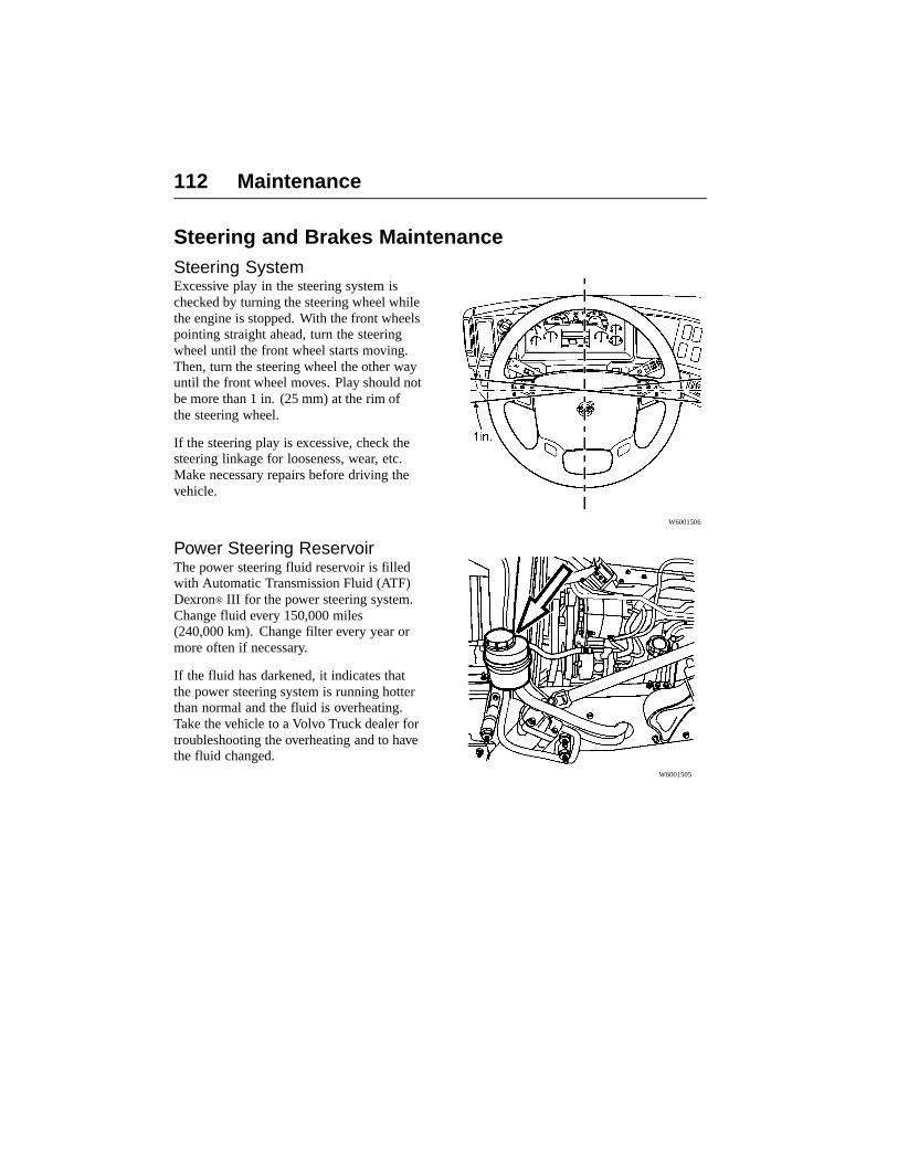
112 Maintenance
Steering and Brakes MaintenanceSteering SystemExcessive play in the steering system ischecked by turning the steering wheel whilethe engine is stopped. With the front wheelspointing straight ahead, turn the steeringwheel until the front wheel starts moving.Then, turn the steering wheel the other wayuntil the front wheel moves. Play should notbe more than 1 in. (25 mm) at the rim ofthe steering wheel.
If the steering play is excessive, check thesteering linkage for looseness, wear, etc.Make necessary repairs before driving thevehicle.
W6001506
Power Steering ReservoirThe power steering fluid reservoir is filledwith Automatic Transmission Fluid (ATF)Dexron® III for the power steering system.Change fluid every 150,000 miles(240,000 km). Change filter every year ormore often if necessary.
If the fluid has darkened, it indicates thatthe power steering system is running hotterthan normal and the fluid is overheating.Take the vehicle to a Volvo Truck dealer fortroubleshooting the overheating and to havethe fluid changed.
W6001505

Maintenance 113
Steering Linkage Wear CheckWear is checked by gripping the linkage, tierod or draglink, close to the ball joint andmoving the seat of the ball axially. If thereis a larger movement, remove the vehiclefrom service and have the linkage replacedbefore driving.
Inspection Station CriteriaThe joint should not move more thanmaximum 1/8 in. (3mm) measured withhand pressure only.
Any motion, other than rotational, betweenany linkage member and its attachmentpoint of 1/8” (3mm) or more, measured withhand pressure only, is cause to remove thevehicle from service for immediate socketreplacement.
Truck Shop Inspection CriteriaIf no AXIAL movement is detected, thesocket is operable. Any free lash detected byhand requires replacement of the socket.

114 Maintenance
Brake Safety InformationNote: The brake system is a critical vehiclesafety system. For your safety and forthose around you, follow the recommendedpreventive maintenance checks. If anyproblems occur, have them investigatedimmediately by an authorized servicefacility.
DANGER
Failure to properly maintain the brakesystem can result in compromised brakeefficiency and may lead to loss of controlof the vehicle resulting in severe personalinjury or death.
DANGER
DO NOT use replacement parts anywherein the brake system unless it conformsexactly to original specifications. Anonconforming part in your vehicle’sbrake system could cause a malfunction,leading to loss of control of the vehicleresulting in severe personal injury ordeath.
DANGER
DO NOT release the parking brake orattempt to move the vehicle until brakeair pressure in both circuits is at least100 psi (690 kPa). Failure to followthis procedure may lead to uncontrolledvehicle movement and cause severepersonal injury or death.
DANGER
Drain the air system tanks at therecommended intervals. If condensationaccumulates, moisture can enter the brakesystem air valves, causing corrosion orclogging. The safety of the brake systemcould be compromised, leading to anaccident causing severe personal injuryor death.
DANGER
DO NOT inspect or adjust parts orcomponents in the brake system withoutsetting the parking brake, placing thetransmission in neutral and securelychocking the wheels. If the vehicle is notsecured to prevent uncontrolled vehiclemovement, it could roll and cause severepersonal injury or death.
CAUTION
DO NOT use penetrating oil, brake fluidor wax-based oils in the air system. Thesefluids may cause severe damage to airsystem components.

Maintenance 115
Air Tanks
WARNING
When draining the air tanks, DO NOTlook into the area of the draining air.Dirt or sludge particles may be in the airstream that could cause eye injury.
Air tanks should be drained daily. Make surethe drain cocks close properly after draining.Empty moisture from air tanks by pulling thedrain valve lanyard or pull cord. The tanksshould be checked for condensation fluid,even if an automatic drain valve is installed.
It is very important that the air system iskept clean. Air reservoirs should be draineddaily or even twice a day on very hot days.Daily drainage expels any condensation inthe air reservoirs. If sludge or oil is found inthe drainage, the air compressor should bechecked for proper operation.
If an excessive amount of fluid is drained outof the tanks (even when drained daily) havethe system checked for possible problemswith the air dryer.
W8003393
Air DryersAir dryers have a regeneration system thatcleans out the accumulated moisture buteventually the drying medium will be filledup. Change the dryer cartridge when morewater than usual is noticed at the daily tankdrainings. The volume of daily drain waterwill change depending on temperature,geographical location and how much thebrakes are used.
Dryer manufacturers recommends changingthe cartridge every 2 to 3 years but theintervals need to be adjusted for vehicleapplication. In hot, coastal climates, thecartridge may have to be changed every year.

116 Maintenance
Brake Slack Adjusters and Cam
DANGER
Before checking the slack adjusters, setthe parking brakes, place the transmissionin neutral and block the wheels. Failureto do so can result in unexpected vehiclemovement and can cause serious personalinjury or death.
To check the slack adjusters for proper throw,use a breaker bar to lever the slack adjusterout. Measure the distance of the travel. Itshould not exceed 1 to 1 1/4 in. (25 to 30mm) for a 6 in. slack adjuster and should notexceed 3/4 to 1 in. (20 to 25 mm)for a 5 1/2 in. slack adjuster. Also make surethat the length of the slack adjuster is thesame on an axle.
Note: Travel is measured from the chamberface. See 1 in illustration.
W5001492
1 Chamber face

Maintenance 117
Brake Linings
DANGER
Before measuring the brake linings, setthe parking brakes, place the transmissionin neutral and block the wheels. Failureto do so can result in unexpected vehiclemovement and can cause serious personalinjury or death.
Measure the brake lining thickness. If thebrakes are equipped with backing plates,measure through the inspection holes in theplate. Reline the brake shoes if the liningthickness is 1/4 in. (6 mm) or less at themiddle of the shoe.
Check the brake drums for any visible cracksor signs of oil or grease.
W7001278
118 Maintenance
Check ValvesFollow the procedure below to check out theair tank check valves at least once a year.This is to see if air pressure is maintained inthe tanks when the air pressure is depleted inthe supply tank (wet tank).
Note: The check valves should be checkedat least once per year.
1 Chock the rear wheels.2 Let the compressor build up air pressure
to the governor cut-off.3 Bleed the air pressure from the supply
tank (wet tank).4 Check the air pressure gauges on the
instrument panel to see if the pressureis maintained in both primary andsecondary air tanks.
5 Any bleed-off from one or both of thetanks indicates a defective check valve;replace valve.
6 Repressurize the system and remove thewheel chocks.
WARNING
To prevent personal injury, alwaysdrain the air supply from the vehiclebefore attempting to repair or replace acomponent. Wear eye protection and takecare not to get fingers caught in the slackadjusters when spring brakes are applied.
WARNING
Always wear appropriate eye protectionto prevent the risk of injury due to contactwith engine debris or fluids.
DANGER
Before working on or inspecting thevehicle, set the parking brakes, place thetransmission in neutral and block thewheels. Failure to do so can result inunexpected vehicle movement and cancause serious personal injury or death.
DANGER
Compressed air components can separateviolently during disassembly if airpressure is present. Before servicing anypart of the brake air system, completelyrelease the air pressure. Failure to do socan result in serious personal injury ordeath.

Maintenance 119
Front and Rear BrakeSystem Air PressureAir pressure in the two circuits is monitoredby two pressure gauges on the right sideof the instrument panel. The gauge for thesecondary (front) brake circuit is markedwith an “F” within a symbol and The gaugefor the primary (rear) brake circuit is markedwith an “R” within a symbol. The twopointers should register equal or nearly equalpressure. By observing the gauge pointers,the operator is forewarned in the event of apressure drop in either or both of the circuits,and also may readily identify the specificcircuit.
Before operating the vehicle, check the airgauges which indicate air pressure.
The LED lights up if the air pressure dropsbelow 65 psi. DO NOT operate the vehiclein this condition of air pressure being below65 psi.
Gauge 1
Gauge 2
Air Tubing and HosesAll compressed air tubing and hoses needregular inspection. Check for signs of wearand that the routing is not near parts that cancause damage.
Have any damaged tubing or hoses replacedby your local Volvo Truck dealer.
W3005381

120 Maintenance
Electrical System Maintenance
Battery Care
WARNING
Battery posts, terminals and relatedaccessories contain lead and leadcompounds, chemicals known to theState of California to cause cancer andreproductive harm. Wash hands afterhandling.
The electrolyte level on maintenance freebatteries cannot be checked. Periodically,the condition and the state-of-charge ofeach battery should be checked by a VolvoTruck dealer. Maintenance free batteriesDO NOT require any attention other thankeeping them clean and firmly clampedin place in their respective trays. Keepthe cable connections clean and tight.Check the battery state-of-charge indicatorsperiodically to determine battery condition.
Check for worn cables at every majorinspection. Replace worn cables. Checkbattery terminals for cracks.
When disconnecting battery terminals,always disconnect the ground terminal first.When reconnecting, always connect theground terminal last.
W3001022
WARNING
Always wear eye protection whenworking around batteries to prevent therisk of injury due to contact with sulfuricacid or an explosion.
LightingCheck the lights on the vehicle daily. Replaceburned out inserts and bulbs. Following is alisting of bulb types. Replace any broken orcracked side or rear reflectors.
Headlights should be checked for aim atleast once per year.
W3005266

Maintenance 121
Note: The illustration refers to theinformation in the VN interior lights tablethat follows.
WARNING
Using bulbs or lamps other than thosespecified may result in failures that couldlead to a fire or a vehicle accident causedby improper lighting.
Bulb Replacement List, VN, VHD
Interior Lights VN, VHD
ChartNumber
Bulb VolvoNumber
Bulb Number MaximumWattageRating
1 Overhead Dome Lamp 946777 5008 (2x) 10W
1 Overhead Dome/Spot Lamp(connected to door)
85107036946777
Dome: 577Spot: 5008
18W10W
2 Door Courtesy Lamp 82039 578 (T-3) 10W
3 Dome Lamp-Sleeper 85107036 577 (T-4 3/4) (2x) 18W
4 Reading Lamp(under bunk storage)
946777 5008 10W
5 Reading Lamp 85107036 577 (T-4 3/4) 18W
6 Overhead FluorescentLamp -Short
3948411 GEF27/24BX/SPX30orPro-quipFPL24EX-Lor PhillipsPL-L24W/830
24W
7 Overhead FluorescentLamp -Long
3099132 GEF39/36BX/SPX30orPhilipsPL-L36W/830or Pro-quip FPL36EX-L
36W
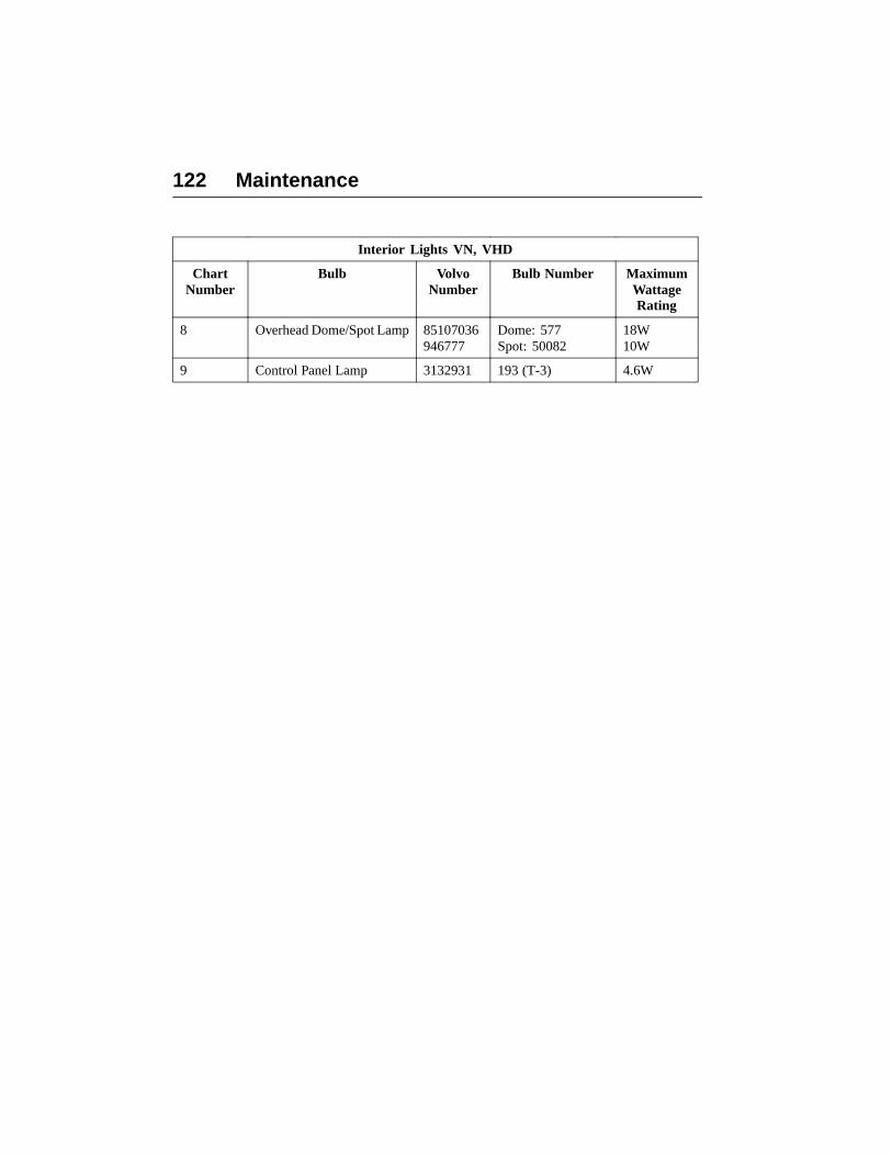
122 Maintenance
Interior Lights VN, VHD
ChartNumber
Bulb VolvoNumber
Bulb Number MaximumWattageRating
8 Overhead Dome/Spot Lamp 85107036946777
Dome: 577Spot: 50082
18W10W
9 Control Panel Lamp 3132931 193 (T-3) 4.6W

Maintenance 123
Exterior Lights, VNM
Bulb Volvo Number Number MaximumWattage Rating
High/Low Beam 3098653 90079007
55W65W
Driving lights 85103971 886 50W
Fog Lights 3946923 H3-55 62W
Front Turn Lamp 85104039 3157AK 28W
Front ParkingLight
85104039 194NA 3.8W
Side RepeaterLamp
3132939 1156 28W
Cab MountedLight
3132929 67 8W
SunvisorMounted
20414610 LED 2W
Brake Lights 3132940 1157 28W/8W
Parking RearLights
3132940 1157 28W/8W
Left/RightTurn/Stop Rear
3132940 1157 28W/8W
Trailer MarkerLight
3132932 2 x 194/168 4.9W
License PlateLight
3132940 1157 28W/8W
Back-of-Cab 3132939 1156 28W
Backup Lights 3132939 1156 28W

124 Maintenance
Exterior Lights, VNL
Bulb Volvo Number Number Maximum WattageRating
High/Low Beam 8510404185104040
H11HB3
55W65W
Driving lights 85103971 886 50W
Fog Lights 85103970 896 50W
Front Turn Lamp 85104039 3157AK 28W/8W001
Front ParkingLight
85107045 194NA 3.8W
Marker Front Side 3132932 194 3.8W
Side RepeaterLamp
965826 1156 28W
Cab MountedLight
3132929 67 8W
Sunvisor MountedLight
20414610 LED 2W
Brake Lights 3132940 1157 28W/8W
Left/RightTurn/Stop Rear
3132940 1157 28W/8W
Parking RearLights
3132940 1157 28W/8W
Trailer MarkerLight
3132932 2 x 194/168 2W
License PlateLight
3132940 1157 32W/3W
Back-of-Cab 3132939 1156 32W
Backup light 3132939 1156 32W

Maintenance 125
Bulb Replacement List, VHD
Exterior Lights VHD
Bulb Volvo Number Number Maximum WattageRating
High/Low Beam 31312273132904
H5001–18522H5006-18523
50W35W
Fog Lights 39416923 H3-55 62W
Front Turn Lamp 3132941 1157NA 24W
Left/Right Turn/StopRear
3132940 1157 28W/8W
Front Parking Light 3132940 1157 28W/8W
Side Repeater Lamp 965826 1156 28W
Brake Lights 3132939 1156 28W
Parking Rear Lights 3132940 1157 28W/8W
Cab Marker Light 3132929 67 8W
Trailer Marker Light 3132932 2 x 194/168 4.9W
License Plate Light 3132940 1157 28W/8W
Back-of-Cab 3132939 1156 28W
Backup light 3132939 1156 28W

126 Maintenance
Tires, Wheels and Hub MaintenanceWheel Safety Information
DANGER
DO NOT attempt to repair wheels or tiresunless you are trained and equipped todo so. Wheel and tire assemblies cannotbe worked on without proper tools andequipment. Failure to follow this maylead to serious personal injury or death.
DANGER
Failure to properly torque-tighten thewheel nuts can result in the breakageof wheel studs and the subsequent lossof wheels. Loss of vehicle control andserious personal injury or death can occur.
DANGER
DO NOT use oil or grease on studs ornuts. The tightening torque is affectedand can lead to incorrect clamping loadsbetween the rim and hub. This could leadto a loss of the wheel. Loss of vehiclecontrol and serious personal injury ordeath can occur.
DANGER
DO NOT install regrooved, retreadedor repaired tires on the steering axle(s).They could fail unexpectedly and causethe loss of vehicle control, leading toserious personal injury or death.
DANGER
DO NOT use mismatched wheelcomponents. If they do not exactly matchthe original design specifications, theymay cause failure or separation leadingto blowout and an accident and personalinjury or death.
DANGER
DO NOT install tires with a load ratingthat is less than stated on the CertificationLabel in the door frame. The tire could beunintentionally overloaded, leading to anaccident, causing serious personal injuryor death.
DANGER
DO NOT use mismatched tires on thesame axle. Always use the same type(radial or bias ply) or size. Mixing tires onthe same axle will affect the roadholdingand can lead to an accident, and seriouspersonal injury or death.

Maintenance 127
Wheels
DANGER
Before checking the wheels, set theparking brakes, place the transmission inneutral and block the wheels. Failure todo so can result in unexpected vehiclemovement and can cause serious personalinjury or death.
DANGER
Wheels must be serviced only by aqualified technician. DO NOT do thiswork yourself. Inflated tires on wheelscontain compressed air and if suddenlyreleased, do so with an explosive force,resulting in serious personal injury ordeath.
Check wheels for signs of rust streaks aroundthe wheel nuts. This indicates looseness(steel rims). Inspect all types of rims forcracks. Cracks can appear in many placesbut typically radiate out from where a load isapplied. Inspect closely around wheelnuts,handholes and inside circumference.
W7001279

128 Maintenance
Wheel Nut TighteningAfter the initial tightening, retightening mustbe made within the first 500 miles (800 km).After the first retightening, only normalinspection of nut tightness is needed.
Check front and rear wheel nut tightnesswith a torque wrench. All disc wheels forVolvo vehicles have a tightening torque of610 Nm (450 ft-lb). Tighten the nuts in thecorrect sequence. For spoke wheels, checkthe manufacturer’s specifications. Inspectbolts and nuts for signs of wear or cracks.Make sure that the bolts are not bent.
W7000774
8 and 10–stud wheelnut tighteningsequence.
DANGER
Failure to properly torque-tighten thewheel nuts can result in the breakage ofwheel studs and the subsequent loss ofwheels. This can lead to loss of vehiclecontrol and serious personal injury ordeath.
This check tightening is particularlyimportant when rims or brake drums arenewly painted. Paint can flake off from thesesurfaces, causing the nuts to lose their gripand the wheel to loosen.

Maintenance 129
Tire Inflation and Wear
DANGER
Before checking the tires, set the parkingbrakes, place the transmission in neutraland block the wheels. Failure to do so canresult in unexpected vehicle movementand can cause serious personal injury ordeath.
WARNING
Check tire pressure when the tire iscool. Never bleed the air from hot tires.Increased tire pressure measured in a hottire is normal. Low pressures may causeside wall flexing, resulting in increasedheat, leading to tire failure and vehicleaccident.
Measure the tread depth. The depth shouldnot be less than 6/32 in. (4.8 mm) on fronttires and not less than 2/32 in. (1.6 mm) ondrive tires.
Note: Most premium steer tires start with18/32 in. (14.2 mm) tread depth when new.Usually remove steer tires at 6/32 in (4.8mm). Drive tires should be removed at notless than 2/32 in. (1.58 mm)
It is important to have the wheels correctlyaligned. Check for uneven tire wearfrequently. Uneven tire wear is a sign ofwheels out of alignment. Refer to page 158for examples of typical tire wear.
W7000773
WARNING
DO NOT operate the vehicle withunder-inflated tires. Always keep yourtires inflated to the manufacturer’srecommendation. Increased flexing in thetire sidewall produces heat. The heat canbuild to the point of blowing the tire outcausing an accident.
Remove stones lodged in ribs or in betweendouble-mounted wheels. Check the tirepressure and leak-test the valve stems.
W7001270

130 Maintenance
Front Wheel HubsThe front wheel hubs can be filled with oneof several types of oil. Motor oil should beSAE 30 or 15W40. The oil can be eitherpetroleum based or synthetic (syntheticshould not be used for the Volvo axle). Axleoil, API GL-5, SAE 75W-90, can also beused.
There are no set change intervals for hublubrication. The only requirement is thatif the hub is opened, the lubricant must bechanged.
DANGER
Failure to keep wheel bearings properlyadjusted may result in accelerated tirewear, poor handling and, in extreme cases,wheel separation from the hub or from thespindle resulting in loss of vehicle controland serious personal injury or death.
W7001271

Maintenance 131
Chassis MaintenanceSpringsNote: This work is best performed by aVolvo Truck dealer or other service outlethaving the proper equipment.
The spring package is fastened to the axlebeam with U-bolts. It is important that theU-bolt nuts are properly tightened. Thenuts may loosen up with time. Severe roadsand service will loosen them faster. LooseU-bolts can cause springs to break, axlemisalignment, hard steering and abnormaltire wear.
Inspect the chassis for broken springs,shocks, loose or broken axle U-bolts. If anyof these are found, contact your local Volvodealer.
The U-bolt nuts, front and rear axle(s)must be retightened to the proper torquespecifications after the first 15,000 miles(24,000 km).

132 Maintenance
Spring Bushings
DANGER
Before working on or inspecting avehicle, set the parking brakes, place thetransmission in neutral and block thewheels. Failure to do so can result inunexpected vehicle movement and cancause serious personal injury or death.
When lubricating the springs, lift the axleoff of the floor, suspend the frame withaxle stands and lower the axle. The springbushings are now in the position wheregrease can be added to the contact surfaces.If the spring bushings are greased withouttaking the load off, high wear and lowerlifetime will occur because of no greasereaching the contact surfaces.
If the vehicle is being driven in severeclimates with a lot of wet, slushy, highlydusty roads, or in off-road service, increasethe frequency of spring bushing lubrication.
W7000449
Rubber BushingsRubber bushings are used for extendedservice life. If your vehicle is equipped withrubber bushings DO NOT lubricate them.
Replace the leaf spring if it is damaged orhas premature or excessive wear.

Maintenance 133
T-Ride Equalizer BeamsThe Volvo T-Ride suspension has equalizerbeams between the tandem axles. The beambushing needs to be lubricated at the normallube intervals for normal highway driving. Ifthe vehicle is being driven in severe climateswith a lot of wet, slushy, highly dusty roads,or in off-road service, increase the frequencyof lubrication. If driving in severe duty,where water may enter the bushing, dailylubrication may be necessary.
W6000838
Cab MaintenanceDoorsThe door lock mechanism should be greasedannually using white grease. Lubricatethe door lock cylinder with liquid graphiteannually, or more often in climates with a lotof snow and salt on the roads. Coat the doorstop arm with white grease annually.
On wet and salted roads, roadspray can enterthe door lock key cylinder. Lubricate thecylinder with liquid graphite annually ormore often if necessary.
The door hinge pins are treated atmanufacturing and then sealed. Nolubrication is necessary.
To keep the door rubber moldings and sealsaround the windows in good working orderand to prevent them from freezing shutduring the cold season, occasionally sprayon a silicone compound.
W8003203

134 Maintenance
HoodThe hood latch mechanism should be greasedwith white grease yearly. If the mechanismis hard to work or binds, the latch should becleaned before greasing.
W8001132
RustprotectionThe rustprotection applied when the cabwas produced is adequate for normaluse and service. If an extension of thecab rustprotection is desired or if thevehicle is used in a severe application, it isrecommended that cavity wax is re-appliedevery 3rd year.
Cab Air FilterAir going into the cab passes a filter locatedon the right, front side of the cab. Removethe filter and clean with an air gun (no morethan 20 psi pressure) after 40,000 miles(64,000 km), (in dusty conditions as often asevery 10,000 miles [16,000 km]). Make surethe air stream is directed from the inside out.
The filter should not be cleaned and reusedmore than once. Replace with a new filterafter maximum 70,000 miles (110,000 km),or earlier if driving in dusty conditions. Aclogged filter decreases the efficiency of theair conditioning system.
W8003189

Maintenance 135
Paint and Brightwork Care
CabWash all exterior painted surfaces frequentlyto remove dirt. It is especially important towash off salt-laden snow and ice during thecold season. A mild detergent can be usedbut avoid strong detergents.
Note: DO NOT aim the water jet directlyat door and window seals or door locks. Iflocks are filled with water, use compressedair to clean the water out and then applyliquid graphite. Be especially careful ofleaving water in locks or around seals duringfreezing weather.
Wet the surface with water to loosen dirt.The use of steam or high pressure waterwill help in removing loose dirt. Wash thesurface with a sponge using a lot of water toflush away dirt. Dry the surface with a towelor chamois. DO NOT wait until it is dry asdry-dusting will scratch the surface.
Apply a coat of wax regularly. This willhelp the paint and other surfaces keep theirluster. If the surface gets dull, use a restoringcleaner specially designed for this. Clean offall tar spots and tree sap before waxing.
When the vehicle is new, allow for enoughtime for the paint to cure. Wait about 30 daysafter the date of manufacture before puttingon the first coat of wax. Never wax on a hotday under the sun and do not apply too muchpressure with a buffer as burns may developfrom the friction.

136 Maintenance
ChassisKeep the chassis free from buildup of dirt.Make sure the chassis is cleaned before themaintenance inspections to help spottingleaks, etc. As salt can be part of the roadsludge during the cold season, removebuildup of snow and ice so it does notpromote corrosion. At the end of the coldseason, thoroughly flush away all collecteddirt from the chassis.
Stainless SteelStainless steel will rust if exposed to salt fortoo long. Wash frequently, especially duringthe cold season, to remove salt-laden snowand ice. If rust appears, wash the surface anduse a rubbing compound to remove the rust.Apply a coat of wax as a finish (do not waxparts that get hot, such as exhaust pipes, etc.).
Note: Never use steel wool to clean stainlesssteel. Pieces of the steel wool breaks off andgive rust stains on the surface.
ChromeChromed surfaces will rust if they are notprotected. This is especially importantduring the cold season when roads are saltedor in coastal areas where the salt level in theair is high.
Clean chrome surfaces with clean water. Ifthe surface has heavy dirt or tar spots, usea tar remover. To remove rust spots, use anon-abrasive chrome cleaner and apply acoat of wax as a finish (do not wax parts thatget hot, such as exhaust pipes, etc.).
Note: Never use steel wool to clean chrome.Pieces of the steel wool breaks off and giverust stains on the surface.

Maintenance 137
AluminumUnprotected aluminum surfaces will forman oxide layer if not maintained. This isespecially important during the cold seasonwhen roads are salted or in coastal areaswhere the salt level in the air is high. Cleanwith steam or high pressure water. Use amild detergent if the dirt is heavy. Rinsewell.
Clean aluminum surfaces with warm water.If the surface has heavy dirt or tar spots,use a tar remover. To prevent spotting, wipealuminum surfaces dry after washing.
UpholsteryClean vinyl and cloth upholstery with lightbrushing or vacuuming. If heavily soiled, usewarm water with mild soap such as saddleor oil soap.

138 Maintenance
Lubrication Chart
W1000189
Grease Coolant
Hub Oil Aut. Transm. Fluid
Engine Oil Man. Transm. Oil
Hydraulic Oil Rear Axle Oil
The numbers in thelubrication chartcorrespond with thenumbered notes onpage 140 and page 141.Read these notes beforeselecting a lubricant. Steering Fluid Brake Fluid
* Auxiliary axle(s) Windshield washer fluidlevel

Maintenance 139
Lubrication VN, VHDChassis Lubrication
DANGER
Before working on or servicing avehicle, set the parking brakes, place thetransmission in neutral and block thewheels. Failure to do so can result inunexpected vehicle movement and cancause serious personal injury or death.
General lubrication includes lubricating allthe grease fittings in the drivetrain, front andrear suspensions, power steering, and frontaxle, using a grease gun.
Grease the chassis every 15,000 miles(24,000 km). However, if the vehicle isin a demanding application or runningin a dirty or corrosive atmosphere,adjust the lubrication intervals to reflectheavy-duty use. For example, if drivenin heavy stop-and-go traffic with a lot ofmaneuvering, the lubrication intervals shouldbe every 10,000 miles (16,000 km) or less.
All lubricating points are found on thechassis lubrication chart on the next page.
Lubricating GreaseUse grease with a lithium base with EPadditives and a consistency of NLGI No. 2.The No. 2 consistency is suitable for mosttemperatures. Use NLGI No. 1 or No. 0 forextremely low temperatures.
Care should be taken not to use any greaseother than one with EP additives for thedriveshaft. DO NOT use any solid lubricants,such as graphite, copper or molybdenumdisulfide.
Lubrication ProcedureMake sure the grease fittings are cleanedoff before filling grease. Dirt on the fittingthat is not cleaned off is pushed into the parttogether with the new grease. Always fillgrease to the point where old grease andcontaminants are forced out from the part andonly new grease comes out. If new greasecannot be filled so old grease is flushed out,the part needs to be checked for problems. Ifa fitting does not accept lubrication due todamage or internal stoppage, replace it witha new fitting.
Note: Think of greasing the same way as anoil change. All old grease should come outand be replaced with new grease.
Where rubber or plastic parts are involved,do not heat part for better grease application.
Remove excess grease from fittings, shacklesand other surfaces.
Note: Always grease a Volvo front axle withthe wheels on the ground.

140 Maintenance
Lubrication Chart Notes
1 Spring hanger: Use a lithium basedgrease with specification API NLGINo. 2. When lubricating the left andright sides of the front springs, liftthe axle off of the floor, suspend theframe with axle stands and lower theaxle. The spring bushings are now inthe position where grease can be addedto the contact surfaces.
Note: Always grease a Volvo front axlewith the wheels on the ground.
Note: To grease non-Volvo axles,they are typically greased with thewheels on the ground. Consult withthe axle manufacturer for the latestrecommendation.
2 Slack adjuster and brake cam: Use alithium based grease with EP additivesto specification API NLGI No.
Note: If the brake cam seal does notpurge, make sure the inner seal does notpurge into the brake drum and onto thebrake linings.
3 Steering gear: Use a lithium basedgrease with specification API NLGI No.2. Only use a hand operated grease gun.The high pressure from an air operatedgrease gun will damage the seal.
4 Draglink and Steering Shaft. Use alithium based grease with specificationAPI NLGI No. 2.
5 Kingpin, upper and lower: Use alithium based grease with specificationAPI NLGI No. 2.
Note: Always grease a Volvo front axlewith the wheels on the ground.
Note: To grease non-Volvo axles,they are typically greased with thewheels on the ground. Consult withthe axle manufacturer for the latestrecommendation.
6 Tie-rod: Use a lithium based greasewith specification API NLGI No. 2.
Note: Volvo axles may use agreased-for-life tie-rod. No provisionsfor adding grease are available.
7 Brake fluid and clutch reservoir.Check the fluid level in the reservoir.Add brake fluid if necessary. Use onlyDOT 4 brake fluid in the clutch releasesystem. Mixing DOT 4 brake fluid withpetroleum based oil will cause sealdamage which will cause leakage.
8 Clutch bearing linkage: Use a lithiumbased grease with EP additives tospecification API NLGI No. 2.
9 U-Joints: Use a lithium based greasewith EP additives to specification APINLGI No. 2.
Note: Ensure that grease purges out ofall four seals of the U-joints.
10 PTO/Hydraulic reservoir.
11 T-Ride bogie beam (48K-70Ksuspension): Use a lithium basedgrease with EP additives to specificationAPI NLGI No. 2. Make sure the greasepurges out of both the outer andinner seals. If necessary, adjust thelubrication schedule to include greasingthe bogie bearing as often as daily, inapplications where the bogie runs incorrosive conditions or is submerged inwater.

Maintenance 141
Lubrication Chart notes Continued.
12 Coolant level: Add coolant ifnecessary. Only use pre-mixed cleanwater and antifreeze in a 50/50 mix.Add only the same type antifreeze, thatis: extended life or standard.
13 Steering assist cylinder: Use a lithiumbased grease with EP additives tospecification API NLGI No. 2 to greaseboth ball joints.
14 Power steering fluid: Check the fluidin the reservoir with the dipstick. Addoil if necessary. Use ATF Dexron®
III. Change fluid every 150,000 miles(240,000 km). Change filter every year.Use a lithium based grease withspecification API NLGI No. 2.
15 Front oil lubricated wheel bearings:There is no set change interval. Changethe oil (or grease) only in connectionwith work on the hub or if dirt is foundin the lubrication. Use motor oil SAE30. Lubricate both the right and the leftwheel bearings.
16 Engine oil and filter: For oil changesee schedule on page 63 to page 67.
17 Windshield washer fluid level.
18 Automatic and manual transmission:Automatic transmission: Use Dexron®
III Automatic Transmission fluid. Seethe manufacturer’s Operator’s Manualfor intervals and quantity.
Manual transmission: Use a mineralor synthetic oil. Check oil levelperiodically. Level should be to thebottom of the inspection hole.
19 Auxiliary axle(s): If equipped withauxiliary lift axles use a lithium basedgrease with specification API NLGINo. 2. Also, lubricate the Brake, Cams,Slack adjuster and Tie-rod ends.
20 Rear axle: Check the oil level in thedifferential by removing the fill/levelplug in the housing. The oil should belevel with the bottom of the fill/levelplug hole. Add oil if necessary.
21 Fifth wheel: The fifth wheel andslider assemblies should always bere-lubricated after steam cleaning or atleast every 15,000 miles (24,000 km).
Note: A heavy coating of greaseis recommended on the fifth wheelplate by using the grease fitting underthe fifth wheel top plate or by directapplication to the top of the plate. Thefifth wheel can be greased with thetrailer connected, by using the greasefittings under the top plate.Grease the support brackets trunnionsthrough the fittings over the bracketpins.Grease the fittings at the saddle plate(1 each side) and the saddle plate lockpockets (1 each side).
Note: See page 142 to page 146 for oiltypes.

142 Maintenance
Viscosity and Capacity TablesVolvo Engine D12D
For oil change intervals, see page 62and page 63
First oil and filterchange
After 1 month or6,000 miles(10,000 km)
Capacity (including filters)
D12 service 37 quarts (35 liters)
Oil volumebetween high andlow on dipstick
7.5 quarts (7.0 liters)
W1000144
1 Only completely syntheticand/or VDS/VDS-2 oils.
2 Only VDS-2 oils.
Cooling System Capacity*
VN, D12D ......... 43.5 liters(11.50 US gal.)
VHD, D12D ...... 39 liters(10.30 US gal.)
* approximate volumes
Clutch Hydraulic System
Clutch systemfluid ...................
brake fluidaccording to DOT 4(SAE J 1703)
Replacementinterval ..............
every two years

Maintenance 143
Fuller Transmission 9,10, 13, 15 and 18–speed
For oil change intervals, see themanufacturer’s Oparator’s Manual
Capacity:
9-speed .............. 13.5 quarts(12.0 liters)
10, 13, 15 and18-speed ............
14.0 quarts(13.0 liters)
W1000179
Allison Automatic Transmission
For oil change intervals, see themanufacturer’s Operator’s Manual.
Approximate Capacity:
MD3560P 5-speedMD3060P 5-speed
19.0 quarts(18.0 liters)
HD4060P 5-speedHD4560P 5-speed
39.0 quarts(37.0 liters)
Oil drain plugtorque ................
18-24 ft-lb (25-32Nm)
W1000143
1) “Arctic” as defined byMIL-L-46167B
Note: Fluid may require changesooner than listed intervalsdepending on operating conditions.Fluid must also be changedwhenever there is evidence of dirtor high temperature condition asindicated by discoloration, strongodor or fluid analysis.

144 Maintenance
Volvo Tandem CTEV87 and RT3210
Oil type:
Petroleum basedoil ......................
API-GL5,MIL-PRF-2105E
First oil change After one month or6,000 miles(10,000 km)
Normal oil changeinterval ..............
every 12 month or75,000 miles(120,000 km)
Syntheticlubricant ............
NOT USED
Capacity:
CTEV87
front tandem,EV87 .................
21.0 quarts(20.0 liters)
rear tandem ....... 9.5 quarts(9.0 liters)
RT2610
front tandem ...... 24.5 quarts(23.0 liters)
rear tandem ....... 20 quarts(19.0 liters)
hub reduction,each hub 1 ..........
3.7 quarts(3.5 liters)
RT3210
front tandem ...... 29.5 quarts(28.0 liters)
rear tandem ....... 24.5 quarts(23.0 liters)
hub reduction,each hub1 ...........
3.2 quarts(3.0 liters)
1 Fill each hub before filling the rear axle.
W4000880
1) For very hard or continuousoperation above an altitude of6,000 ft (2,000 m) above sea level,a viscosity of SAE 140, SAE80W/140 or SAE 85W/140 isrecommended for use instead ofSAE 90.

Maintenance 145
Meritor Single RS23, 25, 26 and 30Meritor Tandem RT40, 44 and 46
For oil change intervals, see themanufacturer’s Operator’s Manual
Capacity:
RS23-160 .......... 20 quarts(19 liters)
RS23-185 .......... 23.5 quarts(22.5 liters)
RT40-145, fronttandemRT40-145, reartandem
15 quarts(14 liters)13 quarts(12 liters)
W4000881
1) Select viscosity from the tableabove. Temperatures refer to stableambient temperature readings.There is no upper limit to theseoutside temperatures but the axlesump temperature MUST NEVEREXCEED 250 �F (120 �C).
Eaton Single 23080, 23105, 26105 and 30105Eaton Tandem DS405, DD405, DDH44 and DS462
For oil change intervals, see themanufacturer’s Operator’s Manual
Capacity:
23080 ................ 20 quarts(19 liters)
23105 and26105 ................
28 quarts(26.5 liters)
DD404, fronttandemDD404, reartandem
15.5 quarts(14.5 liters)14 quarts(13 liters)
DS404, fronttandemDS404, rear tandem
15.5 quarts(14.5 liters)14 quarts(13 liters) W4000882

146 Maintenance
Steering Hydraulic System
Fluid type .......... AutomaticTransmission Fluid(ATF) Dexron® lll
Change interval every150,000 miles(240,000 km)
Hubs
Oil type1 Temperature
Motor oil APICD or CE, SAE30, 15W40 orsynthetic
Minimum: -15 F(-25 C)Maximum: No limit
Gear oil APIGL5, SAE75W90
Minimum: -40 F(-40 C)Maximum: No limit
1For axles with hub reduction, see page 144

Literature 147
Service Assistance and ManualsYour Volvo Truck dealer is trained andequipped to perform expert service on yourVolvo vehicle. Your dealer has direct accessto Volvo Trucks North America, Inc. fortechnical help, parts or service information.
There is also a direct number to Volvo ActionService (VAS), staffed 24 hours a day, if youare in need of assistance. The number to theCustomer Support Center is:1 (800) 528–6586 (or (800) 52–VOLVO).Also on the internet:www.vas.volvo.com
VAS offers:
DeliveryAssurance
If you need roadsideassistance, VAS canarrange for loadforwarding or equipmentrental.
PersonalAssurance
Trained staff for handlingany vehicle problems.
UptimeAssurance
VAS will locate thenearest service providerand guarantee payment soyou can get on the road assoon as possible.
PriceAssurance
VAS audits service andparts billing to ensureguaranteed labor rates andpreferred parts pricing forVolvo components.

148 Literature
To order a single Service Manual or a ServiceManual Set for your vehicle, contact yourauthorized Volvo Truck dealer.
In order to process the request correctly,please give the model, year and VIN (last sixdigits of VIN). For VIN location, refer to theGeneral Information section, under VehicleData, in the VN/VHD Operator’s Manual.
Service Manual prices will vary dependingon the make and model of engine in thevehicle. (A Cummins engine manualis included in your introductory ownerspackage).
Note: Please allow 30 days for delivery ofManuals.
Name Company
Address
CSZ (Province, Postal Code)
Vehicle Model Telephone/Fax
Model Year VIN
Item 1:
Item 2:
Item 3:
Item 4:
Item 5:

Service Charts 149
Scheduled ServicesThe vehicle had a pre-delivery inspection before being delivered to you, the customer.Regular maintenance inspections should be continued. The maintenance program andlubrication intervals that are listed in this manual may not suit your operation. Contactyour nearest Volvo dealer, who can help with designing a maintenance program that worksin your application.For regular service or maintenance, call the dealer in advance and arrange for a serviceappointment. This gives the dealer time to schedule the correct equipment and providea trained technician to service the vehicle. Setting an appointment can decrease vehicledowntime.When in for service at an authorized dealer, ask for outstanding safety related recalls thatrelate to the vehicle. This service is available only at an authorized dealership.
Note: It is strongly recommended thatyou do not attempt to service, repair ormaintain the vehicle yourself unless youare fully trained and have the proper tools,equipment and parts. Some procedures arebetter performed by your Volvo Truck dealerwho has the proper equipment and trainedtechnicians.

150Service
Charts
Work Completed
Date Mileage
Preventive Maintenance(See local dealer for Service Information in group 17, "PreventiveMaintenance Basic Service VN, VHD VERSION2" and group 17,"Preventive Maintenance Annual Service VN, VHD VERSION2.”)
Sched-uled Ser-vice Date
VehicleAge atService

ServiceC
harts151
Work Completed
Date Mileage
Preventive Maintenance(See local dealer for Service Information in group 17, "PreventiveMaintenance Basic Service VN, VHD VERSION2" and group 17,"Preventive Maintenance Annual Service VN, VHD VERSION2.”)
Sched-uled Ser-vice Date
VehicleAge atService

152 Service Charts
Repair RecordKeep track of repairs being made. This helps over the lifetime of the vehicle to spot trendsthat can be used to alter maintenance schedules, for example.

ServiceC
harts153
Repair Record
Date MileageWork Order
or InvoiceNo.
Dealer Notes

154Service
Charts
Repair Record
Date MileageWork Order
or InvoiceNo.
Dealer Notes

ServiceC
harts155
Repair Record
Date MileageWork Order
or InvoiceNo.
Dealer Notes

156Service
Charts
Repair Record
Date MileageWork Order
or InvoiceNo.
Dealer Notes

Service Charts 157
Tire RecordTire Hints
Hints on How to Avoid Unnecessary Tire Wear
• Maintain correct tire pressure
• Check the tire pressure when the tires are cold
• Check that valve caps are not missing
• Keep the wheels balanced
• Tire wear increases with speed
• Overloading not only decreases tire life but also creates a hazard
• Incorrect front end alignment causes increased wear
• Unnecessary tire rotation may cause excessive wear
Note: A cold weather initial driving period will increase the life of new or retreaded tires.Dual mounted wheels should always be of the same type and diameter (maximal diameterdifference allowed is 1/4 in. [6 mm]).
VTNA is committed to repair procedure 642(RP 642), American Tire Association (ATA)and The Maintenance Council (TMC).
Representatives from VTNA activelyparticipated, along with twenty-twocompanies, in developing recommendedpractice 642 entitled “Total VehicleAlignment:” Recommendations forMaximizing Tire and Alignment relatedComponent Life.” Recommended Practice642 (RP 642) is published by theMaintenance Council, American TruckingAssociations, Inc.
Companies that participated in thedevelopment of RP 642 are listed in the RP.
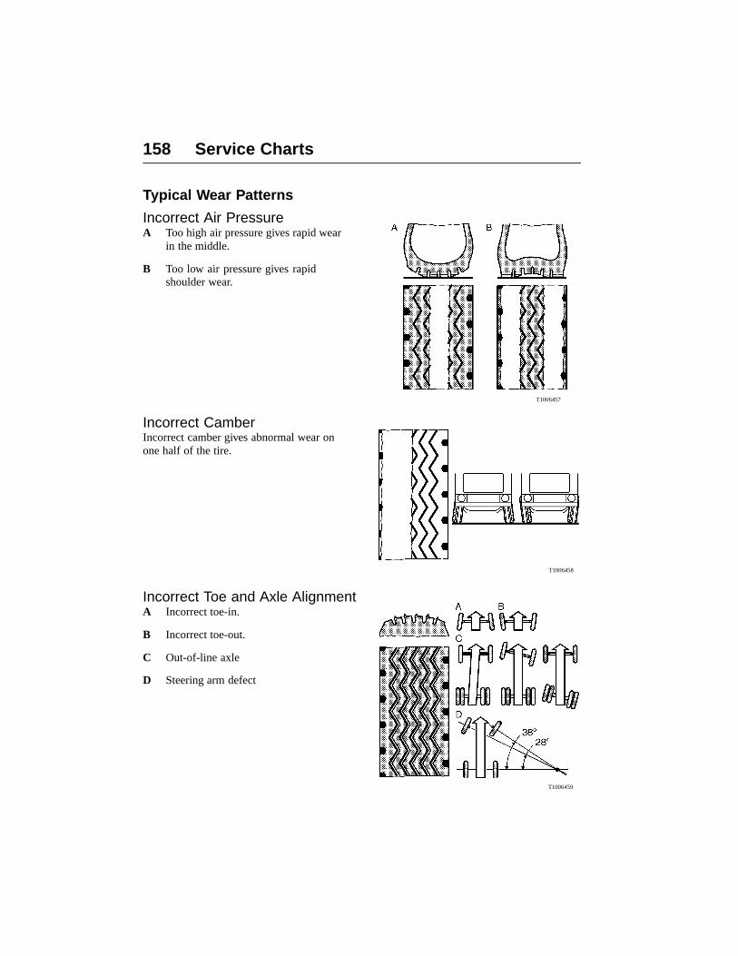
158 Service Charts
Typical Wear Patterns
Incorrect Air PressureA Too high air pressure gives rapid wear
in the middle.
B Too low air pressure gives rapidshoulder wear.
T1006457
Incorrect CamberIncorrect camber gives abnormal wear onone half of the tire.
T1006458
Incorrect Toe and Axle AlignmentA Incorrect toe-in.
B Incorrect toe-out.
C Out-of-line axle
D Steering arm defect
T1006459

Service Charts 159
Dual Wheel MountingA Excessive road camber, different types
of tire, different circumference oroff-center loading gives faster wear onone tire.
B Too low air pressure, mismatched rimsfor the tire type and dimension, excessflexing in tire wall, or different typesof tires in inner and outer tires givescontact wear.
T1006718
Incorrect Caster and ImbalanceA Caster angle.
B Imbalance.
Also rapidly wears the mechanical parts ofsteering linkage, kingpin and wheel bearing.
T1006460
Cuts in the Tire TreadA Cuts.
B Flaking cuts.
C Rubber flaking.
Cuts are due to poor roads, air pressure toohigh or incorrect tire type.
T1006720
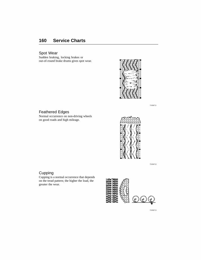
160 Service Charts
Spot WearSudden braking, locking brakes orout-of-round brake drums gives spot wear.
T1006721
Feathered EdgesNormal occurrence on non-driving wheelson good roads and high mileage.
T1006722
CuppingCupping is a normal occurrence that dependson the tread pattern; the higher the load, thegreater the wear.
T1006723

Service Charts 161
AXLE LOAD/TIRE PRESSURE
Axle Loadlb (kg)
Recommended tire pressurepsi (kPa)
W1000109

162 Service Charts
Tire Record
Size Ply Rating Make Type Serial No.
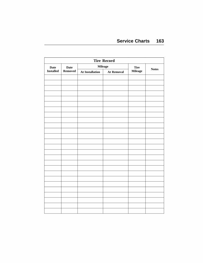
Service Charts 163
Tire RecordMileageDate
InstalledDate
Removed At Installation At Removal
TireMileage
Notes
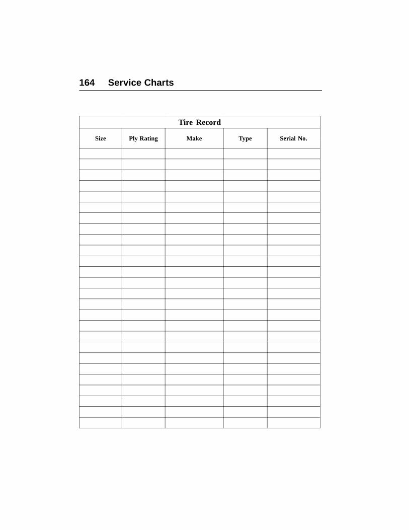
164 Service Charts
Tire Record
Size Ply Rating Make Type Serial No.

Service Charts 165
Tire RecordMileageDate
InstalledDate
Removed At Installation At Removal
TireMileage
Notes

166 Service Charts
Tire Record
Size Ply Rating Make Type Serial No.

Service Charts 167
Tire RecordMileageDate
InstalledDate
Removed At Installation At Removal
TireMileage
Notes

168 Service Charts
Fuel and Oil RecordKeeping track of the fuel and oil consumption gives a record of what is normal for thevehicle. This can be compared with other vehicles in the same service application to indicatewhat is normal fuel and oil consumption for a certain application.
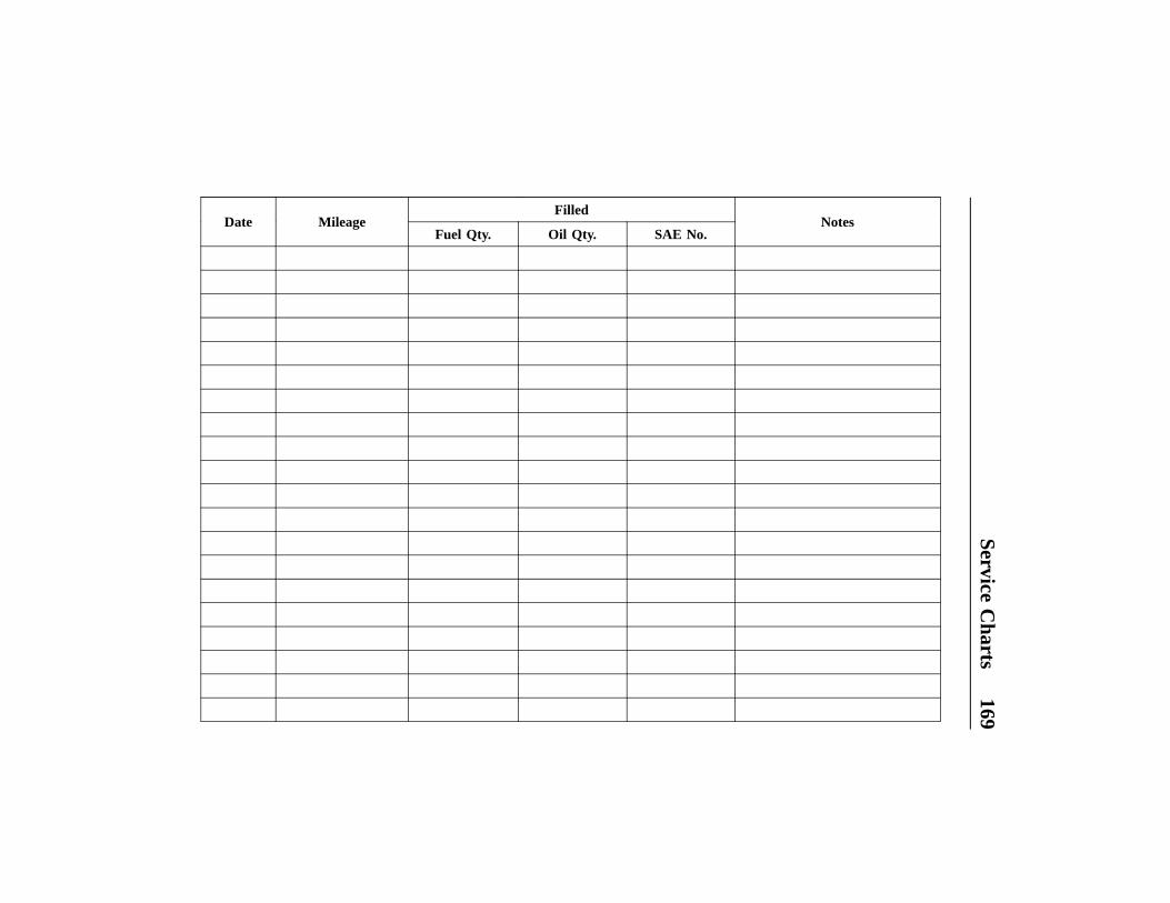
ServiceC
harts169
FilledDate Mileage
Fuel Qty. Oil Qty. SAE No.Notes

170Service
Charts
FilledDate Mileage
Fuel Qty. Oil Qty. SAE No.Notes
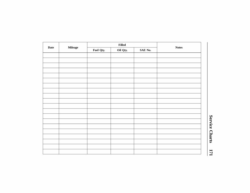
ServiceC
harts171
FilledDate Mileage
Fuel Qty. Oil Qty. SAE No.Notes

172Service
Charts
FilledDate Mileage
Fuel Qty. Oil Qty. SAE No.Notes

ServiceC
harts173
FilledDate Mileage
Fuel Qty. Oil Qty. SAE No.Notes

174Service
Charts
FilledDate Mileage
Fuel Qty. Oil Qty. SAE No.Notes

ServiceC
harts175
FilledDate Mileage
Fuel Qty. Oil Qty. SAE No.Notes


Index 177
IndexA
Air Dryer Maintenance ................. 115Air Filter, Cab ............................... 134Air Filter, Engine ............................ 94Air Tank Draining ......................... 115Allison Transmission OilCapacity ........................................ 143Alternative Fuels ............................. 59Antifreeze Information, General ..... 44Antifreeze Standard ........................ 44Antifreeze/Water Mixture ............... 40
BBattery Maintenance ..................... 120Brake Maintenance Checks .......... 116Brake System Air Pressure ........... 119Burn Prevention ................................ 6
CCanadian Consumer Complaints .... 19Climbing Up or Down .................... 14Coolant Additive Testing ................ 47Coolant Additives ........................... 43Coolant Change Interval, Extended 51Coolant Change Interval, Regular ... 46Coolant Freeze Protection ............... 45Coolant Mixture .............................. 40Coolant System ............................... 36Coolant Water Specification ........... 42Coolant, Changing from Regular toExtended ......................................... 49Cooling System ............................... 35Cooling System, Draining/Filling,D12D ............................................... 96Crankcase Air Breather ................... 93Crushing Prevention ........................ 13Cutting Prevention .......................... 13
DDriveShaft Maintenance ............... 110
EElectric Grounding Practices .......... 17Electric System, Precautions .......... 17Electronic System Precautions ....... 18
Emissions Control Compliance ...... 73Engine Air Filter ............................. 94Engine Damage Prevention ............. 15Engine Data Notes .......................... 32Engine Features .............................. 25Engine Monitoring Systems ........... 18Engine Oil Change .......................... 91Engine Oil Filters ............................ 62Engine Oil, General ........................ 60Engine Optional Equipment ........... 31Engine Overview, D12D ................ 21,22, 23, 24Engine Shut-Down System ............. 18Engine Standard Equipment ........... 30Engine Storage ................................ 33Engine Variants D12D .................... 30Engine, Before Starting .................. 16Ether Start ................................. 11, 16Explosion Prevention ........................ 9Exterior Lights, VHD ................... 125Exterior Lights, VNL .................... 124Exterior Lights, VNM ................... 123
FFan Drive Belts ............................... 95Fire Prevention .................................. 9Fuel Additives ................................. 57Fuel Cetane Number ....................... 55Fuel Cloud Point ............................. 56Fuel Enhancers ................................ 57Fuel Filter Change Intervals ......... 100Fuel Filter Replacement ................ 100Fuel Filter Replacement, Primary . 101Fuel Filter Replacement,Secondary ..................................... 103Fuel Filters ...................................... 54Fuel Pour Point ............................... 56Fuel Quality .................................... 53Fuel Safety Information .................. 52Fuel Storage .................................... 55Fuel Sulfur Content ......................... 54Fuel System .................................... 52Fuel System, Bleeding .................. 105

178 Index
Fuel Viscosity ................................. 56Fuel, Alternative ............................. 59
GGeneral Coolant Information .......... 39General Engine DesignInformation ..................................... 21General Information .......................... 1
IInjury Prevention .............................. 6Interior Lights, VN, VHD ............. 121
LLiterature ....................................... 147Lubrication Chart, VN .................. 139
MMaintenance .................................... 73Maintenance Hazards ...................... 90Maintenance Safety Precautions ....... 3
NNoise Emissions .............................. 81
OOil Additives ................................... 66Oil Change Intervals ....................... 62Oil Consumption ............................. 67Oil filters ....................................... 109Oil Filters, Engine ........................... 92Oil Pressure Priming ....................... 34Oil Quality ...................................... 61Oil Sulfur Level .............................. 66Oil System ...................................... 60Oil Total Base Number (TBN) ........ 66Oil Viscosity ................................... 65Oil, Synthetic .................................. 64Owner Information, General ............. 1Owner’s Information Package .......... 2
PPower Steering Reservoir ............. 112
RRadiator Package, Cleaning ............ 99Rear Axle Oil ................................ 110Respiratory Hazard Prevention ....... 12Roadside Assistance ..................... 147Rubber Bushings ........................... 132
SSafety Defects, Reporting ............... 19Safety Information ............................ 3Safety Information, Brakes ........... 114Selling Vehicle .................................. 1Service Assistance ........................ 147Service Charts ............................... 149Service Manuals ............................ 148Service Schedules VN, VHD .......... 68Speed Restrictive Tires ................... 20Spring Bushings ............................ 132Spring Maintenance ...................... 131Steering System Maintenance ....... 112
TTires, Wheels and HubsMaintenance .................................. 127Total Base Number (TBN) .............. 66Transmission oil ............................ 108Transmission Oil Quality .............. 109Turbo and Charge-Air-Cooler ......... 98
UU-bolts .......................................... 131
VVendor Component Information ....... 1Volvo Action Service .................... 147Volvo D12 Oil Capacity ................ 142Volvo Rear Axle Oil Capacity ...... 144

Truck Model & Serial
Engine Model & Serial
Transmission Model & Serial
Rear Axle Model & Serial
Your Truck Was Delivered By:
If you need assistance on the road or if you need
service repairs, contact the VAS support center.
VAS is available 24 hours per day, 7 days per
week at 1-800-528-6586.
Please report the specific nature of the service
problem to the Volvo Customer Support
Specialist, who will answer your questions and
arrange for the assistance you need.
Volvo Action Service (VAS)
Support Center
1-800-52-VOLVO

Volvo Trucks North America, Inc.P.O. Box 26115 Greensboro, NC 27402-6115
Volvo Trucks Canada, Ltd.5600A Cancross Court, Mississauga, Ontario L5R 3E9
http://www.volvotrucks.volvo.com
PV776-20707967 (USA) 07.2004 © Volvo Trucks North America, Inc. , 2004