Locomotion analysis and optimization of actinomorphic ...
16
University of Wollongong University of Wollongong Research Online Research Online Faculty of Engineering and Information Sciences - Papers: Part B Faculty of Engineering and Information Sciences 2018 Locomotion analysis and optimization of actinomorphic robots Locomotion analysis and optimization of actinomorphic robots with soft arms actuated by shape memory alloy wires with soft arms actuated by shape memory alloy wires Chunshan Liu University of Science and Technology of China Erbao Dong University of Science and Technology of China Min Xu University of Science and Technology of China, [email protected] Gursel Alici University of Wollongong, [email protected] Jie Yang University of Science and Technology of China Follow this and additional works at: https://ro.uow.edu.au/eispapers1 Part of the Engineering Commons, and the Science and Technology Studies Commons Recommended Citation Recommended Citation Liu, Chunshan; Dong, Erbao; Xu, Min; Alici, Gursel; and Yang, Jie, "Locomotion analysis and optimization of actinomorphic robots with soft arms actuated by shape memory alloy wires" (2018). Faculty of Engineering and Information Sciences - Papers: Part B. 1775. https://ro.uow.edu.au/eispapers1/1775 Research Online is the open access institutional repository for the University of Wollongong. For further information contact the UOW Library: [email protected]
Transcript of Locomotion analysis and optimization of actinomorphic ...

University of Wollongong University of Wollongong
Research Online Research Online
Faculty of Engineering and Information Sciences - Papers: Part B
Faculty of Engineering and Information Sciences
2018
Locomotion analysis and optimization of actinomorphic robots Locomotion analysis and optimization of actinomorphic robots
with soft arms actuated by shape memory alloy wires with soft arms actuated by shape memory alloy wires
Chunshan Liu University of Science and Technology of China
Erbao Dong University of Science and Technology of China
Min Xu University of Science and Technology of China, [email protected]
Gursel Alici University of Wollongong, [email protected]
Jie Yang University of Science and Technology of China
Follow this and additional works at: https://ro.uow.edu.au/eispapers1
Part of the Engineering Commons, and the Science and Technology Studies Commons
Recommended Citation Recommended Citation Liu, Chunshan; Dong, Erbao; Xu, Min; Alici, Gursel; and Yang, Jie, "Locomotion analysis and optimization of actinomorphic robots with soft arms actuated by shape memory alloy wires" (2018). Faculty of Engineering and Information Sciences - Papers: Part B. 1775. https://ro.uow.edu.au/eispapers1/1775
Research Online is the open access institutional repository for the University of Wollongong. For further information contact the UOW Library: [email protected]

Locomotion analysis and optimization of actinomorphic robots with soft arms Locomotion analysis and optimization of actinomorphic robots with soft arms actuated by shape memory alloy wires actuated by shape memory alloy wires
Abstract Abstract This article presents the locomotion analysis and optimization of actinomorphic soft robots, which are composed of soft arms actuated by shape memory alloy wires. The soft arm that is a composite modular structure is actuated by a self-sensing feedback control strategy. A theoretical model was established to describe the deformation of the soft arm, combining the Euler-Bernoulli beam model of the soft arm with the constitutive model and the heat transfer model of the shape memory alloy wire. The kinematics of the actinomorphic soft robot was analyzed using the modified Denavit-Hartenberg method, and the motion equation of the actinomorphic soft robot was presented based on the quasi-static hypothesis. Results show that the actinomorphic soft robot moves with a zig-zag pattern. The locomotion of four actinomorphic soft robots with three to six arms was analyzed, and the gait parameters of each locomotion type were optimized. The optimization results indicate that the three-arm actinomorphic robot with certain gait parameters has the best performance and achieves a maximum stride length of 75 mm. A series of experiments were conducted to investigate the movement performance of the three-arm actinomorphic robot in various environments.
Disciplines Disciplines Engineering | Science and Technology Studies
Publication Details Publication Details Liu, C., Dong, E., Xu, M., Alici, G. & Yang, J. (2018). Locomotion analysis and optimization of actinomorphic robots with soft arms actuated by shape memory alloy wires. International Journal of Advanced Robotic Systems, 15 (4), 1-14.
This journal article is available at Research Online: https://ro.uow.edu.au/eispapers1/1775

Research Article
Locomotion analysis and optimizationof actinomorphic robots with soft armsactuated by shape memory alloy wires
Chunshan Liu1, Erbao Dong1, Min Xu1, Gursel Alici2 and Jie Yang1
AbstractThis article presents the locomotion analysis and optimization of actinomorphic soft robots, which are composed of softarms actuated by shape memory alloy wires. The soft arm that is a composite modular structure is actuated by a self-sensing feedback control strategy. A theoretical model was established to describe the deformation of the soft arm,combining the Euler–Bernoulli beam model of the soft arm with the constitutive model and the heat transfer model of theshape memory alloy wire. The kinematics of the actinomorphic soft robot was analyzed using the modified Denavit–Hartenberg method, and the motion equation of the actinomorphic soft robot was presented based on the quasi-statichypothesis. Results show that the actinomorphic soft robot moves with a zig-zag pattern. The locomotion of four acti-nomorphic soft robots with three to six arms was analyzed, and the gait parameters of each locomotion type wereoptimized. The optimization results indicate that the three-arm actinomorphic robot with certain gait parameters has thebest performance and achieves a maximum stride length of 75 mm. A series of experiments were conducted to investigatethe movement performance of the three-arm actinomorphic robot in various environments.
KeywordsSoft robot, locomotion analysis, gait optimization, bio-inspiration, shape memory alloy
Date received: 25 July 2017; accepted: 30 May 2018
Topic: Bioinspired RoboticsTopic Editor: Mohsen ShahinpoorAssociate Editor: Claudio Rossi
Introduction
Currently, robots are employed in an extensive range of
applications from manufacturing to domestic service. Con-
ventional, rigid-bodied robots are typically composed of
rigid links and joints, and they could perform tasks that
require speed and precision in manufacturing. But rigid-
bodied robots often lack compliance and are unsafe for
human-centered tasks. Soft robots, primarily composed of
soft materials, provide an alternative to bridge the gap
between humans and machines.1 Soft robots have a contin-
uous deformable structure and result in conforming to
unknown objects and conditions. Soft robots are attracting
the attention of many researchers due to their promising
applications and satisfactory performance.2–5
The actuation is one of the key issues for soft-robotic
systems. Various actuators have been used to develop soft
robots such as pneumatic actuation, dielectric elastomer
1 Department of Precision Machinery and Precision Instrumentation,
University of Science and Technology of China, Anhui, People’s
Republic of China2School of Mechanical, Materials and Mechatronic Engineering, and ARC
Centre of Excellence for Electromaterials, University of Wollongong,
New South Wales, Australia
Corresponding author:
Erbao Dong, Department of Precision Machinery and Precision
Instrumentation, University of Science and Technology of China, Hefei,
Anhui 230026, People’s Republic of China.
Email: [email protected]
International Journal of AdvancedRobotic Systems
July-August 2018: 1–14ª The Author(s) 2018
DOI: 10.1177/1729881418787943journals.sagepub.com/home/arx
Creative Commons CC BY: This article is distributed under the terms of the Creative Commons Attribution 4.0 License
(http://www.creativecommons.org/licenses/by/4.0/) which permits any use, reproduction and distribution of the work without
further permission provided the original work is attributed as specified on the SAGE and Open Access pages (https://us.sagepub.com/en-us/nam/
open-access-at-sage).

actuators (DEAs), ionic polymer metal composite (IPMC),
electroactive polymer actuators, and shape memory alloy
(SMA) wires or springs.6–9 A pneumatically actuated robot
fabricated by soft lithography has been demonstrated to
navigate obstacles by combining a crawling gait with undu-
lation gaits.10 Soft grippers based on DEAs have been
designed to manipulate deformable, fragile objects of any
shape.11 A pectoral-fin-mimicking manta ray consisting of
a polydimethylsiloxane (PDMS) membrane using four
IPMCs has been developed to achieve the undulating loco-
motion.12 A robotic insect inspired by a flea has been built
to achieve jumping on water using planar SMA actuators.13
Compared with other types of actuators, SMAs cannot only
offer a high power-to-weight ratio and miniaturize the
mechanism but also generate explosive force. In addition,
SMAs have diverse crystal structures under different
phases (such as the martensite phase and austenite phase),14
suggesting that the electrical and mechanical properties of
SMAs vary with their phase transformation. Based on these
properties, SMAs can achieve self-sensing feedback con-
trol,15–18 where SMAs can act as both an actuator and a
sensor. Therefore, SMAs are suitable for engineering and
technical applications in various fields.19–22
Recently, many soft robots have been designed for dif-
ferent functions. Some robots may serve as manipulators
and complete grasping tasks, such as a simple gripper,23 a
soft robot arm,24 and a soft hand,25 whereas others may
achieve good locomotion, such as walking, rolling, jump-
ing, and swimming. A pneumatically actuated, quadrupedal
soft robot has been fabricated to achieve walking gait in a
variety of adverse environmental conditions.26 A
caterpillar-inspired soft robot can generate rolling locomo-
tion using SMA coils.27 A tripedal soft robot has been
demonstrated to achieve jumping locomotion using a
chemical reaction.28 An octopus-inspired, multi-modal,
soft robot can perform shape-changing pulsed-jet propul-
sion and benthic legged-locomotion based on a hybrid least
squares/genetic algorithm-based method.29 These soft
robots own good locomotive performance and show poten-
tial for many potential applications (such as environmental
monitoring or search and rescue operations).
Many soft robots, which show good performance, are
inspired by biological systems. For example, a fluidic elas-
tomer robotic snake has been developed to synthesize the
interesting locomotion gait of snakes.30 An inchworm-
inspired robot has been designed to achieve both two-
way linear and turning movement.31 A turtle mimetic soft
robot driven by flipper actuators has been proposed to pro-
duce distinct motions corresponding to different swimming
gaits.32 A miniature jellyfish-inspired robot can achieve a
diversity of propulsion modes using jet propulsion.33 In the
biological locomotion field, symmetry is one of the typical
features, such as the bilateria and the radiata. Among these
creatures, the radiata (e.g. brittle star and starfish) achieves
a high mobility for the radial symmetry of its body. As the
shape of the radiata is actinomorphic, its gait pattern can be
easily modularized. However, a few studies have been con-
ducted on the locomotion of the actinomorphic soft robot.
A starfish-like soft robot has been developed to achieve
multigait movements.34 However, it moves slowly in var-
ious terrains. A soft robot inspired from the starfish has
been designed to achieve various locomotions.35 However,
the locomotion mechanism of the soft robot is not analyzed.
This article investigates the locomotion of the actino-
morphic soft robot composed of soft arms and the effect of
gait parameters on the locomotive performance of the acti-
nomorphic soft robot. First, actinomorphic soft robots with
different number of soft arms were designed with a layer
casting technique, and a self-sensing feedback control strat-
egy was adopted to modulate the bending range of the soft
arm. Then, theoretical models were established including
the model of the soft arm and the kinematics as well as the
motion equation of the actinomorphic soft robot, to analyze
the motion of the actinomorphic soft robot. Furthermore,
each locomotion type corresponding to each actinomorphic
soft robot with a specific number of arms was presented,
and relative gait parameters were optimized to select the
one with the best performance. In addition, a series of
experiments were conducted on a three-arm actinomorphic
soft robot to investigate its basic movements and perfor-
mance in various environments.
System design of actinomorphic softrobots
Design and fabrication of actinomorphic robots
Actinomorphic soft robots with three to six arms were
designed as shown in Figure 1. Each actinomorphic soft
robot is primarily comprised of two parts: soft arms and
a regular polygon rack. The soft arm was fabricated by a
molding technique and a layer casting technique.36 Their
soft bodies were manufactured using PDMS (Sylgard
184, Dow Corning [Shepherdsville, Kentucky, United
States]), and a thin polyvinyl chloride (PVC) polymer
plate was embedded in PDMS. These soft robots were
actuated by SMA wires (diameter of 0.15 mm, a transi-
tion temperature of 90�C; Flexinol® nickel–titanium
alloy wires by Dynalloy, Inc., Irvine, California, USA).
Multiple SMA wires can be connected in a parallel or
serial system.37 It could increase the force capabilities of
the SMA actuator to connect SMA wires mechanically
in parallel.38 However, the power supply requirement
may be affected by such an arrangement. Besides, this
arrangement has a negative effect on the motion of the
actinomorphic soft robot for the wires at the end of the
actuator. Therefore, SMA wires were arranged in M-
shaped layouts with a serial manner. Racks were fabri-
cated via three-dimensional (3D) printing technology
with acrylonitrile butadiene styrene plastic in the form
of regular polygons. Table 1 lists the sizes and masses
of these soft robots.
2 International Journal of Advanced Robotic Systems

Actuation strategy of the soft arm
Figure 2 shows a circuit diagram of the self-sensing feedback
control strategy for actuating the soft arm. An STM32F103
processor was employed to send the control signal via the
PWM output and measure the voltage VS via the analogue
input. A MOSFET IRF540 module, acted as the switching
element, was used to control the heating or cooling state of the
SMA wire. A precise resistor RS was connected in series to the
SMA wire to indirectly measure the resistance of the SMA
wire during the actuation process. The effect of the MOSFET
on the circuit can be neglected when the on-resistance of
the MOSFET is low. A direct current (DC) voltage source
(model GPR-3060D) was used to supply a DC voltage for the
SMA wire. In the following experiments, the input of the
SMA wire is described by the supply current that is equal to
the supply voltage VCC divided by the initial resistance.
Actinomorphic soft robots follow a wave gait while mov-
ing according to the sequential diagrams, in which each arm
has two processes: a heating and a cooling process. In the
heating process, a rapid fluctuation occurs in the SMA resis-
tance when the SMA wire of the soft arm undergoes a phase
transformation. Therefore, the deformation of each arm can
be regulated. The set duty cycle is high during heating and
low during cooling. The switch controller shown in Figure 3
can switch between these two processes according to the
sequential diagrams. Here, the high duty cycle was set to
100%, and the low duty cycle was set to 0.
In the heating process, the SMA resistance exhibits a
regular variation when the soft arm is under a nonloaded
condition, as shown in Figure 4(a). Within the ranges of
A–B and C–D, the SMA resistance is primarily affected by
temperature. Within the range of B–C, the SMA resistance
decreases monotonously because of the occurrence of phase
transformation dominating the change of the SMA resistance.
A normalized resistance l is utilized between the maximal
resistance and the minimal resistance, as shown in Figure 4(a).
Figure 4(b) shows the bending range of the soft arm from
B–C, which is the angle between the final and initial bending
angle. The bending angle b is used to quantify the bending
range d. According to Figure 4(b), the bending range of the
Figure 2. Circuit schematic of the self-sensing feedback controlstrategy.
Figure 1. Structures of actinomorphic soft robots. (a) Fabrication of the soft arm. (b) Actinomorphic soft robots with multiple arms.
Table 1. Body sizes and masses of actinomorphic soft robots.
Number of arms Height (mm) Length (mm) Mass (g)
3 43 176 364 43 184 475 43 192 596 43 200 72
Liu et al. 3
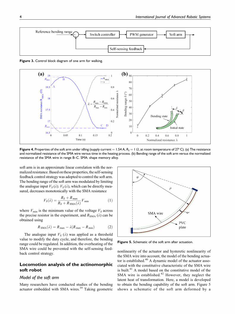
soft arm is in an approximate linear correlation with the nor-
malized resistance. Based on these properties, the self-sensing
feedback control strategy was adopted to control the soft arm.
The bending range of the soft arm was modulated by limiting
the analogue input VS (l). VS (l), which can be directly mea-
sured, decreases monotonically with the SMA resistance
VSðlÞ ¼RS þ R max
RS þ R SMAðlÞV min ð1Þ
where Vmin is the minimum value of the voltage VS across
the precise resistor in the experiment, and RSMA (l) can be
obtained using
R SMAðlÞ ¼ R max � lðR max � R minÞ ð2Þ
The analogue input VS (l) was applied as a threshold
value to modify the duty cycle, and therefore, the bending
range could be regulated. In addition, the overheating of the
SMA wire could be prevented with the self-sensing feed-
back control strategy.
Locomotion analysis of the actinomorphicsoft robot
Model of the soft arm
Many researchers have conducted studies of the bending
actuator embedded with SMA wires.39 Taking geometric
nonlinearity of the actuator and hysteretic nonlinearity of
the SMA wire into account, the model of the bending actua-
tor is established.40 A dynamic model of the actuator asso-
ciated with the constitutive characteristic of the SMA wire
is built.41 A model based on the constitutive model of the
SMA wire is established.42 However, they neglect the
latent heat of transformation. Here, a model is developed
to obtain the bending capability of the soft arm. Figure 5
shows a schematic of the soft arm deformed by a
Figure 3. Control block diagram of one arm for walking.
Figure 4. Properties of the soft arm under idling (supply current¼ 1.54 A, RS¼ 1 O, at room temperature of 27�C). (a) The resistanceand normalized resistance of the SMA wire versus time in the heating process. (b) Bending range of the soft arm versus the normalizedresistance of the SMA wire in range B–C. SMA: shape memory alloy.
Figure 5. Schematic of the soft arm after actuation.
4 International Journal of Advanced Robotic Systems

contraction force of SMA wire, and the parameters of this
soft arm are listed in Table 2. Three assumptions are made
in the model: (i) the soft arm behaves as a Euler beam
throughout the bending deformation, and its bending shape
is approximated as a circular arc; (ii) the PVC surface is the
neutral plane of the soft arm, and the distance d between the
SMA wire as well as the PVC surface is constant during
actuation; and (iii) the temperature variation of the PDMS
is negligible if the heating time is short.
When the soft arm is deformed by a bending moment
generated by the contraction force FSMA of the SMA wire,
with its bending deformation measured by the bending
deformation ’, then
F SMAd
E SAI SA
¼ 1
�ð3Þ
where ESA is the effective elastic modulus of the soft arm,
ISA is the area moment of inertia of the soft arm, and � is the
radius of curvature of the soft arm. Because the bending
shape of the soft arm is approximated as a circular arc, the
radius of curvature � is given by
� ¼ L SA
’ð4Þ
where LSA is the length of the soft arm. The bending defor-
mation ’ can be approximately expressed by
’ ¼ ðeL � e SMAÞL SA
dð5Þ
where e SMA is the strain of the SMA wire and eL is the
maximum residual strain of the SMA wire.
According to equations (1) to (3), the contraction force
of the SMA wire is
F SMA ¼E SAI SA
d2ðeL � e SMAÞ ð6Þ
The equilibrium state of the soft arm is given by
F SMA ¼ s SMAA SMA � F ini ð7Þ
where sSMA is the stress in the SMA wire, ASMA is the
cross-sectional area of the SMA wire, and Fini is the initial
pull force of the SMA wire.
The resulting stress of the SMA wire is
s SMA ¼ kðeL � e SMAÞ þ s ini ð8Þ
where k ¼ ðE SAI SAÞ=ðd2A SMAÞ and s ini ¼ F ini=A SMA.
When the temperature of the SMA wire is higher than
the austenite start temperature As, the SMA wire starts to
transfer from the martensite to the austenite phase and gen-
erates the contraction force. The behavior of the SMA wire
is described by Liang–Rogers model43
_s SMA ¼ EðxÞ _eSMA þY _T þ OðxÞ _x ð9Þ
where E(x) is the Young’s modulus of the SMA wire, Y is
the thermoelastic tensor for the SMA wire and is assumed
to be negligible, T is the temperature of the SMA wire, O(x)is the phase transformation tensor, and x is the martensite
fraction. E(x) is assumed to be linear with the martensite
fraction, namely EðxÞ ¼ EA þ xðEM � EAÞ, where EA and
EM are Young’s moduli when austenite is 100% and mar-
tensite is 100%, respectively. O(x) is related to E(x) and can
be defined by OðxÞ ¼ �eLEðxÞ. Therefore, the SMA con-
stitutive model can be simplified as
_sSMA ¼ EðxÞð _e SMA � eL_xÞ ð10Þ
During the transformation process of the SMA wire
from the martensite to austenite ( M! A), its martensite
fraction is expressed by
x ¼ xM
2cos½aAðT � AsÞ þ bAs SMA� þ
xM
2;
A sþs SMA
C A
� T � A f þs SMA
C A
ð11Þ
where a A ¼ p=ðAf � AsÞ and b A ¼ �a A=C A. xM is the ini-
tial martensite fraction prior to the beginning of the M! A
transformation process. CA is a constant, representing the
effect of stress on the austenite temperature of the SMA wire.
During the transformation process of the SMA wire
from the austenite to martensite ( A! M), its martensite
fraction is expressed by
x ¼ 1� xA
2cos½aMðT �Mf Þ þ bMs SMA� þ
1þ xA
2;
M f þsSMA
C M
� T � M sþsSMA
C M
ð12Þ
where a M ¼ p=ðMs �Mf Þ and b M ¼ �a A=C M. xA is the
initial martensite fraction prior to the beginning of the
Table 2. Parameters in the model of the soft arm.
Description (parameter) Value (unit)
Initial size of the soft arm (length � width �high)
80 � 20 � 5mm
Distance between the SMA wire and PVCsurface (d)
1.7 mm
SMA wire diameter (dSMA) 0.15 mmLength of the SMA wire (lSMA) 320 mmResistance per length (�) 55 O/mDensity (�SMA) 6.45 g/cm3
Specific heat capacity (cSMA) 837 J/(kg � �C)Latent heat of transformation (H) 24.2 � 103 J/kgAustenite start temperature (As) 80�CAustenite finish temperature (Af) 108�CMartensitic start temperature (Ms) 78�CMartensitic finish temperature (Mf) 60�CAustenitic Young’s modulus (EA) 83 GPaMartensitic Young’s modulus (EM) 28 GPaMaximum residual strain (eL) 6.6%Effect of stress on austenite temperature (CA) 12 MPa/�CEffect of stress on martensitic temperature (CM) 10 MPa/�C
SMA: shape memory alloy; PVC: polyvinyl chloride.
Liu et al. 5

A! M transformation process. CM is a constant, which
represents the effect of stress on the martensite temperature
of the SMA wire.
Therefore, the derivatives of equations (11) and (12) can
be expressed by
_x ¼ hT_T þ hs _s ð13Þ
where
hT ¼
�aA
xM
2sin½aAðT � AsÞ þ bAs SMA� M! A
�aM
1� x A
2sin½aMðT �Mf Þ þ bMs SMA� A! M
8>>>><>>>>:
ð14Þ
hs ¼
�bA
xM
2sin½aAðT � AsÞ þ bAsSMA� M! A
�bM
1� x A
2sin½aMðT �Mf Þ þ bMs SMA� A! M
8>>>><>>>>:
ð15Þ
When the SMA wire is heated through current, its ther-
mal model can be expressed by
�SMAc SMAV SMA_T ¼ i2
SMAR SMA � hS SMAðT � TambÞþ �SMAV SMAH _x
ð16Þ
where �SMA is the density of the SMA wire, cSMA is the
specific heat capacity, VSMA is the volume of the SMA wire,
iSMA is the supply current, RSMA is the resistance of the SMA
wire, h is the heat transfer coefficient, SSMA is the surface
area of the SMA wire, Tamb is the ambient temperature, and
H is the latent heat of transformation of the SMA wire.
During the actuation process of the SMA wire, the fol-
lowing equations are derived from equations (8) to (16)
_x_T
_e
264
375 ¼
f ðs; TÞi2
SMAR SMA � hS SMAðT � TambÞ� SMAV SMAc SMA
þ Hf ðs; TÞc SMA
EðxÞeL
EðxÞ þ kf ðs; TÞ
26666664
37777775ð17Þ
where
f ðs; TÞ ¼hT
i2SMAR SMA � hS SMAðT � TambÞ
� SMAV SMAc SMA
1þ hskeL
EðxÞEðxÞ þ k
� hT
H
c SMA
ð18Þ
Figure 6 shows the bending range of the soft arm under
idling, in which the supply voltage is 30 V with 160 ms
heating time in one period. According to Figure 6, the cool-
ing process is longer than the heating process and the
bending range is approximately linear to the time during
the heating process. The experimental and simulation
results exhibit similar motion, and therefore, the model of
the soft arm could be used to analyze the locomotion of the
actinomorphic soft robot.
Spatial robot kinematics
To model the kinematics of the actinomorphic soft robot, a
modified Denavit–Hartenberg (D-H) method was intro-
duced. The modified D-H method is first proposed to model
the kinematics of continuum robots, in which the move-
ment of a planar curve is described by three coupled move-
ments.44 To reflect a correct orientation term, the
continuum robot section is based on a rigid-link arm con-
sisting of two revolute joints with intersecting axes, fol-
lowed by a translational and two more revolute joints
with intersecting axes in the modified D-H method.45
The kinematics of the actinomorphic soft robot is
analyzed. The geometric parameters for one arm of the
actinomorphic soft robot shown (see Figure 7) are listed
Figure 6. Bending range of the soft arm versus time under idling(heating time ¼ 160 ms, period ¼ 2 s, supply current ¼ 1.54 A).
Figure 7. D-H frames for one arm of the actinomorphic softrobot. D-H: Denavit–Hartenberg.
6 International Journal of Advanced Robotic Systems

in Table 3. XYZ-system is the world coordinate system, and
the actinomorphic soft robot moves in the YZ plane. Frame
0 is located in the geometric center of the 3-D printing rack,
in which axis x0 is parallel to axis X. a1 is the angle from
z0-axis to z1-axis about x0-axis, which is related to the
distribution of the arm. The soft arm is described by a
pseudo-rigid link with a coupled link/joint arrangement.
Using the D-H table, the homogeneous transformation
matrix for the arm can be written as
0 T 5 ¼
cosðq1 þ q2Þ 0 � sinðq1 þ q2Þ �d2 sinq1
� sina1 sinðq1 þ q2Þ cosa1 � sina1 cosðq1 þ q2Þ � sina1ðd1 þ d2 cosq1Þcosa1 sinðq1 þ q2Þ sina1 cosa1 cosðq1 þ q2Þ cosa1ðd1 þ d2 cosq1Þ
0 0 0 1
26664
37775 ð19Þ
where q2 þ q1 ¼ 2q1 ¼ ’.
Locomotion state and motion equation
In the movement of the actinomorphic soft robot, the arm
owns two states: swing and supporting state. In the swing
state, the arm is off the ground. In the supporting state, the
arm could be static or moving depending on the friction
force with the ground. The locomotion state is a series of
arm states that enable the actinomorphic soft robot to move
in the environment. To analyze the locomotion model of
the actinomorphic soft robot, an equivalent parallel closed-
chain mechanism was proposed, as shown in Figure 8. The
ground, the supporting arm, and the 3D printing rack with
the swing arm correspond to the frame, link, and end effec-
tor of the closed-chain mechanism, respectively. The
linkup between the supporting arm and the 3D printing rack
is approximate to a revolute pair. The linkups between the
ground and the static or moving supporting arm are the
revolute pair and cylindrical and planar pair, respectively.
The total degrees of freedom (DOF) in the equivalent
closed-chain mechanism is given by
DOF ¼ 6ðnþ 1Þ � 5n�Xn
i¼1
fi ¼ nþ 6�Xn
i¼1
fi ð20Þ
where n is the number of supporting arms, andPni¼1
fi is the
DOF limited by the linkups between the ground and sup-
porting arms. Because the soft robot could be mobile, the
DOF is constrained by
1 � DOF � 6 ð21Þ
If all the supporting arms are moving, then
Xn
i¼1
fi ¼ n; DOF ¼ 6 ð22Þ
If there is one static supporting arm, then
Xn
i¼1
fi ¼ nþ 4; DOF ¼ 2 ð23Þ
If there are two static supporting arms, then
Xn
i¼1
fi ¼ nþ 8; DOF < 0 ð24Þ
Therefore, during the movement of the actinomorphic
soft robot, the locomotion state of the actinomorphic soft
robot falls into two categories: all arms are in the moving
state and only one arm is the static supporting arm.
During the movement of the actinomorphic soft robot,
the bending state of the arm changes with the temperature
of the SMA wire, resulting in the variation of the support
force and frictional force exerted on the arm. When the
state of force equilibrium is broken in the current locomo-
tion state, the soft robot switches from the current locomo-
tion state to the other state in which the equilibrium
condition could be satisfied. The switch between locomo-
tion states is related to the state of force equilibrium and
input signal of the soft arm.
When the actinomorphic soft robot moves slowly in
the environment, its motion is approximated to a quasi-
static process. In the quasi-static process, the resultant F
of all forces acting on the soft robot is zero. Therefore,
the translational equilibrium and rotational equilibrium
equations in the world coordinate system could be
expressed by XFy ¼ 0;
XFz ¼ 0X
MxðFÞ ¼ 0
(ð25Þ
Combined with the model of the soft arm and spatial
robot kinematics, the relative position of each arm end
relative to the frame 0 could be calculated, and therefore,
2n-3 distance equations could be derived. The distance
equation between two arm ends in the world coordinate
system satisfies
d ðarmi ; armj Þ ¼jjðyi; ziÞ � ðyj; zjÞjj ð26Þ
where ðyi; ziÞ and ðyj; zjÞ are coordinates of arms i and j in
the YZ plane, respectively. When all the supporting arms
are moving, solutions of these equations could be
expressed by
Liu et al. 7

x ¼ ðy1; z1; . . . ; yn; znÞT ð27Þ
When there is one static supporting arm, solutions of
these equations could be expressed by
x ¼ ðy1; z1; . . . ; yk�1; zk�1; ykþ1; zkþ1; . . . ; yn; zn; fky; fkzÞT
ð28Þ
where k is the index of the static supporting arm, fky and fkz
are the static frictional forces exerted on the arm k.
Figure 9 shows the locomotion of a three-arm soft robot,
in which only one arm is actuated. The sequential diagram
is shown in Figure 9(a), in which the period is 2 s with the
pulse width 160 ms. The displacement of the three-arm soft
robot is shown in Figure 9(b). The experimental and simu-
lation results exhibit similar locomotion characteristics
with a zig-zag movement pattern (see Figure 9(b)), due to
the switch of the locomotion state caused by the variation
of the support force and frictional force. Nevertheless, the
stride lengths in one period of the three-arm soft robot in
experiment and simulation are different. This is mainly
caused by several factors including the quasi-static and
pseudo-rigid approximation in the simulation scene and the
variable friction coefficient affected by the changing con-
tact surface of the arm in the experiment.
Gait optimization of actinomorphic softrobots
Gait planning for locomotion
Controlling the locomotion of soft robots is challenging
because of the difficulty in accurate modeling of the
robot–environment interaction. The robot locomotion is
formulated as a type of optimization problem,46 complex
for a multiarm robot such as a six-arm robot, and some of
the locomotion is not realistic. Robot locomotion is typi-
cally inspired from biology.31,32 Inspired by starfish loco-
motion, two rays are pushed in advance, with three rays
behind; or three rays pushed in advance, followed by two
rays.47 According to this principle, wave gaits were
adopted; these actuated the soft robots in a sequential man-
ner with an actuation wave travelling through their bodies
from the front toward the rear.
Figure 10 depicts the locomotion of four types of acti-
nomorphic soft robots. These sequential diagrams exhibit a
series of wave gaits. Figure 10(a) shows the sequential
diagram of a three-arm soft robot. First, arms 2 and 3 are
activated and bent, thereby causing the center of gravity to
move ahead. Second, arm 1 is activated and bent; this
action helps accumulate the elastic potential energy to drive
the robot to move forward. Figure 10(b) displays the
sequence chart of a four-arm soft robot. First, arm 4 is
activated and contracted; the contraction produces forward
movement to cause the center of gravity to shift ahead.
Second, arms 2 and 3 are activated and bent simultaneously
to upraise the body. Third, arm 1 bends and drives the robot
crawling motion using the accumulated elastic potential
energy. Figure 10(c) shows a five-arm soft robot that moves
forward with the wave gait. First, arms 4 and 5 are activated
and bent, thereby causing the center of gravity of the body
to shift forward. Next, arms 2 and 3 are activated and con-
tracted to hold the entire body. Finally, arm 1 is activated
and bent, thereby storing elastic potential energy to cause
the entire body to move forward with ground friction. Fig-
ure 10(d) shows a six-arm soft robot that achieves forward
motion via a series of sequential movements. First, arm 6 is
activated and bent, thereby causing the center of gravity of
the body to move ahead. Next, arms 4 and 5 are activated
and the body raised. Subsequently, arms 2 and 3 are
Table 3. D-H table for one arm of the actinomorphic soft robotin Figure 7.
Link i di qi ai ai
1 0 0 0 a1
2 d1 0 0 �p/23 0 q1 0 p/24 d2 0 0 �p/25 0 q2 0 p/2
D-H: Denavit–Hartenberg.
Figure 8. Schematic of an equivalent parallel closed-chainmechanism for an actinomorphic soft robot.
Figure 9. Locomotion of a three-arm soft robot with oneactuating arm. (a) Sequential diagram for the locomotion (pulsewidth ¼ 8%, period ¼ 2 s, supply current ¼ 1.54 A). (b) Displa-cement–time curve in the Z direction.
8 International Journal of Advanced Robotic Systems

activated and contracted to hold the body. Finally, arm 1 is
activated and contracted, thereby accumulating elastic
potential energy to propel the robot forward. In Figure
10, Ti (i ¼ 1, 2, 3, 4) is the period of motion in each
locomotion; tij (i¼ 1, 2, 3, 4; j¼ 1, 2, 3) is the time interval
of the startup time between two adjacent groups of arms in
each locomotion; and Dtij (i¼ 1, 2, 3, 4; j¼ 1, 2, 3, 4) is the
heating time of each arm.
Performance comparisons of the actinomorphic softrobots
Four types of actinomorphic robot prototypes were
designed to investigate the effects of factors, for example,
the number of arms and Dtij, on the performance of the
robots. A series of experiments were conducted to select
the optimal gait parameters to actuate robots with a satis-
factory performance. The heating time Dtij of each arm was
regulated by controlling the corresponding normalized
resistance lij of each arm according to the self-sensing
feedback control strategy, and lij corresponds to Dtij. The
period of motion Ti in each locomotion is sufficiently long
to prevent the SMA wires from overheating, and these
periods were set as 2, 2, 2, and 4 s for three-, four-, five-,
and six-arm robots, respectively. To simplify the experi-
ments, the time intervals tij were defined to be equivalent in
each locomotion, such as t21¼ t22, t31¼ t32, and t41¼ t42¼t43, and arm 1 of each robot bent with a maximum bending
range, namely, the corresponding normalized resistance lwas set to 1. Several sets of experiments were performed to
evaluate the effects of the time interval and heating time on
the performance of robots. The time interval tij ranged from
10 ms to 100 ms with an increment of 30 ms, and the
normalized resistance lij (which was used to regulate the
heating time) ranged from 0.1 to 1.0, with an increment of
0.3. These experiments were conducted on a flat surface at
the room temperature of 27�C.
Appendix Tables 1A to 1D list the stride lengths in one
period of different robots to accomplish locomotion for the
conditions stated in the previous paragraph. According to
Appendix Table 1A, the three-arm soft robot could
achieve better performance (a longer stride length) when
the parameters satisfy the conditions of 0.1 � l12 � 0.4 or
70 � t11 � 100. In Appendix Table 1B, the four-arm soft
robot could exhibit better performance when 0.1 � l22 �0.4 or 70 � t21 � 100. Appendix Table 1C shows that the
five-arm soft robot performs better when 0.4 � l33 � 1.0
or 0.4 � l32 � 0.7. As shown in Appendix Table 1D, the
Figure 10. Locomotion of actinomorphic soft robots. (a) to (d) are sequential diagrams of the locomotion principle for the three-arm,four-, five-, and six-arm robots, respectively.
Liu et al. 9

six-arm soft robot could perform better when 0.4 � l43 �1.0 or 40 � t41 � 100. These results indicate that the gait
parameters affect the performance of actinomorphic soft
robots with multiple arms.
The maximum periodic stride lengths of the three-, four-,
five-, and 6-arm robots are 75, 72, 63, and 58 mm, respec-
tively. Figure 11 shows the displacement–time curves of
these robots at the maximum periodic stride lengths, in
which the displacements are the trajectories of each center
of rack (CoR). These robots exhibit similar locomotion
characteristic with a zig-zag movement pattern. Their
CoRs move forward for a short distance initially and then
backward for a long distance. Afterwards, their CoRs
move forward for a long distance and then backward for
a short distance. As a result, the CoRs move forward for
one stride length. The average stride lengths of the three-,
four-, five-, and six-arm robots are 52, 47, 28, and 29 mm,
respectively, as shown in Figure 12. The average stride
length of the three-arm robot is greater than that of the
four-arm robot, and the six-arm robot has a similar aver-
age stride length as the five-arm robot. Among these
robots, the three-arm robot shows the best performance.
Locomotive performance of the three-armactinomorphic soft robot
In the natural environment, actinomorphic animals inhabit
a wide range of surroundings, for example, sandy beach,
tidal pools, and deep-sea floor. The actinomorphic animals
show different locomotive performance in different envi-
ronment. Here, a series of experiments were conducted
with the three-arm actinomorphic soft robot to analyze the
locomotive performance under different circumstances.
In addition to moving in a flat terrestrial environment
shown in previous experiments, the actinomorphic soft
robot could move in a semisubmerged environment, as
shown in Figure 13(a). The actinomorphic soft robot could
achieve locomotion with an average stride length of 33 mm
at a frequency of 1 Hz, as shown in Figure 13(b). In addi-
tion, the displacement of the actinomorphic soft robot exhi-
bits a zig-zag trend at an average speed of 33 mm/s.
Sand is one ordinary intertidal zone habitat for actino-
morphic animals, such as starfish. The three-arm actino-
morphic soft robot could move on sand. Figure 14(a)
shows a sequence of snapshots of locomotion on dry
sand, and Figure 14(b) shows the displacement–time
curve of the robot moving on dry sand at a frequency
of 1 Hz. On dry sand, the soft robot could achieve loco-
motion with an average speed of 5.2 mm/s. Figure 15(a)
shows a sequence of snapshots of locomotion on wet
sand, and Figure 15(b) shows the displacement–time
curve of the robot moving on wet sand at a frequency
of 1 Hz. On wet sand, the soft robot could achieve loco-
motion with an average speed of 22.4 mm/s. These
experimental results indicate that the performance for the
actinomorphic soft robot moving with a zig-zag pattern
on wet sand is superior to the performance for the acti-
nomorphic soft robot moving on dry sand.
Transitional environment is one of the common terrains
encountered in nature, for example, the water–land transi-
tional zone. Figure 16(a) shows images from an experiment
of a three-arm actinomorphic soft robot operating in a
region transitioning from wet sand to a semisubmerged
environment. Figure 16(b) shows the displacement–time
curve for the forward translation from the wet sand envi-
ronment to the semisubmerged environment. In this experi-
ment, the soft robot moved at a frequency of 1 Hz. The soft
robot could achieve locomotion with an average speed of
Figure 11. Displacement–time curves of actinomorphic softrobots for forward translation: (a) to (d) are displacement–timecurves of the three-, four-, five-, and 6-arm soft robots,respectively.
Figure 12. Average stride lengths of actinomorphic soft robots.
10 International Journal of Advanced Robotic Systems

Figure 13. Locomotion in a semisubmerged environment. (a) Frames of locomotion in the semisubmerged environment. (b) Dis-placement–time curve for forward translation in the semisubmerged environment.
Figure 14. Locomotion on dry sand. (a) Frames of locomotion on dry sand. (b) Displacement–time curve for forward translation.
Figure 15. Locomotion on wet sand. (a) Frames of locomotion on wet sand. (b) Displacement–time curve for forward translation.
Liu et al. 11

45 mm/s in the transition region and the performance in the
transition region was superior to the performance in the
other two surroundings.
Moving from the wet sand to the semisubmerged
environment. (a) Frames of locomotion in the environment.
(b) Displacement–time curve for forward translation.
Conclusion
A model was established to analyze the locomotion of the
actinomorphic soft robot, combining the model of the soft
arm with the spatial kinematics and the motion equation of
the actinomorphic soft robot. Experimental and simula-
tion results show that the actinomorphic soft robot moves
on a flat surface with the zig-zag pattern caused by the
switch of the locomotion state. Besides, the parameters of
the wave gait for four actinomorphic soft robots with three
to six arms were optimized according to the criterion of
stride length. The three-arm actinomorphic soft robot out-
performs other types of robots and could achieve a max-
imum stride length of 75 mm, which is nearly 0.4 times its
body length. Moreover, the three-arm actinomorphic soft
robot could achieve locomotion under different circum-
stances, including the semisubmerged environment, dry
and wet sand as well as the transitional environment.
Results show that the three-arm actinomorphic soft robot
exhibits similar locomotion characteristic with the zig-zag
movement pattern in various environment. Future work
will focus on enhancing the autonomy and mobility of the
actinomorphic soft robot.
Acknowledgement
The authors would like to thank Dr Hu Jin for his support and
advice in writing this article.
Declaration of conflicting interests
The author(s) declared no potential conflicts of interest with respect
to the research, authorship, and/or publication of this article.
Funding
The author(s) disclosed receipt of the following financial support
for the research, authorship, and/or publication of this article: This
work was supported by the National Natural Science Foundation
of China (nos. 51105349 and 61375095).
ORCID iD
Gursel Alici http://orcid.org/0000-0001-6527-2881
References
1. Rus D and Tolley MT. Design, fabrication and control of soft
robots. Nature 2015; 521(7553): 467–475.
2. Pfeifer R, Lungarella M, and Iida F. The challenges ahead for
bio-inspired ‘soft’ robotics. Commun ACM 2012; 55(11): 76–87.
3. Bauer S, Bauer-Gogonea S, Graz I, et al. 25th anniversary
article: a soft future: from robots and sensor skin to energy
harvesters. Adv Mater 2014; 26(1): 149–162.
4. Wehner M, Truby RL, Fitzgerald DJ, et al. An integrated
design and fabrication strategy for entirely soft, autonomous
robots. Nature 2016; 536(7617): 451–455.
5. Laschi C, Mazzolai B, and Cianchetti M. Soft robotics:
technologies and systems pushing the boundaries of robot
abilities. Sci Robot 2016; 1(1): eaah3690.
6. Mosadegh B, Polygerinos P, Keplinger C, et al. Pneumatic
networks for soft robotics that actuate rapidly. Adv Funct
Mater 2014; 24(15): 2163–2170.
7. Mutlu R, Alici G, and Li W. A soft mechatronic microstage
mechanism based on electroactive polymer actuators. IEEE
ASME Trans Mech 2016; 21(3): 1467–1478.
8. Nguyen CH, Alici G, and Mutlu R. A compliant translational
mechanism based on dielectric elastomer actuators. J Mech
Des 2014; 136(6): 061009.
Figure 16. Moving from the wet sand to the semi-submerged environment. (a) Frames of locomotion in the environment.(b) Displacement–time curve for forward translation.
12 International Journal of Advanced Robotic Systems

9. Seok S, Onal CD, Cho KJ, et al. Meshworm: a peristaltic soft
robot with antagonistic nickel titanium coil actuators.
IEEEASME Trans Mech 2013; 18(5): 1485–1497.
10. Shepherd RF, Ilievski F, Choi W, et al. Multigait soft robot.
Proc Natl Acad Sci 2011; 108(51): 20400–20403.
11. Shintake J, Rosset S, Schubert B, et al. Versatile soft grippers
with intrinsic electroadhesion based on multifunctional poly-
mer actuators. Adv Mater 2016; 28(2): 231–238.
12. Chen Z, Um TI, and Bart-Smith H. A novel fabrication of
ionic polymer–metal composite membrane actuator capable
of 3-dimensional kinematic motions. Sens Actuat Phys 2011;
168(1): 131–139.
13. Koh JS, Yang E, Jung GP, et al. Jumping on water: surface
tension–dominated jumping of water striders and robotic
insects. Science 2015; 349(6247): 517–521.
14. Jani JM, Leary M, Subic A, et al. A review of shape memory
alloy research, applications and opportunities. Mater Des
2014; 56: 1078–1113.
15. Ma N, Song G, and Lee H. Position control of shape
memory alloy actuators with internal electrical resistance
feedback using neural networks. Smart Mater Struct 2004;
13: 777.
16. Lan CC, Lin CM, and Fan CH. A self-sensing microgripper
module with wide handling ranges. IEEEASME Trans Mech
2011; 16(1): 141–150.
17. Wang TM, Shi ZY, Liu D, et al. An accurately controlled
antagonistic shape memory alloy actuator with self-sensing.
Sensors 2012; 12(6): 7682–7700.
18. Joseph SRD and Dhanalakshmi K. Shape memory alloy with
bi-functionality in the master system to control a slave. Sens
Actuat Phys 2016; 238: 351–360.
19. Wang G and Shahinpoor M. A new design for a rotatory joint
actuator made with a shape memory alloy contractile wire.
J Intell Mater Syst Struct 1997; 8: 215–219.
20. Dimitris CL. Shape memory alloys: modeling and engineer-
ing applications. New York: Springer, 2008.
21. Zhang S, Liu B, Wang L, et al. Design and implementation of
a lightweight bioinspired pectoral fin driven by SMA.
IEEEASME Trans Mech 2014; 19(6): 1773–1785.
22. Yuan H, Fauroux J, Chapelle F, et al. A review of rotary
actuators based on shape memory alloys. J Intell Mater Syst
Struct 2017; 28: 1863–1885.
23. Martinez RV, Glavan AC, Keplinger C, et al. Soft actuators
and robots that are resistant to mechanical damage. Adv Funct
Mater 2014; 24(20): 3003–3010.
24. Laschi C, Cianchetti M, Mazzolai B, et al. Soft robot arm
inspired by the octopus. Adv Robot 2012; 26(7): 709–727.
25. Zhao H, O’Brien K, Li S, et al. Optoelectronically innervated
soft prosthetic hand via stretchable optical waveguides. Sci
Robot 2016; 1(1): eaai7529.
26. Tolley MT, Shepherd RF, Mosadegh B, et al. A resilient,
untethered soft robot. Soft Robot 2014; 1(3): 213–223.
27. Lin HT, Leisk GG, and Trimmer B. GoQBot: a caterpillar-
inspired soft-bodied rolling robot. Bioinspir Biomim 2011;
6(2): 026007.
28. Shepherd RF, Stokes AA, Freake J, et al. Using explosions to
power a soft robot. Angew Chem Int Ed 2013; 52(10):
2892–2896.
29. Giorgio-Serchi F, Arienti A, Corucci F, et al. Hybrid para-
meter identification of a multi-modal underwater soft robot.
Bioinspir Biomim 2017; 12(2): 025007.
30. Onal CD and Rus D. Autonomous undulatory serpentine
locomotion utilizing body dynamics of a fluidic soft robot.
Bioinspir Biomim 2013; 8(2): 026003.
31. Wang W, Lee JY, Rodrigue H, et al. Locomotion of
inchworm-inspired robot made of smart soft composite
(SSC). Bioinspir Biomim 2014; 9(4): 046006.
32. Song SH, Kim MS, Rodrigue H, et al. Turtle mimetic soft
robot with two swimming gaits. Bioinspir Biomim 2016;
11(3): 036010.
33. Yu J, Xiao J, Li X, et al. Towards a miniature self-propelled
jellyfish-like swimming robot. Int J Adv Robot Syst 2016;
13(5): 1729881416666796.
34. Mao S, Dong E, Jin H, et al. Gait study and pattern generation
of a starfish-like soft robot with flexible rays actuated by
SMAs. J Bionic Eng 2014; 11(3): 400–411.
35. Jin H, Dong E, Alici G, et al. A starfish robot based on soft
and smart modular structure (SMS) actuated by SMA wires.
Bioinspir Biomim 2016; 11(5): 056012.
36. Jin H, Dong E, Xu M, et al. Soft and smart modular structures
actuated by shape memory alloy (SMA) wires as tentacles of
soft robots. Smart Mater Struct 2016; 25(8): 085026.
37. Mohd JJ, Leary M, and Subic A. Designing shape memory
alloy linear actuators: a review. J Int Mater Syst Struct 2017;
28(13): 1699–1718.
38. Mosley M, Mavroidis C, and Pfeiffer C. Design and dynamics
of a shape memory alloy wire bundle actuator. In: Proceed-
ings of the ANS, 8th Topical Meeting on Robotics and Remote
Systems, Pittsburgh Pennsylvania, U.S.A, 25–29 April 1999,
pp. 1–14. La Grange Park, IL: American Nuclear Society.
39. Rodrigue H, Wang W, Han MW, et al. An overview of shape
memory alloy-coupled actuators and robots. Soft Robot 2017;
4(1): 3–15.
40. Wang G and Shahinpoor M. Design, prototyping and com-
puter simulations of a novel large bending actuator made with
a shape memory alloy contractile wire. Smart Mater Struct
1997; 6(2): 214–221.
41. Du Y, Liu B, Xu M, et al. Dynamic characteristics of planar
bending actuator embedded with shape memory alloy.
Mechatronics 2015; 25: 18–26.
42. Rodrigue H, Wang W, Kim DR, et al. Curved shape memory
alloy-based soft actuators and application to soft gripper.
Compos Struct 2017; 176: 398–406.
43. Liang C and Rogers CA. One-dimensional thermomechanical
constitutive relations for shape memory materials. J Int Mater
Syst Struct 1997; 8: 285–302.
44. Hannan MW and Walker ID. Kinematics and the implemen-
tation of an elephant’s trunk manipulator and other conti-
nuum style robots. J Field Robot 2003; 20(2): 45–63.
45. Jones BA and Walker ID. Kinematics for multisection con-
tinuum robots. IEEE Trans Robot 2006; 22(1): 43–55.
Liu et al. 13

46. Umedachi T, Vikas V, and Trimmer B. Softworms: the
design and control of non-pneumatic, 3D-printed, deformable
robots. Bioinspir Biomim 2016; 11(2): 025001.
47. Cole LJ. Direction of locomotion of the starfish (Asterias
forbesi). J Exp Zool Part Ecol Genet Physiol 1913; 14: 1–32.
Appendix 1
Tables 1A to 1C show stride lengths in one period of
different robots.
Table 1A. Stride lengths (mm) of the three-arm actinomorphicrobot in one period.
t11 (ms)l12 10 40 70 100
0.1 48 52 53 500.4 66 75 72 600.7 36 38 44 531.0 32 36 49 66
Table 1B. Stride lengths (mm) of the four-arm actinomorphicrobot in one period.a
t21 (ms)l22 10 40 70 100
t21 (ms)l22 10 40 70 100
0.1 53 46 46 52 0.1 46 50 51 480.4 54 50 53 52 0.4 40 52 53 530.7 NaN NaN NaN NaN 0.7 22 20 40 371.0 NaN NaN NaN NaN 1.0 21 23 64 58
(a) l23 ¼ 0.1 (b) l23 ¼ 0.4
t21 (ms)l22 10 40 70 100
t21 (ms)l22 10 40 70 100
0.1 69 68 72 69 0.1 35 53 70 400.4 56 54 53 58 0.4 44 56 67 700.7 20 23 45 52 0.7 20 22 67 561.0 23 23 37 43 1.0 20 24 70 64(c) l23 ¼ 0.7 (d) l23 ¼ 1.0
aNaN indicates that it is difficult for the robot to move forward in astraight direction with these parameters.
Table 1C. Stride lengths (mm) of the five-arm actinomorphicrobot in one period.
t31 (ms)l32 10 40 70 100
t31 (ms)l32 10 40 70 100
0.1 20 7 7 5 0.1 37 39 16 50.4 26 16 16 14 0.4 20 37 39 270.7 35 9 6 5 0.7 21 32 45 261.0 17 12 9 8 1.0 39 38 12 13
(a) l33 ¼ 0.1 (b) l33 ¼ 0.4
t31 (ms)l32 10 40 70 100
t31 (ms)l32 10 40 70 100
0.1 40 46 47 42 0.1 35 43 42 250.4 23 27 54 44 0.4 41 44 63 350.7 24 21 62 57 0.7 40 45 40 231.0 15 17 24 29 1.0 39 26 20 20(c) l33 ¼ 0.7 (d) l33 ¼ 1.0
Table 1D. Stride lengths (mm) of the 6-arm actinomorphic robotin one period.
t41 (ms)l42 10 40 70 100
t41 (ms)l42 10 40 70 100
0.1 27 23 20 21 0.1 20 47 48 520.4 30 26 44 43 0.4 28 31 39 350.7 20 24 23 21 0.7 22 35 25 151.0 17 18 19 15 1.0 16 22 22 17
(a) l44 ¼ 0.1, l43 ¼ 0.1 (b) l33 ¼ 0.4
t41 (ms)l42 10 40 70 100
t41 (ms)l42 10 40 70 100
0.1 51 54 48 47 0.1 43 37 50 560.4 36 40 40 43 0.4 18 31 56 580.7 22 27 38 40 0.7 5 17 31 381.0 15 16 10 8 1.0 20 19 14 13
(c) l44 ¼ 0.1, l43 ¼ 0.7 (d) l44 ¼ 0.1, l43 ¼ 1.0
t41 (ms)l42 10 40 70 100
t41 (ms)l42 10 40 70 100
0.1 11 23 15 10 0.1 27 39 44 320.4 22 32 29 26 0.4 38 37 35 280.7 32 25 28 28 0.7 32 35 28 341.0 10 13 10 7 1.0 10 22 12 15
(e) l44 ¼ 0.4, l43 ¼ 0.1 (f) l44 ¼ 0.4, l43 ¼ 0.4
t41 (ms)l42 10 40 70 100
t41 (ms)l42 10 40 70 100
0.1 25 51 56 42 0.1 35 37 53 500.4 38 42 42 41 0.4 22 32 41 480.7 23 34 30 35 0.7 11 23 42 451.0 10 14 10 15 1.0 10 8 16 18
(g) l44 ¼ 0.4, l43 ¼ 0.7 (h) l44 ¼ 0.4, l43 ¼ 1.0
t41 (ms)l42 10 40 70 100
t41 (ms)l42 10 40 70 100
0.1 17 22 20 15 0.1 15 39 30 210.4 16 40 47 45 0.4 26 45 43 310.7 21 27 41 48 0.7 31 25 21 251.0 18 25 10 12 1.0 25 29 24 17
(i) l44 ¼ 0.7, l43 ¼ 0.1 (j) l44 ¼ 0.7, l43 ¼ 0.4
t41 (ms)l42 10 40 70 100
t41 (ms)l42 10 40 70 100
0.1 18 26 23 21 0.1 14 26 25 270.4 15 37 30 32 0.4 21 43 42 460.7 17 22 24 24 0.7 21 41 40 331.0 14 17 16 12 1.0 15 32 36 38
(k) l44 ¼ 0.7, l43 ¼ 0.7 (l) l44 ¼ 0.7, l43 ¼ 1.0
t41 (ms)l42 10 40 70 100
t41 (ms)l42 10 40 70 100
0.1 25 13 10 11 0.1 31 36 15 200.4 22 15 17 16 0.4 31 41 40 340.7 23 30 33 30 0.7 38 56 47 441.0 25 17 16 13 1.0 33 29 21 17
(m) l44 ¼ 1.0, l43 ¼ 0.1 (n) l44 ¼ 1.0, l43 ¼ 0.4
t41 (ms)l42 10 40 70 100
t41 (ms)l42 10 40 70 100
0.1 41 40 39 41 0.1 34 31 33 270.4 39 40 49 46 0.4 36 36 43 380.7 25 28 27 32 0.7 34 37 36 431.0 36 37 35 32 1.0 35 34 27 24(o) l44 ¼ 1.0, l43 ¼ 0.7 (p) l44 ¼ 1.0, l43 ¼ 1.0
14 International Journal of Advanced Robotic Systems


![Locomotion [2015]](https://static.fdocuments.net/doc/165x107/55d39c9ebb61ebfd268b46a2/locomotion-2015.jpg)