
LIQUID FUEL CUTTING TORCH SYSTEM REFERENCE …20… · LIQUID FUEL CUTTING TORCH SYSTEM REFERENCE...
32
LIQUID FUEL CUTTING TORCH SYSTEM REFERENCE MANUAL VERSION 1.1 CONFIDENTIAL AND PROPRIETARY INFORMATION
Transcript of LIQUID FUEL CUTTING TORCH SYSTEM REFERENCE …20… · LIQUID FUEL CUTTING TORCH SYSTEM REFERENCE...
LIQUID FUEL CUTTING TORCH SYSTEM
REFERENCEMANUAL
VERSION 1.1
CONFIDENTIAL AND PROPRIETARY INFORMATION

Thank you for putting your trust in Petrogen products.
NOTE: Petrogen systems are bespoke appliances, not com-patible with any other oxy-fuel cutting torch systems.
CONFIDENTIAL AND PROPRIETARY INFORMATION CONFIDENTIAL AND PROPRIETARY INFORMATION
System Components Pg. 4-10Pg. 4 Complete System
Pg. 6 Liquid Fuel Torch
Pg. 8 Liquid Fuel Tank
Pg. 9 Oxygen Bottle
System Assembly Pg. 10-19Pg. 10 System Component Check
Pg. 10 Torch Assembly
Pg. 11 Packing Nut Check
Pg. 13 Oxygen Regulator & Oxygen Hose
Pg. 14 Oxygen Hose Pressurization
Pg. 14 Oxygen Pressure Settings
Pg. 16 Fuel Tank Filling
Pg. 17 Fuel Tank Pressurization
Pg. 18 Fuel Line Purge
Light Up Pg. 19-22Pg. 19 Safety Checks
Pg. 20 Light Up
Pg. 22 Shutdown
Storage Pg. 23-26Pg. 23 Normal Shutdown
Pg. 23 Storage Shutdown
Pg. 24 Ready Levels
CONTENTSCutting Basics Pg. 26-30
Pg. 26 Keys to Success
Pg. 27 Torch Position
Pg. 28 Introduce High Pressure Oxygen
Pg. 28 Assess the Cut
Pg. 28 Steel is the Fuel
Pg. 29 Failed Cut
Advanced Techniques Pg. 30-33Pg. 30 V-Cut
Pg. 30 Hole Punching
Pg. 31 Layer Cutting
Pg. 32 Gap Cutting
Pg. 33 Drive Technique
Maintenance Pg. 33-37Pg. 33 Tip Maintenance
Pg. 36 Packing Nut Maintenance
Troubleshooting Pg. 37-40Pg. 37 Warranty
Pg. 37 System Troubleshooting
Repairs Pg. 40-54Pg. 40 Fuel Stream Check
Pg. 41 Mixer Repair
Pg. 44 High Pressure Oxygen Valve Repair
Pg. 49 Pump Assembly Repair
CONFIDENTIAL AND PROPRIETARY INFORMATION CONFIDENTIAL AND PROPRIETARY INFORMATION
4 5CONFIDENTIAL AND PROPRIETARY INFORMATION CONFIDENTIAL AND PROPRIETARY INFORMATION
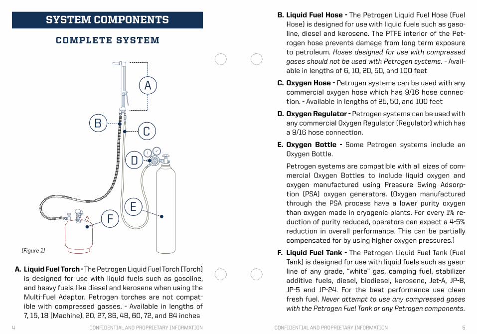
A. Liquid Fuel Torch - The Petrogen Liquid Fuel Torch (Torch) is designed for use with liquid fuels such as gasoline, and heavy fuels like diesel and kerosene when using the Multi-Fuel Adaptor. Petrogen torches are not compat-ible with compressed gasses. - Available in lengths of 7, 15, 18 (Machine), 20, 27, 36, 48, 60, 72, and 84 inches
SYSTEM COMPONENTS
COMPLETE SYSTEM
FE
C
D
B
A
(Figure 1)
B. Liquid Fuel Hose - The Petrogen Liquid Fuel Hose (Fuel Hose) is designed for use with liquid fuels such as gaso-line, diesel and kerosene. The PTFE interior of the Pet-rogen hose prevents damage from long term exposure to petroleum. Hoses designed for use with compressed gases should not be used with Petrogen systems. - Avail-able in lengths of 6, 10, 20, 50, and 100 feet
C. Oxygen Hose - Petrogen systems can be used with any commercial oxygen hose which has 9/16 hose connec-tion. - Available in lengths of 25, 50, and 100 feet
D. Oxygen Regulator - Petrogen systems can be used with any commercial Oxygen Regulator (Regulator) which has a 9/16 hose connection.
E. Oxygen Bottle - Some Petrogen systems include an Oxygen Bottle.
Petrogen systems are compatible with all sizes of com-mercial Oxygen Bottles to include liquid oxygen and oxygen manufactured using Pressure Swing Adsorp-tion (PSA) oxygen generators. (Oxygen manufactured through the PSA process have a lower purity oxygen than oxygen made in cryogenic plants. For every 1% re-duction of purity reduced, operators can expect a 4-5% reduction in overall performance. This can be partially compensated for by using higher oxygen pressures.)
F. Liquid Fuel Tank - The Petrogen Liquid Fuel Tank (Fuel Tank) is designed for use with liquid fuels such as gaso-line of any grade, “white” gas, camping fuel, stabilizer additive fuels, diesel, biodiesel, kerosene, Jet-A, JP-8, JP-5 and JP-24. For the best performance use clean fresh fuel. Never attempt to use any compressed gases with the Petrogen Fuel Tank or any Petrogen components.
6 7CONFIDENTIAL AND PROPRIETARY INFORMATION CONFIDENTIAL AND PROPRIETARY INFORMATION
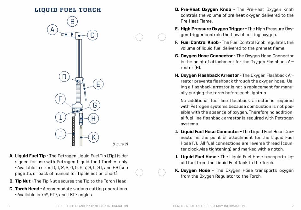
A. Liquid Fuel Tip - The Petrogen Liquid Fuel Tip (Tip) is de-signed for use with Petrogen (liquid fuel) Torches only. - Available in sizes 0, 1, 2, 3, 4, 5, 6, 7, 8, L, 81, and 83 (see page 15, or back of manual for Tip Selection Chart)
B. Tip Nut - The Tip Nut secures the Tip to the Torch Head.
C. Torch Head - Accommodate various cutting operations. - Available in 75º, 90º, and 180º angles
LIQUID FUEL TORCH
KJ
HI
GF
ED
C
BA
(Figure 2)
D. Pre-Heat Oxygen Knob - The Pre-Heat Oxygen Knob controls the volume of pre-heat oxygen delivered to the Pre-Heat Flame.
E. High Pressure Oxygen Trigger - The High Pressure Oxy-gen Trigger controls the flow of cutting oxygen.
F. Fuel Control Knob - The Fuel Control Knob regulates the volume of liquid fuel delivered to the preheat flame.
G. Oxygen Hose Connector - The Oxygen Hose Connector is the point of attachment for the Oxygen Flashback Ar-restor (H).
H. Oxygen Flashback Arrestor - The Oxygen Flashback Ar-restor prevents flashback through the oxygen hose. Us-ing a flashback arrestor is not a replacement for manu-ally purging the torch before each light-up.
No additional fuel line flashback arrestor is required with Petrogen systems because combustion is not pos-sible with the absence of oxygen. Therefore no addition-al fuel line flashback arrestor is required with Petrogen systems.
I. Liquid Fuel Hose Connector - The Liquid Fuel Hose Con-nector is the point of attachment for the Liquid Fuel Hose (J). All fuel connections are reverse thread (coun-ter clockwise tightening) and marked with a notch.
J. Liquid Fuel Hose - The Liquid Fuel Hose transports liq-uid fuel from the Liquid Fuel Tank to the Torch.
K. Oxygen Hose - The Oxygen Hose transports oxygen from the Oxygen Regulator to the Torch.
8 9CONFIDENTIAL AND PROPRIETARY INFORMATION CONFIDENTIAL AND PROPRIETARY INFORMATION
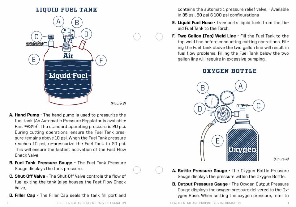
A. Hand Pump - The hand pump is used to pressurize the fuel tank (An Automatic Pressure Regulator is available: Part #2348). The standard operating pressure is 20 psi. During cutting operations, ensure the Fuel Tank pres-sure remains above 10 psi. When the Fuel Tank pressure reaches 10 psi, re-pressurize the Fuel Tank to 20 psi. This will ensure the fastest activation of the Fast Flow Check Valve.
B. Fuel Tank Pressure Gauge - The Fuel Tank Pressure Gauge displays the tank pressure.
C. Shut-Off Valve - The Shut-Off Valve controls the flow of fuel exiting the tank (also houses the Fast Flow Check Valve).
D. Filler Cap - The Filler Cap seals the tank fill port and
LIQUID FUEL TANK
Liquid Fuel
AirFE
DC
BA
(Figure 3)
contains the automatic pressure relief valve. - Available in 35 psi, 50 psi & 100 psi configurations
E. Liquid Fuel Hose - Transports liquid fuels from the Liq-uid Fuel Tank to the Torch.
F. Two Gallon (Top) Weld Line - Fill the Fuel Tank to the top weld line before conducting cutting operations. Fill-ing the Fuel Tank above the two gallon line will result in fuel flow problems. Filling the Fuel Tank below the two gallon line will require in excessive pumping.
OXYGEN BOTTLE
A. Bottle Pressure Gauge - The Oxygen Bottle Pressure Gauge displays the pressure within the Oxygen Bottle.
B. Output Pressure Gauge - The Oxygen Output Pressure Gauge displays the oxygen pressure delivered to the Ox-ygen Hose. When setting the oxygen pressure, refer to
OxygenE
D C
B A
(Figure 4)

10 11CONFIDENTIAL AND PROPRIETARY INFORMATION CONFIDENTIAL AND PROPRIETARY INFORMATION
1. SYSTEM COMPONENT CHECKBefore assembling your system or after prolonged stor-age check that all components are present, serviceable, and undamaged. It is also best practice to check system components for serviceability before each use. If there is any question as to whether or not a part is in good working order, please contact Petrogen Customer Service 877-888-6724.
2. TORCH ASSEMBLY2.1 Slide Tip Nut over chosen Tip. Place Tip’s seating sur-face into Torch Head (Fig. 5). (see page 15, or back of manual for Tip Selection Chart).
the Petrogen Tip Selection Chart (see page 15, or back of the manual) as pressures vary between tip sizes.
C. Oxygen Bottle Valve - The Oxygen Bottle Valve opens and closes the oxygen bottle.
D. Regulator Control Valve - The Regulator Control Valve regulates the oxygen pressure delivered from the Oxy-gen Bottle to the Oxygen Hose.
E. Oxygen Hose - The Oxygen Hose transports oxygen from the Oxygen Regulator to the Torch.
SYSTEM ASSEMBLYO
XY
GA
S
(Figure 5)
2.2 Tighten the Tip Nut in a clockwise manner using an Ad-justable Wrench (Fig. 6). DO NOT OVERTIGHTEN.
2.3 Attach the Oxygen Flashback Arrestor (found in the Standard Spare Parts Kit) to the Torch’s Oxygen Hose Con-nector (labeled OXY). Use an Adjustable Wrench to snug the Oxygen Flashback Arrestor to the Torch (Fig. 7).
3. PACKING NUT CHECKUse the included Packing Nut Wrench found in the Standard Tool Kit to check the following packing nuts for snugness:
(1) Pre-Heat Oxygen Packing Nut - located under the Pre-Heat Oxygen Knob on the Torch, shown in figure 8.
OX
Y
GA
S
(Figure 6)
OX
Y
GA
S
(Figure 7)
12 13CONFIDENTIAL AND PROPRIETARY INFORMATION CONFIDENTIAL AND PROPRIETARY INFORMATION
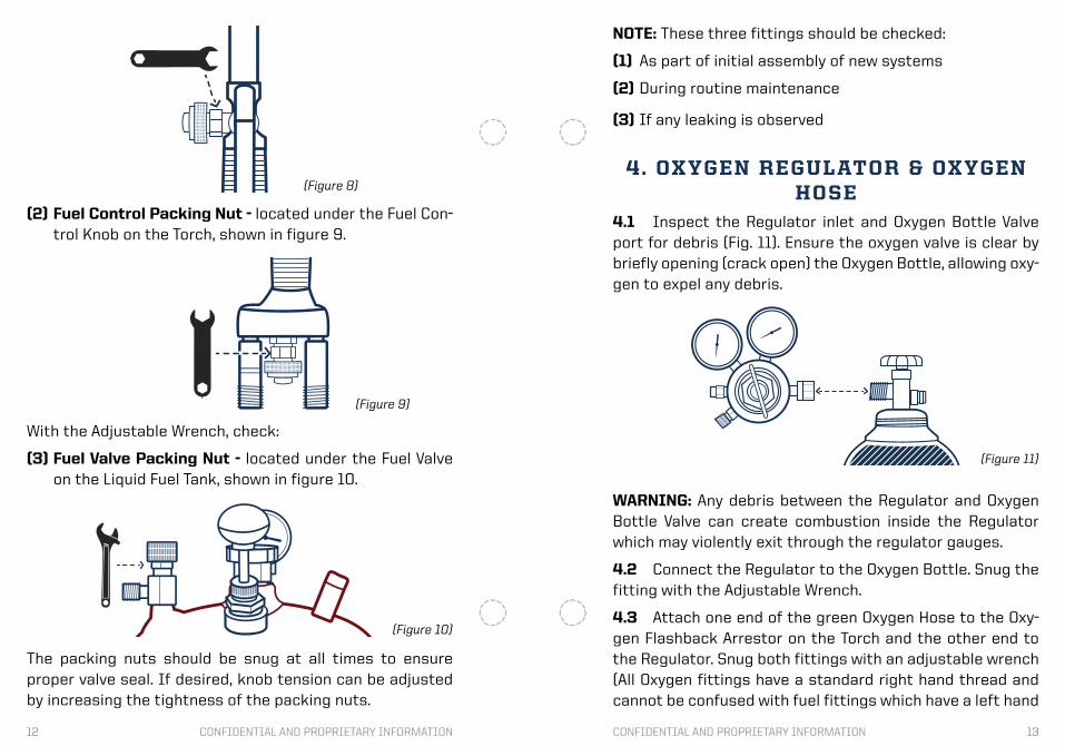
(2) Fuel Control Packing Nut - located under the Fuel Con-trol Knob on the Torch, shown in figure 9.
With the Adjustable Wrench, check:
(3) Fuel Valve Packing Nut - located under the Fuel Valve on the Liquid Fuel Tank, shown in figure 10.
(Figure 8)
(Figure 9)
(Figure 10)
The packing nuts should be snug at all times to ensure proper valve seal. If desired, knob tension can be adjusted by increasing the tightness of the packing nuts.
WARNING: Any debris between the Regulator and Oxygen Bottle Valve can create combustion inside the Regulator which may violently exit through the regulator gauges.
4.2 Connect the Regulator to the Oxygen Bottle. Snug the fitting with the Adjustable Wrench.
4.3 Attach one end of the green Oxygen Hose to the Oxy-gen Flashback Arrestor on the Torch and the other end to the Regulator. Snug both fittings with an adjustable wrench (All Oxygen fittings have a standard right hand thread and cannot be confused with fuel fittings which have a left hand
(Figure 11)
NOTE: These three fittings should be checked:
(1) As part of initial assembly of new systems
(2) During routine maintenance
(3) If any leaking is observed
4. OXYGEN REGULATOR & OXYGEN HOSE
4.1 Inspect the Regulator inlet and Oxygen Bottle Valve port for debris (Fig. 11). Ensure the oxygen valve is clear by briefly opening (crack open) the Oxygen Bottle, allowing oxy-gen to expel any debris.
14 15CONFIDENTIAL AND PROPRIETARY INFORMATION CONFIDENTIAL AND PROPRIETARY INFORMATION
thread).
5. OXYGEN HOSE PRESSURIZATIONIt is best practice to pressurize the oxygen line before the fuel line. Maintaining positive pressure throughout the oxy-gen system safeguards the oxygen line against fuel con-tamination. If fuel is allowed to enter the Oxygen Hose, a flashback may occur. Purging the Torch before light up fur-ther protects the operator against oxygen line flashback.
5.1 When opening the Oxygen Bottle Valve, ALWAYS FACE AWAY FROM THE GAUGES. Open the valve slowly and fully.
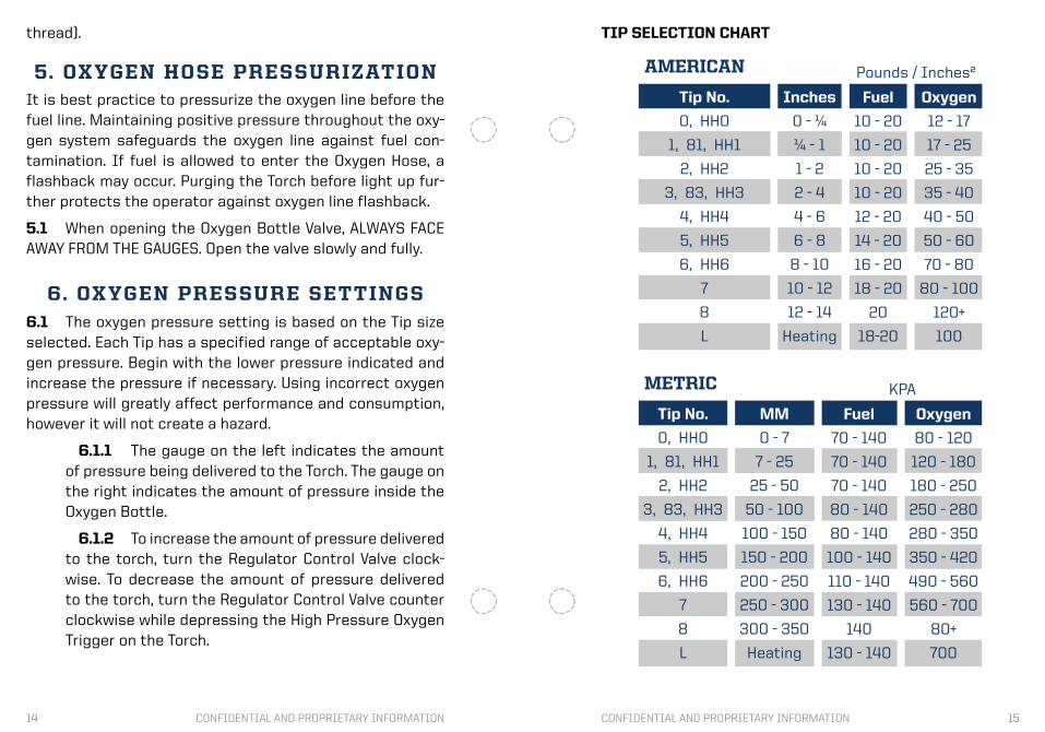
6. OXYGEN PRESSURE SETTINGS6.1 The oxygen pressure setting is based on the Tip size selected. Each Tip has a specified range of acceptable oxy-gen pressure. Begin with the lower pressure indicated and increase the pressure if necessary. Using incorrect oxygen pressure will greatly affect performance and consumption, however it will not create a hazard.
6.1.1 The gauge on the left indicates the amount of pressure being delivered to the Torch. The gauge on the right indicates the amount of pressure inside the Oxygen Bottle.
6.1.2 To increase the amount of pressure delivered to the torch, turn the Regulator Control Valve clock-wise. To decrease the amount of pressure delivered to the torch, turn the Regulator Control Valve counter clockwise while depressing the High Pressure Oxygen Trigger on the Torch.
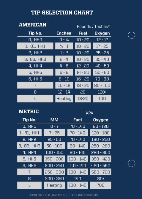
TIP SELECTION CHART
Tip No.
0, HH0
1, 81, HH1
2, HH2
3, 83, HH3
4, HH4
5, HH5
6, HH6
7
8
L
Pounds / Inches²AMERICAN
Fuel
10 - 20
10 - 20
10 - 20
10 - 20
12 - 20
14 - 20
16 - 20
18 - 20
20
18-20
Oxygen
12 - 17
17 - 25
25 - 35
35 - 40
40 - 50
50 - 60
70 - 80
80 - 100
120+
100
Inches
0 - ¼
¼ - 1
1 - 2
2 - 4
4 - 6
6 - 8
8 - 10
10 - 12
12 - 14
Heating
Tip No.
0, HH0
1, 81, HH1
2, HH2
3, 83, HH3
4, HH4
5, HH5
6, HH6
7
8
L
KPAMETRIC
Fuel
70 - 140
70 - 140
70 - 140
80 - 140
80 - 140
100 - 140
110 - 140
130 - 140
140
130 - 140
Oxygen
80 - 120
120 - 180
180 - 250
250 - 280
280 - 350
350 - 420
490 - 560
560 - 700
80+
700
MM
0 - 7
7 - 25
25 - 50
50 - 100
100 - 150
150 - 200
200 - 250
250 - 300
300 - 350
Heating
16 17CONFIDENTIAL AND PROPRIETARY INFORMATION CONFIDENTIAL AND PROPRIETARY INFORMATION
7. FUEL TANK FILLING7.1 Select Fuel - For best performance, use clean fresh fuel. If the only fuel available is old or fouled the system can still be operated without damage.
7.1.1 Fuels suitable for use include gasoline of any grade, white gas, camping fuel, and stabilized (tool or small engine) fuels. When using the Multi-Fuel Adap-tor, diesel, biodiesel, kerosene, Jet-A, JP-8, JP-5 and JP-24 can be used.
7.2 Remove Filler Cap from the Fuel Tank - If there is pressure in the Fuel Tank, open the cap slowly until you hear the pressure venting through the machined groove in the cap body. Let the tank completely vent its pressure before removing the cap completely.
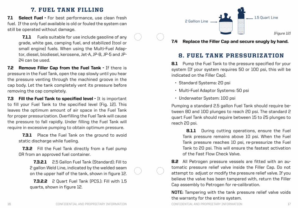
7.3 Fill the Fuel Tank to specified level - It is important to fill your Fuel Tank to the specified level (Fig. 12). This leaves the optimum amount of air space in the Fuel Tank for proper pressurization. Overfilling the Fuel Tank will cause the pressure to fall rapidly. Under filling the Fuel Tank will require in excessive pumping to obtain optimum pressure.
7.3.1 Place the Fuel Tank on the ground to avoid static discharge while fueling.
7.3.2 Fill the Fuel Tank directly from a fuel pump OR from an approved fuel container.
7.3.2.1 2.5 Gallon Fuel Tank (Standard): Fill to 2 gallon Weld Line, indicated by the welded seam on the upper half of the tank, shown in figure 12.
7.3.2.2 2 Quart Fuel Tank (PCS.): Fill with 1.5 quarts, shown in figure 12.
7.4 Replace the Filler Cap and secure snugly by hand.
8. FUEL TANK PRESSURIZATION8.1 Pump the Fuel Tank to the pressure specified for your system (If your system requires 50 or 100 psi, this will be indicated on the Filler Cap).
• Standard Systems: 20 psi
• Multi-Fuel Adaptor Systems: 50 psi
• Underwater System: 100 psi
Pumping a standard 2.5 gallon Fuel Tank should require be-tween 80 and 100 plunges to reach 20 psi. The standard 2 quart Fuel Tank should require between 15 to 25 plunges to reach 20 psi.
8.1.1 During cutting operations, ensure the Fuel Tank pressure remains above 10 psi. When the Fuel Tank pressure reaches 10 psi, re-pressurize the Fuel Tank to 20 psi. This will ensure the fastest activation of the Fast Flow Check Valve.
8.2 All Petrogen pressure vessels are fitted with an au-tomatic pressure relief valve inside the Filler Cap. Do not attempt to adjust or modify the pressure relief valve. If you believe the valve has been tampered with, return the Filler Cap assembly to Petrogen for re-calibration.
NOTE: Tampering with the tank pressure relief valve voids the warranty for the entire system.
2 Gallion Line1.5 Quart Line
(Figure 12)
18 19CONFIDENTIAL AND PROPRIETARY INFORMATION CONFIDENTIAL AND PROPRIETARY INFORMATION
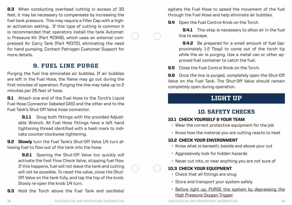
8.3 When conducting overhead cutting in excess of 30 feet, it may be necessary to compensate by increasing the fuel tank pressure. This may require a Filler Cap with a high-er activation setting. If this type of cutting is common it is recommended that operators install the tank Automat-ic Pressure Kit (Part #2349), which uses an external com-pressed Air Carry Tank (Part #2370), eliminating the need for hand pumping. Contact Petrogen Customer Support for more details.
9. FUEL LINE PURGEPurging the fuel line eliminates air bubbles. If air bubbles are left in the Fuel Hose, the flame may go out during the first minutes of operation. Purging the line may take up to 2 minutes per 25 feet of hose.
9.1 Attach one end of the Fuel Hose to the Torch’s Liquid Fuel Hose Connector (labeled GAS) and the other end to the Fuel Tank’s Shut-Off Valve hose connector.
9.1.1 Snug both fittings with the provided Adjust-able Wrench. All Fuel Hose fittings have a left hand tightening thread identified with a hash mark to indi-cate counter-clockwise tightening.
9.2 Slowly turn the Fuel Tank’s Shut-Off Valve 1/4 turn al-lowing fuel to flow out of the tank into the hose.
9.2.1 Opening the Shut-Off Valve too quickly will activate the Fast Flow Check Valve, stopping fuel flow. If this happens, fuel will not leave the tank and cutting will not be possible. To reset the valve, close the Shut-Off Valve on the tank fully, and tap the top of the knob. Slowly re-open the knob 1/4 turn.
9.3 Hold the Torch above the Fuel Tank and oscillate/
agitate the Fuel Hose to speed the movement of the fuel through the Fuel Hose and help eliminate air bubbles.
9.4 Open the Fuel Control Knob on the Torch.
9.4.1 This step is necessary to allow air in the fuel line to escape.
9.4.2 Be prepared for a small amount of fuel (ap-proximately 1-2 Tbsp) to come out of the torch tip while the air is purging. Use a metal can or other ap-proved fuel container to catch the fuel.
9.5 Close the Fuel Control Knob on the Torch.
9.6 Once the line is purged, completely open the Shut-Off Valve on the Fuel Tank. The Shut-Off Valve should remain completely open during operation.
10. SAFETY CHECKS10.1 CHECK YOURSELF & YOUR TEAM
• Wear the correct protective equipment for the job
• Know how the material you are cutting reacts to heat
10.2 CHECK YOUR ENVIRONMENT• Know what is beneath, beside and above your cut
• Aggressively look for hidden hazards
• Never cut into, or near anything you are not sure of
10.3 CHECK YOUR EQUIPMENT• Check that all fittings are snug
• Store and transport your system safely
• Before light up, PURGE the system by depressing the High Pressure Oxygen Trigger
LIGHT UP
20 21CONFIDENTIAL AND PROPRIETARY INFORMATION CONFIDENTIAL AND PROPRIETARY INFORMATION
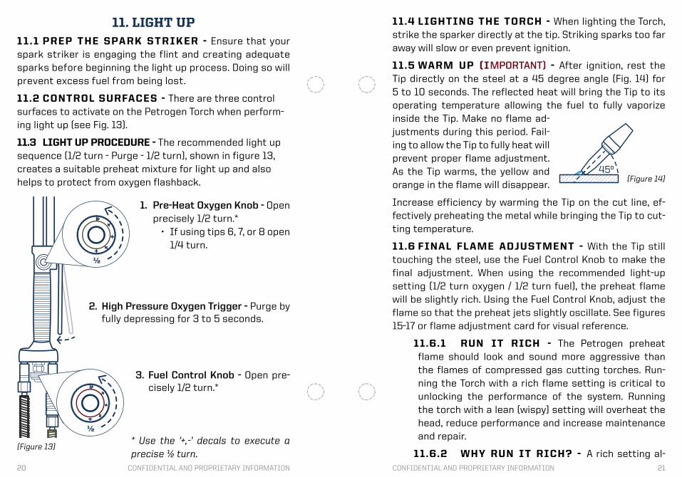
11. LIGHT UP11 .1 PREP THE SPA RK S TR IKER - Ensure that your spark striker is engaging the flint and creating adequate sparks before beginning the light up process. Doing so will prevent excess fuel from being lost.
11.2 CONTROL SURFACES - There are three control surfaces to activate on the Petrogen Torch when perform-ing light up (see Fig. 13).
11.3 LIGHT UP PROCEDURE - The recommended light up sequence (1/2 turn - Purge - 1/2 turn), shown in figure 13, creates a suitable preheat mixture for light up and also helps to protect from oxygen flashback.
½
½
1. Pre-Heat Oxygen Knob - Open precisely 1/2 turn.*
• If using tips 6, 7, or 8 open 1/4 turn.
2. High Pressure Oxygen Trigger - Purge by fully depressing for 3 to 5 seconds.
3. Fuel Control Knob - Open pre-cisely 1/2 turn.*
* Use the ‘+,-’ decals to execute a precise ½ turn.
11.4 LIGHTING THE TORCH - When lighting the Torch, strike the sparker directly at the tip. Striking sparks too far away will slow or even prevent ignition.
11.5 WARM UP (IMPORTANT) - After ignition, rest the Tip directly on the steel at a 45 degree angle (Fig. 14) for 5 to 10 seconds. The reflected heat will bring the Tip to its operating temperature allowing the fuel to fully vaporize inside the Tip. Make no flame ad-justments during this period. Fail-ing to allow the Tip to fully heat will prevent proper flame adjustment. As the Tip warms, the yellow and orange in the flame will disappear.
Increase efficiency by warming the Tip on the cut line, ef-fectively preheating the metal while bringing the Tip to cut-ting temperature.
11.6 FINAL FLAME ADJUSTMENT - With the Tip still touching the steel, use the Fuel Control Knob to make the final adjustment. When using the recommended light-up setting (1/2 turn oxygen / 1/2 turn fuel), the preheat flame will be slightly rich. Using the Fuel Control Knob, adjust the flame so that the preheat jets slightly oscillate. See figures 15-17 or flame adjustment card for visual reference.
11.6.1 RUN IT RICH - The Petrogen preheat flame should look and sound more aggressive than the flames of compressed gas cutting torches. Run-ning the Torch with a rich flame setting is critical to unlocking the performance of the system. Running the torch with a lean (wispy) setting will overheat the head, reduce performance and increase maintenance and repair.
11.6.2 WHY RUN IT RICH? - A rich setting al-(Figure 13)
90º
¼˝- ½˝ *coupling distance
(Front View)
45º(Figure 14)
22 23CONFIDENTIAL AND PROPRIETARY INFORMATION CONFIDENTIAL AND PROPRIETARY INFORMATION
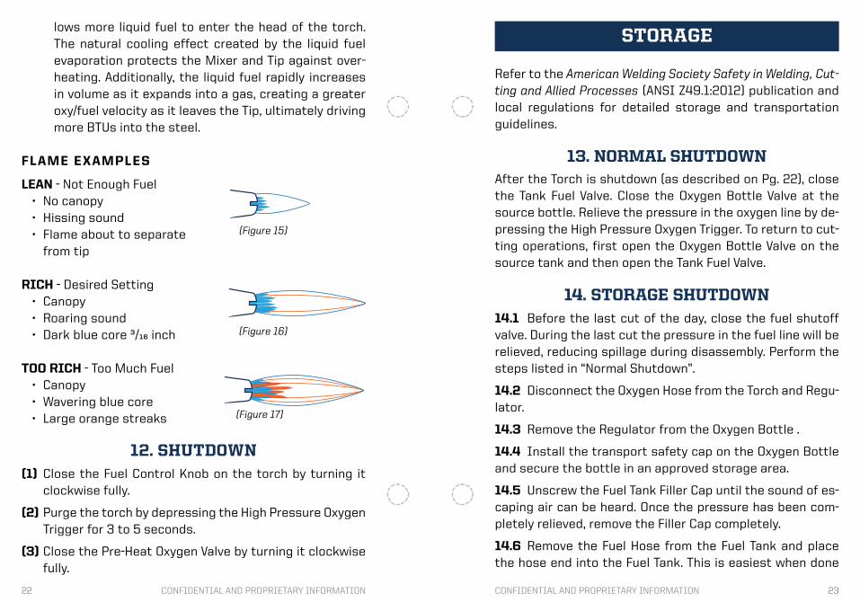
lows more liquid fuel to enter the head of the torch. The natural cooling effect created by the liquid fuel evaporation protects the Mixer and Tip against over-heating. Additionally, the liquid fuel rapidly increases in volume as it expands into a gas, creating a greater oxy/fuel velocity as it leaves the Tip, ultimately driving more BTUs into the steel.
FLAME EXAMPLES
LEAN - Not Enough Fuel• No canopy • Hissing sound• Flame about to separate
from tip
RICH - Desired Setting• Canopy• Roaring sound• Dark blue core 3/16 inch
TOO RICH - Too Much Fuel• Canopy• Wavering blue core• Large orange streaks
(Figure 15)
(Figure 16)
(Figure 17)
12. SHUTDOWN(1) Close the Fuel Control Knob on the torch by turning it
clockwise fully.
(2) Purge the torch by depressing the High Pressure Oxygen Trigger for 3 to 5 seconds.
(3) Close the Pre-Heat Oxygen Valve by turning it clockwise fully.
Refer to the American Welding Society Safety in Welding, Cut-ting and Allied Processes (ANSI Z49.1:2012) publication and local regulations for detailed storage and transportation guidelines.
13. NORMAL SHUTDOWNAfter the Torch is shutdown (as described on Pg. 22), close the Tank Fuel Valve. Close the Oxygen Bottle Valve at the source bottle. Relieve the pressure in the oxygen line by de-pressing the High Pressure Oxygen Trigger. To return to cut-ting operations, first open the Oxygen Bottle Valve on the source tank and then open the Tank Fuel Valve.
14. STORAGE SHUTDOWN14.1 Before the last cut of the day, close the fuel shutoff valve. During the last cut the pressure in the fuel line will be relieved, reducing spillage during disassembly. Perform the steps listed in “Normal Shutdown”.
14.2 Disconnect the Oxygen Hose from the Torch and Regu-lator.
14.3 Remove the Regulator from the Oxygen Bottle .
14.4 Install the transport safety cap on the Oxygen Bottle and secure the bottle in an approved storage area.
14.5 Unscrew the Fuel Tank Filler Cap until the sound of es-caping air can be heard. Once the pressure has been com-pletely relieved, remove the Filler Cap completely.
14.6 Remove the Fuel Hose from the Fuel Tank and place the hose end into the Fuel Tank. This is easiest when done
STORAGE
24 25CONFIDENTIAL AND PROPRIETARY INFORMATION CONFIDENTIAL AND PROPRIETARY INFORMATION
with two people. Hold the Torch above the level of the Fuel Tank and open the Fuel Control Knob on the Torch to elimi-nate any vacuum which might keep fuel in the line or Torch.
14.7 Working from the Torch to the Fuel Tank, push any re-maining fuel out of the hose by holding the line above the Fuel Tank. Repeat this until no fuel drains from the hose into the Fuel Tank.
14.8 Remove the torch from the fuel line and allow both to fully air dry. IMPORTANT: NEVER STORE ANY OXY/FUEL SYS-TEM IN AN AIRTIGHT CONTAINER OR COMPARTMENT. FLAM-MABLE FUMES MAY COLLECT AND EXPLODE.
14.9 Drain the contents of the Fuel Tank into an approved storage container. If no container is available, the Petrogen Fuel Tank actually meets or exceeds the requirements for flammable liquid storage containers in most areas. It is a UL tested, ASME code pressure vessel.
Prolonged storage of fuel in the Fuel Tank or Torch will not damage the equipment. However, over time fuel will degrade and lose volatility. If the quality of the fuel has degraded to a point where performance is adversely affected, replace the fuel in the tank and lines. Remove old fuel and oily build-up by flushing the Fuel Hose using a ratio of one cup of fresh fuel per 25 feet of hose. Generally fuel will remain effective for 2-3 months when stored in the system. Fuel stabilizing additives may be used to extend fuel life.
15. READY LEVELS15.1 Ready 1 should be used when cutting operations must be initiated in the shortest amount of time. Primed and ready for use, this is the highest level of system readi-ness.
Common usage: During daily operations, Rescue/Military Ve-hicles In Service.
• Fuel tank full and pressurized
• Fuel in line
• Fuel and oxygen hoses connected and secure
• Fuel and oxygen off at the Torch
• Fuel and oxygen off at the bottles
a. PCS/SAR systems include oxygen valve protection. The Regulator may remain attached at all times including during transport.
b. Standard Systems do not include additional Oxygen Valve protection and Regulators should be disconnect-ed from the Oxygen Bottle during vehicle transport.
15.2 Ready 2 is a safe way to store and transport the Pet-rogen System when use is intermittent. Keep in mind that it will be necessary to pressurize the fuel tank and prime the fuel line before cutting.
• Fuel in tank NOT UNDER PRESSURE
• Fuel line empty
• Fuel and oxygen hoses connected and secure
• Fuel and oxygen off at the Torch
• Fuel and oxygen off at the bottles
• Regulator disconnected and safely stored
a. PCS/SAR systems include oxygen valve protection. The Regulator may remain attached at all times including during transport.
b. Standard Systems do not include additional Oxygen Valve protection and Regulators should be disconnect-
26 27CONFIDENTIAL AND PROPRIETARY INFORMATION CONFIDENTIAL AND PROPRIETARY INFORMATION
ed from the Oxygen Bottle during vehicle transport.
15.3 Ready 3 is the appropriate way to store the Petrogen System for prolonged periods.
• Fuel tank empty and not under pressure
• Fuel line empty
• Regulator disconnected and safely stored
• Oxygen bottle turned off and stored with transport safe-ty cap installed
• Fuel and oxygen hoses disconnected
* The above storage procedures are recommendations and may be modified to fit established SOP’s
16. KEYS TO SUCCESSPerforming clean, fast cuts requires practice. Make the following habits a standard part of cutting operations to greatly increase productivity and reduce the learning curve of the operator.
• Take the time to find a stable, comfortable position
• Use what’s available to rest or stabilize the torch and/or the operators hand
• Use small, smooth movements
• Use a consistent speed of travel throughout the cut
• Pay extra attention at the beginning of the cut to ensure that the flame has completely penetrated the material before proceeding.
• If at any time sparks or molten material exits the cut
CUTTING BASICS17.2 Preheat the steel along the cut line.
17.3 Position the preheat flame so that half of the flame is on the steel and the other half runs down the leading edge of the steel (Fig. 19).
17.4 Keep the torch perpendicular to the face of the steel while cutting (Fig. 20). This directs all of the energy of the pre-heat flame and high pressure oxygen jet directly into the steel, maximizing cutting efficiency and controlling hot material as it exits the cut.
from a direction other than directly from the bottom of the material, examine the area, as the flame may not be fully penetrating the steel.
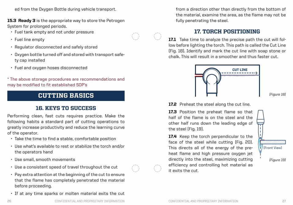
17. TORCH POSITIONING17.1 Take time to analyze the precise path the cut will fol-low before lighting the torch. This path is called the Cut Line (Fig. 18). Identify and mark the cut line with soap stone or chalk. This will result in a smoother and thus faster cut.
(Figure 18)
90º
¼˝- ½˝ *coupling distance
(Front View)
45º
(Figure 19)
CUT LINE
28 29CONFIDENTIAL AND PROPRIETARY INFORMATION CONFIDENTIAL AND PROPRIETARY INFORMATION
* Coupling distance is the distance be-tween the Tip and the material.
18. INTRODUCE HIGH PRESSURE OXYGENOnce the steel becomes molten, depress the High Pressure Oxygen Trigger smoothly and fully. If ignition is lost, release the trigger and allow the preheat flame to bring the steel back to a molten temperature.
19. ASSESS THE CUTIt is best to assess and fix mistakes as they occur rather than waiting to the end of the cut and attempting to re-member where they happened. The best indicator that the cut is not completely penetrating the steel is when the sparks move sideways rather than straight from the bottom of the cut. Any time this is observed, evaluate the area and do what is necessary to fix any problem.
20. STEEL IS THE FUELThe BTUs generated by the burning steel produce the ma-jority of the overall energy released in the cutting precess. The preheat flame is simply the catalysis for ignition. When faced with difficult cutting scenarios, consider how the burning steel can be used to ignite layers beneath it. This is essential knowledge when cutting through air gaps, layers or difficult shapes because it is the contribution of BTUs
90º
¼˝- ½˝ *coupling distance
(Front View)
45º
(Figure 20)
from the burning steel that allow these operations to be possible.
21. FAILED CUTIn the event that the steel does not fully separate after the cut is complete, you may need to go back and retrace a por-tion of the cut. Take the following actions:
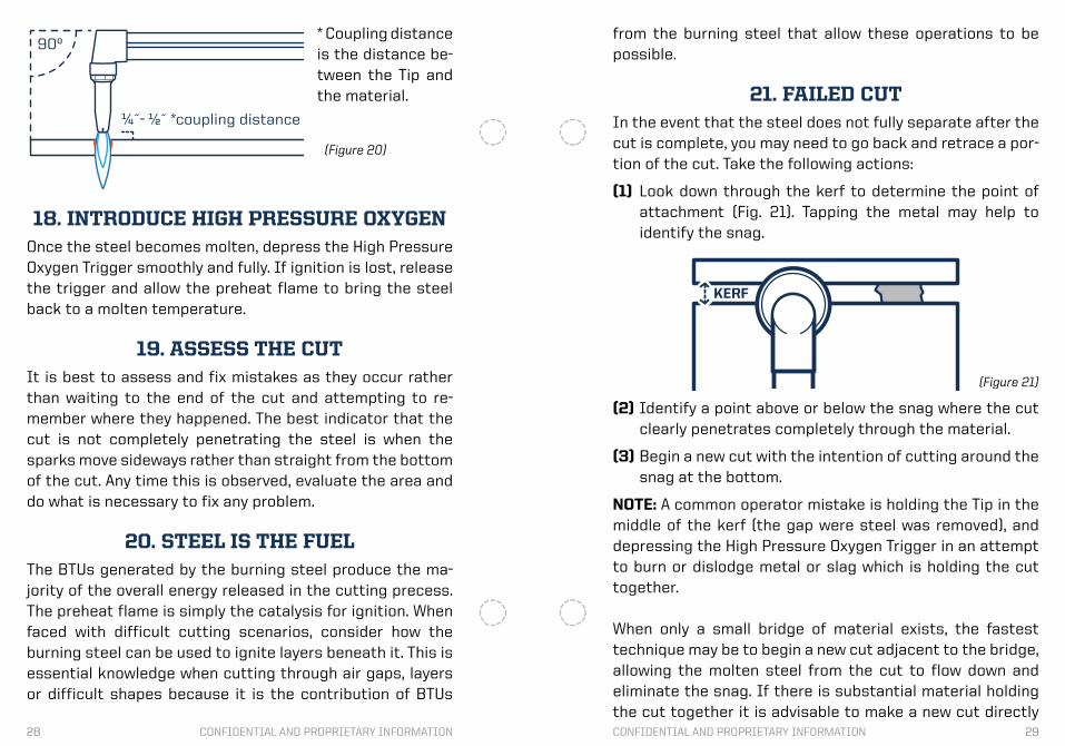
(1) Look down through the kerf to determine the point of attachment (Fig. 21). Tapping the metal may help to identify the snag.
KERF
(2) Identify a point above or below the snag where the cut clearly penetrates completely through the material.
(3) Begin a new cut with the intention of cutting around the snag at the bottom.
NOTE: A common operator mistake is holding the Tip in the middle of the kerf (the gap were steel was removed), and depressing the High Pressure Oxygen Trigger in an attempt to burn or dislodge metal or slag which is holding the cut together.
When only a small bridge of material exists, the fastest technique may be to begin a new cut adjacent to the bridge, allowing the molten steel from the cut to flow down and eliminate the snag. If there is substantial material holding the cut together it is advisable to make a new cut directly
(Figure 21)

30 31CONFIDENTIAL AND PROPRIETARY INFORMATION CONFIDENTIAL AND PROPRIETARY INFORMATION
23. HOLE PUNCHINGPlace the preheat flame in the location of the desired hole (Fig. 23). Maintain a 1/4 inch coupling distance and observe beneath the preheat flame for a molten puddle to form. Once a molten puddle has formed and be-gins to drip (spider out) perform the follow-
parallel to the original cut. It is important to move into the material deep enough to engage fresh steel. Generally 1/4 inch is sufficient.
Common causes for a cutting pass to fail include moving too quickly, stopping slightly short leaving a web on the bot-tom end, not using the appropriate tip size, or incorrect oxy-gen pressure for the Tip size.
22. V-CUTThe V-Cut (Fig. 22) is a very subtle technique used to grab added steel from the top most layer of a stack to fuel the layers beneath. This added back and forth “V” motion is use-ful in situations when there is a significant buildup of debris between layers or there is difficulty achieving penetration through all layers.
ADVANCED TECHNIQUES
V-CUT
(Figure 22)
(Figure 23)
ing three actions simultaneously.• Smoothly engage the High Pres-
sure Oxygen Trigger fully.
• Increasing the coupling distance 1/4 to 1/2 inch (Fig 24).
• Move the torch 1/4 to 1/2 inch left, right or back (Fig. 24).
The movement of the torch head will create a small trench which molten material and expanding gases will follow. The material will travel in the opposite direction of the movement of the torch. For example, to direct the material to the left, move the torch head right. Don’t push the torch forward as this will direct the material toward the operator.
Once a hole has been pierced through the steel, the opera-tor may enlarge the hole by keeping the High Pressure Oxy-gen Trigger depressed and moving the Torch in an outward spiral.
When this technique is performed properly, little or no pop-ping will occur and the tip will be protected from overheat-ing because the heat is directed away. Failure to use a prop-er hole punching technique may result in overheating the head of the torch or melting the Tip. Indications that this has occurred include: the Tip Nut becoming loose, and leak-ing around the Tip Nut due to melted O-rings on the Mixer (see Mixer Repair Pg. 41).
24. LAYER CUTTINGIf the layers are exposed, preheat the cut line and down the
(Figure 24)
32 33CONFIDENTIAL AND PROPRIETARY INFORMATION CONFIDENTIAL AND PROPRIETARY INFORMATION
side of the material (Fig. 25) where the cut will be initiated before beginning the cut. If the layers are not exposed, begin by punching a hole (as described on page 30). Once the top-most layer becomes molten, depress the High Pressure Oxygen Trigger smoothly and fully, allowing the heat generated from the top lay-ers to ignite the bottom layers before moving deeper into the cut.
When proceeding into the cut, executing the small, controlled ‘V’ pattern (see Fig. 22) will make penetrating the bottom layers much easier. Once through all layers (Fig. 26), pro-ceed with the cut normally, using the ‘V-Cut’ technique whenever needed.
Watch the material as it leaves the bottom of the cut. If it does not exit directly from the bottom, as it would when cutting a solid piece, then the cut is probably not penetrating all of the layers.
NOTE: When cutting layers, it is generally necessary to in-crease one tip size over the cutting chart recommendation for the solid equivalent of the cut thickness.
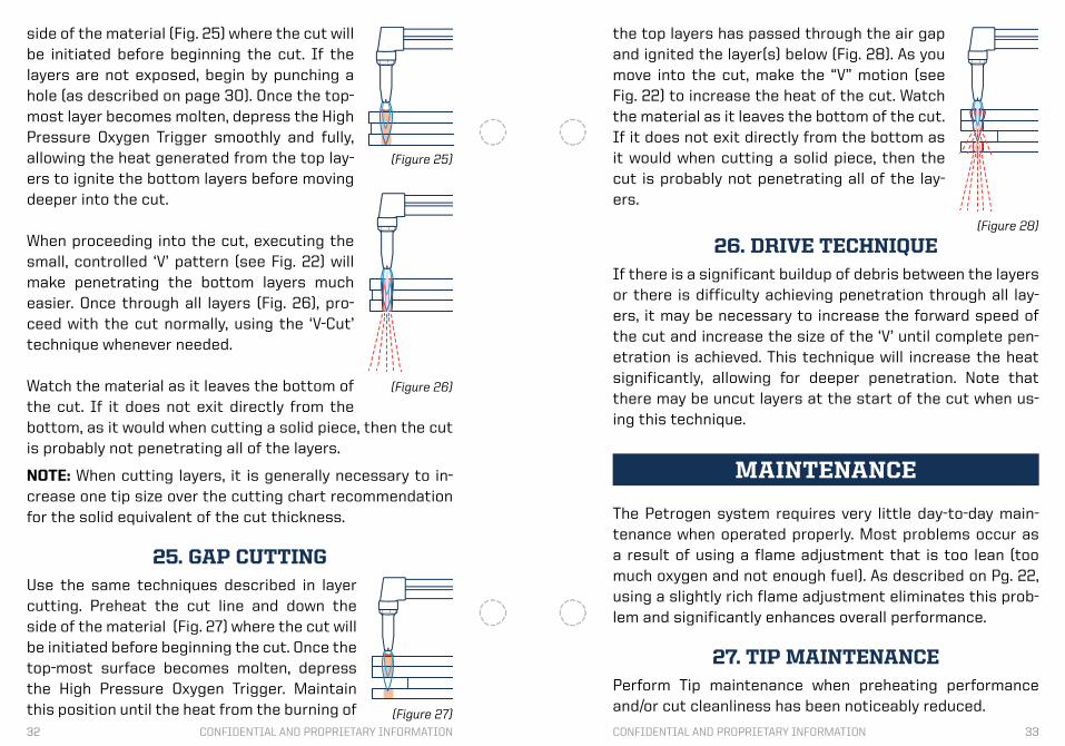
25. GAP CUTTINGUse the same techniques described in layer cutting. Preheat the cut line and down the side of the material (Fig. 27) where the cut will be initiated before beginning the cut. Once the top-most surface becomes molten, depress the High Pressure Oxygen Trigger. Maintain this position until the heat from the burning of
(Figure 26)
(Figure 25)
MAINTENANCE
The Petrogen system requires very little day-to-day main-tenance when operated properly. Most problems occur as a result of using a flame adjustment that is too lean (too much oxygen and not enough fuel). As described on Pg. 22, using a slightly rich flame adjustment eliminates this prob-lem and significantly enhances overall performance.
27. TIP MAINTENANCEPerform Tip maintenance when preheating performance and/or cut cleanliness has been noticeably reduced.
the top layers has passed through the air gap and ignited the layer(s) below (Fig. 28). As you move into the cut, make the “V” motion (see Fig. 22) to increase the heat of the cut. Watch the material as it leaves the bottom of the cut. If it does not exit directly from the bottom as it would when cutting a solid piece, then the cut is probably not penetrating all of the lay-ers.
26. DRIVE TECHNIQUEIf there is a significant buildup of debris between the layers or there is difficulty achieving penetration through all lay-ers, it may be necessary to increase the forward speed of the cut and increase the size of the ‘V’ until complete pen-etration is achieved. This technique will increase the heat significantly, allowing for deeper penetration. Note that there may be uncut layers at the start of the cut when us-ing this technique.
(Figure 28)
(Figure 27)

34 35CONFIDENTIAL AND PROPRIETARY INFORMATION CONFIDENTIAL AND PROPRIETARY INFORMATION
Tip Shell Tip Core
Tip Assembly(Part #0, 1, 2, 3, 4, 5, 6, 7, 8, 81, 83,
L, HH0, HH1, HH2, HH3, HH4, HH5, HH6)
Flutes Shell Bore
Pre-HeatSupply Channels
MaleSeatingSurface
MaleSeatingSurface
High Pressure OxygenSupply Channel
* A cleaner Tip will produce a cleaner cut. Clean the preheat flutes to produce a more consistent preheat flame. Clean the high pressure oxygen center hole to improve cut edge quality. Though cleaning the preheat flutes will produce a more stable flame, cleaning the high pressure oxygen cen-ter hole directly affects cut edge quality by enhancing lami-nar flow of the oxygen jet.
27.1 TIP ASSEMBLY & COMPONENTS
(Figure 29)
27.2 TIP REMOVAL - Using an adjustable wrench, loosen the Tip Nut by turning it counterclockwise. Remove the Tip Nut and Tip from the head of the torch, being careful not to drop the tip core.
Note: To cool a hot Tip before removal, take the following actions. Briefly open the torch fuel control valve. The evap-orating fuel will quickly cool the Tip to room temperature. Once the fuel exiting the Tip becomes a liquid immediately close the fuel valve.
27.3 Tip Reamer (Part # 4012) - Used to remove depos-its from the slot inside of the tip shell.
0 1 2 3 4 56
78 No.3
(Figure 30)
27.4 Two Part Tip Brush (Part #4013) - Used to remove slag from the Tip shell and the flutes of the Tip core. DO NOT use this brush or any abrasives on the seating surface of the Tip core where it mates with the Mixer inside the Torch Head (see Fig. 31).
0 1 2 3 4 56
78 No.3
(Figure 31)
36 37CONFIDENTIAL AND PROPRIETARY INFORMATION CONFIDENTIAL AND PROPRIETARY INFORMATION
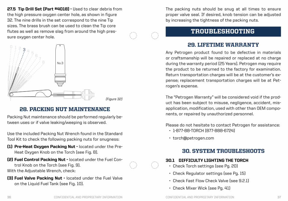
27.5 Tip Drill Set (Part #4018) - Used to clear debris from the high pressure oxygen center hole, as shown in figure 32. The nine drills in the set correspond to the nine Tip sizes. The brass brush can be used to clean the Tip core flutes as well as remove slag from around the high pres-sure oxygen center hole.
0 1 2 3 4 56
78 No.3
(Figure 32)
28. PACKING NUT MAINTENANCEPacking Nut maintenance should be performed regularly be-tween uses or if valve leaking/weeping is observed. Use the included Packing Nut Wrench found in the Standard Tool Kit to check the following packing nuts for snugness:
(1) Pre-Heat Oxygen Packing Nut - located under the Pre-Heat Oxygen Knob on the Torch (see Fig. 8).
(2) Fuel Control Packing Nut - located under the Fuel Con-trol Knob on the Torch (see Fig. 9).
With the Adjustable Wrench, check:
(3) Fuel Valve Packing Nut - located under the Fuel Valve on the Liquid Fuel Tank (see Fig. 10).
29. LIFETIME WARRANTYAny Petrogen product found to be defective in materials or craftsmanship will be repaired or replaced at no charge during the warranty period (25 Years). Petrogen may require the product to be returned to the factory for examination. Return transportation charges will be at the customer’s ex-pense; replacement transportation charges will be at Pet-rogen’s expense. The “Petrogen Warranty” will be considered void if the prod-uct has been subject to misuse, negligence, accident, mis-application, modification, used with other than OEM compo-nents, or repaired by unauthorized personnel.
Please do not hesitate to contact Petrogen for assistance:• 1-877-88-TORCH (877-888-6724)
30. SYSTEM TROUBLESHOOTS
30.1 DIFFICULTY LIGHTING THE TORCH• Check Torch settings (see Pg. 20)
• Check Regulator settings (see Pg. 15)
• Check Fast Flow Check Valve (see 9.2.1)
• Check Mixer Wick (see Pg. 41)
TROUBLESHOOTING
The packing nuts should be snug at all times to ensure proper valve seal. If desired, knob tension can be adjusted by increasing the tightness of the packing nuts.
38 39CONFIDENTIAL AND PROPRIETARY INFORMATION CONFIDENTIAL AND PROPRIETARY INFORMATION
• Fuel Stream Check (see Pg. 40)
30.2 FUEL LEAKS
30.2.1 TIP• Fully close the torch Fuel Control Valve
30.2.2 TIP NUT/ TORCH HEAD• Loosen and retighten the Tip Nut
• Check Mixer O-ring(s) (see Pg. 41)
30.2.3 TORCH HANDLE WEEP HOLE/S• Contact Petrogen for warranty service
30.2.4 FUEL CONTROL KNOB• Tighten the packing nut under the knob
30.2.5 FUEL HOSE / TORCH HOSE CONNECTOR• Remove the Fuel Hose and clean the
threads and mating surfaces
30.2.6 FUEL HOSE /TANK FUEL HOSE CONNECTOR• Remove the Fuel Hose and clean the
threads and mating surfaces
30.2.7 SHUT-OFF VALVE
• Tighten the compression fitting below the Fuel Control Knob
30.2.8 PUMP CYLINDER• If fuel is leaking past the Pump Cylinder
Check Valve, the first indication will be the pump handle raising by itself.
• Release the Fuel Tank pressure by unscrew-ing the Filler Cap until air begins to escape
• Replace the Pump Check Valve Seal (see 34.9)
30.3 OXYGEN LEAKS
30.3.1 TIP• Check High Pressure Oxygen Valve (see Pg.
44)
30.3.2 PRE-HEAT OXYGEN KNOB• Tighten packing nut under the knob
30.3.3 OXYGEN HOSE / TORCH HOSE CONNECTOR• Remove the Oxygen Hose and clean the
threads and mating surfaces
30.3.4 OXYGEN HOSE / REGULATOR• Remove the Oxygen Hose and clean the
threads and mating surfaces
30.3.5 REGULATOR / OXYGEN BOTTLE VALVE• Use a plastic bristle brush to clean the
threads of the Regulator Valve Connector and the threads of the Oxygen Bottle Valve
• Never use liquids or abrasives to clean this connection
• Carefully inspect the components for debris before reassembling
30.4 FUEL TANK PRESSURE
30.4.1 DIFFICULTY PRESSURIZING THE FUEL TANK
• Check the Leather Pump Cup (see 34.4)
• Check the fuel level in the Fuel Tank (see 7.3)
• Use smooth, complete strokes when pump-ing
30.4.2 FUEL TANK LOSES PRESSURE WHEN NOT IN USE
• Make sure the Filler Cap Gasket is in place
40 41CONFIDENTIAL AND PROPRIETARY INFORMATION CONFIDENTIAL AND PROPRIETARY INFORMATION
• Contact Petrogen Customer Service for war-ranty repair
30.5 POPPING• Loosen and retighten the Tip Nut
• Inspect the seating surfaces of the Tip and replace the Tip if necessary
30.6 FLICKERING OR UNSTABLE FLAME• Clean the Tip
• Check Torch settings (see Pg. 20)
• Check Mixer Wick (see Pg. 41)
31. FUEL STREAM CHECKIf little or no fuel exits the Tip when the Fuel Tank and Torch valves are open, perform the following test to de-termine the location of the restriction.
NOTE: Because the problem may be an accidental activa-tion of the Fast Flow Check Valve, reset the valve before be-ginning the test (see 9.2.1).
NOTE: Safety Glasses are required safety equipment for the Fuel Stream Check.
• Perform this test with the Oxygen Bottle Valve open and the Oxygen Hose pressurized. (This will protect the oxy-gen system from fuel contamination during the test.)
• Begin the test with the Torch Fuel Control Knob and Pre-Heat Oxygen Knob closed.
REPAIRS
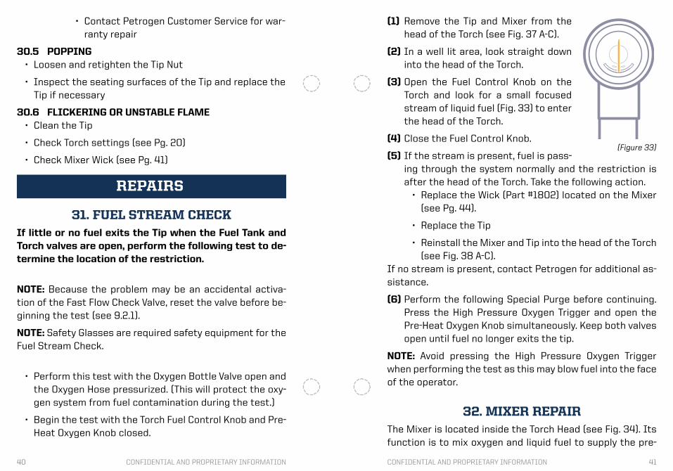
(1) Remove the Tip and Mixer from the head of the Torch (see Fig. 37 A-C).
(2) In a well lit area, look straight down into the head of the Torch.
(3) Open the Fuel Control Knob on the Torch and look for a small focused stream of liquid fuel (Fig. 33) to enter the head of the Torch.
(4) Close the Fuel Control Knob.
(5) If the stream is present, fuel is pass-ing through the system normally and the restriction is after the head of the Torch. Take the following action.
• Replace the Wick (Part #1802) located on the Mixer (see Pg. 44).
• Replace the Tip
• Reinstall the Mixer and Tip into the head of the Torch (see Fig. 38 A-C).
If no stream is present, contact Petrogen for additional as-sistance.
(6) Perform the following Special Purge before continuing. Press the High Pressure Oxygen Trigger and open the Pre-Heat Oxygen Knob simultaneously. Keep both valves open until fuel no longer exits the tip.
NOTE: Avoid pressing the High Pressure Oxygen Trigger when performing the test as this may blow fuel into the face of the operator.
32. MIXER REPAIRThe Mixer is located inside the Torch Head (see Fig. 34). Its function is to mix oxygen and liquid fuel to supply the pre-
(Figure 33)

42 43CONFIDENTIAL AND PROPRIETARY INFORMATION CONFIDENTIAL AND PROPRIETARY INFORMATION
Mixer Assembly(Part #1800)
Small O-Ring(Part #1804)
Large O-Ring(Part #1803)
Wick(Part #1802)
Bare Mixer Body
heat flame.
The Mixer does not require regular maintenance, how-ever it may require attention if any of the following prob-lems is encoun-tered.
Fuel leaks from between the Torch Head and Tip Nut• Replace Small and/or Large O-ring(s)
Popping occurs• Clean the Tip and/or Mixer seating surfaces
Dying flame or no fuel flow to the Tip• Replace Mixer Wick
• See fuel stream test
NOTE: Running the Torch with a rich fuel setting will keep both the Tip and the head of the torch cool, preventing dam-age to the Mixer O-rings and Wick.
32.1 MIXER ASSEMBLY & COMPONENTS
(Figure 34)
Mixer Assembly(Part #1800)
Small O-Ring(Part #1804)
Large O-Ring(Part #1803)
Wick(Part #1802)
Bare Mixer Body
(Figure 35)
32.2 MIXER REMOVAL:• Using the Adjustable Wrench (Part #6022), remove the
Tip Nut and Tip from the Torch Head (Fig. 36 A). Be care-ful not to drop the tip core when removing the tip.
• The Mixer sits directly beneath the tip inside the head of the Torch. Slide the Jackscrew (Part #4016), which can be found in the Tool Kit, into the center hole of the Mixer and turn it clockwise (Fig. 36 B). Keep turning the Jack Screw until the Mixer is pulled from it’s position in the head (Fig. 36 C).
Jackscrew
32.3 O-RING & WICK REPLACEMENT:• Remove the damaged O-rings and replace them with the
provided spares from the Standard Spare Parts Kit (Part #4002). There is one large and one small O-ring. Some-times damage to the O-rings is not obvious. Overheating can reduce the elasticity of the O-ring, keeping it from forming a complete seal inside the head of the torch.
• Remove the damaged Wick and replace it with the pro-vided spare from the Spare Parts Kit. A Damaged Wick will have a brown “cooked” appearance. Severe over-heating can fuse the centered bronze, reducing fuel flow into the Mixer.
(Figure 36)
(A) (B) (C)
44 45CONFIDENTIAL AND PROPRIETARY INFORMATION CONFIDENTIAL AND PROPRIETARY INFORMATION
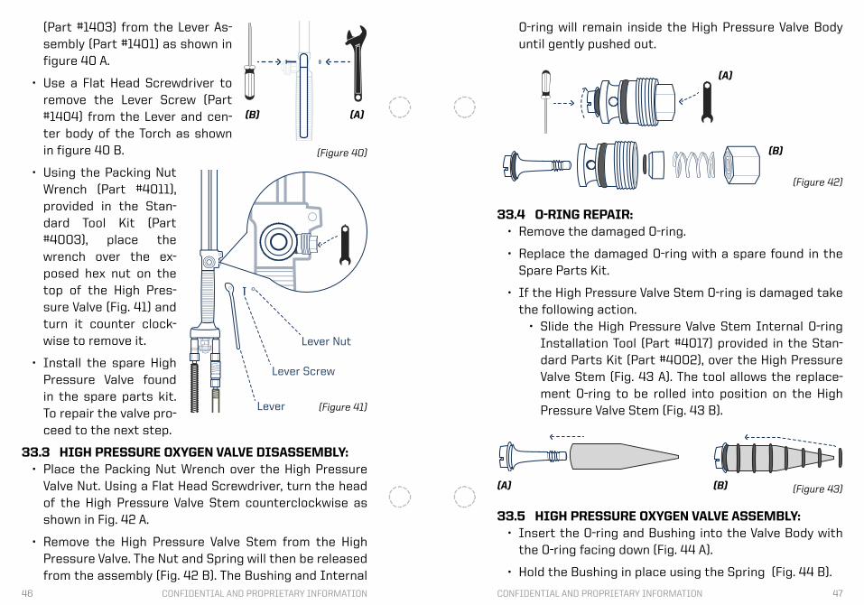
Nut
Spring
Bushing
Stem
Body
External O-Ring(Part #1356)
Internal O-Ring(Part #1357)
Internal O-Ring(Part #1357)
High Pressure Oxygen ValveComplete Assembly(Part #1300)
(Figure 37)
(A) (B) (C)
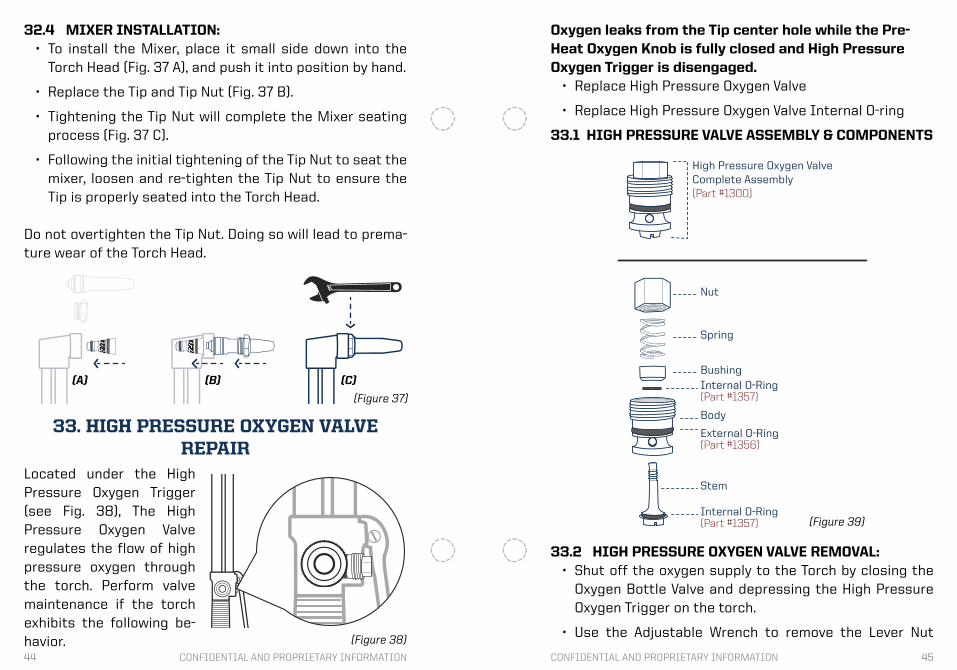
32.4 MIXER INSTALLATION:• To install the Mixer, place it small side down into the
Torch Head (Fig. 37 A), and push it into position by hand.
• Replace the Tip and Tip Nut (Fig. 37 B).
• Tightening the Tip Nut will complete the Mixer seating process (Fig. 37 C).
• Following the initial tightening of the Tip Nut to seat the mixer, loosen and re-tighten the Tip Nut to ensure the Tip is properly seated into the Torch Head.
Do not overtighten the Tip Nut. Doing so will lead to prema-ture wear of the Torch Head.
33. HIGH PRESSURE OXYGEN VALVEREPAIR
Located under the High Pressure Oxygen Trigger (see Fig. 38), The High Pressure Oxygen Valve regulates the flow of high pressure oxygen through the torch. Perform valve maintenance if the torch exhibits the following be-havior. (Figure 38)
(Figure 39)
Oxygen leaks from the Tip center hole while the Pre-Heat Oxygen Knob is fully closed and High Pressure Oxygen Trigger is disengaged.
• Replace High Pressure Oxygen Valve
• Replace High Pressure Oxygen Valve Internal O-ring
33.1 HIGH PRESSURE VALVE ASSEMBLY & COMPONENTS
33.2 HIGH PRESSURE OXYGEN VALVE REMOVAL:• Shut off the oxygen supply to the Torch by closing the
Oxygen Bottle Valve and depressing the High Pressure Oxygen Trigger on the torch.
• Use the Adjustable Wrench to remove the Lever Nut
46 47CONFIDENTIAL AND PROPRIETARY INFORMATION CONFIDENTIAL AND PROPRIETARY INFORMATION
(Part #1403) from the Lever As-sembly (Part #1401) as shown in figure 40 A.
• Use a Flat Head Screwdriver to remove the Lever Screw (Part #1404) from the Lever and cen-ter body of the Torch as shown in figure 40 B.
• Using the Packing Nut Wrench (Part #4011), provided in the Stan-dard Tool Kit (Part #4003), place the wrench over the ex-posed hex nut on the top of the High Pres-sure Valve (Fig. 41) and turn it counter clock-wise to remove it.
• Install the spare High Pressure Valve found in the spare parts kit. To repair the valve pro-ceed to the next step.
33.3 HIGH PRESSURE OXYGEN VALVE DISASSEMBLY:• Place the Packing Nut Wrench over the High Pressure
Valve Nut. Using a Flat Head Screwdriver, turn the head of the High Pressure Valve Stem counterclockwise as shown in Fig. 42 A.
• Remove the High Pressure Valve Stem from the High Pressure Valve. The Nut and Spring will then be released from the assembly (Fig. 42 B). The Bushing and Internal
(Figure 40)
(A)(B)
Lever
Lever Screw
Lever Nut
(Figure 41)
O-ring will remain inside the High Pressure Valve Body until gently pushed out.
H.P. ValveInternal O-RingInstallation Tool
33.4 O-RING REPAIR:• Remove the damaged O-ring.
• Replace the damaged O-ring with a spare found in the Spare Parts Kit.
• If the High Pressure Valve Stem O-ring is damaged take the following action.
• Slide the High Pressure Valve Stem Internal O-ring Installation Tool (Part #4017) provided in the Stan-dard Parts Kit (Part #4002), over the High Pressure Valve Stem (Fig. 43 A). The tool allows the replace-ment O-ring to be rolled into position on the High Pressure Valve Stem (Fig. 43 B).
(Figure 42)
(A)
(B)
H.P. ValveInternal O-RingInstallation Tool
H.P. ValveInternal O-RingInstallation Tool
(Figure 43)(A) (B)
33.5 HIGH PRESSURE OXYGEN VALVE ASSEMBLY: • Insert the O-ring and Bushing into the Valve Body with
the O-ring facing down (Fig. 44 A).
• Hold the Bushing in place using the Spring (Fig. 44 B).
48 49CONFIDENTIAL AND PROPRIETARY INFORMATION CONFIDENTIAL AND PROPRIETARY INFORMATION
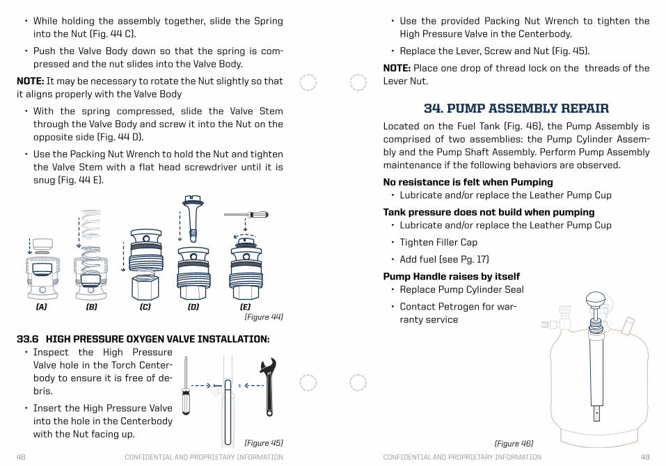
33.6 HIGH PRESSURE OXYGEN VALVE INSTALLATION:• Inspect the High Pressure
Valve hole in the Torch Center-body to ensure it is free of de-bris.
• Insert the High Pressure Valve into the hole in the Centerbody with the Nut facing up.
(Figure 44)(A) (B) (C) (D) (E)
• Use the provided Packing Nut Wrench to tighten the High Pressure Valve in the Centerbody.
• Replace the Lever, Screw and Nut (Fig. 45).
NOTE: Place one drop of thread lock on the threads of the Lever Nut.
34. PUMP ASSEMBLY REPAIRLocated on the Fuel Tank (Fig. 46), the Pump Assembly is comprised of two assemblies: the Pump Cylinder Assem-bly and the Pump Shaft Assembly. Perform Pump Assembly maintenance if the following behaviors are observed.
No resistance is felt when Pumping• Lubricate and/or replace the Leather Pump Cup
Tank pressure does not build when pumping• Lubricate and/or replace the Leather Pump Cup
• Tighten Filler Cap
• Add fuel (see Pg. 17)
Pump Handle raises by itself • Replace Pump Cylinder Seal
• Contact Petrogen for war-ranty service
(Figure 45) (Figure 46)
• While holding the assembly together, slide the Spring into the Nut (Fig. 44 C).
• Push the Valve Body down so that the spring is com-pressed and the nut slides into the Valve Body.
NOTE: It may be necessary to rotate the Nut slightly so that it aligns properly with the Valve Body
• With the spring compressed, slide the Valve Stem through the Valve Body and screw it into the Nut on the opposite side (Fig. 44 D).
• Use the Packing Nut Wrench to hold the Nut and tighten the Valve Stem with a flat head screwdriver until it is snug (Fig. 44 E).
50 51CONFIDENTIAL AND PROPRIETARY INFORMATION CONFIDENTIAL AND PROPRIETARY INFORMATION
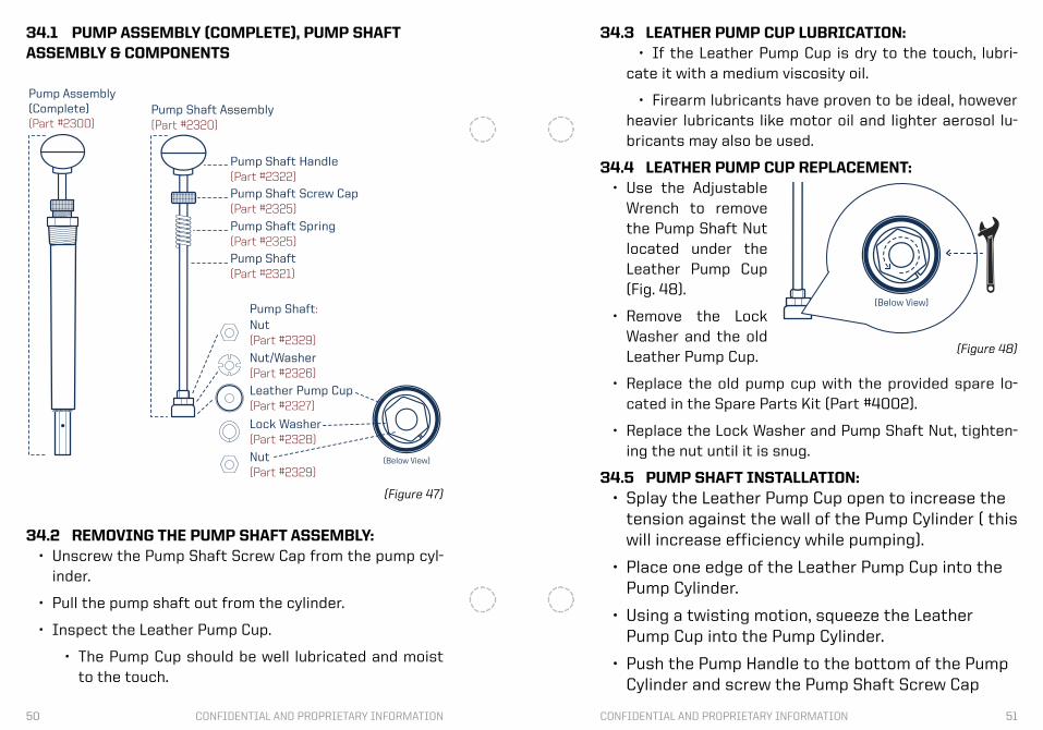
34.1 PUMP ASSEMBLY (COMPLETE), PUMP SHAFTASSEMBLY & COMPONENTS
(Figure 47)
Pump Shaft Assembly(Part #2320)
Pump Shaft Handle(Part #2322)
Pump Shaft Screw Cap(Part #2325)
Pump Shaft Spring(Part #2325)
Pump Shaft(Part #2321)
Nut(Part #2329)
Nut(Part #2329)
Nut/Washer(Part #2326)
Leather Pump Cup(Part #2327)
Lock Washer(Part #2328)
Pump Shaft:
(Below View)
Pump Assembly(Complete)(Part #2300)
34.2 REMOVING THE PUMP SHAFT ASSEMBLY:• Unscrew the Pump Shaft Screw Cap from the pump cyl-
inder.
• Pull the pump shaft out from the cylinder.
• Inspect the Leather Pump Cup.
• The Pump Cup should be well lubricated and moist to the touch.
34.3 LEATHER PUMP CUP LUBRICATION:• If the Leather Pump Cup is dry to the touch, lubri-
cate it with a medium viscosity oil.
• Firearm lubricants have proven to be ideal, however heavier lubricants like motor oil and lighter aerosol lu-bricants may also be used.
34.4 LEATHER PUMP CUP REPLACEMENT:• Use the Adjustable
Wrench to remove the Pump Shaft Nut located under the Leather Pump Cup (Fig. 48).
• Remove the Lock Washer and the old Leather Pump Cup.
• Replace the old pump cup with the provided spare lo-cated in the Spare Parts Kit (Part #4002).
• Replace the Lock Washer and Pump Shaft Nut, tighten-ing the nut until it is snug.
34.5 PUMP SHAFT INSTALLATION:• Splay the Leather Pump Cup open to increase the
tension against the wall of the Pump Cylinder ( this will increase efficiency while pumping).
• Place one edge of the Leather Pump Cup into the Pump Cylinder.
• Using a twisting motion, squeeze the Leather Pump Cup into the Pump Cylinder.
• Push the Pump Handle to the bottom of the Pump Cylinder and screw the Pump Shaft Screw Cap
(Below View)
(Figure 48)
52 53CONFIDENTIAL AND PROPRIETARY INFORMATION CONFIDENTIAL AND PROPRIETARY INFORMATION
back to the Pump Cylinder.
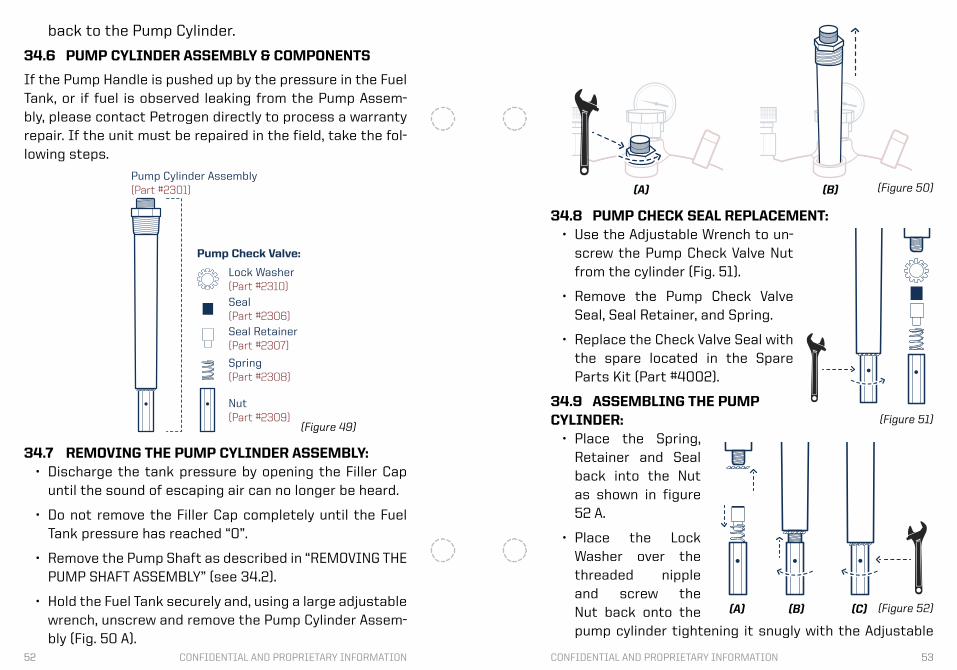
34.6 PUMP CYLINDER ASSEMBLY & COMPONENTS
If the Pump Handle is pushed up by the pressure in the Fuel Tank, or if fuel is observed leaking from the Pump Assem-bly, please contact Petrogen directly to process a warranty repair. If the unit must be repaired in the field, take the fol-lowing steps.
Complete Pump Assembly(Part #2300)
Pump Cylinder Assembly(Part #2301)
Lock Washer(Part #2310)
Pump Check Valve:
Seal(Part #2306)
Seal Retainer(Part #2307)
Spring(Part #2308)
Nut(Part #2309)
(Figure 49)
34.7 REMOVING THE PUMP CYLINDER ASSEMBLY:• Discharge the tank pressure by opening the Filler Cap
until the sound of escaping air can no longer be heard.
• Do not remove the Filler Cap completely until the Fuel Tank pressure has reached “0”.
• Remove the Pump Shaft as described in “REMOVING THE PUMP SHAFT ASSEMBLY” (see 34.2).
• Hold the Fuel Tank securely and, using a large adjustable wrench, unscrew and remove the Pump Cylinder Assem-bly (Fig. 50 A).
34.8 PUMP CHECK SEAL REPLACEMENT:• Use the Adjustable Wrench to un-
screw the Pump Check Valve Nut from the cylinder (Fig. 51).
• Remove the Pump Check Valve Seal, Seal Retainer, and Spring.
• Replace the Check Valve Seal with the spare located in the Spare Parts Kit (Part #4002).
34.9 ASSEMBLING THE PUMPCYLINDER:
• Place the Spring, Retainer and Seal back into the Nut as shown in figure 52 A.
• Place the Lock Washer over the threaded nipple and screw the Nut back onto the pump cylinder tightening it snugly with the Adjustable
(Figure 50)
(Figure 51)
(A) (B)
(Figure 52)(A) (B) (C)
54 55CONFIDENTIAL AND PROPRIETARY INFORMATION CONFIDENTIAL AND PROPRIETARY INFORMATION
Wrench (Fig. 52 B&C).
34.10 PUMP CYLINDER INSTALLATION:• Clean the threads of the Pump Cylinder and Fuel Tank
making sure that no PTFE tape or dirt remains.
• Make two complete wraps of the Pump Cylinder threads with new Teflon tape.
• Place the Pump Cylinder back into the Fuel Tank, and tighten it with the Adjustable Wrench.
• Reinstall the Pump Shaft as described in “PUMP SHAFT INSTALLATION” (see 34.5).
• Pressurize the tank and then perform a leak test using soapy water.
• If the tank leaks, tighten the fitting further.
Your System Is Under WarrantyPlease do not hesitate to contact us for assistance:
• 1-877-88-TORCH (877-888-6724)
For additional resources, visit:
• www.petrogen.com/training
• www.petrogen.com/videos
This manual is available online at:
• www.petrogen.com/training

56 57CONFIDENTIAL AND PROPRIETARY INFORMATION CONFIDENTIAL AND PROPRIETARY INFORMATION

58 59CONFIDENTIAL AND PROPRIETARY INFORMATION CONFIDENTIAL AND PROPRIETARY INFORMATION
TIP SELECTION CHART
Tip No.
0, HH0
1, 81, HH1
2, HH2
3, 83, HH3
4, HH4
5, HH5
6, HH6
7
8
L
Pounds / Inches²AMERICAN
Fuel
10 - 20
10 - 20
10 - 20
10 - 20
12 - 20
14 - 20
16 - 20
18 - 20
20
18-20
Oxygen
12 - 17
17 - 25
25 - 35
35 - 40
40 - 50
50 - 60
70 - 80
80 - 100
120+
100
Inches
0 - ¼
¼ - 1
1 - 2
2 - 4
4 - 6
6 - 8
8 - 10
10 - 12
12 - 14
Heating
Tip No.
0, HH0
1, 81, HH1
2, HH2
3, 83, HH3
4, HH4
5, HH5
6, HH6
7
8
L
KPAMETRIC
Fuel
70 - 140
70 - 140
70 - 140
80 - 140
80 - 140
100 - 140
110 - 140
130 - 140
140
130 - 140
Oxygen
80 - 120
120 - 180
180 - 250
250 - 280
280 - 350
350 - 420
490 - 560
560 - 700
80+
700
MM
0 - 7
7 - 25
25 - 50
50 - 100
100 - 150
150 - 200
200 - 250
250 - 300
300 - 350
Heating
CONFIDENTIAL AND PROPRIETARY INFORMATION


![ก ˘ ˇ˘ˆ˙˝ ˛ Plasma cutting Torch height controlfile.siam2web.com/cnctak/files[document]/2012724_78232.pdf · Plasma cutting Torch height control Manufacturing BY:CNCtak .com](https://static.fdocuments.net/doc/165x107/5b970d2409d3f2e3488bd89b/-plasma-cutting-torch-height-document201272478232pdf.jpg)