Lighting Energy Management Building Controls LibRE...
14
Lighting Energy Management Building Controls LibRE Installation Guide V 0.1 March 2015
Transcript of Lighting Energy Management Building Controls LibRE...

Lighting
Energy Management
Building Controls
LibRE Installation Guide
V 0.1 March 2015
LibRE System Installation Guide
0000000 rev 0.1 P a g e | 2
1 Safety Information
Save These Instructions
The following symbols are used throughout this manual to indicate potentially dangerous conditions or mark
important safety instructions.
WARNING: Indicates a potentially dangerous condition. Use extreme caution when performing
this task.
NOTE: Indicates a procedure or function that is important for the safe and proper operation.
General Safety Information
Read all the instructions and cautions in the manual before beginning installation.
There are no user serviceable parts inside the components. Do not disassemble or attempt to repair them.
Disconnect all sources of power to the PDM before installing or disconnecting the PDM.
There are no fuses or disconnects inside the PDM. Install external fuses/breakers as required.
Do not allow water to enter the PDM.
Confirm that power connections are tight to avoid excessive heating from a loose connection.
Follow all local electrical code requirements as directed by your Agency Having Jurisdiction (AHJ).
Batteries can release significant energy. Use caution when connecting or working near battery connections and
always use circuit breakers and fuses as recommended by the battery and charger manufacturers.
References
National Electrical Code, ANSI/NFPA 70
UL2108 Low Voltage Lighting System
UL8750 LED Luminaires
TIA 568-B
LibRE System Installation Guide
0000000 rev 0.1 P a g e | 3
2 System Architecture
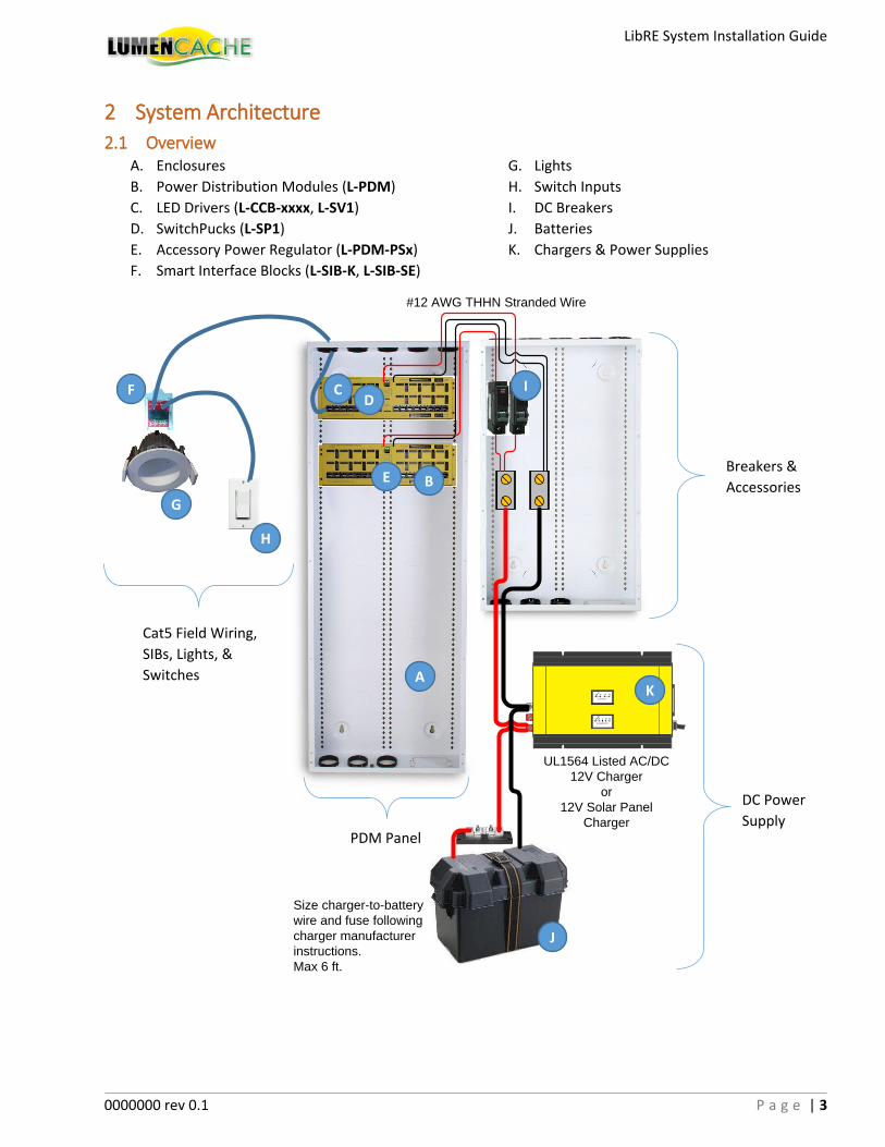
2.1 Overview A. Enclosures G. Lights
B. Power Distribution Modules (L-PDM) H. Switch Inputs
C. LED Drivers (L-CCB-xxxx, L-SV1) I. DC Breakers
D. SwitchPucks (L-SP1) J. Batteries
E. Accessory Power Regulator (L-PDM-PSx) K. Chargers & Power Supplies
F. Smart Interface Blocks (L-SIB-K, L-SIB-SE)
UL1564 Listed AC/DC
12V Charger
or
12V Solar Panel
Charger
#12 AWG THHN Stranded Wire
Size charger-to-battery
wire and fuse following
charger manufacturer
instructions.
Max 6 ft.
DC Power
Supply
Breakers &
Accessories
PDM Panel
Cat5 Field Wiring,
SIBs, Lights, &
Switches
(Lights & Switches)
A
B
C D
E
F
G
H
I
J
K
LibRE System Installation Guide
0000000 rev 0.1 P a g e | 4
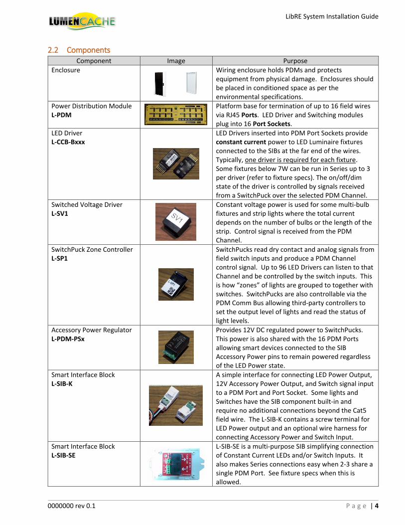
2.2 Components Component Image Purpose
Enclosure
Wiring enclosure holds PDMs and protects equipment from physical damage. Enclosures should be placed in conditioned space as per the environmental specifications.
Power Distribution Module L-PDM
Platform base for termination of up to 16 field wires via RJ45 Ports. LED Driver and Switching modules plug into 16 Port Sockets.
LED Driver L-CCB-Bxxx
LED Drivers inserted into PDM Port Sockets provide constant current power to LED Luminaire fixtures connected to the SIBs at the far end of the wires. Typically, one driver is required for each fixture. Some fixtures below 7W can be run in Series up to 3 per driver (refer to fixture specs). The on/off/dim state of the driver is controlled by signals received from a SwitchPuck over the selected PDM Channel.
Switched Voltage Driver L-SV1
Constant voltage power is used for some multi-bulb fixtures and strip lights where the total current depends on the number of bulbs or the length of the strip. Control signal is received from the PDM Channel.
SwitchPuck Zone Controller L-SP1
SwitchPucks read dry contact and analog signals from field switch inputs and produce a PDM Channel control signal. Up to 96 LED Drivers can listen to that Channel and be controlled by the switch inputs. This is how “zones” of lights are grouped to together with switches. SwitchPucks are also controllable via the PDM Comm Bus allowing third-party controllers to set the output level of lights and read the status of light levels.
Accessory Power Regulator L-PDM-PSx
Provides 12V DC regulated power to SwitchPucks. This power is also shared with the 16 PDM Ports allowing smart devices connected to the SIB Accessory Power pins to remain powered regardless of the LED Power state.
Smart Interface Block L-SIB-K
A simple interface for connecting LED Power Output, 12V Accessory Power Output, and Switch signal input to a PDM Port and Port Socket. Some lights and Switches have the SIB component built-in and require no additional connections beyond the Cat5 field wire. The L-SIB-K contains a screw terminal for LED Power output and an optional wire harness for connecting Accessory Power and Switch Input.
Smart Interface Block L-SIB-SE
L-SIB-SE is a multi-purpose SIB simplifying connection of Constant Current LEDs and/or Switch Inputs. It also makes Series connections easy when 2-3 share a single PDM Port. See fixture specs when this is allowed.
LibRE System Installation Guide
0000000 rev 0.1 P a g e | 5
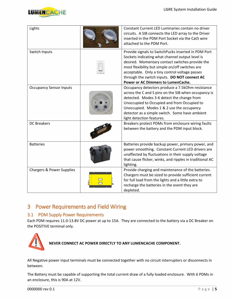
Lights
Constant Current LED Luminaries contain no driver circuits. A SIB connects the LED array to the Driver inserted in the PDM Port Socket via the Cat5 wire attached to the PDM Port.
Switch Inputs
Provide signals to SwitchPucks inserted in PDM Port Sockets indicating what channel output level is desired. Momentary contact switches provide the most flexibility but simple on/off switches are acceptable. Only a tiny control voltage passes through the switch inputs. DO NOT connect AC Power or AC Dimmers to LumenCache.
Occupancy Sensor Inputs
Occupancy detectors produce a 7.5kOhm resistance across the C and S pins on the SIB when occupancy is detected. Modes 3-6 detect the change from Unoccupied to Occupied and from Occupied to Unoccupied. Modes 1 & 2 use the occupancy detector as a simple switch. Some have ambient light detection features.
DC Breakers
Breakers protect PDMs from enclosure wiring faults between the battery and the PDM input block.
Batteries
Batteries provide backup power, primary power, and power smoothing. Constant Current LED drivers are unaffected by fluctuations in their supply voltage that cause flicker, winks, and ripples in traditional AC lighting.
Chargers & Power Supplies
Provide charging and maintenance of the batteries. Chargers must be sized to provide sufficient current for full load from the lights and a little extra to recharge the batteries in the event they are depleted.
3 Power Requirements and Field Wiring
3.1 PDM Supply Power Requirements Each PDM requires 11.0-13.8V DC power at up to 15A. They are connected to the battery via a DC Breaker on
the POSITIVE terminal only.
NEVER CONNECT AC POWER DIRECTLY TO ANY LUMENCACHE COMPONENT.
All Negative power input terminals must be connected together with no circuit interrupters or disconnects in
between.
The Battery must be capable of supporting the total current draw of a fully loaded enclosure. With 6 PDMs in
an enclosure, this is 90A at 12V.

LibRE System Installation Guide
0000000 rev 0.1 P a g e | 6
The main Power Supply may be a solar, wind or other renewable charger, or an AC/DC battery charger.
AC Mains-connected Chargers and Power Supplies must provide sufficient Isolation from AC Mains.
Acceptable power supplies must be certified to meet UL1564 or UL60950-1 safety standards and
environmental conditions of the room where the enclosure is located.
3.2 Field Device Cabling Requirements
3.2.1 General Wire Requirements Each SIB can be connected to the PDM Port using standard Category Wire (Cat5e, Cat 6). It may be shielded or
unshielded.
All field wires must be UL Listed and meet NEC 725/800 codes suitable for their installed environment. For
example: CL2 or CM rated. Plenum rating is required if routed through plenums.
Field wire lengths should be kept below 300’ but Constant Current drivers can easily operate over 1000’ and
automatically compensate for varying wire lengths.
PDM Power Input wires should be limited to 15’ to avoid requiring a larger AWG wire.
Confirm the PDM Power Input Wires and Battery to Charger wires have sufficient Amperage
carrying capacity.
Each PDM Power Input requires #12 AWG THHN wire. Up to 6 PDMs can share a #4 AWG wire.
To reduce the risk of fire, connect only to a circuit provided with a maximum branch-circuit overcurrent
protection rating not to exceed the PDM current rating of 15A each, and in accordance with the National
Electrical Code, ANSI/NFPA 70.
3.2.2 Field Wiring Options and Load Calculations The driver Category mark indicates the electrical current supplied to the LED luminaries. The chart below
indicates the Current range, LED Array Total Voltage, wire AWG, and the maximum recommended wire length.
Category Current Vmin/max Min Wire (AWG) Max Length
A 150mA 18/52 Cat5 (24) 1000’
B 300mA 18/52 Cat5 (24) 350’
C 500mA 18/32 Cat5 (24) 250’ Example: 300mA, 36-40V typ.
3.2.3 LCbus™ Wire LCbus™ is 16 AWG 2 conductor wire and 2 UTP 24AGW wire pairs in a single jacket. The 16AWG wires allows
up to 4A (refer to UL Listed Rating for the wire). The PDM Ports do not support this power level but signal
Amplifiers can be used to repeat Switched Voltage power from L-SV1 regulators. This is effective for powering
large LED strip lights and multi-bulb fixtures such as chandeliers.
Proper fusing and protection must be used on the wires leaving the Amplifiers to avoid exceeding the wire
current capacity. Terminations at the fixture must meet the current carrying requirements. Consult your local
AHJ for requirements when using this configuration.
B 38
LibRE System Installation Guide
0000000 rev 0.1 P a g e | 7
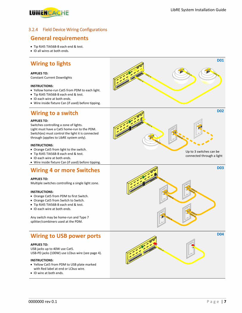
3.2.4 Field Device Wiring Configurations
INSTRUCTIONS:· Yellow home-run Cat5 from PDM to each light.· Tip RJ45 TIA568-B each end & test.· ID each wire at both ends.· Wire inside fixture Can (if used) before tipping.
Wiring to lights
APPLIES TO:Constant Current Downlights
INSTRUCTIONS:· Orange Cat5 from light to the switch.· Tip RJ45 TIA568-B each end & test.· ID each wire at both ends.· Wire inside fixture Can (if used) before tipping.
Wiring to a switchAPPLIES TO:Switches controlling a zone of lights.Light must have a Cat5 home-run to the PDM.Switch(es) must control the light it is connected through (applies to LibRE system only).
0301-A
0301-A0302-A
0302-A
0302-A
0302-B
0302-B
0302-B
0302-B
0302-C
0302-D
0302-D
0302-A
Wiring 4 or more SwitchesAPPLIES TO:Multiple switches controlling a single light zone.
· Tip RJ45 TIA568-B each end & test.· ID all wires at both ends.
General requirements
0302-C
INSTRUCTIONS:· Orange Cat5 from PDM to first Switch.· Orange Cat5 from Switch to Switch.· Tip RJ45 TIA568-B each end & test.· ID each wire at both ends.
Any switch may be home-run and Type 7 splitter/combiners used at the PDM.
0302-A
Wiring to USB power portsAPPLIES TO:USB jacks up to 40W use Cat5.USB-PD jacks (100W) use LCbus wire (see page 4).
INSTRUCTIONS:· Yellow Cat5 from PDM to USB plate marked
with Red label at end or LCbus wire.· ID wire at both ends.
Up to 3 switches can be connected through a light
D01
D02
D03
D04
LibRE System Installation Guide
0000000 rev 0.1 P a g e | 8
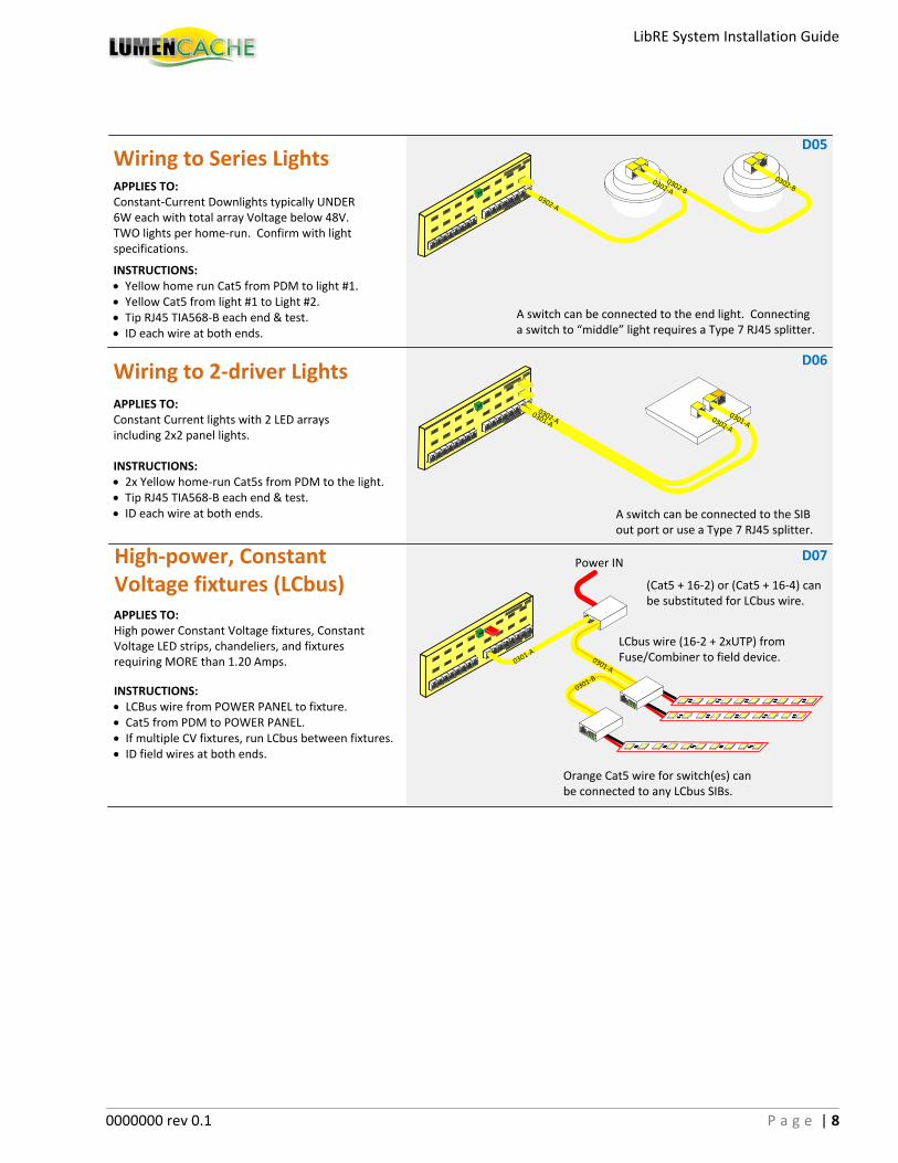
INSTRUCTIONS:· Yellow home run Cat5 from PDM to light #1.· Yellow Cat5 from light #1 to Light #2.· Tip RJ45 TIA568-B each end & test.· ID each wire at both ends.
Wiring to Series LightsAPPLIES TO:Constant-Current Downlights typically UNDER 6W each with total array Voltage below 48V.TWO lights per home-run. Confirm with light specifications.
0302-B
0302-A
0302-A
0302-B
INSTRUCTIONS:· LCBus wire from POWER PANEL to fixture.· Cat5 from PDM to POWER PANEL.· If multiple CV fixtures, run LCbus between fixtures.· ID field wires at both ends.
High-power, Constant Voltage fixtures (LCbus)APPLIES TO:High power Constant Voltage fixtures, Constant Voltage LED strips, chandeliers, and fixtures requiring MORE than 1.20 Amps.
LCbus wire (16-2 + 2xUTP) from Fuse/Combiner to field device.
INSTRUCTIONS:· 2x Yellow home-run Cat5s from PDM to the light.· Tip RJ45 TIA568-B each end & test.· ID each wire at both ends.
Wiring to 2-driver Lights
APPLIES TO:Constant Current lights with 2 LED arrays including 2x2 panel lights.
0301-A
0302-A
A switch can be connected to the end light. Connecting a switch to “middle” light requires a Type 7 RJ45 splitter.
0301-A0302-A
0
0301-A
Power IN
(Cat5 + 16-2) or (Cat5 + 16-4) can be substituted for LCbus wire.
A switch can be connected to the SIB out port or use a Type 7 RJ45 splitter.
0301-A
0
0
0301-B
Orange Cat5 wire for switch(es) can be connected to any LCbus SIBs.
D05
D06
D07
LibRE System Installation Guide
0000000 rev 0.1 P a g e | 9
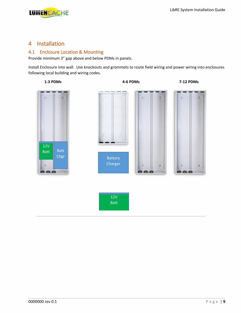
4 Installation
4.1 Enclosure Location & Mounting Provide minimum 3” gap above and below PDMs in panels.
Install Enclosure into wall. Use knockouts and grommets to route field wiring and power wiring into enclosures
following local building and wiring codes.
1-3 PDMs 4-6 PDMs 7-12 PDMs
Battery
Charger
Batt
Chgr
12V
Batt
12V
Batt
LibRE System Installation Guide
0000000 rev 0.1 P a g e | 10
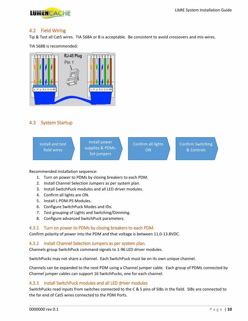
4.2 Field Wiring Tip & Test all Cat5 wires. TIA 568A or B is acceptable. Be consistent to avoid crossovers and mis-wires.
TIA 568B is recommended:
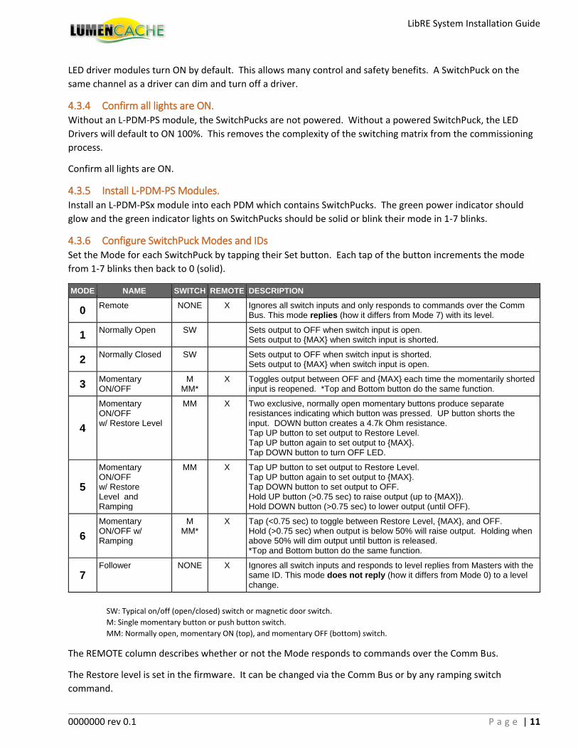
4.3 System Startup
Recommended installation sequence:
1. Turn on power to PDMs by closing breakers to each PDM.
2. Install Channel Selection Jumpers as per system plan.
3. Install SwitchPuck modules and all LED driver modules.
4. Confirm all lights are ON.
5. Install L-PDM-PS Modules.
6. Configure SwitchPuck Modes and IDs.
7. Test grouping of Lights and Switching/Dimming.
8. Configure advanced SwitchPuck parameters.
4.3.1 Turn on power to PDMs by closing breakers to each PDM. Confirm polarity of power into the PDM and that voltage is between 11.0-13.8VDC.
4.3.2 Install Channel Selection Jumpers as per system plan. Channels group SwitchPuck command signals to 1-96 LED driver modules.
SwitchPucks may not share a channel. Each SwitchPuck must be on its own unique channel.
Channels can be expanded to the next PDM using a Channel jumper cable. Each group of PDMs connected by
Channel jumper cables can support 16 SwitchPucks, one for each channel.
4.3.3 Install SwitchPuck modules and all LED driver modules SwitchPucks read inputs from switches connected to the C & S pins of SIBs in the field. SIBs are connected to
the far end of Cat5 wires connected to the PDM Ports.
Install and test
field wires
Install power
supplies & PDMs.
Set jumpers
Confirm all lights
ON
Confirm Switching
& Controls
LibRE System Installation Guide
0000000 rev 0.1 P a g e | 11
LED driver modules turn ON by default. This allows many control and safety benefits. A SwitchPuck on the
same channel as a driver can dim and turn off a driver.
4.3.4 Confirm all lights are ON. Without an L-PDM-PS module, the SwitchPucks are not powered. Without a powered SwitchPuck, the LED
Drivers will default to ON 100%. This removes the complexity of the switching matrix from the commissioning
process.
Confirm all lights are ON.
4.3.5 Install L-PDM-PS Modules. Install an L-PDM-PSx module into each PDM which contains SwitchPucks. The green power indicator should
glow and the green indicator lights on SwitchPucks should be solid or blink their mode in 1-7 blinks.
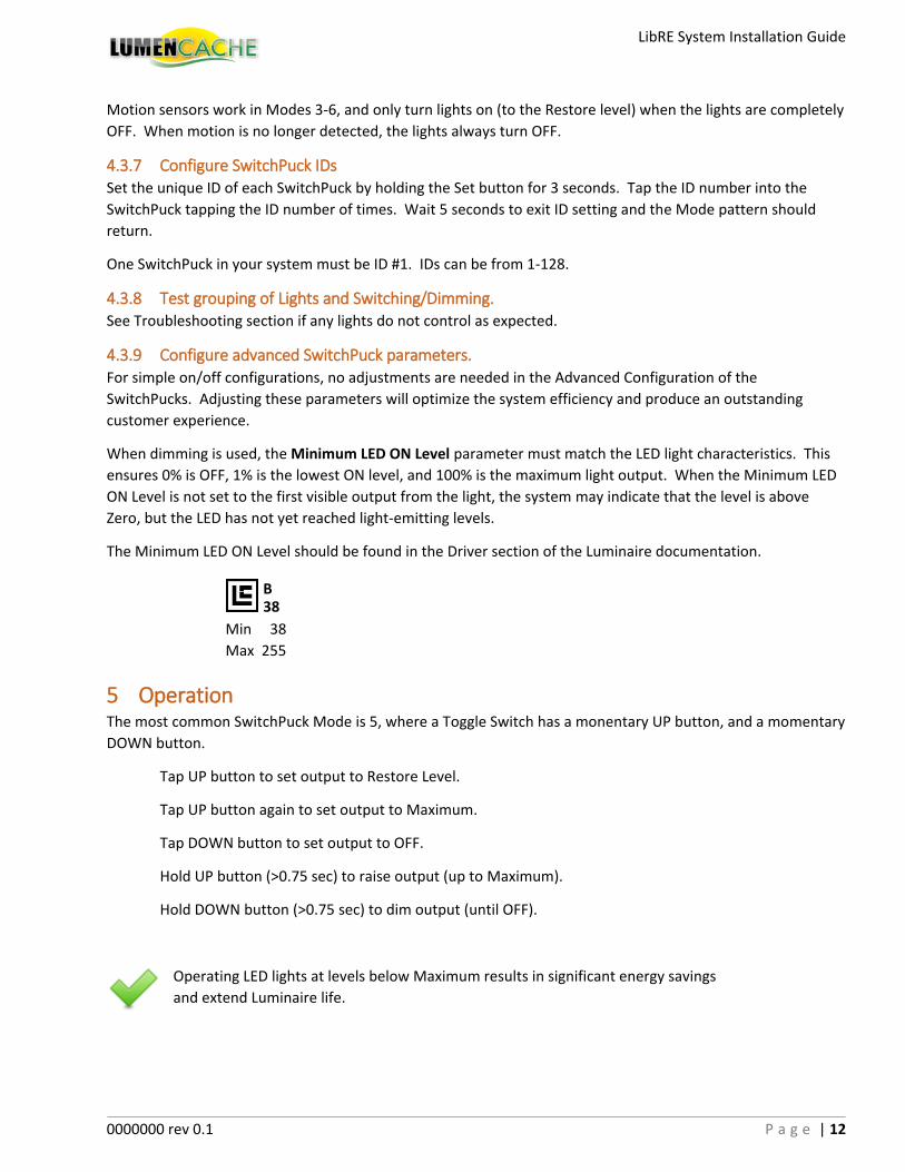
4.3.6 Configure SwitchPuck Modes and IDs Set the Mode for each SwitchPuck by tapping their Set button. Each tap of the button increments the mode
from 1-7 blinks then back to 0 (solid).
MODE NAME SWITCH REMOTE DESCRIPTION
0 Remote NONE X Ignores all switch inputs and only responds to commands over the Comm
Bus. This mode replies (how it differs from Mode 7) with its level.
1 Normally Open SW Sets output to OFF when switch input is open.
Sets output to {MAX} when switch input is shorted.
2 Normally Closed SW Sets output to OFF when switch input is shorted.
Sets output to {MAX} when switch input is open.
3 Momentary ON/OFF
M MM*
X Toggles output between OFF and {MAX} each time the momentarily shorted input is reopened. *Top and Bottom button do the same function.
4
Momentary ON/OFF w/ Restore Level
MM X Two exclusive, normally open momentary buttons produce separate resistances indicating which button was pressed. UP button shorts the input. DOWN button creates a 4.7k Ohm resistance. Tap UP button to set output to Restore Level. Tap UP button again to set output to {MAX}. Tap DOWN button to turn OFF LED.
5
Momentary ON/OFF w/ Restore Level and Ramping
MM X Tap UP button to set output to Restore Level. Tap UP button again to set output to {MAX}. Tap DOWN button to set output to OFF. Hold UP button (>0.75 sec) to raise output (up to {MAX}). Hold DOWN button (>0.75 sec) to lower output (until OFF).
6
Momentary ON/OFF w/ Ramping
M MM*
X Tap (<0.75 sec) to toggle between Restore Level, {MAX}, and OFF. Hold (>0.75 sec) when output is below 50% will raise output. Holding when above 50% will dim output until button is released. *Top and Bottom button do the same function.
7 Follower NONE X Ignores all switch inputs and responds to level replies from Masters with the
same ID. This mode does not reply (how it differs from Mode 0) to a level change.
SW: Typical on/off (open/closed) switch or magnetic door switch.
M: Single momentary button or push button switch.
MM: Normally open, momentary ON (top), and momentary OFF (bottom) switch.
The REMOTE column describes whether or not the Mode responds to commands over the Comm Bus.
The Restore level is set in the firmware. It can be changed via the Comm Bus or by any ramping switch
command.
LibRE System Installation Guide
0000000 rev 0.1 P a g e | 12
Motion sensors work in Modes 3-6, and only turn lights on (to the Restore level) when the lights are completely
OFF. When motion is no longer detected, the lights always turn OFF.
4.3.7 Configure SwitchPuck IDs Set the unique ID of each SwitchPuck by holding the Set button for 3 seconds. Tap the ID number into the
SwitchPuck tapping the ID number of times. Wait 5 seconds to exit ID setting and the Mode pattern should
return.
One SwitchPuck in your system must be ID #1. IDs can be from 1-128.
4.3.8 Test grouping of Lights and Switching/Dimming. See Troubleshooting section if any lights do not control as expected.
4.3.9 Configure advanced SwitchPuck parameters. For simple on/off configurations, no adjustments are needed in the Advanced Configuration of the
SwitchPucks. Adjusting these parameters will optimize the system efficiency and produce an outstanding
customer experience.
When dimming is used, the Minimum LED ON Level parameter must match the LED light characteristics. This
ensures 0% is OFF, 1% is the lowest ON level, and 100% is the maximum light output. When the Minimum LED
ON Level is not set to the first visible output from the light, the system may indicate that the level is above
Zero, but the LED has not yet reached light-emitting levels.
The Minimum LED ON Level should be found in the Driver section of the Luminaire documentation.
5 Operation The most common SwitchPuck Mode is 5, where a Toggle Switch has a monentary UP button, and a momentary
DOWN button.
Tap UP button to set output to Restore Level.
Tap UP button again to set output to Maximum.
Tap DOWN button to set output to OFF.
Hold UP button (>0.75 sec) to raise output (up to Maximum).
Hold DOWN button (>0.75 sec) to dim output (until OFF).
Operating LED lights at levels below Maximum results in significant energy savings
and extend Luminaire life.
B 38
Min 38
Max 255
LibRE System Installation Guide
0000000 rev 0.1 P a g e | 13
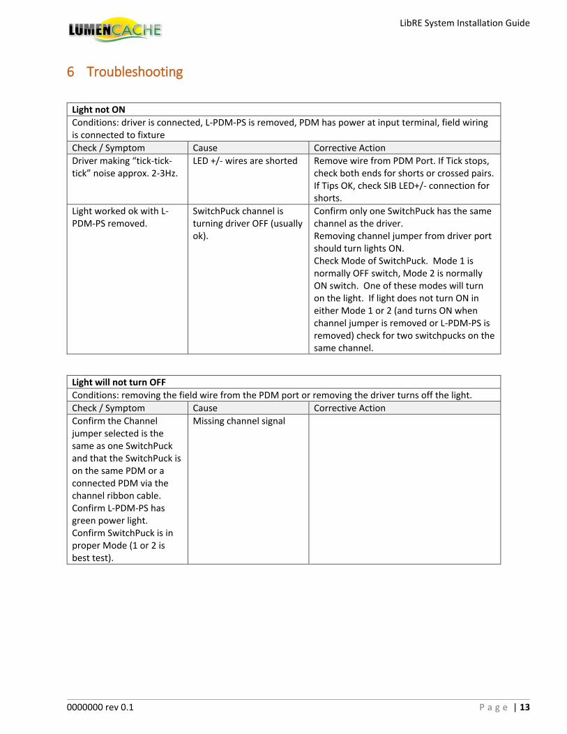
6 Troubleshooting
Light not ON
Conditions: driver is connected, L-PDM-PS is removed, PDM has power at input terminal, field wiring is connected to fixture
Check / Symptom Cause Corrective Action
Driver making “tick-tick-tick” noise approx. 2-3Hz.
LED +/- wires are shorted Remove wire from PDM Port. If Tick stops, check both ends for shorts or crossed pairs. If Tips OK, check SIB LED+/- connection for shorts.
Light worked ok with L-PDM-PS removed.
SwitchPuck channel is turning driver OFF (usually ok).
Confirm only one SwitchPuck has the same channel as the driver. Removing channel jumper from driver port should turn lights ON. Check Mode of SwitchPuck. Mode 1 is normally OFF switch, Mode 2 is normally ON switch. One of these modes will turn on the light. If light does not turn ON in either Mode 1 or 2 (and turns ON when channel jumper is removed or L-PDM-PS is removed) check for two switchpucks on the same channel.
Light will not turn OFF
Conditions: removing the field wire from the PDM port or removing the driver turns off the light.
Check / Symptom Cause Corrective Action
Confirm the Channel jumper selected is the same as one SwitchPuck and that the SwitchPuck is on the same PDM or a connected PDM via the channel ribbon cable. Confirm L-PDM-PS has green power light. Confirm SwitchPuck is in proper Mode (1 or 2 is best test).
Missing channel signal
LibRE System Installation Guide
0000000 rev 0.1 P a g e | 14
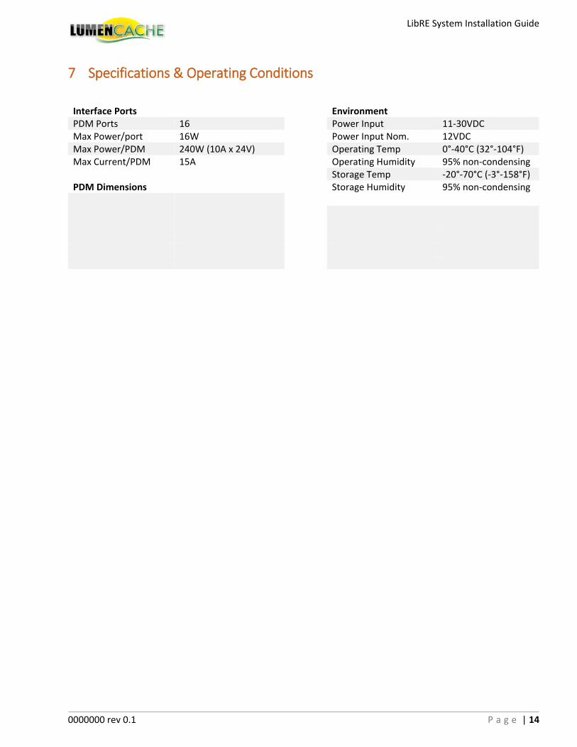
7 Specifications & Operating Conditions
Interface Ports Environment PDM Ports 16 Power Input 11-30VDC Max Power/port 16W Power Input Nom. 12VDC Max Power/PDM 240W (10A x 24V) Operating Temp 0°-40°C (32°-104°F) Max Current/PDM 15A Operating Humidity 95% non-condensing Storage Temp -20°-70°C (-3°-158°F) PDM Dimensions Storage Humidity 95% non-condensing