A Building-Block Approach to Industrial Controls ...
12
Paper ID #14584 A Building-Block Approach to Industrial Controls Laboratories Using Pro- grammable Logic Controllers Prof. Robert J. Durkin, Indiana University - Purdue University, Indianapolis Mr. Durkin teaches courses in Mechanical and Electrical Engineering Technology; including the capstone design and independent study projects. He serves as a Faculty Senator and earned the 2013 Outstanding Teacher Award. He has over 25 years of engineering and manufacturing experience including; design, project management, and various engineering, research and manufacturing leadership roles. He has been awarded two US patents. He is an alumnus of Indiana Institute of Technology, and the University of Notre Dame; where he graduated Magna cum Laude. c American Society for Engineering Education, 2016
Transcript of A Building-Block Approach to Industrial Controls ...

Paper ID #14584
A Building-Block Approach to Industrial Controls Laboratories Using Pro-grammable Logic Controllers
Prof. Robert J. Durkin, Indiana University - Purdue University, Indianapolis
Mr. Durkin teaches courses in Mechanical and Electrical Engineering Technology; including the capstonedesign and independent study projects. He serves as a Faculty Senator and earned the 2013 OutstandingTeacher Award. He has over 25 years of engineering and manufacturing experience including; design,project management, and various engineering, research and manufacturing leadership roles. He has beenawarded two US patents. He is an alumnus of Indiana Institute of Technology, and the University of NotreDame; where he graduated Magna cum Laude.
c©American Society for Engineering Education, 2016

A Building-block Approach to Industrial Controls Laboratories using Programmable Logic Controllers
Abstract
Industrial control systems design often incorporates reusable sections of prior design that can easily be adapted for new machine and process control systems. For instance, inclusion of a tri-mode control structure (Manual, Automatic and Set-up modes) often becomes a ‘cut and paste’ section from a previous control system design. The prior design is already proven, and development time is available for the newer aspects of the control system. This building-block method can also be used to structure university laboratory exercises for Electrical Engineering Technology industrial controls design courses. Reusing hardware and software sections from previous laboratories can enhance the student’s design capability by focusing lab time on the new problem instead of recreating the previous control system structures.
This paper describes a semester-long industrial controls laboratory using programmable logic controllers (PLC) as the primary lab equipment. It describes fourteen increasingly difficult PLC laboratory experiments that generally build on the components of the prior labs. The final lab assignment is an open-ended team project to design a complete system for a typical industrial machine or process. All of the PLCs are networked to provide the students with communications content within the lab experience.
The pedagogical features of the laboratory exercises are illustrated and results from student comments and numerical ratings of the effectiveness of the lab exercises and equipment are also included in the paper.
Introduction
A common career path for Electrical Engineering Technology (EET) students is the design and maintenance of industrial control systems. These industrial controls are typically designed using Programmable Logic Controllers (PLC) to execute and monitor the machine or process. PLCs are equipped with discrete and analog control of high and low current AC and DC voltages, and can also include PID control algorithms for closed-loop control structures. 2 Our University includes a total of twelve credit hours of courses to study the selection of control systems components and the overall system design; introduction, PLC-specific controls, and process control and automation.
• Electrical Power and Controls: 4 Cr. (3 Class, 2 Lab) An introduction to transformers, induction motors, and single-phase and three-phase power systems, motor control devices, programmable logic controllers, PLC input and output devices, and PLC communications. 1
• Introduction to Control Systems: 4 Cr. (3 Class, 2 Lab) A continuation of the study of industrial controls including on-off, open-and closed-loop control systems, and analog-based systems. Major topics include relay controls, PLC, controls, HMI and open-PC controls, and networking. 1

• Automation, Instrumentation, and Process Control: 4 Cr. (2 Class, 4 Lab) A project-oriented course combining key areas of automation, instrumentation, and process control. The course covers automatic testing, computer interfacing, data collection, robotic controls, programmable logic controllers, and graphical process control software. 1
The courses all include laboratory content that build on early material to increasing difficult topics. For example the initial course, Electrical Power and Controls, begins with simple labs that introduce the student to basic control systems components such as transformers, electric motors, control relays, motor starters and PLC input and output hardware. The successive courses build on this content to expand the student exposure to more complex PLC systems, human-machine interfaces (HMI) and machine-machine interfaces with robots and vision systems. The linchpin course to a future career in industrial controls is the middle course; Introduction to Control Systems. This course takes the students from simple sequential control to information and data processing, and then builds to PID, HMI and network communication. The lab content for this transition to increasing complex concepts and systems is built upon content from prior labs to minimize duplicate student effort.
Introduction to Control Systems: The Lab Equipment
The PLC Laboratory is equipped with twelve stations, all consisting of a Dell OptiPlex personal computer, an Allen Bradley Compact Logix PLC and PanelView Plus 600 HMI, and an Agilent oscilloscope, multimeter and power supply. All of the computers, PLCs and HMIs are networked using Ethernet communication, and the test equipment is connected by a General Purpose Interface Bus (GPIB). The PLC system includes;
The CompactLogix setup contains the following hardware:
• 1769-L32E processor (slot 0) • 1769-PA16 power supply slot P/S • 1769-IA16 120V AC Input (slot 1) • 1769-OW16 16-Point AC/DC Relay Output (slot 2) • 1769-IF4XOF2 4-Input, 2-Output, Combination Analog I/O (slot 3) • PanelView Plus 600 HMI station
The Dell computer uses the following software:
• RSLogix 5000 programming software • RSLinx Classic communications server software • RSView Studio HMI programming software

Introduction to Control Systems: The Lab Experiments
There are fourteen one-hundred minute laboratories over fifteen weeks in this course. The first thirteen labs are snippets of real machine and process control systems, and the final two periods are student-team projects that design and demonstrate complete industrial control systems. The initial thirteen labs are instructor-led control problems that require students to write a PLC program to solve the problem and then demonstrate their solution to the instructor. Students are given the entire lab period to complete the assignment. If the student is not able to demonstrate a working solution, a portion of the following lab period can be used to demonstrate the prior lab’s program. Lab assignments are graded on a ten-point scale and points are deducted for late demonstrations of the program solution. Three of the labs have fixtures (Stoplight), test equipment, and simulation software associated with them. The other nine experiments are thought problems, and no simulator software or hardware is provided to assist the student in visualizing the control system or machine/process it controls.
Laboratory assignments are arraigned in an increasing level of difficulty with each successive lab using sections of a prior lab or labs.
• Experiment 1 Introduction to RSLogix 5000 – Start/Stop and Motor Control • Experiment 2 Downloading a Program to the PLC– Operating Modes • Experiment 3 Monitoring a Program – Pulse Width Modulation using Timers • Experiment 4 Sequential Circuit I – Drilling Machine • Experiment 5 Sequential Circuit II – Welding Machine • Experiment 6 Analog to Digital Conversion – Heat Treat Furnace • Experiment 7 Data Arrays - Recipe Selection for Soft Drink Dispenser • Experiment 8 Shift Registers - Paint Booth and Conveyor • Experiment 9 Sequencers - Stoplight Design • Experiment 10 Tuning a PID control loop – Steam Flow System • Experiment 11 Dynamic Data Exchange (DDE) w/Excel – Soft Drink Dispenser • Experiment 12 FactoryTalk and RSView Studio – PanelView HMI Design • Experiment 13 Advanced PanelView HMI – Stoplight Design • Experiment 14 Group Project Demonstration (including hardware selection)
Figure 1: PLC Laboratory Workstation

Experiment One: This lab exposes the student to the basic operation of RSLogix 5000 programming software. It asks the student to create his or her first project; creating an Ethernet connection between the PLC and the Dell computer, configuring of the PLC hardware (including I/O), organization of the Program Tasks and Main routine, and creating the first program. The program is a simple Start, Stop and latch of a motor contactor. It illustrates the use of normally open (NO) and normally closed (NC) contacts of pushbuttons and their effect on the states of XIO and XIC program commands. Failure modes of NO and NC inputs and their effect on the states of XIO and XIC program commands are emphasized. This Start/Stop circuit is included in all of the Labs that follow. All control programs include some kind of start and stop routine, and the hardware and Ethernet communications setup is defined in this lab and will not have to be re-programmed in subsequent labs. The benefit of re-using this lab is illustrated by Experiment Two.
Experiment Two: The next lab directs the student to download his or her first program into their PLC. The exercise repeats the Ethernet connection from the first lab and then introduces the Controller modes, forcing I/O, assigning tags and aliases, ’power flow’ concepts and editing and de-bugging the program. The lab introduces some new control concepts including the tri-mode control of Auto/Manual and Jog operations, and anti-tiedown and anti-repeat dual pushbutton Start circuits.
Figure 2: Ethernet communication
Experiment Three: The third lab uses the second project as its template and broadens the prior labs with a simple pulse-width modulation (PWM) circuit. Design instructions are included in the lab, but the student must independently incorporate his/her Start/Stop (with anti-
tiedown/repeat), Auto/Manual and Jog circuits from the prior lab. Trend Routines are created by the student to monitor the timers associated with the PWM circuit.
Experiment Four: As before, this lab begins with the content of Experiment Two. A Drilling Machine control circuit is designed and tested by the student to control a three axis drilling machine fed by a conveyor. Broadly-stated operating instructions are provided; ‘A metal piece is moved into position by the conveyor and when sensed by PE2, moved and clamped by the Pneumatic Ram into a drill fixture where any combination of three possible holes is drilled into the piece.’ The students design and debug their new program while incorporating the operator controls from the prior lab and editing out the PWM portion of the prior lab.
Experiment Four: This experiment uses Experiment Three as its starting point. Here, the student incorporates all of that lab’s design to create a control system for a Spot Welding Machine. The PWM control is used to adjust the average welding current control and a counter circuit tracks and controls the total current applied to the weld. The electrode contact force is controlled by a pneumatic cylinder and pressure switch.
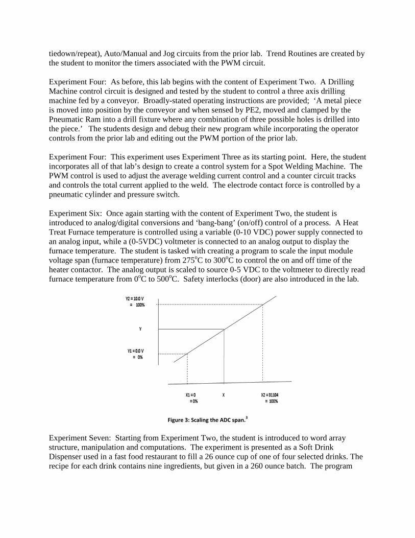
Experiment Six: Once again starting with the content of Experiment Two, the student is introduced to analog/digital conversions and ‘bang-bang’ (on/off) control of a process. A Heat Treat Furnace temperature is controlled using a variable (0-10 VDC) power supply connected to an analog input, while a (0-5VDC) voltmeter is connected to an analog output to display the furnace temperature. The student is tasked with creating a program to scale the input module voltage span (furnace temperature) from 275oC to 300oC to control the on and off time of the heater contactor. The analog output is scaled to source 0-5 VDC to the voltmeter to directly read furnace temperature from 0oC to 500oC. Safety interlocks (door) are also introduced in the lab.
Figure 3: Scaling the ADC span.3
Experiment Seven: Starting from Experiment Two, the student is introduced to word array structure, manipulation and computations. The experiment is presented as a Soft Drink Dispenser used in a fast food restaurant to fill a 26 ounce cup of one of four selected drinks. The recipe for each drink contains nine ingredients, but given in a 260 ounce batch. The program
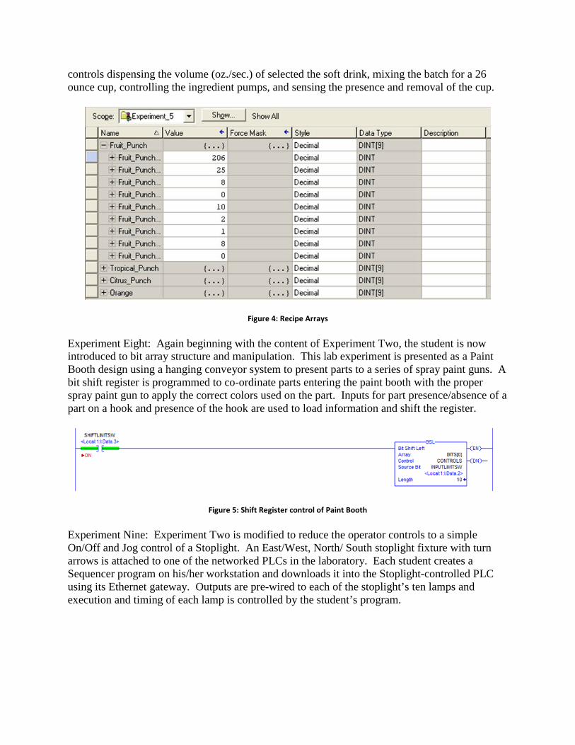
controls dispensing the volume (oz./sec.) of selected the soft drink, mixing the batch for a 26 ounce cup, controlling the ingredient pumps, and sensing the presence and removal of the cup.
Figure 4: Recipe Arrays
Experiment Eight: Again beginning with the content of Experiment Two, the student is now introduced to bit array structure and manipulation. This lab experiment is presented as a Paint Booth design using a hanging conveyor system to present parts to a series of spray paint guns. A bit shift register is programmed to co-ordinate parts entering the paint booth with the proper spray paint gun to apply the correct colors used on the part. Inputs for part presence/absence of a part on a hook and presence of the hook are used to load information and shift the register.
Figure 5: Shift Register control of Paint Booth
Experiment Nine: Experiment Two is modified to reduce the operator controls to a simple On/Off and Jog control of a Stoplight. An East/West, North/ South stoplight fixture with turn arrows is attached to one of the networked PLCs in the laboratory. Each student creates a Sequencer program on his/her workstation and downloads it into the Stoplight-controlled PLC using its Ethernet gateway. Outputs are pre-wired to each of the stoplight’s ten lamps and execution and timing of each lamp is controlled by the student’s program.

Figure 6: Traffic Light Experiment
Experiment Ten: This is the only laboratory experiment that uses simulation software. PID control of a simulated steam flow system is used to evaluate the results of tuning a PID loop using three open and closed loop tuning methods. Ziegler-Nichols, Cohen-Coon, and Fertik methods are used to tune a self-regulating first order lag process with the transfer function (𝒔𝒔) = 𝟖𝟖𝒆𝒆
−𝟎𝟎.𝟓𝟓𝒔𝒔
𝟎𝟎.𝟓𝟓𝒔𝒔+𝟏𝟏 , with the PID controller set to an interacting mode for the proportional gain.
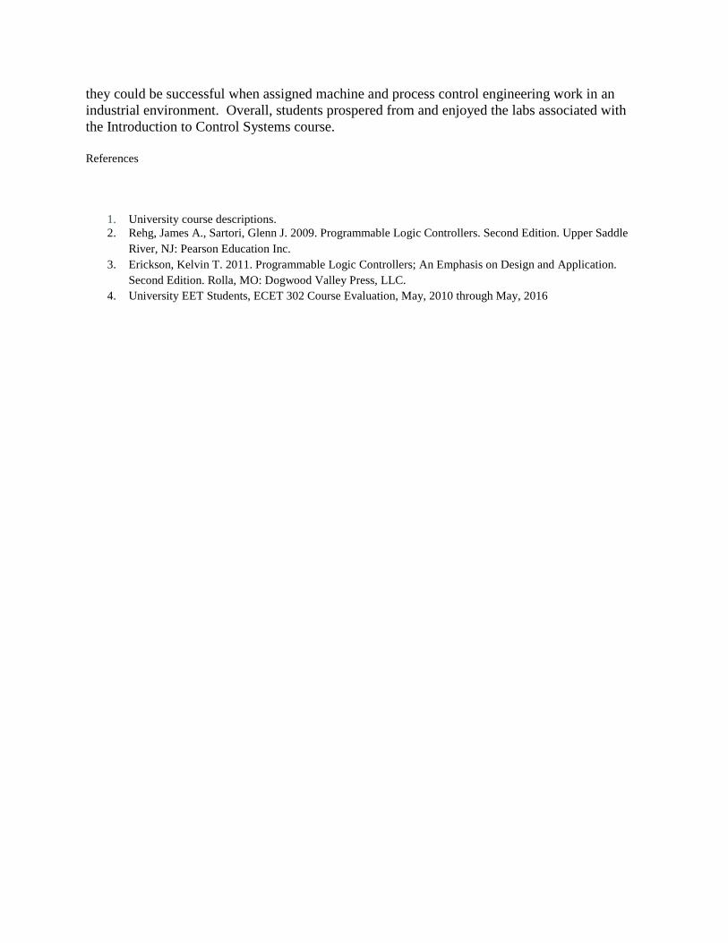
Experiment Eleven: Using the program developed in Experiment Seven, the student is asked to create a Dynamic Data Exchange (DDE) communications bridge between a Microsoft Excel spreadsheet hosted on the workstation’s Dell computer and the program for Soft Drink Dispenser operating on the workstation’s PLC using Ethernet communications. RSLinx is used to facilitate information transfer between the programs. Macros in the Excel spreadsheet are programmed using Visual Basic to transfer Word Data from the spreadsheet to the PLC program arrays. Recall that Experiment Seven was presented as a Soft Drink Dispenser used in a fast food restaurant to fill a 26 ounce cup of one of four selected drinks. The recipe for each drink contains nine ingredients, and the Excel spreadsheet revises the values of the nine ingredients used for each of the four recipes. This new experiment is designed to demonstrate supervisory control of an individual PLC-driven process.
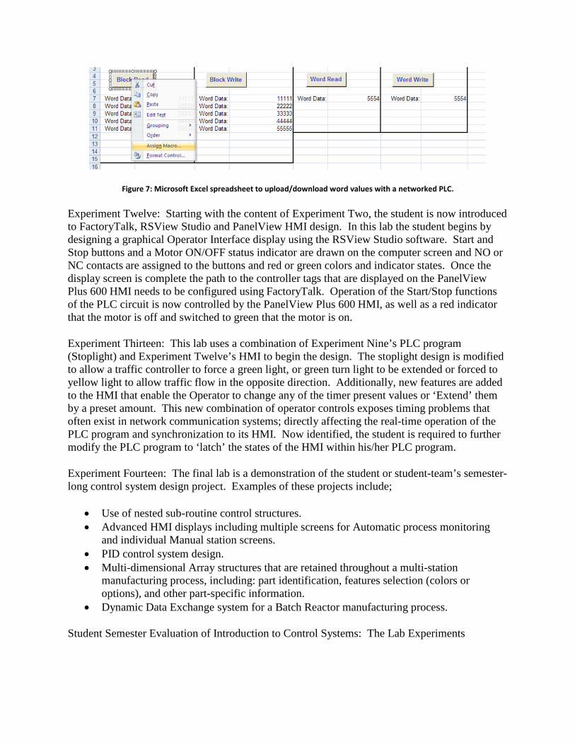
Figure 7: Microsoft Excel spreadsheet to upload/download word values with a networked PLC.
Experiment Twelve: Starting with the content of Experiment Two, the student is now introduced to FactoryTalk, RSView Studio and PanelView HMI design. In this lab the student begins by designing a graphical Operator Interface display using the RSView Studio software. Start and Stop buttons and a Motor ON/OFF status indicator are drawn on the computer screen and NO or NC contacts are assigned to the buttons and red or green colors and indicator states. Once the display screen is complete the path to the controller tags that are displayed on the PanelView Plus 600 HMI needs to be configured using FactoryTalk. Operation of the Start/Stop functions of the PLC circuit is now controlled by the PanelView Plus 600 HMI, as well as a red indicator that the motor is off and switched to green that the motor is on.
Experiment Thirteen: This lab uses a combination of Experiment Nine’s PLC program (Stoplight) and Experiment Twelve’s HMI to begin the design. The stoplight design is modified to allow a traffic controller to force a green light, or green turn light to be extended or forced to yellow light to allow traffic flow in the opposite direction. Additionally, new features are added to the HMI that enable the Operator to change any of the timer present values or ‘Extend’ them by a preset amount. This new combination of operator controls exposes timing problems that often exist in network communication systems; directly affecting the real-time operation of the PLC program and synchronization to its HMI. Now identified, the student is required to further modify the PLC program to ‘latch’ the states of the HMI within his/her PLC program.
Experiment Fourteen: The final lab is a demonstration of the student or student-team’s semester-long control system design project. Examples of these projects include;
• Use of nested sub-routine control structures. • Advanced HMI displays including multiple screens for Automatic process monitoring
and individual Manual station screens. • PID control system design. • Multi-dimensional Array structures that are retained throughout a multi-station
manufacturing process, including: part identification, features selection (colors or options), and other part-specific information.
• Dynamic Data Exchange system for a Batch Reactor manufacturing process.
Student Semester Evaluation of Introduction to Control Systems: The Lab Experiments

Student surveys were collected over a six year period to assess the satisfaction of students participating in the Lab Experiments. The tabulated results showed that the mean scores of all ten survey questions ranged from 3.25 to 3.66 on a 4.0 scale, and all ratings were normally distributed and skewed to the right.
The Student Experience - In their own Words
A review of the six semester student comments regarding the Introduction to Control Systems lab experiments found that most enjoyed the program assignments and felt they strengthened their understanding of the program structure and commands. Excerpts from a sampling of student comments include;
“The HMI stuff was tedious”4
“Some of the instructions just needed to be run through again and updated, but that happens with age.” 4
“The labs were intense, but I liked them.” 4
“I still don't understand PID controls.” 4
“Great teacher, very good answers to questions in lab.” 4
“Panelview labs got a little crowded, but I'm not sure what can be done to solve that with only one lab period.” 4
“Sometimes he (professor) was stuck helping one group for a long time, so others didn't get help as quickly.” 4
Course: ECET 30200 - INTRO TO CONTROL SYSTEMS Six Semesters 2010-2015
4-Point Scale (1=Strongly Disagree, 2=Disagree, 3=Agree, 4=Strongly Agree)
Questions N Mean Median Mode1 Laboratory work reinforced material in class/course objectives. 97 3.56 4.00 4.002 Appropriate tools were available to do the laboratory exercises. 97 3.50 3.70 4.003 Laboratory equipment functioned adequately. 97 3.25 3.43 4.00
4The laboratory instructor provide clear instructions on how to participate in laboratory activities.
97 3.44 3.60 4.00
5The laboratory instructor provided sufficient help to assist students during the laboratory periods.
97 3.45 3.87 4.00
6 The laboratory instructor provided clear safety guidelines. 97 3.66 3.87 4.007 The laboratory instructor provided timely feedback. 97 3.60 3.87 4.008 The amount of laboratory work required was appropriate. 97 3.56 3.87 4.009 Overall, I learned a great deal from the laboratory work. 97 3.59 4.00 4.00
10Overall, this laboratory instructor was effective at teaching the course.
97 3.65 3.87 4.00

“I learned more from the lab than the class. The hands- on experience help me to solidify the principles in my mind.” 4
“Helped me learn about controls in the real world with real world problems. I was able think on my feet and solve labs using real world situations.” 4
“There were just enough PLC's for everyone in the class. If one happened to malfunction then we would have solve labs using real world situations.” 4
“Felt like a lot at times, however, the lab time was appropriate enough to finish or get a significant portion of the lab out of the way within that time.” 4
“Perfect for implementing what I learned in lecture.” 4
“Lecture material would be nothing without the lab.” 4
“I feel you can do so much with PLC's. I think the instructor should have taking time out and demo some of the cool stuff in the lab. Like the car wash, or the conveyor belt in the lab. I think he would have keep some attention with a couple of cool demos. Everything doesn't have to be by the book.” 4
“Some network issues. It would be better to have a controls system to wire up. The lab and class is lacking the electrical hardware wiring teaching. Maybe buy a control panel that is for instructional purposes.” 4
“Probaby one of better labs (I) have had with amount of equipment and programs used and all worked very well all year.” 4
“The fact that labs are generally due during the day they are being done, but allowing them to be demonstrated.” 4
“Really helped our group as we got to the more intensive (i.e. time consuming) labs. It's always nice.” 4
“To be able to feel a sense of accomplishment about fully completing a lab rather than having to rush out” 4
“Something not completely working as that feels frustrating and diminishes the overall learning experience.” 4
Conclusions
There was a strong, positive and emotional impact with students and the labs in this course. Students were re-energized in their conviction that they had made the right career choice in Electrical Engineering Technology. They found this experiential method of learning interesting, challenging, and rewarding. After completing these Lab Experiments they became confident that
they could be successful when assigned machine and process control engineering work in an industrial environment. Overall, students prospered from and enjoyed the labs associated with the Introduction to Control Systems course.
References
1. University course descriptions. 2. Rehg, James A., Sartori, Glenn J. 2009. Programmable Logic Controllers. Second Edition. Upper Saddle
River, NJ: Pearson Education Inc. 3. Erickson, Kelvin T. 2011. Programmable Logic Controllers; An Emphasis on Design and Application.
Second Edition. Rolla, MO: Dogwood Valley Press, LLC. 4. University EET Students, ECET 302 Course Evaluation, May, 2010 through May, 2016