Led Backlight Controller Ds NoPW
7
LED BACKLIGHT CONTROLLER Genera l D igital ™ Corporatio n 8 Nutm e g R oa d So ut h Sout h W indsor , CT 0 6 0 7 4 To l l - F r e e Phone : 800.952.2535 : . : . . Specification s subjec t t o chan g e withou t notic e or obligation . Trademark s are th e pro pe rt y o f the i r respectiv e o w n e r s . Februar y 2010 L E D B A C K L I G H T C O N T R O L L E R O v e r v i e w P a g e 1 o f 6 General Digital’s™ micr opro cesso r-base d LED Backlight Controller has been designed to support LCD Monitor ap pl ic at io ns th at requ ir e su nl ig ht re ad ab ili t y, as well as night time vision (NVIS) performance. This con tro lle r is opti ma lly des igne d to drive up to four (4) LED rails (up to two sun ligh t rea dab le rails and up to two NVIS rails). The controller will operate from + 1 2 Vdc to + 3 4 Vdc an d drives LEDs up to 10 amps in sun ligh t rea dab le mode, an d 3 amps in NVIS mode. The maximum and minimum brightness for each mode of ope rat ion (su nlig ht rea dab le/ NVIS) is programmable. The controller allows brightness control from full off to full brightness in both modes of ope rat ion, prov idin g 256 steps and more than 1000:1 dim- ming. It accepts both push bu tto n br ig htn ess contr ol via a mem bra ne swi tch or me cha nical butt ons (Fig. 4) or a 10K analog potentiometer (Fig. 5). In sunlight mode, the max- imum curren t is monitored and controlled to prevent “ther ma l runaway ” under extre me tem perat ure condi- tions, assur ing long life for the LEDs. Operators may select bet wee n sun lig ht mode and NVIS mode via a two-pin input from a me cha nic al swi tch or TTL signal. OVER TE M PE R ATU RE A LG OR ITH M Our mi cro pro ces so r-dr iv e n LED contro lle r is con figu re d to co mmu ni cat e wi t h a pair of te mper at ur e sensors (t h e r mis- tors). This ab il it y enables our co ntr ol le r to m on it o r th e te m pe ra tu r e of our LED Backlight rails. The LED control- ler ’s firmwar e can be pr og ra mm e d to re sp on d to “over tem pe ra tur e ” c on di tio n s th a t can re su l t from failure of th e mo nito r ’s ele ctr oni c s (e.g., fans), op er at o r error (e.g., blocked fan airflow), or en vi ro nmen ta l co nd it io n s (e.g., air co ndi ti on in g failure, solar ra di at io n or ext re m e heat) that can th re at e n the he a lt h of the LCD and /o r othe r monitor ele ctr oni cs . When the rail te mp er at ur e exceeds a pr ed et e r - mined “over te mp er at ur e ” limit, the co nt ro ll er automati- cally reduces the ba ck lig h t br ig ht ne s s (e.g. 80%) to reduce p ow e r consu mpt io n , whi c h in turn, will reduce the amount of heat ge nerate d . If the te m pe ratu r e co nt inu e s to rise an d reaches a s uccessive limit th re sh o ld , then the back light bright nes s is fu rt he r r ed uc ed . In the event th a t the rail te mpe ra tu r e r ep or te d exceeds a final l imit, the bac kli gh t is turned off com ple tel y. The ba ck li gh t br igh tne s s will be Serial Layout Figure 1 Serial-Parallel Layout Figure 2
-
Upload
tiny-atmega -
Category
Documents
-
view
244 -
download
0
Transcript of Led Backlight Controller Ds NoPW

8/4/2019 Led Backlight Controller Ds NoPW
http://slidepdf.com/reader/full/led-backlight-controller-ds-nopw 1/7
LED BACKLIGHT CONTROLLER
G e n e r al D i g i t a l™ C o r p o r a t i on 8 N u t m eg R o ad S o u th S o u th W i n d s o r , CT 0 6 0 74 To l l - F r ee P h o n e:8 0 0 . 9 5 2 . 2 5 3 5 : . : . .S p e c i f i c a t i o ns s u b j e ct to c h a n ge w i t h o ut n o t i ce o r o b l i g a t i o n. Tr a d e m a r ks a re t he p r o p e r ty of the ir r e s p e c t i ve o w n e r s . F e b r u a r y 2 0 1
LED
BACKLIGHT
CONTR
OLLER
O v e r v
i e w
Page
1
of
6
General Digital’s™ microprocesso r-based LED Backlight
Controller has been designed to support LCD Monitor
applications that require sunlight readabilit y, as well as
night time vision (NVIS) performance. This controller is
optimally designed to drive up to four (4) LED rails (up to
two sunlight readable rails and up to two NVIS rails). Thecontroller will operate from +12 Vdc to +34 Vdc and
drives LEDs up to 10 amps in sunlight readable mode, and
3 amps in NVIS mode. The maximum and minimum
brightness for each mode of operation (sunlight readable/
NVIS) is programmable. The controller allows brightness
control from full off to full brightness in both modes of
operation, providing 256 steps and more than 1000:1 dim-
ming. It accepts both push button brightness control via a
membrane switch or mechanical buttons (Fig. 4) or a 10K
analog potentiometer (Fig. 5). In sunlight mode, the max-
imum current is monitored and controlled to prevent“thermal runaway ” under extreme temperature condi-
tions, assuring long life for the LEDs. Operators may select
between sunlight mode and NVIS mode via a two-pin
input from a mechanical switch or TTL signal.
OVER TEMPER ATURE ALGORITHM
Our microprocesso r-drive n LED controlle r is configure d to
communicat e wit h a pair of temperatur e sensors (the r mis-
tors). This abilit y enables our controlle r to monito r the
temperatur e of our LED Backlight rails. The LED control-
ler ’s firmwar e can be programme d to respon d to “over temperature ” condition s that can resul t from failure of the
monito r ’s electronic s (e.g., fans), operato r error (e.g.,
blocked fan airflow), or environmenta l condition s (e.g., air
conditionin g failure, solar radiatio n or extrem e heat) that
can threate n the healt h of the LCD and/o r other monitor
electronics . When the rail temperatur e exceeds a predete r
mined “over temperature ” limit, the controlle r automati-cally reduces the backligh t brightnes s (e.g. 80%) to reduce
powe r consumption , whic h in turn, will reduce th
amount of heat generated . If the temperatur e continue s t
rise and reaches a successive limit threshold , then th
backlight brightnes sis furthe r reduced . In the event tha
the rail temperatur e reporte d exceeds a final limit, th
backligh t is turned off completel y. The backligh
brightnes s will be
Serial Layout
Figure 1
Serial-Parallel Layout
Figure 2

8/4/2019 Led Backlight Controller Ds NoPW
http://slidepdf.com/reader/full/led-backlight-controller-ds-nopw 2/7
LED
BACKLIGHT
CONTR
OLLER
O v e r v
i e w
Page
2
of
6
restore d to various brightnes s levels as the rail tempera-
ture returns to normal operatin g levels (Fig. 3). Since Gen-
eral Digital has contro l of the firmware , customer s can
define the numbe r of temperatur e limits , their associated
temperatures , the brightnes s reductio n require d at each
level and the clearing temperatures . The defaul t fir mware provide s three over-temperatur e limits with brightness
reductio n values of 80%, 60% and off, respectivel y.
BRIGHTNESS CONTROL
A unique feature of the General Digital’s LED Backlight
Controller PCB is an interface to support a pair of bright-
ness sensors (I2C). Feedback from the optical sensor allows
the controller to maintain a constant backlight brightness
even when the ambient temperatures vary drasticall y.
This greatly improves functionality since the cur rent
draw and brightness of the LED is directly influenced by
its temperature.
CONVENTIONAL DESIGNS
Most commercial LED rails for LCD displays are designed
to be driven serially (Fig. 1). The prima ry advantage of
this design approach is that the associated controller
requires only a very low output current. Typicall y, the
controllers occupy a small footprint since the low output
override requires only small traces. Howeve r, the glaring
disadvantage of a serial driven LED rail, and associated
controlle r, is that there is no soft failure mechanism in the
event of an individual LED failure. A failure of a single
LED will render the entire rail inoperable. The other
disad- vantage is that the LED controller will produce a
very high output voltage (100 Vdc typical), which
constitutes a haz- ardous voltage and complicates its
integration.
OUR DESIGN
General Digital’s™ LED backlight designs are designed to
provide a very low cost of ownership by ensuring extended
operational life of the LEDs. Our LED rails use a serial- parallel design philosoph y, whereby we drive groupings of
multiple LEDs. Howeve r, what differentiates our design
approach from other ’s is that each of the LED groupings
is driven in a parallel manner (Fig. 2). The prima ry benefi t
is that a single LED failure will only affect its immediate
grouping (soft failure), but will not affect any of the other
groupings of LEDs. The benefi t is that singular or multi-
ple LED failures will not render the monitor inoperable,
and in most cases will still provide a very unifo rm back
light. This non-catastrophic failure condition is essential
for mission critical applications. It should also be noted
that our LED Controller can support up to 10 amps o
output current. This is far greater than typical cur rent
regulated LED module drivers, which only support 1 amp
per module. Prior to the advent of our LED controlle r, ou
typical sunlight/NVIS backlight for 19" display required
six LED modules to drive our LED rails. Substituting ou
LED Controller saved considerable expense, mechanical
space and weight. Furthe rmore, our controller eliminated
the need for technician time to calibrate each of the indi
vidual modules, providing further cost savings.
PROGRAMMABILITY
The performance of the LED controller is programmableat the facto ry to meet the specific requirements of each
application. The following parameters are programmable:
„ Maximum / Minimum Brightness of Sunlight Readable
LED Rails
„ Maximum / Minimum Brightness of NVIS LED Rails
„ Current Limiting of Sunlight Readable & NVIS
LED Rails
» Monitor Maximum Output of Sunlight Readable
Rails to Prevent Thermal Runaway Under Extreme
Thermal Environments
» Ensures Long Life of LEDs
„ Define Brightness of Sunlight Readable and NVIS
Modes When Switching Modes
» Brightness Algorithm Choices
• Default Brightness (value defined by user)
• Last Brightness (recalls last setting)
• Based on Potentiometer Position
• Custom
„ Define “Over Temperature” Brightness Reduction
Parameters (can be disabled)
» Number of Over Temperature Limits
(set points)
» Corresponding Temperature Value for Each Limit
(set point)
» Target Backlight Brightness (e.g., 80%) for Each
Temperature Limit
8/4/2019 Led Backlight Controller Ds NoPW
http://slidepdf.com/reader/full/led-backlight-controller-ds-nopw 3/7
LED BACKLIGHT CONTROLLER
LED
BACKLIGHT
CONTR
OLLER
O v e r v
i e w
Page
3
of
6
FEATURE BENEFIT
Support for Brightness Sensors (Up to Two)
- One (1) LED Rail – Sunlight R eadable (SR)and Night
Vision Imaging System (NVIS)
- One (1) Ambient Light with Proximity Sensor
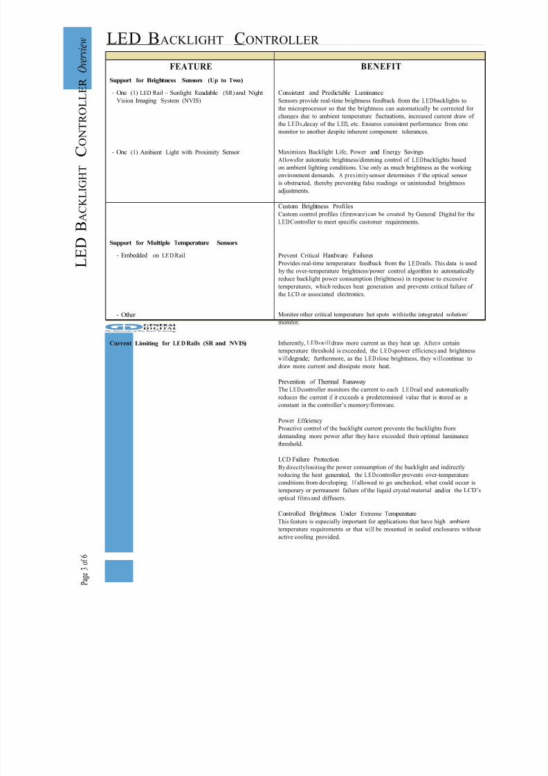
Consistent and Predictable Luminance
Sensors provide real-time brightness feedback from the L ED backlights to
the microprocessor so that the brightness can automatically be corrected for
changes due to ambient temperature fluctuations, increased current draw of the L E Ds ,decay of the LED, etc. Ensures consistent performance from one
monitor to another despite inherent component tolerances.
Maximizes Backlight Life, Power and Energy Savings
Allowsfor automatic brightness/dimming control of L ED backlights based
on ambient lighting conditions. Use only as much brightness as the working
environment demands. A proximity sensor determines if the optical sensor
is obstructed, thereby preventing false readings or unintended brightness
adjustments.
Custom Brightness Profi les
Custom control profiles (firmware)can be created by General Digital for the
L EDController to meet specific customer requirements.
Support for Multiple Temperature Sensors
- Embedded on LED Rail
- Other
Prevent Critical Hardware Failures
Provides real-time temperature feedback from the LE Drails. This data is used
by the over-temperature brightness/power control algorithm to automatically
reduce backlight power consumption (brightness) in response to excessive
temperatures, which reduces heat generation and prevents critical failure of
the LCD or associated electronics.
Monitor other critical temperature hot spots within the integrated solution/
monitor .
Current Limiting for LEDRails (SR and NVIS) Inherently, LEDswil l draw more current as they heat up. After a certain
temperature threshold is exceeded, the L E D s power efficiencyand brightness
willdegrade; furthermore, as the L E D slose brightness, they willcontinue todraw more current and dissipate more heat.
Prevention of Thermal R unaway
The LE Dcontroller monitors the current to each LE Drail and automatically
reduces the current if it exceeds a predetermined value that is stored as a
constant in the controller’s memory/firmware.
Power Efficiency
Proactive control of the backlight current prevents the backlights from
demanding more power after they have exceeded their optimal luminance
threshold.
LCD Failure Protection
By directlylimiting the power consumption of the backlight and indirectly
reducing the heat generated, the LE Dcontroller prevents over -temperatureconditions from developing. I f allowed to go unchecked, what could occur is
temporary or permanent failure of the liquid crystal material and/or the LCD’s
optical filmsand diffusers.
Controlled Brightness Under Extreme Temperature
This feature is especially important for applications that have high ambient
temperature requirements or that will be mounted in sealed enclosures without
active cooling provided.

8/4/2019 Led Backlight Controller Ds NoPW
http://slidepdf.com/reader/full/led-backlight-controller-ds-nopw 4/7
LED
BACKLIGHT
CONTR
OLLER
O v e r v
i e w
Page
4
of
6
LED BACKLIGHT CONTROLLER
FEATURE BENEFIT
Hardware Protection Critical Failure Detection
In the event that the microprocessor or either of the digital potentiometers
fails, the backlights will be intentionally shut off. Thiswi l l prevent the LEDs
from entering a “runaway” thermal condition that could lead to permanent
damage of the LCD and its infrastructure.
Programability
- Automatic Ove r -Temperature “Soft Failure” Algorithm
- Minimum/Maximum Sunlight R eadable Brightness
- Minimum/Maximum NVIS Brightness
- Current Limits
- Define Brightness of Sunlight R eadable and NVIS
Modes when Switching Between Modes
Critical Failure Protection
In response to over-temperature conditions reported within the monitor
from an integrated temperature sensor, the controller can be programmed
to automatically reduce brightness and power consumption of the L E D
backlights, thereby reducing internally generated heat. Default code will
reduce brightness to 80% at the first over-temperature failure, 60% for the
second failure, and willshut off the backights if the third temperature limit is
exceeded. Backlights will be turned on and brightness increased as internal
temperature decreases below each established temperature limit. Custom
firmware can be developed to establish a specific number of temperature
limitsand the percentage of brightness for each limit.
Consistent and Predictable Luminance
The firmware can be configured to ensure that the minimum brightness does
not go below a specific luminance, and the maximum brightness does not
exceed a specific luminance. The results are more accurate when using the
optional brightness sensors.
Consistent and Predictable Luminance
The firmware can be configured to ensure that the minimum brightness does
not go below a specific luminance, and the maximum brightness does not
exceed a specific luminance. The results are more accurate when using the
optional brightness sensors.
Maximizes Backlight Life/Critical Failure Protection
Prevents thermal runaway under extreme thermal environment variations and
increases L E D longevity.
Consistent and Predictable Luminance
The brightness can be programmed to be a default brightness (defined
by customer), or last brightness (recalls last setting made), based on
potentiometer position, or a custom setting.
Supports General Digital’s Serial- Parallel LED
Backlight Designs
Soft Failure Design
General Digital’s LED backlight rails utilizea serial-parallel design philosophy
that provides applications with a hardware “soft failure” mechanism, which
minimizes the risk of a critical failure due to the failure of a single, or multiple,
LEDs.
8/4/2019 Led Backlight Controller Ds NoPW
http://slidepdf.com/reader/full/led-backlight-controller-ds-nopw 5/7
LED
BACKLIGHT
CONTR
OLLER
O v e r v
i e w
Page
5
of
6
LED BACKLIGHT CONTROLLER
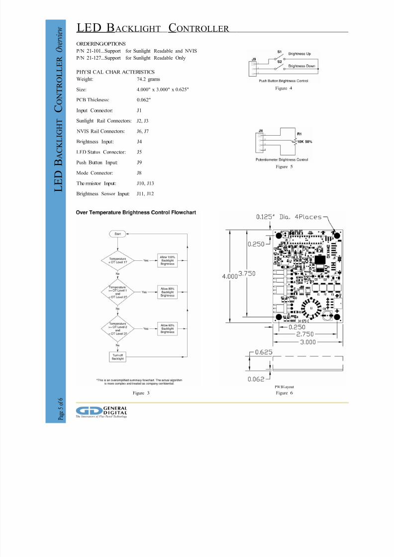
ORDERING/OPTIONS
P/N 21-101...Support for Sunlight Readable and NVIS
P/N 21-127...Support for Sunlight Readable Only
PHYSI CAL CHAR ACTERISTICS
Weight: 74.2 grams
Size: 4.000" x 3.000" x 0.625"
PCB Thickness: 0.062"
Input Connector: J1
Sunlight Rail Connectors: J2, J3
NVIS Rail Connectors: J6, J7
Brightness Input: J4
LED Status Connector: J5
Push Button Input: J9
Mode Connector: J8
The rmistor Input: J10, J13
Brightness Sensor Input: J11, J12
Figure 3
Figure 4
Figure 5
PWBLayout
Figure 6
8/4/2019 Led Backlight Controller Ds NoPW
http://slidepdf.com/reader/full/led-backlight-controller-ds-nopw 6/7
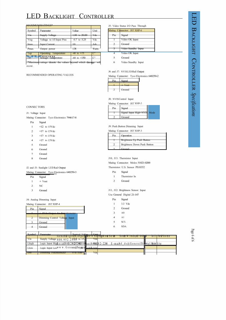
Symbol Parameter Value Unit
Vin Supply Voltage 1.00 to 20.00 Vdc
Vsig Voltage to A ll Input Pins -0.7 to 5.25 Vdc
Imax Input Current 10 Adc
Pmax Output power 138 Watts
Top Operating Temperature -40 to +75 C°
Tst Storage Temperature -60 to +150 C°
Pin Signal
1 Video OK Input
2 Ground
3 Video Standby Input
4 Video OK Input
5 Ground
6 Video Standby Input
Symbol Parameter Typical Value Unit
Vin Supply Voltage 12.0 to 15.3 Vdc
Lhigh Logic Input High 1.27 to 5.00 Vdc
Llow Logic Input Low 0 to 0.70 Vdc
Din Dimming Potentiometer 0 to 5.00 Vdc
Pin Signal
1 Signal Input High=NVIS Mode
2 Ground
Pin Signal
1 +12 to 15Vdc
2 +12 to 15Vdc
3 +12 to 15Vdc
4 +12 to 15Vdc
5 Ground
6 Ground
7 Ground
8 Ground
Pin Signal
1 Thermistor In
2 Ground
Pin Signal
1 + Vout
2 NC
3 Ground
Pin Signal
1 3.3 Vdc
2 Ground
3 A0
4 A1
5 SCL
6 SDA
LED
BACKLIGHT
CONTROL
LER
S p
e c i f i
c a t i o n s
Page
6
of
6
LED BACKLIGHT CONTROLLER
MAXIMUM RATINGS* J5: Video Status I/O Pass Through
Mating Connector: JST XHP-6
*Maximum ratings denote the values beyond which damage will
occur .
RECOMMENDED OPERATING VALUES
J6 and J7: NVISLEDRail Output
Mating Connector: Tyco Electronics 640250-2
Pin Signal
1 + Vout
2 Ground
CONNEC TORS
J1: Voltage Input
Mating Connector: Tyco Electronics 794617-8
J8: NVISControl Input
Mating Connector: JST XHP-2
J9: Push Button Dimming Input
Mating Connector: JST XHP-3
Pin Operation
1 Brightness Up Push Button
2 Brightness Down Push Button
3 Ground
J2 and J3: Sunlight L E D Rail Output
Mating Connector: Tyco Electronics 640250-3
J10, J13: Thermistor Input
Mating Connector: Molex 51021-0200
Thermistor: U.S. Sensor PS10352
J4: Analog Dimming Input
Mating Connector: JST XHP-4
J11, J12: Brightness Sensor Input
Use General Digital 21-147
Pin Signal
1 + 5Vdc Output for Potentiometer
2 Dimming Control Voltage Input
3 Ground
4 Ground
G e n e r al D i g i t a l™ C o r p o r a t i on 8 N u t m eg R o ad S o u th S o u th W i n d s o r , CT 0 6 0 74 To l l - F r ee P h o n e:
8 0 0 . 9 5 2 . 2 5 3 5
L o c a l: (8 60) 28 2- 29 00 F a x: (8 60) 28 2- 22 44 E - m a i l: g d _ d s @ G e n e r a l D i g i t a l . c om W eb S i t e:
w w w . G e n e r a l D i g i t a l . c o m

8/4/2019 Led Backlight Controller Ds NoPW
http://slidepdf.com/reader/full/led-backlight-controller-ds-nopw 7/7
S p e c i f i c a t i o ns s u b j e ct t o ch an ge w i t h o ut n o t i ce o r o b l i g a t i o n. Tr a d e m a r ks a re t he p r o p e r ty o f their r e s p e c t i ve o w n e r s. F e b r u a r y 2 0 1 0