LASER WELDING OF CYLINDRICAL PARTS
32
LASER WELDING OF CYLINDRICAL PARTS Bachelor’s thesis Mechanical Engineering and Production Technology Riihimäki 14.10.2011 Olga Närhi-Ratkovskaja PDF created with pdfFactory trial version www.pdffactory.com
Transcript of LASER WELDING OF CYLINDRICAL PARTS
LASER WELDING OF CYLINDRICAL PARTS
Bachelor’s thesis
Mechanical Engineering and Production Technology
Riihimäki 14.10.2011
Olga Närhi-Ratkovskaja
PDF created with pdfFactory trial version www.pdffactory.com

ABSTRACT
Riihimäki Mechanical Engineering and Production Technology Production Systems Author Olga Närhi-Ratkovskaja Year 2011 Subject of Bachelor’s thesis Laser welding of cylindrical parts
ABSTRACT
The purpose of this paper is to conduct the laser welding work of the cy-lindrical parts, particularly fuel filters, according to the safety instructions. The welding was followed by the additional test for a gas resistance of fil-ters. The topic was commissioned by the company Laserplus Oy, located in Hämeenlinna. The aim of the project on laser welding of filters was to find out optimum parameters for the company’s welding. Optimum parameters include the minimum laser power with optimum speed and maximum allowed focus distance from the surface of the welded part that will be appropriate for the company. Before tests conducting the theory on laser, laser welding, and laser tech-niques were studied. The experiment was done in five main steps: − Preparing the equipment for the laser welding and checking the rotat-
ing speeds; − Weld trial pieces; − Making samples and microscopic examination of trial laser welding
pieces; − Filters welding and testing them for the leakage; − Making samples and microscopic examination of laser welded filters. During the experiment the main mechanical laboratory of HAMK, the ro-botic cell and the chemistry laboratory was used. Filters were received from the company and the material of filters was stainless steel. It was de-cided to use an ytterbium fiber laser YLR-1000 for welding. The results of this work were 12 welded filters that were all tested under the water for the gas resistance and three of them were examined under the microscope. The conclusion is the rotational speed of 5,5 m/min, which was stated by the company, is good speed for the power of 600 W and also 1000 W, the maximum focus distance from the surface can be +2 mm, for longer distances the welding was not good enough.
Keywords Laser, laser welding, fiber laser, cylindrical parts, fuel filters. Pages 28 p.
PDF created with pdfFactory trial version www.pdffactory.com

CONTENTS
1 INTRODUCTION ................................................................................................... 1
2 LASER WELDING ................................................................................................. 1
2.1 History ............................................................................................................. 1 2.2 The fundamentals and main advantages of the laser ......................................... 2 2.3 Different types of lasers and operating principles. ............................................ 3
2.3.1 Solid-state laser .................................................................................... 3 2.3.2 Fiber laser ............................................................................................. 4 2.3.3 Gas laser ............................................................................................... 6
2.4 Technological features of laser welding ........................................................... 7 2.4.1 Pulsed laser welding ............................................................................. 7 2.4.2 Continuous laser welding ...................................................................... 8 2.4.3 Heat-conduction mode and deep-penetration mode welds ..................... 8
2.5 Efficiency of lasers .......................................................................................... 9
3 EXPERIMENTAL WORK WITH TEST PIECES ................................................. 10
3.1 Aim and main steps of the experiment............................................................ 10 3.2 Filter dimensions ........................................................................................... 10 3.3 Specifications of the laser used (YLR-1000) .................................................. 11 3.4 Preparation ..................................................................................................... 11 3.5 Laser welding of trial pieces........................................................................... 15 3.6 Making the samples and microscopic examination of trial welds. ................... 16
3.6.1 Preparation of samples ........................................................................ 16 3.6.2 Microscopic examination .................................................................... 18
3.7 Laser welding of filters and testing for the leakage. ........................................ 19 3.8 Making the samples and microscopic examination of laser welded filters. ...... 22 3.9 Safety instructions at work ............................................................................. 24 3.10 Error analysis ................................................................................................. 24
4 CONCLUSION ..................................................................................................... 25
SOURCES .................................................................................................................. 27
PDF created with pdfFactory trial version www.pdffactory.com

Laser welding of cylindrical parts
1
1 INTRODUCTION
How to measure the distance between the Earth and Moon with high accu-racy? How to drill a hole in a diamond, to make an operation on the eye, to shoot down a ballistic missile in the air in a second? There is only one an-swer: with laser technology – the greatest innovation of the 20th century. Laser technology is still very young; however, during this short period of time the laser from the curious laboratory device becomes a great scien-tific study and an instrument highly used in the industry. Laser technology is an increasing field of production technology. It is difficult to find an area of modern technology, where lasers would not work. Their emission is used for communication, writing and reading of information, for accu-rate measurements. Also, they are indispensable in medicine, surgery and therapy. The special properties of laser radiation explain the huge potential of laser technology. Quantum mechanics is studying the laser’s nature; therefore the laser is also called the optical quantum generator.
2 LASER WELDING
2.1 History
The concept of lasers goes back to Einstein’s time in the beginning of the 20th century. Albert Einstein was the first person, who predicted the phe-nomenon of light emission. If an environment, in which the atoms are in an excited level, will be created and run it a gentle stream of coherent pho-tons, its intensity will grow. The only small thing left: figure out how such an environment to "do". It took more than 30 years. (Fjodorov 1988, 45.) This is the principle behind the laser. In the early 50’s Russian scientists Nikolay Basov, Alexander Prokhorov and independently from them, the American physicist Charles Townes created a power of high frequency radio waves on the ammonia molecules (Fjodorov 1988, 45.) In 1960 an American physicist Theodor Maiman built the first quantum generator of the optical laser range. Light amplification occurred in a crys-tal clear ruby. This laser was a solid state type and operated in a pulsed mode. The same year the American physicians A. Dzhevan, B. Bepnet and D. Erroit created a gas laser, which was working on a mixture of helium and neon. This laser emitted a red light no longer by pulses, but conti-nuously. The mixture of gases was so well chosen that the helium-neon lasers are still the most common sources of light; though the emission suc-ceeded to obtain from many other gases and vapors. The color of the beam depends on the composition of the gas or vapor, on which the laser works. Argon, for example, gives a blue light. Krypton - yellow, xenon and va-pors of copper – green, CO2 and vapor of the water are invisible (infrared) rays. (Laser 2011.)
PDF created with pdfFactory trial version www.pdffactory.com

Laser welding of cylindrical parts
2
After this, physicists and engineers around the world have joined “the race” to develop all kinds of lasers. This “race” still exists in nowadays; therefore this area of science is still relatively new developing.
2.2 The fundamentals and main advantages of the laser
Light is a flow emitted by the atom’s special particles - photons, or quan-tum of electromagnetic radiation. They should be thought of as waves and not as particles. Each photon carries a portion of the energy ejected by atoms. But for an atom to radiate energy, it must have some storage of energy.(Lasers solution: looking for a problem 2007, video). When the atomic energy is minimal, they say that it is on the lower or sta-ble energy level. All other levels are called excited. In a stable state the atom can exist indefinitely long, but from an excited level it tries to "fall", giving out energy. In the transition from a high level to a lower level the atom radiates a photon.(How laser work? 2011). At any excited energy level the atom is holding off for a while. Then it must be returned spontaneously to the stable state, emitting a photon. But if this period is quite large (on the atomic scale), then another mechanism can happen - radiation. The atom then "jumps off" from the upper to the lower level under the influence of the flying photon. It is necessary that the photon energy is equal to the energy difference between atomic le-vels.(How laser work? 2011). Energy photons of light are absorbed by the surface during the light emis-sion to the body surface. The heat is formed and the surface temperature rises. If the light energy concentrates on a small portion of the surface, high temperatures can be gained. These are the fundamentals of the beam light welding by the optical photons generator – laser.(How laser work? 2011). The term "laser" is derived from the first letters of the English expression: "Light amplification by the stimulated emission of radiation". Academi-cian N. G. Basov together with A. M. Prokhorov and American scientist Charles Townes, who was awarded in 1964 the Nobel Prize for the theo-retical foundation and development of lasers, describes the laser as: "This is a device in which energy, such as thermal, chemical, electrical, con-verted into the energy of electromagnetic fields - a laser beam. Under such a transformation part of the energy is inevitably lost, but the important thing is that the resulting laser energy has a much higher quality. The qual-ity of the laser energy is determined by its high concentration and the abil-ity to transmit at a considerable distance." (Encyclopedia for laser physics and technology 2011). Laser welding is carried out in open air or in surroundings of shielding gas: argon, CO2. A vacuum is not needed; therefore large-scale structures can be welded with the laser beam. The laser beam is easy controlled and regulated by a mirror optical system. It can be easily transported and di-rected to difficult to reach places. In contrast to the electron beam and
PDF created with pdfFactory trial version www.pdffactory.com

Laser welding of cylindrical parts
3
electrical arc, the laser is not affected by magnetic fields, which allows forming a constant and straight joint. In the process of laser welding, be-cause of the high concentration of energy, the weld pool of the thermal zones is small, and there is little time of heating and cooling. It provides high strength of welded joints and the small deformation of welded struc-tures. (Adithan 2009, 175). The high concentration of energy, high speed, and a slight thermal effect on the seam zone due to high rates of heating and cooling of the metal, significantly increases the resistance of most structural materials to the formation of hot and cold cracking. It provides high quality of welding. Deformation of welded parts decreases significantly, which reduces the cost of corrections.(Boreisho 1992, 85). The most common defect in laser welding of thick parts is uneven penetra-tion and the presence of cavities in the joint. To reduce the possibility of melting peaks in the not-deep-penetration welding it is recommended to increase the welding speed and deflect the laser beam vertically at 15 to 17 ° angle to the direction of the beam. (Fjodorov 1988, 213). The main energy characteristics of laser welding are the concentration of power [E] of laser beam and the duration [t] of its action. With the conti-nuous emission, time [t] can be derived from the duration of the exposure time, and with pulse emission the pulse duration can be determined. Ex-ceeding the upper limit of [E] brings to an intensive boiling and evapora-tion of the metal, resulting in the release of metal and weld defects. In practice, laser welding is carried out at E = 106 to 107 Watt/cm2. For E <105 W/cm2 laser loses its main advantage - a high concentration of ener-gy. Changing the E and t value allows welding to be done for different construction materials with a thickness of several micrometers to millime-ters.(Zvelto 1990, 65).
2.3 Different types of lasers and operating principles.
Lasers can also be divided into two groups of high power lasers, particu-larly CO2, Nd:YAG, diode, fiber lasers; and low power lasers, mainly sol-id state lasers. Typical power output in solid state lasers is 10-20 W, in comparison to the high power laser, where power output might be up to few kilo Watts, it is the case of fiber laser. Key elements of the laser are a generator and an active gain medium. Among active gain medium they distinguish solid-state lasers, gas lasers, chemical lasers, semiconductor lasers, photonic crystals lasers, dye lasers, free electron lasers and bio las-ers. (Laser beam welding, 2011).
2.3.1 Solid-state laser
Aluminium oxide (A12O3) with chromium ions (Cr 3 +) are most often used in solid-state lasers (Fig. 1) rods made of pink ruby. Under the radia-tion, the chromium ions move on a different energy state - excited and
PDF created with pdfFactory trial version www.pdffactory.com

Laser welding of cylindrical parts
then turn the stored energy in the form of light. At the ends of the ruby rod[1] a layer of reflective substance[3] (for example silver) is plotted, so that one end is formed by an opaque[4] and, the other, - a semitransparent mirror. The emission of chromium ions are reflected from these mirrors and circulated along the optical axis of the rod, stimulating new ions. This is a snowballing process. A rapid release of radiant energy is happening, which gives out by a parallel beam through a semitransparent mirror and focus by a lens in place of welding. The output power of the solid state lasers is up to 10-20 W in the beam cross-section of less than 1 cm2. In the place of focus is achieved the enormous concentration of energy, allowing the temperature to be up to a million degrees.(How lasers work? 2011).
1 - ruby rod, 2 - generator pump, 3 - reflector, 4 - non-transparent mirror, 5 – cooling medium, 6 - power supply, 7 - beam splitter, 8 - light beam, 9 - fo-cusing lens, 10 - the workpiece.
Figure 1 The scheme of solid state laser.
2.3.2 Fiber laser
Fiber lasers are the most popular from diode pumped lasers. Fiber lasers have been developed not long ago in 1980s. Their active gain medium is an optical fiber doped with rare-earth elements such as erbium, ytterbium, neodymium, dysprosium, praseodymium, and thulium. At the present time there are models of industrial fiber lasers with the ca-pacity up to few kilo Watts. Today, these devices have reached the certain level of performance in high power, ideal beam quality, compactness and reliability, allowing them to solve successfully various problems in the la-ser materials processing. They represent almost ideal converters of light energy of laser diode into laser emission with a high efficiency, as com-pared, for example, with solid-state Nd:YAG-lasers.(Fiber laser 2011). The creation of such lasers was the result of development of laser technol-ogy during the decades. Recently, fiber lasers are actively displacing tradi-tional lasers in such applications of laser technology, like laser cutting and welding materials, marking and surface treatment, printing and high-speed laser printing, robotic industrial welding. They are used in laser range finders and in three-dimensional radars, in equipment for telecommunica-tions, in medical facilities and in other areas of industrial and military cen-ters.(Fiber laser 2011).
PDF created with pdfFactory trial version www.pdffactory.com

Laser welding of cylindrical parts
The fiber laser consists of two fibers: central and inner. The fiber cross-section is shown in Fig. 2.
1 2 3 4
1 - core doped with rare-earth element, 2 - quartz fiber, 3 - polymer shell, 4 - external protective coating.
Figure 2 Cross-section of fiber.
The internal fiber or core [1] filled with the active medium (eg. ytterbium) is located inside a quartz (central) fiber [2]. The inner walls of fiber are covered with a light-reflecting surface, therefore a moving stream of pho-tons undergoing a multiple reflection. Photons and ions knock out the rare-earth elements in the process of col-liding with each other, which increases the total flow of the light. The main advantage of the fiber laser is a small loss of radiation energy. Photons arise during the transition of particles from the upper to the lower energy level. As a result of multiple reflections and collisions of particles, the laser is pumped to a form of a light emission. In various types of lasers pumping occurs in many ways. For example, in solid-state Nd:YAG las-ers, pumping occurs with the light bulb, and in gas lasers it occurs with collisions of particles of different gases. In the fiber laser, the pump is car-ried out by diodes with single-mode radiation. The main feature of this laser is that the radiation is appearing in the small diameter fiber [3] of 6-8 microns (core - for example, the active medium is ytterbium), which is actually located inside the quartz fiber [2] with a di-ameter of 400-600 microns. The scheme of construction of a fiber laser is shown in Fig. 3. (Fiber laser 2011).
PDF created with pdfFactory trial version www.pdffactory.com
Laser welding of cylindrical parts
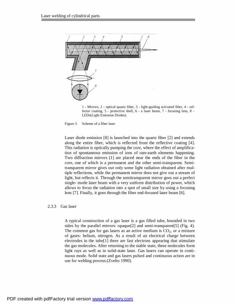
1 - Mirrors, 2 - optical quartz fiber, 3 - light-guiding activated fiber, 4 - ref-lector coating, 5 - protective shell, 6 - a laser beam, 7 - focusing lens, 8 – LEDs(Light Emission Diodes).
Figure 3 Scheme of a fiber laser
Laser diode emission [8] is launched into the quartz fiber [2] and extends along the entire fiber, which is reflected from the reflective coating [4]. This radiation is optically pumping the core, where the effect of amplifica-tion of spontaneous emission of ions of rare-earth elements happening. Two diffraction mirrors [1] are placed near the ends of the fiber in the core, one of which is a permanent and the other semi-transparent. Semi-transparent mirror gives out only some light radiation obtained after mul-tiple reflections, while the permanent mirror does not give out a stream of light, but reflects it. Through the semitransparent mirror goes out a perfect single- mode laser beam with a very uniform distribution of power, which allows to focus the radiation into a spot of small size by using a focusing lens [7]. Finally, it goes through the fiber end-focused laser beam [6].
2.3.3 Gas laser
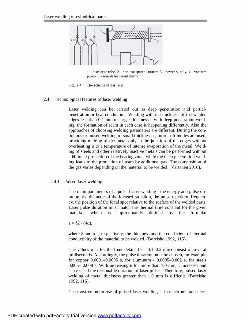
A typical construction of a gas laser is a gas filled tube, bounded in two sides by the parallel mirrors: opaque[2] and semi-transparent[5] (Fig. 4). The common gas for gas lasers as an active medium is CO2, or a mixture of gases: helium, nitrogen. As a result of an electrical charge between electrodes in the tube[1] there are fast electrons appearing that stimulate the gas molecules. After returning to the stable state, these molecules form light rays as well as in solid-state laser. Gas lasers can operate in conti-nuous mode. Solid state and gas lasers pulsed and continuous action are in use for welding process.(Zvelto 1990).
PDF created with pdfFactory trial version www.pdffactory.com
Laser welding of cylindrical parts
1 - discharge tube, 2 - non-transparent mirror, 3 - power supply, 4 - vacuum pump, 5 - semi-transparent mirror.
Figure 4 The scheme of gas laser.
2.4 Technological features of laser welding
Laser welding can be carried out as deep penetration and partial-penetration or heat conduction. Welding with the thickness of the welded edges less than 0.1 mm or larger thicknesses with deep penetration weld-ing, the formation of seam in each case is happening differently. Also the approaches of choosing welding parameters are different. During the con-tinuous or pulsed welding of small thicknesses, more soft modes are used, providing melting of the metal only in the junction of the edges without overheating it to a temperature of intense evaporation of the metal. Weld-ing of steels and other relatively inactive metals can be performed without additional protection of the heating zone, while the deep penetration weld-ing leads to the protection of seam by additional gas. The composition of the gas varies depending on the material to be welded. (Väisänen 2010).
2.4.1 Pulsed laser welding
The main parameters of a pulsed laser welding - the energy and pulse du-ration, the diameter of the focused radiation, the pulse repetition frequen-cy, the position of the focal spot relative to the surface of the welded parts. Laser pulse duration must match the thermal time constant for the given material, which is approximately defined by the formula: τ = δ2 / (4α), where δ and α -, respectively, the thickness and the coefficient of thermal conductivity of the material to be welded. (Boreisho 1992, 115). The values of τ for the finer details (δ = 0.1–0.2 mm) consist of several milliseconds. Accordingly, the pulse duration must be chosen, for example for copper 0.0001–0.0005 s, for aluminum - 0.0005–0.002 s, for steels 0.005– 0.008 s. With increasing δ for more than 1.0 mm, τ increases and can exceed the reasonable duration of laser pulses. Therefore, pulsed laser welding of metal thickness greater than 1.0 mm is difficult. (Boreisho 1992, 116). The most common use of pulsed laser welding is in electronic and elec-
PDF created with pdfFactory trial version www.pdffactory.com

Laser welding of cylindrical parts
8
trical industry, where welding the edge, overlap and butt joints of thin-walled parts. Good quality connections provided by a laser beam welding of thin parts (0.05 - 0.5 mm) with massive parts. During the laser welding metal heating and melting occur so quickly that the deformation of a thin edge may not have to happen before the metal solidifies. This allows you to weld a thin piece with a massive overlap. (Laser equipment and tech-nology 2001).
2.4.2 Continuous laser welding
Details of small thickness can be also welded with the gas or solid-state lasers by continuous action with the power up to 1 kW. The best way of forming the seam is the butt joint of fine details. However, the assembly of such compounds for laser welding imposed more strict requirements: a minimum and uniform gap must be provided at the junction and the almost no edges shift.(Volchenko 1996, 276) It is harder to form a seam with the parts of thickness greater than 1.0 mm with deep penetration. As soon as the power concentration of laser emis-sion of radiation comes to the critical level, the heating of the metal will run at speeds much higher than the rate of heat removal based on the thermal conductivity of the metal. On the surface of the molten metal the gap is formed. It forms a channel filled with steam and surrounded by the liquid metal. The vapor pressure is sufficient enough to counteract the forces of hydrostatic pressure and surface tension, therefore the channel is not filled with liquid metal. With certain welding speed the channel forms a stable appearance. In the front wall of the channel is melting metal on the back - solidification. The presence of channels facilitates the absorp-tion of laser light in the depth of material, and not just on its sur-face.(Volchenko 1996, 276) Focusing of the beam affects the quality of welds. For welding, beam is focused to a spot diameter of 0.1 - 3.0 mm. With a smaller diameter, high power density leads to overheating of the molten metal and increases its evaporation, which causes defects in the seam. The formation of the joint depends also on the position of the focal plane relative to the surface of the welded parts. The maximum depth of penetration is achieved if the focus of the laser beam will be above the surface of the part.(Volchenko 1996, 277)
2.4.3 Heat-conduction mode and deep-penetration mode welds
The welding processes are differentiated between two: heat conduction and deep penetration. In heat conduction welding only the surface of the metal is melted and it is suitable typically for the pulsed Nd:YAG laser welding in electrical industry. In the deep penetration, welding produces very deep seam. While welding with deep penetration mode the keyhole is appearing on the workpiece. (Bitzel, Borcherdt, Müller, Neidhart, Parey, Rau, Riecke, Schmid, Trentmann, Vorländer, Zimmermann 2010, 125.) The type of mode of welding process, which should be conducted, de-
PDF created with pdfFactory trial version www.pdffactory.com

Laser welding of cylindrical parts
9
pends on the design of welded products, technological requirements and other factors. Deep penetration is more widely used in welding the sheet metal structures, on the other hand heat conduction mode often used for the sealing or for the fastening small details with a massive one.(Laser equipment and technology. 2009.) Among the lasers that conduct deep pe-netration and produces keyhole distinguishes Nd:YAG laser, CO2 laser, fi-ber laser. High power diode laser in working on the heat conduction mode.(Väisänen 2010).
2.5 Efficiency of lasers
By increasing the ability of penetration of the laser beam, the efficiency of laser welding can be increased. One of the alternatives is to apply the pulsed laser welding. With the pulse frequency of 0.4 - 1 kHz and pulse duration of 20 - 50 ms, the depth of penetration can be increased to 3 - 4 times, in comparison with continuous operation. In pulsed mode, the effi-ciency of the beam in 2 - 3 times higher than in continuous. However, pulsed welding requires a very accurate pointing on the laser beam to the joint, a higher quality edge preparation for welding, but its speed is several times less than the speed of welding with continuous welding.(Duong 2010) Another way to improve the efficiency it is to supply in the welding zone an additional stream of gas under the pressure. The depth of penetration increases, but an excessive increase in gas consumption can easily lead to a weakening in the formation of the seam and appearing unnecessary pores. The gas starts to blow out the molten metal. Welding process be-comes the cutting process. The efficiency of laser welding can be im-proved by introducing into the welding zone the chemical elements that can ionize the gas in the welding area and reduce the shielding effect of the flare. This is achieved by applying to the surface of the welded edges the coating containing elements with low ionization potential (potassium, sodium).(Duong 2010)
PDF created with pdfFactory trial version www.pdffactory.com

Laser welding of cylindrical parts 3 EXPERIMENTAL WORK WITH TEST PIECES
3.1 Aim and main steps of the experiment
The company Laserplus Oy, located in Hämeenlinna, issued a topic on a practical work, including laser welding of fuel stainless steel filters and following checking for the gas resistance of these filters. The aim of the project on laser welding of the filters was to find out the minimum laser power with optimum speed and maximum focus from the surface of the welded part that will be economically efficient. It was decided to use an ytterbium fiber laser YLR-1000. The experiment was done in five main steps: − Preparing the equipment for the laser welding and checking rotating
speeds; − Laser welding of trial pieces; − Making samples and microscopic examination of trial laser welding
pieces; − Laser welding of filters and testing them for the leakage; − Making samples and microscopic examination of laser welded filters.
3.2 Filter dimensions
The welding of filters was circular welding and should be done in three places, one weld – the big diameter of 55 mm and two others – the smaller diameter 18 mm. The thickness of the wall of the filter was approximately 1 mm. The material was stainless steel AISI – SUS430. This material has a chemical composition of C=0.12% maximum, Mn=1% maximum and Cr=17%.(Stainless steel, 2008) Inside the filter there were paper and po-lyurethane, like shown in figure 5.
Figure 5 Fuel filter and its parts.
PDF created with pdfFactory trial version www.pdffactory.com
Laser welding of cylindrical parts 3.3 Specifications of the laser used (YLR-1000)
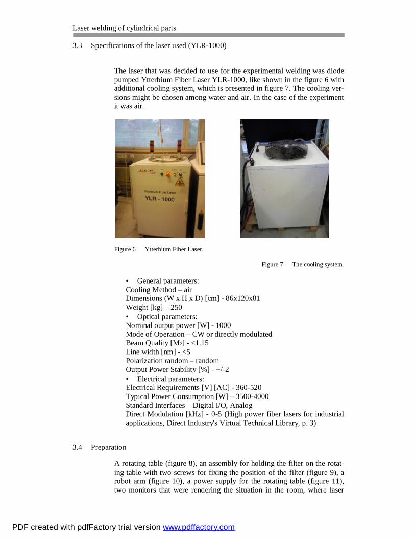
The laser that was decided to use for the experimental welding was diode pumped Ytterbium Fiber Laser YLR-1000, like shown in the figure 6 with additional cooling system, which is presented in figure 7. The cooling ver-sions might be chosen among water and air. In the case of the experiment it was air.
Figure 6 Ytterbium Fiber Laser.
Figure 7 The cooling system.
• General parameters: Cooling Method – air Dimensions (W x H x D) [cm] - 86x120x81 Weight [kg] – 250 • Optical parameters: Nominal output power [W] - 1000 Mode of Operation – CW or directly modulated Beam Quality [M2] - <1.15 Line width [nm] - <5 Polarization random – random Output Power Stability [%] - +/-2 • Electrical parameters: Electrical Requirements [V] [AC] - 360-520 Typical Power Consumption [W] – 3500-4000 Standard Interfaces – Digital I/O, Analog Direct Modulation [kHz] - 0-5 (High power fiber lasers for industrial applications, Direct Industry's Virtual Technical Library, p. 3)
3.4 Preparation
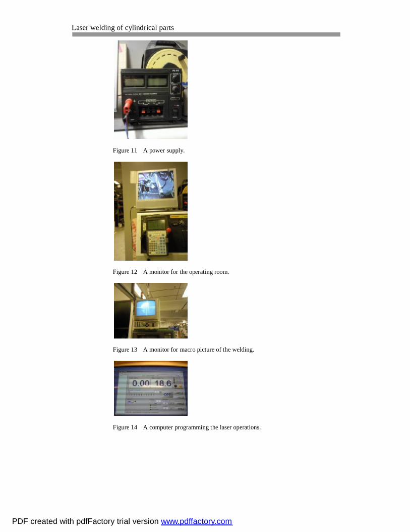
A rotating table (figure 8), an assembly for holding the filter on the rotat-ing table with two screws for fixing the position of the filter (figure 9), a robot arm (figure 10), a power supply for the rotating table (figure 11), two monitors that were rendering the situation in the room, where laser
PDF created with pdfFactory trial version www.pdffactory.com

Laser welding of cylindrical parts
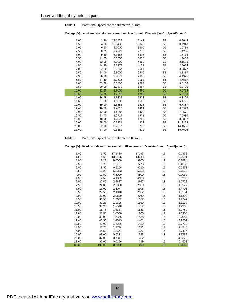
welding was happening, and the detailed macro picture of the laser weld (figure 12 and 13) and the computer that is programming the laser welding operation (figure 14), were prepared for the testing work to begin. The as-sembly for holding the filter on the rotating table was fixed and a filter in-serted. The speed was checked using a stop watch and visually counting rounds per minute. The results were collected and inserted in the tables 1 and 2 below. The highlighted green areas are the needed speeds, which the company asks to test, with pointing on the needed voltage.
Figure 8 A rotating table.
Figure 9 An assembly for holding the filter.
Figure 10 A robot arm.
PDF created with pdfFactory trial version www.pdffactory.com
Laser welding of cylindrical parts
Figure 11 A power supply.
Figure 12 A monitor for the operating room.
Figure 13 A monitor for macro picture of the welding.
Figure 14 A computer programming the laser operations.
PDF created with pdfFactory trial version www.pdffactory.com
Laser welding of cylindrical parts
14
Table 1 Rotational speed for the diameter 55 mm.
Voltage [V] № of rounds/min sec/round millisec/round Diameter[mm] Speed[m/min]
1.00 3.50 17.1429 17143 55 0.60481.50 4.60 13.0435 13043 55 0.79482.00 6.25 9.6000 9600 55 1.07992.50 8.25 7.2727 7273 55 1.42553.00 9.50 6.3158 6316 55 1.64153.50 11.25 5.3333 5333 55 1.94394.00 12.50 4.8000 4800 55 2.15984.50 14.50 4.1379 4138 55 2.50547.00 22.50 2.6667 2667 55 3.88777.50 24.00 2.5000 2500 55 4.14697.90 26.00 2.3077 2308 55 4.49258.50 27.50 2.1818 2182 55 4.75179.00 29.00 2.0690 2069 55 5.01089.50 30.50 1.9672 1967 55 5.2700
10.00 32.25 1.8605 1860 55 5.572410.50 34.25 1.7518 1752 55 5.918011.00 36.75 1.6327 1633 55 6.349911.60 37.50 1.6000 1600 55 6.479512.00 39.00 1.5385 1538 55 6.738712.40 40.50 1.4815 1481 55 6.997912.90 42.00 1.4286 1429 55 7.257113.50 43.75 1.3714 1371 55 7.559515.00 48.50 1.2371 1237 55 8.380220.00 65.00 0.9231 923 55 11.231225.00 82.00 0.7317 732 55 14.168629.60 97.00 0.6186 619 55 16.7604
Table 2 Rotational speed for the diameter 18 mm.
Voltage [V] № of rounds/min sec/round millisec/round Diameter[mm] Speed[m/min]
1.00 3.50 17.1429 17143 18 0.19791.50 4.60 13.0435 13043 18 0.26012.00 6.25 9.6000 9600 18 0.35342.50 8.25 7.2727 7273 18 0.46653.00 9.50 6.3158 6316 18 0.53723.50 11.25 5.3333 5333 18 0.63624.00 12.50 4.8000 4800 18 0.70694.50 14.50 4.1379 4138 18 0.82007.00 22.50 2.6667 2667 18 1.27237.50 24.00 2.5000 2500 18 1.35727.90 26.00 2.3077 2308 18 1.47038.50 27.50 2.1818 2182 18 1.55519.00 29.00 2.0690 2069 18 1.63999.50 30.50 1.9672 1967 18 1.7247
10.00 32.25 1.8605 1860 18 1.823710.50 34.25 1.7518 1752 18 1.936811.00 36.75 1.6327 1633 18 2.078211.60 37.50 1.6000 1600 18 2.120612.00 39.00 1.5385 1538 18 2.205412.40 40.50 1.4815 1481 18 2.290212.90 42.00 1.4286 1429 18 2.375013.50 43.75 1.3714 1371 18 2.474015.00 48.50 1.2371 1237 18 2.742620.00 65.00 0.9231 923 18 3.675725.00 82.00 0.7317 732 18 4.637029.60 97.00 0.6186 619 18 5.485230.30 100.00 0.6000 600 18 5.6549
PDF created with pdfFactory trial version www.pdffactory.com
Laser welding of cylindrical parts 3.5 Laser welding of trial pieces
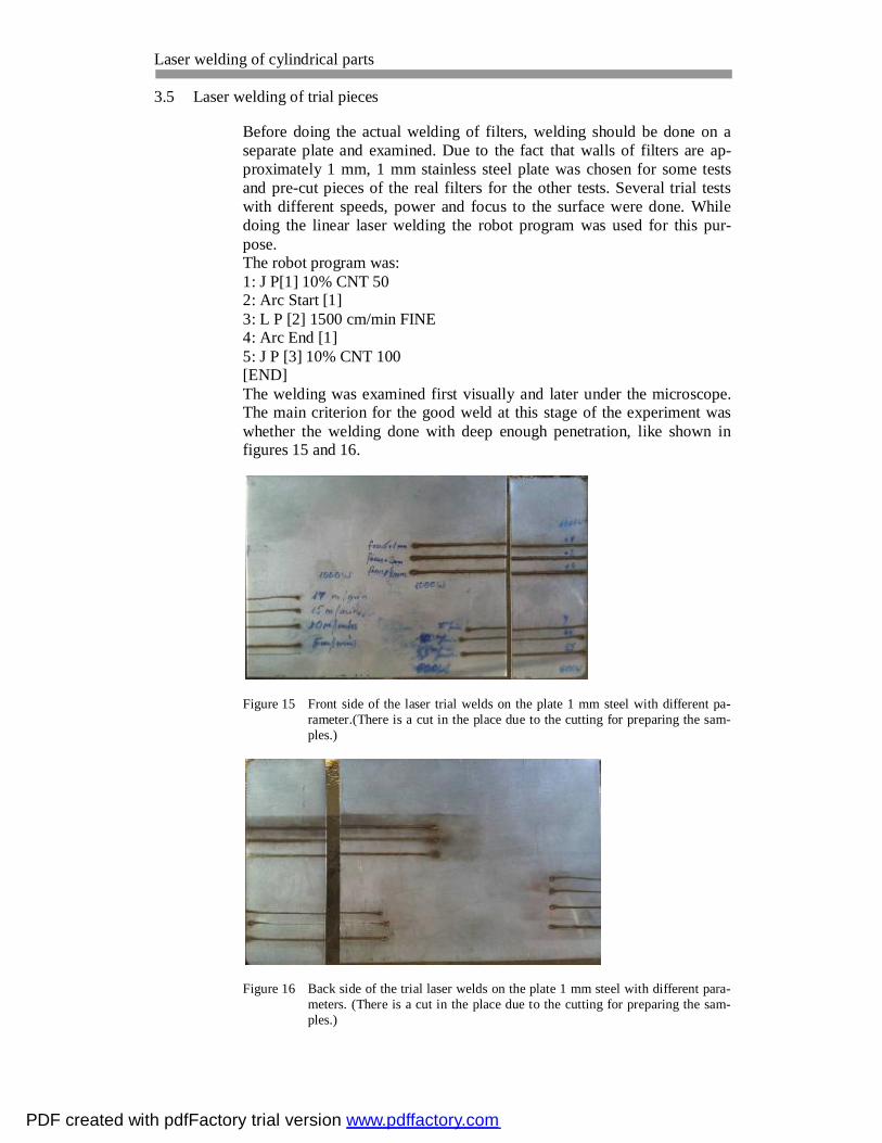
Before doing the actual welding of filters, welding should be done on a separate plate and examined. Due to the fact that walls of filters are ap-proximately 1 mm, 1 mm stainless steel plate was chosen for some tests and pre-cut pieces of the real filters for the other tests. Several trial tests with different speeds, power and focus to the surface were done. While doing the linear laser welding the robot program was used for this pur-pose. The robot program was: 1: J P[1] 10% CNT 50 2: Arc Start [1] 3: L P [2] 1500 cm/min FINE 4: Arc End [1] 5: J P [3] 10% CNT 100 [END] The welding was examined first visually and later under the microscope. The main criterion for the good weld at this stage of the experiment was whether the welding done with deep enough penetration, like shown in figures 15 and 16.
Figure 15 Front side of the laser trial welds on the plate 1 mm steel with different pa-rameter.(There is a cut in the place due to the cutting for preparing the sam-ples.)
Figure 16 Back side of the trial laser welds on the plate 1 mm steel with different para-meters. (There is a cut in the place due to the cutting for preparing the sam-ples.)
PDF created with pdfFactory trial version www.pdffactory.com

Laser welding of cylindrical parts 3.6 Making the samples and microscopic examination of trial welds.
The next step of the experiment was to make the samples out of pre-cut pieces and examine them with the microscope for better results.
3.6.1 Preparation of samples
For better results the trial pieces were examined under the microscope. Be-fore they can be examined the samples needed to be done. The procedure of making the samples was to prepare first the cup, where place and fix small pieces with welding seam. The cup should be greased with the re-lease agent for easier release. It is shown in the figure 17.
Figure 17 A cup with welded pieces.
After the cup should be accurately filled with a mixture of 15 g of Resin and 3 g of hardener and left for one day to harden. Four ready samples are shown in figure 18.
Figure 18 Samples 1, 2, 3, 4.
When samples are ready grinding should be done. The grinding is done on the grinding machine with four different grinding papers. The higher the number on the grinding paper, the finer grinding can be done. At first, grinding paper with the number 120 was used, then 240, after 600 and at last 1200. The grinding process is shown in the figure 19.
PDF created with pdfFactory trial version www.pdffactory.com

Laser welding of cylindrical parts
Figure 19 Grinding process.
The process polishing was following grinding to make the surface smoother. Polishing is used to create a flat, defect-free surface for exami-nation of a metal’s microstructure. The polishing was done on the polish-ing machine using diamond suspension with 1 or 6 microns. Each sample was polished for about 15-20 minutes. Figure 20 shows the polishing process.
Figure 20 Polishing process.
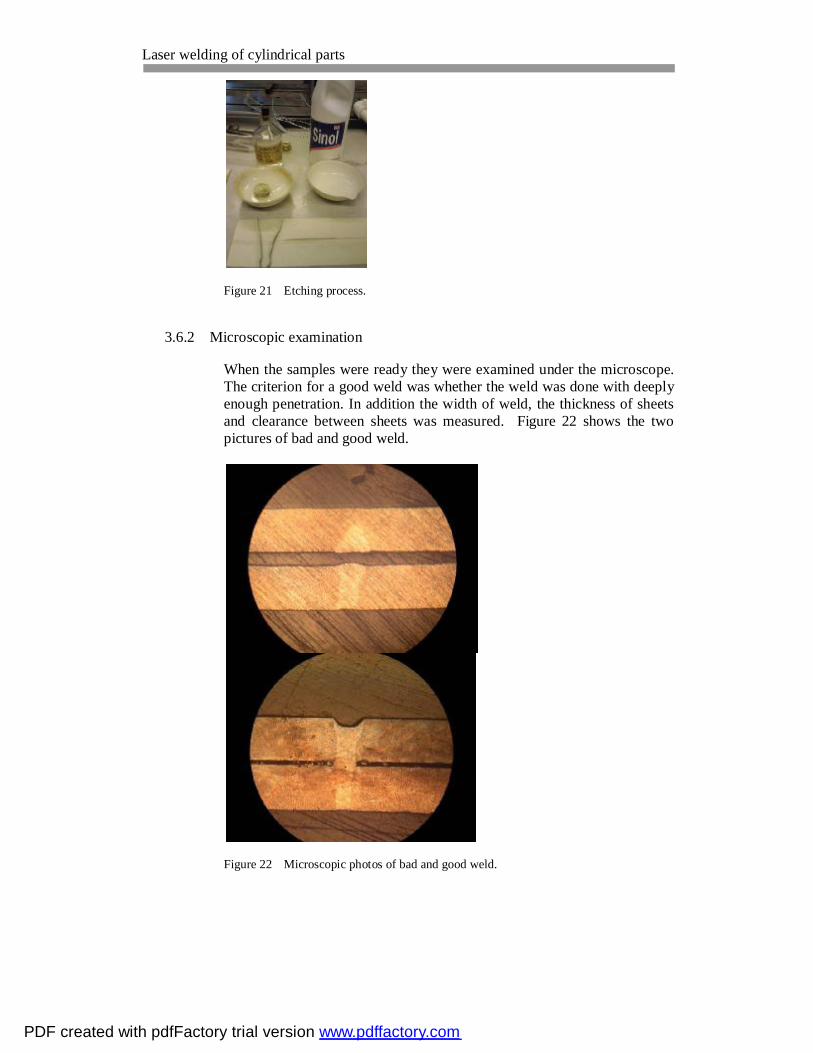
And the final step before microscopic examination is the process etching. The process called etching because at the end of this process clearly can see the edges where metal was touched by any external invasion, in the case of this work it is welding. This gives more opportunities for deeper investigation of the welding process. The process etching consists of two steps: firstly to put the examining end of the sample into the substance, which includes 142,5 ml H2O+7,5 ml HCl+3,0 ml HNO3 and hold it there for a while, secondly to wash the samples in Sinol. The time of holding the sample in the acid mixture depends on the material of the test pieces. Fig-ure 21 shows the etching process.
PDF created with pdfFactory trial version www.pdffactory.com
Laser welding of cylindrical parts
Figure 21 Etching process.
3.6.2 Microscopic examination
When the samples were ready they were examined under the microscope. The criterion for a good weld was whether the weld was done with deeply enough penetration. In addition the width of weld, the thickness of sheets and clearance between sheets was measured. Figure 22 shows the two pictures of bad and good weld.
Figure 22 Microscopic photos of bad and good weld.
PDF created with pdfFactory trial version www.pdffactory.com

Laser welding of cylindrical parts
All the samples were examined and the table with the results was created.
Table 3 The results of the microscopic examination of the samples
sample № focus[mm] speed[m/min/] power[W] width of weld[mm] thickness of sheets[mm] clearance between sheets[mm]sample 1
+0 12 1000 0.30 0.47 0.06+0 15 1000 0.30 0.45 0.05+0 10 1000 0.38 0.45 & 0.47 0.15+0 16.7 1000 0.30 0.46 0.14+0 10 800 0.44 0.45 & 0.47 0.10+0 15 800 no results no results no results
sample 2+0 4 600 0.30 0.53 & 0.50 0.01+0 5 600 0.30 0.50 0.07 & 0.05+0 6 600 0.30 0.50 & 0.54 0.07 & 0.06+0 7 600 0.26 0.46 & 0.45 0.05 & 0.06+0 8 600 0.22 0.46 & 0.47 0.07 & 0.06+0 9 600 ?0.22 ?0.46 ?0.04
company weld not known not known not known 0.43 0.53 & 0.5 0.08 & 0.02
sample 3 +0 5.5 600 0.25 - 0.50 1.00 0.20+0 7 600 0.22 - 0.40 1.20 0.17+0 10 600 not through 1.00 0.24+1 6 1000 0.36 - 0.56 1.00 0.33+2 6 1000 0.26 - 0.75 1.00 0.52+4 6 1000 not through 1.00 ?0.49
sample 4 +0 17 1000 0.14 - 0.22 1.00 0.21+0 15 1000 0.12 - 0.30 1.00 0.19+0 10 1000 0.20 - 0.23 1.00 0.22+0 5 1000 0.30 - 0.60 1.00 0.26
3.7 Laser welding of filters and testing for the leakage.
The next step of the experiment was the welding of the actual filters using different parameters of welding. It was welded all together 12 filters (Fig-ure 23), one of those was the filter with paper inside and one of those was the filter with bolts on the ends, therefore the last one was impossible to test for leakages with the ready make assembly for the leakage test. Before any filter was welded the deviation was checked using the dial indicator (Figure 24), the base of which was fixed by the magnet to the rotating ta-ble and the other end had a touch-signal point. While the filter on the fixed table was rotating the deviation was checked. The allowed value for the deviation was 0,1- 0,3 mm. If the amounts exceeded the allowed values, then the position of the filter was corrected by two screws fastened to the assembly.
Figure 23 12 welded filters.(Two filters were taken by the company)
PDF created with pdfFactory trial version www.pdffactory.com

Laser welding of cylindrical parts
Figure 24 Dial indicator.
The leakage test was conducted by sinking the welded filter into the buck-et of water. On one end of the filter was the screwed structure with dead end and another end was connected to the pressurized air system of the la-boratory. The compression pressure varies between 6.5 bars and 7 bars, due to the automation in the system that adds pressure if it drops lower than 6.5 bars and stops supplying pressure if it goes over 7 bars. The criterion for the good weld was whether bubbles appearing in the bucket of water or not. Figure 25 shows the testing equipment for the leakage test.
Figure 25 Testing equipment for leakage.
PDF created with pdfFactory trial version www.pdffactory.com

Laser welding of cylindrical parts
21
At the end of this step the table with the results was created. Table 4 in-cludes 12 filters, the welding parameters and the condition of the filter af-ter testing for the leakage.
Table 4 Parameters and conditions of filters.
Filter №Parameters
Diameter[mm] 55 18 55 18 55 18Time[ms] 1800 650 1800 650 1800 650Voltage[V] 10.5 29.8 12.5 30.4 10.5 30.2Speed[m/min] 6 5.5 7 5.65 6 5.65Power[W] 600 600 600 600 1000 1000Deviation[mm] 0.1 not measure 0.2 not measure 0.15 0.15Focus [mm] +0 +0 +0 +0 +2 +2ResultFilter №Parameters
Diameter[mm] 55 18 55 18 55 18Time[ms] 1800 650 1800 650 1800 650Voltage[V] 10.5 30.5 10.5 29.8 10.5 30Speed[m/min] 6 5.65 6 5.5 6 5.65Power[W] 1000 1000 600 600 600 600Deviation[mm] 0.2 0.15 0.15 0.15 0.2 0.15Focus [mm] +3 +3 +1 +1 +0 +0ResultFilter №Parameters
Diameter[mm] 55 18 55 18 55 18Time[ms] 1800 650 1800 650 1800 650Voltage[V] 10.5 30 10.5 30.4 10.5 30.4Speed[m/min] 6 5.65 6 5.65 6 5.65Power[W] 600 600 1000 1000 1000 1000Deviation[mm] 0.2 0.3 0.3 0.3 <0.2 0.4Focus [mm] +0 +0 +0 +0 +2 +2ResultFilter №Parameters
Diameter[mm] 55 18 55 18 55 18Time[ms] 1900 650 1900 650 1900 650Voltage[V] 10 30 10 30 10 30Speed[m/min] 5.5 5.5 5.5 5.5 5.5 5.5Power[W] 600 600 600 600 600 600Deviation[mm] 0.2 0.2 0.3 0.25 0.2 0.48Focus [mm] +0 +0 +0 +0 +0 +0
10
no leakage no leakage no leakage
leakage, bad weld7 8 9
leakage in one place11
no leakage leakage in one place12
1 2 3
4
leakage, bad weld no leakage
5 6
PDF created with pdfFactory trial version www.pdffactory.com

Laser welding of cylindrical parts 3.8 Making the samples and microscopic examination of laser welded filters.
After the main work was done, it was decided to examine the selected fil-ters under the microscope. Filters № 3, 9 and 10 were chosen (Figure 26).
Figure 26 Filter # 3, 9 and 10 for microscopic examination
The welded walls of the big diameter (55mm) of the filter were cut and 3 samples were made, following the same procedure as described in chapter 3.6.1 of this work. The samples were grinded, polished, etched, and inves-tigated under the microscope. The figure 27 shows the samples 5, 6 and 7.
Figure 27 Samples # 5, 6 and 7 of actual welded filters.
The results of the investigation of the 3 samples are in the table 5 below. The microscopic photos of the samples of the filter # 3, 9 and 10 are in figures 28, 29 and 30 respectively.
PDF created with pdfFactory trial version www.pdffactory.com

Laser welding of cylindrical parts
Figure 28 Microscopic picture of the weld of filter #3.
Figure 29 Microscopic picture of the weld of filter #9
Figure 30 Microscopic picture of weld of filter #10.
Table 5 Results of the welded filters № 3, 9 and 10 from the microscope investiga-tion.
sample № Filter № focus speed power weld width deepness condition[mm] [m/min] [W] [mm] [mm]
sample 53 +2 6 1000 0.32 through good weld, no leakage
sample 610 +0 5.5 600 0.24 through good weld, no leakage
sample 79 +2 6 1000 0.32 through small leakage
PDF created with pdfFactory trial version www.pdffactory.com
Laser welding of cylindrical parts
24
3.9 Safety instructions at work
During the work with the laser one should follow certain safety instruc-tions. Always check the blinking light on the laser before starting the program. There are potential hazards: radiation, fire, fumes, mechanical, electric shock, and eye and skin damage. During welding the light radiation is produced. The light radiation reflected from the work piece to the work area and this radiation can seriously burn eyes and skin. Keep the flamma-bles away from the welding area, since reflected radiation can start fire. Very often during the welding the metals vaporize, therefore the mist that produced can be dangerous for the human respiratory system. The good ventilation should be installed. Sometimes by accident the robot arm can be turned to a different direction, which causes mechanical injury. Lasers require a large amount of electrical power, so the safety instructions of how to work with electricity should be taken into the consideration. (Laser welding and cutting safety 1998) In any case the sliding door to the oper-ating room should be always closed. Additionally, the laser would not start, if the door is open. Before welding remember to put shield gas to protect the seam. This pre-vents the melted metal to react with the air. In some cases only pressurized air is used to protect laser head optics from sparks, fumes, etc. When cutting the pieces from the filters, use protective gloves for avoiding damage of hands and fingers. During the process of grinding, one must be careful with the fingers. Sometimes fingers that hold the test sample can be touch the grinding sur-face and hurt it. During the process of etching some harmful liquids are used like the mix-ture of acids, therefore one should not touch the substance with the hands, and clean the dish, where the acid was, carefully, because can damage the skin.
3.10 Error analysis
During the experiment the particular uncertainties might happen and some errors must be considered. In error analysis chapter it is summarized and analyzed all the possible errors occurred in this work. One of the uncertainties was counting the rounds per minute visually in the beginning of the test. In such situation the human factor should be kept in mind, because the eye of a human cannot 100% catch the rounds espe-cially in high speeds. Voltage on the power supply, which is connected to the rotating table was sometime jumping by +/-0,1 V. This causes the incorrect results in count-ing number of rounds per minute.
PDF created with pdfFactory trial version www.pdffactory.com

Laser welding of cylindrical parts
25
The main problem with laser welding is a lot of sparks afterwards that produces dirt, this illuminates by the compressed air that supplies. During the cutting of pieces for the purpose of making samples, the cut can be done so that the welded walls can be stretched apart from each oth-er. This leads to the inaccurate measurements during the investigation un-der the microscope. The testing material and the material of the actual filters were slightly dif-ferent, which might cause the improbability of the results, while compare them after laser weld. When welding two pre-cut filter pieces, the tightness between them is not good. It leads to the gap and brings the measurements to some small mis-takes. Before conducting any weld of the filter the deviation was checked using dial indicator. This was another possible error due to the fact that the devi-ation values sometimes exceeded the allowed values, which were 0,1- 0,3 mm. This leads to the bad or uneven weld. One of the mistakes during the test was the wrong programming of the la-ser program, particularly wrong time input; therefore weld in some cases was only half way, or in other cases overlap weld happened. Another important uncertainty was the rotational speed of laser weld was not exactly stable all the time during the weld. It started in the beginning of welding with lower speed than declared, and accelerated later. This leads to the problem such as good weld with deep penetration in the be-ginning and might be not as good in the end.
4 CONCLUSION
When starting the experiment on welding, the company Laserplus Oy de-fined the main focus of research that is to find out the optimum welding parameters for particular filter laser welding, especially in rotational speed, laser power and focus from the surface. They also asked to give de-sign recommendations. The laser power varied from 600 Watts to 1000 Watts. The last should be more expensive to purchase than the first one for welding filters. The minimum required speed was 5,5 m/min, because the company wanted to bring to the smallest value the welding time. This work is clearly explains the procedure of how the optimum parameters were found and clarifies the results. The testing was conducted safely and well organized. The conclusion of the work is that the rotational speed of 5,5 m/min and power of 600 Watts makes a combination for good welding, therefore the
PDF created with pdfFactory trial version www.pdffactory.com

Laser welding of cylindrical parts
26
company can purchase cheaper welding laser of 600 W and it will be still suitable for that kind of weld. The power of 1000 W is as well suitable and makes good weld. Also the focus can be moved away from the welded surface on maximum 2 mm from the original point of welding and the weld still will be good. This is done for the better welding result due to the fact that the longer the distance from the surface the wider the seam of the weld and the more gas resistance will be. The focus of +3 mm and more did not weld well enough that brings to the bad leakages, like in filter #4. If the leakage appeared in the filter only in one place, like in filter #7 and #9, then it appeared only in the bigger diameter (55mm) of filter. This can be explained by the analysis, where stays that the speed of the welding is not constant permanently: in the beginning it is lower than declared, then accelerates to the correct value. The lower the speed the better the welding and to weld the diameter of 18 mm takes less time, than to weld the di-ameter 55 mm; therefore in welding of 18 mm diameter there is more chance to weld good. When welding the filter with paper and polyurethane inside, as their actual appearance should look like, then the paper was not burned and polyure-thane was not melted, which means that it was good weld. Two welded filters were given to the company for their use and investiga-tions, filter #1 and #7. The work was limited by the amount of filters; therefore the very accurate design cannot be suggested to the company. The results of the work are relatively reliable, due to the fact that some errors and mistakes that are carefully explained in chapter 3.9, took place during the experimental work and not enough of the welding was done. Another important uncertainty is the rotational speed of laser weld is not exactly stable all the time during the weld. It started in the beginning of welding with lower speed than declared, and accelerated later. This leads to the problem such as good weld with deep penetration in the beginning and might be not as good in the end. The suggestion to the company is to lower a bit the speed while welding 55 mm diameter.
PDF created with pdfFactory trial version www.pdffactory.com

Laser welding of cylindrical parts
27
SOURCES
Adithan, M. 2009, Unconventional machining processes. New Delhi: Atlantic.
Bitzel, H., Borcherdt, J., Müller, J., Neidhart, F., Parey, K., Rau, A., Riecke, S., Schmidt, A., Trentmann, G., Vorländer, G., Zimmermann, K. 2010. Extract of the book: “The fascinating world of sheet metal”. Federal Republic of Germany. Ditzingen: TRUMPF GmbH + Co.
Boreisho, A. 1992, Lasers: Mechanism and process. Study handouts. Mechani-cal institution of Saint Petersburg.
Duong, J. 2010. Qualification of the convection mode laser beam welding process. Lappeenranta University of Technology. Department of Mechanical Engineering. Master’s Thesis.
Encyclopedia of laser physics and technology 2011. Lasers. PR Photonics Con-sulting GmbH. Accessed 2nd September 2011. http://www.rpphotonics.com/lasers.html
Encyclopedia of laser physics and technology 2011. High power lasers. PR Pho-tonics Consulting GmbH. Accessed 27th September. http://www.rpphotonics.com/high_power_lasers.html
Fjodorov, B. 1988, Lasers. Principle of working and applications. Moscow: Dosaaf.
Fiber laser 2011. The free Encyclopedia. Wikimedia Foundation Inc. Accessed 19th September 2011. http://en.wikipedia.org/wiki/Fiber_laser
High power fiber lasers for industrial applications. Direct Industry's Virtual Technical Library. p. 3. Pdf-file. Accessed 30th August 2011. http://pdf.directindustry.com/pdf/ipg-photonics-corporation/ylr-hp-series-150kw-ytterbium-fiber-lasers/29249-91596-_3.html How lasers work? 2011. How stuff works. A discovery company. Accessed 30th August 2011 http://science.howstuffworks.com/laser1.htm Laser welding and cutting safety. 1998. Safety and health fact sheet #19. Ameri-can welding society. Accessed 19th September. http://www.aws.org/technical/facts/FACT-19.pdf
Laser beam welding 2011.The free Encyclopedia. Wikimedia Foundation Inc. Accessed 20th September 2011. http://en.wikipedia.org/wiki/Laser_welding
Laser equipment and technology 2001. OKB Bulat. Accessed 17th September 2011 http://www.laser-bulat.ru/technolog
Lasers solution: Looking for a problem 2007. Youtube. Accessed 17th Septem-ber 2011. Video. http://www.youtube.com/LCSwriter
PDF created with pdfFactory trial version www.pdffactory.com

Laser welding of cylindrical parts
28
Laser 2011. Wikipedia. The free Encyclopedia. Wikimedia Foundation Inc. Ac-cessed 26th September 2011. http://en.wikipedia.org/wiki/Laser
Polishing 2011. The free Encyclopedia. Wikimedia Foundation Inc. Accessed 2nd September 2011. http://en.wikipedia.org/wiki/Polishing_%28metalworking%29 Single mode fiber lasers for industrial and scientific applications. The power to transform. IPG Photonics. IPGP NASDAQ listed. p. 3. Accessed 30th August 2011. http://japanese.ipgphotonics.com/Collateral/Documents/English-US/SM_IPGBrochure.pdf
Solid state laser 2011. How products are made. Advameg Inc. Accessed 30th August 2011. http://www.madehow.com/Volume-6/Solid-State-Laser.html#ixzz1Y2ytvfTB
Stainless steel. AISI SUS430. 2008. Site editor Dmitry Kopeliovich. Accessed 26th of September 2011. http://www.substech.com/dokuwiki/doku.php?id=stainless_steel_aisi_430
Volchenko, V. 1996, Welding and welded materials. Encyclopedia. Moscow: Mitallurgija.
Väisänen, T. 2010, Handouts of the laser technology course. HAMK University of Applied Sciences spring 2011.
Zvelto, O. 1990, The principle of laser. Saint Peterbsurg: Mir.
PDF created with pdfFactory trial version www.pdffactory.com

Laser welding of cylindrical parts
PDF created with pdfFactory trial version www.pdffactory.com