LASER WELDING IN SPACE - NASA · LASER WELDING IN SPACE POST WELD SURFACE STRUCTURE ... 1.1...
101
CR i(.2 FINAL REPORT for Contract NAS 9 - 17962 ENTITLED LASER WELDING IN SPACE Principal Investigators: Gary L. Workman, Ph.D. and William F. Kaukier, Ph.D. submitted to National Aeronautics and Space Adminstration Johnson Space Center Houston, Texas 77058 October 26, 1989 The University of Alabama in Huntsville Huntsville, Alabama 35899 91-2741 ci as 19384 https://ntrs.nasa.gov/search.jsp?R=19910018227 2018-06-15T04:31:30+00:00Z
Transcript of LASER WELDING IN SPACE - NASA · LASER WELDING IN SPACE POST WELD SURFACE STRUCTURE ... 1.1...

CR i(.2 Ic.a4Z
FINAL REPORT
for Contract NAS 9 - 17962
ENTITLED
LASER WELDING IN SPACE
Principal Investigators: Gary L. Workman, Ph.D.
and William F. Kaukier, Ph.D.
submitted to National Aeronautics and Space Adminstration
Johnson Space Center Houston, Texas 77058
October 26, 1989
The University of Alabama in Huntsville Huntsville, Alabama 35899
91-2741
ci as 19384
https://ntrs.nasa.gov/search.jsp?R=19910018227 2018-06-15T04:31:30+00:00Z

OR1 M'
COLOR LLUSTTS EXECUTIVE SU*ARY
Laser welding provides a flexible foundation for assembly,
repair and maintenance functions on Space platforms or on other
planetary bodies. Flexibility is attained through the ability of
the laser beam to interact with practically all materials and
through the variety of techniques available to produce and
deliver laser power to. a workpiece. Although other countries have
developed capabilities in the more traditional welding techniques
for use in Space, no group has yet developed this dynamic,
rapidly evolving technology. The United States can very easily
lead the way into this technological advancement.
Most of the lessons learned about the behavior of the
welding process in low gravity in this study were obtained by
utilization of NASA's KC-135 aircraft. Performing such
experiments is extremely beneficial, not only to observe weld
phenomena in a simulated microgravity environment; but also to
better understand both the physical and chemical processes
occuring and the capabilities of the equipment used in the
experiments.
The results were not too surprising. Solidification type
experiments in microgravity have been performed for many years.
The role of convection in such phenomena is fairly well
understood. We were surprised; however, to observe convective
effects in the small volumes obtained in the laser weld zone.
Surface tension driven flows are obviously important as are the
surface curvatures and ripples observed after welding. Heat
transfer within the weld was affected by acceleration level as

indicated by the resulting microstructure changes in low G. All
experiments were performed such that both high and low G welds
I
occurred along the same weld beam. Hence we observed effects due
to gravity alone.
Our experiments indicate that laser welding in a space
environment is feasible and can be safely performed IVA or EVA. I Development of the hardware to perform the experiment in a
S Hitchhiker-g platform is the next step. This experiment provides NASA with an extremely capable technology for routine and
emergency welding needs in Space; and the opportunity to once
again push the state of the art by putting this technology to
work in Space.
We have assessed the resources required to perform this
experiment in space, aboard a Shuttle Hitchhiker-g pallet. Over
the four year period 1991-94, we recommend that the task will
otrequire 13.6 manyears and $ 914,900. In addition to demonstrating
the technology and ferreting out the problems encountered, NASA
$ will also have a useful laser materials processing facility for
working with both the scientific and the engineering aspects of
materials processing in Space.
I
In the far term we also include several concepts for
optimizing available solar power through solar pumping solid
state lasers directly for welding power. The concept is not new,
only the application. Other NASA engineers and scientists have
considered solar pumped lasers for other applications. Our thrust
is to provide welding capability, effectively and the solar
I

pumped lasers concepts described in the report provide that
capability. The implementation of the concept will obviously not
be available until late in the 1990's, if we begin ground based
experimentation now.

OR
2N
AL
PA
GE
C
OLO
R H
OTO
GR
AF
>-
w
xo
Wj
z-LLI 0
-J LIJ
0 1I L
L
wcr
co
w
<0 -Jo mrca
/
0) co co
C)
D) 0
0
C0
.E
E
Oiw
ct
o
Co ;
0 I-
> —
C) C
l) 0
'-
2 0 c
o -
Co
v ' 0 C
>
O.LO
Co
CD
.2 co
a,
-'
0
C)E
0c
.00D
)
C)()
L CI) d
oc
C _0.
>
4-C
) W
C'-0
ø
0
£1.o
•; :': ;j;i,
,
02=
00 0
000

I I $ I 1 I 4
1 I 1 I t I
TABLE OF CONTENTS
1.0 BACKGROUND 1
1.1 INTRODUCTION 1
1.2 PREVIOUS WORK 3
1.3 SUPPORTING TECHNOLOGY ADVANCES 10
2.0 OBJECTIVE OF FLIGHT EXPERIMENT 19
2.1 SCOPE OF ACTIVITIES 20
2.2 SPECIFIC OBJECTIVES 22
3.0 FLIGHT EXPERIMENT JUSTIFICATION 24
4.0 POTENTIAL PAYOFFS/BENEFITS OF
TECHNOLOGY DEVELOPMENT 27
5.0 INTER-RELATIONSHIPS TO OTHER GROUPS 28
6.0 TECHNICAL DESCRIPTION OF FLIGHT EXPERIMENT 31
7.0 SUPPORTING ANALYSES 38
7.1 KC-135 EXPERIMENTS 38
7.2 KC-135 APPARATUS DESIGN REQUIREMENTS 42
7.3 SPECIMEN ANALYSIS AND METALLOGRAPHY 52
7.4 RESULTS 54
7.5 HEAT FLOW CALCULATIONS 66
7.6 MICRO-HARDNESS 71
7.7 WELD FERRITE IN AUSTENITIC STEEL 7.7
8.0 OUTLINE FOR FLIGHT DEVELOPMENT 78
9.0 INTIAL ASSESSMENT OF DEVELOPMENT COSTS AND SCHEDULE 79
10.0 SOLAR-PUMPED LASERS 81
11.0 ACKNOWLEDGEMENTS 88
12.0 REFERENCES 90
.1

FIGURES . PAGE
1. REPRESENTATION OF CROSS SECTION OF MELT IN LASER WELDING ............. 5 2. COMPUTED VELOCITY AND TEMPERATURE FIELDS IN A STATIONARY
GTA WELD POOL OF 6061 ALUMINUM ................................. 7 3, TYPICAL SPECTRA SOURCES FOR OPTICAL PUMPING ND:YAG LASERS ........... 12
4.
SPECTRAL CHARACTERISTICS OF CERTAIN METALS AND LASERS ............... 14 5. COMPARISON OF CONDUCTION LIMITED AND KEYHOLD WELDS .................. 16 6. SPEED VERSUS PENETRATION FOR SS304 USING PULSED YAG LASERS .......... 17 7. LASER WELDING DATA FOR SS304 FOR PULSED, CW, AND 30kV EB ............ 18
8.
RELATIVE EASE OF FUSION WELDING OF VARIOUS METALS ................... 30 9. LASER WELDING EXPERIMENT ............................................ 32
10. LASER WELDING EXPERIMENT MOUNTED ON HITCHHIKER-g PLATE .............. 34 11. LASER WELDING EXPERIMENT WITH FLAT PLATE SAMPLES .................... 37
12.
LASER WELDING EXPERIMENT MOUNTED ON HITCHHIKER-M BRIDGE ............. 37 13. BREAKOUT OF THE LASER WELDER FLOWN ON THE KC-135 .................... 44 14. VARIOUS VIEWS OF THE KC-135 LASER WELDING EXPERIMENT ................ 46 15. EXPERIMENT INTERCONECTIONS FOR THE KC-135 LASER WELDING EXPERIMENT .47
16.17.
TV CAMERA OPTICS FOR THE KC-135 LASER WELDING EXPERIMENT ............SAMPLE CHAMBER FOR LASER WELDING EXPERIMENT ......................... 48
50 18. VACUUM CHAMBER SAMPLE CONFIGURATION FOR KC-135 ...................... 51 19. LASER WELDING TRANSLATOR CALIBRATOR .................................. 53
t 20. 21.
LASER WELDING IN SPACE POST WELD SURFACE STRUCTURE ..................LASER WELDING IN SPACE TRANSVERSE MICROSTRUCTURES T46S2 ............. 57
58 22. LASER WELDING IN SPACE TRANSVERSE MICROSTRUCTURES T47S3 ............. 59 23. LASER WELDING IN SPACE TRANSVERSE MICROSTRUCTURES T39S1 ............. 60
24. 25.
LASER WELDING IN SPACE POSTWELD SURFACE STRUCTURE T38S1 ............LASER WELDING IN SPACE POST WELD SURFACE STRUCTURE T31OS1 ........... 63
64 26. LASER WELDING IN SPACE TRANSVERSE MICROSTRUCTURES T31OS1 ............ 65 27. DATA TRACE T39S1 .................................................... 67
a
28. 29.
DATA TRACE T31OS1 ...................................................DATA TRACE T46S2 ..................................................... 68
69 30. DATA TRACE T46S3 .................................................... 70 31. PENETRATION DATA COMPARISON OF ALUMINUM AND SS304 ................... 72
32.33.
MICROHARDNESS CONVERSION ...........................................MICROHARDNESS PROFILE T46S2 LOW-g END .............................. .75 74
34• MICROHARDNESS PROFILE T46S2 HIGH-g END .............................. 76 35. FLIGHT EXPERIMENT SCHEDULE .......................................... 82 36. SOLAR COLLECTOR EXPERIMENTS .......................................... 85
37.MULTI-FIBER-LASER CONCEPT ........................................... 86
38. SOLAR-PUMPED LASER WELDER ON SPACE STATION .......................... 89
ulTABLES
I. PERCENT REFLECTANCE .................................................13 II. SPECIMEN SUMMARY ....................................................40
t
I
[I
I!

I I
1.0 BACKGROUND
1.1 INTRODUCTION
A new Space Age will begin when the Space Station Freedom is
placed into orbit in the 1990's. Our preconceived concepts about
• the effects of long duration exposure in the space environment on
I
people and facilities will then become a reality. We know that
there is a need to transfer certain technologies currently
available on Earth to capabilities on orbit to meet the needs of
on-orbit repair and maintenance. Evolving from that point in time
I other technology transfers will occur. Eventually there will be a
Ineed to move forward even beyond the orbiting platform. We can
anticipate that the ability to perform construction and
manufacturing on another planetary body is conceptually-possible
now and probably achievable during the beginning of the next
century.
However, how does one measure the state of technological and
.1 engineering ability in order to determine the necessary steps to
,I move forward into these new domains, considering that we have
never performed tasks of this magnitude before? What rulers are
available for such measurements?
Since, our time in Space has been so short, we have had very
little experience with extended durations in Space. For example,
the Space Station is to be designed for a 30 year life, yet there
are many questions which need to considered in order to select
the appropriate materials and construction techniques for a 30
year life in Space. Given the goal of planning for construction,
irepairing and maintaining of facilities on other planetary

bodies, one senses a large defiency in our current depth of
knowledge to design and build structures for long term duration
outside the earth's terrestrial environment.
It is evident that improving our technological base for
performing scientific and engineering tasks in orbital platforms
and on other planetary bodies is a necessary step in the
progression of activities needed to move planetary exploration
forward. For example, The Ride Report, Leadership and
America's Future in Space, stated to the NASA Administrator in
August, 1987 that NASA needs to set goals such as Outpost on the
Moon and Humans on Mars in order to maintain momentum in our
Space Program and its technological base. The Report also
recommends that each of these programs use the Space Station
platform as a testbéd for developing technology and systems for
space exploration and as an assembly facility for planetary
exploration vehicles.. A major incentive for developing
technologies for use in Space, as was pointed out in the report,
is that until advanced technology programs are initiated, the
existing goals of human exploration will always remain 10-20
years in the future.
Obviously, te time to determine which technologies are
going to be important for space habitation and exploration is
now. The inclusion of materials joining technologies as a
necessary capability for Space is also obvious. Construction
(assembly), repair, and manufacturing all require joining
techniques. Welding has always been the dominant metals joining
technique. With the inclusion of composite materials and
2

I, i I
thermoplastics as structural materials, adhesive joining
techniques have begun to play a larger role. At this time;
Ihowever, reliability of adhesives and composite materials for
long term service in Space is still questionable.
ITo our knowledge, laser welding of metals has not been
attempted previously in a microgravity environment. Little
information is available about welding in space or in
microgravity using any process. More experiments need to be
performed to increase our understanding of laser materials
processing in microgravity.
1 1.2 PREVIOUS WORK
I
In ground based activities, there are almost as many welding
techniques available as there are materials. Obviously, NASA will
not be expected to develop all these techniques for space use. In
actuality, only a few techniques will be needed for welding most
I construction materials encountered in Space structures. Laser
welding is obviously the most diverse, being able to work with
metals and non-metals alike. Both electron beam (EB) and arc
Iwelding processes require that the material being welded be a
metal. Electron beam requires a vacuum and arc welding requires
an inert gas. Laser beam welding requires neither and can work
within either environment. It is probably safe to say that some I combination of these three techniques will be part of the tool
I
kit in the Space Station, ready to be used for an emergency
repair.
1 1 3

I I I
A thorough discussion of the behavior of molten materials
and solidification phenomena was presented in the proposal for
Ithis work being reported. We repeat some of the discussion here.
Temperature distribution within the weld pool and the
I circulation of the melt within the pool will affect the final
I weld microstructure and composition. Figures la and lb, taken from Anthony and Cline' shows an example of how convection flows
distribute the molten metal in a weld. Surface tension driven
convection is the major fluid driving force in laser welding3.
I Most models for weld pool shapes (example: any by Mazumder
et. al. 3 or Kou et. al. 6) assume that the weld pool surface is I flat and coplanar with the parent metal surface. This trend is
changing with the work by Zacharia et a1 8 ' 9 where a program called
WELDER can model the free surface liquid pool shape and the
contributory flows underneath. In another paper, by Lin and
Eager', the claim is that a vortex forms within the weld pool at
the arc centerline that depresses the surface. Toroidal flow of
liquid was assumed to occur from electromagnetic and surface
tension driven flow from the high (300A) current used.
IThe overall weld pool temperature is lowered by increasing
convection rates'. This lower temperature of the melt helps I keep dendrite fragments in suspension without remelting. This
keeps grain size down and more equiaxed in the fusion zone.
- Greater convection rates are expected when buoyancy effects
Icontribute to surface tension gradient driven flows. Convec-
1 1 4

(a) AI 7/
(b)aE*sOFF
I I I I I Ii
1 I I I I I I I I I I I
FIGURE 1.
REPRESENTATION OF CROSS SECTION OF MELT POOL IN LASER WELDING
Figure 1A. Representation of melt pool during laser welding.
aLA'
LA
////
Figure lB. A cross section perpendicular to the laser beam path through the melt pool in the steady—state regime of the above figure.
SURFACE
/
'1. SOUDUOUID INTERFACE WITHOUT SURFACE TENSION-GRADIENT
SOLID-UQUIO INTERFACE '. /'WITN SURFACE TENSION
GRADIENT
/
10 :;.
5

I
I
[1
tive flows across the solid-liquid interface in the pool will
control the rate and quality of freezing. Since stainless steel
has a strong negative surface tension temperature coefficient,
heat from the laser spot will be transported to the edges of the
pool across the surface, as shown in Figure lb. Natural
convection due to buoyancy effects from hotter melts being less
dense than cooler melts contribute to heat transfer when
accelerations (gravity) are significant. Buoyancy driven flow
adds to the surface tension driven flow if the temperature
coefficient of surface tension is negative. This flow mechanism
is non-existent in a microgravity environment.
Electric fields from arc or plasma or EB methods induce
magneto-hydrodynamic convective flows that are superposed with
the surface tension driven flows. The results from computing
velocity and temperature fields in a stationary GTA weld pool of
6061 aluminum' are given in Figure 2. At moderate currents of 150
amps or less, surface tension driven flows can dominate
electromagnetically caused flows in arc welds 3 . With the thin-
sectioned space structure materials, such low currents would be
the normal amount if arc welding. Changes in the flows caused by
microgravity need to be studied since the weld pool will be of
significant size relative to the metal thickness. All
metallurgical aspects of the weld are affected. The size and
shape of the HAZ, the surface character of the weld bead, and the
solidification structures of the fusion zone will all be
influenced by the heat transfer changes. Changes in convective
flow affect porosity, can lead to lack of fusion, and may lead to
6

FIGURE 2. Computed Velocity and Temperature Fields in
a Stationary GTA Weld Pool of 6061 Aluminum
(a),(c), and (e) represent velocity fields (b), (d) and (f) represent temperature fields The magnitudes of velocities are represented by the lengths
of the arrows. From Kou and Sun.
VELOCITY FIELD TEMPERATURE FIELD
Buoyancy Force
• e ' t t 'Pt?
- -.-- S t
- 1 Cm/sec
(a)
Electromagnetic Force
• ••
• . . . ,.' t I S •
rn/seC
(c)
7
I I I I I I I I I I 1 1 I I I I I I I
Surface Tension
Tr'1111 I
- 1 rn/sec
.1 rn/sec(e)

I 1
variable penetration along the weld bead. Weld conditions for
the process in space may need to be modified to make sound welds.
In fact, we believe the process will be better when done in
space. I The work performed under this effort utilized the KC-135 as a low gravity simulator for studying the effect of gravity on
laser welds. Section 7 of this report will present the results of
these experiments. Even with the small volume of the heat
effected zone (HAZ) resulting from the laser heat source, we were
able to observe differences in solidification in high G versus
low G. The impact of these differences in microstructure on the
service requirements of structural materials has never been
considered, much less studied. Only one welding experiment has
been manifested by NASA in previous years. 10 The results of that
experiment were never fully analyzed in terms of the value of the
process (EB welding) as a construction or repair process in
microgravity. The observed metallurgical differences as compared
to ground based samples were not fully described in the report.
Comparisons of results obtained from their KC-135 experiments and
with the laser welding system we flew on the KC-135 are also
difficult, since they apparently were not able to process any
samples in low gravity on the KC-135.
It is well known throughout the aerospace community that the
Soviets have flown numerous welding experiments in Space. We have
been able to obtain only one paper which reports on the results
of their experiments. 11 It was a translation of a historical
document that presents many interesting perspectives of the
I 1
[1 I [I] [1 1 I I I I I I 1 8

Soviet's work in Space welding. The most interesting part of the
paper was the historical information defining their space
experiments beginning in 1965 with 25-30 seconds of low gravity
on the Tu-104 aircaraft. These experiments were performed in
preparation for the first space experiment, which occurred in
1969 with the 'Vulkan' device. It is interesting that the Soviets
performed a series of experiments on their parabolic aircraft in
order to define which welding experiments would be the most
useful for Space. They also indicated that the extended
microgravity time in Space required some additional experimental
adjustments for both manual and automated welding.
Metallurgical features of samples welded in Space were
described as having greater porosity, 30 to 40% increase in
strength of welds on stainless steel and titanium alloys with
simultaneous refinement of the metal structure. They also state
"obviously these effects are connected with the peculiarities of
crystallization of the metal during welding in weightlessness".
Another observation reported was the lack of burn-through in the
absence of gravity, resulting in easier welding of thin
materials. The explanation was described in terms of the greatly
increased influence of capillary effects in weightlessness.
The only other data we have available on the effects of
gravity on welding processes is that obtained in the series of
KC-135 flights performed under this contract. Since both of the
principal investigators in this study have several years
experience in studying the effects of microgravity on
solidification phenomena, we were able to apply many of the
9

I I
lessons learned from previous work in performing such
experiments.
I1.3 SUPPORTING TECHNOLOGY ADVANCES
I Tremendous advances have been made during the past year in
I several technologies which will benefit laser welding in Space. A number of major milestones in improvements in efficiency,
I
power, diversity in pump sources, fiber optical coupling
techniques, and overall capabilities of solid state lasers for
I materials processing applications have been achieved. The
continued growth in technological advances in solid state lasers
is fueled by a number of commercial interests. Space applications
of these systems can benefit from these advances without having
to push the technology for its own reasons. On the other hand
Isolar pumped applications will predominantly benefit space
applications and for that reason, this technology will probably I only mature after NASA once again takes a lead in its
development. Earlier developments pursued by NASA for solar
pumped lasers apparently were pre-mature. The laser devices, as
Iwell as our understanding of how to integrate these systems, are
much more sophisticated today than they were 10 years ago. I Among the technological advances in the solid-state laser,
I which will assist in determining the design of the space
experiment, include the laser pumping system and the laser beam
delivery system. Key ingredients for laser pumping a Nd:YAG laser
are overlapping wavelengths between the pump source and the
1 optimal absorption region of the Nd ions in the YAG matrix. 1 10
I I
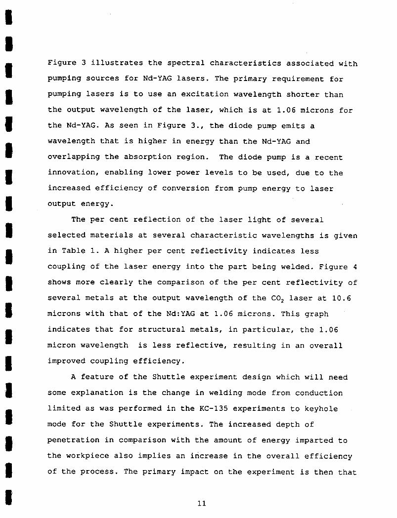
Figure 3 illustrates the spectral characteristics associated with
pumping sources for Nd-YAG lasers. The primary requirement for
pumping lasers is to use an excitation wavelength shorter than
the output wavelength of the laser, which is at 1.06 microns for
the Nd-YAG. As seen in Figure 3., the diode pump emits a
wavelength that is higher in energy than the Nd-YAG and
overlapping the absorption region. The diode pump is a recent
innovation, enabling lower power levels to be used, due to the
increased efficiency of conversion from pump energy to laser
output energy.
The per cent reflection of the laser light of several
selected materials at several characteristic wavelengths is given
in Table 1. A higher per cent reflectivity indicates less
coupling of the laser energy into the part being welded. Figure 4
shows more clearly the comparison of the per cent reflectivity of
several metals at the output wavelength of the CO 2 laser at 10.6
microns with that of the Nd:YAG at 1.06 microns. This graph
indicates that for structural metals, in particular, the 1.06
micron wavelength is less reflective, resulting in an overall
improved coupling efficiency.
A feature of the Shuttle experiment design which will need
some explanation is the change in welding mode from conduction
limited as was performed in the KC-135 experiments to keyhole
mode for the Shuttle experiments. The increased depth of
penetration in comparison with the amount of energy imparted to
the workpiece also implies an increase in the overall efficiency
of the process. The primary impact on the experiment is then that
I I I I I I II [1 I I I I I I I II 11

I 1 •1 ICO
cc LU C
O
1L
u-I
I Ici
.1
WZ
LL
LL
IC
ti 00
ILu
LL C
O C
L
CL
I-I
• I -2 >
-Q cc
I. •0
IU
-
I I I I
cli
0
C.,
I —z
LU >
c'.1
cm
2
8
—
—
- TI-W
3/M
W '3
3N
VIG
VII
'Vt.

Lurl 'L
8U
e8A
O
NLC)
0)N
. 0)
N(0
(0
00-c
C)
000)
N
0)
(00
0)
0)
0)
0)
0)
0)
00(0
0)
0)
0)
0)
00N
L() 0
)C)
0)
0)
0)00
0) .0
)0)
0)C)
0 O
L()
N(0
F) (0
L()If)
(I) (f)
NN
(0 0)
(0LO
If)
C14 (.0p
- °c;
o C
)-o
cb
GO
Li
o
I o
i) CL
- N
o
-J C
-0
-t
..., 3.
I,Q
oQ
1cv,
Wr-4
-J
9
ii
0
--Q)
I I I I I I I I I I I I I 1 I I I 1 I
£ a) > •L
—I—
a)
a
(,—J
OC
co
-4-
0
1)
a)
£0 a O
C a)-'--a)
-I—
>
CO
a) 0 a) 0

I 1. I I 1 10 ui LL
I0cr L
U
I Ucrc
IL
LJ w
z LU
I
-J
IF
-
I
0
w
I I I I I
41 .0
1.4
I o
4, •0
- 41 4
1
- 0
co
'a •1•4
'a —
U U
) -# 0 U
).
•0
41 h
i U
4,_
'a 'a
0 V
-4 C
L go
410
I-I • p
.4
• 41
- U
=
01.1
U
410 h
a
hi
44
j
0
rl
!33TLZ
41 Z
r
41
41 'a U
)
co 41 41
41 'a U
)

I I
the welding is performed by a series of pulses, rather than
continuously as in the CW mode of operation. Examples of welds
1 using the two modes of operation are given in Figure 5, which is taken from reference material published by Laserdyne, Inc.. The
I pulsed mode of operation does result in deeper penetration, a
I
smaller heat affected zone, and lower overall energy requirements. All factors represent favorable attributes for
Iwelding in space. The weld speed is then determined by the pulse
rate of the laser energy. Figures 6 and 7, indicate the
I relationships occurring between power, speed, and mode of
welding.'1 Note that in Figure 7, the close proximity of the I parameters for the pulsed laser to those for the 30 kV electron
I beam.There is a need to construct stiff, lightweight, and
Ilong-lived structures for the extendible portions of Space sta-
tion. With all the available materials, the lightweight and I long-lived aspects are easily satisfied. It is by using metal
I
components and welding the joints that one can achieve the
stiffest and most rigid structures. Alternate concepts include
Ilock-rings, crimped fittings, flanges of various types and
adhesives. None of these joining methods will produce as reli-
able a joint as a simple weld. These joining methods all add
I weight at the joints that raise the inertial mass of the struc-ture and thereby increase the stresses on the anchor points of
I I 1 15

I FIGURE 5.
I COMPARISON OF CONDUCTION LIMITED AND KEYHOLE WELDS
These two micrographs show typical crossections of laser weldsin stainless steel 304. Conduction limited mode is displayed in (a); while pulsed mode can produce keyholing holing leading to crossections displayed in (b).
I I [ I • 't . ,-. , ^ A^rr- - I - .
..ç - 4 ' :
II • I, .
p"
- •)ø•7P ,.... ..I..
x itI
I I I I I El
Ref. Laserdyne, Inc.
I

p 25
I......................... ................... . ......................................................................
E N E 1 20 R A T
I 15 0 N
I 10 n
m m 5
I I I I 1 I I I I I I I I I I I I 1 I
FIGURE 6. SPEED VERSUS PENETRATION FOR SS304
USING PULSED YAG LASERS
30
17
0 0.5 1 1.5 2
SPEED (rn/mm)
• 1800W
1100W
I( 700W
0 400W

N 0 R M A
Ii. Z E D
S P E E D
in
FIGURE 7. LASER WELDING DATA FOR SS304
FOR PULSED, OW, AND 30kV EB
10
0.1
10
100
NORMALIZED BEAM POWER
PULSED I CW 30kVEB
18

I I I I I I I I I [ i -J
I I I I Li I
I I
the structure since it will undergo minor maneuvers in orbit.
Infusible events can cause damage to the station structure
and require repair. Regardless of the materials selected laser
welding of the repair can be performed. One could simply fill
in small holes formed by meteorites by laser melting a plug of
the same material in place. Metals, ceramics and polymers can
all be melted by laser processing.
2.0 OBJECTIVE OF FLIGHT EXPERIMENT
The objective of this proposed activity is to perform laser
welding experiments with different materials in the space
environment using experimental apparatus specially constructed
for the Shuttle and return the apparatus and samples to earth for
analysis. Beginning with a completely automated welding
experiment, the goal will be to develop welding procedures for
different materials and to gradually increase the involvement of
the flight crew to determine the capability of humans to assemble
and repair structures in Space using laser welding techniques.
The major experimental parameters for the Shuttle experiment
are the extended microgravity, the hard vacuum of space, and
human factors. One needs to know if welds in space are worse or
better than on the ground and by how much. As the Soviet's work
has indicated, repair methods will certainly need modification to
accommodate space conditions. Due to severe power constraints and cooling requirements, Q-switching of the laser will be
introduced.
I 19

Engineering concepts for the laser welding facility need
to be tested by Space flight. Critical components and condi-
tions need evaluation and verification. Use of the laser in
close proximity to the work area requires a different philosophy
from using a laser as a space weapon or for communications in
space. In the planned experiment, a fiber optic delivery system
will be used to bring the laser power safely to the workpiece.
The advantages are clear, but the space environment may bring out
disadvantages not otherwise anticipated.
A number of technological developments will be demonstrated
in the implementation of the Shuttle laser welding system:
a. to implement a laser system that can melt metal within available resources.
b. power dissipation from the laser and the specimen.
c. develop pulsed modes for use in microgravity and see if plasma becomes . a problem in high vacuum and low gravity.
d. engineering design of a flight qualified laser with emphasis on pumping methods and heat transfer in the Shuttle environment.
2.1 SCOPE OF ACTIVITIES
Since the initial phases of this project began, it has
become clear that many different materials can be processed in
the proposed laser welding facility. The list of materials is
very broad, because the range of materials which can be welded by
lasers is very broad. A design goal of this experiment is to
enable a number of different materials to be processed; thereby,
expanding the scope of its experimental utility and expanding the
number of scientific and engineering investigators who can
1 I I r] I I I [1 I I I I I
I 1 II 20

participate and benefit from its availablity. We have already had
a number of conversations with other researchers who would be
interested in participating in a space-based laser welding
capability.
As was recognized at INSTEP 88, welding is a materials
processing discipline. The information obtained from such
experiments can be applied to engineering materials or to provide
a scientific foundation for understanding how materials do join,
both in 0 G as well as in 1 G.
The laser welding experiment will be constructed to
accomodate the processing of many different materials, allowing
many investigators to participate in the experiments. The system
as designed will capable of performing studies of weld processes
for different materials and for the development of procedures to
perform laser welding on particular materials of interest to
engineering organizations. The experimental apparatus will be an
assembly to weld either tubes of different thicknesses circum-
ferentially and types of materials and/or flat specimens, also of
varying thicknesses and compositions.
Evolving through a progression of laser welding capabilities
in Space, it is eve i appropriate to begin developing concepts for
a space-based laser welding facility which is pumped by solar
radiation; thereby, becoming without a doubt, the welding
technology with the lowest power requirements of all the
currently conceived approaches for space. For Space Station to
achieve IOC, such a capability is not only affordable, but
21

certainly it also represents a concept which is simple to
implement.
At a later time, we intend to test a solar pumped laser
device for future use as a welding system. Or, if it is more
feasible, to use concentrated solar energy to directly preheat
the weldment and reduce power requirements for the laser. This
way, the laser can still produce a minimal weld volume and HAZ.
The need for preheat arises when accounting for the likely frigid
temperatures the structure may have when in space. Our research
has found that over 95% of the heat needed to weld is used to
raise the metal temperature to melting from ambient. Many have
suggested that concentrated solar energy be used to weld and
bypass laser conversion. While the concept would be possible and
could be less complex, the fact remains that only monochromatic
and coherent light from a laser can be focused to a small enough
point to obtain the nearly infinitely high temperatures necessary
to form small weld beads with small heat affected zones. Since
high weld strength is characterized by minimal HAZ's and rapid
solidification, welding by laser admirably offers these
performance characteristics. A number of intriguing scenarios are
possible with the solar pumped laser welding facility for the
Space Station.
2.3 SPECIFIC OBJECTIVES
Briefly, the need to perform the experiment in Space will be
to verify and expand upon the results obtained from the KC-135
experiments and to verify the engineering design of the laser
22

I I
welding facility focusing on these critical components for
operation in Space:
1 1) Diode pumped laser system
2) Q-switching devices
1 3) Power supply
4) Cooling system I 5) Fiber optic delivery system
1
and to analyze the results from laser welding in space by: 1) Microstructural examination, as in the past.
I 2) Analyzing pulsed operation of the laser.
3) Testing the welds for strength in comparison to 1 G.
1 4) Measuring material losses from melting in hard vacuum.
• As a result of our research, the number of unknowns
-
regarding welding in space has been minimized. Our experiments
have shown differences in the microstructure of a weld when
welding in a low G environment. Secondly, in the Shuttle ex-
periment, a true space vacuum can be achieved without the need
I
for enclosing the weidment in a chamber. For our experiments,
in order to Simulate space vacuum, we have had to pass the
Ilaser beam through a window and suffer relatively poor vacuum
conditions. We are following the proper course of action for
the development of a flight experiment:
I
l) test the experiment on the ground,
2) then test the experiment on the KC-135
3) and then with this experience, design a true space ex-
periment for the Shuttle.
I 1 23

a
I
It is interesting to note that the Soviets followed this
line of thought in the 1960's. The U.S. program seems to be
Iseveral decades late in this mode of thinking.
I. FLIGHT EXPERIMENT JUSTIFICATION
The logical experiment to follow the experiments flown on
Ithe KC-135 is to develop a Shuttle experiment for laser welding
in Space. Even the Soviets noted that equipment and processes had
to be modified to operate in Space, even after succesful
I
operation in parabolic aircraft experiments. However, the time and money spent in these modifications are much . less than in
Imaking the jump from ground-based experimentation to Space. Also
there is a difference between 10-2 G and 106 G in terms of the I microstructure observed upon solidification; a well debated issue
I
in the Materials Processing in Space community. The results achieved on the KC-135 can only promote interest to extend the
I
experiments into Space.
Structural benefits will be provided by using the small
I weld volumes offered by laser melting. ' Similarly small heat
affected zones will minimize degradation of material strength I caused by the welding process. In this work, the effect
' microgravity has on the shape of the weld pool and the resulting
changes to the heat transfer conditions are being investigated.
The use of laser light for heating and a flexible beam
delivery system will give considerably greater flexibility over 1 other methods. NASA should be interested in laser welding .1 ' 24

Imethods because of the following disadvantages of the other
methods:
1) Although they are electrical heat sources, plasma or
arc welding requires that a supply of consumable special
gases be available. These requirements impacts logistics of
supply and design for storage. Also contamination of the
environment with gaseous debris will become more probable
unlessextreme care is taken in the design of the welding
apparatus. Scientific experiments, particularly the ones
which use the Space Station as a scientific observation
platform will be severely impacted by such contamination.
2) Short (less than 20 feet) electrical connections need to
be made for circuit completion for EB or arc welding
apparatus, in order to avoid power loss due to voltage drops.
3) High accelerating voltages are used for EB or arc
methods that could affect sensitive instruments , in the
vicinity or impact the electromagnetic environment of the
Space Station.
4) There is a danger of X-Radiation from EB apparatus,
impacting requirements for safety consideration for weld
operations.
1
5) EB welding requires a vacuum and the arc torches will be
designed for operation in a vacuum thus precluding their use I in the habitable environment.
f
6) Only metals can be joined by EB or arc.
7) Either method consumes considerable power and can only
I 1 25

I I
I
be provided by electrical connections at specific locations
on Space Station.
8) In emergencies, electrical power may not be available
to run EB or arc.
9) With plasma or arc methods, weld bead and HAZ dimensions
are far greater than with laser or EB. A larger volume of
metal is melted and so solidification is slowed.
Clear advantages of the laser welding technique are that
with a fiber optic delivery system one could bring the laser
power safely into the habitable environment or into a
vessel or chamber that otherwise would not permit a larger
welding device to be introduced. Multiple sources can also be
combined for increased output power. The fiber optic can easily
be gripped by a robot arm and allow remote welding or automated
welding by laser. The length of the fiber optic cable can
exceed 100 feet or better without a loss in output power. Output
power can also be controlled and safety devices attached to
.prevent accidental exposure.
The logical path to implementation of a space-based welding
facility appears to be a two step process consisting of two
experiments. One, is to perform laser melting experiments on the
Shuttle that will simulate welding procedures on Space Station
using a fiber-optic delivered Nd-YAG laser beam. The second, is
to fly a solar pumped laser with its own concentrator system.
Since it is our contention that all power for welding must
ultimately come from the sun, a solar-powered-laser would reduce
the load on the already overloaded Space Station power grid. A
I I I I I I I [1 I
I I
•1 26

I. I
solar concentrator for power collection has not been flown in
- space. Other research groups, including groups within NASA, are
Iinterested in developing a solar concentrator power conversion
system to fly for other purposes. Our interest is to prepare to
I have a sun-powered welder available for Space structure assembly,
I and not just for repair. A Shuttle experiment will have two aspects: verification
of technique and studying space effects on laser welding. The
experiment would not be "to see if one could weld in space".
It is understood that one can. Experiments on the KC-135 show
I
welding materials in microgravity can be done with a laser. In addition to our work, Duley et a1 16 have welded plastics with a
002 laser on the KC-135. This experience base leads us to the
conclusion that various materials can be welded in space with a
I laser.
1 4. POTENTIAL PAYOFFS/BENEFITS OF TECHNOLOGY DEVELOPMENT As mentioned in previous sections, the NASA is embarking on
a number of activities in Space which will require welding of
materials. In order for these activities to be cost effective, as
I well as successful, we need to develop the following:
I
a. Ability to assemble and repair structures in Space.
b. An experimental facility for improving our
understanding of weld processes.
C. Improved efficiencies in diode pumped and solar pumped
I laser systems.
I 27

I I
The payoffs are then reflected in two ways. Successful space
• programs that generate interest and enthusiasm to enhance the
I role of the US in Space and in the technology transfer to other
government and industrial programs that normally evolves from
I successfully implemented NASA programs.
5. INTER-RELATIONSHIPS TO OTHER GROUPS
The welding research community includes aerospace., nuclear,
and university groups who either seek to improve the welding of
unique materials or perform experiments to better understand the
metallurgical .processes occurring during welding. A microgravity
.1laser welding facility provides a unique platform for this
research community. Eliminating bouyancy and convection forces
Idue to gravity simplifies the theoretical basis for the process.
Several recent publications describe other NASA programs
I which impact the laser design proposed for the laser welding
I
facility. NASA has already chosen solid state lasers for future
remote sensing systems 13 and deep space communcations 14 . In a
more recent article, the space qualification of of a Nd-YAG laser
and associated reliability concepts are presented. 15 The
I experience of these groups in working on space qualifying solid
_ state lasers for NASA programs will be applied to the design of
the laser welding facility.
Materials research groups have performed many studies on
metal fusion in order to determine which elements will fuse,
thereby being 'weldable'. Although the material is a bit dated at
1 28

I I
this time, Cohen" gives an excellent summary of laser materials
processing. In that article he reproduces a chart first published
by Irving17 and is partially reproduced in Figure 8. Examples of
metal combinations which are of interest to researchers in laser
welding are presented in a matrix format and represent a suitable
place to start in defining useful experiments for space.
Obviously, the more common weldable combinations can still
provide interesting and sometimes beneficial microstructure when
welded in Space, although the most interesting experiments should
be those experimenting with metal combinations which are not
compatible on Earth, but may be compatible in. Space.
We also anticipate that having such a Space Laser Welding
Facility available for researchers participating in welding
experiments will provide NASA with a strong cadre of welding
experts available for future projects or programs.
I I I [1 I I $ 11I I
I I 29

[1 I —
jC 0
c -Q
)
l .:3 co
W2
.2Ec3
—o
U
E
Q34—.0.
=.
Eas
W
LLQ
3C
L 0
0
Q•
0oL
- z
&5C
00
—c
c
w#W
E
cic
ZiFo
010--
—0
000
D
0>
o[o
000
LL.z
0C
30
0
I2II00iiIIIIII L
L5000•Q
oQ
OQ
0
o0_0
0__
p-------;-----;--
- Iii
Iiii
w wE
EE
E.2.2
EW
E
F-
0C
0.O
CLX
I I. I El I I I 1 I I I [1
0
I I
6.0 TECHNICAL DESCRIPTION OF FLIGHT EXPERINT
The rapidly changing technologies in today's laser materials
processing industry creates several problems in defining the
components for a space experiment which will not fly for several
years. For the purposes of this report we have chosen to present
the most probable configuration of a laser welding module, using
the state-of-the art capabilities commercially available today.
The caveat to remember is that we will be able to simplify the
system, once we are able to characterize the capabilities of
pulsed welding on KC-135 experiments. These experiments are
needed to determine the actual power requirements for welding in
microgravity using a diode pumped laser system.
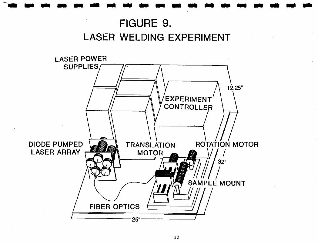
Figure 9 is a schematic diagram of the proposed experiment
as it stands at this time. In this representation of the
experimental apparatus, the laser energy will come from a bank of
Q-switched diode pumped Nd-YAG lasers. These represent the
latest technology in solid-state lasers, as well as the most
conservative in power requirements. In this drawing, the laser
source is represented by a bank of five diode-pumped lasers
transmitting laser energy into five optical fibers which will
then steer the exit beams to a single, common fiber. A focussing
system concentrates the output of the fiber onto the weldment
surface. The working end of the fiber will be mounted to a
translation platform. By indexing the platform to different stations along the tube, a series of circumferential welds will
be made by turning the tube for one revolution. Alternately, the
31
2 LO
c'J
I..,
cc w
:c') w
CL 0
CO
U)
z
LU
E LU 0 >< LU
Wz
cr
Ow
LU
Co
—j
cc 0
z -
0
j:Lu
CC
a. cc
C/)
0<
C'.1
Lt)
c'J

[1 I
fiber optic can traverse along a flat specimen and generate a
weld bead. Figure 10 illustrates a sample mount which can
accomodate flat plates. The change-out of sample mounts will be
easily performed by a crew member, making the scheduling of
experiments quite flexible.
Due to power limits for an experiment on the Shuttle, this
approach will safely operate within the power envelope. Such
an experiment would best be manifested to operate in the
Shuttle bay as a Hitchhiker-g package, as shown in Figure 11. The
current design considerations will meet power, weight and
dimensional constraints. The total laser welding package will weigh less than 500 pounds.
By diode pumping, high power arc lamps and complex cooling
systems are bypassed. Reliability from simplicity and redun-
dancy are added benefits. The technology is rapidly advancing
in this area and in a year, efficiencies and powers will be even
higher than the currently available systems claim. Diode pumped
lasers presently have the highest efficiencies among the solid
state lasers. The designed configuration shown employs
commercial lasers which are available from several manufacturers.
Several major factors form the basis for the proposed
design. They are:
1) Nd-YAG lasers produce the 1 micrometer wavelength most worthwhile for melting metals.
2) diode pumping gives high efficiency with low power con-sumption.
3) diode pumping reduces cooling problems to an accep-tible minimum.
I I I I I [1 F] I I [1 I I I I I [1 I--i
I 33

z 0 w
F —z
0w
oW
O
0
1wE
cr W
W
S2 x
L
L =
0
0
ZI-
-J w
cc w
CI)
-J
0
(I)
a, 0
)..-. cc cts
—0
aC
O
CM
CL
G)0
CD
Il--c
-Ca)
ii-
—o
,IE
co 0
10
CL
cu
CL
0
occ
IlC
.E a)-
-c
cc 0
0.
—I-
.
a)0,
CL
0)
I I I I I I I I I I I I I I I I I I I
qw (n

I
I
-ZC
/)
WW
-J
C
L
wC
o
WW
LL
C
Lu -ii-
-
>-J
LL.
w
Cl)
—j
I I 1 [1 I I I I I I 1 II I I I- lh w
—
-*-
—
00
— 0
--
0
CL
0
cc .c —
-c CD
asa)
caC
l3._
cC
U
O)G
)I
0W
eZ
.2ta—
. w
a, ca
.LO
.
--
—
rCD
m
Cc
,0-
a)a,
.c0
Cl.
•
I-
I I [j

[1 I I 4) fiber optic delivery simplifies the welding process.
5) bundled fiber optics and multiple lasers make up the I design features of the Phase II experiment. 6) Current NASA programs are already working on flight qualifying laser systems of the type required for this
I experiment.
In addition to the first Shuttle configuration, which will
be designed to occupy a Hitchhiker-g pad and operate in an
automated mode, we anticipate that a follow-on design for the
I Hitchhiker-M pallet will also occur. Adding more involvement of
the flight crew in manipulating the laser optics to repair welds
can be most conveniently configured in that configuration. Figure
12 shows a viewof the laser welding apparatus on a Hitchhiker M
pallet. The samples can then be placed in a convenient manner for
a person to oversee or perform the required welds on top of the
bridge structure.
Li I I I I I [1 1 36

C,)
CL
cm
0
• cw
--
ca-- '-
Ca
—zo )
cl
— —
Ca
0-
N
I I I I I I I I I 1 I I I I I I I I I
z 0
w
I —z
ow
zcr C
M L
LJ
Lu
LLJ cc
cc LLi
IJ-W
=
=
Lii
cc w
C
l)
—J

I I
7. SUPPORTING ANALYSES
7.1 KC-135 EXPERIMENTS
In these experiments, a Nd-YAG laser is used to make an
autonomous weld bead in a low gravity environment with the
weidment held in a small vacuum chamber. In this way the two
properties of space that would influence the quality of a weld
are simulated. The whole assembly of the laser, cooling sys-
tem, data acquisition equipment and human operators were flown
on NASA' s KC-135 as it flew parabolic maneuvers to create low
gravity. Specimens of 301 or, most often, 304 stainless steel
sheet were processed with up to 18 W output multimode of CW 1.06
micrometer laser light. Welding speeds of approximately 1.5x10²
m/min were used.-
What is so elegant about the analysis is that the variations
that are seen are directly attributable to the changes in g-
level. The degree of sensitivity when making the comparisons
could never be achieved by performing separate runs on separate
specimens in subtly different conditions. In our experiments,
the only variable that changes in the few seconds of
g-transition is the g-level itself. Laser power, focus,
specimen absorptivity and emissivity, temperature, vacuum, etc.
are all constant for those seconds when the g-level is abruptly
reduced or increased.
By using light energy for melting, one needs only to
consider heat transfer conditions and their effects on
microstructure of the weld. Although power coupling is more
efficient With electric current based methods, they introduce
U I I U I I I [] 1 I I I I I I II 38

I I
strong masking effects (magneto-hydrodynamic convective flows)
that prevent clearly observing the effects that a space
environment may have on the welding process. Detrimental
magnetic and electrical fields are generated by electrical weld
methods.
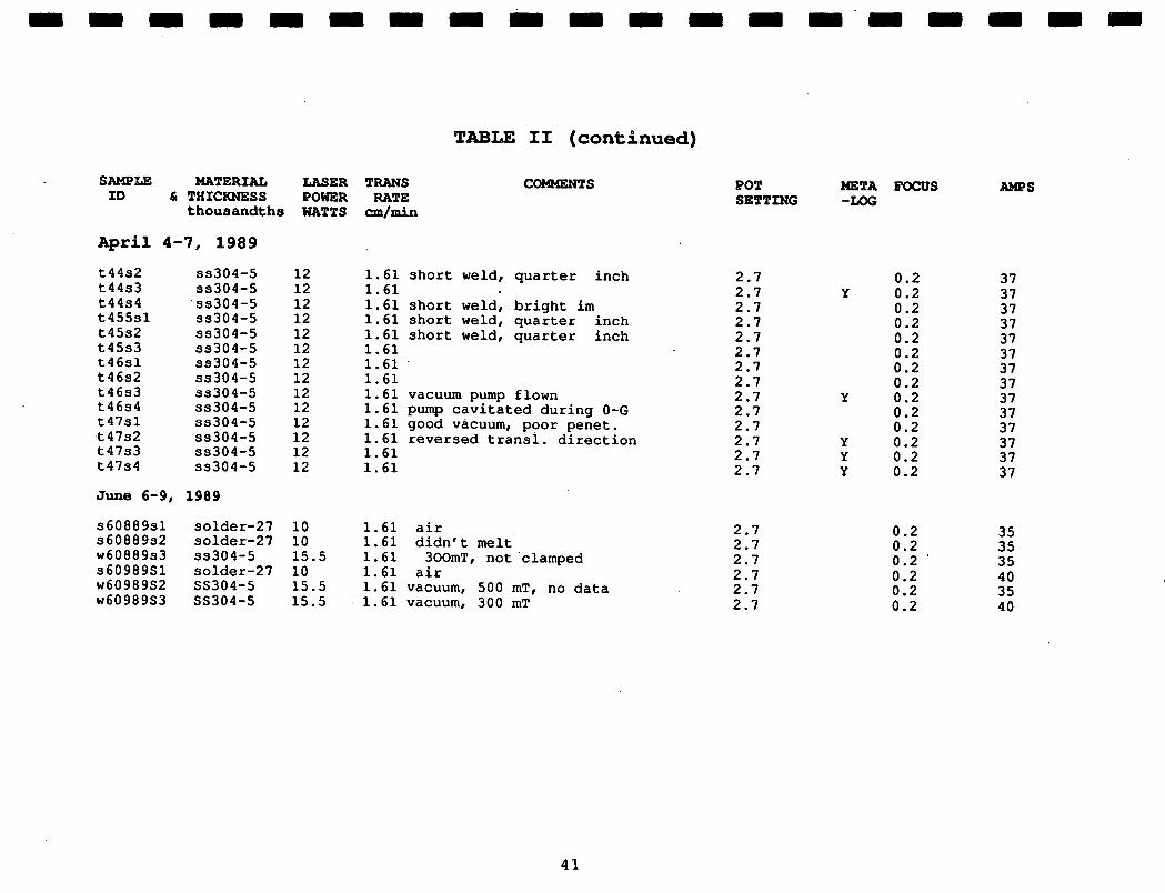
Table 2 shows the flight specimen summary for the project.
On five separate occasions welds were made on the KC-135. On
two previous occasions, the welding apparatus was taken to
Houston for inspection and approval of the hardware to fly.
There are 46 specimens listed in the Table. Variations in
I
thickness, material, power level, translation rate and vacuum
were made to maximize the quality of the, results.
1
The laser welding apparatus constructed for the KC-135 work
used equipment that was readily available during this first
phase. For instance the Nd-YAG laser was a GFE laser on loan from
I Marshall Space Flight Center and the power supply that we used was compatible with the KC-135, but did not easily support 0-
Iswitched mode of operation. In these earlier experiments we feel
that the data obtained by using a continuous wave output, was
I useful in that variations in heat transfer caused by going into
I a low-G environment are not masked by the non-linear effects of laser pulsing. In addition, modeling the thermal behavior is also
Isimplified without pulsing. The additional variables of pulse
width, repetition rate and higher absorptivities did not serve to
I answer the initial questions at hand, so the simplest and most
available approach was used. As we go forward in the program, it
I I I Li I I
I39

I I(N
(N (N
It) I
t) It) w
0 IS
) It) N N
N N
00000
U) U
) N N
N N
N
Irl(N
r-4-1,-I.-4
-.4.-l.-I.-4.-4.-I.-I(N
(N(N
(N(N
c'4(N
(Ncc
cccccc
1H
U) U
) U) in
U) U
)N
N N
N 0 N
N
N N
N N
N N
N N
N N
N N
E
l 0
(N
(N
(N
(N
Z El
H
E4 o
E1 r
DiC
I
I(N
00
..4.
40.0
.0.
i.J 4.).l.)
WG
)W
.0J
H
4.14.1•..4
4J 4J0
0 W
000
v
--4-4
-dE
w
•,-i>
,v0
,4
4J4.4
0
I.1--I
.14.1 co
00
C
-I I
-IC
-4
(1)-
4-i.0
C—I
I4IW
II-I
-4-1
0.U)
0
U)(1) 4
•4d_44
44-4444.4
..4
cc ccC
U).0
4JU)
a) U
)U)U
)U)U
)0
()41
4.1 C-,
EE
EE
E
E
E
Ew
U)U
)U)U
)U)U
) C
EE
EE
EE
i-
Cl)O)
U)U
)U)U
)tC
)EE
C.)
4.1Cli-.-I
Izl
•••4f•4•••4•••4•-4••-I>
C'C
'>
.0
WU
)
4r-4,-4-I -1
IClU)>4-i
El
W
'.0 c
o c
o k
o '.O
'.0 '.0
'.0 '.0
'.0 %
D '.0
1.0 OD
101.01.0
I9 E
4 04
U) U
)U
)U
) U) U
) U)
c_)
00•C
o
Co at
iI.d
.1 I
.4 .4
.d .4
1
.4 ,4 .d .d '.0
1.0
.d
Ci
LI) 0 (N
(N (N
(N (N
U) LI) IS) U
) 00
(N (N
(N (N
(NN
v-IC
i
w '.o '.o
'..ø (
.0 w
Ci
.1.4-
Go
H C
) U
) 0
C')
- (
)
-4 C
D G
o c
o c
o O
D c
o i-I U
) U) U
) U) L
n U
) ) U) U
) U) U
) IS)
Hø
v-
111111
11I1111
$1111
1111111
ri X
.-1 ' .-
1 ..-
I
U)' U
)' U)' U
)' U)'
U)' U
)' U)' U
)' U)' U
)' U)' U
)' U)' U
)' U)' U
)' E4E-4 0
000000 I 0
00
00
00
000000000(D
00
,I (V
)(V)(V
)(fl(fl(flmm
mm
mm
m0
O)O
)O)U
)Q)o)
10O
)U)U
)a)O)O
)a) i-•I
a)a)a
)a)a
)a)a
)O)a
) U
))0)a
)a)o
) v-4
U)Q
)a)a)q)
Iw
w .-I (N
-4 (N -.4
04 •Q
.-4 (N c' -1
(N 6') U)'
a)a)U)O
)O)U
)O
)O)0)C
t)g).-4(N
(')—
IcNr')
wco
co O
N C
) 00
)
U) U
) 11) '.0 '.0 1.01.0Q
14 ('4
C') U
) U) U
) .-I (N (V
) co 0) 0)
,,
0(D
-4 'd
•
'-1
14 14 .-4 ..I .4H
C) C
) 0) 0
) 0) 0
00
Q
-4 -4 '-I '-4 -1 '-I(N
(N (N
(N (N
('4 (N
N N
N
C) C) C) '-4 .-4 ,-1 H
0
0 CI)
Z
.
I
IT
I I I I I •1 I I I I .1 I I 1 I I I I I
a' .r1 0 C)
H
H -1
El El
N N
N N
N N
N N
N N
N N
N N
N N
N N
N N
004
•
"CN
(N
(N(N
C'1
(N(N
.CD
0 C)
00
I••.4
04J.4
.I ..4
--1.-I
00
Cl)E
El--4
Z1.4
1.11.1Q
.r4 111
0
i-IW
O0.
0
xi-i 1.1
i1.i
015
41545
0
04
--
C)
4'0
.0)
C)E
-'E-
IwO
cE
E
.1.1-1
54.14.)
-- - -
0. 5
w1-4 0
0 0
10
'
4J 0
4J
W
00
-
'-4 '-4--I 0
it) C')
Cl)W
OW
0.0'
- 15
450
4J E-4 -
Eo
o.E
EE 4J
4.1
4.).).)
1.1141.414
1.4
VO
14l)
0
000
oEo
d4C
')-4Q
Q
.
4 C
r.to
ow
0)
Q)O
)).)I4
to
Z E
l.4
4 .4
r.4 ,.4 ..-4 ,4 r4
.1
4 ,4
,4r4
'.0
.0 '.0
'.0 '.0 '.0
'.0 '.0
'.0 '.0
'.0 '.0
'.0'0
'.0 '.0
1.0
4.Q
'.0
El
Cl) r4
r4E
-i C
QE
l i0i
In
In In
(N (N (N (N (N (N (N (N (N (N (N (N ('4
(N0(D
It)
0 In
In I-I .4
4.4
.-4
4 .-1 .-I1.4
.-4 .-4
4.4
.4 .-44.4 _4 .-4
0
s.C
fl4J
NN
N CV (14
(N Cl)
C'
In in II') U) LI) it) In In
U') In
LI) L
I) II) In
I I In I In In
HIIIIIIIIIIIIII
1414114i
I
Czl0
00000000000000
10 0
00
El C)
C') C') C') C') C') C') C') C') C') C') C') (')C') C')0)
l .-4 C') .-1 C
') C')
.H
OGo
0000cnu
ø E
4 4JN
0)
.4C
NC
').4(N
C')
IO
)Q)1
5(/)C
/)CI)
'.00)0
)0)0
)0)0
) (N
)(N C
V ) .4
(N
,-4(N
(flq
X Q
)a)1
5In
O)U
)a)Q
)15a)O
)O)o
, ''
' '
In In In W '0 '.01.0 N
N N
NCl)
000000
.'H1)4
Cl)4I
jjjjj
I)O
)Q)O
)
N N
N N
N N
N N
N N
N N
N N
In 11) I
n 0
In o
(V
) (
) (
) C') C
') C') C
') C') C
') C') C') C') C
') C')C') CV) C
') W C') IV
§
ci c
i c,i c
'i (N c'.j (
N (N (N (N (N (N (N (N
(N (N (N (N (N (N
00000000000000
000000
I>4
>4>
4>4
-4 IcT

U I
has become obvious that pulsed laser welding may be more
appropriate for Space applications.
7.2 KC-135 APPARATUS DESIGN REQUIREMENTS
Preparing the apparatus to fly on the aircraft and adapting
the various components for microgravity conditions became the
dominant effort. A major advantage in using a Nd-YAG laser,
besides its availability for our experiments, is its smaller
size in comparison to a CO 2 gas laser. Experiments to be flown on
the KC-135 are restricted to size and weight limits, although
other researchers have flown smaller power CO lasers on the KC-
135. As shown previously in Figure 4, the Nd-YAG laser also
produces a shorter wavelength emission which couples more
efficiently with the weld alloys used.
All apparatus that was flown on the KC-135 had to be
ruggedly constructed for safety reasons. The YAG laser is
inherently rugged. The laser used, considering its age, was as
high in power consumption as possible for the KC-135 environment.
Our laser was a 15 year old model 114 dual lamp Quantronix Nd-YAG
designed for 38 watts output continuous in multimode. Power
measurements revealed that the beam power was no greater than 18
W prior to entering the beam delivery system. Beam
characteristics are 2mm diameter, 6 mr divergence and 5% rms
stability. Power for the laser arc lamps had to be supplied from
the aircraft power bus (which feeds 400Hz 208V three phase
power). To operate the laser head from the aircraft power, a
special power supply, the 10KW YAG-Drive from ALE Inc. was used.
I I I I I I I I I I I I I I I I I
42

I I
This power supply could operate from the 400Hz frequency and is
more compact than most other supplies of equal or less power
capacity. Power inverters in the aircraft do supply 120V 60Hz
power for the other instruments.
The standard cooling system (containing filters, deionizers,
and heat exchangers) was not used with the laser system. Instead,
a truly bare-bones coolant supply was fabricated. All cooling is
supplied by 20 liters of de-ionized water circulated through the
laser head by a 1/3 HP 120V AC impeller pump. This pump can
provide the 6 gal/min and 20 psi pressure that prevents lamp and
crystal damage. The cooling system limitation, in conjunction
with logistics of changing samples during parabolic maneuvers,
permitted up to 4 specimens to be processed per flight. Note that
the cooling system has to function properly in a microgravity
environment and operate with considerable reliability for
aircraft personnel safety. Cooling water temperature was kept
below 40 °C to protect the laser head.
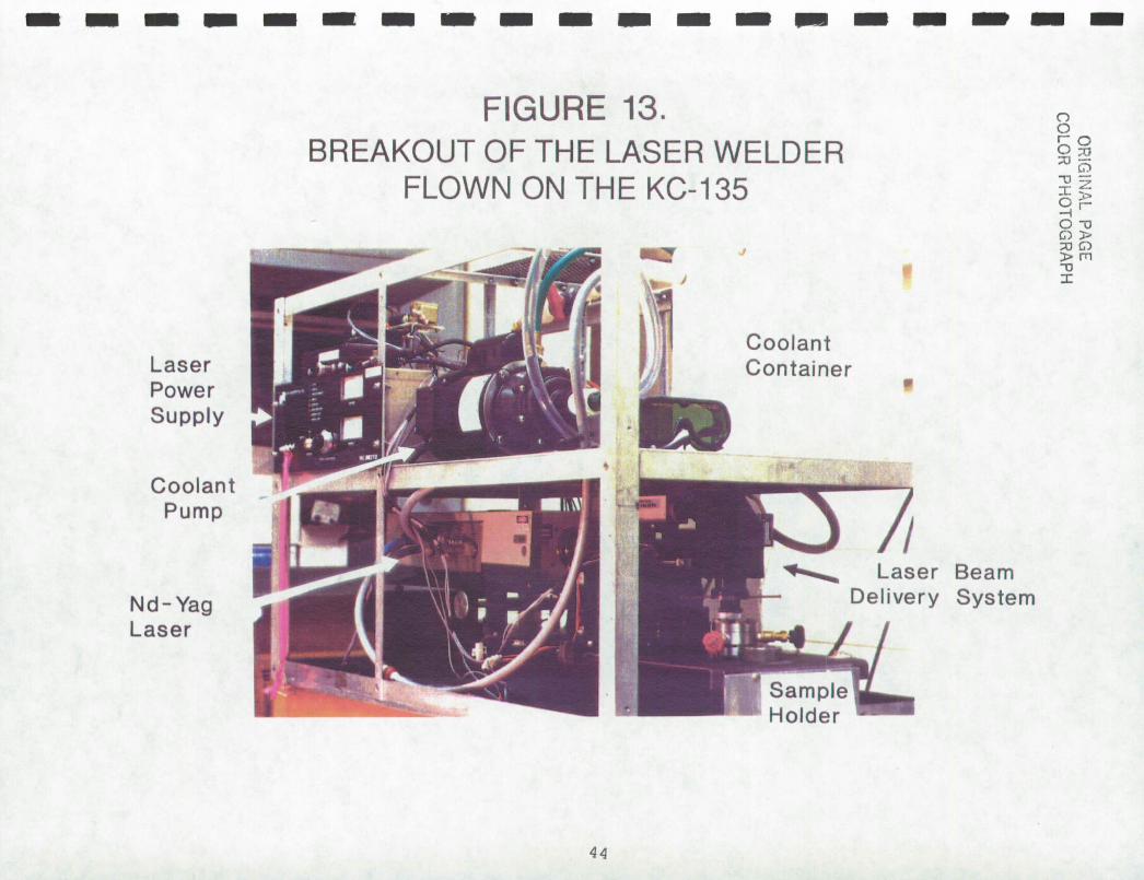
An aluminum frame of 60x70x120 cm houses the laser, beam
delivery system, power supply and cooling system. This is shown
in Figure 13. The experiment is performed inside this apparatus
with aluminum sheet fully covering the exterior of the frame for
safety reasons. There is no control over the experiment except
translation speed and power to the laser once the box is closed.
There have been no alignment problems either with the laser
resonator cavity or the beam delivery system. This is not a
trivial statement given that the equipment is trucked thousands
of miles to and from the airfield between flights. Several
I I I 11
I I I I I [ I I I I I I
43
I
4—
. CD
co
M
--
00
00
p I I I I I I I I I I I I I I I I I I
rr w
0
—J
w
) co
wO
co
LLI—
J-r
I
gL
L0
LLoz
DO
vLL
w
ci CID
OF
G1N
AL P
AG
E
CO
LO
R P
HO
TO
GR
AP
H
cU
)
CC
/)
Go co
WI-
'a-
L
1) )
A:W
,4
II 4d
ca j5i;•
0
>
Cl
0Q
0)
DC
I) cc
ZJ

I Li 1
perspective views of the experiment package also provided in Figure 14.
I A heavy and precise translator system is used for the beam I delivery/translator. Without precision optical grade screw drives, the raising and lowering of the gravity level during the
Iexperiment could alter the laser focus. The translator supports
the beam delivery optics and the video imaging system. A closed
I circuit television system is used for the observation of the
I welding process. The numerical data is recorded with an 80286 based computer. The interconnections for the system as a whole
I
are shown in Figure 15.
By employing a video overlay circuit, the computer graphics
Iand data are superimposed on the magnified weld pool image as it
is being recorded on the S-VHS VCR. A S-VHS monitor provides the I experimenters instantaneous an view of all conditions during the
ON run. By using a hot-mirror and filters, the camera can view the
weld pool along the same optical axis as the laser beam. Figure
16 is a schematic of the optical path. The exit beam from the
laser passes through a 4X beam expander and then a dichroic hot-
mirror tuned to the YAG wavelength reflects the beam down through
' the focusing lens onto the weidment after passing through the
window of the vacuum chamber. The focal length of the lens is 1.5
inches. The weld pool is imaged by the beam-focusing lens up to
the camera. The camera used is a CCD type (NEC TI-23A). A
I visible pass interference filter is placed in the camera optical
path to see the weld pool. Early tests showed strong laser I reflection from the molten metal pools. The combination of
145

IIIIIIIIIiI"
mi

I I C
E H
I I
II
I III
III LJQ
..
fu
LU
K
-C
aL_ij
zII_ -
o w
II
LL
LJfi
Z
L.J
U U
C/)E
II
I00.
I
>ck> -
LJ-
a
(.1C
I
II
CL
..J fri
[H
117rz.
c3u
I
LU
0i
(I -
Z Z
c<L-S = 1
F )
4: I, W
Z TL
-J _J L
6A
cro
IIC
I •IIL
F —
NI
z LU
I
>D
I
JD
-<LI
r
LL
LU
Z
__1I
U
I
ZW
—>
I',ThJl
I' <
U
I
Z
I
co
UJ L
O
i
.L
I -
EE
'_
0 _
__ _
__
0 ' LU
°
____LL
-H
z
U
U I
—. >
<
1>-cL.0
-I-U
' LU
-
U
<4:.-
.1______
II
I I

rzl
I'
14M
g
rA
14'1
4a
.a
Cc
mmC
.)
0d
o cc
SO
Coo E
CJ W
4 24
ad
.S
S
SS
SS
•
•S
•
S
F –z
w
LU I
—w rr
CL O
x L
LW
(CI)(3
UJF
-co-j
Ow
LL
CC
Cr
CF)
F-
0
lw

lenses used gives a net 80 magnification to the monitor screen.
The weld pool image is about 0.8 cm in diameter on the screen.
To see moving features clearly, the camera operates at a
shutter speed of 1/1000 second per frame.
The sample container used to simulate low gravity and space
for the KC-135 experiments is shown in Figure 17. The vacuum
valve and thermocouple gauge provided access for evacuating the
chamber to a specified pressure. Figure 18 shows a further break-
down of the components used to fabricate the specimens for
flight. Although the intent was to provide a specific pressure in
the chamber for each sample, the 0-rings shown in the figure
never did functionproperly. Hence the 'space' simulation was not
very accurate. A vaccum pump was included in the flight hardware
on later flights; however, even then the leakage around the seals
allowed the pressure to rise continuously. The roughing pump used
for the experiments contained oil and could not run in low G. An
oil-less pump was too expensive for this phase of the work and
was not available for the experiments. This chamber will be re-
designed for future KC-135 experiments.
Attached to the translation head was a precision linear
potentiometer such that the head position could be monitored.
The device served three main purposes:
a) to relay the head position to the operator without having to open the light baffles on the aircraft. This was necessary to bring the translator head to its standard starting position.
b) to monitor the position of the translator head with time during the course of the experiment.
c) to measure the welding rate.
49

P\GE
r'
-
I I I 1ui
C
/) U)
I I Iciw 0 2E
NL
L
Iax
Iu
-Iz
Iui _j Lu
ID
-
10) I I I 1 I
;^ 2
1:
wI
LL
QW
CL J0
I—
Ociw
.IO>
±,-O
zo
IO<
Z0.jW
WW
<iI
CL O
- z
IO'z
<
aLt )<
<:
1(5
LLU
JQ
E
WO
it
—cf)<
iw 0
0
UJLLJ
w , 0 a
.Z
0 -
IL
I— -.
LU
> 0
' _
i 0 a
. 0
CD J)

FIGURE 18.
VACUUM CHAMBER SAMPLE CONFIGURATION FOR KC-135 LASER WELDING EXPERIMENT
VIEWING CAP
0-RING
VACUUM COMPONENT
0-RING
SAMPLE
0-RING
BASE
51
I I I I I I I I I I I I I 1 1 'I I I I

1 An accelerometer was also mounted to the translation head
in the vertical direction. From this, the major axis accelera-
tion levels could be monitored during the flight and recorded
for each specimen.
Translation rate was adjusted manually for these experi-
ments. A potentiometer controlled a voltage through a regu-
lated circuit which powered a DC gearhead motor. The motor
turned a precision screw drive in the translator head resulting
in linear movement. Safety limit switches were employed to
prevent damage of the apparatus since translation was not con-
trolled by computer. A calibration of the translation. mechanism
is shown in Figure 19.
The output power of the laser as measured through the op-
tics of the delivery system and chamber window was measured
using a Coherent Model 102 Laser Power Meter. A calibration was
established between the diode in the laser to the power at the
between the diode in the laser to the power at the specimen.
Changes in laser power were affected by the power into the laser
which was recorded as amperes in. Power was not a strict function
of amperes alone as water temperature and condition of the lamps
and optics also had an effect.
7.3 SPECIMEN ANALYSIS AND METALLOGRAPHY
As each specimen was received, careful examination of
the weldnient surfaces was performed. The welds were evaluated
I
I I I
I-] I I I I 1 I
ill I II
52

I II-
C)
1E-
------i-----
0 --0
LL
ko
I
Li -J 4
m >
U)
I-z 0 CL 4 I-4 0
[1S
]H3N
I
I

I
1
for suitability to be further tested. Specimens without irreg-
ularities or known artifacts that reduced viability for data
collection were culled for detailed examination and sectioning.
Surface features of each selected weldment were photographed by
optical microscopy prior to sectioning. During the experiment,
position and acceleration data were collected by the computer
and later mapped onto the weld bead by hand.
Cut pieces of weidments were mounted in Bakelite and
mechanically polished through to 0.05 micrometer Alumina.
Kalling's etchant or electrolytic etching with dilute oxalic or
nitric acid was used to reveal structure. Both transverse and
longitudinal cross sections were made. Transverse sections
reveal the weld pool shape in a plane normal to the translation
axis. The longitudinal section cuts the weld bead vertically
in the plane containing the translation axis. This latter cut
reveals microstructural variations from front to back in the
pool. The trailing edge and convective patterns near this edge
of the weld pool are clearly visible, variations in partial
penetration with position are seen in one cut. A few sections
were tested for microhardness using a diamond pyramid indenter.
It should be noted that not all specimens were found to-be
suitable for metallographic examination. Certain combinations
of material thickness, power and translation rate produced in-
adequate penetration for metallography.
7.4 RESULTS
Nearly all the welds made were of high quality. When air
I 1
54
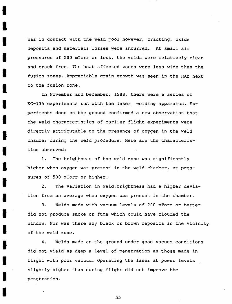
was in contact with the weld pool however, cracking, oxide
deposits and materials losses were incurred. At small air
pressures of 500 mTorr or less, the welds were relatively clean
and crack free. The heat affected zones were less wide than the
fusion zones. Appreciable grain growth was seen in the HAZ next
to the fusion zone.
In November and December, 1988, there were a series of
KC-135 experiments run with the laser welding apparatus. Ex-
periments done on the ground confirmed a new observation that
Ithe weld characteristics of earlier flight experiments were
I
directly attributable to the presence of oxygen in the weld
chamber during the weld procedure. Here are the characteris-
tics observed:
1. The brightness of the weld zone was significantly
I higher when oxygen was present in the weld chamber, at pres-
sures of 500 mTorr or higher.
2. The variation in weldbrightness had a higher devia-
tion from an average when oxygen was present in the chamber.
3. Welds made with vacuum levels of 200 mTorr or better
did not produce smoke or fume which could have clouded the
window. Nor was there any black or brown deposits in the vicinity
of the weld zone.
4. Welds made on the ground under good vacuum conditions
did not yield as deep a level of penetration as those made in
flight with poor vacuum. Operating the laser at power levels
slightly higher than during flight did not improve the
penetration.
55

Measurements were made from the video tapes using image
processing techniques which showed two things: one, there was no
structural detail within the bright flashes of light that were
recorded. Second, when the laser power was shut off at the end
of a run, emission of radiation from the hot metal of the weld
pool did not have sufficient strength to register on the CCD due
to the high degree of attenuation used. It became clear that the small weld pool size prevented visualization of fluid-dynamic
events. The narrow band-pass filter prevented the visualization
of the thermal gradients.
The weld pool shape is a near perfect circle when viewed
from above. This can be determined from the weldrnent by the
shape of the ripples formed at the trailing edge of the pool.
Such rippling is shown in Figure 20 for 0.127 mm thick 304
stainless steel sheet. In this micrograph, ripples were
suppressed in high gravity conditions. Structural weakening of
the weld will occur if the ripples become severe. Weld ripples
are extensively discussed in Anthony and Cline'. Both Zacharias8
and Lin5 found as we did that the pool liquid profile or shape
affects the convection path and therefore the heat transfer process.
The microstructure of the laser welds generated in the KC-
135 experiments provide interesting analyses. Typical examples
are specimens t46s2, t47s3, and t39s1 which are shown in Figures
21-23. These micrographs show transverse weld sections of
specimens where one is from a 1.8 g portion of the experiment and
the other formed in 0.01 g conditions. These are full penetration
56

-
cD
cl)
-
4iQ
_JD
)
C
>
..Co
ci
•=
NC
CsJ
CD-0)
CZ0
oC
)O -
CD
O0
czU
)
__51I_
.o
(j-o
o
(I)L()
c 0)
co,r
CO
4-'
-
CIO(n.-
—0 CZ
CZ
U-)
- U
Lr
w CC
Lii F
-
00
(/)1-
-uJ
00
—U-
UJ(I)
UJw
(I)
Cl)—
U--- 0
IQ
Iw
I0
ILL

OR
!CN
AL P
,E
SLA
CK
AN
D W
HIT
E P
HO
TO
GR
AP
H
x 0 (1
5
0 a.
%-
C•sJ
—J
o <
.-
0
0 —J
—J
w
LJ
F—I
0
cc co
I C) I —w
6 cc
00
a 0 I . -0 w
CsJ
C/)
(0
IT F—z
U)
w 0 w C,)
I I IU
)
LU
I I I ILU cr
wZ
0
$c2LLJ U
3ia: l
cr I w
w
,fr 0)
I<LU
—
J> C,) a
z I
ciI
I-
I I I

)< 0
0
.cJ
'-
-J o
<
o
CL
-
0
-Jci -J w
LL I-I 0 cr co I 0 I-w 6 cr I-0 w LU
00 0
C1) C,) N-I-z wJ)
0 w 0 C/)
IC') CO
w
—
J
IUJ O
H
I<C
O
Ico
0
IZ
° —
w
C\J
ZO
LU
Ia
Oa
D_JH
Iou
J LL
cr
Icr
IUJLU (I)
I •z
•fI
IF-
O!NAL PAGE BLACK AND WHITE PHOTOGRAPH

TI-
CO
C)
C')
I—z w
0
w
0 C,)
'0
rs0
'-,
c'J
'—
J o
<
o
CL
cl
LLI
LL
EE
co
uj
6 LLI
LU
00 0
—
0 Fat
BL
AC
K A
ND
WH
ITE
PH
OT
OG
RA
PH
I I I(I)
LLI
I I Ici)
I1L1J
• Uco
C\J
'-"I -
lcD'
IS2LLJ a^
cr I
cr I
LLJUJ coVIc
E
(I)
I-J
>
•z
IIr
IF—
I I I

[1 1
autogenous welds. The first figure of the series best represents
the type of microstructure observed. The equiaxed dendritic
microstructure of the high-g weld resulted from the higher
convection velocities possibly due to the buoyancy convection
contribution. A radial (to the weld axis) columnar structure can
be seen in the low-g weldment. Each of the low-g sections in the
series has a radially emphasized microstructure while the high-g
sections have a random or mixed orientation to the structure. In
low-g the heat flow pattern is radial as is the solidification
direction. Such behavior result's from a reduction in
convective flow. It is our contention that buoyancy driven
convection effects are nearly zero in our weld pools and during
low-g conditions, it is more likely that the changed shape of the
molten pool causes the changes in heat flow.
By removing gravity, a higher curvature can be sustained
in the liquid surface of the bead. If surface tension is the
main driving force and not significantly reduced by higher
temperatures, then the width of the weld pool should diminish.
Since heat input is not, reduced, the amount of metal that melts
should not change. Except for heat transfer arguments, the
pool volume stays constant and as a result, if it is a partial
penetration weld, the degree of penetration should increase.
This argument is not reversed if the temperature coefficient of
surface tension is positive. Heiple, et al l added sulfur to 304
stainless welds and reversed convection by inverting the
temperature coefficient of surface tension. It is the high value
of surface tension that causes capillary effects and the
I U I I I LI] I I I LI I I I I I II 61

I I I
bulk expansion of the molten metal that causes the pool to
bulge. Thermal gradients in the surface should alter the
overall shape but not dominate the shape defined by the expan-
sion and capillarity.
Figure 23 shows the post weld surface structure at the point
in its travel when the acceleration level drops from 1.7g to
0.01g. The picture shows 7.3 seconds of weld time. A reduction
of weld bead width by 17% (from 383 to 319 micrometers) can
I clearly be seen. With the full penetration welds of Figures 21 and 22, which have two fluid-gas free surfaces, the bead width
seems less affected by acceleration level.
Although extremely difficult to perform, a longitudinal
section of a partial penetration weld was made. Figure 24 shows
this section made along the weld direction. This micrograph I shows the degree of penetration and how it changed as the laser
I
continuously melted metal in high-g and then in low-g. Figure 25
also shows another acceleration shift in the same specimen. In
I this figure, the transition shown is from high to low gravity. A
surprisingly large increase of 50% in the penetration depth
I occurred under microgravity conditions. The two figures
I
demonstrate that the step up in acceleration level or the step
down both produce similar results. This indicates that weld pool
Ivolume is maintained as the weld bead width diminished in low-g.
From this we see that heat input to the pool is relatively
I constant. Heat flow and convection strengths must however be
I
different between the two g-levels.
It is important to note that not every specimen manifested
62

0'•
-
E.
C\iQ
)
dQ
)
C)
0 10U
) a)
cn CZ
U) U
)
.-o co C
L
E2
cz
p n
.r
IC
OLO
R P
HO
TO
GR
AP
H
I Iw rr
I
LU
I-
00
IQ-a W
E-
I
C\JW
• U
J00
z< I
UJ IL
L(1)
icrj uJw
I I IU
)
0
13
-
II I I

IC
') (-0 LU
-I
ULIJ
z
I<C
/)
IFr' vIct)
0
'Z
r') LU LC
)
ico
wzo
I 1 ' Icr
ILU
W
I,,'C
/)
I Iz
I I1-
x 0
0
C"
a.
-J
0
I-0 -j w
U-
I-I
0 cc CIO I 0 F-LU 6 cc I-0 w -J w 0 0 0 -J >< 0
co 0 Cl) I-z w 0 w CL CO
cq
I 0 I 0 F-
0--. T7
0
0 0 -J
D)rJ
AL
C1
bLA
Ur A
ND
WR
tTE
EH
OT
CC
RA

IC
,)
U)
w
I—i LU
z
I<C
o M
1.
Ico
0
Iw
I I (O''E
-c'JZ
0 w
cc
'ow
0 3: cr
•LLcr
ILUW
'lip'
(I)
I-J>
Iz
IIr
II-
r]
0
0 -J
co 1I
I
>( 0
0
1 -J
0
0
0
—J
w
I-I M
co
I 0
uJ
cc I-0
w
-J w
0
0
0
—J
>< 0
1 co 0
C!, I-z
LU
0
LU 0 C
,)
In
cjIN
L
:T
BLA
CK
AN
D W
HIT
E P
HO
TO
GR
AP
H

Ivisible changes in structure in sympathy with g-level changes.
Many specimens showed no alteration in bead width as seen on
1 the surface. These specimens were saved for tensile testing and not sectioned. Any deviation in surface structure that
I coincided with acceleration changes was cause for further in-
vestigation.
Representative data plots showing the acceleration, laser
power and position for the above specimens are collected in the
Figures 27 to 30. It is from this information that we determine
where on the specimen the g-levels change. For welding to occur,
both translation and laser power has to be in the proper range
and non-zero.
7.5 HEAT FLOW CALCULATIONS
Heat flow calculations were made to compare material and
geometrical properties. Since laser welding was performed on
thin sheets, and power densities were not capable of generating
keyholes, the simple point source/conduction limited analytical
model could be used. Constants and equations were implemented
with MathCad.
The calculations show the temperature profile from the
I source to the edge of the metal at the surface. The trial and
error method permitted the wattage to make the weld pool to be
found. For the conditions of our system with 0.005" thick 304
I I I 66

I I I0
I N
I II-
(N
N4)
H ui cr-
CL
LL
Icn
------
I —- ---
- - -
- - - - - ----------
I 1 ID
-
I I' I I(ooLx
ui)
NO
I1IS
Od'e
]MQ
d'(
OO
LX
6) D
OV
0
o
z
1
I-
cc) 0
0
o 00
co
0 -J LU
0
LU
0
'.0'.0
LU
Of
LU
o
0
CL
c w
cc)
-J
0
N
-J Li
0
0

0
ILO
0
z
0
0
N
(I) 0
CL
U CL 4
-J Li
C-) U
i o
ccz
U
oU
0
o4
-J
0
N
co ko
I I I I IIIIIIIIIIIi'
00
ro
•H
LL
I------
----
I - •--- ---
- •
OC
ccNtLt)
I I(ooLx
ui)
N
OI1
ISod']M
od'(
ooLx 6
) o
ov
I
Em
-J Li
C-) 0
4

0
/
OD
__
3=
_------------
-±
--
-----
-
I I •1 IU
)
IO
)LJ -J
101
I
LL
I
-J CL
U)
Li
z 0
I-01 0 1
in 0
LAJ ('1 a--J LAJ
0
Ui
(/1
z
Li
Li
0
0 Of
Li (11
-J
tlo
I 0 0
0 0
0 0
0 0
0 0
0 0
0 0
0 0
0 0
0 0
0
0C
1N
0
N —
QN
w
01C
N
N .-
I-
(00 L
x u
!) N
OIJ
JS
Od'3
MO
d'(0
0Lx 6
) 03V
I I I. I
-J L
i 0
0

z 0
I-(i-I
0 0
ci '.0
LLJ (I) CL
-J Li
C-) Li (I)
Li
Li 0 a-Li 0 N
0
N
I I I I-----
I U I- - -
Th I I
rr-z
IW
CL ----ri: IIIII"'
( LL
CL
•U
)IIEIIIIIIIII_I
IIIIII_E!EEEEEEEEE' O
OO
OO
OO
OO
OC
OO
OO
QO
O
ON
O
'N
-N
.-.-
-
.-.- - I-
¶-
-
-
I I(ooLx
ui) N
OI1
ISO
d'e
3M
Od'(O
OI.X
6) o
ov
0
-J Li C-) C-)

I I I SS, three watts of heat was needed. If aluminum were used, 12
watts would be needed. This difference is due to the high thermal
I conductivity of the aluminum. When a 0.07" thick aluminum Space
Station strut model was used, 170 watts of power was needed to I weld. All these calculations assume conduction only for heat
I transfer. If one should pulse the heat in a short period of time,
the heat would not have sufficient time to be conducted away and I the local temperature would be much higher. A detailed discussion
of penetration and heat flow can be found in Section 1.
I A comparison can be made of the thermal profile calculated I for the same thickness of Al and SS. Figure 31 shows the
result from these calculations.
A second set of calculations were made to determine the
heat requirements to make a weld bead. After all the thermal
I data was collected, calculations showed:
I
i) 1.459 x 10⁻⁶ moles of SS constitutes a typical weld pool.
2) 183 cal of heat are needed to bring the metal in the
I weld pool up the melting point from room temperature.
3) It takes 0.005 cal of heat to melt the metal at the
I melting point for the volume above.
4) It takes 766 watt-sec of heat to do 2 and 3. I I 7.6 ANALYSIS OF MICROHARDNESS RESULTS
Microhardness profiles of transverse sections were measured.
A diamond pyramid was used as the indenter and hardness readings
taken along the midline of the sectioned specimen at intervals of
1 200-250 micrometers. At least one indentation was made in the I 71
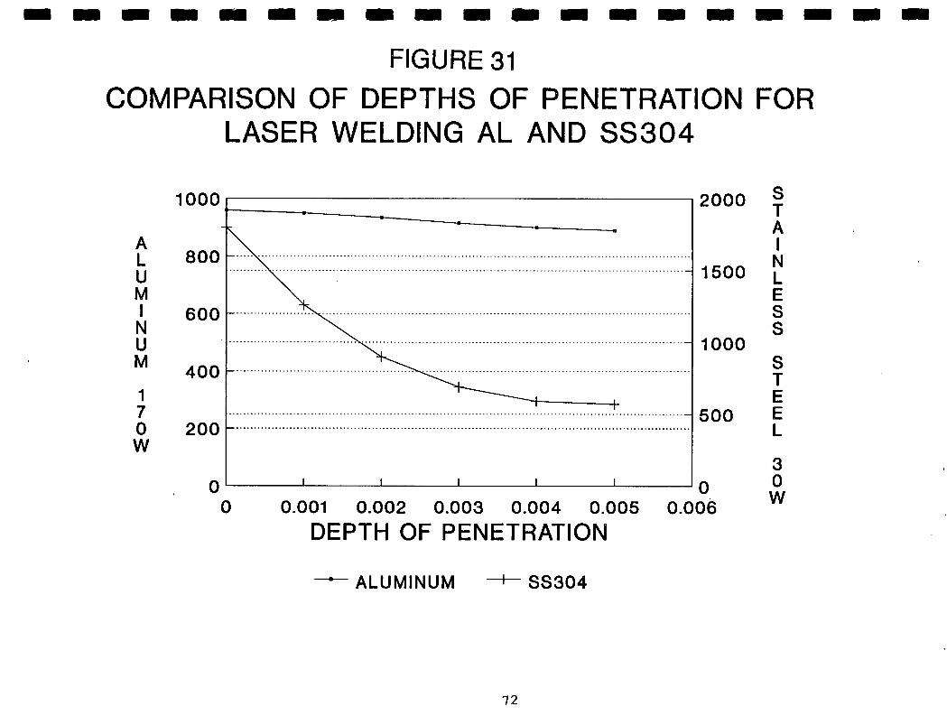
I I I I I I 1 I I I I I I I I I I I I
cr 0 LL
z
Q <0 cCci) F- U) W
CI) z LU a. Z
U-
1 CY
) 0 w
U)
0
u-
w- J
Ow
LL 3: 0 rr w 0 --J
0 0
C/)I—<—
ZJWCI)C/) (/)I— W
LLh.i C)0
o0
0 o
o0
0 o
LO 0
0(0
LO 00 E
l to 0
0
0z
0
01_. w c,Z ow
0 0
Li..
0
0 dl-0 w
10 0 0
00
00
0 0
00
00
0co
(0It
CsJ
<—.i
—Z
i—.O
0 U)04
z

fusion zone and this point was used to center the plots. The
position is in millimeters on a 50X micrograph. Hardness reading
were taken from polished surfaces after metallography was
performed. Conclusions are based on the ten hardness profiles
for specimens with full penetration. Another dozen profile
measurements were made from partial penetration welds, but there
was no consistent pattern. Note that the inherent asymmetry of
the weld caused an asymmetry in the profile.
Based on the accumulated results, the HAZ is represented by
a one millimeter region on either side of the fusion zone which
is only a third. of a millimeter wide. The softest portion of the
HAZ is the region adjacent to the fusion zone and has a hardness
range of 150-200 DPH. This amounts to a tensile strength of 85
ksi as taken from the graph of Figure 32. ( from ASM Metals
Handbook, vol 1. eighth edition) The parent metal hardness ranges
between 400 and 450 DPH or around 200 ksi. All the specimens
were cut from rolled sheets and welded in the highly cold worked,
as-received condition. This accounts for the large drop in
hardness from the parent metal to the fusion zone.
Recrystallization in the HAZ raised the grain size above that. in
the fusion zone. As a result, the fusion zone
hardness is significantly greater than the surrounding !-IAZ. By
welding in a conduction limited regime, the HAZ is wider than it
would be if higher power were available.
Two significant conclusions about the gravity level on laser
welds can be made from comparing the plots. Low gravity welds
have both higher hardness in the fusion zone and generate a
L1 I I 1 I I I LI I I I I I 1 Li
I II 73

00000000000000000000
C1 C
' C
J '-
i-
-
1
ISd 0
001. H
1O
N31S
311S
N31
I I I I I I I IC'4 C) IUJJ
I2 U-I I I 1 I I I I I
z 0 CI)
0 0 CI) CI)
z
0 0
D () D
FA
')Q_ 0
)
N

I: C
z
Cl)
.-
0
-4
-J
'.0
C
0 to
0
N 0 0
z 0 o
Cr, 0 CL
0 IL)
N
0 0 N 0 '.O
0 0
0 0
0 0
00
0 o
It)0
It)0
LO0
It) It)
P')N
)N
N-
H
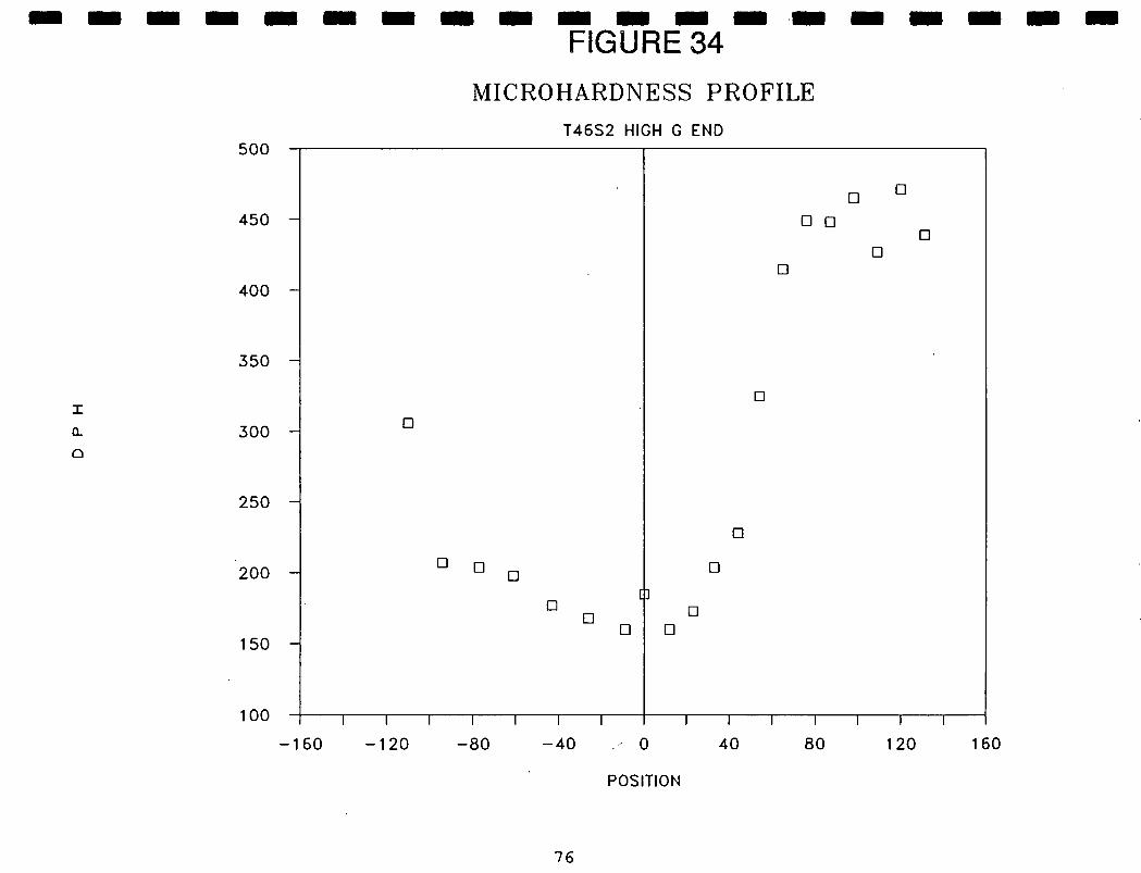
o
o
0
0
0
0
0
0
0 o
i)0
Lt)0
If)0
If)0
If)')
P)
C1404
H
I I I I I I I icy) w rr Im 0 I: I I I I I I I I I
C
m a
- z LiJ
Cf) ri p-I 0
C
C)
tP
0 0 0 ('.1 0 cc
0
z 0 0 a-
oN
0 cc
0 N 0 '0

I I I
narrower HAZ. One such hardness profile (of the ten available)
is shown in Figure 33. These effects are both consequences of
Ithe reduction in convective flow in the low g portions. Another
item of evidence that higher flow rates are found in the high g
1 portions can be seen from the comparison of the relative ' difference in hardness of the fusion zone and its adjacent HAZ.
In most cases, the HAZ is softer in the high g welds. A matching
Ihigh g hardness profile for the same specimen as Figure 33 is
shown in Figure 34. The fusion zone is however much harder with
I respect to its HAZ in the high g welds than the fusion zone
I increase in hardness over the low g weld HAZ. Higher convection rates in the high g welds causes the weld pool to be more
Iisothermal and as a result, grain multiplication mechanisms are
more likely to generate the finer and more equiaxed
I microstructures. More efficient heat transfer in the high g
portion gave more time for grain growth in the HAZ. This could I account for the lower overall hardness of the high g HAZ.
I7,7 WELD FERRITE IN AUSTENITIC STEEL
I Regardless of the welding method, the weld bead of an
austenitic stainless steel will have a duplex structure of -
I ferrite and austenite. Large amounts of a -ferrite will ,reduce
I
the weld ductility and toughness. Some is needed to give
strength to the weld during solidification and prevent cracking.
IIt is the initial composition of the metal that mostly
determines the amount of austenite actually found in the weld.
I Ferrite forming constituents are Cr, Mo, Si and Cb. The total
I 77

I 1
portions of these elements in 304SS add up to 21%. This is a
chromium equivalent. The austenite stabilizers are Ni, C, Mn,
and N. In 304SS, these amount to 13% and represent the nickel
equivalent. One can predict how much a -ferrite will form by
finding the intersection of the Ni and Cr equivalent values on
either a Schaeffler or Delong diagram20 . The Delong diagram
includes the strong effect of N in ferrite formation. Based on
the constitution of 304SS, the Schae .ffler diagram predicts 8% and
the Delong predicts 11% . Q -ferrite in the weld.
Due to the proportion of ferrite seen in the micro-struc-
tures, the higher estimate from Delong seems more reasonable.
Ferrite etches dark on the microstucture and would account in
part, for the higher hardness in the fusion zone. It is the
distribution of ferrite in the austenite that delineates the
differences in microstructure we observe between high and low g
segments.
8.0 OUTLINE FOR FLIGHT DEVELOPMENT
8.1 Final Design Considerations
a.) Purchase diode pumped Nd-YAG Laser and fiber optic
components to establish welding capabilities in
present KC-135 experiemnt apparatus.
b.) Fly package on KC-135 to demonstrate proof of
concept and specifications for diode pumped laser.
c.) Survey potential user community to determine
optimal specifications for broad based research.
I I I I I I I I I [I I I I 1 I [11
78

I I
d.) Finalize experiment specifications and safety
issues
8.2 Finalize Design and Begin Construction
a.) Procurements
b.) Fabrication
C.) Test and qualification procedures.
d.) Work with other scientific investigators for
specific samples for Shuttle flight.
8.3 Obtain manifest to fly
8.4 Prepare Laser Welding Experiment and samples for flight.
9.0 INITIAL ASSESSMENT OF DEVELOPMENT COSTS AND SCHEDULE
The cost estimates and schedules required for performing
laser welding in a Hitchhiker-g platform are presented in this
section. Several assumptions are still required for assessing the
actual hardware costs. As described in Section 6, the use of a
diode pumped Nd-YAG laser is the obvious choice for a space
experiment. Our work with the flash-lamp pumped Nd-YAG laser on
the KC-135 demonstrated that the space experiment is highly
desirable; however, the weld parameters will not be the same in
the system proposed for Space. To operate the diode-pumped laser
in pulsed mode requires determining new weld parameters for that
mode of operation. For that reason, it is necessary to continue
the KC-135 experiments. The preliminary work is also an extension
of the previous work with an emphasis on improving experimental
conditions. For instance the deficiencies in the sample chamber
I I I I [] I I I I I 1 I I I Li
II 79

LI I I
design need to be corrected by adding on-line vacuum pumping
capability during parabolic manuevers and imaging of the weld
I bead during welding needs to be improved. These ground-based
experiments are essential for the design of the Space experiment. I The anticipated costs and man-hours are:
I FY91 FY92 FY93 FY94
I
Man-years 4.26 4.26 3.33 1.79
Labor 140.8 146.7 70.1 58.1
I Equipment & 115.6 151.4 15.5 15.7 Supplies
Indirect Costs 69 71.7 32.7 27.6 I (excludes equipment) Sub-totals 325.4 369.8 118.3 101.4
ITotal man-years 13.64
Total cost $ 914.9I I
Note that indirect costs are only charged on labor, supplies and
materials. Equipment purchases are not charged overhead. Travel
Iexpenses for several KC-135 missions are included under equipment
and supplies. A single diode-pumped laser ($35K) and improvements
to the sample chamber ($20K) are included in FY91 budget. We
I anticipate the need for two diode pumped lasers with a ganged output for the Hitchhiker-g experiment. A spare diode pump laser
is optional and is included in FY92 costs.
A Space Station Welding Facility could be developed from a
I concentrated effort using diode pumped lasers. However, a more
cost effective and expedient process would be to to develop a
I solar pumped welding laser in parallel with the Shuttle Flight
LI80

Experiment. A portion of the time and materials in the estimated
budget is for the design and construction of a ground-based solar
laser welder. This saves the time lost by waiting for the Shuttle
results before designing the solar laser and provides the
opportunity to develop a flight qualified device as the follow-on
step. While both welding and solar pumping a laser are certainly
possible to be done in space, the capability for either-is not
presently available. A laser for welding has different
requirements from those used for communications, ranging, or
scanning. The requirements of laser welding in space will drive
the solar pumped laser welder development.
The schedule which we anticipate following is given in
Figure 35.
10.0 SOLAR PUMPED LASERS
Welding with a laser has been shown to have clear advantages
in a space environment. To power such a laser is not a trivial
problem given the limited electrical power anticipated for Space
Station or on the Shuttle. Al]. power on Space Station comes from
the sun. The photovoltaic arrays planned for Space Station are
only 8% efficient converters of solar energy. it is not in
NASA's best interest to have an inefficient process. Optical
pumping efficiency can be over 10% in solid-state lasers. High
power lasers generally used for material processing are not as
efficient converters of electrical energy as are small diode
lasers (25%). Successful research has been performed in the past
to directly solar pump lasers, usually solid state lasers.
81

*1'
I 4•4
I I II
iI
I I
I I I
II
I II I
I I I
I I I
I
I I I
I I I
I
0) >
-U
-
c) 0) >
-U
-
c%J 0) >
-U
-
1 0) >
-U
-
0
0) >
-U
-
0 ed 0 w
= 0.
(\J co
C
C)
Cl)
I I I I I I..0
I I Ice, 0
wzo
LLJ IL
L
I •cc_i
I W
LL
C,)
I I
-J
I I I I I. I
co C
a, C
0
—
o
0 0
-
C =
Ca,
4-
0 -
—
C
a,
a C
a,
C
0) a
E —
4-
E 0
cc c
oO
o
0. x
4-
0 C
W>
0. 0.
xE
..a,
1•
W
2Z
.0
o >
_
0. ow
a,
a,
CO
LL
LL
LL
C/)
<0
a. w
Cl)
co w CD
I 0.
Relevant papers on this subject are found in references 21 to 40.
Many pumping arrangements have been found in our research, each
with advantages and disadvantages that influence implementation
for a Space Based Welding Facility.
There are many approaches to solar pumping a laser. Our
research has uncovered most of them. Only a few scientists have
constructed a solar pumped laser. All that have tried succeded
to generate a beam.
It was clear from the literature searches that much effort
will need to be expended on the solitary aspect of finding the
best design. How one would weld by laser is not influenced by
the method of generating the beam. It is best to separate the
task of laser welding in space from the solar pumped laser
design. These two efforts can go in parallel. We feel in order
to be prepared for Space Station, development of a solar pumped
laser is needed during the next Developmental Phase. This would
be performed while our Shuttle flight experiment is being
prepared to evaluate salient aspects of welding by laser in
space. At the end of the Developmental Phase, both a Shuttle
Laser Welding Experiment and a prototype ground-based solar
pumped laser for welding would be constructed. This will prepare
us to fly a solar-pumped laser on another Shuttle flight that
would be capable of welding. After that, recommendations could
then be made to begin construction of a Laser Welding Facility
for Space Station.
At this time we are in a position to offer a few alternative
concepts for a Space Based Solar Pumped Laser. One concept which
83

seems to be a rather easy implementation is the use of the Solar
Dynamic Furnace type concentrator with a fiber laser at the
focus. Its use as a Space Station Welding System is shown in
Figure 36. Another concept that stands out as the optimal choice
based on arguments of overall simplicity. In a NASA TM by
Williams and Zapata21, use of a fiber geometry for a solar pumped
Nd laser was mentioned for a communications laser. A Gatling-gun
mechanism was also suggested which has been adapted for our
design. Problems of coherency and phase locking were described
that made the concept difficult for its use as a communications
device. In the case of welding, these problems can be ignored.
Fiber lasers are not new technology. Operating single fiber
lasers have been around for many years. While not necessarily
the highest efficiency, the Multi-Fiber-Laser concept offers
greatest potential for success through built-in redundancy, few
moving parts, simple cooling system, ease for scale-up (to higher
power) and high tolerance to pointing inaccuracies. A schematic
of the concept is shown in Figure 37.
Our prototype will employ the Multi-Fiber-Laser concept.
Again, simplicity for reliability is the key. Our design will
have a cylindrical arrangement of Nd-YAG or glass fibers which
will be rotated continuously through the axial focus of a
parabolic 'trough' reflector. The output of each fiber will be
collected to a common fiber for delivery to the work site. By
using refractory materials for the fibers they can safely reach
high temperatures. Before the temperature reaches dangerous
levels, the fibers in the collector focus are revolved out of the
I [1 I I 1 I [ I I I II
84

I I a)
-
- .
cl
ci cl
I-V o
.E .= I--
I
L()
I I R
I •(D
UD
0 I
LL
Iç)cr I
z I 1I I Ii
0 0 a) —
C 0 0 (ID
I

co
0
a)
'D
C
ci)
(I)
C W
Z.
ci) —
- -
— —
- -
OC
-
a)2D)
CL
E
cn
C
— 0
(t
°C
_00
I I I I I I I I ICY) w
'0
LL
I I I I I
ci w ca —0.
D0 Z
>-o
—J
0 (I)
I U

I I
focus to radiatively cool to space. New fibers are continuously
being brought into focus to lase while others are being removed
to cool. "Power per fiber (10 micrometer diameter) is limited by
stimulated Raman and brillouin scattering.1121
Solar pumping a laser terrestialy as opposed to in space
requires different approaches. On the ground, one can devise
schemes for high concentration ratios to deliver large powers but
actively cool with a large circulating water system. In Space,
cooling or removing unwanted heat is a major problem. Lower
concentration ratios can be used to reduce cooling requirements.
Larger, lightweight structures are easily deployed in the
microgravity environment of space. Radiative cooling is the only
means to remove heat in space. By allowing a material to reach
higher temperatures, radiation losses are much greater and
cooling more efficient. Radiative heat rejection at the low
temperatures obtained by active cooling is very inefficient and
would require a massive radiator and coolant volume. Electrical
power to pump a coolant is not required. In order to control the
output and prevent interference between the lasers, each fiber
will be Q-switched to fire pulses idependently. Q-switching will
produce better penetration by the laser and also improves the
Multi-Fiber-Laser performance.
One of the other novel features of the design is that output
power is increased by lengthening the cylinder of fibers and the
concentrator. Simply by suspending the fibers at their ends, in
the microgravity environment, there will be no sag and fiber
lengthening or contraction from cyclic heating and cooling will
I I
I I i I I I I I I I I II
87

I
be accomodated at the suspension points. Centrifugal force from
rotation may cause the fibers to bow outward slightly. Fiber
1 tension and rotation speed affect this. Focus depth (of the concentrator) is large and some fiber movement is tolerated.
I Failure of some laser fibers or reduced performance will not
Idisable the welding facility. Pointing requirements are reduced
to a simpler azimuthal control. By not requiring exceptionaly
Ihigh concentration ratios, pointing precision is not as critical.
How the Solar-Laser Welder would appear mounted on the
I latest Space Station concept is depicted in Figure 37. By using
the fiber optical delivery method, essentially only the coupling
I losses to the delivery fiber will be incurred. After that,
I
whether the fiber is 5 feet long or 15 feet long, there will be
little difference in output. (This last statement requires
Ithe assumption that there are no severe bends in the fiber.)
1 11.0 ACKNOWLEDGMENTS
I
We wish to thank all the NASA personnel who assisted us in
performing the KC-135 flights, particularly Dr. Robert Shurney
Ifrom the KC-135 Flight Office at MSFC, Robert Williams, the
Flight Test Director for the KC-135 flights at JSC, and Jay
I Bennett, the technical contract monitor at JSC. Others who made
' significant contributions include Teresa Plaster and the students
workers at UAH. In particular we wish to thank Bill Smith, Jeff
IHaight and Robert Bond for putting in a lot of effort on this
project and Christine von Pragenau for assisting in the report
I preparation.
1 88

z
10
I I I0
II-
LU
ILL0-
Icc (1)0
U<
LL
—j I
0w
cxW
I IDcc z
I-j 1
LL O
w
>-<
Icc C
/) <
w
• I
>
•
0
cc
Ca
—Cl)
—
L..oa L-
C.) —
0
C.) C
.) Ca
Co
a)
l_E
CO
).0
—
'-
C'-0
cz U
)O
>
cm
ca
a)0
.
a.E C)
C.) •.;:
;O
L70
a
0.
C)C
00
>0.CO).r
.-.G
) —
C cD
CC
O0
0
>2
00
.
CØi...
Cl)
'-C
a)
ctj.
#1%CM
—0
Ca)
ccas
.-
ol)C
aL
E
o
1<0
01
4_
h1
Cl)
co

11.0 REFERENCES
1. Anthony, T.E. and H.E. dine, (Sept. 1987) J. App. Phys. 48, I 3888.2. Strutt, P.R., B.G. Lewis, and B.H. Kear, Rapidly Solidified
IAmorphous and Crystalline Alloys, Elsevier, 1982, pp 485-498.
3. Chan C., J. Mazumder, and M.M. Chen, (Dec. 1984.) Met Trans
I
ISA: 2175.
4. Heiple, C.R. and P. Burgardt, (1985) Weld J. 64 159s.
I
5, Lin, M. L. and T. W. Eagar, (18-22 May 1986) Advances in Welding Science and Technology, Proceedings, ASM, pp 47-51.
I
6. Kou, S. and D.K. Sun, Metall. Trans. 16A (1985) 203.
7.. Heiple, C.R., P. Burgardt, and J.R. Roper, (18-22 May 1986) Advances in Welding Science and Technology, Proceedings, ASM,
Ipp 387-392.
8. Zacharia, T., A.H. Eraslan, and D.K. Aidun, (Mar. 1988)
IWelding Res. Sup., pp 53s-62s.
9. Zacharia, T., A.H. Eraslan, and D.K. Aidun, (1988) Modeling and Control of Casting and Welding Processes IV, The Minerals I Metals and Materials Soc., pp 177-188. 10. McKannen, E.C. and R.M. Poorman,"Skylab M551 Metals Melting I Experiment", Proceedings of Third Space Processing Symposium: Skylab Results, NASA Publication M-74-5, 1974, pp 85-100.
' 11. Ireland, C.L.M., Laser Focus, November, 1988, pp 49-64.
12. Paton, BY., D.A. Dudko, and V.F. Laphinskiy, "Welding Processes in Outer Space", USSR Report, Materials Science and 1
Metallurgy, JPRS-UMS-8S-08, pp 121-129, translated by Foreign Broadcast Information Service.
1 13. Allario, F., Laser Focus, October, 1988, pp 65-74.
14. Lesh, J.R. and M.D. Rayman, Laser Focus/Electro-optics,
I
October, 1988, pp 81-86.
15. Begley, D. and B. Boscha, Photonics Spectra, August, 19891 pp 81-82.
1
16. Cohen, M.I.,"Material Processing", published in Laser Handbook, vol. 2, ed. Arecchi and Schulz-DuBois, North Holland, Amsterdam, 1972 PP 1577 - 1648.
(\ , I

I I 17. Irving, R.R., The Iron Age, (1965) p 81
18. Mueller, R.E., W.W. Duley, et. al., Jour. Laser Appl. 1 (3) (1989) pp 22-25. I 19. Rosenblum, Welding Jour., 1941
I 20. Koo, Sindo, Welding Metallurgy, John Wiley & Sons, N.Y ,1987 21. Williams, M.D., and L. Zapata, "Solar-Pumped Solid State Nd Lasers", NASA Technical Memorandum 87615, Langley Research
ICenter, 1985, pp. 1-18.
22. Williams, Michael D., "Solar Power absorption in a Glass I Tube", NASA Technical Memorandum 89063, Scientific and Technical Info. Branch, 1987, pp. 1-12.
23. Gleckman, Philip, "Achievement of Ultrahigh Solar I
Concentration with Potential for Efficient Laser Pumping",Applied Optics, Vol. 27, No. 21, 1988, pp. 4385-4391.
I 24. Ross, Monte, Paul Freedman, James Abernathy, George Matassov, John Wolf, and James D. Barry,"Space Optical Communications with the Nd: YAG Laser",Proceedings of the IEEE,
iVol. 66, No. 3, 1978, pp. 319-343.
•
25. Arashi, H., Y. Oka, and M. Ishigame,"A Solar-Pumped Laser on the Space Station",Space Solar Power Review, Vol. 5, 1985, pp. I 131-133.
26. Weksler, M., and J. Shwartz, "Solar-Pumped Solid-State I Lasers", IEEE Journal of Quantum Electronics, Vol.. 24, No. 6, 1988, pp. 1222-1228.
27. Arashi, Haruo, Yasuo Oka, Nenokichi Sasahara, Atsushi 1 Kaimai, and Mareo Ishigame, "A Solar-Pumped cw 18 W Nd: YAG Laser", Japanese Journal of Applied Physics, Vol. 23, No. 8, 1984, pp. 1051-1053.
I28. "Highly Concentrated Sunlight Opens Way To Many New Applications",Research and Development, 1988, p. 58.
I29.Nath, G., "Hand-Held Laser Welding of Metals Using Fibre
Optics", Optics and Laser Technology, 1974, pp. 233-235.
I 30. Young, C.G., "A Sun-Pumped cw One-Watt Laser", Applied U Optics, Vol. 5, No. 6, 1966, pp. 993-998.
I 31. Zittel, Werner, "Design Studies for a Solar Pumped Laser Device", Deutsch Forschungs-und Versuchsanstalt fur Luft-und Raumfahrt, 1988, pp. 4-58. I
Li91

32. Harries, Wynford L., and Zeng-Shevan Fong, "Theoretical Studies of Solar-Pumped Lasers", Technical Report PTR 85-2, 1985, pp. 1-3.
33. Golger, A.L., I.I. Klimovsky, "Solar-Pumped Lasers", Institute of High Temperatures, USSR Academy of Sciences, pp. 686-693.
34. De Young, R.J., G.D. Walberg, E.J. Conway, and L.W. Jones, "A NASA High-Powered Space-Based Laser Research and Applications Program", NASA Scientific and Technical Information Branch, 1983, pp. 1-40.
35. Lazerev, V.V., and V. Ya. Panchenko, "Spectral Transformation of the Sun's Radiation Using a Body Heated by it as the Means of Pumping Gas Lasers", Geliotekhnika, Vol. 22, No. 1, pp. 3-8,1986, (Allerton Press, 1986, pp. 1-7).
36. Harries, W.L., "Criteria for the Evaluation of Laser Solar Energy Converter Systems", Technical Note, American Institute of Aeronautics and Astronautics, 1985, pp. 411-413.
37. Golger, A.L., and I.I. Klimovskii, "Lasers Pumped by Solar Radiation (Review)", American Institute of Physics, 1984, pp. 164-179.
38. Young, R.J., and E.J. Conway, "Progress in Solar-Pumped Laser Research", NASA Langley Research Center, pp. 467-482.
39. Young, R.J., G.H. Walker, M.D. Williams, G.L. Schuster, and E.J. Conway, "Preliminary Design and Cost of a 1-Megawatt Solar-Pumped Iodide Laser Space-to-Space Transmission Station", NASA Technical Memorandum 4002, 1987, pp. 1-19.
40. DeYoung, R.J., J.H. Lee, M.D. Williams, G. Schuster, and E.J. Conway, "One-Megawatt Solar Pumped and Electrically Driven Lasers for Space Power Transmission",
ADDITIONAL REFERENCES USED IN THIS WORK
1. The Physics of Welding, 2nd ed. Ed. J.F. Lancaster, Pergomon Press, 1986.
2. Carrupt, B., M. Rappaz, and M. Zimmerman, "Modeling of Microstructure Formation in Laser Treatment of Materials", Modeling of Casting & Welding Processes IV, 1988, pp. 581-591.
3. Handbook of Solid-State Lasers, Ed. Peter K. Cheo, Marcel Dekker Inc.,1989.
4. Eloy, Jean-Francois, Power Lasers, Halsed Press-Ellis Horwood Limited, 1987.
92

5. Duley, W.W., CO2 Lasers\Effects & Applications, Academic Press Inc., 1976.
6. Modeling of Casting & Welding Processes II, Ed. J.A. Dantzig, J.T.Berry, Conference Proceedings, 1984.
7. Tsai, M.C., and S. Kou, "The Advantage of Orthogonal Curvilinear Coordinates in Simulating Marangoni Convection in Deformed Weld Pools", Modeling of Casting & Welding Processes IV, 1988, pp. 409-420.
8. Paul, A., and T. DebRoy,"Prediction of Marangoni Convection, Heat Transfer, and Surface Profiles during Laser Welding", Modeling of Casting & Welding Processes IV, 1988, pp. 421-429.
9. Zacharia, T., A.H. Eraslan, & D.K. Aidun,"Welder: A Computer Code for Simulating Welding Processes", Modeling of Casting & Welding Processes IV, 1988, pp. 177-185.
10. Eraslan, Arsev H., Thomas Zacharia, Daryush K. Aidun, "Welder: A Computer Code for Simulating Fast-Transient, Three-Dimensional, Three-Phase, Flow, Temperature & Material Composition Conditions During Welding", Dept. of Mechanical & Industrial Engineering, Report No. MIE-142, 1986.
11. Laser Welding , Cutting, & Surface Treatment, The Welding Institute, Cambridge, England, 1984.
12. Sanderson, Ronald J., Lasers in Metalworking (Summary & Forecast), Tech. Tran Corporation, 1983.
13. Laser Photochemistry , Tunable Lasers, and Other To pics, Ed. Stephen F. Jacobs, Murray Sargent III, Marlan 0. Scully, Charles T. Walker, Physics of Quantum Electronics Vol. 4, Addison-Wesley Publishing Co. Inc., 1976.
14. Mortland, J.E., R.M. Evans, & R.E. Monroe, Welding and Brazing of Nickel-Base Alloys, National Aeronautics & Space Administration, 1972.
15. Laser-Material Processing Committee, Guide to Material Processing by Lasers, Laser Institute of America, 1977.
16. Welding Design & Fabrication, Ed. Rosalie Brosilow, Penton Pub., Vol. 62, No. 6, 1989.
17. Welding Handbook, 8th ed., Vol. 1, American WeldingSoiety, 1987.
18. Laser Surface Treatment of Metals, Ed. C.W. Draper and P. Mazzoldi, Martinus Nijhoff Pub., 1986.
I I I II
93

19. Arata, Yoshiaki, Plasma, Electron, and Laser Beam Technology , American Society for Metals, 1986.
20. Laser Welding, Machining, and Materials Processing, Ed. Prof. C. Albright, IFS (Publications) Ltd, 1986.
21. Laser Measurements/Professional Adv. Course, Laser Institute of America, 1985.
-
22. Fundamentals of Lasers/Professional Adv. Course, Laser Institute of America, 1985. 1
23. Power Beam Processing/Electron, Laser, Plasma-Arc, Ed. E.A. Metzbower and D. Hauser, ASM International and the Edison Welding
I
Institute, 1988.
Li I I [1 I
94