LANCIA - FCAGroup
217
LANCIA A story of technological innovation in the car industry LORENZO MORELLO
Transcript of LANCIA - FCAGroup
LANCIA A story of technological innovation
in the car industry
LO RE N ZO M OR ELLO

A story of technological innovation in the car industry

LO RE N ZO M OR ELLO
LANCIA A story of technological innovation
in the car industry

Editing, graphic design and layout:Fregi e Majuscole, Turin
English translation by: Verto Group Srl
© 2014 Lorenzo MorelloPrinted in 2014 by Fiat Group Marketing & Corporate Communication S.p.A.Cover logo:courtesy of Fiat Group Marketing & Corporate Communication S.p.A.
5
The volunteers of the staf project (the fiat History of Automobile Technology), launched in 2009 to select the technical drawings that best show the technical evolution of fiat cars, also found many Lancia designs held in a special sec-
tion of the fiat archive: the material had been moved there in 1984, when the Tech-nical Department of fiat Auto – the part of the company responsible for designing fiat, Lancia and Autobianchi cars – was brought together in a single building in the Mirafiori area. When this ensemble of designs was rediscovered, the members of the project decided to follow the same methodology as used in presenting the mate-rial in fiat, a story of technological innovations in the car industry to prepare a similar book on Lancia cars. This second book – based on technical designs, archive mate-rial and surviving cars – shows the evolution of Lancia cars and their innovations, which frequently included completely original aspects. Locating the material, how-ever, has proved more difficult than it had been for fiat cars, especially in the case of the older models, because the Lancia design archive had been organised without a logical structure, making it difficult to tell apart the various functional groups from aspects of pure detail.
Before the Aurelia, designs were exclusively classified by means of an increasing serial number, with no reference to the contents. Occasionally there was a second identification number preceded by the letter C (standing for complessivo – ‘assembly drawing’) when the design showed assembled items, such as motors, gears, shafts, transmission, electric machines, etc. but without any link to the model to which the design was referring. Knowing this rule did not simplify the work much, because in the same collection of files there were also truck, military vehicle and airplane engine assemblies. Also, many of the complex designs which were felt to be indispensable were not present, while there was an abundance of many others which proved to be of little use in tracing the development of the product, and greatly added to the mass of material to be checked. The overall drawings of the bodywork for nearly all the cars which preceded the Aurelia have also not been found. This is a predictable omission for early examples of bodywork with wooden structures, which were almost certainly made by copying models and patterns, but is disappointing for the monocoques which were already used for the Lambda in 1922. An explanation for this absence could be that the office in charge of planning only turned out detailed drawings of the vari-ous elements used, starting from 3-D handmade models, thus leaving the production factory the job of creating the drawings needed for fabrication and assembly. These drawings must have been drawn up to design the tools used in assembly and the nec-essary control gauges: indeed, the advanced technological level in the production of the Lancia was reflected in a wide range of technical articles published in “American Machinist” in 1928 and 1929, which show how the innovative technological solutions were garnering international interest. It thus seems reasonable to assume that the
INTRODUCTION
6
general arrangement drawings were not held by the same personnel who were in charge of the official technical designs.
Close observation of the models that have survived, contemporary technical arti-cles and photographic documentation have all been useful in reconstructing the characteristics of these cars. And, despite the difficulties, around 600 drawings have been gathered together and examined in detail.
Nearly all the cars that were produced have been included in the book, with the exception of the most recent ones – where the numerous variations have not been considered, so as to fit into this publication’s space limits.
Given the fact that Lancia was run practically as if it were a family, it was felt use-ful to add, alongside the descriptions of the cars and their technical details, some biographical notes on the people who made a personal contribution to developing them. The narrative, which begins at the company’s foundation in 1907, ends at around the 1970s in this case too. Obviously this does not mean that the innovative impulse ends at that point, but that the most visible part of the product, which is linked to the mechanical drawing, was no longer the subject of important innovations, and that the efforts of the technicians were focused on more specialist areas, such as the way the various components were designed, and the introduction of electronic controls.
Finally, it was felt that a chapter showing the contribution of Pininfarina to the development of the style and technology of Lancia bodywork should be added: this decision was justified by the special relationship between the two companies, which often saw the famous designer take on an innovative role in the development of the Lancia style with the introduction – in very beautiful one-offs – of design lines which later appeared in production models.
7
GiorGio Chiapusso (1944) qualified as an electronics expert and worked with fiat Auto on technical links with the bodywork factory in Poland in the construction of the Polonez, the 125 and the 126. He then managed production methods at fiat facili-ties overseas and Ckd production.
GiorGio ConfiGliaCCo (1946) took a degree in electronic engineering and worked with sepa, first in designing control systems for marine motors and propulsion moni-toring systems for merchant and military ships, and then in technical assistance. He later worked with fiat Auto in developing in-car computerised systems. He takes part in projects to restore historic airplanes.
lorenzo GuGlielmina (1945) qualified as an expert in industrial mechanics and worked with fiat Auto, first designing bodywork, then internal and external fittings, and dashboards. In particular, he worked on planning these areas for the Bravo and Brava models, and for the Ducato commercial vehicles, for which he also managed the industrialization and production start-up phase. From 2003 to 2007, he worked as a technical consultant at Pininfarina.
silvio luGaro (1940) took a degree in electrical engineering and worked with fiat Auto, first in the planning calculation office and then in chassis design and devel-opment. He was head of chassis design for fiat and Lancia, developing skills in the suspension, brakes and vehicle set-up. He has worked for various technical consul-tancies in the automobile sector.
lorenzo morello (1944) took a degree in mechanical engineering and worked with the fiat Research Centre on numerous chassis, bodywork and motor innovation projects. Moving to fiat Auto, he was in charge of power unit engineering and then of vehicle engineering. He has taught automotive engineering at Turin Polytechnic and writes studies of the history of automobile technology.
Guido nittolo (1947) qualified as an expert in industrial mechanics and was ini-tially taken on by iveCo as an expert in mechanical maintenance before moving on to the central production group at fiat Auto, to work on standardization, rationalising and regulatory issues, and the drafting of related technical documentation. Finally he dealt with working capital and inventory clearance for preassembled parts.
Gianni raviola (1948) qualified as an expert in industrial mechanics and was tak-en on at fiat as a designer of bodywork for military vehicles, before working on the chassis for various other models. He has worked with Centro Stile Bertone, heading
THE STAF GROUP

8
the technical area for studying the feasibility of style models, then at uts as a body-work design specialist. Returning to fiat Auto he focused on planning studies for new models. He has worked as a technical consultant for Pininfarina.
Giuseppe renna (1948) took a physics degree and has worked with fiat Auto on vari-ous technical and management software development projects. He later worked for various companies in the sector, developing Gps/Gsm and data reading and analysis devices from moving vehicles so as to create databases on their use.
olinto riCossa (1937) qualified as a draftsman and began work at fiat as a trainee fitter in Corso Dante. He then went on to technical support where for many years he trained factory personnel, and became the head of this area. He left fiat to join Westinghouse Italia, in the industrial relations and resource management areas. He currently teaches art history and history of Piedmontese culture at various universi-ties of the third age.
elio rodi (1948) has worked for fiat since 1968 starting as a skilled cutter in the Mirafiori maintenance factory moving on to the chassis design office as a mechanical draftsman in 1970. He has worked in the design of numerous models, and on produc-tion start-up for some of these at various facilities.
sauro savoia (1934) qualified as an expert mechanic and worked at fiat Auto for over forty years, taking part in the planning and development of vehicle architecture and the main chassis elements (suspension, steering, brakes). As head of a chassis planning area he later worked on development projects for many cars, including the Uno, Y10 and Punto. He ended his career training technicians at the Elasis research centre in Pomigliano.
serGio viGna (1938) worked for fiat as a chassis design planner and was involved in creating many of the models which were launched from 1957 to 1981, including the 1800/2300, 1300/1500, 128, 127, Ritmo and Panda. From 1981 to 1991, he took on coordination and control responsibilities for the entire car, following the Tipo and Tempra from the first phases (style definition and technical content) to the start of production.
Acknowledgements
The staf group owes a special debt of recognition to Nevio Di Giusto, President of ata (the Automobile Technical Association) for his encouragement of this project, and for funding the digitalisation and restoration of the designs used in drawing up the text and illustrations.
The members of the staf group would also like to express their gratitude to Gian-felice Formento, of the Product Engineering Department at fiat Automobiles, and to Maurizio Torchio, the head of the fiat History Centre, for having allowed this research to be undertaken.
However, the list of the people who have made the preparation of this book pos-sible is much longer, and includes: Donatella Biffignandi, the head of the Documen-

9
tation Centre of the National Automobile Museum, for the invaluable help in con-sulting the material from the Biscaretti Collection, which allowed us to deal with some omissions in the technical documentation; Rodolfo Gaffino Rossi, the director of the National Automobile Museum, for having allowed the Lancia cars and parts kept in the museum to be photographed and examined in detail; Massimo Castag-nola and Alberta Simonis of the fiat History Centre for selecting the archive photo-graphs which have been used; Raffaele Terlizzi, the curator of the Lancia Collection, for having guided the staf group in the visit to the collection and for having allowed the models described in the text to be photographed; Silvio Angori, Pininfarina CEO and General Manager, for the publication of the photographs in the chapter on Pin-infarina’s role in the evolution of Lancia cars.
From left to right: Guido Nittolo, Elio Rodi, Olinto Ricossa, Silvio Lugaro, Lorenzo Guglielmina, Sergio Vigna, Giorgio Configliacco, Lorenzo Morello, Giuseppe Renna.

11
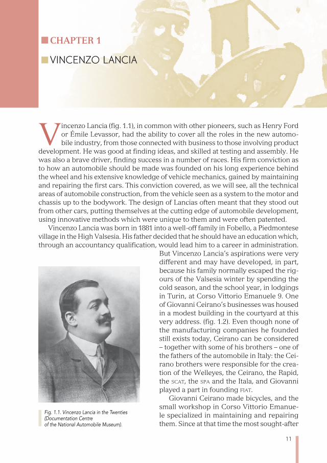
Vincenzo Lancia (fig. 1.1), in common with other pioneers, such as Henry Ford or Émile Levassor, had the ability to cover all the roles in the new automo-bile industry, from those connected with business to those involving product
development. He was good at finding ideas, and skilled at testing and assembly. He was also a brave driver, finding success in a number of races. His firm conviction as to how an automobile should be made was founded on his long experience behind the wheel and his extensive knowledge of vehicle mechanics, gained by maintaining and repairing the first cars. This conviction covered, as we will see, all the technical areas of automobile construction, from the vehicle seen as a system to the motor and chassis up to the bodywork. The design of Lancias often meant that they stood out from other cars, putting themselves at the cutting edge of automobile development, using innovative methods which were unique to them and were often patented.
Vincenzo Lancia was born in 1881 into a well-off family in Fobello, a Piedmontese village in the High Valsesia. His father decided that he should have an education which, through an accountancy qualification, would lead him to a career in administration.
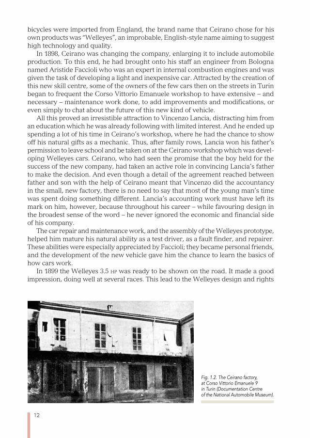
But Vincenzo Lancia’s aspirations were very different and may have developed, in part, because his family normally escaped the rig-ours of the Valsesia winter by spending the cold season, and the school year, in lodgings in Turin, at Corso Vittorio Emanuele 9. One of Giovanni Ceirano’s businesses was housed in a modest building in the courtyard at this very address. (fig. 1.2). Even though none of the manufacturing companies he founded still exists today, Ceirano can be considered – together with some of his brothers – one of the fathers of the automobile in Italy: the Cei-rano brothers were responsible for the crea-tion of the Welleyes, the Ceirano, the Rapid, the sCat, the spa and the Itala, and Giovanni played a part in founding fiat.
Giovanni Ceirano made bicycles, and the small workshop in Corso Vittorio Emanue-le specialized in maintaining and repairing them. Since at that time the most sought-after
Fig. 1.1. Vincenzo Lancia in the Twenties (Documentation Centre of the National Automobile Museum).
Chapter 1
VINCENzO LANCIA
12
bicycles were imported from England, the brand name that Ceirano chose for his own products was “Welleyes”, an improbable, English-style name aiming to suggest high technology and quality.
In 1898, Ceirano was changing the company, enlarging it to include automobile production. To this end, he had brought onto his staff an engineer from Bologna named Aristide Faccioli who was an expert in internal combustion engines and was given the task of developing a light and inexpensive car. Attracted by the creation of this new skill centre, some of the owners of the few cars then on the streets in Turin began to frequent the Corso Vittorio Emanuele workshop to have extensive – and necessary – maintenance work done, to add improvements and modifications, or even simply to chat about the future of this new kind of vehicle.
All this proved an irresistible attraction to Vincenzo Lancia, distracting him from an education which he was already following with limited interest. And he ended up spending a lot of his time in Ceirano’s workshop, where he had the chance to show off his natural gifts as a mechanic. Thus, after family rows, Lancia won his father’s permission to leave school and be taken on at the Ceirano workshop which was devel-oping Welleyes cars. Ceirano, who had seen the promise that the boy held for the success of the new company, had taken an active role in convincing Lancia’s father to make the decision. And even though a detail of the agreement reached between father and son with the help of Ceirano meant that Vincenzo did the accountancy in the small, new factory, there is no need to say that most of the young man’s time was spent doing something different. Lancia’s accounting work must have left its mark on him, however, because throughout his career – while favouring design in the broadest sense of the word – he never ignored the economic and financial side of his company.
The car repair and maintenance work, and the assembly of the Welleyes prototype, helped him mature his natural ability as a test driver, as a fault finder, and repairer. These abilities were especially appreciated by Faccioli; they became personal friends, and the development of the new vehicle gave him the chance to learn the basics of how cars work.
In 1899 the Welleyes 3.5 hp was ready to be shown on the road. It made a good impression, doing well at several races. This lead to the Welleyes design and rights
Fig. 1.2. The Ceirano factory, at Corso Vittorio Emanuele 9 in Turin (Documentation Centre of the National Automobile Museum).
13
being bought by fiat, founded in July 1899 specifically to produce the car developed by Ceirano’s team on an industrial basis.
The first fiat 3.5 hp cars, direct – albeit heavily modified – descendants of the Well-eyes – rolled out of the fiat works in Corso Dante at the end of 1899. In order for this to be possible in such a short time, the agreement between Ceirano and fiat stipulated that not only the drawings and prototypes should be moved to the new company, but also all the personnel and machinery involved in the development of the Welleyes. It was in this way that Vincenzo Lancia was taken on by fiat as chief test driver, and Aristide Faccioli took the role of technical manager.
The era of international car racing was arriving. Inevitably, speed brought motor vehicles down the path of sporting competition. These were seen as tools to stimu-late progress and as effective commercial promotion. fiat formed a team with their best test drivers: Lancia, Nazzaro, Cagno and Storero.
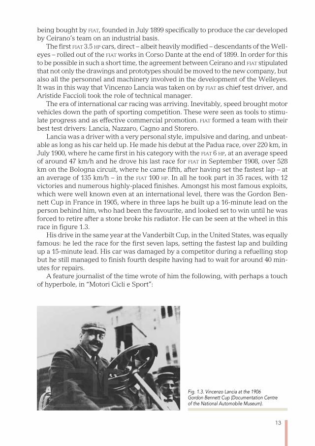
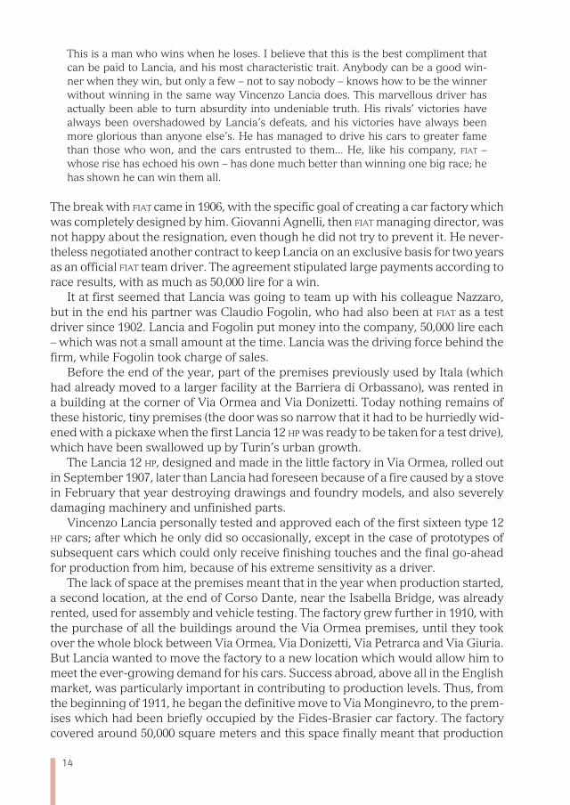
Lancia was a driver with a very personal style, impulsive and daring, and unbeat-able as long as his car held up. He made his debut at the Padua race, over 220 km, in July 1900, where he came first in his category with the fiat 6 hp, at an average speed of around 47 km/h and he drove his last race for fiat in September 1908, over 528 km on the Bologna circuit, where he came fifth, after having set the fastest lap – at an average of 135 km/h – in the fiat 100 hp. In all he took part in 35 races, with 12 victories and numerous highly-placed finishes. Amongst his most famous exploits, which were well known even at an international level, there was the Gordon Ben-nett Cup in France in 1905, where in three laps he built up a 16-minute lead on the person behind him, who had been the favourite, and looked set to win until he was forced to retire after a stone broke his radiator. He can be seen at the wheel in this race in figure 1.3.
His drive in the same year at the Vanderbilt Cup, in the United States, was equally famous: he led the race for the first seven laps, setting the fastest lap and building up a 15-minute lead. His car was damaged by a competitor during a refuelling stop but he still managed to finish fourth despite having had to wait for around 40 min-utes for repairs.
A feature journalist of the time wrote of him the following, with perhaps a touch of hyperbole, in “Motori Cicli e Sport”:
Fig. 1.3. Vincenzo Lancia at the 1906 Gordon Bennett Cup (Documentation Centre of the National Automobile Museum).
14
This is a man who wins when he loses. I believe that this is the best compliment that can be paid to Lancia, and his most characteristic trait. Anybody can be a good win-ner when they win, but only a few – not to say nobody – knows how to be the winner without winning in the same way Vincenzo Lancia does. This marvellous driver has actually been able to turn absurdity into undeniable truth. His rivals’ victories have always been overshadowed by Lancia’s defeats, and his victories have always been more glorious than anyone else’s. He has managed to drive his cars to greater fame than those who won, and the cars entrusted to them... He, like his company, fiat – whose rise has echoed his own – has done much better than winning one big race; he has shown he can win them all.
The break with fiat came in 1906, with the specific goal of creating a car factory which was completely designed by him. Giovanni Agnelli, then fiat managing director, was not happy about the resignation, even though he did not try to prevent it. He never-theless negotiated another contract to keep Lancia on an exclusive basis for two years as an official fiat team driver. The agreement stipulated large payments according to race results, with as much as 50,000 lire for a win.
It at first seemed that Lancia was going to team up with his colleague Nazzaro, but in the end his partner was Claudio Fogolin, who had also been at fiat as a test driver since 1902. Lancia and Fogolin put money into the company, 50,000 lire each – which was not a small amount at the time. Lancia was the driving force behind the firm, while Fogolin took charge of sales.
Before the end of the year, part of the premises previously used by Itala (which had already moved to a larger facility at the Barriera di Orbassano), was rented in a building at the corner of Via Ormea and Via Donizetti. Today nothing remains of these historic, tiny premises (the door was so narrow that it had to be hurriedly wid-ened with a pickaxe when the first Lancia 12 hp was ready to be taken for a test drive), which have been swallowed up by Turin’s urban growth.
The Lancia 12 hp, designed and made in the little factory in Via Ormea, rolled out in September 1907, later than Lancia had foreseen because of a fire caused by a stove in February that year destroying drawings and foundry models, and also severely damaging machinery and unfinished parts.
Vincenzo Lancia personally tested and approved each of the first sixteen type 12 hp cars; after which he only did so occasionally, except in the case of prototypes of subsequent cars which could only receive finishing touches and the final go-ahead for production from him, because of his extreme sensitivity as a driver.
The lack of space at the premises meant that in the year when production started, a second location, at the end of Corso Dante, near the Isabella Bridge, was already rented, used for assembly and vehicle testing. The factory grew further in 1910, with the purchase of all the buildings around the Via Ormea premises, until they took over the whole block between Via Ormea, Via Donizetti, Via Petrarca and Via Giuria. But Lancia wanted to move the factory to a new location which would allow him to meet the ever-growing demand for his cars. Success abroad, above all in the English market, was particularly important in contributing to production levels. Thus, from the beginning of 1911, he began the definitive move to Via Monginevro, to the prem-ises which had been briefly occupied by the Fides-Brasier car factory. The factory covered around 50,000 square meters and this space finally meant that production
15
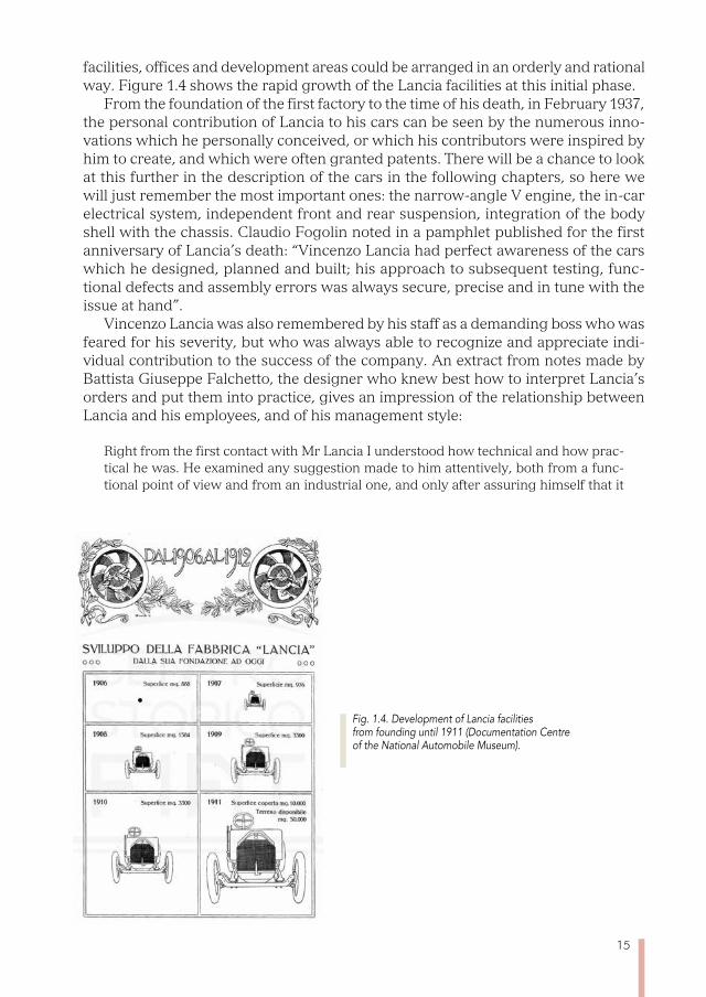
facilities, offices and development areas could be arranged in an orderly and rational way. Figure 1.4 shows the rapid growth of the Lancia facilities at this initial phase.
From the foundation of the first factory to the time of his death, in February 1937, the personal contribution of Lancia to his cars can be seen by the numerous inno-vations which he personally conceived, or which his contributors were inspired by him to create, and which were often granted patents. There will be a chance to look at this further in the description of the cars in the following chapters, so here we will just remember the most important ones: the narrow-angle V engine, the in-car electrical system, independent front and rear suspension, integration of the body shell with the chassis. Claudio Fogolin noted in a pamphlet published for the first anniversary of Lancia’s death: “Vincenzo Lancia had perfect awareness of the cars which he designed, planned and built; his approach to subsequent testing, func-tional defects and assembly errors was always secure, precise and in tune with the issue at hand”.
Vincenzo Lancia was also remembered by his staff as a demanding boss who was feared for his severity, but who was always able to recognize and appreciate indi-vidual contribution to the success of the company. An extract from notes made by Battista Giuseppe Falchetto, the designer who knew best how to interpret Lancia’s orders and put them into practice, gives an impression of the relationship between Lancia and his employees, and of his management style:
Right from the first contact with Mr Lancia I understood how technical and how prac-tical he was. He examined any suggestion made to him attentively, both from a func-tional point of view and from an industrial one, and only after assuring himself that it
Fig. 1.4. Development of Lancia facilities from founding until 1911 (Documentation Centre of the National Automobile Museum).
16
made sense from both, would he give his go-ahead to the trial phase. If he was not able to understand any solution immediately, even though it met the necessary criteria, he would postpone the test, saying: – the night brings counsel, let’s talk about it again tomorrow. He thought about it all evening, and – I think – at night too (he always had a notebook and pencil on his bedside table). The following morning the interrupted test would resume and either he immediately gave his approval, or he would suggest ideas that he had written on a page torn off his notebook.1
1 S. Falchetto, Falchetto, planner and designer, asi Bookshop, Turin 2011.
17
Chapter 2
LANCIA CARS AND THE LANCIA BRAND
All the Lancia cars which will be considered in this book have their own char-acter, given to them by Vincenzo Lancia’s choices for his products, and which were subsequently applied by his successors. This character can be recog-
nized in the sobriety and elegance of their exteriors, in their target market – of discreet luxury – in the interior design, which is full of innovations and is always driven by the quest to make using a car as pleasant as possible to both driver and passengers. And it is this last issue which perhaps best characterizes Lancia production: from the Theta 35 HP in 1913, right up to the Beta in 1972 – the last character in our story – every car saw the application of new technologies.
Since automobile innovation, seen through Lancia’s products, is the central theme of this narrative, the decision has been taken not to miss out any of the cars produced, at least in the base version, since – even when they were produced in limited numbers –, all incorporated elements which were at the cutting edge of contemporary technology.
Some of these technical solutions were subsequently adopted by other manufactur-ers, and have become part of worldwide technological know-how: from independent suspension, introduced in the Lambda, to the unitised body and chassis, introduced in the Lambda and perfected in the Augusta, and up to the use of front-wheel drive in mid-size cars, introduced in the 1960 Flavia and later refined in the 1972 Beta. In other cases Lancia choices were not widely followed as less expensive and equally effective options leading to the same results were later discovered: this was the case of the narrow-V engines, which were brought in because of the need to reduce the bulkiness of the front section, and were replaced by V-configuration engines – which, it is worth remembering, were first introduced in a six-cylinder version by the Lancia Aurelia – or by four-cylinder transverse engines.
Other innovations which were incorporated, just to deal with particular issues, were abandoned by Lancia itself when the problems which had necessitated their introduction were solved in other ways; examples include the motor lubricant dis-tributor in the Alfa 12 hp, the central lubricator of the chassis parts of the Artena or the Astura, or the oil feed for the Aprilia’s front suspension and of the other cars which followed it.
We will try to describe and to understand the reasoning behind all of these special elements, regardless of whether they continued to be used in later models, both to bear witness to the continual effort made by Lancia to improve product performance and also to illustrate the challenges that early automobile manufacturers had to address.
Vincenzo Lancia’s choice of brand name for his cars is one of many cases when the name of the founder is used, as occurred for example in the case of Daimler,
18
Benz, Peugeot, Panhard, Renault, Ford and several others. Lancia’s choice was prob-ably made easier by the meaning of his name in Italian (“una lancia” is “a lance”), a weapon which has associations with the concept of speed. On the subject of names, it is interesting to note that a Michele Lanza (another spelling for “Lancia” in Pied-montese), in 1895, was the first car manufacturer in Italy, even though none of his seven prototypes was ever put into industrial production.
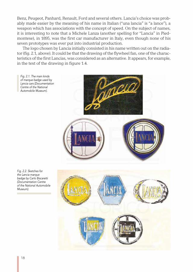
The logo chosen by Lancia initially consisted in his name written out on the radia-tor (fig. 2.1, above). It could be that the drawing of the flywheel fan, one of the charac-teristics of the first Lancias, was considered as an alternative. It appears, for example, in the text of the drawing in figure 1.4.
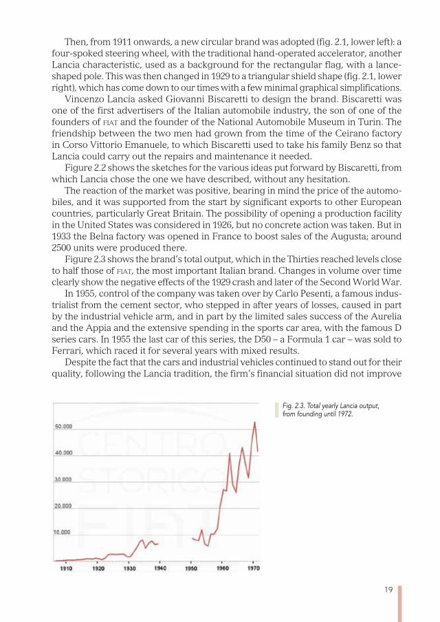
Fig. 2.2. Sketches for the Lancia marque badge by Carlo Biscaretti (Documentation Centre of the National Automobile Museum).
Fig. 2.1. The main kinds of marque badge used by Lancia cars (Documentation Centre of the National Automobile Museum).
19
Then, from 1911 onwards, a new circular brand was adopted (fig. 2.1, lower left): a four-spoked steering wheel, with the traditional hand-operated accelerator, another Lancia characteristic, used as a background for the rectangular flag, with a lance-shaped pole. This was then changed in 1929 to a triangular shield shape (fig. 2.1, lower right), which has come down to our times with a few minimal graphical simplifications.
Vincenzo Lancia asked Giovanni Biscaretti to design the brand. Biscaretti was one of the first advertisers of the Italian automobile industry, the son of one of the founders of fiat and the founder of the National Automobile Museum in Turin. The friendship between the two men had grown from the time of the Ceirano factory in Corso Vittorio Emanuele, to which Biscaretti used to take his family Benz so that Lancia could carry out the repairs and maintenance it needed.
Figure 2.2 shows the sketches for the various ideas put forward by Biscaretti, from which Lancia chose the one we have described, without any hesitation.
The reaction of the market was positive, bearing in mind the price of the automo-biles, and it was supported from the start by significant exports to other European countries, particularly Great Britain. The possibility of opening a production facility in the United States was considered in 1926, but no concrete action was taken. But in 1933 the Belna factory was opened in France to boost sales of the Augusta; around 2500 units were produced there.
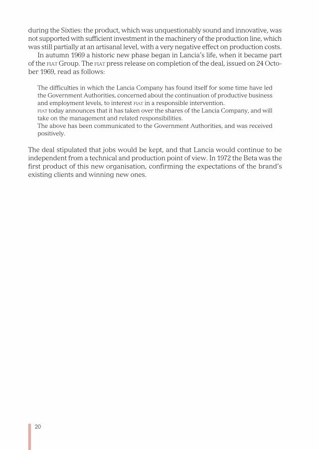
Figure 2.3 shows the brand’s total output, which in the Thirties reached levels close to half those of fiat, the most important Italian brand. Changes in volume over time clearly show the negative effects of the 1929 crash and later of the Second World War.
In 1955, control of the company was taken over by Carlo Pesenti, a famous indus-trialist from the cement sector, who stepped in after years of losses, caused in part by the industrial vehicle arm, and in part by the limited sales success of the Aurelia and the Appia and the extensive spending in the sports car area, with the famous D series cars. In 1955 the last car of this series, the D50 – a Formula 1 car – was sold to Ferrari, which raced it for several years with mixed results.
Despite the fact that the cars and industrial vehicles continued to stand out for their quality, following the Lancia tradition, the firm’s financial situation did not improve
Fig. 2.3. Total yearly Lancia output, from founding until 1972.
20
during the Sixties: the product, which was unquestionably sound and innovative, was not supported with sufficient investment in the machinery of the production line, which was still partially at an artisanal level, with a very negative effect on production costs.
In autumn 1969 a historic new phase began in Lancia’s life, when it became part of the fiat Group. The fiat press release on completion of the deal, issued on 24 Octo-ber 1969, read as follows:
The difficulties in which the Lancia Company has found itself for some time have led the Government Authorities, concerned about the continuation of productive business and employment levels, to interest fiat in a responsible intervention. fiat today announces that it has taken over the shares of the Lancia Company, and will take on the management and related responsibilities. The above has been communicated to the Government Authorities, and was received positively.
The deal stipulated that jobs would be kept, and that Lancia would continue to be independent from a technical and production point of view. In 1972 the Beta was the first product of this new organisation, confirming the expectations of the brand’s existing clients and winning new ones.
21
Chapter 3
THE ALFA AND THE BETA
The first car built by Lancia was the Alfa, which was first presented with the name 12 hp, indicating its engine power, in the way that most manufacturers then did. Then, in 1919, following a suggestion from his brother – who was a
classicist – Vincenzo Lancia decided to give his cars, retroactively, a letter from the Greek alphabet as their identifier. The letter progressed over the years and was not linked to the vehicle’s class, size or sale price.
The Greek letter, written in Latin characters, could be preceded by the Greek ordinal prefix “di”, “tri”, “tetra” etc., for derivative models, which had been slightly modified, mainly in their propulsion: the Dialfa, for example, which will be discussed shortly, had a rolling chassis derived from the Alfa’s where the differences were sim-ply lengthening the longitudinal struts and consequently the wheelbase, with the addition of a more powerful six-cylinder engine, created from three blocks of two cylinders each, identical to those used on the Alfa.
According to the internal numbering system, instituted by the firm for the clas-sification of projects and designs, increasing digits were given to the chassis and motor: in the case of the Alfa, the chassis was given the number 1, while the engine was identified with the number 51, which became 53 in the case of the Dialfa and 54 in that of the Beta.
The Alfa was presented at the Turin Motor Show, in January 1908. The project had been started in 1906, and precisely followed the technical elements Vincenzo Lancia firmly believed in. He felt that they had to make a lighter and livelier car than the competitors then in the market, a car that was easy to use and which would be noted for the simplicity of its construction, and that was elegant and reliable.
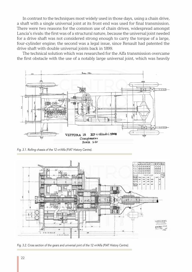
The end result can be considered to have lived up to expectations, since the Alfa was able to reach 90 km/h, could be driven with little additional work, and the whole rolling chassis, despite its 2820 mm wheelbase, only weighed 750 kg.
If we look at the rolling chassis in figure 3.1, we can see the longitudinal struts, which were brought closer to the engine compartment to allow the wheels a wide turning angle and a small turning circle, and were also brought further from the pas-senger area to allow the installation of a sufficiently wide bodywork. They were also moulded at an elevated angle, to allow enough movement of the rear axle, as part of the suspension, without having a negative effect on the clearance from the ground. And finally the longitudinal struts were cut off just after the rear axle, despite the sig-nificant length of the leaf springs, since a cantilever cart spring suspension method using three quarter elliptic leaf springs was chosen because of their superior perfor-mance in terms of flexibility.
22
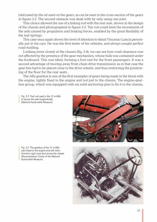
Fig. 3.2. Cross section of the gears and universal joint of the 12 hp/Alfa (FIAT History Centre).
In contrast to the techniques most widely used in those days, using a chain drive, a shaft with a single universal joint at its front end was used for final transmission. There were two reasons for the common use of chain drives, widespread amongst Lancia’s rivals: the first was of a structural nature, because the universal joint needed for a drive shaft was not considered strong enough to carry the torque of a large, four-cylinder engine; the second was a legal issue, since Renault had patented the drive shaft with double universal joints back in 1899.
The technical solution which was researched for the Alfa transmission overcame the first obstacle with the use of a notably large universal joint, which was heavily
Fig. 3.1. Rolling chassis of the 12 hp/Alfa (FIAT History Centre).
23
lubricated by the oil used on the gears, as can be seen in the cross-section of the gears in figure 3.2. The second obstacle was dealt with by only using one joint.
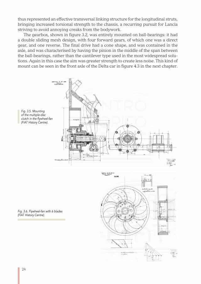
This choice allowed the use of a linking rod with the rear axle, shown in the design of the chassis and photographed in figure 3.3. The rod could limit the movements of the axle caused by propulsion and braking forces, enabled by the great flexibility of the leaf springs.
This case once again shows the level of attention to detail Vincenzo Lancia person-ally put in his cars. He was the first tester of his vehicles, and always sought perfect road-holding.
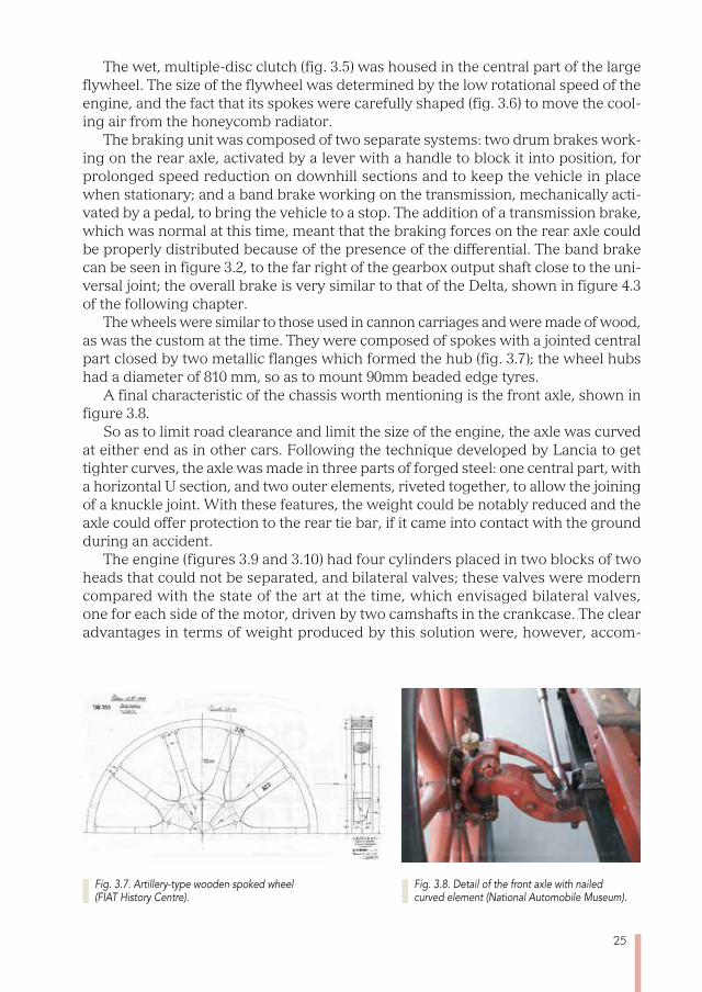
Looking more closely at the chassis (fig. 3.4), we can see how road clearance was not affected by the presence of the gear mechanism, whose bulk was contained under the footboard. This was tilted, forming a foot rest for the front passengers. It was a second advantage of moving away from chain drive transmission as in that case the gear box had to be placed close to the drive wheels, and thus restricting the position-ing of the floor for the rear seats.
The Alfa gearbox is one of the first examples of gears being made in the block with the engine, tightly fixed to the engine and not just to the chassis. The engine-gear-box group, which was equipped with six solid anchoring pins to fix it to the chassis,
Fig. 3.3. Push rod used in the 12 hp/Alfa to secure the axle longitudinally (National Automobile Museum).
Fig. 3.4. The gearbox of the 12 hp/Alfa was linked to the engine and with them formed a rigid cross strut across the chassis (Documentation Centre of the National Automobile Museum).
24
thus represented an effective transversal linking structure for the longitudinal struts, bringing increased torsional strength to the chassis, a recurring pursuit for Lancia striving to avoid annoying creaks from the bodywork.
The gearbox, shown in figure 3.2, was entirely mounted on ball-bearings: it had a double sliding mesh design, with four forward gears, of which one was a direct gear, and one reverse. The final drive had a cone shape, and was contained in the axle, and was characterised by having the pinion in the middle of the span between the ball-bearings, rather than the cantilever type used in the most widespread solu-tions. Again in this case the aim was greater strength to create less noise. This kind of mount can be seen in the front axle of the Delta car in figure 4.3 in the next chapter.
Fig. 3.6. Flywheel-fan with 6 blades (FIAT History Centre).
Fig. 3.5. Mounting of the multiple-disc clutch in the flywheel-fan (FIAT History Centre).
25
The wet, multiple-disc clutch (fig. 3.5) was housed in the central part of the large flywheel. The size of the flywheel was determined by the low rotational speed of the engine, and the fact that its spokes were carefully shaped (fig. 3.6) to move the cool-ing air from the honeycomb radiator.
The braking unit was composed of two separate systems: two drum brakes work-ing on the rear axle, activated by a lever with a handle to block it into position, for prolonged speed reduction on downhill sections and to keep the vehicle in place when stationary; and a band brake working on the transmission, mechanically acti-vated by a pedal, to bring the vehicle to a stop. The addition of a transmission brake, which was normal at this time, meant that the braking forces on the rear axle could be properly distributed because of the presence of the differential. The band brake can be seen in figure 3.2, to the far right of the gearbox output shaft close to the uni-versal joint; the overall brake is very similar to that of the Delta, shown in figure 4.3 of the following chapter.
The wheels were similar to those used in cannon carriages and were made of wood, as was the custom at the time. They were composed of spokes with a jointed central part closed by two metallic flanges which formed the hub (fig. 3.7); the wheel hubs had a diameter of 810 mm, so as to mount 90mm beaded edge tyres.
A final characteristic of the chassis worth mentioning is the front axle, shown in figure 3.8.
So as to limit road clearance and limit the size of the engine, the axle was curved at either end as in other cars. Following the technique developed by Lancia to get tighter curves, the axle was made in three parts of forged steel: one central part, with a horizontal U section, and two outer elements, riveted together, to allow the joining of a knuckle joint. With these features, the weight could be notably reduced and the axle could offer protection to the rear tie bar, if it came into contact with the ground during an accident.
The engine (figures 3.9 and 3.10) had four cylinders placed in two blocks of two heads that could not be separated, and bilateral valves; these valves were modern compared with the state of the art at the time, which envisaged bilateral valves, one for each side of the motor, driven by two camshafts in the crankcase. The clear advantages in terms of weight produced by this solution were, however, accom-
Fig. 3.7. Artillery-type wooden spoked wheel (FIAT History Centre).
Fig. 3.8. Detail of the front axle with nailed curved element (National Automobile Museum).

26
panied by the greater difficulty in casting the blocks, because of the more compli-cated shapes.
This solution was chosen, despite being more demanding from a technologi-cal point of view, because it was believed that it would lead to quicker combustion, because of the smaller combustion chamber, with performance and fuel economy benefits. It was only possible because of the skill of the Lancia foundry workers. On the left of the motor, bronze caps were placed to close the holes needed to work on the valve seats, while the corresponding ones in the exhaust seats were drilled for the spark plug housing.
The highest of the four copper pipes connected the cooling circuit for the two blocks with the radiator, the pipe on the right held the spark plug cables, and that on the left served as the inlet manifold, fed by a transverse pipe placed between the blocks to connect with the carburettor installed on the other side of the motor. A final vertical pipe, in the lower part of the engine, connected the block cooling chamber to the radiator inlet. Unprotected valve stems and the high tension ignition magne-to were on the same side. It is worth emphasising how this was the most advanced
Fig. 3.9. The engine of the 12 hp/Alfa, seen from the right (Lancia Collection).
Fig. 3.10. The engine of the 12 hp/Alfa, seen from the left (Lancia Collection).
27
starting technology of the time, and was in contrast to the widespread presence on the market of battery-operated ignition systems with a vibrator or low-voltage mag-neto with hammer interrupters.
On the right of the engine we can see one of the strong points of the Lancia motor: the automatic engine lubrication distributor. It consisted of a rotating distribution pump, similar to that used by diesel motors in the 1970s and 80s, which was rotated by the engine and attached by copper tubes to seven lubrication points, made of the three main bearings, two camshaft bearings and two tubes for the engine block liners. This system could send an amount of oil that would increase as the engine acceler-ated, and which was proportional to the needs of the points that needed lubricating. The most widely spread solution on the market were hand-controlled gravity systems which took no account of how fast the engine was turning and had to be manually disengaged when the engine was stopped to avoid oil leaks.
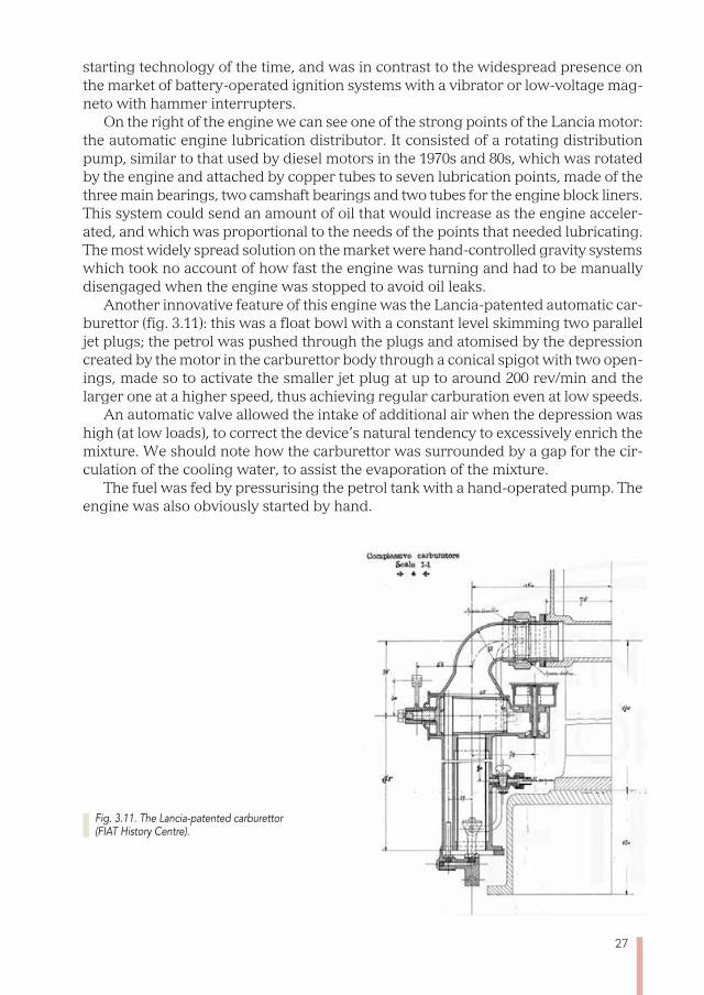
Another innovative feature of this engine was the Lancia-patented automatic car-burettor (fig. 3.11): this was a float bowl with a constant level skimming two parallel jet plugs; the petrol was pushed through the plugs and atomised by the depression created by the motor in the carburettor body through a conical spigot with two open-ings, made so to activate the smaller jet plug at up to around 200 rev/min and the larger one at a higher speed, thus achieving regular carburation even at low speeds.
An automatic valve allowed the intake of additional air when the depression was high (at low loads), to correct the device’s natural tendency to excessively enrich the mixture. We should note how the carburettor was surrounded by a gap for the cir-culation of the cooling water, to assist the evaporation of the mixture.
The fuel was fed by pressurising the petrol tank with a hand-operated pump. The engine was also obviously started by hand.
Fig. 3.11. The Lancia-patented carburettor (FIAT History Centre).
28
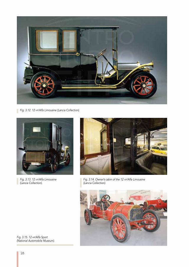
Fig. 3.12. 12 hp/Alfa Limousine (Lancia Collection).
Fig. 3.14. Owner’s cabin of the 12 hp/Alfa Limousine (Lancia Collection).
Fig. 3.15. 12 hp/Alfa Sport (National Automobile Museum).
Fig. 3.13. 12 hp/Alfa Limousine (Lancia Collection).
29
The size of the cylinders, with 90 mm bore and 100 mm stroke, gave a total engine displacement of 2543 cm3. The 4.8 compression ratio meant an output of 24 hp at 1450 rev/min, a much higher figure than the average produced by competitors; a second version could reach 28 hp at 1800 rev/min.
Figures 3.12 and 3.13 show the exterior of an Alfa Limousine, in which the par-ticularly fine finishing of the bodywork can be appreciated. Figure 3.14 shows the high levels of refinement of the internal finishings in the passenger compartment.
As well as the Limousine, the catalogue also offered the Double Phaeton (4-seat soft-top, with no doors at the front), the Coupé and the Landaulet. The latter two differed from the Limousine by having the front seats open to the sky (the rear of the Landau-let could also be uncovered). The chassis was available on its own for anyone who wanted bodywork made on order from other coachbuilders. A Sport version was also constructed (fig. 3.15), which featured a particularly light two-seat bodywork.
Prices ranged from 12,000 lire for the Double Phaeton, to 14,500 lire for the Lim-ousine; the chassis without bodywork was priced at 10,000 lire.
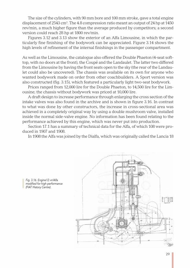
A draft design to increase performance through enlarging the cross section of the intake valves was also found in the archive and is shown in figure 3.16. In contrast to what was done by other constructors, the increase in cross-sectional area was achieved in a completely original way by using a double mushroom valve, installed inside the normal side-valve engine. No information has been found relating to the performance achieved by this engine, which was never put into production.
Section 17.1 has a summary of technical data for the Alfa, of which 108 were pro-duced in 1907 and 1908.
In 1908 the Alfa was joined by the Dialfa, which was originally called the Lancia 18
Fig. 3.16. Engine12 hp/Alfa modified for high performance (FIAT History Centre).
30
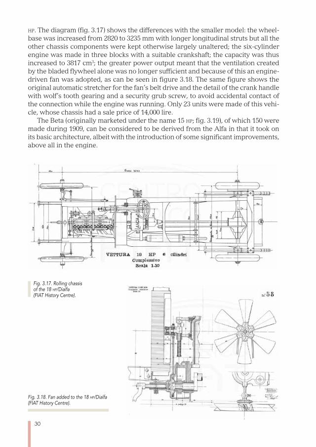
hp. The diagram (fig. 3.17) shows the differences with the smaller model: the wheel-base was increased from 2820 to 3235 mm with longer longitudinal struts but all the other chassis components were kept otherwise largely unaltered; the six-cylinder engine was made in three blocks with a suitable crankshaft; the capacity was thus increased to 3817 cm3; the greater power output meant that the ventilation created by the bladed flywheel alone was no longer sufficient and because of this an engine-driven fan was adopted, as can be seen in figure 3.18. The same figure shows the original automatic stretcher for the fan’s belt drive and the detail of the crank handle with wolf’s tooth gearing and a security grub screw, to avoid accidental contact of the connection while the engine was running. Only 23 units were made of this vehi-cle, whose chassis had a sale price of 14,000 lire.
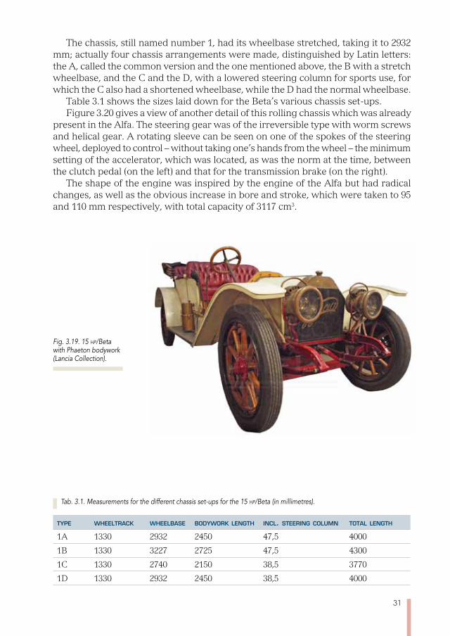
The Beta (originally marketed under the name 15 hp; fig. 3.19), of which 150 were made during 1909, can be considered to be derived from the Alfa in that it took on its basic architecture, albeit with the introduction of some significant improvements, above all in the engine.
Fig. 3.18. Fan added to the 18 hp/Dialfa (FIAT History Centre).
Fig. 3.17. Rolling chassis of the 18 hp/Dialfa (FIAT History Centre).
31
The chassis, still named number 1, had its wheelbase stretched, taking it to 2932 mm; actually four chassis arrangements were made, distinguished by Latin letters: the A, called the common version and the one mentioned above, the B with a stretch wheelbase, and the C and the D, with a lowered steering column for sports use, for which the C also had a shortened wheelbase, while the D had the normal wheelbase.
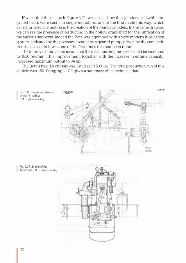
Table 3.1 shows the sizes laid down for the Beta’s various chassis set-ups.Figure 3.20 gives a view of another detail of this rolling chassis which was already
present in the Alfa. The steering gear was of the irreversible type with worm screws and helical gear. A rotating sleeve can be seen on one of the spokes of the steering wheel, deployed to control – without taking one’s hands from the wheel – the minimum setting of the accelerator, which was located, as was the norm at the time, between the clutch pedal (on the left) and that for the transmission brake (on the right).
The shape of the engine was inspired by the engine of the Alfa but had radical changes, as well as the obvious increase in bore and stroke, which were taken to 95 and 110 mm respectively, with total capacity of 3117 cm3.
Tab. 3.1. Measurements for the different chassis set-ups for the 15 hp/Beta (in millimetres).
type wheeltrack wheelbase bodywork length incl. steering column total length
1A 1330 2932 2450 47,5 4000
1B 1330 3227 2725 47,5 4300
1C 1330 2740 2150 38,5 3770
1D 1330 2932 2450 38,5 4000
Fig. 3.19. 15 hp/Beta with Phaeton bodywork (Lancia Collection).
32
Fig. 3.20. Pedals and steering of the 15 hp/Beta (FIAT History Centre).
Fig. 3.21. Engine of the 15 hp/Beta (FIAT History Centre).
If we look at the design in figure 3.21, we can see how the cylinders, still with inte-grated head, were cast in a single monobloc, one of the first made this way, which called for special attention in the creation of the foundry models. In the same drawing we can see the presence of oil ducting in the hollow crankshaft for the lubrication of the various supports: indeed the Beta was equipped with a very modern lubrication system, activated by the pressure created by a geared pump, driven by the camshaft. In this case again it was one of the first times this had been done.
The improved lubrication meant that the maximum engine speed could be increased to 1850 rev/min. This improvement, together with the increase in engine capacity, increased maximum output to 34 hp.
The Beta’s type 1A chassis was listed at 10,500 lire. The total production run of this vehicle was 150. Paragraph 17.2 gives a summary of its technical data.
33
Chapter 4
FROM THE GAMMA TO THE ETA
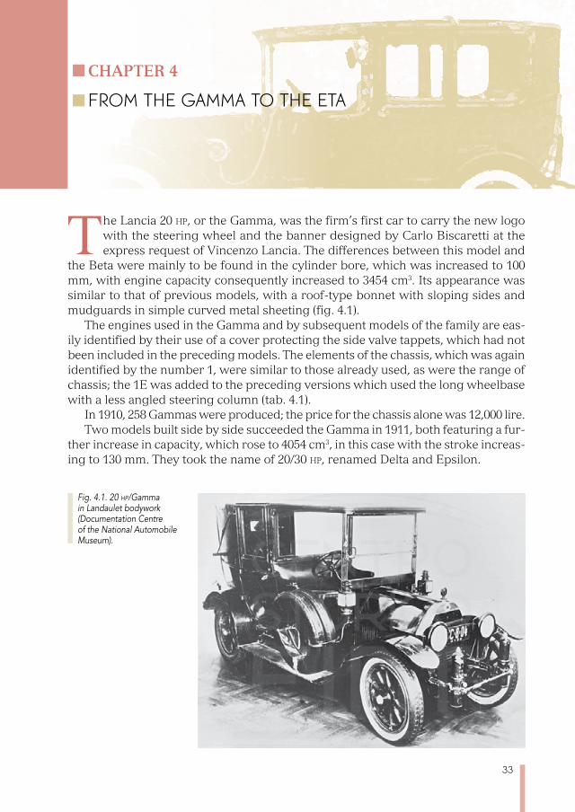
The Lancia 20 hp, or the Gamma, was the firm’s first car to carry the new logo with the steering wheel and the banner designed by Carlo Biscaretti at the express request of Vincenzo Lancia. The differences between this model and
the Beta were mainly to be found in the cylinder bore, which was increased to 100 mm, with engine capacity consequently increased to 3454 cm3. Its appearance was similar to that of previous models, with a roof-type bonnet with sloping sides and mudguards in simple curved metal sheeting (fig. 4.1).
The engines used in the Gamma and by subsequent models of the family are eas-ily identified by their use of a cover protecting the side valve tappets, which had not been included in the preceding models. The elements of the chassis, which was again identified by the number 1, were similar to those already used, as were the range of chassis; the 1E was added to the preceding versions which used the long wheelbase with a less angled steering column (tab. 4.1).
In 1910, 258 Gammas were produced; the price for the chassis alone was 12,000 lire.Two models built side by side succeeded the Gamma in 1911, both featuring a fur-
ther increase in capacity, which rose to 4054 cm3, in this case with the stroke increas-ing to 130 mm. They took the name of 20/30 hp, renamed Delta and Epsilon.
Fig. 4.1. 20 hp/Gamma in Landaulet bodywork (Documentation Centre of the National Automobile Museum).

34
The so-called “pulsometer”, a piston pump run by the camshaft to pressurize the fuel tank, was added to the engine in the new models (serial numbers 56 and 58). A safety valve stopped too much pressure building up. The manual pump continued to be used to start the engine when prolonged stops had led the fuel tank to lose pres-sure because of the inevitable leaks.
The Delta was intended for sports use, with the use of the 1A, 1C, 1D and 1E chas-sis; the Epsilon was for more prestigious bodywork, with the long wheelbase 1B chas-sis. In the same year, 1911, a third model was added to these two, the Eta, which was made with a 2775 mm wheelbase. The engine (number 60, for the Eta) of these three models could develop 60 hp at 1800 rev/min; the top speed was around 115 km/h.
The output of the Delta reached 303 units in 1911; that of the Epsilon, 351 units from 1911 to 1913; that of the Eta, 491 units from 1911 to 1914; an average of around 300 cars a year.
As well as showing the changes with the other models, some of the details of the Delta allow us get a better view of the features they shared which we have not shown for the vehicles which have been described so far since specific designs for them could not be found.
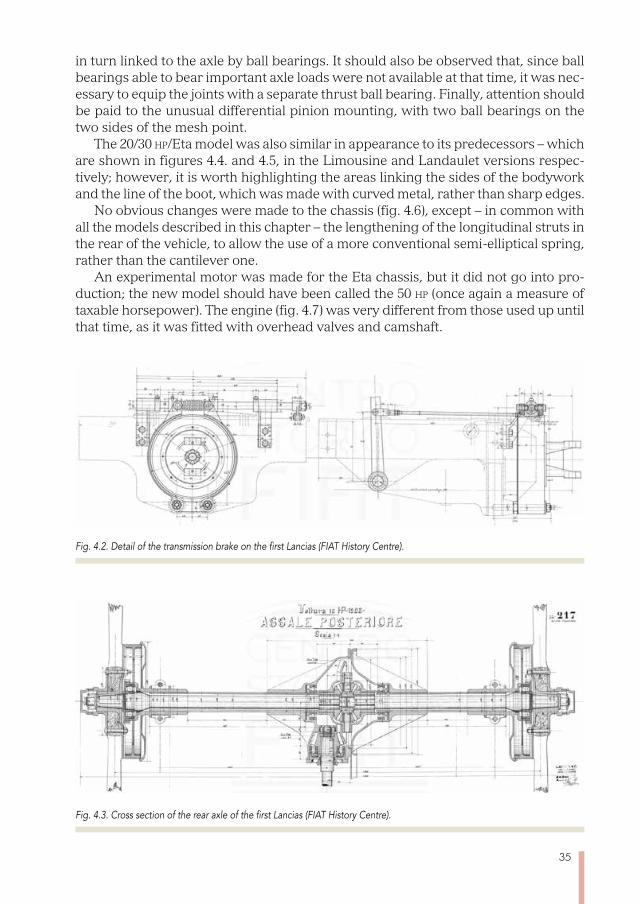
Figure 4.2 shows the transmission brake applied to the exterior of the large uni-versal joint; braking is achieved by using two very flexible bands outside the drum, so as to distribute the braking pressure in the most uniform way. The braking force is obtained by tightening the ends of the two bands.
Figure 4.3 shows the entire rear axle, which was shared by practically all the cars we have mentioned so far. The axle structure was formed by a cast iron central part, into which two steel tubes were inserted to contain the axle shafts. The hub bracket was placed at the end of these tubes, creating the attachment for the leaf spring. Since there was a reactive element, the push rod connected to the gear box, this connection was properly made by using a lubricated ball-bearing: in this way, the leaf springs were not strained by the reaction to the driving or braking torque.
This detail was particularly appreciated: attaching the leaf springs firmly to the axles would have caused the axles to bend into an S shape because of the torque applied to the wheels, especially if the springs were particularly long in order to achieve good flexibility. This elastic type of deformation could have caused unpleasant jolting when braking or speeding up. The presence of the reinforcement bracket should be noted on the differential housing, shown from above (and also in fig. 3.3). This illustration also allows us to understand the system used to mount the wooden spokes between the flanges of the wheel hub: the wheels were supported by axle shafts, which were
Tab. 4.1. Measurements for the different chassis set-ups for the 20 hp/Gamma (in millimetres).
type wheeltrack wheelbase bodywork length incl. steering column total length
1A 1330 2932 2450 47,5 4000
1B 1330 3227 2725 47,5 4300
1C 1330 2740 2150 38,5 3770
1D 1330 2932 2450 38,5 4000
1E 1330 3227 2725 38,5 4300
35
in turn linked to the axle by ball bearings. It should also be observed that, since ball bearings able to bear important axle loads were not available at that time, it was nec-essary to equip the joints with a separate thrust ball bearing. Finally, attention should be paid to the unusual differential pinion mounting, with two ball bearings on the two sides of the mesh point.
The 20/30 hp/Eta model was also similar in appearance to its predecessors – which are shown in figures 4.4. and 4.5, in the Limousine and Landaulet versions respec-tively; however, it is worth highlighting the areas linking the sides of the bodywork and the line of the boot, which was made with curved metal, rather than sharp edges.
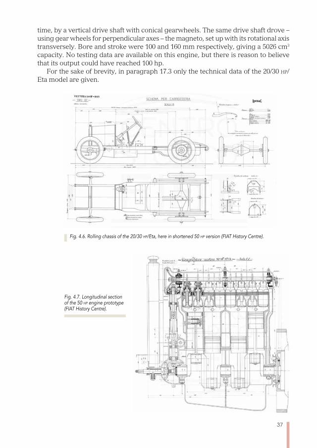
No obvious changes were made to the chassis (fig. 4.6), except – in common with all the models described in this chapter – the lengthening of the longitudinal struts in the rear of the vehicle, to allow the use of a more conventional semi-elliptical spring, rather than the cantilever one.
An experimental motor was made for the Eta chassis, but it did not go into pro-duction; the new model should have been called the 50 hp (once again a measure of taxable horsepower). The engine (fig. 4.7) was very different from those used up until that time, as it was fitted with overhead valves and camshaft.
Fig. 4.2. Detail of the transmission brake on the first Lancias (FIAT History Centre).
Fig. 4.3. Cross section of the rear axle of the first Lancias (FIAT History Centre).

36
Fig. 4.4. 20/30 hp/Eta with Limousine bodywork (FIAT History Centre).
Fig. 4.5. 20/30 hp/Eta with Landaulet bodywork (FIAT History Centre).
This was done following the monobloc pattern, with non-removable heads. The valve diameter was so large as to make it impossible to contain them in the space inside the cylinder liner, so it was necessary to fit them in a misaligned position relative to the cylinder, with the exhaust valves partially contained in bulges in the combustion chambers. The obvious difficulty of working on the seats of these valves, with a cut-ter spindle in the lower part of the liner, as was intended for the intake valves, was circumvented by using a removable beating seat, with its head screwed down and worked on separately. The camshaft was driven, similarly to aviation engines at the
37
time, by a vertical drive shaft with conical gearwheels. The same drive shaft drove – using gear wheels for perpendicular axes – the magneto, set up with its rotational axis transversely. Bore and stroke were 100 and 160 mm respectively, giving a 5026 cm3
capacity. No testing data are available on this engine, but there is reason to believe that its output could have reached 100 hp.
For the sake of brevity, in paragraph 17.3 only the technical data of the 20/30 hp/Eta model are given.
Fig. 4.7. Longitudinal section of the 50 hp engine prototype (FIAT History Centre).
Fig. 4.6. Rolling chassis of the 20/30 hp/Eta, here in shortened 50 hp version (FIAT History Centre).

39
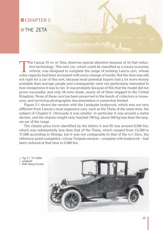
The Lancia 15 hp, or Zeta, deserves special attention because of its fuel reduc-tion technology. This new car, which could be classified as a luxury economy vehicle, was designed to complete the range of existing Lancia cars, whose
cubic capacity had been increased with every change of model. But the time was still not right for a car of this sort, because most potential buyers had a lot more money available than average people and consequently were not particularly interested in how inexpensive it was to run. It was probably because of this that the model did not prove successful, and only 34 were made, nearly all of them shipped to the United Kingdom. None of these cars has been preserved in the hands of collectors or muse-ums, and surviving photographic documentation is somewhat limited.
Figure 5.1 shows the version with the Landaulet bodywork, which was not very different from Lancia’s most expensive cars, such as the Theta of the same time, the subject of Chapter 6. Obviously it was smaller: in particular it was around a metre shorter, and the chassis weight only reached 740 kg, about 300 kg less than the larg-est car of the range
The chassis price (now identified by the letters A and B) was around 8,500 lire, which was substantially less than that of the Theta, which ranged from 13,500 to 17,000 according to fittings, but it was not comparable to that of the fiat Zero, the reference-point competitor, whose Torpedo version – complete with bodywork – had been reduced at that time to 6,900 lire.
Chapter 5
THE zETA
Fig. 5.1. 15 hp/Zeta Landaulet (FIAT History Centre).

40
The rolling chassis shown in figure 5.2 shows: the cantilever leaf springs on the rear axle – the standard system for Lancias until the Gamma model; the transmission united with the axle, using what today would be called a transaxle set-up; the fan located behind the radiator, which had not featured in Lancias up until then – with the exception of the Dialfa. The view from above (figure 5.3) shows these unusual fea-tures as well as showing the absence of a universal joint at the end of the drive shaft.
The push rod, which is typical of Lancia rear axles of this era, here consists of a tube containing the drive shaft and – as we will see – the gear controls; this tube is linked to the chassis at the front, with a fork joint, pivoted on the attachments, visible at the level of the gear box (fig. 5.3) and, in the rear, to the transaxle using a flanged
Fig. 5.2. Rolling chassis of the 15 hp/Zeta (FIAT History Centre).
Fig. 5.3. Rolling chassis of the 15 hp/Zeta from above (FIAT History Centre).
41
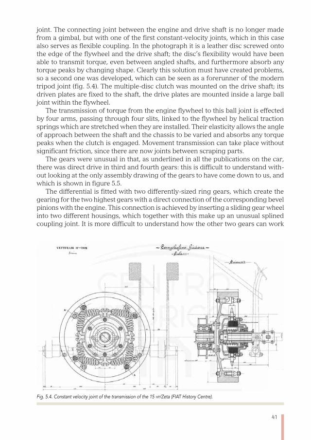
joint. The connecting joint between the engine and drive shaft is no longer made from a gimbal, but with one of the first constant-velocity joints, which in this case also serves as flexible coupling. In the photograph it is a leather disc screwed onto the edge of the flywheel and the drive shaft; the disc’s flexibility would have been able to transmit torque, even between angled shafts, and furthermore absorb any torque peaks by changing shape. Clearly this solution must have created problems, so a second one was developed, which can be seen as a forerunner of the modern tripod joint (fig. 5.4). The multiple-disc clutch was mounted on the drive shaft; its driven plates are fixed to the shaft, the drive plates are mounted inside a large ball joint within the flywheel.
The transmission of torque from the engine flywheel to this ball joint is effected by four arms, passing through four slits, linked to the flywheel by helical traction springs which are stretched when they are installed. Their elasticity allows the angle of approach between the shaft and the chassis to be varied and absorbs any torque peaks when the clutch is engaged. Movement transmission can take place without significant friction, since there are now joints between scraping parts.
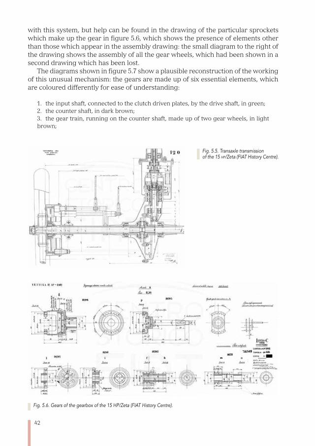
The gears were unusual in that, as underlined in all the publications on the car, there was direct drive in third and fourth gears: this is difficult to understand with-out looking at the only assembly drawing of the gears to have come down to us, and which is shown in figure 5.5.
The differential is fitted with two differently-sized ring gears, which create the gearing for the two highest gears with a direct connection of the corresponding bevel pinions with the engine. This connection is achieved by inserting a sliding gear wheel into two different housings, which together with this make up an unusual splined coupling joint. It is more difficult to understand how the other two gears can work
Fig. 5.4. Constant velocity joint of the transmission of the 15 hp/Zeta (FIAT History Centre).
42
with this system, but help can be found in the drawing of the particular sprockets which make up the gear in figure 5.6, which shows the presence of elements other than those which appear in the assembly drawing: the small diagram to the right of the drawing shows the assembly of all the gear wheels, which had been shown in a second drawing which has been lost.
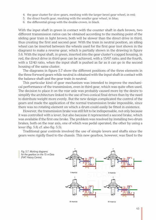
The diagrams shown in figure 5.7 show a plausible reconstruction of the working of this unusual mechanism: the gears are made up of six essential elements, which are coloured differently for ease of understanding:
1. the input shaft, connected to the clutch driven plates, by the drive shaft, in green; 2. the counter shaft, in dark brown; 3. the gear train, running on the counter shaft, made up of two gear wheels, in light brown;
Fig. 5.6. Gears of the gearbox of the 15 HP/Zeta (FIAT History Centre).
Fig. 5.5. Transaxle transmission of the 15 hp/Zeta (FIAT History Centre).
43
4. the gear cluster for slow gears, meshing with the larger bevel gear wheel, in red; 5. the direct fourth gear, meshing with the smaller gear wheel, in blue;6. the differential group with the double crown, in black.
With the input shaft in green in contact with the counter shaft in dark brown, two different transmission ratios can be obtained according to the meshing point of the sliding gear train in light brown; both will be slower than the direct drive in third, thus creating the first and second gear. With the train in neutral position, an idling wheel can be inserted between the wheels used for the first gear (not shown in the diagram) to make a reverse gear, which is partially shown in the drawing in figure 5.6. With the input shaft, in green, inserted into the gear cluster’s cogged housing, in red, the direct drive in third gear can be achieved, with a 15/67 ratio; and the fourth, with a 12/43 ratio, when the input shaft is pushed as far as it can go in the second housing of the same cluster.
The diagrams in figure 5.7 show the different positions of the three elements in the three forward gears while neutral is obtained with the input shaft in contact with the balance shaft and the gear train in neutral.
This particular kind of gear mechanism was intended to improve the mechani-cal performance of the transmission, even in third gear, which was quite often used. The decision to place it on the rear axle was probably caused more by the desire to simplify the architecture linked to the use of two conical final drives than by the need to distribute weight more evenly. But the new design complicated the control of the gears and made the application of the normal transmission brake impossible, since there was no rotating element on which a drum could easily be fitted in existence.
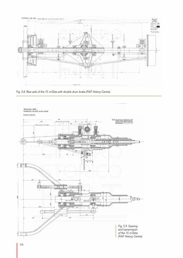
However, the transmission brake was still felt to be indispensable, not only because it was controlled with a lever, but also because it represented a second brake, which was available if the first one broke. The problem was resolved by installing two drum brakes, both on the rear axis, one of which was pedal operated, the other by using a lever (fig. 5.8; cf. also fig. 5.5).
Traditional gear controls involved the use of simple levers and shafts since the gears were rigidly fixed to the chassis. This new gearbox, however, was fixed to the
Fig. 5.7. Working diagrams for the gearbox on the 15 hp/Zeta (FIAT History Centre).
44
Fig. 5.9. Gearing and transmission of the 15 hp/Zeta (FIAT History Centre).
Fig. 5.8. Rear axle of the 15 hp/Zeta with double drum brake (FIAT History Centre).
45
rear axle, so in a variable position in relation to the gear stick, because of the judder-ing of the suspension. So it was important to find a control mechanism which did not risk producing undesired effects caused by suspension movements and the only fixed point of the axle in relation to the cabin was the thrust tube joint. The gear stick was consequently positioned close to this. Figure 5.9 shows that this mechanism was particularly complicated: when the lever was moved to engage a gear the movements shifted the position of the input shaft or the position of the sliding train according to what was selected; that was brought about by two rods inside the drive shaft and driven from outside by special rotating joints.
Starting from the exterior, we can see the transmission tube, in a fixed position, designed to react to the axle’s push. It contains three concentric rotating tubes: the outer one, for movement transmission, the inner one for the sliding train control, and between the two the control of the movement of the input shaft.
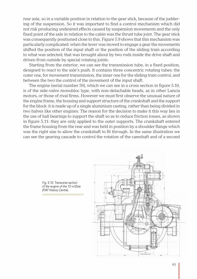
The engine (serial number 59), which we can see in a cross section in figure 5.10, is of the side-valve monobloc type, with non-detachable heads, as in other Lancia motors, or those of rival firms. However we must first observe the unusual nature of the engine frame, the housing and support structure of the crankshaft and the support for the block: it is made up of a single aluminium casting, rather than being divided in two halves like other engines. The reason for the decision to make it this way lies in the use of ball bearings to support the shaft so as to reduce friction losses, as shown in figure 5.11: they are only applied to the outer supports. The crankshaft entered the frame housing from the rear and was held in position by a shoulder flange which was the right size to allow the crankshaft to fit through. In the same illustration we can see the gearing cascade to control the rotation of the camshaft and of a second
Fig. 5.10. Transverse section of the engine of the 15 hp/Zeta (FIAT History Centre).
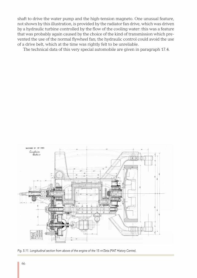
shaft to drive the water pump and the high-tension magneto. One unusual feature, not shown by this illustration, is provided by the radiator fan drive, which was driven by a hydraulic turbine controlled by the flow of the cooling water: this was a feature that was probably again caused by the choice of the kind of transmission which pre-vented the use of the normal flywheel fan; the hydraulic control could avoid the use of a drive belt, which at the time was rightly felt to be unreliable.
The technical data of this very special automobile are given in paragraph 17.4.
Fig. 5.11. Longitudinal section from above of the engine of the 15 hp/Zeta (FIAT History Centre).
46
47
Chapter 6
THE THETA
The 35 hp, or the Theta, was the first really successful Lancia with as many as 1696 units produced from 1913 to 1919, despite its high price of 13,500 lire for the chassis alone. The Theta with saloon bodywork could reach 20,000 lire. To
place this figure in terms of what rivals were doing, we can again quote the 6,900 lire price of the fiat Zero Torpedo which was perhaps the most affordable car amongst those sold in Italy in 1913, or the estimated 50,000 lire asking price for an Itala 50 hp Avalve, which was possibly the top in terms of luxury.
The production run, which represents around 1.5 per cent of the automobiles made in Italy during the model’s lifespan, was in part achieved because of notable export levels, above all to the United Kingdom and the United States, countries in which Lancias were particularly appreciated. Production of the 35 hp stopped at the beginning of the First World War, when the Lancia company decided to concentrate its resources on war production.
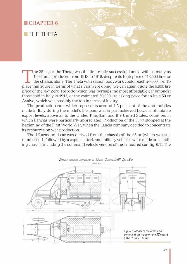
The 1Z armoured car was derived from the chassis of the 35 hp (which was still numbered 1, followed by a capital letter), and military vehicles were made on its roll-ing chassis, including the command vehicle version of the armoured car (fig. 6.1). The
Fig. 6.1. Model of the armoured command car made on the 1Z chassis (FIAT History Centre).
48
1Z vehicle should not be confused with the Zeta, which is much smaller; the “1Z” was the Z version of chassis family 1 which began with the 12 hp/Alfa.
The reason for the success of the 35 hp was not just its strength and reliability, which were characteristics shared by all later Lancia cars, but also some innovative elements, the most important of which was the on-board electrical system: indeed the 35 hp was the first car in Europe to have a complete electrical system as stand-ard, produced in the United States by Rushmore. The first use of a similar system anywhere in the world is attributed to Cadillac, in 1912.
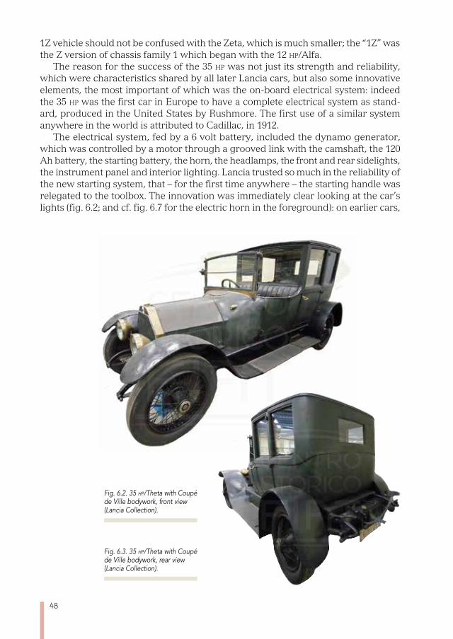
The electrical system, fed by a 6 volt battery, included the dynamo generator, which was controlled by a motor through a grooved link with the camshaft, the 120 Ah battery, the starting battery, the horn, the headlamps, the front and rear sidelights, the instrument panel and interior lighting. Lancia trusted so much in the reliability of the new starting system, that – for the first time anywhere – the starting handle was relegated to the toolbox. The innovation was immediately clear looking at the car’s lights (fig. 6.2; and cf. fig. 6.7 for the electric horn in the foreground): on earlier cars,
Fig. 6.2. 35 hp/Theta with Coupé de Ville bodywork, front view (Lancia Collection).
Fig. 6.3. 35 hp/Theta with Coupé de Ville bodywork, rear view (Lancia Collection).

49
external illumination came from acetylene lights, fuelled by gas produced by mixing water and calcium carbide, normally fixed on a running board. The running chassis was available in two wheelbases, 3100 and 3370 mm, with the steering column which could be moved to three different positions to best adapt to the needs of the driver.
The Coupé de Ville belonging to the Lancia collection and shown in figure 6.2 and 6.3 is in perfect working order, despite having survived until our time, having only had ordinary maintenance work; the photos allow us to appreciate the less shiny look, that of the original colour itself, in comparison with finishes redone using modern products (cf. fig. 6.7).
The body of Coupé de Ville includes a completely closed passenger area, and a driving section for the chauffeur and anyone accompanying him; as it is exposed to the elements, the front seat has a leather cover, while the inside seat has a more comfortable cloth finish (fig. 6.4).
Figure 6.4 shows, alongside some refinements – such as the rather affected cro-cheted seat cover, the walnut finish, the crystal flower holders, the footrests, the roll blinds – some modern elements, including the interior electric lamp, the window winder and the exhaust-gas-powered radiator located under the seat, something that was rarely found in cars at that time.
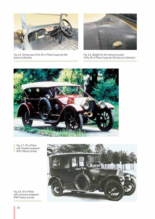
The cockpit (fig. 6.5) shows other interesting aspects, such as the fact the car had a fairly complete set of instruments, a dashboard with electric switches, steer-ing wheel controls for the ignition timer and the accelerator handle and the starter motor pedal, positioned in the centre of the floor. The other larger pedals are the clutch and the transmission brake, while the accelerator is placed in the middle. On the outside there is a second, smaller, pedal to open the exhaust and get top perfor-mance on less busy roads. The gear lever and rear wheel brake lever, while still on the outside of the driving seat, are now brought inside the body. It is interesting to recall that Vincenzo Lancia had felt that the traditional location of these levers outside the cockpit was not very aesthetically pleasing, so much so that he avoided showing them in official photographs.
The instruments, overhung by the large sweep of the dashboard, were lit by a kind of skylight, which could be opened for ventilation, located in the higher, central area
Fig. 6.4. Owner’s cabin of the 35 hp/Theta Coupé de Ville (Lancia Collection).
50
Fig. 6.8. 35 hp/Theta with Limousine bodywork (FIAT History Centre).
Fig. 6.7. 35 hp/Theta with Torpedo bodywork (FIAT History Centre).
Fig. 6.6. Skylight for the instrument panel of the 35 hp/Theta Coupé de Ville (Lancia Collection).
Fig. 6.5. Driving seat of the 35 hp/Theta Coupé de Ville (Lancia Collection).

51
in front of the windscreen (fig. 6.6, in which one of the sidelights can also be seen). The Theta with the Torpedo body (fig. 6.7) recalled the lines of the Coupé de Ville,
albeit with its own distinctive features. An original photograph from the time (fig. 6.8) allows us to grasp the slight differences between the Limousine and the Coupé de Ville, which at first were limited to the addition, in the former, of some minimal shelter for the driving seat.
The chassis (fig. 6.9) is of a conventional type, made with longitudinal struts and ties in pressed sheet metal, a larger-scale version of the design which earlier cars already had; the engine crankcase and the gearbox are moulded so that they actu-ally play the role of cross braces, again in the same way as previous models. It has rigid axle suspension, with semi-elliptical springs. The rear axle is connected with the habitual push rod, running parallel to the drive shaft.
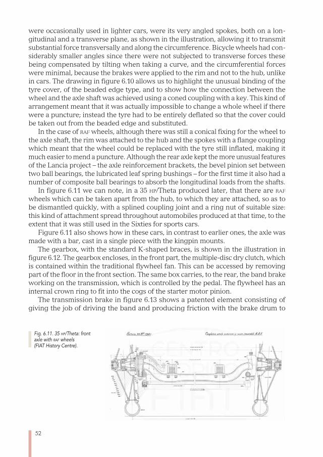
Over the lifetime of this automobile, more modern wheels than the wooden-spoke artillery type were added; two wheel variants are shown in the drawing of the rear axis in figure 6.10: on the right, the artillery type; to the left, those that were then known as the raf type, which were entirely made in metal and had spokes.
The name, from the initials of the British airforce, reflects the fact that this kind of wheel was used for the landing gear of the aircraft of the time because of its light weight. The unusual feature of this wheel, compared with bicycle-type spokes which
Fig. 6.9. 35 hp/Theta: rolling chassis design (FIAT History Centre).
Fig. 6.10. 35 hp/Theta: rear axle with two different wheel options (FIAT History Centre).
52
were occasionally used in lighter cars, were its very angled spokes, both on a lon-gitudinal and a transverse plane, as shown in the illustration, allowing it to transmit substantial force transversally and along the circumference. Bicycle wheels had con-siderably smaller angles since there were not subjected to transverse forces these being compensated by tilting when taking a curve, and the circumferential forces were minimal, because the brakes were applied to the rim and not to the hub, unlike in cars. The drawing in figure 6.10 allows us to highlight the unusual binding of the tyre cover, of the beaded edge type, and to show how the connection between the wheel and the axle shaft was achieved using a coned coupling with a key. This kind of arrangement meant that it was actually impossible to change a whole wheel if there were a puncture; instead the tyre had to be entirely deflated so that the cover could be taken out from the beaded edge and substituted.
In the case of raf wheels, although there was still a conical fixing for the wheel to the axle shaft, the rim was attached to the hub and the spokes with a flange coupling which meant that the wheel could be replaced with the tyre still inflated, making it much easier to mend a puncture. Although the rear axle kept the more unusual features of the Lancia project – the axle reinforcement brackets, the bevel pinion set between two ball bearings, the lubricated leaf spring bushings – for the first time it also had a number of composite ball bearings to absorb the longitudinal loads from the shafts.
In figure 6.11 we can note, in a 35 hp/Theta produced later, that there are raf wheels which can be taken apart from the hub, to which they are attached, so as to be dismantled quickly, with a splined coupling joint and a ring nut of suitable size: this kind of attachment spread throughout automobiles produced at that time, to the extent that it was still used in the Sixties for sports cars.
Figure 6.11 also shows how in these cars, in contrast to earlier ones, the axle was made with a bar, cast in a single piece with the kingpin mounts.
The gearbox, with the standard K-shaped braces, is shown in the illustration in figure 6.12. The gearbox encloses, in the front part, the multiple-disc dry clutch, which is contained within the traditional flywheel fan. This can be accessed by removing part of the floor in the front section. The same box carries, to the rear, the band brake working on the transmission, which is controlled by the pedal. The flywheel has an internal crown ring to fit into the cogs of the starter motor pinion.
The transmission brake in figure 6.13 shows a patented element consisting of giving the job of driving the band and producing friction with the brake drum to
Fig. 6.11. 35 hp/Theta: front axle with raf wheels (FIAT History Centre).
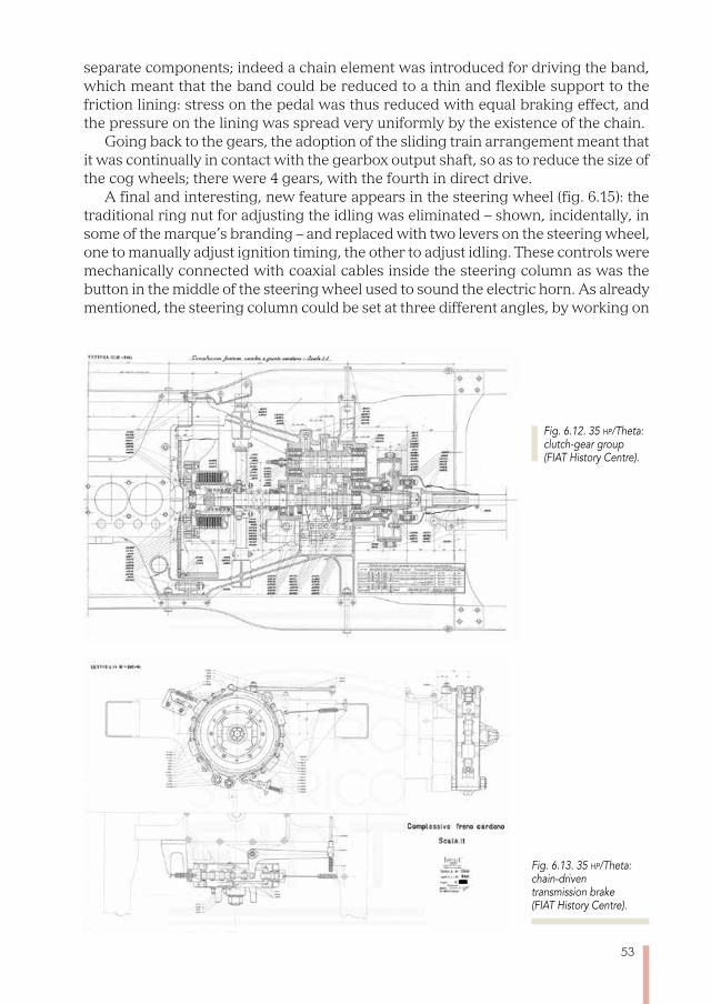
53
separate components; indeed a chain element was introduced for driving the band, which meant that the band could be reduced to a thin and flexible support to the friction lining: stress on the pedal was thus reduced with equal braking effect, and the pressure on the lining was spread very uniformly by the existence of the chain.
Going back to the gears, the adoption of the sliding train arrangement meant that it was continually in contact with the gearbox output shaft, so as to reduce the size of the cog wheels; there were 4 gears, with the fourth in direct drive.
A final and interesting, new feature appears in the steering wheel (fig. 6.15): the traditional ring nut for adjusting the idling was eliminated – shown, incidentally, in some of the marque’s branding – and replaced with two levers on the steering wheel, one to manually adjust ignition timing, the other to adjust idling. These controls were mechanically connected with coaxial cables inside the steering column as was the button in the middle of the steering wheel used to sound the electric horn. As already mentioned, the steering column could be set at three different angles, by working on
Fig. 6.13. 35 hp/Theta: chain-driven transmission brake (FIAT History Centre).
Fig. 6.12. 35 hp/Theta: clutch-gear group (FIAT History Centre).
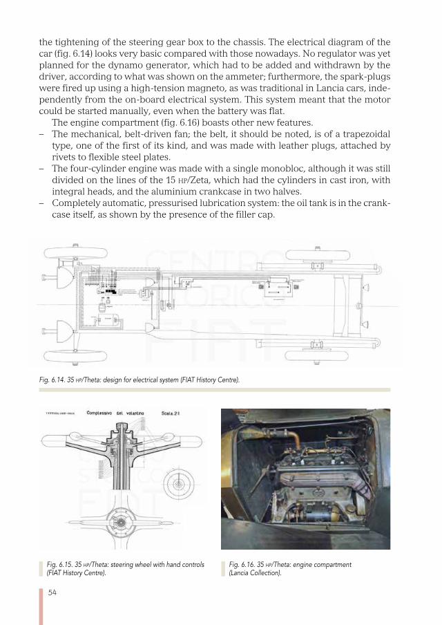
54
the tightening of the steering gear box to the chassis. The electrical diagram of the car (fig. 6.14) looks very basic compared with those nowadays. No regulator was yet planned for the dynamo generator, which had to be added and withdrawn by the driver, according to what was shown on the ammeter; furthermore, the spark-plugs were fired up using a high-tension magneto, as was traditional in Lancia cars, inde-pendently from the on-board electrical system. This system meant that the motor could be started manually, even when the battery was flat.
The engine compartment (fig. 6.16) boasts other new features. – The mechanical, belt-driven fan; the belt, it should be noted, is of a trapezoidal
type, one of the first of its kind, and was made with leather plugs, attached by rivets to flexible steel plates.
– The four-cylinder engine was made with a single monobloc, although it was still divided on the lines of the 15 hp/Zeta, which had the cylinders in cast iron, with integral heads, and the aluminium crankcase in two halves.
– Completely automatic, pressurised lubrication system: the oil tank is in the crank-case itself, as shown by the presence of the filler cap.
Fig. 6.14. 35 hp/Theta: design for electrical system (FIAT History Centre).
Fig. 6.16. 35 hp/Theta: engine compartment (Lancia Collection).
Fig. 6.15. 35 hp/Theta: steering wheel with hand controls (FIAT History Centre).

55
– The gear-driven dynamo generator is placed on the side, between the engine mounting legs.
Figure 6.17 shows a cross section of the engine (serial number 61) with an impos-ing 4940 cm3 capacity, obtained with a bore of 110 mm and a stroke of 130 mm; the power rating was 70 HP at 2200 rev/min. The side valves, now driven from inside the lubricated system, were protected by a cover; the tappet coupled to the cam using a roller contact. The decompression taps were still there, to assist any manual start-ing. The design clearly shows the space taken up by the dynamo generator and the starter motor which connected to the flywheel via internal cogs.
The longitudinal horizontal section of the engine (fig. 6.18) allows us to see the camshaft, also used to start the gear-driven oil pump, located at its rear end; the
Fig. 6.17. 35 hp/Theta: transverse section of the engine (FIAT History Centre).
Fig. 6.18. 35 hp/Theta: longitudinal horizontal section of the engine (FIAT History Centre).
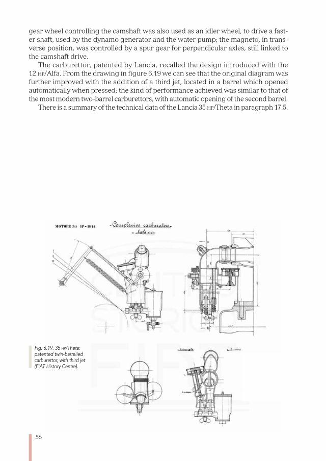
56
gear wheel controlling the camshaft was also used as an idler wheel, to drive a fast-er shaft, used by the dynamo generator and the water pump; the magneto, in trans-verse position, was controlled by a spur gear for perpendicular axles, still linked to the camshaft drive.
The carburettor, patented by Lancia, recalled the design introduced with the 12 hp/Alfa. From the drawing in figure 6.19 we can see that the original diagram was further improved with the addition of a third jet, located in a barrel which opened automatically when pressed; the kind of performance achieved was similar to that of the most modern two-barrel carburettors, with automatic opening of the second barrel.
There is a summary of the technical data of the Lancia 35 hp/Theta in paragraph 17.5.
Fig. 6.19. 35 hp/Theta: patented twin-barrelled carburettor, with third jet (FIAT History Centre).
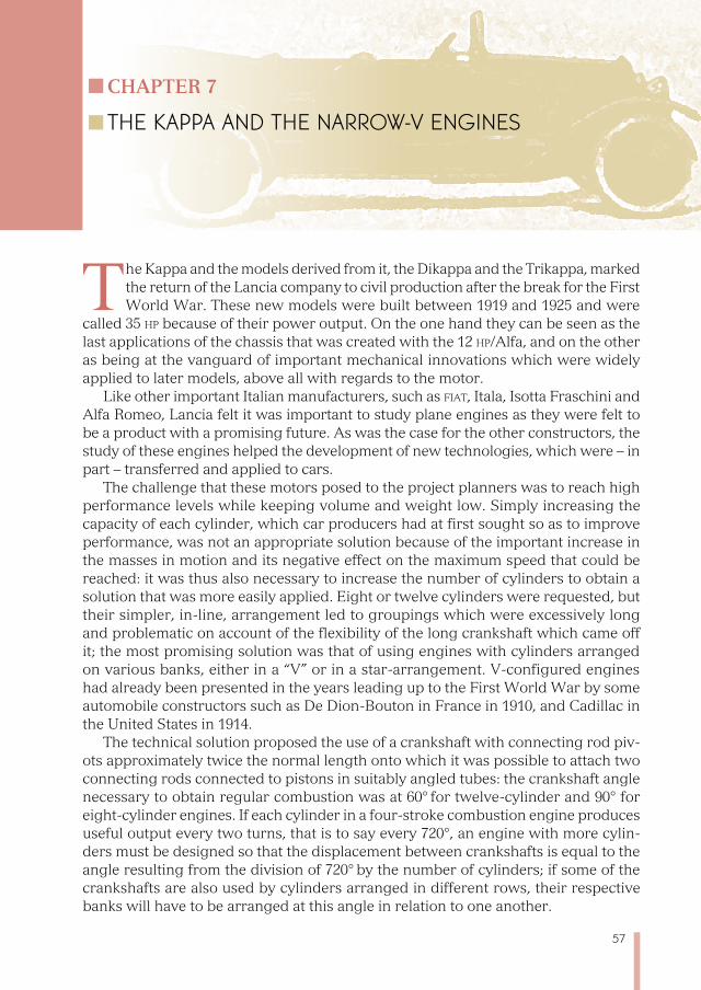
57
Chapter 7
THE KAPPA AND THE NARROW-V ENGINES
The Kappa and the models derived from it, the Dikappa and the Trikappa, marked the return of the Lancia company to civil production after the break for the First World War. These new models were built between 1919 and 1925 and were
called 35 hp because of their power output. On the one hand they can be seen as the last applications of the chassis that was created with the 12 hp/Alfa, and on the other as being at the vanguard of important mechanical innovations which were widely applied to later models, above all with regards to the motor.
Like other important Italian manufacturers, such as fiat, Itala, Isotta Fraschini and Alfa Romeo, Lancia felt it was important to study plane engines as they were felt to be a product with a promising future. As was the case for the other constructors, the study of these engines helped the development of new technologies, which were – in part – transferred and applied to cars.
The challenge that these motors posed to the project planners was to reach high performance levels while keeping volume and weight low. Simply increasing the capacity of each cylinder, which car producers had at first sought so as to improve performance, was not an appropriate solution because of the important increase in the masses in motion and its negative effect on the maximum speed that could be reached: it was thus also necessary to increase the number of cylinders to obtain a solution that was more easily applied. Eight or twelve cylinders were requested, but their simpler, in-line, arrangement led to groupings which were excessively long and problematic on account of the flexibility of the long crankshaft which came off it; the most promising solution was that of using engines with cylinders arranged on various banks, either in a “V” or in a star-arrangement. V-configured engines had already been presented in the years leading up to the First World War by some automobile constructors such as De Dion-Bouton in France in 1910, and Cadillac in the United States in 1914.
The technical solution proposed the use of a crankshaft with connecting rod piv-ots approximately twice the normal length onto which it was possible to attach two connecting rods connected to pistons in suitably angled tubes: the crankshaft angle necessary to obtain regular combustion was at 60° for twelve-cylinder and 90° for eight-cylinder engines. If each cylinder in a four-stroke combustion engine produces useful output every two turns, that is to say every 720°, an engine with more cylin-ders must be designed so that the displacement between crankshafts is equal to the angle resulting from the division of 720° by the number of cylinders; if some of the crankshafts are also used by cylinders arranged in different rows, their respective banks will have to be arranged at this angle in relation to one another.
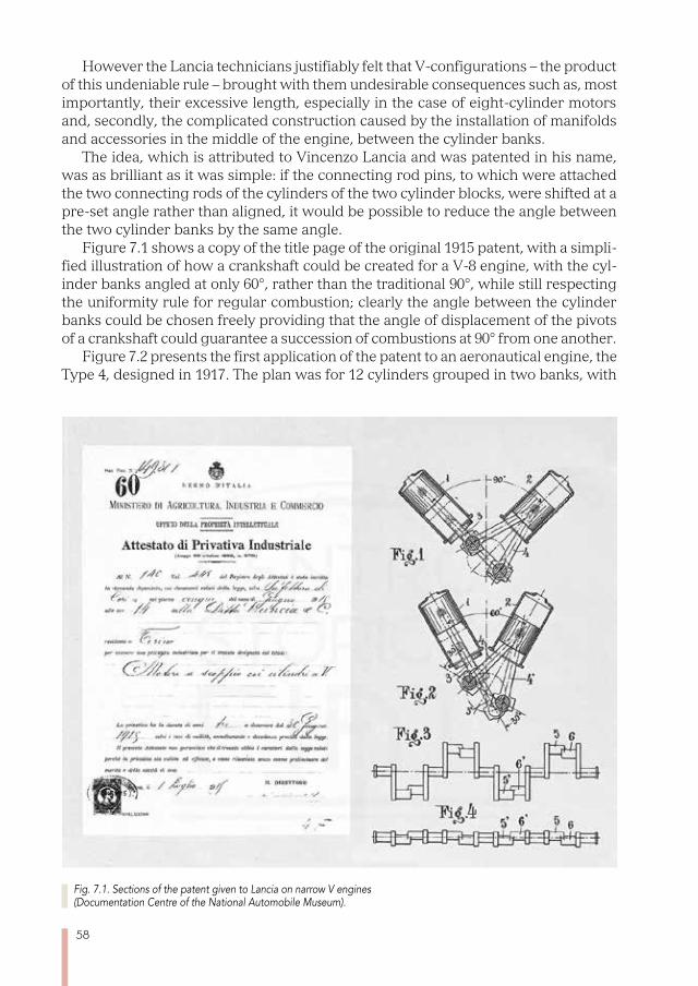
58
However the Lancia technicians justifiably felt that V-configurations – the product of this undeniable rule – brought with them undesirable consequences such as, most importantly, their excessive length, especially in the case of eight-cylinder motors and, secondly, the complicated construction caused by the installation of manifolds and accessories in the middle of the engine, between the cylinder banks.
The idea, which is attributed to Vincenzo Lancia and was patented in his name, was as brilliant as it was simple: if the connecting rod pins, to which were attached the two connecting rods of the cylinders of the two cylinder blocks, were shifted at a pre-set angle rather than aligned, it would be possible to reduce the angle between the two cylinder banks by the same angle.
Figure 7.1 shows a copy of the title page of the original 1915 patent, with a simpli-fied illustration of how a crankshaft could be created for a V-8 engine, with the cyl-inder banks angled at only 60°, rather than the traditional 90°, while still respecting the uniformity rule for regular combustion; clearly the angle between the cylinder banks could be chosen freely providing that the angle of displacement of the pivots of a crankshaft could guarantee a succession of combustions at 90° from one another.
Figure 7.2 presents the first application of the patent to an aeronautical engine, the Type 4, designed in 1917. The plan was for 12 cylinders grouped in two banks, with
Fig. 7.1. Sections of the patent given to Lancia on narrow V engines (Documentation Centre of the National Automobile Museum).
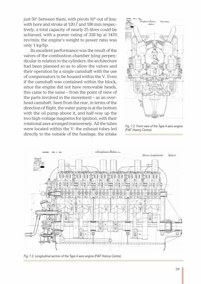
59
just 50° between them, with pivots 10° out of line; with bore and stroke at 120.7 and 180 mm respec-tively, a total capacity of nearly 25 litres could be achieved, with a power rating of 358 hp at 1470 rev/min; the engine’s weight to power ratio was only 1 kg/hp.
Its excellent performance was the result of the valves of the combustion chamber lying perpen-dicular in relation to the cylinders: the architecture had been planned so as to allow the valves and their operation by a single camshaft with the use of compensators to be housed within the V. Even if the camshaft was contained within the block, since the engine did not have removable heads, this came to the same – from the point of view of the parts involved in the movement – as an over-head camshaft. Seen from the rear, in terms of the direction of flight, the water pump is at the bottom with the oil pump above it, and half-way up the two high-voltage magnetos for ignition, with their rotational axes arranged transversely. All the tubes were located within the V: the exhaust tubes led directly to the outside of the fuselage, the intake
Fig. 7.2. Front view of the Type 4 aero engine (FIAT History Centre).
Fig. 7.3. Longitudinal section of the Type 4 aero engine (FIAT History Centre).
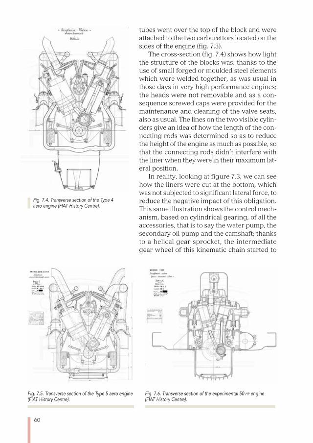
60
tubes went over the top of the block and were attached to the two carburettors located on the sides of the engine (fig. 7.3).
The cross-section (fig. 7.4) shows how light the structure of the blocks was, thanks to the use of small forged or moulded steel elements which were welded together, as was usual in those days in very high performance engines; the heads were not removable and as a con-sequence screwed caps were provided for the maintenance and cleaning of the valve seats, also as usual. The lines on the two visible cylin-ders give an idea of how the length of the con-necting rods was determined so as to reduce the height of the engine as much as possible, so that the connecting rods didn’t interfere with the liner when they were in their maximum lat-eral position.
In reality, looking at figure 7.3, we can see how the liners were cut at the bottom, which was not subjected to significant lateral force, to reduce the negative impact of this obligation. This same illustration shows the control mech-anism, based on cylindrical gearing, of all the accessories, that is to say the water pump, the secondary oil pump and the camshaft; thanks to a helical gear sprocket, the intermediate gear wheel of this kinematic chain started to
Fig. 7.4. Transverse section of the Type 4 aero engine (FIAT History Centre).
Fig. 7.5. Transverse section of the Type 5 aero engine (FIAT History Centre).
Fig. 7.6. Transverse section of the experimental 50 hp engine (FIAT History Centre).
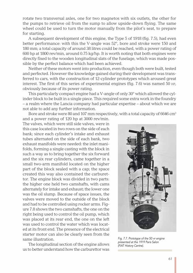
61
rotate two transversal axles, one for two magnetos with six outlets, the other for the pumps to retrieve oil from the sump to allow upside-down flying. The same wheel could be used to turn the motor manually from the pilot’s seat, to prepare for starting.
A subsequent development of this engine, the Type 5 of 1918 (fig. 7.5), had even better performance: with this the V-angle was 52°, bore and stroke were 150 and 180 mm; a total capacity of around 38 litres could be reached, with a power rating of 600 hp at 1800 rev/min, around 0.75 kg/hp. It is worth noting that both engines were directly fixed to the wooden longitudinal slats of the fuselage, which was made pos-sible by the perfect balance which had been achieved.
Neither of these motors went into production, even though both were built, tested and perfected. However the knowledge gained during their development was trans-ferred to cars, with the construction of 12-cylinder prototypes which aroused great interest. The first of this series of experimental engines (fig. 7.6) was named 50 hp, obviously because of its power rating.
This particularly compact engine had a V-angle of only 30° which allowed the cyl-inder block to be built in a single piece. This required some extra work in the foundry – a realm where the Lancia company had particular expertise – about which we are not able to add any further information.
Bore and stroke were 80 and 107 mm respectively, with a total capacity of 6646 cm3 and a power rating of 120 hp at 3000 rev/min. The valves, which were still side valves, were in this case located in two rows on the side of each bank; since each cylinder’s intake and exhaust tubes alternated on the side of each bank, two exhaust manifolds were needed: the inlet mani-folds, forming a single casting with the block in such a way as to bring together the six forward and the six rear cylinders, came together in a small two-arm manifold located on the higher part of the block sealed with a cap; the space created this way also contained the carburet-tor. The engine block was divided in two parts: the higher one held two camshafts, with cams alternately for intake and exhaust; the lower one was the oil slump. Because of space issues, the valves were moved to the outside of the block and had to be controlled using rocker arms. Fig-ure 7.8 shows the two camshafts, the one on the right being used to control the oil pump, which was placed at its rear end, the one on the left was used to control the water which was locat-ed at its front end. The presence of the electrical starter motor can also be clearly seen from the same illustration.
The longitudinal section of the engine allows us to better understand how the carburettor was
Fig. 7.7. Prototype of the 50 hp engine presented at the 1919 Paris Salon (FIAT History Centre).
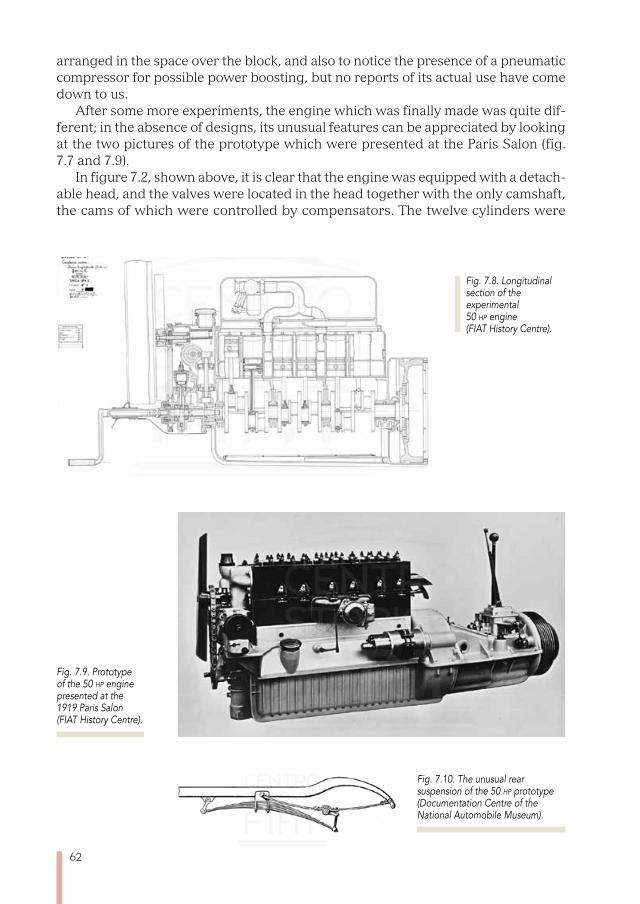
62
Fig. 7.8. Longitudinal section of the experimental 50 hp engine (FIAT History Centre).
arranged in the space over the block, and also to notice the presence of a pneumatic compressor for possible power boosting, but no reports of its actual use have come down to us.
After some more experiments, the engine which was finally made was quite dif-ferent; in the absence of designs, its unusual features can be appreciated by looking at the two pictures of the prototype which were presented at the Paris Salon (fig. 7.7 and 7.9).
In figure 7.2, shown above, it is clear that the engine was equipped with a detach-able head, and the valves were located in the head together with the only camshaft, the cams of which were controlled by compensators. The twelve cylinders were
Fig. 7.9. Prototype of the 50 hp engine presented at the 1919 Paris Salon (FIAT History Centre).
Fig. 7.10. The unusual rear suspension of the 50 hp prototype (Documentation Centre of the National Automobile Museum).
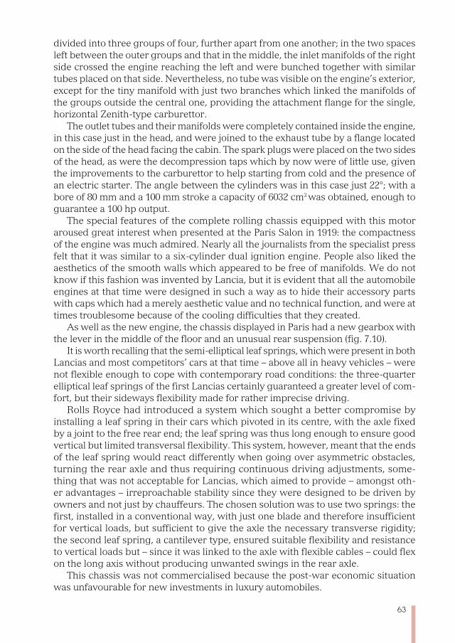
63
divided into three groups of four, further apart from one another; in the two spaces left between the outer groups and that in the middle, the inlet manifolds of the right side crossed the engine reaching the left and were bunched together with similar tubes placed on that side. Nevertheless, no tube was visible on the engine’s exterior, except for the tiny manifold with just two branches which linked the manifolds of the groups outside the central one, providing the attachment flange for the single, horizontal Zenith-type carburettor.
The outlet tubes and their manifolds were completely contained inside the engine, in this case just in the head, and were joined to the exhaust tube by a flange located on the side of the head facing the cabin. The spark plugs were placed on the two sides of the head, as were the decompression taps which by now were of little use, given the improvements to the carburettor to help starting from cold and the presence of an electric starter. The angle between the cylinders was in this case just 22°; with a bore of 80 mm and a 100 mm stroke a capacity of 6032 cm3 was obtained, enough to guarantee a 100 hp output.
The special features of the complete rolling chassis equipped with this motor aroused great interest when presented at the Paris Salon in 1919: the compactness of the engine was much admired. Nearly all the journalists from the specialist press felt that it was similar to a six-cylinder dual ignition engine. People also liked the aesthetics of the smooth walls which appeared to be free of manifolds. We do not know if this fashion was invented by Lancia, but it is evident that all the automobile engines at that time were designed in such a way as to hide their accessory parts with caps which had a merely aesthetic value and no technical function, and were at times troublesome because of the cooling difficulties that they created.
As well as the new engine, the chassis displayed in Paris had a new gearbox with the lever in the middle of the floor and an unusual rear suspension (fig. 7.10).
It is worth recalling that the semi-elliptical leaf springs, which were present in both Lancias and most competitors’ cars at that time – above all in heavy vehicles – were not flexible enough to cope with contemporary road conditions: the three-quarter elliptical leaf springs of the first Lancias certainly guaranteed a greater level of com-fort, but their sideways flexibility made for rather imprecise driving.
Rolls Royce had introduced a system which sought a better compromise by installing a leaf spring in their cars which pivoted in its centre, with the axle fixed by a joint to the free rear end; the leaf spring was thus long enough to ensure good vertical but limited transversal flexibility. This system, however, meant that the ends of the leaf spring would react differently when going over asymmetric obstacles, turning the rear axle and thus requiring continuous driving adjustments, some-thing that was not acceptable for Lancias, which aimed to provide – amongst oth-er advantages – irreproachable stability since they were designed to be driven by owners and not just by chauffeurs. The chosen solution was to use two springs: the first, installed in a conventional way, with just one blade and therefore insufficient for vertical loads, but sufficient to give the axle the necessary transverse rigidity; the second leaf spring, a cantilever type, ensured suitable flexibility and resistance to vertical loads but – since it was linked to the axle with flexible cables – could flex on the long axis without producing unwanted swings in the rear axle.
This chassis was not commercialised because the post-war economic situation was unfavourable for new investments in luxury automobiles.
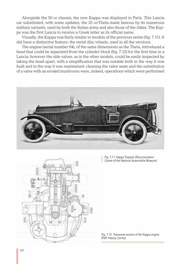
64
Alongside the 50 hp chassis, the new Kappa was displayed in Paris. This Lancia car substituted, with some updates, the 35 hp/Theta made famous by its numerous military variants, used by both the Italian army and also those of the Allies. The Kap-pa was the first Lancia to receive a Greek letter as its official name.
Visually, the Kappa was fairly similar to models of the previous series (fig. 7.11). It did have a distinctive feature: the metal disc wheels, used in all the versions.
The engine (serial number 64), of the same dimensions as the Theta, introduced a head that could be separated from the cylinder block (fig. 7.12) for the first time in a Lancia; however the side valves, as in the other models, could be easily inspected by taking the head apart, with a simplification that was notable both in the way it was built and in the way it was maintained: cleaning the valve seats and the substitution of a valve with an eroded mushroom were, indeed, operations which were performed
Fig. 7.11. Kappa Torpedo (Documentation Centre of the National Automobile Museum).
Fig. 7.12. Transverse section of the Kappa engine (FIAT History Centre).
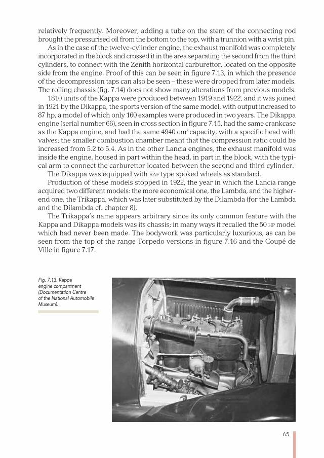
65
relatively frequently. Moreover, adding a tube on the stem of the connecting rod brought the pressurised oil from the bottom to the top, with a trunnion with a wrist pin.
As in the case of the twelve-cylinder engine, the exhaust manifold was completely incorporated in the block and crossed it in the area separating the second from the third cylinders, to connect with the Zenith horizontal carburettor, located on the opposite side from the engine. Proof of this can be seen in figure 7.13, in which the presence of the decompression taps can also be seen – these were dropped from later models. The rolling chassis (fig. 7.14) does not show many alterations from previous models.
1810 units of the Kappa were produced between 1919 and 1922, and it was joined in 1921 by the Dikappa, the sports version of the same model, with output increased to 87 hp, a model of which only 160 examples were produced in two years. The Dikappa engine (serial number 66), seen in cross section in figure 7.15, had the same crankcase as the Kappa engine, and had the same 4940 cm3 capacity, with a specific head with valves; the smaller combustion chamber meant that the compression ratio could be increased from 5.2 to 5.4. As in the other Lancia engines, the exhaust manifold was inside the engine, housed in part within the head, in part in the block, with the typi-cal arm to connect the carburettor located between the second and third cylinder.
The Dikappa was equipped with raf type spoked wheels as standard. Production of these models stopped in 1922, the year in which the Lancia range
acquired two different models: the more economical one, the Lambda, and the higher-end one, the Trikappa, which was later substituted by the Dilambda (for the Lambda and the Dilambda cf. chapter 8).
The Trikappa’s name appears arbitrary since its only common feature with the Kappa and Dikappa models was its chassis; in many ways it recalled the 50 hp model which had never been made. The bodywork was particularly luxurious, as can be seen from the top of the range Torpedo versions in figure 7.16 and the Coupé de Ville in figure 7.17.
Fig. 7.13. Kappa engine compartment (Documentation Centre of the National Automobile Museum).
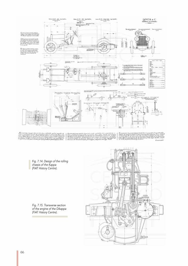
66
Fig. 7.14. Design of the rolling chassis of the Kappa (FIAT History Centre).
Fig. 7.15. Transverse section of the engine of the Dikappa (FIAT History Centre).
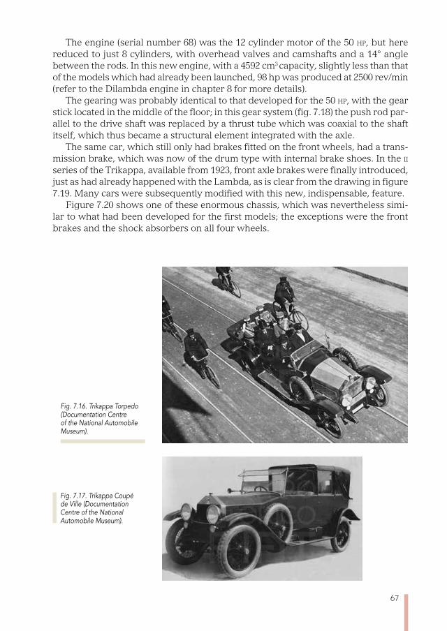
67
The engine (serial number 68) was the 12 cylinder motor of the 50 hp, but here reduced to just 8 cylinders, with overhead valves and camshafts and a 14° angle between the rods. In this new engine, with a 4592 cm3 capacity, slightly less than that of the models which had already been launched, 98 hp was produced at 2500 rev/min (refer to the Dilambda engine in chapter 8 for more details).
The gearing was probably identical to that developed for the 50 hp, with the gear stick located in the middle of the floor; in this gear system (fig. 7.18) the push rod par-allel to the drive shaft was replaced by a thrust tube which was coaxial to the shaft itself, which thus became a structural element integrated with the axle.
The same car, which still only had brakes fitted on the front wheels, had a trans-mission brake, which was now of the drum type with internal brake shoes. In the ii series of the Trikappa, available from 1923, front axle brakes were finally introduced, just as had already happened with the Lambda, as is clear from the drawing in figure 7.19. Many cars were subsequently modified with this new, indispensable, feature.
Figure 7.20 shows one of these enormous chassis, which was nevertheless simi-lar to what had been developed for the first models; the exceptions were the front brakes and the shock absorbers on all four wheels.
Fig. 7.17. Trikappa Coupé de Ville (Documentation Centre of the National Automobile Museum).
Fig. 7.16. Trikappa Torpedo (Documentation Centre of the National Automobile Museum).
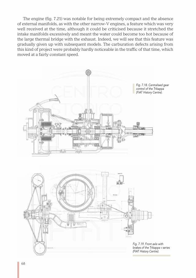
68
The engine (fig. 7.21) was notable for being extremely compact and the absence of external manifolds, as with the other narrow-V engines, a feature which was very well received at the time, although it could be criticised because it stretched the intake manifolds excessively and meant the water could become too hot because of the large thermal bridge with the exhaust. Indeed, we will see that this feature was gradually given up with subsequent models. The carburation defects arising from this kind of project were probably hardly noticeable in the traffic of that time, which moved at a fairly constant speed.
Fig. 7.19. Front axle with brakes of the Trikappa ii series (FIAT History Centre).
Fig. 7.18. Centralised gear control of the Trikappa (FIAT History Centre).

69
Finally, figure 7.22 shows an interesting detail of the rear suspension: the friction shock absorber is of the belt type for greater comfort when overcoming obstacles; the leaf spring was covered with leather to better hold the lubrication grease and avoid unwanted squeaking.
A total of 847 units of the Trikappa were made. For a summary of the technical data for the three vehicles covered, the Kappa, the Dikappa and the Trikappa, see paragraphs 17.6, 17.7 and 17.8 respectively.
Fig. 7.20. Trikappa rolling chassis (Lancia Collection).
Fig. 7.21. Trikappa engine (Lancia Collection).
Fig. 7.22. Detail of the rear suspension of the Trikappa (Lancia Collection).
Fig. 7.18. Centralised gear control of the Trikappa (FIAT History Centre).

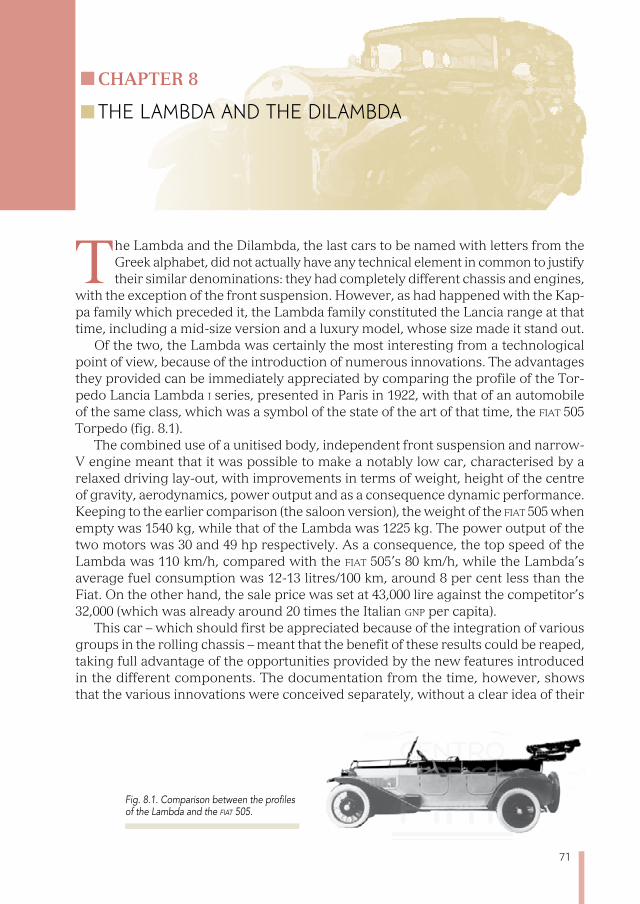
71
Chapter 8
THE LAMBDA AND THE DILAMBDA
The Lambda and the Dilambda, the last cars to be named with letters from the Greek alphabet, did not actually have any technical element in common to justify their similar denominations: they had completely different chassis and engines,
with the exception of the front suspension. However, as had happened with the Kap-pa family which preceded it, the Lambda family constituted the Lancia range at that time, including a mid-size version and a luxury model, whose size made it stand out.
Of the two, the Lambda was certainly the most interesting from a technological point of view, because of the introduction of numerous innovations. The advantages they provided can be immediately appreciated by comparing the profile of the Tor-pedo Lancia Lambda i series, presented in Paris in 1922, with that of an automobile of the same class, which was a symbol of the state of the art of that time, the fiat 505 Torpedo (fig. 8.1).
The combined use of a unitised body, independent front suspension and narrow-V engine meant that it was possible to make a notably low car, characterised by a relaxed driving lay-out, with improvements in terms of weight, height of the centre of gravity, aerodynamics, power output and as a consequence dynamic performance. Keeping to the earlier comparison (the saloon version), the weight of the fiat 505 when empty was 1540 kg, while that of the Lambda was 1225 kg. The power output of the two motors was 30 and 49 hp respectively. As a consequence, the top speed of the Lambda was 110 km/h, compared with the fiat 505’s 80 km/h, while the Lambda’s average fuel consumption was 12-13 litres/100 km, around 8 per cent less than the Fiat. On the other hand, the sale price was set at 43,000 lire against the competitor’s 32,000 (which was already around 20 times the Italian Gnp per capita).
This car – which should first be appreciated because of the integration of various groups in the rolling chassis – meant that the benefit of these results could be reaped, taking full advantage of the opportunities provided by the new features introduced in the different components. The documentation from the time, however, shows that the various innovations were conceived separately, without a clear idea of their
Fig. 8.1. Comparison between the profiles of the Lambda and the fiat 505.

72
contribution to the final results and this was only reached by working on the final project, perhaps in a rather unexpected way.
This means it is useful to examine each of these technical aspects separately, starting from the unitised body. Until that time, cars – even Lancias – used a ladder structure, consisting of a chassis with longitudinal struts and ties in moulded and nailed metal bars, on which the bodywork was mounted, which – in the Twenties – was generally made of metal sheeting fixed to a wooden structure. This technological approach meant that the shapes needed for the bodywork could be obtained using simple folding and bending methods which did not involve the use of very expensive machinery and – most of all – meant that a complete rolling chassis could be built, which could then have different kinds of bodywork added, possibly with input from outside manufacturers. Accompanying these unquestionable advantages, the main drawback was the limited strength of the chassis and thus of the car itself, which – having at that time to travel on road surfaces which were still very rudimentary – quickly became noisy, because of bumps and creaks.
These problems were very clear to Vincenzo Lancia, because of his long experi-ence in driving, and it seems that during his sea crossings to the United States he had thought through the superiority of the structural performance of hull-type structures, compared to that of rectangular flat ones, and had decided to research whether they could be applied to his cars as well.
In March 1919, patent number 171922 was deposited by Lancia in Italy for a body-work with a hull-shaped structure, and figure 8.2 is a reproduction of the illustration.
The document had the following explanatory text:
This invention is for cars in which the chassis is suppressed and the connection between the rear and front axles is made by a solid shell, which has the same func-tion as the bodywork in normal cars. The invention even includes [the definition of] a special kind of this shell, which can be lowered below the level of the wheel axles, and which at the same time gives them greater strength.
Fig. 8.2. Patent on unitised body (Documentation Centre of the National Automobile Museum).
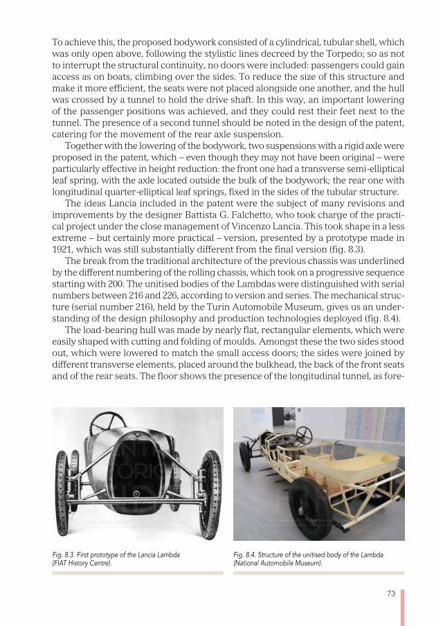
73
To achieve this, the proposed bodywork consisted of a cylindrical, tubular shell, which was only open above, following the stylistic lines decreed by the Torpedo; so as not to interrupt the structural continuity, no doors were included: passengers could gain access as on boats, climbing over the sides. To reduce the size of this structure and make it more efficient, the seats were not placed alongside one another, and the hull was crossed by a tunnel to hold the drive shaft. In this way, an important lowering of the passenger positions was achieved, and they could rest their feet next to the tunnel. The presence of a second tunnel should be noted in the design of the patent, catering for the movement of the rear axle suspension.
Together with the lowering of the bodywork, two suspensions with a rigid axle were proposed in the patent, which – even though they may not have been original – were particularly effective in height reduction: the front one had a transverse semi-elliptical leaf spring, with the axle located outside the bulk of the bodywork; the rear one with longitudinal quarter-elliptical leaf springs, fixed in the sides of the tubular structure.
The ideas Lancia included in the patent were the subject of many revisions and improvements by the designer Battista G. Falchetto, who took charge of the practi-cal project under the close management of Vincenzo Lancia. This took shape in a less extreme – but certainly more practical – version, presented by a prototype made in 1921, which was still substantially different from the final version (fig. 8.3).
The break from the traditional architecture of the previous chassis was underlined by the different numbering of the rolling chassis, which took on a progressive sequence starting with 200. The unitised bodies of the Lambdas were distinguished with serial numbers between 216 and 226, according to version and series. The mechanical struc-ture (serial number 216), held by the Turin Automobile Museum, gives us an under-standing of the design philosophy and production technologies deployed (fig. 8.4).
The load-bearing hull was made by nearly flat, rectangular elements, which were easily shaped with cutting and folding of moulds. Amongst these the two sides stood out, which were lowered to match the small access doors; the sides were joined by different transverse elements, placed around the bulkhead, the back of the front seats and of the rear seats. The floor shows the presence of the longitudinal tunnel, as fore-
Fig. 8.3. First prototype of the Lancia Lambda (FIAT History Centre).
Fig. 8.4. Structure of the unitised body of the Lambda (National Automobile Museum).
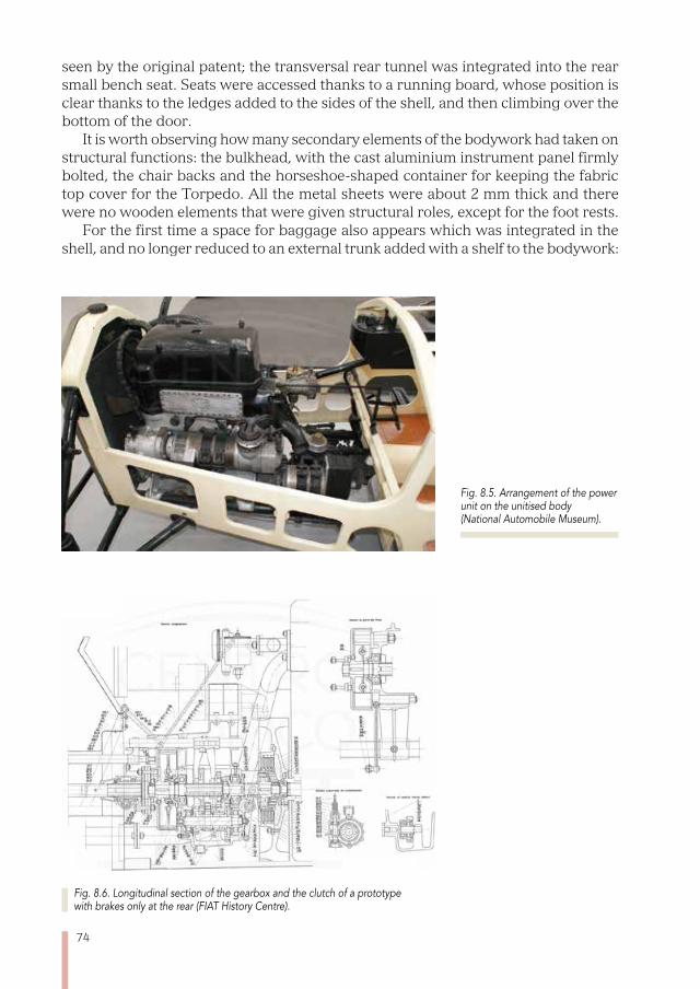
74
seen by the original patent; the transversal rear tunnel was integrated into the rear small bench seat. Seats were accessed thanks to a running board, whose position is clear thanks to the ledges added to the sides of the shell, and then climbing over the bottom of the door.
It is worth observing how many secondary elements of the bodywork had taken on structural functions: the bulkhead, with the cast aluminium instrument panel firmly bolted, the chair backs and the horseshoe-shaped container for keeping the fabric top cover for the Torpedo. All the metal sheets were about 2 mm thick and there were no wooden elements that were given structural roles, except for the foot rests.
For the first time a space for baggage also appears which was integrated in the shell, and no longer reduced to an external trunk added with a shelf to the bodywork:
Fig. 8.6. Longitudinal section of the gearbox and the clutch of a prototype with brakes only at the rear (FIAT History Centre).
Fig. 8.5. Arrangement of the power unit on the unitised body (National Automobile Museum).
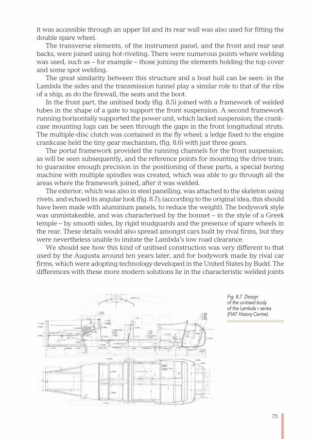
75
it was accessible through an upper lid and its rear wall was also used for fitting the double spare wheel.
The transverse elements, of the instrument panel, and the front and rear seat backs, were joined using hot-riveting. There were numerous points where welding was used, such as – for example – those joining the elements holding the top cover and some spot welding.
The great similarity between this structure and a boat hull can be seen: in the Lambda the sides and the transmission tunnel play a similar role to that of the ribs of a ship, as do the firewall, the seats and the boot.
In the front part, the unitised body (fig. 8.5) joined with a framework of welded tubes in the shape of a gate to support the front suspension. A second framework running horizontally supported the power unit, which lacked suspension; the crank-case mounting lugs can be seen through the gaps in the front longitudinal struts. The multiple-disc clutch was contained in the fly wheel; a ledge fixed to the engine crankcase held the tiny gear mechanism, (fig. 8.6) with just three gears.
The portal framework provided the running channels for the front suspension, as will be seen subsequently, and the reference points for mounting the drive train; to guarantee enough precision in the positioning of these parts, a special boring machine with multiple spindles was created, which was able to go through all the areas where the framework joined, after it was welded.
The exterior, which was also in steel panelling, was attached to the skeleton using rivets, and echoed its angular look (fig. 8.7); (according to the original idea, this should have been made with aluminium panels, to reduce the weight). The bodywork style was unmistakeable, and was characterised by the bonnet – in the style of a Greek temple – by smooth sides, by rigid mudguards and the presence of spare wheels in the rear. These details would also spread amongst cars built by rival firms, but they were nevertheless unable to imitate the Lambda’s low road clearance.
We should see how this kind of unitised construction was very different to that used by the Augusta around ten years later, and for bodywork made by rival car firms, which were adopting technology developed in the United States by Budd. The differences with these more modern solutions lie in the characteristic welded joints
Fig. 8.7. Design of the unitised body of the Lambda v series (FIAT History Centre).
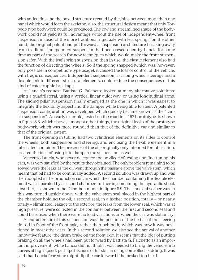
76
with added fins and the boxed structure created by the joins between more than one panel which would form the skeleton; also, the structural design meant that only Tor-pedo type bodywork could be produced. The low and streamlined shape of the body-work could not yield its full advantage without the use of independent-wheel front suspension instead of the more traditional rigid axle with leaf springs; on the other hand, the original patent had put forward a suspension architecture breaking away from tradition. Independent suspension had been researched by Lancia for some time as part of the search for new techniques which would make the front suspen-sion safer. With the leaf spring suspension then in use, the elastic element also had the function of directing the wheels. So if the spring snapped (which was, however, only possible in competition-type usage), it caused the loss of control of the vehicle, with tragic consequences. Independent suspension, ascribing wheel steerage and a flexible link to different structural elements, could reduce the consequences of this kind of catastrophic breakage.
At Lancia’s request, Battista G. Falchetto looked at many alternative solutions: using a quadrilateral, using a vertical linear guideway, or using longitudinal arms. The sliding pillar suspension finally emerged as the one in which it was easiest to integrate the flexibility aspect and the damper while being able to steer. A patented suspension configuration was developed which quickly became known as the “Lan-cia suspension”. An early example, tested on the road in a 1921 prototype, is shown in figure 8.8, which shows, amongst other things, the original looks of the prototype bodywork, which was more rounded than that of the definitive car and similar to that of the original patent.
The front opening in tubing had two cylindrical elements on its sides to control the wheels, both suspension and steering, and enclosing the flexible element in a lubricated container. The presence of the oil, originally only intended for lubrication, created the idea of using it to dampen the suspension as well.
Vincenzo Lancia, who never delegated the privilege of testing and fine-tuning his cars, was very satisfied by the results they obtained. The only problem remaining to be solved were the leaks as the oil went through the passage above the valve stem, which meant that oil had to be continually added. A second solution was drawn up and was then adopted in the production run, in which the chamber containing the flexible ele-ment was separated by a second chamber, further in, containing the hydraulic shock absorber, as shown in the Dilambda model in figure 8.9. The shock absorber was in this way turned upside down, with the valve stem seal placed in the highest part of the chamber holding the oil; a second seal, in a higher position, totally – or nearly totally – eliminated leakage to the exterior; the leaks from the lower seal, which was at high pressure, were collected in the container between the first and second seal and could be reused when there were no load variations or when the car was stationary.
A characteristic of this suspension was the position of the tie bar of the steering tie rod in front of the front axle, rather than behind it, which was how it was posi-tioned in most other cars. In this second solution we also see the arrival of another innovative feature: the drum brake on the front axle. It seems that the idea of putting braking on all the wheels had been put forward by Battista G. Falchetto as an impor-tant improvement, while Lancia did not think it was needed to bring the vehicle into curves at high speed, perhaps because of his skill in using controlled skidding. It was said that Lancia feared he might flip the car forward if he braked too hard.
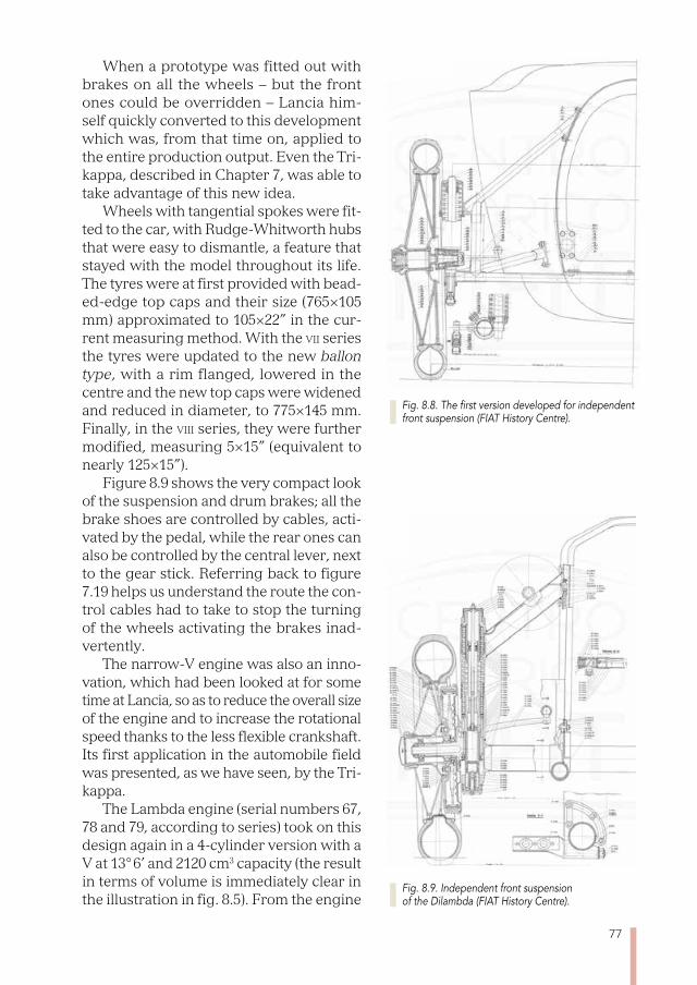
77
When a prototype was fitted out with brakes on all the wheels – but the front ones could be overridden – Lancia him-self quickly converted to this development which was, from that time on, applied to the entire production output. Even the Tri-kappa, described in Chapter 7, was able to take advantage of this new idea.
Wheels with tangential spokes were fit-ted to the car, with Rudge-Whitworth hubs that were easy to dismantle, a feature that stayed with the model throughout its life. The tyres were at first provided with bead-ed-edge top caps and their size (765×105 mm) approximated to 105×22” in the cur-rent measuring method. With the vii series the tyres were updated to the new ballon type, with a rim flanged, lowered in the centre and the new top caps were widened and reduced in diameter, to 775×145 mm. Finally, in the viii series, they were further modified, measuring 5×15” (equivalent to nearly 125×15”).
Figure 8.9 shows the very compact look of the suspension and drum brakes; all the brake shoes are controlled by cables, acti-vated by the pedal, while the rear ones can also be controlled by the central lever, next to the gear stick. Referring back to figure 7.19 helps us understand the route the con-trol cables had to take to stop the turning of the wheels activating the brakes inad-vertently.
The narrow-V engine was also an inno-vation, which had been looked at for some time at Lancia, so as to reduce the overall size of the engine and to increase the rotational speed thanks to the less flexible crankshaft. Its first application in the automobile field was presented, as we have seen, by the Tri-kappa.
The Lambda engine (serial numbers 67, 78 and 79, according to series) took on this design again in a 4-cylinder version with a V at 13° 6’ and 2120 cm3 capacity (the result in terms of volume is immediately clear in the illustration in fig. 8.5). From the engine
Fig. 8.8. The first version developed for independent front suspension (FIAT History Centre).
Fig. 8.9. Independent front suspension of the Dilambda (FIAT History Centre).
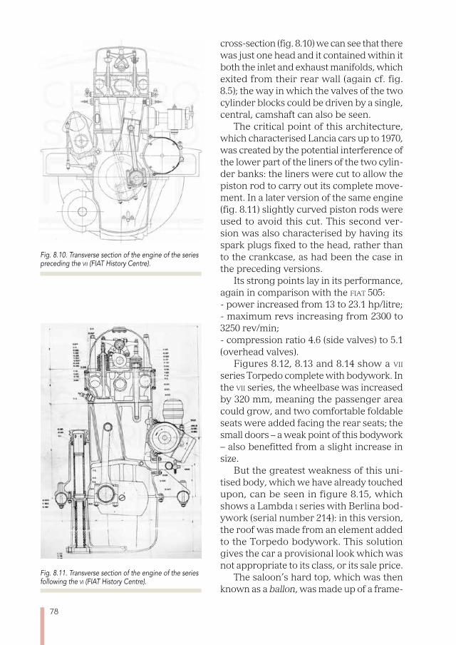
78
cross-section (fig. 8.10) we can see that there was just one head and it contained within it both the inlet and exhaust manifolds, which exited from their rear wall (again cf. fig. 8.5); the way in which the valves of the two cylinder blocks could be driven by a single, central, camshaft can also be seen.
The critical point of this architecture, which characterised Lancia cars up to 1970, was created by the potential interference of the lower part of the liners of the two cylin-der banks: the liners were cut to allow the piston rod to carry out its complete move-ment. In a later version of the same engine (fig. 8.11) slightly curved piston rods were used to avoid this cut. This second ver-sion was also characterised by having its spark plugs fixed to the head, rather than to the crankcase, as had been the case in the preceding versions.
Its strong points lay in its performance, again in comparison with the fiat 505: - power increased from 13 to 23.1 hp/litre;- maximum revs increasing from 2300 to 3250 rev/min; - compression ratio 4.6 (side valves) to 5.1 (overhead valves).
Figures 8.12, 8.13 and 8.14 show a vii series Torpedo complete with bodywork. In the vii series, the wheelbase was increased by 320 mm, meaning the passenger area could grow, and two comfortable foldable seats were added facing the rear seats; the small doors – a weak point of this bodywork – also benefitted from a slight increase in size.
But the greatest weakness of this uni-tised body, which we have already touched upon, can be seen in figure 8.15, which shows a Lambda i series with Berlina bod-ywork (serial number 214): in this version, the roof was made from an element added to the Torpedo bodywork. This solution gives the car a provisional look which was not appropriate to its class, or its sale price.
The saloon’s hard top, which was then known as a ballon, was made up of a frame-
Fig. 8.10. Transverse section of the engine of the series preceding the vii (FIAT History Centre).
Fig. 8.11. Transverse section of the engine of the series following the vi (FIAT History Centre).
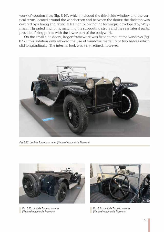
79
work of wooden slats (fig. 8.16), which included the third side window and the ver-tical struts located around the windscreen and between the doors; the skeleton was covered by a lining and artificial leather following the technique developed by Wey-mann. Threaded linchpins, matching the supporting struts and the rear lateral parts, provided fixing points with the lower part of the bodywork.
On the small side doors, larger framework was fixed to mount the windows (fig. 8.17): this solution only allowed the use of windows made up of two halves which slid longitudinally. The internal look was very refined, however.
Fig. 8.12. Lambda Torpedo vii series (National Automobile Museum).
Fig. 8.13. Lambda Torpedo vii series (National Automobile Museum).
Fig. 8.14. Lambda Torpedo vii series (National Automobile Museum).
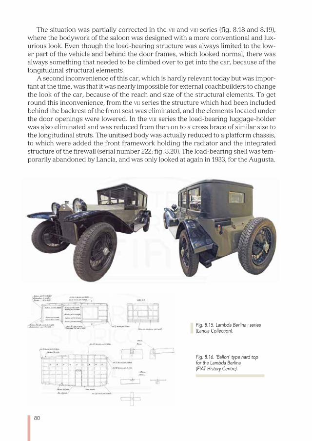
80
The situation was partially corrected in the vii and viii series (fig. 8.18 and 8.19), where the bodywork of the saloon was designed with a more conventional and lux-urious look. Even though the load-bearing structure was always limited to the low-er part of the vehicle and behind the door frames, which looked normal, there was always something that needed to be climbed over to get into the car, because of the longitudinal structural elements.
A second inconvenience of this car, which is hardly relevant today but was impor-tant at the time, was that it was nearly impossible for external coachbuilders to change the look of the car, because of the reach and size of the structural elements. To get round this inconvenience, from the vii series the structure which had been included behind the backrest of the front seat was eliminated, and the elements located under the door openings were lowered. In the viii series the load-bearing luggage-holder was also eliminated and was reduced from then on to a cross brace of similar size to the longitudinal struts. The unitised body was actually reduced to a platform chassis, to which were added the front framework holding the radiator and the integrated structure of the firewall (serial number 222; fig. 8.20). The load-bearing shell was tem-porarily abandoned by Lancia, and was only looked at again in 1933, for the Augusta.
Fig. 8.15. Lambda Berlina i series (Lancia Collection).
Fig. 8.16. ‘Ballon’ type hard top for the Lambda Berlina (FIAT History Centre).
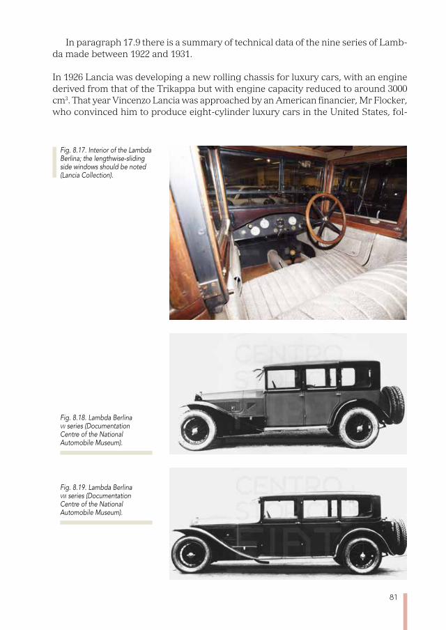
81
In paragraph 17.9 there is a summary of technical data of the nine series of Lamb-da made between 1922 and 1931.
In 1926 Lancia was developing a new rolling chassis for luxury cars, with an engine derived from that of the Trikappa but with engine capacity reduced to around 3000 cm3. That year Vincenzo Lancia was approached by an American financier, Mr Flocker, who convinced him to produce eight-cylinder luxury cars in the United States, fol-
Fig. 8.17. Interior of the Lambda Berlina; the lengthwise-sliding side windows should be noted (Lancia Collection).
Fig. 8.18. Lambda Berlina vii series (Documentation Centre of the National Automobile Museum).
Fig. 8.19. Lambda Berlina viii series (Documentation Centre of the National Automobile Museum).
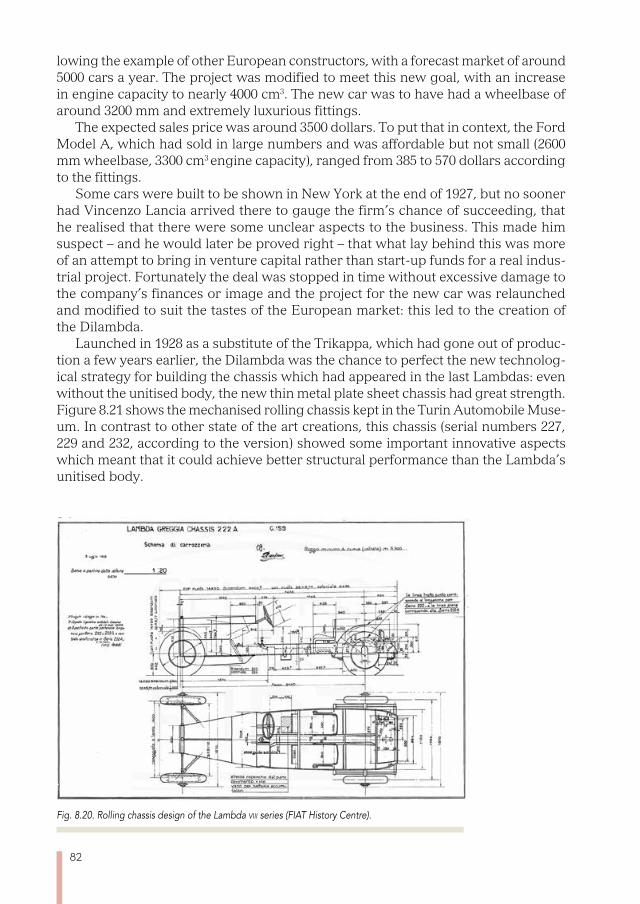
82
lowing the example of other European constructors, with a forecast market of around 5000 cars a year. The project was modified to meet this new goal, with an increase in engine capacity to nearly 4000 cm3. The new car was to have had a wheelbase of around 3200 mm and extremely luxurious fittings.
The expected sales price was around 3500 dollars. To put that in context, the Ford Model A, which had sold in large numbers and was affordable but not small (2600 mm wheelbase, 3300 cm3 engine capacity), ranged from 385 to 570 dollars according to the fittings.
Some cars were built to be shown in New York at the end of 1927, but no sooner had Vincenzo Lancia arrived there to gauge the firm’s chance of succeeding, that he realised that there were some unclear aspects to the business. This made him suspect – and he would later be proved right – that what lay behind this was more of an attempt to bring in venture capital rather than start-up funds for a real indus-trial project. Fortunately the deal was stopped in time without excessive damage to the company’s finances or image and the project for the new car was relaunched and modified to suit the tastes of the European market: this led to the creation of the Dilambda.
Launched in 1928 as a substitute of the Trikappa, which had gone out of produc-tion a few years earlier, the Dilambda was the chance to perfect the new technolog-ical strategy for building the chassis which had appeared in the last Lambdas: even without the unitised body, the new thin metal plate sheet chassis had great strength. Figure 8.21 shows the mechanised rolling chassis kept in the Turin Automobile Muse-um. In contrast to other state of the art creations, this chassis (serial numbers 227, 229 and 232, according to the version) showed some important innovative aspects which meant that it could achieve better structural performance than the Lambda’s unitised body.
Fig. 8.20. Rolling chassis design of the Lambda viii series (FIAT History Centre).
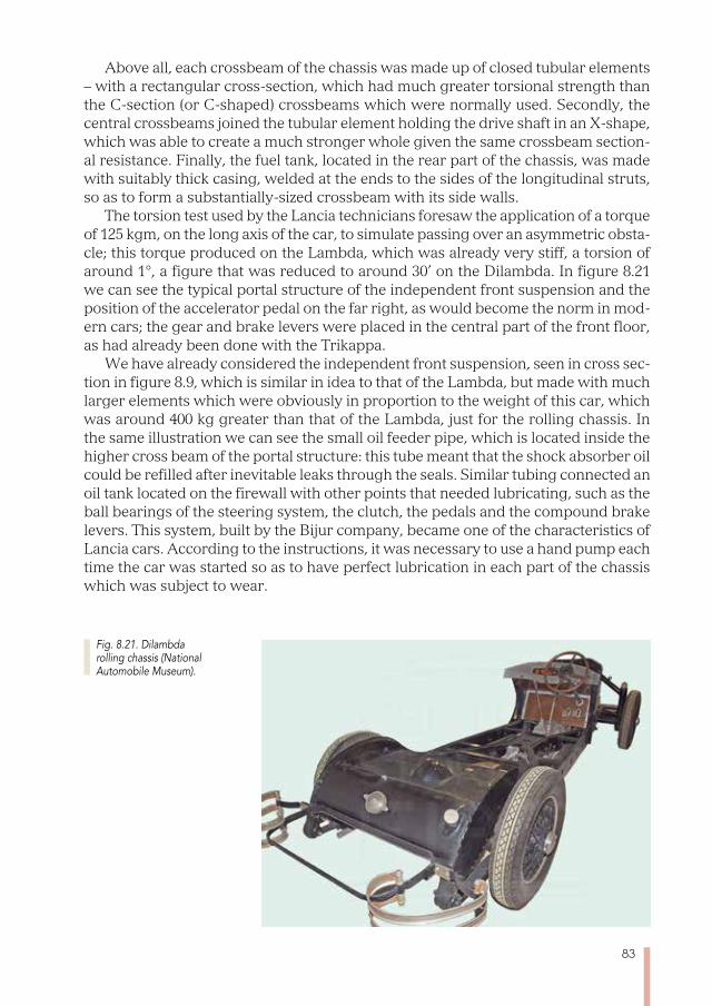
83
Above all, each crossbeam of the chassis was made up of closed tubular elements – with a rectangular cross-section, which had much greater torsional strength than the C-section (or C-shaped) crossbeams which were normally used. Secondly, the central crossbeams joined the tubular element holding the drive shaft in an X-shape, which was able to create a much stronger whole given the same crossbeam section-al resistance. Finally, the fuel tank, located in the rear part of the chassis, was made with suitably thick casing, welded at the ends to the sides of the longitudinal struts, so as to form a substantially-sized crossbeam with its side walls.
The torsion test used by the Lancia technicians foresaw the application of a torque of 125 kgm, on the long axis of the car, to simulate passing over an asymmetric obsta-cle; this torque produced on the Lambda, which was already very stiff, a torsion of around 1°, a figure that was reduced to around 30’ on the Dilambda. In figure 8.21 we can see the typical portal structure of the independent front suspension and the position of the accelerator pedal on the far right, as would become the norm in mod-ern cars; the gear and brake levers were placed in the central part of the front floor, as had already been done with the Trikappa.
We have already considered the independent front suspension, seen in cross sec-tion in figure 8.9, which is similar in idea to that of the Lambda, but made with much larger elements which were obviously in proportion to the weight of this car, which was around 400 kg greater than that of the Lambda, just for the rolling chassis. In the same illustration we can see the small oil feeder pipe, which is located inside the higher cross beam of the portal structure: this tube meant that the shock absorber oil could be refilled after inevitable leaks through the seals. Similar tubing connected an oil tank located on the firewall with other points that needed lubricating, such as the ball bearings of the steering system, the clutch, the pedals and the compound brake levers. This system, built by the Bijur company, became one of the characteristics of Lancia cars. According to the instructions, it was necessary to use a hand pump each time the car was started so as to have perfect lubrication in each part of the chassis which was subject to wear.
Fig. 8.21. Dilambda rolling chassis (National Automobile Museum).
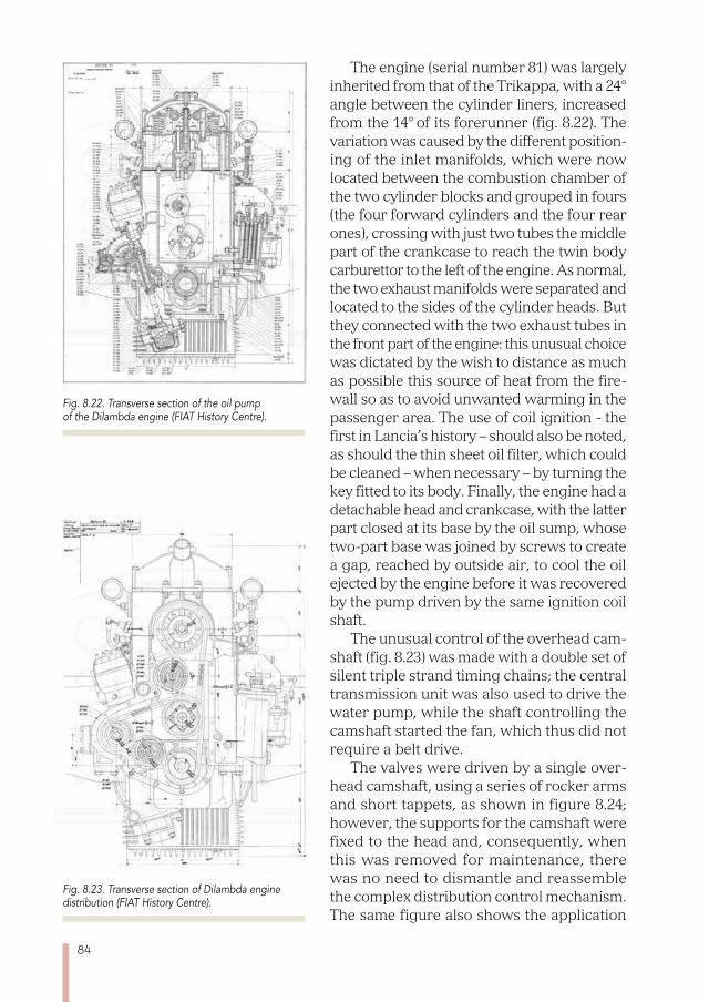
84
The engine (serial number 81) was largely inherited from that of the Trikappa, with a 24° angle between the cylinder liners, increased from the 14° of its forerunner (fig. 8.22). The variation was caused by the different position-ing of the inlet manifolds, which were now located between the combustion chamber of the two cylinder blocks and grouped in fours (the four forward cylinders and the four rear ones), crossing with just two tubes the middle part of the crankcase to reach the twin body carburettor to the left of the engine. As normal, the two exhaust manifolds were separated and located to the sides of the cylinder heads. But they connected with the two exhaust tubes in the front part of the engine: this unusual choice was dictated by the wish to distance as much as possible this source of heat from the fire-wall so as to avoid unwanted warming in the passenger area. The use of coil ignition - the first in Lancia’s history – should also be noted, as should the thin sheet oil filter, which could be cleaned – when necessary – by turning the key fitted to its body. Finally, the engine had a detachable head and crankcase, with the latter part closed at its base by the oil sump, whose two-part base was joined by screws to create a gap, reached by outside air, to cool the oil ejected by the engine before it was recovered by the pump driven by the same ignition coil shaft.
The unusual control of the overhead cam-shaft (fig. 8.23) was made with a double set of silent triple strand timing chains; the central transmission unit was also used to drive the water pump, while the shaft controlling the camshaft started the fan, which thus did not require a belt drive.
The valves were driven by a single over-head camshaft, using a series of rocker arms and short tappets, as shown in figure 8.24; however, the supports for the camshaft were fixed to the head and, consequently, when this was removed for maintenance, there was no need to dismantle and reassemble the complex distribution control mechanism. The same figure also shows the application
Fig. 8.22. Transverse section of the oil pump of the Dilambda engine (FIAT History Centre).
Fig. 8.23. Transverse section of Dilambda engine distribution (FIAT History Centre).
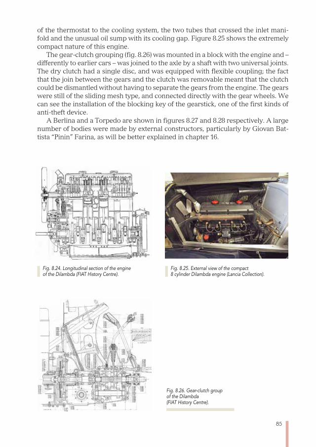
85
Fig. 8.25. External view of the compact 8 cylinder Dilambda engine (Lancia Collection).
of the thermostat to the cooling system, the two tubes that crossed the inlet mani-fold and the unusual oil sump with its cooling gap. Figure 8.25 shows the extremely compact nature of this engine.
The gear-clutch grouping (fig. 8.26) was mounted in a block with the engine and – differently to earlier cars – was joined to the axle by a shaft with two universal joints. The dry clutch had a single disc, and was equipped with flexible coupling; the fact that the join between the gears and the clutch was removable meant that the clutch could be dismantled without having to separate the gears from the engine. The gears were still of the sliding mesh type, and connected directly with the gear wheels. We can see the installation of the blocking key of the gearstick, one of the first kinds of anti-theft device.
A Berlina and a Torpedo are shown in figures 8.27 and 8.28 respectively. A large number of bodies were made by external constructors, particularly by Giovan Bat-tista “Pinin” Farina, as will be better explained in chapter 16.
Fig. 8.24. Longitudinal section of the engine of the Dilambda (FIAT History Centre).
Fig. 8.26. Gear-clutch group of the Dilambda (FIAT History Centre).
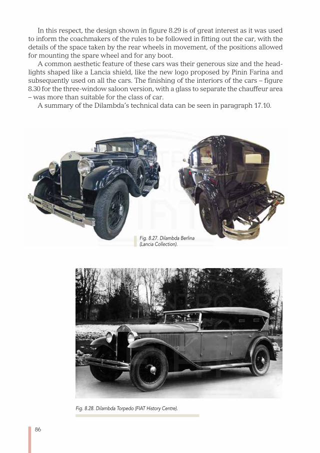
86
Fig. 8.27. Dilambda Berlina (Lancia Collection).
Fig. 8.28. Dilambda Torpedo (FIAT History Centre).
In this respect, the design shown in figure 8.29 is of great interest as it was used to inform the coachmakers of the rules to be followed in fitting out the car, with the details of the space taken by the rear wheels in movement, of the positions allowed for mounting the spare wheel and for any boot.
A common aesthetic feature of these cars was their generous size and the head-lights shaped like a Lancia shield, like the new logo proposed by Pinin Farina and subsequently used on all the cars. The finishing of the interiors of the cars – figure 8.30 for the three-window saloon version, with a glass to separate the chauffeur area – was more than suitable for the class of car.
A summary of the Dilambda’s technical data can be seen in paragraph 17.10.
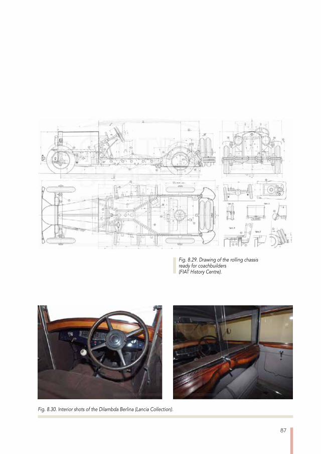
87
Fig. 8.29. Drawing of the rolling chassis ready for coachbuilders (FIAT History Centre).
Fig. 8.30. Interior shots of the Dilambda Berlina (Lancia Collection).

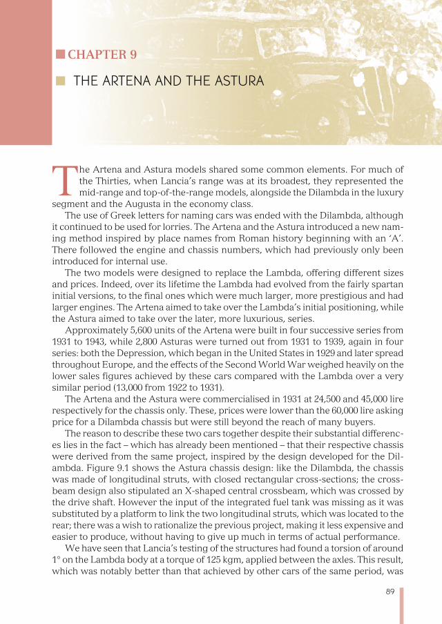
89
Chapter 9
THE ARTENA AND THE ASTURA
The Artena and Astura models shared some common elements. For much of the Thirties, when Lancia’s range was at its broadest, they represented the mid-range and top-of-the-range models, alongside the Dilambda in the luxury
segment and the Augusta in the economy class. The use of Greek letters for naming cars was ended with the Dilambda, although
it continued to be used for lorries. The Artena and the Astura introduced a new nam-ing method inspired by place names from Roman history beginning with an ‘A’. There followed the engine and chassis numbers, which had previously only been introduced for internal use.
The two models were designed to replace the Lambda, offering different sizes and prices. Indeed, over its lifetime the Lambda had evolved from the fairly spartan initial versions, to the final ones which were much larger, more prestigious and had larger engines. The Artena aimed to take over the Lambda’s initial positioning, while the Astura aimed to take over the later, more luxurious, series.
Approximately 5,600 units of the Artena were built in four successive series from 1931 to 1943, while 2,800 Asturas were turned out from 1931 to 1939, again in four series: both the Depression, which began in the United States in 1929 and later spread throughout Europe, and the effects of the Second World War weighed heavily on the lower sales figures achieved by these cars compared with the Lambda over a very similar period (13,000 from 1922 to 1931).
The Artena and the Astura were commercialised in 1931 at 24,500 and 45,000 lire respectively for the chassis only. These, prices were lower than the 60,000 lire asking price for a Dilambda chassis but were still beyond the reach of many buyers.
The reason to describe these two cars together despite their substantial differenc-es lies in the fact – which has already been mentioned – that their respective chassis were derived from the same project, inspired by the design developed for the Dil-ambda. Figure 9.1 shows the Astura chassis design: like the Dilambda, the chassis was made of longitudinal struts, with closed rectangular cross-sections; the cross-beam design also stipulated an X-shaped central crossbeam, which was crossed by the drive shaft. However the input of the integrated fuel tank was missing as it was substituted by a platform to link the two longitudinal struts, which was located to the rear; there was a wish to rationalize the previous project, making it less expensive and easier to produce, without having to give up much in terms of actual performance.
We have seen that Lancia’s testing of the structures had found a torsion of around 1° on the Lambda body at a torque of 125 kgm, applied between the axles. This result, which was notably better than that achieved by other cars of the same period, was
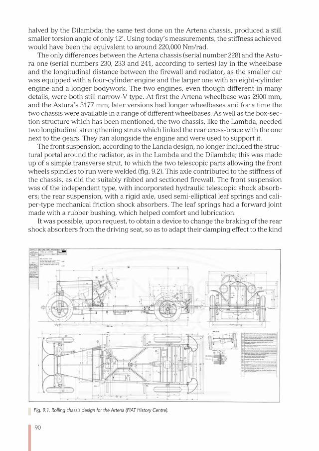
90
halved by the Dilambda; the same test done on the Artena chassis, produced a still smaller torsion angle of only 12’. Using today’s measurements, the stiffness achieved would have been the equivalent to around 220,000 Nm/rad.
The only differences between the Artena chassis (serial number 228) and the Astu-ra one (serial numbers 230, 233 and 241, according to series) lay in the wheelbase and the longitudinal distance between the firewall and radiator, as the smaller car was equipped with a four-cylinder engine and the larger one with an eight-cylinder engine and a longer bodywork. The two engines, even though different in many details, were both still narrow-V type. At first the Artena wheelbase was 2900 mm, and the Astura’s 3177 mm; later versions had longer wheelbases and for a time the two chassis were available in a range of different wheelbases. As well as the box-sec-tion structure which has been mentioned, the two chassis, like the Lambda, needed two longitudinal strengthening struts which linked the rear cross-brace with the one next to the gears. They ran alongside the engine and were used to support it.
The front suspension, according to the Lancia design, no longer included the struc-tural portal around the radiator, as in the Lambda and the Dilambda; this was made up of a simple transverse strut, to which the two telescopic parts allowing the front wheels spindles to run were welded (fig. 9.2). This axle contributed to the stiffness of the chassis, as did the suitably ribbed and sectioned firewall. The front suspension was of the independent type, with incorporated hydraulic telescopic shock absorb-ers; the rear suspension, with a rigid axle, used semi-elliptical leaf springs and cali-per-type mechanical friction shock absorbers. The leaf springs had a forward joint made with a rubber bushing, which helped comfort and lubrication.
It was possible, upon request, to obtain a device to change the braking of the rear shock absorbers from the driving seat, so as to adapt their damping effect to the kind
Fig. 9.1. Rolling chassis design for the Artena (FIAT History Centre).
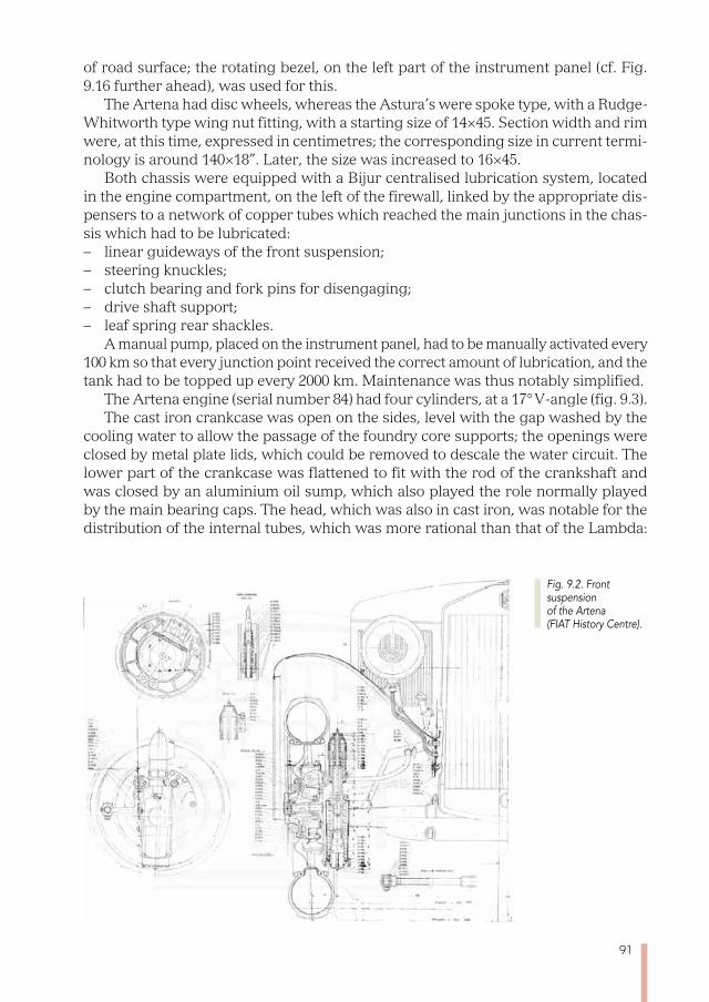
91
of road surface; the rotating bezel, on the left part of the instrument panel (cf. Fig. 9.16 further ahead), was used for this.
The Artena had disc wheels, whereas the Astura’s were spoke type, with a Rudge-Whitworth type wing nut fitting, with a starting size of 14×45. Section width and rim were, at this time, expressed in centimetres; the corresponding size in current termi-nology is around 140×18”. Later, the size was increased to 16×45.
Both chassis were equipped with a Bijur centralised lubrication system, located in the engine compartment, on the left of the firewall, linked by the appropriate dis-pensers to a network of copper tubes which reached the main junctions in the chas-sis which had to be lubricated: – linear guideways of the front suspension; – steering knuckles; – clutch bearing and fork pins for disengaging; – drive shaft support; – leaf spring rear shackles.
A manual pump, placed on the instrument panel, had to be manually activated every 100 km so that every junction point received the correct amount of lubrication, and the tank had to be topped up every 2000 km. Maintenance was thus notably simplified.
The Artena engine (serial number 84) had four cylinders, at a 17° V-angle (fig. 9.3). The cast iron crankcase was open on the sides, level with the gap washed by the
cooling water to allow the passage of the foundry core supports; the openings were closed by metal plate lids, which could be removed to descale the water circuit. The lower part of the crankcase was flattened to fit with the rod of the crankshaft and was closed by an aluminium oil sump, which also played the role normally played by the main bearing caps. The head, which was also in cast iron, was notable for the distribution of the internal tubes, which was more rational than that of the Lambda:
Fig. 9.2. Front suspension of the Artena (FIAT History Centre).
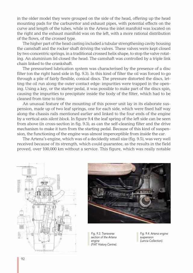
92
in the older model they were grouped on the side of the head, offering up the head mounting pads for the carburettor and exhaust pipes, with potential effects on the curve and length of the tubes, while in the Artena the inlet manifold was located on the right and the exhaust manifold was on the left, with a more rational distribution of the flows, of the crossed type.
The higher part of the head casting included a tubular strengthening cavity housing the camshaft and the rocker shaft driving the valves. These valves were kept closed by two concentric springs, in a traditional crossed helix shape, to stop the valve rotat-ing. An aluminium lid closed the head. The camshaft was controlled by a triple link chain linked to the crankshaft.
The pressurised lubrication system was characterised by the presence of a disc filter (on the right hand side in fig. 9.3). In this kind of filter the oil was forced to go through a pile of fairly flexible, conical discs. The pressure distorted the discs, let-ting the oil run along the outer contact edge: impurities were trapped in the open-ing. Using a key, or the starter pedal, it was possible to make part of the discs spin, causing the impurities to precipitate inside the body of the filter, which had to be cleaned from time to time.
An unusual feature of the mounting of this power unit lay in its elaborate sus-pension, made up of two leaf springs, one for each side, which were fixed half way along the chassis rails mentioned earlier and linked to the four ends of the engine by a vertical axis silent block. In figure 9.4 the leaf spring of the left side can be seen from above (in cross-section in fig. 9.3), as can the self-cleaning filter and the drive mechanism to make it turn from the starting pedal. Because of this kind of suspen-sion, the functioning of the engine was almost imperceptible from inside the car.
The Artena’s engine, which was of a decidedly small size (fig. 9.5), was very well received because of its strength, which could guarantee, as the results in the field proved, over 100,000 km without a service. This figure, which was really notable
Fig. 9.3. Transverse section of the Artena engine (FIAT History Centre).
Fig. 9.4. Artena engine suspension (Lancia Collection).
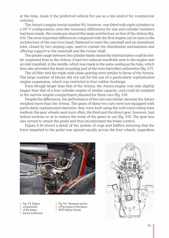
93
at the time, made it the preferred vehicle for use as a taxi and/or for commercial vehicles.
The Astura’s engine (serial number 91), however, was fitted with eight cylinders in a 19° V configuration; once the necessary differences for size and cylinder numbers had been made, the crankcase shared the same architecture as that of the Artena (fig. 9.6). The most important differences compared with the first engine can be seen in the architecture of the cast-iron head, flattened to meet the camshaft and an aluminium tube, closed by two sloping caps, used to contain the distribution mechanisms and offering support to the camshaft and the rocker shaft.
The greater angle between the cylinder banks meant the internal tubes could be bet-ter organised than in the Artena: it had two exhaust manifolds next to the engine and an inlet manifold, in the middle, which was made in the same casting as the tube, which thus also provided the head mounting pad of the twin-barrelled carburettor (fig. 9.7).
The oil filter and the triple rank chain gearing were similar to those of the Artena. The large number of blocks did not call for the use of a particularly sophisticated engine suspension, which was restricted to four rubber bushings.
Even though larger than that of the Artena, the Astura engine was only slightly bigger than that of a four cylinder engine of similar capacity, and could be installed in the narrow engine compartment planned for these cars (fig. 9.8).
Despite the differences, the performance of the cars was similar, because the Astura weighed more than the Artena. The gears of these two cars were not equipped with particularly sophisticated elements: they were built using the well-tried rolling train method; the gear wheels used most often, the third and the direct gear, however, had helical sections so as to reduce the noise of the gears in use (fig. 9.9). The gear box also served to attach the pedal and thus incorporated the brake control.
Figure 9.10 shows a detail of the system of cogs and buffers ensuring that the force imparted to the pedal was spread equally across the four wheels, regardless
Fig. 9.5. Engine compartment of the Artena (Lancia Collection).
Fig. 9.6. Transverse section of the engine of the Astura (FIAT History Centre).
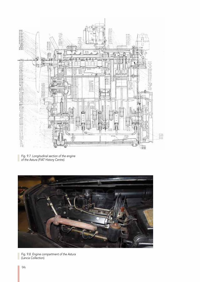
94
Fig. 9.8. Engine compartment of the Astura (Lancia Collection).
Fig. 9.7. Longitudinal section of the engine of the Astura (FIAT History Centre).
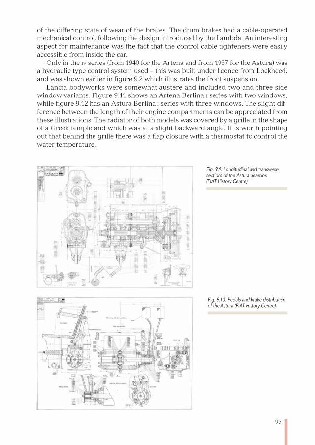
95
of the differing state of wear of the brakes. The drum brakes had a cable-operated mechanical control, following the design introduced by the Lambda. An interesting aspect for maintenance was the fact that the control cable tighteners were easily accessible from inside the car.
Only in the iv series (from 1940 for the Artena and from 1937 for the Astura) was a hydraulic type control system used – this was built under licence from Lockheed, and was shown earlier in figure 9.2 which illustrates the front suspension.
Lancia bodyworks were somewhat austere and included two and three side window variants. Figure 9.11 shows an Artena Berlina i series with two windows, while figure 9.12 has an Astura Berlina i series with three windows. The slight dif-ference between the length of their engine compartments can be appreciated from these illustrations. The radiator of both models was covered by a grille in the shape of a Greek temple and which was at a slight backward angle. It is worth pointing out that behind the grille there was a flap closure with a thermostat to control the water temperature.
Fig. 9.9. Longitudinal and transverse sections of the Astura gearbox (FIAT History Centre).
Fig. 9.10. Pedals and brake distribution of the Astura (FIAT History Centre).
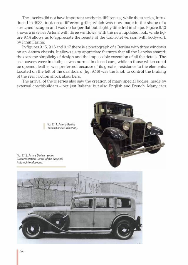
96
The ii series did not have important aesthetic differences, while the iii series, intro-duced in 1933, took on a different grille, which was now made in the shape of a stretched octagon and was no longer flat but slightly dihedral in shape. Figure 9.13 shows a iii series Artena with three windows, with the new, updated look, while fig-ure 9.14 allows us to appreciate the beauty of the Cabriolet version with bodywork by Pinin Farina.
In figures 9.15, 9.16 and 9.17 there is a photograph of a Berlina with three windows on an Astura chassis. It allows us to appreciate features that all the Lancias shared: the extreme simplicity of design and the impeccable execution of all the details. The seat covers were in cloth, as was normal in closed cars, while in those which could be opened, leather was preferred, because of its greater resistance to the elements. Located on the left of the dashboard (fig. 9.16) was the knob to control the braking of the rear friction shock absorbers.
The arrival of the iii series also saw the creation of many special bodies, made by external coachbuilders – not just Italians, but also English and French. Many cars
Fig. 9.11. Artena Berlina i series (Lancia Collection).
Fig. 9.12. Astura Berlina i series (Documentation Centre of the National Automobile Museum).
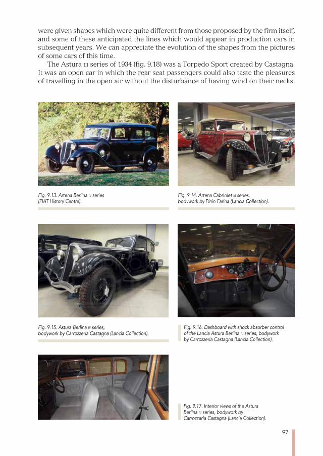
97
were given shapes which were quite different from those proposed by the firm itself, and some of these anticipated the lines which would appear in production cars in subsequent years. We can appreciate the evolution of the shapes from the pictures of some cars of this time.
The Astura iii series of 1934 (fig. 9.18) was a Torpedo Sport created by Castagna. It was an open car in which the rear seat passengers could also taste the pleasures of travelling in the open air without the disturbance of having wind on their necks.
Fig. 9.13. Artena Berlina iii series (FIAT History Centre).
Fig. 9.14. Artena Cabriolet iii series, bodywork by Pinin Farina (Lancia Collection).
Fig. 9.17. Interior views of the Astura Berlina iii series, bodywork by Carrozzeria Castagna (Lancia Collection).
Fig. 9.15. Astura Berlina iii series, bodywork by Carrozzeria Castagna (Lancia Collection).
Fig. 9.16. Dashboard with shock absorber control of the Lancia Astura Berlina iii series, bodywork by Carrozzeria Castagna (Lancia Collection).
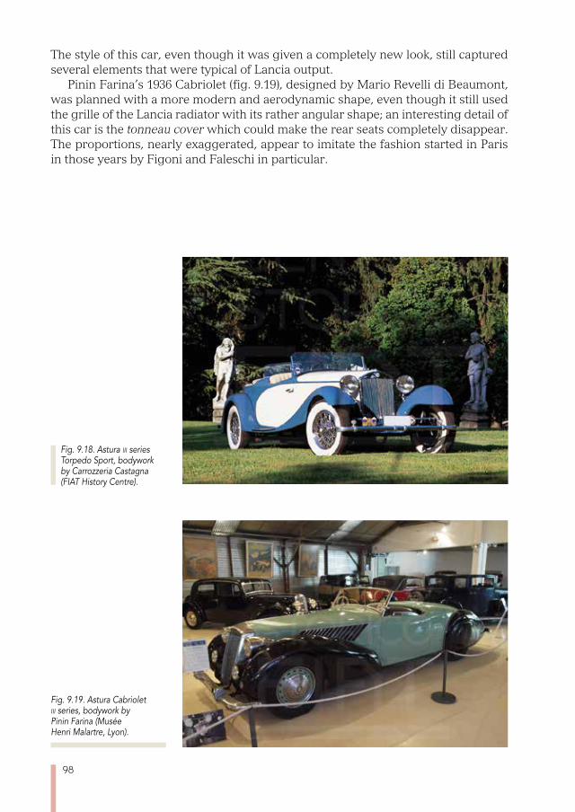
98
The style of this car, even though it was given a completely new look, still captured several elements that were typical of Lancia output.
Pinin Farina’s 1936 Cabriolet (fig. 9.19), designed by Mario Revelli di Beaumont, was planned with a more modern and aerodynamic shape, even though it still used the grille of the Lancia radiator with its rather angular shape; an interesting detail of this car is the tonneau cover which could make the rear seats completely disappear. The proportions, nearly exaggerated, appear to imitate the fashion started in Paris in those years by Figoni and Faleschi in particular.
Fig. 9.18. Astura iii series Torpedo Sport, bodywork by Carrozzeria Castagna (FIAT History Centre).
Fig. 9.19. Astura Cabriolet iii series, bodywork by Pinin Farina (Musée Henri Malartre, Lyon).
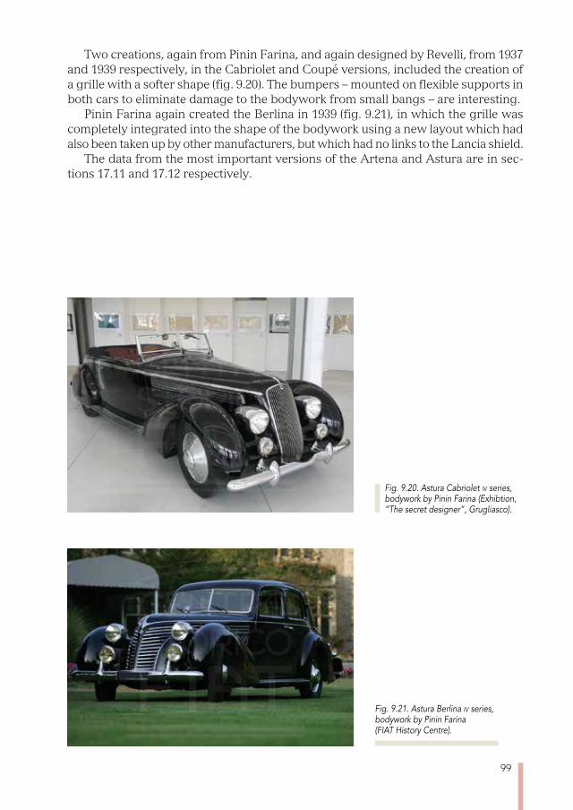
99
Two creations, again from Pinin Farina, and again designed by Revelli, from 1937 and 1939 respectively, in the Cabriolet and Coupé versions, included the creation of a grille with a softer shape (fig. 9.20). The bumpers – mounted on flexible supports in both cars to eliminate damage to the bodywork from small bangs – are interesting.
Pinin Farina again created the Berlina in 1939 (fig. 9.21), in which the grille was completely integrated into the shape of the bodywork using a new layout which had also been taken up by other manufacturers, but which had no links to the Lancia shield.
The data from the most important versions of the Artena and Astura are in sec-tions 17.11 and 17.12 respectively.
Fig. 9.20. Astura Cabriolet iv series, bodywork by Pinin Farina (Exhibtion, “The secret designer”, Grugliasco).
Fig. 9.21. Astura Berlina iv series, bodywork by Pinin Farina (FIAT History Centre).

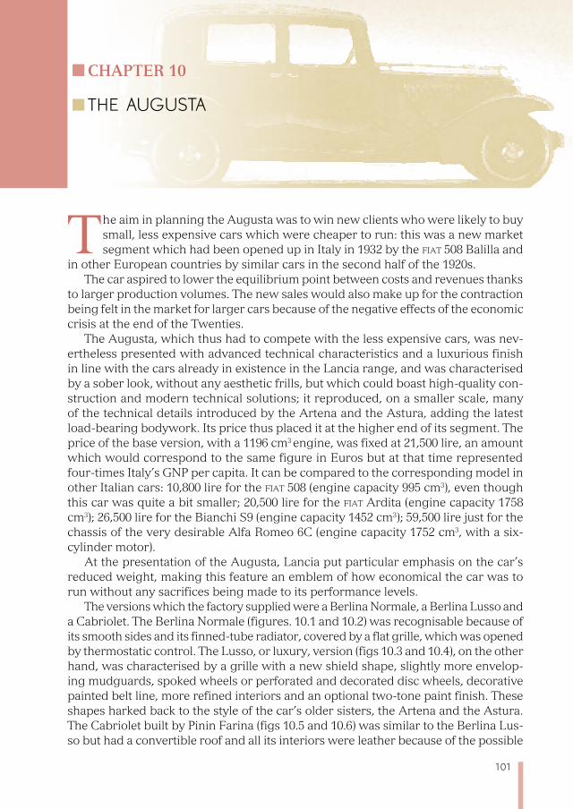
101
Chapter 10
THE AUGUSTA
The aim in planning the Augusta was to win new clients who were likely to buy small, less expensive cars which were cheaper to run: this was a new market segment which had been opened up in Italy in 1932 by the fiat 508 Balilla and
in other European countries by similar cars in the second half of the 1920s. The car aspired to lower the equilibrium point between costs and revenues thanks
to larger production volumes. The new sales would also make up for the contraction being felt in the market for larger cars because of the negative effects of the economic crisis at the end of the Twenties.
The Augusta, which thus had to compete with the less expensive cars, was nev-ertheless presented with advanced technical characteristics and a luxurious finish in line with the cars already in existence in the Lancia range, and was characterised by a sober look, without any aesthetic frills, but which could boast high-quality con-struction and modern technical solutions; it reproduced, on a smaller scale, many of the technical details introduced by the Artena and the Astura, adding the latest load-bearing bodywork. Its price thus placed it at the higher end of its segment. The price of the base version, with a 1196 cm3 engine, was fixed at 21,500 lire, an amount which would correspond to the same figure in Euros but at that time represented four-times Italy’s GNP per capita. It can be compared to the corresponding model in other Italian cars: 10,800 lire for the fiat 508 (engine capacity 995 cm3), even though this car was quite a bit smaller; 20,500 lire for the fiat Ardita (engine capacity 1758 cm3); 26,500 lire for the Bianchi S9 (engine capacity 1452 cm3); 59,500 lire just for the chassis of the very desirable Alfa Romeo 6C (engine capacity 1752 cm3, with a six-cylinder motor).
At the presentation of the Augusta, Lancia put particular emphasis on the car’s reduced weight, making this feature an emblem of how economical the car was to run without any sacrifices being made to its performance levels.
The versions which the factory supplied were a Berlina Normale, a Berlina Lusso and a Cabriolet. The Berlina Normale (figures. 10.1 and 10.2) was recognisable because of its smooth sides and its finned-tube radiator, covered by a flat grille, which was opened by thermostatic control. The Lusso, or luxury, version (figs 10.3 and 10.4), on the other hand, was characterised by a grille with a new shield shape, slightly more envelop-ing mudguards, spoked wheels or perforated and decorated disc wheels, decorative painted belt line, more refined interiors and an optional two-tone paint finish. These shapes harked back to the style of the car’s older sisters, the Artena and the Astura. The Cabriolet built by Pinin Farina (figs 10.5 and 10.6) was similar to the Berlina Lus-so but had a convertible roof and all its interiors were leather because of the possible
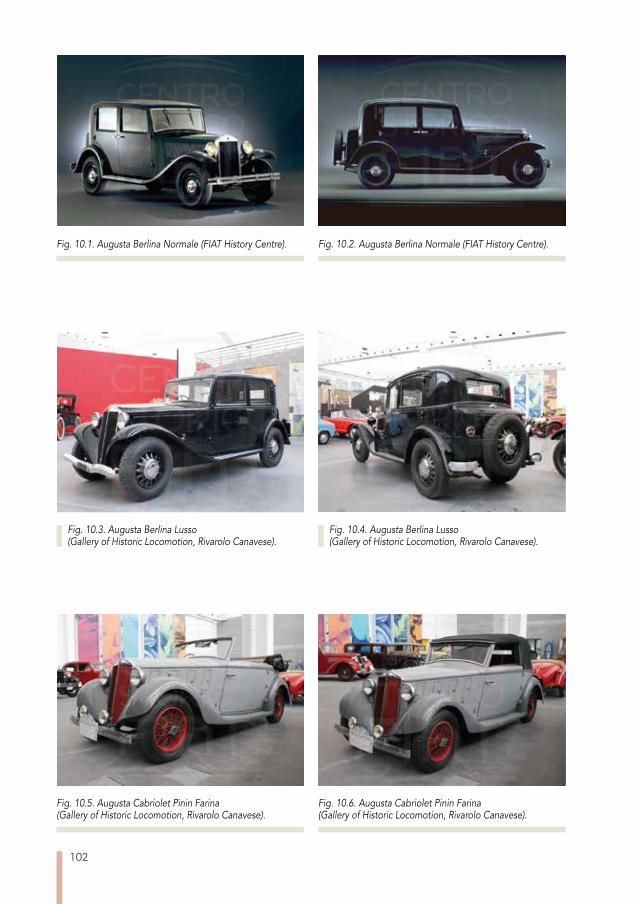
102
Fig. 10.1. Augusta Berlina Normale (FIAT History Centre).
Fig. 10.5. Augusta Cabriolet Pinin Farina (Gallery of Historic Locomotion, Rivarolo Canavese).
Fig. 10.6. Augusta Cabriolet Pinin Farina(Gallery of Historic Locomotion, Rivarolo Canavese).
Fig. 10.2. Augusta Berlina Normale (FIAT History Centre).
Fig. 10.3. Augusta Berlina Lusso (Gallery of Historic Locomotion, Rivarolo Canavese).
Fig. 10.4. Augusta Berlina Lusso (Gallery of Historic Locomotion, Rivarolo Canavese).
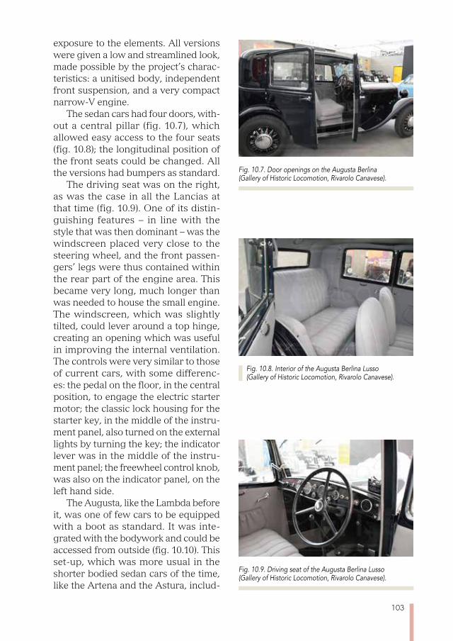
103
exposure to the elements. All versions were given a low and streamlined look, made possible by the project’s charac-teristics: a unitised body, independent front suspension, and a very compact narrow-V engine.
The sedan cars had four doors, with-out a central pillar (fig. 10.7), which allowed easy access to the four seats (fig. 10.8); the longitudinal position of the front seats could be changed. All the versions had bumpers as standard.
The driving seat was on the right, as was the case in all the Lancias at that time (fig. 10.9). One of its distin-guishing features – in line with the style that was then dominant – was the windscreen placed very close to the steering wheel, and the front passen-gers’ legs were thus contained within the rear part of the engine area. This became very long, much longer than was needed to house the small engine. The windscreen, which was slightly tilted, could lever around a top hinge, creating an opening which was useful in improving the internal ventilation. The controls were very similar to those of current cars, with some differenc-es: the pedal on the floor, in the central position, to engage the electric starter motor; the classic lock housing for the starter key, in the middle of the instru-ment panel, also turned on the external lights by turning the key; the indicator lever was in the middle of the instru-ment panel; the freewheel control knob, was also on the indicator panel, on the left hand side.
The Augusta, like the Lambda before it, was one of few cars to be equipped with a boot as standard. It was inte-grated with the bodywork and could be accessed from outside (fig. 10.10). This set-up, which was more usual in the shorter bodied sedan cars of the time, like the Artena and the Astura, includ-
Fig. 10.8. Interior of the Augusta Berlina Lusso (Gallery of Historic Locomotion, Rivarolo Canavese).
Fig. 10.7. Door openings on the Augusta Berlina (Gallery of Historic Locomotion, Rivarolo Canavese).
Fig. 10.9. Driving seat of the Augusta Berlina Lusso (Gallery of Historic Locomotion, Rivarolo Canavese).
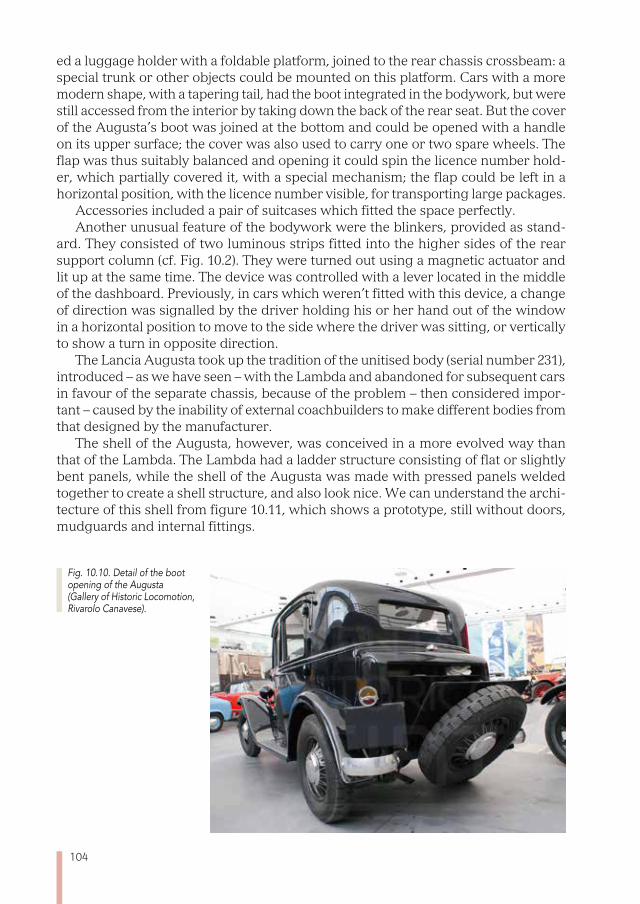
104
ed a luggage holder with a foldable platform, joined to the rear chassis crossbeam: a special trunk or other objects could be mounted on this platform. Cars with a more modern shape, with a tapering tail, had the boot integrated in the bodywork, but were still accessed from the interior by taking down the back of the rear seat. But the cover of the Augusta’s boot was joined at the bottom and could be opened with a handle on its upper surface; the cover was also used to carry one or two spare wheels. The flap was thus suitably balanced and opening it could spin the licence number hold-er, which partially covered it, with a special mechanism; the flap could be left in a horizontal position, with the licence number visible, for transporting large packages.
Accessories included a pair of suitcases which fitted the space perfectly. Another unusual feature of the bodywork were the blinkers, provided as stand-
ard. They consisted of two luminous strips fitted into the higher sides of the rear support column (cf. Fig. 10.2). They were turned out using a magnetic actuator and lit up at the same time. The device was controlled with a lever located in the middle of the dashboard. Previously, in cars which weren’t fitted with this device, a change of direction was signalled by the driver holding his or her hand out of the window in a horizontal position to move to the side where the driver was sitting, or vertically to show a turn in opposite direction.
The Lancia Augusta took up the tradition of the unitised body (serial number 231), introduced – as we have seen – with the Lambda and abandoned for subsequent cars in favour of the separate chassis, because of the problem – then considered impor-tant – caused by the inability of external coachbuilders to make different bodies from that designed by the manufacturer.
The shell of the Augusta, however, was conceived in a more evolved way than that of the Lambda. The Lambda had a ladder structure consisting of flat or slightly bent panels, while the shell of the Augusta was made with pressed panels welded together to create a shell structure, and also look nice. We can understand the archi-tecture of this shell from figure 10.11, which shows a prototype, still without doors, mudguards and internal fittings.
Fig. 10.10. Detail of the boot opening of the Augusta (Gallery of Historic Locomotion, Rivarolo Canavese).
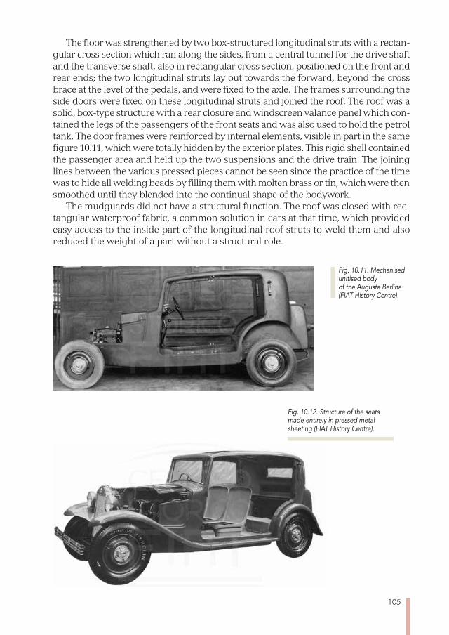
105
The floor was strengthened by two box-structured longitudinal struts with a rectan-gular cross section which ran along the sides, from a central tunnel for the drive shaft and the transverse shaft, also in rectangular cross section, positioned on the front and rear ends; the two longitudinal struts lay out towards the forward, beyond the cross brace at the level of the pedals, and were fixed to the axle. The frames surrounding the side doors were fixed on these longitudinal struts and joined the roof. The roof was a solid, box-type structure with a rear closure and windscreen valance panel which con-tained the legs of the passengers of the front seats and was also used to hold the petrol tank. The door frames were reinforced by internal elements, visible in part in the same figure 10.11, which were totally hidden by the exterior plates. This rigid shell contained the passenger area and held up the two suspensions and the drive train. The joining lines between the various pressed pieces cannot be seen since the practice of the time was to hide all welding beads by filling them with molten brass or tin, which were then smoothed until they blended into the continual shape of the bodywork.
The mudguards did not have a structural function. The roof was closed with rec-tangular waterproof fabric, a common solution in cars at that time, which provided easy access to the inside part of the longitudinal roof struts to weld them and also reduced the weight of a part without a structural role.
Fig. 10.12. Structure of the seats made entirely in pressed metal sheeting (FIAT History Centre).
Fig. 10.11. Mechanised unitised body of the Augusta Berlina (FIAT History Centre).
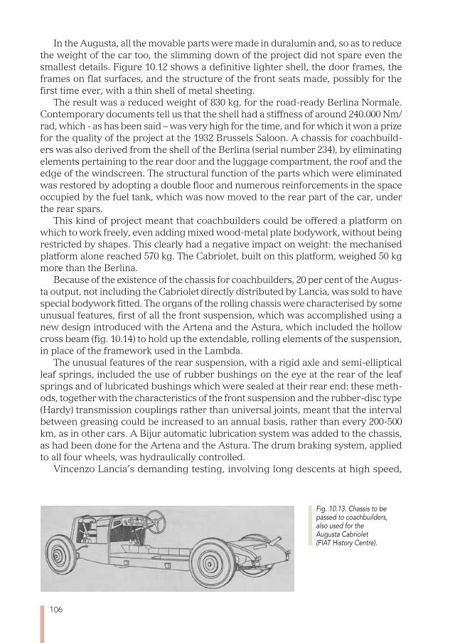
106
In the Augusta, all the movable parts were made in duralumin and, so as to reduce the weight of the car too, the slimming down of the project did not spare even the smallest details. Figure 10.12 shows a definitive lighter shell, the door frames, the frames on flat surfaces, and the structure of the front seats made, possibly for the first time ever, with a thin shell of metal sheeting.
The result was a reduced weight of 830 kg, for the road-ready Berlina Normale. Contemporary documents tell us that the shell had a stiffness of around 240.000 Nm/rad, which - as has been said – was very high for the time, and for which it won a prize for the quality of the project at the 1932 Brussels Saloon. A chassis for coachbuild-ers was also derived from the shell of the Berlina (serial number 234), by eliminating elements pertaining to the rear door and the luggage compartment, the roof and the edge of the windscreen. The structural function of the parts which were eliminated was restored by adopting a double floor and numerous reinforcements in the space occupied by the fuel tank, which was now moved to the rear part of the car, under the rear spars.
This kind of project meant that coachbuilders could be offered a platform on which to work freely, even adding mixed wood-metal plate bodywork, without being restricted by shapes. This clearly had a negative impact on weight: the mechanised platform alone reached 570 kg. The Cabriolet, built on this platform, weighed 50 kg more than the Berlina.
Because of the existence of the chassis for coachbuilders, 20 per cent of the Augus-ta output, not including the Cabriolet directly distributed by Lancia, was sold to have special bodywork fitted. The organs of the rolling chassis were characterised by some unusual features, first of all the front suspension, which was accomplished using a new design introduced with the Artena and the Astura, which included the hollow cross beam (fig. 10.14) to hold up the extendable, rolling elements of the suspension, in place of the framework used in the Lambda.
The unusual features of the rear suspension, with a rigid axle and semi-elliptical leaf springs, included the use of rubber bushings on the eye at the rear of the leaf springs and of lubricated bushings which were sealed at their rear end: these meth-ods, together with the characteristics of the front suspension and the rubber-disc type (Hardy) transmission couplings rather than universal joints, meant that the interval between greasing could be increased to an annual basis, rather than every 200-500 km, as in other cars. A Bijur automatic lubrication system was added to the chassis, as had been done for the Artena and the Astura. The drum braking system, applied to all four wheels, was hydraulically controlled.
Vincenzo Lancia’s demanding testing, involving long descents at high speed,
Fig. 10.13. Chassis to be passed to coachbuilders, also used for the Augusta Cabriolet (FIAT History Centre).
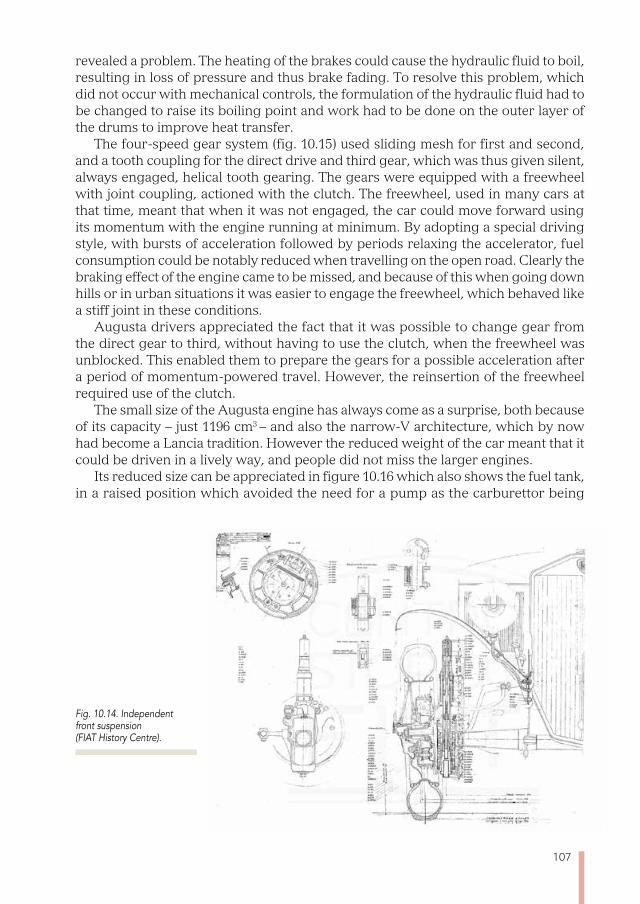
107
revealed a problem. The heating of the brakes could cause the hydraulic fluid to boil, resulting in loss of pressure and thus brake fading. To resolve this problem, which did not occur with mechanical controls, the formulation of the hydraulic fluid had to be changed to raise its boiling point and work had to be done on the outer layer of the drums to improve heat transfer.
The four-speed gear system (fig. 10.15) used sliding mesh for first and second, and a tooth coupling for the direct drive and third gear, which was thus given silent, always engaged, helical tooth gearing. The gears were equipped with a freewheel with joint coupling, actioned with the clutch. The freewheel, used in many cars at that time, meant that when it was not engaged, the car could move forward using its momentum with the engine running at minimum. By adopting a special driving style, with bursts of acceleration followed by periods relaxing the accelerator, fuel consumption could be notably reduced when travelling on the open road. Clearly the braking effect of the engine came to be missed, and because of this when going down hills or in urban situations it was easier to engage the freewheel, which behaved like a stiff joint in these conditions.
Augusta drivers appreciated the fact that it was possible to change gear from the direct gear to third, without having to use the clutch, when the freewheel was unblocked. This enabled them to prepare the gears for a possible acceleration after a period of momentum-powered travel. However, the reinsertion of the freewheel required use of the clutch.
The small size of the Augusta engine has always come as a surprise, both because of its capacity – just 1196 cm3 – and also the narrow-V architecture, which by now had become a Lancia tradition. However the reduced weight of the car meant that it could be driven in a lively way, and people did not miss the larger engines.
Its reduced size can be appreciated in figure 10.16 which also shows the fuel tank, in a raised position which avoided the need for a pump as the carburettor being
Fig. 10.14. Independent front suspension (FIAT History Centre).
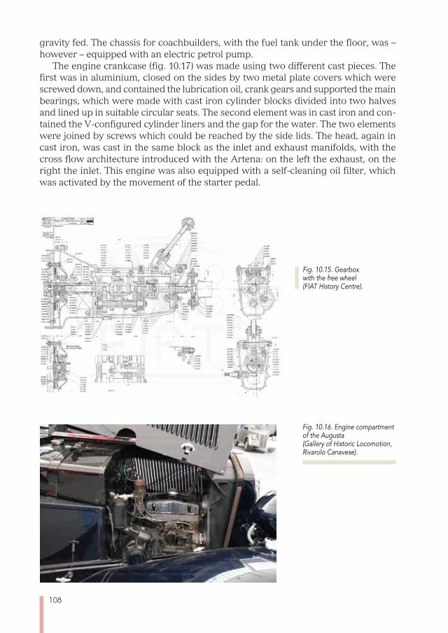
108
gravity fed. The chassis for coachbuilders, with the fuel tank under the floor, was – however – equipped with an electric petrol pump.
The engine crankcase (fig. 10.17) was made using two different cast pieces. The first was in aluminium, closed on the sides by two metal plate covers which were screwed down, and contained the lubrication oil, crank gears and supported the main bearings, which were made with cast iron cylinder blocks divided into two halves and lined up in suitable circular seats. The second element was in cast iron and con-tained the V-configured cylinder liners and the gap for the water. The two elements were joined by screws which could be reached by the side lids. The head, again in cast iron, was cast in the same block as the inlet and exhaust manifolds, with the cross flow architecture introduced with the Artena: on the left the exhaust, on the right the inlet. This engine was also equipped with a self-cleaning oil filter, which was activated by the movement of the starter pedal.
Fig. 10.16. Engine compartment of the Augusta (Gallery of Historic Locomotion, Rivarolo Canavese).
Fig. 10.15. Gearbox with the free wheel (FIAT History Centre).
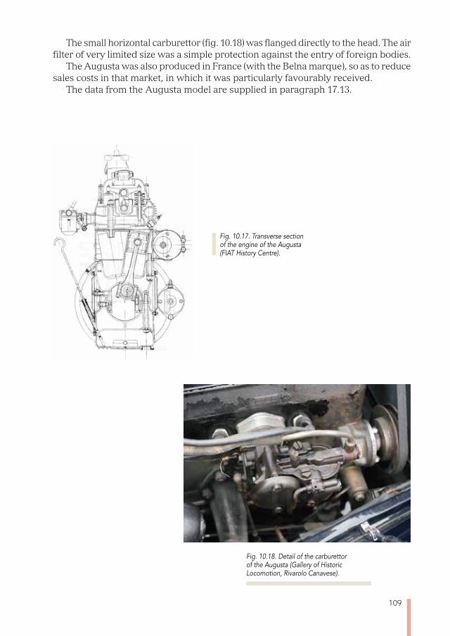
109
The small horizontal carburettor (fig. 10.18) was flanged directly to the head. The air filter of very limited size was a simple protection against the entry of foreign bodies.
The Augusta was also produced in France (with the Belna marque), so as to reduce sales costs in that market, in which it was particularly favourably received.
The data from the Augusta model are supplied in paragraph 17.13.
Fig. 10.18. Detail of the carburettor of the Augusta (Gallery of Historic Locomotion, Rivarolo Canavese).
Fig. 10.17. Transverse section of the engine of the Augusta (FIAT History Centre).

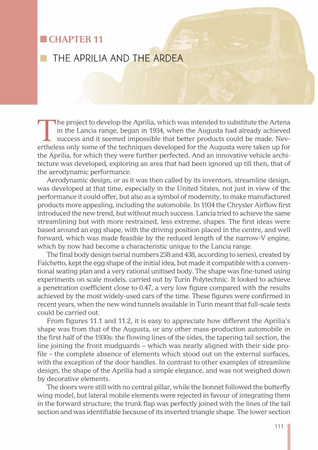
111
Chapter 11
THE APRILIA AND THE ARDEA
The project to develop the Aprilia, which was intended to substitute the Artena in the Lancia range, began in 1934, when the Augusta had already achieved success and it seemed impossible that better products could be made. Nev-
ertheless only some of the techniques developed for the Augusta were taken up for the Aprilia, for which they were further perfected. And an innovative vehicle archi-tecture was developed, exploring an area that had been ignored up till then, that of the aerodynamic performance.
Aerodynamic design, or as it was then called by its inventors, streamline design, was developed at that time, especially in the United States, not just in view of the performance it could offer, but also as a symbol of modernity, to make manufactured products more appealing, including the automobile. In 1934 the Chrysler Airflow first introduced the new trend, but without much success. Lancia tried to achieve the same streamlining but with more restrained, less extreme, shapes. The first ideas were based around an egg shape, with the driving position placed in the centre, and well forward, which was made feasible by the reduced length of the narrow-V engine, which by now had become a characteristic unique to the Lancia range.
The final body design (serial numbers 238 and 438, according to series), created by Falchetto, kept the egg shape of the initial idea, but made it compatible with a conven-tional seating plan and a very rational unitised body. The shape was fine-tuned using experiments on scale models, carried out by Turin Polytechnic. It looked to achieve a penetration coefficient close to 0.47, a very low figure compared with the results achieved by the most widely-used cars of the time. These figures were confirmed in recent years, when the new wind tunnels available in Turin meant that full-scale tests could be carried out.
From figures 11.1 and 11.2, it is easy to appreciate how different the Aprilia’s shape was from that of the Augusta, or any other mass-production automobile in the first half of the 1930s: the flowing lines of the sides, the tapering tail section, the line joining the front mudguards – which was nearly aligned with their side pro-file – the complete absence of elements which stood out on the external surfaces, with the exception of the door handles. In contrast to other examples of streamline design, the shape of the Aprilia had a simple elegance, and was not weighed down by decorative elements.
The doors were still with no central pillar, while the bonnet followed the butterfly wing model, but lateral mobile elements were rejected in favour of integrating them in the forward structure; the trunk flap was perfectly joined with the lines of the tail section and was identifiable because of its inverted triangle shape. The lower section
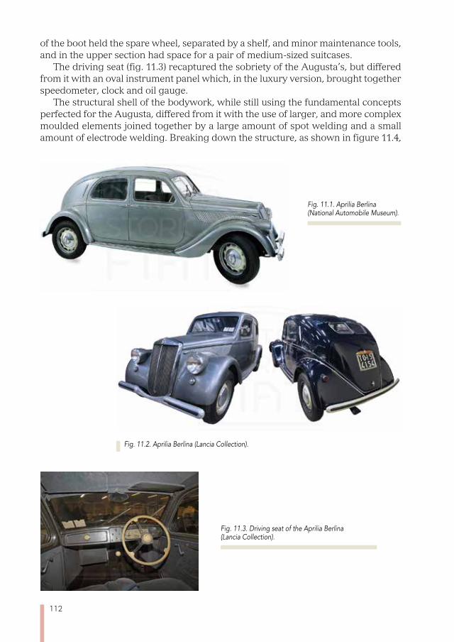
112
of the boot held the spare wheel, separated by a shelf, and minor maintenance tools, and in the upper section had space for a pair of medium-sized suitcases.
The driving seat (fig. 11.3) recaptured the sobriety of the Augusta’s, but differed from it with an oval instrument panel which, in the luxury version, brought together speedometer, clock and oil gauge.
The structural shell of the bodywork, while still using the fundamental concepts perfected for the Augusta, differed from it with the use of larger, and more complex moulded elements joined together by a large amount of spot welding and a small amount of electrode welding. Breaking down the structure, as shown in figure 11.4,
Fig. 11.1. Aprilia Berlina (National Automobile Museum).
Fig. 11.2. Aprilia Berlina (Lancia Collection).
Fig. 11.3. Driving seat of the Aprilia Berlina (Lancia Collection).
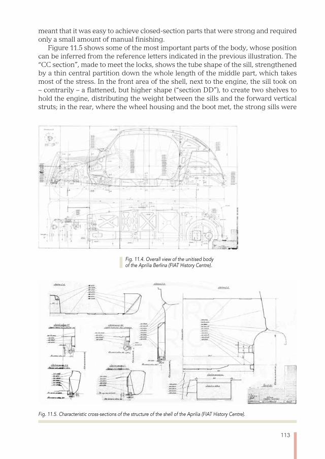
113
meant that it was easy to achieve closed-section parts that were strong and required only a small amount of manual finishing.
Figure 11.5 shows some of the most important parts of the body, whose position can be inferred from the reference letters indicated in the previous illustration. The “CC section”, made to meet the locks, shows the tube shape of the sill, strengthened by a thin central partition down the whole length of the middle part, which takes most of the stress. In the front area of the shell, next to the engine, the sill took on – contrarily – a flattened, but higher shape (“section DD”), to create two shelves to hold the engine, distributing the weight between the sills and the forward vertical struts; in the rear, where the wheel housing and the boot met, the strong sills were
Fig. 11.4. Overall view of the unitised body of the Aprilia Berlina (FIAT History Centre).
Fig. 11.5. Characteristic cross-sections of the structure of the shell of the Aprilia (FIAT History Centre).
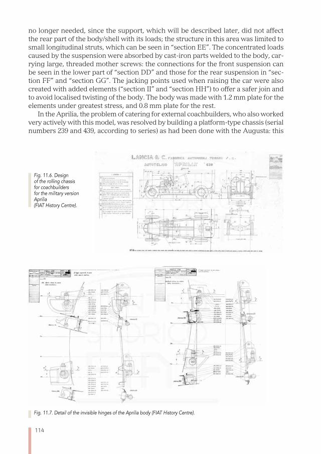
114
no longer needed, since the support, which will be described later, did not affect the rear part of the body/shell with its loads; the structure in this area was limited to small longitudinal struts, which can be seen in “section EE”. The concentrated loads caused by the suspension were absorbed by cast-iron parts welded to the body, car-rying large, threaded mother screws: the connections for the front suspension can be seen in the lower part of “section DD” and those for the rear suspension in “sec-tion FF” and “section GG”. The jacking points used when raising the car were also created with added elements (“section II” and “section HH”) to offer a safer join and to avoid localised twisting of the body. The body was made with 1.2 mm plate for the elements under greatest stress, and 0.8 mm plate for the rest.
In the Aprilia, the problem of catering for external coachbuilders, who also worked very actively with this model, was resolved by building a platform-type chassis (serial numbers 239 and 439, according to series) as had been done with the Augusta: this
Fig. 11.7. Detail of the invisible hinges of the Aprilia body (FIAT History Centre).
Fig. 11.6. Design of the rolling chassis for coachbuilders for the military version Aprilia (FIAT History Centre).
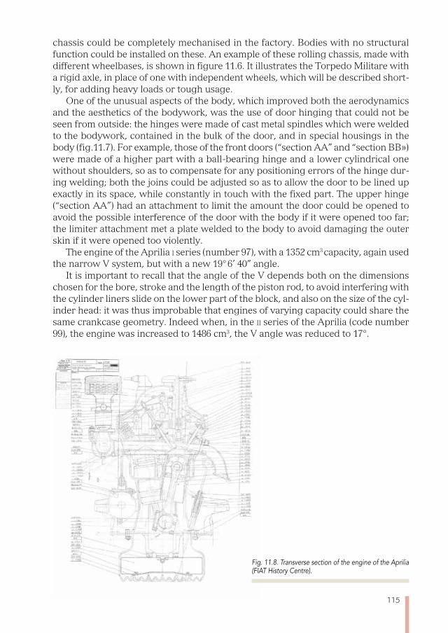
115
chassis could be completely mechanised in the factory. Bodies with no structural function could be installed on these. An example of these rolling chassis, made with different wheelbases, is shown in figure 11.6. It illustrates the Torpedo Militare with a rigid axle, in place of one with independent wheels, which will be described short-ly, for adding heavy loads or tough usage.
One of the unusual aspects of the body, which improved both the aerodynamics and the aesthetics of the bodywork, was the use of door hinging that could not be seen from outside: the hinges were made of cast metal spindles which were welded to the bodywork, contained in the bulk of the door, and in special housings in the body (fig.11.7). For example, those of the front doors (“section AA” and “section BB») were made of a higher part with a ball-bearing hinge and a lower cylindrical one without shoulders, so as to compensate for any positioning errors of the hinge dur-ing welding; both the joins could be adjusted so as to allow the door to be lined up exactly in its space, while constantly in touch with the fixed part. The upper hinge (“section AA”) had an attachment to limit the amount the door could be opened to avoid the possible interference of the door with the body if it were opened too far; the limiter attachment met a plate welded to the body to avoid damaging the outer skin if it were opened too violently.
The engine of the Aprilia i series (number 97), with a 1352 cm3 capacity, again used the narrow V system, but with a new 19° 6’ 40” angle.
It is important to recall that the angle of the V depends both on the dimensions chosen for the bore, stroke and the length of the piston rod, to avoid interfering with the cylinder liners slide on the lower part of the block, and also on the size of the cyl-inder head: it was thus improbable that engines of varying capacity could share the same crankcase geometry. Indeed when, in the ii series of the Aprilia (code number 99), the engine was increased to 1486 cm3, the V angle was reduced to 17°.
Fig. 11.8. Transverse section of the engine of the Aprilia (FIAT History Centre).
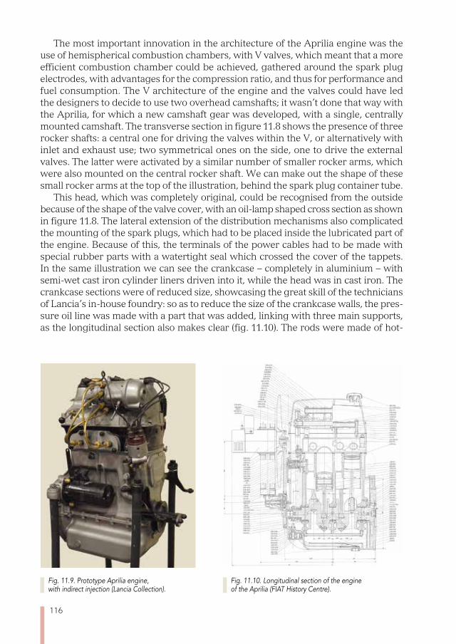
116
The most important innovation in the architecture of the Aprilia engine was the use of hemispherical combustion chambers, with V valves, which meant that a more efficient combustion chamber could be achieved, gathered around the spark plug electrodes, with advantages for the compression ratio, and thus for performance and fuel consumption. The V architecture of the engine and the valves could have led the designers to decide to use two overhead camshafts; it wasn’t done that way with the Aprilia, for which a new camshaft gear was developed, with a single, centrally mounted camshaft. The transverse section in figure 11.8 shows the presence of three rocker shafts: a central one for driving the valves within the V, or alternatively with inlet and exhaust use; two symmetrical ones on the side, one to drive the external valves. The latter were activated by a similar number of smaller rocker arms, which were also mounted on the central rocker shaft. We can make out the shape of these small rocker arms at the top of the illustration, behind the spark plug container tube.
This head, which was completely original, could be recognised from the outside because of the shape of the valve cover, with an oil-lamp shaped cross section as shown in figure 11.8. The lateral extension of the distribution mechanisms also complicated the mounting of the spark plugs, which had to be placed inside the lubricated part of the engine. Because of this, the terminals of the power cables had to be made with special rubber parts with a watertight seal which crossed the cover of the tappets. In the same illustration we can see the crankcase – completely in aluminium – with semi-wet cast iron cylinder liners driven into it, while the head was in cast iron. The crankcase sections were of reduced size, showcasing the great skill of the technicians of Lancia’s in-house foundry: so as to reduce the size of the crankcase walls, the pres-sure oil line was made with a part that was added, linking with three main supports, as the longitudinal section also makes clear (fig. 11.10). The rods were made of hot-
Fig. 11.9. Prototype Aprilia engine, with indirect injection (Lancia Collection).
Fig. 11.10. Longitudinal section of the engine of the Aprilia (FIAT History Centre).
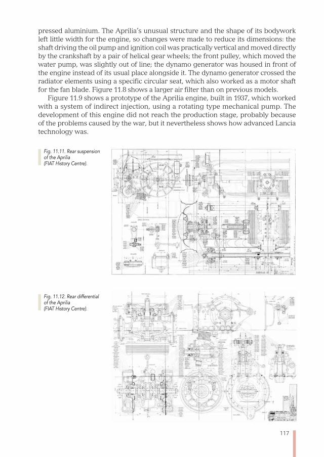
117
pressed aluminium. The Aprilia’s unusual structure and the shape of its bodywork left little width for the engine, so changes were made to reduce its dimensions: the shaft driving the oil pump and ignition coil was practically vertical and moved directly by the crankshaft by a pair of helical gear wheels; the front pulley, which moved the water pump, was slightly out of line; the dynamo generator was housed in front of the engine instead of its usual place alongside it. The dynamo generator crossed the radiator elements using a specific circular seat, which also worked as a motor shaft for the fan blade. Figure 11.8 shows a larger air filter than on previous models.
Figure 11.9 shows a prototype of the Aprilia engine, built in 1937, which worked with a system of indirect injection, using a rotating type mechanical pump. The development of this engine did not reach the production stage, probably because of the problems caused by the war, but it nevertheless shows how advanced Lancia technology was.
Fig. 11.11. Rear suspension of the Aprilia (FIAT History Centre).
Fig. 11.12. Rear differential of the Aprilia (FIAT History Centre).
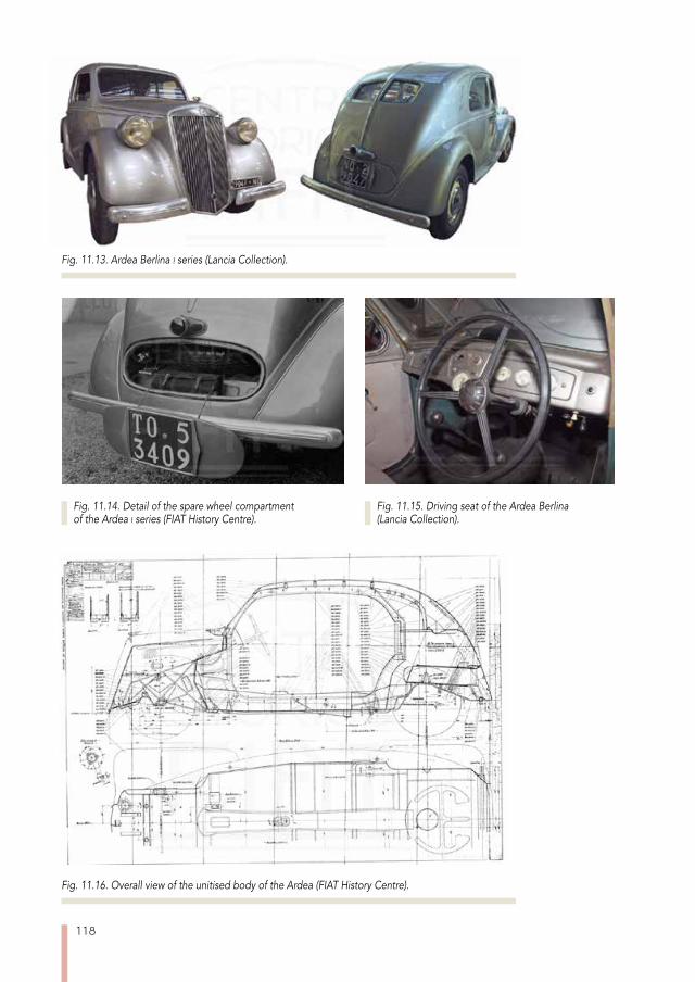
118
Fig. 11.13. Ardea Berlina i series (Lancia Collection).
Fig. 11.16. Overall view of the unitised body of the Ardea (FIAT History Centre).
Fig. 11.14. Detail of the spare wheel compartment of the Ardea i series (FIAT History Centre).
Fig. 11.15. Driving seat of the Ardea Berlina (Lancia Collection).

119
The Aprilia’s front suspension included vertical sliding tubes, as already been used in previous models. The Ardea’s suspension followed that of the Aprilia in many details; in contrast to previous models (figure 11.11), the transversal piece was now made with a single piece of hot-pressed steel.
The rear suspension, however, showed consistent progress, both in absolute terms and in relation to the firm’s practice, and showed some very advanced features, the first of which is the fact that it was of the independent type, which very few others had at the time. A second interesting aspect involved the kinematic system to control the movement of the wheel, which was achieved with two longitudinal arms mounted on ball bearings (bottom left in fig. 11.12). Other examples from the German school (Mercedes, Porsche, Alfa Romeo) had transverse or diagonal arms, which integrated more simply with the chassis but which suffered from strong variations in the angle of cambering of the wheels and the wheel track according to the shaking of the sus-pension. The elastic component was provided by a transverse leaf spring positioned under the arms and attached to it by tie rods (“section AA”). The leaf spring was fixed in the middle, by the differential, and thus had limited stabilising effect in a roll since the two arms were connected to a suitably sized torsion bar.
The attention focussed on reducing the amount of weight oscillating from the axle was not limited to the independent wheels, but also included a suspended differential (fig. 11.12). Also, the brake drums were mounted on the differential so as not to let their weight interfere with the suspension’s own frequency: at that time designs of this type were to be found only in extremely luxurious vehicles or Grand Prix racing cars.
The two rear wheels were linked to the differential by telescopic axle shafts with double universal joints (fig. 11.12) to make them homokinetic; in this case too, great attention was paid to containing the friction from sliding thanks to bearing balls: the effect of this scraping on how the noise of the mechanical parts carried to the pas-senger area was clearly already known at Lancia. The whole rear axle was mounted on a chassis made with pieces of welded metal plate.
A summary of the Aprilia’s data is included in paragraph 17.14.
The Ardea, developed shortly afterwards, to find a suitable substitute for the Augus-ta, had many elements in common with the Aprilia, even though these were limited to appearance rather than substance: indeed many of the big sister’s features were simplified in this car, designed as an economy vehicle.
The external line of the Ardea (fig. 11.13) was similar to that of the Aprilia, with a few exceptions deriving from its smaller size, essentially in the rear section which was less tapered and had no opening to reach the boot, which could now be reached by taking down the rear seat. Another element of diversity was present in the front sec-tion: the bonnet was no longer a butterfly wing design, but had a single part which was hinged under the windscreen, as would become common practice. The small door in the rear part was only used to reach the spare wheel and tools for minor maintenance (fig. 11.14).
In the Ardea series produced after the war, from 1945 to 1953, a larger door and a rear window made from a single transparent piece were introduced. The driving seat (fig. 11.15) recaptured the Aprilia’s sombre lines, but used instruments that were less personalised from an aesthetic point of view. The bodywork (serial numbers 250, 350, 450, 550, 650 according to version), again of the unitised type, was changed following
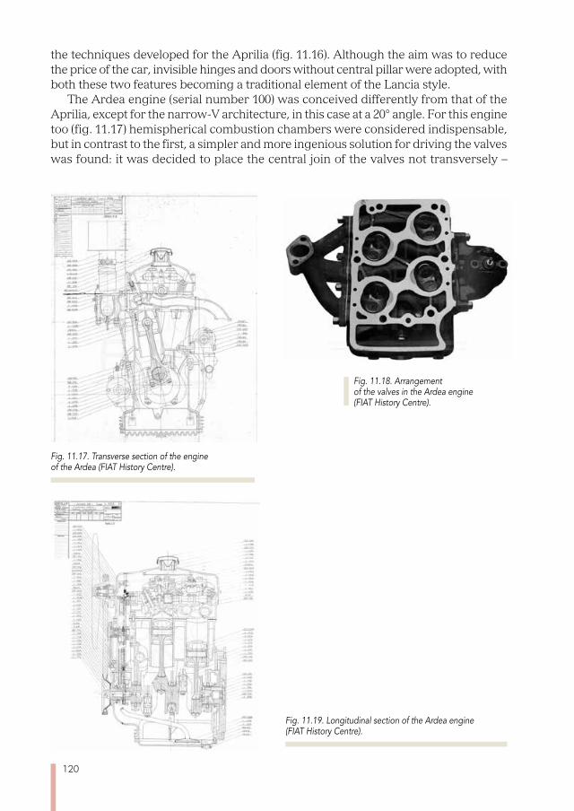
120
the techniques developed for the Aprilia (fig. 11.16). Although the aim was to reduce the price of the car, invisible hinges and doors without central pillar were adopted, with both these two features becoming a traditional element of the Lancia style.
The Ardea engine (serial number 100) was conceived differently from that of the Aprilia, except for the narrow-V architecture, in this case at a 20° angle. For this engine too (fig. 11.17) hemispherical combustion chambers were considered indispensable, but in contrast to the first, a simpler and more ingenious solution for driving the valves was found: it was decided to place the central join of the valves not transversely –
Fig. 11.19. Longitudinal section of the Ardea engine (FIAT History Centre).
Fig. 11.17. Transverse section of the engine of the Ardea (FIAT History Centre).
Fig. 11.18. Arrangement of the valves in the Ardea engine (FIAT History Centre).
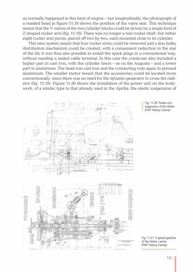
121
as normally happened in this kind of engine – but longitudinally; the photograph of a readied head in figure 11.18 shows the position of the valve seat. This technique meant that the V-valves of the two cylinder blocks could be driven by a single kind of Z-shaped rocker arm (fig. 11.19). There was no longer a real rocker shaft, but rather eight rocker arm pivots, paired off two by two, each mounted close to its cylinder.
This new system meant that four rocker arms could be removed and a less bulky distribution mechanism could be created, with a consequent reduction in the size of the lid; it was thus also possible to install the spark plugs in a conventional way, without needing a sealed cable terminal. In this case the crankcase also included a higher part in cast iron, with the cylinder liners – as on the Augusta – and a lower part in aluminium. The head was cast iron and the connecting rods again in pressed aluminium. The smaller motor meant that the accessories could be located more conventionally, since there was no need for the dynamo generator to cross the radi-ator (fig. 11.19). Figure 11.20 shows the installation of the power unit on the body-work, of a similar type to that already used in the Aprilia: the elastic suspension of
Fig. 11.21. 5-speed gearbox of the Ardea v series (FIAT History Centre).
Fig. 11.20. Power unit suspension of the Ardea (FIAT History Centre).
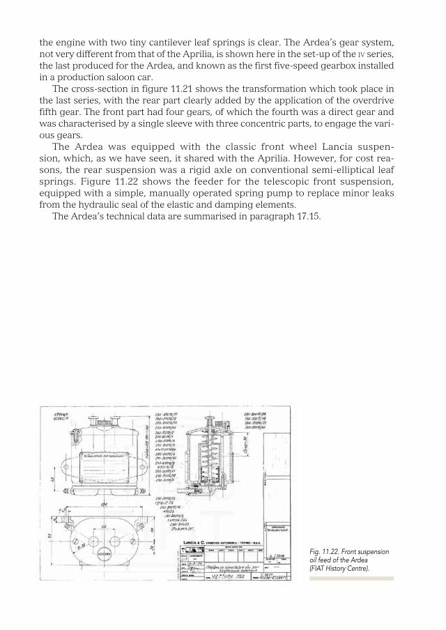
the engine with two tiny cantilever leaf springs is clear. The Ardea’s gear system, not very different from that of the Aprilia, is shown here in the set-up of the iv series, the last produced for the Ardea, and known as the first five-speed gearbox installed in a production saloon car.
The cross-section in figure 11.21 shows the transformation which took place in the last series, with the rear part clearly added by the application of the overdrive fifth gear. The front part had four gears, of which the fourth was a direct gear and was characterised by a single sleeve with three concentric parts, to engage the vari-ous gears.
The Ardea was equipped with the classic front wheel Lancia suspen-sion, which, as we have seen, it shared with the Aprilia. However, for cost rea-sons, the rear suspension was a rigid axle on conventional semi-elliptical leaf springs. Figure 11.22 shows the feeder for the telescopic front suspension, equipped with a simple, manually operated spring pump to replace minor leaks from the hydraulic seal of the elastic and damping elements.
The Ardea’s technical data are summarised in paragraph 17.15.
Fig. 11.22. Front suspension oil feed of the Ardea (FIAT History Centre).

123
Chapter 12
THE AURELIA AND THE APPIA
In 1950, as if by appointment, the three largest Italian car makers all presented new top of the range models to replace the obsolete ones whose designs dated back to the pre-war period. Alfa Romeo introduced the 1900, in place of the famous
6C, fiat the 1400 to replace the 1500, and Lancia launched the Aurelia to take over from the Aprilia.
The three cars had different marketing characteristics: the first appealed because of its sporting feel, the second because of its value for money and the third because of the level of comfort and technological refinement. But they shared a common feature: the size of the passenger area, designed to seat six people, three of them on the front seat.
This new style, like others introduced in Italy in the post-war period, hailed from the United States: they imitated, in smaller versions, the American family cars. The new formula involved the use of a bench seat in the front, a steering-wheel mounted gearstick and the handbrake under the dashboard, so as not to interfere with the space available to the third passenger in the front. Table 12.1 shows a comparison of the main characteristics of these three saloon cars, which for many years repre-sented the highest aspiration for Italian drivers. With no reliable performance data
type alfa romeo 1900 fiat 1400 lancia aurelia
Capacity (cm3) 1884 1395 1754
Engine Arch. 4 L 4 L 6 V
Power (hp) 80 44 56
Torque (kgm) 12,7* 8,3 10,8
Weight (kg) 1100 1130 1150
Specific power (hp/kg) 0,073 0,039 0,049
Specific torque (kgm/kg) 0,012 0,007 0,009
Top speed (km/h) 150 120 135
Fuel consumption (l/100 km)** 10,5 10,5 10,5
Price (lire) 2.310.000 1.275.000 1.830.000
Units produced*** 17.263 201.500 16.607
* Estimate. ** Cuna standards. *** Including derivative models.
Tab. 12.1. Details of the three main new models produced in Italy in 1950 by Alfa Romeo, fiat and Lancia.

124
available, it is worth noting the specific power relating to the weight of the empty vehicle as an indication of the acceleration and specific torque, again in relation to weight, as an indication of the pick-up in top gear.
With the new model, Lancia introduced a different product identification system: the progressive numbering previously used was abandoned and an alphanumeric code was adopted, consisting of a letter indicating the family it belonged to followed by a figure to show the version or series. For example the model which substituted the Aprilia was at first given the letter A, which changed to B when the Aurelia took on its final characteristics. The letter C was given to the Appia and D to the famous racing cars which will be described in chapter 13.
The marketing name Aurelia was used for the Berlinas with the serial numbers B10 and B50 for the i series, B21, B15, B22, B52, B53, for the ii series, and B12 and B56 for the iii series. The Coupé Gt B20 version and the very famous Spider B24 were also constructed. The same serial number was used for chassis, bodywork and engine.
The Aurelia, even though it was at first conceived as an improved version of the Aprilia, distanced itself somewhat from the previous model, above all because of its engine, which no longer strictly followed the architectural code of using the narrow V, whose worth was beginning to be doubted at Lancia. Table 12.2 shows a summary of the geometric characteristics of the narrow-V engines introduced in all the Lancia output: the wide range of V-angles in the various motors is worth noting.
The lack of unification was caused by the geometric restrictions imposed by the arrangement of the valves and the engine accessories and the space taken up by the cylinder liners: different angles had often to be used for small variations in bore and stroke. It meant that the machinery used to produce cylinder heads and crankcases
model bore stroke angle cylinders engine capacity
Trikappa 75 130 14° 8 4592
Lambda 75 120 13° 6’ 4 2119
Lambda (VII s.) 79,37 120 13° 4 2370
Lambda (VIII, IX s.) 82,55 120 13° 14’ 4 2568
Dilambda 79,37 100 24° 8 3956
Artena 82,55 90 17° 4 1927
Astura (I, II s.) 69,85 85 19° 8 2606
Astura (III, IV s.) 74,61 85 17° 30’ 8 2973
Augusta 69,85 78 18° 4 1196
Aprilia (I s.) 72 82 19° 6’ 40” 4 1352
Aprilia (II s.) 74,61 85 17° 4 1486
Ardea 65 68 20° 4 903
Appia 68 75 10° 14’ 4 1089
Fulvia 72 67 13°* 4 1091
*The larger capacity versions of the Fulvia motor kept the same V angle.
Tab. 12.2. Summary of the geometrical arrangement of the V motors of the entire Lancia output.
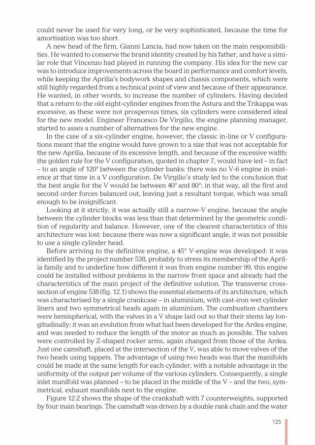
125
could never be used for very long, or be very sophisticated, because the time for amortisation was too short.
A new head of the firm, Gianni Lancia, had now taken on the main responsibili-ties. He wanted to conserve the brand identity created by his father, and have a simi-lar role that Vincenzo had played in running the company. His idea for the new car was to introduce improvements across the board in performance and comfort levels, while keeping the Aprilia’s bodywork shapes and chassis components, which were still highly regarded from a technical point of view and because of their appearance. He wanted, in other words, to increase the number of cylinders. Having decided that a return to the old eight-cylinder engines from the Astura and the Trikappa was excessive, as these were not prosperous times, six cylinders were considered ideal for the new model. Engineer Francesco De Virgilio, the engine planning manager, started to asses a number of alternatives for the new engine.
In the case of a six-cylinder engine, however, the classic in-line or V configura-tions meant that the engine would have grown to a size that was not acceptable for the new Aprilia, because of its excessive length, and because of the excessive width: the golden rule for the V configuration, quoted in chapter 7, would have led – in fact – to an angle of 120° between the cylinder banks: there was no V-6 engine in exist-ence at that time in a V configuration. De Virgilio’s study led to the conclusion that the best angle for the V would be between 40° and 80°: in that way, all the first and second order forces balanced out, leaving just a resultant torque, which was small enough to be insignificant.
Looking at it strictly, it was actually still a narrow-V engine, because the angle between the cylinder blocks was less than that determined by the geometric condi-tion of regularity and balance. However, one of the clearest characteristics of this architecture was lost: because there was now a significant angle, it was not possible to use a single cylinder head.
Before arriving to the definitive engine, a 45° V-engine was developed: it was identified by the project number 538, probably to stress its membership of the April-ia family and to underline how different it was from engine number 99, this engine could be installed without problems in the narrow front space and already had the characteristics of the main project of the definitive solution. The transverse cross-section of engine 538 (fig. 12.1) shows the essential elements of its architecture, which was characterised by a single crankcase – in aluminium, with cast-iron wet cylinder liners and two symmetrical heads again in aluminium. The combustion chambers were hemispherical, with the valves in a V shape laid out so that their stems lay lon-gitudinally: it was an evolution from what had been developed for the Ardea engine, and was needed to reduce the length of the motor as much as possible. The valves were controlled by Z-shaped rocker arms, again changed from those of the Ardea. Just one camshaft, placed at the intersection of the V, was able to move valves of the two heads using tappets. The advantage of using two heads was that the manifolds could be made at the same length for each cylinder, with a notable advantage in the uniformity of the output per volume of the various cylinders. Consequently, a single inlet manifold was planned – to be placed in the middle of the V – and the two, sym-metrical, exhaust manifolds next to the engine.
Figure 12.2 shows the shape of the crankshaft with 7 counterweights, supported by four main bearings. The camshaft was driven by a double rank chain and the water *The larger capacity versions of the Fulvia motor kept the same V angle.

126
Fig. 12.1. Transverse section of the experimental 538 engine (FIAT History Centre).
Fig. 12.2. Longitudinal section of the experimental 538 engine (FIAT History Centre).
Fig. 12.3. Transverse section of the engine of the Aurelia B10 (FIAT History Centre).
Fig. 12.4. Longitudinal section of the engine of the Aurelia B20 (FIAT History Centre).
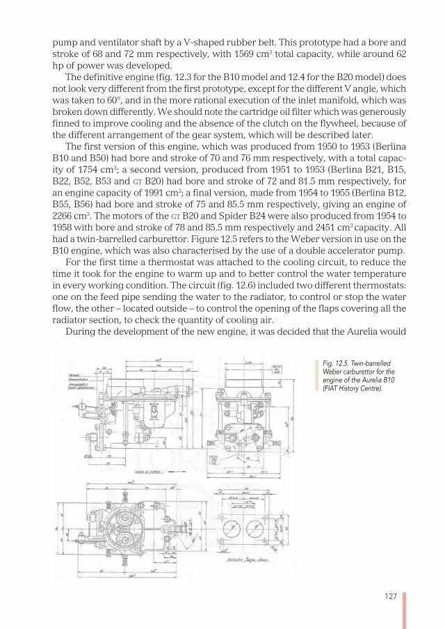
127
pump and ventilator shaft by a V-shaped rubber belt. This prototype had a bore and stroke of 68 and 72 mm respectively, with 1569 cm3 total capacity, while around 62 hp of power was developed.
The definitive engine (fig. 12.3 for the B10 model and 12.4 for the B20 model) does not look very different from the first prototype, except for the different V angle, which was taken to 60°, and in the more rational execution of the inlet manifold, which was broken down differently. We should note the cartridge oil filter which was generously finned to improve cooling and the absence of the clutch on the flywheel, because of the different arrangement of the gear system, which will be described later.
The first version of this engine, which was produced from 1950 to 1953 (Berlina B10 and B50) had bore and stroke of 70 and 76 mm respectively, with a total capac-ity of 1754 cm3; a second version, produced from 1951 to 1953 (Berlina B21, B15, B22, B52, B53 and Gt B20) had bore and stroke of 72 and 81.5 mm respectively, for an engine capacity of 1991 cm3; a final version, made from 1954 to 1955 (Berlina B12, B55, B56) had bore and stroke of 75 and 85.5 mm respectively, giving an engine of 2266 cm3. The motors of the Gt B20 and Spider B24 were also produced from 1954 to 1958 with bore and stroke of 78 and 85.5 mm respectively and 2451 cm3 capacity. All had a twin-barrelled carburettor. Figure 12.5 refers to the Weber version in use on the B10 engine, which was also characterised by the use of a double accelerator pump.
For the first time a thermostat was attached to the cooling circuit, to reduce the time it took for the engine to warm up and to better control the water temperature in every working condition. The circuit (fig. 12.6) included two different thermostats: one on the feed pipe sending the water to the radiator, to control or stop the water flow, the other – located outside – to control the opening of the flaps covering all the radiator section, to check the quantity of cooling air.
During the development of the new engine, it was decided that the Aurelia would
Fig. 12.5. Twin-barrelled Weber carburettor for the engine of the Aurelia B10 (FIAT History Centre).
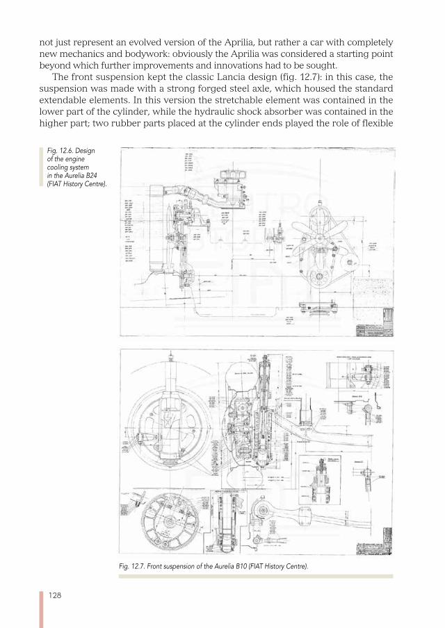
128
Fig. 12.7. Front suspension of the Aurelia B10 (FIAT History Centre).
not just represent an evolved version of the Aprilia, but rather a car with completely new mechanics and bodywork: obviously the Aprilia was considered a starting point beyond which further improvements and innovations had to be sought.
The front suspension kept the classic Lancia design (fig. 12.7): in this case, the suspension was made with a strong forged steel axle, which housed the standard extendable elements. In this version the stretchable element was contained in the lower part of the cylinder, while the hydraulic shock absorber was contained in the higher part; two rubber parts placed at the cylinder ends played the role of flexible
Fig. 12.6. Design of the engine cooling system in the Aurelia B24 (FIAT History Centre).
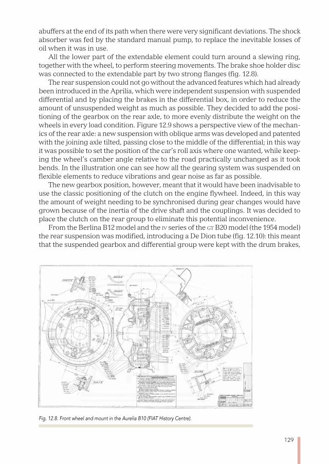
129
abuffers at the end of its path when there were very significant deviations. The shock absorber was fed by the standard manual pump, to replace the inevitable losses of oil when it was in use.
All the lower part of the extendable element could turn around a slewing ring, together with the wheel, to perform steering movements. The brake shoe holder disc was connected to the extendable part by two strong flanges (fig. 12.8).
The rear suspension could not go without the advanced features which had already been introduced in the Aprilia, which were independent suspension with suspended differential and by placing the brakes in the differential box, in order to reduce the amount of unsuspended weight as much as possible. They decided to add the posi-tioning of the gearbox on the rear axle, to more evenly distribute the weight on the wheels in every load condition. Figure 12.9 shows a perspective view of the mechan-ics of the rear axle: a new suspension with oblique arms was developed and patented with the joining axle tilted, passing close to the middle of the differential; in this way it was possible to set the position of the car’s roll axis where one wanted, while keep-ing the wheel’s camber angle relative to the road practically unchanged as it took bends. In the illustration one can see how all the gearing system was suspended on flexible elements to reduce vibrations and gear noise as far as possible.
The new gearbox position, however, meant that it would have been inadvisable to use the classic positioning of the clutch on the engine flywheel. Indeed, in this way the amount of weight needing to be synchronised during gear changes would have grown because of the inertia of the drive shaft and the couplings. It was decided to place the clutch on the rear group to eliminate this potential inconvenience.
From the Berlina B12 model and the iv series of the Gt B20 model (the 1954 model) the rear suspension was modified, introducing a De Dion tube (fig. 12.10): this meant that the suspended gearbox and differential group were kept with the drum brakes,
Fig. 12.8. Front wheel and mount in the Aurelia B10 (FIAT History Centre).
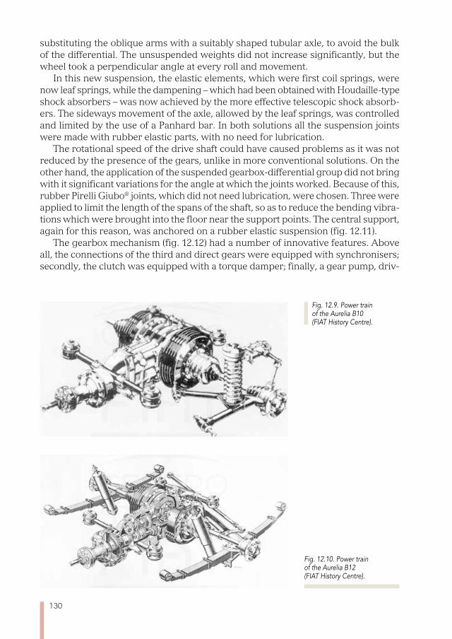
130
substituting the oblique arms with a suitably shaped tubular axle, to avoid the bulk of the differential. The unsuspended weights did not increase significantly, but the wheel took a perpendicular angle at every roll and movement.
In this new suspension, the elastic elements, which were first coil springs, were now leaf springs, while the dampening – which had been obtained with Houdaille-type shock absorbers – was now achieved by the more effective telescopic shock absorb-ers. The sideways movement of the axle, allowed by the leaf springs, was controlled and limited by the use of a Panhard bar. In both solutions all the suspension joints were made with rubber elastic parts, with no need for lubrication.
The rotational speed of the drive shaft could have caused problems as it was not reduced by the presence of the gears, unlike in more conventional solutions. On the other hand, the application of the suspended gearbox-differential group did not bring with it significant variations for the angle at which the joints worked. Because of this, rubber Pirelli Giubo® joints, which did not need lubrication, were chosen. Three were applied to limit the length of the spans of the shaft, so as to reduce the bending vibra-tions which were brought into the floor near the support points. The central support, again for this reason, was anchored on a rubber elastic suspension (fig. 12.11).
The gearbox mechanism (fig. 12.12) had a number of innovative features. Above all, the connections of the third and direct gears were equipped with synchronisers; secondly, the clutch was equipped with a torque damper; finally, a gear pump, driv-
Fig. 12.9. Power train of the Aurelia B10 (FIAT History Centre).
Fig. 12.10. Power train of the Aurelia B12 (FIAT History Centre).
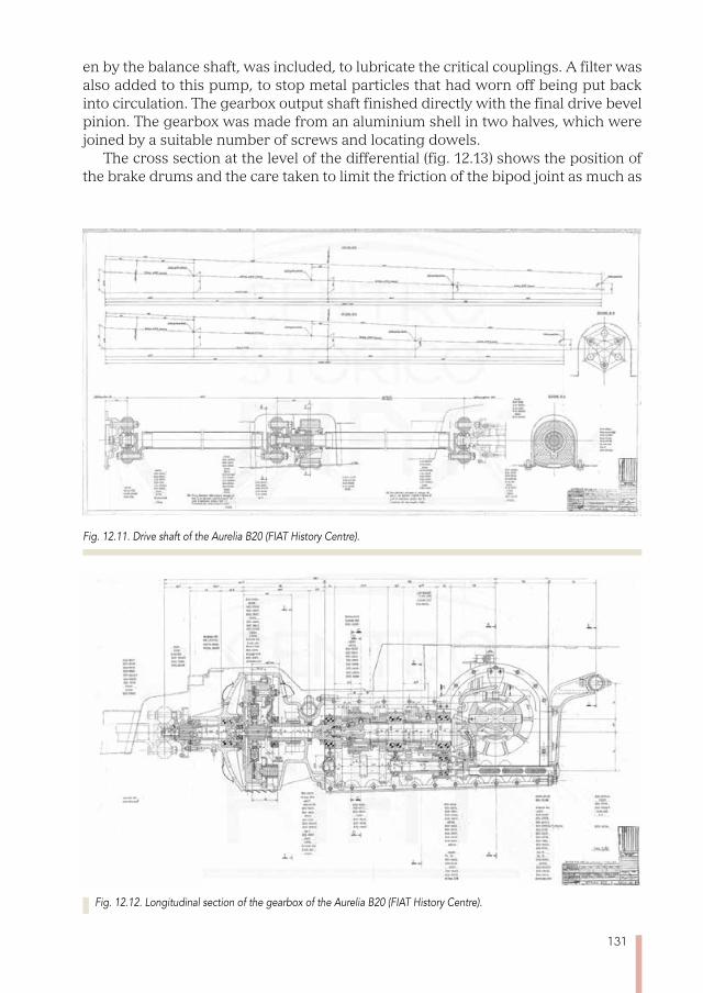
131
en by the balance shaft, was included, to lubricate the critical couplings. A filter was also added to this pump, to stop metal particles that had worn off being put back into circulation. The gearbox output shaft finished directly with the final drive bevel pinion. The gearbox was made from an aluminium shell in two halves, which were joined by a suitable number of screws and locating dowels.
The cross section at the level of the differential (fig. 12.13) shows the position of the brake drums and the care taken to limit the friction of the bipod joint as much as
Fig. 12.11. Drive shaft of the Aurelia B20 (FIAT History Centre).
Fig. 12.12. Longitudinal section of the gearbox of the Aurelia B20 (FIAT History Centre).

132
Fig. 12.13. Transverse section of the differential and the rear brakes of the Aurelia B20 (FIAT History Centre).
Fig. 12.14. Gear change on the steering wheel of the Aurelia B20 Berlina (FIAT History Centre).
Fig. 12.15. Gear change on the steering wheel of the Aurelia B20 (FIAT History Centre).
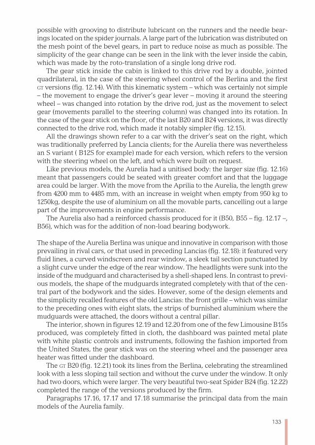
133
possible with grooving to distribute lubricant on the runners and the needle bear-ings located on the spider journals. A large part of the lubrication was distributed on the mesh point of the bevel gears, in part to reduce noise as much as possible. The simplicity of the gear change can be seen in the link with the lever inside the cabin, which was made by the roto-translation of a single long drive rod.
The gear stick inside the cabin is linked to this drive rod by a double, jointed quadrilateral, in the case of the steering wheel control of the Berlina and the first Gt versions (fig. 12.14). With this kinematic system – which was certainly not simple – the movement to engage the driver’s gear lever – moving it around the steering wheel – was changed into rotation by the drive rod, just as the movement to select gear (movements parallel to the steering column) was changed into its rotation. In the case of the gear stick on the floor, of the last B20 and B24 versions, it was directly connected to the drive rod, which made it notably simpler (fig. 12.15).
All the drawings shown refer to a car with the driver’s seat on the right, which was traditionally preferred by Lancia clients; for the Aurelia there was nevertheless an S variant ( B12S for example) made for each version, which refers to the version with the steering wheel on the left, and which were built on request.
Like previous models, the Aurelia had a unitised body: the larger size (fig. 12.16) meant that passengers could be seated with greater comfort and that the luggage area could be larger. With the move from the Aprilia to the Aurelia, the length grew from 4200 mm to 4485 mm, with an increase in weight when empty from 950 kg to 1250kg, despite the use of aluminium on all the movable parts, cancelling out a large part of the improvements in engine performance.
The Aurelia also had a reinforced chassis produced for it (B50, B55 – fig. 12.17 –, B56), which was for the addition of non-load bearing bodywork.
The shape of the Aurelia Berlina was unique and innovative in comparison with those prevailing in rival cars, or that used in preceding Lancias (fig. 12.18): it featured very fluid lines, a curved windscreen and rear window, a sleek tail section punctuated by a slight curve under the edge of the rear window. The headlights were sunk into the inside of the mudguard and characterised by a shell-shaped lens. In contrast to previ-ous models, the shape of the mudguards integrated completely with that of the cen-tral part of the bodywork and the sides. However, some of the design elements and the simplicity recalled features of the old Lancias: the front grille – which was similar to the preceding ones with eight slats, the strips of burnished aluminium where the mudguards were attached, the doors without a central pillar.
The interior, shown in figures 12.19 and 12.20 from one of the few Limousine B15s produced, was completely fitted in cloth, the dashboard was painted metal plate with white plastic controls and instruments, following the fashion imported from the United States, the gear stick was on the steering wheel and the passenger area heater was fitted under the dashboard.
The Gt B20 (fig. 12.21) took its lines from the Berlina, celebrating the streamlined look with a less sloping tail section and without the curve under the window. It only had two doors, which were larger. The very beautiful two-seat Spider B24 (fig. 12.22) completed the range of the versions produced by the firm.
Paragraphs 17.16, 17.17 and 17.18 summarise the principal data from the main models of the Aurelia family.
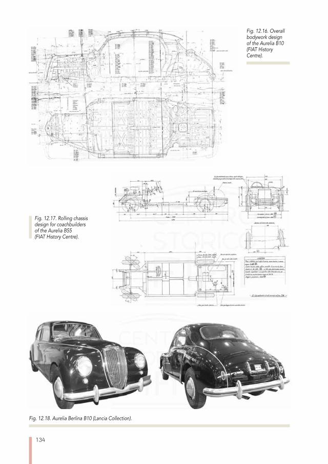
134
Fig. 12.18. Aurelia Berlina B10 (Lancia Collection).
Fig. 12.17. Rolling chassis design for coachbuilders of the Aurelia B55 (FIAT History Centre).
Fig. 12.16. Overall bodywork design of the Aurelia B10 (FIAT History Centre).

135
Lancia’s new small model, the Appia C10, substituted the Ardea three years after the launch of the Aurelia. It copied the Aurelia shape – this was practically a scaled-down derivative (fig. 12.23): the two cars are even more similar than the Aprilia and Ardea were.
The lifespan of the Appia from 1953 to 1963, which was longer than that of the Aure-lia, was marked by two significant changes to the look of the bodywork: the first, on the ii series, presented in 1956, was the change of the tail section, with the addition of
Fig. 12.19. Driving seat of the Aurelia Limousine B15 (Lancia Collection).
Fig. 12.20. Interior views of the Aurelia Limousine B15 (Lancia Collection).
Fig. 12.21. Aurelia gt B20 (National Automobile Museum).
Fig. 12.22. Aurelia Spider B24 (Lancia Collection).

136
a very pronounced third box to increase boot capacity (fig. 12.24). At the same time, the interior was modernised with a new dashboard, with plastic upholstery at the top, and a dual display instrument panel in a more modern shape than the earlier one.
The iii series, introduced in 1959, also had a modified front part, substituting the classic, vertical shield grille, with a new horizontal one (fig. 12.25), similar to that introduced with the new Flaminia (cf. chapter 13).
The mechanics of the Appia were very similar to those of the Ardea, with the same location of the power unit and the same kind of suspension. The engine, however, (fig. 12.26 and 12.27) had numerous modifications, and some features which made it unique.
While keeping the special architecture of the aluminium head, which has already been described for the Ardea, the V valves were arranged transversely to the engine, and were controlled by a system of rods and rocker arms and by two camshafts locat-ed in the crankcase, one either side of the engine. The V-configured engine was the
Fig. 12.24. Appia Berlina ii series C10 (Lancia Collection).
Fig. 12.23. Appia Berlina i series C10 (FIAT History Centre).
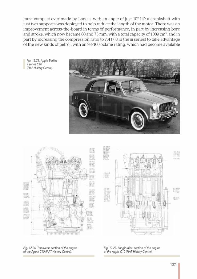
137
most compact ever made by Lancia, with an angle of just 10° 14’; a crankshaft with just two supports was deployed to help reduce the length of the motor. There was an improvement across-the-board in terms of performance, in part by increasing bore and stroke, which now became 60 and 75 mm, with a total capacity of 1089 cm3, and in part by increasing the compression ratio to 7.4 (7.8 in the iii series) to take advantage of the new kinds of petrol, with an 98-100 octane rating, which had become available
Fig. 12.25. Appia Berlina iii series C10 (FIAT History Centre).
Fig. 12.27. Longitudinal section of the engine of the Appia C10 (FIAT History Centre).
Fig. 12.26. Transverse section of the engine of the Appia C10 (FIAT History Centre).
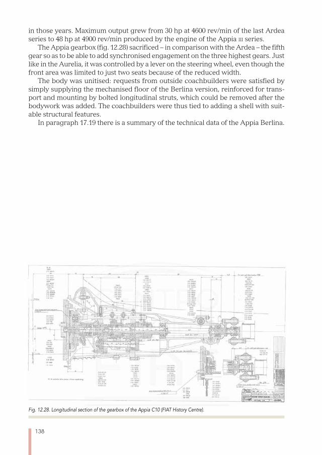
138
in those years. Maximum output grew from 30 hp at 4600 rev/min of the last Ardea series to 48 hp at 4900 rev/min produced by the engine of the Appia iii series.
The Appia gearbox (fig. 12.28) sacrificed – in comparison with the Ardea – the fifth gear so as to be able to add synchronised engagement on the three highest gears. Just like in the Aurelia, it was controlled by a lever on the steering wheel, even though the front area was limited to just two seats because of the reduced width.
The body was unitised: requests from outside coachbuilders were satisfied by simply supplying the mechanised floor of the Berlina version, reinforced for trans-port and mounting by bolted longitudinal struts, which could be removed after the bodywork was added. The coachbuilders were thus tied to adding a shell with suit-able structural features.
In paragraph 17.19 there is a summary of the technical data of the Appia Berlina.
Fig. 12.28. Longitudinal section of the gearbox of the Appia C10 (FIAT History Centre).
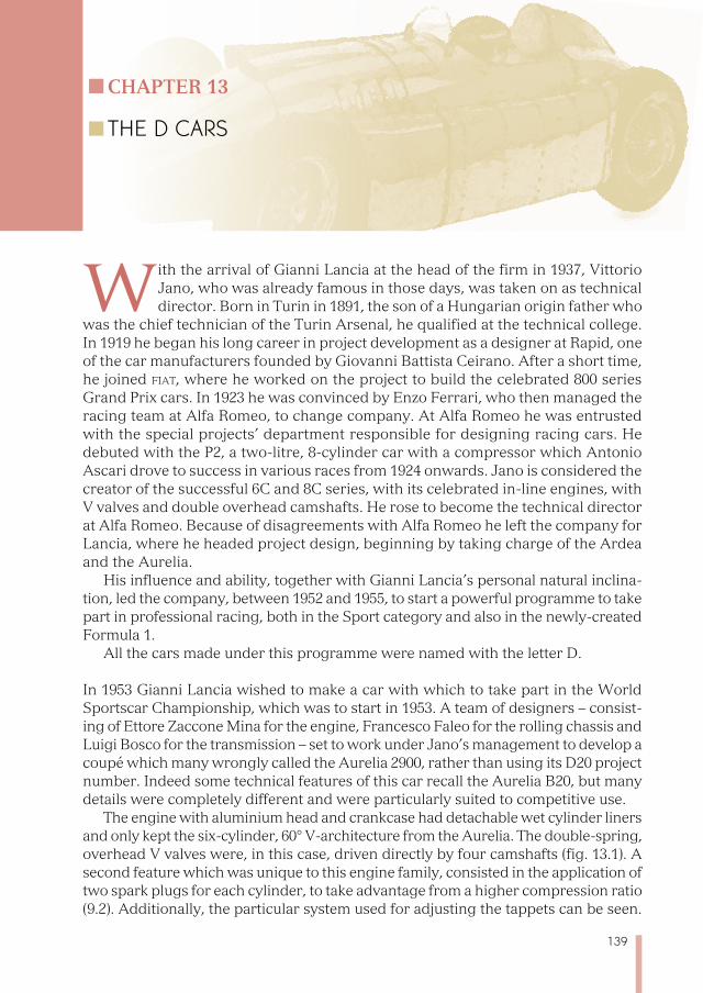
139
Chapter 13
THE D CARS
With the arrival of Gianni Lancia at the head of the firm in 1937, Vittorio Jano, who was already famous in those days, was taken on as technical director. Born in Turin in 1891, the son of a Hungarian origin father who
was the chief technician of the Turin Arsenal, he qualified at the technical college. In 1919 he began his long career in project development as a designer at Rapid, one of the car manufacturers founded by Giovanni Battista Ceirano. After a short time, he joined fiat, where he worked on the project to build the celebrated 800 series Grand Prix cars. In 1923 he was convinced by Enzo Ferrari, who then managed the racing team at Alfa Romeo, to change company. At Alfa Romeo he was entrusted with the special projects’ department responsible for designing racing cars. He debuted with the P2, a two-litre, 8-cylinder car with a compressor which Antonio Ascari drove to success in various races from 1924 onwards. Jano is considered the creator of the successful 6C and 8C series, with its celebrated in-line engines, with V valves and double overhead camshafts. He rose to become the technical director at Alfa Romeo. Because of disagreements with Alfa Romeo he left the company for Lancia, where he headed project design, beginning by taking charge of the Ardea and the Aurelia.
His influence and ability, together with Gianni Lancia’s personal natural inclina-tion, led the company, between 1952 and 1955, to start a powerful programme to take part in professional racing, both in the Sport category and also in the newly-created Formula 1.
All the cars made under this programme were named with the letter D.
In 1953 Gianni Lancia wished to make a car with which to take part in the World Sportscar Championship, which was to start in 1953. A team of designers – consist-ing of Ettore Zaccone Mina for the engine, Francesco Faleo for the rolling chassis and Luigi Bosco for the transmission – set to work under Jano’s management to develop a coupé which many wrongly called the Aurelia 2900, rather than using its D20 project number. Indeed some technical features of this car recall the Aurelia B20, but many details were completely different and were particularly suited to competitive use.
The engine with aluminium head and crankcase had detachable wet cylinder liners and only kept the six-cylinder, 60° V-architecture from the Aurelia. The double-spring, overhead V valves were, in this case, driven directly by four camshafts (fig. 13.1). A second feature which was unique to this engine family, consisted in the application of two spark plugs for each cylinder, to take advantage from a higher compression ratio (9.2). Additionally, the particular system used for adjusting the tappets can be seen.
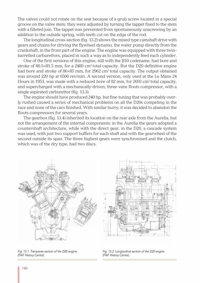
140
The valves could not rotate on the seat because of a grub screw located in a special groove on the valve stem: they were adjusted by turning the tappet fixed to the stem with a filleted join. The tappet was prevented from spontaneously unscrewing by an addition to the outside spring, with teeth cut on the edge of the rod.
The longitudinal cross-section (fig. 13.2) shows the mixed type camshaft drive with gears and chains for driving the flywheel dynamo, the water pump directly from the crankshaft, in the front part of the engine. The engine was equipped with three twin-barrelled carburettors, placed in such a way as to independently feed each cylinder.
One of the first versions of this engine, still with the B10 codename, had bore and stroke of 80.5×81.5 mm, for a 2489 cm3 total capacity. But the D20 definitive engine had bore and stroke of 86×85 mm, for 2962 cm3 total capacity. The output obtained was around 220 hp at 6500 rev/min. A second version, only used at the Le Mans 24 Hours in 1953, was made with a reduced bore of 82 mm, for 2693 cm3 total capacity, and supercharged with a mechanically-driven, three-vane Roots compressor, with a single aspirated carburettor (fig. 13.3).
The engine should have produced 240 hp, but fine-tuning that was probably over-ly rushed caused a series of mechanical problems on all the D20s competing in the race and none of the cars finished. With similar hurry, it was decided to abandon the Roots compressors for several years.
The gearbox (fig. 13.4) inherited its location on the rear axle from the Aurelia, but not the arrangement of the internal components: in the Aurelia the gears adopted a countershaft architecture, while with the direct gear, in the D20, a cascade system was used, with just two support buffers for each shaft and with the gearwheel of the second outside its span. The three highest gears were synchronised and the clutch, which was of the dry type, had two discs.
Fig. 13.1. Transverse section of the D20 engine (FIAT History Centre).
Fig. 13.2. Longitudinal section of the D20 engine (FIAT History Centre).
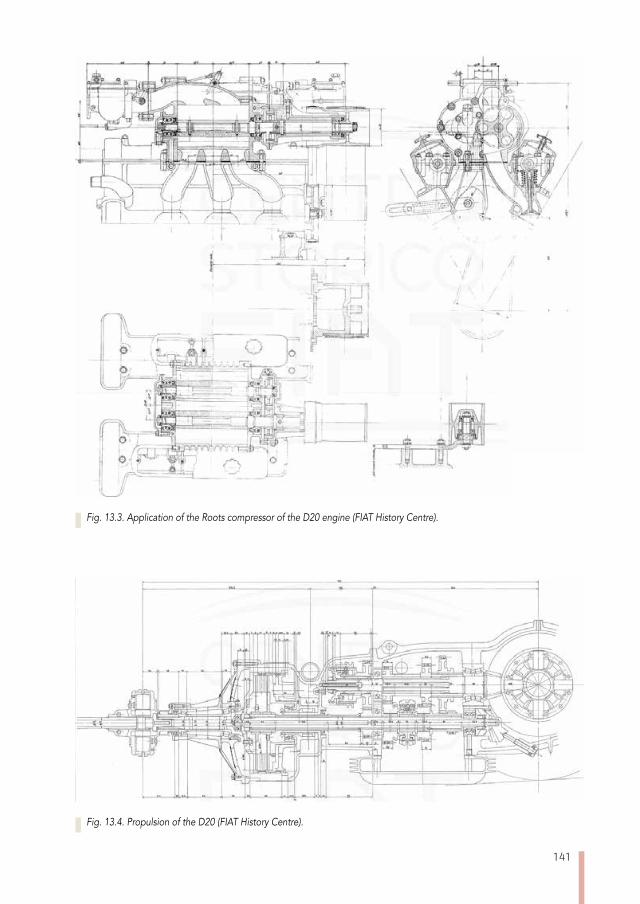
141
Fig. 13.3. Application of the Roots compressor of the D20 engine (FIAT History Centre).
Fig. 13.4. Propulsion of the D20 (FIAT History Centre).
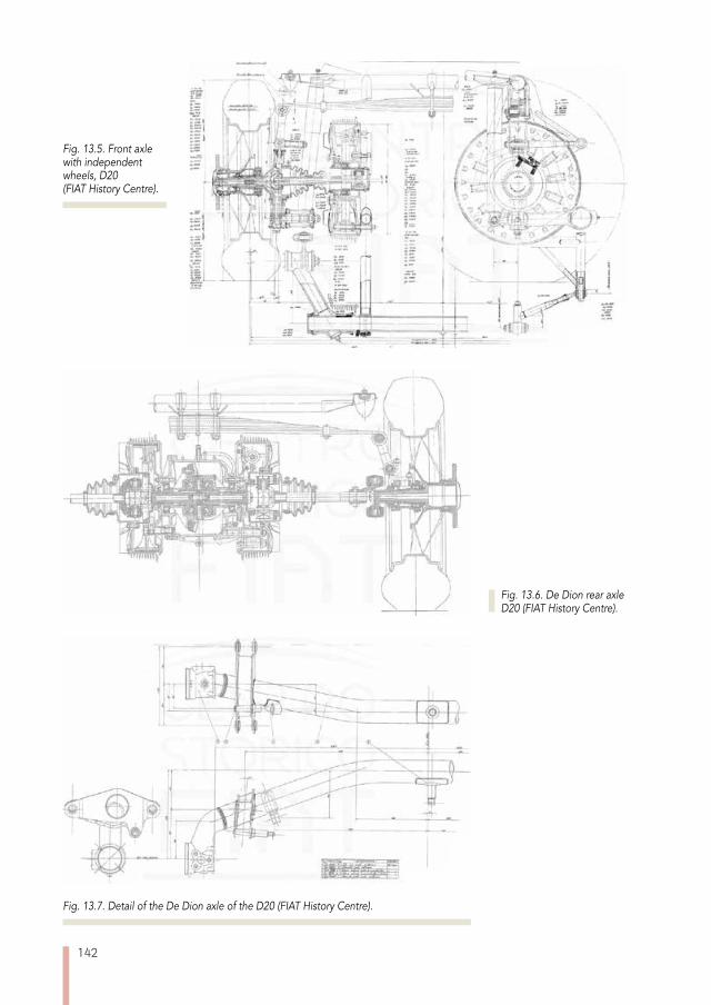
142
Fig. 13.6. De Dion rear axle D20 (FIAT History Centre).
Fig. 13.7. Detail of the De Dion axle of the D20 (FIAT History Centre).
Fig. 13.5. Front axle with independent wheels, D20 (FIAT History Centre).
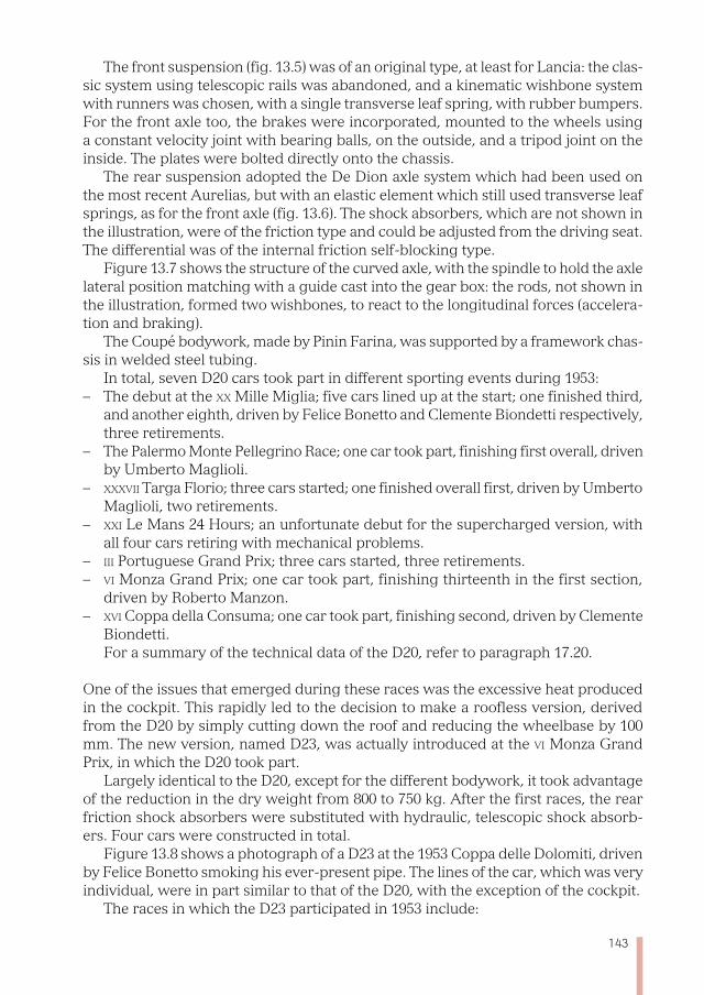
143
The front suspension (fig. 13.5) was of an original type, at least for Lancia: the clas-sic system using telescopic rails was abandoned, and a kinematic wishbone system with runners was chosen, with a single transverse leaf spring, with rubber bumpers. For the front axle too, the brakes were incorporated, mounted to the wheels using a constant velocity joint with bearing balls, on the outside, and a tripod joint on the inside. The plates were bolted directly onto the chassis.
The rear suspension adopted the De Dion axle system which had been used on the most recent Aurelias, but with an elastic element which still used transverse leaf springs, as for the front axle (fig. 13.6). The shock absorbers, which are not shown in the illustration, were of the friction type and could be adjusted from the driving seat. The differential was of the internal friction self-blocking type.
Figure 13.7 shows the structure of the curved axle, with the spindle to hold the axle lateral position matching with a guide cast into the gear box: the rods, not shown in the illustration, formed two wishbones, to react to the longitudinal forces (accelera-tion and braking).
The Coupé bodywork, made by Pinin Farina, was supported by a framework chas-sis in welded steel tubing.
In total, seven D20 cars took part in different sporting events during 1953:– The debut at the xx Mille Miglia; five cars lined up at the start; one finished third,
and another eighth, driven by Felice Bonetto and Clemente Biondetti respectively, three retirements.
– The Palermo Monte Pellegrino Race; one car took part, finishing first overall, driven by Umberto Maglioli.
– xxxvii Targa Florio; three cars started; one finished overall first, driven by Umberto Maglioli, two retirements.
– xxi Le Mans 24 Hours; an unfortunate debut for the supercharged version, with all four cars retiring with mechanical problems.
– iii Portuguese Grand Prix; three cars started, three retirements. – vi Monza Grand Prix; one car took part, finishing thirteenth in the first section,
driven by Roberto Manzon. – xvi Coppa della Consuma; one car took part, finishing second, driven by Clemente
Biondetti. For a summary of the technical data of the D20, refer to paragraph 17.20.
One of the issues that emerged during these races was the excessive heat produced in the cockpit. This rapidly led to the decision to make a roofless version, derived from the D20 by simply cutting down the roof and reducing the wheelbase by 100 mm. The new version, named D23, was actually introduced at the vi Monza Grand Prix, in which the D20 took part.
Largely identical to the D20, except for the different bodywork, it took advantage of the reduction in the dry weight from 800 to 750 kg. After the first races, the rear friction shock absorbers were substituted with hydraulic, telescopic shock absorb-ers. Four cars were constructed in total.
Figure 13.8 shows a photograph of a D23 at the 1953 Coppa delle Dolomiti, driven by Felice Bonetto smoking his ever-present pipe. The lines of the car, which was very individual, were in part similar to that of the D20, with the exception of the cockpit.
The races in which the D23 participated in 1953 include:
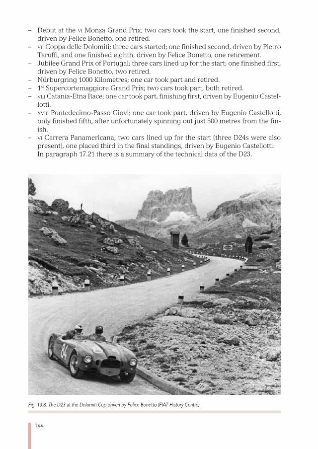
144
– Debut at the vi Monza Grand Prix; two cars took the start; one finished second, driven by Felice Bonetto, one retired.
– vii Coppa delle Dolomiti; three cars started; one finished second, driven by Pietro Taruffi, and one finished eighth, driven by Felice Bonetto, one retirement.
– Jubilee Grand Prix of Portugal; three cars lined up for the start; one finished first, driven by Felice Bonetto, two retired.
– Nürburgring 1000 Kilometres; one car took part and retired. – 1st Supercortemaggiore Grand Prix; two cars took part, both retired. – viii Catania-Etna Race; one car took part, finishing first, driven by Eugenio Castel-
lotti. – xviii Pontedecimo-Passo Giovi; one car took part, driven by Eugenio Castellotti,
only finished fifth, after unfortunately spinning out just 500 metres from the fin-ish.
– vi Carrera Panamericana; two cars lined up for the start (three D24s were also present), one placed third in the final standings, driven by Eugenio Castellotti. In paragraph 17.21 there is a summary of the technical data of the D23.
Fig. 13.8. The D23 at the Dolomiti Cup driven by Felice Bonetto (FIAT History Centre).

145
After the first encouraging results, the development of new solutions continued unstintingly with the D24 model. The engine of the D24, inspired by the same archi-tecture used in the D20 and D23, had bore and stroke increased to 88×90 mm, with a total capacity of 3284 cm3, which could produce 270 hp at 6800 rev/min. The engine used dry sump lubrication, with consequent benefits for the height of its centre of gravity. All the changes made to the chassis were aimed at improving vehicle dynam-ics, through the lowering and shifting of the weight backwards. To assist this, the gearbox was moved to the rear overhang, placing the differential just after the clutch, so that the wheelbase could be shortened from 2600 to 2400 mm. The chassis struc-ture (fig. 13.9) was made in tubes of varying diameter which were welded together in a similar way to what had been done for the D20 and the D23.
The bodywork of the Barchetta D24, again the work of Pinin Farina, looks more graceful than that of the previous cars: figure 13.10 shows the D24 driven by Manuel Fangio at the Carrera Panamericana in 1953.
Eight D24 were constructed, which took part in numerous races between 1953 and 1954.
The races in 1953: – Debut at the Nürburgring 1000 Kilometres; two cars took part. Despite proving
themselves as competitive, they were obliged to retire because of various faults. – i Supercortemaggiore Grand Prix; the two cars taking part were forced to retire
after coming off the track. – vi Bologna-Passo della Raticosa; two cars took part, finishing first and second,
driven by Felice Bonetto and Eugenio Castellotti respectively. – vi Carrera Panamericana; three cars were entered in the race, with two finishing
first and second, driven by Manuel Fangio and Piero Taruffi respectively, ahead of Eugenio Castellotti’s D23; unfortunately the great victory was overshadowed by the death of Felice Bonetto, driving the third D24.
The races in 1954: – Sebring 12-Hours; four cars took part; one finished second, co-driven by Luigi
Valenzano and Porfirio Rubirosa; the fastest lap was driven by Alberto Ascari, who was teamed with Gigi Villoresi, but retired when an axle shaft broke.
– xiv Giro di Sicilia; one car took part, finishing first, driven by Piero Taruffi. – vi Coppa della Toscana; two cars entered, both retired because of incidents.– xxi Mille Miglia; four cars entered, one finished first, driven by Alberto Ascari,
three retired.– xxviii Targa Florio; two cars entered; one finished first, driven by Piero Taruffi;
the fastest lap was driven by Eugenio Castellotti, who retired after his suspension broke.
– Porto Grand Prix; three cars were entered; two finished first and second, driven by Gigi Villoresi and Eugenio Castellotti respectively, one withdrawal.
– xiv Bolzano-Passo Mendola; one car took part, finishing first, driven by Eugenio Castellotti.
– xvi Aosta-Gran San Bernardo; one car took part, finishing first, again driven by Eugenio Castellotti.
– xxi raC Tourist Trophy; two cars entered, finishing first and third, driven by Pie-
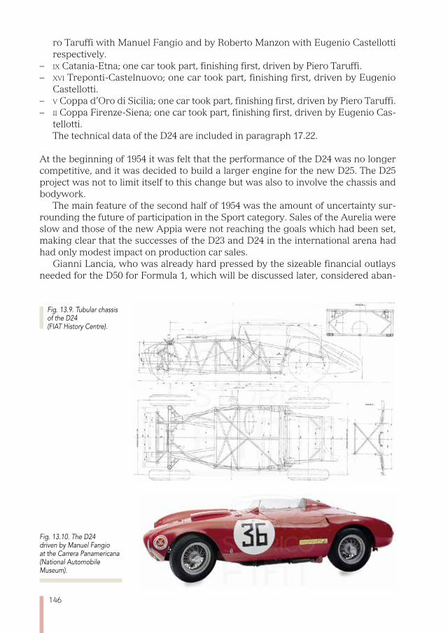
146
ro Taruffi with Manuel Fangio and by Roberto Manzon with Eugenio Castellotti respectively.
– ix Catania-Etna; one car took part, finishing first, driven by Piero Taruffi. – xvi Treponti-Castelnuovo; one car took part, finishing first, driven by Eugenio
Castellotti. – v Coppa d’Oro di Sicilia; one car took part, finishing first, driven by Piero Taruffi. – ii Coppa Firenze-Siena; one car took part, finishing first, driven by Eugenio Cas-
tellotti. The technical data of the D24 are included in paragraph 17.22.
At the beginning of 1954 it was felt that the performance of the D24 was no longer competitive, and it was decided to build a larger engine for the new D25. The D25 project was not to limit itself to this change but was also to involve the chassis and bodywork.
The main feature of the second half of 1954 was the amount of uncertainty sur-rounding the future of participation in the Sport category. Sales of the Aurelia were slow and those of the new Appia were not reaching the goals which had been set, making clear that the successes of the D23 and D24 in the international arena had had only modest impact on production car sales.
Gianni Lancia, who was already hard pressed by the sizeable financial outlays needed for the D50 for Formula 1, which will be discussed later, considered aban-
Fig. 13.9. Tubular chassis of the D24 (FIAT History Centre).
Fig. 13.10. The D24 driven by Manuel Fangio at the Carrera Panamericana (National Automobile Museum).
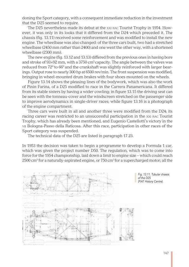
147
doning the Sport category, with a consequent immediate reduction in the investment that the D25 seemed to require.
The D25 nevertheless made its debut at the xxi raC Tourist Trophy in 1954. How-ever, it was only in its looks that it differed from the D24 which preceded it. The chassis (fig. 13.11) received some reinforcement and was modified to install the new engine. The wheelbase was also changed: of the three cars built, two had a stretched wheelbase (2450 mm rather than 2400) and one went the other way, with a shortened wheelbase (2300 mm).
The new engine (fig. 13.12 and 13.13) differed from the previous ones in having bore and stroke of 93×92 mm, with a 3750 cm3 capacity. The angle between the valves was reduced from 72° to 66° and the crankshaft was slightly reinforced with larger bear-ings. Output rose to nearly 300 hp at 6500 rev/min. The front suspension was modified, bringing in wheel-mounted drum brakes with four shoes mounted on the wheels.
Figure 13.14 shows the pleasing lines of the bodywork, which was also the work of Pinin Farina, of a D25 modified to race in the Carrera Panamericana. It differed from its stable sisters by having a wider cowling; in figure 13.15 the driving seat can be seen with the tonneau-cover and the windscreen stretched on the passenger side to improve aerodynamics in single-driver races; while figure 13.16 is a photograph of the engine compartment.
Three cars were built in all and another three were modified from the D24; its racing career was restricted to an unsuccessful participation in the xxi raC Tourist Trophy, which has already been mentioned, and Eugenio Castellotti’s victory in the vii Bologna-Passo della Raticosa. After this race, participation in other races of the Sport category was suspended.
The technical data of the D25 are listed in paragraph 17.23.
In 1953 the decision was taken to begin a programme to develop a Formula 1 car, which was given the project number D50. The regulation, which was to come into force for the 1954 championship, laid down a limit to engine size – which could reach 2500 cm3 for a naturally-aspirated engine, or 750 cm3 for a supercharged motor; all the
Fig. 13.11. Tubular chassis of the D25 (FIAT History Centre).
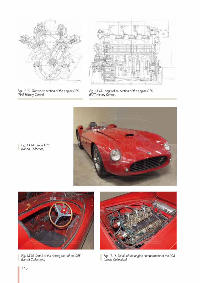
148
Fig. 13.12. Transverse section of the engine D25 (FIAT History Centre).
Fig. 13.13. Longitudinal section of the engine D25 (FIAT History Centre).
Fig. 13.15. Detail of the driving seat of the D25 (Lancia Collection).
Fig. 13.16. Detail of the engine compartment of the D25 (Lancia Collection).
Fig. 13.14. Lancia D25 (Lancia Collection).
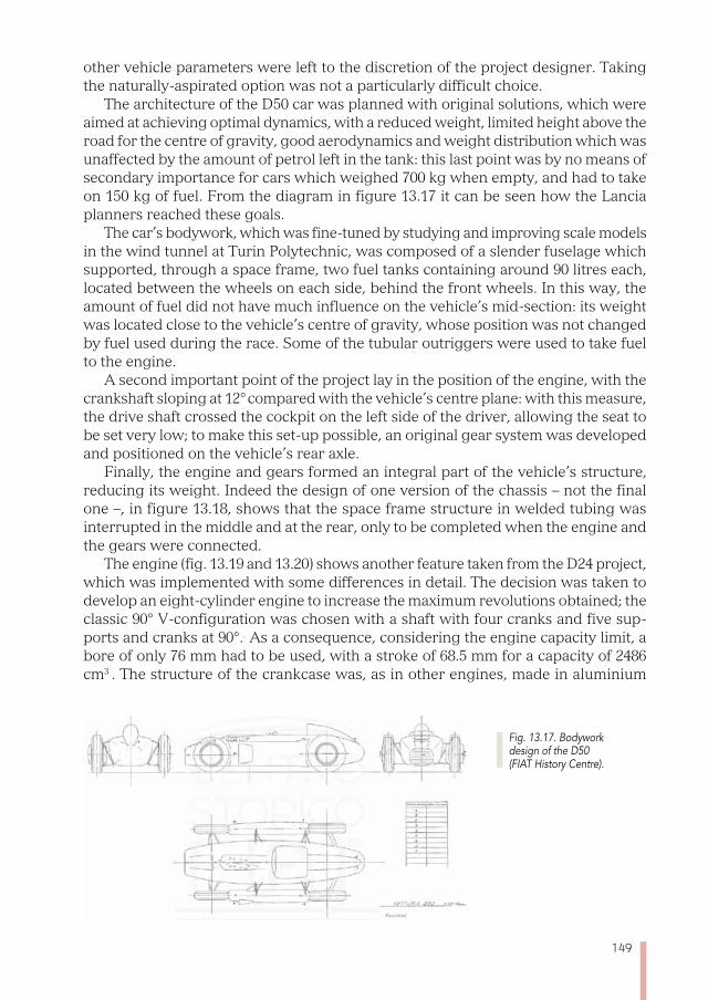
149
other vehicle parameters were left to the discretion of the project designer. Taking the naturally-aspirated option was not a particularly difficult choice.
The architecture of the D50 car was planned with original solutions, which were aimed at achieving optimal dynamics, with a reduced weight, limited height above the road for the centre of gravity, good aerodynamics and weight distribution which was unaffected by the amount of petrol left in the tank: this last point was by no means of secondary importance for cars which weighed 700 kg when empty, and had to take on 150 kg of fuel. From the diagram in figure 13.17 it can be seen how the Lancia planners reached these goals.
The car’s bodywork, which was fine-tuned by studying and improving scale models in the wind tunnel at Turin Polytechnic, was composed of a slender fuselage which supported, through a space frame, two fuel tanks containing around 90 litres each, located between the wheels on each side, behind the front wheels. In this way, the amount of fuel did not have much influence on the vehicle’s mid-section: its weight was located close to the vehicle’s centre of gravity, whose position was not changed by fuel used during the race. Some of the tubular outriggers were used to take fuel to the engine.
A second important point of the project lay in the position of the engine, with the crankshaft sloping at 12° compared with the vehicle’s centre plane: with this measure, the drive shaft crossed the cockpit on the left side of the driver, allowing the seat to be set very low; to make this set-up possible, an original gear system was developed and positioned on the vehicle’s rear axle.
Finally, the engine and gears formed an integral part of the vehicle’s structure, reducing its weight. Indeed the design of one version of the chassis – not the final one –, in figure 13.18, shows that the space frame structure in welded tubing was interrupted in the middle and at the rear, only to be completed when the engine and the gears were connected.
The engine (fig. 13.19 and 13.20) shows another feature taken from the D24 project, which was implemented with some differences in detail. The decision was taken to develop an eight-cylinder engine to increase the maximum revolutions obtained; the classic 90° V-configuration was chosen with a shaft with four cranks and five sup-ports and cranks at 90°.. As a consequence, considering the engine capacity limit, a bore of only 76 mm had to be used, with a stroke of 68.5 mm for a capacity of 2486 cm3 . The structure of the crankcase was, as in other engines, made in aluminium
Fig. 13.17. Bodywork design of the D50 (FIAT History Centre).
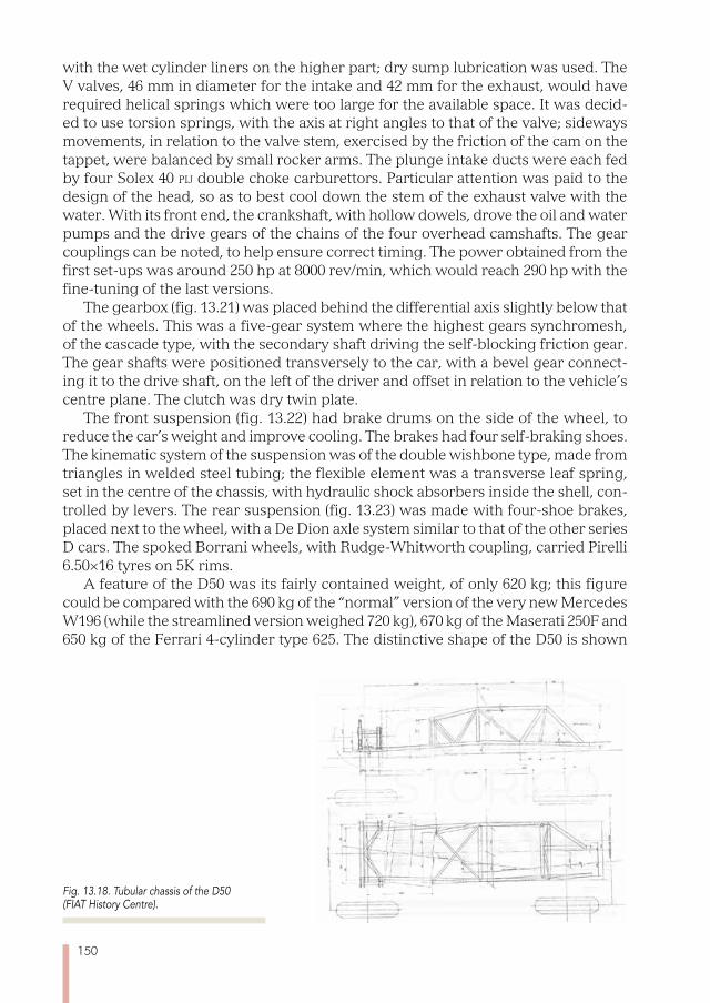
150
with the wet cylinder liners on the higher part; dry sump lubrication was used. The V valves, 46 mm in diameter for the intake and 42 mm for the exhaust, would have required helical springs which were too large for the available space. It was decid-ed to use torsion springs, with the axis at right angles to that of the valve; sideways movements, in relation to the valve stem, exercised by the friction of the cam on the tappet, were balanced by small rocker arms. The plunge intake ducts were each fed by four Solex 40 pij double choke carburettors. Particular attention was paid to the design of the head, so as to best cool down the stem of the exhaust valve with the water. With its front end, the crankshaft, with hollow dowels, drove the oil and water pumps and the drive gears of the chains of the four overhead camshafts. The gear couplings can be noted, to help ensure correct timing. The power obtained from the first set-ups was around 250 hp at 8000 rev/min, which would reach 290 hp with the fine-tuning of the last versions.
The gearbox (fig. 13.21) was placed behind the differential axis slightly below that of the wheels. This was a five-gear system where the highest gears synchromesh, of the cascade type, with the secondary shaft driving the self-blocking friction gear. The gear shafts were positioned transversely to the car, with a bevel gear connect-ing it to the drive shaft, on the left of the driver and offset in relation to the vehicle’s centre plane. The clutch was dry twin plate.
The front suspension (fig. 13.22) had brake drums on the side of the wheel, to reduce the car’s weight and improve cooling. The brakes had four self-braking shoes. The kinematic system of the suspension was of the double wishbone type, made from triangles in welded steel tubing; the flexible element was a transverse leaf spring, set in the centre of the chassis, with hydraulic shock absorbers inside the shell, con-trolled by levers. The rear suspension (fig. 13.23) was made with four-shoe brakes, placed next to the wheel, with a De Dion axle system similar to that of the other series D cars. The spoked Borrani wheels, with Rudge-Whitworth coupling, carried Pirelli 6.50×16 tyres on 5K rims.
A feature of the D50 was its fairly contained weight, of only 620 kg; this figure could be compared with the 690 kg of the “normal” version of the very new Mercedes W196 (while the streamlined version weighed 720 kg), 670 kg of the Maserati 250F and 650 kg of the Ferrari 4-cylinder type 625. The distinctive shape of the D50 is shown
Fig. 13.18. Tubular chassis of the D50 (FIAT History Centre).
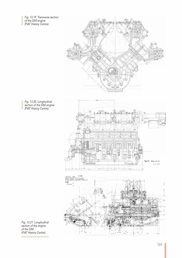
151
Fig. 13.19. Transverse section of the D50 engine (FIAT History Centre).
Fig. 13.20. Longitudinal section of the D50 engine (FIAT History Centre).
Fig. 13.21. Longitudinal section of the engine of the D50 (FIAT History Centre).
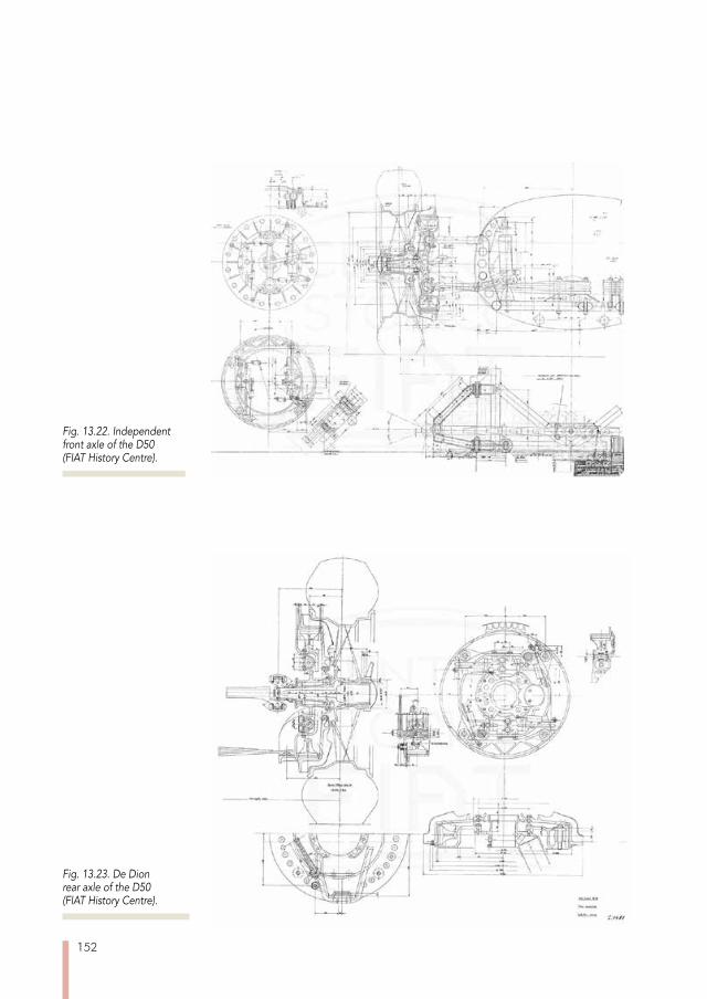
152
Fig. 13.22. Independent front axle of the D50 (FIAT History Centre).
Fig. 13.23. De Dion rear axle of the D50 (FIAT History Centre).
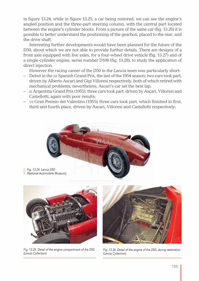
153
in figure 13.24, while in figure 13.25, a car being restored, we can see the engine’s angled position and the three-part steering column, with the central part located between the engine’s cylinder blocks. From a picture of the same car (fig. 13.26) it is possible to better understand the positioning of the gearbox, placed to the rear, and the drive shaft.
Interesting further developments would have been planned for the future of the D50, about which we are not able to provide further details. There are designs of a front axle equipped with live axles, for a four-wheel drive vehicle (fig. 13.27) and of a single-cylinder engine, serial number D100 (fig. 13.28), to study the application of direct injection.
However the racing career of the D50 in the Lancia team was particularly short: – Debut in the xii Spanish Grand Prix, the last of the 1954 season; two cars took part,
driven by Alberto Ascari and Gigi Villoresi respectively, both of which retired with mechanical problems; nevertheless, Ascari’s car set the best lap;
– iii Argentina Grand Prix (1955); three cars took part, driven by Ascari, Villoresi and Castellotti, again with poor results;
– vii Gran Premio del Valentino (1955); three cars took part, which finished in first, third and fourth place, driven by Ascari, Villoresi and Castellotti respectively;
Fig. 13.24. Lancia D50 (National Automobile Museum).
Fig. 13.25. Detail of the engine compartment of the D50 (Lancia Collection).
Fig. 13.26. Detail of the engine of the D50, during restoration (Lancia Collection).

154
– xvi Grand Prix de Pau (1955) three cars took part, finishing second, fourth and fifth, driven by Castellotti, Villoresi and Ascari respectively;
– viii Gran Premio di Napoli (1955); two cars took part, finishing in second and third, driven by Ascari and Villoresi respectively.
– xv Monaco Grand Prix; four cars took part, three of which finished second, fifth and sixth, driven by Castellotti, Villoresi and Louis Chiron respectively; that driven by Ascari ended up in the sea, after performing excellently.
– xvi Belgian Grand Prix; one car took part, driven by Castellotti in a personal capac-ity, forced to pull out with a mechanical problem. Four days earlier, on 26 May 1955, Alberto Ascari had died during a test lap on the Monza circuit and the Lan-cia team withdrew its official participation in sign of mourning.Refer to paragraph 17.24 for a summary of the technical data of this car.
Fig. 13.27. Study to equip the D50 with four-wheel drive (FIAT History Centre).
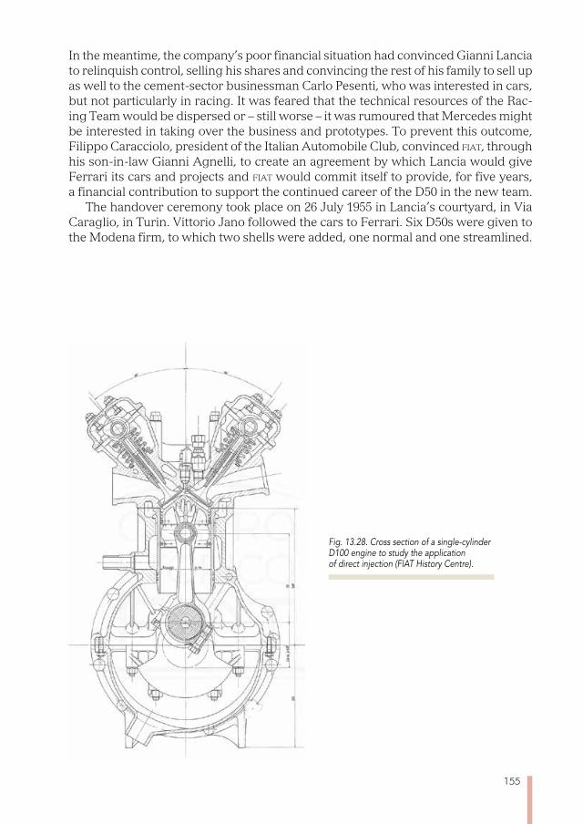
155
In the meantime, the company’s poor financial situation had convinced Gianni Lancia to relinquish control, selling his shares and convincing the rest of his family to sell up as well to the cement-sector businessman Carlo Pesenti, who was interested in cars, but not particularly in racing. It was feared that the technical resources of the Rac-ing Team would be dispersed or – still worse – it was rumoured that Mercedes might be interested in taking over the business and prototypes. To prevent this outcome, Filippo Caracciolo, president of the Italian Automobile Club, convinced fiat, through his son-in-law Gianni Agnelli, to create an agreement by which Lancia would give Ferrari its cars and projects and fiat would commit itself to provide, for five years, a financial contribution to support the continued career of the D50 in the new team.
The handover ceremony took place on 26 July 1955 in Lancia’s courtyard, in Via Caraglio, in Turin. Vittorio Jano followed the cars to Ferrari. Six D50s were given to the Modena firm, to which two shells were added, one normal and one streamlined.
Fig. 13.28. Cross section of a single-cylinder D100 engine to study the application of direct injection (FIAT History Centre).

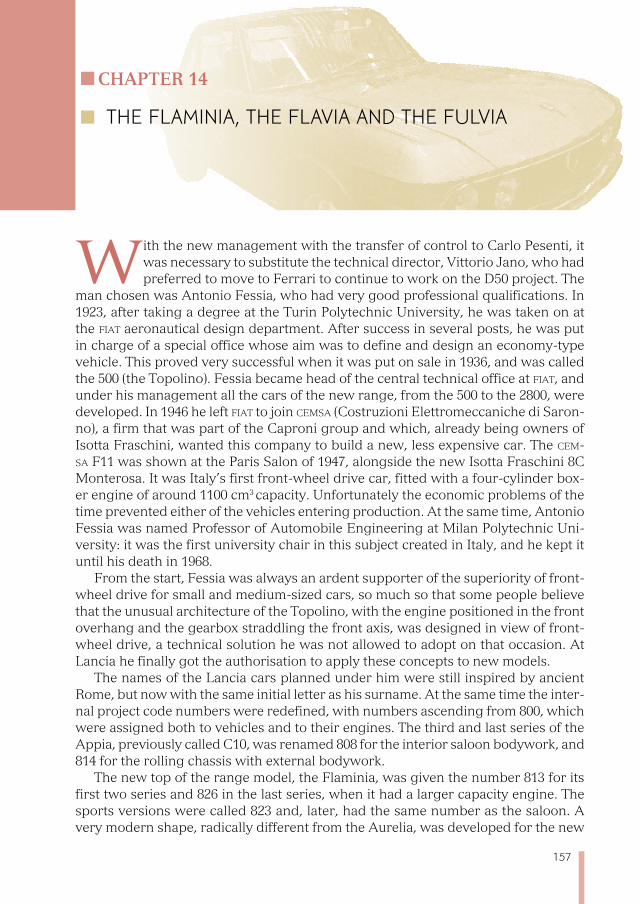
157
Chapter 14
THE FLAmINIA, THE FLAVIA AND THE FULVIA
With the new management with the transfer of control to Carlo Pesenti, it was necessary to substitute the technical director, Vittorio Jano, who had preferred to move to Ferrari to continue to work on the D50 project. The
man chosen was Antonio Fessia, who had very good professional qualifications. In 1923, after taking a degree at the Turin Polytechnic University, he was taken on at the fiat aeronautical design department. After success in several posts, he was put in charge of a special office whose aim was to define and design an economy-type vehicle. This proved very successful when it was put on sale in 1936, and was called the 500 (the Topolino). Fessia became head of the central technical office at fiat, and under his management all the cars of the new range, from the 500 to the 2800, were developed. In 1946 he left fiat to join Cemsa (Costruzioni Elettromeccaniche di Saron-no), a firm that was part of the Caproni group and which, already being owners of Isotta Fraschini, wanted this company to build a new, less expensive car. The Cem-sa F11 was shown at the Paris Salon of 1947, alongside the new Isotta Fraschini 8C Monterosa. It was Italy’s first front-wheel drive car, fitted with a four-cylinder box-er engine of around 1100 cm3 capacity. Unfortunately the economic problems of the time prevented either of the vehicles entering production. At the same time, Antonio Fessia was named Professor of Automobile Engineering at Milan Polytechnic Uni-versity: it was the first university chair in this subject created in Italy, and he kept it until his death in 1968.
From the start, Fessia was always an ardent supporter of the superiority of front-wheel drive for small and medium-sized cars, so much so that some people believe that the unusual architecture of the Topolino, with the engine positioned in the front overhang and the gearbox straddling the front axis, was designed in view of front-wheel drive, a technical solution he was not allowed to adopt on that occasion. At Lancia he finally got the authorisation to apply these concepts to new models.
The names of the Lancia cars planned under him were still inspired by ancient Rome, but now with the same initial letter as his surname. At the same time the inter-nal project code numbers were redefined, with numbers ascending from 800, which were assigned both to vehicles and to their engines. The third and last series of the Appia, previously called C10, was renamed 808 for the interior saloon bodywork, and 814 for the rolling chassis with external bodywork.
The new top of the range model, the Flaminia, was given the number 813 for its first two series and 826 in the last series, when it had a larger capacity engine. The sports versions were called 823 and, later, had the same number as the saloon. A very modern shape, radically different from the Aurelia, was developed for the new
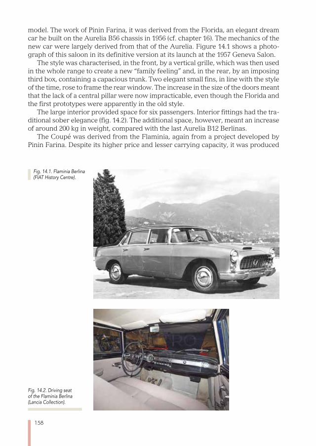
158
model. The work of Pinin Farina, it was derived from the Florida, an elegant dream car he built on the Aurelia B56 chassis in 1956 (cf. chapter 16). The mechanics of the new car were largely derived from that of the Aurelia. Figure 14.1 shows a photo-graph of this saloon in its definitive version at its launch at the 1957 Geneva Salon.
The style was characterised, in the front, by a vertical grille, which was then used in the whole range to create a new “family feeling” and, in the rear, by an imposing third box, containing a capacious trunk. Two elegant small fins, in line with the style of the time, rose to frame the rear window. The increase in the size of the doors meant that the lack of a central pillar were now impracticable, even though the Florida and the first prototypes were apparently in the old style.
The large interior provided space for six passengers. Interior fittings had the tra-ditional sober elegance (fig. 14.2). The additional space, however, meant an increase of around 200 kg in weight, compared with the last Aurelia B12 Berlinas.
The Coupé was derived from the Flaminia, again from a project developed by Pinin Farina. Despite its higher price and lesser carrying capacity, it was produced
Fig. 14.1. Flaminia Berlina (FIAT History Centre).
Fig. 14.2. Driving seat of the Flaminia Berlina (Lancia Collection).
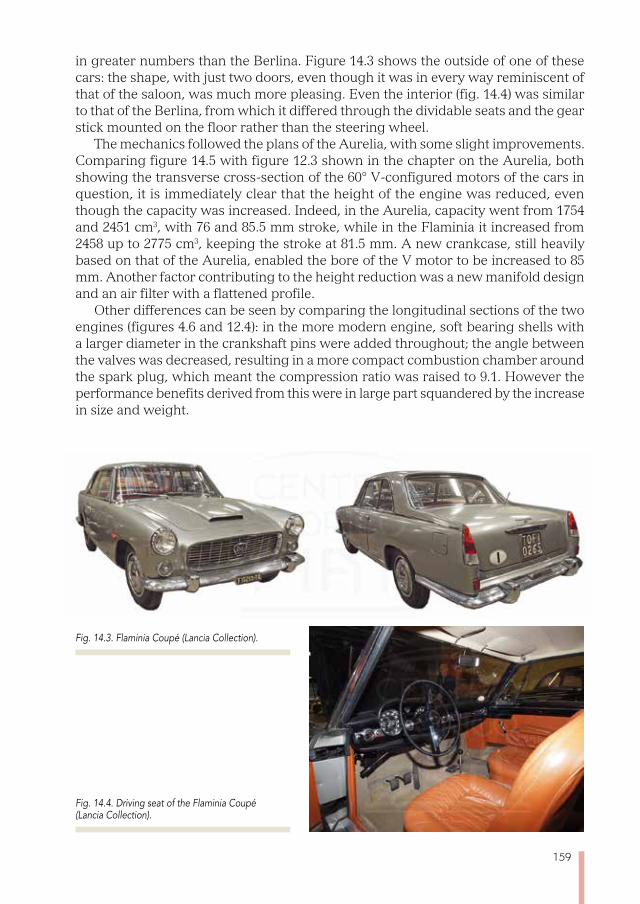
159
in greater numbers than the Berlina. Figure 14.3 shows the outside of one of these cars: the shape, with just two doors, even though it was in every way reminiscent of that of the saloon, was much more pleasing. Even the interior (fig. 14.4) was similar to that of the Berlina, from which it differed through the dividable seats and the gear stick mounted on the floor rather than the steering wheel.
The mechanics followed the plans of the Aurelia, with some slight improvements. Comparing figure 14.5 with figure 12.3 shown in the chapter on the Aurelia, both showing the transverse cross-section of the 60° V-configured motors of the cars in question, it is immediately clear that the height of the engine was reduced, even though the capacity was increased. Indeed, in the Aurelia, capacity went from 1754 and 2451 cm3, with 76 and 85.5 mm stroke, while in the Flaminia it increased from 2458 up to 2775 cm3, keeping the stroke at 81.5 mm. A new crankcase, still heavily based on that of the Aurelia, enabled the bore of the V motor to be increased to 85 mm. Another factor contributing to the height reduction was a new manifold design and an air filter with a flattened profile.
Other differences can be seen by comparing the longitudinal sections of the two engines (figures 4.6 and 12.4): in the more modern engine, soft bearing shells with a larger diameter in the crankshaft pins were added throughout; the angle between the valves was decreased, resulting in a more compact combustion chamber around the spark plug, which meant the compression ratio was raised to 9.1. However the performance benefits derived from this were in large part squandered by the increase in size and weight.
Fig. 14.3. Flaminia Coupé (Lancia Collection).
Fig. 14.4. Driving seat of the Flaminia Coupé (Lancia Collection).

160
It would have been difficult to find a better solution for the rear-mounted engine than that of the Aurelia. The same technical details were repeated. The only excep-tion, from the ii series, was the use of disc brakes on all four wheels, replacing the previous drum brakes (fig. 14.7).
In the front suspension (fig. 14.8), the traditional architecture with extendable vertical elements was abandoned in favour of a more modern approach, a double wishbone suspension with asymmetric arms, improving in comfort and providing more precise driving. Nevertheless, in this suspension too, all the jointed parts still needed regular greasing. The rear suspension was a De Dion axle design with Pan-hard anchor rods, the same as already used on the Aurelia (fig. 14.9).
Various versions of the Flaminia Berlina and Coupé were built, and paragraphs 17.25 and 17.26 should be referred to for the specific data of the respective versions at launch and those sold at the end of the model’s lifespan. Amongst other models
Fig. 14.7. Engine rear of the Flaminia (FIAT History Centre).
Fig. 14.5. Transverse section of the engine of the Flaminia (FIAT History Centre).
Fig. 14.6. Longitudinal section of the engine of the Flaminia (FIAT History Centre).
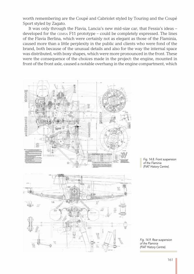
161
worth remembering are the Coupé and Cabriolet styled by Touring and the Coupé Sport styled by Zagato.
It was only through the Flavia, Lancia’s new mid-size car, that Fessia’s ideas – developed for the Cemsa F11 prototype – could be completely expressed. The lines of the Flavia Berlina, which were certainly not as elegant as those of the Flaminia, caused more than a little perplexity in the public and clients who were fond of the brand, both because of the unusual details and also for the way the internal space was distributed, with boxy shapes, which were more pronounced in the front. These were the consequence of the choices made in the project: the engine, mounted in front of the front axle, caused a notable overhang in the engine compartment, which
Fig. 14.9. Rear suspension of the Flaminia (FIAT History Centre).
Fig. 14.8. Front suspension of the Flaminia (FIAT History Centre).
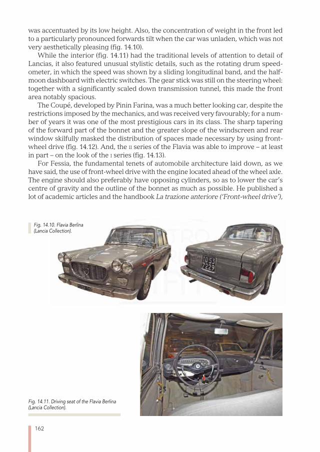
162
was accentuated by its low height. Also, the concentration of weight in the front led to a particularly pronounced forwards tilt when the car was unladen, which was not very aesthetically pleasing (fig. 14.10).
While the interior (fig. 14.11) had the traditional levels of attention to detail of Lancias, it also featured unusual stylistic details, such as the rotating drum speed-ometer, in which the speed was shown by a sliding longitudinal band, and the half-moon dashboard with electric switches. The gear stick was still on the steering wheel: together with a significantly scaled down transmission tunnel, this made the front area notably spacious.
The Coupé, developed by Pinin Farina, was a much better looking car, despite the restrictions imposed by the mechanics, and was received very favourably; for a num-ber of years it was one of the most prestigious cars in its class. The sharp tapering of the forward part of the bonnet and the greater slope of the windscreen and rear window skilfully masked the distribution of spaces made necessary by using front-wheel drive (fig. 14.12). And, the ii series of the Flavia was able to improve – at least in part – on the look of the i series (fig. 14.13).
For Fessia, the fundamental tenets of automobile architecture laid down, as we have said, the use of front-wheel drive with the engine located ahead of the wheel axle. The engine should also preferably have opposing cylinders, so as to lower the car’s centre of gravity and the outline of the bonnet as much as possible. He published a lot of academic articles and the handbook La trazione anteriore (‘Front-wheel drive’),
Fig. 14.10. Flavia Berlina (Lancia Collection).
Fig. 14.11. Driving seat of the Flavia Berlina (Lancia Collection).
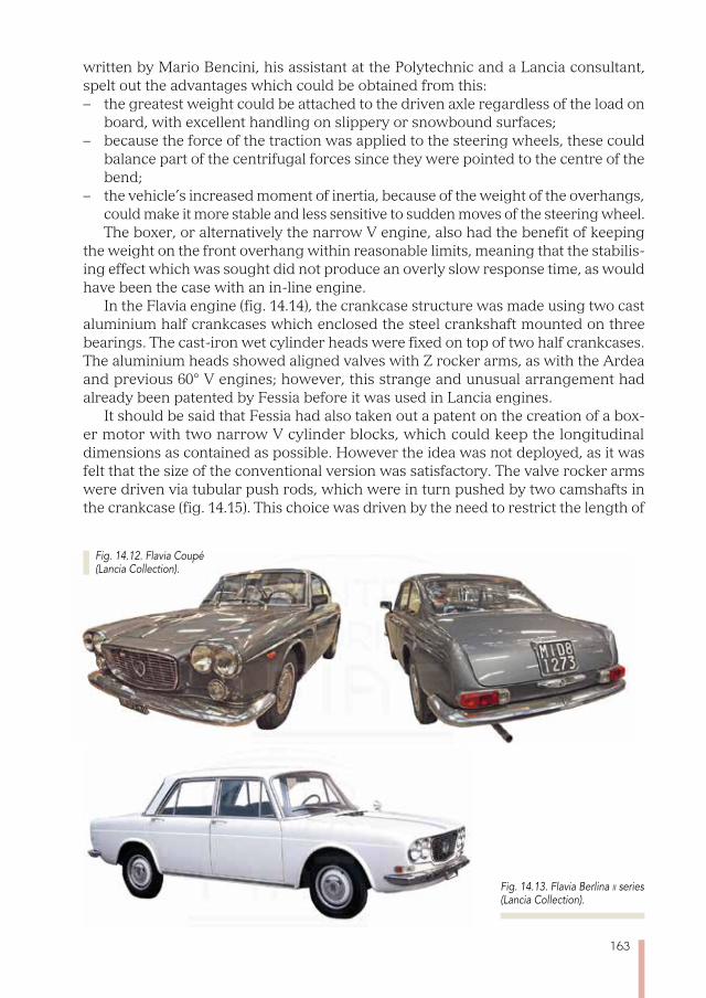
163
written by Mario Bencini, his assistant at the Polytechnic and a Lancia consultant, spelt out the advantages which could be obtained from this: – the greatest weight could be attached to the driven axle regardless of the load on
board, with excellent handling on slippery or snowbound surfaces;– because the force of the traction was applied to the steering wheels, these could
balance part of the centrifugal forces since they were pointed to the centre of the bend;
– the vehicle’s increased moment of inertia, because of the weight of the overhangs, could make it more stable and less sensitive to sudden moves of the steering wheel. The boxer, or alternatively the narrow V engine, also had the benefit of keeping
the weight on the front overhang within reasonable limits, meaning that the stabilis-ing effect which was sought did not produce an overly slow response time, as would have been the case with an in-line engine.
In the Flavia engine (fig. 14.14), the crankcase structure was made using two cast aluminium half crankcases which enclosed the steel crankshaft mounted on three bearings. The cast-iron wet cylinder heads were fixed on top of two half crankcases. The aluminium heads showed aligned valves with Z rocker arms, as with the Ardea and previous 60° V engines; however, this strange and unusual arrangement had already been patented by Fessia before it was used in Lancia engines.
It should be said that Fessia had also taken out a patent on the creation of a box-er motor with two narrow V cylinder blocks, which could keep the longitudinal dimensions as contained as possible. However the idea was not deployed, as it was felt that the size of the conventional version was satisfactory. The valve rocker arms were driven via tubular push rods, which were in turn pushed by two camshafts in the crankcase (fig. 14.15). This choice was driven by the need to restrict the length of
Fig. 14.12. Flavia Coupé (Lancia Collection).
Fig. 14.13. Flavia Berlina ii series (Lancia Collection).
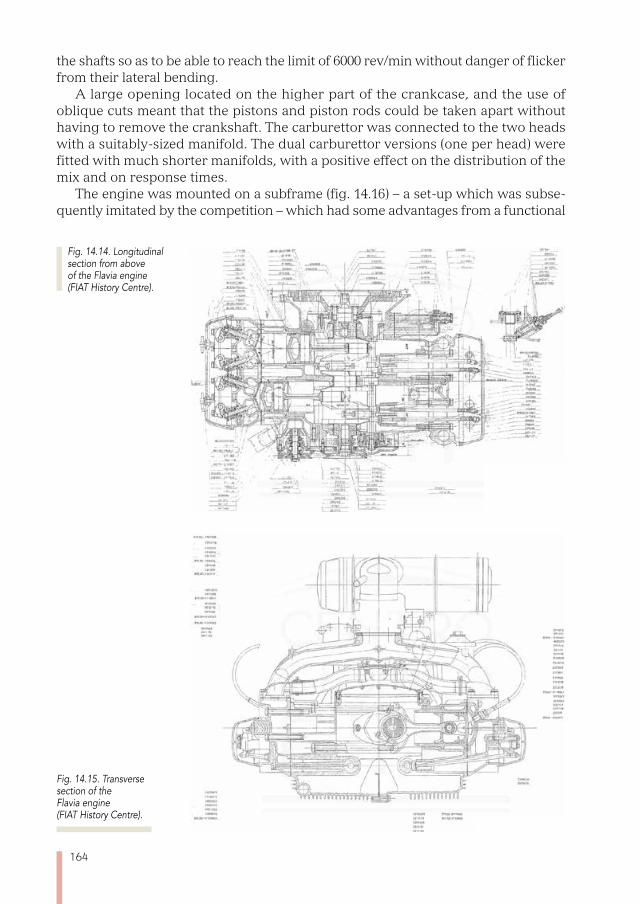
164
the shafts so as to be able to reach the limit of 6000 rev/min without danger of flicker from their lateral bending.
A large opening located on the higher part of the crankcase, and the use of oblique cuts meant that the pistons and piston rods could be taken apart without having to remove the crankshaft. The carburettor was connected to the two heads with a suitably-sized manifold. The dual carburettor versions (one per head) were fitted with much shorter manifolds, with a positive effect on the distribution of the mix and on response times.
The engine was mounted on a subframe (fig. 14.16) – a set-up which was subse-quently imitated by the competition – which had some advantages from a functional
Fig. 14.14. Longitudinal section from above of the Flavia engine (FIAT History Centre).
Fig. 14.15. Transverse section of the Flavia engine (FIAT History Centre).
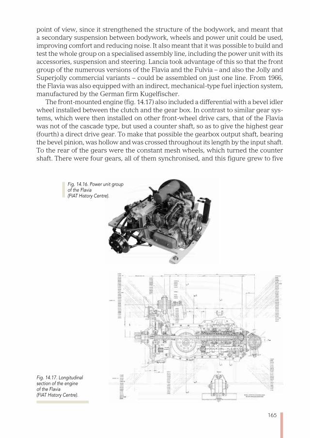
165
point of view, since it strengthened the structure of the bodywork, and meant that a secondary suspension between bodywork, wheels and power unit could be used, improving comfort and reducing noise. It also meant that it was possible to build and test the whole group on a specialised assembly line, including the power unit with its accessories, suspension and steering. Lancia took advantage of this so that the front group of the numerous versions of the Flavia and the Fulvia – and also the Jolly and Superjolly commercial variants – could be assembled on just one line. From 1966, the Flavia was also equipped with an indirect, mechanical-type fuel injection system, manufactured by the German firm Kugelfischer.
The front-mounted engine (fig. 14.17) also included a differential with a bevel idler wheel installed between the clutch and the gear box. In contrast to similar gear sys-tems, which were then installed on other front-wheel drive cars, that of the Flavia was not of the cascade type, but used a counter shaft, so as to give the highest gear (fourth) a direct drive gear. To make that possible the gearbox output shaft, bearing the bevel pinion, was hollow and was crossed throughout its length by the input shaft. To the rear of the gears were the constant mesh wheels, which turned the counter shaft. There were four gears, all of them synchronised, and this figure grew to five
Fig. 14.16. Power unit group of the Flavia (FIAT History Centre).
Fig. 14.17. Longitudinal section of the engine of the Flavia (FIAT History Centre).
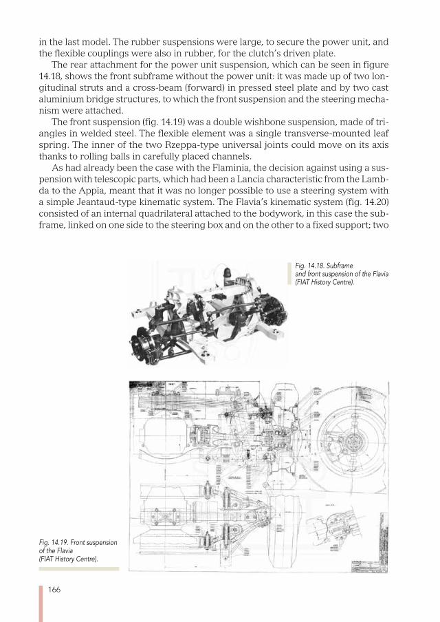
166
in the last model. The rubber suspensions were large, to secure the power unit, and the flexible couplings were also in rubber, for the clutch’s driven plate.
The rear attachment for the power unit suspension, which can be seen in figure 14.18, shows the front subframe without the power unit: it was made up of two lon-gitudinal struts and a cross-beam (forward) in pressed steel plate and by two cast aluminium bridge structures, to which the front suspension and the steering mecha-nism were attached.
The front suspension (fig. 14.19) was a double wishbone suspension, made of tri-angles in welded steel. The flexible element was a single transverse-mounted leaf spring. The inner of the two Rzeppa-type universal joints could move on its axis thanks to rolling balls in carefully placed channels.
As had already been the case with the Flaminia, the decision against using a sus-pension with telescopic parts, which had been a Lancia characteristic from the Lamb-da to the Appia, meant that it was no longer possible to use a steering system with a simple Jeantaud-type kinematic system. The Flavia’s kinematic system (fig. 14.20) consisted of an internal quadrilateral attached to the bodywork, in this case the sub-frame, linked on one side to the steering box and on the other to a fixed support; two
Fig. 14.19. Front suspension of the Flavia (FIAT History Centre).
Fig. 14.18. Subframe and front suspension of the Flavia (FIAT History Centre).
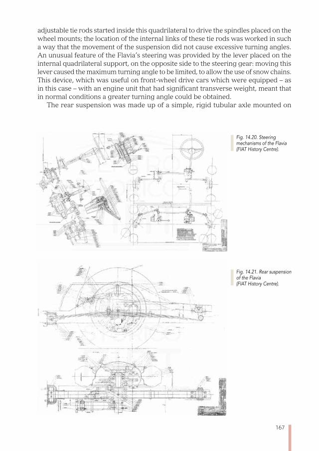
167
adjustable tie rods started inside this quadrilateral to drive the spindles placed on the wheel mounts; the location of the internal links of these tie rods was worked in such a way that the movement of the suspension did not cause excessive turning angles. An unusual feature of the Flavia’s steering was provided by the lever placed on the internal quadrilateral support, on the opposite side to the steering gear: moving this lever caused the maximum turning angle to be limited, to allow the use of snow chains. This device, which was useful on front-wheel drive cars which were equipped – as in this case – with an engine unit that had significant transverse weight, meant that in normal conditions a greater turning angle could be obtained.
The rear suspension was made up of a simple, rigid tubular axle mounted on
Fig. 14.20. Steering mechanisms of the Flavia (FIAT History Centre).
Fig. 14.21. Rear suspension of the Flavia (FIAT History Centre).
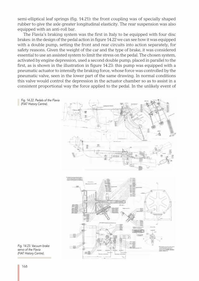
168
semi-elliptical leaf springs (fig. 14.21): the front coupling was of specially shaped rubber to give the axle greater longitudinal elasticity. The rear suspension was also equipped with an anti-roll bar.
The Flavia’s braking system was the first in Italy to be equipped with four disc brakes: in the design of the pedal action in figure 14.22 we can see how it was equipped with a double pump, setting the front and rear circuits into action separately, for safety reasons. Given the weight of the car and the type of brake, it was considered essential to use an assisted system to limit the stress on the pedal. The chosen system, activated by engine depression, used a second double pump, placed in parallel to the first, as is shown in the illustration in figure 14.23: this pump was equipped with a pneumatic actuator to intensify the braking force, whose force was controlled by the pneumatic valve, seen in the lower part of the same drawing. In normal conditions this valve would control the depression in the actuator chamber so as to assist in a consistent proportional way the force applied to the pedal. In the unlikely event of
Fig. 14.23. Vacuum brake servo of the Flavia (FIAT History Centre).
Fig. 14.22. Pedals of the Flavia (FIAT History Centre).
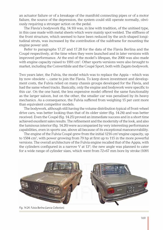
169
an actuator failure or of a breakage of the manifold connecting pipes or of a motor failure, the source of the depression, the system could still operate normally, obvi-ously requiring a stronger action on the pedal.
The Flavia’s bodywork (fig. 14.10) was, in line with tradition, of the unitised type, in this case made with metal sheets which were mainly spot welded. The stiffness of the front structure, which seemed to have been reduced by the arch-shaped longi-tudinal struts, was increased by the contribution of the subframe for mounting the engine power unit.
Refer to paragraphs 17.27 and 17.28 for the data of the Flavia Berlina and the Coupé respectively, at the time when they were launched and in later versions with improved performance. At the end of the model’s lifespan, the 2000 was also made with engine capacity raised to 1991 cm3. Other sports versions were also brought to market, including the Convertibile and the Coupé Sport, both with Zagato bodywork.
Two years later, the Fulvia, the model which was to replace the Appia – which was by now obsolete –, came to join the Flavia. To keep down investment and develop-ment costs, the Fulvia relied on many chassis groups developed for the Flavia, and had the same wheel tracks. Basically, only the engine and bodywork were specific to this car. On the one hand, the less expensive model offered the same functionality as the larger saloon, but on the other, the smaller car was penalised by its heavy mechanics. As a consequence, the Fulvia suffered from weighing 15 per cent more than equivalent competitor models.
The bodywork, although still having the volume distribution typical of front-wheel drive cars, was better looking than that of its older sister (fig. 14.24) and was better received. Even the Coupé (fig. 14.25) proved an immediate success and in a short time achieved excellent sales results. The refinement and the modernity of the look, and also the luminous interior (fig. 14.26) were accompanied by very interesting performance capabilities, even in sports use, above all because of its exceptional manoeuvrability.
The engine of the Fulvia Coupé grew from the initial 1216 cm3 engine capacity, up to 1584 cm3, with power growing from 79 hp at first up to 115 in the more powerful versions. The overall architecture of the Fulvia engine recalled that of the Appia, with the cylinders configured in a narrow V at 13°; the new angle was planned to cater for a wide range of cylinder sizes, which went from 72×67 mm bore by stroke (1091
Fig. 14.24. Fulvia Berlina (Lancia Collection).
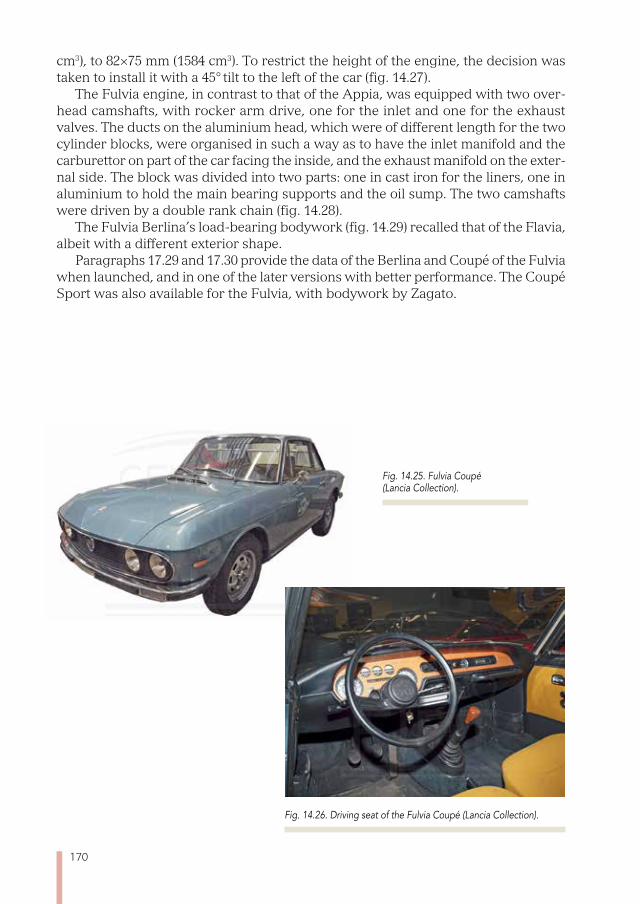
170
cm3), to 82×75 mm (1584 cm3). To restrict the height of the engine, the decision was taken to install it with a 45° tilt to the left of the car (fig. 14.27).
The Fulvia engine, in contrast to that of the Appia, was equipped with two over-head camshafts, with rocker arm drive, one for the inlet and one for the exhaust valves. The ducts on the aluminium head, which were of different length for the two cylinder blocks, were organised in such a way as to have the inlet manifold and the carburettor on part of the car facing the inside, and the exhaust manifold on the exter-nal side. The block was divided into two parts: one in cast iron for the liners, one in aluminium to hold the main bearing supports and the oil sump. The two camshafts were driven by a double rank chain (fig. 14.28).
The Fulvia Berlina’s load-bearing bodywork (fig. 14.29) recalled that of the Flavia, albeit with a different exterior shape.
Paragraphs 17.29 and 17.30 provide the data of the Berlina and Coupé of the Fulvia when launched, and in one of the later versions with better performance. The Coupé Sport was also available for the Fulvia, with bodywork by Zagato.
Fig. 14.25. Fulvia Coupé(Lancia Collection).
Fig. 14.26. Driving seat of the Fulvia Coupé (Lancia Collection).
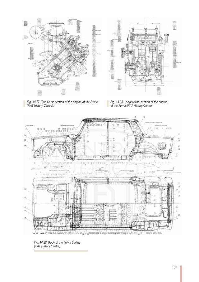
171
Fig. 14.29. Body of the Fulvia Berlina (FIAT History Centre).
Fig. 14.27. Transverse section of the engine of the Fulvia (FIAT History Centre).
Fig. 14.28. Longitudinal section of the engine of the Fulvia (FIAT History Centre).

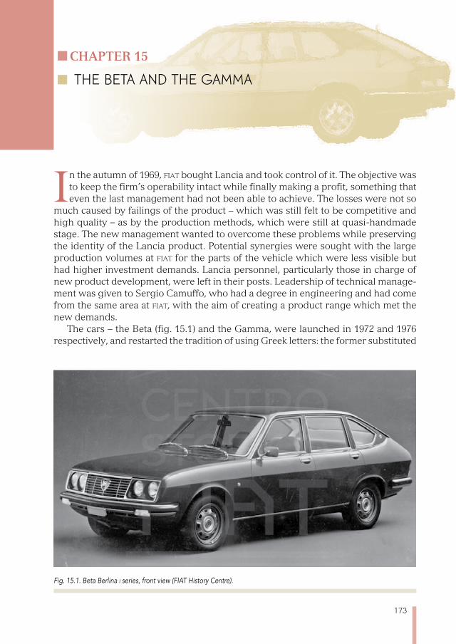
173
Chapter 15
THE BETA AND THE GAmmA
In the autumn of 1969, fiat bought Lancia and took control of it. The objective was to keep the firm’s operability intact while finally making a profit, something that even the last management had not been able to achieve. The losses were not so
much caused by failings of the product – which was still felt to be competitive and high quality – as by the production methods, which were still at quasi-handmade stage. The new management wanted to overcome these problems while preserving the identity of the Lancia product. Potential synergies were sought with the large production volumes at fiat for the parts of the vehicle which were less visible but had higher investment demands. Lancia personnel, particularly those in charge of new product development, were left in their posts. Leadership of technical manage-ment was given to Sergio Camuffo, who had a degree in engineering and had come from the same area at fiat, with the aim of creating a product range which met the new demands.
The cars – the Beta (fig. 15.1) and the Gamma, were launched in 1972 and 1976 respectively, and restarted the tradition of using Greek letters: the former substituted
Fig. 15.1. Beta Berlina i series, front view (FIAT History Centre).
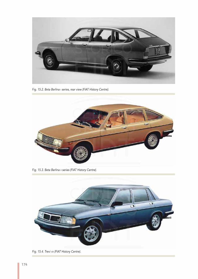
174
Fig. 15.2. Beta Berlina i series, rear view (FIAT History Centre).
Fig. 15.3. Beta Berlina ii series (FIAT History Centre).
Fig. 15.4. Trevi vx (FIAT History Centre).
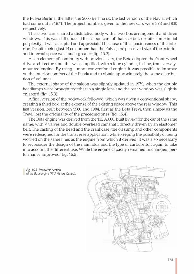
175
the Fulvia Berlina, the latter the 2000 Berlina lx, the last version of the Flavia, which had come out in 1971. The project numbers given to the new cars were 828 and 830 respectively.
These two cars shared a distinctive body with a two-box arrangement and three windows. This was still unusual for saloon cars of that size but, despite some initial perplexity, it was accepted and appreciated because of the spaciousness of the inte-rior. Despite being just 14 cm longer than the Fulvia, the perceived size of the exterior and internal space was much greater (fig. 15.2).
As an element of continuity with previous cars, the Beta adopted the front-wheel drive architecture, but this was simplified, with a four-cylinder, in-line, transversely-mounted engine. By using a more conventional engine, it was possible to improve on the interior comfort of the Fulvia and to obtain approximately the same distribu-tion of volumes.
The external shape of the saloon was slightly updated in 1979, when the double headlamps were brought together in a single lens and the rear window was slightly enlarged (fig. 15.3).
A final version of the bodywork followed, which was given a conventional shape, creating a third box, at the expense of the existing space above the rear window. This last version, built between 1980 and 1984, first as the Beta Trevi, then simply as the Trevi, lost the originality of the preceding ones (fig. 15.4).
The Beta engine was derived from the 132 A.000, built by fiat for the car of the same name, with V valves and double overhead camshaft, directly driven by an elastomer belt. The casting of the head and the crankcase, the oil sump and other components were redesigned for the transverse application, while keeping the possibility of being worked on the same lines as the engine from which it derived. It was also necessary to reconsider the design of the manifolds and the type of carburettor, again to take into account the different use. While the engine capacity remained unchanged, per-formance improved (fig. 15.5).
Fig. 15.5. Transverse section of the Beta engine (FIAT History Centre).
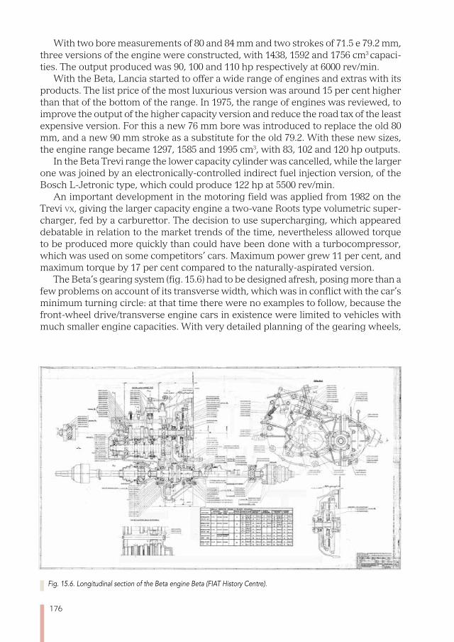
176
With two bore measurements of 80 and 84 mm and two strokes of 71.5 e 79.2 mm, three versions of the engine were constructed, with 1438, 1592 and 1756 cm3 capaci-ties. The output produced was 90, 100 and 110 hp respectively at 6000 rev/min.
With the Beta, Lancia started to offer a wide range of engines and extras with its products. The list price of the most luxurious version was around 15 per cent higher than that of the bottom of the range. In 1975, the range of engines was reviewed, to improve the output of the higher capacity version and reduce the road tax of the least expensive version. For this a new 76 mm bore was introduced to replace the old 80 mm, and a new 90 mm stroke as a substitute for the old 79.2. With these new sizes, the engine range became 1297, 1585 and 1995 cm3, with 83, 102 and 120 hp outputs.
In the Beta Trevi range the lower capacity cylinder was cancelled, while the larger one was joined by an electronically-controlled indirect fuel injection version, of the Bosch L-Jetronic type, which could produce 122 hp at 5500 rev/min.
An important development in the motoring field was applied from 1982 on the Trevi vx, giving the larger capacity engine a two-vane Roots type volumetric super-charger, fed by a carburettor. The decision to use supercharging, which appeared debatable in relation to the market trends of the time, nevertheless allowed torque to be produced more quickly than could have been done with a turbocompressor, which was used on some competitors’ cars. Maximum power grew 11 per cent, and maximum torque by 17 per cent compared to the naturally-aspirated version.
The Beta’s gearing system (fig. 15.6) had to be designed afresh, posing more than a few problems on account of its transverse width, which was in conflict with the car’s minimum turning circle: at that time there were no examples to follow, because the front-wheel drive/transverse engine cars in existence were limited to vehicles with much smaller engine capacities. With very detailed planning of the gearing wheels,
Fig. 15.6. Longitudinal section of the Beta engine Beta (FIAT History Centre).
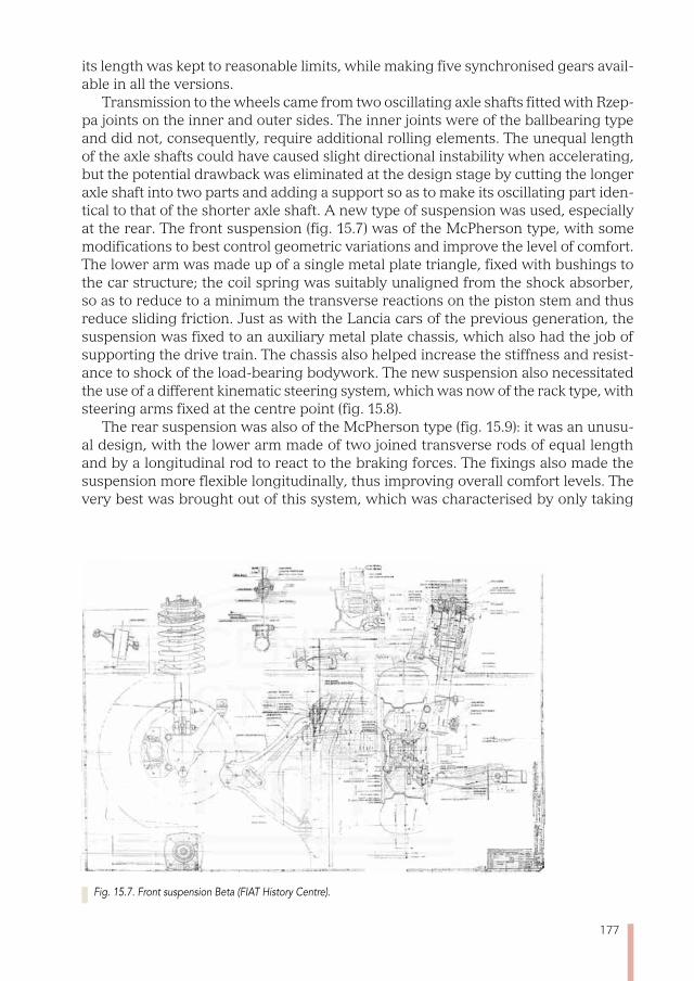
177
its length was kept to reasonable limits, while making five synchronised gears avail-able in all the versions.
Transmission to the wheels came from two oscillating axle shafts fitted with Rzep-pa joints on the inner and outer sides. The inner joints were of the ballbearing type and did not, consequently, require additional rolling elements. The unequal length of the axle shafts could have caused slight directional instability when accelerating, but the potential drawback was eliminated at the design stage by cutting the longer axle shaft into two parts and adding a support so as to make its oscillating part iden-tical to that of the shorter axle shaft. A new type of suspension was used, especially at the rear. The front suspension (fig. 15.7) was of the McPherson type, with some modifications to best control geometric variations and improve the level of comfort. The lower arm was made up of a single metal plate triangle, fixed with bushings to the car structure; the coil spring was suitably unaligned from the shock absorber, so as to reduce to a minimum the transverse reactions on the piston stem and thus reduce sliding friction. Just as with the Lancia cars of the previous generation, the suspension was fixed to an auxiliary metal plate chassis, which also had the job of supporting the drive train. The chassis also helped increase the stiffness and resist-ance to shock of the load-bearing bodywork. The new suspension also necessitated the use of a different kinematic steering system, which was now of the rack type, with steering arms fixed at the centre point (fig. 15.8).
The rear suspension was also of the McPherson type (fig. 15.9): it was an unusu-al design, with the lower arm made of two joined transverse rods of equal length and by a longitudinal rod to react to the braking forces. The fixings also made the suspension more flexible longitudinally, thus improving overall comfort levels. The very best was brought out of this system, which was characterised by only taking
Fig. 15.7. Front suspension Beta (FIAT History Centre).
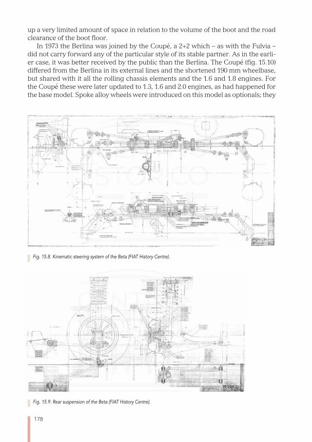
178
up a very limited amount of space in relation to the volume of the boot and the road clearance of the boot floor.
In 1973 the Berlina was joined by the Coupé, a 2+2 which – as with the Fulvia – did not carry forward any of the particular style of its stable partner. As in the earli-er case, it was better received by the public than the Berlina. The Coupé (fig. 15.10) differed from the Berlina in its external lines and the shortened 190 mm wheelbase, but shared with it all the rolling chassis elements and the 1.6 and 1.8 engines. For the Coupé these were later updated to 1.3, 1.6 and 2.0 engines, as had happened for the base model. Spoke alloy wheels were introduced on this model as optionals; they
Fig. 15.8. Kinematic steering system of the Beta (FIAT History Centre).
Fig. 15.9. Rear suspension of the Beta (FIAT History Centre).
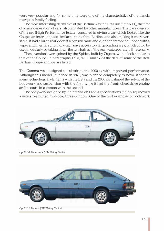
179
were very popular and for some time were one of the characteristics of the Lancia marque’s family feeling.
The most interesting derivative of the Berlina was the Beta hpe (fig. 15.11), the first of a new generation of cars, also imitated by other manufacturers. The base concept of the hpe (High Performance Estate) consisted in giving a car which looked like the Coupé, an interior space similar to that of the Berlina, and also making it more ver-satile. It had a large rear door at a considerable angle, and therefore equipped with a wiper and internal sunblind, which gave access to a large loading area, which could be used modularly by taking down the two halves of the rear seat, separately if necessary.
These versions were joined by the Spider, built by Zagato, with a look similar to that of the Coupé. In paragraphs 17.31, 17.32 and 17.33 the data of some of the Beta Berlina, Coupé and hpe are listed.
The Gamma was designed to substitute the 2000 lx with improved performance. Although this model, launched in 1976, was planned completely ex novo, it shared some technological elements with the Beta and the 2000 lx: it shared the set-up of the bodywork and suspension with the first, while it had the front-wheel drive engine architecture in common with the second.
The bodywork designed by Pininfarina on Lancia specifications (fig. 15.12) showed a very streamlined, two-box, three-window. One of the first examples of bodywork
Fig. 15.10. Beta Coupé (FIAT History Centre).
Fig. 15.11. Beta hpe (FIAT History Centre).
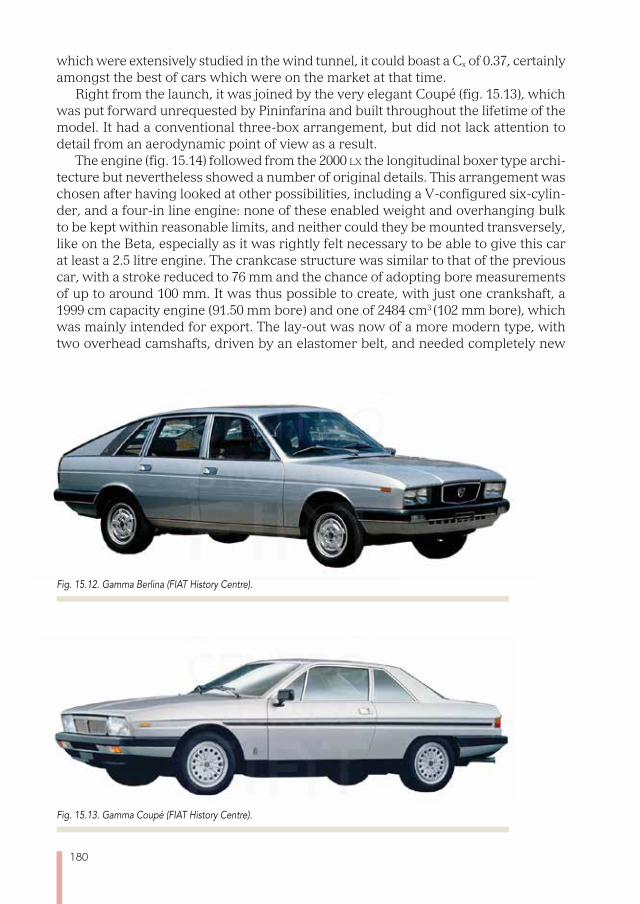
180
which were extensively studied in the wind tunnel, it could boast a Cx of 0.37, certainly amongst the best of cars which were on the market at that time.
Right from the launch, it was joined by the very elegant Coupé (fig. 15.13), which was put forward unrequested by Pininfarina and built throughout the lifetime of the model. It had a conventional three-box arrangement, but did not lack attention to detail from an aerodynamic point of view as a result.
The engine (fig. 15.14) followed from the 2000 lx the longitudinal boxer type archi-tecture but nevertheless showed a number of original details. This arrangement was chosen after having looked at other possibilities, including a V-configured six-cylin-der, and a four-in line engine: none of these enabled weight and overhanging bulk to be kept within reasonable limits, and neither could they be mounted transversely, like on the Beta, especially as it was rightly felt necessary to be able to give this car at least a 2.5 litre engine. The crankcase structure was similar to that of the previous car, with a stroke reduced to 76 mm and the chance of adopting bore measurements of up to around 100 mm. It was thus possible to create, with just one crankshaft, a 1999 cm capacity engine (91.50 mm bore) and one of 2484 cm3 (102 mm bore), which was mainly intended for export. The lay-out was now of a more modern type, with two overhead camshafts, driven by an elastomer belt, and needed completely new
Fig. 15.12. Gamma Berlina (FIAT History Centre).
Fig. 15.13. Gamma Coupé (FIAT History Centre).

181
heads to be developed. The output of these engines, fed by a twin-barrelled carbu-rettor, was 120 and 140 hp respectively at 5500 rev/min.
In 1980 a third version was introduced to coincide with the launch of the ii series. Bodywork details were reviewed for this, and a higher-capacity engine fed by an electronically-controlled indirect injection system, of the Bosch L-Jetronic type. This engine produced a similar output to that using a carburettor. All the groups on the Gamma’s rolling chassis (fig. 15.15), except for the power unit, were derived with small adaptations from the corresponding parts on the Beta.
In paragraphs 17.34 and 17.35 there is a summary of data from some of the ver-sions of the Gamma Berlina and the Gamma Coupé respectively.
Fig. 15.14. Transverse section of the engine of the Gamma (FIAT History Centre).
Fig. 15.15. Design of the rolling chassis of the Gamma Berlina (FIAT History Centre).

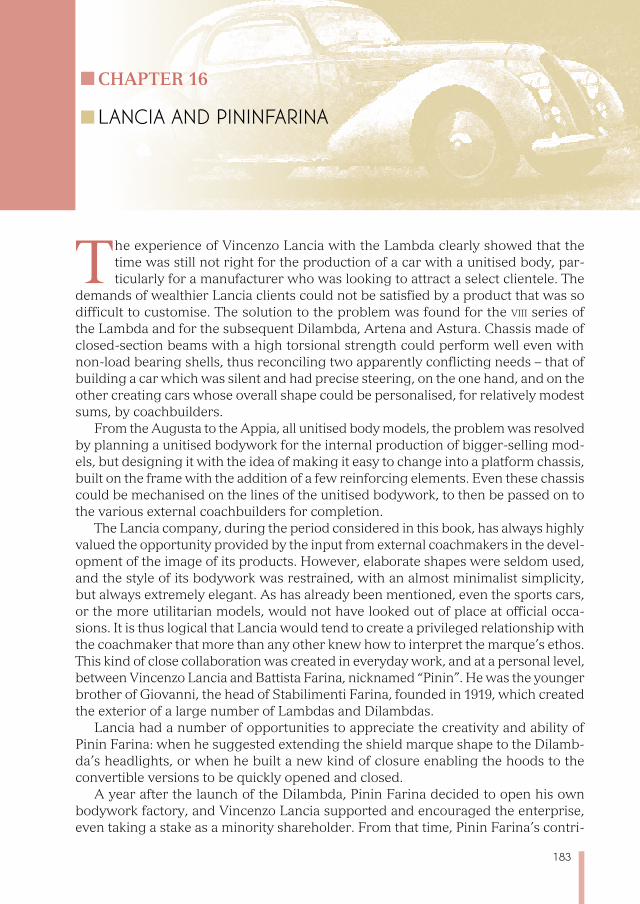
183
Chapter 16
LANCIA AND PININFARINA
The experience of Vincenzo Lancia with the Lambda clearly showed that the time was still not right for the production of a car with a unitised body, par-ticularly for a manufacturer who was looking to attract a select clientele. The
demands of wealthier Lancia clients could not be satisfied by a product that was so difficult to customise. The solution to the problem was found for the viii series of the Lambda and for the subsequent Dilambda, Artena and Astura. Chassis made of closed-section beams with a high torsional strength could perform well even with non-load bearing shells, thus reconciling two apparently conflicting needs – that of building a car which was silent and had precise steering, on the one hand, and on the other creating cars whose overall shape could be personalised, for relatively modest sums, by coachbuilders.
From the Augusta to the Appia, all unitised body models, the problem was resolved by planning a unitised bodywork for the internal production of bigger-selling mod-els, but designing it with the idea of making it easy to change into a platform chassis, built on the frame with the addition of a few reinforcing elements. Even these chassis could be mechanised on the lines of the unitised bodywork, to then be passed on to the various external coachbuilders for completion.
The Lancia company, during the period considered in this book, has always highly valued the opportunity provided by the input from external coachmakers in the devel-opment of the image of its products. However, elaborate shapes were seldom used, and the style of its bodywork was restrained, with an almost minimalist simplicity, but always extremely elegant. As has already been mentioned, even the sports cars, or the more utilitarian models, would not have looked out of place at official occa-sions. It is thus logical that Lancia would tend to create a privileged relationship with the coachmaker that more than any other knew how to interpret the marque’s ethos. This kind of close collaboration was created in everyday work, and at a personal level, between Vincenzo Lancia and Battista Farina, nicknamed “Pinin”. He was the younger brother of Giovanni, the head of Stabilimenti Farina, founded in 1919, which created the exterior of a large number of Lambdas and Dilambdas.
Lancia had a number of opportunities to appreciate the creativity and ability of Pinin Farina: when he suggested extending the shield marque shape to the Dilamb-da’s headlights, or when he built a new kind of closure enabling the hoods to the convertible versions to be quickly opened and closed.
A year after the launch of the Dilambda, Pinin Farina decided to open his own bodywork factory, and Vincenzo Lancia supported and encouraged the enterprise, even taking a stake as a minority shareholder. From that time, Pinin Farina’s contri-
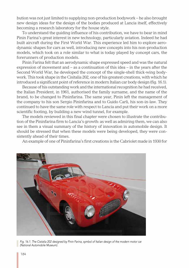
184
bution was not just limited to supplying non-production bodywork – he also brought new design ideas for the design of the bodies produced at Lancia itself, effectively becoming a research laboratory for the house style.
To understand the guiding influence of his contribution, we have to bear in mind Pinin Farina’s great interest in new technology, particularly aviation. Indeed he had built aircraft during the First World War. This experience led him to explore aero-dynamic shapes for cars as well, introducing new concepts into his non-production models, which took on a role similar to what is today played by concept cars, the forerunners of production models.
Pinin Farina felt that an aerodynamic shape expressed speed and was the natural expression of movement and – as a continuation of this idea – in the years after the Second World War, he developed the concept of the single-shell thick-wing body-work. This took shape in the Cisitalia 202, one of his greatest creations, with which he introduced a significant point of reference in modern Italian car body design (fig. 16.1).
Because of his outstanding work and the international recognition he had received, the Italian President, in 1961, authorised the family surname, and the name of the brand, to be changed to Pininfarina. The same year, Pinin left the management of the company to his son Sergio Pininfarina and to Guido Carli, his son-in-law. They continued to have the same role with respect to Lancia and put their work on a more scientific footing, by building a new wind tunnel, for example.
The models reviewed in this final chapter were chosen to illustrate the contribu-tion of the Pininfarina firm to Lancia’s growth: as well as admiring them, we can also see in them a visual summary of the history of innovation in automobile design. It should be stressed that when these models were being developed, they were con-sistently ahead of their times.
An example of one of Pininfarina’s first creations is the Cabriolet made in 1930 for
Fig. 16.1. The Cisitalia 202 designed by Pinin Farina, symbol of Italian design of the modern motor car (National Automobile Museum).
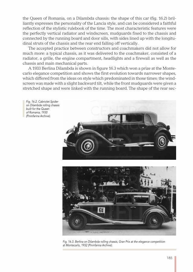
185
the Queen of Romania, on a Dilambda chassis: the shape of this car (fig. 16.2) bril-liantly expresses the personality of the Lancia style, and can be considered a faithful reflection of the stylistic rulebook of the time. The most characteristic features were the perfectly vertical radiator and windscreen, mudguards fixed to the chassis and connected by the running board and door sills, with sides lined up with the longitu-dinal struts of the chassis and the rear end falling off vertically.
The accepted practice between constructors and coachmakers did not allow for much more: a typical chassis, as it was delivered to the coachmaker, consisted of a radiator, a grille, the engine compartment, headlights and a firewall as well as the chassis and main mechanical parts.
A 1933 Berlina Dilambda is shown in figure 16.3 which won a prize at the Monte-carlo elegance competition and shows the first evolution towards narrower shapes, which differed from the ideas on style which predominated in those times: the wind-screen was made with a slight backward tilt, while the front mudguards were given a stretched shape and were linked with the running board. The shape of the rear sec-
Fig. 16.3. Berlina on Dilambda rolling chassis, Gran Prix at the elegance competition at Montecarlo, 1932 (Pininfarina Archive).
Fig. 16.2. Cabriolet Spider on Dilambda rolling chassis built for the Queen of Romania, 1930 (Pininfarina Archive).
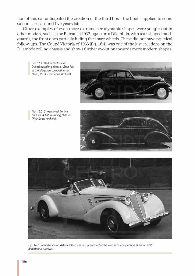
186
tion of this car anticipated the creation of the third box – the boot – applied to some saloon cars, around five years later.
Other examples of even more extreme aerodynamic shapes were sought out in other models, such as the Bateau in 1932, again on a Dilambda, with tear-shaped mud-guards, the front ones partially hiding the spare wheels. These did not have practical follow-ups. The Coupé Victoria of 1933 (fig. 16.4) was one of the last creations on the Dilambda rolling chassis and shows further evolution towards more modern shapes.
Fig. 16.6. Roadster on an Astura rolling chassis, presented at the elegance competition at Turin, 1935 (Pininfarina Archive).
Fig. 16.5. Streamlined Berlina on a 1934 Astura rolling chassis (Pininfarina Archive).
Fig. 16.4. Berlina Victoria on Dilambda rolling chassis, Gran Prix at the elegance competition at Nervi, 1933 (Pininfarina Archive).
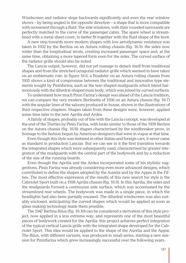
187
Windscreen and radiator slope backwards significantly and even the rear window shows – by being angled in the opposite direction – a shape that is more compatible with movement through a fluid. The side windows, with their rounded surrounds are perfectly matched to the curve of the passenger cabin. The spare wheel is stream-lined with a metal sheet cover, to better fit together with the fluid shape of the boot.
A new step towards more modern shapes with low aerodynamic resistance was taken in 1932 by the Berlina on an Astura rolling chassis (fig. 16.5): the sides now wider than the longitudinal struts, creating increased passenger space and, at the same time, obtaining a more tapered form even for the sides. The curved surface of the radiator grille should also be noted.
The Lancia output, however, did not yet manage to detach itself from traditional shapes and from the stretched octagonal radiator grille which seemed to have taken on an emblematic role: in figure 16.6, a Roadster on an Astura rolling chassis from 1935 shows a kind of compromise between the traditional and innovative type ele-ments sought by Pininfarina, such as the tear-shaped mudguards which blend har-moniously with the dihedral-shaped main body, which was joined by curved surfaces.
To understand how much Pinin Farina’s design was ahead of the Lancia tradition, we can compare the very modern Berlinetta of 1936 on an Astura chassis (fig. 16.7) with the angular lines of the saloons produced in-house, shown in the illustrations of their respective chapters. Shapes taken from these designs were, however, applied some time later to the new Aprilia and Ardea.
A family of shapes, probably out of line with the Lancia concept, was developed at the end of the Thirties by Pinin Farina, with looks similar to those of the 1939 Berlina on the Astura chassis (fig. 16.8): shapes characterised by the windbreaker prow, in homage to the fashion begun by American designers that were in vogue at that time.
Even though this style was imitated in other Italian and foreign cars, it never came as standard in production Lancias. But we can see in it the first transition towards the integrated shapes which were subsequently used, characterised by greater inte-gration of the mudguards with the central part of the bodywork and by a reduction of the size of the running boards.
Even though the Aprilia and the Ardea incorporated some of his stylistic sug-gestions, Pinin Farina was already considering even more advanced designs, which contributed to define the shapes adopted by the Aurelia and by the Appia in the Fif-ties. The most effective expression of the results of this new search for style is the Cabriolet Sport built on a 1938 Aprilia chassis (fig. 16.9). In this Aprilia, the sides and the mudguards formed a continuous side surface, which was accentuated by the streamlined rear wheels. The bodywork was made in a single piece, in which the headlights had also been partially encased. The dihedral windscreen was also suit-ably enclosed, anticipating the curved shapes which would be applied as soon as glass-making technology made them possible.
The 1947 Berlina Bilux (fig. 16.10) can be considered a derivation of this style pro-ject, now applied in a less extreme way, and represents one of the most beautiful pieces of bodywork created for the Aprilia: this project achieves perfect integration of the typical vertical Lancia grille with the integrated shape developed for the Cab-riolet Sport. This idea would be applied to the shape of the Aurelia and the Appia. The Bilux, with different variants, was produced in small series, starting a new mis-sion for Pininfarina which grew increasingly successful over the following years.
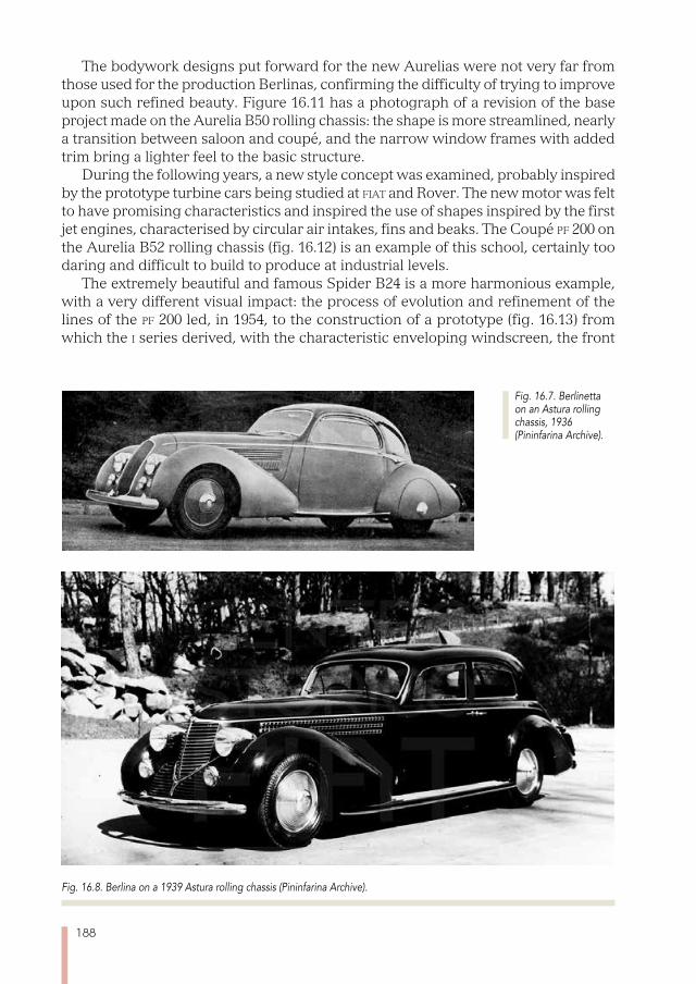
188
The bodywork designs put forward for the new Aurelias were not very far from those used for the production Berlinas, confirming the difficulty of trying to improve upon such refined beauty. Figure 16.11 has a photograph of a revision of the base project made on the Aurelia B50 rolling chassis: the shape is more streamlined, nearly a transition between saloon and coupé, and the narrow window frames with added trim bring a lighter feel to the basic structure.
During the following years, a new style concept was examined, probably inspired by the prototype turbine cars being studied at fiat and Rover. The new motor was felt to have promising characteristics and inspired the use of shapes inspired by the first jet engines, characterised by circular air intakes, fins and beaks. The Coupé pf 200 on the Aurelia B52 rolling chassis (fig. 16.12) is an example of this school, certainly too daring and difficult to build to produce at industrial levels.
The extremely beautiful and famous Spider B24 is a more harmonious example, with a very different visual impact: the process of evolution and refinement of the lines of the pf 200 led, in 1954, to the construction of a prototype (fig. 16.13) from which the i series derived, with the characteristic enveloping windscreen, the front
Fig. 16.8. Berlina on a 1939 Astura rolling chassis (Pininfarina Archive).
Fig. 16.7. Berlinetta on an Astura rolling chassis, 1936 (Pininfarina Archive).
189
Fig. 16.9. Streamlined Cabriolet on a 1938 Aprilia rolling chassis (Pininfarina Archive).
Fig. 16.10. Berlina Bilux on an Aprilia rolling chassis, a small series of this was produced from 1947 (Pininfarina Archive).
Fig. 16.11. Berlina Lusso on a B50 Aurelia rolling chassis from 1951 (Pininfarina Archive).
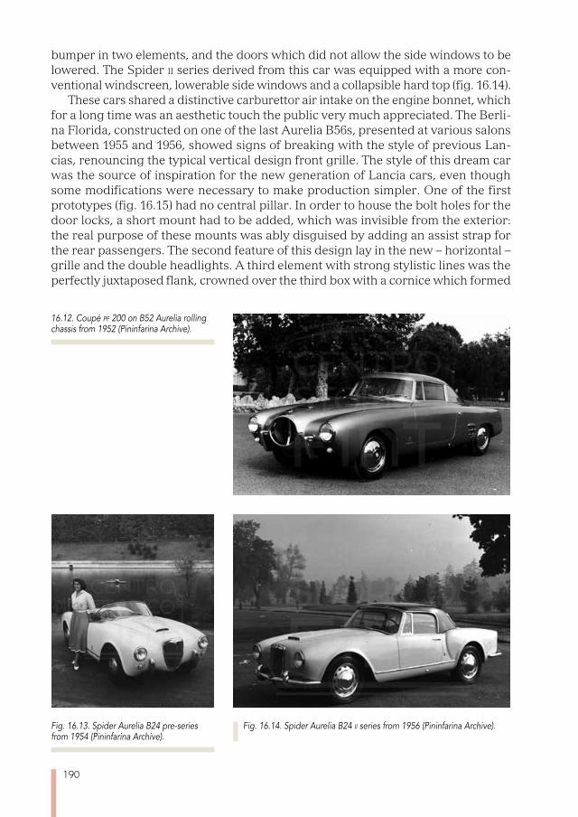
190
bumper in two elements, and the doors which did not allow the side windows to be lowered. The Spider ii series derived from this car was equipped with a more con-ventional windscreen, lowerable side windows and a collapsible hard top (fig. 16.14).
These cars shared a distinctive carburettor air intake on the engine bonnet, which for a long time was an aesthetic touch the public very much appreciated. The Berli-na Florida, constructed on one of the last Aurelia B56s, presented at various salons between 1955 and 1956, showed signs of breaking with the style of previous Lan-cias, renouncing the typical vertical design front grille. The style of this dream car was the source of inspiration for the new generation of Lancia cars, even though some modifications were necessary to make production simpler. One of the first prototypes (fig. 16.15) had no central pillar. In order to house the bolt holes for the door locks, a short mount had to be added, which was invisible from the exterior: the real purpose of these mounts was ably disguised by adding an assist strap for the rear passengers. The second feature of this design lay in the new – horizontal – grille and the double headlights. A third element with strong stylistic lines was the perfectly juxtaposed flank, crowned over the third box with a cornice which formed
16.12. Coupé pf 200 on B52 Aurelia rolling chassis from 1952 (Pininfarina Archive).
Fig. 16.13. Spider Aurelia B24 pre-series from 1954 (Pininfarina Archive).
Fig. 16.14. Spider Aurelia B24 ii series from 1956 (Pininfarina Archive).
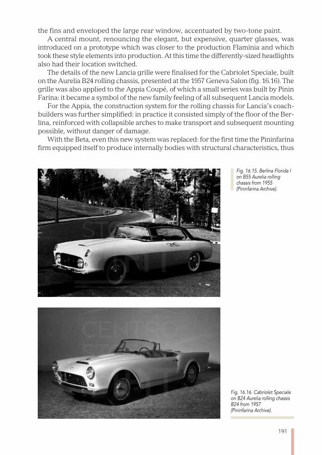
191
the fins and enveloped the large rear window, accentuated by two-tone paint. A central mount, renouncing the elegant, but expensive, quarter glasses, was
introduced on a prototype which was closer to the production Flaminia and which took these style elements into production. At this time the differently-sized headlights also had their location switched.
The details of the new Lancia grille were finalised for the Cabriolet Speciale, built on the Aurelia B24 rolling chassis, presented at the 1957 Geneva Salon (fig. 16.16). The grille was also applied to the Appia Coupé, of which a small series was built by Pinin Farina: it became a symbol of the new family feeling of all subsequent Lancia models.
For the Appia, the construction system for the rolling chassis for Lancia’s coach-builders was further simplified: in practice it consisted simply of the floor of the Ber-lina, reinforced with collapsible arches to make transport and subsequent mounting possible, without danger of damage.
With the Beta, even this new system was replaced: for the first time the Pininfarina firm equipped itself to produce internally bodies with structural characteristics, thus
Fig. 16.15. Berlina Florida I on B55 Aurelia rolling chassis from 1955 (Pininfarina Archive).
Fig. 16.16. Cabriolet Speciale on B24 Aurelia rolling chassis B24 from 1957 (Pininfarina Archive).
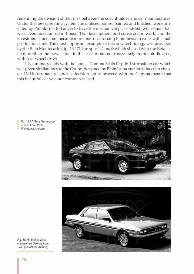
192
redefining the division of the roles between the coachbuilder and car manufacturer. Under the new operating system, the unitised bodies, painted and finished, were pro-vided by Pininfarina to Lancia to have the mechanical parts added, while small lots were even mechanised in-house. The development and construction work, and the investments incurred, became more onerous, forcing Pininfarina to work with small production runs. The most important example of this new technology was provided by the Beta Montecarlo (fig. 16.17), the sports Coupé which shared with the Beta lit-tle more than the power unit, in this case mounted transversely in the middle area, with rear wheel drive.
This summary ends with the Lancia Gamma Scala (fig. 16.18), a saloon car which was given similar lines to the Coupé, designed by Pininfarina and introduced in chap-ter 15. Unfortunately Lancia’s decision not to proceed with the Gamma meant that this beautiful car was not commercialised.
Fig. 16.18. Berlina Scala mechanised Gamma from 1980 (Pininfarina Archive).
Fig. 16.17. Beta Montecarlo ii series from 1980 (Pininfarina Archive).
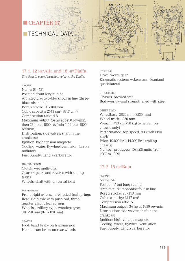
193
17.1. 12 hp/Alfa and 18 hp/DialfaThe data in round brackets refer to the Dialfa.
enGine
Name: 51 (53)Position: front longitudinal Architecture: two-block four in line (three-block six in line) Bore x stroke: 90×100 mm Cubic capacity: 2543 cm3 (3817 cm3) Compression ratio: 4.8 Maximum output: 24 hp at 1450 rev/min, then 28 hp at 1800 rev/min (40 hp at 1800 rev/min) Distribution: side valves; shaft in the crankcase Ignition: high tension magneto Cooling: water; flywheel ventilator (fan on radiator) Fuel Supply: Lancia carburettor
transmission Clutch: wet multi-disc Gears: 4 gears and reverse with sliding trains Wheels: shaft with universal joint
suspension Front: rigid axle; semi-elliptical leaf springs Rear: rigid axle with push rod; three-quarter elliptic leaf springs Wheels: artillery-type, wooden; tyres 810×90 mm (820×120 mm)
brakes Foot: band brake on transmission Hand: drum brake on rear wheels
steerinG Drive: worm gear Kinematic system: Ackermann-Jeantaud quadrilateral
struCture Chassis: pressed steel Bodywork: wood strengthened with steel
other data Wheelbase: 2820 mm (3235 mm) Wheel track: 1330 mm Weight: 710 kg (750 kg) (when empty, chassis only)Performance: top speed, 90 km/h (110 km/h) Price: 10,000 lire (14,000 lire) (rolling chassis)Number produced: 108 (23) units (from 1907 to 1909)
17.2. 15 hp/Beta
enGine
Name: 54 Position: front longitudinal Architecture: monobloc four in line Bore x stroke: 95×110 mm Cubic capacity: 3117 cm3
Compression ratio: 5 Maximum output: 34 hp at 1850 rev/min Distribution: side valves; shaft in the crankcase Ignition: high-voltage magneto Cooling: water; flywheel ventilation Fuel Supply: Lancia carburettor
Chapter 17
TECHNICAL DATA
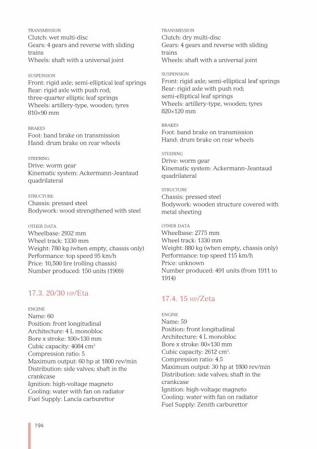
194
transmission Clutch: wet multi-disc Gears: 4 gears and reverse with sliding trains Wheels: shaft with a universal joint
suspension Front: rigid axle; semi-elliptical leaf springs Rear: rigid axle with push rod; three-quarter elliptic leaf springs Wheels: artillery-type, wooden; tyres 810×90 mm
brakes Foot: band brake on transmission Hand: drum brake on rear wheels
steerinG Drive: worm gearKinematic system: Ackermann-Jeantaud quadrilateral
struCture
Chassis: pressed steel Bodywork: wood strengthened with steel
other data Wheelbase: 2932 mm Wheel track: 1330 mm Weight: 780 kg (when empty, chassis only)Performance: top speed 95 km/h Price: 10,500 lire (rolling chassis)Number produced: 150 units (1909)
17.3. 20/30 hp/Eta
enGine
Name: 60 Position: front longitudinal Architecture: 4 L monobloc Bore x stroke: 100×130 mm Cubic capacity: 4084 cm3
Compression ratio: 5 Maximum output: 60 hp at 1800 rev/min Distribution: side valves; shaft in the crankcase Ignition: high-voltage magneto Cooling: water with fan on radiator Fuel Supply: Lancia carburettor
transmission Clutch: dry multi-disc Gears: 4 gears and reverse with sliding trains Wheels: shaft with a universal joint
suspension Front: rigid axle; semi-elliptical leaf springs Rear: rigid axle with push rod; semi-elliptical leaf springs Wheels: artillery-type, wooden; tyres 820×120 mm
brakes Foot: band brake on transmission Hand: drum brake on rear wheels
steerinG Drive: worm gear Kinematic system: Ackermann-Jeantaud quadrilateral
struCture
Chassis: pressed steel Bodywork: wooden structure covered with metal sheeting
other data Wheelbase: 2775 mm Wheel track: 1330 mm Weight: 880 kg (when empty, chassis only) Performance: top speed 115 km/h Price: unknown Number produced: 491 units (from 1911 to 1914)
17.4. 15 hp/Zeta
enGine
Name: 59 Position: front longitudinal Architecture: 4 L monobloc Bore x stroke: 80×130 mm Cubic capacity: 2612 cm3. Compression ratio: 4.5 Maximum output: 30 hp at 1800 rev/min Distribution: side valves; shaft in the crankcase Ignition: high-voltage magneto Cooling: water with fan on radiator Fuel Supply: Zenith carburettor
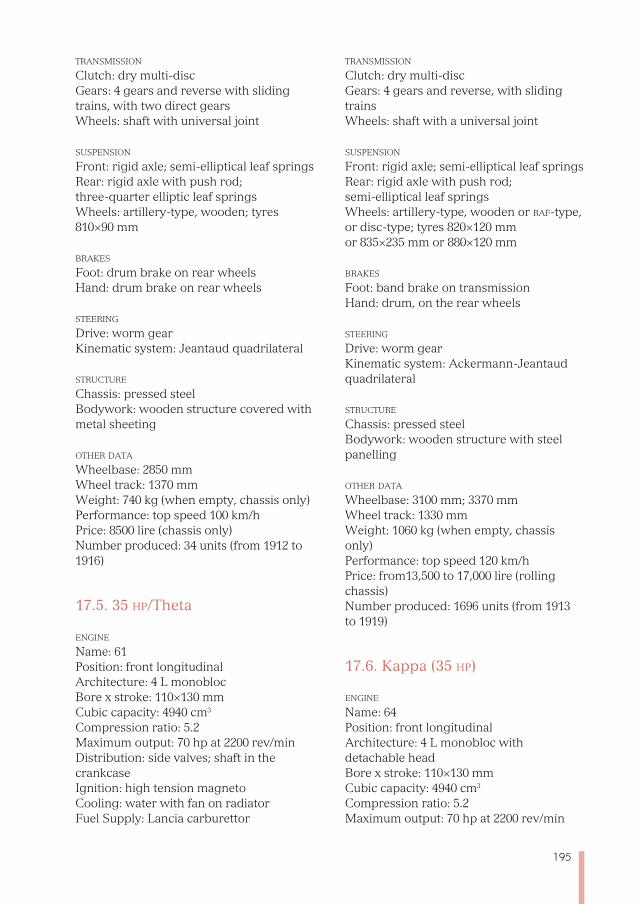
195
transmission Clutch: dry multi-disc Gears: 4 gears and reverse with sliding trains, with two direct gears Wheels: shaft with universal joint
suspension Front: rigid axle; semi-elliptical leaf springs Rear: rigid axle with push rod; three-quarter elliptic leaf springs Wheels: artillery-type, wooden; tyres 810×90 mm
brakes Foot: drum brake on rear wheels Hand: drum brake on rear wheels
steerinG Drive: worm gear Kinematic system: Jeantaud quadrilateral
struCture
Chassis: pressed steel Bodywork: wooden structure covered with metal sheeting
other data Wheelbase: 2850 mm Wheel track: 1370 mm Weight: 740 kg (when empty, chassis only) Performance: top speed 100 km/h Price: 8500 lire (chassis only) Number produced: 34 units (from 1912 to 1916)
17.5. 35 hp/Theta
enGine
Name: 61 Position: front longitudinal Architecture: 4 L monobloc Bore x stroke: 110×130 mm Cubic capacity: 4940 cm3
Compression ratio: 5.2 Maximum output: 70 hp at 2200 rev/min Distribution: side valves; shaft in the crankcase Ignition: high tension magneto Cooling: water with fan on radiator Fuel Supply: Lancia carburettor
transmission Clutch: dry multi-disc Gears: 4 gears and reverse, with sliding trains Wheels: shaft with a universal joint
suspension Front: rigid axle; semi-elliptical leaf springs Rear: rigid axle with push rod; semi-elliptical leaf springs Wheels: artillery-type, wooden or raf-type, or disc-type; tyres 820×120 mm or 835×235 mm or 880×120 mm
brakes Foot: band brake on transmission Hand: drum, on the rear wheels
steerinG Drive: worm gearKinematic system: Ackermann-Jeantaud quadrilateral
struCture
Chassis: pressed steel Bodywork: wooden structure with steel panelling
other data Wheelbase: 3100 mm; 3370 mm Wheel track: 1330 mm Weight: 1060 kg (when empty, chassis only) Performance: top speed 120 km/h Price: from13,500 to 17,000 lire (rolling chassis) Number produced: 1696 units (from 1913 to 1919)
17.6. Kappa (35 hp)
enGine
Name: 64 Position: front longitudinal Architecture: 4 L monobloc with detachable head Bore x stroke: 110×130 mm Cubic capacity: 4940 cm3
Compression ratio: 5.2 Maximum output: 70 hp at 2200 rev/min
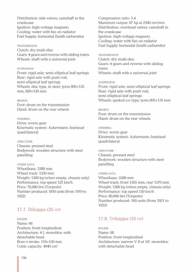
196
Distribution: side valves; camshaft in the crankcase Ignition: high-voltage magneto Cooling: water with fan on radiator Fuel Supply: horizontal Zenith carburettor
transmission Clutch: dry multi-disc Gears: 4 gears and reverse with sliding trains Wheels: shaft with a universal joint
suspension Front: rigid axle; semi-elliptical leaf springs Rear: rigid axle with push rod; semi-elliptical leaf springs Wheels: disc type, in steel; tyres 895×135 mm; 820×120 mm
brakes Foot: drum on the transmission Hand: drum on the rear wheels
steerinG Drive: worm gear Kinematic system: Ackermann-Jeantaud quadrilateral
struCture
Chassis: pressed steel Bodywork: wooden structure with steel panelling
other data Wheelbase: 3388 mm Wheel track: 1330 mm Weight: 1300 kg (when empty, chassis only) Performance: top speed 125 km/h Price: 78,000 lire (Torpedo) Number produced: 1810 units (from 1919 to 1922)
17.7. Dikappa (35 hp)
enGine
Name: 66 Position: front longitudinal Architecture: 4 L monobloc with detachable head Bore x stroke: 110×130 mm Cubic capacity: 4940 cm3
Compression ratio: 5.4 Maximum output: 87 hp at 2300 rev/min Distribution: overhead valves; camshaft in the crankcase Ignition: high-voltage magneto Cooling: water with fan on radiator Fuel Supply: horizontal Zenith carburettor
transmission Clutch: dry multi-disc Gears: 4 gears and reverse with sliding trains Wheels: shaft with a universal joint
suspension Front: rigid axle; semi-elliptical leaf springs Rear: rigid axle with push rod; semi-elliptical leaf springs Wheels: spoked raf type; tyres 895×135 mm
brakes Foot: drum on the transmission Hand: drum on the rear wheels
steerinG Drive: worm gear Kinematic system: Ackermann-Jeantaud quadrilateral
struCture Chassis: pressed steel Bodywork: wooden structure with steel panelling
other data Wheelbase: 3388 mm Wheel track: front 1365 mm; rear 1370 mm Weight: 1300 kg (when empty, chassis only) Performance: top speed 130 km/h Price: 80,000 lire (Torpedo) Number produced: 160 units (from 1921 to 1922)
17.8. Trikappa (35 hp)
enGine
Name: 68 Position: front longitudinal Architecture: narrow V-8 at 14°, monobloc with detachable head
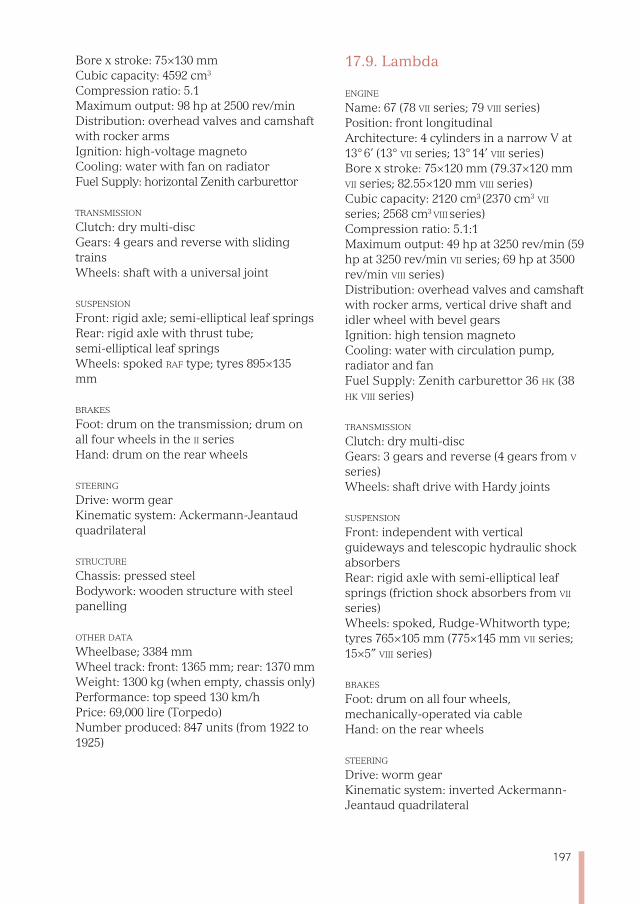
197
Bore x stroke: 75×130 mm Cubic capacity: 4592 cm3
Compression ratio: 5.1 Maximum output: 98 hp at 2500 rev/min Distribution: overhead valves and camshaft with rocker armsIgnition: high-voltage magneto Cooling: water with fan on radiator Fuel Supply: horizontal Zenith carburettor
transmission Clutch: dry multi-disc Gears: 4 gears and reverse with sliding trains Wheels: shaft with a universal joint
suspension Front: rigid axle; semi-elliptical leaf springs Rear: rigid axle with thrust tube; semi-elliptical leaf springs Wheels: spoked raf type; tyres 895×135 mm
brakes Foot: drum on the transmission; drum on all four wheels in the ii series Hand: drum on the rear wheels
steerinG Drive: worm gear Kinematic system: Ackermann-Jeantaud quadrilateral
struCture
Chassis: pressed steel Bodywork: wooden structure with steel panelling
other data Wheelbase; 3384 mm Wheel track: front: 1365 mm; rear: 1370 mm Weight: 1300 kg (when empty, chassis only) Performance: top speed 130 km/h Price: 69,000 lire (Torpedo) Number produced: 847 units (from 1922 to 1925)
17.9. Lambda
enGine
Name: 67 (78 vii series; 79 viii series) Position: front longitudinal Architecture: 4 cylinders in a narrow V at 13° 6’ (13° vii series; 13° 14’ viii series) Bore x stroke: 75×120 mm (79.37×120 mm vii series; 82.55×120 mm viii series) Cubic capacity: 2120 cm3 (2370 cm3 vii series; 2568 cm3 viii series) Compression ratio: 5.1:1 Maximum output: 49 hp at 3250 rev/min (59 hp at 3250 rev/min vii series; 69 hp at 3500 rev/min viii series) Distribution: overhead valves and camshaft with rocker arms, vertical drive shaft and idler wheel with bevel gears Ignition: high tension magneto Cooling: water with circulation pump, radiator and fan Fuel Supply: Zenith carburettor 36 hk (38 hk viii series)
transmission Clutch: dry multi-disc Gears: 3 gears and reverse (4 gears from v series) Wheels: shaft drive with Hardy joints
suspension Front: independent with vertical guideways and telescopic hydraulic shock absorbersRear: rigid axle with semi-elliptical leaf springs (friction shock absorbers from vii series) Wheels: spoked, Rudge-Whitworth type; tyres 765×105 mm (775×145 mm vii series; 15×5” viii series)
brakes Foot: drum on all four wheels, mechanically-operated via cable Hand: on the rear wheels
steerinG Drive: worm gear Kinematic system: inverted Ackermann-Jeantaud quadrilateral
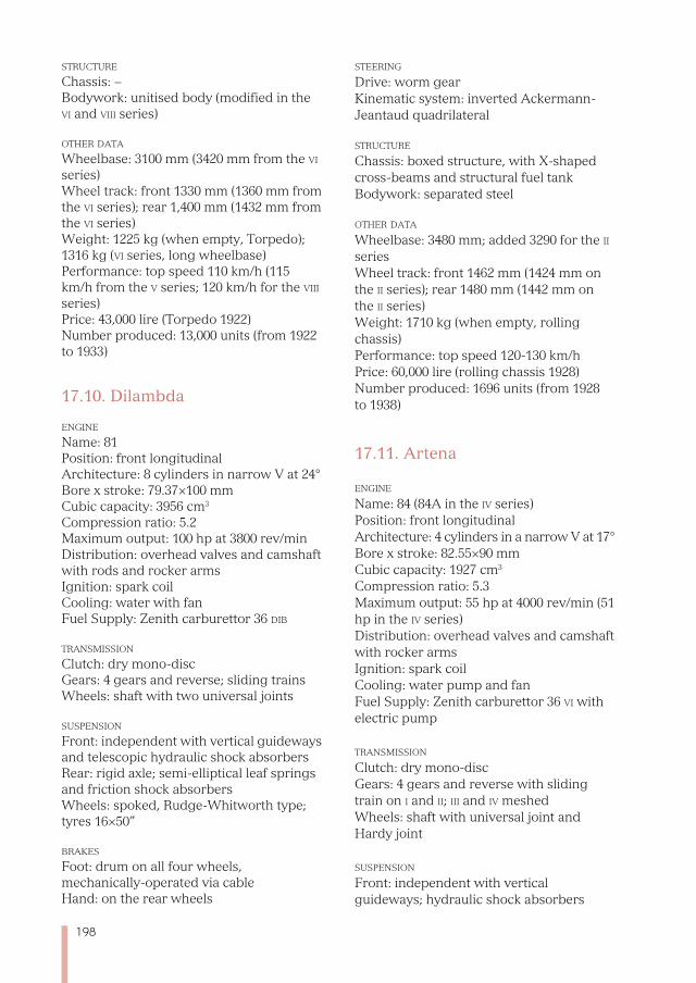
198
struCture
Chassis: −Bodywork: unitised body (modified in the vi and viii series)
other data Wheelbase: 3100 mm (3420 mm from the vi series) Wheel track: front 1330 mm (1360 mm from the vi series); rear 1,400 mm (1432 mm from the vi series) Weight: 1225 kg (when empty, Torpedo); 1316 kg (vi series, long wheelbase) Performance: top speed 110 km/h (115 km/h from the v series; 120 km/h for the viii series) Price: 43,000 lire (Torpedo 1922) Number produced: 13,000 units (from 1922 to 1933)
17.10. Dilambda
enGine
Name: 81 Position: front longitudinal Architecture: 8 cylinders in narrow V at 24°
Bore x stroke: 79.37×100 mm Cubic capacity: 3956 cm3
Compression ratio: 5.2 Maximum output: 100 hp at 3800 rev/min Distribution: overhead valves and camshaft with rods and rocker armsIgnition: spark coil Cooling: water with fan Fuel Supply: Zenith carburettor 36 dib
transmission Clutch: dry mono-disc Gears: 4 gears and reverse; sliding trains Wheels: shaft with two universal joints
suspension Front: independent with vertical guideways and telescopic hydraulic shock absorbersRear: rigid axle; semi-elliptical leaf springs and friction shock absorbers Wheels: spoked, Rudge-Whitworth type; tyres 16×50”
brakes Foot: drum on all four wheels, mechanically-operated via cable Hand: on the rear wheels
steerinG Drive: worm gear Kinematic system: inverted Ackermann-Jeantaud quadrilateral
struCture
Chassis: boxed structure, with X-shaped cross-beams and structural fuel tank Bodywork: separated steel
other data Wheelbase: 3480 mm; added 3290 for the ii series Wheel track: front 1462 mm (1424 mm on the ii series); rear 1480 mm (1442 mm on the ii series) Weight: 1710 kg (when empty, rolling chassis)Performance: top speed 120-130 km/h Price: 60,000 lire (rolling chassis 1928) Number produced: 1696 units (from 1928 to 1938)
17.11. Artena
enGine
Name: 84 (84A in the iv series) Position: front longitudinal Architecture: 4 cylinders in a narrow V at 17°
Bore x stroke: 82.55×90 mm Cubic capacity: 1927 cm3
Compression ratio: 5.3 Maximum output: 55 hp at 4000 rev/min (51 hp in the iv series) Distribution: overhead valves and camshaft with rocker arms Ignition: spark coil Cooling: water pump and fan Fuel Supply: Zenith carburettor 36 vi with electric pump
transmission Clutch: dry mono-disc Gears: 4 gears and reverse with sliding train on i and ii; iii and iv meshedWheels: shaft with universal joint and Hardy joint
suspension Front: independent with vertical guideways; hydraulic shock absorbers
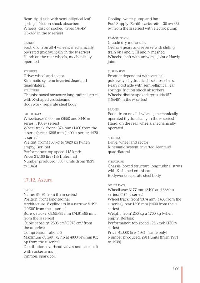
199
Rear: rigid axle with semi-elliptical leaf springs; friction shock absorbers Wheels: disc or spoked; tyres 14×45” (15×45” in the iv series)
brakes Foot: drum on all 4 wheels, mechanically operated (hydraulically in the iv series) Hand: on the rear wheels, mechanically operated
steerinG Drive: wheel and sectorKinematic system: inverted Jeantaud quadrilateral struCture
Chassis: boxed structure longitudinal struts with X-shaped crossbeams Bodywork: separate steel body
other data Wheelbase: 2990 mm (2950 and 3140 iii series; 3180 iv series) Wheel track: front 1374 mm (1400 from the iii series); rear 1396 mm (1400 iii series; 1420 iv series) Weight: from1150 kg to 1620 kg (when empty, Berlina)Performance: top speed 115 km/h Price: 31,100 lire (1931, Berlina) Number produced: 5567 units (from 1931 to 1943)
17.12. Astura
enGine
Name: 85 (91 from the iii series)Position: front longitudinal Architecture: 8 cylinders in a narrow V 19° (19°30’ from the iii series)Bore x stroke: 69.85×85 mm (74.61×85 mm from the iii series) Cubic capacity: 2606 cm3 (2973 cm3 from the iii series) Compression ratio: 5.3 Maximum output: 72 hp at 4000 rev/min (82 hp from the iii series)Distribution: overhead valves and camshaft with rocker arms Ignition: spark coil
Cooling: water pump and fan Fuel Supply: Zenith carburettor 30 dvt (32 dvi from the iii series) with electric pump
transmission Clutch: dry mono-disc Gears: 4 gears and reverse with sliding train on i and ii, III and iv meshedWheels: shaft with universal joint e Hardy joint
suspension Front: independent with vertical guideways; hydraulic shock absorbers Rear: rigid axle with semi-elliptical leaf springs; friction shock absorbers Wheels: disc or spoked; tyres 14×45” (15×45” in the iv series)
brakes Foot: drum on all 4 wheels, mechanically operated (hydraulically in the iv series) Hand: on the rear wheels, mechanically operated
steerinG Drive: wheel and sectorKinematic system: inverted Jeantaud quadrilateral
struCture
Chassis: boxed structure longitudinal struts with X-shaped crossbeamsBodywork: separate steel body
other data Wheelbase: 3177 mm (3100 and 3330 iii series; 3475 iv series) Wheel track: front 1374 mm (1400 from the iii series); rear 1396 mm (1400 from the iii series) Weight: from1250 kg a 1700 kg (when empty, Berlina) Performance: top speed 125 km/h (130 iv series) Price: 45,000 lire (1931, frame only) Number produced: 2911 units (from 1931 to 1939)
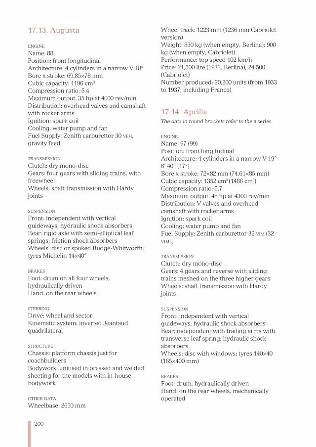
200
17.13. Augusta
enGine
Name: 88 Position: front longitudinal Architecture: 4 cylinders in a narrow V 18° Bore x stroke: 69.85×78 mm Cubic capacity: 1196 cm3
Compression ratio: 5.4 Maximum output: 35 hp at 4000 rev/min Distribution: overhead valves and camshaft with rocker arms Ignition: spark coil Cooling: water pump and fan Fuel Supply: Zenith carburettor 30 veh, gravity feed
transmission Clutch: dry mono-disc Gears: four gears with sliding trains, with freewheel Wheels: shaft transmission with Hardy joints
suspension Front: independent with vertical guideways; hydraulic shock absorbers Rear: rigid axle with semi-elliptical leaf springs; friction shock absorbers Wheels: disc or spoked Rudge-Whitworth; tyres Michelin 14×40”
brakes Foot: drum on all four wheels; hydraulically driven Hand: on the rear wheels
steerinG Drive: wheel and sectorKinematic system: inverted Jeantaud quadrilateral
struCture
Chassis: platform chassis just for coachbuilders Bodywork: unitised in pressed and welded sheeting for the models with in-house bodywork
other data Wheelbase: 2650 mm
Wheel track: 1223 mm (1236 mm Cabriolet version) Weight: 830 kg (when empty, Berlina); 900 kg (when empty, Cabriolet) Performance: top speed 102 km/h Price: 21,500 lire (1933, Berlina); 24,500 (Cabriolet) Number produced: 20,200 units (from 1933 to 1937; including France)
17.14. ApriliaThe data in round brackets refer to the ii series.
enGine
Name: 97 (99) Position: front longitudinal Architecture: 4 cylinders in a narrow V 19°
6’ 40” (17°) Bore x stroke: 72×82 mm (74.61×85 mm) Cubic capacity: 1352 cm3 (1486 cm3) Compression ratio: 5.7 Maximum output: 48 hp at 4300 rev/min Distribution: V valves and overhead camshaft with rocker arms Ignition: spark coil Cooling: water pump and fan Fuel Supply: Zenith carburettor 32 vim (32 viml)
transmission Clutch: dry mono-disc Gears: 4 gears and reverse with sliding trains meshed on the three higher gearsWheels: shaft transmission with Hardy joints
suspension Front: independent with vertical guideways; hydraulic shock absorbers Rear: independent with trailing arms with transverse leaf spring; hydraulic shock absorbers Wheels: disc with windows; tyres 140×40 (165×400 mm)
brakes Foot: drum, hydraulically driven Hand: on the rear wheels, mechanically operated
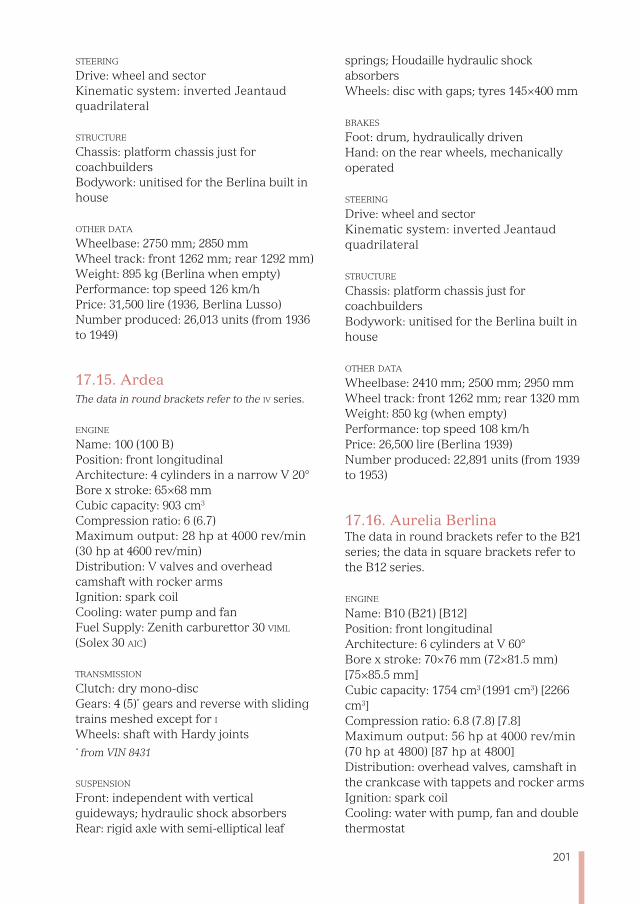
201
steerinG Drive: wheel and sector Kinematic system: inverted Jeantaud quadrilateral
struCture Chassis: platform chassis just for coachbuilders Bodywork: unitised for the Berlina built in house
other data Wheelbase: 2750 mm; 2850 mm Wheel track: front 1262 mm; rear 1292 mm)Weight: 895 kg (Berlina when empty) Performance: top speed 126 km/h Price: 31,500 lire (1936, Berlina Lusso) Number produced: 26,013 units (from 1936 to 1949)
17.15. ArdeaThe data in round brackets refer to the iv series.
enGine
Name: 100 (100 B)Position: front longitudinal Architecture: 4 cylinders in a narrow V 20°
Bore x stroke: 65×68 mm Cubic capacity: 903 cm3
Compression ratio: 6 (6.7) Maximum output: 28 hp at 4000 rev/min (30 hp at 4600 rev/min) Distribution: V valves and overhead camshaft with rocker arms Ignition: spark coil Cooling: water pump and fan Fuel Supply: Zenith carburettor 30 viml (Solex 30 aiC)
transmission Clutch: dry mono-disc Gears: 4 (5)* gears and reverse with sliding trains meshed except for iWheels: shaft with Hardy joints * from VIN 8431
suspension Front: independent with vertical guideways; hydraulic shock absorbers Rear: rigid axle with semi-elliptical leaf
springs; Houdaille hydraulic shock absorbersWheels: disc with gaps; tyres 145×400 mm
brakes Foot: drum, hydraulically driven Hand: on the rear wheels, mechanically operated
steerinG Drive: wheel and sector Kinematic system: inverted Jeantaud quadrilateral
struCture
Chassis: platform chassis just for coachbuilders Bodywork: unitised for the Berlina built in house
other data Wheelbase: 2410 mm; 2500 mm; 2950 mm Wheel track: front 1262 mm; rear 1320 mm Weight: 850 kg (when empty) Performance: top speed 108 km/h Price: 26,500 lire (Berlina 1939) Number produced: 22,891 units (from 1939 to 1953)
17.16. Aurelia BerlinaThe data in round brackets refer to the B21 series; the data in square brackets refer to the B12 series.
enGine
Name: B10 (B21) [B12] Position: front longitudinal Architecture: 6 cylinders at V 60°
Bore x stroke: 70×76 mm (72×81.5 mm) [75×85.5 mm] Cubic capacity: 1754 cm3 (1991 cm3) [2266 cm3] Compression ratio: 6.8 (7.8) [7.8] Maximum output: 56 hp at 4000 rev/min (70 hp at 4800) [87 hp at 4800] Distribution: overhead valves, camshaft in the crankcase with tappets and rocker arms Ignition: spark coil Cooling: water with pump, fan and double thermostat
202
Fuel Supply: carburettor Solex 30 aai [Solex 30 paai]
transmission Clutch: dry mono-disc Gears: 4 gears and reverse; ii, iii and iv
synchronised Wheels: shaft with 3 Giubo joints
suspension Front: independent with vertical guideways; hydraulic shock absorbers Rear: independent with oblique arms [rigid De Dion axle]; lever-type shock absorbers [telescopic] Wheels: disc; tyres 165×400 mm
brakes Foot: drum on all four wheels, hydraulically operated Hand: on the rear wheels, mechanically operated
steerinG Drive: wheel and sector Kinematic system: inverted Jeantaud quadrilateral
struCture
Chassis: platform chassis just for external coachbuilders Bodywork: unitised body for saloon built in house
other data Wheelbase: 2860 mm [2850 mm] Wheel track: front 1280 mm; rear 1300 mm Weight: 1150 kg [1250 kg] (Berlina when empty)Performance: top speed 135 km/h [150 km/h] Price: 1,830,000 lire (Berlina 1950) Number produced: 13,564 units (from 1950 to 1955)
17.17. Aurelia gt
The data in round brackets refer to the vi series.
enGine
Name: B20 Position: front longitudinal Architecture: 6 cylinders in a V at 60°
Bore x stroke: 72×81.5 mm (78×85.5 mm) Cubic capacity: 1991 cm3 (2451 cm3) Compression ratio: 8.4 Maximum output: 75 hp at 4500 rev/min (112 hp at 5000 rev/min) Distribution: overhead valves, camshaft in the crankcase with tappets and rocker arms Ignition: spark coil Cooling: water with pump, fan and double thermostat Fuel Supply: Weber carburettor 32 dr 7SP (40 dCl5)
transmission Clutch: dry mono-disc Gears: 4 gears and reverse; ii, iii and iv
synchronised Wheels: shaft with 3 Giubo joints
suspension Front: independent with vertical guideways; hydraulic shock absorbers Rear: independent with oblique arms (De Dion); lever-type shock absorbers (telescopic) Wheels: disc; tyres 165×400 mm
brakes Foot: drum on all four wheels, hydraulically operated Hand: on the rear wheels, mechanically operated
steerinG Drive: wheel and sector Kinematic system: inverted Jeantaud quadrilateral
struCture
Chassis: – Bodywork: unitised
other data Wheelbase: 2660 mm
203
Wheel track: front 1280 mm; rear 1300 mm Weight: 1000 kg (1250 kg) (when empty) Performance: top speed 162 km/h (180 km/h) Price: 2,850,500 lire (1951)Number produced: 3,141 units (from 1951 to 1958)
17.18. Aurelia Spider
enGine
Name: B24 Position: front longitudinal Architecture: 6 cylinders in a V at 60°
Bore x stroke: 78×85.5 mm Cubic capacity: 2451 cm3
Compression ratio: 8.4 Maximum output: 112 hp at 5000 rev/min Distribution: overhead valves, camshaft in the crankcase with tappets and rocker arms Ignition: spark coil Cooling: water with pump, fan and double thermostat Fuel Supply: Weber carburettor 40 dCl5
transmission Clutch: dry mono-disc Gears: 4 gears and reverse; ii, iii and iv
synchronised Wheels: shaft with 3 Giubo joints
suspension Front: independent with vertical guideways; hydraulic shock absorbers Rear: De Dion; telescopic shock absorbers Wheels: disc: tyres 165×400 mm
brakes Foot: drum on all 4 Wheels hydraulically operated Hand: mechanically operated on the rear wheels
steerinG Drive: wheel and sector Kinematic system: inverted Jeantaud quadrilateral
struCture
Chassis: – Bodywork: unitised
other data Wheelbase: 2450 mm Wheel track: front 1280 mm; rear 1300 mm Weight: 1215 kg (when empty)
Performance: top speed 175 km/h Price: 2,822,000 lire (1958) Number produced: 761 units (from 1954 to 1958)
17.19. Appia Berlina The data in round brackets refer to the ii series; those in square brackets refer to the iii series.
enGine
Name: C10 Position: front longitudinal Architecture: 4 cylinders in a narrow V at 10° 14’ Bore x stroke: 68×75 mm Cubic capacity: 1089cm3
Compression ratio: 7.4 (7.2) [7.8] Maximum output: 38 hp at 4800 rev/min (44 hp) [48 hp at 4.900] Distribution: overhead valves; double camshaft in the crankcase Ignition: spark coil Cooling: water pump and fan Fuel Supply: Solex carburettor 30-32 bi (32 pbiC) [32 pbiC]
transmission Clutch: dry mono-disc Gears: 4 gears and reverse; ii, iii and iv
synchronised Wheels: shaft with two Hardy joints
suspension Front: independent with vertical guideways; hydraulic shock absorbers Rear: rigid axle; telescopic shock absorbers Wheels: disc; tyres 155×15” [155×14”]
brakes Foot: drum on all four wheels, hydraulically operated Hand: on the rear wheels, mechanically operated
204
steerinG Drive: wheel and sector Kinematic system: inverted Jeantaud quadrilateral
struCture Chassis: platform chassis just for external coachbuilders Bodywork: unitised for saloon built in house
other data Wheelbase: 2480 mm (2510 mm) [2510 mm]Wheel track: front 1178 mm; rear 1182 mm Weight: 860 kg (920kg) (when empty) Performance: top speed 120 km/h (128) [132] Price: 1,331,000 lire (1953) Number produced: 107,048 units (from 1953 to 1963)
17.20. D20The data of the version with a compressor are in the round brackets.
enGine
Name: D20 Position: front longitudinal Architecture: 6 cylinders in a V at 60°
Bore x stroke: 86×85 mm (82×85 mm) Cubic capacity: 2962 cm3 (2.693 cm3) Compression ratio: 9.2 (6.6) Maximum output: 220 hp at 6500 rev/min (240 hp) Distribution: four directly-driving overhead camshafts; gear and chain drivenIgnition: dual ignition with two ignition coils Cooling: water pump and fan Fuel Supply: single feed with 3 twin-barrelled Weber 42 dCf7 carburettors (2 twin-barrelled Weber 45 dCo carburettors)
transmission Clutch: dry double-disc Gears: 4 gears and reverse; ii, iii and iv
synchronised Wheels: shaft with two joints; self-blocking differential
suspension Front: transverse double wishbone with
transverse leaf spring; telescopic hydraulic shock absorbersRear: De Dion axle with transverse leaf spring; adjustable friction shock absorbers Wheels: Borrani spokes, front 5K 16”, rear 5½K 16”; front tyres Pirelli 6×16”, rear Pirelli 6.50×16”
brakes Foot: drum brakes, hydraulically operated Hand: on the rear wheels, mechanically operated
steerinG Drive: wheel and sector Kinematic system: internal quadrilateral with suspension arms
struCture Chassis: tubular in welded steel Bodywork: coupe with panelling in aluminium sheets
other data Wheelbase: 2600 mm Wheel track: front 1295 mm; rear 1250 mm Weight: 800 kg (815 kg) (dry weight) Performance: top speed 225 km/h (230 km/h) Number produced: 7 units (from 1952 to 1953)
17.21. D23
enGine
Name: D20 Position: front longitudinal Architecture: 6 cylinders in a V at 60°
Bore x stroke: 86×85 mm Cubic capacity: 2962 cm3
Compression ratio: 9.2Maximum output: 220 hp at 6500 rev/min Distribution: four directly-driven overhead camshafts; gear and chain drivenIgnition: dual ignition with two ignition coils Cooling: water pump and fan Fuel Supply: single feed with 3 twin-barrelled Weber 42 dCf7 carburettors
205
transmission Clutch: dry double-disc Gears: 4 gears and reverse; ii, iii and iv
synchronised Wheels: shaft with two joints; self-blocking differential
suspension Front: transverse double wishbone with transverse leaf spring; telescopic hydraulic shock absorbersRear: De Dion axle with transverse leaf spring; telescopic hydraulic shock absorbers Wheels: Borrani spokes, front 5K 16”, rear 5½K 16”; front tyres Pirelli 6×16”, rear Pirelli 6.50×16”
brakes Foot: drum brakes, hydraulically operated Hand: on the rear wheels, mechanically operated
steerinG Control: screw and sector Kinematic system: internal quadrilateral with suspension arms
struCture
Chassis: tubular in welded steel Bodywork: two-seat roofless in aluminium sheeting
other data Wheelbase: 2600 mm Wheel track: front 1295 mm; rear 1250 mm Weight: 750 kg (dry weight) Performance: top speed 240 km/h Number produced: 7 units (1953)
17.22. D24
enGine
Name: D24 Position: front longitudinal Architecture: 6 cylinders in a V at 60°
Bore x stroke: 88×90 mm Cubic capacity: 3284 cm3
Compression ratio: 9.2 Maximum output: 270 hp at 6800 rev/min
Distribution: four directly-driven overhead camshafts; gear and chain drivenIgnition: dual ignition with two ignition coils Cooling: water pump and fan Fuel Supply: single feed with 3 twin-barrelled 46 dCf7 Weber carburettors
transmission Clutch: dry double-disc Gears: 4 gears and reverse; ii, iii and iv
synchronised Wheels: shaft with two joints; self-blocking differential
suspension Front: transverse double wishbone with transverse leaf spring; telescopic hydraulic shock absorbersRear: De Dion axle with transverse leaf spring; telescopic hydraulic shock absorbers Wheels: Borrani spokes, front 5K 16”, rear 5½K 16”; front tyres Pirelli 6×16”, rear Pirelli 6.50×16”
brakes Foot: drum brakes, hydraulically operated Hand: on the rear wheels, mechanically operated
steerinG Control: screw and sector Kinematic system: internal quadrilateral with suspension arms
struCture
Chassis: tubular in welded steel Bodywork: two-seat roofless in aluminium sheeting
other data Wheelbase: 2600 mm Wheel track: front 1295 mm; rear 1250 mm Weight: 750 kg (dry weight) Performance: top speed 265 km/h Number produced: unknown (from 1953 to 1954)
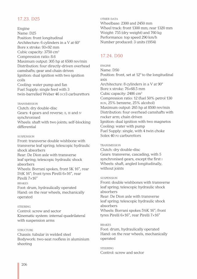
206
17.23. D25
EngineName: D25 Position: front longitudinal Architecture: 6 cylinders in a V at 60°
Bore x stroke: 93×92 mm Cubic capacity: 3750 cm3 Compression ratio: 8.6 Maximum output: 305 hp at 6500 rev/min Distribution: four directly-driven overhead camshafts; gear and chain drivenIgnition: dual ignition with two ignition coils Cooling: water pump and fan Fuel Supply: single feed with 3 twin-barrelled Weber 46 dCf3 carburettors
transmission Clutch: dry double-disc Gears: 4 gears and reverse; ii, iii and iv
synchronisedWheels: shaft with two joints; self-blocking differential
suspension Front: transverse double wishbone with transverse leaf spring; telescopic hydraulic shock absorbersRear: De Dion axle with transverse leaf spring; telescopic hydraulic shock absorbers Wheels: Borrani spokes, front 5K 16”, rear 5½K 16”; front tyres Pirelli 6×16”, rear Pirelli 7×16”brakes Foot: drum, hydraulically operated Hand: on the rear wheels, mechanically operated
steerinG Control: screw and sector Kinematic system: internal quadrilateral with suspension arms
struCture Chassis: tubular in welded steel Bodywork: two-seat roofless in aluminium sheeting
other data Wheelbase: 2300 and 2450 mm Wheel track: front 1300 mm; rear 1320 mm Weight: 755 (dry weight) and 760 kgPerformance: top speed 290 km/h Number produced: 3 units (1954)
17.24. D50
enGine
Name: D50 Position: front, set at 12° to the longitudinal axisArchitecture: 8 cylinders in a V at 90°
Bore x stroke: 76×68.5 mm Cubic capacity: 2486 cm3
Compression ratio: 12 (fuel 50% petrol 130 ron, 25% benzene, 25% alcohol)Maximum output: 265 hp at 8500 rev/min Distribution: four overhead camshafts with rocker arm; chain driven Ignition: dual ignition with two magnetos Cooling: water with pump Fuel Supply: single, with 4 twin choke Solex 40 pij carburettors
transmission Clutch: dry double-disc Gears: transverse, cascading, with 5 synchronised gears, except the first i
Wheels: shaft, angled longitudinally, without joints
suspension Front: double wishbones with transverse leaf spring; telescopic hydraulic shock absorbersRear: De Dion axle with transverse leaf spring; telescopic hydraulic shock absorbers Wheels: Borrani spokes 5½K 16”; front tyres Pirelli 6×16”, rear Pirelli 7×16”
brakes Foot: drum, hydraulically operated Hand: on the rear wheels, mechanically operated
steerinG Control: screw and sector
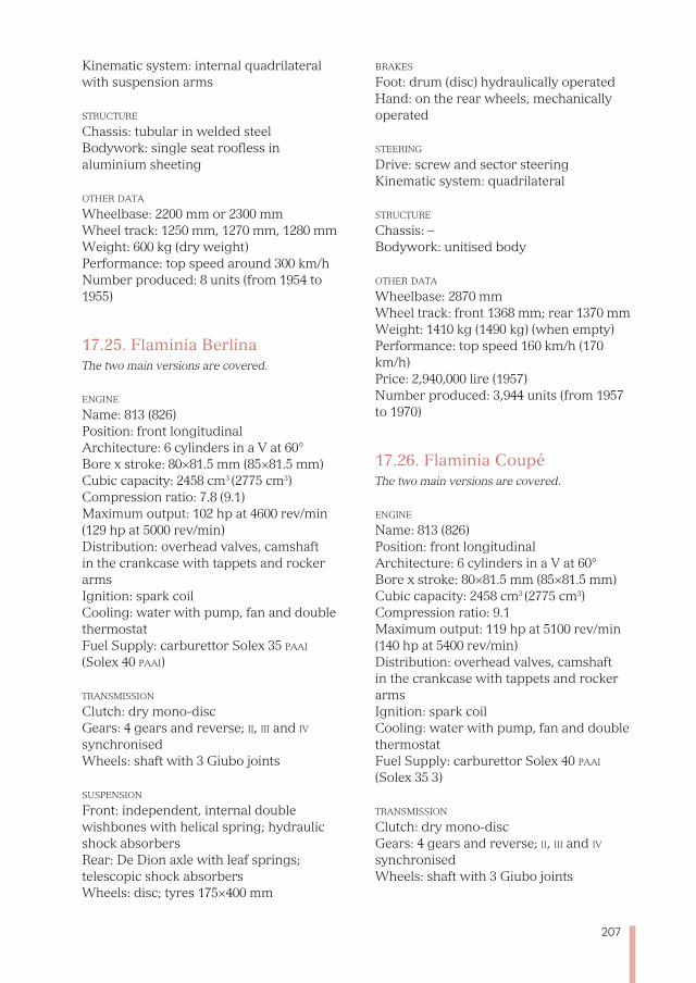
207
Kinematic system: internal quadrilateral with suspension arms
struCture
Chassis: tubular in welded steel Bodywork: single seat roofless in aluminium sheeting
other data Wheelbase: 2200 mm or 2300 mm Wheel track: 1250 mm, 1270 mm, 1280 mm Weight: 600 kg (dry weight) Performance: top speed around 300 km/h Number produced: 8 units (from 1954 to 1955)
17.25. Flaminia BerlinaThe two main versions are covered.
enGine
Name: 813 (826) Position: front longitudinal Architecture: 6 cylinders in a V at 60°
Bore x stroke: 80×81.5 mm (85×81.5 mm) Cubic capacity: 2458 cm3 (2775 cm3) Compression ratio: 7.8 (9.1) Maximum output: 102 hp at 4600 rev/min (129 hp at 5000 rev/min) Distribution: overhead valves, camshaft in the crankcase with tappets and rocker arms Ignition: spark coil Cooling: water with pump, fan and double thermostat Fuel Supply: carburettor Solex 35 paai (Solex 40 paai)
transmission Clutch: dry mono-disc Gears: 4 gears and reverse; ii, iii and iv
synchronised Wheels: shaft with 3 Giubo joints
suspension Front: independent, internal double wishbones with helical spring; hydraulic shock absorbers Rear: De Dion axle with leaf springs; telescopic shock absorbers Wheels: disc; tyres 175×400 mm
brakes Foot: drum (disc) hydraulically operated Hand: on the rear wheels, mechanically operated
steerinG Drive: screw and sector steering Kinematic system: quadrilateral struCture
Chassis: – Bodywork: unitised body other data Wheelbase: 2870 mm Wheel track: front 1368 mm; rear 1370 mm Weight: 1410 kg (1490 kg) (when empty) Performance: top speed 160 km/h (170 km/h) Price: 2,940,000 lire (1957) Number produced: 3,944 units (from 1957 to 1970)
17.26. Flaminia CoupéThe two main versions are covered.
enGine Name: 813 (826) Position: front longitudinal Architecture: 6 cylinders in a V at 60°
Bore x stroke: 80×81.5 mm (85×81.5 mm) Cubic capacity: 2458 cm3 (2775 cm3) Compression ratio: 9.1 Maximum output: 119 hp at 5100 rev/min (140 hp at 5400 rev/min) Distribution: overhead valves, camshaft in the crankcase with tappets and rocker arms Ignition: spark coil Cooling: water with pump, fan and double thermostat Fuel Supply: carburettor Solex 40 paai (Solex 35 3)
transmission Clutch: dry mono-disc Gears: 4 gears and reverse; ii, iii and iv
synchronised Wheels: shaft with 3 Giubo joints
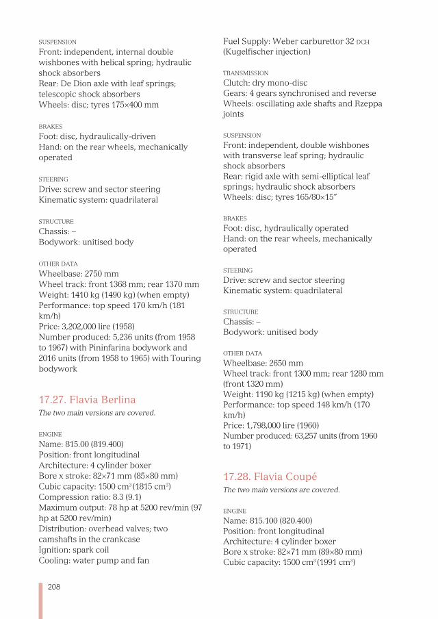
208
suspension Front: independent, internal double wishbones with helical spring; hydraulic shock absorbers Rear: De Dion axle with leaf springs; telescopic shock absorbers Wheels: disc; tyres 175×400 mm brakes Foot: disc, hydraulically-driven Hand: on the rear wheels, mechanically operated
steerinG Drive: screw and sector steering Kinematic system: quadrilateral
struCture
Chassis: – Bodywork: unitised body
other data Wheelbase: 2750 mm Wheel track: front 1368 mm; rear 1370 mm Weight: 1410 kg (1490 kg) (when empty) Performance: top speed 170 km/h (181 km/h) Price: 3,202,000 lire (1958) Number produced: 5,236 units (from 1958 to 1967) with Pininfarina bodywork and 2016 units (from 1958 to 1965) with Touring bodywork
17.27. Flavia BerlinaThe two main versions are covered.
enGine
Name: 815.00 (819.400) Position: front longitudinal Architecture: 4 cylinder boxer Bore x stroke: 82×71 mm (85×80 mm) Cubic capacity: 1500 cm3 (1815 cm3) Compression ratio: 8.3 (9.1) Maximum output: 78 hp at 5200 rev/min (97 hp at 5200 rev/min) Distribution: overhead valves; two camshafts in the crankcase Ignition: spark coil Cooling: water pump and fan
Fuel Supply: Weber carburettor 32 dCh (Kugelfischer injection)
transmission Clutch: dry mono-disc Gears: 4 gears synchronised and reverse Wheels: oscillating axle shafts and Rzeppa joints
suspension Front: independent, double wishbones with transverse leaf spring; hydraulic shock absorbers Rear: rigid axle with semi-elliptical leaf springs; hydraulic shock absorbers Wheels: disc; tyres 165/80×15”
brakes Foot: disc, hydraulically operated Hand: on the rear wheels, mechanically operated
steerinG Drive: screw and sector steering Kinematic system: quadrilateral
struCture
Chassis: – Bodywork: unitised body
other data Wheelbase: 2650 mm Wheel track: front 1300 mm; rear 1280 mm (front 1320 mm) Weight: 1190 kg (1215 kg) (when empty) Performance: top speed 148 km/h (170 km/h) Price: 1,798,000 lire (1960) Number produced: 63,257 units (from 1960 to 1971)
17.28. Flavia CoupéThe two main versions are covered.
enGine
Name: 815.100 (820.400) Position: front longitudinal Architecture: 4 cylinder boxer Bore x stroke: 82×71 mm (89×80 mm) Cubic capacity: 1500 cm3 (1991 cm3)
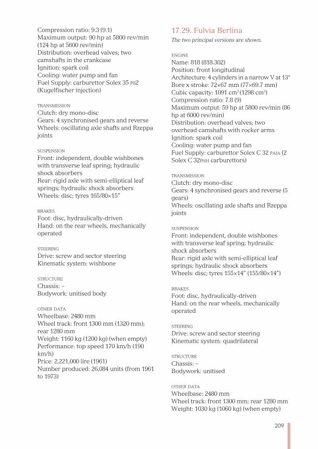
209
Compression ratio: 9.3 (9.1) Maximum output: 90 hp at 5800 rev/min (124 hp at 5600 rev/min) Distribution: overhead valves; two camshafts in the crankcase Ignition: spark coil Cooling: water pump and fan Fuel Supply: carburettor Solex 35 pii2 (Kugelfischer injection)
transmission Clutch: dry mono-disc Gears: 4 synchronised gears and reverse Wheels: oscillating axle shafts and Rzeppa joints
suspension Front: independent, double wishbones with transverse leaf spring; hydraulic shock absorbers Rear: rigid axle with semi-elliptical leaf springs; hydraulic shock absorbers Wheels: disc; tyres 165/80×15”
brakes Foot: disc, hydraulically-driven Hand: on the rear wheels, mechanically operated
steerinG Drive: screw and sector steering Kinematic system: wishbone
struCture Chassis: – Bodywork: unitised body
other data Wheelbase: 2480 mm Wheel track: front 1300 mm (1320 mm); rear 1280 mmWeight: 1160 kg (1200 kg) (when empty) Performance: top speed 170 km/h (190 km/h) Price: 2,221,000 lire (1961) Number produced: 26,084 units (from 1961 to 1973)
17.29. Fulvia BerlinaThe two principal versions are shown.
enGine Name: 818 (818.302)Position: front longitudinal Architecture: 4 cylinders in a narrow V at 13°
Bore x stroke: 72×67 mm (77×69.7 mm) Cubic capacity: 1091 cm3 (1298 cm3) Compression ratio: 7.8 (9) Maximum output: 59 hp at 5800 rev/min (86 hp at 6000 rev/min) Distribution: overhead valves; two overhead camshafts with rocker arms Ignition: spark coil Cooling: water pump and fan Fuel Supply: carburettor Solex C 32 paia (2 Solex C 32phh carburettors)
transmission Clutch: dry mono-disc Gears: 4 synchronised gears and reverse (5 gears) Wheels: oscillating axle shafts and Rzeppa joints
suspension Front: independent, double wishbones with transverse leaf spring; hydraulic shock absorbers Rear: rigid axle with semi-elliptical leaf springs; hydraulic shock absorbers Wheels: disc; tyres 155×14” (155/80×14”)
brakes Foot: disc, hydraulically-driven Hand: on the rear wheels, mechanically operated
steerinG Drive: screw and sector steering Kinematic system: quadrilateral
struCture Chassis: – Bodywork: unitised
other data Wheelbase: 2480 mm Wheel track: front 1300 mm; rear 1280 mm Weight: 1030 kg (1060 kg) (when empty)
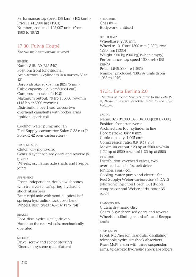
210
Performance: top speed 138 km/h (162 km/h) Price: 1,412,500 lire (1963) Number produced: 192,097 units (from 1963 to 1972)
17.30. Fulvia CoupéThe two main versions are covered.
enGine Name: 818.130 (818.540) Position: front longitudinal Architecture: 4 cylinders in a narrow V at 13°
Bore x stroke: 76×67 mm (82×75 mm) Cubic capacity: 1216 cm3 (1584 cm3) Compression ratio: 9 (10.5) Maximum output: 79 hp at 6000 rev/min (115 hp at 6000 rev/min) Distribution: overhead valves; two overhead camshafts with rocker arms Ignition: spark coil
Cooling: water pump and fan Fuel Supply: carburettor Solex C 32 phh (2 Solex C 42 ddhf carburettors)
transmission Clutch: dry mono-disc Gears: 4 synchronised gears and reverse (5 gears) Wheels: oscillating axle shafts and Rzeppa joints
suspension Front: independent, double wishbones with transverse leaf spring; hydraulic shock absorbers Rear: rigid axle with semi-elliptical leaf springs; hydraulic shock absorbers Wheels: disc; tyres 145×14” (175×14)”
brakes Foot: disc, hydraulically-driven Hand: on the rear wheels, mechanically operated
steerinG Drive: screw and sector steering Kinematic system: quadrilateral
struCture Chassis: – Bodywork: unitised
other data Wheelbase: 2330 mm Wheel track: front 1300 mm (1390); rear 1280 mm (1335) Weight: 950 kg (900 kg) (when empty) Performance: top speed 160 km/h (185 km/h)Price: 1,545,000 lire (1965) Number produced: 139,797 units (from 1965 to 1976)
17.31. Beta Berlina 2.0The data in round brackets refer to the Beta 2.0 ie; those in square brackets refer to the Trevi Volumex.
enGine Name: 828 B1.000 (828 B4.000) [828 B7.000]
Position: front transverse Architecture: four cylinder in line Bore x stroke: 84×90 mm Cubic capacity: 1,995 cm3
Compression ratio: 8.9 (9.1) [7.5] Maximum output: 120 hp at 5500 rev/min (122 hp at 5800 rev/min) [135 hp at 5500 rev/min] Distribution: overhead valves; two overhead camshafts, belt drive Ignition: spark coil Cooling: water pump and electric fan Fuel Supply: Weber carburettor 34 DAT2 (electronic injection Bosch L-J) [Roots compressor and Weber carburettor 36 dCa5]
transmission Clutch: dry mono-disc Gears: 5 synchronised gears and reverse Wheels: oscillating axle shafts and Rzeppa joints
suspension Front: McPherson triangular oscillating; telescopic hydraulic shock absorbers Rear: McPherson with three suspension arms; telescopic hydraulic shock absorbers
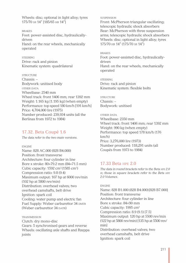
211
Wheels: disc; optional in light alloy; tyres 175/70 sr 14” [185/65 hr 14”]
brakes Foot: power-assisted disc, hydraulically-driven Hand: on the rear wheels, mechanically operated
steerinG Drive: rack and pinion Kinematic system: quadrilateral
struCture Chassis: – Bodywork: unitised body other data Wheelbase: 2540 mm Wheel track: front 1406 mm; rear 1392 mm Weight: 1.165 kg [1.195 kg] (when empty) Performance: top speed 180 km/h [191 km/h] Price: 4,704,000 lire (1975) Number produced: 239,934 units (all the Berlinas from 1972 to 1984)
17.32. Beta Coupé 1.6The data refer to the two main versions.
enGine Name: 828 AC.000 (828 B4.000)
Position: front transverse Architecture: four cylinder in line Bore x stroke: 80×79.2 mm (84×71.5 mm) Cubic capacity: 1592 cm3 (1585 cm3) Compression ratio: 9.8 (9.4) Maximum output: 107 hp at 6000 rev/min (102 hp at 5800 rev/min) Distribution: overhead valves; two overhead camshafts, belt drive Ignition: spark coil Cooling: water pump and electric fan Fuel Supply: Weber carburettor 34 dmtr (Weber carburettor 34 datr)
transmission Clutch: dry mono-disc Gears: 5 synchronised gears and reverse Wheels: oscillating axle shafts and Rzeppa joints
suspension Front: McPherson triangular oscillating; telescopic hydraulic shock absorbers Rear: McPherson with three suspension arms; telescopic hydraulic shock absorbers Wheels: disc; optional in light alloy; tyres 175/70 hr 14” (175/70 sr 14”)
brakes Foot: power-assisted disc, hydraulically-driven Hand: on the rear wheels, mechanically operated
steerinG Drive: rack and pinion Kinematic system: flexible bolts
struCture
Chassis: – Bodywork: unitised
other data Wheelbase: 2350 mm Wheel track: front 1406 mm; rear 1392 mm Weight: 990 kg (when empty) Performance: top speed 178 km/h (176 km/h) Price: 3,276,000 lire (1973) Number produced: 118,291 units (all Coupés from 1973 to 1984)
17.33 Beta hpe 2.0The data in round brackets refer to the Beta hpe 2.0 ie; those in square brackets refer to the Beta hpe 2.0 Volumex.
enGine Name: 828 B1.000 (828 B4.000) [828 B7.000]Position: front transverse Architecture: four cylinder in line Bore x stroke: 84×90 mm Cubic capacity: 1995 cm3
Compression ratio: 8.9 (9.1) [7.5] Maximum output: 120 hp at 5500 rev/min (122 hp at 5800 rev/min) [135 hp at 5500 rev/min] Distribution: overhead valves; two overhead camshafts, belt drive Ignition: spark coil
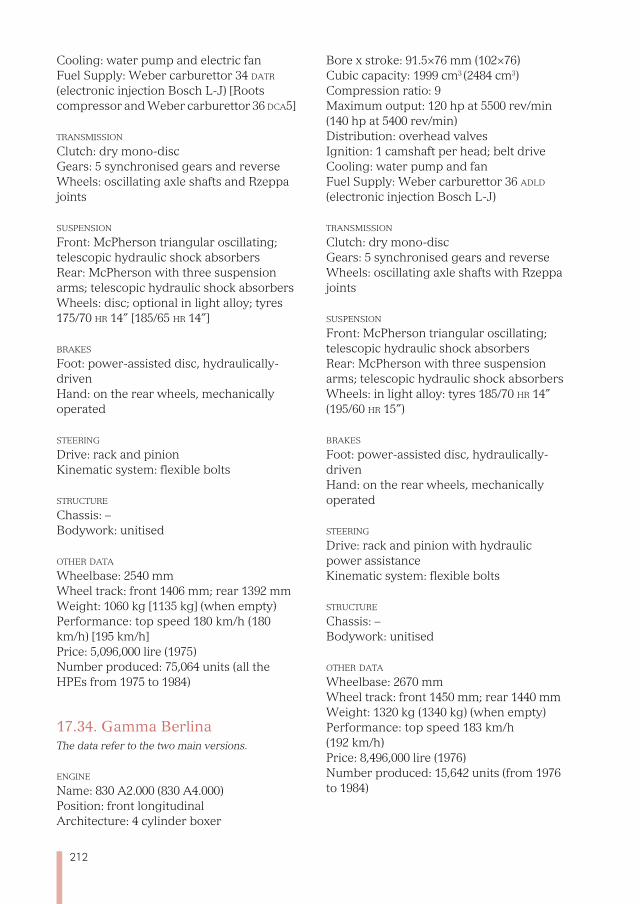
212
Cooling: water pump and electric fan Fuel Supply: Weber carburettor 34 datr (electronic injection Bosch L-J) [Roots compressor and Weber carburettor 36 dCa5]
transmission Clutch: dry mono-disc Gears: 5 synchronised gears and reverse Wheels: oscillating axle shafts and Rzeppa joints
suspension Front: McPherson triangular oscillating; telescopic hydraulic shock absorbers Rear: McPherson with three suspension arms; telescopic hydraulic shock absorbers Wheels: disc; optional in light alloy; tyres 175/70 hr 14” [185/65 hr 14”]
brakes Foot: power-assisted disc, hydraulically-driven Hand: on the rear wheels, mechanically operated
steerinG Drive: rack and pinion Kinematic system: flexible bolts
struCture Chassis: – Bodywork: unitised
other data Wheelbase: 2540 mm Wheel track: front 1406 mm; rear 1392 mm Weight: 1060 kg [1135 kg] (when empty) Performance: top speed 180 km/h (180 km/h) [195 km/h] Price: 5,096,000 lire (1975) Number produced: 75,064 units (all the HPEs from 1975 to 1984)
17.34. Gamma BerlinaThe data refer to the two main versions.
enGine Name: 830 A2.000 (830 A4.000) Position: front longitudinal Architecture: 4 cylinder boxer
Bore x stroke: 91.5×76 mm (102×76) Cubic capacity: 1999 cm3 (2484 cm3) Compression ratio: 9 Maximum output: 120 hp at 5500 rev/min (140 hp at 5400 rev/min) Distribution: overhead valvesIgnition: 1 camshaft per head; belt drive Cooling: water pump and fan Fuel Supply: Weber carburettor 36 adld (electronic injection Bosch L-J)
transmission Clutch: dry mono-disc Gears: 5 synchronised gears and reverse Wheels: oscillating axle shafts with Rzeppa joints
suspension Front: McPherson triangular oscillating; telescopic hydraulic shock absorbers Rear: McPherson with three suspension arms; telescopic hydraulic shock absorbers Wheels: in light alloy: tyres 185/70 hr 14” (195/60 hr 15”)
brakes Foot: power-assisted disc, hydraulically-driven Hand: on the rear wheels, mechanically operated
steerinG Drive: rack and pinion with hydraulic power assistance Kinematic system: flexible bolts
struCture Chassis: – Bodywork: unitised
other data Wheelbase: 2670 mm Wheel track: front 1450 mm; rear 1440 mm Weight: 1320 kg (1340 kg) (when empty) Performance: top speed 183 km/h (192 km/h) Price: 8,496,000 lire (1976) Number produced: 15,642 units (from 1976 to 1984)
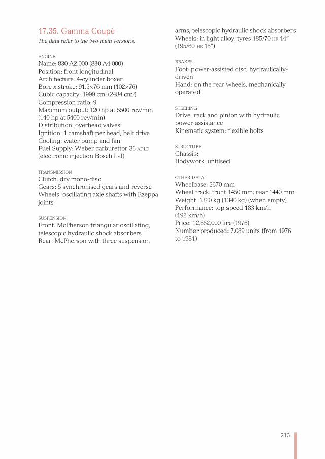
213
17.35. Gamma CoupéThe data refer to the two main versions.
enGine Name: 830 A2.000 (830 A4.000) Position: front longitudinal Architecture: 4-cylinder boxer Bore x stroke: 91.5×76 mm (102×76) Cubic capacity: 1999 cm3 (2484 cm3) Compression ratio: 9 Maximum output; 120 hp at 5500 rev/min (140 hp at 5400 rev/min) Distribution: overhead valvesIgnition: 1 camshaft per head; belt drive Cooling: water pump and fan Fuel Supply: Weber carburettor 36 adld (electronic injection Bosch L-J)
transmission Clutch: dry mono-discGears: 5 synchronised gears and reverse Wheels: oscillating axle shafts with Rzeppa joints
suspension Front: McPherson triangular oscillating; telescopic hydraulic shock absorbers Rear: McPherson with three suspension
arms; telescopic hydraulic shock absorbers Wheels: in light alloy; tyres 185/70 hr 14” (195/60 hr 15”)
brakes Foot: power-assisted disc, hydraulically-driven Hand: on the rear wheels, mechanically operated
steerinG Drive: rack and pinion with hydraulic power assistance Kinematic system: flexible bolts
struCture
Chassis: – Bodywork: unitised
other data Wheelbase: 2670 mm Wheel track: front 1450 mm; rear 1440 mm Weight: 1320 kg (1340 kg) (when empty) Performance: top speed 183 km/h (192 km/h) Price: 12,862,000 lire (1976) Number produced: 7,089 units (from 1976 to 1984)
214
BIBLIOGRAPHY
Bencini M., Dinamica del veicolo considerato come punto, Tamburini, Milan 1956.Bernabò F., Lancia, una storia, una leggenda, una realtà, Lancia, Turin 1986.Bernabò F. e Manganaro A., Lancia: catalogue raisonné 1907-1990, Automobilia, Milan 1991.Cappellano O., Lancia: le antenate eccellenti, Omniablu, Turin 2011.Falchetto S., Falchetto planner e designer, Libreria asi, Turin 2011.Giacosa D., I progettisti della fiat nei primi quarant’anni: da Faccioli a Fessia; Associazione
italiana per la storia dell’Automobile, Turin 1987.Lukas J. A., The American Machinist, Penton, New York, 1928 [“Features of the Lancia Plant
and Organization”, pp. 19-23; “An Unusual Crankshaft and How it is Made”, pp. 445-450; “How Lancia Eliminates the Front Axle”, pp. 487-481; “Automobile Body and Frame Com-bined in a Single Unit”, pp. 725-729; “Testing Parts and Units in the Lancia Plant”, pp. 846-847].
Sessa O., Bruni A., Clarke M. e Paolini F., L’automobile italiana, Giunti, Florence 2006.Tutte le Lancia (1906-2008), Domus, Milan 2008. Weernink W. O., La Lancia, Giorgio Nada, Milan 1979.
215
CONTENTS
IntroduCtIon ...................................................................................................................................................................... 5
the StaF Group ...................................................................................................................................................................... 7
Chapter 1 Vincenzo Lancia ...................................................................................................................... 11
Chapter 2 Lancia cars and the Lancia brand..................................................................... 17
Chapter 3 The Alfa and the Beta ....................................................................................................... 21
Chapter 4 From the Gamma to the Eta .................................................................................... 33
Chapter 5 The Zeta ............................................................................................................................................. 39
Chapter 6 The Theta ......................................................................................................................................... 47
Chapter 7 The Kappa and the narrow V engines ........................................................ 57
Chapter 8 The Lambda and the Dilambda ........................................................................... 71
Chapter 9 The Artena and the Astura ........................................................................................ 89
Chapter 10 The Augusta ................................................................................................................................. 101
Chapter 11 The Aprilia and the Ardea .......................................................................................... 111
Chapter 12 The Aurelia and the Appia ......................................................................................... 123
Chapter 13 The D cars ....................................................................................................................................... 139
Chapter 14 The Flaminia, Flavia and Fulvia ........................................................................... 157
Chapter 15 The Beta and the Gamma ............................................................................................ 173
Chapter 16 Lancia and Pininfarina .................................................................................................... 183
Chapter 17 Technical data ............................................................................................................................ 193
BIBlIoGraphy ...................................................................................................................................................................... 214
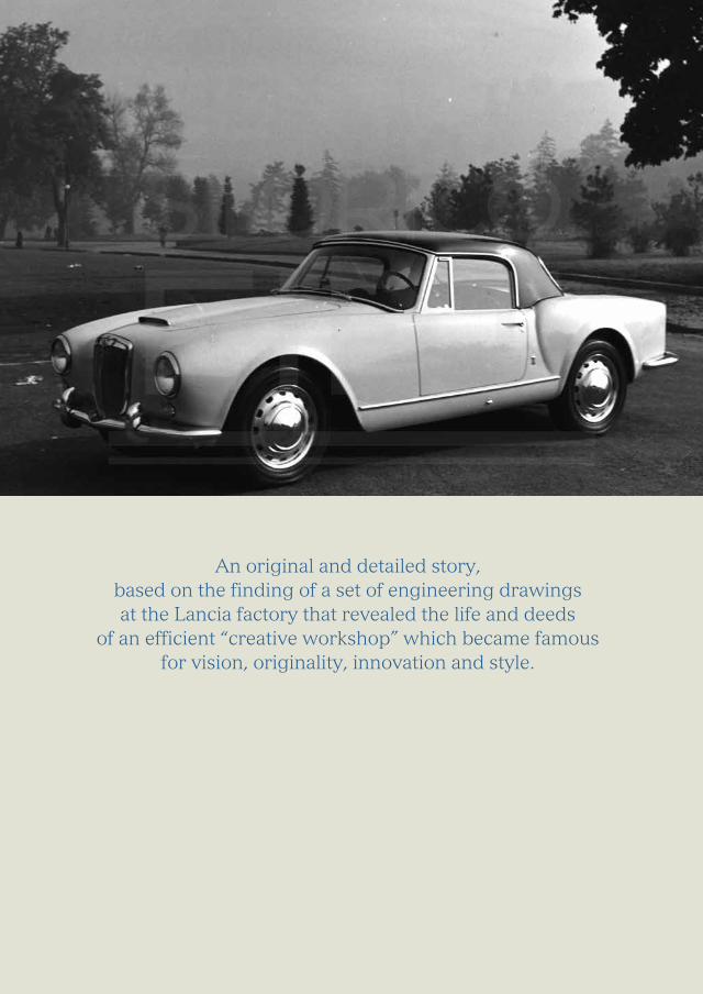
An original and detailed story, based on the finding of a set of engineering drawings at the Lancia factory that revealed the life and deeds
of an efficient “creative workshop” which became famous for vision, originality, innovation and style.