LAN INSTALLATION MANUAL - Fujitsu
27
F 2 MC FAMILY EMULATOR MB2140 SERIES LAN INSTALLATION MANUAL FUJITSU SEMICONDUCTOR MICROCONTROLLER MANUAL CM42–00405–1E
Transcript of LAN INSTALLATION MANUAL - Fujitsu

F2MC FAMILY EMULATORMB2140 SERIESLAN INSTALLATION MANUAL
FUJITSU SEMICONDUCTORMICROCONTROLLER MANUAL
CM42–00405–1E

F2MC FAMILY EMULATORMB2140 SERIES LAN INSTALLATION
USER’S MANUAL
Edition 1.0 November 1994
1994 FUJITSU LIMITED
All Rights Reserved.
Circuit diagrams utilizing Fujitsu products are included as a means of illustrating typicalsemiconductor applications. Complete information sufficient for construction purposesis not necessarily given.
The information contained in this document has been carefully checked and is believedto be reliable. However, Fujitsu assumes no responsibility for inaccuracies.
The information contained in this document does not convey any license under thecopyrights, patent rights or trademarks claimed and owned by Fujitsu.
Fujitsu reserves the right to change products or specifications without notice.
No part of this publication may be copied or reproduced in any form or by any means, ortransferred to any third party without prior written consent of Fujitsu.

iii
PREFACE
This manual describes LAN terms and the equipment required for connecting to a LAN. It is for those peopleinstalling a LAN for the first time.
iv
Table of Contents
1. GENERAL 1-3. . . . . . . . . . . . . . . . . . . . . . . . . . . . . . . . . . . . . . . . . . . . . . . . . . . . . . . . . . . .
2. NETWORK FACILITIES 2-3. . . . . . . . . . . . . . . . . . . . . . . . . . . . . . . . . . . . . . . . . . . . . . . . . 2.1 Network Facility Requirements 2-3. . . . . . . . . . . . . . . . . . . . . . . . . . . . . . . . . . . . . . 2.2 Network Types 2-4. . . . . . . . . . . . . . . . . . . . . . . . . . . . . . . . . . . . . . . . . . . . . . . . . . . . 2.3 Connection Examples 2-7. . . . . . . . . . . . . . . . . . . . . . . . . . . . . . . . . . . . . . . . . . . . . .
2.3.1 Shapes of host-computer connectors 2-7. . . . . . . . . . . . . . . . . . . . . . . . . . . . . . . . . . . . . . . . . 2.3.2 LAN interconnection 2-7. . . . . . . . . . . . . . . . . . . . . . . . . . . . . . . . . . . . . . . . . . . . . . . . . . . . . . . 2.3.3 Examples of connection to personal computers 2-8. . . . . . . . . . . . . . . . . . . . . . . . . . . . . . . . 2.3.4 Examples of connection to workstations 2-9. . . . . . . . . . . . . . . . . . . . . . . . . . . . . . . . . . . . . .
3. INSTALLATION 3-10. . . . . . . . . . . . . . . . . . . . . . . . . . . . . . . . . . . . . . . . . . . . . . . . . . . . . . . 3.1 Network Addressing 3-10. . . . . . . . . . . . . . . . . . . . . . . . . . . . . . . . . . . . . . . . . . . . . . . 3.2 Host-Computer Settings 3-12. . . . . . . . . . . . . . . . . . . . . . . . . . . . . . . . . . . . . . . . . . .
3.2.1 UNIX workstation 3-12. . . . . . . . . . . . . . . . . . . . . . . . . . . . . . . . . . . . . . . . . . . . . . . . . . . . . . . . . 3.2.2 Personal computer 3-13. . . . . . . . . . . . . . . . . . . . . . . . . . . . . . . . . . . . . . . . . . . . . . . . . . . . . . . .
3.3 Emulator Addressing 3-14. . . . . . . . . . . . . . . . . . . . . . . . . . . . . . . . . . . . . . . . . . . . . .
APPENDIX DETAILS OF NETWORK ADDRESSES App.-1. . . . . . . . . . . . . . . . . . . . . . . . 1. MAC Address (or Ethernet Address/Physical Address) App.-1. . . . . . . . . . . . . . . . 2. IP Address (or INET Address) App.-2. . . . . . . . . . . . . . . . . . . . . . . . . . . . . . . . . . . . . . 3. Host Name App.-3. . . . . . . . . . . . . . . . . . . . . . . . . . . . . . . . . . . . . . . . . . . . . . . . . . . . . .

v
Table
Table 2-1 Network Standards 1-4. . . . . . . . . . . . . . . . . . . . . . . . . . . . . . . . . . . . . . . . . . . . . . . . . . . . . . . . . . . . . . .

vi
Figures
Fig. 2.1 Connection to Host Computer 1-3. . . . . . . . . . . . . . . . . . . . . . . . . . . . . . . . . . . . . . . . . . . . . . . . . . . . . . .
Fig. 2.2 10BASE5 Configuration 1-4. . . . . . . . . . . . . . . . . . . . . . . . . . . . . . . . . . . . . . . . . . . . . . . . . . . . . . . . . . . .
Fig. 2.3 10BASE2 Configuration 1-5. . . . . . . . . . . . . . . . . . . . . . . . . . . . . . . . . . . . . . . . . . . . . . . . . . . . . . . . . . . .
Fig. 2.4 10BASE2 Extension 1-5. . . . . . . . . . . . . . . . . . . . . . . . . . . . . . . . . . . . . . . . . . . . . . . . . . . . . . . . . . . . . . .
Fig. 2.5 10BASE-T Configuration 1-6. . . . . . . . . . . . . . . . . . . . . . . . . . . . . . . . . . . . . . . . . . . . . . . . . . . . . . . . . . .
Fig. 2.6 10BASE-T Extension 1-6. . . . . . . . . . . . . . . . . . . . . . . . . . . . . . . . . . . . . . . . . . . . . . . . . . . . . . . . . . . . . .
Fig. 2.7 Shapes of LAN Connectors 1-7. . . . . . . . . . . . . . . . . . . . . . . . . . . . . . . . . . . . . . . . . . . . . . . . . . . . . . . . .
Fig. 2.8 LAN Interconnection 1-7. . . . . . . . . . . . . . . . . . . . . . . . . . . . . . . . . . . . . . . . . . . . . . . . . . . . . . . . . . . . . . .
Fig. 3.1 Example of Network Addresses 1-10. . . . . . . . . . . . . . . . . . . . . . . . . . . . . . . . . . . . . . . . . . . . . . . . . . . .
Fig. 3.2 Emulator Network Addressing 1-14. . . . . . . . . . . . . . . . . . . . . . . . . . . . . . . . . . . . . . . . . . . . . . . . . . . . . .

1. GENERAL

GENERAL
1-3
The MB2142 LAN Adapter is a network adapter conforming to IEEE802.3. It allows the emulator to be oper-ated from a workstation or personal computer connected to the LAN.
� Features
• TCP/IP support for reliable communications
• Standard LAN used with workstations
• InetBIOS* interface allows LAN connection of personal computers.
• Conforms to 10BASE2 and 10BASE-T
* InetBIOS is a LAN interface standard advocated by ASCII.

2. NETWORK FACILITIES
2.1 Network Facility Requirements 2-3. . . . . . . . . . . . . . . . . . . . 2.2 Network Types 2-4. . . . . . . . . . . . . . . . . . . . . . . . . . . . . . . . . . 2.3 Connection Examples 2-7. . . . . . . . . . . . . . . . . . . . . . . . . . . .
NETWORK FACILITIES
2-3
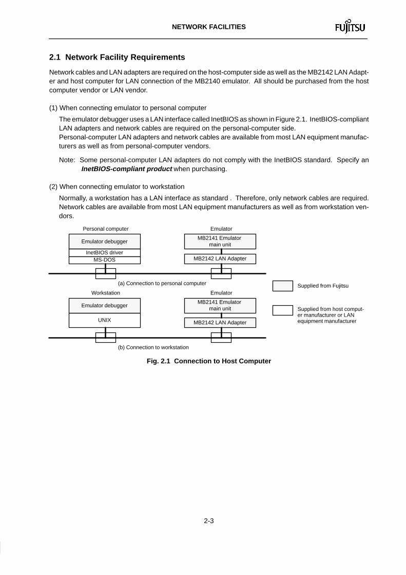
2.1 Network Facility Requirements
Network cables and LAN adapters are required on the host-computer side as well as the MB2142 LAN Adapt-er and host computer for LAN connection of the MB2140 emulator. All should be purchased from the hostcomputer vendor or LAN vendor.
(1) When connecting emulator to personal computer
The emulator debugger uses a LAN interface called InetBIOS as shown in Figure 2.1. InetBIOS-compliantLAN adapters and network cables are required on the personal-computer side. Personal-computer LAN adapters and network cables are available from most LAN equipment manufac-turers as well as from personal-computer vendors.
Note: Some personal-computer LAN adapters do not comply with the InetBIOS standard. Specify anInetBIOS-compliant product when purchasing.
(2) When connecting emulator to workstation
Normally, a workstation has a LAN interface as standard . Therefore, only network cables are required.Network cables are available from most LAN equipment manufacturers as well as from workstation ven-dors.
Supplied from host comput-er manufacturer or LANequipment manufacturer
Personal computer
Emulator debugger
InetBIOS driverMS-DOS
Emulator
MB2141 Emulator main unit
MB2142 LAN Adapter
(a) Connection to personal computer
Workstation
Emulator debugger
UNIX
Emulator
MB2141 Emulator main unit
MB2142 LAN Adapter
(b) Connection to workstation
Supplied from Fujitsu
Fig. 2.1 Connection to Host Computer

NETWORK FACILITIES
2-4
2.2 Network Types
Three types of networks are available: 10BASE5, 10BASE2 and 10BASE-T, each of which has the samebaud rate but different cables or connectors. The major differences in the specifications are listed in Table 2-1.
Two types of MB2142 LAN adapters are available: for 10BASE2, and for 10BASE-T. The adapters should beselected to the LAN. Connection to a 10BASE5 LAN requires an interface for 10BASE2 or 10BASE-T.
(1) 10BASE5
This LAN uses a thick coaxial cable with a diameter of about 10 mm. The cable can be run up to 500 m, butits inflexibility makes cabling difficult.A transceiver is used to connect the host computer or emulator. Depending on the transceiver type, instal-lation tools may be required.
To host computer/emulator
Max. 500 m
Min. 2.5 m
10BASE5 terminalresistor
10BASE5transceiver 10BASE5 cable
10BASE5transceiver
10BASE5 termi-nal resistor
Max. 50 mAUI cable AUI cable
Up to 100 transceiverscan be connected
To host computer/emulator
Fig. 2.2 10BASE5 Configuration
Table 2-1 Network Standards
Twisted pair cable ofabout 3-mm dia.Cable
Maximum segment length
Minimum distancebetween terminals
Maximum number ofterminals connected
10BASE5 10BASE2 10BASE-T
Coaxial cable ofabout 10-mm dia.
Coaxial cable ofabout 5-mm dia.
500 m 185 m 100 m
100 30 1
2.5 m 0.6 m —
NETWORK FACILITIES
2-5
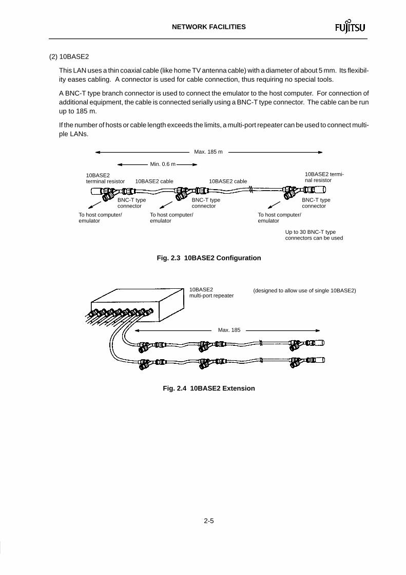
(2) 10BASE2
This LAN uses a thin coaxial cable (like home TV antenna cable) with a diameter of about 5 mm. Its flexibil-ity eases cabling. A connector is used for cable connection, thus requiring no special tools.
A BNC-T type branch connector is used to connect the emulator to the host computer. For connection ofadditional equipment, the cable is connected serially using a BNC-T type connector. The cable can be runup to 185 m.
If the number of hosts or cable length exceeds the limits, a multi-port repeater can be used to connect multi-ple LANs.
To host computer/emulator
Max. 185 m
Min. 0.6 m
10BASE2 terminal resistor 10BASE2 cable
10BASE2 termi-nal resistor
To host computer/emulator
10BASE2 cable
BNC-T typeconnector
BNC-T typeconnector
BNC-T typeconnector
To host computer/emulator
Up to 30 BNC-T typeconnectors can be used
Fig. 2.3 10BASE2 Configuration
Max. 185
(designed to allow use of single 10BASE2)10BASE2 multi-port repeater
Fig. 2.4 10BASE2 Extension

NETWORK FACILITIES
2-6
(3) 10BASE-T
This LAN uses a slender twisted pair cable (about 3-mm diameter). Its high flexibility makes cabling veryeasy. The cable can be run up to 100 m, but a malfunction may occur in noisy environments because it isunshielded.
Only one terminal can be connected to a single cable. Connection of many pieces of equipment requires a10BASE-T hub. The number of pieces of equipment that can be connected to one hub depends on the hubtype. Purchase a hub tailored to the number of pieces of equipment to be connected. If more equipmentmust be connected, up to four hubs can be added as shown in Figure 2.6.
Max. 100 m
10BASE-T hub (designed to allow use of single 10BASE-T)
10BASE-T cable
To host computer/emulator
Fig. 2.5 10BASE-T Configuration
Up to 4 hubs
Fig. 2.6 10BASE-T Extension

NETWORK FACILITIES
2-7
2.3 Connection Examples
2.3.1 Shapes of host-computer connectors
Three types of LAN connectors for personal computers/workstations are available as shown in Figure 2.7.The transceiver external connection type requires a 10BASE2 or 10BASE-T transceiver. Various productssuch as an AUI cable and transceiver integrated type are available. For more information, ask the LANmanufacturer.
(a) Transceiver external connection type (b) 10BASE2 (c) 10BASE-T
Fig. 2.7 Shapes of LAN Connectors
2.3.2 LAN interconnection
10BASE2, 10BASE5 and 10BASE-T can be interconnected using a repeater or hub. As shown in Figure 2.8,different types of established LANs can be interconnected.
10BASE2 repeater
10BASE-T hub
10BASE5
10BASE-T
10BASE2
Fig. 2.8 LAN interconnection

NETWORK FACILITIES
2-8
2.3.3 Examples of connection to personal computers
(1) 10BASE2 minimum configuration
•10BASE2 cable × 1
•10BASE2 BNC-T type connector × 2
•10BASE2 terminal resistor (male) × 2
•10BASE2 personal-computerLAN adapter × 1
•10BASE2 MB2142 LAN adapter × 1MB2141 emulator
10BASE2terminalresistor
BNC-T type
connector10BASE2
cable
BNC-T type
connector
10BASE2 terminal resistor
Personal-computerLAN adapter
MB2142 LAN Adapter
Personal computer
(2) Connection of n host personal computers to m emulators on 10BASE-T
•10BASE-T cable × n + m
•10BASE-T personal-computer LAN adapter × n
•10BASE-T MB2142 LAN adapter × m
•10BASE-T hub (with morethan n+m ports) × 1
10BASE-Tcable
10BASE-T hub
Personal-computer
LAN adapter
Personal-computer
LAN adapter
MB2142 LAN adapter
MB2142 LAN adapter
Personalcomputer
Personalcomputer
MB2141Emulator
MB2141Emulator
(3) Connection to transceiver outer connection type
AUI cable10BASE-T
cable
Personal-computer
LAN adapter
Personalcomputer
10BASE2cable
10BASE2transceiver
10BASE-Ttransceiver
•10BASE2 or 10BASE-T transceiver × 1
•AUI cable × 1
•Other set

NETWORK FACILITIES
2-9
2.3.4 Examples of connection to workstations
(1) 10BASE2 minimum configuration
•10BASE2 cable × 1
•10BASE2 BNC-T type connector × 2
•10BASE2 terminal resistor (male) × 2
•10BASE2 MB2142 LAN adapter × 1
MB2141 emulator
10BASE2terminalresistor
BNC-T type
connector10BASE2
cable
BNC-T type
connector
10BASE2 terminal resistor
MB2142 LAN Adapter
Workstation
(2) Connection of n workstations to m emulators on 10BASE-T
•10BASE-T cable × n + m
•10BASE-T MB2142 LAN adapter × m
•10BASE-T hub (with morethan n+m ports) × 1
10BASE-Tcable
10BASE-T hub
Workstation
MB2142 LAN adapter
MB2142 LAN adapter
MB2141Emulator
MB2141Emulator
Workstation
(3) Connection to transceiver external connection type
AUI cable10BASE-T
cable
10BASE2cable
10BASE2transceiver
10BASE-Ttransceiver
•10BASE2 or 10BASE-T transceiver × 1
•AUI cable × 1
•Other set
Workstation

3. INSTALLATION
3.1 Network Addressing 3-10. . . . . . . . . . . . . . . . . . . . . . . . . . . 3.2 Host-Computer Settings 3-12. . . . . . . . . . . . . . . . . . . . . . . . 3.3 Emulator Addressing 3-14. . . . . . . . . . . . . . . . . . . . . . . . . .
INSTALLATION
3-3
3.1 Network Addressing
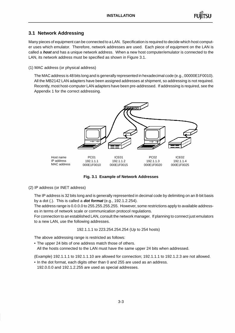
Many pieces of equipment can be connected to a LAN. Specification is required to decide which host comput-er uses which emulator. Therefore, network addresses are used. Each piece of equipment on the LAN iscalled a host and has a unique network address. When a new host computer/emulator is connected to theLAN, its network address must be specified as shown in Figure 3.1.
(1) MAC address (or physical address)
The MAC address is 48 bits long and is generally represented in hexadecimal code (e.g., 00000E1F0010).All the MB2142 LAN adapters have been assigned addresses at shipment, so addressing is not required.Recently, most host-computer LAN adapters have been pre-addressed. If addressing is required, see theAppendix 1 for the correct addressing.
Host name IP address MAC address
PC01192.1.1.1
000E1F0010
ICE01192.1.1.2
000E1F0015
PC02192.1.1.3
000E1F0020
ICE02192.1.1.4
000E1F0025
Fig. 3.1 Example of Network Addresses
(2) IP address (or INET address)
The IP address is 32 bits long and is generally represented in decimal code by delimiting on an 8-bit basisby a dot (.). This is called a dot format (e.g., 192.1.2.254).The address range is 0.0.0.0 to 255.255.255.255. However, some restrictions apply to available address-es in terms of network scale or communication protocol regulations. For connection to an established LAN, consult the network manager. If planning to connect just emulatorsto a new LAN, use the following addresses.
192.1.1.1 to 223.254.254.254 (Up to 254 hosts)
The above addressing range is restricted as follows:
• The upper 24 bits of one address match those of others.All the hosts connected to the LAN must have the same upper 24 bits when addressed.
(Example) 192.1.1.1 to 192.1.1.10 are allowed for connection; 192.1.1.1 to 192.1.2.3 are not allowed.
• In the dot format, each digits other than 0 and 255 are used as an address.192.0.0.0 and 192.1.2.255 are used as special addresses.
INSTALLATION
3-4
(3) Host name
When the equipment on the LAN is actually operating, addresses are inconvenient. Therefore, any hostname can be entered instead of an address. MB2140 emulators also use host names.
Characters used as host names are not restricted but depend on the network manufacturer. Generally, it issafe to decide a host name based on the following restrictions.
• 1 to 9 alphanumeric characters
• Begings with alphabetic character
(Example) PC01 ICE02
INSTALLATION
3-5
3.2 Host-Computer Settings
3.2.1 UNIX workstation
The super user should perform the following work.
(1) Setting host-computer network address
Normally, the host computer is network-addressed when its OS is installed. For more information on ad-dressing, refer to the OS manual.Unless otherwise specified, set the subnet masks and gateways to the not-ready state.
(2) Entering emulator network addresses
Enter the IP address and host address of the desired emulator in the /etc/hosts file. Add the followingone line using an editor.
IP address Host name
Delimit the IP address and host name with a blank or tab character. When using several emulators, de-scribe each emulator on a single line.
(Example) 192.1.1.2 ICE01 192.1.1.4 ICE02
(3) Entering service number and service name of emulator
The service number and service name are used internally for communication over a LAN. Enter them inthe /etc/services file.
The emulator defaults to service No. 5001 and service name fjicesv . Therefore, use an editor to ensurethat the character string 5001/tcp is not contained in the /etc/services file. Then, add the followingline (in lower-case characters).
fjicesv 5001/tcp
If 5001/tcp is already contained in the /etc/services file, replace it with an unused number beginningwith 5002 or greater (such as fjicesv 5002/tcp ).
The emulator retrieves the /etc/services files with the name fjicesv and uses the service numberdescribed in the line to communicate with itself.
(4) Rebooting system
Reboot the system after completing the above work.
3.2.2 Personal computer
(1) Installing personal-computer LAN adapter
Install the personal-computer LAN adapter according to the users manual to activate InetBIOS. The usermay be prompted for entry of a network address during installation.
Unless otherwise specified, set the subnet masks and gateways to the not-ready state.

INSTALLATION
3-6
(2) Setting network address of personal computer
Normally, the user is prompted for entry of a network address during installation of the personal-computerLAN adapter. Enter the host name and IP address of the personal computer. Generally, the personal com-puter is called a local host .
Recently, MAC addresses have already been assigned to most host-computer LAN adapters. If addres-sing is required, see Appendix 1 for proper addressing.
(3) Entering emulator network addresses
Enter the IP address and host address of the emulator in the HOSTS file of the directory indicated by theenvironmental variable INETBIOS . If setting of a remote host is required during installation of the person-al-computer LAN adapter, enter the emulator’s IP address and host name at that time a HOSTS file iscreated automatically; otherwise, use an editor to add the following line to the HOSTS file.
IP address Host name
Delimit the IP address and the host name with a blank or tab character. When using several emulators,describe each emulator on a single line.
(Example) 192.1.1.2 ICE01 192.1.1.4 ICE02
(4) Entering service number and service name of emulator
The service number and service name are used internally for communication over the LAN. Enter them inthe SERVICES file of the directory indicated by the environmental variable INETBIOS .
The emulator defaults to service No. 5001 and service name fjicesv . Therefore, use an editor to ensurethat the character string 5001/tcp is not contained in the SERVICES file. Then, add the following line (inlower-case characters).
fjicesv 5001/tcp
If 5001/tcp is already contained in the SERVICES file, replace it with an unused number beginning with5002 or greater (such as fjicesv 5002/tcp ).
The emulator retrieves the SERVICES files with the name fjicesv and uses the service number de-scribed in the line to communicate with itself.
INSTALLATION
3-7
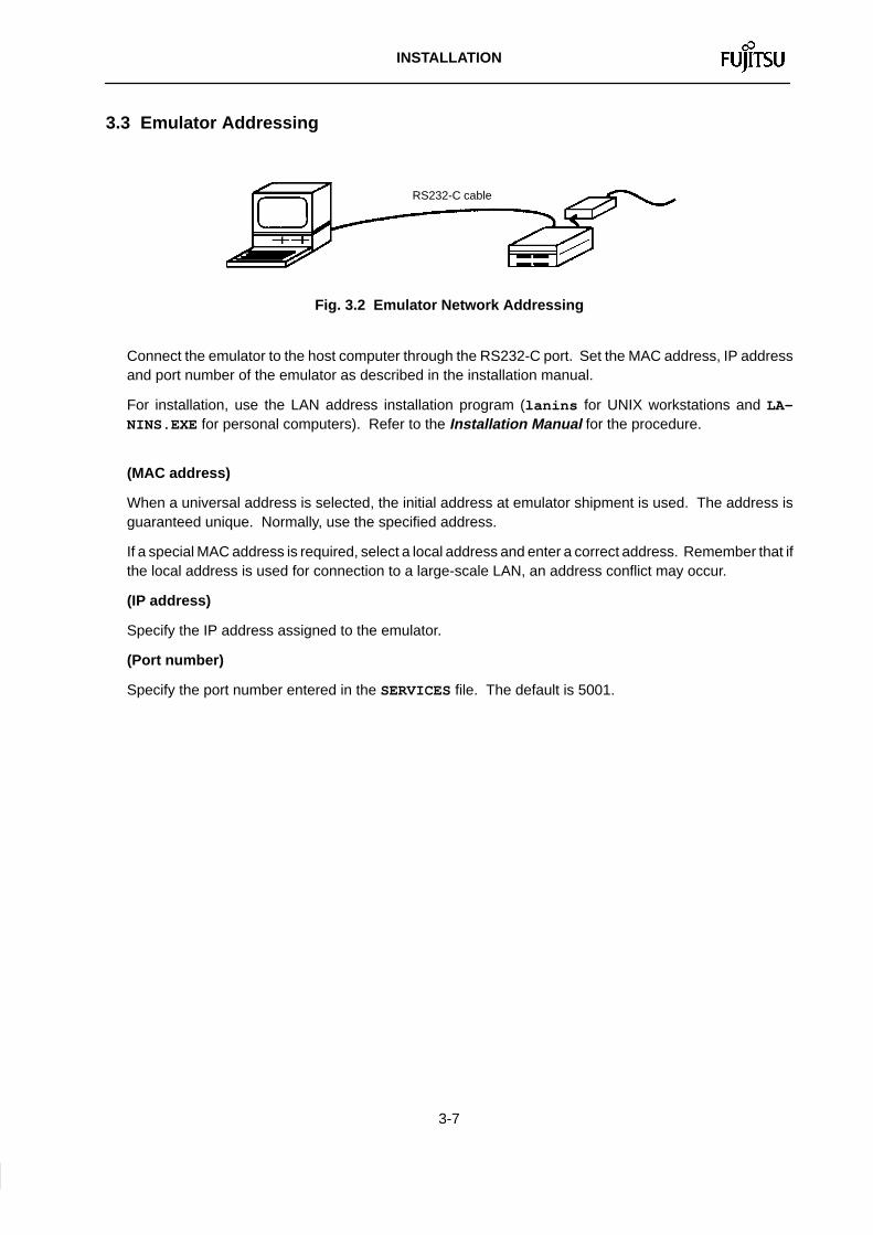
3.3 Emulator Addressing
RS232-C cable
Fig. 3.2 Emulator Network Addressing
Connect the emulator to the host computer through the RS232-C port. Set the MAC address, IP addressand port number of the emulator as described in the installation manual.
For installation, use the LAN address installation program (lanins for UNIX workstations and LA-NINS.EXE for personal computers). Refer to the Installation Manual for the procedure.
(MAC address)
When a universal address is selected, the initial address at emulator shipment is used. The address isguaranteed unique. Normally, use the specified address.
If a special MAC address is required, select a local address and enter a correct address. Remember that ifthe local address is used for connection to a large-scale LAN, an address conflict may occur.
(IP address)
Specify the IP address assigned to the emulator.
(Port number)
Specify the port number entered in the SERVICES file. The default is 5001.
APPENDIX

APPENDIX
App.-1
APPENDIX DETAILS OF NETWORK ADDRESSES
1. MAC Address (or Ethernet Address/Physical Address)
A MAC address is 48 bits long and is generally represented in hexadecimal code.
(Example) 00000E1F00FF
The address is classified by using its second digit in hexadecimal code in order to avoid overlap on the samenetwork.
0, 4, 8, C: Universal addresses (such as 00000E1F00FF)
2, 6, A, E: Local addresses (such as 12000E1F00FF)
Others: Special addresses (such as 23000E1F00FF)
× × × × × × × × × × × × Hexadecimal code
Universal addresses are assigned by the IEEE and are guaranteed unique.
Local addresses are used for self-addressing without address assignment. Remember that using local ad-dresses on a large-scale network may cause an overlap.
The MB2142 LAN adapters have been pre-addressed at shipment with the universal addresses assigned bythe IEEE. Normally, use the LAN adapters as they are without changing the universal addresses.

APPENDIX
App.-2
2. IP Address (or INET Address)
An IP address is 32 bits long and is generally represented in decimal code by delimiting on an 8-bit basis by adot (.). This is called a dot format .
(Example) 192.1.2.128
IP addresses are classified into three according to the network scale. Each class is identified by the first digitgroup in the dot format.
× × × . × × × . × × × . × × ×
0 to 127: Class A (large-scale network)
128 to 191: Class B (medium-scale network)
192 to 223: Class C (small-scale network)
224 to 255: Reserved
Class C permits up to 254 hosts to be connected to one network. If the number of hosts is less than 254, useclass-C addresses. For connection to a larger network, consult the network manager.Class C is described below.
• In the dot format, 0 and 255 are used as special addresses. Normally, use addresses 1 to 254.(Example) 192.0.0.0, 192.1.1.0 and 192.1.2.255 are not available.
• When specifying class-C addresses, match the upper 24 bits of all the hosts connected to the same net-work.
(Example) 192.1.1.1,192.1.1.2 and 192.1.1.254 are allowed for connection; 192.1.1.1, 192.1.2.1 and 192.2.3.254are not allowed.
APPENDIX
App.-3
3. Host Name
In network communication, an IP address is used to specify the host to communicate with. However, address-es are inconvenient for actual use. Therefore, any host name can be used instead of an IP address.
(Example) HOST1 HOST2 ICE01
The emulator debugger specifies the host name of an emulator to be connected to a network.
Characters used as a host name depend on the host computer type or LAN adapter manufacturer. Somemanufacturers have no special restrictions but, generally, it is safe to decide the host name based on the fol-lowing restrictions.
• The host name should be 1 to 9 alphanumeric characters long.
• The host name should consist of alphabetic or numeric characters.
• The host name should begin with an alphabetic character.
Consult the network manager.

For further information please contact:
Japan
North and South America
Europe
Asia Pacific
FUJITSU MICROELECTRONICS, INC.Semiconductor Division3545 North First StreetSan Jose, CA 95134–1804, USATel: (408) 922–9000FAX: (408) 432–9044/9045
I9411 FUJITSU LIMITED Printed in Japan
FUJITSU LIMITEDElectronic DevicesInternational Operations DepartmentKAWASAKI PLANT, 1015 Kamikodanaka,Nakahara–ku, Kawasaki–shi,Kanagawa 211, JapanTel: (044) 754–3753FAX: (044) 754–3332
FUJITSU MICROELECTRONICS ASIA PTE LIMITEDNo. 51 Bras Basah Road,Plaza By The Park,#06–04 to #06–07Singapore 0718Tel: 336–1600FAX: 336–1609
FUJITSU MIKROELEKTRONIK GmbHAm Siebenstein 6–1063303 Dreieich–Buchschlag,GermanyTel: (06103) 690–0FAX: (06103) 690–122