Local Area Network (LAN) Communications Installation Guide
16
Agilent Technologies Local Area Network (LAN) Communications Installation Guide 6820 Accessory G4325A (LAN) Overview These instructions provide the procedure for adding a Local Area Network (LAN) communications interface to an Agilent 6820 Gas Chromatograph (hereafter referred to as the GC). Before following this procedure, refer to safety information found on the last page. Components • MIO cover with LAN board assembly • LAN Crossover cable • Assorted mounting items • Instructions (this manual) Tools • Electrostatic protection such as a grounded wrist strap (available as Agilent p/n 9300-0969 for large wrists or Agilent p/n 9300-0970 for small wrists) • T-20 Torx screwdriver • Flat-blade screwdriver (Agilent p/n 20-17-050)
Transcript of Local Area Network (LAN) Communications Installation Guide
Agilent Technologies
Local Area Network (LAN) Communications Installation Guide
6820 Accessory G4325A (LAN)
Overview
These instructions provide the procedure for adding a Local Area Network (LAN) communications interface to an Agilent 6820 Gas Chromatograph (hereafter referred to as the GC). Before following this procedure, refer to safety information found on the last page.
Components
• MIO cover with LAN board assembly
• LAN Crossover cable
• Assorted mounting items
• Instructions (this manual)
Tools
• Electrostatic protection such as a grounded wrist strap (available as Agilent p/n 9300-0969 for large wrists or Agilent p/n 9300-0970 for small wrists)
• T-20 Torx screwdriver
• Flat-blade screwdriver (Agilent p/n 20-17-050)

2
General Steps
1 Determine your GC LAN environment.
2 Prepare the GC.
3 Install the MIO cover and LAN board assembly.
4 Install the cables.
5 Restore the GC to operating condition.
6 Configure your GC LAN parameters.
Determine Your GC LAN Environment
Your external LAN cable connects your GC and computer using LAN communications. There are two connection modes (Figure 1):
• Communications between the GC and computer pass through a “house” network system via devices called “hubs” or “switches”, or
• Communications between the GC and computer are direct via a special “crossover” cable between them
Have the appropriate LAN cable to be connected from the GC to the appropriate destination device ready as part of this installation process.
Figure 1 Connection via a house LAN system, or via direct connection
LAN cableLAN cable
ComputerGC
LAN hub/switch
ComputerGC
Crossover LAN cable 5183-4649
8121-0940 8121-0940
3
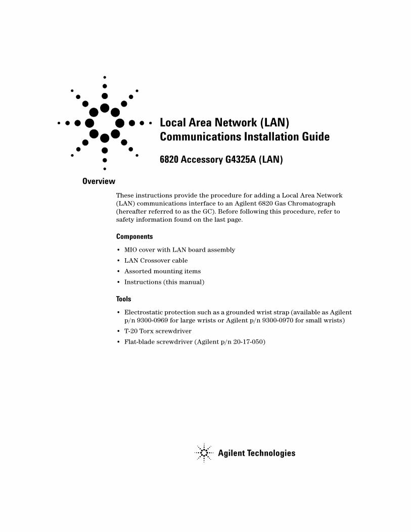
Prepare the GC
1 Switch off power to the GC and disconnect its power cord (Figure 2).
WARNING Hazardous voltages are present in the mainframe when the GC power cord is connected. Avoid a potentially dangerous shock hazard by disconnecting the power cord before removing side panels.
Figure 2 Power switch and power cord
Power cord
Power switch= Off= On
4
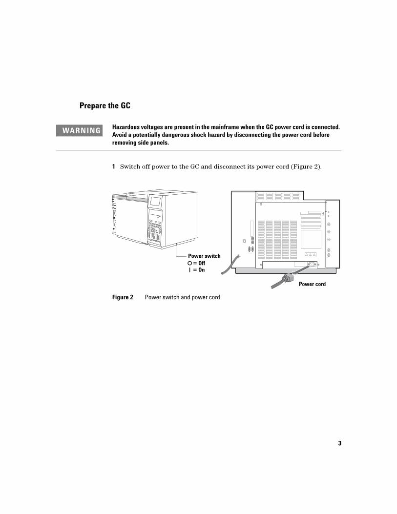
2 Remove the electronics side and top cover (Figure 3). Loosen two captive screws using a T-20 Torx screwdriver and lift the cover off.
Figure 3 Electronics side and top cover
Captive screws
Electronics side and top cover
5
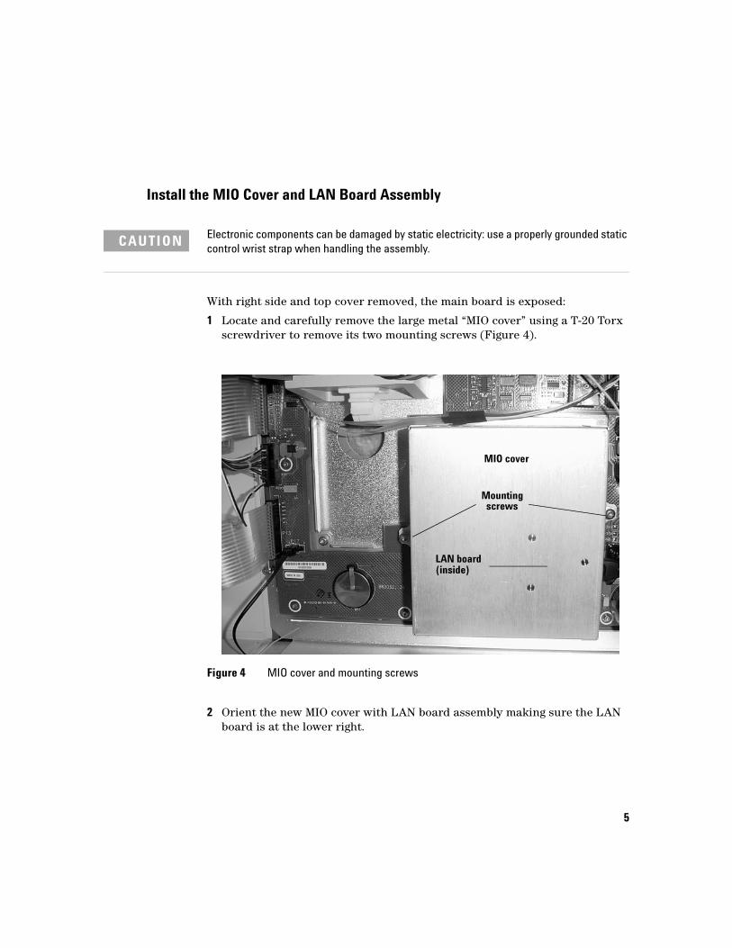
Install the MIO Cover and LAN Board Assembly
With right side and top cover removed, the main board is exposed:
1 Locate and carefully remove the large metal “MIO cover” using a T-20 Torx screwdriver to remove its two mounting screws (Figure 4).
2 Orient the new MIO cover with LAN board assembly making sure the LAN board is at the lower right.
CAUTION Electronic components can be damaged by static electricity: use a properly grounded static control wrist strap when handling the assembly.
Figure 4 MIO cover and mounting screws
MIO cover
Mountingscrews
LAN board(inside)
6
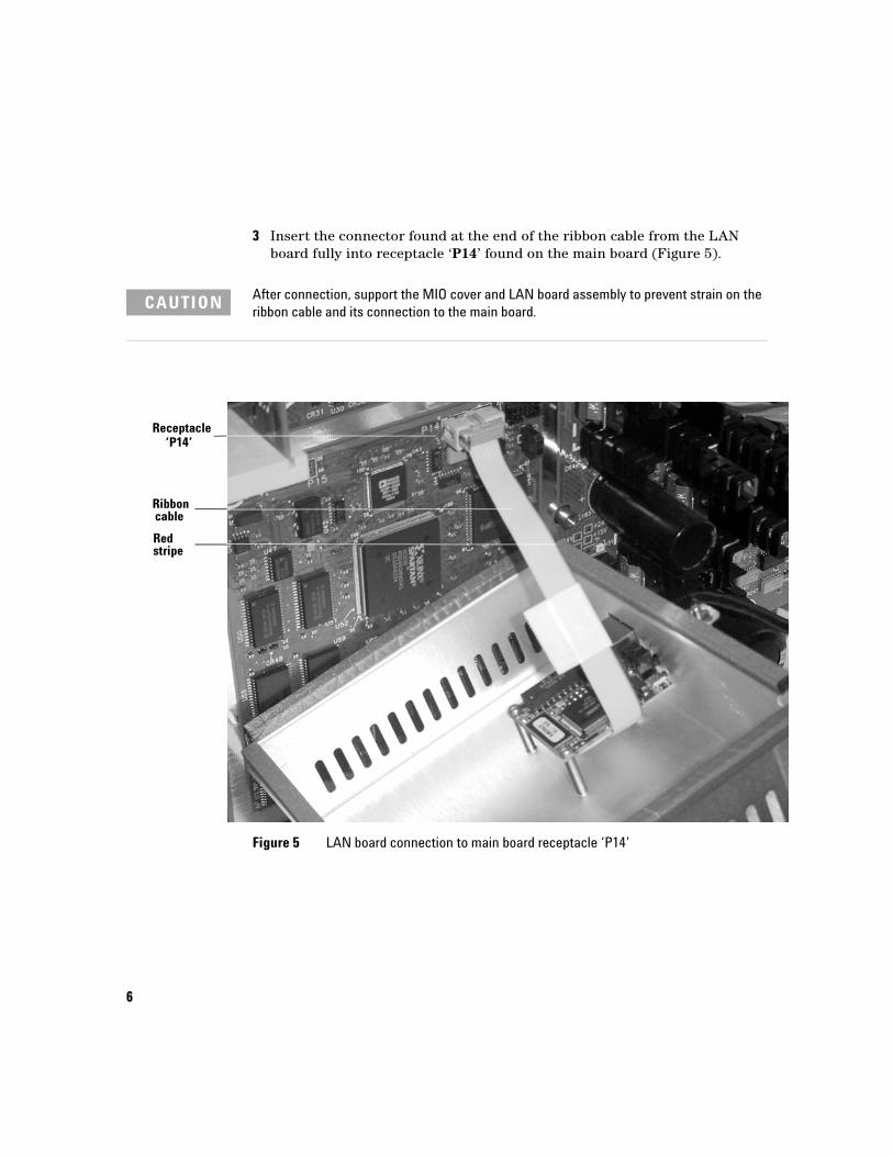
3 Insert the connector found at the end of the ribbon cable from the LAN board fully into receptacle ‘P14’ found on the main board (Figure 5).
CAUTION After connection, support the MIO cover and LAN board assembly to prevent strain on the ribbon cable and its connection to the main board.
Figure 5 LAN board connection to main board receptacle ‘P14’
Receptacle‘P14’
Ribboncable
Redstripe
7
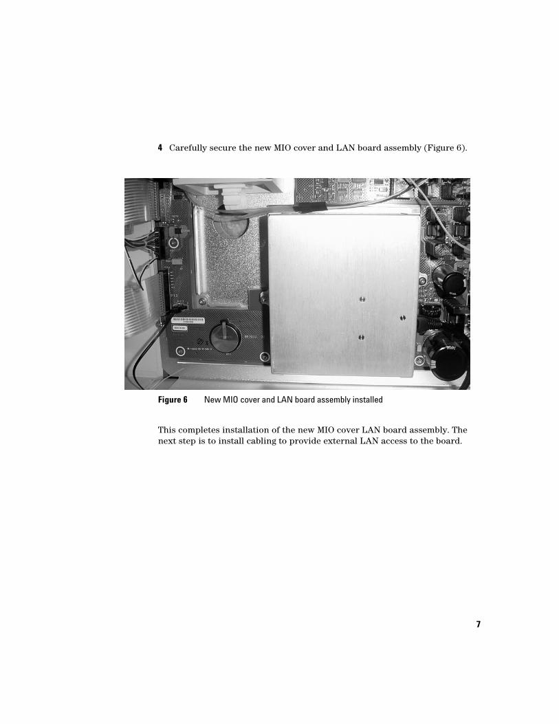
4 Carefully secure the new MIO cover and LAN board assembly (Figure 6).
This completes installation of the new MIO cover LAN board assembly. The next step is to install cabling to provide external LAN access to the board.
Figure 6 New MIO cover and LAN board assembly installed
8
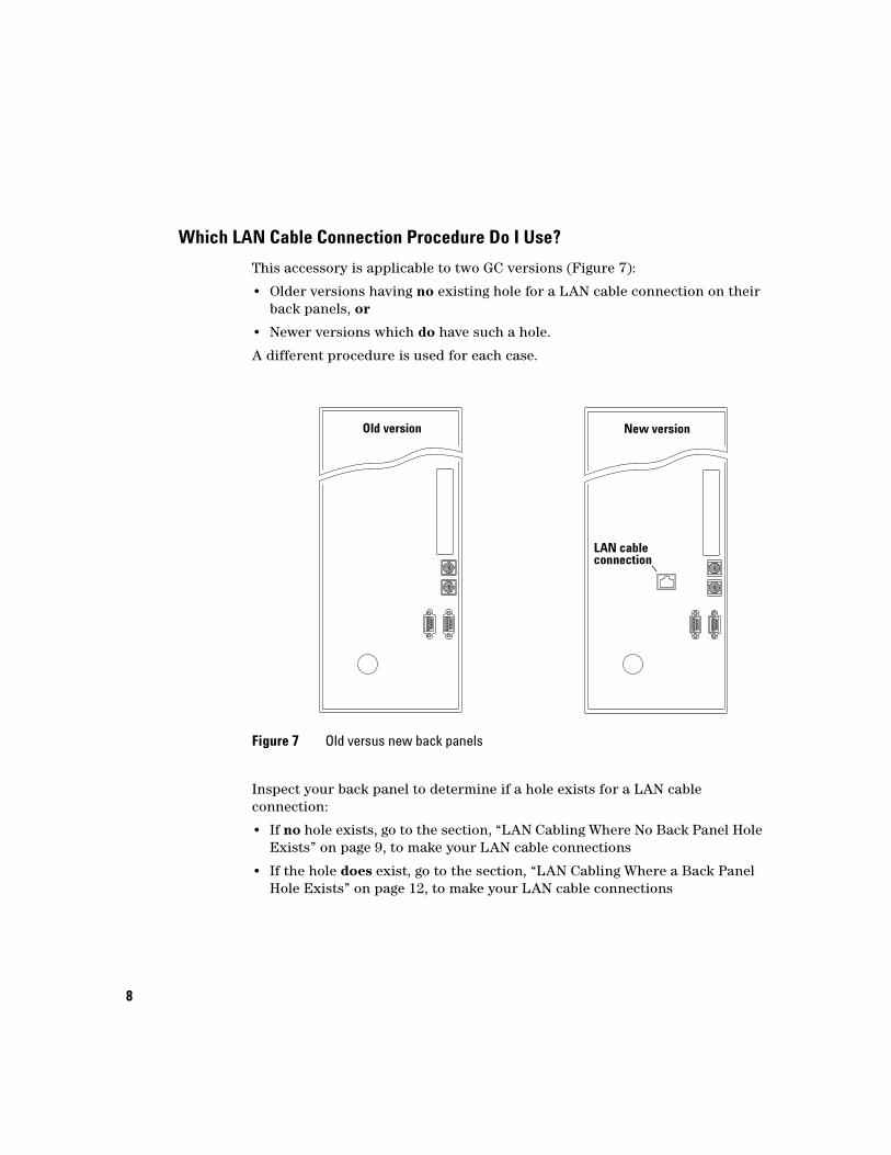
Which LAN Cable Connection Procedure Do I Use?
This accessory is applicable to two GC versions (Figure 7):
• Older versions having no existing hole for a LAN cable connection on their back panels, or
• Newer versions which do have such a hole.
A different procedure is used for each case.
Inspect your back panel to determine if a hole exists for a LAN cable connection:
• If no hole exists, go to the section, “LAN Cabling Where No Back Panel Hole Exists” on page 9, to make your LAN cable connections
• If the hole does exist, go to the section, “LAN Cabling Where a Back Panel Hole Exists” on page 12, to make your LAN cable connections
Figure 7 Old versus new back panels
Old version New version
LAN cableconnection
9
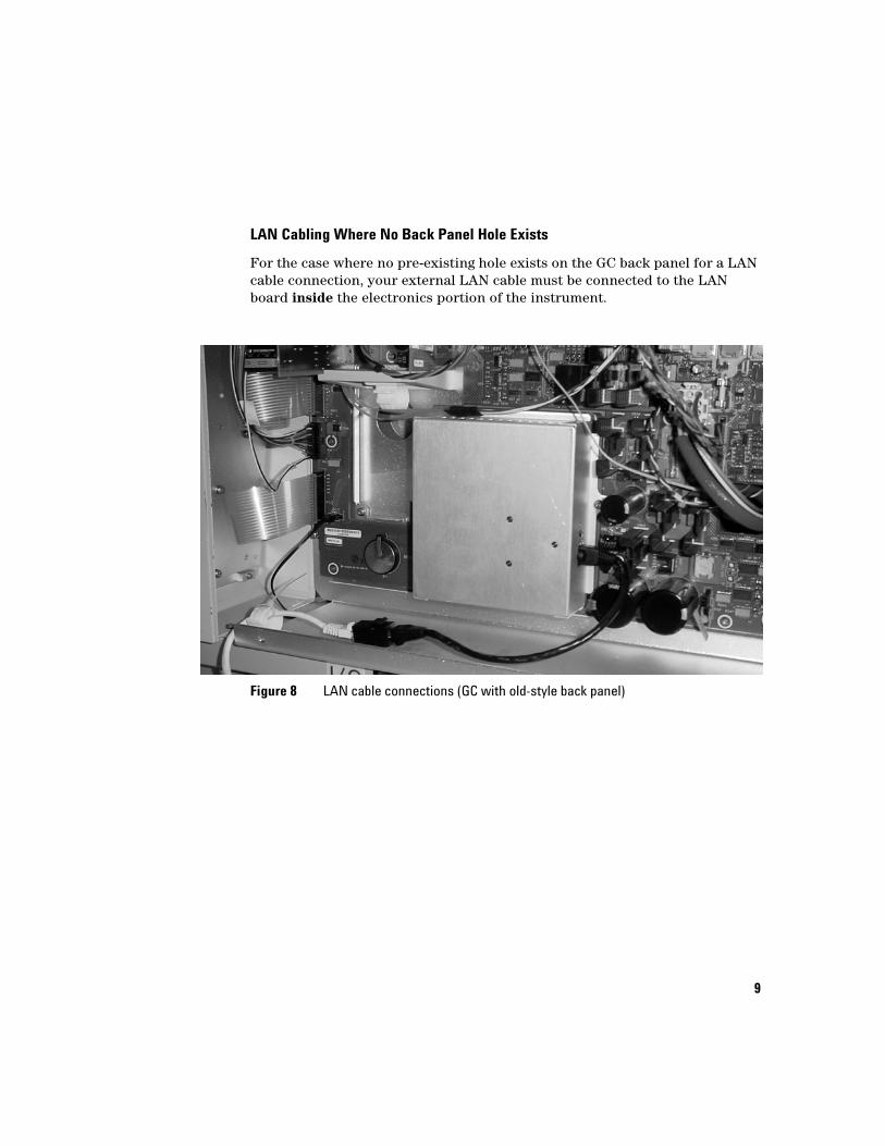
LAN Cabling Where No Back Panel Hole Exists
For the case where no pre-existing hole exists on the GC back panel for a LAN cable connection, your external LAN cable must be connected to the LAN board inside the electronics portion of the instrument.
Figure 8 LAN cable connections (GC with old-style back panel)
10
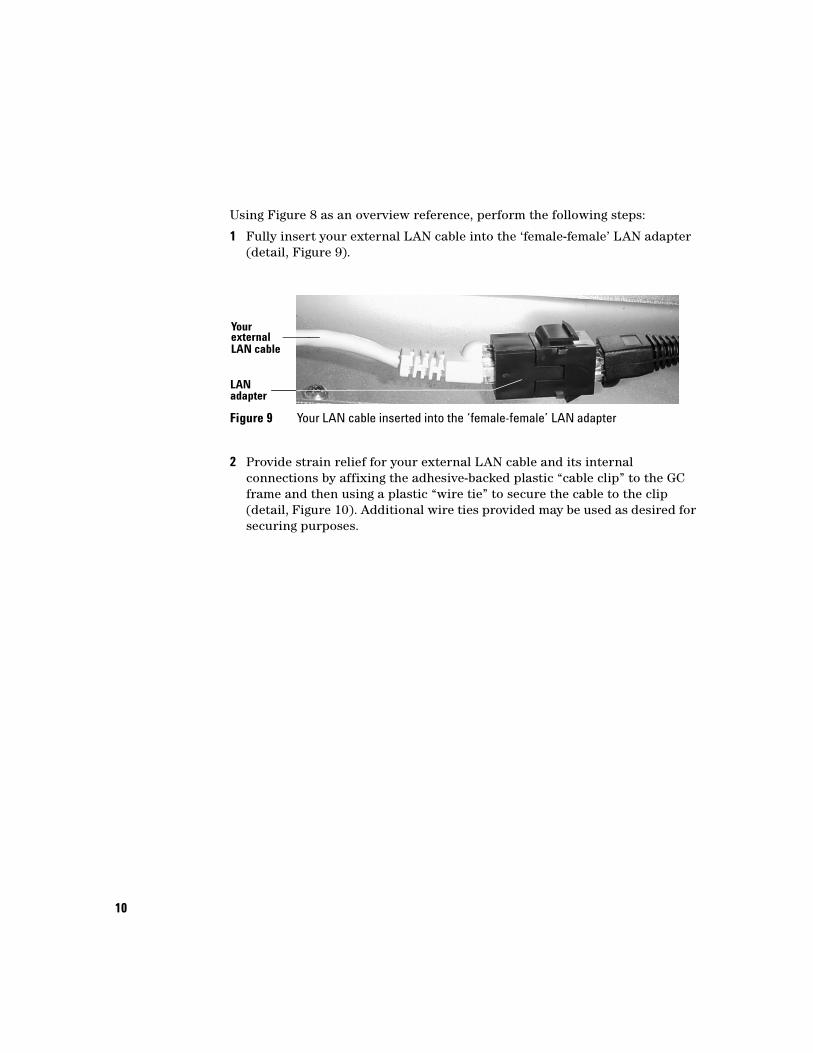
Using Figure 8 as an overview reference, perform the following steps:
1 Fully insert your external LAN cable into the ‘female-female’ LAN adapter (detail, Figure 9).
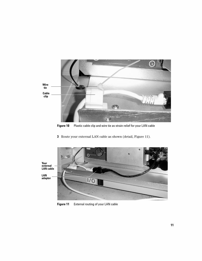
2 Provide strain relief for your external LAN cable and its internal connections by affixing the adhesive-backed plastic “cable clip” to the GC frame and then using a plastic “wire tie” to secure the cable to the clip (detail, Figure 10). Additional wire ties provided may be used as desired for securing purposes.
Figure 9 Your LAN cable inserted into the ‘female-female’ LAN adapter
LANadapter
externalLAN cable
Your
11
3 Route your external LAN cable as shown (detail, Figure 11).
Figure 10 Plastic cable clip and wire tie as strain relief for your LAN cable
Figure 11 External routing of your LAN cable
Cableclip
Wiretie
LANadapter
externalLAN cable
Your
12
This completes LAN cabling where no hole exists on the GC back panel for a LAN cable connection. Now skip to the section, “Restore the GC to Operating Condition” on page 14.
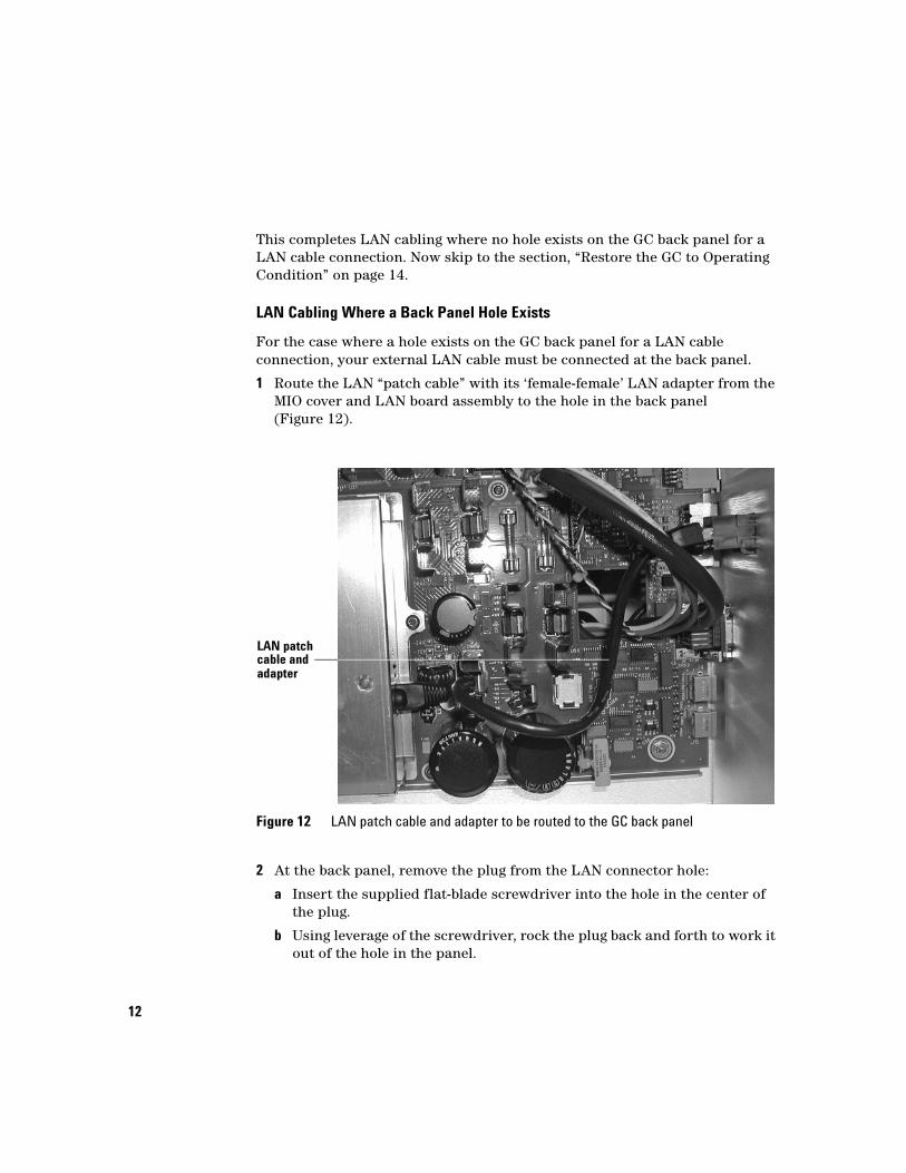
LAN Cabling Where a Back Panel Hole Exists
For the case where a hole exists on the GC back panel for a LAN cable connection, your external LAN cable must be connected at the back panel.
1 Route the LAN “patch cable” with its ‘female-female’ LAN adapter from the MIO cover and LAN board assembly to the hole in the back panel (Figure 12).
2 At the back panel, remove the plug from the LAN connector hole:
a Insert the supplied flat-blade screwdriver into the hole in the center of the plug.
b Using leverage of the screwdriver, rock the plug back and forth to work it out of the hole in the panel.
Figure 12 LAN patch cable and adapter to be routed to the GC back panel
LAN patchcable andadapter
13
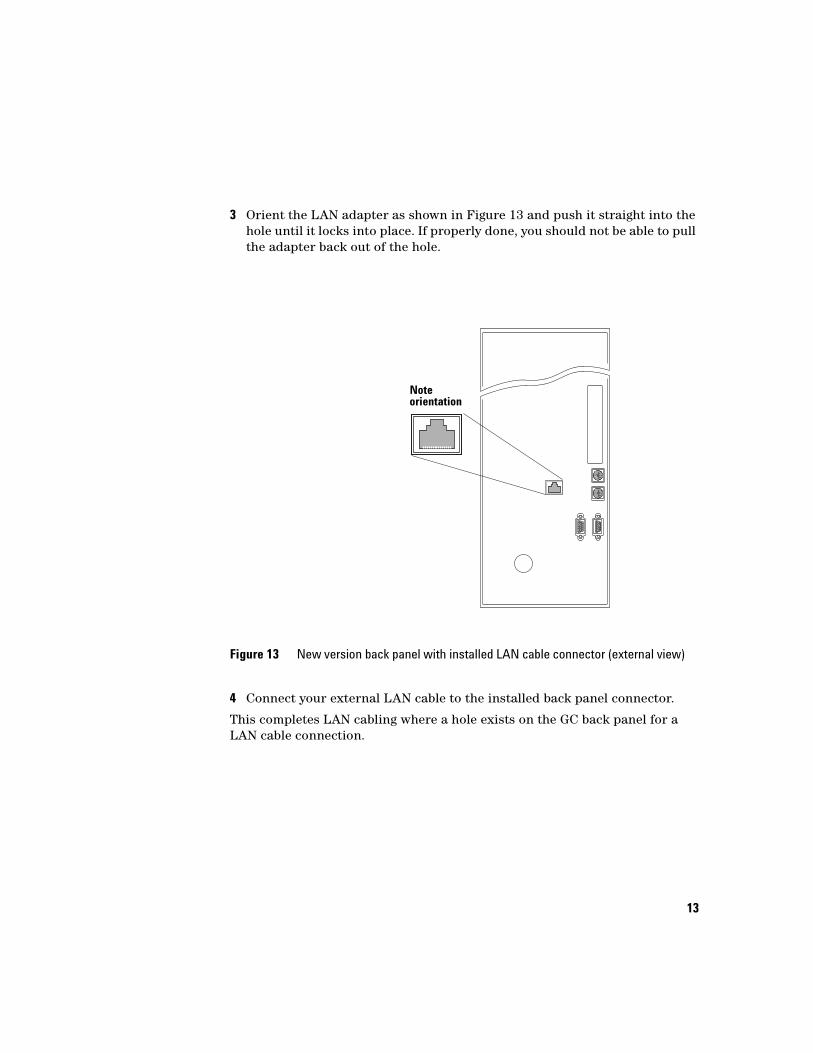
3 Orient the LAN adapter as shown in Figure 13 and push it straight into the hole until it locks into place. If properly done, you should not be able to pull the adapter back out of the hole.
4 Connect your external LAN cable to the installed back panel connector.
This completes LAN cabling where a hole exists on the GC back panel for a LAN cable connection.
Figure 13 New version back panel with installed LAN cable connector (external view)
Noteorientation
14
Restore the GC to Operating Condition
1 Reattach the electronics side and top cover.
2 Connect the GC power cord and switch on power to the GC.
Configure Your GC LAN Parameters
If using a LAN “crossover” cable, use LAN settings given in Table 1. If you are connecting through a “house” LAN system, obtain settings to be used from your LAN administrator.
After connecting to your LAN, and obtaining settings if needed, set the GC IP address as follows:
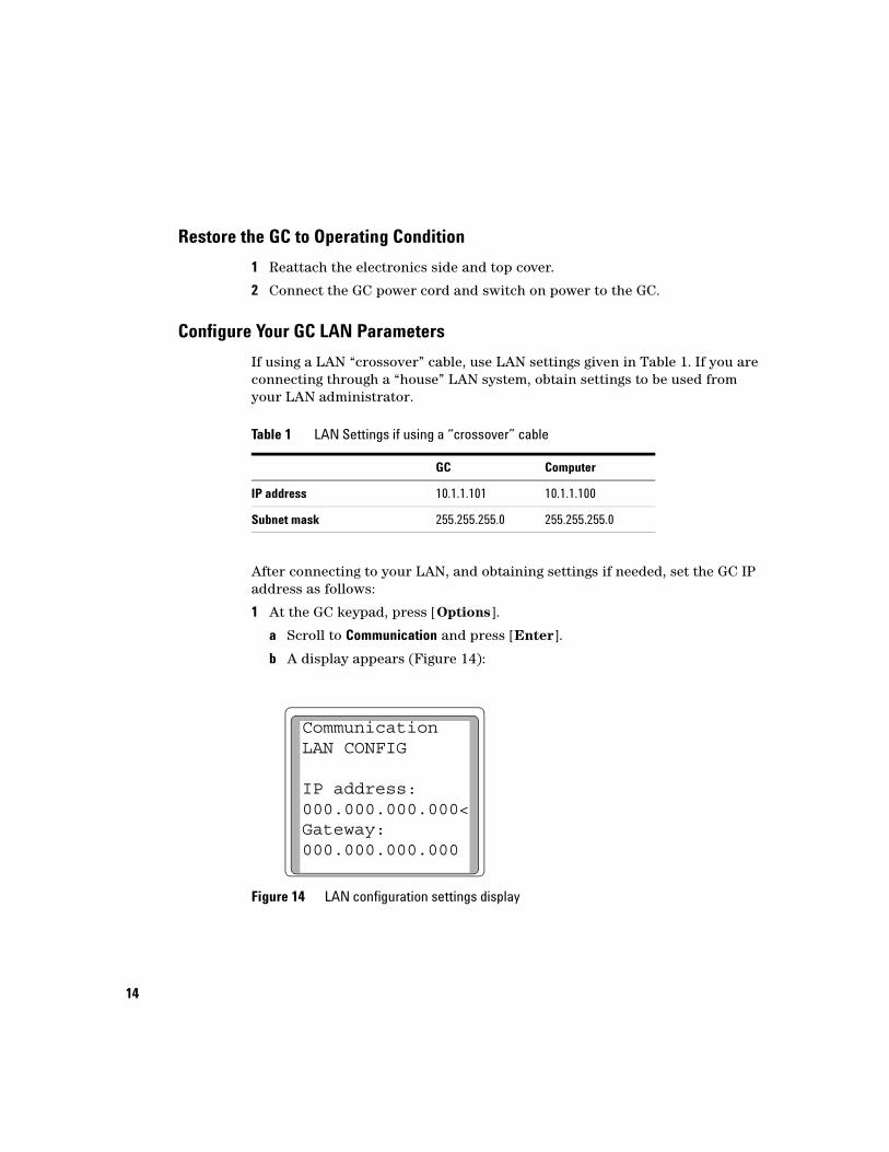
1 At the GC keypad, press [Options].
a Scroll to Communication and press [Enter].
b A display appears (Figure 14):
Table 1 LAN Settings if using a “crossover” cable
GC Computer
IP address 10.1.1.101 10.1.1.100
Subnet mask 255.255.255.0 255.255.255.0
Figure 14 LAN configuration settings display
CommunicationLAN CONFIG
IP address:000.000.000.000<Gateway:000.000.000.000

15
2 Enter the IP address for your GC. Enter numbers, separated by periods, [ . ] , and press [Enter].
• The GC displays a message instructing you to power cycle the GC. Do not power cycle this time.
3 Press [Clear] and scroll to Gateway. Enter the Gateway number, again separated by periods, [ . ] , and press [Enter].
• The GC displays a message instructing you to power cycle the GC. Do not power cycle at this time.
4 Press [Clear]. Scroll to Subnet mask and press [Mode/Type]. Scroll to the appropriate subnet mask from the list of modes and press [Enter].
• The GC displays a message instructing you to power cycle the instrument. Now do power cycle the GC to apply and store LAN settings.
5 After the GC has power-cycled, press [Options] and scroll to Communication. Press [Enter] to confirm correct LAN settings.
For more details, and/or to learn how to use DHCP to set the GC IP address, see your GC Operation Manual.
Agilent Technologies
© Agilent Technologies, Inc. 2005
No part of this manual may be reproduced in any form or by any means (including electronic storage and retrieval or translation into a foreign language) without prior agreement and written consent from Agilent Technologies, Inc. as governed by United States and international copyright laws.
G1176-90757
First edition, August 2005
Printed in China
Agilent Technologies, Inc.412 Ying Lun RoadWaigaoqiao Free Trade ZoneShanghai 200131 China
CAUTION
A CAUTION notice denotes a hazard. It calls attention to an operating procedure, practice, or the like that, if not correctly performed or adhered to, could result in damage to the prod-uct or loss of important data. Do not proceed beyond a CAUTION notice until the indicated conditions are fully understood and met.
WARNING
A WARNING notice denotes a hazard. It calls attention to an operating procedure, prac-tice, or the like that, if not correctly performed or adhered to, could result in personal injury or death. Do not proceed beyond a WARNING notice until the indicated conditions are fully understood and met.
G1176-90757