KUbe series 3 DYnAMIC Colours leD DIsPlAY series Controllers | ProGrAMMers Fields oF applications 3...
8
KUBE SERIES CONTROLLERS | PROGRAMMERS FIELDS OF APPLICATIONS 3 DYNAMIC COLOURS LED DISPLAY THE COLOUR CHANGES DEPENDING ON PROCESS VALUE • COMPACT SIZE • HOT GLUE AND BEADING MACHINES • WRAPPING, BLISTERING MACHINES • PAINTING ROOMS • TEXTILE PRINTING MACHINES • PACKAGING MACHINERY • CLIMATIC CHAMBERS AND INCUBATORS • HOT RUNNER EXTRUDERS • GLASS BENDING FURNACES • CONTINUOUS MULTI-ZONE FURNACES • CERAMIC FURNACES • SIMPLE CASCADE CONTROLS • HEAT TREATMENT FURNACES • FOOTWEAR MACHINERY • HEAT EXCHANGERS • INDUSTRIAL BOILERS • MACHINES FOR LEATHER GOODS • evoGreen for energy saving; • evoTune auto-tune PID parameters “push and forget”; • Universal Input (TC, mV, V, mA, Pt100-Pt1000 / PTC-NTC); • Universal Output (relay, Vout for SSR, linear mA/V, servomotor); • User calibration for sensor position compensation; • 8 segments Programmer function with “guaranteed soak”; • Independent Timer Function with 5 different operating modes; • Working hours/days counter with programmable alarms; • Wattmeter measuring instantaneous/integrated power consumption; • Parameters sequence fully customizable; • evoTools - configuration with codes for quick start-up; • evoTools - programming key for instant parameterisation.
Transcript of KUbe series 3 DYnAMIC Colours leD DIsPlAY series Controllers | ProGrAMMers Fields oF applications 3...

KUbe seriesControllers | ProGrAMMers
Fields oF applications
3 DYnAMIC Colours leD DIsPlAYtHe Colour CHAnGes DePenDInG on ProCess VAlue
• CoMPACt sIze
• HOTGLUEANDBEADINGMACHINES
• WRAPPING,BLISTERINGMACHINES
• PAINTINGROOMS
• TEXTILEPRINTINGMACHINES
• PACKAGINGMACHINERY
• CLIMATICCHAMBERSANDINCUBATORS
• HOTRUNNEREXTRUDERS
• GLASSBENDINGFURNACES
• CONTINUOUSMULTI-ZONEFURNACES
• CERAMICFURNACES
• SIMPLECASCADECONTROLS
• HEATTREATMENTFURNACES
• FOOTWEARMACHINERY
• HEATEXCHANGERS
• INDUSTRIALBOILERS
• MACHINESFORLEATHERGOODS
• evoGreen for energy saving;• evotune auto-tune PID parameters “push and forget”;•Universal input (tC, mV, V, mA, Pt100-Pt1000 / PtC-ntC);•Universal output (relay, Vout for ssr, linear mA/V, servomotor);•User calibration for sensor position compensation;• 8 segments programmer function with “guaranteed soak”;• Independent timer Function with 5 different operating modes;• Working hours/days counter with programmable alarms;•Wattmeter measuring instantaneous/integrated power consumption;• Parameters sequence fully customizable;• evotools - configuration with codes for quick start-up;• evotools - programming key for instant parameterisation.
viale Indipendenza, 56 · 27029 Vigevano (PV) Italy tel +39 0381 69 871 · fax +39 0381 69 87 30
[email protected] www.ascontecnologic.com
KUbe seriesControllers | ProGrAMMers
3 COLOUr DisPLAY
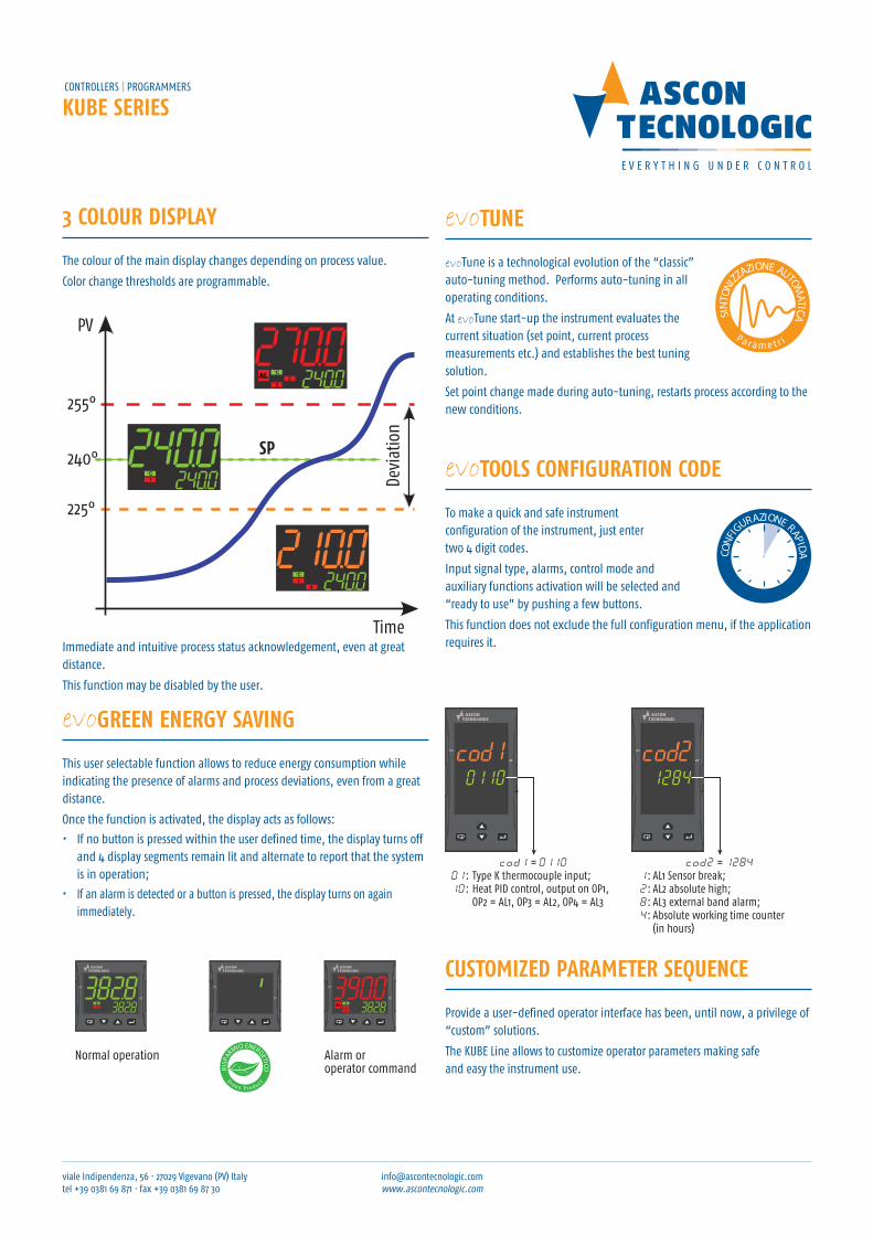
the colour of the main display changes depending on process value.
Color change thresholds are programmable.
SP
Time
Devi
atio
n
PV
255°
225°
240°
evoGreen enerGY sAvinG
this user selectable function allows to reduce energy consumption while indicating the presence of alarms and process deviations, even from a great distance.
once the function is activated, the display acts as follows:
• If no button is pressed within the user defined time, the display turns off and 4 display segments remain lit and alternate to report that the system is in operation;
• If an alarm is detected or a button is pressed, the display turns on again immediately.
evotUne
evotune is a technological evolution of the “classic” auto-tuning method. Performs auto-tuning in all operating conditions.
At evotune start-up the instrument evaluates the current situation (set point, current process measurements etc.) and establishes the best tuning solution.
set point change made during auto-tuning, restarts process according to the new conditions.
Paramet r i
SIN
TONI
ZZAZIONE AUTOM
ATICA
AT
PV
AT
PV
AT
PV
Normal operation Alarm or operator command
PV
AT
PV
AT
PV
AT
CUstOMiZeD PArAMeter seQUenCe
Provide a user-defined operator interface has been, until now, a privilege of “custom” solutions.
the KuBe line allows to customize operator parameters making safe and easy the instrument use.
evotOOLs COnfiGUrAtiOn CODe
to make a quick and safe instrument configuration of the instrument, just enter two 4 digit codes.
Input signal type, alarms, control mode and auxiliary functions activation will be selected and “ready to use” by pushing a few buttons.
this function does not exclude the full configuration menu, if the application requires it.
CONF
IGURAZIONE RAPIDA
cod1 = 011001: Type K thermocouple input;10: Heat PID control, output on OP1,
OP2 = AL1, OP3 = AL2, OP4 = AL3
cod2 = 12841: AL1 Sensor break;2: AL2 absolute high;8: AL3 external band alarm;4: Absolute working time counter
(in hours)
cod1: 0110LM = 01:Ingresso da termo- coppia tipo K;NO = 10:Regolazione PID in riscaldamento con uscita di controllo OP1,AL1 = OP2, AL2 = OP3, AL3 = OP4
cod2: 1284P = 1: AL1 rottura
sensore;Q = 2: AL2 assoluto
alto;R = 8: AL3 esterno alla
banda;S = 4: Conteggio del
tempo di lavoro assoluto (ore)
Immediate and intuitive process status acknowledgement, even at great distance.
this function may be disabled by the user.
viale Indipendenza, 56 · 27029 Vigevano (PV) Italy tel +39 0381 69 871 · fax +39 0381 69 87 30
[email protected] www.ascontecnologic.com
KUbe seriesControllers | ProGrAMMers
ACCessOries
A01 - Programming key
An electronic key, with memory, that can be connected directly to the instrument (even not powered), It provides a variety of functions, including:
• Memorize an instrument configuration (even not fully functional) and transfer it into another one;
• Configure the instruments in a safe and quick way, without the need for a PC;
• Communicate with a PC, even if the instrument is not equipped with an rs-485 port.
Configuration software
supplied free of charge, once loaded on PC, allows to:
• easily configure an instrument;
• upload and download previously saved configurations;
• simplify the start-up , thanks to the real time update of variables and parameters.
Wintec - supervisor
Based on simple and flexible sCADA, it provides:
• Data acquisition;
• Centralized control;
• Alarm and recipes management;
• trend;
• report.
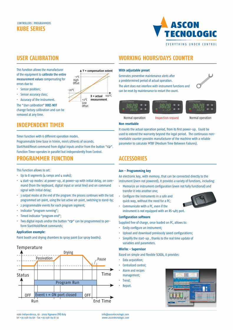
WOrKinG HOUrs/DAYs COUnter
With adjustable preset
Generates preventive maintenance alerts after a predetermined period of actual operation.
the alert does not interfere with instrument functions and can be reset by maintenance to restart the count.
PrOGrAMMer fUnCtiOn
this function allows to set:
• up to 8 segments (4 ramps and 4 soaks);
• 4 start-up modes: at power-up, at power-up with initial delay, on com-mand (from the keyboard, digital input or serial line) and on command signal with initial delay;
• 3 output modes at the end of the program: the process continues with the last programmed set-point, using the last active set-point, switching to stand-by;
• 2 programmable events for each program segment;
• Indicator “program running”;
• timed indicator “program end”;
• two digital inputs and/or the button “a“ can be programmed to per-form start/Hold/reset commands;
Application example:
Paint booth and drying chambers to spray paint (car spray booths).
Time
Time
TemperatureDrying
Passivation Pause
Program Run
Event 1 = ON port closed OFFOFF
Run End
Status
User CALibrAtiOn
this function allows the manufacturer of the equipment to calibrate the entire measurement values compensating for errors due to:
• sensor position;
• sensor accuracy class;
• Accuracy of the instrument.
the “user calibration” does not change factory calibration and can be removed at any time.
-1°CHigh Offset
-20°C
X = actual measurement+2°C
LowOffset
Y = compensation extent
100°C
Inspection requestNormal operation Normal operation
non resettable
It counts the actual operation period, from its first power-up. Could be used to extend the warranty beyond the legal period. the continuous non-resettable counter provides manufacturer of the machine with a reliable parameter to calculate MtBF (Medium time Between Failures).
inDePenDent tiMer
timer function with 6 different operation modes.
Programmable time base in h/min, min/s s/thents of seconds.
start/Hold/reset command from digital inputs and/or from the button “a“.
Function timer operates in parallel but independently from Control.
viale Indipendenza, 56 · 27029 Vigevano (PV) Italy tel +39 0381 69 871 · fax +39 0381 69 87 30
[email protected] www.ascontecnologic.com
KUbe seriesControllers | ProGrAMers
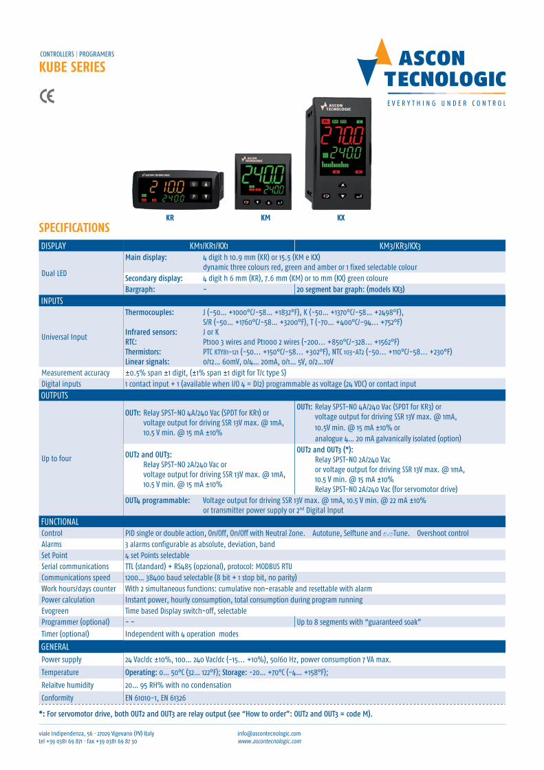
sPeCifiCAtiOnsDIsPlAY KM1/Kr1/KX1 KM3/Kr3/KX3
Dual leD
Main display: 4 digit h 10.9 mm (Kr) or 15.5 (KM e KX) dynamic three colours red, green and amber or 1 fixed selectable colour
secondary display: 4 digit h 6 mm (Kr), 7.6 mm (KM) or 10 mm (KX) green coloureBargraph: - 20 segment bar graph: (models KX3)
InPuts
universal Input
thermocouples: J (-50… +1000°C/-58… +1832°F), K (-50… +1370°C/-58… +2498°F), s/r (-50… +1760°C/-58… +3200°F), t (-70… +400°C/-94... +752°F)
infrared sensors: J or KRtc: Pt100 3 wires and Pt1000 2 wires (-200... +850°C/-328... +1562°F)thermistors: PtC KtY81-121 (-50... +150°C/-58... +302°F), ntC 103-At2 (-50... +110°C/-58... +230°F)linear signals: 0/12… 60mV, 0/4… 20mA, 0/1… 5V, 0/2…10V
Measurement accuracy ±0.5% span ±1 digit, (±1% span ±1 digit for t/c type s)Digital inputs 1 contact input + 1 (available when I/o 4 = DI2) programmable as voltage (24 VDC) or contact input
outPuts
up to four
oUt1: relay sPst-no 4A/240 Vac (sPDt for Kr1) or voltage output for driving ssr 13V max. @ 1mA, 10.5 V min. @ 15 mA ±10%
oUt1: relay sPst-no 4A/240 Vac (sPDt for Kr3) or voltage output for driving ssr 13V max. @ 1mA, 10.5V min. @ 15 mA ±10% or analogue 4… 20 mA galvanically isolated (option)
oUt2 and oUt3: relay sPst-no 2A/240 Vac or voltage output for driving ssr 13V max. @ 1mA, 10.5 V min. @ 15 mA ±10%
oUt2 and oUt3 (*): relay sPst-no 2A/240 Vac or voltage output for driving ssr 13V max. @ 1mA, 10.5 V min. @ 15 mA ±10% relay sPst-no 2A/240 Vac (for servomotor drive)
oUt4 programmable: Voltage output for driving ssr 13V max. @ 1mA, 10.5 V min. @ 22 mA ±10% or transmitter power supply or 2nd Digital Input
FunCtIonAlControl PID single or double action, on/off, on/off with neutral zone. Autotune, selftune and evotune. overshoot controlAlarms 3 alarms configurable as absolute, deviation, bandset Point 4 set Points selectableserial communications ttl (standard) + rs485 (opzional), protocol: MoDBus rtuCommunications speed 1200… 38400 baud selectable (8 bit + 1 stop bit, no parity)Work hours/days counter With 2 simultaneous functions: cumulative non-erasable and resettable with alarmPower calculation Instant power, hourly consumption, total consumption during program runningevogreen time based Display switch-off, selectableProgrammer (optional) - - up to 8 segments with “guaranteed soak”
timer (optional) Independent with 4 operation modes
GenerAlPower supply 24 Vac/dc ±10%, 100… 240 Vac/dc (-15... +10%), 50/60 Hz, power consumption 7 VA max.
temperature operating: 0… 50°C (32… 122°F); storage: -20… +70°C (-4… +158°F);
relaitve humidity 20… 95 rH% with no condensation
Conformity en 61010-1, en 61326
*: For servomotor drive, both oUt2 and oUt3 are relay output (see “How to order”: oUt2 and oUt3 = code M).
Kr KM KX
viale Indipendenza, 56 · 27029 Vigevano (PV) Italy tel +39 0381 69 871 · fax +39 0381 69 87 30
[email protected] www.ascontecnologic.com
KUbe seriesControllers | ProGrAMMers
How to order
ModelKR1 - = ControllerKR1T = Controller+ timerKR3- = ControllerKR3T = Controller+ timerKR3P = Controller+ timer + programmer
Power supplyH = 100... 240 VACL = 24 VAC/DC
Analogue input + digital input DI1 (standard)C = J, K, R, S, T, PT100, PT 1000 (2 wires), mA, mV, VE = J, K, R, S, T, NTC, PTC, mA, mV, V
Output 1I = 4... 20 mA (KR3 only)R = Relay SPDT 4 A (resistive load)O = VDC for SSR
Output 3- = Not availableR = Relay SPST 2 A (resistive load)O = VDC for SSRM = Relay SPST 2 A (servomotor drive KR3 only)(*)
Input/Output 4D = Output 4 (VDC for SSR)/Power transmitter/Dig. Input DI2
Serial communication- = TTL ModbusS = RS485 Modbus + TTL Modbus
Connection type- = Standard (non-removable screw terminal block)E = With removable screw terminal blockM = With removable spring terminal blockN = With removable terminal block (fixed part only)
Output 2- = Not availableR = Relay SPST 2 A (resistive load)O = VDC for SSRM = Relay SPST 2 A (servomotor drive KR3 only)(*)
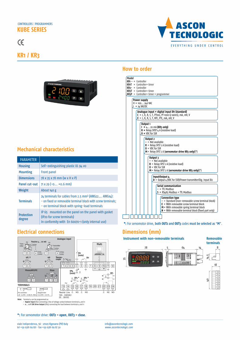
Kr1 / Kr3
Mechanical characteristics
PArAMeter
Housing self–extinguishing plastic ul 94 v0
Mounting Front panel
dimensions 78 x 35 x 78 mm (w x H x P)
panel cut-out 71 x 29 (-0... +0.6 mm)
Weight About 140 g
terminals24 terminals for cables from 2.5 mm² (AWG22…. AWG14): - on fixed or removable terminal block with screw terminals; - on terminal block with spring-load terminals
protection degree
IP 65 mounted on the panel on the panel with gasket (IP20 for screw terminals) In conformity with en 60070-1 (only internal use)
electrical connections
RS485
DI1
OP3 * OP2 *
Neutral Line NO NOCC
100... 240VAC/20... 30VDC
NCC NO
OP1
Thermo-couple
mV, V mA
Pt100Pt1000/NTC/PTC
12Vdc (note)
PVPassive 4... 20 mA
2 wires
Trans-mitter
3 wires
2Vdc(note)
PV
Transmitter
OP4(note)
DI2(note)
TERMINALS
L
Analogue input
Note: Terminal 4 can be programmed as:- Digital Input (DI2) connecting a free of voltage contact between terminals 4 and 11- 0... 12 V SSR Drive Output (OP4) connecting the load between terminals 4 and 11- 12 Vdc (20 mA) transmitter power supply connecting the transmitter between terminals 4 and 1
Pin connector:
q 1.4 mm - 0.055 in. max.Stripped wireL 5.5 mm - 0.21 in.
78
35
5 64 14
AT
PV
4014
.5
18
8
Removableterminals
Instrument with non-removable terminals
Dimensions (mm)
*: For servomotor drive, both OUt2 and OUt3 codes must be selected as “M”.
*: For servomotor drive: OUt2 = open, OUt3 = close.
viale Indipendenza, 56 · 27029 Vigevano (PV) Italy tel +39 0381 69 871 · fax +39 0381 69 87 30
[email protected] www.ascontecnologic.com
KUbe seriesControllers | ProGrAMMers
How to order
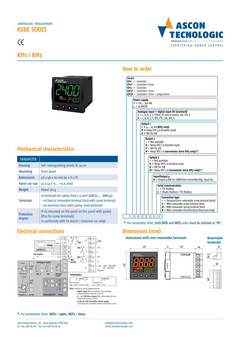
ModelKM1 - = ControllerKM1T = Controller+ timerKM3 - = ControllerKM3T = Controller+ timerKM3P = Controller+ timer + programmer
Power supplyH = 100... 240 VACL = 24 VAC/DC
Analogue input + digital input DI1 (standard)C = J, K, R, S, T, PT100, PT 1000 (2 wires), mA, mV, VE = J, K, R, S, T, NTC, PTC, mA, mV, V
Output 1I = 4... 20 mA (KM3 only)R = Relay SPST 4 A (resistive load)O = VDC for SSR
Output 3- = Not availableR = Relay SPST 2 A (resistive load)O = VDC for SSRM = Relay SPST 2 A (servomotor drive KM3 only)(*)
Input/Output 4D = Output 4 (VDC for SSR)/Power transmitter/Dig. Input DI2
Serial communication- = TTL ModbusS = RS485 Modbus + TTL Modbus
Connection type- = Standard (non-removable screw terminal block)E = With removable screw terminal blockM = With removable spring terminal blockN = With removable terminal block (fixed part only)
Output 2- = Not availableR = Relay SPST 2 A (resistive load)O = VDC for SSRM = Relay SPST 2 A (servomotor drive KM3 only)(*)
KM1 / KM3
electrical connections
Thermo-couple
DI1
OP3 *
OP2 *
OP1
OP4(note)
DI2 (note)
Analogue input
RS485
mV, V mA
Note: Terminal 4 can be programmed as:- Digital Input (DI2) connecting a free of voltage
contact between terminals 4 and 16- 0... 12 V SSR Drive Output (OP4) connecting the load
between terminals 4 and 16- 12 Vdc (20 mA) transmitter power supply
connecting the transmitter between terminals 4 and 1
Neutral
Line 100... 240 VAC/ 20... 30 VDC
12 VDC(note)PV
Passive 4... 20 mA
2 wires
Transducer
3 wires
12 VDC (note)
PV
Transducer
Pt100Pt1000/NTC/PTC
TERMINALS
LPin connector:
q 1.4 mm - 0.055 in. max.Stripped wireL 5.5 mm - 0.21 in.
48
48
48
PV
AT
1411
4014
.5
18
8
Removableterminals
Instrument with non-removable terminals
Dimensions (mm)
Mechanical characteristics
PArAMeter
Housing self–extinguishing plastic ul 94 v0
Mounting Front panel
dimensions 48 x 48 x 62 mm (w x H x P)
panel cut-out 45 x 45 (-0... +0.6 mm)
Weight About 120 g
terminals16 terminals for cables from 2.5 mm² (AWG22…. AWG14): - on fixed or removable terminal block with screw terminals; - on terminal block with spring-load terminals
protection degree
IP 65 mounted on the panel on the panel with gasket (IP20 for screw terminals) In conformity with en 60070-1 (internal use only)
*: For servomotor drive: OUt2 = open, OUt3 = close.
*: For servomotor drive, both OUt2 and OUt3 codes must be selected as “M”.
viale Indipendenza, 56 · 27029 Vigevano (PV) Italy tel +39 0381 69 871 · fax +39 0381 69 87 30
[email protected] www.ascontecnologic.com
KUbe seriesControllers | ProGrAMMers
How to order
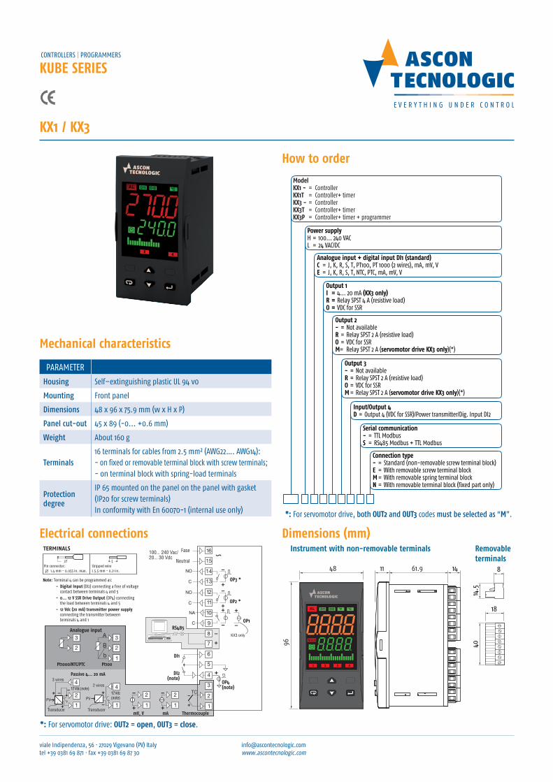
ModelKX1 - = ControllerKX1T = Controller+ timerKX3 - = ControllerKX3T = Controller+ timerKX3P = Controller+ timer + programmer
Power supplyH = 100... 240 VACL = 24 VAC/DC
Analogue input + digital input DI1 (standard)C = J, K, R, S, T, PT100, PT 1000 (2 wires), mA, mV, VE = J, K, R, S, T, NTC, PTC, mA, mV, V
Output 1I = 4... 20 mA (KX3 only)R = Relay SPST 4 A (resistive load)O = VDC for SSR
Output 3- = Not availableR = Relay SPST 2 A (resistive load)O = VDC for SSRM = Relay SPST 2 A (servomotor drive KX3 only)(*)
Input/Output 4D = Output 4 (VDC for SSR)/Power transmitter/Dig. Input DI2
Serial communication- = TTL ModbusS = RS485 Modbus + TTL Modbus
Connection type- = Standard (non-removable screw terminal block)E = With removable screw terminal blockM = With removable spring terminal blockN = With removable terminal block (fixed part only)
Output 2- = Not availableR = Relay SPST 2 A (resistive load)O = VDC for SSRM= Relay SPST 2 A (servomotor drive KX3 only)(*)
KX1 / KX3
OP2 *
OP3 *
mV, V mA
Neutral
100... 240 Vac/20... 30 Vdc
12 Vdc(note)PV
12 Vdc (note)
PV
Pt100Pt1000/NTC/PTC
NO
NO
C
C
Fase
KX3 onlyAnalogue input
Note: Terminal 4 can be programmed as:- Digital Input (DI2) connecting a free of voltage
contact between terminals 4 and 5- 0... 12 V SSR Drive Output (OP4) connecting
the load between terminals 4 and 5- 12 Vdc (20 mA) transmitter power supply
connecting the transmitter between terminals 4 and 1
TERMINALS
LPin connector:
q 1.4 mm - 0.055 in. max.Stripped wireL 5.5 mm - 0.21 in.
3 wires
Transducer Transducer
Passive 4... 20 mA
2 wires
Thermocouple
DI1
OP1
OP4(note)
DI2(note)
RS485
NA
C
96
48 61.9 1411
4014
.5
18
8
DI1 DI2
Removableterminals
Instrument with non-removable terminals
electrical connections Dimensions (mm)
Mechanical characteristics
PArAMeter
Housing self–extinguishing plastic ul 94 v0
Mounting Front panel
dimensions 48 x 96 x 75.9 mm (w x H x P)
panel cut-out 45 x 89 (-0... +0.6 mm)
Weight About 160 g
terminals16 terminals for cables from 2.5 mm² (AWG22…. AWG14): - on fixed or removable terminal block with screw terminals; - on terminal block with spring-load terminals
protection degree
IP 65 mounted on the panel on the panel with gasket (IP20 for screw terminals) In conformity with en 60070-1 (internal use only)
*: For servomotor drive: OUt2 = open, OUt3 = close.
*: For servomotor drive, both OUt2 and OUt3 codes must be selected as “M”.

CAnADA UsA MeXiCO veneZUeLA brAZiL ireLAnD UK POrtUGAL sPAin frAnCe beLGiUM HOLLAnD LUXeMbOUrG DenMArK GerMAnY sWitZerLAnD AUstriA finLAnD nOrWAY sWeDen sLOveniA POLAnD HUnGArY CZeCH reP. rOMAniA GreeCe ALGeriA tUnisiA MOrOCCO eGYPt jOrDAn isrAeL sYriA sOUtH AfriCA Csi LAtvijA KAZAKHstAn tUrKeY sinGAPOre HOnG KOnG tHAiLAnD tAiWAn CHinA AUstrALiA neW ZeLAnD CAnADA UsA MeXiCO veneZUeLA brAZiL ireLAnD UK POrtUGAL sPAin frAnCe beLGiUM HOLLAnD LUXeMbOUrG DenMArK GerMAnY sWitZerLAnD AUstriA finLAnD nOrWAY sWeDen sLOveniA POLAnD HUnGArY CZeCH reP. rOMAniA GreeCe ALGeriA tUnisiA MOrOCCO eGYPt jOrDAn isrAeL sYriA sOUtH AfriCA Csi LAtvijA KAZAKHstAn tUrKeY sinGAPOre HOnG KOnG tHAiLAnD tAiWAn CHinA AUstrALiA neW ZeLAnD CAnADA UsA MeXiCO veneZUeLA brAZiL ireLAnD UK POrtUGAL sPAin frAnCe beLGiUM HOLLAnD LUXeMbOUrG DenMArK GerMAnY sWitZerLAnD AUstriA finLAnD nOrWAY sWeDen sLOveniA POLAnD HUnGArY CZeCH reP. rOMAniA GreeCe ALGeriA tUnisiA MOrOCCO eGYPt jOrDAn isrAeL sYriA sOUtH AfriCA Csi LAtvijA KAZAKHstAn tUrKeY sinGAPOre HOnG KOnG tHAiLAnD tAiWAn CHinA AUstrALiA neW ZeLAnD CAnADA UsA MeXiCO veneZUeLA brAZiL ireLAnD UK POrtUGAL sPAin frAnCe beLGiUM HOLLAnD LUXeMbOUrG DenMArK GerMAnY sWitZerLAnD AUstriA finLAnD nOrWAY sWeDen sLOveniA POLAnD HUnGArY CZeCH reP. rOMAniA GreeCe ALGeriA tUnisiA MOrOCCO eGYPt jOrDAn isrAeL sYriA sOUtH AfriCA Csi LAtvijA KAZAKHstAn tUrKeY sinGAPOre HOnG KOnG tHAiLAnD tAiWAn CHinA AUstrALiA neW ZeLAnD CAnADA UsA MeXiCO veneZUeLA brAZiL ireLAnD UK POrtUGAL sPAin frAnCe beLGiUM HOLLAnD LUXeMbOUrG DenMArK GerMAnY sWitZerLAnD AUstriA finLAnD nOrWAY sWeDen sLOveniA POLAnD HUnGArY CZeCH reP. rOMAniA GreeCe ALGeriA tUnisiA MOrOCCO eGYPt jOrDAn isrAeL sYriA sOUtH AfriCA Csi LAtvijA KAZAKHstAn tUrKeY sinGAPOre HOnG KOnG tHAiLAnD tAiWAn CHinA AUstrALiA neW ZeLAnD CAnADA UsA MeXiCO veneZUeLA brAZiL ireLAnD UK POrtUGAL sPAin frAnCe beLGiUM HOLLAnD LUXeMbOUrG DenMArK GerMAnY sWitZerLAnD AUstriA finLAnD nOrWAY sWeDen sLOveniA POLAnD HUnGArY CZeCH reP. rOMAniA GreeCe ALGeriA
Ascon tecnologic s.r.l.viale Indipendenza, 56 · 27029 Vigevano (PV) Italy tel +39 0381 69 871 · fax +39 0381 69 87 30
[email protected] www.ascontecnologic.com
SUBSIDIARIES
PRODUCTION
HEADQUARTERS
Ascon tecnologic FranceBP 76 · 77202 - Marne la Vallee Cedex 1tel +33 1 64 30 62 62 · fax +33 1 64 30 84 [email protected]/fr
tecnologic uk ltdunit number 1, Farnborough Business Centreeelmoor road, Farnborough Hampshire Gu14 7XAtel +44 125 2377 600 · fax +44 125 2377 [email protected]
Ascon Polska sp. z o.o.KoCHCICe ul. Kochanowicka 4342-713 Kochanowicetel +48 34 35 33 619 · fax +48 34 35 33 [email protected]
Ascon tecnologic - north America1111 Brook Park roadCleveland, oH 44109 tel. +1 216 485 8350 ext. [email protected]/en
Coelmatic ltdaAl. Vincente Pinzon, 173 - 9° andarsao Paulo · sP - CeP 04547 - 130 tel. / fax +55 [email protected]
Coelmatic sAPI sA de CVPaseo De los Cipreses, 3720Del Paseo residencial, Monterrey, nuevo león - CeP 64920tel. +52 81 8104 [email protected]. coelmatic.com.mx
Printed in July 2013. this publication belongs exclusively to Ascon tecnologic s.r.l. and may not be reproduced unless with expressed authorisation. Ascon tecnologic s.r.l. reserves the right to make modifications without warning.
Distributors and assistance Worldwide. Contatct Ascon tecnologic for more info.