KINOVA™ Ultra lightweight robotic arm user guide · 2019-12-13 · KINOVA™ Ultra lightweight...
102
User Guide KINOVA ™ Ultra lightweight roboc arm
Transcript of KINOVA™ Ultra lightweight robotic arm user guide · 2019-12-13 · KINOVA™ Ultra lightweight...
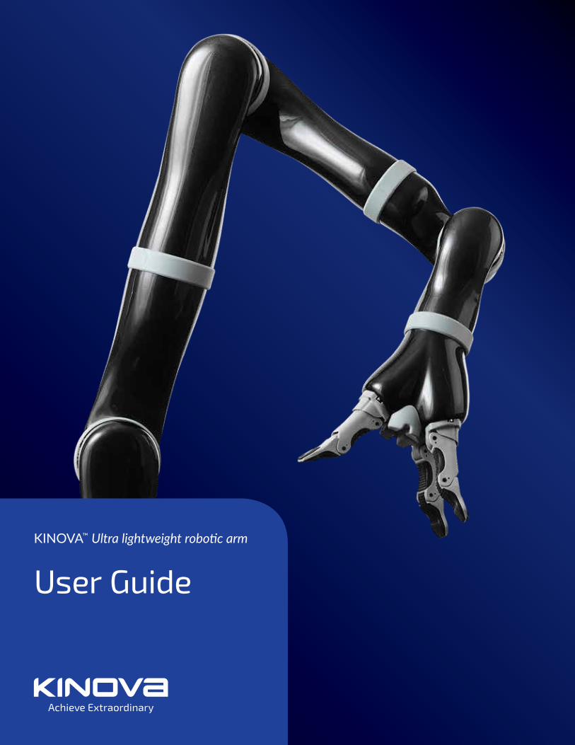
User Guide
KINOVA™ Ultra lightweight robotic arm
|
Contents
About this document............................................................................................................................................ 6
Symbols, definitions, and acronyms............................................................................................................... 7
Warranty....................................................................................................................................................................8
Warnings....................................................................................................................................................................9
Disclaimer................................................................................................................................................................ 10
General Information..............................................................................................................................................11
Robotic arm Configurations.............................................................................................................................. 12
4 DOF Components.............................................................................................................................................. 15
6 DOF Curved Wrist Components.................................................................................................................. 16
6 DOF Spherical Wrist Components.............................................................................................................. 17
7 DOF Spherical Wrist Components.............................................................................................................. 18
External Connectors............................................................................................................................................ 19
Comparing robotic arm configurations.......................................................................................................20
Markings and Labels...........................................................................................................................................22
Installation of the robotic arm....................................................................................................................... 23
Mechanical mounting of the robotic arm...................................................................................................24
Electrical integration.......................................................................................................................................... 26
Integrating a new end effector (optional)..................................................................................................27
Control integration.............................................................................................................................................. 29
Control modes overview...................................................................................................................................30
|
Control peripheral options overview.............................................................................................................31
Kinova joystick controller.................................................................................................................................32
Joystick movements and modes....................................................................................................................33
Operating principles and Cartesian mode.................................................................................................. 34
Home / Retracted positions.............................................................................................................................35
Operating the arm via joystick.......................................................................................................................36
Joystick control quick start..............................................................................................................................37
Default joystick motion settings - Cartesian three-axis mode........................................................... 39
Default joystick motion settings - Cartesian two-axis mode..............................................................40
Controlling the arm in Angular mode.......................................................................................................... 41
Kinova Joystick LED feedback.........................................................................................................................43
Kinova joystick Blue LEDs feedback.............................................................................................................44
Kinova joystick Green LEDs feedback..........................................................................................................45
Kinova joystick Red LEDs feedback..............................................................................................................46
Controlling the arm using Kinova software.............................................................................................. 47
Controlling the arm using the Kinova API................................................................................................. 49
Singularity Avoidance........................................................................................................................................ 50
Self-collisions auto-avoidance........................................................................................................................ 53
7 DOF Spherical Null space motion..............................................................................................................54
Protection zones.................................................................................................................................................. 55
Rotating frame / Fixed frame.........................................................................................................................56
|
Usable workspace................................................................................................................................................57
Admittance control............................................................................................................................................. 58
Torque Control......................................................................................................................................................60
Improving robot behavior in Torque mode................................................................................................ 61
Optimal mode code example.......................................................................................................................... 62
Important considerations for setting Optimal mode............................................................................. 64
Specific Utilization Limitations....................................................................................................................... 65
Recommended maximum actuators utilization....................................................................................... 66
Software position limitations of actuators................................................................................................67
Software position limitations of fingers.....................................................................................................69
Advanced Configuration.................................................................................................................................... 70
Kinematics Parameters.......................................................................................................................................71
Basic geometric parameters - 4 DOF........................................................................................................... 72
Basic geometric parameters - 6 DOF curved wrist.................................................................................74
Alternate geometric parameters - 6 DOF curved wrist.........................................................................77
Basic geometric parameters - 6 DOF spherical wrist............................................................................ 79
Basic geometric parameters - 7 DOF spherical wrist............................................................................. 81
Classic DH parameters - 4 DOF......................................................................................................................83
Classic DH parameters - 6 DOF curved wrist........................................................................................... 84
Classic DH parameters - 6 DOF spherical.................................................................................................. 86
Classic DH parameters - 7 DOF spherical.................................................................................................. 88

|
Directions of joints in angular space........................................................................................................... 90
Advanced sensors information........................................................................................................................91
Normal use definition........................................................................................................................................ 92
Electromagnetic interference from radio wave sources...................................................................... 93
Maintenance and Disposal............................................................................................................................... 94
Packing Materials................................................................................................................................................ 95
Troubleshooting / FAQs....................................................................................................................................96
Contacting support..............................................................................................................................................98
3-axis mode joystick controls reminder..................................................................................................... 99
2-axis mode joystick controls reminder................................................................................................... 100

KINOVA™ Ultra lightweight robotic arm user guide 6
About this document
Read all instructions before using this product.
Keep these instructions for future reference.
Read all warnings on the product and in this guide.
Follow all instructions.
This document contains information regarding product setup and the operation. It is intendedfor:
• Field service, customer support and sales employees of authorized Kinova distributors• Kinova product end users

KINOVA™ Ultra lightweight robotic arm user guide 7
Symbols, definitions, and acronyms
Important information regarding the safety related to the product and the user.
Tip on the maintenance, operation and manipulation of Kinova’s products.
Refer to accompanying documents.
Direct current.
Alternating current.
Operating temperature range.
Compliance with WEEE2 directive.
Compliance with ROHS3 directive.
Type BF Applied Part device.
KINOVA™ Ultra lightweight robotic arm user guide 8
Warranty
This section describes the Kinova warranty terms.
Subject to the terms of this clause, Kinova warrants to End User that the Products are free ofdefects in materials and workmanship that materially affect their performance for a period oftwo (2) years from the date Kinova ships the Products to the End User ("Delivery Date").
Kinova agrees to repair or replace (at Kinova's option) all Products which fail to conform to therelevant warranty provided that:
1. Notification of the defect is received by Kinova within the warranty period specified above.2. Allegedly defective Products are returned to Kinova, at the End User’s expense, with
Kinova's prior authorization within thirty (30) days of the defect becoming apparent.3. The Products have not been altered, modified or subject to misuse, incorrect installation,
maintenance, neglect, accident or damage by excessive current or used with incompatibleparts
4. The End User is not in default under any of its obligations under this Agreement.5. Replacement Products must have the benefit of the applicable warranty for the remainder of
the applicable warranty period.
If Kinova diligently repairs or replace the Products in accordance with this section, it will haveno further liability for a breach of the relevant warranty.
Allegedly defective Products returned to Kinova in accordance with this contract will, if foundby Kinova on examination not to be defective, be returned to End User and Kinova may a chargea fee for examination and testing.
The warranty cannot be assigned or transferred and is to the sole benefit of the End User.
Where the Products have been manufactured and supplied to Kinova by a third party, anywarranty granted to Kinova in respect of the Products may be passed on to the End User.
Kinova is entitled in its absolute discretion to refund the price of the defective Products in theevent that such price has already been paid.

KINOVA™ Ultra lightweight robotic arm user guide 9
Warnings
This section summaries important warnings and cautions related to use of the roboticarm.
It is not recommended to use the arm under heavy rain or snow.
Never use the HOME/RETRACTED function when carrying liquid. The HOME position ispreset and the wrist may rotate and drop the liquid.
Do not manipulate cutting, very sharp or any dangerous tools or objects with the arm.
When the power is turned off, the arm will fall down and may cause damage to itself,depending on its position at the time of disconnection. Be sure to support its wrist beforeturning the power off.
Do not force the fingers beyond their maximal opening. This could damage some internalcomponents.
Do not immerse any part of the arm under water or snow.
When lifting weight near the maximum load and reach, if the red lights of the controllerblink, put down the object in the gripper, bring back the arm to HOME or RETRACTED positionand wait until the warning goes away before using it again.
KINOVA™ Ultra lightweight robotic arm user guide 10
Disclaimer
KINOVA™ and Kinova’s logo are trademarks of Kinova Inc., herein referred to as Kinova. Allother brand and product names are trademarks or registered trademarks of their respectivecorporations.
The mention of any product does not constitute an endorsement by Kinova. This manual isfurnished under a lease agreement and may only be copied or used within accordance with theterms of such lease agreement. Except as permitted by such lease agreement, no part of thispublication may be reproduced, stored in any retrieval system, or transmitted, in any form orby any means, electronic, mechanical, recording, or otherwise, without prior written consent ofKinova.
The content of this manual is furnished for informational use only, is subject to changewithout notice, and should not be construed as a commitment by Kinova. Kinova assumes noresponsibility or liability for any errors or inaccuracies that may appear in this document.
Changes are periodically made to the information herein; these changes will be incorporatedinto new editions of this publication. Kinova may make improvements and/or changes in theproducts and/or software programs described in this publication at any time.
Address any questions or comments concerning this document, the information it contains orthe product it describes to:
Kinova may use or distribute whatever information you supply in any way it believesappropriate without incurring any obligations to you.

KINOVA™ Ultra lightweight robotic arm user guide 11
General Information
The KINOVA™ Ultra lightweight robotic arm is a light-weight robot composed of four, six, orseven inter-linked segments. Through the controller or through a computer, the user can movethe robot in three-dimensional space and grasp or release objects with the gripper (if a gripper isinstalled).
Do not modify this equipment without authorization of the manufacturer.
The Normal Use Definition contains some fundamental information to the proper operationof the robotic arm. arm.
It is not recommended to use the arm under heavy rain or snow.
KINOVA™ Ultra lightweight robotic arm user guide 12
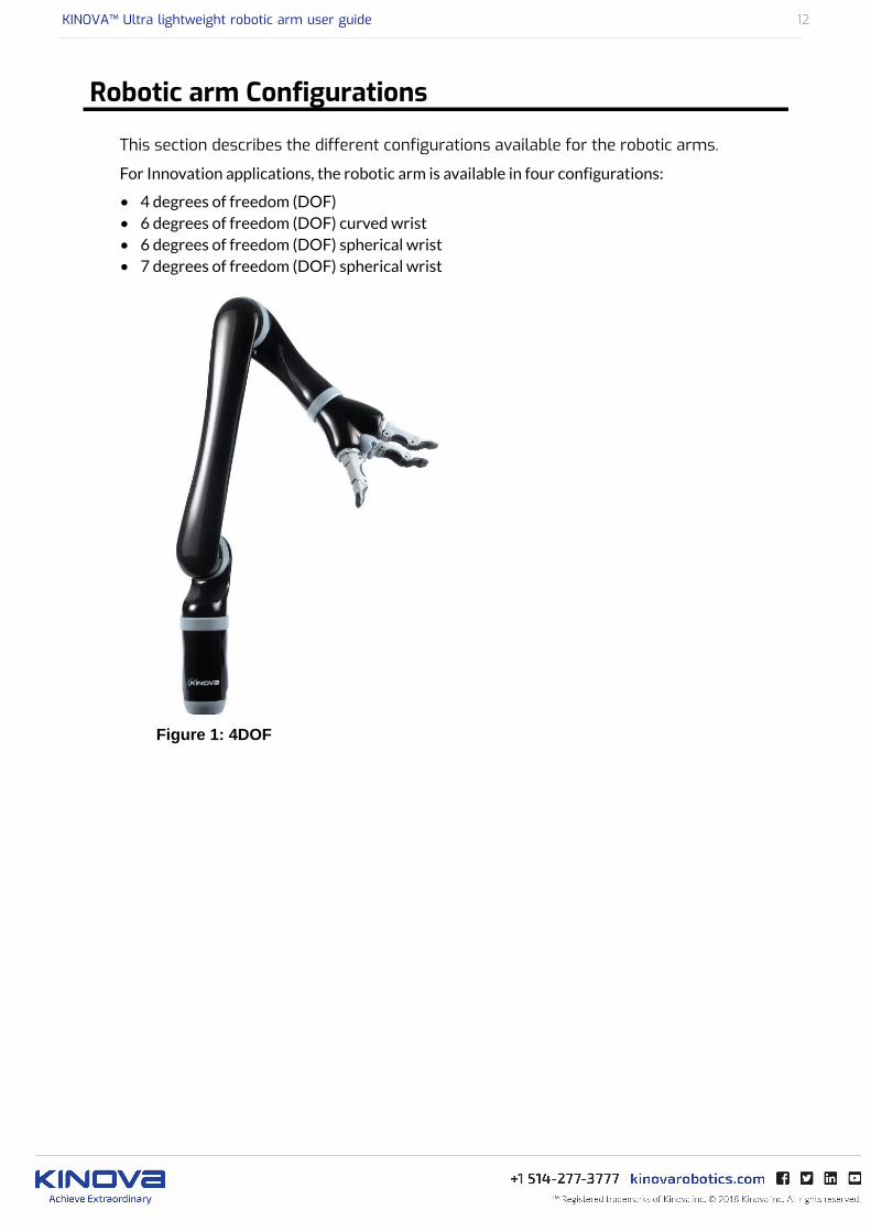
Robotic arm Configurations
This section describes the different configurations available for the robotic arms.
For Innovation applications, the robotic arm is available in four configurations:
• 4 degrees of freedom (DOF)• 6 degrees of freedom (DOF) curved wrist• 6 degrees of freedom (DOF) spherical wrist• 7 degrees of freedom (DOF) spherical wrist
Figure 1: 4DOF
KINOVA™ Ultra lightweight robotic arm user guide 13
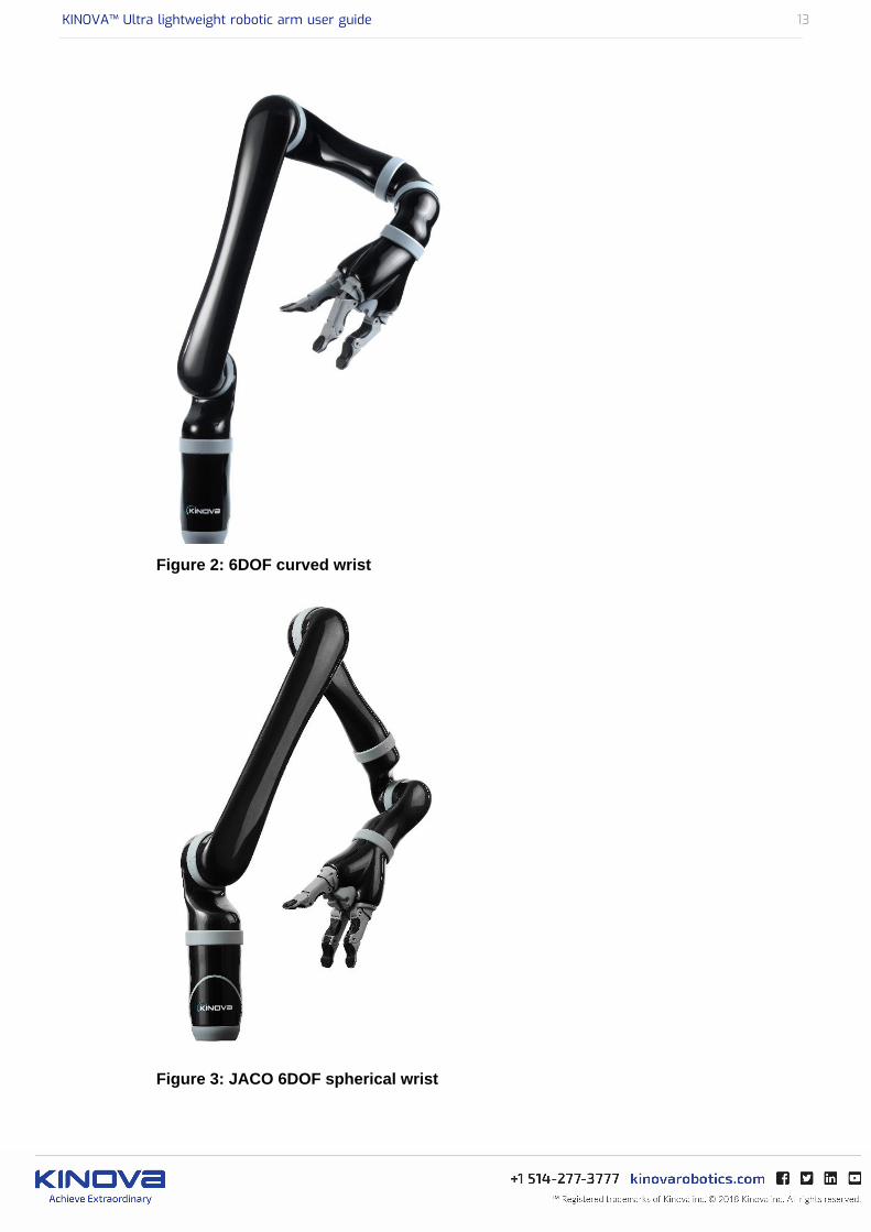
Figure 2: 6DOF curved wrist
Figure 3: JACO 6DOF spherical wrist
KINOVA™ Ultra lightweight robotic arm user guide 14
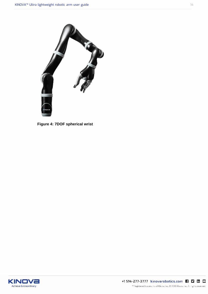
Figure 4: 7DOF spherical wrist

KINOVA™ Ultra lightweight robotic arm user guide 15
4 DOF Components
This section shows the components of the 4 DOF robotic arm.

KINOVA™ Ultra lightweight robotic arm user guide 16
6 DOF Curved Wrist Components
This section shows the components of the 6 DOF curved wrist robotic arm.
KINOVA™ Ultra lightweight robotic arm user guide 17
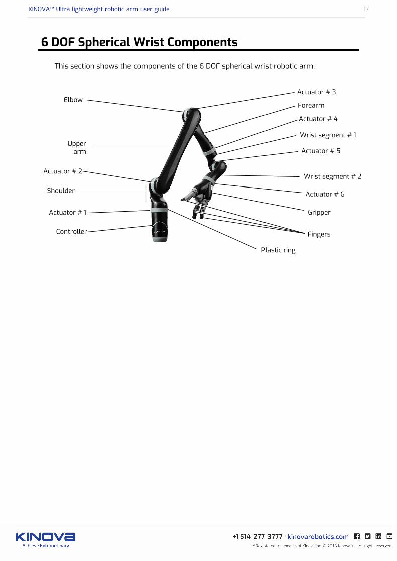
6 DOF Spherical Wrist Components
This section shows the components of the 6 DOF spherical wrist robotic arm.
KINOVA™ Ultra lightweight robotic arm user guide 18
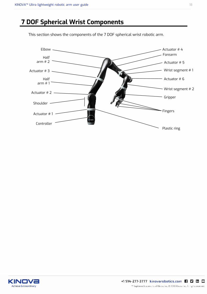
7 DOF Spherical Wrist Components
This section shows the components of the 7 DOF spherical wrist robotic arm.
KINOVA™ Ultra lightweight robotic arm user guide 19
External Connectors
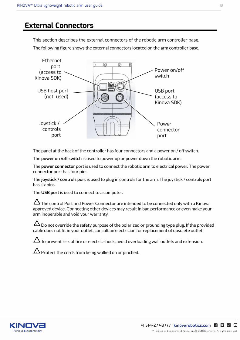
This section describes the external connectors of the robotic arm controller base.
The following figure shows the external connectors located on the arm controller base.
The panel at the back of the controller has four connectors and a power on / off switch.
The power on /off switch is used to power up or power down the robotic arm.
The power connector port is used to connect the robotic arm to electrical power. The powerconnector port has four pins
The joystick / controls port is used to plug in controls for the arm. The joystick / controls porthas six pins.
The USB port is used to connect to a computer.
The control Port and Power Connector are intended to be connected only with a Kinovaapproved device. Connecting other devices may result in bad performance or even make yourarm inoperable and void your warranty.
Do not override the safety purpose of the polarized or grounding type plug. If the providedcable does not fit in your outlet, consult an electrician for replacement of obsolete outlet.
To prevent risk of fire or electric shock, avoid overloading wall outlets and extension.
Protect the cords from being walked on or pinched.

KINOVA™ Ultra lightweight robotic arm user guide 20
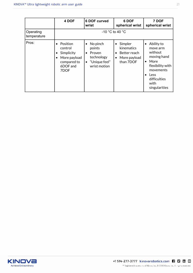
Comparing robotic arm configurations
This section compares the different arm configurations.
Each of the four available robotic arm configurations have their particular strengths. The bestoption depends on the needs of the specific users / group. The following table compares the fouroptions.
Table 1: Configurations
4 DOF 6 DOF curvedwrist
6 DOFspherical wrist
7 DOFspherical wrist
Total weight 3.6 kg 4.4 kg 4.4 kg 5.5 kg
Reach 75 cm 90 cm 98.4 cm 98.4 cm
Maximumpayload
• 4.4 kg(mid-rangecontinuous)
• 3.5 kg (full-reach peak /temporary)
• 2.6 kg(mid-rangecontinuous)
• 2.2 kg (full-reach peak /temporary)
• 2.6 kg(mid-rangecontinuous)
• 2.2 kg (full-reach peak /temporary)
• 2.4 kg(mid rangecontinuous)
• 2.1 kg (full-reach peak /temporary)
Materials Carbon fiber (links), Aluminum (actuators)
Joint range(softwarelimitation)
± 27.7 turns
Maximum lineararm speed
20 cm / s
Power supplyvoltage
18 to 29 VDC
Average power 25 W (5 W in standby) 25 W (15Wstandby)
Peak power 100W
Communicationprotocol
RS485
Communicationcables
20 pins flat flex cable
Water resistance IPX2
KINOVA™ Ultra lightweight robotic arm user guide 21
4 DOF 6 DOF curvedwrist
6 DOFspherical wrist
7 DOFspherical wrist
Operatingtemperature
-10 °C to 40 °C
Pros: • Positioncontrol
• Simplicity• More payload
compared to6DOF and7DOF
• No pinchpoints
• Proventechnology
• “Unique feel”wrist motion
• Simplerkinematics
• Better reach• More payload
than 7DOF
• Ability tomove armwithoutmoving hand
• Moreflexibility withmovements
• Lessdifficultieswithsingularities

KINOVA™ Ultra lightweight robotic arm user guide 22
Markings and Labels
This section describes markings and labels on the robotic arm.
Please note that these labels may slightly differ from the ones accompanying your devicedepending of your country. The following figure depicts the information about the label affixedon the robotic arm controller.
KINOVA™ Ultra lightweight robotic arm user guide 23
Installation of the robotic arm
This section describes the main high level steps of the installation process.
The robotic arm’s installation consists of four high-level steps:
1. Mechanical integration2. Electrical integration3. End-effector electrical integration (optional)4. Control integration

KINOVA™ Ultra lightweight robotic arm user guide 24
Mechanical mounting of the robotic arm
This section describes the steps for mechanical mounting of the robotic arm.
About this task
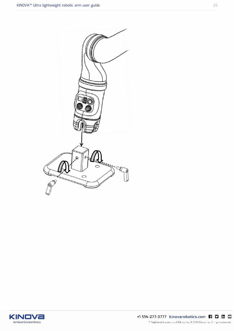
The arm is designed to be installed on a fixed surface or mobile platform. Please makesure the arm is fixed in such a way that its base cannot fall or break during operationsinvolving maximum reach of the arm. Here is a guide on how to install the arm on themounting kit (XK 0000 0014) supplied with your robotic arm.
Procedure
1. Assemble the mounting kit. Insert the mounting post into the square cavity on the top of themounting plate and use an 8 mm hex key to attach from the bottom of the mounting plate.
2. Affix the mounting kit to a flat surface. You can either place the larger side of the mountingkit on the edge of a solid flat surface and clamp it as firmly as possible by placing the twoclamps supplied with the package on each side of the mounting post or secure four M12screws through the holes in the mounting plate.
3. Insert the robot arm on the top of the mounting post. Screw the two M8 lever screws intothe mounting post, one in the back of the controller and the other on one of the sides of therobot.
KINOVA™ Ultra lightweight robotic arm user guide 25

KINOVA™ Ultra lightweight robotic arm user guide 26
Electrical integration
This section describes how to connect the robotic arm to an electrical power source.
There are two ways of powering the robotic arm:
• Wall electrical outlet• Battery power
Electrical outlet - You can power your robotic arm using a standard 110/220 V power outlet byplugging the power cord (EH 0300 0001 (USA), EH 2500 0001 (EUR), EH 2500 0002 (AUS), EH2500 0003 (UK)) into the Power Supply Unit (PSU - AE 0000 0029) on one end and into a poweroutlet on the other. Then plug the PSU into the base controller power connector.
Battery power - You can use the battery power cord (EH 01M8 0003) by plugging one end intothe base controller power connector and connecting the four wires at the other end to a 24Vbattery. The following table shows the relationships between power connector pinout, thesignal, and the wire color.
Pinout table
Pin # Signal Wire color
1 24V Red
2 24V Brown
3 GND Black
4 GND Orange
Make sure that your battery respects the electrical specifications of the robotic arm.
KINOVA™ Ultra lightweight robotic arm user guide 27
Integrating a new end effector (optional)
This section describes how to integrate a new end effector with Kinova actuators, whetherin a Kinova robotic arm or custom application.
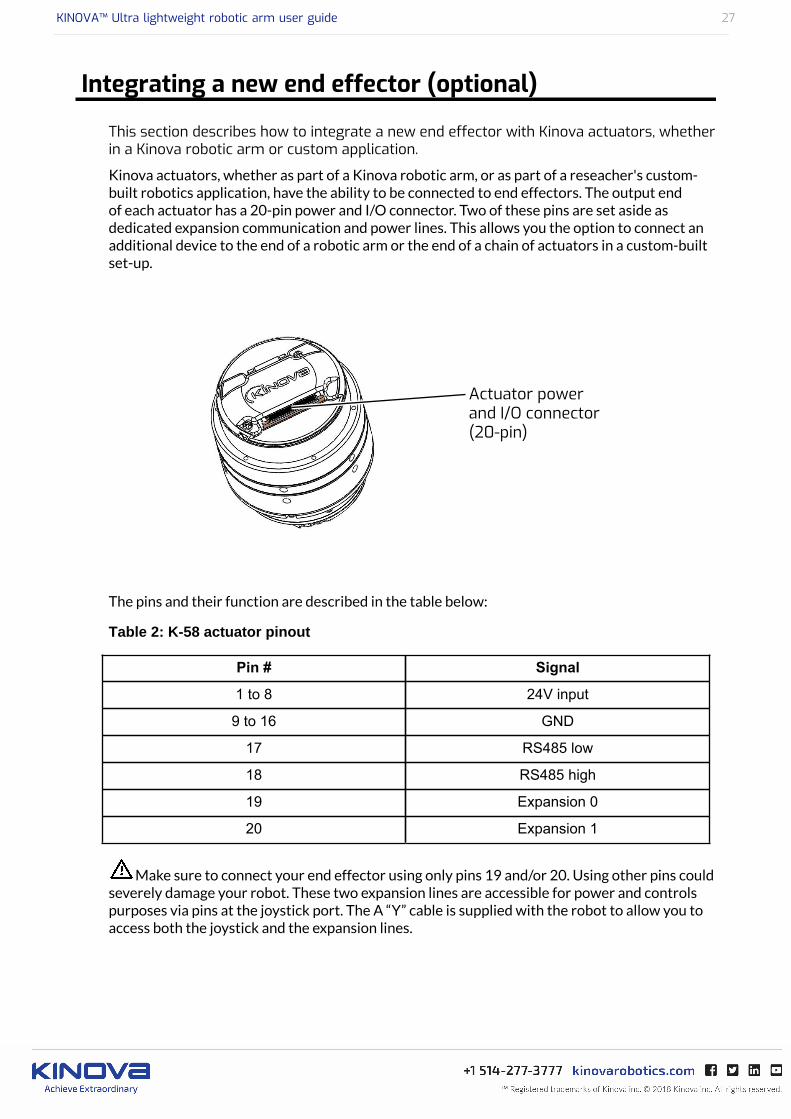
Kinova actuators, whether as part of a Kinova robotic arm, or as part of a reseacher's custom-built robotics application, have the ability to be connected to end effectors. The output endof each actuator has a 20-pin power and I/O connector. Two of these pins are set aside asdedicated expansion communication and power lines. This allows you the option to connect anadditional device to the end of a robotic arm or the end of a chain of actuators in a custom-builtset-up.
The pins and their function are described in the table below:
Table 2: K-58 actuator pinout
Pin # Signal
1 to 8 24V input
9 to 16 GND
17 RS485 low
18 RS485 high
19 Expansion 0
20 Expansion 1
Make sure to connect your end effector using only pins 19 and/or 20. Using other pins couldseverely damage your robot. These two expansion lines are accessible for power and controlspurposes via pins at the joystick port. The A “Y” cable is supplied with the robot to allow you toaccess both the joystick and the expansion lines.
KINOVA™ Ultra lightweight robotic arm user guide 28
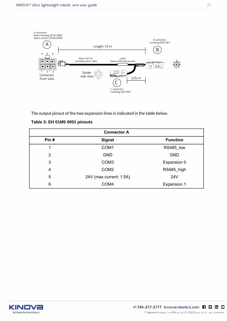
The output pinout of the two expansion lines is indicated in the table below.
Table 3: EH 01M5 0001 pinouts
Connector A
Pin # Signal Function
1 COM1 RS485_low
2 GND GND
3 COM3 Expansion 0
4 COM2 RS485_high
5 24V (max current: 1.5A) 24V
6 COM4 Expansion 1
KINOVA™ Ultra lightweight robotic arm user guide 29
Control integration
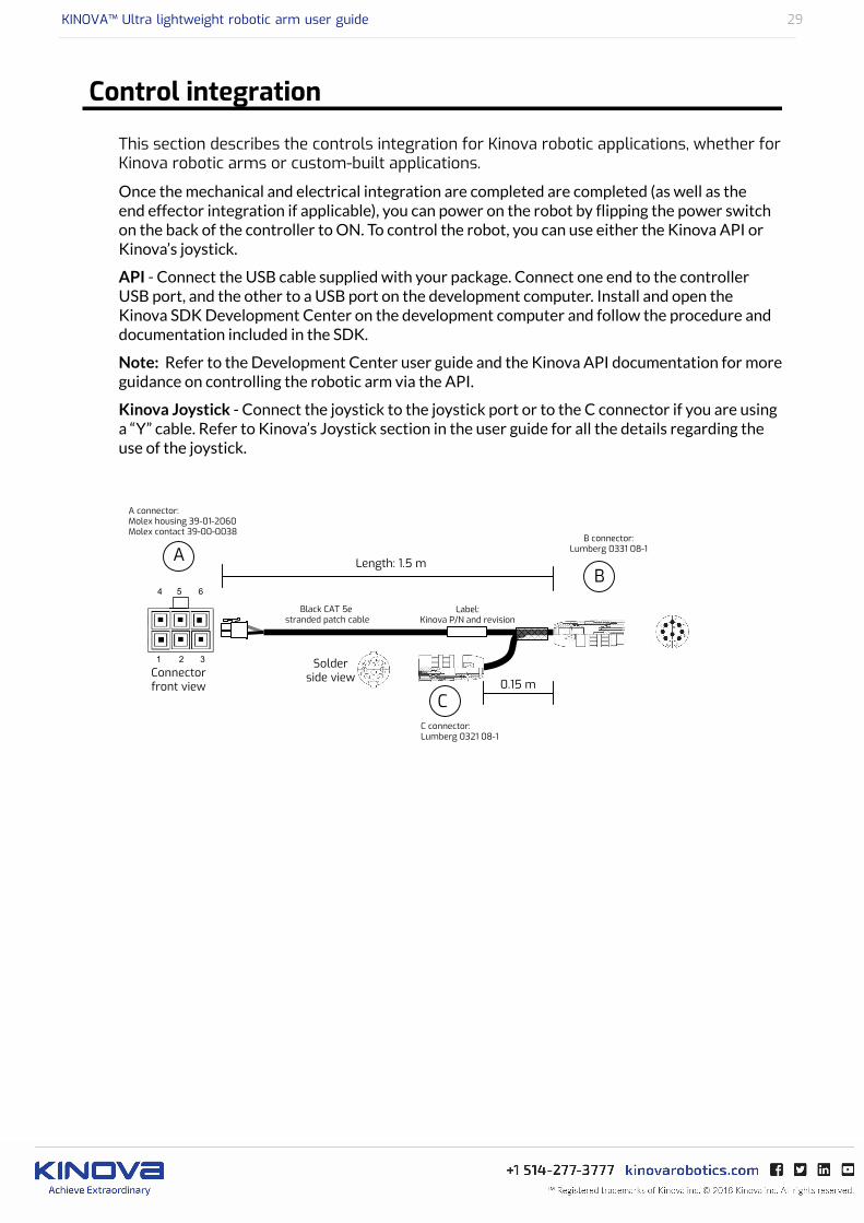
This section describes the controls integration for Kinova robotic applications, whether forKinova robotic arms or custom-built applications.
Once the mechanical and electrical integration are completed are completed (as well as theend effector integration if applicable), you can power on the robot by flipping the power switchon the back of the controller to ON. To control the robot, you can use either the Kinova API orKinova’s joystick.
API - Connect the USB cable supplied with your package. Connect one end to the controllerUSB port, and the other to a USB port on the development computer. Install and open theKinova SDK Development Center on the development computer and follow the procedure anddocumentation included in the SDK.
Note: Refer to the Development Center user guide and the Kinova API documentation for moreguidance on controlling the robotic arm via the API.
Kinova Joystick - Connect the joystick to the joystick port or to the C connector if you are usinga “Y” cable. Refer to Kinova’s Joystick section in the user guide for all the details regarding theuse of the joystick.

KINOVA™ Ultra lightweight robotic arm user guide 30
Control modes overview
This section explains how to operate the robotic arm with factory configuraton.
Kinova robot actuators can be controlled by end effector position, actuators' angular position oractuators' torque. Kinova robots offer the following control mode options:
Table 4: Control modes
Control mode Description
Cartesian position Specifies end-effector’s position and end-effector’sorientation (Euler angles, X-Y’-Z’’ convention) in the baseframe.
Cartesian velocity Specifies end-effector’s translation velocities in the baseframe and end-effector’s rotation velocities in the effector’sframe.
Angular position Specifies each actuator’s angle.
Angular velocity Specifies each actuator’s angular (rotational) velocity.
Cartesian admittance(Reactive Force control inCartesian space)
Applies forces and torques on the end-effector and get aCartesian motion (translation/rotation) in the appropriatedirection.
Angular admittance (ReactiveForce control in joint space)
Applies torques on actuators and get an angular motion (jointrotation) in the appropriate direction.
Direct torque control Specifies each actuator’s torque. By default, each actuatorreceives its corresponding gravity torque so the robotcompensates its own weight.
Force control Specifies forces and torques at the end-effector. The robotautomatically computes the torque at each actuator requiredto generate the appropriate forces/torques at the end-effector.
KINOVA™ Ultra lightweight robotic arm user guide 31
Control peripheral options overview
Three options are available to control Kinova robotic arms. Two of these options use the API.The
third option is the joystick control. The three options are:
• (Kinova) joystick control: This controls the arm in Cartesian velocity (by default as soon asthe robot reaches its READY position) or in Angular velocity (if angular control is activated).Joystick control in Cartesian mode is the only control peripheral option Assistive usersshould be familiar with.
• Kinova software control: Kinova provides two different software control panels that allowyou to control the arm via a graphical user interface.: the Development Center and theTorque Console. These two software panels allow users to command the arm in position,velocity, and trajectories. It also allows users to activate admittance control (inside theDevelopment Center) and direct torque control/force control (inside the Torque Console).For more details on Kinova software, please see the Development Center User guide(downloadable from Kinova website).
• API control: Kinova has a library of C++ functions to control its robotic arms. This libraryof functions is referred to as the Kinova API. The API (.dll files and .h files) is downloadablefrom Kinova’s website as part of the Kinova software development kit (SDK). The SDK issupplemented by HTML-based documentation detailing all the available functions. TheKinova API is supported on both Windows and Ubuntu. Kinova also offers developers thepossibility for developers to control the robotic arm through a ROS interface (ROS Indigo onUbuntu 14.04 currently supported). For more information, see the Kinova ROS Github pageat https://github.com/Kinovarobotics/kinova-ros.
A fourth option is to control the arm by directly interacting with it (pushing/pulling on some linkor at the end-effector). The robot becomes reactive to direct interaction in admittance controland direct torque/force control.
KINOVA™ Ultra lightweight robotic arm user guide 32
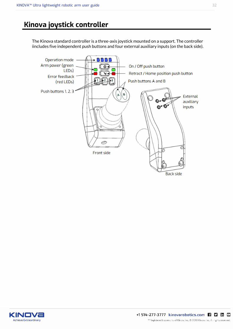
Kinova joystick controller
The Kinova standard controller is a three-axis joystick mounted on a support. The controlleriincludes five independent push buttons and four external auxiliary inputs (on the back side).
KINOVA™ Ultra lightweight robotic arm user guide 33
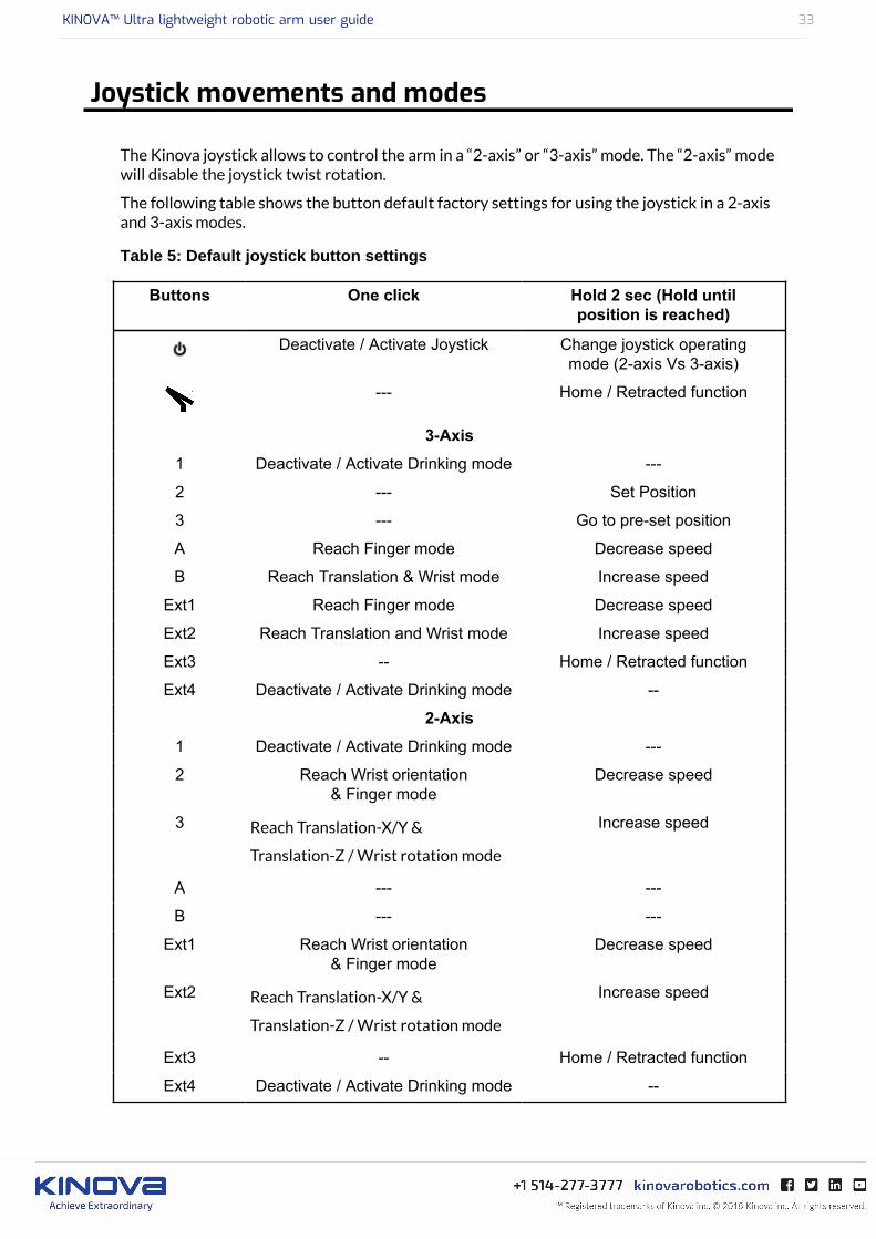
Joystick movements and modes
The Kinova joystick allows to control the arm in a “2-axis” or “3-axis” mode. The “2-axis” modewill disable the joystick twist rotation.
The following table shows the button default factory settings for using the joystick in a 2-axisand 3-axis modes.
Table 5: Default joystick button settings
Buttons One click Hold 2 sec (Hold untilposition is reached)
Deactivate / Activate Joystick Change joystick operatingmode (2-axis Vs 3-axis)
--- Home / Retracted function
3-Axis
1 Deactivate / Activate Drinking mode ---
2 --- Set Position
3 --- Go to pre-set position
A Reach Finger mode Decrease speed
B Reach Translation & Wrist mode Increase speed
Ext1 Reach Finger mode Decrease speed
Ext2 Reach Translation and Wrist mode Increase speed
Ext3 -- Home / Retracted function
Ext4 Deactivate / Activate Drinking mode --
2-Axis
1 Deactivate / Activate Drinking mode ---
2 Reach Wrist orientation& Finger mode
Decrease speed
3 Reach Translation-X/Y &
Translation-Z / Wrist rotation mode
Increase speed
A --- ---
B --- ---
Ext1 Reach Wrist orientation& Finger mode
Decrease speed
Ext2 Reach Translation-X/Y &
Translation-Z / Wrist rotation mode
Increase speed
Ext3 -- Home / Retracted function
Ext4 Deactivate / Activate Drinking mode --

KINOVA™ Ultra lightweight robotic arm user guide 34
Operating principles and Cartesian mode
This section describes at a high level the control of the arm using the joystick in Cartesianmode.
Operating principles
The operating principles are very simple and intuitive. The robotic arm may be operated throughseveral controllers. The following sections present the general control principles throughKinova’s joystick.
Basic movements
The normal control of the robotic arm with the joystick is said to be Cartesian. The usercommands the end-effector’s translations (position variations) with respect to the base and therotations (orientation variations) around the end-effector’s reference point. The different jointsare piloted automatically following the given command.
In “Translation mode”, the user controls the position of the gripper in space. The gripper willalways keep its parallelism with the arm’s base. Translation X refers to left/right movements ofthe gripper. Translation Y refers to front/back movements of the gripper. Translation Z refers toup/down movements of the gripper.
In the “Wrist mode”, the user controls the position of the gripper around its center point(reference point) which will not move (or move slightly) when operating in this mode. Lateralorientation refers to a thumb/index circular movement of the wrist around the reference point.Vertical orientation refers to a top/bottom circular movement of the wrist around the referencepoint. Wrist rotation refers to a circular movement of the gripper around itself.
The “Drinking mode” is to be used with the wrist rotation only. While operating the Jaco² armin “Drinking mode”, the reference point (normally set in the middle of the gripper), is offset inheight and length to produce a rotation around another point in the space of the arm.
In the “Finger mode”, the user controls the opening and closing of the fingers.
Note: The arm will sometimes respond differently to a given command than described in thissection. This may be due to the singularity and collision avoidance algorithms embedded in thekinematics. It is a normal protective behaviour of the arm and is position dependent. Both theseavoidance algorithms can be deactivated by the user.
KINOVA™ Ultra lightweight robotic arm user guide 35
Home / Retracted positions
This section describes the Home and Retracted positions of the robotic arm.
The arm comes with two factory default pre-set positions that may be configured in the KinovaDevelopment Center:
• Home position and• Retracted position.
The Home position refers to the position of the arm when it is ready to be used. In the Homeposition, the arm is awaiting a commands from the joystick.
The Retracted position refers to the position of the arm when it is not used. The user shouldalways place the arm in the Retracted position when it is unused as it decreases the physicalvolume occupied by the arm. In the Retracted position, the arm is in standby mode; the joystickfeatures are disabled and power consumption is much lower.
Never use the Home / Retracted function when carrying liquid. The Home position is pre-set and the wrist may have to rotate and will drop the liquid.
KINOVA™ Ultra lightweight robotic arm user guide 36
Operating the arm via joystick
This section describes operation of the arm using the joystick.
This section explains how to operate the arm with factory configuration. Contact your resellerfor operation instructions in the case of an adapted configuration.
Before operating the arm, please make sure it is properly installed.
Do not manipulate cutting, very sharp or any dangerous tools or objects with the arm.
This equipment is not designed to act as a lift.
This equipment is not designed to be used in presence of flammable mixture. (Not AP orAPG rated).
Do not install the arm near any heat sources, such as radiators. Do not use it to directlymanipulate hot objects.
KINOVA™ Ultra lightweight robotic arm user guide 37
Joystick control quick start
This section describes how to get started using the Kinova joystick to control the arm inthe default configuration.
About this task
Procedure
1. Turn ON the device by pushing the ON/OFF switch located on the arm base.
2. Wait until the green lights on the controller stop flashing.
3. Put the arm in its Home position by holding down the HOME/RETRACTED button. untilthe arm stops moving. The arm will slowly reach the Home position.
Note: When starting the arm, you are in 3-Axis operation mode, "Translation controlmode”, meaning that any movement of the joystick will move the center of the gripperparallel to the floor.
4. You may move the 3 axes of the joystick to experience the Translation control mode.
Note: To change the operating mode of the Joystick, hold the ON/OFF button for 2seconds. At this point, you are in 2-axis mode and the stick rotation is deactivated.
5. One press of Button B will bring you in Wrist control mode meaning that any movement ofthe joystick will result in a rotation of the gripper around its center.
Note: Another press of Button B will bring you back in Translation control mode.
6. One press of Button 1 will activate the Drinking mode which may be used only in Wristmode. When rotating the joystick lever, you will see that the arm’s wrist rotation nowcompensates for the height and radius of a virtual glass. This movement is ideal when tryingto drink directly from a glass.
Note: Another press of Button 1 will disable Drinking mode.
7. One press of Button A will bring you in Finger control mode. The fingers will move per aleft/right inclination of the joystick.
Note: At any time, you may use the Home / Retracted button until the arm stops moving tobring it back to its Home position.
Note: If you hold the Home / Retracted button again, the arm will start to move toward theRetracted position.
8. Hold the On/Off Button for 2 seconds to change the operating mode. This will disable thestick rotation. You are now in a 2-Axis Translation control mode. Stick rotation won't haveany effect and you will only be able to control the horizontal translation of the arm (X- andY- axis).
9. One press of Button 3 will bring you to control the vertical translation of the gripper(Translation-Z) and Wrist rotation.
Note: Another hit on Button 3 will bring you back in Translation-X and Translation-Ycontrol mode.
10. One press of Button 1 will activate the Drinking mode which may be used only in Wristmode. When rotating the joystick lever, you will see that the arm’s wrist rotation nowcompensates for the height and radius of a virtual glass. This movement is ideal whendrinking directly from a glass.
11. One press of Button 2 will bring you to control the wrist orientation (Lateral orientationand Vertical orientation).
12. Another press of Button 2 will bring you to Finger control mode. The fingers will moveaccording to a left/right inclination of the joystick.

KINOVA™ Ultra lightweight robotic arm user guide 38
Note: Another press of Button 2 will bring you back in Lateral orientation and Verticalorientation control mode.
KINOVA™ Ultra lightweight robotic arm user guide 39
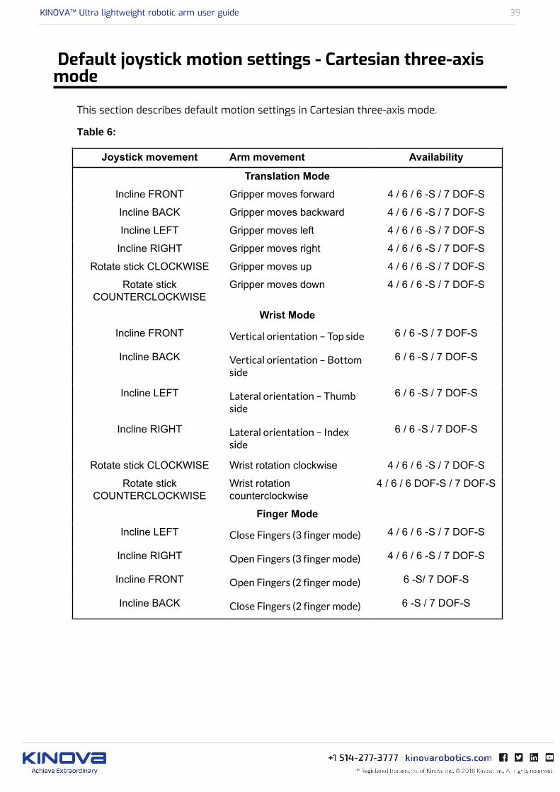
Default joystick motion settings - Cartesian three-axismode
This section describes default motion settings in Cartesian three-axis mode.
Table 6:
Joystick movement Arm movement Availability
Translation Mode
Incline FRONT Gripper moves forward 4 / 6 / 6 -S / 7 DOF-S
Incline BACK Gripper moves backward 4 / 6 / 6 -S / 7 DOF-S
Incline LEFT Gripper moves left 4 / 6 / 6 -S / 7 DOF-S
Incline RIGHT Gripper moves right 4 / 6 / 6 -S / 7 DOF-S
Rotate stick CLOCKWISE Gripper moves up 4 / 6 / 6 -S / 7 DOF-S
Rotate stickCOUNTERCLOCKWISE
Gripper moves down 4 / 6 / 6 -S / 7 DOF-S
Wrist Mode
Incline FRONT Vertical orientation – Top side 6 / 6 -S / 7 DOF-S
Incline BACK Vertical orientation – Bottomside
6 / 6 -S / 7 DOF-S
Incline LEFT Lateral orientation – Thumbside
6 / 6 -S / 7 DOF-S
Incline RIGHT Lateral orientation – Indexside
6 / 6 -S / 7 DOF-S
Rotate stick CLOCKWISE Wrist rotation clockwise 4 / 6 / 6 -S / 7 DOF-S
Rotate stickCOUNTERCLOCKWISE
Wrist rotationcounterclockwise
4 / 6 / 6 DOF-S / 7 DOF-S
Finger Mode
Incline LEFT Close Fingers (3 finger mode) 4 / 6 / 6 -S / 7 DOF-S
Incline RIGHT Open Fingers (3 finger mode) 4 / 6 / 6 -S / 7 DOF-S
Incline FRONT Open Fingers (2 finger mode) 6 -S/ 7 DOF-S
Incline BACK Close Fingers (2 finger mode) 6 -S / 7 DOF-S
KINOVA™ Ultra lightweight robotic arm user guide 40
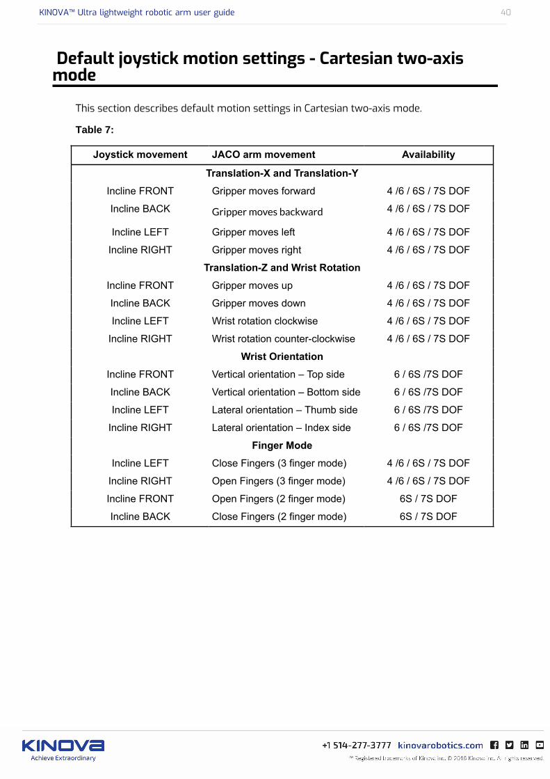
Default joystick motion settings - Cartesian two-axismode
This section describes default motion settings in Cartesian two-axis mode.
Table 7:
Joystick movement JACO arm movement Availability
Translation-X and Translation-Y
Incline FRONT Gripper moves forward 4 /6 / 6S / 7S DOF
Incline BACK Gripper moves backward 4 /6 / 6S / 7S DOF
Incline LEFT Gripper moves left 4 /6 / 6S / 7S DOF
Incline RIGHT Gripper moves right 4 /6 / 6S / 7S DOF
Translation-Z and Wrist Rotation
Incline FRONT Gripper moves up 4 /6 / 6S / 7S DOF
Incline BACK Gripper moves down 4 /6 / 6S / 7S DOF
Incline LEFT Wrist rotation clockwise 4 /6 / 6S / 7S DOF
Incline RIGHT Wrist rotation counter-clockwise 4 /6 / 6S / 7S DOF
Wrist Orientation
Incline FRONT Vertical orientation – Top side 6 / 6S /7S DOF
Incline BACK Vertical orientation – Bottom side 6 / 6S /7S DOF
Incline LEFT Lateral orientation – Thumb side 6 / 6S /7S DOF
Incline RIGHT Lateral orientation – Index side 6 / 6S /7S DOF
Finger Mode
Incline LEFT Close Fingers (3 finger mode) 4 /6 / 6S / 7S DOF
Incline RIGHT Open Fingers (3 finger mode) 4 /6 / 6S / 7S DOF
Incline FRONT Open Fingers (2 finger mode) 6S / 7S DOF
Incline BACK Close Fingers (2 finger mode) 6S / 7S DOF

KINOVA™ Ultra lightweight robotic arm user guide 41
Controlling the arm in Angular mode
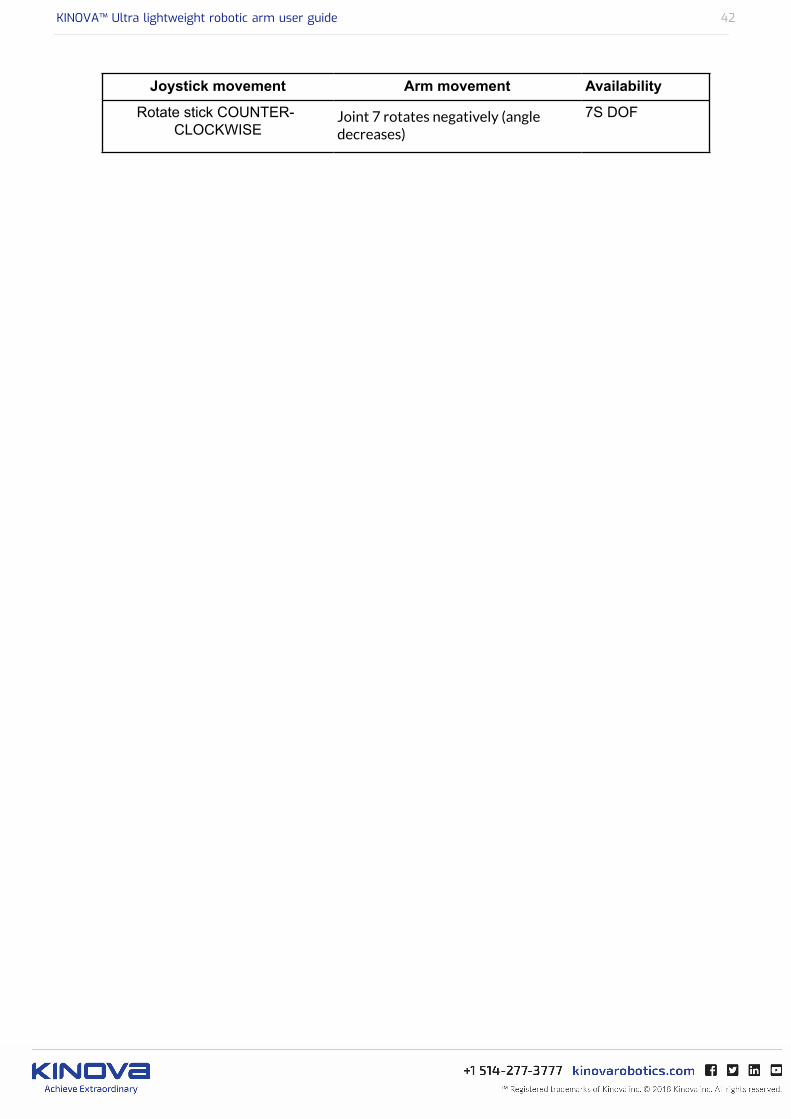
In Angular mode, the user commands each individual actuator’s rotation. Angular mode must beactivated using the Kinova Development Center software or Kinova API. Multiple joints can becommanded simultaneously using the joystick (when diagonal control is enabled). The joystickdefault settings in Angular mode are summarized in the following table.
Table 8:
Joystick movement Arm movement Availability
Translation mode
Incline LEFT Joint 1 rotates positively(angle increases)
6S /7S DOF
Incline RIGHT Joint 1 rotates negatively(angle decreases)
6S /7S DOF
Incline FRONT Joint 2 rotates negatively(angle decreases)
6S /7S DOF
Incline BACK Joint 2 rotates positively(angle increases)
6S /7S DOF
Rotate CLOCKWISE Joint 3 rotates positively(angle increases)
6S /7S DOF
Rotate stick COUNTER-CLOCKWISE
Joint 3 rotates negatively(angle decreases)
6S /7S DOF
Wrist mode
Incline LEFT Joint 4 rotates negatively(angle decreases)
6S /7S DOF
Incline RIGHT Joint 4 rotates positively(angle increases)
6S /7S DOF
Incline FRONT Joint 5 rotates positively (angleincreases)
6S /7S DOF
Incline BACK Joint 5 rotates negatively(angle decreases)
6S /7S DOF
Rotate CLOCKWISE Joint 6 rotates positively(angle increases)
6S /7S DOF
Rotate stick COUNTER-CLOCKWISE
Joint 6 rotates negatively(angle decreases)
6S /7S DOF
Finger mode
Incline LEFT Close Fingers (3 finger mode) 6S /7S DOF
Incline RIGHT Open Fingers (3 finger mode) 6S /7S DOF
Incline FRONT Open Fingers (2 finger mode) 6S /7S DOF
Incline BACK Close Fingers (2 finger mode) 6S /7S DOF
Rotate CLOCKWISE Joint 7 rotates positively(angle increases)
7S DOF
KINOVA™ Ultra lightweight robotic arm user guide 42
Joystick movement Arm movement Availability
Rotate stick COUNTER-CLOCKWISE
Joint 7 rotates negatively (angledecreases)
7S DOF

KINOVA™ Ultra lightweight robotic arm user guide 43
Kinova Joystick LED feedback
The Kinova joystick offers visual feedback:
• Blue lights : Feedback on control mode• Green lights : Feedback on arm power• Red lights : Feedback on error

KINOVA™ Ultra lightweight robotic arm user guide 44
Kinova joystick Blue LEDs feedback
This section describes the blue LED feedback on the Kinova controller.
The blue LEDs on the controller give feedback on the current control mode. The interpretationof the blue mode LED indicators is described in the following table.
Table 9: Control mode feedback
Blue LED indication Control Mode
Translation (X-Y-Z)
Wrist
Fingers
Drinking mode (to be used with wrist rotation mode)
3-Axis
Disabled controller
Translation (X-Y)
Translation (Z) / Wrist Rotation
Wrist Orientation
Fingers
Drinking mode (to be used with wrist rotation mode)
2-Axis
Disabled controller
When no blue lights are visible, the controller is disabled. To enable the controller, you musteither proceed with the following options:
• The On/Off button must be pushed• The arm must be set in its HOME position by holding the HOME/RETRACTED function until
the arm stops moving.
KINOVA™ Ultra lightweight robotic arm user guide 45
Kinova joystick Green LEDs feedback
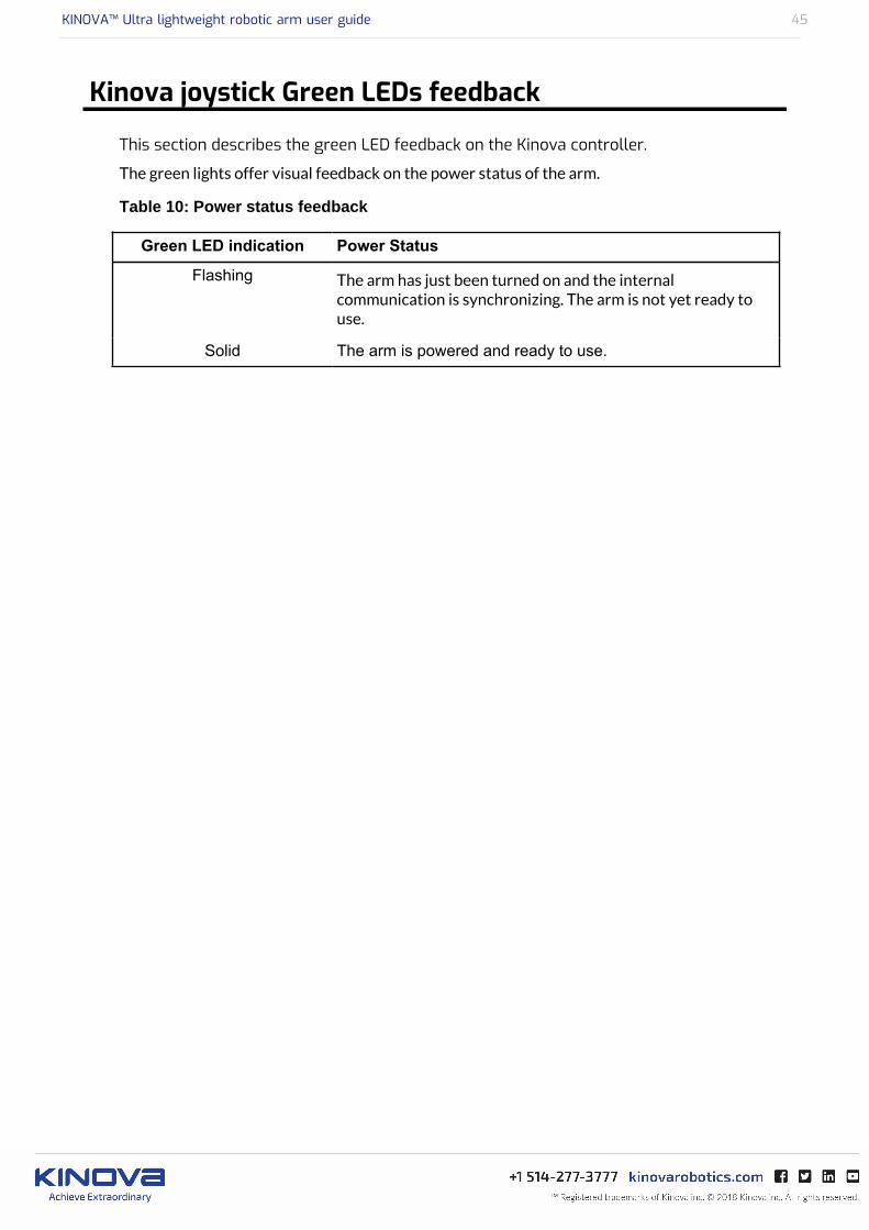
This section describes the green LED feedback on the Kinova controller.
The green lights offer visual feedback on the power status of the arm.
Table 10: Power status feedback
Green LED indication Power Status
Flashing The arm has just been turned on and the internalcommunication is synchronizing. The arm is not yet ready touse.
Solid The arm is powered and ready to use.
KINOVA™ Ultra lightweight robotic arm user guide 46
Kinova joystick Red LEDs feedback
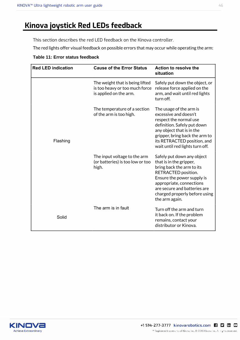
This section describes the red LED feedback on the Kinova controller.
The red lights offer visual feedback on possible errors that may occur while operating the arm:
Table 11: Error status feedback
Red LED indication Cause of the Error Status Action to resolve thesituation
The weight that is being liftedis too heavy or too much forceis applied on the arm.
Safely put down the object, orrelease force applied on thearm, and wait until red lightsturn off.
The temperature of a sectionof the arm is too high.
The usage of the arm isexcessive and doesn’trespect the normal usedefinition. Safely put downany object that is in thegripper, bring back the arm toits RETRACTED position, andwait until red lights turn off.
Flashing
The input voltage to the arm(or batteries) is too low or toohigh.
Safely put down any objectthat is in the gripper,bring back the arm to itsRETRACTED position.Ensure the power supply isappropriate, connectionsare secure and batteries arecharged properly before usingthe arm again.
Solid
The arm is in fault Turn off the arm and turnit back on. If the problemremains, contact yourdistributor or Kinova.
KINOVA™ Ultra lightweight robotic arm user guide 47
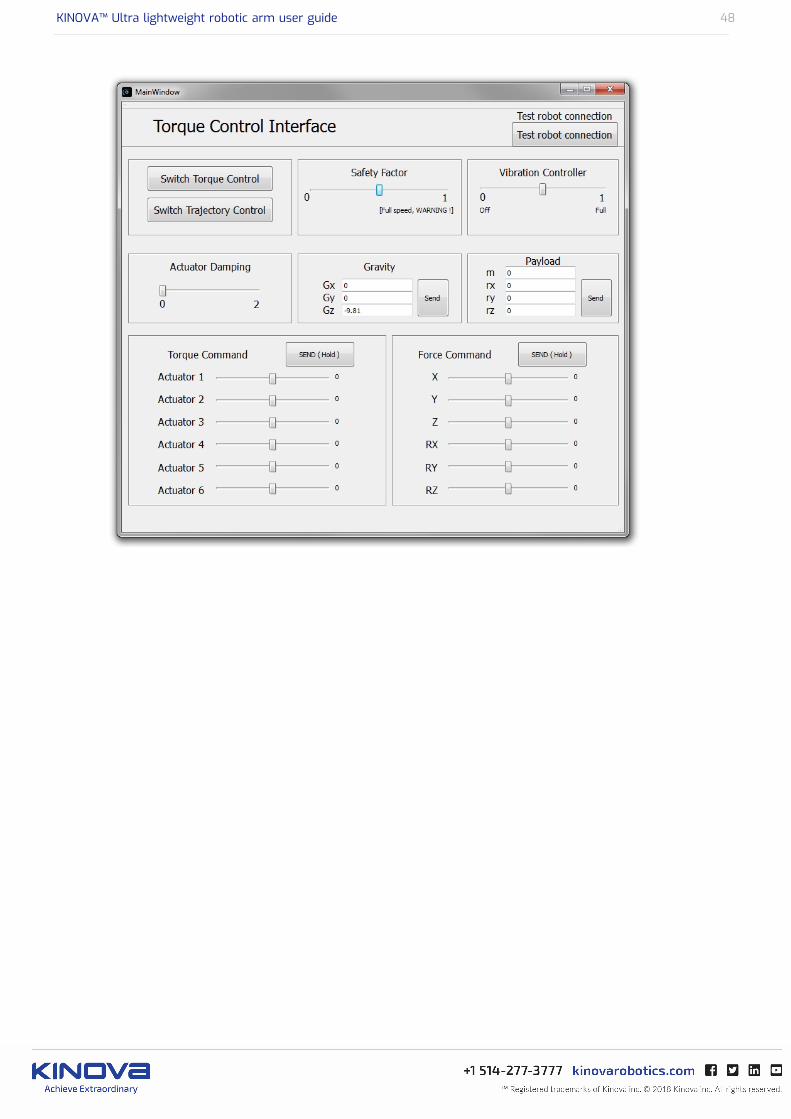
Controlling the arm using Kinova software
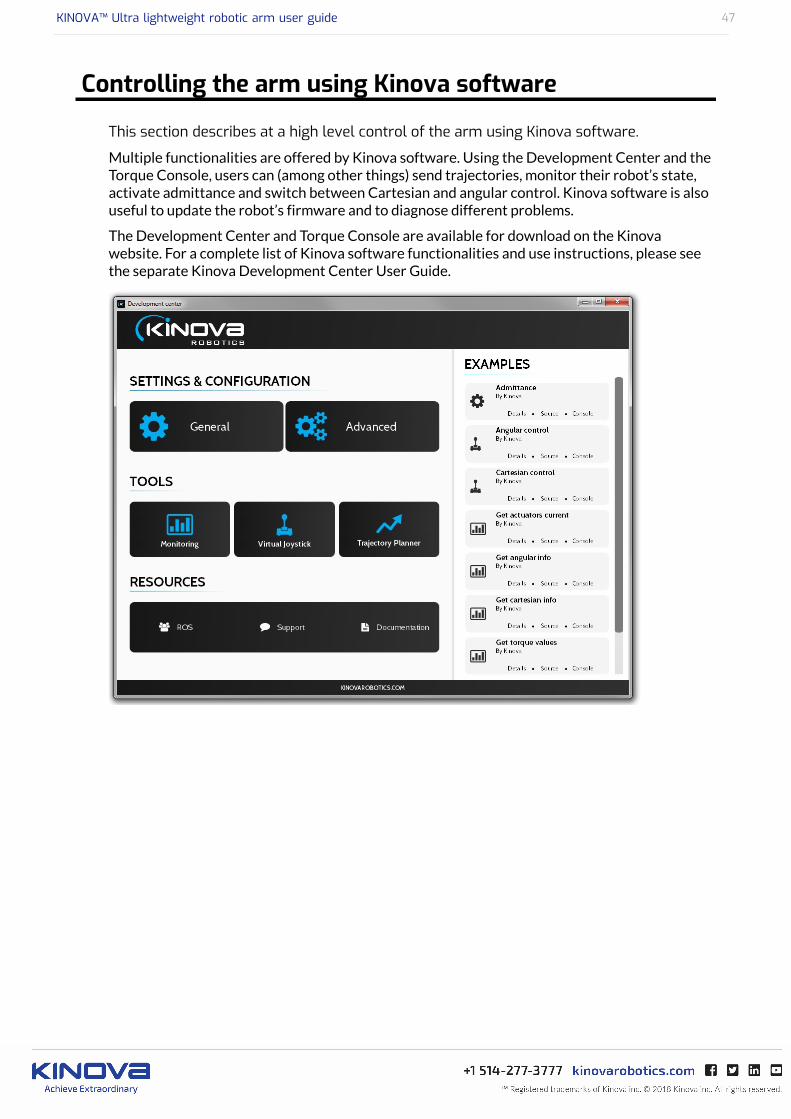
This section describes at a high level control of the arm using Kinova software.
Multiple functionalities are offered by Kinova software. Using the Development Center and theTorque Console, users can (among other things) send trajectories, monitor their robot’s state,activate admittance and switch between Cartesian and angular control. Kinova software is alsouseful to update the robot’s firmware and to diagnose different problems.
The Development Center and Torque Console are available for download on the Kinovawebsite. For a complete list of Kinova software functionalities and use instructions, please seethe separate Kinova Development Center User Guide.
KINOVA™ Ultra lightweight robotic arm user guide 48
KINOVA™ Ultra lightweight robotic arm user guide 49
Controlling the arm using the Kinova API
This section describes at a high level control of the arm using Kinova API.
As with the Development Center and the Torque Console, information about the APIis downloadable from Kinova’s website. The Development Center comes with HTMLdocumentation describing the C++ programming functions that can be used to access the API. Agood way to start with the API is to look at the examples provided with the Kinova DevelopmentCenter. For more details, please see the Kinova Development Center User Guide and the HTML-based API documentation.
KINOVA™ Ultra lightweight robotic arm user guide 50
Singularity Avoidance
This section discusses singularity-avoidance in the robotic arm.
In Cartesian mode, there are some configurations in which the robot loses one or more degreesof freedom (meaning the robot is not able to move in one direction or the other.). Theseconfigurations are called singularities and Kinova robots avoid them automatically. This meansthat Cartesian commands sent by the user may be modified somewhat to avoid a singularity.
Singularity auto-avoidance behavior can be deactivated using theActivateAutomaticSingularityAvoidance API function and setting its parameter to false.
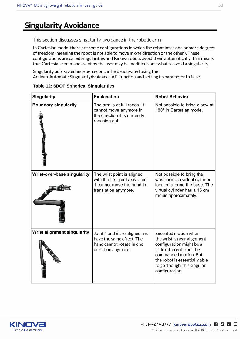
Table 12: 6DOF Spherical Singularities
Singularity Explanation Robot Behavior
Boundary singularity The arm is at full reach. Itcannot move anymore inthe direction it is currentlyreaching out.
Not possible to bring elbow at180° in Cartesian mode.
Wrist-over-base singularity The wrist point is alignedwith the first joint axis. Joint1 cannot move the hand intranslation anymore.
Not possible to bring thewrist inside a virtual cylinderlocated around the base. Thevirtual cylinder has a 15 cmradius approximately.
Wrist alignment singularity Joint 4 and 6 are aligned andhave the same effect. Thehand cannot rotate in onedirection anymore.
Executed motion whenthe wrist is near alignmentconfiguration might be alittle different from thecommanded motion. Butthe robot is essentially ableto go ‘though’ this singularconfiguration.

KINOVA™ Ultra lightweight robotic arm user guide 51
Table 13: 7DOF Spherical Singularities
Singularity Explanation Robot Behavior
Boundary singularity The arm is at full reach. Joint4 is at 180°. The arm cannotmove in the direction it iscurrently reaching out.
When singularity avoidanceis activated, it’s not possibleto bring the elbow at 180° inCartesian mode.
Joints 2 and 3 singularity Joint 2 is at 180° so joints 1and 3 are perfectly alignedand have the same effect.Joint 3 is at 90° or at 270°so joint 2 and joint 4’s axisis perpendicular. The robotcannot move purely along anaxis in translation anymore.
When singularity avoidanceis activated, it’s not possibleto bring joint 3 near 90° or270° when joint 2 is near 180°(or vice versa, to bring joint2 near 180° when joint 3 isnear 90° or 270°) in Cartesianmode. Besides, the fitnessfunction will try to avoidthe singularity by movingjoint 2 away from 180° andjoint 3 away from 90° or270° while moving in therobot’s null space. For moreinformation on the fitnessfunction, please see section“Null space motion."
Joints 2 and 6 singularity Joint 2 is at 180° so joints 1and 3 are perfectly alignedand have the same effect.Joint 6 is at 180° so joints 5and 7 are perfectly alignedand have the same effect. Thehand cannot rotate in onedirection anymore.
When singularity avoidanceis activated, it’s not possibleto bring joint 2 near 180°when joint 6 is near 180° inCartesian mode. Besides,the fitness function will tryto avoid the singularity bymoving joints 2 and 6 awayfrom 180° while moving in therobot’s null space. For moreinformation on the fitnessfunction, please see section“Null space motion.”
KINOVA™ Ultra lightweight robotic arm user guide 52
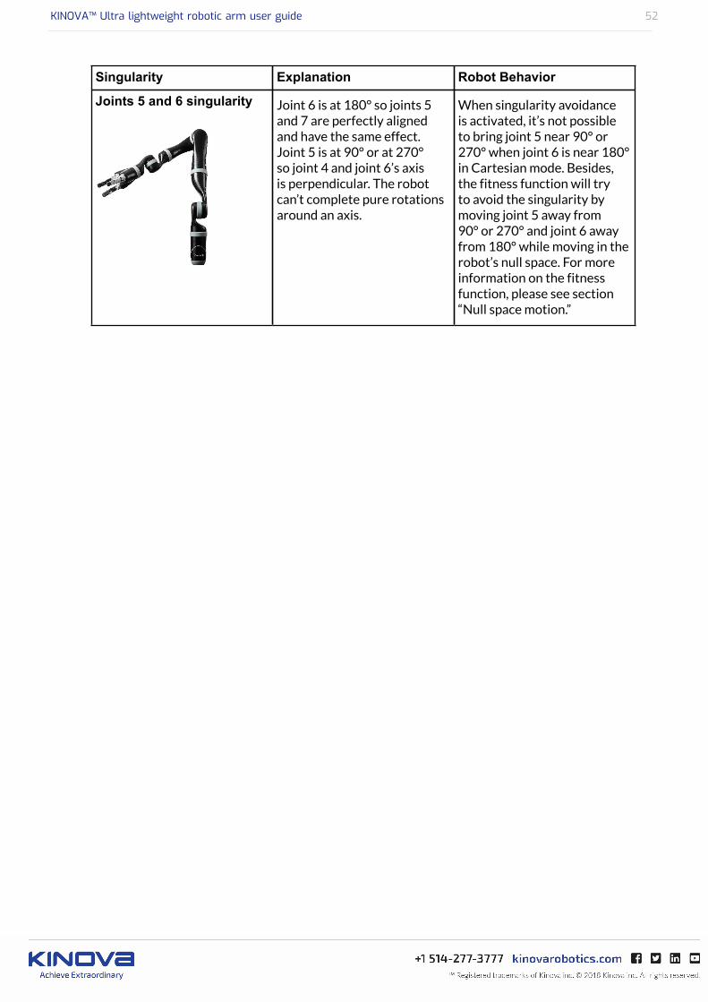
Singularity Explanation Robot Behavior
Joints 5 and 6 singularity Joint 6 is at 180° so joints 5and 7 are perfectly alignedand have the same effect.Joint 5 is at 90° or at 270°so joint 4 and joint 6’s axisis perpendicular. The robotcan’t complete pure rotationsaround an axis.
When singularity avoidanceis activated, it’s not possibleto bring joint 5 near 90° or270° when joint 6 is near 180°in Cartesian mode. Besides,the fitness function will tryto avoid the singularity bymoving joint 5 away from90° or 270° and joint 6 awayfrom 180° while moving in therobot’s null space. For moreinformation on the fitnessfunction, please see section“Null space motion.”

KINOVA™ Ultra lightweight robotic arm user guide 53
Self-collisions auto-avoidance
In Cartesian mode, Kinova robots avoid self-collisions (essentially collisions betweenthe hand and the base but also between the hand and the arm segment). This meansthe Cartesian command sent by the user may be modified by the control software toavoid a self-collision. Singularity auto-avoidance behavior can be deactivated using theActivateAutomaticCollsionAvoidance API function and setting its parameter to false.
Please note that collisions with other objects present in the environment are not automaticallyhandled by the robot.
Self-collisions are not automatically avoided during angular control. Only joint limits arehandled.
KINOVA™ Ultra lightweight robotic arm user guide 54
7 DOF Spherical Null space motion
The 7 DOF-S robot is redundant because it only requires six degrees of freedom (=sixactuators) to move and orient its effector in 3D space although it has seven actuators. A robotwith six actuators can only reach a given end-effector position and orientation with a fewconfigurations, which are very different from one another. The 7th degree of freedom (or 7thactuator) gives more flexibility to the robot and lets it reach a given end-effector position andorientation with a multiple/infinite number of configurations.
In fact, the robot can even move its elbow (joint 4) without modifying its end-effector positionand orientation. This type of motion is called “null space motion” because it does not affectwhere the end-effector is (i.e. it has no effect in the task space). During Cartesian control,Kinova automatically optimizes the robot motion in its null space with a special optimisationfunction called the fitness function. The fitness function will try to find the best compromiseto avoid singularities, position the elbow and avoid angular limits of the 7 DOF-S arm withoutmodifying the user’s Cartesian command. Right now, the robot’s null space motion can bedeactivated, but the fitness function parameters cannot be modified.
Because of null space motion, the robot’s elbow can move quite a lot during Cartesiancontrol. This is because the robot is trying to avoid singularities and angle limits while trying tokeep a preferred angle position and without modifying the user’s Cartesian command.
If the currently implemented null space motion algorithm does not suit your needs, you cancontrol the robot in angular space or deactivate the null space motion using the API function.
KINOVA™ Ultra lightweight robotic arm user guide 55
Protection zones
Protection zones can be defined using the API (For research users) or with the help of a Kinovaqualified service personnel member (for Assistive users). Protection zones must be box-shaped.Once a protection zone is defined, the robot will avoid getting inside this zone. If possible, itwill slide on the zone. If not, it will stop. By default, a protection zone is defined near the baseconnectors.
If you give a command and the robot stops moving because it is too close to a protectionzone, try moving the robot in another direction. If you notice that your robot is not movingunder any command, your robot’s behaviour is abnormal. Try sending the arm to its Readyposition (to continue using it) and contact Kinova support (to report the problem).
Protection zones are not avoided during angular control. Only joint limits are handled.
KINOVA™ Ultra lightweight robotic arm user guide 56
Rotating frame / Fixed frame
This section describes the difference between Rotating frame and Fixed frame for thehand/gripper.
By default, Kinova robots are configured in Rotating frame. In Rotating frame, the hand/gripperrotates automatically to follow the arm’s motion in the horizontal plane. This gives a morehuman-like behavior. In Fixed frame, the hand’s orientation will not change unless explicitlycommanded.
Users can switch between Rotating frame and Fixed frame using the Kinova DevelopmentCenter software or API. Frame selection (Rotating or Fixed) is recorded inside the robot’smemory. This means that a robot that was configured in Fixed frame will not reset to Rotatingframe at reboot.

KINOVA™ Ultra lightweight robotic arm user guide 57
Usable workspace
This section describes the usable workspace of the robotic arm.
The robotic arm's usable workspace is represented in the graphic below. The workspaceprovided is for angular control.
When the robot is in Cartesian mode, its effective usable workspace will be slightly smallerbecause of singularities, self-collisions and protection zone automatic avoidance algorithms.
Figure 5: Usable workspace - dimensions in mm. 6 DOF shown for illustrativepurposes

KINOVA™ Ultra lightweight robotic arm user guide 58
Admittance control
This section describes admittance control both in Cartesian and in angular mode.
Admittance control (also called Reactive Force control) can be activated and deactivatedusing the Kinova Development Center software or API. When admittance is active, it becomespossible to move the robot by hand. For Cartesian admittance, the robot must be in Cartesianmode and admittance must be activated. For angular/joint admittance, the robot must be inangular mode and admittance must be activated.
During Cartesian admittance control, the robot continues to avoid singularities, self collisionsand protection zones automatically (unless these functions are deactivated using the API). Thenull space motion will also stay active (unless deactivated using the API). Finally, maximumvelocity and acceleration limits stay active during admittance control in angular or Cartesianspace. User force input is automatically bounded between a minimum and a maximum valueinside the code. These minimum and maximum values are configurable inside the API. Dampingand inertia parameters present in the robot’s admittance model are also configurable.
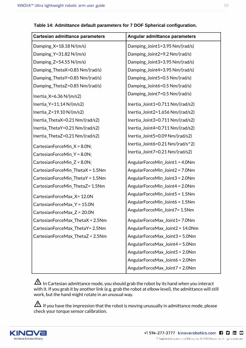
The table below shows default admittance parameters for the 7 DOf spherical configuration.Details will differ for other configurations.
KINOVA™ Ultra lightweight robotic arm user guide 59
Table 14: Admittance default parameters for 7 DOF Spherical configuration.
Cartesian admittance parameters Angular admittance parameters
Damping_X=18.18 N/(m/s)
Damping_Y=31.82 N/(m/s)
Damping_Z=54.55 N/(m/s)
Damping_ThetaX=0.85 Nm/(rad/s)
Damping_ThetaY=0.85 Nm/(rad/s)
Damping_ThetaZ=0.85 Nm/(rad/s)
Inertia_X=6.36 N/(m/s2)
Inertia_Y=11.14 N/(m/s2)
Inertia_Z=19.10 N/(m/s2)
Inertia_ThetaX=0.21 Nm/(rad/s2)
Inertia_ThetaY=0.21 Nm/(rad/s2)
Inertia_ThetaZ=0.21 Nm/(rad/s2)
CartesianForceMin_X = 8.0N;
CartesianForceMin_Y = 8.0N;
CartesianForceMin_Z = 8.0N;
CartesianForceMin_ThetaX = 1.5Nm
CartesianForceMin_ThetaY = 1.5Nm
CartesianForceMin_ThetaZ= 1.5Nm
CartesianForceMax_X= 12.0N
CartesianForceMax_Y = 15.0N
CartesianForceMax_Z = 20.0N
CartesianForceMax_ThetaX = 2.5Nm
CartesianForceMax_ThetaY= 2.5Nm
CartesianForceMax_ThetaZ = 2.5Nm
Damping_Joint1=3.95 Nm/(rad/s)
Damping_Joint2=9.2 Nm/(rad/s)
Damping_Joint3=3.95 Nm/(rad/s)
Damping_Joint4=3.95 Nm/(rad/s)
Damping_Joint5=0.5 Nm/(rad/s)
Damping_Joint6=0.5 Nm/(rad/s)
Damping_Joint7=0.5 Nm/(rad/s)
Inertia_Joint1=0.711 Nm/(rad/s2)
Inertia_Joint2=1.656 Nm/(rad/s2)
Inertia_Joint3=0.711 Nm/(rad/s2)
Inertia_Joint4=0.711 Nm/(rad/s2)
Inertia_Joint5=0.09 Nm/(rad/s2)
Inertia_Joint6=0.21 Nm/(rad/s^2)
Inertia_Joint7=0.21 Nm/(rad/s2)
AngularForceMin_Joint1 = 4.0Nm
AngularForceMin_Joint2 = 7.0Nm
AngularForceMin_Joint3 = 2.0Nm
AngularForceMin_Joint4 = 2.0Nm
AngularForceMin_Joint5 = 1.5Nm
AngularForceMin_Joint6 = 1.5Nm
AngularForceMin_Joint7= 1.5Nm
AngularForceMax_Joint1= 7.0Nm
AngularForceMax_Joint2 = 14.0Nm
AngularForceMax_Joint3 = 5.0Nm
AngularForceMax_Joint4 = 5.0Nm
AngularForceMax_Joint5 = 2.0Nm
AngularForceMax_Joint6 = 2.0Nm
AngularForceMax_Joint7 = 2.0Nm
In Cartesian admittance mode, you should grab the robot by its hand when you interactwith it. If you grab it by another link (e.g. grab the robot at elbow level), the admittance will stillwork, but the hand might rotate in an unusual way.
If you have the impression that the robot is moving unusually in admittance mode, pleasecheck your torque sensor calibration.
KINOVA™ Ultra lightweight robotic arm user guide 60
Torque Control
This section describes torque control.
As its name suggests, torque control lets the user control the motors in torque rather than inposition. By default, the arm compensates its own weight in torque mode. Users can also sendtorque commands and force commands using Kinova Torque Console or API.
By default, the robot also includes some safety features. The first safety is that the arm will notswitch from position mode to torque mode unless the torque read by the actuators and thegravity torques computed by the gravity model inside the robot are too different. On reboot, thearm will always go back to position mode.
Once in torque mode, some safety features can bring back the arm in position mode. This isthe case when one of the motors’ rotation velocity gets too high. Users can disable this safetyfeature at their own risk using the Kinova Torque Console or API (Safety Factor to 0). By default,the robot will also switch back to position mode if the hand gets too close from the base or if aspecific joint gets too close from its angle limits. Users can disable the base collision avoidancesafety feature at their own risk using the API.
Please note that when the robot is in torque mode, it is NOT possible to move the robot’sfingers. This is a limit to our actual system and it should be fixed in the next firmware release.
Do not disable the velocity safety feature unless you are sure that your robot’s torquesensors are well calibrated.
Be very careful when you disable a torque control safety feature. Ideally, keep the robotin an open environment free of near potential obstacles. Please keep in mind that commandingyour robot in torque mode with safeties disabled could damage your robot if the motors startturning too fast or if the robot collides with itself or the environment. If you disable the basecollision avoidance safety, keep in mind that the robot could collide with itself. A lot of safetyparameters are customizable in torque mode (see API HTML documentation for more details),but be aware that these customizations require knowledge to use appropriately.
Moving the robot very quickly in torque mode can lead, in rare occasions, to an unexpectedreboot - the robot stops moving or switches back to position mode and waits for a Home/Ready command. If you observe this behaviour, please contact the Kinova Support team (seeContacting Support).
KINOVA™ Ultra lightweight robotic arm user guide 61
Improving robot behavior in Torque mode
This section describes how to improve behavior of the robot in Torque mode.
Kinova robots allow to compensate the gravity torques associated with their own weight. Twogravity compensation modes are available:
• Manual (default mode)• Optimal (must be activated by user)
In Manual mode, each robot segment mass and center of mass is specified. For a robot with6 motors, this makes 24 parameters. Users can change segment masses and centers of massthrough the function SetManualInputParam().
In Optimal mode, the robot computes gravity torques from a series of parameters linking theangle and torque readings. To find these parameters, the robot must perform an automatictrajectory. The accuracy of the gravity torques estimation with the Optimal mode is usuallyabout three times better than with the Manual mode.
To use the Optimal gravity compensation mode, you need to create a custom C++ programcalling three main functions from Kinova API:
1. a. RunGravityZEstimationSequence() - for 6 DOF Sphericalb. RunGravityZEstimationSequence7DOF() - for 7 DOF Spherical
2. SetOptimalZParam()
3. SetGravityType()
The first function to be called is either RunGravityZEstimationSequence() for the 6DOF Spherical, or RunGravityZEstimationSequence7DOF() for the 7 DOF Spherical.RunGravityZEstimationSequence() takes for input the robot type and an empty arrayof 16 floats, while RunGravityZEstimationSequence7DOF() takes the robot type and anempty array of 19 floats. This will compute the 16 (or 19) optimal gravity parameters and placethem in the empty array of 16 (or 19) floats. RunGravityZEstimationSequence() willalso write the parameters in a text file called ParametersOptimal_Z.txt.This file is foundin the same folder as your C++ project. This function is not called every time you want to usethe robot. Once the optimal parameters have been obtained, this function does not need to becalled. Only call this function if you want to recalibrate the gravity parameters (which is the caseif you tighten/untighten some screws, or if the robot seems to have an unusual behaviour afterresetting the ‘zero’ of the torque sensors.
The second function to be called is SetOptimalZParam(), which takes for input the arrayof optimal parameters from the previous step. SetOptimalZParam() informs the robot onthe new optimal parameters. This function must be called at every reboot. When you call thisfunction without prior calling to RunGravityZEstimationSequence(), you must initializethe array of 16 floats with the values found in the text file ParametersOptimal_Z.txt.
The third function to be called is SetGravityType(), which takes for input either OPTIMAL(activates the Optimal gravity compensation mode) or MANUAL_INPUT (activates theMANUAL gravity compensation mode). This function must also be called at every reboot.
KINOVA™ Ultra lightweight robotic arm user guide 62
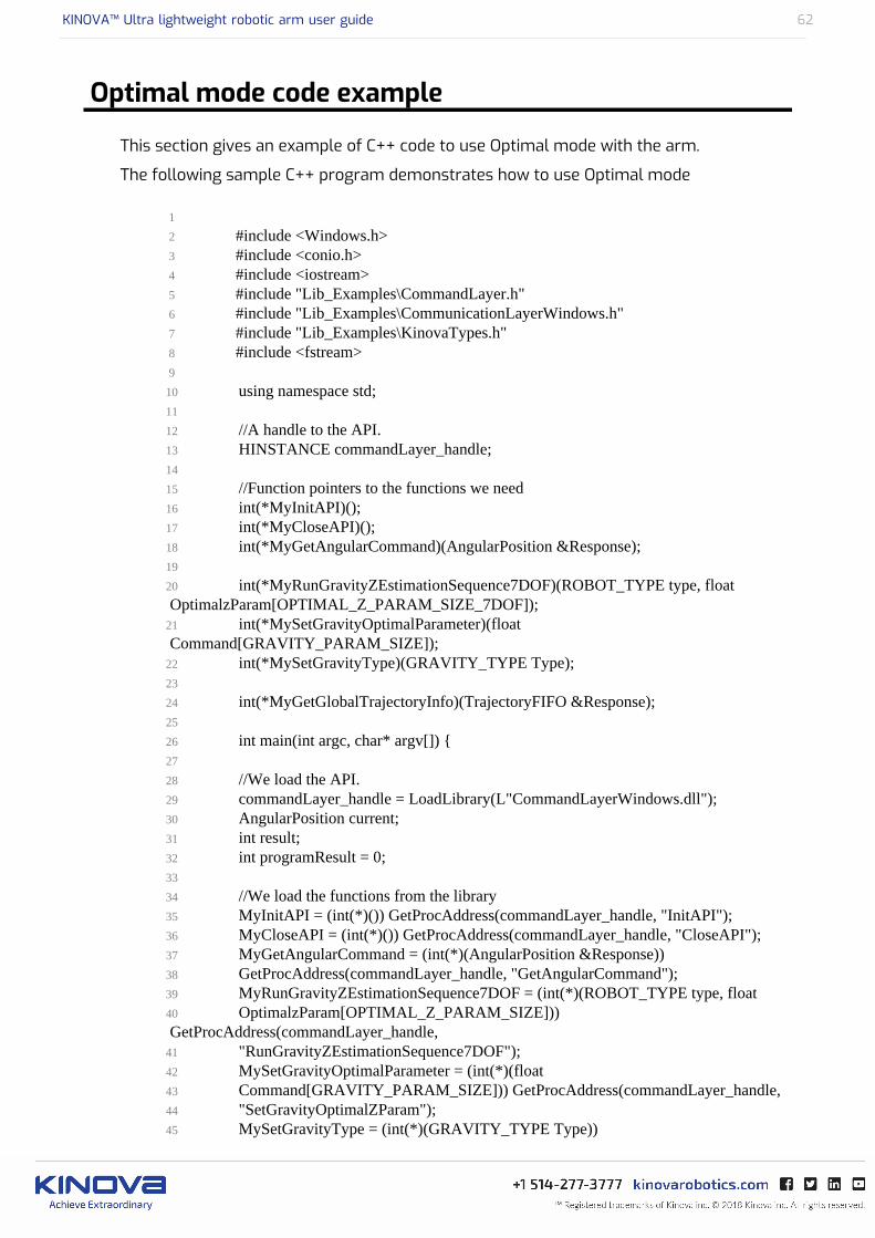
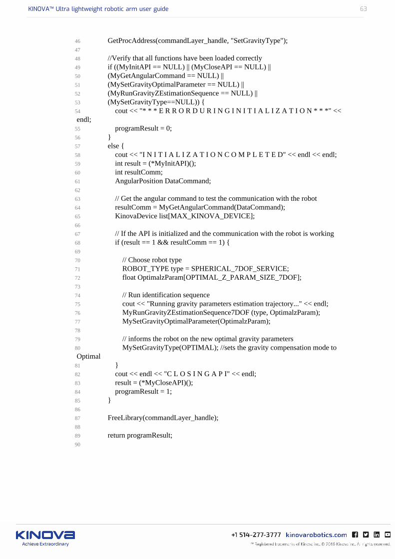
Optimal mode code example
This section gives an example of C++ code to use Optimal mode with the arm.
The following sample C++ program demonstrates how to use Optimal mode
1
2 #include <Windows.h> 3 #include <conio.h> 4 #include <iostream> 5 #include "Lib_Examples\CommandLayer.h" 6 #include "Lib_Examples\CommunicationLayerWindows.h" 7 #include "Lib_Examples\KinovaTypes.h" 8 #include <fstream> 9
10 using namespace std;11
12 //A handle to the API.13 HINSTANCE commandLayer_handle;14
15 //Function pointers to the functions we need16 int(*MyInitAPI)();17 int(*MyCloseAPI)();18 int(*MyGetAngularCommand)(AngularPosition &Response);19
20 int(*MyRunGravityZEstimationSequence7DOF)(ROBOT_TYPE type, float OptimalzParam[OPTIMAL_Z_PARAM_SIZE_7DOF]);21 int(*MySetGravityOptimalParameter)(float Command[GRAVITY_PARAM_SIZE]);22 int(*MySetGravityType)(GRAVITY_TYPE Type);23
24 int(*MyGetGlobalTrajectoryInfo)(TrajectoryFIFO &Response);25
26 int main(int argc, char* argv[]) {27
28 //We load the API.29 commandLayer_handle = LoadLibrary(L"CommandLayerWindows.dll");30 AngularPosition current;31 int result;32 int programResult = 0;33
34 //We load the functions from the library35 MyInitAPI = (int(*)()) GetProcAddress(commandLayer_handle, "InitAPI");36 MyCloseAPI = (int(*)()) GetProcAddress(commandLayer_handle, "CloseAPI");37 MyGetAngularCommand = (int(*)(AngularPosition &Response))38 GetProcAddress(commandLayer_handle, "GetAngularCommand");39 MyRunGravityZEstimationSequence7DOF = (int(*)(ROBOT_TYPE type, float40 OptimalzParam[OPTIMAL_Z_PARAM_SIZE])) GetProcAddress(commandLayer_handle,41 "RunGravityZEstimationSequence7DOF");42 MySetGravityOptimalParameter = (int(*)(float43 Command[GRAVITY_PARAM_SIZE])) GetProcAddress(commandLayer_handle,44 "SetGravityOptimalZParam");45 MySetGravityType = (int(*)(GRAVITY_TYPE Type))
KINOVA™ Ultra lightweight robotic arm user guide 63
46 GetProcAddress(commandLayer_handle, "SetGravityType");47 48 //Verify that all functions have been loaded correctly 49 if ((MyInitAPI == NULL) || (MyCloseAPI == NULL) || 50 (MyGetAngularCommand == NULL) || 51 (MySetGravityOptimalParameter == NULL) ||52 (MyRunGravityZEstimationSequence == NULL) ||53 (MySetGravityType==NULL)) {54 cout << "* * * E R R O R D U R I N G I N I T I A L I Z A T I O N * * *" << endl;55 programResult = 0;56 } 57 else { 58 cout << "I N I T I A L I Z A T I O N C O M P L E T E D" << endl << endl;59 int result = (*MyInitAPI)();60 int resultComm;61 AngularPosition DataCommand;62 63 // Get the angular command to test the communication with the robot64 resultComm = MyGetAngularCommand(DataCommand);65 KinovaDevice list[MAX_KINOVA_DEVICE];66 67 // If the API is initialized and the communication with the robot is working68 if (result == 1 && resultComm == 1) {69 70 // Choose robot type71 ROBOT_TYPE type = SPHERICAL_7DOF_SERVICE;72 float OptimalzParam[OPTIMAL_Z_PARAM_SIZE_7DOF];73 74 // Run identification sequence75 cout << "Running gravity parameters estimation trajectory..." << endl;76 MyRunGravityZEstimationSequence7DOF (type, OptimalzParam);77 MySetGravityOptimalParameter(OptimalzParam); 78 79 // informs the robot on the new optimal gravity parameters80 MySetGravityType(OPTIMAL); //sets the gravity compensation mode to Optimal81 }82 cout << endl << "C L O S I N G A P I" << endl;83 result = (*MyCloseAPI)();84 programResult = 1;85 }86 87 FreeLibrary(commandLayer_handle);88 89 return programResult;90
KINOVA™ Ultra lightweight robotic arm user guide 64
Important considerations for setting Optimal mode
IMPORTANT: Before launching the calibration trajectory with the functionRunGravityZEstimationSequence(), please ensure the robot has enough space to move. The top1.5 meter-radius spherical space around the base should be free of obstacles. The hand shouldtechnically never go below the base, so the base can be fixed on a table. For ideal results, you canattach the base on asmall stand so the space below the robot (except the space below the base)is free.
Before launching the calibration trajectory to find the optimal gravity parameters(RunGravityZEstimationSequence() function), reset the torque sensors zero value.Whenever your torque sensors readings seem off, start by resetting the torque sensors zerovalue, especially if you want to use admittance or torque mode.
The Optimal gravity compensation mode works only when the arm is standing on a flat surface(the gravity vector is in the direction [0, 0, -9.81]).
The robot does not save the optimal gravity parameters. If you want to use the Optimal gravitycompensation mode, you will have to load the parameters from the ‘ParametersOptimal_Z.txt’text file, send them to the robot using the SetOptimalZParam() function and activate theOptimal mode using the SetGravityType() function after each reboot.

KINOVA™ Ultra lightweight robotic arm user guide 65
Specific Utilization Limitations
The robotic arm has certain utilization limitations that research users should be cautious of. Thisincludes:
• Recommended maximum actuators utilization• Software position limitations of actuators• Software position limitations of fingers

KINOVA™ Ultra lightweight robotic arm user guide 66
Recommended maximum actuators utilization
Big actuators(75mm)
Small actuators(58mm)
Fingers actuators
Maximum RPM 6 RPM 8 RPM 600 RPM
Maximum command /sec
36° / sec 48° / sec 300 mm / sec
10800° / sec
Maximum repetitivecurrent
1.5A 1.6A 1.4
Maximumtemperature
80°C 80°C 80°C
Utilization over these maximum recommended parameters may affect lifetime ofthe arm and its modules. Please refer to the specification sheet information for yourparticular arm configuration for additional information

KINOVA™ Ultra lightweight robotic arm user guide 67
Software position limitations of actuators
This section provides a reference of software position limitations of various robotic armconfigurations.
The following limitations indicate the software limitations that are presents in the robotic armcontroller base to ensure safety of the robot. These limitations are there to protect the arm andits environment.
When moving the actuators, the following minimum and maximum positions should be followed.If the command sent to any of these actuators goes further than these values, the actuators willstop moving.
Table 15: 4 DOF software limitations
Joint Min(°) Max(°)
1 -10 000 10 000
2 47 313
3 19 341
4 -10 000 10 000
Table 16: 6DOF curved wrist software limitations
Joint Min(°) Max(°)
1 -10 000 10 000
2 50 310
3 19 341
4 -10 000 10 000
5 -10 000 10 000
6 -10 000 10 000
Table 17: 6 DOF Spherical software limitations
Joint Min(°) Max(°)
1 -10 000 10 000
2 47 313
3 19 341
4 -10 000 10 000
5 65 295
6 -10 000 10 000
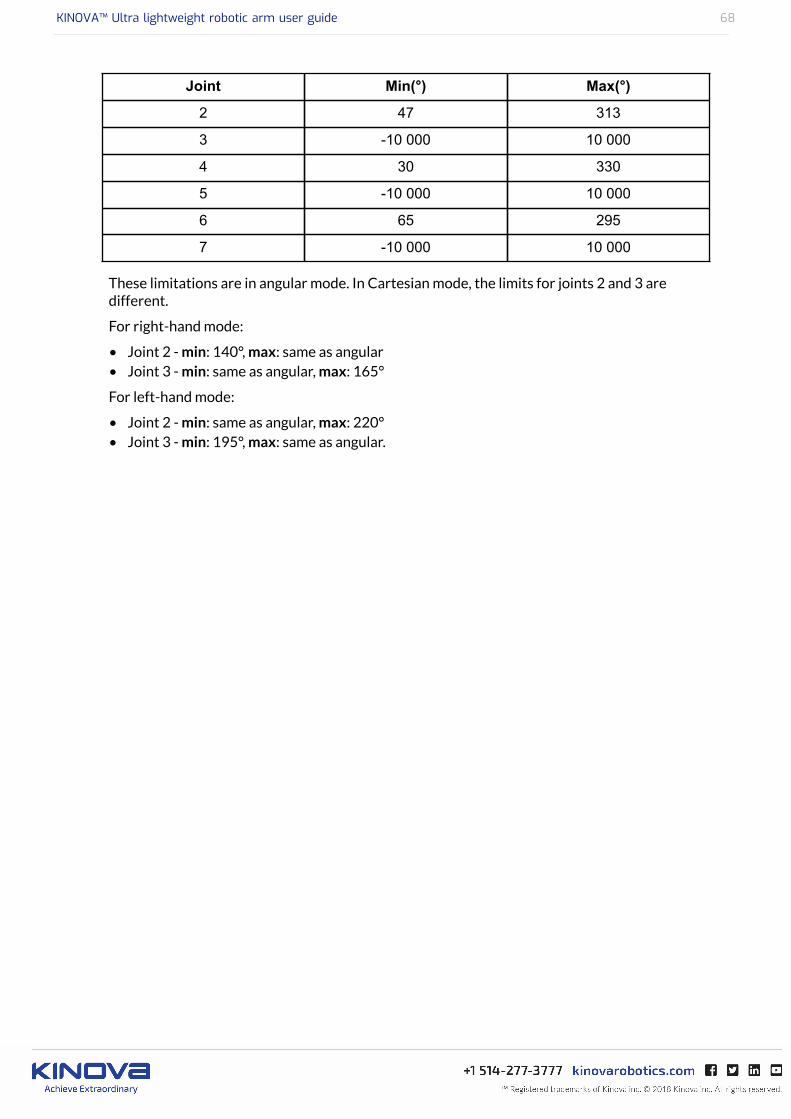
Table 18: 7 DOF Spherical software limitations
Joint Min(°) Max(°)
1 -10 000 10 000
KINOVA™ Ultra lightweight robotic arm user guide 68
Joint Min(°) Max(°)
2 47 313
3 -10 000 10 000
4 30 330
5 -10 000 10 000
6 65 295
7 -10 000 10 000
These limitations are in angular mode. In Cartesian mode, the limits for joints 2 and 3 aredifferent.
For right-hand mode:
• Joint 2 - min: 140°, max: same as angular• Joint 3 - min: same as angular, max: 165°
For left-hand mode:
• Joint 2 - min: same as angular, max: 220°• Joint 3 - min: 195°, max: same as angular.
KINOVA™ Ultra lightweight robotic arm user guide 69
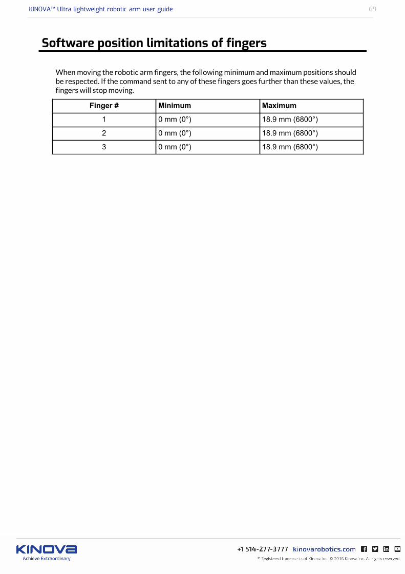
Software position limitations of fingers
When moving the robotic arm fingers, the following minimum and maximum positions shouldbe respected. If the command sent to any of these fingers goes further than these values, thefingers will stop moving.
Finger # Minimum Maximum
1 0 mm (0°) 18.9 mm (6800°)
2 0 mm (0°) 18.9 mm (6800°)
3 0 mm (0°) 18.9 mm (6800°)
KINOVA™ Ultra lightweight robotic arm user guide 70
Advanced Configuration
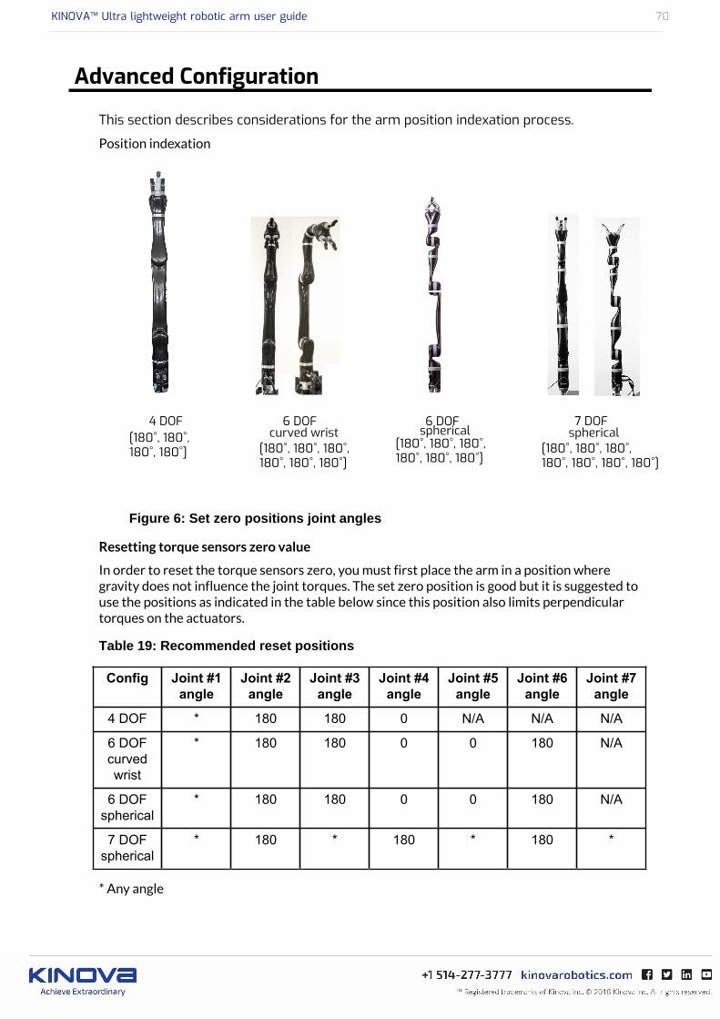
This section describes considerations for the arm position indexation process.
Position indexation
Figure 6: Set zero positions joint angles
Resetting torque sensors zero value
In order to reset the torque sensors zero, you must first place the arm in a position wheregravity does not influence the joint torques. The set zero position is good but it is suggested touse the positions as indicated in the table below since this position also limits perpendiculartorques on the actuators.
Table 19: Recommended reset positions
Config Joint #1angle
Joint #2angle
Joint #3angle
Joint #4angle
Joint #5angle
Joint #6angle
Joint #7angle
4 DOF * 180 180 0 N/A N/A N/A
6 DOFcurvedwrist
* 180 180 0 0 180 N/A
6 DOFspherical
* 180 180 0 0 180 N/A
7 DOFspherical
* 180 * 180 * 180 *
* Any angle
KINOVA™ Ultra lightweight robotic arm user guide 71
Kinematics Parameters
There are several sets of useful kinematic parameters:
• Basic geometric parameters of the arm• Classic Denavit-Hartenberg (DH) parameters• Directions of joints in angular space• Inertial parameters
KINOVA™ Ultra lightweight robotic arm user guide 72
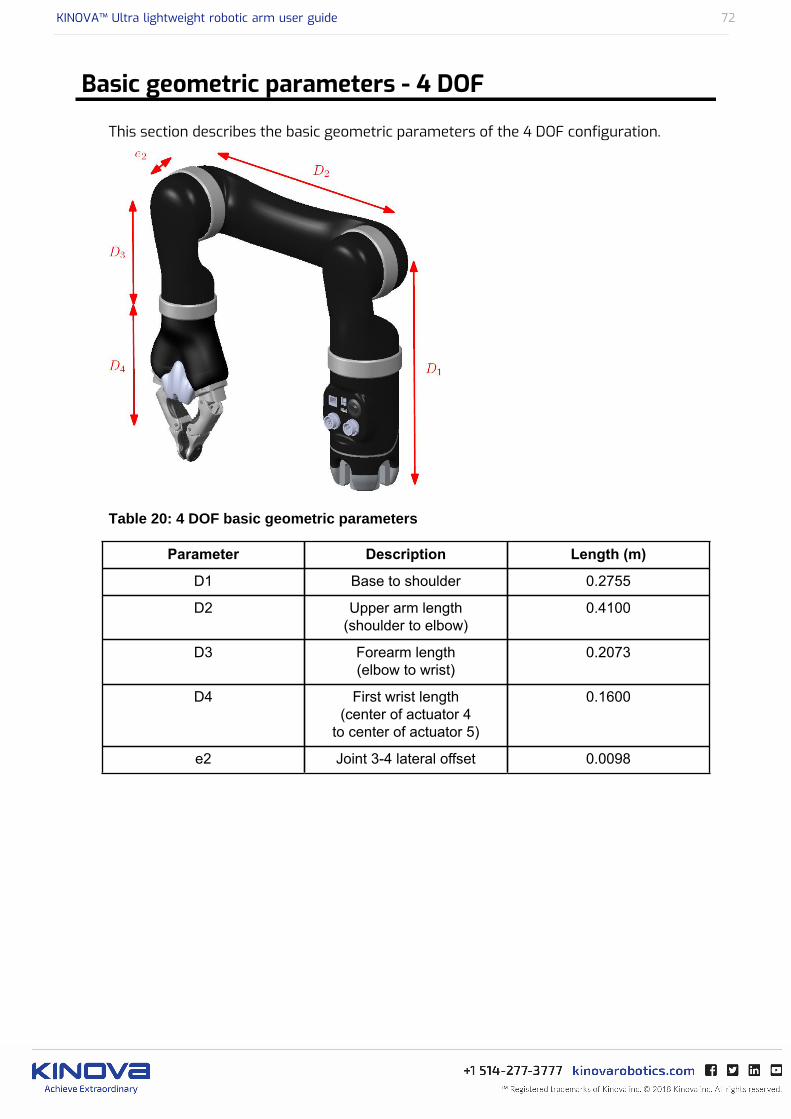
Basic geometric parameters - 4 DOF
This section describes the basic geometric parameters of the 4 DOF configuration.
Table 20: 4 DOF basic geometric parameters
Parameter Description Length (m)
D1 Base to shoulder 0.2755
D2 Upper arm length(shoulder to elbow)
0.4100
D3 Forearm length(elbow to wrist)
0.2073
D4 First wrist length(center of actuator 4
to center of actuator 5)
0.1600
e2 Joint 3-4 lateral offset 0.0098
KINOVA™ Ultra lightweight robotic arm user guide 73
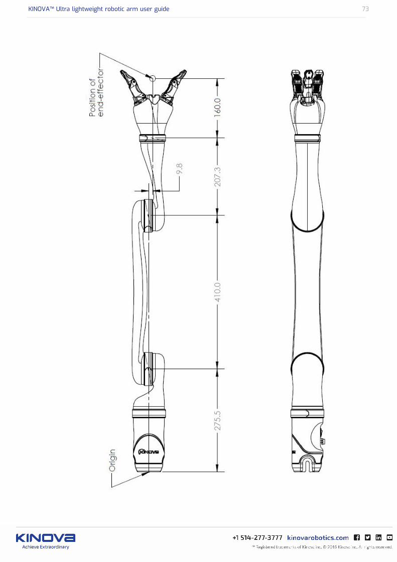
Figure 7: Detailed 4 DOF robot length values (units in mm)
KINOVA™ Ultra lightweight robotic arm user guide 74
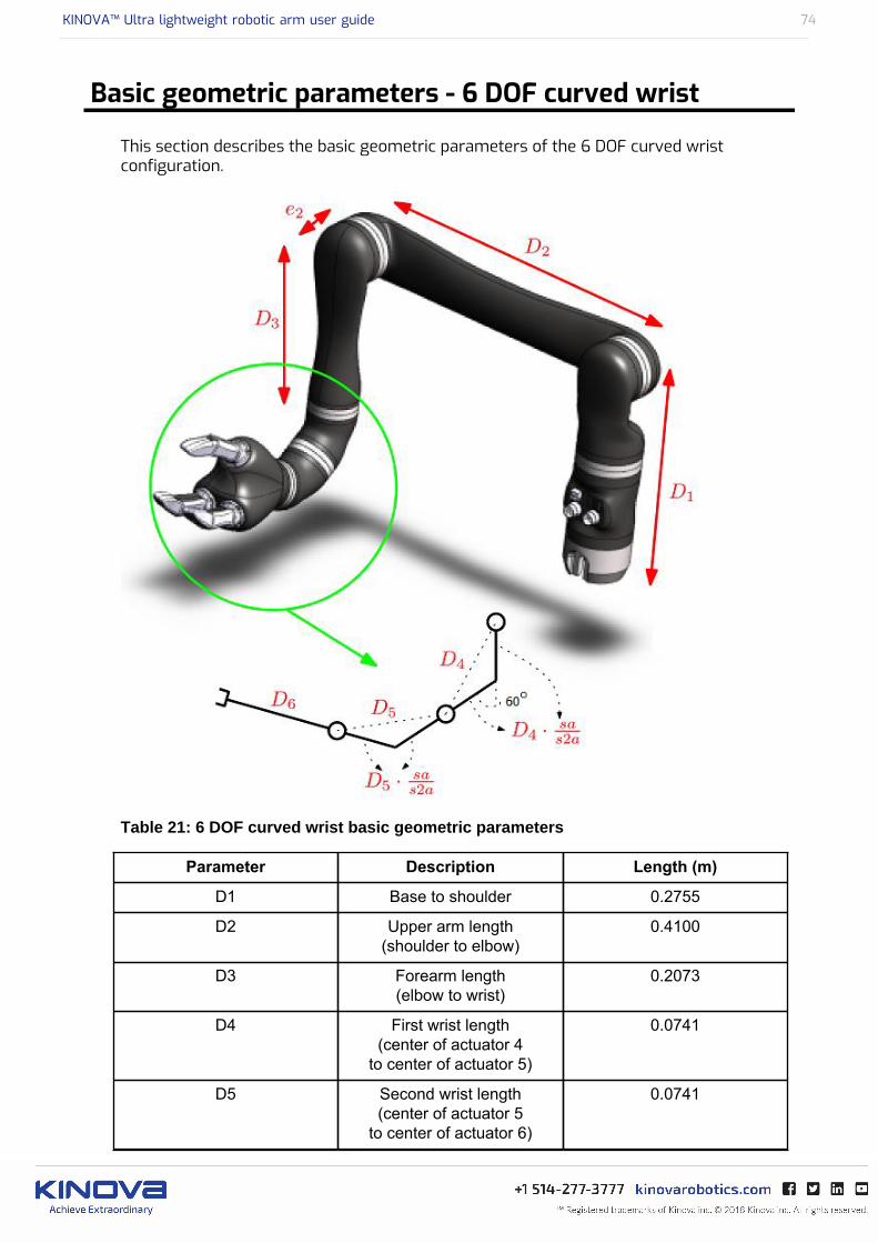
Basic geometric parameters - 6 DOF curved wrist
This section describes the basic geometric parameters of the 6 DOF curved wristconfiguration.
Table 21: 6 DOF curved wrist basic geometric parameters
Parameter Description Length (m)
D1 Base to shoulder 0.2755
D2 Upper arm length(shoulder to elbow)
0.4100
D3 Forearm length(elbow to wrist)
0.2073
D4 First wrist length(center of actuator 4
to center of actuator 5)
0.0741
D5 Second wrist length(center of actuator 5
to center of actuator 6)
0.0741
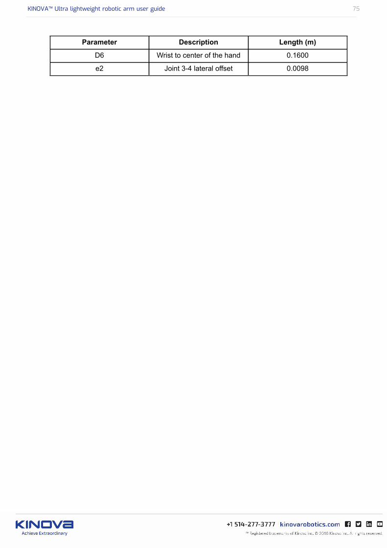
KINOVA™ Ultra lightweight robotic arm user guide 75
Parameter Description Length (m)
D6 Wrist to center of the hand 0.1600
e2 Joint 3-4 lateral offset 0.0098
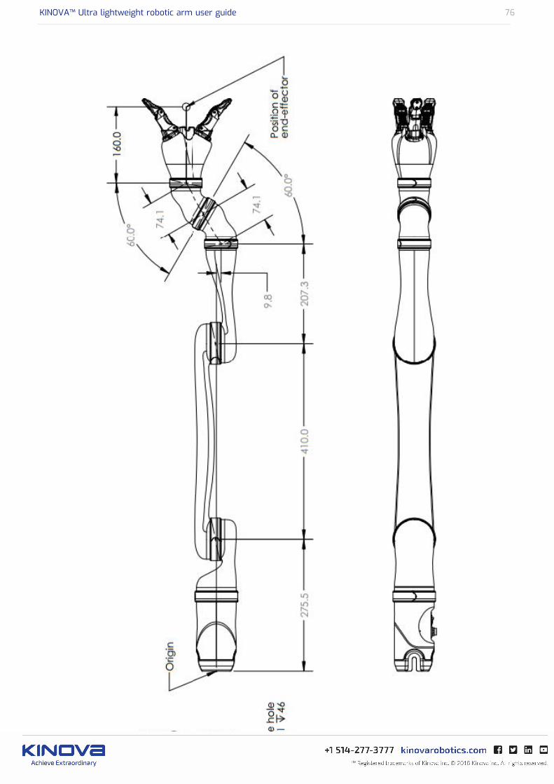
KINOVA™ Ultra lightweight robotic arm user guide 76
Figure 8: Detailed 6 DOF curved wrist robot length values (units in mm)
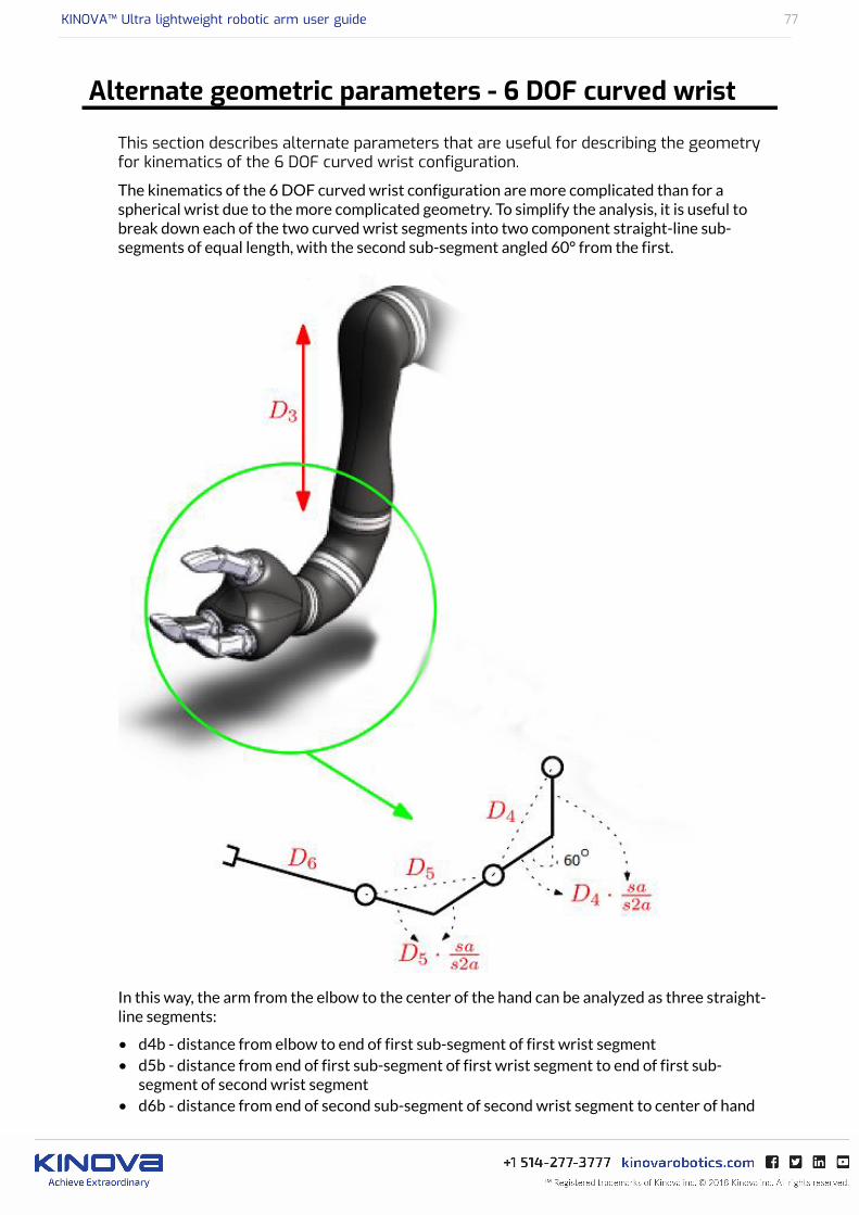
KINOVA™ Ultra lightweight robotic arm user guide 77
Alternate geometric parameters - 6 DOF curved wrist
This section describes alternate parameters that are useful for describing the geometryfor kinematics of the 6 DOF curved wrist configuration.
The kinematics of the 6 DOF curved wrist configuration are more complicated than for aspherical wrist due to the more complicated geometry. To simplify the analysis, it is useful tobreak down each of the two curved wrist segments into two component straight-line sub-segments of equal length, with the second sub-segment angled 60° from the first.
In this way, the arm from the elbow to the center of the hand can be analyzed as three straight-line segments:
• d4b - distance from elbow to end of first sub-segment of first wrist segment• d5b - distance from end of first sub-segment of first wrist segment to end of first sub-
segment of second wrist segment• d6b - distance from end of second sub-segment of second wrist segment to center of hand
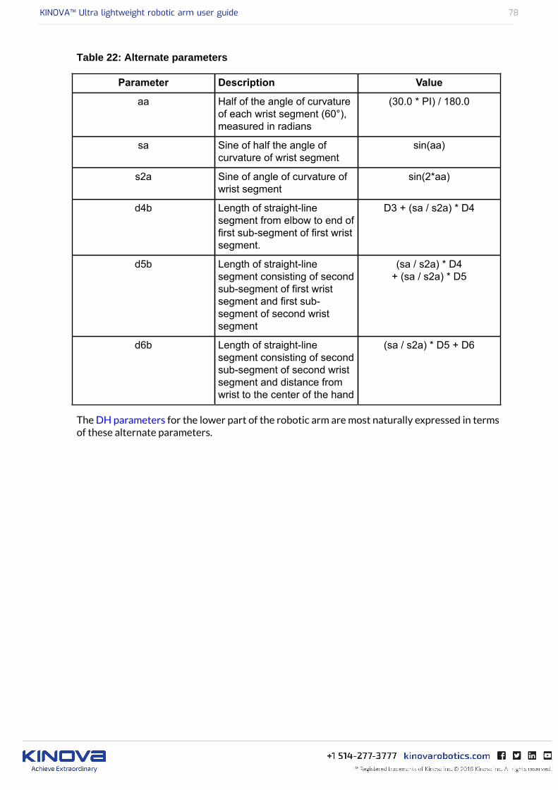
KINOVA™ Ultra lightweight robotic arm user guide 78
Table 22: Alternate parameters
Parameter Description Value
aa Half of the angle of curvatureof each wrist segment (60°),measured in radians
(30.0 * PI) / 180.0
sa Sine of half the angle ofcurvature of wrist segment
sin(aa)
s2a Sine of angle of curvature ofwrist segment
sin(2*aa)
d4b Length of straight-linesegment from elbow to end offirst sub-segment of first wristsegment.
D3 + (sa / s2a) * D4
d5b Length of straight-linesegment consisting of secondsub-segment of first wristsegment and first sub-segment of second wristsegment
(sa / s2a) * D4+ (sa / s2a) * D5
d6b Length of straight-linesegment consisting of secondsub-segment of second wristsegment and distance fromwrist to the center of the hand
(sa / s2a) * D5 + D6
The DH parameters for the lower part of the robotic arm are most naturally expressed in termsof these alternate parameters.
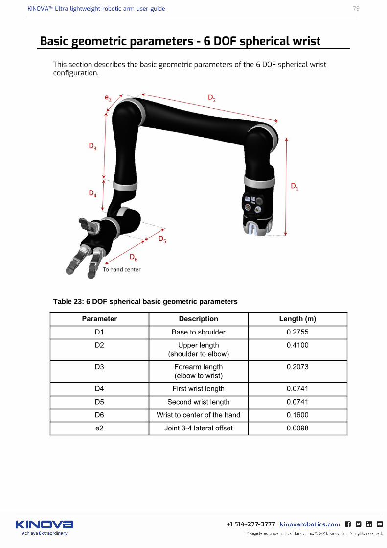
KINOVA™ Ultra lightweight robotic arm user guide 79
Basic geometric parameters - 6 DOF spherical wrist
This section describes the basic geometric parameters of the 6 DOF spherical wristconfiguration.
Table 23: 6 DOF spherical basic geometric parameters
Parameter Description Length (m)
D1 Base to shoulder 0.2755
D2 Upper length(shoulder to elbow)
0.4100
D3 Forearm length(elbow to wrist)
0.2073
D4 First wrist length 0.0741
D5 Second wrist length 0.0741
D6 Wrist to center of the hand 0.1600
e2 Joint 3-4 lateral offset 0.0098

KINOVA™ Ultra lightweight robotic arm user guide 80
Figure 9: Detailed 6 DOF spherical robot length values (units in mm)

KINOVA™ Ultra lightweight robotic arm user guide 81
Basic geometric parameters - 7 DOF spherical wrist
This section describes the basic geometric parameters of the 7 DOF spherical wrist.
Table 24: 7 DOF spherical basic geometric parameters
Parameter Description Length (m)
D1 Base to shoulder 0.2755
D2 First half upper arm length 0.2050
D3 Second half upper arm length 0.2050
D4 Forearm length(elbow to wrist)
0.2073
D5 First wrist length 0.1038
D6 Second wrist length 0.1038
D7 Wrist to center of the hand 0.1600
e2 Joint 3-4 lateral offset 0.0098

KINOVA™ Ultra lightweight robotic arm user guide 82
Figure 10: Detailed 7 DOF spherical robot length values (units in mm)

KINOVA™ Ultra lightweight robotic arm user guide 83
Classic DH parameters - 4 DOF
This section describes the Classic DH parameters for the 4 DOF.
Table 25: 4 DOF DH parameters
i αi-1 ai-1 di θi
1 π / 2 0 D1 q1
2 π D2 0 q2
3 π / 2 0 -e2 q3
4 π 0 D3 + D4 q4
Table 26: Transformation from DH algorithm to robotic arm physical angles
Q1(physical) = -Q1(DH algo)
Q2(physical) = Q2(DH algo) + 90
Q3(physical) = Q3(DH algo) - 90
Q4(physical) = Q4(DH algo) - 270
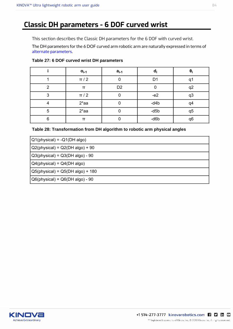
KINOVA™ Ultra lightweight robotic arm user guide 84
Classic DH parameters - 6 DOF curved wrist
This section describes the Classic DH parameters for the 6 DOF with curved wrist.
The DH parameters for the 6 DOF curved arm robotic arm are naturally expressed in terms ofalternate parameters.
Table 27: 6 DOF curved wrist DH parameters
i αi-1 ai-1 di θi
1 π / 2 0 D1 q1
2 π D2 0 q2
3 π / 2 0 -e2 q3
4 2*aa 0 -d4b q4
5 2*aa 0 -d5b q5
6 π 0 -d6b q6
Table 28: Transformation from DH algorithm to robotic arm physical angles
Q1(physical) = -Q1(DH algo)
Q2(physical) = Q2(DH algo) + 90
Q3(physical) = Q3(DH algo) - 90
Q4(physical) = Q4(DH algo)
Q5(physical) = Q5(DH algo) + 180
Q6(physical) = Q6(DH algo) - 90

KINOVA™ Ultra lightweight robotic arm user guide 85
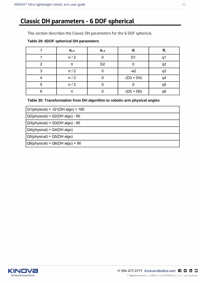
KINOVA™ Ultra lightweight robotic arm user guide 86
Classic DH parameters - 6 DOF spherical
This section describes the Classic DH parameters for the 6 DOF spherical.
Table 29: 6DOF spherical DH parameters
i αi-1 ai-1 di θi
1 π / 2 0 D1 q1
2 π D2 0 q2
3 π / 2 0 -e2 q3
4 π / 2 0 -(D3 + D4) q4
5 π / 2 0 0 q5
6 π 0 -(D5 + D6) q6
Table 30: Transformation from DH algorithm to robotic arm physical angles
Q1(physical) = -Q1(DH algo) + 180
Q2(physical) = Q2(DH algo) - 90
Q3(physical) = Q3(DH algo) - 90
Q4(physical) = Q4(DH algo)
Q5(physical) = Q5(DH algo)
Q6(physical) = Q6(DH algo) + 90
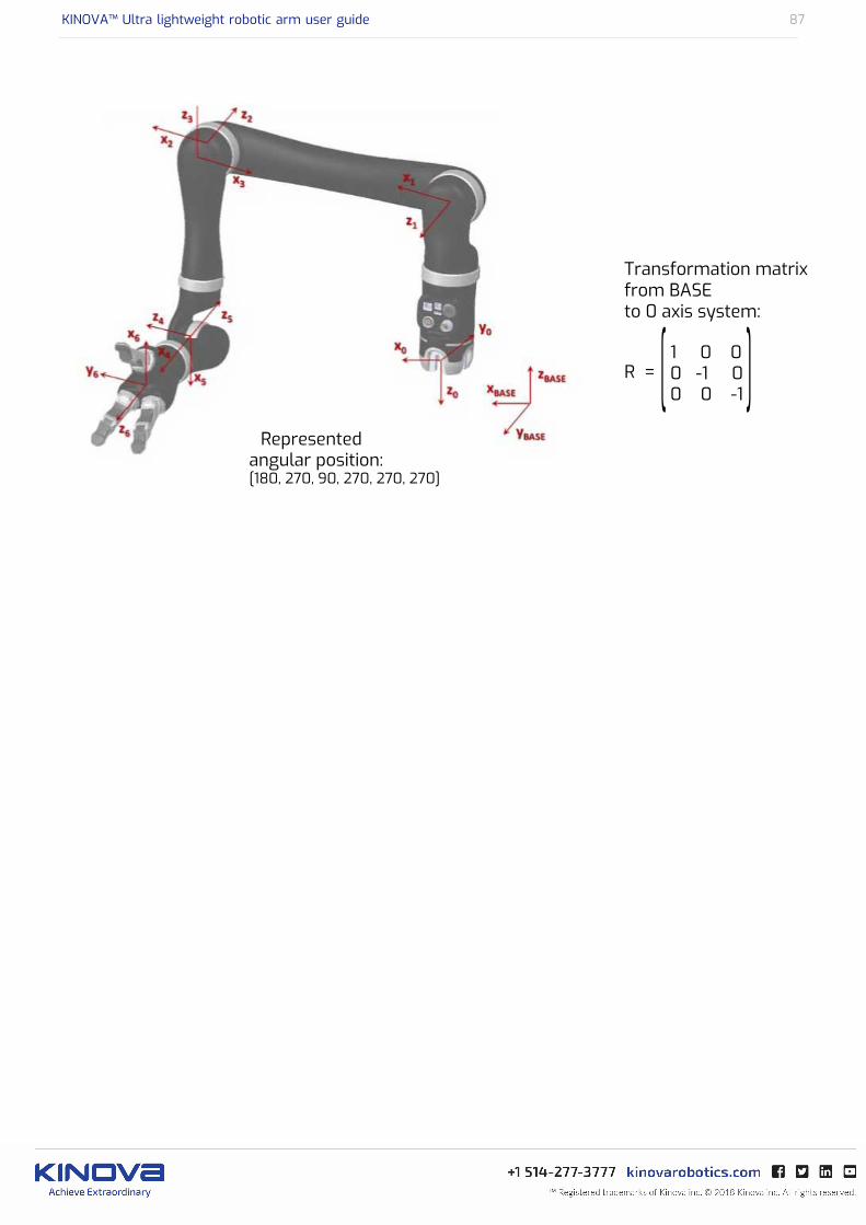
KINOVA™ Ultra lightweight robotic arm user guide 87

KINOVA™ Ultra lightweight robotic arm user guide 88
Classic DH parameters - 7 DOF spherical
This section describes the Classic DH parameters for the 7 DOF spherical.
Table 31: 7 DOF spherical DH parameters
i αi-1 ai-1 di θi
1 π / 2 0 -D1 q1
2 π / 2 0 0 q2
3 π / 2 0 -(D2 + D3) q3
4 π / 2 0 -e2 q4
5 π / 2 0 -(D4 + D5) q5
6 π / 2 0 0 q6
7 π 0 -(D6 + D7) q7
Table 32: Transformation from DH algorithm to robotic arm physical angles
Q1(physical) = Q1(DH algo) + 180
Q2(physical) = Q2(DH algo)
Q3(physical) = Q3(DH algo)
Q4(physical) = Q4(DH algo)
Q5(physical) = Q5(DH algo)
Q6(physical) = Q6(DH algo) + 90
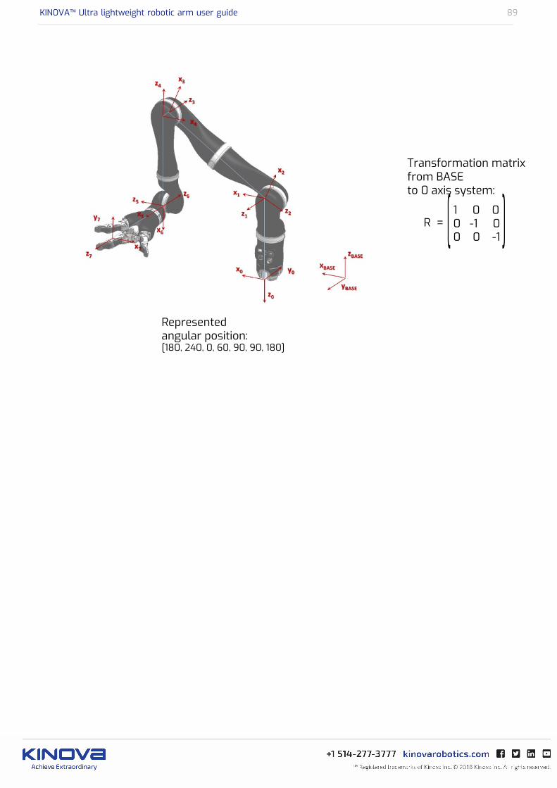
KINOVA™ Ultra lightweight robotic arm user guide 89
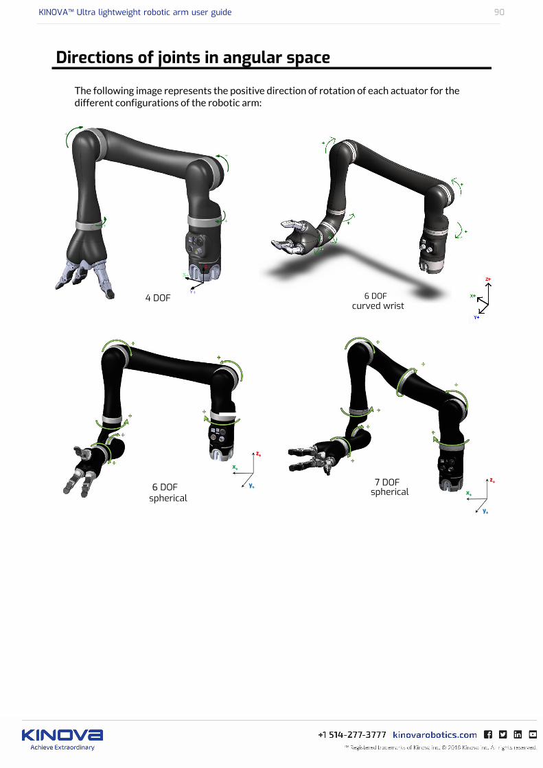
KINOVA™ Ultra lightweight robotic arm user guide 90
Directions of joints in angular space
The following image represents the positive direction of rotation of each actuator for thedifferent configurations of the robotic arm:

KINOVA™ Ultra lightweight robotic arm user guide 91
Advanced sensors information
This section has information about the accelerometers in each actuator.
The image below shows information about the accelerometers in each joint actuator.
KINOVA™ Ultra lightweight robotic arm user guide 92
Normal use definition
This section describes the normal use of the robotic arm.
The definition of a normal use of the robotic arm includes that you can lift, push, pull ormanipulate a maximum load of:
• Continuously 2.6 kg from minimum to middle reach for 6 DOF, 6 DOF-S, and 7 DOF-S (45-49cm distance between the actuator #2 and the load, depending on the configuration) and 4.4kg from minimum to middle reach for the 4 DOF (35 cm distance between actuator #2 andthe load).
• Temporary 2.2 kg from middle to full reach for 6 DOF, 6 DOF-S, 7 DOF-S (90-98 cm distancebetween actuator #2 and the load, depending on the configuration) and 3.5 kg from middle tofull reach for 4DOF (75 cm distance between actuator #2 and the load).
The arm is designed to be able to hold objects in the environment of the user, but it is amanipulator that in some positions and loads near the maximum reach and maximum loadsholds for a long period, it can heat. When this occurs, before overheating and being dangerousfor either the user or the arm, red lights on the joystick will blink. This is a warning. Simply putdown any object in the gripper, and bring back the arm to the HOME or RETRACTED positionsand wait until the warning goes away before using the arm.
If you don’t use a Joystick in your application, make sure to read all the error statuses andtemperature of all actuators modules via the API to ensure that they do not go higher thanrecommended parameters. If this occurs, the arm should be held in an idle position near thebase for a certain time without any object in the gripper to cool down the arm.
When lifting weight near the maximum load and reach, if the red lights of the controllerblinks, put down the object in the gripper, and bring back the arm to HOME or RETRACTEDposition and wait until the warning goes away before using it.
Note: During normal operation, the joints are subject to heating. The joints are normallycovered with plastic rings which will protect the user from any danger that may be occurred bythe heating of the metal parts.
The fingers of the arm are made flexible in order to protect the internal mechanism. When usingthe fingers to push on objects, the user must take special care not flex the fingers beyond theirmaximal opening as this could damage the internal mechanism.
Do not force the fingers beyond their maximal opening as this could damage some internalcomponents.

KINOVA™ Ultra lightweight robotic arm user guide 93
Electromagnetic interference from radio wave sources
This section describes electromagnetic interference considerations for the JACO roboticarm.
Even if the product complies with all relevant standards, your arm may still be susceptible toelectromagnetic interference (EMI), which is interfering electromagnetic energy (EM) emittedfrom sources such as radio stations, TV stations, amateur radio (HAM) transmitters, two wayradios, and cellular phones. The interference (from radio wave sources) can cause the productto stop moving for a period of 10 seconds. In this case, the device will simply re-initialize andyou will be able to continue to use it. In extremely rare case, it can also permanently damage thecontrol system.
The intensity of the interfering EM energy can be measured in volts per meter (V/m). Theproduct can resist EMI up to certain intensity. This is called “immunity level”. The higher theimmunity level is, the greater is the protection. At this time, current technology is capable ofachieving at least a 20 V/m immunity level, which would provide useful protection from themore common sources of radiated EMI.
There are a number of sources of relatively intense electromagnetic fields in the everydayenvironment. Some of these sources are obvious and easy to avoid. Others are not apparent andexposure is unavoidable. However, we believe that by following the warnings listed below, yourrisk to EMI will be minimized.
The sources of radiated EMI can be broadly classified into three types:
1. Gripper-held portable transceivers (e.g. transmitters-receivers with the antenna mounteddirectly on the transmitting unit, including citizens band (CB) radios, walkie-talkie, security,fire and police transceivers, cellular phones, and other personal communication devices).Some cellular phones and similar devices transmit signals while they are ON, even if notbeing actively used.
2. Medium-range mobile transceivers, such as those used in police cars, fire trucks, ambulancesand taxis. These usually have the antenna mounted on the outside of the vehicle.
3. Long-range transmitters and transceivers, such as commercial broadcast transmitters (radioand TV broadcast antenna towers) and amateur (HAM) radios. Other types of gripper-helddevices, such as cordless phones, laptop computers, AM/FM radios, TV sets, CD players,cassette players, and small appliances, such as electric shavers and hair dryers, so far as weknow, are not likely to cause EMI problems to your device.
Because EM energy rapidly becomes more intense as one move closer to the transmittingantenna (source), the EM fields from gripper-held radio wave sources (transceivers) are ofspecial concern. It is possible to unintentionally bring high levels of EM energy very close tothe control system while using these sorts of devices. Therefore, the warnings listed below arerecommended to reduce the effects of possible interference with the control system.
Do not operate gripper-held transceivers (transmitter’s receivers), such as citizens band(CB) radios, or turn ON personal communication devices, such as cellular phones, while thedevice is turned ON.
Be aware of nearby transmitters, such as radio or TV stations, and try to avoid coming closeto them.
Be aware that adding accessories or components, close to the device may make it moresusceptible to EMI.
Report all incidents of unintended shut down to your local distributor, and note whetherthere is a source of EMI nearby.
KINOVA™ Ultra lightweight robotic arm user guide 94
Maintenance and Disposal
This section describes maintenance and disposal considerations.
Cleaning instructions
Only the external surfaces of the product may be cleaned. Cleaning may be done using a dampcloth and light detergent. The following described the steps for the cleaning the product:
• Prepare a water/soap preparation using a proportion of about 2ml of dish soap for 100ml ofwater
• Immerse a clean cotton cloth in the preparation• Take out the cloth and wring out thoroughly• Gently rub the external surface to be cleaned
Do not wash more than three times per day.
Do not immerse any part of the product under water or snow.
The product is not intended to be sterile. No sterilization process should be applied to theproduct.
Do not rub the external surfaces with abrasive materials.
Preventive Maintenance
The product requires no maintenance. Fingers should be cleaned and lubricated every 6months.
Refer all services to qualified service personnel. A service is required when the apparatushas been damaged in any way, for example if the power-supply cord or plug is damaged, if theproduct does not operate normally or has been dropped.
There is no “home serviceable” part inside the product. Do not open..
Disposal
The product contains parts that are deemed to be hazardous waste at the end of theirlife. For further information on recycling, contact your local recycling authority or local Kinovadistributor. In any way, always dispose of product through a recognized agent.

KINOVA™ Ultra lightweight robotic arm user guide 95
Packing Materials
The product packing material can be disposed as recyclable material.
Metal parts
Metal parts can be disposed as recyclable scrap metal.
Electrical parts, circuit boards, and carbon fiber
Please contact your local distributor to have information regarding disposal of such parts. Youcan also address questions directly to Kinova through our website (see Contacting Support).

KINOVA™ Ultra lightweight robotic arm user guide 96
Troubleshooting / FAQs
This section gives guidance in troubleshooting common issues
Table 33:
Issues
My arm will not switchfrom position mode totorque mode
Make sure nothing is touching your robot when you try to switchto torque mode. Monitor your robot’s torque readings, computedgravity-free torques and force/torque at the hand using the KinovaDevelopment Center or API. Normally, gravity-free torques andforce/torque at the hand should be low. If your torque readingsseem unusual, redo your torque sensors zero calibration. Normally,a good position to switch from position mode to torque mode isthe robot’s Ready position (although any position is technicallyacceptable).
My arm keeps fallingdown in torque mode
Torque mode is very sensitive to gravity compensation. First, checkthat your torque sensors’ zero was adequately calibrated. You canalso follow the tips given in Appendix 5. If your robot keeps fallingdown, you can try adding a negative (m < 0) virtual mass using theKinova Torque Console or API. * Note: If instead of falling down,your arm is always going up, you should follow the same tips butwith adding a positive virtual mass at the end instead of a negativeone.
KINOVA™ Ultra lightweight robotic arm user guide 97
Issues
I sent a trajectory inCartesian mode and therobot stops at some pointin the trajectory.
This problem can take several forms: the robot is in a randomposition when the trajectory is launched, the robot ‘reaches’ thefirst point but does not continue passed that. In this case, the robotnever really reaches the first point, but goes towards it withoutreaching it; the robot starts the trajectory but gets stuck trying toreach a point; the robot takes a very unusual twist trying to reacha point. All of these problems are in fact one problem: the robotcannot reach the next trajectory point if it gets into singularity,self-collision or runs into a protection zone. “But I moved the robotwith the joystick to create the trajectory”. When you are using thejoystick, the robot receives a succession of small movements thateventually lead it to the points you have recorded in the trajectory.Besides, when the robot receives a joystick point (or Cartesianvelocity point), it tries to reach it, then erases it and waits for thenext point. When the robot receives a Cartesian trajectory point(or Cartesian position), it computes a straight line from its currentposition to the next trajectory point. Then it computes the nextreachable point on this straight line considering maximum velocityand acceleration limits and gets deviated by its automatic self-collision and singularity avoidance algorithms. Finally, the robotverifies if the desired trajectory point was reached. If it did notreach the trajectory point, it repeats the process and it NEVERerases the trajectory point until it reaches it (within a certain errormargin). Because the robot is not able to reach the next trajectorypoint while avoiding singularities and self-collision, and becausethis trajectory point does not get erased from the list, you get theimpression that the robot either does not receive all the trajectorypoint or freezes in the middle of the trajectory.
Now, what to do? Here are a few tips:
• Record more points in the trajectory, especially for difficult partsof the trajectory (will also reduce the risk of having your robotdoing unusual moves between your trajectory points)
• Familiarize yourself with your robot’s singularity configurations;
• If you do not want to be bothered with singularity and self-collision avoidance algorithms, use angular trajectories.
My robot has an unusualbehaviour in admittance/force control mode.
It is probably because the gravity compensation is not right. Pleasetry to follow the tips given in Appendix 5 (check torque sensors’zero, use optimal gravity model, etc.).
My arm is in angularmode and it will notswitch back to Cartesianmode? However, whenI send the robot back toits HOME position, it willswitch back to Cartesianmode
The robot will not switch back to Cartesian mode if it is not in avalid Cartesian pose, i.e. too close from a singularity, too close fromthe base for self-collision avoidance, too close from a joint limitand inside a protection zone. The reason why the robot is alwaysswitching back to Cartesian control when you bring it to the Homeposition is because the Home position is chosen as a valid Cartesianposition.

KINOVA™ Ultra lightweight robotic arm user guide 98
Contacting support
If you need help or have any questions about this product, this guide or the information detailedin it, please contact a Kinova representative at [email protected].
We value your comments!
To help us assist you more effectively with problem reports, the following information will berequired when contacting Kinova or your distributor support:
• Product serial number (This will allow the support agent to have all the informationregarding your product as the software version running in the device, the part revisions andcharacteristics, etc.)
• Date/Time of the problem• Environment where the problem occurred• Actions performed immediately before the problem occurred

KINOVA™ Ultra lightweight robotic arm user guide 99
3-axis mode joystick controls reminder
This section is a visual reminder of the joystick controls in 3-axis mode.
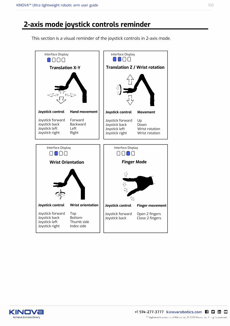
KINOVA™ Ultra lightweight robotic arm user guide 100
2-axis mode joystick controls reminder
This section is a visual reminder of the joystick controls in 2-axis mode.


Kinova Europe GmbH
Friedrich-Ebert-Allee 13 53113 Bonn, Deutschland
+49 (0) 228-9293-9148www.kinovarobotics.de
Kinova Inc. (Headquarters) 4333 Boul. de la Grande Allée Boisbriand, Qc, Canada J7H 1 M7
+1 (514) 277 – [email protected] [email protected]
ULW
S-R
A-JAC
-UG
-IN
T-E
N
20
18
04
-1.0
©
20
18
Kin
ova
Inc.