BILL-E: Robotic Platform for Locomotion and Manipulation ... · American Institute of Aeronautics...
12
American Institute of Aeronautics and Astronautics 1 BILL-E: Robotic Platform for Locomotion and Manipulation of Lightweight Space Structures Benjamin Jenett 1 and Kenneth Cheung 2 We describe a robotic platform for traversing and manipulating a modular 3D lattice structure. The robot is designed to operate within a specifically structured environment, which enables low numbers of degrees of freedom (DOF) compared to robots performing comparable tasks in an unstructured environment. This allows for simple controls, as well as low mass and cost. This approach, designing the robot relative to the local environment in which it operates, results in a type of robot we call a “relative robot.” We describe a bipedal robot that can locomote across a periodic lattice structure, as well as being able to handle, manipulate, and transport building block parts that compose the lattice structure. Based on a general inchworm design, the robot has added functionality for travelling over and operating on a host structure. I. Introduction UTOMATED construction of large structures is desirable in numerous fields, such as infrastructure and aerospace vehicles [1]. The construction of large space structures presents challenges due to the limitations of human-based extravehicular activity (EVA) and autonomous extravehicular robotics (EVR). Both areas of technology seek to reduce risk, and increase throughput and reliability [2] [3]. One solution is the autonomous robotic assembly of structures based on truss elements [4], [5]. Generally, these systems use a multi-DOF industrial robotic arm mounted to a carriage that can traverse along an X and Y direction gantry system encompassing a build area equal to or larger in size to the target structure. The Automated Structures Assembly Laboratory [6] successfully demonstrated the viability of using robotic manipulators to automatically assemble and disassemble large truss structures. Figure 1. Comparison of robotic assembly platforms for space structures. (L) Gantry-based robotic arm assembly system, based on work from [6]. (R) Relative robotic system The use of robots to assist in the exploration and manipulation of structures has been an active topic of research for decades. Truss climbing robots are a form of climbing robot devoted to the traversal of three-dimensional truss structures [7]. Combined with a node design that can be robotically manipulated, such robots promise to provide an autonomous assembly, inspection, and reconfiguration platform for the creation of complex structures [8]. Locomotion strategies for previous robots have focused on treating the truss as a collection of struts and nodes [9] [10]. These robots combine 1-D translation along the length of strut with a method for transferring from one strut to another. This strategy is compatible with trusses that have an irregular geometry, at the cost of robotic complexity; in addition to 1 Graduate Researcher, Center for Bits and Atoms, MIT, Cambridge, MA, 02139 USA 2 Research Scientist, NASA Ames Research Center, Moffett Field, CA 94035 USA A https://ntrs.nasa.gov/search.jsp?R=20170006219 2018-08-18T04:10:12+00:00Z
Transcript of BILL-E: Robotic Platform for Locomotion and Manipulation ... · American Institute of Aeronautics...

American Institute of Aeronautics and Astronautics
1
BILL-E: Robotic Platform for Locomotion and
Manipulation of Lightweight Space Structures
Benjamin Jenett1 and Kenneth Cheung2
We describe a robotic platform for traversing and manipulating a modular 3D lattice
structure. The robot is designed to operate within a specifically structured environment, which
enables low numbers of degrees of freedom (DOF) compared to robots performing
comparable tasks in an unstructured environment. This allows for simple controls, as well as
low mass and cost. This approach, designing the robot relative to the local environment in
which it operates, results in a type of robot we call a “relative robot.” We describe a bipedal
robot that can locomote across a periodic lattice structure, as well as being able to handle,
manipulate, and transport building block parts that compose the lattice structure. Based on a
general inchworm design, the robot has added functionality for travelling over and operating
on a host structure.
I. Introduction
UTOMATED construction of large structures is desirable in numerous fields, such as infrastructure and
aerospace vehicles [1]. The construction of large space structures presents challenges due to the limitations of
human-based extravehicular activity (EVA) and autonomous extravehicular robotics (EVR). Both areas of technology
seek to reduce risk, and increase throughput and reliability [2] [3]. One solution is the autonomous robotic assembly
of structures based on truss elements [4], [5]. Generally, these systems use a multi-DOF industrial robotic arm mounted
to a carriage that can traverse along an X and Y direction gantry system encompassing a build area equal to or larger
in size to the target structure. The Automated Structures Assembly Laboratory [6] successfully demonstrated the
viability of using robotic manipulators to automatically assemble and disassemble large truss structures.
Figure 1. Comparison of robotic assembly platforms for space structures. (L) Gantry-based robotic arm assembly
system, based on work from [6]. (R) Relative robotic system
The use of robots to assist in the exploration and manipulation of structures has been an active topic of research
for decades. Truss climbing robots are a form of climbing robot devoted to the traversal of three-dimensional truss
structures [7]. Combined with a node design that can be robotically manipulated, such robots promise to provide an
autonomous assembly, inspection, and reconfiguration platform for the creation of complex structures [8]. Locomotion
strategies for previous robots have focused on treating the truss as a collection of struts and nodes [9] [10]. These
robots combine 1-D translation along the length of strut with a method for transferring from one strut to another. This
strategy is compatible with trusses that have an irregular geometry, at the cost of robotic complexity; in addition to
1 Graduate Researcher, Center for Bits and Atoms, MIT, Cambridge, MA, 02139 USA 2 Research Scientist, NASA Ames Research Center, Moffett Field, CA 94035 USA
A
https://ntrs.nasa.gov/search.jsp?R=20170006219 2018-08-18T04:10:12+00:00Z

American Institute of Aeronautics and Astronautics
2
doubling the translational degrees of freedom, performing a strut transfer also requires additional degrees of freedom,
which move the relative position of the two translation mechanisms.
An alternative to the strut and node strategy is an approach we call the “Relative Robot.” Instead of strut-node
networks, Relative Robots traverse a structure composed of sparse building blocks, which allows translation with
fewer degrees of freedom and enables increased reliability through fault-tolerant connection mechanisms. Examples
include platforms such as the Automatic Modular Assembly System (AMAS) [11],; and usually the robot and structure
are designed simultaneously as a whole system. Prior work such as AMAS has addressed structural systems with
higher mass density than is typical for space structures.
Recent work has shown that modular structures built from lattice building blocks can result in structures with high
stiffness to weight ratios [12], making them desirable for space applications [13]. There are numerous benefits
afforded by this approach. One is that the building blocks can be reversibly assembled, disassembled, and reconfigured
into new structural configurations [14]. Another is that the periodic lattice provides a structured environment in which
a robotic platform can operate. This has potential advantages over traditional robotic construction systems which rely
on a gantry-based build envelope [15]. In addition to being able to build arbitrarily large structures, a relative robot
achieves metrology based on discrete lattice locations, rather than relying on global positioning systems or complex
vision based systems [16] .
We propose a relative robotic platform for this modular lattice system, the Bipedal Isotropic Lattice Locomoting
Explorer (BILL-E). Its design is specific to its tasks within the structured environment. We will describe the lattice
structure in which it operates, the functional requirements of its tasks, and how these inform the design of the robot.
We will describe the prototype and investigate its performance analytically and with numerous experiments.
II. Methodology
The chosen structural environment is a Cuboct lattice, composed of vertex connected octahedrons (Figure 2).
These are referred to as voxels, or volumetric pixels, because they can be used to fill 3D space. The voxels used in
this paper have a lattice pitch P = 76.2mm (3.0in) and a strut length 𝐿 = 𝑃√2/2 = 53.88mm (2.12in). The strut has an
approximately square cross section with a side length ~ 𝐿/32 = 1.5mm (0.056in). These building blocks can be
manufactured in a number of ways, such as by assembly from discrete struts and nodes [14]. In this case, they are
either injection molded or 3D printed. The former allows for high performance materials, low manufacturing time,
and high dimensional repeatability between parts. The injection molded parts are made from PEI, a thermoplastic, and
are reinforced with 20% chopped glass fiber. They are joined together using 0-80 screws and nuts. This allows them
to be reversibly assembled, while also assuring sufficient load transfer and rigidity at the joints.
Figure 2. Octahedron voxel geometry and 3D lattice structure. (L to R) Building block voxel, 3x3x3 cube of
voxels, example macro geometry made of voxels.
The design of the robotic platform was developed from a set of functional requirements:
-Robot shall be able to traverse linearly (X, Y or Z)
-Robot shall be able to turn and traverse in the direction orthogonal to first direction (X to Y, Y to Z, X to Z)
-Robot shall be able to turn up/down concave and convex corners
-Robot shall be able to step up/down a level (+/- Z)

American Institute of Aeronautics and Astronautics
3
Figure 3. Relative robot design: primitive functional requirements for lattice locomotion and resulting minimum
dimensions meeting functional requirements.
Morphologically, the minimum number of required attachments to the structure is two. Bipedal robots, specifically
those using an inchworm motion for movement, are ubiquitous in the literature [17]–[19], with some designs many
degrees of freedom to provide added functionality and directions of motion [20]. The main difference between our
robot and existing bipedal inchworm robots is operation within a 3D isotropic lattice.
Based on the functional requirements, we can determine the approximate dimensions as a function of lattice pitch
L. The convex corner turn requires the longest reach, and thus the robot design is based on this maneuver. Simpler
maneuvers, such as linear steps, can reach much further than a single inch-worm step, as shown in Figure 3
Figure 4. Schematic for Bipedal Isotropic Lattice Locomoting Explorer. Robot is shown in neutral position.
From here, we discuss sub-components, the following of which will be described: foot, lower leg, upper leg, and
actuated joints, as labeled in Figure 5.

American Institute of Aeronautics and Astronautics
4
Figure 5. BILL-E Prototype. (L) Photograph of working prototype of BILL-E. (R) General dimensions.
TABLE I. ROBOT PHYSICAL PARAMETERS
Parameter Properties
Mass 520 g
Small Servo Motor Hitec HS-5065MG; m = 11g, Torque @ 6V = 2.2 kg*cm
Large Servo Motor Hitec HS 7950TH; m = 68g, Torque @ 6V = 30 kg*cm
Bearings Double Shielded Radial Ball Bearing; 12.7mm (0.5in) dia. ID, 28.575mm (1.125in) dia. OD
3D Printed Parts Feet, latch, gear, lower leg link, upper leg link, servo horn hirth coupling.
The foot is designed to fit around the outside of the top half of one octahedron (Figure 6). It terminates in a
cylindrical feature with outside diameter designed to press-fit into the ankle bearing. The foot has mating features that
align with the four nodes of the voxel. These contact points provide a rotational constraint in X, Y, and Z as well as a
translational constraint in X, Y, and –Z. The +Z constraint is provided by the latching mechanism, which passes
through a pair of holes in the foot and underneath the top interior corner of the voxel, thereby constraining the foot in
+Z. The latch is driven by a small servo motor mounted to the outside of the foot.
The foot is press fit into the inside race of a radial bearing. The outside race is press fit into the lower leg link. This
provides a rotational degree of freedom in the Z direction, while providing a translational constraint in X, Y, and Z,
and a rotational constraint in X and Y. This rotation is actuated by a pair of spur gears. One gear is built into the lower
leg, the other gear is mounted to a small servo. The top of the lower leg consists of a bracket and a shaft which is
press-fit into the inside of a bearing. The outside of the bearing is press-fit into the end of the upper leg portion.
There are two types of upper legs. Each type has a similar interface with the lower leg. A servo motor is mounted
so that its output spline radial axis is aligned with bearing interface with the lower leg. The lower leg shaft extends
through the bearing and rigidly attaches to the servo spline. This allows a rotational degree of freedom between the
upper and lower leg to be controlled by the servo (Figure 6). The upper legs interface at the “hip”, where a similar
rotational degree if freedom is used between the two upper legs. One leg has a shaft which press-fits into the inside of
a bearing. The other leg press-fits around the outside of the bearing, and a servo is mounted to align with the bearing.
The servo is rigidly attached to the shaft of the other leg which passes through the bearing.

American Institute of Aeronautics and Astronautics
5
Figure 6. Description of lattice gripping end effector. (L) Foot geometry is designed to fit around octahedra
voxel. Slot allows latch mechanism to pass beneath underside of top corner of voxel. Corner features mate with node
geometry of voxel. (R) Exploded view of ankle joint.
III. Analysis While operating on earth, or in an environment with gravity, the mass of the motors becomes significant when
performing certain maneuvers. It is possible to perform these maneuvers in ways to minimize the applied torque on
the motor by the mass of the robot being actuated. The servo motors located at joints 1 and 5, which provide the latch
and ankle rotation mechanism actuation, are primarily driven by geometric constraints- they have a small area in which
they have to fit. However, this can create problems if the torque required by them during certain maneuvers in certain
configurations is greater than their capacity. One such configuration is shown in Figure 7. Here, the robot is extended
fully, and will rotate about an axis perpendicular to the direction of gravity.
Figure 7. Robot mass under gravity loading in scenario generating greatest torque. Masses are shown as
summations of links or motor mass acting under gravity loading. Torque is shown only for actuator on axis of rotation.
American Institute of Aeronautics and Astronautics
6
The masses and lengths are as follows: m1= 90g, m2= 40g, m3= 90g, m4= 40g, m5= 90g, and m6= 70g; L1= 20mm,
L2= 85mm, L3= 160mm, L4= 215mm, L5= 270mm, L6= 290mm. We can then find the resulting torque applies at the
point of rotation by summing the torques created from each mass and its respective moment arm, as shown in Eq. 1:
∑ 𝜏 = 𝑚1 ∗ 𝐿1 + 𝑚2 ∗ 𝐿2 + ⋯ 𝑚𝑛 ∗ 𝐿𝑛
𝑛
𝑖=0
(1)
We find that τtotal is 72800 g-mm, or 7.28 kg-cm. As shown in Table 1, the servos used for this actuation are rated
to 2.2 kg-cm. Therefore, in this worst case scenario, the servo would be unable to rotate the robot as configured.
However, as we show in the experiments, it is possible to align the robot with the axis of rotation, thus minimizing
the moment arm for all of the robot mass to be rotated. This allows the motor to sufficiently rotate the robot. For space
applications, the mass of the robot must be reduced to its minimum required to perform its tasks. This will require
optimization of motor mass relative to torque capacity and required torque for maneuvering. Another consideration is
using the torque generated by this rotation as a useful force during space operations, such as attitude control.
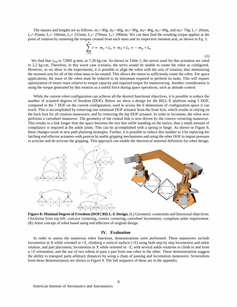
While the current robot configuration can achieve all the desired functional objectives, it is possible to reduce the
number of actuated degrees of freedom (DOF). Below we show a design for the BILL-E platform using 5 DOF,
compared to the 7 DOF on the current configuration, used to access the 6 dimensions of configuration space it can
reach. This is accomplished by removing one rotational DOF actuator from the front foot, which results in relying on
the back foot for all rotation maneuvers, and by removing the hip DOF actuator. In order to locomote, the robot now
performs a cartwheel maneuver. The geometry of the central link is now driven by the convex cornering maneuver.
This results in a link longer than the space between the two feet while standing on the lattice, thus a small amount of
compliance is required at the ankle joints. This can be accomplished with a spring or hinge. As shown in Figure 8,
these changes result in new path planning strategies. Further, it is possible to reduce this number to 3 by replacing the
latching end effector actuators with passive bi-stable gripping mechanisms and using the other DOF to impart pressure
to activate and de-activate the gripping. This approach can enable the theoretical minimal definition for robot design.
Figure 8: Minimal Degree of Freedom (DOF) BILL-E Design. (L) Geometric constraints and functional objectives.
Clockwise from top left- concave cornering, convex cornering, cartwheel locomotion, compliant ankle requirement.
(R) Artist concept of robot based using end effectors of original design.
IV. Evaluation
In order to assess the numerous robot functions, demonstrations were performed. These maneuvers include
locomotion in X while oriented in +Z, climbing a vertical surface (+Z) using both step by step locomotion and ankle
rotation, and part placement, locomotion in X while oriented in –Z, with several ankle rotations to climb to and from
a +Z orientation, and the use of two robots to pass a part from one robot to the other. These demonstrations suggest
the ability to transport parts arbitrary distances by using a chain of passing and locomotion maneuvers. Screenshots
from these demonstrations are shown in Figure 9. The full sequence of these are in the appendix.

American Institute of Aeronautics and Astronautics
7
Figure 9: Screenshots from demonstrations testing maneuvering and manipulation. (L to R) Climbing, part
placement, inverted locomotion, coordinated part transportation.
In order to assess the validity of the relative robotic system, we performed steady state, open loop locomotion on
a long section of structure. With two simple commands (step forward with front foot, step forward with back foot),
we were able to demonstrate continuous, error-free locomotion for 10 steps (see appendix). Further work will enable
continuous locomotion on the order of 100 steps using a treadmill test platform.
V. Conclusion
Robots like BILL-E can have numerous applications in space. One is as it applies to structures- their construction,
repair, and inspection. Several possible space structures made from discrete lattice elements include: booms/masts,
pressure vessels, plates/shelters, and structure for precision instruments such as reflector dishes. The construction of
hierarchical trusses can be much more structurally efficient [24], and BILL-E could be used to assist in constructing
these trusses made of trusses.
Figure 10. Space applications for BILL-E structures. (L to R) Pressure vessel, habitat, and hierarchical truss. In
the first two cases, skinning the structure would also be done by a relative robot to be designed in further research.
In the last case, special lattice parts may be required for interfacing between diagonal macro-struts.
The second application is using BILL-E as a mobile and reconfigurable source of actuation throughout these larger
structures. In this case, BILL-E could provide a number of services such as active damping, attitude control, and macro
scale actuation for on-orbit operations. As an active damper, a number of robots could be distributed throughout a
structure, based on the modal analysis of the structure and the desired damping. As shown in Figure 11, a plate could
contain damping joints in which robots would be placed for controlling the behavior of the overall structure. As a
method for attitude control, the rotational ability of BILL-E can be compared to that of a reaction wheel. In order to
maintain the orientation of a satellite while in orbit, reaction wheels are used to offset the tendency for the satellite to
realign itself with the body it is orbiting. Reaction wheels become saturated, and normally need propulsion to de-
saturate them for reuse. BILL-E robots could serve as a secondary system that allows fuel to be conserved, or to
possible replace reaction wheels entirely. Lastly, large scale robotic platforms such as cranes and arms could be
constructed using links made of lattice structure and using one or more robots as the joint. This would enable modular,
reconfigurable, macro-scale robots to be built, used, and disassembled on orbit for a number of purposes.
Figure 11. Conceptual diagrams for future BILL-E space applications. (L to R) Active damping of a plate
structure, attitude control for a satellite, actuation of a macro-structures.

American Institute of Aeronautics and Astronautics
8
The next steps for this research will look at the joining of voxels. Automated bolting is an existing technology,
and adapting an end effector for BILL-E to grab, place, and bolt a voxel in place will be developed. Once this is
possible, control and optimization for build strategies will be addressed. Coordination of multiple robots will require
algorithms for autonomous building. From a hardware perspective, autonomy will be assisted by wireless
communication and battery power. The goal would be for the robot to be solar powered, or to be rechargeable by
replacing battery packs, which can be addressed by a secondary system which can replace power and material (new
voxels) as needed.
Appendix
The following images are screenshots from video footage taken of benchtop demonstrations. The parts shown in
Figure 12-13 are made from 3D printed photopolymer.
Figure 12: Demonstration of climbing by taking single steps with convex and concave corner maneuvering. In
steps 1-5, the robot takes single steps forward. In steps 6-11, it approaches the concave corner by stepping up on the
vertical face of the structure. In steps 12-13, it steps entirely onto the vertical face of the structure. In steps 14-15, it
steps around the convex corner of the structure onto the top of the structure. In steps 16-17, it completes the sequence
by stepping all the way onto the top of the structure. Total elapsed time: 5 min.
Figure 13: Demonstration of climbing via rotation about ankle joint. In steps 1-3, the robot reaches out and grips
the vertical face of the structure. In steps 4-7, it rotates 180° about its ankle joint. In steps 8-10, it swings up to place
its foot atop the structure. In steps 11-12, it completes the sequence by stepping onto the top of the structure. Total
elapsed time: 2 min.

American Institute of Aeronautics and Astronautics
9
Figure 14: Demonstration of part manipulation. In steps 1-4, the robot grabs the part. In steps 5-7, the robot rotates
about its ankle joint 180° to face the desired location for part placement. In steps 8-9, it places the part and releases
its gripper. In steps 10-12, the robot rotates back to its original position. Total elapsed time: 1.5 min.
Figure 15: Demonstration of climbing 360° around a loop using ankle rotation and upside down locomotion. In
steps 1-7, the robot uses ankle rotation to climb to the upper surface of the structure. In steps 8-13, the robot steps
along the upper surface of the structure while hanging upside down. In steps 14-24, the robot uses two ankle rotation
maneuvers to step to the side of the structure and then to return to its original position. Total elapsed time: 10 min.

American Institute of Aeronautics and Astronautics
10
Figure 16: Steady state open loop locomotion. The robot is programmed to perform two motions- stepping forward
with the front foot and then the back foot. This is performed 10 times to demonstrate one benefit of a relative robot:
every time it takes a step, it registers itself to the lattice, thus errors do not stack up over time and are limited to each
individual motion as it is performed.

American Institute of Aeronautics and Astronautics
11
Figure 17: Demonstration of two robots transporting material. In steps 1-9, robot 1 grabs and positions the part
to be transferred to robot 2. In steps 10-11, the part is handed off from robot 1 to robot 2. In steps 12-29, robot 1 walks
around to the other side of robot 2 and positions itself to receive the part. In steps 30-32, robot 2 rotates to hand off
the part to robot 1. In step 33, the robots are handing the part off. Total elapsed time: 10 min.
Acknowledgments
This work is sponsored by the NASA Space Technology Research Fellowship (NSTRF), NASA ARMD CAS
Mission Adaptive Digital Composite Aerostructures Technologies (MADCAT), NASA STMD GCD Advanced
Manufacturing Technologies, and the Center for Bits and Atoms sponsors.

American Institute of Aeronautics and Astronautics
12
References
[1] W. Whittaker, C. Urmson, P. Staritz, B. Kennedy, and R. O. Ambrose, “Robotics for assembly, inspection, and
maintenance of space macrofacilities,” Am. Inst. Aeronaut. Astronaut., 2000.
[2] M. D. Rhodes, R. W. Will, and C. Quach, “Baseline Tests of an Autonomous Telerobotic System for Assembly of Space
Truss Structures,” Langley, 1994.
[3] M. S. Lake, W. L. Heard, J. J. Watson, and T. J. Collins, “Evaluation of Hardware and Procedures for Astronaut Assembly
and Repair of Large Precision Reflectors,” Langley Research Center, NASA /TP-2000-210317, 2000.
[4] M. Mikulas and J. T. Dorsey, “An integrated in-space construction facility for the 21st century,” NASA Tech. Memo.
101515, 1988.
[5] M. Mikulas and H. Bush, “Design, Construction, and Utilization of a Space Station Assembled from 5-Meter Erectable
Struts,” NASA Struct. Interact. Technol., 1987.
[6] W. R. Doggett, “Robotic Assembly of Truss Structures for Space Systems and Future Research Plans,” in IEEE Aerospace
Conference Proceedings, 2002.
[7] B. Chu, K. Jung, C. S. Han, and D. Hong, “A survey of climbing robots: Locomotion and adhesion,” Int. J. Precis. Eng.
Manuf., vol. 11, no. 4, pp. 633–647, 2010.
[8] P. J. Staritz, S. Skaff, C. Urmson, and W. Whittaker, “Skyworker: A robot for assembly, inspection and maintenance of
large scale orbital facilities,” in Proceedings - IEEE International Conference on Robotics and Automation, 2001, vol. 4,
pp. 4180–4185.
[9] F. Nigl, S. Li, J. E. Blum, and H. Lipson, “Structure-reconfiguring robots: Autonomous truss reconfiguration and
manipulation,” IEEE Robot. Autom. Mag., vol. 20, no. 3, pp. 60–71, 2013.
[10] Y. Yoon and D. Rus, “Shady3D: A Robot that Climbs 3D Trusses,” in IEEE International Conference on Robotics and
Automation, 2007.
[11] Y. Terada and S. Murata, “Automatic assembly system for a large-scale modular structure - hardware design of module
and assembler robot,” 2004 IEEE/RSJ Int. Conf. Intell. Robot. Syst. (IEEE Cat. No.04CH37566), vol. 3, pp. 2349–2355,
2004.
[12] K. C. Cheung and N. Gershenfeld, “Reversibly assembled cellular composite materials.,” Science, vol. 341, no. 6151, pp.
1219–21, 2013.
[13] M. M. Mikulas, T. J. Collins, W. Doggett, J. Dorsey, and J. Watson, “Truss performance and packaging metrics,” in AIP
Conference Proceedings, 2006, vol. 813, pp. 1000–1009.
[14] B. Jenett, D. Cellucci, C. Gregg, and K. C. Cheung, “Meso-scale digital materials: modular, reconfigurable, lattice-based
structures,” in Proceedings of the 2016 Manufacturing Science and Engineering Conference, 2016.
[15] M. Carney and B. Jenett, “Relative Robots: Scaling Automated Assembly of Discrete Cellular Lattices,” in Proceedings
of the 2016 Manufacturing Science and Engineering Conference, 2016.
[16] W. R. Doggett, “A Guidance Scheme for Automated Tetrahedral Truss Structure Assembly Based on Machine Vision,”
1996.
[17] K. D. Kotay and D. L. Rus, “Navigating 3D steel web structures with an inchworm robot,” Proc. IEEE/RSJ Int. Conf.
Intell. Robot. Syst. IROS ’96, vol. 1, pp. 368–375, 1996.
[18] S. M. Felton, M. T. Tolley, C. D. Onal, D. Rus, and R. J. Wood, “Robot self-assembly by folding: A printed inchworm
robot,” in Proceedings - IEEE International Conference on Robotics and Automation, 2013, pp. 277–282.
[19] C. Balaguer, A. Gimenez, J. M. Pastor, V. M. Padron, and M. Abderrahim, “A climbing autonomous robot for inspection
applications in 3d complex environments,” Robotica, vol. 18, no. 3, pp. 287–297, 2000.
[20] R. L. Tummala, R. Mukherjee, N. Xi, D. Aslam, H. Dulimarta, J. Xiao, M. Minor, and G. Dangi, “Climbing the walls,”
IEEE Robot. Autom. Mag., vol. 9, no. 4, pp. 10–19, 2002.
[21] F. Scholz, “Tolerance stack analysis methods,” Res. Technol. Boeing Inf. …, no. December, 1995.
[22] “EEW.” [Online]. Available: http://www.eew-protec.de/110.0.html?&L=1.
[23] M. a. Minor and R. Mukherjee, “Under-Actuated Kinematic Structures for Miniature Climbing Robots,” J. Mech. Des.,
vol. 125, no. 2, p. 281, 2003.
[24] T. Murphey and J. Hinkle, “Some performance trends in hierarchical truss structures,” in 44th AIAA/ASME/ASCE/AHS
Structures, Structural Dynamics, and Materials Conference, 2003.