
Gen3 a lightweight t - Kinova robotics · 2019-12-13 · KINOVA® Gen3 Ultra lightweight robot User...
155
5 | kinovarobotics.com KINOVA ® Gen3 Ultra lightweight robot User Guide
Transcript of Gen3 a lightweight t - Kinova robotics · 2019-12-13 · KINOVA® Gen3 Ultra lightweight robot User...

5 | kinovarobotics.com
KINOVA® Gen3 Ultra lightweight robot
User Guide
Contents
Introduction............................................................................................................................................................... 6Welcome.......................................................................................................................................................................6About this document............................................................................................................................................... 6Normal use definition..............................................................................................................................................6Risk assessment........................................................................................................................................................7EU Declaration of Incorporation.......................................................................................................................... 7FCC Declaration of Comformity........................................................................................................................... 8Safety directives and warnings......................................................................................................................... 10Warranty.....................................................................................................................................................................12Disclaimer.................................................................................................................................................................. 12Acronyms and abbreviations.............................................................................................................................. 13
Robot components................................................................................................................................................. 16Overview.....................................................................................................................................................................16Base..............................................................................................................................................................................16
Controller quick connect system............................................................................................................. 17Controller connector panel.......................................................................................................................20
Actuators................................................................................................................................................................... 20Interface module..................................................................................................................................................... 21Vision module.......................................................................................................................................................... 23Robot communications and network interfaces.........................................................................................24
Getting started........................................................................................................................................................27Overview.................................................................................................................................................................... 27What's in the case?................................................................................................................................................27Manipulating the robot joints when the robot is powered off...............................................................28Robot mounting options...................................................................................................................................... 28
Mounting the robot on a tabletop......................................................................................................... 28Mounting the robot on a horizontal surface without the table clamp...................................... 30Mounting the robot on a wall or ceiling...............................................................................................32
Robot power adapter and E-stop.....................................................................................................................34Powering on the robot..........................................................................................................................................35Power-up, booting, and initialization sequence.......................................................................................... 35Resetting the robot to factory settings......................................................................................................... 36Operating the robot...............................................................................................................................................36
Supported gamepad controllers............................................................................................................. 36Home and retract positions...................................................................................................................... 41Putting the robot into admittance using the interface buttons....................................................41
Connecting a computer to the robot...............................................................................................................42Connecting a computer to the robot via Ethernet (for the first time)........................................42KINOVA® KORTEX™ Web App...................................................................................................................44Changing the robot wired connection IP address and connecting the robot to a LAN.......... 46Connecting a computer to the robot via Wi-Fi.................................................................................. 46
Dimensions, specifications, and capabilities................................................................................................ 48Schematic and dimensions - 7 DoF spherical wrist...................................................................................48Technical Specifications.......................................................................................................................................49
Sensors.......................................................................................................................................................................52Base readings available............................................................................................................................. 53Tool readings available...............................................................................................................................53Actuators readings available................................................................................................................... 54Interface readings available.....................................................................................................................54Gripper readings available........................................................................................................................ 54
Effective workspace.............................................................................................................................................. 55Maximum payload vs. workspace.................................................................................................................... 56
Interface, expansion, and vision........................................................................................................................57Interface module expansion - tips for installing tools............................................................................. 57
End effector reference design................................................................................................................. 58Removing end cap from Interface module...........................................................................................61Robotiq Adaptive Grippers installation (optional).............................................................................61Robotiq 2F-85 Gripper tool configuration........................................................................................... 63Interface module bolting pattern...........................................................................................................64Interface module user expansion connector pinout........................................................................64Using interface module expansion to control devices via API......................................................66Spring-loaded connector pinout............................................................................................................. 66
Accessing Vision module color and depth streams................................................................................... 67
Concepts and terminology.................................................................................................................................. 69Robot key concepts............................................................................................................................................... 69Terminology reference...........................................................................................................................................71
General mathematics and robotics.........................................................................................................71Features, components and functionalities.......................................................................................... 73Control and Operation Modes..................................................................................................................74
Robot control...........................................................................................................................................................75High-level and low-level robot control.......................................................................................................... 75High-level and low-level robot control methods overview.................................................................... 75Control features...................................................................................................................................................... 77
Singularity avoidance.................................................................................................................................. 77Protection zones........................................................................................................................................... 77Angular limits.................................................................................................................................................78Cartesian limits.............................................................................................................................................80
Control modes overview..................................................................................................................................... 80Trajectory control modes...........................................................................................................................81Joystick control modes...............................................................................................................................82Admittance modes....................................................................................................................................... 82
Configurations and safeties............................................................................................................................... 84Configurable parameters.................................................................................................................................... 84
Control library configuration................................................................................................................... 84Base configuration.......................................................................................................................................85Actuators configuration............................................................................................................................. 86Interface configuration...............................................................................................................................86Device configuration....................................................................................................................................87Vision configuration.....................................................................................................................................87
Safety items.............................................................................................................................................................88Base (controller) safeties..........................................................................................................................88Actuators safeties........................................................................................................................................89Interface module safeties.......................................................................................................................... 91
KINOVA® KORTEX™ Web App User Guide........................................................................................................93Introduction.............................................................................................................................................................. 93Purpose...................................................................................................................................................................... 93Device availability of Web App..........................................................................................................................93Platform and browser support..........................................................................................................................95User login.................................................................................................................................................................. 95Web App layout and navigation........................................................................................................................96Robot control panel..............................................................................................................................................101
Pose virtual joystick control....................................................................................................................101Angular virtual joystick control............................................................................................................. 102Virtual joystick keyboard shortcuts..................................................................................................... 103Admittance modes panel......................................................................................................................... 105Actions panel................................................................................................................................................105Camera panel............................................................................................................................................... 106Snapshot tool...............................................................................................................................................106
Main pages..............................................................................................................................................................106Configurations page group......................................................................................................................106Safeties........................................................................................................................................................... 110Operations page group..............................................................................................................................110Systems page group...................................................................................................................................121Users................................................................................................................................................................125
KINOVA® KORTEX™ Developer Guide............................................................................................................. 128Introduction............................................................................................................................................................ 128Devices and services........................................................................................................................................... 128Available services................................................................................................................................................. 129Users, connections and sessions....................................................................................................................129Services, methods, and messages................................................................................................................. 130KINOVA® KORTEX™ API and Google Protocol Buffer................................................................................ 130Service client-server model..............................................................................................................................130Notifications............................................................................................................................................................ 131Blocking and non-blocking calls...................................................................................................................... 131Robot servoing modes.........................................................................................................................................131
High-level servoing.................................................................................................................................... 132Low-level servoing.....................................................................................................................................132
Device routing........................................................................................................................................................ 133Error management............................................................................................................................................... 133KINOVA® KORTEX™ GitHub repository...........................................................................................................133KINOVA® KORTEX™ ROS packages and GitHub repository overview.................................................. 134KINOVA® KORTEX™ MATLAB® API and GitHub repository overview................................................... 134Working with camera streams using GStreamer...................................................................................... 134
Windows command examples............................................................................................................... 135Linux command examples....................................................................................................................... 135
KINOVA® KORTEX™ ROS vision module package and Github overview..............................................136
Guidance for advanced users........................................................................................................................... 137Overview...................................................................................................................................................................137Reference frames and transformations....................................................................................................... 137
Standard Cartesian reference frames................................................................................................. 137Homogeneous transforms....................................................................................................................... 137Homogeneous transform matrices - 7 DoF spherical wrist........................................................ 138
Vision module sensors reference frames..........................................................................................140Denavit-Hartenberg (DH) parameters - 7 DoF spherical wrist................................................... 141
7 DoF singular configurations..........................................................................................................................143Inertial parameters definition..........................................................................................................................145Inertial parameters of the 7 DoF robot........................................................................................................ 145
Maintenance and troubleshooting................................................................................................................. 149Maintenance........................................................................................................................................................... 149Troubleshooting..................................................................................................................................................... 151
Base controller LEDs................................................................................................................................. 152How to respond to safety warnings and errors.............................................................................. 152Contacting Kinova support......................................................................................................................154
KINOVA® Gen3 Ultra lightweight robot User Guide 6
Introduction
Welcome
Welcome to the KINOVA® Gen3 Ultra lightweight robot.
Thank you for choosing our robot as a tool for your pathbreaking research needs.
This document is meant to provide you with all the information you need to get up and running with yournew robot and get the most out of it.
We are here to help you in your journey. If you need any help or have any questions about how to get towhere you're going with the robot, please feel free to contact our support team:
www.kinovarobotics.com/support
About this document
User Guide contents and warnings.
Read all instructions before using this product and any third-party options.
Read all warnings on the product and in this guide.
This document contains information regarding product setup and operation. It is intended for Kinovaproduct end users.
All third-party product names, logos, and brands appearing herein are the property of their respectiveowners and are for identification purposes only. Their use in this document is not meant to implyendorsement by Kinova.
Kinova has made every effort to ensure that this document is accurate, accessible and complete. Aspart of our commitment to continuous improvement, we welcome any comments or suggestions atwww.kinovarobotics.com/support.
From time to time, Kinova will make udpates to this document. To download the most up to date versionof this document, visit the product technical resources page at www.kinovarobotics.com/knowledge-hub/gen3-ultra-lightweight-robot.
For general inquiries please contact us at +1 (514) 277-3777
Normal use definition
This section describes the normal use of the robot.
The definition of normal use includes lifting, pushing, pulling, or manipulating (without a gripper or otherend effector attached) a maximum load of:• mid-range, continuous: 4 kg• full-reach, temporary: 4.5 kg• full-reach, continuous 1.1 kg
The robot is designed to hold, move, and manipulate objects in the user environment. However, for someloads in certain positions (near maximum load and reach), holding an object for an extended period of timemay result in heating. To protect the robot hardware from excessive heat, safety thresholds shut down therobot if the temperature rises above a certain threshold. Before this is reached, an API notification will be
rendered as a user alert on the KINOVA® KORTEX™ Web App.
The robot includes a number of temperature-related safeties:• base - CPU core and ambient temperatures• actuators - CPU core and motor temperatures• interface module - CPU core and gripper motor temperatures
If you receive any temperature warnings, put down any object as soon as is practical and place the robotinto a stable rest position to allow it to cool down.
KINOVA® Gen3 Ultra lightweight robot User Guide 7
During normal operation, the robot joints are subject to heating. The joints are normally covered in plasticrings to protect the user from the metal surfaces which may become hot.
Risk assessment
Before proceeding it is imperative that a risk assessment be performed (note that this is required by lawin many countries). As it is a machine, the safety of the robot depends on how well it is integrated with itsenvironment and with other machines.
The recommended international standards for conducting a risk assessment are as follows:
• ISO 12100• ISO 10218-2The risk assessment should take into consideration all activities carried out in the context of the robotapplication, including (but not limited to):
• teaching the robot (during set-up)• development of the robot installation• robot troubleshooting• robot maintenance• everyday robot operation
The risk assessment must be completed before integration of the robot in an application and should addressconfiguration settings as well as the need for any additional emergency stop buttons.
EU Declaration of Incorporation
The Declaration of Conformity is a self-declared assessment produced and signed by a manufacturer of aproduct to assert that the product meets all of the requirements of the applicable directives.
In the case of KINOVA® Gen3 Ultra lightweight robot KR L53 0007, the applicable directives that are eligiblefor CE declaration are the following:• Machinery Directive 2006/42/EC• Electromagnetic Compatibility (EMC) Directive 2014/30/EU
The Machinery Directive 2006/42/EC Article 2 (g) states that:
‘Partly completed machinery’ means an assembly which is almost machinery but which cannot initself perform a specific application. A drive system is partly completed machinery. Partly completedmachinery is only intended to be incorporated into or assembled with other machinery or otherpartly completed machinery or equipment, thereby forming machinery to which this Directiveapplies; is not eligible to CE marking by its own because it is an “incomplete machine.”
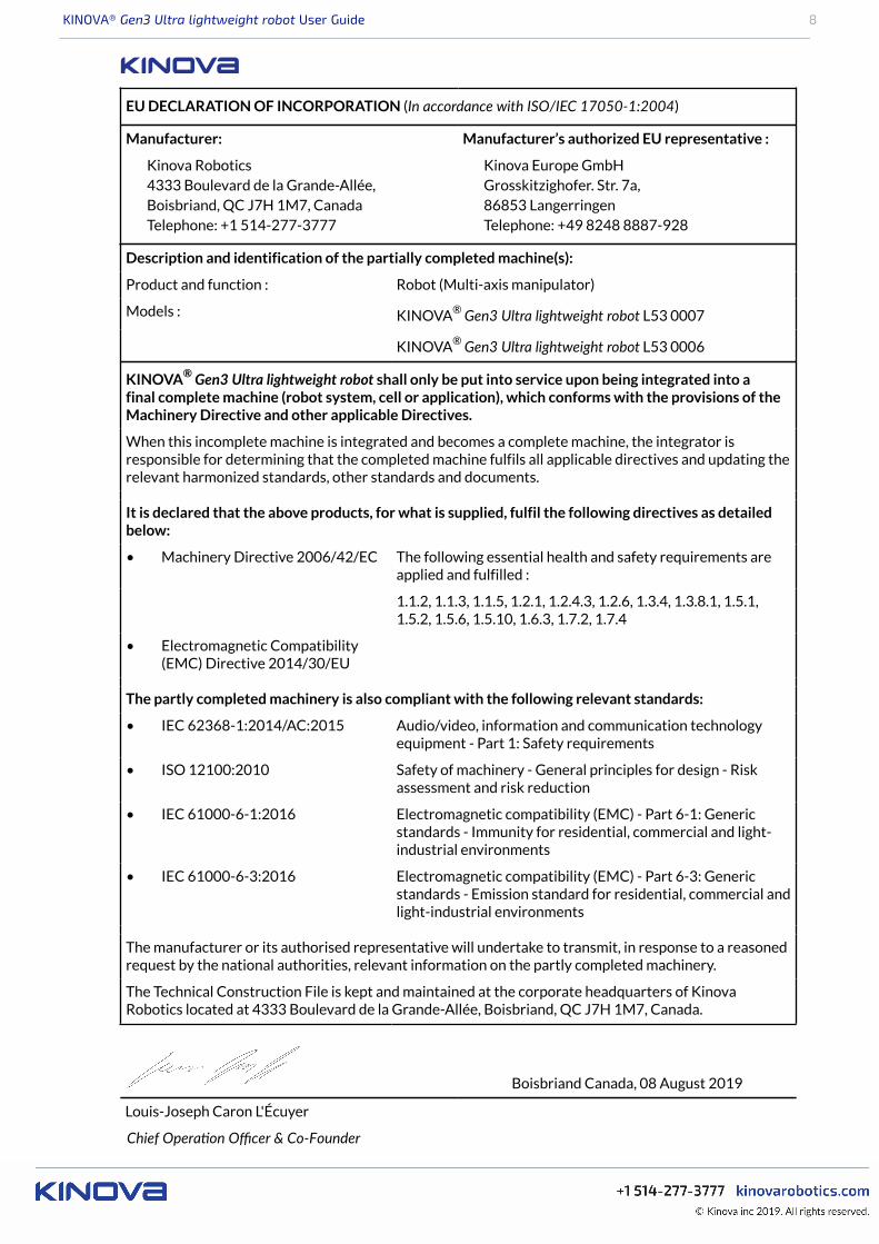
Based on this definition, our product Gen3 Ultra lightweight robot KR L53 0007 is considered partlycompleted machinery because it has no specific application. The robot application is determined when it isincorporated in a system, given an end-effector and expected workpieces. Once the product is incorporatedinto a complete system and the system complies to all applicable directives, then the integrator is permittedto issue a Declaration of Conformity and affix a CE marking to the completed machine. For incompletemachinery, a Declaration of Incorporation (DoI) is required from the manufacturer. The Declaration ofIncorporation for the robot is inserted below.
KINOVA® Gen3 Ultra lightweight robot User Guide 8
Description and identification of the partially completed machine(s):
Product and function : Robot (Multi-axis manipulator)
Models : KINOVA® Gen3 Ultra lightweight robot L53 0007
KINOVA® Gen3 Ultra lightweight robot L53 0006
KINOVA® Gen3 Ultra lightweight robot shall only be put into service upon being integrated into afinal complete machine (robot system, cell or application), which conforms with the provisions of theMachinery Directive and other applicable Directives.
When this incomplete machine is integrated and becomes a complete machine, the integrator isresponsible for determining that the completed machine fulfils all applicable directives and updating therelevant harmonized standards, other standards and documents.
It is declared that the above products, for what is supplied, fulfil the following directives as detailedbelow:
• Machinery Directive 2006/42/EC The following essential health and safety requirements areapplied and fulfilled :
1.1.2, 1.1.3, 1.1.5, 1.2.1, 1.2.4.3, 1.2.6, 1.3.4, 1.3.8.1, 1.5.1,1.5.2, 1.5.6, 1.5.10, 1.6.3, 1.7.2, 1.7.4
• Electromagnetic Compatibility(EMC) Directive 2014/30/EU
The partly completed machinery is also compliant with the following relevant standards:
• IEC 62368-1:2014/AC:2015 Audio/video, information and communication technologyequipment - Part 1: Safety requirements
• ISO 12100:2010 Safety of machinery - General principles for design - Riskassessment and risk reduction
• IEC 61000-6-1:2016 Electromagnetic compatibility (EMC) - Part 6-1: Genericstandards - Immunity for residential, commercial and light-industrial environments
• IEC 61000-6-3:2016 Electromagnetic compatibility (EMC) - Part 6-3: Genericstandards - Emission standard for residential, commercial andlight-industrial environments
The manufacturer or its authorised representative will undertake to transmit, in response to a reasonedrequest by the national authorities, relevant information on the partly completed machinery.
The Technical Construction File is kept and maintained at the corporate headquarters of KinovaRobotics located at 4333 Boulevard de la Grande-Allée, Boisbriand, QC J7H 1M7, Canada.
Boisbriand Canada, 08 August 2019
Louis-Joseph Caron L'Écuyer
Chief Operaon Officer & Co-Founder
EU DECLARATION OF INCORPORATION (In accordance with ISO/IEC 17050-1:2004)
Manufacturer:
Kinova Robotics4333 Boulevard de la Grande-Allée,Boisbriand, QC J7H 1M7, CanadaTelephone: +1 514-277-3777
Manufacturer’s authorized EU representative :
Kinova Europe GmbHGrosskitzighofer. Str. 7a,86853 LangerringenTelephone: +49 8248 8887-928
KINOVA® Gen3 Ultra lightweight robot User Guide 9
FCC Regulatory Disclosures: This equipment has been tested and found to comply with the limits for aClass B digital device, pursuant to part 15 of the FCC Rules. These limits are designed to provide reasonableprotection against harmful interference in a residential installation. This equipment generates, uses and canradiate radio frequency energy and, if not installed and used in accordance with the instructions, may causeharmful interference to radio communications. However, there is no guarantee that interference will notoccur in a particular installation. If this equipment does cause harmful interference to radio or televisionreception, which can be determined by turning the equipment off and on, the user is encouraged to try tocorrect the interference by one or more of the following measures:• Reorient or relocate the receiving antenna• Increase the separation between the equipment and receiver• Connect the equipment into an outlet on a circuit different from that to which the receiver is
connected• Consult the dealer or an experienced radio/TV technician for help
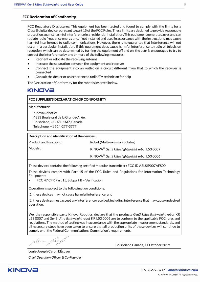
The Declaration of Conformity for the robot is inserted below.
FCC SUPPLIER'S DECLARATION OF CONFORMITY
Manufacturer:
Kinova Robotics4333 Boulevard de la Grande-Allée,Boisbriand, QC J7H 1M7, CanadaTelephone: +1 514-277-3777
Description and identification of the devices:
Product and function : Robot (Multi-axis manipulator)
Models : KINOVA® Gen3 Ultra lightweight robot L53 0007
KINOVA® Gen3 Ultra lightweight robot L53 0006
These devices contains the following certified modular transmitter : FCC ID A3LSIP007AFS00
These devices comply with Part 15 of the FCC Rules and Regulations for Information TechnologyEquipment :• FCC 47 CFR Part 15, Subpart B – Verification
Operation is subject to the following two conditions:
(1) these devices may not cause harmful interference, and
(2) these devices must accept any interference received, including interference that may cause undesiredoperation.
We, the responsible party Kinova Robotics, declare that the products Gen3 Ultra lightweight robot KRL53 0007 and Gen3 Ultra lightweight robot KR L53 0006 are to conform to the applicable FCC rules andregulations. The method of testing was in accordance with the appropriate measurement standards, andall necessary steps have been taken to ensure that all production units of these devices will continue tocomply with the Federal Communications Commission's requirements.
Boisbriand Canada, 11 October 2019
Louis-Joseph Caron L'Écuyer
Chief Operaon Officer & Co-Founder
FCC Declaration of Comformity
KINOVA® Gen3 Ultra lightweight robot User Guide 10
Safety directives and warnings
Directives, warnings and safety considerations for the KINOVA®Gen3 Ultra lightweightrobot.
IMPORTANT
Before operating the robot for the first time, ensure that you have read, completely understood andcomplied with all of the following directives, warnings and cautionary notes. Failure to do so may result inserious injury or death to the user, damage to the robot, or a reduction in its useful life.
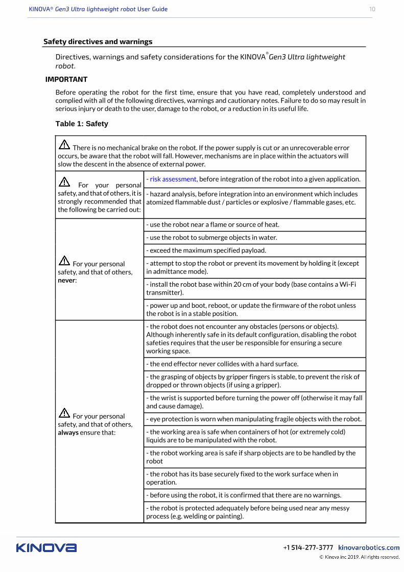
Table 1: Safety
There is no mechanical brake on the robot. If the power supply is cut or an unrecoverable erroroccurs, be aware that the robot will fall. However, mechanisms are in place within the actuators willslow the descent in the absence of external power.
- risk assessment, before integration of the robot into a given application. For your personal
safety, and that of others, it isstrongly recommended thatthe following be carried out:
- hazard analysis, before integration into an environment which includesatomized flammable dust / particles or explosive / flammable gases, etc.
- use the robot near a flame or source of heat.
- use the robot to submerge objects in water.
- exceed the maximum specified payload.
- attempt to stop the robot or prevent its movement by holding it (exceptin admittance mode).
- install the robot base within 20 cm of your body (base contains a Wi-Fitransmitter).
For your personalsafety, and that of others,never:
- power up and boot, reboot, or update the firmware of the robot unlessthe robot is in a stable position.
- the robot does not encounter any obstacles (persons or objects).Although inherently safe in its default configuration, disabling the robotsafeties requires that the user be responsible for ensuring a secureworking space.
- the end effector never collides with a hard surface.
- the grasping of objects by gripper fingers is stable, to prevent the risk ofdropped or thrown objects (if using a gripper).
- the wrist is supported before turning the power off (otherwise it may falland cause damage).
- eye protection is worn when manipulating fragile objects with the robot.
- the working area is safe when containers of hot (or extremely cold)liquids are to be manipulated with the robot.
- the robot working area is safe if sharp objects are to be handled by therobot
- the robot has its base securely fixed to the work surface when inoperation.
- before using the robot, it is confirmed that there are no warnings.
For your personalsafety, and that of others,always ensure that:
- the robot is protected adequately before being used near any messyprocess (e.g. welding or painting).
KINOVA® Gen3 Ultra lightweight robot User Guide 11
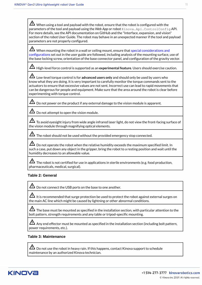
When using a tool and payload with the robot, ensure that the robot is configured with theparameters of the tool and payload using the Web App or robot Kinova.Api.ControlConfig API.For more details, see the API documentation on GitHub and the "Interface, expansion, and vision"section of the robot User Guide. The robot may behave in an unexpected manner if the tool and payloadparameters are not properly configured.
When mounting the robot in a wall or ceiling mount, ensure that special considerations andconfigurations set out in the user guide are followed, including analysis of the mounting surface, use ofthe base locking screw, orientation of the base connector panel, and configuration of the gravity vector.
High-level force control is supported as an experimental feature. Users should exercise caution.
Low-level torque control is for advanced users only and should only be used by users whoknow what they are doing. It is very important to carefully monitor the torque commands sent to theactuators to ensure that excessive values are not sent. Incorrect use can lead to rapid movements thatcan be dangerous for people and equipment. Make sure that the area around the robot is clear beforeexperimenting with torque control.
Do not power on the product if any external damage to the vision module is apparent.
Do not attempt to open the vision module.
To avoid eyesight injury from wide angle infrared laser light, do not view the front-facing surface ofthe vision module through magnifying optical elements.
The robot should not be used without the provided emergency stop connected.
Do not operate the robot when the relative humidity exceeds the maximum specified limit. Insuch a case, put down any object in the gripper, bring the robot to a resting position and wait until thehumidity decreases to an allowable value.
The robot is not certified for use in applications in sterile environments (e.g. food production,pharmaceuticals, medical, surgical).
Table 2: General
Do not connect the USB ports on the base to one another.
It is recommended that surge protection be used to protect the robot against external surges onthe main AC line which might be caused by lightning or other abnormal conditions.
The base must be mounted as specified in the installation section, with particular attention to thebolt pattern, strength requirements and any table or tripod-specific mounting.
Any end effector must be mounted as specified in the installation section (including bolt pattern,power requirements, etc.).
Table 3: Maintenance
Do not use the robot in heavy rain. If this happens, contact Kinova support to schedulemaintenance by an authorized Kinova technician.
KINOVA® Gen3 Ultra lightweight robot User Guide 12
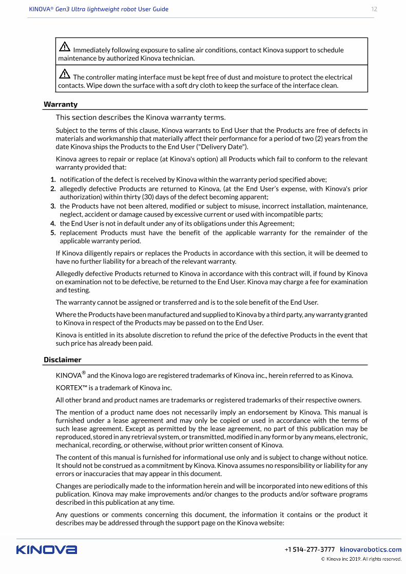
Immediately following exposure to saline air conditions, contact Kinova support to schedulemaintenance by authorized Kinova technician.
The controller mating interface must be kept free of dust and moisture to protect the electricalcontacts. Wipe down the surface with a soft dry cloth to keep the surface of the interface clean.
Warranty
This section describes the Kinova warranty terms.
Subject to the terms of this clause, Kinova warrants to End User that the Products are free of defects inmaterials and workmanship that materially affect their performance for a period of two (2) years from thedate Kinova ships the Products to the End User ("Delivery Date").
Kinova agrees to repair or replace (at Kinova's option) all Products which fail to conform to the relevantwarranty provided that:
1. notification of the defect is received by Kinova within the warranty period specified above;2. allegedly defective Products are returned to Kinova, (at the End User’s expense, with Kinova's prior
authorization) within thirty (30) days of the defect becoming apparent;3. the Products have not been altered, modified or subject to misuse, incorrect installation, maintenance,
neglect, accident or damage caused by excessive current or used with incompatible parts;4. the End User is not in default under any of its obligations under this Agreement;5. replacement Products must have the benefit of the applicable warranty for the remainder of the
applicable warranty period.
If Kinova diligently repairs or replaces the Products in accordance with this section, it will be deemed tohave no further liability for a breach of the relevant warranty.
Allegedly defective Products returned to Kinova in accordance with this contract will, if found by Kinovaon examination not to be defective, be returned to the End User. Kinova may charge a fee for examinationand testing.
The warranty cannot be assigned or transferred and is to the sole benefit of the End User.
Where the Products have been manufactured and supplied to Kinova by a third party, any warranty grantedto Kinova in respect of the Products may be passed on to the End User.
Kinova is entitled in its absolute discretion to refund the price of the defective Products in the event thatsuch price has already been paid.
Disclaimer
KINOVA® and the Kinova logo are registered trademarks of Kinova inc., herein referred to as Kinova.
KORTEX™ is a trademark of Kinova inc.
All other brand and product names are trademarks or registered trademarks of their respective owners.
The mention of a product name does not necessarily imply an endorsement by Kinova. This manual isfurnished under a lease agreement and may only be copied or used in accordance with the terms ofsuch lease agreement. Except as permitted by the lease agreement, no part of this publication may bereproduced, stored in any retrieval system, or transmitted, modified in any form or by any means, electronic,mechanical, recording, or otherwise, without prior written consent of Kinova.
The content of this manual is furnished for informational use only and is subject to change without notice.It should not be construed as a commitment by Kinova. Kinova assumes no responsibility or liability for anyerrors or inaccuracies that may appear in this document.
Changes are periodically made to the information herein and will be incorporated into new editions of thispublication. Kinova may make improvements and/or changes to the products and/or software programsdescribed in this publication at any time.
Any questions or comments concerning this document, the information it contains or the product itdescribes may be addressed through the support page on the Kinova website:
KINOVA® Gen3 Ultra lightweight robot User Guide 13
www.kinovarobotics.com/support
Kinova would like to thank you for your contribution, while retaining the right to use or distribute whateverinformation you supply in any way it believes appropriate (without incurring any obligations to you).
Acronyms and abbreviations
APIApplication Programming Interface
CIDRClassless Inter-Domain Routing
CISPRComité International Spécial des Perturbations Radioélectriques
EEEnd Effector
EMIElectromagnetic Interference
FOVField of View
fpsframes per second
GPIOGeneral-Purpose Input/Output
HDMIHigh-Definition Multimedia Interface
ICIntegrated Circuit
IEEEInstitute of Electrical and Electronics Engineers
I2CInter-Integrated Circuit (bus)
I/OInput / Output
IPIngress Protection or Internet Protocol
ITInformation Technology
ISOInternational Organization for Standardization
KINOVA® Gen3 Ultra lightweight robot User Guide 14
LEDLight-Emitting Diode
n/cno connection
NVRAMNon-Volatile Random-Access Memory
PCPersonal Computer
ROSRobot Operating System
RPCRemote Procedure Call
RPMRevolutions Per Minute
RSRecommended Standard
RxReceiver
SSIDService Set IDentifier
TCPTransmission Control Protocol
TxTransmitter
UARTUniversal Asynchronous Receiver-Transmitter
UDPUser Datagram Protocol
USBUniversal Serial Bus
ULUnderwriters Laboratory
UVUltraviolet light
VLANVirtual Local Area Network

KINOVA® Gen3 Ultra lightweight robot User Guide 15
WEEEWaste of Electrical and Electronic Equipment

KINOVA® Gen3 Ultra lightweight robot User Guide 16
Robot components
Overview
This section describes the main components of the KINOVA® Gen3 Ultra lightweight robot.
The robot consists of:• base (base shell and controller)• actuators• interface module• vision module
The following image shows the main components of the robot.
Figure 1: Robot main components (7 DoF model shown)
Base
This section describes the purpose, components, and functionalities of the robot base.
The Gen3 Ultra lightweight robot base features a quick connect base.
Figure 2: Quick connect base
KINOVA® Gen3 Ultra lightweight robot User Guide 17
The base is a two-part structure securing the robot onto its physical mounting point and connecting therobot to power and control signals. This consists of:• controller• base shell
The controller is the "brains" of the robot. The internal components of the controller include:• CPU• Wi-Fi / Bluetooth adapter (Only Wi-Fi is used at present)• Ethernet switch• USB hub• temperature sensor• accelerometer/gyroscope
A Linux web server runs on the controller and manages connectivity between the controller and the armdevices, and between the controller and an external computer.
The controller includes a connector panel at the rear for connecting to power and external devices.
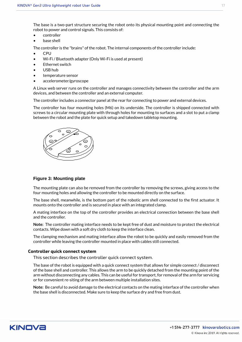
The controller has four mounting holes (M6) on its underside. The controller is shipped connected withscrews to a circular mounting plate with through holes for mounting to surfaces and a slot to put a clampbetween the robot and the plate for quick setup and takedown tabletop mounting.
Figure 3: Mounting plate
The mounting plate can also be removed from the controller by removing the screws, giving access to thefour mounting holes and allowing the controller to be mounted directly on the surface.
The base shell, meanwhile, is the bottom part of the robotic arm shell connected to the first actuator. Itmounts onto the controller and is secured in place with an integrated clamp.
A mating interface on the top of the controller provides an electrical connection between the base shelland the controller.
Note: The controller mating interface needs to be kept free of dust and moisture to protect the electricalcontacts. Wipe down with a soft dry cloth to keep the interface clean.
The clamping mechanism and mating interface allow the robot to be quickly and easily removed from thecontroller while leaving the controller mounted in place with cables still connected.
Controller quick connect systemThis section describes the controller quick connect system.
The base of the robot is equipped with a quick connect system that allows for simple connect / disconnectof the base shell and controller. This allows the arm to be quickly detached from the mounting point of thearm without disconnecting any cables. This can be useful for transport, for removal of the arm for servicingor for convenient re-siting of the arm between multiple installation sites.
Note: Be careful to avoid damage to the electrical contacts on the mating interface of the controller whenthe base shell is disconnected. Make sure to keep the surface dry and free from dust.
KINOVA® Gen3 Ultra lightweight robot User Guide 18
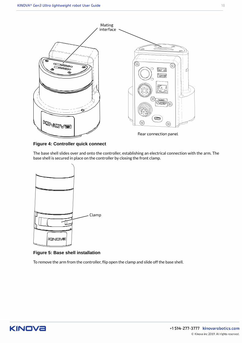
Figure 4: Controller quick connect
The base shell slides over and onto the controller, establishing an electrical connection with the arm. Thebase shell is secured in place on the controller by closing the front clamp.
Clamp
Figure 5: Base shell installation
To remove the arm from the controller, flip open the clamp and slide off the base shell.
KINOVA® Gen3 Ultra lightweight robot User Guide 19
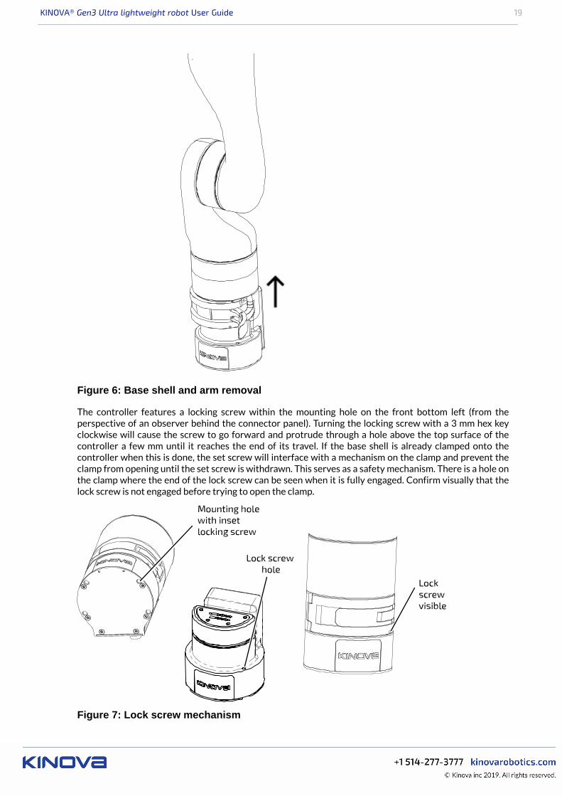
Figure 6: Base shell and arm removal
The controller features a locking screw within the mounting hole on the front bottom left (from theperspective of an observer behind the connector panel). Turning the locking screw with a 3 mm hex keyclockwise will cause the screw to go forward and protrude through a hole above the top surface of thecontroller a few mm until it reaches the end of its travel. If the base shell is already clamped onto thecontroller when this is done, the set screw will interface with a mechanism on the clamp and prevent theclamp from opening until the set screw is withdrawn. This serves as a safety mechanism. There is a hole onthe clamp where the end of the lock screw can be seen when it is fully engaged. Confirm visually that thelock screw is not engaged before trying to open the clamp.
Figure 7: Lock screw mechanism
KINOVA® Gen3 Ultra lightweight robot User Guide 20
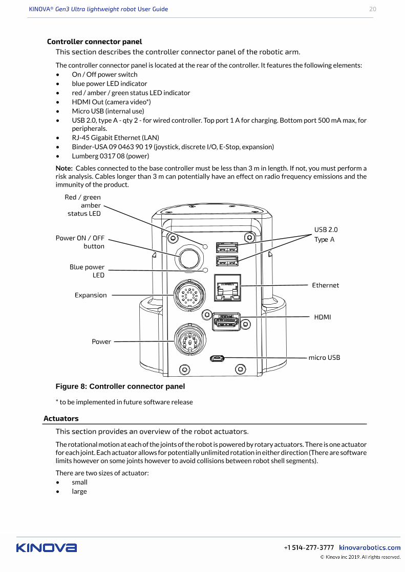
Controller connector panelThis section describes the controller connector panel of the robotic arm.
The controller connector panel is located at the rear of the controller. It features the following elements:• On / Off power switch• blue power LED indicator• red / amber / green status LED indicator• HDMI Out (camera video*)• Micro USB (internal use)• USB 2.0, type A - qty 2 - for wired controller. Top port 1 A for charging. Bottom port 500 mA max, for
peripherals.• RJ-45 Gigabit Ethernet (LAN)• Binder-USA 09 0463 90 19 (joystick, discrete I/O, E-Stop, expansion)• Lumberg 0317 08 (power)
Note: Cables connected to the base controller must be less than 3 m in length. If not, you must perform arisk analysis. Cables longer than 3 m can potentially have an effect on radio frequency emissions and theimmunity of the product.
Figure 8: Controller connector panel
* to be implemented in future software release
Actuators
This section provides an overview of the robot actuators.
The rotational motion at each of the joints of the robot is powered by rotary actuators. There is one actuatorfor each joint. Each actuator allows for potentially unlimited rotation in either direction (There are softwarelimits however on some joints however to avoid collisions between robot shell segments).
There are two sizes of actuator:• small• large
KINOVA® Gen3 Ultra lightweight robot User Guide 21
Each actuator has:• torque sensing• current and temperature sensing on each motor phaseWrist joints use small actuators, while large actuators are used for other joints. All actuators are equippedwith a 100:1 strain wave gear for smooth motion.
The actuators are connected to each other and to the interconnect board using a series of 41-pin flex cables.These cables convey:• power• 2 x full-duplex 100 Mbps Ethernet
º one for 1 kHz controlº one for vision / expansion data traffic
Actuator Specifications:• actuator speed (maximum, unloaded):
º 25 RPM (small)º 13 RPM (large)
• actuator torque (small):º 13 N·m (nominal)º 34 N·m (peak)
• actuator torque (large):º 32 N·m (nominal)º 54 N·m (peak)
Interface module
This section describes the interface module.
The interface module provides an interface for connecting a gripper or other tools at the end of the arm.The interface module also provides a mounting point and connection for the vision module.
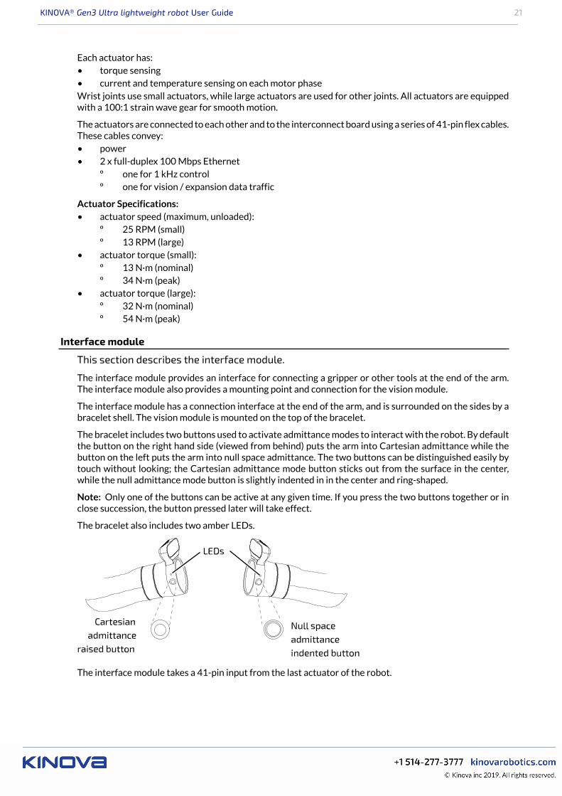
The interface module has a connection interface at the end of the arm, and is surrounded on the sides by abracelet shell. The vision module is mounted on the top of the bracelet.
The bracelet includes two buttons used to activate admittance modes to interact with the robot. By defaultthe button on the right hand side (viewed from behind) puts the arm into Cartesian admittance while thebutton on the left puts the arm into null space admittance. The two buttons can be distinguished easily bytouch without looking; the Cartesian admittance mode button sticks out from the surface in the center,while the null admittance mode button is slightly indented in in the center and ring-shaped.
Note: Only one of the buttons can be active at any given time. If you press the two buttons together or inclose succession, the button pressed later will take effect.
The bracelet also includes two amber LEDs.
The interface module takes a 41-pin input from the last actuator of the robot.
KINOVA® Gen3 Ultra lightweight robot User Guide 22
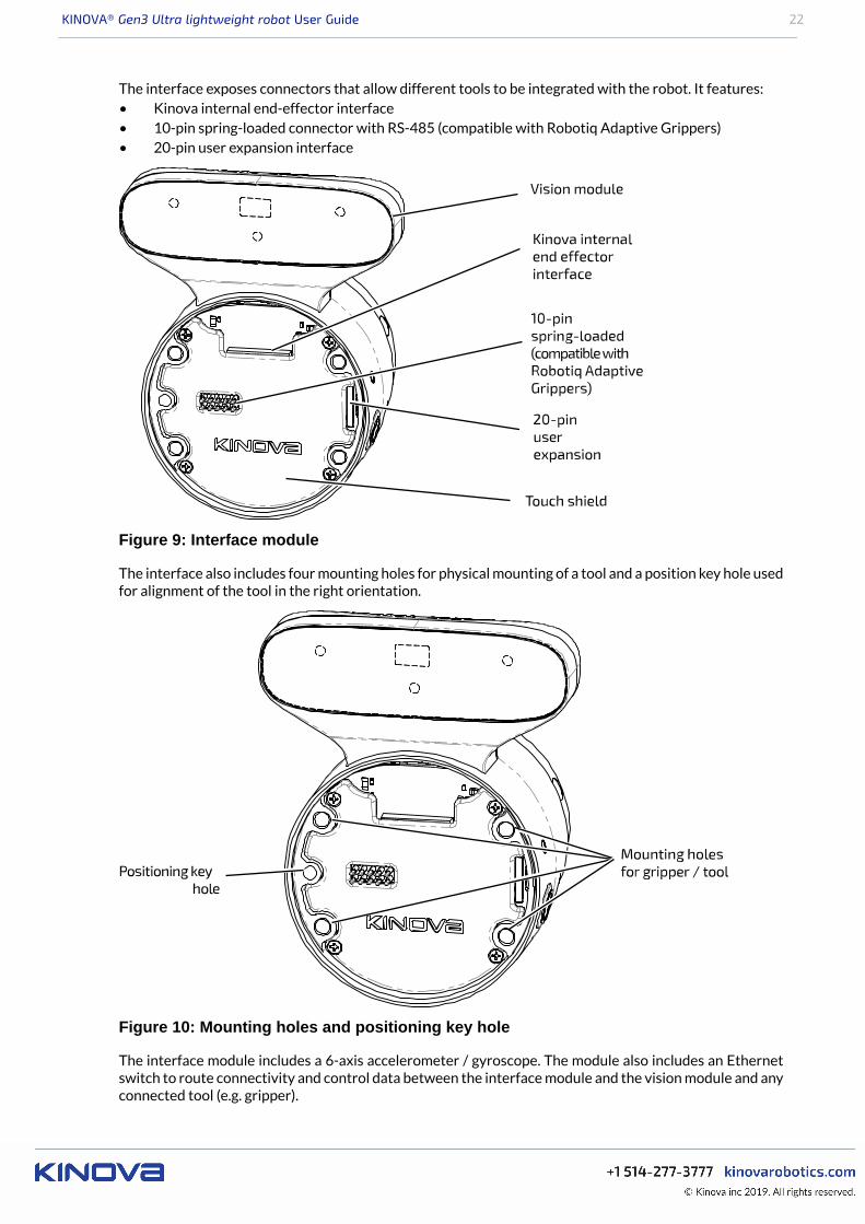
The interface exposes connectors that allow different tools to be integrated with the robot. It features:• Kinova internal end-effector interface• 10-pin spring-loaded connector with RS-485 (compatible with Robotiq Adaptive Grippers)• 20-pin user expansion interface
Figure 9: Interface module
The interface also includes four mounting holes for physical mounting of a tool and a position key hole usedfor alignment of the tool in the right orientation.
Figure 10: Mounting holes and positioning key hole
The interface module includes a 6-axis accelerometer / gyroscope. The module also includes an Ethernetswitch to route connectivity and control data between the interface module and the vision module and anyconnected tool (e.g. gripper).
KINOVA® Gen3 Ultra lightweight robot User Guide 23
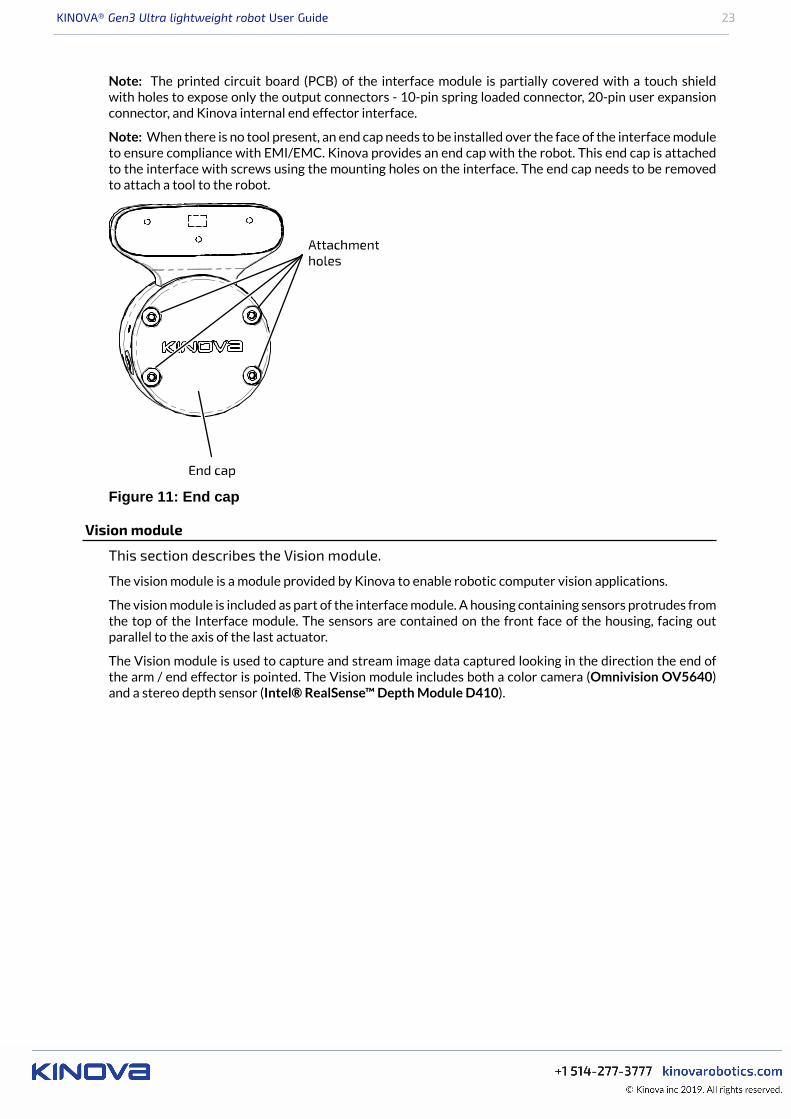
Note: The printed circuit board (PCB) of the interface module is partially covered with a touch shieldwith holes to expose only the output connectors - 10-pin spring loaded connector, 20-pin user expansionconnector, and Kinova internal end effector interface.
Note: When there is no tool present, an end cap needs to be installed over the face of the interface moduleto ensure compliance with EMI/EMC. Kinova provides an end cap with the robot. This end cap is attachedto the interface with screws using the mounting holes on the interface. The end cap needs to be removedto attach a tool to the robot.
Figure 11: End cap
Vision module
This section describes the Vision module.
The vision module is a module provided by Kinova to enable robotic computer vision applications.
The vision module is included as part of the interface module. A housing containing sensors protrudes fromthe top of the Interface module. The sensors are contained on the front face of the housing, facing outparallel to the axis of the last actuator.
The Vision module is used to capture and stream image data captured looking in the direction the end ofthe arm / end effector is pointed. The Vision module includes both a color camera (Omnivision OV5640)and a stereo depth sensor (Intel® RealSense™ Depth Module D410).

KINOVA® Gen3 Ultra lightweight robot User Guide 24
Figure 12: Vision module sensors
The color sensor captures a 2D array of RGB pixel data representating the field of view from the perspectiveof the sensor.
The depth sensor includes an IR projector and two stereo imagers - left and right. Here left and right arefrom the perspective of an observer looking out from the sensor toward the imaged region. The depthsensor captures a 2D array of pixels and the depth for each pixel within the field of view of the sensor.
Together, the two sensors allow the capture of RGBD (color and depth) data. Both camera sensors can be
configured using the KINOVA® KORTEX™ VisionConfig interface.
Note that performance for the Vision module depth sensor may be degraded at temperatures below 0° C.For more details, please consult the depth sensor data sheet.
The color and depth sensors data streams are made accessible to developers through a computer with aconnection to the robot. For more information on accessing these data streams programatically, see here.
Vision module specifications
Color sensor:
• resolution, frame rates (fps), and fields of view (FOV):º 1920 x 1080 (16:9) @ 30, 15 fps; FOV 47 ± 3° (diagonal)º 1280 x 720 (16:9) @ 30, 15 fps; FOV 60 ± 3° (diagonal)º 640 x 480 (4:3) @ 30, 15 fps; FOV 65 ± 3° (diagonal)º 320 x 240 (4:3)@ 30, 15 fps; FOV 65 ± 3° (diagonal)
• focusing range - 30 cm to ∞
Depth sensor:• resolution, frame rates (fps), and fields of view (FOV):
º 480 x 270 (16:9) @ 30, 15, 6 fps; FOV 72 ± 3° (diagonal)º 424 x 240 (16:9) @ 30, 15, 6 fps; FOV 72 ± 3° (diagonal)
• minimum depth distance (min-Z) - 18 cm
Robot communications and network interfaces
This section describes communications and network interfaces within the robot.
KINOVA® Gen3 Ultra lightweight robot User Guide 25
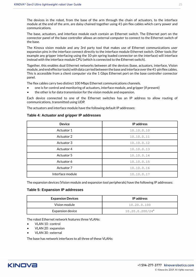
The devices in the robot, from the base of the arm through the chain of actuators, to the interfacemodule at the end of the arm, are daisy chained together using 41-pin flex cables which carry power andcommunications.
The base, actuators, and interface module each contain an Ethernet switch. The Ethernet port on theconnector panel of the base controller allows an external computer to connect to the Ethernet switch ofthe base.
The Kinova vision module and any 3rd party tool that makes use of Ethernet communications userexpansion pins in the interface connect directly to the interface module Ethernet switch. Other tools (forexample any gripper interfacing using the 10-pin spring loaded connector on the interface) will interfaceinstead with the interface module CPU (which is connected to the Ethernet switch).
Together, this enables dual Ethernet networks between all the devices (base, actuators, interface, Visionmodule, and end effector tools) with data carried between the base and interface over the 41-pin flex cables.This is accessible from a client computer via the 1 Gbps Ethernet port on the base controller connectorpanel.
The flex cables carry two distinct 100 Mbps Ethernet communications channels.• one is for control and monitoring of actuators, interface module, and gripper (if present)• the other is for data transmission for the vision module and expansion.
Each device connected to one of the Ethernet switches has an IP address to allow routing ofcommunications, transmitted using UDP.
The actuators and interface module have the following default IP addresses:
Table 4: Actuator and gripper IP addresses
Device IP address
Actuator 1 10.10.0.10
Actuator 2 10.10.0.11
Actuator 3 10.10.0.12
Actuator 4 10.10.0.13
Actuator 5 10.10.0.14
Actuator 6 10.10.0.15
Actuator 7 10.10.0.16
Interface module 10.10.0.17
The expansion devices (Vision module and expansion tool peripherals) have the following IP addresses:
Table 5: Expansion IP addresses
Expansion Devices IP address
Vision module 10.20.0.100
Expansion device 10.20.0.200/24*
The robot Ethernet network features three VLANs:• VLAN 10 : control• VLAN 20 : expansion• VLAN 30 : external
The base has network interfaces to all three of these VLANs:
KINOVA® Gen3 Ultra lightweight robot User Guide 26
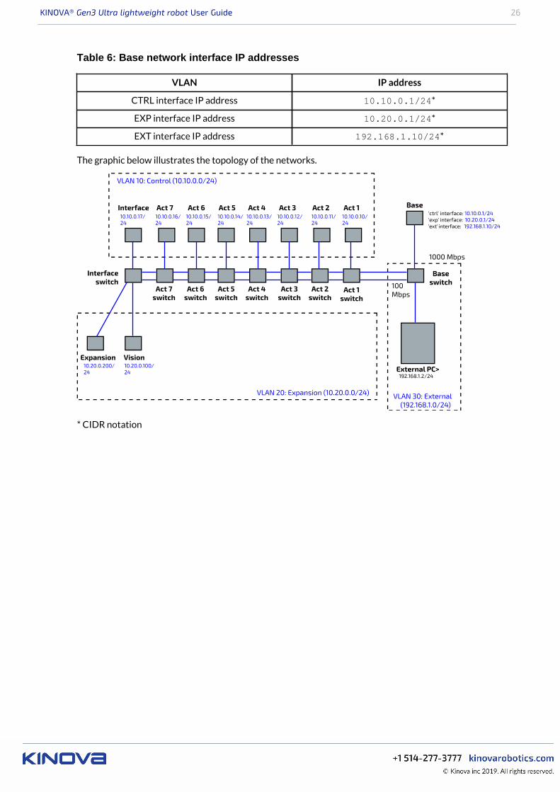
Table 6: Base network interface IP addresses
VLAN IP address
CTRL interface IP address 10.10.0.1/24*
EXP interface IP address 10.20.0.1/24*
EXT interface IP address 192.168.1.10/24*
The graphic below illustrates the topology of the networks.
* CIDR notation

KINOVA® Gen3 Ultra lightweight robot User Guide 27
Getting started
Overview
This section describes how to get started with the arm.
The pages that follow lead you through getting started with the robot. This includes:• unboxing• physically mounting the robot securely• provisioning electrical power• controlling the robot using an Xbox gamepad• moving the robot in admittance using physical buttons• connecting a computer to the robot• connecting to the KINOVA® KORTEX™ Web App
What's in the case?
This section describes the KINOVA® Gen3 Ultra lightweight robot shipping case contents.
Figure 13: Gen3 Ultra lightweight robot shipping case contents
The shipping case contains the following contents.
At the top of the interior of the box, you will find the Quick Start Guide. The Quick Start Guide is a largeprinted visual guide.
The Quick Start guide provides a handy reference for first steps, and should have you up and running within30 minutes. Make sure to keep the Quick Start Guide as a reference for people in your team or organizationgetting newly acquainted with your robot. The Quick Start Guide is also available on the Kinova website:
www.kinovarobotics.com/knowledge-hub/gen3-ultra-lightweight-robot
The contents of the box are arranged in three layers from top to bottom. These packing layers can beremoved from the box to unpack the contents.
KINOVA® Gen3 Ultra lightweight robot User Guide 28
In the top layer:• Robot
In the second layer:• Power adapter and cable with integrated emergency stop (E-stop) button• Table clamp• Mounting plate and robot controller
The bottom area contains:• Ethernet (RJ-45) cable• Power cable• Bag with useful tools and fasteners
º hex keys: 3, 4 and 5 mmº M5 screws (qty. 4)
An Xbox gamepad and cable are shipped with the robot, but packaged separately.
There is also space for storage of papers and other items.
Note: The shipping case is also useful for transportation and storage of the robot. Make sure to save it andthe packing layers within for future use.
Manipulating the robot joints when the robot is powered off
This describes how to manipulate the robot joints when the robot is powered off.
When the robot is powered on, the actuators will hold their position and prevent the joints from movingin response to external forces and torques. When the power is on, the arm will not move except whencommanded. The arm joints are stiff and you will not be able to rotate the joints with your hands.
When the robot is powered off, as it is when you first receive the robot, the joints can be moved by handslowly.
Note: If you move the joints too quickly, mechanisms within the joints will limit the speed.
This moveability of the joints when the robot is unpowered is useful when taking the robot out of the boxand setting it up to get started. This lets you arrange the joints of the robot into a stable, balanced positionprior to mounting and powering on the robot.
Robot mounting options
This section describes the physical mounting options for the robot.
The first step to getting started with the arm after unboxing is to physically mount the arm in a stablemanner so that the robot can be connected and used.
The most basic mounting option uses the mounting plate and a table clamp to quickly mount the robot ona tabletop in a "right side up," vertical orientation.
However, if is also possible to mount the robot in different ways, as well as different orientations, dependingon the needs of your particular application. The sections that follow will describe this in more detail.
Mounting the robot on a tabletopThis section describes the procedure for mounting the robot oriented vertically on the edgeof a tabletop using the clamp.
Before you begin
The robot should have the joints of the robot unfolded so that it is in a stable, balancedposition ready for mounting.
About this task
The robot is mounted to a tabletop using the base mounting plate and a table clamp.
Note: The table must be large and sturdy to support a tabletop edge mounting. If the table is too small ortoo flimsy, the weight of the robot at the table edge combined with the movement vibrations may renderit unstable.
KINOVA® Gen3 Ultra lightweight robot User Guide 29
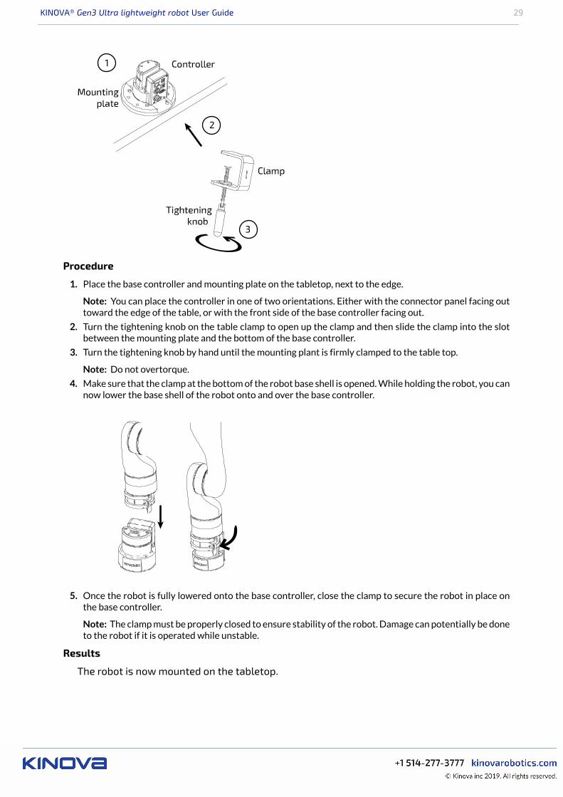
Procedure
1. Place the base controller and mounting plate on the tabletop, next to the edge.
Note: You can place the controller in one of two orientations. Either with the connector panel facing outtoward the edge of the table, or with the front side of the base controller facing out.
2. Turn the tightening knob on the table clamp to open up the clamp and then slide the clamp into the slotbetween the mounting plate and the bottom of the base controller.
3. Turn the tightening knob by hand until the mounting plant is firmly clamped to the table top.
Note: Do not overtorque.
4. Make sure that the clamp at the bottom of the robot base shell is opened. While holding the robot, you cannow lower the base shell of the robot onto and over the base controller.
5. Once the robot is fully lowered onto the base controller, close the clamp to secure the robot in place onthe base controller.
Note: The clamp must be properly closed to ensure stability of the robot. Damage can potentially be doneto the robot if it is operated while unstable.
Results
The robot is now mounted on the tabletop.

KINOVA® Gen3 Ultra lightweight robot User Guide 30
What to do next
You can now proceed to connect the robot to the power supply and E-stop.
Mounting the robot on a horizontal surface without the table clampThis section describes how to mount the robot on a horizontal surface without the tableclamp..
About this task
Here, we describe mounting the robot in a vertical orientation on a flat, horizontal surface,affixing the mounting plate or controller base to the surface using screws and sunk holes inthe surface.
Procedure
1. Choose whether to mount the robot base controller directly onto the surface, or whether to use themounting plate.
2. Using either the mounting plate bolting pattern or the controller bolting pattern or as a guide, drill holesinto the surface. If the controller is to be mounted directly to the surface, the holes will have to be drilledall the way through the mounting surface.
3. Use appropriate screws to mount either the base controller or the mounting plate to the surface. If thebase controller is mounted directly, the screws will need to go through the mounting surface from theother side.
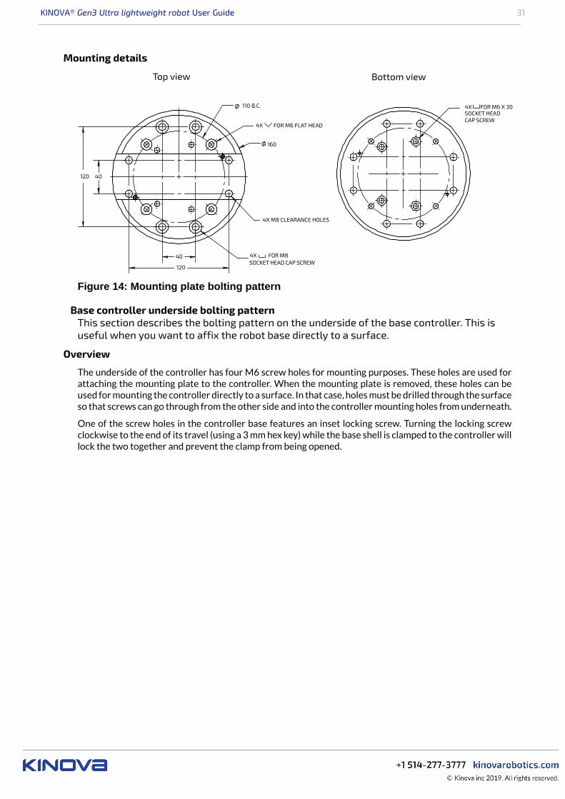
Controller mounting plate bolting patternThis section describes the bolting pattern of the mounting plate. This is useful whenmounting the robot to a surface using the mounting plate.
Overview
The mounting plate is attached to the bottom of the base controller. The mounting plate has two sets of M8screw holes (4) and one set of counter-sunk M6 screw holes (4) available for mounting the plate to a surface.
KINOVA® Gen3 Ultra lightweight robot User Guide 31
Mounting details
Figure 14: Mounting plate bolting pattern
Base controller underside bolting patternThis section describes the bolting pattern on the underside of the base controller. This isuseful when you want to affix the robot base directly to a surface.
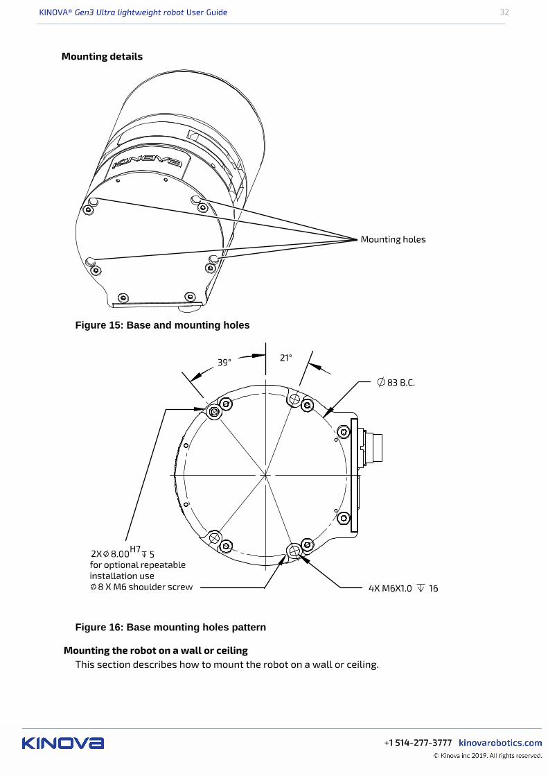
Overview
The underside of the controller has four M6 screw holes for mounting purposes. These holes are used forattaching the mounting plate to the controller. When the mounting plate is removed, these holes can beused for mounting the controller directly to a surface. In that case, holes must be drilled through the surfaceso that screws can go through from the other side and into the controller mounting holes from underneath.
One of the screw holes in the controller base features an inset locking screw. Turning the locking screwclockwise to the end of its travel (using a 3 mm hex key) while the base shell is clamped to the controller willlock the two together and prevent the clamp from being opened.
KINOVA® Gen3 Ultra lightweight robot User Guide 32
Mounting details
Figure 15: Base and mounting holes
Figure 16: Base mounting holes pattern
Mounting the robot on a wall or ceilingThis section describes how to mount the robot on a wall or ceiling.
KINOVA® Gen3 Ultra lightweight robot User Guide 33
The procedure for mounting is generally similar to that of mounting onto a horizontal surface:
1. Choose whether to mount the controller directly to the surface, or using the mounting plate.2. Drill holes in an appropriate pattern in the surface based on the appropriate bolting pattern diagram.3. Attach the controller or mounting plate to the surface with appropriate screws.
There are however important differences.
It is essential to follow all special considerations for wall and ceiling mounting. This includes the need to:• perform a careful analysis of the proposed mounting surface• mount and clamp the robot onto the controller with the locking screw engaged before mounting the
robot on the surface• configure the gravity vector and compute any needed transformations between the user / lab
reference frame and the robot base frame to account for the new orientation of the robot base
Special considerations and configurations for wall and ceiling mountsThis section describes special considerations that are important for wall and ceilingmounts.
For safety reasons, there are special preparations and steps that need to be undertaken before mountingthe robot on a wall or ceiling.
Before trying to mount the arm on a wall or ceiling, perform a comprehensive analysis of weight,torque, and vibrations and ensure the material is stable enough.
The locking screw on the bottom left front of the controller must be screwed in fully with a hex keywhile the base shell is clamped on. This will block the clamp from being opened while the arm is mountedon a wall or ceiling, and provides an added measure of security. The robot therefore needs to be clamped tothe controller and the lock screw adjusted before trying to mount the robot.
For wall mounting, the robot needs to be mounted with the controller connector panel facingdownwards. This is to prevent water ingress at the connector panel.
Note: A robot mounted in a ceiling mount is not certified for ingress protection.
Note: In a wall or ceiling mount, the gravity vector will have a different orientation than usual with respectto the base reference frame. It will be necessary to set the gravity vector using the Kinova Web Appor Kinova.Api.ControlConfig API. If the gravity vector is not configured appropriately, the robotcontrol library will not be able to properly compensate for torques due to gravity on the robot and the robotwill behave in unexpected ways.
Note: The Cartesian control of the robot is by default in relation to the base reference frame. This basereference frame will be rotated relative to the natural reference frame of the perspective of the user /operator. You will need to apply the appropriate coordinate transformations to control the robot in theseorientations.
Adjusting the controller locking screw to secure base clampThis section describes how to adjust the controller locking screw to secure the clamp onthe base.
Before you begin
You will need a 3 mm hex key.
About this task
Adjusting the controller locking screw while the base shell is attached and clamped locksthe clamp shut and prevents it from being opened. This improves the safety of the robotwhen mounted on a wall or ceiling
KINOVA® Gen3 Ultra lightweight robot User Guide 34
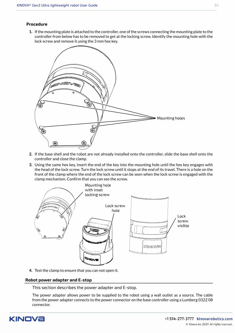
Procedure
1. If the mounting plate is attached to the controller, one of the screws connecting the mounting plate to thecontroller from below has to be removed to get at the locking screw. Identify the mounting hole with thelock screw and remove it using the 3 mm hex key.
2. If the base shell and the robot are not already installed onto the controller, slide the base shell onto thecontroller and close the clamp.
3. Using the same hex key, insert the end of the key into the mounting hole until the hex key engages withthe head of the lock screw. Turn the lock screw until it stops at the end of its travel. There is a hole on thefront of the clamp where the end of the lock screw can be seen when the lock screw is engaged with theclamp mechanism. Confirm that you can see the screw.
4. Test the clamp to ensure that you can not open it.
Robot power adapter and E-stop
This section describes the power adapter and E-stop.
The power adapter allows power to be supplied to the robot using a wall outlet as a source. The cablefrom the power adapter connects to the power connector on the base controller using a Lumberg 0322 08connector.
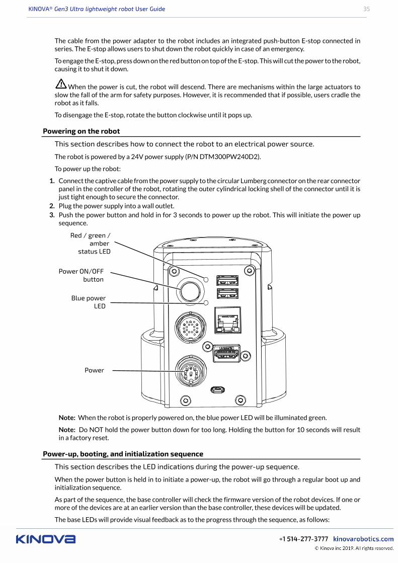
KINOVA® Gen3 Ultra lightweight robot User Guide 35
The cable from the power adapter to the robot includes an integrated push-button E-stop connected inseries. The E-stop allows users to shut down the robot quickly in case of an emergency.
To engage the E-stop, press down on the red button on top of the E-stop. This will cut the power to the robot,causing it to shut it down.
When the power is cut, the robot will descend. There are mechanisms within the large actuators toslow the fall of the arm for safety purposes. However, it is recommended that if possible, users cradle therobot as it falls.
To disengage the E-stop, rotate the button clockwise until it pops up.
Powering on the robot
This section describes how to connect the robot to an electrical power source.
The robot is powered by a 24V power supply (P/N DTM300PW240D2).
To power up the robot:
1. Connect the captive cable from the power supply to the circular Lumberg connector on the rear connectorpanel in the controller of the robot, rotating the outer cylindrical locking shell of the connector until it isjust tight enough to secure the connector.
2. Plug the power supply into a wall outlet.3. Push the power button and hold in for 3 seconds to power up the robot. This will initiate the power up
sequence.
Note: When the robot is properly powered on, the blue power LED will be illuminated green.
Note: Do NOT hold the power button down for too long. Holding the button for 10 seconds will resultin a factory reset.
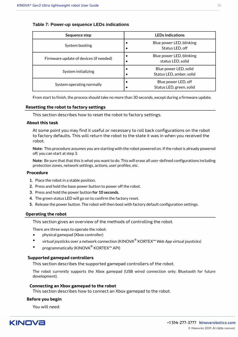
Power-up, booting, and initialization sequence
This section describes the LED indications during the power-up sequence.
When the power button is held in to initiate a power-up, the robot will go through a regular boot up andinitialization sequence.
As part of the sequence, the base controller will check the firmware version of the robot devices. If one ormore of the devices are at an earlier version than the base controller, these devices will be updated.
The base LEDs will provide visual feedback as to the progress through the sequence, as follows:
KINOVA® Gen3 Ultra lightweight robot User Guide 36
Table 7: Power-up sequence LEDs indications
Sequence step LEDs indications
System booting• Blue power LED, blinking• Status LED, off
Firmware update of devices (if needed)• Blue power LED, blinking• status LED, solid
System initializing• Blue power LED, solid• Status LED, amber, solid
System operating normally• Blue power LED, off• Status LED, green, solid
From start to finish, the process should take no more than 30 seconds, except during a firmware update.
Resetting the robot to factory settings
This section describes how to reset the robot to factory settings.
About this task
At some point you may find it useful or necessary to roll back configurations on the robotto factory defaults. This will return the robot to the state it was in when you received therobot.
Note: This procedure assumes you are starting with the robot powered on. If the robot is already poweredoff, you can start at step 3.
Note: Be sure that that this is what you want to do. This will erase all user-defined configurations includingprotection zones, network settings, actions, user profiles, etc.
Procedure
1. Place the robot in a stable position.
2. Press and hold the base power button to power off the robot.
3. Press and hold the power button for 10 seconds.
4. The green status LED will go on to confirm the factory reset.
5. Release the power button. The robot will then boot with factory default configuration settings.
Operating the robot
This section gives an overview of the methods of controlling the robot.
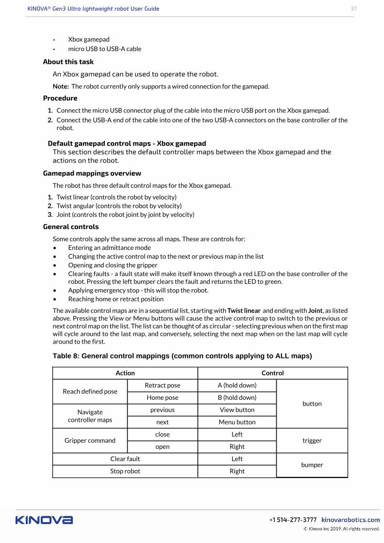
There are three ways to operate the robot:• physical gamepad (Xbox controller)• virtual joysticks over a network connection (KINOVA® KORTEX™ Web App virtual joysticks)• programmatically (KINOVA® KORTEX™ API)
Supported gamepad controllersThis section describes the supported gamepad controllers of the robot.
The robot currently supports the Xbox gamepad (USB wired connection only; Bluetooth for futuredevelopment).
Connecting an Xbox gamepad to the robotThis section describes how to connect an Xbox gamepad to the robot.
Before you begin
You will need:
KINOVA® Gen3 Ultra lightweight robot User Guide 37
• Xbox gamepad
• micro USB to USB-A cable
About this task
An Xbox gamepad can be used to operate the robot.
Note: The robot currently only supports a wired connection for the gamepad.
Procedure
1. Connect the micro USB connector plug of the cable into the micro USB port on the Xbox gamepad.
2. Connect the USB-A end of the cable into one of the two USB-A connectors on the base controller of therobot.
Default gamepad control maps - Xbox gamepadThis section describes the default controller maps between the Xbox gamepad and theactions on the robot.
Gamepad mappings overview
The robot has three default control maps for the Xbox gamepad.
1. Twist linear (controls the robot by velocity)2. Twist angular (controls the robot by velocity)3. Joint (controls the robot joint by joint by velocity)
General controls
Some controls apply the same across all maps. These are controls for:• Entering an admittance mode• Changing the active control map to the next or previous map in the list• Opening and closing the gripper• Clearing faults - a fault state will make itself known through a red LED on the base controller of the
robot. Pressing the left bumper clears the fault and returns the LED to green.• Applying emergency stop - this will stop the robot.• Reaching home or retract position
The available control maps are in a sequential list, starting with Twist linear and ending with Joint, as listedabove. Pressing the View or Menu buttons will cause the active control map to switch to the previous ornext control map on the list. The list can be thought of as circular - selecting previous when on the first mapwill cycle around to the last map, and conversely, selecting the next map when on the last map will cyclearound to the first.
Table 8: General control mappings (common controls applying to ALL maps)
Action Control
Retract pose A (hold down)Reach defined pose
Home pose B (hold down)
previous View buttonNavigatecontroller maps next Menu button
button
close LeftGripper command
open Righttrigger
Clear fault Left
Stop robot Rightbumper
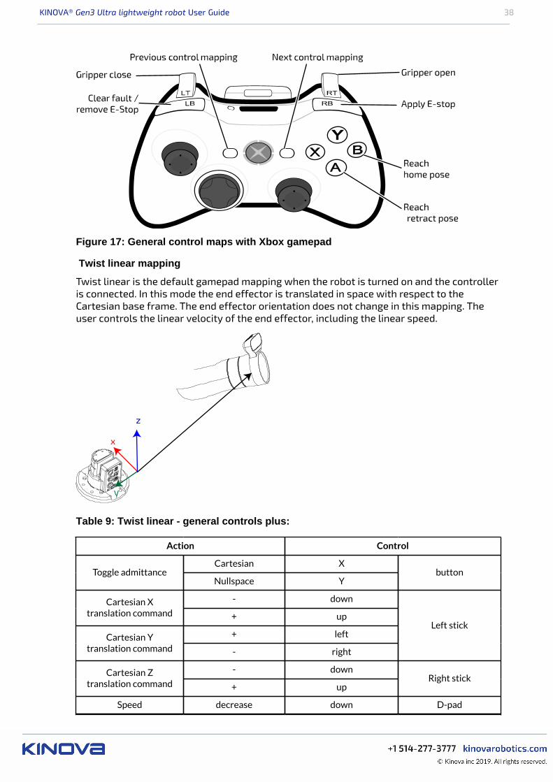
KINOVA® Gen3 Ultra lightweight robot User Guide 38
Figure 17: General control maps with Xbox gamepad
Twist linear mapping
Twist linear is the default gamepad mapping when the robot is turned on and the controlleris connected. In this mode the end effector is translated in space with respect to theCartesian base frame. The end effector orientation does not change in this mapping. Theuser controls the linear velocity of the end effector, including the linear speed.
Table 9: Twist linear - general controls plus:
Action Control
Cartesian XToggle admittance
Nullspace Ybutton
- downCartesian Xtranslation command + up
+ leftCartesian Ytranslation command - right
Left stick
- downCartesian Ztranslation command + up
Right stick
Speed decrease down D-pad
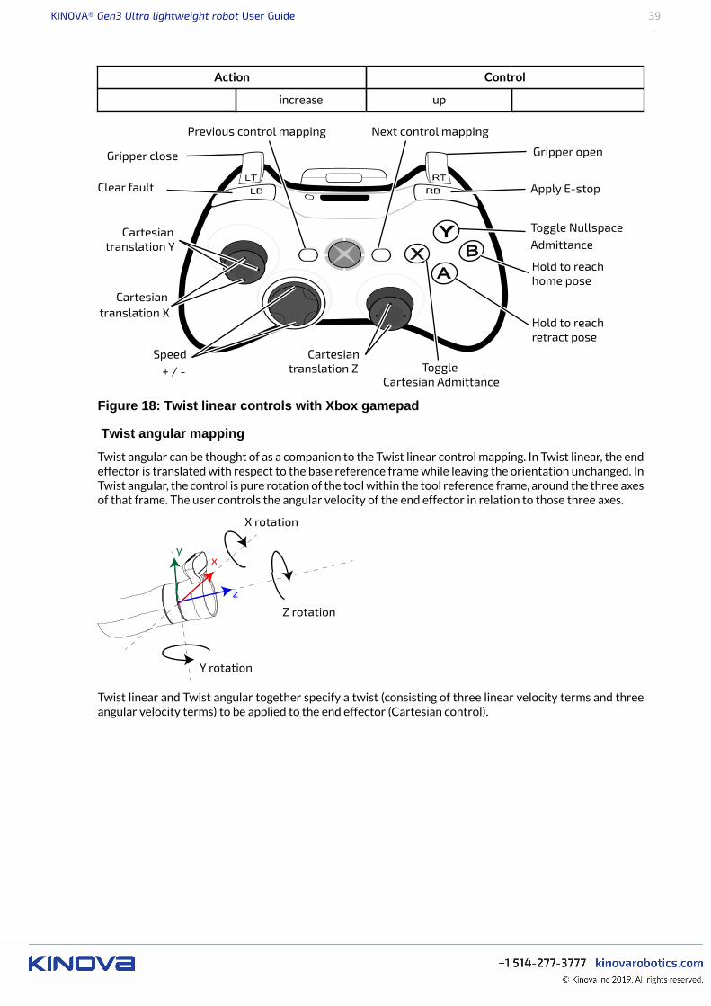
KINOVA® Gen3 Ultra lightweight robot User Guide 39
Action Control
increase up
Apply E-stopClear fault
Gripper close Gripper open
Toggle NullspaceAdmittance
ToggleCartesian Admittance
Cartesiantranslation Z
Cartesiantranslation Y
Cartesiantranslation X
Previous control mapping Next control mapping
Hold to reachhome pose
Hold to reachretract pose
Speed+ / -
Figure 18: Twist linear controls with Xbox gamepad
Twist angular mapping
Twist angular can be thought of as a companion to the Twist linear control mapping. In Twist linear, the endeffector is translated with respect to the base reference frame while leaving the orientation unchanged. InTwist angular, the control is pure rotation of the tool within the tool reference frame, around the three axesof that frame. The user controls the angular velocity of the end effector in relation to those three axes.
z
yx
Z rotation
Y rotation
X rotation
Twist linear and Twist angular together specify a twist (consisting of three linear velocity terms and threeangular velocity terms) to be applied to the end effector (Cartesian control).
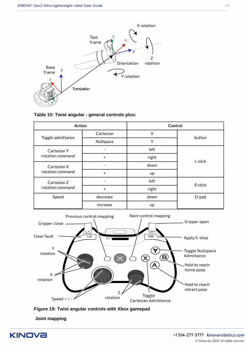
KINOVA® Gen3 Ultra lightweight robot User Guide 40
Table 10: Twist angular - general controls plus:
Action Control
Cartesian XToggle admittance
Nullspace Ybutton
- leftCartesian Yrotation command + right
- downCartesian Xrotation command + up
L stick
- leftCartesian Zrotation command + right
R stick
decrease downSpeed
increase up
D-pad
Apply E-stopClear fault
Gripper close Gripper open
Toggle NullspaceAdmittance
ToggleCartesian Admittance
Zrotation
Y rotation
Xrotation
Previous control mapping Next control mapping
Speed + / -
Hold to reachhome pose
Hold to reachretract pose
Figure 19: Twist angular controls with Xbox gamepad
Joint mapping
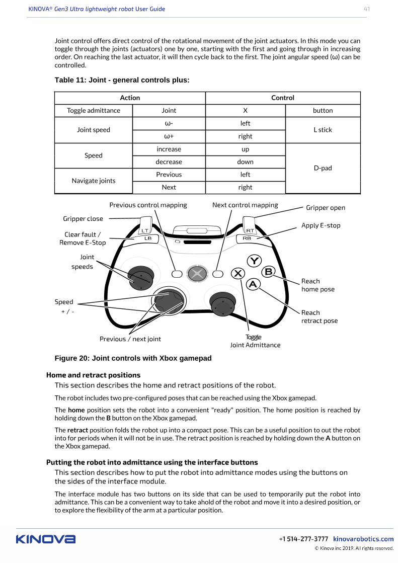
KINOVA® Gen3 Ultra lightweight robot User Guide 41
Joint control offers direct control of the rotational movement of the joint actuators. In this mode you cantoggle through the joints (actuators) one by one, starting with the first and going through in increasingorder. On reaching the last actuator, it will then cycle back to the first. The joint angular speed (ω) can becontrolled.
Table 11: Joint - general controls plus:
Action Control
Toggle admittance Joint X button
ω- leftJoint speed
ω+ rightL stick
increase upSpeed
decrease down
Previous leftNavigate joints
Next right
D-pad
Figure 20: Joint controls with Xbox gamepad
Home and retract positionsThis section describes the home and retract positions of the robot.
The robot includes two pre-configured poses that can be reached using the Xbox gamepad.
The home position sets the robot into a convenient "ready" position. The home position is reached byholding down the B button on the Xbox gamepad.
The retract position folds the robot up into a compact pose. This can be a useful position to out the robotinto for periods when it will not be in use. The retract position is reached by holding down the A button onthe Xbox gamepad.
Putting the robot into admittance using the interface buttonsThis section describes how to put the robot into admittance modes using the buttons onthe sides of the interface module.
The interface module has two buttons on its side that can be used to temporarily put the robot intoadmittance. This can be a convenient way to take ahold of the robot and move it into a desired position, orto explore the flexibility of the arm at a particular position.
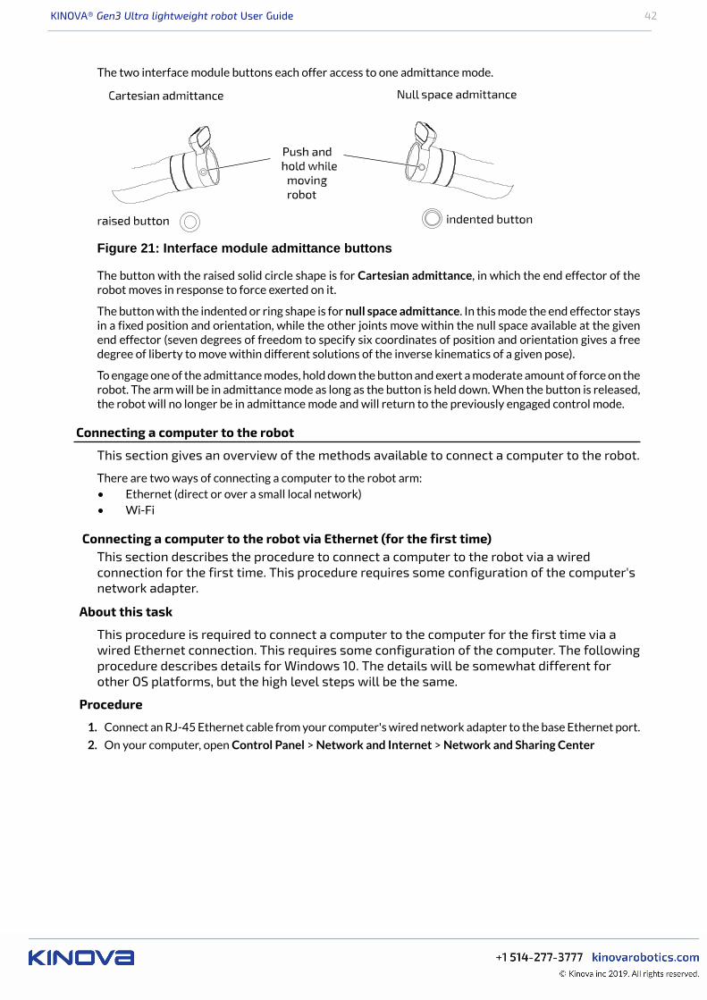
KINOVA® Gen3 Ultra lightweight robot User Guide 42
The two interface module buttons each offer access to one admittance mode.
Figure 21: Interface module admittance buttons
The button with the raised solid circle shape is for Cartesian admittance, in which the end effector of therobot moves in response to force exerted on it.
The button with the indented or ring shape is for null space admittance. In this mode the end effector staysin a fixed position and orientation, while the other joints move within the null space available at the givenend effector (seven degrees of freedom to specify six coordinates of position and orientation gives a freedegree of liberty to move within different solutions of the inverse kinematics of a given pose).
To engage one of the admittance modes, hold down the button and exert a moderate amount of force on therobot. The arm will be in admittance mode as long as the button is held down. When the button is released,the robot will no longer be in admittance mode and will return to the previously engaged control mode.
Connecting a computer to the robot
This section gives an overview of the methods available to connect a computer to the robot.
There are two ways of connecting a computer to the robot arm:• Ethernet (direct or over a small local network)• Wi-Fi
Connecting a computer to the robot via Ethernet (for the first time)This section describes the procedure to connect a computer to the robot via a wiredconnection for the first time. This procedure requires some configuration of the computer'snetwork adapter.
About this task
This procedure is required to connect a computer to the computer for the first time via awired Ethernet connection. This requires some configuration of the computer. The followingprocedure describes details for Windows 10. The details will be somewhat different forother OS platforms, but the high level steps will be the same.
Procedure
1. Connect an RJ-45 Ethernet cable from your computer's wired network adapter to the base Ethernet port.
2. On your computer, open Control Panel > Network and Internet > Network and Sharing Center
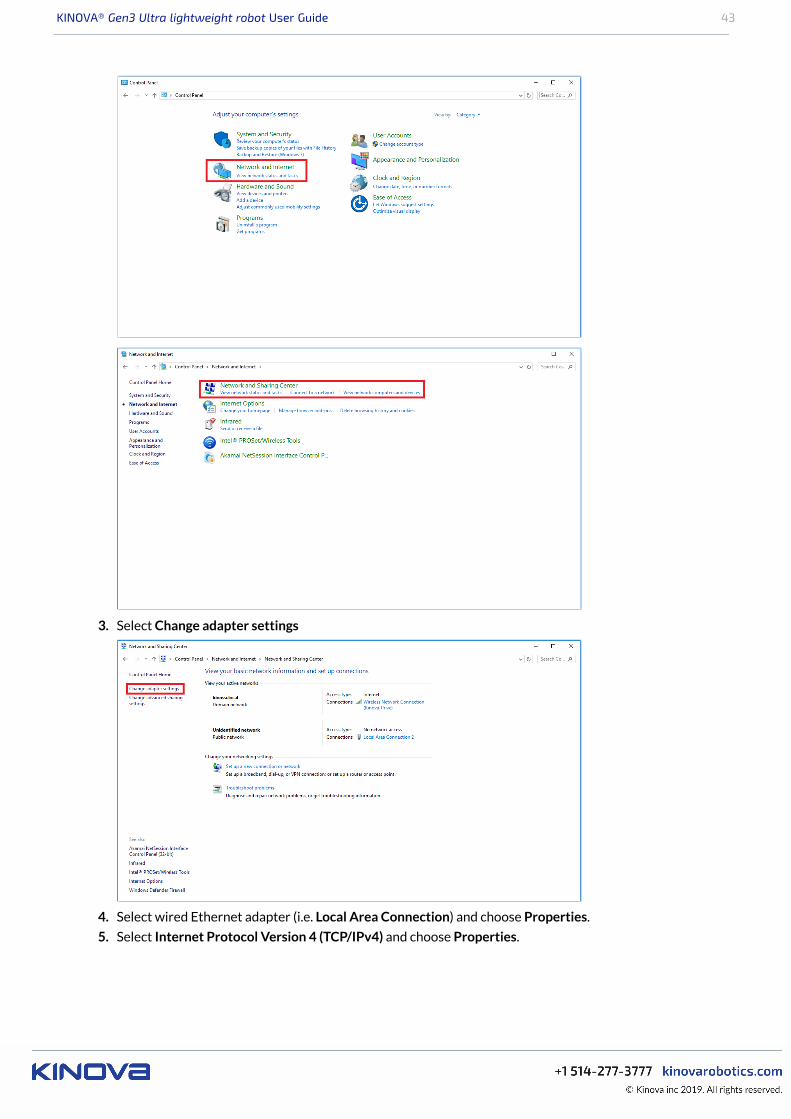
KINOVA® Gen3 Ultra lightweight robot User Guide 43
3. Select Change adapter settings
4. Select wired Ethernet adapter (i.e. Local Area Connection) and choose Properties.
5. Select Internet Protocol Version 4 (TCP/IPv4) and choose Properties.
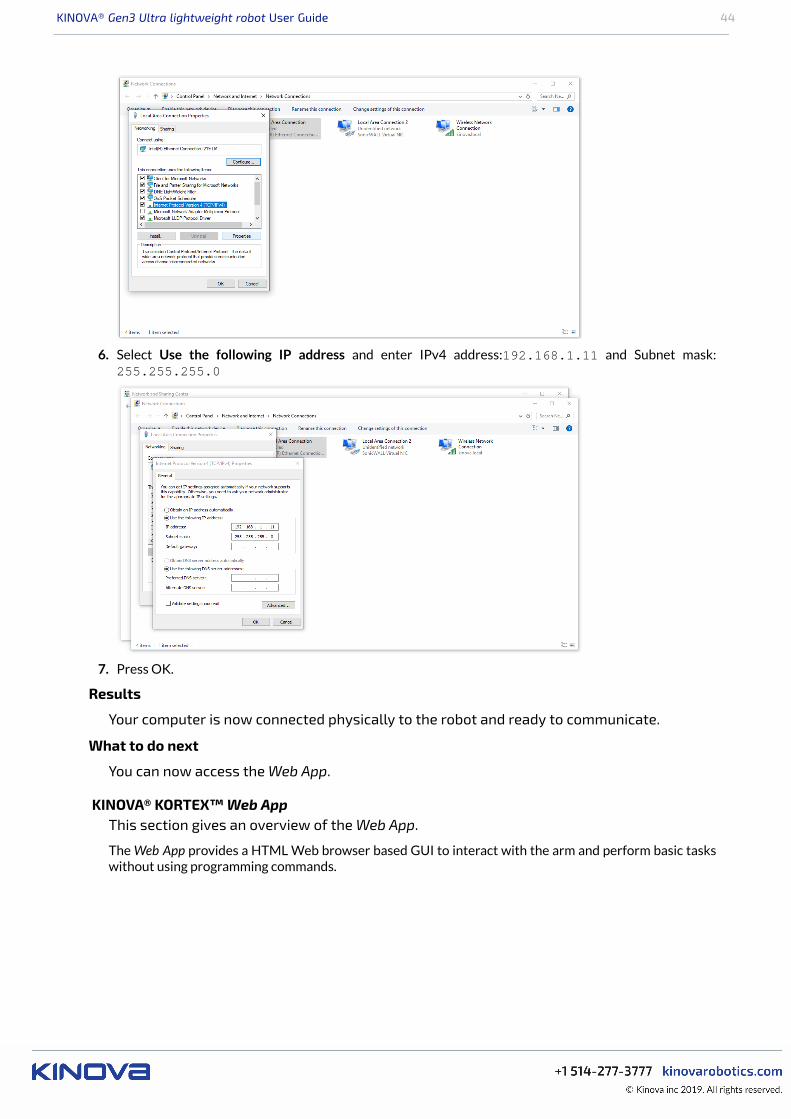
KINOVA® Gen3 Ultra lightweight robot User Guide 44
6. Select Use the following IP address and enter IPv4 address:192.168.1.11 and Subnet mask:255.255.255.0
7. Press OK.
Results
Your computer is now connected physically to the robot and ready to communicate.
What to do next
You can now access the Web App.
KINOVA® KORTEX™ Web AppThis section gives an overview of the Web App.
The Web App provides a HTML Web browser based GUI to interact with the arm and perform basic taskswithout using programming commands.
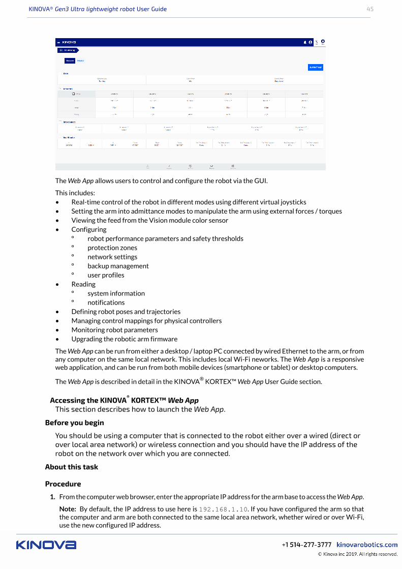
KINOVA® Gen3 Ultra lightweight robot User Guide 45
The Web App allows users to control and configure the robot via the GUI.
This includes:• Real-time control of the robot in different modes using different virtual joysticks• Setting the arm into admittance modes to manipulate the arm using external forces / torques• Viewing the feed from the Vision module color sensor• Configuring
º robot performance parameters and safety thresholdsº protection zonesº network settingsº backup managementº user profiles
• Readingº system informationº notifications
• Defining robot poses and trajectories• Managing control mappings for physical controllers• Monitoring robot parameters• Upgrading the robotic arm firmware
The Web App can be run from either a desktop / laptop PC connected by wired Ethernet to the arm, or fromany computer on the same local network. This includes local Wi-Fi neworks. The Web App is a responsiveweb application, and can be run from both mobile devices (smartphone or tablet) or desktop computers.
The Web App is described in detail in the KINOVA® KORTEX™ Web App User Guide section.
Accessing the KINOVA® KORTEX™ Web AppThis section describes how to launch the Web App.
Before you begin
You should be using a computer that is connected to the robot either over a wired (direct orover local area network) or wireless connection and you should have the IP address of therobot on the network over which you are connected.
About this task
Procedure
1. From the computer web browser, enter the appropriate IP address for the arm base to access the Web App.
Note: By default, the IP address to use here is 192.168.1.10. If you have configured the arm so thatthe computer and arm are both connected to the same local area network, whether wired or over Wi-Fi,use the new configured IP address.
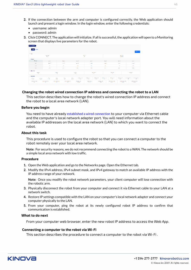
KINOVA® Gen3 Ultra lightweight robot User Guide 46
2. If the connection between the arm and computer is configured correctly, the Web application shouldlaunch and present a login window. In the login window, enter the following credentials:
• username: admin• password: admin
3. Click CONNECT. The application will initialize. If all is successful, the application will open to a Monitoringscreen that displays live parameters for the robot.
Changing the robot wired connection IP address and connecting the robot to a LANThis section describes how to change the robot's wired connection IP address and connectthe robot to a local area network (LAN).
Before you begin
You need to have already established a wired connection to your computer via Ethernet cableand the computer's local network adapter port. You will need information about theavailable IP addresses on the local area network (LAN) to which you want to connect therobot.
About this task
This procedure is used to configure the robot so that you can connect a computer to therobot remotely over your local area network.
Note: For security reasons, we do not recommend connecting the robot to a WAN. The network should bea simple local area network with low traffic.
Procedure
1. Open the Web application and go to the Networks page. Open the Ethernet tab.
2. Modify the IPv4 address, IPv4 subnet mask, and IPv4 gateway to match an available IP address with theIP address range of your network.
Note: Once you modify the robot network parameters, your client computer will lose connection withthe robotic arm.
3. Physically disconnect the robot from your computer and connect it via Ethernet cable to your LAN at anetwork switch.
4. Restore IP settings compatible with the LAN on your computer's local network adapter and connect yourcomputer physically to the LAN.
5. From your computer, ping the robot at its newly configured robot IP address to confirm thatcommunication is established.
What to do next
From your computer web browser, enter the new robot IP address to access the Web App.
Connecting a computer to the robot via Wi-FiThis section describes the procedure to connect a computer to the robot via Wi-Fi .
KINOVA® Gen3 Ultra lightweight robot User Guide 47
Before you begin
You will need to have a wired connection between the computer and robot to carry out thisprocedure.
About this task
The robot features a Wi-Fi adapter. This allows the arm to connect to a local Wi-Ficonnection. Once this connection is established, other devices on the same Wi-Fi networkcan then connect to the robot wirelessly.
Procedure
1. On a computer connected to the arm via Ethernet, open the Web App and connect to the arm.
2. Select Networks in the main navigation panel of the Web App to go to the Networks page.
3. Select the Wi-Fi tab.
4. The Wi-Fi tab will list all of the detected Wi-Fi networks. Choose one of the networks, and click thecorresponding Connect text button.
Note: It is not recommended to connect to Wi-Fi networks which are potentially insecure. Securitysettings of at least WPA2 are recommended.
5. A pop-up window will appear to sign in to the network, with information about the signal strength andsecurity settings. Enter the password for the network and click the CONNECT button. Take note of theIPv4 address that the robotic arm obtains after clicking the CONNECT button
6. On any wireless device connected to the same Wi-Fi network, open a Web browser and type the IP addressthat the robot obtained at Step 5 (This address corresponds to the robot's address on the Wi-Fi network).
7. At the Login screen, enter the appropriate user name and password, and click the CONNECT button.
Results
You are now connected to the Web App through the Wi-Fi network adapter of the robot. Youcan now configure, monitor, and control the robot wirelessly.
Warning: A Wi-Fi connection is not recommended for 1 kHz (low-level) control of the robot due to potentiallatency issues - a wired connection must be used for this purpose.
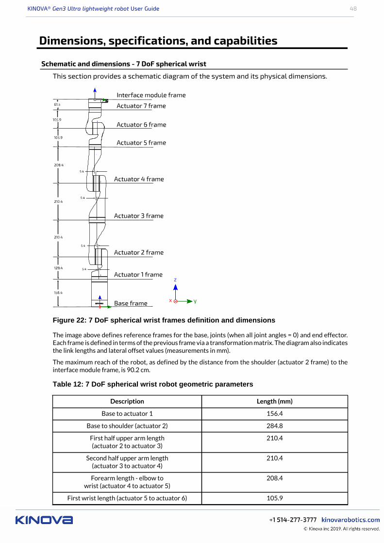
KINOVA® Gen3 Ultra lightweight robot User Guide 48
Dimensions, specifications, and capabilities
Schematic and dimensions - 7 DoF spherical wrist
This section provides a schematic diagram of the system and its physical dimensions.
Figure 22: 7 DoF spherical wrist frames definition and dimensions
The image above defines reference frames for the base, joints (when all joint angles = 0) and end effector.Each frame is defined in terms of the previous frame via a transformation matrix. The diagram also indicatesthe link lengths and lateral offset values (measurements in mm).
The maximum reach of the robot, as defined by the distance from the shoulder (actuator 2 frame) to theinterface module frame, is 90.2 cm.
Table 12: 7 DoF spherical wrist robot geometric parameters
Description Length (mm)
Base to actuator 1 156.4
Base to shoulder (actuator 2) 284.8
First half upper arm length(actuator 2 to actuator 3)
210.4
Second half upper arm length(actuator 3 to actuator 4)
210.4
Forearm length - elbow towrist (actuator 4 to actuator 5)
208.4
First wrist length (actuator 5 to actuator 6) 105.9
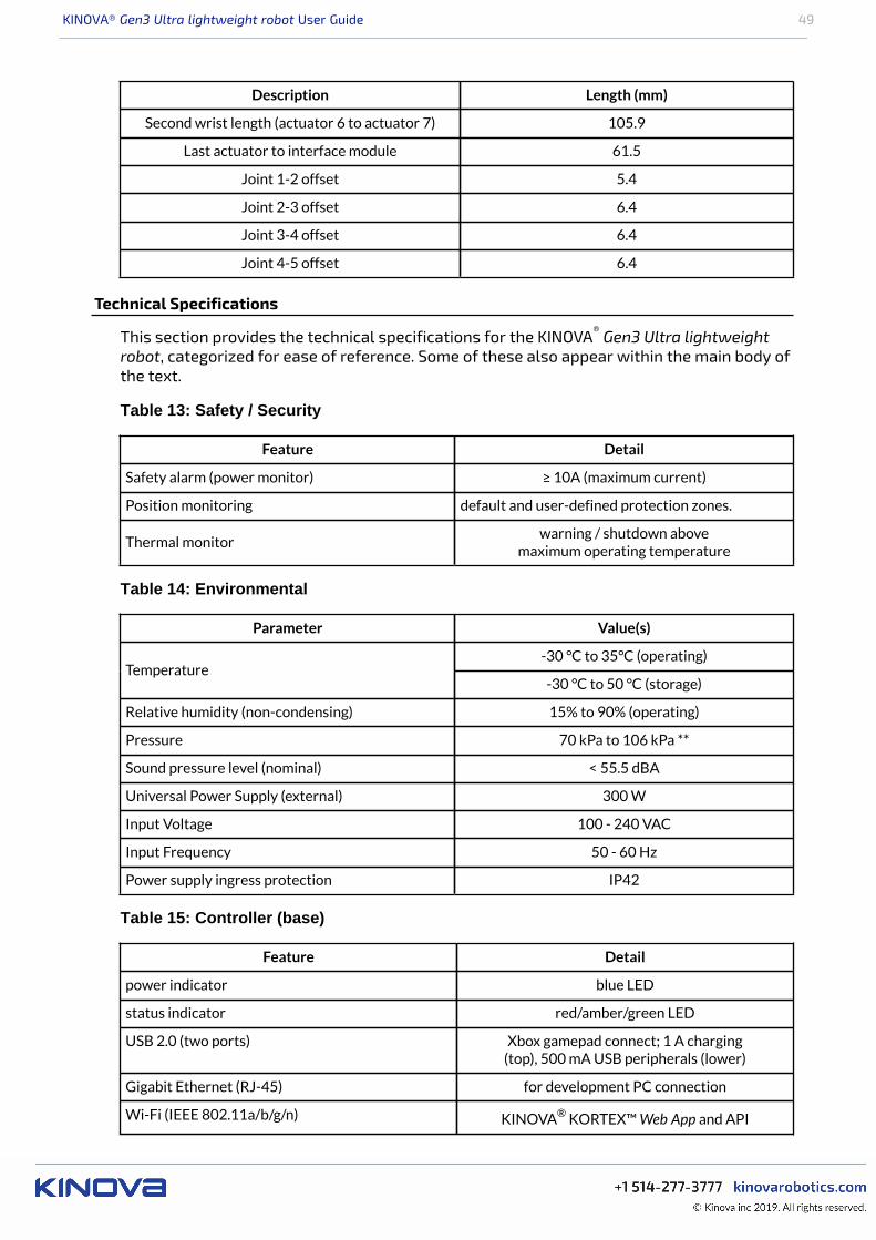
KINOVA® Gen3 Ultra lightweight robot User Guide 49
Description Length (mm)
Second wrist length (actuator 6 to actuator 7) 105.9
Last actuator to interface module 61.5
Joint 1-2 offset 5.4
Joint 2-3 offset 6.4
Joint 3-4 offset 6.4
Joint 4-5 offset 6.4
Technical Specifications
This section provides the technical specifications for the KINOVA® Gen3 Ultra lightweightrobot, categorized for ease of reference. Some of these also appear within the main body ofthe text.
Table 13: Safety / Security
Feature Detail
Safety alarm (power monitor) ≥ 10A (maximum current)
Position monitoring default and user-defined protection zones.
Thermal monitorwarning / shutdown above
maximum operating temperature
Table 14: Environmental
Parameter Value(s)
-30 °C to 35°C (operating)Temperature
-30 °C to 50 °C (storage)
Relative humidity (non-condensing) 15% to 90% (operating)
Pressure 70 kPa to 106 kPa **
Sound pressure level (nominal) < 55.5 dBA
Universal Power Supply (external) 300 W
Input Voltage 100 - 240 VAC
Input Frequency 50 - 60 Hz
Power supply ingress protection IP42
Table 15: Controller (base)
Feature Detail
power indicator blue LED
status indicator red/amber/green LED
USB 2.0 (two ports) Xbox gamepad connect; 1 A charging(top), 500 mA USB peripherals (lower)
Gigabit Ethernet (RJ-45) for development PC connection
Wi-Fi (IEEE 802.11a/b/g/n) KINOVA® KORTEX™ Web App and API

KINOVA® Gen3 Ultra lightweight robot User Guide 50
Feature Detail
HDMI 1.4a (for future use)
circular connector [Binder-USA 09 0463 90 19]joystick, discrete I/O, emergency
line assert, expansion
circular connector [Lumberg 0317 08] power
sensors voltage, current, temperature,accelerometer and gyroscope
Table 16: Robot
Parameter Value(s)
Weight 8.2 kg (with vision module, no gripper)
Payload 4 kg (mid-range continuous; no gripper)
4.5 kg (full-reach peak / temporary; no gripper)
1.1 kg (full-reach continuous; no gripper)
Maximum reach (fully extended) 902 mm (7 DoF)
Degrees of freedom 7 DoF
qty 3 (small)Actuators
qty 4 (large)
Wrist interaction buttons qty 2 (user-configurable*; default for nullspace and Cartesian admittance control)
Power supply voltage 24 VDC (nominal, 18 to 30 V)
Carbon fiber shellMaterials
Aluminum
100 Mbps Ethernet for real-time 1 kHz controlCommunciations and control
100 Mbps Ethernet for vision module / expansion
Table 17: Actuators
Feature Value(s)
Sensors current sensors (motor), temperatures(motor), voltage, torque, position
Table 18: Interface module
Feature Function
Vision module color and depth sensing
Wrist status LEDs admittance mode indication
Kinova internal end-effector interface connector Kinova internal use*
10-pin spring-loaded connector RS-485 (compatible withRobotiq Adaptive Grippers)
KINOVA® Gen3 Ultra lightweight robot User Guide 51
Feature Function
100 Mbps Ethernet
UART (3.3V)
I2C (3.3V)
GPIO (3.3V, qty 4)
24V @ 0.5A
20-pin user expansion connector
[AVX/Kyocera 046288020000846+]
3.3V @ 0.1A for signaling
Sensors accelerometer and gyroscope,voltage, temperature
Table 19: Vision
Feature Detail
Depth sensor
480 x 270 (16:9) @ 30, 15, 6 fps
424 x 240 (16:9) @ 30, 15, 6 fps
FOV: 72 ± 3° (diagonal)
minimum depth distance - 18 cm
Color sensor
1920 x 1080 (16:9) @ 30, 15 fps; FOV 47 ± 3°(diagonal)
1280 x 720 (16:9) @ 30, 15 fps ; FOV 60 ± 3°(diagonal)
640 x 480 (4:3) @ 30, 15 fps; FOV 65 ± 3° (diagonal)
320 x 240 (4:3) @ 30, 15 fps; FOV 65 ± 3° (diagonal)
focusing range - 30 cm to ∞
Table 20: Software / control
Feature Detail
Low-level control torque, position, velocity, current
High-level control Cartesian twist (linear and angularvelocity) and wrench (force and
torque - EXPERIMENTAL) , joint speed
protection zones - rectangular, spheric, cylindricalHigh-level control features (mode dependent)
singularity handling
Servoing modes high-level, low-level
Data recorder*logging of position, speed, temperature,torque, battery, etc. (user-configurable)
Velocity
Angular position of individual joints
Angular speed of individual joints
user-configurable
Supported ROS distribution Kinetic Kame
Boot time 45 s
KINOVA® Gen3 Ultra lightweight robot User Guide 52
Feature Detail
Internal communication frequency 1 kHz
* to be implemented in future software release
** subject to future change
Sensors
This section describes the robot sensors.
The robot contains a number of sensors to provide feedback on the status of the robot. This data is used bythe robot for internal monitoring and control.
The robot components contain the following sensors:
Base sensors• voltage• current• temperature• 6-axis accelerometer / gyroscopeActuator sensors• motor phases current sensors (one per phase)• motor phases temperature sensors (one per phase)• CPU temperature sensor• input voltage sensor• Hall effect sensors for BLDC motor drive• absolute rotary position encoder• incremental rotary position encoder• torque sensorsInterface module sensors• voltage monitoring (future enhancement)• temperature sensors (CPU, accelerometer and board)• 6-axis accelerometer / gyroscope
Vision module
• temperature sensors (CPU, board)
Gripper sensors (for connected gripper)• motor temperature• motor voltage• motor current• position
Access to sensors data
Data from some sensors can be read by users using the APIs or through the Monitoring page of the WebApplication.
The API method RefreshFeedback() in the BaseCyclic API returns a data structure with readingsfrom sensors in:• base and end effector tool• actuators• interface module• gripper (if gripper connected)For detailed information on how to unpack this data in an application, see the BaseCyclic API
documentation on the KINOVA® KORTEX™ GitHub repo.
The following tables give more information about the sensor data.
KINOVA® Gen3 Ultra lightweight robot User Guide 53
Base readings available
Table 21: Base readings available through API
Field name Description
arm_voltage arm voltage in V
arm_current arm current in A
temperature_cpu CPU temperature in °C
temperature_ambient ambient temperature in °C
imu_acceleration_x IMU measured acceleration (X-Axis)
of base in m / s2
imu_acceleration_y IMU measured acceleration (Y-Axis)
of base in m / s2
imu_acceleration_z IMU measured acceleration (Z-Axis)
of base in m / s2
imu_angular_velocity_x IMU measured angular velocity (X-Axis) ωxof base in ° / s
imu_angular_velocity_y IMU measured angular velocity (Y-Axis) ωy of base in ° / s
imu_angular_velocity_z IMU measured angular velocity (Z-Axis) ωz of base in ° / s
Tool readings available
Table 22: Tool readings available via API
Field name Description
tool_pose_x Measured Cartesian position(X-axis) of the tool in m
tool_pose_y Measured Cartesian position(Y-axis) of the tool in m
tool_pose_z Measured Cartesian position(Z-axis) of the tool in m
tool_pose_theta_x Measured Cartesian orientation(X-axis) of the tool in °
tool_pose_theta_y Measured Cartesian orientation(Y-axis) of the tool in °
tool_pose_theta_z Measured Cartesian orientation(Z-axis) of the tool in °
tool_twist_linear_x Measured Cartesian linearvelocity (X-Axis) of the tool in m / s
tool_twist_linear_y Measured Cartesian linearvelocity (Y-Axis) of the tool in m / s
tool_twist_linear_z Measured Cartesian linearvelocity (Z-Axis) of the tool in m / s

KINOVA® Gen3 Ultra lightweight robot User Guide 54
Field name Description
tool_twist_angular_x Measured Cartesian angularvelocity (X-Axis) of the tool in ° / s
tool_twist_angular_y Measured Cartesian angularvelocity (Y-Axis) of the tool in ° / s
tool_twist_angular_z Measured Cartesian angularvelocity (Z-Axis) of the tool in ° / s
Actuators readings available
Table 23: Actuators readings available via API
Field name Description
position angular position of the actuator in °
velocity angular velocity of the actuator in ° / sec
torque torque in N·m
current_motor motor current in A
voltage main board voltage in V
temperature_motor actuator motor temperature in °C (highest of three 3phases)
temperature_core microcontroller temperature in °C
Interface readings available
Table 24: Interface readings available via API
Field name Description
imu_acceleration_X IMU measured acceleration (X-Axis) of interface
module in m / s2
imu_acceleration_Y IMU measured acceleration (Y-Axis) of interface
module in m / s2
imu_acceleration_Z IMU measured acceleration (Z-Axis) of interface
module in m / s2
imu_angular_velocity_X IMU measured angular velocity (X-Axis) ωx ofinterface module in ° / s
imu_angular_velocity_Y IMU measured angular velocity (Y-Axis) ωy ofinterface module in ° / s
imu_angular_velocity_Z IMU measured angular velocity (Z-Axis) ωz ofinterface module in ° / s
voltage main board voltage in V
temperature_core microcontroller temperature in °C
Gripper readings available
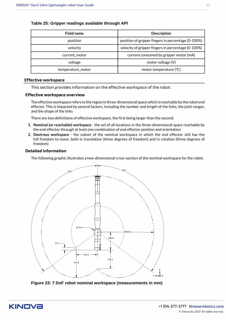
KINOVA® Gen3 Ultra lightweight robot User Guide 55
Table 25: Gripper readings available through API
Field name Description
position position of gripper fingers in percentage (0-100%)
velocity velocity of gripper fingers in percentage (0-100%)
current_motor current consumed by gripper motor (mA)
voltage motor voltage (V)
temperature_motor motor temperature (°C)
Effective workspace
This section provides information on the effective workspace of the robot.
Effective workspace overview
The effective workspace refers to the region in three-dimensional space which is reachable by the robot endeffector. This is impacted by several factors, including the number and length of the links, the joint ranges,and the shape of the links
There are two definitions of effective workspace, the first being larger than the second.
1. Nominal (or reachable) workspace - the set of all locations in the three-dimensional space reachable bythe end effector through at least one combination of end effector position and orientation
2. Dextrous workspace - the subset of the nominal workspace in which the end effector still has thefull freedom to move, both in translation (three degrees of freedom) and in rotation (three degrees offreedom)
Detailed information
The following graphic illustrates a two-dimensional cross-section of the nominal workspace for the robot.
126.1° 126.1°
37.2
R900.6
301.2
284.8
340.2
Ø 124.3
479.8
y
z
x
Figure 23: 7 DoF robot nominal workspace (measurements in mm)
KINOVA® Gen3 Ultra lightweight robot User Guide 56
Maximum payload vs. workspace
This section describes the variation of maximum payload over the workspace anddepending on the type of use.
Overview
The maximum payload of the robot is the maximum mass that the robot can hold up and carry around.
This is generally not one constant figure, but will depend on a few factors.• radial distance from the base - the maximum payload the robot can handle will be highest closest to
the base, and will go down as the end effector gets farther out from the base axis.• temporary vs. continuous - the robot will have a maximum payload that can be handled temporarily
for a short period of time. However, continued use of the arm with that payload for an indefinite periodwill cause the arm to heat up, as the heat generated by the strain on the actuator exceeds the rate atwhich heat can be dissipated. However, a smaller mass can be handled for an indefninite period. Thisis referred to as the continuous payload limit.
The maximum payload will also depend on whether a gripper is attached or not, with some of the payloadcapability reduced to lift the weight of the gripper.

KINOVA® Gen3 Ultra lightweight robot User Guide 57
Interface, expansion, and vision
Interface module expansion - tips for installing tools
This section describes what is needed to install and integrate a new tool onto the interfacemodule.
At some point, you may want to install a new tool such as a gripper or sensor onto the robot.
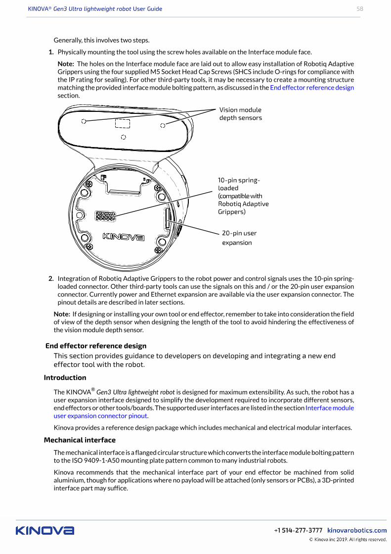
KINOVA® Gen3 Ultra lightweight robot User Guide 58
Generally, this involves two steps.
1. Physically mounting the tool using the screw holes available on the Interface module face.
Note: The holes on the Interface module face are laid out to allow easy installation of Robotiq AdaptiveGrippers using the four supplied M5 Socket Head Cap Screws (SHCS include O-rings for compliance withthe IP rating for sealing). For other third-party tools, it may be necessary to create a mounting structurematching the provided interface module bolting pattern, as discussed in the End effector reference designsection.
2. Integration of Robotiq Adaptive Grippers to the robot power and control signals uses the 10-pin spring-loaded connector. Other third-party tools can use the signals on this and / or the 20-pin user expansionconnector. Currently power and Ethernet expansion are available via the user expansion connector. Thepinout details are described in later sections.
Note: If designing or installing your own tool or end effector, remember to take into consideration the fieldof view of the depth sensor when designing the length of the tool to avoid hindering the effectiveness ofthe vision module depth sensor.
End effector reference designThis section provides guidance to developers on developing and integrating a new endeffector tool with the robot.
Introduction
The KINOVA® Gen3 Ultra lightweight robot is designed for maximum extensibility. As such, the robot has auser expansion interface designed to simplify the development required to incorporate different sensors,end effectors or other tools/boards. The supported user interfaces are listed in the section Interface moduleuser expansion connector pinout.
Kinova provides a reference design package which includes mechanical and electrical modular interfaces.
Mechanical interface
The mechanical interface is a flanged circular structure which converts the interface module bolting patternto the ISO 9409-1-A50 mounting plate pattern common to many industrial robots.
Kinova recommends that the mechanical interface part of your end effector be machined from solidaluminium, though for applications where no payload will be attached (only sensors or PCBs), a 3D-printedinterface part may suffice.
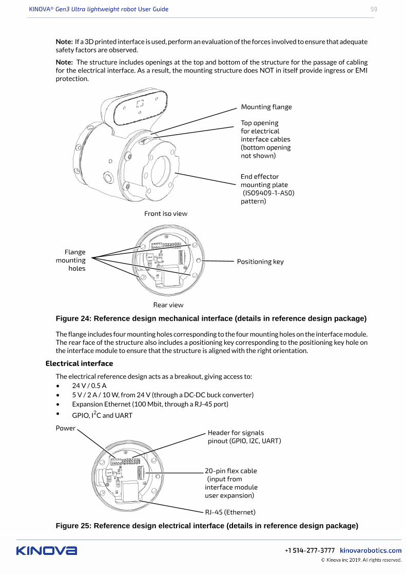
KINOVA® Gen3 Ultra lightweight robot User Guide 59
Note: If a 3D printed interface is used, perform an evaluation of the forces involved to ensure that adequatesafety factors are observed.
Note: The structure includes openings at the top and bottom of the structure for the passage of cablingfor the electrical interface. As a result, the mounting structure does NOT in itself provide ingress or EMIprotection.
Figure 24: Reference design mechanical interface (details in reference design package)
The flange includes four mounting holes corresponding to the four mounting holes on the interface module.The rear face of the structure also includes a positioning key corresponding to the positioning key hole onthe interface module to ensure that the structure is aligned with the right orientation.
Electrical interface
The electrical reference design acts as a breakout, giving access to:• 24 V / 0.5 A• 5 V / 2 A / 10 W, from 24 V (through a DC-DC buck converter)• Expansion Ethernet (100 Mbit, through a RJ-45 port)• GPIO, I2C and UART
Figure 25: Reference design electrical interface (details in reference design package)
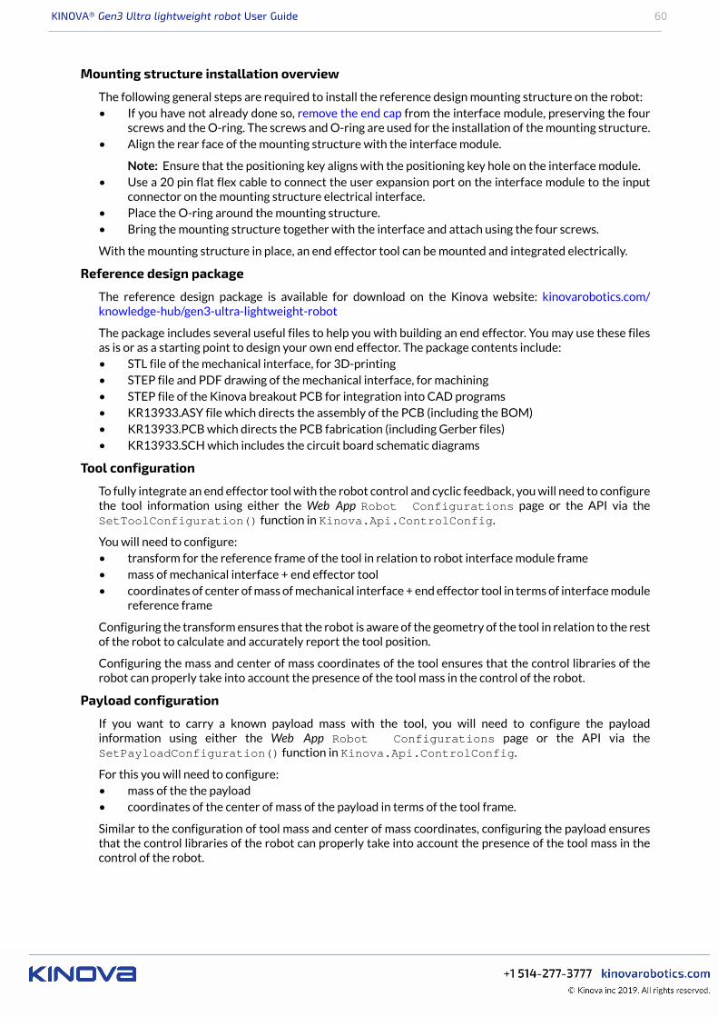
KINOVA® Gen3 Ultra lightweight robot User Guide 60
Mounting structure installation overview
The following general steps are required to install the reference design mounting structure on the robot:• If you have not already done so, remove the end cap from the interface module, preserving the four
screws and the O-ring. The screws and O-ring are used for the installation of the mounting structure.• Align the rear face of the mounting structure with the interface module.
Note: Ensure that the positioning key aligns with the positioning key hole on the interface module.• Use a 20 pin flat flex cable to connect the user expansion port on the interface module to the input
connector on the mounting structure electrical interface.• Place the O-ring around the mounting structure.• Bring the mounting structure together with the interface and attach using the four screws.
With the mounting structure in place, an end effector tool can be mounted and integrated electrically.
Reference design package
The reference design package is available for download on the Kinova website: kinovarobotics.com/knowledge-hub/gen3-ultra-lightweight-robot
The package includes several useful files to help you with building an end effector. You may use these filesas is or as a starting point to design your own end effector. The package contents include:• STL file of the mechanical interface, for 3D-printing• STEP file and PDF drawing of the mechanical interface, for machining• STEP file of the Kinova breakout PCB for integration into CAD programs• KR13933.ASY file which directs the assembly of the PCB (including the BOM)• KR13933.PCB which directs the PCB fabrication (including Gerber files)• KR13933.SCH which includes the circuit board schematic diagrams
Tool configuration
To fully integrate an end effector tool with the robot control and cyclic feedback, you will need to configurethe tool information using either the Web App Robot Configurations page or the API via theSetToolConfiguration() function in Kinova.Api.ControlConfig.
You will need to configure:• transform for the reference frame of the tool in relation to robot interface module frame• mass of mechanical interface + end effector tool• coordinates of center of mass of mechanical interface + end effector tool in terms of interface module
reference frame
Configuring the transform ensures that the robot is aware of the geometry of the tool in relation to the restof the robot to calculate and accurately report the tool position.
Configuring the mass and center of mass coordinates of the tool ensures that the control libraries of therobot can properly take into account the presence of the tool mass in the control of the robot.
Payload configuration
If you want to carry a known payload mass with the tool, you will need to configure the payloadinformation using either the Web App Robot Configurations page or the API via theSetPayloadConfiguration() function in Kinova.Api.ControlConfig.
For this you will need to configure:• mass of the the payload• coordinates of the center of mass of the payload in terms of the tool frame.
Similar to the configuration of tool mass and center of mass coordinates, configuring the payload ensuresthat the control libraries of the robot can properly take into account the presence of the tool mass in thecontrol of the robot.
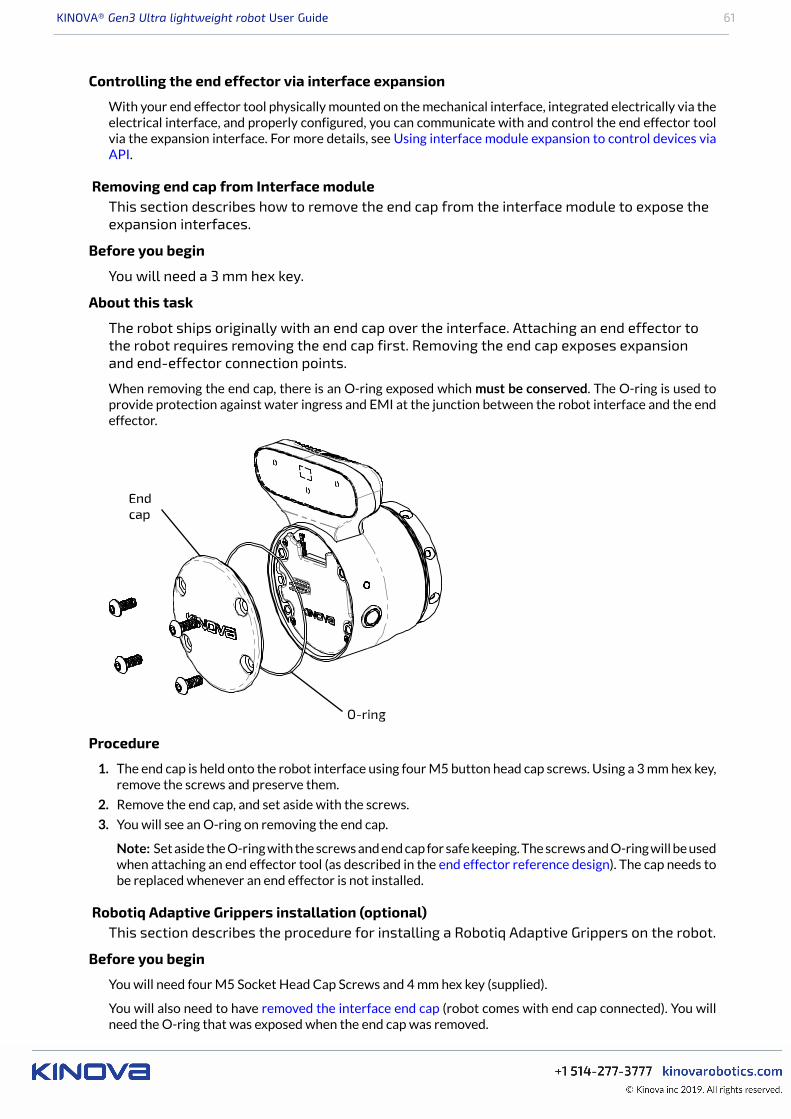
KINOVA® Gen3 Ultra lightweight robot User Guide 61
Controlling the end effector via interface expansion
With your end effector tool physically mounted on the mechanical interface, integrated electrically via theelectrical interface, and properly configured, you can communicate with and control the end effector toolvia the expansion interface. For more details, see Using interface module expansion to control devices viaAPI.
Removing end cap from Interface moduleThis section describes how to remove the end cap from the interface module to expose theexpansion interfaces.
Before you begin
You will need a 3 mm hex key.
About this task
The robot ships originally with an end cap over the interface. Attaching an end effector tothe robot requires removing the end cap first. Removing the end cap exposes expansionand end-effector connection points.
When removing the end cap, there is an O-ring exposed which must be conserved. The O-ring is used toprovide protection against water ingress and EMI at the junction between the robot interface and the endeffector.
Procedure
1. The end cap is held onto the robot interface using four M5 button head cap screws. Using a 3 mm hex key,remove the screws and preserve them.
2. Remove the end cap, and set aside with the screws.
3. You will see an O-ring on removing the end cap.
Note: Set aside the O-ring with the screws and end cap for safe keeping. The screws and O-ring will be usedwhen attaching an end effector tool (as described in the end effector reference design). The cap needs tobe replaced whenever an end effector is not installed.
Robotiq Adaptive Grippers installation (optional)This section describes the procedure for installing a Robotiq Adaptive Grippers on the robot.
Before you begin
You will need four M5 Socket Head Cap Screws and 4 mm hex key (supplied).
You will also need to have removed the interface end cap (robot comes with end cap connected). You willneed the O-ring that was exposed when the end cap was removed.
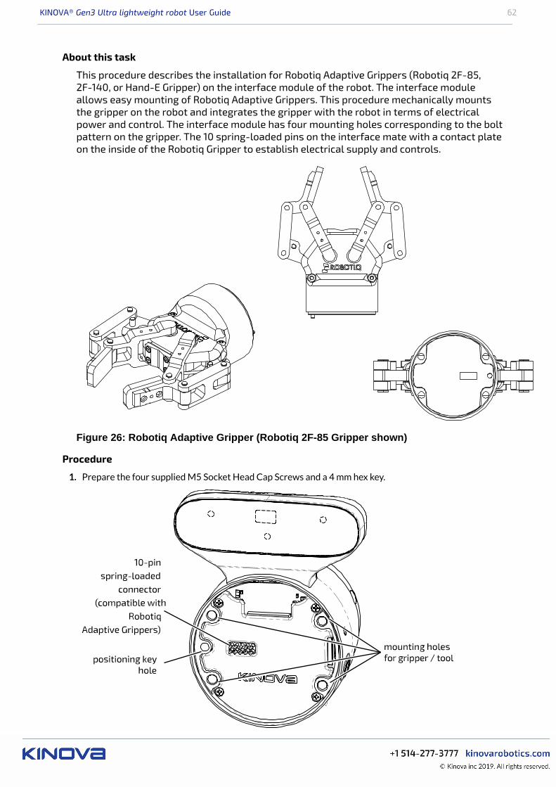
KINOVA® Gen3 Ultra lightweight robot User Guide 62
About this task
This procedure describes the installation for Robotiq Adaptive Grippers (Robotiq 2F-85,2F-140, or Hand-E Gripper) on the interface module of the robot. The interface moduleallows easy mounting of Robotiq Adaptive Grippers. This procedure mechanically mountsthe gripper on the robot and integrates the gripper with the robot in terms of electricalpower and control. The interface module has four mounting holes corresponding to the boltpattern on the gripper. The 10 spring-loaded pins on the interface mate with a contact plateon the inside of the Robotiq Gripper to establish electrical supply and controls.
Figure 26: Robotiq Adaptive Gripper (Robotiq 2F-85 Gripper shown)
Procedure
1. Prepare the four supplied M5 Socket Head Cap Screws and a 4 mm hex key.
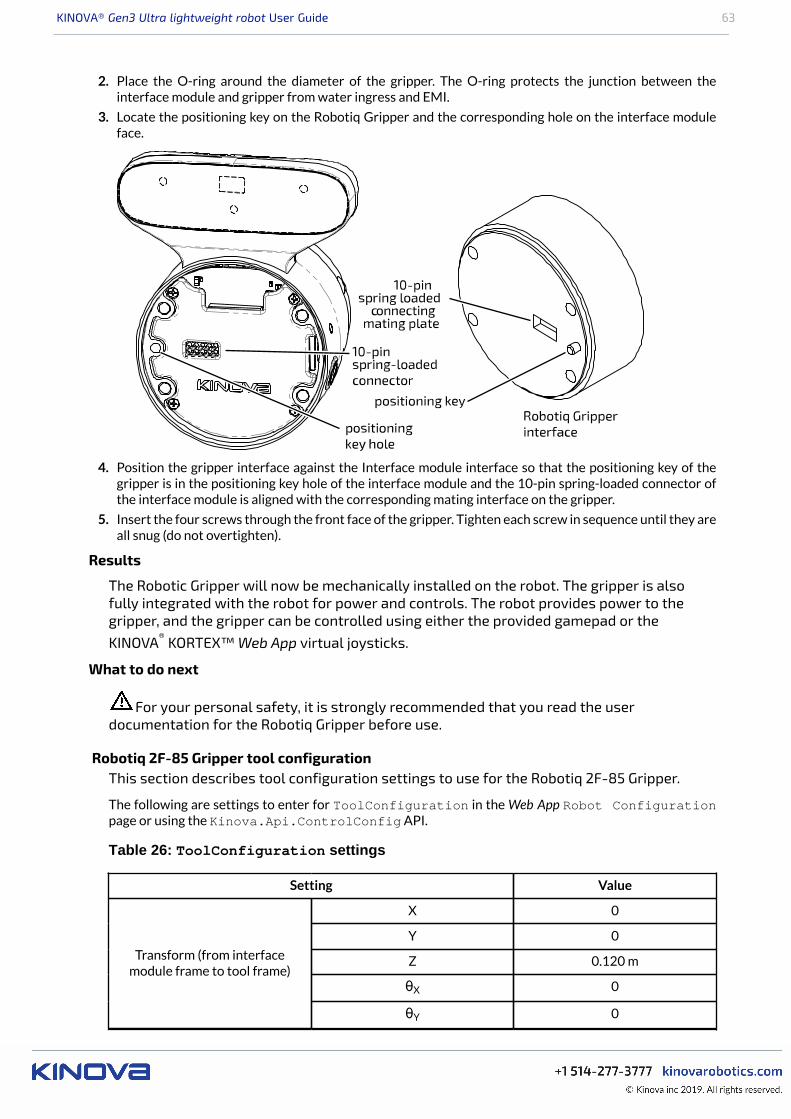
KINOVA® Gen3 Ultra lightweight robot User Guide 63
2. Place the O-ring around the diameter of the gripper. The O-ring protects the junction between theinterface module and gripper from water ingress and EMI.
3. Locate the positioning key on the Robotiq Gripper and the corresponding hole on the interface moduleface.
4. Position the gripper interface against the Interface module interface so that the positioning key of thegripper is in the positioning key hole of the interface module and the 10-pin spring-loaded connector ofthe interface module is aligned with the corresponding mating interface on the gripper.
5. Insert the four screws through the front face of the gripper. Tighten each screw in sequence until they areall snug (do not overtighten).
Results
The Robotic Gripper will now be mechanically installed on the robot. The gripper is alsofully integrated with the robot for power and controls. The robot provides power to thegripper, and the gripper can be controlled using either the provided gamepad or theKINOVA® KORTEX™ Web App virtual joysticks.
What to do next
For your personal safety, it is strongly recommended that you read the userdocumentation for the Robotiq Gripper before use.
Robotiq 2F-85 Gripper tool configurationThis section describes tool configuration settings to use for the Robotiq 2F-85 Gripper.
The following are settings to enter for ToolConfiguration in the Web App Robot Configurationpage or using the Kinova.Api.ControlConfig API.
Table 26: ToolConfiguration settings
Setting Value
X 0
Y 0
Z 0.120 m
θX 0
Transform (from interfacemodule frame to tool frame)
θY 0
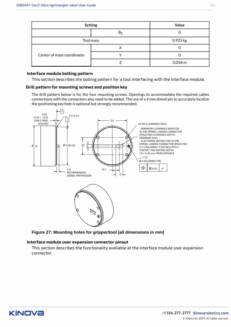
KINOVA® Gen3 Ultra lightweight robot User Guide 64
Setting Value
θZ 0
Tool mass 0.925 kg
X 0
Y 0Center of mass coordinates
Z 0.058 m
Interface module bolting patternThis section describes the bolting pattern for a tool interfacing with the Interface module.
Drill pattern for mounting screws and position key
The drill pattern below is for the four mounting screws. Openings to accommodate the required cablesconnections with the connectors also need to be added. The use of a 4 mm dowel pin to accurately localizethe positioning key hole is optional but strongly recommended.
Figure 27: Mounting holes for gripper/tool (all dimensions in mm)
Interface module user expansion connector pinoutThis section describes the functionality available at the interface module user expansionconnector.
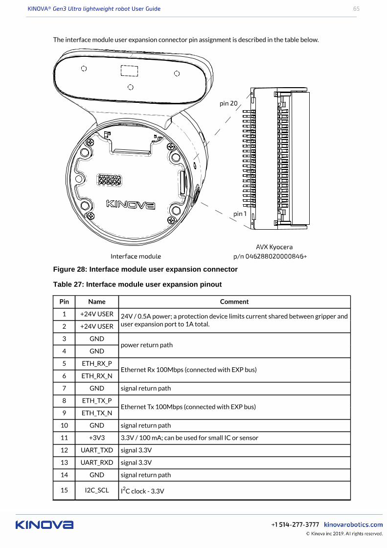
KINOVA® Gen3 Ultra lightweight robot User Guide 65
The interface module user expansion connector pin assignment is described in the table below.
Figure 28: Interface module user expansion connector
Table 27: Interface module user expansion pinout
Pin Name Comment
1 +24V USER
2 +24V USER
24V / 0.5A power; a protection device limits current shared between gripper anduser expansion port to 1A total.
3 GND
4 GNDpower return path
5 ETH_RX_P
6 ETH_RX_NEthernet Rx 100Mbps (connected with EXP bus)
7 GND signal return path
8 ETH_TX_P
9 ETH_TX_NEthernet Tx 100Mbps (connected with EXP bus)
10 GND signal return path
11 +3V3 3.3V / 100 mA; can be used for small IC or sensor
12 UART_TXD signal 3.3V
13 UART_RXD signal 3.3V
14 GND signal return path
15 I2C_SCL I2C clock - 3.3V
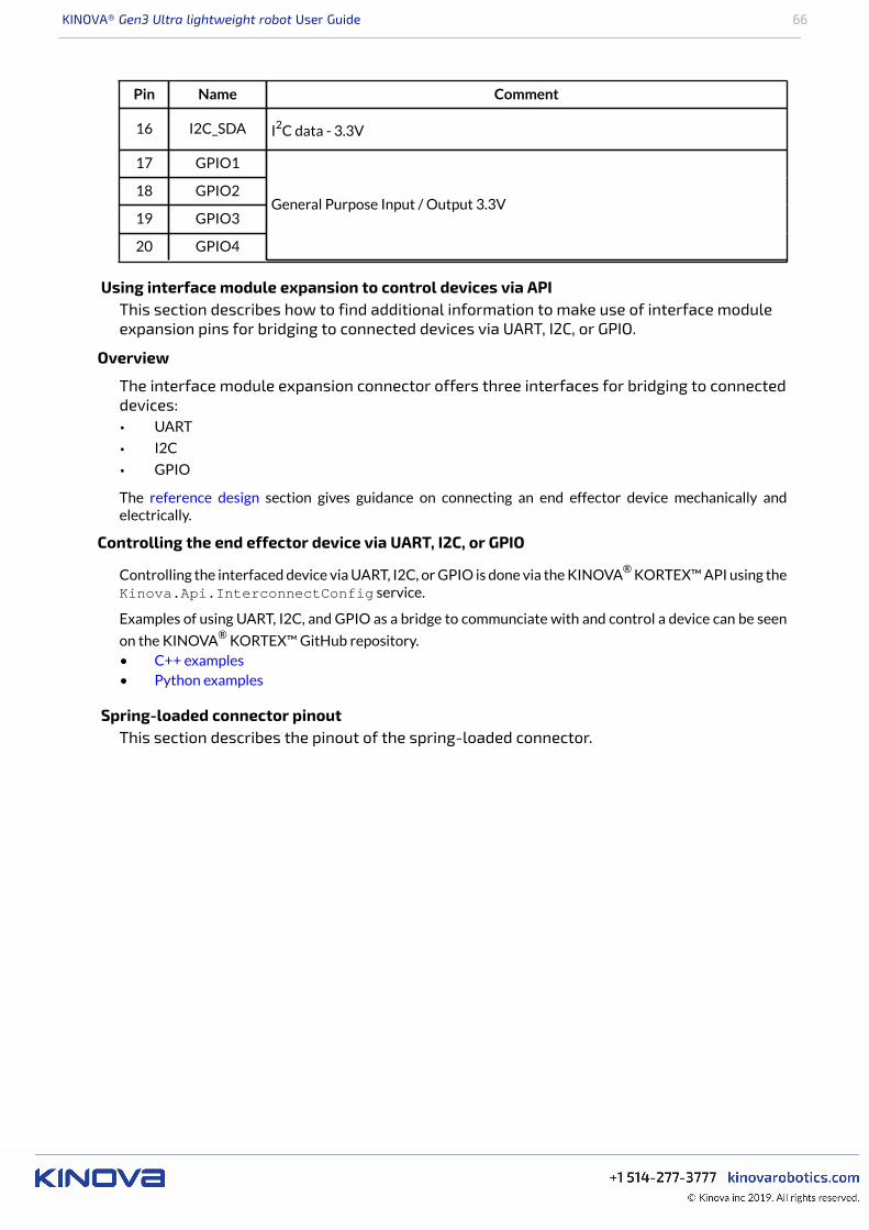
KINOVA® Gen3 Ultra lightweight robot User Guide 66
Pin Name Comment
16 I2C_SDA I2C data - 3.3V
17 GPIO1
18 GPIO2
19 GPIO3
20 GPIO4
General Purpose Input / Output 3.3V
Using interface module expansion to control devices via APIThis section describes how to find additional information to make use of interface moduleexpansion pins for bridging to connected devices via UART, I2C, or GPIO.
Overview
The interface module expansion connector offers three interfaces for bridging to connecteddevices:• UART
• I2C
• GPIO
The reference design section gives guidance on connecting an end effector device mechanically andelectrically.
Controlling the end effector device via UART, I2C, or GPIO
Controlling the interfaced device via UART, I2C, or GPIO is done via the KINOVA® KORTEX™ API using theKinova.Api.InterconnectConfig service.
Examples of using UART, I2C, and GPIO as a bridge to communciate with and control a device can be seen
on the KINOVA® KORTEX™ GitHub repository.• C++ examples• Python examples
Spring-loaded connector pinoutThis section describes the pinout of the spring-loaded connector.

KINOVA® Gen3 Ultra lightweight robot User Guide 67
The spring-loaded connector pin assignment is described in the table below.
Figure 29: Spring-loaded connector
Table 28: Spring-loaded connector pinout
Pin Name Comment
1 GND
2 GNDpower return path
3 +24V
4 +24V
24V / 1A power for end device (current limit shared with interface module userexpansion port)
5 PRESENT end device presence detection (connect to GND on end device)
6 N/C no connection
7 RS485_N
8 RS485_PRS-485 signal pair (bidirectional)
9 GND signal return path
10 N/C no connection
Accessing Vision module color and depth streams
This section describes access to the video module color and depth streams.
The video module sensors capture two video streams:• color• depth
The data from these streams is sent from the vision module back to the base controller via the vision /expansion channel carried over the internal flex cable links.

KINOVA® Gen3 Ultra lightweight robot User Guide 68
These two streams are accessible via the Real Time Streaming Protocol (RTSP) on a computer connectedto the robot (with transport over real-time transport protocol (RTP)).
Using the default IP address settings for the base controller, the two streams are accessible via:
• color sensor stream: rtsp://<base IPv4 address>/color
• depth sensor stream: rtsp://<base IPv4 address>/depth
For the default configuration of the base controller network interface, this would give:• rtsp://192.168.1.10/color
• rtsp://192.168.1.10/depth
Note: Examples in the documentation will use the default base controller IP setting for simplicity.
Streams specifications
• pixel format: Z16 pixel format - 16 bits LSB transferred as grayscale• H.264 baseline profile (constant bitrate)• RTSP server listening on port 554 (default)• maximum of two simultaneous connections per stream• inactivity timeout of 30 seconds
The KINOVA® KORTEX™ Developer Guide section of the user guide describes in more detail how to workwith the vision module camera streams.
For more guidance on configuring the vision module using the KINOVA® KORTEX™ API, see the vision
examples on the KINOVA® KORTEX™ GitHub repository:• C++ vision examples• Python vision examples
KINOVA® Gen3 Ultra lightweight robot User Guide 69
Concepts and terminology
Robot key concepts
This section describes some important concepts related to the robot.
Actions
An action is something that the user wants the robot to do. An action can be invoked explicitly, in the contextof a Sequence or associated to a controller device (button/joystick/gamepad) event. This can include (butis not limited to):• sending a command to the robot• playing a simple trajectory• toggling admittance mode• changing a position or motion parameter• applying emergency stop or clear faults• adding a delay• sending a gripper command• executing or stopping an action• playing a pre-computed trajectory
The full set of action types is defined in the Base API.
Control modes
A control mode is one of several modalities of controlling the motion of the robot while it is in run mode.Different modes provide different means to describe or guide the desired motion. The control modes forthe arm are:• angular joystick• Cartesian joystick• Cartesian trajectory• angular trajectory• Cartesian admittance• joint admittance• null space admittance
Event
An event is something of interest that happens related to the robot. Users can get informed withnotifications about related events by subscribing to the appropriate topic.
Factory settings
Factory settings are the configuration settings of the robot as they were when the robot arrived from themanufacturer. A robot can be returned to factory settings, which includes the base configuration and thenetwork settings.
Map
A map is a set of associations between controller device inputs and actions to be triggered by those inputswhen the map is active.
Mappings
A mapping is a full definition of the possible correspondances between controller device inputs and actionsthat are triggered by those inputs when the mapping is active. A mapping can consist of multiple maps, forexample to enable multiple different modes on the same controller device.
Notifications
A notification is a log of an event related to a particular topic that happens while a user is using the robot.
A notification will include the user profile, type of event, details of the event (if applicable), and a timestamp.
Operating mode

KINOVA® Gen3 Ultra lightweight robot User Guide 70
Operating modes are the different operational states of the robot. The operating modes for the arm are:• update - in process of update• update completed - update is completed successfully• update failed - update process started but failed to complete successfully• shutting down - arm is in process of shutting down• run - normal operating mode. Arm is ready to accept control inputs.• fault - robot is in an error state
Protection zone
A protection zone defines a three-dimensional region with respect to the robot base where the end effectoror arm is either prevented from entering or where its speed is limited. Protection zones are used forenabling obstacle avoidance. For the robot, protection zones can be one of three shapes:• cylinder• rectangular prism• sphere
Sequence
A sequence is an ordered list of actions.
Servoing mode
A servoing mode is a modality through which commands are transmitted to robot devices during operation.The servoing modes are as follows:• high-level servoing - user(s) control the robot by sending a single command to the base. The base
manages the low-level details of executing the command, breaking it down, applying any relevanthigh-level protections, and routing commands to the desired devices via a 1 kHz communication loopwith the devices.º single-level - a single user sends commands to a base
• low-level servoing - the user controls the robot by sending a series of actuator commands to the basevia a user-controlled loop. The base routes these commands to the desired device via its own 1 kHzcommunication loop with the actuators.
Topic
A set of related robot events to which the user can subscribe and receive notifications as part of a Publisher-Subscriber (pub-sub) arrangement. There are a number of different topics, including:• user• controller device input• safety• action or sequence• connection / disconnection of arm, controller, or tool• configuration change or backup• factory restore• protection zone• control, operation, or servoing mode
Upgrade package
An upgrade package is an image containing firmware updates for all modules on the robot (base, actuator,interface, vision).
User profiles
A user profile is a collection of basic information about the person using the robot, along with credentials(username and password) for access. A user profile allows access to the robot to be controlled based onlogin credentials, and allows permissions for reading, updating, and deleting different configuration itemsto be controlled. The user profile also allows notifications for events happening during a user's session tobe associated with the user. Notifications that were sent by the robot can be viewed in the Web App >Notifications page if the Web App is open and connected to the robot before the notifications weresent.
KINOVA® Gen3 Ultra lightweight robot User Guide 71
Terminology reference
The following sections serve as a reference for terminology used with the robot.
For ease of reference, the terminology reference section has been divided into the following categories:• General mathematics and robotics• Features, components and functionalities• Control and Operation Modes
General mathematics and robotics
AxisA fixed line with direction and units. It is used for the measurement of coordinates orangles, in relation to which is specified the robot motion (in linear or rotational fashion).
Base FrameThe reference frame located at the center of the bottom surface of the arm's base. Thisserves as the origin frame in Cartesian space.
Cartesian SpaceThe Euclidean space described by x, y and z axes of the Cartesian coordinate system.
Center of MassUnique point of a rigid body where an applied force will generate only linear acceleration(and no angular acceleration)
Closed loop controlControl of a device where the device is controlled in relation to the different betweensensed current state and goal state. Used on the robot for control of actuators.
Coordinate SystemA system used to represent a position in three-dimensional space, consisting of threecoordinate axes and an origin. The term "frame" is also used to designate a coordinatesystem.
Degrees of Freedom (DoF)The number of independent directions or joints of the robot, which would allow the robot tomove its end effector through the required sequence of motions. For arbitrary positioning,six degrees of freedom are needed: three for position and three for orientation.
EndpointThe nominal commanded position that the robot will try to reach with the tool center pointat the end of a motion path.
Euler AngleDescribes the rotation in three dimensions of a rigid body in terms of a sequence of threerotations with respect to a coordinate system.
Gravity VectorVector representing direction and magnitude of the local force of gravity, expressed interms of the robot base frame.
Joint AngleDescribes the position of every joint of a robot as as series of angles.
Joint SpaceThe set of all possible joint positions.
KINOVA® Gen3 Ultra lightweight robot User Guide 72
Null SpaceThe mathematical space of joint speeds where the robot can change its configuration(generate joint speed and motion) without changing the end-effector pose (Null Twist atthe end effector).
OrientationThe orientation of a rigid body describes the pure rotations that should be applied to thebody to move it from a reference placement to its current placement.
PathThe continuous locus of points (or positions in three dimensional space) traversed by thetool center point and described in a specified coordinate system.
Path (Angular)The set of at least two angular poses, through which the actuator values angles shouldpass during motion.
Path (Cartesian)The set of at least two Cartesian poses, through which the tool of the robot should passduring motion.
PayloadThe object that is carried or manipulated by the robot tool.
PoseDescribes the position and orientation of a rigid body in Cartesian space.
PositionThe definition of an object's location in 3D space, usually defined by a 3D coordinate systemusing X, Y, and Z coordinates.
Tool ConfigurationConfigurations made to enable use of a tool at the end effector position of the robot. Thisconsists of the mass and center of mass of the tool, and the tool transform.
Tool FrameA coordinate system attached to the end effector tool.
Tool TransformTransformation (translation and orientation) between the interface module referenceframe and the reference frame of the tool attached to the end of the robot.
TrajectoryA time-parametrized path in the robot workspace that can be defined by the user.
TwistGeneralized velocity vector, which is a combination of translational velocity and rotationalvelocity. Term comes from Screw Theory.
WrenchGeneralized force (vector which is a combination of linear force and torques). Term comesfrom Screw Theory.
VectorMathematical representation of physical quantities that have both magnitude anddirection, expressed in terms of a coordinate system.
KINOVA® Gen3 Ultra lightweight robot User Guide 73
Features, components and functionalities
AdmittanceIn this document, admittance is used to refer to human-robot interaction modes. In thesemodes, the robot will respond to external efforts applied on the body and tool and generatea motion to follow these efforts.
BaseRefers to the stationary base structure of a robot arm that supports the first arm joint.
Base supportThe stable platform to which the base is attached
End EffectorThe device at the end of a robot, designed to directly interact with the environment. Alsoreferred to as tool.
JointSection of the manipulator system which allows one rotational degree of freedom.
Path PlanningComputation of a path to reach a goal pose subject to applicable constraints and criteria.
Payload - MaximumThe maximum mass that the robot can manipulate at a specified speed, acceleration/deceleration, center of gravity location (offset), and repeatability in continuous operationover a specified working space, specified in kilograms.
Pinch PointAny location on the robot (or its accessories) which poses a risk of injury to fingers or otherappendages close by.
Protection ZoneA volume in space where the motion of the robot can be limited for safety purposes.
RedundancyOccurs when the manipulator (robot) has more degrees of freedom than it needs to executea given task. Applicable to 7 DoF robot.
Redundancy OptimizationMethod used to avoid a singularity by using redundant degrees-of-freedom motion (ifavailable).
SafetiesHardware limitations which are monitored to increase robot safety.
Singularity AvoidanceStrategy to avoid configurations where the robot loses its ability to move the end effectorin a given direction no matter how it moves its joints.
ToolSee End Effector.

KINOVA® Gen3 Ultra lightweight robot User Guide 74
Control and Operation Modes
Angular ModeIndependent joint control, whereby each axis of the manipulator is controlled separately.
Cartesian ModeMode used to control the velocities (translation and orientation) of the tool in Cartesianspace.
Cartesian Admittance ModeAllows the application of external force to the tool, so as to guide the arm to a new position.
Joint Admittance ModeAllows the application of external force at the links to rotate joints.
Null Space Admittance ModeRobot configuration can be changed by applying external forces at the links withoutaffecting the tool pose.
Trajectory ModeMode allowing user to specify an endpoint (in joint space or Cartesian space) that the robotshould reach.
KINOVA® Gen3 Ultra lightweight robot User Guide 75
Robot control
High-level and low-level robot control
This section describes the concepts of high-level and low-level robot control
There are two levels of controlling the movement of the robot:• high-level• low-level
High-level is the default on boot-up and offers the safest and most straight-forward control.
In both high-level and low-level, commands are sent through the robot base.
In high-level control, commands are sent to the base via a single command using the Kinova.Api.BaseAPI. These commands are processed by Kinova robot control libraries. The robot control libraries applyhigh-level control features like singularity avoidance, protection zones, and joint limits, and break downthe command into smaller commands that the base will send to the individual robot actuators via its 1 kHzcommunication loop with the actuators.
In low-level control, the user sends a series of small, incremental commands to the actuator and gripper aspart of a user-defined loop (at a rate up to 1 kHz) using the Kinova.Api.BaseCyclic API. The basereceives these commands and forwards them to the appropriate actuators and the gripper via the 1 KHzcommunication loop between the base and robot devices.
High-level is simpler to use, and offers added protections, but is slower due to the overhead of processingby the Kinova control library.
Low-level offers lighter and faster commands and finer-grained control, but the user is responsible for moreof the low-level details.
For more information, see the KINOVA® KORTEX™ Developer Guide section of the User Guide.
High-level and low-level robot control methods overview
This section lists robot control methods available through the API.
High-level (Kinova.Api.Base)
Table 29: Send or play a trajectory (Cartesian or joint)
Method Description
PlayCartesianTrajectory(ConstrainedPose)
Moves to the specifed pose (with specifiedCartesian constraint on trajectory)
PlayCartesianTrajectoryPosition(ConstrainedPosition)
Moves to the specifed position (with specifiedCartesian constraint on trajectory)
PlayCartesianTrajectoryOrientation(ConstrainedOrientation)
Moves to the specifed orientation (with specifiedCartesian constraint on trajectory)
PlayJointTrajectory(ConstrainedJointAngles)
Moves to the specified joint angles (with specifiedjoint constraint on trajectory)
PlaySelectedJointTrajectory(ConstrainedJointAngle)
Moves specifed joint to the specifed joint angle(with specified joint constraint on trajectory)
PlayPreComputedJointTrajectory(PreComputedJointTrajectory)
Play pre-computed angular trajectory
KINOVA® Gen3 Ultra lightweight robot User Guide 76
Table 30: Send Cartesian command to tool
Method Description
SendTwistCommand (TwistCommand) Sends a twist command to tool (velocity andangular velocity)
SendTwistJoystickCommand(TwistCommand)
Sends a twist joystick command to tool. The twistvalues sent to this call are expected to be a ratio ofmaximum value (between -1.0/+1.0)
(EXPERIMENTAL) SendWrenchCommand(WrenchCommand)
Force control. Sends a wrench command to tool(force and torque)
(EXPERIMENTAL)SendWrenchJoystickCommand(WrenchCommand)
Force control. Sends a wrench joystick commandto tool. The wrench values sent to this call areexpected to be a ratio of maximum value (between-1.0/+1.0)
Note: High-level force control is supported, but as an experimental feature only. Users should exercisecaution.
Table 31: Sent command to joints
Method Description
SendJointSpeedsCommand (JointSpeeds) Sends a joint speeds command, that is the desiredspeed of one or many joints
SendSelectedJointSpeedCommand(JointSpeed)
Sends a speed command for a specific joint
SendJointSpeedsJoystickCommand(JointSpeeds)
Sends the desired joystick speeds for one ormultiple joints. Values sent to this call are expectedto be a ratio of maximum value (between -1.0/+1.0)
SendSelectedJointSpeedJoystickCommand(JointSpeed)
Sends a joystick speed for a specific joint. Valuesent to this call is expected to be a ratio ofmaximum value (between -1.0/+1.0)
Table 32: Initiate admittance control
Method Description
SetAdmittance (Admittance) Sets the robot in the chosen admittance mode(Cartesian, joint, null space)
Table 33: Send gripper commands
Method Description
SendGripperCommand (GripperCommand) Sends a command to move the gripper. Commandsthe fingers of the gripper in either position orvelocity.
KINOVA® Gen3 Ultra lightweight robot User Guide 77
Low-level (Kinova.Api.BaseCyclic)
Table 34: Low-level cyclic commands
Method Description
Refresh (Command) Commands refresh (with feedback). Commandactuators position, angular velocity, torque(ADVANCED USERS ONLY), actuator motorcurrent, and gripper finger motors.
RefreshCommand (Command) Commands refresh (no feedback). Commandactuators position, angular velocity, torque(ADVANCED USERS ONLY), actuator motorcurrent, and gripper finger motors.
Note: Low-level actuator torque control is for advanced users only and should only be used by users whoknow what they are doing. It is very important to carefully monitor the torque commands sent to theactuators to ensure that excessive torque values are not sent. Incorrect use can lead to rapid movementsthat can be dangerous for people and equipment. Make sure that the area around the robot is clear beforeexperimenting with torque control.
Control features
This section gives an overview of control features of the robot.
The robot has the following control features that improve the safety and usability of the robot, and protectit from damage:• singularity avoidance• protection zones• angular limits• Cartesian limits
Singularity avoidanceThis section describes the Singularity avoidance feature of the robotic arm.
A singularity refers to any robot configuration (set of joint angles) which causes the Jacobiantransformation matrix relating actuator rotation speed to end effector velocities to be ill-conditioned, thusrendering the solution mathematically unstable (determinant of the Jacobian matrix loses rank).
At a singularity, the mobility of the robot is reduced, meaning the arbitrary motion of the manipulator in aCartesian direction is lost (losing a degree of freedom). This occurs when two or more robot axes becomecolinear, leading to unpredictable / extreme joint velocities when trying to attain a certain Cartesian pose.For example, when two axes become colinear in space, rotation of one can be canceled by counter-rotationof the other, leaving the actual joint location indeterminate. Near a singularity a small linear end effectormotion requires disproportionately large angular velocities of the actuators.
Note: The robot controller firmware features capabilities to handle / avoid singularities in any 'Cartesian'mode. As a singularity cannot occur unless inverse kinematics are calculated, singularities do not occur inany of the 'joint' modes.
Note: The robot behavior may change somewhat at or near a singularity. For example, the tool speed maybe reduced or the motion may deviate from the commanded motion.
For more information on robot singularity configurations, see here.
Protection zonesThis section describes the protection zones feature of the robot.
Overview
With this feature, the user defines protection zones programmatically or by using the Web App, based ona few basic geometric shapes. Moreover, the user can specify a speed limitation in the envelope of definedthickness surrounding each protection zone.
KINOVA® Gen3 Ultra lightweight robot User Guide 78
One or more protection zones can be configured to define geometric volumes about the robot base, wherethe motion of the robot end effector is either limited or precluded.
By defining suitable protection zones, the robot can be set to avoid collisions with known fixed obstacles inthe immediate environment of the robot while in operation.
Note: Protection zones are active only in Cartesian control modes. These protections are not available inangular control modes.
Note: If multiple protection zones are used, we recommend that the same envelope speed limitations beused for each.
Note: Envelope-only protection zones, where all the dimensions of the protection zone are set to zero butthe envelope thickness is set to a non-zero value are NOT supported.
Robot tool behavior
The tool of the robot will never enter protection zones. If the robot is commanded to enter or pass througha protection zone, any motion of the tool will toward the inside of the protection zone will stop at the outerboundary of the protection zone. The tool will be able to "slide" on the outer surface of the zone but notenter inwards.
The tool can move within the surrounding envelope, but at a reduced speed.
Checkpoints and behavior of checkpoints
Additional checkpoints are used for protection zones and are defined for the robot at the center of thereference frames of joints 3, 4, 5, and 6.
Note: The vision module is NOT currently included in the defined checkpoints. It is possible that the visionmodule can enter into a protection zone. Use caution when moving the end of the robot near a protectionzone.
For these checkpoints, the motion will stop at the outer surface of the protection zone. Checkpoints willmove within the envelope surrounding a protection zone, but at a reduced speed.
Protection zone shapes
Protection zones can be defined using one of three basic shape types:• rectangular prism - position of center, length, width, and height dimensions, and angular orientation
of the rectangular prism are configurable• cylindrical - position of center, radius, height, and angular orientation of the cylinder are configurable.• spherical - position of center and radius of sphere are configurable
A planar or disc-shaped protection zone can be defined by setting the thickness of the zone to zero in eithera rectangular prism or cylindrical protection zone.
Editing protection zones
Protection zones can be defined, edited, and deleted using either the Web App or the developer API.
Angular limitsThis section describes angular limits used in robot high-level control.
Overview
When controlling the robot in high-level, the robot control library applies a number of different angularlimits for safety purposes. This includes limits on:• joint position• joint speed• joint acceleration• joint torques• joint command speed• joint command acceleration
The limits applied in a particular situation depend on the current high-level control mode.
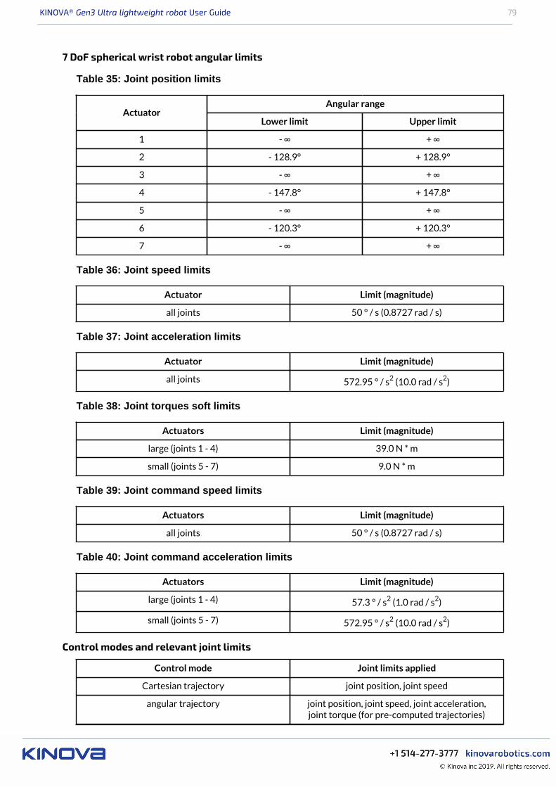
KINOVA® Gen3 Ultra lightweight robot User Guide 79
7 DoF spherical wrist robot angular limits
Table 35: Joint position limits
Angular rangeActuator
Lower limit Upper limit
1 - ∞ + ∞
2 - 128.9° + 128.9°
3 - ∞ + ∞
4 - 147.8° + 147.8°
5 - ∞ + ∞
6 - 120.3° + 120.3°
7 - ∞ + ∞
Table 36: Joint speed limits
Actuator Limit (magnitude)
all joints 50 ° / s (0.8727 rad / s)
Table 37: Joint acceleration limits
Actuator Limit (magnitude)
all joints 572.95 ° / s2 (10.0 rad / s2)
Table 38: Joint torques soft limits
Actuators Limit (magnitude)
large (joints 1 - 4) 39.0 N * m
small (joints 5 - 7) 9.0 N * m
Table 39: Joint command speed limits
Actuators Limit (magnitude)
all joints 50 ° / s (0.8727 rad / s)
Table 40: Joint command acceleration limits
Actuators Limit (magnitude)
large (joints 1 - 4) 57.3 ° / s2 (1.0 rad / s2)
small (joints 5 - 7) 572.95 ° / s2 (10.0 rad / s2)
Control modes and relevant joint limits
Control mode Joint limits applied
Cartesian trajectory joint position, joint speed
angular trajectory joint position, joint speed, joint acceleration,joint torque (for pre-computed trajectories)
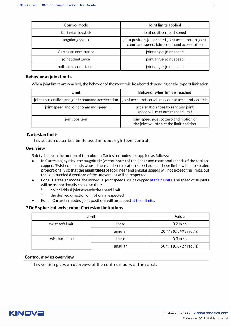
KINOVA® Gen3 Ultra lightweight robot User Guide 80
Control mode Joint limits applied
Cartesian joystick joint position, joint speed
angular joystick joint position, joint speed, joint acceleration, jointcommand speed, joint command acceleration
Cartesian admittance joint angle, joint speed
joint admittance joint angle, joint speed
null space admittance joint angle, joint speed
Behavior at joint limits
When joint limits are reached, the behavior of the robot will be altered depending on the type of limitation.
Limit Behavior when limit is reached
joint acceleration and joint command acceleration joint acceleration will max out at acceleration limit
joint speed and joint command speed acceleration goes to zero and jointspeed will max out at speed limit
joint position joint speed goes to zero and motion ofthe joint will stop at the limit position
Cartesian limitsThis section describes limits used in robot high-level control.
Overview
Safety limits on the motion of the robot in Cartesian modes are applied as follows:• In Cartesian joystick, the magnitude (vector norm) of the linear and rotational speeds of the tool are
capped. Twist commands whose linear and / or rotation speed exceed these limits will be re-scaledproportionally so that the magnitudes of tool linear and angular speeds will not exceed the limits, butthe commanded directions of tool movement will be respected.
• For all Cartesian modes, the individual joint speeds will be capped at their limits. The speed of all jointswill be proportionally scaled so that:º no individual joint exceeds the speed limitº the desired direction of motion is respected
• For all Cartesian modes, joint positions will be capped at their limits.
7 DoF spherical wrist robot Cartesian limitations
Limit Value
linear 0.2 m / stwist soft limit
angular 20 ° / s (0.3491 rad / s)
linear 0.3 m / stwist hard limit
angular 50 ° / s (0.8727 rad / s)
Control modes overview
This section gives an overview of the control modes of the robot.

KINOVA® Gen3 Ultra lightweight robot User Guide 81
The robot is controllable via a number of control modes:• trajectory modes
º angular trajectoryº Cartesian trajectory
• joystick control modesº Cartesian joystickº angular joystick
• admittance modesº Cartesian admittanceº joint admittanceº null space admittance
Users do not select the control mode directly. The robot software will set the robot into the control modedepending on the control action currently being used with the robot. The following sections describe theinternal control modes.
Trajectory control modesThis section describes the Trajectory Control modes of the robot.
Using Trajectory Control modes, the user can command the robot to a desired endpoint.
There are two ways a trajectory can be defined.
Users can provide an endpoint, and the let the control software of the robot compute how to follow a pathto reach the endpoint. The robot controller computes an interpolated trajectory (between current pose andtarget pose) to reach the final position while satisfying configured limits, and commands the robot to followthis trajectory. These trajectories, once defined, can be played back. This is a good setting when you wantthe robot to go to a desired end state but you are not concerned about how it goes about getting there.
Users can supply a pre-computed trajectory to the robot. A pre-computed trajectory is generally auto-generated by some sort of path planning software or algorithm rather than built manually. A pre-computedtrajectory is defined as a time series of settings for joints angular positions, velocities, and accelerationsat each timestamp. The robot control software will verify that the trajectory is valid and reasonable,satisfying configured limits. Users can indicate a desired continuity mode for the trajectory against whichthe trajectory can be checked (position, or position and velocity, or position, velocity and acceleration).
The robot control library will perform the following validations on the pre-computed trajectory:• trajectory is non-empty• for each trajectory point, position, velocity, and acceleration values must be provided for each joint
in the robot• trajectory contains no NaN values• timestamp of the first trajectory point must be 0.000 seconds and the difference in time stamps
between successive points must be 0.001 seconds• joint positions, speeds, accelerations, and torques must be within robot joint limits• continuity - the trajectory is continuous in terms of (user can specify which of these continuity checks
to apply):º position - joint position variation between successive timesteps is less than the maximum
variation (based on joint speed limit)º speed - speed values are consistent (within tolerances) with derivative of positionº acceleration - acceleration values are consistent (within tolerances) with derivative of speed
• trajectory execution (when starting the trajectory) - the joint positions and speeds for the first pointin the trajectory must match the initial robot joint positions and speeds
Note: For safety reasons, trajectories failing any of the validation checks will be rejected, and you willreceive an error notification. To get more detailed information about why a particular trajectory failed, usethe method GetTrajectoryErrorReport() in Kinova.Api.Base.
In Cartesian Trajectory mode the endpoint is defined in terms of the desired Cartesian space pose of thetool center. This mode enables singularity avoidance. Cartesian Trajectory mode is not compatible with pre-computed trajectories.
KINOVA® Gen3 Ultra lightweight robot User Guide 82
In Angular Trajectory mode the endpoint is defined in terms of the desired joint angles for the actuators.Angular Trajectory mode can be activated by sending either the endpoint joint state alone or via a pre-computed trajectory.
Users have the option to apply constraints to trajectories. There are three options available for constraints:• duration - the time period (in seconds) in which the trajectory is to be carried out• speed - the maximum speed (meters / second for Cartesian, degrees / second for angular) of the
motion while carrying out the trajectory• no constraint - the robot will go to the endpoint without the time or speed being specified
Note: If a requested trajectory constraint will cause angular limits to be exceeded in the course of thetrajectory, (e.g. the duration is too short and requires a speed or acceleration that is not feasible) thetrajectory will be rejected.
In angular trajectories, all three options are available (duration, speed, no constraint).
In Cartesian trajectories, the speed constraint or no constraint options are available.
Trajectory control modes are set by sending a trajectory using the appropriate API methods, or via the WebApp Actions page.
Joystick control modesThis section describes the Joystick Control modes of the robot.
Joystick Control modes provide the user the ability to create a desired motion of the robot by sendingcommands to the robot. This is done using joystick control inputs (physical gamepad or virtual joystick) ordirectly using API commands.
In Cartesian Joystick mode the motion of the robot end effector, both linear and angular, is controlled.Cartesian joystick is entered by:• sending API twist commands (specify linear and angular velocity of the end effector)• activating Xbox gamepad Twist linear and Twist angular modes• sending Web App Pose virtual joystick control inputs in velocity controlThis mode provides for singularity avoidance and obstacle avoidance (protection zones).
For Cartesian control, the reference frames for translation and orientation control are configurable:
Table 41: Cartesian reference frames options
Cartesian frame mode Reference frame for translation Reference frame for orientation
mixed mode base tool
tool mode tool tool
base mode base base
Note: Orientations are defined using an z-y-x Tait-Bryan extrinsic convention. That is, rotation about thefixed x-axis, followed by rotation about the fixed y-axis, followed by rotation about the fixed z-axis.
In Angular Joystick mode the joints of the robot are moved in angular space using joint angular velocitycommands or joystick control inputs provided to the actuators. The joints can be moved individually ortogether.
Angular joystick mode can be entered by:• sending API joint speed commands• activating Xbox gamepad Joint mapping• sending commands via Web App Angular virtual joystick
Admittance modesThis section describes the Admittance modes of the arm.
By setting the control mode of the arm to admittance mode, the user can manually apply external effort onthe robot and it will move accordingly.
KINOVA® Gen3 Ultra lightweight robot User Guide 83
In Cartesian Admittance mode, the user manipulates the tool. A spherical workspace centered on actuatortwo is defined. If the user tries to extend the robot beyond this workspace, the robot will resist and comeback inside the workspace.
In Joint Admittance mode the joints of the robot rotate according to the external torques applied.
In Null Space Admittance mode, the end effector stays in the same pose while the user manipulates thejoints of the arm (within the null space). The arm moves within the null space according to the torquesapplied.
Note: For all three admittance modes, the robot control library will automatically adapt to theuser-configured gravity vector, tool, and payload information. The user is responsible for correctlydefining the gravity vector, as well as tool and payload information using either the Web App or API(Kinova.Api.ControlConfig). Incorrect configuration of these parameters can cause unexpectedbehavior in admittance modes.
There are four ways to put the robot into admittance:• use the method SetAdmittance in the API.• Web App control panel admittance mode selection• admittance selection buttons on Xbox gamepad modes (Twist linear and angular modes for Cartesian
and Null space admittance, Joint mode for Joint admittance)• admittance mode physical buttons on the interface module (for Cartesian and Null space admittance
modes).
Note: Motion in admittance modes is constrained by internal safety limits for the robot on velocityand torques. This includes Cartesian linear velocity limits and joint limits for angular velocity andtorque. Admittance mode performance is also tuned using configurable parameters. The values for theseparameters are not currently user-configurable, but will be available for configuration in a future softwarerelease.
KINOVA® Gen3 Ultra lightweight robot User Guide 84
Configurations and safeties
Configurable parameters
This section lists the configurable parameters of the robot and gives guidance on how toconfigure them.
The robotic arm includes a number of parameters that can be configured to customize the operation of therobot.
These parameters can be configured using the appropriate KINOVA™ KORTEX® APIs. For more details onhow to perform configuration using the APIs, see the API documentation..
Some of these parameters can also be configured using the Web App GUI, which can be accessed as follows:
1. Open the Web App2. Navigate to the Robot Configurations page
The following tables give a summary of the configurable parameters.
Control library configuration
Table 42: Control modes configuration (Kinova.Api.ControlConfig)
Configurable item Description
Global gravity vector
Defines global value for gravitational acceleration vector (x,y,z) in relation to
the base frame in units of m/s2.
Note: Configuration of the gravity vector is necessary to mount the robot inarbitrary orientations (e.g. wall mount, ceiling mount). Accurate configurationof the direction and strength of gravity is important for the robot to properlycompensate for torques due to gravity on the robot actuators.
Tool configuration
• Set Cartesian transform of x, y, z (m) and θx, θy, and θz of tool frame inrelation to interface module frame.
Note: The Cartesian pose feedback available in base cycliccommunications uses the pose of the tool frame in relation to the baseframe. The specific choice of the tool frame will therefore impact thereadings for the current Cartesian pose.
• Set tool mass (kg), and tool mass center position x, y, z (m)
Note: The mass and center of mass of the tool need to be configured forthe robot control libraries to properly adapt the control of the robot to theadditional mass of the tool.
Payload configuration
Set payload mass (kg) and mass center of payload x,y,z (m) in relation to the toolframe.
Note: The mass and center of mass of the payload need to be configured for therobot control libraries to properly adapt the control of the robot to the additionalmass of the payload.
KINOVA® Gen3 Ultra lightweight robot User Guide 85
Configurable item Description
Cartesianreference frame
Set the reference frame convention for translation and orientation to use withCartesian Twist and Wrench commands. There are three options:• Mixed - translation reference frame = base frame and orientation
reference frame = tool frame• Tool - tool reference frame used for both translation and orientation
reference frames• Base - base reference frame used for both translation and orientation
reference frames
Note: Changing the reference frame convention will affect the readings that areprovided for the current Cartesian pose of the end effector tool.
Base configuration
Table 43: Base configuration (Kinova.Api.Base)
Configurable item Description
User Profiles Create, read, update and delete user profiles
Protection Zone
Create, read, update and delete protection zones (for obstacle avoidance).Configurable parameters are:• enabled / disabled• zone shape type (rectangular prism, cylinder, sphere)• zone origin and orientation• zone dimensions• envelope thickness• zone limitation types (velocity) and values• envelope limitation types (velocity) and values
Control Mapping Create, read control mapping
Action Create, read, update, delete action
Sequence Create, read, update, delete a sequence of actions
IPv4
Set IPv4 configured (for specified network adapter):• IP address• subnet mask• default gateway
CommunicationInterface
Enable communication interface:• network type (Wi-Fi or Ethernet)• enabled/disabled
Wi-Fi
Set:• SSID• security key• automatic connection allowed• country code
TCP bridgeto hardware
Enable or disable
Restore factorysettings
Delete all configurations and reverts settings to factory defaults (exceptnetwork settings)
Restore factoryproduct configuration
Restore product configuration to factory product configuration
KINOVA® Gen3 Ultra lightweight robot User Guide 86
Actuators configuration
Table 44: Actuator configuration (Kinova.Api.ActuatorConfig)
Configurable item Description
Axis offsets Set actuator axis offset position
Torque offset Set actuator torque offset value
Control mode
Set actuator control mode. Options:• position• velocity• current• torque
Control loopparameters
Configure an individual control loop parameter:• joint or motor position• joint or motor velocity• joint torque• motor current
Configure:• error saturation value• output saturation value• kAz• kBz• error dead band value
Vector driveparameters
Set vector drive parameters:• kpq• kiq• kpd• kid
Encoder derivativeparameters
Set encoder derivative parameters:• maximum window width• minimum encoder tick count
Command mode
Set command mode. Options:• cyclic - cyclic data only• asynchronous - configuration messages only• cyclic jitter compensation using position or posi tion and velocity inputs
Note: These options are available in the API but should NOT be used
Servoing Enable servoing
Interface configuration
Table 45: Interface configuration (Kinova.Api.InterconnectConfig)
Configurable item Description
UART communciations Configure interface UART - enable /disable, speed, word length, stop bits, parity
Ethernet communications Configure interface Ethernetport - speed, duplex mode
GPIO Configure interface GPIOs - mode,pull mode, value, default value
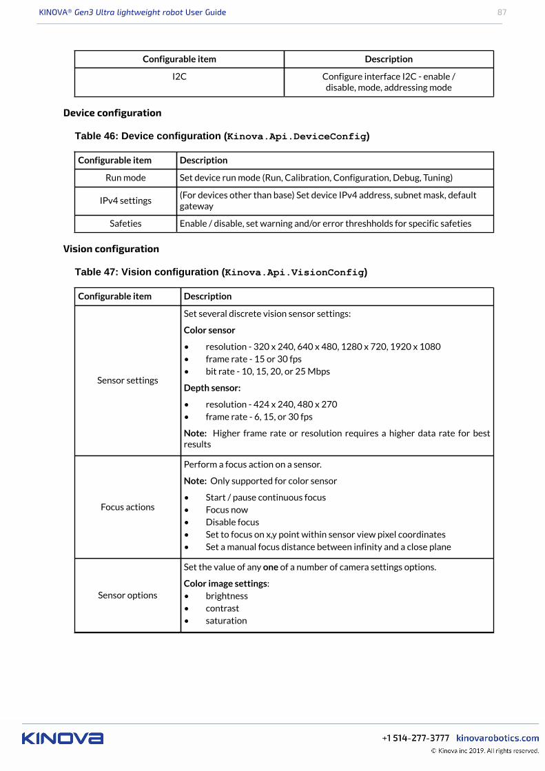
KINOVA® Gen3 Ultra lightweight robot User Guide 87
Configurable item Description
I2C Configure interface I2C - enable /disable, mode, addressing mode
Device configuration
Table 46: Device configuration (Kinova.Api.DeviceConfig)
Configurable item Description
Run mode Set device run mode (Run, Calibration, Configuration, Debug, Tuning)
IPv4 settings(For devices other than base) Set device IPv4 address, subnet mask, defaultgateway
Safeties Enable / disable, set warning and/or error threshholds for specific safeties
Vision configuration
Table 47: Vision configuration (Kinova.Api.VisionConfig)
Configurable item Description
Sensor settings
Set several discrete vision sensor settings:
Color sensor
• resolution - 320 x 240, 640 x 480, 1280 x 720, 1920 x 1080• frame rate - 15 or 30 fps• bit rate - 10, 15, 20, or 25 Mbps
Depth sensor:
• resolution - 424 x 240, 480 x 270• frame rate - 6, 15, or 30 fps
Note: Higher frame rate or resolution requires a higher data rate for bestresults
Focus actions
Perform a focus action on a sensor.
Note: Only supported for color sensor
• Start / pause continuous focus• Focus now• Disable focus• Set to focus on x,y point within sensor view pixel coordinates• Set a manual focus distance between infinity and a close plane
Sensor options
Set the value of any one of a number of camera settings options.
Color image settings:• brightness• contrast• saturation
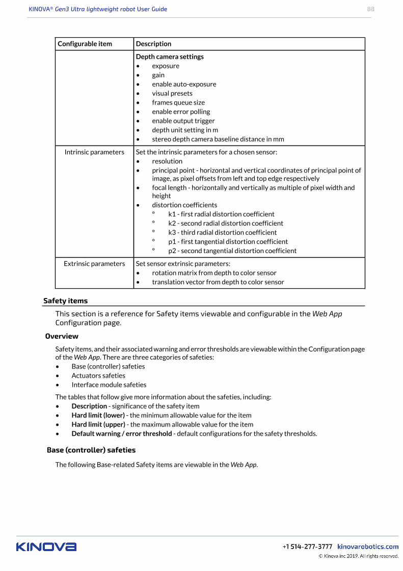
KINOVA® Gen3 Ultra lightweight robot User Guide 88
Configurable item Description
Depth camera settings• exposure• gain• enable auto-exposure• visual presets• frames queue size• enable error polling• enable output trigger• depth unit setting in m• stereo depth camera baseline distance in mm
Intrinsic parameters Set the intrinsic parameters for a chosen sensor:• resolution• principal point - horizontal and vertical coordinates of principal point of
image, as pixel offsets from left and top edge respectively• focal length - horizontally and vertically as multiple of pixel width and
height• distortion coefficients
º k1 - first radial distortion coefficientº k2 - second radial distortion coefficientº k3 - third radial distortion coefficientº p1 - first tangential distortion coefficientº p2 - second tangential distortion coefficient
Extrinsic parameters Set sensor extrinsic parameters:• rotation matrix from depth to color sensor• translation vector from depth to color sensor
Safety items
This section is a reference for Safety items viewable and configurable in the Web AppConfiguration page.
Overview
Safety items, and their associated warning and error thresholds are viewable within the Configuration pageof the Web App. There are three categories of safeties:• Base (controller) safeties• Actuators safeties• Interface module safeties
The tables that follow give more information about the safeties, including:• Description - significance of the safety item• Hard limit (lower) - the minimum allowable value for the item• Hard limit (upper) - the maximum allowable value for the item• Default warning / error threshold - default configurations for the safety thresholds.
Base (controller) safeties
The following Base-related Safety items are viewable in the Web App.
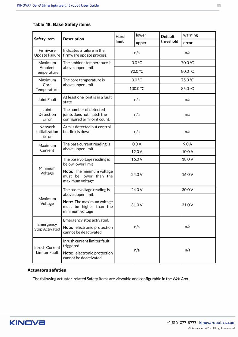
KINOVA® Gen3 Ultra lightweight robot User Guide 89
Table 48: Base Safety items
lower warningSafety Item Description
Hardlimit upper
Defaultthreshold error
FirmwareUpdate Failure
Indicates a failure in thefirmware update process.
n/a n/a
0.0 °C 70.0 °CMaximumAmbient
Temperature
The ambient temperature isabove upper limit
90.0 °C 80.0 °C
0.0 °C 75.0 °CMaximumCore
Temperature
The core temperature isabove upper limit
100.0 °C 85.0 °C
Joint FaultAt least one joint is in a faultstate
n/a n/a
JointDetection
Error
The number of detectedjoints does not match theconfigured arm joint count.
n/a n/a
NetworkInitialization
Error
Arm is detected but controlbus link is down n/a n/a
0.0 A 9.0 AMaximumCurrent
The base current reading isabove upper limit
12.0 A 10.0 A
16.0 V 18.0 V
MinimumVoltage
The base voltage reading isbelow lower limit
Note: The minimum voltagemust be lower than themaximum voltage
24.0 V 16.0 V
24.0 V 30.0 V
MaximumVoltage
The base voltage reading isabove upper limit.
Note: The maximum voltagemust be higher than theminimum voltage
31.0 V 31.0 V
EmergencyStop Activated
Emergency stop activated.
Note: electronic protectioncannot be deactivated
n/a n/a
Inrush CurrentLimiter Fault
Inrush current limiter faulttriggered.
Note: electronic protectioncannot be deactivated
n/a n/a
Actuators safeties
The following actuator-related Safety items are viewable and configurable in the Web App.
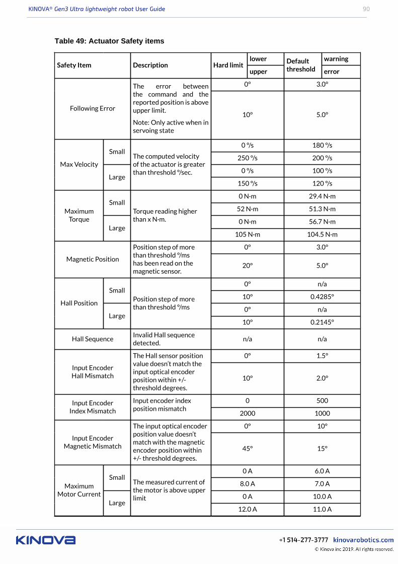
KINOVA® Gen3 Ultra lightweight robot User Guide 90
Table 49: Actuator Safety items
lower warningSafety Item Description Hard limit
upper
Defaultthreshold error
0° 3.0°
Following Error
The error betweenthe command and thereported position is aboveupper limit.
Note: Only active when inservoing state
10° 5.0°
0 °/s 180 °/sSmall
250 °/s 200 °/s
0 °/s 100 °/sMax Velocity
Large
The computed velocityof the actuator is greaterthan threshold °/sec.
150 °/s 120 °/s
0 N·m 29.4 N·mSmall
52 N·m 51.3 N·m
0 N·m 56.7 N·m
MaximumTorque
Large
Torque reading higherthan x N·m.
105 N·m 104.5 N·m
0° 3.0°
Magnetic Position
Position step of morethan threshold °/mshas been read on themagnetic sensor.
20° 5.0°
0° n/aSmall
10° 0.4285°
0° n/aHall Position
Large
Position step of morethan threshold °/ms
10° 0.2145°
Hall SequenceInvalid Hall sequencedetected.
n/a n/a
0° 1.5°
Input EncoderHall Mismatch
The Hall sensor positionvalue doesn’t match theinput optical encoderposition within +/-threshold degrees.
10° 2.0°
0 500Input EncoderIndex Mismatch
Input encoder indexposition mismatch
2000 1000
0° 10°
Input EncoderMagnetic Mismatch
The input optical encoderposition value doesn’tmatch with the magneticencoder position within+/- threshold degrees.
45° 15°
0 A 6.0 ASmall
8.0 A 7.0 A
0 A 10.0 A
MaximumMotor Current
Large
The measured current ofthe motor is above upperlimit
12.0 A 11.0 A
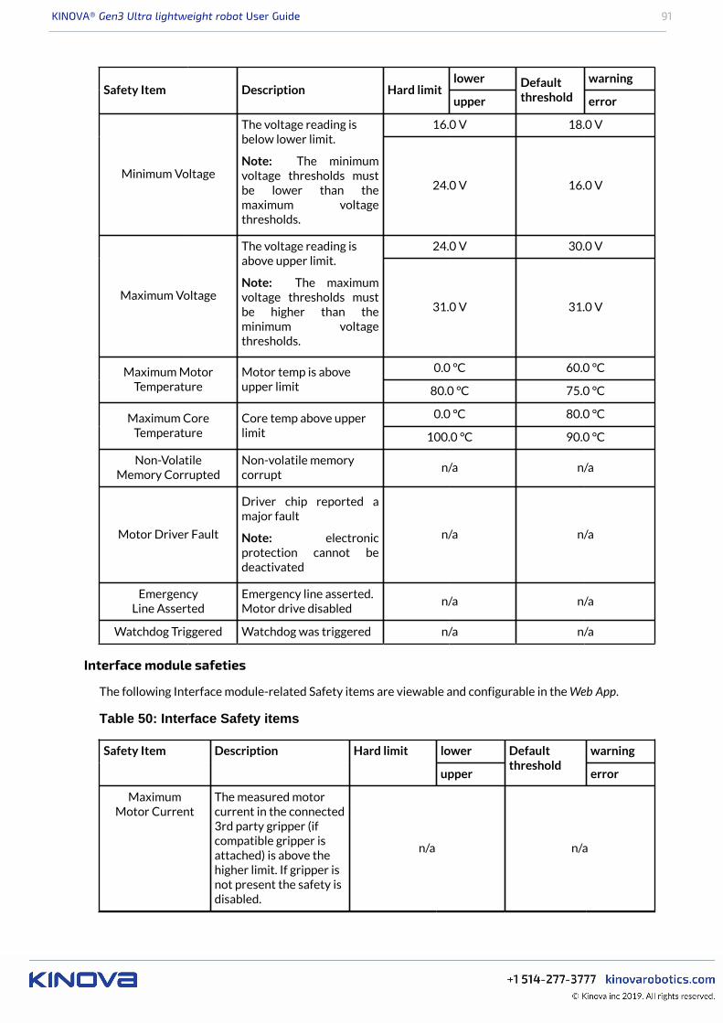
KINOVA® Gen3 Ultra lightweight robot User Guide 91
lower warningSafety Item Description Hard limit
upper
Defaultthreshold error
16.0 V 18.0 V
Minimum Voltage
The voltage reading isbelow lower limit.
Note: The minimumvoltage thresholds mustbe lower than themaximum voltagethresholds.
24.0 V 16.0 V
24.0 V 30.0 V
Maximum Voltage
The voltage reading isabove upper limit.
Note: The maximumvoltage thresholds mustbe higher than theminimum voltagethresholds.
31.0 V 31.0 V
0.0 °C 60.0 °CMaximum MotorTemperature
Motor temp is aboveupper limit 80.0 °C 75.0 °C
0.0 °C 80.0 °CMaximum CoreTemperature
Core temp above upperlimit 100.0 °C 90.0 °C
Non-VolatileMemory Corrupted
Non-volatile memorycorrupt
n/a n/a
Motor Driver Fault
Driver chip reported amajor fault
Note: electronicprotection cannot bedeactivated
n/a n/a
EmergencyLine Asserted
Emergency line asserted.Motor drive disabled
n/a n/a
Watchdog Triggered Watchdog was triggered n/a n/a
Interface module safeties
The following Interface module-related Safety items are viewable and configurable in the Web App.
Table 50: Interface Safety items
lower warningSafety Item Description Hard limit
upper
Defaultthreshold
error
MaximumMotor Current
The measured motorcurrent in the connected3rd party gripper (ifcompatible gripper isattached) is above thehigher limit. If gripper isnot present the safety isdisabled.
n/a n/a
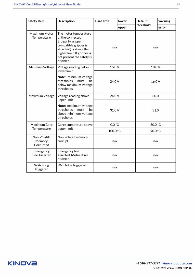
KINOVA® Gen3 Ultra lightweight robot User Guide 92
lower warningSafety Item Description Hard limit
upper
Defaultthreshold
error
Maximum MotorTemperature
The motor temperatureof the connected3rd party gripper (ifcompatible gripper isattached) is above thehigher limit. If gripper isnot present the safety isdisabled.
n/a n/a
16.0 V 18.0 VMinimum Voltage Voltage reading belowlower limit
Note: minimum voltagethresholds must bebelow maximum voltagethresholds
24.0 V 16.0 V
24.0 V 30.0Maximum Voltage Voltage reading aboveupper limit
Note: maximum voltagethresholds must beabove minimum voltagethresholds
31.0 V 31.0
0.0 °C 80.0 °CMaximum CoreTemperature
Core temperature aboveupper limit
100.0 °C 90.0 °C
Non-VolatileMemory
Corrupted
Non-volatile memorycorrupt n/a n/a
EmergencyLine Asserted
Emergency lineasserted. Motor drivedisabled
n/a n/a
WatchdogTriggered
Watchdog triggeredn/a n/a

KINOVA® Gen3 Ultra lightweight robot User Guide 93
KINOVA® KORTEX™ Web App User Guide
Introduction
The following sections describe the KINOVA® KORTEX™ Web App. The Web App is used for controlling,configuring and monitoring the robot.
This pages that follow describe the purpose, layout, and use of the Web App.
Purpose
This section describes the purpose of the Web App.
The Web App is an HTML GUI (Graphical User Interface) that runs on the robot. This web interface allowsusers to configure, control and monitor the robot through a web browser interface from a computerconnected to the robot over a wired Ethernet or Wi-Fi connection.
Device availability of Web App
This section describes the device availability of the Web App.
The Web App is a responsive web application. It is designed to adapt itself to various aspect ratios andresolutions enabling it to run on multiple platforms that support the Google Chrome browser. This includes:• desktop / laptop computer• tablet computer• smartphone
Figure 30: Desktop
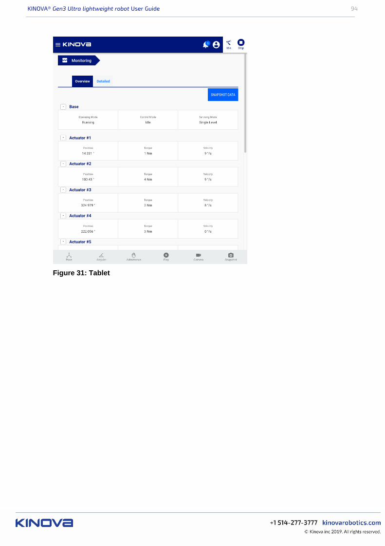
KINOVA® Gen3 Ultra lightweight robot User Guide 94
Figure 31: Tablet
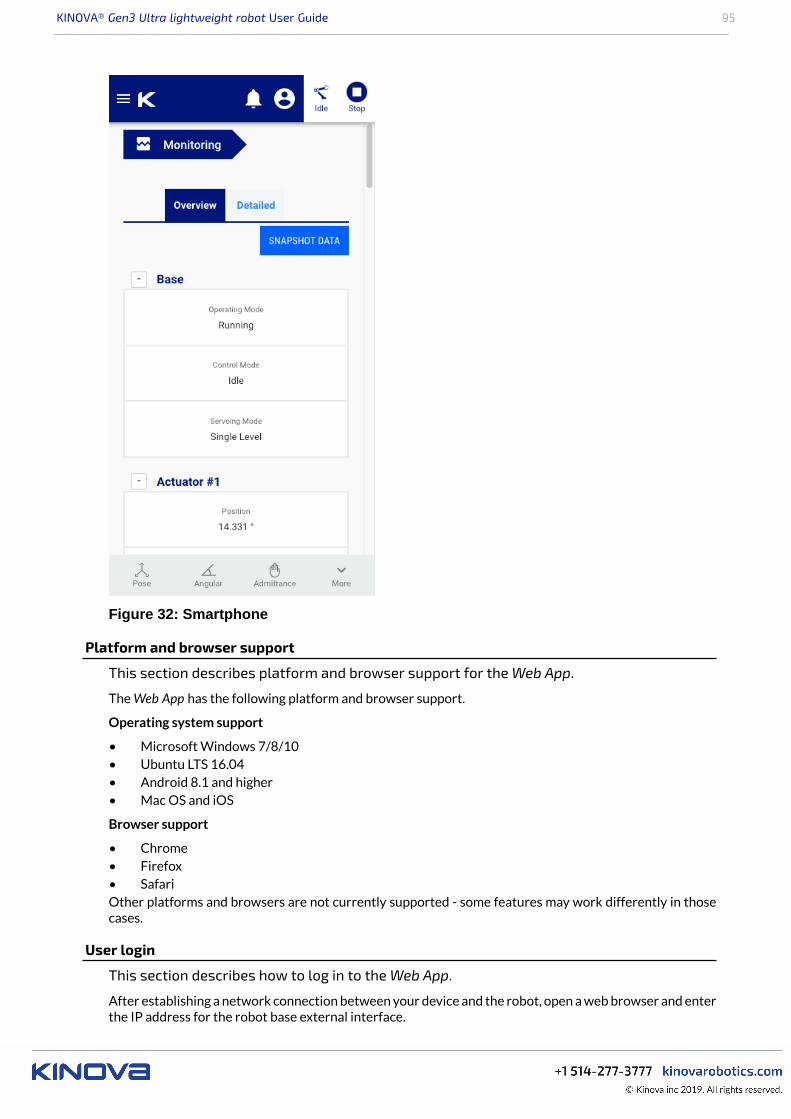
KINOVA® Gen3 Ultra lightweight robot User Guide 95
Figure 32: Smartphone
Platform and browser support
This section describes platform and browser support for the Web App.
The Web App has the following platform and browser support.
Operating system support
• Microsoft Windows 7/8/10• Ubuntu LTS 16.04• Android 8.1 and higher• Mac OS and iOS
Browser support
• Chrome• Firefox• SafariOther platforms and browsers are not currently supported - some features may work differently in thosecases.
User login
This section describes how to log in to the Web App.
After establishing a network connection between your device and the robot, open a web browser and enterthe IP address for the robot base external interface.
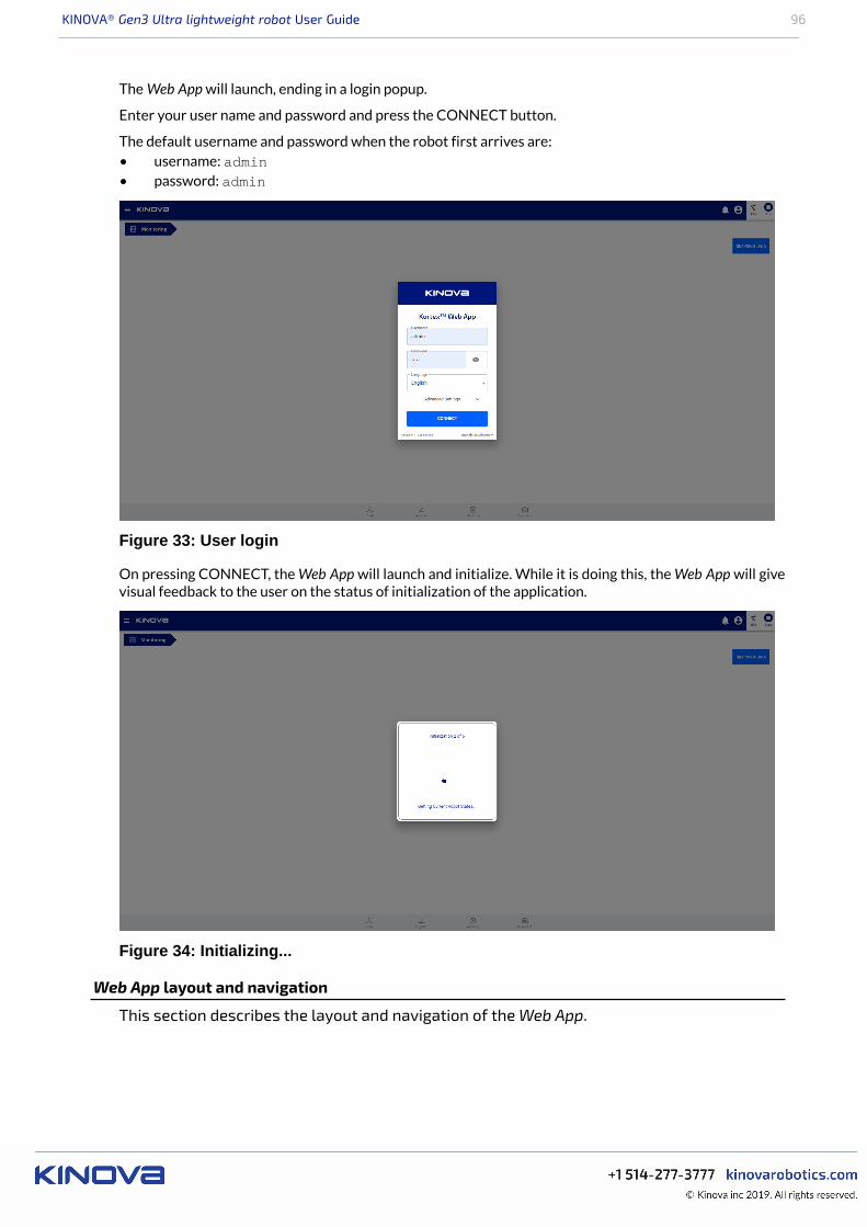
KINOVA® Gen3 Ultra lightweight robot User Guide 96
The Web App will launch, ending in a login popup.
Enter your user name and password and press the CONNECT button.
The default username and password when the robot first arrives are:• username: admin• password: admin
Figure 33: User login
On pressing CONNECT, the Web App will launch and initialize. While it is doing this, the Web App will givevisual feedback to the user on the status of initialization of the application.
Figure 34: Initializing...
Web App layout and navigation
This section describes the layout and navigation of the Web App.

KINOVA® Gen3 Ultra lightweight robot User Guide 97
The Web App screen is divided into several main sections:• Main navigation panel• Main information panel• Notification bar• Shortcuts panel• Robot control panel• Mode indicator, user icon, and E-stop
Figure 35: Web App Layout
Pages menu
In the middle of the screen is the main information panel containing the contents of each page of theapplication. The page can be changed from a pages menu on the left of the screen. This menu is hidden bydefault, but can be lauched by clicking / tapping the menu icon in the upper left.
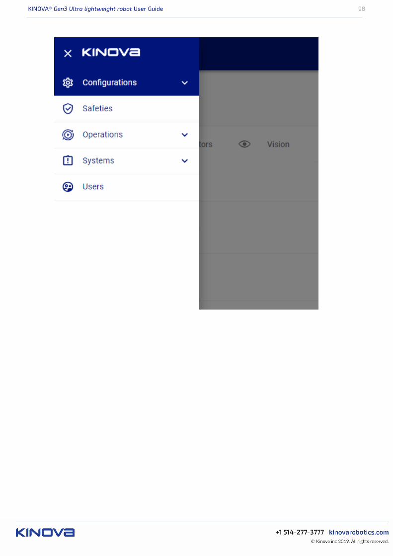
KINOVA® Gen3 Ultra lightweight robot User Guide 98
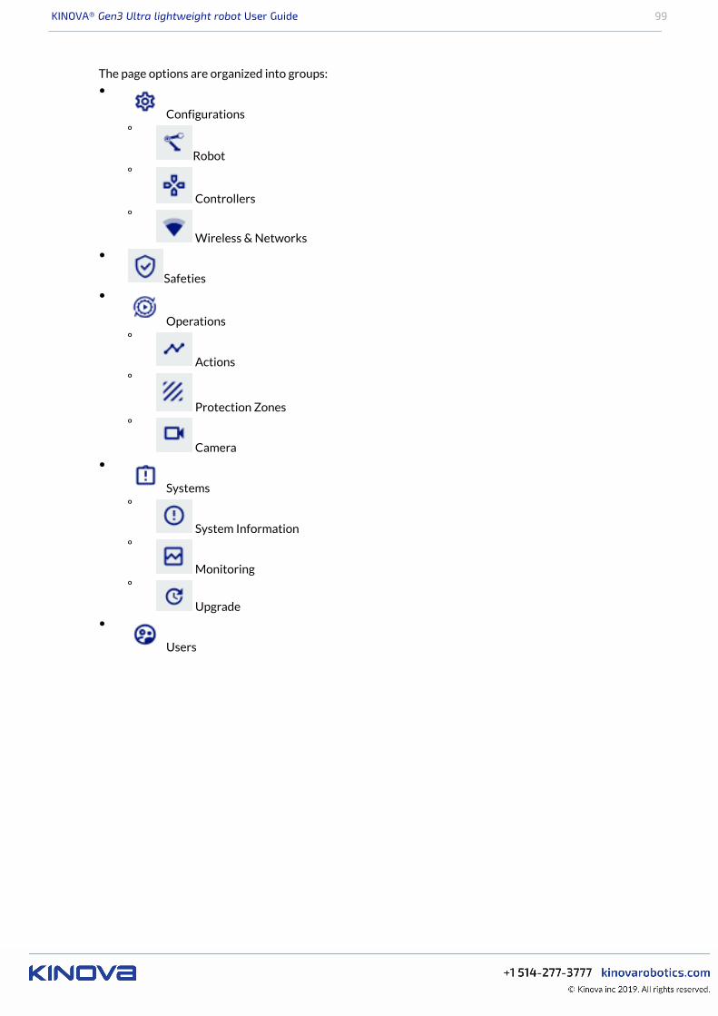
KINOVA® Gen3 Ultra lightweight robot User Guide 99
The page options are organized into groups:•
Configurationsº
Robotº
Controllersº
Wireless & Networks•
Safeties•
Operationsº
Actionsº
Protection Zonesº
Camera•
Systemsº
System Informationº
Monitoringº
Upgrade•
Users
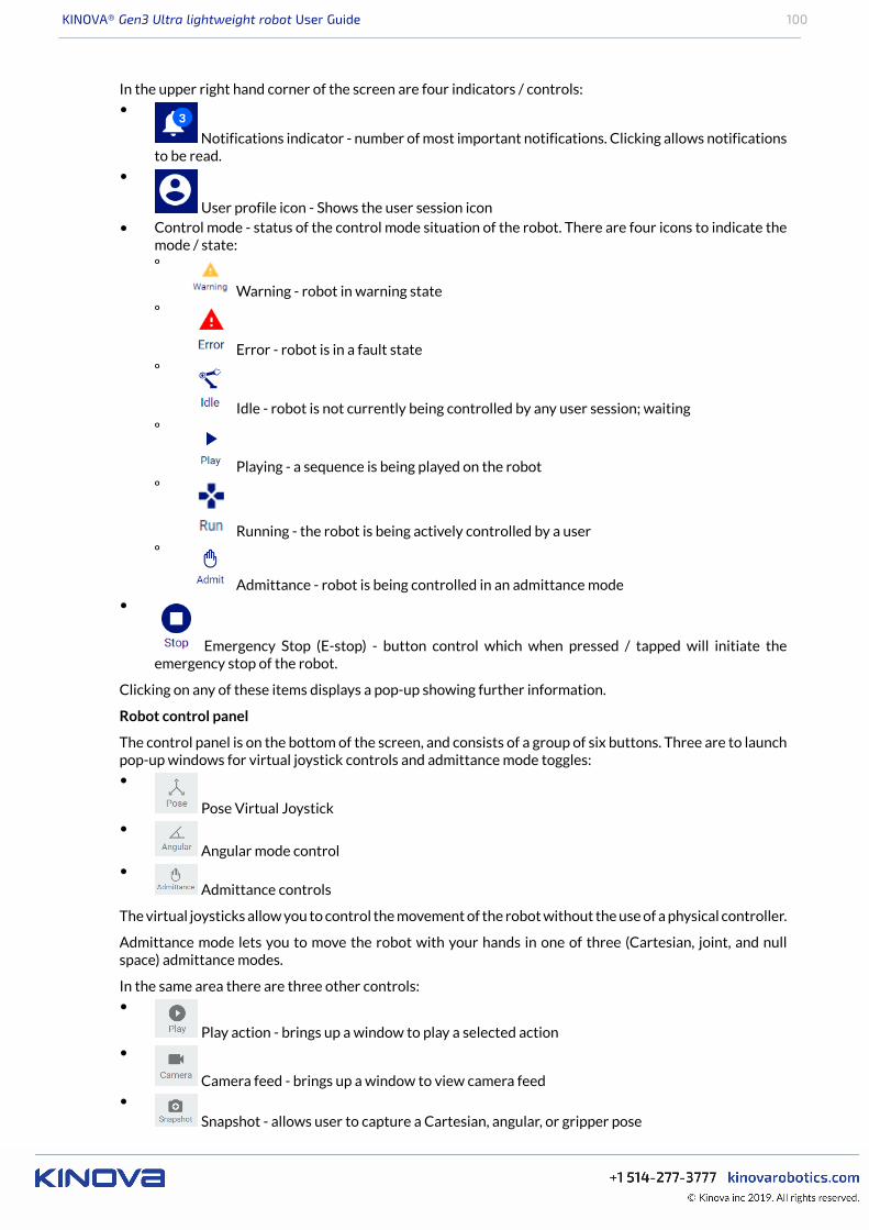
KINOVA® Gen3 Ultra lightweight robot User Guide 100
In the upper right hand corner of the screen are four indicators / controls:•
Notifications indicator - number of most important notifications. Clicking allows notificationsto be read.
•
User profile icon - Shows the user session icon• Control mode - status of the control mode situation of the robot. There are four icons to indicate the
mode / state:º
Warning - robot in warning stateº
Error - robot is in a fault stateº
Idle - robot is not currently being controlled by any user session; waitingº
Playing - a sequence is being played on the robotº
Running - the robot is being actively controlled by a userº
Admittance - robot is being controlled in an admittance mode•
Emergency Stop (E-stop) - button control which when pressed / tapped will initiate theemergency stop of the robot.
Clicking on any of these items displays a pop-up showing further information.
Robot control panel
The control panel is on the bottom of the screen, and consists of a group of six buttons. Three are to launchpop-up windows for virtual joystick controls and admittance mode toggles:•
Pose Virtual Joystick•
Angular mode control•
Admittance controls
The virtual joysticks allow you to control the movement of the robot without the use of a physical controller.
Admittance mode lets you to move the robot with your hands in one of three (Cartesian, joint, and nullspace) admittance modes.
In the same area there are three other controls:•
Play action - brings up a window to play a selected action•
Camera feed - brings up a window to view camera feed•
Snapshot - allows user to capture a Cartesian, angular, or gripper pose
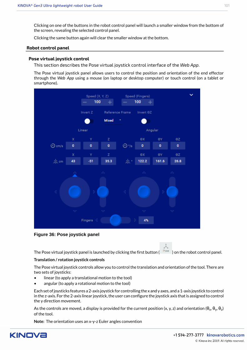
KINOVA® Gen3 Ultra lightweight robot User Guide 101
Clicking on one of the buttons in the robot control panel will launch a smaller window from the bottom ofthe screen, revealing the selected control panel.
Clicking the same button again will clear the smaller window at the bottom.
Robot control panel
Pose virtual joystick controlThis section describes the Pose virtual joystick control interface of the Web App.
The Pose virtual joystick panel allows users to control the position and orientation of the end effectorthrough the Web App using a mouse (on laptop or desktop computer) or touch control (on a tablet orsmartphone).
Figure 36: Pose joystick panel
The Pose virtual joystick panel is launched by clicking the first button ( ) on the robot control panel.
Translation / rotation joystick controls
The Pose virtual joystick controls allow you to control the translation and orientation of the tool. There aretwo sets of joysticks:• linear (to apply a translational motion to the tool)• angular (to apply a rotational motion to the tool)
Each set of joysticks features a 2-axis joystick for controlling the x and y axes, and a 1-axis joystick to controlin the z-axis. For the 2-axis linear joystick, the user can configure the joystick axis that is assigned to controlthe y direction movement.
As the controls are moved, a display is provided for the current position (x, y, z) and orientation (θx, θy, θz)of the tool.
Note: The orientation uses an x-y-z Euler angles convention

KINOVA® Gen3 Ultra lightweight robot User Guide 102
Finger controls
It is possible to open and close the fingers using a single 1-axis joystick control (if a gripper is installed). Pushthe control up to open the fingers and down to close. The fingers position can be controlled between 0%(fully closed) and 100% (fully open).
Velocity control
The robot can be controlled in velocity control.
Additional settings
By clicking the caret icon on the upper right-hand side, additional controls and displays are revealed.• current linear and angular velocity display• invert z and θz toggles
• reference frames conventions selection• gripper speed control• speed limitSpeed control
The actuators speed and finger speed can be adjusted between 0 and 100% of the hard limits for the robot.
Reference frames
The Cartesian pose of the tool can be specified in one of three reference frame conventions:• Mixed - linear in base reference frame, angular in tool reference frame• Base - linear and angular both in base reference frame• Tool - linear and angular both in tool reference frame
The tool reference frame is useful when controlling the robot using visual feedback from the camerasensors. The joystick will control movement of the tool with respect to the tool reference frame, which isvery close to the reference frame of the camera. This makes it easy to command the robot in relation towhat is seen through the camera.
Z and θz toggles
The default for the 1-axis z-direction controls is that 'up' increases the z-position or z-angle, while 'down'decreases it. This can be reversed using the Invert Z and Invert θz toggles.
Angular virtual joystick controlThis section describes the angular virtual joystick control interface of the Web App.
The angular virtual joystick panel allows users to control the robot joint angles and gripper fingers (if gripperinstalled) through the Web App using a mouse (or touch control on a tablet or smartphone).
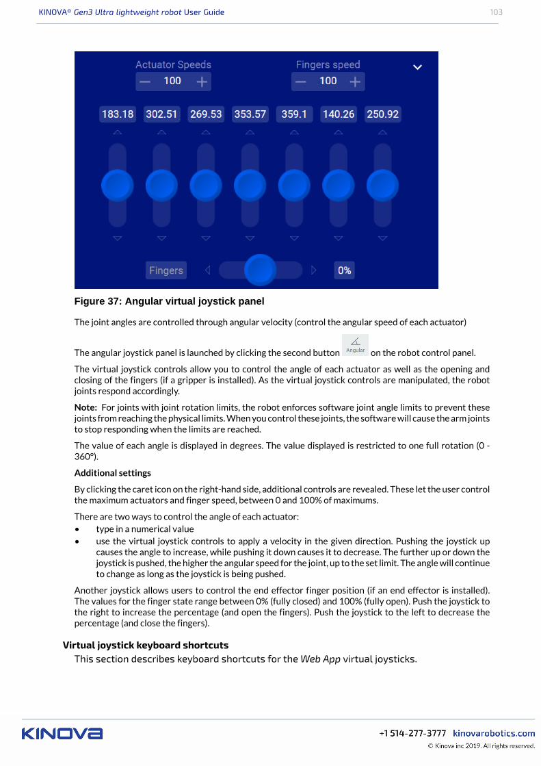
KINOVA® Gen3 Ultra lightweight robot User Guide 103
Figure 37: Angular virtual joystick panel
The joint angles are controlled through angular velocity (control the angular speed of each actuator)
The angular joystick panel is launched by clicking the second button on the robot control panel.
The virtual joystick controls allow you to control the angle of each actuator as well as the opening andclosing of the fingers (if a gripper is installed). As the virtual joystick controls are manipulated, the robotjoints respond accordingly.
Note: For joints with joint rotation limits, the robot enforces software joint angle limits to prevent thesejoints from reaching the physical limits. When you control these joints, the software will cause the arm jointsto stop responding when the limits are reached.
The value of each angle is displayed in degrees. The value displayed is restricted to one full rotation (0 -360°).
Additional settings
By clicking the caret icon on the right-hand side, additional controls are revealed. These let the user controlthe maximum actuators and finger speed, between 0 and 100% of maximums.
There are two ways to control the angle of each actuator:• type in a numerical value• use the virtual joystick controls to apply a velocity in the given direction. Pushing the joystick up
causes the angle to increase, while pushing it down causes it to decrease. The further up or down thejoystick is pushed, the higher the angular speed for the joint, up to the set limit. The angle will continueto change as long as the joystick is being pushed.
Another joystick allows users to control the end effector finger position (if an end effector is installed).The values for the finger state range between 0% (fully closed) and 100% (fully open). Push the joystick tothe right to increase the percentage (and open the fingers). Push the joystick to the left to decrease thepercentage (and close the fingers).
Virtual joystick keyboard shortcutsThis section describes keyboard shortcuts for the Web App virtual joysticks.
KINOVA® Gen3 Ultra lightweight robot User Guide 104
Introduction
The virtual joysticks for the Web App are controllable with mouse or touch inputs. Some people (particularlythose with a background in PC gaming) may find it more natural to control using keyboard shortcuts. If youare accessing the Web App using a desktop device that has a keyboard (such as a desktop or laptop PC) thereare handy keyboard shortcuts available for the joystick controls.
Cartesian joysticks keyboard shortcuts
Table 51: Pose translation joystick shortcuts
Control Shortcut
+ WX translation
- S
+ AY translation
- D
+ QZ translation
- E
Table 52: Pose orientation joystick shortcuts
Control Shortcut key
+ IX rotation
- K
+ LY rotation
- J
+ UZ rotation
- O
Table 53: Gripper controls (if gripper installed)
Control Shortcut key
open gripper fingers CGripper fingers
close gripper fingers V
Angular joystick keyboard shortcuts
Table 54: Actuators controls
Control Shortcut key
+ 1Actuator 1 angle
- Q
+ 2Actuator 2 angle
- W
+ 3Actuator 3 angle
- E
Actuator 4 angle + 4
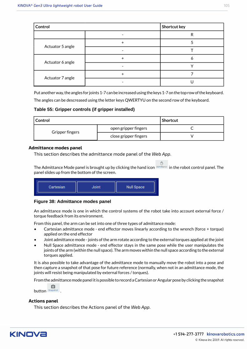
KINOVA® Gen3 Ultra lightweight robot User Guide 105
Control Shortcut key
- R
+ 5Actuator 5 angle
- T
+ 6Actuator 6 angle
- Y
+ 7Actuator 7 angle
- U
Put another way, the angles for joints 1-7 can be increased using the keys 1-7 on the top row of the keyboard.
The angles can be descreased using the letter keys QWERTYU on the second row of the keyboard.
Table 55: Gripper controls (if gripper installed)
Control Shortcut
open gripper fingers CGripper fingers
close gripper fingers V
Admittance modes panelThis section describes the admittance mode panel of the Web App.
The Admittance Mode panel is brought up by clicking the hand icon in the robot control panel. Thepanel slides up from the bottom of the screen.
Figure 38: Admittance modes panel
An admittance mode is one in which the control systems of the robot take into account external force /torque feedback from its environment.
From this panel, the arm can be set into one of three types of admittance mode:• Cartesian admittance mode - end effector moves linearly according to the wrench (force + torque)
applied on the end effector• Joint admittance mode - joints of the arm rotate according to the external torques applied at the joint• Null Space admittance mode - end effector stays in the same pose while the user manipulates the
joints of the arm (within the null space). The arm moves within the null space according to the externaltorques applied.
It is also possible to take advantage of the admittance mode to manually move the robot into a pose andthen capture a snapshot of that pose for future reference (normally, when not in an admittance mode, thejoints will resist being manipulated by external forces / torques).
From the admittance mode panel it is possible to record a Cartesian or Angular pose by clicking the snapshot
button .
Actions panelThis section describes the Actions panel of the Web App.
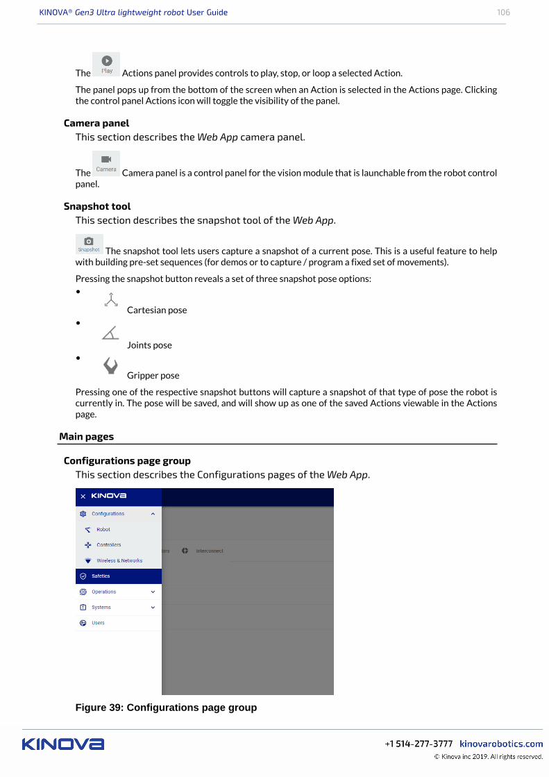
KINOVA® Gen3 Ultra lightweight robot User Guide 106
The Actions panel provides controls to play, stop, or loop a selected Action.
The panel pops up from the bottom of the screen when an Action is selected in the Actions page. Clickingthe control panel Actions icon will toggle the visibility of the panel.
Camera panelThis section describes the Web App camera panel.
The Camera panel is a control panel for the vision module that is launchable from the robot controlpanel.
Snapshot toolThis section describes the snapshot tool of the Web App.
The snapshot tool lets users capture a snapshot of a current pose. This is a useful feature to helpwith building pre-set sequences (for demos or to capture / program a fixed set of movements).
Pressing the snapshot button reveals a set of three snapshot pose options:•
Cartesian pose•
Joints pose•
Gripper pose
Pressing one of the respective snapshot buttons will capture a snapshot of that type of pose the robot iscurrently in. The pose will be saved, and will show up as one of the saved Actions viewable in the Actionspage.
Main pages
Configurations page groupThis section describes the Configurations pages of the Web App.
Figure 39: Configurations page group
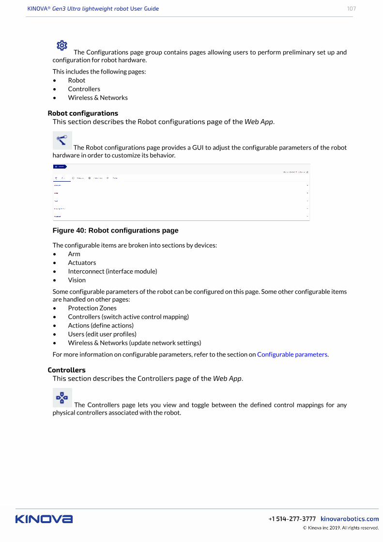
KINOVA® Gen3 Ultra lightweight robot User Guide 107
The Configurations page group contains pages allowing users to perform preliminary set up andconfiguration for robot hardware.
This includes the following pages:• Robot• Controllers• Wireless & Networks
Robot configurationsThis section describes the Robot configurations page of the Web App.
The Robot configurations page provides a GUI to adjust the configurable parameters of the robothardware in order to customize its behavior.
Figure 40: Robot configurations page
The configurable items are broken into sections by devices:• Arm• Actuators• Interconnect (interface module)• Vision
Some configurable parameters of the robot can be configured on this page. Some other configurable itemsare handled on other pages:• Protection Zones• Controllers (switch active control mapping)• Actions (define actions)• Users (edit user profiles)• Wireless & Networks (update network settings)
For more information on configurable parameters, refer to the section on Configurable parameters.
ControllersThis section describes the Controllers page of the Web App.
The Controllers page lets you view and toggle between the defined control mappings for anyphysical controllers associated with the robot.
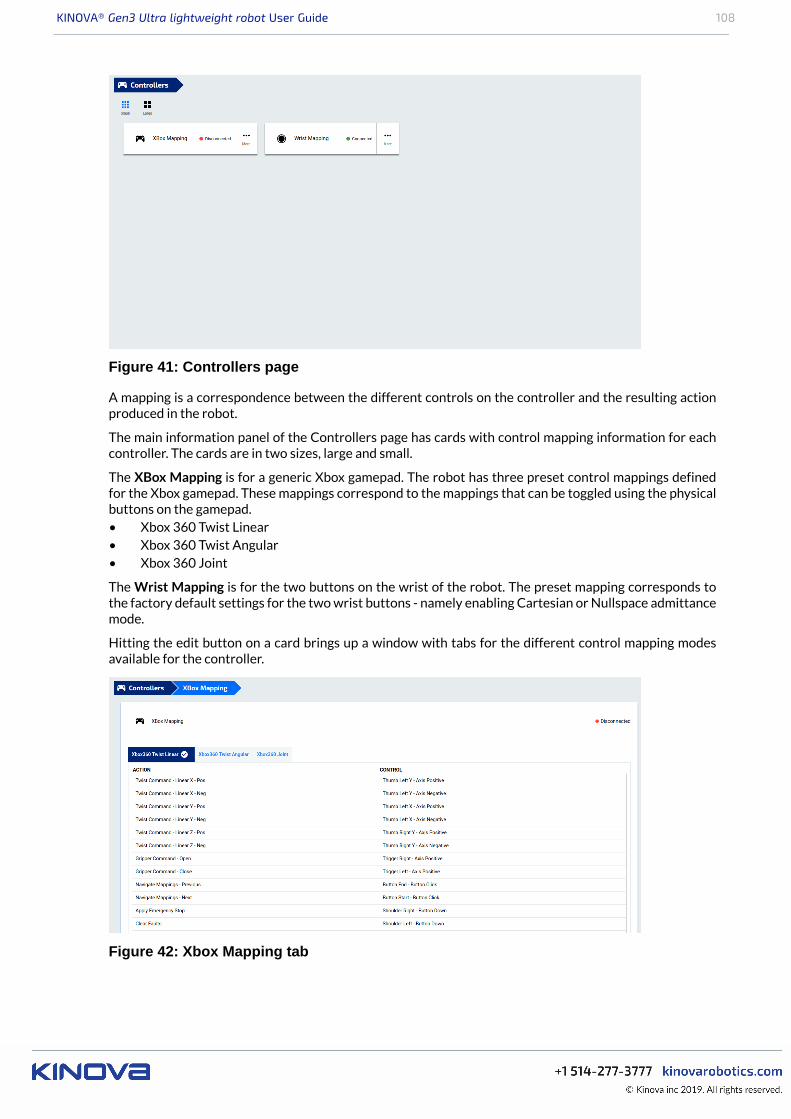
KINOVA® Gen3 Ultra lightweight robot User Guide 108
Figure 41: Controllers page
A mapping is a correspondence between the different controls on the controller and the resulting actionproduced in the robot.
The main information panel of the Controllers page has cards with control mapping information for eachcontroller. The cards are in two sizes, large and small.
The XBox Mapping is for a generic Xbox gamepad. The robot has three preset control mappings definedfor the Xbox gamepad. These mappings correspond to the mappings that can be toggled using the physicalbuttons on the gamepad.• Xbox 360 Twist Linear• Xbox 360 Twist Angular• Xbox 360 Joint
The Wrist Mapping is for the two buttons on the wrist of the robot. The preset mapping corresponds tothe factory default settings for the two wrist buttons - namely enabling Cartesian or Nullspace admittancemode.
Hitting the edit button on a card brings up a window with tabs for the different control mapping modesavailable for the controller.
Figure 42: Xbox Mapping tab
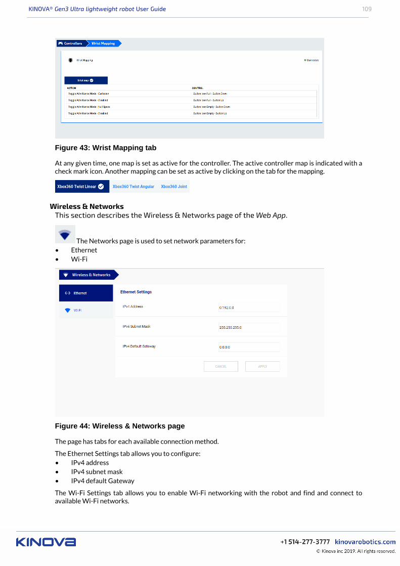
KINOVA® Gen3 Ultra lightweight robot User Guide 109
Figure 43: Wrist Mapping tab
At any given time, one map is set as active for the controller. The active controller map is indicated with acheck mark icon. Another mapping can be set as active by clicking on the tab for the mapping.
Wireless & NetworksThis section describes the Wireless & Networks page of the Web App.
The Networks page is used to set network parameters for:• Ethernet• Wi-Fi
Figure 44: Wireless & Networks page
The page has tabs for each available connection method.
The Ethernet Settings tab allows you to configure:• IPv4 address• IPv4 subnet mask• IPv4 default Gateway
The Wi-Fi Settings tab allows you to enable Wi-Fi networking with the robot and find and connect toavailable Wi-Fi networks.
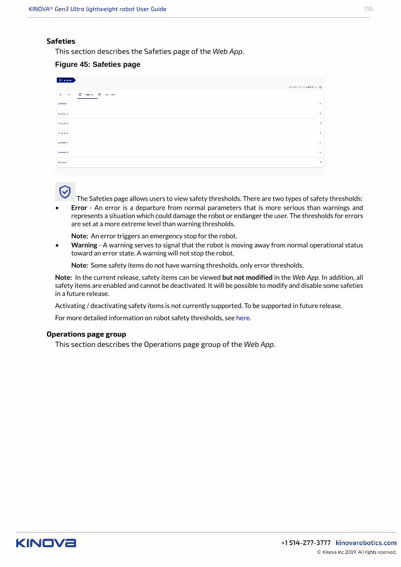
KINOVA® Gen3 Ultra lightweight robot User Guide 110
SafetiesThis section describes the Safeties page of the Web App.
Figure 45: Safeties page
The Safeties page allows users to view safety thresholds. There are two types of safety thresholds:• Error - An error is a departure from normal parameters that is more serious than warnings and
represents a situation which could damage the robot or endanger the user. The thresholds for errorsare set at a more extreme level than warning thresholds.
Note: An error triggers an emergency stop for the robot.• Warning - A warning serves to signal that the robot is moving away from normal operational status
toward an error state. A warning will not stop the robot.
Note: Some safety items do not have warning thresholds, only error thresholds.
Note: In the current release, safety items can be viewed but not modified in the Web App. In addition, allsafety items are enabled and cannot be deactivated. It will be possible to modify and disable some safetiesin a future release.
Activating / deactivating safety items is not currently supported. To be supported in future release.
For more detailed information on robot safety thresholds, see here.
Operations page groupThis section describes the Operations page group of the Web App.
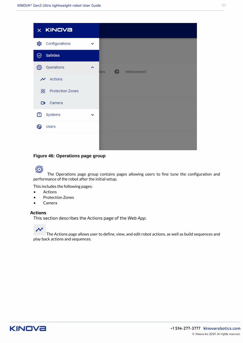
KINOVA® Gen3 Ultra lightweight robot User Guide 111
Figure 46: Operations page group
The Operations page group contains pages allowing users to fine tune the configuration andperformance of the robot after the initial setup.
This includes the following pages:• Actions• Protection Zones• Camera
ActionsThis section describes the Actions page of the Web App.
The Actions page allows user to define, view, and edit robot actions, as well as build sequences andplay back actions and sequences.
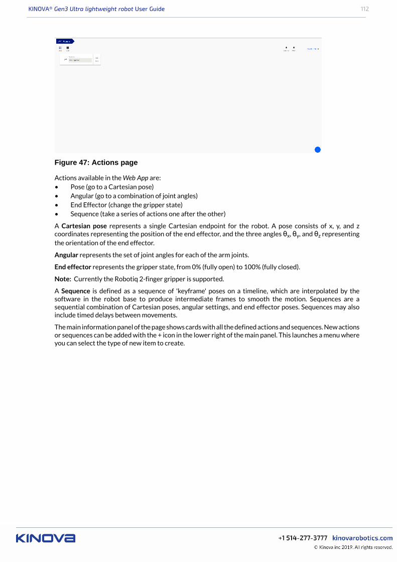
KINOVA® Gen3 Ultra lightweight robot User Guide 112
Figure 47: Actions page
Actions available in the Web App are:• Pose (go to a Cartesian pose)• Angular (go to a combination of joint angles)• End Effector (change the gripper state)• Sequence (take a series of actions one after the other)
A Cartesian pose represents a single Cartesian endpoint for the robot. A pose consists of x, y, and zcoordinates representing the position of the end effector, and the three angles θx, θy, and θz representingthe orientation of the end effector.
Angular represents the set of joint angles for each of the arm joints.
End effector represents the gripper state, from 0% (fully open) to 100% (fully closed).
Note: Currently the Robotiq 2-finger gripper is supported.
A Sequence is defined as a sequence of 'keyframe' poses on a timeline, which are interpolated by thesoftware in the robot base to produce intermediate frames to smooth the motion. Sequences are asequential combination of Cartesian poses, angular settings, and end effector poses. Sequences may alsoinclude timed delays between movements.
The main information panel of the page shows cards with all the defined actions and sequences. New actionsor sequences can be added with the + icon in the lower right of the main panel. This launches a menu whereyou can select the type of new item to create.
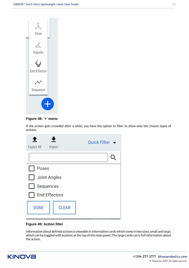
KINOVA® Gen3 Ultra lightweight robot User Guide 113
Figure 48: '+' menu
If the screen gets crowded after a while, you have the option to filter to show only the chosen types ofactions.
Figure 49: Action filter
Information about defined actions is viewable in information cards which come in two sizes, small and large,which can be toggled with buttons at the top of the main panel. The large cards carry full information aboutthe action.
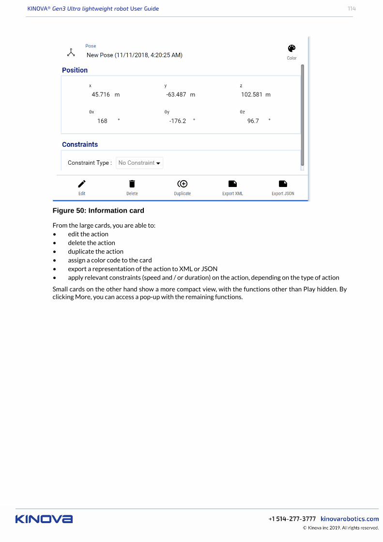
KINOVA® Gen3 Ultra lightweight robot User Guide 114
Figure 50: Information card
From the large cards, you are able to:• edit the action• delete the action• duplicate the action• assign a color code to the card• export a representation of the action to XML or JSON• apply relevant constraints (speed and / or duration) on the action, depending on the type of action
Small cards on the other hand show a more compact view, with the functions other than Play hidden. Byclicking More, you can access a pop-up with the remaining functions.
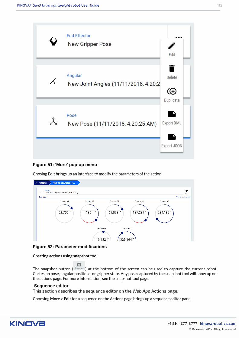
KINOVA® Gen3 Ultra lightweight robot User Guide 115
Figure 51: 'More' pop-up menu
Chosing Edit brings up an interface to modify the parameters of the action.
Figure 52: Parameter modifications
Creating actions using snapshot tool
The snapshot button ( ) at the bottom of the screen can be used to capture the current robotCartesian pose, angular positions, or gripper state. Any pose captured by the snapshot tool will show up onthe actions page. For more information, see the snapshot tool page.
Sequence editorThis section describes the sequence editor on the Web App Actions page.
Choosing More > Edit for a sequence on the Actions page brings up a sequence editor panel.
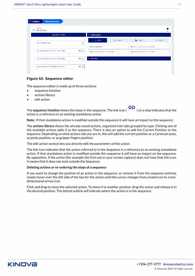
KINOVA® Gen3 Ultra lightweight robot User Guide 116
Figure 53: Sequence editor
The sequence editor is made up of three sections:• sequence timeline• actions library• edit action
The sequence timeline shows the steps in the sequence. The link icon ( ) on a step indicates that theaction is a reference to an existing standalone action.
Note: If that standalone action is modified outside this sequence it will have an impact on the sequence.
The actions library shows the already saved actions, organized into tabs grouped by type. Clicking one ofthe available actions adds it to the sequence. There is also an option to add the Current Position to thesequence. Depending on what actions tab you are in, this will add the current position as a Cartesian pose,as joints position, or as gripper fingers position.
The edit action section lets you directly edit the parameters of the action.
The link icon indicates that the action referred to in the Sequence is a reference to an existing standaloneaction. If that standalone action is modified outside this sequence it will have an impact on the sequence.By opposition, if the action (for example the first one in your screen capture) does not have that link icon,it means that it does not exist outside the Sequence.
Deleting actions or re-ordering the steps of a sequence
If you want to change the position of an action in the sequence, or remove it from the sequence entirely,simply hover over the left side of the box for the action until the cursor changes from a hand icon to a two-dimensional arrow icon.
Click and drag to move the selected action. To move it to another position, drag the action and release it inthe desired position. The dotted outline will indicate where the action is in the sequence.
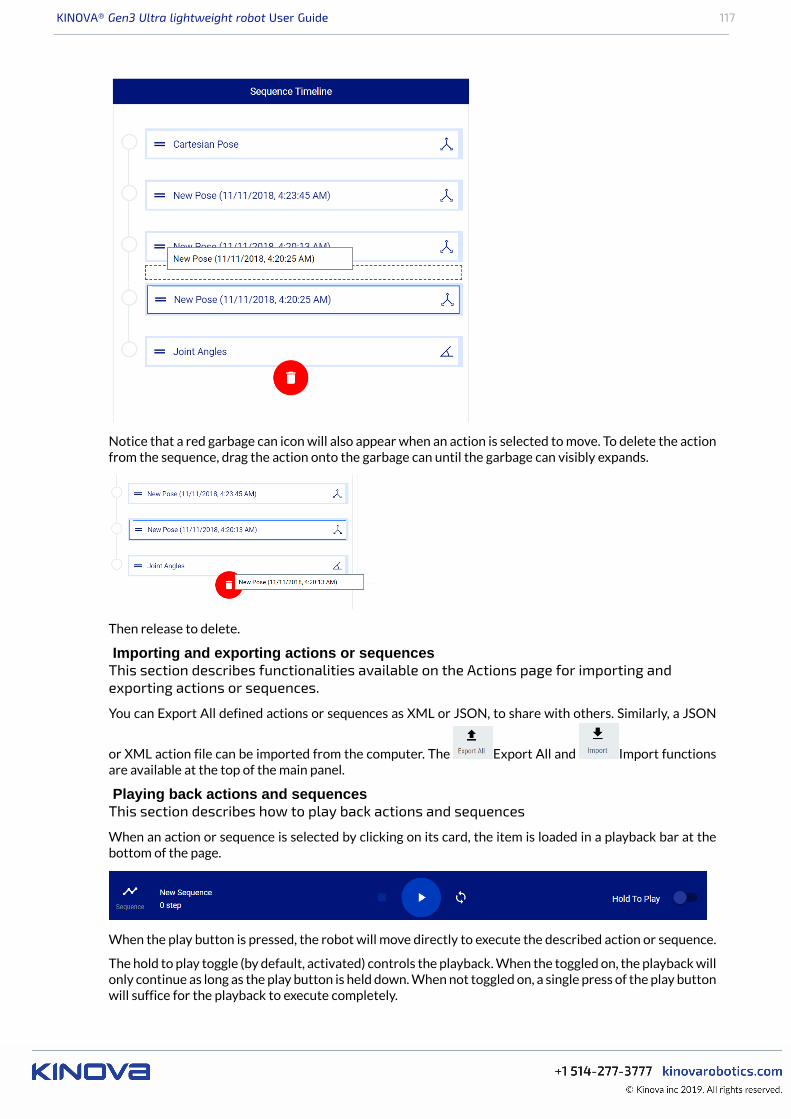
KINOVA® Gen3 Ultra lightweight robot User Guide 117
Notice that a red garbage can icon will also appear when an action is selected to move. To delete the actionfrom the sequence, drag the action onto the garbage can until the garbage can visibly expands.
Then release to delete.
Importing and exporting actions or sequencesThis section describes functionalities available on the Actions page for importing andexporting actions or sequences.
You can Export All defined actions or sequences as XML or JSON, to share with others. Similarly, a JSON
or XML action file can be imported from the computer. The Export All and Import functionsare available at the top of the main panel.
Playing back actions and sequencesThis section describes how to play back actions and sequences
When an action or sequence is selected by clicking on its card, the item is loaded in a playback bar at thebottom of the page.
When the play button is pressed, the robot will move directly to execute the described action or sequence.
The hold to play toggle (by default, activated) controls the playback. When the toggled on, the playback willonly continue as long as the play button is held down. When not toggled on, a single press of the play buttonwill suffice for the playback to execute completely.
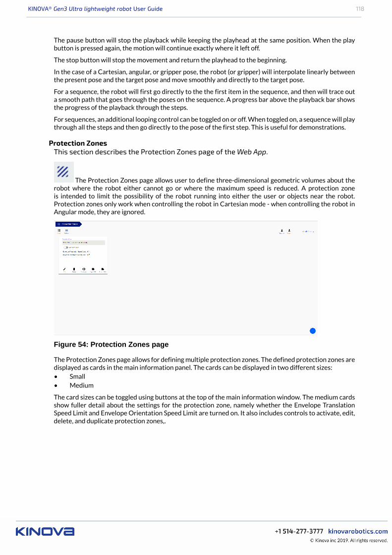
KINOVA® Gen3 Ultra lightweight robot User Guide 118
The pause button will stop the playback while keeping the playhead at the same position. When the playbutton is pressed again, the motion will continue exactly where it left off.
The stop button will stop the movement and return the playhead to the beginning.
In the case of a Cartesian, angular, or gripper pose, the robot (or gripper) will interpolate linearly betweenthe present pose and the target pose and move smoothly and directly to the target pose.
For a sequence, the robot will first go directly to the the first item in the sequence, and then will trace outa smooth path that goes through the poses on the sequence. A progress bar above the playback bar showsthe progress of the playback through the steps.
For sequences, an additional looping control can be toggled on or off. When toggled on, a sequence will playthrough all the steps and then go directly to the pose of the first step. This is useful for demonstrations.
Protection ZonesThis section describes the Protection Zones page of the Web App.
The Protection Zones page allows user to define three-dimensional geometric volumes about therobot where the robot either cannot go or where the maximum speed is reduced. A protection zoneis intended to limit the possibility of the robot running into either the user or objects near the robot.Protection zones only work when controlling the robot in Cartesian mode - when controlling the robot inAngular mode, they are ignored.
Figure 54: Protection Zones page
The Protection Zones page allows for defining multiple protection zones. The defined protection zones aredisplayed as cards in the main information panel. The cards can be displayed in two different sizes:• Small• Medium
The card sizes can be toggled using buttons at the top of the main information window. The medium cardsshow fuller detail about the settings for the protection zone, namely whether the Envelope TranslationSpeed Limit and Envelope Orientation Speed Limit are turned on. It also includes controls to activate, edit,delete, and duplicate protection zones,.

KINOVA® Gen3 Ultra lightweight robot User Guide 119
Figure 55: Protection Zone card
Small cards show a more compact view. Only the name of the protection zone and a toggle to activate thezone are displayed. By clicking More, a pop-up menu gives options to edit, delete, or duplicate the protectionzone.
Figure 56: 'More' menu
Multiple protection zones can be active at the same time.
A new protection can be added by clicking the + sign icon in the lower right of the main information panel.This will create a new, empty protection zone, and add a new card to the page. By clicking Edit, a newinterface window is launched where you can configure the protection zone.

KINOVA® Gen3 Ultra lightweight robot User Guide 120
Figure 57: Configure protection zone
There are two tabs:• Zone Shape - for defining the protection zone geometry• Limits - for setting limits on velocity within an envelope surrounding the shape.
Zone Shapes
Three protection zone shapes are available:• Rectangular prism• Sphere• Cylinder
The dimensions of the zone (in cm) are configurable:• For a Prism shape, this means height, width, and depth• For a cylinder, this means the height and radius• For a sphere, it means the radiusIn addition, a thickness (in cm) can be defined around the outside of the protection zone where motion isallowed but velocity is limited.
The default is for the protection zone to be centered on the robot base, with its z-axis aligned with the basez-axis. However, this is also configurable. The center of the protection zone can be displaced in the x, y, andz directions. It can also be rotated around each of the base axes.
Limits
Figure 58: Limits tab
Under the Limits tab, speed limitations can be set for the protection zone. Limits can be set for:• Envelope Translation Speed (between 0 and 10 cm/s)
In addition, the thickness of the envelope can be configured between 0 and 1000 cm.
CameraThis section describes the Camera page of the Web App.
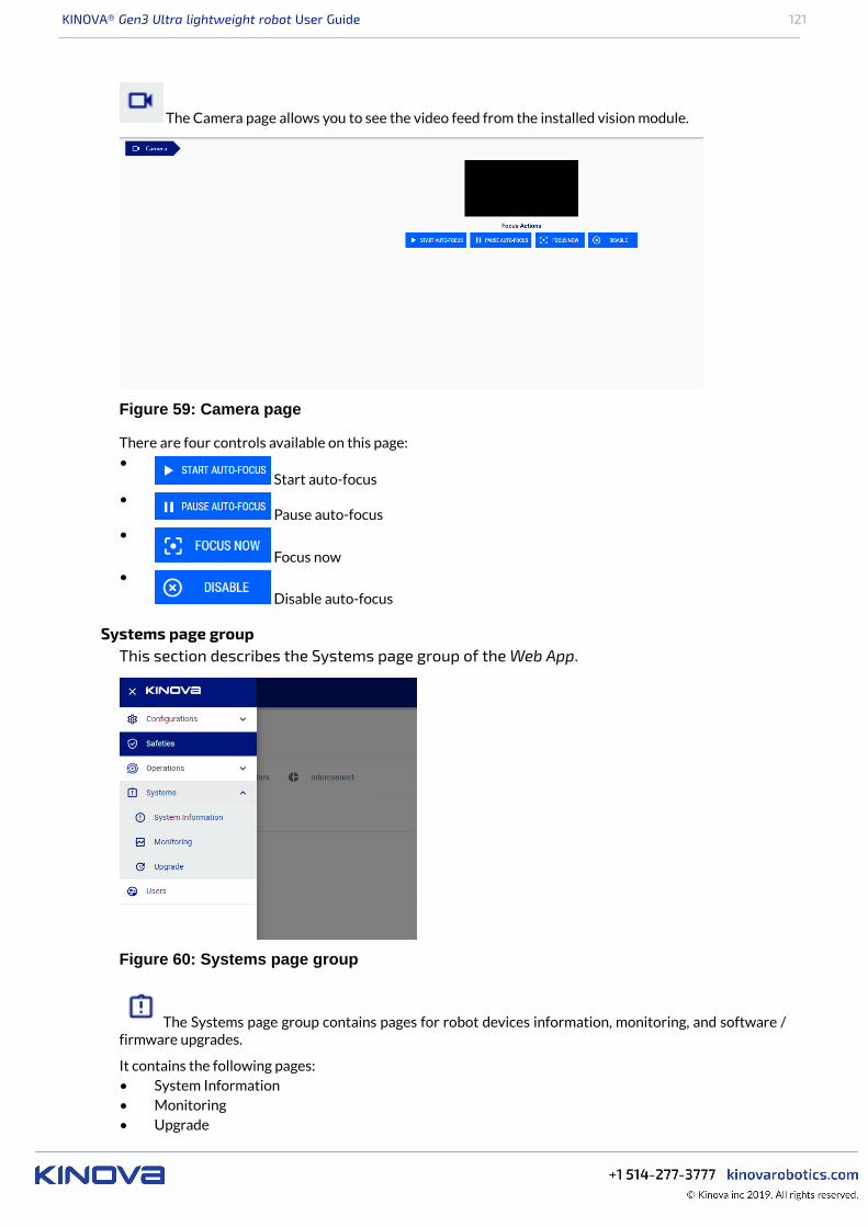
KINOVA® Gen3 Ultra lightweight robot User Guide 121
The Camera page allows you to see the video feed from the installed vision module.
Figure 59: Camera page
There are four controls available on this page:•
Start auto-focus•
Pause auto-focus•
Focus now•
Disable auto-focus
Systems page groupThis section describes the Systems page group of the Web App.
Figure 60: Systems page group
The Systems page group contains pages for robot devices information, monitoring, and software /firmware upgrades.
It contains the following pages:• System Information• Monitoring• Upgrade
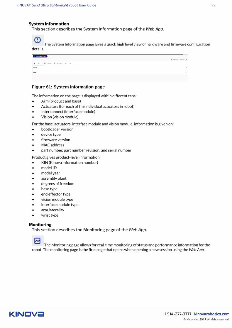
KINOVA® Gen3 Ultra lightweight robot User Guide 122
System InformationThis section describes the System Information page of the Web App.
The System Information page gives a quick high level view of hardware and firmware configurationdetails.
Figure 61: System Information page
The information on the page is displayed within different tabs:• Arm (product and base)• Actuators (for each of the individual actuators in robot)• Interconnect (interface module)• Vision (vision module)
For the base, actuators, interface module and vision module, information is given on:• bootloader version• device type• firmware version• MAC address• part number, part number revision, and serial number
Product gives product-level information:• KIN (Kinova information number)• model ID• model year• assembly plant• degrees of freedom• base type• end effector type• vision module type• interface module type• arm laterality• wrist type
MonitoringThis section describes the Monitoring page of the Web App.
The Monitoring page allows for real-time monitoring of status and performance information for therobot. The monitoring page is the first page that opens when opening a new session using the Web App.
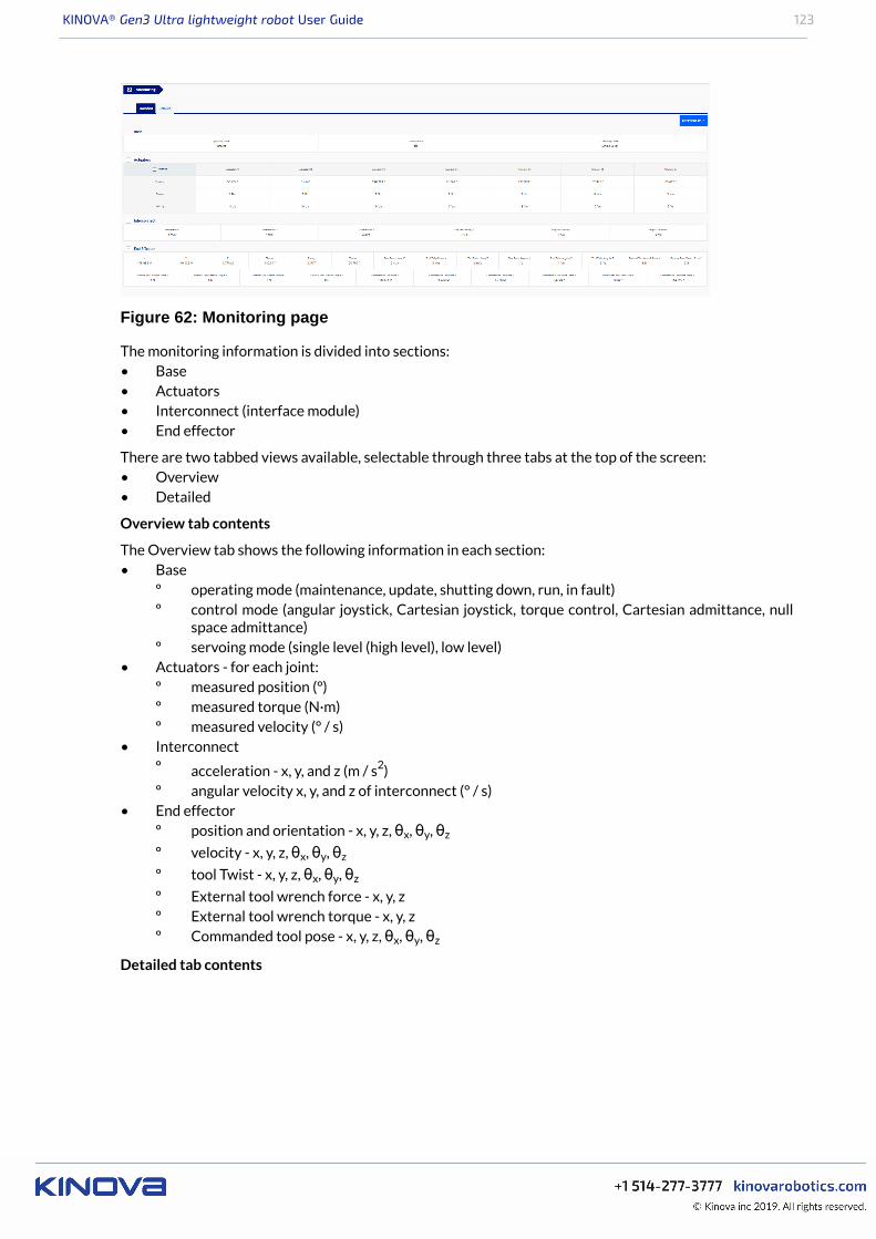
KINOVA® Gen3 Ultra lightweight robot User Guide 123
Figure 62: Monitoring page
The monitoring information is divided into sections:• Base• Actuators• Interconnect (interface module)• End effector
There are two tabbed views available, selectable through three tabs at the top of the screen:• Overview• Detailed
Overview tab contents
The Overview tab shows the following information in each section:• Base
º operating mode (maintenance, update, shutting down, run, in fault)º control mode (angular joystick, Cartesian joystick, torque control, Cartesian admittance, null
space admittance)º servoing mode (single level (high level), low level)
• Actuators - for each joint:º measured position (°)º measured torque (N·m)º measured velocity (° / s)
• Interconnectº acceleration - x, y, and z (m / s2)º angular velocity x, y, and z of interconnect (° / s)
• End effectorº position and orientation - x, y, z, θx, θy, θz
º velocity - x, y, z, θx, θy, θz
º tool Twist - x, y, z, θx, θy, θz
º External tool wrench force - x, y, zº External tool wrench torque - x, y, zº Commanded tool pose - x, y, z, θx, θy, θz
Detailed tab contents
KINOVA® Gen3 Ultra lightweight robot User Guide 124
The detailed tab shows the following information in each section:• Base
º operating mode (maintenance, update, shutting down, run, in fault)º control mode (angular joystick, Cartesian joystick, torque control, Cartesian admittance, null
space admittance)º servoing mode (single level (high level), low level, bypass)º arm voltage (V)º arm current (A)º CPU core temperature (°C)º ambient temperature (°C)º acceleration x, y, z of the base (m / s2)º angular velocity x, y, z of base (° / s)
• Actuators - for each joint:º measured position (°)º measured velocity (° / s)º measured torque (N·m)º motor current (A)º voltage (V)º motor temperature (°C)º core temperature (°C)
• Interconnectº acceleration x, y, z of interface (m / s2)º angular velocity x, y, z of interface (° / s)º voltage (V)º core temperature (°C)
• End effectorº position and orientation - x, y, z, θx, θy, θz
º tool Twist - x, y, z, θx, θy, θz
º External tool wrench force - x, y, zº External tool wrench torque - x, y, zº Commanded tool pose - x, y, z, θx, θy, θz
Exporting a snapshot of monitoring data
It is possible to export a snapshot of the currenting monitoring data for the robot.
By pressing the snapshot data button ( ), you have the ability to save a dump of the monitoringdata locally on your computer to JSON format. This can be useful information to share with Kinova supportfor troubleshooting purposes.
UpgradeThis section describes the Upgrade page of the Web App.
The Upgrade page provides a simple interface to perform upgrades to the robot.
Robot upgrade files are bundled as a package (.swu file).
The robot upgrade package includes:• robot devices firmware updates:
º base controllerº actuatorsº interface moduleº vision module
• Web App upgrade package• KINOVA® KORTEX™ API upgrade package
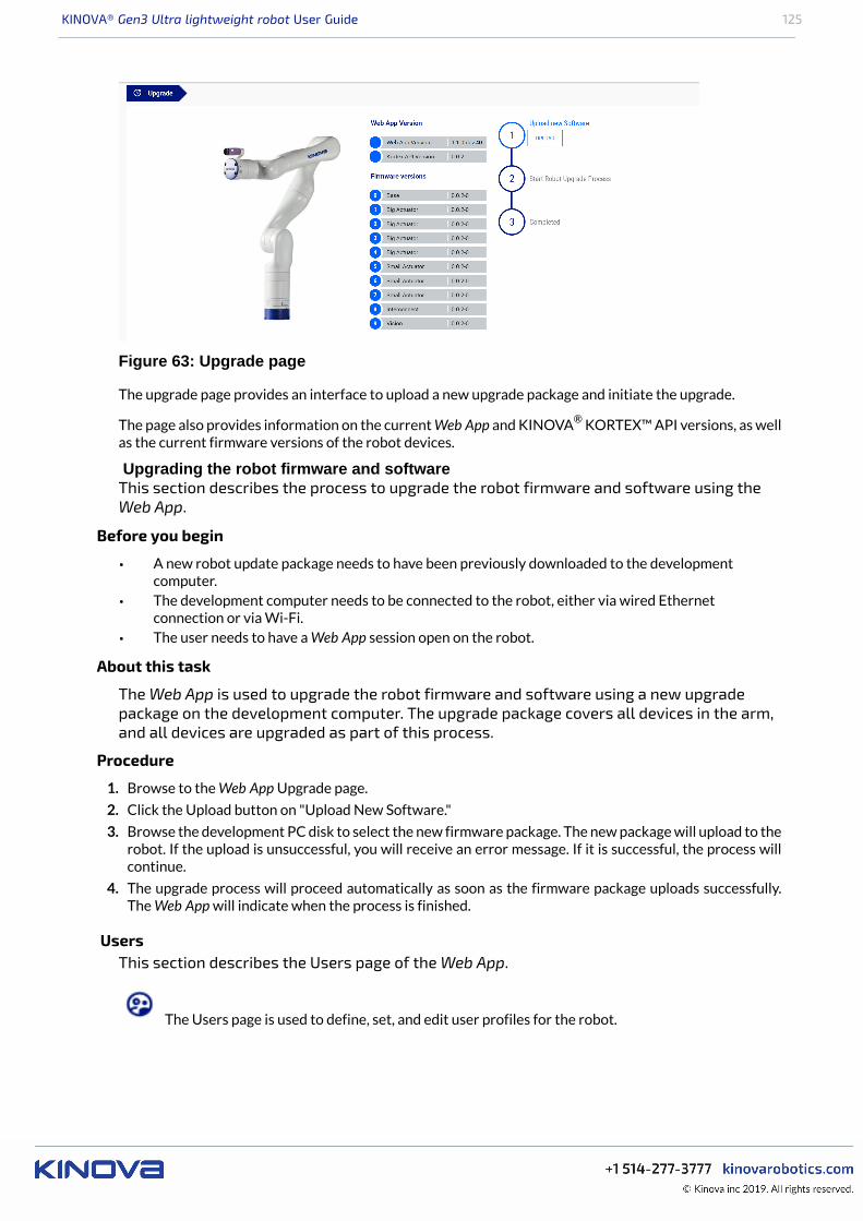
KINOVA® Gen3 Ultra lightweight robot User Guide 125
Figure 63: Upgrade page
The upgrade page provides an interface to upload a new upgrade package and initiate the upgrade.
The page also provides information on the current Web App and KINOVA® KORTEX™ API versions, as wellas the current firmware versions of the robot devices.
Upgrading the robot firmware and softwareThis section describes the process to upgrade the robot firmware and software using theWeb App.
Before you begin
• A new robot update package needs to have been previously downloaded to the developmentcomputer.
• The development computer needs to be connected to the robot, either via wired Ethernetconnection or via Wi-Fi.
• The user needs to have a Web App session open on the robot.
About this task
The Web App is used to upgrade the robot firmware and software using a new upgradepackage on the development computer. The upgrade package covers all devices in the arm,and all devices are upgraded as part of this process.
Procedure
1. Browse to the Web App Upgrade page.
2. Click the Upload button on "Upload New Software."
3. Browse the development PC disk to select the new firmware package. The new package will upload to therobot. If the upload is unsuccessful, you will receive an error message. If it is successful, the process willcontinue.
4. The upgrade process will proceed automatically as soon as the firmware package uploads successfully.The Web App will indicate when the process is finished.
UsersThis section describes the Users page of the Web App.
The Users page is used to define, set, and edit user profiles for the robot.
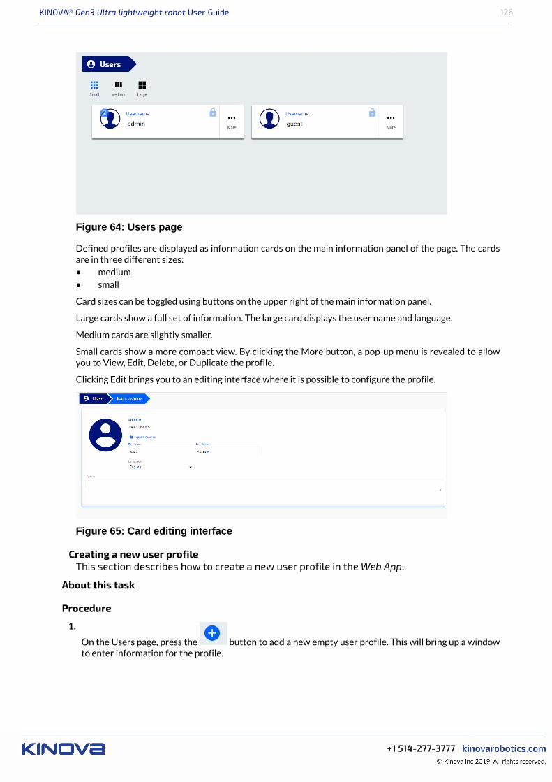
KINOVA® Gen3 Ultra lightweight robot User Guide 126
Figure 64: Users page
Defined profiles are displayed as information cards on the main information panel of the page. The cardsare in three different sizes:• medium• small
Card sizes can be toggled using buttons on the upper right of the main information panel.
Large cards show a full set of information. The large card displays the user name and language.
Medium cards are slightly smaller.
Small cards show a more compact view. By clicking the More button, a pop-up menu is revealed to allowyou to View, Edit, Delete, or Duplicate the profile.
Clicking Edit brings you to an editing interface where it is possible to configure the profile.
Figure 65: Card editing interface
Creating a new user profileThis section describes how to create a new user profile in the Web App.
About this task
Procedure
1.
On the Users page, press the button to add a new empty user profile. This will bring up a windowto enter information for the profile.
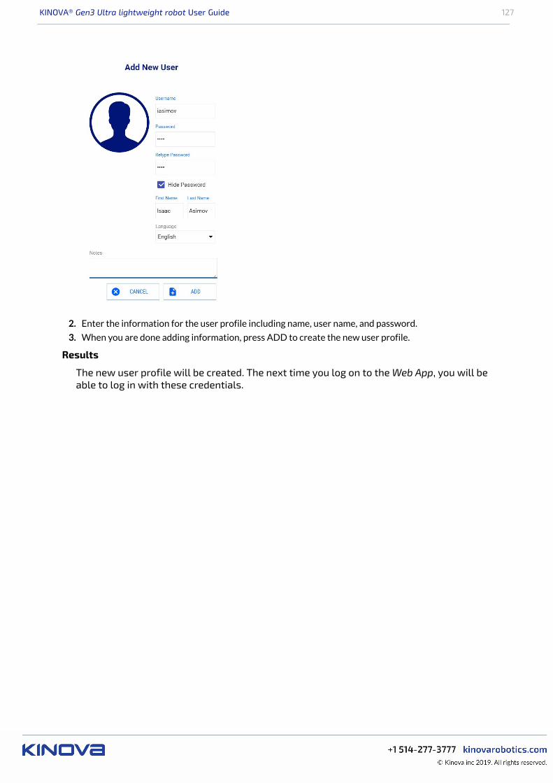
KINOVA® Gen3 Ultra lightweight robot User Guide 127
2. Enter the information for the user profile including name, user name, and password.
3. When you are done adding information, press ADD to create the new user profile.
Results
The new user profile will be created. The next time you log on to the Web App, you will beable to log in with these credentials.
KINOVA® Gen3 Ultra lightweight robot User Guide 128
KINOVA® KORTEX™ Developer Guide
Introduction
This section of the documentation provides guidance on developing custom software applications for therobot.
Your robot is enabled by KINOVA® KORTEX™, the Kinova software framework and applicationdevelopment platform. This growing and evolving framework will allow you to configure and control therobot programmatically, adapting to your specific needs and supporting you in integrating new Kinova
products into robotics applications. The KINOVA® KORTEX™ API supports multiple robot products fromKinova as a cross-hardware development framework.
Note: Some of the specific features of the API are hardware dependent and may not be available on yourrobot.
APIs are currently provided for the following languages:• C++• Python• MATLAB® (simplified API supporting a subset of Kortex functionality)
Kinova also offers ROS packages covering most of the same functionalities.
The pages that follow describe the general philosophy and approach of the APIs.
The following GitHub respositories contain additional developer guidance and resources, includingdetailed API documentation, setup instructions, and source code examples:• KINOVA® KORTEX™ API: kinovarobotics/kortex• KINOVA® KORTEX™ ROS: kinovarobotics/ros_kortex• KINOVA® KORTEX™ ROS Vision: kinovarobotics/ros_kortex_vision• KINOVA® KORTEX™ MATLAB® API: kinovarobotics/matlab_kortex
Devices and services
This section describes the concept of devices and services in the robot.
The API consists of services which define interfaces implemented and available on the various robotdevices.
The robot consists of several devices:• base controller• actuators (each actuator is a distinct device)• interface module• vision module
A service consists of methods and communication exchange data structures. The devices in the robot eachimplement a particular set of services, some of which are available across multiple devices. The methodsavailable as part of a service on a device are accessed via remote procedure calls (RPC).
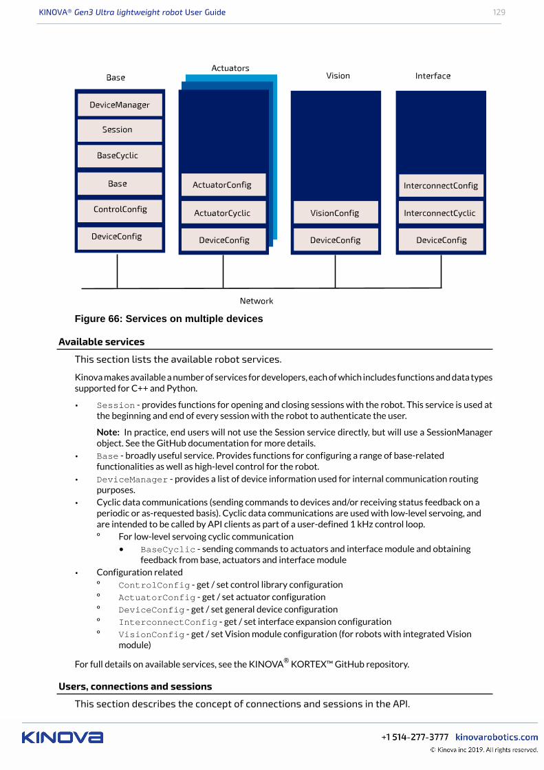
KINOVA® Gen3 Ultra lightweight robot User Guide 129
Figure 66: Services on multiple devices
Available services
This section lists the available robot services.
Kinova makes available a number of services for developers, each of which includes functions and data typessupported for C++ and Python.
• Session - provides functions for opening and closing sessions with the robot. This service is used atthe beginning and end of every session with the robot to authenticate the user.
Note: In practice, end users will not use the Session service directly, but will use a SessionManagerobject. See the GitHub documentation for more details.
• Base - broadly useful service. Provides functions for configuring a range of base-relatedfunctionalities as well as high-level control for the robot.
• DeviceManager - provides a list of device information used for internal communication routingpurposes.
• Cyclic data communications (sending commands to devices and/or receiving status feedback on aperiodic or as-requested basis). Cyclic data communications are used with low-level servoing, andare intended to be called by API clients as part of a user-defined 1 kHz control loop.º For low-level servoing cyclic communication
• BaseCyclic - sending commands to actuators and interface module and obtainingfeedback from base, actuators and interface module
• Configuration relatedº ControlConfig - get / set control library configurationº ActuatorConfig - get / set actuator configurationº DeviceConfig - get / set general device configurationº InterconnectConfig - get / set interface expansion configurationº VisionConfig - get / set Vision module configuration (for robots with integrated Vision
module)
For full details on available services, see the KINOVA® KORTEX™ GitHub repository.
Users, connections and sessions
This section describes the concept of connections and sessions in the API.
KINOVA® Gen3 Ultra lightweight robot User Guide 130
Introduction
A user has a connection with the robot when communication is established between the client applicationand the robot.
A session is active when the user has used the connection to log in to the robot with credentials. The defaultsession credentials for the robot are:• user: admin• password: adminA session is opened using a SessionManager object.
Sessions and robot control
Multiple users can connect to the same robot simultaneously, and have multiple sessions open on the robot.
A session must be created before commands can be received by the base (otherwise they will be discarded).Sessions are only supported for communications routed through the base.
Note: Currently, high-level servoing for the robot only allows one single simultaneous user. High-levelservoing with multiple simultaneous users is NOT currently supported. What this means is that multiplesessions can be active on the robot, and multiple users can concurrently pull data from the robot. However,only one session can actively control the robot at any given time. Rules are in place on the robot base tomanage which session has active control of the robot at any given time.
Services, methods, and messages
This section describes the concept of messages used by functions within services.
The API services offer a set of RPC and pub/sub methods. The methods exchange data which are structuredas Google Protocol Buffer message objects.
KINOVA® KORTEX™ API and Google Protocol Buffer
This section describes the use of Google Protocol Buffer for the KINOVA® KORTEX™ API.
On Google Protocol Buffer
The KINOVA® KORTEX™ API is based on the Google Protocol Buffer 3 mechanism for serializing structureddata. Using Protocol Buffer, the API is made available in C++ and Python languages.
Developers accustomed to Protocol Buffer can see .proto files on the KINOVA® KORTEX™ GitHubrepository. These files are published as a means to document the services and methods offered via the API.
The API data structures are based on Google Protocol Buffer messages. Extensivedocumentation has been made available by Google explaining the different mechanismsoffered to:• set a field in a message
• read a OneOf element in a message
• go through a nested object
• set a nested object
• get/set a collection
For more details on how the above works, check out the following documentation on theGoogle Protocol Buffer website:• C++ tutorial: https://developers.google.com/protocol-buffers/docs/reference/cpp-generated
• Python tutorial: https://developers.google.com/protocol-buffers/docs/reference/python-generated
Service client-server model
This section describes the client-server model for services.
Services operate on a client-server model. The server component of the service runs on the device itself.The client component runs on the client computer.
KINOVA® Gen3 Ultra lightweight robot User Guide 131
Services offer a set of device functionalities which are transparently exposed to the end-user via RPC andpub/sub methods.
The API is built on a transparent client/server communication protocol which allows an end-user (clientside) to call methods on robot devices.
Notifications
This section describes the concept of notifications in the API.
The robot base can provide notifications on different topics as requested by a client application that has asession open with the robot.
The robot base uses a Publish/Subscribe design pattern. That is, rather than needing to poll periodicallyfor updates, the client application subscribes to a list of Topics. Whenever a change happens related tothat topic, whether caused by the same client session, or another, a publisher sends a notification to allsubscribers. Notifications are surfaced to clients via the API, and are also displayed in the Notifications pageof the Web app.
Client applications can also unsubcribe from a topic.
Methods for subscribing and unsubscribing from notification topics are descrcibed in the
Kinova.Api.Base API documentation on the KINOVA® KORTEX™ GitHub respository.
Blocking and non-blocking calls
This section describes the concept of blocking vs. non-blocking calls in the context of RPCson the robot.
The API defines interfaces of methods to be executed on devices in the robot.
The methods can be one of two types, depending on what the client application does while waiting for theresponse:• blocking• non-blocking
With a blocking call, the flow of the client application will pause and wait for the remote procedure call toreturn a response before proceeding. With non-blocking call, the procedure call is sent, and the flow of theapplication carries on while waiting for the response. When the response arrives, the caller will handle theresponse.
For the Python API, only blocking calls are enabled.
In the context of C++, remote procedure calls in the API can in general be set as either blocking or non-blocking.
There are two types of non-blocking calls available in the C++ API:• Future / Promise• Registered callback
For more information on how this works, see the API documentation on the KINOVA® KORTEX™ GitHubrespository.
Robot servoing modes
This section describes the concept of servoing modes on the robot.
There are multiple servoing modes on the robot. A servoing mode is a modality through which commandsare transmitted to robot devices during operation. Depending on the servoing mode chosen, the detailsinvolved in controlling via the API will be different.
There are two servoing modes:• High-level
• Low-level
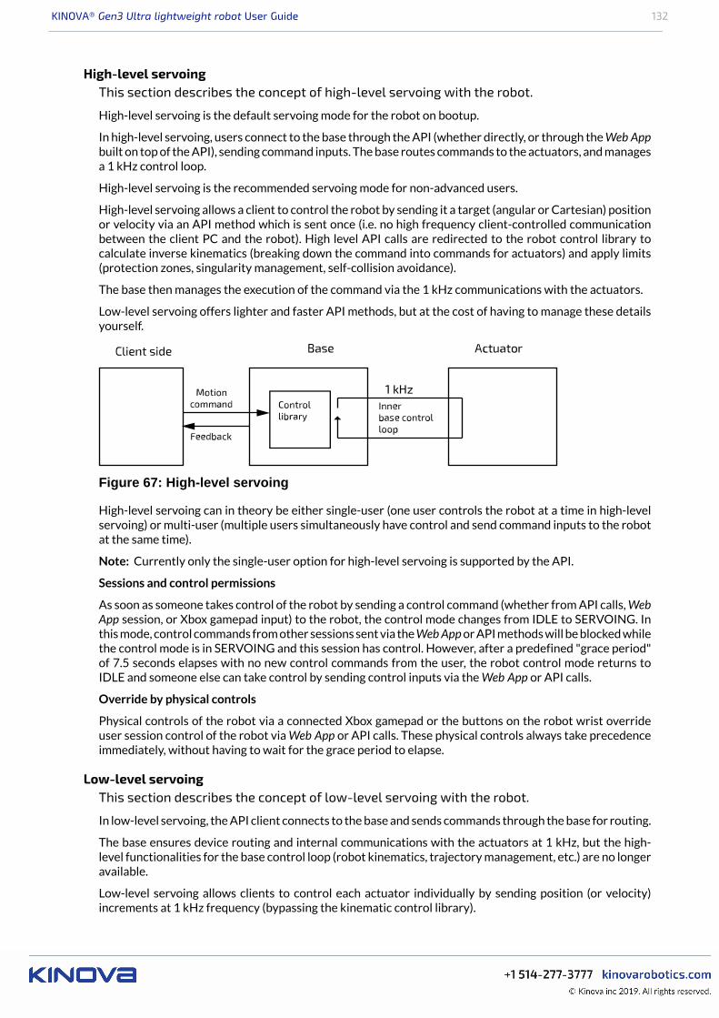
KINOVA® Gen3 Ultra lightweight robot User Guide 132
High-level servoingThis section describes the concept of high-level servoing with the robot.
High-level servoing is the default servoing mode for the robot on bootup.
In high-level servoing, users connect to the base through the API (whether directly, or through the Web Appbuilt on top of the API), sending command inputs. The base routes commands to the actuators, and managesa 1 kHz control loop.
High-level servoing is the recommended servoing mode for non-advanced users.
High-level servoing allows a client to control the robot by sending it a target (angular or Cartesian) positionor velocity via an API method which is sent once (i.e. no high frequency client-controlled communicationbetween the client PC and the robot). High level API calls are redirected to the robot control library tocalculate inverse kinematics (breaking down the command into commands for actuators) and apply limits(protection zones, singularity management, self-collision avoidance).
The base then manages the execution of the command via the 1 kHz communications with the actuators.
Low-level servoing offers lighter and faster API methods, but at the cost of having to manage these detailsyourself.
Figure 67: High-level servoing
High-level servoing can in theory be either single-user (one user controls the robot at a time in high-levelservoing) or multi-user (multiple users simultaneously have control and send command inputs to the robotat the same time).
Note: Currently only the single-user option for high-level servoing is supported by the API.
Sessions and control permissions
As soon as someone takes control of the robot by sending a control command (whether from API calls, WebApp session, or Xbox gamepad input) to the robot, the control mode changes from IDLE to SERVOING. Inthis mode, control commands from other sessions sent via the Web App or API methods will be blocked whilethe control mode is in SERVOING and this session has control. However, after a predefined "grace period"of 7.5 seconds elapses with no new control commands from the user, the robot control mode returns toIDLE and someone else can take control by sending control inputs via the Web App or API calls.
Override by physical controls
Physical controls of the robot via a connected Xbox gamepad or the buttons on the robot wrist overrideuser session control of the robot via Web App or API calls. These physical controls always take precedenceimmediately, without having to wait for the grace period to elapse.
Low-level servoingThis section describes the concept of low-level servoing with the robot.
In low-level servoing, the API client connects to the base and sends commands through the base for routing.
The base ensures device routing and internal communications with the actuators at 1 kHz, but the high-level functionalities for the base control loop (robot kinematics, trajectory management, etc.) are no longeravailable.
Low-level servoing allows clients to control each actuator individually by sending position (or velocity)increments at 1 kHz frequency (bypassing the kinematic control library).

KINOVA® Gen3 Ultra lightweight robot User Guide 133
Figure 68: Low-level servoing
Device routing
This section describes device routing.
Figure 69: Device routing
The API allows you to communicate with the robot devices. Using a device identifier the RPC and pub/submethods of the API are simply routed by the robot base and directly bridged to the intended device.
Error management
This section describes the concept of error management with the robot.
When an API method is called, sometimes an error will result.
There are three main categories of errors:• Protocol server errors• Protocol client errors• Device errors
The first two categories of errors include all errors relating to the the internal communication protocol. (ex:invalid, unsupported or unknown calls, out of session call, etc.)
The other category is for errors coming from the target device.
For each high level category, there are also more detailed and specific errors.
For more information about the error codes that can be produced, see the KINOVA® KORTEX™ GitHubdocumentation.
KINOVA® KORTEX™ GitHub repository
This section describes the KINOVA® KORTEX™ GitHub repository.
For more detailed information about developing applications using the API visit the KINOVA® KORTEX™GitHub repository at: github.com/kinovarobotics/kortex
The repository offers access to a number of resources for developers.

KINOVA® Gen3 Ultra lightweight robot User Guide 134
• setup instructions and release notes• detailed API documentation by language• code examples
KINOVA® KORTEX™ ROS packages and GitHub repository overview
This section describes the ROS packages for the robot (and all other products enabled byKINOVA® KORTEX™).
Introduction
KINOVA® KORTEX™ ROS is the official repository containing ROS packages to interact with Kortex andrelated products. It consists of a number of ROS packages built on top of the client Kortex API.
These ROS packages are designed to work with ROS Kinectic Kame. Note that ROS Kinetic Kame isprimarily targeted for Ubuntu 16.04 (Xenial) LTS (although other platforms are also supported to differentdegrees).
Methods provided by the underlying API are offered as ROS services and topics, dependingon the method.• RPC methods are exposed via ROS services
• pub/sub methods are exposed via ROS topics
The ROS Messages correspond to the message type definitions of the underlying API.
The ROS interface can be accessed using either Python (rospy) or C++ (roscpp).
Support is included for Gazebo and MoveIt!.
Detailed documentation of the packages is available on the Kinova ros_kortex GitHub repository atgithub.com/kinovarobotics/ros_kortex
The repository includes various packages related to ROS development:
• setup instruction and release notes• kortex_api (package containing header files and libraries needed to use the C++ Kortex API)• kortex_control (package contains configuration files for the ros_control controllers used to
control the simulated robot• kortex_description (package contains URDF and STL files of the robot)• kortex_driver (ROS node package to allow direct communication with the robot base)• kortex_examples (examples needed to understand the basics of ros_kortex)• kortex_gazebo (package contains files to simulate the robot)• kortex_moveit_config (contains all the auto-generated MoveIt! configuration ROS packages)
KINOVA® KORTEX™ MATLAB® API and GitHub repository overview
This section describes the KINOVA® KORTEX™ MATLAB API and GitHub repository.
The KINOVA® KORTEX™ MATLAB® API provides a wrapper giving access, via MATLAB® and Simulink®
to a subset of the Kortex API functionality.
The package also includes integration of the vision module with the MATLAB® Image Acquisition Toolbox™.
This package has been tested on Ubuntu 16.04 (64-bit) and Windows 10.
More detailed information is available on the matlab_kortex GitHub repository at github.com/kinovarobotics/matlab_kortex.
Working with camera streams using GStreamer
This section describes how to work with vision module camera streams using theGStreamer framework.
GStreamer
KINOVA® Gen3 Ultra lightweight robot User Guide 135
Kinova recommends that developers use the GStreamer framework for handling the camera's sensorstreams. GStreamer offers a pipeline-based framework that allows you to link together plugins for image-processing workflows.
Requirements:• GStreamer version: 1.8.3 and above• Supported operating systems:
º Windows 7 and laterº Ubuntu 16.04 and later
Using GStreamer
GStreamer pipelines can be called from the command line using the gst-launch-1.0 utility.
For integration with applications, GStreamer offers a number of language bindings, which include both C++ and Python.
Official documentation for the GStreamer framework, including installation instructions, applicationdevelopment guidance, and tutorials can be accessed here: https://gstreamer.freedesktop.org/documentation/
Windows command examplesThis section provides examples of using GStreamer with the robot vision module camerastreams on the Windows command line.
Color stream CLI example: command to display the color stream
gst-launch-1.0.exe rtspsrc location=rtsp://192.168.1.10/color latency=30 !rtph264depay ! avdec_h264 ! autovideosink
Unpacking the example:• gst-launch-1.0.exe: launch GStreamer• rtspsrc location=rtsp://192.168.1.10/color latency=30: connect to the RTSP
server at the color stream URL with latency of 30 ms.• rtph264depay: Extract H.264 video payload from RTP packets• avdec_h264: decode H.264 video• autovideosink: search computer registry for video sink (player) and plays decoded video stream.
Depth stream CLI example: command to display the depth stream
gst-launch-1.0.exe rtspsrc location=rtsp://192.168.1.10/depth latency=30 !rtpgstdepay ! videoconvert ! autovideosink
Unpacking the example:• gst-launch-1.0.exe: launch GStreamer• rtspsrc location=rtsp://192.168.1.10/depth latency=30: connect to the RTSP
server at the color stream URL with latency of 30 ms.• rtpgstdepay: extract GStreamer buffers from RTP packets• videoconvert: automatically convert the video to a format understandable to the chosen video sink
in the next step• autovideosink: search computer registry for video sink (player) and plays decoded video stream.
Linux command examplesThis section provides examples of using GStreamer with the robot vision module camerastreams on the Linux command line.
Color stream CLI example: command to display the color stream
gst-launch-1.0 rtspsrc location=rtsp://192.168.1.10/color latency=30 !rtph264depay ! avdec_h264 ! autovideosink

KINOVA® Gen3 Ultra lightweight robot User Guide 136
Unpacking the example:• gst-launch-1.0: launch GStreamer• rtspsrc location=rtsp://192.168.1.10/color latency=30: connect to the RTSP
server at the color stream URL with latency of 30 ms.• rtph264depay: extract H.264 video payload from RTP packets• avdec_h264: decode H.264 video• autovideosink: search computer registry for video sink (player) and play decoded video stream.
Depth stream CLI example: command to display the depth stream
gst-launch-1.0 rtspsrc location=rtsp://192.168.1.10/depth latency=30 !rtpgstdepay ! videoconvert ! autovideosink
Unpacking the example:• gst-launch-1.0: launch GStreamer• rtspsrc location=rtsp://192.168.1.10/depth latency=30: connect to the RTSP
server at the color stream URL with latency of 30 ms.• rtpgstdepay: extract GStreamer buffers from RTP packets• videoconvert: automatically convert the video to a format understandable to the chosen video sink
in the next step• autovideosink: search computer registry for video sink (player) and play decoded video stream.
KINOVA® KORTEX™ ROS vision module package and Github overview
This section describes the ROS vision module package for the robot.
The KINOVA® KORTEX™ ROS vision module package provides helper methods and launch scripts to accessthe Gen3 Ultra lightweight robot vision module depth and color sensor streams within ROS.
For more details, including documentation, see the Kinova ros_kortex_vision GitHub repository atgithub.com/kinovarobotics.com/ros_kortex_vision.
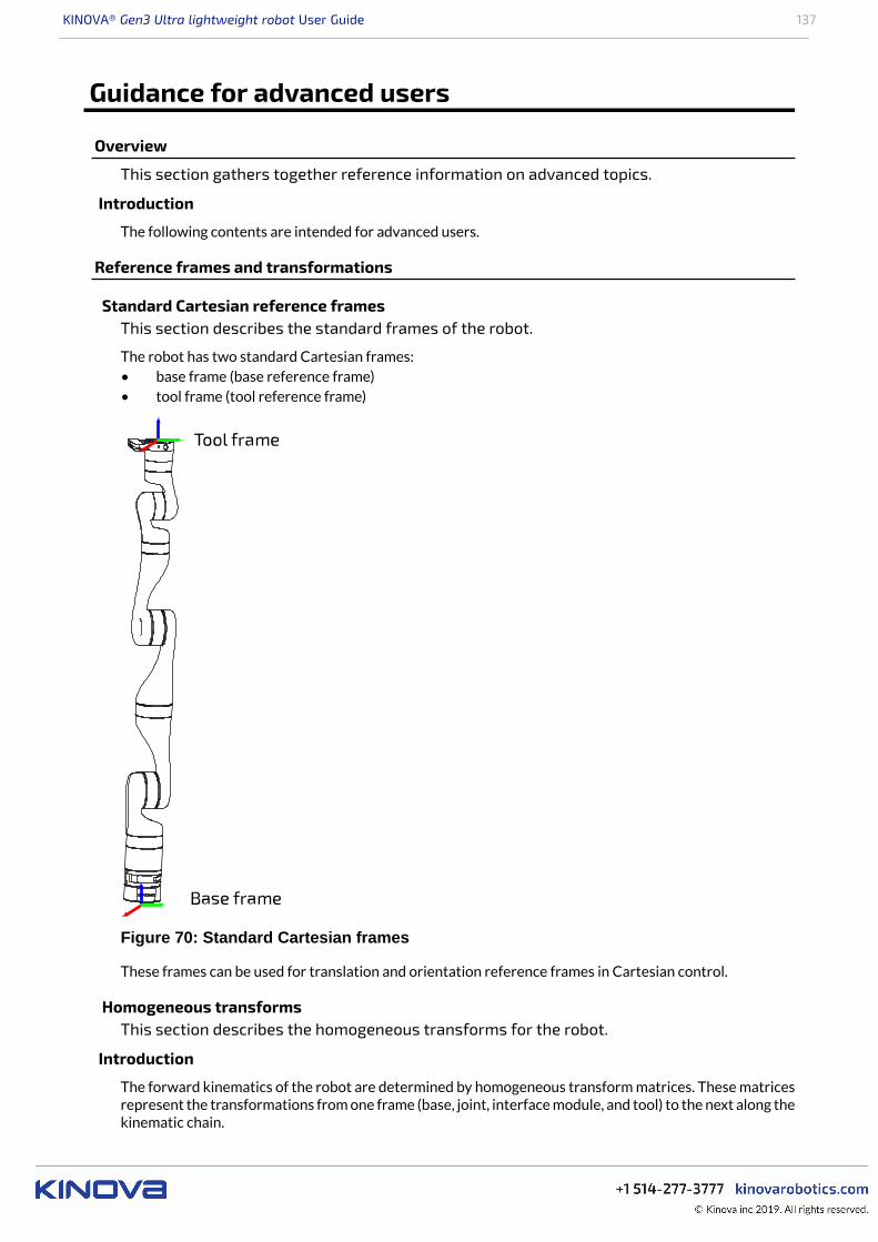
KINOVA® Gen3 Ultra lightweight robot User Guide 137
Guidance for advanced users
Overview
This section gathers together reference information on advanced topics.
Introduction
The following contents are intended for advanced users.
Reference frames and transformations
Standard Cartesian reference framesThis section describes the standard frames of the robot.
The robot has two standard Cartesian frames:• base frame (base reference frame)• tool frame (tool reference frame)
Figure 70: Standard Cartesian frames
These frames can be used for translation and orientation reference frames in Cartesian control.
Homogeneous transformsThis section describes the homogeneous transforms for the robot.
Introduction
The forward kinematics of the robot are determined by homogeneous transform matrices. These matricesrepresent the transformations from one frame (base, joint, interface module, and tool) to the next along thekinematic chain.

KINOVA® Gen3 Ultra lightweight robot User Guide 138
The overall transformation from the base frame to the end effector frame is given by:
Where:
qi = joint angle for joint icqi = cos(qi)sqi = sin(qi)
i-1Ti = Transformfrom frame i-1to frame i for qi=0
i-1Ti is the transform from the previous frame [i-1] to the current frame [i] where qi, the angle for joint i, is 0.
Rz(qi) is the transformation matrix for a rotation of qi around joint i (the z axis for the joint frame is alwaysdefined to be along the joint axis of rotation.)
i-1T*i is the matrix for the general transformation matrix from frame [i-1] to frame [i].
Homogeneous transform matrices - 7 DoF spherical wristThis section is a reference for the homogeneous transform matrices for the 7 DoF sphericalwrist robot.
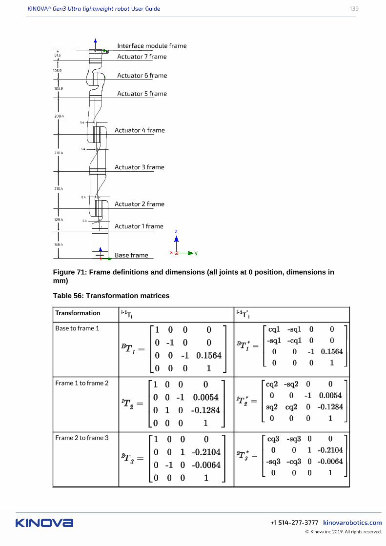
KINOVA® Gen3 Ultra lightweight robot User Guide 139
Figure 71: Frame definitions and dimensions (all joints at 0 position, dimensions inmm)
Table 56: Transformation matrices
Transformation i-1Tii-1T*
i
Base to frame 1
Frame 1 to frame 2
Frame 2 to frame 3
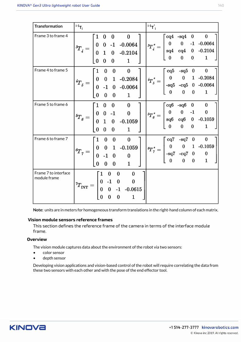
KINOVA® Gen3 Ultra lightweight robot User Guide 140
Transformation i-1Tii-1T*
i
Frame 3 to frame 4
Frame 4 to frame 5
Frame 5 to frame 6
Frame 6 to frame 7
Frame 7 to interfacemodule frame
Note: units are in meters for homogeneous transform translations in the right-hand column of each matrix.
Vision module sensors reference framesThis section defines the reference frame of the camera in terms of the interface moduleframe.
Overview
The vision module captures data about the environment of the robot via two sensors:• color sensor• depth sensor
Developing vision applications and vision-based control of the robot will require correlating the data fromthese two sensors with each other and with the pose of the end effector tool.
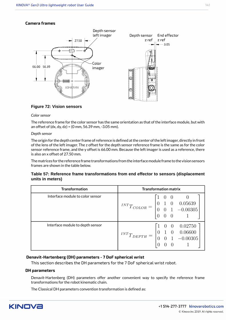
KINOVA® Gen3 Ultra lightweight robot User Guide 141
Camera frames
Figure 72: Vision sensors
Color sensor
The reference frame for the color sensor has the same orientation as that of the interface module, but withan offset of (dx, dy, dz) = (0 mm, 56.39 mm, -3.05 mm).
Depth sensor
The origin for the depth center frame of reference is defined at the center of the left imager, directly in frontof the lens of the left imager. The z offset for the depth sensor reference frame is the same as for the colorsensor reference frame, and the y offset is 66.00 mm. Because the left imager is used as a reference, thereis also an x offset of 27.50 mm.
The matrices for the reference frame transformations from the interface module frame to the vision sensorsframes are shown in the table below.
Table 57: Reference frame transformations from end effector to sensors (displacementunits in meters)
Transformation Transformation matrix
Interface module to color sensor
Interface module to depth sensor
Denavit-Hartenberg (DH) parameters - 7 DoF spherical wristThis section describes the DH parameters for the 7 DoF spherical wrist robot.
DH parameters
Denavit-Hartenberg (DH) parameters offer another convenient way to specify the reference frametransformations for the robot kinematic chain.
The Classical DH parameters convention transformation is defined as:
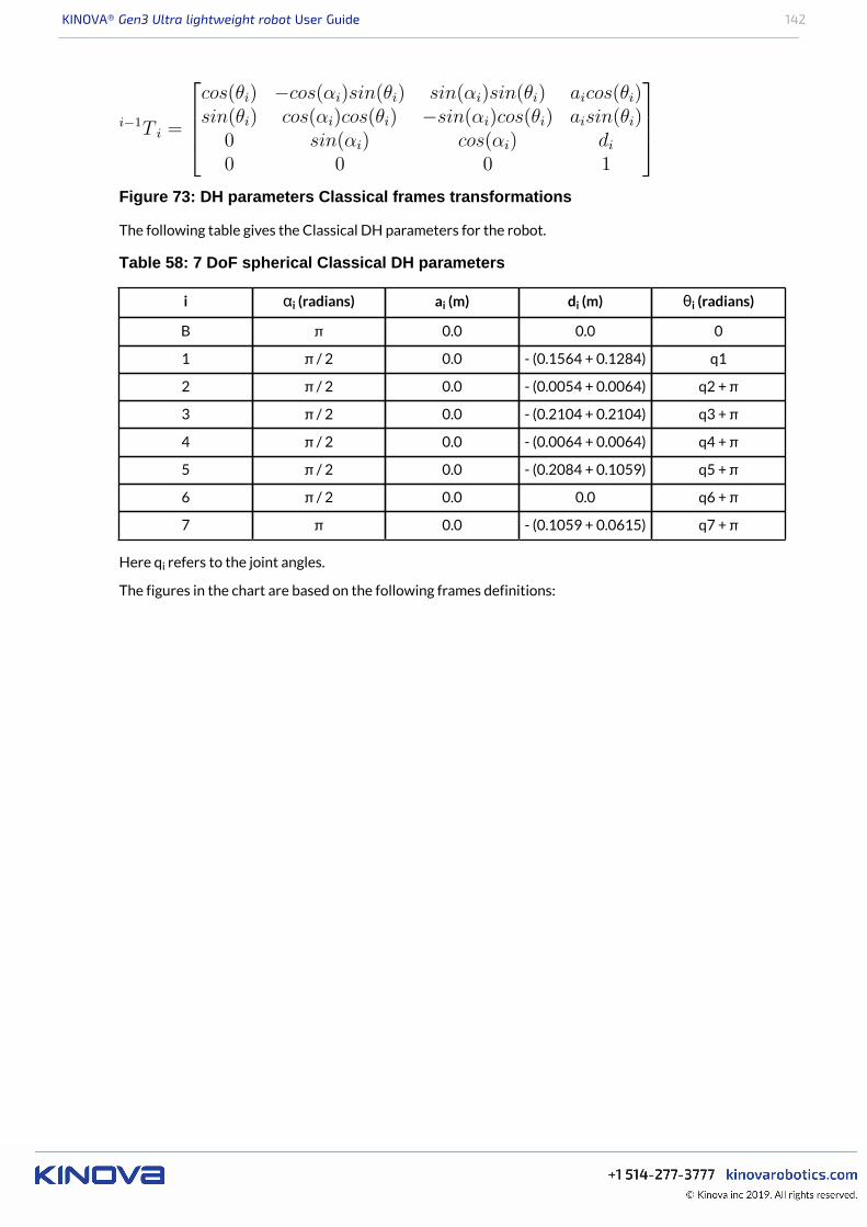
KINOVA® Gen3 Ultra lightweight robot User Guide 142
Figure 73: DH parameters Classical frames transformations
The following table gives the Classical DH parameters for the robot.
Table 58: 7 DoF spherical Classical DH parameters
i αi (radians) ai (m) di (m) θi (radians)
B π 0.0 0.0 0
1 π / 2 0.0 - (0.1564 + 0.1284) q1
2 π / 2 0.0 - (0.0054 + 0.0064) q2 + π
3 π / 2 0.0 - (0.2104 + 0.2104) q3 + π
4 π / 2 0.0 - (0.0064 + 0.0064) q4 + π
5 π / 2 0.0 - (0.2084 + 0.1059) q5 + π
6 π / 2 0.0 0.0 q6 + π
7 π 0.0 - (0.1059 + 0.0615) q7 + π
Here qi refers to the joint angles.
The figures in the chart are based on the following frames definitions:
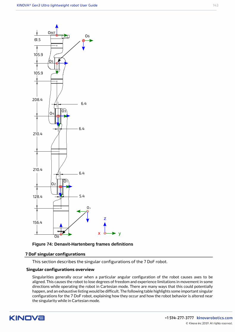
KINOVA® Gen3 Ultra lightweight robot User Guide 143
x y
z
O 0
OB
O1O2
O3O4
O5
O661.5
105.9
105.9
6.4208.4
210.4
210.4
128.4
156.4
6.4
6.4
5.4
OINT
Figure 74: Denavit-Hartenberg frames definitions
7 DoF singular configurations
This section describes the singular configurations of the 7 DoF robot.
Singular configurations overview
Singularities generally occur when a particular angular configuration of the robot causes axes to bealigned. This causes the robot to lose degrees of freedom and experience limitations in movement in somedirections while operating the robot in Cartesian mode. There are many ways that this could potentiallyhappen, and an exhaustive listing would be difficult. The following table highlights some important singularconfigurations for the 7 DoF robot, explaining how they occur and how the robot behavior is altered nearthe singularity while in Cartesian mode.
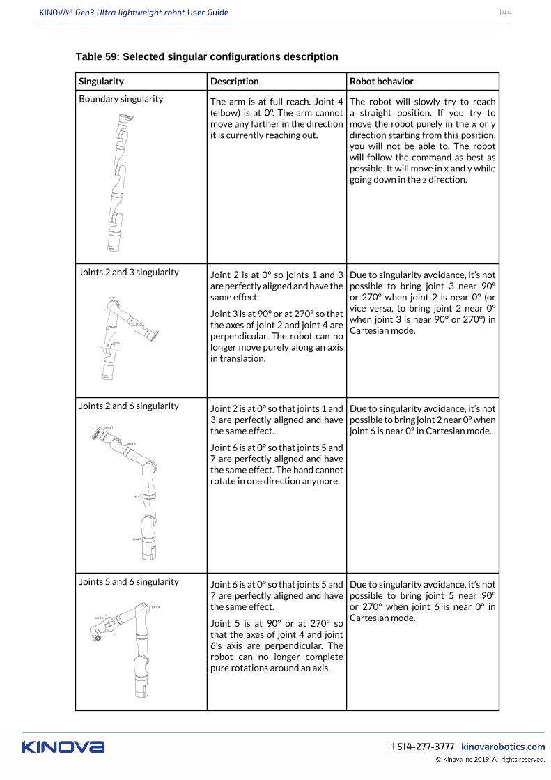
KINOVA® Gen3 Ultra lightweight robot User Guide 144
Table 59: Selected singular configurations description
Singularity Description Robot behavior
Boundary singularity The arm is at full reach. Joint 4(elbow) is at 0°. The arm cannotmove any farther in the directionit is currently reaching out.
The robot will slowly try to reacha straight position. If you try tomove the robot purely in the x or ydirection starting from this position,you will not be able to. The robotwill follow the command as best aspossible. It will move in x and y whilegoing down in the z direction.
Joints 2 and 3 singularity Joint 2 is at 0° so joints 1 and 3are perfectly aligned and have thesame effect.
Joint 3 is at 90° or at 270° so thatthe axes of joint 2 and joint 4 areperpendicular. The robot can nolonger move purely along an axisin translation.
Due to singularity avoidance, it’s notpossible to bring joint 3 near 90°or 270° when joint 2 is near 0° (orvice versa, to bring joint 2 near 0°when joint 3 is near 90° or 270°) inCartesian mode.
Joints 2 and 6 singularity Joint 2 is at 0° so that joints 1 and3 are perfectly aligned and havethe same effect.
Joint 6 is at 0° so that joints 5 and7 are perfectly aligned and havethe same effect. The hand cannotrotate in one direction anymore.
Due to singularity avoidance, it’s notpossible to bring joint 2 near 0° whenjoint 6 is near 0° in Cartesian mode.
Joints 5 and 6 singularity Joint 6 is at 0° so that joints 5 and7 are perfectly aligned and havethe same effect.
Joint 5 is at 90° or at 270° sothat the axes of joint 4 and joint6’s axis are perpendicular. Therobot can no longer completepure rotations around an axis.
Due to singularity avoidance, it’s notpossible to bring joint 5 near 90°or 270° when joint 6 is near 0° inCartesian mode.

KINOVA® Gen3 Ultra lightweight robot User Guide 145
Inertial parameters definition
This section describes conventions used for inertial parameters of the robot.
Overview
The following tables describe the key inertial parameters of each independently moving rigid link segmentof the 7 robot. This includes:• mass in kg• centers of masses in meters• moments of inertia in kg*m2
The six distinct moments of inertia (Ixx, Ixy, Ixz, Iyy, Iyz, Izz) are presented in tabular form.
Conventions used
The following conventions are used:
1. The center of mass of a link is always expressed in terms of the reference frame of the precedent joint.2. The mass of a link segment includes the shell and portions of the actuators at each end of the link (as
applicable) that are enclosed within the link and move rigidly with the link.3. The moments of inertia of the link segments are taken in a frame defined at the center of mass of the link
segment and aligned with the precedent joint frame.
Note: These conventions align with those used in URDF files in the <inertial> section of <link>definitions.
Figure 75: Inertial parameters conventions
Inertial parameters of the 7 DoF robot
This section describes the inertial parameters of the 7 DoF robot.
Overview
The following tables describe the key inertial parameters of the link segments of the 7 DoF robot.
Table 60: Base
Physical quantity Value
mass (kg) 1.697
center of masscoordinates (m)
[-0.000648, -0.000166, 0.084487]
Ixx 0.004622
Ixy 0.000009moments of
inertia (kg · m2)Ixz 0.000060

KINOVA® Gen3 Ultra lightweight robot User Guide 146
Physical quantity Value
Iyy 0.004495
Iyz 0.000009
Izz 0.002079
Table 61: Link 1
Physicalquantity
Value
mass (kg) 1.377
center of masscoordinates (m)
[-0.000023, -0.010364, -0.07336]
Ixx 0.004570
Ixy 0.000001
Ixz 0.000002
Iyy 0.004831
Iyz 0.000448
moments of
inertia (kg · m2)
Izz 0.001409
Table 62: Link 2
Physical quantity Value
mass (kg) 1.1636
center of masscoordinates (m)
[-0.000044, -0.09958, -0.013278]
Ixx 0.011088
Ixy 0.000005
Ixz 0.000000
Iyy 0.001072
Iyz -0.000691
moments of
inertia (kg · m2)
Izz 0.011255
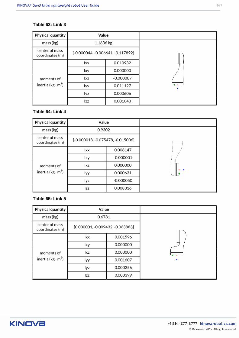
KINOVA® Gen3 Ultra lightweight robot User Guide 147
Table 63: Link 3
Physical quantity Value
mass (kg) 1.1636 kg
center of masscoordinates (m)
[-0.000044, -0.006641, -0.117892]
Ixx 0.010932
Ixy 0.000000
Ixz -0.000007
Iyy 0.011127
Iyz 0.000606
moments of
inertia (kg · m2)
Izz 0.001043
Table 64: Link 4
Physical quantity Value
mass (kg) 0.9302
center of masscoordinates (m)
[-0.000018, -0.075478, -0.015006]
Ixx 0.008147
Ixy -0.000001
Ixz 0.000000
Iyy 0.000631
Iyz -0.000050
moments of
inertia (kg · m2)
Izz 0.008316
Table 65: Link 5
Physical quantity Value
mass (kg) 0.6781
center of masscoordinates (m)
[0.000001, -0.009432, -0.063883]
Ixx 0.001596
Ixy 0.000000
Ixz 0.000000
Iyy 0.001607
Iyz 0.000256
moments of
inertia (kg · m2)
Izz 0.000399
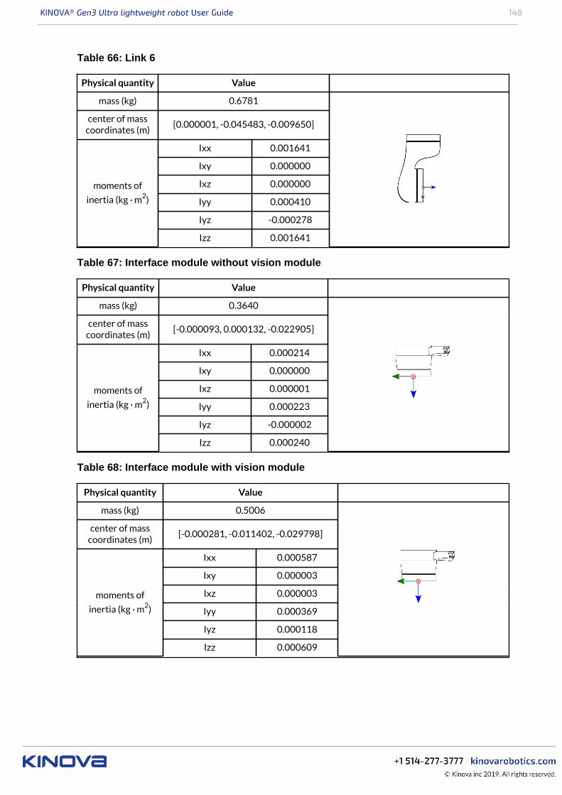
KINOVA® Gen3 Ultra lightweight robot User Guide 148
Table 66: Link 6
Physical quantity Value
mass (kg) 0.6781
center of masscoordinates (m)
[0.000001, -0.045483, -0.009650]
Ixx 0.001641
Ixy 0.000000
Ixz 0.000000
Iyy 0.000410
Iyz -0.000278
moments of
inertia (kg · m2)
Izz 0.001641
Table 67: Interface module without vision module
Physical quantity Value
mass (kg) 0.3640
center of masscoordinates (m)
[-0.000093, 0.000132, -0.022905]
Ixx 0.000214
Ixy 0.000000
Ixz 0.000001
Iyy 0.000223
Iyz -0.000002
moments of
inertia (kg · m2)
Izz 0.000240
Table 68: Interface module with vision module
Physical quantity Value
mass (kg) 0.5006
center of masscoordinates (m)
[-0.000281, -0.011402, -0.029798]
Ixx 0.000587
Ixy 0.000003
Ixz 0.000003
Iyy 0.000369
Iyz 0.000118
moments of
inertia (kg · m2)
Izz 0.000609
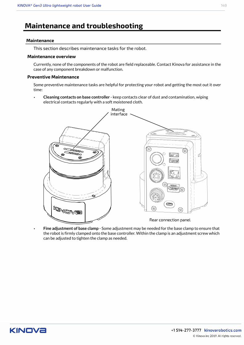
KINOVA® Gen3 Ultra lightweight robot User Guide 149
Maintenance and troubleshooting
Maintenance
This section describes maintenance tasks for the robot.
Maintenance overview
Currently, none of the components of the robot are field replaceable. Contact Kinova for assistance in thecase of any component breakdown or malfunction.
Preventive Maintenance
Some preventive maintenance tasks are helpful for protecting your robot and getting the most out it overtime:
• Cleaning contacts on base controller - keep contacts clear of dust and contamination, wipingelectrical contacts regularly with a soft moistened cloth.
• Fine adjustment of base clamp - Some adjustment may be needed for the base clamp to ensure thatthe robot is firmly clamped onto the base controller. Within the clamp is an adjustment screw whichcan be adjusted to tighten the clamp as needed.
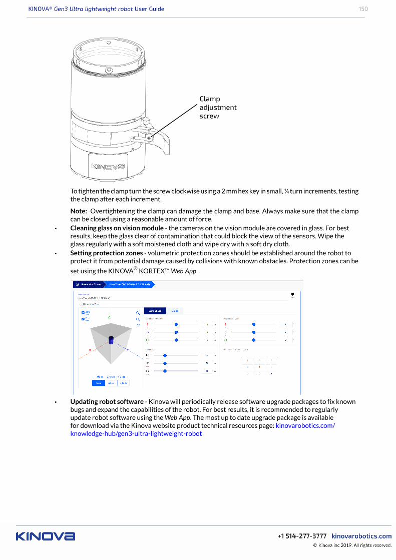
KINOVA® Gen3 Ultra lightweight robot User Guide 150
To tighten the clamp turn the screw clockwise using a 2 mm hex key in small, ¼ turn increments, testingthe clamp after each increment.
Note: Overtightening the clamp can damage the clamp and base. Always make sure that the clampcan be closed using a reasonable amount of force.
• Cleaning glass on vision module - the cameras on the vision module are covered in glass. For bestresults, keep the glass clear of contamination that could block the view of the sensors. Wipe theglass regularly with a soft moistened cloth and wipe dry with a soft dry cloth.
• Setting protection zones - volumetric protection zones should be established around the robot toprotect it from potential damage caused by collisions with known obstacles. Protection zones can be
set using the KINOVA® KORTEX™ Web App.
• Updating robot software - Kinova will periodically release software upgrade packages to fix knownbugs and expand the capabilities of the robot. For best results, it is recommended to regularlyupdate robot software using the Web App. The most up to date upgrade package is availablefor download via the Kinova website product technical resources page: kinovarobotics.com/knowledge-hub/gen3-ultra-lightweight-robot

KINOVA® Gen3 Ultra lightweight robot User Guide 151
• Updating development packages - Kinova will periodically release updates for the KINOVA®
KORTEX™, KINOVA® KORTEX™ ROS, and KINOVA® KORTEX™ ROS vision packages on thekinovarobotics/kortex, kinovarobotics/ros_kortex, and kinovarobotics/ros_kortex_vision GitHubrepositories. These updates will fix known bugs and expand the capabilities of the robot.
Troubleshooting
This section describes troubleshooting for the robot
Troubleshooting resources
There are several resources that can be used to help diagnose issues when they occur:• KINOVA® KORTEX™ Web App notifications• Web App monitoring - the monitoring page provides useful status information on the robot
components, including the base, all actuators, and the interface. Notably, currents, voltages, CPU coretemperatures and motor temperatures from the sensors are updated in real-time on the monitoringpage
• Web App safeties page - when a safety item's warning or error threshold is exceeded, the safety itemwill be highlighted in the Robot Configurations Safety page.
• Base controller LED indicators - LEDs on the robot base controller connector panel provide visualfeedback on the robot status
• API errors• GitHub - detailed API documentation, code examples, information on known issues and workarounds• Release notes - information about KINOVA® KORTEX™ software updates, new features, known
issues and workarounds
General tips for troubleshooting issues with the robot
When the robot enters a fault state, the robot will become unresponsive until the fault is cleared. Thegamepad can be used to clear faults - press the left bumper once and proceed.
Open the Web App and check the monitoring page for high-level status information on various components.
Check the Web App Notifications page for any recent notifications.
Check the Web App Safeties page to see if the robot has passed a warning or error threshold. If any safetyus triggered, the safety item will be Look up the information on the safety for guidance on handling.
Remember that the behavior of the robot will change as the robot nears singularities or enters the envelopeof protection zones. If robot behavior deviates from what you expect, verify whether one of these two casesapplies.
For API-related errors, check the reference tables for guidance on the source of the error and how to dealwith it.
Kinova recommends updating robot firmware and KINOVA® KORTEX™ API packages regularly to keep upwith the latest bug fixes and ensure optimal performance.
If all else fails, try rebooting the robot.
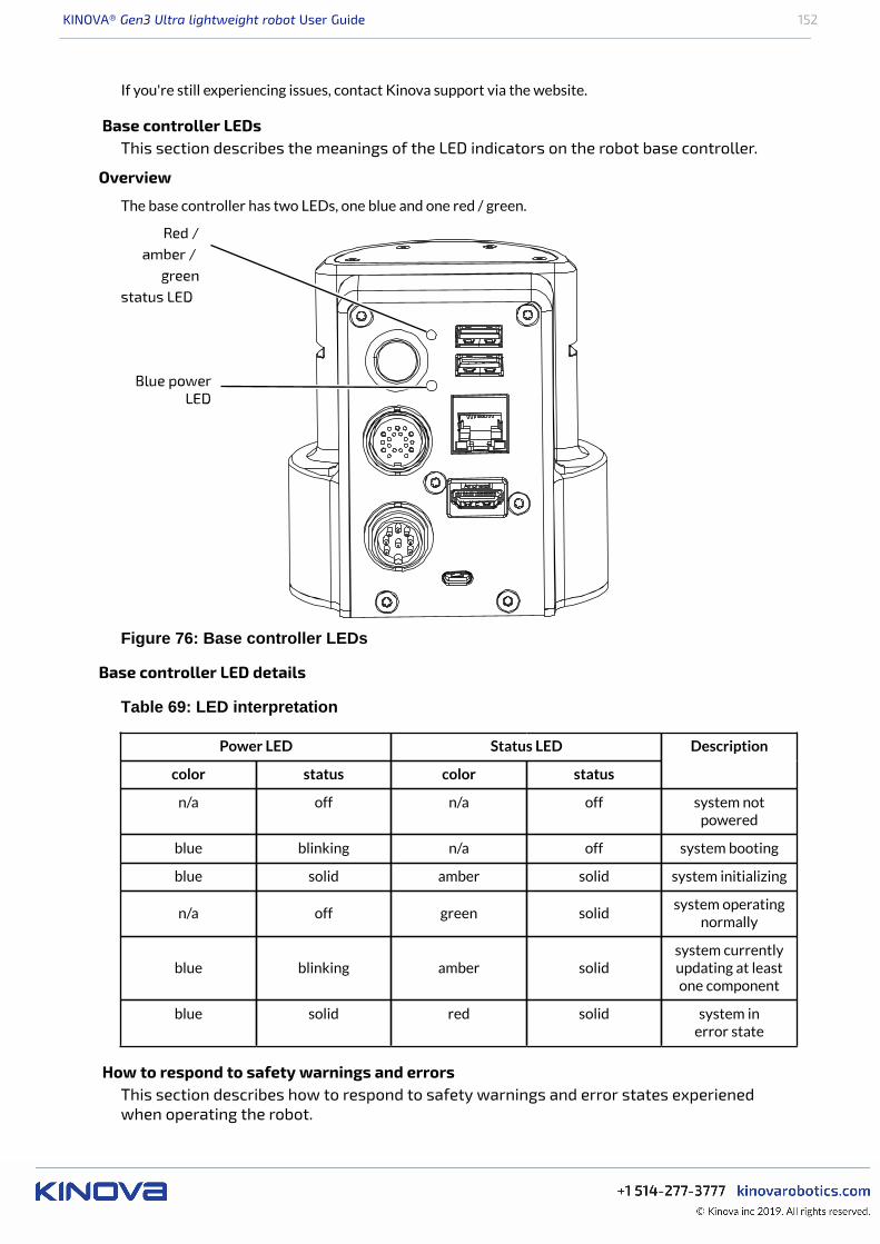
KINOVA® Gen3 Ultra lightweight robot User Guide 152
If you're still experiencing issues, contact Kinova support via the website.
Base controller LEDsThis section describes the meanings of the LED indicators on the robot base controller.
Overview
The base controller has two LEDs, one blue and one red / green.
Figure 76: Base controller LEDs
Base controller LED details
Table 69: LED interpretation
Power LED Status LED
color status color status
Description
n/a off n/a off system notpowered
blue blinking n/a off system booting
blue solid amber solid system initializing
n/a off green solidsystem operating
normally
blue blinking amber solidsystem currentlyupdating at leastone component
blue solid red solid system inerror state
How to respond to safety warnings and errorsThis section describes how to respond to safety warnings and error states experienedwhen operating the robot.
KINOVA® Gen3 Ultra lightweight robot User Guide 153
Overview
The robot has a number of warning and error thresholds set for safety purposes. These are viewable (andin some case configurable) in the Web application. The following tables give more guidance as to the sourceof the problem when a safety threshold is triggered.
Safeties handling details
Table 70: Base safeties handling
Safety Most Probable Cause
Incompatible Firmware version • Firmware issue
Firmware Update Failure• Firmware issue• Communication issue
Maximum Ambient Temperature• CPU heat sink issue• Unknown thermal issue
Maximum Core Temperature• CPU heat sink issue• Unknown thermal issue
Joint Fault • Joint error / warning state
Joint Detection Error • Communication issue
Network Initialization Error • Base CPU board issue
Maximum Current• Shorted phases on a joint• Payload exceeded
Maximum Voltage• Power supply issue• Electronic component failure
Minimum Voltage• Power supply issue• Electronic component failure
Emergency Stop Activated
• XBox gamepad emergencystop button clicked
• Web application emergencystop button clicked
Emergency Line Asserted• Joint not programmed• Joint in a boot loop• Electrical component failure
Inrush Current Limiter Fault• Payload exceeded• Electrical component failure
Table 71: Actuators safeties handling
Safety Most Probable Cause
Following error• Communication issue• Firmware issue
Maximum velocity• Communication issue• Firmware issue
Maximum torque• Strain gauge improperly soldered• Incorrect torque calibration
Magnetic position • Magnet improperly glued
Hall position • Hall sensor major malfunction
KINOVA® Gen3 Ultra lightweight robot User Guide 154
Safety Most Probable Cause
Hall sequence • Hall sensor major malfunction(s)
Input encoder Hall mismatch • Dirt and/or particles on encoder disk
Input encoder index mismatch • Dirt and/or particles on encoder disk
Input encoder magnetic mismatch• Dirt and/or particles on encoder disk• Detached magnet on magnetic encoder
Maximum motor current• Shorted phases• Bad motor
Non-volatile memory corrupted• Incomplete calibration(s• No system information entered• No torque calibration
Motor driver fault• Shorted phases• Hall sensor issue
Watchdog triggered • Firmware issue
Contacting Kinova supportHere's where to turn for related support and advice.
For support and advice on hardware related issues, please don't hesitate to contact us through the supportform on our website:
www.kinovarobotics.com/support
For development guidance and software-related questions, check out our GitHub repositories:• KINOVA® KORTEX™ GitHub: github.com/kinovarobotics/kortex• KINOVA® KORTEX™ ROS GitHub: github.com/kinovarobotics/ros_kortex• KINOVA® KORTEX™ ROS vision GitHub: github.com/Kinovarobotics/ros_kortex_vision• KINOVA® KORTEX™ MATLAB API GitHub: https://github.com/Kinovarobotics/matlab_kortex

There is no need too small. No task too great.
kinovarobotics.com
Kinova inc. (Headquarters)4333, Boulevard de la Grande-Allée
Boisbriand (QC) J7H 1M7
Canada
+1 (514) 277-3777
Kinova Europe GmbH
Großkitzighofer Straße 7 a
86853 Langerringen
+49 8248 8887-928
Assistive Solutions: +49 08248 888 7743
UG
-014
_R05