
KeepGoing.pdf
283
Oracle® Enterprise Manager Ops Center Keep Going Release 2.5 March 2011
Transcript of KeepGoing.pdf

Oracle® Enterprise Manager Ops CenterKeep Going
Release 2.5
March 2011

Oracle Enterprise Manager Ops Center, 2.5
Copyright © 2007, 2011, Oracle and/or its affiliates. All rights reserved.
This software and related documentation are provided under a license agreementcontaining restrictions on use and disclosure and are protected by intellectual propertylaws. Except as expressly permitted in your license agreement or allowed by law, youmay not use, copy, reproduce, translate, broadcast, modify, license, transmit,distribute, exhibit, perform, publish, or display any part, in any form, or by any means.Reverse engineering, disassembly, or decompilation of this software, unless requiredby law for interoperability, is prohibited.
The information contained herein is subject to change without notice and is notwarranted to be error-free. If you find any errors, please report them to us in writing.
If this is software or related software documentation that is delivered to the U.S.Government or anyone licensing it on behalf of the U.S. Government, the followingnotice is applicable:
U.S. GOVERNMENT RIGHTS Programs, software, databases, and relateddocumentation and technical data delivered to U.S. Government customers are"commercial computer software" or "commercial technical data" pursuant to theapplicable Federal Acquisition Regulation and agency-specific supplementalregulations. As such, the use, duplication, disclosure, modification, and adaptationshall be subject to the restrictions and license terms set forth in the applicableGovernment contract, and, to the extent applicable by the terms of the Governmentcontract, the additional rights set forth in FAR 52.227-19, Commercial ComputerSoftware License (December 2007). Oracle America, Inc., 500 Oracle Parkway,Redwood City, CA 94065.
This software or hardware is developed for general use in a variety of informationmanagement applications. It is not developed or intended for use in any inherentlydangerous applications, including applications which may create a risk of personalinjury. If you use this software or hardware in dangerous applications, then you shallbe responsible to take all appropriate fail-safe, backup, redundancy, and othermeasures to ensure its safe use. Oracle Corporation and its affiliates disclaim anyliability for any damages caused by use of this software or hardware in dangerousapplications.
Oracle and Java are registered trademarks of Oracle and/or its affiliates. Other namesmay be trademarks of their respective owners.
Intel and Intel Xeon are trademarks or registered trademarks of Intel Corporation. AllSPARC trademarks are used under license and are trademarks or registeredtrademarks of SPARC International, Inc. AMD, Opteron, the AMD logo, and the AMDOpteron logo are trademarks or registered trademarks of Advanced Micro Devices.UNIX is a registered trademark licensed through X/Open Company, Ltd.
This software or hardware and documentation may provide access to or informationon content, products, and services from third parties. Oracle Corporation and itsaffiliates are not responsible for and expressly disclaim all warranties of any kind withrespect to third-party content, products, and services. Oracle Corporation and itsaffiliates will not be responsible for any loss, costs, or damages incurred due to youraccess to or use of third-party content, products, or services.

Oracle® Enterprise Manager Ops Center
Keep Going (PDF)Contents
PrefaceAccess to Oracle Support
Provision an OSAbout OS Provisioning
OS ImagesOS Profiles
Importing OS Images and FLARsBefore You BeginTo Import an OS Image or a FLARTo Monitor an OS Image Job
Loading OS Images From CD or DVDTo Load an OS Image From CD or DVDTo Monitor an OS Image Job
Downloading OS ImagesTo Download an OS ImageTo Monitor an OS Image Job
Viewing the Available OS ImagesTo View the Available OS Images
Editing OS Image InformationTo Edit OS Image Information
Deleting OS ImagesTo Delete an OS Image
Creating OS Profiles for Solaris SystemsBefore You BeginTo Create an OS Profile for Solaris Systems
Creating OS Profiles for Linux SystemsBefore You BeginTo Create an OS Profile for Linux Target Systems
Importing JET TemplatesBefore You BeginTo Import a JET Template
To View the Available OS ProfilesEditing an OS Profile
Before You BeginTo Edit an OS Profile
To Clone an OS ProfileDeleting an OS Profile
To Delete an OS ProfileInstalling JET Modules
JET Resources and DocumentationTo Check for Installed JET ModulesTo Install a JET ModuleJET Module Parameters
JET Module Parametersbase_config
Preparing to Provision an OSDiscovering Target SystemsDisabling System MonitoringConfiguring DHCP Services
Identifying Available Ethernet InterfacesTo Configure DHCP Services by Using the BUITo Configure DHCP Services by Using the Commandproxyadm
Troubleshooting Known Solaris DHCP IssuesOS Provisioning for a Single System
Before You BeginTo Provision an OS on a Single System

Oracle® Enterprise Manager Ops Center
OS Provisioning for Multiple SystemsBefore You BeginTo Provision an OS on Multiple Systems
OS Provisioning a SPARC Enterprise M-Series Server DomainBefore You BeginTo Provision an OS on a SPARC Enterprise M-Series Server Domain
Provision FirmwareAbout Firmware ProvisioningFirmware Images
Creating a Firmware ImageBefore You BeginTo Create a Firmware Image
Displaying Firmware ImagesTo Display Firmware Images
Editing a Firmware ImageTo Edit a Firmware Image
Determining Metadata for a Firmware ImageChanging the Default Location of Firmware Images
To Change the Default Location of Firmware ImagesDeleting a Firmware Image
To Delete a Firmware ImageFirmware Profiles
Creating a Firmware ProfileTo Create a Firmware Profile
Displaying a Firmware ProfileTo Display a Firmware Profile
Editing a Firmware ProfileTo Edit a Firmware Profile
Deleting a Firmware ProfileDeleting a Firmware Profile
Firmware UpdatesUpdating Firmware
To Update FirmwareUpdating Firmware for a SPARC Enterprise M-Series Server
Before You BeginTo Create a Firmware ImageTo Create a Firmware ProfileTo Update Firmware
Firmware Compliance ReportTo Run a Firmware Compliance ReportExample - Using a Firmware Compliance Report to Validate an Update
Viewing the Updated Firmware VersionUpdate an OSAbout Updating an OS
Managing SystemsObtaining PatchesLocal Content (Solaris and Linux OS only)ReportsSystem Catalogs (Solaris and Linux OS only)Update Job
Solaris OS PatchingLinux OS PatchingWindows OS PatchingUsing Profiles and Policies to define and control the job (Solaris and Linux only)
OS Update CapabilityOS Update Reports
Update Roles and AuthorizationsAdmin AuthorizationOS Update Profiles
Predefined ProfilesCreating an OS Update Profile
To Create a New ProfileEditing an OS Update Profile
To Edit a ProfileExporting an OS Update Profile

Oracle® Enterprise Manager Ops Center
To Export an OS Update ProfileImporting an OS Update Profile
To Import an OS Update ProfileDeleting an OS Update Profile
To Delete an OS ProfileOS Update PoliciesCreating an OS Update Policy
Policy Component and Action SettingsTo Create an OS Update Policy
Editing an OS Update PolicyTo Edit an OS Update Policy
Exporting an OS Update PolicyTo Export an OS Update Policy
Importing an OS Update PolicyTo Import an OS Update Policy
Deleting an OS Update PolicyTo Delete an OS Update Policy
System CatalogsComparing System Catalogs
To Compare System Catalogs and Copy a CatalogCreating a Historical Catalog
To Create a Historical CatalogCreating a Profile From a System Catalog
To Create a Profile From a System CatalogViewing and Modifying a Catalog
To View a CatalogTo Modify a Catalog
Updating a Solaris OSMethods of Updating a Solaris OSCreating a Solaris OS Update Job
To Create a New Update JobUpdating From a Solaris OS Profile
To Create a Job From a ProfileUpdating a Solaris OS With Other Report ResultsUpdating an OS With BAR Output
To Use BAR Output to Update a Solaris OSUpdating a Solaris OS by Modifying a System Catalog
To Update a Solaris OS by Modifying a System CatalogUpdating With Solaris Live UpgradeAbout Solaris Live Upgrade

Oracle® Enterprise Manager Ops Center
Supported Operating SystemsBoot Environments
Disk RequirementsFile Systems
Critical File SystemsShareable File Systems
Guidelines for Selecting Slices for Shareable File SystemsReconfiguring a Disk
SwapDisplaying Boot Environment Details
To Display Boot EnvironmentsSynchronizing Boot EnvironmentsABE Reports and System Catalogs
About File SystemsCritical File SystemsShareable File Systems
Guidelines for Selecting Slices for Shareable File SystemsReconfiguring a Disk
SwapConfiguring Swap for the New Boot Environment
Live Upgrade RequirementsRequired PatchesRequired Packages
To Check for Solaris Live Upgrade PackagesTo Get the Required Packages
Support and Limitations With Live UpgradeLimitations With Live Upgrade
Limitations With Live Upgrade and Solaris ZonesBE Reports and System Catalogs
ReportsCatalogs
Creating an ABE ScriptTo Create an ABE ScriptSolaris Live Upgrade Swap Space
Configuring Swap for the New Boot EnvironmentExample - No Swap Slice is SpecifiedExample - Swap Slice is SpecifiedExample - Add a Swap Slice and Share a Swap Slice
Failed Boot Environment Creation if Swap is in UseCreating an ABE
Before You BeginTo Create an ABE
Updating an ABEBefore You BeginTo Update an ABE
Updating ZonesInstalling Packages and Patches on ZonesConfiguring and Commandspatchadd pkgadd
To Edit the Fileuce.rc
Updating a Global ZoneUpdating Non-Global ZonesSolaris OS Update ReportsBaseline Analysis ReportSolaris BaselinesWhite ListBlack ListRunning a Baseline Analysis Report
To Run a Baseline Analysis ReportCVE Compliance Report for a Solaris OS
To Run a CVE Compliance Report for a Solaris OSDistribution Update Report for a Solaris OS
To Run a Distribution Update Report for a Solaris OSExporting Results of a Solaris OS Report
To Export Results of a Solaris OS ReportHost Compliance Report for a Solaris OS

Oracle® Enterprise Manager Ops Center
To Run a Host Compliance Report for a Solaris OSIncident Compliance Report for a Solaris OS
To Run an Incident Compliance Report for a Solaris OSJob History Report for a Solaris OS
To Run a Job History Report for a Solaris OSPackage Compliance Report for a Solaris OS
To Run the Package Compliance Report for a Solaris OSSolaris Update Compliance Report
To Run a Solaris Update Compliance ReportUpdating a Linux OSMethods of Updating a Linux OSCreating a Linux OS Update Job
To Create a New Update JobUpdating from a Linux OS Profile
To Create a Job From a ProfileUpdating With a Linux OS ReportUpdating a Linux OS by Modifying a System Catalog
To Update a Linux OS by Modifying a System CatalogCVE Compliance Report for a Linux OS
To Run a CVE Compliance Report for a Linux OSDistribution Update Report for a Linux OS
To Run a Distribution Update Report for a Linux OSExporting Results of a Linux OS Report
To Export Results of a Linux OS ReportHost Compliance Report for a Linux OS
To Run a Host Compliance Report for a Linux OSIncident Compliance Report for a Linux OS
To Run an Incident Compliance Report for a Linux OSJob History Report for a Linux OS
To Run a Job History Report for a Linux OSPackage Compliance Report for a Linux OS
To Run the Package Compliance Report for a Linux OSService Pack Compliance Report for a Linux OS
To Run a Service Pack Compliance Report for a Linux OSUpdating a Windows OSAbout Updating a Windows OS
Patching in Connected and Disconnected ModeReportsUpdate Job
Method of Updating a Windows OSConfiguring Ops Center for Updating Windows OSConfiguring Ops Center to Interact with SCCM
To configure Ops Center to interact with the identified SCCMTo Unconfigure Ops Center's interaction with the SCCM
Windows Updates ReportsHost Compliance Report for Windows Updates
To Run a Host Compliance Report for Windows UpdatesIncident Compliance Report for Windows Updates
To Run an Incident Compliance Report for Windows UpdatesCreating a New Windows Update Job
To Create a New Windows Update JobManaging Windows Update ReportsManaging Windows Report ResultsViewing a Windows Report Result
To View a Windows Report ResultDeleting a Windows Report
To Delete a Windows ReportRerunning a Windows Report
To Rerun a Windows ReportManaging Windows Report TemplatesViewing a Windows Report Template
To View a Windows OS Report TemplateEditing a Windows Report Template
To Edit a Windows Report TemplateRunning a Report from a Windows Report Template

Oracle® Enterprise Manager Ops Center
To Run a Report from a Windows Report TemplateDelete a Windows Report Template
To Delete a Windows Report TemplateVirtualizationLogical DomainsAbout Logical Domains
Ops Center With Logical DomainsRequirements of Logical DomainsArchitecture of Logical DomainsRoles of Logical DomainsWhen to Use Logical Domains
Requirements of Logical DomainsHardware RequirementsOS RequirementsOS Patch RequirementsFirmware RequirementsProxy Controller Requirements
Roles of Logical DomainsControl DomainGuest DomainService DomainI/O Domain
Virtualization HostsLogical Domains
Creating a Virtualization HostProvisioning Control DomainConfigurations of Control Domain
Recommended Minimum ConfigurationsCPU ThreadsCrypto UnitsExampleRAM
Additional ConfigurationsVirtual Network SwitchVirtual Disk ServerVirtual Console Concentrator
Importing an OS ImageBefore You BeginTo Import an OS Image
Creating a Logical Domain ProfileTo Create a LDom ProfileProvisioning the Control DomainBefore You BeginChanging the Job Timeout Value for ProvisioningTasks Performed by the Provisioning Job
Associating Libraries to a Logical Domain HostTo Associate Libraries to a Logical Domain Host
Editing the Attributes of Logical Domain HostTo Edit the Attributes of an LDom HostManaging a Virtualization HostMonitoring a Logical Domain Host
SummaryLibrariesNetworkChartJobsConfiguration
Rebooting a Logical Domain HostTo Reboot a Logical Domain Host
Creating a GuestCreating a Guest Domain
Before You BeginTo Create a Guest Domain
Accessing Serial Console Outside Ops CenterProvisioning a Guest Domain

Oracle® Enterprise Manager Ops Center
Before You BeginTo Provision a Guest Domain
Managing a GuestMonitoring a Guest
SummaryOS DetailsConsoleNetworkStorageChartJobs
Editing the Attributes of a Guest DomainTo Edit the Attributes of a Guest Domain
Starting a Guest DomainTo Start a Guest Domain
Rebooting a Guest DomainTo Reboot a Guest Domain
Shutting Down a Guest DomainTo Shut Down a Guest Domain
Deleting a Guest DomainTo Delete a Guest Domain
Migrating a Guest DomainBefore You BeginTo Migrate a Guest Domain (Warm Migration)
Connecting a Guest to NetworksTo Connect a Guest to Networks
Solaris ContainersAbout Zones
How Zones WorkUnderstanding Facts in Zone ManagementTypes of ZonesZones Support in Ops Center
Support and Limitation for ZonesLimitations For Zone Support in Ops Center
Creating Zones Using Ops CenterCreate Zones
Before You BeginWhole Root Zone RequirementSparse Root Zone RequirementBranded Zone Requirement
Setting Up an Anonymous FTP ServerTo Create a Zone
Editing Zone ConfigurationBefore You BeginTo Edit Zone Configuration
Discovering and Managing Existing ZonesDiscovering Zones Overview
Discovering ZonesDiscovering Zones in a Logical Domain Guest
Managing ZonesUnmanaging Zones
Provisioning an OS With ZonesBefore You BeginTo Provision an OS With Zones
Managing and Monitoring ZonesManaging and Monitoring the Global Zone

Oracle® Enterprise Manager Ops Center
SummaryUtilizationLibrariesOS DetailsTo Change Thresholds of OS Monitoring VariablesTo Change File System Thresholds for an OSNetworksChartsJobsConfiguration
Managing and Monitoring Zones Created Using Ops CenterSummaryConsoleOS DetailsTo Change Monitoring Variables ThresholdTo Change File System Thresholds for an OSNetworkStorageChartsJobsConfiguration
Managing and Monitoring Existing Zones Through Ops CenterOS Details
To Change the Monitoring Variables ThresholdConsoleNetworkChartsJobsConfiguration
Performing Zone TasksBooting a Zone
To Boot a ZoneRebooting a Zone
To Reboot a ZoneAdding Libraries to the Global Zone
To Associate a Library With the Global ZoneDisassociating Libraries From Global Zone
To Disassociate Libraries From Global ZoneAdding File Systems to Zones
To Add a File System to a ZoneAdding Storage to Zones
To Add Storage to ZonesManaging Zone NetworksAssigning Networks to a Global Zone
To Assign a Network to a Global ZoneRemoving a Network From a Global Zone
To Unbind a Network From a Global ZoneConnecting Networks to Zones
To Connect a Network to a ZoneDisconnecting a Network From a ZoneTo Disconnect a Network From a Zone
Cloning a ZoneTo Clone a Zone
Attaching to Zone ConsoleTo Attach to a Zone Console
Disabling the Zone Console ConnectionTo Disable a Zone Console Connection
Accessing the Serial ConsoleBefore You BeginSerial Console for Zones and Logical DomainsTo Access the Serial ConsoleTroubleshooting the Access to Serial Console
Migrating ZonesMigrating a Zone to a Different Machine

Oracle® Enterprise Manager Ops Center
Compatible Global Zones for MigrationBefore You BeginTo Migrate a Zone Using Ops CenterBacking Out Patches and Packages
Migrating a Physical Solaris System Into a ZoneBefore You BeginTo Migrate a Physical Solaris System Into a Zone
Updating ZonesInstalling Packages and Patches on ZonesConfiguring and Commandspatchadd pkgadd
To Edit the Fileuce.rc
Updating a Global ZoneUpdating Non-Global ZonesHalting a Zone
To Halt a ZoneShutting Down a Zone
To Shut Down a ZoneDeleting a Zone
To Delete a ZoneMonitor Assets
OS MonitoringHardware Monitoring
Monitor AssetsOS MonitoringHardware Monitoring
About MonitoringOS MonitoringHardware Monitoring
About MonitoringOS MonitoringHardware Monitoring
Managing and Monitoring an OSManaging and Monitoring an OSMonitoring an OS
To Change Thresholds of OS Monitoring VariablesTo Change Thresholds of Monitoring Variables for an OS GroupTo Change File System Thresholds for an OS GroupOS Health States
Monitoring an OSTo Change Thresholds of OS Monitoring VariablesTo Change Thresholds of Monitoring Variables for an OS GroupTo Change File System Thresholds for an OS GroupOS Health States
Monitoring a Windows OSComprehensive Monitoring
Monitoring a Windows OSComprehensive Monitoring
Monitoring a System With the Windows OSWindows OS AttributesWindows OS OperationsServer AttributesServer Operations
To Display Window OS Monitoring DataEditing Monitoring Thresholds
To Change Thresholds of OS Monitoring VariablesTo Change Thresholds of Monitoring Variables for an OS GroupTo Change File System Thresholds for an OS Group
Windows OS Health StatesOS Health States
ChartsTo Display ChartsTo Display Charts for Solaris ContainersTo Display Charts for GroupsExporting Chart Data
Rebooting an OS

Oracle® Enterprise Manager Ops Center
To Reboot an OSManaging Boot EnvironmentsDisplaying BE and ABE Details
To Display BE and ABE DetailsSynchronize Boot Environments
To Synchronize Boot EnvironmentsActivate a Boot Environment
To Activate a Boot EnvironmentManaging and Monitoring HardwareAccessing the Serial Console
Before You BeginSerial Console for Zones and Logical DomainsTo Access the Serial ConsoleTroubleshooting the Access to Serial Console
Monitoring Hardware HealthStates of Hardware Health
Managing and Monitoring M-Series ServersFeatures Monitored
Managing Locator LightsTo Activate a Locator LightTo Deactivate a Locator LightTo Manage Locator Lights in a Group
Managing and Monitoring Server Power StatesTo Power On a Server or ChassisTo Power Off a Server or Chassis
Monitoring Power UtilizationChecking Power CapabilityPower Utilization GraphsTo View Power Utilization ChartsTo Export Power Utilization Charts
Monitoring Hardware VariablesMonitoring ConnectivityResetting a Server
To Reset a ServerMonitoring Job Information
To View Current or Historical JobsLibrariesAbout Libraries
OS Provisioning LibraryFirmware Provisioning LibraryUpdates LibraryStorage Libraries
Updates LibraryManaging ProfilesManaging PoliciesManaging Components and Local Content
Adding a Local CategoryTo Add a Local Category
Deleting a Local ComponentTo Delete a Local Component File
Editing a Local Component FileTo Edit Local Component Files
Uploading a Local ActionTo Upload a Local Action
Uploading a Local Configuration FileTo Upload a Local Configuration File
Uploading a Local Software PackageTo Upload a Local Software Package
Uploading Local Software in BulkTo Upload Local Software in Bulk
Uploading Software in Disconnected ModeTo Upload Software in Disconnected Mode
Viewing Bulk Upload ResultsTo View Bulk Upload Results
Viewing Component Details

Oracle® Enterprise Manager Ops Center
To View Component DetailsStorage LibrariesFibre Channel Libraries
LUNTerms in SAN StorageManaging Fibre Channel Libraries
Configuring Fibre Channel StorageTo Configure Storage for Fibre Channel Libraries
Creating a Fibre Channel LibraryBefore You BeginTo Create a Fibre Channel LibraryAdding LUNs to the Library ManuallySelecting LUNs from the Available LUNs
Adding LUNs to a Fibre Channel LibraryTo Add LUNs to a Fibre Channel LibraryViewing the Contents of a Fibre Channel LibraryTo View the Contents of a Fibre Channel Library
Editing a Fibre Channel LibraryTo Edit a Fibre Channel Library
Deleting a Fibre Channel LibraryBefore You BeginTo Delete a Fibre Channel Library
Troubleshooting Fibre Channel LibrariesCheck if Solaris Multipathing (MPxIO) Is Enabled for Fibre Channel DisksCheck Whether the Fibre Channel Host Bus Adaptors (HBAs) Are ConfiguredCheck Whether the Fibre Channel HBAs Are Connected to the Fabric
Network Attached Storage LibrariesAbout Network Attached Storage (NAS) Storage LibrariesViewing the Contents of a NAS Storage LibraryViewing Image Details
To View Image DetailsConfiguring NAS Storage LibrariesSetting Up the CIFS Server
To Set Up a Shared Folder on the CIFS ServerDefining the CIFS Mount Point
Setting Up the NFS ServerTo Set Up a Share on the NFS ServerTo Set Up an NFS Client
To Create a NAS Storage LibraryAssociating or Disassociating Libraries
To Associate a Storage Library With a Virtual PoolTo Disassociate a Library From a Virtual Pool
Adding ISO and Appliance ImagesUpload ISO Images
To Upload ISO ImagesUpload Appliance Images
To Upload Appliance ImagesImport Images
To Import ISO or Appliance ImagesMoving an ImageEditing Image Details
To Edit Image DetailsDeleting Images
To Delete ImagesTo Change the Attributes of a NAS Storage LibraryTo Remove a NAS Storage LibraryTroubleshooting a NAS Storage Library
Troubleshooting Library CreationNFS Mount PointsNFS Share
Troubleshooting DNS and NIS ConfigurationAbout NetworksCreating a Network
Before You BeginTo Create a Network

Oracle® Enterprise Manager Ops Center
Routing ModesNo Dynamic Routing ModeDynamic Routing On ModeAutomatic Routing Mode
Changing the Routing ModeAdding a Static Route for the Network
To Add a Static Route for the NetworkEditing the Network Attributes
To Edit the Network AttributesEditing the Network Services
To Edit the Network ServicesDeleting a Network
Before You BeginTo Delete a Network
Guests and NetworksConnecting Guests to a Network
Before You BeginTo Connect Guests to a Network
Disconnecting a Guest From a NetworkTo Disconnect a Guest From a Network
Viewing the Virtualization Hosts and Guests Using the NetworkVirtual Pools and NetworksAssigning a Network to Virtual Pools
To Assign a Network to Virtual PoolsDissociating a Network from a Virtual PoolViewing the Networks in a Virtual PoolEnterprise Controller AdministrationConfiguring the Local Agent
To Configure the Local AgentUnconfiguring an Enterprise Controller
To Unconfigure an Enterprise ControllerAdding a Product Alias
To Add a Product AliasChanging the HTTP Proxy
To Change the HTTP ProxyAuthentications
To Edit AuthenticationsConfiguring an Enterprise Controller for Updates
Before You BeginManually Enabling the Co-Located Proxy ControllerManually Enabling a Ops Center Agent
Viewing Service StatusTo View Service Status
Viewing Agent ControllersTo View Agent Controllers
Updating Agent ControllersTo Update Agent Controllers
Viewing LogsTo View Logs
Proxy Controller AdministrationUnconfiguring and Uninstalling a Proxy Controller
To Unconfigure and Uninstall a Proxy ControllerTo Unconfigure a Proxy Controller From the Command Line
Setting a Proxy Controller as DefaultTo Set a Proxy Controller as Default
Clearing a Proxy Controller's Default StatusTo Clear a Proxy Controller's Default Status
DHCP ConfigurationTo Configure DHCP ServicesTo Monitor a DHCP Configuration Job
SubnetsSpecifying IP Address RangesTo Configure a Subnet
External DHCP Servers

Oracle® Enterprise Manager Ops Center
External DHCP Server RequirementsBefore You BeginTo Install the Script on the External DHCP Serverscninstall_ext_dhcp.pl
To Configure External DHCP ServersViewing a Proxy Controller's Configuration
To View a Proxy Controller's ConfigurationBackup and RecoveryBacking Up an Enterprise Controller
To Back Up an Enterprise ControllerRestoring an Enterprise Controller
To Restore an Enterprise ControllerExample - Restoring a Backup File for an Enterprise Controller Running on a Solaris OS
User and Role ManagementTo View Users and Roles
Adding a UserTo Add a User
Deleting a UserTo Delete a User
Roles and AuthorizationsEnterprise Controller Admin RoleAll Assets Admin RoleGroup RolesGroup AdminGroup ManageGroup ProvisionGroup UpdateGroup Update Simulate
Assigning a RoleTo Assign a Role to a User
Configuring a Notification ProfileTo Configure a Notification Profile
Deleting a Notification ProfileTo Delete a Notification Profile
Job ManagementTo Display All Jobs
Job DetailsTo Display Job Details
Stopping a JobTo Stop a Job
Deleting a JobTo Delete a Job
Re-running a JobTo Re-Run a Job
Re-running a Job on Failed TargetsTo Re-Run a Job on Failed Targets
Copying a JobTo Copy a Job
Answering QuestionsTo Answer Questions
Monitoring Jobs for an AssetTo Monitor Jobs for an Asset
Notifications and ReportsMessages
To View MessagesViewing Notifications
To View NotificationsDeleting Notifications
To Delete Specific NotificationsTo Delete All Notifications
Enabling Asset NotificationsTo Enable Notifications
Disabling Asset NotificationsTo Disable Notifications
Uninstalling Ops Center Software

Oracle® Enterprise Manager Ops Center
To Uninstall Ops Center Agent SoftwareTo Uninstall Ops Center Proxy Controller SoftwareTo Uninstall Ops Center Enterprise Controller Software
PrefaceThis document is intended for all levels of Oracle Enterprise Manager Ops Center administrators, as well as operating system,virtualization, hardware, and storage administrators using Oracle Enterprise Manager Ops Center to monitor and maintain their ITinfrastructure.
Access to Oracle Support
Oracle customers have access to electronic support through My Oracle Support. For information, visit or visit if you are hearing impaired.http://www.oracle.com/support/contact.html http://www.oracle.com/accessibility/support.html
Provision an OSOperating system (OS) provisioning enables you to use Ops Center to automatically install operating systems onto systems thatare attached to your network. In most circumstances, OS provisioning requires no manual interaction with the system that youwant to install. You initiate these OS installations from a centralized location, using the Ops Center BUI, rather than from thesystems that you want to install.
Check for the list of operating systems that you can provision with Ops Center.Supported Operating Systems
OS provisioning involves three main tasks:
Creating and Managing OS ImagesCreating and Managing OS ProfilesProvisioning Operating Systems
Creating OS images and creating OS profiles are one-time tasks for each OS configuration that you want to provision. After an OSimage and associated OS profile exist in Ops Center, you can provision the OS onto systems that are attached to your network.
Ops Center enables OS provisioning on single systems, groups of systems, or a combination of the two. OS provisioning forgroups of systems requires using homogeneous groups, as described in and .Creating a Group Adding Assets to a Group
About OS ProvisioningOperating system (OS) provisioning enables you to use Ops Center to automatically install operating systems onto systems thatare attached to your network. In most circumstances, OS provisioning requires no manual interaction with the system that youwant to install. You initiate these OS installations from a centralized location, using the Ops Center BUI, rather than from thesystems that you want to install.
Check for the list of operating systems that you can provision with Ops Center.Supported Operating Systems
Before you can provision an OS, you must have the following in Ops Center:
OS ImagesOS Profiles
Creating OS images and creating OS profiles are one-time tasks for each OS configuration that you want to provision. After an OSimage and associated OS profile exist in Ops Center, you can provision the OS onto systems that are attached to your network.
Ops Center enables OS provisioning on single systems, groups of systems, or a combination of the two. OS provisioning forgroups of systems requires using homogeneous groups, as described in and .Creating a Group Adding Assets to a Group

Oracle® Enterprise Manager Ops Center
OS Images
You use OS images as the source of data used to install operating systems onto systems on your network. OS provisioningrequires that you import an OS image into Ops Center, and then associate the OS image with a customized OS profile.
To use OS images in Ops Center, you can:
Import an OS image from an existing ISO fileImport a Solaris Flash archive (FLAR) and associate it with an OS imageLoad (copy) an image from physical CD or DVD installation mediaDownload an OS image from Sun Microsystems
You can obtain an OS image from the following sources:
CDs (Linux only)DVDs (Solaris, Linux)ISO files made from CDs (Linux only)ISO files made from DVDs (Solaris, Linux)Sun public server (Solaris only)
Check for the list of operating systems that you can provision with Ops Center.Supported Operating Systems
OS Profiles
An OS profile specifies how to configure an OS as it installs onto a set of target systems. An OS profile specifies configurationoptions, including what OS to install, what software groups to install, and what disk partitions and network settings to use. EachOS profile is associated with a specific OS image. Each OS profile describes how to install and configure one OS image, or oneFLAR associated with one OS image.
OS profiles used for the Solaris OS are similar to Sun JumpStart Enterprise Toolkit (JET) templates. Solaris OS profiles use JETtechnology to provision the operating system. A Ops Center Proxy Controller installation includes the and SUNWjet JetFLASH
packages, which provide the , , and JET modules. These JET modules provide the core JET functionsbase_config custom flash
required by Ops Center. If you want to use additional JET modules, you must manually install them on the Proxy Controllers wherethey will be needed. Refer to for more information about installing JET modules.Installing JET Modules
You can create a Solaris OS profile in one of the following ways:
Create an OS profile without providing any specific JET information.Create an OS profile exclusively from a JET template.Create an OS profile that includes parameters associated with additional JET modules.
OS profiles for RHEL and SLES do not use JET parameters, but they do require parameters that are specific to those operatingsystems.
For Linux and Solaris software, you can use System Catalogs to create profiles.
Importing OS Images and FLARsYou can import OS images from existing ISO files, or you can import Solaris Flash archive (FLAR) files and associate them with OSimages that you have already imported into Ops Center. After you import an OS image or a FLAR, you can then create an OSprofile that you use to provision the OS onto systems on your network.
When you import an OS image or a FLAR, an OS profile is created by default. The OS profile is named using the imagename that you enter in the Import OS Image wizard. This default OS profile is intended for use as a template. You canmodify the default OS profile for your specific systems.
OS image names that you specify must be unique, can consist of up to 100 characters, and may include numbers, letters,and some special symbols. The following special symbols are prohibited: comma, asterisk, single quote, double quote,parenthesis, question mark, equal sign, and newline.
FLAR files that you intend to import require a file name extension to be recognized by the Import OS Image.flar

Oracle® Enterprise Manager Ops Center
1. 2.
3.
4. 5. 6.
7. 8.
9.
wizard. For example: S10_flash_sun4u.flar
FLAR files are only used for Solaris installations.
FLAR files must represent complete OS archives. Differential Solaris Flash archives are not compatible with OSprovisioning in Ops Center.
OS images for virtualization hosts are provided as ISO files that you import in the same manner as Solaris or Linux OSimages.
Before You Begin
The Enterprise Controller must be able to access the files that you want to import. These files may be stored on theEnterprise Controller's local file system, or a file system that the Enterprise Controller mounts using NFS.
Solaris OS images cannot be imported from ISO files made from Solaris installation CDs.
When importing a SUSE Linux Enterprise Server (SLES) 9 SP3 OS distribution from ISO files, you must perform the importprocedure twice, and specify the same OS image name each time. Use the Import OS Image wizard the first time toimport the SLES 9 distribution, and then use the same wizard again to import the SLES 9 Update 3 distribution.
To use a FLAR to provision an OS, you must separately import an OS image and the FLAR that you want to use. You mustimport the OS image first, to make it available for selection as the Parent ISO in the Import OS Image wizard. Each FLARthat you import requires a Parent ISO. The Parent ISO provides a network boot environment for the systems that you intend to install. The FLAR provides thedata that installs the OS. To use a FLAR to provision an OS, be sure to import an OS image that represents an OS revisionlevel at least equal to the OS revision level represented by the FLAR.
To Import an OS Image or a FLAR
Click Libraries in the Navigation panel.Click OS Images.A list of OS images is displayed in the center panel.Click Import OS Image in the Actions panel.The Import OS Image screen is displayed.
In the Image Name field, enter the name that you want to assign to the ISO image or FLAR that you will import.In the Description field, enter a description of the file that you will import.Select either the ISO or FLAR image type, depending on the type of file that you will import.
If you select the FLAR file type, the Parent ISO field is displayed.Select the OS image that you want to use as the parent ISO for the FLAR that you will import.
Click Browse to display the Browse Server panel.Use the Browse Server panel to navigate to the directory that holds the ISO or FLAR that you want to import. You canuse the Refresh button to refresh the display of your current directory.

Oracle® Enterprise Manager Ops Center
9.
10.
1. 2.
3.
4.
1. 2.
3. 4.
5.
1. 2.
3.
4.
Select the ISO or FLAR that you want to import, then click Add Files.The file that you selected is displayed in the Files list in the Import OS Image panel.When the list of files that you want to import is complete, click Import.
To Monitor an OS Image Job
You can monitor the progress of the job that imports an OS image or FLAR by listing the job in the Jobs panel.
Select the Jobs panel.Select All Jobs or In Progress from the Jobs panel, and identify the OS image import job from the list that is displayed.Jobs to import OS images are identified as jobs.OSImage_SatelliteTask
Double-click the OS import job to display the Job Details panel that describes the job.The Event Log tab displays messages that describe the job's progress.Click Close to dismiss the Job Details panel.
Loading OS Images From CD or DVDYou can load OS images from physical CDs or DVDs for use in Ops Center. After you load an OS image, you can then create anOS profile to provision the OS onto systems on your network.
When you import an OS image, an OS profile of the same name is created by default. This default OS profile is intendedfor use as a template. The default OS profile is optimized for Sun Fire x4200 systems, so you might need to modify theprofile for your specific systems.
Loading an OS image from CDs is only supported for Linux media.
Image names that you specify must be unique, can consist of up to 100 characters, and may include numbers, letters, andsome special symbols. The following special symbols are prohibited: comma, asterisk, single quote, double quote,parenthesis, question mark, equal sign, and newline.
To Load an OS Image From CD or DVD
Click Libraries in the Navigation panel.Click OS Images.A list of OS images is displayed in the center panel.Click Load OS Image from CD or DVD in the Actions panel.In the Load OS Image from CD or DVD dialog box, enter the required information:
Image Name - Enter the name that you want to assign to the OS image that you will load from theCD or DVD.Description - Enter a description that will help identify the OS image that this process creates.Device - Enter the device name of the CDROM or DVD drive where the source CD or DVD islocated. For example, use device names like or . You/cdrom/cdrom0 /vol/dev/dsk/c0t6d0
can use the command to show the CDROM or DVD device name.ls -l /dev/sr*
Click Load to submit the job to load the OS image.
To Monitor an OS Image Job
You can monitor the progress of the job that loads an OS image by listing the job in the Jobs panel.
Select the Jobs panel.Select All Jobs or In Progress from the Jobs panel, and identify the load OS image job from the list that is displayed. Jobsto load OS images are identified as jobs.OSImage_SatelliteTask
Double-click the load OS image job to display the Job Details panel that describes the job.The Event Log tab displays messages that describe the job's progress.Click Close to dismiss the Job Details panel.
Oracle® Enterprise Manager Ops Center
1. 2.
3.
4.
5.
6.
1. 2. 3.
4.
Downloading OS ImagesYou can download OS images and Solaris Flash archives (FLARs) from Sun Microsystems for use in Ops Center. After youdownload an OS image, you can then create an OS profile to provision the OS onto systems on your network.
OS images and FLARs that you download are automatically associated with the OS Provisioning library. If an OS image isappropriate for use with a profile, a default profile is generated.
Note – You must download OS images in connected mode. There is no support for image download in disconnected mode.If update is configured in disconnected mode, there is no connectivity to the Sun knowledge base (KB). You cannot download ISOimages from the local KB because they are not included in the harvester bundle.
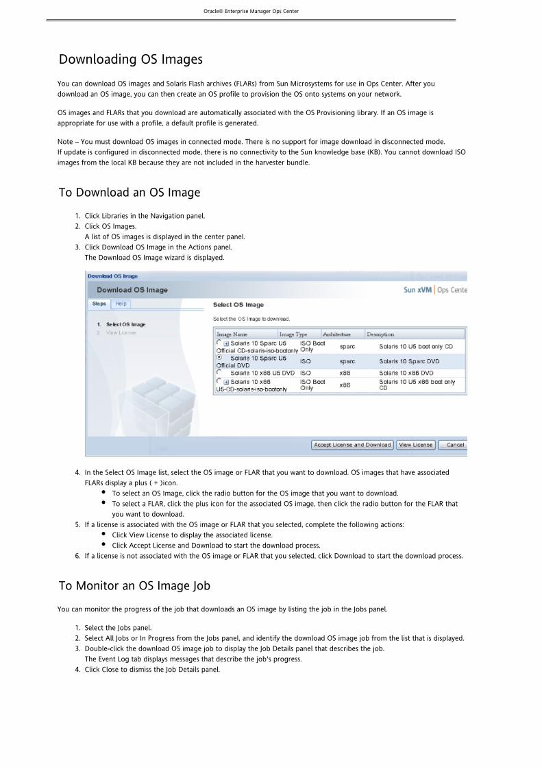
To Download an OS Image
Click Libraries in the Navigation panel.Click OS Images.A list of OS images is displayed in the center panel.Click Download OS Image in the Actions panel.The Download OS Image wizard is displayed.
In the Select OS Image list, select the OS image or FLAR that you want to download. OS images that have associatedFLARs display a plus ( + )icon.
To select an OS Image, click the radio button for the OS image that you want to download.To select a FLAR, click the plus icon for the associated OS image, then click the radio button for the FLAR thatyou want to download.
If a license is associated with the OS image or FLAR that you selected, complete the following actions:Click View License to display the associated license.Click Accept License and Download to start the download process.
If a license is not associated with the OS image or FLAR that you selected, click Download to start the download process.
To Monitor an OS Image Job
You can monitor the progress of the job that downloads an OS image by listing the job in the Jobs panel.
Select the Jobs panel.Select All Jobs or In Progress from the Jobs panel, and identify the download OS image job from the list that is displayed.Double-click the download OS image job to display the Job Details panel that describes the job.The Event Log tab displays messages that describe the job's progress.Click Close to dismiss the Job Details panel.

Oracle® Enterprise Manager Ops Center
1. 2.
3.
Viewing the Available OS ImagesYou can view the OS images and Solaris Flash archives (FLARs) that are available for use in Ops Center.
To View the Available OS Images
Click Libraries in the Navigation panel.Click OS Images.A list of OS images is displayed in the center panel.The OS Images list displays information for OS images and FLARs.
Select an OS image or FLAR to display the OS Image Details and Files panels for that image or FLAR.
The OS Image Details panel lists the following information about the OS Image or FLAR that you selected:
Field Description
ImageName
Displays the user-defined name assigned to the OS image or FLAR.
ImageType
Indicates if this item is an OS image (ISO) or a Solaris Flash archive (FLAR).
Description Displays the user-defined description of the OS image or FLAR.
OS Type Identifies the operating system that the OS image or FLAR represents, for example, Solaris or Red Hat.
Version Indicates the OS version and architecture of the OS image.

Oracle® Enterprise Manager Ops Center
1. 2.
3. 4.
5.
1. 2.
3. 4. 5.
HVMCapable
Indicates whether the OS image is capable of hardware virtual machine.
PV Capable Indicates whether the OS image is capable of paravirtualization.
Parent ISO FLARs must be associated with a parent OS image to be used for OS provisioning. This field identifies the imagename of the parent ISO OS image that is associated with the FLAR.
The Files panel lists the path name of the OS image or FLAR on the Enterprise Controller.
Editing OS Image InformationYou can edit the name and description that you assign to an OS image or Solaris Flash archive (FLAR). After you change the nameand description of an OS image or FLAR, the OS profiles that use that OS image or FLAR reflect the new information.
To Edit OS Image Information
Click Libraries in the Navigation panel.Click OS Images.A list of OS images is displayed in the center panel.Select the OS image or FLAR for which you want to change the name or description.Click the Edit OS Image icon in the OS Images panel.In the Edit OS Image panel, change the name and description as desired.Click Save to save your changes.
Deleting OS ImagesYou can delete an OS image or Solaris Flash archive (FLAR) from its library in Ops Center.
You cannot delete an OS image or FLAR that is currently part of an OS profile. If you attempt to do so, a message isdisplayed that indicates that the OS Image or FLAR is currently in use.
To Delete an OS Image
Click Libraries in the Navigation panel.Click OS Images.A list of OS images is displayed in the center panel.Select an OS image or FLAR that you want to delete.Click the Delete OS Image icon.Click Delete in the confirmation message to delete the OS Image or FLAR.
Creating OS Profiles for Solaris SystemsOS profiles describe how Ops Center provisions operating systems onto target systems on your network. You can create differentOS profiles to describe the different OS provisioning configurations that you need. You can configure Solaris OS profiles with orwithout specifying additional JumpStart Enterprise Toolkit (JET) parameters, and to run custom scripts on target systems. JETparameters apply only to Solaris target systems.
Before You Begin
You must load or import an OS image into Ops Center before you can create a profile for a particular OS.

Oracle® Enterprise Manager Ops Center
1. 2.
3.
4.
OS profile names can consist of up to 100 characters and may include numbers, letters, and some special symbols. Thefollowing special symbols are prohibited: comma, asterisk, single quote, double quote, parenthesis, question mark, equalsign, and newline.For Solaris target systems, if you want to use JET modules other than the , , and modulesbase_config custom flash
that are installed in Ops Center by default, you must install those additional modules on the Proxy Controllers that willuse them. Refer to for more information about installing JET modules.Installing JET ModulesYou must install any additional JET modules before you use them within an OS profile for Solaris target systems.Scripts must exist in a directory that the Ops Center Enterprise Controller can access. Scripts may be located in a localdirectory of the Enterprise Controller, or in a directory that the Enterprise Controller mounts using NFS.When you create a password, the password must contain at least one character. You cannot create an OS profile thatuses a space as a password.
The Create OS Profile wizard presents different panels depending on the operating system contained in the OS image that youselect. Ops Center provides OS provisioning services for Solaris and Linux. Use the following procedures to create OS profiles forthe Solaris operating system.
To Create an OS Profile for Solaris Systems
Click Libraries in the Navigation panel.Click OS Profiles.A list of OS profiles is displayed in the center panel.Click Create OS Profile in the Actions panel.The Create OS Profile wizard is displayed.
In the Define Profile panel, provide the following information:OS ImageSelect the OS image that you want to associate with this profile. For this procedure, select a Solaris OS imagethat you have imported into Ops Center.Profile TypeSelect the Bare Metal option. The Guest option is used to provision guest OS instances on virtualization hosts.The Guest option is only available for x86-based OS images.Profile NameEnter a name for the new OS profile.DescriptionEnter a description for the new OS profile.Specify JET ParametersIf you want to use JET parameters to customize how this profile provisions an OS, select Specify Jet Parameters.

Oracle® Enterprise Manager Ops Center
4.
5.
6.
7.
8.
9.
This selection adds the JET Parameters panel to the list of configuration panels in the Create OS Profile wizard.This selection only applies to OS profiles that are used to provision the Solaris OS.Click Next.If you selected Specify JET Parameters in the Define Profile panel, the JET Parameters panel is displayed.Continue to the next step.If you did not select Specify JET Parameters in the Define Profile panel, and you did not select a FLAR from theOS Image list, the Specify Distribution panel is displayed. Skip the next step.
If the JET Parameters panel is displayed, provide the following information:JET ModulesEnter a comma-separated list of JET module names. Enter the names of any additional JET modules that you haveinstalled on the Proxy Controller that will perform the OS provisioning operations described by this OS profile.The , , and JET modules are always installed, and you do not need to specify thembase_config custom flash
here. Refer to for more information about JET module names.Installing JET ModulesJet ParametersUse the Add icon in the Jet Parameters list to add JET name-value pairs. In the Name field, enter the name of theJET parameter that you want to add. In the Value field, enter the value that you want to assign to the JETparameter. Refer to for more information about JET parameters.Installing JET ModulesClick Next. The Specify Distribution panel is displayed if you did not select a FLAR from the OS Image list.
In the Specify Distribution panel, select the distribution types that you want to use from the Available list, and add themto the Selected list. For Solaris OS profiles, select only one distribution type. Click Next.
Caution – The Core distribution in Solaris 10 and Solaris 8 OS does not contain the SSH package bydefault. Hence, Ops Center cannot provision the agent after OS Provisioning. The workaround is tomanually provision the agent on the system. See .Installing Agents Manually
The Specify Parameters panel is displayed.
In the Specify Parameters panel, provide the following information:LanguageSelect a language from the list.Time ZoneSelect a time zone from the list.Root PasswordEnter a password for the user on systems provisioned using this OS profile. The password must contain atroot
least one character. You cannot use a space as a password.Confirm PasswordRe-enter the password that you specified in the previous field.Specify NIS SettingsSelect this option if you want systems that are provisioned using this profile to be configured as NIS clients. Thisselection adds the NIS Settings panel to the list of configuration panels in the Create OS Profile wizard. Youcannot use this option with the Specify LDAP Settings option.Specify LDAP SettingsSelect this option if you want systems that are provisioned using this profile to be configured as LDAP clients.This selection adds the LDAP Settings panel to the list of configuration panels in the Create OS Profile wizard.You cannot use this option with the Specify NIS Settings option.Add ScriptsSelect this option if you want to run specific scripts on the target system. This selection adds the Add Scriptspanel to the list of configuration panels in the Create OS Profile wizard. Click Next. The panel that is displayed next depends on the options that you selected in this panel.
If you selected Specify NIS Settings in the Specify Parameters panel, the NIS Settings panel is displayed. Provide thefollowing information to configure the target system as an NIS client:
Enable NISSelect this option if you want the target system to run as an NIS client after OS provisioning is complete.Domain NameEnter the name of the NIS domain to which the target system will bind.NIS Server IPIf this field is active, enter the IP address of the NIS server to which the target system will bind.Click Next. The panel that is displayed next depends on the options that you selected in the Specify Parameters panel.
If you selected Specify LDAP Settings in the Specify Parameters panel, the LDAP Settings panel is displayed. Provide thefollowing information to configure the target system as an LDAP client:
Enable LDAP

Oracle® Enterprise Manager Ops Center9.
10.
11.
Select this option if you want the target system to run as an LDAP client after OS provisioning is complete.LDAP Server IPEnter the IP address of the LDAP server for the domain that you enter in the Domain Name field.Domain NameEnter the name of the LDAP domain that the target system will use.Click Next. The panel that is displayed next depends on the options that you selected in the Specify Parameterspanel.
If you selected Add Scripts in the Specify Parameters panel, the Add Scripts panel is displayed after either the SpecifyParameters, NIS Settings, or LDAP Settings panels. Click the Add icon to add scripts to run on the target system. TheBrowse Server icon enables you to locate scripts by browsing the file systems that are available to the EnterpriseController.For each script that you add, choose one of the following three script types:
postIndicates that the script will run after the OS installation completes on the target system.preIndicates that the script will run before the OS installation begins on the target system.postnochrootIndicates that the script will run after the OS installation completes on the target system, and that chroot
functions are disallowed. The postnochroot type is only applicable to Red Hat target systems.(1M)
Click Next.The Define Partitions panel is displayed.
In the Define Partitions panel, define the disk partitions and file systems that you want to create on the target system.Click the Add icon to define a new partition. The root ( ) and a file system are defined by default./ swap
For each partition that you define, provide the following information:Mount PointEnter a directory to use as a mount point for partitions that use the or file system type. Swap fileufs unnamed
systems disable this field.DeviceEnter the keyword and a slice value to describe a partition on the target system's boot disk, forrootdisk
example, , or enter the logical device name, for example, , of the partition that yourootdisk.s0 c1t0d0s0
want to create.File SystemSelect a file system type: , , , or .ufs unnamed swap zfs
Specify SizeSelect this option to specify a specific size for a partition. If you want a single partition to use all of theremaining space on the disk, deselect this option.Size (MB)With the Specify Size option selected for a partition, enter the size that you want to assign to the partition,expressed in MBytes.

Oracle® Enterprise Manager Ops Center
11.
12.
1. 2.
3.
4.
5.
6.
Click Next. The Summary panel is displayed.
The Summary page displays the information that you specified in all of the preceding panels in the Create OS Profilewizard. If the summary information is correct, click Save OS Profile.
Creating OS Profiles for Linux SystemsOS profiles describe how Ops Center provisions operating systems onto target systems on your network. You can create differentOS profiles to describe the different OS provisioning configurations that you need.
Before You Begin
You must load or import an OS image into Ops Center before you can create a profile for a particular OS.OS profile names can consist of up to 100 characters and may include numbers, letters, and some special symbols. Thefollowing special symbols are prohibited: comma, asterisk, single quote, double quote, parenthesis, question mark, equalsign, and newline.When you create a password, the password must contain at least one character. You cannot create an OS profile thatuses a space as a password.If you have custom scripts that you want to run on target systems, those scripts must exist in a directory that the OpsCenter Enterprise Controller can access. Scripts may be located in a local directory of the Enterprise Controller, or in adirectory that the Enterprise Controller mounts using NFS.
The Create OS Profile wizard presents different panels depending on the operating system contained in the OS image that youselect. Ops Center provides OS provisioning services for Solaris, RHEL, and SLES Linux. Use the following procedures to create OSprofiles for Red Hat Linux and SUSE Linux operating systems.
To Create an OS Profile for Linux Target Systems
Click Libraries in the Navigation panel.Click OS Profiles.A list of OS profiles is displayed in the center panel.Click Create OS Profile in the Actions panel.The Create OS Profile wizard is displayed.In the Define Profile panel, provide the following information:
OS ImageSelect an OS Image to associate with this profile. For this procedure, select a Red Hat Linux or SUSE Linux OSimage that you have imported into Ops Center.Profile TypeSelect the Bare Metal option.Profile NameEnter a name for the new OS profile.DescriptionEnter a description for the new OS profile.Click Next. The Specify Distribution panel is displayed.
In the Specify Distribution panel, select the distribution types that you want to use from the Available list, and add themto the Selected list. For Linux OS profiles, you may select more than one distribution type.For RHEL profiles, the Specify Linux Packages check box appears. Select the Specify Linux Packages check box. The Additional/Excluded Linux Packages text box appears.Type the names of Linux packages that you want to include or exclude in the text box.Click Next. The Specify Parameters panel is displayed. In the Specify Parameters panel, provide the following information:
LanguageSelect a language from the list.Time ZoneSelect a time zone from the list.Root PasswordEnter a password for the user on systems that are provisioned using this OS profile.root

Oracle® Enterprise Manager Ops Center
6.
7.
8.
9.
10.
Confirm PasswordRe-enter the password that you specified in the previous field.Specify NIS SettingsSelect this option if you want systems that are provisioned using this profile to be configured as NIS clients. Thisselection adds the NIS Settings panel to the list of configuration panels in the Create OS Profile wizard. Youcannot use this option with the Specify LDAP Settings option.Specify LDAP SettingsSelect this option if you want the systems that are provisioned using this profile to be configured as LDAPclients. This selection adds the LDAP Settings panel to the list of configuration panels in the Create OS Profilewizard. You cannot use this option with the Specify NIS Settings option.Add ScriptsSelect this option if you want to run specific scripts on the target system. This selection adds the Add Scriptspanel to the list of configuration panels in the Create OS Profile wizard.Click Next. The panel that is displayed next depends on the options that you selected in this panel.
If you selected Specify NIS Settings in the Specify Parameters panel, the NIS Settings panel is displayed. Provide thefollowing information to configure the target system as an NIS client:
Enable NISSelect this option if you want the target system to run as an NIS client after OS provisioning is complete.Domain NameEnter the name of the NIS domain to which the target system will bind.NIS Server IPIf this field is active, enter the IP address of the NIS server to which the target system will bind.Click Next. The panel that is displayed next depends on the options that you selected in the Specify Parameters panel.
If you selected Specify LDAP Settings in the Specify Parameters panel, the LDAP Settings panel is displayed. Provide thefollowing information to configure the target system as an LDAP client:
Enable LDAPSelect this option if you want the target system to run as an LDAP client after OS provisioning is complete.LDAP Server IPEnter the IP address of the LDAP server for the domain that you enter in the Domain Name field.Domain NameEnter the name of the LDAP domain that the target system will use.Click Next. The panel that is displayed next depends on the options that you selected in the Specify Parameters panel.
If you selected Add Scripts in the Specify Parameters panel, the Add Scripts panel is displayed after either the SpecifyParameters, NIS Settings, or LDAP Settings panels. Click the Add icon to add scripts to run on the target system. TheBrowse Server icon enables you to locate scripts by browsing the file systems that are available to the EnterpriseController.For each script that you add, choose one of the following script types:
postIndicates that the script will run after the OS installation completes on the target system.preIndicates that the script will run before the OS installation begins on the target system.postnochroot(Red Hat target systems) Indicates that the script will run after the OS installation completes on the targetsystem, and that (1M) functions are disallowed.chroot
Click Next. The panel that is displayed next depends on the Linux OS image that you selected at the beginning of thisprocedure.
If you selected a Red Hat OS image, the Specify Red Hat Preferences panel is displayed. Provide the followinginformation:
Installation Number(Optional) Enter the installation number used to allow installation of all of the Red Hat software that is includedin your subscription.Partition ActionChoose how you want to affect the disk partitions on the target system:Remove all Linux PartitionsSelect this option to remove any existing Linux partitions, establish new partitions according to yourspecifications, and retain non-Linux partitions.
Preserve all existing partitionsSelect this option to preserve all existing partitions. You will need to define partitions, outside of thepartitions that exist, in which to install the OS.Remove all partitionsSelect this option to remove all existing partitions and establish new partitions according to your

Oracle® Enterprise Manager Ops Center
10.
11.
12.
13.
specifications.MD5 ChecksumSelect this option to use MD5 encryption for user passwords.Initialize Disk LabelSelect this option to initialize labels on new disks. This option creates labels that are appropriate for the targetsystem architecture.Clear Master Boot RecordSelect this option to clear all invalid partition tables.Reboot System After InstallationSelect this option to reboot the target system after the OS installation completes.Use Shadow PasswordsSelect this option to use an file to store passwords on the target system./etc/shadow
Click Next. The Define Partitions panel is displayed.
If you selected a SUSE Linux OS image, the Specify SUSE Preferences panel is displayed. Provide the followinginformation:
FTP Proxy ServerEnter the name of the FTP proxy server if one is needed to support FTP services.HTTP Proxy ServerEnter the name of the HTTP proxy server if one is needed to support HTTP services.Enable Proxy ServersSelect this option if you want to enable the FTP and HTTP proxy servers that you specified in the FTP ProxyServer and HTTP Proxy Server fields.Reboot System After InstallationSelect this option if you want the target system to reboot after the OS installation completes.Click Next. The Define Partitions panel is displayed.
In the Define Partitions panel, define the disk partitions and file systems that you want to create on the target system.Click the Add icon to define a new partition. The root ( ) and file systems are defined by default. For each/ swap
partition that you define, provide the following information:Mount PointEnter a directory to use as a mount point for partitions that use any file system type except . Swap fileswap
systems disable this field.DeviceEnter the logical device name, for example, or , of the partition that you want to create.sda /dev/sda
File SystemSelect a file system type. Red Hat Linux profiles list , , , or file system types. SUSE Linuxvfat ext2 ext3 swap
profiles list , , , , , and file system types.jfs xfs reiser ext2 ext3 swap
Specify SizeSelect this option to specify a specific size for a partition. If you want a single partition to use all of theremaining space on the disk, deselect this option.Size (MB)When you select the Specify Size option, enter the size that you want to assign to the partition, expressed inMBytes.Click Next. The Summary panel is displayed.
The Summary page displays the information that you specified in the preceding panels in the Create OS Profile wizard. Ifthe summary information is correct, click Save OS Profile.
Importing JET TemplatesYou can import a JumpStart Enterprise Toolkit (JET) template to create a Solaris OS profile. You can then use the OS profile toprovision the Solaris OS on one or more target systems. You can use a JET template only to create a Solaris OS profile.
Before You Begin
JET templates must exist in a directory that the Ops Center Enterprise Controller can access. JET templates can be locatedin a local directory of the Enterprise Controller, or in a directory that the Enterprise Controller mounts using NFS.OS profile names can consist of up to 100 characters and may include numbers, letters, and some special symbols. Thefollowing special symbols are prohibited: comma, asterisk, single quote, double quote, parenthesis, question mark, equal

Oracle® Enterprise Manager Ops Center
1. 2.
3.
4.
5.
1. 2.
3.
sign, and newline.
To Import a JET Template
Click Libraries in the Navigation panel.Click OS Profiles.A list of OS profiles is displayed in the center panel.Click Import JET Template in the Actions panel.The Import JET Template wizard is displayed.In the General Information panel, provide the following information:
Profile NameEnter a name for the new OS profile.DescriptionEnter a description for the new OS profile.OS ImageChoose the OS Image that you want to associate with this profile. Only Solaris OS images displayin the OS Image list.JET TemplateEnter the path name of the JET template that you want to use to create the OS profile. TheBrowse button enables you to locate JET templates by browsing the file systems that are availableto the Enterprise Controller.
Click Next. The Summary page is displayed.
Review the information in the Summary page, and click Import if it is correct.
You can verify that the new OS profile exists by selecting the OS Profiles tab in the OS Provisioning library.
To View the Available OS ProfilesYou can view the OS profiles that exist in Ops Center.
Click Libraries in the Navigation panel.Click OS Profiles.A list of OS profiles is displayed in the center panel.Select an OS profile from the OS Profiles list.OS Profile Details for the OS profile are displayed.

Oracle® Enterprise Manager Ops Center
3.
1. 2.
Editing an OS ProfileYou can edit existing OS profiles. When you import an OS image into Ops Center, a default OS profile is created automatically. Inmany cases, you must edit this default profile to match your specific system and configuration requirements. In addition, your OSprovisioning requirements might change, which might cause you to change information within your OS profiles.
The following procedure describes all of the panels that the Edit OS Profile wizard might present, including the panels that arespecific to Solaris and to Red Hat and SUSE Linux profiles. When editing an OS profile, you only need to edit the specific fieldsthat contain information that you want to change. Leave alone any field that you do not want to change.
Before You Begin
You can change nearly all of the information that is specified in an OS profile, but some exceptions exist.For Solaris target systems, if you want to use JET modules other than the , and modulesbase_config custom flash
that are installed in Ops Center by default, you must install those additional modules on the Proxy Controllers that willuse them. Refer to for more information about installing JET modules.Installing JET Modules
To Edit an OS Profile
Click Libraries in the Navigation panel.Click OS Profiles.

Oracle® Enterprise Manager Ops Center
2.
3.
4.
5.
6.
7.
8.
9.
A list of OS profiles is displayed in the center panel.Select an OS profile from the OS Profiles list.The OS Profile Details for the OS profile that you selected are displayed.Click the Edit OS Profile icon.The Define Profile panel of the Edit OS Profile wizard is displayed. The Edit OS Profile wizard presents the same panels asthe Create OS Profile wizard. Refer to for more information about theCreating OS Profiles for Solaris Systemsinformation required to create OS profiles.In the Define Profile panel, you cannot change the OS Image or Profile Type selections. You can change the followinginformation in the Define Profile panel:
Profile NameEnter a name for the OS profile.DescriptionEnter a description for the OS profile.Specify JET Parameters(Solaris OS profiles only) If the profile that you are editing has additional JET parameters that youwant to change, select Specify JET Parameters. The JET Parameters panel is displayed, where youcan make your desired changes. If you do not select this option, the JET Parameters panel is notdisplayed, and no change is made to any additional JET parameters that are associated with thisOS profile.
Click Next.
If you selected Specify JET Parameters in the Define Profile panel, the JET Parameters panel is displayed.If you did not select Specify JET Parameters in the Define Profile panel, the Specify Distribution panel isdisplayed.
If the JET Parameters panel is displayed, you can change the following information:
JET ModulesEnter a comma-separated list of JET module names. Enter the names of any additional JET modulesthat you have installed on the Proxy Controller that will perform the OS provisioning operationsdescribed by this OS profile. The , , and JET modules are alwaysbase_config custom flash
installed, and you do not need to specify them here. Refer to for moreInstalling JET Modulesinformation about JET module names.Jet ParametersUse this list to add or remove JET name-value pairs.
To add a name-value pair, click the Add icon. In the Name field, enter the name of theJET parameter that you want to add. In the Value field, enter the value that you want toassign to the JET parameter.To remove a name-value pair, select the row for the name-value pair, then click theRemove icon.Refer to for more information about JET parameters.Installing JET Modules
Click Next. The Specify Distribution panel is displayed.
In the Specify Distribution panel, you can use the Add, Add All, Remove, or Remove All buttons to select the distributiontypes that you want to use from the Available list, and add them to the Selected list.
(Solaris OS profiles) Select only one distribution type.(Red Hat and SUSE Linux OS profiles) Select all distribution types that are appropriate for the desiredinstallation.
Click Next.The Specify Parameters panel is displayed.In the Specify Parameters panel, you can change the following information:

Oracle® Enterprise Manager Ops Center
9.
10.
11.
12.
LanguageSelect a language from the list.Time ZoneSelect a time zone from the list.Root PasswordEnter a password for the user on systems provisioned using this OS profile.root
Confirm PasswordRe-enter the password that you specified in the previous field.Specify NIS SettingsSelect this option if you want the systems that are provisioned using this profile to be configuredas NIS clients, or if you want to change the NIS settings that are specified in this OS profile. Thisselection adds the NIS Settings panel to the list of configuration panels in the Create OS Profilewizard. You cannot use this option with the Specify LDAP Settings option.Specify LDAP SettingsSelect this option if you want the systems that are provisioned using this profile to be configuredas LDAP clients, or if you want to change the LDAP settings that are specified in this OS profile.This selection adds the LDAP Settings panel to the list of configuration panels in the Create OSProfile wizard. You cannot use this option with the Specify NIS Settings option.Add ScriptsSelect this option if you want to run specific scripts on the target system, or if you want to changethe script details that are specified in this OS profile. This selection adds the Add Scripts panel tothe list of configuration panels in the Create OS Profile wizard.
If you deselect any of the options in this panel, the values that were previously specified for those options remainunchanged.Click Next. The panel that is displayed depends on the options that you selected in this panel.
If you selected Specify NIS Settings in the Specify Parameters panel, the NIS Settings panel is displayed. In the NISSettings panel, you can change the following information to configure the target system as an NIS client:
Enable NISSelect this option if you want the target system to run as an NIS client after OS provisioning iscomplete.Domain NameEnter the name of the NIS domain to which the target system will bind.Find a NIS ServerSelect this option to cause the target system to identify an NIS server in the domain that youspecified in the Domain Name field.Specify a NIS ServerSelect this option to activate the NIS Server IP field.NIS Server IPIf this field is active, enter the IP address of the NIS server to which the target system will bind.
Click Next. The panel that is displayed depends on the options that you selected in the Specify Parameters panel.
If you selected Specify LDAP Settings in the Specify Parameters panel, the LDAP Settings panel is displayed. In the LDAPSettings panel, you can change the following information to configure the target system as an LDAP client:
Enable LDAPSelect this option if you want the target system to run as an LDAP client after OS provisioning iscomplete.Server IPEnter the IP address of the LDAP server for the domain that you enter in the Domain Name field.Domain NameEnter the name of the LDAP domain that the target system will use.
Click Next. The panel that is displayed depends on the options that you selected in the Specify Parameters panel.
If you selected Add Scripts in the Specify Parameters panel,the Add Scripts panel is displayed after the SpecifyParameters, NIS Settings, or LDAP Settings panels. In the Add Scripts panel, use the Scripts list to add or remove scriptsfor this OS profile.

Oracle® Enterprise Manager Ops Center
12.
13.
14.
15.
To add a script to run on the target system, click the Add icon. The Browse Server icon enables you to locate scripts bybrowsing the file systems that are available to the Enterprise Controller. For each script that you add, choose one of the following script types:
postIndicates that the script will run after the OS installation completes on the target system.preIndicates that the script will run before the OS installation begins on the target system.postnochroot(Red Hat target systems) Indicates that the script will run after the OS installation completes onthe target system, and that (1M) functions are disallowed.chroot
To remove a script, select the row for the script, then click the Remove icon.Click Next.
For Solaris OS profiles, the Define Partitions panel is displayed.For Red Hat and SUSE Linux OS profiles, the panel that is displayed depends on the Linux OS image that isassociated with the OS profile.
If the OS profile is associated with a Red Hat OS image, the Specify Red Hat Preferences panel is displayed. In this panel,you can change the following preferences:
Installation Number(Optional) Enter the installation number used to allow installation of all of the Red Hat softwarethat is included in your subscription.Partition ActionChoose how you want to affect the disk partitions on the target system:
Remove all Linux PartitionsSelect this option to remove any existing Linux partitions, establish new partitionsaccording to your specifications, and retain non-Linux partitions.Preserve all existing partitionsSelect this option to preserve all existing partitions. You will need to define newpartitions in which to install the OS.Remove all partitionsSelect this option to remove all existing partitions and establish new partitions accordingto your specifications.
MD5 ChecksumSelect this option to use MD5 encryption for user passwords.Initialize Disk LabelSelect this option to initialize labels on new disks. This option creates labels that are appropriatefor the target system architecture.Clear Master Boot RecordSelect this option to clear all invalid partition tables.Reboot System After InstallationSelect this option to reboot the target system after the OS installation completes.Use Shadow PasswordsSelect this option to use an file to store passwords on the target system./etc/shadow
Click Next. The Define Partitions panel is displayed.
If the OS profile is associated with a SUSE Linux OS image, the Specify SUSE Preferences panel is displayed. In the SpecifySUSE Preferences panel, you can change the following preferences:
FTP Proxy ServerEnter the name of the FTP proxy server if one is needed to support FTP services.HTTP Proxy ServerEnter the name of the HTTP proxy server if one is needed to support HTTP services.Enable Proxy ServersSelect this option if you want to enable the FTP and HTTP proxy servers that you specified in theFTP Proxy Server and HTTP Proxy Server fields.Reboot System After InstallationSelect this option if you want the target system to reboot after the OS installation completes.
Click Next. The Define Partitions panel is displayed.
In the Define Partitions panel, you can change the disk partitions and file systems that you want to create on the target
Oracle® Enterprise Manager Ops Center
15.
16.
1. 2.
3.
4.
5.
6.
1. 2.
3.
system. Click the Add icon to define a new partition. The root ( ) and a file system are defined by default./ swap
For each partition that you define, provide the following information:
Mount PointEnter a directory to use as a mount point for partitions that use any file system type except .swap
Swap file systems disable this field.Device(Solaris OS profiles) Enter the keyword and a slice value to describe a partition on therootdisk
target system's boot disk, for example, , or enter the logical device name, forrootdisk.s0
example, of the partition that you want to create. c1t0d0s0
(Red Hat or SUSE Linux OS profiles) Enter the logical device name, for example, or sda
, of the partition that you want to create./dev/sda
File SystemSelect a file system type:
(Solaris OS profiles) , , or ufs unnamed swap
(Red Hat Linux profiles) , , , or vfat ext2 ext3 swap
(SUSE Linux profiles) , , , , , and jfs xfs reiser ext2 ext3 swap
Specify SizeIf you want to enter a specific size for a partition, select this option.If you want a partition to use all of the remaining space on the disk, you can deselect thisoption for only one partition.
Size (MB)When you select the Specify Size option, enter the size that you want to assign to the partition,expressed in MBytes.
Click Next. The Summary panel is displayed.
The Summary page displays the information that you specified in the preceding panels in the Edit OS Profile wizard. TheSummary page also displays existing OS profile information from panels that you chose not to view. If the summaryinformation is correct, click Save OS Profile.
To Clone an OS ProfileYou can create a copy of an existing OS profile, and use it as a basis for further customization. Copying an OS profile is referredto as an OS profile.cloning
Click Libraries in the Navigation panel.Click OS Profiles.A list of OS profiles is displayed in the center panel.Select an OS profile from the OS Profiles list.The OS Profile Details for the OS profile that you selected are displayed.Select the Clone OS Profile icon.The Clone OS Profile dialog box is displayed.Enter a name for the clone in the New Profile Name field, and click Clone.The new OS profile displays in the OS Profiles list.If you want to customize the new OS profile, follow the procedure described in .Editing an OS Profile
Deleting an OS ProfileYou can delete an existing OS profile. However, you cannot delete an OS profile that is currently being used to provision anoperating system.
To Delete an OS Profile
Click Libraries in the Navigation panel.Click OS Profiles.A list of OS profiles is displayed in the center panel.

Oracle® Enterprise Manager Ops Center
3.
4.
5.
Select an OS profile from the OS Profiles list.The OS Profile Details for the OS profile that you selected are displayed.Click the Delete OS Profile icon.A confirmation dialog box is displayed.Click Delete in the confirmation dialog box.The OS profile is removed from the OS Profiles list.
Installing JET ModulesYou must manually install any JumpStart Enterprise Toolkit (JET) modules, beyond the , , and JETbase_config custom flash
modules that are installed by default, onto the Ops Center Proxy Controllers where they will be used for OS provisioning. A OpsCenter Proxy Controller installation includes the and packages, which provide the , ,SUNWjet JetFLASH base_config custom
and JET modules. Additional modules that you might install require that the package already be installed.flash SUNWjet
JET modules are only used on Solaris OS-based Ops Center Proxy Controllers. Do not install JET modules on RHEL-based ProxyControllers.
To install additional JET modules, you must download the JET datastream package, , and use it to install the packagesjet.pkg
that deliver the modules that you want to use. The JET datastream package contains the complete set of JET packages.
Working with JET modules and parameters in Ops Center requires the following tasks and resources:
JET Resources and DocumentationTo Check for Installed JET ModulesTo Install a JET ModuleJET Module Parameters
The following table lists the JET modules that contains, their associated package names, and if the package is installedjet.pkg
by default.
JET ModuleName
JET Package InstalledbyDefault
Description
base_config SUNWjet Yes Provides the standard installation configuration for the client, including theinformation required to set up the JumpStart server to allow the client to boot andbuild
custom SUNWjet Yes Adds functionality to the JumpStart framework to handle packages, patches, scripts,and files
explo JetEXPLO No Adds explorer support to the JET JumpStart framework
flash JetFLASH Yes Adds the ability for the JumpStart server to deliver Solaris images in Solaris Flashformat
n/a JetISO No Adds JET utilities to manage lofi mounting and sharing of ISO images
jass JetJASS Yes Adds the ability for the JumpStart server to install, configure, and execute JASS
ldom JetLDOM Yes Adds capability to install and configure Logical Domains
N/A JetRBAC No Enables non- users to run JET using the Role Based Access Control (RBAC)root
facility
san JetSAN No Installs and patches the SAN Foundation kit and SNIA packages, and configuresSTMS
sbd JetSBD No Adds capability to configure the Secure by Default feature in Solaris 10
sds JetSDS No Adds Solstice DiskSuite (Solaris Volume Manager) support to the JumpStartframework
vts JetVTS No Adds support for installation of the Sun VTS software under the JumpStartframework

Oracle® Enterprise Manager Ops Center
1. 2.
N/A JetWanBoot No Adds the WAN Boot allocation methods to the JET framework
zfs JetZFS No Adds capability to configure ZFS file systems on JumpStart clients
zones JetZONES No Allows creation of simple zones on Solaris 10 systems
N/A SUNWjetd No Installs the JET User Guide, /opt/SUNWjet/doc/jet_userguide.pdf
JET Resources and Documentation
The following table lists sources of information about JET, and the location where you can download the JET datastream package.
Content Description
JET PortalonBigAdmin
This page presents the JET disclaimer, and links to blogs and JET downloads.
SunDownloads
This link gets you to the Sun Downloads listing, indexed for the alphabetic group that includes the datastreampackage, for the JumpStart Enterprise Toolkit. The latest version available at this time (November, 2008)jet.pkg
is 4.4.7.
JET UserGuide
This wiki-based documentation set describes the JumpStart Enterprise Toolkit.
CompleteJET UserGuide
This document describes how to create a PDF version of the JET User Guide, or to print the guide as a whole.
To Check for Installed JET Modules
To check what JET modules are currently installed on a Ops Center Proxy Controller, list the contents of the directory on the Proxy Controller. The directory contains one/opt/SUNWjet/Products /opt/SUNWjet/Products
directory named for each installed JET module. For example, the Proxy Controller on which the following set of commands ranhas the default set of JET modules for Ops Center installed:
# cd /opt/SUNWjet/Products # lsbase_config custom flash#
To Install a JET Module
Use this procedure on the Ops Center Proxy Controller to install a JET module.
Download the JET datastream package, , from . jet.pkg Sun DownloadsUse the command to list the packages that the package contains. From this list, determine whatpkginfo jet.pkg
package you want to install. For example:

Oracle® Enterprise Manager Ops Center
2.
3.
# *pkginfo -d jet.pkg*application JetEXPLO jet explo productapplication JetFLASH JET flash productapplication JetISO JET ISO productapplication JetJASS JASS productapplication JetLDOM JET LDOM productapplication JetRBAC JET RBAC productapplication JetSAN JET san productapplication JetSBD Secure By Default productapplication JetSDS JET sds productapplication JetVTS JET VTS productapplication JetWanBoot JET WanBoot supportapplication JetZFS JET zfs productapplication JetZONES JET Zones moduleapplication SUNWjet Sun JumpStart Enterprise Toolkitapplication SUNWjetd JET Documentation#
Use the command to install the package that delivers the module that you want to add to the Proxy Controller.pkgadd
For example:
# *pkgadd -d jet.pkg JetZONES*
(output omitted)
Do you want to with the installation of <JetZONES> [y,n,?] ycontinue
(output omitted)
Installation of <JetZONES> was successful.#
JET Module Parameters
The and packages are installed by default on Ops Center Proxy Controllers. The package installsSUNWjet JetFLASH SUNWjet
the and JET modules. The package installs the JET module. The parameters of thesebase_config custom JetFLASH flash
JET modules are available for use in OS profiles by default. You can review the parameters for these modules by looking at the file in the directory on a Proxy Controller.sample.template /opt/SUNWjet/Templates
Refer to the module.conf configuration files that are associated with JET modules for information about parameters for specificJET modules. Configuration files for installed JET modules reside in the directories on the/opt/SUNWjet/Products/module
Proxy Controller, where module is the name of the JET module. For example, the configuration files for the and custom flash
JET modules are and /opt/SUNWjet/Products/custom/custom.conf /opt/SUNWjet/Products/flash/flash.conf
, respectively.
JET Module Parametersbase_config
If you specify JET parameters with an OS profile, the following parameters from the JET module are automaticallybase_config
updated within the OS profile and should not be modified:
base_config_ClientArch
base_config_ClientEther
base_config_client_allocation
base_config_sysidcfg_network_interface
base_config_sysidcfg_ip_address
base_config_sysidcfg_netmask
base_config_sysidcfg_nameservice
base_config_sysidcfg_system_locale
base_config_sysidcfg_terminal
base_config_sysidcfg_timeserve
base_config_sysidcfg_timezone

Oracle® Enterprise Manager Ops Center
base_config_sysidcfg_root_password
base_config_sysidcfg_security_policy
base_config_sysidcfg_protocol_ipv6
The following table describes the parameters that are associated with the JET module. These parameters providebase_config
basic operating system configuration information. Values for many of these parameters use the term totargetableComponentrepresent the target system.
Parameter Name Description Default Value
base_config_client_allocation The mechanism used to build this client. Bydefault, the options listed in
are/opt/SUNWjet/etc/jumpstart.conf
used. Leave the value blank unless you need to dosomething different from the default for thisspecific client. If you are provisioning the Solaris 101/06 x86 release, set the value of this variable toGRUB to enable GRUB-based booting andinstallation.
base_config_ClientArch Kernel architecture, such as sun4u or x86. Bydefault, this is set to the kernel architecture of thetargetable component.
[targetableComponent:kernel_arch]
base_config_ClientEther Ethernet MAC address. By default, this is set to theEthernet MAC address of the targetablecomponent.
[targetableComponent:ethernet_mac_address]
base_config_ClientOS Version of the OS to be provisioned.
base_config_dedicated_dump_device If set, the utility configures the partitiondumpadm
as a Dedicated Dump Device. See dumpadm(1M)for supported Operating Environments.
base_config_defaultrouter Value to use for ./etc/defaultrouter
base_config_disable_sysid_probe If set, skip the sysid step on the first reboot. Thiscan significantly increase provisioning efficiency onsystems that have many unused network adapters.
yes
base_config_dns_disableforbuild Delay DNS configuration until later. If DNS is notavailable in the build environment, set this variableto .yes
base_config_dns_domain DNS domain entry for the /etc/resolv.conffile.
base_config_dns_nameservers Space-separated list of IP addresses to use for DNSname server entries in the /etc/resolv.conffile.
base_config_dns_searchpath List of entries to go in the DNS search line in file./etc/resolv.conf
base_config_dumpadm_minfree Set a limit so that crash dumps do not fill up thedump file system. See the dumpadm(1M) -moption for possible values.
base_config_enable_altbreak If set, enable alternate break sequence.
base_config_enable_rootftp If set to any value, enable root FTP access.
base_config_enable_rootlogin If set to any value, enable network root login from , , and .telnet rsh ssh
base_config_enable_savecore If set to any value, enable save core for Solaris 2.6systems.
yes

Oracle® Enterprise Manager Ops Center
base_config_grub_append For Solaris 10 1/06 x86 systems, specifies additionaloptions or arguments to pass to the GRUBbootloader.
base_config_ipmp_networkifs Space-separated list of interfaces to be definedunder IPMP control. For each interface listed,define sets of variables to provide the netgroup,mode, test1, test2, netmask, host name, log-ip,hostname2, and log-ip2 for the interface.
base_config_networkifs Space-separated list of additional networkinterfaces to be defined. For logical interfaces, useunderscores ({}) rather than colons ( ). Use the:
. For each interface listed, defineformat _nc tndnsets of variables to provide the netname, netmask,host name, and IP address for the interface.
base_config_nfs_mounts Space-separated list of remote NFS mount points.Use ? to separate the mount source from themount target, as shown in the example.
base_config_nfsv4_domain Set up the NFSv4 domain to prevent beingprompted at first reboot. If not set, look first forthe entry in , andbase_config_dns_domain
second for the domain value in ./etc/default/nfs
base_config_noautoshutdown If set to any value, disable power management. pm_disabled
base_config_nodename Value to use for if not the/etc/nodename
default host name.
base_config_notrouter If set to , then disable IPv4 forwarding and createy
the file./etc/notrouter
base_config_ntp_servers Space-separated list of names or IP addresses forthe NTP servers. The first server will be given a
tag. This section places lines of the form: prefer
into the server [prefer]
file. For additional NTP/etc/inet/ntp.conf
control, use the custom module to deploy yourown custom file.ntp.conf
base_config_patchdir Path to the patches. If blank, use information fromthe file and the IP address ofjumpstart.conf
the JET server. If your patch files are not stored onthe JET server, then provide an NFS-style path tothe location of the patches.
base_config_poweroff_afterbuild If set, shut down the machine once the buildcompletes.
base_config_productdir Path to the products. If blank, use informationfrom the file and the IPjumpstart.conf
address of the JET server. If your package files arenot stored on the JET server, then provide anNFS-style path to the location of the packages.
base_config_products JET modules to provision.

Oracle® Enterprise Manager Ops Center
base_config_profile Create your own custom JumpStart profile. Bydefault, if you leave this variable blank, the OSprovisioning plug-in creates the /opt/SUNWjet/Clients/hostname/profile
based on the other base_config_profilevariables. Alternatively, you can create your owncustom JumpStart profile as explained in Solaris 10Installation Guide: Custom JumpStart and
. To use the profile that youAdvanced Installationscreated manually, set the
variable to the name ofbase_config_profile
the created profile. By default, the OS provisioningplug-in looks for the profile in the
directory./opt/SUNWjet/Clients/hostname
To direct the plug-in to a profile in anotherdirectory, provide an absolute path name in the
variable. – If youbase_config_profile Noteare provisioning the Solaris OS on x86 target hosts,you must create a custom JumpStart profile thatdeletes any existing partitions, and point to thatprofile in the variable.base_config_profile
For instructions about how to create a JumpStartprofile that deletes existing partitions with the
keyword, see fdisk Solaris 10 Installation Guide:.Custom JumpStart and Advanced Installations
base_config_profile_add_clusters Space-separated list of cluster packages to add.
base_config_profile_add_geos Comma-separated list of geographical regions toadd.
base_config_profile_add_locales Comma-separated list of locales to add.
base_config_profile_add_packages Space-separated list of packages to add.
base_config_profile_additional_disks A list of disks to use and configure in addition tothe boot disk. Use the format . For eachcntndndisk listed, define sets of variables for each slice toidentify the mount point and the size.
base_config_profile_cluster Solaris software group package. SUNWCreq
base_config_profile_del_clusters Space-separated list of cluster packages to remove.
base_config_profile_del_geos Comma-separated list of geographical regions todelete.
base_config_profile_del_locales Comma-separated list of locales to delete.
base_config_profile_del_packages Space-separated list of packages to remove. Toprevent interactive installations on Solaris x86headless target hosts, set this value to SUNWxwssu
.SUNWxwscf
base_config_profile_dontuse A comma-separated list of disks that should not beused. Use the format . This variable appliescntndnonly if is notbase_config_profile_usedisk
set.
base_config_profile_root Root space ( , or size in Megabytes)free free.
base_config_profile_s3_mtpt Mount path to slice 3. – If you are usingNoteVxVM and you want your boot disk to look like themirror, then leave slices 3 and 4 empty.

Oracle® Enterprise Manager Ops Center
base_config_profile_s3_size Size of slice 3 (in Megabytes).
base_config_profile_s4_mtpt Mount path of slice 4.
base_config_profile_s4_size Size of slice 4 (in Megabytes).
base_config_profile_s5_mtpt Mount path of slice 5. /var
base_config_profile_s5_size Size of slice 5 (in Megabytes).
base_config_profile_s6_mtpt Mount path of slice 6. /usr
base_config_profile_s6_size Size of slice 6 (in Megabytes).
base_config_profile_s7_mtpt Mount path of slice 7. – If you are usingNoteSolaris Volume Manager (SVM), the defaultbehavior is to use slice 7 as a location formetastate databases. If you are using the SVMdefault configuration, do not use slice 7 for data.
/opt
base_config_profile_s7_size Size of slice 7 (in Megabytes).
base_config_profile_swap Swap space (in Megabytes). 256
base_config_profile_usedisk Defines the boot disk onto which the OS will beloaded. Use the format or the keyword cntndn
. If the value is , then therootdisk rootdisk
current boot disk will be used.
rootdisk
base_config_shutup_sendmail If set, create an alias host name to disablesendmail.
yes
base_config_sysidcfg_default_route Router IP address to use during JumpStart forSolaris 9 or later environments. If blank, will try touse value from the defaultrouter_base_configvariable. If that is also blank, or for another netinterface, JumpStart will get a router IPsysidcfg
from the JET server.
base_config_sysidcfg_ip_address IP address to use at initial boot. By default, this isset to the IP address of the targetable component.
[targetableComponent:ethernet_ip_address]
base_config_sysidcfg_nameservice Name service to configure at initial boot. NIS
base_config_sysidcfg_netmask Netmask to use at initial boot. By default, this is setto the netmask of the targetable component.
[targetableComponent:ethernet_netmask]
base_config_sysidcfg_network_interface Network interface to use at initial boot. NONE
base_config_sysidcfg_protocol_ipv6 Whether to use IPv6 protocol at initial boot. no
base_config_sysidcfg_root_password Encrypted root password.
base_config_sysidcfg_security_policy Kerberos security policy to use at initial boot. NONE
base_config_sysidcfg_system_locale System locale to use at initial boot.
base_config_sysidcfg_terminal Terminal emulator to set at initial boot. vt100
base_config_sysidcfg_timeserver Where to get system time for initial boot. If blank,system time comes from the JET server.Alternatively, you can set this variable to
to get the system time from thelocalhost
hardware clock on the client.
base_config_sysidcfg_timezone System time zone to use for initial boot.
base_config_sysidcfg_x86_kdmfile For Solaris x86 systems, specifies the name of akeyboard, display, and mouse configuration file toappend to the file.sysidcfg

Oracle® Enterprise Manager Ops Center
base_config_ufs_logging_filesys For Solaris 7 and later systems, a space-separatedlist of mount points to use for logging. To enablelogging on all UFS file systems, use the keyword
. Solaris 9 09/04 enables logging by default. Toall
disable logging on a specific file system, add ahyphen in front of the mount point. To disablelogging on all file systems, use the keyword . none
– You cannot mix keywords and mountNotepoints. You can specify the root file system ( ),/
although the root file system is included as part ofthe all and none keywords.
all
base_config_update_terminal If set, put the terminal type into sysidcfg
.inittab
yes
base_config_x86_confflags For Solaris 9 x86 systems, specifies arguments tobe used with the attribute of the confflags
command.add_install_client
base_config_x86_console For x86 systems, set the console to the correct ttyport if you are not going to connect a keyboardand monitor to the client. Setting this variableenables you to perform installs through the serialport. For b1600, v20z, and v40z systems, use .ttya
For lx50, v60x, and v65x systems, use .ttyb
base_config_x86_disable_acpi For x86 systems, any value disables ACPI. DisablingACPI might make the installation process proceedbetter due to how the interrupts are handled.
base_config_x86_disable_kdmconfig For Solaris x86 systems, disables the kdmconfiginteractive utility for configuring the keyboard,display, and mouse of the target host. If you areinstalling a Solaris OS with the GRUB bootloader,set this variable value to .yes
base_config_x86_nowin For x86 systems, prevents Solaris from trying torun Windows during the install.
yes
base_config_x86_safetoreboot For x86 systems, controls whether the systemautomatically reboots. If your PXE boot is aone-time option, and the next reboot will attemptto boot from disk, you should set this option to
.yes
Preparing to Provision an OSUsing Ops Center to provision operating systems requires some preparation, including:
Importing, loading, or downloading an OS image to use to install the OS onto target systems. Importing OS Images and, , and describe three ways to bring OS images intoFLARs Loading OS Images From CD or DVD Downloading OS Images
Ops Center.Creating an OS profile appropriate for the target systems. , Creating OS Profiles for Solaris Systems Importing JET
, and describe three ways to create OS profiles that are appropriate for your targetTemplates Editing an OS Profilesystems.Discovering the service processor of the target systems. describes a simple custom discoveryDiscovering Target Systemsprocedure. contains links to additional procedures for discovering assets. See forAsset Management Custom Discoverymore information about custom asset discovery.Disabling monitoring for servers that you plan to provision. This step is useful to avoid generating events or errorsrelated to a monitored system going offline during the OS provisioning process.Configuring DHCP services on Ops Center Proxy Controllers.

Oracle® Enterprise Manager Ops Center
1. 2.
3.
4. 5. 6.
7. 8. 9.
10.
1.
2. 3.
4.
Discovering Target Systems
If the system that you intend to use as a target for OS provisioning has not been discovered by Ops Center, use Custom Discoveryto discover the system. For example:
Select Assets from the Navigation pane. Select Custom Discovery from the Actions panel.The Custom Asset Criteria Table is displayed. Click the New Criteria button.The Specify Asset Discovery Criteria panel is displayed. Use the fields and options in the panel to define the type and thescope of the search. Check Save Criteria for Future Use and Save Password. Enter a name for this set of criteria in the Discovery Criteria Name field. Enter the IP address of a system or a system's service processor in the IP Addresses, IP Ranges, or Subnets field. If youspecify more than one, use a comma to separate each one. Enter the name of a host in the Host Names field. If you specify more than one, use a comma to separate each one. For Service Tag Optional Controls, enter appropriate authentication information for the assets that you want to discover. In the Search For Type list, select the asset type to restrict the discovery search or choose All.A status message indicates that the discovery job has started. Click OK to dismiss the status message.Use the Jobs panel to view the progress and status of your discovery job.The new set of discovery criteria is included in the Custom Asset Criteria Table.
Disabling System Monitoring
You must disable monitoring of systems on which you plan to provision an OS. To disable the monitoring of a system, youuninstall its agent software.
Select Assets from the Navigation panel.The All Managed Assets list is displayed. Select the OS instance that is installed on the system that you intend to to provision. Click the Unmanage/Delete Asset icon.The Introduction panel of the Unmanage and Delete Asset wizard is displayed. Click Next.The Enter Server Credential panel is displayed.

Oracle® Enterprise Manager Ops Center
4.
5.
6.
7.
8.
In the Enter Server Credential panel, enter the SSH user name and associated password for the or privileged userroot
on the target system. Select one of the two options that control how the credentials that you enter apply to the listedassets:
Use the Same SSH Username and Password for All Assets Listed BelowUse Different SSH Username and Password for All Assets Listed Below
Click Next.The Unmanage/Delete panel is displayed. In the Unmanage/Delete panel, verify that the correct system to unmanage is listed. Click Next.The Summary panel is displayed. Click Unmanage/Delete Asset to submit the job to unmanage and delete the selected asset.
Configuring DHCP Services
OS provisioning in Ops Center requires DHCP services to be enabled on the Proxy Controllers that will perform OS provisioningoperations. In a typical Ops Center installation, you configure one Proxy Controller in every network where you want to provisionoperating systems. The Proxy Controller must be in the same subnet as the target hosts for OS provisioning to work.
The Proxy Controller that is attached to a particular network provides the DHCP services and OS provisioning services that thetarget systems on that network require. DHCP services provided by Proxy Controllers support the or operationsnetboot PXE bootof target systems.
OS provisioning in Ops Center requires only the basic DHCP services that the DHCP Config action configures on Proxy Controllers.You can configure additional DHCP services using the Subnets action. As an alternative to the DHCP Config and Subnets actions,you can configure an external DHCP server using the External DHCP Servers action. These DHCP configuration actions aredescribed here:
DHCP ConfigurationSubnetsExternal DHCP Servers
You can configure the basic DHCP services that OS provisioning requires by using either the Ops Center BUI, or by using the command. To configure DHCP services on a Proxy Controller, you must specify the network interface that you want toproxyadm
use for OS provisioning traffic.
Identifying Available Ethernet Interfaces
To show the list of network interfaces on a Proxy Controller, you can use the command. For example:ifconfig
# ifconfig -alo0: flags=2001000849<UP,LOOPBACK,RUNNING,MULTICAST,IPv4,VIRTUAL> mtu 8232 index 1inet 127.0.0.1 netmask ff000000hme0: flags=1000843<UP,BROADCAST,RUNNING,MULTICAST,IPv4> mtu 1500 index 2inet 172.20.25.230 netmask fffffc00 broadcast 172.20.27.255ether 8:0:20:e9:35:b9qfe0: flags=1000802<BROADCAST,MULTICAST,IPv4> mtu 1500 index 3inet 0.0.0.0 netmask 0ether 8:0:20:e9:35:b9qfe1: flags=1000802<BROADCAST,MULTICAST,IPv4> mtu 1500 index 4inet 0.0.0.0 netmask 0ether 8:0:20:e9:35:b9qfe2: flags=1000802<BROADCAST,MULTICAST,IPv4> mtu 1500 index 5inet 0.0.0.0 netmask 0ether 8:0:20:e9:35:b9qfe3: flags=1000802<BROADCAST,MULTICAST,IPv4> mtu 1500 index 6inet 0.0.0.0 netmask 0ether 8:0:20:e9:35:b9#
This example lists five external Ethernet interfaces, , , , , and . The loopback interface is not usedhme0 qfe0 qfe1 qfe2 qfe3 lo0
for DHCP or OS provisioning services. Choose the Ethernet interface that is attached to the network that you want to use for OSprovisioning operations.

Oracle® Enterprise Manager Ops Center
1.
To Configure DHCP Services by Using the BUI
To use the Ops Center BUI to configure DHCP services on a Proxy Controller, perform the steps described in the DHCP procedure.Configuration
This is the preferred method of configuring DHCP services.
To Configure DHCP Services by Using the Commandproxyadm
You can use the command to manually configure DHCP services on a Ops Center Proxy Controller. The proxyadm proxyadm
command resides in the directory on Solaris systems, and in the directory on/opt/SUNWxvmoc/bin /opt/sun/xvmoc/bin
RHEL 5.0 systems. The example below from a Solaris system uses the following options:
configure – Initiates a configuration operation on the Proxy Controller. – Specify either or to implement either the Internet Standards Consortium (ISC) reference DHCP-D isc solaris
server, or the Solaris native DHCP server. The ISC server is generally preferred. – Specify the device name of the Ethernet interface that the Proxy Controller will use for OS provisioning traffic.-I
Stop the Proxy Controller services before you configure DHCP services, then start the Proxy Controller services again. Forexample:
# /opt/SUNWxvmoc/bin/proxyadm stop -w# /opt/SUNWxvmoc/bin/proxyadm configure -D isc -I hme0# /opt/SUNWxvmoc/bin/proxyadm start -w
Troubleshooting Known Solaris DHCP Issues
Refer to for information about troubleshooting a known issue with the Solaris default DHCP server and OpsTroubleshootingCenter.
OS Provisioning for a Single SystemThe Provision OS wizard enables you to provision an OS on a single target system. When you select a single system from theAssets panel, the Provision OS wizard only allows you to specify configuration information for the system that you selected. Thesystem that you select is the only target for the OS provisioning action.
This procedure describes using the Provision OS wizard to provision an OS on a single target system, other than a virtualizationhost.
Before You Begin
Make the OS image that you want to use available in Ops Center, using one of the , Importing OS Images and FLARs, or procedures.Loading OS Images From CD or DVD Downloading OS Images
Create an OS Profile that is appropriate for provisioning the OS that you want to use, using either the Creating OS or procedure.Profiles for Solaris Systems Creating OS Profiles for Linux Systems
Discover the systems that you want to provision, disable system monitoring, and configure DHCP services, using theprocedures in . If you do not configure DHCP services, the Provision OS wizard will give anPreparing to Provision an OSappropriate error message.
To Provision an OS on a Single System
From the Assets panel, select the system to use as the target for OS provisioning.The Actions list for Assets displays the available actions, including the Provision OS action. If Ops Center discovered anOS that was already installed on the target system, one icon for the system hardware or service processor, and one for
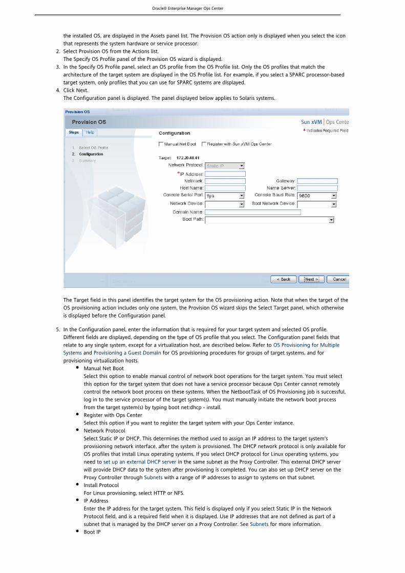
Oracle® Enterprise Manager Ops Center1.
2.
3.
4.
5.
the installed OS, are displayed in the Assets panel list. The Provision OS action only is displayed when you select the iconthat represents the system hardware or service processor. Select Provision OS from the Actions list.The Specify OS Profile panel of the Provision OS wizard is displayed. In the Specify OS Profile panel, select an OS profile from the OS Profile list. Only the OS profiles that match thearchitecture of the target system are displayed in the OS Profile list. For example, if you select a SPARC processor-basedtarget system, only profiles that you can use for SPARC systems are displayed.Click Next.The Configuration panel is displayed. The panel displayed below applies to Solaris systems.
The Target field in this panel identifies the target system for the OS provisioning action. Note that when the target of theOS provisioning action includes only one system, the Provision OS wizard skips the Select Target panel, which otherwiseis displayed before the Configuration panel.
In the Configuration panel, enter the information that is required for your target system and selected OS profile.Different fields are displayed, depending on the type of OS profile that you select. The Configuration panel fields thatrelate to any single system, except for a virtualization host, are described below. Refer to OS Provisioning for Multiple
and for OS provisioning procedures for groups of target systems, and forSystems Provisioning a Guest Domainprovisioning virtualization hosts.
Manual Net BootSelect this option to enable manual control of network boot operations for the target system. You must selectthis option for the target system that does not have a service processor because Ops Center cannot remotelycontrol the network boot process on these systems. When the NetbootTask of OS Provisioning job is successful,log in to the service processor of the target system(s). You must manually initiate the network boot processfrom the target system(s) by typing boot net:dhcp - install.Register with Ops CenterSelect this option if you want to register the target system with your Ops Center instance.Network ProtocolSelect Static IP or DHCP. This determines the method used to assign an IP address to the target system'sprovisioning network interface, after the system is provisioned. The DHCP network protocol is only available forOS profiles that install Linux operating systems. If you select DHCP protocol for Linux operating systems, youneed to in the same subnet as the Proxy Controller. This external DHCP serverset up an external DHCP serverwill provide DHCP data to the system after provisioning is completed. You can also set up DHCP server on theProxy Controller through with a range of IP addresses to assign to systems on that subnet.SubnetsInstall ProtocolFor Linux provisioning, select HTTP or NFS.IP AddressEnter the IP address for the target system. This field is displayed only if you select Static IP in the NetworkProtocol field, and is a required field when it is displayed. Use IP addresses that are not defined as part of asubnet that is managed by the DHCP server on a Proxy Controller. See for more information.SubnetsBoot IP

Oracle® Enterprise Manager Ops Center
5.
6.
7.
For Linux provisioning, enter the IP address of the network interface that the target system will use for OSprovisioning. This is a required field when it is displayed.NetmaskEnter the netmask value that the target system will use after the OS has been installed.GatewayEnter the gateway value that the target system will use after the OS has been installed.Host NameEnter the host name that the target system will use after the OS has been installed.Name ServerEnter the IP address or host name of the name server that the target system will use after the OS has beeninstalled.Console Serial PortTo monitor the installation using a serial connection, select the correct console serial port device.Console Baud RateTo monitor the installation using a serial connection, select the correct serial port device baud rate.Network DeviceSelect the device for the network interface that the target system will use after the OS has been installed.Typically you only need to manually specify this value if it is not automatically determined.Boot NetmaskFor Linux provisioning, enter the netmask value that of the network interface that the target system will use forOS provisioning, if required.Boot GatewayFor Linux provisioning, enter the IP address of the gateway for the network interface that the target system willuse for OS provisioning, if required.Boot Host NameFor Linux provisioning, enter the host name that the target system will use for OS provisioning, if required.Boot Name ServerFor Linux provisioning, enter the IP address or host name of the name server that the target system will use forOS provisioning, if required.Kernel ParametersFor Linux provisioning, enter kernel parameters for the GRUB menu of the target system, if necessary.Domain NameFor Solaris provisioning, enter the DNS domain name that the target system will use, if required.Boot PathFor Solaris provisioning, select a physical device name from the Boot Path list, if the target system requires thatyou specify it manually.
In the Configuration panel, click Next.The Summary panel is displayed.Click Provision to submit the OS provisioning job.A message indicates that the OS provisioning job has been submitted. Click OK to dismiss the message.The Provision OS wizard will give an error message if the Boot IP address is not in the subnet of any of the Proxyinterfaces or DHCP subnets.
You can view the status of the provisioning job from the Jobs panel.
OS Provisioning for Multiple SystemsUse the Provision OS wizard to provision an OS on multiple target systems.
When you select a system group from the Assets panel, the Provision OS wizard allows you to:
Provision all systems in a system group according to the same configuration informationAdjust the list of OS provisioning targets, either by adding systems or groups, or removing systems or groups, from thelist of targets for the OS provisioning actionSpecify configuration information separately for each target in the Target List, or specify the same configurationinformation for all targets
Any system group or single system that you include in the Target List is considered a single target. You can specify configurationinformation for any target that you include in the Target List.
This procedure describes using the Provision OS wizard to provision an OS on multiple target systems, other than VirtualizationHosts.

Oracle® Enterprise Manager Ops Center
1. 2.
3.
4.
5.
6.
Before You Begin
Make the OS image that you want to use available in Ops Center, using one of the , Importing OS Images and FLARs, or procedures.Loading OS Images From CD or DVD Downloading OS Images
Create an OS Profile that is appropriate for provisioning the OS that you want to use, using either the Creating OS or procedure.Profiles for Solaris Systems Creating OS Profiles for Linux Systems
Discover the systems that you want to provision, disable system monitoring, and configure DHCP services, using theprocedures in . If you do not configure DHCP services, the Provision OS wizard will give anPreparing to Provision an OSappropriate error message.
To Provision an OS on Multiple Systems
From the Assets panel, select an existing system group as the target for OS provisioning. Select Provision OS from the Actions list.The Specify OS Profile panel of the Provision OS wizard is displayed, containing a list of only those OS profiles that matchthe architecture of the system group. For example, if you select a group of SPARC technology-based target systems, onlyprofiles for SPARC systems are displayed. Select an OS profile and click Next. All targets will be provisioned according to the OS profile that you select.The Select Targets panel is displayed. The Target List shows the system group that you selected. The Available Items listdisplays all of the assets that use the OS profile you selected, including assets that are not part of the system group thatyou selected. Use the Add to Target List and Remove from Target List buttons to identify all the targets to be provisioned. Add targetsfrom the Available Items list or remove targets from the Target List, as necessary. Click Next.The Configuration panel is displayed.
If you specified one target, the Target field displays the name.If you specified more than one target, the Target List contains all the target names and includes two buttons:the Configure All Targets button and the Configure the Targets One at a Time button. These buttons affect theTarget field.
If you select Configure All Targets, the information that you will specify applies to all targets in theTarget List. The Target field indicates All Targets.If you select Configure the Targets One at a Time, you specify information each target separately. TheTarget field displays the list of targets. From the Target field, select the target that you want toconfigure first.
In the Configuration panel, enter the information that is required for the OS profile and for the current target, or for alltargets. The required information differs, depending on the OS profile, whether a target comprises multiple systems, andwhether you have multiple targets in the Target List.
Manual Net BootSelect this option to enable manual control of network boot operations for the target system. You must selectthis option for the target system that does not have a service processor because Ops Center cannot remotelycontrol the network boot process on these systems. When the NetbootTask of OS Provisioning job is successful,log in to the service processor of the target system(s). You must manually initiate the network boot processfrom the target system(s) by typing boot net:dhcp - install.Register with Ops CenterSelect this option if you want to register the target with your Ops Center instance.Configure All TargetsSelect this option to use the same configuration information for all targets. This option displays if the Target Listcontains multiple targets.Configure the Targets One at a TimeSelect this option to specify different configuration information for each target. This option displays if theTarget List contains multiple targets.Target
With only one target to provision, the name of the target displays.With more than one target to provision, and with Configure the Targets One at a Time selected, thisfield displays a pull-down list of target names. Select the target for which you want to specifyconfiguration information.With more than one target to provision, and with Configure All Targets selected, this field displays AllTargets.
Network ProtocolSelect Static IP or DCHP. This determines the method used to assign an IP address to the target system'sprovisioning network interface, after the system is installed. The DHCP network protocol is only available for OSprofiles that install Linux operating systems.

Oracle® Enterprise Manager Ops Center
6.
7.
Install ProtocolFor Linux provisioning, select HTTP or NFS.IP AddressEnter the IP address for the target system. This field is displayed only if you select Static IP in the NetworkProtocol field, and the target consists of a single system. This is a required field when it is displayed. Use IPaddresses that are not defined as part of a subnet that is managed by the DHCP server on a Proxy Controller.See for more information.SubnetsIP Address RangesEnter the IP address ranges for the target. This field is displayed only if you select Static IP in the NetworkProtocol field, and the target consists of multiple systems. You can specify IP addresses as a comma-separatedlist, and address ranges using two IP addresses separated by a dash, for example, . This10.5.3.10-10.5.3.20
is a required field when it is displayed. Use IP addresses that are not defined as part of a subnet that is managedby the DHCP server on a Proxy Controller. See for more information.SubnetsBoot IPFor Linux provisioning, enter the IP address of the network interface that the target system will use for OSprovisioning. This field displays only if the target consists of a single system. This is a required field when it isdisplayed. Use IP addresses that are not defined as part of a subnet that is managed by the DHCP server on aProxy Controller. See for more information.SubnetsBoot IP RangesFor Linux provisioning, enter the IP address range of the network interface that the target systems will use forOS provisioning. This field displays only if the target consists of a multiple systems. You can specify IP addressesas a comma-separated list, and address ranges using two IP addresses separated by a dash, for example,
. This is a required field when it is displayed. Use IP addresses that are not defined as10.5.3.10-10.5.3.20
part of a subnet that is managed by the DHCP server on a Proxy Controller. See for more information.SubnetsNetmaskEnter the netmask value that the target will use after the OS has been installed.GatewayEnter the gateway value that the target will use after the OS has been installed.Host NameEnter the host name that the target system will use after the OS has been installed. This field is active only if thetarget consists of a single system.Name ServerEnter the IP address or host name of the name server that the target will use after the OS has been installed.Console Serial PortTo monitor the installation using a serial connection, select the correct console serial port device from theConsole Serial Port list.Console Baud RateTo monitor the installation using a serial connection, select the correct serial port device baud rate from theConsole Baud Rate list.Network DeviceSelect the device for the network interface that the target will use after the OS has been installed. Typically youonly need to manually specify this value if it is not automatically determined.Boot NetmaskFor Linux provisioning, enter the netmask value of the network interface that the target will use for OSprovisioning, if required.Boot GatewayFor Linux provisioning, enter the IP address of the gateway for the network interface that the target will use forOS provisioning, if required.Boot Host NameFor Linux provisioning, enter the host name that the target system will use for OS provisioning, if required. Thisfield is active only if the target consists of a single system.Boot Name ServerFor Linux provisioning, enter the IP address or host name of the name server that the target will use for OSprovisioning, if required.Kernel ParametersFor Linux provisioning, enter kernel parameters for the GRUB menu of the target, if necessary.Domain NameFor Solaris provisioning, enter the DNS domain name that the target will use, if needed.Boot PathFor Solaris provisioning, select a physical device name from the Boot Path list, if the target system requires thatyou specify it manually. This field is displayed only if the target consists of a single system.
In the Configuration panel, click Next.With more than one target to provision, and with Configure the Targets One at a Time selected, the ProvisionOS wizard selects the next target which requires configuration information. Specify configuration informationfor all targets, and click Next. The Summary panel is displayed.

Oracle® Enterprise Manager Ops Center7.
8.
1.
2.
3.
4.
5.
a.
b.
c.
d.
e. f. g. h.
i.
With only one target to provision, or with Configure All Targets selected, the Summary panel is displayed. Click Provision to submit the OS provisioning job.A message indicates that the OS provisioning job has been submitted. Click OK to dismiss the message.The Provision OS wizard will give an error message if the Boot IP address is not in the subnet of any of the Proxyinterfaces or DHCP subnets.
You can view the status of the provisioning job from the Jobs panel.
OS Provisioning a SPARC Enterprise M-Series Server DomainThe Provision OS wizard enables you to provision an OS on a single target system or domain. When you select a single domainfrom the Asset panel, you are only able to specify configuration information for the selected domain which is the only target forthe OS provisioning action. To provision the OS on the domain in Ops Center, the domain must have an IP address. To provisionan OS on multiple domains, see .OS Provisioning for Multiple Systems
Before You Begin
Import an OS image and save it in Ops Center as described in , Importing OS Images and FLARs Loading OS Images From, or CD or DVD Downloading OS Images
Create an OS profile as described in Creating OS Profiles for Solaris SystemsDiscover existing domains as described in Discovering a SPARC Enterprise M-Series ServerDisable system monitoring and configure DHCP services as described in Preparing to Provision an OS
To Provision an OS on a SPARC Enterprise M-Series Server Domain
From the Asset panel, select the domain to use as the target for OS provisioning.The Actions list displays the available actions, including the Provision OS action. If Ops Center discovered an OS that wasalready installed on the target system, one icon for the system hardware or service processor and one for the installedOS are displayed in the Asset panel list. The Provision OS action only is displayed when you select the icon thatrepresents the system hardware or service processor.Select Provision OS from the Actions panel.The Specify OS Profile panel of the Provision OS wizard is displayed.In the Specify OS Profile panel, select an OS profile from the OS Profile list. Only the OS profiles that match thearchitecture of the target system are displayed in the OS Profile list. For example, if you select a SPARC-based targetsystem, only profiles that you can use for SPARC systems are displayed.Click Next.The Configuration panel is displayed. The Target field in this panel identifies the target system for the OS provisioningaction. Note that when the target of the OS provisioning action includes only one domain, the Provision OS wizard skipsthe Select Target panel, which otherwise is displayed before the Configuration panel.In the Configuration panel, enter the information that is required for your target system and selected OS profile. Thefields in the Configuration panel differ, depending on the type of OS profile that you select. The Configuration panelfields that relate to any single system are described below. Refer to for OSOS Provisioning for Multiple Systemsprovisioning procedures for groups of target systems.
Manual Net Boot – Select this option to enable manual control of network boot operations for the targetsystem. You must select Manual Net Boot for an OS-based or manually-discovered system, because Ops Centercannot remotely control the network boot process on these systems. If you select this option, you mustmanually initiate the network boot process from the target system.Register with Ops Center – Select this option if you want to register the target system with your Ops Centerinstance.Network Protocol – Select Static IP. This determines the method used to assign an IP address to the targetsystem's provisioning network interface, after the system is installed. The DHCP network protocol is onlyavailable for installing Linux OS profiles.IP Address – Enter the IP address for the target domain. Use IP addresses that are not defined as part of a subnetthat is managed by the DHCP server on a Proxy Controller. See for more information.SubnetsNetmask – Enter the netmask value that the target system will use after the OS has been installed.Gateway – Enter the gateway value that the target system will use after the OS has been installed.Host Name – Enter the host name that the target system will use after the OS has been installed.Name Server – Enter the IP address or host name of the name server that the target system will use after the OShas been installed.
Oracle® Enterprise Manager Ops Center
5.
i.
j.
k.
l. m.
6.
7.
1. 2. 3.
Console Serial Port – To monitor the installation using a serial connection, select the correct console serial portdevice.Console Baud Rate – To monitor the installation using a serial connection, select the correct serial port devicebaud rate.Network Device – Select the device for the network interface that the target system will use after the OS hasbeen installed. Typically you only need to manually specify this value if it is not automatically determined.Domain Name – Enter the DNS domain name that the domain will use, if required.Boot Path – Select a physical device name from the Boot Path list, if the target domain requires that you specifyit manually.
In the Configuration panel, click Next.The Summary panel is displayed.Click Provision to submit the OS provisioning job.A message indicates that the OS provisioning job has been submitted. Click OK to dismiss the message.
Provision FirmwareOps Center automates firmware provisioning at a single chassis or system level, and at data center level. The provisioning processis similar, regardless of the hardware, operating system, or underlying technology that you are deploying.
Firmware provisioning enables you to install firmware updates on a server by using firmware images and firmware profiles.
At a high level, provisioning firmware involves the following steps:
Importing a firmware file with the associated metadata into the Firmware Library.Creating firmware profiles based on one or more firmware images.Updating firmware based on the profile and its associated firmware images or by applying updates based on the outputof a Firmware Compliance report.
About Firmware ProvisioningFirmware provisioning enables you to provision a version of the firmware on servers or chassis. The firmware provisioning processin Ops Center is similar to the OS provisioning process. The process involves three main steps:
1. Creating a Firmware Image2. Creating a Firmware Profile3. Updating Firmware
The first two steps are typically one-time tasks for each collection of firmware that you want to update.
A firmware image is a copy of a particular system firmware with associated metadata. The firmware image allows you to updatethe firmware in an automated way through the use of firmware profiles. The firmware metadata helps determine compatibilitybetween a firmware image and a target system. The required metadata includes the firmware type, what system or systems thefirmware is for, the version of the firmware, and any dependent firmware (other firmware on which the firmware depends).
A firmware profile is a collection of one or more firmware images and policies that defines how to update one or more firmwareimages on a system. A firmware profile can contain any set of unique firmware images. In addition, a firmware profile cannotcontain different versions of the same firmware image. You can also use a firmware profile to generate compliance reports for aset of servers.
Firmware profiles are used to update your firmware. Most firmware updates to the Service Processor require that the server beshut down prior to the firmware update. If the firmware image has the power off option selected, this is a hard shutdown of thesystem and you must gracefully bring down the OS prior to attempting updating the firmware.
You can also update firmware for SPARC Enterprise M-Series Servers such as the Sun SPARC Enterprise®M3000/M4000/M5000/M8000/M9000 server or a Fujitsu SPARC Enterprise M3000/M4000/M5000/M8000/M9000 server. Theprovisioning process is the same as any other server.
Firmware Images

Oracle® Enterprise Manager Ops Center
1. 2. 3.
4.
5.
6. 7. 8.
9. 10.
11.
1. 2.
3.
This section describes how to create, edit, view, and delete firmware images as well as how to determine firmware metadata andlocate the default image location on the Enterprise Controller.
Creating a Firmware Image
Firmware images are platform-specific and must be downloaded to an image directory that is accessible by the EnterpriseController. By default, the firmware image is stored at on the Enterprise Controller./var/opt/sun/xvm/images/firmWare
Before You Begin
Download the firmware image to the Enterprise Controller. If required, uncompress any files that provide the specific firmwarefile and its associated README. These files can be stored on the local file system or an NFS mounted file system.You should check the firmware update's README file for metadata.
To Create a Firmware Image
Click Libraries in the Navigation panel.Click Firmware Images.Click Create Firmware Image in the Actions panel.The Create Firmware Image wizard is displayed.Type the firmware image name and description.The image name must be the same as the firmware file name, for example, .FFXCP1080.tar.gz
Select the firmware image file from the Enterprise Controller. If you do not have the image file in the EnterpriseController, upload the image file from your local system to the Enterprise Controller.Click Next.Select the platforms for the firmware image, then click Next.Specify the type and version of the firmware image.The version must match the version number of the firmware image file.For example, if you create a firmware image for the image file , enter as the version.FFXCP1080.tar.gz 1080
Select the firmware images that this firmware image depends on.Select Power Off and click Next.Most firmware updates to the Service Processor require that the server has been shut down. When a firmware image hasthe Power Off attribute, you must bring down the OS and shut down the server before you attempt to provisionfirmware.Review the details in the Summary page. Click Finish to create the firmware image.
Displaying Firmware Images
After you create a firmware image, the image appears in the Firmware Provisioning section in Libraries. You can use view the following image details in the library:
Image nameVersionDescriptionTypeDependenciesSupported platformsPower off requirement
To Display Firmware Images
Click Libraries in the Navigation panel.Click Firmware Images.A list of firmware images is displayed in the center panel.Click the image name for details on that image.

Oracle® Enterprise Manager Ops Center
1. 2.
3. 4. 5.
Editing a Firmware Image
Editing a firmware image involves editing the parameters that were specified when you created the firmware image.
To Edit a Firmware Image
Click Libraries in the Navigation panel.Click Firmware Images.A list of firmware images is displayed in the center panel.Select a firmware image from the list in the center panel.Click the Edit Firmware Image icon.Edit the firmware image parameters and click Save.
Determining Metadata for a Firmware Image
When you import a firmware image, you need to provide metadata for the firmware update. You can usually find much of themetadata information for a firmware update in its corresponding README file.
The metadata that you provide includes the firmware type, what system or systems the firmware is for, the version of thefirmware, and the additional firmware that the firmware depends on.
The following is an example from a README file for ALOM-CMT firmware, where a single binary is deployed to the ServiceProcessor. This example represents the contents of the README file. Each README file might have a different format forproviding the same information required to create the firmware image.
To determine the type and version of the firmware update:
Latest Sun Firmware(6.1.2):System ---------------------------------- Firmware 6.1.2 Sun Fire[TM] T2000 2006/01/20 18:19System ALOM-CMT v1.1.2 Jan 20 2006 18:06:10 VBSC 1.1.1 Jan 20 2006 17:56:19 Reset V1.0.0 Hypervisor 1.1.0 2005/12/15 11:10 OBP 4.20.0 2005/12/15 16:48 Sun Fire[TM] T2000 POST 4.20.0 2005/12/15 17:19
To determine the models supported:
This README is intended users who wish to forupgrade the firmware in their Sun Fire T2000.
To determine if the system needs to be powered off prior to updating the firmware:
a)To update the Sun Firmware, the system must be powered offSystem (i.e. in standby mode).
Based on the preceding information, you would provide the following metadata information for the firmware update:
Available platforms – Sun Fire T2000Type – VBSCVersion – 1.1.1Require power off – Yes
For this example, the VBSC firmware subcomponent/type with version 1.1.1 was used. You can use any of the other types such asALOM-CMT:1.1.2 or OBP:4.20.0. However, you must ensure that the version specified is always the firmware subcomponent/type.Failure to do so may result in the firmware update operation failing or not being performed.
Oracle® Enterprise Manager Ops Center
1.
2. 3.
4. 5.
6.
1. 2.
3.
1. 2.
3.
Changing the Default Location of Firmware Images
By default, firmware images created through Ops Center are placed in the directory./var/opt/sun/xvm/images/firmWare
The default location of firmware images is defined by the following properties files on the Enterprise controller and Proxycontroller:/var/opt/sun/xvm/satellite.properties
/var/opt/sun/xvm/proxy.properties
Note – If the default location for importing firmware image files is changed, both firmware and OS image files are affected.Changing the default location could affect the High Availability capabilities of Ops Center. Please contact Sun Support Servicesbefore changing the default location.
To Change the Default Location of Firmware Images
On the Enterprise Controller, open the following property file:/var/opt/sun/xvm/satellite.properties
Change the value of to the desired location.id.satellite_base_dir
On the Proxy Controller, open the following property file:/var/opt/sun/xvm/proxy.properties
Change the values of and to the desired locations.id.satellite_base_dir id.proxy_base_dir
Depending on whether you are pointing to a new Enterprise Controller or to Proxy Controller directories, manually moveor copy the entire directory structure (one or both) to the new directory. This includes any previously imported firmwareimage files.Restart the Enterprise Controller and Proxy Controller.
Deleting a Firmware Image
Caution – You cannot delete a firmware image that is currently part of a firmware profile. First, remove the firmware image fromthe firmware profile and then delete the firmware image.
To Delete a Firmware Image
Click Libraries in the Navigation panel.Click Firmware Images.A list of firmware images is displayed in the center panel.Click the image name in the center panel, then click the Delete Firmware Image icon.
Firmware ProfilesThis section describes how to create, edit, view, and delete firmware profiles.
Creating a Firmware Profile
A firmware profile is a template that defines how to provision one or more firmware images on a system. A firmware profile cancontain any set of firmware images; however, a firmware profile cannot contain two different versions of the same firmwareimage. A firmware profile also allows you to generate a for a set of servers.Firmware Compliance Report
To Create a Firmware Profile
Click Libraries in the Navigation panel.Click Firmware Profiles.

Oracle® Enterprise Manager Ops Center
3.
4.
5.
6.
7.
8. 9.
1. 2.
3.
1. 2.
3. 4. 5.
1. 2.
3. 4.
Click Create Firmware Profile in the Actions panel.The Create Firmware Profile wizard is displayed.Specify a profile name.The profile name must be the same as the firmware file name, for example, .FFXCP1080.tar.gz
Select the Force Reinstall check box to specify whether a firmware re-install must be forced if the target system hasfirmware at the same version as that of the update.Select the Force Downgrade check box to specify whether a firmware downgrade must be forced if the target system hasfirmware at a higher version than that of the update.Select the Reset Service Processor check box to reset the service processor before the firmware update, then click Next.
– The action of resetting the service processor before the firmware update allows the service processor to beNoteflashed with a higher rate of success. This is especially useful for older service processors. This action is supported onlyfor servers and not chassis.Select the firmware images that must be part of this firmware profile, then click Next.Review the details in the Summary screen, then click Finish to create a firmware profile.
Displaying a Firmware Profile
You can display a list of profiles, and use the existing profiles to create new versions.
To Display a Firmware Profile
Click Libraries in the Navigation panel.Click Firmware Images.A list of firmware profiles is displayed in the center panel.Click the image name for details on that image.
Editing a Firmware Profile
A profile contains one or more firmware images and policies that define how to update one or more firmware images on asystem. You can edit the profile to change the images and policies associated with the profile.
To Edit a Firmware Profile
Click Libraries in the Navigation panel.Click Firmware Profiles.A list of available firmware profiles is displayed in the center panel.Select a firmware profile from the list in the center panel.Click the Edit Firmware Profile icon.Edit the firmware profile parameters, then click Save.
Deleting a Firmware Profile
You can delete an existing firmware profile, unless the profile is currently being used to provision firmware on a server.
Deleting a Firmware Profile
Click Libraries in the Navigation panel.Click Firmware Profiles.A list of available firmware profiles is displayed in the center panel.Select the firmware profile to delete.Click the Delete Firmware Profile icon.

Oracle® Enterprise Manager Ops Center
1. 2. 3.
4. 5. 6. 7. 8.
1. 2. 3.
1. 2. 3. 4. 5.
6.
Firmware UpdatesYou can use a profile or a Firmware Compliance report to provision or update your firmware. Most firmware updates to theService Processor require that the server be shut down prior to the firmware update. If the firmware image has the power offoption selected, this is a hard shutdown of the system and you must gracefully bring down the OS prior to attempting updatingthe firmware.
Updating Firmware
Firmware profiles are used to update your firmware. Most firmware updates to the Service Processor require that the server beshut down prior to the firmware update. If the firmware image has the power off option selected, this is a hard shutdown of thesystem and you must gracefully bring down the OS prior to attempting updating the firmware.
The hardware component is unavailable for service during the firmware update. If a network failure occurs during the update,you must update the firmware again. Failure to do so might result in display of an incomplete firmware inventory list.
To Update Firmware
Expand All Assets in the Navigation panel.Click on Systems or Chassis.Click Update Firmware in the Actions panel.The Update Firmware wizard is displayed.In the Select a firmware profile window, select a firmware profile and click Next.Select the targets for updating the firmware, then click Next.Review the details in the Summary screen and click Update to update the firmware.To track the progress of the firmware update, go to the Jobs section of the BUI and view the job status.Reset the server after the Update Firmware job completes.
Note – Automatic reboot of the hardware component upon completion of the firmware update is not supported.
Updating Firmware for a SPARC Enterprise M-Series Server
The procedure to update firmware on a Sun SPARC Enterprise® M3000/M4000/M5000/M8000/M9000 server or a Fujitsu SPARCEnterprise® M3000/M4000/M5000/M8000/M9000 server, sometimes referred to as SPARC Enterprise M-series servers, differsfrom firmware provisioning on other types of systems.
The domains in the server appear as blade servers under the chassis. To update the firmware on the M-series servers, you mustdownload the firmware image and create a firmware profile.
The hardware component is unavailable for service during the firmware update. If a network failure occurs during the update,you must update the firmware again. Failure to do so might result in display of an incomplete firmware inventory list.
Updating firmware on a SPARC Enterprise M-Series server consists of the following tasks:
Creating a Firmware ImageCreating a Firmware ProfileUpdating Firmware
Before You Begin
Before you can use Ops Center to update the firmware on a SPARC Enterprise M3000/M4000/M5000/M8000/M9000 server andthen manage the service processor and domains, you must perform the following tasks on the server:
In the XSCF service processor, create a user that has privileges.platadm
Use the user name and password that have the permissions when managing the servers.platadm
Manually .configure the domainsCreate a group for the SPARC Enterprise M-Series servers and add the servers to the group.Assign the Ops Center Admin role to the group.

Oracle® Enterprise Manager Ops Center
6. 7.
1.
2.
3. 4.
a. b. c.
d.
e.
f. g.
h.
i.
Discover the SPARC Enterprise M-Series Server to discover the server in Ops Center.Power off the domains before doing a firmware upgrade from the Ops Center BUI.
Note – To successfully perform M-Series discovery and firmware provisioning, the XSCF service processor account must have auser with privilege.platadm
To Create a Firmware Image
The M-Series does not support OpenBoot PROM (OBP) images. The firmware image file includes the images for XSCF, XCP, andOBP. The following naming conventions are used for the servers in the series:
FF – M4000, M5000DC – M8000, M9000IK – M3000
Download the firmware image file to a directory that is accessible by the Enterprise Controller. By default, the firmwareimage is stored at on the Enterprise Controller./var/opt/sun/xvm/images/firmWare
The naming convention for an M4000 or M5000 firmware image is:
{FF}XCP{VVVV}.tar.gz
The naming convention for an M8000 or M9000 firmware image is:
{DC}XCP{VVVV}.tar.gz
The naming convention for an M3000 firmware image is:
{IK}XCP{VVVV}.tar.gz
If required, uncompress any files that provide the specific firmware file and its associated README. These files may bestored on the local file system or an NFS mounted file system.Check the firmware update's README file for metadata.Create a firmware image through the BUI.
Click Libraries in the Navigation panel.Click Firmware Images.Click Create Firmware Image in the Actions panel.The Create Firmware Image wizard is displayed.Type the firmware image name and description.The image name must be the same as the firmware file name, for example, .FFXCP1080.tar.gz
Select the firmware image file from the Enterprise Controller, then click Next. If you do not have the image filein the Enterprise Controller, upload the image file from your local system to the Enterprise Controller.Select the supported platforms for the firmware image, then click Next.Specify the type and version of the firmware image.
– The firmware image version must match the version number in the firmware image file.NoteFor example, if you create a firmware image for the image file , the version numberFFXCP1080.tar.gz
entered from BUI must be 1080.Select the firmware images that this firmware image depends on.
– XCP firmware upgrades do not require a hard shutdown of SPARC Enterprise M-Series platform. XCPNotefirmware upgrades can be performed with running domains. After upgrading the firmware, reboot the domains.Review the details in the Summary screen and click Finish to create a firmware image.
To Create a Firmware Profile
You use a firmware profile to provision one or more firmware images on a server and to generate a Firmware Compliance Reportfor a set of servers. A firmware profile can contain any set of firmware images. However, the profile cannot contain two differentversions of the same firmware image.
The profile used to update your firmware must be specific to the type of chassis, which means that it should only contain the

Oracle® Enterprise Manager Ops Center
1. 2. 3.
4.
5.
6.
7. 8. 9.
10.
1. 2. 3.
4. 5. 6. 7. 8.
1. 2. 3.
4. 5.
1. 2. 3. 4.
SPARC Enterprise server firmware images.
Click Libraries in the Navigation panel.Click Firmware Profiles.Click Create Firmware Profile in the Actions panel.The Create Firmware Profile wizard is displayed.Specify a profile name.The profile name must be the same as the firmware file name, for example, .FFXCP1080.tar.gz
For each firmware image included in the firmware profile, specify whether a firmware re-install should be forced if thetarget system has firmware at the same version as that of the update.For each firmware image included in the firmware profile, specify whether a firmware downgrade should be forced if thetarget system has firmware at a higher version than that of the update.Click Next.Select the firmware images that should be part of this firmware profile.Click Next.Review the details in the Summary screen and click Finish to create a firmware profile.
To Update Firmware
Expand All Assets in the Navigation panel, then click Chassis.Click M-Series.Click Update Firmware in the Actions panel.The Update Firmware wizard is displayed.In the Select a firmware profile, select a firmware profile and click Next.Select the targets for updating the firmware, then click Next.Review the details in the Summary screen and click Update to update the firmware.To track the progress of the firmware update, go to the Jobs section in the BUI and view the job status.Reset the server after the Update Firmware job completes.
Note – Automatic reboot of the hardware component upon completion of the firmware update is not supported.
Firmware Compliance Report
The Firmware Compliance Report feature allows you to create a report by running a profile against one or more firmwareinstances. The report indicates whether or not the firmware complies with the profile's specifications. Once the report is run, youhave the option of updating the firmware prior to exiting the Firmware Compliance Report wizard.
To Run a Firmware Compliance Report
Expand All Assets in the Navigation panel.Click on Systems or Chassis.Click Run Firmware Compliance Report in the Actions Panel.The Firmware Compliance Report wizard is displayed.Select the firmware profile and click Next.Review the details in the Summary screen and click Finish.
Example – Using a Firmware Compliance Report to Validate an Update
You can use a Firmware Compliance report to verify that a firmware update was successfully applied to all target systems. As anexample, you have 10 systems with firmware version X that must be upgraded to firmware version Y.
Create a firmware profile.Provision the firmware with version Y to all systems.Wait until the completion of the firmware provisioning job.Run the Firmware Compliance Report on firmware version Y on all systems.For successfully updated machines, the report will show a compliant status. The failed systems are reported separately.

Oracle® Enterprise Manager Ops Center
1.
2.
3. 4.
Viewing the Updated Firmware Version
In Ops Center, the firmware information is monitored and refreshed at periodic intervals (30 minutes) for both servers andchassis. This ensures that the firmware information is current. The attribute that is re-read during the firmware refresh is
.firmwareInfo
If you have updated the firmware through Ops Center, you can view the updated firmware version in the BUI afterrefreshing the browser.If you have updated the firmware outside of Ops Center, click Refresh from the Server Actions panel. When the Refreshjob completes successfully, you can view the updated firmware version in the BUI.
Update an OSOps Center enables you to update, or patch, the following operating systems:
Solaris softwareLinuxWindows
Several update reports and methods of patching are available, depending on the OS type. In some cases, you can use profiles andpolicies to define how patches are applied and how the update job runs. You can also create, modify, and compare systemcatalogs, and create a profile from a system catalog. The reports and update methods are discussed in detail in the OS-specificupdate sections.
About Updating an OSUsing Ops Center, operating systems are secure and current. You can patch the following operating systems:
Solaris 8, 9, and 10 (SPARC)Solaris 10 (x86)Red Hat Linux Advanced Server 3, 4, and 5SUSE Linux Enterprise 8, 9, and 10Microsoft Windows
The processes for installing patches on Solaris and Linux operating systems are very similar. The process for updating Windows isdifferent. Detailed information is available in each OS-specific section.
Managing Systems
Before you can use Ops Center to patch and update an OS, you must discover the OS to gather identification for each operatingsystem and then you must manage the OS to install the agent controller software. The agent controller software allows OpsCenter to check the current condition of the operating system and to perform update operations.When you manage an OS, the following actions occur:
The Agent is registered. This might take five minutes. Until the agent is registered, you cannot perform any updatefunctions.A Notification is displayed when the agent OS update functionality is enabled. The agent is registered and the TargetSelector is enabled.The agent runs an inventory check and creates an OS Update Catalog for the system.A notification is displayed when the OS Update Catalog is available. The OS Update Catalog actions are enabled.
Obtaining Patches
By default, Ops Center software downloads patches and new software using Internet access. The Enterprise Controller isconnected to the Internet and to the Solaris Knowledge Services database. You can configure Ops Center to connect to thirdparty vendors, such as Red Hat, and provide authentication details. When you run an update job, the patches are downloaded

Oracle® Enterprise Manager Ops Center
from the corresponding site. For example, Solaris OS patches are available from the SunSolve web site and Red Hat patches areavailable from the Red Hat site.
Ops Center downloads only signed patches from SunSolve or EIS DVD. The patches must be in the jar or jar.gz format or in thepatch directory.
If your data center cannot have direct Internet access, configure the software to operate in Disconnected mode. In this mode, theEnterprise Controller is not connected to the Internet and you must upload all content, such as patches, to the EnterpriseController. To obtain the patches and packages, you must run the harvester script on a system outside of the data center thatdoes have Internet access. You then save the downloaded information to a portable media device, such as a CD or DVD, and bringit to your data center for manual upload. The uploaded software is stored in the Local Content section of the Updates Library.
Another option is to run your Enterprise Controller in Disconnected Mode until you need to download patches or packages. Youthen change the Enterprise Controller's mode to Connected only to download the required patches and packages, and thenchange back to the Disconnected mode.
Local Content (Solaris and Linux OS only)
Local Content enables you to save custom files, scripts, executables, or binaries in the Updates Library. You can save these files onyour hosted tier and they remain private to your organization. Your local content files might include instructions that must becarried out before or after a job. For example, you might use local content to test managed hosts before running a job.
You can add categories for your content in the Updates Library, edit a component file, and delete a local component from yourlibrary.
Reports
Several OS Update reports are available. Reports are OS-specific, but many reports check for new patches and security advisories.You can get a general report, or test a system or installed package for available fixes. For auditing purposes, you can create a OpsCenter job history report.
Detailed information is available in each OS-specific section. When you create a report, you select the criteria that are relevant toyou, such as a list of hosts that have a specific patch or a list of hosts that do not have a specific patch. You can export the resultsof most reports to a CSV format.
For Solaris Baseline Analysis Reports, you can run the report much quicker if you run a patch simulation and do not download thepatches.
The BUI supports column-based sorting in the Report Results section for all the OS Update reports except for Job History Reportand Baseline Analysis Report. Clicking on any field in the header part of the results table in the center panel will sort the results ofthat column.
System Catalogs (Solaris and Linux OS only)
A list of installed OS software components is available in the system catalog. The catalog is automatically created when you firstmanage the OS. You can display and modify the catalog. You can also create historical catalogs, which are snapshots of the OS.You can use the System Catalog to create a snapshot of your OS before you run an update job.
You can upload patches, packages, and local content and save it in the Updates Library. Local content includes files, scripts,executables, or binaries that are not known to the hosted tier and are private to your organization. Your local content filestypically include instructions that must be carried out before or after an update job.
Update Job
Ops Center contains the following options in an update job to maintain control and consistency across your data center:
Groups – Help you to organize the display of assets in the user interface and act as targets for many types of jobs.Roles – Enable you to determine the tasks that a user can perform on a specific asset, or a group of assets.Update Profiles – Define what you will allow, or not allow, to be installed on a target. You can select from a list ofpredefined profiles, your existing custom profiles, or you can create a new profile by modifying an existing profile.Update Policies – Define how a job is performed and sets the automation level of the job. You can select from a list of

Oracle® Enterprise Manager Ops Center
your existing policies or you can create a new policy.Solaris Baselines, white lists, and black lists – Enable you to bring all systems to a baseline, and remove or add patchesfrom the list of patches to install.Local Content – Enable you to add custom packages, software, and scriptsPatch Simulations – Estimates how much time is required to complete an update job based on the policy and profile andif the job will succeed.Rollback and recovery capabilities – Enables you to back out patchesReports – Maintain patch records, including compliance reports and patch history.
You can define the following job parameters while creating a new update job:
Job Name and Description – Identifies the job in the Jobs list. A detailed description is helpful in clearly identifying thejob in the historical record. You can rerun existing jobs.Profile – Defines what you will allow, or not allow, to be installed on a target. You can select from a list of predefinedprofiles, your existing custom profiles, or you can create a new profile by modifying an existing profile.Policy – Defines how a job is performed and sets the automation level of the job. You can select from a list of yourexisting policies or you can create a new policy.Target Settings – Defines whether the target should be different or similar for each task in the job.Run Type – Defines whether this job is in simulation mode or is an actual run. You can choose to deploy the job, or torun a job simulation. A job simulation determines the actions and results of a job, and estimates how much time isrequired to complete the job. Job simulations also indicate if your policy and profile responses will enable the job tosucceed. You can tun a job simulation without downloading patches and packages.Task Execution Order – Specifies whether the tasks should be run in parallel or sequentially.Task Failure Policy – Specifies what action to take if the task fails.Targets – Selects the target systems for the job.
Solaris OS Patching
The following package and patch services and features are supported for patching the Solaris OS in Ops Center:
Recommended patch clustersSolaris baseline reportsCustom packagesActive dependency rulesPatch analysisJob simulationJob schedulingRollback and recovery
You can use Solaris Live Upgrade to update your Solaris software or you can update your Solaris Containers and zones.
Linux OS Patching
The following package and RPM installation services and features are supported for patching Linux systems in Ops Center:
Linux Red Hat Package Manager (RPM)Custom packagesActive dependency rulesPatch analysisJob simulationJob schedulingRollback and recovery
Windows OS Patching
The following features are supported for patching Windows systems in Ops Center:
Patch analysisJob scheduling
Using Profiles and Policies to define and control the job (Solaris and Linux only)

Oracle® Enterprise Manager Ops Center
Solaris and Linux OS use profiles and policies to manage update jobs, use your own files and scripts in Ops Center, and createsnapshots (known as system catalogs.)
OS Update Capability
Service Solaris OS Linux Windows Zones Branded Zones
Patch analysis Yes Yes Yes Yes Yes
Job simulation Yes Yes No Yes Yes
Job scheduling Yes Yes Yes Yes Yes
Rollback and recovery Yes Yes No
Custom packages Yes Yes No Yes Yes
Active dependency rules Yes Yes No Yes Yes
OS Update Reports
Several predefined OS Update reports are available. The reports enable you to check for new patches and security advisories. Youcan get a general report, or test a system or installed package for available fixes. For auditing purposes, you can create a OpsCenter job history report.
When you create a report, you select the criteria that are relevant to you, such as a list of hosts that have a specific patch or a listof hosts that do not have a specific patch. You can export the results of most reports to a CSV format.
Reports Solaris OS Linux Windows Zones Branded Zones
Baseline Reports Yes No No Yes Yes
CVE Compliance Reports Yes Yes No Yes Yes
Distribution Update Report Yes Yes No Yes Yes
Host Compliance Report Yes Yes Yes Yes Yes
Incident Compliance Report Yes Yes Yes Yes Yes
Job History Report Yes Yes No Yes Yes
Package Compliance Report Yes Yes No Yes Yes
Service Pack Compliance Report No Yes No Yes Yes
Update Roles and AuthorizationsTo use the Update feature, you must have the proper permissions, or user role, for the asset.
An Ops Center administrator can grant a user one or more of the following roles for a group or asset:
Roles Enables You To
Admin Perform administration actions such as grouping
Update Update a system or group of systems
Update Sim Run simulated update jobs
Provision Provision new operating systems

Oracle® Enterprise Manager Ops Center
Manage Use management actions, such as rebooting
An Admin can assign a user role for a specific asset, such as the Enterprise Controller, or an asset group. When a user is assigneda group role, the user also has the same permissions to all subgroups.
To update multiple operating systems with a single job, you must use a homogeneous OS group as the target. See Using Groupsfor information about how to create a group and add operating systems to the group. Homogeneous groups contain the samerelease of an OS.
To update a Linux OS, you must provide your Red Hat or SuSe login credentials. Ops Center uses the credentials to log in to thethird-party site and download the patches or packages. To provide or update your SunSolve or third-party vendor credentials, see
.Authentications
Admin Authorization
Task Admin Non-Admin
Reports
Save, run, and view BAR from DB Report Yes Yes
Save and view BAR from Agent Report Yes Yes
Run BAR from Agent Report Yes Yes, if you have the Update or Update Sim role for the OStargets
Save/Run/View Compliance Report Yes Yes
Job Submission
Launch Job Wizard from Asset/Group/Profile Yes Yes
View Catalog / Catalog Compare Yes Yes
Launch Job Wizard from Catalog / CatalogCompare
Yes Yes
Submit Simulation Job Yes Yes, if you have the Update or Update Sim role for the OStargets
Submit Deploy Job Yes Yes, if you have the Update role for the OS targets
Answer questions Yes Yes, if you have the Update or Update Sim role for the jobtargets
Rerun job Yes Yes, if you have the Update or Update Sim role for the jobtargets
Launch Copy Job wizard Yes Yes
Profile/Policy Management
Create Profile/Policy Yes No
Save Profile/Policy from job Yes No, even if you have permissions on the original profile/policy
Edit Profile/Policy Yes Yes, if you have the admin role for profile/policy
Delete Profile/Policy Yes Yes, if you have the admin role for profile/policy
View Profile/Policy Yes Yes
View Profile/Policy from job Yes Yes
Administration
Edit Authentications Yes No
Setup Connection Mode Yes No

Oracle® Enterprise Manager Ops Center
OS Update Library Actions Yes No
Note – You must have root permissions to view system profiles/policies. You cannot view system defined profile/policy from job.
OS Update ProfilesProfiles specify which components are to be installed and which are prohibited, and the action to be performed on a system. Aprofile defines the component configuration of the systems that you want to manage.
Use profiles to accomplish the following:
Manage multiple systems in a consistent mannerAutomate repetitive administration jobsRecord the requirements of your enterpriseAutomatically create servers and workstationsManage dependencies and ensure consistency
The profile settings Required, Not Allowed, and Upgrade affect a managed host only during the actual deployment of the profile.After deploying a profile, you could run another job that contradicts the settings of the profile; therefore, you should thoroughlyunderstand your system settings and requirements.
Note – If a conflict occurs between a profile and policy, the profile overrides the policy.
Predefined Profiles
Predefined profiles are provided to perform common system-wide checks and to automate the operating system updates. Theseprofiles cannot be edited or deleted. When creating a new job with a predefined profile, you must also include a policy. Thepolicy determines the trends and automation of the deployment of the complete profile.
The predefined profiles in Ops Center are shown here.
The following are the predefined profiles:
Check Bugs Fix – Checks every bug fix patch known to the Enterprise Controller of the selected distribution to seewhether the patch can fix the installed components.Check Security – Checks every security instance known to the Enterprise Controller of the selected distribution to seewhether the instance can fix the installed components.Check System – Installs or upgrades missing dependent components according to the rules that are set in the satellitelocal services of the selected distribution.Check Withdrawn Patches – Checks the installed patch to determine whether the patch has been withdrawn. If so, theprofile either upgrades to a newer patch or downgrades to a supported version.Local Software Review – Checks local components against the Enterprise Controller of the selected distribution. Thisprofile helps you to find the local components under software packages. If you confirm the actions of this profile, thelocal version is replaced with a certified version.Perform Reboot – Restarts the selected system.

Oracle® Enterprise Manager Ops Center
1. 2. 3.
4. 5. 6.
7.
8.
9. 10.
Perform Reboot + Reconfigure – Restarts the selected system and performs specific post-installation configurations.Upgrade All Components – Checks the installed component against the Enterprise Controller of the selected distributionto see if the installed components can be upgraded.
Creating an OS Update ProfileYou can create your own profiles in Ops Center. You should have the necessary to create profiles.authorization
An OS update job requires one (and only one) profile and one (and only one) policy. In the current release Profiles cannot benested or combined, except as noted below. When the job is submitted a component called the Dependency Resolver (DR)attempts to find a series of actions that can be performed on the target which satisfy the the requirements of the Profile and anyconditions imposed by the Policy.
It's important to note that a Profile is not limited to a set of actions for a single operating system; it can contain actions for oneor more different operating systems, but each action is OS specific. When the profile is applied on the target system, actionswhich do not apply to the target OS are ignored.
The buttons associated with OS Update Profiles are disabled until at least one operating system is activated. This normallyhappens when an asset is managed. Note that the process of managing an asset may take a few minutes to complete.
To Create a New Profile
Click Libraries from the Navigation panel.Click Update Profiles from the Library.Click New Profile from the Actions panel.The New OS Update Profile window is displayed.
Enter a Profile Name and brief Description of the profile.Select the OS Distribution from the drop-down list. (For example, SOLARIS10_86)Locate and select a Component from the Component Tree.You can locate the component by clicking the Expand ( + ) icon to expand the tree, or by using the search box. If a component cannot be found, check that the correct Distribution is selected.If required, select the check box to specify that the component should be added to all applicable distributions.
– This only applies to currently known distributions. When new distributions are activated, you must edit the profileNoteto explicitly add any new components.Specify whether the action is Required, Upgrade, or Uninstall.
– Some actions might not apply. For example, a component cannot be Required if the system does not have theNoteinformation about how to obtain the component.(Optional) You can repeat actions to select multiple components for the same or different operating systems.When you are finished, click Save as Named Profile.

Oracle® Enterprise Manager Ops Center
1. 2. 3. 4. 5. 6.
7.
1. 2. 3. 4.
5.
As components are added to the profile, Profile Contents shows the Component Name, Distribution, and type of action.To remove a component from the list, select the component from Profile Contents list and click Remove from Profile.
Note – The user interface should not allow you to select an illegal combination of actions; for example you cannot mark the samepackage as both Required and Uninstalled. However, this does not guarantee that the set of actions in the Profile has a legalsolution. The UI does not check for dependencies or conflicts, this is handled by the Dependency Resolver on the target when thejob is processed.
As stated earlier, profiles cannot be nested or combined. It is possible to import the actions from another profile by selecting theprofile and clicking Required, but it must be stressed that this causes the actions from that profile to be copied into the currentprofile. Future edits to the other profile will not affect this one.
Editing an OS Update ProfileYou can edit a profile if you have proper authorization.
To Edit a Profile
Click Libraries from the Navigation panel.Click Update Profiles from the Libraries menu.Select a profile from the user-defined profiles list. (System-defined profiles cannot be edited)Click Edit Profile.The Edit OS Update Profile window is displayed.Edit the profile details as required.You can add or remove Components and change profile settings, such as the name or description.Click Save as Named Profile to save the changes made to the profile.If you changed the profile name the system will save the profile under the new name and the old version will beunaffected.If you did not change the profile name, or changed it to match an existing profile, the system will warn you before youoverwrite the existing version.
Exporting an OS Update ProfileYou can export only the User-defined profiles, not the System-defined profiles. You can export profiles one at a time.The exported profile is in an XML-style format which can be read and copied easily. It can also be edited with any standard texteditor.
To Export an OS Update Profile
Click Libraries from the Navigation panel.Click Update Profiles under Libraries.Select one items from the User-defined profiles table in the center panel.Click the Export Profile icon in the center panel.Depending on your browser, you will get a pop-up window from which you can either open the file or save the file to adisk.Click either Open or Save to disk, then click OK.
Importing an OS Update ProfileA profile that has been exported can be imported into a different environment. In this release, the profile might not contain anycomponents for distributions which are not activated; attempting to do so will result in an error. (A solution is to manually editthe profile to remove any such entries). Additionally, any profile entries referring to 'NCOs', such as local content, are silently

Oracle® Enterprise Manager Ops Center
1. 2. 3.
4. 5.
1. 2. 3. 4. 5.
removed during the import process.
To Import an OS Update Profile
Click Libraries from the Navigation panel.Click Update Profiles under Libraries.Click on the Import Profile icon in the center panel.An Import OS Update Profile window is displayed.Enter the file name or click Browse to locate the file to be imported.Click Import Profile.
If the import is successful, the Edit Profile window is displayed. See for more information. You canEditing an OS Update Profilereview the profile, making changes as appropriate, before saving it to the database.
– If you do not save the profile, it will be discarded.Note
Deleting an OS Update ProfileUsers can delete profiles that they have created. Users cannot delete System profile, or profiles created by other users.
To Delete an OS Profile
Click Libraries from the Navigation panel.Click OS Update Profiles.Select a profile to delete from the user-defined profiles list.Click the Delete Profile icon.Click Yes to confirm the delete action.
Note – This marks the profile as deleted in the database; it can no longer be accessed through the UI and will not appear in thelists. Completely removing the profile, or recovering a deleted profile, is a task for a database administrator and is beyond thescope of these instructions.
OS Update PoliciesWhen an OS Update job is executed, the dependency resolver examines the profile to determine what actions to take and in whatorder. Often there will be dependencies on other components, actions that must be performed in single user mode, arequirement to reboot the target operating system, etc. By default the user will be prompted to confirm or reject each of thesesteps during a question and answer exchange. The user can provide answers to the questions in advance by supplying a policy.
A policy is a list of actions that are explicitly approved or denied. They can be created by the user in advance of submitting a job;alternatively the question and answer exchange when a job is executed can be saved as a policy for future re-use.
As with profiles, policies can contain actions relating to more than one operating system.
There are a number of system policies which can be used to automate the update jobs.

Oracle® Enterprise Manager Ops Center
Policy settings are hierarchical; if there is not a policy setting for a component then the policy for that component's parentapplies, and so on. For example, it is possible to create a policy that allows the system to install a given component but prohibitsinstallation of certain specific versions of that component, or vice versa.
Note – The policy only applies to actions that are implicitly generated by the dependency resolver. If a conflict occurs between aprofile and policy, the profile overrides the policy.
Creating an OS Update PolicyPolicies focus on the component level. Depending on the selected distribution, OS Update Components categories may include:
Solaris BaselinesPackages or SoftwarePatchesClustersNotifications
There is also a category of User's Policies, which allows existing policy definitions to be merged into the current policy.
You can select a single component within a category, such as the latest Solaris baseline, or an entire category. You can set thefollowing policy actions for the selected component:
InstallUninstallUpgradeDowngradeApply FixIgnore Conflict
If the selected component is a category or a package group, the setting applies to all the packages in the category or packagegroup. Once you select the component and OS distribution, you can define the policy actions. The Policy Component and ActionSettings are described below.
Policy Component and Action Settings

Oracle® Enterprise Manager Ops Center
1. 2.
3.
4. 5. 6.
Parameter Ask Me Yes No
Install orUninstall
Pause the job for confirmation before installingor uninstalling the selected component.
Install or uninstall the selectedcomponent automatically, asrequired by solution.
Find a solution that doesnot install or uninstall theselected component.
Upgradefrom orDowngradefrom
Pause the job for confirmation before changingthe version of the selected component.
Upgrade or downgrade theselected componentautomatically, as required bysolution.
Find a solution that doesnot upgrade or downgradethe selected component.
Apply Fix Pause the job for confirmation before fixingdependency, security, or bug issues on selectedcomponent.
Automatically apply the fix. Find a solution that doesnot apply a fix on theselected component.
Ignore FileConflict
Pause the job for confirmation, so you see theconflict and decide at run-time whether to ignoreit and continue the job, or to fail the job.
The conflict is understood andknown to be unimportant.Continue the job withoutpause.
Find a solution that doesnot allow for any fileconflicts.
A file conflict will occur if the selected component provides a file that cannot be installed on a machine with a file provided byanother component that is already installed. If both components are certified, the rules of the knowledge base handledeployment without conflicts. If one or both are local components that are not in the knowledge base, the conflict will cause thejob to fail.
Note – Do not set the Ignore File Conflict setting to Yes unless you know the conflict.
If a policy has the Ask Me action, the job pauses for confirmation before continuing. The user will receive a notification that thereis a job waiting for an answer. Click Jobs to view the job status. If a job is paused, the Waiting User Input icon appears in thestatus column. Click the icon to answer the questions.
To Create an OS Update Policy
This procedure enables you to create an OS policy that you can use in update jobs. All user roles can create an OS Policy. Otherusers see the policies as read-only and can use or copy your policies, but they cannot edit or delete them.
Click Libraries in the Navigation panel.Click OS Update Policies.A list of existing policies is displayed in the Summary tab.Click New Policy in the Actions panel or click New Policy icon in the Summary tab.The New OS Policy window is displayed.
A default policy name is provided. Edit the policy name and add a brief OS Policy Description.Select the distribution from which you want to select a component.Select a category or component.
Oracle® Enterprise Manager Ops Center
6.
7. 8.
9. 10.
1. 2.
3. 4.
5.
1. 2. 3. 4.
5.
Expand a category to display the available components.Click on the component for which you want to specify policy valuesSet the policy values for each action.Once an action has been set for a component that component will appear in the Policy Contents area.Repeat for additional components.Click Save as Named Policy.The policy appears in the OS Update Policies Summary page.
Note – It is important to know that policy value changes apply to the component currently selected in the component tree. Tomake additional changes to a component, it is necessary to find that component in the tree again. Selecting the entry underPolicy Contents has no effect.
Editing an OS Update PolicyYou can edit the user-defined policies that you have created. You have read-only option for policies created by other users.
To Edit an OS Update Policy
Click Libraries from the Navigation panel.Click OS Update Policies.A list of policies is displayed in the Summary tab.Select a policy from the user-defined policies list.Click the Edit Policy icon in the Summary tab.The Edit OS Policy window is displayed. You can change the name, description, and policy settings.Click Save as Named Policy to save the changes.If you changed the policy name the system will save the policy under the new name and the old version will beunaffected.If you did not change the policy name, or changed it to match an existing policy, the system will warn you before youoverwrite the existing version.
Exporting an OS Update PolicyYou can export only the User-defined policies, not the System-defined policies. You can export policies one at a time.The exported policy is in an XML-style format which can be read and copied easily. It can also be edited with any standard texteditor.
To Export an OS Update Policy
Click Libraries from the Navigation panel.Click Update Policies under Libraries.Select one items from the User-defined policies table in the center panel.Click the Export Policy icon in the center panel.Depending on your browser, you will get a pop-up window from which you can either open the file or save the file to adisk.Click either Open or Save to disk, then click OK.
Importing an OS Update PolicyA policy that has been exported can be imported into a different environment. Unlike Profiles, the policy might containcomponents for distributions which are not activated; however the UI will be unable to display these correctly. They will appear as"System Policy Item" and the Distribution will appear as "Unknown". You can delete them, but you cannot edit them. Additionally,any policy entries referring to NCO, such as local content, are silently removed during the import process.

Oracle® Enterprise Manager Ops Center
1. 2. 3.
4. 5.
1. 2.
3. 4. 5.
To Import an OS Update Policy
Click Libraries from the Navigation panel.Click Update Policies under Libraries.Click on the Import Policy icon in the center panel.An Import OS Update Policy window is displayed.Enter the file name or click Browse to locate the file to be imported.Click Import Policy.
If the import is successful, the Edit Policy window is displayed. You can review the policy, making changes as appropriate, beforesaving it to the database.
Note – If you do not save the policy, it will be discarded.
Deleting an OS Update PolicyYou can delete the policies that you have created. You cannot delete the policies created by other users.
To Delete an OS Update Policy
Click Libraries from the Navigation panel.Click OS Update Policies.A list of policies is displayed in the Summary tab.Select a policy from the user-defined policies list.Click the Delete Policy icon in the summary tab.Click Yes to confirm the delete action.
Note – This marks the policy as deleted in the database. It can no longer be accessed through the UI and will not appear in thelists. Completely removing the policy, or recovering a deleted policy, is a task for a database administrator and is beyond thescope of these instructions.
System CatalogsA system catalog is a list of OS software components that are installed on a particular managed system. An initial catalog iscreated after the system is discovered and managed.
Once an operating system is available and selected, catalogs can be viewed and modified, and historical catalogs (snapshots of thesystem) of the component can be created.
Modifying a catalog is an alternate option for running an OS update job to install, uninstall, or upgrade a component. Modifying acatalog does not require an OS update profile to run the update job. It is a quick way of changing the component configurationin a system.
System catalogs of two managed systems can be compared. You can view the summary of the comparison and also have theoption to make the target system the same as the source system.
Catalogs provide the capability to directly manipulate the installed software components on a single operating system or a groupof operating systems. Alternatively, a catalog can be saved as a profile, and then an OS update job can be run using this profile.
Comparing System CatalogsYou can compare two managed hosts or two system catalogs for differences in the installed components. You can also comparethe current system catalog and saved snapshots of the same managed host to examine the difference in the components thatwere installed and uninstalled after executing a job.

Oracle® Enterprise Manager Ops Center
1. 2. 3.
4. 5.
1.
2.
3. 4.
5. 6.
Use the Compare Catalogs option to change the software components of a particular operating system to that of the sourcesystem.
Note – If you have an alternate boot environment (ABE), you cannot create and compare catalogs until you activate the ABE. Bydefault only the catalogs of the active BE are compared.
To view differences between a target and one of its ABEs, perform the following tasks:
Create a snapshot of the current BE.Activate the ABE.Wait for the Activate job to finish and for the catalog of the ABE to be reported. Check the notification alerts. When theactivation is completed, an OS Update Inventory is Available message appears.Select the snapshot created in step 1 as the source.Select the new BE (previous ABE) to compare as the target.
To Compare System Catalogs and Copy a Catalog
Select an OS from the Assets section of the Navigation panel.The center panel displays summary, connectivity, file system monitoring, charts, and jobs information.Click Compare System Catalogs from the Actions panel.The Compare Catalogs window is displayed. The source host is displayed first.Select a catalog for the source host.Click Select target(s) from inventory.The Select Target window is displayed.
Select one or more target systems.Select one of the following options:Differences Between Systems - Displays the difference between the source and the target host components. The difference is displayed in the Compare Catalog window.

Oracle® Enterprise Manager Ops Center
6.
a.
b. c.
1. 2.
3.
4.
Tasks to Make Target Like Source - Creates the list of components that needs to be installed on the target system. SelectInclude for the components that you want to install on the target system.
Click Create Job to Copy the source to the Target.The New Job wizard is displayed.Complete the job information in the wizard.Either click Run Now to run the job immediately or click Next to schedule the job to run later.
Creating a Historical CatalogYou can create a historical catalog or snapshots for an OS. A snapshot of a system is created, then stored with the timestamp andjob details after every job is executed on a system. All the snapshots are listed in the catalog list.
When you create a historical catalog, the current state of the selected system is identified and stored as the previous catalog ofthe system. The saved previous catalog is the most recent system catalog.
Note – You can create a historical catalog only for the current state of the system.
The catalog list always provides the listing of the most recent catalog. The catalog list is populated when the system is updated ora historical catalog is created. The current catalog is identified with a timestamp when you create a historical catalog.
To Create a Historical Catalog
Select Assets from the Navigation panel.Select an OS group or a specific OS from the All Managed Assets tab.The center panel displays summary, connectivity, file system monitoring, charts, and jobs information.Select View/Modify Catalog.
If you selected an OS Group, the available systems appear in the center panel. After you select a system, theView/Modify Catalog icon is available above the list of systems.If you select a specific system from the All Managed Assets tab, the View/Modify Catalog option appears in theActions panel.
Select Create Historical Catalog.
Creating a Profile From a System CatalogUse the View/Modify Catalog option in the Actions panel to create a profile from a system catalog. Save the profile for future use

Oracle® Enterprise Manager Ops Center
1. 2.
3.
4.
5.
6.
7.
1. 2.
3.
4.
to create systems for production.
To Create a Profile From a System Catalog
Select Assets from the Navigation panel.Select an OS from the Assets section.The center panel displays summary, connectivity, file system monitoring, charts, and jobs information.Choose View/Modify Catalog from the Actions panel.The View/Modify Catalog window is displayed.Select a system catalog to save as a profile.The installed components for the selected catalog are displayed.(Optional) Select the option Profile Should Include The Removal Actions if you want to save the exact state of the system.This option ensures that the components that are not installed are selected with Uninstall as the Action in the profile.The removal actions option is checked. The default is no removal actions included in the profile.To save the catalog as a profile, click Convert Catalog to Profile.The Profile window is displayed. You can edit the profile name and description. If necessary, you can add or delete anycomponent, or modify a component action in the profile settings.Click Save as Named Profile to save the profile.
Viewing and Modifying a CatalogA catalog is available for each system that you discover and manage in Ops Center. A catalog is automatically created when youmanage a system.
If you are using dual boot environments for Solaris Live Upgrade, the catalog always displays the inventory of the active BE of theoperating system. To view the catalog of an alternate boot environment (ABE), you must first activate the ABE from the BUI, andthen wait for the job to finish. The current catalog is updated and contains the ABE catalog information and OS softwarecomponents. This will also automatically update the catalog of any zones.
To View a Catalog
Select Assets from the Navigation panel.Select an OS from Assets section. You can restrict the display of assets to only operating systems by using the View pane.The center panel displays summary, connectivity, file system monitoring, charts, and jobs information.Select View/Modify Catalog from the Actions panel.The View/Modify Catalog window is displayed. The current catalog is displayed by default.
If a previous catalog is available, select a catalog from the Catalog list.

Oracle® Enterprise Manager Ops Center
4.
1. 2.
3.
4.
5.
6. 7.
8. 9.
The installed components are displayed.
To Modify a Catalog
Select Assets from the Navigation panel.Select an OS from the Assets section.The center panel displays summary, connectivity, file system monitoring, charts, and jobs information.Select View/Modify Catalog from the Actions panel.The View/Modify Catalog window is displayed.Select a catalog from the Catalog list.The components that are installed on the system are displayed.Select the component for which you want to modify the action.The available actions are No Action, Required, Uninstall and Upgrade. The actions that are available for the selectedcomponent are enabled accordingly.Select the action for the component that you want to modify.Click Launch Modification Job.A New Job wizard is displayed.Complete the job Information details as required.Either click Run Now to run the job immediately or click Next to schedule the job later.
Updating a Solaris OSYou can update a Solaris operating system after you have discovered it and managed it. A managed asset has Ops Center agentsoftware installed on it.
To keep your systems current, use the and to determine which patches, updates,System Catalogs Solaris OS Update Reportssoftware, and actions apply to your system.
Methods of Updating a Solaris OSOps Center provides several options for updating your Solaris operating systems:
Use predefined or custom profiles to update a system or group of systems. This method is often used for Linux updates.Use a system catalog to create a simple update job without creating a profile. This method is used to apply a single patchquickly.Use compliance report outputs to update your OS. This method is used to make your systems compliant with the newlyreleased updates.Use compare catalogs to roll a system back to its previous state.
There are various methods to update a Solaris OS.

Oracle® Enterprise Manager Ops Center
1.
2. 3.
Creating a Solaris OS Update JobCreating a new update job enables you to use custom or predefined profiles to create an update job. This method is typicallyused for complex update scenarios.
The Update OS job wizard enables you to create customized update jobs. When creating a job, you need to define the followingjob parameters:
Name of the update job.Profile – Defines what updates are to be installed, uninstalled, or upgraded on an OS. Select a profile from the list ofprofiles. Predefined profiles are available, or you can create customized profiles.Policy – Defines how a job is performed and sets the automation level of the job. Select a policy from the list of availablepolicies. You can also create your own policies.Target Settings – Defines whether the target should be different or similar for each task in the job.Run Type – Defines the type of update job:
Simulation – Determines the actions and results of a job, and estimates how much time is required to completethe job. A job simulation also indicates whether your policy and profile responses will enable the job to succeed.You can run a simulation with or without downloading patches.Actual Run – Deploys the update job.
Task Execution Order – Specifies whether the tasks should be run in parallel or sequentially.Task Failure Policy – Specifies what action should be taken if a task fails.Targets – Select one or more target operating systems for this job.
Note – If you want to use an alternate boot environment (ABE) and run ABE pre-action scripts, see the procedures in Updating.With Solaris Live Upgrade
To Create a New Update Job
Expand All Assets or select Operating Systems in the All Assets menu in the Navigation panel.
Select an OS instance.Click New Update OS Job from the Center or Actions panel.

Oracle® Enterprise Manager Ops Center
3.
4. 5.
6.
7.
8.
9.
10.
11.
12.
13.
14.
The New Update OS Job wizard is displayed. The Job Information window is displayed first.Enter a name for the update job.Select the Target Setting:
Use the same Targets for all tasks in the jobUse different Targets for each task in the job
Select a Run type:Simulation – Enables you to run a job simulation without downloading patches.
Download – Click the Download check box to download the patches as part of the job simulation.Actual Run – Enables you to download the patches and run the update job.
Select the Task Execution Order:SequentialParallel
Select the Task Failure Policy:Complete as much of job as possibleStop at failure and notify
If you want to use an alternate boot environment (ABE) and run ABE pre-action scripts, see the procedures in Updating.With Solaris Live Upgrade
Click the Add ( + ) icon to add more tasks to the update job.You can define the profile, policy, and target for each task. If the target setting is a different target for each task in thejob, then the new task includes the Select Targets button. Click Select Targets to select the target for the task.To change the profile or policy, click the appropriate cell for the target to display a drop-down menu. Select the profilesand policies from the menus.
Note – If there is a conflict between a profile and policy, the profile overrides the policy.
To change the selected target system, select the row and click Edit Targets.The Select Targets window is displayed. Select the targets on which you want to run the update job. You can select morethan one target.Determine how you want to run the job:
To schedule the job to run later, click Next.To run the job immediately, click Run Now.
Select a schedule option.Now – Starts the update job immediately.Start Date – Enables you to define a start date.On a Recurring Schedule – Enables you to create a recurring schedule.

Oracle® Enterprise Manager Ops Center
14.
15.
1. 2. 3. 4.
Click Next to display the Job Summary. Click Finish to run the update job according to the defined configuration andschedule.
Updating From a Solaris OS ProfileIn Ops Center, you can create an update job from the OS Update Profile section. In the OS Update Profile section, the New OSUpdate Job option is available for running an update job.
To Create a Job From a Profile
Click Libraries in the Navigation panel.Click Update Profiles.Select a profile from the predefined profile or user-defined profile list.Click New Update OS Job in the Actions panel.The New Job wizard is displayed.

Oracle® Enterprise Manager Ops Center4.
5. 6. 7.
8. 9.
10. 11.
Enter a name and description for the update job in the Job Information window.Select the Run Type for the job. It can be either Simulation or Actual Run.Make your selections for the following:
Task Execution OrderTarget SettingTask Failure PolicyBoot Environment TypeRun ABE Pre-action Script
Select the profile and policy from the pull-down menu under the Profile and Policy columns in the Tasks table.Click on the link below the Targets column in the Task table to select the target for the task.The Select Targets window is displayed. Select the target on which you want to run the update job and click Add toTarget List. You can select more than one target.Click Select in the Select Targets window.Click Run Now to run the job immediately or click Next to schedule the job to run later.
Updating a Solaris OS With Other Report ResultsIn Ops Center, you can generate the following compliance reports:
Host Compliance ReportPackage Compliance ReportIncident Compliance ReportSolaris Update Compliance ReportCVE Compliance ReportDistribution Update Report
Refer to for information about generating these reports. You can generate these reports forSolaris OS Update Reportsnon-compliant components. The report result is displayed with the option to install the patches, packages, updates, and incidents.
In the report result, click Run Compliance Job to initiate a job to install the non-compliant component updates. The New Jobwizard launches, enabling you to enter job information and to schedule the job. When you click Run Compliance Job, the requireddata for profiles, policies, and targets is automatically pre-populated in the job wizard.
Updating an OS With BAR OutputA Baseline Analysis Report (BAR) enables you to determine whether your managed system is in compliance with a Solaris baseline.

Oracle® Enterprise Manager Ops Center
1.
2.
3. 4.
5.
6. 7.
Solaris baselines contain a list of dated baselines. This report helps to check the compliance of your systems against the newlyreleases baselines.
Refer to to generate a BAR. After you submit the job to run the report, the report result is displayed inBaseline Analysis Reportthe Report Results of the Update Reports Summary window.
To Use BAR Output to Update a Solaris OS
The BAR results are stored in the database associated with the Enterprise Controller. The history of the reports is maintained foranalysis purposes.
Click Reports from the Navigation panel.The saved reports and the Baseline Analysis Report result are displayed.In the Report Results section, select the required report and click the View Results icon.The report summary and the analysis report for each selected host are listed.
(Optional) Click Export to CSV to export the report result in CSV format.Select the host for which you want to view the result.The report for the host is displayed.
The report lists the patch number, the operation required (install or uninstall), and the link to patch information in theSunSolve web site.Click Run Compliance Job to update the patches.The New Job wizard is displayed.Select the job information as required.Click Run Now to run the job immediately or click Next to schedule the job to run later.The job is submitted and updates the managed system to the selected baseline.
Updating a Solaris OS by Modifying a System CatalogA system catalog is a list of OS software components that are installed on a managed system. Catalogs provide the capability todirectly manipulate the installed software components on a single operating system or a group of operating systems.

Oracle® Enterprise Manager Ops Center
1. 2.
3.
4.
5.
6. 7.
8. 9.
Refer to for more information about managing catalogs.System Catalogs
Updating an OS by modifying a system catalog provides the following advantages:
Enables you to create a quick ad hoc jobProvides an easy method of applying a single patch, baseline, or packageEnables you to update an OS without creating a profile for a one-time job
To Update a Solaris OS by Modifying a System Catalog
Select Asset from the Navigation panel.Select an OS from the Asset sectionThe center panel displays summary, connectivity, file system monitoring, charts, and jobs information.Select View/Modify Catalog from the Actions panel.The View/Modify Catalog window is displayed.Select a catalog from the Catalog list.The components that are installed on the system are displayed.Select the component for which you want to modify the action.The available actions are No Action, Required, Uninstall, and Upgrade. The actions that are available for the selectedcomponent are enabled accordingly.Select the action for the component that you want to modify.Click Launch Modification Job.A New Job wizard is displayed.Complete the job Information details as required.Either click Run Now to run the job immediately or click Next to schedule the job to run later.
Updating With Solaris Live UpgradeYou can use the Solaris Live Upgrade technology in Ops Center to apply patches to a duplicate, inactive boot environment. Thisreduces the amount of downtime required to update your Solaris software and enables you to fully test the update beforeintroducing it in your production environment. When you are satisfied with the update, you can switch boot environments anddeploy the updated boot environment. The downtime is essentially the time it takes to reboot into the new environment.
You must have a boot environment (BE) and an alternate boot environment (ABE) in order to use this method of patching. Youcan use an ABE that was created outside of Ops Center, but the preferred method is to create the ABE with Ops Center. Using thismethod provides you with an exact replica of your boot environment.
To create an ABE, write one or more scripts that use the commands. Add these scripts to the OS Update Library inlucreate
Ops Center, then use them to run an OS Update job. You can run an OS Update job to create an ABE without downloading andapplying updates, or you can inject the script as part of an overall update job and create an ABE as part of a job that appliespatches to the current active system.
Ops Center automatically discovers and manages alternate boot environments, but you must manually discover and manage theOS before you can use Live Upgrade in Ops Center. You can view details about each environment, synchronize the environmentsand then create update jobs, or update job simulations to update the ABE. When you activate the ABE, the BE and ABE areswitched and the ABE becomes the live boot environment.
About Solaris Live UpgradeYou can use the Solaris Live Upgrade technology and a dual boot environment within Ops Center to manage your Solaris softwareupdates and significantly reduce the service outage time that is usually associated with patching.
The Live Upgrade technology enables you to duplicate a boot environment and perform the following tasks without affecting thecurrently running system:
Run a Solaris software update simulation on the inactive boot environment. You can run the simulation with or withoutdownloading the patches.Update your Solaris OS on the inactive boot environment and test the update before deploying it as your active

Oracle® Enterprise Manager Ops Center
environment.Maintain multiple boot environments with different images. For example, you can create one boot environment thatcontains all current patches and another that contains only security patches.
Supported Operating Systems
The following operating systems are supported with Live Upgrade in Ops Center:
Solaris 10 OS for x86 Platforms up to and including Solaris 10 5/09 – Update alternate boot environments for physicalsystemsSolaris 10 OS for SPARC up to and including Solaris 10 5/09 – Update alternate boot environments for physical andvirtual machines, including Solaris Containers and Sun Logical Domains (LDoms)Solaris 9 OS SPARC – Update alternate boot environments for physical machinesSolaris 8 OS SPARC – Update alternate boot environments for physical machines
Note – Additional packages and patches might be required to support Live Upgrade. See for a list ofLive Upgrade Requirementsrequired patches and packages.
Content Description
Boot Environments Provides an overview of boot environments and how they work.
About File Systems Describes how Solaris Live Upgrade uses and shares file systems.
Live Upgrade Requirements Provides a list of required patches and packages needed to use Solaris Live Upgrade.
Using Live Upgrade With Solaris 8 OS Describes the special patching instructions needed to use Live Upgrade with Solaris8 OS.
Support and Limitations With LiveUpgrade
Support and Limitations With Live Upgrade.
BE Reports and System Catalogs BE Reports and System Catalogs.
Boot Environments
A boot environment is the set of all file systems and devices that are unique to a Solaris OS instance on a system. A dual bootenvironment consists of a live boot environment (BE) and an inactive alternate boot environment (ABE).
Disk RequirementsFile SystemsDisplaying Boot Environment DetailsSynchronizing Boot Environments
Disk Requirements
In general, you must follow the general disk space requirements for an upgrade.
When you create a boot environment, the space requirements are calculated. You can estimate the file system required to createa boot environment by starting to create a new boot environment and then canceling the process after the space requirementsare calculated.
The disk on the new boot environment must be able to serve as a boot device. Some systems restrict which disks can serve as aboot device. Refer to your system's documentation to determine if any boot restrictions apply.
The disk might need to be prepared before you create the new boot environment. Check that the disk is formatted properly:
Identify slices large enough to hold the file systems to be copied.Identify file systems that contain directories that you want to share between boot environments rather than copy. If youwant a directory to be shared, you need to create a new boot environment with the directory put on its own slice. Thedirectory is then a file system and can be shared with future boot environments. For more information about creating

Oracle® Enterprise Manager Ops Center
separate file systems for sharing, see Guidelines for Selecting Slices for Shareable File Systems in the Solaris Live Upgradedocumentation.
File Systems
When using alternate boot environments with Solaris Live Upgrade, file systems are categorized into the following types:
Critical File SystemsShareable File SystemsSwap
Critical File Systems
Critical, or non-shareable, file systems are those that are required by the Solaris OS. These file systems are separate mount pointsin the of the active and inactive boot environments. These file systems are always copied from the source to the inactivevfstab
boot environment.
Examples of critical file systems are root ( / ), , , and ./usr /var /opt
Shareable File Systems
Shareable file systems are user-defined files such as that contain the same mount point in the in both the/export vfstab
active and inactive boot environments. Updating shared files in the active boot environment also updates data in the inactiveboot environment. When you create a new boot environment, shareable file systems are shared by default. If you specify adestination slice, also known as a partition, the file systems are copied.
Guidelines for Selecting Slices for Shareable File Systems
Live Upgrade copies the entire contents of a slice to the designated new boot environment slice. You might want some large filesystems on that slice to be shared between boot environments rather than copied to conserve space and copying time. Filesystems that are critical to the OS such as root ( / ) and must be copied. File systems such as are not critical file/var /home
systems and could be shared between boot environments. Shareable file systems must be user-defined file systems and onseparate swap slices on both the active and new boot environments. You can reconfigure the disk several ways, depending yourneeds.
Reconfiguring a Disk
You can reslice, or partition, the disk before creating the new boot environment and put the shareable file system on its ownslice. For example, if the root ( / ) file system, , and are on the same slice, reconfigure the disk and put on its/var /home /home
own slice. When you create any new boot environments, is shared with the new boot environment by default./home
If you want to share a directory, the directory must be split off to its own slice. The directory is then a file system that can beshared with another boot environment. You can use the command with the option to create a new bootlucreate -m
environment and split a directory off to its own slice. But, the new file system cannot yet be shared with the original bootenvironment. You need to run the command with the option again to create another boot environment. The twolucreate -m
new boot environments can then share the directory.
Swap
Swap depends on the type of file system:
For UFS file systems, swap is a special shareable volume. Like a shareable file system, all swap slices are shared by default.If you specify a destination directory for swap, the swap slice is copied.For ZFS file systems, swap and dump volumes are shared within the pool.
Displaying Boot Environment Details
An alternate boot environment (ABE) appears in the Asset panel as an attribute of the associated OS. If you have not created anABE, boot information is not displayed for the active boot environment. You cannot view and compare boot environments. You

Oracle® Enterprise Manager Ops Center
1. 2. 3.
4.
must boot into the alternate boot environment to get an accurate comparison.
The following types of information is available for associated boot environments:
Name and descriptionStatus
Active – The current boot environmentInactive – Alternate boot environments that are available for activation and useInvalid – The ABE is not available for activation.
File System location and descriptionDevice size, mount location and optionsDate and time that the ABE was last synchronized
From this panel you can choose which ABE to activate and schedule when to activate it. You can also choose to synchronize (alsoknown as sync) the boot environments.
To Display Boot Environments
Expand the Assets section of the navigation panel.(Optional) Filter the gear by selecting an asset type in the View window, or selecting a tag in the With Tag window.Click the OS.Information about the selected OS is displayed in the center panel.Click the Boot Environments tab in the center panel.All associated boot environments are displayed in the center panel. The active boot environment appears first and has agreen banner. One or more alternate boot environments are displayed below the active boot environment.
Synchronizing Boot Environments
You can create an OS Update job to patch the duplicate boot environment while the original boot environment continues to run.The original system configuration remains fully functional and unaffected by the update. When you reboot the system, thealternate boot environment becomes the active boot environment. If a failure occurs, you can fall back to the original bootenvironment.
Before you run an update job, you can choose to synchronize the ABE and BE. This will make the ABE identical to the currentlyrunning BE, including all applications that are running on the BE. You can synchronize by OS or by group. When you synchronizeboot environments, you create a complete copy of the current boot environment. When you switch and make a new bootenvironment active, the environment is rebooted. Files are synchronized between boot environments the first time that you boota newly created boot environment. Changes to the active boot environment are propagated to the alternate boot environmentwhen booting into it.
Note -– In Ops Center, you cannot fall back to an earlier patch configuration and also propagate other changes that took placesince the earlier snapshot was taken unless you manually manage the synchlist file.
ABE Reports and System Catalogs
Solaris Update reports enable you to check for new patches and security advisories. You can generate a general report,or moredetailed compliance and job history reports.
An update catalog is an OS inventory of your active BE. You can create snapshots, or historical catalogs, of an OS.
You can only run a report against the active boot environment. If you want to run a report against an ABE, you must make thatthe active boot environment. See for more information about ABE and BE reports and catalogs.BE Reports and System Catalogs
About File Systems
When using alternate boot environments or live upgrade, file systems are categorized into the following types:
Critical File SystemsShareable File SystemsSwap

Oracle® Enterprise Manager Ops Center
Critical File Systems
Critical, or non-shareable, file systems are those that are required by the Solaris OS. These file systems are separate mount pointsin the of the active and inactive boot environments. These file systems are always copied from the source to the inactivevfstab
boot environment.
Examples of critical file systems are root ( / ), , , and ./usr /var /opt
Shareable File Systems
Shareable file systems are user-defined files such as that contain the same mount point in the in both the/export vfstab
active and inactive boot environments. Updating shared files in the active boot environment also updates data in the inactiveboot environment. When you create a new boot environment, shareable file systems are shared by default. If you specify adestination slice, also known as a partition, the file systems are copied.
Guidelines for Selecting Slices for Shareable File Systems
Live Upgrade copies the entire contents of a slice to the designated new boot environment slice. You might want some large filesystems on that slice to be shared between boot environments rather than copied to conserve space and copying time. Filesystems that are critical to the OS such as root ( / ) and must be copied. File systems such as are not critical file/var /home
systems and could be shared between boot environments. Shareable file systems must be user-defined file systems and onseparate swap slices on both the active and new boot environments. You can reconfigure the disk several ways, depending yourneeds.
Reconfiguring a Disk
You can reslice, or partition, the disk before creating the new boot environment and put the shareable file system on its ownslice. For example, if the root ( / ) file system, , and are on the same slice, reconfigure the disk and put on its/var /home /home
own slice. When you create any new boot environments, is shared with the new boot environment by default./home
If you want to share a directory, the directory must be split off to its own slice. The directory is then a file system that can beshared with another boot environment. You can use the command with the option to create a new bootlucreate -m
environment and split a directory off to its own slice. But, the new file system cannot yet be shared with the original bootenvironment. You need to run the command with the option again to create another boot environment. The twolucreate -m
new boot environments can then share the directory.
Swap
Swap depends on the type of file system:
For UFS file systems, swap is a special shareable volume. Like a shareable file system, all swap slices are shared by default.If you specify a destination directory for swap, the swap slice is copied.For ZFS file systems, swap and dump volumes are shared within the pool.
Configuring Swap for the New Boot Environment
You can configure a swap slice in three ways by using the command with the option:lucreate -m
If you do not specify a swap slice, the swap slices belonging to the current boot environment are configured for the newboot environment.If you specify one or more swap slices, these slices are the only swap slices that are used by the new boot environment.The two boot environments do not share any swap slices.You can specify to both share a swap slice and add a new slice for swap.
The following examples show the three ways of configuring swap. The current boot environment is configured with the root ( / )file system on . The swap file system is on .c0t0d0s0 c0t0d0s1
In the following example, no swap slice is specified. The new boot environment contains the root ( / ) file system on . Swap is shared between the current and new boot environment on .c0t1d0s0 c0t0d0s1

Oracle® Enterprise Manager Ops Center
# lucreate -n be2 -m /:/dev/dsk/c0t1d0s0:ufs
In the following example, a swap slice is specified. The new boot environment contains the root ( / ) file system on . A new swap file system is created on . No swap slice is shared between the current and new bootc0t1d0s0 c0t1d0s1
environment.
# lucreate -n be2 -m /:/dev/dsk/c0t1d0s0:ufs -m -:/dev/dsk/c0t1d0s1:swap
In the following example, a swap slice is added and another swap slice is shared between the two boot environments.The new boot environment contains the root ( / ) file system on . A new swap slice is created on .c0t1d0s0 c0t1d0s1
The swap slice on is shared between the current and new boot environment.c0t0d0s1
# lucreate -n be2 -m /:/dev/dsk/c0t1d0s0:ufs -m -:shared:swap \
-m -:/dev/dsk/c0t1d0s1:swap
Note – A boot environment creation will fail if the swap slice is being used by any boot environment except for the current bootenvironment. If the boot environment was created using the option, the alternate-source boot environment can use the swap-s
slice, but not any other boot environment.
Live Upgrade Requirements
You must install the latest Solaris Live Upgrade packages from installation media and install the patches listed in the SunSolve infodoc 206844 before you can successfully update with alternate boot environments. The latest packages and patches ensure thatyou have all the latest bug fixes and new features in the release.
Note – See for special patch instructions when using Live Upgrade on Solaris 8 software.Using Live Upgrade With Solaris 8 OS
Verify that all the packages and patches that are relevant to your system are installed before creating a new boot environment:
Required PatchesRequired Packages
To Check for Solaris Live Upgrade PackagesTo Get the Required Packages
Required Patches
The list of required patches is channel-specific. Additional patches are required for a system that is running zones.
Note – You cannot use Solaris Live Upgrade to patch your boot environments if you created or migrated a zone in Ops Center, orif the global zone contains zones in separate zpools.
The latest list of required patches is available on . This page contains information about Solaris Live Upgrade that is notSunSolverelevant to patching in Ops Center. The relevant information is located in the section titled Patch Lists for full Live UpgradeFeature Support.
The following patch is required in addition to the Solaris Live Upgrade patches detailed in SunSolve:
125952-1 – Fixes a webconsole bug (CR 6751843) in Solaris which causes shutdown, and the live update activationoperation, to hang for a couple of hours.
Required Packages

Oracle® Enterprise Manager Ops Center
1. 2.
1. 2.
3.
4.
The following packages are required to successfully upgrade a system using an ABE.
SUNWadmap
SUNWadmlib-sysid
SUNWadmr
SUNWlibC
SUNWgzip (only for Solaris 10 3/05)SUNWj5rt (Required if you upgrade and use CD media)
If you installed Solaris 10 using any of the following software groups, you should have the required packages:
Entire Solaris Software Group Plus OEM SupportEntire Solaris Software GroupDeveloper Solaris Software GroupEnd User Solaris Software Group
If you install one of these Software Groups, then you might not have all the required packages:
Core System Support Software GroupReduced Network Support Software Group
To Check for Solaris Live Upgrade Packages
Perform the following steps to check for packages on your system:
Open a terminal windowType the following command.
% pkginfo package_name
To Get the Required Packages
The following steps are in the SunSolve info doc 206844:
Become superuser or assume an equivalent role.From the SunSolve web site, follow the instructions in info doc 206844 to remove and add Solaris Live Upgradepackages.The three Solaris Live Upgrade packages, , , and , are required to use Solaris LiveSUNWluu SUNWlur SUNWlucfg
Upgrade. These packages include existing software, new features, and bug fixes. If you do not remove the existingpackages and install the new packages on your system before using Solaris Live Upgrade, upgrading to the target releasefails. The package is new starting with the Solaris 10 8/07 release. If you are using Solaris Live UpgradeSUMWlucfg
packages from a release previous to Solaris 10 8/07, you do not need to remove this package.
# pkgrm SUNWlucfg SUNWluu SUNWlur
Install the new Solaris Live Upgrade packages from the release to which you are upgrading. For instructions, see InstallingSolaris Live Upgrade.Before running Solaris Live Upgrade, install the required patches to ensure that you have all the latest bug fixes and newfeatures in the release. Search for the info doc 206844 (formerly 72099) on the SunSolve web site to get the latest list ofpatches.
If you are storing the patches on a local disk, create a directory such as and download/var/tmp/lupatches
the patches to that directory.From the SunSolve web site, obtain the list of patches.Change to the patch directory.
# cd / /tmp/lupatchesvar
Install the patches with the command.patchadd

Oracle® Enterprise Manager Ops Center
4.
# patchadd patch_id
patch_id is the patch number or numbers. Separate multiple patch names with a space. – The patches need to be applied in the order that is specified in info doc 206844.Note
Reboot the system if necessary. Certain patches require a reboot to be effective.: Rebooting the system is required or Solaris Live Upgrade fails.x86 only
# init 6
You now have the packages and patches necessary for a successful migration.
Support and Limitations With Live Upgrade
The Live Upgrade functionality enables you to run an OS Update job to create an alternate boot environment, manage bootenvironments, or to patch a managed Solaris OS.
The following operating systems are supported with Live Upgrade in Ops Center:
Solaris 10 OS for x86 Platforms up to and including Solaris 10 5/09 – Update alternate boot environments for physicalsystemsSolaris 10 OS for SPARC up to and including Solaris 10 5/09 – Update alternate boot environments for physical andvirtual machines, including Solaris Containers and Sun Logical Domains (LDoms)Solaris 9 OS SPARC – Update alternate boot environments for physical machinesSolaris 8 OS SPARC – Update alternate boot environments for physical machines
To successfully perform a live update, verify that you have the required packages and patches. See forLive Upgrade Requirementsmore information about the requirements.
– See for special patch instructions when using Live Upgrade on Solaris 8 software.Note Using Live Upgrade With Solaris 8 OS
Limitations With Live Upgrade
Live Upgrade functionality is limited in this release of Ops Center.
Using Live Upgrade and alternate boot environments is not supported for your Enterprise Controller and Proxy Controllersystems. Live Upgrade does not synchronize all of the files that are required for the Enterprise Controller and Proxy Controller.
The ability to upgrade from one Solaris OS version to another, such as upgrading from the Solaris 8 OS to the Solaris 10 OS, is notsupported.
Limitations With Live Upgrade and Solaris Zones
There is limited support for using Live Upgrade in Ops Center to update your Solaris Containers and non-global zones (zones).
The following zone configurations with an alternate boot environment (ABE) are supported in this release:
UFS zonesZFS zones on the same root pool as the global zone
ABE support is disabled for configurations where zones are on a separate non-root pool.
The following list describes the dependencies in this release of Ops Center:
If you use Live Upgrade to update the zones, you cannot manage the zones in Ops Center.If you create or migrate a zone in Ops Center, you cannot use an ABE to upgrade the zone.If the global zone contains zones in separate zpools, you cannot run any ABE-related operations on the global zone.

Oracle® Enterprise Manager Ops Center
BE Reports and System Catalogs
The OS Update Reports and Catalogs are those of the active boot environment (BE). To see the differences between the active BEand the alternate boot environment (ABE), you must reboot into the ABE and then compare the snapshots.
Reports
You can run all available reports for the active BE, including compliance reports. Reports are generally not available for the ABE,and any reports are typically outdated.
To view a current report for an ABE, you must reboot into it to make it the active BE and then manually take a snapshot. Thesnapshot does not maintain an association with the active or alternate boot environment. To maintain an accurate historicalrecord, add details about the snapshot and boot environment in the description field.
Catalogs
An update catalog is an OS inventory of your OS and is automatically created when you manage a system. When you have a dualboot environment, the OS Update catalog displays the name and description of the active boot environment.
The catalog is the inventory of the active boot environment. To view the current inventory of an ABE, you must make it the activeboot environment and create a historical catalog (snapshot).
When you create the snapshot, manually specify the system. The snapshot is of the current active boot environment and does notindicate that the system might be an ABE.
Viewing and updating an OS Update catalog for a boot environment is the same as other OS catalog.
Creating an ABE ScriptYou can create to one or more scripts and then run them inside Ops Center to create an alternate boot environment.
The scripts cannot contain parameters. The ABE name must be hardcoded into the script itself or otherwise be provided outsideof Ops Center. The ABE name defined in the script must match the ABE name that you use when you run the update job to createthe ABE.
To create the scripts, you will use the lucreate command, as described in the Solaris Live Upgrade documentation. Once you havethe scripts, you can add them to your Local Content library in Ops Center and then run a New OS Update Job, your profiles andpolicies to create an ABE and synchronize it and associate it with an existing boot environment.
To Create an ABE Script
Use the command to create a script, then add the script to the Local Content section of the Updates Library.lucreate
See the for detailed instructions and examples forSolaris 10 5/09 Installation Guide: Solaris Live Upgrade and Upgrade Planningcreating a boot environment. See to add a script to the Local Content in Ops Center.Uploading a Local Action
The Update OS job wizard enables you to create customized update jobs, including using scripts located in the Local Contentsection of the Updates Library to create an alternate boot environment.
Solaris Live Upgrade Swap Space
These guidelines contain configuration recommendations and examples for selecting a slice for a swap file system.
Configuring Swap for the New Boot Environment
You can configure a swap slice in three ways by using the command with the option:lucreate -m

Oracle® Enterprise Manager Ops Center
If you do not specify a swap slice, the swap slices belonging to the current boot environment are configured for the newboot environment.If you specify one or more swap slices, these slices are the only swap slices that are used by the new boot environment.The two boot environments do not share any swap slices.You can specify to both share a swap slice and add a new slice for swap.
The following examples show the three ways of configuring swap. The current boot environment is configured with the root {{ / }}file system on . The swap file system is on .c0t0d0s0 c0t0d0s1
Example – No Swap Slice is Specified
In the following example, no swap slice is specified. The new boot environment contains the root file system on . Swap is shared between the current and new boot environment on .c0t1d0s0 c0t0d0s1
# lucreate -n be2 -m /:c0t1d0s0:ufs
Example – Swap Slice is Specified
In the following example, a swap slice is specified. The new boot environment contains the root file system on . A new swap file system is created on . No swap slice is shared between the current and new bootc0t1d0s0 c0t1d0s1
environment.
# lucreate -n be2 -m /:c0t1d0s0:ufs -m -:c0t1d0s1:swap
Example – Add a Swap Slice and Share a Swap Slice
In the following example, a swap slice is added and another swap slice is shared between the two boot environments.The new boot environment contains the root file system on . A new swap slice is created on . Thec0t1d0s0 c0t1d0s1
swap slice on is shared between the current and new boot environment.c0t0d0s1
# lucreate -n be2 -m /:c0t1d0s0:ufs -m -:shared:swap -m -:c0t1d0s1:swap
Failed Boot Environment Creation if Swap is in Use
A boot environment creation fails if the swap slice is being used by any boot environment except for the current bootenvironment. If the boot environment was created using the option, the alternate-source boot environment can use the swap-s
slice, but not any other boot environment.
Creating an ABETo create an alternate boot environment (ABE), you must use the command, which is part of a suite of commandslucreate
that make up the Live Upgrade feature of the Solaris software. If you use Ops Center to create the ABE, the script must return 0on success and non-zero on failure. See the for the available options and examples. man pagelucreate
These methods are available to create an ABE:
Upload an script as Local Content in Ops Center. Run an OS update job and specify a pre-action which runslucreate
the script. You can select multiple compatible targets and create an ABE for each target using the same scriptlucreate
at the same time.Upload an script as Local Content in Ops Center, create an OS Profile, and then run an OS Update job.lucreate
Use an script from the command line to create the ABE. In this option, you must log in to each agent and runlucreate
the script to create the ABE.
When you create the ABE with an OS Update job, You can choose to run the job immediately, or you can schedule the job to run

Oracle® Enterprise Manager Ops Center
1. a. b. c.
d.
e. f. g.
2. a. b.
c. d. e.
f. g.
3. 4.
during your maintenance window. In all methods, the new boot environment is automatically discovered and a new BootEnvironment tab will appear in the center panel for OS management.
This task describes how to run a New OS Update job to create the ABE. Although it is a New OS Update job, the sole purpose ofthe job is to create an ABE. The job will use the that you uploaded to Local Content to create a duplicate of your bootlucreate
environment.
Note – Do not use Live Upgrade on your Enterprise Controller or Proxy Controllers. Live Upgrade does not synchronize all of thefiles that are required for these Ops Center components.
Before You Begin
Review for the following information:About Solaris Live Upgrade
LimitationsSupported Operating SystemsPatch and Package Requirements
To Create an ABE
Upload a script as a pre-action.Click Libraries in the Navigation panel.Click Local Content in the Solaris/Linux OS Updates library.Click Upload Local Action.The Upload Local Action window is displayed.Type a name and description for the action. The name should be clearly understood. For example,ABE_Create_S10_5/09_SPARC.Select the Pre-Actions Action type.Select the Distribution.In File to Upload, browse for and select the create script to upload, then click Upload.
Create a profile and define the ABE create script as the pre-action.Click Update Profiles in the Updates Library.Click New Profile from the Actions panel.The New OS Update Profile window is displayed.Type a name and brief description of the new profile.Select the OS Distribution from the drop-down list.Search for your ABE create script, or expand Local in the OS Update Components tree and select the script fromthe Pre-actions category.Click Required.Click Save as Named Profile.
Create a new OS Update job that uses your pre-action script and the ABE profile that you created in the previous step.Click New Update OS Job in the Actions panel.The New Update OS Job wizard is displayed. The Job Information window is displayed first.

Oracle® Enterprise Manager Ops Center
4.
5. a. b. c. d. e.
f.
g. h.
6.
7.
8.
Complete the following Job parameters:Type a job name.Select Actual Run.Select the Sequential task execution order.Select the Target Setting: Use the same Targets for all tasks in the job.Select a Task Failure Policy:
Complete as much of the job as possibleStop at failure and notify
To edit the profile or policy of the default task, click the Profile or Policy cell for the task to display a drop-downmenu. Select the profile that you created in step 2 from the menu.Click the Target link, expand the Assets tree, highlight an OS, click Add to Target List, then click Select.Click Next.
Schedule the job, then click Next.Run Now starts the job immediately after you click Finish in the Job Summary.Start Date enables you to select a date and time to start the job.On a recurring schedule enables you to run the same job on a monthly or daily scheduled time.
Review the Job Summary, then click Finish to run the job as scheduled in the previous step.
When the job completes, the ABE is created and associated with the OS. To verify that the ABE was created, click the OSin the Assets panel. The Boot Environment tab appears in the center panel. Click the Boot Environment tab to display thenew ABE, as specified in the script. An OS can have multiple associated ABEs.lucreate

Oracle® Enterprise Manager Ops Center8.
1. 2.
– The Boot Environment tab is only displayed if there is at least one ABE associated with the OS.Note
Updating an ABEYou can create a customized update job, including the option to use an alternate boot environment (ABE) to perform a liveupgrade of your Solaris 10 OS. With Live Upgrade, you create an inactive ABE, update and patch the ABE, synchronize the ABEand BE, and then switch boot environments. When you switch boot environments, the patched and tested ABE becomes the activeboot environment.
Note – Do not use Live Upgrade on your Enterprise Controller or Proxy Controllers. Live Upgrade does not synchronize all of thefiles that are required for these Ops Center components.
You must run a separate update job for systems that use an ABE from those that do not use an ABE. When creating a job, youneed to define the following job parameters:
Name and description of the update job.Alternate Boot Environment.Profile – Defines what updates are to be installed, uninstalled, or updated on an OS. Select a profile from the list ofpredefined and customized profiles.Policy – Defines how a job is performed and sets the automation level of the job. Select a policy from the list of availablepolicies. You can also create your own policies.Target Settings – Defines whether the target should be different or similar for each task in the job.Actual Run – Defines whether this job is in simulation mode. You can choose to deploy the job, or to run a jobsimulation. A job simulation determines the actions and results of a job, and estimates how much time is required tocomplete the job. A job simulation also indicates whether your policy and profile responses will enable the job tosucceed.Task Execution Order – Specifies whether the tasks should be run in parallel or sequentially.Task Failure Policy – Specifies what action should be taken if a task fails.Targets – Select one or more target hosts for this job.
Before You Begin
If you want to create an ABE as part of this job, you must write at least one script that uses the command and thenlucreate
upload the script to the Local Content, as described in .Uploading a Local Action
Note – The ABE name defined in the script must match the ABE name that you use when you run the update job to create theABE.
To Update an ABE
Click Assets in the Navigation panel.Expand All Assets, or use the All Assets filter to locate the Solaris 10 OS instance.

Oracle® Enterprise Manager Ops Center
2.
3.
4.
5. 6.
7.
Click New Update OS Job from the Actions panel.The New Update OS Job wizard is displayed. The Job Information window is displayed first.
Unable to render embedded object: File (NewJob.jpg) not found.
Complete the following Job parameters:Type a job name.Select the Run Type:
Simulation. To download the required patches as part of the simulation, click the Download check box.Actual Run.
Select the task execution order:SequentialParallel
Choose the Target Setting:Use the same Targets for all tasks in the jobUse different Targets for each task in the job
Choose the Task Failure Policy:Complete as much of the job as possibleStop at failure and notify
Click the ABE check box.(optional) If you want to create an alternate boot environment during this job by running an ABE Pre-ActionScript, click the Enable check box.
– You must have already created the script and uploaded it to the Library for this option.NoteYou can define the profile, policy and target for each task, or edit the profile and policy.To edit the profile or policy of the default task, click the Profile or Policy cell for the task to display a drop-down menu.Select the profile or policy from the menu.To add a new task, click the plus ( + ) icon.
A second row will appear. Click the Profile cell for that row to display a drop-down menu. Select the new profilethat you want to add.
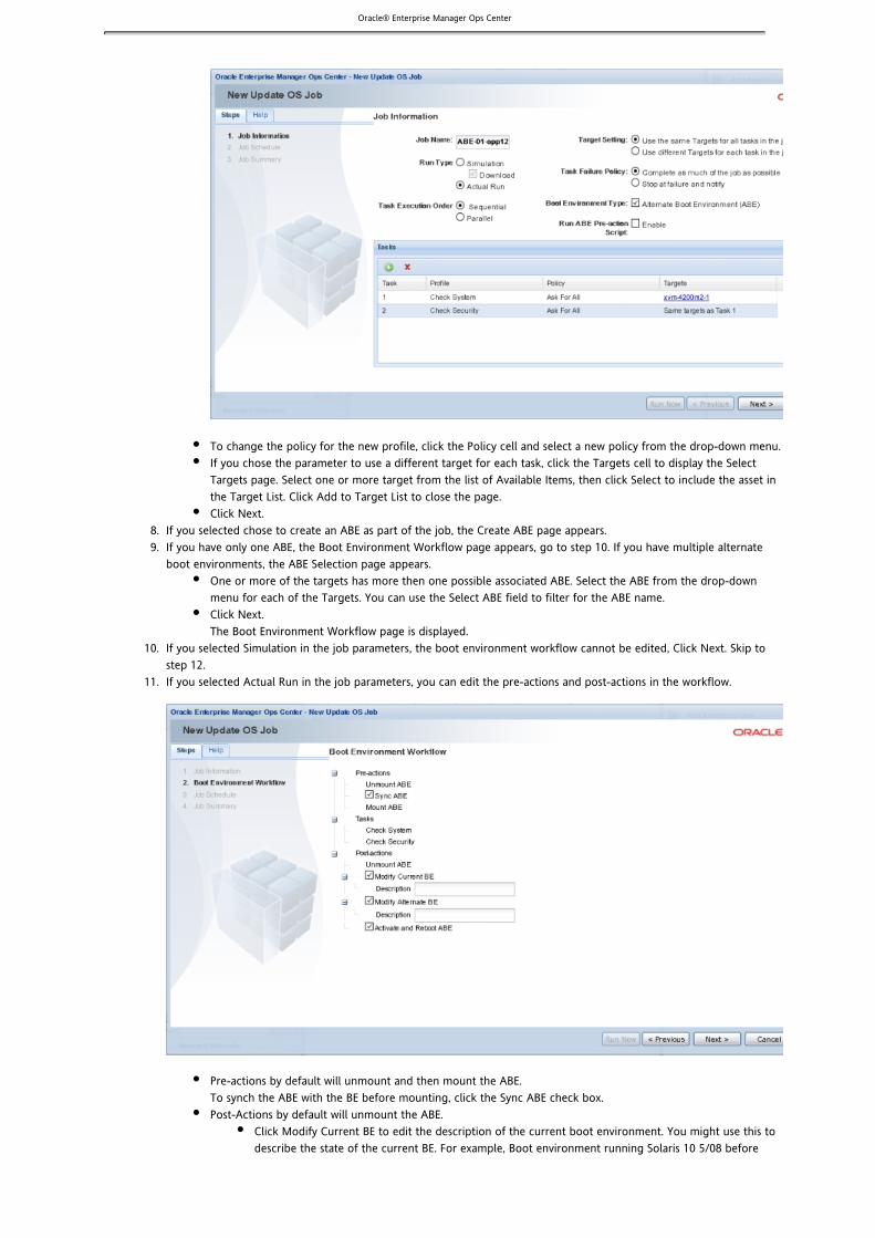
Oracle® Enterprise Manager Ops Center
7.
8. 9.
10.
11.
To change the policy for the new profile, click the Policy cell and select a new policy from the drop-down menu.If you chose the parameter to use a different target for each task, click the Targets cell to display the SelectTargets page. Select one or more target from the list of Available Items, then click Select to include the asset inthe Target List. Click Add to Target List to close the page.Click Next.
If you selected chose to create an ABE as part of the job, the Create ABE page appears.If you have only one ABE, the Boot Environment Workflow page appears, go to step 10. If you have multiple alternateboot environments, the ABE Selection page appears.
One or more of the targets has more then one possible associated ABE. Select the ABE from the drop-downmenu for each of the Targets. You can use the Select ABE field to filter for the ABE name.Click Next.The Boot Environment Workflow page is displayed.
If you selected Simulation in the job parameters, the boot environment workflow cannot be edited, Click Next. Skip tostep 12.If you selected Actual Run in the job parameters, you can edit the pre-actions and post-actions in the workflow.
Pre-actions by default will unmount and then mount the ABE.To synch the ABE with the BE before mounting, click the Sync ABE check box.Post-Actions by default will unmount the ABE.
Click Modify Current BE to edit the description of the current boot environment. You might use this todescribe the state of the current BE. For example, Boot environment running Solaris 10 5/08 before

Oracle® Enterprise Manager Ops Center
11.
12.
13.
1. 2.
applying the Solaris 10 September baseline.Click Modify Alternate BE to edit the description of the ABE. You might use this to describe the state ofthe ABE. For example, Boot environment running Solaris 10 5/08 after applying the Solaris 10September baseline.
Click Activate and Reboot ABE to switch boot environments after update.Schedule the job, then click Next.
Run Now starts the job immediately after you click Finish in the Job Summary.Start Date enables you to select a date and time to start the job.On a recurring schedule enables you to run the same job on a monthly or daily scheduled time.
Review the Job Summary, then click Finish to run the job as scheduled in the previous step.
Updating ZonesOps Center enables you to update the global and non-global zones of your Solaris systems. You can run a patch job on the globalzone and update all zones without using the command.-G
The concepts that relate to updating global and non-global zones and the procedures to update the zones are described on thissection.
Content Description
Packages and Patches Describes the parameters for installation of the packages and patches
Updating a Global Zone Describes the concepts involved in updating a global zone
Updating Non-Global Zones Describes the concepts involved in updating different non-global zones
Installing Packages and Patches on Zones
A patch is a collection of files and directories that replace existing files and directories that are preventing proper execution ofthe software.
You can install packages and patches on a zone. The and commands operate in the background to install apatchadd pkgadd
patch and package respectively. However, the installation of packages on zones also depends on the parameters in the followingtable. These parameters control whether a package can be installed on global zones or non-global zones.
Parameter Action
SUNW_PKG_ALLZONES If the value is true, the package is installed on all zones, both global and non-global.
SUNW_PKG_HOLLOW If the value is true, the package information is propagated to the non-global zones, but the packageis not installed.
SUNW_PKG_THISZONE If the value is true, the package is installed only in that zone.
Configuring and Commandspatchadd pkgadd
By default in Ops Center, the , , , and commands are implemented without the switch. Topatchadd pkgadd patchrm pkgrm -G
install updates or packages only on the current zone, enable the switch by editing the file.-G uce.rc
To Edit the Fileuce.rc
Open the file in the directory in the managed system.uce.rc /opt/SUNWuce/agent/bin
Add the following lines to the file:uce.rc
( all ) (invisible.__is_patchadd_g_specified, )false( all ) (invisible.__is_patchremove_g_specified, )false( all ) ( invisible.__is_pkgadd_g_specified, )false

Oracle® Enterprise Manager Ops Center
3. 4. 5.
Set the parameter to true for the action that you want to perform.-G
Save and close the file.For this change to take effect, restart the services using the following commands:
svcadm disable -s update-agentsvcadm enable -s update-agent
Updating a Global ZoneIn Ops Center, when a package or patch is installed, the and commands are implemented in the backgroundpatchadd pkgadd
as shown in the example below:
patchadd <patchid>
pkgadd <pkgname>
You can change the way that these commands are implemented by enabling the switch. You can enable the switch to-G -G
cause the patch or package to be installed to the target zone only if the package parameter SUNW_PKG_THISZONE is set to true.Refer to for information about configuring the and commands onInstalling Packages and Patches on Zones patchadd pkgadd
the managed systems.
Refer to the following table when you are updating a global zone. The results shown in this table determine whether the updatejob will be successful, depending on the package information.
SUNW_PKG_ALLZONES SUNW_PKG_THISZONE SUNW_PKG_HOLLOW Impact Impact with -Gconfiguration
False False False The package will beinstalled on the globalzone and all thenon-global zones.
The package is installedonly in the global zone.
True False False The package is installedon the global zone andall the non-global zones.
The -G switch cannotoverride theSUNW_PKG_ALLZONESparameter, and thepackage is installed inall the zones.
True False True The package is installedon the global zone andthe package informationis made available on allthe non-global zones.
The -G switch cannotoverride theSUNW_PKG_ALLZONESparameter, and thepackage is installed inall the zones.
False True False The package is installedonly on the global zone.
The package is installedonly on the globalzone.
Patches are simply sets of updates to packages. When you install a patch, the patch will be installed on the global zone and thenon-global zones, depending on the package parameters as shown in the previous table.
Note – Use caution while enabling the -G option on a host with sparse zones. Packages that are inherited from the global zone,which are not SUNW_ALL_ZONES, cannot be patched within a sparse zone.
Updating Non-Global Zones

Oracle® Enterprise Manager Ops Center
As a zone administrator, you can install packages and patches on non-global zones. The and commandpatchadd pkgadd
should be used without any options. Do not configure the switch to the commands while updating the non-global zones.-G
Refer to the following table when you are updating a non-global zone. The results shown in the table determine whether theupdate job will be successful, depending on the package information.
Note – The switch does not have any impact on installing packages or patches in a non-global zone.-G
SUNW_PKG_ALLZONES SUNW_PKG_THISZONE SUNW_PKG_HOLLOW Impact
False False False The package is installed only on the targetnon-global zone.
True False False The package installation fails.
True False True The package installation fails.
False True False The package is installed only on the targetnon-global zone.
Patches are simply sets of packages that need to be installed. If any one of the packages has the SUNW_PKG_ALLZONES set totrue, then the patch installation fails. For a successful patch installation, ensure that none of the packages haveSUNW_PKG_ALLZONES set to true.
Note – Packages that deliver to read-only inherit directories will fail to install to sparse root zones. Such packages should beinstalled from the global zone with the switch disabled. If such a package has the parameter SUNW_PKG_THISZONE=true, it-G
will not appear as installed from the sparse zone and the software might not function correctly. In this case, a whole root zoneshould be used. In general, packages with SUNW_PKG_THISZONE=true should not deliver to read-only inherit directories.
Solaris OS Update ReportsSolaris OS Update reports enable you to check for new patches and security advisories. You can get a general report, or test asystem or installed package for available fixes. For auditing purposes, you can create a Ops Center job history report.
When you create a report, you select the criteria that are relevant to you, such as a list of hosts that have a specific patch or a listof hosts that do not have a specific patch. The CVE Compliance report enables you to search for specific Solaris patches by theirCVE IDs.
Baseline Analysis ReportThe Baseline Analysis Report (BAR) allows you to determine whether your managed system is in compliance with recently releasedSolaris baselines. Baselines pertain only to Solaris systems.
The Solaris Baselines component contains a list of dated baselines. This report helps to check the compliance of your systemagainst newly released baselines (as and when they are available in Sun's Knowledge Base).
Before generating a report, it is necessary to understand Solaris Baselines, white lists, and black lists.
Solaris BaselinesA Solaris baseline is a dated collection of Solaris patches, patch metadata, and tools. Sun releases Solaris baselines on a monthlybasis. When you install the patches of a baseline on a host, that system is considered to be compliant with that baseline.
Using Solaris baselines enables you to easily identify the patch level of your hosts. For example, you install some test hosts with aparticular baseline. Then, you test these hosts for a period of time to see whether the patches in this baseline are stable enoughto be used on your production hosts. When the testing reveals that this baseline is stable, you can install the same baseline onyour production hosts.
Baseline information is available in the following locations in the BUI:

Oracle® Enterprise Manager Ops Center
1. 2.
View/Modify CatalogProfile EditorBaseline Analysis Report
Each dated baseline contains these patch sets:
Full – Includes all Solaris patchesRecommended – Includes Solaris recommended patches and security patchesSecurity – Includes only Solaris security patches
All baselines include patches for a specific time frame. However, the Full baseline often contains Solaris OS patches that are notincluded in the Recommended baseline. The Full baseline includes additional patches based on feedback from various customersupport groups within Sun. These patches are not always included in the Recommended baseline.
To install the Recommended and Security baselines, you either need to deploy two jobs, or have a job that includes multiple tasks.This might result in multiple reboots, for example, if both tasks (baselines) include patches that have Single User moderequirements.
Ops Center's Knowledge Base (KB) is updated with the details of the baselines. This is done a few days after the official release ofbaselines by Sun.
Note – The Solaris 8 OS was placed into End of Service Live (EOSL) on March 31, 2009. Solaris 8 OS baselines are availablethrough March, 2009. The KB might contain artificial baselines after that date. Do not use baselines dated after March, 2009.
White ListA white list is the list of patches that you want to install, uninstall, or upgrade. To establish a white list, create a profile using theRequired setting. You can also specify a white list when generating a Baseline Analysis report.
For example, establishing a list of Solaris OS patch IDs that must be applied to a specific system involves the following:
Creating a profile with the patches that need to be installed.Creating a job with the selected profile.
As another example, baseline B includes patches X, Y, Z, and the white list has patches U, V, and W. When your Baseline AnalysisReport is created, the host is marked compliant only when all six patches X, Y, Z, U, V, and W are present.
Black ListA black list is a list of patches that you do not want installed. You create a black list by creating a policy with the specified actionfor the patches. You can select a black list option when you create a Baseline Analysis Report. Select the black list either from thecreated policy or as a text file that you can create. In the text file, enter the patch IDs separated by new lines.
If a particular patch in the profile is set with the policy component setting as Never for install action, then the patch will not beinstalled. If the patch is already installed, it will not be uninstalled or removed.
For example, if baseline A has patches X, Y, and Z, and the black list specifies only Y and Z, the system is compliant as long as X isinstalled. Even if the patches Y and Z are installed, they will not get uninstalled if you run a compliance job from the reportresults.
Running a Baseline Analysis ReportThis section describes how to generate a Baseline Analysis Report (BAR). The report gives the compliancy of the managed systemwith the selected Solaris baseline that has been released.
In Ops Center, you can generate two types of BAR reports:

Oracle® Enterprise Manager Ops Center
1. 2. 3.
4.
5.
6.
7.
8.
9.
10.
11.
12.
13. 14.
15.
16.
Agent-based BAR reportDatabase-based BAR report
In an agent-based BAR report, a simulated job is executed against the managed hosts. This type of report takes time to completebecause it checks for dependent components and missing dependencies, and then downloads the patches that need to beinstalled. When you run a compliance job from this report result, the job is completed quickly because the patches are alreadydownloaded. However, to improve the report performance of a BAR report, you can skip the downloads in a simulated job bydeselecting the checkbox that is provided for this purpose.
In a database-based BAR report, the report is run against the database of the management server, the selected baselines arebroken down into individual patch IDs, and then formed into an incidents list. The report runs on the details that are available onthe database. Based on the report result, you can run a compliance job.
To Run a Baseline Analysis Report
This report provides information on the hosts which are compliant with a baseline OS.
Select Reports from the Navigation panel.Select Solaris/Linux OS Updates from the Reports section.Select Baseline Analysis Report from the Actions panel.The Baseline Analysis Report wizard is displayed.Specify the report parameters. They include:
Name – A name for the report(Optional) Description – A description of the report
Click Next.The Select Targets page is displayed.Add one or more targets by selecting them in the list on the left and clicking Add to Target List, then click Next.The Baseline(s) or Profile(s) page is displayed.Make the following selections:
Select either Baseline or Profile.If you selected Baseline, select either Run report against Database or Run Report against actual agent.Select one or more baselines or profiles by clicking them and clicking Add or by clicking Add All, then clickNext.The White List page is displayed.
Select a White List option. They include:None - No white list.Text list - Enter a list of patches.Import from profile - Select a profile to import as a white list.
Click Next.The Black List page is displayed.Select a black list option. They include:
None - No black list.Text list - Enter a list of patches.Import from profile - Select a profile to import as a black list.
Click Next.The Schedule page is displayed.Select a schedule for the report. You can schedule the report to run:
Immediately.On a start date and time - Select a date and time to generate the report.On a recurring schedule - Select the month and day when you want to generate the report. Select the StartTime, End Time and Number of Hours between runs. This is to set the number of times the report generatedbetween the specified start and end time. For example, if you set the Start Time at 6.00 AM, End Time at 12.00AM and the Number of hours between runs as 2, then the report is run at 6.00 AM, 8.00 AM, 10.00 AM and12.00 AM.
Click Next to display the Summary page.Click Run Report.The Report is launched.When the report stats changes to Success, click View Results.The Report results are displayed.(Optional) Click Run Compliance Job to bring the systems into compliance with the baseline.

Oracle® Enterprise Manager Ops Center
1. 2. 3.
4.
5.
6.
7.
8.
9.
10.
11. 12.
1. 2. 3.
4.
5.
6.
CVE Compliance Report for a Solaris OSThis report provides information on incidents that are related to specific CVE IDs and the systems that should have these incidentsinstalled. Common Vulnerability and Exposure Identifiers (CVE IDs) are unique, common identifiers for publicly known informationsecurity vulnerabilities. The patches and packages from a list of vendors are published as common vulnerabilities and securityexposure incidents. CVEs are identified by a candidate ID (CAN ID).
To Run a CVE Compliance Report for a Solaris OS
Select Reports from the Navigation panel.Select Solaris/Linux OS Updates from the Reports section.Select CVE Compliance Report from the Actions panel.The CVE Compliance Report wizard is displayed.Specify the report parameters. They include:
Name – A name for the report(Optional) Description – A description of the reportStatus – The compliance status that the report will cover. Select either compliant or noncompliant.
Click Next.The Select Targets page is displayed.Add one or more targets by selecting them in the list on the left and clicking Add to Target List, then click Next.The Select CVE page is displayed.Select one or more CVEs using the Add or Add All buttons, then click Next.The Summary page is displayed.(Optional) Click Save Report to save the report for future use. This returns you to the Reports tab, where you can run thereport by selecting it from the Saved Reports section and clicking Re-run Report.Click Run Report.The report is displayed.(Optional) Select one or more CVE IDs by clicking them or by clicking Select All, then click Make Host Compliant toinstall the recommended patches.(Optional) Click Export to CSV to export the report.Click Done to close the report.
Distribution Update Report for a Solaris OSThis report provides a mapping between selected updates, packages, and CVEs and selected distributions so that you can find outwhether the updates are installed. This report determines whether a specific distribution has been updated with specific updates,packages, or CVEs.
To Run a Distribution Update Report for a Solaris OS
Select Reports from the Navigation panel.Select Solaris/Linux OS Updates from the Reports section.Select Distribution Update Report from the Actions panel.The Distribution Update Report wizard is displayed.Specify the report parameters. They include:
Name – A name for the report.(Optional) Description – A description of the report.Category – Select one or more of the following:
SecurityBug fixEnhancementService PackSolaris UpdateCD
Type – Select Package, Update or both.Release Date – Select a Start Date and End Date.
Click Next.The Specify Distributions page is displayed.

Oracle® Enterprise Manager Ops Center
6.
7.
8.
9.
10.
11.
12.
13. 14.
1.
2.
1. 2. 3.
4.
5.
6.
7.
8.
9. 10. 11.
Select one or more distributions by clicking them and clicking Add or by clicking Add All, then click Next.The Select Updates page is displayed.Select one or more updates by clicking them or clicking Select All, then click Next.The Select Packages page is displayed.Select one or more packages by clicking them or clicking Select All, then click Next.The Select CVE page is displayed.Select one or more CVEs by clicking them or clicking Select All, then click Next.The Summary page is displayed.(Optional) Click Save Report to save the report for future use. This returns you to the Reports tab, where you can run thereport by selecting it from the Saved Reports section and clicking Re-run Report.Click Run Report.The report is displayed.(Optional) Select one or more incidents by clicking them or by clicking Select All, then click Execute Job to launch a jobto update them.(Optional) Click Export to CSV to export the report.Click Done to close the report.
Exporting Results of a Solaris OS ReportYou can export the OS Updates report results to CSV format and save it.
To Export Results of a Solaris OS Report
Run any as required.OS update reportsThe report is generated and the result is displayed.In the report result window, click Export to CSV.The report result will be saved in the local system desktop where the Ops Center BUI is running.
Host Compliance Report for a Solaris OSYou can run a host compliance report to determine whether the hosts are complaint with security and bug fix incidents.
To Run a Host Compliance Report for a Solaris OS
Select Reports from the Navigation panel.Select Solaris/Linux OS Updates from the Reports section.Select Host Compliance Report from the Actions panel.The Host Compliance Report wizard is displayed.Specify the report parameters. They include:
Name - A name for the report.(Optional) Description - A description of the report.Status - The compliance status that the report will cover. Select either compliant or noncompliant.Level - Select either security or bug fix.
Click Next.The Select Targets page is displayed.Add one or more targets by selecting them in the list on the left and clicking Add to Target List, then click Next.The Summary page is displayed.(Optional) Click Save Report to save the report for future use. This returns you to the Reports tab, where you can run thereport by selecting it from the Saved Reports section and clicking Re-run Report.Click Run Report.The report is displayed.(Optional) Select one or more patches by clicking them or by clicking Select All, then click Install Patch(es).(Optional) Click Export to CSV to export the report.Click Done to close the report.

Oracle® Enterprise Manager Ops Center
1. 2. 3.
4.
5.
6. 7.
8.
9.
10.
11.
12.
13.
14. 15.
1. 2.
3.
Incident Compliance Report for a Solaris OSIncidents are the patches that are available for an application or feature. An incident applies to one or more packages or RPMs.
You can run a incident compliance report to determine whether the incidents on the managed hosts are compliant with the latestreleased version.
To Run an Incident Compliance Report for a Solaris OS
Select Reports from the Navigation panel.Select Solaris/Linux OS Updates from the Reports section.Select Incident Compliance Report from the Actions panel.The Incident Compliance Report wizard is displayed.Specify the report parameters. They include:
Name - A name for the report.(Optional) Description - A description of the report.Status - The compliance status that the report will cover. Select either compliant or noncompliant.Criteria - The criteria for selecting the patches that will be used as a comparison. Your choice here will causedifferent steps to appear later in the wizard.
Click Next.The Select Targets page is displayed.Add one or more targets by selecting them in the list on the left and clicking Add to Target List, then click Next.If you selected Select Updates as the criteria, the Select Updates page is displayed. Select one or more updates byclicking them or clicking Select All, then click Next.If you selected Filter Updates as the criteria, the Filter Updates page is displayed. Select filters, then click Next. Filtersinclude:
Category - Select one or more of the following:SecurityBug FixEnhancement
Update Type - Select Package, Update or both.Release Date - Select a Start Date and End Date.
If you selected Filter Updates as the criteria, the Select Packages page is displayed. Select one or more packages byclicking them or clicking Select All, then click Next.If you selected Filter Updates as the criteria, the Select CVE page is displayed. Select one or more CVEs by clicking themand clicking Add or by clicking Add All, then click Next.The Summary page is displayed.(Optional) Click Save Report to save the report for future use. This returns you to the Reports tab, where you can run thereport by selecting it from the Saved Reports section and clicking Re-run Report.Click Run Report.The report is displayed.(Optional) Select one or more incidents by clicking them or by clicking Select All, then click Install Fix(es) to install therecommended patches.(Optional) Click Export to CSV to export the report.Click Done to close the report.
Job History Report for a Solaris OSSolaris OS Update Job History reports provide a detailed history of the install and uninstall actions taken on systems throughoutOps Center. This report also shows which user made the deployments, enabling you to track a team of operators. After yourreport criteria is selected, you can generate a report and save it as a template. The saved report template enables you to run thereport again with the same specified parameters for the targeted systems, install actions, and time period.
To Run a Job History Report for a Solaris OS
Select Reports from the Navigation panel.Select Solaris/Linux OS Updates from the Reports section.

Oracle® Enterprise Manager Ops Center
3.
4.
5.
6.
7.
8.
9. 10.
1. 2. 3.
4.
5.
6.
7.
8.
9.
10.
11. 12.
Select Jobs History Report from the Actions panel.The Job History Report wizard is displayed.Specify the Report Parameters. They include:
Name - A name for the report.(Optional) Description - A description of the report.Actions - The actions to be reported. Check installs, uninstalls, or both.Dates - The time which the report will cover. Enter a start date and an end date, or click the calendar icon toselect start and end dates from a calendar.
Click Next.The Select Targets page is displayed.Add one or more targets by selecting them in the list on the left and clicking Add to Target List, then click Next.The Summary page is displayed.(Optional) Click Save Report to save the report for future use. This returns you to the Reports tab, where you can run thereport by selecting it from the Saved Reports section and clicking Re-run Report.Click Run Report.The report is displayed.(Optional) Click Export to CSV to export the report.Click Done to close the report.
Package Compliance Report for a Solaris OSThis report provides details pertaining to the selected packages on the managed system and indicates whether the system iscompliant with the latest recommended version available.
To Run the Package Compliance Report for a Solaris OS
Select Reports from the Navigation panel.Select Solaris/Linux OS Updates from the Reports section.Select Package Compliance Report from the Actions panel.The Package Compliance Report wizard is displayed.Specify the report parameters. They include:
Name – A name for the report.(Optional) Description – A description of the report.Status – The compliance status that the report will cover. Select either compliant or noncompliant.Level – Select Security or Bug Fix.
Click Next.The Select Targets page is displayed.Add one or more targets by selecting them in the list on the left and clicking Add to Target List, then click Next.The Select Packages page is displayed.Select one or more packages by clicking them or clicking Select All, then click Next.The Summary page is displayed.(Optional) Click Save Report to save the report for future use. This returns you to the Reports tab, where you can run thereport by selecting it from the Saved Reports section and clicking Re-run Report.Click Run Report.The report is displayed.(Optional) Select one or more packages by clicking them or by clicking Select All, then click Install Package(s) to launch ajob to install them.(Optional) Click Export to CSV to export the report.Click Done to close the report.
Solaris Update Compliance ReportThe Solaris Update Compliance reports allows you to determine whether a specific Solaris system is compliant with a particularUpdate.

Oracle® Enterprise Manager Ops Center
1. 2. 3.
4.
5.
6.
7.
8.
9. 10.
To Run a Solaris Update Compliance Report
Select Reports from the Navigation panel.Select Solaris/Linux OS Updates from the Reports section.Select Solaris Update Compliance from the Actions panel.The Solaris Update Compliance Report wizard is displayed.Specify the report parameters. They include:
Name – A name for the report.(Optional) Description – A description of the report.Status – The compliance status that the report will cover. Select either compliant or noncompliant.Updates – The update to be used in the report.
Click Next.The Select Targets page is displayed.Add one or more targets by selecting them in the list on the left and clicking Add to Target List, then click Next.The Summary page is displayed.(Optional) Click Save Report to save the report for future use. This returns you to the Reports tab, where you can run thereport by selecting it from the Saved Reports section and clicking Re-run Report.Click Run Report.The report is displayed.(Optional) Click Export to CSV to export the report.Click Done to close the report.
Updating a Linux OSYou can update a Linux operating system after you have discovered it and managed it. A managed asset has Ops Center agentsoftware installed on it.
To keep your systems current, use the and to determine which patches, updates,System Catalogs Linux OS Update Reportssoftware, and actions apply to your system.
There are different methods for running an update job. This section describes the update feature in Ops Center, how tocustomize an update job, updating in disconnected mode, using profiles and policies for Linux updates, and managing localcontents.
Methods of Updating a Linux OSIn Ops Center, you have different options for updating your Linux operating systems:
Use predefined or custom profiles to update a system or group of systems. This method is often used for Linux updates.Use a system catalog to create a simple update job without creating a profile. This method is used to apply a single patchquickly.Use compliance report outputs to update your OS. This method is used to make your systems compliant with the newlyreleased updates.Use compare catalogs to roll a system back to its previous state.
There are various methods to update a Linux OS.

Oracle® Enterprise Manager Ops Center
1. 2. 3.
Creating a Linux OS Update JobCreating a new update job enables you to use custom or predefined profiles to create an update job. This method is typicallyused for complex update scenarios and to update Linux operating systems.
The Update OS job wizard enables you to create customized update jobs. When creating a job, you need to define the followingjob parameters:
Name and description of the update job.Profile – Defines what updates are to be installed, uninstalled, or upgraded on an OS. Select a profile from the list ofpredefined and customized profiles.Policy – Defines how a job is performed and sets the automation level of the job. Select a policy from the list of availablepolicies. You can also create your own policies.Target Settings – Defines whether the target should be different or similar for each task in the job.Actual Run – Defines whether this job is in simulation mode. You can choose to deploy the job, or to run a jobsimulation. A job simulation determines the actions and results of a job, and estimates how much time is required tocomplete the job. A job simulation also indicates whether your policy and profile responses will enable the job tosucceed.Task Execution Order – Specifies whether the tasks should be run in parallel or sequentially.Task Failure Policy – Specifies what action should be taken if a task fails.Targets – Select one or more target hosts for this job.
Note – If there is a conflict between a profile and policy, the profile overrides the policy.
To Create a New Update Job
Click Asset in the Navigation panel.Click an OS instance.Click New Update OS Job from the Center or Actions panel.The New Update OS Job wizard is displayed. The Job Information window is displayed first.

Oracle® Enterprise Manager Ops Center
3.
4. 5. 6. 7.
8.
9. 10.
1. 2. 3. 4.
Enter a name and description for the update job in the Job Information window.Select the Actual Run for the job. It can be either Simulation or Actual Run.Select the Profile and Policy from the list.If you want to change the selected target system, select the row and click Edit Targets icon.The Select Targets window is displayed. Select the targets on which you want to run the update job. You can select morethan one target.Click Add icon to add more tasks to the update job.You can define the profile, policy and target for each task. If the target setting is a different target for each task in thejob, then the new task includes the Select Targets button. Click Select Targets to select the target for the task.Select the task execution order and failure policy for the job.Click Run Now to run the job immediately or click Next to schedule the job to run later.
Updating from a Linux OS ProfileIn Ops Center, you can create an update job from the OS Update Profile section. In the OS Update Profile section, the New OSUpdate Job option is available for running an update job.
To Create a Job From a Profile
Select Libraries from the Navigation panel.Select OS Update Profiles from the Libraries section.Select a profile from the predefined profile or user-defined profile list.Click New Update OS Job in the Actions panel or select the New Update OS Job icon in the Summary page. The New Job wizard is displayed.

Oracle® Enterprise Manager Ops Center
4.
5. 6. 7. 8.
9.
10. 11.
Enter a name and description for the update job in the Job Information window.Select the Actual Run for the job. It can be either Simulation or Actual Run.Select the Profile and Policy from the list.Click Select Targets to select the target for the task.The Select Targets window is displayed. Select the targets on which you want to run the update job. You can select morethan one target. To change the target, select the task and click the Edit Targets icon.Click the Add icon to add more tasks to the update job.You can define the profile, policy, and target for each task.Select the task execution order and failure policy for the job.Click Run Now to run the job immediately or click Next to schedule the job to run later.
Updating With a Linux OS ReportIn Ops Center, you can generate the following compliance reports:
Host Compliance ReportPackage Compliance ReportIncident Compliance ReportService Pack Compliance ReportCVE Compliance ReportDistribution Update Report
Refer to for information about generating these reports. You can generate these reports forLinux OS Update Reportsnon-compliant components. The report result is displayed with the option to install the patches, packages, updates, and incidents.
In the report result, click Run Compliance Job to initiate a job to install the non-compliant component updates. The New Jobwizard launches, enabling you to enter job information and to schedule the job. When you click Run Compliance Job, the requireddata for profiles, policies, and targets is automatically pre-populated in the job wizard.
Updating a Linux OS by Modifying a System CatalogA system catalog is a list of OS software components that are installed on a managed system. Catalogs provide the capability todirectly manipulate the installed software components on a single operating system or a group of operating systems.
Refer to for more information about managing catalogs.System Catalogs
Oracle® Enterprise Manager Ops Center
1. 2.
3.
4.
5.
6. 7.
8. 9.
1. 2. 3.
4.
5.
6.
7.
8.
9.
10.
11. 12.
Updating an OS by modifying a system catalog provides the following advantages:
Enables you to create a quick ad hoc jobProvides an easy method of applying a single patch, baseline, or packageEnables you to update an OS without creating a profile for a one-time job
To Update a Linux OS by Modifying a System Catalog
Select Asset from the Navigation panel.Select an OS from the Asset sectionThe center panel displays summary, connectivity, file system monitoring, charts, and jobs information.Select View/Modify Catalog from the Actions panel.The View/Modify Catalog window is displayed.Select a catalog from the Catalog list.The components that are installed on the system are displayed.Select the component for which you want to modify the action.The available actions are No Action, Required, Uninstall, and Upgrade. The actions that are available for the selectedcomponent are enabled accordingly.Select the action for the component that you want to modify.Click Launch Modification Job.A New Job wizard is displayed.Complete the job Information details as required.Either click Run Now to run the job immediately or click Next to schedule the job to run later.
CVE Compliance Report for a Linux OSThis report provides information on incidents that are related to specific CVE IDs and the systems that should have these incidentsinstalled. Common Vulnerability and Exposure Identifiers (CVE IDs) are unique, common identifiers for publicly known informationsecurity vulnerabilities. The patches and packages from a list of vendors are published as common vulnerabilities and securityexposure incidents. CVEs are identified by a candidate ID (CAN ID).
To Run a CVE Compliance Report for a Linux OS
Select Reports from the Navigation panel.Select Linux OS Updates from the Reports section.Select CVE Compliance Report from the Actions panel.The CVE Compliance Report wizard is displayed.Specify the report parameters. They include:
Name – A name for the report(Optional) Description – A description of the reportStatus – The compliance status that the report will cover. Select either compliant or noncompliant.
Click Next.The Select Targets page is displayed.Add one or more targets by selecting them in the list on the left and clicking Add to Target List, then click Next.The Select CVE page is displayed.Select one or more CVEs using the Add or Add All buttons, then click Next.The Summary page is displayed.(Optional) Click Save Report to save the report for future use. This returns you to the Reports tab, where you can run thereport by selecting it from the Saved Reports section and clicking Re-run Report.Click Run Report.The report is displayed.(Optional) Select one or more CVE IDs by clicking them or by clicking Select All, then click Make Host Compliant toinstall the recommended patches.(Optional) Click Export to CSV to export the report.Click Done to close the report.

Oracle® Enterprise Manager Ops Center
1. 2. 3.
4.
5.
6.
7.
8.
9.
10.
11.
12.
13. 14.
1.
2.
Distribution Update Report for a Linux OSThis report provides a mapping between selected updates, packages, and CVEs and selected distributions so that you can find outwhether the updates are installed. This report determines whether a specific distribution has been updated with specific updates,packages, or CVEs.
To Run a Distribution Update Report for a Linux OS
Select Reports from the Navigation panel.Select Linux OS Updates from the Reports section.Select Distribution Update Report from the Actions panel.The Distribution Update Report wizard is displayed.Specify the report parameters. They include:
Name – A name for the report.(Optional) Description – A description of the report.Category – Select one or more of the following:
SecurityBug fixEnhancementService PackCD
Type – Select Package, Update or both.Release Date – Select a Start Date and End Date.
Click Next.The Specify Distributions page is displayed.Select one or more distributions by clicking them and clicking Add or by clicking Add All, then click Next.The Select Updates page is displayed.Select one or more updates by clicking them or clicking Select All, then click Next.The Select Packages page is displayed.Select one or more packages by clicking them or clicking Select All, then click Next.The Select CVE page is displayed.Select one or more CVEs by clicking them or clicking Select All, then click Next.The Summary page is displayed.(Optional) Click Save Report to save the report for future use. This returns you to the Reports tab, where you can run thereport by selecting it from the Saved Reports section and clicking Re-run Report.Click Run Report.The report is displayed.(Optional) Select one or more incidents by clicking them or by clicking Select All, then click Execute Job to launch a jobto update them.(Optional) Click Export to CSV to export the report.Click Done to close the report.
Exporting Results of a Linux OS ReportYou can export the OS Updates report results to CSV format and save it.
To Export Results of a Linux OS Report
Run any as required.OS update reportsThe report is generated and the result is displayed.In the report result window, click Export to CSV.The report result will be saved in the local system desktop where the Ops Center BUI is running.
Host Compliance Report for a Linux OS
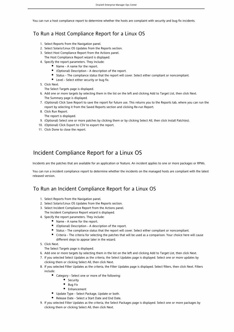
Oracle® Enterprise Manager Ops Center
1. 2. 3.
4.
5.
6.
7.
8.
9. 10. 11.
1. 2. 3.
4.
5.
6. 7.
8.
9.
10.
You can run a host compliance report to determine whether the hosts are complaint with security and bug fix incidents.
To Run a Host Compliance Report for a Linux OS
Select Reports from the Navigation panel.Select Solaris/Linux OS Updates from the Reports section.Select Host Compliance Report from the Actions panel.The Host Compliance Report wizard is displayed.Specify the report parameters. They include:
Name - A name for the report.(Optional) Description - A description of the report.Status - The compliance status that the report will cover. Select either compliant or noncompliant.Level - Select either security or bug fix.
Click Next.The Select Targets page is displayed.Add one or more targets by selecting them in the list on the left and clicking Add to Target List, then click Next.The Summary page is displayed.(Optional) Click Save Report to save the report for future use. This returns you to the Reports tab, where you can run thereport by selecting it from the Saved Reports section and clicking Re-run Report.Click Run Report.The report is displayed.(Optional) Select one or more patches by clicking them or by clicking Select All, then click Install Patch(es).(Optional) Click Export to CSV to export the report.Click Done to close the report.
Incident Compliance Report for a Linux OSIncidents are the patches that are available for an application or feature. An incident applies to one or more packages or RPMs.
You can run a incident compliance report to determine whether the incidents on the managed hosts are compliant with the latestreleased version.
To Run an Incident Compliance Report for a Linux OS
Select Reports from the Navigation panel.Select Solaris/Linux OS Updates from the Reports section.Select Incident Compliance Report from the Actions panel.The Incident Compliance Report wizard is displayed.Specify the report parameters. They include:
Name - A name for the report.(Optional) Description - A description of the report.Status - The compliance status that the report will cover. Select either compliant or noncompliant.Criteria - The criteria for selecting the patches that will be used as a comparison. Your choice here will causedifferent steps to appear later in the wizard.
Click Next.The Select Targets page is displayed.Add one or more targets by selecting them in the list on the left and clicking Add to Target List, then click Next.If you selected Select Updates as the criteria, the Select Updates page is displayed. Select one or more updates byclicking them or clicking Select All, then click Next.If you selected Filter Updates as the criteria, the Filter Updates page is displayed. Select filters, then click Next. Filtersinclude:
Category - Select one or more of the following:SecurityBug FixEnhancement
Update Type - Select Package, Update or both.Release Date - Select a Start Date and End Date.
If you selected Filter Updates as the criteria, the Select Packages page is displayed. Select one or more packages byclicking them or clicking Select All, then click Next.

Oracle® Enterprise Manager Ops Center
10.
11.
12.
13.
14. 15.
1. 2. 3.
4.
5.
6.
7.
8.
9. 10.
1. 2. 3.
4.
If you selected Filter Updates as the criteria, the Select CVE page is displayed. Select one or more CVEs by clicking themand clicking Add or by clicking Add All, then click Next.The Summary page is displayed.(Optional) Click Save Report to save the report for future use. This returns you to the Reports tab, where you can run thereport by selecting it from the Saved Reports section and clicking Re-run Report.Click Run Report.The report is displayed.(Optional) Select one or more incidents by clicking them or by clicking Select All, then click Install Fix(es) to install therecommended patches.(Optional) Click Export to CSV to export the report.Click Done to close the report.
Job History Report for a Linux OSLinux OS Update Job History reports provide a detailed history of the install and uninstall actions taken on systems throughoutOps Center. This report also shows which user made the deployments, enabling you to track a team of operators. After yourreport criteria is selected, you can generate a report and save it as a template. The saved report template enables you to run thereport again with the same specified parameters for the targeted systems, install actions, and time period.
To Run a Job History Report for a Linux OS
Select Reports from the Navigation panel.Select Solaris/Linux OS Updates from the Reports section.Select Jobs History Report from the Actions panel.The Job History Report wizard is displayed.Specify the Report Parameters. They include:
Name - A name for the report.(Optional) Description - A description of the report.Actions - The actions to be reported. Check installs, uninstalls, or both.Dates - The time which the report will cover. Enter a start date and an end date, or click the calendar icon toselect start and end dates from a calendar.
Click Next.The Select Targets page is displayed.Add one or more targets by selecting them in the list on the left and clicking Add to Target List, then click Next.The Summary page is displayed.(Optional) Click Save Report to save the report for future use. This returns you to the Reports tab, where you can run thereport by selecting it from the Saved Reports section and clicking Re-run Report.Click Run Report.The report is displayed.(Optional) Click Export to CSV to export the report.Click Done to close the report.
Package Compliance Report for a Linux OSThis report provides details pertaining to the selected packages on the managed system and indicates whether the system iscompliant with the latest recommended version available.
To Run the Package Compliance Report for a Linux OS
Select Reports from the Navigation panel.Select Solaris/Linux OS Updates from the Reports section.Select Package Compliance Report from the Actions panel.The Package Compliance Report wizard is displayed.Specify the report parameters. They include:
Name – A name for the report.(Optional) Description – A description of the report.

Oracle® Enterprise Manager Ops Center4.
5.
6.
7.
8.
9.
10.
11. 12.
1. 2. 3.
4.
5.
6.
7.
8.
9. 10.
Status – The compliance status that the report will cover. Select either compliant or noncompliant.Level – Select Security or Bug Fix.
Click Next.The Select Targets page is displayed.Add one or more targets by selecting them in the list on the left and clicking Add to Target List, then click Next.The Select Packages page is displayed.Select one or more packages by clicking them or clicking Select All, then click Next.The Summary page is displayed.(Optional) Click Save Report to save the report for future use. This returns you to the Reports tab, where you can run thereport by selecting it from the Saved Reports section and clicking Re-run Report.Click Run Report.The report is displayed.(Optional) Select one or more packages by clicking them or by clicking Select All, then click Install Package(s) to launch ajob to install them.(Optional) Click Export to CSV to export the report.Click Done to close the report.
Service Pack Compliance Report for a Linux OSThis report provides information on incidents created by the publication and release of a service pack by a vendor. This helps todetermine whether the systems have the latest service packs that were released by the vendor.
To Run a Service Pack Compliance Report for a Linux OS
Select Reports from the Navigation panel.Select Solaris/Linux OS Updates from the Reports section.Select Service Pack Compliance from the Actions panel.The Service Pack Compliance Report wizard is displayed.Specify the report parameters. They include:
Name - A name for the report.(Optional) Description - A description of the report.Status - The compliance status that the report will cover. Select either compliant or noncompliant.Services - The services to be covered in the report.
Click Next.The Select Targets page is displayed.Add one or more targets by selecting them in the list on the left and clicking Add to Target List, then click Next.The Summary page is displayed.(Optional) Click Save Report to save the report for future use. This returns you to the Reports tab, where you can run thereport by selecting it from the Saved Reports section and clicking Re-run Report.Click Run Report.The report is displayed.(Optional) Click Export to CSV to export the report.Click Done to close the report.
Updating a Windows OSOps Center enables you to update your managed Windows operating systems. You need to discover and manage the assets thatyou want to update. See for information about how to discover a system. Ops Center uses Microsoft SystemAsset ManagementCenter Configuration Manager (SCCM) for updating the Windows operating systems. The Windows Update functionality dependson the SCCM's agent installed on the managed systems. You can configure SCCM to install agents on your managed Windowssystems either automatically or through a manual process.
To ensure that your managed systems are up to date, you need to determine which patches, updates, and actions to apply to yoursystem. The help you determine the patches that are applicable to your systems and how many of theWindows Updates Reportsapplicable patches are compliant or not compliant for the selected systems.

Oracle® Enterprise Manager Ops Center
About Updating a Windows OSUsing Ops Center, you can discover any Windows operating systems and then manage your systems to be secure and up to date.Ops Center uses Microsoft System Center Configuration Manager 2007 (SCCM) to implement the software updates for WindowsOS. More specifically, Ops Center uses the Windows software update capability of SCCM to update any Windows OS that arediscovered and managed by Ops Center. You should be able to identify a functional SCCM that is configured for software updateand management of the Windows systems that are managed by Ops Center. The Windows Update functionality depends on theSCCM's agent installed on the managed systems. You can configure SCCM to install agents on your managed Windows systemseither automatically or through a manual process.
Patching in Connected and Disconnected Mode
The Enterprise Controller connects to Microsoft System Center Configuration Manager (SCCM) to obtain the latest informationabout patches and packages. SCCM is connected to the internet for downloading the metadata that is used for complianceanalysis. Ops center can also be connected to the internet to download patches which are then handled by SCCM for installation.
When you want to download and install a patch, the patch is downloaded from the Microsoft site. You do not need anyauthentication to access the Microsoft web site. However you need to provide authentication details to access the SCCM server.
You can also update the managed systems when the Enterprise Controller is in disconnected mode, that is, when the EnterpriseController is not connected to the internet.
Reports
Several predefined OS Update reports are available. The reports enable you to check for new patches and and update yoursystems. You can get a general report, or test a system for available fixes.
When you create a report, you select the criteria that are relevant to you, such as Category, Severity, Superseded, and ReleaseDate of the update patches. You can also select specific updates on which to run the compliance reports.
Update Job
Ops Center contains the following options in an update job to maintain control and consistency across your data center:
Groups – Help you to organize your assets in the user interface, and act as targets for many types of jobs.Roles – Enable you to determine the tasks that a user can perform on a specific piece of asset or a group of assets.Reports – Enable you to run compliance reports and create update jobs from the compliance reports.
You can define the following job parameters while creating a :New Windows Update Job
Name and Description – Identifies the name of the report against which you want to create a new Windows OS updatejob. A detailed description is helpful in clearly identifying the job in the historical record.Reboot behavior – Lets you select the reboot behavior if a reboot is required after the new update job is executed. Youcan select whether you want the system to reboot immediately following the update operation or whether you want toreboot the system at the default setting of the SCCM server.License Terms – Lets you review the license terms and either accept or decline it. The License Terms window appears onlywhen the updates in the report require License Terms that need to be reviewed.Schedule – Lets you decide how you want to schedule the execution of the new update job.
Method of Updating a Windows OSOps Center enables you to use the output from compliance reports to update your Windows OS to be compliant with the newlyreleased updates.
Use the results of the Host Compliance Report and the Incident Compliance Report to update your Windows systems.

Oracle® Enterprise Manager Ops Center
1. 2.
Configuring Ops Center for Updating Windows OSOps Center uses Microsoft System Center Configuration Manager 2007 (SCCM) to implement the software updates for WindowsOS. More specifically, Ops Center uses the Windows software update capability of SCCM to update any Windows OS that arediscovered and managed by Ops Center. You need to identify a functional SCCM that is configured for software update andmanagement of the Windows systems that are managed by Ops Center.
To configure Ops Center to interact with the identified SCCM, you need to provide the following credentials in the configurationwindow:
SCCM Server
Server NameDomain NameSite NameUser NamePassword
SCCM Share
URLDomain NameUser NamePassword
The configuration details are displayed in the Configuration tab of the Windows Update window.
Note: Ops Center uses the same SCCM credentials for accessing the SCCM server as well as for enabling the SCCM share. Use the< > format for the Domain Name field. Do not use the < >\< > format. If you entered an incorrect formatdomain domain usernamefor the Domain Name field and if the configuration task returns an error, then unconfigure the SCCM and configure the SCCMagain with the correct format for the credentials. See for information on how toConfiguring Ops Center to Interact with an SCCMconfigure and unconfigure Ops Center to interact with the SCCM.
Configuring Ops Center to Interact with SCCMBefore you can use Ops Center to update your Windows systems, you need to configure it to interact with the identifiedMicrosoft System Center Configuration Manager (SCCM).
To configure Ops Center to interact with the identified SCCM
In the Navigation panel, click Administration, then click Windows Update.In the Actions panel, click SCCM Configuration.An SCCM Configuration window is displayed.

Oracle® Enterprise Manager Ops Center2.
3.
4.
1. 2.
3.
Enter the credentials for the following fields:SCCM ServerServer NameDomain NameSite NameUser NamePasswordConfirm PasswordSCCM ShareURLDomain NameUser NamePasswordConfirm PasswordClick Submit.
Ops Center is now configured to interact with the SCCM.
To Unconfigure Ops Center's interaction with the SCCM
In the Navigation panel, click Administration, then click Windows Updates.In the Actions panel, click Unconfigure.A confirmation window appears.Click Yes to unconfigure Ops Center's interaction with the SCCM.
Windows Updates ReportsCompliance reports provide information on whether your systems are compliant with the Windows updates incidents. You can geta report on the number of applicable Windows updates for each system. You can also get a report that shows the number ofsystems to which the selected Windows updates apply.
When you create a report, you select the criteria that are relevant to you, such as Category, Severity, Superseded, and ReleaseDate of the update patches. You can also select specific updates on which to run the compliance reports.
You can create a new Windows update job from the results of the compliance reports. See Creating a New Windows Update Jobfor information on how to create a new update job from the report results.

Oracle® Enterprise Manager Ops Center
1. 2. 3.
4.
5.
6.
7.
8.
9.
10.
1.
Host Compliance Report for Windows UpdatesThe Host Compliance Report provides information on whether your systems are compliant with the Windows updates incidents.This report shows the number of Windows updates that are applicable to each system, and whether the updates are alreadyinstalled or need to be installed to make the system compliant. You can also create a new Windows update job based on theresults of a Host Compliance Report.
To Run a Host Compliance Report for Windows Updates
Select Reports from the Navigation panel.Select Windows OS Updates from the Reports section.Select Host Compliance Report from the Actions panel.The Host Compliance Report wizard is displayed.Specify the report parameters. They include:
Report Name — A name for the report.(Optional) Description — A description of the report.Specify the Windows OS updates on which to run the report — You can specify filter criteria such as Category,Severity, Superseded, and Release Date for Windows OS updates, or you can select specific Windows OS updatesto run the report.
Click Next.Based on your selection in Step 4, either the Define Updates Filter window is displayed or the Select Updates window isdisplayed. If the Define Updates Filter window is displayed, proceed to Step 6. If the Select Updates window is displayed,proceed to Step 7.Make your selections in the Define Updates Filter screen. They include:
Category — Includes Application, Critical Updates, Definition Updates, Drivers, Service Packs, Security Updates,Tools, Update Rollups, and WSUS Infrastructure Updates. You can select either All available updates under allcategory or Selected categories only. Use the Control key on the keyboard to select multiple items in the listunder Selected category only.Severity — Includes Critical, Important, Moderate, Low, and Default. You can select either All updates with anyseverity or Selected Severities only. Use the Control key on the keyboard to select multiple items in the listunder Severity.Superseded — Enables you to select all or just the most recent updates.Release Date — Refers to the date that the update patches were released. You can choose the range of releasedates that you want to include in your report by filling in the From and To fields.Click Next. Proceed to Step 8.
Make your selections in the Select Updates window. Under Search, Select All enables you to include a bulletin ID, articleID, and title in your search, or you can select specific fields to narrow your search. Use the Control key on the keyboardto make multiple selections in the list under Available Windows Software Updates. Click Add to Updates List, then. ClickNext.Add one or more targets by selecting them in the list of Available Items. Click Add to Target List, then click Next.The Summary page is displayed.(Optional) Click Save as Template to save the parameters of the report as a template for future use. After you click Saveas Template, you will not have the option of returning to the previous steps. The Save as Template button as well as thePrevious button will be grayed, and the only two options that you will have is to either click Finish or Cancel. After atemplate is saved, you can view, delete, edit, or run the report from Report Templates.Click Finish to run the report.You should see the results of the report under Report Results List.
Incident Compliance Report for Windows UpdatesThe Incident Compliance Report provides information on whether your systems are compliant with the Windows updatesincidents. This report shows the number of systems to which the selected Windows updates apply, how many systems have theupdates installed, and how many require the updates to be installed to make the systems compliant. You can create a newWindows update job based on the results of an Incident Compliance Report.
To Run an Incident Compliance Report for Windows Updates

Oracle® Enterprise Manager Ops Center
1. 2. 3.
4.
5.
6.
7.
8.
9.
10.
1. 2.
3. 4.
Select Reports from the Navigation panel.Select Windows OS Updates from the Reports section.Select Incident Compliance Report from the Actions panel.The Incident Compliance Report wizard is displayed.Specify the report parameters. They include:
Report Name — A name for the report.(Optional) Description — A description of the report.Specify the Windows OS updates on which to run the report — You can specify filter criteria such as Category,Severity, Superseded, and Release Date for Windows OS updates, or you can select specific Windows OS updatesto run the report.
Click Next.Based on your selection in Step 4, either the Define Updates Filter window is displayed or the Select Updates window isdisplayed. If the Define Updates Filter window is displayed, proceed to Step 6. If the Select Updates window is displayed,proceed to Step 7.Make your selections in the Define Updates Filter screen. They include:
Category - Includes Application, Critical Updates, Definition Updates, Drivers, Service Packs, Security Updates,Tools, Update Rollups, and WSUS Infrastructure Updates. You can select either All available updates under allcategory or Selected categories only. Use the Control key on the keyboard to select multiple items in the listunder Selected category only.Severity - Includes Critical, Important, Moderate, Low, and Default. You can select either All updates with anyseverity or Selected Severities only. Use the Control key on the keyboard to select multiple items in the listunder Severity.Superseded - Enables you to select all or just the most recent updates.Release Date - Refers to the date that the update patches were released. You can choose the range of releasedates that you want to include in your report by filling in the From and To fields.Click Next. Proceed to Step 8.
Make your selections in the Select Updates window. Under Search, Select All enables you to include a bulletin ID, articleID, and title in your search, or you can select specific fields to narrow your search. Use the Control key on the keyboardto make multiple selections in the list under Available Windows Software Updates. Click Add to Updates List, then. ClickNext.Add one or more targets by selecting them in the list of Available Items. Click Add to Target List, then click Next.The Summary page is displayed.(Optional) Click Save as Template to save the parameters of the report as a template for future use. After you click Saveas Template, you will not have the option of returning to the previous steps. The Save as Template button as well as thePrevious button will be grayed, and the only two options that you will have is to either click Finish or Cancel. After atemplate is saved, you can view, delete, edit, or run the report from Report Templates.Click Finish to run the report.You should see the results of the report under Report Results List.
Creating a New Windows Update JobYou can use the results of the Host Compliance Report and the Incident Compliance Report to make your systems compliant bycreating a new update job.
The Create New Windows Update Job wizard enables you to create a new update job. When creating a new update job, you needto define the following job parameters:
Name and Description for the new Windows software update job.Reboot behavior – Lets you select whether you want to reboot the system to reboot immediately following the updateoperation or at the default setting of the SCCM server.License Terms – Lets you review the license terms and either accept or decline it. The License Terms window appears onlywhen the updates in the report require license terms that need to be reviewed.Schedule – Lets you decide how you want to schedule the execution of the new update job.
To Create a New Windows Update Job
Click Reports in the Navigation panel.Click Windows OS Updates.The executed reports are listed under the Report Results List tab in the center panel.Select a report from the list of the executed reports in the Windows OS Update Report Results table.Click the View Report icon.

Oracle® Enterprise Manager Ops Center
4.
5.
6. 7.
8.
9.
10.
1. 2.
3. 4.
A compliance report details window is displayed.Click Make Targets Compliant.The Create New Windows Update Job wizard is displayed.Enter a name and description for the update job in the Job Information window.Select one of the two options under Reboot.Select whether you want the system to reboot immediately following the update operation, or whether you want toreboot the system at the default setting of the SCCM Server. Click Next.When you click Next, either the License Terms window or the Schedule window is displayed. The License Terms window isdisplayed only when the updates in the report require license terms to be reviewed.Review and accept the Software License Terms for the updates that require license terms.The table shows only the updates for the license terms that have not been accepted or declined before. Under Search,you can choose Select All to include a bulletin ID, article ID, title, and license terms in your search, or you can selectspecific fields to narrow your search. Click Next.Select the schedule for the the new Windows software update job from the following options:Now (immediately) Start Date and Start TimeOn a Recurring Schedule by specifying Month, Days, Earliest Job Start Time, and Latest Job Start TimeClick Next.Verify the details in the Summary window. Click Finish to execute the new Windows software update job.
Managing Windows Update ReportsOps Center enables you to manage the results and the saved templates of the compliance reports.
You can view, run, and delete a report from the results of the compliance reports.You can create a new update job based on the results of the reports.You can view, delete,and edit a saved report template.You can also run a report using the parameters of a saved template.
Managing Windows Report ResultsAfter you launch the compliance report wizard and run it, the results of the report is saved and can be viewed as described in
. After viewing the details of the report, you can rerun or delete the report.Viewing a Windows Report Result
Viewing a Windows Report ResultYou can save a compliance report and view the report from the list of reports under the Report Results tab.
To View a Windows Report Result
Select Report from the Navigation panel.Select Windows OS Updates.In the center panel, under the Report Results List tab, a list of created compliance reports is displayed.Browse for and select the report to view.Click the View Report icon.A compliance report details window is displayed.
After viewing the details of the report, you can click Make Targets Compliant to , you canCreate a New Windows Update Jobrerun the report again or you can delete the report.
Deleting a Windows Report

Oracle® Enterprise Manager Ops Center
1. 2.
3. 4.
5.
1. 2.
3. 4.
5.
1. 2.
3. 4.
You can delete a Windows report from the list of reports under the Report Results tab.
To Delete a Windows Report
Select Report from the Navigation panel.Select Windows OS Updates.In the center panel, under the Report Results List tab, a list of created compliance reports is displayed.Browse for and select the report to rerun.Click the delete Report icon.A Delete Reports confirmation window is displayed.Click Delete to delete the report.
Rerunning a Windows ReportYou can rerun a report from the list of reports under the Report Results tab.
To Rerun a Windows Report
Select Report from the Navigation panel.Select Windows OS Updates.In the center panel, under the Report Results List tab, a list of compliance reports is displayed.Browse for and select the report to rerun.Click the Rerun Report icon.A Rerun Report confirmation window is displayed.Click Rerun to run the report again.
You can also rerun a report after viewing the details of the report. See for information on howViewing a Windows Report Resultto view the results of a report.
Managing Windows Report TemplatesWhen you launch either a Host Compliance Report or an Incident Compliance Report wizard, at the summary window you havethe option to save the parameters of the report as a template. You can retrieve the saved template to view, edit, and delete it.You can also run a report from a saved report template.
Viewing a Windows Report TemplateYou can view a saved report template from the list of templates under the Report Template tab.
To View a Windows OS Report Template
Select Report from the Navigation panel.Select Windows OS Updates.In the center panel, under the Report Template tab, a list of saved templates is displayed.Browse for and select the template to view.Click the View Template icon.Either a Windows Host Compliant Report Template Details window or a Windows Incident Compliant Report TemplateDetails window is displayed.After viewing the details of the template, you can click Run to run a report.

Oracle® Enterprise Manager Ops Center
1. 2.
3. 4.
5.
6.
7.
8.
9.
10.
1. 2.
3. 4.
5.
Editing a Windows Report TemplateYou can edit an existing report template by changing the report name and other criterias, and then save it as a new reporttemplate.
To Edit a Windows Report Template
Select Report from the Navigation panel.Select Windows OS Updates.In the center panel, under the Report Template tab, a list of saved templates is displayed.Browse for and select the template to edit.Click the Edit Template icon.An Edit Windows Incident Compliance Report or Edit Windows Host Compliance Report wizard appears.Specify the report parameters. They include:
Report Name — A name for the report.(Optional) Description — A description of the report.Specify the Windows Software updates on which to run the report — You can select whether you want tospecify filter criteria such as Category, Severity, Superseded, and Release Date for Windows software updates, orwhether you want to select specific Windows software updates to run the report.
Click Next.Based on your selection in Step 5, either Define Updates Filter is displayed or Select Updates is displayed. If DefineUpdates Filter is displayed, proceed to Step 7. If Select Updates is displayed, proceed to Step 8.Make your selections in the Define Updates Filter window. They include:
Category — Includes Application, Critical Updates, Definition Updates, Drivers, Service Packs, Security Updates,Tools, Update Rollups, and WSUS Infrastructure Updates. You can select either All available updates under all thecategories or Selected categories only. Use the Control key on the keyboard to highlight one or more options inthe list under Selected category only.Severity — Includes Critical, Important, Moderate, Low, and Default. You can select either All updates with anyseverity or Selected Severities only. Use the Control key on the keyboard to highlight one or more options in thelist under Severity.Superseded — Allows you to select all the updates or just the most recent updates to be included in yourreport.Release Date — Refers to the date that the update patches were released. You can choose the range of therelease dates that you want included in your report by filling in the From and To fields.Click Next. Proceed to Step 9.
Make your selections in the Select Updates window. Under Search, you can choose Select All to search all the updates oryou can search for updates by Bulletin ID, Article ID, or Title. Use the Control key on the keyboard to highlight one ormore updates in the list under Available Windows Software Updates. Click Add to Updates List.Click Next.Add one or more targets by selecting them in the list of Available Items. Click Add to Target List and click Next.The Summary page is displayed.Click Finish to save the edited template.
Running a Report from a Windows Report TemplateYou can run a report from the list of templates under the Report Template tab.
To Run a Report from a Windows Report Template
Select Report from the Navigation panel.Select Windows OS Updates.In the center panel, under the Report Template tab, a list of saved templates is displayed.Browse for and select the template to run the report.Click the Run Report icon.A Run Report confirmation window is displayed.Click Run to run the report.

Oracle® Enterprise Manager Ops Center
1. 2.
3. 4.
5.
Delete a Windows Report TemplateYou can delete a saved report template from the list of templates under the Report Template tab.
To Delete a Windows Report Template
Select Report from the Navigation panel.Select Windows OS Updates.In the center panel, under the Report Template tab, a list of saved templates is displayed.Browse for and select the template to delete.Click the Delete Template icon.A Delete Report Templates confirmation window is displayed.Click Delete to delete the report template.
VirtualizationVirtualization maximizes your use of resources and has become an important technology across all aspects of the IT environment.
Ops Center can manage assets and resources even if they are virtual assets and resources. The Virtualization Controller managesand monitors the agent software on a virtual asset or storage resource as if it were a physical component.
Ops Center supports the following virtualization technology:
Solaris OS virtualizationSPARC server virtualization
Logical DomainsLogical Domains, or LDoms, technology is part of a suite of methodologies for consolidation and resource management forSPARC® Chip Multi Threading (CMT) systems. This technology allows you to allocate a system's various resources, such asmemory, CPU threads, and devices, into logical groupings and create multiple discrete systems. These discrete systems have theirown operating system, resources, and identity within a single system. By careful architecture, an LDoms environment can help youachieve greater resource usage, better scaling, and increased security and isolation.
About Logical DomainsWith Logical Domains (LDoms) technology, you can create and manage LDoms; virtualize resources; create communicationschannels; and define network, storage, and other I/O devices as services that can be shared from one domain to another.
An LDom is defined as a full virtual machine, with a set of resources, such as a boot environment, CPU threads, memory, I/Odevices, and its own operating system.
A domain is created when LDoms are installed. This domain is called the control domain. Each LDom can run as an independentOS, and these OS instances are referred as guest domains, or simply guests. The control domain manages the guests. Each guestcan be created, destroyed, reconfigured, and rebooted independently of other guests.
Ops Center With Logical Domains
Ops Center supports LDoms version 1.2, but does not support the previous versions.

Oracle® Enterprise Manager Ops Center
Ops Center supports management of LDoms that are created through the Ops Center BUI. LDom provisioning through OpsCenter installs the Solaris OS, control domain, and agent freshly on the target system. This provisioning action removes everythingthat was present prior to provisioning, including the guest domains.
Note – Using Ops Center, you can discover the LDoms that were created through the native CLI ( ) and display them inldm(1M)the Assets tree. However, you cannot use Ops Center to perform any actions on those domains.
Requirements of Logical Domains
The LDom host must meet specific hardware, OS, and firmware requirements. For a detailed list of these requirements, see .Requirements of Logical Domains
Architecture of Logical Domains
This diagram shows a control domain and three guest domains. The first guest deploys a financial application; the second guestdeploys a database application; the third guest deploys a web application. CPU threads and memory resources are assigned toeach guest depending on the requirements.
The control domain looks after the LDoms environment and communicates with the processes and firmware to create therequired guests.
The hypervisor is a firmware layer on the flash PROM of the motherboard. The hypervisor is a thin software layer between the OSand the hardware. The hypervisor implements a stable sun4v interface. The hypervisor provides a set of support functions to theOS, so that the OS does not need the details of how to perform functions with the hardware. This allows the OS to simply call thehypervisor with calls to the sun4v platform.
Roles of Logical Domains
LDoms handle different roles, including control domain, guest domain, service domain, and I/O domain. For information on thesedomains, see .Roles of Logical Domains
When to Use Logical Domains
LDom functionality is especially useful in scenarios such as the following:
To combine several small UNIX® and Linux servers, you could create guests to host the applications running on thoseservers.To use different OS kernels in the same system, you could create guests to host different OS kernels.To provide maximum isolation and security, LDoms can provide completely separate OS and hardware resources.To replace multiple legacy servers, you can use LDoms to setup a one-to-one mapping from legacy servers to the guests.
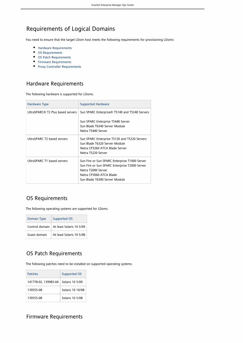
Oracle® Enterprise Manager Ops Center
Requirements of Logical DomainsYou need to ensure that the target LDom host meets the following requirements for provisioning LDoms:
Hardware RequirementsOS RequirementsOS Patch RequirementsFirmware RequirementsProxy Controller Requirements
Hardware Requirements
The following hardware is supported for LDoms.
Hardware Type Supported Hardware
UltraSPARC® T2 Plus based servers Sun SPARC Enterprise® T5140 and T5240 Servers
Sun SPARC Enterprise T5440 Server Sun Blade T6340 Server Module Netra T5440 Server
UltraSPARC T2 based servers Sun SPARC Enterprise T5120 and T5220 Servers Sun Blade T6320 Server Module Netra CP3260 ATCA Blade Server Netra T5220 Server
UltraSPARC T1 based servers Sun Fire or Sun SPARC Enterprise T1000 Server Sun Fire or Sun SPARC Enterprise T2000 Server Netra T2000 Server Netra CP3060 ATCA Blade Sun Blade T6300 Server Module
OS Requirements
The following operating systems are supported for LDoms.
Domain Type Supported OS
Control domain At least Solaris 10 5/09
Guest domain At least Solaris 10 5/08
OS Patch Requirements
The following patches need to be installed on supported operating systems.
Patches Supported OS
141778-02, 139983-04 Solaris 10 5/09
139555-08 Solaris 10 10/08
139555-08 Solaris 10 5/08
Firmware Requirements

Oracle® Enterprise Manager Ops Center
The firmware requirements are based on the hardware that is used for LDoms. The first public release of firmware to includeLDoms support is System Firmware Version 6.4.x. The correct firmware ensures that the hardware and hypervisor cancommunicate correctly.
When you perform the steps to , a firmware check is done in the background to determine if theprovision the control domaintarget system has the required system firmware version installed. A warning or error message is displayed if the required systemfirmware version is not present on the target system. The error message also contains the required system firmware version andthe required firmware patch for that target system.
The following system firmware patches are required for use with LDoms on supported servers.
System Firmware Version Patches Supported Servers
6.7.4 139434-03 Sun Fire and SPARC Enterprise T2000 Servers
6.7.4 139435-03 Sun Fire and SPARC Enterprise T1000 Servers
6.7.4 139436-02 Netra T2000 Server
6.7.4 139437-02 Netra CP3060 ATCA Blade
6.7.4 139438-03 Sun Blade T6300 Server Module
7.2.2 139439-04 Sun SPARC Enterprise T5120 and T5220 Servers
7.2.2 139440-03 Sun Blade T6320 Server Module
7.2.2 139442-06 Netra T5220 Server
7.2.2 139441 Sun Netra CP3260 ATCA Blade Server
7.2.2 139444-03 Sun SPARC Enterprise T5140 and T5240 Servers
7.2.2 139445-04 Netra T5440 Server
7.2.2 139446-03 Sun SPARC Enterprise T5440 Server
7.2.2 139448-02 Sun Blade T6340 Server Module
Proxy Controller Requirements
LDom provisioning is only supported on Solaris SPARC or x86 Proxy Controllers. The Proxy Controller can be remote orco-located, but it must be the Solaris OS Proxy Controller that was used during provisioning.
If the Proxy Controller is remote, the Enterprise Controller can run on a Linux or Solaris OS. If the Proxy Controller is co-located,the Enterprise Controller and co-located Proxy Controller must run on a Solaris OS.
Roles of Logical DomainsThere are several different roles for LDoms. A domain may have one or more of these roles, such as combining the functions ofan I/O and service domain.
Control Domain
The LDom host runs in the control domain, allowing you to create and manage other LDoms and allocate virtual resources toother domains. There can be only one control domain for each server. The initial domain created when installing LDoms softwareis a control domain and is named the primary domain. The control domain contains the SUNWldm packages, including the LDomhost application and the LDom host daemon (ldmd) process required for managing LDoms. If you have OS and other softwarerunning on a server, that server becomes your control domain once you install the LDom software.
Note – Zones are not supported in the control domain. You must not run user applications in the control domain and you cannotmigrate, delete, or shut down a control domain.

Oracle® Enterprise Manager Ops Center
1.
Guest Domain
The guest domain is a complete virtualized environment that has no ownership of physical I/O or virtual devices. This domain ismanaged by the control domain and uses services from the I/O and service domains. The guest domain must run an OS thatunderstands both the sun4v platform and the virtual devices presented by the hypervisor.
Service Domain
The service domain provides virtual device services such as a virtual network switch, a virtual console concentrator, or a virtualdisk service, to other domains.
I/O Domain
The I/O domain has direct ownership of and direct access to physical I/O devices, such as a network card in a PCI Expresscontroller. This domain shares the devices with others in the form of virtual devices when the I/O domain is also the controldomain. The number of I/O domains that you can have is dependent on your platform architecture. For example, if you are usingan UltraSPARC T1 processor, you can have a maximum of two I/O domains, one of which also must be the control domain.
Note – In Ops Center 2.5, control, service, and I/O domains are in the same domain.
Virtualization HostsHardware virtualization enables you to create multiple virtual machines on a single piece of physical hardware. Unlike SolarisContainers, where the operating system is the same, virtual machines can run on full instances of different operating systems, ordifferent versions of the same operating system. These instances are called guests.
The software uses a control domain, or virtualization host, to create and manage the guests and allocate virtual resources to otherdomains.
Logical Domains
Logical Domains (LDoms) enable server virtualization on SPARC platforms. The software enables you to create and managemultiple virtual machines instances simultaneously on a single compatible SPARC machine.
With Ops Center, you can monitor and manage all of the virtual machines from a single browser user interface. You can usevirtual pool technology to automatically balance the load of a number of servers to maximize capacity without overloading aserver. Load balancing enables you to move a virtual machine from one physical system to another, from the user interface. Youcan set parameters that enable the software to automatically balance the load, or you can elect to receive email notification andthen decide if you want to balance the load.
Creating a Virtualization HostYou can create or provision a virtualization host, or Logical Domain (LDom), in Ops Center.
Provisioning Control DomainYou create a control domain when you install LDoms. There can be only one control domain on a system. The control domainallows you to create and manage the guest domains.
Provisioning the control domain involves the following major tasks:

Oracle® Enterprise Manager Ops Center
1. 2. 3.
Importing an OS ImageCreating a Logical Domain ProfileProvisioning the Control Domain
Configurations of Control DomainBefore installing the control domain, you must specify resources such as CPU threads, crypto units, and memory as part of
. The values specified in the profile are set during the control domain provisioning.Creating a Logical Domain Profile
Note – Ops Center does not support use of the LDoms configuration manager in LDoms 1.2. Do not attempt to manuallyreconfigure the control domain and guest domains using the native CLI ( ) of LDoms software.ldm(1M)
Recommended Minimum Configurations
The recommended minimum configurations for the control domain are described in the following sections.
CPU Threads
System CPUs Control Domain CPU Threads
Less than 16 2
16 to 64 4
Greater than 64 8
Crypto Units
Crypto units are the cryptographic resources on the supported platforms that provide high-performance, dedicated cryptographicengines. These can be used for tasks such as encrypting and decrypting network traffic that could occur between a Secure SocketLayer (SSL) web server and an application server.
Each CPU core has one crypto unit and four or eight CPU threads. There are eight crypto units on eight-core platforms. As cryptounits are part of a core, they can be bound only to a domain that contains at least one thread from the parent core.
Crypto units cannot be split like CPU threads and must be aligned with a CPU core. For example, you have assigned the cryptounit for the first CPU core to the control domain. If the new guest domain is assigning a thread from the first CPU core and thecrypto unit for that core is already assigned, the hypervisor cannot assign that crypto unit to the new guest.
You must assign at least one crypto unit to the control domain because the crypto unit is used to speed up domain migration.Allocation of crypto units might not succeed, especially if a core is split between domains. An LDom host might allocate fewercrypto units or none at all.
Example
In UltraSPARC® T1 based servers, one core is four CPU threads. Therefore, assign one crypto unit and four CPU threads to thecontrol domain. These values are set in the LDom profile.
In UltraSPARC T2 and T2 Plus based servers, one core is eight CPU threads. Therefore, assign one crypto unit and eight CPUthreads to the control domain.
RAM
System RAM Control Domain RAM
Less than 8 GB 1 GB
8 GB to 16 GB 2 GB

Oracle® Enterprise Manager Ops Center
1.
2.
16 GB to 64 GB 4 GB
Greater than 64 GB 8 GB
Additional Configurations
Apart from CPU threads, crypto units, and memory, the following additional configurations must be set up for the controldomain:
Virtual network switchVirtual disk serverVirtual console concentrator
These configurations are performed during LDom provisioning.
Virtual Network Switch
A virtual network switch for each subnet is created and configured by Ops Center during LDom provisioning. The name of thevirtual network switch that is created is , for example, 10.17.7.0_24.subnet-address_prefix-length
Virtual Disk Server
A virtual disk server is created during LDom provisioning, and named .primary-vds0
Virtual Console Concentrator
A virtual console concentrator is created during LDom provisioning, and named .primary-vcc0
Importing an OS ImageYou can import OS images from existing ISO files. After you import an OS image, you can then create a profile for LDoms thatyou use to provision the control domain onto systems on your network.
When you import an OS image, an OS profile is created by default. The OS profile is named using the image name thatyou enter in the Import OS Image wizard. This default OS profile is intended for use as a template. You can modify thedefault OS profile for your specific systems.
On the Ops Center Enterprise Controller, OS images are stored in the /var/opt/sun/xvm/images/os/isodirectory. The OS images that are stored on Proxy Controllers are temporary, and are used for the provisioning process.
OS image names that you specify must be unique, can consist of up to 100 characters, and may include numbers, letters,and some special symbols. The following special symbols are prohibited: comma, asterisk, single quote, double quote,parenthesis, question mark, equal sign, and newline.
Note – You need to import at least the Solaris 10 5/09 OS SPARC ISO image for the LDoms feature to work.
Before You Begin
The Enterprise Controller must be able to access the files that you want to import. These files may be stored on theEnterprise Controller's local file system, or on a file system that the Enterprise Controller mounts using NFS.
Solaris OS images cannot be imported from ISO files made from Solaris installation CDs.
To Import an OS Image
Click Libraries in the Navigation panel, then Click OS Provisioning.The OS Images list and list of OS Provisioning Actions is displayed.

Oracle® Enterprise Manager Ops Center
2.
3. 4. 5. 6. 7.
8.
9.
Click Import OS Image in the Actions panel.The Import OS Image screen is displayed.
In the Image Name field, enter the name that you want to assign to the ISO image that you will import.In the Description field, enter a description of the file that you will import.Select the ISO image type.Click Browse to display the Browse Server panel.Use the Browse Server panel to navigate to the directory that holds the ISO image that you want to import. You can usethe Refresh button to refresh the display of your current directory.Select the ISO that you want to import, then click Add Files.The file that you selected is displayed in the Files list in the Import OS Image panel.To add more files, repeat this step.When the list of files that you want to import is complete, click Import.Example of a Solaris OS image imported into Ops Center

Oracle® Enterprise Manager Ops Center
1.
2.
3.
4.
Creating a Logical Domain Profile
To Create a LDom Profile
Click Libraries in the Navigation panel, then click OS Profiles under OS Provisioning.The OS Provisioning profiles page is displayed.
Click Create OS Profile in the Actions panel.The Define Profile page in the Create OS Profile wizard is displayed.In the Define Profile page, provide the following information:
OS Image – Select at least the Solaris 10 5/09 SPARC ISO image from the OS image drop-down list.Profile Type – Select the LDOM option. This option is enabled only when you select at least the Solaris 10 5/09SPARC ISO image.Profile Name – Enter a name for the new LDom profile.Description – Enter a description for the new LDom profile.Specify JET Parameters – If you want to use JET parameters to customize how this profile provisions the controldomain, select Specify Jet Parameters. This selection adds the JET Parameters panel to the list of configurationpanels in the Create OS Profile wizard.Click Next.If you selected Specify JET Parameters in the Define Profile panel, the JET Parameters panel is displayed.Continue to the next step.If you did not select Specify JET Parameters in the Define Profile panel, the Specify Distribution page is displayed.Skip the next step.
If the JET Parameters panel is displayed, provide the following information:JET Modules – Enter a comma-separated list of JET module names. Enter the names of any additional JETmodules that you have installed on the Proxy Controller to perform the provisioning operations described bythis LDom profile. The , , and JET modules are always installed, and you do notbase_config custom flash
need to specify them here. Refer to for more information about JET module names.Installing JET ModulesJet Parameters – Use the Add icon in the Jet Parameters list to add JET name-value pairs. In the Name field, enterthe name of the JET parameter that you want to add. In the Value field, enter the value that you want to assignto the JET parameter. Refer to for more information about JET parameters.Installing JET Modules

Oracle® Enterprise Manager Ops Center
4.
5.
6.
7.
8.
9.
10.
Click Next. The Specify Distribution page is displayed.In the Specify Distribution panel, select either the Entire Distribution plus OEM Support or Entire Distribution that youwant to use from the Available list, and add them to the Selected list. These two distributions are supported forprovisioning of control domain. Click Next.The Specify Parameters page is displayed.In the Specify Parameters panel, provide the following information:
Language – Select a language from the list.Time Zone – Select a time zone from the list.Root Password – Enter a password for the user on systems provisioned using this Logical Domain profile.root
Confirm Password – Re-enter the password that you specified in the previous field.Specify NIS Settings – Select this option if you want systems that are provisioned using this profile to beconfigured as NIS clients. This selection adds the NIS Settings panel to the list of configuration panels in theCreate OS Profile wizard. You cannot use this option with the Specify LDAP Settings option.Specify LDAP Settings – Select this option if you want systems that are provisioned using this profile to beconfigured as LDAP clients. This selection adds the LDAP Settings panel to the list of configuration panels in theCreate OS Profile wizard. You cannot use this option with the Specify NIS Settings option.Add Scripts – Select this option if you want to run specific scripts on the target system. This selection adds theAdd Scripts panel to the list of configuration panels in the Create OS Profile wizard. Click Next.The page that is displayed next depends on the options that you selected on this page.
If you selected Specify NIS Settings in the Specify Parameters panel, the NIS Settings panel is displayed. Provide thefollowing information to configure the target system as NIS client:
Enable NIS – Select this option if you want the target system to run as an NIS client after OS provisioning iscomplete.Domain Name – Enter the name of the NIS domain to which the target system will bind.NIS Server IP – If this field is active, enter the IP address of the NIS server to which the target system will bind.Click Next.The panel that is displayed next depends on the options that you selected in the Specify Parameters page.
If you selected Specify LDAP Settings in the Specify Parameters panel, the LDAP Settings panel is displayed. Provide thefollowing information to configure the target system as an LDAP client:
Enable LDAP – Select this option if you want the target system to run as an LDAP client after provisioning iscomplete.LDAP Server IP – Enter the IP address of the LDAP server for the domain that you enter in the Domain Namefield.Domain Name – Enter the name of the LDAP domain that the target system will use. Click Next.The page that is displayed next depends on the options that you selected in the Specify Parameters page.
If you selected Add Scripts in the Specify Parameters panel, the Add Scripts panel is displayed after either the SpecifyParameters, NIS Settings, or LDAP Settings panels. Click the Add icon to add scripts to run on the target system. TheBrowse Server icon enables you to locate scripts by browsing the file systems that are available to the EnterpriseController.For each script that you add, choose one of the following three script types:
post – Indicates that the script runs after the provisioning completes on the target system.pre – Indicates that the script runs before the provisioning begins on the target system.postnochroot – Indicates that the script runs after the provisioning completes on the target system, and that
functions are disallowed. The postnochroot type is only applicable to RHEL target systems.chroot (1M)
Click Next. The Logical Domain Control Domain Parameters page is displayed.
Specify the resources that you want to assign to the control domain.

Oracle® Enterprise Manager Ops Center
10.
11.
12.
See the recommended configurations for control domain at .Configurations of Control Domain
CPU Threads – Specify the number of CPU threads that you want to assign to the control domain. The remainingCPU threads are available for the guest domains.Memory – Specify the amount of memory that you want to assign to the control domain. The remainingmemory is available for the guest domains.Crypto Units – Specify the number of crypto units that you want to assign to the control domain. The remainingcrypto units are available for the guest domains.Virtual Console Port Range – Specify the minimum port and maximum port of the virtual console of the controldomain. The default port range for virtual console is 5000 to 6000.Enable JASS – Select this check box to harden the system by installing the package.SUNWjass
Enable Multiplexed I/O (MPxIO) – Select this check box to enable Fibre Channel connectivity for the controldomain. This action enables Fibre Channel ports on the system that is configured for storage. Click Next.The Define Partitions page is displayed.
In the Define Partitions panel, define the disk partitions and file systems that you want to create on the target system.Click the Add icon to define a new partition. The root ( ) and a file system are defined by default./ swap
For each partition that you define, provide the following information:Mount Point – Enter a directory to use as a mount point for partitions.Device – Enter the keyword and a slice value to describe a partition on the target system's boot disk,rootdisk
for example, , or enter the logical device name, for example, , of the partition thatrootdisk.s0 c1t0d0s0
you want to create.File System – Select a file system type, either , , or .ufs unnamed swap
Specify Size – Select this option to specify a specific size for a partition. If you want a single partition to use all ofthe remaining space on the disk, deselect this option.Size (MB) – With the Specify Size option selected for a partition, enter the size that you want to assign to thepartition, expressed in MBytes. Click Next.The Summary panel is displayed.
The Summary page displays the information that you specified in all of the preceding panels in the Create OS Profilewizard. If the summary information is correct, click Finish to create a profile for LDoms.Example of an LDom Profile

Oracle® Enterprise Manager Ops Center
12.
1.
2. 3. 4.
1.
2.
3.
Provisioning the Control Domain
Before You Begin
Ensure that the target system meets the appropriate system requirements as described in Requirements of Logical.Domains
Discover the target system that you want to provision LDoms. See .Discovering AssetsConfigure DHCP services on Ops Center Proxy Controllers. See .DHCP ConfigurationThere are specific recommended values for control domain parameters such as CPU threads and Crypto units. See the
section.Configurations of Control Domain
Note – The OS in the control domain must have the default locale set to C. The control domain provisioning is supported onSPARC or Sun x86 Proxy Controllers, but not on Linux Proxy Controllers.
Note – To successfully provision the LDom Controller, the proper system model name must be populated on the serviceprocessor. The model name is not available on the service processor of the Sun Blade T6320 hardware.
To provision the control domain:
In the Navigation panel, click Assets. Expand and select the system to use as the target for LDom provisioning.The Actions panel for Assets displays the available actions, including the Provision OS action. The Provision OS action isdisplayed only when you select the icon that represents the system hardware or service processor.Click Provision OS in the Actions panel.The Specify OS Profile page of the Provision OS wizard is displayed.In the Specify OS Profile page, select the LDom profile from the OS Profile list. Only the LDom profiles that are createdfrom at least the Solaris 10 5/09 SPARC ISO image are displayed. Click Next.The Configuration panel is displayed.
– At this step, a firmware check is done in the background to determine if the target system has the requiredNotesystem firmware version installed. A warning or error message is displayed if the required system firmware version is notpresent on the target system. The error message also contains the required system firmware version and the requiredfirmware patch for that target system. If the required system firmware version is present, the Configuration panel isdisplayed. Some T2000 and ALOM-CMT systems do not report the system firmware version. In such cases, Ops Centerchecks the ALOM-CMT firmware version and determines whether the provisioning can proceed.

Oracle® Enterprise Manager Ops Center
3.
4.
5.
6.
A model number check is also performed. To successfully provision the LDom Controller, the model name must beavailable.In the Configuration page, enter the information that is required for your target system and selected LDom profile.
The Configuration fields that relate to any single target system include:
Target – This field identifies the target system for the control domain provisioning action. Note that when thetarget of the control domain provisioning action includes only one system, the Provision OS wizard skips theSelect Target panel, which otherwise is displayed before the Configuration panel.Manual Net Boot – Select this option to enable manual control of network boot operations for the targetsystem. You must select this option for a target system that does not have a service processor because OpsCenter cannot remotely control the network boot process on these systems. When the of theNetbootTask
control domain provisioning job is successful, user intervention is required. Log in to the service processor ofthe target system(s) and manually initiate the network boot process by typing .boot net:dhcp - install
– If the target system is already up and running, type and then initiate the network boot process byNote halt
typing .boot net:dhcp - install
Network Protocol – Static IP is selected as the network protocol by default. This means that a specific IP addressis assigned to the target system's provisioning network interface, after the system is provisioned.IP Address – Enter the IP address for the target system. This is a required field when it is displayed. Use IPaddresses that are not defined as part of a subnet that is managed by the DHCP server on a Proxy Controller.See for more information.SubnetsNetmask – Enter the netmask value that the target system will use after the OS has been installed.Gateway – Enter the gateway value that the target system will use after the OS has been installed.Host Name – Enter the host name that the target system will use after the OS has been installed.Name Server – Enter the IP address or host name of the name server that the target system will use after the OShas been installed.Console Serial Port – To monitor the installation using a serial connection, select the correct console serial portdevice.Console Baud Rate – To monitor the installation using a serial connection, select the correct serial port devicebaud rate.Network Device – Select the device for the network interface that the target system will use after the OS hasbeen installed. Typically you only need to specify this value if it is not automatically determined.Domain Name – Enter the DNS domain name that the target system will use, if required.Boot Path – Select a physical device name from the Boot Path list, if the target system requires that you specifyit manually.
In the Configuration page, click Next.The Summary panel is displayed.Click Provision to submit the control domain provisioning job.You can view the status of the provisioning job in the Jobs panel.
Note – When the control domain is re-provisioned, any previous LDom configuration is removed from the service processor by

Oracle® Enterprise Manager Ops Center
1. 2.
3. 4.
resetting the service processor with the factory defaults.
Changing the Job Timeout Value for Provisioning
The control domain provisioning job takes approximately two hours to complete. The default timeout value is three hours.
In certain environments, the provisioning job takes longer to finish and might time out. You can increase the default timeoutvalue by increasing the value of the property in the osp.default_timeout
file./var/opt/sun/xvm/satellite.properties
############################################################################### # OS Provisioning ############################################################################### # Default Timeout of OSP Job osp.default_timeout=180
The value of the property is in minutes. You must restart the Enterprise Controller after changing theosp.default_timeout
value.
Tasks Performed by the Provisioning Job
The control domain provisioning job performs the following major tasks:
Downloads the appropriate OS imageInitiates a net boot action on the Service ProcessorConfigures DHCP and installs the OSInstalls the LDom hostConfigures the LDom host according to the values set in the profile such as memory, CPU threads, crypto units, andvirtual console port rangeInstalls the package to harden the systemSUNWJass
Enables the fiber channel ports on the system that is configured for storageInstalls and configures Ops Center agent
Note – If LDoms are created through the Ops Center BUI, do not install the agent manually on the LDom host.
Associating Libraries to a Logical Domain HostBefore you can associate libraries to an LDom host, you need to discover and provision an LDom host.
Note – If you do not perform this procedure, the SPARC ISO images will not be available in the Use an Installation Source From aLibrary drop-down list of the Create LDom Guest wizard.
To Associate Libraries to a Logical Domain Host
In the Navigation panel, click Assets. Expand Assets and select an LDom host.From the Actions panel, click Associate Libraries.The Associate Libraries screen is displayed.In the Available Libraries table, select the required libraries that have SPARC ISO images.Click Associate Libraries.A job is submitted to associate the selected libraries to the LDom host.
Editing the Attributes of Logical Domain HostYou can modify the attributes of an LDom host such as name, description, and tags.

Oracle® Enterprise Manager Ops Center
1.
2. 3.
To Edit the Attributes of an LDom HostIn the Navigation panel, click Assets and select an LDom host that you want to edit.The Summary tab is displayed.Modify the values of Name, Description, and Tags as required.Click the Save icon to save the changes.
Managing a Virtualization HostYou can manage a Virtualization Host, or Logical Domain (LDom), in Ops Center.
Monitoring a Logical Domain HostWhen you select an LDom host from the Assets panel, the following six tabs are displayed in the center panel of Ops Center:
SummaryLibrariesNetworkChartJobsConfiguration
In this section, the information on each tab is described in detail.
Summary
In the Summary tab, the following information about the LDom host is displayed:
NameDescriptionSun LDom Host StatusReachableRunning TimeTagsVirtual Pool (associated virtual pool)Total and Available CPU threadsTotal and Available Crypto UnitsTotal and Available Memory
The Available CPU threads, crypto units, and memory can be utilized by the guests.
The Sun LDom Control Domain Specification section in the Summary tab displays the CPU threads, memory, and crypto unitsutilization percentages for the control domain. The Sun LDom Host Resource Utilization section in the Summary tab displays theCPU threads and memory utilization percentages for all the domains including the control domain.
Ops Center collects data in five-minute intervals and displays the data in the form of charts. (Refer to for detailedChartsinformation about collecting and calculating data for different intervals). For an LDom host, the following utilization data isdisplayed:
CPU utilizationMemory utilizationNetwork utilization
The Virtual Guests table in the Summary tab displays the details of the guests that are running in the LDom host. The detailsinclude the CPU threads, crypto units, memory, and state of the guests.

Oracle® Enterprise Manager Ops Center
1. 2.
Libraries
The Libraries tab displays the libraries that are associated with this LDom host. The libraries represent the storage resources thatare available for this LDom host.
When you select a library, the guests that are associated with this library are listed under the Usage tab. You can also view thecontents of the library from the Contents tab.
From the Usage tab, you can perform the following operations:
Starting a guestShutting down a guestRebooting a guestMigrating a guestConnecting a guest to a networkDeleting a guest
Network
The Networks tab lists all the networks that are assigned to the LDom host and the guests that are using a selected network.
The following options are available in the Network tab to manage the networks:
Attach Network – You can attach a network to a virtual pool.Unbind Network from Virtual Pool -- You can remove a network from a virtual pool.Modify Physical Connectivity -- You can modify the network interface properties such as the Address Allocation method.
Chart
Ops Center collects data in five-minute intervals and displays the data in the form of charts. (Refer to for detailedChartsinformation about collecting and calculating data for different intervals.) For an LDom host, the following utilization data isdisplayed:
CPU utilizationMemory utilizationNetwork utilization
Jobs
The Jobs tab lists the currently running and historical jobs of the LDom host. (Refer to for more informationJob Managementabout managing jobs.)
Configuration
The Configuration tab displays information such as remote logging, routing, NFS, and name service information for the LDomhost.
Rebooting a Logical Domain HostThe LDom host can be rebooted regardless of the state of the guests. During the reboot, the guests might hang for a momentbut will keep their current states.
To Reboot a Logical Domain Host
In the Assets panel, select the LDom host that you want to reboot.In the Actions panel, click Reboot Sun LDom Host.

Oracle® Enterprise Manager Ops Center
2.
1. 2.
3.
4.
A job is submitted to reboot the LDom host.
The page Shutting Down a Logical Domain Host does not exist.
Creating a GuestYou can create or provision a virtual system, or guest, in Ops Center.
Creating a Guest DomainA guest domain is a virtual machine that is associated with an LDom host. Each guest can run a full version of the operatingsystem. You can create a guest by using an ISO image from a library or by using an installation source in a CD/DVD drive.
Note – You can create guests only by using the ISO images.
Before You Begin
Ensure that you have the appropriate Solaris 10 (at least Solaris 10 5/08) ISO image saved in a library, or an image savedon a CD/DVD drive.Ensure that you have sufficient amount of CPU threads, crypto units, and memory to assign to the guest.Ensure that you have libraries that can store the meta data of the guest image and the virtual disks.Ensure that you have at least one network that you can assign to the guest.Ensure that you have associated the required libraries to the LDom Host. (See Associating Libraries to a Logical Domain
.)Host
Note – The library used to store the meta data of the guest image is different from the libraries used to store the virtual disks.You specify the library to store the meta data in the Identify Guest panel in the Create LDom Guest wizard. You specify thelibraries to store the virtual disks in the Specify Storage and Disks panel of the Create LDom Guest wizard. You cannot store themeta data of the guest image on a Fibre Channel Library. You can store the meta data only on a local library, CIFS library, or NFSlibrary. You can store the virtual disks on NFS libraries, local libraries, or Fibre Channel libraries. You cannot store virtual disks onCIFS libraries.
To Create a Guest DomainIn the Assets panel, select an appropriate LDom host.In the Actions panel, click Create Guest.The Create LDom Guest wizard is displayed.In the Select Installation Source panel of the wizard, select the installation source for creating a guest.The installation source could be from a library or from a CD/DVD drive.
Use an installation source from a library – Select an appropriate ISO image. The drop-down list displays all theISO images supported by LDoms.Use an installation source in a CD/DVD drive – Select the OS type from the OS Type drop-down list.Click Next. The Identify Guest panel is displayed.
In the Identify Guest panel, provide the following information:Guest Name – Enter a unique guest name in the Guest Name field. By default, the guest name is populated withthe image name. The guest name can be a maximum of 20 characters long. The following characters areallowed: A-Z, a-z, 0-9, -, _, (, ) and spaces.Description – Enter a description of the guest in the Description field. By default, the description is populatedwith the image description.Tags – Provide tags to create keywords. Use a space to separate multiple tags.Guest Library – Select a library that will store the configuration information (meta data) of the guest image. TheGuest Library drop-down list contains the libraries that are associated. The default library is the library with the

Oracle® Enterprise Manager Ops Center
4.
5.
6.
7.
8.
1. 2.
most available space.Click Next.The Configure CPU Threads and Memory panel is displayed.
In the Configure CPU Threads and Memory panel, provide the following information:CPU Threads – Specify the number of CPU threads that you want to assign to the new guest. The physical CPUsare shared among the CPU threads of all the guests.Requested Crypto Unit – Specify the number of crypto units that you want to assign to the new guest domain.There is a crypto unit per core. If the CPU threads assigned to the guest come from cores where crypto unitshave already been allocated to other guests, the actual number of crypto units assigned might be less than thenumber requested. When the Create Guest job completes, the job notification includes both the number ofcrypto units requested and the number of crypto units assigned to the new guest.Memory – Specify the amount of memory that you want to assign to the new guest. To successfully create theguest, at least 1 Gbyte of memory is required.Click Next.The Specify Storage and Disks panel is displayed.
In the Specify Storage and Disks panel, specify the storage library and virtual disks.Logical Domain guests require virtual disks for storage.The guest will be created with two default virtual disks, the boot disk (root) and the CD/DVD disk. You can addadditional virtual disks by clicking the + icon.The Recommended Storage Size in this panel is equal to the size of the default boot disk (10 Gbytes). The CurrentAccumulated Storage Size in this panel increases as more virtual disks are added.Each virtual disk of a guest domain has a unique device name that is assigned when the domain is bound. When a guestdomain virtual disks is running the Solaris OS, each virtual disk appears in the domain as a c0dn disk device, where n isthe device number of the virtual disk. The device name is incremented for each virtual disk like c0d0, c0d1, c0d2, and soon.The first disk displayed is a virtual boot disk of size 10 Gbytes. You cannot delete this virtual boot disk. By default, thevirtual boot disk will be created on a library that stores the guest image. You can also create the virtual boot disk on adifferent library.The Library drop-down list contains all the libraries associated with the virtual pool. The libraries that you specify in thisstep are used to store the virtual disks. The libraries can be NFS libraries, local libraries, or Fibre Channel libraries. Youcannot associate CIFS libraries to the virtual pool.
If you select NFS library or local library from the Library drop-down list, enter the virtual disk name in the VirtualDisk Name field and the size in the Size field. A virtual disk image will be created.If you select a Fibre Channel library from the Library drop-down list, the Virtual Disk Name field becomes adrop-down list containing all available LUNs in the selected library. Select a LUN from the Virtual Disk Namedrop-down list. The Size field is a read-only field and will show either "-" or the size of the selected LUN. Youcannot specify the size or create the new virtual disk image. You can create only one guest on each LUN.
– After the guest is created, you can provision the OS on the guest. (See ).Note Provisioning a Guest DomainDuring OS provisioning, file systems are created on the virtual disks.Click Next.The Specify Networks panel is displayed.
In the Specify Networks panel, select at least one network from the available networks. The Network Name drop-downlist contains all the networks that are associated with the virtual pool. You can add more networks to associate with theguest.Click Next.The Summary panel is displayed.In the Summary panel, review the information about the new guest and click Finish.The Summary panel displays the number of crypto units requested and not the number of crypto units that will beassigned to the new guest. When the Create Guest job completes, the guest appears in the Assets panel under the LDomhost. When the Create Guest job completes, the job notification includes both the number of crypto units requested andthe number of crypto units assigned to the new guest.The Create Guest job creates a new guest, guest network, and virtual disks. The Create Guest job also assigns MACaddresses automatically to each guest. When the Create Guest job completes, the new guest appears in the Assets panel.
Accessing Serial Console Outside Ops Center
Serial console access requires appropriate firewall and routing settings for the Enterprise Controller to connect to the ProxyController through ssh (on port 22). When the enterprise controller cannot connect to the proxy controller because of firewallissues, you cannot access the serial console through BUI of Ops Center. In this case, you can access the serial console only fromthe command line.
Log in to the control domain.Open a telnet session to the console.

Oracle® Enterprise Manager Ops Center
2.
3.
1. 2.
3.
4.
5.
6.
telnet localhost port
Where port is the virtual console port number of LDom guest.
If you have lost the console for the guest, perform the following steps to obtain the console.
ldm stop guest-uuidldm start guest-uuidtelnet localhost 5000
For more information, see the . man pageldm
Provisioning a Guest DomainA guest domain is a virtual machine that is associated with an LDom host. You can provision at least Solaris 10 8/07 OS on theguest.
Before You Begin
Ensure that you have imported the appropriate Solaris 10 (at least Solaris 10 8/07) ISO image into the OS Provisioninglibrary.Ensure that you have created a SPARC OS profile for an LDom guest. The profile must be of Guest type.
To Provision a Guest Domain
In the Assets panel, select an appropriate LDom host.In the Actions panel, click Provision Guest.The Provision LDom Guest wizard is displayed.In the Select Guest Profile panel of the Provision LDom Guest wizard, specify the appropriate OS profile.}Only SPARC® OS profiles of Guest type are displayed in the OS Profile drop-down list. You can provision one guest foreach LDom host. For a group of LDom hosts, you can specify the number of guests to provision.Click Next.The Configure Guests panel is displayed.In the Configure Guests panel of the wizard, provide the following information.
Register with Sun Ops Center – Select this option to register the provisioned guests with the Ops Centerinstance. This option applies to all the provisioned guests.Guest Name – Enter a unique guest name in the Guest Name field. The guest name can be a maximum of 20characters long.Description – Enter a description of the guest in the Description field.Tags – Provide tags to create keywords. Use a space to separate multiple tags.Storage Library – Select a library that will store the configuration information (meta data) of the guest image.The Storage Library drop-down list contains the libraries that are associated. The default library is the librarywith the most available space. This library will also be the default library for storing virtual disks. As FibreChannel libraries cannot be used to store a guest image, they will not be listed here. However, you can select aFibre Channel library for a virtual disk when configuring the disks in a later step.Click Next.The Configure Guest Networks panel is displayed.
In the Configure Guest Networks panel of the wizard, provide IP address, netmask, and gateway information.Select at least one network from the available networks and identify one network as the boot network. Enter an IPaddress for the boot network.To configure a network, select a row in the Network table. Click the Network Name field to select a network, and clickthe IP Address, Netmask and Gateway fields to enter values. Networks use DHCP to obtain an IP address if none isspecified.Click Next.The Configure Guest Disks panel is displayed.

Oracle® Enterprise Manager Ops Center
6.
7.
Logical Domain guests require virtual disks for storage.The guest will be created with two default virtual disks, the boot disk (root) and the CD/DVD disk. You can addadditional virtual disks by clicking the + icon.The Recommended Storage Size in this panel is equal to the size of the default boot disk (10 GB). The CurrentAccumulated Storage Size in this panel increases as more virtual disks are added.Each virtual disk of a guest domain has a unique device name that is assigned when the domain is bound. When a guestdomain with virtual disks is running the Solaris OS, each virtual disk appears in the domain as a c0dn disk device, where nis the device number of the virtual disk. The device name is incremented for each virtual disk like c0d0, c0d1, c0d2, andso on.The first disk displayed is a virtual boot disk of size 10 GB. You cannot delete this virtual boot disk. By default, the virtualboot disk will be created on a library that stores the guest image. You can also create the virtual boot disk on a differentlibrary.The Library drop-down list contains all the libraries associated with the virtual pool. The libraries that you specify in thisstep are used to store the virtual disks. The libraries can be NFS libraries, local libraries, or Fiber Channel libraries. Youcannot associate CIFS libraries to the virtual pool.
If you select NFS library or local library from the Library drop-down list, enter the virtual disk name in the VirtualDisk Name field and the size in the Size field. A virtual disk image will be created.If you select a Fiber Channel library from the Library drop-down list, the Virtual Disk Name field becomes adrop-down list containing all available LUNs in the selected library. Select a LUN from the Virtual Disk Namedrop-down list. The Size field is a read-only field and will show either "-" or the size of the selected LUN. Youcannot specify the size or create the new virtual disk image. You can create only one guest on each LUN.Click Next.The Summary panel is displayed.
In the Summary panel, review the information about the new guest and click Finish to submit the provisioning job.
Managing a GuestYou can manage guest operating systems, or domains, in Ops Center.
Monitoring a GuestWhen you select an LDom guest from the Assets panel, the following tabs display in the center panel of Ops Center:
SummaryOS DetailsConsoleNetworkStorageChartJobs
In this section, the information on each tab is described in detail.
Summary
In the Summary tab, the following information about the guest is displayed:
Guest NameDescriptionStatusRunning TimeOperating SystemTagGuest ImageBoot DeviceCPU ThreadsCrypto UnitsMemory Size

Oracle® Enterprise Manager Ops Center
CPU Utilization Percentage
The Virtual Disk Images table in the Summary tab lists the disk images that are associated with this guest.
Ops Center collects data in five-minute intervals and displays the data in the form of charts. (Refer to for detailedChartsinformation about collecting and calculating data for different intervals.) For a guest, the following utilization data is displayed:
CPU utilizationMemory utilization
OS Details
The following information about the OS is displayed in the OS Details tab:
OS Name and DetailsOS HealthNotification statusOS Monitoring VariablesFile System thresholds and usageHourly chart of CPU and Memory Utilization
Console
The Console tab allows you connect to the virtual console of the guest. Click Enable Console to activate the console.
Network
The Network tab displays the networks that are assigned to this guest. This tab displays details such as NIC Name, IP Address,MAC Address, and Network.
Storage
Guests require virtual disks for storage. The total storage size of all the virtual disks that are associated with this guest isdisplayed.
The Storage tab displays a table listing the virtual disks that make up the storage for the guest. These virtual disks can be fromNFS or local libraries, or LUNs from the Fiber Channel library. These virtual disks are defined and configured while creating theguest. This table is read-only, which means that you cannot add additional virtual disks and you cannot delete any of the existingvirtual disks.
When you select a LUN in this table, additional details such as name, vendor, GUID, product, status, and revision are displayed.
Chart
Ops Center collects data in five-minute intervals and displays the data visually in the form of charts. (Refer to for detailedChartsinformation about collecting and calculating data for different intervals.) For a guest, the following utilization data is displayed:
CPU utilizationMemory utilization
Jobs
The Jobs tab lists the currently running and historical jobs of the guest. (Refer to for more information aboutJob Managementmanaging jobs.)
Editing the Attributes of a Guest Domain

Oracle® Enterprise Manager Ops Center
1.
2. 3. 4.
1. 2.
1. 2. 3.
1.
You can edit the attributes of a guest. You can modify the resource assignments such as CPU threads and crypto units.
Note – You must shut down the guest before you can edit the attributes.
To Edit the Attributes of a Guest Domain
In the Assets panel, select a guest domain that you want to edit.The Summary tab is displayed.In the Actions panel, click Edit Attributes.Modify the values of Description, Tag, CPU threads, crypto units, and CD ROM/DVD as required.Click the Save icon to save the changes.
Starting a Guest DomainGuests that are shut down can be started. The guest domain is powered on and the OS is booted.
To start a guest in a shutdown state, you must select a stand-alone LDom host or an LDom virtual pool that has sufficientresources to host the guest. It is possible for an LDom guest in this state to change the following at startup time:
Virtual poolLogical Domain hostNetworkLibrary resourcesAgent configuration
To Start a Guest Domain
In the Assets panel, select a shutdown guest domain that you want to start.In the Actions panel, click Start Guest.A job is submitted to start the guest.
Rebooting a Guest DomainYou can reboot a guest domain from the BUI.
To Reboot a Guest Domain
In the Assets panel, select the LDom guest that you want to reboot.In the Actions panel, click Reboot Guest.Click Reboot Guest in the pop-up window that is displayed.A job is submitted to reboot the guest.
Shutting Down a Guest DomainWhen you shut down a guest, it is disconnected from the associated networks and is disassociated from the LDom host. When youshut down a guest, all the associated resources are released. The guest can be re-started later with the same configuration that ismaintained in the library.
To Shut Down a Guest Domain

Oracle® Enterprise Manager Ops Center
1. 2. 3.
1. 2. 3.
1. 2.
3.
4.
In the Assets panel, select an LDom guest that you want to shut down.In the Actions panel, click Shutdown Guest.Click Shutdown Guest in the pop-up window that is displayed.A job is submitted to shut down the guest.
Deleting a Guest DomainWhen you delete a guest, it is disconnected from the associated networks and is disassociated from the LDom host. All theassociated resources are released and the domain configuration is removed from the library. All the references to the guest,including its disk image and snapshots are removed from the system.
To Delete a Guest Domain
In the Assets panel, select the Logical Domain guest that you want to delete.In the Actions panel, click Delete Guest.Click Delete Guest in the pop-up window that is displayed.A job is submitted to delete the guest.
Migrating a Guest DomainYou can migrate an LDom guest from one LDom host to another within the same virtual pool. This is called warm migration.
In warm migration, the guest is shut down or suspended and then its static configuration is moved to the target host. The guest isthen restarted on the target host using the same virtual image. Warm migration does not maintain the live run state of theoperating system (that is, going through a save-to-disk cycle during the migration). Shared storage is required for thisimplementation.
Before You Begin
Ensure that the requirements have been set up:
Source and destination hosts are in the same virtual pool.Source and destination hosts are in the same network.Network accessible storage (disk image) for the migrating guest is available at both source and destination hosts.The guest crypto unit count must be 0. Remove all the crypto units before migrating the guest.Enough resources (CPU threads, memory) are available at the destination host.
To Migrate a Guest Domain (Warm Migration)
In the Assets panel, select an LDom guest that you want to migrate.In the Actions panel, click Migrate Guest.The Migrate Guest wizard is displayed.In the Select Destination panel, select a target LDom host that can host the guest.The Select Destination panel displays the details of the migrating guest such as Crypto Units, CPU threads, memory, andname of the source LDom host. The panel also displays a set of possible target LDom hosts in order of decreasingpreference. Only the hosts that have enough resources to host the migrating guest are displayed.Click Next.Review the details in the Summary panel and click Finish to migrate the LDom guest.
Connecting a Guest to Networks

Oracle® Enterprise Manager Ops Center
1. 2.
3. 4.
Before you connect a guest to networks, ensure that the appropriate guest is in shutdown state.
To Connect a Guest to Networks
In the Assets panel, select a guest that is in shutdown state.In the Actions panel, click Connect Guest to Network.The Connect Guests to Network pop-up window is displayed. The networks that are not currently connected to theselected guest are displayed in a table.Select the networks to which you want to connect the guest.Click Connect to Network.
Solaris ContainersSolaris Containers are an integral part of the Solaris 10 operating system (OS). Solaris Containers isolate software applications andservices using flexible software-defined boundaries. They enable you to create many private execution environments within asingle instance of the Solaris 10 OS. Each environment has its own identity that is separate from the underlying hardware. Eachenvironment behaves independently as if running on its own system, making consolidation simple, safe, and secure.
You can build Solaris Containers by using the following technologies:
Solaris Resource ManagerSolaris Zones partitioning technology
Content Description
About Zones Provides an overview of Solaris Zones, types of zones, how zones are supported, andlimitations for the support of zones
Creating Zones Describes how to create zones and modify zone configuration
Discovering and ManagingExisting Zones
Describes how to discover and manage already existing zones
Managing and MonitoringZones
Describes how to manage and monitor the performance of zone
Performing Zone Tasks Describes how to perform zone management tasks using Ops Center
About ZonesA zone is a virtualized operating system environment created within a single instance of the Solaris OS. With the zones feature,the operating system is represented to the applications as virtual operating system environments that are isolated and secure. Theapplications run in different zones with complete isolation, while the underlying operating system resources are centrallymanaged and administered.
The Solaris operating system supports two types of zones:
Global zoneNon-global zone
The global zone is the default operating system and has control over all the processes. A global zone always exists even when noother zones are configured.
Non-global zones, referred to simply as zones hereafter, are configured inside the global zone. Zones are isolated from thephysical hardware characteristics of the machine by the virtual platform layer.
See for more information about SolarisSystem Administration Guide: Solaris Containers-Resource Management and Solaris ZonesContainers.

Oracle® Enterprise Manager Ops Center
How Zones Work
A zone can be thought of as a box. One or more applications can run in this box without interacting with the rest of the system.Solaris zones isolate software applications or services by using flexible, software-defined boundaries. Applications that are runningin the same instance of the Solaris OS can then be managed independently of one other. Thus, different versions of the sameapplication can be run in different zones, to match the requirements of your configuration.
Every Solaris 10 system contains a global zone. The global zone has a dual function. The global zone is both the default zone forthe system and the zone used for system-wide administrative control. All processes run in the global zone if no zones, are createdby the global administrator.
Understanding Facts in Zone Management
It is necessary to understand certain facts and terms while managing a zone.
Every Solaris OS contains a global zone.The global zone is both the default zone for the system and the zone used for system-wide administrative control.The global zone is the only zone from which a non-global zone can be configured and installed.Booting the global zone is equivalent to booting the system hardware.Each zone, including the global zone, is assigned a zone name. The global zone always has the name .global
Each zone is also given a unique numeric identifier, which is assigned by the system when the zone is booted.The global zone is always mapped to ID 0.Each zone has a path to its root directory that is relative to the global zone's root directory.The zone is not aware of the existence of any other zones.
Types of Zones
You can create the following types of zones using Ops Center:
Sparse Root Zone – Contains a read/write copy of only a portion of the file system existing on the global zone (hence thename sparse root) while other file systems are mounted read-only from the global zone as loop-back virtual file systems.When a sparse root zone is created, the global administrator selects which file systems to share with the sparse root zone(by default, the , , , and directories are shared as read-only file systems). All packages that/usr /lib /sbin /platform
are installed on the global zone are made available to the sparse root zone; a package database is created and all files inthe mounted file system are shared with the zone.Whole Root Zone – Contains a read/write copy of the entire file system existing on the global zone. When a whole rootzone is created, all packages that are installed on the global zone are made available to the whole root zone; a packagedatabase is created and all files are copied onto the whole root zone for the dedicated and independent use of the zone.Branded Zone – Supports different versions of Solaris OS in the zones for running applications. For example, you caninstall Solaris 8 or 9 in the branded zone on a system with the Solaris 8 or 9 Container products.
Zones Support in Ops Center
Refer to for more information about how zones are supported in Ops Center, and theSupport and Limitations for Zoneslimitations that are currently applicable for this release.
Support and Limitation for ZonesOps Center 2.5 provides more support for Solaris Zones. You can create zones, discover and identify existing zones, managestorage for zones, modify and save zone configuration data, migrate zones, clone zones, and display per-zone resource utilizationdata.
Refer to for supported Solaris OS versions for zones.Supported Operating Systems
You can use Ops Center to create a zone and manage already existing zones in a Solaris OS.
You can discover and manage the zones that have been already configured and installed by other means such as thecommand-line interface (CLI). There is less support for these zones compared to the zones that were created using the OpsCenter.

Oracle® Enterprise Manager Ops Center
The following illustration provides a clear picture of how zones are supported in Ops Center. In the illustration, Zone 2 is createdusing the CLI and the Ops Center provides the following support for Zone 2:
Boot zoneShut down zoneHalt zoneClone zoneDelete zoneMonitor zone resource utilization
The Zone 1 in the illustration is created using Ops Center. Ops Center provides the same support, and in addition, the followingbenefits:
Edit zone configurationManage zone storageManage zone networkMigrate zone
You can clone zones that are discovered and managed in Ops Center such that a cloned zone is similar to a zone created usingOps Center.
Limitations For Zone Support in Ops Center
Actions Limitations
AdministeringZones in OpsCenter
It is essential that the zones created through Ops Center must be administered only using Ops Center. Youmust not make changes or perform zone tasks using other utilities such as CLI. If not, Ops Center will suspendthe management of the zones created through Ops Center.
PerformingZone tasks
Zone management tasks such as Add File Systems, Add Storage, Connect Network and Edit Zone Configurationare enabled only if the zone is in the shut down state. Whereas, the Migrate Zone and clone zone are enabledeven when the zone is running.

Oracle® Enterprise Manager Ops Center
Live Upgradeand Zones
If you use Live Upgrade to update the zones, then you cannot manage the zones using Ops Center. ABE is notsupported for zones that were created using Ops Center. When you migrate a zone, ABE is not supported.
Creating Zones Using Ops Center
You can create zones using Ops Center. Zones that were created using Ops center are indicated by a (green) icon in theAssets tree. Any zone that you create using Ops Center will be automatically managed by Ops Center. The zone configuration datais stored as a zone image in the selected library. You can modify the configuration of the zones that were created through OpsCenter.
Create ZonesYou can configure and install zones using Ops Center.Creating zones with Ops Center results in the following operations which run automatically in the background and are hiddenfrom the user:
The file systems of the zones are implemented as ZFS file systems.Storage added to a zone is pooled in a zpool.A zpool is created with the name of the zone metadata.There is one zpool for each created zone in Ops Center 2.5.You cannot edit or delete the storage added to the zone. However, you can add new storage to the zone which will beadded to the existing zpool.The storage that is allocated to the zone is pooled in a zpool and used by all the file systems.
Note – When you create or migrate a zone using Ops Center, you cannot use Solaris Live Upgrade and an alternate bootenvironment (ABE) to update the zone.
Before You Begin
You must provide the following data when you create a zone:
Type of zone: , , or .whole root zone sparse root zone branded zoneZone name – Provide a unique zone name. You cannot use names that start with and .global SUNW
Autoboot – Specifies whether the zone will boot after creation and whenever the global zone boots.Shared CPU – Provides the CPU resources by number of shares. Depending on the workload requirements on the zone,you can allocate the CPU shares to the zone. The CPU is shared with other zones in the default resource pool. You canalso cap the CPU resources. The CPU cap provides a limit on the amount of CPU resources that can be used by a zone.For example, a CPU cap value of 1 means 100% of a CPU.Dedicated CPU – Provides the CPU resources in number of CPUs. Enter the minimum and maximum dedicated CPUs. Themaximum dedicated CPUs should be greater or equal to the minimum number of dedicated CPUs. A temporary resourcepool is created and dedicated to the zone.Importance – Defines the relative importance of a pool. You can assign an importance value for the zone when themaximum dedicated CPU is greater than the minimum dedicated CPU. If there are not enough CPU resources to satisfyall zones, then the zone that has the greater importance value receives a larger share of the available CPU resources.Memory Caps – Sets the cap for physical, swap and lock memory resources.Shared IP – Each zone that requires network connectivity has one or more dedicated IP addresses. A shared-IP zoneshares the IP layer configuration and state with the global zone. The IP addresses are associated with logical networkinterfaces.Exclusive IP – An exclusive IP zone has its own IP layer configuration and state. An exclusive-IP zone is assigned its ownset of network interfaces. You must configure the network interfaces dedicated to the zone using the standard networkconfiguration methods applied to all Solaris 10 OS configurations.
Whole Root Zone Requirement
Whole root zones contain a read/write copy of the file system that exists on the global zone. A whole root zone has the followingrequirements;

Oracle® Enterprise Manager Ops Center
1. 2.
3.
4.
1.
2.
The minimum size of the file system is 5 Gigabytes.The minimum size of the virtual disk for the selected storage library is 6 Gigabytes.
Sparse Root Zone Requirement
Sparse root zones contain a read/write copy of a portion of the file system existing on the global zone and read-only sharing ofthe , , , and directories. A sparse root zone has the following requirements:/usr /lib /sbin /platform
The minimum size of the file system is 1 Gigabyte.The minimum size of the virtual disk for the selected storage library is 1 Gigabytes.
Branded Zone Requirement
Branded zones emulate user environments from OSes other than Solaris 10. For example, you can create a branded zone on aSolaris 10 system that runs Solaris 8 applications. A branded zone has the following requirements:
You must download and install the images for the brand.For Solaris 8 branded zone, see this .locationFor Solaris 9 branded zone, see this . locationYou can also download the images from the or from the Solaris 10 OS media. Sun Download CenterInstall the following packages in the global zone:If the global zone is running Solaris 10 10/08 OS or later:
Install SUNWs8brandk from Solaris 8 Containers 1.0.1.Install SUNWs9brandk from Solaris 9 Containers 1.0.1.
If the global zone is running and earlier version of Solaris 10 10/08 OS:Install SUNWs8brandr and SUNWs8brandu from Solaris 8 Containers 1.0.1.Install SUNWs9brandr, SUNWs9brandu, and SUNWs9brandk from Solaris 9 Containers 1.0.1. For more instructions, refer to the README files in the Solaris 8 or 9 Containers bundle.
You must create the location where the guest FLAR images for the branded zone are stored. This location can be adirectory, an HTTP server, or an FTP server. For example, use the following procedure to set up an FTP server for a Solaris9 branded zone.
Setting Up an Anonymous FTP Server
Log on to your Enterprise Controller as the user.root
Check whether a directory named exists, and create it if it does not:/export/home
# ls -d /export/home/export/home: No such file or directory# mkdir -p /export/home
Use the command to set up an anonymous FTP server:ftpconfig
# ftpconfig /export/home/ftpCreating user ftpCreating directory /export/home/ftpUpdating directory /export/home/ftp
Copy the Solaris 9 flash archive images to the anonymous FTP directory.For example:
# cp /opt/ses/flar/solaris9-image.flar /export/home/ftp/pub
To Create a Zone
Expand the Assets section and select the global zone.The Summary page of the selected global zone is displayed.In the Actions panel, click Create Zone.

Oracle® Enterprise Manager Ops Center
2.
3.
a.
b.
c. d.
4. 5.
The Create Zone wizard is displayed.Select the type of zone that you want to create in the wizard.To create a branded zone, provide the following information:
Specify the location of the image:For the global zone, specify the image location as .file:///path/to/the/image.flarFor an HTTP server, specify the image location as .http://path/to/the/image.flarFor an FTP server, specify the image location as .ftp://path/to/the/image.flar
Select the brand type, either Solaris 8 or 9. The Solaris packages must already be installed. – After installing the packages, it takes at least five minutes for Ops Center to refresh the brand list.Note
(Optional) Specify the HostID if you want to run application that are associated with specific host IDs.(Optional) Specify the Machine Type as Sun4u or Sun4v for Solaris 8 or 9 branded zones. Click Next.The next step of the Create Zone wizard is displayed.
Identify the zone. Enter a zone name and description for the zone.Select one of the libraries associated with the global zone from the Library list.The new zone metadata will be stored in the selected library. Click Next.The next step of the Create Zone wizard is displayed.

Oracle® Enterprise Manager Ops Center
5.
6.
7.
8.
Configure the CPU and memory thresholds.The CPU shares can be either Shared or Dedicated. Set the memory thresholds as required. Ensure that the lockedmemory threshold value is less than or equal to physical memory threshold.
– When you set Shared CPU, the zone is automatically placed in the Fair Share Scheduling. Click Next.NoteThe next step of the Create Zone wizard is displayed.
Configure the language, time zone, terminal type, and root password for the zone. The zone name is taken as the hostname for the zone.Set the boot properties of the zone as required.You can set the boot properties so that the zone boots after creation and whenever the global zone boots. Click Next.The next step of the Create Zone wizard is displayed.

Oracle® Enterprise Manager Ops Center
8.
9.
10.
Configure the zone file system.The zone is created with a default root file system, the zone path. You cannot delete this file system or change its readand write access. You can add more file systems to the zone, and define the size and access to the file system. You canenter the Reserved size which is the size of the file system. You can also enter the Quota size which is the maximum sizethat the file system can utilize. Click Next.The next step of the Create Zone wizard is displayed.
Configure the zone storage.Select a library and specify the virtual disks that make up for the zone storage. The library can be either a NAS storage orFibre Channel library. For a NAS storage library, specify the virtual disk name and size of the disk. For a Fibre Channelstorage library, select a LUN from the available list of LUNs in the library. The size of the selected LUN is displayed. Youcannot change the size of the LUN.The size of the storage is displayed as Currently Accumulated Storage. The required storage for the added file system is
displayed as Recommended Storage Size. To configure more storage resources for the zone, click the icon. When theCurrently Accumulated Storage size reaches the Recommended Storage size, click Next.

Oracle® Enterprise Manager Ops Center
10.
11.
– Provide sufficient storage space to accommodate the file systems added to the zone. Ensure that you allocate 20%Notemore than the required storage space for a good performance.
– If you provide local library for the zone storage, then you cannot migrate the zone.NoteThe next step of the Create Zone wizard is displayed.
Specify the network interfaces.You need to assign at least one network to the zone. Select the zone IP type as Shared or Exclusive.
Shared IP – The networks that are assigned to the global zone with shared IP type are listed in the Networks list.Select a network from the list. Each shared Network Interface Card (NIC) for the selected network are listed inthe NIC list. Select a NIC from the list. If the selected network has its defined IP range, then Auto Allocate IP isdisplayed in the Management Interface. The Zone IP will be automatically populated with an IP in the definedrange. If the selected network does not have any IP range defined, then in the Management Interface, Use StaticIP is displayed. You must enter a valid IP address in the Zone IP field.Exclusive IP – The networks that are assigned to the global zone and not used by other zones are listed in theNetworks list. Select a network from the list. The NICs that have not been bound to other networks are listed inthe NIC list. Select a NIC from the list. If the selected network has its defined IP range, then Auto Allocate IP isdisplayed in the Management Interface. The Zone IP will be automatically populated with an IP in the definedrange. If the selected network does not have any IP range defined, there are two options in the ManagementInterface to select. You can select Use Static IP and enter a valid IP address in the Zone IP field. If you have anexternal DHCP, select the option Assigned by ext. DHCP. The Zone IP is automatically allocated by the DHCPexternal to Ops Center. Automatically Allocated is displayed in the Zone IP field. Click Next.The next step of the Create Zone wizard is displayed.

Oracle® Enterprise Manager Ops Center
11.
12. View the summary of your selections for the new zone. Click Finish to launch the job for creating a zone.
Editing Zone ConfigurationYou can modify the configuration of a zone to change the CPU or memory resources, scheduler, and the identity of the zone.When you modify the CPU and memory configuration, you must reboot the zone for the changes to take effect.
If the zone is not in the running state during modification, then the change in resources takes effect during the next reboot. Ifthe zone is in the running state during modification, then reboot the zone for the changes to take effect.
Note – You can edit the configuration of the non-global zone only if it has been created using Ops Center.
Before You Begin
You can modify the following properties of a zone:
CPU Model – The CPU model can be shared or dedicated. For a shared CPU, you can modify the number of CPU sharesallocated to the zone. For a dedicated CPU, you can edit the minimum and maximum dedicated CPU numbers. You canalso set the relative importance of the zone compared to other zones when contending for CPUs.Memory Caps – You can specify caps on various aspects of memory used by the zone. You can modify the caps set forphysical, swap, and locked memory.Scheduler &ndahs; For shared CPU model, the scheduler is automatically assigned to Fair Share Scheduler (FSS). For adedicated CPU model, you can set the following scheduler attributes:
Fair Share Scheduler (FSS)Fixed Priority (FX)Interactive (IA)Real-time (RT)Timer Sharing (TS)
LightWeight Processes (LWP) – You can set the maximum number of LWPs simultaneously available to a zone.Message IDs – You can set the maximum number of message queue IDs allowed for a zone.Semaphore IDs – You can set the maximum number of semaphore IDs allowed for a zone.Shared Memory IDs – You can set the maximum number of shared memory IDs allowed for a zone.Shared Memory – You can set the maximum amount of shared memory allowed for a zone.
To Edit Zone Configuration

Oracle® Enterprise Manager Ops Center
1. 2.
3.
4.
In the Navigation panel, select the Assets section.Choose the zone for which you want to modify the configuration from the Assets section.The Summary page of the zone is displayed in the center panel.Select the Configuration tab in the center panel.The current configuration of the zone is displayed.Click Edit Configuration in the Actions panel.The Edit Zone Configuration window is displayed. You can edit the following zone attributes:
CPU ModelSchedulerMemory CapsLightWeight ProcessesMessage IDsSemaphore IDsShared Memory IDsShared Memory
Discovering and Managing Existing ZonesOps Center provides support for management of zones that were created by other means such as through the CLI commands.
You can discover and manage the zones that were created by other means. These zones are displayed with a icon in the Assetstree.
See for configuring and installing zones.System Administration Guide: Solaris Containers-Resource Management and Solaris Zones
Discovering Zones OverviewYou can discover a global zone and its zones in the same way as any other managed systems in a data center. When you discover a system with at least Solaris 10 8/07 OS or later, the zone features are identified in the system.
The global zone and the related zones are in an asset tree, which represents the hierarchy of the zones as shown in the followingfigure. This helps to manage the zones efficiently.
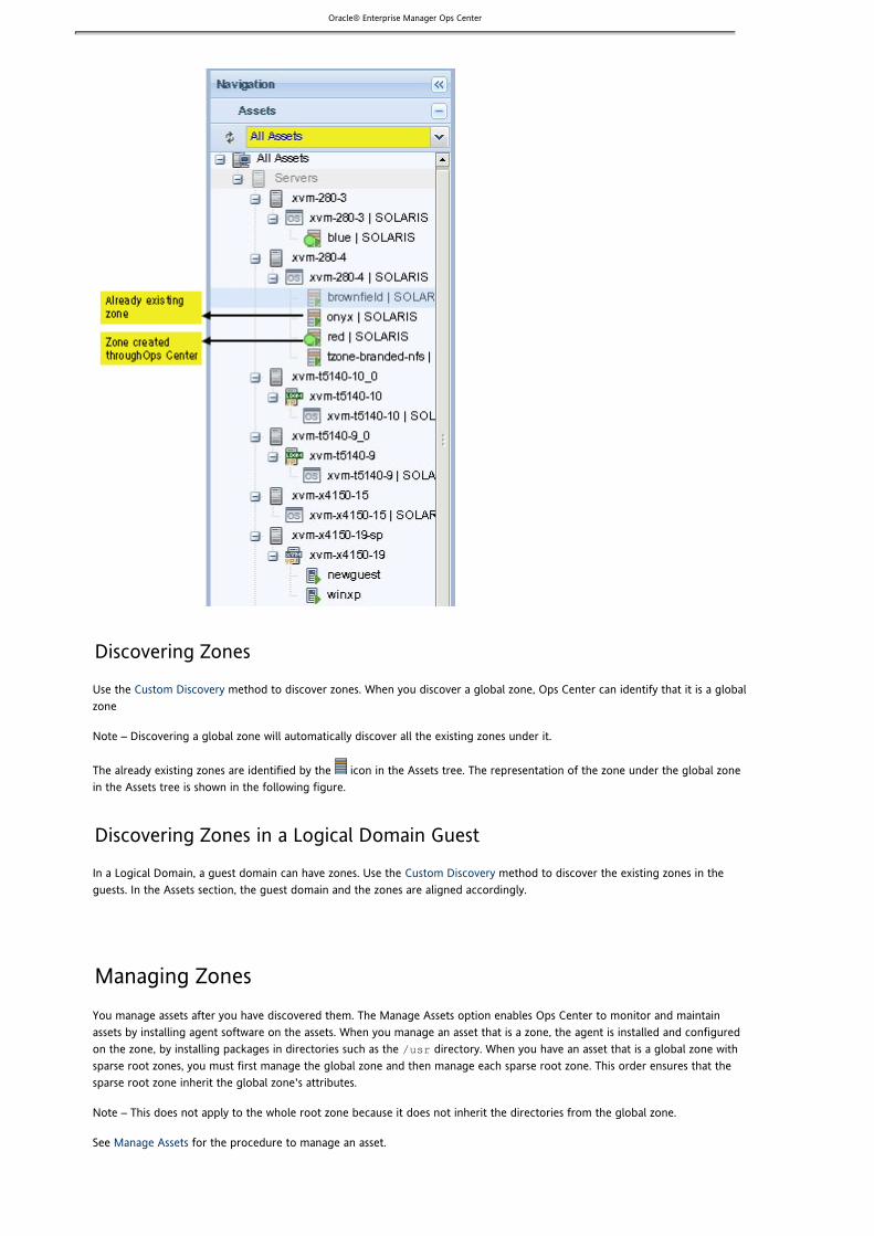
Oracle® Enterprise Manager Ops Center
Discovering Zones
Use the method to discover zones. When you discover a global zone, Ops Center can identify that it is a globalCustom Discoveryzone
Note – Discovering a global zone will automatically discover all the existing zones under it.
The already existing zones are identified by the icon in the Assets tree. The representation of the zone under the global zonein the Assets tree is shown in the following figure.
Discovering Zones in a Logical Domain Guest
In a Logical Domain, a guest domain can have zones. Use the method to discover the existing zones in theCustom Discoveryguests. In the Assets section, the guest domain and the zones are aligned accordingly.
Managing ZonesYou manage assets after you have discovered them. The Manage Assets option enables Ops Center to monitor and maintainassets by installing agent software on the assets. When you manage an asset that is a zone, the agent is installed and configuredon the zone, by installing packages in directories such as the directory. When you have an asset that is a global zone with/usr
sparse root zones, you must first manage the global zone and then manage each sparse root zone. This order ensures that thesparse root zone inherit the global zone's attributes.
Note – This does not apply to the whole root zone because it does not inherit the directories from the global zone.
See for the procedure to manage an asset.Manage Assets

Oracle® Enterprise Manager Ops Center
1.
2.
3.
4.
5.
6.
1.
2.
3.
4. 5.
6.
Unmanaging Zones
When you want to unmanage or delete a global zone, you must first unmanage or delete any subordinate zones and thenunmanage or delete the global zone. If you delete a global zone without deleting the zones under it, the job fails and the globalzone is not deleted.
To unmanage or delete a zone, follow the procedure.Unmanaging and Deleting Assets
Provisioning an OS With ZonesYou can provision an OS with zones on a new bare-metal system. The zones that are created are treated as zones that are
discovered and managed through Ops Center and are displayed with the icon in the Assets tree.
Before You Begin
Complete the following preparations before you attempt to provision an OS with zones:
Complete the procedures in the topic: discover the target system, create appropriate OSPreparing to Provision an OSprofiles, and import or download Solaris OS images.Install the JETZones package onto the Proxy Controller. The Jumpstart Enterprise Toolkit (JET) modules, found in theJETZones package, must be installed manually. See for more information.Installing JET ModulesOn the Enterprise Controller system, create a template for the zone in the directory./opt/SUNWjet/Templates
./make_zone_template template_name
Import the JET templates into the directory. See for more/opt/SUNWjet/Templates Importing JET Templatesinformation.Edit the template to fill in the OS information and specify the zone parameters such as zone name and zone path. For ashared-IP zone, provide the IP address. See for examples of zone parameters.sample JET templateCreate an OS profiles with the JET template. See for information about creating OS profiles.OS Provisioning
To Provision an OS With Zones
Log in to the Enterprise Controller user interface. The following procedure describes how to provision an OS on a bare-metalsystem:
In the Navigation panel, select the target system from the Asset section.The target system is a bare-metal system which does not have an OS.Select the hardware in the Asset section.In the Actions panel, all the available options for that asset are displayed.Select the Provision OS action.The Provision OS wizard is displayed.In the Provision OS wizard, select the OS profile from the list of OS profiles. Click Next.Enter the details in the Configuration window. Depending on the OS profile you selected, different fields are displayed.You can find information on the fields in .OS Provisioning for a Single SystemComplete the Provision OS wizard.The provision job starts. You can view the status of the job from View OS Jobs menu.
Managing and Monitoring ZonesWhen you select a zone in the Assets tree, Ops Center provides options that enable you to manage and monitor the performanceof zones in the center panel. Ops Center provides per-zone resource utilization monitoring.
You can monitor all zones using Ops Center.
When you discover and manage already existing zones, the following operations are restricted in Ops Center because there is noaccess to the zone metadata:

Oracle® Enterprise Manager Ops Center
You cannot edit the zone configuration.You cannot add storage to the zone.You cannot add file systems to the zone.You cannot migrate the zones.
This section describes how to use the options that are available for zone management, and monitor the performance of zones.
Managing and Monitoring the Global ZoneWhen you select a global zone in the Assets section, the following nine tabs display in the center panel of Ops Center:
SummaryUtilizationLibrariesOS DetailsNetworksChartsJobsConfiguration
In this section, each tab is described in detail with respect to the information displayed.
Summary
In the Summary page, the following information of the global zone is displayed:
NameDescriptionStateOS VersionServer nameTotal CPUsTotal CPU UtilizationTotal Memory UtilizationZone under the global zone
From the Summary page, the following operations are available for the zones that are under the global zone:
Boot ZoneShutdown ZoneHalt ZoneConnect NetworkAdd Storage to ZoneReplicate ZoneReboot ZoneMigrate zoneDelete Zone
Depending on whether the zone is created through Ops Center, or discovered and managed through Ops Center, the zonemanagement icons are enabled accordingly.
Utilization
Extended accounting is enabled in the global zone. This gives CPU and memory utilization on a per-zone basis. The utilization ofeach zone is the utilization of all the processes in each zone over the same interval.
The CPU resources for a zone could be dedicated or shared. Regardless of how CPU resources are utilized, the CPU usagestatistics for every five minutes interval is provided.
The memory utilization for virtual, physical, and locked memory usage are provided. The memory usage by each zone is polled infive-minutes intervals.

Oracle® Enterprise Manager Ops Center
1.
2.
3.
Libraries
The libraries that are associated with the global zone are listed in this page. The libraries represent the storage resources that areavailable for the global zone. The local storage, NAS storage, and Fiber Channel libraries that are associated with the global zoneare listed.
Select a local library or NAS storage library from the list. The zones that are associated with the selected library are listed underthe Usage tab. The Usage tab provides you with the same zone operations that are available in the Summary page. You can alsoview the contents of the library, when you select the Contents tab. The Contents tab provides you with the following libraryoperations:
Upload ISO ImageUpload Appliance ImageImport ImageView Image DetailsEdit Image DetailsDelete Image DetailsMove ImageClone a Selected Template
When you select a Fiber Channel library from the associated library list, the LUNs tab is displayed. The LUNs tab lists the LUNs thatare allocated to the global zone. The following Fiber Channel library operations are available:
Add LUNsEdit LUN DetailsDelete LUN Details
The LUN information is displayed when you select a LUN.
Refer to for more information about the procedures to manage the images in Libraries.Storage Libraries
OS Details
In the OS Details page, the following information about the global zone OS is displayed:
OS NameServer nameHealth statusNotification statusOS monitoring variablesFile system monitoringHourly charts of CPU, memory, and network usage
The different OS health states are as follows:
Good – The server is working properly.Unknown – An error occurred while attempting to retrieve information about the health of the OS resource. The serveris connected but does not return any information.Unreachable – The server agent IP address cannot be contacted for the status of the health of the OS resource. Thisindicates network problems or that the server is in standby mode.Warning Failure – A potential or impending fault condition has been detected on the server. Action should be taken toprevent the problem from becoming more serious.Critical Failure – A fault condition has occurred on the server. Corrective action is required.
To Change Thresholds of OS Monitoring Variables
Perform the following procedure to edit the monitoring variables:
Select the global zone OS from the Assets section in the Navigation panel.The Summary page of the selected OS is displayed.Select the OS Details tab in the center panel.The OS Details page of the selected global zone is displayed.In the OS Monitoring Variables, select the variables for which you want to change the threshold values for Warning and

Oracle® Enterprise Manager Ops Center
3.
4.
5.
6.
1.
2.
3.
4.
5.
6.
Critical.Use the Shift key to select more than one variable.Click the Change Threshold icon.The Change OS Monitoring Thresholds window is displayed with the selected variables.Enter the Warning and Critical thresholds values as required.For all the variables, the unit of measurement is displayed. The values depend on the number of processors in yoursystem and on the usage characteristics. If you enter an incorrect value, an error message is displayed.Click Change Thresholds to submit the changes.
Ideally, the value of any given monitored OS health attribute is compared to a threshold value. Monitoring variable values arecompared against the thresholds at regular intervals. If the value of a monitored OS health attribute rises above the warningthreshold, notification is issued with the status of Warning Failure. If the value continues to increase and passes the criticalthreshold, notification is issued with the status of Critical Failure.
To Change File System Thresholds for an OS
Perform the following procedure to change the file system thresholds for an OS:
Select the global zone OS from the Assets section in the Navigation panel.The Summary page of the selected OS is displayed.Select the OS Details tab in the center panel.The File System Monitoring is displayed under OS Monitoring Variables in the OS Details page.Select the file system for which you want to edit the thresholds.Use the Shift key to select more than one file system.Click the Edit Threshold icon.The Change File System Monitoring Thresholds is displayed with the selected file systems.Enter the Warning and Critical thresholds values as required.The unit of measurement can be in Gigabytes, percentage, or both.Click Change Threshold to set the newly entered values.
Networks
The Networks tab lists all the networks that have been assigned to the global zone. When you select a network, the zones that areusing the network are displayed under the Zones Using tab. The following options are available in the Networks tab to managethe networks:
Assign Network – Click the Assign Network icon. The Assign Network to Global Zones wizard is displayed. Refer to for detailed information.Assigning Networks to a Global Zone
Unbind Network – You can remove a network that has been assigned to the global zone. Select a network and click theUnbind Network icon.Modify Physical Connectivity – You can modify the network interface properties such as the Address Allocation method.
Charts
Ops Center collects data in five-minute interval and displays the data visually in the form of charts. Refer to for detailedChartsinformation about collecting and calculating data for different intervals. For a global zone, the following charts are displayed:
CPU utilization – You can display the CPU utilization for different CPU model such as shared CPU and dedicated CPU. Ifyou have zones that have dedicated CPUs, then all those zones will be displayed under Dedicated CPUs list. You canselect one or more zones from the list for which you want to display the chart. For Shared CPU, there could be morethan one resource pool. The shared CPU is listed for all the resource pools in the global zone. The shared CPU for adefault resource pool has the following cascading menu:
Total (Aggregate)kernelglobalList of zones in the pool or pset(processor set)You can select the chart plot (both X-axis and Y-axis) as per your requirement and it will be displayed as in thesample figure.

Oracle® Enterprise Manager Ops Center
Memory utilization - The following memory utilization charts are available:Physical memoryVirtual MemoryLocked memoryThere is only one pool of memory for all zones to share, and it is not affected by the psets or resource pools.Therefore, you have the chart plot for:Total (Aggregate)KernelGlobalList of all zones in the global zoneA sample chart is displayed as in the figure.

Oracle® Enterprise Manager Ops Center
Network utilization – You can view charts for all the NICs present in the global zone. The following chart options areavailable:
Total (Aggregate)All the NICs in the systemPer-zone network utilization data is not available.
File System Utilization – Whenever you create a zone, a zpool is created with the zone guest image name. All the zpoolsunder the global zone are listed in the file system list. You can select a file system and display the utilization rate for ahistorical period. The current utilization data can be seen in the OS Details page. The OS Details page lists all the filesystems and the current utilization rate.A sample chart is displayed as in the figure.

Oracle® Enterprise Manager Ops Center
System Load – The system load on the OS is displayed as a chart for the selected time period.A sample chart is displayed as in the figure.
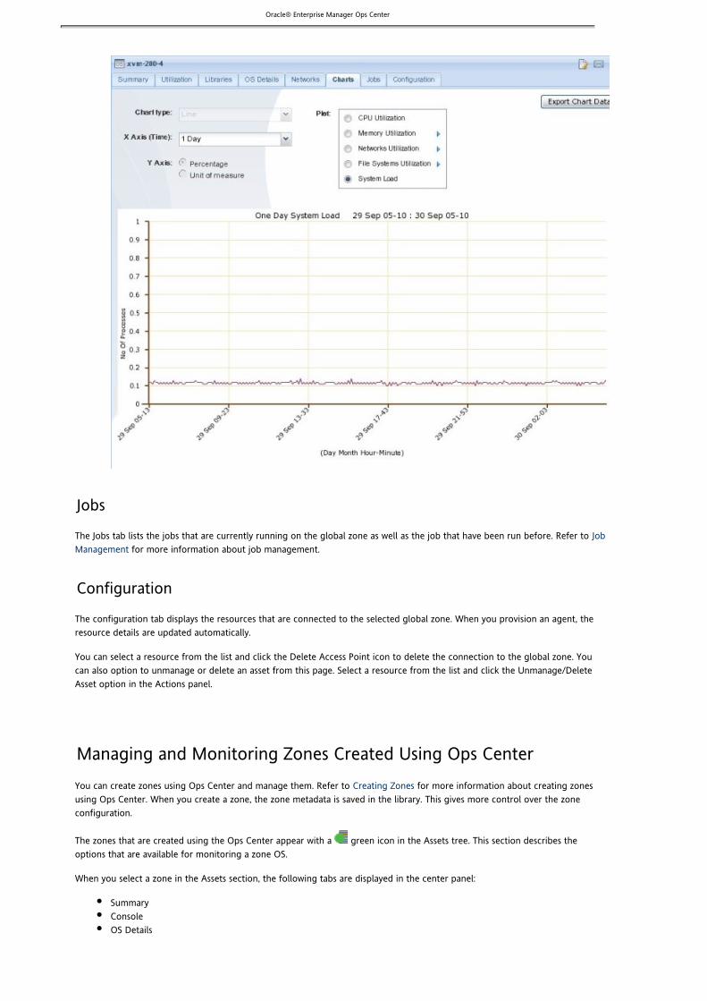
Oracle® Enterprise Manager Ops Center
Jobs
The Jobs tab lists the jobs that are currently running on the global zone as well as the job that have been run before. Refer to Job for more information about job management.Management
Configuration
The configuration tab displays the resources that are connected to the selected global zone. When you provision an agent, theresource details are updated automatically.
You can select a resource from the list and click the Delete Access Point icon to delete the connection to the global zone. Youcan also option to unmanage or delete an asset from this page. Select a resource from the list and click the Unmanage/DeleteAsset option in the Actions panel.
Managing and Monitoring Zones Created Using Ops CenterYou can create zones using Ops Center and manage them. Refer to for more information about creating zonesCreating Zonesusing Ops Center. When you create a zone, the zone metadata is saved in the library. This gives more control over the zoneconfiguration.
The zones that are created using the Ops Center appear with a green icon in the Assets tree. This section describes theoptions that are available for monitoring a zone OS.
When you select a zone in the Assets section, the following tabs are displayed in the center panel:
SummaryConsoleOS Details

Oracle® Enterprise Manager Ops Center
1.
2.
3.
4.
NetworksStorageChartsJobsConfiguration
If you have zones that have been already created using CLI, then you can discover and manage the zones using Ops Center. These
zones are distinguished in the Ops Center BUI with the icon.
Summary
The Summary tab of the selected zone displays the following information:
Zone name and its stateType of zone and the zone pathZone library and storage sizeCPU model and utilizationFile systems allocated to the zoneStorage size and usageHourly utilization chart of CPU, network, and memory resources
Console
You can connect to the console of the zones that were created using Ops Center. Click the Enable the Console Connection icon toinvoke the to the zone. Log into the zone using the zone username and password. The zone console exists till you logzlogin
out of Ops Center, explicitly click the Disable the Console Connection icon, or the global zone is shut down.
You can click the Undock the Console icon to undock the console session from the Ops Center, making it available separately foryour use.
OS Details
This tab displays the following information about the OS:
OS name and detailsOS healthNotification statusOS monitoring variablesFile system thresholds and usageHourly utilization chart of CPU, memory and network resources
The different OS health states are as follows:
Good – The server is working properly.Unknown – An error occurred while attempting to retrieve information about the health of the OS resource. The serveris connected but does not return any information.Unreachable – The server agent IP address cannot be contacted for the status of the health of the OS resource. Thisindicates network problems or that the server is in standby mode.Warning Failure – A potential or impending fault condition has been detected on the server. Action should be taken toprevent the problem from becoming more serious.Critical Failure – A fault condition has occurred on the server. Corrective action is required.
To Change Monitoring Variables Threshold
The following procedure describes how to change the monitoring variables threshold:
Select the zone from the Assets section in the Navigation panel.The Summary page of the selected OS is displayed with the current values for the monitoring variables.Select the variables for which you want to change the threshold values for Warning and Critical.Use the Shift key to select more than one variable.Click the Change Threshold icon.The Change OS Monitoring Thresholds window is displayed with the selected variables.

Oracle® Enterprise Manager Ops Center
4.
5.
1.
2.
3.
4.
5.
6.
Enter the Warning and Critical thresholds values as required.For all the variables, the unit of measurement is displayed. The values depend on the number of processors in yoursystem and on the usage characteristics. If you enter an incorrect value, an error message is displayed.Click Change Thresholds to submit the changes.
Ideally, the value of any given monitored OS health attribute is compared to a threshold value. Monitoring variable values arecompared against the thresholds at regular intervals. If the value of a monitored OS health attribute rises above the warningthreshold, notification is issued with the status of Warning Failure. If the value continues to increase and passes the criticalthreshold, notification is issued with the status of Critical Failure.
To Change File System Thresholds for an OS
Perform the following procedure to change the file system thresholds for a zone OS:
Select the zone OS from the Assets section in the Navigation panel.The Summary page of the selected OS is displayed.Select the OS Details tab in the center panel.The File System Monitoring is displayed under OS Monitoring Variables in the OS Details page.Select the file system for which you want to edit the thresholds.Use the Shift key to select more than one file system.Click the Edit Threshold icon.The Change File System Monitoring Thresholds is displayed with the selected file systems.Enter the Warning and Critical thresholds values as required.The unit of measurement can be in Gigabytes, percentage or both.Click Change Threshold to set the newly entered values.
Network
The network tab lists all the networks that are assigned to the zone. You have the following options in the Network tab:
Connect NetworkDisconnect Zone Network
Connect Network icon is enabled only when the zone is in the shutdown state, which is when you can assign a network to a zone.
To disconnect a zone network, select a network from the list and click the Disconnect Zone Network icon.
Storage
The Storage tab lists the root file system along with other file systems that were added to the zone. You cannot edit the read andwrite access to the root file system, which is the default file system of the zone.
The storage tab also displays the virtual disks that make up the zpool, which is created when you create a zone. The zpoolcomprises the virtual disks and LUNs that make up the storage. Ops Center creates one zpool per zone. File systems areimplemented as ZFS file systems and mapped to the storage.
The following options are provided in this page:
Add File SystemsEdit File SystemDelete File SystemAdd Storage to Zone
Note – You can add storage to the existing zpool, but you cannot remove or delete storage from the zpool.
Charts
Ops Center collects data in five-minutes interval and displays the data in the form of charts. Refer to for detailedChartsinformation about collecting and calculating data for different time periods. For a zone, the following utilization data aredisplayed:
CPU utilization – You can display the CPU utilization for the zone. The per-zone utilization data is collected by the

Oracle® Enterprise Manager Ops Center
extended accounting in the global zone.Network utilization – Network usage is not available for each zone. The chart displays the total utilization for the all thezones including the global zone.Memory utilization – The following memory utilization charts are available:
Physical memoryVirtual memorySwapped memoryLocked memoryThe memory utilization is the physical, virtual, swapped, and locked memory in use by each zone. The zoneutilization data are collected through extended accounting for every five-minute interval.
File System Utilization – Whenever you create a zone, a zpool is created with the zone metadata name. The file systemlists the root file system and other file systems that are added to the zone. You can select a file system and display theutilization rate for a historical period. The OS Details page lists all the file systems and the current utilization rate.
Jobs
The jobs tab lists the jobs that are currently running on the zone and historical jobs that have run on the zone. Refer to Job for more information about job management.Management
Configuration
The Configuration tab displays the zone configuration information. Depending on the type of CPU model, the configurationdetails can vary.
The access points list the Proxy Controller through which the zone is connected to the Enterprise Controller. It also states theconnection health and the protocol through which it is connected.
Managing and Monitoring Existing Zones Through Ops CenterIf you have zones that are already configured and installed using the CLI, then you can directly discover and manage the zonesusing Ops Center. See and for more information about discovering and managing zones.Discovering Zones Managing Zones
The zones that are discovered and managed using Ops Center appear with icon in the Assets tree.
This section describes the different options that are available for monitoring a zone OS.
When you select a zone in the Assets panel, the following tabs are displayed in the center panel :
OS DetailsConsoleNetworksChartsJobsConfiguration
OS Details
The OS Details tab displays the following information about the OS:
OS name and detailsOS healthNotification statusOS monitoring variablesFile system thresholds and usageHourly utilization chart of CPU, memory and network resources
To Change the Monitoring Variables Threshold

Oracle® Enterprise Manager Ops Center
1.
2.
3.
4.
5.
The following procedure describes how to change the monitoring variables threshold:
Select the zone from the Assets section in the Navigation panel.The OS Details page of the selected OS is displayed with the current values for the monitoring variables.Select the variables for which you want to change the threshold values for Warning and Critical.Use the Shift key to select more than one variable.Click the Change Threshold icon.The Change OS Monitoring Thresholds window is displayed with the selected variables.Enter the Warning and Critical thresholds values as required.For all the variables, the unit of measurement is displayed. The values depend on the number of processors in yoursystem and on the usage characteristics. If you enter an incorrect value, an error message is displayed.Click Change Thresholds to submit the changes.
Ideally, the value of any given monitored OS health attribute is compared to a threshold value. Monitoring variable values arecompared against the thresholds at regular intervals. If the value of a monitored OS health attribute rises above the warningthreshold, notification is issued with the status of Warning Failure. If the value continues to increase and passes the criticalthreshold, notification is issued with the status of Critical Failure.
Console
You can connect to the console of the zone. Click Enable Console to invoke the zlogin to the zone. Use the zone user name andpassword to log into the zone. The zone console exists till you log out of Ops Center, or explicitly click Disable Console, or theglobal zone is shut down.
You can undock the console session from the Ops Center, making it available separately for your use.
The console will not be available if it is in use by other user.
Network
The Network tab lists only the networks that are assigned to the zone. You do not have options to connect to a network ordisconnect from a network.
Charts
Ops Center collects data in five-minute interval and displays the data visually in the form of charts. Refer to for detailedChartsinformation about collecting and calculating data for different intervals. For a zone, the following utilization data are displayed:
CPU utilization – Displays the historic chart for a selected time period in the X-axis. The CPU usage for a zone iscalculated as the CPU time used by the zone as a percentage of the number of CPUs in the processor set (pset) or theresource pool.Network utilization – Is enabled only when you select the chart option Display Selected Utilization Graphs as ThumbnailImage. The graph displays the utilization of the network interfaces assigned to the zone.Memory utilization – Displays the number of bytes used as a percentage of total memory allocated for the zone.File System utilization – Lists the file systems that are mounted for this zone. You can view the historical consumption ofeach file system.System load – The system load on the selected zone is displayed as a chart for the selected time period.
Jobs
The jobs tab lists the jobs that are currently running on the zone and historical jobs that have run on the zone. Refer to Job for more information about job management.Management
Configuration
The Configuration tab displays the resources that are connected to the selected zone. When you provision an agent, the resourcedetails are updated automatically.
To delete the connection to a zone, select the resource from the list, then click the Delete Access Point icon. To unmnanage ordelete an asset from this page, select a resource from the list, then click the Unmanage/Delete Asset option in the Actions panel.

Oracle® Enterprise Manager Ops Center
1. 2.
3. 4. 5.
1.
2. 3. 4.
Performing Zone TasksYou can perform the following zone management tasks using Ops Center:
Boot a zoneReboot a zoneManage zone networksAdd storage to zonesManage zone librariesConnect to zone consoleClone a zoneMigrate a zoneUpdate zonesHalt a zoneShut down a zoneDelete a zone
Booting a ZoneBooting a zone places the zone in the running state. The Boot Zone option is enabled only when the zone is in the ready orinstalled state, but not in the running state. Booting a zone applies the changes that have been made to the zone configuration.
If you have set the autoboot properties during zone creation, then the zone will boot when the global zone boots.
To Boot a Zone
Select Assets from the Navigation panel.Select a zone. Alternatively, you can select a global zone, then select the zone listed in the center panel of the Summarypage.The Summary page of the zone and the corresponding actions are enabled in the Actions panel. The Boot Zone optionwill be enabled if the zone is in the Ready or Installed state.Click Boot Zone in the Actions panel or click the Boot Zone icon in the Zones pane.Click Boot Now or click Boot Later.If you chose Boot Later, schedule the boot job.
Rebooting a ZoneYou can reboot a zone that is in the running state. This type of reboot is different from the command wherezoneadm reboot
the zone is first halted then booted again. Instead, Ops Center handles the reboot gracefully, first shutting down the zone andthen booting it.
To Reboot a Zone
Select a zone from the Asset section in the Navigation panel. Alternatively, select the global zone from the Asset section,then select the zone listed in the center panel.The Summary page of the selected asset is displayed in the center panel.Click Reboot Zone in the Actions panel or click the Reboot Zone icon in the zones content pane.Click Reboot Now or Reboot Later.Schedule the Reboot job.

Oracle® Enterprise Manager Ops Center
1. 2.
3.
4. 5.
1.
2.
3.
4.
5.
Adding Libraries to the Global ZoneYou can associate one or more libraries with a global zone. The libraries are available to all zones in the hierarchy of the globalzone.
To Associate a Library With the Global Zone
Select Assets from the Navigation panel.Select a global zone.The Summary page of the global zone is displayed.Click Associate Libraries in the Actions panel.The Associate Library window is displayed.
The libraries that are not associated with the selected global zone are listed.
Select one or more libraries.Click Associate Libraries.A job is submitted to associate the libraries.
Disassociating Libraries From Global ZoneYou can disassociate the libraries that you have associated with a global zone. When you disassociate a library from global zone:
The libraries are disassociated from the global zone.The libraries will not be available for any new zone creation.The libraries are not disassociated from the existing zones in that global zone.
To Disassociate Libraries From Global Zone
Select the global zone from the Assets section in the Navigation panel.The Summary page of the selected global zone is displayed in the center panel.Select Libraries tab from the center panel.The associated libraries with the global zone are listed.Select a library from the list.The Disassociate Library icon is enabled.Click the Disassociate Library icon.The Disassociate Library window is displayed.

Oracle® Enterprise Manager Ops Center
5.
1.
2.
3. 4.
5. 6.
7. 8.
9.
1. 2.
3. 4.
5.
6.
Click Disassociate Library to confirm unmounting the library.
Adding File Systems to ZonesUsing Ops Center, you can add file systems only to zones that were created using Ops Center. This section provides procedure foradding file systems to zones.You must shutdown the zone before you add file systems.
To Add a File System to a Zone
Select a zone from the Assets tree in the Navigation panel.The zone can be either created using Ops Center or using native CLI.Click Shutdown Zone from the Actions panel.Shutdown Zone window is displayed.Click Shutdown Zone to shut down the zone immediately.Select the zone in the Assets tree, then click Add File Systems from the Actions panel.The Add File Systems window is displayed.Click the + icon to add the file systems.Enter the Reserved and Quota for the file system to be added.Refer to the Available Storage size in the disk for adding new file systems.Click Add File Systems to add the file systems to the selected zone.Select the zone in the Assets tree, then click Boot Zone in the Actions panel or click the Boot Zone icon in the Zonespanel.Click Boot Now or click Boot Later.
Adding Storage to ZonesYou can add storage only to the zones that are created using Ops Center. The storage is added to the zpool that is created for thezone. You can add storage to the zpool but you cannot delete storage from the zpool.
Note – The zone must be in the shutdown state for adding storage devices to the zpool.
To Add Storage to Zones
Select a zone that was created using Ops Center from the Assets section.Click Add Storage in the Actions panel, or select the Storage tab and click the Add Storage to Zone icon under Zpool andStorage.The Add Storage to the Zone window is displayed.
Click the icon to add storage.Select a library from the list.The library can be an NFS library or Fiber Channel library.For an NFS library, enter a virtual disk name and specify the size of the disk. For a Fiber Channel library, select a LUNfrom the list. You cannot specify the size of the disk.The Additional Storage Specified reflects the storage space added in each row.Click Add Storage to add the specified storage to the zone.
Managing Zone NetworksIn Ops Center, you can connect or disconnect networks from zones. This section describes how to connect, modify, anddisconnect networks from zones.

Oracle® Enterprise Manager Ops Center
1. 2.
3.
4. 5.
6.
Assigning Networks to a Global ZoneYou can assign one or more networks to the global zone. When you assign a network to a global zone, you need to define themode of the network. The network mode can be either Shared or Exclusive.
In Shared IP mode, the network interface will be connected to the global zone through the PNIC provided by the user duringassignment of the network. The network interface is shared by more than one zone. In Exclusive IP mode, you can assign anetwork interface to be dedicated to a zone. When you assign an exclusive IP mode for a zone, the zone has a dedicated networkinterface. IP configuration is not required for the exclusive network interface at the global zone level, but you need to define theIP configuration at the zone level. In Ops Center, an exclusive network must be declared at the global zone level through AssignNetworks to Global Zone.
The networks that are assigned to the global zone automatically becomes available for all the zones under it. A network that isused in a shared mode cannot be used in exclusive mode for another zone. A network can be deployed only in one mode on theglobal zone.
Note – A network that is assigned as shared on a global zone can be assigned as exclusive on another global zone.
To Assign a Network to a Global Zone
Select a global zone from the Assets section in the Navigation Panel.In the Actions panel, click Assign Network.The Assign Networks to Global Zone wizard is displayed.
In Select Networks and IP Model page, select a network that you want to associate with the global zone.In the Network list, the networks that are defined in the Ops Center and not assigned to the global zone are listed.(Optional) To assign more networks to the global zone, Click the Add icon.Select the IP mode for each selected network.The IP mode could either be Shared or Exclusive. If you have selected Shared IP mode for a network, then you will bedirected to define the network interfaces of the network.
– You cannot define the network interfaces for an exclusive IP mode.NoteClick Next. If you have Shared IP mode network, you would be directed to Specify Networks page. If you have onlyExclusive IP mode, you will be required to define the network interfaces for the zones while or using creating a zone
option.Connect Network to Zone

Oracle® Enterprise Manager Ops Center
1.
2.
3.
4.
5.
1.
2.
3.
4.
5.
Removing a Network From a Global ZoneYou can unbind networks from a global zone. When you unbind a network from a global zone, the corresponding zones are alsodisconnected from the network.
To Unbind a Network From a Global Zone
Select the global zone from the Assets tree in the Navigation panel.The Summary page of the global zone is displayed.Select the Networks tab in the center panel.The network page lists the networks that are assigned to the global zone.Select the network that you want to disconnect from the zone.The Unbind Network icon is enabled.Click the Unbind Network icon.The Unbind network from Global Zone window is displayed. The list of zones from which the network will be unboundare displayed.
– You can unbind only one network at a time.NoteClick Disconnect Zones to unbind the network from the global zone.A job is submitted to remove the network from the global zone.
Connecting Networks to ZonesYou can connect to the networks that are available to a zone using the Connect Network option. The Connect Network option isavailable in the Actions panel and in the Networks tab of the selected zone. This option will be enabled only in the followingconditions:
The selected zone is created using Ops Center.The selected zone is in the shutdown state. If the zone is in the running state, the networks would be assigned only in thenext reboot of the zone. You should shut down the zones before applying any network modifications.
The Connect Network option is disabled in the following condition:
The zone is discovered and managed using Ops Center.The zone is not in the shutdown state.
To Connect a Network to a Zone
Select the zone from the Assets tree in the Navigation panel. – Ensure that the zone was created using Ops Center.Note
Click Connect Network in the Actions panel or select the Networks tab in the center panel and click the ConnectNetwork icon.The Connect Networks to Zone window is displayed.
– Ensure that the zone is in the shutdown state.NoteIn the Connect Networks to Zone window, select the networks that you want to connect to the zone.In the networks list, depending on the zone IP model that was defined during zone creation, all the networks are listedthat are assigned to the global zone with the same IP model as that of the zone and not yet connected to the zone.Specify the network interface of the selected networks.
– You can add more than one network to connect to the zone.NoteClick Connect Networks to initiate the job to assign the networks to the zone.
Disconnecting a Network From a Zone
You can disconnect the networks that have been assigned to a zone. The Disconnect Network option is available in the Networkstab of the selected zone. This option is enabled only in the following condition:
A network should have been selected from the list of assigned networks.The zone should be in the shutdown state. If the zone is in the running state, then the modification takes place only in

Oracle® Enterprise Manager Ops Center
1. 2.
3.
4.
1. 2.
3. 4.
5.
6. 7.
8.
9.
10.
11.
the next reboot of the zone.
The Disconnect Network option is available for zones that have been created using Ops Center and for zones that have beendiscovered and managed using Ops Center.
To Disconnect a Network From a Zone
Select the zone from the Assets tree in the Navigation panel.Select the Networks tab in the center panel.The networks that are assigned to the zone are listed.Select the network that you want to disconnect from the zone.The Disconnect Network option is enabled.Click the Disconnect Network icon.
Cloning a ZoneCloning allows you to copy an existing configured and installed zone on your system to rapidly provision a new zone on the samesystem. Cloning a zone is analogous to creating a zone in Ops Center. When you clone a zone, you will be taken through a wizardsimilar to creating a zone. Define the zone properties in the wizard for the new zone.
You can clone any type of zones in the Assets section.
To Clone a Zone
Select a zone from the assets section in the Navigation panel.Click Replicate Zone in the Actions panel.The Replicate Zone wizard is displayed.Enter a zone name and description for the zone.Select a library from the Library list.The libraries that are associated with the global zone are listed in the Library list. The new cloned zone metadata will bestored in the selected library.Click Next to configure the CPU and memory thresholds.The CPU shares that are already allocated for the source zone is displayed. As required, you can edit the changes.Click Next to configure the language, timezone, terminal type, host name and root password for the zone.Set the boot properties of the zone as required.You can set the boot properties so that the new zone boots after creation and whenever the global zone boots.Click Next to configure the zone file system.The new zone will be created with a default root file system which is the zone path. You cannot delete this file system orchange its read and write access. The file systems that are added to the source zone are also listed. You can add more filesystems to the zone and define the size and access to the file system. You can enter the Reserved and Quota size for thefile system. Reserved is the size of the file system that the user can reserve. Quota is the maximum size that the filesystem can utilize.
– When you are modifying or adding new file systems to the new cloned zone, ensure that the new cloned zone hasNoteenough required file system size to hold the source zone file system. For example, you cannot modify the root file sytemof the new zone to a size lesser than the source zone root file system. This could result in incompatibility between thenew and the source zone, and the clone job can fail. Do not try to modify the system file system if they are alreadydefined in the source zone.Click Next to configure the zone storage.The libraries that are already associated with the source zone are listed. You can modify or associate libraries with thenew zone. The library can be either a NAS storage or Fiber Channel library. If the library is NAS storage, then specify thevirtual disk name and size of the disk. If the library is Fiber Channel, select a LUN from the available list of LUNs in thelibrary. The size of the selected LUN is displayed. You cannot change the size of the LUN.The accumulated size of the storage is displayed as Currently Accumulated Storage. The required storage for the addedfile system is displayed as Recommended Storage Size. You can click Next to proceed in the wizard, only when theCurrently Accumulated Storage size is equivalent to the Recommended Storage size.Click the Add icon to configure more storage resources to the zone if the Currently Accumulated Storage is less than theRecommended Storage Size.Click Next to specify the network interfaces.You need to assign at least one network to the zone. Select the zone IP type as Shared or Exclusive.

Oracle® Enterprise Manager Ops Center11.
12. 13.
1.
2. 3.
4.
5. 6. 7.
1.
2.
3.
Shared IP – The networks that are assigned to the global zone with shared IP type are listed in the Networks list.Select a network from the list. Each shared Network Interface Card (NIC) for the selected network is listed in theNIC list. Select a NIC from the list. If the selected network has its defined IP range, then Auto Allocate IP isdisplayed in the Management Interface. The Zone IP will be automatically populated with an IP in the definedrange. If the selected network does not have any IP range defined, then in the Management Interface, Use StaticIP is displayed. You must enter a valid IP address in the Zone IP field.Exclusive IP – The networks that are assigned to the global zone and not used by other zones are listed in theNetworks list. Select a network from the list. The NICs that are not bound to other networks are listed in the NIClist. Select a NIC from the list. If the selected network has its defined IP range, then Auto Allocate IP is displayedin the Management Interface. The Zone IP will be automatically populated with an IP in the defined range. If theselected network does not have any IP range defined, there are two options in the Management Interface toselect. You can select Use Static IP and enter a valid IP address in the Zone IP field. If you have an external DHCP,select the option Assigned by ext. DHCP. The Zone IP is automatically allocated by the DHCP external to OpsCenter. Automatically Allocated is displayed in the Zone IP field.
Click Next to view the summary of the selected parameters for replicating the zone.Click Finish to launch the job for replicating a zone.When the job successfully completes, the new zone will be displayed in the Assets section.
Attaching to Zone ConsoleYou can attach to the zone console directly using Ops Center. You have to first enable the console connection and then connectto the console.
To Attach to a Zone Console
Select the zone from the Assets section in the Navigation panel.The Summary page of the selected zone is displayed.Select the Console tab in the center panel.Click the Enable the Console Connection icon.A job is initiated to enable the console connection.Click the Connect to the Console icon.The connection is established and the console appears on the BUI.Enter the zone user name and password to log into the zone.(Optional) Click the Undock the Console icon to make the console available separately from the BUI.(Optional) Click the Set Console Connection Timeout icon to set the timeout for the console in minutes.The console connection is enabled for the set time limit. After that, you need to enable the console connection again.The default connection timeout is set to 120 minutes.
Note – If you go out of zone view in the Assets tree, you need to connect to the zone console again.
Disabling the Zone Console ConnectionYou can disable the zone console connection from Ops Center after you have finished using it.
To Disable a Zone Console Connection
Select the zone from the Assets tree in the Navigation panel.The Summary page of the zone is displayed.Select the Console tab of the zone in the center panel.The zone console that is already enabled is displayed.Click Disable the Console Connection to disable the zone console in the Ops Center BUI.
Note – When you go out of zone view in the Assets tree, the zone is automatically logged out but the connection exists till thetimeout set for the console connection.

Oracle® Enterprise Manager Ops Center
1.
2. 3.
4.
Accessing the Serial ConsoleOps Center provides access to a serial console for your managed hardware. The console enables you to log in to and run remotecommands on the system. You can run the console within the BUI, or you can undock the console and use it as a floating consolewindow.
By logging in through the console, you can perform commands on the service processor and operating system, as describedbelow:
Service Processor – Log in to the service processor and run commands using the management protocol, such as ALOM orILOMOperating System – Log in to the OS and run commands in a standard SSH session
Before You Begin
To use console access for both the OS and service processor (SP), you must discover the OS and the SPs on the hardware, thenenable SSH access. This is done by performing a custom discovery of the assets.
If you have a managed asset that does not have SSH enabled, or the SP or OS are not discovered, you can run a new customdiscovery job to add capabilities. After successfully running the new custom discovery job, your managed asset is automaticallyupgraded to include the new capabilities.
Note – The console requires SSH access and the ability to reach the system.
Serial console access requires appropriate firewall and routing settings for the Enterprise Controller to connect to the ProxyController or agent through ssh (on port 22).
Serial Console for Zones and Logical Domains
In Logical Domain (LDom) guests, the serial console is exposed through the control domain. A temporary local user account iscreated on the control domain to provide serial console access to the LDoms over ssh. When this user account is enabled, TTY isdisplayed and automatically logs in over SSH to this user account.
In zones, the user account is created on the global zone. If the global zone is discovered through SSH but not managed, the useraccount is created on the Proxy Controller. When the user account is enabled, it will directly connect to the zone's console whenthe user logs in to it.
To Access the Serial Console
Select the hardware from the assets tree in the Navigation panel.The asset details are displayed in the center panel.Click the Console tab in the center panel.Click Enable Console to activate the console.A job is submitted to activate the console.(Optional) Click Undock to free the console from the BUI and move it to another location on your monitor.
Troubleshooting the Access to Serial Console
If your firewall settings prevent connections to the port 22, the Enterprise Controller cannot connect to the Proxy Controllerthrough SSH and the serial console functionality through the BUI will not be enabled.
In this case, you can access the serial console only through the command-line environment. For zones, log in to the global zoneand execute the following command manually:
zlogin -C < >zonename
For LDoms, log in to the Control Domain and execute the following command manually:
telnet localhost <domain_port>
Refer to the man page of for zones.zlogin

Oracle® Enterprise Manager Ops Center
Migrating ZonesYou can migrate a zone created using Ops Center. There are two methods by which you can migrate a zone in Ops Center:
Migrating a zone from one global zone to another global zone managed by Ops Center.Migrating an existing Solaris system into a zone on a global zone. This is referred to as physical to virtual (P2V)conversion.
Migrating a Zone to a Different MachineIn Ops Center, you can migrate a zone to a different machine using the Migrate Zone option. When you migrate a zone, you canperform a trial run before the zone is moved to the new machine. This helps to verify whether the target global zone has thecorrect configuration to host the zone before actually doing the attach.
When you migrate a zone, the destination global zone can have same or more recent versions of the following required operatingsystem packages and patches as those installed on the zone.
Packages that deliver files under an resourceinherit-pkg-dir
Packages where SUNW_PKG_ALLZONES=true
Other packages and patches, such as those for third-party products, can be different.
If the destination global zone has later versions of the zone-dependent packages or their associated patches, you can updatethose packages within the zone to match the destination. If the destination global zone supports update-on-attach capability, thenthe zone that is being migrated is checked for packages that must be updated to match the destination. Only those packages areupdated. The rest of the packages, and their associated patches, can vary from zone to zone. The patches that need to be backedout of the zone before the update are also listed. If the destination global zone does not support backout-on-attach capability,then you must manually remove the patches on the zone and run the migration job again.
Compatible Global Zones for Migration
The following table provides a matrix of the compatible source and destination global zones for zone migration.
Destination GlobalZone
Source GlobalZone
< Solaris 10 8/07 Solaris 108/07
Solaris 105/08
Solaris 1010/08
Solaris 105/09
Solaris 1010/09
< Solaris 10 8/07 Incompatible Incompatible Incompatible Incompatible Incompatible Incompatible
Solaris 10 8/07 Incompatible Compatible Incompatible Compatible Compatible Compatible
Solaris 10 5/08 Incompatible Incompatible Compatible Compatible Compatible Compatible
Solaris 10 10/08 Incompatible Incompatible Incompatible Compatible Compatible Compatible
Solaris 10 5/09 Incompatible Incompatible Incompatible Incompatible Compatible Compatible
Solaris 10 10/09 Incompatible Incompatible Incompatible Incompatible Incompatible Compatible
When you click the Migrate Zone option in the Actions panel, the Ops Center first checks for global zones that are compatible formigration. If there are compatible global zones in the managed Assets list, then the Migrate Zone wizard is displayed. Otherwise, apop-up window is displayed, informing you that the zone cannot be migrated.
Before You Begin

Oracle® Enterprise Manager Ops Center
1. 2.
3.
4.
5.
6. 7. 8.
9.
10.
11.
12.
13.
14.
The zone migration will be carried out successfully only on following certain conditions:
There should be compatible global zones in Ops Center for the zone to be migrated.The compatible global zones should have access to all the libraries associated with the zone.The zone image is not stored in the global zone local library.The zone should not use global zone local library for storage. It has to be associated with NFS or Fiber Channel libraryfor storage.The Migrate Zone option is enabled only when the zone is in the running state.You can migrate zones that were created only through Ops Center.If you migrate a zone that was created using Ops Center, you cannot use an alternate boot environment (ABE) toupgrade the zone.
To Migrate a Zone Using Ops Center
Select a zone from the Assets tree in the Navigation panel.Click Migrate Zone from the Actions panel.If there are compatible global zones for migration, you will be instructed to take a ZFS snapshot of the zone. The zonewill be in shutdown state on the source global zone if the migration fails. The ZFS snapshot enables you to manuallyrestore and reboot the zone from Ops Center when migration fails.Click Continue Migration if you have a ZFS snapshot of the zone.The Migrate Zone wizard is displayed.In the Select Destination window, select a global zone from the compatible list.The compatible global zone list is displayed with the number of zones that are already running, total CPUs and dedicatedCPUs available.Click Next to review the migration test result.The source global zone should be running at least Solaris 10 5/08 OS to support test migration. Continue migrationbased on the following conditions on the destination global zone:
If the destination global zone does not support update-on-attach capability, you can continue to migrate thezone without updating the zone's patches and packages.If the destination global zone supports update-on-attach capability, you can update the zone's patches andpackages to match the destination global zone.
(Optional) To save the migration test result displayed under Result Details, click Save Test Result As.(Optional) To change the destination global zone, click Select New Destination.Click Next to continue zone identification.The Review Zone Identification window is displayed. The new name for the zone is displayed with the current zone nameappended with a number.Enter a unique zone name.If the Zone Name is displayed in red, then it implies that the zone name already exists in the destination global zone.Click Next to specify the network interfaces.The Specify Network Interfaces window is displayed.This window displays the network interfaces that are not accessible by the target global zone in yellow. You have tospecify a new network interface for the inaccessible networks or select Do Not Connect to that network.Select the network which is in yellow.The network interface details are displayed under Network Interface.Select a new network interface from the Network list or select Do Not Connect.The selected network can be either shared or dedicated. Enter the required network interface information for theselected network.
– You must have at least one valid network interface for the migration to continue.NoteClick Next for the summary of the migration job.The Summary window displays all the information selected for the zone migration. It also displays a warning if there arepatches that need to be backed out on the zone.
If the destination global zone supports backout-on-attach capability, then a warning is displayed that thefollowing list of patches are removed or downgraded. The list of patches are displayed in Patches to be backedout field.If the destination global zone does not support backout-on-attach, then the patches and packages on the zonehave to be manually removed or downgraded to match the destination global zone. You have to cancel themigration or select a new destination global zone.If there are no patches and packages to be backed out, continue with the migration.
Click Finish to initiate the migration job.
Backing Out Patches and Packages
If the destination global zone does not support backout-on-attach capability, then you must manually remove or downgrade the

Oracle® Enterprise Manager Ops Center
1.
2. 3.
1.
2. 3.
patches and packages. You can use the Update OS Profiles to back out the patches and packages. Follow the steps in Ops Centerto backout the patches and packages:
Create an OS Update Profile with the list of patches and packages that need to be backed out.For more information, see to create an OS Update Profile.Creating an OS Update ProfileSelect the zone for which you want to backout the patches and packages.Create a New Update OS Job with the OS Update Profile.The OS Update job removes or downgrades the patches and packages of the zone. Then, you can run the migration jobon the zone. For more information, see to create an OS update job.Creating a Solaris OS Update Job
Migrating a Physical Solaris System Into a ZoneA "physical to virtual" (P2V) capability is used to directly migrate an existing Solaris system into a zone on a target system. Thesystem image to be installed through P2V must not be newer than the target host operating system release, or the installation willfail.
The following illustration outlines the steps for P2V conversion.
Before You Begin
Before migration, follow the steps below:
For P2V conversion, assess the system that needs to be migrated and collect information about the source system. Referto this for information about collecting information about the source system.documentThe source system that you want to install through P2V should not be newer than the destination global zone. Otherwise,the installation will fail.The destination global zone should be running at least Solaris 10 8/07 OS.The supported branded zones are Solaris 8 and 9.For the branded zones to be supported on the destination global zone, you need to remove the following brandpackages from the global zone:
pkgrm SUNWs8brandu
pkgrm SUNWs8brandr
pkgrm SUNWs9brandu
pkgrm SUNWs9brandr
Download and install the correct brand packages.For Solaris 8 branded zone, refer to this .locationFor Solaris 9 branded zone, refer to this .location
All types of image formats are supported by Ops Center.
To Migrate a Physical Solaris System Into a Zone
Create an image of the source Solaris System that you want to migrate. Refer to this for creating an image ofdocumentthe Solaris system.Select the destination global zone from the Assets tree in the Navigation panel.

Oracle® Enterprise Manager Ops Center
3.
4. 5. 6. 7. 8.
1. 2.
Click Create Zone option from the Actions panel.The Create Zone wizard is displayed.Select Branded Zone for the type of the zone.Enter the URL of the image that you created in Step 1.(Optional) Specify the HostID if you want to run applications that are associated with a specific host ID.(Optional) Specify the machine type as Sun4U or Sun4V.Complete the Create Zone wizard.Refer to page to complete the wizard.create zone
Updating ZonesOps Center enables you to update the global and non-global zones of your Solaris systems. You can run a patch job on the globalzone and update all zones without using the command.-G
The concepts that relate to updating global and non-global zones and the procedures to update the zones are described on thissection.
Content Description
Packages and Patches Describes the parameters for installation of the packages and patches
Updating a Global Zone Describes the concepts involved in updating a global zone
Updating Non-Global Zones Describes the concepts involved in updating different non-global zones
Installing Packages and Patches on Zones
A patch is a collection of files and directories that replace existing files and directories that are preventing proper execution ofthe software.
You can install packages and patches on a zone. The and commands operate in the background to install apatchadd pkgadd
patch and package respectively. However, the installation of packages on zones also depends on the parameters in the followingtable. These parameters control whether a package can be installed on global zones or non-global zones.
Parameter Action
SUNW_PKG_ALLZONES If the value is true, the package is installed on all zones, both global and non-global.
SUNW_PKG_HOLLOW If the value is true, the package information is propagated to the non-global zones, but the packageis not installed.
SUNW_PKG_THISZONE If the value is true, the package is installed only in that zone.
Configuring and Commandspatchadd pkgadd
By default in Ops Center, the , , , and commands are implemented without the switch. Topatchadd pkgadd patchrm pkgrm -G
install updates or packages only on the current zone, enable the switch by editing the file.-G uce.rc
To Edit the Fileuce.rc
Open the file in the directory in the managed system.uce.rc /opt/SUNWuce/agent/bin
Add the following lines to the file:uce.rc
( all ) (invisible.__is_patchadd_g_specified, )false( all ) (invisible.__is_patchremove_g_specified, )false( all ) ( invisible.__is_pkgadd_g_specified, )false

Oracle® Enterprise Manager Ops Center
3. 4. 5.
Set the parameter to true for the action that you want to perform.-G
Save and close the file.For this change to take effect, restart the services using the following commands:
svcadm disable -s update-agentsvcadm enable -s update-agent
Updating a Global ZoneIn Ops Center, when a package or patch is installed, the and commands are implemented in the backgroundpatchadd pkgadd
as shown in the example below:
patchadd <patchid>
pkgadd <pkgname>
You can change the way that these commands are implemented by enabling the switch. You can enable the switch to-G -G
cause the patch or package to be installed to the target zone only if the package parameter SUNW_PKG_THISZONE is set to true.Refer to for information about configuring the and commands onInstalling Packages and Patches on Zones patchadd pkgadd
the managed systems.
Refer to the following table when you are updating a global zone. The results shown in this table determine whether the updatejob will be successful, depending on the package information.
SUNW_PKG_ALLZONES SUNW_PKG_THISZONE SUNW_PKG_HOLLOW Impact Impact with -Gconfiguration
False False False The package will beinstalled on the globalzone and all thenon-global zones.
The package is installedonly in the global zone.
True False False The package is installedon the global zone andall the non-global zones.
The -G switch cannotoverride theSUNW_PKG_ALLZONESparameter, and thepackage is installed inall the zones.
True False True The package is installedon the global zone andthe package informationis made available on allthe non-global zones.
The -G switch cannotoverride theSUNW_PKG_ALLZONESparameter, and thepackage is installed inall the zones.
False True False The package is installedonly on the global zone.
The package is installedonly on the globalzone.
Patches are simply sets of updates to packages. When you install a patch, the patch will be installed on the global zone and thenon-global zones, depending on the package parameters as shown in the previous table.
Note – Use caution while enabling the -G option on a host with sparse zones. Packages that are inherited from the global zone,which are not SUNW_ALL_ZONES, cannot be patched within a sparse zone.
Updating Non-Global Zones

Oracle® Enterprise Manager Ops Center
1.
2.
3.
1.
2.
3.
As a zone administrator, you can install packages and patches on non-global zones. The and commandpatchadd pkgadd
should be used without any options. Do not configure the switch to the commands while updating the non-global zones.-G
Refer to the following table when you are updating a non-global zone. The results shown in the table determine whether theupdate job will be successful, depending on the package information.
Note – The switch does not have any impact on installing packages or patches in a non-global zone.-G
SUNW_PKG_ALLZONES SUNW_PKG_THISZONE SUNW_PKG_HOLLOW Impact
False False False The package is installed only on the targetnon-global zone.
True False False The package installation fails.
True False True The package installation fails.
False True False The package is installed only on the targetnon-global zone.
Patches are simply sets of packages that need to be installed. If any one of the packages has the SUNW_PKG_ALLZONES set totrue, then the patch installation fails. For a successful patch installation, ensure that none of the packages haveSUNW_PKG_ALLZONES set to true.
Note – Packages that deliver to read-only inherit directories will fail to install to sparse root zones. Such packages should beinstalled from the global zone with the switch disabled. If such a package has the parameter SUNW_PKG_THISZONE=true, it-G
will not appear as installed from the sparse zone and the software might not function correctly. In this case, a whole root zoneshould be used. In general, packages with SUNW_PKG_THISZONE=true should not deliver to read-only inherit directories.
Halting a ZoneWhen you halt a zone, it removes both the application environment and the virtual platform for a zone. Halting a zone changesthe zone-ready state to installed state. When the zone is brought to halt state, all processes are killed, devices are unconfigured,network interfaces are unplumbed, file systems are unmounted, and the kernel data structures are destroyed.
To Halt a Zone
Select a zone from the Assets section in the Navigation panel. Alternatively, you can select a global zone from the Assetsection and then select a zone from the Zone contents pane in the center panel.Click Halt Zone in the Actions panel or click the Halt Zone icon in the center panel.The Halt Zone window is displayed.Click Halt Zone to halt the zone.
Shutting Down a ZoneYou can do a graceful shutdown of the zones. When you shut down a zone, the zone takes an installed state.
To Shut Down a Zone
Select the Zone from the Assets section in the Navigation panel.The Summary page of the selected zone is displayed in the center panel.Click Shutdown Zone from the Actions panel.Shutdown Zone window is displayed.Click Shutdown Zone to shut down the zone immediately.
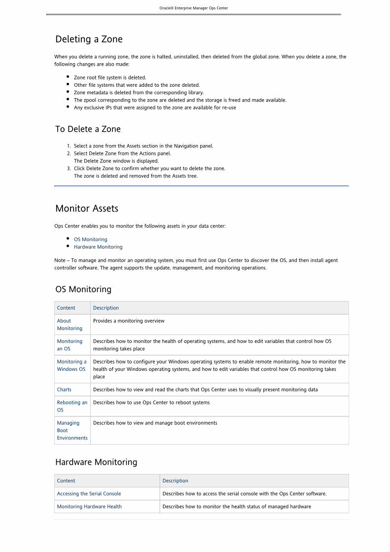
Oracle® Enterprise Manager Ops Center
1. 2.
3.
Deleting a ZoneWhen you delete a running zone, the zone is halted, uninstalled, then deleted from the global zone. When you delete a zone, thefollowing changes are also made:
Zone root file system is deleted.Other file systems that were added to the zone deleted.Zone metadata is deleted from the corresponding library.The zpool corresponding to the zone are deleted and the storage is freed and made available.Any exclusive IPs that were assigned to the zone are available for re-use
To Delete a Zone
Select a zone from the Assets section in the Navigation panel.Select Delete Zone from the Actions panel.The Delete Zone window is displayed.Click Delete Zone to confirm whether you want to delete the zone.The zone is deleted and removed from the Assets tree.
Monitor AssetsOps Center enables you to monitor the following assets in your data center:
OS MonitoringHardware Monitoring
Note – To manage and monitor an operating system, you must first use Ops Center to discover the OS, and then install agentcontroller software. The agent supports the update, management, and monitoring operations.
OS Monitoring
Content Description
AboutMonitoring
Provides a monitoring overview
Monitoringan OS
Describes how to monitor the health of operating systems, and how to edit variables that control how OSmonitoring takes place
Monitoring aWindows OS
Describes how to configure your Windows operating systems to enable remote monitoring, how to monitor thehealth of your Windows operating systems, and how to edit variables that control how OS monitoring takesplace
Charts Describes how to view and read the charts that Ops Center uses to visually present monitoring data
Rebooting anOS
Describes how to use Ops Center to reboot systems
ManagingBootEnvironments
Describes how to view and manage boot environments
Hardware Monitoring
Content Description
Accessing the Serial Console Describes how to access the serial console with the Ops Center software.
Monitoring Hardware Health Describes how to monitor the health status of managed hardware

Oracle® Enterprise Manager Ops Center
Managing Locator Lights Describes how to locate hardware using the locator lights
Managing and Monitoring Server PowerStates
Describes different power states of a system and how to power on or power offa system
Monitoring Power Utilization Describes how to view and read the power usage charts
Monitoring Hardware Variables andConnectivity
Describes how hardware variables and connectivity are monitored
Resetting a Server Describes how to reset a server
Monitoring Job Information Describes how to monitor the current jobs and historical jobs
Managing and Monitoring M-Series Server Describes how M-Series servers are monitored through Ops Center
Note – You cannot perform any management or monitoring actions on the Ops Center Enterprise Controller or Proxies.
Monitor AssetsOps Center enables you to monitor the following assets in your data center:
OS MonitoringHardware Monitoring
Note – To manage and monitor an operating system, you must first use Ops Center to discover the OS, and then install agentcontroller software. The agent supports the update, management, and monitoring operations.
OS Monitoring
Content Description
AboutMonitoring
Provides a monitoring overview
Monitoringan OS
Describes how to monitor the health of operating systems, and how to edit variables that control how OSmonitoring takes place
Monitoring aWindows OS
Describes how to configure your Windows operating systems to enable remote monitoring, how to monitor thehealth of your Windows operating systems, and how to edit variables that control how OS monitoring takesplace
Charts Describes how to view and read the charts that Ops Center uses to visually present monitoring data
Rebooting anOS
Describes how to use Ops Center to reboot systems
ManagingBootEnvironments
Describes how to view and manage boot environments
Hardware Monitoring
Content Description
Accessing the Serial Console Describes how to access the serial console with the Ops Center software.
Monitoring Hardware Health Describes how to monitor the health status of managed hardware
Managing Locator Lights Describes how to locate hardware using the locator lights
Managing and Monitoring Server PowerStates
Describes different power states of a system and how to power on or power offa system

Oracle® Enterprise Manager Ops Center
Monitoring Power Utilization Describes how to view and read the power usage charts
Monitoring Hardware Variables andConnectivity
Describes how hardware variables and connectivity are monitored
Resetting a Server Describes how to reset a server
Monitoring Job Information Describes how to monitor the current jobs and historical jobs
Managing and Monitoring M-Series Server Describes how M-Series servers are monitored through Ops Center
Note – You cannot perform any management or monitoring actions on the Ops Center Enterprise Controller or Proxies.
About MonitoringOps Center enables you to monitor the following assets in your data center:
Managed operating systemsServersChassis
Note – To manage and monitor an operating system, you must first use Ops Center to discover the OS, and then install agentcontroller software. The agent supports the update, management, and monitoring operations.
OS Monitoring
You can monitor the health of your Solaris, Linux, and Windows operating systems. You can edit the variables that control how OSmonitoring takes place. You can also reboot your OS from the Ops Center BUI.
Hardware Monitoring
You can monitor and manage your servers and chassis from a central BUI, including the following:
Hardware health statusManage and monitor the power states of a system and power systems on and offDisplay and chart power usage:
ILOM based serversILOM based chassis
Monitor hardware variables and connectivity, including M-series serversReset a serverDisplay job status and job historyUse locator lights to locate assets
About MonitoringOps Center enables you to monitor the following assets in your data center:
Managed operating systemsServersChassis
Note – To manage and monitor an operating system, you must first use Ops Center to discover the OS, and then install agentcontroller software. The agent supports the update, management, and monitoring operations.
OS Monitoring
You can monitor the health of your Solaris, Linux, and Windows operating systems. You can edit the variables that control how OSmonitoring takes place. You can also reboot your OS from the Ops Center BUI.
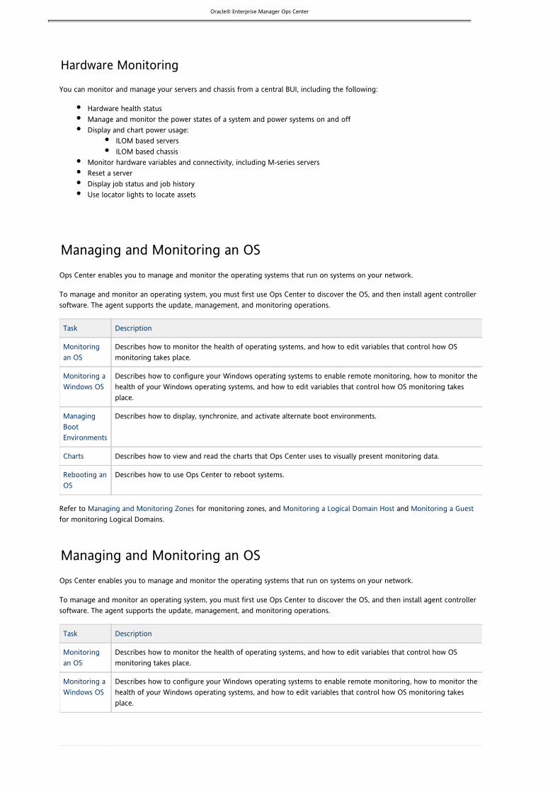
Oracle® Enterprise Manager Ops Center
Hardware Monitoring
You can monitor and manage your servers and chassis from a central BUI, including the following:
Hardware health statusManage and monitor the power states of a system and power systems on and offDisplay and chart power usage:
ILOM based serversILOM based chassis
Monitor hardware variables and connectivity, including M-series serversReset a serverDisplay job status and job historyUse locator lights to locate assets
Managing and Monitoring an OSOps Center enables you to manage and monitor the operating systems that run on systems on your network.
To manage and monitor an operating system, you must first use Ops Center to discover the OS, and then install agent controllersoftware. The agent supports the update, management, and monitoring operations.
Task Description
Monitoringan OS
Describes how to monitor the health of operating systems, and how to edit variables that control how OSmonitoring takes place.
Monitoring aWindows OS
Describes how to configure your Windows operating systems to enable remote monitoring, how to monitor thehealth of your Windows operating systems, and how to edit variables that control how OS monitoring takesplace.
ManagingBootEnvironments
Describes how to display, synchronize, and activate alternate boot environments.
Charts Describes how to view and read the charts that Ops Center uses to visually present monitoring data.
Rebooting anOS
Describes how to use Ops Center to reboot systems.
Refer to for monitoring zones, and and Managing and Monitoring Zones Monitoring a Logical Domain Host Monitoring a Guestfor monitoring Logical Domains.
Managing and Monitoring an OSOps Center enables you to manage and monitor the operating systems that run on systems on your network.
To manage and monitor an operating system, you must first use Ops Center to discover the OS, and then install agent controllersoftware. The agent supports the update, management, and monitoring operations.
Task Description
Monitoringan OS
Describes how to monitor the health of operating systems, and how to edit variables that control how OSmonitoring takes place.
Monitoring aWindows OS
Describes how to configure your Windows operating systems to enable remote monitoring, how to monitor thehealth of your Windows operating systems, and how to edit variables that control how OS monitoring takesplace.

Oracle® Enterprise Manager Ops Center
1.
2. 3.
4.
5.
6.
1.
ManagingBootEnvironments
Describes how to display, synchronize, and activate alternate boot environments.
Charts Describes how to view and read the charts that Ops Center uses to visually present monitoring data.
Rebooting anOS
Describes how to use Ops Center to reboot systems.
Refer to for monitoring zones, and and Managing and Monitoring Zones Monitoring a Logical Domain Host Monitoring a Guestfor monitoring Logical Domains.
Monitoring an OSSelect the OS from the asset list in the Navigational panel to view the Summary page in the center panel. Each operating system(OS) is monitored for the following characteristics:
ConnectivityFile system statusMonitoring variablesCPU usageMemory usageNetwork usage
In the Summary page, the following information about the OS is displayed:
OS NameServer nameHealth statusNotification statusOS detailsOS monitoring variables
To Change Thresholds of OS Monitoring Variables
Perform the following procedure to edit the monitoring variables:
Select the OS from the Asset section in the Navigation panel.The Summary page of the selected OS is displayed. For Linux OS, the Summary page is displayed with the current valuesfor the monitoring variables.Select the OS Details tab from the center panel.Select the variables for which you want to change the threshold values for Warning and Critical.Use the Shift key to select more than one variable.Click the Change Threshold icon.The Change OS Monitoring Thresholds window is displayed with the selected variables.Enter the Warning and Critical thresholds values as required.For all the variables, the unit of measurement is displayed. The values depend on the number of processors in yoursystem and on the usage characteristics.Click Change Thresholds to submit the changes.
Ideally, the value of any given monitored OS health attribute is compared to a threshold value. Monitoring variable values arecompared against the thresholds at regular intervals. If the value of a monitored OS health attribute rises above the warningthreshold, notification is issued with the status of Warning Failure. If the value continues to increase and passes the criticalthreshold, notification is issued with the status of Critical Failure.
Note – You can set specific threshold values for different operating systems.
To Change Thresholds of Monitoring Variables for an OS Group
Perform the following procedure to edit the monitoring variables for an OS group:

Oracle® Enterprise Manager Ops Center
1.
2.
3.
4.
1.
2.
3.
4.
1.
Select the OS group from the Assets section in the Navigation panel.The Summary page of the selected OS group is displayed.In the Actions panel, select the option Change Monitoring Thresholds.The Change OS Monitoring Thresholds For All Members of the Group window is displayed.Edit the threshold variables as required.
– Only the percentage values of the warning and critical thresholds of the monitoring variables can be changed.NoteClick Change Thresholds to set the newly entered values.The new value will be set for all the members of the group.
To Change File System Thresholds for an OS Group
Perform the following procedure to change the file system thresholds for an OS group:
Select the OS group from the Assets section in the Navigation panel.The Summary page of the selected OS group is displayed.In the Actions panel, select the option Change File System Thresholds.The Change File System Thresholds For All Members of the Group window is displayed.Edit the threshold values.
– Only the threshold value of common file systems of the group can be changed.NoteClick Change Threshold to set the newly entered values.The new value will be set for all the members of the group.
OS Health States
The different OS health states are as follows:
Good – The server is working properly.Unknown – An error occurred while attempting to retrieve information about the health of the OS resource. The serveris connected but does not return any information.Unreachable – The server agent IP address cannot be contacted for the status of the health of the OS resource. Thisindicates network problems or that the server is in standby mode.Warning Failure – A potential or impending fault condition has been detected on the server. Action should be taken toprevent the problem from becoming more serious.Critical Failure – A fault condition has occurred on the server. Corrective action is required.
Monitoring an OSSelect the OS from the asset list in the Navigational panel to view the Summary page in the center panel. Each operating system(OS) is monitored for the following characteristics:
ConnectivityFile system statusMonitoring variablesCPU usageMemory usageNetwork usage
In the Summary page, the following information about the OS is displayed:
OS NameServer nameHealth statusNotification statusOS detailsOS monitoring variables
To Change Thresholds of OS Monitoring Variables
Perform the following procedure to edit the monitoring variables:
Select the OS from the Asset section in the Navigation panel.

Oracle® Enterprise Manager Ops Center
1.
2. 3.
4.
5.
6.
1.
2.
3.
4.
1.
2.
3.
4.
The Summary page of the selected OS is displayed. For Linux OS, the Summary page is displayed with the current valuesfor the monitoring variables.Select the OS Details tab from the center panel.Select the variables for which you want to change the threshold values for Warning and Critical.Use the Shift key to select more than one variable.Click the Change Threshold icon.The Change OS Monitoring Thresholds window is displayed with the selected variables.Enter the Warning and Critical thresholds values as required.For all the variables, the unit of measurement is displayed. The values depend on the number of processors in yoursystem and on the usage characteristics.Click Change Thresholds to submit the changes.
Ideally, the value of any given monitored OS health attribute is compared to a threshold value. Monitoring variable values arecompared against the thresholds at regular intervals. If the value of a monitored OS health attribute rises above the warningthreshold, notification is issued with the status of Warning Failure. If the value continues to increase and passes the criticalthreshold, notification is issued with the status of Critical Failure.
Note – You can set specific threshold values for different operating systems.
To Change Thresholds of Monitoring Variables for an OS Group
Perform the following procedure to edit the monitoring variables for an OS group:
Select the OS group from the Assets section in the Navigation panel.The Summary page of the selected OS group is displayed.In the Actions panel, select the option Change Monitoring Thresholds.The Change OS Monitoring Thresholds For All Members of the Group window is displayed.Edit the threshold variables as required.
– Only the percentage values of the warning and critical thresholds of the monitoring variables can be changed.NoteClick Change Thresholds to set the newly entered values.The new value will be set for all the members of the group.
To Change File System Thresholds for an OS Group
Perform the following procedure to change the file system thresholds for an OS group:
Select the OS group from the Assets section in the Navigation panel.The Summary page of the selected OS group is displayed.In the Actions panel, select the option Change File System Thresholds.The Change File System Thresholds For All Members of the Group window is displayed.Edit the threshold values.
– Only the threshold value of common file systems of the group can be changed.NoteClick Change Threshold to set the newly entered values.The new value will be set for all the members of the group.
OS Health States
The different OS health states are as follows:
Good – The server is working properly.Unknown – An error occurred while attempting to retrieve information about the health of the OS resource. The serveris connected but does not return any information.Unreachable – The server agent IP address cannot be contacted for the status of the health of the OS resource. Thisindicates network problems or that the server is in standby mode.Warning Failure – A potential or impending fault condition has been detected on the server. Action should be taken toprevent the problem from becoming more serious.Critical Failure – A fault condition has occurred on the server. Corrective action is required.
Monitoring a Windows OS

Oracle® Enterprise Manager Ops Center
Ops Center enables you to manage and monitor your Windows, Solaris, and Linux operating systems from a single console. Alightweight Java agent monitors key OS parameters such as CPU, memory, swap space, file system, I/O, and power information.The monitoring capabilities are available when your Enterprise Controller is connected to the Internet, or in an environmentwithout an Internet connection (disconnected mode).
You can configure the thresholds to meet your data center guidelines. You are notified when a defined threshold is exceeded.You choose how you want to receive the alert: by email or on the BUI. Event logging records all events for the monitoredattributes.
Comprehensive Monitoring
You can manage and monitor your Windows OS with Ops Center, including the following key OS parameters:
ConnectivityFile system statusMonitoring variablesCPU usageMemory usageNetwork usage
Historical data includes CPU, memory, I/O and power data. You can store the data for future management analysis. Based on thedata collected, users can graph the historical data for trend analysis and forecasting.
Content Description
Configuring a Windows OS for RemoteMonitoring
Describes how to configure the Windows Management Instrumentation (WMI) toenable remote monitoring
Monitoring a System With the WindowsOS
Describes the attributes available for monitoring and how to display them in the BUI
Editing Monitoring Thresholds Describes how to change the monitoring thresholds.
Windows OS Health States Defines the monitoring health states.
Monitoring a Windows OSOps Center enables you to manage and monitor your Windows, Solaris, and Linux operating systems from a single console. Alightweight Java agent monitors key OS parameters such as CPU, memory, swap space, file system, I/O, and power information.The monitoring capabilities are available when your Enterprise Controller is connected to the Internet, or in an environmentwithout an Internet connection (disconnected mode).
You can configure the thresholds to meet your data center guidelines. You are notified when a defined threshold is exceeded.You choose how you want to receive the alert: by email or on the BUI. Event logging records all events for the monitoredattributes.
Comprehensive Monitoring
You can manage and monitor your Windows OS with Ops Center, including the following key OS parameters:
ConnectivityFile system statusMonitoring variablesCPU usageMemory usageNetwork usage
Historical data includes CPU, memory, I/O and power data. You can store the data for future management analysis. Based on thedata collected, users can graph the historical data for trend analysis and forecasting.
Content Description

Oracle® Enterprise Manager Ops Center
Configuring a Windows OS for RemoteMonitoring
Describes how to configure the Windows Management Instrumentation (WMI) toenable remote monitoring
Monitoring a System With the WindowsOS
Describes the attributes available for monitoring and how to display them in the BUI
Editing Monitoring Thresholds Describes how to change the monitoring thresholds.
Windows OS Health States Defines the monitoring health states.
Monitoring a System With the Windows OSFor systems installed with the Windows OS, you can monitor a number of OS attributes and perform several OS operations:
Windows OS AttributesWindows OS OperationsServer Attributes
In part, the attributes that are monitored are determined by what is supported with the Windows Management Instrumentation(WMI) remote monitoring capabilities. You must configure the WMI on the system that you want to monitor before you canmanage or monitor the Windows OS.
Windows OS Attributes
Ops Center can monitor the following OS attributes that are supported by WMI:
StatusHost nameCPU usageFile system usageDescriptionCPU architectureMemory usageSwap usageInterface informationSystem up time
Windows OS Operations
You can perform the following operations:
ShutdownRebootUnconfigure and shutdown
Server Attributes
You can monitor the following server attributes from the BUI:
Boot device informationStatusCPU informationEthernet port informationManufacturerMemory informationModel
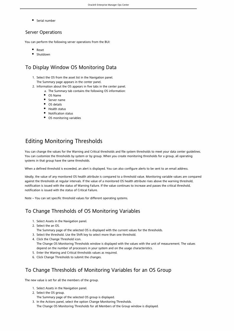
Oracle® Enterprise Manager Ops Center
1.
2. a.
1. 2.
3. 4.
5. 6.
1. 2.
3.
4.
Serial number
Server Operations
You can perform the following server operations from the BUI:
ResetShutdown
To Display Window OS Monitoring Data
Select the OS from the asset list in the Navigation panel.The Summary page appears in the center panel.Information about the OS appears in five tabs in the center panel.
The Summary tab contains the following OS information:OS NameServer nameOS detailsHealth statusNotification statusOS monitoring variables
Editing Monitoring ThresholdsYou can change the values for the Warning and Critical thresholds and file system thresholds to meet your data center guidelines.You can customize the thresholds by system or by group. When you create monitoring thresholds for a group, all operatingsystems in that group have the same thresholds.
When a defined threshold is exceeded, an alert is displayed. You can also configure alerts to be sent to an email address.
Ideally, the value of any monitored OS health attribute is compared to a threshold value. Monitoring variable values are comparedagainst the thresholds at regular intervals. If the value of a monitored OS health attribute rises above the warning threshold,notification is issued with the status of Warning Failure. If the value continues to increase and passes the critical threshold,notification is issued with the status of Critical Failure.
Note – You can set specific threshold values for different operating systems.
To Change Thresholds of OS Monitoring Variables
Select Assets in the Navigation panel.Select the an OS.The Summary page of the selected OS is displayed with the current values for the thresholds.Select the threshold. Use the Shift key to select more than one threshold.Click the Change Threshold icon.The Change OS Monitoring Thresholds window is displayed with the values with the unit of measurement. The valuesdepend on the number of processors in your system and on the usage characteristics.Enter the Waning and Critical thresholds values as required.Click Change Thresholds to submit the changes.
To Change Thresholds of Monitoring Variables for an OS Group
The new value is set for all the members of the group.
Select Assets in the Navigation panel.Select the OS group.The Summary page of the selected OS group is displayed.In the Actions panel, select the option Change Monitoring Thresholds.The Change OS Monitoring Thresholds for all Members of the Group window is displayed.

Oracle® Enterprise Manager Ops Center
4.
5.
1. 2.
3.
4.
5.
Edit the threshold variables as required. – Only the percentage values of the warning and critical thresholds of the monitoring variables can be changed.Note
Click Change Thresholds to submit the changes.
To Change File System Thresholds for an OS Group
The new value is set for all the members of the group.
Select Assets in the Navigation panel.Select the OS group.The Summary page of the selected OS group is displayed.In the Actions panel, select the option Change File System Thresholds.The Change File System Thresholds for all Members of the Group window is displayed.Edit the threshold values.
– Only the threshold value of common file systems of the group can be changed.NoteClick Change Threshold to set the newly entered values.
Windows OS Health StatesYou can monitor the following attributes for your Windows OS:
ConnectivityFile system statusMonitoring variablesCPU usageMemory usageNetwork usage
OS Health States
The following are definitions of the different OS health states:
Good – The server is working properly.Unknown – An error occurred while attempting to retrieve information about the health of the OS resource. The serveris connected but does not return any information.Unreachable – The server agent IP address cannot be contacted for the status of the health of the OS resource. Thisindicates network problems or that the server is in standby mode.Warning Failure – A potential or impending fault condition has been detected on the server. Action should be taken toprevent the problem from becoming more serious.Critical Failure – A fault condition has occurred on the server. Corrective action is required.
ChartsOps Center provides a variety of charts to help you optimize your data center resources. You can create the usage charts 24 hoursafter you start to manage the gear. By default, Ops Center gathers information every five minutes and displays an hour ofutilization data in the Summary tab and OS Details page of any managed asset.
The table shows all of the available charts and the type of asset that uses the chart.
Chart Description Type of Asset
Power Utilization Power usage Servers
CPU Utilization CPU usage for OS, host, and virtual pools OS, host, guest OS, virtual pools
Memory Utilization Memory usage OS, host, virtual pools
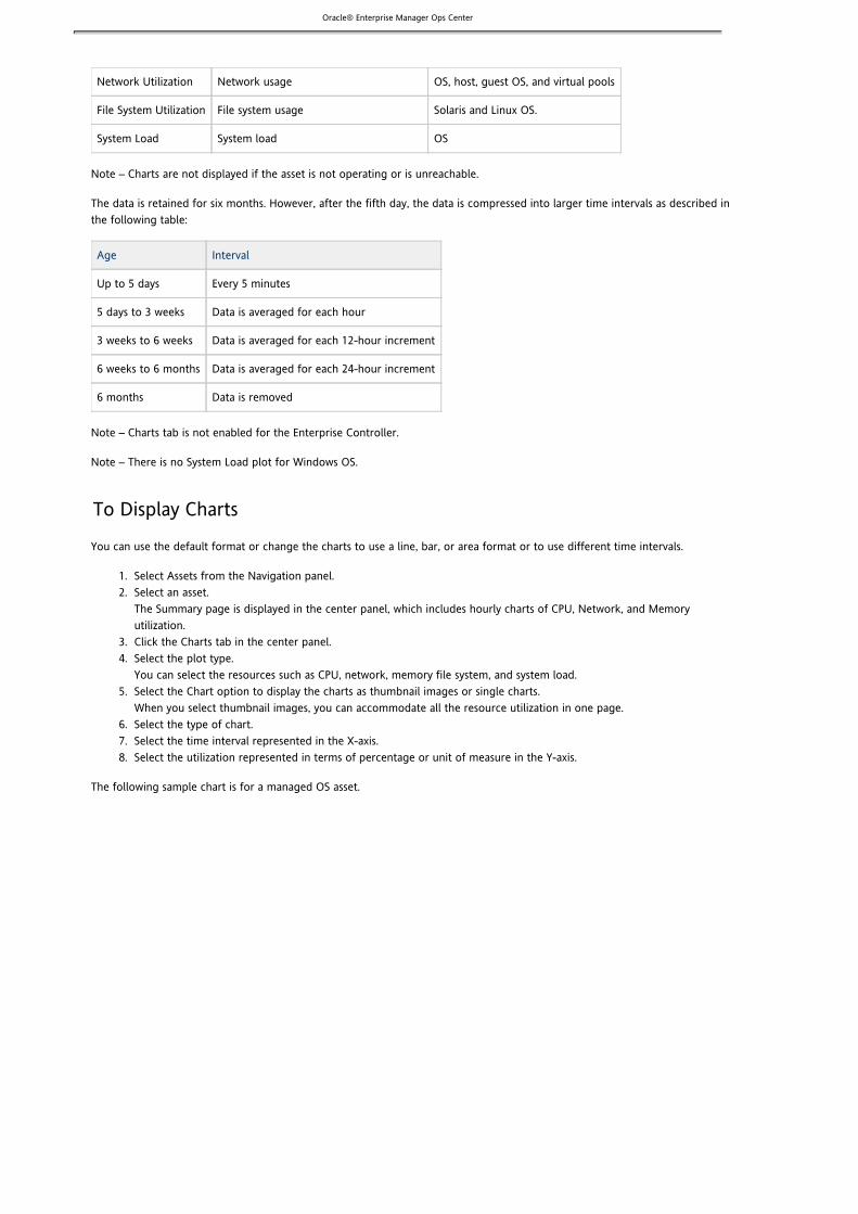
Oracle® Enterprise Manager Ops Center
1. 2.
3. 4.
5.
6. 7. 8.
Network Utilization Network usage OS, host, guest OS, and virtual pools
File System Utilization File system usage Solaris and Linux OS.
System Load System load OS
Note – Charts are not displayed if the asset is not operating or is unreachable.
The data is retained for six months. However, after the fifth day, the data is compressed into larger time intervals as described inthe following table:
Age Interval
Up to 5 days Every 5 minutes
5 days to 3 weeks Data is averaged for each hour
3 weeks to 6 weeks Data is averaged for each 12-hour increment
6 weeks to 6 months Data is averaged for each 24-hour increment
6 months Data is removed
Note – Charts tab is not enabled for the Enterprise Controller.
Note – There is no System Load plot for Windows OS.
To Display Charts
You can use the default format or change the charts to use a line, bar, or area format or to use different time intervals.
Select Assets from the Navigation panel.Select an asset.The Summary page is displayed in the center panel, which includes hourly charts of CPU, Network, and Memoryutilization.Click the Charts tab in the center panel.Select the plot type.You can select the resources such as CPU, network, memory file system, and system load.Select the Chart option to display the charts as thumbnail images or single charts.When you select thumbnail images, you can accommodate all the resource utilization in one page.Select the type of chart.Select the time interval represented in the X-axis.Select the utilization represented in terms of percentage or unit of measure in the Y-axis.
The following sample chart is for a managed OS asset.

Oracle® Enterprise Manager Ops Center
To Display Charts for Solaris Containers
You can display charts for zones by selecting the type of zone in the Assets section. You have per-zone utilization data availablefor CPU and memory resources. See section for more information about zone resourceManaging and Monitoring Zonesutilization.
To Display Charts for Groups
In addition to displaying charts for individual operating systems, you can display a chart for a group of operating systems. In the Summary page of the OS group, the hourly usage is displayed as bar charts.
Select the user-defined groups or pre-defined smart groups to display the five highest- and the five least-utilized operatingsystems in the group.
You can view the following utilization charts for the managed groups:
Resource Type Server Chassis OS Host
CPU - -
System Load - - -
Network - -
Memory - - -

Oracle® Enterprise Manager Ops Center
1. 2. 3.
1. 2.
3.
Allocated Memory - - -
Power - -
A sample chart for a group OS is shown below.
Exporting Chart Data
You can use the export feature to create output files in XML or CSV format.
Display the charts.Click Export Chart Data.Select the format and time period, and then click Export.The data is exported and saved on the system on which you are running the Ops Center BUI.
Rebooting an OSYou can reboot an OS from Ops Center.
To Reboot an OS
In the Navigation panel, select the OS from the Asset section.Select Reboot in the Actions panel.A confirmation window is displayed.Confirm the reboot action.

Oracle® Enterprise Manager Ops Center
1. 2. 3.
Managing Boot EnvironmentsIf an OS has one or more associated alternate boot environments (ABEs), they are automatically displayed in the Ops Center userinterface. You can create an ABE outside of Ops Center and it automatically appears in the user interface.
All boot environments are available for management, but you can only monitor an active BE. To get monitoring and managementinformation about an ABE, you must activate it and make it the BE.
Displaying BE and ABE DetailsAn alternate boot environment (ABE) appears in the Asset panel as an attribute of the associated OS. Boot information is onlydisplayed if you have alternate boot environments associated with the live boot environment. You cannot view and compare bootenvironments or manage an ABE within Ops Center. You must boot into the alternate boot environment to get accurate details.
The following types of information is available for the associated boot environments:
Name and descriptionStatus
Active or Live – Current boot environmentInactive – ABEs that are available for activation and useInvalid – An ABE is not available for activation
File System location and descriptionDevice size, mount location and optionsDate and time that the ABE was last synchronized
From this panel you can choose which ABE to activate and schedule when to activate it. You can also choose to synchronize (alsoknown as sync) the boot environments.
To Display BE and ABE Details
Expand the Assets section of the navigation panel.(Optional) Filter the gear by selecting an asset type in the View window, or selecting a tag in the With Tag window.Click a Solaris OS in the Assets tree in the Navigation panel. OS Details are displayed in the center panel. If there is anassociated ABE, the Boot Environments tab appears in the center panel.

Oracle® Enterprise Manager Ops Center
3.
4.
5.
Information about the selected OS is displayed in the center panel.
Click the Boot Environments tab in the center panel.All associated boot environments are displayed in the center panel. The active boot environment appears first and showsan Active status. One or more alternate boot environments are displayed below the active boot environment.Shared files and directories appear in the Synch List. Click the icon next to the Status to display unique boot environmentdetails, including a list of file systems. The type of file system, device size, and mount details are also displayed.
Synchronize Boot EnvironmentsWhen you synchronize boot environments, you create an ABE identical to the currently running BE. For example, if you installapplications on your running BE, the ABE will not contain these applications. This might cause a problem when you activate the

Oracle® Enterprise Manager Ops Center
1. 2. 3.
4.
1. 2. 3.
alternate boot environment. Before you activate an ABE, you can synchronize it with the live boot environment and capture thoseapplications.
To Synchronize Boot Environments
Expand the Assets section of the navigation panel.(Optional) Filter the gear by selecting an asset type in the View window, or selecting a tag in the With Tag window.Click a Solaris OS in the Assets tree in the Navigation panel. OS Details are displayed in the center panel. If there is anassociated ABE, the Boot Environments tab appears in the center panel.
Information about the selected OS is displayed in the center panel.
Click Synchronize Boot Environment in the Actions panel.All associated boot environments are displayed in the center panel. The active boot environment appears first and showsan Active status. One or more alternate boot environments are displayed below the active boot environment.
Activate a Boot EnvironmentSynchronization is used to make an ABE identical to the currently running BE. For example, if you install applications on yourrunning BE, the ABE will not contain these applications. This might cause a problem when you activate the alternate bootenvironment. Before you activate an ABE, you can synchronize it with the live boot environment and capture those applications.
From this panel you can choose which ABE to activate and schedule when to activate it. You can also choose to synchronize (alsoknown as sync) the boot environments.
To Activate a Boot Environment
Expand the Assets section of the navigation panel.(Optional) Filter the gear by selecting an asset type in the View window, or selecting a tag in the With Tag window.Click a Solaris OS in the Assets tree in the Navigation panel. OS Details are displayed in the center panel. If there is an

Oracle® Enterprise Manager Ops Center
3.
4.
5. 6.
associated ABE, the Boot Environments tab appears in the center panel.Click the Boot Environments tab in the center panel. All associated boot environments are displayed in the center panel.
The active boot environment appears first and shows an Active status. One or more alternate boot environments aredisplayed below the active boot environment.
Click the inactive boot environment that you want to activate.Click Activate Boot Environment and Reboot in the Actions panel.
Managing and Monitoring HardwareOps Center can manage hardware health, power states, variables and connectivity, jobs, notification status, and locator lights.
– You cannot perform any management or monitoring actions on the Enterprise Controller or Proxy Controllers.Note
Accessing the Serial ConsoleOps Center provides access to a serial console for your managed hardware. The console enables you to log in to and run remotecommands on the system. You can run the console within the BUI, or you can undock the console and use it as a floating consolewindow.
By logging in through the console, you can perform commands on the service processor and operating system, as describedbelow:
Service Processor – Log in to the service processor and run commands using the management protocol, such as ALOM orILOMOperating System – Log in to the OS and run commands in a standard SSH session
Before You Begin

Oracle® Enterprise Manager Ops Center
1.
2. 3.
4.
To use console access for both the OS and service processor (SP), you must discover the OS and the SPs on the hardware, thenenable SSH access. This is done by performing a custom discovery of the assets.
If you have a managed asset that does not have SSH enabled, or the SP or OS are not discovered, you can run a new customdiscovery job to add capabilities. After successfully running the new custom discovery job, your managed asset is automaticallyupgraded to include the new capabilities.
Note – The console requires SSH access and the ability to reach the system.
Serial console access requires appropriate firewall and routing settings for the Enterprise Controller to connect to the ProxyController or agent through ssh (on port 22).
Serial Console for Zones and Logical Domains
In Logical Domain (LDom) guests, the serial console is exposed through the control domain. A temporary local user account iscreated on the control domain to provide serial console access to the LDoms over ssh. When this user account is enabled, TTY isdisplayed and automatically logs in over SSH to this user account.
In zones, the user account is created on the global zone. If the global zone is discovered through SSH but not managed, the useraccount is created on the Proxy Controller. When the user account is enabled, it will directly connect to the zone's console whenthe user logs in to it.
To Access the Serial Console
Select the hardware from the assets tree in the Navigation panel.The asset details are displayed in the center panel.Click the Console tab in the center panel.Click Enable Console to activate the console.A job is submitted to activate the console.(Optional) Click Undock to free the console from the BUI and move it to another location on your monitor.
Troubleshooting the Access to Serial Console
If your firewall settings prevent connections to the port 22, the Enterprise Controller cannot connect to the Proxy Controllerthrough SSH and the serial console functionality through the BUI will not be enabled.
In this case, you can access the serial console only through the command-line environment. For zones, log in to the global zoneand execute the following command manually:
zlogin -C < >zonename
For LDoms, log in to the Control Domain and execute the following command manually:
telnet localhost <domain_port>
Refer to the man page of for zones.zlogin
Monitoring Hardware HealthOps Center monitors the hardware health of managed assets.
Sensors in the hardware of the managed asset monitor the temperature, voltage, and fan speed. The following characteristics ofserver hardware are monitored:
CPU temperatureAmbient temperatureFan speed in revolutions per minuteVoltagesLEDsHard disks and memory
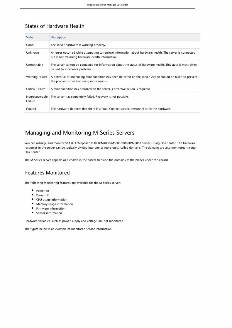
Oracle® Enterprise Manager Ops Center
States of Hardware Health
State Description
Good The server hardware is working properly.
Unknown An error occurred while attempting to retrieve information about hardware health. The server is connectedbut is not returning hardware health information.
Unreachable The server cannot be contacted for information about the status of hardware health. This state is most oftencaused by a network problem.
Warning Failure A potential or impending fault condition has been detected on the server. Action should be taken to preventthe problem from becoming more serious.
Critical Failure A fault condition has occurred on the server. Corrective action is required.
NonrecoverableFailure
The server has completely failed. Recovery is not possible.
Faulted The hardware declares that there is a fault. Contact service personnel to fix the hardware.
Managing and Monitoring M-Series ServersYou can manage and monitor SPARC Enterprise? M3000/M4000/M5000/M8000/M9000 Servers using Ops Center. The hardwareresources in the server can be logically divided into one or more units, called domains. The domains are also monitored throughOps Center.
The M-Series server appears as a chassis in the Assets tree and the domains as the blades under the chassis.
Features Monitored
The following monitoring features are available for the M-Series server:
Power onPower offCPU usage informationMemory usage informationFirmware informationSensor information
Hardware variables, such as power supply and voltage, are not monitored.
The figure below is an example of monitored sensor information.

Oracle® Enterprise Manager Ops Center
1. 2.
3.
1. 2.
3.
1. 2.
The following monitoring features are available for the domains:
Power onPower offPower on with netboot (required for OS provisioning)CPU usage informationMemory usage information
Managing Locator LightsYou can use Ops Center to illuminate an LED locator light to locate a specific server in a rack. From your browser, you can switchon or off a server or chassis locator light.
To Activate a Locator Light
Expand All Assets in the Assets section of the Navigation panel.Click the blade or the server that you want to find.Appropriate management information is displayed.Click Locator Lights On in the Actions panel.The LED locator light on the physical server or blade illuminates.
To Deactivate a Locator Light
Expand All Assets in the Assets section of the Navigation panel.Click the blade or the server that you want to find.Appropriate management information is displayed.Click Locator Lights Off in the Actions panel.The LED locator light on the physical server or blade is switched off.
To Manage Locator Lights in a Group
Expand All Assets in the Assets section of the Navigation panel.Select the group whose locator lights you want to manage.Appropriate management information is displayed.

Oracle® Enterprise Manager Ops Center
2.
3.
4.
1. 2. 3. 4. 5.
6.
1. 2. 3.
4.
In the group Summary page, the servers in the group are displayed under All Assets in Group. You can select a server ora set of servers from the list.
– You can manage the locator lights for homogeneous hardware groups only .NoteSelect a server or a set of servers from the list in All Assets in Group.When the servers are selected, the available action icons are highlighted.Click the Locator Light On or Locator Lights Off icon as required.The LED locator light on each physical server or blade will be switched on or off accordingly.
Managing and Monitoring Server Power StatesYou can use Ops Center to power on and power off a managed host. Stopping a server initiates a graceful shutdown of theoperating system and subsequent power-off of the managed server. If no operating system is installed, you have to force ashutdown of the server. The following are the different power states of a managed host:
State Description
On The server is powered on and running.
Standby The server is powered off but responds to commands.
Unknown An error occurred while attempting to retrieve the power status of the hardware. The server is connected but isnot returning any information on power status.
Unreachable The server cannot be contacted for information about its power state. This most often indicates a networkproblem or that the server is in standby mode.
To Power On a Server or Chassis
You can power on a managed server or a server group. If boot PROMs are configured, the servers will boot.
Select an asset from the Assets section in the Navigation panel.Select the server that you want to start.Choose Power On from the Actions menu. For server groups, select the servers from the list and click the Power On icon.To start the server, choose Default Power On.To start the server and use a manual network boot, choose Power On with Network Boot.A manual network boot is required for OS-based or manually discovered servers.Click OK.A job is submitted. Jobs initiated on groups of servers will run longer than jobs on individual servers.
To Power Off a Server or Chassis
You can power off a managed server or a server group.
Select an asset from the Assets section in the Navigation panel.Select the server that you want to power off.Choose Power Off from the Actions menu. For server groups, select the servers from the list and click the Power Officon.A Power OFF pop-up window opens. The following options are available:
Power OFFForce Power OFFEmergency Power OFF (This is available only for Chassis.)
Click the appropriate option.A job is initiated. The selected asset is be powered off.
Monitoring Power Utilization
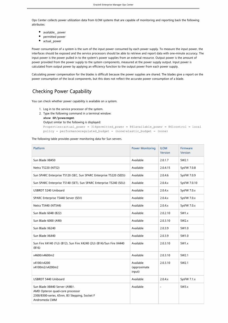
Oracle® Enterprise Manager Ops Center
1. 2.
Ops Center collects power utilization data from ILOM systems that are capable of monitoring and reporting back the followingattributes:
available_ powerpermitted poweractual_power
Power consumption of a system is the sum of the input power consumed by each power supply. To measure the input power, theinterfaces should be exposed and the service processors should be able to retrieve and report data with one-minute accuracy. Theinput power is the power pulled in to the system's power supplies from an external resource. Output power is the amount ofpower provided from the power supply to the system components, measured at the power supply output. Input power iscalculated from output power by applying an efficiency function to the output power from each power supply.
Calculating power compensation for the blades is difficult because the power supplies are shared. The blades give a report on thepower consumption of the local components, but this does not reflect the accurate power consumption of a blade.
Checking Power Capability
You can check whether power capability is available on a system.
Log in to the service processor of the system.Type the following command in a terminal window:
show SP/powermgmt
Output similar to the following is displayed:Properties:actual_power = 314permitted_power = 861available_power = 861control = local
policy = performanceregulated_budget = (none)elastic_budget = (none)
The following table provides power monitoring data for Sun servers.
Platform Power Monitoring ILOMVersion
FirmwareVersion
Sun Blade X8450 Available 2.0.1.7 SW2.1
Netra T5220 (NT52) Available 2.0.4.15 SysFW 7.0.8
Sun SPARC Enterprise T5120 (SEC, Sun SPARC Enterprise T5220 (SED)) Available 2.0.4.6 SysFW 7.0.9
Sun SPARC Enterprise T5140 (SET), Sun SPARC Enterprise T5240 (SEU) Available 2.0.4.x SysFW 7.0.10
USBRDT 5240 Uniboard Available 2.0.4.x SysFW 7.0.x
SPARC Enterprise T5440 Server (SEV) Available 2.0.4.x SysFW 7.0.x
Netra T5440 (NT544) Available 2.0.4.x SysFW 7.0.x
Sun Blade 6048 (B22) Available 2.0.2.10 SW1.x
Sun Blade 6000 (A90) Available 2.0.3.10 SW2.x
Sun Blade X6240 Available 2.0.3.9 SW1.0
Sun Blade X6440 Available 2.0.3.9 SW1.0
Sun Fire X4140 (1U) (B12), Sun Fire X4240 (2U) (B14)/Sun Fire X4440(B16)
Available 2.0.3.10 SW1.x
x4600/x4600m2 Available 2.0.3.10 SW2.1
x4100/x4200x4100m2/x4200m2
Available(approximateinput)
2.0.3.10 SW2.1
USBRDT 5440 Uniboard Available 2.0.4.x SysFW 7.1.x
Sun Blade X8440 Server (A98)\AMD Opteron quad-core processor2300/8300-series, 65nm, B3 Stepping, Socket FAndromeda CMM
Available - SW3.x

Oracle® Enterprise Manager Ops Center
1.
2.
1.
2.
Sun Blade T6340 Available - SysFW 7.1.x
Sun Blade T6320 Server Module (A95) Available - SysFW 7.1.x
Lynx Available - -
Sun Blade X6270 Available - -
SupernovaBronze/Platinum/Silver
Available - -
Sun Fire X4150 (B13)/Sun Fire X4450 (B15) Available - -
Power Utilization Graphs
In Ops Center, the power consumption for hardware is represented as a graph in the hardware Summary page, showing hourlydata for power consumption. You can also view the historical data for power consumption of a system in the Charts tab of theselected system asset. The charts are available for the following periods:
One hour – 1HOne day – 1DFive days – 5DThree weeks – 3WSix weeks – 6WSix months – 6M
Note – You must have discovered your system at least 24 hours earlier to view data for 3W, 6W, and 6M. – If the server does not have the appropriate ILOM version or has not been discovered through the ILOM driver, the chartNote
will be empty. The chart will not be displayed if the server is shut down or unreachable.
To View Power Utilization Charts
You can view historical data about power consumption.
Select a hardware from the Assets section in the Navigation panel. You can also select a hardware group or virtual poolfrom the Assets section.The Summary page of the hardware is displayed. The hourly power consumption is displayed as a graph in this page. Forhardware groups and virtual pools, you can view the five highest or lowest power consumers of the group in theSummary page.
– Charts are available for groups only with hardware assets.NoteSelect the Charts tab to view the historical data.The following options are available:
Chart Type: The charts are displayed only in Line format.Time: Select the time periods for 1H, 1D, 5D, 3W, 6W, and 6M.Export Chart Data: Export the chart data for a selected time period to CSV format and save it.For groups and virtual pools, the following options are available:Select Order: The five highest or lowest historical power charts.Select Resource: Select the Power or Aggregate Power option. The power option displays power utilization forthe five highest or lowest power consumers in the group or virtual pool. Aggregate Power displays the powerutilization for the whole group or virtual pool. It takes the sum of all the group members that are able to reportthe power consumption. For example, if you have a group of four servers but only three are able to reportpower, the power utilization chart is built only with the data coming from 3 servers. If the composition of thegroup or virtual pool is changed during the time, the chart is calculated taking into account the group membersat the time of the calculation.
– The top or bottom five charts are displayed only for homogeneous groups containing servers.Note
To Export Power Utilization Charts
You can export and save the power utilization charts.
Select the hardware from the Assets section in the Navigation panel.The Summary page of the hardware is displayed. The hourly power consumption is displayed in the Summary page.

Oracle® Enterprise Manager Ops Center
2. 3. 4.
5.
6.
7.
1.
2. 3.
1. 2.
3.
Select the Charts tab to view the historical data.Select Time for the period for which you want to export the data.Click the Export Chart Data button.The Export Data window is displayed.In the Export Data window, select the format in which you want to view or store the chart data.The options available are CSV and XML format.If you have already set the time period of the chart, select the option Current View for the Time Period.If you want the data for six months, select the 6 Months option for the Time Period.Click Export to store the chart data.The data is exported and saved in the directory where you are currently running the user interface.
Monitoring Hardware VariablesTo monitor the following hardware variable types, you should have previously made an ILOM discovery of the hardware:
CurrentDiskFanPower supplyTemperatureVoltage
Perform the following steps to view the hardware monitoring variables:
Select the hardware from the Assets section in the Navigation panel.The Summary page of the hardware is displayed in the center panel.In the Center panel, select the HW Monitoring tab to view the variables.In the HW Monitoring page, you can select the Variable type for which you want to view the variables.The variables are listed with the Warning, Critical, and Non Recoverable threshold values.
Monitoring ConnectivityConnectivity is the network interface of the system. The Network Interface Card (NIC) information is displayed in the Connectivitytab of the selected hardware in the Assets section.
NIC details such as name, connection status, MAC address, and the corresponding IP address are displayed.
Resetting a ServerYou can reset a server or a set of servers.
To Reset a Server
Select a server or server group from the Assets in the Navigation panel.Click Reset Server(s) to reset the system. For a group, select the list of servers from the group and click the ResetServer(s) icon. A Reset pop-up window appears with the following options:
ResetForce ResetReset with Network Boot
Click the appropriate option as required to reset the selected hardware.
Monitoring Job Information

Oracle® Enterprise Manager Ops Center
1. 2.
3.
You can view information about historical and current jobs for selected assets.
Current Jobs that are running. The status of each job is Running or Scheduled.Historical jobs that have run previously and are completed.
To View Current or Historical Jobs
Select Assets from the Navigation panel.Select an asset.The Summary page of the asset is displayed in the center panel.Select the Jobs tab in the Center panel.The Jobs page is displayed.
LibrariesAn Ops Center library stores and manages cached data, images, patches, and metadata for the use of virtualization hosts.
Content Description
About Libraries Describes the types of libraries
Libraries and Virtual Pools Describes how the hosts in a virtual pool get access to the resources in libraries.
Updates Library Describes the content of Solaris and Linux updates library.
Storage Libraries Describes the content of the storage libraries used by guests.
About LibrariesOps Center uses libraries to store and manage cached data, images, patches, and metadata. For images, the libraries store thefollowing types:
ISO image: operating system (OS) or other software applicationsAppliance image: Pre-configured application and an operating systemSnapshot: Particular state of a virtual machine
Libraries are categorized by the type of content stored in them:
OS Provisioning Library: ISO imagesFirmware Provisioning LibraryUpdates Library for Solaris and LinuxStorage Libraries
OS Provisioning Library
The OS Provisioning Library manages the ISO images, any FLAR files associated with an ISO image, and the profile for each ISOimage. The ISO images are used to provision one or more systems with an operating system. The OS profile describes how toconfigure one OS image, or one FLAR associated with one OS image, when the OS image is installed on a set of target systems.
The library's files are located in the following directories of the Enterprise Controller:
/ /opt/sun/xvm/images/os/iso var / /opt/sun/xvm/images/os/flarsvar
During the provisioning process, the OS images and FLAR files are copied from the library to each Proxy Controller's directory./var/opt/sun/xvm/proxyImageCache/os/iso

Oracle® Enterprise Manager Ops Center
To see the contents of the library, see and Viewing the Available OS Images Viewing the Available OS ProfilesTo add images and FLARs to the library, see .Importing OS Images and FLARs
Firmware Provisioning Library
The Firmware Provisioning Library manages firmware images, the supporting metadata, and the profiles for the firmware.The library resides on the Enterprise Controller system at the following location:
/ /opt/sun/xvm/images/firmWarevar
To see the contents of the library, see and .Displaying Firmware Images Displaying a Firmware ProfileTo add images and profiles to the library, see and .Creating a Firmware Image Creating a Firmware Profile
See for an overview of the basic concepts.About Firmware ProvisioningSee for more information about managing firmware profiles and updating firmware.Provision Firmware
Updates Library
Ops Center enables you to update, or patch, the following operating systems:
Solaris softwareLinuxWindows
To see the contents of the Updates Library and to add to the contents, see .Updates Library
Storage Libraries
When a guest (virtual image) is created, the configuration information for its operating system, data, CPU, memory, and networkdetails are saved as metadata in a storage library. The data files reside in the same location as the metadata. Storage libraries areof the following types, depending on the type of virtualization.
Fibre Channel Libraries for LDom hostsViewing the Contents of a Fibre Channel LibraryCreating a Fibre Channel Library
Network Attached Storage (NAS) Storage Libraries for all types of virtualization dataViewing the Contents of a NAS Storage LibraryCreating a NAS Storage Library
Updates LibraryThe Updates library contains the policies and profiles used to upgrade an operating system. It also stores any local content yourorganization requires such as files, scripts, executables, or binaries that are not known to the hosted tier.Local content files typically include instructions that must be carried out before or after a job. For example, you might develop ascript to test managed hosts before running a job.
Local content files are stored in the Enterprise Controller and are not synchronized with Sun's knowledge base.Use Ops Center to upload local content to the Updates library, to add categories for your content, to edit a component file, andto delete a local component from your library.
Managing Profiles
The Solaris/Linux OS Updates library contains system-defined profiles and any custom profiles that have been created. See for information on using and creating update profiles.OS Update Profiles

Oracle® Enterprise Manager Ops Center
1. 2. 3.
Managing Policies
The Solaris/Linux OS Updates library contains system-defined polices and any custom policies that have been created. See for information on using and creating update policies.OS Update Policies
Managing Components and Local Content
The Solaris/Linux OS Updates library stores the packages, patches, and configuration files that are used to update an OS. Thislibrary also contains any local components and custom configuration files.
Content Description
Uploading LocalSoftware in Bulk
Describes how to upload (in bulk) patches, packages, and RPMs from either a directory or an OSimage.
Viewing Bulk UploadResults
Describes how to view the history and details of the software that you have uploaded in bulk.
Uploading a LocalSoftware Package
Describes how to upload a local software package in PKG or RPM format.
Uploading a LocalConfiguration File
Describes how to upload a local configuration file.
Uploading a LocalAction
Describes how to upload and distribute a local action.
Adding a LocalCategory
Describes how to define your own sub-categories or to organize the files under a specific node.
Editing a LocalComponent File
Describes how to edit the specific information associated with the file or to replace the file.
Deleting a LocalComponent
Describes how to remove the component from the system completely.
Viewing ComponentDetails
Describes how to view details about your file including distribution, version, release, group, size URL,who added and edited the file, as well as any summary and description information.
Uploading Software inDisconnected Mode
Describes how to upload software while your environment is disconnected from the EnterpriseController (disconnected mode).
Adding a Local CategoryYour site's local content is organized into the following default categories: local RPMs or PKGs, configuration files, macros,pre-actions, post-actions, and probes. You can create subcategories to further organize your local content. The type of localcontent allowed in a subcategory depends on its parent category.
To Add a Local Category
Expand Libraries in the Navigation panel.Click Local Content in the Solaris/Linux OS Updates library.Click Add Local Category in the Actions panel.The Add Local Category window is displayed.

Oracle® Enterprise Manager Ops Center
3.
4. 5. 6. 7. 8.
1. 2. 3.
Enter a name for the new subcategory.Enter a brief description for the new subcategory such as its purpose.Click Distribution to assign to the subcategory.Click Parent to select one of the default categories for the subcategory.Click Apply.The new subcategory is created under the selected default category. You can now upload software packages and filesinto the new subcategory.
You cannot edit or delete one of the default categories. However, you can edit and delete a subcategory and you can delete thecontent in the subcategory. See .Deleting a Local Component
Deleting a Local ComponentYou can remove your site's local content but you cannot remove the default categories.
Note-- Deleting content does not require confirmation and cannot be undone. Verify you are deleting the correct localcomponent.
To Delete a Local Component File
Expand Libraries in the Navigation panel.Click Local Content in the Solaris/Linux OS Updates library.Click Delete Local Component in the Actions panel.The Delete Component window is displayed.

Oracle® Enterprise Manager Ops Center
3.
4.
5. 6.
1. 2. 3.
Expand the category to display the component you want to delete.To change the distribution that is displayed, click Distribution.Select the component or a subcategory to delete.Click Delete.
To remove a subcategory and its components, do not attempt to remove each component and then remove the subcategory.When there are no components in a subcategory, the subcategory creates a placeholder component, which you cannot delete. Ifthis occurs, repeat the procedure and select the subcategory itself to delete. The placeholder component is also removed.
Editing a Local Component FileYou can edit the contents of a local component file. For example, if you uploaded a system file that contained IP addresses anddetermined that there was an incorrect IP address in the file, you can edit the file to correct the IP address. You can also use thisprocedure to replace the file with one that you have already corrected.
To Edit Local Component Files
Expand Libraries in the Navigation panel.Click Local Content in the Solaris/Linux OS Updates library.Click Edit Local Component File in the Actions panel.The Edit Local Component window is displayed.

Oracle® Enterprise Manager Ops Center
3.
4.
5.
1. 2. 3.
To specify the file, you can type its name or click the Browse button to navigate to the file.If the file is a component of a different distribution, click Distribution to select the correct distribution. The files in thethe selected distribution are displayed.Select either Edit existing file or Replace existing file.
If you choose to edit the file, make changes to the file and click Save.If you choose to replace the file, browse for the replacement file and click Upload.
Uploading a Local ActionAn action is a script, binary, or executable that makes changes to a host. The following actions are available:
Pre-Actions – Script that runs on a managed host before job tasks are carried out.Post-Actions – Script that runs on a managed host after job tasks are completed.Probes – Script that runs on a managed host to verify that a job task can be performed.Macros – Script that outputs a single line. This output replaces a macro sign in a local configuration file. The macro valueis used to customize a configuration file for its host machine. The macro actions can be leveraged to deploy a singleconfiguration file across multiple hosts by customizing the configuration file for different environments.
To Upload a Local Action
Expand Libraries in the Navigation panel.Click Local Content in the Solaris/Linux OS Updates library.Click Upload Local Action in the Actions panel.The Upload Local Action window is displayed.

Oracle® Enterprise Manager Ops Center
3.
4. 5. 6. 7.
8. 9.
1. 2. 3.
Type a name for the file.Enter a brief description of the purpose of the action.Click the type of action in the Action list.Click the name of the distribution that uses the action in the Distribution list.The Parent field shows the category, based on the type of Action.Click Browse to locate and select the file.Click Upload.The file is uploaded to the selected distribution.
Uploading a Local Configuration FileA configuration file is a text file, binary, or non-RPM application that is distributed to all managed hosts for consistentconfiguration.
Note – You can create subcategories under the parent category, Configuration Files, so that you can group uploaded files. See .Adding a Local Category
To Upload a Local Configuration File
Expand Libraries in the Navigation panel.Click Local Content in the Solaris/Linux OS Updates library.Click Upload Local Configuration File in the Actions panel.The Upload Local Configuration File window is displayed.

Oracle® Enterprise Manager Ops Center
3.
4. 5.
6. 7.
8. 9.
10.
1. 2. 3.
In Target path on server, type the full path to the directory on the managed hosts where the files must be installed.In Version, type an identifying name for this version of the file. This value is appended to the file name when it isdisplayed in a Components list.Type a brief description of the file.Select the Distribution to which this file is applied.You can choose multiple distributions.In Parent, accept the Configuration Files category or click Browse to locate a subcategory.Click Browse to locate and select the configuration file.Click Upload.The file is uploaded to the selected distributions.
To create a configuration job, create a profile that includes this configuration file. See andCreating OS Profiles for Solaris Systems.Creating OS Profiles for Linux Systems
Uploading a Local Software PackageOps Center can upload software in the following formats:
pkg
rpm (for Linux RPMs)Package data stream and package directoriestar
zip
gzip
compress
You can select any number of packages for uploading. If the file is in compressed format, the file is uncompressed. Verify that allextracted files are of one of the supported types: , , , or .pkg rpm zip tar
To Upload a Local Software Package
Expand Libraries in the Navigation panel.Click Local Content in the Solaris/Linux OS Updates library.Click Upload Local Software Package in the Actions panel.The Upload Local Software Packages window is displayed.

Oracle® Enterprise Manager Ops Center3.
4. 5. 6. 7. 8.
1. 2. 3.
Select Yes if the package is a security fix for a previous version of the software. Otherwise, select No.Click the name of the distribution to which you want to add this package.In Parent, click Local PKGs or click Browse to locate a subcategory.In Files, select the software package.Click Upload.The software package is uploaded and listed under the Local Content.
To create a configuration job, create a profile that includes this package. See and Creating OS Profiles for Solaris Systems Creating.OS Profiles for Linux Systems
Uploading Local Software in BulkYou can upload multiple files or the entire contents of a directory in one operation. For example, you can upload the entirecontents of an EIS DVD or Solaris CD/DVD. Bulk upload accepts the following formats:
pkg
rpm (for Linux RPMs)Package data stream and package directoriestar
zip
gzip
compress
You select a directory that contains the components. The directories are scanned recursively and all components in the directoryand subdirectories are uploaded.
If files are gzipped or compressed, the software extracts the files. Verify that the resulting files have the supported file types: , , , or )..pkg .rpm zip tar
To Upload Local Software in Bulk
Expand Libraries in the Navigation panel.Click Local Content in the Solaris/Linux OS Updates library.Click Bulk Upload Packages and Patches in the Actions panel.The Upload Packages, Patches, and RPMS window is displayed

Oracle® Enterprise Manager Ops Center
3.
4. 5. 6.
a. b.
7.
1. 2. 3. 4. 5. 6.
7.
Click Distribution to select the distribution that applies to these files.Select either Upload from OS Image or Upload from Directory.Specify the path to the OS image or directory or click Browse to locate and select it. If you specify a directory, all files in the directory and its subdirectories are uploaded. If you specify an OS image, you must mount the OS image and select the files.
Click on one of the OS images and click Mount.Click Browse to locate and select the files.
Click Submit.The upload job is created.
To view the status of the upload job, select .Bulk Upload Results
To view the certified packages that have been uploaded, click on Update Components in the Navigation panel.To view non-certified packages that have been uploaded, click on Local Content in the Navigation panel.
Uploading Software in Disconnected ModeIn Disconnected mode, you must upload all required content manually. If the software and other files are not uploaded, an errormessage similar to "Not installable by current KB" is displayed when jobs are run that require local content.
The Bulk Upload Packages and Patches option is used to upload all the patches, packages, and RPMs content from an EIS DVD orSolaris CD/DVD. Multiple files or the entire contents of an EIS DVD or Solaris CD/DVD can be uploaded at the same time.
To Upload Software in Disconnected Mode
Expand Libraries in the Navigation panel.Click Local Content in the Solaris/Linux OS Updates library.Click Bulk Upload Packages and Patches in the Actions panel.Click Distribution to select the distribution that applies to these files.Select Upload from Directory.Specify the path to the CD/DVD or click Browse to locate and select it.All files on the CD/DVD are uploaded.Click Submit to upload the files.The Upload Job is submitted.
To view the status of the upload job, select .Bulk Upload ResultsTo view the Sun-certified packages that have been uploaded, click on Update Components in the Navigation panel.To view non-certified packages that have been uploaded, click on Local Content in the Navigation panel.

Oracle® Enterprise Manager Ops Center
1. 2. 3.
4.
1. 2.
3.
4.
5.
Viewing Bulk Upload ResultsYou can view a detailed history of all the local components that were uploaded in bulk. You can view the result of the bulkupload.
To View Bulk Upload Results
Click Libraries in the Navigation panel.Click Solaris/Linux Updates Library.Click Bulk Upload Results in the Actions panel.The Bulk Upload Result window is displayed.
The uploaded components list displays the name, description, status, and date for each component.
Select a component and click View Results.The details of the uploaded components are displayed.
Viewing Component DetailsYou can view details about a component such as distribution, version, release, group, size URL, who added and edited the file andwhen, as well as any summary and description information, host, RPM, and vendor.
To View Component Details
Expand Libraries in the Navigation panel.Click Local Content in the Solaris/Linux OS Updates library.The center panel displays the standard categories of local content: configuration files, local packages, macros,pre-actions, post-actions, and probes.Expand a category to see view the components. For the local packages category, the content is organized further by thename of the server that discovered the package, for example , so you must alsoAgent <hostname> auto register
expand this subcategory.Double-click on the component to view information about it.A dialog containing information about the component is displayed, using tabs to organize the information such asGeneral, Incident, Dependencies, Installed, and Rules.To dismiss the component details, click Close.

Oracle® Enterprise Manager Ops Center
Storage LibrariesA storage library contains data and the metadata used by virtualization software so that both types of information are available tohosts through Ops Center.When a virtual image (guest) is created, the configuration information for its operating system,data, CPU, memory, and network details are saved as metadata in a storage library. The data files reside in the same location asthe metadata: in local, NFS, or CIFS storage libraries. Storage libraries are also used to group raw block storage devices, such asfibre channel SANs or NAS-hosted large-files.
Ops Center does not manage storage resources, that is, Ops Center does not create, modify or update LUs on disk arrays and itdoes not manage NAS shares on NAS systems. Ops Center manages how hosts get access to the metadata by controlling access tothe storage libraries where the metadata resides. Hosts, which must have appropriate storage management utilities and services,use NFS or CIFS services to attach to the storage libraries. For example, to get access to a CIFS storage library, the smbfsfilesystem must be available to the host.
In configurations that use virtual pools, the storage libraries are associated with the pool; any host in a virtual pool can get accessto the storage libraries that are associated with the virtual pool.
Storage libraries are identified by the type of storage and by the type of virtualization.
Type of Virtualization Storage Requirements Type of Storage Library
Logical Domains(LDom)
For shared assets, including pools and migration, on anetwork.Uses raw partitions made available by the Control Domain
SAN storage library using Fibre Channel
All types For shared assets on a network.Used for hosting metadata.
NAS storage library using either NFS orCIFS
The diagram shows how the storage libraries and types of virtualization interact with virtual disks.
SAN storage libraries expose data as logical units (LUNs), identified by their LUN GUIDs.NAS storage libraries expose data as raw files and files in VMDK format.
The LUNs, raw files, and raw volumes store data and provide the metadata for the guests. The metadata for NAS virtual disks arestored in the NAS Storage Library. Metadata for SAN virtual disks is persisted in the SAN Storage Library.

Oracle® Enterprise Manager Ops Center
Fibre Channel LibrariesA Fibre Channel storage library is a logical grouping of raw storage (LUNs).
In this release, SAN storage is accomplished through Fibre Channel libraries.
When you create a fibre channel storage library, you associate the library with any virtual pool, Logical Domain host, and globalzone.
When you create a guest or zone, any LUN in the fibre channel storage library can be allocated to the guest or zone.
Note – You cannot store the metadata of Logical Domain guest in the fibre channel library. Store the guest images in NAS.storage libraries
LUN
LUN is part of the address of the storage that you are presenting to a host. LUNs have a finite set of resources available, such asthe amount of data that can be stored, as well as the number of active commands that a device or LUN can process at one time.
Each LUN is of fixed size. You cannot modify the size. You cannot sub-divide LUNs among Logical Domain guests and zones. Whena LUN is assigned to a global zone or a Logical Domain guest, this LUN cannot be assigned to other guests. For example, you havefive LUNs in a fibre channel library. You have assigned the first LUN to a Logical Domain guest. In such a case, the first LUNcannot be assigned to other guests.
Since LUNs cannot be sub-divided among hosts, the user needs to perform significant initial planning with respect to storageoptimization. The user has to ensure that the storage space in LUNs is utilized as much as possible. The user needs to analyze thestorage requirements of zones and Logical Domain guests and assign LUNs of appropriate size to them.
Terms in SAN Storage
Disk – The physical disks installed in the disk array.Volume – A logical entity that aggregates the storage space provided by several physical disks.Slice – A partition of a volume that can be exposed as a logical unit to the servers connected to the disk array.LUN (Logical Unit Number) – The representation of a slice as seen from the outside world.GUID – The Global Unique Identifier that is associated with each LUN.HBA (Host Bus Adapter)-- The physical interface card that allows a system to connect to a SCSI or fibre channel storagedevice.initiator – A SCSI client trying to access a SCSI device. It is usually the port of an HBA installed on the server.

Oracle® Enterprise Manager Ops Center
1. 2. 3. 4. 5. 6.
target – A SCSI storage server which exposes logical units that can be accessed by SCSI initiators.WWN (Word Wide Name) – A globally unique identifier which is associated with SCSI initiators or targets.
Managing Fibre Channel Libraries
Contents Description
Configuring Fibre ChannelStorage
Describes the major steps in configuring storage for fibre channel libraries. This configurationneeds to be performed outside of Ops Center.
Creating a Fibre ChannelLibrary
Describes how to create a fibre channel library.
Adding LUNs to a FibreChannel Library
Describes how to add LUNs to a fibre channel library.
Viewing the Contents of aFibre Channel Library
Describes how to view the contents of a fibre channel library.
Editing a Fibre Channel Library Describes how to edit a fibre channel library.
Deleting a Fibre ChannelLibrary
Describes how to delete a fibre channel library.
Troubleshooting Fibre ChannelLibraries
Describes the troubleshooting issues with fibre channel libraries.
Configuring Fibre Channel StorageThe storage for fibre channel libraries is configured outside of Ops Center. Virtualization vendors qualify fibre channel disk arraysfrom specific vendors.
To Configure Storage for Fibre Channel Libraries
You need to have a fibre channel disk array and a fiber channel switch with sufficient ports.
The following is the general procedure for configuring storage. See your vendor-specific storage documentation for the exactsteps.
Log in to the fibre channel disk array using the service processor credentials.Define volumes on the disk array with the required number of disks.Initialize the volumes on the disk array.Create LUNs (slices) from the volumes. These LUNs will be used by zones and Logical Domain guests.Map the LUNs (slices).Enable the Multipath support (MPxIO) on the fibre channel disk array for the fibre channel LUNs to be visible throughSolaris multipathing.
Creating a Fibre Channel LibraryWhen you create a fibre channel library, you can specify whether to add LUNs to the library manually or select LUNs from theavailable LUNs.
Before You Begin
Configure storage for fiber channel libraries so that LUNs are available and accessible, according to vendor documentation. See for the major steps involved in configuring the storage.Configuring Fibre Channel Storage

Oracle® Enterprise Manager Ops Center
1. 2. 3.
4.
5.
1.
To Create a Fibre Channel Library
Expand Libraries in the Navigation panel.Click Fibre Channel Storage in Storage Libraries.Click New Fibre Channel Library in the Actions panel.The Create New Fibre Channel Library wizard is displayed.
In the Identify Library panel, enter the name and description of the library. Click Next.The Associate Library panel is displayed.If you want to manually add LUNs to the library, see .Adding LUNs to the Library ManuallyORIf you want to select LUNs from the available LUNs, see .Selecting LUNs from the Available LUNs
Adding LUNs to the Library Manually
In the Associate Library panel of the Create New Fibre Channel Library wizard, select Create the library associations laterand click Next.The Identify LUNs panel is displayed.
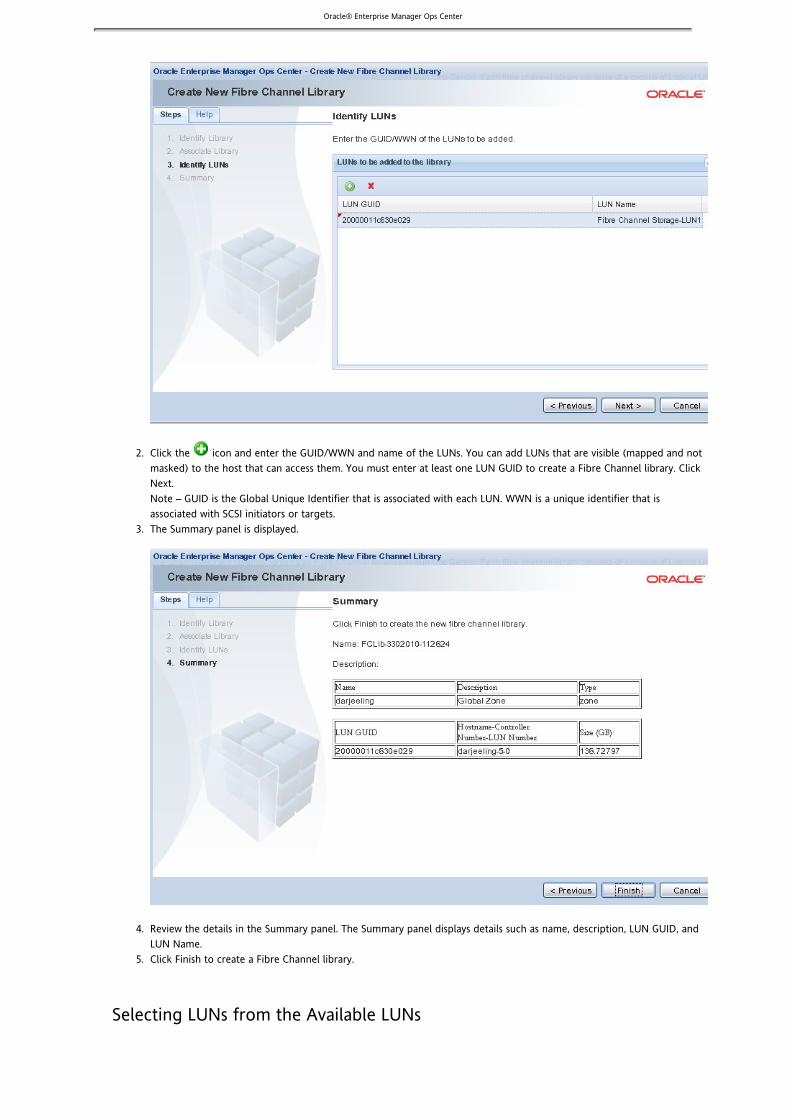
Oracle® Enterprise Manager Ops Center
1.
2.
3.
4.
5.
1.
Click the icon and enter the GUID/WWN and name of the LUNs. You can add LUNs that are visible (mapped and notmasked) to the host that can access them. You must enter at least one LUN GUID to create a Fibre Channel library. ClickNext.
– GUID is the Global Unique Identifier that is associated with each LUN. WWN is a unique identifier that isNoteassociated with SCSI initiators or targets.The Summary panel is displayed.
Review the details in the Summary panel. The Summary panel displays details such as name, description, LUN GUID, andLUN Name.Click Finish to create a Fibre Channel library.
Selecting LUNs from the Available LUNs

Oracle® Enterprise Manager Ops Center
1.
2.
3.
4.
5.
6.
In the Associate Library panel of the Create New Fibre Channel Library wizard, select Associate the new library with theselected items.The Associate Library panel is displayed.
A table is displayed that contains the name, description, and type of virtual pools, Logical Domain hosts, and globalzones.
Select at least one item from the table that you want to associate with the new library. You can view and select LUNs thatare accessible from the selected systems in the next step.Click Next.The Identify LUNs panel is displayed.
Select LUNs from the Available LUNs table. You must select at least one LUN from the Available LUNs table to create aFibre Channel library. Click Next.Review the details in the Summary panel. The Summary panel displays details such as name, description, and LUNs withsize.

Oracle® Enterprise Manager Ops Center
6.
1. 2. 3. 4.
5.
a. b.
a. 6.
1. 2. 3. 4.
Click Finish to create a Fibre Channel library.
Adding LUNs to a Fibre Channel LibraryIf the fibre channel storge library is associated with a virtual pool, Logical Domain host, or global zone, you have the option ofadding LUNs by selecting them from a list of available LUNs. If the storage library is not associated, you add LUNs by identifyingthem.
To Add LUNs to a Fibre Channel Library
Expand Libraries in the Navigation panel.Click Fibre Channel Storage in Storage Libraries.Click one of the available fibre channel libraries.Click Add LUN in the Actions panel.The Add LUNs to Fibre Channel Library panel is displayed.Choose the method for adding LUNs:
To add LUNs to the library manually, accept the default method: Manually enter the GUID/WWN of the LUNs tobe added.
Click the Add icon.Enter the GUID (Global Unique Identifier) and name of the LUN.
To select LUNs from the available LUNs, select Select from available LUNs.The Available LUNs table displays LUNs that can be accessed by all the hosts in the virtual pool.
Select one or more LUNs.Click Add LUNs.
The Available LUNs table has the following fields:
LUN GUID – A unique identifier for LUN regardless of where it is accessed from.Hostname – Host name or host IP address of the host that can access the LUN.Controller Number – Controller number on the host that identifies the HBA port.LUN Number – LUN number on the host also called as SCSI LUN. This is not the same as LUN GUID or LUN WWN.Size (GB) – Size of each LUN in Gigabytes.
Viewing the Contents of a Fibre Channel Library
In addition to the viewing the contents of the storage library, you can manage the LUNs in the storage library.
To View the Contents of a Fibre Channel Library
Expand Libraries panel in the Navigation panel.Click Fibre Channel Storage in Storage Libraries.Click one of the fibre channel libraries.The details of the selected Fibre Channel library appear in the central panel.

Oracle® Enterprise Manager Ops Center
4.
5.
1. 2. 3. 4. 5.
6.
Total Storage Size – Size of all LUNs in the library.Allocated Storage – Total size of all LUNs in the library that are allocated to guests and zones.State – State of the Fibre Channel library. The state of the library depends on each LUN.Associated To – Names of the virtual pools, Logical Domain hosts, or global zones that are associated with thisfibre channel library.LUN Name – Name of the LUN.Allocated To – Name of the guest or zone that this LUN is allocated.LUN GUID – Global Unique Identifier that is associated with each LUN.Size (GB) – Size of the LUN in Gigabytes.
From the LUNs table, you can add, edit, and delete LUNs.Add LUN – Click to add LUNs manually or select LUNs from the available LUNs. See Adding LUNs to a Fibre
for more information.Channel LibraryEdit LUN Details – Click to edit the LUN name.Delete LUN Details – Click to delete LUNs from the fibre channel library. Only LUNs that are not assigned to anyguests or zones can be deleted from the library.
Editing a Fibre Channel LibraryYou can change the name and description of the library and you can add LUNs to the library.
To Edit a Fibre Channel Library
Expand Libraries in the Navigation panel.Click Fibre Channel Storage in Storage LibrariesClick the Fibre Channel library you want to change.Click Edit Fibre Channel Library Attributes in the Actions panel.Edit the library name and description.

Oracle® Enterprise Manager Ops Center
6.
1. 2. 3. 4.
5.
Click Save.
Deleting a Fibre Channel LibraryDeleting a fibre channel library removes the associations between guests and the fibre channel library.
Before You Begin
Verify that no LUN in the fibre channel library is associated with any guest or zone.
To Delete a Fibre Channel Library
Expand Libraries in the Navigation panel.Click Fibre Channel Storage in Storage Libraries.Click on the Fibre Channel library you want to delete.Click Remove Fibre Channel Library from the Actions panel.The Remove Library panel is displayed. The guests associated with the fibre channel library are displayed in the VirtualGuests table.Click Remove Library.A job is submitted to remove the associations between the guests and the fiber channel library.
Troubleshooting Fibre Channel Libraries
Check if Solaris Multipathing (MPxIO) Is Enabled for Fibre Channel Disks
bash-3.00# stmsboot -Lstmsboot: MPxIO is not enabled
Check Whether the Fibre Channel Host Bus Adaptors (HBAs) Are Configured
bash-3.00# fcinfo hba-port HBA Port WWN: 21000003ba68a3ac OS Device Name: /dev/cfg/c1 Manufacturer: QLogic Corp. Model: 2200 Firmware Version: 2.01.145 FCode/BIOS Version: ISP2200 FC-AL Host Adapter Driver: 1.14 01/11/20 Serial : not availableNumber Driver Name: qlc Driver Version: 20080617-2.29 Type: L-port State: online Supported Speeds: 1Gb Current Speed: 1Gb Node WWN: 20000003ba68a3ac
The controlled device associated with the HBA is ./dev/cfg/c1
Check Whether the Fibre Channel HBAs Are Connected to the Fabric

Oracle® Enterprise Manager Ops Center
bash-3.00# cfgadm -l
Ap_Id Type Receptacle Occupant Conditionc0 scsi-bus connected configured unknownc1 fc- connected configured unknownprivatec2 scsi-bus connected unconfigured unknownusb0/1 unknown empty unconfigured okusb0/2 unknown empty unconfigured okusb0/3 unknown empty unconfigured okusb0/4 unknown empty unconfigured ok
You can see that indicates that it is not connected to the fabric.fc-private
Network Attached Storage LibrariesNetwork-attached-storage (NAS) libraries are storage libraries for NFS and CIFS storage device mount points. Each storage librarycan store ISO images, appliance and guest template images, and backup images of guests.
Content Description
About Network Attached Storage (NAS) StorageLibraries
Shows the role of the library.
Viewing the Contents of a NAS Storage Library Displays the images in an existing NAS storage library.
Configuring NAS Storage Libraries Describes the tasks for creating a NAS storage library.
Adding ISO and Appliance Images Describes the procedures for uploading and importing images into astorage library.
Changing a NAS Storage Library Describes how to edit the attributes of a NAS storage library.
Deleting a NAS Storage Library Describes how to remove a NAS storage library from the EnterpriseController.
Troubleshooting a NAS Storage Library Describes how to diagnose problems with a NAS storage library
About Network Attached Storage (NAS) Storage LibrariesA NAS storage library stores ISO images, appliance and guest template images, and backup images of virtual guests.When a virtual image (guest) is created, the configuration information for its operating system, data, CPU, memory, and networkdetails are saved as metadata in a storage library. Storage libraries are also used to group raw block storage devices, such aslarge-files.
Ops Center does not manage NAS shares on NAS systems. Instead, Ops Center manages how virtualization hosts get access to themetadata. Virtualization hosts, which must have appropriate storage management utilities and services, use NFS or CIFS services toattach to the storage libraries and gain access to the data and metadata.
If the LDOM host is in a virtual pool, you must store its metadata in a NAS storage library. Do not attempt to store this metadatain a Fibre Channel storage library or a local library.
When a NAS storage library is associated with an LDOM guest and the library becomes unavailable, the LDOM guest is affected inthe following ways:
If the storage library is used for metadata, the LDOM guest continues to function but Ops Center can no longer managethe guest. Ops Center relies on its interaction with the metadata in the storage library so, if the storage library is notavailable, jobs that need to read or modify the metadata begin to fail. You must administer the LDOM guest manually.
If the storage library is used for NFS large files that support virtual disks, the LDOM guest does not function.

Oracle® Enterprise Manager Ops Center
1. 2. 3.
1. 2.
If the boot disk is on the NFS share, the LDOM guest cannot be rebooted.
The LDOM guest cannot be migrated.
If you use a local library to store metadata for a standalone zone or standalone LDOM guest, the local library remains available.However, any guest with metadata in a local library cannot be migrated.
You can store metadata for all guests in one NAS storage library or you can store each guest's metadata in a separate storagelibrary. The benefit of using separate storage libraries is to increase the ease of access from different global zones or from LDOMcontrol domains, to increase capacity, and to increase performance.
Viewing the Contents of a NAS Storage LibraryIn the Navigation panel, expand Libraries.Under Storage Libraries, click NAS Storage.Click on one of the NAS storage libraries.The central panel displays information about the library on three tabs.
Tab Description
Summary Lists all the images in the library by type and the size and date it was modified. The types of images include:Appliance/Guest Template Image, Backup Image, ISO Image, LDom Guest Image, Guest Image, and Zone GuestImage.
Usage Lists all Guest images in the library and the current information for each one such as Name, Tag, Allocated Memory,vCPU, vCPU Utilization, and Size.
Disks Lists all disks in the library by name and description and shows the current use of each one by allocation and size.
Viewing Image DetailsThe Library Summary tab lists all the images (guest images, ISO images and appliance images) that are stored in that library.
To View Image Details
Select the image from the library.Click the View Image Details icon.

Oracle® Enterprise Manager Ops Center
2.
For an ISO image, the Image Name and Description are displayed.For guest images, the Summary page is displayed as shown in the illustration.
Configuring NAS Storage Libraries
Content Description
Setting Up the NFS ServerSetting Up the CIFS Server
Describes how to prepare the mountpoint for the storage library.
Creating a NAS Storage Library Describes how to define a new storage library.
Associating or Disassociating StorageLibraries
Describes how to initialize the storage library.
Adding ISO and Appliance Images Describes how to add images into the storage library, by upload, import, ormove.
Oracle® Enterprise Manager Ops Center
1. 2.
3. 4. 5. 6. 7.
1.
2.
3.
Setting Up the CIFS ServerWhen you create a NAS storage library, you can specify that it is served by the CIFS services of a Windows file system. To createthe CIFS mount point for a library, you prepare the shared folder on the Windows system and then you create a NAS storagelibrary that relies on that folder.
To Set Up a Shared Folder on the CIFS Server
Log in to the Windows system.Right-click on the folder that needs to be shared.A list of options is displayed.Select Properties.Select the Sharing tab.Select the Share This Folder option.Click Permissions and select Allow For All actions.Click OK to save the changes.
Defining the CIFS Mount Point
When you use the New NAS Storage wizard, choose the CIFS option when you define the Type of library.Enter the Windows system's username and password.
Setting Up the NFS ServerA storage library is required to store disk and guest images. The libraries can be based on the shares of an NFS server. TheNFS-based libraries can be created by one of the following methods:
Create a local storage library before attaching the virtualization host to Ops Center. After attaching the virtualizationhost, associate the storage library to the virtual pool.Create a storage library using the Ops Center BUI and add it to a virtual pool.
Note – The NFS protocol requires agreement on the Domain Name System (DNS) to which the NFS server and NFS clients belong.The server and a client must agree on the identity of the authorized users accessing the share.
Because the Enterprise Controller does not mount the NFS share, install the NFS server on a system that is close to the systemswhere the NFS share will be used, that is, the systems that host global zones and LDOM hosts.
To Set Up a Share on the NFS Server
On the NFS server, edit the file. Locate the NFSMAPID_DOMAIN variable and change the variable/etc/default/nfs
value to the domain name.Define a group and user that are common to both the NFS server and the NFS clients. Create the group account withGID 60, and the user with UID 60. For example, use the following commands to create a group and a user named :xvm
Create the group:xvm
# groupadd -g 60 xvm
Create the user:xvm
# useradd -u 60 -g 60 -d / -c 'Ops Center user' -s /bin/ xvmtrue
Create the directory that you want to share, and set its ownership and permission modes. For example:
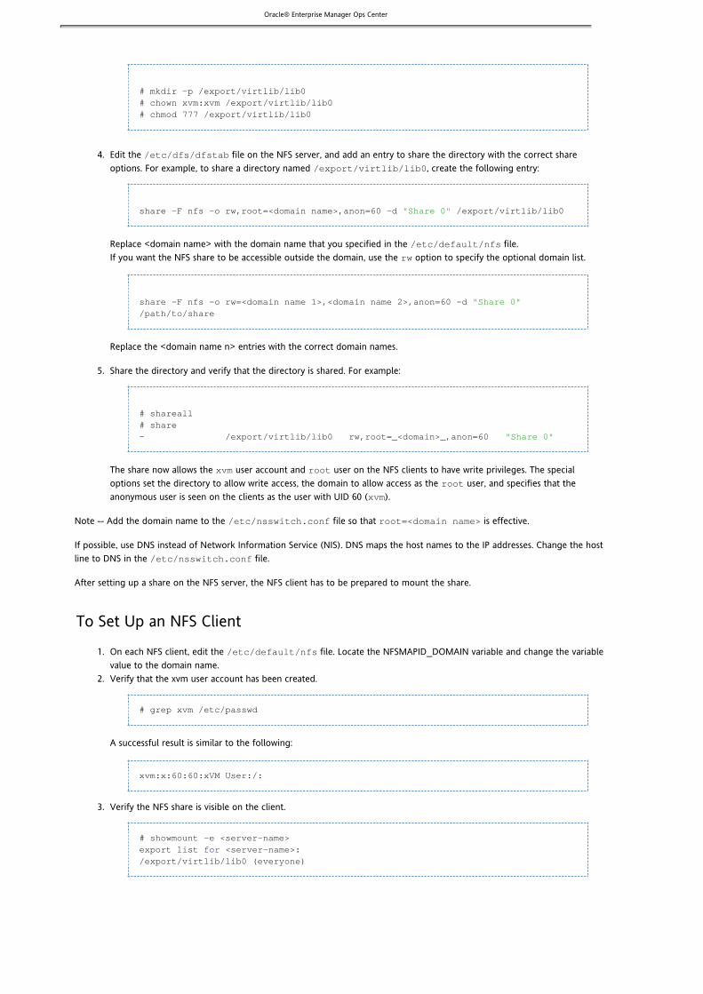
Oracle® Enterprise Manager Ops Center3.
4.
5.
1.
2.
3.
# mkdir -p /export/virtlib/lib0# chown xvm:xvm /export/virtlib/lib0# chmod 777 /export/virtlib/lib0
Edit the file on the NFS server, and add an entry to share the directory with the correct share/etc/dfs/dfstab
options. For example, to share a directory named , create the following entry:/export/virtlib/lib0
share -F nfs -o rw,root=<domain name>,anon=60 -d /export/virtlib/lib0"Share 0"
Replace with the domain name that you specified in the file. <domain name> /etc/default/nfs
If you want the NFS share to be accessible outside the domain, use the option to specify the optional domain list.rw
share -F nfs -o rw=<domain name 1>,<domain name 2>,anon=60 -d "Share 0"/path/to/share
Replace the entries with the correct domain names.<domain name n>
Share the directory and verify that the directory is shared. For example:
# shareall# share- /export/virtlib/lib0 rw,root=_<domain>_,anon=60 "Share 0"
The share now allows the user account and user on the NFS clients to have write privileges. The specialxvm root
options set the directory to allow write access, the domain to allow access as the user, and specifies that theroot
anonymous user is seen on the clients as the user with UID 60 ( ).xvm
Note -- Add the domain name to the file so that is effective./etc/nsswitch.conf root=<domain name>
If possible, use DNS instead of Network Information Service (NIS). DNS maps the host names to the IP addresses. Change the hostline to DNS in the file./etc/nsswitch.conf
After setting up a share on the NFS server, the NFS client has to be prepared to mount the share.
To Set Up an NFS Client
On each NFS client, edit the file. Locate the NFSMAPID_DOMAIN variable and change the variable/etc/default/nfs
value to the domain name.Verify that the xvm user account has been created.
# grep xvm /etc/passwd
A successful result is similar to the following:
xvm:x:60:60:xVM User:/:
Verify the NFS share is visible on the client.
# showmount -e <server-name>export list <server-name>:for/export/virtlib/lib0 (everyone)

Oracle® Enterprise Manager Ops Center
1. 2. 3.
4. 5. 6. 7.
8.
To Create a NAS Storage LibraryIn the Navigation panel, expand Libraries.Under Storage Libraries, click on NAS Storage.In the Actions panel, click New NAS Storage.The Create New NAS library window is displayed.
Enter a name for the library and a description.Select one or more virtual pools to be associated with this library.For the Type, select either NFS or CFS to indicate the mount point of the library.If this library uses a CIFS mount point, enter the User Name, Password, and domain name of the server. If this library uses an NFS mount point, enter the path of shared directory.Click on the New NAS Library button to create the library.
A new storage library has a size of -2 MB and a state of UNKNOWN because the storage library is not yet mounted.
For storage libraries that have CIFS mount points and for storage libraries that use NFS mount points and an Enterprise Controlleron Linux OS systems, the storage library is mounted when a virtual pool is associated with the storage library. The mount processoccurs on a host in the virtual pool. After the virtual pool is associated with a storage library, all the actions on the library areenabled and the size of the storage library is accurate.
To initialize a library, associate the library with one or more LDom hosts, virtual pools, or zones:
Associating Libraries to a Logical Domain HostAdding Libraries to the Global ZoneAssociating or Disassociating Storage Libraries

Oracle® Enterprise Manager Ops Center
1. 2. 3.
4. 5.
6. 7.
1. 2. 3.
4. 5.
6.
Associating or Disassociating LibrariesYou can associate or disassociate a NAS storage library from a virtual pool.
To Associate a Storage Library With a Virtual Pool
When you , you associate it with a virtual pool. Use the following procedure to associate an existing librarycreate a new librarywith a virtual pool.
Select Assets in the Navigation panel.Click on the All Assets drop-down list.Select Virtual Pools.The panel shows all virtual pools.Select the virtual pool you want.Click Associate Libraries from the Actions panel.The Associate Library window is displayed.Select the libraries from the list.Click Associate Library.The selected libraries are associated to the virtual pool.
To Disassociate a Library From a Virtual Pool
You can dissociate a library from a virtual pool using the following procedure:
Select Assets in the Navigation panel.Click on the All Assets drop-down list.Select Virtual Pools.The panel shows all virtual pools.Select the virtual pool you want.Click the Libraries tab in the center panel.The associated libraries and the guests that are stored in the libraries are listed.Select the library from the list and click the Disassociate Library icon.The selected library is detached from the virtual pool.
Adding ISO and Appliance ImagesAn ISO image can be an image of an OS or a software application.
An appliance is a pre-installed and pre-configured environment containing an application and an operating system environment.The appliance image can be loaded when and where needed, allowing the appliance to function without having to install,configure, and maintain the complete software stack. The appliance image is in the form of a VMDK files, compressed into a tar,gz, or zip file.
Another type of appliance image is a guest image. This image contains all of the data and metadata for a virtual machine, theguest.
When you upload an ISO or appliance image, the image is copied from the local directory (or the mounted directories) of thesystem where the BUI runs to the Enterprise Controller. The image is then copied from the Enterprise Controller to its NASstorage library.
When you import an image, the image is copied from the directory on the NFS or CIFS server where the storage library isattached to the Enterprise Controller's NAS storage library. The image must be in the server's directory before you attempt toimport it.
If the image is not resident on the system that is running the BUI, importing the image takes less time than uploading it.
To add an ISO image or an appliance image to a storage library:

Oracle® Enterprise Manager Ops Center
1. 2. 3.
4. 5. 6.
Content Description
Upload ISO Images Describes how to upload an ISO image.
Upload Appliance Images Describes how to upload an appliance image.
Import Images Describes how to import an ISO image or appliance image.
Upload ISO ImagesTo be available for uploading:
The ISO image must reside on the local machine, that is, the system that is running the BUI. You cannot upload imagesfrom remote locations.The appliance image must be in a compressed file format: tar, gz, or zip.The file and directory must have the correct permissions for uploading.
Note – Make sure you have Java installed and enabled on your browser before you upload an ISO image.
To Upload ISO Images
Click Libraries from the Navigation panel.Select the library in which you want to store the ISO image.Click Upload Image in the Actions panel.The Upload an ISO Image window is displayed
Enter the name of the file in the Source of ISO File field or click Browse to select the ISO image.Enter the name and description of the image.Click Upload Image.The progress of the upload to the Enterprise Controller is displayed.
After uploading, the image is copied to the storage library.
Upload Appliance Images

Oracle® Enterprise Manager Ops Center
1. 2. 3.
4. 5. 6.
1.
2.
1. 2. 3.
To be available for uploading:
The appliance image must reside on the local machine, that is, the system that is running the BUI. You cannot uploadimages from remote locations.The appliance image must be in a compressed file format: tar, gz, or zip.
To Upload Appliance Images
You can upload an appliance image using the following procedure:
Click Libraries from the Navigation panel.Select the storage library in which you want to store the appliance image.In the Actions panel, select Upload Appliance Image option.The Upload an Appliance Image window is displayed.
Click Choose File to select the location of the appliance image.Enter a name and description for the appliance image.Click Upload Appliance.The appliance image is uploaded and stored in the selected library.
Import ImagesTo import an image into a library, the image must reside in a blobs directory on the NFS or the CIFS server. To make imagesavailable for importing, use the following procedure:
On the NFS or CIFS server, create a blobs directory under the storage mountpoint. For example, if the NFS mountpoint is, the new directory is .xvmserver1/nfs_share/lib1 xvmserver1/nfs_share/lib1/blobs
Copy the ISO and the appliance images to the new directory.
To Import ISO or Appliance Images
Select Libraries from the Navigation panel.Select the library to which you want to import the image.Click Import Image in the Actions panel.The Import an Image window is displayed.

Oracle® Enterprise Manager Ops Center
3.
4. 5. 6.
1. 2. 3. 4.
5. 6. 7.
Note – If there is no image in the blobs directory, the following message is displayed;No images found for library <library_name>
Enter a name for the image and a description.Select an image from the list of images available.Click Import Image to copy the image to the library.
Moving an ImageYou can move an image from one library to another library.
In Ops Center, select Libraries from the Navigation panel.Select the library from which you want to move an image.Select the image from the list.Click the Move Image icon to move the virtual image.The Move an Image to Another Library window is displayed.
– When you are moving virtual server images, the guests must be in the shutdown state. Otherwise, an error isNotedisplayed.The selected image and the corresponding library are displayed.In the Move to option, select the library to which you want to move the image, that is, the target library.Click Move Image.
The image is moved from the source library to the target library. The job might fail if the target library does not have enoughfree space for the image.
Editing Image DetailsThe Library Summary tab lists all the images (guest images, ISO images and appliance images) that are stored in that library.

Oracle® Enterprise Manager Ops Center
1. 2.
3.
To Edit Image Details
Select the image from the library.Click the Edit Image Details icon.
For an ISO image, the Image Name and Description are editable.For guest images, the Summary page is displayed. An example of guest image edit option is shown.Click Submit to submit the updates.
Deleting ImagesThe Library Summary tab lists all the images (guest images, ISO images and appliance images) that are stored in that library.

Oracle® Enterprise Manager Ops Center
1. 2. 3.
1. 2. 3. 4.
1. 2. 3. 4.
To Delete Images
Note: When you delete a server image or guest image, the corresponding guests are also deleted.
Select the image from the storage library.Click the Delete Image Details icon to delete the image.Click OK to confirm the delete action.
To Change the Attributes of a NAS Storage LibraryIn the Navigation panel, expand Libraries.Under Storage Libraries, click on NAS Storage.Select the NAS storage library you want to change.In the Actions panel, click on Edit Library Attributes.You can change the Name and Description of the library.Need username and password.
To Remove a NAS Storage LibraryWhen you remove a library, the library is removed from the list of NAS storage libraries and any guests associated with the libraryare removed.
In the Navigation panel, expand Libraries.Under Storage Libraries, click on NAS Storage.Select the NAS storage library you want to remove.In the Actions panel, click on Remove NAS Library.The Remove Library window is displayed, showing the guests that use this library.

Oracle® Enterprise Manager Ops Center
4.
5. Click on the Remove Library button.
Troubleshooting a NAS Storage LibraryOps Center reports a status for each library:
OK: Mount is successful. The library is accessible by Ops Center and by all hosts that use this storage library.UNKNOWN: The library cannot start the mounting process because of some incompatibility.FAULTED: The library mounting failed. None of the hosts that use the library can get access to it.DEGRADED: The performance or availability of the library is not complete. Some hosts that use the library can get accessto the library but other hosts that are associated with the library cannot get access to it.
Troubleshooting Library Creation
Whenever there is an issue on NFS share, check the following:
Check the NFS setup on the Server.Check the NFS setup on the Client.Check the mount table on the client. For example, on Solaris systems, execute the following command:cat /etc/mnttab
The output gives the mount point on the client for the NFS share. Check the mount point directory for the list of files forfurther investigation.
NFS Mount Points
When the creation of a storage library with an NFS mount point fails, check the permissions for the files in the mount directory.For example:
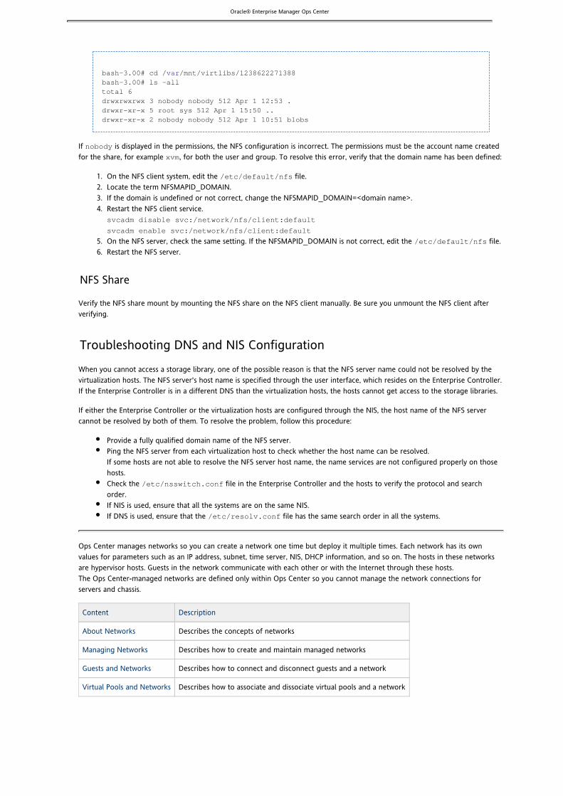
Oracle® Enterprise Manager Ops Center
1. 2. 3. 4.
5. 6.
bash-3.00# cd / /mnt/virtlibs/1238622271388varbash-3.00# ls -alltotal 6drwxrwxrwx 3 nobody nobody 512 Apr 1 12:53 .drwxr-xr-x 5 root sys 512 Apr 1 15:50 ..drwxr-xr-x 2 nobody nobody 512 Apr 1 10:51 blobs
If is displayed in the permissions, the NFS configuration is incorrect. The permissions must be the account name creatednobody
for the share, for example , for both the user and group. To resolve this error, verify that the domain name has been defined:xvm
On the NFS client system, edit the file./etc/default/nfs
Locate the term NFSMAPID_DOMAIN.If the domain is undefined or not correct, change the NFSMAPID_DOMAIN= .<domain name>Restart the NFS client service.svcadm disable svc:/network/nfs/client:default
svcadm enable svc:/network/nfs/client:default
On the NFS server, check the same setting. If the NFSMAPID_DOMAIN is not correct, edit the file./etc/default/nfs
Restart the NFS server.
NFS Share
Verify the NFS share mount by mounting the NFS share on the NFS client manually. Be sure you unmount the NFS client afterverifying.
Troubleshooting DNS and NIS Configuration
When you cannot access a storage library, one of the possible reason is that the NFS server name could not be resolved by thevirtualization hosts. The NFS server's host name is specified through the user interface, which resides on the Enterprise Controller.If the Enterprise Controller is in a different DNS than the virtualization hosts, the hosts cannot get access to the storage libraries.
If either the Enterprise Controller or the virtualization hosts are configured through the NIS, the host name of the NFS servercannot be resolved by both of them. To resolve the problem, follow this procedure:
Provide a fully qualified domain name of the NFS server.Ping the NFS server from each virtualization host to check whether the host name can be resolved.If some hosts are not able to resolve the NFS server host name, the name services are not configured properly on thosehosts.Check the file in the Enterprise Controller and the hosts to verify the protocol and search/etc/nsswitch.conf
order.If NIS is used, ensure that all the systems are on the same NIS.If DNS is used, ensure that the file has the same search order in all the systems./etc/resolv.conf
Ops Center manages networks so you can create a network one time but deploy it multiple times. Each network has its ownvalues for parameters such as an IP address, subnet, time server, NIS, DHCP information, and so on. The hosts in these networksare hypervisor hosts. Guests in the network communicate with each other or with the Internet through these hosts.The Ops Center-managed networks are defined only within Ops Center so you cannot manage the network connections forservers and chassis.
Content Description
About Networks Describes the concepts of networks
Managing Networks Describes how to create and maintain managed networks
Guests and Networks Describes how to connect and disconnect guests and a network
Virtual Pools and Networks Describes how to associate and dissociate virtual pools and a network

Oracle® Enterprise Manager Ops Center
1.
2.
About NetworksYou can use networks to do the following:
Manage individual hostsConnect hosts to the Proxy ControllerAllow guests to communicate with each other or with the InternetConnect remote JMX with the public API
A managed network depends on the physical network interface card (PNIC) that is available the host. You can create onemanaged network for each physical network interface card. If one host has two PNICs, it is a good practice to create twomanaged networks: a management network and a data network. This configuration lets you place all the guests on the datanetwork, keeping them separated from the management network, which gives access to internal resources of the data center.
The following configuration shows how two hosts participate in two managed networks.The actual network connection is made to the PNICs in the Virtualization Host.Network A is connected to PNIC 1 of both hosts and Network B is connected to PNIC 2 of the hosts.
Creating a Network
Before You Begin
You need to have a physical network interface card that is not used. – Starting with Release 2, you can also specify a link aggregation.Note
The mandatory network parameters are:
IP address of the networkNetmaskIf you use static IP addressing, the IP address of the management interfaceIf you use dynamic IP addressing, the range of allowed IP addresses and the gateway address
To Create a Network
From the Navigation panel, click Managed Networks.A list of physical networks appears under the Managed Networks section.
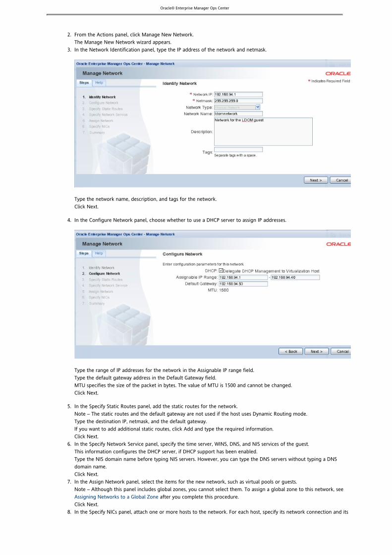
Oracle® Enterprise Manager Ops Center
2.
3.
4.
5.
6.
7.
8.
From the Actions panel, click Manage New Network.The Manage New Network wizard appears.In the Network Identification panel, type the IP address of the network and netmask.
Type the network name, description, and tags for the network.Click Next.
In the Configure Network panel, choose whether to use a DHCP server to assign IP addresses.
Type the range of IP addresses for the network in the Assignable IP range field.Type the default gateway address in the Default Gateway field.MTU specifies the size of the packet in bytes. The value of MTU is 1500 and cannot be changed. Click Next.
In the Specify Static Routes panel, add the static routes for the network. – The static routes and the default gateway are not used if the host uses Dynamic Routing mode. Note
Type the destination IP, netmask, and the default gateway.If you want to add additional static routes, click Add and type the required information.Click Next.In the Specify Network Service panel, specify the time server, WINS, DNS, and NIS services of the guest.This information configures the DHCP server, if DHCP support has been enabled. Type the NIS domain name before typing NIS servers. However, you can type the DNS servers without typing a DNSdomain name.Click Next.In the Assign Network panel, select the items for the new network, such as virtual pools or guests.
– Although this panel includes global zones, you cannot select them. To assign a global zone to this network, see Note after you complete this procedure.Assigning Networks to a Global Zone
Click Next.In the Specify NICs panel, attach one or more hosts to the network. For each host, specify its network connection and its

Oracle® Enterprise Manager Ops Center
8.
9.
1. 2. 3. 4. 5. 6.
management interface. – Starting with Release 2, you can specify a link aggregation as the network connection.Note
In the NIC column, each list displays the available NICs and link aggregations. For each host, specify the networkconnection.For the management interface, choose either a static IP address or a dynamic IP address.
For a static IP address, type the IP address of the management interface in the Mgmt Int. IP/DHCPClient ID field.For a dynamic IP address, the DHCP server assigns the client ID and displays it in the Mgmt Int. IP/DHCPClient ID field.
Click Next.In the Summary panel, review the network specifications.Click Save to create the new network.The new network is listed in the Managed Networks section.
Routing ModesVirtualization hosts use one of the following routing modes.
No Dynamic Routing ModeDynamic Routing On ModeAutomatic Routing Mode
You specify the host's routing mode during its initial configuration, if you do not accept the default mode, Automatic Routing.You can change the routing mode subsequently.
No Dynamic Routing Mode
Static routes and the default gateway of all the networks in the virtualization host are pushed to the host's routing table. Inaddition, for the initial network, the default gateway retrieved from a DHCP lease is pushed to the routing table by the SolarisDHCP agent.
Dynamic Routing On Mode
The dynamic routing service adds any routes that are notified by the routers. In this mode, the default gateway and the staticroutes of all the networks in the virtualization host are ignored.
Automatic Routing Mode
This is the default routing mode. Applying the static routes depends on the following conditions:
If any routing information (default gateway or static route) is defined by the user or retrieved from DHCP lease, thisinformation takes precedence and dynamic routing is turned off.If no routing information (default gateway or static route) is defined by the user or retrieved from DHCP lease, dynamicrouting is turned on.
Changing the Routing ModeYou can change the routing mode of a virtualization host.
From the Assets panel, select Virtual Pools.Select a virtual pool that contains the virtualization host for which you want to change the routing mode.Select the Summary tab.Select a virtualization host from the Virtualization Hosts section.From the More Actions menu, click Change Routing Configuration.Specify the routing mode that you want to set.

Oracle® Enterprise Manager Ops Center
1. 2. 3. 4. 5.
6. 7.
1.
2. 3. 4.
5.
1.
2. 3.
4. 5.
Adding a Static Route for the NetworkAlthough you define a default gateway for a network, it might not reach a particular subnet. In this case, you need to add a staticroute for the subnet. Static routes specify the route that must be taken by the network to have external access.
When you create a network, you can apecify the static route. To add static routes after the network has been created, use thefollowing procedure.
To Add a Static Route for the Network
From the Navigation panel, click Managed Networks.Select a network from the list of networks.Select the Network Details tab.From the Static Routes pane, click the Edit Static Routes icon.Click the Add a Static Route icon.A row is added to the table.Type the values for destination IP, netmask, and gateway.Click the Save the Static Routes icon.
You can also edit and delete the static routes using the icons in the Static Routes panel. You can also move the static routes upand down in the table.
Editing the Network AttributesYou can edit the attributes of the network such as network name, assignable IP range, and default gateway.
To Edit the Network Attributes
From the Navigation panel, click Managed Networks.A list of physical networks appear under the Managed Networks section.Select a network from the list of networks.From the Actions panel, click Edit Network Attributes or from the central panel, click the Edit icon.Modify the values of the network attributes in the Network Details tab as required.Network IP, netmask, and network type cannot be edited. Network name cannot be empty.Click Save.
Editing the Network ServicesYou can edit the network services such as time server, WINS, DNS server, and NIS server.
To Edit the Network Services
From the Navigation panel, click Managed Networks.A list of physical networks appear under the Managed Networks section.Select a network from the list of networks.From the Actions panel, click Edit Network Services.The Edit Network Services pop-up window appears.Modify the values of the network services such as time server, WINS server, DNS server, and NIS server.Click Submit.

Oracle® Enterprise Manager Ops Center
1.
2. 3.
4.
1.
2. 3.
4. 5.
Deleting a Network
Before You Begin
Ensure that the network that is being deleted is not associated with any guests and is not part of any virtual pool.
Note – You cannot delete the last network.
To Delete a Network
From the Navigation panel, click Managed Networks.A list of physical networks appear under the Managed Networks section.Select a network to be deleted.From the Actions panel, click Delete Network.The Delete a Network pop-up window appears.Click Delete Network.The virtualization hosts that are attached to the network are detached from the network. The assigned resources such asDHCP server are released from the network. The network is also dissociated from the virtual pools.
Guests and Networks
Content Description
Connecting Guests to a Network Describes how to connect the guests to a network.
Disconnecting a Guest From a Network Describes how to disconnect a guest from a network.
Viewing the Virtualization Hosts and GuestsUsing the Network
Describes how to view the virtualization hosts, such as the LDom Hosts, andguests that are using the network.
Connecting Guests to a NetworkEach guest must be connected to a network. The available networks are listed in the Managed Networks section of the Navigationpanel.
This procedure describes how to connect a guest to an available network from Managed networks. You can also connect a guestto a network from Resource Management, as described in .Connecting Guests to a Network
Before You Begin
Ensure that the guests are in "stopped" state.
To Connect Guests to a Network
From the Navigation panel, click Managed Networks.A list of physical networks appear under the Managed Networks section.Select a network to which you want to connect the guests.From the Actions panel, click Connect Guests.The Connect Guests to Network pop-up window appears. The guests that are not connected to the network are displayedin a table. The Type column in this table indicates the type of the guest (xVM guest or Logical Domain guest).
– Zone guests are not displayed in this table.NoteSelect one or more guests from the table.Click Connect Guests.
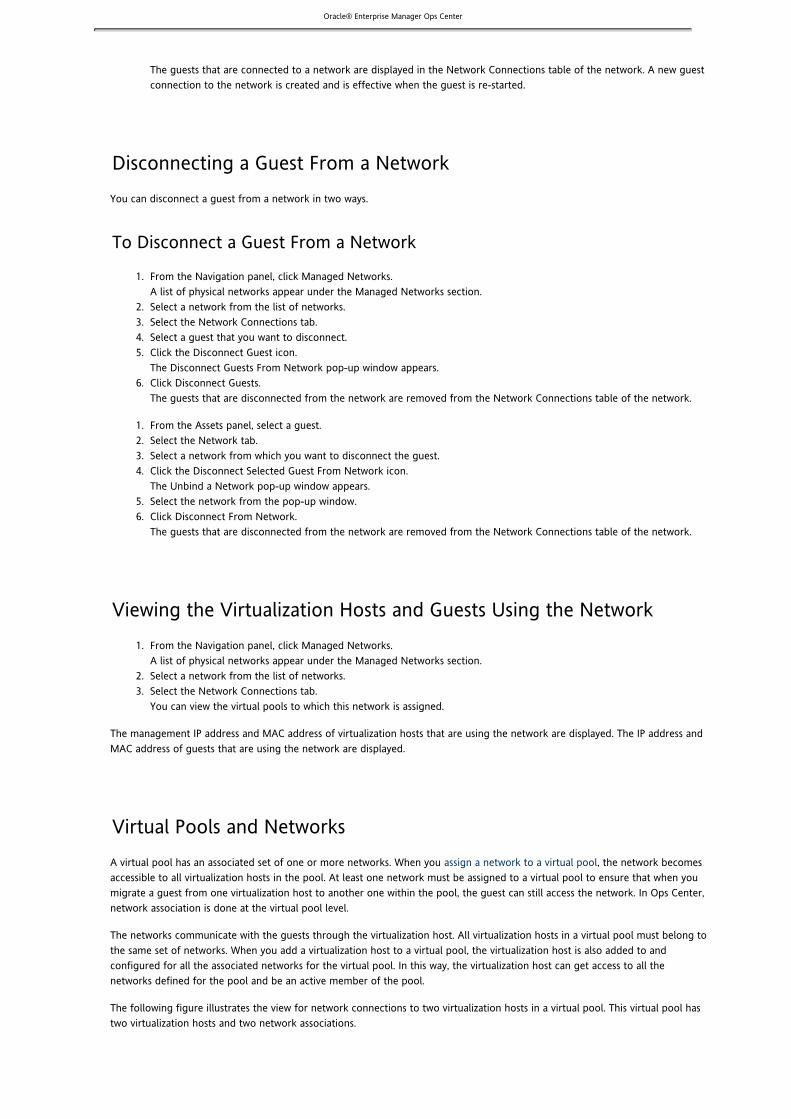
Oracle® Enterprise Manager Ops Center
5.
1.
2. 3. 4. 5.
6.
1. 2. 3. 4.
5. 6.
1.
2. 3.
The guests that are connected to a network are displayed in the Network Connections table of the network. A new guestconnection to the network is created and is effective when the guest is re-started.
Disconnecting a Guest From a NetworkYou can disconnect a guest from a network in two ways.
To Disconnect a Guest From a Network
From the Navigation panel, click Managed Networks.A list of physical networks appear under the Managed Networks section.Select a network from the list of networks.Select the Network Connections tab.Select a guest that you want to disconnect.Click the Disconnect Guest icon.The Disconnect Guests From Network pop-up window appears.Click Disconnect Guests.The guests that are disconnected from the network are removed from the Network Connections table of the network.
From the Assets panel, select a guest.Select the Network tab.Select a network from which you want to disconnect the guest.Click the Disconnect Selected Guest From Network icon.The Unbind a Network pop-up window appears.Select the network from the pop-up window.Click Disconnect From Network.The guests that are disconnected from the network are removed from the Network Connections table of the network.
Viewing the Virtualization Hosts and Guests Using the NetworkFrom the Navigation panel, click Managed Networks.A list of physical networks appear under the Managed Networks section.Select a network from the list of networks.Select the Network Connections tab.You can view the virtual pools to which this network is assigned.
The management IP address and MAC address of virtualization hosts that are using the network are displayed. The IP address andMAC address of guests that are using the network are displayed.
Virtual Pools and NetworksA virtual pool has an associated set of one or more networks. When you , the network becomesassign a network to a virtual poolaccessible to all virtualization hosts in the pool. At least one network must be assigned to a virtual pool to ensure that when youmigrate a guest from one virtualization host to another one within the pool, the guest can still access the network. In Ops Center,network association is done at the virtual pool level.
The networks communicate with the guests through the virtualization host. All virtualization hosts in a virtual pool must belong tothe same set of networks. When you add a virtualization host to a virtual pool, the virtualization host is also added to andconfigured for all the associated networks for the virtual pool. In this way, the virtualization host can get access to all thenetworks defined for the pool and be an active member of the pool.
The following figure illustrates the view for network connections to two virtualization hosts in a virtual pool. This virtual pool hastwo virtualization hosts and two network associations.

Oracle® Enterprise Manager Ops Center
1. 2. 3.
4. 5. 6.
7. 8.
1. 2. 3. 4.
5.
Assigning a Network to Virtual PoolsWhen you , you can assign the network to virtual pools through the Manage New Network wizard. If you want tocreate a networkassign this network to different virtual pools after the network has been created, use this procedure.
If you want to assign a network to global zones, see .Assigning Networks to a Global Zone
To Assign a Network to Virtual Pools
From the Assets panel, click Managed Networks.Select a network that you want to assign to virtual pools.From the Actions panel, click Assign Network to VPool.The Attach a Network to VPool wizard appears.In the Network Identification screen of the wizard, select the virtual pools to which you want to assign this network.Click Next.In the Specify NICs screen, specify the NICs and management interface for each virtualization host in the selected virtualpools.Each NIC drop-down list displays all the NICs available in the system.For the management interface, you can either use a static IP or get the IP address assigned by DHCP.If you select Use Static IP from the Management Interface drop-down list, type the IP address of the managementinterface in the Mgmt Int. IP/DHCP Client ID field.If you select Assign By DHCP from the Management Interface drop-down list, the DHCP client ID is automaticallygenerated and displayed in the Mgmt Int. IP/DHCP Client ID field.In the Summary screen of the wizard, review the selections that you made.Click Save.
When a network is assigned to virtual pools, the network details are displayed in the Networks tab for the corresponding virtualpools.
Dissociating a Network from a Virtual PoolFrom the Assets drop-down list, select Virtual Pools.Select the appropriate virtual pool.Select the Networks tab.Select the network that you want to dissociate from the virtual pool.

Oracle® Enterprise Manager Ops Center
5.
1. 2. 3.
1. 2.
3.
1. 2.
3.
Click the Unbind Network from Virtual Pool icon.The selected network will be dissociated from the virtual pool.
Viewing the Networks in a Virtual PoolFrom the Assets drop-down list, select Virtual Pools.Select a virtual pool for which you want to view the networks.Select the Networks tab for the virtual pool.The networks that are present in a virtual pool are displayed. Network details such as network name, network IP,netmask, and description are displayed in a table.
Enterprise Controller AdministrationThe Enterprise Controller is the core of Ops Center. It generates the browser user interface, routes commands from the user tothe proper Proxy Controller, and communicates with Sun and other external data sources.
Configuring the Local AgentThe Local Agent is the Agent software installed on the Enterprise Controller system. Configuring the Local Agent lets you monitorthe system that supports the Enterprise Controller and launch jobs that target it.
Jobs that would cause the Enterprise Controller system to restart cannot be performed.
To Configure the Local Agent
Click the Enterprise Controller in the Administration section of the Navigation panel.Click Configure Local Agent in the Actions panel.A confirmation window is displayed.Click Ok.A job is launched to configure the local Agent.
Unconfiguring an Enterprise ControllerUnconfiguring an Enterprise Controller removes user, authentication, and configuration data and unregisters the EnterpriseController from Sun Inventory. Data about Proxy Controllers and managed systems is retained.
You can unconfigure an Enterprise Controller to reconfigure it or as a precursor to uninstalling.
To Unconfigure an Enterprise Controller
Click the Enterprise Controller in the Administration section of the Navigation panel.Click Unconfigure in the Actions panel.A confirmation window is displayed.Click Unconfigure.
The page Downloads does not exist.The page Upgrading the Enterprise Controller does not exist.

Oracle® Enterprise Manager Ops Center
1. 2.
3.
4.
1. 2.
3.
4.
5.
1. 2.
3. 4.
Adding a Product AliasIn some cases, an asset's type will not be recognized properly. In these cases, you can add a product alias to ensure that an assetis properly recognized by Ops Center and that all of its features are available.
Note – This feature should be used as directed by Sun Support Services.
To Add a Product Alias
Click the Enterprise Controller in the Administration section of the Navigation panel.Click Add Product Alias in the Actions panel.The Add Product Alias window is displayed.Enter the Product Alias information.
Product Alias – This is the existing asset name.Product ID – This is the full product ID number.If a Product Label is supplied, the Product ID is optional.Product Label – This is the original factory label for the asset.If a Product ID is supplied, the product Label is optional.
Click Add Product Alias.The alias is added to the Enterprise Controller.
Changing the HTTP ProxyIf your Enterprise Controller accesses the Internet through an HTTP proxy, you can edit the HTTP proxy information.
To Change the HTTP Proxy
Click the Enterprise Controller in the Administration section of the Navigation Panel.Click Change HTTP Proxy in the Actions panel.The Change HTTP Proxy wizard is displayed.Enter the HTTP proxy information, including Proxy and port number. If the HTTP proxy requires authentication, check theAuthenticating HTTP Proxy box and enter a user name and password for the HTTP proxy.Click Next.The Summary page is displayed.Click Finish.The HTTP proxy information is updated.
AuthenticationsAuthentications are necessary to download content such as updates from SunSolve or third-party sites.
You can add or edit authentications to access additional external resources.
To Edit Authentications
Click the Enterprise Controller in the Administration section of the Navigation Panel.Click Edit Authentications in the Actions panel.The Edit Authentications window is displayed.Edit one or more of the authentications by editing the description, user name, and password.Click Submit.A job is launched to update the authentications.

Oracle® Enterprise Manager Ops Center
1. 2.
1.
2.
3.
The page Connection Mode does not exist.
Configuring an Enterprise Controller for UpdatesConfiguring a Ops Center Enterprise Controller to receive automatic software updates is optional.
Caution – Carefully consider if you want to enable software updates for your Enterprise Controller, because many softwareupdates will cause the Enterprise Controller to reboot or run in single-user mode.
Configuring a Ops Center Enterprise Controller to receive automatic software updates requires the following two steps:
The Proxy Controller that was automatically installed on the Enterprise controller must be configured and enabled.A Ops Center agent must be manually enabled on the Enterprise Controller.
If the co-located Proxy Controller was enabled during the initial Enterprise Controller configuration, you do not need to manuallyenable the Proxy Controller. Refer to the page for more information about enabling the ProxyEnterprise Controller ConfigurationController during initial configuration.
If the co-located Proxy Controller was not enabled during the initial Enterprise Controller configuration, you must manuallyenable the Proxy Controller before you enable the Ops Center agent on the Enterprise Controller.
Before You Begin
To supply the and command arguments that these procedures require, you need the followingproxyadm agentadm
information:
Administrative user name on the Enterprise ControllerManual Proxy Controller and agent configuration requires using an administrative user account that exists on the OpsCenter Enterprise Controller. This user account provides authentication that supports agent registration. You use this username as the argument for the and options.proxyadm -u agentadm -u
Password for the administrative user name on the Enterprise ControllerIn this procedure, you use this password to populate the file. You then use this file name as/var/tmp/xVM/mypasswd
the argument for the and options.proxyadm -p agentadm -p
IP address or host name of the Proxy Controller with which you will associate the agentYou use this IP address or host name as the argument for the option. For these procedures, the IPagentadm -x
address or host name of the Proxy Controller is the same as those of the Enterprise Controller. Both of these services runon the same system. Use this same information for the option.proxyadm -s
The example commands in this procedure use the alternative administrative user name . In this example, the userdroot droot
exists on the Enterprise Controller associated with this Ops Center installation.
Manually Enabling the Co-Located Proxy Controller
Perform this procedure on the Enterprise Controller.
Perform this procedure only if the co-located Proxy Controller is not yet configured on the Enterprise Controller.
If you designated an alternative administrator of the Ops Center Enterprise Controller, use the same user name to register yourProxy Controller with the Enterprise Controller. Otherwise, use the user to register the co-located Proxy Controller with theroot
Enterprise Controller.
Create a temporary directory, for example, , to hold the password file that you will create in this/var/tmp/xVM
procedure.
# mkdir -p / /tmp/xVMvar
Create an empty file named , and set its permission mode to 400./var/tmp/xVM/mypasswd
# touch / /tmp/xVM/mypasswdvar# chmod 400 / /tmp/xVM/mypasswdvar
Edit the file so that it contains the password of the user that you designated as the/var/tmp/xVM/mypasswd

Oracle® Enterprise Manager Ops Center
3.
4.
5.
1.
2.
3.
administrator of your Ops Center Enterprise Controller. The following command appends the password to the echo
file. (Replace with the correct password.) For example:/var/tmp/xVM/mypasswd password
# echo 'password' > / /tmp/xVM/mypasswdvar
Use the command to register the co-located Center Proxy Controller with the Enterprise Controller.proxyadm
Solaris OS: Use the command./opt/SUNWxvmoc/bin/proxyadm
RHEL OS: Use the command./opt/sun/xvmoc/bin/proxyadm
The example command below uses the following options:
-s – Specifies the host name of the Enterprise Controller with which to register the ProxyController. In this case, the host name is that of the current system.
– Specifies the user that you designated as the administrator of the Enterprise Controller.-u
– Specifies the absolute path name of the file that contains the password for the user that you-p
specified with the option.-u
Accept any certificates that might be presented. For example:
# /opt/SUNWxvmoc/bin/proxyadm configure -s amritsar.central -u droot -p //tmp/xVM/mypasswdvar
Connection registered successfully.#
For more information about the command, see the .proxyadm man pageproxyadm
Use the command to start the Ops Center Proxy Controller services.proxyadm
Solaris OS: Use the command./opt/SUNWxvmoc/bin/proxyadm
RHEL OS: Use the command./opt/sun/xvmoc/bin/proxyadm
For example:
# /opt/SUNWxvmoc/bin/proxyadm start -wproxyadm: Starting proxy with SMF...proxyadm: Proxy services have started#
Manually Enabling a Ops Center Agent
Perform this procedure on the Enterprise Controller.
Use the command to verify that the co-located Proxy Controller is online.proxyadm
The Proxy Controller must be online before you enable the Ops Center agent on the Enterprise Controller.Solaris OS: Use the command./opt/SUNWxvmoc/bin/proxyadm
RHEL OS: Use the command./opt/sun/xvmoc/bin/proxyadm
For example:
# /opt/SUNWxvmoc/bin/proxyadm statusonline#
Create an empty file named , and set its permission mode to 400./var/tmp/xVM/mypasswd
# touch / /tmp/xVM/mypasswdvar# chmod 400 / /tmp/xVM/mypasswdvar
Edit the file so that it contains the password for the administrative user that exists on the/var/tmp/xVM/mypasswd
Enterprise Controller.The following command appends the password to the file. Replace with theecho /var/tmp/xVM/mypasswd passwordcorrect password. For example:
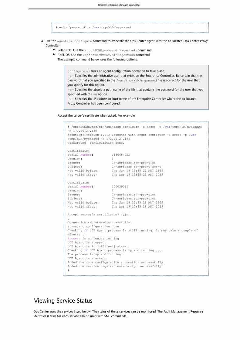
Oracle® Enterprise Manager Ops Center
3.
4.
# echo 'password' > / /tmp/xVM/mypasswdvar
Use the command to associate the Ops Center agent with the co-located Ops Center Proxyagentadm configure
Controller.Solaris OS: Use the command./opt/SUNWxvmoc/bin/agentadm
RHEL OS: Use the command./opt/sun/xvmoc/bin/agentadm
The example command below uses the following options:
configure – Causes an agent configuration operation to take place. – Specifies the administrative user that exists on the Enterprise Controller. Be certain that the-u
password that you specified in the file is correct for the user that/var/tmp/xVM/mypasswd
you specify for this option. – Specifies the absolute path name of the file that contains the password for the user that you-p
specified with the option.-u
– Specifies the IP address or host name of the Enterprise Controller where the co-located-x
Proxy Controller has been configured.
Accept the server's certificate when asked. For example:
# /opt/SUNWxvmoc/bin/agentadm configure -u droot -p / /tmp/xVM/mypasswdvar-x 172.20.27.185agentadm: Version 1.0.3 launched with args: configure -u droot -p /var/tmp/xVM/mypasswd -x 172.20.27.185 workaround configuration done.
Certificate:Serial : 1180654722NumberVersion: 3Issuer: CN=amritsar_scn-proxy_caSubject: CN=amritsar_scn-proxy_agentNot valid before: Thu Jun 19 15:45:21 MDT 1969Not valid after: Thu Apr 19 15:45:21 MDT 2029
Certificate:Serial : 200039089NumberVersion: 3Issuer: CN=amritsar_scn-proxy_caSubject: CN=amritsar_scn-proxy_caNot valid before: Thu Jun 19 15:45:18 MDT 1969Not valid after: Thu Apr 19 15:45:18 MDT 2029
Accept server's certificate? (y|n)yConnection registered successfully.scn-agent configuration done. Checking UCE Agent process is still running, it may take a couple ofifminutes ...
is no longer running ProcessUCE Agent is stopped. UCE Agent is in [offline*] state. Checking UCE Agent process is up and running ... ifThe process is up and running. UCE Agent is started. Added the zone configuration automation successfully. Added the service tags recreate script successfully. #
Viewing Service StatusOps Center uses the services listed below. The status of these services can be monitored. The Fault Management ResourceIdentifier (FMRI) for each service can be used with SMF commands.

Oracle® Enterprise Manager Ops Center
1. 2.
These services should not be disabled outside of Ops Center. To manage these services, use the , , and satadm proxyadm
commands.agentadm
To View Service Status
Click the Enterprise Controller in the Administration section of the Navigation Panel.Click the Configuration tab.The Service Status is displayed.
Service Name Fault Management Resource Identifier (FMRI) Purpose
Cacao, a common Java container forJDMX/JMX based managementsolution
svc:/application/management/common-agent-container-1:scn-proxy The managementcontainer for thejava codecontaining thebusiness logic forthe ProxyController.
Cacao, a common Java container forJDMX/JMX based managementsolution
svc:/application/management/common-agent-container-1:default The managementcontainer for thejava codecontaining thebusiness logic forthe EnterpriseController.
SCN Infrastructure report database svc:/application/scn/reportdb:default Manages thedata store forOps Centercharts andgraphs.
SCN Infrastructure database svc:/application/scn/db:default Manages thepostgresdatabase for OpsCenter.
SCN Satellite Console svc:/application/scn/console:default Service for thecontainerholding the Userinterface logic.
Virtualization Host AjaxTerm SerialConsole
svc:/application/scn/ajaxterm:default Managessoftware for theremote serialconsole feature.
Update Connection Enterprise -Scheduler
svc:/application/scn/uce-scheduler:default Handles thelaunching of jobsaccording to adefined schedule.
Update Connection Enterprise -Server
svc:/application/scn/uce-server:default Provides theinformation thatthe Agent needsto execute a job.
DHCPD svc:/application/scn/dhcpd:default Provides DHCPservices for OSProvisioning.

Oracle® Enterprise Manager Ops Center
1. 2.
1. 2.
3. 4.
5.
6.
1. 2. 3.
Viewing Agent ControllersAgent Controllers are installed on operating systems and virtualization tools managed by Ops Center. You can view them to seetheir status, their current version, and any available updates.
To View Agent Controllers
Click the Enterprise Controller in the Administration section of the Navigation panel.Click the Agent Controllers tab.Agent Controller information is displayed.
Updating Agent ControllersYou can remotely update Agent Controllers to the latest available version.
Agent files are stored in the directory. If Ops Center is operating in disconnected mode,/var/opt/sun/xvm/images/agent
Agent Controller files must be added to the directory before they can be used./var/opt/sun/xvm/images/agent
To Update Agent Controllers
Click the Enterprise Controller in the Administration section of the Navigation panel.Click the Agent Controllers tab.Agent Controller information is displayed.Select one or more Agent Controllers.Click the Update to Latest Available Version icon in the center panel.The Upgrade Agents wizard is displayed.Select an option for providing upgrade credentials.
Upgrade without requiring ssh credentials – Is only supported for Agents of at least version 2.5.Re-use SSH credentials used during discovery for the selected hosts – Uses the saved discovery criteria.Apply the same SSH credentials to all – Uses the same ssh credentials for all selected assets.Enter SSH credentials for each of the selected hosts – Uses separately entered ssh credentials for all assets.
Click Submit.A job is launched to upgrade the Agent.
Viewing LogsYou can view logs to diagnose problems or examine Ops Center activities.
Note – The update channel download log and the update channel error log will not be displayed. Select either of these logs todisplay its location.
To View Logs
Click the Enterprise Controller in the Administration section of the Navigation Panel.Click the Logs tab.Select a log from the dropdown list.
Cacao logUI logDB transaction logDB report logProxy logUpdate error logUpdate channel download logUpdate channel error log

Oracle® Enterprise Manager Ops Center
3.
4.
1. 2.
3.
a.
4.
1. 2.
3.
The log is displayed.(Optional) Click Refresh Log File to refresh the displayed version of the log file.
Proxy Controller AdministrationThe Proxy Controller carries out commands from the Enterprise Controller. All Ops Center deployments have at least one ProxyController.
The Enterprise Controller has a co-located Proxy Controller, which can be enabled or disabled, and remote Proxy Controllers canalso be installed on separate systems. One Proxy Controller can manage up to 250 managed systems.
Unconfiguring and Uninstalling a Proxy ControllerUnconfiguring and uninstalling a Proxy Controller breaks its connection with the Enterprise Controller and removes the ProxyController software. All Assets discovered or managed by the Proxy Controller are removed as well.
Three methods are available for unconfiguring and uninstalling a Proxy Controller. The first two options are performed throughthe BUI.
Connect to the Proxy Controller through SSH, then command it to unregister and uninstall itself. This option can only beused if the Proxy Controller is reachable.Remove the Proxy Controller from Ops Center. This option does not uninstall the Proxy Controller. This option can beused even if the Proxy Controller is unreachable.Manually unconfigure the Proxy Controller. The Proxy Controller software must be uninstalled separately.
To Unconfigure and Uninstall a Proxy Controller
Click a Proxy Controller in the Administration section of the Navigation Panel.Click Unconfig/uninstall Proxy in the Actions panel.The Unconfigure/Uninstall Proxy Controller window is displayed.Select an Unconfiguration/Uninstallation option.
Send Job to Remote Proxy: This option sends a command to the Proxy to unconfigure and uninstall itself.Enter the privileged user name and password for the Proxy Controller. If root logon is not permitted onthe Proxy Controller, enter a non-root user name and password followed by the root user name andpassword.
Force the Removal of the Proxy from Ops Center: This will remove the Proxy Controller from Ops Center, butwill not uninstall the Proxy Controller software.
Click Unconfigure/Unregister.
To Unconfigure a Proxy Controller From the Command Line
From the command line, log in to the Proxy Controller.Use the command and the subcommand to stop the Proxy Controller. The commandproxyadm stop proxyadm
resides in the directory on a Solaris system, and in the on a Linux/opt/SUNWxvmoc/bin /opt/sun/xvmoc/bin
system. The example below uses the following option: – Wait for services to complete stopping.-w
/opt/SUNWxvmoc/bin/proxyadm stop -w
Use the command and the subcommand to unconfigure the Proxy Controller. The exampleproxyadm unconfigure
below uses the following option: – Unregisters the Proxy Controller from the Enterprise Controller.-s
/opt/SUNWxvmoc/bin/proxyadm unconfigure -s
The Proxy Controller is now unconfigured from the Enterprise Controller.

Oracle® Enterprise Manager Ops Center
1. 2.
3.
1. 2.
3.
Setting a Proxy Controller as DefaultYou can set a Proxy Controller as the default. Jobs will be completed by the default Proxy Controller wherever possible.
To Set a Proxy Controller as Default
Click a Proxy Controller in the Administration section of the Navigation Panel.Click Set as Default in the Actions panel.A popup appears, confirming that the Proxy Controller has been set as the default.Click OK.
Clearing a Proxy Controller's Default StatusYou can remove the default status from a Proxy Controller. Jobs will be completed by the proxy on the appropriate subnet.
To Clear a Proxy Controller's Default Status
Click the default Proxy Controller in the Administration section of the Navigation Panel.Click Clear Default in the Actions panel.A popup appears, confirming that the Proxy Controller is no longer the default.Click OK.
DHCP ConfigurationYou can configure and enable DHCP services on a Proxy Controller. DHCP configuration configures and enables basic DHCPservices on the Proxy Controller to support OS provisioning operations in Ops Center. The Proxy Controller must be in the samesubnet as the target hosts for OS provisioning to work.
The DHCP Config action configures and enables either a Solaris DHCP server, or an Internet Standards Consortium (ISC) DHCPserver, on the Proxy Controller that you select.
The DHCP Config action requires that you specify the Ethernet interface through which the Proxy Controller will provide DHCPservices, for example . Currently you may establish DHCP services on all the Ethernet interfaces in the proxy controller. Thebge0
Proxy Controller's Ethernet interface that you specify must be connected to the network where the target systems for OSprovisioning are connected.
Similarly, the Ethernet interface that you select in the Boot Network Device field of the Provision OS wizard must be connected tothe network where the Proxy Controller is providing DHCP services. See and OS Provisioning for a Single System OS Provisioning
for more information about the Provision OS wizard.for Multiple Systems
The DHCP Config and External DHCP Servers actions are mutually exclusive. Use only one of these two actions to configure DHCPservices to support OS provisioning operations. The DHCP Config action is more commonly used, and is simpler to implement.
The following diagram illustrates the basic DHCP configuration.

Oracle® Enterprise Manager Ops Center
1.
2.
3.
4. 5.
6.
1. 2. 3.
4.
The Provision OS wizard supplies the specific identity information that the target system requests, using the basic DHCP servicesthat you establish on the Proxy Controller.
To Configure DHCP Services
In the Administration panel, select the Proxy Controller where you want to configure DHCP services. The Actions listshows the available actions, including the DHCP Config action.Select DHCP Config in the Actions panel.The DHCP Configuration dialog box is displayed.In the DHCP Configuration dialog box, provide the following information:
DHCP Server – Select either ISC or Solaris to implement either the Internet Standards Consortium (ISC) referenceDHCP server, or the Solaris native DHCP server. The ISC server is generally preferred.Interface – Enter the Ethernet interface on the Proxy Controller where you want to provide DHCP services, forexample, . DHCP configuration is possible for multiple Ethernet interfaces in the Proxy Controller.qfe0
Enable DHCP – Select this option to enable the DHCP server that you selected.Click Save Config to save the DHCP configuration that you specified.A warning indicates that any existing subnets in the DHCP configuration will be removed. Click Yes to accept that actionand continue.A message indicates that the DHCP configuration job has been submitted. Click OK to dismiss the message.
Note – You can configure DHCP server on the Proxy Controller to listen to multiple Ethernet interfaces. For example, consider thefollowing network configuration for the Proxy Controller:
e1000g0 10.0.0.2e1000g1 192.168.1.2e1000g2 172.16.12.2
If you configure the DHCP server to listen to e1000g1 and e1000g2, then the target system must have the IP address in the rangeof 192.168.1.0/24 or 172.16.12.0/24.
To Monitor a DHCP Configuration Job
The DHCP Config action creates a job to configure DHCP services on the Proxy Controller. DHCP services are only available afterthe job completes successfully.
You can monitor the progress of the job that configures DHCP services on a Proxy Controller by listing the job in the Jobs panel.
Select the Jobs panel.Select All Jobs or In Progress from the Jobs panel, and identify the DHCP configuration job from the list that displays.Double-click the DHCP configuration job to display the Job Details panel that describes the job. The Event Log tabdisplays messages that describe the job's progress.

Oracle® Enterprise Manager Ops Center
4.
1.
2.
3.
4.
Click Close to dismiss the Job Details panel.
SubnetsYou can configure subnets to use the DHCP server on a Proxy Controller for purposes in addition to OS provisioning, or to definesubnets that are used with external DHCP servers.
Configuring subnets is required to establish the basic DHCP services that are required for OS provisioning, unless you arenotusing an external DHCP server.
Typically you would configure subnets for the following reasons:
To configure a subnet to provide IP address, DNS server, and router information to systems that may request them onthe same network where the Proxy Controller is providing basic DHCP services for OS provisioning;If you choose to configure an external DHCP server instead of configuring a DHCP server on a Proxy Controller, you mustconfigure a subnet for each network from which you might receive relayed DHCP requests.
Specifying IP Address Ranges
The Subnets action allows you to specify an IP address range that the DHCP server will assign to systems that request them. The IPaddresses that you specify in the Low IP Address and High IP Address fields for the subnet define the low and high boundaries ofthe IP address range.
The IP addresses that are within the range that you specify may not be used for OS provisioning operations. If, for example, youspecify 192.168.0.64 and 192.168.0.128 as the low and high IP addresses, you could not use any of the IP addresses within thatrange, including the low and high addresses, as values for the IP Address or IP Address Ranges fields in the Provision OS wizard.
See and for more information about the Provision OSOS Provisioning for a Single System OS Provisioning for Multiple Systemswizard.
To Configure a Subnet
In the Administration panel, select the Proxy Controller where you want to configure a DHCP subnet. The Actions listshows the available actions, including the Subnets action.Select Subnets in the Actions panel.The DHCP Subnets Configuration dialog box is displayed.In the DHCP Subnets Configuration dialog box, provide the following information:
Subnet – To create a new subnet on the selected Proxy Controller, select Create New Subnet. Select an existingsubnet from the pull-down list to modify its configuration. The Refresh button updates the list of subnets.Subnet Name – Enter the name of the subnet where you want to establish or modify DHCP services.Network – Enter the network address.Netmask – Enter the netmask for the network.Router IP Adress – Enter the IP address of the router that systems that on this subnet will use.Low IP Address – Enter the IP address to use as the lower limit of the IP address range that systems on thissubnet will use.High IP Address – Enter the IP address to use as the upper limit of the IP address range that systems on thissubnet will use.Name Server – Enter the IP addresses of the DNS servers that systems will use.Domain – Enter the names of the DNS domains that systems will use to resolve host names.
Click Create Subnet to create the subnet configuration that you specified. A message indicates that a job to create thesubnet was submitted. Click OK to dismiss the message.
External DHCP ServersOps Center enables you to use DHCP servers that are external to Proxy Controllers to provide the DHCP services that OSprovisioning operations require.

Oracle® Enterprise Manager Ops Center
The DHCP Config and External DHCP Servers actions are mutually exclusive. Use only one of these two actions to configure DHCPservices to support OS provisioning operations. The DHCP Config action is more commonly used, and is simpler to implement.
The following diagram illustrates DHCP configuration using External DHCP servers.
You run the script on the External DHCP server to establish communication between the Proxyscinstall_ext_dhcp.pl
Controller and the External DHCP server. The Subnets panel allows you to define subnets where DHCP relay traffic is expected.The External DHCP Servers panel configures the Proxy Controller to relay DHCP configuration information that the Provision OSwizard supplies. The Provision OS wizard supplies the specific identity information that the target system requests. The targetsystem makes its DHCP requests, which are relayed to the External DHCP server. The routers or other network asset that connectsthe External DHCP server to the Proxy Controller must have DHCP relay capabilities enabled.
External DHCP Server Requirements
The External DHCP Servers action is only compatible with Solaris DHCP server and not with ISC DHCP server.
Before You Begin
Configuring External DHCP servers requires the following prerequisite work:
You must establish DHCP relay or forwarding services on the network routers, switches, or systems that comprise yournetwork. Refer to the documentation for those components for the required procedures.You must use the script to establish the communication channel between a Proxyscninstall_ext_dhcp.pl
Controller and the External DHCP server. The script enables access to the DHCPscninstall_ext_dhcp.pl ssh
server without requiring passwords.

Oracle® Enterprise Manager Ops Center
1.
2.
3.
1.
2.
3.
4.
To Install the Script on the External DHCPscninstall_ext_dhcp.pl
Server
You need to use to get the script from the Proxy Controller to the External DHCP server.wget scninstall_ext_dhcp.pl
On the external DHCP server, execute the following command to get the script from thescninstall_ext_dhcp.pl
Proxy Controller.
# wget http://proxy_ip:8004/pub/scninstall_ext_dhcp.pl
Where proxy_ip is the IP address of the Proxy Controller.
Grant execute permissions for the script.
# chmod +x scninstall_ext_dhcp.pl
Install the script as user.root
# ./scninstall_ext_dhcp.pl install
This will perform the following actions:
Sets up user.scnospadmin
Downloads the package from the proxy directory.SUNWscnosp-extdhcp
Sets up the configuration file for limited commands to run from user.scnospadmin
Sets up keys to allow commands from the Proxy Controller to the external DHCP server without requiringssh ssh/scp
passwords.
Note – Ensure that you use to copy the script from the Proxy Controller to another externalwget scninstall_ext_dhcp.pl
DHCP server.
To Configure External DHCP Servers
In the Administration panel, select the Proxy Controller where you want to configure an external DHCP server. TheActions list shows the available actions, including the External DHCP Servers action.Select External DHCP Servers in the Actions panel.The External DHCP Servers Configuration dialog box is displayed.In the External DHCP Servers Configuration dialog box, provide the following information:
DHCP Server – To create a new DHCP server on the selected Proxy Controller, select Create New DHCP Server.Select an existing DHCP server from the pull-down list to modify its configuration. The Refresh button updatesthe list of DHCP servers.Subnet Name – Enter the name of the subnet where you want to establish or modify DHCP services.DHCP Server – Select Solaris to implement the Solaris native DHCP server.DHCP Server IP – Enter the IP address of the DHCP server.Network – Enter the network address where you want to establish or modify DHCP services.Netmask – Enter the netmask for the network where you want to establish or modify DHCP services.Router IP Adress – Enter the IP address of the router that the DHCP server will assign to systems.Low IP Address – Enter the IP address to use as the lower limit of the IP address range that the DHCP server willallocate to systems.High IP Address – Enter the IP address to use as the upper limit of the IP address range that the DHCP server willallocate to systems.Name Server – Enter the IP addresses of the DNS servers that systems will use.Domain – Enter the names of the DNS domains that systems will use to resolve host names.
Click Create DHCP Server to create the DHCP server configuration that you specified. A message indicates that a job tocreate the external DHCP server was submitted. Click OK to dismiss the message.

Oracle® Enterprise Manager Ops Center
1. 2.
1. 2.
Viewing a Proxy Controller's ConfigurationYou can view the configuration of a Proxy Controller, including:
IP AddressRegistration DateStatus (Online or Offline)Whether or not the Proxy Controller is the default
To View a Proxy Controller's Configuration
Click the Proxy Controller in the Administration section of the Navigation Panel.Click the Configuration tab in the Center panel.The Proxy Controller's configuration is displayed.
Backup and RecoveryYou can create a backup of your Enterprise Controller which can be used to facilitate disaster recovery.
Backing Up an Enterprise ControllerThe command enables you to back up and restore the Enterprise Controller, but it does not back up or restore thesatadm
proxy. The backup command temporarily shuts down the Enterprise Controller functionality before backing up the data, saves theback up data in a tar file, and then restarts the Enterprise Controller. You can specify the name and location of the backup fileand the log file. For information about the supported flags and other information about the command, see the satadm satadm
man page.
Note – The backup command does not back up the directory. This is intentional,satadm /var/opt/sun/xvm/images/os
because the size of some of the files can be prohibitively large, such as those found under the sub-directory./iso
In addition to running the command, you should also back up the satadm back up /var/opt/sun/xvm/images/os
directory and manually archive the files to another server, file-share facility, or a location outside of the /var/opt/sundirectory.
If you have already stored exact copies of the ISO images elsewhere, such as the location from which the ISO's were originallyimported into Ops Center, you can exclude the ISO images matched by the
when making the manual archive. The ISO signature files, which are/var/opt/sun/xvm/images/os/iso/DISTRO*.iso
matched by should be archived along with all other files from the /var/opt/sun/xvm/images/os/iso/DISTRO*.sig
(possibly excluding the .)/var/opt/sun/xvm/images/os hierarchy os/DISTRO*.iso's
To Back Up an Enterprise Controller
This procedure describes the steps required to back up the Ops Center Enterprise Controller. The back up cannot be used tomigrate an Enterprise Controller to a new configuration.
By default, the server data is saved in a backup file in the directory with a file name that includes a date and time/var/tmp
stamp. You can define the file name and location during the backup, as shown in the example below. To use additional options,see the man page.satadm
From the command line, log in to the Enterprise Controller system.Use the command to shut down the co-located Proxy Controller. The command resides in the proxyadm proxyadm
directory on a Solaris system, and in the on a Linux system. For/opt/SUNWxvmoc/bin /opt/sun/xvmoc/bin
example:

Oracle® Enterprise Manager Ops Center2.
3.
4.
1. a.
b.
2.
3.
./proxyadm stop
Use the command with the subcommand to back up the Enterprise Controller. The commandsatadm backup satadm
resides in the directory on a Solaris system, and in the on a Linux/opt/SUNWxvmoc/bin /opt/sun/xvmoc/bin
system. The example below uses the following flag: – Indicate the directory location of the backup file.-o
./satadm backup -o / /tmp/backup-file-name.tarvar
Use the command to restart the co-located Proxy Controller. For example:proxyadm
./proxyadm start
Restoring an Enterprise ControllerOnce you have created a backup of an Enterprise Controller, you can use that backup to restore it.
Note – The commands do not back up or restore the directory. This is intentional,satadm /var/opt/sun/xvm/images/os
because the size of some of the files can be prohibitively large, such as those found under the sub-directory./iso
In the event that it is necessary to completely rebuild the Ops Center Enterprise Controller, you must manually restore the hierarchy from the user-created archive after the job has completely/var/opt/sun/xvm/images/os satadm restore
finished.
If the were excluded from the user-created archive, then you will need/var/opt/sun/xvm/images/os/iso/DISTRO*.iso
to copy in the exact ISO images from elsewhere and named according to the saved files that must also be restored to the /var/opt/sun/xvm/images/os/iso/DISTRO*.sig
directory./var/opt/sun/xvm/images/os/iso
To Restore an Enterprise Controller
This procedure describes the steps required to restore the data from the backup file, which is the archive created by the satadmbackup operation.
The restore can only be performed on a freshly installed Enterprise Controller prior to configuration.If you are restoring the backup on a new system, then the IP address, host name, and Enterprise Controllersoftware version of the restored system must match that of the backed up system.If you are restoring the backup on the same system, uninstall and reinstall the Enterprise Controller softwarebefore running the command. Change directory to where the installer script resides, and run the restore
command. The Solaris SPARC?, Solaris x86, and Linux installation archives place the installer scriptuninstall
in the , , and SunOS_sparc/Product/installer SunOS_i386/Product/installer
directories, respectively. Each archive only contains the script that isLinux_i686/Product/installer
appropriate for its intended OS and platform. For example, type the following to run the Solaris OS SPARCuninstall script:
# cd / /tmp/xVMSunOS_sparc/Product/installervar# ./install -e
Install the Enterprise Controller.Solaris OS: Installing an Enterprise Controller on a Solaris SystemLinux OS: Installing an Enterprise Controller on a Linux SystemDo not configure the Enterprise Controller. The command will restore your configuration settings.restore
– The Enterprise Controller version must match the version that was backed up.Note

Oracle® Enterprise Manager Ops Center
3. a. b.
4.
5.
6.
1. 2.
1. 2.
3.
Change to the directory where the file is located on your system.satadm
On Solaris systems, go to the directory./opt/SUNWxvmoc/bin/
On Linux systems, go to the directory./opt/sun/xvmoc/bin/
Enter the command with the subcommand. The flag is required to restore the data from thesatadm restore -i
backup file. To use additional options, see the man page.satadm
./satadm restore -i backup-directory-location/file-name
For an Enterprise Controller with a co-located Proxy Controller, restart the co-located Proxy Controller using the command. The command is in the same directory as the command.proxyadm proxyadm satadm
./proxyadm start -w
For an Enterprise Controller with a co-located Proxy Controller, use the method to rediscover theCustom Discoverysystem after running the command. You do not need to re-register the assets.restore
– After restoring the Enterprise Controller, the asset details might take several minutes to display completely in theNoteuser interface.
Example - Restoring a Backup File for an Enterprise Controller Running on a SolarisOS
In this example, the command includes flags to set the restore in verbose mode ( ), and to create a restore log ( )restore -v -l
for debugging purposes. The input ( ) specifies the backup file location.-i
# /opt/SUNWxvmoc/bin/satadm restore -v -i / /tmp/xVM/server1/backup-May28-2008.tar -lvar/ /tmp/xVM/server1/logfile-restore-May28-2008.logvar
User and Role ManagementYou can add users to Ops Center from the local authentication subsystem of the Enterprise Controller's operating system. Eachuser can be given a different role which grants or denies access to the different functions of Ops Center.
To View Users and Roles
Select Administration from the Navigation panel.Click either the Users tab or the Roles tab.The Users tab displays the list of known users.The Roles tab displays the role of any specified user and the authorizations granted by that role.
Adding a UserUsers with admin privileges can add other users to the list of users recognized by Ops Center. New user information, such as thepasswords for new users, will be pulled from the local authentication subsystem.
To Add a User
Select Administration in the Navigation panel.Click the Users tab.The Users page is displayed.Click the Add User icon.

Oracle® Enterprise Manager Ops Center
3.
4. 5.
1. 2.
3. 4.
5.
The Add User window is displayed.Enter the user name.Click Add User.The new user is created.
Deleting a UserA user with admin rights can delete other users, removing the user and their role from Ops Center.
To Delete a User
Select Administration in the Navigation panel.Click the Users tab.The Users page is displayed.Select the user that you want to delete.Click the Delete User icon.The Delete User window is displayed.Click Confirm.The user is deleted.
Roles and AuthorizationsRoles grant users the ability to use the different functions of Ops Center. By giving a role to a user, an administrator can controlwhat functions are available to that user on specific assets and groups.
Each role grants a user a specific set of authorizations. To perform a job, you must have the correct role for the assets or grouptargeted by the job. Administrators can grant roles to a user that cover the following assets or groups:
Enterprise ControllerAll Assets groupUser-created groups
– Subgroups inherit the roles assigned to the parent group.Note
Roles and Authorization for users are shown in this image.

Oracle® Enterprise Manager Ops Center
Enterprise Controller Admin Role
The Enterprise Controller Admin role grants root access to Ops Center. A user with the Enterprise Controller Admin role canperform asset discovery, perform administration actions on Ops Center, add new users, and edit roles. When Ops Center isconfigured, the privileged user is automatically given this role. At least one user must have this role.
All Assets Admin Role
A user with the All Assets Admin role can perform any action, including provisioning, updating, and managing, on any asset orgroup. When Ops Center is configured, the privileged user is automatically given this role.
Group Roles
An Enterprise Controller Admin can grant one or more of these roles to any user for any user-defined group:
Content Description
Group Admin This role allows the user to use administration actions such as adding or removing assets.
Group Provision This role allows the user to provision new operating systems and firmware.
Group Update This role allows the user to do patching.
Group Update Simulate This role allows the user to run simulated update jobs.
Group Manage This role allows the user to use management and monitoring actions.
Group Admin
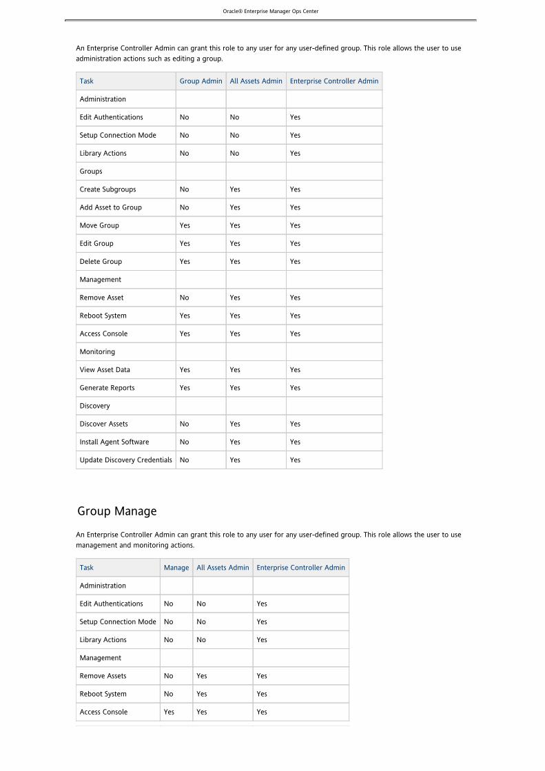
Oracle® Enterprise Manager Ops Center
An Enterprise Controller Admin can grant this role to any user for any user-defined group. This role allows the user to useadministration actions such as editing a group.
Task Group Admin All Assets Admin Enterprise Controller Admin
Administration
Edit Authentications No No Yes
Setup Connection Mode No No Yes
Library Actions No No Yes
Groups
Create Subgroups No Yes Yes
Add Asset to Group No Yes Yes
Move Group Yes Yes Yes
Edit Group Yes Yes Yes
Delete Group Yes Yes Yes
Management
Remove Asset No Yes Yes
Reboot System Yes Yes Yes
Access Console Yes Yes Yes
Monitoring
View Asset Data Yes Yes Yes
Generate Reports Yes Yes Yes
Discovery
Discover Assets No Yes Yes
Install Agent Software No Yes Yes
Update Discovery Credentials No Yes Yes
Group Manage
An Enterprise Controller Admin can grant this role to any user for any user-defined group. This role allows the user to usemanagement and monitoring actions.
Task Manage All Assets Admin Enterprise Controller Admin
Administration
Edit Authentications No No Yes
Setup Connection Mode No No Yes
Library Actions No No Yes
Management
Remove Assets No Yes Yes
Reboot System No Yes Yes
Access Console Yes Yes Yes

Oracle® Enterprise Manager Ops Center
Monitoring
View Asset Data Yes Yes Yes
View Asset Jobs Yes Yes Yes
Generate Reports No Yes Yes
Group Provision
An Enterprise Controller Admin can grant this role to any user for any user-defined group. This role allows the user to provisionnew operating systems and firmware.
Task Provision All AssetsAdmin
Enterprise ControllerAdmin
Administration
Edit Authentications No No Yes
Setup Connection Mode No No Yes
Library Actions No No Yes
Profiles and Policies
Create Profile/Policy No Yes Yes
Save Profile/Policy from job No, even if you have permissions on theoriginal profile/policy
Yes Yes
Edit Profile/Policy Yes, if you have the admin role forprofile/policy
Yes Yes
Delete Profile/Policy Yes, if you have the admin role forprofile/policy
Yes Yes
View Profile/Policy Yes Yes Yes
View Profile/Policy from job Yes Yes Yes
Provisioning
Launch Job Wizard fromAsset/Group/Profile
Yes Yes Yes
View Catalog / Catalog Compare Yes Yes Yes
Launch Job Wizard from Catalog /Catalog Compare
Yes Yes Yes
Submit Provisioning Job Yes Yes Yes
Answer questions Yes Yes Yes
Rerun job Yes Yes Yes
Launch Copy Job wizard Yes Yes Yes
Group Update
An Enterprise Controller Admin can grant this role to any user for any user-defined group. This role allows the user to installoperating system patches and product updates.

Oracle® Enterprise Manager Ops Center
Task Update All AssetsAdmin
Enterprise ControllerAdmin
Administration
Edit Authentications No No Yes
Setup Connection Mode No No Yes
OS Update Library Actions No No Yes
Profile/Policy Management
Create Profile/Policy No Yes Yes
Save Profile/Policy from job No, even if you have permissions on theoriginal profile/policy
Yes Yes
Edit Profile/Policy Yes, if you have the admin role forprofile/policy
Yes Yes
Delete Profile/Policy Yes, if you have the admin role forprofile/policy
Yes Yes
View Profile/Policy Yes Yes Yes
View Profile/Policy from job Yes Yes Yes
Job Submission
Launch Job Wizard fromAsset/Group/Profile
Yes Yes Yes
View Catalog / Catalog Compare Yes Yes Yes
Launch Job Wizard from Catalog /Catalog Compare
Yes Yes Yes
Submit Simulation Job Yes Yes Yes
Submit Deploy Job Yes Yes Yes
Answer questions Yes Yes Yes
Rerun job Yes Yes Yes
Launch Copy Job wizard Yes Yes Yes
Reports
Save, run, and view BAR from DBReport
Yes Yes Yes
Save and view BAR from Agent Report Yes Yes Yes
Run BAR from Agent Report Yes Yes Yes
Save/Run/View Compliance Report Yes Yes Yes
Note – If you want to update multiple operating systems with a single job, you must use a homogeneous OS group as the target.See for information about how to create a group and add operating systems to the group.Using Groups
To update a Linux OS, you must provide your Red Hat or SUSE login credentials. Ops Center uses the credentials to log in to thethird-party site and download the patches or packages. To provide or update your SunSolve or third-party vendor credentials, see
.Authentications
Group Update Simulate

Oracle® Enterprise Manager Ops Center
An Enterprise Controller Admin can grant this role to any user for any user-defined group. This role allows the user to runsimulated update jobs.
Task Update Simulate All AssetsAdmin
Enterprise ControllerAdmin
Administration
Edit Authentications No No Yes
Setup Connection Mode No No Yes
OS Update Library Actions No No Yes
Profile/Policy Management
Create Profile/Policy No Yes Yes
Save Profile/Policy from job No, even if you have permissions on theoriginal profile/policy
Yes Yes
Edit Profile/Policy Yes, if you have the admin role forprofile/policy
Yes Yes
Delete Profile/Policy Yes, if you have the admin role forprofile/policy
Yes Yes
View Profile/Policy Yes Yes Yes
View Profile/Policy from job Yes Yes Yes
Job Submission
Launch Job Wizard fromAsset/Group/Profile
Yes Yes Yes
View Catalog / Catalog Compare Yes Yes Yes
Launch Job Wizard from Catalog /Catalog Compare
Yes Yes Yes
Submit Simulation Job Yes Yes Yes
Submit Deploy Job No Yes Yes
Answer questions Yes Yes Yes
Rerun job Yes Yes Yes
Launch Copy Job wizard Yes Yes Yes
Reports
Save, run, and view BAR from DBReport
Yes Yes Yes
Save and view BAR from Agent Report Yes Yes Yes
Run BAR from Agent Report Yes Yes Yes
Save/Run/View Compliance Report Yes Yes Yes
Note – If you want to update multiple operating systems with a single job, you must use a homogeneous OS group as the target.See for information about how to create a group and add operating systems to the group.Using Groups
To update a Linux OS, you must provide your Red Hat or SUSE login credentials. Ops Center uses the credentials to log in to thethird-party site and download the patches or packages. To provide or update your SunSolve or third-party vendor credentials, see
.Authentications

Oracle® Enterprise Manager Ops Center
1. 2.
3. 4. 5. 6.
7.
1. 2. 3.
4. 5.
6.
a. b. c.
a.
Assigning a RoleRoles grant users the ability to use the different functions of Ops Center. By giving a role to a user, an administrator can controlwhat functions are available to that user for specific groups. See for a list of the available roles and theirRoles and Authorizationsfunctions.
An Enterprise Controller Admin can grant users different roles for the Enterprise Controller, the All Assets group, and anyuser-defined groups. A user who is assigned a role for a group will receive the same role for all subgroups.
To Assign a Role to a User
Note – You must have the Enterprise Controller Admin role to assign roles to other users.
Select Administration in the Navigation panel.Click the Roles tab.The Roles page is displayed.Select a user from the dropdown menu.Select Enterprise Controller, All Assets, or a user-defined group.Click Edit Roles.Select the checkbox for the role or roles you want to assign.You can remove a role by un-checking the checkbox.Click Update Role Capabilities.
Configuring a Notification ProfileNotification Profiles determine how notifications are sent to a user and what levels of notifications are sent. By configuringseparate notification profiles, different users can receive specific levels of notifications through the BUI, through email, orthrough a pager.
There are four levels of notification that can be sent to a specific destination (the BUI, an email address, or a pager).
None – No notifications will be sent to the destination.Low and Higher – Low, medium, and high severity notifications will be sent to the destination.Medium and Higher – Medium and high severity notifications will be sent to the destination.High – High severity notifications will be sent to the destination.
Different levels of notifications can be sent for specific Virtualization Pools, Groups, or top-level Smart Groups.
If a user has no notification profile, all notifications (Low and Higher) for all assets will be sent to the BUI, and no notifications willbe sent to other destinations.
To Configure a Notification Profile
You can configure a new notification profile for a user or edit an existing profile.
Select Administration in the Navigation panel.Select the Enterprise Controller.Click the Users tab.The Users page is displayed.Select the user for whom you want to configure notifications.Click the Configure Notification Profile icon.The Configure Notification Profile window appears.If a Notification Profile has already been configured for the user, the existing profile is displayed.Select either Subscribe to All Notifications or Subscribe to Custom Filtered Notifications.
If you select Subscribe to All Notifications, you will receive notifications for all assets.Use the Application drop-down list to select the severity of messages to be received through the BUI.Use the Email drop-down list to select the severity of messages to be received through email.Use the Pager drop-down list to select the severity of messages to be received through a pager.
If you select Subscribe to Custom Filtered Notifications, you will receive the specified priority of notifications foreach Virtualization Pool and Group.

Oracle® Enterprise Manager Ops Center
6.
a.
b.
c. 7.
8.
9.
10.
1. 2. 3.
4. 5.
6.
1.
2.
For each Virtualization Pool, select the severity of messages to be received through the BUI, email, andpager.For each Smart Group, select the severity of messages to be received through the BUI, email, andpager.For each Group, select the severity of messages to be received through the BUI, email, and pager.
If you chose to receive notifications by email, enter an email address and mail host.The mail host specifies an external mail host through which messages are sent.If you chose to receive notifications by pager, enter a pager address and mail host.The mail host specifies an external mail host through which messages are sent.(Optional) Click More Options to view additional options.
Enter a Mail User and Mail Password to specify credentials for the mail host.Click Update Notification Profile.
Deleting a Notification ProfileNotification Profiles determine what events generate notifications for a user and how those notifications are sent to the user. If auser's notification profile is deleted, notifications of all severity levels to be sent to the BUI.
To Delete a Notification Profile
Select Administration in the Navigation panel.Select the Enterprise Controller.Click the Users tab.The Users page is displayed.Select the user whose Notification Profile you want to delete.Click the Delete Notification Profile icon.The Delete User Notification Profile confirmation window is displayed.Click Delete.The User's Notification Profile is deleted.
Job ManagementAll major tasks within Ops Center, such as asset discovery or OS provisioning, create jobs.
From the Jobs tab, you can monitor and control current and historical jobs. You can see the status of all jobs and choose to viewdetailed information about a specific job. You manage jobs by stopping, re-running, or deleting them.
To Display All Jobs
Click the Jobs panel at the bottom of the User Interface.The All Jobs list is displayed.(Optional) To view all jobs with a specific status, select the status from the Jobs tab of the Navigation panel.
For each job, the following information is displayed:
Job statusJob IDName of jobMode of jobType of jobOwner of jobDate and time when the job started or is scheduled to startElapsed time

Oracle® Enterprise Manager Ops Center
1. 2. 3.
4.
1. 2. 3.
4.
Job DetailsYou can view detailed information about a job. This information includes:
Job IDRun IDIf a job has been run multiple times, each run of the job will have a separate run ID.Job TypeStart DateElapsed TimeStatusCreation DateDescriptionMode (Simulation or Actual Run)OwnerTask Execution OrderFailure policyRecurring job status and Next Scheduled TimeList of tasksTask execution orderTask progress/resultsEvent logsEvent logs are generated by tasks as they progress.
To Display Job Details
Select Jobs in the Navigation panel.Select a job.Click View Job Details or double-click the job.The job details are displayed. The most recent run ID is displayed first.(Optional) Select a different run ID from the dropdown menu.The job details for the new run ID are displayed.
Stopping a JobYou can stop a job that is currently running. The job will end; running tasks will be interrupted and tasks that have not yet startedwill be aborted.The completion status of the job will depend on the number tasks that have completed, been interrupted, and not started.
To Stop a Job
Note – Only running jobs can be stopped.
Select Jobs in the Navigation panel.Select the job ID that you want to stop.Click the Stop Selected Jobs button.A confirmation window is displayed.Click Stop Job.The job is now stopped.
Deleting a JobDeleting a job removes it from the queue entirely. It cannot be re-run or resumed, and its job details will no longer be visible.

Oracle® Enterprise Manager Ops Center
1. 2. 3.
4.
1. 2. 3.
4.
1. 2. 3. 4.
5.
1. 2. 3.
4.
5.
To Delete a Job
Note – You cannot delete jobs that are running. See for information about stopping a running job.Stopping a Job
Select Jobs in the Navigation panel.Select the job ID or IDs that you want to delete.Click the Delete Selected Jobs button.A confirmation window is displayed.Click Delete Job.The job is now deleted.
Re-running a JobIf a job is completed, you can re-run the job, repeating the job with a new Run ID.
To Re-Run a Job
You can re-run jobs on failed targets from the Job Details window.
Select Jobs in the Navigation panel.Select the job ID or IDs that you want to re-run.Click the Re-run Selected Job button.A confirmation window is displayed.Click Run Job.The job runs again with a new Run ID.
Re-running a Job on Failed TargetsIf a job is listed as partially completed, failed, or stopped, you can re-run the job on failed targets.
To Re-Run a Job on Failed Targets
Select Jobs in the Navigation panel.Select the job that you want to re-run.Click View Job Details.Click Rerun Job on Failed Targets.A confirmation window is displayed.Click Run Job.The job is run again without creating a new Run ID.
Copying a JobYou can copy a job, using an old job as a template for a new job.
To Copy a Job
Select Jobs in the Navigation panel.Select the job that you want to copy.Click Copy Job.The New Job wizard is displayed.(Optional) Modify the job information for its new task.

Oracle® Enterprise Manager Ops Center
5. 6. 7.
1. 2. 3.
4. 5.
6.
1.
2.
Click Next.Select a schedule for the job and click Next.Review the job information and click Submit Job.The new job is submitted with a new Job ID.
Answering QuestionsSome jobs might require your input.
To Answer Questions
Select Jobs at the bottom of the browser window to display the Jobs panel.Select the job that requires input.Click Answer Questions.The Answer Pending Questions window is displayed. There may be multiple pages of questions.(Optional) Click the page icon next to a component to display the component details.Answer the pending questions. The following options are available:
Select Yes or No for each question using the buttons in the right column.Click Yes to All to set the response for every question to yes.Click No to All to set the response for every question to no.Click Reset to set the response for every question back to the default value.
Click Submit.The job will be resubmitted using the same Job ID and Run ID.
Monitoring Jobs for an AssetYou can view the current and historical jobs for a selected asset.
The current jobs category includes jobs that are currently running. The historical jobs category includes jobs that have completedwith any status.
To Monitor Jobs for an Asset
Select the asset in the Assets section of the Navigation panel.The Summary page of the selected asset is displayed in the center panel.Select the Jobs tab in the Center panel.The Jobs page is displayed. Current and Historical jobs for the selected asset, and their status, are displayed.
Notifications and ReportsNotifications and reports allow you to stay aware of changing hardware, software, and job conditions.
Notifications alert you to events, such as the discovery of new assets, a change in asset status, or the completion of a job.Notifications can be sent to the BUI, to an email address, or to a pager. Different users can be given different notification profiles,receiving what severity of messages are sent to them and by what method.
Reports allow you to gather more detailed information about operating systems and firmware.
Messages

Oracle® Enterprise Manager Ops Center
1.
1.
2. 3.
1.
2. 3.
1.
2.
3.
The Messages box at the top of the UI provides information about a number of global conditions in Ops Center.The following information appears in the Messages box:
The number of unread notificationsThe number of users logged inThe number of active systemsThe number of Virtualization Hosts being managedThe power consumption of managed servers
To View Messages
Click the arrow buttons to the left and right of the alert window.Messages will also cycle automatically.
Viewing NotificationsOps Center generates notifications for all event operations and when the set thresholds are exceeded.
You can enable or disable the notifications for a server or blade, chassis, or OS. The status of notifications for the asset isdisplayed in the asset's monitoring window.
To View Notifications
Open the notifications window.Click the notifications icon in the center panel.The messages box will also periodically show the number of unread notifications. Click this bulletin.The notifications window is displayed.
(Optional) Use the search function in the upper right section of the window to search for specific notifications.(Optional) Use the filter function in the upper right section of the window to filter the notifications. The following filtersare available:
Info: Shows only notifications that provide information.Action Required: Shows only notifications of events that require action.Show Only Unread: Shows only unread notifications.
Deleting NotificationsYou can delete any notification. You can also delete all notifications.
To Delete Specific Notifications
Click the notifications icon in the upper right section of the BUI.The notifications window is displayed.Select the notification or notifications you want to delete.Click the Delete icon.
To Delete All Notifications
Click the notifications icon in the upper right section of the BUI.The notifications window is displayed.Click the Delete All Notifications icon.A confirmation window is displayed.Click Yes.All notifications are deleted.

Oracle® Enterprise Manager Ops Center
1. 2. 3.
1. 2. 3.
1.
Enabling Asset NotificationsAssets can generate notifications when events occur.
To Enable Notifications
Select Assets in the Navigation panel.Select the specific asset for which you want to enable notifications.Choose Enable Notifications from the Actions menu.A job is submitted to enable notifications for the asset.
Disabling Asset NotificationsYou can disable notifications for an asset. Regardless of users' notification profiles, no notifications will be sent about the asset'sstatus.
To Disable Notifications
Select Assets in the Navigation panel.Select the specific asset for which you want to disable notifications.Choose Disable Notifications from the Actions menu.A job is submitted to disable notifications for the asset.
The page Upgrading Ops Center does not exist.
Uninstalling Ops Center SoftwareThese procedures describe uninstalling Ops Center Agent, Proxy Controller, and Enterprise Controller software.
Check with Sun Support Services for any additional scripts that might be available to ensure a clean removal of Ops CenterEnterprise Controller or Proxy Controller software.
To Uninstall Ops Center Agent Software
Select Assets from the Navigation panel.The All Managed Assets list in the Managed Assets tab shows the list of currently managed assets.

Oracle® Enterprise Manager Ops Center
1.
2.
3.
From the All Managed Assets list, select the managed OS instance that is currently installed on the system from whichyou want to remove the agent software.Selecting the managed OS allows you to uninstall the Ops Center agent that is currently installed.Click the Unmanage/Delete Assets icon.The Introduction panel of the Unmanage and Delete Assets wizard is displayed.

Oracle® Enterprise Manager Ops Center
3.
4.
5. 6.
Click Next.The Enter Server Credential panel is displayed.
For this example, select Use the Same SSH Credentials for All Assets Listed Below.Enter the access credentials using the following fields:
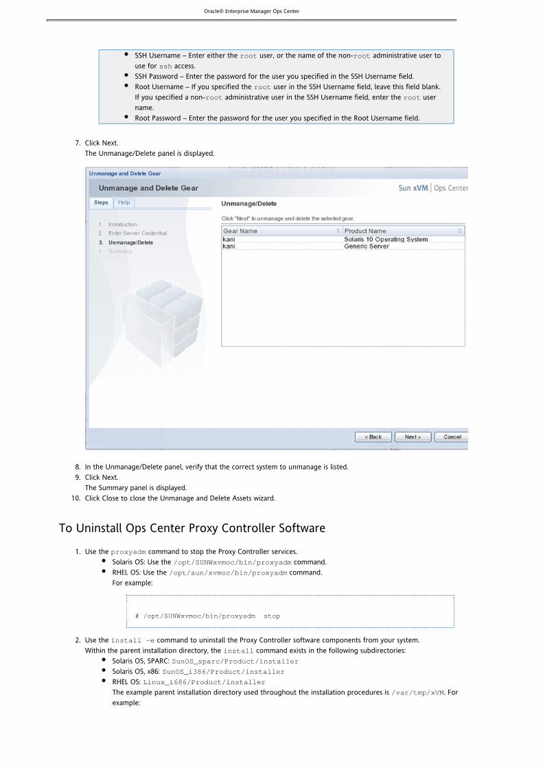
Oracle® Enterprise Manager Ops Center
6.
7.
8. 9.
10.
1.
2.
SSH Username – Enter either the user, or the name of the non- administrative user toroot root
use for access.ssh
SSH Password – Enter the password for the user you specified in the SSH Username field.Root Username – If you specified the user in the SSH Username field, leave this field blank.root
If you specified a non- administrative user in the SSH Username field, enter the userroot root
name.Root Password – Enter the password for the user you specified in the Root Username field.
Click Next.The Unmanage/Delete panel is displayed.
In the Unmanage/Delete panel, verify that the correct system to unmanage is listed.Click Next.The Summary panel is displayed.Click Close to close the Unmanage and Delete Assets wizard.
To Uninstall Ops Center Proxy Controller Software
Use the command to stop the Proxy Controller services.proxyadm
Solaris OS: Use the command./opt/SUNWxvmoc/bin/proxyadm
RHEL OS: Use the command./opt/sun/xvmoc/bin/proxyadm
For example:
# /opt/SUNWxvmoc/bin/proxyadm stop
Use the command to uninstall the Proxy Controller software components from your system.install -e
Within the parent installation directory, the command exists in the following subdirectories:install
Solaris OS, SPARC: SunOS_sparc/Product/installerSolaris OS, x86: SunOS_i386/Product/installerRHEL OS: Linux_i686/Product/installerThe example parent installation directory used throughout the installation procedures is . For/var/tmp/xVM
example:

Oracle® Enterprise Manager Ops Center
2.
1.
2.
# cd / /tmp/xVM/SunOS_sparc/Product/installervar# ./install -eInvoking uninstall
The script displays a list of uninstallation tasks that automatically updates as the uninstallationinstall
proceeds. For example:
Ops Center Satellite Server Uninstall (version 2.1.0.870 on SunOS)
1. Uninstall empty directories. [NotUninstalled] 2. Uninstall Expect. [NotUninstalled] 3. Uninstall IPMI tool. [NotUninstalled] 4. Uninstall Agent components. [NotUninstalled] 5. Uninstall application packages. [NotUninstalled] 6. Uninstall Core Channel components. [NotUninstalled] 7. Uninstall Proxy Server components. [NotUninstalled] 8. Uninstall UCE Http proxy. [NotUninstalled] 9. Uninstall OS provisioning components. [NotUninstalled]10. Stop and delete services. [Uninstalled]
Executing current step: Uninstall OS provisioning components...
When complete, the script indicates that the Ops Center Proxy Controller has been uninstalled.install
To Uninstall Ops Center Enterprise Controller Software
Use the command to stop the Enterprise Controller services.satadm
Solaris OS: Use the command./opt/SUNWxvmoc/bin/satadm
RHEL OS: Use the command./opt/sun/xvmoc/bin/satadm
For example:
# /opt/SUNWxvmoc/bin/satadm stopsatadm: Shutting down satellite using SMF...#
Use the command to uninstall the Enterprise Controller software components from your system.install -e
Within the parent installation directory, the command exists in the following subdirectories:install
Solaris OS, SPARC: SunOS_sparc/Product/installerSolaris OS, x86: SunOS_i386/Product/installerRHEL OS: Linux_i686/Product/installerThe example parent installation directory used throughout the installation procedures is . For/var/tmp/xVM
example:
# cd / /tmp/xVM/SunOS_sparc/Product/installervar# ./install -eInvoking uninstall
The script displays a list of uninstallation tasks that automatically updates as the uninstallationinstall

Oracle® Enterprise Manager Ops Center
2.
proceeds. For example:
Ops Center Satellite Server Uninstall (version 2.1.0.870 on SunOS)
1. Restore file system configuration. [NotUninstalled] 2. Uninstall empty directories. [NotUninstalled] 3. Uninstall Agent components. [NotUninstalled] 4. Remove users. [NotUninstalled] 5. Uninstall application packages. [NotUninstalled] 6. Run preremove tasks. [NotUninstalled] 7. Uninstall Expect. [NotUninstalled] 8. Uninstall IPMI tool. [NotUninstalled] 9. Destroy database. [NotUninstalled]10. Uninstall Core Channel components. [NotUninstalled]11. Uninstall Proxy Core components. [NotUninstalled]12. Uninstall Satellite Server components. [NotUninstalled]13. Uninstall Update Connection - Enterprise. [NotUninstalled]14. Uninstall xVM BUI components. [NotUninstalled]15. Uninstall OS provisioning components. [NotUninstalled]16. Stop and delete services. [Uninstalled]
Executing current step: Uninstall OS provisioning components...
When complete, the script indicates that the Ops Center Enterprise Controller has been uninstalled.install
Copyright © 2010, Oracle and/or its affiliates. All rights reserved.
This software and related documentation are provided under a license agreement containing restrictions on use and disclosureand are protected by intellectual property laws. Except as expressly permitted in your license agreement or allowed by law, youmay not use, copy, reproduce, translate, broadcast, modify, license, transmit, distribute, exhibit, perform, publish, or display anypart, in any form, or by any means. Reverse engineering, disassembly, or decompilation of this software, unless required by lawfor interoperability, is prohibited.
The information contained herein is subject to change without notice and is not warranted to be error-free. If you find any errors,please report them to us in writing.
If this is software or related software documentation that is delivered to the U.S. Government or anyone licensing it on behalf ofthe U.S. Government, the following notice is applicable:
U.S. GOVERNMENT RIGHTS Programs, software, databases, and related documentation and technical data delivered to U.S.Government customers are "commercial computer software" or "commercial technical data" pursuant to the applicable FederalAcquisition Regulation and agency-specific supplemental regulations. As such, the use, duplication, disclosure, modification, andadaptation shall be subject to the restrictions and license terms set forth in the applicable Government contract, and, to theextent applicable by the terms of the Government contract, the additional rights set forth in FAR 52.227-19, CommercialComputer Software License (December 2007). Oracle America, Inc., 500 Oracle Parkway, Redwood City, CA 94065.
This software or hardware is developed for general use in a variety of information management applications. It is not developedor intended for use in any inherently dangerous applications, including applications which may create a risk of personal injury. If

Oracle® Enterprise Manager Ops Center
you use this software or hardware in dangerous applications, then you shall be responsible to take all appropriate fail-safe,backup, redundancy, and other measures to ensure its safe use. Oracle Corporation and its affiliates disclaim any liability for anydamages caused by use of this software or hardware in dangerous applications.
Oracle and Java are registered trademarks of Oracle and/or its affiliates. Other names may be trademarks of their respectiveowners.
AMD, Opteron, the AMD logo, and the AMD Opteron logo are trademarks or registered trademarks of Advanced Micro Devices.Intel and Intel Xeon are trademarks or registered trademarks of Intel Corporation. All SPARC trademarks are used under licenseand are trademarks or registered trademarks of SPARC International, Inc. UNIX is a registered trademark licensed through X/OpenCompany, Ltd.
This software or hardware and documentation may provide access to or information on content, products, and services from thirdparties. Oracle Corporation and its affiliates are not responsible for and expressly disclaim all warranties of any kind with respectto third-party content, products, and services. Oracle Corporation and its affiliates will not be responsible for any loss, costs, ordamages incurred due to your access to or use of third-party content, products, or services.


