Joining of Large Components in a Harsh Environment
64
Recognized under application of the Decree of 30 January 1947 1 J1 Joining of Large Components in a Harsh Environment Research report for the Vanguard Initiative ADMA Energy Pilot – Challenges and outlook date 27-11-2019 version v1.1 reference ADMA Energy Research Report for Joining of Large Components © copyright Sirris author Jeroen Tacq contact [email protected] +32 493 31 06 44 Antwerpen Technologiepark – Zwijnaarde 48 Brussel-Bruxelles BE-9052 Zwijnaarde Charleroi tel. : +32 9 395 06 97 Gent fax : +32 9 345 13 78 Hasselt [email protected] Kortrijk www.sirris.be Leuven Liège
Transcript of Joining of Large Components in a Harsh Environment
Recognized under application of the Decree of 30 January 1947 1
J1
Joining of Large Components in a
Harsh Environment Research report for the Vanguard Initiative ADMA Energy
Pilot ndash Challenges and outlook
date 27-11-2019
version v11
reference ADMA Energy Research Report for Joining of Large Components
copy copyright Sirris
author Jeroen Tacq
contact Jeroentacqsirrisbe
+32 493 31 06 44
Antwerpen Technologiepark ndash Zwijnaarde 48
Brussel-Bruxelles BE-9052 Zwijnaarde
Charleroi tel +32 9 395 06 97
Gent fax +32 9 345 13 78
Hasselt infosirrisbe
Kortrijk wwwsirrisbe
Leuven
Liegravege
copy Sirris Joining of Large Components in a Harsh Environment 2
Table of Contents
TABLE OF CONTENTS 2
1 INTRODUCTION 4
2 APPROACH AND METHODOLOGY ERROR BOOKMARK NOT DEFINED
3 REPORT SCOPE 4
4 LARGE COMPONENTS AND JOINING TECHNOLOGIES IN CURRENT DESIGNS 6
41 FIXED WIND 6 42 FLOATING WIND 13 43 TIDAL ENERGY CONVERTORS (TEC) 14 44 WAVE ENERGY CONVERTORS (WEC) 17
5 CHALLENGES IN CURRENT DESIGNS 20
51 DESIGN CHALLENGES 20 511 Large flanged joints 20 512 MPTP connection 21 513 Large bolt sizes 22 514 Modular design 22 515 Segmented blades 23 516 Blade to hub connection 23 517 Adhesive bonding 27 518 Testing and certification 28
52 UNDERSTANDING AND PREVENTING DEGRADATION 29 521 Bolted connections 29 522 Pre-load 30 523 Fatigue performance 32 524 Corrosion 33 525 Hydrogen embrittlement 37 526 Reliability database 38
53 INSPECTION AND MONITORING 38 531 Bolt inspection and monitoring 39 532 Grout inspectionmonitoring 41 533 Operational Modal Analysis 41 534 Monitoring of compositesteel joints 42 535 Cost of Monitoring 42
6 STAKEHOLDER COMPANIES 43
7 CURRENT AND PAST PROJECTS 43
8 ADMA REGIONSrsquo STRENGTHS AND INTERESTS 47
9 TEST SITES 49
10 FUNDING OPPORTUNITIES AND GABS 51
11 IDEAS FOR COLLABORATIVE PROJECTS 54
111 BOLTED CONNECTIONS 54 1111 Pre-load 54 1112 Bolt degradation in a maritime environment 55 1113 Large flanged joint 57 1114 Submerged bolted connections 58
112 COMPOSITESTEEL JOINT 58 113 ADHESIVE BONDING 60 114 RELIABILITY DATABASE FOR JOINTS 61
copy Sirris Joining of Large Components in a Harsh Environment 3
12 RECOMMENDATIONS AND FURTHER ACTIONS 62
APPENDIX A ndash BIBLIOGRAPHY 63
APPENDIX B ndash STAKEHOLDER COMPANIES ERROR BOOKMARK NOT DEFINED
copy Sirris Joining of Large Components in a Harsh Environment 4
1 Introduction Joining of large components in renewable energy devices has been identified by the ADMA Energy pilot as a potential topic for research development and demonstration within a European collaboration ADMA Energy is a pilot project of the European Vanguard Initiative in Advanced Manufacturing for Energy-Related Applications in Harsh Environments The aim of this report which has been ordered by the ADMA Energy pilot is to assess the state of the art in order to identify key issues challenges existing projects lessons learned and potential for future collaboration on research and demonstration projects ADMA aims to support companies across the entire Offshore Renewable Energy (ORE) value chain by initiating collaborative research and demonstration projects related to the joining of large components in ORE devices The information contained in this report should allow ADMA to assess the possibility to launch one or more research andor demonstration projects as well as provide the necessary information to define a project scope and partnership or specify which further actions are needed in order to obtain this information The three main chapters of this report are
- Chapter 3 Large components and joining technologies in current designs - Chapter 4 Challenges in current designs - Chapter 10 Ideas for Collaborative projects
In chapter 3 an overview is given of the different offshore renewable energy technologies and what the focus points are in terms of joining technology Chapter 4 takes a closer look at the specific challenges related to joining of large components in a harsh environment In chapter 10 the challenges are translated into ideas for collaborative projects Supporting information to establish collaborative projects is contained in the other chapters This includes information about possible partners throughout the ADMA regions potential test sites and funding opportunities The report is concluded in chapter 11 with a short recommendation on which projects could be taken forward within the ADMA Energy pilot These are the authorsrsquo own suggestions and are meant to serve as a starting point for a discussion within the ADMA Energy pilot
2 Report Scope Devices under study
Fixed and floating wind Wave and tidal energy
Type of joints Bolted connections Adhesive bonding Alternative mechanical connections (eg slip joint grouting)
Materials Metallic materials (Focus on Construction steel and Stainless steel) Fibre reinforced composites Technical challenges
Design challenges Understanding and preventing degradation (combined mechanical and environmental loading)
Inspection and monitoring Definition of large components joining
Focus on components where joint failure has a critical impact on structural integrity and device functionality ie a critical impact on system level
Welding and the connection of mooring lineschains have been excluded from the scope of this report Welding technology and the study of the fatigue performance of welds in a harsh environment is an entire field of study on its own which requires specific expertise and knowledge It was not possible to include this within the scope of work The connection of mooring lineschains has also not been considered as this is a very specific technology and merits dedicated attention This connection will to some extent be covered in a separate research report on lsquoMooring systemsrsquo ordered by the ADMA Energy pilot
copy Sirris Joining of Large Components in a Harsh Environment 5
copy Sirris Joining of Large Components in a Harsh Environment 6
3 Large components and joining technologies in current designs In the following a high-level overview is given of which large components are being joined together and are considered in this research report Most information is available on wind energy devices as these are relatively standardised designs and all have more or less the same connections in them For floating wind and tidal energy important additional elements or major differences are discussed For wave energy the large variety in design concepts makes it difficult to give a general overview It is likely that many of the problems TEC developers encounter will be similar to the ones encountered in either wind or tidal devices It is therefore important to raise awareness about the possible challenges so that they can be addressed in an early stage of the design
31 Fixed wind
Components and joining types In this section the most important structural joints present in wind turbine devices will be identified The four main structural components of the turbine are here considered to be
bull M1 Rotor
bull M2 Nacelle
bull M3 Tower
bull M4 Substructure Each of these components is connected to another by means of a structural joint Additionally within a single main structural element there are also structural joints between subcomponents For each main component the subcomponents assembly and joints are summarised in a table In the lsquoAssemblyrsquo section the joints are indicated lsquoMJrsquo stands for main joint ie a joint that lsquoexitsrsquo the main component lsquoJrsquo stands for structural joints within the main component In the lsquoJointsrsquo section the joint type is described
Figure 1 Overview of the general design of a wind turbine rotor and nacelle1
Main component M1 Rotor
Subcomponents Blades Blade Bearings Hub Spinner (ie the cap around the hub)
Assembly J1 Blade root gt Blade Bearings J2 Blade Bearings gt Hub MJ Hub (in M1) gt Main shaft (in M2)
1 Source windenergygov
copy Sirris Joining of Large Components in a Harsh Environment 7
Joints MJ Conventionally the rotor is flange-connected to the main shaft using a single or double row of structural fasteners [6] J1 Typically M30 or M36 grade 109 bolts or studs Differing arrangements are used to provide threaded connection for fasteners connecting the blade root to the bearing A ring set into the root of the blade Inserts bonded into holes drilled in the root Inserts infused during manufacture Single or double row of ldquoIKEA-typerdquo threaded bars set perpendicular to the direction
of orientation of studs (T-bolt) -gt up to plusmn60m blades J2 Typically M30 or M36 grade 109 bolts or studs
Additional Information
The blade to hub bearing connection is the only one that is made during on-site installation
Blade root The blade root acts as the interface between the main composite section of the blade and the steel blade bearing The root of the blade must be sufficiently flat so as not to apply excessive uneven load to the blade bearing
Loading of the root-end and fasteners at the blade root is critical due to the complex geometry especially of the hub and bearing under load Development testing of root end strength is common
Generally the spinner is made from fibreglass in sections and bolted together on a galvanised steel frame
T-bolt or barrel nut connections have long been the commonly used blade root connection For larger blade lengths inserts are becoming the new standard (see section 416)
Inserts can also be infused into the root section This allows higher bolt densities and thus higher load transfer in conjunction with thinner root laminates Insert solution is relatively strong plus efficient on mass and cost Therefore higher loads go towards insert solutions [20]
Using more but smaller size bolts is preferred as this uses less material (mass amp cost) [20]
Figure 2 Wind turbine hub being installed1
1 Source By Paul Anderson CC BY-SA 20 httpscommonswikimediaorgwindexphpcurid=13457166
copy Sirris Joining of Large Components in a Harsh Environment 8
Figure 3 Fiberglass-reinforced epoxy blades of Siemens SWT-23-101 wind turbines The blade size of 49 meters[43] is in comparison to a substation behind them at Wolfe Island Wind Farm1
Figure 4 Overview of the main components in the nacelle and connection to the rotor hub
Main component M2 Nacelle
Subcomponents Bedplate Main bearing Main shaft Transfers torque from the rotor to the gearbox or for some direct drive
designs to the generator Supported at the rotor end by the main shaft bearing and at the other end either by the gearboxgenerator or separately mounted bearing [6]
Gearbox Generator Yaw Bearing
Assembly (The following is considered for a traditional high-speed drivetrain see below this table for a short overview of current innovations with an impact on the joints incorporated into the assembly [12]) J1 Gearbox gt Bedplate J2 Generator gt Bedplate J3 Generator gt Gearbox J4 Bedplate (underside) gt Yaw bearing J5 Main bearing housing gt bedplate MJ Yaw bearing (in M2) gt Tower top flange (M3)
Joints J1 Flexibly mounted J2 Flexibly mounted J3 Not a real lsquojointrsquo the coupling that connects the generator to the gearbox is able to cope with substantial misalignment J4 Typically M36 or larger grade 109 bolts or studs J5 Typically M36 or larger grade 109 bolts or studs MJ Yaw bearing connected to a flange on the top of the tower Requires a flat mounting surface so the tower flange will be machined after welding
1 Source By Z22 - Own work CC BY-SA 30 httpscommonswikimediaorgwindexphpcurid=28994238
copy Sirris Joining of Large Components in a Harsh Environment 9
Additional Information
Most of the joints within the nacelle can be realised in a workshop environment Only the yaw bearing connection is performed on-site
There are a large number of bolts in the nacellerotor or a wind turbine The total quickly amounts to a few hundred bolts
New designs of offshore turbines place a high emphasis on maintainability This is being achieved through modular designs for large components so more subcomponents can be replaced using the nacelle crane
Main shaft Forged and machined from high-grade steel such as 42CrMo4 or cast hollow from EN-GJS-400-18U-LT Different turbine concepts require quite different main shaft designs Fatigue loading is important It is critical to minimise stress concentrations [6]
Planned maintenance should typically be only on an annual basis To protect all nacelle components from corrosion the nacelle is well sealed and the
whole area is served by a local air conditioning system Many offshore wind developers are moving towards direct drive technology This
vastly improves reliability and reduces offshore maintenance
Drive train innovations with an impact on joints in the nacelle assembly [12] Three types of drive trains can be distinguished the traditional high speed drive rain a medium speed drivetrain and a direct drive system High speed drivetrain The image below illustrates the joints between major subcomponents in particular the high stiffness joint (bolted) between the main bearings and the bedplate and the flexible mounting of gearbox and generator to the bedplate
High speed drivetrain with integrated main bearing and integrated mainframe In this design the flexible mounting between gearbox and bedplate is no long present The entire assembly of main bearing and gearbox is mounted with a bolted flange to the housingbedplate
copy Sirris Joining of Large Components in a Harsh Environment 10
Medium speed drivetrain concept with integrated generator main bearing and mainframe It can be seen on the image below that the number of joints between major subcomponents as defined in the table above is further reduced In particular the generator no longer requires a flexible mounting to the bedplate
Main component M3 Tower
Subcomponents Tower sections
Assembly J1 Tower section n gt Tower section n+1
Joints J1 Bolted flange In general tower flanges of wind turbines are connected using hot-dip galvanized high strength bolting assemblies for preloading according to national or European standards [16] Sizes M36-M72 (These connections are also called tower splices)
Additional Information
Towers are manufactured by cutting and rolling steel plate welding to make typically 3m ldquocansrdquo then welding these to make tower sections of say 40m with bolted flanges each end
Tower top flanges are machined post welding to ensure top flange flatness is within tolerances required for the yaw bearing
copy Sirris Joining of Large Components in a Harsh Environment 11
Innovations in tower design could allow for the development of single section towers by 2025 allowing a more streamlined manufacturing and a reduced need for bolt inspections (lower OPEX) [10]
Main component M4 Substructures
Design types MonopileTP (plusmn80) Jacket (plusmn15) (does not have a separate TP) Gravity Base Tripod Tripile Suction Bucket (does not require a separate TP) Self-installed gravity base foundation
Subcomponents Transition Piece (in MP designs this is a separate TP in jacket and gravity base designs the TP is included in the foundation structure) finished at the top with a flange that will mate to the flange at the base of the turbine tower
Pin piles (in Jacket designs)
Assembly J1 Monopile gt Transition piece (only for the MP design) J1rsquo Alternative joint Monopile gt Turbine Tower J2 Pin piles gt Jacket base MJ Transition piece gt Turbine Tower (M3)
Joints J1rsquo Slip Joint (Tested in 2018-2019 at the Delft Offshore Turbine DOT) [9] or bolted J1 Grouted or Bolted Grouted Typically a long joint either cylindrical with shear keys or conical
(extensively used since 2009 [16]) filled with grout Jacking points allow adjustment to ensure that the transition piece is vertical before the grout is poured
Bolted Flange welded on the top of the MP and a flange on the TPTower are bolted together with a large number of bolts and nuts The flange is sealed to prevent moisture ingress (First used in 2013 at the Humber Gateway and Amrumbank West Wind Farms) Bolt of upto M72 are used and are typically galvanised as a means of corrosion protection The flanges are typically coated
J2 Installation usually involves pre-piling the pin piles The jacket is then lowered into place over the pin piles and grouted Post-piling may alternatively be used in which the pin piles are driven (or lowered into pre-drilled sockets) through a sleeve on the jacket legs MJ Bolted flange (The bottom of the tower is bolted directly to the MP or to the top of the transition piece (TP) by the use of flanges pre-welded to the tubular shells)
Additional Information
Settlements of the TP on several offshore wind farms (OWF) in 2010 with the traditional cylindrical grouted connection led to the development of todays most widely used conical grouted connection and alternatives such as the bolted ring flange connection or slipdouble slip joints Current tendencies are that an increased number of offshore wind farms are moving towards the bolted flange solution between the MP-TP [13]
Grouts and grouted connections are well covered by offshore standards for bolted connections a number of issues arise with respect to standardisation especially for bolts larger than M72
For larger turbines and in deeper water the cost of monopiles rises substantially At around 35m water depth jacket designs become cost competitive It is easier to design a stiffer jacket structure for turbines of 10MW and above in order to meet natural frequency requirements giving such structures the edge over monopiles However further developments in monopile designs may make them cost effective at larger water depths
Jackets can be used in a wider range of ground conditions where the ground is either too hard or too soft to suit monopiles
A separate transition piece (in combination with MPs) avoids pile driving on the flange below the turbine tower and allows secondary steelwork to avoid pile-driving loads Innovations in design and installation are also working towards designs
copy Sirris Joining of Large Components in a Harsh Environment 12
without transition piece If secondary steel can be attached directly to the MP without need for a TP this greatly reduces cost Additionally if the tower is connected directly to the MP and the joint can be moved to a location above the splash zone the corrosion risk to the joint is also reduced considerably
Suction buckets have the advantage of little or no piling noise They can only be installed in certain soil conditions preferably sand or clay that is neither too dense or hard nor too loose or soft Sites with shallow bedrock or the presence of boulders in clay soils are not suited to suction buckets
The top of the transition piece needs to be approximately 20m above the highest astronomical tide (HAT) to keep the working platform above the worst expected combination of wave height splash height tide height and storm surge
The tower interface level is typically around 20m above water level Corrosion protection Flange and washer contact surfaces are thermal spray
metallized all other areas are corrosion protected by epoxy coating (Amrumbank Wind Farm) Fasteners (bolts and nuts) are typically hot dip galvanized [16]
Pile driving can cause plastic deformation andor fatigue loading of the MP flange This can be avoided by introducing a small nominal tilt of the flange to the bottom to ensure that the anvil-flange contact area is limited to the projection of the MP wall [16]
Additional information Specifications Fasteners for critical structural joints within large turbines are typically of size M30
or M36 and grade 109 Often the fasteners are specified to have threads rolled after heat treatment to
improve fatigue properties All critical structural fasteners are preloaded either using hydraulic torque tooling or
(in the case of studs) hydraulic tensioning Increasingly preload indicators or other visual checks on tightness are used
Coatings provide corrosion protection Multi-layer corrosion protection systems have not had any serious issues as far as publicly known [3] One-layer corrosion protection when applied correctly and without faults can be very cost effective However in case of faults the maintenance costs can be very high
Inspection and monitoring
Typical maintenance includes inspection checking of bolted joints and replacement of worn parts Typically there is a combination of limited yearly checks and more extensive inspections every 3-5 years
Drones are increasingly being used for inspection work They can be equipped with a digital camera a thermographic camera or a combination A digital camera provides proof of the visual failures and damages to the tower nacelle rotor blades and bolt jointing
Inspections and surveys include monopile internal inspections of the grouted or bolted connections
Economic considerations
The structural fasteners cost for a 10MW wind turbine is about pound70000 (for all fasteners in rotor and nacelle)
Typical inspection scheme inspection on a 2-yearly interval approximately 5000 EUR per inspection per turbine According to industry a reduction by 50 should be envisaged and feasible
Total Operations Maintenance and Service (OMS) cost About pound75 million per annum for a 1GW wind farm (100 10MW turbines) including insurance and internal asset owner costs
o pound25 million per annum goes into operations o pound50 million per annum goes into maintenance and service (pound33 million for
turbines pound17 for balance of plant) The blade root it represents between seven percent and 20 percent of the total
blade cost [18]
copy Sirris Joining of Large Components in a Harsh Environment 13
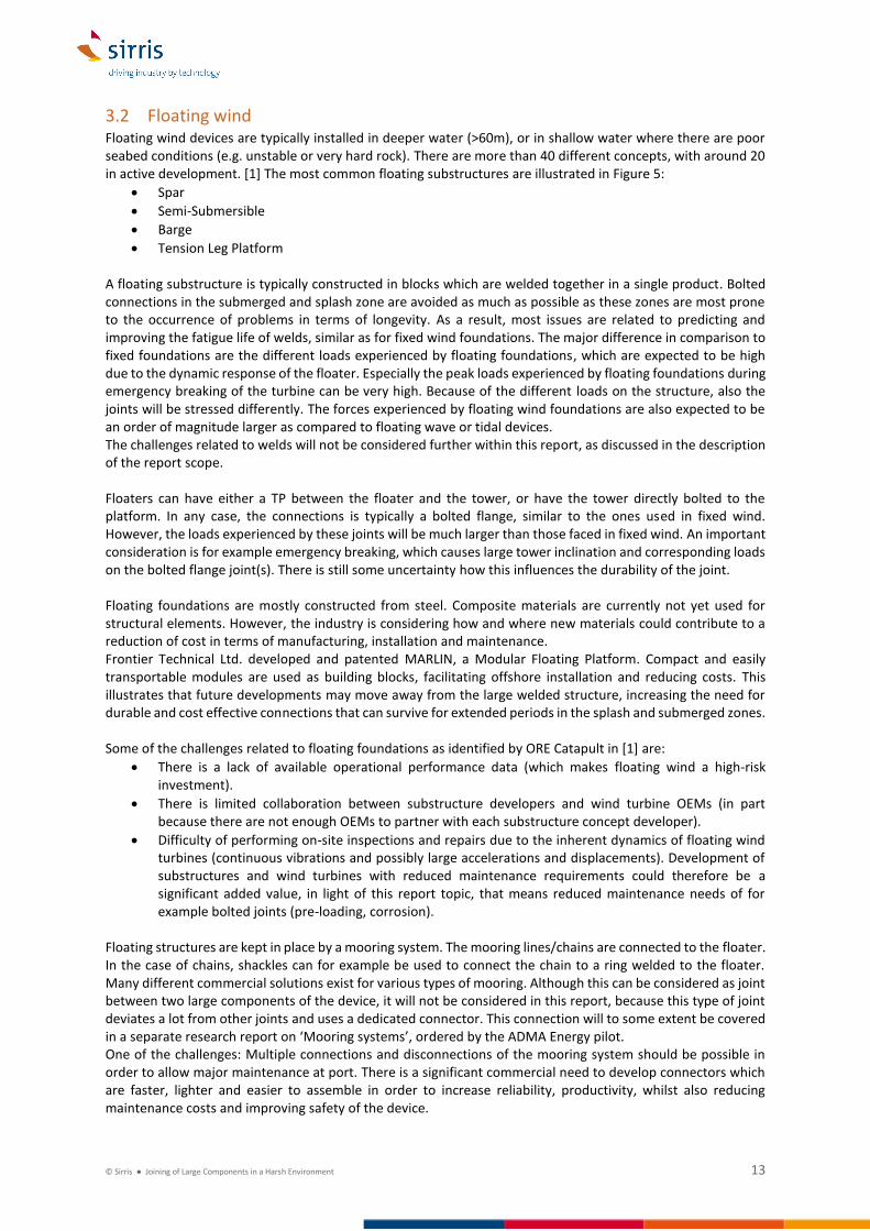
32 Floating wind Floating wind devices are typically installed in deeper water (gt60m) or in shallow water where there are poor seabed conditions (eg unstable or very hard rock) There are more than 40 different concepts with around 20 in active development [1] The most common floating substructures are illustrated in Figure 5
bull Spar
bull Semi-Submersible
bull Barge
bull Tension Leg Platform A floating substructure is typically constructed in blocks which are welded together in a single product Bolted connections in the submerged and splash zone are avoided as much as possible as these zones are most prone to the occurrence of problems in terms of longevity As a result most issues are related to predicting and improving the fatigue life of welds similar as for fixed wind foundations The major difference in comparison to fixed foundations are the different loads experienced by floating foundations which are expected to be high due to the dynamic response of the floater Especially the peak loads experienced by floating foundations during emergency breaking of the turbine can be very high Because of the different loads on the structure also the joints will be stressed differently The forces experienced by floating wind foundations are also expected to be an order of magnitude larger as compared to floating wave or tidal devices The challenges related to welds will not be considered further within this report as discussed in the description of the report scope Floaters can have either a TP between the floater and the tower or have the tower directly bolted to the platform In any case the connections is typically a bolted flange similar to the ones used in fixed wind However the loads experienced by these joints will be much larger than those faced in fixed wind An important consideration is for example emergency breaking which causes large tower inclination and corresponding loads on the bolted flange joint(s) There is still some uncertainty how this influences the durability of the joint Floating foundations are mostly constructed from steel Composite materials are currently not yet used for structural elements However the industry is considering how and where new materials could contribute to a reduction of cost in terms of manufacturing installation and maintenance Frontier Technical Ltd developed and patented MARLIN a Modular Floating Platform Compact and easily transportable modules are used as building blocks facilitating offshore installation and reducing costs This illustrates that future developments may move away from the large welded structure increasing the need for durable and cost effective connections that can survive for extended periods in the splash and submerged zones Some of the challenges related to floating foundations as identified by ORE Catapult in [1] are
bull There is a lack of available operational performance data (which makes floating wind a high-risk investment)
bull There is limited collaboration between substructure developers and wind turbine OEMs (in part because there are not enough OEMs to partner with each substructure concept developer)
bull Difficulty of performing on-site inspections and repairs due to the inherent dynamics of floating wind turbines (continuous vibrations and possibly large accelerations and displacements) Development of substructures and wind turbines with reduced maintenance requirements could therefore be a significant added value in light of this report topic that means reduced maintenance needs of for example bolted joints (pre-loading corrosion)
Floating structures are kept in place by a mooring system The mooring lineschains are connected to the floater In the case of chains shackles can for example be used to connect the chain to a ring welded to the floater Many different commercial solutions exist for various types of mooring Although this can be considered as joint between two large components of the device it will not be considered in this report because this type of joint deviates a lot from other joints and uses a dedicated connector This connection will to some extent be covered in a separate research report on lsquoMooring systemsrsquo ordered by the ADMA Energy pilot One of the challenges Multiple connections and disconnections of the mooring system should be possible in order to allow major maintenance at port There is a significant commercial need to develop connectors which are faster lighter and easier to assemble in order to increase reliability productivity whilst also reducing maintenance costs and improving safety of the device
copy Sirris Joining of Large Components in a Harsh Environment 14
Figure 5 Schematic illustration of the most common Floating wind typologies (left to right barge spar tension leg platform (TLP) semi-submersible) [1]
33 Tidal Energy Convertors (TEC) The vast majority of TECs being developed or close to commercialisation are horizontal axis turbines (see Figure 6) Horizontal-axis turbines also represent tidal converters with highest technology readiness levels (TRLs) These operate much like wind turbines but instead of getting power from the wind they get power from tidal flows The rotor and nacelle of horizontal axis tidal turbines close to commercialisation consist largely of the same components as wind turbines
- A rotor made up of two three or more blades connected to a hub - The hub connected to a main shaft entering the nacelle where power is generated either through a
direct drive generator or a combination of a gearbox and generator The blades are generally made from composite materials (glass fibre andor carbon fibre) but are of a significantly smaller size than those for wind turbines with rotor diameters up to 25m
Figure 6 Distribution of RampD efforts in TECs types (Source 2014 JRC Ocean Energy Status Report)
Tidal devices can be installed on fixed structure such as monopiles pods and gravity foundations or floating and moored to the seabed by tethers Whilst a convergence can be seen in the type of tidal technology the same cannot be said with regards to foundations about 40 of tidal devices require floating connections and 60 require fixed foundations
copy Sirris Joining of Large Components in a Harsh Environment 15
In the case of a tidal kite the nacelle is attached beneath the kite [8] A number of examples of tidal energy convertors is shown in the figures below For a more complete list of TEC developers the reader is referred to the website of EMEC1
Figure 7 Examples of bottom fixed turbines
Figure 8 Examples of floating tidal turbines
1 httpwwwemecorgukmarine-energytidal-developers
copy Sirris Joining of Large Components in a Harsh Environment 16
Figure 9 Example of Tidal Kite
Whilst the tidal sector exhibits a certain level of design consensus the picture looks slightly different when components and subcomponents of TECs are taken into account [8] As a result the design and type of joints used in the TECs is also different One major joint that is encountered in all devices is the connection between rotor blades and the hub In case of composite blades the design of the connection is similar to that for wind turbines Encountered connection types are the T-bolt principle a steel ring adhesively bonded into the blade root or adhesively bonded inserts in which studs are placed A major difference with respect to wind turbines is the fact that the tidal blades are submerged in seawater which has an impact of the degradation mechanisms to which this joint is exposed (see sections 417 and 424) Individual parts of the steel structure are either welded or bolted together In contract to wind energy devices the bolted flanges are located either underwater or in the splash zone As a result protection of these bolted connections against corrosion and leakage presents a much greater challenge (see section 424) The importance of installing the bolts with the correct pre-load and maintaining this preload is comparable to that for offshore wind although many devices have not yet been long enough in the water to observe issues related to loss of pre-load Additionally because technology developers are aware of the importance of pre-loading and the fact that for TECs inspection is extremely costly great care is given to the installation An additional concern is the impact of biofouling which can have a big impact on the feasibility and cost of inspection of submerged joints An additional consideration for submerged bolted joints is the material usage Submerged systems are typically protected using cathodic protection As a result there is a risk on hydrogen evolution Therefore lower strength bolts (grade 88) are typically prescribed for submerged applications Also the risk on corrosion mechanisms like crevice corrosion pitting corrosion and stress corrosion cracking is increased To manage the risk of for example stress corrosion cracking bolts can be overdesigned in order to reduce the stress levels However this again introduces unwanted additional costs If these risks cannot be properly managed it is likely that bolts will have to be changed every 5-10 years which would introduce a significant maintenance cost As is the case for wind energy turbines horizontal axis tidal turbines can have pitch and yaw systems in order to align the rotor and blades so as to maximise energy generation or break the system However as these systems are submerged sealing of these systems and the joints between the major components against water ingress (for example blade to pitch bearing to hub) is an important challenge along with protection against degradation due to sea water Because these submerged bearings provide potential failure modes certain systems are also designed without them Next to pitch and yaw bearings tidal energy devices may have other mobile joints to allow relative movement of two components Because these joints are either in the splash zone or submerged protection of these joints against corrosion poses an additional challenge Some bottom fixed structures utilise a unique joint type between the foundation and the nacelle to allow easy recovery of the nacelle The foundation has a large socket on its top on which the nacelle can be lowered and is kept in place (either by gravity alone or in combination with a fixture) The nacelle has a large pinprotrusion at its bottom which slides into the female type socket on top of the foundation A major concern here is protection of both sides of the connection against weardamage during installation and subsequent corrosion Floating structures are kept in place by a mooring system The mooring lineschains are connected to the floater In the case of chains shackles can for example be used to connect the chain to a ring welded to the floater Many different commercial solutions exist for various types of mooring Although this can be considered as joint
copy Sirris Joining of Large Components in a Harsh Environment 17
between two large components of the device it will not be considered in this report because this type of joint deviates a lot from other joints and merits dedicated attention It will also to some extent be covered in a separate research report on lsquoMooring systemsrsquo ordered by the ADMA Energy pilot
34 Wave Energy Convertors (WEC) The large variety in design concepts for WECs makes it impossible to give a general overview of the structural elements of Wave Energy Convertors and how they are joined together In this section a few specific points of attention will be highlighted and a few examples given The problems that will be encountered in terms of joining are likely to be similar as for tidal devices although the solutions will need to be adapted to specific WEC designs A lot could be learned from solutions currently used in the OilampGas sector Different types of WEC have been proposed over the years differentiated mainly by the way the devices would react to the force exerted by waves According to the JRC Ocean Energy Status Report [8] most RampD effort is undertaken on the development of point absorber type of devices as is illustrated in Figure 10 Wave energy presents the form of ocean energy with the highest deployment potential in European waters associated with a global potential 30 times higher than that of tidal energy IRENA has shown that 64 of WECs have been designed for offshore operation and 36 for near-shore and onshore operation (IRENA 2014b) [8]
Figure 10 Distribution of RampD efforts according to wave energy technology type Source JRC 2014 [8]
The structural requirements necessary to ensure the survival of a wave energy converter (WEC) in extreme sea states are a key cost driver in WEC design and represent a central challenge to the development of WECs into a reliable cost-efficient source of renewable energy [8] Depending on the type and design of the WEC the joints between key structural elements will play an important role in the survivability of the device and should therefore be considered with great care including the degradation due to the sea water environment Wave energy developers have focussed on designing WECs that could harness directly the most powerful resources offshore adding further complexity to the design challenges of a reliable wave energy conversion device Regardless of type each WEC comprises the following three elements [8]
bull A prime mover a structural component reacting to the incoming wave power activating a PTO or inducing the movement of other structural components
bull Moorings or foundations according to the location and application of the device
bull Power take-off single or multiple PTOs that can be embedded within the device or located on the seabedshore
As for tidal energy devices WECs may have mobile joints to allow relative movement of two components If these joints are exposed either in the splash zone or submerged protection of these joints against corrosion poses an additional challenge Some designs manage to avoid external moving parts which are prone to degradation by totally enclosing all the moving parts (mechanical hydraulic and electrical) inside a closed waterproof shell thereby sheltering them from the action of the sea However this is not possible for all types of wave energy convertors
copy Sirris Joining of Large Components in a Harsh Environment 18
Currently there are still very limited amounts of long-term operating data available Many WEC developers also have not yet been confronted with problems related to fatigue and corrosion of joints because the prototype devices havenrsquot been operational for sufficiently long periods of time Wave devices are often using traditional joining solutions which are easily available on the market Focus is still on development of the power take-off power generation efficiency etc Many of the devices are not yet cost optimised and are therefore not yet in a stage where long-term reliability is a major design driver (for first prototypes) first the technologies ability to generate electricity has to be proven In engaging with WEC developers the focus could therefore mainly be placed on awareness raising so that joints are designed with the necessary care in an early design stage By learning from well-established sectors such as OampG and even the more advanced Tidal Energy Devices costly design iterations in terms of joint design and protection can be avoided The most used material in WECs is steel The use of composite materials is still limited Weight is less of a concern for most wave devices (most devices even need to ballasted) so the major benefit of composites is in terms of corrosion protection But same as with the joints most project are not yet in a stage where material optimisation studies have been performed Below a number of example devices are described (after [23]) This illustrates that while some devices have limited external joints others do have external joints moving parts and flexible connections exposed to the sea water
Figure 11 Examples of WECs after [23] (a) PS Frog MK 5 (b) Searev (c) WET-NZ (d) Wavebob (e) Aquabuoy (f) Uppsala
The PS frogMK5 is a point absorber that consists of a large buoyant paddle with a ballasted handle hanging below it The waves act on the paddle When the WEC is pitching power is extracted by partially resisting the sliding of a power-take-off mass which moves in guides above sea level This device is totally enclosed in a steel hull with no external moving parts The Searev WEC is a point absorber that encloses a heavy horizontal axis wheel The centre of gravity of the wheel is off centred and this allows it to behave like a pendulum The rotational motion of this pendular wheel relative to the hull activates a power take-off (PTO) system All the moving parts (mechanical hydraulic and electrical) are sheltered from the action of the sea inside a closed waterproof shell The WET-NZ extracts energy from the differential motion of two bodies of different mass a reactive hull and an active float The reactive hull is sufficiently long to extend below the wave motion whilst the float is at the surface where maximal wave energy is located The energy is absorbed through a single pivot rotating motion The Wavebob consists of two oscillating bodies that are controlled by a damping system an inner float and an outer ring The inner float undergoes heaving motion slowly in the outer ring The energy of this motion is captured to generate electricity through a high-pressure oil system The Aquabuoy consists of a floater which keeps the system afloat A large cylinder called the accelerator tube is connected below the floater A piston is housed in the centre of the accelerator tube and is connected to the
copy Sirris Joining of Large Components in a Harsh Environment 19
top and bottom section of the buoy using a hose pump The relative motion between the buoy and the piston stretches and compresses the hose pump which in turn drives the water through a Pelton turbine to generate electricity The Uppsala Point Absorber has a linear direct drive generator placed on the seabed A buoy is connected to the moving part of the generator using a line and a piston Springs are attached beneath the translator of the generator to store energy and act as a restoring force during wave troughs
copy Sirris Joining of Large Components in a Harsh Environment 20
4 Challenges in current designs Generally speaking four main classes of connections can be identified for large components in offshore energy devices
- Bolted joints - Adhesively bonded joints - Grouted connections (MPTP jacket pin-piles) - Mechanical contact joints (eg slip-joint)
An attempt has been made to map the challenges related to joining of large components in offshore energy devices through a combination of literature reports and interviews with industry experts The following is a summary of the findings and should give a good overview of the challenges that are currently driving the industry This document does not however claim to present an exhaustive list and individual asset owners technology and project developers may be faced with other issues The current authors are however confident that most of the major elements are to a certain extent covered It will however become clear that bolted joints take up the biggest space This is a reflection of the fact that this is indeed the most used type of connection (next to welding which is not within the scope of this document) and that most of the identified challenges relate to this type of connection The challenges and difficulties identified have been subdivided in three main sections
- Design challenges - Understanding and preventing degradation - Inspection and monitoring
41 Design challenges
411 Large flanged joints A major issue that can impact the durability of large flanged joints is the tolerance on the opposing flanges With ever increasing sizes of components precision manufacturing of these components is a real challenge The tolerances on fabrication (and accumulated during installation) have an impact on the load bearing capacity of bolted flanges (both in maximum load and fatigue loading) [13] In [16] an example is given for the production of a flange connection with an outer diameter of 52m Criteria for flange flatness state an allowed deviation of 1 mm over a segment of 30deg Additionally only gaps of up to 3 mm are allowed to be closed by tightening the bolts This is a challenge when producing flanges with ever increasing diameters A typical example of a large flanged joint is the bolted connection between the MP and the TP of offshore wind turbines The authors of [16] advise that flange flatness tolerance guidelines should be reviewed for the case of MP foundations This should be supported by advanced modelling work that includes the influences of fabrication and installation tolerances on static and dynamic load calculations [13] Even with larger tolerances allowed it will remain challenging to fabricate large flanges (up to 10m diameter) within the specified criteria A problem specific to the MP-TP connection is the horizontal storage of the MPs prior to installation Prolonged periods of storage can lead to the MP cross-section becoming slightly oval instead of perfectly circular This will lead to small mismatches between the MP and TP flange As a result not all bolts are perfectly in place leading to a small amounts of slack In combination with the complex loads to which wind turbines are subjected even very small deviations (lt 1mm) may lead to some bolts being loaded more than other and can influence the long term fatigue behaviour of the bolted joint It is yet unclear just how big this effect can be and whether or not it needs to be considered Current designs of large flanged joints still use assumptions from 20 years ago which were applicable to smaller diameter flanges It is uncertain that these assumptions are still valid for larger flanges and that these tolerances can be met in production There are two approaches to solving this issue A first solution is to improve manufacturing processes so that they can deliver large components with very tight tolerances However this may proof impossible andor very costly for the ever increasing device sizes Another approach is to allow for larger imperfections and take this into account in the design stage The latter will require development of new design methods and modelling tools
copy Sirris Joining of Large Components in a Harsh Environment 21
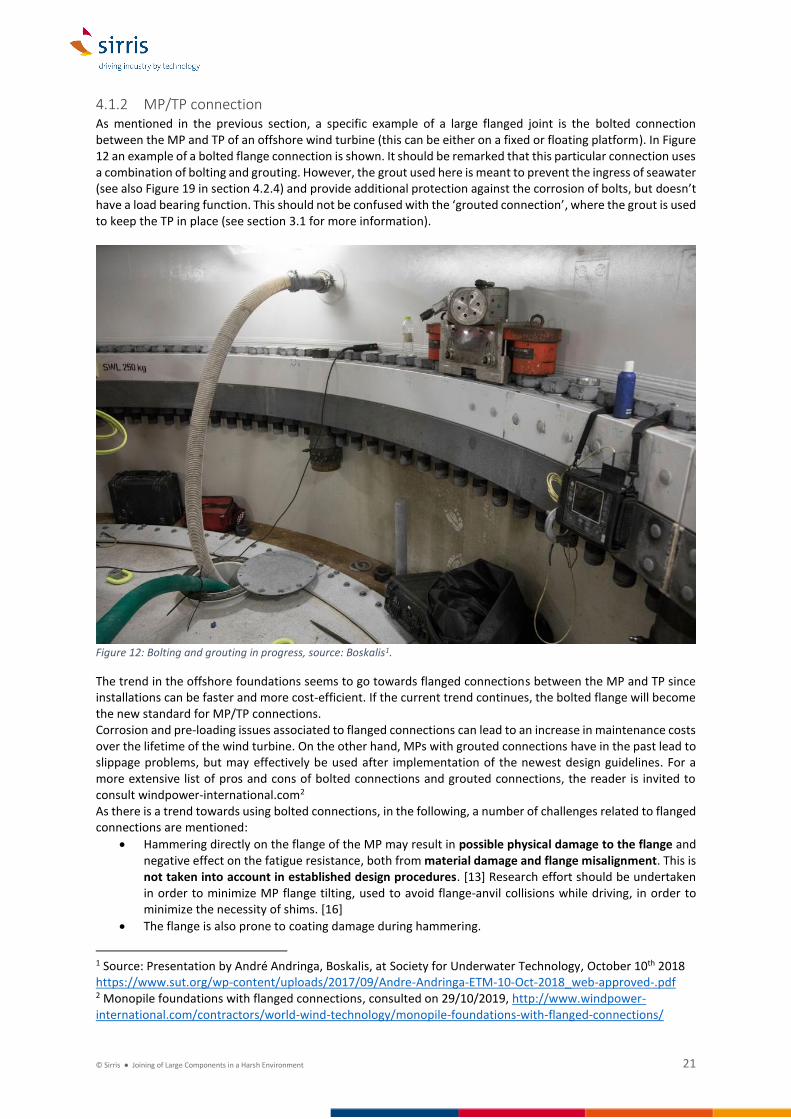
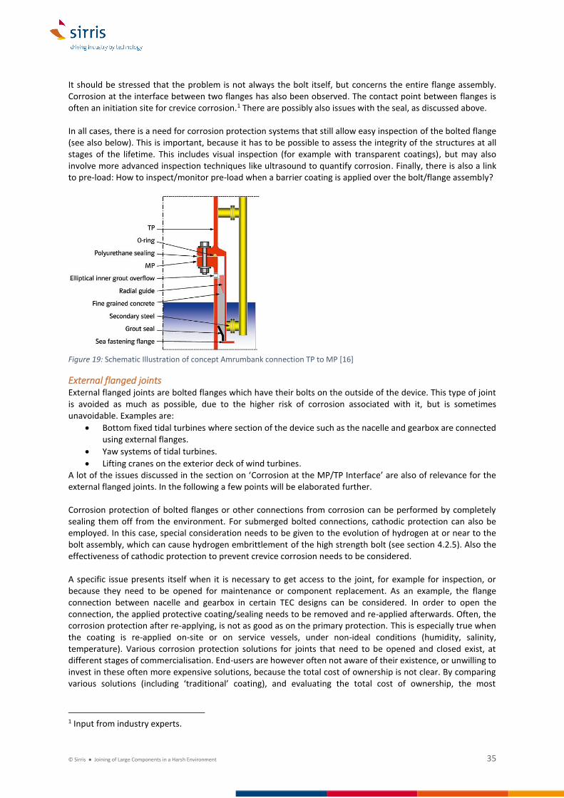
412 MPTP connection As mentioned in the previous section a specific example of a large flanged joint is the bolted connection between the MP and TP of an offshore wind turbine (this can be either on a fixed or floating platform) In Figure 12 an example of a bolted flange connection is shown It should be remarked that this particular connection uses a combination of bolting and grouting However the grout used here is meant to prevent the ingress of seawater (see also Figure 19 in section 424) and provide additional protection against the corrosion of bolts but doesnrsquot have a load bearing function This should not be confused with the lsquogrouted connectionrsquo where the grout is used to keep the TP in place (see section 31 for more information)
Figure 12 Bolting and grouting in progress source Boskalis1
The trend in the offshore foundations seems to go towards flanged connections between the MP and TP since installations can be faster and more cost-efficient If the current trend continues the bolted flange will become the new standard for MPTP connections Corrosion and pre-loading issues associated to flanged connections can lead to an increase in maintenance costs over the lifetime of the wind turbine On the other hand MPs with grouted connections have in the past lead to slippage problems but may effectively be used after implementation of the newest design guidelines For a more extensive list of pros and cons of bolted connections and grouted connections the reader is invited to consult windpower-internationalcom2 As there is a trend towards using bolted connections in the following a number of challenges related to flanged connections are mentioned
bull Hammering directly on the flange of the MP may result in possible physical damage to the flange and negative effect on the fatigue resistance both from material damage and flange misalignment This is not taken into account in established design procedures [13] Research effort should be undertaken in order to minimize MP flange tilting used to avoid flange-anvil collisions while driving in order to minimize the necessity of shims [16]
bull The flange is also prone to coating damage during hammering
1 Source Presentation by Andreacute Andringa Boskalis at Society for Underwater Technology October 10th 2018 httpswwwsutorgwp-contentuploads201709Andre-Andringa-ETM-10-Oct-2018_web-approved-pdf 2 Monopile foundations with flanged connections consulted on 29102019 httpwwwwindpower-internationalcomcontractorsworld-wind-technologymonopile-foundations-with-flanged-connections
copy Sirris Joining of Large Components in a Harsh Environment 22
bull High corrosion risk The bolted connections need special attention because the highly corrosive environment of the seawater causes steel corrosion of the normally galvanised components
bull Misalignment of bolt holes can lead to a reduced fatigue life
bull Bolts need to be pre-loaded to the correct load in order to ascertain the fatigue life This also brings with it high maintenance and inspections costs (see section 422 for more information)
bull Transition pieces with bolted joints require the monopile to be installed to within a small deviation from vertical Driving the MP into the seabed can result in the MP not being perfectly vertical and the mounting flange being inclined This is not covered in existing design procedures [13] Imperfections in verticality may need to be corrected using foundation-specific solutions such as adapter rings If an adapter ring is used to correct verticality the bolts need to be longer than the standard bolts leading to higher costs and longer waiting periods [14]
bull Installation procedures are not always entirely clear or not followed to the letter for example on which type of grease to use (may influence corrosion resistance and bolt pre-load) which type of pre-load measurement to apply etc
bull Monopile foundations are getting bigger to handle the loads of larger turbines which would require bigger and more bolts in the flanged connection Therefore larger bolt sizes will need to be standardised (see also section 413) Other material grades may also need to be considered which are not currently covered by design standards and guidelines
bull It is not always easy or possible to verify that design assumptions are being respected (ie no corrosion correct pre-load flange positioning experienced loads etc)
413 Large bolt sizes The largest bolt size currently used in offshore wind MPTP connections is an M72 bolt With the ongoing trend of ever increasing turbine sizes (12MW+ turbines) there is also a demand for larger diameter monopile foundations (8-10m) As a consequence larger bolts will also be needed to transfer the increased load from the turbine to the foundation However there are currently no standards for fatigue lifetime assessment of bolts at size larger than M72 Ie what are allowed tolerances on geometrical accuracy ovality surface roughness etc to allow for a 30 year fatigue lifetime Such standards will be required in order to be able to certify and get insurance for projects using larger turbines Although the above focusses on monopile foundations larger turbine sizes will lead to larger diameter connections to the foundation regardless of the type of foundation being used This therefore also applies to jacket structures and in the future potentially also floating foundations
414 Modular design The ADMA Prioritisation study lsquoADMA Energy Analysis and Priority Settingrsquo undertaken by Optimat undertaken in 2019 mentions as an option for prioritisation an lsquoIncreasing Modular Approach to Systemsrsquo Modular design provides the possibility to implement standardised designs and adopt a modular approach to process units thereby reducing design schedule and cost uncertainty Modular design offers opportunities for savings and the options for onsite fabrication and offsite shop modular fabrication in order to add engineering accuracy and quality efficiency The development of a modular approach to system fabrication necessitates the introduction of larger amount of structural joints between large components Two examples are
bull Modular construction of floating platforms for offshore wind Using the concept of compact easily transportable modules as building blocks Such building blocks could be standardised welded cans which can be joined together through bolted flanges The amount of cans required could then be adapted based on the required size of the floating platform The bolted flange connection could in many respects be similar to the MPTP bolted joint although possibly with a different orientation (vertical vs horizontal) and different applied load spectrum The impact of the potentially large loads at emergency breaking on the design and durability of bolted joints should be investigated Also the potential on-site realisation of the joint could be very challenging with a preference to perform assembly on a construction yard
bull Developments in substation installation include the use of modular structures so that the individual lifts can be undertaken by a vessel with a lower crane capacity This will require the on-site realisation of joints between large components Depending on the design different types of joints (not necessarily
copy Sirris Joining of Large Components in a Harsh Environment 23
bolted) could be envisaged Operational experience focused on ease of on-site assembly (including time requirements) and durability of the joints will be required to evaluate alternative designs
415 Segmented blades Difficulties in manufacture testing transportation and installation are associated to the production of increasingly long blades (gt 100m) Therefore the concept of segmented blades is being investigated These segments will need to be connected to one another in a reliable and cost effective way (Little or no maintenance need good fatigue resistance corrosion resistance etc) Adhesive bonds are expected to provide structural and economic efficiency but in-field assembly poses a big issue (see also section 417) Prototype segmented blades using T-bolt joints studs and spar bridge concepts have proven successful as well as aerodynamically-shaped root and hub extenders [18]
Figure 13 The Nabrajoint as an example of an approach to segmented blades Developed by Nabrawind1
Current status [20]
bull Tip replacements designed and implemented
bull Various design assessments and prototypes in the business
bull Steel to composite solutions applied Maintaining the original blade specs (mass stiffness freq) and the joint between the segments (spar cap joint) still provide challenges Alternative joining solutions are still being proposed and developed further One example could be thermoplastic welding of composite material2 Companies like GE and Siemens are developing prototypes with segmented blades (also for onshore turbines where the challenges related to logistics are even larger)
416 Blade to hub connection
Wind Turbines The composite wind turbine blades need to be joined to the steel hub (in effect the blade bearing) Today this is achieved by means of a bolted connection The most commonly used way to integrate the boltsstuds in the composite laminate is by means of a T-bolt connection The use of T-bolts has its limitations when moving towards larger blades as will be discussed below As a result another type of connection based on inserts with an internal thread (stud root connection) is becoming more popular The challenge on how to transfer large loads at the compositesteel interface remains a topic of investigation and continuous development with the ever increasing size of offshore wind turbines driving the developments forward
1 Source httpswwwnabrawindcomnabrajoint (consulted on 30102019) 2 Source Interview with Dirk-Jan Kootstra Quattra-P
copy Sirris Joining of Large Components in a Harsh Environment 24
The weight of the joint is less important since it is added close to the hub and the centre of rotation As a consequence it does not have a big impact on the bladersquos eigenfrequencies and edge-wise and dynamic loads This is different for blade segmentation joints which are placed further outboard Due to the superior fatigue performance of T-bolts and studs other blade root designs have become rare [18]
Figure 14 An overview of bladed root joints (a) Flange root connection (b) Hub-type root connection (c) T-bolt root connection (d) Stud root connection Source [18]
Figure 15 Elementary T-bolt parts Source [17]
The T-bolt connection is the most commonly used root connection because it has a lot of advantages It does not rely on adhesives its cost is lower than other connection types it has a good reproducibility and when a bolt or barrel nut is broken it can easily be removed and replaced However it needs a high drilling accuracy in order not to introduce unnecessary bending but this is not a big problem with current machining tools The T-bolt joint is reliable and inexpensive but has a low structural efficiency resulting in a high weight compared to other solutions such as inserts Packing limitations exist and lead to a significant laminate build-up The barrel nut is a steel cylinder which is placed in a drilled hole in the composite shell of the blade at a certain distance from the end side with its axis normal to the shell The barrel nut is glued to the laminate but this glue has little stiffness Its purpose is just to hold the barrel nut in place and not to transfer the forces The forces are always transferred by bearing of the laminate against the barrel nut In order to allow this bearing and because the forces are the highest at the blade root connection the laminate is a lot thicker at the root This thickness is oversized due to an absolute lack of information related to the bearing strength of very thick laminates with a hole in the middle of the bearing area for the bolt Guidelines suggest a thickness of about 15 times the barrel nut diameter [17]
copy Sirris Joining of Large Components in a Harsh Environment 25
This high material usage due to the introduction of high stresses in the composite around the T-bolt is the biggest disadvantage of this type of connection [17] At the blade root the loads are highest and the cross-section comparatively small which necessitates the use of thicker laminates Additionally the hole in which the barrel nut is positioned acts as a stress concentrator Because very high loads need to be transferred from the composite laminate to the bolt at this location this further increases the required laminate thickness The biggest challenge is the lack of knowledge on how such thick laminates behave Moreover this is a challenge which is unique to the wind industry as such thick laminates are not used in any other business Because wind energy is pioneering in this field there is no knowledge from other sectors that can be used In order to understand the behaviour of these connections and predict their lifetime accurate modelling and testing of the connection is necessary As blade lengths increase the load that needs to be transferred increases faster than the blade root circumference As a result the T-bolts need to be placed closer together In order to be able to transfer the load from the barrel nut to the laminate the laminate thickness needs to increase further Eventually this increases the risk on undesired failure modes (Figure 17) Further increasing the laminate thickness therefore doesnrsquot result in any additional gain Essentially the T-bolt is reaching its limit because the centre-to-centre-distance over hole diameter ratio is becoming undesirable and the favoured failure mode can no longer be imposed The size of the barrel nut is also large compared to the stud diameter As the number of studs required to be able to bear the load increases the barrel nuts would eventually need to lsquooverlaprsquo This is evidently not possible and again illustrates the limitations of this design One possibility could for example be not to have all the barrel nuts on a single line but distributed over two lines Composite materials are sensitive to damage through moisture uptake To prevent this the composite is coated with a barrier coating The position of the barrel-nut presents a critical location for degradation due to moisture uptake The holes are drilled in the laminate meaning that at this location the fibres are exposed to the environment It is essential to provide good long term protection at this location which can be a challenge
Figure 16 Image of a blade being connected to its hub The T-bolt principle is used The barrel nuts can clearly be seen around the circumference of the blade root1
1 httpwwwsiemenscompresspooldepressebilder2012photonews300dpiPN201209PN201209-01_300dpijpg
copy Sirris Joining of Large Components in a Harsh Environment 26
Figure 17 Failure modes of pin-loaded composites (a) Net-Tension (b) Shear Out (c) Bearing Bearing is the desired failure mode as this occurs gradually while (a) and (b) may result in sudden failure Source [20]
Another solution being applied is the use of inlaid inserts which are essentially adhesively bonded to the laminate The diameter of these inserts is smaller than that of the barrel nuts allowing more bolts to be incorporated within the same blade root circumference The stress concentrations around such an insert are also greatly reduced allowing the use of thinner laminates Therefore this type of connection is much easier to upscale to larger blades The principle of this type of connection developed by WE4CE1 is illustrated in Figure 18 Failure of this type of connection could occur due to shear-out of the insert This is prevented by having a sufficiently large surface area (length of the insert) and potentially mechanical interlocking The inserts are tapered to reduce stress concentrations at the end of the insert The stud or insert root joint relies on longitudinal bolts attached to studs or inserts Typically the inserts are female threaded and made of steel causing a thermal and flexural mismatch Often the studs are glued into the blade In wood composite blades the studs are placed in holes that are drilled while in glass fibre blades the holes are preferably formed during fabrication Positioning of the stud is vital to the quality of the joint as a non-uniform adhesive thickness causes stress concentrations In general to provide sufficient pull-out strength inserts have to be long Various improvements have been suggested to increase the pull-out strength allowing shorter lighter inserts [18] Input from the industry suggests that the design with inserts currently performs well from a load bearingtransfer perspective and that this technology provides a solution for the next generation of larger turbine blades
Figure 18 Illustration of the concept of inserts to connect composite blades to the hub Source [20] Fiberline We4Ce
With longer inserts larger loads can be transferred from the composite to the steel With further upscaling of such a solution the limits of strength of the steel could eventually be reached Today steel grade 109 is used
1 httpswwwwe4ceeueninnovationswe4ce-blade-root-connection
copy Sirris Joining of Large Components in a Harsh Environment 27
for the boltsstuds It might be necessary to consider higher strength materials for the studs For designs using T-bolts this could also open the way to using less bolts and reducing laminate thicknesses Inspection of bladehub connection can also be a challenge This includes the condition of the boltsstuds the pre-load but also of the composite laminate For the T-bolt connection this involves inspecting or monitoring the laminate region around the barrel nuts for cracks For the inserts the condition of the bondinterface between the studs and the laminate needs to be monitored Techniques like ultrasound inspection of imbedding of optical fibres could potentially be used to inspectmonitor this interface All current blade designs start from the principle that the connection to the roothub needs to be a detachable connection The reasons can for example be the need for easy replacement onshore testing (for which blades need to be attached and detached) andor easy on-site installation As such the choice for mechanical joints is unavoidable This also brings with it some level of stress concentration and a need for thicker laminates This can be avoided by using adhesive bonding although adhesive bonding also has its own limitation and challenges as discussed in section 417 Alternative design concepts have also been presented where the connection between the blade and hub is moved to another location on the blade where the cross-section is higher As a result the load that needs to be transferred per unit of circumference is reduced
Tidal Turbines Similar design concepts can be used for Tidal Turbine blades A major difference with respect to wind turbines is the material of choice (depending on the design carbon fibre composites may be used) and the environment in which they operate Tidal turbines blades are submerged in seawater which adds a challenge regarding corrosion protection of the metallic parts of the connection (section 424) as well as bio-fouling Additionally preventing water uptake by the composite particularly at the contact with steel is of great importance (section 423) Where the blade is connected to the hub a pitch bearing may also be present in tidal turbines This bearing needs to be sealed against water ingress which can also pose challenge
417 Adhesive bonding Currently composites are being assembled using fasteners This represents a huge weight penalty for composites since holes cut through the load carrying fibres and destroy the load path Adhesive bonding is the most promising joining technology in terms of weight and performance However its lack of acceptance is limiting its application to secondary structures whose failure is not detrimental for the structural safety In primary (critical-load-bearing) structures fasteners are always included along bond lines as ldquoback-uprdquo in case the bond fails The main reasons for this lack of acceptance are the limited knowledge of their key manufacturing parameters non-destructive inspection techniques damage tolerance methodology and reliable diagnosis and prognosis of their structural integrity1 The use of adhesive bonding could be an option for the structural joint between composite blade sections or the connection between the blade and the blade bearing as has been discussed in section 416 Also for non-structural joints between for example walkway gratings and steel supports this could be an option In the latter case use of adhesive bonding circumvents current problems and maintenance costs associated to corrosion of the bolts used to fix the gratings to their steel supports Furthermore future developments will likely see the introduction of load-bearing composite components in the structure for example replacing the steel support for the gratings by a composite support This avoids corrosion issues Bonding between composite components using adhesives has great potential to reduce both cost and weight as compared to bolted connections between composite components Different composite components of a blade which cannot be manufactured as a single part (due to cost or technical constraints) can be bonded using adhesives As blade sizes increase in wind turbines the need for joining of components will likely only increase Adhesive joints can be structurally efficient light and inexpensive They have low stress concentrations and good damage tolerance [18] However the use of adhesive bonds also present a number of challenges
1 Source httpswwwcosteuactionsCA18120tabs|Nameoverview
copy Sirris Joining of Large Components in a Harsh Environment 28
bull Lack of inherent self-alignment of adhesive joints which makes on-site installation very challenging [18]
bull Difficulty of producing a high quality bond on-site compared to under controlled conditions [18] o Surface preparation temperature and humidity affect the quality of adhesive joints o Good control over the bond thickness is important to avoid stress concentrations o Air entrapment can drastically reduce the strength of adhesive joints
bull Because of the large number of factors influencing the quality of an adhesive joint proper control of the joining process and thereby achieving a high quality joint with good repeatability is still a major challenge Also for post-installation inspection of the joint to ascertain the quality there are not many techniques available and no standardised procedures
bull The durability of adhesive joints in a harsh environment is currently not well understood UV water humidity salinity etc can all have a negative impact on the durability of adhesive bonds and little is known about how various adhesives behave in a marine environment or submerged in seawater An additional difficulty is that the adhesive often loses strength first in regions which are difficult to access or inspect
bull Modelling of large adhesive joints currently still presents a lot of challenges
bull Adhesive bonds are non-reversible ie they cannot be opened and closed in the same way as bolted connections This has implications with respect to maintenance For example if one were to use adhesive bonding to join the blade to the hub it cannot be easily replaced
In contrast mechanical joints for composite blade connections are heavy and expensive but are fast and easy to assemble Furthermore they are easier to inspect but require some maintenance [18] The above difficulties related to adhesive joining also make that it is difficult to know what strength and fatigue properties can be allowed in the design phase of adhesive joints Under a complex fatigue loading condition there are still a lot of questions on how the non-degraded adhesive behaves Adding to that degradation due to environmental influences makes a correct estimation of design values even more challenging The lack of understanding and limited research done on this topic so far may be limiting the market uptake of adhesive bonding Not only the adhesive itself but also the (mechanical) design of the components to be bonded should be carefully considered The largest challenges are not necessarily at a technological level but the fact that end-users designers and customers are not familiar with how to design a good adhesive joint especially for large hybrid connections (eg steelcomposite)
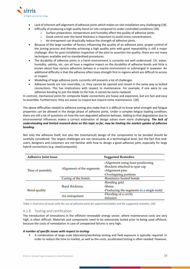
Table 1 Overview of issues with the use of adhesive joints for segmented blades and the suggested remedies [18]
418 Testing and certification The introduction of innovations in the offshore renewable energy sector where maintenance costs are very high is often difficult Materials and components need to be extensively tested prior to being used offshore because the costs of remediation in case of unexpected failures is very high A number of specific issues with respect to testing
A combination of large scale laboratoryworkshop testing and field exposure is typically required In order to reduce the time to market as well as the costs accelerated testing is often needed However
copy Sirris Joining of Large Components in a Harsh Environment 29
establishing a direct link between accelerated testing and the real lifetime of a material or component is not straightforward
There is a lack of standardised accelerated test procedures for connections (bolted welded adhesive) in an aggressive environment (corrosion fouling UB) often in combination with fatigue loading
There is a lack of fatigue test data especially for large bolts (gtM72) Also in combination with corrosion Standardised test procedures should be developed to approve and certify the use of certain types of bolts also on full scale
Fatigue testing of M36 and M42 bolts is already very expensive In order to make extensive fatigue testing on M72 bolts and larger feasible (which is required in order to update the design standards) new and cheaper accelerated testing methods will be required
Combined testing of corrosionfatigue No clear understanding of how corrosion and fatigue loading influence each other therefore also no guidelines on standardized testing Fatigue and corrosion can both be accelerated but processes are taking place on a different timescale and fatigue is accelerated more than corrosion Therefore there are questions on how representative the results of such tests are for real exposure conditions
Large scale fatigue testing of composites steel structures and joints is expensive and time consuming The costs for large and full scale testing in a representative environment (ie offshore) can be very
high Often funding is not readily available because these are not necessarily research issues but can often be classified as engineering challenges
42 Understanding and preventing degradation Two major types of failure mechanisms need to be considered when designing offshore energy devices [24]
bull for Survivability Immediate failure caused by exceedance of material ultimate strength and
bull for Durability Fatigue failure caused by repeated mechanical loads below the ultimate material strength
Both mechanisms depend on material strength in hot spots in the structure and on external loads The strength may change as a result of degradation during usage by [24]
bull corrosion changing load carrying material content and geometry
bull wear also changing load carrying material content and geometry
bull marine growth causing changed mechanical behaviour In this section of the report a number of challenges related to understanding and preventing degradation of joints will be discussed The topic of adhesive joining has mainly been addressed in section 417 It is important to keep in mind that
1 Costs in offshore operations are very different from onshore Offshore needs more reduction in assembly time and has a higher drive to reduce maintenance than in onshore
2 Many problems have already been encountered in OampG however the pressure on reducing costs is very higher in renewable energy There is a perception that some of the solutions which are working well in OampG may simply be too expensive for renewable energy Relative costs related to offshore inspection and maintenance are also higher for offshore renewable energy because these devices are unmanned An objective study of cost of ownership of joining solutions available from OampG should be performed in order to evaluate which solutions from OampG can or cannot be used in the offshore renewable energy sector
421 Bolted connections As is already clear from the previous sections in this document the bolted connection is a frequently used type of connection There are bolted connections of different sizes depending on the components being joined A lot of questions remain on the degradation and damage mechanisms to which bolts are exposed and how these influence their lifetime Understanding bolt degradation and preventing it are important issues not only for wind energy but also for wave and tidal However there is a clear distinction both in degradation processes and protection needs in the atmospheric zone as compared to splash and submerged zones The latter two pose a much higher degradation risk and are of major importance to wave and tidal devices where the entire structure is contained in these two zones
copy Sirris Joining of Large Components in a Harsh Environment 30
The issues related to bolt degradation and protection need to be tackled taking into consideration different possible circumstances
bull Installation in submerged vs splash zone vs atmospheric conditions
bull Bolted connections with continuousfrequent usage (ie opening and closing of flanges) vs connections checked only routinely (ie every 5 or 10 or 15 years)
bull Connections between same metals vs different metals vs metalcomposite connections A number of possible root causes for breaking of bolts have been identified in [21] which is mainly for bolts in the atmospheric zone
bull Fabrication and Installation o poor lubrication ineffective contact between bolt and nut connection undone o improper bolting sequence uneven stress distribution stress concentration overutilization o missing washers improper stress transferral loosening of connection
bull Design poorly specified pretension force loosening of connection at one bolt more bolts to loosen
bull OampM o excessive loading during testing of bolts exceeding elastic limit loss of pre-load o insufficient sealing against water through grease caps corrosion o internal climate control broken high humidity corrosive environment
In the submerged zone other risks can be added to this list such as a risk of hydrogen embrittlement when combined with cathodic protection especially if higher strength bolts are used Also the risk on corrosion mechanisms like crevice corrosion pitting corrosion and stress corrosion cracking is increased To manage the risk of for example stress corrosion cracking bolts can be overdesigned in order to reduce the stress levels However this again introduces unwanted additional costs A better understanding of the risks possible failure modes and alternative solutions should allow to optimise designs and reduce costs Also for joints within subcomponents the challenges related to bolting play an important role For example direct drive machines require very large welded structures to support the generator These are become so large that the support structure will have to be split in sectors and joined with bolts Also here the issues related to flatness tolerances pre-loading and fatigue degradation play a role
422 Pre-load
Importance of pre-load In order to increase the fatigue life of bolts they are pre-loaded to a high percentage of their tensile strength If the bolts are loaded correctly they only experience a small percentage change in load as external loads occur and the fatigue life of the bolts is practically infinite If the pre-load reduces over time this will drastically reduce the fatigue life of the bolts Thatrsquos why the installation tightening procedure and achieved pre-load are so important [19] If a too low or high load to the bolt is applied during new construction or maintenance it will lead to a direct influence on the fatigue life of the bolts in the operational phase resulting in a loss of load or worse bolt failure [22] Over 90 of all bolted joint failures can be attributed to low bolt tension on installation tightening Achieving and maintaining the correct installed design load will eliminate failures1 Offshore wind parks are still relatively new and the first wind turbines had larger safety margins built into the design Since wind turbines are getting bigger and heavier the safety margins become smaller With a 70 spread in load it is assumed that a wind turbine will not achieve its expected lifespan of 25-30 years without costly repairs or bolt replacements Most companies in the offshore wind industry are now aware of the fact that the quality of the bolted connections is a serious concern [22] When the bolts are installed and maintained at the correct load less maintenance is needed and they do not need to be replaced at a later stage When the old school torque procedures are used (for example the DASt norm) the bolts in the flange connection will experience enormous fluctuations in loads (see also section 411) and should be replaced once every 2-7 years [22]
1 Source httpswwwrotaboltcouk
copy Sirris Joining of Large Components in a Harsh Environment 31
Applying and maintaining the correct pre-load There are two main categories of bolt pre-loading torque methods and tensionpull methods In the torque method the load is applied by rotating the bolt to a certain degree In the tension methods a load is applied axially by gripping one or both ends of the bolt and pulling on it Within the torque methods various mays of controlling the pre-load exist The control variable may be the applied torque the rotation angle or a combination of both The latter is also called yield control tightening because if the measured rotation increases with a reduced increase in the torque this means the bolt material is yielding The quality of a bolted connection depends very much on the load in the bolts Torque wrenches are not a good way to achieve or determine the correct load In fact torque (in Nm) and load (in kN) have no direct predictive relation to each other Using torque tools the wrench stops when the bolt or nut offers a certain resistance In the laboratory the resistance of each bolt seems the same but there may be up to 40 deviation which in offshore practice can lead to a spread in bolt tension up to 70 affecting the entire flange [22] It is generally accepted that applying pre-load to the bolt in an accurate and repeatable way should be done using tensioning tools rather that torque tools However most tensioning tools require longer bolts (access to the bolt thread is required to apply the tension) and sufficient space around the nut to operate1 Where access is more restricted torque tools are often the only solution In order to be able to tension all bolts using tension tools the space required to operate these tools needs to be taken into account in the turbine design stage Applying pre-load correctly is a slow process and requires the use of heavy and cumbersome hydraulic equipment within the nacelle (during installation and maintenance operations) Hydraulic power packs and hoses are difficult to use in the often confined or difficult to reach spaces in the turbine There is also a risk of spilling of hydraulic fluid Work is being done on the development of new tools to apply pre-load easier faster and with fewer people such as the development of electrical tools Electrical tools are also faster to deploy than hydraulic tools which is of great importance to the Offshore Renewables Sector Electrical wrench tools are already on the market but do not yet provide the same level of accuracy and repeatability as hydraulic tools It is expected that this technology will continue to develop to improve accuracy Another solution could be to monitor the load in the bolt itself instead of through the installation tool No indications were found for the existence of electric tension tools The key to developing successful installation and inspection tools is that they need to reduce assembly and maintenance times and provide a closely controlled and homogeneously distributed pre-load In addition to the technology used to apply the pre-load also the procedures of tightening and load spreading are important [22] This involves for example the order in which bolt tightening is done whether or not several bolts can be loaded simultaneously etc Pre-loading a bolt will change the pre-load of adjacent bolts As a result the pre-load may be non-uniform along the circumference of the flange Therefore in order to have a high quality of pre-loading and knowing the exact pre-load a pre-load measurement system should be used during installation It is yet unclear what the impact of different pre-loading methods and devices is on the homogeneity and loss of pre-load The design calculations of the flanges clearly indicate what the required pre-load is However the procedures to apply verify and maintain the pre-load are not yet clearly established In case of a lack of installation guidelines or unclear guidelines there can be a lot of uncertainty from the very beginning of the lifetime of the bolt
bull When using torque tools use of type and amount of grease can influence the achieved pre-load as well as the environmental conditions under which the bolt was installed Presence of water can affect the lubricant of the nuts leading to increased friction in the contact surfaces of the joint2 and a different pre-load
bull It is not always clear how pre-load was measured (torque or tension) If torque is measured it is not clear if the required tension is also achieved And if measured directly there can be a question about whether the tension was measured correctly The latter is related to proper training of personnel Considering the importance of pre-load and the cost of maintenance in offshore installations highly trained personnel should be and are used in this sector
1 Source httpswwwenerpaccomen-ustrainingetensioning 2 Source httpwwwwindactionorgposts46369-vestas-wind-turbine-collapse-in-lemnhult-swedenXY4dL0YzaUk consulted in October 2019
copy Sirris Joining of Large Components in a Harsh Environment 32
bull For older installations it is often not known whether the bolts were installed with the correct pre-load In new installations it seems that constructors and owners have realised the importance of pre-load and greater care is being taken to correctly install bolts and measure pre-load after or during installation
bull During installation of the bolts the structure is already subjected to external loads It is unclear to what extent these external loads influence the measured pre-load and when the external loads are removed or change how this influences the pre-load on the bolt
Also during maintenance there is source of uncertainty If bolts loosen and are replaced andor re-loaded it is unclear if and how many of the neighbouring bolts also need to be inspected This brings with it a high cost so economic considerations factor into the decision process Pre-load is a major concern for all bolted connections exposed to fatigue loading The challenges outlined above are therefore not unique to wind energy applications Although the current WEC and TEC devices may not have been in operation for long enough for serious issues to have surfaced also for these technologies maintaining pre-load under fatigue loading will be a challenge1 Many developers are well aware of this importance and take great care in the design of the connections for example by using longer bolt lengths This is especially true for permanently submerged devices where inspection is practically impossible
Loss of pre-load Both literature sources and contacts with various stakeholders confirm that loss of pre-load is currently one of the major issues concerning bolted connections for wind turbines (both on and off shore) In order to maintain pre-load in the bolts they need to be regularly inspected or monitored to determine the load in the bolts and if necessary maintenance needs to be scheduled to perform re-loading or replacement This brings with it high costs During the first day after pre-loading bolts can lose 10-15 of the applied preload This can for example be due to temperature increases during tightening followed by the temperature decreasing again Over time an additional 10-20 or more may be lost The root cause of loss of pre-load is still not fully understood It is not clear under what circumstances and how fast bolts lose pre-load
- Does creep of coating materials influence loss of pre-load - Do temperature variations introduce loss of pre-load (There is evidence that bolts need to be re-
loaded much more frequently in cold climates) - How does corrosion influence pre-load - What is the influence of the use of grease
A major issue is also the collection of data about bolts pre-load loss of pre-load failure rates and failure modes A thorough investigation of the mechanisms behind loss of pre-load the time on which pre-load is lost and the impact of loss of pre-load on a system level (the entire joint) could help to establish guidelines and good practices for design installation procedures and maintenance of bolted joints However there is currently insufficient data available to perform such a study What problem owners essentially want is a lsquomaintenance free boltrsquo that doesnrsquot lose pre-load After a period of testing and certification this could greatly reduce the maintenance costs by reducing costs associated to inspection monitoring and re-loading work In particular for the bolted ring flange connections several RampD programs are running on the development of maintenance free bolts In a JIP led by DNV-GL a definition of what a maintenance free bolted joint is has been established along with what the checks are that need to be carried out to determine whether a bolted joint is indeed maintenance free (JIP lsquoIntegrated Design Installation and Maintenance of Bolted Jointsrsquo) A major concern is the occurrence of corrosion In corrosive environments bolts may never become completely lsquomaintenance freersquo For example for the MPTP connection to date no flawless anti-corrosion system has been found yet
423 Fatigue performance Fatigue performance of materials in the harsh marine environment is not well understood This is also true for bolts and other types of joining like adhesive joining The interaction with the sea water is especially important
1 Source httpswwwnord-lockcomnl-nlinsightscustomer-cases2017converting-sea-wave-motion-into-energy consulted in October 2019
copy Sirris Joining of Large Components in a Harsh Environment 33
for the MPTP connection of wind energy devices and for tidal and wave energy as these devices are closer to the water (ie submerged or in the splash zone) The design is nowadays very conservative based on old standards and fatigue information It is expected that there is significant margin to reduce costs by optimising new designs based on more accurate information about the fatigue life of bolts composites and adhesives in a sea water environment For example using higher strength bolts could reduce costs but is limited because of a lack of standardization In terms of fatigue lifetime not only the interaction between corrosion and fatigue loading is of concern but also the fracture toughness of the material and behaviour under low temperatures Research is needed on service life assessment of bolted joints (including fatigue and effect preloading of bolts)
bull Effect of corrosion on the fatigue strength of bolts
bull Effect of corrosion on preloading and load distribution
bull Monitoring preloading
bull Effect of structural imperfections on fatigue
bull Effect of loss of pre-load on service life The fatigue performance of the composite materials submerged in seawater is also not fully understood Fibre reinforced polymer composites are prone to moisture uptake which reduces the fatigue lifetime Especially around the connection between the blade and the hub this can be an issue In general composite materials are coated to prevent or limit the uptake of water However around the composite steelinterface this can be challenging especially if holes need to be drilled in the composite laminate
424 Corrosion Corrosion of the joint between components can be an issue in the aggressive offshore environment A distinction can be made between joints on the inside of devices and those on the outside The atmosphere inside the devices is generally conditioned to reduce humidity and chlorine contents As a consequence corrosion is often not a severe issue in these locations On the other hand joints which are outside of this conditioned zone are exposed to the aggressive marine environment and are at a higher risk of corroding Horizontal flanges are also of greater concern than inclined flanges as water may accumulate on these flanges For wind turbines this means that no indications of major corrosion issues where found for the bolted connections between tower sections or for bolted connections within the nacelle (this includes the bed plate to yaw bearing to tower assembly) Two major joints which are exposed to more aggressive conditions are the MPTP connection and the blade to hub connection When the MPTP connection is a bolted flange corrosion may be an issue This is addressed further on in this section of the report The blade to hub connection is an external connection However no corrosion issues for this joint have been identified by the current authors To some extent this connection is protected by a shroud The combination with corrosion resistant boltsstuds (typically double-dip galvanised and finished with a Ni-base coating) appears to be sufficient to prevent corrosion For tidal devices external connections are either submerged or in the splash zone The latter is of concern for floating devices not for bottom fixed installations The two types of connections which are of most concern are large (external) flanged joints and the compositesteel hybrid joint when composite blades are used Both are addressed in more detail in this section The first concern is to avoid the occurrence of corrosion Depending on the situation and the type of corrosion protection used it can be difficult to inspect for corrosion (for example under non-transparent coatings) If corrosion does occur issues with respect to quantification are raised Ie how much corrosion did occur how much does it increase from year-to-year and what is the impact on the (fatigue) strength of the joint Answering the latter question could allow to determining and hopefully reduce inspection frequencies and to decide whether a corroded components needs to be replaced immediately or whether it can wait to the next scheduled maintenance A problem in answering these question is that corrosion of bolts is not well understood
bull What are the relevant local corrosion mechanisms (does stress corrosion pitting crevice andor uniform corrosion occur)
bull What are the associated corrosion rates
copy Sirris Joining of Large Components in a Harsh Environment 34
bull Are bolts susceptible to hydrogen embrittlement including various types of bolts and strengths (possible sources of hydrogen are cathodic protection MIC hydro-carbon based grease etc)
bull Is MIC an issue for bolted connections (and in what applicationsenvironments) If MIC is an issue how can it be prevented
The type of corrosion and the corrosion rate depend on many different parameters application and environmental conditions material properties stress and strain effects and effectiveness of the protective measures The focus on corrosion resistance of fasteners is increasing as the commercial aspects of having corroded fasteners are pushing towards smarter solutions [11] Another topic is corrosion of major component interfaces Some examples are
bull In the nacelle many major components have lubrication systems such as the gearbox and main bearing When replacing or maintaining these components corrosion is sometimes seen at the interfaces which can lead to lost time during remedial works Components may need to be lowered to a jack-up vessel and polished before being re-fitted No solutions have been offered for this to date1
bull Corrosion of the hydraulic systems for yaw and pitch movement on offshore turbines can be an issue Especially the threaded connection by which the hydraulic system is connected to the turbine is susceptible to corrosion This is a challenge for hydraulic system manufacturers who are looking for solutions with a long lifetime in order to meet the requirements of the turbine manufacturers2
Corrosion at the MPTP Interface To date no flawless corrosion protection for MPTP flange has been found The MPTP flanged connection is typically protected from corrosion by the application of a seal in combination with barrier coatings An example is shown in Figure 19 There is evidence that the seal (in various designs) is unable to fully prevent ingress of moisture leading to bolt corrosion and hydrogen embrittlement (see 425) This is possibly linked to the large loads exerted on the joint Water ingress could be an issue for many L-flange designs because the connection may open and there may not be enough pressure to provide sufficient sealing The seal is typically close to the wall while the bolts are in the flange itself As a result tightening the bolts tends to result in a small opening of the part with the seal There are also questions as to whether the seals can withstand the large loads in combination with salt water (and sun if you take away the skirt and grout seal) In other offshore sectors there is ample experience with this type of sealing of bolted connections Testing and evaluation of different designs to effectively seal the joint for a 30 year lifetime would help to standardize the way in which flanged connections are realized and reduce maintenance costs The bolts used in the MPTP bolted flange are typically hot-dip galvanized It seems that so far this has provided the best corrosion resistance with other types of coatings also tested However galvanizing also introduces a risk of reducing the mechanical properties (H-embrittlement issues) If other types of efficient coatings could be found maybe smaller bolts could also be used (smaller cheaper faster) At a corrosion workshop organised in Ghent Belgium by the Innovative Business Network for Offshore Energy3 and the NeSSIE project a number of additional challenges with respect to the bolted MPTP flange were put forward
bull How to inspect and monitor bolted flanges at the MPTP for the occurrence of corrosion without
having to remove each individual bolt as this would be a costly and time consuming operation
bull How to monitor corrosion in bolthole MPTP connection without removing the bolts
bull How to quantify the amount of corrosion on the MPTP bolted connection It is not enough to answer the question lsquoIs there corrosionrsquo the question lsquoHow much corrosion is therersquo needs to be answered
bull What are the optimal materials andor coatings to prevent corrosion The flanges are normally coated
but during use vibrations and applied forces can cause slight displacements of the flanges with respect
to one another resulting in coating damage In new designs the flanges are often metallized This
appears to be a good solution Is it the best solution
bull What types of grease can be used or may help to prevent corrosion
1 European NeSSIE project lsquoTaming NeSSIErsquo ndash International conference on Anti-corrosion solutions for Offshore Renewable Energy the Offshore Wind Industry SSErsquos story January 24 2019 2 Input from industry experts Tecnalia 3 httpwwwoffshoreenergyclusterbe
copy Sirris Joining of Large Components in a Harsh Environment 35
It should be stressed that the problem is not always the bolt itself but concerns the entire flange assembly Corrosion at the interface between two flanges has also been observed The contact point between flanges is often an initiation site for crevice corrosion1 There are possibly also issues with the seal as discussed above In all cases there is a need for corrosion protection systems that still allow easy inspection of the bolted flange (see also below) This is important because it has to be possible to assess the integrity of the structures at all stages of the lifetime This includes visual inspection (for example with transparent coatings) but may also involve more advanced inspection techniques like ultrasound to quantify corrosion Finally there is also a link to pre-load How to inspectmonitor pre-load when a barrier coating is applied over the boltflange assembly
Figure 19 Schematic Illustration of concept Amrumbank connection TP to MP [16]
External flanged joints External flanged joints are bolted flanges which have their bolts on the outside of the device This type of joint is avoided as much as possible due to the higher risk of corrosion associated with it but is sometimes unavoidable Examples are
bull Bottom fixed tidal turbines where section of the device such as the nacelle and gearbox are connected using external flanges
bull Yaw systems of tidal turbines
bull Lifting cranes on the exterior deck of wind turbines A lot of the issues discussed in the section on lsquoCorrosion at the MPTP Interfacersquo are also of relevance for the external flanged joints In the following a few points will be elaborated further Corrosion protection of bolted flanges or other connections from corrosion can be performed by completely sealing them off from the environment For submerged bolted connections cathodic protection can also be employed In this case special consideration needs to be given to the evolution of hydrogen at or near to the bolt assembly which can cause hydrogen embrittlement of the high strength bolt (see section 425) Also the effectiveness of cathodic protection to prevent crevice corrosion needs to be considered A specific issue presents itself when it is necessary to get access to the joint for example for inspection or because they need to be opened for maintenance or component replacement As an example the flange connection between nacelle and gearbox in certain TEC designs can be considered In order to open the connection the applied protective coatingsealing needs to be removed and re-applied afterwards Often the corrosion protection after re-applying is not as good as on the primary protection This is especially true when the coating is re-applied on-site or on service vessels under non-ideal conditions (humidity salinity temperature) Various corrosion protection solutions for joints that need to be opened and closed exist at different stages of commercialisation End-users are however often not aware of their existence or unwilling to invest in these often more expensive solutions because the total cost of ownership is not clear By comparing various solutions (including lsquotraditionalrsquo coating) and evaluating the total cost of ownership the most
1 Input from industry experts
copy Sirris Joining of Large Components in a Harsh Environment 36
appropriate solution could be identified While this is a general concern it is of special concern to WEC and TEC devices which are either submerged or have topside completely exposed to the splash zone Most problems are related to bolted connections with larger bolt size (gt M30) Smaller bolts seem to present less issues in terms of corrosion protection There is also a question with respect to durability of O-rings in large connections Design lifetime are on the order of 25 years Although it is expected that O-rings can survive these 25 years such a long lifetime is generally not guaranteed This means they need to be inspected at some time during the lifetime of the device and possibly replaced The solution would be to develop O-rings with high durability and methods to test and certify their lifetime Alternatively O-rings which can easily be inspected and or replaced could be used On this topic there is a lot of expertise from the OilampGas sector which could be tapped into
Joining of dissimilar metals When joining dissimilar metals galvanic corrosion is an issue Various solutions to deal with this exist for example from experience in OampG However these solutions may be too expensive to be used in renewable energy devices where there is a much bigger drive on cost reduction As a result tidal and wave developers need to spend more effort on for example the design of an effective cathodic protection system There is a challenge both with regards to awareness raising and finding or developing more cost-effective solutions
Corrosion at compositesteel connections With optimising the use of different materials for different components also comes the consequence that dissimilar materials need to be joined in some locations The most important example is the compositesteel hybrid joint Although steel inserts in the composite laminate may be well protected inside the material other steel elements in the joint may suffer from corrosion Crevice corrosion of stainless steel at the interface with glass fibre composites is a known issue Crevice corrosion is likely to occur when the parts clamped by stainless steel boltsnuts contain non-metallic materials like polymer composites The phenomena can occur when moisture is present in a small crevice and can lead to a highly corrosive microenvironment especially in combination with the presence of chloride ions Known solutions for this issue are correct material choice for the boltnut using greasewax to protect the interface or complete sealing of the joint interface For TECs and WECs where compositesteel joints may be submerged this issue of corrosion may be even more severe this includes stainless steel corrosion in sea water Popular materials like 316 are susceptible to pitting and crevice corrosion when exposed to sea water Another challenge is presented when using carbon fibre composites submerged in seawater as is often used for tidal turbine blades Carbon fibres are found in the galvanic series amongst the most noble metals When in contact with steel even stainless steel galvanic corrosion of the steel can occur and lead to rapid failure Different methods to prevent this type of corrosion are being applied with varying levels of success Possible solutions include
bull Apply cathodic protection to the steel A disadvantage with this approach which is often used in submerged conditions is that it has been shown to lead to cathodic disbondment at the compositesteel interface
bull Preventing electric contact between the carbon fibres and the steel o A sufficiently thick polymer layer at the edge of the laminate o In case of a hole drilled in the laminate in which a steel insert is placed coat the edges of the
hole with a barrier coating o Have an insulating layer of glass fibre laminate in the region of contact with the steel A
disadvantage with this approach is that the region in contact with the steel is often the region of highest load transfer where the strength of the carbon fibre is required Also in regions where there is a risk of the joint interface getting wet this solutions may not suffice Moister uptake by the polymer may result in enough conductivity to cause corrosion andor cathodic disbondment
bull Prevent closing the electronic circuit through the electrolyte either by completely coating the carbon fibre composite with a barrier coating or the steel
copy Sirris Joining of Large Components in a Harsh Environment 37
What the best approach is to preventing corrosion and cathodic disbondment when using carbon fibres is likely to be application dependent and an important challenge to be addressed There is currently still a lack of understanding regarding the corrosion behaviour of combined metalcomposite components
Combined corrosion-fatigue Corrosion may lead to nucleation andor accelerate growth of fatigue cracks There are two ways to deal with this
bull Use fatigue strength curves that take this effect into account in the design stage
bull Prevent corrosion allowing to use less conservative design curves Fatigue strength curves should be developed for unprotected free corroding bolts in seawater Additionally the effect of protecting bolts against localised corrosion should be evaluated As mentioned before the entire flange assembly is of concern As such there is also an interest to investigate the influence of corrosion on pre-load If the clamped material corrodes this will from a bolting perspective increase the risk of loss of preload that could result in premature fatigue failure On the other hand if the bolt assembly would corrode this could result in corrosion fatigue of the bolted assembly The solution to minimize the rate of corrosion is to choose a coating which is equivalent to the corrosion protection system of the construction [11]
Socket of easy-lift Tidal Turbines Some bottom fixed structures utilise a unique joint type between the foundation and the nacelle to allow easy recovery of the nacelle The foundation has a large socket on its top on which the nacelle can be lowered and is kept in place (either by gravity alone or in combination with a fixture) The nacelle has a large pinprotrusion at its bottom which slides into the female type socket on top of the foundation A major concern here is protection of both sides of the connection against weardamage during installation and subsequent corrosion As the nacelle with its pin is lowered into the foundation socket the pin can impact the socket Any corrosion protection coatings that were applied are at risk of being damaged and subsequently corroding
Corrosion protection of mobile joints Wave and Tidal devices may have mobile joints to allow relative movement of two components Because these joints are either in the splash zone or submerged protection of these joints against corrosion poses an additional challenge because the movement introduces a wear component Solutions for these types of joints exist from the OampG sector but often involve the use of expensive materials andor coatings The challenge for offshore renewable energy is to find solutions which are more cost effective in order to reduce the LCoE An example of this type of joint is a pin-joint The pins can be made from stainless steel or carbon steel with a stainless lining However also stainless may degrade in seawater unless more expensive grades are used Another solution might be to use carbon steel with a very hard coating
425 Hydrogen embrittlement Issues with the flange connection between MPTP during construction and first year of operation have been reported with significant numbers of broken nuts reported There is reason to believe that hydrogen embrittlement is the cause of observed nut fracture at the MPTP connection The MPTP joint is typically sealed to prevent ingress of moisture between the flanges and into the boltnut assembly This means that the sealing of the joint is likely not entirely reliable Apart from issues with hydrogen embrittlement this could also cause general corrosion issues Other sources of hydrogen also need to be considered such as the degradation of grease due to vibrations and hydrogen coming from the cathodic protection of the MP foundation While it is generally assumed that the steel of the foundation itself is not subject to hydrogen embrittlement (low strength steel) this is not the case for the high strength steel used in bolts and nuts Especially galvanized bolts and nuts are at risk of hydrogen embrittlement because of the possible introduction of hydrogen during the galvanization process However to date galvanized bolts remain the standard because no other solutions provides the same level of corrosion protection for a low cost The combination of a hydrogen source tensile loads material choice and the condition of the material leads to failure The challenge is to understand the failure and source of hydrogen and prevent future issues Whether or not there is a risk for hydrogen embrittlement will be application and situation dependent eg different for wind and tidal devices Submerged systems are typically protected using cathodic protection As a
copy Sirris Joining of Large Components in a Harsh Environment 38
result there is a risk on hydrogen evolution Therefore lower strength bolts (grade 88) are typically prescribed for submerged applications If there is a risk it may be difficult to predictmodel the reduction in lifetime due to (a risk on) hydrogen embrittlement In combination with monitoring of moisture and hydrogen levels this may be possible However it is likely that a great deal of research is still required to answer these questions
426 Reliability database For offshore wind energy devices a vast amount of information already exists on the operational performance of different types of connections or design variations of the same type of connection This data is generally owned by companies and not publicly shared because data can be of great commercial value While a lot of work has already been done on analysing (large) subsets of data (for example in the ROMEO project) a structured and centralised repository of operating and reliability data could help to move to a standardised design of large joints based on the objective evaluation of different design approaches However this brings with it issues related to IP and confidentiality of data Examples on ways to approach this challenge are DNV GLrsquos Veracity portal and the OPERA project (for wave energy) In contract to offshore wind energy the amount of data available on the reliability of tidal energy and especially wave energy devices is very limited Individual developers or companies do not have sufficient data in order to perform statistical analyses or compare various solutions Collaboration and data sharing on a larger scale could help to more quickly advance these technologies to successful market integration A reliability database combining information on different types of designs environmental and use conditions could be build up in order to feed information into the design of the next generation of offshore renewable energy devices Some examples of what could be included in such a database (not necessarily limited to joints)
bull Used corrosion protection measures
bull Applied pre-loading on bolts and methods of pre-loading
bull Time to loss of pre-load on bolts
bull Observed failures and failure modes
bull Cost and frequency of maintenancereplacement Making operational data publicly available would also facilitate cross-sector learning and avoid the same mistakes from being made in new designs of for example wave and tidal devices Additionally such data could be used by start-ups research organisations and established companies developing new toolsservices to reduce OampM costs such as for example through monitoring solutions Finally making such data publicly available and applying AI techniques to large amounts of operational data could help to identify which are the most costly failure modes and critical areas of devices where there is potential to reduce the LCoE There are already some initiatives in wave energy like the WES Knowledge library1 Also the newest update of ETIP Oceans Strategic Research and Innovation Agenda2 mentions plans for an open-data repository The focus of this initiative should be on developing a structured databases in order to increase the usability of the data for design optimisation OampM etc
43 Inspection and monitoring Inspection and monitoring is an important topic of development with the aim of reducing OampM costs evaluating the integrity of devices and optimizing future designs This is relevant for many elements of the offshore energy devices also for joints For the purpose of this report inspection is considered as requiring manual intervention (ie someone needs to go on-site) whereas monitoring can be done from the control room (or anywhere with computer access) using remote sensors This topic has already been brought up in the ADMA Energy Analysis and Priority Setting analysis in the beginning of 2019 [5] There it was stated that the reliability and survivability of ocean energy devices can be improved by developing monitoring systems for real conditions and identifying potential failure modes to subsequently improve designs The development of new tools and sensors for condition monitoring systems along with
1 httpslibrarywaveenergyscotlandcouk consulted on 27112019 2 Draft report presentation Live Webinar 27112019
copy Sirris Joining of Large Components in a Harsh Environment 39
OampM models to improve predictive and preventive maintenance processes was indicated as a priority The latter element clearly indicates that it is not sufficient to develop sensors and measurement devices The necessary knowledge algorithms and computer models to interpret and use the data need to be developed simultaneously It is also important to think about a back-up plan if the monitoring system fails especially for critical components on remote and hard to access assets Is there secondary data that can be used to analyse whether failure of the monitoring system is linked to critical failure of the device How long can the monitoring system be allowed to remain out of operation Should redundancy be built into the system An analysis of integration cost should also be performed for on-site testing in order to quantify expected benefits Once the system is proved satisfactory in real conditions and cost-efficient then it can be deployed on commercial devices [21] Monitoring can be expensive therefore hotspots to be monitored should be defined using finite element calculation Such calculation would also provide valuable information on the operating range of the sensors that should be chosen [21] Sufficiently accurate FE models and software that are capable of correctly predicting possibly strongly localised lsquohot zonesrsquo will be required to accomplish this Existing operating data should also be used to identify critical zones and possible failure modes in order to engineer an efficient and effective monitoring system Such data is not easily publicly available making cross-sector learning more difficult (See also section 426) Joints of interest to be monitored in off shore wind turbines as identified in the Romeo project [21] include the MPTP grout connection the integrity of the connection between the jacket legs and the pin piles bolted connections in general and the tensioning of the TP-tower bolted connection in particular As an additional element the compositesteel joint at the root of the blades could be added The technology developed in wind energy for monitoring of bolts and composites could potentially be introduced in ocean energy (wave and tidal) devices Currently the most advanced wave and tidal technologies are entering a (pre-)commercial stage with increasingly long deployment times and are therefore also starting to consider the implementation of remote monitoring technologies in order to assess the structural integrity without a need for manual inspections Additionally by monitoring how current designs behave future designs could also be optimised
431 Bolt inspection and monitoring Bolt inspection and monitoring is focussed on two major aspects pre-load and corrosion More detailed investigations into the structural integrity may also look for the presence of fatigue cracks or other faults but are not part of routine investigations and OampM practices Inspection involves an inspector going on-site whereas monitoring utilises sensors or devices that can measure or perform inspections without the need for on-site manual intervention While inspection is a concern for all marine devices monitoring is currently only being considered by the more mature offshore wind sector However developments in the offshore wind sector can evidently be transferred to wave and tidal devices where the business case for monitoring may be even stronger due to the often increased difficulty of inspection (depending on device design) The biggest concern for offshore wind is currently to guarantee the pre-load on all the bolts as this has a major impact on the fatigue lifetime of the bolts Questions relate to
bull Finding the ideal combination of inspection and monitoring tools
bull Determining the correct inspection interval and strategy in order to reduce the amount of inspections (cost) without compromising safety and structural integrity
bull Checking whether design assumptions are being respected Specifically for bolts and bolted connections at MPTP interface the issue of inspectionmonitoring of corrosion presents an additional challenge
Load inspectionmonitoring Pre-loading a bolt will change the pre-load of adjacent bolts As a result the pre-load may be non-uniform along the circumference of the flange Therefore in order to have a high quality of pre-loading and knowing the exact pre-load a pre-load measurement system should be used during installation Various techniques for measuring the load in bolts are available [16 21] at different stages of developmentcommercialisation
copy Sirris Joining of Large Components in a Harsh Environment 40
bull Strain gauge mounted on the body of the bolt
bull Centric applied strain gauges
bull Ultrasonic based method (the velocity of the ultrasonic waves depends on the axial load in the bolt)
bull Vibration-based damage assessment of bolted structures Post-processing of vibration signal is complex and it can be difficult to detect bolt looseness using this technique
bull Acoustoelastic effect based method
bull Piezoelectric active sensing method
bull Piezoelectric impedance method
bull Load measurement washers While these systems can be used for inspection it may be difficult to use such systems as monitoring systems especially if frequent recalibration or maintenance of the measurement systems is required It might also be very expensive and not cost-efficient to monitor all bolts [21] One of the main issues when dealing with bolt monitoring would therefore be to determine which bolts should be monitored This is a topic under consideration in the ROMEO project [21] The question also remains whether monitoring of subset of bolts will give sufficient information for risk management ie whether loosening of non-monitored bolts can be detected with sufficient accuracy Many organisations are working on developing and testing various pre-load measurement devices However there is no consensus as to which technologies work best in terms of cost accuracy handling etc One question which needs to be considered is whether it is cost-effective to incorporate monitoringmeasurement devices in the boltswashers or if this should be limited to load measurement installation tools An additional element of consideration mentioned in [16] is that not all measurement methods may be able to deal with bolt bending as a result of non-perfect flanges This remark was aimed specifically at the development of stable ultrasonic bolt force measurement suitable for bolt bending up to min 1-2 but is likely to also be applicable to other techniques Bolt loosening when reaching a certain extent can be responsible for a slack between the two parts which could possibly induce a change in vibration properties of the structure Hence a good solution to detect a possible bolt-loosening would be to perform a vibration or modal analysis of the area of concern in order to detect a deviation from the original state using accelerometers This would be much less expensive than installing bolt-loosening monitoring systems on bolts However once again other phenomenon might interfere and it could be interesting to install two systems eg bolt-tension measurement and accelerometers for comparison and to have a better understanding of the physics [21] Assuming that either individual bolts or entire bolt assemblies can be monitored a real challenge also remains in correctly interpreting the data in terms of structural integrity Large amounts of data need to be analysed This will involve the development of a combination of FE models andor Artificial Intelligence based algorithms A number of practical challenges with respect to monitoring have also been identified
bull Wireless monitoring of bolted connections is a challenge making a wireless battery based connection work that is robust enough to survive harsh offshore conditions with acceptable costs
bull Specifically for wave and tidal devices monitoring of bolts in submerged conditions presents a challenge
Using the data from inspectionmonitoring of bolts is not only valuable in order to plan OampM activities but also to optimize the joint design itself Additionally an improved joint design may also contribute to optimizing the surrounding structure Eg change of the hub design reduction of safety factor on other components etc
Corrosion inspection and monitoring Specifically for the MPTP bolted joint of wind turbines inspection and monitoring of corrosion has also been raised as an issue This is a challenge which may also be transferred to wave and tidal devices as the operational periods become longer and the effects of corrosion become more sever Inspection of bolts in the MPTP connection for corrosion is expensive and labour intensive as bolts need to be removed in order to visually inspect the bolts Additionally it is difficult to quantify the amount of corrosion on-site and even more difficult to evaluate the year-by-year evolution In case corrosion is observed current
copy Sirris Joining of Large Components in a Harsh Environment 41
practise is often limited to making a photo-report and replacing the affected bolts The challenge can be summarised in the following question How to quantify corrosion on the MP-TP bolted connection without loosening every bolt Techniques for monitoring corrosion of bolted joints are still in an experimental phase There has been mention of various methods
bull Methods based on acoustic emission (monitoring)
bull Ultrasonic mapping of the bolt cross section (inspection)
bull Potential and or current measurements
bull Electrical Resistance sensors installed in the bolt hole or between the flanges Other questions relate to determining and adjusting inspection intervals Risk based inspection of bolts possibly in combination with environmental monitoring should allow to determine an economic and safe inspection regime and to ascertain whether design assumptions are being respected
432 Grout inspectionmonitoring A challenge is to assess the integrity of grout used in offshore wind turbines Detection of cracks and general degradation of grout in the TPMP connection and the jacket foundation (fixation of pin piles) With regards to the grouted connection at jackets the issue mainly lies on the confinement of this connection and the total lack of access Also how cyclic loading can ultimately affect the upper section of the connection and lead to early grout degradation At present there are no suitable inspection techniques Should inspection be required the only way forward at present is coring ie taking a material sample by drilling [21] A solution was developed for grouted MPTP connections by Uniper in answer to the Carbon Trustrsquos Subsea Inspection competition a system which uses interfering low frequency ultrasound waves to detect gaps in the layer of grout between the inner and outer steel tubes An ROV is used to position the ultrasound device (inspection from the inside) [15] Acoustic Emission could be used for monitoring but a lot of challenges remain There are a lot of interfering signals from the surrounding environment which need to be filtered out One of the problems in using AE in a brittle material such as the grout is that it is a heterogeneous material due to cracking occurring during drying which leads to a non-uniform wave speed in the material Although it is difficult to determine the exact type and size of damage acoustic emission can be used for damage localization and combined with other techniques to get a more accurate damage interpretation The application of this method is being investigated in the H2020 project ROMEO [21] It could also be interesting to measure the relative displacements between the TP and the MP by using strain gauges or displacement sensors In [21] the use of accelerometers (installed on the nacelle of many wind turbines) to monitor failure of the grout connection was considered It was concluded that damage could potentially be detected in the grout by monitoring the natural frequency of the structure (Operational Modal Analysis) Therefore it could be interesting to install accelerometers on the mast to determine whether there is a slack between the mast and the TP It should be remarked that for MPTP connections the trend is towards using bolted connections There can still be grout between the TP skirt and the MP to prevent ingress of seawater however this is no longer a structural joint
433 Operational Modal Analysis Operational Modal Analysis is a technique based on measuring the vibrations of the structure or parts of a structure and by analysing these vibrations obtaining information about the state of the structure In the sections above this has been considered both for bolt monitoring and grout monitoring An important challenge is to be able to signals related to detect damage within noise generated due to changes in Environmental and Operational Conditions Currently the signal processing techniques are not always sufficiently powerful to deal with a full scale operational environment Furthermore it can be difficult to identify which is the phenomenon responsible for the deviation from the normal behaviour Identifying the cause of abnormal response requires a model for which it can be difficult to identify all the parameters [21]
copy Sirris Joining of Large Components in a Harsh Environment 42
An example of vibrational analysis for Tidal Turbines can be found in the REMO project (see section 6)
434 Monitoring of compositesteel joints Inspection of the blade root to hub connection is a challenge This includes the condition of the boltsstuds the pre-load but also of the composite laminate For the T-bolt connection this involves inspecting or monitoring the laminate region around the barrel nuts for cracks For the inserts the condition of the bondinterface between the studs and the laminate needs to be monitored A key question is lsquoWhat is the condition of the interface at the laminateinsert after 15 years of operationrsquo Techniques like ultrasound inspection or imbedding of optical fibres could potentially be used to inspectmonitor this interface However currently there appears to be no standard practise on how to inspect or monitor the critical interface between composite and steel Similar to other parts of the structure vibrational analysis of the blades could also provide information about the connection but will likely not indicate exactly which boltstud is concerned The above challenge currently exists both for wind turbine blades and tidal turbine blades but may be even more critical for tidal turbine blades using adhesive bonding It is unclear how the seawater affects the adhesive and what strength loss there is over time Additionally the adhesive is often located in a position with is difficult to inspect Currently there appear to be no standard techniques for inspection of adhesive bonds between compositesteel The problem may also be expanded to inspection of compositecomposite adhesive bonds Inspection of adhesive bonds is not only an OampM challenge but also relates to quality control during installation It has already been indicated that on-site installation using adhesives presents specific challenges (section 417) In order to ascertain the quality of installation and repeatability of the process accurate inspection techniques will be a crucial element of the installation procedure
435 Cost of Monitoring Operators have started appreciating the importance of investing in Structural Health Monitoring However although monitoring has many proven advantages it is expensive This makes that it is generally impossible to instrument all devices with an extensive sensor arrangement Therefore hotspots to be monitored should be defined using finite element calculation and digital twin methods could be developed in order to reduce the cost of monitoring
copy Sirris Joining of Large Components in a Harsh Environment 43
5 Stakeholder companies During the work done in preparation of this report relevant supply-chain companies that were encountered have been noted down A list of these companies can be obtained by contacting the author As these are companies encountered while working on this report this list is not meant to be an exhaustive list of supply-chain companies
6 Current and past projects This section of the report gives some examples of current and past projects related to the topic of joining of large components in harsh environments The goal of this section is not to provide an exhaustive list of all projects that have a connection to the topic of the current report but rather to illustrate what types of projects have been or are being undertaken These examples can serve as reference points when developing new projects from within ADMA European databases listing EU projects can be found online such as httpseceuropaeuinforesearch-and-innovationprojectsproject-databases_en Floating wind prototype projects Hywind WindFloat FLOATGEN TetraSpar Ideol SeaTwirl
OampM Centre of Excellence
Start date - End date - Status Ongoing
Website httpsorecatapultorgukoperation-performancestrategic-programmesomce
A joint initiative between the ORE Catapult and the University of Hull bringing together key offshore wind stakeholders to focus on the industryrsquos priority OampM challenges and accelerate the development and deployment of innovative solutions The OMCE has completed six scoping projects of which the most relevant for the current topic are
- Monopile Foundations Remaining Useful Life Assessment - Reducing Mandatory Inspections
Interreg Qualify
Start date 13072017 End date 31072020 Status Ongoing
Website httpswwwinterreg2seaseuenqualify
Enabling Qualification of Hybrid Structures for Lightweight and Safe Maritime Transport The drivers to reduce weight in traditionally heavy loaded structures such as ships demands the development of durable lightweight solutions that can withstand such loads under extreme conditions The combination of steels and composites in adhesively bonded structures can reduce weight while preserving strength leading to lighter and stronger ships 10 weight reduction triggers a reduction of up to 7 in fuel consumption The potential savings along to the manufacturing advantages have motivated the shipbuilding industry to explore the use of adhesively bonded hybrid joints in primary structures capable to withstand high loads and guaranteeing safety Currently no certification guidelines exist to orient the industry when certifying new designs using such hybrid assemblies which limits their use to secondary structures QUALIFY will provide the necessary knowledge to remove these technological and regulatory barriers enabling their use in primary structures in shipbuilding
FS FOUND
Start date 2018 End date - Status Ongoing
Website httpsorecatapultorgukstoriesfs-found
Led by ORE Catapult Demonstrated the design manufacture installation and maintenance of five innovative float-and-submerge gravity based foundations at EDFs Blyth Offshore Wind Farm One of the projectrsquos key elements a custom instrumentation system designed by our engineers collects operational data from the turbines that is being used to optimise future foundation design and validate its cost model
H2020 OPERA project
Start date 01022016 End date 31072019 Status Finished
copy Sirris Joining of Large Components in a Harsh Environment 44
Website httpopera-h2020eu httpseceuropaeuineaenhorizon-2020projectsh2020-energyoceanopera
Open Sea Operating Experience to Reduce Wave Energy Cost (OPERA) led by Tecnalia Delivering for the first time open access high-quality open-sea operating data to the wave energy development community (device performance survivability and reliability) Research project involving field demonstration with reduced power prototype (not full scale) 4 industrial innovations validated
- Novel biradial air turbine - Advanced control strategies - Elastomeric mooring teether - Shared mooring configuration
H2020 ROMEO project
Start date 01062017 End date 31052022 Status Ongoing
Website httpswwwromeoprojecteu httpseceuropaeuineaenhorizon-2020projectsh2020-energywindromeo
Develop advanced technological solutions that enable the operation and maintenance costs of offshore wind power facilities to be reduced The main objective is to develop a platform for the analysis and management of the data obtained from the offshore wind power generation plants during their operation and use the data collected in the design of strategies that enable the operation and maintenance of the wind farms to be improved
- Increase wind farm reliability and decrease the number of failures leading to downtime - Increase the life time of key turbine components - Reduce the WT OampM costs through the reduction of the resources required for annual inspections
of the turbine - Reduce the OampM costs associated to foundation through reduction in jacket substructures
inspections
COST Action CA18120 - Reliable roadmap for certification of bonded primary structures
Start date 04042019 End date 03042023 Status Ongoing
Website httpswwwcosteuactionsCA18120tabs|Nameoverview
The Action aims to deliver a reliable roadmap for enabling certification of primary bonded composite structures Despite the motivation being aircraft structures which is believed to have the most demanding certification it will directly involve other application fields in which similar needs are required This Action will tackle the scientific challenges in the different stages of the life-cycle of a bonded structure through the synergy of multi-disciplinary fields and knowledge transfer
Fieldlab Zephyros
Start date 2018 End date - Status Ongoing
Website httpswwwworldclassmaintenancecomprojectfieldlab-zephyros
This initiative unites the Dutch offshore wind sector (industry education and knowledge institutes) in achieving better offshore wind energy performance The goal of Fieldlab Zephyros is to develop test and demonstrate innovations and to develop knowledge and skills The ultimate goal no unnecessary downtime and no need for on-site maintenance of the offshore wind energy system Within this FieldLab there is a project on OampM of bolts Offshore Wind Bolting (Partners Stork Lubo International Arvick InHolland and TNO)
H2020 RAMSSES
Start date 01062017 End date 31052021 Status Ongoing
Website httpswwwramsses-projecteu httpseceuropaeuineaenhorizon-2020projectsh2020-transportwaterborneramsses
For a broad variety of ship types RAMSSES develops produces and assesses thirteen industry led and market driven demonstrator cases which cover applications from structural components and equipment up to ship integration Of relevance for the current report is that large hybrid structures are also considered Innovations implemented and rested in RAMSSES could potentially also be valuable for offshore renewable energy devices
copy Sirris Joining of Large Components in a Harsh Environment 45
BONDSHIP
Start date 01042000 End date 30062003 Status Finished
Website httpscordiseuropaeuprojectrcn51636factsheeten
The BONDSHIP project was a major European initiative to introduce into shipbuilding the use of adhesive bonding for joining lightweight materials Main tasks
- studying the structural behaviour of bonded joints including long-term performance in a marine environment
- designing building testing and repairing prototypes involving superstructures of patrol craft secondary attachments to cruise ship superstructures and load bearing connections in superstructures
- preparing guidelines for use of adhesive bonding in such applications The main results are guidelines for the design and modelling of bonded joints acceptance tests and criteria inspection methods documented application cases and joint designs production and repairs procedures
FAUSST
Start date 01042000 End date 30062003 Status Finished
Website httpswwwfausstcom httpswwwhyconnectdeen
FAUSST is a hybrid fabric with a metallic and non-metallic part Tailored knitted fabrics made out of steel and eg glass fibres permit the construction of a laminate that can be welded on one side FAUSST is a ready to use constructive element that integrates into the fibre reinforced part a steel sheet that can be easily welded to the ship structures The project ended by having found a new way to join metal and composites that is currently being commercialised by HYCONNECT
FloTEC
Start date 01012016 End date 30062019 Status Finished
Website httpsorbitalmarinecom httpseceuropaeuineaenhorizon-2020projectsh2020-energyoceanflotec
Led by Orbital Marine Power this project aims to demonstrate the potential for floating tidal stream turbines to provide low-cost high-value energy to the European grid mix The FloTEC project has 5 core objectives 1 Demonstrate a full-scale prototype floating tidal energy generation system for optimised energy extraction in locally varying tidal resources 2 Reduce the Levelised Cost of Energy of floating tidal energy from current estimated euro250MWh to euro200MWh through both CAPEX and OPEX cost reductions in Scotrenewables Tidal Technology 3 Develop potential of tidal energy generation towards flexible baseload generation through the integration of energy storage 4 Demonstrate the potential for centralised MV power conversion to provide a generic optimised low-cost solution for tidal arrays 5 Progress tidal energy towards maturity and standard project financing by reducing cost and risk improving reliability and developing an advanced financing plan for first arrays This will be realised through the construction of a M2-SR2000 2MW turbine which will incorporate the following innovations 50 greater energy capture through enlarged rotors with a lower rated speed Automated steel fabrication Centralised MV power conversion Integrated Energy Storage Mooring load dampers Composite Blade Manufacturing
REMO project
Start date 01122012 End date 30112014 Status Finished
Website httpremo-projecteu httpscordiseuropaeuprojectrcn106287factsheeten
Online Remote Condition Monitoring of Tidal Stream Generators This aim of this project was to develop a system for the remote and permanent monitoring of the structural integrity of all the rotating components in a tidal stream generator so that advanced warning of potential structural failure is obtained well in advance and thereby avoiding potential damage and allowing all necessary component repairs or replacements to be performed at scheduled maintenance intervals REMO technology is based on the monitoring of structural vibrations throughout the entire frequency spectrum generated by the rotating components and so combines a suite of accelerometer sensors for the low frequency regime and acoustic emission sensors for the high frequency regime The REMO technology
copy Sirris Joining of Large Components in a Harsh Environment 46
permanently monitors tidal wave generators and determines the vibrational signature of a healthy turbine and the evolution of that signature during the turbine life cycle It then highlights any significant change in that signature that could be a symptom of a structural health problem or the build-up of marine fouling at any point in the life cycle and then issue an automatic warning
JIP - Integrated Design Installation and Maintenance of Bolted Joints
Start date 092016 End date 092019 Status Finished
Website -
Led by DNV-GL Focus on bolted joints in the nacelle WP1 collecting evidence and data on bolted joints in general most data collected on MPTP still relatively limited openness about sharing of operational data WP2 modify design methods to allow for imperfections of flanges WP3 definition of what a maintenance free bolt is and what checks need to be performed in order to certify such a bolt WP4 investigation and adjusting of design factors in light of newly developed features check whether less conservative designs are now possible WP5 recommended practices
BlueGift
Start date 032019 End date 032022 Status Ongoing
Website httpbluegifteu httpswwwwavecorgenresearch-developmentprojectsbluegift
This project will help Atlantic Arc companies test the next generation of Marine Renewable Energy (MRE) technology in real sea environments and prove power can be economically generated from the ocean Blue-GIFT will result in a minimum of 8 MRE floating wind wave or tidal precommercial demonstrations over 24000hrs of operation work with over 20 SMEs sustaining 30+ jobs and helping to secure euro15M investment into MRE companies
copy Sirris Joining of Large Components in a Harsh Environment 47
7 ADMA Regionsrsquo Strengths and Interests General themes highlighted by Basque Country
bull Sensorization of critical and auxiliary systems
bull Connectivity and cybersecurity of components
bull CMS systems for offshore OampM
bull New materials and coatings for harsh environments Table below specific input from questionnaires on companies and RTOrsquos potentially interested in participating on projects related to the topic of joining of large components in harsh environments Completed questionnaires were received from five regions Andalusia Basque Country Flanders Lombardy and Scotland No responses were received from other ADMA regions Navarre Norte Asturias Dalarna Scania and Emilia-Romagna
Andalusia
Cluster Mariacutetimo Naval Cadiz Cluster
EnerOcean RTO in design and development of floating platforms very interested in demonstration projects that can scale up its design with large components
Navantia RTO Manufacturer of offshore foundations fixed structures like jackets floating structures and offshore substations
Basque Country
Tecnalia RTO Investigation of corrosion-fatigue development of bolt monitoring Expertise in corrosion protection Experience with Ocean Energy Convertors Experience with large European projects
Ikerlan RTO Structural reliability pre-loading of bolts adhesive joining structural integrity of large devices extensive experience in offshore renewables Experience with adhesive bonding of composites including degradation due to environmental condition and mechanical loading Condition monitoring systems
Nautilus Company floating platform developer
Saitec Offshore Technologies Company floating platform developer
Erreka Fastening Solutions Company working on the development of bolt load measurement and installation tools are working their way into offshore have produced bolts for the Heliade X wind turbine Are designing a fatigue test machine for large bolts searching for partners to develop this further
Euskal Forging Company Manufacturer of seamless rolled rings these constitute the flange of bolted flange connections
NabraWind Company Segmented blade design
Flanders
University of Ghent RTO Composite materials corrosion and fatigue degradation of materials modelling and testing
University of Brussels RTO Research on load monitoring vibrational analysis of offshore structures structural integrity analysis
IBN Offshore Energy Cluster Cluster and networking organisation for the Belgian Offshore Energy Value-Chain
24SEA Company Monitoring of offshore structures load monitoring vibrational analysis
ComampSens Company Monitoring using optical fibres
Force Technology Company Installation maintenance and service inspection of bolted connections both onshore and offshore
Smulders Company Manufacturer of offshore foundations (TPs and Jackets)
DEME Company Installation of offshore energy devices
copy Sirris Joining of Large Components in a Harsh Environment 48
Jan De Nul Company Installation of offshore energy devices
Lombardy
Universitagrave di Bergamo RTO
Cescor Company An engineering company that operates in the fields of corrosion prevention cathodic protection inspections and asset integrity (including corrosion monitoring) Is aware of the interest of OilampGas industry in the field of joining of medium and large components from which past experiences failures and solutions can be derived and rearranged for structures used in renewables
Donelli Alexo Company An engineering company that operates in the fields of corrosion prevention cathodic protection inspections and asset integrity A lot of experience in offshore structures eg OampG Also provides dedicated corrosion protection solutions for bolted connections Can also provide contacts to company working on inserts bonded in composites
Scotland
University of Strathclyde RTO Structural integrity of Offshore Energy Devices
University of Edinburgh RTO Development of composite materials for wind and tidal blades
National Subsea Research Initiative (NSRI)
RTO Dedicated to advancing underwater technology and sharing cross industry knowledge within the subsea domain Matchmaking organization Decades of experience in OampG sector Solutions used in OampG could be transferred to joining of large components in Offshore Renewables
Advanced Forming Research Centre (AFRC)
RTO World leading metal forming and forging research hot forging and forming cold forming materials characterisation metallography metrology furnaces and machining
Composites UK RTO Composites UK is the Trade Body for the UK composites industry (UK composite capabilities database)
Subsea UK RTO not-for-profit industry body that champions the UKrsquos underwater supply chain
Wave Energy Scotland RTO support a range of projects focused on the key systems and sub-systems of Wave Energy Converters
ORE Catapult RTO The UKrsquos leading technology innovation and research centre for offshore renewable energy
Nova Innovation Company TEC developer
Orbital Marine Power Company TEC developer
SIMEC Atlantis Energy Company TEC developer
European Marine Energy Centre (EMEC)
RTO Offshore test-site
SSE Company Offshore windfarm owner
copy Sirris Joining of Large Components in a Harsh Environment 49
8 Test sites In the following a number of test sites that could be relevant for the development and demonstration of joining technologies are listed
Blade testing
ORE Catapult blade test site fatigue testing httpsorecatapultorguktesting-validationfacilitiesblades
Siemens Gamesa
is building worlds largest wind turbine blade test stand in Aalborg Denmark
Fraunhofer IWES
Full-scale blade testing upto 83m httpswwwiwesfraunhoferdeentest-centers-and-measurementshtml
University of Edinburgh
will commission a Tidal Blade test rig FASTBlade in 202021
Components and materials
Fraunhofer IWES
Site for testing of windturbine components and materials
bull 110 scale testing of foundations
bull nacelle test rig for complete nacelles
httpswwwiwesfraunhoferdeentest-centers-and-measurementshtml
OCAS CRONOS
large scale testing of flanged bolted connections possibly in combination with a corrosive environment
httpswwwocasbe
Basin testing
COB The lsquoCoastal and Ocean Basinrsquo wave tank in short is a large concrete construction filled with water (30 m x 30 m x 14 m deep) in which controlled waves currents and wind can be generated Unique is that its features allow wind waves and currents to be manipulated independently Scale models of offshore constructions constructions for coastal protection floating wind turbines golf energy convertershellip are placed in this tank where their design and behaviour under the influence of waves currents and wind are being studied
httpwwwaquaugentbecoastal-ocean-basin-cob-or-wave-tank-new-flanders-maritime-laboratory-ostend-belgium
Field testing
EMEC Multi-berth purpose-built open sea test facilities for wave and tidal energy converters
httpwwwemecorguk
Harsh Lab Tecnalia
Advanced floating platform for the evaluation of standardized probes and components in real offshore environment Harsh Lab v10 is suitable to test new materials and solutions against corrosion ageing and fouling in real and monitored offshore conditions
httpswwwtecnaliacomenenergy-and-environmentinfrastructure-a-equipmentharsh-lab-v10-enharsh-lab-v10-enhtm
UN-SEA-MD Test-Center
Testing platform in marine environment The capacity to test all materials (composites concrete iron hellip) in simulated natural and accelerated condition for deep sea immersion area splash and tidal zone and spay area coupled with mechanical loading (abrasion and static or cyclic loading)
httpswwwweamecfrenblogrecord_technologytesting-platform-in-marine-environment
BIOCOLMAR BIOCOLMAR is an offshore measurement station to provide the real data base from the intended MRE installing site It has been designed to measure the physico-chemical parameters of the water as well as the sampling of the organisms colonizing offshore structures
httpswwwweamecfrenblogrecord_technologybiocolmar
copy Sirris Joining of Large Components in a Harsh Environment 50
Sem-Rev offshore test site
SEM-REV is the first European site for multi-technology offshore testing that is connected to the grid It has all the equipment - offshore and on land - to develop test and improve energy recovery systems (mainly from wind and wave sources) It will play a decisive role in meeting the challenge of Marine Renewable Energy development in France It is operated by Centrale Nantes with the aim of helping industrialists develop new energy production capacities
httpswwwec-nantesfrresearch-facilitiessem-rev-offshore-test-sitesem-rev-offshore-test-site-153194kjsp
Galway Bay Test Site SmartBay
The Galway Bay frac14 scale wave energy test site has been in operation since 2006 The site is situated on the North side of Galway Bay 1 mile East of Spiddal The site is 37 Hectares in depths of 20-23m The area is marked by navigation markers on each corner The site has provided test and validation facilities for a number of devices to date Real time oceanographic data are available on the Galway Bay dashboard Time series data and full spectral data set are available through the Marine Institutersquos Data Request service
httpswwwmarineieHomesite-areainfrastructure-facilitiesocean-energygalway-bay-test-site-0 httpswwwsmartbayiefacilities
Funding Ocean Renewable Energy through Strategic European Action (FORESEA) [30] is an 11M euro project funded through Interreg North West Europe which helps to bring offshore renewable energy technologies to market by offering free access to a world-leading network of test centres
copy Sirris Joining of Large Components in a Harsh Environment 51
9 Funding opportunities and gabs It is impossible to give a complete overview of all funding opportunities within the EU and the various regions Furthermore the funding landscape is continuously changing Upon selection of a certain topic for a project it is advisable to get in touch with the National Contact Points of interested partners to find the most suitable funding regime In the following a brief summary of a number of main EU funding schemes is given along with a short discussion on strategic fit with the EU Ocean Energy policy The section is concluded by pointing out a number of funding gabs identified from the questionnaires send out to the ADMA partners
Main Funding mechanisms at EU level1 bull European Structural and Investment funds (ESIF) ESIF consist of five funds2
o European Social Fund (ESF) o European Regional Development Fund (ERDF) Interreg program falls under ERDF as well as
the Vanguard Initiative and funding for the prioritisation of regional research and innovation smart specialisation strategies (RIS3)
o European Maritime and Fisheries Fund (EMFF)3 o Cohesion Fund (CF) o European Agricultural Fund for Rural Development (EAFRD)
bull European Investment Bank (EIB) o InnovFin Energy Demo Projects (EDP)
bull NER 300 Initiative NER 300 is a funding programme pooling together about EUR 2 billion for innovative low-carbon energy demonstration projects The programme has been conceived as a catalyst for the demonstration of environmentally safe Carbon Capture and Storage (CCS) and innovative renewable energy (RES) technologies on a commercial scale within the European Union The program mainly focusses on large demonstration projects4
bull Horizon 2020 programme This is the EUs framework program that ran from 2014 to 2020 and had a wide range of call topics and actions Two very specific ones which could be applicable to the topics considered within this report are given below It should be remarked that the H2020 program is ending and no new calls are expected A follow-up program will be established by the EU currently given the name lsquoHorizon Europersquo5
o OCEANERA-NET COFUND participating countries regions are the Basque Country Brittany Ireland Pays de la Loire Portugal Scotland Spain and Sweden The aim is to coordinate support for RampD in OE to encourage collaborative projects that tackle some of the key challenges identified for the sector
o MANU-NET is a specific support action to move towards a European regionally-based Research Area on manufacturing It supports innovation-driven close-to-market research and development projects in manufacturing
bull COST Actions Funding to set up interdisciplinary research networks6
bull Research Fund for Coal and Steel (RFCS)7 Might be applicable for smaller projects on the use of high strength steels or other innovative steels (eg corrosion resistant) in the maritime industry Success rates are typically somewhat higher when compared with for example H2020 applications
bull Interreg Europe8 Funding for Interregional Cooperation Projects Program runs from 2014-2020 with funding coming from European Regional Development Fund (ERDF) It is unclear whether there will be a follow-up program
1 httpseceuropaeuinforesearch-and-innovationfundingfunding-opportunities_en consulted on 11102019 2 httpseceuropaeuregional_policyenfunding consulted on 17102019 3 httpseceuropaeufisheriescfpemff consulted on 25112019 4 httpseceuropaeuclimapoliciesinnovation-fundner300_en consulted on 25112019 5 httpseceuropaeuinfonode71880 consulted on 25112019 6 httpswwwcosteufundingwhat-do-we-fund consulted on 07112019 7 httpseceuropaeuinforfcs_en consulted on 05112019 8 httpswwwinterregeuropeeu consulted on 27112019
copy Sirris Joining of Large Components in a Harsh Environment 52
EU Strategic Fit The EU is the leading region in the world for the development and application of offshore renewable energy technologies Maintaining a world leading position in this field is of major importance to the EU both in terms of reaching climate and sustainability goals and to continue the growth of the economic potential and jobs in the Blue Economy From all of the available documentation on priorities and strategies two major drivers can be extracted which are considered by the EU as crucial in order to maintain a world leading position and compete with countries like China and the USA that have an increasing interest in Ocean Energy
bull Development of systems subsystems and components with added functionality (eg smart systems sensitisation) and increased reliability (longer lifetime less maintenance requirements less down time) This should allow European companies active in the development and manufacture of systems for Ocean Energy devices to remain competitive against low cost manufacturing in other countries
bull Reduction of the LCoE This can be done both through a reduction in CAPEX One example is the introduction of are new technologies for lighter weight subsystems or new joining techniques that allow faster and lower cost installation procedures Reduction of OPEX is also considered which typically comes from a reduction in inspection and maintenance costs Here there is a clear link to the increased functionality (sensors) and reliability of systems subsystems and components
The Ocean Energy Forum has identified main technology focus areas The most relevant ones for the topic under consideration in this report are
bull Testing and modelling ndash which covers validation of concepts and development of high definition modelling through to demonstration in real conditions and deployment It includes modelling on sub-systems components and the entire device in real and in controlled environments
bull Reliability and survivability ndash to increase the reliability of ocean energy devices by developing monitoring systems for real conditions and to identify potential failure modes to subsequently improve designs
bull Installation and logistics - a new generation of waterborne and sub-sea solutions is needed to match the specificities of ocean energy devices and reach the targeted costs per kWh
The European Technology and Innovation Platform for Ocean Energy (ETIP Ocean) is funded by the European Commission to define research and innovation priorities for the ocean energy sector The two most relevants topics for the current report are
bull Focus on the development of systems and test-rigs that allow data for condition monitoring algorithms to be obtained and optimise
bull Determine component failure rates by testing full scale systems with accelerated lifetime testing from test rigs and feed into the design of ocean energy converters
Funding gabs Although there are a wide range of funding mechanisms available a number of funding gabs have been indicated by the ADMA partners that replied to the questionnaire
bull Funding for pre-normative research ie research focussed on the definition of new or updated standards This typically requires significant research and demonstration programs but has no immediate return in terms of job creation Additionally individual companies are not likely to invest in such work themselves as the results are by definition shared with the entire sector and therefore do not result in a commercial advantage Nevertheless research to update existing standards or create new standards is of major importance to forward industry as a whole and has the potential for major cost savings and design improvements on an EU-wide level It prevents mistakes from being made multiple times results in efficiency gains both in research and development work and makes sure that advances in technology are captured for future generations and easily dessiminated to entire value-chains
bull Large scale demonstration of disruptive innovations There are EU calls to very large demonstration projects (for example new generations of large turbines) but this funding is not well fitted to demonstrate disruptive concepts The funding is mainly aimed at higher TRL levels and doesnrsquot support large scale demonstration at lower TRL levels where the risk is much higher (although potential gains in terms of succes may on the mid-long term be higher aswell) Still in order to advance disruptive innovations more rapidly large scale demonstration is required Under the motto lsquoFail Fastrsquo (and learn
copy Sirris Joining of Large Components in a Harsh Environment 53
quickly) this may in the long run be less expensive than a long and slow development process that drags on
bull Large scale demonstration with a research component In line of the above it has been noted that the lastest EU calls are oriented to demonstration of very large wind turbines to demonstrate viability of already existing turbines (for example for floating) but that there are not much calls for collaborative demonstration projects where there is also a research component involved Especially in the maritime sector research often requires demonstration in the field because the real maritime conditions are difficult to mimic in the lab This type of in-field research often also requires large investments in testing equipment which are difficult for research organisations to bear at funding rates of 50-60
bull Cross-sector knowledge transfer and engineering Many technology developers have problems identifying solution providers and assessing the various technologiessolutions available Specifically for offshore renewable energy many solutions are available from the Oil amp Gas sector However a real engineering effort is required to adapt solutions to the renewables sector and specific devices where there is a different market mechanism cost drive and OampM environment Because of the very challenging environment and need to reduce costs and therefore work with lsquocheaprsquo solutions it is unclear whether solutions for other sectors will also work when they need to be adapted for offshore renewable energy devices Searching for potential solution providers assessing all the different solutions on the market adapting where necessary and testing various solutions is a time and capital intensive job Because this is often conceived as lsquoengineering workrsquo and not lsquoat the right TRL levelrsquo it is difficult to find government funding On the other hand it is also difficult to do this kind of work in a JIP because if the technology developers pay for it they donrsquot want other technology developers to benefit from it ie they want to keep the competitive benefit However if a solution is developed together with solution providers it is also unreasonable to expect these solution providers to not sell the technology to anyone else Therefore this kind of work has the biggest chance of success and impact when performed in an open innovation approach This however requires government support because the benefits belong to a wide range of companies along the value chain (and potentially also other value chains such as aqua-culture etc where margins are potentially also smaller)
bull Revenue support for marine energy (Wave and Tidal) There is no revenue support for marine energy projects which makes it difficult for projects to compete in the UK Governments Contracts for Difference auction rounds (in which offshore wind is making traction due to significant cost reductions) There was ring-fenced funding to be allocated to innovative energy generation but this has been removed Renewable UKScottish Renewables and the Marine Energy Council (comprised of a number of mostly tidal developers) are making a coordinated effort to lobby UK Government in this regard
copy Sirris Joining of Large Components in a Harsh Environment 54
10 Ideas for Collaborative projects In this chapter the challenges identified in chapter 4 will be used to define a number of collaborative project ideas The specific challenges will not be discussed in detail because this was already done in chapter 4 When preparing a project based on the ideas in this chapter it is recommended to read the relevant sections in chapter 4
101 Bolted connections Bolted connections are the major type of joint being used in renewable energy devices Each wind turbine potentially requires in excess of 20000 bolts1 and also Wave and Tidal devices use large numbers of bolts Some challenges are generic for all devices like pre-loading while others may be device specific like corrosion
1011 Pre-load Over 90 of all bolted joint failures can be attributed to low bolt tension on installation tightening Better control of pre-load can allow a reduction of design safety margins leading to cost reductions New methods of applying pre-load can reduce installation costs An improved understanding of loss of pre-load can also help to reduced OampM costs
Bolt Installation tools pre-loading Type of activity Development
Problem statement
Two main types of applying pre-loading exist torque tools and tension tools It is generally accepted that tension tools result in a more reliable application of the correct level of pre-loading However these tools require more space for installation which is not always available A combination of innovative tooling and taking into account the space required for pre-loading in the design of renewable energy devices could help overcome the barriers to the general use of tension tools Currently hydraulic tools are generally used These can however be cumbersome to use There is a demand for fast accurate and reliable methods that are easy to use and have no risk on oil spills Electrical tools could be the answer to this but a lot of development work is still needed to optimise this type of tooling The key to developing successful installation and inspection tools is that they need to reduce assembly and maintenance times and provide a closely controlled and homogeneously distributed pre-load
Key Activities
- Engineering and development of fast accurate easy to use and repeatable pre-loading tools - Close collaboration between bolt manufacturers installation tool developers and renewable energy
technology developers to incorporate the bolt installation procedures in the entire design and installation process
Challenges in reaching the market
Development of new types of tooling is underway Technology developers are also realising that the space required for pre-loading should be factored into designs There appears to be no market-failure In the coming years the technology will continue to evolve and the best solutions will likely find their way to the market Joint Industry Projects could be established led by an RTO or cluster organisation to accelerate the development of these tools and perform an objective comparison of various technologies
Maintaining bolt pre-load Type of activity Research and demonstration
Problem statement
The root cause of loss of pre-load is not understood As a result there are no clear guidelines on what are the best installation and maintenance procedures A better understanding of why and how pre-load is lost may also result in technological developments of innovative bolting systems that require less and preferably no maintenance in terms of pre-load
Key Activities
Investigation of mechanisms leading to loss of pre-load
1 httpwwwclydefastenerscomenergy consulted on 31102019
copy Sirris Joining of Large Components in a Harsh Environment 55
- Influence of various environmental conditions (windwave loads temperature variations corrosion etc)
- Investigate the reduction of pre-load over time - Combination of large scale demonstration in a controlled lab environment and data collection from
in-service installations Investigate influence of different installation procedures
- Influence of forces exerted on the structure during installation (eg wind and waves) - Influence of bolt loading sequence and loading method - Influence of manufacturing and installation tolerances on flanges - Combination of large scale demonstration in a controlled lab environment and data collection from
in-service installations Investigate ways to inspectmonitor pre-load in a cost-effective way
- Objective comparison of existing technologies (accuracy repeatability need for a reference at installation or can also be used on existing structures possibility to monitor cost speed of measurement etc)
- Development of new technologies - Determine if and how monitoring of a subset of bolts can provide sufficient information to determine
the state of the entire joint system Interpretation and collection of data
- Collection of data about bolts pre-load loss of pre-load failure rates and failure modes - Develop methods for data interpretation in terms of structural integrity - Investigate the impact of loss of pre-load on a system level (the entire joint)
Demonstration Idea - For MPTP connection In collaboration with a project developer the bolt-load after installation of
multiple turbines could be investigated (in first 12 hours first days etc) with different installation procedures followed on different turbines During installation the bolt load of multiple bolts should be monitored allowing to see how tightening of one bolts influences another
- For bladehub connection A similar demonstration could be done onshore in a blade testing facility where fatigue loading is accelerated and the effect of pre-load investigated
Development of installation and maintenance guidelines - Correct installation inspection after installation and training of personnel (ie quality control) - Required inspection frequency - Optimal method of inspectionmonitoring - Knowledge transfer and awareness raising (incorporate in existing standards)
Challenges in reaching the market
Investigation of the fundamental mechanisms leading to loss of pre-load requires applied academic research a large amount of data and dedicated demonstration projects The outcomes of such research are likely to lead to advances in technologies however the research itself requires sector wide collaboration supported by government funding For monitoringinspection systems various developments underway No support needed in technology development but rather in data interpretation and best way to apply the technology (eg monitoring of a subset of bolts) One possible issue in term of monitoringinspection systems currently a lot of different technologies are being developed A Joint Industry Project lead by an RTO cluster of certification body could help to develop a more standardized technology and result in more collaboration along the value chain instead of having a lot of non-compatible solutions Research effort required in terms of data interpretation Applied academic research requiring in-field data and possibly dedicated demonstrators Methods and algorithms from which entire sector benefits Large effort required possibly too much for a single company Collaboration required to collect sufficient data
1012 Bolt degradation in a maritime environment
Improving the understanding of bolt degradation mechanisms in a maritime environment Type of activity Research and demonstration
Problem statement
The degradation mechanisms of bolts exposed to a maritime environment are not well understood
copy Sirris Joining of Large Components in a Harsh Environment 56
- What are the relevant local corrosion mechanisms (pitting crevice andor uniform corrosion stress corrosion cracking)
- What are the associated corrosion rates - Are bolts susceptible to hydrogen embrittlement including various types of bolts and strengths
(possible sources of hydrogen are cathodic protection MIC hydro-carbon based grease etc) - Is MIC an issue for bolted connections (and in what applicationsenvironments) If MIC is an issue
how can it be prevented - How do corrosion and fatigue loading interact What is the impact on the expected fatigue lifetime
An improved understanding of these mechanisms will lead to design improvements better maintenance procedures and protection measures Results from research on this topic can be incorporated in existing standards to guide future designs Many devices are currently over-engineered especially for submerged connections because of the large uncertainty associated with these connections which introduced unwanted costs A better understanding of the risks possible failure modes and alternative solutions should allow to optimise designs and reduce costs Additionally there is a lack of standardised and affordable accelerated test procedures for connections (bolted welded adhesive) in an aggressive environment (corrosion fouling UB) especially in combination with fatigue loading This makes market uptake of innovative solutions more difficult because it is hard to prove the effectiveness of these solutions in an objective way (ie certify) without expensive and very long in-field test campaigns
Key Activities
Research to improve the understanding of the fundamental degradation mechanisms of bolts operating in a maritime environment and exposed to a combination of stresses (both mechanical and environmental)
- Study the low temperature fatigue behaviour of bolts - Study the corrosion mechanisms on bolts after a number of years in-service - Study the behaviour of high strength bolts - Study the potential risk on hydrogen embrittlement (various sources of hydrogen need to be
considered) - Study the interaction between different degradation mechanisms
Improved lifetime prediction of bolted connections - Investigate the impact of corrosion on the fatigue strength and lifetime of bolted joints
Development of standardised and affordable accelerated test procedures for a combination of corrosion and fatigue in a maritime environment
- Specific procedures for bolts should be developed also for full-scale testing - Developed test methods should allow certification of technological innovations in terms of joining
technology (eg the use of high strength bolts) or protection of joints from the environment - Accelerated tests should be validated using long exposure field tests or if available high quality
historic data Incorporate the new insights in existing standards to allow for optimisation of future designs
- Including the behaviour of high strength materials - Optimised SN curves for bolts also taking into account large bolts (gtM72)
Corrosion inspection and quantification of bolts in-service should also be considered - Development of monitoring andor inspection technologies that allow to quantify corrosion as well
as the structural health of bolts and bolt holes in a bolted connection preferably without having to remove every bolt
- Development of technologies that allow monitoring andor inspection without having to remove protective coatings
In all activities a clear distinction should be made between the submerged and atmospheric zones Both degradation mechanisms and testing procedures will be different
Challenges in reaching the market
The research activities required to better understand the fundamental degradation mechanisms are academic in nature The results will feed into new technological developments but the research work should be performed by RTOs Because the return on investment is not clearly defined it is difficult to obtain private funding for this type of work Development of test procedures requires collaboration between RTOs certifying bodies and end-users in order to make sure that the results from testing will be accepted by all parties involved Also here there is no
copy Sirris Joining of Large Components in a Harsh Environment 57
clear return on investment for individual companies but rather for the sector as a whole Therefore government funding is better suited to this development work An additional difficulty is that a relatively long funding period is required in order to validatecorrelate the accelerated tests with field tests For the development of new technologies for inspectionmonitoring of bolted connections collaboration should be sought between companies that develop and commercialise inspection equipment and RTOs that can provide support in terms of data interpretation Because of the many technological challenges involved with the development of inspectionmonitoring technologies and the relatively high risk a combination of government and private funding should be established
1013 Large flanged joint
Supporting the development of the next generation of large flanged joints Type of activity Development and Demonstration
Problem statement
Large flanged joints (diameters of several meters) have imperfections associated with the flanges (flatness roundness hole alignment) These imperfections can influence the long term fatigue behaviour of the bolted joint However it is yet unclear just how big this effect can be and if and how this needs to be considered in the design stage The flatness tolerance guidelines currently being used by the industry are not adapted to the size of the flanges being used today meaning that it is sometimes impossible to meet the requirements Larger joints also means transfer of higher loads Therefore the use of larger bolts andor high strength bolts is being considered However there are no standards for fatigue lifetime assessment of these bolts especially in a maritime environment Additionally sealing and corrosion protection of large flanged joints both in the submerged and splash zones still presents a challenge To date no flawless maintenance free corrosion protection systems have been found for example for the MPTP connection But also large bolted joints in Tidal and Wave energy devices often in the submerged zone suffer from imperfect sealing and corrosion protection
Key Activities
Flange tolerances - Improve understanding of the effect flange tolerances have on the design life of a bolted flange
connection through a combination of modelling and testing - Investigate the feasibility and potential benefits of precision manufacturing of large flanges - Large scale demonstration involving manufacturing and installing large flanges measuring all the
relevant tolerances and validating models for fatigue lifetime possibly through a large scale accelerated fatigue test
- Review and update flange tolerance guidelines for large flanged joints Using larger bolts (gtM72) andor high strength bolts
- Fatigue testing of large bolts and high strength bolts possibly in combination with environmental influences (see section 1012)
- Development of innovative fatigue testing methods that are more affordable andor faster - Develop standards for large bolts and high strength bolts
Sealing and corrosion protection of large flanged joints - Implementation and demonstration of alternative sealing and corrosion protection Preliminary
testing of solutions could potentially be performed by means of accelerated testing However because of the very specific in-service conditions final proof of a protection system can only be performed on real-life installations with results only becoming evident after a few years of exposure
- New methods are being tried and implemented by the industry with each new project - More sharing of information within the industry could accelerate the adoption and standardisation
of efficient solutions This means sharing information on solutions being tested and how well they perform
Challenges in reaching the market
Fatigue testing of large bolts is very expensive This means industry wide collaboration is required to be able to cover the costs Additionally the benefits are not for a single company but industry wide which means there is no commercial advantage over other companies Rather the advantage is for the society with the development of a new generation of larger and more efficient renewable energy devices (specifically offshore wind) Therefore a very strong consortium in which all major technology developers are involved should be
copy Sirris Joining of Large Components in a Harsh Environment 58
established in order to be able to tackle this issue A certain amount of government funding could help to facilitate this especially considering the advantage for society as a whole Similarly solving issues related to the flange tolerances benefits not just a single company but the entire offshore energy industry Also here the costs related to a demonstration campaign will likely be large Additionally part of the work on understanding the impact of flange tolerances on fatigue lifetime can be considered as applied research to be performed by RTOs or universities Therefore a combination of private and government funding will be required to tackle these challenges Sealing and corrosion protection no real market failure but difficult to get industry wide collaboration and sharing of best-practices or successful solutions because of the commercial benefits often associated with this information To some extent this is covered by the scale enlargement of existing companies and consolidation in a small number of companies active world-wide ie a single company may have enough data and funds to keep on working towards a good solution that will than be applied in a large number of devices world-wide The downside to this is that other upcomming sectors like wave and tidal may not be able to profit from the learnings in offshore wind
1014 Submerged bolted connections
Corrosion and leakage prevention of submerged bolted connections Type of activity Development and Demonstration
Problem statement
Corrosion and leakage prevention of submerged bolted connections presents a challenge to tidal and wave energy developers Many problems have already been encountered in OampG and other maritime sectors however the pressure on reducing costs is much higher in renewable energy There is a perception that some of the solutions which are working well in OampG may simply be too expensive for renewable energy Relative costs related to offshore inspection and maintenance are also higher for offshore renewable energy because these devices are unmanned
Key Activities
Knowledge transfer from existing sectors like OampG to offshore renewables - An objective study of cost of ownership of joining solutions available from OampG should be performed
in order to evaluate which solutions from OampG can or cannot be used in the offshore renewable energy sector and how cross-sector knowledge transfer can lead to a reduction of the LCoE
- Further developing and adapting existing solutions to better suit the needs of the offshore renewables industry
- Demonstration Evaluate a number of selected solutions during field testing at relevant test sites Investigate the possibility to use high strength andor corrosion resistant materials
- High strength steels combination with cathodic protection and risk on hydrogen embrittlement - Evaluate the life cycle cost of using more expensive materials
Evaluate maintenance and inspection procedures - Evaluate the use of remote monitoring or automated inspection for submerged devices which are
expensive and difficult to inspect - Evaluate the possibility for underwater maintenance for example using ROVs for cleaning (fouling)
underwater paint application etc
Challenges in reaching the market
A large amount of potential solutions is already available on the market However for the relatively small companies developing wave and tidal devices it is difficult to evaluate which solutions would work best Additionally there is high development and engineering costs associated with testing a large amount of solutions in order to find the optimum one for a specific device Furthermore there is a high pressure towards cost reduction and lack of funding for wave and tidal development because of the successes of offshore wind Especially for the type of work described above which is at a high TRL level (ie adaption and evaluation of existing solutions) there is not much government funding available A Joint Industry Project could potentailly be set up to learn from existing maritime sectors
102 CompositeSteel Joint
CompositeSteel Joints in Marine applications Type of activity Development and Demonstration
copy Sirris Joining of Large Components in a Harsh Environment 59
Problem statement
There is a trend towards using more composite material in the design of offshore renewable energy devices either because of the benefits associated to lower weight or because of the improved corrosion resistance This means that the amount of compositesteel joints will also increase Much of the technology required to realise a good joint already exists There is however a lack of experience and track record End-users designers and manufacturers donrsquot know what is possible and how to best design large hybrid joints The best known compositesteel joint is the blade root connection Bonded inserts are accepted as the solution of choice for large blades Nevertheless more accurate modelling tools are required to support in the design of large scale hybrid structures with a focus on very thick laminate sections around the compositesteel joint It is expected that more and more other components will also be made from fibre reinforced composites in the near future A wider range of joining techniques will be required to have a cost-optimised solution for these different components Designers and manufactures will therefore need to build up the necessary know-how on joining of composite and steel sections Additionally there are concerns about reliability of hybrid joints in terms of for example corrosion but this is also mainly awareness raising (ie solutions are on the market) Coupled with engineering and demonstration work to prove the viability of innovative designs Inspection of compositesteel joints presents a real challenge Innovative technologies need to be developed to be able to inspect andor monitor these joints (For joining using adhesives see section 103)
Key Activities
- Awareness raising and knowledge build-up on various types of compositesteel joining - Investigate the use of adhesives for hybrid connections taking into account that adhesive bonds are
not detachable which has an impact on design installation and maintenance ie this is a system engineering aspect of the choice of connection type
- The joining technology cannot be considered separately but depends on the components being joined A project should therefore also look at the economic benefits of using composites and identify what components could result in a reduction of LCoE when made from fibre reinforced polymers Synergies should be sought with recommendations from the report on new materials ordered by ADMA A potential project should
o Identifying potential components to be made from composites o Evaluate potential joining technologies o Chose the best candidates in terms of joining technology considering manufacturing cost
reliability installation costs and maintenance costs o Adapt designs in order to accommodate for this type of joining
- Evaluate the use of higher strength bolts in T-bolt or insert connections in order to reduce laminate thickness
- Develop and evaluate solutions for corrosion protection of hybrid joints (mainly for submerged zone eg tidal blades and splash zone eg working platforms)
- Development of inspectionmonitoring technologies - Large scale demonstration testing of the connection is necessary to improve reliability and market
uptake this includes installation and decommissioning procedures and costs
Challenges in reaching the market
The main challenge is related to awareness raising Designers and developers are still searching for potential candidate components to be made from composites This requires multi-disciplinary knowledge on manufacturability manufacturing costs mechanical performance durability etc The joining of composite and steel components is only a small part of the bigger picture Networking effort is required to bring different actors together A project focussing on evaluating various candidate components for example for offshore wind turbines could be useful The RAMSSES project can be seen as an example for shipbuilding (see chapter 6) Technological challenges in terms of inspectionmonitoring of the joint New solutions will need to be developed Collaboration should be sought between companies that can commercialise inspection equipment and RTOs that can support in the technological development Radical design changes may be required in order to profit from innovative joining techniques (for example adhesive joining) In order to better understand the consequences and demonstrate whether the expected benefits are indeed achievable (for example in terms of installation cost and speed) large scale
copy Sirris Joining of Large Components in a Harsh Environment 60
demonstration projects may be required Because there may be large risk of failure associated with such a demonstration it may be difficult to find private investment
103 Adhesive bonding
Adhesive bonding in Marine applications Type of activity Research Development and Demonstration
Problem statement
Adhesive bonding holds great potential but a lot of work is required to make them generally accepted for manufacturingjoining of large components Adhesive bonding can be used for joining of composite and steel components but also for joining of individual composite sections or even steel to steel The two main barriers to wider uptake of adhesive joining are
- A lack of experience and knowledge on the potential benefits of adhesive joining and in which applications they can be used The potential positive impacts of using adhesives is not well understood especially because design adaptations may be required which brings with it significant costs The complete cost of ownership of innovative designs employing adhesive bonding needs to be evaluated and understood
- Limited knowledge of their key manufacturing and installation parameters non-destructive inspection techniques damage tolerance methodology and reliable diagnosis and prognosis of their structural integrity There is a lot of uncertainty about the performance and durability of adhesive joints exposed to a combination of environmental degradation (temperature humidity UV) and mechanical loading (extreme loads fatigue loads)
Key Activities
Research on the durability and fatigue performance of adhesive joints exposed to a combination of environmental degradation and mechanical loading
- A combination of laboratory and field testing - Development of test procedures that can be standardised - Investigation of degradation mechanisms A better understand could allow the development of
dedicated adhesives for maritime applications Identification of potential applications for adhesive joining
- A collaboration of engineering companies and RTOs with knowledge on the use of adhesive bonding can identify potential applications for adhesive joining
- Adaptation of current designs to make optimal use of adhesive joining different installation procedures maintenance is different adhesively bonded parts cannot necessarily easily be dis-bonded again if individual parts need to be replaced
- Evaluation of the cost of ownership of devices incorporating adhesives ie impact on the LCoE An LCA should also be performed
- Large scale demonstration to evaluate whether the envisaged benefits are achievable and what problems may be encountered in terms of manufacturing and installation
Depending on the results of above activities new adhesives dedicated to maritime applications may be required
- Improved durability under the influence of seawater - Development of reversible bonding or adhesives that can easily be removed (for maintenance
purposes) Development of techniques to inspect adhesive bonds
- Techniques for quality control after installation - In-service inspection andor monitoring in combination with data processing and analysis to evaluate
the structural integrity and remaining life of adhesive bonds
Challenges in reaching the market
There is a combination of technological challenges and a lack of knowledgeexperience on the use of adhesive bonding Technological challenges associated to the question of performance and durability in a maritime environment should be answered by means of research projects lead by RTOs and universities These projects should include a significant awareness raising and knowledge transfer element in order to convince the industry of the potential benefits of adhesive joining A large collaborative demonstration project supported by government funding could help to accelerate the market uptake of adhesive joining for large components in a maritime environment By means of large scale
copy Sirris Joining of Large Components in a Harsh Environment 61
demonstration advances in terms of manufacturing and installation procedures can also be made These steps need to be taken in order to be able to more accurately assess the potential economic benefits of adhesive joining Wider market uptake doesnrsquot only depend on proving the durability of the adhesives but also on a better understanding of how adhesive joining impacts the design manufacturing and installation procedures
104 Reliability database for joints
Reliability database for joints Type of activity Development
Problem statement
A lot of information on used joining types failure modes failure rates and inspection costs exist at individual companies Such data is not easily shared amongst companies because it either gives a commercial advantage or because it might reflect badly on a company Not sharing this information inevitable leads to the same solutions being tested multiple times By sharing development and selection of optimal solutions would be accelerated considerable A reliability database combining information on different types of designs environmental and use conditions could feed information into the design of the next generation of offshore renewable energy devices Making operational data publicly available would also facilitate cross-sector learning and avoid the same mistakes from being made in new designs of for example wave and tidal devices Additionally such data could be used by start-ups research organisations and established companies developing new toolsservices to reduce OampM costs such as for example through monitoring solutions Finally making such data publicly available and applying AI techniques to large amounts of operational data could help to identify which are the most costly failure modes and critical areas of devices where there is potential to reduce the LCoE
Key Activities
- Identification of required data - Develop an approach to deal with IP and data sharing issues - Data collection and structuring (what data should be collected and how can it be ordered in a
database so that it can be used to feed into AI algorithms) - Development of algorithms to extract information from the data in terms of for example
o Failure Mode and Effects Analysis o Optimal installation procedures o Optimal corrosion protection o Optimised inspection and maintenance procedures
- Demonstration A reliability database can be considered as a digital demonstrator
Challenges in reaching the market
The major challenge are IP and data sharing issues which may be an insurmountable obstacle
copy Sirris Joining of Large Components in a Harsh Environment 62
11 Recommendations and further actions From the above project ideas those that fit best with the ADMA Energy goals and approach should be selected to be taken forward The essence of what ADMA Energy has set out to accomplish can be captured by the following quotes and will be used as a guidelines in this assessment
ldquoThe Pilot aims to make Europe the global leader in manufacturing of robust high integrity components and systems for marine renewables subsea and offshore energy applications by creating new business opportunities and increased growth for the sector and helping larger companies strengthen their supply chains by working with innovative SMEs all over
Europe whilst providing smaller companies with new high-demand customers to grow their businessesrdquo
ldquoADMA Energy also aims to create new value chains across the growing offshore energy and
subsea industries through the provision of support for advanced manufacturing technologies across traditional and emerging sectors and technologies ndash as well as disruptive
innovations related to design functionality integration automation material communication etc of components and systems in the ldquoBlue Growthrdquo and subsea domains
These innovations will enhance the quality and efficiency of products services and processesrdquo
ldquoOur fields of activity include marine renewable energy traditional offshore energy sectors as well as components and systems for application in harsh subsea and deep-underground
environmentsrdquo
In terms of research the most interesting challenges are
- Bolt degradation in a maritime environment - Adhesive bonding - Interpretation of bolt pre-load data and impact on structural integrity and fatigue life
In terms of (large scale) demonstration the following topics are considered to be most interesting - Large flanged joints (precision manufacturing of large components and impact of tolerances on design
lifetime) - Adhesive bonding possible in combination with compositeSteel joint focus on identification and
evaluation of possible applications followed by large scale demonstration Adhesive bonding and the compositesteel joint could be combined in a single project because adhesive bonding could be a good choice for compositesteel joining
- Development of guidelines on bolt installation and pre-load inspectionmaintenance Companies interested in participating in a project related to the topics described above are invited to contact the ADMA Energy Pilot (wwws3vanguardinitiativeeu) or the author of this report
copy Sirris Joining of Large Components in a Harsh Environment 63
Appendix A ndash Bibliography List of consulted sources and companies contacted (interviews)
Consulted Reports 1 Floating Wind_Key risks and how to mitigate them_ORE Catapult 2017
2 ORE-Catapult-Innovation-Highlights-2018-19 201819
3 Substructures for offshore wind turbines current trends and developments 2014
4 Offshore wind in Europe-key trends and statistics 2018_Wind Europe 2018
5 ADMA Energy Analysis and Priority Setting 2019
6 guide-to-offshore-wind-farm-2019 2019
7 IRENA_Innovation_Outlook_Offshore_Wind_2016_summary 2016
8 2014-JRC-Ocean-Energy-Status-Report 2015
9 Slip Joint Turbine Completes Offshore Tests 2019
10 InnoEnergy - Future renewable energy costs Offshore wind 2017
11 Fasteners - Corrosion protection systems and durability 2018
12 Wind Turbine Drivetrain Technology and Cost Drivers_JohnCoultate_Romax 2011
13 Analytical and numerical investigation of bolted steel ring flange connection for offshore wind monopile foundations
2017
14 Monopile foundations with flanged connections 2019
15 Innovative inspection for offshore turbine foundations 2018
16 Flanged foundation connection of the Offshore Wind Farm Amrumbank West ndash Concept approval design tests and installation
2014
17 Detailed modeling of connections in large composite wind turbine blades 2013
18 The concept of segmented wind turbine blades - a review 2017
19 Wind generator tower splice bolts - the problems in north america 2008
20 Mechanical Joints in Composites - Experiences from the Wind Industry 2019
21 ROMEO project D41 - Monitoring technology and specification of the support structure monitoring problem for offshore wind farms
2018
22 Boltlife extends lifespan of wind turbines 2018
23 A Design Outline for Floating Point Absorber Wave Energy Converters 2014
Interviews Companyorganisation Type Interviewed on
ENGIE Project Developer 07102018
Tecnalia (Materials Department) Research Institute 08102019
Quattra-P Engineering company 08102019
Force Mechanics OampM 10102019
Donelli Alexo OampM 11102019
SSE Project Developer 14102019
Simec Atlantis Technology Developer 14102019
Tecnalia (Wave Energy) Research Institute 16102019
Ikerlan Research Institute 17102019
Erreka Structural Fastener Supplier 17102019
DNV GL Certification and standardisation 25102019
Magallanes Technology Developer 25102019
Navantia Technology Developer 31102019
EMEC Research Institute 31102019
Orbital Marine Power Technology Developer 05112019
Recognized under application of the Decree of 30 January 1947 64

copy Sirris Joining of Large Components in a Harsh Environment 2
Table of Contents
TABLE OF CONTENTS 2
1 INTRODUCTION 4
2 APPROACH AND METHODOLOGY ERROR BOOKMARK NOT DEFINED
3 REPORT SCOPE 4
4 LARGE COMPONENTS AND JOINING TECHNOLOGIES IN CURRENT DESIGNS 6
41 FIXED WIND 6 42 FLOATING WIND 13 43 TIDAL ENERGY CONVERTORS (TEC) 14 44 WAVE ENERGY CONVERTORS (WEC) 17
5 CHALLENGES IN CURRENT DESIGNS 20
51 DESIGN CHALLENGES 20 511 Large flanged joints 20 512 MPTP connection 21 513 Large bolt sizes 22 514 Modular design 22 515 Segmented blades 23 516 Blade to hub connection 23 517 Adhesive bonding 27 518 Testing and certification 28
52 UNDERSTANDING AND PREVENTING DEGRADATION 29 521 Bolted connections 29 522 Pre-load 30 523 Fatigue performance 32 524 Corrosion 33 525 Hydrogen embrittlement 37 526 Reliability database 38
53 INSPECTION AND MONITORING 38 531 Bolt inspection and monitoring 39 532 Grout inspectionmonitoring 41 533 Operational Modal Analysis 41 534 Monitoring of compositesteel joints 42 535 Cost of Monitoring 42
6 STAKEHOLDER COMPANIES 43
7 CURRENT AND PAST PROJECTS 43
8 ADMA REGIONSrsquo STRENGTHS AND INTERESTS 47
9 TEST SITES 49
10 FUNDING OPPORTUNITIES AND GABS 51
11 IDEAS FOR COLLABORATIVE PROJECTS 54
111 BOLTED CONNECTIONS 54 1111 Pre-load 54 1112 Bolt degradation in a maritime environment 55 1113 Large flanged joint 57 1114 Submerged bolted connections 58
112 COMPOSITESTEEL JOINT 58 113 ADHESIVE BONDING 60 114 RELIABILITY DATABASE FOR JOINTS 61
copy Sirris Joining of Large Components in a Harsh Environment 3
12 RECOMMENDATIONS AND FURTHER ACTIONS 62
APPENDIX A ndash BIBLIOGRAPHY 63
APPENDIX B ndash STAKEHOLDER COMPANIES ERROR BOOKMARK NOT DEFINED
copy Sirris Joining of Large Components in a Harsh Environment 4
1 Introduction Joining of large components in renewable energy devices has been identified by the ADMA Energy pilot as a potential topic for research development and demonstration within a European collaboration ADMA Energy is a pilot project of the European Vanguard Initiative in Advanced Manufacturing for Energy-Related Applications in Harsh Environments The aim of this report which has been ordered by the ADMA Energy pilot is to assess the state of the art in order to identify key issues challenges existing projects lessons learned and potential for future collaboration on research and demonstration projects ADMA aims to support companies across the entire Offshore Renewable Energy (ORE) value chain by initiating collaborative research and demonstration projects related to the joining of large components in ORE devices The information contained in this report should allow ADMA to assess the possibility to launch one or more research andor demonstration projects as well as provide the necessary information to define a project scope and partnership or specify which further actions are needed in order to obtain this information The three main chapters of this report are
- Chapter 3 Large components and joining technologies in current designs - Chapter 4 Challenges in current designs - Chapter 10 Ideas for Collaborative projects
In chapter 3 an overview is given of the different offshore renewable energy technologies and what the focus points are in terms of joining technology Chapter 4 takes a closer look at the specific challenges related to joining of large components in a harsh environment In chapter 10 the challenges are translated into ideas for collaborative projects Supporting information to establish collaborative projects is contained in the other chapters This includes information about possible partners throughout the ADMA regions potential test sites and funding opportunities The report is concluded in chapter 11 with a short recommendation on which projects could be taken forward within the ADMA Energy pilot These are the authorsrsquo own suggestions and are meant to serve as a starting point for a discussion within the ADMA Energy pilot
2 Report Scope Devices under study
Fixed and floating wind Wave and tidal energy
Type of joints Bolted connections Adhesive bonding Alternative mechanical connections (eg slip joint grouting)
Materials Metallic materials (Focus on Construction steel and Stainless steel) Fibre reinforced composites Technical challenges
Design challenges Understanding and preventing degradation (combined mechanical and environmental loading)
Inspection and monitoring Definition of large components joining
Focus on components where joint failure has a critical impact on structural integrity and device functionality ie a critical impact on system level
Welding and the connection of mooring lineschains have been excluded from the scope of this report Welding technology and the study of the fatigue performance of welds in a harsh environment is an entire field of study on its own which requires specific expertise and knowledge It was not possible to include this within the scope of work The connection of mooring lineschains has also not been considered as this is a very specific technology and merits dedicated attention This connection will to some extent be covered in a separate research report on lsquoMooring systemsrsquo ordered by the ADMA Energy pilot
copy Sirris Joining of Large Components in a Harsh Environment 5
copy Sirris Joining of Large Components in a Harsh Environment 6
3 Large components and joining technologies in current designs In the following a high-level overview is given of which large components are being joined together and are considered in this research report Most information is available on wind energy devices as these are relatively standardised designs and all have more or less the same connections in them For floating wind and tidal energy important additional elements or major differences are discussed For wave energy the large variety in design concepts makes it difficult to give a general overview It is likely that many of the problems TEC developers encounter will be similar to the ones encountered in either wind or tidal devices It is therefore important to raise awareness about the possible challenges so that they can be addressed in an early stage of the design
31 Fixed wind
Components and joining types In this section the most important structural joints present in wind turbine devices will be identified The four main structural components of the turbine are here considered to be
bull M1 Rotor
bull M2 Nacelle
bull M3 Tower
bull M4 Substructure Each of these components is connected to another by means of a structural joint Additionally within a single main structural element there are also structural joints between subcomponents For each main component the subcomponents assembly and joints are summarised in a table In the lsquoAssemblyrsquo section the joints are indicated lsquoMJrsquo stands for main joint ie a joint that lsquoexitsrsquo the main component lsquoJrsquo stands for structural joints within the main component In the lsquoJointsrsquo section the joint type is described
Figure 1 Overview of the general design of a wind turbine rotor and nacelle1
Main component M1 Rotor
Subcomponents Blades Blade Bearings Hub Spinner (ie the cap around the hub)
Assembly J1 Blade root gt Blade Bearings J2 Blade Bearings gt Hub MJ Hub (in M1) gt Main shaft (in M2)
1 Source windenergygov
copy Sirris Joining of Large Components in a Harsh Environment 7
Joints MJ Conventionally the rotor is flange-connected to the main shaft using a single or double row of structural fasteners [6] J1 Typically M30 or M36 grade 109 bolts or studs Differing arrangements are used to provide threaded connection for fasteners connecting the blade root to the bearing A ring set into the root of the blade Inserts bonded into holes drilled in the root Inserts infused during manufacture Single or double row of ldquoIKEA-typerdquo threaded bars set perpendicular to the direction
of orientation of studs (T-bolt) -gt up to plusmn60m blades J2 Typically M30 or M36 grade 109 bolts or studs
Additional Information
The blade to hub bearing connection is the only one that is made during on-site installation
Blade root The blade root acts as the interface between the main composite section of the blade and the steel blade bearing The root of the blade must be sufficiently flat so as not to apply excessive uneven load to the blade bearing
Loading of the root-end and fasteners at the blade root is critical due to the complex geometry especially of the hub and bearing under load Development testing of root end strength is common
Generally the spinner is made from fibreglass in sections and bolted together on a galvanised steel frame
T-bolt or barrel nut connections have long been the commonly used blade root connection For larger blade lengths inserts are becoming the new standard (see section 416)
Inserts can also be infused into the root section This allows higher bolt densities and thus higher load transfer in conjunction with thinner root laminates Insert solution is relatively strong plus efficient on mass and cost Therefore higher loads go towards insert solutions [20]
Using more but smaller size bolts is preferred as this uses less material (mass amp cost) [20]
Figure 2 Wind turbine hub being installed1
1 Source By Paul Anderson CC BY-SA 20 httpscommonswikimediaorgwindexphpcurid=13457166
copy Sirris Joining of Large Components in a Harsh Environment 8
Figure 3 Fiberglass-reinforced epoxy blades of Siemens SWT-23-101 wind turbines The blade size of 49 meters[43] is in comparison to a substation behind them at Wolfe Island Wind Farm1
Figure 4 Overview of the main components in the nacelle and connection to the rotor hub
Main component M2 Nacelle
Subcomponents Bedplate Main bearing Main shaft Transfers torque from the rotor to the gearbox or for some direct drive
designs to the generator Supported at the rotor end by the main shaft bearing and at the other end either by the gearboxgenerator or separately mounted bearing [6]
Gearbox Generator Yaw Bearing
Assembly (The following is considered for a traditional high-speed drivetrain see below this table for a short overview of current innovations with an impact on the joints incorporated into the assembly [12]) J1 Gearbox gt Bedplate J2 Generator gt Bedplate J3 Generator gt Gearbox J4 Bedplate (underside) gt Yaw bearing J5 Main bearing housing gt bedplate MJ Yaw bearing (in M2) gt Tower top flange (M3)
Joints J1 Flexibly mounted J2 Flexibly mounted J3 Not a real lsquojointrsquo the coupling that connects the generator to the gearbox is able to cope with substantial misalignment J4 Typically M36 or larger grade 109 bolts or studs J5 Typically M36 or larger grade 109 bolts or studs MJ Yaw bearing connected to a flange on the top of the tower Requires a flat mounting surface so the tower flange will be machined after welding
1 Source By Z22 - Own work CC BY-SA 30 httpscommonswikimediaorgwindexphpcurid=28994238
copy Sirris Joining of Large Components in a Harsh Environment 9
Additional Information
Most of the joints within the nacelle can be realised in a workshop environment Only the yaw bearing connection is performed on-site
There are a large number of bolts in the nacellerotor or a wind turbine The total quickly amounts to a few hundred bolts
New designs of offshore turbines place a high emphasis on maintainability This is being achieved through modular designs for large components so more subcomponents can be replaced using the nacelle crane
Main shaft Forged and machined from high-grade steel such as 42CrMo4 or cast hollow from EN-GJS-400-18U-LT Different turbine concepts require quite different main shaft designs Fatigue loading is important It is critical to minimise stress concentrations [6]
Planned maintenance should typically be only on an annual basis To protect all nacelle components from corrosion the nacelle is well sealed and the
whole area is served by a local air conditioning system Many offshore wind developers are moving towards direct drive technology This
vastly improves reliability and reduces offshore maintenance
Drive train innovations with an impact on joints in the nacelle assembly [12] Three types of drive trains can be distinguished the traditional high speed drive rain a medium speed drivetrain and a direct drive system High speed drivetrain The image below illustrates the joints between major subcomponents in particular the high stiffness joint (bolted) between the main bearings and the bedplate and the flexible mounting of gearbox and generator to the bedplate
High speed drivetrain with integrated main bearing and integrated mainframe In this design the flexible mounting between gearbox and bedplate is no long present The entire assembly of main bearing and gearbox is mounted with a bolted flange to the housingbedplate
copy Sirris Joining of Large Components in a Harsh Environment 10
Medium speed drivetrain concept with integrated generator main bearing and mainframe It can be seen on the image below that the number of joints between major subcomponents as defined in the table above is further reduced In particular the generator no longer requires a flexible mounting to the bedplate
Main component M3 Tower
Subcomponents Tower sections
Assembly J1 Tower section n gt Tower section n+1
Joints J1 Bolted flange In general tower flanges of wind turbines are connected using hot-dip galvanized high strength bolting assemblies for preloading according to national or European standards [16] Sizes M36-M72 (These connections are also called tower splices)
Additional Information
Towers are manufactured by cutting and rolling steel plate welding to make typically 3m ldquocansrdquo then welding these to make tower sections of say 40m with bolted flanges each end
Tower top flanges are machined post welding to ensure top flange flatness is within tolerances required for the yaw bearing
copy Sirris Joining of Large Components in a Harsh Environment 11
Innovations in tower design could allow for the development of single section towers by 2025 allowing a more streamlined manufacturing and a reduced need for bolt inspections (lower OPEX) [10]
Main component M4 Substructures
Design types MonopileTP (plusmn80) Jacket (plusmn15) (does not have a separate TP) Gravity Base Tripod Tripile Suction Bucket (does not require a separate TP) Self-installed gravity base foundation
Subcomponents Transition Piece (in MP designs this is a separate TP in jacket and gravity base designs the TP is included in the foundation structure) finished at the top with a flange that will mate to the flange at the base of the turbine tower
Pin piles (in Jacket designs)
Assembly J1 Monopile gt Transition piece (only for the MP design) J1rsquo Alternative joint Monopile gt Turbine Tower J2 Pin piles gt Jacket base MJ Transition piece gt Turbine Tower (M3)
Joints J1rsquo Slip Joint (Tested in 2018-2019 at the Delft Offshore Turbine DOT) [9] or bolted J1 Grouted or Bolted Grouted Typically a long joint either cylindrical with shear keys or conical
(extensively used since 2009 [16]) filled with grout Jacking points allow adjustment to ensure that the transition piece is vertical before the grout is poured
Bolted Flange welded on the top of the MP and a flange on the TPTower are bolted together with a large number of bolts and nuts The flange is sealed to prevent moisture ingress (First used in 2013 at the Humber Gateway and Amrumbank West Wind Farms) Bolt of upto M72 are used and are typically galvanised as a means of corrosion protection The flanges are typically coated
J2 Installation usually involves pre-piling the pin piles The jacket is then lowered into place over the pin piles and grouted Post-piling may alternatively be used in which the pin piles are driven (or lowered into pre-drilled sockets) through a sleeve on the jacket legs MJ Bolted flange (The bottom of the tower is bolted directly to the MP or to the top of the transition piece (TP) by the use of flanges pre-welded to the tubular shells)
Additional Information
Settlements of the TP on several offshore wind farms (OWF) in 2010 with the traditional cylindrical grouted connection led to the development of todays most widely used conical grouted connection and alternatives such as the bolted ring flange connection or slipdouble slip joints Current tendencies are that an increased number of offshore wind farms are moving towards the bolted flange solution between the MP-TP [13]
Grouts and grouted connections are well covered by offshore standards for bolted connections a number of issues arise with respect to standardisation especially for bolts larger than M72
For larger turbines and in deeper water the cost of monopiles rises substantially At around 35m water depth jacket designs become cost competitive It is easier to design a stiffer jacket structure for turbines of 10MW and above in order to meet natural frequency requirements giving such structures the edge over monopiles However further developments in monopile designs may make them cost effective at larger water depths
Jackets can be used in a wider range of ground conditions where the ground is either too hard or too soft to suit monopiles
A separate transition piece (in combination with MPs) avoids pile driving on the flange below the turbine tower and allows secondary steelwork to avoid pile-driving loads Innovations in design and installation are also working towards designs
copy Sirris Joining of Large Components in a Harsh Environment 12
without transition piece If secondary steel can be attached directly to the MP without need for a TP this greatly reduces cost Additionally if the tower is connected directly to the MP and the joint can be moved to a location above the splash zone the corrosion risk to the joint is also reduced considerably
Suction buckets have the advantage of little or no piling noise They can only be installed in certain soil conditions preferably sand or clay that is neither too dense or hard nor too loose or soft Sites with shallow bedrock or the presence of boulders in clay soils are not suited to suction buckets
The top of the transition piece needs to be approximately 20m above the highest astronomical tide (HAT) to keep the working platform above the worst expected combination of wave height splash height tide height and storm surge
The tower interface level is typically around 20m above water level Corrosion protection Flange and washer contact surfaces are thermal spray
metallized all other areas are corrosion protected by epoxy coating (Amrumbank Wind Farm) Fasteners (bolts and nuts) are typically hot dip galvanized [16]
Pile driving can cause plastic deformation andor fatigue loading of the MP flange This can be avoided by introducing a small nominal tilt of the flange to the bottom to ensure that the anvil-flange contact area is limited to the projection of the MP wall [16]
Additional information Specifications Fasteners for critical structural joints within large turbines are typically of size M30
or M36 and grade 109 Often the fasteners are specified to have threads rolled after heat treatment to
improve fatigue properties All critical structural fasteners are preloaded either using hydraulic torque tooling or
(in the case of studs) hydraulic tensioning Increasingly preload indicators or other visual checks on tightness are used
Coatings provide corrosion protection Multi-layer corrosion protection systems have not had any serious issues as far as publicly known [3] One-layer corrosion protection when applied correctly and without faults can be very cost effective However in case of faults the maintenance costs can be very high
Inspection and monitoring
Typical maintenance includes inspection checking of bolted joints and replacement of worn parts Typically there is a combination of limited yearly checks and more extensive inspections every 3-5 years
Drones are increasingly being used for inspection work They can be equipped with a digital camera a thermographic camera or a combination A digital camera provides proof of the visual failures and damages to the tower nacelle rotor blades and bolt jointing
Inspections and surveys include monopile internal inspections of the grouted or bolted connections
Economic considerations
The structural fasteners cost for a 10MW wind turbine is about pound70000 (for all fasteners in rotor and nacelle)
Typical inspection scheme inspection on a 2-yearly interval approximately 5000 EUR per inspection per turbine According to industry a reduction by 50 should be envisaged and feasible
Total Operations Maintenance and Service (OMS) cost About pound75 million per annum for a 1GW wind farm (100 10MW turbines) including insurance and internal asset owner costs
o pound25 million per annum goes into operations o pound50 million per annum goes into maintenance and service (pound33 million for
turbines pound17 for balance of plant) The blade root it represents between seven percent and 20 percent of the total
blade cost [18]
copy Sirris Joining of Large Components in a Harsh Environment 13
32 Floating wind Floating wind devices are typically installed in deeper water (gt60m) or in shallow water where there are poor seabed conditions (eg unstable or very hard rock) There are more than 40 different concepts with around 20 in active development [1] The most common floating substructures are illustrated in Figure 5
bull Spar
bull Semi-Submersible
bull Barge
bull Tension Leg Platform A floating substructure is typically constructed in blocks which are welded together in a single product Bolted connections in the submerged and splash zone are avoided as much as possible as these zones are most prone to the occurrence of problems in terms of longevity As a result most issues are related to predicting and improving the fatigue life of welds similar as for fixed wind foundations The major difference in comparison to fixed foundations are the different loads experienced by floating foundations which are expected to be high due to the dynamic response of the floater Especially the peak loads experienced by floating foundations during emergency breaking of the turbine can be very high Because of the different loads on the structure also the joints will be stressed differently The forces experienced by floating wind foundations are also expected to be an order of magnitude larger as compared to floating wave or tidal devices The challenges related to welds will not be considered further within this report as discussed in the description of the report scope Floaters can have either a TP between the floater and the tower or have the tower directly bolted to the platform In any case the connections is typically a bolted flange similar to the ones used in fixed wind However the loads experienced by these joints will be much larger than those faced in fixed wind An important consideration is for example emergency breaking which causes large tower inclination and corresponding loads on the bolted flange joint(s) There is still some uncertainty how this influences the durability of the joint Floating foundations are mostly constructed from steel Composite materials are currently not yet used for structural elements However the industry is considering how and where new materials could contribute to a reduction of cost in terms of manufacturing installation and maintenance Frontier Technical Ltd developed and patented MARLIN a Modular Floating Platform Compact and easily transportable modules are used as building blocks facilitating offshore installation and reducing costs This illustrates that future developments may move away from the large welded structure increasing the need for durable and cost effective connections that can survive for extended periods in the splash and submerged zones Some of the challenges related to floating foundations as identified by ORE Catapult in [1] are
bull There is a lack of available operational performance data (which makes floating wind a high-risk investment)
bull There is limited collaboration between substructure developers and wind turbine OEMs (in part because there are not enough OEMs to partner with each substructure concept developer)
bull Difficulty of performing on-site inspections and repairs due to the inherent dynamics of floating wind turbines (continuous vibrations and possibly large accelerations and displacements) Development of substructures and wind turbines with reduced maintenance requirements could therefore be a significant added value in light of this report topic that means reduced maintenance needs of for example bolted joints (pre-loading corrosion)
Floating structures are kept in place by a mooring system The mooring lineschains are connected to the floater In the case of chains shackles can for example be used to connect the chain to a ring welded to the floater Many different commercial solutions exist for various types of mooring Although this can be considered as joint between two large components of the device it will not be considered in this report because this type of joint deviates a lot from other joints and uses a dedicated connector This connection will to some extent be covered in a separate research report on lsquoMooring systemsrsquo ordered by the ADMA Energy pilot One of the challenges Multiple connections and disconnections of the mooring system should be possible in order to allow major maintenance at port There is a significant commercial need to develop connectors which are faster lighter and easier to assemble in order to increase reliability productivity whilst also reducing maintenance costs and improving safety of the device
copy Sirris Joining of Large Components in a Harsh Environment 14
Figure 5 Schematic illustration of the most common Floating wind typologies (left to right barge spar tension leg platform (TLP) semi-submersible) [1]
33 Tidal Energy Convertors (TEC) The vast majority of TECs being developed or close to commercialisation are horizontal axis turbines (see Figure 6) Horizontal-axis turbines also represent tidal converters with highest technology readiness levels (TRLs) These operate much like wind turbines but instead of getting power from the wind they get power from tidal flows The rotor and nacelle of horizontal axis tidal turbines close to commercialisation consist largely of the same components as wind turbines
- A rotor made up of two three or more blades connected to a hub - The hub connected to a main shaft entering the nacelle where power is generated either through a
direct drive generator or a combination of a gearbox and generator The blades are generally made from composite materials (glass fibre andor carbon fibre) but are of a significantly smaller size than those for wind turbines with rotor diameters up to 25m
Figure 6 Distribution of RampD efforts in TECs types (Source 2014 JRC Ocean Energy Status Report)
Tidal devices can be installed on fixed structure such as monopiles pods and gravity foundations or floating and moored to the seabed by tethers Whilst a convergence can be seen in the type of tidal technology the same cannot be said with regards to foundations about 40 of tidal devices require floating connections and 60 require fixed foundations
copy Sirris Joining of Large Components in a Harsh Environment 15
In the case of a tidal kite the nacelle is attached beneath the kite [8] A number of examples of tidal energy convertors is shown in the figures below For a more complete list of TEC developers the reader is referred to the website of EMEC1
Figure 7 Examples of bottom fixed turbines
Figure 8 Examples of floating tidal turbines
1 httpwwwemecorgukmarine-energytidal-developers
copy Sirris Joining of Large Components in a Harsh Environment 16
Figure 9 Example of Tidal Kite
Whilst the tidal sector exhibits a certain level of design consensus the picture looks slightly different when components and subcomponents of TECs are taken into account [8] As a result the design and type of joints used in the TECs is also different One major joint that is encountered in all devices is the connection between rotor blades and the hub In case of composite blades the design of the connection is similar to that for wind turbines Encountered connection types are the T-bolt principle a steel ring adhesively bonded into the blade root or adhesively bonded inserts in which studs are placed A major difference with respect to wind turbines is the fact that the tidal blades are submerged in seawater which has an impact of the degradation mechanisms to which this joint is exposed (see sections 417 and 424) Individual parts of the steel structure are either welded or bolted together In contract to wind energy devices the bolted flanges are located either underwater or in the splash zone As a result protection of these bolted connections against corrosion and leakage presents a much greater challenge (see section 424) The importance of installing the bolts with the correct pre-load and maintaining this preload is comparable to that for offshore wind although many devices have not yet been long enough in the water to observe issues related to loss of pre-load Additionally because technology developers are aware of the importance of pre-loading and the fact that for TECs inspection is extremely costly great care is given to the installation An additional concern is the impact of biofouling which can have a big impact on the feasibility and cost of inspection of submerged joints An additional consideration for submerged bolted joints is the material usage Submerged systems are typically protected using cathodic protection As a result there is a risk on hydrogen evolution Therefore lower strength bolts (grade 88) are typically prescribed for submerged applications Also the risk on corrosion mechanisms like crevice corrosion pitting corrosion and stress corrosion cracking is increased To manage the risk of for example stress corrosion cracking bolts can be overdesigned in order to reduce the stress levels However this again introduces unwanted additional costs If these risks cannot be properly managed it is likely that bolts will have to be changed every 5-10 years which would introduce a significant maintenance cost As is the case for wind energy turbines horizontal axis tidal turbines can have pitch and yaw systems in order to align the rotor and blades so as to maximise energy generation or break the system However as these systems are submerged sealing of these systems and the joints between the major components against water ingress (for example blade to pitch bearing to hub) is an important challenge along with protection against degradation due to sea water Because these submerged bearings provide potential failure modes certain systems are also designed without them Next to pitch and yaw bearings tidal energy devices may have other mobile joints to allow relative movement of two components Because these joints are either in the splash zone or submerged protection of these joints against corrosion poses an additional challenge Some bottom fixed structures utilise a unique joint type between the foundation and the nacelle to allow easy recovery of the nacelle The foundation has a large socket on its top on which the nacelle can be lowered and is kept in place (either by gravity alone or in combination with a fixture) The nacelle has a large pinprotrusion at its bottom which slides into the female type socket on top of the foundation A major concern here is protection of both sides of the connection against weardamage during installation and subsequent corrosion Floating structures are kept in place by a mooring system The mooring lineschains are connected to the floater In the case of chains shackles can for example be used to connect the chain to a ring welded to the floater Many different commercial solutions exist for various types of mooring Although this can be considered as joint
copy Sirris Joining of Large Components in a Harsh Environment 17
between two large components of the device it will not be considered in this report because this type of joint deviates a lot from other joints and merits dedicated attention It will also to some extent be covered in a separate research report on lsquoMooring systemsrsquo ordered by the ADMA Energy pilot
34 Wave Energy Convertors (WEC) The large variety in design concepts for WECs makes it impossible to give a general overview of the structural elements of Wave Energy Convertors and how they are joined together In this section a few specific points of attention will be highlighted and a few examples given The problems that will be encountered in terms of joining are likely to be similar as for tidal devices although the solutions will need to be adapted to specific WEC designs A lot could be learned from solutions currently used in the OilampGas sector Different types of WEC have been proposed over the years differentiated mainly by the way the devices would react to the force exerted by waves According to the JRC Ocean Energy Status Report [8] most RampD effort is undertaken on the development of point absorber type of devices as is illustrated in Figure 10 Wave energy presents the form of ocean energy with the highest deployment potential in European waters associated with a global potential 30 times higher than that of tidal energy IRENA has shown that 64 of WECs have been designed for offshore operation and 36 for near-shore and onshore operation (IRENA 2014b) [8]
Figure 10 Distribution of RampD efforts according to wave energy technology type Source JRC 2014 [8]
The structural requirements necessary to ensure the survival of a wave energy converter (WEC) in extreme sea states are a key cost driver in WEC design and represent a central challenge to the development of WECs into a reliable cost-efficient source of renewable energy [8] Depending on the type and design of the WEC the joints between key structural elements will play an important role in the survivability of the device and should therefore be considered with great care including the degradation due to the sea water environment Wave energy developers have focussed on designing WECs that could harness directly the most powerful resources offshore adding further complexity to the design challenges of a reliable wave energy conversion device Regardless of type each WEC comprises the following three elements [8]
bull A prime mover a structural component reacting to the incoming wave power activating a PTO or inducing the movement of other structural components
bull Moorings or foundations according to the location and application of the device
bull Power take-off single or multiple PTOs that can be embedded within the device or located on the seabedshore
As for tidal energy devices WECs may have mobile joints to allow relative movement of two components If these joints are exposed either in the splash zone or submerged protection of these joints against corrosion poses an additional challenge Some designs manage to avoid external moving parts which are prone to degradation by totally enclosing all the moving parts (mechanical hydraulic and electrical) inside a closed waterproof shell thereby sheltering them from the action of the sea However this is not possible for all types of wave energy convertors
copy Sirris Joining of Large Components in a Harsh Environment 18
Currently there are still very limited amounts of long-term operating data available Many WEC developers also have not yet been confronted with problems related to fatigue and corrosion of joints because the prototype devices havenrsquot been operational for sufficiently long periods of time Wave devices are often using traditional joining solutions which are easily available on the market Focus is still on development of the power take-off power generation efficiency etc Many of the devices are not yet cost optimised and are therefore not yet in a stage where long-term reliability is a major design driver (for first prototypes) first the technologies ability to generate electricity has to be proven In engaging with WEC developers the focus could therefore mainly be placed on awareness raising so that joints are designed with the necessary care in an early design stage By learning from well-established sectors such as OampG and even the more advanced Tidal Energy Devices costly design iterations in terms of joint design and protection can be avoided The most used material in WECs is steel The use of composite materials is still limited Weight is less of a concern for most wave devices (most devices even need to ballasted) so the major benefit of composites is in terms of corrosion protection But same as with the joints most project are not yet in a stage where material optimisation studies have been performed Below a number of example devices are described (after [23]) This illustrates that while some devices have limited external joints others do have external joints moving parts and flexible connections exposed to the sea water
Figure 11 Examples of WECs after [23] (a) PS Frog MK 5 (b) Searev (c) WET-NZ (d) Wavebob (e) Aquabuoy (f) Uppsala
The PS frogMK5 is a point absorber that consists of a large buoyant paddle with a ballasted handle hanging below it The waves act on the paddle When the WEC is pitching power is extracted by partially resisting the sliding of a power-take-off mass which moves in guides above sea level This device is totally enclosed in a steel hull with no external moving parts The Searev WEC is a point absorber that encloses a heavy horizontal axis wheel The centre of gravity of the wheel is off centred and this allows it to behave like a pendulum The rotational motion of this pendular wheel relative to the hull activates a power take-off (PTO) system All the moving parts (mechanical hydraulic and electrical) are sheltered from the action of the sea inside a closed waterproof shell The WET-NZ extracts energy from the differential motion of two bodies of different mass a reactive hull and an active float The reactive hull is sufficiently long to extend below the wave motion whilst the float is at the surface where maximal wave energy is located The energy is absorbed through a single pivot rotating motion The Wavebob consists of two oscillating bodies that are controlled by a damping system an inner float and an outer ring The inner float undergoes heaving motion slowly in the outer ring The energy of this motion is captured to generate electricity through a high-pressure oil system The Aquabuoy consists of a floater which keeps the system afloat A large cylinder called the accelerator tube is connected below the floater A piston is housed in the centre of the accelerator tube and is connected to the
copy Sirris Joining of Large Components in a Harsh Environment 19
top and bottom section of the buoy using a hose pump The relative motion between the buoy and the piston stretches and compresses the hose pump which in turn drives the water through a Pelton turbine to generate electricity The Uppsala Point Absorber has a linear direct drive generator placed on the seabed A buoy is connected to the moving part of the generator using a line and a piston Springs are attached beneath the translator of the generator to store energy and act as a restoring force during wave troughs
copy Sirris Joining of Large Components in a Harsh Environment 20
4 Challenges in current designs Generally speaking four main classes of connections can be identified for large components in offshore energy devices
- Bolted joints - Adhesively bonded joints - Grouted connections (MPTP jacket pin-piles) - Mechanical contact joints (eg slip-joint)
An attempt has been made to map the challenges related to joining of large components in offshore energy devices through a combination of literature reports and interviews with industry experts The following is a summary of the findings and should give a good overview of the challenges that are currently driving the industry This document does not however claim to present an exhaustive list and individual asset owners technology and project developers may be faced with other issues The current authors are however confident that most of the major elements are to a certain extent covered It will however become clear that bolted joints take up the biggest space This is a reflection of the fact that this is indeed the most used type of connection (next to welding which is not within the scope of this document) and that most of the identified challenges relate to this type of connection The challenges and difficulties identified have been subdivided in three main sections
- Design challenges - Understanding and preventing degradation - Inspection and monitoring
41 Design challenges
411 Large flanged joints A major issue that can impact the durability of large flanged joints is the tolerance on the opposing flanges With ever increasing sizes of components precision manufacturing of these components is a real challenge The tolerances on fabrication (and accumulated during installation) have an impact on the load bearing capacity of bolted flanges (both in maximum load and fatigue loading) [13] In [16] an example is given for the production of a flange connection with an outer diameter of 52m Criteria for flange flatness state an allowed deviation of 1 mm over a segment of 30deg Additionally only gaps of up to 3 mm are allowed to be closed by tightening the bolts This is a challenge when producing flanges with ever increasing diameters A typical example of a large flanged joint is the bolted connection between the MP and the TP of offshore wind turbines The authors of [16] advise that flange flatness tolerance guidelines should be reviewed for the case of MP foundations This should be supported by advanced modelling work that includes the influences of fabrication and installation tolerances on static and dynamic load calculations [13] Even with larger tolerances allowed it will remain challenging to fabricate large flanges (up to 10m diameter) within the specified criteria A problem specific to the MP-TP connection is the horizontal storage of the MPs prior to installation Prolonged periods of storage can lead to the MP cross-section becoming slightly oval instead of perfectly circular This will lead to small mismatches between the MP and TP flange As a result not all bolts are perfectly in place leading to a small amounts of slack In combination with the complex loads to which wind turbines are subjected even very small deviations (lt 1mm) may lead to some bolts being loaded more than other and can influence the long term fatigue behaviour of the bolted joint It is yet unclear just how big this effect can be and whether or not it needs to be considered Current designs of large flanged joints still use assumptions from 20 years ago which were applicable to smaller diameter flanges It is uncertain that these assumptions are still valid for larger flanges and that these tolerances can be met in production There are two approaches to solving this issue A first solution is to improve manufacturing processes so that they can deliver large components with very tight tolerances However this may proof impossible andor very costly for the ever increasing device sizes Another approach is to allow for larger imperfections and take this into account in the design stage The latter will require development of new design methods and modelling tools
copy Sirris Joining of Large Components in a Harsh Environment 21
412 MPTP connection As mentioned in the previous section a specific example of a large flanged joint is the bolted connection between the MP and TP of an offshore wind turbine (this can be either on a fixed or floating platform) In Figure 12 an example of a bolted flange connection is shown It should be remarked that this particular connection uses a combination of bolting and grouting However the grout used here is meant to prevent the ingress of seawater (see also Figure 19 in section 424) and provide additional protection against the corrosion of bolts but doesnrsquot have a load bearing function This should not be confused with the lsquogrouted connectionrsquo where the grout is used to keep the TP in place (see section 31 for more information)
Figure 12 Bolting and grouting in progress source Boskalis1
The trend in the offshore foundations seems to go towards flanged connections between the MP and TP since installations can be faster and more cost-efficient If the current trend continues the bolted flange will become the new standard for MPTP connections Corrosion and pre-loading issues associated to flanged connections can lead to an increase in maintenance costs over the lifetime of the wind turbine On the other hand MPs with grouted connections have in the past lead to slippage problems but may effectively be used after implementation of the newest design guidelines For a more extensive list of pros and cons of bolted connections and grouted connections the reader is invited to consult windpower-internationalcom2 As there is a trend towards using bolted connections in the following a number of challenges related to flanged connections are mentioned
bull Hammering directly on the flange of the MP may result in possible physical damage to the flange and negative effect on the fatigue resistance both from material damage and flange misalignment This is not taken into account in established design procedures [13] Research effort should be undertaken in order to minimize MP flange tilting used to avoid flange-anvil collisions while driving in order to minimize the necessity of shims [16]
bull The flange is also prone to coating damage during hammering
1 Source Presentation by Andreacute Andringa Boskalis at Society for Underwater Technology October 10th 2018 httpswwwsutorgwp-contentuploads201709Andre-Andringa-ETM-10-Oct-2018_web-approved-pdf 2 Monopile foundations with flanged connections consulted on 29102019 httpwwwwindpower-internationalcomcontractorsworld-wind-technologymonopile-foundations-with-flanged-connections
copy Sirris Joining of Large Components in a Harsh Environment 22
bull High corrosion risk The bolted connections need special attention because the highly corrosive environment of the seawater causes steel corrosion of the normally galvanised components
bull Misalignment of bolt holes can lead to a reduced fatigue life
bull Bolts need to be pre-loaded to the correct load in order to ascertain the fatigue life This also brings with it high maintenance and inspections costs (see section 422 for more information)
bull Transition pieces with bolted joints require the monopile to be installed to within a small deviation from vertical Driving the MP into the seabed can result in the MP not being perfectly vertical and the mounting flange being inclined This is not covered in existing design procedures [13] Imperfections in verticality may need to be corrected using foundation-specific solutions such as adapter rings If an adapter ring is used to correct verticality the bolts need to be longer than the standard bolts leading to higher costs and longer waiting periods [14]
bull Installation procedures are not always entirely clear or not followed to the letter for example on which type of grease to use (may influence corrosion resistance and bolt pre-load) which type of pre-load measurement to apply etc
bull Monopile foundations are getting bigger to handle the loads of larger turbines which would require bigger and more bolts in the flanged connection Therefore larger bolt sizes will need to be standardised (see also section 413) Other material grades may also need to be considered which are not currently covered by design standards and guidelines
bull It is not always easy or possible to verify that design assumptions are being respected (ie no corrosion correct pre-load flange positioning experienced loads etc)
413 Large bolt sizes The largest bolt size currently used in offshore wind MPTP connections is an M72 bolt With the ongoing trend of ever increasing turbine sizes (12MW+ turbines) there is also a demand for larger diameter monopile foundations (8-10m) As a consequence larger bolts will also be needed to transfer the increased load from the turbine to the foundation However there are currently no standards for fatigue lifetime assessment of bolts at size larger than M72 Ie what are allowed tolerances on geometrical accuracy ovality surface roughness etc to allow for a 30 year fatigue lifetime Such standards will be required in order to be able to certify and get insurance for projects using larger turbines Although the above focusses on monopile foundations larger turbine sizes will lead to larger diameter connections to the foundation regardless of the type of foundation being used This therefore also applies to jacket structures and in the future potentially also floating foundations
414 Modular design The ADMA Prioritisation study lsquoADMA Energy Analysis and Priority Settingrsquo undertaken by Optimat undertaken in 2019 mentions as an option for prioritisation an lsquoIncreasing Modular Approach to Systemsrsquo Modular design provides the possibility to implement standardised designs and adopt a modular approach to process units thereby reducing design schedule and cost uncertainty Modular design offers opportunities for savings and the options for onsite fabrication and offsite shop modular fabrication in order to add engineering accuracy and quality efficiency The development of a modular approach to system fabrication necessitates the introduction of larger amount of structural joints between large components Two examples are
bull Modular construction of floating platforms for offshore wind Using the concept of compact easily transportable modules as building blocks Such building blocks could be standardised welded cans which can be joined together through bolted flanges The amount of cans required could then be adapted based on the required size of the floating platform The bolted flange connection could in many respects be similar to the MPTP bolted joint although possibly with a different orientation (vertical vs horizontal) and different applied load spectrum The impact of the potentially large loads at emergency breaking on the design and durability of bolted joints should be investigated Also the potential on-site realisation of the joint could be very challenging with a preference to perform assembly on a construction yard
bull Developments in substation installation include the use of modular structures so that the individual lifts can be undertaken by a vessel with a lower crane capacity This will require the on-site realisation of joints between large components Depending on the design different types of joints (not necessarily
copy Sirris Joining of Large Components in a Harsh Environment 23
bolted) could be envisaged Operational experience focused on ease of on-site assembly (including time requirements) and durability of the joints will be required to evaluate alternative designs
415 Segmented blades Difficulties in manufacture testing transportation and installation are associated to the production of increasingly long blades (gt 100m) Therefore the concept of segmented blades is being investigated These segments will need to be connected to one another in a reliable and cost effective way (Little or no maintenance need good fatigue resistance corrosion resistance etc) Adhesive bonds are expected to provide structural and economic efficiency but in-field assembly poses a big issue (see also section 417) Prototype segmented blades using T-bolt joints studs and spar bridge concepts have proven successful as well as aerodynamically-shaped root and hub extenders [18]
Figure 13 The Nabrajoint as an example of an approach to segmented blades Developed by Nabrawind1
Current status [20]
bull Tip replacements designed and implemented
bull Various design assessments and prototypes in the business
bull Steel to composite solutions applied Maintaining the original blade specs (mass stiffness freq) and the joint between the segments (spar cap joint) still provide challenges Alternative joining solutions are still being proposed and developed further One example could be thermoplastic welding of composite material2 Companies like GE and Siemens are developing prototypes with segmented blades (also for onshore turbines where the challenges related to logistics are even larger)
416 Blade to hub connection
Wind Turbines The composite wind turbine blades need to be joined to the steel hub (in effect the blade bearing) Today this is achieved by means of a bolted connection The most commonly used way to integrate the boltsstuds in the composite laminate is by means of a T-bolt connection The use of T-bolts has its limitations when moving towards larger blades as will be discussed below As a result another type of connection based on inserts with an internal thread (stud root connection) is becoming more popular The challenge on how to transfer large loads at the compositesteel interface remains a topic of investigation and continuous development with the ever increasing size of offshore wind turbines driving the developments forward
1 Source httpswwwnabrawindcomnabrajoint (consulted on 30102019) 2 Source Interview with Dirk-Jan Kootstra Quattra-P
copy Sirris Joining of Large Components in a Harsh Environment 24
The weight of the joint is less important since it is added close to the hub and the centre of rotation As a consequence it does not have a big impact on the bladersquos eigenfrequencies and edge-wise and dynamic loads This is different for blade segmentation joints which are placed further outboard Due to the superior fatigue performance of T-bolts and studs other blade root designs have become rare [18]
Figure 14 An overview of bladed root joints (a) Flange root connection (b) Hub-type root connection (c) T-bolt root connection (d) Stud root connection Source [18]
Figure 15 Elementary T-bolt parts Source [17]
The T-bolt connection is the most commonly used root connection because it has a lot of advantages It does not rely on adhesives its cost is lower than other connection types it has a good reproducibility and when a bolt or barrel nut is broken it can easily be removed and replaced However it needs a high drilling accuracy in order not to introduce unnecessary bending but this is not a big problem with current machining tools The T-bolt joint is reliable and inexpensive but has a low structural efficiency resulting in a high weight compared to other solutions such as inserts Packing limitations exist and lead to a significant laminate build-up The barrel nut is a steel cylinder which is placed in a drilled hole in the composite shell of the blade at a certain distance from the end side with its axis normal to the shell The barrel nut is glued to the laminate but this glue has little stiffness Its purpose is just to hold the barrel nut in place and not to transfer the forces The forces are always transferred by bearing of the laminate against the barrel nut In order to allow this bearing and because the forces are the highest at the blade root connection the laminate is a lot thicker at the root This thickness is oversized due to an absolute lack of information related to the bearing strength of very thick laminates with a hole in the middle of the bearing area for the bolt Guidelines suggest a thickness of about 15 times the barrel nut diameter [17]
copy Sirris Joining of Large Components in a Harsh Environment 25
This high material usage due to the introduction of high stresses in the composite around the T-bolt is the biggest disadvantage of this type of connection [17] At the blade root the loads are highest and the cross-section comparatively small which necessitates the use of thicker laminates Additionally the hole in which the barrel nut is positioned acts as a stress concentrator Because very high loads need to be transferred from the composite laminate to the bolt at this location this further increases the required laminate thickness The biggest challenge is the lack of knowledge on how such thick laminates behave Moreover this is a challenge which is unique to the wind industry as such thick laminates are not used in any other business Because wind energy is pioneering in this field there is no knowledge from other sectors that can be used In order to understand the behaviour of these connections and predict their lifetime accurate modelling and testing of the connection is necessary As blade lengths increase the load that needs to be transferred increases faster than the blade root circumference As a result the T-bolts need to be placed closer together In order to be able to transfer the load from the barrel nut to the laminate the laminate thickness needs to increase further Eventually this increases the risk on undesired failure modes (Figure 17) Further increasing the laminate thickness therefore doesnrsquot result in any additional gain Essentially the T-bolt is reaching its limit because the centre-to-centre-distance over hole diameter ratio is becoming undesirable and the favoured failure mode can no longer be imposed The size of the barrel nut is also large compared to the stud diameter As the number of studs required to be able to bear the load increases the barrel nuts would eventually need to lsquooverlaprsquo This is evidently not possible and again illustrates the limitations of this design One possibility could for example be not to have all the barrel nuts on a single line but distributed over two lines Composite materials are sensitive to damage through moisture uptake To prevent this the composite is coated with a barrier coating The position of the barrel-nut presents a critical location for degradation due to moisture uptake The holes are drilled in the laminate meaning that at this location the fibres are exposed to the environment It is essential to provide good long term protection at this location which can be a challenge
Figure 16 Image of a blade being connected to its hub The T-bolt principle is used The barrel nuts can clearly be seen around the circumference of the blade root1
1 httpwwwsiemenscompresspooldepressebilder2012photonews300dpiPN201209PN201209-01_300dpijpg
copy Sirris Joining of Large Components in a Harsh Environment 26
Figure 17 Failure modes of pin-loaded composites (a) Net-Tension (b) Shear Out (c) Bearing Bearing is the desired failure mode as this occurs gradually while (a) and (b) may result in sudden failure Source [20]
Another solution being applied is the use of inlaid inserts which are essentially adhesively bonded to the laminate The diameter of these inserts is smaller than that of the barrel nuts allowing more bolts to be incorporated within the same blade root circumference The stress concentrations around such an insert are also greatly reduced allowing the use of thinner laminates Therefore this type of connection is much easier to upscale to larger blades The principle of this type of connection developed by WE4CE1 is illustrated in Figure 18 Failure of this type of connection could occur due to shear-out of the insert This is prevented by having a sufficiently large surface area (length of the insert) and potentially mechanical interlocking The inserts are tapered to reduce stress concentrations at the end of the insert The stud or insert root joint relies on longitudinal bolts attached to studs or inserts Typically the inserts are female threaded and made of steel causing a thermal and flexural mismatch Often the studs are glued into the blade In wood composite blades the studs are placed in holes that are drilled while in glass fibre blades the holes are preferably formed during fabrication Positioning of the stud is vital to the quality of the joint as a non-uniform adhesive thickness causes stress concentrations In general to provide sufficient pull-out strength inserts have to be long Various improvements have been suggested to increase the pull-out strength allowing shorter lighter inserts [18] Input from the industry suggests that the design with inserts currently performs well from a load bearingtransfer perspective and that this technology provides a solution for the next generation of larger turbine blades
Figure 18 Illustration of the concept of inserts to connect composite blades to the hub Source [20] Fiberline We4Ce
With longer inserts larger loads can be transferred from the composite to the steel With further upscaling of such a solution the limits of strength of the steel could eventually be reached Today steel grade 109 is used
1 httpswwwwe4ceeueninnovationswe4ce-blade-root-connection
copy Sirris Joining of Large Components in a Harsh Environment 27
for the boltsstuds It might be necessary to consider higher strength materials for the studs For designs using T-bolts this could also open the way to using less bolts and reducing laminate thicknesses Inspection of bladehub connection can also be a challenge This includes the condition of the boltsstuds the pre-load but also of the composite laminate For the T-bolt connection this involves inspecting or monitoring the laminate region around the barrel nuts for cracks For the inserts the condition of the bondinterface between the studs and the laminate needs to be monitored Techniques like ultrasound inspection of imbedding of optical fibres could potentially be used to inspectmonitor this interface All current blade designs start from the principle that the connection to the roothub needs to be a detachable connection The reasons can for example be the need for easy replacement onshore testing (for which blades need to be attached and detached) andor easy on-site installation As such the choice for mechanical joints is unavoidable This also brings with it some level of stress concentration and a need for thicker laminates This can be avoided by using adhesive bonding although adhesive bonding also has its own limitation and challenges as discussed in section 417 Alternative design concepts have also been presented where the connection between the blade and hub is moved to another location on the blade where the cross-section is higher As a result the load that needs to be transferred per unit of circumference is reduced
Tidal Turbines Similar design concepts can be used for Tidal Turbine blades A major difference with respect to wind turbines is the material of choice (depending on the design carbon fibre composites may be used) and the environment in which they operate Tidal turbines blades are submerged in seawater which adds a challenge regarding corrosion protection of the metallic parts of the connection (section 424) as well as bio-fouling Additionally preventing water uptake by the composite particularly at the contact with steel is of great importance (section 423) Where the blade is connected to the hub a pitch bearing may also be present in tidal turbines This bearing needs to be sealed against water ingress which can also pose challenge
417 Adhesive bonding Currently composites are being assembled using fasteners This represents a huge weight penalty for composites since holes cut through the load carrying fibres and destroy the load path Adhesive bonding is the most promising joining technology in terms of weight and performance However its lack of acceptance is limiting its application to secondary structures whose failure is not detrimental for the structural safety In primary (critical-load-bearing) structures fasteners are always included along bond lines as ldquoback-uprdquo in case the bond fails The main reasons for this lack of acceptance are the limited knowledge of their key manufacturing parameters non-destructive inspection techniques damage tolerance methodology and reliable diagnosis and prognosis of their structural integrity1 The use of adhesive bonding could be an option for the structural joint between composite blade sections or the connection between the blade and the blade bearing as has been discussed in section 416 Also for non-structural joints between for example walkway gratings and steel supports this could be an option In the latter case use of adhesive bonding circumvents current problems and maintenance costs associated to corrosion of the bolts used to fix the gratings to their steel supports Furthermore future developments will likely see the introduction of load-bearing composite components in the structure for example replacing the steel support for the gratings by a composite support This avoids corrosion issues Bonding between composite components using adhesives has great potential to reduce both cost and weight as compared to bolted connections between composite components Different composite components of a blade which cannot be manufactured as a single part (due to cost or technical constraints) can be bonded using adhesives As blade sizes increase in wind turbines the need for joining of components will likely only increase Adhesive joints can be structurally efficient light and inexpensive They have low stress concentrations and good damage tolerance [18] However the use of adhesive bonds also present a number of challenges
1 Source httpswwwcosteuactionsCA18120tabs|Nameoverview
copy Sirris Joining of Large Components in a Harsh Environment 28
bull Lack of inherent self-alignment of adhesive joints which makes on-site installation very challenging [18]
bull Difficulty of producing a high quality bond on-site compared to under controlled conditions [18] o Surface preparation temperature and humidity affect the quality of adhesive joints o Good control over the bond thickness is important to avoid stress concentrations o Air entrapment can drastically reduce the strength of adhesive joints
bull Because of the large number of factors influencing the quality of an adhesive joint proper control of the joining process and thereby achieving a high quality joint with good repeatability is still a major challenge Also for post-installation inspection of the joint to ascertain the quality there are not many techniques available and no standardised procedures
bull The durability of adhesive joints in a harsh environment is currently not well understood UV water humidity salinity etc can all have a negative impact on the durability of adhesive bonds and little is known about how various adhesives behave in a marine environment or submerged in seawater An additional difficulty is that the adhesive often loses strength first in regions which are difficult to access or inspect
bull Modelling of large adhesive joints currently still presents a lot of challenges
bull Adhesive bonds are non-reversible ie they cannot be opened and closed in the same way as bolted connections This has implications with respect to maintenance For example if one were to use adhesive bonding to join the blade to the hub it cannot be easily replaced
In contrast mechanical joints for composite blade connections are heavy and expensive but are fast and easy to assemble Furthermore they are easier to inspect but require some maintenance [18] The above difficulties related to adhesive joining also make that it is difficult to know what strength and fatigue properties can be allowed in the design phase of adhesive joints Under a complex fatigue loading condition there are still a lot of questions on how the non-degraded adhesive behaves Adding to that degradation due to environmental influences makes a correct estimation of design values even more challenging The lack of understanding and limited research done on this topic so far may be limiting the market uptake of adhesive bonding Not only the adhesive itself but also the (mechanical) design of the components to be bonded should be carefully considered The largest challenges are not necessarily at a technological level but the fact that end-users designers and customers are not familiar with how to design a good adhesive joint especially for large hybrid connections (eg steelcomposite)
Table 1 Overview of issues with the use of adhesive joints for segmented blades and the suggested remedies [18]
418 Testing and certification The introduction of innovations in the offshore renewable energy sector where maintenance costs are very high is often difficult Materials and components need to be extensively tested prior to being used offshore because the costs of remediation in case of unexpected failures is very high A number of specific issues with respect to testing
A combination of large scale laboratoryworkshop testing and field exposure is typically required In order to reduce the time to market as well as the costs accelerated testing is often needed However
copy Sirris Joining of Large Components in a Harsh Environment 29
establishing a direct link between accelerated testing and the real lifetime of a material or component is not straightforward
There is a lack of standardised accelerated test procedures for connections (bolted welded adhesive) in an aggressive environment (corrosion fouling UB) often in combination with fatigue loading
There is a lack of fatigue test data especially for large bolts (gtM72) Also in combination with corrosion Standardised test procedures should be developed to approve and certify the use of certain types of bolts also on full scale
Fatigue testing of M36 and M42 bolts is already very expensive In order to make extensive fatigue testing on M72 bolts and larger feasible (which is required in order to update the design standards) new and cheaper accelerated testing methods will be required
Combined testing of corrosionfatigue No clear understanding of how corrosion and fatigue loading influence each other therefore also no guidelines on standardized testing Fatigue and corrosion can both be accelerated but processes are taking place on a different timescale and fatigue is accelerated more than corrosion Therefore there are questions on how representative the results of such tests are for real exposure conditions
Large scale fatigue testing of composites steel structures and joints is expensive and time consuming The costs for large and full scale testing in a representative environment (ie offshore) can be very
high Often funding is not readily available because these are not necessarily research issues but can often be classified as engineering challenges
42 Understanding and preventing degradation Two major types of failure mechanisms need to be considered when designing offshore energy devices [24]
bull for Survivability Immediate failure caused by exceedance of material ultimate strength and
bull for Durability Fatigue failure caused by repeated mechanical loads below the ultimate material strength
Both mechanisms depend on material strength in hot spots in the structure and on external loads The strength may change as a result of degradation during usage by [24]
bull corrosion changing load carrying material content and geometry
bull wear also changing load carrying material content and geometry
bull marine growth causing changed mechanical behaviour In this section of the report a number of challenges related to understanding and preventing degradation of joints will be discussed The topic of adhesive joining has mainly been addressed in section 417 It is important to keep in mind that
1 Costs in offshore operations are very different from onshore Offshore needs more reduction in assembly time and has a higher drive to reduce maintenance than in onshore
2 Many problems have already been encountered in OampG however the pressure on reducing costs is very higher in renewable energy There is a perception that some of the solutions which are working well in OampG may simply be too expensive for renewable energy Relative costs related to offshore inspection and maintenance are also higher for offshore renewable energy because these devices are unmanned An objective study of cost of ownership of joining solutions available from OampG should be performed in order to evaluate which solutions from OampG can or cannot be used in the offshore renewable energy sector
421 Bolted connections As is already clear from the previous sections in this document the bolted connection is a frequently used type of connection There are bolted connections of different sizes depending on the components being joined A lot of questions remain on the degradation and damage mechanisms to which bolts are exposed and how these influence their lifetime Understanding bolt degradation and preventing it are important issues not only for wind energy but also for wave and tidal However there is a clear distinction both in degradation processes and protection needs in the atmospheric zone as compared to splash and submerged zones The latter two pose a much higher degradation risk and are of major importance to wave and tidal devices where the entire structure is contained in these two zones
copy Sirris Joining of Large Components in a Harsh Environment 30
The issues related to bolt degradation and protection need to be tackled taking into consideration different possible circumstances
bull Installation in submerged vs splash zone vs atmospheric conditions
bull Bolted connections with continuousfrequent usage (ie opening and closing of flanges) vs connections checked only routinely (ie every 5 or 10 or 15 years)
bull Connections between same metals vs different metals vs metalcomposite connections A number of possible root causes for breaking of bolts have been identified in [21] which is mainly for bolts in the atmospheric zone
bull Fabrication and Installation o poor lubrication ineffective contact between bolt and nut connection undone o improper bolting sequence uneven stress distribution stress concentration overutilization o missing washers improper stress transferral loosening of connection
bull Design poorly specified pretension force loosening of connection at one bolt more bolts to loosen
bull OampM o excessive loading during testing of bolts exceeding elastic limit loss of pre-load o insufficient sealing against water through grease caps corrosion o internal climate control broken high humidity corrosive environment
In the submerged zone other risks can be added to this list such as a risk of hydrogen embrittlement when combined with cathodic protection especially if higher strength bolts are used Also the risk on corrosion mechanisms like crevice corrosion pitting corrosion and stress corrosion cracking is increased To manage the risk of for example stress corrosion cracking bolts can be overdesigned in order to reduce the stress levels However this again introduces unwanted additional costs A better understanding of the risks possible failure modes and alternative solutions should allow to optimise designs and reduce costs Also for joints within subcomponents the challenges related to bolting play an important role For example direct drive machines require very large welded structures to support the generator These are become so large that the support structure will have to be split in sectors and joined with bolts Also here the issues related to flatness tolerances pre-loading and fatigue degradation play a role
422 Pre-load
Importance of pre-load In order to increase the fatigue life of bolts they are pre-loaded to a high percentage of their tensile strength If the bolts are loaded correctly they only experience a small percentage change in load as external loads occur and the fatigue life of the bolts is practically infinite If the pre-load reduces over time this will drastically reduce the fatigue life of the bolts Thatrsquos why the installation tightening procedure and achieved pre-load are so important [19] If a too low or high load to the bolt is applied during new construction or maintenance it will lead to a direct influence on the fatigue life of the bolts in the operational phase resulting in a loss of load or worse bolt failure [22] Over 90 of all bolted joint failures can be attributed to low bolt tension on installation tightening Achieving and maintaining the correct installed design load will eliminate failures1 Offshore wind parks are still relatively new and the first wind turbines had larger safety margins built into the design Since wind turbines are getting bigger and heavier the safety margins become smaller With a 70 spread in load it is assumed that a wind turbine will not achieve its expected lifespan of 25-30 years without costly repairs or bolt replacements Most companies in the offshore wind industry are now aware of the fact that the quality of the bolted connections is a serious concern [22] When the bolts are installed and maintained at the correct load less maintenance is needed and they do not need to be replaced at a later stage When the old school torque procedures are used (for example the DASt norm) the bolts in the flange connection will experience enormous fluctuations in loads (see also section 411) and should be replaced once every 2-7 years [22]
1 Source httpswwwrotaboltcouk
copy Sirris Joining of Large Components in a Harsh Environment 31
Applying and maintaining the correct pre-load There are two main categories of bolt pre-loading torque methods and tensionpull methods In the torque method the load is applied by rotating the bolt to a certain degree In the tension methods a load is applied axially by gripping one or both ends of the bolt and pulling on it Within the torque methods various mays of controlling the pre-load exist The control variable may be the applied torque the rotation angle or a combination of both The latter is also called yield control tightening because if the measured rotation increases with a reduced increase in the torque this means the bolt material is yielding The quality of a bolted connection depends very much on the load in the bolts Torque wrenches are not a good way to achieve or determine the correct load In fact torque (in Nm) and load (in kN) have no direct predictive relation to each other Using torque tools the wrench stops when the bolt or nut offers a certain resistance In the laboratory the resistance of each bolt seems the same but there may be up to 40 deviation which in offshore practice can lead to a spread in bolt tension up to 70 affecting the entire flange [22] It is generally accepted that applying pre-load to the bolt in an accurate and repeatable way should be done using tensioning tools rather that torque tools However most tensioning tools require longer bolts (access to the bolt thread is required to apply the tension) and sufficient space around the nut to operate1 Where access is more restricted torque tools are often the only solution In order to be able to tension all bolts using tension tools the space required to operate these tools needs to be taken into account in the turbine design stage Applying pre-load correctly is a slow process and requires the use of heavy and cumbersome hydraulic equipment within the nacelle (during installation and maintenance operations) Hydraulic power packs and hoses are difficult to use in the often confined or difficult to reach spaces in the turbine There is also a risk of spilling of hydraulic fluid Work is being done on the development of new tools to apply pre-load easier faster and with fewer people such as the development of electrical tools Electrical tools are also faster to deploy than hydraulic tools which is of great importance to the Offshore Renewables Sector Electrical wrench tools are already on the market but do not yet provide the same level of accuracy and repeatability as hydraulic tools It is expected that this technology will continue to develop to improve accuracy Another solution could be to monitor the load in the bolt itself instead of through the installation tool No indications were found for the existence of electric tension tools The key to developing successful installation and inspection tools is that they need to reduce assembly and maintenance times and provide a closely controlled and homogeneously distributed pre-load In addition to the technology used to apply the pre-load also the procedures of tightening and load spreading are important [22] This involves for example the order in which bolt tightening is done whether or not several bolts can be loaded simultaneously etc Pre-loading a bolt will change the pre-load of adjacent bolts As a result the pre-load may be non-uniform along the circumference of the flange Therefore in order to have a high quality of pre-loading and knowing the exact pre-load a pre-load measurement system should be used during installation It is yet unclear what the impact of different pre-loading methods and devices is on the homogeneity and loss of pre-load The design calculations of the flanges clearly indicate what the required pre-load is However the procedures to apply verify and maintain the pre-load are not yet clearly established In case of a lack of installation guidelines or unclear guidelines there can be a lot of uncertainty from the very beginning of the lifetime of the bolt
bull When using torque tools use of type and amount of grease can influence the achieved pre-load as well as the environmental conditions under which the bolt was installed Presence of water can affect the lubricant of the nuts leading to increased friction in the contact surfaces of the joint2 and a different pre-load
bull It is not always clear how pre-load was measured (torque or tension) If torque is measured it is not clear if the required tension is also achieved And if measured directly there can be a question about whether the tension was measured correctly The latter is related to proper training of personnel Considering the importance of pre-load and the cost of maintenance in offshore installations highly trained personnel should be and are used in this sector
1 Source httpswwwenerpaccomen-ustrainingetensioning 2 Source httpwwwwindactionorgposts46369-vestas-wind-turbine-collapse-in-lemnhult-swedenXY4dL0YzaUk consulted in October 2019
copy Sirris Joining of Large Components in a Harsh Environment 32
bull For older installations it is often not known whether the bolts were installed with the correct pre-load In new installations it seems that constructors and owners have realised the importance of pre-load and greater care is being taken to correctly install bolts and measure pre-load after or during installation
bull During installation of the bolts the structure is already subjected to external loads It is unclear to what extent these external loads influence the measured pre-load and when the external loads are removed or change how this influences the pre-load on the bolt
Also during maintenance there is source of uncertainty If bolts loosen and are replaced andor re-loaded it is unclear if and how many of the neighbouring bolts also need to be inspected This brings with it a high cost so economic considerations factor into the decision process Pre-load is a major concern for all bolted connections exposed to fatigue loading The challenges outlined above are therefore not unique to wind energy applications Although the current WEC and TEC devices may not have been in operation for long enough for serious issues to have surfaced also for these technologies maintaining pre-load under fatigue loading will be a challenge1 Many developers are well aware of this importance and take great care in the design of the connections for example by using longer bolt lengths This is especially true for permanently submerged devices where inspection is practically impossible
Loss of pre-load Both literature sources and contacts with various stakeholders confirm that loss of pre-load is currently one of the major issues concerning bolted connections for wind turbines (both on and off shore) In order to maintain pre-load in the bolts they need to be regularly inspected or monitored to determine the load in the bolts and if necessary maintenance needs to be scheduled to perform re-loading or replacement This brings with it high costs During the first day after pre-loading bolts can lose 10-15 of the applied preload This can for example be due to temperature increases during tightening followed by the temperature decreasing again Over time an additional 10-20 or more may be lost The root cause of loss of pre-load is still not fully understood It is not clear under what circumstances and how fast bolts lose pre-load
- Does creep of coating materials influence loss of pre-load - Do temperature variations introduce loss of pre-load (There is evidence that bolts need to be re-
loaded much more frequently in cold climates) - How does corrosion influence pre-load - What is the influence of the use of grease
A major issue is also the collection of data about bolts pre-load loss of pre-load failure rates and failure modes A thorough investigation of the mechanisms behind loss of pre-load the time on which pre-load is lost and the impact of loss of pre-load on a system level (the entire joint) could help to establish guidelines and good practices for design installation procedures and maintenance of bolted joints However there is currently insufficient data available to perform such a study What problem owners essentially want is a lsquomaintenance free boltrsquo that doesnrsquot lose pre-load After a period of testing and certification this could greatly reduce the maintenance costs by reducing costs associated to inspection monitoring and re-loading work In particular for the bolted ring flange connections several RampD programs are running on the development of maintenance free bolts In a JIP led by DNV-GL a definition of what a maintenance free bolted joint is has been established along with what the checks are that need to be carried out to determine whether a bolted joint is indeed maintenance free (JIP lsquoIntegrated Design Installation and Maintenance of Bolted Jointsrsquo) A major concern is the occurrence of corrosion In corrosive environments bolts may never become completely lsquomaintenance freersquo For example for the MPTP connection to date no flawless anti-corrosion system has been found yet
423 Fatigue performance Fatigue performance of materials in the harsh marine environment is not well understood This is also true for bolts and other types of joining like adhesive joining The interaction with the sea water is especially important
1 Source httpswwwnord-lockcomnl-nlinsightscustomer-cases2017converting-sea-wave-motion-into-energy consulted in October 2019
copy Sirris Joining of Large Components in a Harsh Environment 33
for the MPTP connection of wind energy devices and for tidal and wave energy as these devices are closer to the water (ie submerged or in the splash zone) The design is nowadays very conservative based on old standards and fatigue information It is expected that there is significant margin to reduce costs by optimising new designs based on more accurate information about the fatigue life of bolts composites and adhesives in a sea water environment For example using higher strength bolts could reduce costs but is limited because of a lack of standardization In terms of fatigue lifetime not only the interaction between corrosion and fatigue loading is of concern but also the fracture toughness of the material and behaviour under low temperatures Research is needed on service life assessment of bolted joints (including fatigue and effect preloading of bolts)
bull Effect of corrosion on the fatigue strength of bolts
bull Effect of corrosion on preloading and load distribution
bull Monitoring preloading
bull Effect of structural imperfections on fatigue
bull Effect of loss of pre-load on service life The fatigue performance of the composite materials submerged in seawater is also not fully understood Fibre reinforced polymer composites are prone to moisture uptake which reduces the fatigue lifetime Especially around the connection between the blade and the hub this can be an issue In general composite materials are coated to prevent or limit the uptake of water However around the composite steelinterface this can be challenging especially if holes need to be drilled in the composite laminate
424 Corrosion Corrosion of the joint between components can be an issue in the aggressive offshore environment A distinction can be made between joints on the inside of devices and those on the outside The atmosphere inside the devices is generally conditioned to reduce humidity and chlorine contents As a consequence corrosion is often not a severe issue in these locations On the other hand joints which are outside of this conditioned zone are exposed to the aggressive marine environment and are at a higher risk of corroding Horizontal flanges are also of greater concern than inclined flanges as water may accumulate on these flanges For wind turbines this means that no indications of major corrosion issues where found for the bolted connections between tower sections or for bolted connections within the nacelle (this includes the bed plate to yaw bearing to tower assembly) Two major joints which are exposed to more aggressive conditions are the MPTP connection and the blade to hub connection When the MPTP connection is a bolted flange corrosion may be an issue This is addressed further on in this section of the report The blade to hub connection is an external connection However no corrosion issues for this joint have been identified by the current authors To some extent this connection is protected by a shroud The combination with corrosion resistant boltsstuds (typically double-dip galvanised and finished with a Ni-base coating) appears to be sufficient to prevent corrosion For tidal devices external connections are either submerged or in the splash zone The latter is of concern for floating devices not for bottom fixed installations The two types of connections which are of most concern are large (external) flanged joints and the compositesteel hybrid joint when composite blades are used Both are addressed in more detail in this section The first concern is to avoid the occurrence of corrosion Depending on the situation and the type of corrosion protection used it can be difficult to inspect for corrosion (for example under non-transparent coatings) If corrosion does occur issues with respect to quantification are raised Ie how much corrosion did occur how much does it increase from year-to-year and what is the impact on the (fatigue) strength of the joint Answering the latter question could allow to determining and hopefully reduce inspection frequencies and to decide whether a corroded components needs to be replaced immediately or whether it can wait to the next scheduled maintenance A problem in answering these question is that corrosion of bolts is not well understood
bull What are the relevant local corrosion mechanisms (does stress corrosion pitting crevice andor uniform corrosion occur)
bull What are the associated corrosion rates
copy Sirris Joining of Large Components in a Harsh Environment 34
bull Are bolts susceptible to hydrogen embrittlement including various types of bolts and strengths (possible sources of hydrogen are cathodic protection MIC hydro-carbon based grease etc)
bull Is MIC an issue for bolted connections (and in what applicationsenvironments) If MIC is an issue how can it be prevented
The type of corrosion and the corrosion rate depend on many different parameters application and environmental conditions material properties stress and strain effects and effectiveness of the protective measures The focus on corrosion resistance of fasteners is increasing as the commercial aspects of having corroded fasteners are pushing towards smarter solutions [11] Another topic is corrosion of major component interfaces Some examples are
bull In the nacelle many major components have lubrication systems such as the gearbox and main bearing When replacing or maintaining these components corrosion is sometimes seen at the interfaces which can lead to lost time during remedial works Components may need to be lowered to a jack-up vessel and polished before being re-fitted No solutions have been offered for this to date1
bull Corrosion of the hydraulic systems for yaw and pitch movement on offshore turbines can be an issue Especially the threaded connection by which the hydraulic system is connected to the turbine is susceptible to corrosion This is a challenge for hydraulic system manufacturers who are looking for solutions with a long lifetime in order to meet the requirements of the turbine manufacturers2
Corrosion at the MPTP Interface To date no flawless corrosion protection for MPTP flange has been found The MPTP flanged connection is typically protected from corrosion by the application of a seal in combination with barrier coatings An example is shown in Figure 19 There is evidence that the seal (in various designs) is unable to fully prevent ingress of moisture leading to bolt corrosion and hydrogen embrittlement (see 425) This is possibly linked to the large loads exerted on the joint Water ingress could be an issue for many L-flange designs because the connection may open and there may not be enough pressure to provide sufficient sealing The seal is typically close to the wall while the bolts are in the flange itself As a result tightening the bolts tends to result in a small opening of the part with the seal There are also questions as to whether the seals can withstand the large loads in combination with salt water (and sun if you take away the skirt and grout seal) In other offshore sectors there is ample experience with this type of sealing of bolted connections Testing and evaluation of different designs to effectively seal the joint for a 30 year lifetime would help to standardize the way in which flanged connections are realized and reduce maintenance costs The bolts used in the MPTP bolted flange are typically hot-dip galvanized It seems that so far this has provided the best corrosion resistance with other types of coatings also tested However galvanizing also introduces a risk of reducing the mechanical properties (H-embrittlement issues) If other types of efficient coatings could be found maybe smaller bolts could also be used (smaller cheaper faster) At a corrosion workshop organised in Ghent Belgium by the Innovative Business Network for Offshore Energy3 and the NeSSIE project a number of additional challenges with respect to the bolted MPTP flange were put forward
bull How to inspect and monitor bolted flanges at the MPTP for the occurrence of corrosion without
having to remove each individual bolt as this would be a costly and time consuming operation
bull How to monitor corrosion in bolthole MPTP connection without removing the bolts
bull How to quantify the amount of corrosion on the MPTP bolted connection It is not enough to answer the question lsquoIs there corrosionrsquo the question lsquoHow much corrosion is therersquo needs to be answered
bull What are the optimal materials andor coatings to prevent corrosion The flanges are normally coated
but during use vibrations and applied forces can cause slight displacements of the flanges with respect
to one another resulting in coating damage In new designs the flanges are often metallized This
appears to be a good solution Is it the best solution
bull What types of grease can be used or may help to prevent corrosion
1 European NeSSIE project lsquoTaming NeSSIErsquo ndash International conference on Anti-corrosion solutions for Offshore Renewable Energy the Offshore Wind Industry SSErsquos story January 24 2019 2 Input from industry experts Tecnalia 3 httpwwwoffshoreenergyclusterbe
copy Sirris Joining of Large Components in a Harsh Environment 35
It should be stressed that the problem is not always the bolt itself but concerns the entire flange assembly Corrosion at the interface between two flanges has also been observed The contact point between flanges is often an initiation site for crevice corrosion1 There are possibly also issues with the seal as discussed above In all cases there is a need for corrosion protection systems that still allow easy inspection of the bolted flange (see also below) This is important because it has to be possible to assess the integrity of the structures at all stages of the lifetime This includes visual inspection (for example with transparent coatings) but may also involve more advanced inspection techniques like ultrasound to quantify corrosion Finally there is also a link to pre-load How to inspectmonitor pre-load when a barrier coating is applied over the boltflange assembly
Figure 19 Schematic Illustration of concept Amrumbank connection TP to MP [16]
External flanged joints External flanged joints are bolted flanges which have their bolts on the outside of the device This type of joint is avoided as much as possible due to the higher risk of corrosion associated with it but is sometimes unavoidable Examples are
bull Bottom fixed tidal turbines where section of the device such as the nacelle and gearbox are connected using external flanges
bull Yaw systems of tidal turbines
bull Lifting cranes on the exterior deck of wind turbines A lot of the issues discussed in the section on lsquoCorrosion at the MPTP Interfacersquo are also of relevance for the external flanged joints In the following a few points will be elaborated further Corrosion protection of bolted flanges or other connections from corrosion can be performed by completely sealing them off from the environment For submerged bolted connections cathodic protection can also be employed In this case special consideration needs to be given to the evolution of hydrogen at or near to the bolt assembly which can cause hydrogen embrittlement of the high strength bolt (see section 425) Also the effectiveness of cathodic protection to prevent crevice corrosion needs to be considered A specific issue presents itself when it is necessary to get access to the joint for example for inspection or because they need to be opened for maintenance or component replacement As an example the flange connection between nacelle and gearbox in certain TEC designs can be considered In order to open the connection the applied protective coatingsealing needs to be removed and re-applied afterwards Often the corrosion protection after re-applying is not as good as on the primary protection This is especially true when the coating is re-applied on-site or on service vessels under non-ideal conditions (humidity salinity temperature) Various corrosion protection solutions for joints that need to be opened and closed exist at different stages of commercialisation End-users are however often not aware of their existence or unwilling to invest in these often more expensive solutions because the total cost of ownership is not clear By comparing various solutions (including lsquotraditionalrsquo coating) and evaluating the total cost of ownership the most
1 Input from industry experts
copy Sirris Joining of Large Components in a Harsh Environment 36
appropriate solution could be identified While this is a general concern it is of special concern to WEC and TEC devices which are either submerged or have topside completely exposed to the splash zone Most problems are related to bolted connections with larger bolt size (gt M30) Smaller bolts seem to present less issues in terms of corrosion protection There is also a question with respect to durability of O-rings in large connections Design lifetime are on the order of 25 years Although it is expected that O-rings can survive these 25 years such a long lifetime is generally not guaranteed This means they need to be inspected at some time during the lifetime of the device and possibly replaced The solution would be to develop O-rings with high durability and methods to test and certify their lifetime Alternatively O-rings which can easily be inspected and or replaced could be used On this topic there is a lot of expertise from the OilampGas sector which could be tapped into
Joining of dissimilar metals When joining dissimilar metals galvanic corrosion is an issue Various solutions to deal with this exist for example from experience in OampG However these solutions may be too expensive to be used in renewable energy devices where there is a much bigger drive on cost reduction As a result tidal and wave developers need to spend more effort on for example the design of an effective cathodic protection system There is a challenge both with regards to awareness raising and finding or developing more cost-effective solutions
Corrosion at compositesteel connections With optimising the use of different materials for different components also comes the consequence that dissimilar materials need to be joined in some locations The most important example is the compositesteel hybrid joint Although steel inserts in the composite laminate may be well protected inside the material other steel elements in the joint may suffer from corrosion Crevice corrosion of stainless steel at the interface with glass fibre composites is a known issue Crevice corrosion is likely to occur when the parts clamped by stainless steel boltsnuts contain non-metallic materials like polymer composites The phenomena can occur when moisture is present in a small crevice and can lead to a highly corrosive microenvironment especially in combination with the presence of chloride ions Known solutions for this issue are correct material choice for the boltnut using greasewax to protect the interface or complete sealing of the joint interface For TECs and WECs where compositesteel joints may be submerged this issue of corrosion may be even more severe this includes stainless steel corrosion in sea water Popular materials like 316 are susceptible to pitting and crevice corrosion when exposed to sea water Another challenge is presented when using carbon fibre composites submerged in seawater as is often used for tidal turbine blades Carbon fibres are found in the galvanic series amongst the most noble metals When in contact with steel even stainless steel galvanic corrosion of the steel can occur and lead to rapid failure Different methods to prevent this type of corrosion are being applied with varying levels of success Possible solutions include
bull Apply cathodic protection to the steel A disadvantage with this approach which is often used in submerged conditions is that it has been shown to lead to cathodic disbondment at the compositesteel interface
bull Preventing electric contact between the carbon fibres and the steel o A sufficiently thick polymer layer at the edge of the laminate o In case of a hole drilled in the laminate in which a steel insert is placed coat the edges of the
hole with a barrier coating o Have an insulating layer of glass fibre laminate in the region of contact with the steel A
disadvantage with this approach is that the region in contact with the steel is often the region of highest load transfer where the strength of the carbon fibre is required Also in regions where there is a risk of the joint interface getting wet this solutions may not suffice Moister uptake by the polymer may result in enough conductivity to cause corrosion andor cathodic disbondment
bull Prevent closing the electronic circuit through the electrolyte either by completely coating the carbon fibre composite with a barrier coating or the steel
copy Sirris Joining of Large Components in a Harsh Environment 37
What the best approach is to preventing corrosion and cathodic disbondment when using carbon fibres is likely to be application dependent and an important challenge to be addressed There is currently still a lack of understanding regarding the corrosion behaviour of combined metalcomposite components
Combined corrosion-fatigue Corrosion may lead to nucleation andor accelerate growth of fatigue cracks There are two ways to deal with this
bull Use fatigue strength curves that take this effect into account in the design stage
bull Prevent corrosion allowing to use less conservative design curves Fatigue strength curves should be developed for unprotected free corroding bolts in seawater Additionally the effect of protecting bolts against localised corrosion should be evaluated As mentioned before the entire flange assembly is of concern As such there is also an interest to investigate the influence of corrosion on pre-load If the clamped material corrodes this will from a bolting perspective increase the risk of loss of preload that could result in premature fatigue failure On the other hand if the bolt assembly would corrode this could result in corrosion fatigue of the bolted assembly The solution to minimize the rate of corrosion is to choose a coating which is equivalent to the corrosion protection system of the construction [11]
Socket of easy-lift Tidal Turbines Some bottom fixed structures utilise a unique joint type between the foundation and the nacelle to allow easy recovery of the nacelle The foundation has a large socket on its top on which the nacelle can be lowered and is kept in place (either by gravity alone or in combination with a fixture) The nacelle has a large pinprotrusion at its bottom which slides into the female type socket on top of the foundation A major concern here is protection of both sides of the connection against weardamage during installation and subsequent corrosion As the nacelle with its pin is lowered into the foundation socket the pin can impact the socket Any corrosion protection coatings that were applied are at risk of being damaged and subsequently corroding
Corrosion protection of mobile joints Wave and Tidal devices may have mobile joints to allow relative movement of two components Because these joints are either in the splash zone or submerged protection of these joints against corrosion poses an additional challenge because the movement introduces a wear component Solutions for these types of joints exist from the OampG sector but often involve the use of expensive materials andor coatings The challenge for offshore renewable energy is to find solutions which are more cost effective in order to reduce the LCoE An example of this type of joint is a pin-joint The pins can be made from stainless steel or carbon steel with a stainless lining However also stainless may degrade in seawater unless more expensive grades are used Another solution might be to use carbon steel with a very hard coating
425 Hydrogen embrittlement Issues with the flange connection between MPTP during construction and first year of operation have been reported with significant numbers of broken nuts reported There is reason to believe that hydrogen embrittlement is the cause of observed nut fracture at the MPTP connection The MPTP joint is typically sealed to prevent ingress of moisture between the flanges and into the boltnut assembly This means that the sealing of the joint is likely not entirely reliable Apart from issues with hydrogen embrittlement this could also cause general corrosion issues Other sources of hydrogen also need to be considered such as the degradation of grease due to vibrations and hydrogen coming from the cathodic protection of the MP foundation While it is generally assumed that the steel of the foundation itself is not subject to hydrogen embrittlement (low strength steel) this is not the case for the high strength steel used in bolts and nuts Especially galvanized bolts and nuts are at risk of hydrogen embrittlement because of the possible introduction of hydrogen during the galvanization process However to date galvanized bolts remain the standard because no other solutions provides the same level of corrosion protection for a low cost The combination of a hydrogen source tensile loads material choice and the condition of the material leads to failure The challenge is to understand the failure and source of hydrogen and prevent future issues Whether or not there is a risk for hydrogen embrittlement will be application and situation dependent eg different for wind and tidal devices Submerged systems are typically protected using cathodic protection As a
copy Sirris Joining of Large Components in a Harsh Environment 38
result there is a risk on hydrogen evolution Therefore lower strength bolts (grade 88) are typically prescribed for submerged applications If there is a risk it may be difficult to predictmodel the reduction in lifetime due to (a risk on) hydrogen embrittlement In combination with monitoring of moisture and hydrogen levels this may be possible However it is likely that a great deal of research is still required to answer these questions
426 Reliability database For offshore wind energy devices a vast amount of information already exists on the operational performance of different types of connections or design variations of the same type of connection This data is generally owned by companies and not publicly shared because data can be of great commercial value While a lot of work has already been done on analysing (large) subsets of data (for example in the ROMEO project) a structured and centralised repository of operating and reliability data could help to move to a standardised design of large joints based on the objective evaluation of different design approaches However this brings with it issues related to IP and confidentiality of data Examples on ways to approach this challenge are DNV GLrsquos Veracity portal and the OPERA project (for wave energy) In contract to offshore wind energy the amount of data available on the reliability of tidal energy and especially wave energy devices is very limited Individual developers or companies do not have sufficient data in order to perform statistical analyses or compare various solutions Collaboration and data sharing on a larger scale could help to more quickly advance these technologies to successful market integration A reliability database combining information on different types of designs environmental and use conditions could be build up in order to feed information into the design of the next generation of offshore renewable energy devices Some examples of what could be included in such a database (not necessarily limited to joints)
bull Used corrosion protection measures
bull Applied pre-loading on bolts and methods of pre-loading
bull Time to loss of pre-load on bolts
bull Observed failures and failure modes
bull Cost and frequency of maintenancereplacement Making operational data publicly available would also facilitate cross-sector learning and avoid the same mistakes from being made in new designs of for example wave and tidal devices Additionally such data could be used by start-ups research organisations and established companies developing new toolsservices to reduce OampM costs such as for example through monitoring solutions Finally making such data publicly available and applying AI techniques to large amounts of operational data could help to identify which are the most costly failure modes and critical areas of devices where there is potential to reduce the LCoE There are already some initiatives in wave energy like the WES Knowledge library1 Also the newest update of ETIP Oceans Strategic Research and Innovation Agenda2 mentions plans for an open-data repository The focus of this initiative should be on developing a structured databases in order to increase the usability of the data for design optimisation OampM etc
43 Inspection and monitoring Inspection and monitoring is an important topic of development with the aim of reducing OampM costs evaluating the integrity of devices and optimizing future designs This is relevant for many elements of the offshore energy devices also for joints For the purpose of this report inspection is considered as requiring manual intervention (ie someone needs to go on-site) whereas monitoring can be done from the control room (or anywhere with computer access) using remote sensors This topic has already been brought up in the ADMA Energy Analysis and Priority Setting analysis in the beginning of 2019 [5] There it was stated that the reliability and survivability of ocean energy devices can be improved by developing monitoring systems for real conditions and identifying potential failure modes to subsequently improve designs The development of new tools and sensors for condition monitoring systems along with
1 httpslibrarywaveenergyscotlandcouk consulted on 27112019 2 Draft report presentation Live Webinar 27112019
copy Sirris Joining of Large Components in a Harsh Environment 39
OampM models to improve predictive and preventive maintenance processes was indicated as a priority The latter element clearly indicates that it is not sufficient to develop sensors and measurement devices The necessary knowledge algorithms and computer models to interpret and use the data need to be developed simultaneously It is also important to think about a back-up plan if the monitoring system fails especially for critical components on remote and hard to access assets Is there secondary data that can be used to analyse whether failure of the monitoring system is linked to critical failure of the device How long can the monitoring system be allowed to remain out of operation Should redundancy be built into the system An analysis of integration cost should also be performed for on-site testing in order to quantify expected benefits Once the system is proved satisfactory in real conditions and cost-efficient then it can be deployed on commercial devices [21] Monitoring can be expensive therefore hotspots to be monitored should be defined using finite element calculation Such calculation would also provide valuable information on the operating range of the sensors that should be chosen [21] Sufficiently accurate FE models and software that are capable of correctly predicting possibly strongly localised lsquohot zonesrsquo will be required to accomplish this Existing operating data should also be used to identify critical zones and possible failure modes in order to engineer an efficient and effective monitoring system Such data is not easily publicly available making cross-sector learning more difficult (See also section 426) Joints of interest to be monitored in off shore wind turbines as identified in the Romeo project [21] include the MPTP grout connection the integrity of the connection between the jacket legs and the pin piles bolted connections in general and the tensioning of the TP-tower bolted connection in particular As an additional element the compositesteel joint at the root of the blades could be added The technology developed in wind energy for monitoring of bolts and composites could potentially be introduced in ocean energy (wave and tidal) devices Currently the most advanced wave and tidal technologies are entering a (pre-)commercial stage with increasingly long deployment times and are therefore also starting to consider the implementation of remote monitoring technologies in order to assess the structural integrity without a need for manual inspections Additionally by monitoring how current designs behave future designs could also be optimised
431 Bolt inspection and monitoring Bolt inspection and monitoring is focussed on two major aspects pre-load and corrosion More detailed investigations into the structural integrity may also look for the presence of fatigue cracks or other faults but are not part of routine investigations and OampM practices Inspection involves an inspector going on-site whereas monitoring utilises sensors or devices that can measure or perform inspections without the need for on-site manual intervention While inspection is a concern for all marine devices monitoring is currently only being considered by the more mature offshore wind sector However developments in the offshore wind sector can evidently be transferred to wave and tidal devices where the business case for monitoring may be even stronger due to the often increased difficulty of inspection (depending on device design) The biggest concern for offshore wind is currently to guarantee the pre-load on all the bolts as this has a major impact on the fatigue lifetime of the bolts Questions relate to
bull Finding the ideal combination of inspection and monitoring tools
bull Determining the correct inspection interval and strategy in order to reduce the amount of inspections (cost) without compromising safety and structural integrity
bull Checking whether design assumptions are being respected Specifically for bolts and bolted connections at MPTP interface the issue of inspectionmonitoring of corrosion presents an additional challenge
Load inspectionmonitoring Pre-loading a bolt will change the pre-load of adjacent bolts As a result the pre-load may be non-uniform along the circumference of the flange Therefore in order to have a high quality of pre-loading and knowing the exact pre-load a pre-load measurement system should be used during installation Various techniques for measuring the load in bolts are available [16 21] at different stages of developmentcommercialisation
copy Sirris Joining of Large Components in a Harsh Environment 40
bull Strain gauge mounted on the body of the bolt
bull Centric applied strain gauges
bull Ultrasonic based method (the velocity of the ultrasonic waves depends on the axial load in the bolt)
bull Vibration-based damage assessment of bolted structures Post-processing of vibration signal is complex and it can be difficult to detect bolt looseness using this technique
bull Acoustoelastic effect based method
bull Piezoelectric active sensing method
bull Piezoelectric impedance method
bull Load measurement washers While these systems can be used for inspection it may be difficult to use such systems as monitoring systems especially if frequent recalibration or maintenance of the measurement systems is required It might also be very expensive and not cost-efficient to monitor all bolts [21] One of the main issues when dealing with bolt monitoring would therefore be to determine which bolts should be monitored This is a topic under consideration in the ROMEO project [21] The question also remains whether monitoring of subset of bolts will give sufficient information for risk management ie whether loosening of non-monitored bolts can be detected with sufficient accuracy Many organisations are working on developing and testing various pre-load measurement devices However there is no consensus as to which technologies work best in terms of cost accuracy handling etc One question which needs to be considered is whether it is cost-effective to incorporate monitoringmeasurement devices in the boltswashers or if this should be limited to load measurement installation tools An additional element of consideration mentioned in [16] is that not all measurement methods may be able to deal with bolt bending as a result of non-perfect flanges This remark was aimed specifically at the development of stable ultrasonic bolt force measurement suitable for bolt bending up to min 1-2 but is likely to also be applicable to other techniques Bolt loosening when reaching a certain extent can be responsible for a slack between the two parts which could possibly induce a change in vibration properties of the structure Hence a good solution to detect a possible bolt-loosening would be to perform a vibration or modal analysis of the area of concern in order to detect a deviation from the original state using accelerometers This would be much less expensive than installing bolt-loosening monitoring systems on bolts However once again other phenomenon might interfere and it could be interesting to install two systems eg bolt-tension measurement and accelerometers for comparison and to have a better understanding of the physics [21] Assuming that either individual bolts or entire bolt assemblies can be monitored a real challenge also remains in correctly interpreting the data in terms of structural integrity Large amounts of data need to be analysed This will involve the development of a combination of FE models andor Artificial Intelligence based algorithms A number of practical challenges with respect to monitoring have also been identified
bull Wireless monitoring of bolted connections is a challenge making a wireless battery based connection work that is robust enough to survive harsh offshore conditions with acceptable costs
bull Specifically for wave and tidal devices monitoring of bolts in submerged conditions presents a challenge
Using the data from inspectionmonitoring of bolts is not only valuable in order to plan OampM activities but also to optimize the joint design itself Additionally an improved joint design may also contribute to optimizing the surrounding structure Eg change of the hub design reduction of safety factor on other components etc
Corrosion inspection and monitoring Specifically for the MPTP bolted joint of wind turbines inspection and monitoring of corrosion has also been raised as an issue This is a challenge which may also be transferred to wave and tidal devices as the operational periods become longer and the effects of corrosion become more sever Inspection of bolts in the MPTP connection for corrosion is expensive and labour intensive as bolts need to be removed in order to visually inspect the bolts Additionally it is difficult to quantify the amount of corrosion on-site and even more difficult to evaluate the year-by-year evolution In case corrosion is observed current
copy Sirris Joining of Large Components in a Harsh Environment 41
practise is often limited to making a photo-report and replacing the affected bolts The challenge can be summarised in the following question How to quantify corrosion on the MP-TP bolted connection without loosening every bolt Techniques for monitoring corrosion of bolted joints are still in an experimental phase There has been mention of various methods
bull Methods based on acoustic emission (monitoring)
bull Ultrasonic mapping of the bolt cross section (inspection)
bull Potential and or current measurements
bull Electrical Resistance sensors installed in the bolt hole or between the flanges Other questions relate to determining and adjusting inspection intervals Risk based inspection of bolts possibly in combination with environmental monitoring should allow to determine an economic and safe inspection regime and to ascertain whether design assumptions are being respected
432 Grout inspectionmonitoring A challenge is to assess the integrity of grout used in offshore wind turbines Detection of cracks and general degradation of grout in the TPMP connection and the jacket foundation (fixation of pin piles) With regards to the grouted connection at jackets the issue mainly lies on the confinement of this connection and the total lack of access Also how cyclic loading can ultimately affect the upper section of the connection and lead to early grout degradation At present there are no suitable inspection techniques Should inspection be required the only way forward at present is coring ie taking a material sample by drilling [21] A solution was developed for grouted MPTP connections by Uniper in answer to the Carbon Trustrsquos Subsea Inspection competition a system which uses interfering low frequency ultrasound waves to detect gaps in the layer of grout between the inner and outer steel tubes An ROV is used to position the ultrasound device (inspection from the inside) [15] Acoustic Emission could be used for monitoring but a lot of challenges remain There are a lot of interfering signals from the surrounding environment which need to be filtered out One of the problems in using AE in a brittle material such as the grout is that it is a heterogeneous material due to cracking occurring during drying which leads to a non-uniform wave speed in the material Although it is difficult to determine the exact type and size of damage acoustic emission can be used for damage localization and combined with other techniques to get a more accurate damage interpretation The application of this method is being investigated in the H2020 project ROMEO [21] It could also be interesting to measure the relative displacements between the TP and the MP by using strain gauges or displacement sensors In [21] the use of accelerometers (installed on the nacelle of many wind turbines) to monitor failure of the grout connection was considered It was concluded that damage could potentially be detected in the grout by monitoring the natural frequency of the structure (Operational Modal Analysis) Therefore it could be interesting to install accelerometers on the mast to determine whether there is a slack between the mast and the TP It should be remarked that for MPTP connections the trend is towards using bolted connections There can still be grout between the TP skirt and the MP to prevent ingress of seawater however this is no longer a structural joint
433 Operational Modal Analysis Operational Modal Analysis is a technique based on measuring the vibrations of the structure or parts of a structure and by analysing these vibrations obtaining information about the state of the structure In the sections above this has been considered both for bolt monitoring and grout monitoring An important challenge is to be able to signals related to detect damage within noise generated due to changes in Environmental and Operational Conditions Currently the signal processing techniques are not always sufficiently powerful to deal with a full scale operational environment Furthermore it can be difficult to identify which is the phenomenon responsible for the deviation from the normal behaviour Identifying the cause of abnormal response requires a model for which it can be difficult to identify all the parameters [21]
copy Sirris Joining of Large Components in a Harsh Environment 42
An example of vibrational analysis for Tidal Turbines can be found in the REMO project (see section 6)
434 Monitoring of compositesteel joints Inspection of the blade root to hub connection is a challenge This includes the condition of the boltsstuds the pre-load but also of the composite laminate For the T-bolt connection this involves inspecting or monitoring the laminate region around the barrel nuts for cracks For the inserts the condition of the bondinterface between the studs and the laminate needs to be monitored A key question is lsquoWhat is the condition of the interface at the laminateinsert after 15 years of operationrsquo Techniques like ultrasound inspection or imbedding of optical fibres could potentially be used to inspectmonitor this interface However currently there appears to be no standard practise on how to inspect or monitor the critical interface between composite and steel Similar to other parts of the structure vibrational analysis of the blades could also provide information about the connection but will likely not indicate exactly which boltstud is concerned The above challenge currently exists both for wind turbine blades and tidal turbine blades but may be even more critical for tidal turbine blades using adhesive bonding It is unclear how the seawater affects the adhesive and what strength loss there is over time Additionally the adhesive is often located in a position with is difficult to inspect Currently there appear to be no standard techniques for inspection of adhesive bonds between compositesteel The problem may also be expanded to inspection of compositecomposite adhesive bonds Inspection of adhesive bonds is not only an OampM challenge but also relates to quality control during installation It has already been indicated that on-site installation using adhesives presents specific challenges (section 417) In order to ascertain the quality of installation and repeatability of the process accurate inspection techniques will be a crucial element of the installation procedure
435 Cost of Monitoring Operators have started appreciating the importance of investing in Structural Health Monitoring However although monitoring has many proven advantages it is expensive This makes that it is generally impossible to instrument all devices with an extensive sensor arrangement Therefore hotspots to be monitored should be defined using finite element calculation and digital twin methods could be developed in order to reduce the cost of monitoring
copy Sirris Joining of Large Components in a Harsh Environment 43
5 Stakeholder companies During the work done in preparation of this report relevant supply-chain companies that were encountered have been noted down A list of these companies can be obtained by contacting the author As these are companies encountered while working on this report this list is not meant to be an exhaustive list of supply-chain companies
6 Current and past projects This section of the report gives some examples of current and past projects related to the topic of joining of large components in harsh environments The goal of this section is not to provide an exhaustive list of all projects that have a connection to the topic of the current report but rather to illustrate what types of projects have been or are being undertaken These examples can serve as reference points when developing new projects from within ADMA European databases listing EU projects can be found online such as httpseceuropaeuinforesearch-and-innovationprojectsproject-databases_en Floating wind prototype projects Hywind WindFloat FLOATGEN TetraSpar Ideol SeaTwirl
OampM Centre of Excellence
Start date - End date - Status Ongoing
Website httpsorecatapultorgukoperation-performancestrategic-programmesomce
A joint initiative between the ORE Catapult and the University of Hull bringing together key offshore wind stakeholders to focus on the industryrsquos priority OampM challenges and accelerate the development and deployment of innovative solutions The OMCE has completed six scoping projects of which the most relevant for the current topic are
- Monopile Foundations Remaining Useful Life Assessment - Reducing Mandatory Inspections
Interreg Qualify
Start date 13072017 End date 31072020 Status Ongoing
Website httpswwwinterreg2seaseuenqualify
Enabling Qualification of Hybrid Structures for Lightweight and Safe Maritime Transport The drivers to reduce weight in traditionally heavy loaded structures such as ships demands the development of durable lightweight solutions that can withstand such loads under extreme conditions The combination of steels and composites in adhesively bonded structures can reduce weight while preserving strength leading to lighter and stronger ships 10 weight reduction triggers a reduction of up to 7 in fuel consumption The potential savings along to the manufacturing advantages have motivated the shipbuilding industry to explore the use of adhesively bonded hybrid joints in primary structures capable to withstand high loads and guaranteeing safety Currently no certification guidelines exist to orient the industry when certifying new designs using such hybrid assemblies which limits their use to secondary structures QUALIFY will provide the necessary knowledge to remove these technological and regulatory barriers enabling their use in primary structures in shipbuilding
FS FOUND
Start date 2018 End date - Status Ongoing
Website httpsorecatapultorgukstoriesfs-found
Led by ORE Catapult Demonstrated the design manufacture installation and maintenance of five innovative float-and-submerge gravity based foundations at EDFs Blyth Offshore Wind Farm One of the projectrsquos key elements a custom instrumentation system designed by our engineers collects operational data from the turbines that is being used to optimise future foundation design and validate its cost model
H2020 OPERA project
Start date 01022016 End date 31072019 Status Finished
copy Sirris Joining of Large Components in a Harsh Environment 44
Website httpopera-h2020eu httpseceuropaeuineaenhorizon-2020projectsh2020-energyoceanopera
Open Sea Operating Experience to Reduce Wave Energy Cost (OPERA) led by Tecnalia Delivering for the first time open access high-quality open-sea operating data to the wave energy development community (device performance survivability and reliability) Research project involving field demonstration with reduced power prototype (not full scale) 4 industrial innovations validated
- Novel biradial air turbine - Advanced control strategies - Elastomeric mooring teether - Shared mooring configuration
H2020 ROMEO project
Start date 01062017 End date 31052022 Status Ongoing
Website httpswwwromeoprojecteu httpseceuropaeuineaenhorizon-2020projectsh2020-energywindromeo
Develop advanced technological solutions that enable the operation and maintenance costs of offshore wind power facilities to be reduced The main objective is to develop a platform for the analysis and management of the data obtained from the offshore wind power generation plants during their operation and use the data collected in the design of strategies that enable the operation and maintenance of the wind farms to be improved
- Increase wind farm reliability and decrease the number of failures leading to downtime - Increase the life time of key turbine components - Reduce the WT OampM costs through the reduction of the resources required for annual inspections
of the turbine - Reduce the OampM costs associated to foundation through reduction in jacket substructures
inspections
COST Action CA18120 - Reliable roadmap for certification of bonded primary structures
Start date 04042019 End date 03042023 Status Ongoing
Website httpswwwcosteuactionsCA18120tabs|Nameoverview
The Action aims to deliver a reliable roadmap for enabling certification of primary bonded composite structures Despite the motivation being aircraft structures which is believed to have the most demanding certification it will directly involve other application fields in which similar needs are required This Action will tackle the scientific challenges in the different stages of the life-cycle of a bonded structure through the synergy of multi-disciplinary fields and knowledge transfer
Fieldlab Zephyros
Start date 2018 End date - Status Ongoing
Website httpswwwworldclassmaintenancecomprojectfieldlab-zephyros
This initiative unites the Dutch offshore wind sector (industry education and knowledge institutes) in achieving better offshore wind energy performance The goal of Fieldlab Zephyros is to develop test and demonstrate innovations and to develop knowledge and skills The ultimate goal no unnecessary downtime and no need for on-site maintenance of the offshore wind energy system Within this FieldLab there is a project on OampM of bolts Offshore Wind Bolting (Partners Stork Lubo International Arvick InHolland and TNO)
H2020 RAMSSES
Start date 01062017 End date 31052021 Status Ongoing
Website httpswwwramsses-projecteu httpseceuropaeuineaenhorizon-2020projectsh2020-transportwaterborneramsses
For a broad variety of ship types RAMSSES develops produces and assesses thirteen industry led and market driven demonstrator cases which cover applications from structural components and equipment up to ship integration Of relevance for the current report is that large hybrid structures are also considered Innovations implemented and rested in RAMSSES could potentially also be valuable for offshore renewable energy devices
copy Sirris Joining of Large Components in a Harsh Environment 45
BONDSHIP
Start date 01042000 End date 30062003 Status Finished
Website httpscordiseuropaeuprojectrcn51636factsheeten
The BONDSHIP project was a major European initiative to introduce into shipbuilding the use of adhesive bonding for joining lightweight materials Main tasks
- studying the structural behaviour of bonded joints including long-term performance in a marine environment
- designing building testing and repairing prototypes involving superstructures of patrol craft secondary attachments to cruise ship superstructures and load bearing connections in superstructures
- preparing guidelines for use of adhesive bonding in such applications The main results are guidelines for the design and modelling of bonded joints acceptance tests and criteria inspection methods documented application cases and joint designs production and repairs procedures
FAUSST
Start date 01042000 End date 30062003 Status Finished
Website httpswwwfausstcom httpswwwhyconnectdeen
FAUSST is a hybrid fabric with a metallic and non-metallic part Tailored knitted fabrics made out of steel and eg glass fibres permit the construction of a laminate that can be welded on one side FAUSST is a ready to use constructive element that integrates into the fibre reinforced part a steel sheet that can be easily welded to the ship structures The project ended by having found a new way to join metal and composites that is currently being commercialised by HYCONNECT
FloTEC
Start date 01012016 End date 30062019 Status Finished
Website httpsorbitalmarinecom httpseceuropaeuineaenhorizon-2020projectsh2020-energyoceanflotec
Led by Orbital Marine Power this project aims to demonstrate the potential for floating tidal stream turbines to provide low-cost high-value energy to the European grid mix The FloTEC project has 5 core objectives 1 Demonstrate a full-scale prototype floating tidal energy generation system for optimised energy extraction in locally varying tidal resources 2 Reduce the Levelised Cost of Energy of floating tidal energy from current estimated euro250MWh to euro200MWh through both CAPEX and OPEX cost reductions in Scotrenewables Tidal Technology 3 Develop potential of tidal energy generation towards flexible baseload generation through the integration of energy storage 4 Demonstrate the potential for centralised MV power conversion to provide a generic optimised low-cost solution for tidal arrays 5 Progress tidal energy towards maturity and standard project financing by reducing cost and risk improving reliability and developing an advanced financing plan for first arrays This will be realised through the construction of a M2-SR2000 2MW turbine which will incorporate the following innovations 50 greater energy capture through enlarged rotors with a lower rated speed Automated steel fabrication Centralised MV power conversion Integrated Energy Storage Mooring load dampers Composite Blade Manufacturing
REMO project
Start date 01122012 End date 30112014 Status Finished
Website httpremo-projecteu httpscordiseuropaeuprojectrcn106287factsheeten
Online Remote Condition Monitoring of Tidal Stream Generators This aim of this project was to develop a system for the remote and permanent monitoring of the structural integrity of all the rotating components in a tidal stream generator so that advanced warning of potential structural failure is obtained well in advance and thereby avoiding potential damage and allowing all necessary component repairs or replacements to be performed at scheduled maintenance intervals REMO technology is based on the monitoring of structural vibrations throughout the entire frequency spectrum generated by the rotating components and so combines a suite of accelerometer sensors for the low frequency regime and acoustic emission sensors for the high frequency regime The REMO technology
copy Sirris Joining of Large Components in a Harsh Environment 46
permanently monitors tidal wave generators and determines the vibrational signature of a healthy turbine and the evolution of that signature during the turbine life cycle It then highlights any significant change in that signature that could be a symptom of a structural health problem or the build-up of marine fouling at any point in the life cycle and then issue an automatic warning
JIP - Integrated Design Installation and Maintenance of Bolted Joints
Start date 092016 End date 092019 Status Finished
Website -
Led by DNV-GL Focus on bolted joints in the nacelle WP1 collecting evidence and data on bolted joints in general most data collected on MPTP still relatively limited openness about sharing of operational data WP2 modify design methods to allow for imperfections of flanges WP3 definition of what a maintenance free bolt is and what checks need to be performed in order to certify such a bolt WP4 investigation and adjusting of design factors in light of newly developed features check whether less conservative designs are now possible WP5 recommended practices
BlueGift
Start date 032019 End date 032022 Status Ongoing
Website httpbluegifteu httpswwwwavecorgenresearch-developmentprojectsbluegift
This project will help Atlantic Arc companies test the next generation of Marine Renewable Energy (MRE) technology in real sea environments and prove power can be economically generated from the ocean Blue-GIFT will result in a minimum of 8 MRE floating wind wave or tidal precommercial demonstrations over 24000hrs of operation work with over 20 SMEs sustaining 30+ jobs and helping to secure euro15M investment into MRE companies
copy Sirris Joining of Large Components in a Harsh Environment 47
7 ADMA Regionsrsquo Strengths and Interests General themes highlighted by Basque Country
bull Sensorization of critical and auxiliary systems
bull Connectivity and cybersecurity of components
bull CMS systems for offshore OampM
bull New materials and coatings for harsh environments Table below specific input from questionnaires on companies and RTOrsquos potentially interested in participating on projects related to the topic of joining of large components in harsh environments Completed questionnaires were received from five regions Andalusia Basque Country Flanders Lombardy and Scotland No responses were received from other ADMA regions Navarre Norte Asturias Dalarna Scania and Emilia-Romagna
Andalusia
Cluster Mariacutetimo Naval Cadiz Cluster
EnerOcean RTO in design and development of floating platforms very interested in demonstration projects that can scale up its design with large components
Navantia RTO Manufacturer of offshore foundations fixed structures like jackets floating structures and offshore substations
Basque Country
Tecnalia RTO Investigation of corrosion-fatigue development of bolt monitoring Expertise in corrosion protection Experience with Ocean Energy Convertors Experience with large European projects
Ikerlan RTO Structural reliability pre-loading of bolts adhesive joining structural integrity of large devices extensive experience in offshore renewables Experience with adhesive bonding of composites including degradation due to environmental condition and mechanical loading Condition monitoring systems
Nautilus Company floating platform developer
Saitec Offshore Technologies Company floating platform developer
Erreka Fastening Solutions Company working on the development of bolt load measurement and installation tools are working their way into offshore have produced bolts for the Heliade X wind turbine Are designing a fatigue test machine for large bolts searching for partners to develop this further
Euskal Forging Company Manufacturer of seamless rolled rings these constitute the flange of bolted flange connections
NabraWind Company Segmented blade design
Flanders
University of Ghent RTO Composite materials corrosion and fatigue degradation of materials modelling and testing
University of Brussels RTO Research on load monitoring vibrational analysis of offshore structures structural integrity analysis
IBN Offshore Energy Cluster Cluster and networking organisation for the Belgian Offshore Energy Value-Chain
24SEA Company Monitoring of offshore structures load monitoring vibrational analysis
ComampSens Company Monitoring using optical fibres
Force Technology Company Installation maintenance and service inspection of bolted connections both onshore and offshore
Smulders Company Manufacturer of offshore foundations (TPs and Jackets)
DEME Company Installation of offshore energy devices
copy Sirris Joining of Large Components in a Harsh Environment 48
Jan De Nul Company Installation of offshore energy devices
Lombardy
Universitagrave di Bergamo RTO
Cescor Company An engineering company that operates in the fields of corrosion prevention cathodic protection inspections and asset integrity (including corrosion monitoring) Is aware of the interest of OilampGas industry in the field of joining of medium and large components from which past experiences failures and solutions can be derived and rearranged for structures used in renewables
Donelli Alexo Company An engineering company that operates in the fields of corrosion prevention cathodic protection inspections and asset integrity A lot of experience in offshore structures eg OampG Also provides dedicated corrosion protection solutions for bolted connections Can also provide contacts to company working on inserts bonded in composites
Scotland
University of Strathclyde RTO Structural integrity of Offshore Energy Devices
University of Edinburgh RTO Development of composite materials for wind and tidal blades
National Subsea Research Initiative (NSRI)
RTO Dedicated to advancing underwater technology and sharing cross industry knowledge within the subsea domain Matchmaking organization Decades of experience in OampG sector Solutions used in OampG could be transferred to joining of large components in Offshore Renewables
Advanced Forming Research Centre (AFRC)
RTO World leading metal forming and forging research hot forging and forming cold forming materials characterisation metallography metrology furnaces and machining
Composites UK RTO Composites UK is the Trade Body for the UK composites industry (UK composite capabilities database)
Subsea UK RTO not-for-profit industry body that champions the UKrsquos underwater supply chain
Wave Energy Scotland RTO support a range of projects focused on the key systems and sub-systems of Wave Energy Converters
ORE Catapult RTO The UKrsquos leading technology innovation and research centre for offshore renewable energy
Nova Innovation Company TEC developer
Orbital Marine Power Company TEC developer
SIMEC Atlantis Energy Company TEC developer
European Marine Energy Centre (EMEC)
RTO Offshore test-site
SSE Company Offshore windfarm owner
copy Sirris Joining of Large Components in a Harsh Environment 49
8 Test sites In the following a number of test sites that could be relevant for the development and demonstration of joining technologies are listed
Blade testing
ORE Catapult blade test site fatigue testing httpsorecatapultorguktesting-validationfacilitiesblades
Siemens Gamesa
is building worlds largest wind turbine blade test stand in Aalborg Denmark
Fraunhofer IWES
Full-scale blade testing upto 83m httpswwwiwesfraunhoferdeentest-centers-and-measurementshtml
University of Edinburgh
will commission a Tidal Blade test rig FASTBlade in 202021
Components and materials
Fraunhofer IWES
Site for testing of windturbine components and materials
bull 110 scale testing of foundations
bull nacelle test rig for complete nacelles
httpswwwiwesfraunhoferdeentest-centers-and-measurementshtml
OCAS CRONOS
large scale testing of flanged bolted connections possibly in combination with a corrosive environment
httpswwwocasbe
Basin testing
COB The lsquoCoastal and Ocean Basinrsquo wave tank in short is a large concrete construction filled with water (30 m x 30 m x 14 m deep) in which controlled waves currents and wind can be generated Unique is that its features allow wind waves and currents to be manipulated independently Scale models of offshore constructions constructions for coastal protection floating wind turbines golf energy convertershellip are placed in this tank where their design and behaviour under the influence of waves currents and wind are being studied
httpwwwaquaugentbecoastal-ocean-basin-cob-or-wave-tank-new-flanders-maritime-laboratory-ostend-belgium
Field testing
EMEC Multi-berth purpose-built open sea test facilities for wave and tidal energy converters
httpwwwemecorguk
Harsh Lab Tecnalia
Advanced floating platform for the evaluation of standardized probes and components in real offshore environment Harsh Lab v10 is suitable to test new materials and solutions against corrosion ageing and fouling in real and monitored offshore conditions
httpswwwtecnaliacomenenergy-and-environmentinfrastructure-a-equipmentharsh-lab-v10-enharsh-lab-v10-enhtm
UN-SEA-MD Test-Center
Testing platform in marine environment The capacity to test all materials (composites concrete iron hellip) in simulated natural and accelerated condition for deep sea immersion area splash and tidal zone and spay area coupled with mechanical loading (abrasion and static or cyclic loading)
httpswwwweamecfrenblogrecord_technologytesting-platform-in-marine-environment
BIOCOLMAR BIOCOLMAR is an offshore measurement station to provide the real data base from the intended MRE installing site It has been designed to measure the physico-chemical parameters of the water as well as the sampling of the organisms colonizing offshore structures
httpswwwweamecfrenblogrecord_technologybiocolmar
copy Sirris Joining of Large Components in a Harsh Environment 50
Sem-Rev offshore test site
SEM-REV is the first European site for multi-technology offshore testing that is connected to the grid It has all the equipment - offshore and on land - to develop test and improve energy recovery systems (mainly from wind and wave sources) It will play a decisive role in meeting the challenge of Marine Renewable Energy development in France It is operated by Centrale Nantes with the aim of helping industrialists develop new energy production capacities
httpswwwec-nantesfrresearch-facilitiessem-rev-offshore-test-sitesem-rev-offshore-test-site-153194kjsp
Galway Bay Test Site SmartBay
The Galway Bay frac14 scale wave energy test site has been in operation since 2006 The site is situated on the North side of Galway Bay 1 mile East of Spiddal The site is 37 Hectares in depths of 20-23m The area is marked by navigation markers on each corner The site has provided test and validation facilities for a number of devices to date Real time oceanographic data are available on the Galway Bay dashboard Time series data and full spectral data set are available through the Marine Institutersquos Data Request service
httpswwwmarineieHomesite-areainfrastructure-facilitiesocean-energygalway-bay-test-site-0 httpswwwsmartbayiefacilities
Funding Ocean Renewable Energy through Strategic European Action (FORESEA) [30] is an 11M euro project funded through Interreg North West Europe which helps to bring offshore renewable energy technologies to market by offering free access to a world-leading network of test centres
copy Sirris Joining of Large Components in a Harsh Environment 51
9 Funding opportunities and gabs It is impossible to give a complete overview of all funding opportunities within the EU and the various regions Furthermore the funding landscape is continuously changing Upon selection of a certain topic for a project it is advisable to get in touch with the National Contact Points of interested partners to find the most suitable funding regime In the following a brief summary of a number of main EU funding schemes is given along with a short discussion on strategic fit with the EU Ocean Energy policy The section is concluded by pointing out a number of funding gabs identified from the questionnaires send out to the ADMA partners
Main Funding mechanisms at EU level1 bull European Structural and Investment funds (ESIF) ESIF consist of five funds2
o European Social Fund (ESF) o European Regional Development Fund (ERDF) Interreg program falls under ERDF as well as
the Vanguard Initiative and funding for the prioritisation of regional research and innovation smart specialisation strategies (RIS3)
o European Maritime and Fisheries Fund (EMFF)3 o Cohesion Fund (CF) o European Agricultural Fund for Rural Development (EAFRD)
bull European Investment Bank (EIB) o InnovFin Energy Demo Projects (EDP)
bull NER 300 Initiative NER 300 is a funding programme pooling together about EUR 2 billion for innovative low-carbon energy demonstration projects The programme has been conceived as a catalyst for the demonstration of environmentally safe Carbon Capture and Storage (CCS) and innovative renewable energy (RES) technologies on a commercial scale within the European Union The program mainly focusses on large demonstration projects4
bull Horizon 2020 programme This is the EUs framework program that ran from 2014 to 2020 and had a wide range of call topics and actions Two very specific ones which could be applicable to the topics considered within this report are given below It should be remarked that the H2020 program is ending and no new calls are expected A follow-up program will be established by the EU currently given the name lsquoHorizon Europersquo5
o OCEANERA-NET COFUND participating countries regions are the Basque Country Brittany Ireland Pays de la Loire Portugal Scotland Spain and Sweden The aim is to coordinate support for RampD in OE to encourage collaborative projects that tackle some of the key challenges identified for the sector
o MANU-NET is a specific support action to move towards a European regionally-based Research Area on manufacturing It supports innovation-driven close-to-market research and development projects in manufacturing
bull COST Actions Funding to set up interdisciplinary research networks6
bull Research Fund for Coal and Steel (RFCS)7 Might be applicable for smaller projects on the use of high strength steels or other innovative steels (eg corrosion resistant) in the maritime industry Success rates are typically somewhat higher when compared with for example H2020 applications
bull Interreg Europe8 Funding for Interregional Cooperation Projects Program runs from 2014-2020 with funding coming from European Regional Development Fund (ERDF) It is unclear whether there will be a follow-up program
1 httpseceuropaeuinforesearch-and-innovationfundingfunding-opportunities_en consulted on 11102019 2 httpseceuropaeuregional_policyenfunding consulted on 17102019 3 httpseceuropaeufisheriescfpemff consulted on 25112019 4 httpseceuropaeuclimapoliciesinnovation-fundner300_en consulted on 25112019 5 httpseceuropaeuinfonode71880 consulted on 25112019 6 httpswwwcosteufundingwhat-do-we-fund consulted on 07112019 7 httpseceuropaeuinforfcs_en consulted on 05112019 8 httpswwwinterregeuropeeu consulted on 27112019
copy Sirris Joining of Large Components in a Harsh Environment 52
EU Strategic Fit The EU is the leading region in the world for the development and application of offshore renewable energy technologies Maintaining a world leading position in this field is of major importance to the EU both in terms of reaching climate and sustainability goals and to continue the growth of the economic potential and jobs in the Blue Economy From all of the available documentation on priorities and strategies two major drivers can be extracted which are considered by the EU as crucial in order to maintain a world leading position and compete with countries like China and the USA that have an increasing interest in Ocean Energy
bull Development of systems subsystems and components with added functionality (eg smart systems sensitisation) and increased reliability (longer lifetime less maintenance requirements less down time) This should allow European companies active in the development and manufacture of systems for Ocean Energy devices to remain competitive against low cost manufacturing in other countries
bull Reduction of the LCoE This can be done both through a reduction in CAPEX One example is the introduction of are new technologies for lighter weight subsystems or new joining techniques that allow faster and lower cost installation procedures Reduction of OPEX is also considered which typically comes from a reduction in inspection and maintenance costs Here there is a clear link to the increased functionality (sensors) and reliability of systems subsystems and components
The Ocean Energy Forum has identified main technology focus areas The most relevant ones for the topic under consideration in this report are
bull Testing and modelling ndash which covers validation of concepts and development of high definition modelling through to demonstration in real conditions and deployment It includes modelling on sub-systems components and the entire device in real and in controlled environments
bull Reliability and survivability ndash to increase the reliability of ocean energy devices by developing monitoring systems for real conditions and to identify potential failure modes to subsequently improve designs
bull Installation and logistics - a new generation of waterborne and sub-sea solutions is needed to match the specificities of ocean energy devices and reach the targeted costs per kWh
The European Technology and Innovation Platform for Ocean Energy (ETIP Ocean) is funded by the European Commission to define research and innovation priorities for the ocean energy sector The two most relevants topics for the current report are
bull Focus on the development of systems and test-rigs that allow data for condition monitoring algorithms to be obtained and optimise
bull Determine component failure rates by testing full scale systems with accelerated lifetime testing from test rigs and feed into the design of ocean energy converters
Funding gabs Although there are a wide range of funding mechanisms available a number of funding gabs have been indicated by the ADMA partners that replied to the questionnaire
bull Funding for pre-normative research ie research focussed on the definition of new or updated standards This typically requires significant research and demonstration programs but has no immediate return in terms of job creation Additionally individual companies are not likely to invest in such work themselves as the results are by definition shared with the entire sector and therefore do not result in a commercial advantage Nevertheless research to update existing standards or create new standards is of major importance to forward industry as a whole and has the potential for major cost savings and design improvements on an EU-wide level It prevents mistakes from being made multiple times results in efficiency gains both in research and development work and makes sure that advances in technology are captured for future generations and easily dessiminated to entire value-chains
bull Large scale demonstration of disruptive innovations There are EU calls to very large demonstration projects (for example new generations of large turbines) but this funding is not well fitted to demonstrate disruptive concepts The funding is mainly aimed at higher TRL levels and doesnrsquot support large scale demonstration at lower TRL levels where the risk is much higher (although potential gains in terms of succes may on the mid-long term be higher aswell) Still in order to advance disruptive innovations more rapidly large scale demonstration is required Under the motto lsquoFail Fastrsquo (and learn
copy Sirris Joining of Large Components in a Harsh Environment 53
quickly) this may in the long run be less expensive than a long and slow development process that drags on
bull Large scale demonstration with a research component In line of the above it has been noted that the lastest EU calls are oriented to demonstration of very large wind turbines to demonstrate viability of already existing turbines (for example for floating) but that there are not much calls for collaborative demonstration projects where there is also a research component involved Especially in the maritime sector research often requires demonstration in the field because the real maritime conditions are difficult to mimic in the lab This type of in-field research often also requires large investments in testing equipment which are difficult for research organisations to bear at funding rates of 50-60
bull Cross-sector knowledge transfer and engineering Many technology developers have problems identifying solution providers and assessing the various technologiessolutions available Specifically for offshore renewable energy many solutions are available from the Oil amp Gas sector However a real engineering effort is required to adapt solutions to the renewables sector and specific devices where there is a different market mechanism cost drive and OampM environment Because of the very challenging environment and need to reduce costs and therefore work with lsquocheaprsquo solutions it is unclear whether solutions for other sectors will also work when they need to be adapted for offshore renewable energy devices Searching for potential solution providers assessing all the different solutions on the market adapting where necessary and testing various solutions is a time and capital intensive job Because this is often conceived as lsquoengineering workrsquo and not lsquoat the right TRL levelrsquo it is difficult to find government funding On the other hand it is also difficult to do this kind of work in a JIP because if the technology developers pay for it they donrsquot want other technology developers to benefit from it ie they want to keep the competitive benefit However if a solution is developed together with solution providers it is also unreasonable to expect these solution providers to not sell the technology to anyone else Therefore this kind of work has the biggest chance of success and impact when performed in an open innovation approach This however requires government support because the benefits belong to a wide range of companies along the value chain (and potentially also other value chains such as aqua-culture etc where margins are potentially also smaller)
bull Revenue support for marine energy (Wave and Tidal) There is no revenue support for marine energy projects which makes it difficult for projects to compete in the UK Governments Contracts for Difference auction rounds (in which offshore wind is making traction due to significant cost reductions) There was ring-fenced funding to be allocated to innovative energy generation but this has been removed Renewable UKScottish Renewables and the Marine Energy Council (comprised of a number of mostly tidal developers) are making a coordinated effort to lobby UK Government in this regard
copy Sirris Joining of Large Components in a Harsh Environment 54
10 Ideas for Collaborative projects In this chapter the challenges identified in chapter 4 will be used to define a number of collaborative project ideas The specific challenges will not be discussed in detail because this was already done in chapter 4 When preparing a project based on the ideas in this chapter it is recommended to read the relevant sections in chapter 4
101 Bolted connections Bolted connections are the major type of joint being used in renewable energy devices Each wind turbine potentially requires in excess of 20000 bolts1 and also Wave and Tidal devices use large numbers of bolts Some challenges are generic for all devices like pre-loading while others may be device specific like corrosion
1011 Pre-load Over 90 of all bolted joint failures can be attributed to low bolt tension on installation tightening Better control of pre-load can allow a reduction of design safety margins leading to cost reductions New methods of applying pre-load can reduce installation costs An improved understanding of loss of pre-load can also help to reduced OampM costs
Bolt Installation tools pre-loading Type of activity Development
Problem statement
Two main types of applying pre-loading exist torque tools and tension tools It is generally accepted that tension tools result in a more reliable application of the correct level of pre-loading However these tools require more space for installation which is not always available A combination of innovative tooling and taking into account the space required for pre-loading in the design of renewable energy devices could help overcome the barriers to the general use of tension tools Currently hydraulic tools are generally used These can however be cumbersome to use There is a demand for fast accurate and reliable methods that are easy to use and have no risk on oil spills Electrical tools could be the answer to this but a lot of development work is still needed to optimise this type of tooling The key to developing successful installation and inspection tools is that they need to reduce assembly and maintenance times and provide a closely controlled and homogeneously distributed pre-load
Key Activities
- Engineering and development of fast accurate easy to use and repeatable pre-loading tools - Close collaboration between bolt manufacturers installation tool developers and renewable energy
technology developers to incorporate the bolt installation procedures in the entire design and installation process
Challenges in reaching the market
Development of new types of tooling is underway Technology developers are also realising that the space required for pre-loading should be factored into designs There appears to be no market-failure In the coming years the technology will continue to evolve and the best solutions will likely find their way to the market Joint Industry Projects could be established led by an RTO or cluster organisation to accelerate the development of these tools and perform an objective comparison of various technologies
Maintaining bolt pre-load Type of activity Research and demonstration
Problem statement
The root cause of loss of pre-load is not understood As a result there are no clear guidelines on what are the best installation and maintenance procedures A better understanding of why and how pre-load is lost may also result in technological developments of innovative bolting systems that require less and preferably no maintenance in terms of pre-load
Key Activities
Investigation of mechanisms leading to loss of pre-load
1 httpwwwclydefastenerscomenergy consulted on 31102019
copy Sirris Joining of Large Components in a Harsh Environment 55
- Influence of various environmental conditions (windwave loads temperature variations corrosion etc)
- Investigate the reduction of pre-load over time - Combination of large scale demonstration in a controlled lab environment and data collection from
in-service installations Investigate influence of different installation procedures
- Influence of forces exerted on the structure during installation (eg wind and waves) - Influence of bolt loading sequence and loading method - Influence of manufacturing and installation tolerances on flanges - Combination of large scale demonstration in a controlled lab environment and data collection from
in-service installations Investigate ways to inspectmonitor pre-load in a cost-effective way
- Objective comparison of existing technologies (accuracy repeatability need for a reference at installation or can also be used on existing structures possibility to monitor cost speed of measurement etc)
- Development of new technologies - Determine if and how monitoring of a subset of bolts can provide sufficient information to determine
the state of the entire joint system Interpretation and collection of data
- Collection of data about bolts pre-load loss of pre-load failure rates and failure modes - Develop methods for data interpretation in terms of structural integrity - Investigate the impact of loss of pre-load on a system level (the entire joint)
Demonstration Idea - For MPTP connection In collaboration with a project developer the bolt-load after installation of
multiple turbines could be investigated (in first 12 hours first days etc) with different installation procedures followed on different turbines During installation the bolt load of multiple bolts should be monitored allowing to see how tightening of one bolts influences another
- For bladehub connection A similar demonstration could be done onshore in a blade testing facility where fatigue loading is accelerated and the effect of pre-load investigated
Development of installation and maintenance guidelines - Correct installation inspection after installation and training of personnel (ie quality control) - Required inspection frequency - Optimal method of inspectionmonitoring - Knowledge transfer and awareness raising (incorporate in existing standards)
Challenges in reaching the market
Investigation of the fundamental mechanisms leading to loss of pre-load requires applied academic research a large amount of data and dedicated demonstration projects The outcomes of such research are likely to lead to advances in technologies however the research itself requires sector wide collaboration supported by government funding For monitoringinspection systems various developments underway No support needed in technology development but rather in data interpretation and best way to apply the technology (eg monitoring of a subset of bolts) One possible issue in term of monitoringinspection systems currently a lot of different technologies are being developed A Joint Industry Project lead by an RTO cluster of certification body could help to develop a more standardized technology and result in more collaboration along the value chain instead of having a lot of non-compatible solutions Research effort required in terms of data interpretation Applied academic research requiring in-field data and possibly dedicated demonstrators Methods and algorithms from which entire sector benefits Large effort required possibly too much for a single company Collaboration required to collect sufficient data
1012 Bolt degradation in a maritime environment
Improving the understanding of bolt degradation mechanisms in a maritime environment Type of activity Research and demonstration
Problem statement
The degradation mechanisms of bolts exposed to a maritime environment are not well understood
copy Sirris Joining of Large Components in a Harsh Environment 56
- What are the relevant local corrosion mechanisms (pitting crevice andor uniform corrosion stress corrosion cracking)
- What are the associated corrosion rates - Are bolts susceptible to hydrogen embrittlement including various types of bolts and strengths
(possible sources of hydrogen are cathodic protection MIC hydro-carbon based grease etc) - Is MIC an issue for bolted connections (and in what applicationsenvironments) If MIC is an issue
how can it be prevented - How do corrosion and fatigue loading interact What is the impact on the expected fatigue lifetime
An improved understanding of these mechanisms will lead to design improvements better maintenance procedures and protection measures Results from research on this topic can be incorporated in existing standards to guide future designs Many devices are currently over-engineered especially for submerged connections because of the large uncertainty associated with these connections which introduced unwanted costs A better understanding of the risks possible failure modes and alternative solutions should allow to optimise designs and reduce costs Additionally there is a lack of standardised and affordable accelerated test procedures for connections (bolted welded adhesive) in an aggressive environment (corrosion fouling UB) especially in combination with fatigue loading This makes market uptake of innovative solutions more difficult because it is hard to prove the effectiveness of these solutions in an objective way (ie certify) without expensive and very long in-field test campaigns
Key Activities
Research to improve the understanding of the fundamental degradation mechanisms of bolts operating in a maritime environment and exposed to a combination of stresses (both mechanical and environmental)
- Study the low temperature fatigue behaviour of bolts - Study the corrosion mechanisms on bolts after a number of years in-service - Study the behaviour of high strength bolts - Study the potential risk on hydrogen embrittlement (various sources of hydrogen need to be
considered) - Study the interaction between different degradation mechanisms
Improved lifetime prediction of bolted connections - Investigate the impact of corrosion on the fatigue strength and lifetime of bolted joints
Development of standardised and affordable accelerated test procedures for a combination of corrosion and fatigue in a maritime environment
- Specific procedures for bolts should be developed also for full-scale testing - Developed test methods should allow certification of technological innovations in terms of joining
technology (eg the use of high strength bolts) or protection of joints from the environment - Accelerated tests should be validated using long exposure field tests or if available high quality
historic data Incorporate the new insights in existing standards to allow for optimisation of future designs
- Including the behaviour of high strength materials - Optimised SN curves for bolts also taking into account large bolts (gtM72)
Corrosion inspection and quantification of bolts in-service should also be considered - Development of monitoring andor inspection technologies that allow to quantify corrosion as well
as the structural health of bolts and bolt holes in a bolted connection preferably without having to remove every bolt
- Development of technologies that allow monitoring andor inspection without having to remove protective coatings
In all activities a clear distinction should be made between the submerged and atmospheric zones Both degradation mechanisms and testing procedures will be different
Challenges in reaching the market
The research activities required to better understand the fundamental degradation mechanisms are academic in nature The results will feed into new technological developments but the research work should be performed by RTOs Because the return on investment is not clearly defined it is difficult to obtain private funding for this type of work Development of test procedures requires collaboration between RTOs certifying bodies and end-users in order to make sure that the results from testing will be accepted by all parties involved Also here there is no
copy Sirris Joining of Large Components in a Harsh Environment 57
clear return on investment for individual companies but rather for the sector as a whole Therefore government funding is better suited to this development work An additional difficulty is that a relatively long funding period is required in order to validatecorrelate the accelerated tests with field tests For the development of new technologies for inspectionmonitoring of bolted connections collaboration should be sought between companies that develop and commercialise inspection equipment and RTOs that can provide support in terms of data interpretation Because of the many technological challenges involved with the development of inspectionmonitoring technologies and the relatively high risk a combination of government and private funding should be established
1013 Large flanged joint
Supporting the development of the next generation of large flanged joints Type of activity Development and Demonstration
Problem statement
Large flanged joints (diameters of several meters) have imperfections associated with the flanges (flatness roundness hole alignment) These imperfections can influence the long term fatigue behaviour of the bolted joint However it is yet unclear just how big this effect can be and if and how this needs to be considered in the design stage The flatness tolerance guidelines currently being used by the industry are not adapted to the size of the flanges being used today meaning that it is sometimes impossible to meet the requirements Larger joints also means transfer of higher loads Therefore the use of larger bolts andor high strength bolts is being considered However there are no standards for fatigue lifetime assessment of these bolts especially in a maritime environment Additionally sealing and corrosion protection of large flanged joints both in the submerged and splash zones still presents a challenge To date no flawless maintenance free corrosion protection systems have been found for example for the MPTP connection But also large bolted joints in Tidal and Wave energy devices often in the submerged zone suffer from imperfect sealing and corrosion protection
Key Activities
Flange tolerances - Improve understanding of the effect flange tolerances have on the design life of a bolted flange
connection through a combination of modelling and testing - Investigate the feasibility and potential benefits of precision manufacturing of large flanges - Large scale demonstration involving manufacturing and installing large flanges measuring all the
relevant tolerances and validating models for fatigue lifetime possibly through a large scale accelerated fatigue test
- Review and update flange tolerance guidelines for large flanged joints Using larger bolts (gtM72) andor high strength bolts
- Fatigue testing of large bolts and high strength bolts possibly in combination with environmental influences (see section 1012)
- Development of innovative fatigue testing methods that are more affordable andor faster - Develop standards for large bolts and high strength bolts
Sealing and corrosion protection of large flanged joints - Implementation and demonstration of alternative sealing and corrosion protection Preliminary
testing of solutions could potentially be performed by means of accelerated testing However because of the very specific in-service conditions final proof of a protection system can only be performed on real-life installations with results only becoming evident after a few years of exposure
- New methods are being tried and implemented by the industry with each new project - More sharing of information within the industry could accelerate the adoption and standardisation
of efficient solutions This means sharing information on solutions being tested and how well they perform
Challenges in reaching the market
Fatigue testing of large bolts is very expensive This means industry wide collaboration is required to be able to cover the costs Additionally the benefits are not for a single company but industry wide which means there is no commercial advantage over other companies Rather the advantage is for the society with the development of a new generation of larger and more efficient renewable energy devices (specifically offshore wind) Therefore a very strong consortium in which all major technology developers are involved should be
copy Sirris Joining of Large Components in a Harsh Environment 58
established in order to be able to tackle this issue A certain amount of government funding could help to facilitate this especially considering the advantage for society as a whole Similarly solving issues related to the flange tolerances benefits not just a single company but the entire offshore energy industry Also here the costs related to a demonstration campaign will likely be large Additionally part of the work on understanding the impact of flange tolerances on fatigue lifetime can be considered as applied research to be performed by RTOs or universities Therefore a combination of private and government funding will be required to tackle these challenges Sealing and corrosion protection no real market failure but difficult to get industry wide collaboration and sharing of best-practices or successful solutions because of the commercial benefits often associated with this information To some extent this is covered by the scale enlargement of existing companies and consolidation in a small number of companies active world-wide ie a single company may have enough data and funds to keep on working towards a good solution that will than be applied in a large number of devices world-wide The downside to this is that other upcomming sectors like wave and tidal may not be able to profit from the learnings in offshore wind
1014 Submerged bolted connections
Corrosion and leakage prevention of submerged bolted connections Type of activity Development and Demonstration
Problem statement
Corrosion and leakage prevention of submerged bolted connections presents a challenge to tidal and wave energy developers Many problems have already been encountered in OampG and other maritime sectors however the pressure on reducing costs is much higher in renewable energy There is a perception that some of the solutions which are working well in OampG may simply be too expensive for renewable energy Relative costs related to offshore inspection and maintenance are also higher for offshore renewable energy because these devices are unmanned
Key Activities
Knowledge transfer from existing sectors like OampG to offshore renewables - An objective study of cost of ownership of joining solutions available from OampG should be performed
in order to evaluate which solutions from OampG can or cannot be used in the offshore renewable energy sector and how cross-sector knowledge transfer can lead to a reduction of the LCoE
- Further developing and adapting existing solutions to better suit the needs of the offshore renewables industry
- Demonstration Evaluate a number of selected solutions during field testing at relevant test sites Investigate the possibility to use high strength andor corrosion resistant materials
- High strength steels combination with cathodic protection and risk on hydrogen embrittlement - Evaluate the life cycle cost of using more expensive materials
Evaluate maintenance and inspection procedures - Evaluate the use of remote monitoring or automated inspection for submerged devices which are
expensive and difficult to inspect - Evaluate the possibility for underwater maintenance for example using ROVs for cleaning (fouling)
underwater paint application etc
Challenges in reaching the market
A large amount of potential solutions is already available on the market However for the relatively small companies developing wave and tidal devices it is difficult to evaluate which solutions would work best Additionally there is high development and engineering costs associated with testing a large amount of solutions in order to find the optimum one for a specific device Furthermore there is a high pressure towards cost reduction and lack of funding for wave and tidal development because of the successes of offshore wind Especially for the type of work described above which is at a high TRL level (ie adaption and evaluation of existing solutions) there is not much government funding available A Joint Industry Project could potentailly be set up to learn from existing maritime sectors
102 CompositeSteel Joint
CompositeSteel Joints in Marine applications Type of activity Development and Demonstration
copy Sirris Joining of Large Components in a Harsh Environment 59
Problem statement
There is a trend towards using more composite material in the design of offshore renewable energy devices either because of the benefits associated to lower weight or because of the improved corrosion resistance This means that the amount of compositesteel joints will also increase Much of the technology required to realise a good joint already exists There is however a lack of experience and track record End-users designers and manufacturers donrsquot know what is possible and how to best design large hybrid joints The best known compositesteel joint is the blade root connection Bonded inserts are accepted as the solution of choice for large blades Nevertheless more accurate modelling tools are required to support in the design of large scale hybrid structures with a focus on very thick laminate sections around the compositesteel joint It is expected that more and more other components will also be made from fibre reinforced composites in the near future A wider range of joining techniques will be required to have a cost-optimised solution for these different components Designers and manufactures will therefore need to build up the necessary know-how on joining of composite and steel sections Additionally there are concerns about reliability of hybrid joints in terms of for example corrosion but this is also mainly awareness raising (ie solutions are on the market) Coupled with engineering and demonstration work to prove the viability of innovative designs Inspection of compositesteel joints presents a real challenge Innovative technologies need to be developed to be able to inspect andor monitor these joints (For joining using adhesives see section 103)
Key Activities
- Awareness raising and knowledge build-up on various types of compositesteel joining - Investigate the use of adhesives for hybrid connections taking into account that adhesive bonds are
not detachable which has an impact on design installation and maintenance ie this is a system engineering aspect of the choice of connection type
- The joining technology cannot be considered separately but depends on the components being joined A project should therefore also look at the economic benefits of using composites and identify what components could result in a reduction of LCoE when made from fibre reinforced polymers Synergies should be sought with recommendations from the report on new materials ordered by ADMA A potential project should
o Identifying potential components to be made from composites o Evaluate potential joining technologies o Chose the best candidates in terms of joining technology considering manufacturing cost
reliability installation costs and maintenance costs o Adapt designs in order to accommodate for this type of joining
- Evaluate the use of higher strength bolts in T-bolt or insert connections in order to reduce laminate thickness
- Develop and evaluate solutions for corrosion protection of hybrid joints (mainly for submerged zone eg tidal blades and splash zone eg working platforms)
- Development of inspectionmonitoring technologies - Large scale demonstration testing of the connection is necessary to improve reliability and market
uptake this includes installation and decommissioning procedures and costs
Challenges in reaching the market
The main challenge is related to awareness raising Designers and developers are still searching for potential candidate components to be made from composites This requires multi-disciplinary knowledge on manufacturability manufacturing costs mechanical performance durability etc The joining of composite and steel components is only a small part of the bigger picture Networking effort is required to bring different actors together A project focussing on evaluating various candidate components for example for offshore wind turbines could be useful The RAMSSES project can be seen as an example for shipbuilding (see chapter 6) Technological challenges in terms of inspectionmonitoring of the joint New solutions will need to be developed Collaboration should be sought between companies that can commercialise inspection equipment and RTOs that can support in the technological development Radical design changes may be required in order to profit from innovative joining techniques (for example adhesive joining) In order to better understand the consequences and demonstrate whether the expected benefits are indeed achievable (for example in terms of installation cost and speed) large scale
copy Sirris Joining of Large Components in a Harsh Environment 60
demonstration projects may be required Because there may be large risk of failure associated with such a demonstration it may be difficult to find private investment
103 Adhesive bonding
Adhesive bonding in Marine applications Type of activity Research Development and Demonstration
Problem statement
Adhesive bonding holds great potential but a lot of work is required to make them generally accepted for manufacturingjoining of large components Adhesive bonding can be used for joining of composite and steel components but also for joining of individual composite sections or even steel to steel The two main barriers to wider uptake of adhesive joining are
- A lack of experience and knowledge on the potential benefits of adhesive joining and in which applications they can be used The potential positive impacts of using adhesives is not well understood especially because design adaptations may be required which brings with it significant costs The complete cost of ownership of innovative designs employing adhesive bonding needs to be evaluated and understood
- Limited knowledge of their key manufacturing and installation parameters non-destructive inspection techniques damage tolerance methodology and reliable diagnosis and prognosis of their structural integrity There is a lot of uncertainty about the performance and durability of adhesive joints exposed to a combination of environmental degradation (temperature humidity UV) and mechanical loading (extreme loads fatigue loads)
Key Activities
Research on the durability and fatigue performance of adhesive joints exposed to a combination of environmental degradation and mechanical loading
- A combination of laboratory and field testing - Development of test procedures that can be standardised - Investigation of degradation mechanisms A better understand could allow the development of
dedicated adhesives for maritime applications Identification of potential applications for adhesive joining
- A collaboration of engineering companies and RTOs with knowledge on the use of adhesive bonding can identify potential applications for adhesive joining
- Adaptation of current designs to make optimal use of adhesive joining different installation procedures maintenance is different adhesively bonded parts cannot necessarily easily be dis-bonded again if individual parts need to be replaced
- Evaluation of the cost of ownership of devices incorporating adhesives ie impact on the LCoE An LCA should also be performed
- Large scale demonstration to evaluate whether the envisaged benefits are achievable and what problems may be encountered in terms of manufacturing and installation
Depending on the results of above activities new adhesives dedicated to maritime applications may be required
- Improved durability under the influence of seawater - Development of reversible bonding or adhesives that can easily be removed (for maintenance
purposes) Development of techniques to inspect adhesive bonds
- Techniques for quality control after installation - In-service inspection andor monitoring in combination with data processing and analysis to evaluate
the structural integrity and remaining life of adhesive bonds
Challenges in reaching the market
There is a combination of technological challenges and a lack of knowledgeexperience on the use of adhesive bonding Technological challenges associated to the question of performance and durability in a maritime environment should be answered by means of research projects lead by RTOs and universities These projects should include a significant awareness raising and knowledge transfer element in order to convince the industry of the potential benefits of adhesive joining A large collaborative demonstration project supported by government funding could help to accelerate the market uptake of adhesive joining for large components in a maritime environment By means of large scale
copy Sirris Joining of Large Components in a Harsh Environment 61
demonstration advances in terms of manufacturing and installation procedures can also be made These steps need to be taken in order to be able to more accurately assess the potential economic benefits of adhesive joining Wider market uptake doesnrsquot only depend on proving the durability of the adhesives but also on a better understanding of how adhesive joining impacts the design manufacturing and installation procedures
104 Reliability database for joints
Reliability database for joints Type of activity Development
Problem statement
A lot of information on used joining types failure modes failure rates and inspection costs exist at individual companies Such data is not easily shared amongst companies because it either gives a commercial advantage or because it might reflect badly on a company Not sharing this information inevitable leads to the same solutions being tested multiple times By sharing development and selection of optimal solutions would be accelerated considerable A reliability database combining information on different types of designs environmental and use conditions could feed information into the design of the next generation of offshore renewable energy devices Making operational data publicly available would also facilitate cross-sector learning and avoid the same mistakes from being made in new designs of for example wave and tidal devices Additionally such data could be used by start-ups research organisations and established companies developing new toolsservices to reduce OampM costs such as for example through monitoring solutions Finally making such data publicly available and applying AI techniques to large amounts of operational data could help to identify which are the most costly failure modes and critical areas of devices where there is potential to reduce the LCoE
Key Activities
- Identification of required data - Develop an approach to deal with IP and data sharing issues - Data collection and structuring (what data should be collected and how can it be ordered in a
database so that it can be used to feed into AI algorithms) - Development of algorithms to extract information from the data in terms of for example
o Failure Mode and Effects Analysis o Optimal installation procedures o Optimal corrosion protection o Optimised inspection and maintenance procedures
- Demonstration A reliability database can be considered as a digital demonstrator
Challenges in reaching the market
The major challenge are IP and data sharing issues which may be an insurmountable obstacle
copy Sirris Joining of Large Components in a Harsh Environment 62
11 Recommendations and further actions From the above project ideas those that fit best with the ADMA Energy goals and approach should be selected to be taken forward The essence of what ADMA Energy has set out to accomplish can be captured by the following quotes and will be used as a guidelines in this assessment
ldquoThe Pilot aims to make Europe the global leader in manufacturing of robust high integrity components and systems for marine renewables subsea and offshore energy applications by creating new business opportunities and increased growth for the sector and helping larger companies strengthen their supply chains by working with innovative SMEs all over
Europe whilst providing smaller companies with new high-demand customers to grow their businessesrdquo
ldquoADMA Energy also aims to create new value chains across the growing offshore energy and
subsea industries through the provision of support for advanced manufacturing technologies across traditional and emerging sectors and technologies ndash as well as disruptive
innovations related to design functionality integration automation material communication etc of components and systems in the ldquoBlue Growthrdquo and subsea domains
These innovations will enhance the quality and efficiency of products services and processesrdquo
ldquoOur fields of activity include marine renewable energy traditional offshore energy sectors as well as components and systems for application in harsh subsea and deep-underground
environmentsrdquo
In terms of research the most interesting challenges are
- Bolt degradation in a maritime environment - Adhesive bonding - Interpretation of bolt pre-load data and impact on structural integrity and fatigue life
In terms of (large scale) demonstration the following topics are considered to be most interesting - Large flanged joints (precision manufacturing of large components and impact of tolerances on design
lifetime) - Adhesive bonding possible in combination with compositeSteel joint focus on identification and
evaluation of possible applications followed by large scale demonstration Adhesive bonding and the compositesteel joint could be combined in a single project because adhesive bonding could be a good choice for compositesteel joining
- Development of guidelines on bolt installation and pre-load inspectionmaintenance Companies interested in participating in a project related to the topics described above are invited to contact the ADMA Energy Pilot (wwws3vanguardinitiativeeu) or the author of this report
copy Sirris Joining of Large Components in a Harsh Environment 63
Appendix A ndash Bibliography List of consulted sources and companies contacted (interviews)
Consulted Reports 1 Floating Wind_Key risks and how to mitigate them_ORE Catapult 2017
2 ORE-Catapult-Innovation-Highlights-2018-19 201819
3 Substructures for offshore wind turbines current trends and developments 2014
4 Offshore wind in Europe-key trends and statistics 2018_Wind Europe 2018
5 ADMA Energy Analysis and Priority Setting 2019
6 guide-to-offshore-wind-farm-2019 2019
7 IRENA_Innovation_Outlook_Offshore_Wind_2016_summary 2016
8 2014-JRC-Ocean-Energy-Status-Report 2015
9 Slip Joint Turbine Completes Offshore Tests 2019
10 InnoEnergy - Future renewable energy costs Offshore wind 2017
11 Fasteners - Corrosion protection systems and durability 2018
12 Wind Turbine Drivetrain Technology and Cost Drivers_JohnCoultate_Romax 2011
13 Analytical and numerical investigation of bolted steel ring flange connection for offshore wind monopile foundations
2017
14 Monopile foundations with flanged connections 2019
15 Innovative inspection for offshore turbine foundations 2018
16 Flanged foundation connection of the Offshore Wind Farm Amrumbank West ndash Concept approval design tests and installation
2014
17 Detailed modeling of connections in large composite wind turbine blades 2013
18 The concept of segmented wind turbine blades - a review 2017
19 Wind generator tower splice bolts - the problems in north america 2008
20 Mechanical Joints in Composites - Experiences from the Wind Industry 2019
21 ROMEO project D41 - Monitoring technology and specification of the support structure monitoring problem for offshore wind farms
2018
22 Boltlife extends lifespan of wind turbines 2018
23 A Design Outline for Floating Point Absorber Wave Energy Converters 2014
Interviews Companyorganisation Type Interviewed on
ENGIE Project Developer 07102018
Tecnalia (Materials Department) Research Institute 08102019
Quattra-P Engineering company 08102019
Force Mechanics OampM 10102019
Donelli Alexo OampM 11102019
SSE Project Developer 14102019
Simec Atlantis Technology Developer 14102019
Tecnalia (Wave Energy) Research Institute 16102019
Ikerlan Research Institute 17102019
Erreka Structural Fastener Supplier 17102019
DNV GL Certification and standardisation 25102019
Magallanes Technology Developer 25102019
Navantia Technology Developer 31102019
EMEC Research Institute 31102019
Orbital Marine Power Technology Developer 05112019
Recognized under application of the Decree of 30 January 1947 64
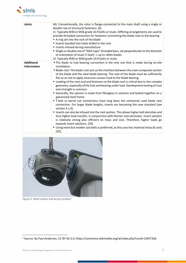