Jet pumps and boosters - pompe | robinete | clapete ... · Jet pumps and boosters 1. ... NBR...
40
GRUNDFOS DATA BOOKLET Jet pumps and boosters 50/60 Hz
Transcript of Jet pumps and boosters - pompe | robinete | clapete ... · Jet pumps and boosters 1. ... NBR...
GRUNDFOS DATA BOOKLET
Jet pumps and boosters50/60 Hz

Ta
ble
of c
on
ten
ts
2
Jet pumps and boosters
1. Product description 3Applications 4Identification 5Installation 6
2. Technical data for jet pumps 8JP 5, JP 6 8JPC, JPRain 10JPBasic 12JDBasic 14Ejector nozzle 16
3. Technical data for jet pump boosters 17JP Booster PM 2 17JP Booster PM 1 19JP Booster PT 21JPRain PM 23JPBasic PM 25JPBasic PS 27JPC PT, JPRain PT 29JPBasic PT 31
4. Product numbers 33
5. Further product information 37WebCAPS 37WinCAPS 38GO CAPS 39

Pro
du
ct
de
sc
rip
tio
n
Jet pumps and boosters 1
1. Product description
Grundfos offers jet pumps for a wide range of domestic applications such as raw water supply, pressure boosting, irrigation and dewatering. The jet pumps ensure a constant supply of fresh water to your home and garden. Grundfos offers five different product types which include a jet pump:
• stand-alone jet pumps (JP, JPC, JPRain, JPBasic)
• a jet pump and an external ejector nozzle for deep-well applications (JDBasic)
• booster solutions which include a jet pump and a Pressure Manager (JP Booster PM1/PM2, JPRain PM, JPBasic PM)
• a booster solution which includes a jet pump and a pressure switch (JPBasic PS)
• booster solutions which include a jet pump, a pressure switch and a pressure tank (JP Booster PT, JPC PT, JPRain PT, JPBasic PT).
JP, JPRain and JPBasicThe jet pumps are self-priming centrifugal pumps designed for long and trouble-free operation. A jet pump has an excellent suction capacity, and due to the built-in ejector the pump is self-priming.
The pump is small, handy and easy to move around, which makes it suitable for a various of applications.
Fig. 1 JP 5, JP 6, JPRain and JPBasic
Booster unitsThe booster units are compact booster systems for domestic water supply. The pressure booster units consist of a Grundfos jet pump and a pressure control unit. The pressure control unit allows the pump to start and stop automatically according to demand and protects the pump from dry running (only applicable for the Grundfos Pressure Manager).
The booster units offered by Grundfos are available in different variants depending on the desired jet pump and pressure control unit. The booster units are divided into two main groups, i.e. jet pumps with Pressure Manager and jet pumps with pressure switch. Pump control with a pressure switch can be combined with a pressure tank to reduce the number of starts and stops.
In addition, the pump can be combined with a diaphragm pressure tank to limit the switching frequency of the pump in case of low water consumption or leakage loss.
Fig. 2 JP Booster PM1, JP Booster PT and JPBasic PS
TM
01
45
95
35
02
- T
M0
5 5
20
5 3
41
2G
r10
45
- G
r79
03
_p
07
04
TM
05
59
87
43
12
- T
M0
5 5
98
9 4
31
2G
r79
08
_p
08
04
- T
M0
5 8
22
5 2
113
3

Pro
du
ct d
es
crip
tion
4
Jet pumps and boosters1
ApplicationsJet pumps and booster units are used for water supply to domestic installations. They are ideal for use in home, garden and hobby applications as well as in agriculture, horticulture and wherever self-priming operation is necessary.
Jet pumps and boosters may be used in:
• single- or two-family households
• summer houses and weekend cottages.
Fig. 3 JP Booster supplying water for different applications
Pumped liquidsJet pumps and boosters are suitable for pumping clean, thin, non-aggressive and non-explosive liquids without solid particles or fibres. Examples of use:
• potable water
• rainwater.
Note: If the pumps are used for pumping unclean liquids, such as pool water, they must subsequently be flushed with clean water. The pumps must not be used for transfer of diesel oil or other oil-containing liquids. Sand and other impurities in the water will cause wear to the pump.
TM
04
48
22
21
09
PM 1/PM 2
Hmax = 8 m
JP
Hmax = 7 m

Pro
du
ct
de
sc
rip
tio
n
Jet pumps and boosters 1
Identification
Type key, JP
Type key, JP Booster
Example JP5 B- A- CVBP- C- Y 1 x 220-240 V, 50 Hz
Pump typeJP 5JP 6
Pipe connectionsA: Rp 1 internal thread (only on request)B: G 1 external thread
MaterialA: Composite motor stool/stainless-steel impellerB: Aluminium motor stool/stainless-steel impellerX: Variant
Code for shaft sealC: O-ring seal with spring as seal driverV: CeramicB: Carbon, resin-impregnatedP: NBR (nitrile rubber)
Mains cable and plugA: Australian plugC: Schuko plugD: Cable, no plugE: No cableF: Swiss plug
SwitchY: With on/off switchN: Without on/off switch
Voltage1 x 220-240 V, 50 Hz3 x 220-240/380-415 V, 50 Hz
Example JPB 5 A- A- A- C- C- P 24L
Pump typeJPB: JP Booster
JP model5: JP 56: JP 6
Booster pump versionA: Standard JP Booster pumpX: Special JP Booster pump
Pipe connectionA:Inlet, JP ext. G 1"Outlet, 5-way valve ext. R1"B:Inlet, JP ext. G 1"Outlet PM thread ext. G1"X: Other pipe configuration
Material of wetted partsA:Sleeve: stainless steelMotor stool: compositeHydraulic parts: stainless steelPressure Manager: technopolymerB:Sleeve: stainless steelMotor stool: stainless steelHydraulic parts: stainless steelPressure Manager: technopolymer
Supply voltageC: 1 x 220-240 V, 50 HzF: 3 x 220-240 V, 50 Hz
Mains cable and plugA: Australian plugC: Schuko plugD: Cable, no plugE: No cable
Control deviceA: PM1 - 1.5 barB: PM1 - 2.2 barC: PM2P: Pressure switch
Pressure tank size
5
Pro
du
ct d
es
crip
tion
6
Jet pumps and boosters1
Installation
Mechanical installationPlacing the pump above ground is generally a convenient way of establishing a water or rainwater supply.
Place the pump as close as possible to the water supply to make the suction pipe as short as possible.
If a hose is used as suction pipe, it must be non-collapsible. To prevent solids from entering the pump, fit a strainer to the suction pipe.
Suction pipe limitations
Although dry-installed pumps have been designed for optimum suction capacity, a few limitations apply to the suction pipe.
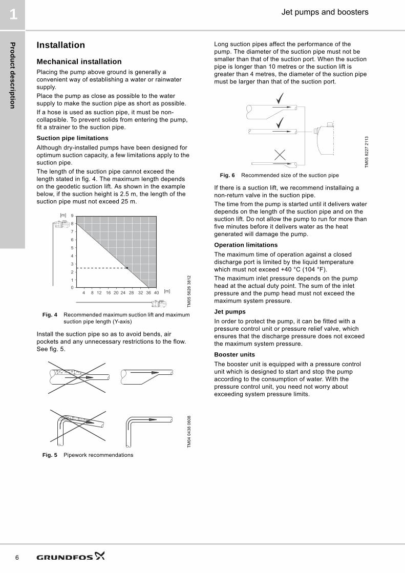
The length of the suction pipe cannot exceed the length stated in fig. 4. The maximum length depends on the geodetic suction lift. As shown in the example below, if the suction height is 2.5 m, the length of the suction pipe must not exceed 25 m.
Fig. 4 Recommended maximum suction lift and maximum suction pipe length (Y-axis)
Install the suction pipe so as to avoid bends, air pockets and any unnecessary restrictions to the flow. See fig. 5.
Fig. 5 Pipework recommendations
Long suction pipes affect the performance of the pump. The diameter of the suction pipe must not be smaller than that of the suction port. When the suction pipe is longer than 10 metres or the suction lift is greater than 4 metres, the diameter of the suction pipe must be larger than that of the suction port.
Fig. 6 Recommended size of the suction pipe
If there is a suction lift, we recommend installaing a non-return valve in the suction pipe.
The time from the pump is started until it delivers water depends on the length of the suction pipe and on the suction lift. Do not allow the pump to run for more than five minutes before it delivers water as the heat generated will damage the pump.
Operation limitations
The maximum time of operation against a closed discharge port is limited by the liquid temperature which must not exceed +40 °C (104 °F).
The maximum inlet pressure depends on the pump head at the actual duty point. The sum of the inlet pressure and the pump head must not exceed the maximum system pressure.
Jet pumps
In order to protect the pump, it can be fitted with a pressure control unit or pressure relief valve, which ensures that the discharge pressure does not exceed the maximum system pressure.
Booster units
The booster unit is equipped with a pressure control unit which is designed to start and stop the pump according to the consumption of water. With the pressure control unit, you need not worry about exceeding system pressure limits.
TM
05
56
26
38
12
TM
04
04
38
06
08
0
1
4 8 12 16 20 24 28 32 36 40
2
3
4
5
6
7
8
9[m]
[m]
TM
05
82
27
211
3

Pro
du
ct
de
sc
rip
tio
n
Jet pumps and boosters 1
Electrical installationThe electrical connection and protection should be carried out in accordance with local regulations.
• The pump must be connected to an external mains switch with a minimum contact gap of 3 mm in all poles.
• Make sure that the pump and pressure control unit are suitable for the power supply to which they are to be connected.
• The pump and pressure control unit must always be correctly earthed.
• One-phase pumps incorporate thermal protection and therefore require no external protection.
• Three-phase pumps require external motor protection in accordance with the applicable regulations.
• The electrical installation of the pressure control unit must be carried out so as to ensure that the enclosure class is maintained.
7

Te
ch
nic
al d
ata
for je
t pu
mp
s
8
Jet pumps and boosters2
2. Technical data for jet pumps
JP 5, JP 6
Fig. 7 JP 6
JP 5 and JP 6 are self-priming, single-stage centrifugal pumps with axial suction port and radial discharge port, G 1. They have a built-in ejector with guide vanes for optimum self-priming properties. JP 5 and JP 6 are made of high-quality materials, which makes them very robust.
ApplicationsJP 5 and JP 6 are ideal for water supply and transfer in minor applications such as domestic systems, garden irrigation and car washing. JP 5 and JP 6 may be used in the following domestic installations:
• single- or two-family households
• summer houses and weekend cottages.
JP 5 and JP 6 are especially ideal for use in small-scale agriculture, gardening and wherever self-priming operation is necessary.
MotorThe pump is directly coupled to a special fan-cooled asynchronous Grundfos motor which corresponds to the pump performance. Single-phase motors have a built-in thermal switch and require no additional motor protection. Three-phase motors require external motor protection.
Features• Self-priming
• robust design
• corrosion-free materials.
Operating conditions
Electrical data, 50 Hz
Approvals and markings
* Note: JP pumps are available in two material variants: composite or aluminium motor stool. The ACS certificates only cover the composite motor stool version.
TM
01
45
95
35
02
Enclosure class: IP44 (splash-proof).Insulation class: F.
System pressure Max. 6 bar
Suction liftMax. 7 m, including suction-pipe pressure loss at a liquid temperature of +20 °C
Liquid temperature 0 °C to +40 °C
Ambient temperatureMax. +45 °C
Min. -20 °C
Relative air humidity Max. 95 %
Enclosure class IP44
Insulation class F
Sound pressure levelThe sound pressure level of the pump is below 72 dB(A).
Supply voltage1 x 220-240 V, 50 Hz
3 x 220-240/380-415 V, 50 Hz
Start/stop frequency Max. 100 per hour
Pump type Voltage [V] P1 [W] n [min-1] In [A] Istart [A]
JP 51 x 220-240 850 2650 3.8 13.0
3 x 220-240/380-415
780 28302.4 / 1.4
7.0
JP 61 x 220-240 1400 2800 6.2 26.0
3 x 220-240/380-415
1325 28504.1 / 2.4
16.3
Pump type
Approvals Markings
WRAS ACS CE C-TickGOST /
EAC
JP 5 ● ●* ● ● ●
JP 6 - ●* ● ● ●

Te
ch
nic
al
da
ta f
or
jet
pu
mp
s
Jet pumps and boosters 2
Performance curves
Fig. 8 Performance curves for JP 5 and JP 6
Wetted partsThe below table specifies the parts of the pump which are in contact with water.
MaterialsJP 5 and JP 6 are available in two material variants:
Material variant A
Cover plate, motor stool and base plate are one unit, which is made of composite material. The handle is fitted crosswise and also made of composite material.
Material variant B
Stainless-steel cover plate, aluminium motor stool and stainless-steel base plate, all separate parts. The handle is fitted lengthwise and made of composite material.
Dimensions
TM
05
81
38
22
13
- T
M0
5 7
84
5 2
21
3
0.0 0.2 0.4 0.6 0.8 1.0 1.2 1.4 1.6 1.8 2.0 2.2 2.4 2.6 2.8 3.0 3.2 3.4 3.6 Q [m³/h]
0
5
10
15
20
25
30
35
40
45
H[m]
0.0 0.1 0.2 0.3 0.4 0.5 0.6 0.7 0.8 0.9 1.0 Q [l/s]
JP 5ISO 9906:1999 Annex A
0m0.25m2m
3m4m5m6m7m
0.0 0.5 1.0 1.5 2.0 2.5 3.0 3.5 4.0 4.5 5.0 Q [m³/h]
0
5
10
15
20
25
30
35
40
45
50
H[m]
0.0 0.2 0.4 0.6 0.8 1.0 1.2 1.4 Q [l/s]
JP 6ISO 9906:1999 Annex A
7 m6 m 5 m
4 m3 m 2 m
0.25 m
0 m
Designation MaterialTechnical description
Pump sleeve Stainless steelEN 1.4301AISI 304
Impeller Stainless steelEN 1.4301AISI 304
Diffuser Technopolymer PP 20 % Talc
Ejector Technopolymer PPE/PS 20 % GF
Nozzle Stainless steelEN 1.4301AISI 304
Shaft Stainless steelEN 1.4301AISI 304
Shaft seal Carbon with resin/ceramic CVBP
Filling plug Technopolymer PES 30 % GF
Drainage plug Technopolymer PES 30 % GF
TM
04
23
46
23
08
TM
04
23
47
23
08
Pump type
Material variant A
Pump type
Material variant B
Dimensions [mm]Weight [kg]
Dimensions [mm]Weight [kg]
A B C A B C
JP 5, material variant A 300 364 240 8.5 JP 5, material variant B 300 364 240 11.0
JP 6, material variant A 300 401 240 10.0 JP 6, material variant B 300 401 240 10.8
9

Te
ch
nic
al d
ata
for je
t pu
mp
s
10
Jet pumps and boosters2
JPC, JPRain
Fig. 9 JPC / JPRain
JPC, JPRain is a self-priming, single-stage centrifugal pump with axial suction port and radial discharge port, G 1. The pump has a built-in ejector with guide vanes for optimum self-priming properties.
ApplicationsJPC, JPRain is ideal for water supply and transfer in minor applications such as domestic systems, garden irrigation and car washing. JPC, JPRain may be used in the following domestic installations:
• single- or two-family households
• summer houses and weekend cottages.
JPC, JPRain is especially ideal for use in small-scale agriculture, gardening and wherever self-priming operation is necessary.
MotorThe rotor is mounted on an oversize, sealed, greased-for-life ball bearings to ensure silent running and long life. Single-phase motors have built-in thermal and current protection and require no additional motor protection.
Features• Self-priming
• robust design
• corrosion-free materials.
Operating conditions
Electrical data, 50 Hz
Electrical data, 60 Hz
Approvals and markings
TM
05
50
91
32
12
Enclosure class: IP44 (splash-proof).Insulation class: F.
System pressure Max. 6 bar
Suction liftMax. 8 m, including suction-pipe pressure loss at a liquid temperature of +20 °C
Liquid temperature 0 °C to +35 °C
Ambient temperature Max. +40 °C
Relative air humidity Max. 95 %
Enclosure class IP44
Insulation class F
Sound pressure level
Maximum sound pressure level of the pump:JPC, JPRain 2: 82.9 dBJPC, JPRain 3: 84.8 dBJPC, JPRain 4: 88.0 dB
Supply voltage 1 x 220-240 V, 50 Hz
Start/stop frequency Max. 20 per hour
Pump type Voltage [V] P1 [W] n [min-1] In [A] Istart [A]
JPC / JPRain 2 1 x 220-240 720 2900 3.12 8.54
JPC / JPRain 3 1 x 220-240 850 2900 3.8 11.27
JPC / JPRain 4 1 x 220-240 1130 2900 5.1 17.8
Pump type
Voltage [V] P1 [W] P2 [W] n [min-1] In [A] Istart [A]
JPC 2 1 x 110-120 730 450 3400 6.6 22.4
JPC 2 1 x 220-240 700 450 3400 4 11.3
JPC 3 1 x 110-120 900 600 3400 8 26.8
JPC 3 1 x 220-240 880 600 3400 3.9 13.2
JPC 4 1 x 110-120 1100 750 3400 9.7 47.5
JPC 4 1 x 220-240 1100 750 3400 5 23.9
Pump typeApprovals Markings
WRAS ACS CE C-Tick EAC
JPC / JPRain 2 - - ● ● ●
JPC / JPRain 3 - - ● ● ●
JPC / JPRain 4 - - ● ● ●

Te
ch
nic
al
da
ta f
or
jet
pu
mp
s
Jet pumps and boosters 2
Performance curves
Fig. 10 Performance curves for JPC/JPRain 2, JPC/JPRain 3 and JPC/JPRain 4
Wetted partsThe below table specifies the parts of the pump which are in contact with water.
MaterialsThe pump body is made of technopolymer and the motor support of die-cast aluminium. Internal components, such as impeller, diffuser, venturi tube and sand guard, are made of technopolymer.
Dimensions
TM
06
07
31
10
14
- T
M0
6 0
84
4 1
114
0.0 0.5 1.0 1.5 2.0 2.5 3.0 3.5 4.0 Q [m³/h]05
101520253035404550
H[m]
0 10 20 30 40 50 60 Q [l/min]
50 Hz
2
34
JP Rain /JPC
Q m3/h0 0,5 1 1,5 2 2,5 3 3,5 40
10
20
30
40
50
0
20
40
60
80
100
120
160
Q l/sQ l/min
0
0
0,2 0,4 0,6 0,8 1
10 20 30 40 50 60
Hft
2
4
3
JPC 60 Hz
H[m]
Designation MaterialTechnical description
Pump body Technopolymer PP 30 % GF
Impeller TechnopolymerPPE 20 % GF brass
Diffuser Technopolymer PPE 20 % GF
Diffuser ring Stainless steelEN 1.4401AISI 316
Venturi tubeTechnopolymerRubber
PPE + 20 % GFNBR
Seal housing Rubber NBR
Shaft Stainless steelEN 1.4305AISI 303
Shaft seal Carbon with resin/ceramic CBBXP
Filling plug Technopolymer PPE 20 % GF
Filling plug gasket Rubber NBR
Drainage plug Technopolymer PPE 20 % GF
Drainage plug gasket Rubber NBR
Mechanical seal disc Stainless steelEN 1.4301AISI 304
TM
05
56
05
37
12
Pump typeDimensions [mm]
PortsWeight
[kg]A B C
JPC / JPRain 2 171 410 200 G 1 or NPT 1 9.1
JPC / JPRain 3 171 410 200 G 1 or NPT 1 9.4
JPC / JPRain 4 171 410 210 G 1 or NPT 1 11.4
11

Te
ch
nic
al d
ata
for je
t pu
mp
s
12
Jet pumps and boosters2
JPBasic
Fig. 11 JPBasic
JPBasic is a self-priming, single-stage centrifugal pump with axial suction port and radial discharge port. The pump has a built-in ejector with guide vanes for optimum self-priming properties.
ApplicationsJPBasic is ideal for water supply and transfer in minor applications such as domestic systems, garden irrigation and car washing. JPBasic may be used in the following domestic installations:
• single- or two-family households
• summer houses and weekend cottages.
JPBasic is especially ideal for use in small-scale agriculture, gardening and wherever self-priming operation is necessary.
MotorThe rotor is mounted on an oversize, sealed, greased-for-life ball bearings to ensure silent running and long life. Single-phase motors have built-in thermal and current protection and require no additional motor protection.
Three-phase motors require external motor protection.
Features• Self-priming
• robust design
• corrosion-resistant materials
• sand guard.
Operating conditions
Electrical data, 50 Hz
Approvals and markings
Gr7
90
3 -
Gr7
92
1 -
Gr7
91
7
Enclosure class: IP44 (splash-proof).Insulation class: F.
System pressureMax. 6 bar (JPBasic 2, -3, -4)Max. 7.5 bar (JPBasic 5, -7, -9, -10)
Operating range 0.6 to 10.5 m3/h
Suction liftMax. 8 m, including suction-pipe pressure loss at a liquid temperature of +20 °C
Liquid temperature0 °C to +35 °C (for domestic use)0 °C to +40 °C (for other use)
Ambient temperature Max. +40 °C
Relative air humidity Max. 95 %
Enclosure class IP44
Insulation class F
Sound pressure levelThe sound pressure level of the pump is below 77 dB(A).
Supply voltage1 x 220-240 V, 50 Hz3 x 220-240/380-415 V, 50 Hz
Start/stop frequency Max. 20 per hour
Pump type Voltage [V] P1 [W] n [min-1] In [A]
JPBasic 21 x 220-240 720
28503.12
3 x 220-240/380-415
6702.1 / 1.2
JPBasic 31 x 220-240 850
27503.8
3 x 220-240/380-415
8602.8 / 1.6
JPBasic 41 x 220-240 1130
28005.1
3 x 220-240/380-415
10403.3 / 1.9
JPBasic 51 x 220-240 1600
28007.2
3 x 220-240/380-415
16005.2 / 3.0
JPBasic 71 x 220-240 2200
280010
3 x 220-240/380-415
22006.9 / 4.0
JPBasic 91 x 220-240 2000
28509
3 x 220-240/380-415
20006.8 / 3.9
JPBasic 101 x 220-240 2700
285012
3 x 220-240/380-415
27008.5 / 4.9
Pump type
Approvals Markings
WRAS ACS CE C-TickGOST /
EAC
JPBasic 2 - - ● ● ●
JPBasic 3 - - ● ● ●
JPBasic 4 - - ● ● ●
JPBasic 5 - - ● ● ●
JPBasic 7 - - ● ● ●
JPBasic 9 - - ● ● ●
JPBasic 10 - - ● ● ●

Te
ch
nic
al
da
ta f
or
jet
pu
mp
s
Jet pumps and boosters 2
Performance curves
Fig. 12 Performance curves for JPBasic
Wetted partsThe below table specifies the parts of the pump which are in contact with water.
* Applies to JPBasic 2, -3, -4.
MaterialsThe pump body and the motor support are made of cast iron. Internal components, such as impeller, diffuser, venturi tube and sand guard, are made of technopolymer.
Dimensions
TM
02
89
36
18
04
0 1 2 3 4 5 6 7 8 9 10 11 Q [m³/h]
0
5
10
15
20
25
30
35
40
45
50
55
60
65
H[m]
0.0 0.5 1.0 1.5 2.0 2.5 3.0 Q [l/s]
0
100
200
300
400
500
600
p[kPa]
JPBasic50 Hz
75
10
9
4
3
2
Designation MaterialTechnical description
Pump body Cast iron EN-GJL-200
Motor supportCast ironDie-cast aluminum*
EN-GJL-200EN AB 46100
Impeller Technopolymer Noryl GFN 2
Diffuser Technopolymer Noryl GFN 2
Diffuser ring Stainless steelEN 1.4401AISI 316
Venturi tubeTechnopolymerRubber
Noryl GFN 2
Shaft Stainless steelEN 1.4305AISI 303
Shaft seal Carbon with resin/ceramic BBQP
Filling/drainage plug Technopolymer PPE 20 % GF
Filling/drainage plug gasket
Rubber NBR
Back plate Stainless steelEN 1.4301AISI 304
TM
02
84
44
02
04
- T
M0
2 9
02
6 1
30
4
Pump type
Dimensions [mm] Weight
[kg]
Port
A B H Suction Discharge
JPBasic 2 470 240 240 11.6 Rp 1 Rp 1
JPBasic 3 470 240 240 12.2 Rp 1 Rp 1
JPBasic 4 470 240 240 13.9 Rp 1 Rp 1
JPBasic 5 680 293 246 32.3 Rp 1 1/4 Rp 1
JPBasic 7 680 293 246 32.7 Rp 1 1/4 Rp 1
JPBasic 9 680 293 246 35.9 Rp 1 1/2 Rp 1 1/4
JPBasic 10 680 293 246 32.2 Rp 1 1/2 Rp 1 1/4
C
H
GB
I
AA1
DNM
E F
H3
DN
A
G
B
Iø
E
AC
DNM
H1D
NE
HD
NA
H2
13

Te
ch
nic
al d
ata
for je
t pu
mp
s
14
Jet pumps and boosters2
JDBasic
Fig. 13 JDBasic
JDBasic is a self-priming centrifugal pump for suction up to 27 metres, achieved by means of an ejector to be inserted into wells with a diameter of 4" or larger. The pump is ideal for supplying water to farmhouses and in small-scale agriculture.
ApplicationsJPBasic PT is suitable for pressure boosting from mains water or below-ground water tanks where self-priming operation is necessary. Due to the pressure switch and the diaphragm tank, the booster unit provides great comfort for the user. The booster unit may be used in the following domestic installations:
• single- or two-family households
• summer houses and weekend cottages.
Features
Pump
Cast-iron pump body and motor support, anti-corrosion treated on the outer as well as the inner surfaces. Technopolymer impeller, diffuser and Venturi tube and brass nozzle. Stainless-steel pressure disc. Carbon/ceramic mechanical seal mounted on stainless-steel rotor shaft extension.
Ejector
Cast-iron body, anti-corrosion treated on the outer as well as the inner surfaces. Technopolymer Venturi tube and brass nozzle. The ejector is available in 3 models (E20, E25, E30) to be chosen according to performance requirements. See section Ejector nozzle.
Motor
The rotor is mounted on an oversize, sealed, greased-for-life ball bearings to ensure silent running and long life. Single-phase motors have built-in thermal and current protection and require no additional motor protection.
Three-phase motors require external motor protection.
Operating conditions
Electrical data, 50 Hz
Approvals and markings
Gr7
8 9
9_
p 0
80
4 -
TM
00
99
74
-01
08
97
Enclosure class: IP44 (splash-proof).Insulation class: F.
System pressureMax. 6 bar (JDBasic 2, 4)Max. 7.5 bar (JDBasic 5, 7)
Suction liftMax. 27 m, including suction-pipe pressure loss at a liquid temperature of +20 °C
Liquid temperature0 °C to +35 °C (for domestic use)0 °C to +40 °C (for other use)
Ambient temperature Max. +40 °C
Relative air humidity Max. 95 %
Enclosure class IP44
Insulation class F
Sound pressure levelThe sound pressure level of the pump is below 77 dB(A).
Supply voltage1 x 220-240 V, 50 Hz3 x 220-240/380-415, 50 Hz
Start/stop frequency Max. 20 per hour
Pump type Voltage [V] P1 [W] n [min-1] In [A]
JDBasic 21 x 220-240 690 2850 3.2
3 x 220-240/380-415
660 28502.6 / 1.5
JDBasic 41 x 220-240 790 2850 3.8
3 x 220-240/380-415
640 28502.6 / 1.5
JDBasic 51 x 220-240 1560 2850 7
3 x 220-240/380-415
1450 28504.7 / 2.7
JDBasic 71 x 220-240 2100 2850 8.3
3 x 220-240/380-415
1780 28505.6 / 3.2
Pump type
Approvals Markings
WRAS ACS CE C-TickGOST /
EAC
JDBasic 2 - - ● - ●
JDBasic 4 - - ● - ●
JDBasic 5 - - ● - ●
JDBasic 7 - - ● - ●

Te
ch
nic
al
da
ta f
or
jet
pu
mp
s
Jet pumps and boosters 2
Principle
Fig. 14 Installation principle for JDBasic
Wetted partsThe below table specifies the parts of the pump which are in contact with water.
Pump
* Applies to JPBasic 2, -4.
Dimensions
TM
00
99
76
10
97
Designation MaterialTechnical description
Pump body Cast iron EN-GJL-200
Motor supportCast ironDie-cast aluminum*
EN-GJL-200EN AB 46100
Impeller Technopolymer Noryl GFN 2
Diffuser Technopolymer Noryl GFN 2
Diffuser ring Stainless steelEN 1.4401AISI 316
Venturi tubeTechnopolymerRubber
Noryl GFN 2
Shaft Stainless steelEN 1.4305AISI 303
Shaft seal Carbon with resin/ceramic BBQP
Filling/drainage plug Technopolymer PPE 20 % GF
Filling/drainage plug gasket
Rubber NBR
Back plate Stainless steelEN 1.4301AISI 304
TM
02
84
55
02
04
- T
M0
2 8
45
5 1
80
4
Pump type
Dimensions [mm]
Weight [kg]
Port
A B H Suction Discharge
JDBasic 2 365 180 225 13.9 G 1 1/4 G1
JDBasic 4 470 240 240 16.8 G 1 1/4 G1
TM
02
84
62
18
04
Pump type
Dimensions [mm]
Weight [kg]
Port
A B H Suction Discharge
JDBasic 5 428 293 240 27 G 1 1/4 G1
JDBasic 7 612 293 246 32 G 1 1/4 G1
H2
H
GB
V
X
Z
HH
1
AC
H
GB
I
AA1
DNM
E F
H3
DN
A
CA
E
B
DNM
G
I ØX
V
Z
HH
1
15

Te
ch
nic
al d
ata
for je
t pu
mp
s
16
Jet pumps and boosters2
Ejector nozzleThe ejector is available in three models (E20, E25, E30) to be chosen according to performance requirements.
Fig. 15 Ejector
JDBasic 2, JDBasic 4
JDBasic 5, JDBasic 7
Instructions for conversion
Conversion from JDBasic 5 or JDBasic 7 to JPBasic 5 or JPBasic 7
Screw nozzle (9) into the seat of ejector body (2) and Venturi tube (8).
Position O-rings (27 and 29) in their respective seats, and mount ejector body (2) on pump body (1) with the two screws (53).
Conversion from JPBasic 5 or JPBasic 7 to JDBasic 5 or JDBasic 7
Loosen and remove the two joining screws (53) between ejector body (2) and pump body (1).
Collect O-rings (27 and 29).
TM
02
84
56
02
04
- T
M0
2 8
45
7 0
20
4Pos. Description
2 Ejector body
8 Venturi tube
9 Nozzle
Pump typeA
[mm]H
[mm]H1
[mm]x v z
JDBasic 97 295 243 G 1 G 1 G 1 1/4
Hydraulic data (n ≈ 2850 min -1)
Pump type
Ejector type
Suction depth
Delivery pressure in bar
1.5 2.0 2.5 3.0 3.5 4.0
Capacity table in [l/h]
JD
Ba
sic
2 E25
9 1813 1080 446 33
12 1426 720 225
15 900 326
E30
9 1753 1286 812 524 261 46
12 1345 965 608 356 162 0
15 1166 761 452 228 45
JD
Ba
sic
4
E25
9 2386 1756 1097 515 126
12 1930 1190 536 87
15 1459 773 252
E30
12 1240 872 566 329 156
15 1028 701 449 255 96
18 785 527 302 150 15
21 635 374 180 39
8
2
9
1 6 28
16 4X
V
Z
HH
1
Hydraulic data (n ≈ 2850 min -1)
Pu
mp
ty
pe
Eje
cto
r ty
pe
Su
cti
on
de
pth Delivery pressure [bar]
3.0 3.5 4.0 4.5 5.0 5.5 6.0 6.5 7.0 7.5 8.0
Capacity table [l/h]
JD
Ba
sic
5
E 20
9 3412 2769 2090 1363 586
12 3065 2400 1719 952 143
15 2643 2000 1257 495
18 2289 1593 826 0
E 25
15 2745 2244 1761 1257 814 435 77
18 2465 1969 1477 997 584 218
21 2206 1712 1224 779 388 45
E 30
21 1797 1615 1368 1106 861 658 472 312 163 25
24 1652 1484 1217 962 740 547 378 220 67
27 1520 1333 1069 841 636 448 287 139
JD
Ba
sic
7
E 20
9 3431 2751 2033 1236 448
12 3043 2324 1554 763 0
15 2665 1936 1145 344
18 2244 1478 675
E 25
15 2840 2324 1806 1296 849 463 138
18 2535 2038 1523 1049 640 286
21 2267 1757 1257 817 424 91
24 1970 1458 989 583 226
E 30
21 1812 1671 1419 1163 919 716 531 377 226 91
24 1668 1549 1278 1023 791 619 445 297 156 13
27 1541 1395 1145 906 700 521 351 206 62
TM
00
99
80
10
97
- T
M0
0 9
98
1 1
09
7

Te
ch
nic
al
da
ta f
or
jet
pu
mp
bo
os
ters
Jet pumps and boosters 3
3. Technical data for jet pump boosters
JP Booster PM 2
Fig. 16 JP Booster PM 2
JP Booster PM 2 is an automatic booster unit for water supply in domestic and irrigation applications as well as other installations where small leakages are expected to occur. The pressure booster unit consists of a JP 5 or JP 6 pump combined with a Grundfos PM 2 Pressure Manager. The Pressure Manager allows the pump to start and stop automatically according to demand.
To reduce the number of starts/stops, an external tank can be installed. See sections GT-U, bladder and GT-H, diaphragm on page 36.
ApplicationsJP Booster PM 2 is suitable for pressure boosting from mains water or below-ground water tanks where self-priming operation is necessary. The booster unit may be used in the following domestic installations:
• single- or two-family households
• summer houses and weekend cottages.
Features• Self-priming
• robust design
• corrosion-free materials
• automatic start/stop
• integrated non-return valve.
The PM 2 Pressure Manager incorporated in the booster unit provides the following features:
Adjustable start pressure
The booster unit can be set to start automatically within an adjustable pressure range of 1.5 to 5 bar. The current pressure is indicated on the LED display on the front of the PM 2.
Anti-cycling
If there is a minor leakage in the system, or a tap has not been entirely closed, the PM 2 would normally start and stop the pump periodically. However, in order to avoid cycling, the anti-cycling function of the PM 2 will stop the pump and indicate an alarm.
Dry-running protection
The PM 2 incorporates dry-running protection that automatically stops the pump in case of dry running. The dry-running protection functions differently during priming and operation.
Maximum continuous operating time (30 minutes)
When this function is enabled, the pump will stop when it has been running continuously for 30 minutes. The purpose of the function is to avoid unnecessary water and current consumption, e.g. in case of pipe fracture or considerable leakages.
MotorThe pump is directly coupled to a special fan-cooled asynchronous Grundfos motor which corresponds to the pump performance. Single-phase motors have a built-in thermal switch and require no additional motor protection.
Operating conditions
Electrical data, 50 Hz
Approvals and markings
TM
05
59
88
43
12
Enclosure class: IP44 (splash-proof).Insulation class: F.
System pressure Max. 6 bar
Suction liftMax. 7 m, including suction-pipe pressure loss at a liquid temperature of +20 °C
Liquid temperature 0 °C to +40 °C
Ambient temperatureMax. +45 °C
Min. -20 °C
Relative air humidity Max. 95 %
Enclosure class IP44
Insulation class F
Sound pressure levelThe sound pressure level of the pump is below 72 dB(A).
Supply voltage 1 x 220-240 V, 50 Hz
Start/stop frequency Max. 100 per hour
Pump type Voltage [V] P1 [W] n [min-1] In [A] Istart [A]
JP 5 Booster PM 2 1 x 220-240 850 2650 3.8 13.0
JP 6 Booster PM 2 1 x 220-240 1400 2800 6 26.0
Pump type
Approvals Markings
WRAS ACS CE C-TickGOST TR / EAC
JP Booster PM 2 - - ● ● ●
17

Te
ch
nic
al d
ata
for je
t pu
mp
bo
os
ters
18
Jet pumps and boosters3
Performance curves
Fig. 17 Performance curves for JP 5 and JP 6
Note: The performance curves are for the pumps only. Additional pressure drop over the Pressure Manager will occur.
Wetted partsThe below tables specify the parts of the pump and Pressure Manager which are in contact with water.
Pump
Pressure Manager
PumpJP Booster PM 2 is available with a JP 5 or JP 6 pump. The motor stool of the pump is made of composite, and the pump has no handle. For further information on the differences between JP 5 and JP 6, see page 8.
Dimensions
TM
05
81
38
22
13
- T
M0
5 7
84
5 2
21
3
0.0 0.2 0.4 0.6 0.8 1.0 1.2 1.4 1.6 1.8 2.0 2.2 2.4 2.6 2.8 3.0 3.2 3.4 3.6 Q [m³/h]
0
5
10
15
20
25
30
35
40
45
H[m]
0.0 0.1 0.2 0.3 0.4 0.5 0.6 0.7 0.8 0.9 1.0 Q [l/s]
JP 5ISO 9906:1999 Annex A
0m0.25m2m
3m4m5m6m7m
0.0 0.5 1.0 1.5 2.0 2.5 3.0 3.5 4.0 4.5 5.0 Q [m³/h]
0
5
10
15
20
25
30
35
40
45
50
H[m]
0.0 0.2 0.4 0.6 0.8 1.0 1.2 1.4 Q [l/s]
JP 6ISO 9906:1999 Annex A
7 m6 m 5 m
4 m3 m 2 m
0.25 m
0 m
Designation MaterialTechnical description
Pump sleeve Stainless steelEN 1.4301AISI 304
Impeller Stainless steelEN 1.4301AISI 304
Diffuser Technopolymer PP 20 % Talc
Ejector Technopolymer PPE/PS 20 % GF
Nozzle Stainless steelEN 1.4301AISI 304
Shaft Stainless steelEN 1.4301AISI 304
Shaft seal Carbon with resin/ceramic CVBP
Filling plug Technopolymer PES 30 % GF
Drainage plug Technopolymer PES 30 % GF
Designation MaterialTechnical description
Main housing Technopolymer PP 30 % GF
Shutter Technopolymer PPO 20 % GF
O-ring Rubber NBR
Cover magnet Technopolymer PPO 20 % GF
Fitting 1" Technopolymer PPO 30 % GF
Spring Stainless steelEN 1.4305AISI 303
Diaphragm Butil Foodgum 55 N/B
TM
05
59
71
43
12
Pump typeDimensions [mm]
Weight [kg]A B C D
JP 5 364 206 420 182 8.5
JP 6 401 206 420 182 10.0

Te
ch
nic
al
da
ta f
or
jet
pu
mp
bo
os
ters
Jet pumps and boosters 3
JP Booster PM 1
Fig. 18 JP Booster PM 1
JP Booster PM 1 is a compact booster unit for water supply in domestic and irrigation applications. The pressure booster unit consists of a JP 5 or JP 6 combined with a Grundfos PM 1 Pressure Manager. The Pressure Manager allows the pump to start and stop automatically according to demand and protects the pump from dry running. Depending on the booster unit, the pump automatically starts at 1.5 or 2.2 bar.
To reduce the number of starts/stops, an external tank can be installed. See sections GT-U, bladder and GT-H, diaphragm, page 36.
ApplicationsJP Booster PM 1 is suitable for pressure boosting from mains water or below-ground break tanks where self-priming operation is necessary. The booster unit may be used in the following domestic installations:
• single- or two-family households
• summer houses and weekend cottages.
Features• Self-priming
• robust design
• corrosion-free materials
• automatic start/stop
• integrated non-return valve.
The PM 1 Pressure Manager incorporated in the booster unit provides the following features:
Anti-cycling
If there is a minor leakage in the system, or a tap has not been entirely closed, the PM 1 would normally start and stop the pump periodically. However, in order to avoid cycling, the anti-cycling function of the PM 1 will stop the pump and indicate an alarm.
Dry-running protection
The PM 1 incorporates dry-running protection that automatically stops the pump in case of dry running. The dry-running protection functions differently during priming and operation.
MotorThe pump is directly coupled to a special fan-cooled asynchronous Grundfos motor which corresponds to the pump performance. Single-phase motors have a built-in thermal switch and require no additional motor protection.
Operating conditions
Electrical data, 50 Hz
Approvals and markings
TM
05
59
89
43
12
Enclosure class: IP44 (splash-proof).Insulation class: F.
System pressure Max. 6 bar
Suction liftMax. 7 m, including suction-pipe pressure loss at a liquid temperature of +20 °C
Liquid temperature 0 °C to +40 °C
Ambient temperatureMax. +45 °C
Min. -20 °C
Relative air humidity Max. 95 %
Enclosure class IP44
Insulation class F
Sound pressure levelThe sound pressure level of the pump is below 72 dB(A).
Supply voltage 1 x 220-240 V, 50 Hz
Start/stop frequency Max. 100 per hour
Pump type Voltage [V] P1 [W] n [min-1] In [A] Istart [A]
JP 5 Booster PM 1 1 x 220-240 850 2650 3.8 13.0
JP 6 Booster PM 1 1 x 220-240 1400 2800 6 26.0
Pump type
Approvals Markings
WRAS ACS CE C-TickGOST TR / EAC
JP Booster PM 1 - - ● ● ●
19
Te
ch
nic
al d
ata
for je
t pu
mp
bo
os
ters
20
Jet pumps and boosters3
Performance curves
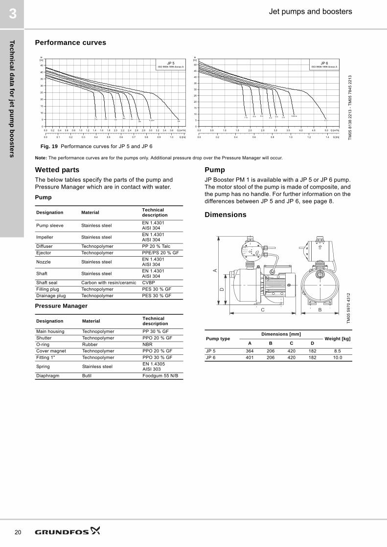
Fig. 19 Performance curves for JP 5 and JP 6
Note: The performance curves are for the pumps only. Additional pressure drop over the Pressure Manager will occur.
Wetted partsThe below tables specify the parts of the pump and Pressure Manager which are in contact with water.
Pump
Pressure Manager
PumpJP Booster PM 1 is available with a JP 5 or JP 6 pump. The motor stool of the pump is made of composite, and the pump has no handle. For further information on the differences between JP 5 and JP 6, see page 8.
Dimensions
TM
05
81
38
22
13
- T
M0
5 7
84
5 2
21
3
0.0 0.2 0.4 0.6 0.8 1.0 1.2 1.4 1.6 1.8 2.0 2.2 2.4 2.6 2.8 3.0 3.2 3.4 3.6 Q [m³/h]
0
5
10
15
20
25
30
35
40
45
H[m]
0.0 0.1 0.2 0.3 0.4 0.5 0.6 0.7 0.8 0.9 1.0 Q [l/s]
JP 5ISO 9906:1999 Annex A
0m0.25m2m
3m4m5m6m7m
0.0 0.5 1.0 1.5 2.0 2.5 3.0 3.5 4.0 4.5 5.0 Q [m³/h]
0
5
10
15
20
25
30
35
40
45
50
H[m]
0.0 0.2 0.4 0.6 0.8 1.0 1.2 1.4 Q [l/s]
JP 6ISO 9906:1999 Annex A
7 m6 m 5 m
4 m3 m 2 m
0.25 m
0 m
Designation MaterialTechnical description
Pump sleeve Stainless steelEN 1.4301AISI 304
Impeller Stainless steelEN 1.4301AISI 304
Diffuser Technopolymer PP 20 % Talc
Ejector Technopolymer PPE/PS 20 % GF
Nozzle Stainless steelEN 1.4301AISI 304
Shaft Stainless steelEN 1.4301AISI 304
Shaft seal Carbon with resin/ceramic CVBP
Filling plug Technopolymer PES 30 % GF
Drainage plug Technopolymer PES 30 % GF
Designation MaterialTechnical description
Main housing Technopolymer PP 30 % GF
Shutter Technopolymer PPO 20 % GF
O-ring Rubber NBR
Cover magnet Technopolymer PPO 20 % GF
Fitting 1" Technopolymer PPO 30 % GF
Spring Stainless steelEN 1.4305AISI 303
Diaphragm Butil Foodgum 55 N/B
TM
05
59
70
43
12
Pump typeDimensions [mm]
Weight [kg]A B C D
JP 5 364 206 420 182 8.5
JP 6 401 206 420 182 10.0

Te
ch
nic
al
da
ta f
or
jet
pu
mp
bo
os
ters
Jet pumps and boosters 3
JP Booster PT
Fig. 20 JP Booster PT
JP Booster PT is an automatic booster unit for water supply in domestic and agricultural applications as well as other installations where small leakages are expected to occur. The pressure booster unit consists of a JP 5 or JP 6 pump combined with a pressure switch and a diaphragm tank.
The pressure switch automatically starts the pump according to demand. The preset cut-in and cut-out pressures are 2.2 and 3.3 bar, respectively.
The diaphragm tank ensures a controlled pressure in the water supply and thereby limits the switching frequency of the pump in case of low water consumption or leakage loss. Furthermore, the diaphragm tank increases system comfort by compensating for pressure drops when a tap is opened, and finally it reduces problems with water hammer in the pipework.
JP Booster PT is available with the following diaphragm tanks:
• 18-litre vertical tank
• 24-litre horizontal tank
• 60-litre horizontal tank.
ApplicationsJP Booster PT is suitable for pressure boosting from mains water or below-ground water tanks where self-priming operation is necessary. Due to the pressure switch and the diaphragm tank, the booster unit provides great comfort for the user. The booster unit may be used in the following domestic installations:
• single- or two-family households
• summer houses and weekend cottages.
Features• Self-priming
• robust design
• corrosion-free materials
• automatic start/stop
• constant water supply.
MotorThe pump is directly coupled to a special fan-cooled asynchronous Grundfos motor which corresponds to the pump performance. Single-phase motors have a built-in thermal switch and require no additional motor protection. Three-phase motors require external motor protection.
Operating conditions
Electrical data, 50 Hz
Approvals and markings
TM
05
59
87
43
12
Enclosure class: IP44 (splash-proof).Insulation class: F.
System pressure Max. 6 bar
Suction liftMax. 7 m, including suction-pipe pressure loss at a liquid temperature of +20 °C
Liquid temperature 0 °C to +40 °C
Ambient temperatureMax. +45 °C
Min. -20 °C
Relative air humidity Max. 95 %
Enclosure class IP44
Insulation class F
Sound pressure levelThe sound pressure level of the pump is below 72 dB(A).
Supply voltage1 x 220-240 V, 50 Hz
3 x 220-240/380-415 V, 50 Hz
Start/stop frequency Max. 100 per hour
Pump type Voltage [V] P1 [W] n [min-1] In [A] Istart [A]
JP 51 x 220-240 850 2650 3.8 13.0
3 x 220-240/380-415
780 28302.4 / 1.4
7.0
JP 6 1 x 220-240 1400 2800 6 26.0
3 x 220-240/380-415
1325 28504.1 / 2.35
16.3
Pump type
Approvals Markings
WRAS ACS CE C-TickGOST TR / EAC
JP Booster PT - - ● - ●
21

Te
ch
nic
al d
ata
for je
t pu
mp
bo
os
ters
22
Jet pumps and boosters3
Performance curves
Fig. 21 Performance curves for JP 5 and JP 6
Note: The performance curves are for the pumps only. Additional pressure drop over the pressure switch will occur.
Wetted partsThe below tables specify the parts of the pump, pressure switch and pressure tank which are in contact with water.
Pump
Pressure switch
Pressure tank
DimensionsJP Booster PT is available with different diaphragm tank sizes. The setup of the booster unit will differ depending on the size of the selected tank.
TM
05
81
38
22
13
- T
M0
5 7
84
5 2
21
3
0.0 0.2 0.4 0.6 0.8 1.0 1.2 1.4 1.6 1.8 2.0 2.2 2.4 2.6 2.8 3.0 3.2 3.4 3.6 Q [m³/h]
0
5
10
15
20
25
30
35
40
45
H[m]
0.0 0.1 0.2 0.3 0.4 0.5 0.6 0.7 0.8 0.9 1.0 Q [l/s]
JP 5ISO 9906:1999 Annex A
0m0.25m2m
3m4m5m6m7m
0.0 0.5 1.0 1.5 2.0 2.5 3.0 3.5 4.0 4.5 5.0 Q [m³/h]
0
5
10
15
20
25
30
35
40
45
50
H[m]
0.0 0.2 0.4 0.6 0.8 1.0 1.2 1.4 Q [l/s]
JP 6ISO 9906:1999 Annex A
7 m6 m 5 m
4 m3 m 2 m
0.25 m
0 m
Designation MaterialTechnical description
Pump sleeve Stainless steelEN 1.4301AISI 304
Impeller Stainless steelEN 1.4301AISI 304
Diffuser Technopolymer PP 20 % Talc
Ejector Technopolymer PPE/PS 20 % GF
Nozzle Stainless steelEN 1.4301AISI 304
Shaft Stainless steelEN 1.4301AISI 304
Shaft seal Carbon with resin/ceramic CVBP
Filling plug Technopolymer PES 30 % GF
Drainage plug Technopolymer PES 30 % GF
Designation MaterialTechnical description
Pressure sensor Zinc alloy NF EN 12844
5-way valve Brass MSG58
Pressure gauge Brass
Pressure tank Rubber/stainless steel
Armed rubber hose Rubber/stainless steel
TM
05
59
72
43
12
Pump typeTank size
[l]
Dimensions [mm] Weight [kg]A B C D
JP 5, JP 6 18 668 275 475 494 20
JP 5, JP 6 24 680 291 510 506 21
JP 5, JP 6 60 786 390 580 612 26

Te
ch
nic
al
da
ta f
or
jet
pu
mp
bo
os
ters
Jet pumps and boosters 3
JPRain PM
Fig. 22 JPRain PM
JPRain PM is a self-priming, single-stage centrifugal pump with axial suction port and radial discharge port. The pressure booster unit consists of a JPRain combined with a Grundfos PM 1PM 1 Pressure Manager and a power supply cable. The Pressure Manager allows the pump to start and stop automatically according to demand and protects the pump from dry running. The booster unit starts automatically at 1.5 bar.
To reduce the number of starts/stops, an external tank can be installed. See sections GT-U, bladder and GT-H, diaphragm on page 36.
ApplicationsJPRain PM is ideal for water supply and transfer in minor applications such as domestic systems, garden irrigation and car washing. JPRain PM may be used in the following domestic installations:
• single- or two-family households
• summer houses and weekend cottages.
JPRain PM is especially ideal for use in small-scale agriculture, gardening and wherever self-priming operation is necessary. JPRain PM adds the comfort of an automatically operated pump.
Features• Self-priming
• robust design
• corrosion-resistant materials
• sand guard
• automatic start/stop
• integrated non-return valve.
The PM 1 Pressure Manager incorporated in the booster unit provides the following features:
Anti-cycling
If there is a minor leakage in the system, or a tap has not been entirely closed, the PM 1 would normally start and stop the pump periodically. However, in order to avoid cycling, the anti-cycling function of the PM 1 will stop the pump and indicate an alarm.
Dry-running protection
The PM 1 incorporates dry-running protection that automatically stops the pump in case of dry running. The dry-running protection functions differently during priming and operation.
MotorThe rotor is mounted on an oversize, sealed, greased-for-life ball bearings to ensure silent running and long life. Single-phase motors have built-in thermal and current protection and require no additional motor protection.
Operating conditions
Electrical data, 50 Hz
Approvals and markings
TM
05
80
07
18
13
Enclosure class: IP44 (splash-proof).Insulation class: F.
System pressure Max. 6 bar
Suction liftMax. 8 m, including suction-pipe pressure loss at a liquid temperature of +20 °C
Liquid temperature 0 °C to +35 °C
Ambient temperature Max. +40 °C
Relative air humidity Max. 95 %
Enclosure class IP44
Insulation class F
Sound pressure level
The sound pressure level of the pump is below:JPRain 2 PM: 82.9 dBJPRain 3 PM: 84.8 dBJPRain 4 PM: 88.0 dB
Supply voltage 1 x 220-240 V, 50 Hz
Start/stop frequency Max. 20 per hour
Pump type Voltage [V] P1 [W] n [min-1] In [A] Istart [A]
JPRain 2 PM 1 x 220-240 720 2900 3.12 8.54
JPRain 3 PM 1 x 220-240 850 2900 3.8 11.27
JPRain 4 PM 1 x 220-240 1130 2900 5.1 17.8
Pump type
Approvals Markings
WRAS ACS CE C-TickGOST /
EAC
JPRain 2 PM - - ● ● -
JPRain 3 PM - - ● ● -
JPRain 4 PM - - ● ● -
23

Te
ch
nic
al d
ata
for je
t pu
mp
bo
os
ters
24
Jet pumps and boosters3
Performance curves
Fig. 23 Performance curves for JPRain 2, JPRain 3 and JPRain 4
Note: The performance curves are for the pumps only. Additional pressure drop over the Pressure Manager will occur.
Wetted partsThe below tables specify the parts of the pump and Pressure Manager which are in contact with water.
Pressure Manager
MaterialsThe pump body is made of technopolymer and the motor support of die-cast aluminium. Internal components,such as impeller, diffuser, venturi tube and sand guard, are made of technopolymer.
Dimensions
TM
05
52
37
35
12
0.0 0.5 1.0 1.5 2.0 2.5 3.0 3.5 4.0 Q [m³/h]
05
101520253035404550
H[m]
0 10 20 30 40 50 60 Q [l/min]
JP Rain50 Hz
2
34
Designation MaterialTechnical description
Pump body Technopolymer PP 30 % GF
Impeller TechnopolymerPPE 20 % GF brass
Diffuser Technopolymer PPE 20 % GF
Diffuser ring Stainless steelEN 1.4401AISI 316
Venturi tubeTechnopolymerRubber
PPE + 20 % GFNBR
Seal housing Rubber NBR
Shaft Stainless steelEN 1.4305AISI 303
Shaft seal Carbon with resin/ceramic CBBXP
Filling plug Technopolymer PPE 20 % GF
Filling plug gasket Rubber NBR
Drainage plug Technopolymer PPE 20 % GF
Drainage plug gasket Rubber NBR
Mechanical seal disc Stainless steelEN 1.4301AISI 304
Designation MaterialTechnical description
Main housing Technopolymer PP 30 % GF
Shutter Technopolymer PPO 20 % GF
O-ring Rubber NBR
Cover magnet Technopolymer PPO 20 % GF
Fitting 1" Technopolymer PPO 30 % GF
Spring Stainless steelEN 1.4305AISI 303
Diaphragm Butil Foodgum 55 N/B
TM
05
75
74
12
13
Pump type
Dimensions [mm] Weight
[kg]
Port
A B H Suction Discharge
JPRain 2 PM 585 235 235 11 G 1 G 1
JPRain 3 PM 585 235 235 11.5 G 1 G 1
JPRain 4 PM 585 235 235 13.5 G 1 G 1

Te
ch
nic
al
da
ta f
or
jet
pu
mp
bo
os
ters
Jet pumps and boosters 3
JPBasic PM
Fig. 24 JPBasic PM
JPBasic PM is a self-priming, single-stage centrifugal pump with axial suction port and radial discharge port. The pressure booster unit consists of a JPBasic combined with a Grundfos PM 1 Pressure Manager and a power supply cable. The Pressure Manager allows the pump to start and stop automatically according to demand and protects the pump from dry running. Depending on the booster unit, the pump automatically starts at 1.5 or 2.2 bar.
To reduce the number of starts/stops, an external tank can be installed. See sections GT-U, bladder and GT-H, diaphragm on page 36.
ApplicationsJPBasic PM is ideal for water supply and transfer in minor applications such as domestic systems, garden irrigation and car washing. JPBasic PM may be used in the following domestic installations:
• single- or two-family households
• summer houses and weekend cottages.
JPBasic PM is especially ideal for use in small-scale agriculture, gardening and wherever self-priming operation is necessary. JPBasic adds the comfort of an automatically operated pump.
Features• Self-priming
• robust design
• corrosion-resistant materials
• sand guard
• automatic start/stop
• integrated non-return valve.
The PM 1 Pressure Manager incorporated in the booster unit provides the following features:
Anti-cycling
If there is a minor leakage in the system, or a tap has not been entirely closed, the PM 1 would normally start and stop the pump periodically. However, in order to avoid cycling, the anti-cycling function of the PM 1 will stop the pump and indicate an alarm.
Dry-running protection
The PM 1 incorporates dry-running protection that automatically stops the pump in case of dry running. The dry-running protection functions differently during priming and operation.
MotorThe rotor is mounted on an oversize, sealed, greased-for-life ball bearings to ensure silent running and long life. Single-phase motors have built-in thermal and current protection and require no additional motor protection.
Operating conditions
Electrical data, 50 Hz
Approvals and markings
TM
05
75
71
111
3
Enclosure class: IP44 (splash-proof).Insulation class: F.
System pressure Max. 6 bar
Operating range 0.6 to 3.6 m3/h
Suction liftMax. 8 m, including suction-pipe pressure loss at a liquid temperature of +20 °C
Liquid temperature0 °C to +35 °C (for domestic use)0 °C to +40 °C (for other use)
Ambient temperature Max. +40 °C
Relative air humidity Max. 95 %
Enclosure class IP44
Insulation class F
Sound pressure levelThe sound pressure level of the pump is below 77 dB(A).
Supply voltage 1 x 220-240 V, 50 Hz
Start/stop frequency Max. 20 per hour
Pump type Voltage [V] P1 [W] n [min-1] In [A]
JPBasic 2 PM 1 x 220-240 720 2850 3.12
JPBasic 3 PM 1 x 220-240 850 2750 3.4
JPBasic 4 PM 1 x 220-240 1130 2800 4.7
Pump type
Approvals Markings
WRAS ACS CE C-TickGOST /
EAC
JPBasic 2 PM - - ● ● ●
JPBasic 3 PM - - ● ● ●
JPBasic 4 PM - - ● ● ●
25

Te
ch
nic
al d
ata
for je
t pu
mp
bo
os
ters
26
Jet pumps and boosters3
Performance curves
Fig. 25 Performance curves for JPBasic
Note: The performance curves are for the pump only. Additional pressure drop over the Pressure Manager will occur.
Wetted partsThe below tables specify the parts of the pump and Pressure Manager which are in contact with water.
* Applies to JPBasic 2, -3, -4.
Pressure Manager
MaterialsThe pump body and the motor support are made of cast iron. Internal components, such as impeller, diffuser, venturi tube and sand guard, are made of technopolymer.
Dimensions
TM
02
89
40
17
04
0.0 0.4 0.8 1.2 1.6 2.0 2.4 2.8 Q [m³/h]
0
5
10
15
20
25
30
35
40
45
50[m]H
0
100
200
300
400
[kPa]P
0
20
40
60
80
100
120
140
160[ft]H
0 10 20 30 40 50 Q [l/min]
0 2 4 6 8 10 Q [IMP GPM]
0 2 4 6 8 10 12 14 Q [US GPM]
0.0 0.2 0.4 0.6 0.8 Q [l/s]
JPBasic 2
JPBasic 3
JPBasic 4
Designation MaterialTechnical description
Pump body Cast iron EN-GJL-200
Motor supportCast ironDie-cast aluminum*
EN-GJL-200EN AB 46100
Impeller Technopolymer Noryl GFN 2
Diffuser Technopolymer Noryl GFN 2
Diffuser ring Stainless steelEN 1.4401AISI 316
Venturi tubeTechnopolymerRubber
Noryl GFN 2
Shaft Stainless steelEN 1.4305AISI 303
Shaft seal Carbon with resin/ceramic BBQP
Filling/drainage plug Technopolymer PPE 20 % GF
Filling/drainage plug gasket
Rubber NBR
Back plate Stainless steelEN 1.4301AISI 304
Designation MaterialTechnical description
Main housing Technopolymer PP 30 % GF
Shutter Technopolymer PPO 20 % GF
O-ring Rubber NBR
Cover magnet Technopolymer PPO 20 % GF
Fitting 1" Technopolymer PPO 30 % GF
Spring Stainless steelEN 1.4305 AISI 303
Diaphragm Butil Foodgum 55 N/B
TM
05
75
75
12
13
Pump typeDimensions [mm] Weight
[kg]
Port
A B H Suction Discharge
JPBasic 2 PM 395 178 355 11.8 Rp 1 G 1
JPBasic 3 PM 395 178 355 11.9 Rp 1 G 1
JPBasic 4 PM 414 178 368 17.1 Rp 1 G 1
A B
H DN
A
DNMC

Te
ch
nic
al
da
ta f
or
jet
pu
mp
bo
os
ters
Jet pumps and boosters 3
JPBasic PS
Fig. 26 JPBasic PS
JPBasic PS is a self-priming, single-stage centrifugal pump with axial suction port and radial discharge port. The pressure booster unit consists of a JPBasic combined with a pressure switch, a pressure gauge and a power supply cable. Furthermore, a three-way brass connector for connecting to a tank is included. The pressure switch allows the pump to start and stop automatically according to demand.
To reduce the number of starts/stops, an external tank can be installed. See sections GT-U, bladder and GT-H, diaphragm on page 36.
ApplicationsJPBasic PS is ideal for water supply and transfer in minor applications such as domestic systems, garden irrigation and car washing. JPBasic PS may be used in the following domestic installations:
• single- or two-family households
• summer houses and weekend cottages.
JPBasic PS is especially ideal for use in small-scale agriculture, gardening and wherever self-priming operation is necessary. JPBasic PS adds the comfort of an automatically operated pump.
Features• Self-priming
• robust design
• corrosion-resistant materials
• sand guard
• automatic start/stop.
MotorThe rotor is mounted on an oversize, sealed, greased-for-life ball bearings to ensure silent running and long life. Single-phase motors have built-in thermal and current protection and require no additional motor protection.
Operating conditions
Electrical data, 50 Hz
Approvals and markings
Gr7
90
8
Enclosure class: IP44 (splash-proof).Insulation class: F.
System pressure Max. 6 bar
Operating range 0.6 to 3.6 m3/h
Suction liftMax. 8 m, including suction-pipe pressure loss at a liquid temperature of +20 °C
Liquid temperature0 °C to +35 °C (for domestic use)0 °C to +40 °C (for other use)
Ambient temperature Max. +40 °C
Relative air humidity Max. 95 %
Enclosure class IP44
Insulation class F
Sound pressure levelThe sound pressure level of the pump is below 77 dB(A).
Supply voltage 1 x 220-240 V, 50 Hz
Start/stop frequency Max. 20 per hour
Pump type Voltage [V] P1 [W] n [min-1] In [A]
JPBasic 2 PS 1 x 220-240 720 2850 3.12
JPBasic 3 PS 1 x 220-240 850 2750 3.8
JPBasic 4 PS 1 x 220-240 1130 2800 5.1
JPBasic 5 PS 1 x 220-240 1600 2800 7.2
Pump type
Approvals Markings
WRAS ACS CE C-TickGOST /
EAC
JPBasic 2 PS - - ● ● ●
JPBasic 3 PS - - ● ● ●
JPBasic 4 PS - - ● ● ●
JPBasic 5 PS - - ● ● ●
27

Te
ch
nic
al d
ata
for je
t pu
mp
bo
os
ters
28
Jet pumps and boosters3
Performance curves
Fig. 27 Performance curves for JPBasic
Note: The performance curves are for the pump only. Additional pressure drop over the pressure switch will occur.
Wetted partsThe below tables specify the parts of the pump and pressure switch which are in contact with water.
* Applies to JPBasic 2, -3, -4.
Pressure switch
MaterialsThe pump body and the motor support are made of cast iron. Internal components, such as impeller, diffuser, venturi tube and sand guard, are made of technopolymer.
Dimensions
TM
02
89
36
18
04
0 1 2 3 4 5 6 7 8 9 10 11 Q [m³/h]
0
5
10
15
20
25
30
35
40
45
50
55
60
65
H[m]
0.0 0.5 1.0 1.5 2.0 2.5 3.0 Q [l/s]
0
100
200
300
400
500
600
p[kPa]
JPBasic50 Hz
75
10
9
4
3
2
Designation MaterialTechnical description
Pump body Cast iron EN-GJL-200
Motor supportCast ironDie-cast aluminum*
EN-GJL-200EN AB 46100
Impeller Technopolymer Noryl GFN 2
Diffuser Technopolymer Noryl GFN 2
Diffuser ring Stainless steelEN 1.4401AISI 316
Venturi tubeTechnopolymerRubber
Noryl GFN 2
Shaft Stainless steelEN 1.4305AISI 303
Shaft seal Carbon with resin/ceramic BBQP
Filling/drainage plug Technopolymer PPE 20 % GF
Filling/drainage plug gasket
Rubber NBR
Back plate Stainless steelEN 1.4301AISI 304
Designation MaterialTechnical description
Pressure sensorStainless steel
EN 1.4301AISI 304
Rubber TIMO 70
5-way valve Brass MSG58
Pressure gauge Brass
TM
05
75
69
111
3
Pump typeDimensions [mm] Weight
[kg]
Port
A B H Suction Discharge
JPBasic 2 PS 440 238 307 11.9 Rp 1 Rp 1
JPBasic 3 PS 440 238 307 12.1 Rp 1 Rp 1
JPBasic 4 PS 440 238 307 13.9 Rp 1 Rp 1
JPBasic 5 PS 610 293 246 33.5 Rp 1 1/4 Rp 1
H
A
B

Te
ch
nic
al
da
ta f
or
jet
pu
mp
bo
os
ters
Jet pumps and boosters 3
JPC PT, JPRain PT
Fig. 28 JPC PT / JPRain PT
JPC PT, JPRain PT is an automatic booster unit for water supply in domestic and agricultural applications as well as other installations where small leakages are expected to occur. The pressure booster unit consists of a JPC, JPRain pump combined with a pressure switch, a pressure gauge and a diaphragm tank.
The pressure switch allows the pump to start and stop automatically according to demand.
The diaphragm tank ensures a controlled pressure in the water supply and thereby limits the switching frequency of the pump in case of low water consumption or leakage loss. Furthermore, the diaphragm tank increases system comfort by compensating for pressure drops when a tap is opened, and finally it reduces problems with water hammer in the pipework.
JPC PT, JPRain PT is available with an 8- or 18-litre vertical diaphragm tank.
ApplicationsJPC PT, JPRain PT is suitable for pressure boosting from mains water or below-ground water tanks where self-priming operation is necessary. Due to the pressure switch and the diaphragm tank, the booster unit provides great comfort for the user. The booster unit may be used in the following domestic installations:
• single- or two-family households
• summer houses and weekend cottages.
Features• Self-priming
• robust design
• corrosion-free materials
• constant water supply
• automatic start/stop.
MotorThe rotor is mounted on an oversize, sealed, greased-for-life ball bearings to ensure silent running and long life. Single-phase motors have built-in thermal and current protection and require no additional motor protection.
Operating conditions
Electrical data, 50 Hz
Electrical data, 60 Hz
Approvals and markings
TM
05
82
25
211
3
Enclosure class: IP44 (splash-proof).Insulation class: F.
System pressure Max. 6 bar
Suction liftMax. 8 m, including suction-pipe pressure loss at a liquid temperature of +20 °C
Liquid temperature 0 °C to +35 °C
Ambient temperature Max. +40 °C
Relative air humidity Max. 95 %
Enclosure class IP44
Insulation class F
Sound pressure level
The sound pressure level of the pump is below:JPC / JPRain 2 PT: 82.9 dBJPC / JPRain 3 PT: 84.8 dBJPC / JPRain 4 PT: 88.0 dB
Supply voltage 1 x 220-240 V, 50 Hz
Start/stop frequency Max. 20 per hour
Pump type Voltage [V] P1 [W] n [min-1] In [A] Istart [A]
JPC / JPRain 2 PT 1 x 220-240 720 2900 3.12 8.54
JPC / JPRain 3 PT 1 x 220-240 850 2900 3.8 11.27
JPC / JPRain 4 PT 1 x 220-240 1130 2900 5.1 17.8
Pump type
Voltage [V]P1 [W]
P2 [W]
n [min-1] In [A] Istart [A]
JPC 2 PT 1 x 110-120 730 450 3400 6.6 22.4
JPC 2 PT 1 x 220-240 700 450 3400 4 11.3
JPC 3 PT 1 x 110-120 900 600 3400 8 26.8
JPC 3 PT 1 x 220-240 880 600 3400 3.9 13.2
JPC 4 PT 1 x 110-120 1100 750 3400 9.7 47.5
JPC 4 PT 1 x 220-240 1100 750 3400 5 23.9
Pump typeApprovals Markings
WRAS ACS CE C-Tick EAC
JPC / JPRain 2 PT - - ● ● ●
JPC / JPRain 3 PT - - ● ● ●
JPC / JPRain 4 PT - - ● ● ●
29
Te
ch
nic
al d
ata
for je
t pu
mp
bo
os
ters
30
Jet pumps and boosters3
Performance curves
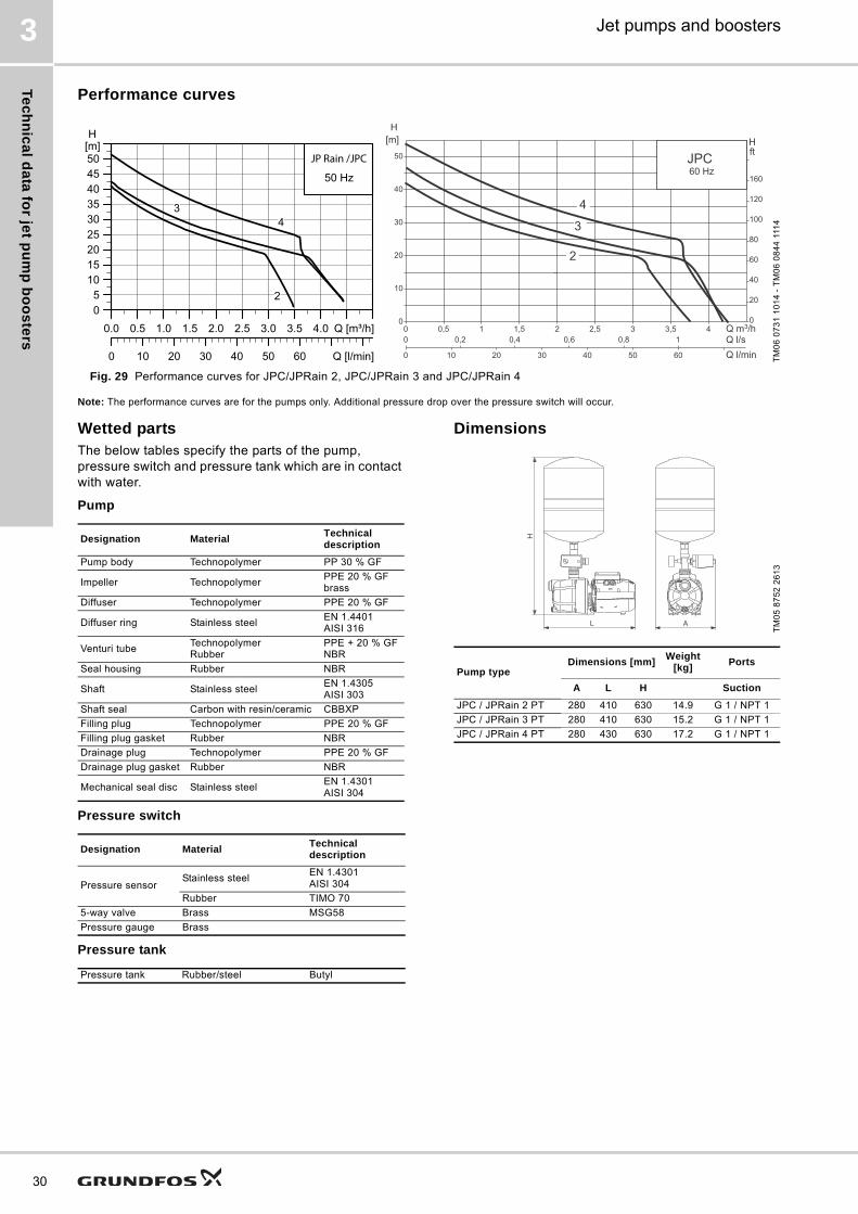
Fig. 29 Performance curves for JPC/JPRain 2, JPC/JPRain 3 and JPC/JPRain 4
Note: The performance curves are for the pumps only. Additional pressure drop over the pressure switch will occur.
Wetted partsThe below tables specify the parts of the pump, pressure switch and pressure tank which are in contact with water.
Pump
Pressure switch
Pressure tank
Dimensions
TM
06
07
31
10
14
- T
M0
6 0
84
4 1
114
0.0 0.5 1.0 1.5 2.0 2.5 3.0 3.5 4.0 Q [m³/h]05
101520253035404550
H[m]
0 10 20 30 40 50 60 Q [l/min]
50 Hz
2
34
JP Rain /JPC
Q m3/h0 0,5 1 1,5 2 2,5 3 3,5 40
10
20
30
40
50
0
20
40
60
80
100
120
160
Q l/sQ l/min
0
0
0,2 0,4 0,6 0,8 1
10 20 30 40 50 60
Hft
2
4
3
JPC 60 Hz
H[m]
Designation MaterialTechnical description
Pump body Technopolymer PP 30 % GF
Impeller TechnopolymerPPE 20 % GF brass
Diffuser Technopolymer PPE 20 % GF
Diffuser ring Stainless steelEN 1.4401AISI 316
Venturi tubeTechnopolymerRubber
PPE + 20 % GFNBR
Seal housing Rubber NBR
Shaft Stainless steelEN 1.4305AISI 303
Shaft seal Carbon with resin/ceramic CBBXP
Filling plug Technopolymer PPE 20 % GF
Filling plug gasket Rubber NBR
Drainage plug Technopolymer PPE 20 % GF
Drainage plug gasket Rubber NBR
Mechanical seal disc Stainless steelEN 1.4301AISI 304
Designation MaterialTechnical description
Pressure sensorStainless steel
EN 1.4301AISI 304
Rubber TIMO 70
5-way valve Brass MSG58
Pressure gauge Brass
Pressure tank Rubber/steel Butyl
TM
05
87
52
26
13
Pump typeDimensions [mm]
Weight [kg]
Ports
A L H Suction
JPC / JPRain 2 PT 280 410 630 14.9 G 1 / NPT 1
JPC / JPRain 3 PT 280 410 630 15.2 G 1 / NPT 1
JPC / JPRain 4 PT 280 430 630 17.2 G 1 / NPT 1
Te
ch
nic
al
da
ta f
or
jet
pu
mp
bo
os
ters
Jet pumps and boosters 3
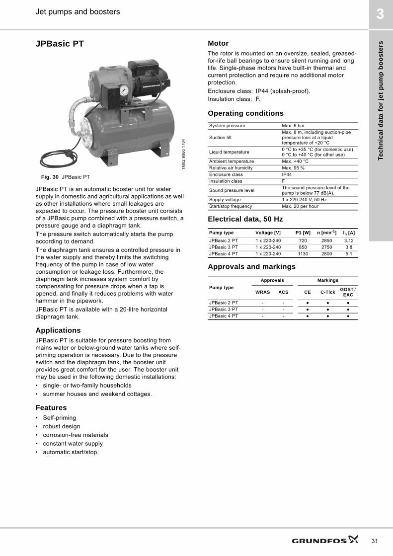
JPBasic PT
Fig. 30 JPBasic PT
JPBasic PT is an automatic booster unit for water supply in domestic and agricultural applications as well as other installations where small leakages are expected to occur. The pressure booster unit consists of a JPBasic pump combined with a pressure switch, a pressure gauge and a diaphragm tank.
The pressure switch automatically starts the pump according to demand.
The diaphragm tank ensures a controlled pressure in the water supply and thereby limits the switching frequency of the pump in case of low water consumption or leakage loss. Furthermore, the diaphragm tank increases system comfort by compensating for pressure drops when a tap is opened, and finally it reduces problems with water hammer in the pipework.
JPBasic PT is available with a 20-litre horizontal diaphragm tank.
ApplicationsJPBasic PT is suitable for pressure boosting from mains water or below-ground water tanks where self-priming operation is necessary. Due to the pressure switch and the diaphragm tank, the booster unit provides great comfort for the user. The booster unit may be used in the following domestic installations:
• single- or two-family households
• summer houses and weekend cottages.
Features• Self-priming
• robust design
• corrosion-free materials
• constant water supply
• automatic start/stop.
MotorThe rotor is mounted on an oversize, sealed, greased-for-life ball bearings to ensure silent running and long life. Single-phase motors have built-in thermal and current protection and require no additional motor protection.
Operating conditions
Electrical data, 50 Hz
Approvals and markings
TM
02
90
60
17
04
Enclosure class: IP44 (splash-proof).Insulation class: F.
System pressure Max. 6 bar
Suction liftMax. 8 m, including suction-pipe pressure loss at a liquid temperature of +20 °C
Liquid temperature0 °C to +35 °C (for domestic use)0 °C to +40 °C (for other use)
Ambient temperature Max. +40 °C
Relative air humidity Max. 95 %
Enclosure class IP44
Insulation class F
Sound pressure levelThe sound pressure level of the pump is below 77 dB(A).
Supply voltage 1 x 220-240 V, 50 Hz
Start/stop frequency Max. 20 per hour
Pump type Voltage [V] P1 [W] n [min-1] In [A]
JPBasic 2 PT 1 x 220-240 720 2850 3.12
JPBasic 3 PT 1 x 220-240 850 2750 3.8
JPBasic 4 PT 1 x 220-240 1130 2800 5.1
Pump type
Approvals Markings
WRAS ACS CE C-TickGOST /
EAC
JPBasic 2 PT - - ● ● ●
JPBasic 3 PT - - ● ● ●
JPBasic 4 PT - - ● ● ●
31

Te
ch
nic
al d
ata
for je
t pu
mp
bo
os
ters
32
Jet pumps and boosters3
Performance curves
Fig. 31 Performance curves for JPBasic PT
Note: The performance curves are for the pump only. Additional pressure drop over the pressure switch will occur.
Wetted partsThe below tables specify the parts of the pump, pressure switch and pressure tank which are in contact with water.
Pump
* Applies to JPBasic 2, -3, -4.
Pressure switch
Pressure tank
Dimensions
TM
02
89
40
17
04
0.0 0.4 0.8 1.2 1.6 2.0 2.4 2.8 Q [m³/h]
0
5
10
15
20
25
30
35
40
45
50[m]H
0
100
200
300
400
[kPa]P
0
20
40
60
80
100
120
140
160[ft]H
0 10 20 30 40 50 Q [l/min]
0 2 4 6 8 10 Q [IMP GPM]
0 2 4 6 8 10 12 14 Q [US GPM]
0.0 0.2 0.4 0.6 0.8 Q [l/s]
JPBasic 2
JPBasic 3
JPBasic 4
Designation MaterialTechnical description
Pump body Cast iron EN-GJL-200
Motor supportCast ironDie-cast aluminum*
EN-GJL-200EN AB 46100
Impeller Technopolymer Noryl GFN 2
Diffuser Technopolymer Noryl GFN 2
Diffuser ring Stainless steelEN 1.4401AISI 316
Venturi tubeTechnopolymerRubber
Noryl GFN 2
Shaft Stainless steelEN 1.4305AISI 303
Shaft seal Carbon with resin/ceramic BBQP
Filling/drainage plug Technopolymer PPE 20 % GF
Filling/drainage plug gasket
Rubber NBR
Back plate Stainless steelEN 1.4301AISI 304
Designation MaterialTechnical description
Pressure sensorStainless steel
EN 1.4301AISI 304
Rubber TIMO 70
5-way valve Brass MSG58
Pressure gauge Brass
Pressure tank Rubber/stainless steel
Armed rubber hose Rubber/stainless steel
TM
02
90
68
17
04
Pump typeDimensions [mm]
Weight [kg]
Port
A L H + H1 Suction Discharge
JPBasic 2 PT 447 238 307 15.8 Rp 1 Rp 1
JPBasic 3 PT 447 238 307 18.1 Rp 1 Rp 1
JPBasic 4 PT 447 238 307 19.8 Rp 1 Rp 1
D
H1
H
BA
L
A1

Pro
du
ct
nu
mb
ers
Jet pumps and boosters 4
4. Product numbers
Jet pumps
JP
JPC, JPRain, JPBasic
Pump typeVoltage
1 x 220-240 V,50 Hz
Voltage3 x 220-240/380-415 V,
50 Hz
Material variant Cable PlugWith on/off
switchProduct number
Jet pumps
JP 5
●
A 1.5 m
Schuko ● 46511002
●No plug
● 46511011
● 46511012
● Australian ● 98155855
● No plug 46531011
●
B 1.5 m
Schuko ● 46711002
●
No plug
● 46711011
● 46711012
● 46731011
JP 6
●
A 1.5 m
No plug● 46611011
● 46611012
● Australian ● 98155858
● No plug 46631011
●
B 1.5 m
Schuko ● 46811002
●
No plug
● 46811011
● 46811012
● 46831011
● Schuko ● 46611002
Pump typeVoltage
1 x 220-240 V,50 Hz
Voltage1 x 110-120 V,
60 Hz
Voltage1 x 220-240/
60 HzCable Plug Threads Product number
Jet pumps
JPC 2
●
1.5 m No plug
G 198601006
● 98601008
● NPT 1 98629746
● G 1 98601010
● NPT 1 98629749
JPC 3
●G 1
98601024
● 98601025
● NPT 1 98629747
● G 1 98601026
● NPT 1 98629750
JPC 4
●G 1
98601027
● 98601029
● NPT 1 98629748
● G 1 98601031
● NPT 1 98629751
JPRain 2 ● 2 m Australian
G 1
96827879
JPRain 3 ● 2 m Australian 96827877
JPRain 4 ● 2 m Australian 96827878
JPBasic 2 ●
No cable No plug G 1
96121750
JPBasic 3 ● 96121751
JPBasic 4 ● 96121752
JPBasic 5 ● 96121754
JPBasic 7 ● 96121758
JPBasic 9 ● 96121756
JPBasic 10 ● 96121760
33

Pro
du
ct n
um
be
rs
34
Jet pumps and boosters4
JDBasic
Booster units
Pump typeVoltage
1 x 220-240 V,50 Hz
Voltage3 x 220-240/380-415 V,
50 HzCable Plug Threads Product number
Jet pumps for deep wells
JDBasic 2 ●No cable No plug
G 1
96121777
JDBasic 4 ● 96121779
JDBasic 5 ● 2 m Australian 96149988
JDBasic 7 ● No cable No plug 96121783
Ejector E 20 96150012
Ejector E 25 96150013
Ejector E 30 96150014
Pump typeVoltage
1 x 220-240 V,50 Hz
Voltage3 x 220-240/380-415 V,
50 Hz
Tank size Cable Plug Threads Product number
Booster unit, plug and pump (The jet pump and Pressure Manager are combined into one unit with common installation and operating instructions)
JP 5 Booster PM 1●
1.5 m
Schuko
G 1
98071524
● Australian 98071526
JP 5 Booster PM 2● Schuko 98071528
● Australian 98071530
JP 6 Booster PM 1● Schuko 98071533
● Australian 98071535
JP 6 Booster PM 2● Schuko 98071537
● Australian 98071539
JPBasic 2 PM ●
1.5 m
Australian
G 1
98393779
JPBasic 3 PM ● Australian 98393780
JPBasic 4 PM● Australian 98393781
● Schuko 98393783
JPBasic 5 PM ● 2 m Australian 98388476
JPRain 2 PM ●
1.5 m Australian G 1
98388472
JPRain 3 PM ● 98388473
JPRain 4 PM ● 98388475
JPBasic 2 PS ●
2 m Schuko G 1
96121875
JPBasic 3 PS ● 96121876
JPBasic 4 PS ● 96121877
JPBasic 5 PS ● 96121878
JP Booster, package solution (The jet pump and Pressure Manager are delivered in the same box with one product number, but with two separate installation and operating instructions)
JP 5 Booster PM 1 ●
1.5 m Schuko G 1
98071540
JP 6 Booster PM 1 ● 98071541
JP 5 Booster PM 2 ● 98071542
JP 6 Booster PM 2 ● 98071543
Booster unit with pressure switch and tank
JP 5 Booster PT
● 18 l
1.5 m
Schuko
G 1
4651BTBB
● 24 l 4651BPBB
● 60 l 4651BQBB
● 24 lNo plug
4653FPDB
● 60 l 4653FQDB
JP 6 Booster PT
● 18 l
1.5 m
Schuko
4661BTBB
● 24 l 4661BPBB
● 60 l 4661BQBB
● 24 lNo plug
4663FPDB
● 60 l 4663FQDB
JPBasic 2 PT ●
20 l 2 m Schuko G 1
96150002
JPBasic 3 PT ● 96150003
JPBasic 4 PT ● 96150004

Pro
du
ct
nu
mb
ers
Jet pumps and boosters 4
Pump typeVoltage
1 x 220-240 V,50 Hz
Voltage1 x 110-120 V,
60 Hz
Voltage1 x 220-240/
60 HzTank size Cable Plug Threads Product number
JPC 2 PT
●
18 l 1.5 m No plug
G 198616018
● 98616017
● NPT 1 98629752
● G 1 98616052
● NPT 1 98629755
JPC 3 PT
●G 1
98616054
● 98616053
● NPT 1 98629753
● G 1 98616055
● NPT 1 98629756
JPC 4 PT
●G 1
98616057
● 98616056
● NPT 1 98629754
● G 1 98616058
● NPT 1 98629757
JPRain 2 PT ● 8 l
2 m Australian G 1
96827840
JPRain 3 PT ● 18 l 96935306
JPRain 4 PT ● 18 l 96935307
35
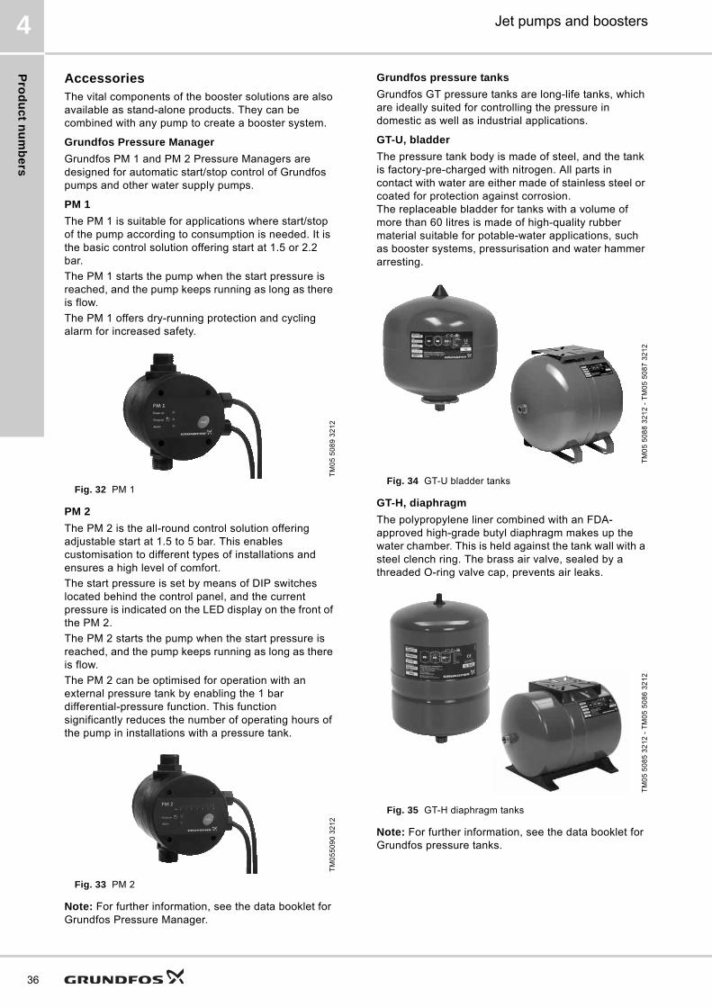
Pro
du
ct n
um
be
rs
36
Jet pumps and boosters4
AccessoriesThe vital components of the booster solutions are also available as stand-alone products. They can be combined with any pump to create a booster system.
Grundfos Pressure Manager
Grundfos PM 1 and PM 2 Pressure Managers are designed for automatic start/stop control of Grundfos pumps and other water supply pumps.
PM 1
The PM 1 is suitable for applications where start/stop of the pump according to consumption is needed. It is the basic control solution offering start at 1.5 or 2.2 bar.
The PM 1 starts the pump when the start pressure is reached, and the pump keeps running as long as there is flow.
The PM 1 offers dry-running protection and cycling alarm for increased safety.
Fig. 32 PM 1
PM 2
The PM 2 is the all-round control solution offering adjustable start at 1.5 to 5 bar. This enables customisation to different types of installations and ensures a high level of comfort.
The start pressure is set by means of DIP switches located behind the control panel, and the current pressure is indicated on the LED display on the front of the PM 2.
The PM 2 starts the pump when the start pressure is reached, and the pump keeps running as long as there is flow.
The PM 2 can be optimised for operation with an external pressure tank by enabling the 1 bar differential-pressure function. This function significantly reduces the number of operating hours of the pump in installations with a pressure tank.
Fig. 33 PM 2
Note: For further information, see the data booklet for Grundfos Pressure Manager.
Grundfos pressure tanks
Grundfos GT pressure tanks are long-life tanks, which are ideally suited for controlling the pressure in domestic as well as industrial applications.
GT-U, bladder
The pressure tank body is made of steel, and the tank is factory-pre-charged with nitrogen. All parts in contact with water are either made of stainless steel or coated for protection against corrosion. The replaceable bladder for tanks with a volume of more than 60 litres is made of high-quality rubber material suitable for potable-water applications, such as booster systems, pressurisation and water hammer arresting.
Fig. 34 GT-U bladder tanks
GT-H, diaphragm
The polypropylene liner combined with an FDA-approved high-grade butyl diaphragm makes up the water chamber. This is held against the tank wall with a steel clench ring. The brass air valve, sealed by a threaded O-ring valve cap, prevents air leaks.
Fig. 35 GT-H diaphragm tanks
Note: For further information, see the data booklet for Grundfos pressure tanks.
TM
05
50
89
32
12
TM
05
50
90
32
12
TM
05
50
88
32
12
- T
M0
5 5
08
7 3
21
2T
M0
5 5
08
5 3
21
2 -
TM
05
50
86
32
12

Fu
rth
er
pro
du
ct
info
rma
tio
n
Jet pumps and boosters 5
5. Further product information
WebCAPS
WebCAPS is a Web-based Computer Aided Product Selection program available on www.grundfos.com.
WebCAPS contains detailed information on more than 220,000 Grundfos products in more than 30 languages.
Information in WebCAPS is divided into six sections:
• Catalogue
• Literature
• Service
• Sizing
• Replacement
• CAD drawings.
Catalogue
Based on fields of application and pump types, this section contains the following:• technical data• curves (QH, Eta, P1, P2, etc.) which can be adapted to the
density and viscosity of the pumped liquid and show the number of pumps in operation
• product photos• dimensional drawings• wiring diagrams• quotation texts, etc.
Literature
This section contains all the latest documents of a given pump, such as• data booklets• installation and operating instructions• service documentation, such as Service kit catalogue and
Service kit instructions• quick guides• product brochures.
Service
This section contains an easy-to-use interactive service catalogue. Here you can find and identify service parts of both existing and discontinued Grundfos pumps.Furthermore, the section contains service videos showing you how to replace service parts.
37

Fu
rthe
r pro
du
ct in
form
atio
n
38
Jet pumps and boosters5
WinCAPS
Fig. 36 WinCAPS DVD
Sizing
This section is based on different fields of application and installation examples and gives easy step-by-step instructions in how to size a product:• Select the most suitable and efficient pump for your
installation.• Carry out advanced calculations based on energy,
consumption, payback periods, load profiles, life cycle costs, etc.
• Analyse your selected pump via the built-in life cycle cost tool.• Determine the flow velocity in wastewater applications, etc.
Replacement
In this section you find a guide to selecting and comparing replacement data of an installed pump in order to replace the pump with a more efficient Grundfos pump. The section contains replacement data of a wide range of pumps produced by other manufacturers than Grundfos.
Based on an easy step-by-step guide, you can compare Grundfos pumps with the one you have installed on your site. When you have specified the installed pump, the guide will suggest a number of Grundfos pumps which can improve both comfort and efficiency.
CAD drawings
In this section, it is possible to download 2-dimensional (2D) and 3-dimensional (3D) CAD drawings of most Grundfos pumps.
These formats are available in WebCAPS:
2-dimensional drawings:• .dxf, wireframe drawings• .dwg, wireframe drawings.
3-dimensional drawings:• .dwg, wireframe drawings (without surfaces)• .stp, solid drawings (with surfaces)• .eprt, E-drawings.
WinCAPS is a Windows-based Computer Aided Product Selection program containing detailed information on more than 220,000 Grundfos products in more than 30 languages.
The program contains the same features and functions as WebCAPS, but is an ideal solution if no internet connection is available.
WinCAPS is available on DVD and updated once a year.
0 1

Fu
rth
er
pro
du
ct
info
rma
tio
n
Jet pumps and boosters 5
GO CAPS
Mobile solution for professionals on the GO!
CAPS functionality on the mobile workplace.
Subject to alterations.
39

GRUNDFOS A/S DK-8850 Bjerringbro . DenmarkTelephone: +45 87 50 14 00www.grundfos.com
V7112680 0314
ECM: 1131927 Th
e n
am
e G
run
dfo
s, t
he
Gru
nd
fos
log
o,
an
d b
e t
hin
k i
nn
ov
ate
are
re
gis
tere
d t
rad
em
ark
s o
wn
ed
by
Gru
nd
fos
Ho
ldin
g A
/S o
r G
run
dfo
s A
/S,
De
nm
ark
. A
ll ri
gh
ts r
ese
rve
d w
orl
dw
ide
.©
Co
pyr
igh
t G
run
dfo
s H
old
ing
A/S