Jet Flow Characteristics of 3-Slot Nozzle at Gas Wiping ...
7
JFE TECHNICAL REPORT No. 24 (Mar. 2019) Copyright © 2019 JFE Steel Corporation. All Rights Reser ved. 135 Jet Flow Characteristics of 3-Slot Nozzle at Gas Wiping Process in CGL TAKEDA Gentaro *1 TAKAHASHI Hideyuki *2 KABEYA Kazuhisa *3 Abstract: The single-slot gas wiping is commonly used in coat- ing weight control of continuous galvanizing lines (CGL). In the gas wiping process, it requires more effi- cient coating controllability and avoiding surface defects on the steel sheet. A multi-slot nozzle with two auxiliary slots arranged on the two sides of the main slot attracts attention. JFE steel investigated relationship between the mixed jets behavior and the wiping capability. This study revealed that the velocity difference between the center slot jet flow and the ambient gas decreases due to the auxiliary slot jets, and diffusion of the jet flow is sup- pressed due to a reduction in the turbulent kinetic energy at the two sides of the center slot jet, then the wiping capability can be improved. 1. Introduction Gas wiping is used for coating weight control in Continuous Galvanizing Lines (CGL) which produce coated steel sheets for automobiles, building materials and electric appliances. Because the impinging gas jet wipes the excess molten zinc from the steel strip, gas wiping provides a noncontact method for controlling the coating weight. Gas wiping has advantages such as uniformity in the width direction, the ability to produce a thin plating and economy. Usually, a single-slot gas nozzle (hereinafter, 1-slot nozzle) is installed above the molten zinc pot. The gas wiping mechanism is essen- tially established theoretically 1–4) . From those results, control of the gas jet pressure in gas wiping should make it possible to increase the CGL line speed in order to realize higher productivity. How- ever, wiping performance is limited by the need for a thin plating capability 5) and the problem of the surface defect called splashing 6) . In recent years, multi-slot gas nozzles have been investigated with the aim of over- coming these problems 7–8) . However, the influence on wiping performance and changes in the formation of the three jets depending on the velocity of the auxiliary slot jets have not been clarified. The main objective of the present study is to clarify the mechanism of jet mixing with a 3-slot nozzle devel- oped by JFE Steel and the effect of jet mixing charac- teristics on coating weight control. The impinging pres- sure distribution and the jet formation were analyzed under several pressure conditions by Computational Fluid Dynamics (CFD), and wiping performance was examined by using the same model wiping apparatus as in previous studies 9–10) . 2. Mathematical Model of Coating Thickness As a mechanism of coating thickness control by gas wiping, the following concept is known 2–3) . As shown in Fig. 1, the impinging pressure of the gas wiping jet on a steel strip causes a pressure gradient, and this pressure gradient and the shear stress of the wall jet that flows along the steel strip surface act on the mol- ten zinc layer adhering to the strip after the strip passes through the zinc pot. The liquid film thickness is pre- dicted by this gas wiping mechanism under the follow- ing basic assumptions: The fluid flow in the liquid coating film flow can † Originally published in JFE GIHO No. 42 (Aug. 2018), p. 77−82 *2 Senior Researcher General Manager, Rolling & Processing Research Dept., Steel Res. Lab., JFE Steel *1 Senior Researcher Manager, Rolling & Processing Research Dept., Steel Res. Lab., JFE Steel *3 Dr. Eng., Executive Assistant, General Manager, Research Planning & Administration Dept., Steel Res. Lab., JFE Steel
Transcript of Jet Flow Characteristics of 3-Slot Nozzle at Gas Wiping ...

JFE TECHNICAL REPORT No. 24 (Mar. 2019)
Copyright © 2019 JFE Steel Corporation. All Rights Reserved.
135
Jet Flow Characteristics of 3-Slot Nozzle at Gas Wiping Process in CGLTAKEDA Gentaro*1 TAKAHASHI Hideyuki*2 KABEYA Kazuhisa*3
Abstract:The single-slot gas wiping is commonly used in coat-
ing weight control of continuous galvanizing lines (CGL). In the gas wiping process, it requires more effi-cient coating controllability and avoiding surface defects on the steel sheet. A multi-slot nozzle with two auxiliary slots arranged on the two sides of the main slot attracts attention. JFE steel investigated relationship between the mixed jets behavior and the wiping capability. This study revealed that the velocity difference between the center slot jet flow and the ambient gas decreases due to the auxiliary slot jets, and diffusion of the jet flow is sup-pressed due to a reduction in the turbulent kinetic energy at the two sides of the center slot jet, then the wiping capability can be improved.
1. Introduction
Gas wiping is used for coating weight control in Continuous Galvanizing Lines (CGL) which produce coated steel sheets for automobiles, building materials and electric appliances. Because the impinging gas jet wipes the excess molten zinc from the steel strip, gas wiping provides a noncontact method for controlling the coating weight. Gas wiping has advantages such as uniformity in the width direction, the ability to produce a thin plating and economy. Usually, a single-slot gas nozzle (hereinafter, 1-slot nozzle) is installed above the molten zinc pot. The gas wiping mechanism is essen-tially established theoretically1–4).
From those results, control of the gas jet pressure in gas wiping should make it possible to increase the CGL
line speed in order to realize higher productivity. How-ever, wiping performance is limited by the need for a thin plating capability5) and the problem of the surface defect called splashing6). In recent years, multi-slot gas nozzles have been investigated with the aim of over-coming these problems7–8). However, the influence on wiping performance and changes in the formation of the three jets depending on the velocity of the auxiliary slot jets have not been clarified.
The main objective of the present study is to clarify the mechanism of jet mixing with a 3-slot nozzle devel-oped by JFE Steel and the effect of jet mixing charac-teristics on coating weight control. The impinging pres-sure distribution and the jet formation were analyzed under several pressure conditions by Computational Fluid Dynamics (CFD), and wiping performance was examined by using the same model wiping apparatus as in previous studies9–10).
2. Mathematical Model of Coating Thickness
As a mechanism of coating thickness control by gas wiping, the following concept is known2–3). As shown in Fig. 1, the impinging pressure of the gas wiping jet on a steel strip causes a pressure gradient, and this pressure gradient and the shear stress of the wall jet that flows along the steel strip surface act on the mol-ten zinc layer adhering to the strip after the strip passes through the zinc pot. The liquid film thickness is pre-dicted by this gas wiping mechanism under the follow-ing basic assumptions:
The fluid flow in the liquid coating film flow can
† Originally published in JFE GIHO No. 42 (Aug. 2018), p. 77−82 *2 Senior Researcher General Manager, Rolling & Processing Research Dept., Steel Res. Lab., JFE Steel
*1 Senior Researcher Manager, Rolling & Processing Research Dept., Steel Res. Lab., JFE Steel
*3 Dr. Eng., Executive Assistant, General Manager, Research Planning & Administration Dept., Steel Res. Lab., JFE Steel

Jet Flow Characteristics of 3-Slot Nozzle at Gas Wiping Process in CGL
136 JFE TECHNICAL REPORT No. 24 (Mar. 2019)
be described by a steady state, two-dimensional equa-tion of incompressible, constant viscosity. The flow perpendicular to the strip is sufficiently small relative to the flow parallel to the strip.
Surface tension, oxidation effects, strip surface roughness and interfacial alloy formation can be neglected.
There is no slip between the fluid coating and the strip at the strip-fluid interface.
Solving the equation of motion of the coating liq-uid film under these assumptions, the film thickness can be expressed as:
2 42
S S GTG
+ += ………………………… (1)
where, /L LT t g Vρ μ= …………………………… (2)
L LS Vgτ ρ μ= ………………………… (3)
1 ( / ) LG dp dx gρ= + ……………………… (4)
T, S and G are non-dimensional numbers related to gas wiping. T is the non-dimensional film thickness, S is the non-dimensional wall shear stress, G is the non-dimensional pressure gradient, μ L is the viscosity of the coating liquid, ρ L is the density of the coating liquid, g is the acceleration of gravity, P is the impinging pres-sure, t is the local film thickness and V is the strip travel velocity. The pressure gradient (forced by the wiping jet) dp/dx and wall shear stress τ decide the coating film thickness. In the case of a 1-slot nozzle, the combina-tion of the slot nozzle gap, the jet pressure and the dis-tance between the strip and the nozzle tip uniquely
determine dp/dx and τ 1). On the other hand, there are few studies on the jet characteristics of multi-slot noz-zles such as 3-slot nozzles. As a form close to that, ear-lier studies have examined the mixing and diffusion behavior of a coaxial circular jet11).
3. Experimental Procedure and Numerical Analysis
3.1 3-Slot Nozzle
In comparison with 1-slot nozzles, the jet character-istics of 3-slot nozzles are affected by a number of parameters, such as the nozzle geometry and gas jet conditions. A previous study9) by some of the same authors indicated that the distance between the main slot and the auxiliary slots has a remarkable influence on the formation of the jets after the three jets merge. In particular, wiping performance was improved by shortening the distance between the main slot and the auxiliary slots. Figure 2 shows a schematic diagram of the tip shape of the 3-slot gas wiping nozzle used in this paper. Based on the previous report, the distance between the main slot and the upper/lower auxiliary slots was set at 0.1 mm. In addition, it is estimated that the jet angle of the auxiliary slot (angle of the main slot and the auxiliary slots) greatly influences jet forma-tion. Since wiping performance improves as the nozzle outer angle becomes more acute12), wiping performance is expected to change due to factors other than the slot jet if the outer angle is changed from the 50° of the nozzle used in the previous study. Therefore, in the present study, one kind of 3-slot nozzle with a nozzle outer angle of 50° and upper/lower nozzles with jet angle inclinations of 20° arranged symmetrically above/below the center slot was tested. A photograph of this nozzle is shown in Photo 1. Here, the gaps D of the center, upper and lower slots were all 1.0 mm, and the slot width was 250 mm.
3.2 Experimental Gas Wiping Simulator
Wiping performance was investigated by using the
Fig. 1 Analytical model of gas wiping
Fig. 2 Tip shape of 3-slot gas wiping nozzle
Jet Flow Characteristics of 3-Slot Nozzle at Gas Wiping Process in CGL
JFE TECHNICAL REPORT No. 24 (Mar. 2019) 137
previously-developed gas wiping simulator9–10). The arrangement of the experimental apparatus is shown in Fig. 3. In this apparatus, the strip in coil form is paid off from the pay-off reel and immersed continually in the coating liquid bath. The coating weight of the liq-uid is controlled by mutually-opposed wiping nozzles arranged above the coating bath, and the strip is then coiled by the coiler. Wiping conditions such as the noz-zle jet angle, wiping gas pressure and distance between the strip and nozzle can be set optionally. In this experi-ment, the tilt angles of the two wiping nozzles were fixed at 0.0° (i.e., horizontal).
Paraffin having a melting point of approximately 60˚C was used as the coating liquid, and the bath tem-perature during the experiment was 90˚C, that is, approximately 30˚C higher than the melting point. The liquid paraffin cooled about 10˚C while passing the wiping nozzles but did not solidify before the strip arrived at the top roll, which was located 1.5 m above the wiping nozzles. Table 1 shows a comparison of the physical properties, gas wiping conditions and non-dimensional numbers T, G and S of the molten zinc used in the actual CGL and the paraffin used in this experiment. Because the non-dimensional numbers T, S and G of the simulator were within the ranges of those of the CGL, and the coating thickness obtained with the simulator was in good agreement with the value predicted from the mathematical model men-
tioned above9), it is thought that hydrodynamic similar-ity is established between the CGL and the simulator. When zinc is coated on a steel strip, an alloying reac-tion may occur. However, no such reaction occurs at the interface of the paraffin and the metal. This means that verification purely in terms of gas wiping theory is possible. In this experiment, the coating weight was measured by comparison of the coating weight before/after delamination in order to quantify the mean coat-ing weight of a relatively large area precisely.
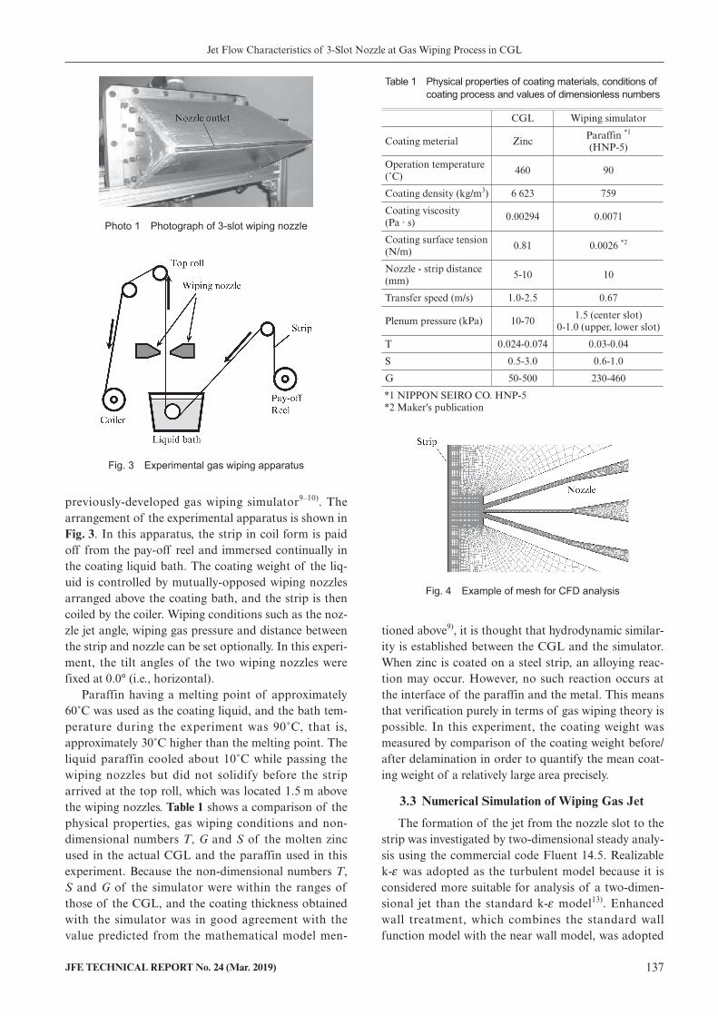
3.3 Numerical Simulation of Wiping Gas Jet
The formation of the jet from the nozzle slot to the strip was investigated by two-dimensional steady analy-sis using the commercial code Fluent 14.5. Realizable k-ε was adopted as the turbulent model because it is considered more suitable for analysis of a two-dimen-sional jet than the standard k-ε model13). Enhanced wall treatment, which combines the standard wall function model with the near wall model, was adopted
Photo 1 Photograph of 3-slot wiping nozzle
Fig. 3 Experimental gas wiping apparatus
Fig. 4 Example of mesh for CFD analysis
Table 1 Physical properties of coating materials, conditions of coating process and values of dimensionless numbers
CGL Wiping simulator
Coating meterial ZincParaffin *1
(HNP-5)
Operation temperature (˚C)
460 90
Coating density (kg/m3) 6 623 759
Coating viscosity (Pa · s)
0.00294 0.0071
Coating surface tension (N/m)
0.81 0.0026 *2
Nozzle - strip distance (mm)
5-10 10
Transfer speed (m/s) 1.0-2.5 0.67
Plenum pressure (kPa) 10-701.5 (center slot)
0-1.0 (upper, lower slot)
T 0.024-0.074 0.03-0.04
S 0.5-3.0 0.6-1.0
G 50-500 230-460
*1 NIPPON SEIRO CO. HNP-5 *2 Maker's publication

Jet Flow Characteristics of 3-Slot Nozzle at Gas Wiping Process in CGL
138 JFE TECHNICAL REPORT No. 24 (Mar. 2019)
for treatment of the near wall14). An example of the calculation mesh is shown in Fig. 4. The mesh number was approximately 80 000. The validity of this CFD analysis was confirmed by comparing the analysis results with the measured impinging pressure distribu-tion10).
4. Experimental Results and Discussion
4.1 Influence of Auxiliary Slot Jets on Wiping Performance
The paraffin wiping experiment was carried out under the conditions shown in Table 1. The header pressure of the center slot was fixed at 1.5 kPa, and the upper/lower slot jets were injected individually or simultaneously at pressures from 0.2 kPa to 1.0 kPa.
Figure 5 shows the experimental results. The results for the upper/lower slot pressures of 0.0 kPa indicate the coating weight in the case of injection only from the center slot. In comparison with the cases of indi-vidual injection of the jet from the upper or lower slot,
the greatest improvement in wiping performance was achieved in the case of simultaneous jetting from the upper and lower slots in this gas pressure range, and a thin coating film was obtained. Comparing injection of only the upper slot jet with only the lower slot jet, a somewhat thinner paraffin thickness was achieved with the upper slot jet. Focusing on the influence of gas pressure, the coating weight was the lowest at the upper or lower slot pressure of 0.2 kPa with all jet patterns, and the coating weight increased when the gas pressure exceeded 0.2 kPa. With the conventional 1-slot nozzle, the coating weight decreases as the wiping gas pressure increases, as predicted from the mathematical model of gas wiping presented above. However, with the 3-slot nozzle, these results showed that increasing the jet pres-sure does not necessarily lead to an improvement in wiping performance due to variations in the formation of the center jet flow caused by the upper/lower slot jets.
Figure 6 shows the calculated impinging pressure distributions obtained by CFD. Here, the x direction position on the horizontal axis is translated to a non-dimensional position by the slot gap D. As the slope of the impinging pressure distribution becomes steeper, the non-dimensional number G in the gas wiping equa-tion (4) increases, which means that wiping perfor-mance improves. Therefore, the jet characteristics at the upper and lower slot pressure of 0.2 kPa, which reduced the coating weight in comparison with the 1-slot nozzle, and the jet characteristics at 1.0 kPa, which increased the coating weight in comparison with the 1-slot nozzle, were investigated in detail. Fig. 6(a) shows the calculated impinging pressure distributions when the center, upper and lower slots are jetted together. In comparison with jetting from only the cen-ter slot, when the pressure of the upper and lower slots is 0.2 kPa, the maximum pressure increases without an accompanying increase in the width of the impinging pressure distribution, and the impinging pressure dis-
Fig. 5 Coating weight in paraffin wiping experiments with 3-slot wiping nozzle
Fig. 6 Calculated impinging pressure distribution on strip surface

Jet Flow Characteristics of 3-Slot Nozzle at Gas Wiping Process in CGL
JFE TECHNICAL REPORT No. 24 (Mar. 2019) 139
tribution is steeper than the distribution with only the center slot. However, at the upper/ lower slot pressure of 1.0 kPa, a further increase in the maximum imping-ing pressure is
observed, but the width of the impinging pressure distribution also increases, becoming more than double, and the pressure gradient becomes somewhat more moderate. Fig. 6(b) shows the impinging pressure dis-tributions when the center and upper slot were jetted together. Due to the upper slot jet, the pressure distri-bution becomes asymmetrical, and the x position of the maximum pressure shifts slightly to the lower side (x/D < 0) of the center slot position. Furthermore, the jet flow is formed with different pressure gradients on the upper side (x/D > 0) and the lower side (x/D < 0). It is estimated that this variation in jet formation will influence wiping performance.
4.2 Jet Flow Formation of 3-Slot Nozzle
As an example of the formation of the jet flow by mixing of the flows from the three slots from the nozzle tip to the strip, the velocity contours calculated by CFD are shown in Fig. 7 (a) for the center slot pressure of 1.5 kPa, in (b) for the center slot pressure of 1.5 kPa and upper/lower slot pressures of 0.2 kPa and in (c) for the center slot pressure of 1.5 kPa and upper/lower slot pressures of 1.0 kPa. In this simulation, the gas jet velocity is 42 m/s at 1.5 kPa, 15 m/s at 0.2 kPa (35.7% of center slot velocity) and 32 m/s at 1.0 kPa (76.2% of center slot velocity). In comparison with (a), the decre-ment of the center slot jet weakens in (b) and (c), and the high jet velocity is kept until further to the rear. Thus, in the region near the nozzle, it is possible to compare the jet flow mixing behavior by using the velocity distribution. However, a simple comparison of mixing behavior by using only the velocity distribution is difficult in the wall jet region near the strip because the dynamic pressure of the jet flow is converted to static pressure on the strip in the wall jet region, and
the jet directions and half-width of the wall jet also change. Therefore, in this paper, the jet mixture process was investigated by the total pressure distribution, which was defined as the sum of the dynamic pressure and static pressure in the CFD analysis. The total pres-sure transition from the nozzle tip to the near-strip region (y/D=0–8, nozzle tip is y=0) is shown in Fig. 8. This figure shows the calculated result for (a) only cen-ter slot with pressure of 1.5 kPa (1 jet), (b) and (c); center slot + upper/lower slots (3 jets) and (d) and (e); center slot + upper slot (2 jets).
In (b), where the upper/lower slot pressures are 0.2 kPa, peaks of the dynamic pressure due to the upper and lower slot jets can be seen after jetting (y/D=0), but these peaks disappear quickly at y/D=2 due to merging of the three jets, and the jet takes a shape approaching that of single jet. Because the velocity dif-ference between the center jet and the ambient gas is reduced by the slow jets from the upper/lower sides, the decrement of the center jet is suppressed and the impinging pressure near the strip increases. Wiping performance is improved by this kind of jet formation. In (c), where the upper/lower slot pressure is 1 kPa, the peaks caused by the upper/lower jets remain at y/D=4. After this point, complete mixing occurs and jet diffu-sion progresses. Under this condition, the pressure dis-tribution is gentler than that of the 1-slot jet.
In (d), which is a 2-slot arrangement with the upper slot pressure of 0.2 kPa, jet formation is the same as in (b) on the upper side (x/D > 0) and the same as (a) on the lower side (x/D < 0). In this case, the peak of the total pressure does not increase so effectively because suppression of center jet diffusion is insufficient with only one auxiliary jet. These results indicate that sup-plying slow auxiliary jets from both sides of a center jet is effective for suppressing diffusion of the main slot jet. In (e), which is the 2-slot arrangement with the upper slot pressure of 1.0 kPa, the pressure gradient at x/D < 0 changes to an extremely sharp form due to
Fig. 7 Velocity contours of 1-slot and 3-slot jet

Jet Flow Characteristics of 3-Slot Nozzle at Gas Wiping Process in CGL
140 JFE TECHNICAL REPORT No. 24 (Mar. 2019)
deviation of the center jet to the lower side. This behavior can be observed until about the y/D=4 posi-tion, that is, before the two jets mix completely. Although this jet pattern might appear to improve wip-ing performance, the pressure gradient moderates quickly after the two jets mix, and wiping performance deteriorates at y/D=10.
In order to estimate the diffusion of the two-dimen-sional jet flow discussed above more directly, the turbu-lent kinetic energy (k of the k-ε model) calculated by CFD will be compared. Figure 9 represents the turbu-lent kinetic energy distributions under the same condi-tions as in Fig. 7. For the center slot jet, under condi-tion (a), i.e., jetting into a static gas, the large velocity difference on the two sides of the jet causes strong tur-bulent kinetic energy. On the other hand, under condi-tion (b), that is, low-speed jetting with auxiliary jets, the turbulent kinetic energy on the two sides of the center slot jet decreases due to the lower velocity differ-ence with the ambient gas. Moreover, since remarkable turbulent kinetic energy is not generated on the outer sides of the upper/lower slot jets, this energy does not
have a large influence on the jet width after mixing. Comparing the integral value of the turbulent kinetic energy in the flow field from the nozzle tip to the strip (–4 x/D 4, 0 y/D 10), assuming the value of (a) is 100, the value of (b) is reduced to 79.3, or a reduc-tion of about 20%. However, in the case of (c), which is the case of high-speed auxiliary jets, the width of the mixed jet increases to the equivalent of the width of the three jets due to the increased turbulent kinetic energy at the outside of the auxiliary jets in compari-son with that at the sides of the center jet. As a result, the integral value of (c) is 84.7. In other words, the tur-bulence in the total flow field increases under condition (c) in comparison with (b).
5. Conclusion
In order to clarify the function of the auxiliary slot jets in the wiping performance of a 3-slot nozzle, gas wiping experiments were performed with liquid paraf-fin, and a CFD analysis was carried out. The results are summarized as follows.
Fig. 8 Total pressure distributions between nozzle tip and strip with single, 2-slot and 3-slot jets
Fig. 9 Turbulent kinetic energy contours of 1-slot and 3-slot jets

Jet Flow Characteristics of 3-Slot Nozzle at Gas Wiping Process in CGL
JFE TECHNICAL REPORT No. 24 (Mar. 2019) 141
Copyright © 2019 JFE Steel Corporation. All Rights Reserved. Unauthorized reproduction prohibited.
(1) When the center slot pressure was 1.5 kPa, wiping performance was improved by upper/lower slot pressures in the range of 0.2–0.4 kPa. However, wiping performance gradually deteriorated with further increases in the upper/lower slot pressure. Simultaneous use of the upper and lower slot jets improved wiping performance.
(2) The pressure gradient is sharp under jet conditions that improve wiping performance (upper/lower slot pressure: 0.2 kPa), and the pressure gradient is moderate under jet conditions that deteriorate wiping performance (upper/lower slot pressure: 1.0 kPa).
(3) The velocity difference between the center slot jet flow and the ambient gas decreases due to the aux-iliary slot jets, and diffusion of the jet flow is sup-pressed due to a reduction in the turbulent kinetic energy at the two sides of the center slot jet. If the auxiliary jet velocity is set low, for example, to around 35% of the center jet velocity, the jet width does not spread after mixing of the three jets. However, if the auxiliary slot jet velocity is increased, the outer edge of the auxiliary slot jets becomes the outer edge of the mixed jet, and in effect, the width of the mixed jet spreads. As a result, the impinging pressure gradient becomes more moderate and wiping performance deterio-rates.
As described above, in gas wiping with multi-slot nozzles, the center slot diffusion behavior and the width of the mixed jet change remarkably depending
on the flow of the upper/lower auxiliary slot jets, and wiping performance is affected by these changes. Thus, in addition to estimation of the impinging gas pressure, this study revealed that the turbulence in the flow field is also an important parameter for designing a 3-slot nozzle and optimizing its operational conditions.
References
1) Takeishi, Y.; Aoki, T. Tetsu-to-Hagané. 1995, vol. 81, no.2, p. 135–140.
2) Thornton, J. A.; Graff, H. F. Metallurgical Transactions B. 1976, vol. 7B, p. 607–618.
3) Ellen, C.H.; Tu, C. V. Transaction of the ASME Journal of Flu-ids Engineering. 1984, vol. 106, p. 399–404.
4) Takeishi, Y.; Yamauchi, A.; Miyauchi, S. Tetsu-to-Hagané. 1995, vol. 81, no. 6, p. 643–648.
5) Dubois, M.; Callegari, J. 8th International Conference on Zinc and Zinc Alloy Coated Sheet Steels Galvatech’11. 2011, p. 845–852.
6) Takeishi, Y.; Suzuki, Y.; Yabuki, K. Jpn. J. Multiph.flow. 2000, vol. 14, no. 2, p. 194–202.
7) Tamadonfar, P.; McDermid, J.R.; Hrymak, A.N.; Goodwin, F.E. 8th International Conference on Zinc and Zinc Alloy Coated Sheet Steels Galvatech’11. 2011, p. 817–823.
8) Dubois, M. 8th International Conference on Zinc and Zinc Alloy Coated Sheet Steels Galvatech’11. 2011, p. 787–802.
9) Takeda, G.; Takahashi, H.; Miyake, M.; Nakata, N. Jpn. J. Mul-tiph.flow. 2014, vol. 28, no. 1, p. 90–98.
10) Takeda, G.; Takahashi, H.; Kabeya, K. Tetsu-to-Hagané. 2016, vol. 102, no. 10, p. 576–582.
11) Shakouchi, T.; Kato, T. Trans. Jpn. Soc. Mech. Eng. 1997, vol. 63, no. 614, p. 3278–3286.
12) Takahashi, H.; Takeda, G.; Miyake, M.; Nakata, N. J. Jpn. Soc. Exp. Mech. 2015, vol. 15, no. 3, p. 217–224.
13) Shih, T.-H.; Liou, W. W.; Shabbir, A.; Yang, Z.; Zhu, J. Comput-ers Fluids. 1995, vol. 24, no. 3, p. 227–238.
14) Kader, B. International Journal of Heat and Mass Transfer. 1981, vol. 24, no. 9, p. 1541–1544.