JECS 29(2009) Santillan Sofc
8
Available online at www.sciencedirect.com Journal of the European Ceramic Society 29 (2009) 1125–1132 Electrophoretic deposition of La 0.6 Sr 0.4 Co 0.8 Fe 0.2 O 3−δ cathodes on Ce 0.9 Gd 0.1 O 1.95 substrates for intermediate temperature solid oxide fuel cell (IT-SOFC) M.J. Santillán a , A. Caneiro a , N. Quaranta b , A.R. Boccaccini c,∗ a Comisión Nacional de Energía Atómica, CONICET, Centro Atómico Bariloche and Instituto Balseiro, 8400 S.C. de Bariloche, Argentina b CIC Researcher, FR San Nicolás, Universidad Tecnológica Nacional, 2900 San Nicolás, Argentina c Department of Materials, Imperial College London, Prince Consort Road, London SW7 2BP, UK Received 27 April 2008; received in revised form 24 July 2008; accepted 30 July 2008 Available online 13 September 2008 Abstract Porous thick films of La 0.6 Sr 0.4 Co 0.8 Fe 0.2 O 3−δ (LSCF) on Ce 0.9 Gd 0.1 O 1.95 (CGO) substrates were prepared by the electrophoretic deposition (EPD) method. Organic suspensions of different compositions containing LSCF ceramic particles were investiga ted with the aim to determine the optimal composition of the suspension and EPD conditions. Stainless steel substrates were used in order to determine the optimal parameters for the EPD process. The best results were achieved with solutions containing acetylacetone, iodine and starch. The EPD conditions leading to uniform LSCF films were: appli ed voltage 20 V and depos ition time 120 s, with the electr odes separ ated 1.5 cm. EPD was also demo nstra ted to be a simp le and useful method for making porous LSCF cathodes on CGO substrates. It was shown that the microstructure of the films can be controlled by changing the applied voltage, deposition time and concentration of additives in suspension. © 2008 Elsevier Ltd. All rights reserved. Keywords: Electrophoretic deposition; Solid oxide fuel cells; Porous cathodes 1. Intro ductio n Energy conversion using solid oxide fuel cells (SOFC) is a highly efficient and an environmentally friendly technology with reduced emission of pollu tants in comp arison to other power sources based on fossil fuel combustion. 1 However, the development of SOFC for efficient and low cost power gener- ation has still failed to reach widespread commercial viability. This drawback is mainly due to thermal degradation problems associated with the high operation temperatures of SOFC and the need to use highly expensive materials. These issues have prompted the development of intermediate temperature SOFC (IT-SOFC), which will allow to use alternative interconnection materials and to achieve important cost reductions. 2 Since the ∗ Corresponding author. E-mail address: [email protected] (A.R. Boccaccini). operation at intermediate temperatures causes an increase in the interfacial polarization losses of a solid-state cell, the perfor- mance of IT-SOFC is strongly dependent on the cathode and cathode–electrolyte interface. Optimizing IT-SOFC operation implies therefore the control of the mi cros tru ct ure of the ca thode wh ic h de pe nds on the de po - sition technique used for its fabrication. A convenient candidate for the cathode is the perovskite-type La 0.6 Sr 0.4 Co 0.8 Fe 0.2 O 3−δ (LSCF) material. This composition exhibits very good mixed ionic–electronic conductivity and it is appropriate for deposi- tion on Ce 0.9 Gd 0.1 O 1.95 (CGO) electrolytes exhibiting a similar the rma l expansio n coe fficie nt (TE C) tha n tha t of the CGO electrolyte. 3–5 For IT -SOFC catho de prepa ratio n, vari ous metho ds have been reported, such as lase r assi sted depositio n, 6 chemical vapour deposition, 7 dip coating, 8 and spray coating. 9 In the las t yea rs, ele ctr oph oretic dep osi tio n (EPD) has become an attractive technique for the fabrication of SOFC 0955-2219/$ – see front matter © 2008 Elsevier Ltd. All rights reserved. doi:10.1016/j.jeurceramsoc.2008.07.057
Transcript of JECS 29(2009) Santillan Sofc

8/9/2019 JECS 29(2009) Santillan Sofc
http://slidepdf.com/reader/full/jecs-292009-santillan-sofc 1/8
Available online at www.sciencedirect.com
Journal of the European Ceramic Society 29 (2009) 1125–1132
Electrophoretic deposition of La0.6Sr0.4Co0.8Fe0.2O3−δ cathodeson Ce0.9Gd0.1O1.95 substrates for intermediate temperature
solid oxide fuel cell (IT-SOFC)
M.J. Santillán a, A. Caneiro a, N. Quaranta b, A.R. Boccaccini c,∗
a Comisión Nacional de Energía Atómica, CONICET, Centro Atómico Bariloche and Instituto Balseiro,
8400 S.C. de Bariloche, Argentinab CIC Researcher, FR San Nicolás, Universidad Tecnológica Nacional, 2900 San Nicolás, Argentina
c Department of Materials, Imperial College London, Prince Consort Road, London SW7 2BP, UK
Received 27 April 2008; received in revised form 24 July 2008; accepted 30 July 2008
Available online 13 September 2008
Abstract
Porous thick films of La0.6Sr0.4Co0.8Fe0.2O3−δ (LSCF) on Ce0.9Gd0.1O1.95 (CGO) substrates were prepared by the electrophoretic deposition (EPD)
method. Organic suspensions of different compositions containing LSCF ceramic particles were investigated with the aim to determine the optimal
composition of the suspension and EPD conditions. Stainless steel substrates were used in order to determine the optimal parameters for the EPD
process. The best results were achieved with solutions containing acetylacetone, iodine and starch. The EPD conditions leading to uniform LSCF
films were: applied voltage 20 V and deposition time 120 s, with the electrodes separated 1.5 cm. EPD was also demonstrated to be a simple
and useful method for making porous LSCF cathodes on CGO substrates. It was shown that the microstructure of the films can be controlled by
changing the applied voltage, deposition time and concentration of additives in suspension.
© 2008 Elsevier Ltd. All rights reserved.
Keywords: Electrophoretic deposition; Solid oxide fuel cells; Porous cathodes
1. Introduction
Energy conversion using solid oxide fuel cells (SOFC) is
a highly efficient and an environmentally friendly technology
with reduced emission of pollutants in comparison to other
power sources based on fossil fuel combustion.1 However, the
development of SOFC for efficient and low cost power gener-
ation has still failed to reach widespread commercial viability.
This drawback is mainly due to thermal degradation problems
associated with the high operation temperatures of SOFC and
the need to use highly expensive materials. These issues have
prompted the development of intermediate temperature SOFC
(IT-SOFC), which will allow to use alternative interconnection
materials and to achieve important cost reductions.2 Since the
∗ Corresponding author.
E-mail address: [email protected] (A.R. Boccaccini).
operation at intermediate temperatures causes an increase in the
interfacial polarization losses of a solid-state cell, the perfor-
mance of IT-SOFC is strongly dependent on the cathode and
cathode–electrolyte interface.
Optimizing IT-SOFC operation implies therefore the control
of the microstructure of the cathode which depends on the depo-
sition technique used for its fabrication. A convenient candidate
for the cathode is the perovskite-type La0.6Sr0.4Co0.8Fe0.2O3−δ
(LSCF) material. This composition exhibits very good mixed
ionic–electronic conductivity and it is appropriate for deposi-
tion on Ce0.9Gd0.1O1.95 (CGO) electrolytes exhibiting a similar
thermal expansion coefficient (TEC) than that of the CGO
electrolyte.3–5
For IT-SOFC cathode preparation, various methods have
been reported, such as laser assisted deposition,6 chemical
vapour deposition,7 dip coating,8 and spray coating.9
In the last years, electrophoretic deposition (EPD) has
become an attractive technique for the fabrication of SOFC
0955-2219/$ – see front matter © 2008 Elsevier Ltd. All rights reserved.
doi:10.1016/j.jeurceramsoc.2008.07.057
8/9/2019 JECS 29(2009) Santillan Sofc
http://slidepdf.com/reader/full/jecs-292009-santillan-sofc 2/8
1126 M.J. Santillán et al. / Journal of the European Ceramic Society 29 (2009) 1125–1132
components.10–14 EPD is a very effective process to produce
thick films and free standing objects from suspensions of
particles.15 EPD is a two-step process, in the first step (elec-
trophoresis), charged ceramic particles suspended in a liquid
solvent are forced to move towards an electrode with opposite
charge by applying an electric field. The second step (depo-
sition) is the coagulation of the migrated particles onto thesubstrate to yield a deposit.16 Like in all particle processing
methods, in order to obtain a ceramic film with homogeneous
and reproducible microstructure it is essential to control the par-
ticle packing in the green body and the sintering condition. EPD
presents several advantages (short production times, low cost)
and allows production of ceramic components and coatings of
relevant quality in terms of controllable porosity, thickness and
surface roughness.15,16 Another fundamental characteristic of
EPDcoatingsis that they canbe made of any macroscopic shape,
e.g. planar or tubular, because this depends only on the shape of
the deposition substrate.15
The purpose of this study is to explore the poten-
tial application of the EPD technique for fabrication of La0.6Sr0.4Co0.8Fe0.2O3−δ IT-SOFC cathodes with controlled
microstructure on dense CGO substrates. To the best of our
knowledge this is the first report on the use of the EPD technique
for deposition of LSCF materials on CGO substrates.
2. Experimental procedures
2.1. Starting materials
Powders of La0.6Sr0.4Co0.8Fe0.2O3−δ composition were pre-
pared by the liquid-mix method (modified citrate route).17
SrCO3, La2O3, Co3O4 and metallic Fe were used as startingmaterials. Appropriate quantities were dissolved in a nitric acid
solution and heated until the solvent evaporated and a light-red
colored solid appeared. The mixture of nitrates was dissolved in
a solution containing concentrated citric acid (99.9% C6H8O7)
in distillated water. Then, 2% of ethylene glycol (C 2H6O2)
was added to this solution and a brown colored resin was
obtained upon drying at 150 ◦C. The obtained product was
heat treated at 800 and 950 ◦C in air for a period of 12 h. The
presence of single phase materials was confirmed by powder
XRD.
2.2. Preparation of suspensions for EPD
Acetylacetone, ethyl alcohol and acetone (High Purity
Chemical) were used as solvents and poly(vinylbutyral-co-
vinyl alcohol-co-vinyl acetate) (average Mw= 50000, Aldrich)
(PVB), phosphate ester (PE) (Merck) as binder and dispersant,
respectively. Iodine (Merck) wasselected in order to enhance the
charge of the particles in the acetone solutions. The suspensions
utilized for EPDare listed in Table 1. The concentrations of com-
ponents, including iodine, in the optimized suspensions finally
used for EPD are also indicated in Table 1. These concentrations
were determined by a trial-and-error approach, as discussed in
Section 3 below. The concentrations of additives, such as PVB
(binder) and PE (dispersant), were determined following the
work of Zhitomirsky and Petric12 on similar alcohol based sus-
pensions.In all cases, the suspensions were ultrasonicallytreated
before deposition.
2.3. Substrates for electrophoretic deposition
2.3.1. Stainless steel substrates
In order to determine the optimum deposition parameters,
preliminary experiments were carried out on planar AISI 318
stainless-steel (SS) substrates of 15 mm× 10mm× 0.5 mm.
Before EPD, the substrates were cleaned with acetone.
2.3.2. CGO substrates
Dense solid electrolyte substrates were obtained by uniax-
ial pressing Ce0.9Gd0.1O1.95 (CGO) powder (Praxair Surface
Technologies). Green pellets of 13 mm in diameter and 1.1 mm
thickness were sintered at 1360 ◦C for 6 h in air. Before deposi-
tion of the perovskite film by EPD, the surface of the sampleswas polished by conventional methods and covered with a thin
film of gold or silver by sputtering. There is information in the
specialized literature indicating that layers or particles of Ag on
SOFCs substrates do not negatively affect the performance of
the electrolyte.18,19
2.4. Electrophoretic deposition
2.4.1. Deposition on SS substrates
LSCF films were deposited on one face of the stainless steel
substrates using LSCF suspension with compositions shown in
Table 1. The EPD experiments were performed at constant volt-age conditions (10–40 V) for periods between 60 and 300 s. At
least three EPD experiments were carried out for each condition
and the results were averaged. After deposition, the samples
were dried at room temperature using a desiccator with con-
trolled humidity.
2.4.2. Deposition on CGO substrates
EPD was carried out according to the optimal conditions
determined on SS substrates. For deposition on CGO substrates,
the EPD cell included the CGO electrode centered between two
parallel planar stainless-steel counter-electrodes separated a dis-
tance of 1.5 cm, as shown in Fig. 1. This configuration allowsthe deposition of LSCF on both faces of the pellet simultane-
ously. Starch and graphite with different concentrations were
also used in order to enhance the porosity of the LSCF film.
Different amounts of starch, graphite and different deposition
conditions were investigated such as deposition time (1–5 min)
and voltage (20–40 V). Table 1 shows the concentrations of
different suspensions investigated.Details of the different exper-
iments conductedare given in thefollowing sections.After EPD,
the ceramic pellets were heat-treated at temperatures between
900 and 1100 ◦C in air for 2 h to sinter the LSCF layer and in
order to promote adhesion of the LSCF coating on the CGO
substrate.
8/9/2019 JECS 29(2009) Santillan Sofc
http://slidepdf.com/reader/full/jecs-292009-santillan-sofc 3/8
M.J. Santillán et al. / Journal of the European Ceramic Society 29 (2009) 1125–1132 1127
Table 1
Composition of the suspensions employed in the EPD process of LSCF particles
Suspension Solvent LSCF (wt%) I2 (wt%) Starch (wt‰) Graphite (wt%) PVB (wt%) PE (wt%)
A Ethanol 1.26 – – – – –
B 1.26 0.75 – – – –
C 1.26 – – – 0.25 0.25
D Acetone 1.28 – – – – –E 1.28 0.77 – – – –
F Acetylacetone 1.05 0.63 0.1 – – –
G 1.05 0.63 0.52 0.2 – –
2.5. Characterization techniques
The microstructure of the films was observed by scanning
electron microscopy (SEM) using a Philips 515 microscope
and the chemical composition verified by EDS using an EDAX
Genesis 2000 spectrometer. Sintered films were characterized
by X-ray diffraction (XRD) analysis with a Phillips PW 1700
diffractometer equipped with a graphite monochromator and CuK radiation. Thepatterns were collected in the 20–70◦ 2θ range
with scan steps of 0.02◦.
3. Results and discussion
3.1. EPD on SS substrates
Different solvents were considered and their effects on the
suspension stability were investigated. Table 1 gives an overview
of the different suspensions investigated. The stability of the
LSCF suspension depends mainly on the functional groups of
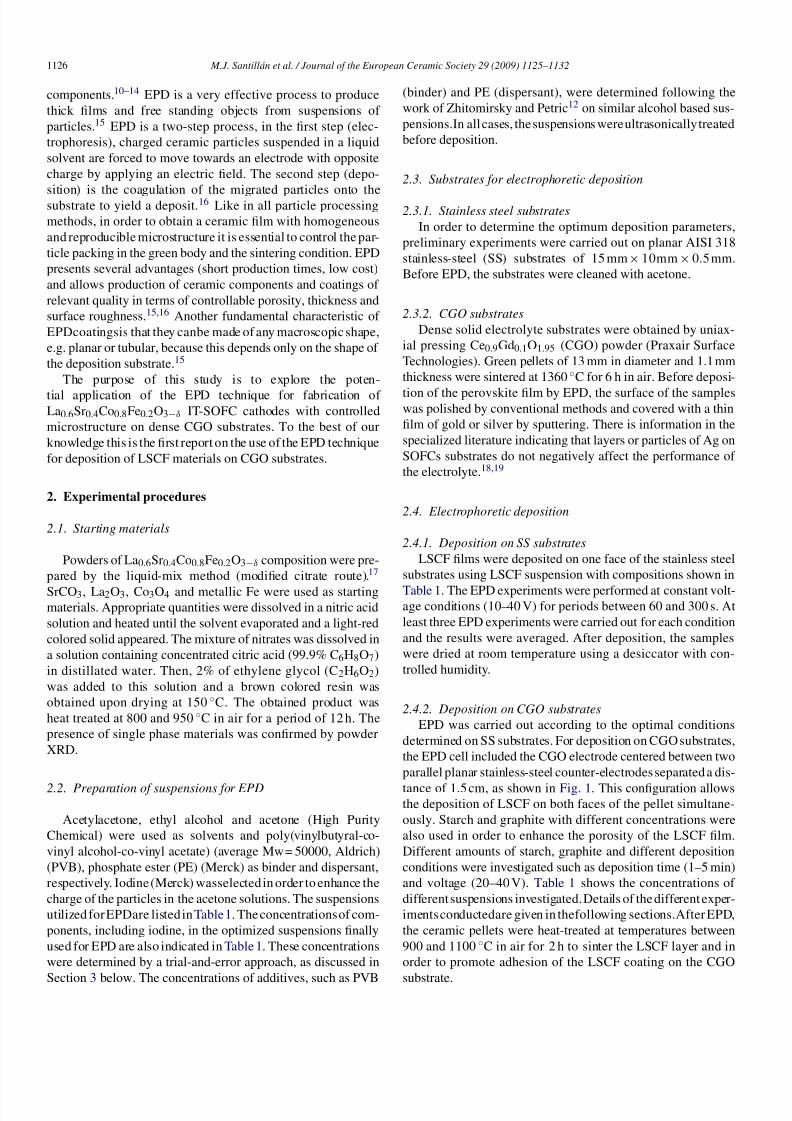
Fig. 1. Schematic diagram of EPD cell used for deposition of LSCF onto CGO
disk substrates, where deposition occurs simultaneously on both faces of the
CGO disk.
the solvents and on the interaction between the ceramic par-
ticles, solvent and additives. The obtention of a homogeneous
ceramic film by EPD requires a well dispersed and stable col-
loidal suspension. Consequently, the selection of the solvent
plays a fundamental role in the development of suitable sus-
pensions for EPD.
The results of the LSCF deposited weight (DW) per unit area
as function of time for an applied voltage of 20 V are shown inFig. 2. It can be seen that for all suspensions the DW of LSCF
increases with time at a constant applied voltage. A low DW
was obtained for a suspension containing pure ethanol and no
additives (suspension A). It was also observed that the addition
of iodine, PE and PVB to ethanol did not affect appreciably the
DW, e.g. suspensions B and C, respectively.
The films obtained using alcoholic suspensions (A, B and C)
showed poor adherence to the substrate and they did not cover
the substrate’sentire surface. Similar results were obtained using
suspensions containing acetone and iodine (suspension E). In
addition, it was also confirmed that deposition was not possible
with suspensions containing only acetone (suspension D).
The DW was seen to increase appreciably when acetylace-
tone was used as solvent and I2 as additive (suspension F). The
shape of the curve shows a decreasing deposition rate at higher
deposition times. This behavior is typical of a deposition pro-
Fig. 2. Deposit weight vs. deposition time for different LSCF suspensions (see
Table 1), all were deposited at 20 V.
8/9/2019 JECS 29(2009) Santillan Sofc
http://slidepdf.com/reader/full/jecs-292009-santillan-sofc 4/8
1128 M.J. Santillán et al. / Journal of the European Ceramic Society 29 (2009) 1125–1132
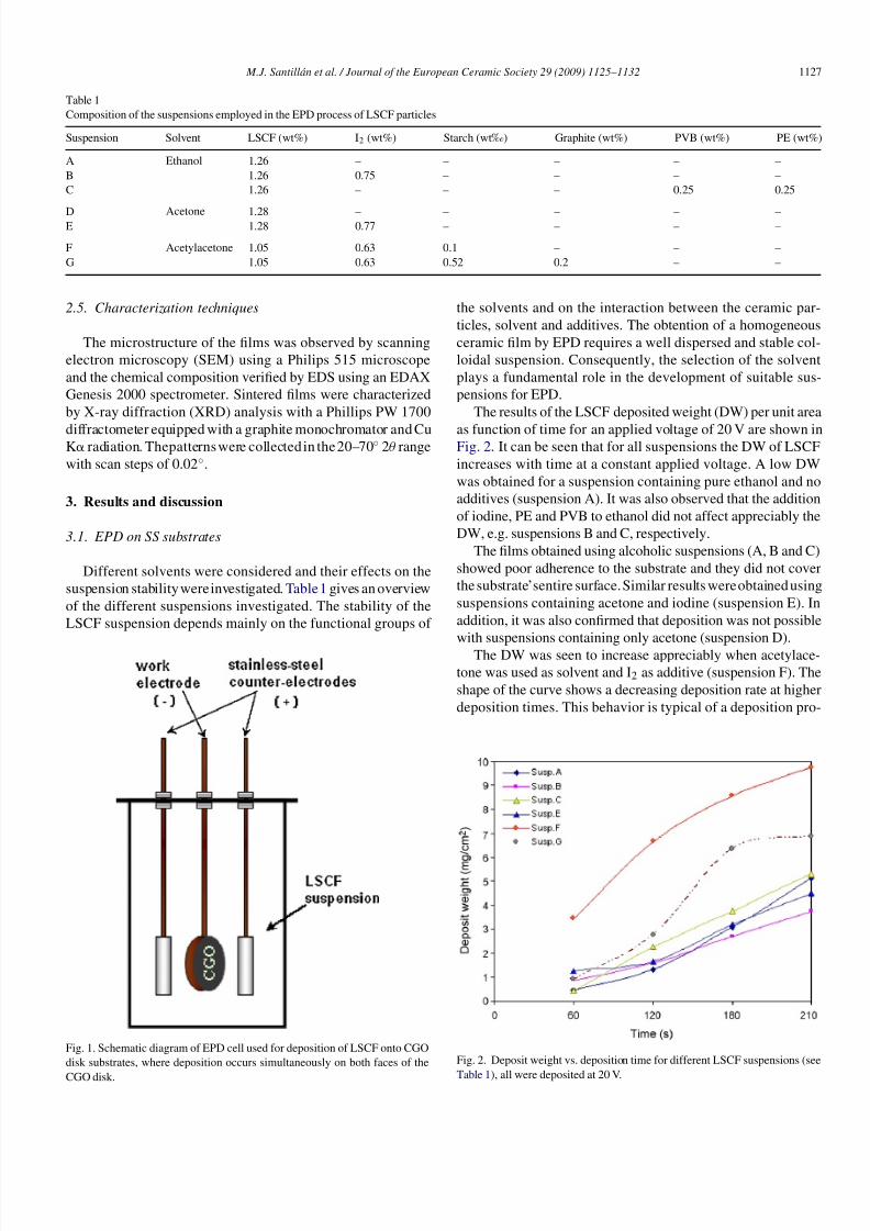
Fig. 3. Plot of deposit weight vs. deposition time obtained at different voltages
(10, 20 and 30 V) from LSCF suspensions F and G, using AcAc as solvent. Data
shown are average and standard deviation of three EPD runs for each condition.
cess at constant voltage, as discussed in the literature. 15,16 This
effect is due to the increment of the resistance between elec-
trodes caused by both the growth of the film and by a decreasing
concentration of the charge carrier in the solution as the EPD
process progresses.20
Finally it was observed that the DW for suspension G showed
intermediate values between those of suspension F and those of
suspensions A, B, C and D. Suspension G contains, in addition
to iodine, graphite and starch. These two additives were added
with the aim of increasing the porosity of the deposited LSCFfilm after heat treatment. Taking into account that the better
DW behaviour was achieved with suspensions F and G, only
results obtained using these two suspensions will be reported
and discussed further here.
The effect of the applied voltage (10, 20 and 30 V) on DW for
suspensions F and G is shown in Fig. 3. It can be seen that the
applied voltage has an appreciably effect on the DW for values
between 10 and20 V andthat DWdoes notincreasesubstantially
for higher voltages. The effect is quite different for suspension
G, where the DW does not change between 10 and 20 V but
increases in the range 20–30 V.
It is well known that the amount of deposited material in
EPDstronglydepends on thenature of additives since they play afundamental role on thestabilization of thesuspensionand on the
surface charge of the ceramic particles. In the overall behaviour
of particles in suspension the role of both adsorbed ions and
steric stabilization must be considered.12,16 In the present study
the charge of the particles in suspension was promoted by proton
adsorption on their surfaces.
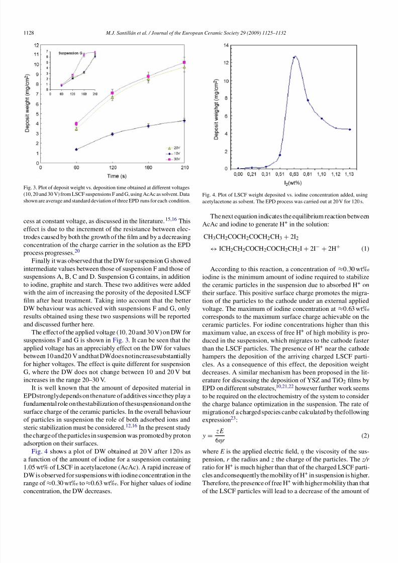
Fig. 4 shows a plot of DW obtained at 20 V after 120 s as
a function of the amount of iodine for a suspension containing
1.05 wt% of LSCF in acetylacetone (AcAc). A rapid increase of
DW is observed for suspensions with iodine concentration in the
range of ≈0.30 wt‰ to≈0.63 wt‰. For higher values of iodine
concentration, the DW decreases.
Fig. 4. Plot of LSCF weight deposited vs. iodine concentration added, usingacetylacetone as solvent. The EPD process was carried out at 20 V for 120 s.
The next equation indicates the equilibrium reaction between
AcAc and iodine to generate H+ in the solution:
CH3CH2COCH2COCH2CH3 + 2I2
↔ ICH2CH2COCH2COCH2CH2I+ 2I− + 2H+ (1)
According to this reaction, a concentration of ≈0.30 wt‰
iodine is the minimum amount of iodine required to stabilize
the ceramic particles in the suspension due to absorbed H+ on
their surface. This positive surface charge promotes the migra-tion of the particles to the cathode under an external applied
voltage. The maximum of iodine concentration at ≈0.63 wt‰
corresponds to the maximum surface charge achievable on the
ceramic particles. For iodine concentrations higher than this
maximum value, an excess of free H+ of high mobility is pro-
duced in the suspension, which migrates to the cathode faster
than the LSCF particles. The presence of H+ near the cathode
hampers the deposition of the arriving charged LSCF parti-
cles. As a consequence of this effect, the deposition weight
decreases. A similar mechanism has been proposed in the lit-
erature for discussing the deposition of YSZ and TiO2 films by
EPD on different substrates,10,21,22 however further work seems
to be required on the electrochemistry of the system to considerthe charge balance optimization in the suspension. The rate of
migrationof a charged species canbe calculated by thefollowing
expression23:
y =zE
6ηr(2)
where E is the applied electric field, η the viscosity of the sus-
pension, r the radius and z the charge of the particles. The z/r
ratio for H+ is much higher than that of the charged LSCF parti-
cles and consequently the mobility of H+ in suspension is higher.
Therefore, the presence of free H+ with higher mobility than that
of the LSCF particles will lead to a decrease of the amount of
8/9/2019 JECS 29(2009) Santillan Sofc
http://slidepdf.com/reader/full/jecs-292009-santillan-sofc 5/8
M.J. Santillán et al. / Journal of the European Ceramic Society 29 (2009) 1125–1132 1129
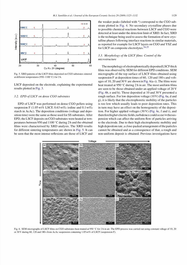
Fig. 5. XRD patterns of the LSCF films deposited on CGO substrates sintered
at different temperatures (950–1100◦C) for 2 h.
LSCF deposited on the electrode, explaining the experimental
results plotted in Fig. 3.
3.2. EPD of LSCF on dense CGO substrates
EPD of LSCF was performed on dense CGO pellets using
suspension F (1.05 wt% LSCF, 0.63 wt‰ iodine and 0.1 wt‰
starch in AcAc). The deposition conditions (voltage and depo-
sition time) were the same as those used for SS substrates. After
EPD, the LSCF deposits on CGO substrates were heated at tem-
peratures between 950 and 1100 ◦C during 2 h and the obtained
films were characterised by XRD analysis. The XRD results
for different sintering temperatures are shown in Fig. 5. It can
be seen that the most intense reflexions are those of LSCF and
the weaker peaks (labeled with *) correspond to the CGO sub-
strate plotted in Fig. 4. No secondary crystalline phases due
to possible chemical reactions between LSCF and CGO were
detected at least under the detection limit of XRD. In fact, XRD
is the technique being used to assess the formation of new crys-
talline phases following interface reactions in similar materials,
as reported for example for LSCF layers on CGO and YSZ and
for LSCF on composite electrolytes.24,25
3.3. Morphology of the LSCF films: Control of the
microstructure
The morphology of electrophoretically deposited LSCF thick
films was observed by SEM for different EPD conditions. SEM
micrographs of the top surface of LSCF films obtained using
suspension F at deposition times of 60, 120 and 180 s and volt-
ages of 10, 20 and 30 V are shown in Fig. 6(a–i). The films were
heat treated at 950 ◦C during 2 h in air. The most uniform films
are seen to be those obtained under an applied voltage of 20 V
(Fig. 6b, e and h). Those deposited at 10 and 30 V presented arough surface. For low deposition voltage (10 V) (Fig. 6a, d and
g), it is likely that the electrophoretic mobility of the particles
is too low which usually leads to poor deposition rates. This
in turn may have an effect on the homogeneity of the deposi-
tion. For higher applied voltages (30 V) (Fig. 6c, f and i), and
thereforehigher electric fields,turbulence could occur in thesus-
pension which can affect the uniform flow of particles arriving
to the electrode. Due to their high electrophoretic mobility and
high deposition rate, a close-packed arrangement of the particles
cannot be obtained and as a consequence of that, a rough and
non-uniform deposit is obtained. Previous investigations have
Fig. 6. SEM micrographs of LSCF films on CGO substrates heat-treated at 950 ◦C for 2 h in air. The EPD process was carried out using constant voltage of 10, 20
or 30 V during 60, 120 and 180 s from AcAc suspension containing 1.05 wt% of LSCF (suspension F).
8/9/2019 JECS 29(2009) Santillan Sofc
http://slidepdf.com/reader/full/jecs-292009-santillan-sofc 6/8
1130 M.J. Santillán et al. / Journal of the European Ceramic Society 29 (2009) 1125–1132
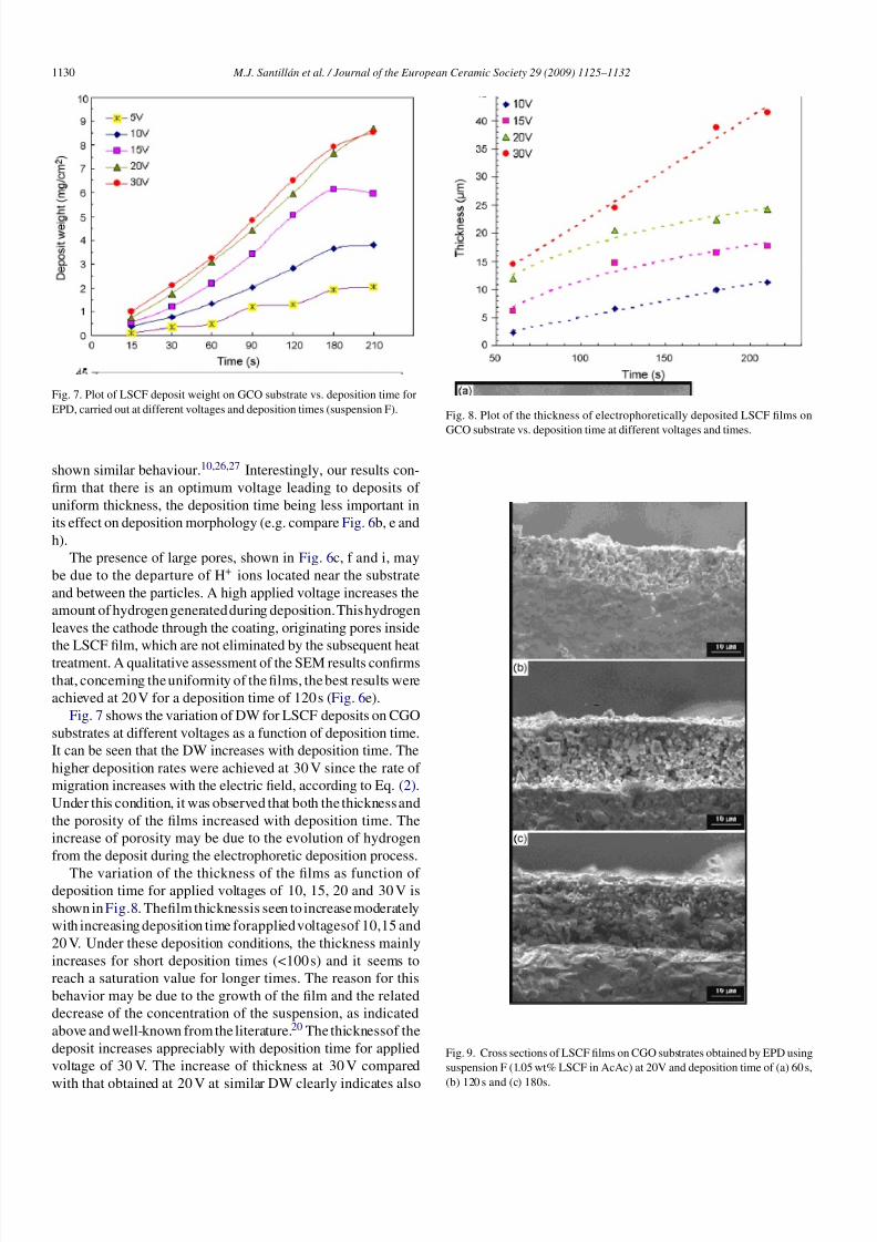
Fig. 7. Plot of LSCF deposit weight on GCO substrate vs. deposition time for
EPD, carried out at different voltages and deposition times (suspension F).
shown similar behaviour.10,26,27 Interestingly, our results con-
firm that there is an optimum voltage leading to deposits of
uniform thickness, the deposition time being less important in
its effect on deposition morphology (e.g. compare Fig. 6b, e and
h).
The presence of large pores, shown in Fig. 6c, f and i, may
be due to the departure of H+ ions located near the substrate
and between the particles. A high applied voltage increases the
amount of hydrogen generated during deposition.This hydrogen
leaves the cathode through the coating, originating pores inside
the LSCF film, which are not eliminated by the subsequent heattreatment. A qualitative assessment of the SEM results confirms
that, concerning the uniformity of the films, the best results were
achieved at 20 V for a deposition time of 120 s (Fig. 6e).
Fig. 7 shows the variation of DW for LSCF deposits on CGO
substrates at different voltages as a function of deposition time.
It can be seen that the DW increases with deposition time. The
higher deposition rates were achieved at 30 V since the rate of
migration increases with the electric field, according to Eq. (2).
Under this condition, it was observed that both the thickness and
the porosity of the films increased with deposition time. The
increase of porosity may be due to the evolution of hydrogen
from the deposit during the electrophoretic deposition process.
The variation of the thickness of the films as function of deposition time for applied voltages of 10, 15, 20 and 30 V is
shown in Fig.8. Thefilm thicknessis seen to increase moderately
with increasing deposition time forapplied voltagesof 10,15 and
20 V. Under these deposition conditions, the thickness mainly
increases for short deposition times (<100 s) and it seems to
reach a saturation value for longer times. The reason for this
behavior may be due to the growth of the film and the related
decrease of the concentration of the suspension, as indicated
above and well-known from the literature.20 The thicknessof the
deposit increases appreciably with deposition time for applied
voltage of 30 V. The increase of thickness at 30 V compared
with that obtained at 20 V at similar DW clearly indicates also
Fig. 8. Plot of the thickness of electrophoretically deposited LSCF films on
GCO substrate vs. deposition time at different voltages and times.
Fig. 9. Cross sections of LSCF films on CGO substrates obtained by EPD using
suspension F (1.05 wt% LSCF in AcAc) at 20V and deposition time of (a) 60 s,
(b) 120 s and (c) 180s.
8/9/2019 JECS 29(2009) Santillan Sofc
http://slidepdf.com/reader/full/jecs-292009-santillan-sofc 7/8
M.J. Santillán et al. / Journal of the European Ceramic Society 29 (2009) 1125–1132 1131
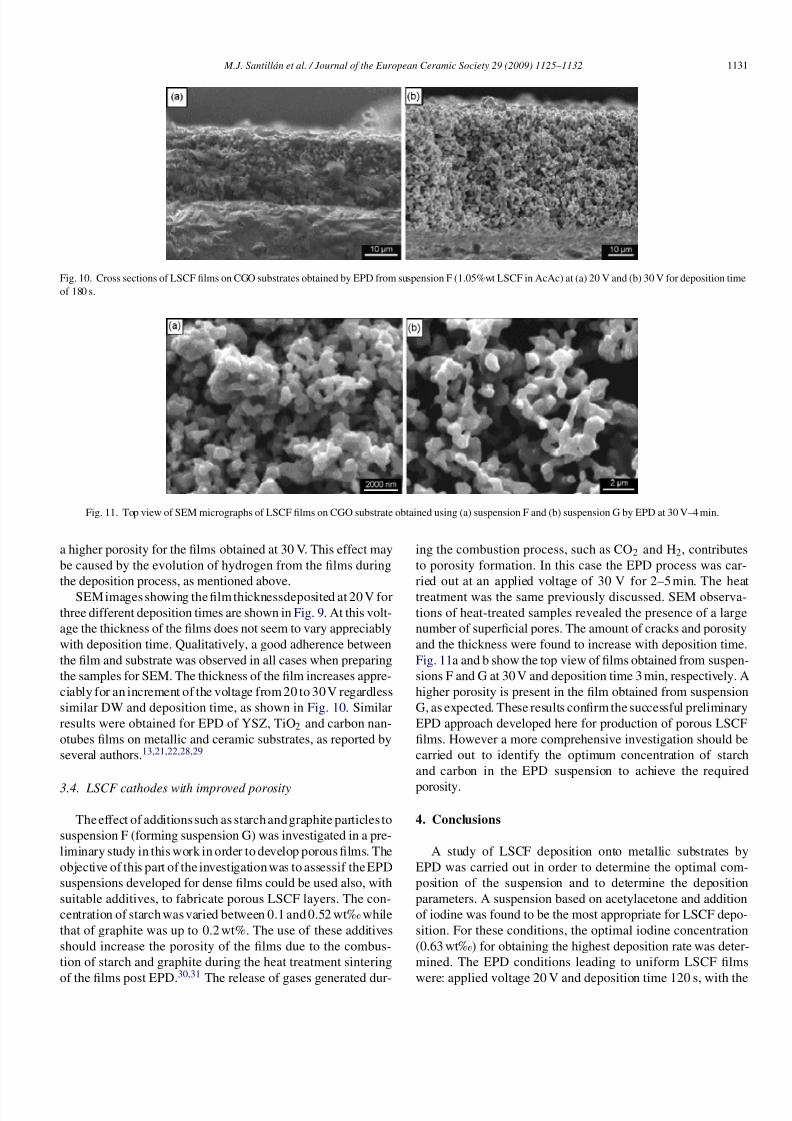
Fig. 10. Cross sections of LSCF films on CGO substrates obtained by EPD from suspension F (1.05%wt LSCF in AcAc) at (a) 20 V and (b) 30 V for deposition time
of 180 s.
Fig. 11. Top view of SEM micrographs of LSCF films on CGO substrate obtained using (a) suspension F and (b) suspension G by EPD at 30 V–4 min.
a higher porosity for the films obtained at 30 V. This effect may
be caused by the evolution of hydrogen from the films during
the deposition process, as mentioned above.
SEM images showing the film thicknessdeposited at 20 V for
three different deposition times are shown in Fig. 9. At this volt-
age the thickness of the films does not seem to vary appreciably
with deposition time. Qualitatively, a good adherence between
the film and substrate was observed in all cases when preparing
the samples for SEM. The thickness of the film increases appre-
ciably for an increment of the voltage from 20 to 30 V regardless
similar DW and deposition time, as shown in Fig. 10. Similar
results were obtained for EPD of YSZ, TiO2 and carbon nan-
otubes films on metallic and ceramic substrates, as reported by
several authors.13,21,22,28,29
3.4. LSCF cathodes with improved porosity
The effect of additions such as starch and graphite particles to
suspension F (forming suspension G) was investigated in a pre-
liminary study in this work in order to develop porous films. The
objective of this part of the investigation was to assessif the EPD
suspensions developed for dense films could be used also, with
suitable additives, to fabricate porous LSCF layers. The con-
centration of starch was varied between 0.1 and 0.52 wt‰ while
that of graphite was up to 0.2 wt%. The use of these additives
should increase the porosity of the films due to the combus-
tion of starch and graphite during the heat treatment sintering
of the films post EPD.30,31
The release of gases generated dur-
ing the combustion process, such as CO2 and H2, contributes
to porosity formation. In this case the EPD process was car-
ried out at an applied voltage of 30 V for 2–5 min. The heat
treatment was the same previously discussed. SEM observa-
tions of heat-treated samples revealed the presence of a large
number of superficial pores. The amount of cracks and porosity
and the thickness were found to increase with deposition time.
Fig. 11a and b show the top view of films obtained from suspen-
sions F and G at 30 V and deposition time 3 min, respectively. A
higher porosity is present in the film obtained from suspension
G, as expected. These results confirm the successful preliminary
EPD approach developed here for production of porous LSCF
films. However a more comprehensive investigation should be
carried out to identify the optimum concentration of starch
and carbon in the EPD suspension to achieve the required
porosity.
4. Conclusions
A study of LSCF deposition onto metallic substrates by
EPD was carried out in order to determine the optimal com-
position of the suspension and to determine the deposition
parameters. A suspension based on acetylacetone and addition
of iodine was found to be the most appropriate for LSCF depo-
sition. For these conditions, the optimal iodine concentration
(0.63 wt‰) for obtaining the highest deposition rate was deter-
mined. The EPD conditions leading to uniform LSCF films
were: applied voltage 20 V and deposition time 120 s, with the
8/9/2019 JECS 29(2009) Santillan Sofc
http://slidepdf.com/reader/full/jecs-292009-santillan-sofc 8/8
1132 M.J. Santillán et al. / Journal of the European Ceramic Society 29 (2009) 1125–1132
electrodes separated 1.5 cm. The effect of the applied voltage
and deposition time on the morphology, porosity, and thick-
ness of LSCF films onto CGO substrate was evaluated and
discussed. It was found that a high applied voltage (30 V)
increases the porosity and the thickness of the film. Similar
effect was obtained with addition of starch and graphite par-
ticles to the organic suspension. Thus EPD was confirmed to
be a convenient and simple technique to obtain porous thick
LSCF films on CGO substrates with controlled microstruc-
ture. The composition of the suspension, applied voltage and
deposition time, as investigated here, are the key parameters
playing a crucial role in determining the microstructure of
the electrophoretically deposited films. Current work focuses
on characterizing the electrochemical properties of the new
LSCF layers.
Acknowledgements
The authors thank Carlos Cotaro, Ernesto Scerbo and
Silvina Perez Fornells (CAB-IB) for assistance with SEM,EDS and XRD analyses. Financial support from CNEA,
SECyT (ANPCyT PICT 12-14493), CONICET (PIP 5594), and
UNCuyo (PI + D 06/C183) is acknowledged.
References
1. Chung, T-D., Hong, W-T., Chyou, Y-P., Yu, D-D., Lin, K-F. and Lee, C-
H., Efficiency analyses of solid oxide fuel cell power plant systems. Appl.
Thermal Eng., 2008, 28, 933–941.
2. Yin, Y., Li, S., Xi, C. and Meng, G., Electrochemical performance of IT-
SOFCs with a double-layer anode. J. Power Sources, 2007, 167, 90–93.
3. Inaba, H. and Tagawa, H., Ceria-based solid electrolytes. Solid State Ionics,
1996, 83, 1–16.
4. Steele, B. C. H.,Materials forIT-SOFC stacks35 years R&D: theinevitabil-
ity of gradualness? Solid State Ionics, 2000, 134, 3–20.
5. Grunbaum, N., Dessemond, L., Fouletier, J., Prado, F. and Caneiro, A.,
Electrode reaction of Sr1− xLa xCo0.8Fe0.2O3−δ with x = 0. 1 and 0. 6
on Ce0.9Gd0. 1 O1.95 at 600≤T ≤ 800◦C. Solid State Ionics, 2006, 177,
907–913.
6. Imanishi,N., Matsumura, T., Sumiya,Y.,Yoshimura,K., Hirano, A., Takeda,
Y. et al., Impedance spectroscopy of perovskite air electrodes for SOFC
prepared by laser ablation method. Solid State Ionics, 2004, 174, 245–252.
7. Takeyama, T., Takahashi, N., Nakamura, T. and Itoh, S., -Bi2O3 thin films
depositedon dense YSZ substrates by CVDmethod under atmospheric pres-
sure for intermediate temperature SOFC applications. Surf. Coat. Technol.,
2006, 200, 4797–4801.
8. Baqué, L. and Serquis, A., Microstructural characterization of
La0.4Sr0.6Co0.8Fe0.2O3−δ films deposited by dip coating. Appl. Surf.
Sci., 2007, 254, 213–218.
9. Baqué, L., Serquis, A., Grunbaum, N., Prado, F. andCaneiro,A., Preparation
and characterization of solid oxide fuel cells cathode films. Mater. Res. Soc.
Symp. Proc., 2006, 928, 181–186.
10. Ishihara, T., Sato, K. and Takita, Y., Electrophoretic deposition of Y2O3-
stabilized ZrO2 electrolyte films in solid oxide fuel cells. J. Am. Ceram.
Soc., 1996, 79, 913–919.
11. Zhitomirsky, I. and Petric, A., Electrolytic and electrophoretic deposition of
CeO2 films. Mater. Lett., 1999, 40, 263–268.
12. Zhitomirsky, I. and Petric, A., Electrophoretic deposition of ceramic mate-
rials for fuel cell applications. J. Eur. Ceram. Soc., 2000, 20, 2055–2061.
13. Matsuda,M., Hosomi, T., Murata, K., Fukui, T. and Miyake,M., Fabrication
of bilayered YSZ/SDC electrolyte film by electrophoretic deposition for
reduced-temperature operating anode-supported SOFC. J. Power Sources,
2007, 165, 102–107.
14. Negishi, H., Oshima, N., Sakaki, K., Haraya, K., Idemoto, Y., Koura, N.et al., Preparation of tubular mixed conducting oxide membrane by elec-
trophoretic deposition technique. Desalination, 2006, 200, 71–73.
15. Boccaccini, A. R. and Zhitomirsky, I., Application of electrophoretic and
electrolytic deposition techniques in ceramics processing. Curr. Opin. Solid
State Mater Sci., 2002, 6, 251–260.
16. Sarkar, P. and Nicholson, P. S., Electrophoretic deposition (EPD): mecha-
nisms, kinetics, and application to ceramics. J. Am. Ceram Soc., 1996, 79,
1987–2002.
17. Serquis,A., Prado, F. andCaneiro, A.,Synthesis method, control of cationic
composition and superconducting behavior of Nb1.85Ce0.15Cu1±δO y. Phys.
C , 1995, 253, 339–350.
18. Wang, S., Kato, T., Nagata, S., Honda, H., Kaneko, T., Iwashita, N. et al.,
Performance of a La0.6Sr0.4Co0.8Fe0. 2 O3–Ce0.8Gd0.2O1.9–Ag cathode for
ceria electrolyte SOFCs. Solid State Ionics, 2002, 146, 203–210.
19. Simner, S. P., Anderson, M. D., Templeton, J. W. and Stevenson, J. W.,Silver-perovskite composite SOFC cathodes processed via mechanofusion.
J. Power Sources, 2007, 168, 236–239.
20. Anné, G., Vanmensel, K. and Van der Biest, O., Influence of the suspension
composition on the electric field and deposition rate during electrophoretic
deposition. Colloids Surf. A Physicochem. Eng. Aspects, 2004, 245, 35–39.
21. Kaya, C., Kaya, F., Su,B., Thomas, B. andBoccaccini, A. R.,Structural and
functional thick ceramic coatings by electrophoretic deposition. Surf. Coat.
Technol., 2005, 191, 303–310.
22. Santillán, M. J., Quaranta,N. E., Membrives, F. and Boccaccini, A. R., Char-
acterization of TiO2 nanoparticlesuspensions for electrophoreticdeposition.
J. Nanopart. Res., 2008, 10, 787–793.
23. Ferrari, B. and Moreno, R., Electrophoretic deposition of aqueous alumina
slips. J. Eur. Ceram. Soc., 1997, 17(4), 549–556.
24. Murray, E. P., Sever, M. J. and Barnett, S. A., Electrochemical performance
of (La,Sr)(Co,Fe)O3–(Ce,Gd)O3 composite cathodes. Solid State Ionics,
2002, 148, 27–34.
25. Guo, W., Liua, J., Jin, C., Gao, H. and Zhanga, Y., Electrochemical
evaluation of La0.6Sr0.4Co0.8Fe0.2O3−I–La0.9Sr0.1Ga0.8Mg0.2O3−I com-
posite cathodes for La0.9Sr0.1Ga0.8Mg0.2O3−ı electrolyte SOFCs. J. Alloys
Compd., 2008., doi:10.1016/j.jallcom.2008.05.058.
26. Zhitomirsky, I., Cathodic electrodeposition of ceramic and organoceramic
materials. Fundamental aspects. Adv. Colloid Interface Sci., 2002, 97,
279–317.
27. Sarkar, P., De, D. and Rho, H., Synthesis and microstructural manipulation
of ceramics by electrophoretic deposition. J. Mater. Sci., 2004, 39, 819–823.
28. Chicatún, F., Cho, J., Schaab, S., Brusatin, G., Colombo, V., Roether, J.
A. et al., Carbon nanotube deposits and CNT/SiO2 composite coatings by
electrophoretic deposition. Adv. Appl. Ceram., 2007, 106(4), 186–195.
29. Negishi, H., Sakai, N., Yamaji, K., Horita, T. and Yokokawa, H., Appli-
cation of electrophoretic deposition technique to solid oxide fuel cells. J.
Electrochem. Soc., 2000, 147, 1682–1687.
30. Yamaji, K., Kishimoto, H., Xiong, Y., Horita, T., Sakai, N. and Yokokawa,
H., Performance of anode-supported SOFCs fabricated with EPD tech-
niques. Solid State Ionics, 2004, 175, 165–169.
31. Xu, Z., Rajaram, G., Sankar, J. and Pai, D., Electrophoretic deposition of
YSZ electrolyte coatings for SOFCs. Fuel Cells Bull., 2007, 3, 12–16.