
Jan. 4, 2013 - fcac.org Control Surface...Revised – Jan. 4, 2013 Trademarks: NewTek, TriCaster,...
126
Transcript of Jan. 4, 2013 - fcac.org Control Surface...Revised – Jan. 4, 2013 Trademarks: NewTek, TriCaster,...
Revised – Jan. 4, 2013
Trademarks: NewTek, TriCaster, TriCaster XD, TCXD40, TriCaster 40, TriCaster TCXD40, TCXD8000, TriCaster 8000,
TriCaster TCXD8000, TCXD850, TCXD850 EXTREME, TriCaster TCXD850 EXTREME, TriCaster 850 EXTREME, TriCaster
EXTREME, TriCaster 850, TCXD450, TCXD450 EXTREME, TriCaster TCXD450 EXTREME, TriCaster 450 EXTREME, TriCaster
450, TCXD455, TriCaster 455, TriCaster TCXD455, TriCaster 855, TCXD855, TriCaster TCXD855, IsoCorder, TCXD300,
TriCaster 300, TriCaster TCXD300, TriCaster PRO, TriCaster STUDIO, TriCaster BROADCAST, TriCaster DUO, ProTek, ProTek
Care, ProTek Elite, iVGA, SpeedEDIT, 3PLAY, 3Play, 3Play 820, 3PXD820, 3Play 330, 3PXD330, LiveText, DataLink, LiveSet,
LiveMatte, TimeWarp, VT, VT[3], VT[4], V[T5], Video Toaster, Toaster, Inspire 3D, 3D Arsenal, Aura, LightWave, LightWave
3D and LightWave CORE are trademarks, service marks, and registered trademarks of NewTek. All other brand names,
product names, and trademarks belong to their respective holders. All rights reserved.
TriCaster 8000 CS AVID
® Artist Mix
TriCaster 450/850 CS TimeWarp 850 TW
TriCaster 40 CS TimeWarp TW-42 LiveControl LC-11
TABLE OF CONTENTS
1 About This Manual .............................................................................................................. 1
1.1 Manual Organization ........................................................................................................ 1
A.1 A Control Surface for Every Need ...................................................................................... 2
2 Welcome and Setup ............................................................................................................ 3
2.1 Welcome ........................................................................................................................... 3
2.2 Something for Everyone .................................................................................................... 3
2.2.1 Primary Control ......................................................................................................... 3
2.2.2 Instant Replay ........................................................................................................... 4
2.3 Installation ........................................................................................................................ 4
2.3.1 Making the Connection ............................................................................................. 4
3 TriCaster™ 8000 CS.............................................................................................................. 7
3.1 Walkthrough ..................................................................................................................... 7
3.1.1 Switcher Rows ........................................................................................................... 8
3.1.2 MAIN TRANSITION Controls ...................................................................................... 9
3.1.3 MEDIA PLAYERS....................................................................................................... 13
3.1.4 POSITIONER ............................................................................................................. 15
3.1.5 M/Es ........................................................................................................................ 17
3.2 Features and Controls ..................................................................................................... 20
3.2.1 Connecting to TriCaster .......................................................................................... 21
3.2.2 Delegates and Synchronization ............................................................................... 21
3.2.3 Switcher Controls .................................................................................................... 21
3.2.4 MAIN TRANSITION Group ....................................................................................... 23
3.2.5 M/E Controls ........................................................................................................... 25
3.2.6 POSITIONER Group .................................................................................................. 29
3.2.7 MEDIA PLAYERS Group ........................................................................................... 32
3.2.8 Record Group .......................................................................................................... 34
3.3 Special Buttons ................................................................................................................ 34
3.3.1 MACRO .................................................................................................................... 34
3.4 T-Bar Illumination ........................................................................................................... 35
3.4.1 M/E TRANSITION – Lighting .................................................................................... 35
3.4.2 MAIN TRANSITION .................................................................................................. 36
4 Avid® Artist Mix ................................................................................................................ 37
4.1 Installing AVID® Artist Mix Software ............................................................................... 38
4.2 Connecting Artist Mix ...................................................................................................... 38
4.3 Getting started ................................................................................................................ 39
4.3.1 Panel Layout ............................................................................................................ 40
4.3.2 NUDGE .................................................................................................................... 41
4.3.3 BANK ....................................................................................................................... 41
4.3.4 Level Control ........................................................................................................... 42
4.3.5 Knob Set Selectors .................................................................................................. 42
4.3.6 Balance/Pan Control ............................................................................................... 43
4.3.7 Mono/Talk ............................................................................................................... 43
4.3.8 Solo & Mute ............................................................................................................ 43
4.3.9 Follow ...................................................................................................................... 44
4.4 Audio Groups................................................................................................................... 44
4.5 EQ Control ....................................................................................................................... 44
4.6 Compressor/Limiter......................................................................................................... 45
4.7 CHAN Mode ..................................................................................................................... 46
4.8 FLIP Mode ....................................................................................................................... 47
4.9 INSERT (Mic) .................................................................................................................... 47
4.10 Locking Channels ............................................................................................................. 49
4.11 Audio Presets .................................................................................................................. 50
5 TriCaster™ 450 CS & 850 CS ............................................................................................... 51
5.1 Walkthrough ................................................................................................................... 52
5.1.1 Switcher Rows ......................................................................................................... 52
5.1.2 Transition ................................................................................................................ 53
5.1.3 Local Controls .......................................................................................................... 53
5.1.4 Media Players .......................................................................................................... 58
5.1.5 Positioner ................................................................................................................ 59
5.1.6 Virtual Inputs........................................................................................................... 61
5.2 Features and Controls ..................................................................................................... 64
5.2.1 Connecting to TriCaster .......................................................................................... 65
5.2.2 Delegates and Synchronization ............................................................................... 65
5.2.3 Switcher Controls .................................................................................................... 66
5.2.4 Transition Group ..................................................................................................... 68
5.2.5 Virtual Input Group ................................................................................................. 71
5.2.6 Positioner Group ..................................................................................................... 74
5.2.7 Media Player Group ................................................................................................ 78
5.2.8 Record Group .......................................................................................................... 79
5.2.9 Qualifier Buttons ..................................................................................................... 80
6 TriCaster™ 40 CS ............................................................................................................... 81
6.1 Features and Controls ..................................................................................................... 81
6.1.1 Connecting to TriCaster .......................................................................................... 82
6.1.2 Delegates and Synchronization ............................................................................... 82
6.1.3 Switcher Delegates ................................................................................................. 83
6.1.4 SHIFT & ALT ............................................................................................................. 84
6.1.5 Transitions ............................................................................................................... 85
7 Timewarp™ ....................................................................................................................... 89
7.1 Walkthrough ................................................................................................................... 90
7.1.1 Setting Up ............................................................................................................... 90
7.1.2 Recording and Playing Replays ............................................................................... 91
7.2 Features and Controls ..................................................................................................... 91
7.2.1 Overview ................................................................................................................. 92
7.2.2 DDR Delegate .......................................................................................................... 93
7.2.3 Edit group ................................................................................................................ 94
7.2.4 Play Speed ............................................................................................................... 94
7.2.5 Marking Group ........................................................................................................ 95
7.2.6 ALT and Qualifiers ................................................................................................... 97
7.2.7 Record toggle .......................................................................................................... 98
7.2.8 DDR options ............................................................................................................ 99
7.2.9 Preset (DDR Playlist) ............................................................................................... 99
7.2.10 Transport (Clip controls) ......................................................................................... 99
7.2.11 Tips and Tricks ....................................................................................................... 101
8 TriCaster™ LC-11 ............................................................................................................. 103
8.1 Overview ....................................................................................................................... 103
8.1.1 LC-11 Variants ....................................................................................................... 103
8.2 Switcher Section ............................................................................................................ 105
8.2.1 Selecting Switcher Sources ................................................................................... 106
8.2.2 Auto and Take ....................................................................................................... 107
8.3 Transition Section .......................................................................................................... 108
8.3.1 Fade and FX ........................................................................................................... 108
8.3.2 SPEED and FX ........................................................................................................ 109
8.3.3 FTB and ALT ........................................................................................................... 109
8.3.4 Fade All & Take All ................................................................................................ 110
8.4 Overlay Section – TriCaster SD ...................................................................................... 110
8.4.1 The Joysticks ......................................................................................................... 111
8.4.2 DDR1, DDR2 & TXT Knobs ..................................................................................... 111
8.4.3 EXT, DDR 1, DDR 2 and TXT Buttons ..................................................................... 111
8.4.4 Fade & Take (Overlay) ........................................................................................... 112
8.5 Overlay Section – TRICASTER™ 300, 450, 850, 455 AND 855 ........................................ 112
8.5.1 Joysticks ................................................................................................................ 112
8.5.2 DDR, Still and Titles Knobs .................................................................................... 112
8.5.3 Mode Buttons ....................................................................................................... 113
8.5.4 Fade & Take (Overlay) ........................................................................................... 115
Credits .................................................................................................................................... 117

Page | 1
1 ABOUT THIS MANUAL
Estimates are that between 60 and 97% of the human race hate
reading manuals. Most prefer to jump right in, maybe asking a
friend for occasional help … and who can blame them?
This manual attempts to tell you what you need to know in a
friendly, concise way, and also provides a comprehensive reference
section you can turn to when you need finer detail.
1.1 MANUAL ORGANIZATION
Even if you hate reading, please take a moment to peruse this section, which explains the
manual’s organization. You may find you can escape with a minimum of reading (or, if you are a
devout reader, you can be the hero others turn to for expert advice).
The manual is structured as follows:
Part I – Getting Started: Part 1 provides an introduction to TriCaster™ Control Surfaces – a
brisk jog through fundamentals including an overview of control surface categories and
models, and their installation.
Part II – The Control Surfaces
o TriCaster™ 8000 CS: A striking new control surface designed specifically to
provide primary control of the revolutionary TriCaster™ 8000 model live
production system.
o TriCaster™ 450 & 850 CS: This section will familiarize you with two very
similar control surfaces designed specifically to provide primary control of
TriCaster™ 455 and 855 model live production systems.
Page | 2
o TimeWarp
TriCaster™ 850 TW: Turn here for everything you need to know
about this powerful instant replay control surface designed exclusively
for TriCaster™.
TimeWarp™ TW-42: This section includes coverage of the original
NewTek TimeWarp™ instant replay controller.
o TriCaster™ LC-11: A discussion of the primary control surface designed for
use with the standard definition model TriCaster Studio™ and TriCaster
Broadcast™ live production systems.
Note: The original TriCaster™ RS-8 (or TriCaster™ VM) control surface is no
longer in production and is not covered.
A.1 A CONTROL SURFACE FOR EVERY NEED
This User Guide discusses multiple TriCaster™ control surfaces, including TriCaster™ 8000 CS, 450
and 850 CS, TriCaster™ 850 TW, and several others.
Two of these (TriCaster™ 450 and 850 CS) are virtually identical as respects operations and
control layouts, and we will consider them together in Part II. Others sections cover various CS
models in turn. We’re very confident you’ll find one or more of these devices to be just excellent
for your live production needs.
Page | 3
2 WELCOME AND SETUP
This chapter introduces the different control surfaces offered by
NewTek®, helping you to see how they complement your
TriCaster™ and bring added ability to your production setup.
The section also includes brief notes on connecting TriCaster™
control surfaces for use with your live production system.
2.1 WELCOME
NewTek TriCaster™ systems provide unrivalled live production power. With a TriCaster™ control
surface in front of you, all of that power is right at your fingertips. These sleek yet rugged control
surfaces deliver precise control over the video layers constituting your program. Quickly and
confidently perform your switching operations. Advanced TriCaster control surfaces manage
transitions on a per layer basis, govern the background composition, overlay and overlay
transitions, multi-layer virtual input configuration and zoom, control multiple Media Players,
record, stream and grab features, Auxiliary output, and even more.
2.2 SOMETHING FOR EVERYONE
TriCaster control surfaces can be grouped into two categories offering either primary switcher
control or instant replay functionality.
2.2.1 PRIMARY CONTROL
At the time of writing, three devices fall into this category, as follows:
TriCaster 8000 CS: A full-function control surface matched to the TriCaster 8000 live
production system.
Page | 4
TriCaster 850 CS: A full-function control surface designed to complement TriCaster 855,
along with TriCaster 850 and 850 EXTREME™.
TriCaster 450 CS: Similar to the above but, slightly more compact, being designed for use
with TriCaster 455, 450 and 450 EXTREME™ (which have less inputs).
TriCaster LC-11: This control surface was designed for use the standard definition
TriCaster Studio and TriCaster Broadcast models.
2.2.2 INSTANT REPLAY
NewTek provides potent instant replay solutions in the form of its dedicated 3Play™ systems, but for less demanding installations many have found their TriCaster-based TimeWarp™ control surfaces (which take advantage of TriCaster’s integrated recording and playback capabilities) quite valuable.
TriCaster 850 TW: The perfect complement to either TriCaster 850 CS or TriCaster 450 CS, this instant replay controller is equally capable of performing as a solo act alongside any high definition TriCaster live production system.
TriCaster™ TW-42: This is NewTek’s original TimeWarp™ device. While originally supplied for use with the standard definition TriCaster lineup, it also provides workmanlike instant replay functionality with high definition TriCaster models.
2.3 INSTALLATION
2.3.1 MAKING THE CONNECTION
Simply connect the TriCaster control surface unit to your NewTek TriCaster using the USB cable
supplied. There is no need to install drivers, or configure the software. Recognition of the
control surface is automatic.
POWER CONSIDERATIONS
The power requirements of TriCaster control surfaces vary, but generally speaking are not
inconsequential. TriCaster 8000CS alone utilizes a standard AC power connection, in addition to
Page | 5
its USB control connection. All other control surfaces are powered by their USB cable. In the
latter case, connecting the unit using a USB cable longer than the one originally supplied can
diminish available power to the point where problems could ensue, including connection
recognition failure or operational problems.
To avoid problems, we strongly recommend that the control surface be connected to a powered
USB hub using a short USB cable, in turn connecting the USB hub to a USB port on the TriCaster.
(See also Section 5.2.1.)
Important Note: So-called USB extenders are not recommended, having proven less reliable than
long USB cables (with powered hub, as discussed above). This is because each added connector in
the circuit introduces ‘reflections’ that can degrade the signal. In this configuration, the control
surface may seem reliable for some time, but then fail unexpectedly. (If this should happen,
disconnecting and reconnecting the control surface may temporarily restore functionality).

Page | 7
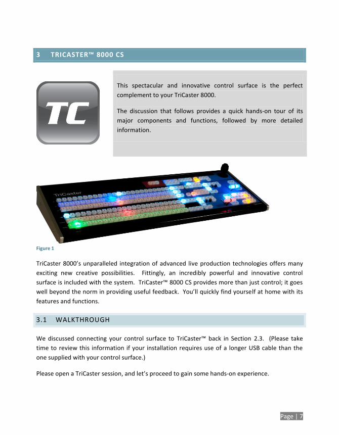
3 TRICASTER™ 8000 CS
This spectacular and innovative control surface is the perfect
complement to your TriCaster 8000.
The discussion that follows provides a quick hands-on tour of its
major components and functions, followed by more detailed
information.
Figure 1
TriCaster 8000’s unparalleled integration of advanced live production technologies offers many
exciting new creative possibilities. Fittingly, an incredibly powerful and innovative control
surface is included with the system. TriCaster™ 8000 CS provides more than just control; it goes
well beyond the norm in providing useful feedback. You’ll quickly find yourself at home with its
features and functions.
3.1 WALKTHROUGH
We discussed connecting your control surface to TriCaster™ back in Section 2.3. (Please take
time to review this information if your installation requires use of a longer USB cable than the
one supplied with your control surface.)
Please open a TriCaster session, and let’s proceed to gain some hands-on experience.
Page | 8
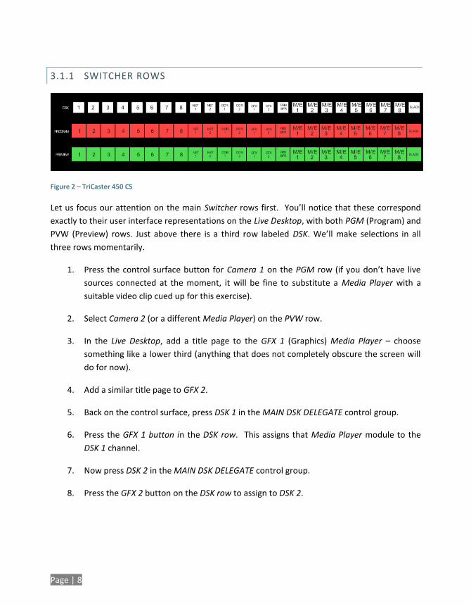
3.1.1 SWITCHER ROWS
Figure 2 – TriCaster 450 CS
Let us focus our attention on the main Switcher rows first. You’ll notice that these correspond
exactly to their user interface representations on the Live Desktop, with both PGM (Program) and
PVW (Preview) rows. Just above there is a third row labeled DSK. We’ll make selections in all
three rows momentarily.
1. Press the control surface button for Camera 1 on the PGM row (if you don’t have live
sources connected at the moment, it will be fine to substitute a Media Player with a
suitable video clip cued up for this exercise).
2. Select Camera 2 (or a different Media Player) on the PVW row.
3. In the Live Desktop, add a title page to the GFX 1 (Graphics) Media Player – choose
something like a lower third (anything that does not completely obscure the screen will
do for now).
4. Add a similar title page to GFX 2.
5. Back on the control surface, press DSK 1 in the MAIN DSK DELEGATE control group.
6. Press the GFX 1 button in the DSK row. This assigns that Media Player module to the
DSK 1 channel.
7. Now press DSK 2 in the MAIN DSK DELEGATE control group.
8. Press the GFX 2 button on the DSK row to assign to DSK 2.
Page | 9
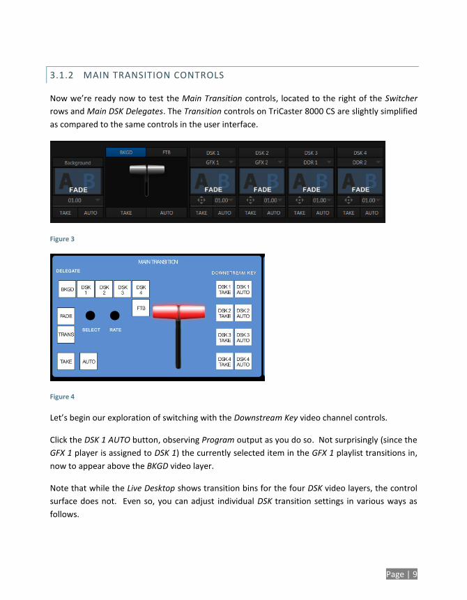
3.1.2 MAIN TRANSITION CONTROLS
Now we’re ready now to test the Main Transition controls, located to the right of the Switcher
rows and Main DSK Delegates. The Transition controls on TriCaster 8000 CS are slightly simplified
as compared to the same controls in the user interface.
Figure 3
Figure 4
Let’s begin our exploration of switching with the Downstream Key video channel controls.
Click the DSK 1 AUTO button, observing Program output as you do so. Not surprisingly (since the
GFX 1 player is assigned to DSK 1) the currently selected item in the GFX 1 playlist transitions in,
now to appear above the BKGD video layer.
Note that while the Live Desktop shows transition bins for the four DSK video layers, the control
surface does not. Even so, you can adjust individual DSK transition settings in various ways as
follows.
Page | 10
9. Click the BKGD delegate button in the MAIN TRANSITION> DELEGATE control group.
10. Twist the Select knob below (next to Fade) to cycle through the current entries in the
BKGD Transition Bin.
11. Click the DSK 1 button in the MAIN TRANSITION> DELEGATE control group.
12. Again, twist the Select knob, and choose a different transition for DSK 1 – choose one
that is in a different numeric place in the bin than the BKGD selection below.
13. Now press the BKGD and DSK 1 delegate buttons together, multi-selecting them.
14. Twist Select again, slowly, click by click – the selections advance together.
15. Rotate the nearby Rate knob (just above the main Auto button), and keep an eye on the
Transition Duration time displays in the Live Desktop. Observe that the transition
duration for both delegates changes as you do so.
16. Now push the Rate knob a few times (as though it was a button). As you do so, watch
the Transition speed of both selected delegates in the user interface. The settings will
cycle through the presets (in the Speed menu) each time you press Rate.
17. In the user interface, open the Duration menu for the BKGD layer so you can see the
state of the Reverse option for the transition.
18. Push the Select knob (as though it was a button). Doing so toggles the Reverse
transition mode for this transition; you’ll be able to see this in the menu you opened.
19. Open the Transition Speed menu for the BKGD layer on the Live Desktop.
20. Locate the SHIFT, CTRL and ALT buttons, to the left of the MAIN TRANSITION control
group. Press ALT and continue to hold it down, and the watch the menu as you push
Select several times in succession. You should see the Ping Pong switch for the current
BKGD transition toggle on or off each time you push Select.
Page | 11
Note: DSK Transitions always Ping Pong. Hence their duration menus have no Reverse or
Ping Pong switches.
21. If necessary, adjust the Live Desktop Workspace options to show the Preview monitor
(next to Program).
22. On the control surface, press the BKGD button in the MAINTRANSITION>DELEGATE
group, resulting in it alone being selected.
23. Press the main Auto button (below the Select knob on the control surface), or operate
the T-bar to perform a BKGD transition.
24. Earlier, we displayed DSK 1, using the dedicated DSK 1 Auto button. The BKGD transition
we just performed did not affect it, so it should still be displayed (if you removed it from
view while experimenting, please restore it before continuing).
25. Press the BKGD, DSK 1 and DSK 2 delegate buttons all together, multi-selecting them.
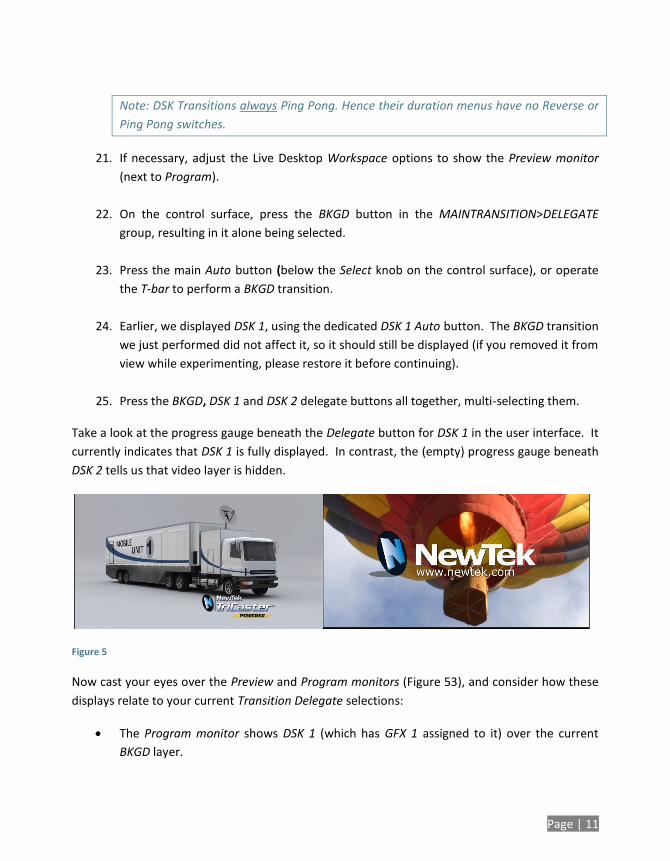
Take a look at the progress gauge beneath the Delegate button for DSK 1 in the user interface. It
currently indicates that DSK 1 is fully displayed. In contrast, the (empty) progress gauge beneath
DSK 2 tells us that video layer is hidden.
Figure 5
Now cast your eyes over the Preview and Program monitors (Figure 53), and consider how these
displays relate to your current Transition Delegate selections:
The Program monitor shows DSK 1 (which has GFX 1 assigned to it) over the current
BKGD layer.
Page | 12
The Preview monitor shows DSK 2 (which has GFX 2 assigned to it) over the current
Preview row selection.
The Look Ahead Preview monitor (or simply, Preview) is showing us the composition that will
result if we perform a Take or Auto operation right now.
26. Press the DSK 1 and DSK 2 buttons in MAIN TRANSITION>DELEGATE (so that BKGD is no
longer selected).
Note that, when you do this, the Preview monitor no longer shows the Switcher’s Preview row
selection. Why not?
Having de-selected the BKGD delegate, only the DSK 1 and DSK 2 buttons remain lit. Thus only
those two video layers will be affected by a (Main) Take or Auto. The end result of either of those
operations will be as follows:
DSK 1, currently seen on Program will be removed from view (but will re-appear on
Preview).
DSK 2 will be displayed on Program instead.
The BKGD layer will not change; that’s why the Preview correctly predicts no change to
that video layer, instead showing the same BKGD in both the Preview and Program
monitors.
The MAIN TRANSITION>DELEGATE feature provides flexible and convenient video layer
management, providing complete control over your ultimate Program output composition.
One more little detail to note, before we leave the Transition group – FTB, although located
below its MAIN TRANSITION > DELEGATE siblings on the control surface, is nevertheless a
delegate button, just like them.
Page | 13
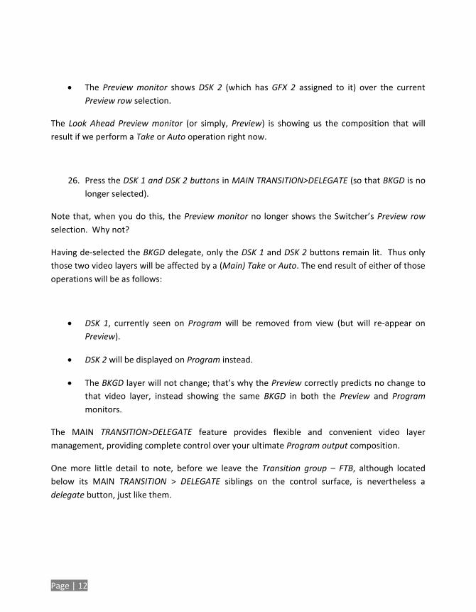
Figure 6
27. Press FTB – note that when you do:
a. The other Transition delegate buttons are de-selected.
b. The Preview monitor goes completely black.
28. Press the main Auto button, or operate the T-bar.
Observe that pressing FTB did not actually perform a Fade to Black operation – rather it
delegated the main Take, Auto and T-bar controls to control the FTB video layer.
Hint – Press Shift + FTB to actually perform an FTB operation without being required to press
Auto, Take or the T-Bar.
29. Press the main Take button again, clearing the FTB video layer from Program out.
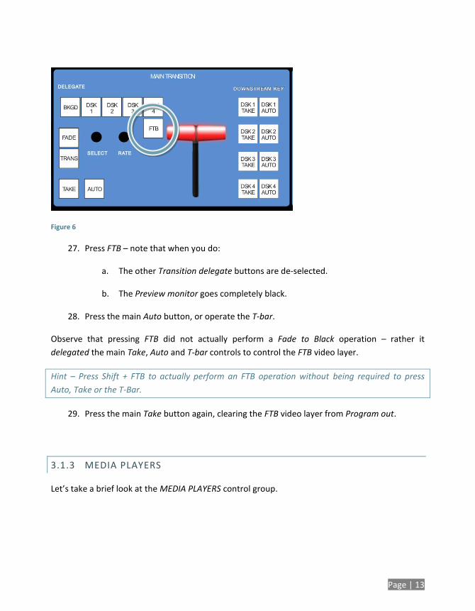
3.1.3 MEDIA PLAYERS
Let’s take a brief look at the MEDIA PLAYERS control group.
Page | 14
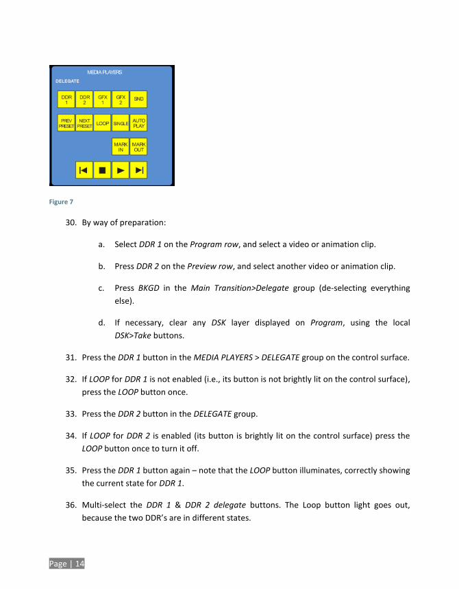
Figure 7
30. By way of preparation:
a. Select DDR 1 on the Program row, and select a video or animation clip.
b. Press DDR 2 on the Preview row, and select another video or animation clip.
c. Press BKGD in the Main Transition>Delegate group (de-selecting everything
else).
d. If necessary, clear any DSK layer displayed on Program, using the local
DSK>Take buttons.
31. Press the DDR 1 button in the MEDIA PLAYERS > DELEGATE group on the control surface.
32. If LOOP for DDR 1 is not enabled (i.e., its button is not brightly lit on the control surface),
press the LOOP button once.
33. Press the DDR 2 button in the DELEGATE group.
34. If LOOP for DDR 2 is enabled (its button is brightly lit on the control surface) press the
LOOP button once to turn it off.
35. Press the DDR 1 button again – note that the LOOP button illuminates, correctly showing
the current state for DDR 1.
36. Multi-select the DDR 1 & DDR 2 delegate buttons. The Loop button light goes out,
because the two DDR’s are in different states.
Page | 15
37. Press LOOP. LOOP is turned on for both of the delegated Media Players.
38. Press the LOOP button yet again. LOOP is disabled for both delegated Media Players.
39. Repeat this exercise using the AUTOPLAY or SINGLE buttons (or both together).
Until this point, we’ve not done anything to the Media Players that couldn’t
have been done without the control surface, so try the following simple but
powerful step:
40. Press Play. Both Media Players begin to run simultaneously. Press Stop.
3.1.4 POSITIONER
Let’s kick it up a notch now, using the control surface to perform multiple simultaneous
operations.
41. Enable AUTOPLAY, SINGLE and LOOP for both DDRs.
42. Select different video sources on the Switcher’s PGM and PVW rows.
43. Use the DSK row to assign DDR 1 to DSK 1.
44. Likewise, assign DDR 2 to DSK 2.
45. Select both DSK 1 and DSK 2 delegate buttons in the Positioner group on the control
surface.
46. Press the POS/SCALE button to the left of the joystick (this button group controls the
Joystick function mode).
47. Twist the joystick counter-clockwise (as viewed from above) to Scale both DSK overlays
down at once. Reduce them to 15-20% of the screen size. (Notice that the Preview
monitor temporarily shows the results of your operation as you do so).
48. Push the DSK 1 button in the Positioner DELEGATE group, and use the joystick to
reposition DSK 1 to the upper-left quadrant of the screen, again using Preview to guide
you.

Page | 16
(Push forward or back to move the delegated source vertically in the frame, and left or
right for lateral movement.)
49. Push the DSK 2 button in the Positioner DELEGATE group, and repeat the step above,
positioning DSK 2 in the lower right quadrant of the screen.
50. Select the BKGD button in the MAIN TRANSITION>DELEGATE group, and press Rate as
many times necessary to set the transition speed for the BKGD video layer to 00.15.
51. Multi-select DSK 1and DSK 2 in the MAIN TRANSITION>DELEGATE group, press RATE
until both DSK video layer transitions is set to 01.00.
52. Multi-select BKGD, DSK 1and DSK 2 in the TRANSITION DELEGATE group.
Figure 8
At this point, the display on the Preview monitor should look something like Figure 56.
53. Push the main Auto button. The following will occur:
a. The BKGD transition is performed, swapping the Program and Preview row
sources.
b. Both DSKs transition in above the BKGD layer.
c. And the two DDRs automatically begin to play.
Page | 17
54. Let this all run for a moment or two to take it all in, then press Auto again.
All of the above resulted from your pressing a single button. You can see that the control surface
allows you to quickly configure complex compositions, and display them with flair.
Multi-selecting delegates provides a great deal of convenience, as we’ve seen. Consider too that
it becomes a simple matter to ensure matching positioning (etc.) for a series of sources, such as
title overlays, picture-in-picture setups, and so on. Let’s look at an example using M/Es.
3.1.5 M/ES
We’ll perform a very simple exercise, but it will quickly impart everything you need to know.
Turn off both DSKs, and press the BKGD button in the MAIN TRANSITION>DELEGATE
group.
The Preview monitor will now show the Switcher’s Preview row selection (only);
and the Program monitor will display the current Program row selection – this
will let you see how subsequent steps affect delegated Virtual Inputs.
In the onscreen user interface (Live Desktop), click the tab labeled M/E 1 (if necessary,
press the m key to toggle the M/E pane open first).
In the tabbed pane that appears, click the Effect button over the thumbnail icon in the
center.
If necessary, click the name label for the effect (below the thumbnail icon) and, using
the Media Browser that opens, select Default (2 Layer) from the Default effect group.
Repeat these two steps for M/E 2.
(We’re going to create two matching M/E setups. We could just as easily use different effects,
but our current purposes don’t require that, so we’ll opt for simplicity.)
Select M/E 1 on PGM, and M/E 2 on PVW, so you can follow the action to come.
Page | 18
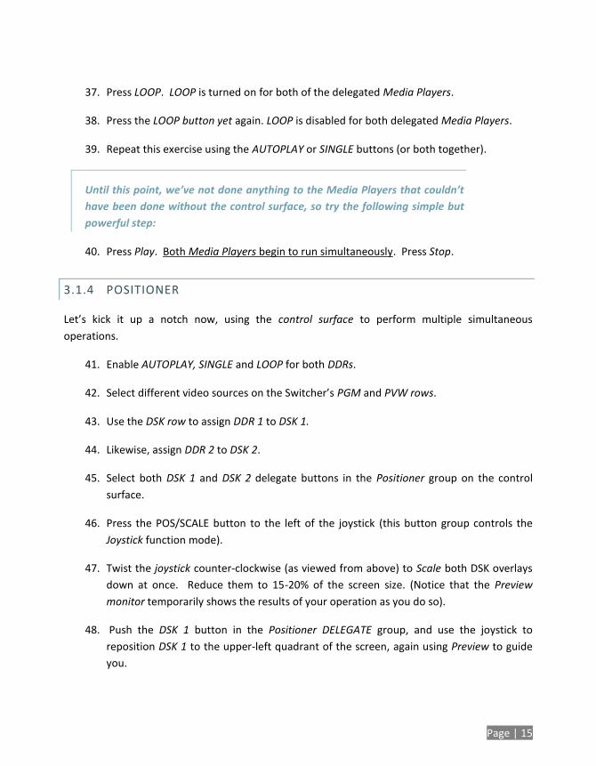
Figure 9
Multi-select the M/E 1 and M/E 2 buttons in the M/E DELEGATE button group.
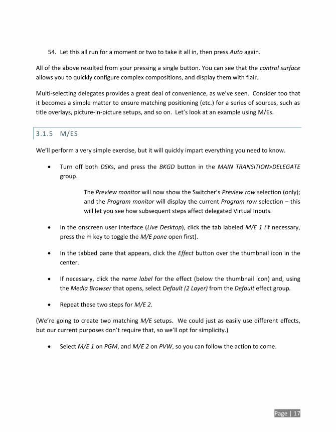
Push the A button in the M/E Layer Delegate group, assigning the A/C source row at left
to govern the source for input A in all currently delegated M/Es (in this instance then,
for both M/E 1 and 2).
Push the DDR 1 button on the row labeled “A”.
Push the B button in the M/E Layer Delegate group, and then push the DDR 2 button on
the row labeled B/D at left.
Now push Key 1 in the M/E KEY DELEGATE group.
Push the GFX 2 button in the KEY row (above the A/C row). Make sure that the Key 1
Take button at far right is off for the moment.
Page | 19
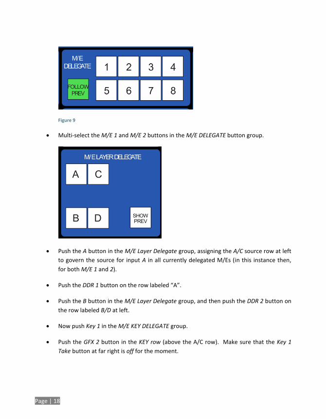
In the POSITIONER group, press the delegate button for layer A. This delegates the
Joystick to control the attributes of the A layer of all currently delegated M/Es – in this
case, M/E 1 and 2 will both be affected.
Figure 10
Press the POS/SCALE button in the POSITIONER mode group. Watch the monitors as
you Scale and position the source assigned to Input A to approximate Figure 59.
Hint: If Positioner settings have been applied to Inputs A or B previously in either M/E 1
or 2, you can simply press Reset with M/E 1, M/E 2 and POS/SCALE selected to clear
them all to the defaults in one operation.
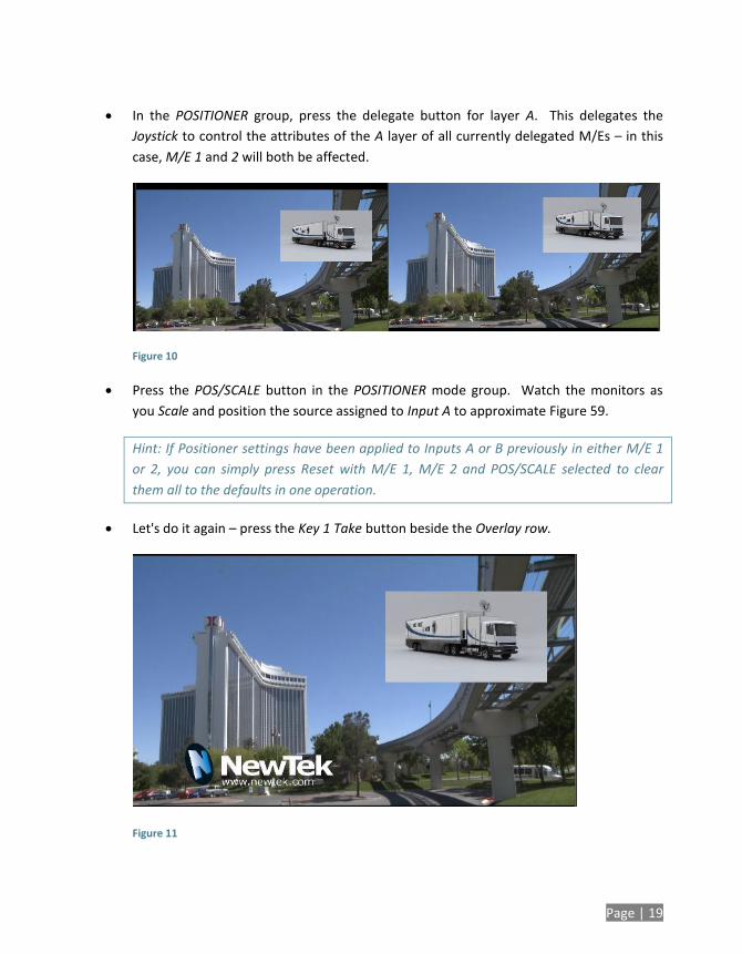
Let's do it again – press the Key 1 Take button beside the Overlay row.
Figure 11
Page | 20
Press the KEY 1 delegate button in the POSITIONER group, and adjust the title page
assigned to Key 1 to a suitable size and position (Figure 60).
In like fashion, you can easily manipulate the elements of any composition to match perfectly.
(You may find this particularly useful, for example, to make sure that station ID ‘bugs’ or lower
thirds title overlays appear in exactly the same place for multiple Virtual Inputs.)
By this point, the fundamental principles of your TriCaster control surface should be clear; with a
little bit of practice you’ll be able to control your TriCaster with unparalleled ease and
confidence. This concludes our walkthrough. If you like, please continue reading for the
complete details of every feature.
3.2 FEATURES AND CONTROLS
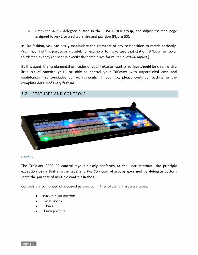
Figure 12
The TriCaster 8000 CS control layout closely conforms to the user interface, the principle
exception being that singular M/E and Position control groups governed by delegate buttons
serve the purpose of multiple controls in the UI.
Controls are comprised of grouped sets including the following hardware types:
Backlit push buttons
Twist knobs
T-bars
3-axis joystick
Page | 21
3.2.1 CONNECTING TO TRICASTER
It is recommended that you connect control surface to TriCaster using the cable it comes with, or
a similar length one of good quality. Please be advised that so-called USB extenders are not
recommended. This is because each added connector introduces ‘reflections’, degrading the
signal. Your TriCaster CS may seem reliable for some time in this configuration, and then
unexpectedly fail. (If this should happen, disconnecting and reconnecting the control surface may
serve as an temporarily measure to restore functionality).
3.2.2 DELEGATES AND SYNCHRONIZATION
Both TriCaster’s Live Desktop and the control surface supply delegate button groups to govern
other controls. This is extends the capability of controls and also supports multi-selections, thus
permitting simultaneous operations.
When initially selecting multiple delegates, the settings and states of the individual members
selected will often vary. For example, when you delegate several M/Es at once, the transition
Rate for various channels in the multi-selection could very well be different. Generally, wherever
it makes sense to do so, as you make adjustments to settings for multi-delegated groups, the
settings will be progressively synchronized.
3.2.3 SWITCHER CONTROLS
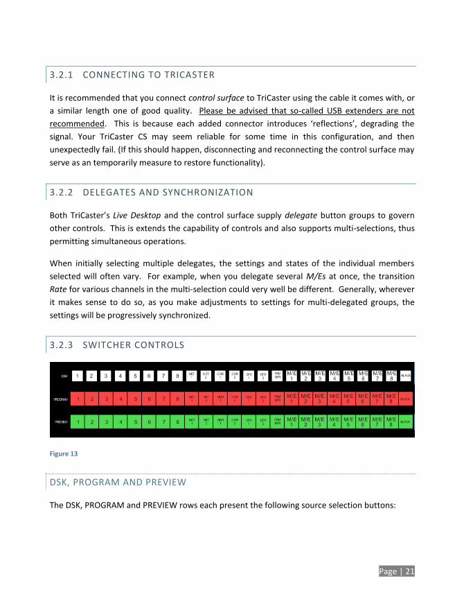
Figure 13
DSK, PROGRAM AND PREVIEW
The DSK, PROGRAM and PREVIEW rows each present the following source selection buttons:
Page | 22
1. 1 – 8, Camera inputs
2. NET 1 and NET 2
3. Media Players:
a. DDR 1 and DDR 2
b. GFX 1and GFX 2
c. FRM BFR (Frame Buffer)
d. M/E 1 - 8
e. BLACK
Switcher row buttons are mutually exclusive, and the active selection button remains lit. The
subordinate role of the DSK row is subtly reinforced by the use of slightly smaller buttons.
Hint: Hold down CTRL when clicking a button on the PREVIEW row to toggle LiveMatte on/off for
that source. Likewise, hold ALT while pushing a PREVIEW row button to toggle its Proc Amp. Note
that the source need not be actually selected on the PREVIEW row to do this, and multi-selections
are supported.
MAIN DSK DELEGATE
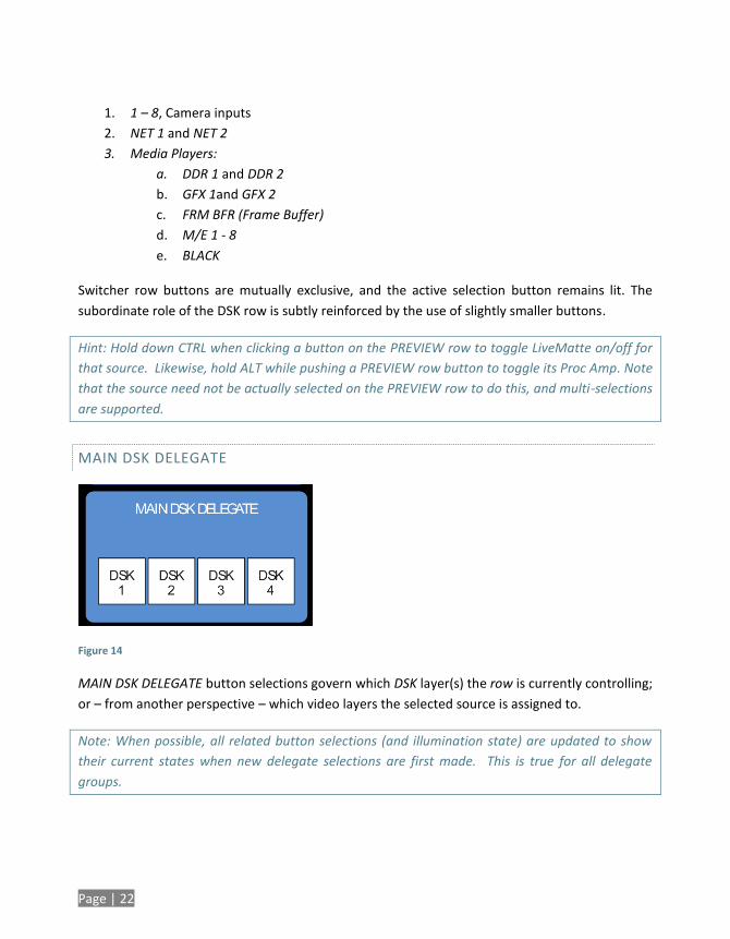
Figure 14
MAIN DSK DELEGATE button selections govern which DSK layer(s) the row is currently controlling;
or – from another perspective – which video layers the selected source is assigned to.
Note: When possible, all related button selections (and illumination state) are updated to show
their current states when new delegate selections are first made. This is true for all delegate
groups.
Page | 23
(An exception is made when newly selecting multiple delegates with control settings that do not
initially match. For example, if DSK1 and DSK 2 have different sources assigned and are newly
multi-selected in the delegate group, no buttons on the DSK row are lit.)
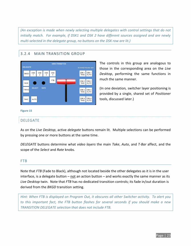
3.2.4 MAIN TRANSITION GROUP
The controls in this group are analogous to
those in the corresponding area on the Live
Desktop, performing the same functions in
much the same manner.
(In one deviation, switcher layer positioning is
provided by a single, shared set of Positioner
tools, discussed later.)
DELEGATE
As on the Live Desktop, active delegate buttons remain lit. Multiple selections can be performed
by pressing one or more buttons at the same time.
DELEGATE buttons determine what video layers the main Take, Auto, and T-Bar affect, and the
scope of the Select and Rate knobs.
FTB
Note that FTB (Fade to Black), although not located beside the other delegates as it is in the user
interface, is a delegate button – not an action button – and works exactly the same manner as its
Live Desktop twin. Note that FTB has no dedicated transition controls; its fade in/out duration is
derived from the BKGD transition setting.
Hint: When FTB is displayed on Program Out, it obscures all other Switcher activity. To alert you
to this important fact, the FTB button flashes for several seconds if you should make a new
TRANSITION DELEGATE selection that does not include FTB.
Figure 15
Page | 24
TRANSITION BIN CONTROL
The control surface does not have Transition Bins for the different video layers as such, but can
nevertheless control the transitions (and their attributes) for delegated video layers.
SELECT
When a single layer, such as BKGD, is selected in the MAIN TRANSITION > DELEGATE group on the
control surface, rotating the SELECT knob cycles the current transitions in the Transition Bin for
that layer.
When multiple video layers have been delegated, turning SELECT affects the transitions for all
layers as follows:
When all delegated layers are currently on the same transition bin 'slot', the selection in
the corresponding transition bins simply cycles left or right synchronously.
Otherwise (when the Transition Bin slots for multi-delegated layers are not harmonized),
rotating the knob moves the selection layer by layer as the knob turns until the selected
slots are aligned. From that point, continuing to twist SELECT moves the transition
selection in lock step.
The SELECT knob also acts as a push button:
Push SELECT to toggle the Reverse setting for the BKGD transition.
Push ALT + SELECT to toggle the Ping Pong switch for the BKGD transition.
RATE
The RATE knob operates in similar fashion to SELECT. Rotate the knob to modify the transition
Rate for delegated layers. Or press the knob to cycle through the standard Slow, Medium and
Fast presets.
Multi-delegate selections are handled the same as for Select (for both twist and push
operations).
Page | 25
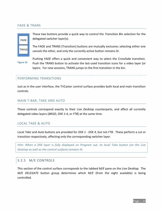
FADE & TRANS
These two buttons provide a quick way to control the Transition Bin selection for the
delegated switcher layer(s).
The FADE and TRANS (Transition) buttons are mutually exclusive; selecting either one
cancels the other, and only the currently active button remains lit.
Pushing FADE offers a quick and convenient way to select the Crossfade transition.
Push the TRANS button to activate the last-used transition icons for a video layer (or
layers. For new sessions, TRANS jumps to the first transition in the bin.
PERFORMING TRANSITIONS
Just as in the user interface, the TriCaster control surface provides both local and main transition
controls.
MAIN T-BAR, TAKE AND AUTO
These controls correspond exactly to their Live Desktop counterparts, and affect all currently
delegated video layers (BKGD, DSK 1-4, or FTB) at the same time.
LOCAL TAKE & AUTO
Local Take and Auto buttons are provided for DSK 1 - DSK 4, but not FTB. These perform a cut or
transition respectively, affecting only the corresponding switcher layer.
Hint: When a DSK layer is fully displayed on Program out, its local Take button (on the Live
Desktop as well as the control surface) remains lit.
3.2.5 M/E CONTROLS
This section of the control surface corresponds to the tabbed M/E pane on the Live Desktop. The
M/E DELEGATE button group determines which M/E (from the eight available) is being
controlled.
Figure 16
Page | 26
Figure 17
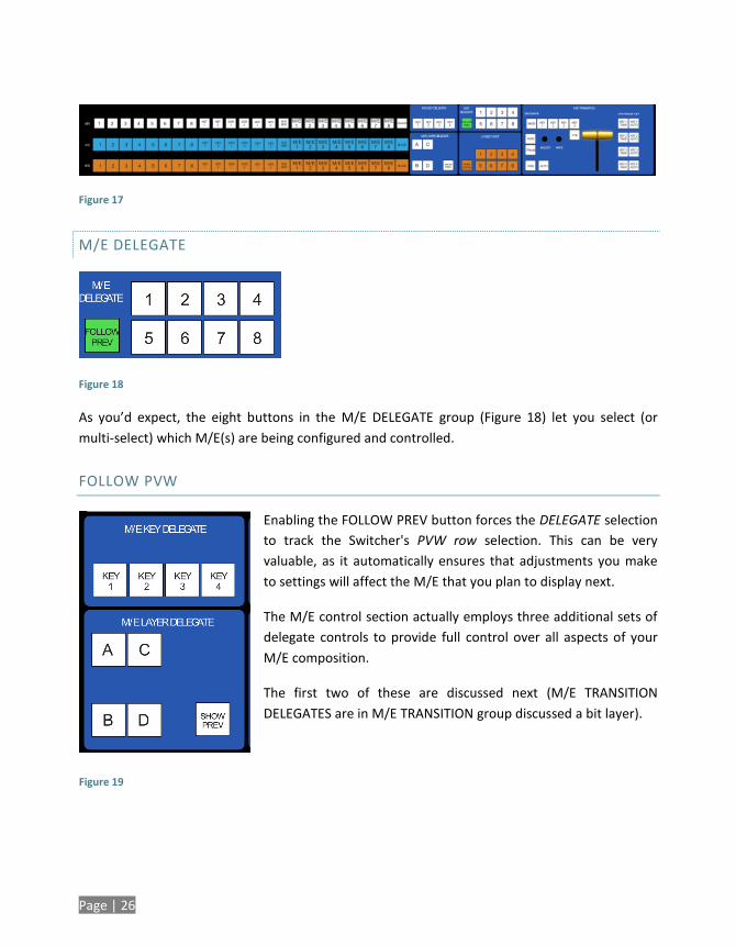
M/E DELEGATE
Figure 18
As you’d expect, the eight buttons in the M/E DELEGATE group (Figure 18) let you select (or
multi-select) which M/E(s) are being configured and controlled.
FOLLOW PVW
Enabling the FOLLOW PREV button forces the DELEGATE selection
to track the Switcher's PVW row selection. This can be very
valuable, as it automatically ensures that adjustments you make
to settings will affect the M/E that you plan to display next.
The M/E control section actually employs three additional sets of
delegate controls to provide full control over all aspects of your
M/E composition.
The first two of these are discussed next (M/E TRANSITION
DELEGATES are in M/E TRANSITION group discussed a bit layer).
Figure 19
Page | 27
M/E LAYER AND KEY DELEGATE
These two delegate button groups control the functionality of the source selection rows at left,
allowing you to specify sources for any or all of the video layers of all currently delegated M/E(s).
Naturally, the M/E KEY DELEGATE selection(s) govern the KEY row buttons at left
Just beneath the KEY row you will notice two identical rows labeled A/C and B/D. The result of
selections in the A/C source row is controlled by the M/E LAYER DELEGATE buttons labeled A and
C. Likewise, B and D buttons in the M/E LAYER DELEGATE group govern the B/D row.
SHOW PREV
This buttons toggles the Tabs Follow All Delegates option in TriCaster, which in turn causes M/E
Preview monitor panes to update when a new M/E Delegate selection is made.
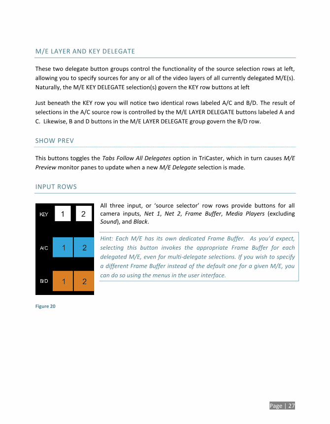
INPUT ROWS
All three input, or ‘source selector’ row rows provide buttons for all camera inputs, Net 1, Net 2, Frame Buffer, Media Players (excluding Sound), and Black.
Hint: Each M/E has its own dedicated Frame Buffer. As you’d expect,
selecting this button invokes the appropriate Frame Buffer for each
delegated M/E, even for multi-delegate selections. If you wish to specify
a different Frame Buffer instead of the default one for a given M/E, you
can do so using the menus in the user interface.
Figure 20
Page | 28
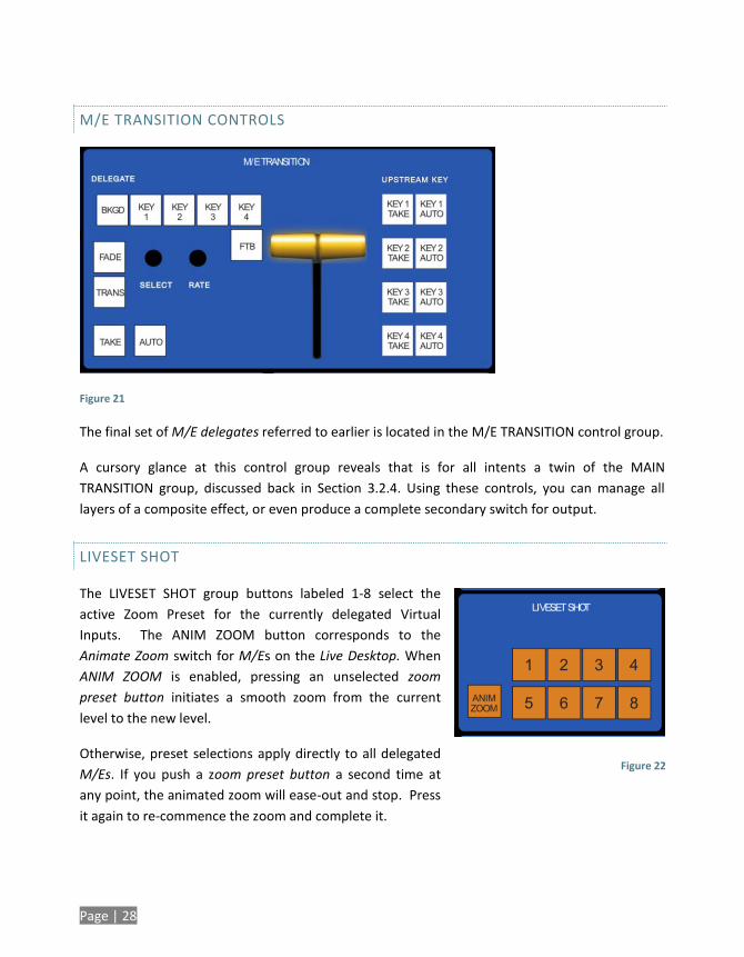
M/E TRANSITION CONTROLS
Figure 21
The final set of M/E delegates referred to earlier is located in the M/E TRANSITION control group.
A cursory glance at this control group reveals that is for all intents a twin of the MAIN
TRANSITION group, discussed back in Section 3.2.4. Using these controls, you can manage all
layers of a composite effect, or even produce a complete secondary switch for output.
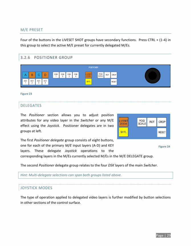
LIVESET SHOT
The LIVESET SHOT group buttons labeled 1-8 select the
active Zoom Preset for the currently delegated Virtual
Inputs. The ANIM ZOOM button corresponds to the
Animate Zoom switch for M/Es on the Live Desktop. When
ANIM ZOOM is enabled, pressing an unselected zoom
preset button initiates a smooth zoom from the current
level to the new level.
Otherwise, preset selections apply directly to all delegated
M/Es. If you push a zoom preset button a second time at
any point, the animated zoom will ease-out and stop. Press
it again to re-commence the zoom and complete it.
Figure 22
Page | 29
M/E PRESET
Four of the buttons in the LIVESET SHOT groups have secondary functions. Press CTRL + (1-4) in
this group to select the active M/E preset for currently delegated M/Es.
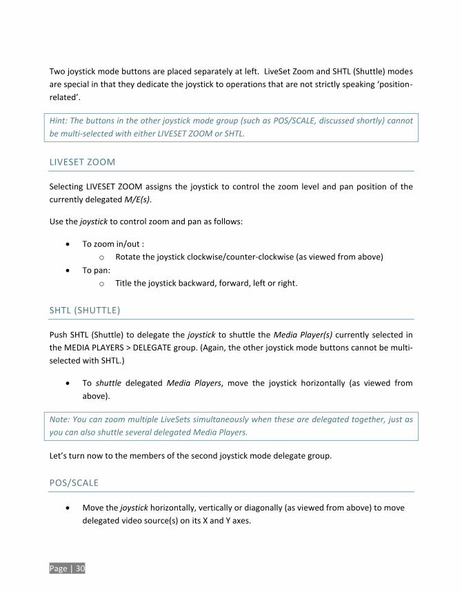
3.2.6 POSITIONER GROUP
Figure 23
DELEGATES
The Positioner section allows you to adjust position
attributes for any video layer in the Switcher or any M/E
effect using the Joystick. Positioner delegates are in two
groups at left.
The first Positioner delegate group consists of eight buttons,
one for each of the primary M/E input layers (A-D) and KEY
layers. These delegate Joystick operations to the
corresponding layers in the M/Es currently selected M/Es in the M/E DELEGATE group.
The second Positioner delegate group relates to the four DSK layers of the main Switcher.
Hint: Multi-delegate selections can span both groups listed above.
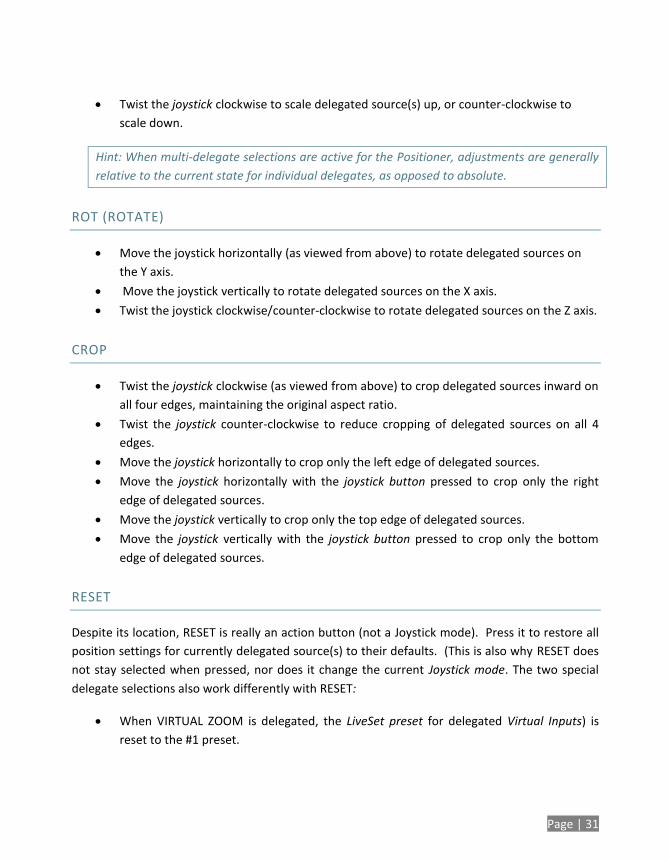
JOYSTICK MODES
The type of operation applied to delegated video layers is further modified by button selections
in other sections of the control surface.
Figure 24
Page | 30
Two joystick mode buttons are placed separately at left. LiveSet Zoom and SHTL (Shuttle) modes
are special in that they dedicate the joystick to operations that are not strictly speaking ‘position-
related’.
Hint: The buttons in the other joystick mode group (such as POS/SCALE, discussed shortly) cannot
be multi-selected with either LIVESET ZOOM or SHTL.
LIVESET ZOOM
Selecting LIVESET ZOOM assigns the joystick to control the zoom level and pan position of the
currently delegated M/E(s).
Use the joystick to control zoom and pan as follows:
To zoom in/out :
o Rotate the joystick clockwise/counter-clockwise (as viewed from above)
To pan:
o Title the joystick backward, forward, left or right.
SHTL (SHUTTLE)
Push SHTL (Shuttle) to delegate the joystick to shuttle the Media Player(s) currently selected in
the MEDIA PLAYERS > DELEGATE group. (Again, the other joystick mode buttons cannot be multi-
selected with SHTL.)
To shuttle delegated Media Players, move the joystick horizontally (as viewed from
above).
Note: You can zoom multiple LiveSets simultaneously when these are delegated together, just as
you can also shuttle several delegated Media Players.
Let’s turn now to the members of the second joystick mode delegate group.
POS/SCALE
Move the joystick horizontally, vertically or diagonally (as viewed from above) to move
delegated video source(s) on its X and Y axes.
Page | 31
Twist the joystick clockwise to scale delegated source(s) up, or counter-clockwise to
scale down.
Hint: When multi-delegate selections are active for the Positioner, adjustments are generally
relative to the current state for individual delegates, as opposed to absolute.
ROT (ROTATE)
Move the joystick horizontally (as viewed from above) to rotate delegated sources on
the Y axis.
Move the joystick vertically to rotate delegated sources on the X axis.
Twist the joystick clockwise/counter-clockwise to rotate delegated sources on the Z axis.
CROP
Twist the joystick clockwise (as viewed from above) to crop delegated sources inward on
all four edges, maintaining the original aspect ratio.
Twist the joystick counter-clockwise to reduce cropping of delegated sources on all 4
edges.
Move the joystick horizontally to crop only the left edge of delegated sources.
Move the joystick horizontally with the joystick button pressed to crop only the right
edge of delegated sources.
Move the joystick vertically to crop only the top edge of delegated sources.
Move the joystick vertically with the joystick button pressed to crop only the bottom
edge of delegated sources.
RESET
Despite its location, RESET is really an action button (not a Joystick mode). Press it to restore all
position settings for currently delegated source(s) to their defaults. (This is also why RESET does
not stay selected when pressed, nor does it change the current Joystick mode. The two special
delegate selections also work differently with RESET:
When VIRTUAL ZOOM is delegated, the LiveSet preset for delegated Virtual Inputs) is
reset to the #1 preset.
Page | 32
When SHUTTLE is delegated, selected Media Players are reset to the starting point of
the current item (or playlist).
MONITORING
While using the joystick in most POSITIONER DELEGATE modes, many adjustments are
temporarily shown on the Live Desktop’s Preview monitor. The Preview monitor reverts to its
default display a few moments after releasing the joystick to its at-rest position, just as occurs
when using Positioner tools on the Live Desktop.
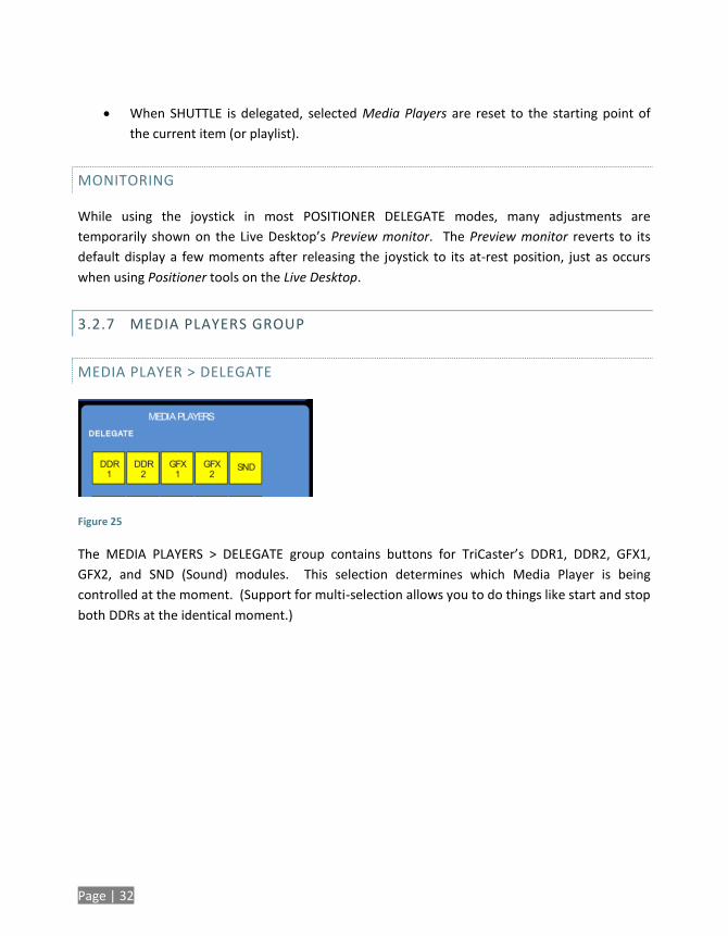
3.2.7 MEDIA PLAYERS GROUP
MEDIA PLAYER > DELEGATE
Figure 25
The MEDIA PLAYERS > DELEGATE group contains buttons for TriCaster’s DDR1, DDR2, GFX1,
GFX2, and SND (Sound) modules. This selection determines which Media Player is being
controlled at the moment. (Support for multi-selection allows you to do things like start and stop
both DDRs at the identical moment.)
Page | 33
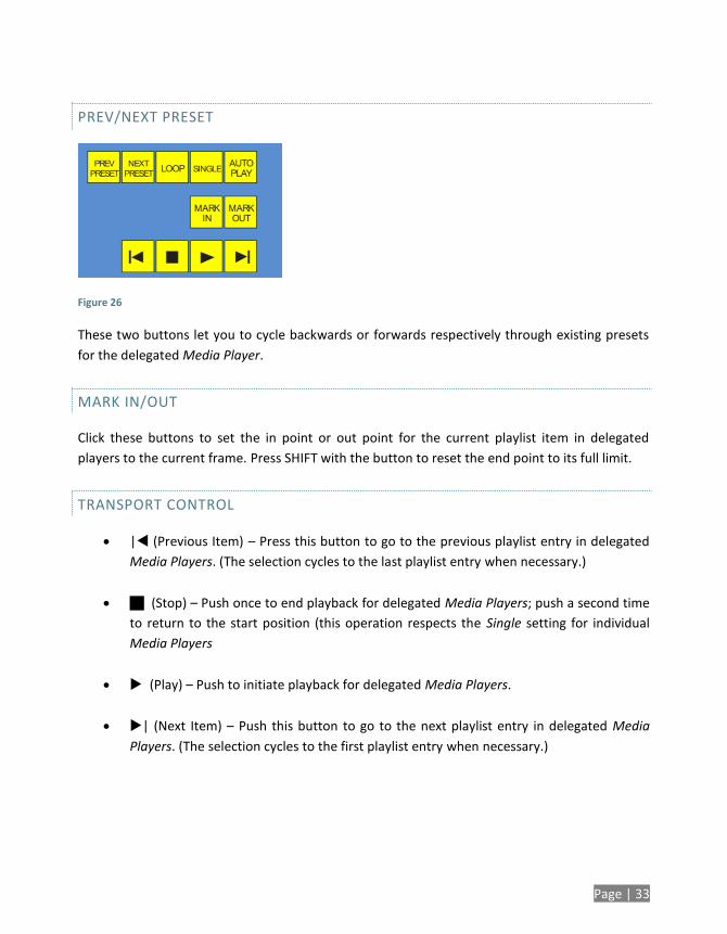
PREV/NEXT PRESET
Figure 26
These two buttons let you to cycle backwards or forwards respectively through existing presets
for the delegated Media Player.
MARK IN/OUT
Click these buttons to set the in point or out point for the current playlist item in delegated
players to the current frame. Press SHIFT with the button to reset the end point to its full limit.
TRANSPORT CONTROL
| (Previous Item) – Press this button to go to the previous playlist entry in delegated
Media Players. (The selection cycles to the last playlist entry when necessary.)
(Stop) – Push once to end playback for delegated Media Players; push a second time
to return to the start position (this operation respects the Single setting for individual
Media Players
(Play) – Push to initiate playback for delegated Media Players.
| (Next Item) – Push this button to go to the next playlist entry in delegated Media
Players. (The selection cycles to the first playlist entry when necessary.)
Page | 34
MEDIA PLAYER OPTIONS
LOOP, SINGLE, and AUTOPLAY are mode buttons, and toggle the respective settings for all
delegated Media Players as appropriate (for example, the Sound player has no Autoplay feature,
so logically AUTOPLAY does not affect it).
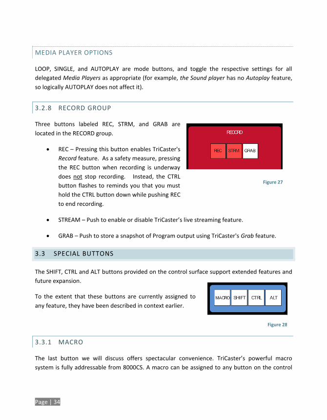
3.2.8 RECORD GROUP
Three buttons labeled REC, STRM, and GRAB are
located in the RECORD group.
REC – Pressing this button enables TriCaster's
Record feature. As a safety measure, pressing
the REC button when recording is underway
does not stop recording. Instead, the CTRL
button flashes to reminds you that you must
hold the CTRL button down while pushing REC
to end recording.
STREAM – Push to enable or disable TriCaster’s live streaming feature.
GRAB – Push to store a snapshot of Program output using TriCaster's Grab feature.
3.3 SPECIAL BUTTONS
The SHIFT, CTRL and ALT buttons provided on the control surface support extended features and
future expansion.
To the extent that these buttons are currently assigned to
any feature, they have been described in context earlier.
3.3.1 MACRO
The last button we will discuss offers spectacular convenience. TriCaster’s powerful macro
system is fully addressable from 8000CS. A macro can be assigned to any button on the control
Figure 28
Figure 27
Page | 35
surface in much the same manner as it can be assigned to a keyboard button. The steps are as
follows:
1. On TriCaster’s Live Desktop, open the Macro Configuration Editor.
2. Select the macro you wish to assign in the onscreen lister.
3. Click the mouse in the Listen field at bottom left.
4. Hold down the MACRO button and press a suitable button on the control surface.
That’s it – you can close the Macro configuration Panel and test the result. To play back the
macro at any time, press the MACRO button along with the assigned key.
3.4 T-BAR ILLUMINATION
TriCaster 8000CS uses colorful illumination to provide feedback and status updates your control
surface selections and operations. The lighting schemes for both the M/E and MAIN TRANSITION
T-Bars reinforce the traditional button illumination in a way that soon becomes instinctive and
which provides unparalleled confidence in use.
The following tables provide a color code for your convenience.
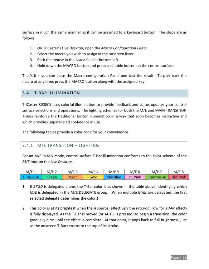
3.4.1 M/E TRANSITION – LIGHTING
For an M/E in Mix mode, control surface T-Bar illumination conforms to the color scheme of the
M/E tabs on the Live Desktop.
M/E 1 M/E 2 M/E 3 M/E 4 M/E 5 M/E 6 M/E 7 M/E 8
Turquoise Green Peach Gold Sky Blue Lt. Pink Chartreuse Hot Pink
1. If BKGD is delegated alone, the T-Bar color is as shown in the table above, identifying which
M/E is delegated in the M/E DELEGATE group. (When multiple M/Es are delegated, the first
selected delegate determines the color.)
2. This color is at its brightest when the A source (effectively the Program row for a Mix effect)
is fully displayed. As the T-Bar is moved (or AUTO is pressed) to begin a transition, the color
gradually dims until the effect is complete. At that point, it pops back to full brightness, just
as the onscreen T-Bar returns to the top of its stroke.
Page | 36
3. In a mixed delegate situation (BKGD along with one or more KEY layers) the T-Bar is lit it
medium blue, and conforms to the BKGD behavior described above.
4. If one or more KEY layers are delegated without BKGD, the T-Bar color is purple. When the
KEY layer (or, for multi-KEY selections, the first KEY layer) is fully displayed, T-Bar lighting is at
its brightest. Removing the layer dims the illumination.
5. The T-bar is always lit in orange for M/E’s in Effect mode.
3.4.2 MAIN TRANSITION
1. Just as you would expect, the illumination of this T-Bar uses red-green coloration, standard
color coding for Program and Preview rows.
2. As for M/Es, described earlier, DSK-only delegate operations result in the T-Bar being lit in
purple.
3. Mixed mode (BKGD plus DSK delegates) likewise result in blue illumination after the fashion
of the M/E T-Bar behavior previously described.
Page | 37
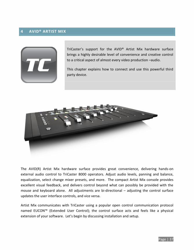
4 AVID® ARTIST MIX
TriCaster’s support for the AVID® Artist Mix hardware surface
brings a highly desirable level of convenience and creative control
to a critical aspect of almost every video production –audio.
This chapter explains how to connect and use this powerful third
party device.
The AVID(R) Artist Mix hardware surface provides great convenience, delivering hands-on
external audio control to TriCaster 8000 operators. Adjust audio levels, panning and balance,
equalization, select change mixer presets, and more. The compact Artist Mix console provides
excellent visual feedback, and delivers control beyond what can possibly be provided with the
mouse and keyboard alone. All adjustments are bi-directional – adjusting the control surface
updates the user interface controls, and vice versa.
Artist Mix communicates with TriCaster using a popular open control communication protocol
named EUCON™ (Extended User Control); the control surface acts and feels like a physical
extension of your software. Let’s begin by discussing installation and setup.
Page | 38
4.1 INSTALLING AVID® ARTIST MIX SOFTWARE
AVID(R) provides a utility called EuControl for use with the Artist Mix control surface. This
software runs in the background, and is required for TriCaster to recognize and respond to the
control surface.
1. From the TriCaster Startup screen, click the Shutdown icon, and choose Administrator
Mode.
2. Select Exit to Windows to leave the TriCaster environment.
3. Obtain the EuControl installer by using one of the following two methods:
a. With TriCaster connected to the Internet, download the most recent installer
for the Windows(R) 64bit operating system from the webpage below:
www.avid.com/artistsupport (Requires Avid website account.)
b. Otherwise, download the installer as above to a different computer, and
transfer it to TriCaster’s hard drive across a network or by USB flash drive (etc.)
4. Double-click the icon for the installer application (Install_EuControl.exe).
5. Follow the instructions displayed to complete the installation.
4.2 CONNECTING ARTIST MIX
After the software installation is complete, shut down TriCaster, and connect the AVID(R) Artist
Mix panel to TriCaster as follows:
1. Plug one end of the AC power cord into the power adapter and the other into an
electrical outlet (push the AC power connector firmly into the adapter).
2. Connect the DC output cable from the power adapter to the DC input on the left rear
side of the control surface.
3. Connect the control surface to TriCaster using the crossover cable supplied with the
Artist Mix, or – as will often be true, in cases where TriCaster network connectivity is a
requirement – to the same network subnet your TriCaster is connected to using a
Page | 39
suitable Ethernet cable. In most cases you will wish to use a switch or router rather than
a direct connection between the two devices, so TriCaster can also connect to the
Internet, etc.
4. Power up TriCaster, and wait for the Start screen to appear; then press the POWER
button on the control surface.
AVID symbols briefly appear on the OLED display above each fader at this point. When
EuControl recognizes the control surface, the display shows rectangles in place of the logo
icons to tell you the control surface is in a ‘ready’ state.
Connectivity Notes: If the control surface OLED display continues to show the AVID symbols,
this indicates it has not been detected by EuControl. You can try simply turning the Artist
Control power switch off and then on again. If this does not help, power Artist Mix off,
restart TriCaster, and turn the surface on again. If Artist Mix is still not recognized at this
point, double check your connections. Also, when more than one TriCaster is connected to the
network make sure each one has a unique system name.
If this fails (or for complex installations, such as when multiple TriCasters or Artist Mix devices
are on the same network) you may need to Exit to Windows and use the configuration tools
the EuControl application provides in its interface. Right-click the EuControl icon (E) shown in
the Notification Area of the Windows taskbar to access these controls, and then select
EuControl Settings. Refer to the AVID® documentation for further details.
5. Launch a TriCaster session. The OLED rectangle icons are replaced by custom TriCaster
audio control labels and displays.
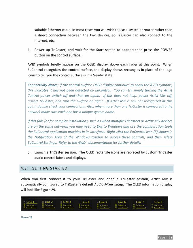
4.3 GETTING STARTED
When you first connect it to your TriCaster and open a TriCaster session, Artist Mix is
automatically configured to TriCaster’s default Audio Mixer setup. The OLED information display
will look like Figure 29.
Figure 29
Page | 40
Let’s note in passing that this initial layout may not match the Audio Mixer setup in your TriCaster
session just at the moment. We’ll discuss how to customize this default configuration a bit later,
but for now let’s consider basic navigation.
4.3.1 PANEL LAYOUT
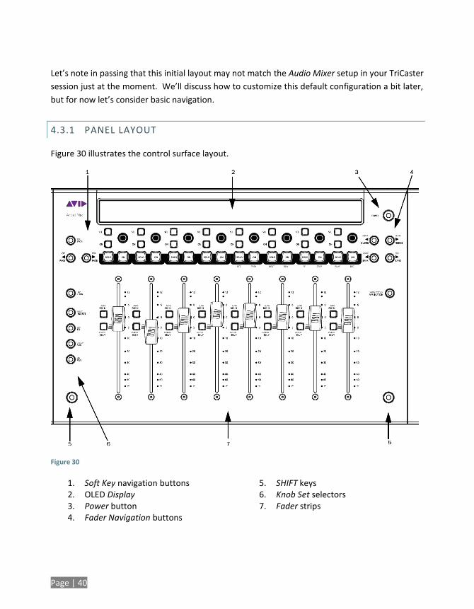
Figure 30 illustrates the control surface layout.
Figure 30
1. Soft Key navigation buttons 2. OLED Display 3. Power button 4. Fader Navigation buttons
5. SHIFT keys 6. Knob Set selectors 7. Fader strips
Page | 41
Of course, Artist Mix can be used with a variety of systems and software applications apart from
TriCaster. You may already be familiar with its use for certain other purposes. The Artist Mix
User Guide provides details regarding each control. In this manual, we’ll focus on the controls as
they apply to TriCaster 8000 only.
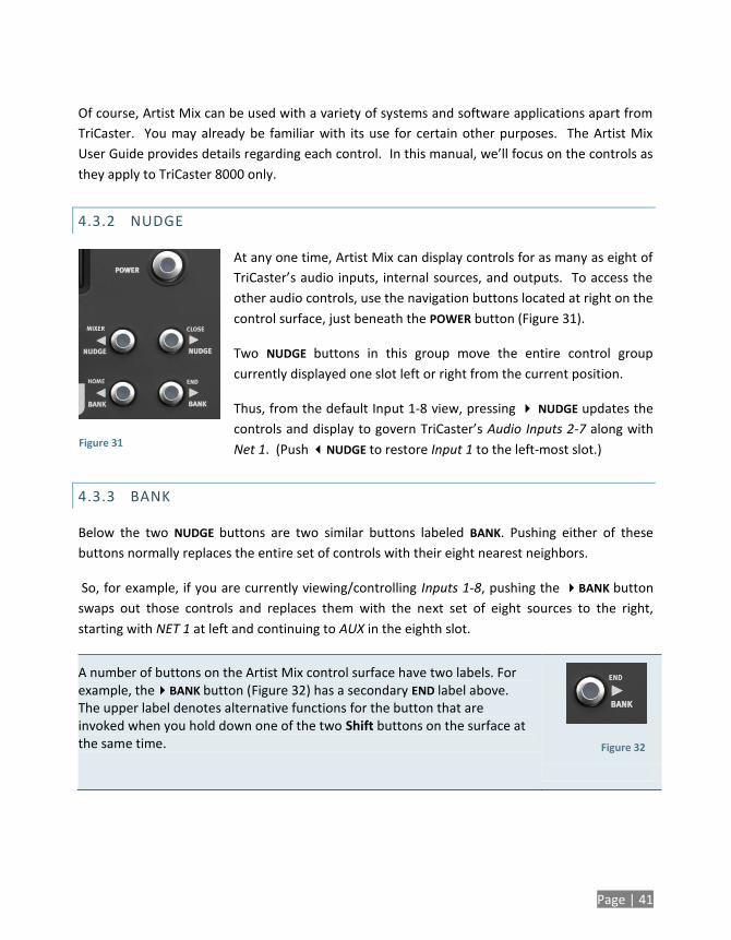
4.3.2 NUDGE
At any one time, Artist Mix can display controls for as many as eight of
TriCaster’s audio inputs, internal sources, and outputs. To access the
other audio controls, use the navigation buttons located at right on the
control surface, just beneath the POWER button (Figure 31).
Two NUDGE buttons in this group move the entire control group
currently displayed one slot left or right from the current position.
Thus, from the default Input 1-8 view, pressing NUDGE updates the
controls and display to govern TriCaster’s Audio Inputs 2-7 along with
Net 1. (Push NUDGE to restore Input 1 to the left-most slot.)
4.3.3 BANK
Below the two NUDGE buttons are two similar buttons labeled BANK. Pushing either of these
buttons normally replaces the entire set of controls with their eight nearest neighbors.
So, for example, if you are currently viewing/controlling Inputs 1-8, pushing the BANK button
swaps out those controls and replaces them with the next set of eight sources to the right,
starting with NET 1 at left and continuing to AUX in the eighth slot.
A number of buttons on the Artist Mix control surface have two labels. For example, theBANK button (Figure 32) has a secondary END label above. The upper label denotes alternative functions for the button that are invoked when you hold down one of the two Shift buttons on the surface at the same time.
Figure 31
Figure 32
Page | 42
Note that the BANK buttons each have alternate functions when pressed with Shift, specifically
HOME and END. These combinations jump past all other configured control groups to display the
first and last entries respectively.
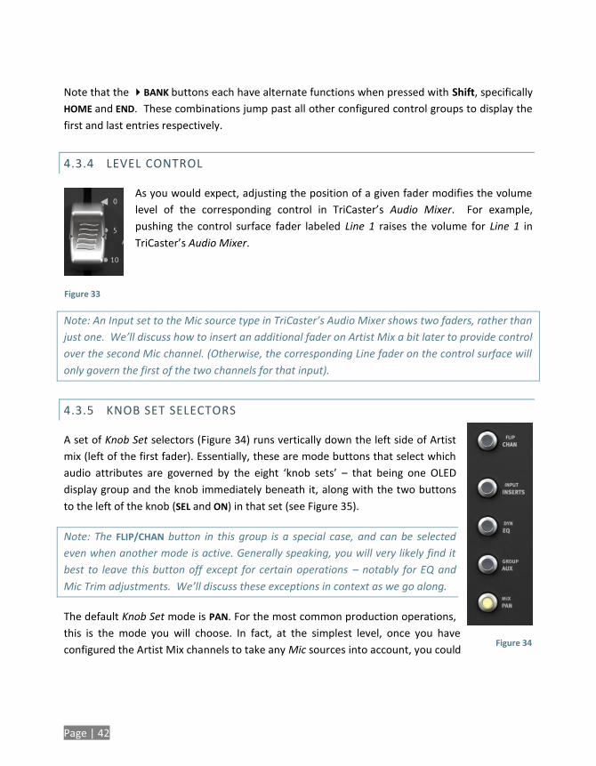
4.3.4 LEVEL CONTROL
As you would expect, adjusting the position of a given fader modifies the volume
level of the corresponding control in TriCaster’s Audio Mixer. For example,
pushing the control surface fader labeled Line 1 raises the volume for Line 1 in
TriCaster’s Audio Mixer.
Note: An Input set to the Mic source type in TriCaster’s Audio Mixer shows two faders, rather than
just one. We’ll discuss how to insert an additional fader on Artist Mix a bit later to provide control
over the second Mic channel. (Otherwise, the corresponding Line fader on the control surface will
only govern the first of the two channels for that input).
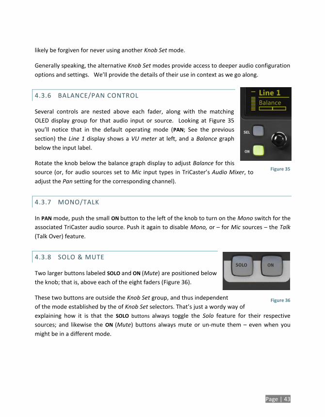
4.3.5 KNOB SET SELECTORS
A set of Knob Set selectors (Figure 34) runs vertically down the left side of Artist
mix (left of the first fader). Essentially, these are mode buttons that select which
audio attributes are governed by the eight ‘knob sets’ – that being one OLED
display group and the knob immediately beneath it, along with the two buttons
to the left of the knob (SEL and ON) in that set (see Figure 35).
Note: The FLIP/CHAN button in this group is a special case, and can be selected
even when another mode is active. Generally speaking, you will very likely find it
best to leave this button off except for certain operations – notably for EQ and
Mic Trim adjustments. We’ll discuss these exceptions in context as we go along.
The default Knob Set mode is PAN. For the most common production operations,
this is the mode you will choose. In fact, at the simplest level, once you have
configured the Artist Mix channels to take any Mic sources into account, you could
Figure 33
Figure 34
Page | 43
Figure 36
likely be forgiven for never using another Knob Set mode.
Generally speaking, the alternative Knob Set modes provide access to deeper audio configuration
options and settings. We’ll provide the details of their use in context as we go along.
4.3.6 BALANCE/PAN CONTROL
Several controls are nested above each fader, along with the matching
OLED display group for that audio input or source. Looking at Figure 35
you’ll notice that in the default operating mode (PAN; See the previous
section) the Line 1 display shows a VU meter at left, and a Balance graph
below the input label.
Rotate the knob below the balance graph display to adjust Balance for this
source (or, for audio sources set to Mic input types in TriCaster’s Audio Mixer, to
adjust the Pan setting for the corresponding channel).
4.3.7 MONO/TALK
In PAN mode, push the small ON button to the left of the knob to turn on the Mono switch for the
associated TriCaster audio source. Push it again to disable Mono, or – for Mic sources – the Talk
(Talk Over) feature.
4.3.8 SOLO & MUTE
Two larger buttons labeled SOLO and ON (Mute) are positioned below
the knob; that is, above each of the eight faders (Figure 36).
These two buttons are outside the Knob Set group, and thus independent
of the mode established by the of Knob Set selectors. That’s just a wordy way of
explaining how it is that the SOLO buttons always toggle the Solo feature for their respective
sources; and likewise the ON (Mute) buttons always mute or un-mute them – even when you
might be in a different mode.
Figure 35
Page | 44
Hint: As with most convenient rules, there is one exception to the above. If the SOLO and ON
buttons are unresponsive, check to see if the SHIFT LOCK button (i.e., the left SHIFT button on the
control surface) is lit; if it is, turn it off.
4.3.9 FOLLOW
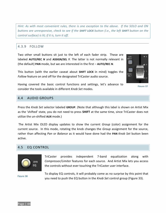
Two other small buttons sit just to the left of each fader strip. These are
labeled AUTO/REC N and ASSIGN/SEL Y. The latter is not normally relevant in
(the default) PAN mode, but we are interested in the first – AUTO/REC N.
This button (with the earlier caveat about SHIFT LOCK in mind) toggles the
Follow feature on and off for the designated TriCaster audio source.
Having covered the basic control functions and settings, let’s advance to
consider the tools available in different Knob Set modes.
4.4 AUDIO GROUPS
Press the Knob Set selector labeled GROUP. (Note that although this label is shown on Artist Mix
as the ‘shifted’ state, you do not need to press SHIFT at the same time, since TriCaster does not
utilize the un-shifted AUX mode.)
The Artist Mix OLED display updates to show the current Group (color) assignment for the
current source. In this mode, rotating the knob changes the Group assignment for the source,
rather than affecting Pan or Balance as it would have done had the PAN Knob Set button been
active.
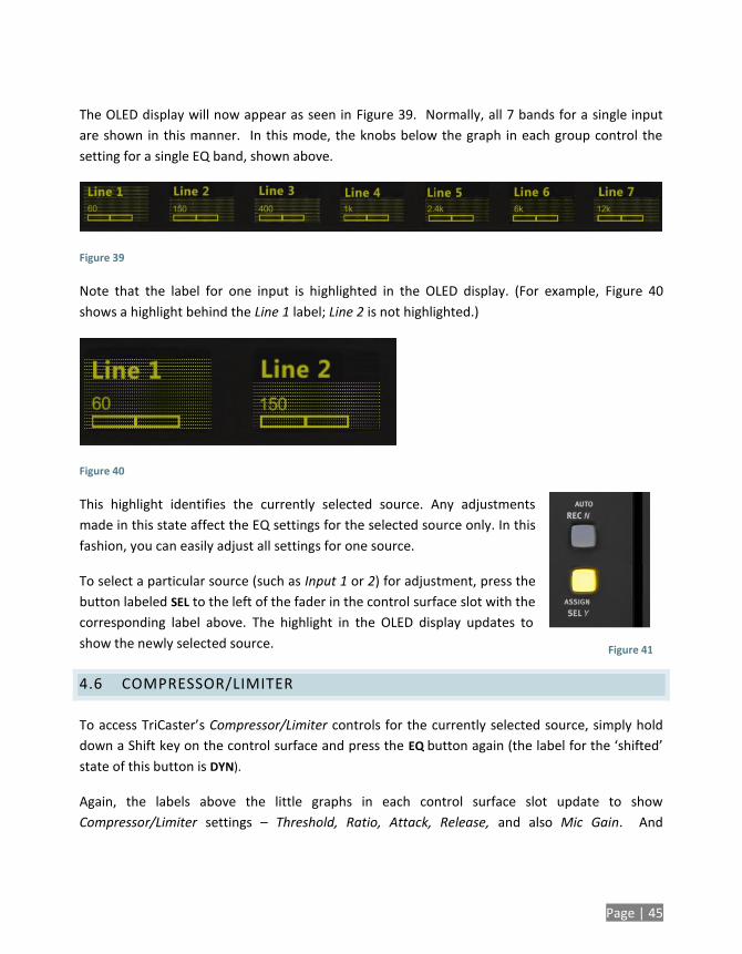
4.5 EQ CONTROL
TriCaster provides independent 7-band equalization along with
Compressor/Limiter features for each source. And Artist Mix lets you access
the controls without ever touching the TriCaster user interface.
To display EQ controls, it will probably come as no surprise by this point that
you need to push the EQ button in the Knob Set control group (Figure 33).
Figure 37
Figure 38
Page | 45
The OLED display will now appear as seen in Figure 39. Normally, all 7 bands for a single input
are shown in this manner. In this mode, the knobs below the graph in each group control the
setting for a single EQ band, shown above.
Figure 39
Note that the label for one input is highlighted in the OLED display. (For example, Figure 40
shows a highlight behind the Line 1 label; Line 2 is not highlighted.)
Figure 40
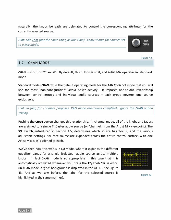
This highlight identifies the currently selected source. Any adjustments
made in this state affect the EQ settings for the selected source only. In this
fashion, you can easily adjust all settings for one source.
To select a particular source (such as Input 1 or 2) for adjustment, press the
button labeled SEL to the left of the fader in the control surface slot with the
corresponding label above. The highlight in the OLED display updates to
show the newly selected source.
4.6 COMPRESSOR/LIMITER
To access TriCaster’s Compressor/Limiter controls for the currently selected source, simply hold
down a Shift key on the control surface and press the EQ button again (the label for the ‘shifted’
state of this button is DYN).
Again, the labels above the little graphs in each control surface slot update to show
Compressor/Limiter settings – Threshold, Ratio, Attack, Release, and also Mic Gain. And
Figure 41
Page | 46
naturally, the knobs beneath are delegated to control the corresponding attribute for the
currently selected source.
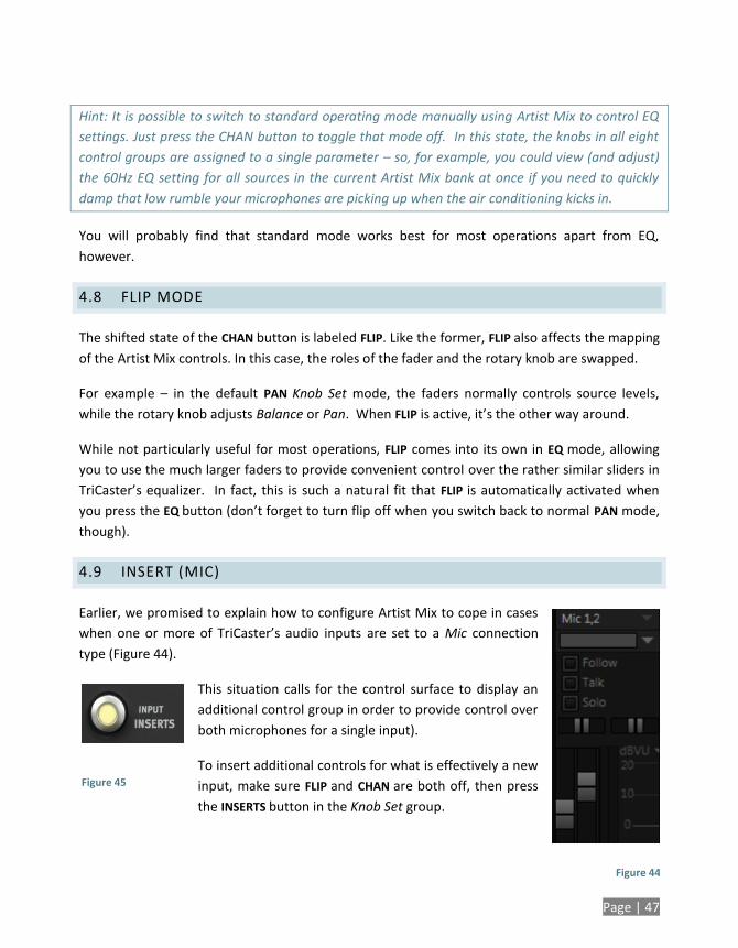
Hint: Mic Trim (not the same thing as Mic Gain) is only shown for sources set
to a Mic mode.
4.7 CHAN MODE
CHAN is short for “Channel”. By default, this button is unlit, and Artist Mix operates in ‘standard’
mode.
Standard mode (CHAN off) is the default operating mode for the PAN Knob Set mode that you will
use for most ‘non-configuration’ Audio Mixer activity. It imposes one-to-one relationship
between control groups and individual audio sources – each group governs one source
exclusively.
Hint: In fact, for TriCaster purposes, PAN mode operations completely ignore the CHAN option
setting.
Pushing the CHAN button changes this relationship. In channel mode, all of the knobs and faders
are assigned to a single TriCaster audio source (or ‘channel’, from the Artist Mix viewpoint). The
SEL switch, introduced in section 4.5, determines which source has ‘focus’, and the various
adjustable settings for that source are expanded across the entire control surface, with one
Artist Mix ‘slot’ assigned to each.
We’ve seen how this works in EQ mode, where it expands the different
equalizer bands for a single (selected) audio source across multiple
knobs. In fact CHAN mode is so appropriate in this case that it is
automatically activated whenever you press the EQ Knob Set selector.
(In CHAN mode, a ‘grid’ background is displayed in the OLED - see Figure
43. And as we saw before, the label for the selected source is
highlighted in the same manner).
Figure 42
Figure 43
Page | 47
Hint: It is possible to switch to standard operating mode manually using Artist Mix to control EQ
settings. Just press the CHAN button to toggle that mode off. In this state, the knobs in all eight
control groups are assigned to a single parameter – so, for example, you could view (and adjust)
the 60Hz EQ setting for all sources in the current Artist Mix bank at once if you need to quickly
damp that low rumble your microphones are picking up when the air conditioning kicks in.
You will probably find that standard mode works best for most operations apart from EQ,
however.
4.8 FLIP MODE
The shifted state of the CHAN button is labeled FLIP. Like the former, FLIP also affects the mapping
of the Artist Mix controls. In this case, the roles of the fader and the rotary knob are swapped.
For example – in the default PAN Knob Set mode, the faders normally controls source levels,
while the rotary knob adjusts Balance or Pan. When FLIP is active, it’s the other way around.
While not particularly useful for most operations, FLIP comes into its own in EQ mode, allowing
you to use the much larger faders to provide convenient control over the rather similar sliders in
TriCaster’s equalizer. In fact, this is such a natural fit that FLIP is automatically activated when
you press the EQ button (don’t forget to turn flip off when you switch back to normal PAN mode,
though).
4.9 INSERT (MIC)
Earlier, we promised to explain how to configure Artist Mix to cope in cases
when one or more of TriCaster’s audio inputs are set to a Mic connection
type (Figure 44).
This situation calls for the control surface to display an
additional control group in order to provide control over
both microphones for a single input).
To insert additional controls for what is effectively a new
input, make sure FLIP and CHAN are both off, then press
the INSERTS button in the Knob Set group.
Figure 44
Figure 45
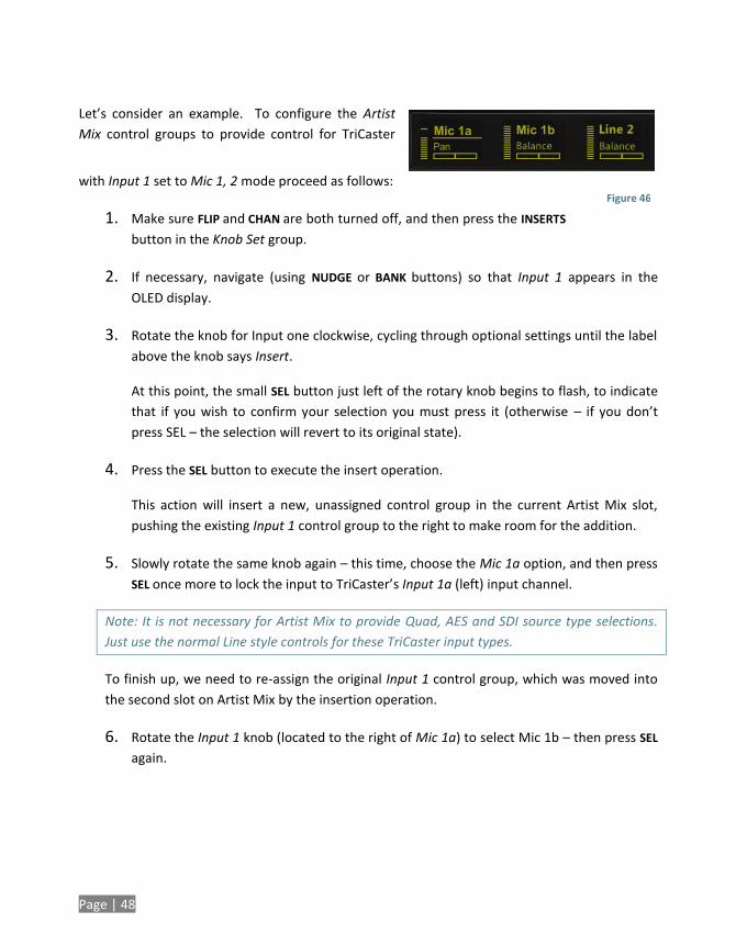
Page | 48
Let’s consider an example. To configure the Artist
Mix control groups to provide control for TriCaster
with Input 1 set to Mic 1, 2 mode proceed as follows:
1. Make sure FLIP and CHAN are both turned off, and then press the INSERTS
button in the Knob Set group.
2. If necessary, navigate (using NUDGE or BANK buttons) so that Input 1 appears in the
OLED display.
3. Rotate the knob for Input one clockwise, cycling through optional settings until the label
above the knob says Insert.
At this point, the small SEL button just left of the rotary knob begins to flash, to indicate
that if you wish to confirm your selection you must press it (otherwise – if you don’t
press SEL – the selection will revert to its original state).
4. Press the SEL button to execute the insert operation.
This action will insert a new, unassigned control group in the current Artist Mix slot,
pushing the existing Input 1 control group to the right to make room for the addition.
5. Slowly rotate the same knob again – this time, choose the Mic 1a option, and then press
SEL once more to lock the input to TriCaster’s Input 1a (left) input channel.
Note: It is not necessary for Artist Mix to provide Quad, AES and SDI source type selections.
Just use the normal Line style controls for these TriCaster input types.
To finish up, we need to re-assign the original Input 1 control group, which was moved into
the second slot on Artist Mix by the insertion operation.
6. Rotate the Input 1 knob (located to the right of Mic 1a) to select Mic 1b – then press SEL
again.
Figure 46
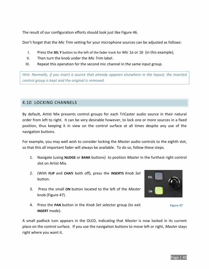
Page | 49
The result of our configuration efforts should look just like Figure 46.
Don’t forget that the Mic Trim setting for your microphone sources can be adjusted as follows:
I. Press the SEL Y button to the left of the fader track for Mic 1a or 1b (in this example),
II. Then turn the knob under the Mic Trim label.
III. Repeat this operation for the second mic channel in the same input group.
Hint: Normally, if you insert a source that already appears elsewhere in the layout, the inserted
control group is kept and the original is removed.
4.10 LOCKING CHANNELS
By default, Artist Mix presents control groups for each TriCaster audio source in their natural
order from left to right. It can be very desirable however, to lock one or more sources in a fixed
position, thus keeping it in view on the control surface at all times despite any use of the
navigation buttons.
For example, you may well wish to consider locking the Master audio controls to the eighth slot,
so that this all important fader will always be available. To do so, follow these steps.
1. Navigate (using NUDGE or BANK buttons) to position Master in the furthest right control
slot on Artist Mix.
2. (With FLIP and CHAN both off), press the INSERTS Knob Set
button.
3. Press the small ON button located to the left of the Master
knob (Figure 47).
4. Press the PAN button in the Knob Set selector group (to exit
INSERT mode).
A small padlock icon appears in the OLED, indicating that Master is now locked in its current
place on the control surface. If you use the navigation buttons to move left or right, Master stays
right where you want it.
Figure 47
Page | 50
Note: Locking sources has one slightly annoying side effect. You will see a clone of locked sources
elsewhere in the Artist Mix layout. This does not pose a real issue, since the duplicate is fully
synced with the locked one, and will operate as expected if you do use it.
Unlocking a previously locked source restores it to its normal position.
4.11 AUDIO PRESETS
Artist Mix implementation provides full access to TriCaster’s Audio Mixer preset system. Keep in
mind that these can be a very convenient way to store and recall different source layouts for
Artist Mix, too. You can choose a preset or create a new one using either the user interface or
Artist mix. To select a preset, proceed as follows:
Press Shift + INSERTS (INPUT) to display the list of existing mixer presets left to right
across the slots in the OLED display.
Press the SEL button below the PLED label of the reset you want to select.
Hint: Rotate the knob below a preset on the OLED display to access copy and paste (preset)
functions.
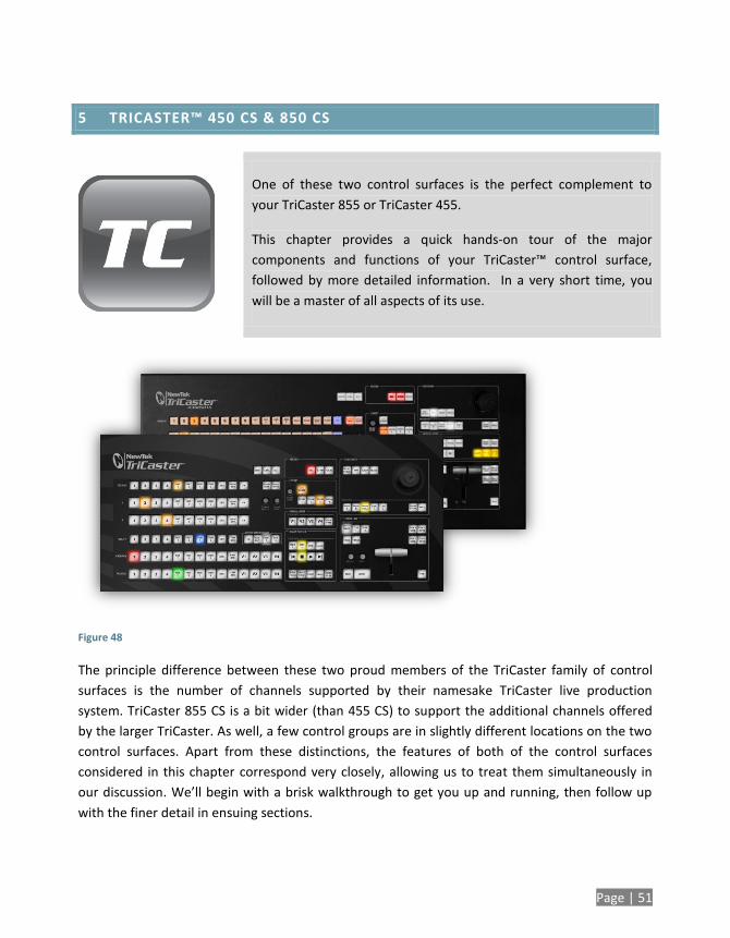
Page | 51
5 TRICASTER™ 450 CS & 850 CS
One of these two control surfaces is the perfect complement to
your TriCaster 855 or TriCaster 455.
This chapter provides a quick hands-on tour of the major
components and functions of your TriCaster™ control surface,
followed by more detailed information. In a very short time, you
will be a master of all aspects of its use.
Figure 48
The principle difference between these two proud members of the TriCaster family of control
surfaces is the number of channels supported by their namesake TriCaster live production
system. TriCaster 855 CS is a bit wider (than 455 CS) to support the additional channels offered
by the larger TriCaster. As well, a few control groups are in slightly different locations on the two
control surfaces. Apart from these distinctions, the features of both of the control surfaces
considered in this chapter correspond very closely, allowing us to treat them simultaneously in
our discussion. We’ll begin with a brisk walkthrough to get you up and running, then follow up
with the finer detail in ensuing sections.
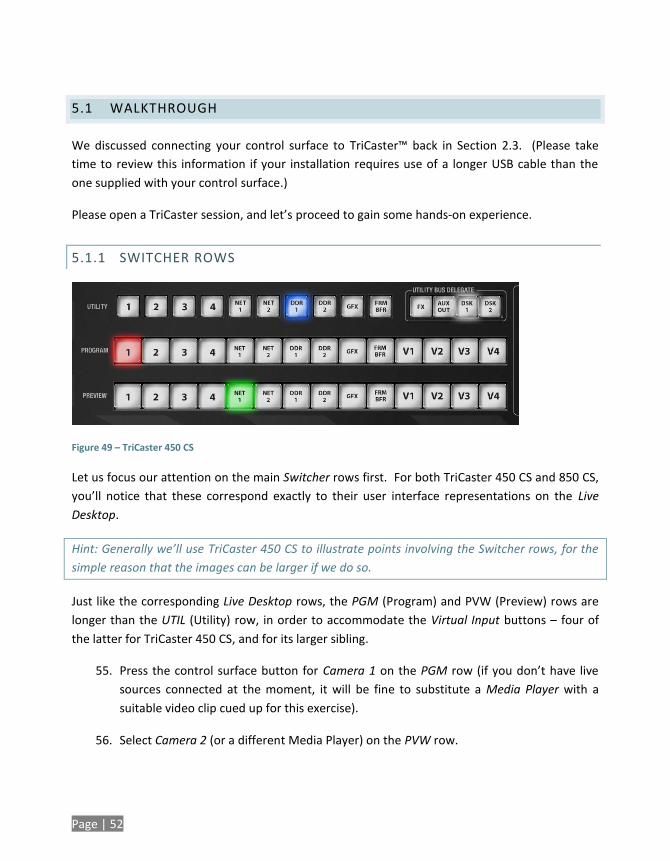
Page | 52
5.1 WALKTHROUGH
We discussed connecting your control surface to TriCaster™ back in Section 2.3. (Please take
time to review this information if your installation requires use of a longer USB cable than the
one supplied with your control surface.)
Please open a TriCaster session, and let’s proceed to gain some hands-on experience.
5.1.1 SWITCHER ROWS
Figure 49 – TriCaster 450 CS
Let us focus our attention on the main Switcher rows first. For both TriCaster 450 CS and 850 CS,
you’ll notice that these correspond exactly to their user interface representations on the Live
Desktop.
Hint: Generally we’ll use TriCaster 450 CS to illustrate points involving the Switcher rows, for the
simple reason that the images can be larger if we do so.
Just like the corresponding Live Desktop rows, the PGM (Program) and PVW (Preview) rows are
longer than the UTIL (Utility) row, in order to accommodate the Virtual Input buttons – four of
the latter for TriCaster 450 CS, and for its larger sibling.
55. Press the control surface button for Camera 1 on the PGM row (if you don’t have live
sources connected at the moment, it will be fine to substitute a Media Player with a
suitable video clip cued up for this exercise).
56. Select Camera 2 (or a different Media Player) on the PVW row.
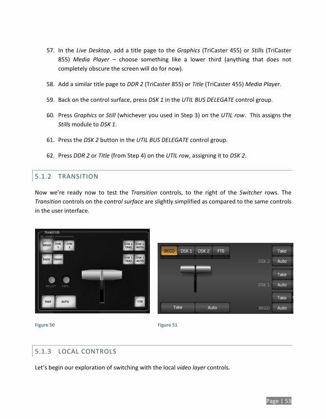
Page | 53
57. In the Live Desktop, add a title page to the Graphics (TriCaster 455) or Stills (TriCaster
855) Media Player – choose something like a lower third (anything that does not
completely obscure the screen will do for now).
58. Add a similar title page to DDR 2 (TriCaster 855) or Title (TriCaster 455) Media Player.
59. Back on the control surface, press DSK 1 in the UTIL BUS DELEGATE control group.
60. Press Graphics or Still (whichever you used in Step 3) on the UTIL row. This assigns the
Stills module to DSK 1.
61. Press the DSK 2 button in the UTIL BUS DELEGATE control group.
62. Press DDR 2 or Title (from Step 4) on the UTIL row, assigning it to DSK 2.
5.1.2 TRANSITION
Now we’re ready now to test the Transition controls, to the right of the Switcher rows. The
Transition controls on the control surface are slightly simplified as compared to the same controls
in the user interface.
Figure 50
Figure 51
5.1.3 LOCAL CONTROLS
Let’s begin our exploration of switching with the local video layer controls.
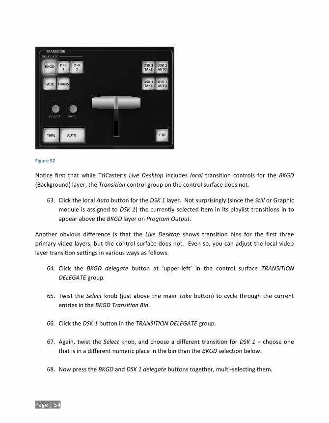
Page | 54
Figure 52
Notice first that while TriCaster’s Live Desktop includes local transition controls for the BKGD
(Background) layer, the Transition control group on the control surface does not.
63. Click the local Auto button for the DSK 1 layer. Not surprisingly (since the Still or Graphic
module is assigned to DSK 1) the currently selected item in its playlist transitions in to
appear above the BKGD layer on Program Output.
Another obvious difference is that the Live Desktop shows transition bins for the first three
primary video layers, but the control surface does not. Even so, you can adjust the local video
layer transition settings in various ways as follows.
64. Click the BKGD delegate button at ‘upper-left’ in the control surface TRANSITION
DELEGATE group.
65. Twist the Select knob (just above the main Take button) to cycle through the current
entries in the BKGD Transition Bin.
66. Click the DSK 1 button in the TRANSITION DELEGATE group.
67. Again, twist the Select knob, and choose a different transition for DSK 1 – choose one
that is in a different numeric place in the bin than the BKGD selection below.
68. Now press the BKGD and DSK 1 delegate buttons together, multi-selecting them.
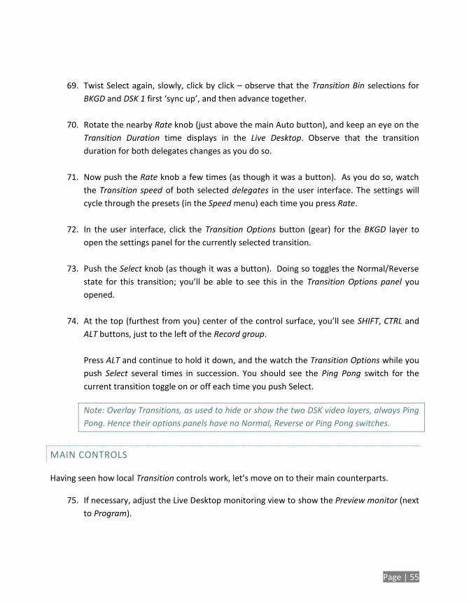
Page | 55
69. Twist Select again, slowly, click by click – observe that the Transition Bin selections for
BKGD and DSK 1 first ‘sync up’, and then advance together.
70. Rotate the nearby Rate knob (just above the main Auto button), and keep an eye on the
Transition Duration time displays in the Live Desktop. Observe that the transition
duration for both delegates changes as you do so.
71. Now push the Rate knob a few times (as though it was a button). As you do so, watch
the Transition speed of both selected delegates in the user interface. The settings will
cycle through the presets (in the Speed menu) each time you press Rate.
72. In the user interface, click the Transition Options button (gear) for the BKGD layer to
open the settings panel for the currently selected transition.
73. Push the Select knob (as though it was a button). Doing so toggles the Normal/Reverse
state for this transition; you’ll be able to see this in the Transition Options panel you
opened.
74. At the top (furthest from you) center of the control surface, you’ll see SHIFT, CTRL and
ALT buttons, just to the left of the Record group.
Press ALT and continue to hold it down, and the watch the Transition Options while you
push Select several times in succession. You should see the Ping Pong switch for the
current transition toggle on or off each time you push Select.
Note: Overlay Transitions, as used to hide or show the two DSK video layers, always Ping
Pong. Hence their options panels have no Normal, Reverse or Ping Pong switches.
MAIN CONTROLS
Having seen how local Transition controls work, let’s move on to their main counterparts.
75. If necessary, adjust the Live Desktop monitoring view to show the Preview monitor (next
to Program).
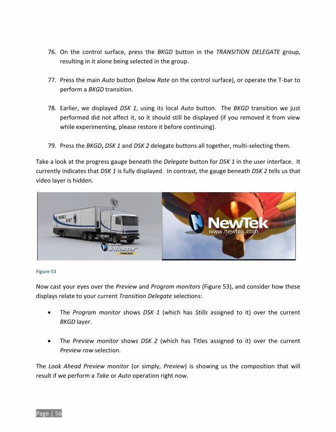
Page | 56
76. On the control surface, press the BKGD button in the TRANSITION DELEGATE group,
resulting in it alone being selected in the group.
77. Press the main Auto button (below Rate on the control surface), or operate the T-bar to
perform a BKGD transition.
78. Earlier, we displayed DSK 1, using its local Auto button. The BKGD transition we just
performed did not affect it, so it should still be displayed (if you removed it from view
while experimenting, please restore it before continuing).
79. Press the BKGD, DSK 1 and DSK 2 delegate buttons all together, multi-selecting them.
Take a look at the progress gauge beneath the Delegate button for DSK 1 in the user interface. It
currently indicates that DSK 1 is fully displayed. In contrast, the gauge beneath DSK 2 tells us that
video layer is hidden.
Figure 53
Now cast your eyes over the Preview and Program monitors (Figure 53), and consider how these
displays relate to your current Transition Delegate selections:
The Program monitor shows DSK 1 (which has Stills assigned to it) over the current
BKGD layer.
The Preview monitor shows DSK 2 (which has Titles assigned to it) over the current
Preview row selection.
The Look Ahead Preview monitor (or simply, Preview) is showing us the composition that will
result if we perform a Take or Auto operation right now.
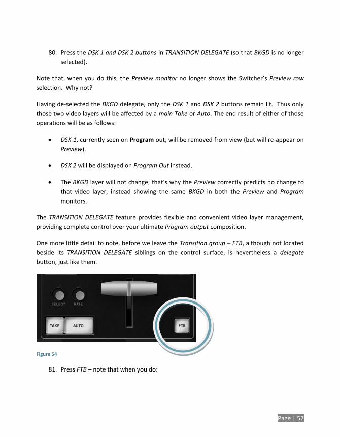
Page | 57
80. Press the DSK 1 and DSK 2 buttons in TRANSITION DELEGATE (so that BKGD is no longer
selected).
Note that, when you do this, the Preview monitor no longer shows the Switcher’s Preview row
selection. Why not?
Having de-selected the BKGD delegate, only the DSK 1 and DSK 2 buttons remain lit. Thus only
those two video layers will be affected by a main Take or Auto. The end result of either of those
operations will be as follows:
DSK 1, currently seen on Program out, will be removed from view (but will re-appear on
Preview).
DSK 2 will be displayed on Program Out instead.
The BKGD layer will not change; that’s why the Preview correctly predicts no change to
that video layer, instead showing the same BKGD in both the Preview and Program
monitors.
The TRANSITION DELEGATE feature provides flexible and convenient video layer management,
providing complete control over your ultimate Program output composition.
One more little detail to note, before we leave the Transition group – FTB, although not located
beside its TRANSITION DELEGATE siblings on the control surface, is nevertheless a delegate
button, just like them.
Figure 54
81. Press FTB – note that when you do:
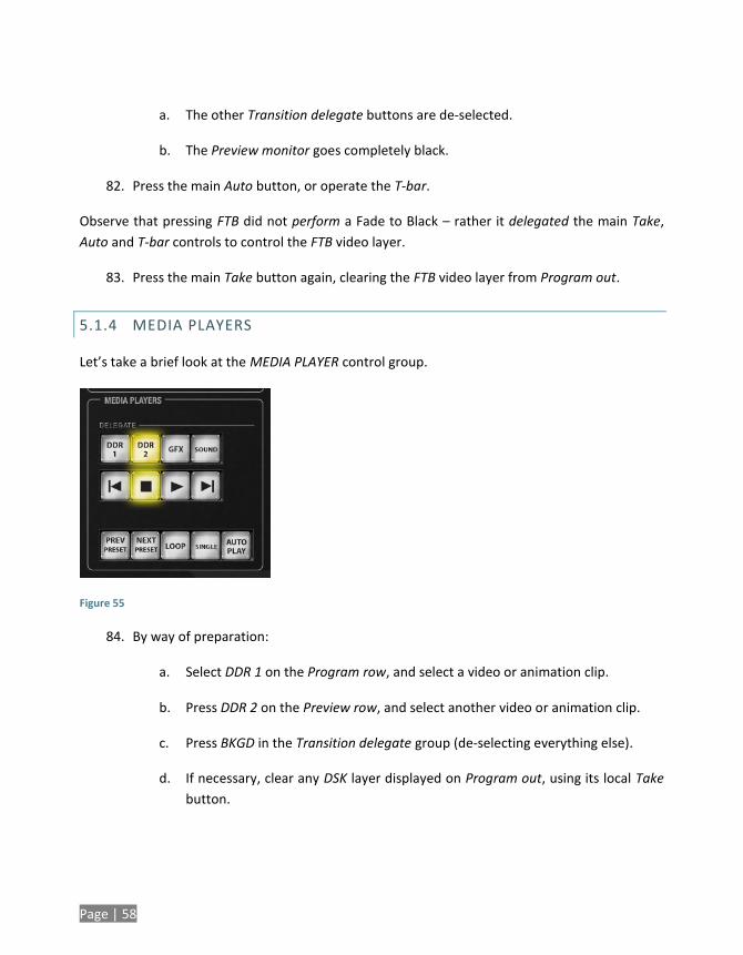
Page | 58
a. The other Transition delegate buttons are de-selected.
b. The Preview monitor goes completely black.
82. Press the main Auto button, or operate the T-bar.
Observe that pressing FTB did not perform a Fade to Black – rather it delegated the main Take,
Auto and T-bar controls to control the FTB video layer.
83. Press the main Take button again, clearing the FTB video layer from Program out.
5.1.4 MEDIA PLAYERS
Let’s take a brief look at the MEDIA PLAYER control group.
Figure 55
84. By way of preparation:
a. Select DDR 1 on the Program row, and select a video or animation clip.
b. Press DDR 2 on the Preview row, and select another video or animation clip.
c. Press BKGD in the Transition delegate group (de-selecting everything else).
d. If necessary, clear any DSK layer displayed on Program out, using its local Take
button.
Page | 59
e. Click the DDR 1 and DDR 2 tabs in the user interface (to let you to see what
happens in response to your control surface operations).
85. Press the DDR 1 button in the DELEGATE group under MEDIA PLAYERS on the control
surface.
86. If LOOP for DDR 1 is not enabled (i.e., its button is not brightly lit on the control surface),
press the LOOP button once.
87. Press the DDR 2 button in the DELEGATE group.
88. If LOOP for DDR 2 is enabled (its button is brightly lit on the control surface) press the
LOOP button once to turn it off.
89. Press the DDR 1 button again – note that the LOOP button illuminates, correctly showing
the current state for DDR 1.
90. Multi-select the DDR 1 & DDR 2 delegate buttons.
91. Press LOOP. LOOP is turned off for both of the delegated Media Players.
92. Press LOOP again – The LOOP feature is enabled for both delegated Media Players.
93. Repeat this exercise using the AUTOPLAY or SINGLE buttons (or both together).
Until this point, we’ve not done anything to the Media Players that couldn’t
have been done without the control surface, so try the following simple but
powerful step:
94. Press Play. Both Media Players begin to run simultaneously. Press Stop.
5.1.5 POSITIONER
Let’s kick it up a notch now, using the control surface to perform multiple simultaneous
operations.
95. Enable AUTOPLAY, SINGLE and LOOP for both DDRs (see Section 5.1.4).
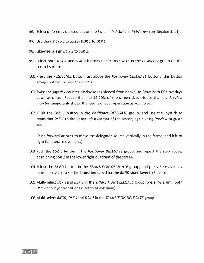
Page | 60
96. Select different video sources on the Switcher’s PGM and PVW rows (see Section 5.1.1).
97. Use the UTIL row to assign DDR 1 to DSK 1.
98. Likewise, assign DDR 2 to DSK 2.
99. Select both DSK 1 and DSK 2 buttons under DELEGATE in the Positioner group on the
control surface.
100. Press the POS/SCALE button just above the Positioner DELEGATE buttons (this button
group controls the Joystick mode).
101. Twist the joystick counter-clockwise (as viewed from above) to Scale both DSK overlays
down at once. Reduce them to 15-20% of the screen size. (Notice that the Preview
monitor temporarily shows the results of your operation as you do so).
102. Push the DSK 1 button in the Positioner DELEGATE group, and use the joystick to
reposition DSK 1 to the upper-left quadrant of the screen, again using Preview to guide
you.
(Push forward or back to move the delegated source vertically in the frame, and left or
right for lateral movement.)
103. Push the DSK 2 button in the Positioner DELEGATE group, and repeat the step above,
positioning DSK 2 in the lower right quadrant of the screen.
104. Select the BKGD button in the TRANSITION DELEGATE group, and press Rate as many
times necessary to set the transition speed for the BKGD video layer to F (fast).
105. Multi-select DSK 1and DSK 2 in the TRANSITION DELEGATE group, press RATE until both
DSK video layer transitions is set to M (Medium).
106. Multi-select BKGD, DSK 1and DSK 2 in the TRANSITION DELEGATE group.
Page | 61
Figure 56
At this point, the display on the Preview monitor should look something like Figure 56.
107. Push the main Auto button. The following will occur:
a. The BKGD transition is performed, swapping the Program and Preview row
sources.
b. Both DSKs transition in above the BKGD layer.
c. And the two DDRs automatically begin to play.
108. Let this all run for a moment or two to take it all in, then press Auto again.
All of the above resulted from your pressing a single button. You can see that the control surface
allows you to quickly configure complex compositions, and display them with flair.
Multi-selecting delegates provides a great deal of convenience, as we’ve seen. Consider too that
it becomes a simple matter to ensure matching positioning (etc.) for a series of sources, such as
title overlays, picture-in-picture setups, and so on. Let’s look at an example using Virtual Input
layers.
5.1.6 VIRTUAL INPUTS
We’ll perform a very simple exercise, but it will quickly impart everything you need to know.
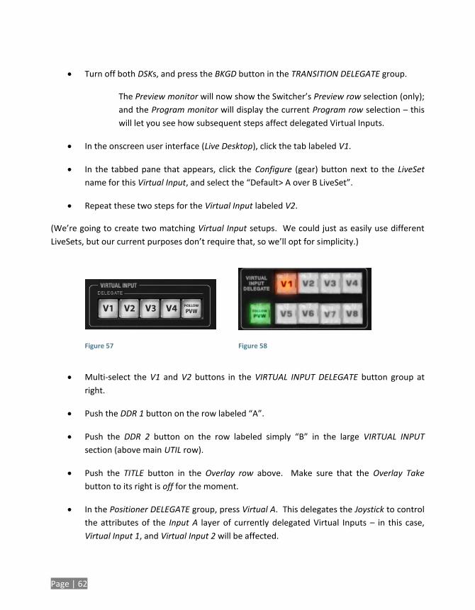
Page | 62
Turn off both DSKs, and press the BKGD button in the TRANSITION DELEGATE group.
The Preview monitor will now show the Switcher’s Preview row selection (only);
and the Program monitor will display the current Program row selection – this
will let you see how subsequent steps affect delegated Virtual Inputs.
In the onscreen user interface (Live Desktop), click the tab labeled V1.
In the tabbed pane that appears, click the Configure (gear) button next to the LiveSet
name for this Virtual Input, and select the “Default> A over B LiveSet”.
Repeat these two steps for the Virtual Input labeled V2.
(We’re going to create two matching Virtual Input setups. We could just as easily use different
LiveSets, but our current purposes don’t require that, so we’ll opt for simplicity.)
Figure 57
Figure 58
Multi-select the V1 and V2 buttons in the VIRTUAL INPUT DELEGATE button group at
right.
Push the DDR 1 button on the row labeled “A”.
Push the DDR 2 button on the row labeled simply “B” in the large VIRTUAL INPUT
section (above main UTIL row).
Push the TITLE button in the Overlay row above. Make sure that the Overlay Take
button to its right is off for the moment.
In the Positioner DELEGATE group, press Virtual A. This delegates the Joystick to control
the attributes of the Input A layer of currently delegated Virtual Inputs – in this case,
Virtual Input 1, and Virtual Input 2 will be affected.
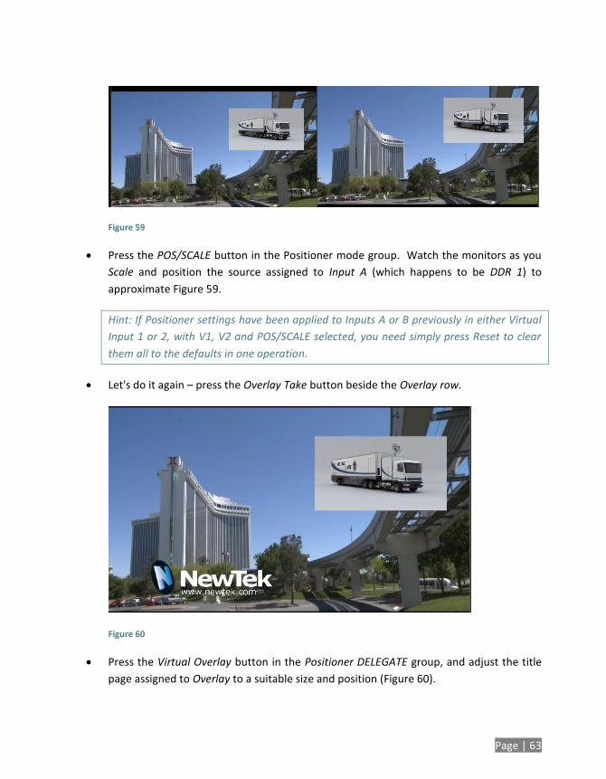
Page | 63
Figure 59
Press the POS/SCALE button in the Positioner mode group. Watch the monitors as you
Scale and position the source assigned to Input A (which happens to be DDR 1) to
approximate Figure 59.
Hint: If Positioner settings have been applied to Inputs A or B previously in either Virtual
Input 1 or 2, with V1, V2 and POS/SCALE selected, you need simply press Reset to clear
them all to the defaults in one operation.
Let's do it again – press the Overlay Take button beside the Overlay row.
Figure 60
Press the Virtual Overlay button in the Positioner DELEGATE group, and adjust the title
page assigned to Overlay to a suitable size and position (Figure 60).
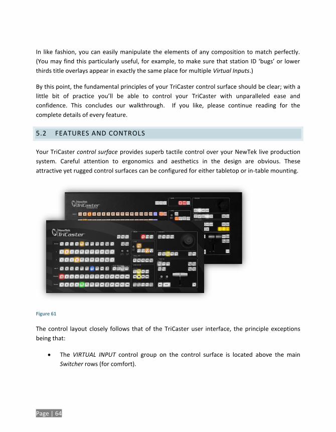
Page | 64
In like fashion, you can easily manipulate the elements of any composition to match perfectly.
(You may find this particularly useful, for example, to make sure that station ID ‘bugs’ or lower
thirds title overlays appear in exactly the same place for multiple Virtual Inputs.)
By this point, the fundamental principles of your TriCaster control surface should be clear; with a
little bit of practice you’ll be able to control your TriCaster with unparalleled ease and
confidence. This concludes our walkthrough. If you like, please continue reading for the
complete details of every feature.
5.2 FEATURES AND CONTROLS
Your TriCaster control surface provides superb tactile control over your NewTek live production
system. Careful attention to ergonomics and aesthetics in the design are obvious. These
attractive yet rugged control surfaces can be configured for either tabletop or in-table mounting.
Figure 61
The control layout closely follows that of the TriCaster user interface, the principle exceptions
being that:
The VIRTUAL INPUT control group on the control surface is located above the main
Switcher rows (for comfort).
Page | 65
A single Position control group governed by delegate buttons takes the place of multiple
controls in the UI.
The controls are comprised of grouped sets including the following hardware types:
Backlit push buttons
Twist knobs
T-bar
3-axis joystick
LED indicators
5.2.1 CONNECTING TO TRICASTER
If your control surface is connected to TriCaster using the cable it comes with, no external power
is required. If a longer USB cable is required, first connect the control surface to a powered USB
hub by a short cable, and then insert the longer USB cable between the hub and TriCaster.
Please be advised that so-called USB extenders are not recommended, having proven less
reliable than long USB cables (with powered hub, as above). This is because each added
connector introduces ‘reflections’, degrading the signal. Your TriCaster CS may seem reliable for
some time in this configuration, and then unexpectedly fail. (If this should happen, disconnecting
and reconnecting the control surface may serve as an temporarily measure to restore
functionality).
5.2.2 DELEGATES AND SYNCHRONIZATION
Both TriCaster’s Live Desktop and the control surface supply delegate button groups to govern
other controls. This is done both to extend the capability of other controls, and to support multi-
selections – resulting in simultaneous operations.
When initially selecting multiple delegates, as often as not the settings and states of the
individual members selected will vary. For example, when you delegate several Virtual Inputs at
once, the Overlay Transition Rate of each member of the multi-selection could be different.
Generally, wherever it makes sense to do so, when you make adjustments to settings for multi-
delegated groups, the settings will be progressively synchronized. For example:
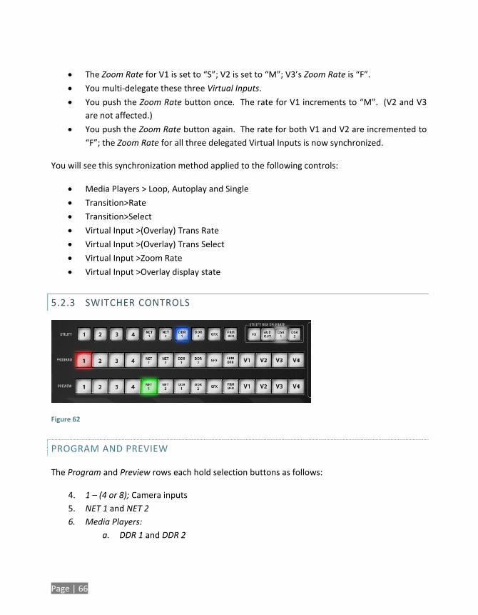
Page | 66
The Zoom Rate for V1 is set to “S”; V2 is set to “M”; V3’s Zoom Rate is “F”.
You multi-delegate these three Virtual Inputs.
You push the Zoom Rate button once. The rate for V1 increments to “M”. (V2 and V3
are not affected.)
You push the Zoom Rate button again. The rate for both V1 and V2 are incremented to
“F”; the Zoom Rate for all three delegated Virtual Inputs is now synchronized.
You will see this synchronization method applied to the following controls:
Media Players > Loop, Autoplay and Single
Transition>Rate
Transition>Select
Virtual Input >(Overlay) Trans Rate
Virtual Input >(Overlay) Trans Select
Virtual Input >Zoom Rate
Virtual Input >Overlay display state
5.2.3 SWITCHER CONTROLS
Figure 62
PROGRAM AND PREVIEW
The Program and Preview rows each hold selection buttons as follows:
4. 1 – (4 or 8); Camera inputs
5. NET 1 and NET 2
6. Media Players:
a. DDR 1 and DDR 2
Page | 67
b. STILL or Graphics
c. TITLE (TriCaster 850 CS only)
d. FRAME BUFFER
e. BLACK (TriCaster 850 CS only)
f. V1 - (V4 or V8); Virtual Inputs
Switcher row buttons are mutually exclusive, and the active selection button remains lit.
Hint: Hold down CTRL when clicking a button on the Preview row to toggle LiveMatte on/off for
that source. Likewise, hold ALT while pushing a Preview row button to toggle its Proc Amp. Note
that the source need not be actually selected on the PREVIEW row to do this, and multi-selections
are supported.
UTIL (UTILITY) ROW
UTIL row buttons are also mutually exclusive. The subordinate role of the UTIL Row is subtly
reinforced by the use of slightly smaller buttons. Source options include:
1. 1 – (4 or 8); Camera inputs
2. NET 1 and NET 2
3. Media Players:
a. DDR 1 and DDR 2
b. STILL or Graphics
c. TITLE (TriCaster 850 CS only)
d. FRAME BUFFER
e. BLACK (TriCaster 850 CS only)
Press SHIFT + (UTIL row button) to access extended source options for the AUX Out delegate
only:
f. [SHIFT + 1] – [SHIFT + (4 or 8] → select VI BFR 1- (4 or 8)
g. [SHIFT + NET 1] → select Preview
h. [SHIFT + NET 2] → select Program
i. [SHIFT + DDR 1] → select Program (Clean)
j. [SHIFT + DDR 2] → select FX
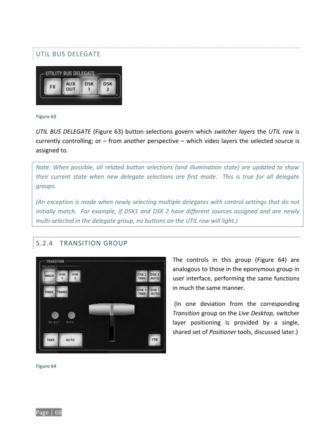
Page | 68
UTIL BUS DELEGATE
Figure 63
UTIL BUS DELEGATE (Figure 63) button selections govern which switcher layers the UTIL row is
currently controlling; or – from another perspective – which video layers the selected source is
assigned to.
Note: When possible, all related button selections (and illumination state) are updated to show
their current state when new delegate selections are first made. This is true for all delegate
groups.
(An exception is made when newly selecting multiple delegates with control settings that do not
initially match. For example, if DSK1 and DSK 2 have different sources assigned and are newly
multi-selected in the delegate group, no buttons on the UTIL row will light.)
5.2.4 TRANSITION GROUP
The controls in this group (Figure 64) are
analogous to those in the eponymous group in
user interface, performing the same functions
in much the same manner.
(In one deviation from the corresponding
Transition group on the Live Desktop, switcher
layer positioning is provided by a single,
shared set of Positioner tools, discussed later.)
Figure 64
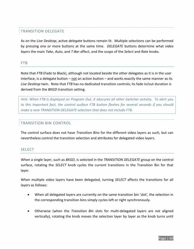
Page | 69
TRANSITION DELEGATE
As on the Live Desktop, active delegate buttons remain lit. Multiple selections can be performed
by pressing one or more buttons at the same time. DELEGATE buttons determine what video
layers the main Take, Auto, and T-Bar affect, and the scope of the Select and Rate knobs.
FTB
Note that FTB (Fade to Black), although not located beside the other delegates as it is in the user
interface, is a delegate button – not an action button – and works exactly the same manner as its
Live Desktop twin. Note that FTB has no dedicated transition controls; its fade in/out duration is
derived from the BKGD transition setting.
Hint: When FTB is displayed on Program Out, it obscures all other Switcher activity. To alert you
to this important fact, the control surface FTB button flashes for several seconds if you should
make a new TRANSITION DELEGATE selection that does not include FTB.
TRANSITION BIN CONTROL
The control surface does not have Transition Bins for the different video layers as such, but can
nevertheless control the transition selection and attributes for delegated video layers.
SELECT
When a single layer, such as BKGD, is selected in the TRANSITION DELEGATE group on the control
surface, rotating the SELECT knob cycles the current transitions in the Transition Bin for that
layer.
When multiple video layers have been delegated, turning SELECT affects the transitions for all
layers as follows:
When all delegated layers are currently on the same transition bin 'slot', the selection in
the corresponding transition bins simply cycles left or right synchronously.
Otherwise (when the Transition Bin slots for multi-delegated layers are not aligned
vertically), rotating the knob moves the selection layer by layer as the knob turns until
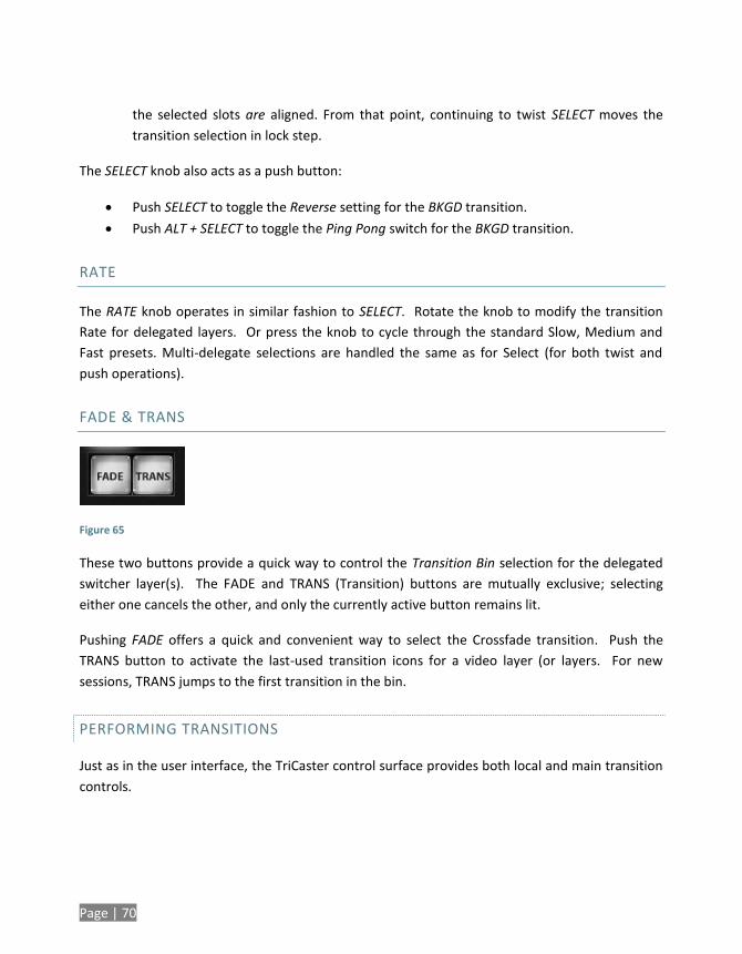
Page | 70
the selected slots are aligned. From that point, continuing to twist SELECT moves the
transition selection in lock step.
The SELECT knob also acts as a push button:
Push SELECT to toggle the Reverse setting for the BKGD transition.
Push ALT + SELECT to toggle the Ping Pong switch for the BKGD transition.
RATE
The RATE knob operates in similar fashion to SELECT. Rotate the knob to modify the transition
Rate for delegated layers. Or press the knob to cycle through the standard Slow, Medium and
Fast presets. Multi-delegate selections are handled the same as for Select (for both twist and
push operations).
FADE & TRANS
Figure 65
These two buttons provide a quick way to control the Transition Bin selection for the delegated
switcher layer(s). The FADE and TRANS (Transition) buttons are mutually exclusive; selecting
either one cancels the other, and only the currently active button remains lit.
Pushing FADE offers a quick and convenient way to select the Crossfade transition. Push the
TRANS button to activate the last-used transition icons for a video layer (or layers. For new
sessions, TRANS jumps to the first transition in the bin.
PERFORMING TRANSITIONS
Just as in the user interface, the TriCaster control surface provides both local and main transition
controls.
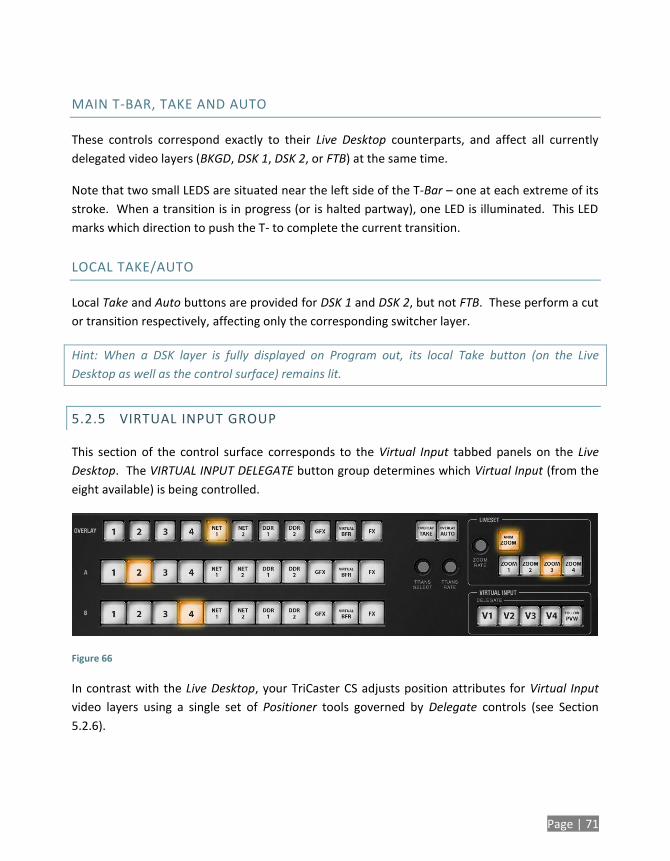
Page | 71
MAIN T-BAR, TAKE AND AUTO
These controls correspond exactly to their Live Desktop counterparts, and affect all currently
delegated video layers (BKGD, DSK 1, DSK 2, or FTB) at the same time.
Note that two small LEDS are situated near the left side of the T-Bar – one at each extreme of its
stroke. When a transition is in progress (or is halted partway), one LED is illuminated. This LED
marks which direction to push the T- to complete the current transition.
LOCAL TAKE/AUTO
Local Take and Auto buttons are provided for DSK 1 and DSK 2, but not FTB. These perform a cut
or transition respectively, affecting only the corresponding switcher layer.
Hint: When a DSK layer is fully displayed on Program out, its local Take button (on the Live
Desktop as well as the control surface) remains lit.
5.2.5 VIRTUAL INPUT GROUP
This section of the control surface corresponds to the Virtual Input tabbed panels on the Live
Desktop. The VIRTUAL INPUT DELEGATE button group determines which Virtual Input (from the
eight available) is being controlled.
Figure 66
In contrast with the Live Desktop, your TriCaster CS adjusts position attributes for Virtual Input
video layers using a single set of Positioner tools governed by Delegate controls (see Section
5.2.6).
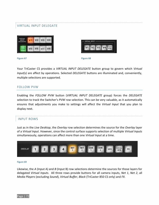
Page | 72
VIRTUAL INPUT DELEGATE
Figure 67
Figure 68
Your TriCaster CS provides a VIRTUAL INPUT DELEGATE button group to govern which Virtual
Input(s) are affect by operations. Selected DELEGATE buttons are illuminated and, conveniently,
multiple selections are supported.
FOLLOW PVW
Enabling the FOLLOW PVW button (VIRTUAL INPUT DELEGATE group) forces the DELEGATE
selection to track the Switcher's PVW row selection. This can be very valuable, as it automatically
ensures that adjustments you make to settings will affect the Virtual Input that you plan to
display next.
INPUT ROWS
Just as in the Live Desktop, the Overlay row selection determines the source for the Overlay layer of a Virtual Input. However, since the control surface supports selection of multiple Virtual Inputs simultaneously, operations can affect more than one Virtual Input at a time.
Figure 69
Likewise, the A (Input A) and B (Input B) row selections determine the sources for those layers for delegated Virtual Inputs. All three rows provide buttons for all camera inputs, Net 1, Net 2, all Media Players (excluding Sound), Virtual Buffer, Black (TriCaster 850 CS only) and FX.
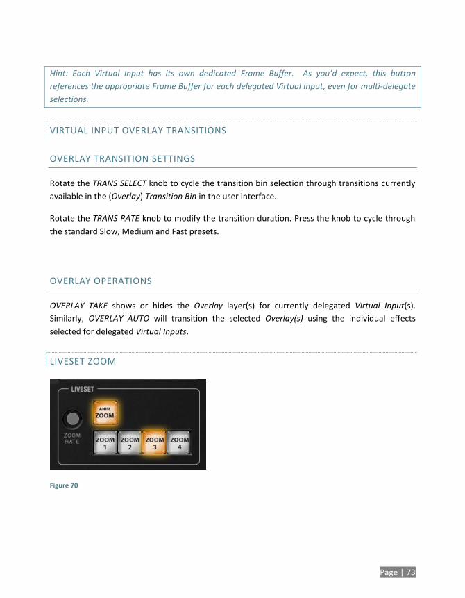
Page | 73
Hint: Each Virtual Input has its own dedicated Frame Buffer. As you’d expect, this button
references the appropriate Frame Buffer for each delegated Virtual Input, even for multi-delegate
selections.
VIRTUAL INPUT OVERLAY TRANSITIONS
OVERLAY TRANSITION SETTINGS
Rotate the TRANS SELECT knob to cycle the transition bin selection through transitions currently
available in the (Overlay) Transition Bin in the user interface.
Rotate the TRANS RATE knob to modify the transition duration. Press the knob to cycle through
the standard Slow, Medium and Fast presets.
OVERLAY OPERATIONS
OVERLAY TAKE shows or hides the Overlay layer(s) for currently delegated Virtual Input(s).
Similarly, OVERLAY AUTO will transition the selected Overlay(s) using the individual effects
selected for delegated Virtual Inputs.
LIVESET ZOOM
Figure 70
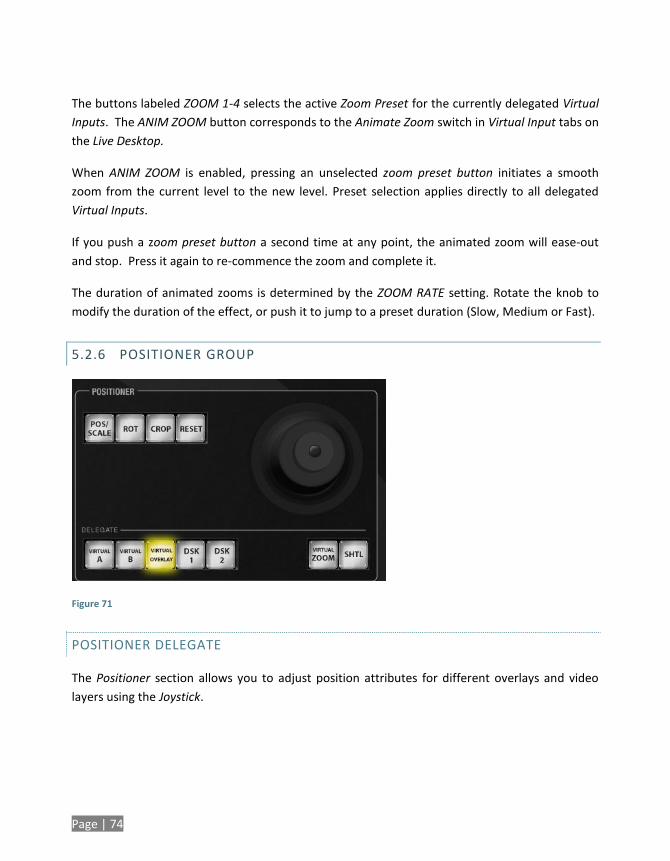
Page | 74
The buttons labeled ZOOM 1-4 selects the active Zoom Preset for the currently delegated Virtual
Inputs. The ANIM ZOOM button corresponds to the Animate Zoom switch in Virtual Input tabs on
the Live Desktop.
When ANIM ZOOM is enabled, pressing an unselected zoom preset button initiates a smooth
zoom from the current level to the new level. Preset selection applies directly to all delegated
Virtual Inputs.
If you push a zoom preset button a second time at any point, the animated zoom will ease-out
and stop. Press it again to re-commence the zoom and complete it.
The duration of animated zooms is determined by the ZOOM RATE setting. Rotate the knob to
modify the duration of the effect, or push it to jump to a preset duration (Slow, Medium or Fast).
5.2.6 POSITIONER GROUP
Figure 71
POSITIONER DELEGATE
The Positioner section allows you to adjust position attributes for different overlays and video
layers using the Joystick.
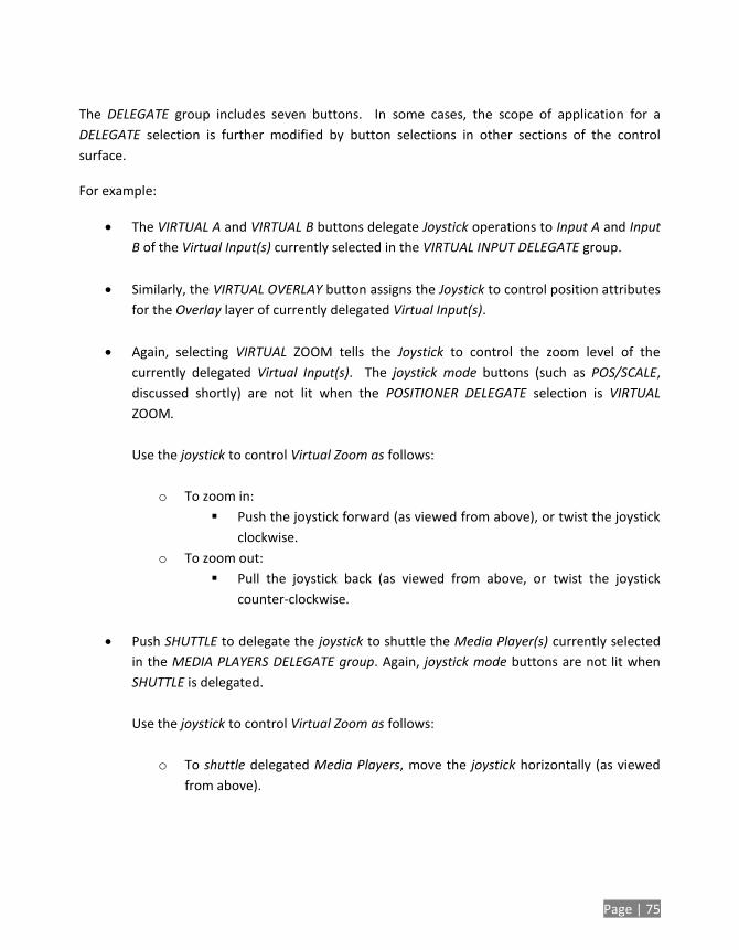
Page | 75
The DELEGATE group includes seven buttons. In some cases, the scope of application for a
DELEGATE selection is further modified by button selections in other sections of the control
surface.
For example:
The VIRTUAL A and VIRTUAL B buttons delegate Joystick operations to Input A and Input
B of the Virtual Input(s) currently selected in the VIRTUAL INPUT DELEGATE group.
Similarly, the VIRTUAL OVERLAY button assigns the Joystick to control position attributes
for the Overlay layer of currently delegated Virtual Input(s).
Again, selecting VIRTUAL ZOOM tells the Joystick to control the zoom level of the
currently delegated Virtual Input(s). The joystick mode buttons (such as POS/SCALE,
discussed shortly) are not lit when the POSITIONER DELEGATE selection is VIRTUAL
ZOOM.
Use the joystick to control Virtual Zoom as follows:
o To zoom in:
Push the joystick forward (as viewed from above), or twist the joystick
clockwise.
o To zoom out:
Pull the joystick back (as viewed from above, or twist the joystick
counter-clockwise.
Push SHUTTLE to delegate the joystick to shuttle the Media Player(s) currently selected
in the MEDIA PLAYERS DELEGATE group. Again, joystick mode buttons are not lit when
SHUTTLE is delegated.
Use the joystick to control Virtual Zoom as follows:
o To shuttle delegated Media Players, move the joystick horizontally (as viewed
from above).
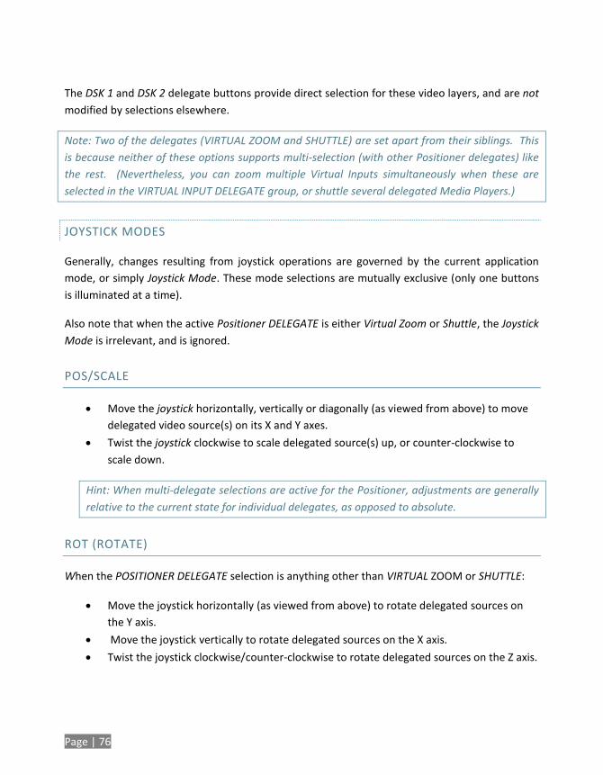
Page | 76
The DSK 1 and DSK 2 delegate buttons provide direct selection for these video layers, and are not
modified by selections elsewhere.
Note: Two of the delegates (VIRTUAL ZOOM and SHUTTLE) are set apart from their siblings. This
is because neither of these options supports multi-selection (with other Positioner delegates) like
the rest. (Nevertheless, you can zoom multiple Virtual Inputs simultaneously when these are
selected in the VIRTUAL INPUT DELEGATE group, or shuttle several delegated Media Players.)
JOYSTICK MODES
Generally, changes resulting from joystick operations are governed by the current application
mode, or simply Joystick Mode. These mode selections are mutually exclusive (only one buttons
is illuminated at a time).
Also note that when the active Positioner DELEGATE is either Virtual Zoom or Shuttle, the Joystick
Mode is irrelevant, and is ignored.
POS/SCALE
Move the joystick horizontally, vertically or diagonally (as viewed from above) to move
delegated video source(s) on its X and Y axes.
Twist the joystick clockwise to scale delegated source(s) up, or counter-clockwise to
scale down.
Hint: When multi-delegate selections are active for the Positioner, adjustments are generally
relative to the current state for individual delegates, as opposed to absolute.
ROT (ROTATE)
When the POSITIONER DELEGATE selection is anything other than VIRTUAL ZOOM or SHUTTLE:
Move the joystick horizontally (as viewed from above) to rotate delegated sources on
the Y axis.
Move the joystick vertically to rotate delegated sources on the X axis.
Twist the joystick clockwise/counter-clockwise to rotate delegated sources on the Z axis.
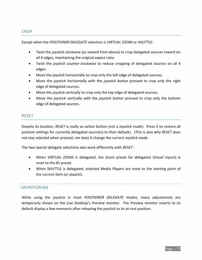
Page | 77
CROP
Except when the POSITIONER DELEGATE selection is VIRTUAL ZOOM or SHUTTLE:
Twist the joystick clockwise (as viewed from above) to crop delegated sources inward on
all 4 edges, maintaining the original aspect ratio.
Twist the joystick counter-clockwise to reduce cropping of delegated sources on all 4
edges.
Move the joystick horizontally to crop only the left edge of delegated sources.
Move the joystick horizontally with the joystick button pressed to crop only the right
edge of delegated sources.
Move the joystick vertically to crop only the top edge of delegated sources.
Move the joystick vertically with the joystick button pressed to crop only the bottom
edge of delegated sources.
RESET
Despite its location, RESET is really an action button (not a Joystick mode). Press it to restore all
position settings for currently delegated source(s) to their defaults. (This is also why RESET does
not stay selected when pressed, nor does it change the current Joystick mode.
The two special delegate selections also work differently with RESET:
When VIRTUAL ZOOM is delegated, the Zoom preset for delegated Virtual Inputs) is
reset to the #1 preset.
When SHUTTLE is delegated, selected Media Players are reset to the starting point of
the current item (or playlist).
MONITORING
While using the joystick in most POSITIONER DELEGATE modes, many adjustments are
temporarily shown on the Live Desktop’s Preview monitor. The Preview monitor reverts to its
default display a few moments after releasing the joystick to its at-rest position.
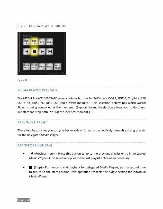
Page | 78
5.2.7 MEDIA PLAYER GROUP
Figure 72
MEDIA PLAYER DELEGATE
The MEDIA PLAYER DELEGATE group contains buttons for TriCaster’s DDR 1, DDR 2, Graphics (450
CS), STILL and TITLE (850 CS), and SOUND modules. This selection determines which Media
Player is being controlled at the moment. (Support for multi-selection allows you to do things
like start and stop both DDRs at the identical moment.)
PREV/NEXT PRESET
These two buttons let you to cycle backwards or forwards respectively through existing presets
for the delegated Media Player.
TRANSPORT CONTROL
| (Previous Item) – Press this button to go to the previous playlist entry in delegated
Media Players. (The selection cycles to the last playlist entry when necessary.)
(Stop) – Push once to end playback for delegated Media Players; push a second time
to return to the start position (this operation respects the Single setting for individual
Media Players
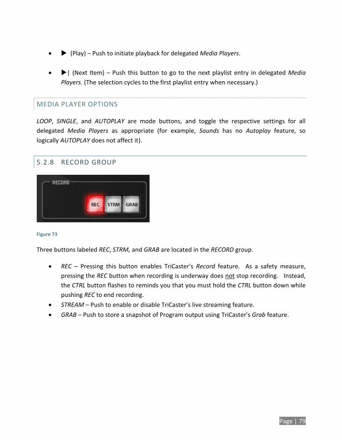
Page | 79
(Play) – Push to initiate playback for delegated Media Players.
| (Next Item) – Push this button to go to the next playlist entry in delegated Media
Players. (The selection cycles to the first playlist entry when necessary.)
MEDIA PLAYER OPTIONS
LOOP, SINGLE, and AUTOPLAY are mode buttons, and toggle the respective settings for all
delegated Media Players as appropriate (for example, Sounds has no Autoplay feature, so
logically AUTOPLAY does not affect it).
5.2.8 RECORD GROUP
Figure 73
Three buttons labeled REC, STRM, and GRAB are located in the RECORD group.
REC – Pressing this button enables TriCaster's Record feature. As a safety measure,
pressing the REC button when recording is underway does not stop recording. Instead,
the CTRL button flashes to reminds you that you must hold the CTRL button down while
pushing REC to end recording.
STREAM – Push to enable or disable TriCaster’s live streaming feature.
GRAB – Push to store a snapshot of Program output using TriCaster's Grab feature.
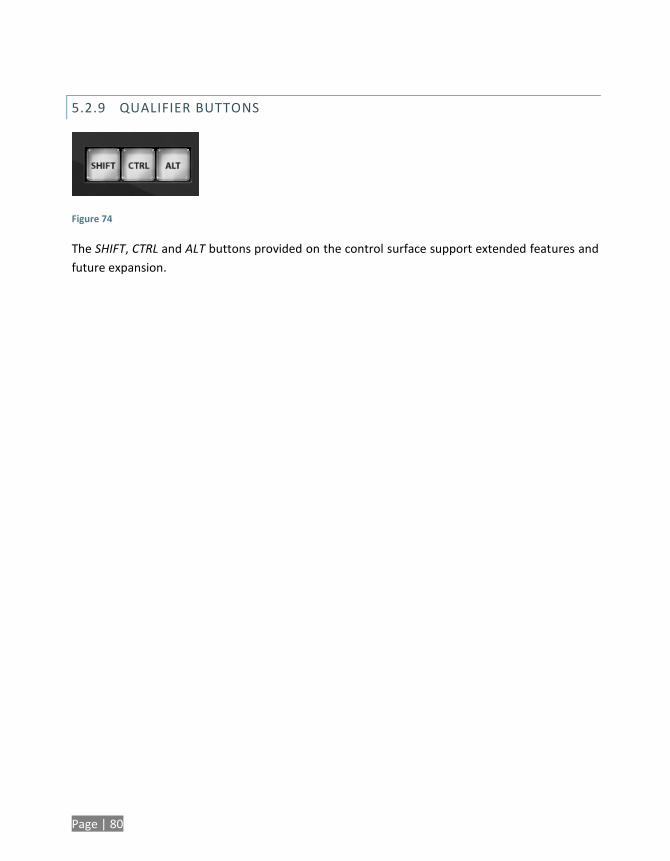
Page | 80
5.2.9 QUALIFIER BUTTONS
Figure 74
The SHIFT, CTRL and ALT buttons provided on the control surface support extended features and
future expansion.
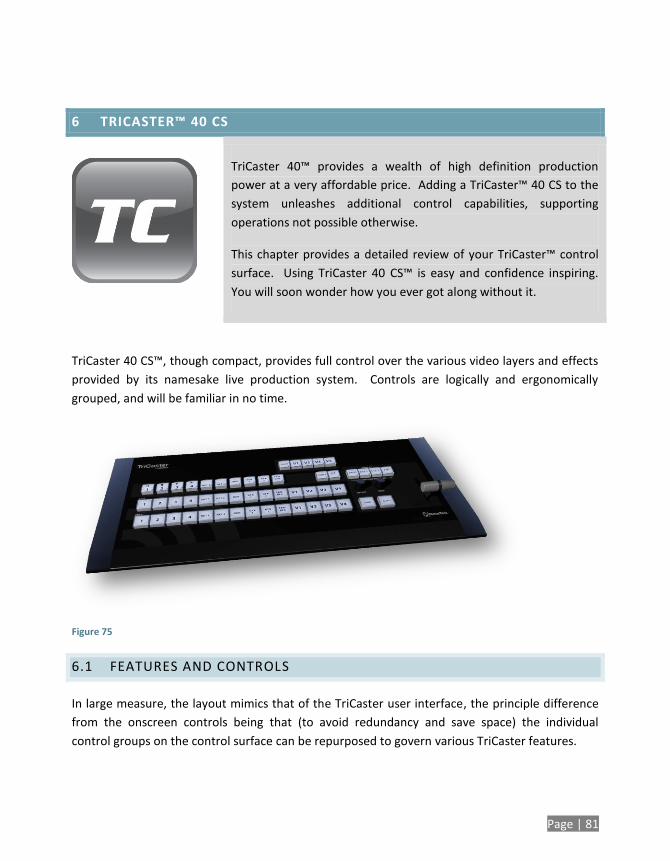
Page | 81
6 TRICASTER™ 40 CS
TriCaster 40™ provides a wealth of high definition production
power at a very affordable price. Adding a TriCaster™ 40 CS to the
system unleashes additional control capabilities, supporting
operations not possible otherwise.
This chapter provides a detailed review of your TriCaster™ control
surface. Using TriCaster 40 CS™ is easy and confidence inspiring.
You will soon wonder how you ever got along without it.
TriCaster 40 CS™, though compact, provides full control over the various video layers and effects
provided by its namesake live production system. Controls are logically and ergonomically
grouped, and will be familiar in no time.
Figure 75
6.1 FEATURES AND CONTROLS
In large measure, the layout mimics that of the TriCaster user interface, the principle difference
from the onscreen controls being that (to avoid redundancy and save space) the individual
control groups on the control surface can be repurposed to govern various TriCaster features.
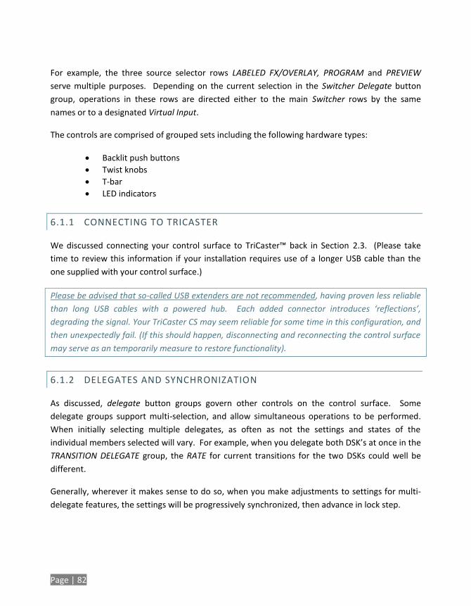
Page | 82
For example, the three source selector rows LABELED FX/OVERLAY, PROGRAM and PREVIEW
serve multiple purposes. Depending on the current selection in the Switcher Delegate button
group, operations in these rows are directed either to the main Switcher rows by the same
names or to a designated Virtual Input.
The controls are comprised of grouped sets including the following hardware types:
Backlit push buttons
Twist knobs
T-bar
LED indicators
6.1.1 CONNECTING TO TRICASTER
We discussed connecting your control surface to TriCaster™ back in Section 2.3. (Please take
time to review this information if your installation requires use of a longer USB cable than the
one supplied with your control surface.)
Please be advised that so-called USB extenders are not recommended, having proven less reliable
than long USB cables with a powered hub. Each added connector introduces ‘reflections’,
degrading the signal. Your TriCaster CS may seem reliable for some time in this configuration, and
then unexpectedly fail. (If this should happen, disconnecting and reconnecting the control surface
may serve as an temporarily measure to restore functionality).
6.1.2 DELEGATES AND SYNCHRONIZATION
As discussed, delegate button groups govern other controls on the control surface. Some
delegate groups support multi-selection, and allow simultaneous operations to be performed.
When initially selecting multiple delegates, as often as not the settings and states of the
individual members selected will vary. For example, when you delegate both DSK’s at once in the
TRANSITION DELEGATE group, the RATE for current transitions for the two DSKs could well be
different.
Generally, wherever it makes sense to do so, when you make adjustments to settings for multi-
delegate features, the settings will be progressively synchronized, then advance in lock step.
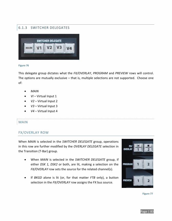
Page | 83
6.1.3 SWITCHER DELEGATES
Figure 76
This delegate group dictates what the FX/OVERLAY, PROGRAM and PREVIEW rows will control.
The options are mutually exclusive – that is, multiple selections are not supported. Choose one
of:
MAIN
VI – Virtual Input 1
V2 – Virtual Input 2
V3 – Virtual Input 3
V4 – Virtual Input 4
MAIN
FX/OVERLAY ROW
When MAIN is selected in the SWITCHER DELEGATE group, operations
in this row are further modified by the OVERLAY DELEGATE selection in
the Transition (T-Bar) group.
When MAIN is selected in the SWITCHER DELEGATE group, if
either DSK 1, DSK2 or both, are lit, making a selection on the
FX/OVERLAY row sets the source for the related channel(s).
If BKGD alone is lit (or, for that matter FTB only), a button
selection in the FX/OVERLAY row assigns the FX bus source.
Figure 77
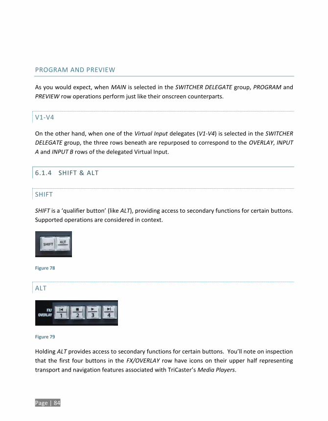
Page | 84
PROGRAM AND PREVIEW
As you would expect, when MAIN is selected in the SWITCHER DELEGATE group, PROGRAM and
PREVIEW row operations perform just like their onscreen counterparts.
V1-V4
On the other hand, when one of the Virtual Input delegates (V1-V4) is selected in the SWITCHER
DELEGATE group, the three rows beneath are repurposed to correspond to the OVERLAY, INPUT
A and INPUT B rows of the delegated Virtual Input.
6.1.4 SHIFT & ALT
SHIFT
SHIFT is a ‘qualifier button’ (like ALT), providing access to secondary functions for certain buttons.
Supported operations are considered in context.
Figure 78
ALT
Figure 79
Holding ALT provides access to secondary functions for certain buttons. You’ll note on inspection
that the first four buttons in the FX/OVERLAY row have icons on their upper half representing
transport and navigation features associated with TriCaster’s Media Players.
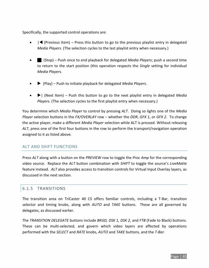
Page | 85
Specifically, the supported control operations are:
| (Previous Item) – Press this button to go to the previous playlist entry in delegated
Media Players. (The selection cycles to the last playlist entry when necessary.)
(Stop) – Push once to end playback for delegated Media Players; push a second time
to return to the start position (this operation respects the Single setting for individual
Media Players.
(Play) – Push to initiate playback for delegated Media Players.
| (Next Item) – Push this button to go to the next playlist entry in delegated Media
Players. (The selection cycles to the first playlist entry when necessary.)
You determine which Media Player to control by pressing ALT. Doing so lights one of the Media
Player selection buttons in the FX/OVERLAY row – whether the DDR, GFX 1, or GFX 2. To change
the active player, make a different Media Player selection while ALT is pressed. Without releasing
ALT, press one of the first four buttons in the row to perform the transport/navigation operation
assigned to it as listed above.
ALT AND SHIFT FUNCTIONS
Press ALT along with a button on the PREVIEW row to toggle the Proc Amp for the corresponding
video source. Replace the ALT button combination with SHIFT to toggle the source’s LiveMatte
feature instead. ALT also provides access to transition controls for Virtual Input Overlay layers, as
discussed in the next section.
6.1.5 TRANSITIONS
The transition area on TriCaster 40 CS offers familiar controls, including a T-Bar, transition
selector and timing knobs, along with AUTO and TAKE buttons. These are all governed by
delegates, as discussed earlier.
The TRANSITION DELEGATE buttons include BKGD, DSK 1, DSK 2, and FTB (Fade to Black) buttons.
These can be multi-selected, and govern which video layers are affected by operations
performed with the SELECT and RATE knobs, AUTO and TAKE buttons, and the T-Bar.
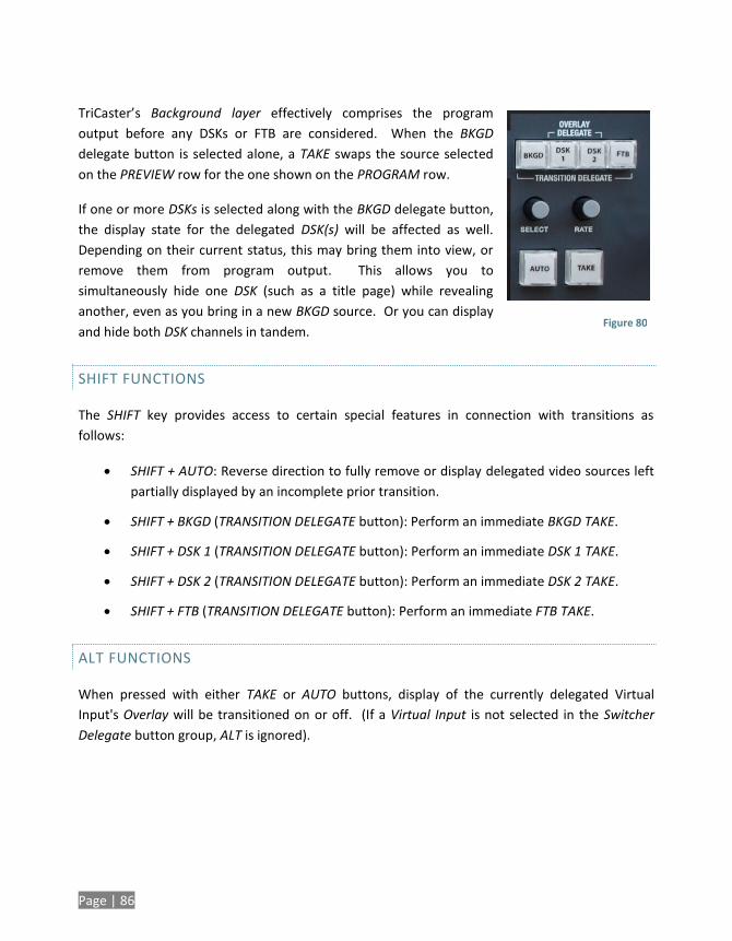
Page | 86
TriCaster’s Background layer effectively comprises the program
output before any DSKs or FTB are considered. When the BKGD
delegate button is selected alone, a TAKE swaps the source selected
on the PREVIEW row for the one shown on the PROGRAM row.
If one or more DSKs is selected along with the BKGD delegate button,
the display state for the delegated DSK(s) will be affected as well.
Depending on their current status, this may bring them into view, or
remove them from program output. This allows you to
simultaneously hide one DSK (such as a title page) while revealing
another, even as you bring in a new BKGD source. Or you can display
and hide both DSK channels in tandem.
SHIFT FUNCTIONS
The SHIFT key provides access to certain special features in connection with transitions as
follows:
SHIFT + AUTO: Reverse direction to fully remove or display delegated video sources left
partially displayed by an incomplete prior transition.
SHIFT + BKGD (TRANSITION DELEGATE button): Perform an immediate BKGD TAKE.
SHIFT + DSK 1 (TRANSITION DELEGATE button): Perform an immediate DSK 1 TAKE.
SHIFT + DSK 2 (TRANSITION DELEGATE button): Perform an immediate DSK 2 TAKE.
SHIFT + FTB (TRANSITION DELEGATE button): Perform an immediate FTB TAKE.
ALT FUNCTIONS
When pressed with either TAKE or AUTO buttons, display of the currently delegated Virtual
Input's Overlay will be transitioned on or off. (If a Virtual Input is not selected in the Switcher
Delegate button group, ALT is ignored).
Figure 80
Page | 87
SELECT AND RATE
These two buttons are also governed by the delegate buttons above. Select BKGD and twist the
appropriate knob to select a different BKGD transition from the onscreen bin, or to change its
rate.
These knobs also act like pushbuttons. Push down and release SELECT to toggle the Reverse
switch for the current BKGD transition. (Note that background transitions are the only type to
offer a reverse option; DSK transitions automatically toggle their direction.) Or push the RATE
knob repeatedly to cycle through the default S (Slow), M (Medium) and F(Fast) transition speeds.
Recall that multi-selection is supported, as well.
T-BAR INDICATORS
TriCaster’s onscreen T-Bar always snaps back to the top at the end of a transition. This is not
true, of course, for the T-Bar on the control surface. To help you know what will result from
moving the physical T-Bar, observe that there are green LEDs located near either end of its
stroke. Normally, one of these is lit to indicate the direction the T-Bar should be moved to
complete the last operation or perform a new one.
In some cases, transition operations can result in the onscreen T-Bar and its control surface
counterpart being out of synch with one another. In such cases one of the LEDs begins to flash,
and the T-Bar is deactivated. It will remain in this state until it is moved fully to one end of its
stroke, re-synchronizing it with the user interface. Afterward, the T-Bar resumes control over the
delegated sources.

Page | 89
7 TIMEWARP™
This chapter discusses the use of a NewTek TimeWarp™ control
surface, explaining how it integrates into your TriCaster live
production system.
Full details of all of the controls and functions on the control
surface follow the short walkthrough section.
This chapter discusses the use of two NewTek TimeWarp™ control surfaces in two variants. Both
models (TriCaster™ 850TW and its predecessor, TW-42) add convenient slow motion instant
replay to the already potent capability of your TriCaster system.
TriCaster 850TW has the same sleek profile as TriCaster 450 CS
and TriCaster 850 CS, making it the perfect complement to
one of these control surfaces. Of course it delivers the
same precise control over TriCaster’s instant replay
recording and live playback when used alone.
The earlier TW-42, though designed for use with SD
format TriCasters, continues to provide great functionality
when connected to the newer HD TriCasters (including TriCaster 300,
450, 850, 455 and 855).
For the most part, both TimeWarp™ models have similar controls, with similar labels, and
perform in much the same manner. For that reason, in the discussion which follows we will focus
on the newer TriCaster 850TW, simply giving you a friendly heads-up whenever we discuss an
item where TW-42 varies from its newer sibling.
TW-42 NOTES Wherever items of special interest to TW-42 users appear in this chapter, they will
be flagged in the same manner as this paragraph.
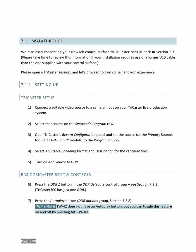
Page | 90
7.1 WALKTHROUGH
We discussed connecting your NewTek control surface to TriCaster back in back in Section 2.3.
(Please take time to review this information if your installation requires use of a longer USB cable
than the one supplied with your control surface.)
Please open a TriCaster session, and let’s proceed to gain some hands-on experience.
7.1.1 SETTING UP
TRICASTER SETUP
1) Connect a suitable video source to a camera input on your TriCaster live production
system.
2) Select that source on the Switcher’s Program row.
3) Open TriCaster’s Record Configuration panel and set the source (or the Primary Source,
for EXTREME™ models) to the Program option.
4) Select a suitable Encoding format and Destination for the captured files.
5) Turn on Add Source to DDR.
BASIC TRICASTER 850 TW CONTROLS
6) Press the DDR 1 button in the DDR Delegate control group – see Section 7.2.2.
(TriCaster300 has just one DDR.)
7) Press the Autoplay button (DDR options group, Section 7.2.8).
TW-42 NOTES TW-42 does not have an Autoplay button, but you can toggle this feature
on and off by pressing Alt + Pause.
Page | 91
8) Press the 50% button in the Play Speed group (Section 7.2.4), presetting playback to a
suitable slow motion playback rate).
7.1.2 RECORDING AND PLAYING REPLAYS
9) Click the REC (Record) button on TriCaster 850 TW to commence live replay recording.
TW-42 NOTES There is no REC button on TW-42, but the next step will automatically
enable Record anyway.
10) Watch your live program for a suitable event, and press the IN button (Marking group,
Section 7.2.5).
11) Wait 10-15 seconds, and press OUT (Marking group, Section 7.2.5)
12) Select DDR 1 on the Switcher’s Preview row.
13) Click Take (or press the keyboard Enter key).
Your instant replay will automatically be displayed on TriCaster’s Program Output, replacing the
live video feed. The replay clip will play through once at half-speed, and then the live source will
be restored to output.
Hint: Really, these last few steps are ‘The Big Ones’ – say them with me: “IN, OUT, DDR and
Enter”. Repeat this mantra over and over for the next four hours (or less, if you’re really confident
you have committed them to memory.
7.2 FEATURES AND CONTROLS
TriCaster 850 TW is quite straightforward to use, especially true if you are already familiar with
common TriCaster controls and features.
In this section, we’ll discuss each part of the control surface, explaining how the various controls
operate and what effect they have, revealing a few little tricks that you may find helpful along
the way.
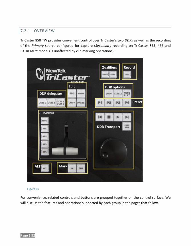
Page | 92
7.2.1 OVERVIEW
TriCaster 850 TW provides convenient control over TriCaster’s two DDRs as well as the recording
of the Primary source configured for capture (Secondary recording on TriCaster 855, 455 and
EXTREME™ models is unaffected by clip marking operations).
Figure 81
For convenience, related controls and buttons are grouped together on the control surface. We
will discuss the features and operations supported by each group in the pages that follow.
Edit
Qualifiers Record
DDR delegates
DDR Transport
DDR options
Preset
Mark ALT
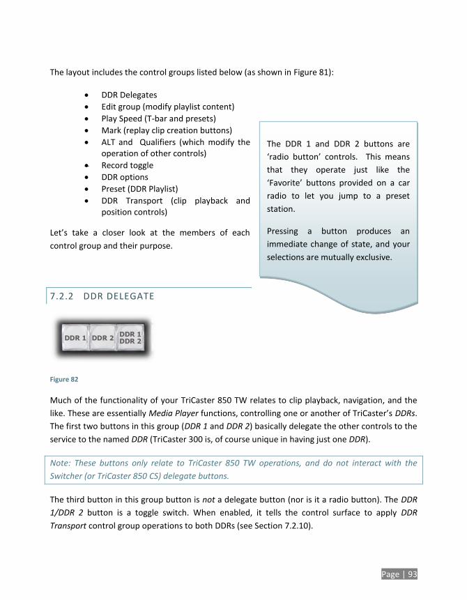
Page | 93
The DDR 1 and DDR 2 buttons are
‘radio button’ controls. This means
that they operate just like the
‘Favorite’ buttons provided on a car
radio to let you jump to a preset
station.
Pressing a button produces an
immediate change of state, and your
selections are mutually exclusive.
The layout includes the control groups listed below (as shown in Figure 81):
DDR Delegates
Edit group (modify playlist content)
Play Speed (T-bar and presets)
Mark (replay clip creation buttons)
ALT and Qualifiers (which modify the operation of other controls)
Record toggle
DDR options
Preset (DDR Playlist)
DDR Transport (clip playback and position controls)
Let’s take a closer look at the members of each
control group and their purpose.
7.2.2 DDR DELEGATE
Figure 82
Much of the functionality of your TriCaster 850 TW relates to clip playback, navigation, and the
like. These are essentially Media Player functions, controlling one or another of TriCaster’s DDRs.
The first two buttons in this group (DDR 1 and DDR 2) basically delegate the other controls to the
service to the named DDR (TriCaster 300 is, of course unique in having just one DDR).
Note: These buttons only relate to TriCaster 850 TW operations, and do not interact with the
Switcher (or TriCaster 850 CS) delegate buttons.
The third button in this group button is not a delegate button (nor is it a radio button). The DDR
1/DDR 2 button is a toggle switch. When enabled, it tells the control surface to apply DDR
Transport control group operations to both DDRs (see Section 7.2.10).
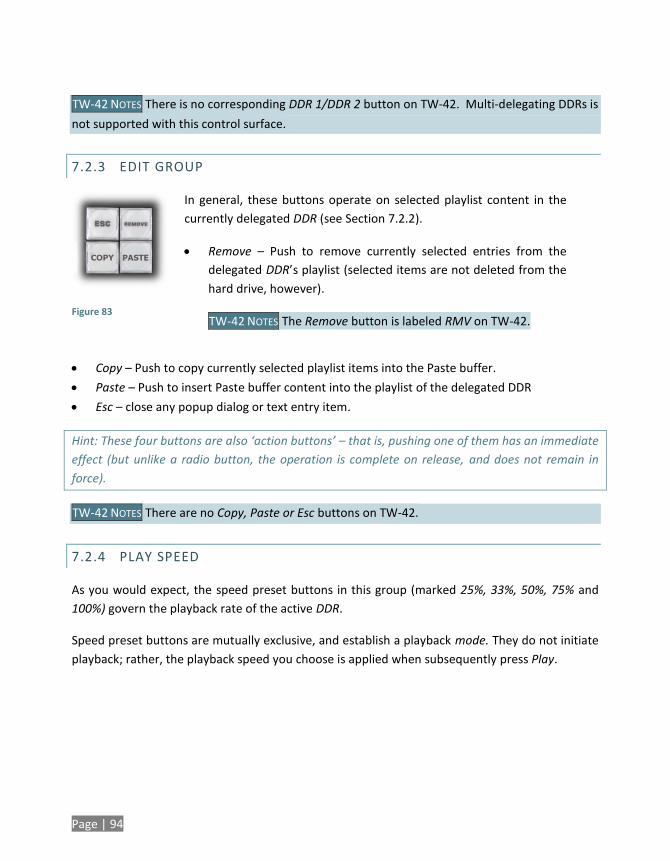
Page | 94
TW-42 NOTES There is no corresponding DDR 1/DDR 2 button on TW-42. Multi-delegating DDRs is
not supported with this control surface.
7.2.3 EDIT GROUP
Figure 83
In general, these buttons operate on selected playlist content in the
currently delegated DDR (see Section 7.2.2).
Remove – Push to remove currently selected entries from the
delegated DDR’s playlist (selected items are not deleted from the
hard drive, however).
TW-42 NOTES The Remove button is labeled RMV on TW-42.
Copy – Push to copy currently selected playlist items into the Paste buffer.
Paste – Push to insert Paste buffer content into the playlist of the delegated DDR
Esc – close any popup dialog or text entry item.
Hint: These four buttons are also ‘action buttons’ – that is, pushing one of them has an immediate
effect (but unlike a radio button, the operation is complete on release, and does not remain in
force).
TW-42 NOTES There are no Copy, Paste or Esc buttons on TW-42.
7.2.4 PLAY SPEED
As you would expect, the speed preset buttons in this group (marked 25%, 33%, 50%, 75% and
100%) govern the playback rate of the active DDR.
Speed preset buttons are mutually exclusive, and establish a playback mode. They do not initiate
playback; rather, the playback speed you choose is applied when subsequently press Play.
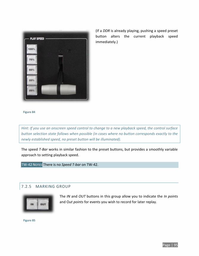
Page | 95
(If a DDR is already playing, pushing a speed preset
button alters the current playback speed
immediately.)
Hint: If you use an onscreen speed control to change to a new playback speed, the control surface
button selection state follows when possible (in cases where no button corresponds exactly to the
newly established speed, no preset button will be illuminated).
The speed T-Bar works in similar fashion to the preset buttons, but provides a smoothly variable
approach to setting playback speed.
TW-42 NOTES There is no Speed T-bar on TW-42.
7.2.5 MARKING GROUP
The IN and OUT buttons in this group allow you to indicate the In points
and Out points for events you wish to record for later replay.
Figure 84
Figure 85
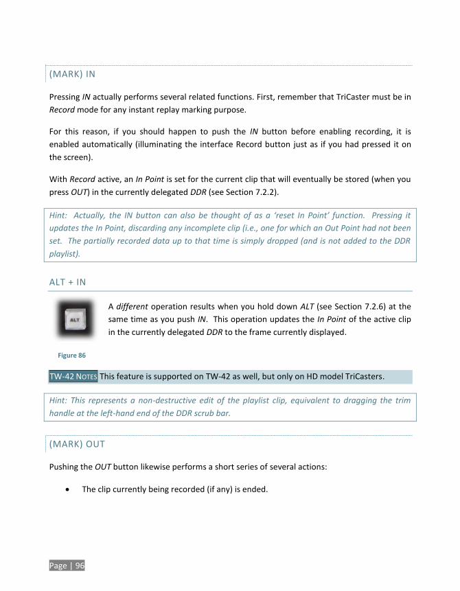
Page | 96
(MARK) IN
Pressing IN actually performs several related functions. First, remember that TriCaster must be in
Record mode for any instant replay marking purpose.
For this reason, if you should happen to push the IN button before enabling recording, it is
enabled automatically (illuminating the interface Record button just as if you had pressed it on
the screen).
With Record active, an In Point is set for the current clip that will eventually be stored (when you
press OUT) in the currently delegated DDR (see Section 7.2.2).
Hint: Actually, the IN button can also be thought of as a ‘reset In Point’ function. Pressing it
updates the In Point, discarding any incomplete clip (i.e., one for which an Out Point had not been
set. The partially recorded data up to that time is simply dropped (and is not added to the DDR
playlist).
ALT + IN
A different operation results when you hold down ALT (see Section 7.2.6) at the
same time as you push IN. This operation updates the In Point of the active clip
in the currently delegated DDR to the frame currently displayed.
TW-42 NOTES This feature is supported on TW-42 as well, but only on HD model TriCasters.
Hint: This represents a non-destructive edit of the playlist clip, equivalent to dragging the trim
handle at the left-hand end of the DDR scrub bar.
(MARK) OUT
Pushing the OUT button likewise performs a short series of several actions:
The clip currently being recorded (if any) is ended.
Figure 86
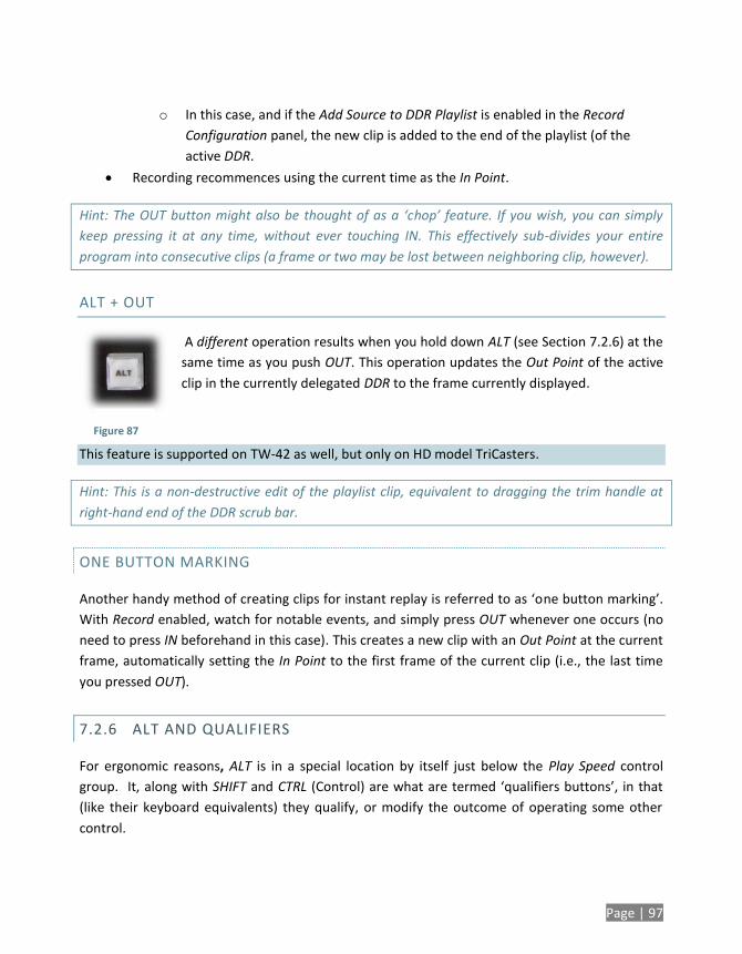
Page | 97
o In this case, and if the Add Source to DDR Playlist is enabled in the Record
Configuration panel, the new clip is added to the end of the playlist (of the
active DDR.
Recording recommences using the current time as the In Point.
Hint: The OUT button might also be thought of as a ‘chop’ feature. If you wish, you can simply
keep pressing it at any time, without ever touching IN. This effectively sub-divides your entire
program into consecutive clips (a frame or two may be lost between neighboring clip, however).
ALT + OUT
A different operation results when you hold down ALT (see Section 7.2.6) at the
same time as you push OUT. This operation updates the Out Point of the active
clip in the currently delegated DDR to the frame currently displayed.
This feature is supported on TW-42 as well, but only on HD model TriCasters.
Hint: This is a non-destructive edit of the playlist clip, equivalent to dragging the trim handle at
right-hand end of the DDR scrub bar.
ONE BUTTON MARKING
Another handy method of creating clips for instant replay is referred to as ‘one button marking’.
With Record enabled, watch for notable events, and simply press OUT whenever one occurs (no
need to press IN beforehand in this case). This creates a new clip with an Out Point at the current
frame, automatically setting the In Point to the first frame of the current clip (i.e., the last time
you pressed OUT).
7.2.6 ALT AND QUALIFIERS
For ergonomic reasons, ALT is in a special location by itself just below the Play Speed control
group. It, along with SHIFT and CTRL (Control) are what are termed ‘qualifiers buttons’, in that
(like their keyboard equivalents) they qualify, or modify the outcome of operating some other
control.
Figure 87
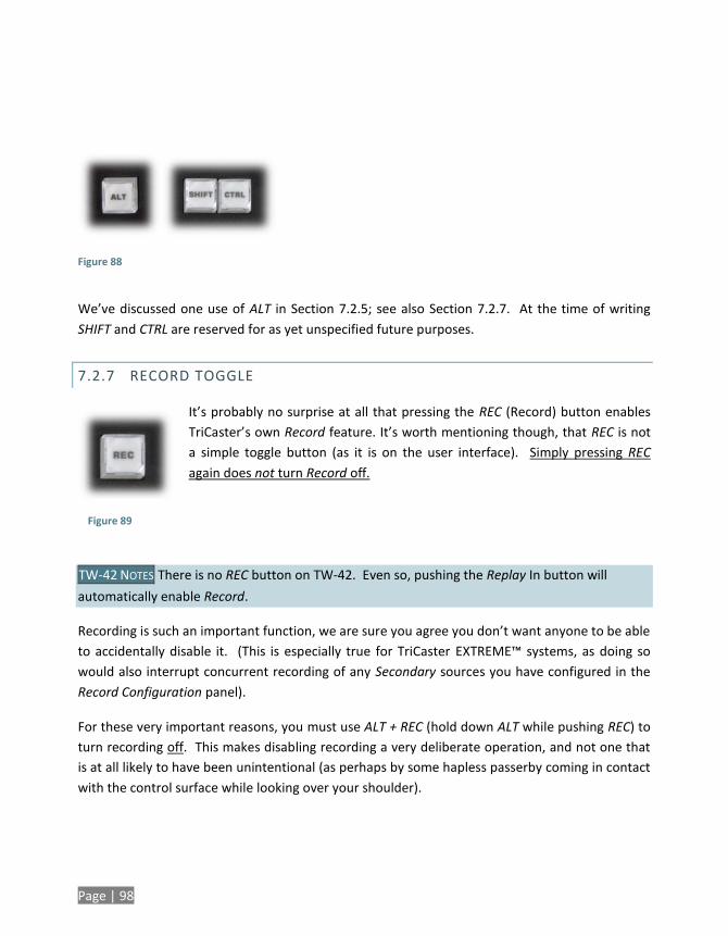
Page | 98
Figure 88
We’ve discussed one use of ALT in Section 7.2.5; see also Section 7.2.7. At the time of writing
SHIFT and CTRL are reserved for as yet unspecified future purposes.
7.2.7 RECORD TOGGLE
It’s probably no surprise at all that pressing the REC (Record) button enables
TriCaster’s own Record feature. It’s worth mentioning though, that REC is not
a simple toggle button (as it is on the user interface). Simply pressing REC
again does not turn Record off.
TW-42 NOTES There is no REC button on TW-42. Even so, pushing the Replay In button will
automatically enable Record.
Recording is such an important function, we are sure you agree you don’t want anyone to be able
to accidentally disable it. (This is especially true for TriCaster EXTREME™ systems, as doing so
would also interrupt concurrent recording of any Secondary sources you have configured in the
Record Configuration panel).
For these very important reasons, you must use ALT + REC (hold down ALT while pushing REC) to
turn recording off. This makes disabling recording a very deliberate operation, and not one that
is at all likely to have been unintentional (as perhaps by some hapless passerby coming in contact
with the control surface while looking over your shoulder).
Figure 89
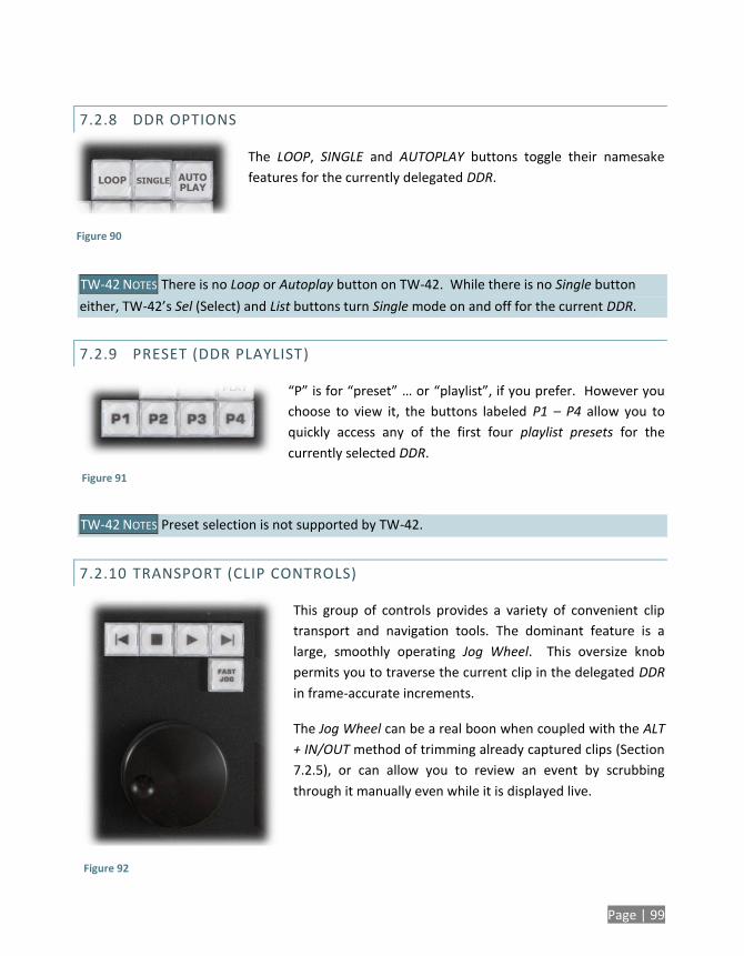
Page | 99
7.2.8 DDR OPTIONS
The LOOP, SINGLE and AUTOPLAY buttons toggle their namesake
features for the currently delegated DDR.
TW-42 NOTES There is no Loop or Autoplay button on TW-42. While there is no Single button
either, TW-42’s Sel (Select) and List buttons turn Single mode on and off for the current DDR.
7.2.9 PRESET (DDR PLAYLIST)
“P” is for “preset” … or “playlist”, if you prefer. However you
choose to view it, the buttons labeled P1 – P4 allow you to
quickly access any of the first four playlist presets for the
currently selected DDR.
TW-42 NOTES Preset selection is not supported by TW-42.
7.2.10 TRANSPORT (CLIP CONTROLS)
This group of controls provides a variety of convenient clip
transport and navigation tools. The dominant feature is a
large, smoothly operating Jog Wheel. This oversize knob
permits you to traverse the current clip in the delegated DDR
in frame-accurate increments.
The Jog Wheel can be a real boon when coupled with the ALT
+ IN/OUT method of trimming already captured clips (Section
7.2.5), or can allow you to review an event by scrubbing
through it manually even while it is displayed live.
Figure 90
Figure 91
Figure 92

Page | 100
The Jog Wheel is supplemented by the nearby Fast Jog button. Press this control to toggle a
high-speed jog mode, which skims through the clip at eight times the normal rate.
TW-42 NOTES The Jog wheel on TW-42 works similarly, but is augmented by an outer Shuttle ring
that can be used to move quickly through a clip or playlist.
The other buttons in this control group are labeled with familiar VCR-style icons, and work as
follows:
Previous (Clip) – Push to highlight the prior clip in the playlist of the delegated DDR.
Stop
o Push to end playback at the current frame.
o When already stopped, push again to go to the first frame of the current clip
(or playlist, when Single mode is off for the DDR).
o Push Alt + Stop during playback to jump to the end of the current clip.
Play – Push to play the current clip in delegated DDR, beginning at the current frame.
Next (Clip) – highlights the next clip in the playlist of the delegated DDR.
TW-42 NOTES
Press ALT + Next to jump the play head 1 sec. forward from its current position in the clip.
Press Alt + Prev to jump the play head 1 sec. back from its current position in the clip. TW-42 has additional buttons it its Transport group, namely Fast Forward and Rewind. Both of these controls have alternate functions, too, as follows:
Press ALT + FF to start playback five seconds into the current clip.
Press ALT + RW to start playback five seconds before the end of the current clip.
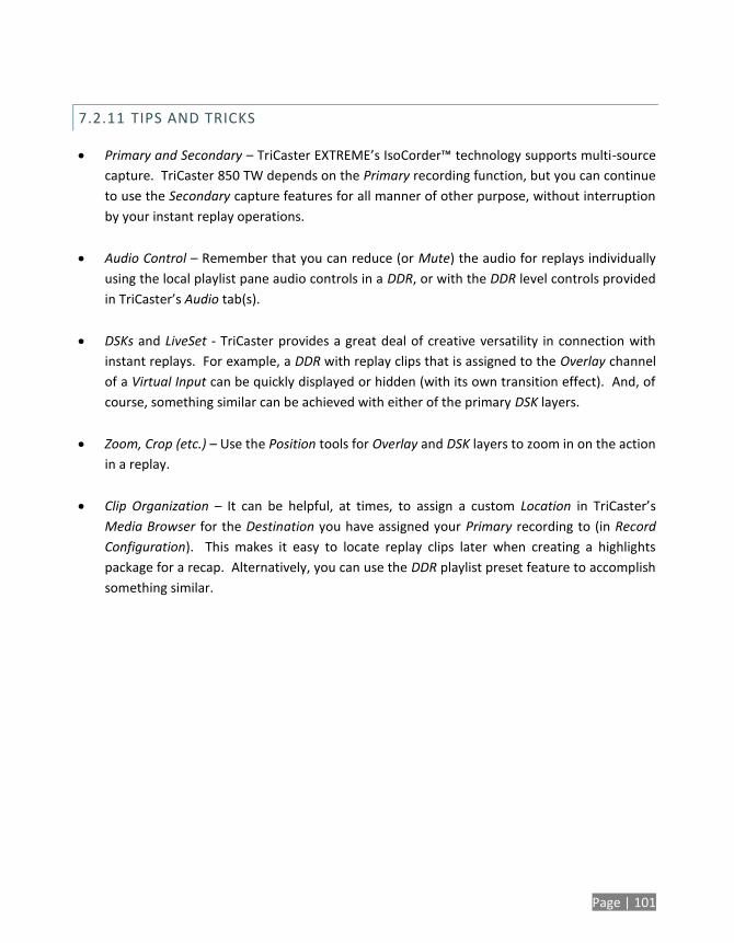
Page | 101
7.2.11 TIPS AND TRICKS
Primary and Secondary – TriCaster EXTREME’s IsoCorder™ technology supports multi-source
capture. TriCaster 850 TW depends on the Primary recording function, but you can continue
to use the Secondary capture features for all manner of other purpose, without interruption
by your instant replay operations.
Audio Control – Remember that you can reduce (or Mute) the audio for replays individually
using the local playlist pane audio controls in a DDR, or with the DDR level controls provided
in TriCaster’s Audio tab(s).
DSKs and LiveSet - TriCaster provides a great deal of creative versatility in connection with
instant replays. For example, a DDR with replay clips that is assigned to the Overlay channel
of a Virtual Input can be quickly displayed or hidden (with its own transition effect). And, of
course, something similar can be achieved with either of the primary DSK layers.
Zoom, Crop (etc.) – Use the Position tools for Overlay and DSK layers to zoom in on the action
in a replay.
Clip Organization – It can be helpful, at times, to assign a custom Location in TriCaster’s
Media Browser for the Destination you have assigned your Primary recording to (in Record
Configuration). This makes it easy to locate replay clips later when creating a highlights
package for a recap. Alternatively, you can use the DDR playlist preset feature to accomplish
something similar.

Page | 103
8 TRICASTER™ LC-11
TriCaster™ LC-11 is designed to augment the SD model TriCaster™
lineup, but has been adapted for service with NewTek’s TriCaster™
live production systems as well.
In this chapter we will detail how TriCaster™ LC-11™ control surface
provides functionality for TriCaster™ Studio, Broadcast, or one of
Newtek’s family of HD live production systems.
8.1 OVERVIEW
The LC-11™ external control surface hosts a bevy of convenient and important buttons and
controls. This chapter explains each button and control in turn. It discloses their functions and
their relationship to various components of your NewTek live production suite.
In large measure, LC-11 physically replicates the Switcher and related controls of your NewTek live production system. (This is no great surprise, since the virtual controls in the interface were cleverly designed to mimic the appearance and behavior of familiar live production equipment.)
LC-11’s controls primarily fall into three groups, each corresponding to specific software
modules. The various buttons, knobs, etc., provide tactile control over their virtual counterparts.
(In addition, the upper-right corner boasts two joysticks, discussed separately.)
8.1.1 LC-11 VARIANTS
To support various NewTek live production systems, LC-11 currently ships in more than one configuration. You may have purchased LC-11 for use with an SD–only model TriCaster (or VT[5]™). On the other hand, perhaps your control surface will be connected to an HD model TriCaster. The button caps installed on your unit may differ accordingly.
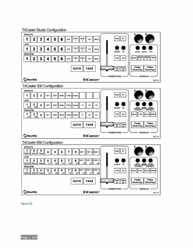
Page | 104
Figure 93
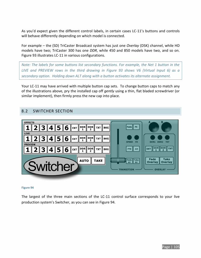
Page | 105
As you’d expect given the different control labels, in certain cases LC-11’s buttons and controls will behave differently depending on which model is connected. For example – the (SD) TriCaster Broadcast system has just one Overlay (DSK) channel, while HD models have two; TriCaster 300 has one DDR, while 450 and 850 models have two, and so on. Figure 93 illustrates LC-11 in various configurations.
Note: The labels for some buttons list secondary functions. For example, the Net 1 button in the
LIVE and PREVIEW rows in the third drawing in Figure 93 shows V6 (Virtual Input 6) as a
secondary option. Holding down ALT along with a button activates its alternate assignment.
Your LC-11 may have arrived with multiple button cap sets. To change button caps to match any of the illustrations above, pry the installed cap off gently using a thin, flat bladed screwdriver (or similar implement), then firmly press the new cap into place.
8.2 SWITCHER SECTION
Figure 94
The largest of the three main sections of the LC-11 control surface corresponds to your live
production system’s Switcher, as you can see in Figure 94.
Page | 106
8.2.1 SELECTING SWITCHER SOURCES
TRICASTER SD MODELS
The Switcher panel of TriCaster Studio and Broadcast models corresponds quite closely to the LC-
11 layout. Some earlier SD TriCasters lack the upper (Effects) row of selection buttons. The
corresponding row of buttons in LC-11’s Switcher section is thus functional only when connected
to suitable TriCaster systems.
TRICASTER™ 300
Effects row: TriCaster™ 300’s Effects row has eight channels, but LC-11 has eleven buttons in
its Effects row. The last three buttons in LC-11’s Effects row are unassigned.
Program and Preview rows: The eleven buttons in each row on LC-11 operate the first eleven
buttons in the corresponding Switcher rows. Then, counting begins again at the left-most
button in the corresponding rows. Thus the first two buttons have optional functions to
accommodate the extra buttons in the onscreen Switcher rows. To select V4 (Virtual Input
4), hold Alt 11 while pressing the first button. Press Alt + the second button to select V5.
TRICASTER™ 455, 450 AND 450 EXTREME™
Utility Row: The LC-11 adaptation for TriCaster 450’s Utility row largely conforms to the
TriCaster 850 configuration illustrated in Figure 93 (the fifth through eight buttons, used for
cameras 5-8 on TriCaster 850, are unassigned). Buttons 1, 3 and 4 perform dual duties.
When ALT is pressed at the same time, they select DDR 2, Graphics and FRM BFR
respectively. For the AUX Out delegate only, additional extended selections are supported.
Hold down ALT while pressing buttons 5 – 8 to assign Preview, Program, Program (Clean)
and FX, respectively, to AUX Out.
Program and Preview rows: The eleven buttons in each row on LC-11 operate TriCaster’s
corresponding Switcher row buttons in natural order. Some buttons also have optional
functions. Hold ALT while pressing the first button to select V2, ALT plus the second button
for V3, and so-on.
Page | 107
TRICASTER™ 850 AND 850 EXTREME™
Utility Row: TriCaster 850’s Utility row has sixteen buttons. To accommodate this higher
number, the first 4 buttons in LC-11’s Effects row have alternate assignments. Hold down
ALT while pressing buttons 1-4 to access the following sources respectively: DDR 2, Still, Title,
FRM BFR, BLACK. For the AUX Out delegate only, an extended selection of sources is
supported. Hold down ALT while pressing buttons 5-9 to assign Preview, Program, Program
(Clean) and FX, respectively, to AUX Out.
Program and Preview rows: The eleven buttons in each row on LC-11 operate TriCaster’s
corresponding Switcher row buttons in natural order. All eleven buttons also have optional
functions to accommodate the additional buttons in TriCaster’s Switcher (see Figure 93).
Hold ALT while pressing the first button to select DDR 2, ALT plus the second button for Still,
and so-on.
8.2.2 AUTO AND TAKE
TriCaster’s primary Auto and Take buttons are located near the T-Bar. The same is true for LC-11,
where they are located left of the T-Bar just beneath the Switcher rows. Functionality remains
unchanged, of course. Auto swaps between the video source that is selected on the Program
row (or the Live row, for SD model TriCasters) and the one from the Preview row, using the
current transition. Take does the same thing, but performs the swap as a hard cut between
sources.
LC-11’s Auto and Take buttons perform brief actions, so don’t light up when pressed. Of course
the buttons on the Switcher rows update to correctly reflect the revised source selections.
TRICASTER™ 300, 450, 850, 455 AND 855
It is good to note that, unlike controls in LC-11’s Transition group (discussed next), the main Auto
and Take buttons ignore the TriCaster’s Transition Delegate settings. However the Take All and
Fade All controls (in LC-11’s Transition group) do respect the Delegate settings.
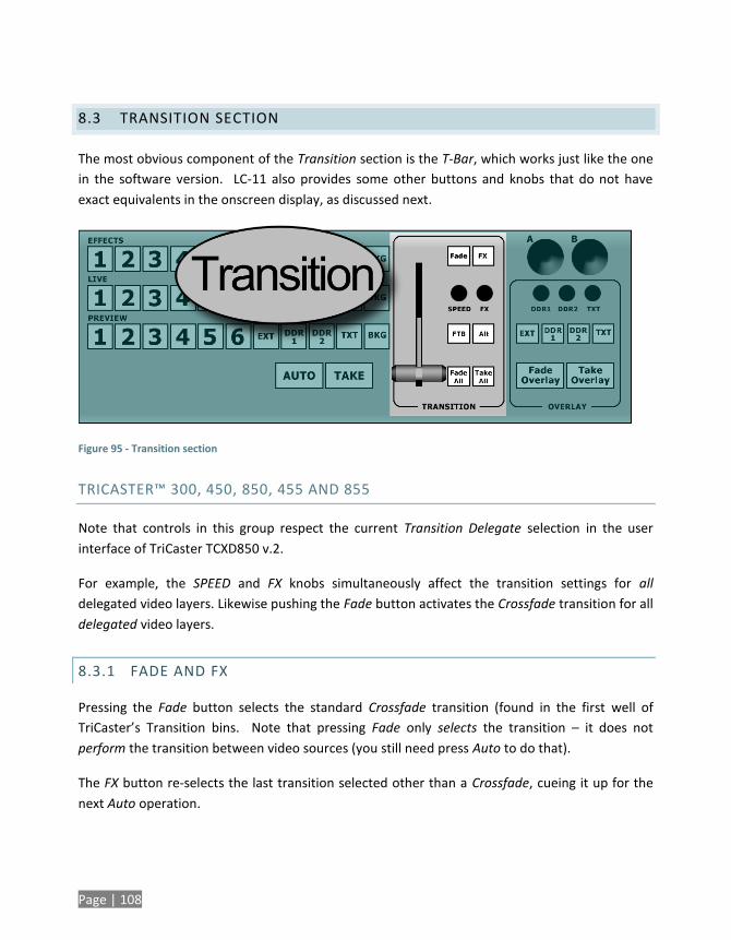
Page | 108
8.3 TRANSITION SECTION
The most obvious component of the Transition section is the T-Bar, which works just like the one
in the software version. LC-11 also provides some other buttons and knobs that do not have
exact equivalents in the onscreen display, as discussed next.
Figure 95 - Transition section
TRICASTER™ 300, 450, 850, 455 AND 855
Note that controls in this group respect the current Transition Delegate selection in the user
interface of TriCaster TCXD850 v.2.
For example, the SPEED and FX knobs simultaneously affect the transition settings for all
delegated video layers. Likewise pushing the Fade button activates the Crossfade transition for all
delegated video layers.
8.3.1 FADE AND FX
Pressing the Fade button selects the standard Crossfade transition (found in the first well of
TriCaster’s Transition bins. Note that pressing Fade only selects the transition – it does not
perform the transition between video sources (you still need press Auto to do that).
The FX button re-selects the last transition selected other than a Crossfade, cueing it up for the
next Auto operation.
Page | 109
8.3.2 SPEED AND FX
Just beneath the Fade and FX buttons are two knobs labeled SPEED and FX. These knobs each
have two distinct functions – one associated with rotation and the other accessed by pressing the
knob (just like a button). The knobs have rotational detents to provide confidence while making
adjustments.
Rotating the SPEED button modifies the duration of the Transition. Pressing it cycles through the
preset speeds (Slow, Medium and Fast).
Twirling the FX knob changes the selected Transition effect, cycling back and forth through the
representative thumbnail icons loaded in TriCaster’s Transition bin.
TRICASTER™ 300, 450, 850, 455 AND 855
For these models only, press LC-11’s FX knob (as though it were a button) to toggle the Reverse
(Transition) switch. Press ALT + FX to toggle the Ping Pong (Transition) switch.
8.3.3 FTB AND ALT
FTB stand for “Fade to Black”. Unlike the two buttons discussed earlier, FTB is an action button;
pressing it does perform a transition, in this case to a computer-generated black background.
There are some exceptions to note, however:
TriCaster™ Studio and Broadcast – when operating in 6-camera mode, these models do
not feature a dedicated Black generator. Instead, FTB uses the background you design
in the system’s internal Color Background tab.
TriCaster™ 300, 455, 450, 855 and 850 – the Fade to Black feature on these models does
not require TriCaster to perform a switch between the sources assigned on Program and
Preview.
Instead, the display on Program output simply fades to or from black. Note that
TriCaster’s FTB is momentarily delegated during an (LC-11) FTB operation, but does not
remain active when it ends.
Page | 110
ALT is used with other buttons to provide alternate operations as noted occasionally in this
manual.
8.3.4 FADE ALL & TAKE ALL
Fade All and Take All perform much like the standard Auto and Take respectively (see Section
8.2.2), with one additional aspect:
TRICASTER™ STUDIO AND BROADCAST
Fade All and Take All simultaneously perform either a Fade Overlay or Take Overlay, timed to
match the established transition speed. The total effect then, is to swap the Live (Program) video
source with the Next (Preview) one, at the same time either removing or displaying the assigned
Overlay, depending on its display status at the moment. (This is, of course, very useful for
introducing a new scene with an identifying lower third graphic, for example.)
TRICASTER™ 300, 450, 850, 455 AND 855
These TriCaster models have two downstream DSK (Overlay) channels. LC-11 respects the current
Transition Delegate selection in the user interface when either Fade All or Take All is pressed.
Also noteworthy, different Overlay Effects can be assigned to either of the DSK channels. Fade
All respects the individual selections for each DSK channel.
8.4 OVERLAY SECTION – TRICASTER SD
LC-11’s Overlay group operation differ quite a bit depending on whether the panel is connected
to an model TriCaster or a TriCaster™ 300, 455, 450. 855 or 850. For that reason, we’ll consider
these configurations separately.
LC-11’s Overlay section contains two joysticks, three knobs, and two rows of buttons. We’ll
consider the standard configuration first.
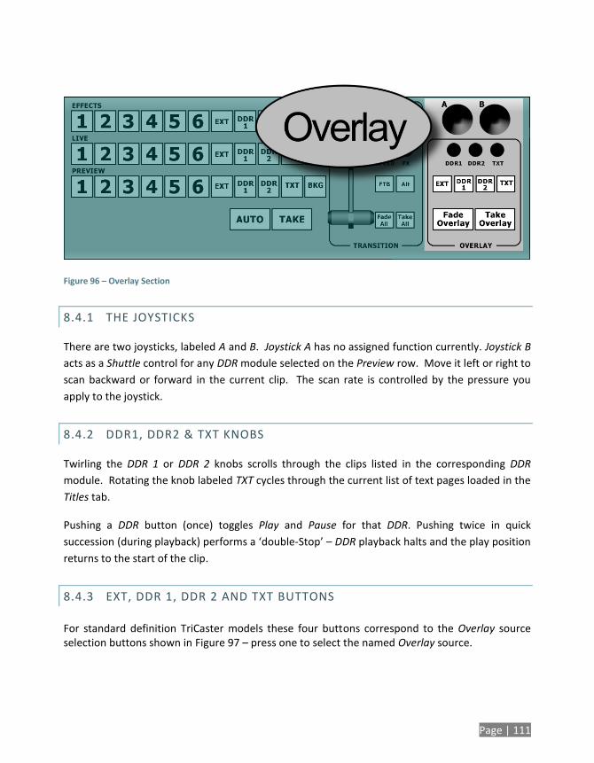
Page | 111
Figure 96 – Overlay Section
8.4.1 THE JOYSTICKS
There are two joysticks, labeled A and B. Joystick A has no assigned function currently. Joystick B
acts as a Shuttle control for any DDR module selected on the Preview row. Move it left or right to
scan backward or forward in the current clip. The scan rate is controlled by the pressure you
apply to the joystick.
8.4.2 DDR1, DDR2 & TXT KNOBS
Twirling the DDR 1 or DDR 2 knobs scrolls through the clips listed in the corresponding DDR
module. Rotating the knob labeled TXT cycles through the current list of text pages loaded in the
Titles tab.
Pushing a DDR button (once) toggles Play and Pause for that DDR. Pushing twice in quick
succession (during playback) performs a ‘double-Stop’ – DDR playback halts and the play position
returns to the start of the clip.
8.4.3 EXT, DDR 1, DDR 2 AND TXT BUTTONS
For standard definition TriCaster models these four buttons correspond to the Overlay source selection buttons shown in Figure 97 – press one to select the named Overlay source.
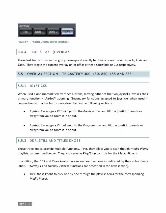
Page | 112
Figure 97 – TriCaster Overlay source selections
8.4.4 FADE & TAKE (OVERLAY)
These last two buttons in this group correspond exactly to their onscreen counterparts, Fade and
Take. They toggle the current overlay on or off as either a Crossfade or Cut respectively.
8.5 OVERLAY SECTION – TRICASTER™ 300, 450, 850, 455 AND 855
8.5.1 JOYSTICKS
When used alone (unmodified by other buttons, moving either of the two joysticks invokes their
primary function – LiveSet™ zooming. (Secondary functions assigned to joysticks when used in
conjunction with other buttons are described in the following sections.)
Joystick A – assign a Virtual Input to the Preview row, and tilt the joystick towards or
away from you to zoom it in or out.
Joystick B – assign a Virtual Input to the Program row, and tilt the joystick towards or
away from you to zoom it in or out.
8.5.2 DDR, STILL AND TITLES KNOBS
These three knobs provide multiple functions. First, they allow you to scan though Media Player
playlists, as described below. They also serve as Play/Stop controls for the Media Players.
In addition, the DDR and Titles knobs have secondary functions as indicated by their subordinate
labels – Overlay 1 and Overlay 2 (these functions are described in the next section).
Twirl these knobs to click one by one through the playlist items for the corresponding
Media Player.
Page | 113
Press ALT while twirling the DDR knob to click one by one through the playlist items for
DDR 2 (TriCaster 455, 450, 855 and 850 only).
Press (click once) a knob to toggle Play/Stop for the respective Media Player (use ALT
while clicking the DDR knob to control DDR 2 when provided.
Double-click a knob to stop play and reset the current play position to the beginning of
the current playlist item.
8.5.3 MODE BUTTONS
The Selct (Select), Pos (Position), Scale and Effect buttons are modifiers – holding one of these
buttons down affects the resulting action when you use one of the joysticks or knobs above.
SELCT (SELECT)
Press and hold the Selct button as described next to assign sources for DSK channels.
PICK OVERLAY CHANNEL SOURCE
1. Press and hold the button labelled Selct.
2. Twirl the Overlay 1 or Overlay 2 knob above to click one by one through the list of
available overlay sources.
POS
Press and hold this button as described next to adjust the positioning for DSK channels.
ADJUST OVERLAY POSITION
1. Press and hold the button labelled Pos.
2. Adjust the (X/Y) position of DSK 1 or DSK 2 using the respective joystick.
Page | 114
RESET OVERLAY POSITION
1. Press (click once) the DSK 1 or DSK 2 knob to reset the Position settings for the
corresponding channel.
SCALE
ADJUST SCALE (ASPECT LOCKED)
1. Press and hold the button labelled Scale.
2. Twirl the Overlay 1 or Overlay 2 knob to adjust the scale of the corresponding DSK
channel on both axes simultaneously.
FREELY ADJUST SCALE
1. Press and hold the button labelled Scale.
2. Use the Overlay 1 or Overlay 2 joysticks to independently adjust the scale of the
corresponding channel on either axis.
RESET SCALE
1. Press and hold the button labelled Scale.
2. Press (click once) the Overlay 1 or Overlay 2 knob to reset the scale of the corresponding
channel.
EFFECT
Press and hold the Effect button while twisting either the Overlay 1 or Overlay 2 knob to cycle
through the list of Overlay Effects currently available in the dropdown menu for the respective
channel.
Page | 115
8.5.4 FADE & TAKE (OVERLAY)
These last two buttons correspond to the local Auto and Take buttons for the two DSK channels
on the Live Desktop. When the button is pressed while ALT is held down, the action is applied to
DSK 2; otherwise, DSK 1 is affected).
As you would expect, pressing Take toggles the current overlay on or off as using a Cut, while the
FADE button uses the currently assigned Effect to display or hide the DSK channel source.

Page | 117
CREDITS
Acknowledgments: Tim Jenison, Jim Plant
Engineering: Andrew Cross, Alvaro Suarez, Bennie Pierce, Bob Peene, Brian Brice, Cary Tetrick,
Charles Steinkuehler, Dan Fletcher, Greg Heine, James Killian, Jan Uribe, Jarrod Davis, Jeremy
Brosius, Jeremy Wiseman, John Perkins, Karen Zipper, Kevin Nations, Kevin Rouviere, Kirk
Morger, Mahdi Mohajer, Masaaki Konno, Menghua Wang, Michael Joiner, Michael Watkins, Mike
Murphy, Nathan Kovner, Naveen Jayakumar, Ryan Hansberger, Shawn Wisniewski, Steve Bowie,
Thomas Nanninga, Todd Bryant, Troy Stevenson
Design Consultants: Kris Gurrad, Dimitry Czar, John Powell
Additional thanks to:
NewTek Marketing and Sales
NewTek Customer Support
NewTek Business Development
Trademarks: NewTek, TriCaster, TriCaster XD, TCXD8000, TriCaster 8000, TriCaster TCXD8000, TCXD850, TCXD850
EXTREME, TriCaster TCXD850 EXTREME, TriCaster 850 EXTREME, TriCaster EXTREME, TriCaster 850, TCXD450, TCXD450
EXTREME, TriCaster TCXD450 EXTREME, TriCaster 450 EXTREME, TriCaster 450, TCXD455, TriCaster 455, TriCaster
TCXD455, TriCaster 855, TCXD855, TriCaster TCXD855, IsoCorder, TCXD300, TriCaster 300, TriCaster TCXD300, TCXD40,
TriCaster 40, TriCaster TCXD40, TriCaster PRO, TriCaster STUDIO, TriCaster BROADCAST, TriCaster DUO, ProTek, ProTek
Care, ProTek Elite, iVGA, SpeedEDIT, 3PLAY, 3Play, 3Play 820, 3PXD820, 3Play 330, 3PXD330, LiveText, DataLink, LiveSet,
TriCaster Virtual Set Editor, TriCaster VSE, LiveMatte, TimeWarp, VT, VT[3], VT[4], V[T5], Video Toaster, Toaster, Inspire
3D, 3D Arsenal, Aura, LightWave, LightWave 3D and LightWave CORE are trademarks, service marks, and registered
trademarks of NewTek. All other brand names, product names, or trademarks belong to their respective holders. All
rights reserved.
(c) NewTek 2005-2013, All Rights Reserved

Page | 118


![Revised April 28, 2010cdn-docs.av-iq.com/instructions/NewTek LiveText User...(TriCaster, VT[5]) 2.2 INSTALLING LIVETEXT On launch, the LiveText installer presents various dialogs to](https://static.fdocuments.net/doc/165x107/60c6b3806260346ec36d39fd/revised-april-28-2010cdn-docsav-iqcominstructionsnewtek-livetext-user-tricaster.jpg)