
IQAN-MC3 Instruction book - Comoso · 2 Precautions ... IQAN-MC3 Instruction Book HY33 ... The...
66
IQAN-MC3 Instruction book Publ no HY33-8001-IB/UK Edition 2014-12-11 www.comoso.com
Transcript of IQAN-MC3 Instruction book - Comoso · 2 Precautions ... IQAN-MC3 Instruction Book HY33 ... The...

IQAN-MC3Instruction bookPubl no HY33-8001-IB/UKEdition 2014-12-11
www.comoso.com

ii
Contents
Instruction book, IQAN-MC3
1 Introduction . . . . . . . . . . . . . . . . . . . . . . . . . . . . . . . . . . . . . . . . . . . . . . . . . . . . 1Warnings . . . . . . . . . . . . . . . . . . . . . . . . . . . . . . . . . . . . . . . . . . . . . . . . . . . . 1Mandatory Safety Requirements . . . . . . . . . . . . . . . . . . . . . . . . . . . . . . . . . . 1Overview of relevant documentation . . . . . . . . . . . . . . . . . . . . . . . . . . . . . . . 2
2 Precautions . . . . . . . . . . . . . . . . . . . . . . . . . . . . . . . . . . . . . . . . . . . . . . . . . . . . 3Read This . . . . . . . . . . . . . . . . . . . . . . . . . . . . . . . . . . . . . . . . . . . . . . . . . . . . 3
Design of control system . . . . . . . . . . . . . . . . . . . . . . . . . . . . . . . . . . . . . 3Start-up, maintenance, and diagnostics . . . . . . . . . . . . . . . . . . . . . . . . . 4
3 Product description . . . . . . . . . . . . . . . . . . . . . . . . . . . . . . . . . . . . . . . . . . . . . 5IQAN-MC3 . . . . . . . . . . . . . . . . . . . . . . . . . . . . . . . . . . . . . . . . . . . . . . . . . . . 5
I/O overview . . . . . . . . . . . . . . . . . . . . . . . . . . . . . . . . . . . . . . . . . . . . . . 5Communication . . . . . . . . . . . . . . . . . . . . . . . . . . . . . . . . . . . . . . . . . . . . 6
4 Safety . . . . . . . . . . . . . . . . . . . . . . . . . . . . . . . . . . . . . . . . . . . . . . . . . . . . . . . . . 7Safety concept . . . . . . . . . . . . . . . . . . . . . . . . . . . . . . . . . . . . . . . . . . . . . . . . 7
Safe state . . . . . . . . . . . . . . . . . . . . . . . . . . . . . . . . . . . . . . . . . . . . . . . . 7Maximum achievable SIL and PL . . . . . . . . . . . . . . . . . . . . . . . . . . . . . . 7System boundaries . . . . . . . . . . . . . . . . . . . . . . . . . . . . . . . . . . . . . . . . . 8Architecture for a complete safety function . . . . . . . . . . . . . . . . . . . . . . . 9Local physical inputs used as part of input subsystem in safety functions 11CAN communication . . . . . . . . . . . . . . . . . . . . . . . . . . . . . . . . . . . . . . . 12Outputs . . . . . . . . . . . . . . . . . . . . . . . . . . . . . . . . . . . . . . . . . . . . . . . . . 13Internal diagnostics . . . . . . . . . . . . . . . . . . . . . . . . . . . . . . . . . . . . . . . . 14
Markings/Approvals . . . . . . . . . . . . . . . . . . . . . . . . . . . . . . . . . . . . . . . . . . . 15
5 Mounting . . . . . . . . . . . . . . . . . . . . . . . . . . . . . . . . . . . . . . . . . . . . . . . . . . . . . 20Mounting the module . . . . . . . . . . . . . . . . . . . . . . . . . . . . . . . . . . . . . . . . . . 20
6 Installation . . . . . . . . . . . . . . . . . . . . . . . . . . . . . . . . . . . . . . . . . . . . . . . . . . . . 21Connectors C1-C4 . . . . . . . . . . . . . . . . . . . . . . . . . . . . . . . . . . . . . . . . . . . . 21
Connector C1 pin assignments . . . . . . . . . . . . . . . . . . . . . . . . . . . . . . . 21Connector C2 pin assignments . . . . . . . . . . . . . . . . . . . . . . . . . . . . . . . 22Connector C3 pin assignments . . . . . . . . . . . . . . . . . . . . . . . . . . . . . . . 23Connector C4 pin assignments . . . . . . . . . . . . . . . . . . . . . . . . . . . . . . . 24
I/O configuration . . . . . . . . . . . . . . . . . . . . . . . . . . . . . . . . . . . . . . . . . . . . . . 25Supply voltage . . . . . . . . . . . . . . . . . . . . . . . . . . . . . . . . . . . . . . . . . . . . . . . 25
Emergency stop . . . . . . . . . . . . . . . . . . . . . . . . . . . . . . . . . . . . . . . . . . 25Connecting of Supply Voltage . . . . . . . . . . . . . . . . . . . . . . . . . . . . . . . . 26
Reverse feed . . . . . . . . . . . . . . . . . . . . . . . . . . . . . . . . . . . . . . . . . . . . . . . . 26IQAN-MC3 addressing/terminating . . . . . . . . . . . . . . . . . . . . . . . . . . . . . . . 26
Use of an ID-Tag . . . . . . . . . . . . . . . . . . . . . . . . . . . . . . . . . . . . . . . . . . 26Terminating . . . . . . . . . . . . . . . . . . . . . . . . . . . . . . . . . . . . . . . . . . . . . . 27
7 I/O functionality . . . . . . . . . . . . . . . . . . . . . . . . . . . . . . . . . . . . . . . . . . . . . . . . 28Inputs . . . . . . . . . . . . . . . . . . . . . . . . . . . . . . . . . . . . . . . . . . . . . . . . . . . . . . 28Voltage inputs . . . . . . . . . . . . . . . . . . . . . . . . . . . . . . . . . . . . . . . . . . . . . . . 28
Using voltage inputs in safety functions . . . . . . . . . . . . . . . . . . . . . . . . 29Digital inputs . . . . . . . . . . . . . . . . . . . . . . . . . . . . . . . . . . . . . . . . . . . . . . . . . 32
Connecting switches to the digital inputs . . . . . . . . . . . . . . . . . . . . . . . 32Using digital inputs in safety functions . . . . . . . . . . . . . . . . . . . . . . . . . 32
Frequency inputs . . . . . . . . . . . . . . . . . . . . . . . . . . . . . . . . . . . . . . . . . . . . . 33Connecting sensors to the frequency inputs . . . . . . . . . . . . . . . . . . . . . 33Using frequency inputs in safety functions . . . . . . . . . . . . . . . . . . . . . . 33
Directional frequency inputs . . . . . . . . . . . . . . . . . . . . . . . . . . . . . . . . . . . . . 33
www.comoso.com
iii
Contents
Instruction book, IQAN-MC3
Connecting sensors to the directional frequency inputs . . . . . . . . . . . . 33Using directional frequency inputs in safety functions . . . . . . . . . . . . . 34
Reference voltage, VREF . . . . . . . . . . . . . . . . . . . . . . . . . . . . . . . . . . . . . . 35Outputs . . . . . . . . . . . . . . . . . . . . . . . . . . . . . . . . . . . . . . . . . . . . . . . . . . . . . 36Proportional outputs . . . . . . . . . . . . . . . . . . . . . . . . . . . . . . . . . . . . . . . . . . . 36
Use of COUT in safety functions . . . . . . . . . . . . . . . . . . . . . . . . . . . . . . 38Digital outputs . . . . . . . . . . . . . . . . . . . . . . . . . . . . . . . . . . . . . . . . . . . . . . . 40
Use of DOUT in safety functions . . . . . . . . . . . . . . . . . . . . . . . . . . . . . . 41
8 Start-up . . . . . . . . . . . . . . . . . . . . . . . . . . . . . . . . . . . . . . . . . . . . . . . . . . . . . . . 42Start-up procedures . . . . . . . . . . . . . . . . . . . . . . . . . . . . . . . . . . . . . . . . . . . 42
Starting the control system . . . . . . . . . . . . . . . . . . . . . . . . . . . . . . . . . . 42Prepare for system start . . . . . . . . . . . . . . . . . . . . . . . . . . . . . . . . . . . . 43Start the system . . . . . . . . . . . . . . . . . . . . . . . . . . . . . . . . . . . . . . . . . . 43
Check list for electronics . . . . . . . . . . . . . . . . . . . . . . . . . . . . . . . . . . . . . . . 44
9 Diagnostics and troubleshooting . . . . . . . . . . . . . . . . . . . . . . . . . . . . . . . . . 45Diagnostic interfaces . . . . . . . . . . . . . . . . . . . . . . . . . . . . . . . . . . . . . . . . . . 45
CAN diagnostics connection . . . . . . . . . . . . . . . . . . . . . . . . . . . . . . . . . 45Bypass application . . . . . . . . . . . . . . . . . . . . . . . . . . . . . . . . . . . . . . . . . . . . 45
Appendix A . . . . . . . . . . . . . . . . . . . . . . . . . . . . . . . . . . . . . . . . . . . . . . . . . . . 46IQAN-MC3 Technical Overview . . . . . . . . . . . . . . . . . . . . . . . . . . . . . . . . . . 46
Appendix B . . . . . . . . . . . . . . . . . . . . . . . . . . . . . . . . . . . . . . . . . . . . . . . . . . . 51Error codes, messages and actions . . . . . . . . . . . . . . . . . . . . . . . . . . . . . . . 51Failure modes . . . . . . . . . . . . . . . . . . . . . . . . . . . . . . . . . . . . . . . . . . . . . . . 52
Failure modes for single inputs . . . . . . . . . . . . . . . . . . . . . . . . . . . . . . . 52Voltage input . . . . . . . . . . . . . . . . . . . . . . . . . . . . . . . . . . . . . . . . . . . . . 52Digital input . . . . . . . . . . . . . . . . . . . . . . . . . . . . . . . . . . . . . . . . . . . . . . 52Frequency input . . . . . . . . . . . . . . . . . . . . . . . . . . . . . . . . . . . . . . . . . . 53Directional frequency input . . . . . . . . . . . . . . . . . . . . . . . . . . . . . . . . . . 53Failure modes for external wiring faults on power drivers - COUT . . . . 54Current output . . . . . . . . . . . . . . . . . . . . . . . . . . . . . . . . . . . . . . . . . . . . 54Failure modes for external wiring faults on power drivers - DOUT . . . . 57Digital output . . . . . . . . . . . . . . . . . . . . . . . . . . . . . . . . . . . . . . . . . . . . . 57
Appendix C . . . . . . . . . . . . . . . . . . . . . . . . . . . . . . . . . . . . . . . . . . . . . . . . . . . 61Dimensioning of the IQAN-MC3 module . . . . . . . . . . . . . . . . . . . . . . . . . . . 61
Appendix D . . . . . . . . . . . . . . . . . . . . . . . . . . . . . . . . . . . . . . . . . . . . . . . . . . . 62Safety manual requirements . . . . . . . . . . . . . . . . . . . . . . . . . . . . . . . . . . . . 62
SMR: Safety Manual Requirement . . . . . . . . . . . . . . . . . . . . . . . . . . . . 62
www.comoso.com

1
Warnings1 Introduction
Instruction book, IQAN-MC3
1 Introduction
These instructions are to be used as a reference tool for the vehicle manufacturer’s design, production, and service personnel.The user of these instructions should have basic knowledge in the handling of electronic equipment.
WarningsSections marked with a symbol in the left margin, must be read and understood by everyone using the system, carrying out service work, or making changes to hardware and software.The different symbols used in this manual are defined below.
WARNING
Sections labeled WARNING with a caution symbol in the left margin, indicate that a hazardous situation exists. We use warnings, marked with the warning symbol, in two ways.
• As a strong recommendation about work practices when using the product in the machine (e.g. routines when updating an application). This use is common to the term 'hazardous situation', that a person is exposed to a hazard.
• As a way of pointing out important information for the machine designer that in some way relates to safety. This includes the design of the physical machine, and also the application program being developed for the control system.
Not all document sections that contain information about safety are marked with a warning symbol (there would be warnings everywhere). Failure to comply with the recommendations can cause unintentional, and unexpected behavior of the control system. This can potentially cause death, serious injury or property damage.
NOTICE
Sections labeled NOTICE with a notice symbol in the left margin, indicate there is important information about the product. Ignoring this could result in less than optimal performance, or damage to the product.
Mandatory Safety RequirementsThe requirements shown in boxes, and labeled SMR, contain important information about the use of the product in safety related applications. If these requirements are not fulfilled, the safety integrity level on the product is not valid. The SIL claim on the product assumes that the user will follow these requirements.
In some cases we put a warning next to a SMR. This is done where there is a need to emphasize that the safety information is just as important when the module is used for normal (non-safety related) functions.
MC3-SMR-00x:A Safety Manual RequirementBoxed sections labeled as SMR contain important safety information. All SMR’s are tagged and numbered for easy access.
www.comoso.com

2
Overview of relevant documentation1 Introduction
Instruction book, IQAN-MC3
Contact the manufacturer if there is anything you are not sure about or if you have any questions regarding the product and its handling or maintenance.The term "manufacturer" refers to Parker Hannifin Corporation.
Overview of relevant documentationThe following publications are relevant for users of this product.The main documentation contains information that is not found elsewhere. The additional documentation contains product information in a compact format, for details on the information found in those documents, consult this manual.
The IQAN-MC3 module documentation system.
IQANdesign User Manual
IQAN-MC3 Instruction BookHY33-8001-IB
(this book)
Mounting and MaintenanceInstruction BookHY33-8327-IB
IQAN-MC3 Catalogue Datasheet
HY33-8001
IQAN-MC3Installation Sheet
HY33-8001-IS
IQAN-MC3Electrical Schematic
HY33-8327-ES
Compact
Documentation
Main
Documentation
www.comoso.com

3
Read This2 Precautions
Instruction book, IQAN-MC3
2 Precautions
Work on the hydraulics control electronics may only be carried out by trained personnel who are well-acquainted with the control system, the machine and its safety regulations.
WARNING
Make sure that you have sufficient knowledge before designing, modifiying or servicing the control system. Read the relevant sections of this document before conducting any work on the control system.
WARNING
This product is not field repairable.
NOTICE
As much as possible of the welding work on the chassis should be done before the installation of the system. If welding has to be done afterwards, the electrical connections on the system must be disconnected from other equipment. The negative cable must always be disconnected from the battery before disconnecting the positive cable. The ground wire of the welder shall be positioned as close as possible to the place of the welding. The cables on the welding unit shall never be placed near the electrical wires of the control system.
Read This
Design of control system
WARNING
Risk of injury may be introduced by design of control system!This product is designed to control hydraulic outputs. The control application must be designed using basic safety principles so that unintentional movement is avoided. The machine must be equipped with an emergency stop that stops all movement. Please refer to section Emergency stop, on page 25.
Before you startRead this document, as a minimum sections 1-7Read the IQANdesign software user manual section on 'application safety'.
MC3-SMR-001:A Use within specificationThe product shall only be used within its specified range.
MC3-SMR-002:A No field repairA damaged product shall not be used, and may only be repaired by the manufacturer.
www.comoso.com

4
Read This2 Precautions
Instruction book, IQAN-MC3
Start-up, maintenance, and diagnosticsFor all personnel carrying out installation, commissioning, maintenance or troubleshooting.
WARNING
Work on the hydraulics control electronics may only be carried out by trained personnel who are well-acquainted with the control system, the machine and its safety regulations.
Before you start, Read section Start-up, on page 42.
Additional information for serviceMounting and maintenance instruction book.
Additional information for diagnosing the system Read section Diagnostics and troubleshooting, on page 45, and see Appendix B, on page 51, in this document.Use the IQANrun software user manual as a reference.
www.comoso.com

5
IQAN-MC33 Product description
Instruction book, IQAN-MC3
3 Product description
IQAN-MC3The IQAN-MC3 is designed for controlling hydraulic systems in vehicles and machinery, using 12/24 Vdc power supply. IQAN-MC3 is especially suited for applications with higher demands on functional safety, where there is a need to prove the safety integrity of each implemented safety function.The IQAN-MC3 is a SIL2 rated master module in the IQANdesign platform. It can be used as a standalone controller, as a single bus master, or together with other IQAN master modules.The MC3 has local I/O for input/output use and has 4 CAN busses that support ICP (IQAN CAN Protocol), SAE J1939 and Generic CAN. As a bus master the MC3 is able to control other IQANdesign platform expansion units.This product is designed for the outdoor environment and comes with an IP6K9K protection for applications where high-pressure water and steam jet cleaning is used.
The IQAN-MC3 module.
I/O overview
+BAT
ADDR-L
ADDR-H
CAN-H
CAN-L
OUTPUTS
-BAT
+VREF
-VREF
INPUTS
Power supply
(and safe path control)
Signal input
CAN
Core(microcontroller
andMemory)
idTag
DIN
VIN
Power driver
MC3 COUT
DOUT
www.comoso.com

6
IQAN-MC33 Product description
Instruction book, IQAN-MC3
InputsAll of the 32 inputs on the IQAN-MC3 can be used for safety related signals, when the inputs are configured in pairs.On the unit there are 16 analog inputs for 0-5 V signals from e.g. hall-effect or potentiometer sensors; 8 digital inputs for e.g. switches; and 8 frequency inputs for e.g. reading signals from quadrature encoders, see list.
Proportional outputsAll of the outputs on the IQAN-MC3 can be used for safety related signals.There are 4 double proportional current outputs, designed to drive proportional hydraulic valves. These outputs can control 4 bi-directional valve sections or 4 single solenoid devices (ie. proportional cartridge valves), see below.
In order to increase the performance of the proportional outputs when controlling proportional valves, the dither frequency can be adjusted.
Digital outputsAll of the outputs on the IQAN-MC3 can be used for safety related signals.There are 5 digital outputs, for driving on-off solenoids. Two of these are also intended to function as alarm outputs, for e.g. LED lamps, see below.
CAN related functionsThe IQAN-MC3 uses a CAN-bus (CAN = Controller Area Network) to communicate with IQAN expansion modules and other systems. The CAN-bus is a robust communication protocol that is widely used and well proven within the automotive industry. The unit has 4 CAN buses, CAN-A thru CAN-D. The buses may be configured using IQAN software to be ICP (ICP = IQAN CAN Protocol), SAE J1939 or Generic user defined CAN protocol (e.g. CANopen).
CommunicationThe communication interfaces are used for uploading/downloading applications or diagnostics when connected to a computer. It is recommended to reserve one of the CAN buses for communication and diagnostics. A CAN communication card is required to be installed in your PC to use this feature. Please contact Parker for a list of CAN cards that are currently supported.
(16) Voltage inputs VIN-A thru VIN-P
and
(8) Frequency inputs FIN-A thru FIN-H, (or DFIN-A± thru DFIN-D±).
and
(8) Digital inputs DIN-A thru DIN-H.
(4) double proportional outputs COUT-A thru COUT-D
or
(4) proportional outputs COUT-A thru COUT-D using single low-side connections
(5) digital outputs DOUT-A thru DOUT-E
www.comoso.com

7
Safety concept4 Safety
Instruction book, IQAN-MC3
4 Safety
Safety conceptAll IQAN modules are designed for controlling hydraulic implements on mobile machines, and when basic safety principles are observed, they can be used for normal functions.The IQAN-MC3 is designed in accordance with IEC 61508, for use in applications with higher demands on functional safety. When there is a need to prove the safety integrity of each implemented safety function, the unit can be used for functions with a maximum safety integrity of SIL2.
Safe stateThe safety analysis of the IQAN-MC3 is done under the assumption that the system is in a safe state when the controller is off.WARNING
System design must not allow any unintentional movement when the unit is off.
If any critical fault within the IQAN-MC3 is detected by its internal checks, the controller will shut down all outputs, including CAN.
• If a fault on one output is detected, that output will be shut off.
• If this occurs, the stop ramps on on the outputs will have no effect, the outputs will shut off immediately.
Therefore, the application must be designed so that a sudden stop on the outputs does not in itself lead to a hazardous situation.
Maximum achievable SIL and PLThe IQAN-MC3 is designed for use in safety functions of up to SIL2 (IEC 61508).The IQAN-MC3 in itself does not come with any safety function; it needs to be put into a system and loaded with an application file. It is recommended for the developer of the safety function to apply a standard written specifically for machine manufacturers when designing safety functions with the IQAN-MC3. Suitable standards for machinery are EN ISO 13849-1, or IEC/EN 62061. The following table shows the relationship between Performance Level (PL) and Safety Integrity Level (SIL), and also the corresponding average probability of dangerous failure per hour (PFHd).The PL and SIL are based both on quantifiable aspects and on non-quantifiable aspects such as the development process used and the safety related software.
MC3-SMR-003:A Safe stateThe application shall be designed so that the system is in a safe state when the controller is off.
www.comoso.com

8
Safety concept4 Safety
Instruction book, IQAN-MC3
For the IQAN-MC3, the maximum achievable Performance Level and Safety Integrity Level is shown in the following table.
System boundaries The safety integrity of the IQAN-MC3 covers:
• All inputs (VIN, DIN, FIN, DFIN)
• All sensor supplies (VREF)
• All outputs (COUT, DOUT)
• Core electronics (processor, memory, power supply)
• CANFor the functions above, the following restrictions apply:
• I/O must be installed and used in accordance with this manual
• Information sent over CAN must also be protected by the high level protocolThe following internal diagnostic information is used for keeping the IQAN-MC3 within the specified range, and may not be used for implementation of safety functions:
• Measurement of module supply voltage
• Measurement of module temperatureThe following built in functionality of the IQAN-MC3 is seen as non-safety related:
• Logs
• LED diagnostics
NOTICE
The IQAN-MC3 does not come with any pre existing safety function implemented. An application file must always be created in IQANdesign before the module can be used.
Average probability of dangerous failure per hour [1/h]
EN 13849-1 PL EN 62061 SIL IEC61508 SIL
>10-5 to < 10-4 a - -
>3 ·10-6 to < 10-5 b 1 1
>10-6 to < 3 ·10-6 c 1 1
>10-7 to < 10-6 d 2 2
>10-8 to < 10-7 e 3 3
- - 4
Maximum achievable Performance Level, EN ISO 13849-1 PLd
Maximum achievable Safety Integrity Level, EN IEC 62061 SIL2
Maximum achievable Safety Integrity Level, EN IEC 61508 SIL2
www.comoso.com

9
Safety concept4 Safety
Instruction book, IQAN-MC3
The IQAN-MC3 provides some diagnostic features related to the interface with sensors and actuators (valves). However, sensors, actuators, and wiring must be analyzed separately for their suitability to be used in safety functions.The internal diagnostics of the IQAN-MC3 as well as built in diagnostics on I/O are dependent on the system cycle time, a longer system cycle will in some cases delay the diagnostics.
Architecture for a complete safety functionWhen analyzing a safety function, the IQAN-MC3 can be modeled as a safety related sub-system. With this approach, there would also be at least one safety related input subsystem (e.g. sensors), and a safety related output subsystem (e.g. valves).
The IQAN-MC3 module as subsystem.
Input subsystemThe input subsystem consists of the sensors or operator controls that initiate the safety function.To get sufficient diagnostics on the inputs on the MC3, the requirements of that input type must be satisfied, see section I/O functionality, on page 28. For most input types, there is a requirement to always use the signal in pair with a secondary redundant signal.The IQAN-MC3 is suitable for connection to input subsystems of category 2, 3 or 4 in accordance with EN ISO13849-1, up to PLd. If inputs are connected as a Category B subystem, that will restrict the overall PL to a lower level.A category 1 subsystem is excluded because the unit is requiring simple electrical inputs (connected to DIN) to be used in pair with a diagnostic signal.
MC3-SMR-004:A System cycle timeThe application shall be designed so that the system cycle time is < 50% of the maximum allowable error detection time.
Inputsubsystem
IQAN-MC3subsystem
Outputsubsystem
www.comoso.com
10
Safety concept4 Safety
Instruction book, IQAN-MC3
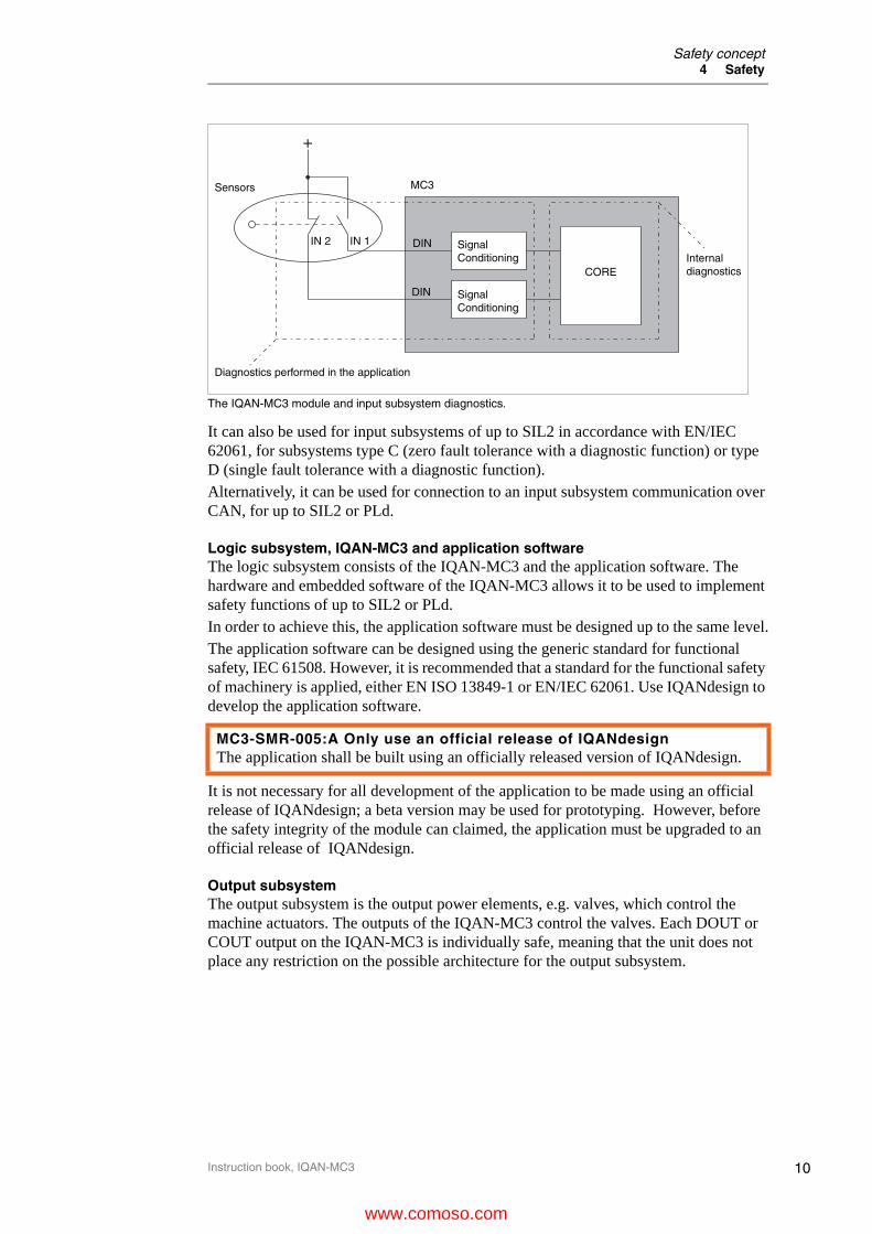
The IQAN-MC3 module and input subsystem diagnostics.
It can also be used for input subsystems of up to SIL2 in accordance with EN/IEC 62061, for subsystems type C (zero fault tolerance with a diagnostic function) or type D (single fault tolerance with a diagnostic function).Alternatively, it can be used for connection to an input subsystem communication over CAN, for up to SIL2 or PLd.
Logic subsystem, IQAN-MC3 and application softwareThe logic subsystem consists of the IQAN-MC3 and the application software. The hardware and embedded software of the IQAN-MC3 allows it to be used to implement safety functions of up to SIL2 or PLd.In order to achieve this, the application software must be designed up to the same level.The application software can be designed using the generic standard for functional safety, IEC 61508. However, it is recommended that a standard for the functional safety of machinery is applied, either EN ISO 13849-1 or EN/IEC 62061. Use IQANdesign to develop the application software.
It is not necessary for all development of the application to be made using an official release of IQANdesign; a beta version may be used for prototyping. However, before the safety integrity of the module can claimed, the application must be upgraded to an official release of IQANdesign.
Output subsystemThe output subsystem is the output power elements, e.g. valves, which control the machine actuators. The outputs of the IQAN-MC3 control the valves. Each DOUT or COUT output on the IQAN-MC3 is individually safe, meaning that the unit does not place any restriction on the possible architecture for the output subsystem.
MC3-SMR-005:A Only use an official release of IQANdesignThe application shall be built using an officially released version of IQANdesign.
MC3
DIN
DIN
SignalConditioning
SignalConditioning
CORE
+
IN 2 IN 1
Diagnostics performed in the application
Internaldiagnostics
Sensors
www.comoso.com
11
Safety concept4 Safety
Instruction book, IQAN-MC3
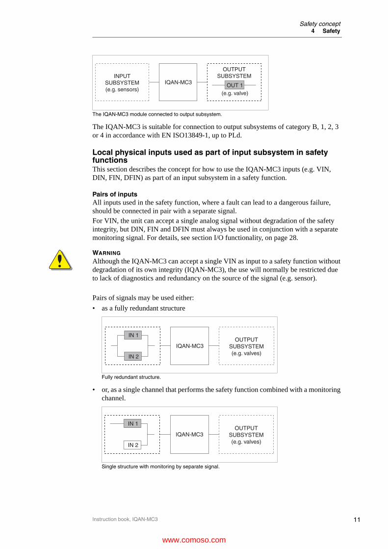
The IQAN-MC3 module connected to output subsystem.
The IQAN-MC3 is suitable for connection to output subsystems of category B, 1, 2, 3 or 4 in accordance with EN ISO13849-1, up to PLd.
Local physical inputs used as part of input subsystem in safety functionsThis section describes the concept for how to use the IQAN-MC3 inputs (e.g. VIN, DIN, FIN, DFIN) as part of an input subsystem in a safety function.
Pairs of inputsAll inputs used in the safety function, where a fault can lead to a dangerous failure, should be connected in pair with a separate signal.For VIN, the unit can accept a single analog signal without degradation of the safety integrity, but DIN, FIN and DFIN must always be used in conjunction with a separate monitoring signal. For details, see section I/O functionality, on page 28.
WARNING
Although the IQAN-MC3 can accept a single VIN as input to a safety function without degradation of its own integrity (IQAN-MC3), the use will normally be restricted due to lack of diagnostics and redundancy on the source of the signal (e.g. sensor).
Pairs of signals may be used either:
• as a fully redundant structure
Fully redundant structure.
• or, as a single channel that performs the safety function combined with a monitoring channel.
Single structure with monitoring by separate signal.
OUT 1(e.g. valve)
IQAN-MC3INPUT
SUBSYSTEM(e.g. sensors)
OUTPUTSUBSYSTEM
IN 1
IN 2
IQAN-MC3OUTPUT
SUBSYSTEM(e.g. valves)
IN 1
IN 2
IQAN-MC3OUTPUT
SUBSYSTEM(e.g. valves)
www.comoso.com
12
Safety concept4 Safety
Instruction book, IQAN-MC3
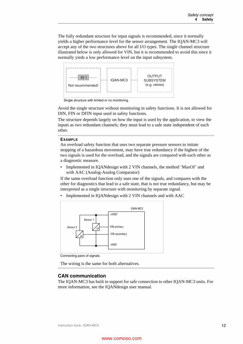
The fully redundant structure for input signals is recommended, since it normally yields a higher performance level for the sensor arrangement. The IQAN-MC3 will accept any of the two structures above for all I/O types. The single channel structure illustrated below is only allowed for VIN, but it is recommended to avoid this since it normally yieds a low performance level on the input subsystem.
Single structure with limited or no monitoring.
Avoid the single structure without monitoring in safety functions. It is not allowed for DIN, FIN or DFIN input used in safety functions.The structure depends largely on how the input is used by the application, to view the inputs as two redundant channels; they must lead to a safe state independent of each other.
CAN communicationThe IQAN-MC3 has built in support for safe connection to other IQAN-MC3 units. For more information, see the IQANdesign user manual.
EXAMPLE
An overload safety function that uses two separate pressure sensors to initate stopping of a hazardous movement, may have true redundancy if the highest of the two signals is used for the overload, and the signals are compared with each other as a diagnostic measure.
• Implemented in IQANdesign with 2 VIN channels, the method ’MaxOf’ and with AAC (Analog-Analog Comparator)
If the same overload function only uses one of the signals, and compares with the other for diagnostics that lead to a safe state, that is not true redundancy, but may be interpreted as a single structure with monitoring by separate signal.
• Implemented in IQANdesign with 2 VIN channels and with AAC
Connecting pairs of signals.
The wiring is the same for both alternatives.
IN 1
Not recommended!
IQAN-MC3OUTPUT
SUBSYSTEM(e.g. valves)
u
u
IQAN-MC3
+VREF
-VREF
VIN secondary
VIN primarySensor 2
Sensor 1
www.comoso.com

13
Safety concept4 Safety
Instruction book, IQAN-MC3
CAN communication between multiple IQAN-MC3 master modules.
The IQAN-MC3 can be used for connection to sensor subsystems over CAN, assuming that the CAN protocol is suitable for safety related communication and that the diagnostic features in that protocol are able to be implemented on the IQAN-MC3.
CAN communication between IQAN-MC3 and other units with support for safe communication.
The diagnostic checks required by the protocol need to be implemented in the application.
OutputsEach individual power driver of the IQAN-MC3 uses a combination of high-side and low-side switches to control the load, this makes it possible to have an alternative shutdown path if one would fail.
MC3-SMR-006:A CAN communicationWhen exchange of safety related data on CAN is done using a protocol that is not supported by IQANdesign, the diagnostic features of that protocol shall be implemented in the application.
Safe communication between IQAN-MC3 units, one CAN bus used
AuxiliaryECU
AuxiliaryECU
Safe communication to other units, one or two CAN buses used, protocol dependent
www.comoso.com

14
Safety concept4 Safety
Instruction book, IQAN-MC3
The IQAN-MC3 module and output diagnostics.
There is also a common high-side switch that supply all outputs, that is used as an additional shutdown path.Because of the built in diagnostics and redundant switches, the architecture of the output subsystem can be selected independent of any constraints set by the unit.
Internal diagnosticsThe concept of the IQAN-MC3 is that the primary CPU is monitored by a second, independent CPU; and they in turn are monitored by a completely separate safety ASIC. The safety ASIC provides an independent alternate path to bring the system into a safe state, via a safe path switch that cuts power to all of the power drivers.To achieve good diagnostics, the IQAN-MC3 executes a high number of self-tests on the processor, memory and peripherials; both during start-up and cyclically, during operation.
MC3 internal diagnostics
MC3
+BAT
Internaldiagnostics
OUT 1
www.comoso.com

15
Markings/Approvals4 Safety
Instruction book, IQAN-MC3
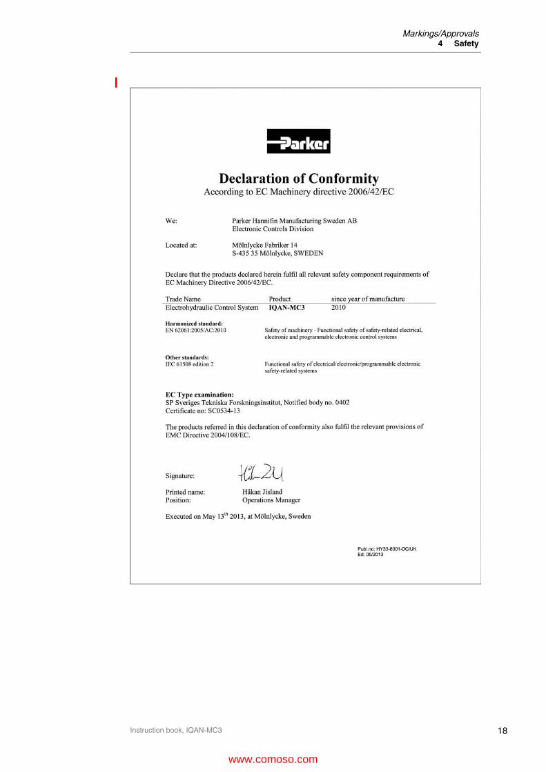
Markings/Approvals
www.comoso.com

16
Markings/Approvals4 Safety
Instruction book, IQAN-MC3
www.comoso.com

17
Markings/Approvals4 Safety
Instruction book, IQAN-MC3
www.comoso.com
18
Markings/Approvals4 Safety
Instruction book, IQAN-MC3
www.comoso.com

19
Markings/Approvals4 Safety
Instruction book, IQAN-MC3
www.comoso.com
20
Mounting the module5 Mounting
Instruction book, IQAN-MC3
5 Mounting
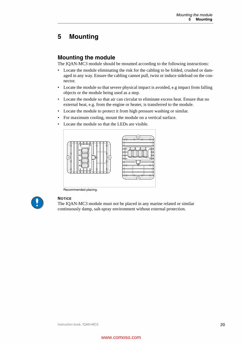
Mounting the moduleThe IQAN-MC3 module should be mounted according to the following instructions:
• Locate the module eliminating the risk for the cabling to be folded, crushed or dam-aged in any way. Ensure the cabling cannot pull, twist or induce sideload on the con-nector.
• Locate the module so that severe physical impact is avoided, e.g impact from falling objects or the module being used as a step.
• Locate the module so that air can circulat to eliminate excess heat. Ensure that no external heat, e.g. from the engine or heater, is transferred to the module.
• Locate the module to protect it from high pressure washing or similar.
• For maximum cooling, mount the module on a vertical surface.
• Locate the module so that the LEDs are visible.
Recommended placing.
NOTICE
The IQAN-MC3 module must not be placed in any marine related or similar continuously damp, salt-spray environment without external protection.
www.comoso.com

21
Connectors C1-C46 Installation
Instruction book, IQAN-MC3
6 Installation
Connectors C1-C4
Connector C1 pin assignments
Connector kit Parker no. 5035016a
a.Kit contains parts for all 4 connectors, C1 - C4
Housing Deutsch no. DT16-18SAK004
Pin types 1062-16-0644
Cables 0.75 mm² (18 AWG)
Plugs (empty pos.) Deutsch no. 114017
Deutsch crimping tool reference
DTT-20-00
Prototype cable Parker no. 5030216
Symbol Pin No.
InOut
Function
-BAT 1 - Power supply GND
-BAT 2 - Power supply GND
CAN-A-L 3 - CAN low voltage bus line, will be LOW in dominant state.
CAN-A-H 4 - CAN high voltage bus line, will be HIGH in dominant state.
CAN-B-L 5 - CAN low voltage bus line, will be LOW in dominant state.
CAN-B-H 6 - CAN high voltage bus line, will be HIGH in dominant state.
ADDR-L 7 - IdTag interface. Low side to address tag. Return signal.
ADDR-H 8 - IdTag interface. High side to address tag. Sourcing +5V.
CAN-C-L 9 - CAN low voltage bus line, will be LOW in dominant state.
CAN-C-H 10 - CAN high voltage bus line, will be HIGH in dominant state.
CAN-D-L 11 - CAN low voltage bus line, will be LOW in dominant state.
CAN-D-H 12 - CAN high voltage bus line, will be HIGH in dominant state.
+BAT 13 - Power supply 12/24 Vdc
+BAT 14 - Power supply 12/24 Vdc
DOUT-D 15 O DOUT power driver (type B), high side
DRET-D 16 O DOUT power driver (type B), low side
DOUT-E 17 O DOUT power driver (type B), high side
DRET-E 18 O DOUT power driver (type B), low side
6
12
18
1
7
13
AC1
www.comoso.com
22
Connectors C1-C46 Installation
Instruction book, IQAN-MC3
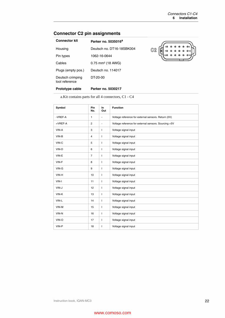
Connector C2 pin assignments
Connector kit Parker no. 5035016a
a.Kit contains parts for all 4 connectors, C1 - C4
Housing Deutsch no. DT16-18SBK004
Pin types 1062-16-0644
Cables 0.75 mm² (18 AWG)
Plugs (empty pos.) Deutsch no. 114017
Deutsch crimping tool reference
DT-20-00
Prototype cable Parker no. 5030217
Symbol Pin No.
InOut
Function
-VREF-A 1 - Voltage reference for external sensors. Return (0V)
+VREF-A 2 - Voltage reference for external sensors. Sourcing +5V
VIN-A 3 I Voltage signal input
VIN-B 4 I Voltage signal input
VIN-C 5 I Voltage signal input
VIN-D 6 I Voltage signal input
VIN-E 7 I Voltage signal input
VIN-F 8 I Voltage signal input
VIN-G 9 I Voltage signal input
VIN-H 10 I Voltage signal input
VIN-I 11 I Voltage signal input
VIN-J 12 I Voltage signal input
VIN-K 13 I Voltage signal input
VIN-L 14 I Voltage signal input
VIN-M 15 I Voltage signal input
VIN-N 16 I Voltage signal input
VIN-O 17 I Voltage signal input
VIN-P 18 I Voltage signal input
6
12
18
1
7
13
BC2
www.comoso.com
23
Connectors C1-C46 Installation
Instruction book, IQAN-MC3
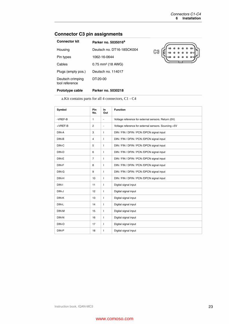
Connector C3 pin assignments
Connector kit Parker no. 5035016a
a.Kit contains parts for all 4 connectors, C1 - C4
Housing Deutsch no. DT16-18SCK004
Pin types 1062-16-0644
Cables 0.75 mm² (18 AWG)
Plugs (empty pos.) Deutsch no. 114017
Deutsch crimping tool reference
DT-20-00
Prototype cable Parker no. 5030218
Symbol Pin No.
InOut
Function
-VREF-B 1 - Voltage reference for external sensors. Return (0V)
+VREF-B 2 - Voltage reference for external sensors. Sourcing +5V
DIN-A 3 I DIN / FIN / DFIN / PCN /DPCN signal input
DIN-B 4 I DIN / FIN / DFIN / PCN /DPCN signal input
DIN-C 5 I DIN / FIN / DFIN / PCN /DPCN signal input
DIN-D 6 I DIN / FIN / DFIN / PCN /DPCN signal input
DIN-E 7 I DIN / FIN / DFIN / PCN /DPCN signal input
DIN-F 8 I DIN / FIN / DFIN / PCN /DPCN signal input
DIN-G 9 I DIN / FIN / DFIN / PCN /DPCN signal input
DIN-H 10 I DIN / FIN / DFIN / PCN /DPCN signal input
DIN-I 11 I Digital signal input
DIN-J 12 I Digital signal input
DIN-K 13 I Digital signal input
DIN-L 14 I Digital signal input
DIN-M 15 I Digital signal input
DIN-N 16 I Digital signal input
DIN-O 17 I Digital signal input
DIN-P 18 I Digital signal input
6
12
18
1
7
13
CC3
www.comoso.com
24
Connectors C1-C46 Installation
Instruction book, IQAN-MC3
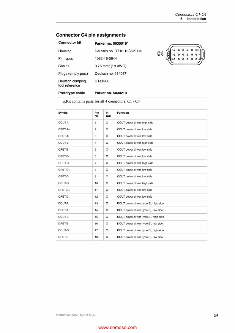
Connector C4 pin assignments
Connector kit Parker no. 5035016a
a.Kit contains parts for all 4 connectors, C1 - C4
Housing Deutsch no. DT16-18SDK004
Pin types 1062-16-0644
Cables 0.75 mm² (18 AWG)
Plugs (empty pos.) Deutsch no. 114017
Deutsch crimping tool reference
DT-20-00
Prototype cable Parker no. 5030219
Symbol Pin No.
InOut
Function
COUT-A 1 O COUT power driver, high side
CRET-A+ 2 O COUT power driver, low side
CRET-A- 3 O COUT power driver, low side
COUT-B 4 O COUT power driver, high side
CRET-B+ 5 O COUT power driver, low side
CRET-B- 6 O COUT power driver, low side
COUT-C 7 O COUT power driver, high side
CRET-C+ 8 O COUT power driver, low side
CRET-C- 9 O COUT power driver, low side
COUT-D 10 O COUT power driver, high side
CRET-D+ 11 O COUT power driver, low side
CRET-D- 12 O COUT power driver, low side
DOUT-A 13 O DOUT power driver (type B), high side
DRET-A 14 O DOUT power driver (type B), low side
DOUT-B 15 O DOUT power driver (type B), high side
DRET-B 16 O DOUT power driver (type B), low side
DOUT-C 17 O DOUT power driver (type B), high side
DRET-C 18 O DOUT power driver (type B), low side
6
12
18
1
7
13
DC4
www.comoso.com

25
I/O configuration6 Installation
Instruction book, IQAN-MC3
I/O configuration
Supply voltageBefore any installation of the IQAN system can take place, make sure the ignition lock is turned off and the battery is disconnected.
Emergency stopThe machine must always be equipped with an Emergency stop that stops all potentially hazardous movements by cutting the power supply to the actuators.The recommended way of implementing this is by cutting the power to all IQAN modules, and also to the actuators directly, e.g. via a dump valve. See below:
Emergency stop.
Since the IQAN-MC3 is capable of implementing safety functions, it may in some applications be tempting for the designer to implement the emergency stop as a function in the IQAN-MC3. The IQAN-MC3 does not have any built in emergency stop function, but if it is implemented anyway, it must be done with extreme caution. Especially when application updates are performed, e.g. during service or commissioning.
+BAT
ADDR-L
ADDR-H
CAN-H
CAN-L
OUTPUTS
-BAT
+VREF
-VREF
INPUTS
Power supply
(and safe path control)
Signal input
CAN
Core(microcontroller
andMemory)
idTag
DIN
VIN
Power driver
MC3 COUT
DOUT
Emergency Stop
+B ATDump Valve
IQAN-MC3
+BAT
www.comoso.com

26
Reverse feed6 Installation
Instruction book, IQAN-MC3
Connecting of Supply VoltageThe supply voltage, should be within the operating interval, see Appendix A, on page 46. Connect the supply voltage to +BAT positions C1:13, C1:14 and -BAT positions C1:1,C1:2. Protect the module by using a fuse. Requisite fuse level should be max. 20 A, fast (F).
Connecting the emergency stop and voltage supply.
NOTICE
Do not use the chassis as the negative terminal.
Reverse feedWARNING
Risk of inadvertently supplying power to the module! If any of the outputs are shorted to battery voltage, the module will be powered by reverse feed of voltage, even when the connection to module power is off. The IQAN-MC3 is capable of detecting if outputs are shorted to battery voltage at start-up, and will prevent the application from starting. If the same short circuit occurs while the module is already powered, it may also be detected by the module, but shutdown will be limited to the specific output. see Appendix B, on page 51 for details.It is highly recommended that this failure mode is considered when designing the electrical system, so that the risk of inhibiting the emergency stop shutdown is minimized.
IQAN-MC3 addressing/terminating
Use of an ID-TagEach IQAN-MC3 module must be configured by using an ID-tag. The value of the ID-tag will give the MC3 an address to differentiate it from other MC3 units on the same bus. The desired functionality is built into the application file using IQANdesign software. For more information please refer to the IQANdesign user manual.
+ -
Emergency Stop
20 A *
* Symbol for disconnecting switch for battery, ignition lock and other fuses.
IQAN-MC3
+BAT
-BAT
www.comoso.com

27
IQAN-MC3 addressing/terminating6 Installation
Instruction book, IQAN-MC3
The maximum number of addresses is eight, denoted as addresses 0, 1, 2, 3, 4, 5, 6, 7 respectively. In order to assign any MC3 module a unique address, the ID-tag will have to be connected to the positions ADDR-H and ADDR-L.
Connecting of Id-Tag.
TerminatingTo eliminate interference in the communications through the CAN bus, the CAN bus must be terminated. By default, the MC3 is terminated internally on all of its CAN buses. When an IQANdesign application is loaded, it can set individual buses to be non-terminated.To give an IQAN-MC3 a unique address, you may use an addressing ID-tag, or an ID-tag having a combined address and terminating function. The ’T’ values of ID-tags are ignored, i.e. an ID-tag 0T is equivalent to ID-tag 0.If the module is located at the end of the CAN-bus, then leave the bus default terminated in the MC3.
NOTICE
The CAN-bus should not be terminated at the MC3 using an external regular terminating resistor, due to the fact that terminating is made from within the MC3 module by default.
IQAN-MC3
ADDR-H
ADDR-L
www.comoso.com

28
Inputs7 I/O functionality
Instruction book, IQAN-MC3
7 I/O functionality
This section contains information about how to connect and use the I/O, with specific additional information about rules that apply when the I/O is used in a safety function.
InputsThere are 3 types of inputs in the IQAN-MC3:
• Voltage inputs
• Digital inputs
• Frequency inputs
Voltage inputs
Connecting sensors to the voltage inputsThe range of the voltage inputs is 0-5 Vdc. For input characteristics, see Appendix A.In order to detect errors such as "open circuit" in the wiring, the active signal range from the sensor must be limited, e.g. 0.5-4.5 Vdc.
Active signal range.
The positive terminal of the sensor is connected to the +VREF position and the corresponding negative terminal to the -VREF position. The sensor signal is connected to appropriate VIN position.
EXAMPLE
Connect the positive and negative terminals of the position sensor to +VREF and-VREF, respectively. Then connect the sensor signal to a VIN.
Connecting VREF and sensor signal VIN.
0
5[V]
Active signal range
Error detection range
Error detection range
t
Position Sensor
IQAN-MC3
+VREF
-VREF
VIN
www.comoso.com

29
Voltage inputs7 I/O functionality
Instruction book, IQAN-MC3
NOTICE
The negative terminal of the sensor must not be connected to the chassis.Maximum load for VREF position: see Appendix A, on page 46.
Selection of sensorsThe voltage inputs are designed for potentiometer type sensors and for 5V hall effect sensors.Sensors with ’padding’ at the min and max limits of the signal range will ensure that the most common (i.e. short circuits, broken wires) wiring errors are detected.For potentiometer type sensors with a 0.5-4.5 V range, we recommend that the potentiometer resistance is 1000 Ohm.
Using voltage inputs in safety functionsThe following addional information applies when the inputs are used in safety functions, where an incorrect input signal can lead to an immediate increase of the risk.
Limits on signal rangeBy limiting the normal operating range of voltage input signals, several faults can be detected. For this check to be effective, the signal range must not be too wide.
Calibration Limits: • Min voltage: >=200 mV
• Max voltage <=4800 mV
VREF usageIt is recommended that the connected sensors shall use one of the VREF’s from the IQAN-MC3, especially when voltage inputs are used in safety functions. If an external 5 V reference is used, it is up to the application to ensure that the reference voltage is correct.
Using a common VREF.
Pairs of inputs may use a common VREF.
MC3-SMR-007:A Limits on VIN signal rangeWhen voltage input signals are used in safety functions, the active signal range shall be limited within 200-4800 mV; and the limits shall be implemented in IQANdesign.
u
u
IQAN-MC3
+VREF
-VREF
VIN secondary
VIN primary
www.comoso.com
30
Voltage inputs7 I/O functionality
Instruction book, IQAN-MC3
Tolerances on voltage inputs in safety functionsThe unit has automatic monitoring of the internal analog-to-digital converter, that is capable of detecting gain errors of 3% or higher. An internal error causing a smaller signal drift than 3% is not detected by the check.
.
Connecting switches to the voltage inputsConnection of switches to voltage inputs will in most cases be restricted by the restriction of signal range on voltage inputs used in safety functions.A voltage input may be connected to a switch, but it shall use +VREF, the switch may not be connected to +BAT.
NOTICE
The VIN are designed for permanent connection to +BAT, but not for +BAT transients. Therefore VIN connection to +BAT should be avoided.
MC3-SMR-008:A Tolerances on VINWhen voltage inputs are used in safety functions, the application shall be designed so that it can tolerate a gain error of 3% on the voltage inputs and still be in a safe state.
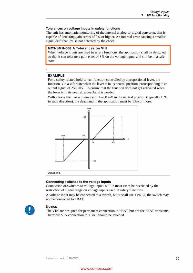
EXAMPLEFor a safety related hold-to-run function controlled by a proportional lever, the function is in a safe state when the lever is in its neutral position, corresponding to an output signal of 2500mV. To ensure that the function does not get activated when the lever is in its neutral, a deadband is needed.With a lever that has a tolerance of +-200 mV in the neutral position (typically 10% in each direction), the deadband in the application must be 13% or more.
Deadband.
IN
OUT
10 100
100
-100
-100 -10
www.comoso.com

31
Voltage inputs7 I/O functionality
Instruction book, IQAN-MC3
The switches are connected to +VREF and VIN/DIN respectively for 5V signal.
NOTICE
Maximum load for VREF position, see Appendix A, on page 46.
EXAMPLE
Connect the positive and negative terminals of the switch to +VREF and VIN, respectively.
Connecting a switch to VIN and VREF.
IQAN-MC3
+VREF
VIN
www.comoso.com
32
Digital inputs7 I/O functionality
Instruction book, IQAN-MC3
Digital inputsThe digital inputs can be connected to vehicle power (i.e. +BAT) or +VREF.For digital input characteristics, see Appendix A, on page 46.
Connecting switches to the digital inputsThe switch would be powered by +BAT when it is desired to conserve +VREF for powering sensors and joysticks.
Using digital inputs in safety functionsThe following addional information applies when the inputs are used in safety functions, where an incorrect input signal can lead to an immediate increase of the risk.
If the additional signal is read by another digital input, it is recommended that the signals are not equal. For example, use linked normally open and normally closed switches.
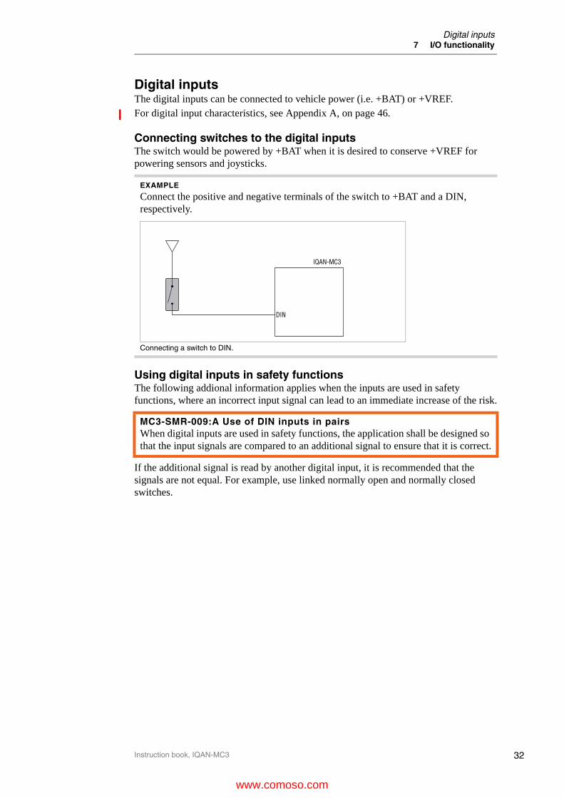
EXAMPLE
Connect the positive and negative terminals of the switch to +BAT and a DIN, respectively.
Connecting a switch to DIN.
MC3-SMR-009:A Use of DIN inputs in pairsWhen digital inputs are used in safety functions, the application shall be designed so that the input signals are compared to an additional signal to ensure that it is correct.
IQAN-MC3
DIN
www.comoso.com
33
Frequency inputs7 I/O functionality
Instruction book, IQAN-MC3
Frequency inputs
Connecting sensors to the frequency inputsFrequency inputs can operate in 2 modes. Speed which is frequency and position which is a pulse count. For the frequency ranges and trigger levels, see Appendix A, on page 46.
Simple frequency sensorThe positive terminal of the frequency sensor is connected to the +VREF and the negative terminal to the -VREF respectively. The sensor signal is connected to the FIN position.
NOTICE
The negative terminal of the sensor must not be connected to the chassis. Maximum load for VREF position, see Appendix A, on page 46.
Using frequency inputs in safety functionsThe following addional information applies when the inputs are used in safety functions, where an incorrect input signal can lead to an immediate increase of the risk.
Directional frequency inputs
Connecting sensors to the directional frequency inputsDirectional frequency inputs can operate in 2 modes. Speed which is frequency and position which is a pulse count. For the frequency ranges and trigger levels, see Appendix A, on page 46.
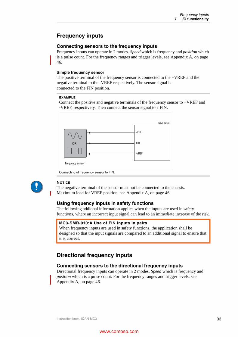
EXAMPLE
Connect the positive and negative terminals of the frequency sensor to +VREF and-VREF, respectively. Then connect the sensor signal to a FIN.
Connecting of frequency sensor to FIN.
MC3-SMR-010:A Use of FIN inputs in pairsWhen frequency inputs are used in safety functions, the application shall be designed so that the input signals are compared to an additional signal to ensure that it is correct.
OR
Frequency sensor
IQAN-MC3
+VREF
FIN
-VREF
www.comoso.com

34
Directional frequency inputs7 I/O functionality
Instruction book, IQAN-MC3
Simple directional frequency sensorThe positive terminal of the directional frequency sensor is connected to the +VREF and the negative terminal to the -VREF respectively. The sensor signals are connected to the DFIN+ and DFIN- positions.
NOTICE
The negative terminal of the sensor must not be connected to the chassis. Maximum load for VREF position, see Appendix A, on page 46.
Using directional frequency inputs in safety functionsThe following addional information applies when the inputs are used in safety functions, where an incorrect input signal can lead to an immediate increase of the risk.
EXAMPLE
Connect the positive and negative terminals of the frequency sensor to +VREF and-VREF, respectively. Then connect the sensor signals to DFIN+ and DFIN-.
Connecting of directional frequency sensor to DFIN+ and DFIN-.
MC3-SMR-011:A Use of DFIN inputs in pairsWhen directional frequency inputs are used in safety functions, the application shall be designed so that the input signals are compared to an additional signal to ensure that it is correct.
Directional frequency sensor
IQAN-MC3
+VREF
DFIN+
-VREF
DFIN-
www.comoso.com

35
Reference voltage, VREF7 I/O functionality
Instruction book, IQAN-MC3
Reference voltage, VREFThe IQAN-MC3 is internally equipped with voltage regulators to generate the reference voltage VREF. The standard 5V reference voltage will feed different kinds of sensors. There is a VREF connection in both the C2 connector, and the C3 connector. Having multiple VREF supplies allows you to distribute power to the sensors in the vehicle according to installation zones or some other configuration.
VREF positions.
NOTICE
It is strongly recommended to use the module’s -VREF and +VREF to all sensors and potentiometers that are connected to the module inputs. This will reduce bad measurement based on potential fault (i.e. different ground points for other supplies in relation to the MC3 ground, -BAT).Maximum load for the VREF supply, see Appendix A, on page 46
IQAN-MC3
+VREF
-VREF
www.comoso.com

36
Outputs7 I/O functionality
Instruction book, IQAN-MC3
Outputs
Proportional outputs The current /PWM outputs control proportional valves and devices. For the current range and loads, see Appendix A, on page 46.
FrequencyTo obtain the best performance from proportional valves the IQAN-MC3 produces a current mode (closed loop) output signal. The units have an adjustable frequency which can be changed using IQAN software. The table below shows the MC3 frequency possibilities. Any frequency may be entered in your application and is translated according to this table. The bold values are the actual frequencies in Hz output by the MC3 for proportional valve control.
Frequency (Hz) entered in appl.
Frequency (Hz) output by MC3
<76 71
77-82 77
83-90 83
91-99 91
100-110 100
111-124 111
125-142 125
143-166 143
167-199 167
200-249 200
250-332 250
333+ 333
www.comoso.com

37
Proportional outputs7 I/O functionality
Instruction book, IQAN-MC3
Connecting loads to proportional outputsThe current outputs are high performance outputs with closed loop current control designed to drive proportional electrohydraulic valves. For COUT and load characteristics, please see Appendix A.Connecting a load, e.g. one proportional valve section, to the current mode or PWM mode outputs is done by using the COUT/CRET paired positions.When a COUT is used with a just single solenoid connected (e.g. a hydraulic motor), the application file must be configured so that the COUT is not bidirectional; otherwise an open load will be detected.
NOTICE
DO NOT install diodes across coils!
Proportional outputs in PWM modeIt is possible to configure the proportional outputs for PWM mode, and control the output directly with the modulation ratio instead of closed loop current control. In PWM mode, the current is not measured, and diagnostics are limited.
NOTICE
The PWM outputs on an IQAN-MC3 can not be used to drive Pulsar valves, select another IQAN module to do that.
COUT mode output diagnosticsThe COUT is capable of detecting internal faults as well as wiring faults. The fault will be identified as one of the following status values in IQANdesign.
• Over load (e.g. over current)
• Open load (e.g. open circuit or under current)
• "Error - internal error in the IQAN-MC3 power driverThe reported status is describing the most likely fault condition, but in certain cases the status will not match the actual fault. For details on failure modes, see Appendix B, on page 51.
EXAMPLE
Positive direction:Connect the proportional valve to the COUT and the CRET+, respectively.Negative direction: Connect the proportional valve to the COUT and the CRET-, respectively.
Connecting a load to a proportional output.
Directional Valve
IQAN-MC3
CRET+
CRET-
COUT
www.comoso.com

38
Proportional outputs7 I/O functionality
Instruction book, IQAN-MC3
There are faults that are detected on startup, and that will prevent the module from starting the application. These are all faults where an output is connected to +BAT on startup.To detect these faults, it is important that all connectors are plugged-in before the module is started. See section Start-up, on page 42.For details on failure modes, see Appendix B, on page 51.
Reset of faultsThe reset behaviour of the COUT is configured in the application file, see IQANdesign user manual.
Use of COUT in safety functions
COUT safe state The COUT is assumed to be in a safe state when the output is off; in this state only the leakage current is delivered (see Appendix A, on page 46).
Minimum current
This is to ensure that there is no movement when the output is off.
Error detection limitsThe COUT has a separate, built in monitoring that detects deviations from the commanded output current. To avoid spurious trips, it is designed to tolerate some deviation, refer to ’under/over current threshold’, see Appendix A, on page 46.
An undetected error that falls within these limits can lead to an unintentional change of speed of the output, and must be safe in the application for which the IQAN-MC3 is used.
During normal operation, when there is no fault; the accuracy is significantly better than the error detection limits.
Undetected wiring faultsThere are COUT wiring faults that are not detectable by the IQAN-MC3, see Appendix B, on page 51.All types of wiring faults must be considered to ensure that the failures are safe in the application.
You should also note that there are wiring errors that can only be detected on start-up of the unit.
MC3-SMR-012:A Minimum current when using COUT as power driverWhen the load connected to the COUT is capable of initiating a hazardous movement, it shall be designed so that it is only activated if the current is > 50 mA.
MC3-SMR-013:A COUT error detection limitsThe application shall be designed so that changes of output current up to the undercurrent and overcurrent threshold are safe.
MC3-SMR-014:A COUT undetected wiring faultsThe application shall be designed so that undetected wiring errors on COUT are safe.
www.comoso.com

39
Proportional outputs7 I/O functionality
Instruction book, IQAN-MC3
Limits on COUT adjustable parametersThe COUT current range and slopes must be limited in the application file. Due to the risks involved with modifying these adjustable values, it is recommended that these limits are kept narrow. Alternatively, the access to modification of current range and slopes can be limited. See IQANdesign user manual.
www.comoso.com

40
Digital outputs7 I/O functionality
Instruction book, IQAN-MC3
Digital outputs The IQAN-MC3 has two types of digital outputs. While all of the digital outputs are designed to drive coils for on-off valves, DOUT D-E are also designed to drive indicators such as LED’s. For current ratings on the DOUT’s, see Appendix A, on page 46.
Connecting loads to digital outputsConnecting of loads to the digital outputs such as on/off valves is done by using the DOUT/DRET paired positions.
Protection against voltage transientsA clamping diode must be placed between the digital output and return, as close to theload as possible. This reduces EMI, it also helps in protecting the output against high voltage transients. Use the diode:1N5408 (3A/1000V).
Depending on the load, other clamping diodes might be used instead.
DOUT output diagnosticsThe DOUT is capable of detecting internal faults as well as wiring faults. The fault will be identified as one of the following status values in IQANdesign.
• Over load (e.g. over current)
• Open load (e.g. open circuit or under current)
• "Error - internal error in the IQAN-MC3 power driverThe reported status is describing the most likely fault condition, but in certain cases the status will not match the actual fault. For details on failure modes, see Appendix B, on page 51.There are faults that are detected on startup, and that will prevent the module from starting the application. These are all faults where an output is connected to +BAT on startup.To detect these faults, it is important that all connectors are plugged-in before the module is started. See section Start-up, on page 42, also, see Appendix B, on page 51.
EXAMPLE
Connect the on/off valve to the digital output using the DOUT and the DRET, respectively.
Connecting a load to the digital output.
d1
IQAN-MC3
DRET
DOUT
www.comoso.com
41
Digital outputs7 I/O functionality
Instruction book, IQAN-MC3
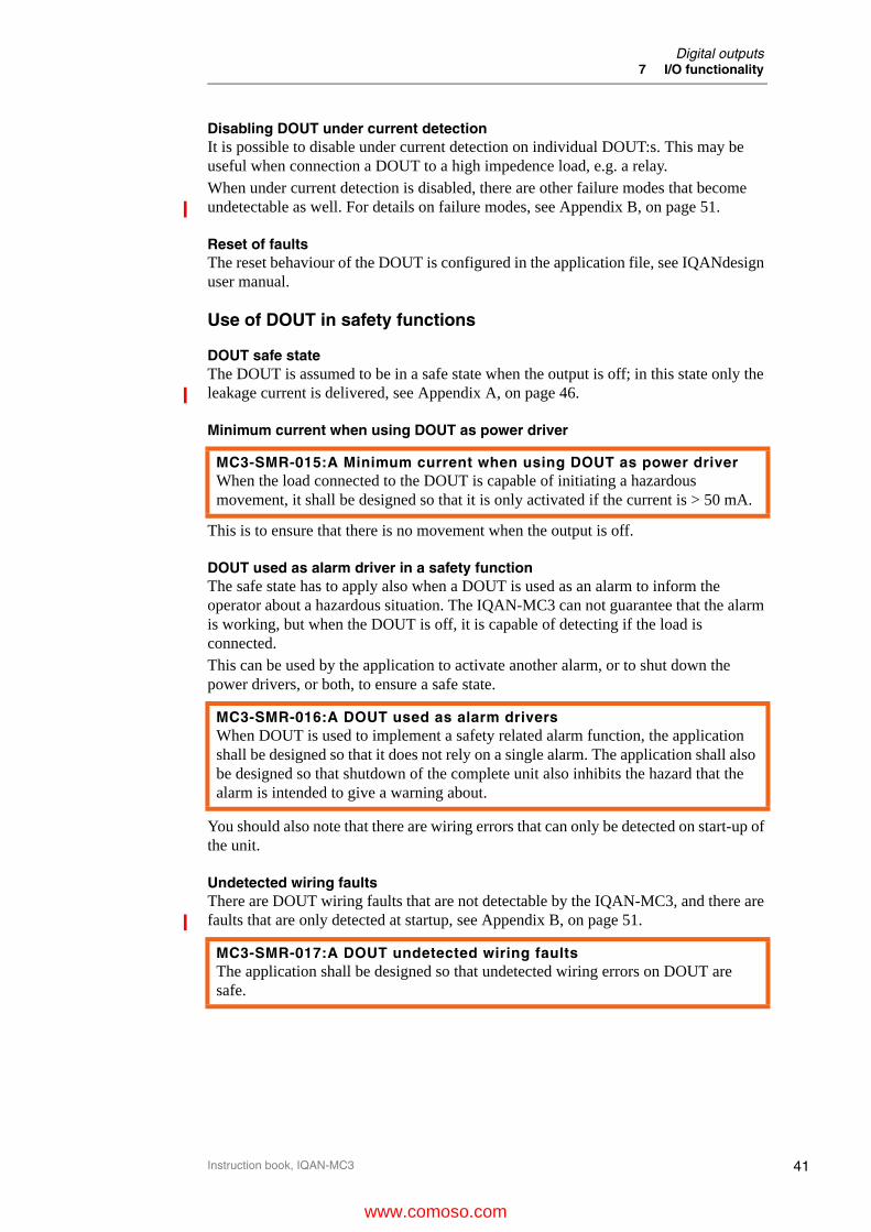
Disabling DOUT under current detectionIt is possible to disable under current detection on individual DOUT:s. This may be useful when connection a DOUT to a high impedence load, e.g. a relay.When under current detection is disabled, there are other failure modes that become undetectable as well. For details on failure modes, see Appendix B, on page 51.
Reset of faultsThe reset behaviour of the DOUT is configured in the application file, see IQANdesign user manual.
Use of DOUT in safety functions
DOUT safe state The DOUT is assumed to be in a safe state when the output is off; in this state only the leakage current is delivered, see Appendix A, on page 46.
Minimum current when using DOUT as power driver
This is to ensure that there is no movement when the output is off.
DOUT used as alarm driver in a safety functionThe safe state has to apply also when a DOUT is used as an alarm to inform the operator about a hazardous situation. The IQAN-MC3 can not guarantee that the alarm is working, but when the DOUT is off, it is capable of detecting if the load is connected.This can be used by the application to activate another alarm, or to shut down the power drivers, or both, to ensure a safe state.
You should also note that there are wiring errors that can only be detected on start-up of the unit.
Undetected wiring faultsThere are DOUT wiring faults that are not detectable by the IQAN-MC3, and there are faults that are only detected at startup, see Appendix B, on page 51.
MC3-SMR-015:A Minimum current when using DOUT as power driverWhen the load connected to the DOUT is capable of initiating a hazardous movement, it shall be designed so that it is only activated if the current is > 50 mA.
MC3-SMR-016:A DOUT used as alarm driversWhen DOUT is used to implement a safety related alarm function, the application shall be designed so that it does not rely on a single alarm. The application shall also be designed so that shutdown of the complete unit also inhibits the hazard that the alarm is intended to give a warning about.
MC3-SMR-017:A DOUT undetected wiring faultsThe application shall be designed so that undetected wiring errors on DOUT are safe.
www.comoso.com
42
Start-up procedures8 Start-up
Instruction book, IQAN-MC3
8 Start-up
Start-up proceduresThis chapter contains instructions for action to be taken in connection with the initial start, for example, setting values, calibrating and testing the system.
WARNING
Risk of injury!If the control system is not fitted properly, the machine could move uncontrollably. The machine’s engine shall not be started before the control system is completely fitted and its signals are verified.
Starting the control system
Start the control system as follows:• Prior to start, all modules and cables are to be fitted correctly.
• Check fuses, i.e. make sure that the supply voltage to the modules is equipped with the correct fuse.
• Make sure that connections for supply voltage and return lines are correct in the cable’s conductor joint.
• Make sure that the ID-tag is connected properly if used.
• Make sure the emergency stop works.
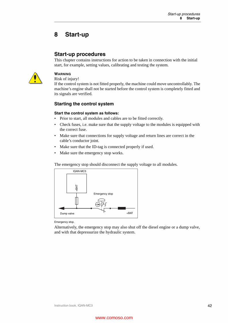
The emergency stop should disconnect the supply voltage to all modules.
Emergency stop.
Alternatively, the emergency stop may also shut off the diesel engine or a dump valve, and with that depressurize the hydraulic system.
+BATDump valve
Emergency stop
IQAN-MC3
+B
AT
www.comoso.com

43
Start-up procedures8 Start-up
Instruction book, IQAN-MC3
Prepare for system start
WARNING
Make sure no one is in dangerous proximity to the vehicle to avoidinjuries when it starts.
Prepare for the initial system start as follows:• The engine for the hydraulic system’s pump shall be in off position.
• Make sure that all connectors are properly connected.
• Turn on the control system.
• Make sure that voltage is being supplied to all modules, the green diode shall be illuminated on all modules. Also make sure that master is in contact with all mod-ules by checking the master’s status LED. Error codes are blinked if the master is not in contact with one or more of the modules.
• Make sure the emergency stop is functioning properly.
Start the system
Start the system as follows:• Start the engine for the hydraulic system’s pump, assuming that the above men-
tioned inspections have been carried out and shown correct values.
• Calibrate and adjust input and output signals according to the instructions related to the master menu system and check each and every output function carefully.
• In addition to these measures, the machine shall also meet the machine directives for the country in question.
WARNING
Work on the hydraulics control electronics may only be carried out by trained personnel who are well-acquainted with the control system, the machine and its safety regulations.
www.comoso.com

44
Check list for electronics8 Start-up
Instruction book, IQAN-MC3
Check list for electronicsThe following table has a list of steps which is a suggested guideline for the commissioning of an electronic control system on a machine.
# Condition Task to be performed Limit
1 OFF(OFF = no power supplied to control system harness)
Measure the resistance of all ground connec-tions between battery ground and -BAT for all modules / sensors. (measure in system har-ness, no modules connected).
<0,5 ohm
2 ONMachine engine not started
Measure all power supply's to each module / sensor.(measure in system harness, no mod-ules connected).
+12Vor+24V
3 OFFMachine engine not started
Connect all units to system harness.
4 ONMachine engine not started
Emergency stop, check that all modules get disconnected from the power +BAT.
0V
5 OFFMachine engine not started
Connect PC with IQAN software (IQANdesign or IQANrun).
6 ONMachine engine not started
Check (via IQAN software) all modules, that CAN connection is OK.
7 ONMachine engine not started
Check (via IQAN software) all modules, that inputs are OK - if not: check the harness or re-calibrate (adjust) the input signals.
8 ONMachine engine not started
Check (via IQAN software) all modules, that current out (COUT) is 0mA, when joystick is not activated.
0mA (0%)
9 OFFMachine engine not started
Check (via IQAN software) all modules, that current out (COUT) is OK, use the joystick to command the outputs.
10 ONMachine engine not started
Ensure that the following requirements are fulfilled before any work is carried out on the hydraulics control electronics.- The machine cannot start moving.- Functions are positioned safely.- The machine is turned off.- The hydraulic system is relieved from any pressure.
11 ONStart machine engine
Check that electrical output signal correspond equal with hydraulic direction.
12 OFFEngine ON
Tune current settings and slope times.
www.comoso.com

45
Diagnostic interfaces9 Diagnostics and troubleshooting
Instruction book, IQAN-MC3
9 Diagnostics and troubleshooting
Diagnostic interfacesIQAN software includes many tools for tuning, measuring, accessing logs and otherwise checking the performance or troubleshooting your control system.
CAN diagnostics connectionOne of the 4 CAN buses of the IQAN-MC3 may be dedicated for diagnostics. Reserving a bus for diagnostics ensures that signals are not interrupted by other bus traffic. A high-speed CAN interface is needed to use this feature. Contact Parker for information about supported CAN interfaces.A termination resistor is usually required at the CAN interface on the PC. Parker part number 5030182 or an equivalent 120 ohm resistor may be used. A flying lead cable may be connected to the IQAN-MC3 to provide a connector interface. The connection from IQAN-MC3 to diagnostic CAN interface can then be made quite easily. It is recommended that the diagnostic connector be a sealed, automotive type. When not being used this connector should be protected from the environment with a cover or mating blank plug.The recommended wiring to the IQAN-MC3 connector C1 is shown below.
Connecting for CAN to PC communication.
Bypass applicationIf the ADDR_L pin is shorted to ADDR_H, (detected when the unit starts/powers up) the application will not be loaded. This is a special start-up mode that is used for master units and puts the MC3 in a safe state without starting any application. When this mode is desired, a jumper is put in place of an ID-Tag.
Customer
IQAN-MC3
120 ohm
CAN-L
CAN-H
resistorspecifiedconnector
www.comoso.com

46
IQAN-MC3 Technical OverviewAppendix A
Instruction book, IQAN-MC3
Appendix A
IQAN-MC3 Technical Overview
Absolute Maximum Ratingsa
a.The “Absolute Maximum Ratings” table lists the maximum limits to which the device can be subjected without damage. This doesn´t imply that the device will function at these extreme conditions, only that, when these conditions are removed and the device operated with-in the “Recommended Operating Conditions”, it will still be functional and its useful life wonít have been shortened.
Ambient temperature, -40 to +85 °C
Storage temperature -40 to +100 °C
Voltage supply on +BAT 6 to 36 Vdc
Voltage on any pin with respect to -BAT 36 Vdc
Power driver load Total load on power drivers < 20A
Environmental ratings
Climate environmentEnclosure, water & dust protectionSalt mistDamp heat, cyclicDamp heat, steady stateHeat, operationHeat, storageColdChange of temperature
IEC 60529:2001, IP67; DIN 40050 Part 9:1993, IP6K9KIEC 60068-2-52:1996 Kb, 72 hIEC 60068-2-30:2005 Db, +55°C, 95% RH, 6 cyclesIEC 60068-2-78:2001 Cab, +40°C, 93% RH, 21 daysIEC 60068-2-2:2007 Bb, +85°C, 72 hoursIEC 60068-2-2:2007 Bb, +100°C, 72 hoursIEC 60068-2-1:1993 Ab, -40°C, 16 hoursIEC 60068-2-14:1984 Nb, - 30°C to +70°C, 100 x 4 hours
Mechanical environmentRandom vibrationBump
IEC 60068-2-64: 2008 Fh, 10 - 1000 Hz, 11.6 Grms, 3 x 10 hIEC 60068-2-27:2008 Ea, 40 g, 6 ms, 1000 * 6 dir
EMCRadiated emissionConducted emissionConducted susceptabilityRadiated susceptabilityConducted transients susceptability
ESD, operationESD, handling
ISO 13766/ISO 14982EN 55025:2003, 0.15-108 MHz, Class 1ISO 11452-4:2005, 1 - 200 MHz, 1 kHz, 80% AM, 100 mAISO 11452-2:2004, 200-2000 MHz, 1kHz, 80% AM, 100 V/mISO 7637-2:2004, Pulse 1,2a,2b,3a,3b,4,5, Level 3ISO 7637-3:2007, Level 3ISO 10605:2008, 8kV (contact), 15kV (air)ISO 10605:2008, 8kV (contact)
Markings / Approvals
CE 2004/108/EC, EMC directive 2011/65/EU, ROHS 2 2006/42/EG, Machinery directive
E-mark ECE Regulation No. 10.04 incl. Amdend. 2:2013Approval number E5 10 R - 04207
Functional safety IEC 61508:2010 up to SIL2
www.comoso.com
47
IQAN-MC3 Technical OverviewAppendix A
Instruction book, IQAN-MC3
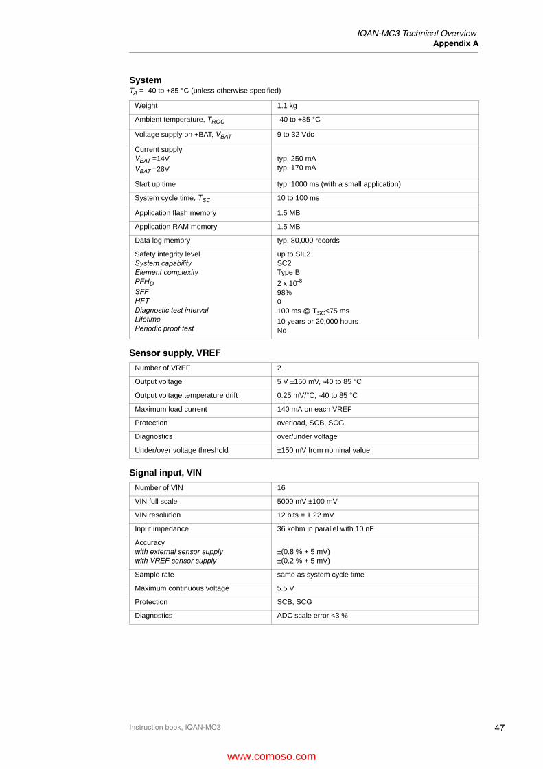
SystemTA = -40 to +85 °C (unless otherwise specified)
Weight 1.1 kg
Ambient temperature, TROC -40 to +85 °C
Voltage supply on +BAT, VBAT 9 to 32 Vdc
Current supplyVBAT =14VVBAT =28V
typ. 250 mAtyp. 170 mA
Start up time typ. 1000 ms (with a small application)
System cycle time, TSC 10 to 100 ms
Application flash memory 1.5 MB
Application RAM memory 1.5 MB
Data log memory typ. 80,000 records
Safety integrity levelSystem capabilityElement complexityPFHD
SFFHFTDiagnostic test intervalLifetimePeriodic proof test
up to SIL2SC2Type B
2 x 10⁻⁸
98%0100 ms @ TSC<75 ms
10 years or 20,000 hoursNo
Sensor supply, VREF
Number of VREF 2
Output voltage 5 V ±150 mV, -40 to 85 °C
Output voltage temperature drift 0.25 mV/°C, -40 to 85 °C
Maximum load current 140 mA on each VREF
Protection overload, SCB, SCG
Diagnostics over/under voltage
Under/over voltage threshold ±150 mV from nominal value
Signal input, VIN
Number of VIN 16
VIN full scale 5000 mV ±100 mV
VIN resolution 12 bits = 1.22 mV
Input impedance 36 kohm in parallel with 10 nF
Accuracywith external sensor supplywith VREF sensor supply
±(0.8 % + 5 mV)±(0.2 % + 5 mV)
Sample rate same as system cycle time
Maximum continuous voltage 5.5 V
Protection SCB, SCG
Diagnostics ADC scale error <3 %
www.comoso.com

48
IQAN-MC3 Technical OverviewAppendix A
Instruction book, IQAN-MC3
Signal input, DIN
Number of DIN 16 (configuration may reduce number)
Logic levelslowhighhysteresis
<1 V>4 V>0.1 V
Input impedance 6.8 kohm in parallel with 10 nF
Sample rate same as system cycle time TSC
Maximum continuous voltage 32 V
Diagnostics Defined in application
Signal input, FIN/DFIN
Number of FIN/DFIN 8/4 (configuration may reduce number)
Frequency rangeFINDFIN
1 to 20,000 kHz, 50% duty cycle1 to 20,000 kHz, 50% duty cycle
Minimum pulse width 10 µs for 5 V signal
Step response 400 ms, 10 to 90% step
Logic levelslowhighhysteresis
<1 V>4 V>0.3 V
Input impedance 6.8 kohm in parallel with 10 nF
Sample rate same as system cycle time TSC
Maximum continuous voltage 32V
Diagnostics Defined in application
Signal input, PCNT/DPCNT
Number of PCNT/DPCNT 8/4 (configuration may reduce number)
Frequency rangePCNDPCN
0 to 20,000 kHz0 to 20,000 kHz
Minimum pulse width 10 µs for 5 V signal
Logic levelslowhighhysteresis
<1 V>4 V>0.3 V
Input impedance 6.8 kohm in parallel with 10 nF
Sample rate same as system cycle time TSC
Maximum continuous voltage 32 V
Diagnostics Defined in application
www.comoso.com

49
IQAN-MC3 Technical OverviewAppendix A
Instruction book, IQAN-MC3
Power driver, COUT
Number of COUT 4 dual outputs
COUT rangelowhigh
100 mA2000 mA
COUT resolution 1 mA
Power driver voltage drop750 mA load1500 mA load
typ. 0.45 V @ saturationtyp. 0.90 V @ saturation
Maximum COUT saturation typ. Command -25%
Absolute accuracy ±(2 % + 15 mA) , -40 to 85 °C
Dither frequency, FDITH 71, 77, 83, 90, 100, 111, 125, 167, 200, 250, 333 Hz
Leakage current in OFF state <100 µA
Supply rejection ±2 mA, VBAT change 9 to 18V or 18 to 32V
Load rejection ±2 mA, load change ±50 %
Maximum loadVBAT = 14V and FDITH ≥ 200 HzVBAT = 14V and FDITH ≥ 200 HzVBAT = 14V and FDITH ≥ 200 HzVBAT = 14V and FDITH ≥ 200 Hz
5 ohm + 10 mH5 ohm + 20 mH10 ohm + 30 mH20 ohm + 60 mH
Maximum allowable load inductance1.0 A load1.5 A load2.0 A load
500 mH 200 mH50 mH
Protection SCB, SCG
DiagnosticsOperational ONOperational OFF
under current, SCG, SCBopen load, SCG
Open load threshold >50 kohm when COUT is OFF
Under/over threshold MaxOf ±100 mA and ±25 %
Power driver, PWMOUT
Number of PWMOUT 4 dual outputs
PWMOUT range 0% to 100% -200µs
PWMOUT resolution 1 µs
Power driver voltage drop typ. 0.8 V @ 1.5 A load
Dither frequency, FDITH 71, 77, 83, 90, 100, 111, 125, 167, 200, 250, 333 Hz
Leakage current in OFF state <100 µA
Maximum load 2A
Maximum allowable load inductance1.0 A load1.5 A load2.0A load
500 mH 200 mH50 mH
Protection SCB, SCG
DiagnosticsOperational ONOperational OFF
SCG, SCBopen load, SCG
Open load threshold >50 kohm when PWMOUT is OFF
www.comoso.com

50
IQAN-MC3 Technical OverviewAppendix A
Instruction book, IQAN-MC3
Power driver, DOUT
Number of DOUT 5
Maximum loadDOUT-A to DOUT-CDOUT-D to DOUT-E
3.0 A1.5 A
Power driver voltage dropDOUT-A to DOUT-CDOUT-D to DOUT-E
typ. 0.70 V @ 3 A loadtyp. 0.90 V @ 1.5 A load
Leakage current in OFF stateDOUT-A to DOUT-CDOUT-D to DOUT-E
<2 mA<100 µA
Maximum allowable load inductanceDOUT-A to DOUT-C1.0 A load2.0 A load3.0 A load
500 mH 200 mH50 mH
Maximum allowable load inductanceDOUT-D to DOUT-E1.0 A load1.5 A load
500 mH 200 mH
Protection overload, SCB, SCG
DiagnosticsOperational ONOperational OFF
under current, SCBopen load, SCG, SCB
Open load threshold >50 kohm or <100 µA when DOUT is OFF
Undercurrent threshold <300 mA when DOUT is ON
Overload threshold >4 A when DOUT is ON
CAN
Number of CAN buses 4
CAN specification 2.0A and 2.0B
CAN bus speed 125 kbit to 500 kbit
Protection SCB, SCG
www.comoso.com

51
Error codes, messages and actionsAppendix B
Instruction book, IQAN-MC3
Appendix B
Error codes, messages and actionsIf one of the following error is detected, a message will be presented with an error code on the module. In some cases, the module will turn off or at least shut down the outputs, to increase safety.
WARNING
Do not use the machine if an error message or error code is activated.
LED indicator showing different MC3 modes
Status Flash (yellow)
Normal operation
Application not loaded
No application available
Waiting for restart
Error code
Error Primary Flash (red)Error category
Secondary Flash (yellow)Error description
1:1 Output
1:2 Input
1:3 VREF
2:1 Power Supply
2:2 Temperature
3:1 CAN, no contact
3:2 IDtag error
3:3 System mismatch
3:4 CAN error (bus off)
4:1 Internal error/OSE
4:2 Critical Temperature
4:3 Critical Stop
www.comoso.com

52
Failure modesAppendix B
Instruction book, IQAN-MC3
Failure modesThe following tables have information about the actions taken by the IQAN-MC3 when certain failure causing conditions occur.
Failure modes for single inputsNOTICE
For safety functions, VIN is the only input type that may be used without another input as comparison.Sensor failure modes are not included in these tables.
Key to symbols• = detection leads to error status on input. See IQANdesign user manual.* = VIN error detection limits are application dependent, and must be used for safety functions. See IQANdesign user manual.** = Use a secondary diagnostic channel for error detection.
Voltage input
Digital input
Failure mode Detected Comment
VIN open • Detection only if valid signal range is limited
VIN short circuit to +BAT • Detection only if valid signal range is limited
VIN short circuit to signal > high error detection voltage *
• Detection only if valid signal range is limited
VIN short circuit to signal within error detection limits *
Incorrect input **
VIN short circuit to signal < low error detection voltage *
• Detection only if valid signal range is limited
VIN short circuit to -BAT • Detection only if valid signal range is limited
Failure mode Detected Comment
DIN open Input low **
DIN short circuit to +BAT Input high **
DIN short circuit to signal > high trigger level *
Input high **
DIN short circuit to signal within low to high trigger level range *
Undefined (input high or low) **
DIN short circuit to signal < low trigger level *
Input low **
DIN short circuit to -BAT Input low **
www.comoso.com

53
Failure modesAppendix B
Instruction book, IQAN-MC3
Frequency input
Directional frequency input
Failure mode Detected Comment
FIN open Frequency 0 **
FIN short circuit to +BAT Frequency 0 **
FIN short circuit to signal > high trigger level *
Frequency 0 **
FIN short circuit to signal within low to high trigger level range *
Undefined **
FIN short circuit to signal < low trigger level *
Frequency 0
FIN short circuit to -BAT Frequency 0 **
Failure mode Detected Comment
DFIN open Frequency 0 **
DFIN short circuit to +BAT Frequency 0 **
DFIN short circuit to signal > high trigger level *
Frequency 0 **
DFIN short circuit to signal within low to high trigger level range *
Undefined **
DFIN short circuit to signal < low trigger level *
Frequency 0
DFIN short circuit to -BAT Frequency 0 **
www.comoso.com
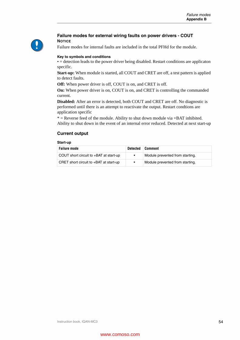
54
Failure modesAppendix B
Instruction book, IQAN-MC3
Failure modes for external wiring faults on power drivers - COUTNOTICE
Failure modes for internal faults are included in the total PFHd for the module.
Key to symbols and conditions• = detection leads to the power driver being disabled. Restart conditions are applicaton specific.Start-up: When module is started, all COUT and CRET are off, a test pattern is applied to detect faults.Off: When power driver is off, COUT is on, and CRET is off.On: When power driver is on, COUT is on, and CRET is controlling the commanded current.Disabled: After an error is detected, both COUT and CRET are off. No diagnostic is performed until there is an attempt to reactivate the output. Restart condtions are application specific* = Reverse feed of the module. Ability to shut down module via +BAT inhibited. Ability to shut down in the event of an internal error reduced. Detected at next start-up
Current output
Start-up
Failure mode Detected Comment
COUT short circuit to +BAT at start-up • Module prevented from starting.
CRET short circuit to +BAT at start-up • Module prevented from starting.
www.comoso.com

55
Failure modesAppendix B
Instruction book, IQAN-MC3
Off
Failure mode Detected Comment
COUT open •
CRET open •
COUT short circuit to CRET No influence on function in this state.
COUT short circuit to +BAT Reverse feed *.No influence on function in this state.
COUT short circuit to -BAT •
CRET short circuit to +BAT Reverse feed *.
No influence on function in this state.
CRET short-circuit to -BAT •
CRET+ short-circuit to CRET- No influence on function in this state.
COUT short-circuit to 2nd COUT No influence on function in this state.
COUT short-circuit to DOUT (active) •
COUT short-circuit to DOUT (passive) No influence on function in this state.
COUT short circuit to 2nd CRET/DRET (active)
No influence on COUT (error detected
on 2nd COUT/DOUT).
COUT short circuit to 2nd CRET/DRET (passive)
No influence on function in this state.
CRET short circuit to 2nd CRET/DRET (active)
•
CRET short circuit to 2nd CRET/DRET (passive)
No influence on function in this state.
www.comoso.com
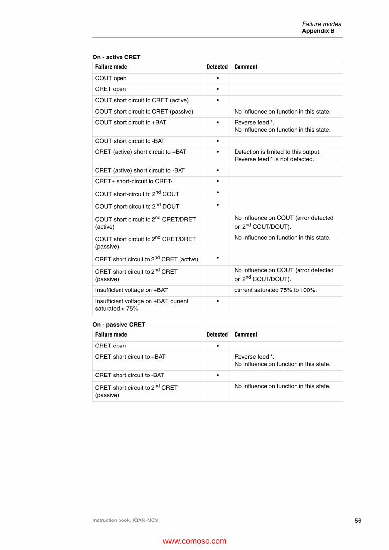
56
Failure modesAppendix B
Instruction book, IQAN-MC3
On - active CRET
On - passive CRET
Failure mode Detected Comment
COUT open •
CRET open •
COUT short circuit to CRET (active) •
COUT short circuit to CRET (passive) No influence on function in this state.
COUT short circuit to +BAT • Reverse feed *.No influence on function in this state.
COUT short circuit to -BAT •
CRET (active) short circuit to +BAT • Detection is limited to this output. Reverse feed * is not detected.
CRET (active) short circuit to -BAT •
CRET+ short-circuit to CRET- •
COUT short-circuit to 2nd COUT •
COUT short-circuit to 2nd DOUT •
COUT short circuit to 2nd CRET/DRET (active)
No influence on COUT (error detected
on 2nd COUT/DOUT).
COUT short circuit to 2nd CRET/DRET (passive)
No influence on function in this state.
CRET short circuit to 2nd CRET (active) •
CRET short circuit to 2nd CRET (passive)
No influence on COUT (error detected
on 2nd COUT/DOUT).
Insufficient voltage on +BAT current saturated 75% to 100%.
Insufficient voltage on +BAT, current saturated < 75%
•
Failure mode Detected Comment
CRET open •
CRET short circuit to +BAT Reverse feed *.No influence on function in this state.
CRET short circuit to -BAT •
CRET short circuit to 2nd CRET (passive)
No influence on function in this state.
www.comoso.com

57
Failure modesAppendix B
Instruction book, IQAN-MC3
Failure modes for external wiring faults on power drivers - DOUTNOTICE
Failure modes for internal faults are included in the total PFHd for the module.
Key to symbols and conditions• = detection leads to the power driver being disabled. Restart conditions are applicaton specific.Start-up: When module is started, all DOUT and DRET are off, a test pattern is applied to detect faults.Off: When power driver is off, DOUT is on, and DRET is off.On: When power driver is on, DOUT is on, and DRET is on.Disabled: After an error is detected, both DOUT and DRET are off. No diagnostic is performed until there is an attempt to reactivate the output. Restart condtions are application specific* = Reverse feed of the module. Ability to shut down module via +BAT inhibited. Ability to shut down in the event of an internal error reduced. Detected at next start-up
Digital output
Start-up
Failure mode Detected Comment
DOUT short circuit to +BAT at start-up • Module prevented from starting.
DRET short circuit to +BAT at start-up • Module prevented from starting.
www.comoso.com

58
Failure modesAppendix B
Instruction book, IQAN-MC3
Off
Failure mode Detected Comment
DOUT open •
DRET open •
DOUT short circuit to DRET No influence on function in this state.
DOUT short circuit to +BAT Reverse feed *.No influence on function in this state.
DOUT short circuit to -BAT • Detected, or fuse blows.
DRET short circuit to +BAT Reverse feed *.No influence on function in this state.
DRET short circuit to -BAT • Current through load, < 100 ms
DOUT short-circuit to 2nd DOUT (active/passive)
No influence on function in this state.
DOUT short-circuit to 2nd COUT (active) •
DOUT short-circuit to 2nd COUT (passive)
No influence on function in this state.
DOUT short circuit to 2nd CRET (active) No influence on DOUT (error detected
on 2nd COUT).
DOUT short circuit to 2nd DRET (active) • Detected, or fuse blows.
DOUT short circuit to 2nd CRET/DRET (passive)
No influence on function in this state.
DRET short circuit to 2nd DRET (active) •
DRET short circuit to 2nd CRET/DRET (passive)
No influence on function in this state.
www.comoso.com
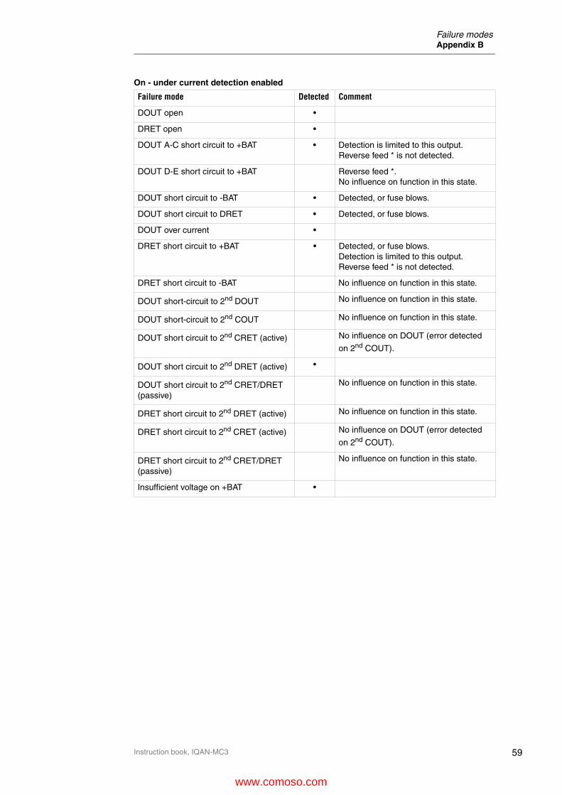
59
Failure modesAppendix B
Instruction book, IQAN-MC3
On - under current detection enabled
Failure mode Detected Comment
DOUT open •
DRET open •
DOUT A-C short circuit to +BAT • Detection is limited to this output. Reverse feed * is not detected.
DOUT D-E short circuit to +BAT Reverse feed *.No influence on function in this state.
DOUT short circuit to -BAT • Detected, or fuse blows.
DOUT short circuit to DRET • Detected, or fuse blows.
DOUT over current •
DRET short circuit to +BAT • Detected, or fuse blows.Detection is limited to this output. Reverse feed * is not detected.
DRET short circuit to -BAT No influence on function in this state.
DOUT short-circuit to 2nd DOUT No influence on function in this state.
DOUT short-circuit to 2nd COUT No influence on function in this state.
DOUT short circuit to 2nd CRET (active) No influence on DOUT (error detected
on 2nd COUT).
DOUT short circuit to 2nd DRET (active) •
DOUT short circuit to 2nd CRET/DRET (passive)
No influence on function in this state.
DRET short circuit to 2nd DRET (active) No influence on function in this state.
DRET short circuit to 2nd CRET (active) No influence on DOUT (error detected
on 2nd COUT).
DRET short circuit to 2nd CRET/DRET (passive)
No influence on function in this state.
Insufficient voltage on +BAT •
www.comoso.com

60
Failure modesAppendix B
Instruction book, IQAN-MC3
On - under current detection disabled
Failure mode Detected Comment
DOUT open No current through load.
DRET open No current through load.
DOUT short circuit to +BAT Reverse feed *.No influence on function in this state.
DOUT short circuit to -BAT Thermal shutdown, or fuse blows.
DOUT short circuit to DRET Thermal shutdown, or fuse blows.
DOUT over current •
DRET short circuit to +BAT • Detected, or fuse blows.Detection is limited to this output. Reverse feed * is not detected.
DRET short circuit to -BAT No influence on function in this state.
DOUT short-circuit to 2nd DOUT No influence on function in this state.
DOUT short-circuit to 2nd COUT No influence on function in this state.
DOUT short circuit to 2nd CRET (active) No influence on DOUT (error detected
on 2nd COUT).
DOUT short circuit to 2nd DRET (active) Thermal shutdown, or fuse blows.
DOUT short circuit to 2nd CRET/DRET (passive)
No influence on function in this state.
DRET short circuit to 2nd DRET (active) No influence on function in this state.
DRET short circuit to 2nd CRET (active) No influence on DOUT (error detected
on 2nd COUT).
DRET short circuit to 2nd CRET/DRET (passive)
No influence on function in this state.
Insufficient voltage on +BAT Under current
www.comoso.com

61
Dimensioning of the IQAN-MC3 moduleAppendix C
Instruction book, IQAN-MC3
Appendix C
Dimensioning of the IQAN-MC3 module
6
12
18
6
12
18
6
12
18
6
12
18
1
7
13
1
7
13
1
7
13
1
7
13
A
B
C
DC4
C3
C2
C1
IQAN-MC3
230
210
5516
3
Ø 6.5
unit = mm
www.comoso.com

62
Safety manual requirementsAppendix D
Instruction book, IQAN-MC3
Appendix D
Safety manual requirementsThis appendix contains a list of the mandatory safety requirements that must be fulfilled in order for the unit to be used up to its specified safety integrity level.
SMR: Safety Manual RequirementMC3-SMR-001:A Use within specification ....................................................... 3MC3-SMR-002:A No field repair ...................................................................... 3MC3-SMR-003:A Safe state............................................................................. 7MC3-SMR-004:A System cycle time................................................................ 9MC3-SMR-005:A Only use an official release of IQANdesign ....................... 10MC3-SMR-006:A CAN communication .......................................................... 13MC3-SMR-007:A Limits on VIN signal range................................................. 29MC3-SMR-008:A Tolerances on VIN............................................................. 30MC3-SMR-009:A Use of DIN inputs in pairs .................................................. 32MC3-SMR-010:A Use of FIN inputs in pairs .................................................. 33MC3-SMR-011:A Use of DFIN inputs in pairs................................................ 34MC3-SMR-012:A Minimum current when using COUT as power driver ........ 38MC3-SMR-013:A COUT error detection limits ............................................... 38MC3-SMR-014:A COUT undetected wiring faults.......................................... 38MC3-SMR-015:A Minimum current when using DOUT as power driver ........ 41MC3-SMR-016:A DOUT used as alarm drivers ............................................. 41MC3-SMR-017:A DOUT undetected wiring faults.......................................... 41
www.comoso.com

For the latest information visit our website www.iqan.com Information in this instructionbook is subject to change without notice
Parker HannifinElectronic Controls DivisionSE-435 35 MölnlyckeSwedenTel +46 31 750 44 00Fax +46 31 750 44 21www.parker.com
Parker HannifinElectronic Controls Division1651 N. Main StreetMorton, IL 61550USATel +1 309 266 2200Fax +1 309 266 6674
Publ no HY33-8001-IB/UKEdition 2014-12-11
www.comoso.com


![Kitab-i-Iqan [1882 edition] - Internet Archive · 2010. 10. 6. · Title: Kitab-i-Iqan [1882 edition] Author: Baha'u'llah Keywords: Created Date: 20101006010919Z](https://static.fdocuments.net/doc/165x107/612d6e041ecc515869422f2f/kitab-i-iqan-1882-edition-internet-archive-2010-10-6-title-kitab-i-iqan.jpg)


