IPSO FACTO - COSMAC ELF - RCA CDP1802 Computing · ipso facto issue /15 r~} ... a single cycle...
62
IPSO FACTO ISSUE /15 1978 (A publication of the Association of Computer Experimenters) HARDWARE PAPER TAPE LOADER IS YOUR MICRO-COMPUTER SIOO .. LOGIC TESTER LETTERS TO THE EDITOR A SINGLE CYCLE CIRCUIT FOR THE 1802 A FINE RESOLUTION AUDIO OSCILLATOn PROGRAM CERTIFYING AUDIO TAPE FOR DIGITAL USE A COIN TOSS -' 14AGNETIC TAPE DATA RECORDING - A SIMPLE 25IC-2 TRANSISTOR CODE PRACTICE OSCILLATOR CONVERSION, AND ASCII I TEMS FOR SALE A DIS-ASSEMBLY OF ED MONITOR A NOTE OF CAUTION FROM ED MCCORMICK THE 1802 MUSIC AN RS-232-C INTERFACE ERRATfA - MEMORY MAPPED I/O ERRATTA - 1802 INTERRUPT PROCESSING TEC-1802 SPEED CONSIDERATIONS ACE ELECTION NOTES A LOW COST 8 DIGIT HEX DISPLAY USING THE 8 DIGIT HEX DISPLAY ACE MEETING MINUTES ACE CLUB NOTES A SUGGESTED PROGRAM CODING FOJU.1 . . ' ; *' 1 2 3 4 5 6 7 8 9 10 11 12 13 14 15 16 17 18 19 20 21 22 23 24 25 26 TABLE OF CONTENTS .. PAGE 2 4 11 12 14 19 20 21 22 24 26 27 29 30 35 36 41 43 44 44 48 49 52 55 59 61 Editor • Tom Crawford Invaluable Assistants; Wayne Bowdish, Diane York, and all contributors to this issue. Information furnished by IPSO FACTO is believed to be accurate and reliable. However, no responsibility is assumed by IPSO FACTO or the Association of Computer Experimenters for it's use; nor for any infringements of patents or other rights of third parties which may result from it's use. All Newsletter correspondence should be sent to: Tom Crawford, 50 Brentwood Drive, Stoney Creek, Ontario, CANADA L8G 2W8 (I)
-
Upload
hoangthuan -
Category
Documents
-
view
246 -
download
15
Transcript of IPSO FACTO - COSMAC ELF - RCA CDP1802 Computing · ipso facto issue /15 r~} ... a single cycle...

IPSO FACTO ISSUE /15r~}{CH, 1978
(A publication of the Association of Computer Experimenters)
EDITO~'S R&\~RKS
HARDWARE PAPER TAPE LOADERIS YOUR MICRO-COMPUTER SIOO COl~ATIBLE?
.. LOGIC TESTERLETTERS TO THE EDITORA SINGLE CYCLE CIRCUIT FOR THE 1802A FINE RESOLUTION AUDIO OSCILLATOn PROGRAMCERTIFYING AUDIO TAPE FOR DIGITAL USEA COIN TOSS PROGRM~
-'14AGNETIC TAPE DATA RECORDING -A SIMPLE 25IC-2 TRANSISTOR CODE PRACTICE OSCILLATORHEX-DEOnJ~L CONVERSION, AND ASCIII TEMS FOR SALEA DIS-ASSEMBLY OF ED MCCOm~ICK'S MONITORA NOTE OF CAUTION FROM ED MCCORMICKTHE 1802 MUSIC ~~CHINE
AN RS-232-C INTERFACEERRATfA - MEMORY MAPPED I/OERRATTA - 1802 INTERRUPT PROCESSINGTEC-1802 SPEED CONSIDERATIONSACE ELECTION NOTESA LOW COST 8 DIGIT HEX DISPLAYUSING THE 8 DIGIT HEX DISPLAYACE MEETING MINUTESACE CLUB NOTESA SUGGESTED PROGRAM CODING FOJU.1
..';
*'
123456789
1011121314151617181920212223242526
TABLE OF CONTENTS .. PAGE
24
111214192021222426272930353641434444484952555961
Editor • Tom CrawfordInvaluable Assistants; Wayne Bowdish, Diane York, and all
contributors to this issue.
Information furnished by IPSO FACTO is believed to beaccurate and reliable. However, no responsibility isassumed by IPSO FACTO or the Association of ComputerExperimenters for it's use; nor for any infringementsof patents or other rights of third parties which mayresult from it's use.
All Newsletter correspondence should be sent to:Tom Crawford,50 Brentwood Drive,Stoney Creek, Ontario,CANADA L8G 2W8
(I)

EDITOR' S RE~·11\RKS BAR. 26, 1978
I am pleased to report that, as of this date, our membershipstands at 351 paid members. This includes 242 Canadians, 105Americans, and 4 International members. I would like also to reportthat, out of this total membership, less than 35 people have contributed to the Newsletter (not counting letters to the Editor). I trustthe remaining 90% are seriously considering a submission in the nearfuture. Remember: you don't have to be an expert in your field towrite for this Newsletter. All you need is an idea, a pencil and apiece of paper! You don't even have to have a working application;if you've been mulling over some idea, put it down on paper in theforu of a proposal, and send it in. Perhaps someone can help youout with some practical suggestions; or perhaps they have alreadydon e it, and can tell you how to get yours wor-k.Lng , Surely youhaven't all packed your 1802s into a box on the shelf and forgottenabout it! The prime purpose of this Newsletter is to communicateideas between members, but you must put your ideas down on paperfirst, so get to it!
MACHINE OR ASSEMBLY LANGUAGB?
The question of whether to document a pro~ram in machine languageis a many-faceted one. On the one hand, a hex dump in machinelanguage is a simple procedure, taking little time, and occupyingonly a small space. On the other hand, an assembly language listing,wi th comuerrt.s and assembled machine code, is a lengthy procedure,requiring a large expenditure of time, and generally occupying asubstantial amount of space. But consider the real purpose of writing a pr-ozr-arn down on paper. Generally, you wish to make it available to s ome or:e else, or even to vourseLf , at a later date. Unlessyour pro~ram is a trivial one (say 10 bytes or less), will you oranyone else be able to understand what it does, or how? Will yourfri ends (or f'e LLow ACS mercbers ) be able to modify your program to.run vii th a different clock frequency, or different I/O devices?What if they load your program, and it doesn't work. Will they everbe able to figure out for themselves what's wrong? All of the aboveque sti ons point to the need for commen t s on a pr-ocr.im Ii stine;, toexplain t h s. details of a programs operation. Com.aent s aren'tdifficult to produce; they usually reflect the thinking of a programmeras he desicns a program, and gets it to work. All the pro~rammer
ne eds to do is write down a com.r errt , each time he wr i tes a machineinstruction. Easy, right?
The use of assembly language a I Lows the pr-ogr-ammer- to easily remember an instruction by its mnemonic rather than by its hex code.It also allows the use of labels for branch points and variable orfixed data locations. These labels can be easily found later, whenyou mus~ re-assemble your program because you needed an extra instruction in the middle.
The ~iggest argument against the use of assembly lan~uage is saidto be the reqUirement for an as senb l er- pr-or-r-am. Tlds simply isn'ttrue. .C' Ad;nittedly ~ an assembler is ni ce to nave , but you cal: [T,ainmany 0.1. t.ne bener i ts of assembly language when hand-assembl1.ng t he

r-IACHIN~ OR ASSEIilBLY LANGUAGE CONT'D
machine code, especially as your programs exceed the 10-20 bytesize. Anyt'lay, how many of you can really think in machine codewhen reading, say, a 256 byte program written by someone else?Think about it.
I think the best way to illustrate my point is with an example,and 2n excellent one has coce to hand. Recently, two large circulation magazines, POPULAR ~L~CTRONICS and DR. DOBB'S JOURNAL,published an interestin.e; monitor program ~or the 1802 (Ed, youwer-e going to tell me why they both printed it?). Unfortunately(in my opinion), both of these magazines published only an un-commented hex dumPTIsting of this program. How many of you, whenfaced with this type of program docurnentation, decided that itwoul.dn t t be wor t.h the effort? HO\'I many others tri ed it, butcouldn't get it to work right? And finally, how many of you beganto dis-assemble, and comment the program, in order to figure outhow to get it working on your particular 1802? \'louldn' tit havebeen nice to have all that information in the original listing?In this issue of IPSO FACTO, you will find a dis-assembly of EdMcCormicl:'smonitor program. I want you to compare this form ofdocumentation with the hex dump published by PE and DDJ. I hopethis example makes my point.
SI~P1Z APPLIC1TIONS
In order to maintain the involvement of those not (yet) interested in a general purpose computer system, we intend to put moreemphasis on simple, fun-type applications, requiring only an 1802,256 bytes of memory maximum, and perhaps a few bits and pieces ofLnt er-f'ac e har-dwaz-e , The first one is in this Issue: The 8 digithex display for under ~10. This simple application \'l/ill be extended in the next issue, to become the display for a Raal Time
. Clock. You will also find a speed control for those cheap 6 VoltDC motors, which requires only a power transistor, a door bellcontrol based on your 1802, and a sump pump t i ner-, How about you?Let's hear about your application: the simpler the better.Remember: the best way to learn is by doing.
I will apologize at this point for the delay in getting outIssue J4; we had a few printing problems. I expect we will soonbe back on schedule.
NETRONICS, ANYONE?
Speaking of schedules, has anyone received a news bulletinfrom Netronic's Elf User's Club? I have had several people askme this question. Their memberships, at 83 eaCh, po back about8 months. Perhaps someone from Netroni cs R&D, Ltd. wouLd care toreply c/o this Editor?
(3)

IITl'~lmATICHAL FOSTAL COUPONS
I have had a number of people send me International postal coupons for post:3.ge. These coupons cost the buyer in tile U.S. 42¢,yet can only oe redeemed for Canadian postage in ~he amount of 12tor 25¢ (d ependdng whdch postal cLer-k I talked to). I sugge st thata 190~~ to 400:, mark-up is a little much. Cash or money orderwould be a better deal, I think. Please remember, though, thatonly Canadian posta~e can be used on letters mailed in Canada.
AN 1802 iUJ·1 ~L~'r
A number of ACE members are also hams, so some members of ourlocal amateur radio club will be attempting: \"0 set up a "net ll todiscuss CO~I:~:.on 1802-type probLems in the near I'ut.ure , They '1illtry to extend coverage as far as possible (interest already existsin British Columbia, Cllicago, and I'lashington, D.(~.!). Contactthe followin~ person for more information: Brian Fox (VE3 EBF)
Fox Comounications Ltd.124-3 King St. ~.
Stoney Creek, Ont.CanaJa LaG IJ2Phone (416)664-5433
INTERlSTIKG AilTICLES
Tv/O articles in particular have been drawn to my attention.The first is a 3-part Video Display Unit construction article, published in Electronics Today International magazine, August-October1976. This unit displays 8 rows of 32 characters each on a TV setor video monitor. Most of the circuitry is TTL, exceut for thecharacter eenerator (a 2513) and tte memory (2X2112's). PC Boardlayouts (single-sided) are included in the article. I would estirna te the parts cost to be about ::~50. Several people are currentlyinvolved in building one of these units. I shall be reporting ontheir progress.
The second article can be found on pages 19 to 21 of the Decenber 1977 Circuits and Sv s t erns Journal of the I~2E. ~'lrit ten byJohn Doyle of the University of Toronto, the article is entitledMicroprocessor Interfacin~. It stows several very simple interfacing techniques to a110\'l connection of Lj~D' s , ,speakers, meters,potentiometer, $ bit D-A's and op amps to your microprocessor.If you are lookinG for a copy of this Journal, I suggest you trythe Science and Engineeri~g Library at your local college oruniversity.
HAltJ'dAR8 PAPGH TM- c; i,vJ~.:J,~l{
Harley Shanko and Jorgen r'lunck
'fhi s desir:n r es u.lted f'r-o:n t he authors' need for a s i mp Le meansof generatin~ a media for pro~rcrn stora~e and for entcrin~ theseprortrams into their uC system. Eac h had a paper tape reader thatwas not yet in use, and a RCA 1802 uP based system. .The dilemnawas t h i s : Isn t t there some simple 'day to punch tape and be able
(4)

HARD'.lAHS PAFl.i:R 'f."PZ LOAD~R. Cel,IT'D
to load it \"Ii thout requiring aof't.war-e to do the ASCII-to-Hl:i:Xconversion and HEX-pair packing into bytes?
Yes! Here is a relatively simple, low cost solution. Itrequires only 4k CI·IOS IC' s, exclusive of the input port. Tapepreparation is very simple; _ in the extre~e, only the object codeneed be punched, with some leader/trailer at each end. This designassumes a compatible interface exists at the paper tape reader,_with +V- Logic 1, OV e Logic 0, for both sprocket and data signals.
MEDIA FORMAT AND FREPAa\'l'ION
It is assumed that a Teletype (TTY) or similar device is available to punch tape and to print hardcopy for a record of the tapecontents. This hardcopy is helpful for verifying accuracy of thedata on the tape, but is not an absolute necessity.
The data to be punched onto the tape is the object code (machinecode) of your program(s). This article deals with hexidecimal(hex) coding only. Thus each byte will be represented on tape bytwo hex characters in ASCII coding. See Table I for a step-by-steptape generation procedure. This format is useable for both motordr~ven and manually-pulled tape readers; the authors have inter-
\
faced both types. Since the manual type requires a lit-~le addi-tional 'formatting' for convenience, that format will be described.By experience it was found to be dif:icult to 'pu~l in' more than256 bytes per 'pull'. Note that, at 10 characters/inch, that isabout 4 1/3 foot 'stretch'. About one foot of trailer is used tofollow each 256 bytes as a zone to 'stop on'. Otherwise, tapemovement between successive pulls could cause erroneous data entry,with the 0.1 inch tape hole spacing•. All ASCII control characters(non-printable codes, column 0 and 1) are transparent to the loader.Several of these control characters are used advantageously; NUL'sare used for the leader, trailer and between the 256 byte blocks;CR and LF are used to format the hardcopy. Figure 1 illustrates arepresentative listing of a formatted object code tape hardcopy.
'l'II~OaY OF OP8R·\'l'ION
The loadar logic consists of three sections: control, conversion, and input port.
The control section consists of two f:J,.ip-flops and a two-dnputOR-r;ate. Figure 2 illustrates the loader th,ine and Figure 3 thelogic. The OR-gate is used to 'detect' the column 3 and 4 ASCIIHEX codes. Full decoding for ASCII-HEX 0 - 9, and A - F codes isnot implemented: and printable ASCII, columns 2 - 7, could beloaded, but since the object code will only be hex, this factpermits the simpler decoding. The presence of a valid cod.e andthe leading edge of the sprocket pulse sets F/F 1, removing the'set' signal from F/F 2. This sir-;nal provides initialization toF/F 2. F/F 2 divides ~he sprocket timinr: by tV10: the positivetransi~tions of F/F 2 Q line sets the DMA flip-flop, F/F 3, TRUE.F/F 3 Q output then pulls the DNA-IN line. V/hen sensed lJy the
(5)

THGORY OF OPiilAfION CONT'D
uP, an input port Enable is generated (S2 or SCI), resetting themlA flip-flop and enabling the port' 3-state gates. The registercontents are then present on the data bUs, and the uP writes thedata into memory.
The conversion section consists of a 4-bit full adder and two4-bit rep;isters. Table II and its note describes the ASCII-to-HEXconversion. Simply stated, the 4 LSB ASCII code bits are ADJEDto a value of zero or nine, depending on the state of input bit 7.When hex A - F (ASCII codes 31 - 46) are present will bit 7 beTRU~; then a value of 9 (binary 1001) is presented to the B-inputof the adder. 'I'he resultant sum is the desired hex code. Theadder outputs are clocked into the first register, and, simultaneously, that register outputs, containing the previous value, isclocked into the second register. This presents an G-bit code tothe input port.
The input port consists of eight 3-state gates (2/3 of the $OC97and the output section of_the 4076) and F/F 3, previously described.In an 1$02 system, F/F 3 Q line connects to the nr:IA-IH line, "\-'1i thS2 or SCI used for the input port enable signal. If the 1$02
·Interrupt line is not used, SCI can be used; otherwise S2 is re·quired; b of a 4555 dual-decoder can be used to generate all fourState decodes.
r·IULTIl-'L~ m:A-IN PCRTS
A contention problem will exist if the tape loader is logicORed with a DMA-IN signal from another input device. The simplestsolution is to add a switch to select which port shall receive theSCI signal, in order to enable the output of that Dort to the databus. Also, wire all ports' ~~ flip-flop RSSETs directly to theSCI signal. What this provides is a reset to all DNA flip-flops,whether that port is selected or not. The reason for this isbecause on power up one or more JHA flip-flops will come up set,and will pr-oduce a continuous DI'!A condition on the ORed lJ:'Lt>.-INline, until it gets reset. Figure 4 shOl"1S a typical arrangement.
(6)

J
TABLE I
TAPE PREPArl1TION
1. Turn on TTY and set to LOCAL mode.2. Punch about one foot of leader (press HERE IS key several times).3. Punch a CR and·LF.4. Now punch the object code. After entering 32 bytes (64 hex
characters), punch CR, LF. Repeat this for each 64 hex characterline. (If tape reader is manually~pulled type, add about onefoot of NUL's after each 256 byte block followed by the CR, LF.This will occupy about 4 1/3 feet of tape; longer lengths maybe difficult to pull through and load properly.)
5. After end of object code, punch about one foot of trailer ~UL's).6. If reader is manually-pulled type, and using black tape, a
visual indicator of each block ending is convenient during loadine. This can be added using white typine, correction fluid, suchas 'Liquid Paper'. This simplifies recognizing the trailer gapsbetween blocks.
TABLE II
ASCII - HEX CONVEHSION TABLE
cha~~-~~~~-~I~AS~~n~;y~i~l' ~~He~~~T=;;r~;; ·~~;-;;~---·:·:~~tP:~-~1. I A - ----'"8 .~_. Sum ::
a ! 0011 0000 ! 30 I 0000 .- 0000 -~_~0~31ue ~1 l 0001 31 0001 00012 1 0010 32 0010 00103 ~ 0011 33 0011 00114 0100 34 0100 01005 0101 35 0101 01016 0110 36 0110 01107 0111 37 0111 01118 ; 1000 38 1000 10009 lOOll 1001 39 1001 0000 1001A 10100 0001 41 0001 1001 1010B !i,,; I 0010 42 I 0010 1010C 0011 I 43 . 0011 I 1100D 0100 l 44 I 0100 1101E 0101 i~?- I 0101Jl 1110F : 0100 0110. ~_~~~. 1001 ---l 1111
NOTE: Observe that the hex code for characters a - 9 areidentical to the 4 LSB's of ASCII codes 30 -39:further note that the hex code for A - F can berepresented by nine (1001) plus the 4 LSB's of 41 - 46.'rhus, using bit 7 to add zero (for bit 7'" 0) or ninefor bit 7 =1).
( 7)

® TIAi Po OW T~1'E...... _
~l--TRA\L(R .1?1''{ T£ N,,-_.......'-......,
® 5PROCKtT
® B\T ~ 0 K 1
I ., :I ,
~L;IIII~tI
:--------~----------.,;-----!I----.L.-_Yr_----Yr_-----~'r_---
- - --I
I
~,~) ~/~ :3 91)M~ - IN )
(9 J-!. P 'PORTI:.NI\~LE
(SCI OR 51)
® FIt:- 2 ~
-CD-
l-lORDWARE: 'PAPER 'APE {...oAUER - T'M' N 6

\'
0
2.
-3
DA'ABUS
4
I;
~.,
s c, I
\I
+\1
®
II~ 16 I z.' BOC91
1
3,/0 4 ,....,_... ._-, .- . z,.I
5 , 4 55 ,1\1
10 " (J"i..,/ ... A ! I 'Z. 1'2. \J c" -::>
1'5 III '3, I U11 .'3 1"3\- I/ °1 \\..\U-'5 'PI'-
4 il ll OO B 4.V/ 9
ll"+ rJL __"")
~rPi/
8I-nl L/
,151 CI
.,,~>-- L:= 1<l)' .... ':l-rr ''I I --- --
( I fA---2. --=-
IS JI
I..(O'Ce--'--_Y 14 • +-'J t--""'2.
'Ie Of40-' I :-Ut;'8"'"
,
~'~llO-J:. B 404912- ~1j1! . I 4-
® 3 c.. Ilf
~ 13~l
S I "3'U r-- - ~ 1
143>-+\1 D I--
IUS1 J I tJ5-/ +'1 u i-'3(
5 UCJ5c:
ltDI '3Q 40n12 3
IQ2.
~ C. -@ ~o \"3-© -10 '2...1:J7
R. ~®-
1."k. y-)----_.
•
')'- 'l. '\
~ 13 >4 12
5 II
l. 10
1 9B {!}
+V 14
'iPRMKhT LI-
\"j). VG'. P-.t.An r ~J:ft
SaL.. PLtL
---~WAEL[ In.
-\0-®
"24 ;:IAN, 8.

C)/V/ f..:, - IN Dr fA ENAcLrFORTH,68Ki:
RESET+.
Df'iR REG. ~..
,DMA R.eG.IJF~T..... 1<1-,.
D,.. TA 0117I, I /. bl/TA B/JS/8 Ig
'80 C, DMA - IN
'1DMA-IN SCI
DATA ENA8L.tPORT#2. ltiki #,DMA At: G, RESl T -"
DMA Rt.GH:SiLA- I'-.,r--
DATA OV.T - /
/8
FIGURS 4
Editor's Notes:
1. The paper taoe re;:~der mentioned in tIle article is a Model,TPR-l optical paper tape reader, available assemoled andtested for U.S. '?32.50 from fiA,SCO, Box 14, l1eadville,Eass. 02137 USA. Write for more details, or see one ofHAli:CO's ads in most of the hobhyist computer journals.
2. The TSC-ld02 keyboard oner'ltes in a Jt~ mode for proframentry. Anyone care to write an 'article showing how theyinterfaced this paier- tape reader to a '1'~C-1802?
(10)

IS YOUR MICROCO~WUTER S-IOO CO}WATIBLE Wm. Lee Pfefferman
I'm sure that by now you all are aware that we COSMAC users areminority members in the world of microcomputing. Being minor-ity members, we are in a sense cut-off from the mainstream ofsoftware that is readily available to the majority. Unfortunately,many of us are members of still another minority; we operatemicrocomputers that are not compatable with the S-lOO bus andthis serves to isolate us from the mainstream of hardware thatis available to the majority.
For me, 5-100 compatibility will make it easier for me toaccomplish the goals that I have set for my computer system andI am currently in the process of makine my C05MAC-based m~cro
computer compatible with the 8-100 bus. Having an 5-100 compatible computer will enable me to do several things that Iwasn't able to do previously.
1. It will be easy for me to EXPAND on the existing featuresof my computer, memory or floppy disk controllers can beadded almost at will.
2. I'll have the ability to CHANGE the existine features ofmy computer, in whole or in part. Changing to a differentmicroprocessor may not be as easy as replacing a singlePC board, but I don't think it will take too much effort.
3. I can INCREASE the CAPABILITIES of my computer byadding boards that perform a wide variety of functions.S-lOO boards now exist that will control floppy disks,synthesize speech, and analyze the operation of acomputer. .
4. I can IMPROVE on the existing parts of my computer·byreferencing the large amount of literature that hasbeen written for 5-100 compatible systems.
By changin~ to the S-lOO bus I will also benefit economically.I will have the ability to select PC boards from many competingvendors, this will assure me of being ahle to purchase topquality boards at low prices. In addition, I will be able tosell and trade my boards with many more people than I couldbefore. Besides the obvious economic benefits, I hope to usethis capability to keep the structure of my system somewhatdymamic in nature.
As you can see, in my case, the advantages to having an8-100 compatible computer are several and I can hardly wait tolook throur,h the advertisements in the next issue of BYTB.
( 11)

LOGIC TSSTER Tom Jones
I designed this tester from available parts to aid in TTLtrouble-shooting some time before I eot into CMOS. I added theCD4050 to allow CD1802 design work. It has helped to resolvesome mainframe problems where my Tektronix 453 could not helpme--due mostly to the TRAP or r·1E~·IORY· mode.
To use, set S2 to pulse and connect either pin 1 (for TTL) orpin 4 (for CMOS) to the test point and observe the 7-segmentdisplay for a "1" or "0" or "P". Also observe the decimal pointfor a "pulse, stretched" indication. A square wave will givea IIp'', but very narrow pulses far apart will only keep the decimal point on. The decimal can now be used to watch for positiveor neF,ative pulses.
If a solid "1" level is observed, you can test for a randomnegative pulse for a long period by settin~ the "1!.' on Sl andsetting S2 to "TRAP" mode, and go to lunch. If the solid high(perhaps 5 volts) ever goes low, the decimal will set. In fact,if the t~ter is being powered from the supply, the trap willset even when the probes are not connected if power fails.
If a solid "0" were monitored you could of course check forpositive pulses by setting Sl to '!J''' and S2 to "TRAP" as before.
In many computer problems, it is necessary to gate the inputwith ano~her function (such as TPB, MRD, or DATA VALID). Connectinput 2 (TTL) or 5 (CMOS) to this function to make sure you areobservine the signal only durinp the period of time you are interested in. Choosing this function can be quite a bit of an art,and is not limited to data strobes. An' auxiliary flip flop thatis set by one function and reset by another function can providethis input on 2 or 5, thus allowinp you to choose whatever timingwindow your ima~ination can create. I've done it. The otherleg of the gate on IC3 is brought out for TTL but not for CNOSon mine, I may bring it out for CUDS if I ever need it.
My unit is housed in a small wooden box (a doctor' gave meseveral, I have no idea what he receives in them). I wired everything on perfboard using a wirin8 pencil and sockets. The transi stor is house numbered, but any good PNP will wor-k, The I/Ojack is half of a 14 pin wire wrap socket, and the plug is theother half with the pins cut short and carefully rounded with afile. I simply push the wires in the socket holes and seal themin with black rubber compound such as the G.~. stuff sold forsealing car windows. Long leads for inputs and power and veryflexible wire will avoid much frustration in the future.
Some features I would like to add to any unit I build again:battery power, to avoid using the system power. The systempower may be the problem, and anyway the hook up wires are abother, and wi.Ll, ruin the unit if connected backward. I wouldlike to add a feature that shows an "F" if the input voltage isnot a valid "1" or "0", also. The present unit shows a floatedpin as a "1" due to the pUll-ups. I think some cheap diodeswould make the "e" and "f" ser.;ments both light for a al" level,instead of only the "e" as presently. I Jeave these to anyoneelse interested in his ovm tester, and hope my experiencesusing mine will sug~est better ideas to you.
( 12)

. i
"':
. ~'l("f 'u;..' ...1 I r:
/
_ _~
,.III
',,,;-; I
-C:"'J_~_ ..r
. I --1-
-t
i c { 8 I II--,-----l
IC~ 7 1'+ iic 3 7 I If I
I-I: I'0 '----,..----.c: .~ 1
.. i
____ . /"3'\.. (a;'0
c0 V
. /<'3
1~o,
(13)
(~ ..n~'" itt:"')
. ,r:)6o
III
""
/3 ".5JI .. ----r2 f --1-7<46 ClP -.JJ
/I ,
llf - +5V
7- SfG. DI!~pL.A'I: HP 50ra2. -77 50

LETTERS TO THE EDITOR'
Dear Tom:I am currently wor-ki ng on an interface between the 1802 and a
National Semiconductor's 57109 number oriented processor. If thehardware result of this could be software coupled to a basicinterpreter such as the tiny basic available from the ITTY BI'l'TYCmIPUT2;R CO., the result would be a pretty tasty system with thenumber crunching done by the peripheral processor. (How does a21\ interpreter capable of floating point or scientific notationand functions such as all trig functions and their inverse, square,square root, log, antilog, LN, exponen,tials? inverse, degrees-toradians, radians-to-degrees, etc. grab you?}
I hope to have some notes available soon if anyone is interested.If anyone else has any ideas, I'd like to hear from them.
Yours truly, Dave Hayward, 6640 Fielding, Apt. #12, Montreal.Quebec, Hl~V lN3
Dear Mr. Crawford: February 6th, 197$.
Received first newsletter last month, keep up the ~ood work!Just a few comments on my system and the nroblems I have en
countered. I am running now an ELF II (no doubt you have heardof it!) and am running it with 1024 bytes of memory. I put thistogether with 2102's bou~ht from S.D. Sales.(it's a good value,11 to 12 dollars for lK.)
I received ~ayne Bowdish's cross-assembler too, although Ifear it will be a stru~gle gettin~ the ------ to run on our PDP-8/E.(has anybody done it yet?)
I have done little work with the computer lately but havesucceeded in getting a few of my ideas working; i.e. hexadecimalcounter on the television screen, "t.v. typewriter" - four linesof eight characters! and a ~emory tester. (sorry but I've notime to write them up in good)
If would print this request for me as soon as possible? I'dlike to know if anybody has considered a game of Tic-Tac-Toe asa machine lan~uaF,e project-please send me your ideas.
Has anyoody considered a light-pen for the CDR1861 graphics ICchip? Please send software that you have implemented.
I have to ~o now so - keep up the good work on the newsletterand keen well.
Yours truly, D'Arcv rtoberts, 660 Laurier Blvd., Brockville,Ontario. K6V 5X8 .
Dear Tom: Jan. 14, 1978.
I am interested in the 1802 User's Group. I just purchased aRCA VIP, and am very pleased with it. I think it has the potentialof the KIM-l, and am considering starting a VIP NewsLet t er , However, I don't wish to duplic3te your efforts. Do you plan on doinga re~ular newsletter? Arc Y0U interested in the VIP? (Ed. Note:I understand RCA is startin~ a VIP User's Group. TC)
Some quick notes on the VIP: Kit assembly went well. RCAestimates 3 hours for assembly; it took me ~ hours (I'm a fairlyexperienced. l<i t bui Lder ) , plus another 4 hour-s of \virinr,: and debuc?in~. Ny 5 volt power' supoLy had an interr:li ttent short \"hi chreduced the volta~e to about 2 volts; after cutting the plastic
(14)

LETTERS TO THE EDITOR CONT']
sealed assembly open, I discovered a. dd ode Tead dangling next tothe heat sink. I bent it into a safer position, and have had nofurther problems.
I'm using the "\'laterloo ll RF modulator (BYTE, Jan '7$), and findit works well, although it interfers with other channels (evenwhen not directly connected) if the RF lead is 6 feet long. Ilike to lie in bed and play with the VIP, so I needed a long connection to my TV. By putting the modulator near the TV and runninga long video line instead, the interference was eliminated. Iused the VIP's 5 volt supnly to power the modulator.
Documentation provided with the kit is pretty good. The logicdescription, trouble-shooting guide, and test programs are excellent; the ROM operating system guide is very good (the operatingsystem itself isudequate); the CHIP-S interpreter guide is onlyfair, however, and there is no description of how each of the 20video games work.
The video games themselves are pretty good, but don't expectquality. "Wipe Out ll and llKaleidoscope" are especially fun (I'veonly tried three so far). My first project will be the game of"Life". .
The CHIP-S interpreter provides a reclhigh level (although hexadecimal) language for controlling the display, reading the hexkeyboard, etc. It is easy to learn, and certainly one of the bestparts of the system. Th~ interpreter itself, by the way, takes512 bytes of RAM, and the first thing the VIP user must do is enterthe interpreter code (in hex) and save it on tape.
Hardware excansion is easy; adding a parallel I/O port and 2Kmore of RM~ is just a matter of plugging in chips •. The parallelI/O port could use more handshakin~lines, however (there is onlyone output handshakin~ line, which is also used on the board forother things).
In summary, it~s a fine system, and provides lots of room forboth hardware and software experimentation. It's the perfectsystem for the computer hobbyist just getting started, or waitingfor "the ultimate svstemll•
Sincerely, Bob \vallace, Co~ind Design, PO Box 5415, Seattle,Wa 98105
Dear Tom Crawford:
Thank you for your kindness and for the time you spent to getme all the information on A.C.~.
I'm really glad to hear, that there is so many of you who workon 1802 systems1 Here in Vancouver only a few of us have 1802CPUs - mostly 8080 - Z80 or 6800 the favourite one. We have acomputer club also that hold meetings on the first Wednesday ofevery month and also publish a newsletter monthly. In the futureI'm going to send you a copy of our newsletters. On our next clubmeeting I'm r,oing to display your letter and I'm sure will havesome very favourahle response about information exchange betweenour two clubs.
Please say HELLO to A. C. ~~. members from our Vancouver club!Thank you again, will be in touch soon1Sincerelly, Veslot Gellerthegyi, No. 305-1315 Brou~hton St.,Vancouver, B.C. V6G 2B6
(15)

LETTER TO THE SDITOR CONT'D
Dear Tom:
I read with interest the fact that there is a 1802 club formedin the Toronto area, from a copy of Byte. I appear to be the onlyone in the Halifax, Nova Scotia area using the u-P at least fromthe club meeting here that I have attended. I am using a P.E.COSNAC ELF board with outboard 4K memory. I/O consists of aASCII Keyboard, paper tape reader and a model 19 Teletype, ofcourse.
I have been programming in machine language up until this pointin time as I am not proficient enough in software to prepare anassembler. \vhile I exuect that you are aware of this already, Inote that Infinite Inc. 1924 Waverley Place, Florida have TinyBASIC as well as a few other small programs available. I amordering this and if you wish can report on any success that Ihave with it. I am enclosing a photocopy of their ava~lable
programs. It appears that only the BASIC related programs are ofmuch value as the others can be done quite easily by most anyonewho has done anything with the chip.
About the only thing that I have done that might be of someuse to your club might be my pro~ram which is a print using BaudotTTY subroutine. This will tal(e ASCII data, either immediate fromthe keyboard, or a block stored in memory, code conver.t it toBaudot and serialize it (as a DART would). It outputs on the Qline and is optoisolated from the selector ma~nets. As it takesno I/O port or hardware other than an optoisoiator and a fewtransistors and resistors, it is a very cheap way to get the 1802talking especially if you can get an old model 15 or 19 free as I did.
I would be interested in hearin~ from you if you have any software available. I \vould be interested in an assembler and possibly BASIC if the Infinite software doesn't map too well with mysetup. Also I would be interested in any work that is being donein either 1702 or 270$ EPROMS as I would like to have some formof monitor and/or paper tape loader in RO!\~ as I am getting tiredof starting from scratch every time 1 shut down to do somethingto the Hardware ••••
Thanking you in advance, I remainYours very truly, Brian Mi.Ll.Ler-, Box 34 Site 12A, R.R.3Armda.Le , N. S •
rvlr. Doerwald:
Thank you for acquainting me with your group, I was a bitsurprised at the size 8nd activity of the lS02 ~roup you describe,1 had thou~ht we were odd birds. I have heard of one group inTexas. My application fee is enclosed.
1 usually like to contribute what I can to any club I join,but at the present, I have little to offer. I am only just getting my home-brew 1802 on the air. I started the desi~n a yearago, but time and money--well, we all know the story. I can sendone proven design, my logic probe, which I have used on CMOS athome" and TTL at work on the job. (1 am a computer field engineerrepresentin~ Honeywell Information Systems.)
(16)

LETTBRS TO THE EDITOR CONT'D
What I have is an 11" by 5" perf board half full of wire wrap,a TTL hex keyboard, and a paper tape read~r. On the board area CPU, 2K of 21L02, a parallel port and a serial port, and anunfinished UART based cassette interface. (I don't intend tofinish it, but to use the Netronics I/O and their monitor inRAM.) I have already decoded on the board all the N lines and32 mapped memory I/O pulses.
On the drawing board still are a CMOS (mostly) TVT, a led 8digit panel and ASCII keyboard combo, and a simple A/D-D/A portaimed at a D~I program. First on the list, however is a newCMOS HEX keyboard utilizing the 74C922 LSI chip and the bestKeypad I can find. My keyboard is a handicap.
Some design thoughts: .I suggest that the use of simple I/O driver routines located
in ROM monitors was a shabby attempt by many hardware manufacturers to nail users into thier systems and a practice not~ to beblindly followed by the users themselves. I believe the 1802group is still not much influenced by manufacturers. The onlyroutine I plan to put in RON at preserit is a bootstrap loadergeared for K.C. standard cassette format. (The DART driving Dr~is too complicated). My tapes will all have a short BRT recordat the beginning which will be a basic loader for the rest of thetape. This followed by one or the other monitor. (The BasicLoader will read the starting location of each record on tape andset the X reg to that.) The only remaining task is the I/O portassignment, and since each peripheral has an subroutine in theMonitor, it is easy to give the user a chance to enter each portin turn and plug them into the routines during startup. Thisscheme is not only to help others use my stuff, but to help me--I change my system constantly also. But any 1802 that can bootin that first record could probably run the program quickly.
J.\Iy other dream is a monitor subroutine that replaces eachjump or call in a program and makes possible dyna~ically relocatable code on an 1802. I lean t.owar-d s the standard 44 pin busfor system design, but the idea of standards in the experimenterworld is doomed in my opinion, so the best scheme is to be asgeneral and flexible as can be. The tape format I am designingis an examo.Le ,
Thank you for your letter, I hope this will introduce me, andI shall look forward to recievins future issues of IPSO FACTO.
Yours truly, Tom Jones
Dear Sirs:
••• 1 have considerable electronics experience as concerns hardware but am strictly a beginner as concerns software.
I have built a small 1802 basic system as described in PopularElectronics. It is mounted in a Hammond case and I have beenable to pro~ram it with the help of the above ma~azine. I haveadapted a pro~ram from P.E. to turn the Q LED and a speaker on andoff under control of a pro~ram which I use with Cibachrome colourprocessin~. Even using a CD4047 as a clock, this micro makes asuper tImer (variable Q time intervals).
(17)

LETT~~S TO THE EDITOR CONT'D
However, I plan to build another for ~eneral purpose usage andmy programming skills will have to be greatly increased.
Looking forward to your newsletters.Yours very truly, Brian Rusk, 1853 Arizona Ave., Ottawa KiH 6Z5
Dear Tom:
... 1 will soon receive the COSMAC VIP version of the 1802 basedsystems and eagerly look forward to a long and hopefully mutuallybeneficial relationship with A.C.Z. For the time being, I'llonly have the VIP, a monitor and a cassette machine as I am doinga product review for QST, the journal of the American Radio RelayLeague for whom I \Vor~ ~f.hen that is done, I intend to expandthe memory, somehow wor-k up a full ASCII interface and go from there.
In some respects, I don't share the all too common problem oftryine to figure out what to do with a microprocessor system--as aham I have all too many practical aDplications. Are there otherhams in the club from the Ontario, i.e. generally, "local" area?If I can be of any amateur radio service to th$m at the ARRL, pleasetell them to feel free to call me at any time. My job there isOSCAa (Orbiting Satellite Carryinf Amateur Radio) Education Program ri:anaser .••
'Thanks for your time and cooperation. I've got a lot to learnand hopefully, in the near future, I'll have a lot to offer.
Sincerely, Steve Place, 271 Williamsto~m Court, Newington,CT 06111
Dear Tom:
••• I own a ELF II and am adding 41\ of RAM and the RCA BinaryArithmetic Subroutines to the Standard Call and Return Techniaue ina 270$. My next move is to add the Number Cruncher from NationalalonF.'; with decoded hex display of upner and lower address bytes.
Some information on parts availability for your readers NSN373dual 7 se~ment display for the Electronics Experimenters Handhook1978 - 1802 display is available from Di~i-Key Corp. P.O. Box 677,Thi~f River Falls MN 56701 for ~2.20 each. 9368 decoder/driver forthe above is available from ACLive Electronic Sales, 44 FaskanDrive, Unit 25, Rexdale, Ontnrio for a decent price. 86 pin wirewrap connectors that fit the ~LF II bus are available from AdventElectronics, 24260 Indoplex Circle, Farmington, }1ichigan 48024.Their code number is 172-0043-005. They can be soldered to theexistin~ bus and wire wrapped for user's needs.
It is great to hear about other 1802 projects and ideas. Thatway I don't work in a vacuum. Thank you. P.S. I would also liketo hear from any other 1$02 users in the Iowa, Missouri, Illinois area.
Yours Sincerely, Alan Bwines, n.I.U. Extension Dept., FairfieldLowa, 52556

LETT3RS TO THE EDITOR CO~~'D
Dear Mr. Crawford:
Following article extracted from Interface Age magazine might beinteresting to our club members.
A byte of music by C.G. Smith in the Nov. issue of Interface Ageteaches how to play music with RCA 1802 Cosmac microcomputer. Themain program \1Titten in machine code for RCA 1802 and 3 J.S.Bachminuets are included in the article. How it works and how to convert the music tunes to music bytes are discussed in the article.The main program is 89 bytes long, so if ydu have only the basicRCA 1802 with 256 bytes RMI, you can already entertain your familywith real music from the micro. How is the interface -- ? --- Theinterface required is only a piece of wire. Connect one end of thewire to the LED attached to the Q output and the other end to theantenna of the radio, place near an AN and tune the radio. Somecharacteristics of the program are:
1. The program works on the RCA 1802 Cosmac microprocessor.2. Only one memory byte is required to give both note frequency
and duration parameter.3. The music is started over again if the end of the song is sensed.4. It is easy to convert real music into music coded form.5. It is possible to play rest by placing Zeroes in the 'note bits'.
ENJOY YOUR NUSIC AND YOUR ---- l:IICJ.O 11111Yours very truly, Mrs. Sianhoei Lie
A SINGLE CYCLS CIRCUIT FOR THE 1802 Wm. Lee Pfefferman
Many of you, I'm sure, are aware of the technique of singlesteppin~a microprocessor to monitor the execution of a program.The 1802 has the ability to be single-stepped and a circuit forsingle-stepning can be found on P.72 of the COS~~C User Manual.
Unlike many other microprocessors, the 1802 has no minimum clockfrequency. For 1802CD users, like myself, this means that ourCOSMACs can operate with clock input frequencies from DC to 3.2 r>IHz.I have made use of this capability to construct a sin~le cyclecircuit. This circuit facilitates the debugging of both hardwareand software.
The circuit operates by setting a select sWitch to one of twopositions.
1. Setting the select switch in system mode connects the systemclock to the clock input on the 1802. This allows theCOSMAC to operate normally.
2. Setting the select switch to manual mode connects a SPDTswitch to the 1802's clock input. Using this switch togenerate clock pulses allO\'1s the user to inspect all information on the COSI'IAC data and address busses, eg. input andoutput data, op-codes, re~ister and memory contents. Pleasemake sure to note that this scheme assumes that the contentsof the busses can be disolayed without being latched.

A Sn~GLE CYCLZ CIRCUIT FOR THE 1802 CONT'D
The circuit that I use is shown below.
manualclockswitch
2k
47 470
r manual clock
toclockinput
system clock
Mode clocksystem: closed selectmanual: open switch
rThe heart of the circuit is the 2:1 multiplexor, constructed
from the gates labeled #1. The multiplexor is used to pass eitherthe manual clock or the system clock to the COS~~C's clock.input,depending on the position of the clock select switch.
I use the S-R flip-flop, gates labeled #2, to de-bounce themanual clock switch.
Finally, the rest of the gates are used to construct a standardTTL oscillator circuit.
A FINE RSSOLUTION AUDIO OSCILLATOR PROGRAM R. G. Edwar-ds
Some people may want to realize a fine resolution for audio tonegeneration using a 1 MHz crystal. The following subroutine may beuseful.
Debounce EF4Return to calline Program via R3Entry Point for SubroutineQuit on EF4 InterruptR9 is Pointer to Delay TableLSB to DFIf LSB is a Zero-5 Word TimesIf LSB is a One-6 Word Times(J cycle NOP)(2 cycle NOP)BIT 1 to DF
Tl,12 B4 *SEP 3TONEGEN REQ
B4 Tl·12TGI LDN 9
SRLSNDLSDNOPSEX 9SR13ND TG2SEX 9 If 8IT 1 is I-Add 2 Word Times
(20)

A FINE R~SOLUTION AUDIO OSCILLATOR PROGRAM CONT'D
TG2 SMI 01BNZ TG2BQ TONEGENSEQBR TGI
4 Word Time Delay LoopUsing R2
Set Q and Generate the other Half ofthe Squarewave
Notice the routine puts out a symmetrical square wave.The subroutine produces tones with a full cycle resolution of
16~s with a 1 MHz crystal. The formulae for the tones are
Delay: 31~50 _ 19 f e 3B~f~
Example:
Delay constantfor f = 440
Frequency fordelay. 52
31250Delay = .440 19 Co 52.022727
~34HEX
f - 31250 - 440 140°4- 52'f'19 .. . 0
DelaysAA#BCC#DD#
for a7B736c645E5751
true temperedE 4CF 46F# 41G 3DG!:/: 38I,
A 34
scale are:
CERTIFYING AUDIO TAPE FOR DIGITAL USE
For best results a tape cassette should be tested before use todetermine if it contains flaws which will create errors. Computergrade tape is subjected to a series of tests \lhich 'certify' itsfreedom from such error producing flaws. Since 'Certified' cassettes sell for two to four times the price of high quality audiocassettes, you will probably prefer to test the quality audio cassettes yourself. The test to be described is not as thorough asthe computer grade certification procedure but it is more thanadequate for the hobbyist.
The procedure is simply to record a continuous signal on tapethen play back at reduced level and let the cassette interface (Withsome additional circuitry) watch for loss of sienal. If the tapepasses the test at reduced play-back level it is almost certain tobe adequate under normal level conditions.
Procedure:1. Record a continuous 2400 Hz tone at nornal operatin~ level on
the cassette. This can be done by connectine; the tape recorderto the KansasCity Standard Cassette Interface since the Interface generates a 2400 Hz signal when idle.
(21)

CERTIFYING AUDIO TAPE FOR DIGITAL USZ_ .. CQEI' t Q
2.3.
Reduce the playback signal level to half of the normal level.Connect the cassette player to the K.C. Standard Cassette Interface and run the tape. If the Data output is connected to thefollowing circuit, any flaws will cause the LED to illuminateuntil reset with the pushbutton switch.
+5V
DATA
PUSH CW TT(11'!
5w,Tc rt (NO)RESET
A COIN TOSS PROGRAM
180A
Robert C. Taubert
I have a COSriiAC SLF II, purchased from. Net.r'onf cs R&D. I haveincluded a brochure and schematic of the ELF II. I have made nomodifications or additions to my ELF though I have some plannedfor the future. I would like to add at least 41\ of memory, anASCII keyboard, a monitor, a cassette interface, and some form ofAD-DA board. I would like to be~in running Tiny Basic as soon aspossible with hopes of advancLng to l~K or larger in the future.
My first attempt at writing a machine language program Has somewhat frustrating and exciting. I wanted a program that would simulate 15 flips of a coin n.nd display the total number of heads onthe left LED and the tails on the right LED. ~"y next project willbe to add a delay sub-routine to allow me to increase the numberof tails.
I have enclosed a copy of the initial coin toss program, whichI wrote, and the random number generater, which I obtaineJ fromRoss Wirth's newsletter. The pro~ram is simple but does use manyof the 1802's instructions.

A COIN TOSS PROGRAI.'; CONT' D
COIN TOSS
# of Flips)(OF - D.15=Max.
"Load R(J).O \'lith address of "MAIN" program-wLoad R(4).0 with address of "RND" subroutine""Set P to R(3) •0 "~lAIN" program counter~Load address of "HEADS" in R(B).O
Zero "HEADS"*Load address of "'fAILS" in R(C) .0
Zero "TAILS"~Load address of "TOSS" in R(D).O
Zero "'ross"itLoad address of "R~.SULT" in R(Z).O
Zero "RESULT"itCall subroutine "RNTI"<4ItIncrement "TOSS"
~GO'l'O 33-.tlncrer:lent "HiADS"
.M(R(A).O) AND 01 to D~IF D='O am<) 2F~ncrement "TAILS"
"'''TOSS'' XOR OF'W'IF D 1= O-COTO IF~hift "HEADS" 4-Bits left
-tt"HEADS" ;COR "TAILS" & store in lvI(R(E) .0)-'ltJ)isplay "HZSULTS" & STOP
01
01
00TAILS
RESULTS
43 AB00 5B44 AC00 5c45 . AD00 5D46 AE00 5E
FA2FFC
F$ 07 A3F$ 51 A4D3F$F$F$F$F$F$FaFaD4OD FC 015DOA32OC5C30 33OB FC 015BOD FI3 OF3A IFOB FE FEFE FEEC F3 5EEE 64HEADSTOSS
00030607OAOD10131619lCIF20232427292C2D21"3233363$3B3D404345
REaISTZ;~ ASSlmr:·fENT
R(3) NAIN Program CounterR(4) RND Program Counter
R($) RND D""R(9) RND Count
R(A) RHD & MAIN Seed & Rnd 11:1/
R(B) lvlAIN HeadsR(C) MAIN TailsR(D) l\'1AIN TossR(E) NAIN Result
(23)

A COIN TOSS FROGRM1 ~ONT'D
RANDQ1.1 NlWillER GZHERATOR
505154575A5D5E61636466696c6E717375787A7B7C
D3F8 7A A9F8 7B ASF8 7C AAF8 00 59OAFA 8E: 5832 7309FB FFFA 01 5908 FB FFFC 01E8 F2 F)30 60o~~ FEE9 F4 5A30 50COUNTDWoSEED
04fEXIT~Load R(9).0 with address of "COUNT"~Load R(S).O with address of "D~"..c..Load R(A).O with address of "SEED""lfZero "COUNT"""'Get "S~ED""AND "SEED" with 8E & store in "D~11-.tIm '= 0 GOTO 11"C"COUNT" to D-cD lOR FF to D-'C]) AND 01 to D to "COUNT"1(I) XOR FF to D"l(l) +-or to D~D~ AND D to D, OW XOR D to D1(GOTCDO-,cShiftl'TS 6.:i:D" I-Bit left~"GOUNT" + D to D"(GO TO "EXIT"
MAGNETIC T_'l.F:i: DATA RECOHDn~G Ken Smith
Recording di~ital data on magnetic tape or elisc is still (andalways. has been) the most cost effective for mass storage, in bothprofessional and hobbyist fields. Althou~h a tape recorder isvery common and is conceptually simple, thin5s get involved andcomplicated when it comes to instrumentation and di~ital datarecordin~. There are several factors which determine the perfor-mance of a magnetic data recording system. '1. Data density (bits per inch)2. Data transfer rate to and from tape3. Access time to a particular part of the tape4. Method of recording eg. frequency shift, az, NRZ, Phase encoding,
Kansas City, etc.5. Data for:nat: preambles, records, inter-record gaps, etc.6. Coding: this is to combat errors e~. pQrity, checksums, cyclic
codes7. Error rate.
Most things boil down to one thing; what about errors? This isthe annoyin~-aspect of data recordinfo. There are several thin~swhich cause errors.1. Tape dropouts due to bad tape2. Dirty heads3. Dust4. Dirty or poor tape transport system5. A cassette which binds and jams or callses too much friction.
The first solution is obvious, use your exnensive stereo reel-toreel deck. But almost all people use an inexpensive cassetterecorder. Use ~ood tape to be~in with. Cheap bar~ain tapes aretemptin~ but are unpredictable for dropouts, etc. Maxell UDAL c-60is one of the best for computer applications. Sony is also ,good.
(24)

MAGN~TIC TAP~ DATA RECORDING COfIT'D
Don't forget that in a cassette, half of the transport is thecassette itself. A bad cassette will make a squealing noise whenrewindin~. As for the cassette recorder itself, make sure it doesnot 'chew-up" the tape. Look at the tape \thi ch has been played afew times. A bad recorder will put longitudinal lines, scratcheson the tape or fray the edges.
Clean the heads, guides, capstan and pinch roller with alcohol.Record a tone and play it back. Does it sound "sick" or "watery"?Dees the recorder have hum or noise from the motor at the output?There are several reasons why -a recorder (a cheap one) 'won" trecord or load programs.
SATURATION RECORDING
R~(Qr,J jP/tlj't{iC"k
Head
TTL. Sca r c e
Almost all commercial digital tape units use "saturation recording". This method saturates the tape material in one directionor the other, which is what binary data is; one state or the other.Recording this way is very sim~le to do. The record head currentis switched from one polarity to the other. The current must besufficient to saturate the tape, typically 1 to 5 mAe Since wewant to switch the magnetic flux, a current source (not voltage) isdesired. The head is usually fairly inductive which impedes achange in current. Fig. 1 shows a simple circuit for saturationrecording. Saturation recording considerably reduces dropouts onplayback and hence errors. The value of C and R will depend onhead resistance and inductance. Adjust R for minimum current forgood saturation, C for best current transient response. Sl isalways in the recorder for switchine between record and playback.Disconnect the record amp.
+sV c
~SO-11- I-Ih .<J~(---Li'.v/~...L-, c
,aafF R J111
PHASe.; ENCODING
FIG. 1 To fJ~'r'BIiCfC··
II /"1~~
Phase encoding, a favourite of mine, is commonly used commercially.This is a method by which data is recorded on tape, while Kansas
City is another way. Fig. 2 shows how phase encoding works. Thedirection of chanze in the middle of the bit "cell" determines ifthe bit is 0 or 1: Phase encoding has many advanta~es. Like Kans~City, it can be A.C. coupled (no D.C.). On playback, the zerocrossines are detected, like Kansas City. But for a given maximumfrequency resnonse of the recorder, phase encoding gives 4 timesthe data rate that Kansas City will. 1200 baud phase encoding •requires a frequency response only from 600-2400 Hz. 300 baudKansas City requires 1200-2400 Hz.
(25)

MAGNETIC TAPE DATA R~CORDING CONT'D
In addition phase encodin~ is self-clockinG; the code itselfgenerates the data and the clock. It is also fairly insensitiveto tape speed variations since the clock is regenerated by thecode. Also, no start or stop bits are required. This is alsotrue for Kansas City but not-FSK.
JlJUlo o o o c o
FIG. 2
Phase encodine is simply ~enerated by exclusive-oring a symmetrical clock, at the baud rate, with direct data synchronouswith the clock. Since Dhase encoding is simple to ~enerate andrecover (data and clock~ simple software will replace the needfor a DART.
Phase encodin~ has its problems. A cheap recorder with badequalization may not properly reproduce phase encoding. We onlyworry about the zero-crossings. Also if the playback signal isinverted, the data gets inverted. You must determine if thishappens with your recorder.
A SIMPLE 25 IC - 2 TRANSISTOR CODS PRACTIS~ OSCILLATORDoug, Nancy Inkster and ,Doug Olenick
With this short program and a minimum amount of hardware additions, you can turn your micro into the most expensive codepractise oscillator you ever saw.
The oscillator can be "keyed" by the "i" button but for truecode practise, hook a code key from gnd. to the EF4 line on theedre card.
"The freq. can be changed to anyone of 256 values, (09 is agood start), by changing the # in memory location 01.
CeDE Kr: r
Q LINi£
£F.,. LINe.
.,. 5 1/
lOOA
00 F801 Frea.(09)02 .4.703 2704 8705 3A06 0307 3908 OC09 7AOA ,30OB 00OC 3FOD OC0" 7B~
OF 3010 00
(26)

HEX~DECIMA1 CONVERSION, AND ASCII Ken Smith
Table 1 is very convenient for hex-decimal conversion. A calculator is not needed. A full address or register is 16 bits or4 hex digits. The largest hex number is FFFF or 65535 decimal.The 4 HEX=DEC columns in the table corresponds to 4 hex digitsin the hex number.
Let a hex number be represented by X4X,X2Xl. To convert todecimal, multiply each di~it by its weighting factor (4096, 256, 16and 1 respectively) and add the products. Table 1 has alreadymultiplied each digit by the weightin~ factors. eg. convert C8F3to decimal - look up each individual hex di~it in the table (ineach column) and add the 4 decimal equivalents thus,
C8F3 hex 1IO 49152 + 2048 't' 240 + 3-51443 decimal
To convert decimal to hex (more often done but more difficult) isthe reverse procedure. The decimal number N is broken up such thatN -4096 X~+256 X3+16 X2+-Xl. Starting with the first hex digit(left), f1nd the decimal number (and corresponding hex) less thanor equal to the decimal number N. Subtract the two, giving a remainder. Do the same, usin~ the previous remainder, for all 4 hexdigits. eg. convert 40,500 to hex - The largest number less thanor equal to 40,500 in the first column is 36864 (or 9000 hex),subtract to get 3636 and so on. Thus,
40,500 =36864 + 358l~'" 48 ...4• 9E3l~ hex
Table 2 shows the ASCII code, a universal code used in thecomputer industry. A full ASCII code has 8 bits (a byte), 7 databits and 1 parity (usually even). The parity bit is the most significant (left) bit. Table 2 shows ASCII without parity. Hencethe maximum code is 0111 1111 or 7F hex. Full ASCII has upper andlower case letters and 32 "control characters" which are usuallynon-printing. The most important control character is carriagereturn (OD hex). Many terminals don't have Lower' case letters; apartial ASCII code. Normal up?er-case letters, special charactersand a few control characters; at most 64 characters. ASCII codefor this is only 6 bits; In fact the PDP-S text editor "packs" 2characters into its 12 bit me~ory locations. The actual form ofmany special characters varies from terminal to terminal. (I'veseen some mighty strange character generator ROMS-you can get oneswith various foreign alphabets.)
TRIVIA
The 1802 has one unusual or illegal opcode; "b8". The manualdoes not say what it does, but here is what it does: "68" isactually an input instruction to port 0 (lNPO). The only problemis that during input N2,Nl,NO =0 (since it is port 0) thus theinput port lo~ic is not activated. If none of N2,Nl,NO are high,we can't tell if an I/O instruction is bein~ executed unless "68"is decoded from the data bus during a fetch cycle (50). A "68"inputs data to M(R(X)) (as usual), but puts 68 into D, instead ofdata into D!
( 27)

-rsx::'P I'Ui1 Y
0 0QI')()1 00012 Q0101 0011-'
4 01005 01016 01107 0111'3 10009 tOOLA 1010F 1011C 11000 1101E 1110't;" 111..1
T:... 8L:"; 2
Hexadecl~al - DAcl~al :o~verslon
H~=D'~C :-r~X=D~~ :E{=D~C H~{=:r~~,-:
o o 0 0 0 0 0 a1 409(, 1 256 1 16 1 12 9192 2 512 2 32 2 23 12238 3 763 3 43 1 3-'
4 16394 4 1024 4 64 4 4
5 20490 5 1230 5 30 5 56 24576 6 1536 6 96 6
,0
7 23672 ? 1792 7 112 7 73 32763 9 2048 8 128 8 89 36864 9 2304 9 144 9 9A 40960 A 2560 A 160 A 10E 45056 E 2316 F 176 p 11C 49152 C 3072 C 192
,., 12v
D 53249 D 3323 D 209 D 13~ 573Ld~ ~ 3594 2 224 E 14F (,1L1.40 F 3 940 F' 240 F 15
ASCII (~ltho~t Parity)
0 1 2 .. 4 5 ~ 7 '3 9 A ?,.,
D ... FJ..... --"
0 'rJL S8H ST{ ~'I',{ -~f)T ~\T'~ AC:( ~';;L E3 !t'r LF VT ::<'F G:=i SO SI1 DL~ DCl T)C2 JC31T)~4 ~A~\. SY~J 31''':: Ck~
~~~", , S"JE 2:.3C FS G.3 =1S iJ3oJ. !
2 SP ! " # $ % &, ( ) * + /, - •
3 a 1 2 3 It 5 6 7 '3 9 r . <. = > ?4
,@ A p ,., D 3 ':0' ,~
:.{ I J K L fiT '~ 0- 'oJ \.Z
c; P ~ :=i S T J V (.[ X Y Z [ \ ] t-'
6 , a b c d e f S h 1 j 1{ I -11 '1 ')
7 0 q r s t u v w x y z { I } nsr, ,.... ......
Contr')l Char~cters
\I'JLson:srx2TX:~Tr
I-<~\q
AC'{F2LP5HI'LFVIF:;'~1
50'31~L;;
~~ll (lea~~r O~ paoer taoe)start of h~a11'1,!
'3tart of text~~d ,')f text~n1 of tra1s~tsslon
-::'11'11 ryAc1mowled c;ellent3ell or atte'1tlon sl~'1al
'Packsnace;.{orl zontal t.abr'L atl onLl'1e feed'lertlcal ta~~latlo'1
':o'or., feedCarrt~~e retur~
Shlft aut'3~1ft \ '1
~atn 111~ escaOA
DC 1..DC2DC3DC4~AX
SY01~TP.
CN'J
SJB3·3C?3GS£1'3:JS5?J2:L
~evlce co~trol 1Devlce co~trol 2Devlce contr~l 3'Jevl c e control 4'J~~atlve ackSynchronous/Idle~ni of tra~s~ltte1 blockCancel (error 1'1 1ata)T~n;l of !ledl·.l~
3tart of soeclal se1u~nce
-::;scaoeFlle se:)aratar}ro'.lO seoaratorqecord seoaratorLJnlt se-parator',oaceDelt~te

I TEr:S FOR SALE
1. An assembled ~LF-II (Netronics :tg;D Ltd) with power transformer,RCA 1802 User's ~anual, RF Modulator and numerous programsfrom POPULAR iL~CTROKICS and IPSO F~CTO. Selline price isUS·,llO.OO. Please contact: Peter U. Snyder, 1417 g 53rd St.,Chicago, Illinois, USA 60615. Phone (312) 241-7236 after6 PM ~ST.
2. TE C-1802 (slow chip), with TEK.TRON 5V Ill. DC regulated powersupply and TEC-1802 5 slot mother board. All assembled and',-,i th documentation. Contact ~·lr. r'i. Skodny, 80 Weir St. S.,Hamilton, Ontario, CANADA L8K 3A6.
3. For Sale:16 pin ~.W. gold sockets -.) .6514 pin W.W. gold sockets .6016 oin tin plated solder tail sockets - .3014 pin tin plated solder tail sockets - .2550 «:«, Vector pins 2.25
Contact: Bernie Murphy, 102 McCraney St., Oakville, Ontario,CANADA L6H IH6
4. For Trade:I have 1 Memorex 1240 ASCII terminal; 60, 30, 15, 10 c.p.s.,
120 print positions, upper/lower case, paper carrier. Al condition. Cost ·~5, 500 new. All servi ce manuals included.I will trade for a 2 channel oscilloscooe, 15 hHz or better. Iprefer a solid state 'scope, although a good quali ty TEI~TRCNIX
or HP tube 'scope will be considered. Serious offers onlyplease. Contact: Bernie Murphy, 102 McCrany St., Oakville,Ontario, CANADA L6H IH6.

A DIS-ASSEMBLY OF ED MCCORMICK'S r.mNITOR Robert Edwards
(Ed. Note: Ed McCormick's Monitor consists of a hex keyboard monitor and cassette interface, in 255 bytes of code which can bestored in a PROt1(1702) and located in any memory page. It is desi ~ned to wor-k with a 2 r,IHz clock, and lK bytes of R.l\!',:! located at0400 to 07FF. This monitor was ori~inally published in POPULARELECTRONICS and DR. DOB3'S JOU~NAL, with accompanying test, inthe followin~ form:
Loc ----------------------- Contents ----------------------------
0 1 2 3 4 5 6 7 8 9 A B C D E F00 Fa 07 Bl F8 FE Al El 6c 64 FC FD 33 3B 3F OD 3710 OF 6c 64 21 BF 3F 15 37 17 6c 64 21 21 AF FO EF20 3F 20 37 22 32 34 F6 33 2B 7B 6c 64 3F 2C 37 2E30 31 2A 30 2B DF 00 00 00 00 00 00 3A 3E 7B F8 0440 Bl F8 00 Al B2 B3 B4 B5 B6 B7 39 9E FB 80 A7 F850 08 A5 7B F8 00 51 35 56 3D 58 F8 00 FC 01 35 5C60 FC ED 3B 56 F8 B3 A2 7A 82 -FF 01 C4 3A 69 35 6E70 . 3D 70 F8 00 FC 01 35 74 FC ED 3B 85 7A FO F6 5180 F8 59 A2 30 8F 7B FO F6 51 87 F4 51 FS 6$ A2 $590 FF 01 A5 3A 68 64 91 FF 08 3A 4F 7A 00 00 7A F$AO 00 A6 A7 F8 10 A2 F8 01 A3 30 AB 31 BO 73 30 B3BO 7A 30 B3 83 FF 01 3A B4 82 FF 01 A2 32 C$ F8 07CO FF 01 3A CO 30 c6 30 AB 86 3A D7 3F A3 F$ 01 AbDO FO A4 Fa 09 A5 30 E5 87 3A F4 85 FF 01 A5 32 EDEO 84 76 A4 33 A3 F8 08 A2 F8 OE A3 30 AB F8 01 A7FO F8 20 30 A5 FS 00 A7 64 91 FF 08 32 9E 30 DO 00
I leave it up to you, the reader, to decide which form of soft-ware documentation you prefer: the hex dump above, or the commentedassembly language below.)
(30)

EDWAHD !,i~CCOmIICS' S ELF OPERATING SYSTSM (2 MHZ CLOCK) & CASSETTE IHTERFACE FOR lK HEji';ORY(0400 TO 07FF) Robert Edwards
07FE .. Rl; 07FE:::ADD~ESS OF fUNCTION07FF ~ ADDRESS OF HIGH & LOW BYTES OF ADDR~SS PUT IN
THROUGH SnITCH~S
0002030506070$09OBODOF11121314151719lAIBlCIDIEIF2022242627292A2B2C2E303234
Fa 07BlF$ FEAlEl6c64FC FD33 3B3F OD37 OF6c6421BF3F1537 176c642121AFFOEF3F 2037 2232 34F633 2B7B6c643F 2C37 2E31 2A30 2BDF
START LDI 07PHI 1LDI FEPLO 1SEX 1INP 4OUT 4ADI FDBD CASIOBN4 11-
B4 ,J{
IUP 4OUT 4DEC 1PHI FBN4 IIB4 'tit
INP 4OUT 4DEC 1DEC 1PLO FLDXSEX FBN4 ~.
B4 ~
BZ EXECSHRBD DISLOOPSEQ
ALTLOOP INP 4DISLOOP OUT 4
BN4 y-
B4 ~
BQ ALTLOOPBR DISLOOP
EXEC SEP F
I-.XGET SVHTCHES (FUNCTION R;~QUESTED)
PUT SWITCHSS ON DISPLAYD OVERFLOWS IF SWITCHES ~ 2IF SWITCHES,. 2 GO TO CASSETTE 10WAIT FOR TOGr.LE~AIT UNTIL TOGnLE GOES OFFGET SWITCH~S (HIGH BYTE OF ADDRESS)PUT HIGH BYTE ON DISPLAYMOVS Rl(X) BACK TO 07FFPUT HIGH BYTE OF ADDRESS IN RF.lWAIT FOR TOGGLEWAIT UN'l'ILTOGGLE GOES OFFGET SWITCHES (LOU BYTE OF ADDRESS)PUT LO~v BYTE ON DISPLAYMOVE Rl(X) BACK TO 07FFMOVE Rl(X) BACK TO 07FEPUT Lmf BYTE OF ADDRESS IN RF.OREQUESTED FUNCTION ~ DF ~X
WAIT FOR TOGnLEWAIT UNTIL TOGGLE GOES OFFSWITCHES~O ~ START EXECUTION AT USERS ADDRESStow BIT OF D INTO DFSWITCHES~1 • DISPLAY 1·1E1'·TORY AT USERS ADDRESSLIGHT LED TO SIGNAL ALTERIEG Fa..:ORYGET SVH TC HESNET.v DATA FOR THIS !:IEMORY LOC TO DISPLAY [Rl(X) -= Rl(X)+l]WAIT FOR TOGGLEWAIT UNTIL TOG~LE GOES OFFALTER MEMORY AT SUCCEEDING Rl(X)DISPLAY MSfllORY AT N£XT SUi~CEEDING Rl (X)START USERS PROGRAM 1I.TJTH P =F
-

¥+3
0001~ -2EDI Bf-1LOOPB32
041001234567~'mITECAS
8070$5
LOOP ON I'lARKS IN TAPr<: RECORDE;{ OF Bj£T\v'E~N BYTZSST~\RT 208. 3333~s HAL~ CYCLE r'lEASURE (EQUALS 52 4.,M.s CYCLE: T1;:::': S)
ADO ONE TO D EVI~Hy J.6~s (EVE~LY 4 CYCL~ rn.as)I~1ARK EXITS '.lITH D ~CJUALS 12 AT I·iOST\'lAS EF2 HIGH ron 22~ (56 ~ CYCLE TUIES) (13+ED OVERFLO~lS D)
IF SPAC~ STAR'r 5 MILLISECJPO DSLAY
-NM-
DELAY ACCORDING TO DSLAY CONSTAIJT IN R2.0R2.0 = 83 (179) FC·l"{ 5 EILLIS~GCI<DS; 68 (104) ron 2.9 j·:S
59 (89) FOR 2.5 r-IILLISl<.;CONDSLOOP IS 7 4,.s CYCL~ rrnss
179 x 28 =5012 ~s; 104 x 28 =2912~89 X 28 =2492~
TunN OF QCLEAR 8YT~ TO B~ LOADZO
PUT HIGH ORDER BIT IN R7 (SET 2:IW OF BYTE S';JITCII TRUS)
PUT SHIFf COUNT IN RS
CLEAR HIGH BYTE OF R2 THROUGH R7
SET Q TO BR:i.NCH TO CASSErrr~ 'JHITZ AFTEH INITIALIZATIon0400 ~ Rl
BNZSEQLDIPHILDIPLOPHIPHIPHIPHIPHIPHIBNQLDIPLOLDIPLOSEQLOI 00STN 1B2 BN2 ·of
LDIADIB2ADIBNDLOIPLORE(~
GLO 2snr 01NOPBNZ ..-}
3A 3E CASIO7BFe 04BlF8 00AlB2B3B4B5B6B739 9EF8 80 READCAS.'1.7Fe 08 RCSTARTA57BF8 005135 56 Im1LOOP30 58F8 00FC 0135 5CFC ED3B 56F8 B3A27A82 BITLOOPFF 01C43A 69
3B3D3E4041434445h647h8494A4C4E4F5152535556585A5C5E606264666768696B6c

-
GOT A MARK - TURN Q:CNGET PARTIAL BYTESHIFT IT RIGHT ONE BIT
STORE ITGET CONSTANT 80 OUT OF R7.0
ADD IT TO PARTIAL BYTESTORE IT
SET DELAY FOR 2.9 ~rrLLISECONDS
GO BACK TO BITLOOP UNTIL 8 BITS HAVEBEEN PROCESSED
TURN Q OFF
SET R6 - LEADER SWITCHCLEAR R7 - END OF BLOCK SWITCHGENERATE A MARK - 8 CYCLES AT 2400 HZ208.333~s HALF CYCLE (52 ~s CYCLE TI~ffiS)
DISPLAY BYTE
07FF IS LAST BYTE TO BE LOADED
IF ALL OF CORE LOADED - TURN_OF Q AND IDLE
DETERMINE IF A NARK ORSPACE AT SAMPLING TIME
WAIT FOR EF2 TO GO HIGH THENADO 1 TO D FOR EVERY 4 CYCLE THIES (16 s )
LOOP BACK IF EF2 STILL HIGHD OVERFLO\'JS IF D~12 (12' 4+ 4 X 12;; 52 C.T. ~ 20~s)
GOT A SPACE - TURN Q OFFGET PARTIAL BYTESHIFT IN A ZERO FROM TOP
-PUT BACK PARTIAL BYTESET DELAY FOR 2.5 MILLISECONDS
16825015BITLOOP4108RCSTART
*'WfI/
0001tf -2EDGOTrv1ARK
159H2NEXTBIT
WRITECAS REQLDI 00PLO 6PLO 7LDI 10PLO 2
B2BN2LDIADIB2ADIBND
GOTSPACE REQLOXSRSTNLDIPLQBR
GOTIiARK SEQLOXSRSTN .1GLO 7ADXSTNLDIPLO
NEXTBIT GLOSMIPLOBNZOUTGHIS~lI
BNZREQIDLE
35 683D 70F8 00Fe 0135 74FC ED3B 857AFOF651F8 59A230 8F7BFOF65187F451F8 68A285FF 01A53A 686491FF 083A 4F7A00007AF8 00A6A7F8 10 r.1ARKGENA2

GO TO MARK OR SPAC~ ACCORDING TOBIT OF BYTE
REDUCE SHIFT COUNT - BRANCH IF ALL8 BITS OUTPUT
GENERATE A SPACE - 4 CYCLES AT 1200 HZ
18 TO HERE FOR MARK - 70 FOR SPACEFIXED •• DELAY OF 28 CYCLE TIMES IN LOOP (SHOULD BE LDI 05)
(26 CYCLE TINES)
54 ',vORD TIMES TO HERE FROI·) EITHER SEQ or REQ FOR MARK106 TO HERE FOR SPACE
54 X 4 =216 (SHOULD BE 208.3333); 106X4 =424(SHOULD BE 416~667)·
2 CYCLE DELAY (SHOULD BE 2 NOPS)52 TO HERE FOR MARK - 104 FOR SPACELEADER SWITCH IS ZERO ~rnEN
LEADER IS BEING GENERATEDIF NO TOGGLE - CONTINUE ~~RK GENERATIONCLEAR R6 - LEADER FLAG
PUT BYTE TO BE OUTPUT IN R4.0
PUT SHIFT COUNT IN R5.0
GENERATE SPACE THAT PRECEEDS DATABRANCH AFTER DOUBLE MARKS AT END OF BYTE
6 WORD TIMES IN i CYCLE TO HERE
10 TO HERE FOR MARK - 62 FOR SPACEDECREMENT CYCLE COUNTER
IW +1301~-2
2012LEAD TEST0701_-2....+2QTEST6EBTESTMARKGEN016
013
.,c' +2RESETQ
LDIPLOBRBQSEQBR VARDELAY
RESETQ REQBR
VARDELAY GLOSMIBNZGLOSMIPLOBZ
FIIDELAY LDIS1>1IBNZBRBR
LEADTEST GLOBNZBN4LDIPLO
BYTEOUT LDXPLO 4LDI 09PLO 5BR SPACEGEN
EBTEST GLO 7BNZ ENDBYTEGLO 5SMI 01PLO 5BZ DOUBMARKGLO 4SHRCPLO 4BD l'1ARKGEN
SPACEGEN LDI 08
QTEST
F8 01A330 AB31 BO7B30 B37A30 B383FF 013A B482FF 01A232 C8F8 07FF 013A CO30 c630 AB863A D73F A3F8 01A6FOA4F8 09A530 E5873A F485FF 01AS32 ED8476A433 A3F8 08
A6A8A9ABADAEBOBlB3B4B6B8B9DBBCBECOC2C4C6C8C9CBCDCIt'DODlD2D4D5D7D8DADBDDDEEOElE2E3E5

A2 PLO 2Fe OE LDI OE VARIABLE DELAY FOR SPACE - 56 CYCLE TIMES VS 4 FOR HARKA3 PLO 3 (THIS SHOULD BE LDI OD??)30 AB BR QTESTFe 01 DOUEr·1ARK LDI 01 AT END OF BYTE - SET EOB SWITCHA7 PLO 7 AND GENERATE DOUBLE MARKFe 20 LDI 2030 A5 BR Y1ARKGEN.2Fe 00 ZNDBYTE LDI 00 AFTER DOUBLE MARK AT END OF BYTE -A7 PLO ,.., RESET END OF BYTE SWITCH - DISPLAYt
64 OUT 4 BYTE91 GHI 1FF oe SMI oe ALL OF CORE WRITTEN AFTER 07FF32 9E BZ WRITECAS GENERATE TRAILER OF ~~RKS
30 DO BR BYTEOUT DO ANOTHER BYTE
NOTE OF CAUTION ON USING MY PROGRAMS FOR CASSETTE INTERFACE WITH CLOCK RATES LESS THAN2 MHZ
Edw. M. McCormick ~C""\-The l:C standard interface described in Feb. '78 Popular Electronics and No. 19 of Dr. Dobbs
urnal was designed for a 2 mhz crystal. Although the programs will operate at lower clock freencies, they will not produce the KC standard tones. If a 1.78 mhz crystal is used the tones11 be 1030 hz and 2060 hz. A 1 mhz clock means that these tones are 597 hz and 1158 hz. Hower, the cassette read and write proerams should operate correctly at these lower frequencies.will simply take longer to read and write the records. The only problem will be in exchanging
pes between systems.Reexamination of these proerams (written a year ago) indicates that it is not possible to
dify them to get 1200 hz and 2400 hz tones if the clock is less than 2 mhz.~he basic reasonr this is in the cassette write program. The minimum number of steps that are used for eachIf cycle (in order to make all the necessary Checks) is 27 instruction executions. This takes6 microseconds with a 2 mhz crystal. Thus a half cycle on Q can not be less than this timeich means that 2315 hz is the highest tone which can be generated with that crystal. To obtain~her frequencies for lower clock rates would require a complete rewrite of the programs. Itn not be done by chaneing any of the values in the proerams (including the operating system ongej4 of DDJ).Either use a 2 mhz crystal or live with the non-standard tones when using lower frequency
-ys taLs ,Sorry about thatl

Duration Bits:For the duration of a note, music works in a binary
fashion. Some bB9~0 cammon notes are quarter notes, eif~th notes,sixteenth notes,~to., known a~ crotohets, quavers and semiquavers,respeotive1y. They sometimes have a dot placed afte~ them, whichincreases their duration by 5~. Suoh an increase can easily beooded in a binary system. Some examples are shown in Table 2.
THEORY OF OPERATION
The program shown in Table 4 is wa1ked-throup:h in 30me detailbelow. This has been done, to help neophyte progr&~ers like myself and others, to be better able to grasr the use of some of thesimple, and extrame1y useful 1804-program code instructions. Toaid in these explanations, an arbitrary first ~usio Byte of B9,(a high octave G, J/16-note long) has been placed in eddress 50,the address of the first note of a melody. The 1802-register 10oations are varioua1y referenoed as R-1.0, low-C, hiEh-B,Registerr, etc.
Music Code Duration Duration Bits
J 1/16-note o 0 1
J l/8-note 010
J: :3/16-note 0 1 1
J 1/4-note 100 Table 2
J. J/8-note 110
7 1/8-rest 010
t 1/4-rest 1 0 0
Ootave Dit:The program has one basio low ootave of twelve scmi
tones programmed into it. This ootave includes the seven basionotes labelled A to G, plus the five sharps or flats. To derivethe high octave of notes, the program doubles the pitch of theselow notes. This is triggered by programming a 'I' in the octavebit. Sane e%8!llp1es show haw the music byte is bulltup, and thenoonverted to HEX-code:
1. Note G, J/8-note 10ng,high ootave: 1 1 1 0 1 0 0 1 =1:9
2. Note B, l/8-note long, low ootave: 0 0 1 0 1 0 1 1 = 2B
o 1 0 0 0 0 0 0 =403. A rest, of duration 1/4-note:THE MUSIC BYTE
Eaoh data byte that is used to program a melody, has its 8data bits broken up into J parts as shown in Figare 1. The 4 lowbits define the note frequency, the next :3 bits define the duration! while the high bit defines whioh ootave is ohosen. Theren tant data byte is oalled a Irtusio Byte.
THE 1802 MUSIC MACHINE
r~ootave lduration: note bits I
bit : bits : :Figure 1
by Cee will1l\ll18
It is well known by most ex~erimenter8, that music ia made upof different frequenoies and durations, plus pauses (or rests),ofdif!erent durations. It is a1ao known that a microprocessor is'eminently oapab1e of deriving suoh frequencies, and outputtingthem from a soris1 output port. In the oase of the C01802 mioroprocessor, by R.C.A., as used in the Cosmac Elf, the Q-outputport oan be programmed to playa melody, via any suitable amplifier and loudspeaker, or even 10 - 20" of wireS
Several musio programs were studi~d, ino1uding those 1n theNov.1977 Interface Age, and in the Feb.1978 Popular E1eotronics.While they worked well, within their limitations, it was decidedto make a program with some features that would be more flexible.This would enable even a neophyte musioian the knowledge to program in his own melodies. Some useful features of the program are:
1. Only one memory byte 1s needed to generate the note frequenoy,its duration, and Whether it 1s in a low or h1gh octave.
2. By sensing the end of a melody, it oan b8 repeated over.
3. A range of two ootaves, with sharps and flats (the b1aoknotes of a piano), may be programmed.
4. Onoe the program has a melody entered at the basio speed, asimple ohange oan alter the speed to anyone of fOUr otherspeeds.
5. As music itself is based on a oode system of seven letters,A to G, (the white notes on a piano), six of these sevennotes, A to F, are coded with the same HlX-code letters.Note G, and the five aocidenta1s
llsharps or flats), use HEX
code numbers. A pause, or rest, s always ooded as a zero.
Note B1t§:Whether the note to be ooded 1s in the high or the low
ootave, the 4 note bits are always ooded in HEX-oode as the lowerHEX-digit, shown in Table 1.
i T! I ! IIlusio Code: A B C 0 E r G AI cI rI " rI rest
Low Hex A B C D I: r 9 4 5 6 7 8 0digitWhere a , 1s a sharp, a halt-tone above the basio note, and aJ,is a flat, a halt-tone below the basio note.
Table 1
Initial Par~eters
Register-8 is firstly made tho staok pointer. Next,address 50is loaded into low-8. The speed modifier address, 43, is thenlosded into low-9. The LOXA in3truotion then extracts the contentsof addrclls 50, (whioh in the example is I.iusic Byte D9), and tlutsit in the D-accumu1ator. The PLO A instruotion then stores this B9in low-A. With a ~usic Hyte of 00 put at the end of a melody, theprogram branohes back to address 01, and repeats the whole melody.This will oontinue, until a 'Halt' oommond stops the program.
Duration Constant
This is obtained by ANDing 70 with the Mus10 Byte. Thin mask3

Memory Half Doable Jilt x 3/'2. xLocation Duration Duration Duration Durlltion
OE F6 fSHR) FE (SHL) FE tHL) FEOF DB PHI D) DB ~9 STR 9) 5910 C4 C4 E9 SEX 9) E911 Cit C4 9B (CHI Br 9B12 C4 C4 F6 f5HR) F6lJ C4 C4 15 SD) F514 C4 C4 "'6 fSRR) C4 (NOP)15 C4 C4 DB mi B) BB16 C4 C4 E8 (SEX 8) E8 TQble )
FE doubles the JO to 6059 stores this 60 at address ~JE9 sets X to 9, making registe~-9 a temporary staok pointer9B retrieves the origInal counter of JOF6 halTes the JO, giTing Hex-ISF5 subtraots thIs 18 from 60 in address 4J, giTing Hex-loSF6 halTes the 48, giTing 24BB stores this ~odified duration oonstant baok in high-BE8 resots th~ staok pointer to 8, for the next Musio Byte
ThUS, the original duration oounter of JO (or deolmal 48),has been ohanged to 24 (or dee1mlll J6) whioh is 0,75 times itsoriginal Talue. This means that eTery Auration of note or restwill be lowered, giT10g an OTera11 speed inorease of 4/ J times.
11. The ~ratian Inop
While the abOTe is going on, each time the Q-output is ~wltched on and off, the oounter at register-F is deoremented manytimes; (it decrecents 18 (or deci~al 2~) timesA for eaoh phaseof ~-on, or ~-off). Arter suffioient of these Hex 18 deorements have decreased the contents of register-F, eTentuallyhigh-F becomes zero. Then, the next t~e the program reachesaddress 2E, the BZ oheok finds the duration t~er has run out,so a branoh is made to pick up the next note.
It oan now be seen that ~ switches on en~ off, at a rate setby the 10itial low-E, and a duration set by the initial high-F.
Duration, or Speed ),;odit1er
The OTerall speed of the melody may be too fast or too slaYlfor the melody programmed in. HoweTer, a sImple change of s~eed
oan be made, by modifying the program at address DE to either SHRor SHL. These tYIO instructions take thll contents of the D-aocUDulator, (in our example, Hex JO), and shift the binary digits oneplaoe to the right, or the left, as de~ired. Thus:
JO • 0011 0000 (count:48] : 3D = 0011 0000 (oount-48)SHR =0001 1000 =18 (count-24) : SHL = 0110 0000 = 60 (00unt=96)
If either instruotion is used! followed by a saTe instructionPHI B at eddrells et OF, the durftt on oonotnnt, and henon thomelody speed, will be either doubled or halTed, as applicable.
One of the other two alternate speeds can also be programmedinto the same addresses. One of these multIplies the orIginalduration oonstant in register-B by 1.5, and the other bY 0.75.Addresses O~ to 06, plus ~3, are pror-rarnmed to tem~orarlly designate rep,ister-9 as a stack pOinter,~nlY durin~ this speed modi-fier. The four wodifiers are shown n'l'eble 3. "n explanationfOllOWS! of the 0.75 duration modifier, with Hex 3D being theorigina oontents of hi~-B:
it willnote.duration.
'l'his cCIlstantbe decremented,frequency,until
out both the octa~e' bit, and the note bits, leaTing the durationbyte, JO. As this is stored in high-B, the oomplete oonstant isJO 00. 1~is is equiTalent to a deoimal number of:
J x 16 x 16 x 16 = 12,288is later used in the duratian loop,wberewhile the ~-output is osoillating at thehi-B gets to zero. This giTes the note's
Speed Modit1er
As written, with NOP's from address O! to 16, the speed of themelody is based on the timing the 'oomposer' puts into each MusioHyte, and remains unaltered. Later, it will be shown how to modifythe oTerall speed of the melody, either up or down, by editingsame or all of these nine address looations.
Note Constant
The note bits are firstly extraoted from the Music Hyte byAMDinl': it with OF. 'l'his masks out the durati on bi tl!l and the octeTebit, leaTing a note oonstant of 09. This oonstant is then OR'd with40, which produoesthe address of the note's frequency oonstant,assocIated wIth the particular note Itself. Here, 09 OR~d with ~O
giTes 49, the address in which the frequency oonstant for note Ghad been preTiously inserted. The LON instruction gets thisfrequency oonstant, JJ (or deoimal 51); PLO E stores it 10 low-E.(Note that by ANDing wi~h 40, all reference notes used In the program are located within addresses 40 through 4F).
OotaTe Constant
The Musio Byte is agsin retrieved by OLD A, and AND'd with 80.This masks out the note and duration bits, and in our exampleleaTes a 'I' in the ootaTe bit. This giTes an ootave oonstant'of10. (If a low octaTa nota had been programmed instead, an 00would haTe reSUlted, whioh would oause the high ootaTe generator
. to be bypassed.) HoweTer it is needed In our example, so thefrequency oonstant is retrieved, and a Shift Right, SHR, is made.This diTides 3J (or deoimal 51) by two. This produoes 19 (ordeo1mal 25), also OF = 1 ,( a remainder), Then a 'I' is ~btraoted from the D-register ,whioh -is then saTed as 18 in low-i:. ThisgiTes a truer pitoh for the high octaTe notes,
TWng Loops:
r. The Note, or ~ On/Off Loop
A oopy is made of the duration oonstant in high-B, and put inhigh-F. Next, the duration constant tram high-P' is put in theloop, and ohecked to see if it has been deoremented to zero,at whioh point a branoh would be made to piok up the nextnote. As high-. is ~ot yet zero, the frequency constant isput in the D-acoumulator, where it is decremented by subtraoting 01. 1'hen, the duration oonstant in register-F is decremented, and a branoh is mada back to address Jl. This shortinner loop is travelled around, until t~e frequency constantin the D-aocumulator has raaohed zero.The note constant inlow-C is oheoked next to see if it oontains either a rest (00)or a note oonstant. If it had been a rest, then the BZ cheokat address 37 would bypass the suooeeding ~-state ohanges.Thus, ~ would remain stationary (either On or Off), enablinga programmed rest, or pause, to be timed out. In the examplewith low-C not equal to zero, a ~ oheok is made to see if '~ =1. If i~s, a branoh is made to reset ~ =0, and thenbaok to address 2D, But, if ~ =0 at address J9, the nextinstruotion sets Q • I, followed by a branoh to 2D, This prooess repeats itself, to oontinuously switoh ~ on and off.
-

MELODY PROGRllrlMING
Figure 3 shows a ~!mple ending to a tune. It is written in thekei of C. in 6:8 t1me~ This timing means the equivalent of 6 notesto a bar, eaoh being 1/8 of a whole note in duration. The tunecould have been written twioe as fast, using a Band 3. instead otE and 6, and a 1 instead of 2, in the tirst Hex-digit. Note thatthe sixth note hiS a new aooidental after it, oalled a 'natural'.It o&noels the or in the same bar, and the note reYerts baok toG-natural, or just G.
Hardware Considerations
Fi«ure ,.
However, the use of a !MHz olook frequency will not affeot theoperation of the program. The basio differenoe will be that thenote's frequenoies will be halved, and their durations' will bedoubled. The notes will still be 1n tune, exoept that they wouldbe one ootave lower than with a 2.0lJ.!Hz olook frequenoy. The IIl'eeddifferenoe oan be adjusted, as desired, by ulling a spee' ~ifier.
Without going any further into music theory, the few introduotions into basio musio given herein, should be enough to enablea microprooessor experimenter to trenscribe a favorite melody intoMusio Bytes. A musioian friend oould give assistanoe, if diffioulties are enoountered in early attempts at transor1ption.
To hear the melody, the output at the Q-output port ~st bemade audible. A simple ,~y of achieving this, is to oonneot ashort wire to the Q-output, and bring the wire olose to theantenna of an A.M. radio. As long as the l802-ohip olook frequenoylies in the range of, say, 7~OkHz to l600~[z, the radio oan betuned to the olock frequency, and the melody oan be heard.
In the author's system, the original ~[z olook frequency hadbeen increased by installing a 2.0lLmz crystal. This simple ohangeenabled reasonably acourate high frequenoy notes to be generatedby the Musio Maohine. With this ory,stal, the low-ootave note A isabout 220Hz, .and the high-ootave GI1 is about 784Hz. These frequenoies! and all the intermediate ones, have been made as close aspossib e to those of a properly tuned piano. To aocom~ate thehigher olock frequency, a simple audio I-transistor amplifier wasused, as shown in Figure 4. Arrr transistor otl3>50 is O.K.Thespeaker oan be 8 oblu or hisher. A ratio of 20:1 tor Tl works well.
Melody No.2
The following melody is part of a well known tango. It hasbeen written direotly in Hex-oode, and should be recognised byalmost everyone:
46 20 40 26 20 40 26 20 27 AA 60 46 20 40 26 20 40 26 20 29 A4 60
46 20 40 26 2D 40 26 20 27 AA 60 C4 29 40 A6 AD AC 20 94 9A 29 20
40 29 20 00
For longer melodies, one of the Speed Modifiers would be putin addresses OE to 16, as a muob easier way to adjust the speedof the melody. Note that the two rests, of duration 4/16 and 2/16,are oanbined as duration 6/16, to save precious mEmory spaoe.
Figure 3
60 OO(End)
3/8 7/16~ Note(rare)
6 (7)E (F)
1/16 1/8 3/16 1/4 5/16~ Note Note ~ Note(rare)
Ootave: 1 2 3 4 (5)Ootave: 9 ABO (0)
A halt nO:!l d oalled a minim; is split between t*omusio llYl'es. I
A dotted minim, d. , needs three musio bytes.A whole note, C) , o~lled a breve, needs four musio byte••
_.EC 29 27 29 68 69 60 ED EC
LowHigh
Note:
Now oome. the interesting task of programming melodies of one'sown oboioe, and then being able to sit baok and listen to them, ~r
aooCIIIJl8ny thea on a guitar, or piano, eto.
In Fieure 2, the two lines of notes show both octaves that areprogrammable by the Musio Machine. The two lines are prefixed by asymbol called the o-olef. This represents the upper olef ofwritten music
lin whioh most melodies, often with acoompanying
words, are wr tten.
The two octaves of notes shown in Figure 2, have all been .ooded with a duration of '4' for a 1/4-note, (a orotohet). Belowthese note. i. a summary of the left-hand Hex-digit options; the ,only differenoe between the two rows being, of oourse, the faot thatthe hieh-octave digits are deoimal-8 greater than the low-octavedigits. This is due to the octave-bit of '1' in the highest bit ofthe Musio Byte. .
Melody No.1
The pitob, or frequency of the notes, is ooded by the sameHeX-digit, for either the high or low octave note. If a rest (orJl8use) needs coding, this lower Hex-digit is always ooded as azero. To differentiate between these two ootaves, a '1' in bit-8
'of the Musio Byte ohanges the frequenoy to a high octave note.
~..-Musio Note: AlB C 0* D r! E. F .,II G r!
Hex Code: 4A 44 4B 4C 4~ 4D 46 4E 4F47 49 48
~
a:::::!t:Ar~Hex Oode CA C4 CB CC O~ OD 06 CE OF C7 09 08
Figure 2v.> Left-Hand Hex-Oidt Options:CQ.

Derivation of the Frequenoy Constants
The TiMing Loops
Eaoh instruotion in the loops ehown in Figure 5 takes a totalof 16 machine oyoles to oomplete.
To program the Q-output to switoh ON and on at a speoir1ofre~uenoy or 'P' Hz, a fre~uenoy oonstant 'Y' MUst be derived.This is a deo1mal oonstant. whose equiTalent in Hex-oode is ~t in
_low-E. The D-aocQMQlator will be deoremented Y-times in the innerloop 'X'.
to t f Inner l tnoteLoop X
GIll BZ GLO SlU rEC BNZ GLO BZ BQ SEQ BR REQ. DRF it E oi 7 jt C if jt to to
'-0 aoo. e-O Q-l 1 0:\0
1i'1gure 5
To get high-F to 00, number of deorements =12288 - -:>5 : 120))
During l-oyole of low-ootave-Gi
the D-aooumulator is deorementedto zero twioe, giving 2 x-51 or 02 deerempnts.
Now, eTery time D-aooUDu1ator is deoremented, so ie Register-F.
So, high-F lets Q oyole at )92Jlz, or: .!fgp =117.97 (= 118'tiJlles)
But, oneoyole of a G of )92Hz is 106 =2551 useemSo, duration )0 is e~uiTalent to ~~a x 2551 useo = .)01 seo
Similar oaloulations show that duration 10 =.10 - seo20 = .20 aeo40 =.41 see60 r: .61 sec
Cheok:Melody No.2, shown esrlier, has the e~uivalent of )2
1/4-notes in it, eaoh of Hex-duration 40. When played throu~five times for a total of 160 1/4-notes, the total time takenWlI.S 65 seoonds.
This gave a duration for '40' t1me of ~ or 0.41 seoonds.Thus,the theory agreed with practice. ~
(]l'HER USES
T =t(16 • 6Y)where P • note frequenoy- in Hz
Or: 6Y. 106 - 16 Or: Y =106 _ 8~ 6~ 3
Another use for this pro~am, with two minor modifications, isto employ it aD an audio sweep generator. For this purpose, thecodes at addresses 2A, 2C, 2F, 42 and 50 are used. The two modifications are:
At address 2A~ ohange C4 to 2E (decrement EIAt address 2F, ohange 04 to 2A (a new branch address)
In the first Music ~e address of 50, a "Sweep Byte" of 22 isinserted as a first attempt. If the program is now run it will beseen that 22 is put in low-A; low-B becomes 20; low-C Is 02; low-Dis 42, (Which makes low-E a value of FF from address 421. Thislow-I of FF is decremented to FE at address 2A, ( or declmal 2541.Atter oopying to low-F, the fre~uency and duration loops arepioked up, letting the ~-output oscillate at 81.68 Hz for about0.2 seoonds. The program then branches back to address 2A, wherelow-E is again deoremented, dropping to PD, or dec1mal 25). Thisallows Q to oscillate at 82.00 Hz for the next 0.2 seconds. Theprooess repeats , with low-I dropping and the fre~uency increas ing,until low-E reaches 01. Then, the next deorement ohen~es it to 00,and the sweep starts up again at the low frequenoy, With theauthor's 2.01 MHz olock fre~uency, the highest fre~uency obtainable is about 9 kHz.
• 8t + )tY• 8t + )tY=16t + 6tY
I: 16T
Iy - 10~ 2. 67 1. -"9&'-then:
So, low~E =YdecimalLet K =olook fr3quenoy in MHz
Then, t =time of 16 maohine oyolesAnalysis of the overall loop gives:
Time ~ is switohed ON • t .. )t • )tY + 4tTime Q is switohed on =t .. )t .. )tY .. lot
'rime of 1 Q-Clf/on oyole = T usee
This giTes;But, T = 106 useo,
So, 106 =td'6 .. 6Y)P
Substituting t =If '
Enmple:Assume K =2.01 MHz; find Y for low-ootave G of 392 Hz
Then, Y =2.0lxl06 - 2.67 =50.7 (or 51 as a whole number)96x)92
Converting to Hex, Y :I 33aex
The oonstant 3) is looated in address 49 as the fre~uenoy oonstantfor low-ootave G-of )92 Hz. Similar oonstants oan be derived foranT olook frequenoy or any note fre~uenoy.
(The aotual note fre~uenoies were obtained fram:"Referenoe Dstafor Radio Engineers", b.r I.T.& T.Corp.)
Derivation of the Duration Constants
A duration oonstant of )0 00 in Register-r will be deoremented3 x 16 x 16 x 16 times, to 00 00. In 0ll1' oase~ we only need high-Fto reaoh zero.
It oan be seen that as the frequenoy gets higher, the stepsbetween notes beoome more apparent, as low-E gets emaller andsmaller. That is to say, a deorement of 01 when low-E is 250, onlTveries the fre~uency by about 0.4~. Howeve!J when low-I ohangesfram 9 to 8, a fre~uency change or aboUt l~ ooours.
With the "Sweep Byte" of 22 in address 50, the total durationfor one oanl'lete sweep is about 52 seoonds. Any "Sweep Byte" frCIII12 to 72 may be put in' address 50; (it must end in a 2). Thesweep duration can thus be programmed to lss~ flaL. ..bout 26 aeee ,to over ) minutes. The Speed Mod1riers of doubling or halving theduration oan also be brought into play, if desired.
A p08sible praotioal use af this sweep generator, is in thetesting of a oomplete audio system. With an oscillosoope on theoutput of the amplifier, the response to the s~uare-wave outputfrCIII the ~-port oan be eXlllllined. With a lOUdspeaker on theamplifier output, resonanoes, partioularly at the lower fre~uen
oies, oan be deteoted.
In oonolusion, it is felt that this reasonably simple programwill stimulate experimenters to work out further modifioations.
I

MEMORY 0KI'EC'l':LOCH. COlE
KNDlONIO llEGIS
STATEMENT 'I'ER'D'C(U{EN'l'S
Speed modif'ier loc'n to R-9.0
(See text tor Speed ModUler)
Get Yusio Byte;advlUIce stk.ptr.Store Yusio Byte in R-A.OIf'Yus.Byte is OO,repeat tuneAND 70 With B9Store result-duration byte = 30
00 B801 1'8 5003 .1.8
04 1'8 4306 109
07 72
08 .lA
09 32 01OB 1'10 70
OD B8
O! to 16 All C4
SEX II
lDl 50PLO 8LOI43PLO 9LDD.PLO A
BZ
ANI 70
PHI B
NOP
Use Register-6 as Bteck-Ftr.50} 1st Yusio Byte 10o'~ to R-8.050
43 }43
::JB9
30 }30
1st Yusio Byte at melody
'Hote' f'requency const~.ts
Get Yusio ByteAND OF with B9Store result-note oonstlUlt =09OR 40 with 09Store result-note 100'~ • 49Get f'req.oonsta~t in 100'~ 49Store ~ote f'req,oonstant • 33Get Yusio ByteAND 80 with B9:oot. byte • 10If' oot, byte is 00, go to 2A
Get low oot. f'req. oo~sta~t
Shirt rt.,~am1~811Y halves 'I:'
7in&1 hi-oct.f'req.oonstant mod'nStore hi-oot.treq.oonstlUltSpare. (See "Hew Uses")Get duration constantYake a oopy.(See "New Uses")Get duration oonstantIf' hi-F=OO,get next Yusio ByteGet frequenoy co~stant
Deorement freq.const;ho1d in 'D'Decrement duration constantBack thru' loop until 'D' = 0Get note oonstantIf' 00, baok thru' dur'n loopIf' Q • I, go to reset QSet Q
Loop baok until dur'n endsReset Q
Loop beok until dur'n ends2D 81so used 8S 'rest' oounterSpare; end ot main program,(See "Hew Uses")ReserYed 100'n f'or sp&edmod'r
170909
303030301817
B9j0909
49 }49
33 }33
: }1033191818
NOP
.I.' (or ~)01 (or 0"')
rI (or I:J)pi (or oJ)d1 (or Ai)G
A
B
cD
:r:'1'
NOP
GLO A
ANI OJ'
PLO 0
ORI40PLO DLDN
PLO :r:GLO .I.
.lHI 80BZ
GLO I:
SHR
SIll 01PLO I:
HOP
CHI B
PBI '1'CHI I'
BZ
GLO !:
51[[ 01DEO '1'
BNZGLO 0
BZ
BQSJ:Q.
BRllEQ.
BR
SA
J'A OF
J.C
'1'9 40ADOD.u8A.
J'A 802A
U~1'6
n 01
I.E
C49BBl"
91'32 048!
[: 01
3A 31SO
3.2 2D
01 JE
~ 2D7A
30,2D
17181.1.lB1Dn:U'20
2123252627292A2B
2C2D21
30
3133343637393B3C)!
31'4041 C442 FF43 0444 5745 4946 4147 3648 3049 334A SC4B 5240 4D4D 45JoE 3D4l' 3950--(-)
!'able 4
(40)

RS-232C INTERFACE Bernie Iv:urphy
If you are fortunate enou~h to have an RS-232 device such as aterminal, di~ital cassette deck, et., and wonder how to plug thatfunny 25 pin connector into your micro, this article should be ofinterest to you.
By using the circuit in figure 1, I was able to connect a 300BPS ASCII terminal to my TEC-1802. The CD4049 was included mainlyas a buffer, as I was a little nervous having a chip that has +/12 volts on its input line tied directly to the 1802 CPUl Perhapsa 10K pullup resistor should exist between the MC1489L and theCD4049 - my interface works fine without it.
The MC1489L is a RS-232-C line receiver and the MC1488L is thematching line driver chip. These chips are easy to use and onlycost $1.75 each. There are actually 4 receivers/drivers in eachchip so that other devices can use the free sections. If you arenot using all inverters in the CD4049, you should tie all inputlines to ground.
In order to test out the interface, the program found in listing1 was written. Note that the input and output routines are writtenas subroutines, so that they can be "lifted" for other programs. Ifyour system clock is running at a speed other than 1 MHZ, then theconstants in statements 73 and 104 will have to be adjusted accordingly. The values in the program listing are for 300 BPS, and canbe changed to run at other speeds if required.
References:
2.
Q
FIGURE 1
(41)
1. User manual for the CD1802 Cosmac Microprocessor, MPM201A,RCA Corporation, p. 73.Application note for MC1489, DS9173, ~10torola SemiconductorProducts Inc.
3. Application. note for MC1488L, DS9162 , Motorola SemiconductorProducts Inc.EIA Standard RS-232-C, Electronic Industries Association,Washington, D.C. 20006.Lancaster 'SERIAL INTERFACE', Byte Magazine, September 1975, p. 22.RCA" COS/~lOS, SSD-203C, RCA Corporation.
A-r~

LOCN OaJ COOE STMT SOURCE STATEMENT 1I0Z VER 1.3 LOCN 08J CODE snn SO~CE STATEMENT 1I0Z VER 1.3
OOIF 03OOZO ADOOZI 78002Z FI 08002~ AE00Z5 fA
RI5-PC FOR DELAY SJ81lRI~"CH.lR .81T CaJNTERR9-PC FOR ItXTTy
FLAG EF3
RESULT IN 0 REG
uELA~ ONE 81T TIMEGET 81TS TILL NOWGET HIGH 81T INTO QFSAVE SHIFTED VALUETEST IF 81T WAS THERENO••• SO SET SPACESKJ:P THE SEOSET TO MARKDELAY ONE BIT TIMENUM8ER OF 81TS TO GOINTO 08RA IF NOT DONE YETSET STOP 81T (MARK'DELAY FOil I SiOP 81TANOTHER ONE •••RETURN TO CALLER
• • • • • • • • • • •RETURN TO CALLERZERO 0 REGCLUR Rlit HIGHEXPECT 8 9ITSNUM8ER OF BITS TO GJWAIT F~R START BITlIZ 81T TI ME
ONLY FOR I MGHZ CLOCKIS-RIS.Z TO MISSLOI 60 AT 'DELAY'OELAY 1/2 81T TIMEGOOD START BIT?DELAY O~E 81T TIMERESET OFBIT ONSET OFGET CHARSHIFT OF INTO CHARSAVE RESULT TILL NO~
BACK UP I LEVELI 81T TIME AT IMGHZ
ONLY FOR I MGHZ CLOCKSAVE AWAYCOUNT DOWNRESULT INTO 0OONE .,RETURN TO CALLER
WORKS
1115RI~
RI~
TXSHIFT
1115RISTXRETURN
R960VALUERIZR12R12OECROLYRTN
RISRU
1113
• • • • • • •R')
oRI~
IRlit•3DVALUE WORKSRISRISRISRXSTAIlTRI5o,"X81 TONoRlit
INPUTS:
OUTPUTS'
REGISTER USAGE t
SEPGLOSHRCPLOLSOFREQSKPSEOSEPDECGLO8NZSEQSEPSEPBIl
SEPLOIABOVEPLODECGLO8NZ8R
• • • • • • • • • • • • • • • • • • • • • • • •RXTTY: TTY INPUT ROUTINE
USES FLAG 3 AS SERIAL I~PUT PORT
•OL YRTNDELAY• NOTE:
5960 TXSHIFT616Z636~
656667686970717Z737~
757677717980 OECP.8182838~ •IS •16.87 •U.19.90 •91 •9Z •93 •9~ •95 _
"6 •9J • • • • • • •91 RXRET'JIlN SEP"" RXENTRY LOI
100 PH!10 I LO I10Z PLO103 IlXSTART 83101t LOIIDS • HOTE: A80VE106 INC107 INC101 SEP109 83110 RXLOOP SEP111 AOti iz 8N3113 SMIlllt RX8ITO!l GHIl1S SHRC116 PHI
OO~Z 0300~3 Fa 0000~5 8E001t6 F8 0800~1 AE001t9 36 ~9
OO~B FI IE
0038 At003C 2C0030 8C003E ]A 3COO~O 30 38
00Z6 OF00Z7 80OOZI 76OOZ9 ADOOZA CF00Z8 fAOOZC 31OOZO 78OOZE OFOOZF 2E0030 8E0031 3A Z70033 78003~ OF0035 OF0036 3D IF
0038 b90039 F8 3C
OO~O IFOOItE IFOO~F OF0050 36 1t9005Z OF0053 FC 000055 3E 590057. FF 000059 9E
. 0051 760058 8E
SJBRRlS-PC FOR DELAYRI~-81T COUNTE RRU-CHAR INPUTRIZ-LOOP COUNTERR9-PC FOR TXTTY
O-CHARACTER TO 8ESENT
o L1NE ••• SERUL OUT
RO-INITlAL P.C.RZ-STACKR3-MAI NLINE P.C.R9-TX/RX SU8R P.C.RI5-0ELAY P.C.
• • • • • • • • • • •SUCK IS R20-0CLEAR R2 HIGHCLUR R3 HI~
CLEAR R~ HIGHCLEAR ItIS HIGHAOOR OF TESTLOOPP.C. FOR MAINLINESTACK AODR FOR NOWSAVE IN RZ.SET UP RI5 AS DELAYSUBROUTI NE P.C.SET P.C. TO R3SET UP R9 AS IlXSUBROUTINE P.C.CALL RX ROUTINESTORE C~AR ON STACKDISPLAY CHARBECAUSE OF CUHSET UP it9 AS TXSUBIIOUTI HE P.C.GET CHAR FROM STACKCALL TX ROUTINEDO IT AGAI N
• • • • • • • • • • •
• • • • • • • • • • •RETURN TO CALLERSAVE CHAR IN 0ser MARK (ON'I 81TS PER CHARACTERNUMBF.R OF 81TS TO GOSET START 81f
IRlit
• • • • • • •R3Rll
REGISTER USAGE :
INPUTSa
OUTPUU:
REGl.STER USAGE:
• • • • • • •RZoRZIl3R9R·15MAINLOOPR3'FFR~
DELAYR15~3
RXENTRYR9R9RZ
ASCIITST, TEST ~KO;RAM
THiS MAINLIN: PROGRAM ECHOS CHARACTERSENTERED 8Y THE KEY80A~0
••••••••••••••• • • • • • •TXRETURN SEPTXENTRY PLO
SEOLOIPLOREO
39 .
0000 EZ0001· FI 000003 8ZOOO~ 830005 89000& 8F0007 FI 110009 AlOOOA FI FFOOOC A20000 FIOOOF AFDOlO 03
~ 0011 FI ~3
l\) 0013 A9001~ 090015 5Z0016 6~
0017 2Z0011 F8 ZOOOU A90018 OZODIC 09DOlO 3D 11
--

LOCN 08J CODE STMT ~OU~CE STATEMENT
005C 2E 117 DEC RlIt0050 8E 118 GLO R14005E 3A 52 119 8NZ RXLOOP0060 OF 120 SEP R150061 9E 121 GHI R140062 30 42 122 8R RXRETURN
123 •00". 12. END
1802 VER 1.3
NUM8ER OF 81TS TO GOI",TO 0BRA IF NO DONE YETDELAY FOR STOP 81TRESULT INTO 0RETURN TO CALLER
o D1A~OSTICS GENERATED12 SYM8JLS
SYMBOL TA8LE:MAINLOOP 0011TXRETURN OOlFTXENTRY 0020TXSHIFT 0027OLYRTN 0038DELAY 0039
OECR 003CRXRETURN 00.2RXENTRY 0043RXST ART 0Q.\9RXLOOP 0052RX8ITQN 0059
ERRATA: MEMORY-MAPPED I/O Tom Crawford
One change is required in the schematics shown in Fig. 2 and 3on pages 17 and Ie of Issues #4 of IPSO FACTO. The change is thesame for both schematics, and is shown below. It consists ofreplacing TPB at one input of the 7430 IC with the NAND combinationof ~ and~. The reason for this is not obvious until one examines the internal structure and operation of the lS02 during theNon-memory cycle of Group 1 type instructions. These instructionsgenerally operate on the lS02's internal registers, and in so doingthe content of the indicated register is transfered to the internalAddress register, and thence to the Address buss, during the Nonmemory cycle (state Sl). If TPB is used as a memory-mapped I/Ostrobe, then under certain conditions, there will appear to be amemory access durin~ Non-memory cycle! This can be preventedthrough the use of JVilID and :rvrtVR' to generate the strobe, since neitherof these will go low during a Non-memory cycle.
11RD ----I"""'"Mh/R )0------1
Another advantage of this change is that the I/O strobe is nowwider than it was with TPB. This will allow faster CPU operationwith certain critical items of hardware, such as DART's. (The oneI am using has a minimum data strobe time of 500 nS, restrictingCPU clock frequency to 2 MHz with TPB-based strobe, arid to 4 MHzwith ~ - NWR - based strobe.)

ERHATTA: 1802 INTERRUPT PROCESSING Jim Howell
Deaf 'rom: (# ) ( .Just received the January issue 4 of IPSO FACTO, hav1ngrecently sent in my membership), and would like to comment on thearticle about 1802 interrupts (page 28). Contrary to what isstated in the article, there is no problem if X is set to 3 (or anyother value) when an interrupt occurs. An interrupt causes the
'current values of P and X to be saved within the processor (in re~gister T), and then P is set to 1 and X is set to 2. No memoryreference occurs during the interrupt cycle~ The beginning of theinterrupt routine must save register T using the SAV instruction.(You can start the interrupt routine with a SEX R2 instruction if itwill make you feel better, but it's not necessary.)
My computer is a COSMAC ELF II. I have on order an extenderboard from Quest. This board, designed to go with their "Super ELF",has 4K of memory and a cassette interface and a monitor in PROM.
I have a manual paper tape reader and a TV typewriter and an BKmemory board, none of which are attached to my ELF yet, but theywill be soon, hopefully.
I have written a few game programs which are short enough to beentered into memory from the hex keyboard. I have also written(and hand-assembled) a "semi-tiny BASIC" interpreter. "Semi-tinyBASIC" occupies 4K of memory, has 26 variables (A to Z), and uses2-byte integer arithmetic. At present it has not been debuggedsince my computer doe,s not yet have enough memory or peripherals.
. Jim Howell
Jim:
As you stated in your letter, the COSMAC 1802 does indeedset X =2 when interupt servicing is initiated. I assumed (incorrectly) that X remained unchanged but your letter and re-readingthe COSlvlAC Product Guide, MPG-180, page 6 has got my thinkingcorrect. Thank youl Bernie Murphy
(Ed. note: When you get your BASIC going please let us know. Howabout a write up on that Quest board?)
TEe 1802 MBI (0.75 K MEMORY BOARD)
A. SPEED ll1PROVElo1ENT
Dan CarriganTEKTRON Equipment Corp.
To improve the speed of operation of this memory board thereare 3 basic modifications (see figure 1): -1. Invert TPA. TPA is used to clock the 4013 flip flop to latch in
the high order address lines. One of the unused inverters in the4049 IC can be used to invert TPA. The inverted signal, TPA isused to clock the 4013 IC. Since the flip flop is edge triggeredon the positive rising edge, this modification allows more set uptime for the high order address lines, allowing them to be,properly latched at higher speeds.
2. Change the 4013 IC (IC2) to a Fairchild F4013. This part is capab~e of performing at higher speed than either the Motorola orRCA part.

- --- - JI.""pC r
FIGUT\E. 1 :
R.. SflEED IMPROVEMENT
L.14~ fa:' G\,t ftl~",rS I ~ ~
Plqc. j ......... pt!") ... ~ r.~v' ....
8. !'~Elt\vK. '1 p~OIe.,,1
C.t f,,;l .....r f(.~"t:3
L.>,f-t ).,):t-J.. ...~ So,...,.,) .....
~IJr;, .·0o 01'11\ _
. . o o
o• o
o·0
-£.~~--~ ,~

TEe 1802 MBl (0.75 K ~~10RY BOARD CONT'D
3. Although not necessary, the following modification can addanother 5-10% speed improvement. By placing a 3.9K seriesresistor in the signal path of TPA to the 4049 IC (inverter)a further delay is introduced. This allows more set up timefor data (high order address lines) to be latched by the 4013latch. The combination of resistance and input capacitance tothe 4049 IC gives a further delay of approximately 60 nsec.
B. TEC 1802 SPEED CONSIDERATIONS
This first set of data applies to the TEC 1802 operating withthe 0.75 K memory board (r~l). Without modifications the board willoperate properly up to video compatible speed (RCA 1861 at 1.76MHz)but with the modification discussed previously consider the following.
PART ACCESS TIME .(Function) (Propagation delay)-- _._-- ... - ....- ._.__ .....•-
I TYPICALL¥__ MAX5101 CMOS RAM ------_._---CE2 to output 1100 ,"SecMC14071B 160 nSec 320 nSecF4013PC 95 "Sec 170 l'\SecMC14049B 80 nSec 160 l'lSec
RCA specifies the memory access time to be 5.5 clock cyclesafter the trailing edge of TPA. Using the above table of data tocalculate the maximum clock frequency gives:
Total delay =1100 + 160 ~ 95 ~ 80 =1435 ~Sec
Fmax· 5.5 • 3.83 MHz1435 'hSec
When the small memory board (MB1) is used with the large expansion board (MB2) a further delay must be considered since the largeboard enables the small one. The delay after TPA that enable theMC14071 on the small board is typically 300 nsec.
Therefore the maximum clock frequency becomes
Fmax = 5.5(1100+300+160)nsec
• 3.52 MHz
Aside from the actual chip access time of the RAM memory themain problem in improving the speed is with latching in the highorder address lines. (See Figure 2) With 5 Volt operation at 3.3 MHzthese high order address lines are available for typically 300 ~sec.
By using a split power supply this length of time can be increased.With the RCA 1802 operating with a split supply at 7 volts the highorder memory address lines double their width. This allows thesystem to be run at higher speeds. Since RCA guarantees the 1802for 3.2 MHz at 5 volt and 5 MHz on a split supply of 5 and 10 Volts
(46)

TEe 1802 1-1Bl (O.1'5 K 1vIElviORY BOA lID Cor:T t D
any speed attained above those indicated are dependant on the individual CPU chip. However the D chip has been seen to operate ona single 5 volt supply at 4.0 MHz and even higher.
If speed is needed then the split power supply is the way to go.The split supply increase& the length of time the high order addresslines are available, making them easier to latch.
The optimum voltage for highest speed is around 7.5 Volts. Thisis because the width of TPA actually gets narrower as the voltageexceeds 8 volts.
SPLIT SUPPLY OPERATION
Pin 40 on the 1802 is disconnected from the Vcc b~s on the TEC-1802PCB and is connected to a low power .7.5 Volt supply.
1000
TIME (nS~c-)
TPA
800
5 - - - - - -,\\\ ~ 300 "S«~.s
\\
0 L-0 ~oo *"00 600
FICURE 2 MBl: 0.75 KRAM 5 Volt Operation freq. 3.3 lv1Hz
C. TEC 1802 MB2 (7K STATIC RAM - 2K EROM)
This board has been designed for memory expansion and compatibilitywith the TEC 1802 MBI (0.75 K memory board). Using LS TTL and L TTLthe board, by itself, is capable of 5 MHz operation if the CPU isused with a split power supply.
Two types of EROM can be used on this board (selected via jumpers).For single 5 volt operation the more expensive INTEL 2758 lKX8 EROMcan be used. If the supply voltage of -5,+1~ are available thecheaper 2708 EROM can be used.
The total power consumption usine National W~2102AN-6L lowpower RAM (450 nsec access) and Intel B2758 EROM {450 nsec access)is approximately 1.25 Amp.
(47)

1"'\-\ ~ E Ey~£4> _ -~-)'---£ C r _0:: S>~ :2--~ George York
In 1976 and 1977 the Hamilton Section of IEEE ran a number ofMicroprocessor courses based on an RCA 1802 system developed byEugene Tekatch of Tektron Equipment Corporation. A group of thestudents, interested in maintaining contact and upgrading expertisein the field, formed a club in September, 1977.
Unquestionably the driving force behind the formation of theclub was the efforts of 4 people--Tom Crawford, Wayne Bowdish,Claus Doen~ald and Eup,ene Tekatch. As is the case with most organizations, these 4 people also assumed an immense extra work load.Their dedication has resulted in amazing success for the club andthe newsletter. However, in the interests of preserving careers,health and marria~es, not necessarily in that order, these peoplehave to be replaced in the upcoming club elections.
The problem is to maintain a high quality, dynamic club and stillnot overwork individuals. The solution is the careful choice of afew key executive and a lot of volunteer working committee people.
The particular area that requires a number of "volunteer" workersis th~ newsletter. Maintaining a current mailing list with over350 names and addresses can be-oa formidable task. We need a "volunteer" with access to a computer for storing and printing mailinglabels. The problems of getting the newsletter printed, collated,stuffed into envelopes and mailed can keep 4 people occupied. Editing the newsletter is a task in itself. Another "volunteer" ortwo to take care of typing and diagrams would be appreciated.
The direction the club will take under a new president has yetto be determined. However, some form of software, hardware, standar~ I
membership and program co-ordination has to be maintained. In mostof these cases the tasks are now handled by a committee of one. Isuggest a committee of at least 2 would lighten the load and tend tokeep the ideas and objectives progressing.
The purpose of this article is, therefore, to point out some ofthe facts of club life and to issue a call for nominations orvolunteers.
As mentioned in a previous letters column, the idea of formingsub-chapters should be considered. There are probably enough membersin the London area to get something going. Anyone interested in"volunteering" for their area should get in touch with the executive.
The Constitution outlines basic election regulations but leavesthe mechanics of selection undefined. Because the club is stillexperiencing growing pains, details of the nominating and electionprocedure have to be developed.
The following procedures are proposed:1. A nominating committee shall, as soon as possible, consist of
3 past presidents and be chaired by the most immediate pastpresident. For the present, a nominatin~ committee selected andchaired by the president, shall propose a slate of new executive.
2. The proposed slate shall be published at least six weeks priorto the election, with a proviso that further nominations mustreach the nominating cow~ittee chairman in writing (note: nominating committee chairman--Tom Crawford, 50 Brentwood Dr., StoneyCreek, Ont. L8G 2W8) at least one month prior to the election.

4.
The proposed slate shall consist of at least one nominee for thepositions of president, secretary, treasurer, and newslettered~tor plus a number of committee executive members.Elfiction and/or ratification of the proposed slate shall becarried out at the annual meeting. If there are no contestedpositions on the slate, ratification of the slate shall be bya show of hands of those members present. If there are contested positions, election shall be by secret ballot as per theConstitution. .
In accordance with the Constitution the meeting scheduled forMay 23, 1978 is defined as the Annual General Meeting. Electionor ratification of the new executive will take place at that time.
Due to the remoteness of a number of our members, it would seemreasonable to limit the nominations to persons within a fortymile radi~s of Hamilton.
All these proposals are optimistically hoping the organizationaldifficulties can be overcome to meet schedules.
One further note on policy in regard to the newsletter. Membersbefore May 31, 1978 will receive all back issues. Members afterJune Ij 1978 will receive only current issues from issue 7 on.After une 1, 1978 back issues (issues 1 to 6) will only be available on a cost plus basis.
A LOW COST 8 DIGIT DISPLAY Blair Gerrish
This article is for those of you whose microprocessor application,such as a multimeter or test instrument, does not require a sophisticated output device such as a CRT or printer. For about $17.00,including Ie's, edge receptacle and a cheap four function calculatorto provide a L.E.D. display you can construct a simple calculatortype display for your micro. Quite often you can find a calculatoron sale which will cost less than a new fully tested 8 digit display.Also watch out for the surplus display buys as they sometimes havedisabled segments or non-uniform intensity levels between segments.
In order to keep the hardware and thereby the cost to a minimumthe micro's software must perform the necessary multiplexing ofdata to the display. For anyone not familiar with display multiplexing, 8 short explanation. The type of display used in thisproject contains g digits with 7 digit segments and a decimal pointin each digit. The anodes of common segments in each digit areconnected together and the cathodes of all the segments and decimalpoint in a given digit are connected together. To display a digita positive voltage is applied at the desired segment connection andthen the cathode of the desired digit position is pulled to alower voltage level than the segment and the display lights. Segment current must of course be limited to safe values. To displaydifferent data in each digit it is only necessary to select thedesired segments, enable the desired digit for a short time thendisable it, select the segments for the next digit, enable it andso on. The display appears to be on continuously when the cycleof data output is kept uf qUickly and continuously, this will bethe micro's job.

CIRCUIT OPERATION
The display hardware must be told which segments and digit toenable. An OUTI instruction is used for segment selection, FIG. 1gives the corresponding segment selection for a '1' state on adata line. The OUT2 instruction is used to select a gigit byplacing a '1' level on the data line for a particular digit asshown in FIG. 2.
DATA SEGMENTLINE SELECTED"
0 A1 B2 C3 D4 E5 F6 G7 D.P.
FIG. 1
~see FIG. 4 for segmentpositions in display
DATA DIGITLINE SELECTED~~
o 21 32 43 54 65 76 87 9
FIG. 2
ow-" the display used has 9 positions,but position 1 is empty. H.P.type 5082 7440
vfuen an OUTI is executed the data lines are valid during thetime period when~ • TPB • NO is true. r.Clc and ICla perform thislogic and provide an inversion which causes IC2 and IC3 to latchthe data lines. The non-inverting outputs of these latches willsource current to the display segments. When the OUT2 instructionis executed Nl goes true along with TPB and MRIT. IC16 will causeIC4 and IC5 to latch the data lines. The inverting outputs ofthese latches will sink current from the selected digit. In amultiplexed display only 1 of these outputs will be.low nt a giventime. For those with the TEC-1802 micro kit the pad numbers on theedge connector corresponding to the required signals are given inFIG. 3.
PAD SIGNAL PAD SIGNAL
1 VDn 14 D28 IvffiD 15 Dl9 D7 16 DO
10 D6 22 VSS11 D5 31 TPB12 D4 41 N113 D3 42 NO
FIG. 3TEC-1802 EDGE CONNECTOR SIGNAL LOCATIONsee pg. 12 TEC-l$02 MICROPROCESSOR KIT NOTES
(50)
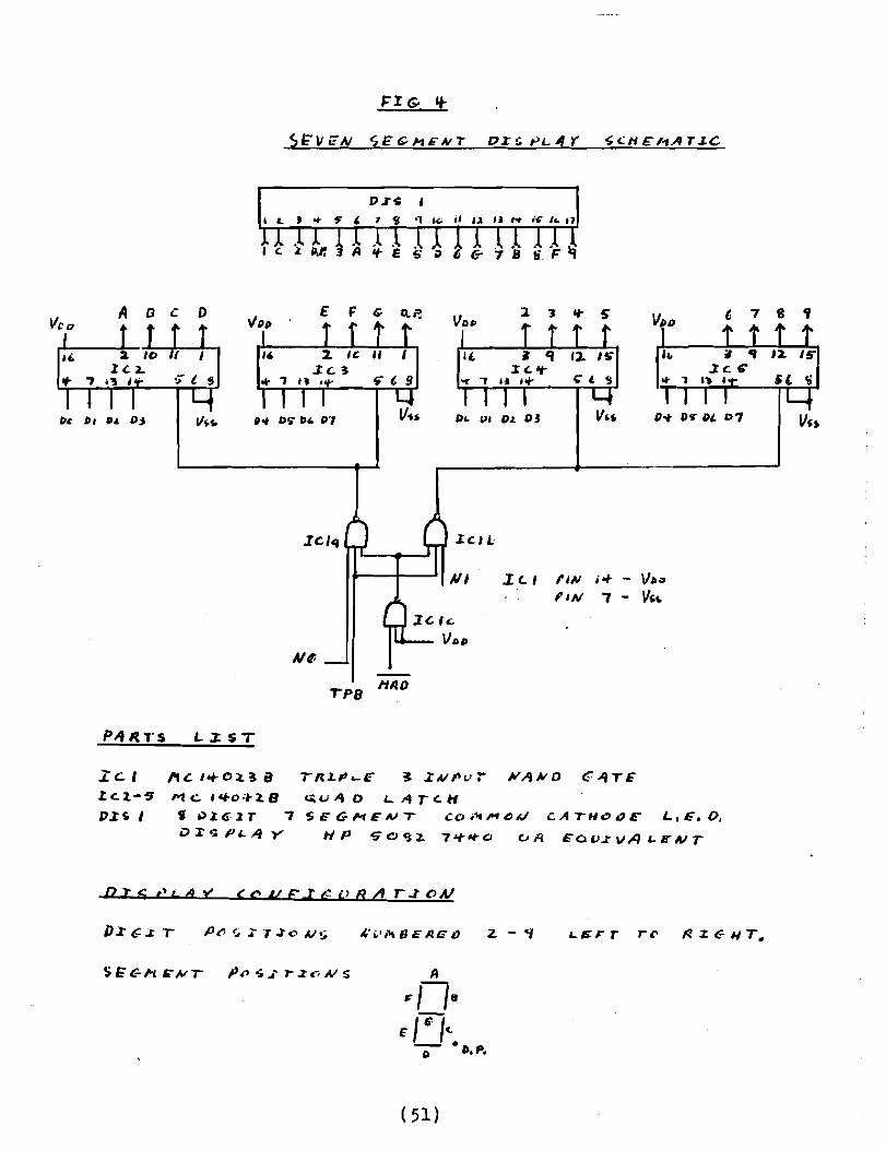
t. 7 8 .,E F G Q.~A oeD
IC/"
PI :r. (., fll.l ;0+ - VU
"N 7 - V,,,
TP8 /'IIlD
LJ:sT
n c l';'O"l.~ 8M c. ,eto ~t '2. 8'a)~€.2T ..,OXc;PL.4Y
~LJ '" 0 L.. A ; c. HS i= (; MEAl ..,. CO i1t ,... ~MeA 7" II C a E" L. E. O.
tiP '5"Cl~:z. 7"i"-ra CJA EOCJ.rvALENT
". ~I i't 8 E Po E a 2. - ~
(51)

Current limiting resistors are not required in series with eachsegment because the maximum output current from the latches, typically 2 ma., will not exceed the maximum rating of the display,typically 3-5 mae average current for most displays of this type.If it is necessary to use larger displays then current buffers andresistors would most likely be needed.
USING THE $ DIGIT DISPLAY 'ltlayne Bowdish
The first part of this 2 part article described the hardwareportion of an $ digit display. In this section I will describe asimple test routine for the hardware. This routine implements an $digit HEX display. Future articles will contain various otherapplications of the display.
The test program consists of a subroutine which displays eightdigits each time that it is called and a simple driver program tocall the subroutine repeatedly. The $ digits are stored in an abyte table right justified (ie. in the low order 4 bits of thebyte). The character table may be filled with any $ HEX digitswhich will then be displayed when the program is run. A listing ofthe program is on the last page of this article.
Since the driver routine is relatively simple, I will concentrateon the operation of the sUbroutine. This subroutine could be usedwith any special applications program that the user might write.
Since the display is sof~tare multiplexed the output subroutinemust be called repeatedly to display the digits. If CHROUT iscalled often enough the display will appear to be on continuously.To output a digit, the following 3 outputs are required:
1. zero the digit select latches2. set the segment select latches to the required pattern3. set the required digit select latchThe output subroutine works as follows:Memory locations #lB through #24 initialize some registers for
the subroutine. Locations #25 through #41 form a loop which isexecuted $ times, once for each digit. Locations 47 through 56 area table of segment select bit patterns for each possible digit.
Within the loop the following 5 major functions are performed:1. memory locations 25 through 2A place the address of the
end of the 3 byte output table in the X-register. Thelast 2 bytes of this table will be filled in with thesegment select data and the digit select bit. The firstbyte is always zero and is used to turn off all digitswhile the new segment select data is being output.
2. memory locations "#2$ through #2E place the digit selectbyte (initially #01) in the output table and then shiftsthe bit left one bit position so that it will be readyfor the next digit.
3. memory locations #2F through #3B take a hex digit (from#0 through #F) and adds this value to the address ofthe start of the segment select table. This new addressis then used to retrieve the proper segment select bytefrom the table.
( 52)

HEXDSIJ IlCI802-VOI 31-11""1-79 ·)]131 I rI II!:XDSP "'lCI noz-v-u JI-'~
I .TITLE HEXDSP I , T.\I~LE TO :;"L':CT CO:Nr:(;T 5~·.T· ':!r~ T!I p~ :,r~j'>l'\2 2 , "!OTT: S~T PoIT 5E,";··I:~lr :)'!3 , TEST RIJ{fTHIS I'll;? 7 SEG!~ENT rlEX DISPLAY 3
" " 0I}17 Ci!l?TA III!j 0000 JO OA B~ START '3 n047 3F .I3YT:' '3:= 06 1)fY.)2 . 00 1)8 DIGTABI • BLOCK 8 , IPfSE~r DlClTS Tn nE 6 ')048 30 .ilYT:: q31J I7 , DISPLAYED il~ac: .,
~')"'.} 5n .",YT:: ,~:,j -:: :!a I)(l()A Fa Iq A9 START I +OlOI CHRI"T.R9 , R9 . CH~oIJT P-ClJWnTIQ (3 m"" "F .~YTr: ·'IF 39 Y.1D r:J oo ~9 9 ')1" !l 1\6 •'wrt; I/"'~ 4It) ''JiW) F''1 17 AA +DLDI LOlJP,Il10 , RIO" !JAlP4LI"E P-CotJ'HE'l I" M'lC 60 · rwr: *..~!1 5
II flOI 3 Ftl co BA II !104;J 7D .IWT': q'J 612 1)1)16 1)/\ SEP IlIO 12 on·1': 07 .:WT::; 407 713 1Y)J7 LilOPI 13 'Yl4i: 7F .qYT'= ;'!7~ ''314 0!11 7 09 SF.P '19 Ill/TPIlT nt~ CH,\RACTE:/S 14 ')('J'j~ 67 • qyr-: ;;1,1 9I~ '1018 30 17 OR LooP GO RACK A'IO [)II A~/ontER 15 (n:; I 77 • !IYT:, ,;77 AI ,; 16 ~':'2 7C .AYTE f!1C ~ (S::.\LL IJ7 17 flO:.iJ 39 .l/Yfr: ;'39 CIH , CHRnlIT - CHARACTER ll\lTPUT ROlITl:/E 18 0054 SE .:lyrE 4I5F. D (S'HLLl19 19 lY.l% n .RYTE "79 E'!O OJIA D.' CH I/RINI SEP RIO RETURIf TO lilAI'I PR:X1lUll 20 0056 71 • ,WTE #71 F21 '10l~ Fa 02 AF ClllWUTI +OLOI DlnT'\B.RIS filS poI'4TS TO 'JAT'\ TARLE 21- 2:! ')11E F'J oo BF ~2 00 OA .?~n SHOT
VI ':!3 .1021 FR 01 L:>l I'. .~ ,~ ')')23 nc Pdl !'II 2 , !l12.HI IS 01"lIT SI;L':(;TW- :.'~ 1Y':!1 :::J S"X 1113
26 1)')23 t'i! 46 '\0 CllIILUPI +DL!>t UIGS!:L.RI J , IlIJ . r.'1D (IF ()!ITIJ'JT TA"ILE:n '''! i f!i I)J no:~. ~ ';02:'1 ?C GHI rH2 (;';T PI'lIT 5EL',CT 'II r A"IO 5AVr=~t) J'; -:~ 73 STXJ) flI3 TnE'! 1:;r; • x To pol'IT rn s~nsEl
I'l '~n::!') r~ SHL Sill I'T ~Ir:IT S~LECT "IT Fo'?II no;:.:'; "C ,>Ill RI2 usxr OI:iPUY OI~lT A'10 C;A~E
1.2 "'}'!J= 4f' L'H 'll::> ,'t',SK oFF ,IIY 11"."1,':::> o-r, "IITS.;1 )/)3') f',\ nF A:II !'JF JW;T I': C\S~ T:I':Y to"', S':TJ·l '1132 f'e 41 ADI CII"n1 A~r- 1.'1.' A!lD;/. or- S!=c,'IP/ r.,.~
'~)34 AE PI.(I '114 ~r:Lr:('T H"!..C "'I') 51.'1':,oJ
.V, 1").'13::i F': 'Xl Lr)1 C:F?TA'_-t1 r;(~T :Wl:t ,,..~; l. or- 1;:-; • '=i~•• rv«.st IV)J7 Ie 'Y) ":>:1 ~ \'1') '\'1 I'! c,~aY j=1 f f" ? '?';~ (If15).:.> ".' j') :'~: 1J!1l ~Io\ T~I?: svvr 'II ;;1 '\llliIE';;,, 'J
J'} "1H Of; L1" t?14 OFT s,~T;JT S"L".:r ;JAH A'mI~ ')'1.1'1 73 ST¥:n Plrr 1:' ()'JT?'IT n'~L',
11 :)}1~ 62 olJT 2 II"TP'1! 'I',IT '),,:3 'OJ.-=;Tl:? 'nD 61 ()I 1-:- I It)t ?"T j!:"'="::'lT Sr;I.!;(;T~:1 ",,,,-,~ ~2 O'IT 2 I)'17"r"1T JI"If J::L!"7f1·1 ''13,; 9~ ~;Il 11:> I\':J C:I:c:: ':~1;1 'iOi'~ To 00.\ :; 1"1:, JA 20; n:1.~ C:flIL'I" LOO? F'n 'J:;:':T fro 'lor ALI. f)O"IE.l1 'vl~ :? 2I'J IA 0'1 C!l"~r! '?r;TII~I" IF A!L ~'l'!;;
H·1'1 ')').1·1 ",.. 1>t~1tKI .'YT~ ') nr'"'lT ~!- \ !!( ;:Imr;.'1.') IY)." :.; 'j'l S':";S::ll .'wrl: t') ~,:!r~~': r :"':L"r:r r;\n~
5") rn,l~ m DIOS':!.I • 1Yr1: o rll"IT S~L'1CT ~lT
51 .SL'I

4. locations #3C through #3E output the 3 bytes from theoutput table. .
5. locations #3F through #43 check the digit select byte.If it is zero (ie. the select bit has been shifted'out)then all g digits have been output and the subroutinereturns to the callinp, program, otherwise the loop isrepeated for another digit.
APPLICATIONS AHD EXTZ!'JSIONS
The display hardware and software forms a general purpose outputdevice. Some possible applications that come to mind are:
- clock display (hh-mm-ss and mm-dd-yy)- multi station thermometer display (indoor outdoor etc.)- games of course (winning ticket number etc.)- monitor data display (address, data, function)- test gear (volt, ohm, current, frequency, etc. display)- and on and on and on ••••••••••
Some possible extensions are:
- decimal point selection (high order data bit set maybe)- additional characters (ie. H, J, L, 0 (small), P, U and
some s tr-ange ones,. .., = = II j., )Extra characters could easily be added by using the low order 5
bits of the data byte and expanding the character table out to 32bytes.

The Association of Ccmputcr Experimenters
Ninutes of Club 1JIeeting No. 7$-2
Held at Stelco Wilcox St. Auditorium
9 February, 1978 8:00 P.N.
78-2-1
78-2-2
78-2-3
78-2-4
78-2-5
The regular meeting was preceded by a 1 hour tutorial.
The ~inutes of the last rneetin~ were included in the Newsletter ••.:>
Tiere were no copies available for distribution thereforethe Hi.nut e s wer-e not approved.
George York, Secretary-treasure~reporteda current bankbalance of ~1,000.38.
Claus Doerwald, Nembership Co-ordinator, announced a paid upmemb er alri p of 233, "Ji th about 10 per week still coraing in. Therewas soMe discussion on the possibility of cutting off bacltissues for new members.
:'laync Boy/dish, Software Co-ordinator, had no report.
7'6-2.-6 Har-dvar e , Eugene 'I'ekat.ch , Har-dwar-e Co-ordinator was absent-no report.
78-2-7 Ne~sletter Editor, Tom Cravford, reported the Newsletter,Issue ~, has gone for printing. We now require about 400 copiesto cover our needs e. g. members pLus back t s suo s for net... members.
78-2-$ Education Co-ordinator, Ken Snith, announced the next tutorialsession will be February 23, 8:00 P.II. at the Stelco WilcoxAuditorium.He mentioned Adam Osborne & Associates are supposed to becoming out with a book on Cosmac programming.
78-2-9 New Bus i ne s s-o-Ther-e Vias no report on possible alpha-numericI/O kits.Anyone with info on used terminals or printers should get intouch \-,i th a member of the executive.There will be an article in the Hamilton Spect~tor on homemicrocomputers that should mention the club.There was some discussion on the development of small systemsand/or communicating between CPU's.Some member-s volunteered to do a literature survey and a shortsynopsis for the Newsletter of any particularly good articles.The members involved' Here J effe VIai te-Kilobaud, Ed Leslie-Byte,Paul Birke-Dr. Dobbs, Blair Gerrish-Popular Electronics,John Williams-Radio Electronics.
(55) cont'd ••••
ACE ~inutes of Club Meeting No. 78-2 (cont'd)
78-2-9 (cont'd)The members wouLd like a cassette standard for the nextmecting t if possible. There was some discussion on the prosand cons of har-dwar-s , sof'twar-c , Kansas City t etc. approaches.
The members wer-e r'erri nd ed that t he election of a new clubexecutive should be considered. As outlined in the ClubConstitution, the elected positions are President, Secretary/Treasurer and Ne'..lsletter Editor. Exe cut.Lve-a'~-larre nenbcr-sare also required to fill positions at the discretion of thePresident.The Constitution t specifically Article 5.4 requires amendmentto allow the executive committee to function in the absenceof the president. The original article reads:
Article 5.1~ llieetings of the executive committee shall be atthe call of the president.
The amended article would read:
Article 5.4 Meetings of the executive committee shall be atthe call of the president or, in his absence,the 5ecretary/tre~surer.
This Constitutional amendment 0i11 be voted on at the firstme~ting after the Newsletter Issue 5 is mailed.
The meeting schedu18 for meetin~s and tutorials until the endof r~Iay is published in New s Let.t.er- Issue 4.
7$-2-10 Kotion to adjourn meetingProposed Jeffe WaiteSeconded - Doug InksterPassed
The meeting adjourned at 10:10 P.M.About 50 people attended the meeting.
( 56)
,I
- !i

78-3-7
78-3-4
78-3-5
78-3-6
The Association of Computer Experimenters
Minutes of Club Meetin~ No. 7$-3
Held at Stelco \lilcox St. Auditorium
7 March, 197$ 8:00 P.B.
78-3-1 The regular meeting was preceded by a 1 hour tutorial.
78-3-2 Mot.Lon to adopt Minut.e s 78-1 and 78-2Proposed - Walt SmithSeconded - Ed BenvenuitiCarried unanimously
78-3-3 Georee York, secretary-treasurer, reported the bank account wasbeing changed to the new club name. The last statement showed .a current balance of ~900.3$.
There was some discus~ion on the need to cover the club's liabilities (eg. incorporating, co-op or insurance).
Motion - the executive is authorized to investigate the liabilitiesaspect of the club. The investigation can include a nominallegal fee.Proposed - Walt SmithSeconded - Brian FoxCarried unanimously.
It was noted the Burlington Amature Radio Club has just finishedincorporating. Their executive should be consulted.
Membership. There are now 323 paid mernber-s ,
Software - No report
Education. Ken Smith took a quick survey to find what subjectswould be of interest for the next tutorial sessions. The sug-gestion was for a keyboard and CRT interface hardware and software. Group effort will be encouraged in the tutorial sessions.
The info sheet for Lyle Sandy on the back of issue #4 should befilled out and sent in.
78-3-8 Motion - the club should pay for a 1 ye2r subscription to Byteand Dr. Dobbs in the name of the Hamilton Public Library. Thesemagazines would be available at the Hamilton Reference Library.Proposed - Tom CrawfordSeconded - Jim RixCarried
Note that the Hamilton Public Library is gettine a subscription toKilobaud magazine also.
cont'd •••
(57)

ACE Minutes of Club Meeting No. 78-) (cont'd)
78-3-9 Ken Collins has volunteered to ~ive a wire wrappinf, demonstrationat the next meeting.
78-3-10 Hardware Co-ordinator, Eugene Tekatch reported there will be asoftware 300 baud I\.C. interface as a club standard. There willalso be a 1200 baud pulse duration software interface developed.
Tektron will soon have a board developed with an 1861 video chipwith RF interface, cassette and teletype interface plus ann-line decoder on board.
Tektron's 7K board with 2Y. ERO~1 is now available.
Large display costs are still excessive but, with the cost ofchips (eg. character generators) dropping, a cheap large displaymay soon be possible.
Gene mentioned that there are a large group of the membershipwho are interested in and need more help with more'hardwareapplications. A call was issued for ideas and/or circuits formore hardware applications.
Some ideas suggested were: an automatic telephone dialer, anindoor/outdoor temperature display, an 8 digit display.
78-3-11 Motion to adjourn meetingProposed - Brian FoxSeconded - Bert DeKatPassed
The meeting adjourned at 10:10 P.M.About 50 people attended the meeting.
(58)

CLUB NOTES
SYSTEM INFO SHEETS Lyle Sandy
Fill out your system information sheet now•••• l Returns havebeen slow (17 so far) to the information sheets included with the'last newsletter. Please respond, even if you have only the simplestsystem, or even no system at all yet. It is important that youraspirations, as well as accomplishments, be made known to other clubmembers in order that good technical progress can be made. Fill outthe form and get it in the mail ASAP so that all info can be summarized in the next newsletter.
LETS PUT THS 1802 TO WORK Eugene Tekatch
Well its about time we put the 1802 to work. We have seen anabundance of assemblers, monitors, editors, etc. but the majorityof ACE members have not got envolved in microprocessor applications.In asking myself why this is the case, I have determined what Ithink is the reason. My micro course moved very fast through basictheory & programming, leaving very little time for hardware applications. Without demonstrations & working system doing hardwarefunctions (driving a relay, controlling a motor, high voltage hookup, TTY connection, CRT, etc.) an air of mystery still existed andin turn people were reluctant to try applications.
I have proposed that the next issue of the newsletter be aspecial project edition. Send in the data on your working projectsBIG or S~~LL including hardware and software. Mail as soon as posible to the Editor of this Newsletter, or to myself:EUGENE TEKATCH, TEKTRON EQUIPMENT CORP., 263 BARTON ST. UNIT #19STONEY CREEK, ONTARIO L8E 2K4
Lets share ideas and in turn encourage more projects.
r-1EETI~G TillES Claus Doerwald
We've had numerous requests from local members to change the dateof the regular club meetings. I'm afraid that for the present we'relocked into the schedule on pg. 35 of issue #4 of the newsletters,but i.n the future we'd like to optimi ze the schedule. We need yourhelp in the form of a return of this questionaire:
MEETING SCHEDl~E SURVEYIf you plan to attend club meetings please indicate preferred nights
in the order of priority (1,2,3, etc. with the highest being one; iftwo or more evenings have equal priority use the same #)
lIiONDAY CJTUESDAY DvlEDN~SDAY 0
THURSDAY 0FRIDAY 0SATURDAY 0
Mail to: CLAUS DOER~ALD, c/o DOFASCO ENGINEERING DEPT. P.O. BOX 460;HA~rrLTON, ONTARIO L8N 3J5
(59)

This page contains a change of address form and an applicationfor membership form. If your address is incorrect or if youraddress has changed, please mail in the change of address form.This will ensure that you get your next copy of the IPSO FACTONewsletter. Don't forget to return your old mailing lable.This will allow us to find the incorrect address and correct it.
If you know of anyone who would be interested in joining ourclub, why not give him/her the membership application. We areconstantly looking for new members with new and interesting ideas.Make cheques payable to the Association of Computer Exper1menters.
Association of Computer Experimenter
.CHANGE OF ADDRESS FORM . ATTACH MAILING !ABLE HERE
._--~-------- . _.-._-- _.....- - -...._-
-MEMBERSHIP APPLICATION FORM FOR THE Association of Computer Experimenter
\


1111111
~, 1
1111111111111111111111111111111111111111111111111111111111