INTERACTIVE VOLUME ILLUSTRATION USING WANG CUBES
48
Purdue University Purdue e-Pubs ECE Technical Reports Electrical and Computer Engineering 10-1-2004 INTECTIVE VOLUME ILLUSTTION USING WANG CUBES Aidong Lu David S. Ebert Wei Qiao Martin Kraus Benjamin Mora Follow this and additional works at: hp://docs.lib.purdue.edu/ecetr is document has been made available through Purdue e-Pubs, a service of the Purdue University Libraries. Please contact [email protected] for additional information. Lu, Aidong; Ebert, David S.; Qiao, Wei; Kraus, Martin; and Mora, Benjamin, "INTECTIVE VOLUME ILLUSTTION USING WANG CUBES" (2004). ECE Technical Reports. Paper 131. hp://docs.lib.purdue.edu/ecetr/131
Transcript of INTERACTIVE VOLUME ILLUSTRATION USING WANG CUBES

Purdue UniversityPurdue e-Pubs
ECE Technical Reports Electrical and Computer Engineering
10-1-2004
INTERACTIVE VOLUME ILLUSTRATIONUSING WANG CUBESAidong Lu
David S. Ebert
Wei Qiao
Martin Kraus
Benjamin Mora
Follow this and additional works at: http://docs.lib.purdue.edu/ecetr
This document has been made available through Purdue e-Pubs, a service of the Purdue University Libraries. Please contact [email protected] foradditional information.
Lu, Aidong; Ebert, David S.; Qiao, Wei; Kraus, Martin; and Mora, Benjamin, "INTERACTIVE VOLUME ILLUSTRATION USINGWANG CUBES" (2004). ECE Technical Reports. Paper 131.http://docs.lib.purdue.edu/ecetr/131

INTERACTIVE VOLUME ILLUSTRATION USING WANG CUBES
AIDONG LU DAVID S. EBERT WEI QIAO MARTIN KRAUS BENJAMIN MORA
TR-ECE -04-05 OCTOBER 2004
SCHOOL OF ELECTRICAL AND COMPUTER ENGINEERING PURDUE UNIVERSITY WEST LAFAYETTE, IN 47907-2035
INTERACTIVE VOLUME ILLUSTRATION
USING WANG CUBES
Aidong Lu, David S. Ebert, Wei Qiao, Martin Kraus, and Benjamin Mora
School of Electrical and Computer Engineering
465 Northwestern Ave.
Purdue University
West Lafayette, Indiana 47907-2035
1This material is based upon work supported by the National Science Foundation under Grant Nos.
0081581, 0098443, 0121288, 0196351, 0222675, 0328984, 9977218, 9978032, 9978099, and the US
Department of Energys VIEWS program.

ii
TABLE OF CONTENTS
Page
LIST OF FIGURES . . . . . . . . . . . . . . . . . . . . . . . . . . . . . . . . iii
ABSTRACT . . . . . . . . . . . . . . . . . . . . . . . . . . . . . . . . . . . . v
1 Introduction . . . . . . . . . . . . . . . . . . . . . . . . . . . . . . . . . . . 1
2 Related Work . . . . . . . . . . . . . . . . . . . . . . . . . . . . . . . . . . 7
3 Wang Cubes . . . . . . . . . . . . . . . . . . . . . . . . . . . . . . . . . . . 9
4 Isotropic Pattern Design . . . . . . . . . . . . . . . . . . . . . . . . . . . . 13
4.1 Points . . . . . . . . . . . . . . . . . . . . . . . . . . . . . . . . . . . 14
4.2 Lines . . . . . . . . . . . . . . . . . . . . . . . . . . . . . . . . . . . . 16
4.3 General Primitives . . . . . . . . . . . . . . . . . . . . . . . . . . . . 18
5 Anisotropic Pattern Design . . . . . . . . . . . . . . . . . . . . . . . . . . . 19
5.1 Volume Data: The General Corner Problem . . . . . . . . . . . . . . 19
5.2 Special Corner Problem with Marching Cubes . . . . . . . . . . . . . 21
5.3 Curvature Direction with Wang Cubes . . . . . . . . . . . . . . . . . 21
5.4 Tangent Orientation with Wang Cubes . . . . . . . . . . . . . . . . . 23
6 Multi-Resolution Cube Design . . . . . . . . . . . . . . . . . . . . . . . . . 25
7 Volume Rendering with Wang Cubes . . . . . . . . . . . . . . . . . . . . . 29
8 Conclusion and Future Work . . . . . . . . . . . . . . . . . . . . . . . . . . 35
LIST OF REFERENCES . . . . . . . . . . . . . . . . . . . . . . . . . . . . . 37

iii
LIST OF FIGURES
Figure Page
1.1 Patterns and textures are commonly employed in scientific illustra-tions. The two example illustrations come from “Atlas of HumanLimb Joints” and “Sobotta Atlas of Human Anatomy” respectively. . 2
1.2 The system diagram. . . . . . . . . . . . . . . . . . . . . . . . . . . . 5
3.1 A set of 16 Wang Cubes with face colors (WENSFB) and 2 colorsfor each face (left), and a truncated volume with a non-periodic tiling(right). . . . . . . . . . . . . . . . . . . . . . . . . . . . . . . . . . . . 10
3.2 (a) A set of Wang Cubes generated interactively from our system. (b)A uniform distribution. (c) A distribution favoring darker cubes. Thedarkness of a cube is the sum of the 6 face color values, which are 1if the face has a point on it, 0 otherwise. (d) A tiling generated bya predefined field (a “CUBE” pattern) with the restriction changingfrom strict to loose from left to right. Therefore the right side hasmore random patterns according to the predefined field than the leftside. . . . . . . . . . . . . . . . . . . . . . . . . . . . . . . . . . . . . 12
4.1 16 cubes with points and four 83 volumes with densities of 1 to 4.The volumes achieve roughly uniform point distributions. In the rightimage, the density of points per voxel is calculated to show the lightingeffect on a sphere. The rendering process will be discussed in Chapter7. . . . . . . . . . . . . . . . . . . . . . . . . . . . . . . . . . . . . . . 15
4.2 The top four images show line patterns with different settings (densityand direction). The bottom images show three kinds of lines: variouslength, infinite lines, and lines with assigned length n. . . . . . . . . . 17

iv
Figure Page
5.1 (a) Primitive distributions by corner colors. Left two show points withdifferent densities, right two show hybrid distributions of points andlines. (b) The 256 cases distribution of (c) shows most occurrencesare at case 0 and case 255. (c) Volume rendering of a foot dataset bypoint patterns with 2 corner colors. The yellow and white regions arecases 0 and 255 respectively (each case is rendered with 16 isotropiccubes), the red color represents the cases 1-254 (each case is renderedwith 1 anisotropic cube). The function at the right bottom corneris designed to color normalized volume data. The point densities forthe two corner colors are: color 0 has 4 points and color 1 has 8points. Although each of the cases 1-254 contains only 1 cube, thepoint patterns are random enough to simulate a man-made drawing. . 20
5.2 An iso-surface of a 643 engine block dataset rendered by polygons.256 × 4 cubes are generated from the left 4 triangle textures to non-periodically tile the surface. An enlarged region is shown in the left. . 22
5.3 The approximated curvature directions of the ears of a bunny dataset(left), and the connected line patterns (right). . . . . . . . . . . . . . 23
6.1 (a) A sample set of “self-face-representing” cubes with face colorsWENSFB. (b) A sample pattern on different scales. The finer scale(red) includes more details than the coarser scale (blue). (c) Themappings from a coarser scale to a finer scale we use for (a). (d) Thebones of the foot are rendered with the finer scale, while the skin usesthe coarser scale. (e) The bones are on the coarser scale while theskin is on the finer scale. (f) Both are on the finer scale. . . . . . . . 26
7.1 An iron protein dataset rendered with different patterns and settings.(a) is rendered with 2D transfer functions and used to be comparedwith illustrative results. The other five images simulate the followingstyles respectively: (b) stipple, (c) stroke, (d) pointillism, (e) water-color, and (f) oil painting. . . . . . . . . . . . . . . . . . . . . . . . . 30
7.2 Illustrations of a segmented hand dataset, a human foot from a poste-rior view, a colonoscopy dataset, and a bonsai tree dataset. Differentpatterns and settings (size, density, opacity, and color) are used in therendering to distinguish each object in the volume. . . . . . . . . . . 31
7.3 (a) 16 cubes generated from a noise volume. (b) Cloud renderedwithout Wang Cubes. Low resolution volume model results in a verysmooth cloud. (c) Cloud rendered with Wang Cubes showing moredetail. Enlarged regions are shown in the top right corner. . . . . . . 33

v
ABSTRACT
To create a new, flexible system for volume illustration, we have explored the
use of Wang Cubes, the 3D extension of 2D Wang Tiles. We use small sets of
Wang Cubes to generate a large variety of non-periodic illustrative 3D patterns and
textures, and we develop a direct volume rendering framework with these cubes.
With the generated patterns and textures, our framework can be used to render
volume datasets effectively and a variety of rendering styles can be achieved with
less storage.
Specifically, we extend the non-periodic tiling process of Wang Tiles to Wang
Cubes and modify it for multi-purpose tiling. We automatically generate isotropic
Wang Cubes consisting of 3D patterns or textures to simulate various illustrative
effects. Anisotropic Wang Cubes are generated to yield patterns which reflect object
properties by using the volume data, curvature, and gradient information. We also
extend the definition of Wang Cubes into a set of different sized cubes to provide
multi-resolution volume rendering. Finally, we provide both coherent 3D geometry-
based and texture-based rendering frameworks that can be integrated with arbitrary
feature exploration methods.

vi

1
1. Introduction
Rendering and exploring features in scientific datasets is important to various re-
search areas, including medicine, biology, and archaeology. In recent years, re-
searchers have started to render their scientific datasets in an illustrative way by
simulating certain scientific illustration techniques, including small primitives [1],
lines [2], hatching [3], and stippling [4]. Most recently, Owada et al. [5] presented an
interactive system for designing and browsing volumetric illustrations through 2D
synthesized textures.
Because of the information loss during the acquisition of volume datasets, many
illustrators employ patterns or textures on an object to enrich details. Figure 1.1
shows two examples of scientific illustrations. The left image shows the human limb
joints of the right wrist [6]. In this black and white image, bones (C, H, 1MC, 5MC,
R, S, T, TR, TZ, U) are drawn with stipples, tendons (7, 10, 11, 16) with wide
line patterns, and muscles and ligaments with thin line patterns. The right image
shows the thoracic viscera of an adult after removal of the anterior thoracic wall [7].
Almost all the structures, including the heart, lung, skin, vessels, diaphragm, etc.,
are all rendered with different colored textures. In scientific illustrations, although
the patterns and textures are usually chosen to simulate the shape and color of the
real objects, they do not have to be exactly the same. Sample textures or even simple
repeated point and line patterns are also commonly used in many illustrations [8].
By applying a certain pattern or texture to an object, the human eye can easily pick
out that object within an image. Even when several objects or parts overlap in space,
each one can still be distinguished from the others. This shows the great potential
for using patterns and textures in volume rendering, which can show more internal

2
Figure 1.1. Patterns and textures are commonly employed in scien-tific illustrations. The two example illustrations come from “Atlasof Human Limb Joints” and “Sobotta Atlas of Human Anatomy”respectively.
structures than surface geometry alone. Compared to the artistic work of scientific
illustration, there have been no competitive direct volume rendering techniques that
are as rich in their choices of textures and rendering styles.
Research efforts in both computer graphics and visual perception have explored
shape perception by textures or patterns. Healey et al. [9] present a non-photorealistic
visualization method based on brush strokes, which uses the results from psychophysics
that many properties of a texture, like color, orientation, size, and contrast, are de-
tected by the low-level visual system and can be used to encode information. It also
has been widely accepted that “shape perception can be enhanced by the addition of
appropriate texture under generic viewing and shading conditions” [10]. Interrante
et al. [11, 12] have performed a series of experiments on the observers’ judgments
of local surface orientation under conditions of anisotropic texturing when they are
aligned with one or both of the principal directions of curvature over the surface.

3
Zaidi and Li examine the roles of oriented texture components in conveying veridical
percepts of concave and convex surfaces that are pitched towards or away from the
observer [13], and on the two necessary conditions for the perception of 3D shape
from texture [14]. Knill [15] determines that both surface contours and texture
patterns can provide strong cues to the 3-dimensional shape of a surface in space.
Todd et al. [16] study the effects of texture, illumination, and surface reflectance on
stereoscopic shape perception. Rosenholtz and Malik [17] examine two models for
human perception of shape from texture, based on isotropy or homogeneity surface
textures. Ware and Knight [18] apply the results from vision research to the synthe-
sis of visual texture for the purpose of information display. Wanger, Ferwerda, and
Greenberg [19] consider six cues in perceiving spatial relationships, including object
and ground textures. Based on these advantages of textures for efficient and illus-
trative visual perception and object detection, we concentrate on texture generation
and rendering to effectively illustrate volumetric datasets.
Another advantage of using textures is to provide multiple rendering styles. The
majority of non-photorealistic rendering (NPR) techniques are designed for one or
two specific rendering styles, although several papers have achieved multiple styles
by successfully using textures, e.g., “image analogies” [20] and “real-time hatch-
ing” [21]. Scientific illustrators [8] point out that almost every rendering technique
or style has its advantages and disadvantages. For example, points are perfect to
illustrate surfaces, while lines are good for outlines. Therefore, different results may
be achieved when an object is rendered with various styles. The choice of rendering
primitives plays an important role in reflecting the textures and properties of ob-
jects. In many applications, one single rendering technique is not sufficient. Instead,
patterns composed of various primitives are widely used in scientific illustrations, as
shown in Figure 1.1. In NPR renderings, the patterns are usually evenly, randomly,
and non-periodically distributed to achieve artistic effects.
At the same time, storage and running time are crucial to the usability of a
visualization system. Many non-photorealistic rendering techniques need to store

4
the positions of all the primitives to render an object, such as points and lines.
When constraints from adjacent regions are added, a local search is needed for every
primitive, such as when distributing points in a volume evenly or extending a long
line segment on an object. Since the primitives are usually assigned per voxel to
achieve these effects, extra space and time are needed. These disadvantages can be
overcome by using a set of patterns, which saves time and space, gives the closest
appearance to real objects, and provides the capability of various rendering styles.
We have developed a system that uses various patterns and textures to render
volume datasets in different styles. Our approach uses Wang Cubes, which are
cubes with “colored” faces. We explore both isotropic and anisotropic cube design
with small sets of Wang Cubes. The cubes can be filled with geometric primitives,
patterns, and textures to generate a large number of 3D patterns. The design of the
cubes and the cube tiling guarantee a consistent pattern over the whole volume and
saves storage. All the cubes and cube tilings are quick to generate, and special care
is taken to ensure their temporal and spatial coherence. Our framework, shown in
Figure 1.2, can be integrated with arbitrary transfer functions and feature selection
methods to select features in a volume, and to assign the patterns and styles for
the features during interactive rendering and exploration. We have developed two
systems, one geometry-based system that renders OpenGL geometry primitives and
one texture-based system that is implemented in a fragment program, to show that
different features can be rendered effectively. In this paper, we show that Wang
Cubes are a convenient tool to add various illustrative non-periodic details to volume
datasets with both compact storage and very little preprocessing.
We begin by summarizing previous work in Wang Tiles, NPR, and volume illus-
tration. In Chapter 3, we extend the Wang Tile stochastic tiling algorithm [22] to 3D
cube tilings and modify it for multi-purpose tilings. In Chapter 4, we discuss three
kinds of isotropic pattern generation, which have the same properties over the entire
volume. By using information from a dataset (volume data, curvature direction, and
tangent orientation) in Chapter 5, we automatically generate cubes with anisotropic

5
Figure 1.2. The system diagram.
patterns, which reflect the features of a volume. In Chapter 6, we extend the defi-
nition of Wang Cubes into a set of different sized cubes to provide multi-resolution
renderings. The issues of direct volume rendering with Wang Cubes are discussed
in Chapter 7. Finally, we discuss the advantages and disadvantages of using Wang
Cubes in volume rendering.

6

7
2. Related Work
Wang Tiles [23,24] are square tiles with “colored” edges. They are placed on a plane
edge-to-edge only if the adjacent edges share the same “color”. The sets of tiles
are called aperiodic because they can never produce a periodic tiling. Numerous
mathematicians and computer scientists have tried to find the smallest set of Wang
Tiles. Analogous to Wang Tiles, Culik and Kari [25] introduced Wang Cubes with
colored faces and proved that there existed an aperiodic set of 21 Wang Cubes.
Several researchers have used Wang Tiles to generate patterns in computer graph-
ics. Jos Stam [26] was the first to use aperiodic texture mapping, employing 16
Wang Tiles to simulate water-like surfaces. Neyret and Cani [27] used triangles
with homogeneous textures to tile surfaces. Different from aperiodic tilings, their
tiling procedure was stochastic, and the number of textures was related to the graph
coloring problem. Recently, Cohen et al. [22] generated non-periodic images with
sample textures. They presented a stochastic method to design sets of Wang Tiles
with different tile numbers and generated the tile patterns automatically. They use
“non-periodic” to indicate the difference between aperiodic tiling and their stochas-
tic tiling. They also indicated that Wang Cubes could be used for three-dimensional
applications in the future. Recently, Sibley et al. [28] performed video synthesis or
geometry placement by using Wang Cubes.
In addition to Wang Tiles, other methods are used to generate patterns or tex-
tures for image synthesis and object rendering. Hiller et al. [29] extended the Lloyd’s
relaxation method to redistribute arbitrary shapes and used patterns for 2D images.
Interrante [2] effectively used patterns and curvature directions to illustrate surfaces
within a volume dataset. As opposed to these studies, we generate patterns and tex-

8
tures without knowledge of the exact geometric mesh or shape. In volume rendering,
patterns and textures are also used to achieve better visual effects, such as glyphs in
vector fields or flow visualizations [30].
Using NPR techniques in volume rendering has been proven to be effective in
the visualization of three-dimensional (volume) data. Saito explored the usage of
simple primitives on isosurfaces to depict volume shapes with hierarchical periodic
point patterns [1]. Kirby et al. [31] utilized concepts from paintings to combine
multiple data values in an image for 2D flows. Ebert and Rheingans [32] combined
non-photorealistic rendering and volume rendering techniques to enhance important
features and regions. Treavett et al. [33] implemented artistic procedures in various
stages of the volume-rendering pipeline. Lu et al. [4] simulated stipple drawing by
carefully placing points in the volume with calculated densities through a variety of
feature enhancements. Lum and Ma [34] implemented a combination of NPR meth-
ods at interactive frame rates for large datasets with a parallel hardware-accelerated
rendering technique. Nagy et al. [3] generated hatch strokes from a number of seed
points and implemented shading and silhouettes using fragment shader hardware.
Hadwiger et al. [35] combined non-photorealistic techniques to effectively render
segmented datasets with high quality on consumer graphics hardware. The usage of
silhouettes and contours has also been explored by several researchers [36,37].

9
3. Wang Cubes
As shown in Fig 1.2, our framework first generates 3D patterns and textures in the
preprocessing phase, then feeds these volumetric patterns and textures into the in-
teractive rendering phase to illustrate a volume dataset. During the rendering phase,
transfer functions or feature extraction methods are used to control the rendering
properties of the selected 3D patterns and textures to form the shape and appear-
ance of the volumetric objects (the details are discussed in Chapter 7). To generate
various 3D patterns and textures, we use a mathematical tool called “Wang Cubes”,
which is the 3D extension of 2D “Wang Tiles” [22]. A set of Wang Cubes can fill
any sized volume very fast by following certain “rules”, which makes the rendering
of arbitrary volume datasets more convenient. Two key elements are generated for
a set of Wang Cubes, a cube tiling and the cube contents. The cube tiling is mainly
correspondent to the repetitive property of the 3D patterns or textures, while the
cube contents are mainly correspondent to the type (primitive, size, opacity, color,
etc.) of the 3D patterns or textures. Different cube tilings and cube contents are
combined to generate a large number of 3D patterns and textures, which provide
many choices for the rendering phase. In this chapter, we explain the general “rules”
of Wang Cubes and the cube tilings. In the following chapters, the generation of
isotropic cube contents and the generations of anisotropic cube tilings and cube
contents will be discussed.
Wang Cubes are cubes with “colored” faces in the sense that two cubes can be put
together only if the adjacent faces have matching “colors,” as shown in Figure 3.1.
To determine how to tile the space, we assume each face has n possible colors and it
is denoted as North(N), South(S), West(W), East(E), Front(F) and Back(B). Since

10
Wang Cubes are not supposed to be rotated, two faces in the same direction (NS,
WE, and FB) must share one set of colors to ensure that they can be put together,
while the face colors on different directions are independent.
Figure 3.1. A set of 16 Wang Cubes with face colors (WENSFB)and 2 colors for each face (left), and a truncated volume with a non-periodic tiling (right).
We extend the stochastic non-periodic tiling process of 2D Wang Tiles [22] to 3D
Wang Cubes. Without loss of generality, we fill the volume from West to East, from
North to South, and from Front to Back. Apart from the cubes on the boundary of
the volume, each position has three constraints (each cube must have N, W, and F
faces that match the S, E, and B faces already placed). Since each face has n colors,
the NWF faces create n3 cases. As long as there is at least one cube in the cube set
with each NWF case, a valid tiling of a volume exists. We can start from the NWF
corner, use the 2D tiling process to tile the first slice in the volume by treating the
NSWE face colors as the edge colors in Wang Tiles, and then tile the rest of the slices
from Front to Back by adding the additional constraint that the front color of the
cube should match the back color of the cube on the same position of the previous
slice. Assuming m cubes are generated for each NWF case, m×n3 cubes are needed.
Since both n and m need to be larger or equal to 2 to generate non-periodic cube
patterns, the minimum number of cubes is 16, which requires 2 colors for each face

11
and 2 cubes for each NWF case. Analogous to Wang Tiles, this process is similar to
the random process of a coin flip, therefore the cube tiling is non-periodic.
One common problem with the cube tiling generation of Wang Tiles or Wang
Cubes is the repetitive appearance. Kari has proven that there do not exist any
“arecurrent” finite tile sets [38]. Although we cannot fundamentally avoid this prob-
lem, we can reduce the repetitive appearance by properly designing the colors for the
cubes. First, to ensure that the set of the cubes can produce non-periodic patterns,
we assign the NWF colors of the cubes in a way that has at least two cubes for each
NWF case. For 16 cubes, there are exactly two cubes for each NWF case. Then,
we choose the SEB colors to meet two criteria to ensure an even distribution of the
cubes in a volume. First, the SEB colors should cover all the color cases. Second,
for every color on each of the NWF faces, the SEB colors should have both the same
and opposite colors. If the second condition cannot be satisfied, we favor the cubes
whose opposite faces have different colors, because they are less likely to produce
repetitive patterns.
We also reduce the repetitive appearance by adding varying probabilities for
each cube. We use a small count table to gather the local occurrence for every cube.
The probability is decreased if a cube appears more than the average frequency,
and vice versa. Statistical results show that the occurrence of the cubes in a tiling
with varying probabilities has on average 1/2 of the standard deviation from a tiling
without. Another application of varying the probability for the Wang Cubes is
generating cube patterns with preferences. We can favor some cubes in the set more
than others and, at the same time, guarantee the non-periodic property of the cube
pattern. We can also arrange the cube patterns according to a predefined probability
field to smoothly vary the generated pattern. Figure 3.2(b)-(d) show the results of
varying probabilities.

12
Figure 3.2. (a) A set of Wang Cubes generated interactively fromour system. (b) A uniform distribution. (c) A distribution favoringdarker cubes. The darkness of a cube is the sum of the 6 face colorvalues, which are 1 if the face has a point on it, 0 otherwise. (d) Atiling generated by a predefined field (a “CUBE” pattern) with therestriction changing from strict to loose from left to right. Thereforethe right side has more random patterns according to the predefinedfield than the left side.

13
4. Isotropic Pattern Design
After tiling the Wang Cubes in a volume, we must generate the cube patterns to fill
in the tiling for use in the final volume rendering. We use two types of cube pattern
generation techniques. In this chapter, we discuss isotropic patterns, which have
the same properties over the entire volume. Anisotropic patterns generated from
additional constraints will be discussed in the following chapter.
The goal of isotropic cube design is to create a large number of illustrative pat-
terns and textures with as small a set of cubes as possible. Therefore, during the
final rendering, the users can have many pattern choices, which can be visually
distinguishable from the surroundings or possess the closest appearance to a real
object. The methods for cube design depend on what is inside the cube: textures or
primitives.
For textures, we can interactively design cubes by manually drawing the cube
contents through our system. An example is shown in Figure 3.2(a). The cubes can
also be automatically generated from 3D sample textures, extending the 2D tiles
method [22] into 3D cubes. First, n sub-volumes are chosen from sample textures
for NS, WE, FB directions respectively, each corresponding to a face color. Then,
we put these sub-volumes in every cube according to the face colors of the cube.
The 16 cubes (each has 83 voxels) in Figure 7.3(a) show an example generated from
a filtered noise volume [39].
Since a large number of primitives are used in scientific illustrations and NPR, we
design an automatic method to fill the cubes uniformly with geometric primitives.
For non-photorealistic volume rendering, three common problems must be addressed.
First, to achieve different shading and density effects at varying resolutions, we need

14
to design the cube patterns at multiple levels. Second, to provide temporal coherence
during rendering, the higher levels should include all the primitives of the lower levels.
For example, point drawing [4, 40] always draws the prefix of the point lists, while
hatching [21] uses line patterns at several levels. Using the same idea, our geometry-
based rendering draws the prefix of the geometry lists per voxel and our texture-based
rendering draws the cubes at several levels. Third, an even distribution of primitives
simulates a Poisson distribution and improves the visual quality of the image. Cohen
et al. [22] use Lloyd’s method to optimize pre-generated point positions among Wang
Tiles, and Praun et al. [21] hierarchically select the best-fitting line from a pool of
candidates. Our method is derived from the combination of these two methods.
Wang Cubes ensure that the cube patterns are non-periodic; therefore, we con-
centrate on the connectivity of the cubes and the even and random distribution of
the primitives at multiple levels. We next discuss cube design for points, lines, and
general primitives.
4.1 Points
For point (stipple) patterns, we recursively divide the volume of a cube into 8
sub-regions based on a predefined depth and maintain an octree structure to store
the number of points contained in the corresponding region. Points are iteratively
added to each cube by the following process. For each point primitive to be added,
we hierarchically calculate the probability of the nodes in the octree from top to
bottom, select a “best” leaf discussed below, randomly generate a point inside the
corresponding region of the leaf, and update the octree. The probability is calculated
by the weighted sum of two factors.
The first factor is the point density, which is the number of points contained in
a region. Let d1 be the density of the current region and d2 be the density sum of
the 26 adjacent regions. We need to consider all the possible combinations from the

15
cube tilings according to the face colors; therefore, adjacent regions from other cubes
and their occurrence frequencies are also considered.
The second factor is based on several 3D restrictions. In contrast to 2D pattern
generations, the appearance of a 3D pattern is the projection on the image plane;
thus, it may look quite different from different viewing directions. Therefore, we need
the points in the cubes to overlap with each other as little as possible to achieve the
overall best effect for all the viewing directions. Our approach uses simple geometric
relations: no three points should be in the same line, and no four points should be
in the same plane. From the center of the selected region, we calculate the point-line
distance d3 (the average from the center to any line by any other two points in the
near region) and the point-plane distance d4 (the average from the center to any
plane by any other three points in the near region).
Figure 4.1. 16 cubes with points and four 83 volumes with densitiesof 1 to 4. The volumes achieve roughly uniform point distributions.In the right image, the density of points per voxel is calculated toshow the lighting effect on a sphere. The rendering process will bediscussed in Chapter 7.
The probability of each region is then calculated as: p = −
∑4
i=1widi, where the
weights, wi, can be interactively adjusted. For instance, weights of 100, 2, -10, -10
are used in Figure 4.1. A region with the maximum probability is a best region. If
multiple best regions exist, we randomly choose one. If a varying point size is used,
the point size should be proportional to the probability value.
We generate one point at a time for each cube and repeat the process until the
desired number of points is reached. Compared to point distribution techniques [22],
we do not need to redistribute the points after the generation. Compared to line

16
distribution techniques [21], we do not need to generate a candidate pool. Finally,
during rendering, we draw the cubes at different levels (corresponding to varying
point numbers) and we always draw from the beginning of the point lists. Therefore,
our method yields an approximately uniform distribution, as shown in the cubes in
Figure 4.1.
4.2 Lines
For generating line patterns, we use different combinations of the following four
user-specified parameters: primary line direction, direction range, maximum line
length, and length range. Lines are divided into two cases: lines within one cube
and lines spanning multiple cubes.
For lines within one cube, we first select a best point for a line to pass through,
using the same method as for points. Then we randomly generate a line direction by
the two direction parameters (primary line direction and direction range) and search
for the best length of the line in both directions. We favor longer lines over shorter
lines by using normalized probabilities along the line segment,∑
l
i=1p/l, in choosing
the best line length l [21].
The lines spanning multiple cubes are generated by manually assigned length,
corresponding to the number of cubes to cross. Instead of selecting the best point
inside the cube, we choose the best point on the colored faces by considering the two
factors from the previous chapter for any colored face. A line segment is then added
for all the cubes with this colored face. According to the assigned length, we divide
the line generation into four cases:
Length Two: A face-inside line segment is added to the cube. One end point is
the face point, the other is inside the cube.
Various Lengths: We connect as many face points as possible. If a single point
remains, we generate a face-inside line segment.
17
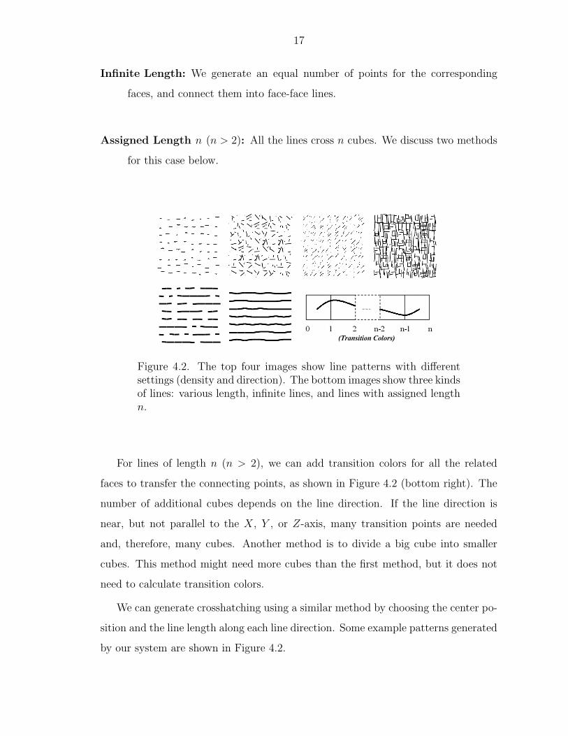
Infinite Length: We generate an equal number of points for the corresponding
faces, and connect them into face-face lines.
Assigned Length n (n > 2): All the lines cross n cubes. We discuss two methods
for this case below.
Figure 4.2. The top four images show line patterns with differentsettings (density and direction). The bottom images show three kindsof lines: various length, infinite lines, and lines with assigned lengthn.
For lines of length n (n > 2), we can add transition colors for all the related
faces to transfer the connecting points, as shown in Figure 4.2 (bottom right). The
number of additional cubes depends on the line direction. If the line direction is
near, but not parallel to the X, Y , or Z-axis, many transition points are needed
and, therefore, many cubes. Another method is to divide a big cube into smaller
cubes. This method might need more cubes than the first method, but it does not
need to calculate transition colors.
We can generate crosshatching using a similar method by choosing the center po-
sition and the line length along each line direction. Some example patterns generated
by our system are shown in Figure 4.2.

18
4.3 General Primitives
Since the skeleton of most geometric primitives can be expressed as points (center)
and lines (center with direction), we use the point or line distribution as their skeleton
position. We randomly choose other properties of the primitives, such as rotation,
to make the results look more random and more visually pleasing. One remaining
problem is that general primitives have thickness which may cause them to exceed
the boundary of the cubes. If we render geometry, we draw the primitives at their
center location; if we use 3D texture-based rendering, we need to treat the over-sized
primitives as face primitives and add them to all the cubes which have the matching
colored face. Examples of illustrative renderings with various primitives are shown
in Figure 7.1 and Figure 7.2.

19
5. Anisotropic Pattern Design
Based on our motivation to effectively render features in a dataset, we are interested
in generating anisotropic patterns that have more power in reflecting the features of
an object than general isotropic patterns. We use the volume data value, curvature
direction, and tangent orientation, to design our anisotropic patterns.
5.1 Volume Data: The General Corner Problem
Besides coloring the faces of Wang Cubes, we can also color the corners. Coloring
the cube corners is called the corner problem when originally introduced for Wang
Tiles by Cohen et al. [22]. We assume each corner has n possible colors. To generate
an anisotropic 3D pattern, generally for each cube in the cube tiling process, 7
corners from the N, W, and F faces need to be matched, totalling n7 combinations.
In this paper, we associate the volume data values with the corner colors. Such a
pattern shows the distribution of the volume data better than randomly distributed
patterns. Since all the 8 corners need to be matched with the corresponding volume
data value, we need to consider all n8 combinations.
Different corner colors may correspond to different primitive densities or different
kinds of primitives. To generate the patterns for the cubes, we add a density field
for each cube according to the corner colors. This density field gi is calculated by
the tri-linear interpolation of the designed densities from each corner of a cube. It
is organized in the same octree structure as the cube and used to modify the first
factor in Chapter 4.1: wi
′
= giwi, i = 1, 2. A new primitive will be generated inside
a region with the maximum probability. Figure 5.1(a) shows 4 cube designs, 2 with

20
different point densities (green:2, red:1) and 2 with different primitives (for point–
green:2, red:1; for line–green:0, red:2). The user can freely design a transfer function
to divide the whole data range into n colors. For example, one color may represent
normal data ranges, and the others represent emphasized data ranges.
Figure 5.1. (a) Primitive distributions by corner colors. Left twoshow points with different densities, right two show hybrid distribu-tions of points and lines. (b) The 256 cases distribution of (c) showsmost occurrences are at case 0 and case 255. (c) Volume renderingof a foot dataset by point patterns with 2 corner colors. The yel-low and white regions are cases 0 and 255 respectively (each case isrendered with 16 isotropic cubes), the red color represents the cases1-254 (each case is rendered with 1 anisotropic cube). The functionat the right bottom corner is designed to color normalized volumedata. The point densities for the two corner colors are: color 0 has4 points and color 1 has 8 points. Although each of the cases 1-254 contains only 1 cube, the point patterns are random enough tosimulate a man-made drawing.
However, many cubes are required. Two colors yield 256 cases, and there are
too many cases with more than two colors. Alternatively, if we can guarantee only
adjacent colors can appear in one cube, we have (n − 1) × 256 cases. If we consider
the face colors and corner colors at the same time, there will be at least 8 × 256
cases. As with coloring faces, we need to have 2 cubes for each case to assure that
the patterns are non-periodic. By statistically examining the cube occurrence for

21
each case, the most frequent cases are 0 (all the corners are 0) and 255 (all the
corners are 1), as shown in Figure 5.1(b). Since other cases occur based on object
properties and only occur at some iso-surfaces, they do not significantly generate
periodic patterns. However, if we only color corners, cases 0 and 255 will generate a
large number of repeated patterns. Therefore, for geometry-based rendering we use
16 isotropic cubes for each of the two special cases and 1 cube for each of the rest.
The corner cases are calculated on-the-fly and we can reuse the isotropic cube tiling
for the two special cases. An example with 2 corner colors is shown in Figure 5.1(c).
5.2 Special Corner Problem with Marching Cubes
If we draw only the cubes corresponding to cases 1 to 254, the result is similar
to an isosurface, but generated by 3D patterns. We further find that the Marching
Cubes algorithm renders polygons to approximate isosurfaces according to the vol-
ume data at the corners of each cell [41], while Wang Cubes tile the volume with
freely designed transfer functions and render various patterns, textures, and poly-
gons. Therefore, in the sense of coloring corners, Marching Cubes is a special case of
the corner problem of Wang Cubes. As with isotropic patterns, we use Wang Cubes
to non-periodically texture the iso-surface with at least 2 texture samples. An exam-
ple is shown in Figure 5.2. With our texture-based rendering, we can also render the
iso-surface without generating the geometry. We use fixed vertex positions instead
of interpolated values and the results can be improved by adding more cubes.
5.3 Curvature Direction with Wang Cubes
Curvature direction plays an important role in conveying the shape of objects [42].
The curvature directions are the eigenvectors corresponding to the first and second
eigenvalues [37]. An intuitive way to generate Wang Cubes from curvature infor-
mation is to use quantized directions to color corners, but this requires too many

22
Figure 5.2. An iso-surface of a 643 engine block dataset renderedby polygons. 256 × 4 cubes are generated from the left 4 triangletextures to non-periodically tile the surface. An enlarged region isshown in the left.
cubes (n8, n > 30). Instead, we use connecting points on cube faces to generate line
patterns.
Assume n connecting points are selected from 6 cube faces. Since we allow all
the combinations of the connecting points, there are 2n cases. For each case, we
randomly design m cubes to connect the connecting points; therefore, m× 2n cubes
are generated. The tiling process is the same as the process of cube tiling generation
in Chapter 3. Generally for each position, we choose the cube which matches the
existing connecting points on the N, W, and F faces and contains the closest line
direction to the curvature direction from the processed voxel. Figure 5.3 uses the 6
center points of cube faces as the connecting points and has 2 cubes for each case,
totalling 128 cubes. The tiling process takes about 5 seconds for a 1283 volume.
Using the same idea, we can also generate patterns which align to other directions,
such as gradient directions and vector fields. The original direction information is
approximately embedded in the designed line patterns. Therefore, they can highlight
object properties better than isotropic patterns.

23
Figure 5.3. The approximated curvature directions of the ears of abunny dataset (left), and the connected line patterns (right).
5.4 Tangent Orientation with Wang Cubes
Tangent orientation is commonly used in volume rendering. We can also gen-
erate cubes based on pre-processed tangent orientations to emphasize the gradient
information. First, the 3D normalized vector space is quantized into n gradient di-
rections. For each cube, we align the flat primitives orthogonally to the assigned
quantized direction and randomly rotate them in the other free directions. If the
cubes contain 3D textures, we need a total of 16n cubes. If we render geometry, we
use only n cubes to indicate the placement of the flat primitive and use the point or
line positions from the isotropic patterns as the skeleton of the primitives. In Fig-
ure 7.1 (d), we use small, different shaped polygons aligned with the tangent plane
to simulate a Pointillist drawing.

24

25
6. Multi-Resolution Cube Design
Wang Cubes are originally cubes of the same size, and all the previous chapters dis-
cuss same sized cubes. However, in volume rendering, we need to render datasets and
different features at varying image resolutions. The introduction of multi-resolution
cubes brings three advantages to Wang Cubes. First, we can emphasize certain por-
tions in a dataset and direct the user’s attention to these more detailed features,
as illustrators do. Second, processing time is saved when we render more distant
objects or surrounding features at a coarser scale. Third, since most scientific data
has a fixed resolution, there will not be enough detail when a portion of the object
is excessively enlarged. We can use multi-resolution cubes to provide a method to
continually add the necessary non-periodic details during zooming.
We use eight small cubes in an octree to “represent” a large cube. By “repre-
sent,” we mean both the textures and six face colors are matched from the small
cubes to the large cube. If there existed a set of cubes which represents themselves,
we could implement infinite resolutions by continuously “representing” the cubes.
Unfortunately, by counting face colors, we know that it is impossible for a set of
cubes with general 3D textures to represent itself.
However, if we only consider the colors of the cube faces, it is possible to find a
set of cubes which can “face-represent” themselves. By “face-represent”, we mean
only the six face colors are matched from the small cubes to the large cube. For each
cube in the set, we consider it as a 23 volume with face colors to see whether it can
be filled. If every cube can be filled with the cubes in the set, then the set of cubes
is “self-face-representing,” as shown in Figure 6.1 (a). Usually there exist multiple
mappings to self-face-represent a cube. For each cube, we choose one mapping, which

26
Figure 6.1. (a) A sample set of “self-face-representing” cubes withface colors WENSFB. (b) A sample pattern on different scales. Thefiner scale (red) includes more details than the coarser scale (blue).(c) The mappings from a coarser scale to a finer scale we use for (a).(d) The bones of the foot are rendered with the finer scale, while theskin uses the coarser scale. (e) The bones are on the coarser scalewhile the skin is on the finer scale. (f) Both are on the finer scale.
contains the largest number of different cubes. Therefore, for all the scales in the
rendering, we reuse one set of face colors and one set of mappings. The cube tiling
is generated at the coarsest scale, and we use the mapping to find the cube index for
finer scales. The cube tiling may appear less random because only one mapping for
each cube is used, but additional cubes can be added to alleviate this problem. We
will now discuss two methods to generate the contents of the self-face-representing
cubes.
One method is to generate one set of cubes and blend the cubes on the adjacent
scales during rendering. In this way, infinite non-periodic resolution can be achieved
by continually blending the cubes of the current scale and the next finer scale. An-
other method is to use one set of cubes for each scale. First, we design the textures
for the cubes of the finest scale. Then, we use the mapping to copy the textures
of the smaller cubes into the larger cubes. Therefore, the connections of cubes are
guaranteed across multiple scales, and the cubes can smoothly transfer from one

27
scale to another without any manipulation. Generally for every isotropic pattern,
we use two scales and 16 cubes for each scale. Figure 6.1 (b) shows a sample pattern
on two adjacent scales.
The volume data on the coarser scale is 1/8 of that on the finer scale; therefore,
the running time significantly improves. The foot dataset in Figure 6.1 (c) renders
about 2 times faster than (e) when both features are rendered at the finer scale. It
also keeps the exact shape of the bones and shows the position of the skin.

28

29
7. Volume Rendering with Wang Cubes
With our cube tiling generation and cube design methods, we can generate various
3D non-periodic patterns and textures for a volume. To ensure the temporal coher-
ence during rendering, we store the cube contents and the cube tilings for the volume
so that for every pattern, the cube for each voxel (or cell) in the volume is fixed. Dur-
ing rendering, a cube will be rendered at different levels according to the calculated
value from the transfer functions. Specifically, we change the number of primitives
to draw for geometry-based rendering and the opacities for texture-based rendering.
Therefore, our rendering framework allows users to use arbitrary feature extraction
and transfer functions to define the features of a volume. Since Wang Cubes provide
a large number of patterns and textures, suitable ones and their settings (primitive,
density, size, and opacity) can be interactively assigned for each feature to achieve
various styles. In Figure 7.1, independent patterns and settings are used to simulate
5 different styles. Specifically, the shapes and sizes of the primitives are designed
to simulate the form of an artistic brush, and the opacities and color schemes are
designed to simulate the properties of the brush. In Figure 7.2, we use the feature
extraction methods and color calculation from Lu et al. [4], and we choose the pat-
terns which are visually distinguishable from surroundings or which have the closest
appearance to the real objects. Our framework can be used to interactively explore
the features in a volume dataset and effectively render them in various styles. We will
discuss the storage of Wang Cubes, our geometry-based system, and texture-based
system, respectively.
We use the same color set of cubes for all the isotropic tilings because the face
color design of the cubes is independent of the components inside the cube. Since we

30
Figure 7.1. An iron protein dataset rendered with different patternsand settings. (a) is rendered with 2D transfer functions and usedto be compared with illustrative results. The other five images sim-ulate the following styles respectively: (b) stipple, (c) stroke, (d)pointillism, (e) watercolor, and (f) oil painting.

31
Figure 7.2. Illustrations of a segmented hand dataset, a humanfoot from a posterior view, a colonoscopy dataset, and a bonsai treedataset. Different patterns and settings (size, density, opacity, andcolor) are used in the rendering to distinguish each object in thevolume.

32
have 16 cubes for each isotropic pattern, 4 bits are needed for each cube tiling. The
size of each cube depends on the primitives inside and their densities. Geometric
cubes are usually less than 32 bytes and we use 83 voxels for each cube for texture-
based rendering. The storage of the cube contents is negligible compared to the
storage of the cube tiling. Although the cube tiling requires extra space, it is much
smaller than storing the textures per voxel to achieve the same non-periodic results.
For example, for geometry-based rendering, if 8 points (3D floats) are stored for each
voxel and each point needs 3× 32 = 96 bits, instead of 4 bits for the cube tiling, the
storage is 8×96/4 = 192 times larger. For texture-based rendering, we use 83 voxels
for each cube and each voxel has RGBA (32 bits). The texture space without Wang
Cubes is 83× 32/4 = 4096 times the space of using Wang Cubes. Therefore, Wang
Cubes can provide non-periodic patterns and textures with much less texture space.
For the geometry-based system, we use 16 cubes for each isotropic cube set at each
level and we use several sets of cubes: 2 for points (one sparse, one dense), 3 for lines
(along three orthogonal directions), and 1 for crosshatching. For anisotropic cubes,
we have 254 extra cubes for the corner pattern, 128 for directions, and 40 for tangent
planes, with a total of no more than 1000 cubes. All the isotropic and anisotropic
cubes and the isotropic cube tilings are generated and stored before rendering. For
the anisotropic cube tilings, while the directions and tangent orientations need to be
generated for each dataset, the cube tiling for the corner problem is calculated on-
the-fly. For each voxel during rendering, we use the cube tiling and the calculated
value to decide which cube at which level to draw. To avoid pattern “popping,”
we draw the integer part of the value in full color, and the fractional part semi-
transparent [4]. Our geometry-based system performance achieves about 3 to 30
frames per second on a Pentium IV with GeForce FX 5200 graphics.
Our 3D texture-based system is developed upon a physically-based multi-field
weather data visualization system [43]. A set of 16 isotropic cubes is generated
for each hydrometeor field (cloud, rain, ice, graupel) using the automatic method
discussed in Chapter 4. The cube indices are divided by 16 to reduce them to the

33
Figure 7.3. (a) 16 cubes generated from a noise volume. (b) Cloudrendered without Wang Cubes. Low resolution volume model re-sults in a very smooth cloud. (c) Cloud rendered with Wang Cubesshowing more detail. Enlarged regions are shown in the top rightcorner.
texel value range of [0,1). Both the Wang Cubes and the cube tiling are stored as
3D textures. Given a set of coordinates, the closest texel determines into which cube
the current fragment maps. We translate texture coordinates to coincide with an
actual voxel for the un-interpolated cube index. We then translate the global texture
coordinates into the local coordinates of the chosen Wang Cube and sample the cube
patterns. The patterns are used to modulate opacity per hydrometeor field and all
fields are blended according to their overall contribution. As shown in Figure 7.3,
the cloud with Wang Cubes contains richer details than the cloud without and voxel
artifacts near the volume boundary are reduced.

34

35
8. Conclusion and Future Work
We have developed a 3D pattern and texture generation method using Wang Cubes
that provides an interactive volume illustration system. Our cube tiling method pro-
duces uniform cube distribution and can be used for multi-purpose tiling. To gener-
ate different styled patterns, we automatically design three types of cubes: isotropic
cubes, anisotropic cubes, and multi-resolution cubes. The design of the pattern is
per voxel; therefore, it is flexible in conveying the shape of objects. Our method
for automatically distributing geometry primitives in isotropic cubes is simple and
flexible and can also distribute hybrid objects or primitives with different densities
in the corner problem of Wang Cubes. We have developed both a geometry-based
system and a 3D texture-based system to show that Wang Cubes provide various
styled non-periodic details for volume rendering. Our system is an interactive fea-
ture exploration tool that effectively renders the features of a volume with different
patterns, textures, styles, and resolutions.
Wang Cubes have several advantages for volume illustration. First, Wang Cubes
use little storage to provide various non-periodic patterns and textures, which are
more visually pleasing than the repetition of a single texture. Second, each cube is
quick to generate and once the cubes are pre-generated, the filling of the textures
for a whole volume is very quick, and the size of the volume can be arbitrarily large.
Third, Wang Cubes can be extended to multi-resolution cubes to provide continuous
and necessary details to scientific datasets. Finally, Wang Cubes can also generate
patterned isosurfaces since the Marching Cubes algorithm can be considered as a
special case of the Wang Cube corner problem. With these 3D patterns and textures,

36
rendering styles and volume transfer functions can be changed interactively by using
our framework.
We believe that volume illustration is an effective way to distinguish different
features in scientific datasets. Wang Cubes, with its great capability to generate
various textures at a small cost, provides a large variety of choices for the rendering.
Various textures can effectively convey the properties of an object and distinguish it
from surrounding objects. Our method is a useful supplement to traditional volume
rendering and has advantages for educational and artistic purposes. Initial feedback
from a medical illustrator is positive and encouraging.
Our future work includes further exploration of Wang Cubes as a general 3D
texture-based method. We would also like to combine our rendering with methods
such as light fields to improve the performance. Although Wang Cubes are not
supposed to be rotated, it would be useful to apply the case counting method of
Marching Cubes to decrease the cube numbers.

LIST OF REFERENCES

37
LIST OF REFERENCES
[1] T. Saito. Real-time previewing for volume visualization. In Proc. of symposiumon Volume visualization, pages 99–106, 1994.
[2] V. L. Interrante. Illustrating surface shape in volume data via principaldirection-driven 3D line integral convolution. In SIGGRAPH 1997, pages 109–116, 1997.
[3] Zoltan Nagy, Jens Schneider, and Rdiger Westermann. Interactive volume il-lustration. In VMV, pages 497–504, 2002.
[4] A. Lu, C. Morris, J. Taylor, D. Ebert, C. Rheingans, P.and Hansen,and M. Hartner. Illustrative interactive stipple rendering. IEEE TVCG,Vol.9(No.2):127–139, 2003.
[5] S. Owada, F. Nielsen, M. Okabe, and T. Igarashi. Volume illustration: Designing3d models with internal textures. In PROC. of SIGGRAPH 2004, pages 322–328, 2004.
[6] J. Guyot(editor) and J. L. Vannson(illustrator). Atlas of human limb joints.Springer-Verlag, 1990.
[7] J. Staubesand and Anna N. Taylor(Editor). Sobotta Atlas of human anatomy.Volume 1: Head, Neck, Upper Limbs, Skin. Volume 2: Thorax, abdomen, Pelvis,Lower Limbs. Urban and Schwarzenberg Baltimore-Munich, 1990.
[8] E. Hodges. The Guild Handbook of Scientific Illustration. John Wiley and Sons,1989.
[9] C. G. Healey, J. T. Enns, L. G. Tateosian, and M. Remple. Perceptually-based brush strokes for nonphotorealistic visualization. ACM Transactions onGraphics, 23(1):64–96, 2004.
[10] S. Kim, H. Hagh-Shenas, and V. Interrante. Conveying shape with texture: ex-perimental investigations of texture’s effects on shape categorization judgments.IEEE Transactions on Visualization and Computer Graphics, 2004.
[11] V. Interrante, S. Kim, and H. Hagh-Shenas. Conveying 3d shape with texture:recent advances and experimental findings. In Human Vision and ElectronicImaging VII, SPIE 4662, pages 197–206, 2002.
[12] S. Kim, H. Hagh-Shenas, and V. Interrante. Showing shape with texture: twodirections seem better than one. In Human Vision and Electronic Imaging VIII,SPIE 5007, pages 332–339, 2003.

38
[13] Q. Zaidi and A. Li. Limitations on shape information provided by texture cues.Vision Research, 42:815–835, 2002.
[14] A. Li and Q. Zaidi. Perception of three-dimensional shape from texture is basedon patterns of oriented energy. Vision Research, 40(2):217–242, 2000.
[15] D. Knill. Contour into texture: information content of surface contours andtexture flow. Journal of the Optical Society of America, A(1):12–35, 2001.
[16] J. Todd, F. Norman, J. Koenderink, and A. Kappers. Effects of texture, illu-mination, and surface reflectance on stereoscopic shape perception. 26:807–822,1997.
[17] R. Rosenholtz and J. Malik. Surface orientation from texture: Isotropy orhomogeneity (or both)? Vision Research, 37(16):2283–2293, 1997.
[18] C. Ware and W. Knight. Using visual texture for information display. 14(1):3–20, 1995.
[19] L. R. Wanger, J. A. Ferwerda, and D. P. Greenberg. Perceiving spatial rela-tionships in computer-generated images. 12(3):44–58, 1992.
[20] A. Hertzmann, C. E. Jacobs, N. Oliver, B. Curless, and D. H. Salesin. Imageanalogies. In PROC. of SIGGRAPH, pages 327–340, 2001.
[21] E. Praun, H. Hoppe, M. Webb, and A. Finkelstein. Real-time hatching. InSIGGRAPH 2001, pages 579–584, 2001.
[22] Michael F. Cohen, Jonathan Shade, Stefan Hiller, and Oliver Deussen. Wangtiles for image and texture generation. In SIGGRAPH, pages 287–294, 2003.
[23] H. Wang. Proving theorems by pattern recognition ii. Bell Systems TechnicalJournal, 40:1–42, 1961.
[24] H. Wang. Games, logic, and computers. Scientific American, pages 98–106,November 1965.
[25] Karel Culik II and Jarkko Kari. An aperiodic set of wang cubes. J.UCS,1(10):675–686, 1995.
[26] J. Stam. Aperiodic texture mapping. Tech. Rep. R046, European ResearchConsortium for Informatics and Mathematics (ERCIM), Jan 1997.
[27] Fabrice Neyret and Marie-Paule Cani. Pattern-based texturing revisited. InSIGGRAPH 1999, pages 235–242, 1999.
[28] P. G. Sibley, P. Montgomery, and G. E. Marai. Wang cubes for video synthesisand geometry placement, 2004. Sibley et al. extent Cohen’s Wang Tiles to threedimentional Wang Cubes and use cubes to perform video synthesis or geometryplacement.
[29] S. Hiller, H. Hellwig, and O. Deussen. Beyond stippling-methods for distributingobjects on the plane. In EG’03, pages 515–522, 2003.
[30] C.M. Wittenbrink, A.T. Pang, and S.K. Lodha. Glyphs for visualizing uncer-tainty in vector fields. IEEE TVCG, 2:266–279, 1996.

39
[31] R. M. Kirby, H. Marmanis, and D. H. Laidlaw. Visualizing multivalued datafrom 2d incompressible flows using concepts from painting. In IEEE Visualiza-tion, pages 333–340, 1999.
[32] D. Ebert and P. Rheingans. Volume illustration: Non-photorealistic renderingof volume models. In IEEE Visualization 2000, pages 195–202, 2000.
[33] S. M. F. Treavett, M. Chen, R. Satherley, and M. W. Jones. Volumes of ex-pression: Artistic modelling and rendering of volume datasets. In ComputerGraphics International 2001, pages 99–106, July 2001.
[34] E. Lum and K. L Ma. Hardware-accelerated parallel non-photoralistic volumerendering. In PROC. of NPAR, pages 67–74, 2002.
[35] M. Hadwiger, C. Berger, , and H. Hauser. High-quality two-level volume ren-dering of segmented data sets on consumer graphics hardware. In IEEE Visu-alization 2003, pages 301–308, 2003.
[36] B. Csebfalvi, L. Mroz, H. Hauser, A. Konig, and M. E. Groller. Fast visualizationof object contours by non-photorealistic volume rendering. Computer GraphicsForum, 20(3):452–460, 2001.
[37] Gordon Kindlmann, Ross Whitaker, Tolga Tasdizen, and Torsten Moller.Curvature-based transfer functions for direct volume rendering: Methods andapplications. In IEEE Visualization 2003, pages 513–520, 2003.
[38] Jarkko Kari. Recent results on aperiodic wang tilings. submitted to WorldScientific, January 2003.
[39] K. Perlin and E. Hoffert. Hypertexture. In Computer Graphics (Proceedings ofACM SIGGRAPH 1989), pages 253–262, 1989.
[40] O. Deussen, C. Colditz, M. Stamminger, and G. Drettakis. Interactive visualiza-tion of complex plant ecosystems. In IEEE Visualization 2002, pages 219–226,2002.
[41] William E. Lorensen and Harvey E. Cline. Marching cubes: A high resolution3d surface construction algorithm. In SIGGRAPH 1987, pages 163–169, 1987.
[42] G. Gorla, V. Interrante, and G. Sapiro. Texture synthesis for 3d shape repre-sentation. IEEE TVCG, pages 512–524, 2003.
[43] K. Riley, D. Ebert, C. Hansen, and J. Levit. Visually accurate multi-fieldweather visualization. In IEEE Visualization 2003, pages 279–286, 2003.