Intelligent Fire Panel AFP-100/AFP-100E€¦ · 35% of all fires. While fire alarm systems are...
100
Intelligent Fire Panel AFP-100/AFP-100E Instruction Manual Document 51010 02/06/2002 Rev: C1 PN 51010:C1 ECN 01-552 www.PDF-Zoo.com
Transcript of Intelligent Fire Panel AFP-100/AFP-100E€¦ · 35% of all fires. While fire alarm systems are...

Intelligent Fire PanelAFP-100/AFP-100E
Instruction Manual
Document 5101002/06/2002 Rev: C1
PN 51010:C1 ECN 01-552
www.PDF-Zoo.com

2 AFP-100/AFP-100E Instruction PN 51010:C1 02/06/2002
Fire Alarm System LimitationsWhile a fire alarm system may lower insurance rates, it is not a substitute for fire insurance!An automatic fire alarm system�typically made up of smoke detectors, heat detectors, manual pull stations, audible warning devices, and a fire alarm control with remote notifica-tion capability�can provide early warning of a developing fire. Such a system, however, does not assure protection against property damage or loss of life resulting from a fire.
The Manufacturer recommends that smoke and/or heat detec-tors be located throughout a protected premise following the recommendations of the current edition of the National Fire Protection Association Standard 72 (NFPA 72), manufacturer's recommendations, State and local codes, and the recommen-dations contained in the Guide for Proper Use of System Smoke Detectors, which is made available at no charge to all installing dealers. A study by the Federal Emergency Man-agement Agency (an agency of the United States government) indicated that smoke detectors may not go off in as many as 35% of all fires. While fire alarm systems are designed to pro-vide early warning against fire, they do not guarantee warning or protection against fire. A fire alarm system may not provide timely or adequate warning, or simply may not function, for a variety of reasons:
Smoke detectors may not sense fire where smoke cannot reach the detectors such as in chimneys, in or behind walls, on roofs, or on the other side of closed doors. Smoke detectors also may not sense a fire on another level or floor of a building. A second-floor detector, for example, may not sense a first-floor or basement fire.
Particles of combustion or �smoke� from a developing fire may not reach the sensing chambers of smoke detectors because:
� Barriers such as closed or partially closed doors, walls, or chimneys may inhibit particle or smoke flow.
� Smoke particles may become �cold,� stratify, and not reach the ceiling or upper walls where detectors are located.
� Smoke particles may be blown away from detectors by air outlets.
� Smoke particles may be drawn into air returns before reaching the detector.
The amount of �smoke� present may be insufficient to alarm smoke detectors. Smoke detectors are designed to alarm at various levels of smoke density. If such density levels are not created by a developing fire at the location of detectors, the detectors will not go into alarm.
Smoke detectors, even when working properly, have sensing limitations. Detectors that have photoelectronic sensing chambers tend to detect smoldering fires better than flaming fires, which have little visible smoke. Detectors that have ion-izing-type sensing chambers tend to detect fast-flaming fires better than smoldering fires. Because fires develop in different ways and are often unpredictable in their growth, neither type of detector is necessarily best and a given type of detector may not provide adequate warning of a fire.
Smoke detectors cannot be expected to provide adequate warning of fires caused by arson, children playing with matches (especially in bedrooms), smoking in bed, and violent explosions (caused by escaping gas, improper storage of flammable materials, etc.).
Heat detectors do not sense particles of combustion and alarm only when heat on their sensors increases at a predeter-mined rate or reaches a predetermined level. Rate-of-rise heat detectors may be subject to reduced sensitivity over time. For this reason, the rate-of-rise feature of each detector should be tested at least once per year by a qualified fire pro-tection specialist. Heat detectors are designed to protect property, not life.
IMPORTANT! Smoke detectors must be installed in the same room as the control panel and in rooms used by the sys-tem for the connection of alarm transmission wiring, communi-cations, signaling, and/or power. If detectors are not so located, a developing fire may damage the alarm system, crip-pling its ability to report a fire.
Audible warning devices such as bells may not alert people if these devices are located on the other side of closed or partly open doors or are located on another floor of a building. Any warning device may fail to alert people with a disability or those who have recently consumed drugs, alcohol or medica-tion. Please note that:
� Strobes can, under certain circumstances, cause seizures in people with conditions such as epilepsy.
� Studies have shown that certain people, even when they hear a fire alarm signal, do not respond or comprehend the meaning of the signal. It is the property owner's responsi-bility to conduct fire drills and other training exercise to make people aware of fire alarm signals and instruct them on the proper reaction to alarm signals.
� In rare instances, the sounding of a warning device can cause temporary or permanent hearing loss.
A fire alarm system will not operate without any electrical power. If AC power fails, the system will operate from standby batteries only for a specified time and only if the batteries have been properly maintained and replaced regularly.
Equipment used in the system may not be technically com-patible with the control. It is essential to use only equipment listed for service with your control panel.
Telephone lines needed to transmit alarm signals from a premise to a central monitoring station may be out of service or temporarily disabled. For added protection against tele-phone line failure, backup radio transmission systems are rec-ommended.
The most common cause of fire alarm malfunction is inade-quate maintenance. To keep the entire fire alarm system in excellent working order, ongoing maintenance is required per the manufacturer's recommendations, and UL and NFPA stan-dards. At a minimum, the requirements of Chapter 7 of NFPA 72 shall be followed. Environments with large amounts of dust, dirt or high air velocity require more frequent mainte-nance. A maintenance agreement should be arranged through the local manufacturer's representative. Maintenance should be scheduled monthly or as required by National and/or local fire codes and should be performed by authorized pro-fessional fire alarm installers only. Adequate written records of all inspections should be kept.
Precau-L-11-2001.fm
www.PDF-Zoo.com

AFP-100/AFP-100E Instruction PN 51010:C1 02/06/2002 3
Installation PrecautionsAdherence to the following will aid in problem-free installation with long-term reliability:WARNING - Several different sources of power can be connected to the fire alarm control panel. Disconnect all sources of power before servicing. Control unit and associ-ated equipment may be damaged by removing and/or insert-ing cards, modules, or interconnecting cables while the unit is energized. Do not attempt to install, service, or operate this unit until this manual is read and understood.
CAUTION - System Reacceptance Test after Software Changes. To ensure proper system operation, this product must be tested in accordance with NFPA 72 Chapter 7 after any programming operation or change in site-specific soft-ware. Reacceptance testing is required after any change, addition or deletion of system components, or after any modifi-cation, repair or adjustment to system hardware or wiring.
All components, circuits, system operations, or software func-tions known to be affected by a change must be 100% tested. In addition, to ensure that other operations are not inadvert-ently affected, at least 10% of initiating devices that are not directly affected by the change, up to a maximum of 50 devices, must also be tested and proper system operation ver-ified.
This system meets NFPA requirements for operation at 0-49° C/32-120° F and at a relative humidity of 85% RH (non-con-densing) at 30° C/86° F. However, the useful life of the sys-tem's standby batteries and the electronic components may be adversely affected by extreme temperature ranges and humid-ity. Therefore, it is recommended that this system and all peripherals be installed in an environment with a nominal room temperature of 15-27° C/60-80° F.
Verify that wire sizes are adequate for all initiating and indi-cating device loops. Most devices cannot tolerate more than a 10% I.R. drop from the specified device voltage.
Like all solid state electronic devices, this system may operate erratically or can be damaged when subjected to light-ning-induced transients. Although no system is completely immune from lightning transients and interferences, proper grounding will reduce susceptibility. Overhead or outside aerial wiring is not recommended, due to an increased sus-ceptibility to nearby lightning strikes. Consult with the Techni-cal Services Department if any problems are anticipated or encountered.
Disconnect AC power and batteries prior to removing or inserting circuit boards. Failure to do so can damage circuits.
Remove all electronic assemblies prior to any drilling, filing, reaming, or punching of the enclosure. When possible, make all cable entries from the sides or rear. Before making modifi-cations, verify that they will not interfere with battery, trans-former, and printed circuit board location.
Do not tighten screw terminals more than 9 in-lbs. Over-tightening may damage threads, resulting in reduced ter-minal contact pressure and difficulty with screw terminal removal.
Though designed to last many years, system components can fail at any time. This system contains static-sensitive components. Always ground yourself with a proper wrist strap before handling any circuits so that static charges are removed from the body. Use static-suppressive packaging to protect electronic assemblies removed from the unit.
Follow the instructions in the installation, operating, and pro-gramming manuals. These instructions must be followed to avoid damage to the control panel and associated equipment. FACP operation and reliability depend upon proper installation by authorized personnel.
Precau-L-11-2001.fm
WARNING: This equipment generates, uses, and can radiate radio frequency energy and if not installed and used in accordance with the instruction manual, may cause interference to radio communications. It has been tested and found to comply with the limits for class A computing device pursuant to Subpart B of Part 15 of FCC Rules, which is designed to provide reasonable pro-tection against such interference when operated in a commercial environment. Operation of this equipment in a residential area is likely to cause interference, in which case the user will be required to correct the interference at his own expense.
Canadian RequirementsThis digital apparatus does not exceed the Class A limits for radiation noise emissions from digital apparatus set out in the Radio Interference Regulations of the Canadian Department of Communications.
Le present appareil numerique n'emet pas de bruits radi-oelectriques depassant les limites applicables aux appar-eils numeriques de la classe A prescrites dans le Reglement sur le brouillage radioelectrique edicte par le ministere des Communications du Canada.
FCC Warning
Acclimate Plus�, HARSH�, NOTI�FIRE�NET�, ONYX�, and VeriFire� are trademarks, and FlashScan® and VIEW® are registered trademarks ofNOTIFIER. NION� and UniNet� are trademarks of NIS. NIS� and Notifier Integrated Systems� are trademarks and NOTIFIER® is a registeredtrademark of Fire�Lite Alarms, Inc. Echelon® is a registered trademark and LonWorks� is a trademark of Echelon Corporation. ARCNET® is a registeredtrademark of Datapoint Corporation. Microsoft® and Windows® are registered trademarks of the Microsoft Corporation. LEXAN® is a registered trademarkof GE Plastics, a subsidiary of General Electric Company.
www.PDF-Zoo.com

4 AFP-100/AFP-100E Instruction PN 51010:C1 02/06/2002
This page intentionally left blank
www.PDF-Zoo.com

Table of Contents
AFP-100/AFP-100E Instruction PN 51010:C1 02/06/2002 5
Table of Contents1. Product Description
�������� ���������������������������������������������������������������������������������������������������������������������� �
����� ������������������������������������������������������������������������������������������������������������������������ �
������ ����������������������������������������������������������������������������������������������������������������������� ��
������������������������ ���������������������������������������������������������������������������������� ��
��������� ��������������������������������������������������������������������������������������������������������������� ��
��������������� ���������������������������������������������������������������������������������������������� ��
������ ����������������������������������������������������������������������������������������������������������������� ��
������������������������������������������������������������������������������������������������������������� ��
������� ������������ �������������������������������������������������������������������������������������������� ��
�������������� �������������������������������������������������������������������������������������������������� ��
���������������� ������ ����������������������������������������������������������������������������� ��
������� ��� �������������������������������������������������������������������������������������������������������� ��
��������� �� ������������������������������������������������������������������������������������������������������ ��
������� ����������� �������� � �������������������������������������������������������������������������� �!
������� ����������������������������������������������������������������������������������������������������������������������� �"
��!�����!������������"���#������������������������������������������������������������������������������� �$
% ������� ����������������������������������������������������������������������������������������������������� �$
&����������� ��������������"&���#�������������������������������������������������������������� �$
'������������������������������������������������������������������������������������������������������������������������ �$
#��� ���� ���������� ������������������������������������������������������������������������������������������� �$
���������������������������������������������������������������������������������������������������������������������� �(
������������ �������������������������������������������������������������������������������������������������������� �(
���������� ���������)����������������������������������������������������������������������������������� �(
�*��!������ ���+���� ���� ������������������������������������������������������������������������������ �(
,��� ��*��!��-��+���� ���.�,���.�$������������������������������������������������������� �(
�������*��!���.��/0.��1�������������������������������������������������������������������������� �(
���!������!�2���� �������������������������������������������������������������������������������������������� �3
#���� %��������� �������������������������������������������������������������������������������������������������� �&
������!���������� ��������������������������������������������������������������������������������������������� �4
�������� ������������ ���������������������������������������������������������������������������������� �5
�� ������������������������������������������������������������������������������������������������������������������� �5
��������� ����.�,��.�6�,7�.��8�,��.��������������������������������������������� �5
��������� ���.�,��.�1�� ����������������������������������������������������������������������� �5
��������� ��6�&���.�,��.�� ������������������������������������������������������������������ �9
��������� ��6�'�����.�,'�.� ������������������������������������������������������������������ �9
,������������� ���.��:%.:��������������������������������������������������������������������� �9
����������.�&�0.���:� ���������������������������������������������������������������������������� �9
����������������'����� ��������������������������������������������������������������������������������������� ��
'��.5,�'����-������������ ��������������������������������������������������������������� �1
2�����.��2��;��������!��������������������-�������������������������� �1
���.�$�������-�������������� �� ����������������������������������������������������������� �1
���.$5(���� ��������������� �� ������������������������������������������������������������� �1
#��������� �������������������������������������������������������������������������������������������������������������� ��
���������������7������ ������������ ��������������������������������������������������������� ��
������������������� ���.����.�3��������������������������������������������������� ��
�����������) �� ����� ���.����.�3������������������������������������������������ ��
������������������� ���.����.<��� �������������������������������������������������� ��
�����������) �� ����� ���.����.<�� ������������������������������������������������ ��
����������,�)� ��� ������������������������������������������������������������������������������������ ��
����������,�)� ��� ���.��,�.�3��� ��������������������������������������������������� ��
����������,�)� ��� ���.��,�.<��������������������������������������������������������� ��
www.PDF-Zoo.com

Table of Contents
6 AFP-100/AFP-100E Instruction PN 51010:C1 02/06/2002
����������,�)� ��� ���.��,�.�3�������������������������������������������������������� ��
������������;���� �������������������������������������������������������������������������������������������� ��
����������'�������������� ���.����.5'� ������������������������������������������ ��
���.�:�1��������'�����,��������������� ��������������������������������������������� �<
��� ����;��������������� ���.����.<�� ��������������������������������������������� �<
��� ����;��������������) �� ����� ���.����.�<� ��������������������������� �<
��� ����;���'������) �� ����� ���.����.'<��������������������������������������� �<
2. Installation����������������������������������������������������������������������������������������������������������������������������� �$
� ��(�� � ��������������������������������������������������������������������������������������������������������������������� �$
�%�����'������)������������������������������������������������������������������������������������������������������ �*
������������ ���������������������������������������������������������������������������������������������������� �+
,��������������� ���������������������������������������������������������������������������������������������������� ��
������������� ��������������������������������������������������������������������������������������������������� �9
���*�0��� ����������� ����������������������������������������������������������������������������������� �9
������"��#����������������������������������������������������������������������������������������������� <1
���,���������������������� �������������������������������������������������������������������������������� !�
�������-��. �������� ������������������������������������������������������������������������������������������ !�
#����������������� ������������������������������������������������������������������������������������������������� !�
/���0�������#��������������� �������������������������������������������������������������������������������� !�
1����)����)����)�2����������� ������������������������������������������������������������������������������� !!
%;��;��+ �������������������������������������������������������������������������������������������������������������� <<
��;������ ���� ��������������������������������������������������������������������������������������������������� <<
��!��� ������� ������������������������������������������������������������������������������������������������ <<
���������������������������������������������������������������������������������������������������������������������� <<
32�,����4��������1����)�-�5�������� ���������������������������������������������������������������� !"
0������ ����������������������������������������������������������������������������������������������������������������� <$
'��.5,���������������������������������������������������������������������������������������������������������������� <$
�� �����)��-�'4+�'����������������������������������������������������������������������������������������� !$
�����! �������������������������������������������������������������������������������������������������������������� <(
�����������8���� �������������������������������������������������������������������������������������� <3
&���= ������������������������������������������������������������������������������������������������������������ <3
,����������,�������0�� ������������������������������������������������������������������������������������������ !+
%;��;��+ �������������������������������������������������������������������������������������������������������������� <5
���!������!�������������������������������������������������������������������������������������������������������� <5
���������������������������������������������������������������������������������������������������������������������� <5
������������!������������������������������������������������������������������������������������������������� <9
��������!������������������������������������������������������������������������������������������������������� <9
���.�$������������ ��������������������������������������������������������������������������������������� <9
3. Programming����������������������������������������������������������������������������������������������������������������������������� "�
�������,����4�� ��������������������������������������������������������������������������������������������������������� "�
'������������� ��������������������������������������������������������������������������������������������������������� "�
��>����!������!�������������������������������������������������������������������������������������������������� $�
��>�'�� ��������������������������������������������������������������������������������������������������������� $�
<�>���-������������������������������������������������������������������������������������������������������������ $�
6�����,��)�����)�'������������������������������������������������������������������������������������������� "!
, ���� ������������������������������������������������������������������������������������������������������������������� "!
,��)���� �)��7�2�������� ���������������������������������������������������������������������������������� ""
����� ��������������������������������������������������������������������������������������������������������������������� $$
�� ��!��� �������������������������������������������������������������������������������������������������������� $$
&�+������������������������������������������������������������������������������������������������������� $(
www.PDF-Zoo.com

Table of Contents
AFP-100/AFP-100E Instruction PN 51010:C1 02/06/2002 7
��������� ��� ������������������������������������������������������������������������������������������ $4
��������� ��� ������������������������������������������������������������������������������������������� $5
������ ��������������������������������������������������������������������������������������������������������������� $5
������� � ���������������������������������������������������������������������������������������������������������� $9
����+�� ��*��!� ������������������������������������������������������������������������������������������������� (1
��� ��������������������������������������������������������������������������������������������������������������������� (1
,��)���� �)��7�2������������������������������������������������������������������������������������������ $�
������� ����������������������������������������������������������������������������������������������������������������� (�
������/����� �������������������������������������������������������������������������������������������������������� (�
?��@�� ��������������������������������������������������������������������������������������������������������������� (�
�*��� -��������� ���������������������������������������������������������������������������������� (�
% ������ ������������������������������������������������������������������������������������������������� (<
���������� ���������������������������������������������������������������������������������������������������� (<
�*��@ ������������������������������������������������������������������������������������������������������������������� (<
������������� ����� �� ���������������������������������������������������������������������������������������� $$
4. Operation��������8�. �������������������������������������������������������������������������������������������������������������� $+
��@��+�� !�-�� ����������������������������������������������������������������������������������������������� (5
�������������������������������������������������������������������������������������������������������������������� (5
������/�� ������� �������������������������������������������������������������������������������������������������� (5
������'��� �������������������������������������������������������������������������������������������������������� (5
�. �������� �26���������� ��������������������������������������������������������������������������������� $�
�����+�� ������������������������������������������������������������������������������������������������������������� (9
,��������� ������������������������������������������������������������������������������������������������������������ (9
� ��;����� ���������������������������������������������������������������������������������������������������������� (9
�������������������������������������������������������������������������������������������������������������������� (9
������������ ���������������������������������������������������������������������������������������������������� (9
/������������� ����������������������������������������������������������������������������������������������������� *�
����%���������������������������������������������������������������������������������������������������������������� *�
� ������������@��������� ����������������������������������������������������������������������������� 3�
��������� ���������� ��������������������������������������������������������������������������������� 3�
��@��+�� !� ������������������������������������������������������������������������������������������������������� 3<
#������������ ������������������������������������������������������������������������������������������������������� *"
������� ��.������������������������������������������������������������������������������������������������������� *"
/#��9/���0�������#���������������:��������� �������������������������������������������������� *"
�������4;.46�����9�;6:��������������������������������������������������������������������������������� *$
���������������� ���������������������������������������������������������������������������������������������������� *$
��������������������������������������������������������������������������������������������������������������� 3(
�����������% ������ ������������������������������������������������������������������������������������ 3(
�� ���� ��� ��;����� ���������������������������������������������������������������������������������������� 3(
������������A���������� ���������������������������������������������������������������������������������� 3(
������������ <�-��4���������( ���������������������������������������������������������������������������� *$
���������������4�/#��������/#���� ���������������������������������������������������������������� **
,�� �)�� ��������������������������������������������������������������������������������������������������������������������� **
��������. ��������� ���������������������������������������������������������������������������������������������� *&
����������*����������"&�������31������ �# ������������������������������������������������������� 34
��.��������������"&��������1������#����������������������������������������������������������� 34
�������'���� �� ������������������������������������������������������������������������������������������������ 34
������A�����������"&�������4<������ �# ����������������������������������������������������������� 34
?������+��������% ������ ������������������������������������������������������������������������������ 35
�������-�������% ������ ������������������������������������������������������������������������������������ 35
?����!�,�� ��������������������������������������������������������������������������������������������������������� 35
-������� ���������������������������������������������������������������������������������������������������������������� *�
www.PDF-Zoo.com

Table of Contents
8 AFP-100/AFP-100E Instruction PN 51010:C1 02/06/2002
'�� ��������� ������������������������������������������������������������������������������������������������� 39
��� �������� �������������������������������������������������������������������������������������������������������� 41
'�� �/�������������������������������������������������������������������������������������������������������������� 41
��������!��� ������������������������������������������������������������������������������������������������������� 41
�����/����� ��������������������������������������������������������������������������������������������������������� 41
�������������������������������������������������������������������������������������������������������������� 4�
Appendix A: Power Supply Calculations� ��#��;��� ����������������������������������������������������������������������������������������������������� &�
� ��'���,����������. ������������������������������������������������������������������������������������������� &!
��������!�*���������� ������������������������������������������������������������������������������ 4(
Appendix B: Electrical Specifications6��������������0������ �������������������������������������������������������������������������������������������� &*
�����+�� ������������������������������������������������������������������������������������������������������������� 43
����� ������������������������������������������������������������������������������������������������������������������ 43
��!�����!����������� ������������������������������������������������������������������������������������������ 43
&����������� ������������� ��������������������������������������������������������������������������� 43
�����6���������� �� ��;������'����� �������������������������������������������������������������� 43
�����+�������% ������������������������������������������������������������������������������������� 44
1����-�5�������� ��������������������������������������������������������������������������������������������������� &&
%;��;��+ �������������������������������������������������������������������������������������������������������������� 44
Appendix C: Software Zones����������0���0�����=��� ������������������������������������������������������������������������������������� +�
6>���� ��0���0�����=��� ������������������������������������������������������������������������������������� +�
���������������� ���� �% ����7���� ��������������������������������������������������������� 5�
������,��)�����)�� ��� ������������������������������������������������������������������������������������ +�
7����!��*�� �������������������������������������������������������������������������������������������������������� 5$
Appendix D: NFPA Standard-Specific Requirements����������������������������������������������������������������������������������������������������������������������������� ++
'�������-�5�������� ������������������������������������������������������������������������������������������� ++
#���������-�5�������� ������������������������������������������������������������������������������������������ ++
��������� �'��������������;��� ������������������������������������������������������������� 55
�)�������,��������������������������������������������������������������������������������������� 55
'�����������,��������������� �������������������������������������������������������������� 55
��� �������,��������������� ��������������������������������������������������������������������� 55
���������-���������������������9,���������,���� � �3���: ������������������������������ +�
#�>����.�����#�����. ��� ����������������������������������������������������������������������������������� ��
-�������������,������������)����)��. ��� ���������������������������������������������������������� ��
,��������.�,������������)����)��. ��� ��������������������������������������������������������������� �!
www.PDF-Zoo.com

AFP-100/AFP-100E Instruction PN 51010:C1 02/06/2002 9
1. Product Description
OverviewThe AFP-100 is a compact, cost effective, intelligent FACP (Fire Alarm Control Panel) with an extensive list of powerful features. The combination of Notifier's addressable devices and the AFP-100 offers the latest in fire protection technology. The power supply and all electronics are contained on a single circuit board housed in a metal cabinet, providing a complete fire control system for most applications. Optional modules, such as the RTM-8F and ACM-8R,which plug into the main circuit board, are available for special functions. Available accessories include LED, graphic and LCD annunciators, digital communicator, local downloading software and remote power expansion. The AFP-100E offers the same features as the AFP-100 but allows connections to 220/240 VAC input.
Note: Unless otherwise specified the term �control panel� or AFP-100 refers to both the AFP-100 and the AFP-100E Fire Alarm Control Panel.
FeaturesThe control panel features the following:
� Single standard SLC loop which meets NFPA Style 4, 6 and 7 requirements� 198 addressable device capacity (99 detectors and 99 monitor/control modules)� 56 software zones� Two main circuit board NACs (Notification Appliance Circuits)� 300 mA resettable power� 300 mA nonresettable power� 3.0 amps NAC power (expandable to 6.0 amps with optional XRM-24)� 40 character LCD display (backlit)� Real-time clock/calendar� History file with 500 event capacity� Advanced fire technology features:
Automatic device Type Code verificationAuto detector testMaintenance alertPoint trouble identification
� Three levels of detector sensitivity� Waterflow (nonsilenceable) selection per module point� Supervisory (latching or nonlatching) selection per point� System alarm verification selection� Walktest with report of two devices set to same address� Presignal per NFPA 72� Continuous/March Time/Temporal or California code for main circuit board NACs� Remote ACK/Silence/Reset/Drill via monitor modules, AFM annunciators or LCD-2X20
Remote Fire Annunciator� Autoprogram (learn mode) reduces installation time� Password and key-protected nonvolatile memory� User programmable password� Fully programmable from panel keyboard or off-line PC� Rapid poll algorithm for manual stations (U.S. Patent Pending)� SLC operates up to 10,000 ft. (3,000 m) or 1,000 ft. (300 m) with untwisted, unshielded wire
(U.S. Patent #5,210,523)
www.PDF-Zoo.com

1. Product Description Options
10 AFP-100/AFP-100E Instruction PN 51010:C1 02/06/2002
Options� RTM-8F eight zone relay module with local energy/reverse polarity transmitter� ACM-8R Relay Control Module� Printer/PC Interface� LED, LCD or Graphic Annunciators� Silence inhibit timer option� Autosilence timer option
Supplemental DocumentationThe table below accommodates a list of document sources containing additional information regarding the AFP-100:
Table 1 Supplemental Documentation
For information on... Refer to... Part Number
All features AFP-100 Data Sheet DN-6629
System Connections AFP-100 Basic System Drawing 51272
SLC Wiring Instructions SLC Wiring Manual 51253
Off-line programming utility VeriFire� CD Medium System Programming Utility - PID
51249
Compatible Devices Notifier Device Compatibility Document 15378
Annunciators Annunciator Control System ManualAnnunciator Fixed Module Manual
1584215048
Annunciator Control ACM-8R Annunciator Control Module Manual 15342
Battery Charger CHG-120 Battery Charger Manual 50641
Field Charger/Power Supply FCPS-24 Field Charger/Power Supply Manual 50059
Lamp Driver Annunciator LDM Series Lamp Driver Annunciator Manual 15885
Remote Fire Annunciator LCD-2X20 Remote Fire Annunciator Manual 51105
Universial Digital Alarm Communicator/Transmitter
The UDACT Instruction Manual 50050
Digital Communications MS-5012 Control Communicator Manual 15465
Fire Alarm Receiver RS-82 Receiving Station Manual 15400
www.PDF-Zoo.com

Components 1. Product Description
AFP-100/AFP-100E Instruction PN 51010:C1 02/06/2002 11
ComponentsThe following components are included in the Basic Equiptment package (BE-AFP100G).
� Main Circuit Board� Cabinet Door� Transformer Assembly (1)
Main Circuit BoardThe main circuit board contains the system's CPU, power supply, other primary components and wiring interface connectors. Optional modules plug-in and are mounted to the main circuit board.
CabinetThe AFP-100 cabinet door is gray with a navy blue front overlay. The backbox is ordered separately. The Main Circuit Board is mounted onto rails of the backbox. Ample knockouts are provided for system wiring.
Transformer AssemblyOne XRM-24 (XRM-24E for 220/240 VAC applications) 100 VA transformer, providing 3.6 amps maximum, is provided standard with the panel. The transformer mounts horizontally (as shown) in the cabinet.
24V UNREG 24V NONRS 24V RST BELL 2 POWER BELL 1 POWER SUPV ALARM TROUBLE PC/PRINTER TERM COMM
GN
D F
AULT
DIS
ABLE
TRAN
SFO
RMER
1TR
ANSF
OR
MER
2
- +BATTERY
RS-
232
PC/P
RIN
TER
RS-
485
TER
M. M
OD
E
TRO
UBLE
+ - + - + - B+ A+ A- B- B+ A+ A- B- NO C NO NC C NO NC C A B B+ A+ B- A- 1 COMM 2ACS SHIELD SLC SLC
OUT+ IN+ OUT- IN-TB4
TB2
TB1
TB3
TB7
TB5
TB6
J16
J6JP3JP1CAUTIONHIGH VOLTAGE
J3TB8
J19
J17
JP4SW1
SW3
SW2C
AU
TION!
HIGH
VOLTA
GE
GNDFAULT 9200
bord
.cdr
afp-
100c
ab.c
drXR
M-2
4.cd
r
www.PDF-Zoo.com

1. Product Description Controls and Indicators
12 AFP-100/AFP-100E Instruction PN 51010:C1 02/06/2002
Controls and IndicatorsThe controls and indicators on the Main Circuit Board include: a membrane panel, five system status LED indicators, the LCD display, and the local panel sounder.
Membrane PanelMounted on the main circuit board, the membrane panel includes five system status LED indicators and a window for the LCD display. The membrane panel, which is visible with the cabinet door closed, has 21 keys, including a 12 key alphanumeric pad similar to a telephone keypad.
Figure 1 Membrane/Display Panel
System Status LED IndicatorsSystem Status LED Indicators are provided to annunciate the following conditions:
LCD DisplayThe control panel uses a 40-character (2 lines x 20 characters) high viewing angle LCD display with a character height of 3/16 inches. The display includes a long-life LED backlight that remains illuminated. If AC power is lost and the system is not in alarm, the LED backlight will turn off to conserve batteries.
Local SounderThe control panel has a local sounder to provide separate and distinct pulse rates for alarm, trouble, and supervisory conditions.
� AC Power (green) � Supervisory (yellow)
� Fire Alarm (red) � Alarm Silence (yellow)
� System Trouble (yellow)
Function keysAcknowledge/StepAlarm SilenceDrillSystem Reset (lamp test)
Service/program keys:keys labeled 1 to 9* (detector) key# (module) key0 (recall) keyFour cursor keys (up, down, right and left/backspace)Enter key
System Status LED Indicators
LCD Display
Membrane Panel
9200
disp
.cdr
www.PDF-Zoo.com

Terminals, Connectors & Switches 1. Product Description
AFP-100/AFP-100E Instruction PN 51010:C1 02/06/2002 13
Terminals, Connectors & SwitchesThe figure below shows the terminals, connectors and switches that are located on the AFP-100 main circuit board.
Figure 2 AFP-100 Main Circuit Board
24V UNREG 24V NONRS 24V RST BELL 2 POWER BELL 1 POWER SUPV ALARM TROUBLE PC/PRINTER TERM COMM
GN
D F
AULT
DIS
ABLE
TRAN
SFO
RM
ER 1
TRAN
SFO
RM
ER 2
- +BATTERY
RS-
232
PC/P
RIN
TER
RS-
485
TER
M. M
OD
E
TRO
UBL
E
+ - + - + - B+ A+ A- B- B+ A+ A- B- NO C NO NC C NO NC C A B B+ A+ B- A- 1 COMM 2ACS SHIELD SLC SLC
OUT+ IN+ OUT- IN-TB4
TB2
TB1
TB3
TB7
TB5
TB6
J16
J6JP3JP1
CAUTIONHIGH VOLTAGE
J3TB8
J19
J17
JP4SW1
SW3
SW2
CA
UTIO
N!
HIG
H VO
LTAG
E
GNDFAULT
TB4 - 24 VDC Power
TB1 - NAC Circuit 1
TB2 - NAC Circuit 2
TB6 - SLC
TB5 - ACS COMM
TB7TERM COMMPC/PRINTER
TB3 - RelaysTROUBLEALARMSUPV
TB8 - ACEARTH
NEUTRAL
HOT
JP1- Battery Charger DisableCut to disable FACP battery charger when using external charger
J3 - Battery Connector
JP3 - Ground Fault DisableCut to disable Ground Fault Detection Circuit
SW3 - EIA-232/EIA-485 SelectionUp position selects EIA-232 for PC/Printer connection.Down position selects EIA-485 for Annunciator connection
SW2 - TroubleNormal position is up for no AC fail reporting delay.If using UDACT for Central Station, SW2 must be down, as shown, to enable AC Loss Delay reporting.
J6 - Connector for optional RTM-8F Module
JP4 - RTM-8F SupervisionCut jumper to supervise RTM-8F module when installedSW1 - Write Protect
Up position is write protect.Down position, as shown, is nonwrite protect which allows panel programming.
Ground Fault LED
J16 -UDACT Connector
J17Xformer 1HighVoltage
J19OptionalXformer 2HighVoltage
9200
bord
.cdr
www.PDF-Zoo.com

1. Product Description Circuits
14 AFP-100/AFP-100E Instruction PN 51010:C1 02/06/2002
CircuitsShown below is a layout of the terminal blocks on the main circuit board and a breif description of what is provided.
Figure 3 Terminal Layout
Signaling Line Circuit (SLC)One SLC, configurable for NFPA Style 4, 6 or 7, is provided for communication to addressable monitor (initiating device) and control (output device) modules.
Output CircuitsThe following output circuits are available on the FACP:
� 24 VDC Resettable Power Output 300 mA� 24 VDC Nonresettable Power Output 300 mA� 24 VDC Battery Charger (up to 18 AH batteries)
Notification Appliance Circuits (NACs)Two NACs, configurable for Style Y (Class B) or Style Z (Class A), are provided with various programmable features.
RelaysThree dry contact relays are provided for System Alarm and System Trouble (Form-C contacts) and Supervisory (Form-A contacts). Contacts are rated 2.0 amps @ 30 VDC (resistive) and 0.5 amps @ 30 VAC (resistive).
24V UNREG 24V NONRS 24V RST BELL 2 POWER BELL 1 POWER SUPV ALARM TROUBLEB+ A+ A- B- B+ A+ A- B- NO C NO NC C NO NC C A B B+ A+ B- A- 1 COMM 2
ACS SHIELD SLC SLCOUT+ IN+ OUT- IN-
TB4
TB2
TB1
TB3
TB7
TB5
TB6
24 VDC Power
9200edge.cdr
NACs Relays SLC
www.PDF-Zoo.com

Accessories and Options 1. Product Description
AFP-100/AFP-100E Instruction PN 51010:C1 02/06/2002 15
Accessories and Options
Dress PanelA blue Dress Panel DP-1-BC is available as an option. The dress panel restricts access to the system wiring while allowing access to the membrane panel.
Note: Required for Canadian installations, and included with the Basic Equiptment package for Canada.
TransformersAn optional XRM-24 (XRM-24E for 220/240 VAC applications) 100 VA transformer is available to provide maximum accessory power (6.6 amps total).
Batteries and Battery BoxesThe control panel uses only sealed lead-acid batteries for standby power. The cabinet provides space for two 12 AH batteries. Batteries must be ordered separately.
The BB-17 battery box may be used to house two 18 AH batteries. The battery box mounts directly below the AFP-100 cabinet. The BB-55 battery box may be used to house two 25 AH batteries, two 55 AH batteries or one 100 AH battery. Both boxes are gray and provided with knockouts.
For 25 to 120 AH batteries, use the CHG-120 Battery Charger. When this charger is mounted in the BB-55, two 25 AH or one 55 AH battery may also be housed in the battery box.
Chargers and Power Supplies
Field Charger/Power Supply - FCPS-24
A compact, cost-effective remote power supply and battery charger. It consists of a filtered, 24 VDC output that can drive up to four Notification Appliance Circuits (NACs).
For information and installation instructions refer to FCPS-24 Field Charger/Power Supply manual.
Battery Charger - CHG-120
Designed to charge 25 to 120 AH lead-acid batteries that provide emergency standby power for a Fire Alarm Control Panel. Provides two (2) output circuits for connection to multiple loads. Can be mounted into a BB-55 Battery Box.
For information and installation instructions refer to CHG-120 Battery Charger manual.
dp92
00.c
dr
++
++
++
++
+
+ ++ ++ +++++++
++
TB2
P3
TB1
TB3
TB4
1
2
3
4
5
6
7
8
9
30
1.0
2520
.8
15
.6
10
.4
5
.2
0
0
D.C. V OLTS
D.C. A MPERE S
FCPS
-24a
ssy.
cdr
TB2
JP4 JP5 JP6
F3 F2 F1
SW1R100
R104
JP8
JP9
JP3
JP7
TB3TB1
CH
G12
0pc.
cdr
www.PDF-Zoo.com

1. Product Description Accessories and Options
16 AFP-100/AFP-100E Instruction PN 51010:C1 02/06/2002
Programming UtilityYou can use the �Veri�Fire CD Medium System Programming Utility� to program the control panel directly from most IBM compatible personal computers, including laptops and portables, equipped with a serial port. Typically, program files can also be created and stored on the PC, then downloaded to the control panel. The software is on a CD (compact disk).
www.PDF-Zoo.com

Addressable Devices 1. Product Description
AFP-100/AFP-100E Instruction PN 51010:C1 02/06/2002 17
Addressable DevicesAddressable devices include intelligent detectors, monitor modules, control modules and manual pull stations.
Intelligent DetectorsIntelligent addressable detectors provide analog information to the control panel on a Signaling Line Circuit (SLC). This allows the control panel to continually process this information to determine the status (alarm, trouble, maintenance or normal) of each detector. Each detector responds to an SLC address that is manually set in the detector head using built-in rotary decimal switches. The detectors send a unique Type Code to aid the automatic programming feature in the control panel.
FSI-751 - Analog, addressable, low profile intelligent smoke detector that incorporates an ionization sensing chamber. Designed to provide open area protection.
FSP-751 - Same as FSI-751, but uses a photoelectric sensing chamber. The FSP-751T adds thermal sensors that will alarm at a fixed temperature of 135° F. Designed to provide open area protection.
FST-751 - Intelligent thermistor sensing circuit for fast response. Designed to provide open area protection with 50 foot spacing capability. The FST-751R incorporates a thermal rate of rise of 15°F (9.4°C).
FSD-751 - Photoelectric Duct Detector. The FSD-751RP includes an alarm relay.
HPX-751 - A special smoke detector that provides early warning smoke detection in hostile environments where traditional smoke detectors are not practical.
FST-751
FSI-751 and FSP-751
www.PDF-Zoo.com

1. Product Description Addressable Devices
18 AFP-100/AFP-100E Instruction PN 51010:C1 02/06/2002
Bases and Accessories
Several bases, to which the detectors are affixed, are available:
ModulesControl Modules and Monitor Modules provide an interface between the control panel and conventional notification and initiating devices. Each module can be set to respond to an address with built-in rotary switches.
Note: For a list of approved notification and initiating devices, refer to the Device Compatibility Document.
Below are descriptions of various addressable monitor modules and control modules used with the control panel.
Note: A blinking LED on a monitor module indicates communication between the module and the control panel.
Monitor Modules - FMM-1, FZM-1 & FDM-1
Addressable monitor modules for monitoring conventional initiating devices. The FMM-1 is used for normally open contact alarm initiating devices, such as manual pull stations, four-wire smoke detectors, heat detectors, waterflow, security contacts, and supervisory devices. Use the FZM-1 for specific two-wire smoke detectors in addition to normally open contacts. The FDM-1 provides two independent 2-wire IDCs at two separate, consecutive addresses. Wire supervised IDCs as NFPA Style B (Class B) or Style D (Class A) circuits. The modules come with a thermoplastic cover for mounting to a 4-inch square mounting box.
Monitor Module - FMM-101
An addressable module that is functionally similar to an FMM-1 Monitor Module �but offered in a smaller package for mounting directly in the electrical box of the device being monitored.
B710LP Standard U.S. Low-Profile base
B501 Standard European flangeless base
B501BH Sounder base, includes B501
B501BHT Same as B501BH, but includes Temporal Sounder
B224RB Low Profile Intelligent relay base
B524BI Intelligent isolator base
RA400Z A Remote Single LED Annunciator that can be wired directly off of an addressable detector for annunciation of that detector's alarm status.
8 910111213
1415012345 6 7
8 9
012345 6 7
TENS
ONESLOOPLOOP ADDRESSADDRESS
8
9
765
98765
0
12
3443
21
0
TENS
ONES
8 9
012345 6 7
8 9101112
131415012
345 6 7
FMM
-1.c
dr
0
10111213
14 15 ADDRESS
LOOP
1234
TENS ONES6789
5
0 1234
67895
FMM
-101
.cdr
www.PDF-Zoo.com

Addressable Devices 1. Product Description
AFP-100/AFP-100E Instruction PN 51010:C1 02/06/2002 19
Control Module, NAC - FCM-1
Addressable Control Module used as Notification Appliance Circuits (NACs) to power and supervise compatible, UL-listed notification appliances. Wired supervised NACs as NFPA Style Y (Class B) or Style Z (Class A). The modules come with a thermoplastic cover for mounting to a 4-inch square mounting box.
Control Module, Relay - FRM-1
Similar to the FCM-1 except used as a Form-C control relay module.
Fault Isolator Module - IXO-X
This module is not addressable, but listed here due to its use in an SLC. Protects the system against wire-to-wire short circuits on the SLC. It should be placed between groups of sensors in an SLC to isolate short circuit problems and protect the rest of the loop so it can continue to operate normally.
Pull Station - NBG-12LX
A non-coded addressable manual pull station with key-lock reset feature. An FSM-101addressable module is housed within the pull station.
8 910111213
1415012345 6 7
8 9
012345 6 7
TENS
ONESLOOPLOOP ADDRESSADDRESS
89
765
98765
0
12344321
0
TENS
ONES
8 9
012345 6 7
8 910111213
1415012345 6 7
FMM
-1.c
drIS
O-X
.cdr
NBG
12fa
ce.c
dr
www.PDF-Zoo.com

1. Product Description Optional Internal Modules
20 AFP-100/AFP-100E Instruction PN 51010:C1 02/06/2002
Optional Internal ModulesThe AFP-100 main circuit board includes option module connectors which are located on the right side of the board. Available optional modules are as follows:
RTM-8F Relay/Transmitter Module
The RTM-8F provides eight high current (5 amps) Form-C relays. These relays track software zones 1 through 8. The module also provides Municipal Box or Remote Station transmitters. A control panel equipped with an RTM-8F meets NFPA 72 codes for Auxiliary and Remote Station requirements. In remote station applications, the RTM-8F can be configured to transmit alarm only or alarm and trouble signals. Disable switches and indicators are provided on the RTM-8F module. The module plugs into connector J6 and mounts on the right side of the AFP-100 main circuit board.
Refer to "Installing a RTM-8F Module" on page 35 for additional information.
UDACT - Universal Digital Alarm Communicator/Transmitter
The UDACT transmits system status to UL-listed Central Station receivers through the public switched telephone network. The UDACT is compact in size and may be mounted inside the FACP cabinet, plugging into the J16 connector, or may mount externally in a separate cabinet. EIA-485 annunciator communications bus and filtered 24 VDC connections are required. The UDACT transmits 198 points or 56 zones when connected to the AFP-100.
For more information and installation instructions refer to the UDACT Instruction manual.Refer to "System Edit" on page 49, for information on programming the AFP-100 for use with the UDACT.
PIM-24 Printer/PC Interface Module
Older versions of the AFP-100 main circuit board will require the PIM-24 Printer/PC Interface Module to permanently connect a printer to the control panel or to connect a computer for upload/download of programming data. The module plugs into the J11 connector on the older AFP-100 main circuit board.
Note: The PIM-24 option cannot be used simultaneously with the DIM-485/LCD-2x20 option.
DIM-485 Display Interface Module
Older versions of the AFP-100 main circuit board will require the DIM-485 Display Interface Module to connect an LCD-2X20 Series Remote Fire Annunciator to the control panel. The module plugs into the J11 connector on the older AFP-100 main circuit board.
Note: The the DIM-485 and LCD-2x20 cannot be used simultaneously with the PIM-24 module.
CNCNOCNCNOCNCNOCNCNOCNCNOCNCNOCNCNOCNCNO
RTM
-8F.
cdr
UD
ACT-
01.c
dr
www.PDF-Zoo.com

Annunciators 1. Product Description
AFP-100/AFP-100E Instruction PN 51010:C1 02/06/2002 21
Annunciators
ACS Series LED Zone Type AnnunciatorsThe �Annunciator Control System� Series annunciators remotely display system status. Connections are through an EIA-485 serial connection from TB5 on the control panel.
For information and installation instructions refer to Annunciator Control System manual.
Refer to "System Edit" on page 49, for information on programming the AFP-100 for annunciator use.
Below are brief descriptions of Annunciator Control and Annunciator Expander Modules used with the control panel.
Annunciator Control Module - ACM-16AT
Provides features for audible and visual indication of alarm and trouble conditions at each annunciator. They include:16 red alarm LEDs, 16 yellow trouble LEDs, 16 momentary touch-pad switches for controlling each point, System trouble LED, Online/Power LED, Local sounder, Silence/Acknowledge switch, and Remote functions.
Annunciator Expander Module - AEM-16AT
Expands the ACM-16AT by 16 system points and is identical in size and appearance. Three expander modules are supported by one control module providing a maximum of 64 system points.
Note: An AEM-16AT cannot be used to expand an ACM-32A.
Annunciator Control Module - ACM-32A
Provides features for audible and visual indication of alarm and trouble conditions at each annunciator. They include: 32 red alarm LEDs, System trouble LED, Online/Power LED, Local sounder, and Silence/Acknowledge switch.
Annunciator Expander Module - AEM-32A
Expands the ACM-32A by 32 system points and is identical in size and appearance. One expander module is supported by the control module providing a maximum of 64 system points.
Note: An AEM-32A cannot be used to expand an ACM-16AT.
ACM
-16A
T.cd
r
Alarm Zone
Alarm Zone
Alarm Zone
1
2
3
4
5
6
7
8
9
10
11
12
13
14
15
16
Alarm Zone
Alarm Zone
Alarm Zone
17
18
19
20
21
22
23
24
25
26
27
28
29
30
31
32
ACM
-32A
.cdr
www.PDF-Zoo.com

1. Product Description Annunciators
22 AFP-100/AFP-100E Instruction PN 51010:C1 02/06/2002
Annunciator Fixed ModulesProvide the control panel with discrete display and control points. Fixed modules turn their LEDs on and off as directed by the CPU, and also report switch activations to the CPU for action. You can only use one fixed module in a system. Each annunciator�s address is fixed at address 1. Connections are through an EIA-485 serial connection from TB5 on the control panel.
For information and installation instructions refer to the Annunciator Fixed Module manual.
Annunciator Fixed Module - AFM-16AT
Contains 16 red alarm and 16 yellow trouble LEDs, a system trouble LED, an Online/Power LED, and a local sounder, and switches for control panel Acknowledge, Alarm Silence, and System Reset. Use the AFM-16AT for systems that require 16 or fewer annunciation points.
Annunciator Fixed Module - AFM-32A
Contains 32 red alarm LEDs, a system trouble LED, an ON LINE/POWER LED, and a local panel sounder with a silence/acknowledge switch. The Local Silence/Acknowledge switch functions as local lamp test and silence for annunciator piezo.
The AFM-32A will not accept expander modules, however multiple annunciators may be used by setting all annunciators to Receive Only, except the last AFM-32A in line.
Annunciator Fixed Module - AFM-16A
The same as the AFM-32A except it has 16 red alarm LEDs.
Annunciator Devices
Annunciator Relay Control Module - ACM-8R
Provides the control panel with a mappable relay control module. Relays can be selected for mapping anywhere in the system memory map (in groups of eight). Provides eight Form-C relays with 5 A @ 125 VAC (resistive) or 30 VDC (resistive) and 2 A @ 125 VAC (inductive) contacts. Tracks any group of eight zones within the system. The module is externally mounted in an ABS-8R enclosure and is connected to the ACS (EIA-485) annunciator communications bus, up to 6,000 feet (1,800 m) away from the control panel. Power-limited, filtered, nonresettable power must be supplied by the FACP.
For more information and installation instructions refer to the ACM-8R Annunciator Relay Control Module manual.
AFM
-16A
T.cd
rAF
M-3
2.cd
r
1 2 3 4 5 6 7 81 2
ACM
-8R
.cdr
www.PDF-Zoo.com

Annunciators 1. Product Description
AFP-100/AFP-100E Instruction PN 51010:C1 02/06/2002 23
LCD-2X20 Series Remote Fire Annunciators
Consists of the LCD-2X20 and LCD-2X20L, are compact, 40-character backlit LCD fire annunciators that are capable of displaying English-language text. The LCD-2X20 mimics the display on the control panel and annunciates device type, point alarm, trouble or supervisory condition, zone assignment plus any custom alpha labels programmed into the control panel. They also provide system
status LEDs to display power, alarm, trouble and supervisory conditions. Additionally, the LCD-2X20 is capable of performing critical system functions such as acknowledge, silence, reset and drill, remotely from the host control panel.
For information and installation instructions refer to LCD-2X20 Remote Fire Annunciator manual.
Lamp Driver Annunciator Module - LDM-32
Provides 32 alarm lamp driver outputs for connection to a custom graphic annunciator. DIP switch selectable for 16 alarm, 16 trouble and 16 switch inputs for control of system control functions as Signal Silence and System Reset.
For information and installation instructions refer to LDM Series Lamp Driver Annunciator manual.
Lamp Driver Annunciator Expander Module - LDM-E32
Expands the LDM-32 by 32 system points, to a maximum of 64 points.
Lamp Driver Relay Expander Module - LDM-R32
Provides the LDM-32 or LDM-E32 with 32 dry Form-A (normally open) contacts.
Ack Silence ResetDrillHold 2 sec.
FIRE ALARM ANNUNCIATOR
lcd2
x20.
cdr
J10
J9
J2
LAMPPOWER
SWITCHMATRIX
KEYSWITCH
ON LINE
J11
J5 J6 J7 J8
J4
J1
SW1
SW2
SW3
SW4
TB2
TB1
2
2
3
3
4
45671
1
LDM
-32.
cdr
www.PDF-Zoo.com

1. Product Description Annunciators
24 AFP-100/AFP-100E Instruction PN 51010:C1 02/06/2002
Notes
www.PDF-Zoo.com

AFP-100/AFP-100E Instruction PN 51010:C1 02/06/2002 25
2. Installation
OverviewCarefully unpack the system and check for shipping damage. Mount the cabinet in a clean, dry, vibration-free area where extreme temperatures are not encountered. The area should be readily accessible with sufficient room to easily install and maintain the control panel.
ChecklistThe table below contains an installation checklist for installing, wiring and testing an AFP-100 system. It has referances to installation information not included in this manual.
Table 2 Installation Checklist
Seq Task Refer to
1 Mount Cabinet to Wall "Cabinet Mounting" on page 26
2 Install Transformer(s) "Component Installation" on page 28
3 Install Main Circuit Board "Component Installation" on page 28
4 Calculate the proper battery rating "Appendix A: Power Supply Calculations" on page 72
5 Connect AC & DC power cables "Power Connections" on page 29
CAUTION: Do NOT connect AC power and Do NOT connect batteries at this time.
6 Connect DC power outputs "DC Power Output Connections" on page 31
7 Connect Standard Relay circuits "Standard Relays Circuits" on page 31
8 Connect Annunciator Circuits "Annunciator Circuits" on page 32
9 Connect the NACs "Notification Appliance Circuits" on page 32
10 Wire the Signaling Line Circuit "Wiring a Signaling Line Circuit" on page 33
11 Install Optional Modules:Relay/Transmitter RTM-8FUDACT
"Installing a RTM-8F Module" on page 35UDACT Instruction Manual
12 Install Printer/Personal Computer "Printer and PC Interface" on page 38
13 Apply AC power to the Main Circuit Board by placing the Circuit breaker to the ON position.
14 Connect the batteries using the interconnect cable
"Battery (DC) Connections" on page 30
15 Program the Control Panel "3. Programming" on page 41
www.PDF-Zoo.com

2. Installation Cabinet Mounting
26 AFP-100/AFP-100E Instruction PN 51010:C1 02/06/2002
Cabinet MountingThis section provides instructions for mounting the AFP-100 cabinet. Follow these guidelines when mounting the backbox:
Caution: Unless you are familiar with the placement of components within this cabinet, only use the knockout locations provided for conduit entry.
� Locate the top of the cabinet approximately 5 feet (1.5 m) above the floor with the hinge mounting on the left.
� Use the four holes in the back surface of the backbox to provide secure mounting.� Mount the cabinet on a surface that is in a clean, dry, vibration free area.
The figure below shows the mounting hole location of the cabinet backbox:
Figure 4 Mounting Holes of Backbox
Step Action
1 Mark and predrill holes for the top two keyhole mounting bolts using the dimensions shown below.
2 Install two upper fasteners in the wall with the screw heads protruding.
3 Using the upper �keyholes,� mount the backbox over the two screws.
4 Mark and drill the lower two holes.
5 Secure backbox by installing the remaining fasteners and tightening all screws.
!
AFP1
bbox
.cdr
MOUNTING HOLES
www.PDF-Zoo.com

Cabinet Mounting 2. Installation
AFP-100/AFP-100E Instruction PN 51010:C1 02/06/2002 27
Shown below are dimensions for the AFP-100 cabinet.
Figure 5 AFP-100 Cabinet Dimensions
TR-4-R Trim Ring
www.PDF-Zoo.com

2. Installation Component Installation
28 AFP-100/AFP-100E Instruction PN 51010:C1 02/06/2002
Component InstallationThis section provides instructions for installing the main components of the system:
� XRM-24 Transformer(s)� Main Circuit Board
Transformer and main circuit board mounting into backbox:
Figure 6 Component Mounting
Step Action
1 Ascertain that backbox area is dry and free of construction dust.
2 Mount the transformer(s) to the backbox studs as shown below.
3 Using the nuts supplied, secure transformer(s) to studs.
4 Install four standoffs in the locations shown below.
5 Position the Main Circuit Board over the backbox rails, aligning mounting holes, as shown below.
6 Secure in place with four (4) screws. Tighten securely.
7 Plug transformer leads into circuit board connectors:� Top transformer (supplied) to J17� Bottom transformer (optional) to J19
24V UNREG 24V NONRS 24V RST BELL 2 POWER BELL 1 POWER SUPV ALARM TROUBLE PC/PRINTER TERM COMM
GN
D F
AU
LTD
ISA
BLE
TRA
NS
FOR
ME
R 1
TRA
NS
FOR
ME
R 2
- +BATTERY
RS
-232
PC/P
RIN
TER
RS
-485
TER
M.
MO
DE
TR
OU
BLE
+ - + - + - B+ A+ A- B- B+ A+ A- B- NO C NO NC C NO NC C A B B+ A+ B- A- 1 COMM 2ACS SHIELD SLC SLC
OUT+ IN+ OUT- IN-TB4
TB2
TB1
TB3
TB7
TB5
TB6
J16
J6JP3JP1
CAUTIONHIGH VOLTAGE
J3TB8
J19
J17
JP4SW1
SW3
SW2
CAU
TION
!H
IGH
VOLTA
GE
G ND FA ULT
Afp1
assy
.cdr
J17
J19
Standoffstyp (4) plcs
www.PDF-Zoo.com

Power Connections 2. Installation
AFP-100/AFP-100E Instruction PN 51010:C1 02/06/2002 29
Power ConnectionsCaution: You can connect different sources of power to the control panel. Before servicing, disconnect all sources of power. Damage to the control panel and associated equipment can result when removing and/or inserting cards, modules or interconnecting cables while the control panel is energized.
AC ConnectionsPrimary power required for the AFP-100 control panel is 110/120 VAC, 60 Hz, 2.3 amps and for the AFP-100E is 220/240 VAC, 50 HZ, 1.2 amps.Overcurrent protection for this circuit must comply with Article 760 of the National Electrical Code (NEC) and/or local codes. Use #14 AWG (2.00 mm2) or larger wire with 600 VAC insulation rating.
In order for the AFP-100E to comply with Compatibility Directive 89/336/EEc for European Communities (EU Requirements), a ferrite bead P/N: 29085, must be installed on the Mains for RF filtering. Refer to Document #50404 for details.
The figure below shows connections for AC power:
Figure 7 AC Power Connections
Earth Ground ConnectionsConnect a wire from the labeled grounding stud located inside the backbox to a known solid earth ground. This connection is vital for maintaining the control panel's immunity to unwanted transients generated by lightning and electrostatic discharge.
!
JP1
CAUTIONHIGH VOLTAGE
TB8
GRD NEUT
HOT
9200
-AC
conn
.cdr
www.PDF-Zoo.com

2. Installation Power Connections
30 AFP-100/AFP-100E Instruction PN 51010:C1 02/06/2002
Battery (DC) ConnectionsWARNING: Battery contains sulfuric acid which can cause severe burns to the skin and eyes and can destroy fabrics. If contact is made with sulfuric acid, immediately flush the skin or eyes with water for 15 minutes and seek immediate medical attention.
Caution: Do NOT connect the battery interconnect wire at this time. Make this connection AFTER initial system primary powerup.
Observe polarity when connecting the battery. Connect the battery cable to terminal J3 on the main circuit board using the plug-in connector provided. Connect red wire to positive (+) terminal and black wire to negative (�) terminal on opposing batteries.
Figure 8 Battery Connections
!
!
- +BATTERY
JP1 J3
Battery Cable PN 75203
9200
-DC
conn
.cdr
Battery Interconnect Cable
www.PDF-Zoo.com

DC Power Output Connections 2. Installation
AFP-100/AFP-100E Instruction PN 51010:C1 02/06/2002 31
DC Power Output ConnectionsAll DC power outputs are power-limited and connections are available from TB4 on the control panel as shown below.
Figure 9 DC Power Outputs (TB4)
Standard Relays CircuitsThrough terminal block TB3 the AFP-100 provides a set of Form-C alarm and Form-C trouble contacts rated for 2.0 amps @ 30 VDC (resistive). The control panel also provides a Form-A supervisory contact rated for 2.0 amps @ 30 VDC (resistive).
Relay connections may be power-limited or nonpower-limited, provided that 0.25 inch spacing is maintained between conductors of power-limited and nonpower-limited circuits, or leave one unused terminal between power-limited and nonpower-limited circuits.
Note: Note: If relays are used as power-limited circuits, affix supplied label to terminal block to indicate use of power-limited wiring.
Figure 10 Relay Connections (TB3)
Nonregulated Special Purpose Power2.5 amps, 24 VDC power for Notification Appliance Circuits.
Resettable Power300 mA, 24 VDC nominal Filtered, resettable power.
Note: This power is unsuitable for EIA-485 annunciation devices.
Nonresettable Power300 mA, 24 VDC nominal Filtered, nonresettable power.
9200
-DC
pwro
ut.c
dr24V UNREG 24V NONRS 24V RST
TB4
SUPV ALARM TROUBLENO C NO NC C NO NC C
TB3
PowerLimited
PowerLimited 92
00-re
lays
.cdr
www.PDF-Zoo.com

2. Installation Annunciator Circuits
32 AFP-100/AFP-100E Instruction PN 51010:C1 02/06/2002
Annunciator CircuitsConnectors are provided for Terminal Mode (TB7) and ACS Mode (TB5) annunciators. When connecting a Terminal Mode annunciator be sure to configure switch SW3 on the main circuit board for the appropriate device. Note that TB7 Out and In polarities are used for connecting Terminal Mode annunciators.
Note: Devices connected to the standard EIA-485 connector, the optional EIA-232/EIA-485 connector may be protected from voltage transients by using one of the UL-listed compatible surge suppressors listed in the Notifier Device Compatibility Document.
Figure 11 Annunciator Interface
Notification Appliance CircuitsThe AFP-100 provides two Notification Appliance Circuits configurable for Style Y or Style Z. Each circuit is capable of 2.5 amps of current. Total current drawn from these as well as other DC power outputs cannot exceed 6.0 amps. Use UL-listed 24 VDC notification appliances only. Circuits are supervised and power-limited. Refer to the Device Compatibility Document for a listing of compatible notification appliances. The two NACs (Notification Appliance Circuits) located on the main circuit board may be expanded using the FCPS-24(E) Field Charger/Power Supply.
Note: Surge protection for notification appliances may be provided by using one of the UL-listed compatible surge suppressors listed in the Device Compatibility Document.
Figure 12 NAC Connections
1 COMM 2ACS
OUT+ IN+ OUT- IN-
TB7
TB5
EIA-485 connection for ACS Mode annunciator. Refer to "UDACT", or appropriate annunciator manual for information on wiring.
EIA-485 connection for Terminal Mode annunciator. Refer to appropriate annunciator manual for information on wiring.
Note: TB7 is also an EIA-232 connection for a PC/Printer.
9200
ACST
.cdr
BELL 2 POWER BELL 1 POWERB+ A+ A- B- B+ A+ A- B-
TB2
TB1
+ � + �
+ �
+ �
+ �
+ �
Style Z Notification Appliance Circuit (supervised and power-limited)
Style Y Notification Appliance Circuit (supervised and power-limited)
Polarized Bell
Polarized Strobe
Polarized Horn
Dummy Load all unused circuits
9200
-nac
.cdr
4.7K ohm, ½ watt EOL, PN 71252 (UL-listed)
Notification Appliance Circuit polarity shown in alarm state.
www.PDF-Zoo.com

Wiring a Signaling Line Circuit 2. Installation
AFP-100/AFP-100E Instruction PN 51010:C1 02/06/2002 33
Wiring a Signaling Line Circuit
OverviewThe AFP-100 communicates with addressable initiating, monitor and control devices through a Signaling Line Circuit (SLC). You can wire the SLC to meet the following NFPA requirements of NFPA Style 4, Style 6 or Style 7.
Device CapacityThe capacity of the AFP-100 includes up to 99 addressable detectors and an additional combination of up to 99 addressable pull stations, control modules, and monitor modules. In addition, the control panel supports two NACs.
Surge SuppressionSurge protection for the SLC may be provided by using one of the UL-listed compatible surge suppressors listed in the Notifier Device Compatibility Document. The SLC is allowed to leave the building only with the use of a UL-listed surge suppressor found in the Notifier Device Compatibility Document.
InstallationFor installation information see the SLC Wiring Manual.
www.PDF-Zoo.com

2. Installation UL Power-limited Wiring Requirements
34 AFP-100/AFP-100E Instruction PN 51010:C1 02/06/2002
UL Power-limited Wiring Requirements
GeneralPower-limited and nonpower-limited circuit wiring must remain separated in the cabinet.
All power-limited circuit wiring must remain at least 0.25 inches (6.35 mm) away from any nonpower-limited circuit wiring.
Furthermore, all power-limited circuit wiring and nonpower-limited circuit wiring must enter and exit the cabinet through different knockouts and/or conduits.
A typical wiring diagram for the AFP-100 is shown below.
Figure 13 Typical UL Power-limited Wiring Requirements
RTM-8FNonpower-limited and power-limited wiring must have a minimum distance of 0.25 inches wire-to-wire. If this module is used to drive nonpower-limited and power-limited circuits, follow the instructions below:
1. Skip a set of dry contacts to maintain the 0.25 inches required space between power-limited and nonpower-limited circuits.
2. If this module is needed to drive power-limited and nonpower-limited relays that are next to each other, make no connection to the Normally Open contact which separates the two groups of relays. Refer to the wiring diagram above.
Note: Refer to "Installing a RTM-8F Module" on page 35, for additional information on the RTM-8F.
24V UNREG 24V NONRS 24V RST BELL 2 POWER BELL 1 POWER SUPV ALARM TROUBLE PC/PRINTER TERM COMM
GN
D F
AULT
DISA
BLE
TRA
NSFO
RM
ER
1TR
ANS
FO
RM
ER
2
- +BATTERY
RS
-232
PC/P
RIN
TER
RS-
485
TERM
. MO
DE
TRO
UBL
E
+ - + - + - B+ A+ A- B- B+ A+ A- B- NO C NO NC C NO NC C A B B+ A+ B- A- 1 COMM 2ACS SHIELD SLC SLC
OUT+ IN+ OUT- IN-TB4
TB2
TB1
TB3
TB7
TB5
TB6
J16
J6JP3JP1CAUTIONHIGH VOLTAGE
J3TB8
J19
J17
JP4SW1
SW3
SW2
CAU
TION
!HIG
H VOLTAGE
GNDFAULT
C
C
C
C
C
C
C
C
NC
NC
NC
NC
NC
NC
NC
NC
NO
NO
NO
NO
NO
NO
NO
NO
Power-limited Circuits
Power-limited Circuits
Nonpower-limited Circuits
Power-limited Circuits
Nonpower-limited Circuits
AC PowerThis output is only nonpower- limited if programmed as a municipal box output.
No connection
9200
pwrl.
cdrGrounding Stud
www.PDF-Zoo.com

Installing a RTM-8F Module 2. Installation
AFP-100/AFP-100E Instruction PN 51010:C1 02/06/2002 35
Installing a RTM-8F ModuleCaution: Disconnect all sources of power (AC and DC) before installing or removing any modules or wiring.
MountingTo install an RTM-8F module, follow these steps and refer to the figures below:
Figure 14 RTM-8F Module Installation
Step Action
1 Cut jumper JP4 (to enable module placement supervision) on the Main Circuit Board.
2 Snap the three 3/4� nylon standoffs (supplied) into the holes located on the right-side of the Main Circuit Board.
3 Install the 3/4� metal standoff (supplied) into the hole at the lower-right corner of board. Secure with nut and tighten securely.
4 Carefully align the J1 connector on the RTM-8F module board with the pins of J6 on the Main Circuit Board.
5 Press firmly on the RTM-8F until it locks in place on the standoffs and the connector is seated onto the pins.
6 Secure RTM-8F to the Main Circuit Board at the lower-right corner mounting standoff (metel) using the provided screw. Tighten securely.
Note: This is critical to the RTM-8F transient protection.
7 If required, affix the terminal identification labels (see Figure 15 on page 36).
!
SUPV AL ARM TROUBLE PC/PRINTER TERM COMM
GND
FAU
LTD
ISAB
LE
RS-
232
PC/P
RIN
TER
RS-4
85TE
RM. M
ODE
TRO
UBL
E
NO C NO NC C NO NC C A B B+ A+ B- A- 1 COMM 2ACS SHIELD SL C SL C
OUT+ IN+ OUT- IN-TB3
TB7
TB5
TB6
J16
J6JP3JP4SW1
SW3
SW2
RTM-8F
AFP-100 Main Circuit Board
3/4 inch nylon standoffs
3/4 inch aluminum standoff with nut (Required for transient protection)
9200
RTM
8.cd
r
www.PDF-Zoo.com

2. Installation Installing a RTM-8F Module
36 AFP-100/AFP-100E Instruction PN 51010:C1 02/06/2002
Connections & ComponentsComponents on the RTM-8F board:
Figure 15 RTM-8F Components
Notes:
1. Zone Relay Contact Ratings:� Maximum Switched Power is 170W or 1800 VA� Maximum Switched Current is 6 amps� Maximum Switched Voltage is 30 VDC or 300 VAC� UL Rating is 6 amps @ 28 VDC or 120/300 VAC
1/8 HP @ 120/240 VAC (100,000 CYC)1.5/0.8 A @ 120/240 VACPilot Duty is 30,000 CYC
� Contact Material is Silver Nickel, Gold Plated
2. Polarity Reversal Output: 24 VDC (nominal), 18.5 mA maximum rated current. Internal Resistance: 1,200 ohms (nominal). Intended for connection to the polarity reversal circuit of a remote station receiving circuit (such as the Fire�Lite RS-82 Receiving Station) having compatible ratings. The RTM-8F is not suitable for separate transmission of both alarm and trouble signals simultaneously to a remote station. Output is power-limited and wiring can leave the building.
CNCNOCNCNOCNCNOCNCNOCNCNOCNCNOCNCNOCNCNO
Pow
erLi
mite
d
Zone 1
Zone 2
Zone 3
Zone 4
Zone 5
Zone 6
Zone 7
Zone 8
Relay Disconnect LED (yellow)Transmitter Disconnect LED (yellow)
Transmitter Output(�) normal(+) normal
J1 (on back of circuit board)
Relay Disconnect SwitchTransmitter Disconnect Switch
Disconnect Switch Settings
Disconnected
Normal
JP2 - Jumper Settings:
Alarm/Trouble Polarity Reversal - Remote Station (Power-limited)
Alarm Only Polarity Reversal - Remote Station (Power-limited)
Local Energy Municipal Box(Nonpower-limited)
Local Energy Municipal Box Trouble LED (yellow)
JP1 - Cut for Polarity Reversal Remote Station operation
Note: If relays are used as power-limited circuits, paste supplied label to terminal block as indicated.
RTM
-8Fc
omp.
cdr
www.PDF-Zoo.com

Installing a RTM-8F Module 2. Installation
AFP-100/AFP-100E Instruction PN 51010:C1 02/06/2002 37
3. Municipal Box output: Supervised for open circuit. Output is power-limited and wiring can leave the building. Yellow Trouble LED, when on, indicates open circuit condition. Check wiring and make certain Municipal Box is reset according to local codes. Maximum current (short circuit) is 0.6 amps. Maximum Voltage (open circuit) is 30.0 V. Maximum Wire Resistance is 3 ohms.
4. To prevent the yellow Trouble LED from turning on when the Transmitter Output is not used (no connections), move jumper JP2 to the Local Energy Municipal Box position (bottom two pins) and install a dummy load across the Transmitter Output terminals as shown below. The dummy load is a 1N4004 diode. The cathode must be connected to the terminal labeled '(�) normal' in Figure 15, and the anode must be connected to the terminal labeled '(+) normal'. Polarity must be observed or the Trouble LED will remain on.
Figure 16 Transmitter Output Dummy LoadCaution: The diode must be removed when using the Transmitter Output to properly supervise the connections.
Transmitter Output 1N4004
RTM
-to.c
dr
!
www.PDF-Zoo.com

2. Installation Printer and PC Interface
38 AFP-100/AFP-100E Instruction PN 51010:C1 02/06/2002
Printer and PC Interface
OverviewA remote serial printer or personal computer may be connected to TB7 on the FACP main circuit board. Switch SW3, located on the bottom center of the main circuit board (see Figure 2 on page 13), must be set to configure terminal block TB7 for the appropriate device. Placing SW3 in the �up� position [RS-232 PC/Printer] will allow connection for most 40 and 80 column printers and most IBM compatible personal computers, including laptops. (Placing SW3 in the �down� position [RS485 Terminal Mode] will allow connection of most Terminal Mode annunciators.)
Caution: Circuit damage may result if a ground fault exists on the control panel. Do not connect a printer or PC to the control panel if a ground fault exists on the control panel.
ProgrammingFor printer or PC programming instructions, refer to "System Edit" on page 49.
InstallationRemote printers and PCs require 120 VAC, 60 Hz or 240 VAC, 50 Hz primary power.
Installation of a printer or PC requires an interface cable prewired to a DB9F connector (see below). Connect the interface cable to TB7 on the AFP-100 main circuit board and the attached cable to the EIA-232 serial port on the printer or PC, as shown below. Use a DB25 adapter if a nine pin connector is not available on your PC or printer. ����������������� ����������������������������������
��������������������������������������������������������� For this reason, it is important that there be no pre-existing ground fault on the control panel. Consult the factory for recommended printers.
Figure 17 Printer and Computer Connections
!
SUPV ALARM TROUBLE PC/PRINTER TERM COMMNO C NO NC C NO NC C A B B+ A+ B- A- 1 COMM 2
ACS SHIELD SLC SLCOUT+ IN+ OUT- IN-
TB3
TB7
TB5
TB6
Black
RCV GRND
TX
5 4 3 2 1
9 8 7 6Green
Jumper
Red
Plug this DB9F connector into the EIA-232 port of the printer or PC.
AFP-100
9200
tb7.
cdr
Cable PN: 75267
www.PDF-Zoo.com

Printer and PC Interface 2. Installation
AFP-100/AFP-100E Instruction PN 51010:C1 02/06/2002 39
Printer ConfigurationRefer to the documentation supplied with the printer for additional pertinent information. Set the printer's options as listed below:
PC ConfigurationConnecting the control panel to a PC requires the following:
� The Windows-based VeriFire CD Medium System Programming Utility
PIM-24 Interface Module������������������ ��������!"�#$������������������������%�&�!��� ����"���������� ����������
������������'()����������������������������������'(#*���������&����������������%�&�!��� ����
��������+����������������������������������������������������������������������,!��#-#�����������
����������������&��.�������'(#*��������� �����������������������������/���������������&����������
����������������� ������������������������������������������������������������������������
����������������������������������������������������������������������0������������ �����������
�������&���������� ������ �������������������.
Figure 18 Printer and Computer Connections with PIM-24
BUFFER: LARGE
DATA BITS: 7
PARITY: EVEN
STOP BIT: 1 STOP
BAUD RATE: 2400
SUPV ALARM TROUBLE OPTIONPRINTER
& UP/DOWN LOADJ11
NO C NO NC C NO NC C A B B+ A+ B- A- 1 COMM 2ACS SHIELD SLC SLC
TB3
TB5
TB6
9200
DB9
F.cd
r
Plug this DB9 connector into the EAI-232 port of the printer or PC.
J1 (on back)Connect to J11PIM-24
www.PDF-Zoo.com

2. Installation Printer and PC Interface
40 AFP-100/AFP-100E Instruction PN 51010:C1 02/06/2002
Notes
www.PDF-Zoo.com

AFP-100/AFP-100E Instruction PN 51010:C1 02/06/2002 41
3. Programming
OverviewThis section provides detailed instructions for programming the control panel. For your convenience, a programming flowchart has been included at the end of this chapter (see "Screen Options Flowchart" on page 55). It may be helpful to follow along with the flowchart as this section is reviewed.
The control panel is completely field programmable and requires no special software skills. Programming may be accomplished in one of three ways:
� The Autoprogram Feature - this method is very convenient for quickly bringing the control panel on-line or for program editing.
� Manual Programming or editing, using the control panel keypad.� The Off-Line Programming Feature - this method allows creation of site-specific custom
programs using a Windows-based computer. For programs requiring a large amount of data entry, this method may be preferred. You can order the VeriFire CD Medium System Programming Utility for off-line programming.
When a programmed system is normal with no active alarms, troubles or supervisories, the 'SYSTEMS ALL NORMAL' screen will be displayed as shown below.
To (1) program the system, (2) read system status, (3) print, (4) edit or (5) Walktest, the ENTER key must first be pressed. After pressing the ENTER key, the following screen displays:
Pressing the 1 key will select system Programming, which may only be accomplished by an authorized user. Before attempting to program the system the SW1 Write Protect switch, located on the lower-right side of the main circuit board, must be placed in the down position. If the switch is in the up 'Write Protect' position while attempting to enter the Programming Mode, the following message appears in the LCD display:
To program the system (Program Level 1 and Program Level 2), you must first enter a valid password. Once the correct password is entered, you can select Autoprogram or Program Edit. After programming is completed, return switch SW1 to the Write Protect position.
SYSTEMS ALL NORMAL
10:00 A MON 01/03/00
1 = PROGRAMMING
2=RD.STATUS 3=AC/BAT
WRITE PROTECT!!!
PRESS BACKSPACE
www.PDF-Zoo.com

3. Programming Initial Power-up
42 AFP-100/AFP-100E Instruction PN 51010:C1 02/06/2002
Initial Power-upAfter completing the wiring of addressable devices to the SLC, power up the fire alarm system. Because the addressable devices are not programmed into the control panel, their LEDs will not flash, the System Trouble LED will be on and the LCD display will alternate between the following two displays:
If the system remains unprogrammed, the panel sounder will activate after two minutes. It can be silenced by pressing the ACKNOWLEDGE/STEP key, but it will continue to resound until the system is programmed.
Menu Selections
1 = ProgrammingThere are two programming levels:
� Program Level 1 is for system configuration in which data relating to device types, zoning, messages, etc. is entered into the system memory. Refer to "Program Change � Level One" on page 44.
� Program Level 2 is where a qualified operator can access features such as Disable, Clear History, Walktest, Time Change and Program Check. For Program Level 2, the SW1 Write Protect switch should remain in the up 'Write Protect' position. Refer to "Program Change � Level Two" on page 51.
2 = Read StatusEntering Read Status allows the user to read the status of any point/zone in the system plus display or print the history file or print the entire user program. The Read Status feature is NOT password protected. Read Status is explained in "Read Status" on page 69.
3 = AC/BATEntering AC/BAT allows the user to read the battery voltage and the AC line voltage. The AC/BAT feature is NOT password protected. The following screen is displayed upon entering AC/BAT:
TROUBLE IN SYSTEM
PROGRAM CORRUPTED
TROUBLE IN SYSTEM
NO DEVICES INSTALL
BATTERY: 24.00 V
AC LINE: 120.00V
BATTERY: 24.00 V
AC LINE: 240.00V
For theAFP-100
For theAFP-100E
www.PDF-Zoo.com

Enter Programming Mode 3. Programming
AFP-100/AFP-100E Instruction PN 51010:C1 02/06/2002 43
Enter Programming ModeFrom the �SYSTEMS ALL NORMAL� screen, press the ENTER key. The screen below will appear:
To enter the programming mode, press 1. The display will read as follows:
PasswordsThere are two factory set programming passwords, '00000' and '11111', which will access two different screens as indicated below. From either of the screens, access to specific system and device programming may be obtained. All programming entries are stored in nonvolatile memory. The factory set passwords can be changed by the user and a method exists to clear one or both passwords. If an invalid password is entered, the display will read 'INCORRECT PASSWORD'. To exit from Programming operations at any time, press the Backspace (left arrow) key repeatedly.
Note: For Canadian applications, both passwords must be changed from the factory settings.
Entering the Level 1 password (default = 00000) will cause the following screen to appear (refer to "Program Change � Level One" on page 44):
Entering the Level 2 password (default = 11111) will cause the following screen to appear (refer to "Program Change � Level Two" on page 51):
1=PROGRAMMING
2=RD>STATUS 3=AC/BAT
KEY PASSWORD, ENTER
0=CLR 1=AUTO 2=POINT
3=SYS 4=PWORD 5=LOAD
1=DISABL 2=CLR HIST
3=WALK 4=TIME 5=CHEK
www.PDF-Zoo.com

3. Programming Program Change � Level One
44 AFP-100/AFP-100E Instruction PN 51010:C1 02/06/2002
Program Change � Level OneWhen the correct password is entered, the control panel will enter �Level One� program mode. In this mode, the trouble relay is activated and the System Trouble LED flashes and cannot be changed to steady and the panel sounder is off. The following display will appear:
ClearThe Clear function is useful when the control panel is first installed, before autoprogramming. Pressing the 0 key clears all general system programming options described in "System Edit" on page 49, and all programmed addressable devices from the nonvolatile memory of the control panel. Before executing the Clear command, the display will prompt the user to press the ENTER key to verify the command before the system actually clears programming data.
Note: It is necessary to autoprogram the control panel after using the clear function.
AutoprogramThe first time the system is brought on-line, it must be autoprogrammed. Pressing the 1 key enters the Autoprogramming mode. The main purpose of autoprogramming is to allow the installer a fast and easy way to bring the system on-line as quickly as possible.
Note: Autoprogram is also the only way to add or delete devices.
Once Autoprogram is selected, the control panel automatically polls all devices installed/wired to the SLC. The control panel communicates with each individual addressable device and displays the type of device at each address location starting with detectors and then modules.
While autoprogramming the system, the control panel will display the following:
Verification of each device address and type installed on the SLC may now occur. If information is correct, press the ENTER key to save the device in the program; if incorrect, press the left arrow key to delete the device. In addition, adjective and noun descriptors plus zone assignments may be added to the display field per device address. If the SYSTEM RESET key is pressed at this time or the control panel is allowed to time-out after 10 minutes of inactivity, a �System Corrupted� message will appear. Be certain to step through all devices, using the ENTER or left arrow key.
The first time that autoprogramming is selected, all points installed on the SLC are identified. Default device type (monitor, smoke detector, control) and software zone assignments for each device are displayed. On any successive enabling of the autoprogram feature, the LCD display only displays the newly installed, deleted, or changed devices on the SLC.
Devices which match the program already in memory are not changed and are not shown to the operator. Devices which do not match the program (not the same address and/or type) are shown to the operator. Devices inadvertently set to the same address are identified and displayed on the screen.
0=CLR 1=AUTO 2=POINT
3=SYS 4=PWORD 5=LOAD
AUTOPROGRAM
PLEASE WAIT
www.PDF-Zoo.com

Program Change � Level One 3. Programming
AFP-100/AFP-100E Instruction PN 51010:C1 02/06/2002 45
New Detectors
For each new detector, the Autoprogram Feature selects default program values and presents the information to the user. A typical example follows:
In the preceding example:
� �P� in �P01� represents the actual Type Code (photoelectric) of the detector found at address 01. ('I' would represent an ionization detector, �T� would represent a thermal detector).
� The ADJ (adjective) and NOUN fields are blank, but may be user programmed.� �MZ00� is the default detector sensitivity and zone selection where �M� indicates medium
sensitivity and �Z00� indicates �general alarm� (main circuit board NAC outputs 1 and 2). Refer to "Appendix C: Software Zones" on page 80, for software zone assignments. Sensitivity settings includes (H)igh, (M)edium, and (L)ow where �H� indicates the highest sensitivity to smoke. The zone and detector sensitivity can be user-programmed.
After the new detector is displayed, press the ENTER key to accept the default information shown or press the left arrow (triangle to the left of the ENTER key) to reject the autoprogram information and not enter it into memory. In most cases, adjective, noun descriptors and zone assignments will be added by using the following procedure.
The control panel will lead you through the program editing process. A blinking cursor moves through the fields as you press the right arrow key (triangle to the right of the ENTER key). After moving into other fields, you may return to a previous field by pressing the left arrow. Change the blinking fields by pressing the up arrow key, the down arrow key or by pressing the appropriate numeric key.
Custom words may be entered via the keypad. The alphanumeric operation of the keypad changes a blinking letter in the ADJ and NOUN fields. For example, to enter the letter �R�, repeatedly press the 7 key to step through 7, P, R and S, stopping when R is displayed. Press the right arrow key (do not press the ENTER key at this time) to move to the next letter display position.
The ADJ field serves one of two puposes:
� Allow a second zone to be associated with the detector. For example, entering �Z10� associates the detector with zone 10. Because the ADJ field can be five characters long, the last two characters should not be used when associating a second zone.
� Provide an adjective portion of the description for the detector.
To reduce the number of key presses, the user may also select from a library of stored words. The ADJ field library provides five-character words selected by the up arrow or down arrow keys from the following list of available words:
Table 3 Adjective Library
Continued on the next page...
_____ (default of blanks)NORTHSOUTH_EAST_WESTFRONTCENTR_REARUPPERLOWER_MAIN
FIRST__2ND__3RD__4TH__5THFLR_1FLR_2FLR_3FLR_4FLR_5RM___
PROGRA SMOKE DET P01
<ADJ> <NOUN> MZ00
www.PDF-Zoo.com

3. Programming Program Change � Level One
46 AFP-100/AFP-100E Instruction PN 51010:C1 02/06/2002
The ADJ (adjective) field may be loaded from the library list above and then modified letter-by-letter if desired. Pressing the up or down arrow keys steps through the library. Once the up or down arrow keys are pressed, the blinking cursor moves to the last character of the ADJ field, assuming that the user will next want to move beyond this field.
Pressing a key on the 12-key pad changes the letter indicated by the blinking cursor. Any alphanumeric character may be entered. Pressing the right or left arrow key moves the blinking cursor one letter right or left. When the right arrow key is pressed with the blinking cursor on the last letter of the ADJ label, the cursor will move to the first letter of the NOUN field.
Altering the NOUN field is done in a similar way. Use the up or down arrow keys to step through the NOUN library which is listed below:
Table 4 Noun Library
In addition, the user may use the Recall/Increment function at any time when the cursor is on the first letter of the ADJ or NOUN field as follows:
� If the 0 key is pressed, a '0' is placed in the first letter position.� If the zero key is then pressed a second time with no intervening key actions, the entire ADJ field
is replaced with the field entered for the previous device programmed, and the cursor moves to the last character of the field (Recall function). The Recalled ADJ or NOUN field may now be changed letter-by-letter.
� If the 0 key is pressed again with no other intervening key actions and the last character in the field is a number '0-9', the number is incremented by one. If the last character is a letter, it changes to a '0'. If the last character goes from 9 to 0 and the characters to the left of the last character are also numbers, they are also incremented (overflow).
� The above increment function may be repeated with each press of the 0 key
As an example, the user could quickly enter 'FLR_3_ROOM_305' as follows:
1. The cursor is on the first letter of the ADJ field. Press the 0 key twice to display 'FLR_3'.
2. With the cursor on the first letter of the NOUN field, press the 0 key twice to recall the display 'ROOM_304'. The cursor automatically jumps from the first to the last letter of the NOUN field.
3. With the cursor on the last letter of the NOUN field, press the 0 key again to increment the room number to '305'.
4. Press the right arrow key to advance to the Zone field.
5. Select a zone number from 00 to 56. Z00 (default zone) is the general alarm zone. Z01 through Z56 may be selected to link software zones.
_________ (default of blanks)BASEMENT_BOILER_RMCLASSROOMCLOSET___CORRIDOR_ELECT._RMELEVATOR_ENTRANCE_FLOOR____GARAGE___HALLWAY__
HVAC_ROOMKITCHEN__LOBBY____OFFICE___PATIENT__RESTROOM_ROOM_____STAIRWAY_STOREROOMWING_____ZONE_____
www.PDF-Zoo.com

Program Change � Level One 3. Programming
AFP-100/AFP-100E Instruction PN 51010:C1 02/06/2002 47
To load the addressable device's program into memory at any time, press the ENTER key. After pressing the ENTER key, autoprogram displays the next new detector. If a detector was previously entered into memory, but is missing (no answer), the LCD display shows the following:
If the ENTER key is pressed, the device is deleted from memory and autoprogram displays the next new device. If the left arrow is pressed, the program is unchanged and the next new device is displayed.
After all new detectors are presented for editing, the autoprogram feature displays the modules on the SLC starting with the device found at the lowest address.
Monitor Modules
This program is similar to the New Detector Autoprogram. When a new monitor module is presented, a typical display might be:
The major program editing for monitor modules is the selection of the Type Code on the first line. To change this selection, use the up and down arrow keys as the entire field blinks. The default selection is monitor as shown in the screen above. Note that selection of a Type Code may change the functional operation of the addressable device as shown below.
Table 5 Monitor Module Type Codes
Follow the same procedure as described in New Detectors section, for editing of the ADJ and NOUN fields. The default zone selection is Z00 (main circuit board NAC outputs 1 and 2) and may be set to Z01 through Z56 if desired. See "Appendix C: Software Zones" on page 80.
The ADJ field for monitor modules can also be used to associate a second zone as described in "New Detectors" on page 45.
Type Code Label Special Function
MONITOR none (default)
PULL BOX none
HEAT DET none
SMOKE ZON none
WATERFLOW causes a nonsilenceable alarm
SUPERVISY becomes supervisory point (see Section 4, Operation)
AUTO SUPV becomes supervisory point (nonlatching supervisory)
TAMPLER_SW becomes supervisory point (see Section 4, Operation)
_________ none (blank label for use when no other Type Code applies)
ACK_SW___ functions like the ACKNOWLEDGE switch
SILENC SW functions like the SILENCE switch
RESET SW functions like the RESET switch
DRILL___ functions like the DRILL switch
PROGRA SMOKE DET P01
NO ANSWER DELETE
PROGRM MONITOR M01
<ADJ> <NOUN> Z00
www.PDF-Zoo.com

3. Programming Program Change � Level One
48 AFP-100/AFP-100E Instruction PN 51010:C1 02/06/2002
Control Modules
A typical control module autoprogram screen is shown below:
Control modules default to Zone 00 (general alarm). All Type Code options are silenceable except Relay and Strobes. The selection of control module Type Codes may change their function. Select the Type Code from the library list shown below, using the arrow keys as described in "New Detectors" on page 45.
Table 6 Control Module Type Codes
Select an adjective descriptor from the library list shown in Table 3 on page 45. Use the arrow keys as described in the New Detectors section. Control modules may be assigned to a maximum of three software zones (refer to "Appendix C: Software Zones" on page 80). Zone Z00 represents general alarm. All control modules are assigned to Zone Z00 upon initial power-up.
Point EditWhile displaying the Program Level 1 Menu screen (see "Program Change � Level One" on page 44), pressing the 2 key allows for editing of the point (addressable device) descriptor screens. These screens show the device type, the device address, adjective and noun field descriptors and the software zone locations that the point is assigned to. Point editing is performed after autoprogramming and may be done at any time, except during an alarm condition. The following display will appear:
For example, select detector address 3 program edit by pressing * key (* = detector), followed by numeric key 3, followed by the ENTER key. To select module address 3 for program edit, press the # key (# = module), press the 3 key, then press the ENTER key. If there is no device installed at this address, the control panel displays the next higher address where a device is installed. After finished editing, press the ENTER key, the display returns to the above menu. Rather than reentering the next point number, the user may press the up or down arrow key to display the next lower or higher existing point.
Using software PN #AFP100V1.0 or greater, to edit NAC 1 or NAC 2, press the * key, then the # key, the press 1 for NAC 1 or 2 for NAC 2. Select either 'BELL_CKT' for silenceable functionality or 'STROBE' for nonsilenceable functionality. Use the system edit menu described in "System Edit" on page 49, to select coding. Coding is only possible if the NAC is programmed as 'BELL_CKT'. The point display formats and the method of editing are described in "Autoprogram" on page 44.
Type Code Label Special Function
CONTROL none (default)
BELL CKT silenceable
HORN CKT silenceable
SOUNDERS silenceable
_________ none (blank label for use when no other Type Code applies), silenceable
RELAY ignore open circuit (nonsilenceable)
STROBES nonsilenceable
PROGRM CONTROL CNN
<ADJ> ZNN ZNN ZNN
POINT PROG. EDIT
PRESS */#, AA,ENTER
www.PDF-Zoo.com

Program Change � Level One 3. Programming
AFP-100/AFP-100E Instruction PN 51010:C1 02/06/2002 49
System EditThe System Edit function is selected by pressing the 3 key. The system edit screen appears as shown below.
Use the up and down arrow keys to scroll through the choices for each option and the left and right arrow keys to move from option to option.
There are nine system function options. The factory default selections and user option selections are shown below:
Table 7 System Function Options
Function Default Option Selection
V = Alarm Verification
(N)one (Y) 120 seconds
I = Silence Inhibit (N)one (Y) 60 seconds1
A = Autosilence (N)one (Y) 10 minutes1
P = Presignal (N)one (Y) 3 minutes with 15 second Acknowledge1
C = Bell Code (N)one (M) = March Time(T) = Temporal(C) = California
A/U = Annunciators with or without UDACT
(N)one (Z) = 56 Zones(ZU) = 56 Zones Annunciator with UDACT2
(P) = 198 Points(PU) = 198 Points Annunciator with UDACT2
L/P = LCD-2X20 or Printer/PC in use
(N)one L = LCD-2X20 Series installedP = Printer or local PC installed
S = SLC style (4) = Style 4 (6) = Style 6
R = Alarm/Trbl Reminder
(N)o (Y)es = Sound onboard piezo every 15 seconds during alarm and every two minutes during trouble after pressing the ACKNOWLEDGE or SILENCE key.
1 Requires prior approval of Local Authority Having Jurisdiction.2 When the UDACT has a fault, this entry allows the FACP to display 'DACT Trouble' on the LCD
display and printer hardcopy. The history file will also be updated with this information. For zone annunciation, up to 56 zones, use AFM Series Annunciators or LDM Series Annunciators. For 198 point annunciation, use the LDM Series Annunciators.
V=N I=N A=N P=N C=N
A/U=N L/P=N S=4 R=N
www.PDF-Zoo.com

3. Programming Program Change � Level One
50 AFP-100/AFP-100E Instruction PN 51010:C1 02/06/2002
Password ChangeWhile displaying the Program Menu, press the 4 key to change either of two passwords. One high level password, defaulted to '00000', allows for point and system programming. A second lower level password, defaulted to '11111', allows for status changes such as:
� Disable points/zones� Clear history file� Walktest enable� Time and date set� Program check
Pressing the 4 key will display the following:
Select the password to change by typing * or #, then enter the new password. As the new program or status password is entered, it is displayed. When the enter key is pressed, the display reads �PRESS ENTER IF OK, NNNNN=NEW PROGRAM PW�. After the ENTER key is pressed, the new password is stored in EEPROM memory and the program returns to the program change screen. If BACKSPACE is entered, the password remains unchanged and the program returns to the program change screen.
LoadCaution: Changes to program entries occur as a result of the downloading process. After successful downloading, make sure to perform the following steps:
1. Print out all programmed data via the print mode or manually view programmed entries and compare to intended program data.
2. Test all affected control panel operations.
3. Immediately correct any problems that you find.
While displaying the Program Menu, program selection 5 sets up the control panel for transfer of its application database from/to a Windows-based computer. This may be used to save the program that exists in an control panel for security and future service reasons; or may be used to transfer a program created off-line to the control panel. Refer to the Veri�Fire CD Medium System Programming Utility help function for additional information. When the Load option is selected, the following screen will be displayed:
The PC connects to the EIA-232 printer interface (instructions provided with the Veri�Fire CD Medium System Programming Utility or see "Printer and PC Interface" on page 38). The left arrow key may be used to return to the program change screen. Continue to press the left arrow key to return to the main program screen.
At the completion of system programming, switch SW1 (Write Protect) should be set to the Write Protect position to prevent inadvertent changes to programmed features. Slide the switch to the up position to select the Write Protect feature.
*,NNNNN, E=LEVEL 1 PW
#,NNNNN, E=LEVEL 2 PW
!
CONNECT COMPUTER NOW
RUN PROGRAM FROM PC
www.PDF-Zoo.com

Program Change � Level Two 3. Programming
AFP-100/AFP-100E Instruction PN 51010:C1 02/06/2002 51
Program Change � Level TwoWhile the control panel is normal with no active alarms, troubles or supervisories, the screen shown below will be displayed:
To access the programming mode, the ENTER key must be pressed, causing the following screen to be displayed:
Pressing 1 will cause the following screen to appear:
Enter the Level 2 password (default = 11111) then press the ENTER key to access Programming Change Level 2. The screen shown below will appear:
From this screen, the available function choices include Point Disable, Clear History, Walktest, Set Time and Check programming.
DisablePress the 1 key to display the following screen:
Press the * key to display detectors, the # key to display modules, enter the device address, then press the ENTER key. A typical display is shown below:
A point is then displayed on the screen similar to a Point Edit display but with the current status label (ENABLE shown) blinking. The current status label may show: NORMAL, TROUBL, DISABL, ENABLE, ALARM, ACTIVE, PROGRM, TEST 01, ON, OFF. The status label can be changed to DISABL or back to its present status by pressing the up or down arrow keys. The disable status is entered/stored in memory by pressing the ENTER key. The display then returns to the DISABLE/ENABLE screen shown above. The operator may then enter a new point number, or may press up/down to bring up the next lower/higher address point.
Note: The control panel only disables initiating devices that are in alarm or control points that are ON occurs after the SYSTEM RESET key is pressed.
All disabled points will scroll on the LCD display and the system will remain in trouble until all programmed points are enabled.
SYSTEMS ALL NORMAL
10:00A MON 01/03/00
1=PROGRAMMING
2=RD STATUS 3=AC/BAT
KEY PASSWORD, ENTER
1=DISABL 2=CLR HIST
3=WALK 4=TIME 5=CHEK
DISABLE/ENABLE
PRESS */#,AA,ENTER
ENABLE SMOKE DET P01
NORTH BASEMENT MZ01
www.PDF-Zoo.com

3. Programming Program Change � Level Two
52 AFP-100/AFP-100E Instruction PN 51010:C1 02/06/2002
Clear HistoryPress the 2 key to display the following screen:
Press the ENTER key to clear the 500-event History file. Press the left arrow key (backspace) to exit without clearing the History file.
Caution: Pressing the ENTER key will clear all History events associated with this control panel. Care should be taken to ensure this is the appropriate action.
WalktestFrom the Program Menu, press the 3 key, then press the ENTER key to display the following:
Press the 1 key to perform a silent Walktest with all sounding devices, control modules and the NAC 1 and NAC 2 outputs OFF. Press the 2 key to perform an audible Walktest which sounds all silenceable control modules and NAC 1 and NAC 2 (if programmed as BELL_CKT as explained in "Point Edit" on page 48) output during Walktest. Disabled NAC outputs will not activate during Walktest. Each alarm and trouble condition (short and open) will be printed in real-time and stored in the 500 event history buffer. After pressing either '1' or '2', the screen shown below will appear:
If the ENTER key is pressed, the second line goes blank and the control panel is in Walktest mode. Walktest may be stopped at any time by pressing the left arrow key (backspace), which returns the control panel to the �All Systems Normal� display. A one hour time-out automatically returns the system to normal operation.
Shorted/Alarm Condition
When in Walktest, the control panel responds to each new alarm and activates its programmed control outputs for four seconds, if those control outputs have been programmed for silenceable activation. It also stores each alarm in the history file and printer with a 'TEST XX' status label. XX is a count of the number of times a device with this address has been tested. Note that this is a convenient way to identify two detectors that are erroneously set to the same address. A complete Walktest will cause a 'TEST 02' indication for the addresses to which both devices are set and no TEST report for the address that one of the devices should have been set to.
Note: If the system under Walktest includes one or more enabled FZM-1 modules, the following may apply:
If the FZM-1 module is used for a supervised, two-wire smoke zone, alarming any monitor module in the system will result in the activation of programmed control outputs for an additional 8 seconds or less. This is caused by the temporary removal of 24 VDC resettable power from the FZM-1 and it reports this loss of power as an open condition in addition to the alarm condition.
ENTER TO CLEAR HIST.
BACKSPACE TO ESCAPE
!
WALKTEST 1-SILENT
2-PULSE SOUNDERS
ENTER START WALKTEST
BACKSPACE TO STOP
www.PDF-Zoo.com

Program Change � Level Two 3. Programming
AFP-100/AFP-100E Instruction PN 51010:C1 02/06/2002 53
Open Condition
All intelligent devices on the SLC, as well as the two main circuit board NACs, are monitored for fault conditions during Walktest mode. When a new trouble condition occurs, it activates all control modules programmed for Walktest and Bell Circuit 1, then shuts them off after an 8 second interval (4 seconds longer than alarms). The trouble status label is 'TEST T'.
While in Walktest, the trouble relay is on and the System Trouble LED flashes (as in all of Program and Status change operations). The alarm relay is not activated. The LCD displays the following:
Set Time and DateFrom the Program Menu, press the 4 key to display the following screen:
The first digit of the hours is flashing and may be changed with the numeric pad. The right arrow moves to the next digit. The up and down arrows select (A)M or (P)M, day of the week, month, day and year. Pressing the ENTER key stores the time and date and returns to the Level 2 screen.
CheckProgram selection 5 performs a check on software zone assignments. The control panel looks for output devices assigned to a software zone that does not contain any input devices (detectors, monitor modules). If multiple devices fail the check, the up and down arrow keys are used to step through the list of devices. The user must return to point editing to correct any errors.
Note: The system continues monitoring alarm conditions during all Programming and Read Status operations with the exception of Walktest.
At the completion of system programming, switch SW1 (Write Protect) should be set to the Write Protect position to prevent inadvertent changes to programmed features. Slide the switch to the up position to select the Write Protect feature.
ENTER START WALKTEST
CHANGE TIME/DATE
10:00 A MON 01/03/00
www.PDF-Zoo.com

3. Programming Program Change � Level Two
54 AFP-100/AFP-100E Instruction PN 51010:C1 02/06/2002
This page intentionally left blank
www.PDF-Zoo.com

Screen Options Flowchart 3. Programming
AFP-100/AFP-100E Instruction PN 51010:C1 02/06/2002 55
Screen Options FlowchartThe charts below and on the following page contain diagrams of the programming options available with software PN #AFP100V1.0 and greater.
Figure 19 Screen Options Flowchart - 1
0=Cir 1=Auto2=Point 3=Sys4=Pword 5=Load
Press �00000�Press �ENTER�Press �00000�Press �ENTER�
Key Password,�ENTER�
Press �1�
WriteProtect
SYSTEMNORMAL
Press �ENTER�
1=Programming2=Read Status3=AC/BAT
Press �2�
Continued onNext Page
TRBL_#<type><addr><adj><noun> Z##
Trouble in SystemNo Device Installed
Trouble in SystemProgram Corrupted
(SYSTEM TROUBLE)(UNPROGRAMMED SYSTEM)
Press �3�
Press �2�Clear Historyt
File
ENTER to Clear HistBackspace to Escape
Change Time/Date00:00A TUE 00/00/00
Press �4�Time/Date
Program Check OKRetest Panel Now
Press �5�ProgramCheck
Walktest 1=Silent2=Pulse Sounders
Press �3�Walktest
Press �1�Disable/Enable
Point
Disable/EnablePress */#, AA, ENTER
1=Disable 2=Clr Hist3=Walk 4=Time 5=Ckek
Press �11111�Press �ENTER�
Press �0�Clear
ENTER to Clear ProgramBACKSPACE to Escape
Press �1�Autoprogram
AutoprogramPlease Wait
Press �2�Point Edit
Point Program EditPress */#, AA, ENTER
V=N I=N A=N P=N C=NA/U=M L/P=N S=4 R=N
Press �3�System Edit
Press �4�Password
*,NNNNN, E=Level 1 PW#,NNNNN, E=Level 2 PW
Press �5�Load
Connect Computer NowRun Program From PC
AFP1
flow
1.cd
r
www.PDF-Zoo.com

3. Programming Screen Options Flowchart
56 AFP-100/AFP-100E Instruction PN 51010:C1 02/06/2002
Read Status Options (see "Read Status" on page 69).
Figure 20 Screen Options Flowchart - 2
Press *AAPress �ENTER�
Press #AAPress �ENTER�
Press **Press �ENTER�
V=N I=N A=N P=N C=NA/U=N L/P=N S=4 R=N
Press **AAPress �ENTER�
Press *# 1or 2Press �ENTER�
Example:OFF BELL CKT B01PANEL CIRCUIT Z##
Press �1�ENTER
Press �2�ENTER
EVENT HISTORY STARTEVENTS IN HIST:XXXX
Program/Status Print History Print
Display Point = */#, AAHistory = 1 Print = 2
Press �2�
Press �1�Enter
LEGENDText inside box actuallyappears in LCD display
Text inside ovalindicates key press
Write Protect Switch on the AFP-100 circuit board
Press �2�Enter
Press �3�ENTER
Detector Data Print
AFP1
flow
2.cd
r
www.PDF-Zoo.com

Screen Options Flowchart 3. Programming
AFP-100/AFP-100E Instruction PN 51010:C1 02/06/2002 57
Notes
www.PDF-Zoo.com

4. Operation Control Keys
58 AFP-100/AFP-100E Instruction PN 51010:C1 02/06/2002
4. Operation
Control KeysThe figure below shows the control keys on the control panel:
Figure 21 Control Keys
Acknowledge/StepThe ACKNOWLEDGE/STEP key silences the control panel sounder and changes all flashing LEDs to steady. Only one key press is necessary regardless of the number of new alarms, troubles or supervisory signals. When the panel sounder is silenced, an �Acknowledge� message is sent to the printer and the history file. Multiple active events are scrolled on the display at a three second rate. Acknowledge also automatically sends a �Silence Piezo� command to the LCD-2X20, AFM and LDM Series annunciators.
When more than one event exists, the first press of the ACKNOWLEDGE/STEP key silences the panel sounder and changes all flashing LEDs to steady. The second key press stops the scrolling and holds the event on the display for 1 minute. Subsequent pressing of the key �steps� through each active event.
Alarm SilenceThe ALARM SILENCE key performs the same functions as ACKNOWLEDGE/STEP key. In addition, if an alarm exists, it turns off all silenceable circuits and causes the Alarm Silence LED to turn on. It also sends an �Alarm Silenced� message to the printer, the history file and the LCD-2X20. A subsequent new alarm will resound the system.
Note: The ALARM SILENCE key operates on silenceable NAC outputs only.
Drill Hold 2 Sec.When the DRILL key is held for 2 seconds (time required to prevent accidental activations), the control panel turns on both control panel NAC outputs and all silenceable circuits (all control modules/NACs that are programmed silenceable) and turns off the ALARM SILENCE LED. The �Manual Evacuate� message is shown on the LCD display. The same message is sent to the printer and history file.
System ResetPressing the SYSTEM RESET key turns off all control modules and NACs, temporarily turns off resettable power to 4-wire detectors, causes an �All Systems Normal� message to be displayed on the LCD and stores �System Reset� in the printer and history file. It also turns on all LEDs, panel sounder and LCD display segments as long as the SYSTEM RESET key is held (lamp test). Any alarm or trouble that exists after pressing the SYSTEM RESET key will resound the system.
Control Keys
9200
disp
.cdr
www.PDF-Zoo.com

AFP-100/AFP-100E Instruction PN 51010:C1 02/06/2002 59
System Status LED IndicatorsThe control panel has five System Status LED Indicators on the front of the control panel as shown below:
Figure 22 System Status LED Indicators Keys
AC PowerThis is a green LED which illuminates if AC power is applied to the control panel.
Fire AlarmThis is a red LED that flashes when one or more alarms occur. The FIRE ALARM LED illuminates steady when you press the ACKNOWLEDGE/STEP key or the ALARM SILENCE key. The FIRE ALARM LED turns off when you press the SYSTEM RESET key.
SupervisoryThis is a yellow LED that flashes when one or more supervisory conditions occur, such as a sprinkler valve tamper condition. It illuminates steady when you press the ACKNOWLEDGE/STEP key or the ALARM SILENCE key. The SUPERVISORY LED turns off when you press the SYSTEM RESET key.
Alarm SilenceThis is a yellow LED that turns on after the ALARM SILENCE key is pressed (preceded by a fire alarm condition). It turns off when you press the DRILL key or the SYSTEM RESET key.
System TroubleThis is a yellow LED that flashes when one or more trouble conditions occur. It stays on steady when the ACKNOWLEDGE/STEP key or ALARM SILENCE key is pressed. The LED turns off when all trouble conditions are cleared. This LED will also illuminate if the microprocessor watchdog circuit is activated.
9200
disp
.cdr
System Status LED Indicators
www.PDF-Zoo.com

4. Operation Normal Operation
60 AFP-100/AFP-100E Instruction PN 51010:C1 02/06/2002
Normal OperationWith no alarms or troubles in the system, the display message is 'Systems All Normal' along with the current time and date as shown below:
Note: To set the time and date, refer to "Set Time and Date" on page 53.
The control panel performs the following functions at regular intervals while in normal mode:
� Polls all devices on the SLC, checking for valid reply, alarms, troubles, etc.� Monitors the AC input voltage and the battery capacity� Refreshes the LCD display and updates the system time� Scans the keypad for entries� Performs detector auto test� Tests memory� Update and reads the EIA-485 communications bus
SYSTEMS ALL NORMAL
10:00 A MON 01/03/00
www.PDF-Zoo.com

Trouble Operation 4. Operation
AFP-100/AFP-100E Instruction PN 51010:C1 02/06/2002 61
Trouble OperationWith no alarms, the detection of a trouble in the system will cause the panel sounder to sound, the System Trouble LED to flash and the trouble relay to activate. A message will appear on the LCD display indicating the trouble condition. The same message is sent to the printer and history file along with time and date. A ground fault will also cause the yellow Ground Fault LED, located on the bottom of the main circuit board, to turn on.
Addressable Smoke DetectorsFor addressable Ionization or Photoelectric smoke detectors, the following is a typical message that could appear on the LCD display for a detector in trouble.
The information displayed in the first line in the example above provides the following information:
� The type of event � in this example, TRBL indicates device trouble.� The Specific Device Trouble for a Detector - the # symbol will be replace by a digit representing
a specific trouble condition (refer to the list of Specific Device Troubles listed below).� Type of device � in this example, SMOKE DET indicates smoke detector.� Point type and address � in this example, P01 indicates Photoelectric detector assigned to
address 01.
The information displayed in the second line in the example above provides the following information:
� <ADJ> � user programmed adjective descriptor from library list or custom entry (five characters maximum).
� <NOUN> � user programmed noun descriptor from library list or custom entry (ten characters maximum).
� Zone � zone to which the point is assigned.
The # symbol in the display will be replaced by a digit that represents the Specific Device Troubles as listed below:
Table 8 Specific Device Troubles for a Detector
# Specific Device Troubles
1 Invalid Reply - may be due to:1) incorrect pulse width received from a detector.2) no answer from a detector due to either a complete device failure or removal from the SLC loop.3) an incorrect identification code received, i.e. a photo detector replaced by an ion detector or vice-versa.
2 Maintenance Alert - indicates that a detector has been within 80% of its alarm threshold for 24 hours, indicating that the detector needs cleaning.
3 Fail Automatic Test - indicates that a detector's sensing chamber and electronics (which are tested for normal safe operation every two hours) has failed the test.
TRBL # SMOKE DET P01
<ADJ><NOUN> MZ00
www.PDF-Zoo.com

4. Operation Trouble Operation
62 AFP-100/AFP-100E Instruction PN 51010:C1 02/06/2002
Monitor and Control ModulesThe following is a typical message that could appear on the LCD display for monitor modules and control modules in trouble.
The information displayed in the first line in the previous example provides the following information:
� The type of event � in this example TRBL indicates device trouble.� The Specific Device Troubles for a module � the # symbol will be replaced by a digit
representing a specific trouble condition (refer to the list of Specific Device Troubles for a module below).
� Type of device � in this example, MONITOR indicates a monitor module.� Point type and address � in this example, M01 indicates monitor module assigned to address 01.
The information displayed in the second line in the previous example provides the following information:
� <ADJ> � user programmed adjective descriptor from library list or custom entry (five characters maximum).
� <NOUN> � user programmed noun descriptor from library list or custom entry (ten characters maximum).
� Zone � zone to which the point is assigned.
The # symbol in the display will be replaced by a digit that represents the Specific Device Troubles as listed below:
Table 9 Specific Device Troubles for a Module
# Specific Device Troubles
1 Invalid Reply - may be due to:1) incorrect pulse width received from a module.2) no answer from a module due to either a complete device failure or removal from the SLC loop.3) an incorrect identification code received, i.e. a monitor module replaced by a control module or vice-versa.
2 Short Circuit Control Module - indicates a short circuit exists across a control module's NAC.
3 Open Circuit Monitor/Control Module - indicates an open circuit exists on a control module�s NAC or the monitor module's Initiating Device Circuit.
TRBL # MONITOR M01
<ADJ><NOUN> Z00
www.PDF-Zoo.com

Trouble Operation 4. Operation
AFP-100/AFP-100E Instruction PN 51010:C1 02/06/2002 63
AcknowledgePressing the ACKNOWLEDGE/STEP key will cause the panel sounder to silence and the System Trouble LED to turn on steady. This occurs regardless of the number of troubles, alarms and supervisory events active in the system (block acknowledge). When you press the ACKNOWLEDGE/STEP key, and at least one new alarm or trouble exists in the system, the �Acknowledge� message is sent to the printer and history file. If the trouble clears, either before or after Acknowledge, the �Clear Trouble� message is sent to the printer as illustrated by the following example:
CLR TRBL_# SMOKE DET P01 <ADJ><NOUN> ZONE# TIME and DATE
If all troubles clear and there are no supervisory or fire conditions active in the system, the system returns to normal operation status and the �Systems All Normal� message is shown on the LCD display and stored in the history and printer files. Trouble restore occurs even if the troubles were never acknowledged (auto-restore).
If the ALARM SILENCE key is pressed when only troubles exist, it will have the same effect as the ACKNOWLEDGE/STEP key. The Alarm Silence LED will not be illuminated unless there was also an alarm in the system.
Note: If a combination of alarms, troubles and/or supervisory conditions occur in the system simultaneously, only the alarms are scrolled on the display.
If multiple trouble conditions exist in the system, they scroll on the LCD display automatically at a 3-second rate. If the ACKNOWLEDGE/STEP key is pressed, the display stops on the present item for one minute or until the Acknowledge/Step key is pressed again. As the ACKNOWLEDGE/STEP key is pressed, the control panel displays events in the following priority order:
1. Alarms in address order
2. Supervisories in address order
3. Troubles in address order
www.PDF-Zoo.com

4. Operation Alarm Operation
64 AFP-100/AFP-100E Instruction PN 51010:C1 02/06/2002
Alarm OperationAlarm operation is similar to trouble operation, but with the following differences:
� The panel sounder produces a steady output, not pulsed.� The System Alarm (not Trouble) LED flashes.� ALARM: device name, type and address are displayed.� Alarms latch and are not allowed to clear automatically.� Alarms activate software zones (control-by-event logic) if so programmed.� Timers (Silence Inhibit, Auto-silence, Trouble Reminder) are started.� Alarms activate the general alarm relay and zone Z00 (NAC 01 and NAC 02).� The trouble relay is not activated.
A typical alarm display would be:
Supervisory OperationSupervisory operation is similar to alarm operation but with the following differences:
� The panel sounder is a warbling sound.� The Supervisory LED (not Alarm) flashes.� The Display Status label is Active.� Supervisory relay is activated.� Silenced alarms are not resounded.� Timers are not started.� The alarm relay is not activated.
A typical supervisory event would display:
Note that, like alarms, supervisory signals latch and can be assigned to a software zone. Supervisory alarms do not cause resound as do other alarm conditions. Open circuits in supervisory wiring are processed by the control panel the same way as other trouble conditions.
NAC (Notification Appliance Circuit) OperationThe control panel has two NACs: NAC 01 and NAC 02.
NAC 01 and NAC 02 are programmable. Both NACs may be either silenceable or nonsilenceable and may be programmed as steady or coded operations. Coded operation includes March Time, Temporal or California types. Refer to "Coded Operation - NAC 01 and NAC 02" on page 66, for additional information on coding.
ALARM: PULL STAT M02
<ADJ><NOUN> ZONE #
ACTIVE TAMPER M02
<ADJ><NOUN> ZONE #
www.PDF-Zoo.com

Control-By-Event (CBE)Operation 4. Operation
AFP-100/AFP-100E Instruction PN 51010:C1 02/06/2002 65
Control-By-Event (CBE)OperationEach addressable detector and monitor module can be assigned to one software alarm zone. Control modules may be assigned to a maximum of three software zones. A general alarm zone (Z00) may be listed for output (control) points, but it is not necessary to list Z00 for input points, as this is the default zone. Z00 is not activated by supervisory points.
When an input device (detector, monitor module) alarms and is not disabled, it activates all software zones assigned to it. An output device (control module or NAC) that is not disabled is turned on when any of the software zones, to which it is mapped, become active.
Note: For more information on CBE operation, refer to "Appendix C: Software Zones" on page 80�.
Detector Functions
Maintenance AlertEach detector is monitored by the control panel for its maintenance status. If a detector is within 80% of its alarm threshold for a 24-hour period, a �Maintenance Alert� message will be automatically displayed, signaling that the detector needs servicing.
Automatic Test OperationAn automatic test of each detector is performed every 2 hours. The detector's sensing chamber and electronics are functionally tested for normal, safe operation. A trouble message is displayed upon failure of this test. You can also clear this trouble by pressing the SYSTEM RESET key.
Type Code SupervisionThe control panel monitors hardware device type codes at slow intervals. Mismatch of any type code, compared to the system program, will cause a device trouble.
System Alarm VerificationYou can also program the control panel to perform alarm verification to detectors. Refer to "Alarm Verification (None or 73 Seconds)" on page 67 for a description of the Alarm Verification Timer.
Time Functions: Real-time ClockThe control panel includes a crystal-based clock that provides time of day, date and day of week. Time is displayed as 12 hour time with month/day/year and is stored in RAM. If both AC and battery power are lost, the time must be reset.
www.PDF-Zoo.com

4. Operation Coded Operation - NAC 01 and NAC 02
66 AFP-100/AFP-100E Instruction PN 51010:C1 02/06/2002
Coded Operation - NAC 01 and NAC 02Shown below are the pulse rate outputs via NAC 01 or NAC 02 when coded operation is selected.
Table 10 Pulse Rates for NAC Coded Selections
PresignalPresignal is used to delay output activation (control modules and NACs) while allowing for visual verification by a person. Once a detector or monitor module triggers an alarm, the panel sounder sounds immediately, but the Notification Appliance Circuits are not activated for 15 seconds. During this time, if the ACKNOWLEDGE/STEP key is pressed, the panel sounder is silenced and the notification appliances will not activate for up to three minutes. After three minutes, the NACs will activate if the source of the alarm is not cleared. This does not affect monitor modules programmed as waterflow or supervisory.
Note: Presignal operation requires the approval of the local Authority Having Jurisdiction.
Code Selection Pulse Rate
Continuous Continuous
March Time Pulses at 120 ppm (pulses per minute)
Temporal Code Pulses at ½ second On, ½ second Off, ½ second On, ½ second Off, ½ second On, 1½ seconds Off
California Code 10 seconds On, 5 seconds Off
www.PDF-Zoo.com

Special System Timers 4. Operation
AFP-100/AFP-100E Instruction PN 51010:C1 02/06/2002 67
Special System Timers
Silence Inhibit Timer (None or 60 Seconds)This option, if selected, prevents the ALARM SILENCE key from functioning for 60 seconds after an alarm.
Note: Silence Inhibit operation requires the approval of the local Authority Having Jurisdiction.
Auto-silence Timer (None or 10 Minutes)If Auto-silence is selected, the notification appliances are silenced automatically after 10 minutes of activation. Pressing the DRILL key will restart the timer with a new 10 minutes.
Note: Auto-silence operation requires the approval of the local Authority Having Jurisdiction.
Trouble ReminderIf selected, this feature causes a reminding �beep� tone every 15 seconds during an alarm (after the Silence key is pressed) and every 2 minutes during a trouble condition (after the ACKNOWLEDGE/STEP key or ALARM SILENCE key is pressed). The �beep� tones from the panel sounder will occur until the alarm or fault is cleared.
Alarm Verification (None or 73 Seconds)If alarm verification is selected, an addressable smoke detector's alarm is ignored for a Retard period of 13 seconds and the detector's alarm condition is automatically reset. There will be no alarm indication at the control panel during the Retard period. A Confirmation period of 1 minute follows, during which a subsequent alarm from the same detector will cause the control panel to immediately activate the appropriate outputs and indicate the alarm condition at the control panel. If a different detector alarms any time during the first detector's verification period, the control panel will immediately activate all appropriate outputs and indicate the alarm condition at the control panel. If no additional detector alarms occur within 73 seconds of the first alarm (13 second retard plus 1 minute confirmation), the timer resets and the control panel is ready to verify any new detector alarms which may occur.
Figure 23 Alarm Verification Timing
73 sec.13 sec.0 sec.
CONFIRMATION (1 Minute)RETARD
Alarm Ignored
Control Panel Processes Alarm if Same Detector is Still in Alarm
Control Panel Immediately Processes Alarm
Detector Alarm Verification (Retard + Confirmation)
Detector Goes Into Alarm
Different Detector Alarms During First Detector's Verification Period
www.PDF-Zoo.com

4. Operation Special System Timers
68 AFP-100/AFP-100E Instruction PN 51010:C1 02/06/2002
Waterflow Circuits OperationIf an alarm exists from a monitor module point that has a WATERFLOW type code, the Alarm Silence key will not function.
Disable/Enable OperationInput points which are disabled do not cause an alarm or any CBE (Control-By-Event) activity. Disabled output points are held in the off state. All disabled points are treated as if they were in trouble, with the exception being the status label that displays is DISABL.
Wiring FaultIf the SLC is wired and programmed for Style 6 and a single fault occurs, the control panel will detect the fault and drive both ends of the line, fully recovering from the fault. The control panel latches the trouble and displays it until the SYSTEM RESET key is pressed. The display shows Style 6 trouble type.
www.PDF-Zoo.com

Read Status 4. Operation
AFP-100/AFP-100E Instruction PN 51010:C1 02/06/2002 69
Read StatusRead Status functions do not require a password. The control panel will continue to provide fire protection while in Read Status mode. Read Status may be entered while the control panel is in alarm or trouble. If a new alarm or trouble occurs during these functions, the Read Status is exited to prevent confusion. For your convenience, a programming flowchart is included (see Figure 20 "Screen Options Flowchart - 2" on page 56). It may be helpful to follow along with the flowchart as this section is reviewed.
Read Status EntryPress the ENTER key to display the programming menu on the LCD display:
To enter Read Status, press the 2 key. The control panel displays the following:
From the display shown above, you can take any of the functions listed below:
Table 11 Read Status Operations
During all Read Status operations, except print operations, a 2-minute timer starts that causes the control panel to return to the previous display if no key is pressed within 2 minutes. Each key press restarts the 2-minute timer. Pressing the left arrow (backspace) key deletes the previous entry. (If there is no previous entry, it will cancel the Read Status operation and return to the previous display.) To cancel Read Status, press the SYSTEM RESET key.
To Do this
Display Point Status Identify the type of device to be read by pressing the * key for a detector or the # key for a module. Key in the two-digit device address, then press the ENTER key.
Display System Parameters
Press the * key two times, then press the ENTER key.
Display Zone status Press the * key two times, key in the zone number (1�56), then press the ENTER key. To view the next or previous zone, press the Up or Down arrow keys.
Display NAC status Press the * key, press the # key, press the 1 or 2 key, then press the ENTER key.
To display the 500-event History file one event at a time
Press the 1 key then press the ENTER key. Use the Up and Down arrow keys to step through the entries in the history file.
Print the program contents and current system status or the history file
Press the 2 key, then press the ENTER key. A new menu appears which prompts the user to press '1' to print Program/Status, '2' to print History file, or '3' to print Detector Data.
1=PROGRAMMING
2=RD STATUS 3=AC/BAT
DISPLAY POINT=*/#,AA
HISTORY=1 PRINT=2
www.PDF-Zoo.com

4. Operation Read Status
70 AFP-100/AFP-100E Instruction PN 51010:C1 02/06/2002
Display PointDisplay Point operations display addressable device status on the LCD display. After the status of the device displays, press the Up arrow key to display the status of the next highest addressable device or press the Down arrow key to display the status of the previous addressable device. The sequence of display point is 1) Detector points 01-99, 2) Module points 01-99, 3) NAC bell circuits 01 and 02, 4) System Parameters, and 5) Zones 1-56.
A typical Read Status display is as follows:
In the preceding display:
� NORMAL is the present status (could be ALARM, TRBL_#, DISABL, etc.)� SMOKE DET is the device type; P indicates that this is a photoelectric detector and 01 is the
device address� WEST HALLWAY is the custom label programmed for this device� MZ56 is the assigned software zone
If the point is not installed, a Read Status command to that point will result in a �Not Installed� message on the display.
Read HistoryThe control panel provides a history file that can store up to 500 events, such as Point Status, System Troubles, and Acknowledge/Step, Alarm Silence, Drill and System Reset key presses. All history events are recorded with the time and date.
History events are stored in volatile memory, therefore, removal of primary AC power and secondary battery power will clear the history buffer. To clear the History file without removing power, see"Clear History" on page 52. To view events in the history file, use the Up and Down arrow keys to step through the events.
Print ProgramYou can use Print Program function to print all user-programmed options, including device types, software zone assignments, system parameters, and current system status.
Note: For instructions on connecting a printer, refer to "Printer and PC Interface" on page 38.
Print HistoryYou can use Print Program function to print the entire 500-event history file.
Note: For instructions on connecting a printer, refer to "Printer and PC Interface" on page 38.
NORMAL SMOKE DET P01
WEST HALLWAY MZ56
www.PDF-Zoo.com

Read Status 4. Operation
AFP-100/AFP-100E Instruction PN 51010:C1 02/06/2002 71
Print Detector DataAn addresssable smoke detector�s ability to detect smoke can change over time as a result of component deterioration due to environmental contaminants and dirt. Use the Print Detector Data function to print the current sensitivity of each addressable smoke detector in the system.
To print each addressable smoke detector�s (sensitivity) data, press �3� then ENTER while viewing the Print screen. A printout similar to the sample shown in Figure 24 will be generated to an optional printer connected to the FACP.
Figure 24 Sample Detector Data Printout
Note: If a printer is not available, it is possible to store Detector Data information by using the HyperTerminal feature available on most personal computers running the Windows® operating system. Any settings which are configured in this feature must reflect the printer settings detailed in "Printer Configuration" on page 39. Refer to the Windows® Manual for information on the HyperTerminal feature.
The Chamber Reading
The Chamber Reading should be within the ranges indicated in Table 12. If the addressable smoke detector�s Chamber Reading is not within the acceptable range, clean the detector, regenerate Detector Data, and recheck the Chamber Reading. If the reading is still not within the acceptable range, replace the detector immediately.
Model Device Type Acceptable Range
FSI-751 Low-Profile Intelligent Ionization Smoke Detector 270 - 1400
FSP-751FSP-751T
Low-Profile Intelligent Photoelectric Smoke Detectors 500 - 1400
HPX-751 Analog Addressable Smoke Detectors 500 - 1400
FSD-751PFSD-751RP
Intelligent Photoelectric Duct Detectors 500 - 1400
FST-751FST-751R
Intelligent Thermal Detectors 600 - 1800
Table 12 Acceptable Ranges for Addressable Detectors
*******************************DETECTOR DATA********************************
DEVICE TYPEDEVICE TYPEDEVICE TYPEDEVICE TYPE CHAMBER READINGCHAMBER READINGCHAMBER READINGCHAMBER READING TIME/DATETIME/DATETIME/DATETIME/DATE
SMOKE DET P01 947 03:52P Fri 09/28/01
SMOKE DET P02 908 03:52P Fri 09/28/01
SMOKE DET I03 968 03:52P Fri 09/28/01
SMOKE DET T04 1000 03:52P Fri 09/28/01
www.PDF-Zoo.com

Appendix A: Power Supply Calculations The AC Branch Circuit
72 AFP-100/AFP-100E Instruction PN 51010:C1 02/06/2002
Appendix A: Power Supply Calculations
The AC Branch CircuitThe control panel requires connection to a separate dedicated 120 VAC or 240 VAC branch circuit, which must be labeled �Fire Alarm.� The branch circuit must connect to the line side of the main power feed of the protected premises. No other equipment may be powered from the fire alarm branch circuit. The branch circuit wire must run continuously, without any disconnect devices, from the power source to the fire alarm control panel. Overcurrent protection for this circuit must comply with Article 760 of the National Electrical Code as well as local codes. Use #14 AWG (2.00 mm2) wire with 600 volt insulation for this branch circuit.
Use the table below to determine the total amount of current, in AC amps, that must be supplied to the fire alarm system.
Table 13 AC Branch Circuit Requirements
Unit Type Number of Units
Current Draw(amps) Total Current
AFP-100 orAFP-100E
1 X 2.3 (AFP-100)1.2 (AFP-100E)
=
CHG-120 Charger
[ ] X 2.0 =
XRM-24(E) Transformer
[ ] X 1.0 =
Total AC Branch Current Required = Amps
www.PDF-Zoo.com

AFP-100/AFP-100E Instruction PN 51010:C1 02/06/2002 73
The Main Power SupplyThe AFP-100 provides filtered power for operating the fire alarm control panel, operating external devices and operating the standby battery. The power for operating external devices is limited. Use Table 14 on page 73 (standby or nonalarm) and Table 15 on page 74 (alarm) to determine if external loading is within the capabilities of the AFP-100 power supply.
Note: Refer to the manufacturer's data sheet packaged with each smoke detector to find the standby and alarm current draws to use in the following tables.
Table 14 Filtered Load in Standby
Device Type Number of Devices
Standby Current (amps)
Total Current1 (amps)
1. Refer to current limitations on the following page.
Main Circuit Board 1 X 0.08 = 0.08RTM-8F [ ] one max. X 0.009 =ACM-8R [ ] X 0.0302
2. TB4 nonresettable terminals (auxiliary power) 300 mA - filtered 24 VDC +/- 5% 120Hz ripple @ 10 mVRMS.
=
AFM-16AT or AFM-32A [ ] one max. X 0.042 =
AEM-16AT or AEM-32A [ ] X 0.0022 =
AFM-16A [ ] X 0.0252 =
UDACT [ ] one max. X 0.04 =LDM-32 [ ] X 0.042 =
LDM-E32 [ ] X 0.0022 =
LCD-2X20 Series [ ] X 0.0642,3
3. During AC loss, LCD-2X20 backlight is extinguished to conserve power, reducing the standby current draw from the batteries to 0.029 amps.
=
4-Wire Smoke Detector [ ] X [ ]4
4. TB4 resettable terminals (smoke detector power) 300 mA - filtered 24 VDC +/- 5% 120Hz ripple @ 10 mVRMS.
=
Power Supervision Relay [ ] X 0.025 =FSI Series detectors [ ] X 0.00027 =FSP Series detectors [ ] X 0.00027 =FST Series detectors [ ] X 0.00027 =FMM-1 [ ] X 0.0003 =FMM-101 [ ] X 0.0003 =FZM-1 [ ] X 0.0002 =FCM-1 [ ] X 0.00035
5. TB4 nonregulated terminals - 24 VDC, 2.5 amps
=
FRM-1 [ ] X 0.0002 =ISO-X [ ] X 0.0004 =NBG-12LX [ ] X 0.0002 =Auxiliary Devices Powered from TB4
[ ] X [ ] =
Sum Column for Standby Load =
www.PDF-Zoo.com

Appendix A: Power Supply Calculations The Main Power Supply
74 AFP-100/AFP-100E Instruction PN 51010:C1 02/06/2002
Table 15 Filtered Load in Alarm
Device Type Number of Devices
Alarm Current (amps)
Total Current1 (amps)
1. Current limitations of terminals:TB4 Nonregulated terminals = 2.5 ampsTB4 Nonresettable terminals = 0.3 ampsTB4 Resettable terminals = 0.3 ampsTB1 and TB2, any one circuit = 2.5 ampsTotal current draw from all terminals cannot exceed 3.6 amps with standard transformer installed; 6.0 amps with both standard transformer and optional XRM-24 (XRM-24E for 220/240 VAC applications) transformer installed. Note that total current from TB4 Nonresettable and Resettable terminals must not exceed 0.600 amps.
Main Circuit Board 1 X 0.168 = 0.168
RTM-8F [ ] one max. X 0.1462
2. All RTM-8F Relays activated.
=
ACM-8R [ ] X 0.1583
3. All eight ACM-8R Relays activated on a single module.
=
AFM-16ATAFM-32A
[ ] one max. X 0.0564
4. All annunciator LEDs on.
=
AEM-16AAEM-32A
[ ] X 0.018d =
AFM-16ATAFM-32A
[ ] X 0.0564 =
AFM-16A [ ] X 0.0654 =
UDACT [ ] one max. X 0.0755
5. UDACT actively making phone call to Central Station. If the normally open contact is used, current consumption increases to 100 mA.
=
LDM-32 [ ] X 0.0566
6. LDM-32 with LEDs on
=
LDM-E32 [ ] X 0.018 =
LCD-2X20 Series [ ] X 0.0667
1� '�����&�������2&'�#3#�����4����������0������������������/�����������������������������
���� ����������������������-������
=
4-Wire Smoke Detector [ ] X [ ] =
Power Supervision Relay [ ] X [ ] =
Addressable Devices maximum draw for all devices
X 0.28
8. Monitor Module current-limited at 90 mA in alarm.
= 0.2
Notification Appliances [ ] X [ ] =
Auxiliary Devices Powered from TB4
[ ] X [ ] =
Sum Column for Alarm Load Amps9
9. This column must not exceed total system current draw of 6.6 amp.
www.PDF-Zoo.com

The Main Power Supply Appendix A: Power Supply Calculations
AFP-100/AFP-100E Instruction PN 51010:C1 02/06/2002 75
Calculating the Battery CapacityUse this table to determine the battery capacity needed for the system:
Table 16 Battery Calculations
The following notes apply to Table 16:
� Up to 12 AH batteries can be located in the AFP-100 backbox.� 12 AH to 18 AH batteries require the Notifier BB-17 battery box.� The AFP-100 main circuit board allows disabling of AFP-100 battery charger if using the CHG-
120 Battery Charger for 25 AH to 100 AH batteries (requires separate housing).
Standby Load Current (amps)[ ]
X Required Standby Time in Hours (24 or 60)[ ] = ___________
Alarm Load Current (amps)[ ]
X Required Alarm Time in Hours (5 min. = 0.084)[ ] = ___________
Add Standby and Alarm Load for Required Ampere Hour Battery = ___________
Multiply above total by the Derating Factor X 1.2
Total Ampere Hours (AH) Required = ___________
www.PDF-Zoo.com

Appendix B: Electrical Specifications Electrical Specifications
76 AFP-100/AFP-100E Instruction PN 51010:C1 02/06/2002
Appendix B: Electrical Specifications
Electrical Specifications
AC PowerAFP-100: 120 VAC, 60 Hz, 2.3 amps
AFP-100E: 240 VAC, 50 Hz, 1.2 amps
Wire size: minimum #14 AWG (2.00 mm2) with 600 VAC insulation
BatteryThe control panel uses only sealed lead-acid batteries for standby power:
Signaling Line CircuitThe SLC (TB6) is supervised and power-limited. It can leave the protected premises, provided an appropriate surge suppressor is used.
Note: Refer to the Device Compatibility Document for a list of UL-listed compatible surge suppressors).
Notification Appliance CircuitsThe control panel provides two NACs (TB1 and TB2) that provide nonregulated, special purpose, power limited circuitry, with the following:
Alarm, Trouble and Supervisory RelaysSpecifications for the relays available from TB3 are:
Maximum Charging Circuit: Normal Flat Charge � 27.6V @ 0.8 amp
Maximum Battery Charger Capacity: 18 Amp Hour
Voltage: 15 VDC nominal, 27.6 VDC maximum
Maximum length: 10,000 ft. (3,000 m) total twisted pair length
Maximum loop current: 250 mA (short circuit) or 100 mA (normal)
Maximum loop resistance: 40 ohms
� Nominal operating voltage: 24 VDC � Maximum voltage drop in wiring: 2.0 VDC
� Current-limit: Fuseless, electronic, power-limited circuitry
� Current for all external devices: 3.0 amps expandable to 6.0 amps
� End-of-line resistor: 4.7K ohms, ½ watt (PN 71252 UL-listed) for NACs
� Maximum signaling current per circuit: 2.50 amps
Contact rating: 2.0 amps @ 30 VDC (resistive)0.5 amps @ 30 VAC (resistive)
Alarm and Trouble relays: Form-C
Supervisory relay: Form-A
www.PDF-Zoo.com

AFP-100/AFP-100E Instruction PN 51010:C1 02/06/2002 77
DC Power for Output CircuitsThree types of DC power circuits (power-limited) are provided (TB4) as listed below.
Wire Requirements
OverviewT-tapping of the SLC wiring is allowed for 2-wire (Style 4) configurations. The total resistance of any branch cannot exceed 40 ohms. The total wire length of all branches cannot exceed 10,000 feet (3,000 meters).
Connecting external system accessories to the AFP-100 main circuits must be carefully considered to ensure proper operation. It is important to use the correct type of wire, wire gauge and wire run length for each AFP-100 circuit. Reference the chart on next page to specify wire requirements and limitations for each AFP-100 circuit.
Note: If the SLC is to be run in conduit with Notification Appliance Circuits, the risk of encountering problems can be greatly reduced by exclusively employing electronic sounders (such as MA/SS-24D) instead of more electronically noisy notification appliances such as electromechanical bells or horns.
Four-wire smoke detector24 VDC (nominal)
Maximum ripple voltage: 10 mVRMSMaximum standby current: 50 mAUp to 300 mA is available for powering four-wire smoke detectors1 2
1. Total current for special purpose power, nonresettable power, four-wire smoke power, and the two NACs, must not exceed 6.0 amps. Total external system current in excess of 3.6 amps requires the XRM-24 transformer (XRM-24E for 220/240 VAC applications) and 12 AH or 18 AH batteries, not 7 AH batteries.
2. Total current for resettable four-wire smoke detector power and nonresettable power must not exceed 600 mA.
Nonresettable, filtered24 VDC (nominal)
Maximum ripple voltage: 10mVRMSMaximum standby current: 150 mATotal DC current available from this output is up to 300 mA 1 2
Nonregulated special purpose24 VDC (nominal)
Operating voltage range: 18 VDC to 30 VDCTotal DC current available for powering external devices is 2.5 amps 2
Note: This power is not to be used for AFM, LDM or LCD-2x20 annunciators
www.PDF-Zoo.com

Appendix B: Electrical Specifications Wire Requirements
78 AFP-100/AFP-100E Instruction PN 51010:C1 02/06/2002
The following table contains wire requirements for the AFP-100:
Table 17 AFP-100 Wire Specifications
CIRCUIT CONNECTIONS WIRE REQUIREMENTS
Circuit Type Circuit Function
Wire Type and Limitations
Recommended Max. DistanceFeet (meters)
Wire Gauge and Compatible Brands
SLC (power-limited)
Connects to Addressable Devices
Twisted, shielded pair, 40 ohms maximum per length of Style 6 and 7 loops. 40 ohms per branch maximum for Style 4 loops1
10,000 (3,000)8,000 (2,400)4,875 (1,450)3,225 (980)
12 AWG (3.25 mm2)14 AWG (2.00 mm2)16 AWG (1.30 mm2)18 AWG (0.75 mm2)
Untwisted, unshielded pair
1,000 (300) 12-18 AWG (3.25 - 0.75 mm2)
ACS COMM Connects to annunciator modules
Twisted, shielded pair with a characteristic impedance of 120 ohms
6,000 (1,800) 18 AWG (0.75 mm2)
TERM COMM Connects to remote printer and PC computer
Twisted, shielded pair 50 (15) 18 AWG (0.75 mm2) minimum
FMM-1 and FMM-101(power-limited)
Initiating Device Circuit
Maximum loop wire resistance is 40 ohms for the FMM-1 and 20 ohms for the FMM-101
2,500 (760) 12-18 AWG (3.25 - 0.75 mm2)
FCM-1(power-limited)
Notification Appliance Circuit
In alarm, no more than a 1.2 volt drop allowed at end of circuit
Distance limitation set by 1.2 volt maximum line drop
12-18 AWG (3.25 - 0.75 mm2)
24 VDCfilteredresettable and nonresettable(power-limited)
Connects to annunciators and other accessories
No more than 1.2 volt drop allowed from supply source to end of any branch
Distance limitation set by 1.2 volt maximum line drop
12-18 AWG (3.25 - 0.75 mm2)
24 VDC nonregulated(power-limited)
Connects to control modules and accessories
No more than 1.2 volt drop allowed from supply source to end of any branch
Distance limitation set by 1.2 volt maximum line drop
12-18 AWG (3.25 - 0.75 mm2)
CHG-120 Remote secondary power source
12 AWG (3.25 mm2) in conduit
20 (6) 12-18 AWG (3.25 - 0.75 mm2)
1. When using untwisted, unshielded wire, full conduit is recommended for optium EMI/RFI protection
www.PDF-Zoo.com

Wire Requirements Appendix B: Electrical Specifications
AFP-100/AFP-100E Instruction PN 51010:C1 02/06/2002 79
Notes
www.PDF-Zoo.com

Appendix C: Software Zones Overview of Software Zones
80 AFP-100/AFP-100E Instruction PN 51010:C1 02/06/2002
Appendix C: Software Zones
Overview of Software ZonesSetup and configuration of an addressable system differs from a conventional system. In a conventional system, assignment of input devices (smoke detectors, pull stations, heat detectors, etc.) to zones is straightforward. Wiring is direct from clearly marked control panel terminals to any device assigned to a particular zone. Connection of output devices (horns, bells, strobes, etc.) in a conventional system is done by direct wiring of the output device to terminals marked 'bell'.
With addressable systems, the same pair of wires is used to connect to all addressable input and output devices. Communications between the control panel and all addressable devices takes place over one pair of wires originating from the control panel. Software programming is used to configure the system, versus direct wiring. Zone assignment is created via software means, hence the term 'software zones'.
Setup of an AFP-100 software zone is straightforward. Any zone may have a minimum of one and a maximum of 198 addressable input devices. Each detector is automatically assigned to a general alarm output (zone Z00). A zone may also have a minimum of one and a maximum of 99 addressable output devices. Control modules can be assigned to a maximum of three software zones. Detectors and monitor modules can be assigned to a maximum of two software zones.
Use the charts on the following pages to help in 'zoning' the system. Note that monitor and control modules make up one group of 99 addresses. It is critical that addresses of detectors are not duplicated and that monitor and control module addresses are not duplicated.
Examples of Software ZonesIn the example in Figure 25 on page 81, Software Zones are zoned as follows:
Software Zone 1 has the following addressable devices assigned to it:
� Two photoelectric detectors with addresses �01� and �02� � One monitor module with address �01� � Three control modules with addresses �03�, �04� and �05�
Software Zone 2 has the following addressable devices assigned to it:
� Two ionization detectors with addresses �03� and �04� � One monitor module with address �02� � Three control modules with addresses �05�, �06� and �07� � One photoelectric detector with address �05�
Software Zone 3 has the following addressable devices assigned to it:
� Two photoelectric detectors with addresses �05� and �06� � One ionization detector with address �07� � Three control modules with addresses �05�, �08� and �09�
The figure also shows some of the key assignment features of the control panel:
� Addresses of detectors and addresses of monitor and control modules are not duplicated.� The control module at address �05� is assigned to the maximum of three software zones
(providing for floor above and floor below). � The photoelectric detector at address �05� is assigned to the maximum of two software zones
(providing a special action like elevator recall).� Detectors and monitor modules are assigned to one software zone.
Note: Make sure to properly plan the installation before installing any devices.
www.PDF-Zoo.com

AFP-100/AFP-100E Instruction PN 51010:C1 02/06/2002 81
Correlation of Inputs and Outputs to ZonesThe figure below shows examples of software zones for inputs and outputs:
Figure 25 Software Zoning Examples
INPUT DEVICES OUTPUT DEVICES
SOFTWARE ZONES
PHOTO02
PHOTO01
MONITOR01
ZONE01
CONTROL03
CONTROL04
CONTROL05
CONTROL06
CONTROL07
ZONE03
ZONE02
CONTROL08
CONTROL09
MONITOR02
ION03
ION04
ION07
PHOTO05
PHOTO06
AFP1
zone
s.cd
r
www.PDF-Zoo.com

Appendix C: Software Zones Sample Programming Sheets
82 AFP-100/AFP-100E Instruction PN 51010:C1 02/06/2002
Sample Programming SheetsThe table below is a sample programming sheet for detectors.
Table 18 Detector Programming Sheet Example
DETECTOR ZONE ASSIGNMENT
Address Device Type
Zone Number
ADJ (5 char. max)NOUN (9 char. max) Address Device
TypeZone
NumberADJ (5 char. max)NOUN (9 char. max)
01 FSP-751 1 FIRST HALL 5102 FSP-751 1 ELEV. LOBBY 5203 FSI-751 2 2ND FLOOR 5304 FSI-751 2 ROOM 210 5405 FSP-751 2,3 3RD FLOOR 5506 FSP-751 3 MEZZANINE 5607 FSI-751 3 MECH. ROOM 5708 5809 5910 6011 6112 6213 6314 6415 6516 6617 6718 6819 6920 7021 7122 7223 7324 7425 7526 7627 7728 7829 7930 8031 8132 8233 8334 8435 8536 8637 8738 8839 8940 9041 9142 9243 9344 9445 9546 9647 9748 9849 9950
www.PDF-Zoo.com

Sample Programming Sheets Appendix C: Software Zones
AFP-100/AFP-100E Instruction PN 51010:C1 02/06/2002 83
The table below is a sample programming sheet for modules:
Table 19 Module Programming Sheet Example
The following pages contain: 1) Blank �Zoning Sheet�, 2) Blank �Detector Zone Assignment Sheet� and 3) Blank �Monitor/Control Module Zone Assignment Sheet�.
MONITOR/CONTROL MODULE ZONE ASSIGNMENT
Address Device Type
Zone Number
ADJ (5 char. max)NOUN (9 char. max) Address Device
TypeZone
NumberADJ (5 char. max)NOUN (9 char. max)
01 FMM-1 1 WEST HALL 5102 FMM-101 2 EAST STAIRWELL 5203 FCM-1 1 EAST HALL 5304 FCM-1 1 1ST FLOOR 5405 FCM-1 1,2,3 2ND FLOOR 5506 FCM-1 2 ELEV. LOBBY 5607 FCM-1 2 MEZZANINE 5708 FCM-1 3 3RD FLOOR 5809 FCM-1 3 MECH. ROOM 5910 6011 6112 6213 6314 6415 6516 6617 6718 6819 6920 7021 7122 7223 7324 7425 7526 7627 7728 7829 7930 8031 8132 8233 8334 8435 8536 8637 8738 8839 8940 9041 9142 9243 9344 9445 9546 9647 9748 9849 9950
www.PDF-Zoo.com

Appendix C: Software Zones Sample Programming Sheets
84 AFP-100/AFP-100E Instruction PN 51010:C1 02/06/2002
Zoning Sheet
ZONES
OUTPUT DEVICESINPUT DEVICES
www.PDF-Zoo.com

Sample Programming Sheets Appendix C: Software Zones
AFP-100/AFP-100E Instruction PN 51010:C1 02/06/2002 85
DETECTOR ZONE ASSIGNMENT
Address Device Type
Zone Number
ADJ (5 char. max)NOUN (9 char. max) Address Device
TypeZone
NumberADJ (5 char. max)NOUN (9 char. max)
01 5102 5203 5304 5405 5506 5607 5708 5809 5910 6011 6112 6213 6314 6415 6516 6617 6718 6819 6920 7021 7122 7223 7324 7425 7526 7627 7728 7829 7930 8031 8132 8233 8334 8435 8536 8637 8738 8839 8940 9041 9142 9243 9344 9445 9546 9647 9748 9849 9950
www.PDF-Zoo.com

Appendix C: Software Zones Sample Programming Sheets
86 AFP-100/AFP-100E Instruction PN 51010:C1 02/06/2002
MONITOR/CONTROL MODULE ZONE ASSIGNMENT
Address Device Type
Zone Number
ADJ (5 char. max)NOUN (9 char. max) Address Device
TypeZone
NumberADJ (5 char. max)NOUN (9 char. max)
01 5102 5203 5304 5405 5506 5607 5708 5809 5910 6011 6112 6213 6314 6415 6516 6617 6718 6819 6920 7021 7122 7223 7324 7425 7526 7627 7728 7829 7930 8031 8132 8233 8334 8435 8536 8637 8738 8839 8940 9041 9142 9243 9344 9445 9546 9647 9748 9849 9950
www.PDF-Zoo.com

Sample Programming Sheets Appendix C: Software Zones
AFP-100/AFP-100E Instruction PN 51010:C1 02/06/2002 87
Notes
www.PDF-Zoo.com

Appendix D: NFPA Standard-Specific Requirements Overview
88 AFP-100/AFP-100E Instruction PN 51010:C1 02/06/2002
Appendix D: NFPA Standard-Specific Requirements
OverviewThe AFP-100 is designed for use in commercial, industrial and institutional applications and meets the requirements for service under the National Fire Protection Association (NFPA) Standards outlined in this Appendix.
Minimum RequirementsThe minimum system components required for compliance with the appropriate NFPA standard are listed below:
� AFP-100 Control Panel - Contains the main control board, cabinet (backbox and door), main power supply transformer and power supply.
� Batteries - Refer to "Appendix A: Power Supply Calculations" on page 72, for Standby Power Requirements.
� Initiating Devices - Connected to one of the control panel's Initiating Device Circuits.� Notification Appliances - Connected to the control panel's Notification Appliance Circuit via a
control module.
Additional RequirementsThe following additional equipment is needed for compliance with the NFPA 72 National Fire Alarm Standards as listed below:
Central and Remote Station Service
Central Station Service (Protected Premises Unit) and Remote Station Service (Protected Premises Unit) requires connection to a compatible listed Central Station DACR or Protected Premises Receiving Unit by one of the following:
� MS-5012 Control Communicator - This unit must be installed as outlined in "Central & Remote Station Service (Protected Premises Unit)" on page 89. For additional information see the MS-5012 Control Communicator Manual.
� UDACT - This unit is to be installed in accordance with the UDACT Instruction Manual. See Figure 27 on page 90 for an illustration of an internal installation of the UDACT.
Auxiliary Fire Alarm System
For connection to a compatible listed Local Energy Municipal Box the following unit is required:
� RTM-8F Relay/Transmitter Module - This unit must be connected as outlined in "Auxiliary Fire Alarm System" on page 91. For additional information see "Installing a RTM-8F Module" on page 35.
Remote Station Fire Alarm System
RTM-8F Relay/Transmitter Module for connection to the Notifier RS82 Remote Station Receiver. See "Remote Station Protective Signaling System" on page 92, for installation instructions for this unit.
Proprietary Fire Alarm System
AFP-100 Alarm, Trouble and Supervisory contacts connected to Transmitter(s). See "Proprietary Protective Signaling Systems" on page 93, for installation instructions for this unit.
www.PDF-Zoo.com

AFP-100/AFP-100E Instruction PN 51010:C1 02/06/2002 89
Central & Remote Station Service (Protected Premises Unit)The following figure illustrates the use of an MS-5012.
General Notes:
1. Program the MS-5012 for slave operation.
2. SW2 Trouble/No AC switch located on the bottom right of the AFP-100 main circuit board, must be positioned in the down position for this application. This prevents the transmission of a trouble on the loss of AC power.
Figure 26 Central Station Service Using MS-5012
TB2
TB3
BELL 1 POWER SUPV ALARM TROUBLE PC/PRINTER TERM COMMB+ A+ A- B- NO C NO NC C NO NC C OUT+ IN+ OUT- IN-
TB1
TB3
TB7
MS-5012
Alarm
Trouble
Supv.
ELR = 2.2K ohms (supplied with MS-5012)
AFP-100
AFP1
ms5
012.
cdr
www.PDF-Zoo.com

Appendix D: NFPA Standard-Specific Requirements Central & Remote Station Service (Protected Premises Unit)
90 AFP-100/AFP-100E Instruction PN 51010:C1 02/06/2002
The following figure illustrates the internal mounting of a UDACT.
Figure 27 Internal installation of UDACT
J10
TROUBLE PC/PRINTER TERM COMM
RS-
232
PC
/PR
INTE
R
RS-
485
TER
M. M
OD
E
TRO
UBL
E
A B B+ A+ B- A- 1 COMM 2ACS SHIELD SLC SLC
OUT+ IN+ OUT- IN-TB3
TB7
TB5
TB6
J6JP3
SW3
SW2
AFP1
udac
t.cdr
www.PDF-Zoo.com

Auxiliary Fire Alarm System Appendix D: NFPA Standard-Specific Requirements
AFP-100/AFP-100E Instruction PN 51010:C1 02/06/2002 91
Auxiliary Fire Alarm SystemAll connections are power-limited and supervised. This applications is not suitable for separate transmission of sprinkler supervisory or trouble conditions.
General Notes:
1. The maximum loop resistance allowed for wiring from the AFP-100 to Municipal Box is 3 ohms.
2. Cut JP4 on the AFP-100 main circuit board to supervise placement of RTM-8F module and circuit.
3. Jumper JP2 must be in position LE MUNCPL BOX for use in this application.
4. For information on UL power-limited wiring requirements see "UL Power-limited Wiring Requirements" on page 34.
Figure 28 Municipal Box Connected to RTM-8F
+
+�
�
CNCNOCNCNOCNCNOCNCNOCNCNOCNCNOCNCNOCNCNO
Gamewell Model M34-56 Local Energy Municipal Box
Nonpower-limitedPolarities shown in alarm condition
Municipal Box Circuit
JP2
AFP1
mbo
x.cd
r
RTM-8F
www.PDF-Zoo.com
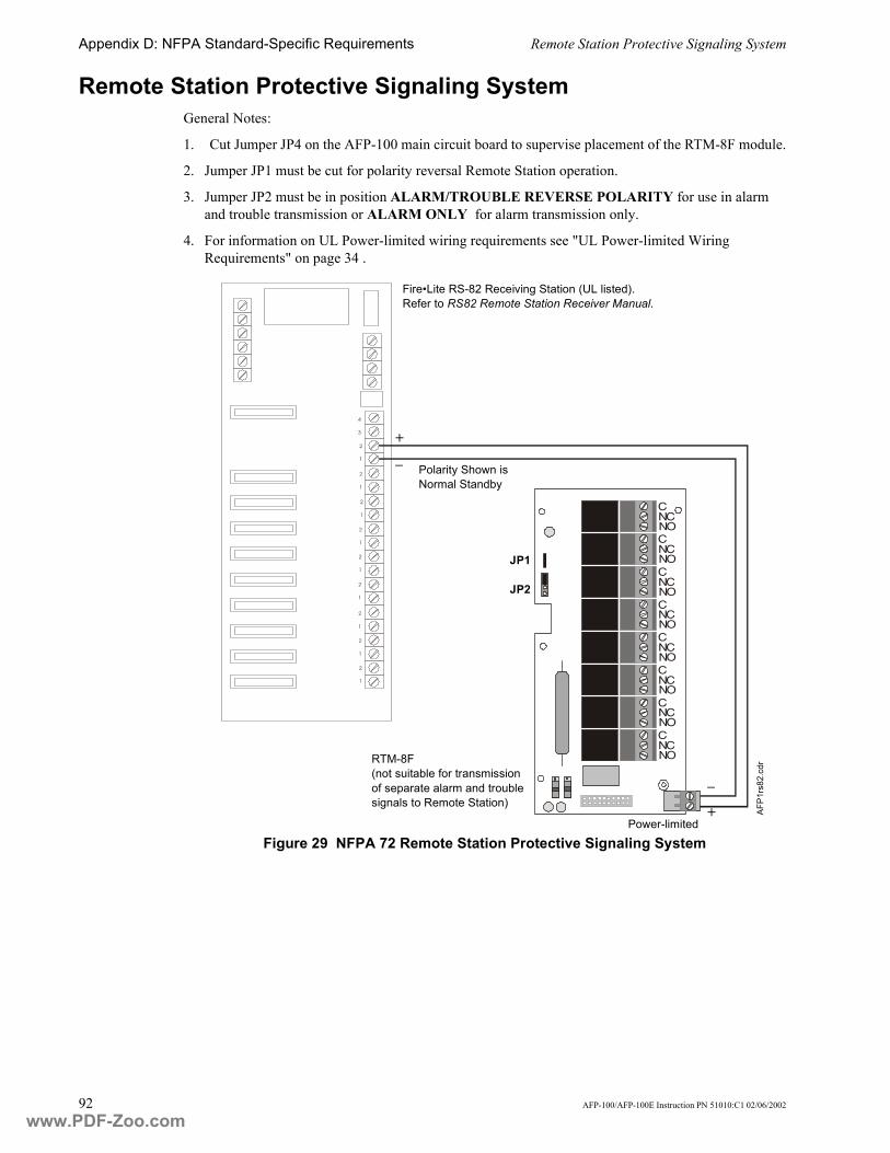
Appendix D: NFPA Standard-Specific Requirements Remote Station Protective Signaling System
92 AFP-100/AFP-100E Instruction PN 51010:C1 02/06/2002
Remote Station Protective Signaling SystemGeneral Notes:
1. Cut Jumper JP4 on the AFP-100 main circuit board to supervise placement of the RTM-8F module.
2. Jumper JP1 must be cut for polarity reversal Remote Station operation.
3. Jumper JP2 must be in position ALARM/TROUBLE REVERSE POLARITY for use in alarm and trouble transmission or ALARM ONLY for alarm transmission only.
4. For information on UL Power-limited wiring requirements see "UL Power-limited Wiring Requirements" on page 34 .
Figure 29 NFPA 72 Remote Station Protective Signaling System
2
1
2
1
4
3
2
1
2
1
2
1
2
1
2
1
2
1
2
1
CNCNOCNCNOCNCNOCNCNOCNCNOCNCNOCNCNOCNCNO
Fire�Lite RS-82 Receiving Station (UL listed).Refer to RS82 Remote Station Receiver Manual.
+
� Polarity Shown is Normal Standby
RTM-8F(not suitable for transmission of separate alarm and trouble signals to Remote Station)
JP1
JP2
Power-limited
AFP1
rs82
.cdr
�
+
www.PDF-Zoo.com

Proprietary Protective Signaling Systems Appendix D: NFPA Standard-Specific Requirements
AFP-100/AFP-100E Instruction PN 51010:C1 02/06/2002 93
Proprietary Protective Signaling SystemsNotes:
1. Connection between the AFP-100 and the transmitter are supervised by the transmitter.
2. This AFP-100/Transmitter arrangement can be employed for NFPA 72 Proprietary Protective Signaling System.
Figure 30 Proprietary Protective Signaling System
Form-A relay contact programmed to activate on Supervisory condition.
Form-C Trouble contact which will automatically activate on any Trouble condition.
Form-C Alarm contact programmed to activate on General Alarm.
AFP-100 Main Board
AFP-100 Addressable Fire Control Panel
www.PDF-Zoo.com

Appendix D: NFPA Standard-Specific Requirements Proprietary Protective Signaling Systems
94 AFP-100/AFP-100E Instruction PN 51010:C1 02/06/2002
Notes
www.PDF-Zoo.com

Index
AFP-100/AFP-100E Instruction PN 51010:C1 02/06/2002 95
IndexNumerics110/120 VAC�2914 AWG wire�29��76220/240 VAC�29
input�924 VDC�14
AABS-8R enclosure�22AC Branch Circuit�72AC Connections�29AC line voltage�42AC Power�76AC Power LED�59AC power, loss of�12AC/BAT�42Accessories�18accessory power�15Acknowledge/Step key�42��58��59��63��66��67ACM-16AT�21ACM-32A�21ACM-8R�22ACS Mode�32additional equipment�88additional information�10address�18addressable�14addressable devices�17��80ADJ field�45��46��47AFM-16AT�22AFM-32A�22AFP-100, older versions�20alarm
contacts�31display�64relay�17threshold�65verification�65
Alarm Operation�64Alarm relay�76Alarm Silence key�58��59��63��67Alarm Silence LED�58��59Alarm Verification�67alphanumeric operation�45Annunciator Control Module�21Annunciator Control System�21Annunciator Fixed Module�22Annunciator Relay Control Module�22application database�50Article 760�29assignment features�80audible indication�21automatic test�65Autoprogram Feature�41��45Autoprogramming mode�44Auto-silence Timer�67available words, list of�45
Bbackbox�11��29backlight, LED�12backspace key�12Bases, detector, listing of�18Basic Equiptment package�11Basic Equiptment package, Canada�15Battery�15
box�15cable�30connecting�30interconnect wire�30specifications�76voltage�42
Battery Charger�14��15BB-17 Battery box�15BB-55 Battery box�15
Ccabinet�15cabinet dimenstions�27cabinet door�11cabinet, locating�26Canadian installations�15capacity�33CBE (Control-By-Event)�68Central Station DACR�88Central Station receivers�20Central Station Service�88Chamber Reading�71Check�53CHG-120 Battery Charger�15Clear command�44Clear function�44Clear History�52Clock�65coded operation�66Command
�Silence Piezo��58Compatibility Directive 89/336/EEc�29computer�20Control Keys�58Control Module�17��19control panel sounder�58Control-By-Event Operation�65CPU�11Current Draw�72current status�51custom words�45
DDB25 adapter�39DB9F connector�39DC Power
connecting�31outputs�32special purpose�77specifications�77
www.PDF-Zoo.com

Index
96 AFP-100/AFP-100E Instruction PN 51010:C1 02/06/2002
default password�43default zone selection�47Detector Data�71detector sensitivity�45detector, new�45detectors, listing of�17device trouble�61��62��65DIM-485�20diode, 1N4004�37Disable�51Disable/Enable�68Display Interface Module�20Display Point operations�70document sources, list of�10downloaded�16downloading�50Drill key�58��67dry contact relays�14dummy load�32��37
Eediting process�45EIA-232�50EIA-232 serial port�39EIA-485�20��21��22electrical box�18emergency standby power�15English-language text�23Enter key�12enviroment, hostile�17European Communities�29expander modules�21external loading�73
Ffault condition�53Fault Isolator Module�19FCM-1�19FCPS-24�15��32FDM-1�18Features of FACP�9ferrite bead�29Field Charger/Power Supply�32field descriptors�48filtered power�73Fire Alarm LED�59Fixed modules�22Flowchart�55FMM-1�18FMM-101�18Form-A�76Form-A contacts�14��31Form-C�76Form-C contacts�14��31Form-C control relay module�19Form-C relays�20��22Four-wire smoke detector power�77FRM-1�19Function keys�12functions of control panel, normal�60FZM-1�18��52
Ggeneral alarm zone�65graphic annunciator�23ground connections�29ground fault�39grounding stud�29
HHistory
buffer�52clear�52events�52��70file�52��70
hostile enviroments�17
Iinitiating device�14��18inputs�81installation checklist�25intelligent detectors�17Internal Resistance�36ionization�17Isolator Module�19IXO-X�19
JJ11(PIM-24 or DIM-485 connection)�20J16 (UDACT connection)�20J17 (Transformer connection)�28J19 (Transformer connection)�28J3 (Battery connection)�30J6 (RTM-8F connection)�20JP1(RTM-8F reverse polarity)�92JP2 (RTM-8F Multi-function)�91��92JP4 (Supervise RTM-8F)�35��91��92
Kkey-lock reset�19knockouts�11
LLamp Driver Annunciator Module�23LCD display�12��44LCD-2X20 Fire Annunciator�20��23��58LDM-32�23LED backlight�12LED Indicators�59list of available words�45Load option�50Local Energy Municipal Box�37local sounder�12
Mmain circuit board�11main components, installation of�28maintenance status�65Manual Programming�41mappable relay control module�22membrane panel�12Message
"Clear Trouble"�63
www.PDF-Zoo.com

Index
AFP-100/AFP-100E Instruction PN 51010:C1 02/06/2002 97
"Not Installed"�70�Acknowledge��58��63�Maintenance Alert��65�Manual Evacuate��58�System Corrupted��44�Systems All Normal��63
Monitor Module�17��18mounting hole location�26MS-5012 Control Communicator�89Municipal Box�20��91Municipal Box output�37
NNAC�14��15
current draw�32exanding with FCPS-24�32Operation�64specifications�76
National Electrical Code�29NBG-12LX�19new detector�45new monitor module�47NFPA Requirements�88nine pin connector�39nonpower-limited circuits�31Nonregulated Special Purpose Power�77Nonresettable Power�14��77Nonresettable Power, connecting�31nonvolatile memory�43normal mode�60Notification Appliance Circuit�14��15��32notification device�18NOUN field�45��46NOUN library�46
OOff-Line Programming Feature�41Older circuit board�39older version AFP-100�20Open Condition�53option module connectors�20Optional Internal Modules�20Options�10Output Circuits�14��77output device�14outputs�81
Ppanel sounder�42��61��63��66Password�43��50��51Password, default�43photoelectric�17Piezo�58PIM-24�20��39Point Edit�48��51point programming�50polarity�30��32��36��37Polarity Reversal Output�36polls�44power output connections�31Power Supply, remote�15
power up�42power, emergency standby�15power-limited requirements
relays�31wiring�34
primary power�29Print Program�70printer�20Printer/PC Interface Module�20printer�s options�39programmable features�14programmed points�51Programming�41��42Programming Mode�43Programming Options, Flowchart�55Programming Sheet
detectors�82modules�83
programming utility�16Protected Premises Receiving Unit�88Protected Premises Unit�88public switched telephone network�20Pull Station�17��19pulse rate outputs�66
Rrate of rise, thermal�17Read Status�42
display�70functions�69
Recall/Increment function�46Relay Module�19Relay/Transmitter Module�20Relays�14
specifications�76Remote Fire Annunciator�20��23Remote Power Supply�15Remote Station Service�88Remote Station transmitters�20reset, key-lock�19Resettable Power�14resettable power�58Resettable Power, connecting�31resistance�77Retard period�67rotary decimal switches�17rotary switches�18RS-82 Receiving Station�36��92RTM-8F�20
components�36module�35wiring requirements�34
RTM-8F Relay/Transmitter Module�91��92
Ssecond zone�47sensitivity settings�45serial connection�21��22Service/program keys�12short circuits�19Shorted/Alarm Condition�52Signaling Line Circuit�17��33��76
www.PDF-Zoo.com

Index
98 AFP-100/AFP-100E Instruction PN 51010:C1 02/06/2002
Silence Inhibit Timer�67silenceable circuits�58slave operation�89SLC�14��33��77
device capacity�33installation�33specifications�76surge protection�33
smoke detector power, four-wire�77smoke detector, trouble�61software alarm zone�65software zone assignments�53Software Zones, examples�80sounder�58Special Function�47��48Special Purpose Power�77
connecting�31Specific Device Troubles (Table)�61��62sprinkler supervisory�91standby battery�73Standby Current�73standby power�15status�17��51status changes�50stored words, library�45Style 4�33Style 6�33Style 7�33Style Y�14��32Style Z�14��32Supervisory
contact�31event�64LED�59relay�14��76
Supervisory Operation�64Surge protection�32��33surge suppressors�76SW1 (Write Protect switch)�41��50��53SW2 (Trouble/No AC switch)�89system
function options�49memory map�22programming�50
System Alarm�14System Reset key�44��58��59��65��68��69System Status LED Indicators�59System Trouble�14System Trouble LED�44��59��61
TTB3 (Relay connections)�31TB4 (DC power connection)�31TB5 (ACS Mode connection)�21��22��32TB7 (Terminal Mode connection)�32telephone network, public switched�20Terminal Mode�32thermal rate of rise�17thermistor�17Timer, Auto-silence�67Timer, Silence Inhibit�67transformer�11��15
transformer, installation of�28Trouble
control modules�62monitor modules�62
trouble condition�52��53��61��62��63��64��91trouble contacts�31Trouble Operation�61Trouble relay�76Trouble Reminder�67Troubles, Specific Device (Table)�61��62T-tapping�77Type Code�17��45��47��65Type Code Label�47��48
UUDACT�20UDACT, internal mounting�90UL wire requirements�34Universal Digital Alarm Communicator/Transmitter�20unpacking the system�25upload/download�20
VVeri�Fire CD Medium System Programming Utility�16��39��50visual indication�21
WWalktest�41��52watchdog circuit�59Waterflow�68wire requirements�78Wire size (AC power)�76Wiring Fault�68words, custom�45words, stored�45Write Protect�50
XXRM-24�11��15��28
Zzone selection�45zone selection, default�47zones�65
www.PDF-Zoo.com

AFP-100/AFP-100E Instruction PN 51010:C1 02/06/2002 99
Limited Warranty
NOTIFIER® warrants its products to be free from defects in materials andworkmanship for eighteen (18) months from the date of manufacture,under normal use and service. Products are date stamped at time ofmanufacture. The sole and exclusive obligation of NOTIFIER® is torepair or replace, at its option, free of charge for parts and labor, any partwhich is defective in materials or workmanship under normal use andservice. For products not under NOTIFIER® manufacturing date-stampcontrol, the warranty is eighteen (18) months from date of originalpurchase by NOTIFIER®�s distributor unless the installation instructionsor catalog sets forth a shorter period, in which case the shorter periodshall apply. This warranty is void if the product is altered, repaired orserviced by anyone other than NOTIFIER® or its authorized distributorsor if there is a failure to maintain the products and systems in which theyoperate in a proper and workable manner. In case of defect, secure aReturn Material Authorization form from our customer servicedepartment. Return product, transportation prepaid, to NOTIFIER®,12 Clintonville Road, Northford, Connecticut 06472-1653.
This writing constitutes the only warranty made by NOTIFIER® withrespect to its products. NOTIFIER® does not represent that its productswill prevent any loss by fire or otherwise, or that its products will in allcases provide the protection for which they are installed or intended.Buyer acknowledges that NOTIFIER® is not an insurer and assumes norisk for loss or damages or the cost of any inconvenience, transportation,damage, misuse, abuse, accident or similar incident.
NOTIFIER® GIVES NO WARRANTY, EXPRESSED OR IMPLIED, OFMERCHANTABILITY, FITNESS FOR ANY PARTICULAR PURPOSE, OROTHERWISE WHICH EXTEND BEYOND THE DESCRIPTION ON THEFACE HEREOF. UNDER NO CIRCUMSTANCES SHALL NOTIFIER®BE LIABLE FOR ANY LOSS OF OR DAMAGE TO PROPERTY, DIRECT,INCIDENTAL OR CONSEQUENTIAL, ARISING OUT OF THE USE OF,OR INABILITY TO USE NOTIFIER® PRODUCTS. FURTHERMORE,NOTIFIER® SHALL NOT BE LIABLE FOR ANY PERSONAL INJURY ORDEATH WHICH MAY ARISE IN THE COURSE OF, OR AS A RESULTOF, PERSONAL, COMMERCIAL OR INDUSTRIAL USE OF ITSPRODUCTS.
This warranty replaces all previous warranties and is the only warrantymade by NOTIFIER®. No increase or alteration, written or verbal, of theobligation of this warranty is authorized.
"NOTIFIER" is a registered trademark.Warn-NL-10-2001.fm
www.PDF-Zoo.com

World Headquarters12 Clintonville Road
Northford, CT 06472-1653 USA203-484-7161
fax 203-484-7118
www.notifier.com
NOTIFIER is an operation of
www.PDF-Zoo.com