Intellect Software Package - AxxonSoft
823
AxxonSoft INTELLECT TM Software Package Administrator’s Guide Installation and Configuration Manual Version 2.1.6 Moscow 2012
Transcript of Intellect Software Package - AxxonSoft

AxxonSoft
INTELLECTTM
Software Package
Administrator’s Guide
Installation and Configuration Manual
Version 2.1.6
Moscow 2012
2
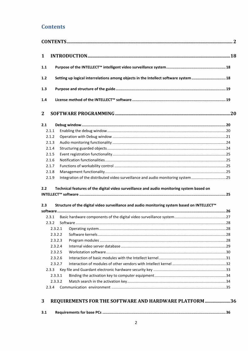
Contents
CONTENTS ................................................................................................................................................ 2
1 INTRODUCTION ............................................................................................................................ 18
1.1 Purpose of the INTELLECT™ intelligent video surveillance system...................................................... 18
1.2 Setting up logical interrelations among objects in the Intellect software system ............................... 18
1.3 Purpose and structure of the guide .................................................................................................... 19
1.4 License method of the INTELLECT™ software ..................................................................................... 19
2 SOFTWARE PROGRAMMING .................................................................................................... 20
2.1 Debug window ................................................................................................................................... 20
2.1.1 Enabling the debug window ................................................................................................................. 20
2.1.2 Operation with Debug window ............................................................................................................ 21
2.1.3 Audio monitoring functionality ............................................................................................................ 24
2.1.4 Structuring guarded objects ................................................................................................................. 24
2.1.5 Event registration functionality ............................................................................................................ 25
2.1.6 Notification functionalities ................................................................................................................... 25
2.1.7 Functions of workability control .......................................................................................................... 25
2.1.8 Management functionality ................................................................................................................... 25
2.1.9 Integration of the distributed video surveillance and audio monitoring system ................................. 25
2.2 Technical features of the digital video surveillance and audio monitoring system based on
INTELLECT™ software ..................................................................................................................................... 25
2.3 Structure of the digital video surveillance and audio monitoring system based on INTELLECT™
software ......................................................................................................................................................... 26
2.3.1 Basic hardware components of the digital video surveillance system ................................................. 27
2.3.2 Software ............................................................................................................................................... 28
2.3.2.1 Operating system......................................................................................................................... 28
2.3.2.2 Software kernels .......................................................................................................................... 28
2.3.2.3 Program modules ........................................................................................................................ 28
2.3.2.4 Internal video server database .................................................................................................... 29
2.3.2.5 Workstation software .................................................................................................................. 30
2.3.2.6 Interaction of basic modules with the Intellect kernel ................................................................ 31
2.3.2.7 Interaction of modules of other vendors with Intellect kernel ................................................... 32
2.3.3 Key file and Guardant electronic hardware security key ..................................................................... 33
2.3.3.1 Binding the activation key to computer equipment .................................................................... 34
2.3.3.2 Match search in the activation key .............................................................................................. 34
2.3.4 Communication environment ............................................................................................................. 35
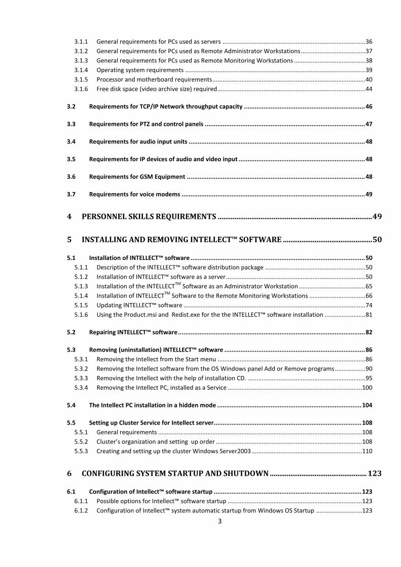
3 REQUIREMENTS FOR THE SOFTWARE AND HARDWARE PLATFORM ...................... 36
3.1 Requirements for base PCs ................................................................................................................ 36
3
3.1.1 General requirements for PCs used as servers .................................................................................... 36
3.1.2 General requirements for PCs used as Remote Administrator Workstations ...................................... 37
3.1.3 General requirements for PCs used as Remote Monitoring Workstations .......................................... 38
3.1.4 Operating system requirements .......................................................................................................... 39
3.1.5 Processor and motherboard requirements .......................................................................................... 40
3.1.6 Free disk space (video archive size) required ....................................................................................... 44
3.2 Requirements for TCP/IP Network throughput capacity .................................................................... 46
3.3 Requirements for PTZ and control panels .......................................................................................... 47
3.4 Requirements for audio input units ................................................................................................... 48
3.5 Requirements for IP devices of audio and video input ....................................................................... 48
3.6 Requirements for GSM Equipment .................................................................................................... 48
3.7 Requirements for voice modems ....................................................................................................... 49
4 PERSONNEL SKILLS REQUIREMENTS ................................................................................... 49
5 INSTALLING AND REMOVING INTELLECT™ SOFTWARE ................................................ 50
5.1 Installation of INTELLECT™ software .................................................................................................. 50
5.1.1 Description of the INTELLECT™ software distribution package ........................................................... 50
5.1.2 Installation of INTELLECT™ software as a server .................................................................................. 50
5.1.3 Installation of the INTELLECTTM
Software as an Administrator Workstation ....................................... 65
5.1.4 Installation of INTELLECTTM
Software to the Remote Monitoring Workstations ................................. 66
5.1.5 Updating INTELLECT™ software ........................................................................................................... 74
5.1.6 Using the Product.msi and Redist.exe for the the INTELLECT™ software installation ........................ 81
5.2 Repairing INTELLECT™ software ......................................................................................................... 82
5.3 Removing (uninstallation) INTELLECT™ software ............................................................................... 86
5.3.1 Removing the Intellect from the Start menu ....................................................................................... 86
5.3.2 Removing the Intellect software from the OS Windows panel Add or Remove programs .................. 90
5.3.3 Removing the Intellect with the help of installation CD. ..................................................................... 95
5.3.4 Removing the Intellect PC, installed as a Service ............................................................................... 100
5.4 The Intellect PC installation in a hidden mode ................................................................................. 104
5.5 Setting up Cluster Service for Intellect server................................................................................... 108
5.5.1 General requirements ........................................................................................................................ 108
5.5.2 Cluster’s organization and setting up order ...................................................................................... 108
5.5.3 Creating and setting up the cluster Windows Server2003 ................................................................. 110
6 CONFIGURING SYSTEM STARTUP AND SHUTDOWN .................................................... 123
6.1 Configuration of Intellect™ software startup ................................................................................... 123
6.1.1 Possible options for Intellect™ software startup ............................................................................... 123
6.1.2 Configuration of Intellect™ system automatic startup from Windows OS Startup ........................... 123
4
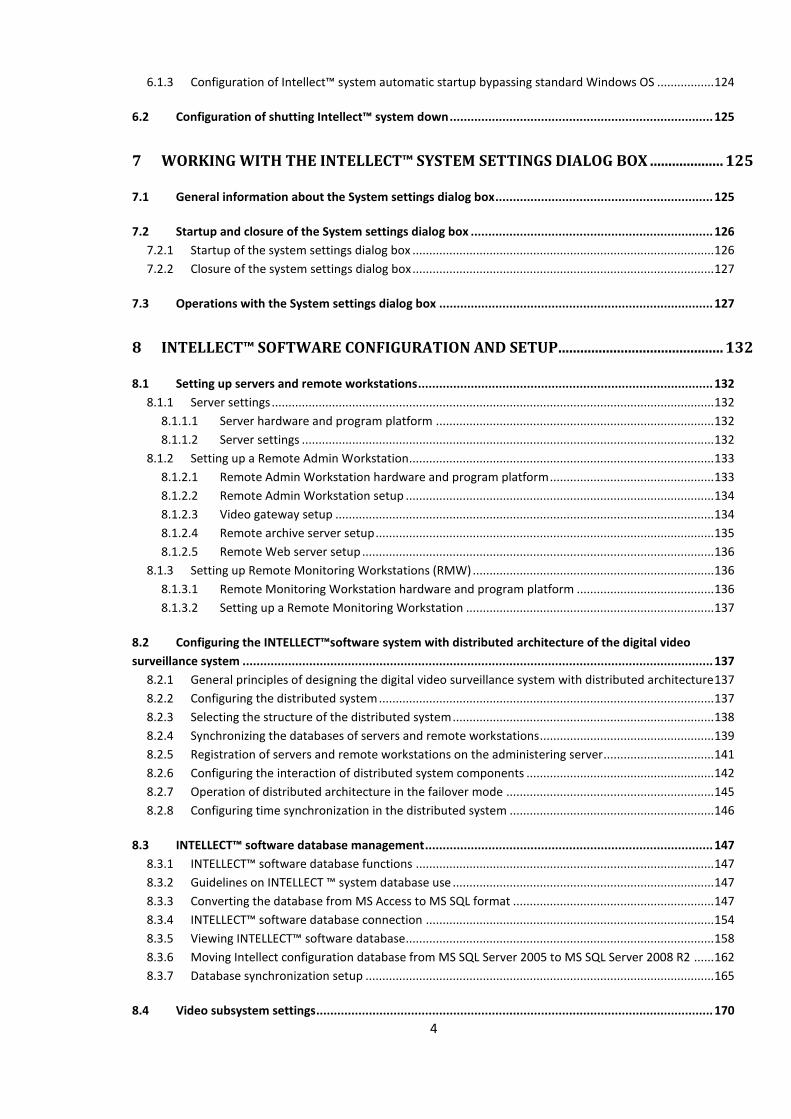
6.1.3 Configuration of Intellect™ system automatic startup bypassing standard Windows OS ................. 124
6.2 Configuration of shutting Intellect™ system down ........................................................................... 125
7 WORKING WITH THE INTELLECT™ SYSTEM SETTINGS DIALOG BOX .................... 125
7.1 General information about the System settings dialog box .............................................................. 125
7.2 Startup and closure of the System settings dialog box ..................................................................... 126
7.2.1 Startup of the system settings dialog box .......................................................................................... 126
7.2.2 Closure of the system settings dialog box .......................................................................................... 127
7.3 Operations with the System settings dialog box .............................................................................. 127
8 INTELLECT™ SOFTWARE CONFIGURATION AND SETUP ............................................. 132
8.1 Setting up servers and remote workstations .................................................................................... 132
8.1.1 Server settings .................................................................................................................................... 132
8.1.1.1 Server hardware and program platform ................................................................................... 132
8.1.1.2 Server settings ........................................................................................................................... 132
8.1.2 Setting up a Remote Admin Workstation........................................................................................... 133
8.1.2.1 Remote Admin Workstation hardware and program platform ................................................. 133
8.1.2.2 Remote Admin Workstation setup ............................................................................................ 134
8.1.2.3 Video gateway setup ................................................................................................................. 134
8.1.2.4 Remote archive server setup ..................................................................................................... 135
8.1.2.5 Remote Web server setup ......................................................................................................... 136
8.1.3 Setting up Remote Monitoring Workstations (RMW) ........................................................................ 136
8.1.3.1 Remote Monitoring Workstation hardware and program platform ......................................... 136
8.1.3.2 Setting up a Remote Monitoring Workstation .......................................................................... 137
8.2 Configuring the INTELLECT™software system with distributed architecture of the digital video
surveillance system ...................................................................................................................................... 137
8.2.1 General principles of designing the digital video surveillance system with distributed architecture 137
8.2.2 Configuring the distributed system .................................................................................................... 137
8.2.3 Selecting the structure of the distributed system .............................................................................. 138
8.2.4 Synchronizing the databases of servers and remote workstations .................................................... 139
8.2.5 Registration of servers and remote workstations on the administering server................................. 141
8.2.6 Configuring the interaction of distributed system components ........................................................ 142
8.2.7 Operation of distributed architecture in the failover mode .............................................................. 145
8.2.8 Configuring time synchronization in the distributed system ............................................................. 146
8.3 INTELLECT™ software database management .................................................................................. 147
8.3.1 INTELLECT™ software database functions ......................................................................................... 147
8.3.2 Guidelines on INTELLECT ™ system database use .............................................................................. 147
8.3.3 Converting the database from MS Access to MS SQL format ............................................................ 147
8.3.4 INTELLECT™ software database connection ...................................................................................... 154
8.3.5 Viewing INTELLECT™ software database ............................................................................................ 158
8.3.6 Moving Intellect configuration database from MS SQL Server 2005 to MS SQL Server 2008 R2 ...... 162
8.3.7 Database synchronization setup ........................................................................................................ 165
8.4 Video subsystem settings ................................................................................................................. 170
5
8.4.1 General information on video subsystem settings............................................................................. 170
8.4.1.1 Video subsystem components description ................................................................................ 170
8.4.1.2 Configuring video capture cards ................................................................................................ 170
8.4.1.3 Configuring IP-devices ............................................................................................................... 171
8.4.1.4 Video signal compression and decompression.......................................................................... 171
8.4.1.5 How to record digitized video signals ........................................................................................ 171
8.4.1.6 Digital video signal transmission to Remote Workplaces .......................................................... 172
8.4.1.7 Video signal display ................................................................................................................... 172
8.4.2 Registration of video grabbers and camera registration in the INTELLECT™ software ...................... 172
8.4.3 Setting up the video signals processing mode while using video capture cards and analog video
cameras ........................................................................................................................................................... 173
8.4.3.1 Video signals digitization and processing settings ..................................................................... 173
8.4.3.1.1 Setting up format (PAL or NTSC) for the input analog video signal ...................................... 173
8.4.3.1.2 Setting up frame resolution .................................................................................................. 174
8.4.3.1.3 Frame rate settings ............................................................................................................... 175
8.4.3.1.4 Brightness, contrast, color depth, color rendition format settings ...................................... 190
8.4.3.1.5 Video signal compression settings ....................................................................................... 194
8.4.3.2 Additional information on camera ............................................................................................ 197
8.4.4 Virtual video capture card creation and setting ................................................................................. 198
8.4.5 Video signals archiving settings .......................................................................................................... 200
8.4.5.1 General information .................................................................................................................. 200
8.4.5.2 Setup procedure of video signals archiving ............................................................................... 203
8.4.5.3 Selecting the disks for video archive storage ............................................................................ 203
8.4.5.4 Using the network disks ............................................................................................................ 204
8.4.5.5 Switching off automatic recording on alarm event registration ............................................... 205
8.4.5.6 Video frame rate setup .............................................................................................................. 206
8.4.5.7 Video settings in the Hot Recording mode ................................................................................ 207
8.4.5.8 Video signal pre-event recording setup..................................................................................... 208
8.4.5.9 Post-event recording setup ....................................................................................................... 209
8.4.5.10 Audio and video synchro recording settings ............................................................................. 210
8.4.6 Settings of video signal transmission to Remote Workstations ......................................................... 211
8.4.7 Video signal display settings ............................................................................................................... 212
8.4.7.1 General information .................................................................................................................. 212
8.4.7.2 Video monitor setup sequence ................................................................................................. 213
8.4.7.3 Creation of Monotor object ....................................................................................................... 213
8.4.7.4 Selecting the parameters of «Мonitor» interface window ....................................................... 214
8.4.7.5 Selection and setting of video cameras ..................................................................................... 216
8.4.7.6 Complex selection of video cameras ......................................................................................... 218
8.4.7.7 Setting the option of camera’s windows displaying .................................................................. 221
8.4.7.8 Selecting the overlay mode ....................................................................................................... 223
8.4.7.9 Setting up PTZ control priority with the use of Monitor object ................................................ 224
8.4.7.10 Setting up the titles displaying .................................................................................................. 225
8.4.8 Enabling, setting up and disabling the video detectors ..................................................................... 226
8.4.8.1 General information .................................................................................................................. 226
8.4.8.2 Requirements to video parameters while working with detectors ........................................... 227
8.4.8.3 Enabling and configuring detectors ........................................................................................... 227
8.4.8.4 Detectors connection ................................................................................................................ 228
8.4.8.5 Detectors setup ......................................................................................................................... 229
8.4.8.5.1 Main motion detector setup ................................................................................................ 229
8.4.8.5.2 Motion detector setup ......................................................................................................... 230
6
8.4.8.5.3 Focusing detector setup ....................................................................................................... 232
8.4.8.5.4 Setup of the video signal stability detector .......................................................................... 233
8.4.8.5.5 Setup of the background change detector ........................................................................... 235
8.4.8.5.6 Setup of the camera blinding detector................................................................................. 236
8.4.8.5.7 Setup of the lens blocking detector...................................................................................... 237
8.4.8.5.8 Set up of face detector ......................................................................................................... 238
8.4.8.5.9 Lost items detector setup ..................................................................................................... 240
8.4.8.5.10 Setup of the infrared detector ........................................................................................... 241
8.4.9 Setting up object’s panoramic view by means of Scene object ......................................................... 244
8.4.9.1 Creating the Scene object .......................................................................................................... 244
8.4.9.2 Setting the parameters of Scene interface window .................................................................. 245
8.4.9.3 Cameras selection and setup ..................................................................................................... 245
8.4.10 Intellectual search in archive set up .......................................................................................... 247
8.4.10.1 General information .................................................................................................................. 247
8.4.10.2 Object trajectories DB set up and creation ............................................................................... 248
8.4.10.3 Tracker object setup and creation ............................................................................................. 249
8.4.10.4 Creating and configuring VMDA detectors ................................................................................ 253
8.4.10.4.1 Cross line detector configuration ....................................................................................... 254
8.4.10.4.2 Motion in the Area detector configuration ........................................................................ 257
8.4.11 Embedded detectors ................................................................................................................. 260
8.4.11.1 Creating embedded detectors ................................................................................................... 260
8.4.11.2 Embedded detectors setup ....................................................................................................... 261
8.5 Configuring video viewing from fish-eye cameras ............................................................................ 262
8.5.1 General information ........................................................................................................................... 262
8.5.2 Configuring the Fisheye camera monitor interface object................................................................. 262
8.6 Configuring the access to the archive in external storage ................................................................ 263
8.6.1 General information ........................................................................................................................... 263
8.6.2 Creating the External storage object .................................................................................................. 263
8.6.3 Configuring the connection to external storage ................................................................................ 264
8.6.4 Setting the list of cameras to access the external storage ................................................................. 265
8.7 Configuring telemetry ...................................................................................................................... 266
8.8 Audio subsystem setup .................................................................................................................... 267
8.8.1 General information on audio subsystem setup ................................................................................ 267
8.8.1.1 Audio digitizing devices ............................................................................................................. 267
8.8.1.1.1 Video capture cards .............................................................................................................. 267
8.8.1.1.2 Standard soundcards, microphones, loudspeakers and headphones .................................. 268
8.8.1.1.3 Multichannel audio capture devices .................................................................................... 268
8.8.1.1.4 IP-devices .............................................................................................................................. 268
8.8.1.2 Configuring the digitization devices for audio signals ............................................................... 268
8.8.1.3 Digitized audio signal recording................................................................................................. 269
8.8.1.4 Digital audio signal transmission to Remote Workstations and servers ................................... 269
8.8.1.5 Audio signal playback ................................................................................................................ 269
8.8.2 Registration of audio capture cards and microphones in the INTELLECT™ software ........................ 269
8.8.3 Setup of audio signals digitization and processing ............................................................................. 270
8.8.3.1 Audio signals sample rate settings ............................................................................................ 270
8.8.3.2 Set up of audio signal volume amplification.............................................................................. 271
8.8.3.3 Setting up the Automatic Gain Control for sound cards of Olha line ........................................ 272
7
8.8.4 Setup of audio signals recording ........................................................................................................ 274
8.8.4.1 Audio signals recording modes .................................................................................................. 274
8.8.4.2 Selecting the disks for audio archive storage ............................................................................ 274
8.8.4.3 Setup of sound activated recording .......................................................................................... 276
8.8.4.4 Setup of audio and video synchro recording ............................................................................. 277
8.8.5 Configuring Audio Analytics ............................................................................................................... 278
8.8.5.1 General information .................................................................................................................. 278
8.8.5.2 How to configure audio analytics: ............................................................................................. 279
8.8.5.3 Specifying the type of analytics ................................................................................................. 279
8.8.5.4 Configuring an audio detector ................................................................................................... 280
8.8.5.5 Sample macros for audio analytics ............................................................................................ 281
8.8.6 Setup of audio signal transmission to Remote Workstations and servers ......................................... 283
8.8.7 Setup of audio playback .................................................................................................................... 284
8.8.7.1 Creating and setting of “Playing card” object ............................................................................ 284
8.8.7.2 Creating and setting of “Speaker” object .................................................................................. 286
8.8.8 Some features of audio signals playback by the video monitor ......................................................... 287
8.8.9 Setup of audio signals playback by the Audio player ......................................................................... 287
8.8.9.1 Audio player setup sequence .................................................................................................... 287
8.8.9.2 Creating the Audio player object ............................................................................................... 288
8.8.9.3 Setting the parameters of Audio player window....................................................................... 289
8.8.9.4 Setting uo the recording and audio signals’ playback ............................................................... 290
8.8.10 Setting up the voice notification ............................................................................................... 291
8.8.10.1 Setting up the voice notification using «Audio player» object .................................................. 292
8.8.10.2 Setting up the voice notification using Sound notification object ............................................. 293
8.8.11 Setting up the sound switch ...................................................................................................... 294
8.8.11.1 Creating and setting up «Live sound switch» object ................................................................. 294
8.8.11.2 Working with the «Live sound switch» object........................................................................... 298
8.8.12 Features of standard sound card use ........................................................................................ 299
8.8.12.1 General information on standard sound cards .......................................................................... 299
8.8.12.2 Features of standard sound card setup ..................................................................................... 299
8.8.13 Using multi-channel audio capture devices ............................................................................... 300
8.8.13.1 General information on multi-channel audio capture devices .................................................. 300
8.8.13.2 Setting up multi-channel audio capture devices ....................................................................... 301
8.8.14 Using IP-devices ......................................................................................................................... 302
8.8.14.1 General information on IP-devices ............................................................................................ 302
8.8.14.2 Setup of video signals transmission to IP-devices ..................................................................... 302
8.8.14.3 Setting up the transmission of audio signals to IP-device Bosсh ............................................... 304
8.8.14.4 Setting up and transmission of duplex audio signals to IP-devices ........................................... 306
8.9 Setup and connection of the special keyboard ................................................................................. 313
8.9.1 Connecting the special keyboard to the Workstations ...................................................................... 314
8.9.2 Setting up the layout of the special keyboard device ........................................................................ 316
8.9.2.1 Installation of the software for programming of the “Special keyboard” device ...................... 316
8.9.2.2 Programming the “Special keyboard” device in Windows OS ................................................... 321
8.9.3 “Special keyboard” device setup in INTELLECT™ software ................................................................ 326
8.9.4 Settings the interpretation rules of “Special keyboard” layout by Intellect program complex ........ 327
8.9.4.1 The use of standard ini-file ........................................................................................................ 327
8.9.4.2 Setting up Intellect program software with the use of several Special keyboard devices ........ 330
8.9.4.3 Editing the standard ini-file(optionally) ..................................................................................... 331
8.10 Voice notification service ................................................................................................................. 332
8
8.10.1 Setting up the Alarm Message window ..................................................................................... 332
8.10.1.1 General description and usage details of the Alarm Message window..................................... 332
8.10.1.2 Creating and setting up the Alarm Message Window object .................................................... 332
8.10.2 Setting up the Short Message Service (SMS) ............................................................................. 333
8.10.2.1 General description and usage details of the Short Message Service ....................................... 333
8.10.2.2 Creating and setting up the Short Message Service object ....................................................... 334
8.10.2.3 Creating and setting up the short messages ............................................................................. 334
8.10.2.4 Creating and setting up the macro for sending the short message .......................................... 335
8.10.3 Setting up the Mail Message Service (E-mail) ........................................................................... 335
8.10.3.1 General description and usage details of the Mail Message Service ........................................ 335
8.10.3.2 Creating and setting up the Mail Message Service.................................................................... 336
8.10.3.3 Creation of e-mail messages...................................................................................................... 337
8.10.3.4 Creating and setting up a macro for sending the e-mail message ............................................ 337
8.10.4 Setting up the Voice Message Service (V-dial) .......................................................................... 338
8.10.4.1 General information and usage details of the Voice Message Service ..................................... 338
8.10.4.2 Creating and setting up the Voice Message Service object ....................................................... 339
8.10.4.3 Creating voice messages ............................................................................................................ 339
8.10.4.4 Creating and setting up the macro for sending the voice message .......................................... 340
8.10.5 Setting up the Voice Notification Service .................................................................................. 341
8.10.5.1 General description and usage details of the Voice Notification Service (VNS) ........................ 341
8.10.5.2 Creating and setting up the Voice Notification Service object .................................................. 341
8.10.5.3 Creating and setting up the macro for sending the voice notification ...................................... 342
8.11 Setting up the SNMP-service ............................................................................................................ 343
8.11.1 SNMP-service setting order ....................................................................................................... 343
8.11.2 Creating the SNMP trap object .................................................................................................. 344
8.11.3 Events selection for transmitting to SNMP agent ..................................................................... 346
8.11.4 Setting up the message conversion into SNMP format ............................................................. 347
8.11.5 Setting up the trap with SNMP-message ................................................................................... 348
8.12 Setting up the «System restarting service» ...................................................................................... 349
8.13 Setting up the Videogate module..................................................................................................... 352
8.13.1 General information .................................................................................................................. 352
8.13.2 Order of setting up the Videogate object .................................................................................. 353
8.13.3 Creation of Videogate object ..................................................................................................... 354
8.13.4 Selection and setting up the cameras ....................................................................................... 355
8.13.5 Complex selection of video cameras ......................................................................................... 356
8.13.6 Selection of disks for storing the archive of Videogate module ................................................ 359
8.14 Setting up backup archiving ............................................................................................................. 361
8.14.1 Purpose and implementation of backup archiving in the Intellect software ............................ 361
8.14.2 Setting up the Active Archiving module .................................................................................... 361
8.14.2.1 Set up order of the Active Archiving .......................................................................................... 362
8.14.2.2 Creating the Active Archiving object ......................................................................................... 362
8.14.2.3 Choosing and setting up the cameras ....................................................................................... 363
8.14.2.4 Complex selection of cameras ................................................................................................... 364
8.14.2.5 Setting the parameters of video archive transmission over a local network ............................ 366
8.14.2.6 Choosing the drives to store the archive of the Active Archiving module ................................ 367
8.14.2.7 Setting up the scaling of the video archive ................................................................................ 369
8.14.2.8 Setting up the timetable of the video archive copying.............................................................. 370
9
8.14.2.9 Setting up the Panel of Active Archiving ................................................................................... 372
8.14.3 Configuring the Active audio archive module ........................................................................... 373
8.15 Replicating archive from unconnected servers using the removable storage ................................... 374
8.15.1 Order of archive replication from unconnected servers ........................................................... 374
8.15.2 Configuring the Data replication service object ........................................................................ 375
8.15.3 Configuring the Target object tree for data replication ............................................................ 376
8.15.4 Creating the query file ............................................................................................................... 376
8.15.5 Copying the archive from the Source ........................................................................................ 377
8.15.6 Restoring the archive on the Target .......................................................................................... 378
8.16 Configuring the Web-server module ................................................................................................ 379
8.16.1 General description of the Web-server module ........................................................................ 379
8.16.2 System requirements................................................................................................................. 380
8.16.3 Installation of Java Runtime Environment ................................................................................. 380
8.16.4 Authorization on the Web-server home page ........................................................................... 381
8.16.5 Starting and setting up the Web-server module ....................................................................... 381
8.16.6 Setting up the videoserver for connection of the operator workstations via the Web-server
module 381
8.16.6.1 Creation of the Web-server object ............................................................................................ 382
8.16.6.2 Selection and set up of cameras ................................................................................................ 383
8.16.7 Web-server home page template and Java applet settings ...................................................... 385
8.16.8 Setting up the surveillance monitor interface of the Web-server module ............................... 387
8.16.9 Setting up the display of the data for traffic estimation in the Web-server ............................. 388
8.16.10 Setting up the Web-server module to act as a gate on a different HTTP-server....................... 389
8.17 Counting the system events ............................................................................................................. 390
8.17.1 General Information .................................................................................................................. 390
8.17.2 Events Counter setup ................................................................................................................ 390
8.17.3 Data output and counter control............................................................................................... 392
8.18 Setting up the Event Viewer ............................................................................................................. 393
8.18.1 Setting up the interface object «Events viewer»....................................................................... 393
8.18.1.1 Order of setting up the interface object «Event viewer» .......................................................... 393
8.18.1.2 Events selection ......................................................................................................................... 394
8.18.1.3 Setting up the events viewer’s parameters ............................................................................... 396
8.18.1.4 Parameters of «Events viewer» displaying ................................................................................ 397
8.18.1.5 Setting up the database «Events viewer» ................................................................................. 398
8.19 Setting up the interactive map for object state indication and controlling the objects .................... 399
8.19.1 General information on the structure of the interactive map of the guarded location ............ 399
8.19.2 Setting up the interactive map .................................................................................................. 399
8.19.2.1 Setup procedure ........................................................................................................................ 399
8.19.2.2 Setting up the location of the map on the screen ..................................................................... 400
8.19.2.3 Creation of the layers of the interactive map............................................................................ 400
8.19.2.4 Attachment of objects to the layers of interactive map ............................................................ 405
8.19.2.5 Operations with objects in Map editor utility ........................................................................... 407
8.19.2.6 Linking the layers of the interactive map .................................................................................. 412
8.19.3 Setting up the display of the alarm signals on multilevel maps ................................................ 414
8.20 Setting up the user interface ............................................................................................................ 416
10
8.20.1 The user interface in the Intellect software .............................................................................. 416
8.20.2 Creating the screens .................................................................................................................. 416
8.20.3 Placing the interface components on the screen ...................................................................... 417
8.20.4 Assigning the screens to the operator workstations ................................................................. 417
8.20.5 Examples of the user interface setup ........................................................................................ 418
8.21 Rights administration ....................................................................................................................... 419
8.21.1 The users‘ rights ........................................................................................................................ 419
8.21.2 User registration and removal ................................................................................................... 419
8.21.2.1 General information about user registration in Intellect software ........................................... 419
8.21.2.2 User registration ........................................................................................................................ 420
8.21.2.3 Administrator password registration......................................................................................... 420
8.21.2.4 Department registration ............................................................................................................ 421
8.21.2.5 Registration of operator accounts ............................................................................................. 422
8.21.2.6 Removing user accounts ............................................................................................................ 422
8.21.3 Registration of users’ rights ....................................................................................................... 423
8.21.3.1 Registration of operator rights .................................................................................................. 423
8.21.3.2 General information on the limits to the administrative functions .......................................... 424
8.21.3.3 Limiting access to the tabs of the System Settings window ...................................................... 424
8.21.3.4 Limiting access to the administration of the system objects, control and viewing functions ... 425
8.21.3.5 Limiting access to shutting the system down ............................................................................ 426
8.21.3.6 Limiting the rights to hide the interface components ............................................................... 427
8.21.3.7 Limiting access to video and audio archives .............................................................................. 428
8.21.4 Assigning rights and passwords to operators for authorization in the Intellect ....................... 429
8.21.5 Setting up the initial user........................................................................................................... 431
8.22 Creating and using macros .............................................................................................................. 432
8.22.1 About macros ............................................................................................................................ 432
8.22.2 Creating macros ......................................................................................................................... 432
8.22.3 Examples of macros ................................................................................................................... 435
8.23 Creating and using time zones ......................................................................................................... 437
8.23.1 About time zones ....................................................................................................................... 437
8.23.2 Creating and setting up time zones ........................................................................................... 437
8.23.3 Examples of time zones usage ................................................................................................... 440
8.24 The Timer object creation and usage ............................................................................................... 442
8.24.1 General Information .................................................................................................................. 442
8.24.2 The Timer object creation and setup ......................................................................................... 442
8.24.3 Examples of Timer object usage ................................................................................................ 444
8.25 Subdivision of the guarded location into areas and regions ............................................................. 447
8.25.1 About areas and regions ............................................................................................................ 447
8.25.2 Creating areas ............................................................................................................................ 447
8.25.3 Creating regions ......................................................................................................................... 447
8.25.4 Examples of using areas and regions ......................................................................................... 448
9 THE REPORT SYSTEM ............................................................................................................. 449
9.1 General information ........................................................................................................................ 449
11
9.2 Starting and closing the Report system ............................................................................................ 449
9.2.1 Starting the Report system ................................................................................................................. 449
9.2.2 Closing the Report system .................................................................................................................. 450
9.3 The Report window ......................................................................................................................... 451
9.3.1 The OptionsForm window .................................................................................................................. 454
9.4 Connecting to databases .................................................................................................................. 456
9.4.1 Connecting to the main database of the Intellect system ................................................................. 456
9.4.1.1 Selecting an Access database and setting up the connection ................................................... 457
9.4.1.2 Selecting an SQL database and setting up its parameters ......................................................... 463
9.4.2 Connecting to the Events Log (PROTOCOL table)............................................................................... 472
9.5 Manual loading of the configuration and registered events from the database ............................... 474
9.6 Viewing the general information on the events in the database ...................................................... 474
9.7 Creating the log of changes made to the system configuration ........................................................ 475
9.8 Using the report templates in the Report system ............................................................................ 477
9.8.1 Recommendations for template creation .......................................................................................... 477
9.8.2 Creating a report template ................................................................................................................. 477
9.8.3 Deleting the report templates ............................................................................................................ 480
9.9 Using screen and printed reports ..................................................................................................... 480
9.9.1 Creating a screen report ..................................................................................................................... 481
9.9.1.1 Creating a screen report from the report template .................................................................. 482
9.9.2 Creating a printed report ................................................................................................................... 483
9.9.3 Printing the report .............................................................................................................................. 486
9.9.4 Exporting the report to a file .............................................................................................................. 486
9.10 Video recording playback from the Report system .......................................................................... 488
9.10.1 Selecting the playback mode of video recordings ..................................................................... 488
9.10.2 Playback of the video recordings from the Report system ....................................................... 489
9.11 Filtering the events in the screen report according to the additional information ........................... 490
9.12 The keyboard shortcuts list .............................................................................................................. 491
10 CONCLUSION ............................................................................................................................... 493
11 APPENDIX 1. INTERFACE ....................................................................................................... 494
11.1 Description of the Main Control Panel Interface .............................................................................. 494
11.2 Description of the system settings dialog box .................................................................................. 494
11.2.1 Tabs panel .................................................................................................................................. 494
11.2.2 Objects tree ............................................................................................................................... 495
11.2.3 Context menu of the system object .......................................................................................... 497
11.2.3.1 Create object function ............................................................................................................... 497
11.2.3.2 Delete object function ............................................................................................................... 498
12
11.2.3.3 Create folder function ............................................................................................................... 498
11.2.3.4 Move to folder function ............................................................................................................ 500
11.2.3.5 Save function ............................................................................................................................. 501
11.2.3.6 The Find function ....................................................................................................................... 502
11.2.3.7 The Reconnect function ............................................................................................................. 505
11.2.3.8 The Send to all function ............................................................................................................. 505
11.2.3.9 The Send key function ............................................................................................................... 506
11.2.4 Object setting panel................................................................................................................... 506
11.2.5 The Apply and Cancel buttons ................................................................................................... 509
11.2.6 System settings dialog box elements ........................................................................................ 509
11.2.7 Architecture tab ......................................................................................................................... 509
11.2.7.1 Connection settings table .......................................................................................................... 509
11.2.8 Hardware tab ............................................................................................................................. 511
11.2.8.1 Hardware tab components ........................................................................................................ 511
11.2.8.2 Computer settings panel ........................................................................................................... 511
11.2.8.3 Video capture card settings panel ............................................................................................. 516
11.2.8.4 Camera settings panel ............................................................................................................... 520
11.2.8.5 Detection zone settings panel ................................................................................................... 527
11.2.8.6 Audio card settings panel .......................................................................................................... 532
11.2.8.7 Microphone settings panel ........................................................................................................ 534
11.2.8.8 Telemetry controller settings panel .......................................................................................... 537
11.2.8.9 PTZ Unit settings panel .............................................................................................................. 540
11.2.8.10 Settings panel of the Control panel ....................................................................................... 542
11.2.8.11 Active archive settings panel ................................................................................................. 545
11.2.8.12 Special keyboard settings panel ............................................................................................ 548
11.2.8.13 Settings panel of the system object «System restarting service» ......................................... 551
11.2.8.14 Settings panel of the Voice Notification Service object ........................................................ 553
11.2.8.15 Voice messages service settings panel .................................................................................. 556
11.2.8.16 Voice message settings panel ............................................................................................... 559
11.2.8.17 Settings panel of the Short Message Service object ............................................................. 561
11.2.8.18 Settings panel of the Short Message object .......................................................................... 562
11.2.8.19 Settings panel of the Mail Message Service object ............................................................... 564
11.2.8.20 Settings panel of the Mail Message object ........................................................................... 567
11.2.8.21 Settings panel of the Web-server object ............................................................................... 569
11.2.8.22 Settings panel of the Operator search window .................................................................... 573
11.2.8.23 Settings panel of the Alarm notification window object ....................................................... 576
11.2.8.24 Videogate settings panel ....................................................................................................... 577
11.2.8.25 Event Counter settings panel ................................................................................................ 580
11.2.8.26 Data replication service object settings panel ...................................................................... 585
11.2.8.27 SNMP trap object settings panel ........................................................................................... 586
11.2.9 Interface Tab .............................................................................................................................. 588
11.2.9.1 Interfaces tab components ........................................................................................................ 589
11.2.9.2 Screen settings panel ................................................................................................................. 589
11.2.9.3 Monitor settings panel .............................................................................................................. 591
11.2.9.4 Audio player settings panel ....................................................................................................... 596
11.2.9.5 Settings panel of the Telemetry control panel .......................................................................... 599
11.2.9.6 Settings of the Active Archiving panel ....................................................................................... 602
11.2.9.7 Map settings panel .................................................................................................................... 605
11.2.9.8 Layer settings panel ................................................................................................................... 608
11.2.9.9 Event Viewer settings panel ...................................................................................................... 609
13
11.2.9.10 External window settings panel ............................................................................................ 614
11.2.9.11 Scene object settings panel ................................................................................................... 616
11.2.10 Programming tab ....................................................................................................................... 619
11.2.10.1 Common settings panel ........................................................................................................ 619
11.2.10.2 Macro command settings panel ............................................................................................ 620
11.2.10.3 Program settings panel ......................................................................................................... 624
11.2.10.4 Time zone settings panel ....................................................................................................... 627
11.2.10.5 Script settings panel .............................................................................................................. 629
12 APPENDIX 2. THE UTILITIES ................................................................................................. 634
12.1 The utility for reading video capture card code and the electronic hardware protection key .......... 634
12.1.1 The purpose of the CodeReader.exe utility ............................................................................... 634
12.1.2 Starting and closing the utility ................................................................................................... 634
12.1.3 Using the CodeReader.exe utility .............................................................................................. 635
12.2 Converter.exe utility for converting video and audio archives ......................................................... 635
12.2.1 The purpose of the Converter.exe utility .................................................................................. 635
12.2.2 Starting and ending the utility ................................................................................................... 636
12.2.3 Converter.exe interface ............................................................................................................. 638
12.2.3.1 Archive Converter dialog box .................................................................................................... 638
12.2.3.2 Export Setup dialog box ............................................................................................................. 640
12.2.3.3 A dialog box for choosing the video codec ................................................................................ 644
12.2.3.4 A dialog box for selecting audio format .................................................................................... 645
12.2.4 Using the Converter.exe utility .................................................................................................. 646
12.2.4.1 General description ................................................................................................................... 646
12.2.4.2 Selecting an archive to be played or converted ........................................................................ 647
12.2.4.3 Looking for a video fragment .................................................................................................... 648
12.2.4.4 Looking for a fragment in a recording ....................................................................................... 648
12.2.4.5 Looking for a frame in a recording ............................................................................................ 648
12.2.4.6 Recording playback .................................................................................................................... 648
12.2.4.7 Converting video and audio archives to AVI files ...................................................................... 649
12.2.4.8 Exporting recordings and frames ............................................................................................... 649
12.2.4.9 Printing a frame ......................................................................................................................... 651
12.2.4.10 Video export with titles ......................................................................................................... 652
12.3 Tweaki.exe utility for advanced setup of the Intellect software system ........................................... 654
12.3.1 The purpose of tweaki.exe utility .............................................................................................. 654
12.3.2 Starting and closing the utility ................................................................................................... 654
12.3.3 Description of the Intellect Tweaker window............................................................................ 655
12.3.3.1 The setting panel of the Windows section ................................................................................ 656
12.3.3.2 The setting panel of the Intellect section .................................................................................. 658
12.3.3.3 The setting panel of the DNS section........................................................................................ 662
12.3.3.4 The setting panel of the Access control system section ............................................................ 664
12.3.3.5 The setting panel of the Distributed configuration section ....................................................... 664
12.3.3.6 The setting panel of the Compressing MS Access DB section ................................................... 667
12.3.3.7 The setting panel of the MSDE (MS SQL) configuration section................................................ 668
12.3.3.8 The setting panel of the Video subsystem section .................................................................... 670
12.3.3.9 The setting panel of the Testing video capture cards section ................................................... 674
12.3.3.10 The setting panel of the Telemetry section .......................................................................... 675

14
12.3.3.11 The setting panel of the POS section .................................................................................... 676
12.3.3.12 The setting panel of the Version section ............................................................................... 676
12.3.4 Typical tasks concerning system extended settings .................................................................. 678
12.3.4.1 Selecting and enabling the debug mode of Intellect software .................................................. 678
12.3.4.2 Extended setup of the distributed architecture ........................................................................ 679
12.3.4.3 Changing computer names and IP-addresses in the configuration database of the Intellect
system 680
12.3.4.4 Limiting memory usage by an MS SQL server............................................................................ 684
12.3.4.5 Re-indexing the audio and video recordings archive ................................................................ 686
12.3.4.6 Enabling the Pure video/CUDA hardware support .................................................................... 687
12.3.4.7 Testing operability of video capture cards ................................................................................ 689
12.4 The utility for collecting configuration data on servers and RWS for the Technical Support............. 692
12.4.1 The purpose of the Support.exe utility ...................................................................................... 692
12.4.2 Starting and closing the utility ................................................................................................... 692
12.4.3 The Support interface description ............................................................................................. 693
12.4.4 Collecting information about videoservers and remote workstations using the Support.exe
utility 693
12.5 The Fps.exe utility for productivity estimation ................................................................................. 695
12.5.1 The purpose of the Fps.exe utility ............................................................................................. 695
12.5.2 Starting and closing the utility ................................................................................................... 695
12.5.3 Using the Fps.exe utility............................................................................................................. 696
12.6 The SignCheck.exe utility for checking the authenticity of exported frames and video recordings .. 698
12.6.1 The purpose of the SignCheck.exe utility .................................................................................. 698
12.6.2 Starting and closing the utility ................................................................................................... 698
12.6.3 Using the SignCheck.exe utility .................................................................................................. 699
12.7 The Convert.exe utility for correcting modification dates of video archives ..................................... 700
12.7.1 The purpose of the Convert.exe utility ...................................................................................... 700
12.7.2 Starting and closing the utility ................................................................................................... 700
12.7.3 Restoring changed creation dates using the Convert.exe utility ............................................... 701
12.8 The ddi.exe utility for editing database templates and external settings files .................................. 701
12.8.1 Editing intellect.dbi and intellect.ext.dbi database templates using the ddi.exe utility ........... 702
12.8.2 Editing the external setting file (intellect.ddi) using the ddi.exe utility .................................... 703
12.8.2.1 General information .................................................................................................................. 703
12.8.2.2 Names tab .................................................................................................................................. 703
12.8.2.3 Events tab .................................................................................................................................. 704
12.8.2.4 Reactions tab ............................................................................................................................. 705
12.8.2.5 Labels tab ................................................................................................................................... 706
12.8.2.6 States tab ................................................................................................................................... 707
12.8.2.7 Transition rules tab .................................................................................................................... 708
12.9 The Arpedit.exe utility for creating user dialog windows ................................................................. 709
12.9.1 The purpose of the Arpedit.exe utility....................................................................................... 709
12.9.2 Starting and closing the Arpedit.exe utility ............................................................................... 709
12.9.3 Interface elements of the Arpedit.exe window ......................................................................... 710
12.9.3.1 Main menu ................................................................................................................................ 711
12.9.3.2 Toolbar ....................................................................................................................................... 711
15
12.9.3.3 Working area ............................................................................................................................. 714
12.9.3.4 Status line .................................................................................................................................. 715
12.9.4 Creating dialog windows using the Arpedit.exe utility .............................................................. 715
12.9.4.1 Creating a dialog box form ........................................................................................................ 715
12.9.4.2 Creating objects ......................................................................................................................... 715
12.9.4.3 Relative positions of the objects ............................................................................................... 716
12.9.4.4 Object setup .............................................................................................................................. 717
12.9.5 An example of creating a dialog window for reading the number of motions registered by a
camera 719
12.9.5.1 Step 1. Creating a dialog window form ..................................................................................... 719
12.9.5.2 Step 2. Creating an Operator Request Window object ............................................................. 721
12.10 The HubSearch.exe utility for searching IP-devices ...................................................................... 722
12.10.1 The purpose of the HubSearch.exe utility ................................................................................. 722
12.10.2 Starting and closing the utility ................................................................................................... 722
12.10.3 Interface elements of HubSearch.exe utility window ............................................................... 724
12.10.4 Using the HubSearch utility ....................................................................................................... 726
12.11 The MatrixCodeReader.exe utility ............................................................................................... 728
12.11.1 The purpose of MatrixReader.exe utility ................................................................................... 728
12.11.2 Starting and closing the utility ................................................................................................... 728
12.11.3 Interface elements of the MatrixCodeReader.exe .................................................................... 729
12.11.4 Work order with MatrixCodeReader.exe .................................................................................. 730
12.12 The Boards.exe utility .................................................................................................................. 731
12.12.1 The purpose of the Boards.exe utility ....................................................................................... 731
12.12.2 Starting and closing the utility ................................................................................................... 731
12.12.3 Interface elements of Boards.exe .............................................................................................. 733
12.12.4 Using the Boards.exe ................................................................................................................. 733
12.13 The idb.exe utility for converting databases, selecting database templates and making backup
copies of databases ...................................................................................................................................... 734
12.13.1 The purpose of the idb.exe utility ............................................................................................. 734
12.13.2 Starting and closing the utility ................................................................................................... 735
12.13.3 Interface elements of the idb.exe window ................................................................................ 736
12.13.4 Using the idb.exe utility ............................................................................................................. 741
12.13.5 Work with idb.exe utility with the use of keys .......................................................................... 741
12.13.6 Singling the events protocol into a separate database ............................................................. 742
12.14 Configuration check utility ........................................................................................................... 748
12.14.1 Starting and closing the utility ................................................................................................... 748
12.14.2 Interface description ................................................................................................................. 751
12.14.3 The Configuration check utility operation ................................................................................. 752
12.14.3.1 Template creation ................................................................................................................. 752
12.14.3.2 Downloading and verifying the template .............................................................................. 754
12.14.3.3 Verifying and correcting the configuration ........................................................................... 756
12.15 Index.exe utility for reindexing archive files ................................................................................ 757
12.15.1 The purpose of Index.exe utility ................................................................................................ 757
12.15.2 Starting and closing the utility ................................................................................................... 757
12.15.3 Working with index.exe utility ................................................................................................... 758
16
12.16 The shedule.exe utility for creating a replication query file ......................................................... 759
12.16.1 The purpose of the shedule.exe utility ...................................................................................... 759
12.16.2 Starting and closing the utility ................................................................................................... 759
12.16.3 Working with the schedule.exe utility ....................................................................................... 761
12.16.3.1 Creating the query file ........................................................................................................... 761
12.16.3.2 Saving the query file .............................................................................................................. 762
12.16.3.3 Opening the query file........................................................................................................... 763
12.17 The AxxonPlayer.exe utility for viewing the multimedia archive ................................................. 764
12.17.1 Purpose of the AxxonPlayer.exe utility ...................................................................................... 764
12.17.2 Starting the AxxonPlayer.exe utility .......................................................................................... 764
12.17.3 Opening video files .................................................................................................................... 765
12.17.3.1 Opening video files by specifying the path in the utility ....................................................... 765
12.17.3.2 Opening video files using the command line ........................................................................ 768
12.17.4 Deinterlacing configuration ....................................................................................................... 769
12.17.5 Viewing video using the AxxonPlayer.exe utility ....................................................................... 770
12.17.5.1 Playback control panel .......................................................................................................... 770
12.17.5.2 Archive navigation using the calendar .................................................................................. 771
12.17.5.3 Archive navigation using the time scale ................................................................................ 773
12.17.5.4 Scaling the video image ......................................................................................................... 774
12.17.5.5 Saving the frame from the command line ............................................................................ 774
12.17.6 Exporting the Intellect multimedia archive using the AxxoPlayer.exe utility ............................ 775
12.17.6.1 Order of multimedia archive export ..................................................................................... 775
1. Specify the path to the folder to which archive files are to be exported. .......................................... 775
12.17.6.2 Specifying the export folder .................................................................................................. 775
12.17.6.3 Going to the export panel ..................................................................................................... 776
12.17.6.4 Creating the export task ........................................................................................................ 777
12.17.6.5 Run the archive export .......................................................................................................... 779
12.17.6.6 Set the export parameters from the command line ............................................................. 779
13 APPENDIX 3. RELEVANT INFORMATION ON USING WINDOWS OPERATING
SYSTEM................................................................................................................................................. 780
13.1 Working with Windows OS registry ................................................................................................. 780
13.1.1 General information about Windows OS registry ..................................................................... 780
13.1.2 Using the registry editor ............................................................................................................ 782
13.1.2.1 Starting and closing the editor .................................................................................................. 782
13.1.2.2 Interface elements..................................................................................................................... 784
13.1.2.3 Navigating the registry tree ....................................................................................................... 785
13.1.3 Adding string parameters to the registry .................................................................................. 785
13.1.4 Modifying the value of string parameters in Windows OS registry ........................................... 791
13.1.5 Deleting parameters from the Windows OS registry ................................................................ 795
13.1.6 Setting up the User Account Control (UAC) in Windows OS for operating Intellect PC ............ 797
13.2 Connecting network disks in Windows Vista and Windows 7 OS ..................................................... 799
13.3 Setting up serial (COM) ports in Windows ....................................................................................... 800
13.4 Working with Windows OS services for operating Intellect PC that is installed as a Service ............. 801
13.4.1 General information about Intellect PC operation as a Service ................................................ 801

17
13.4.2 Working with network disks of INTELLECT™ installed as a Service .......................................... 801
13.4.3 Disabling of Intellect PC as a Service startup ............................................................................. 802
13.5 The list of TCP ports, used in Intellect PC ......................................................................................... 805
14 APPENDIX 4. INSTALING THE «MICROSOFT .NET FRAMEWORK 3.5 SP1» ........... 806
15 APPENDIX 5. «MICROSOFT SQL SERVER 2008 EXPRESS R2» SETUP ...................... 810
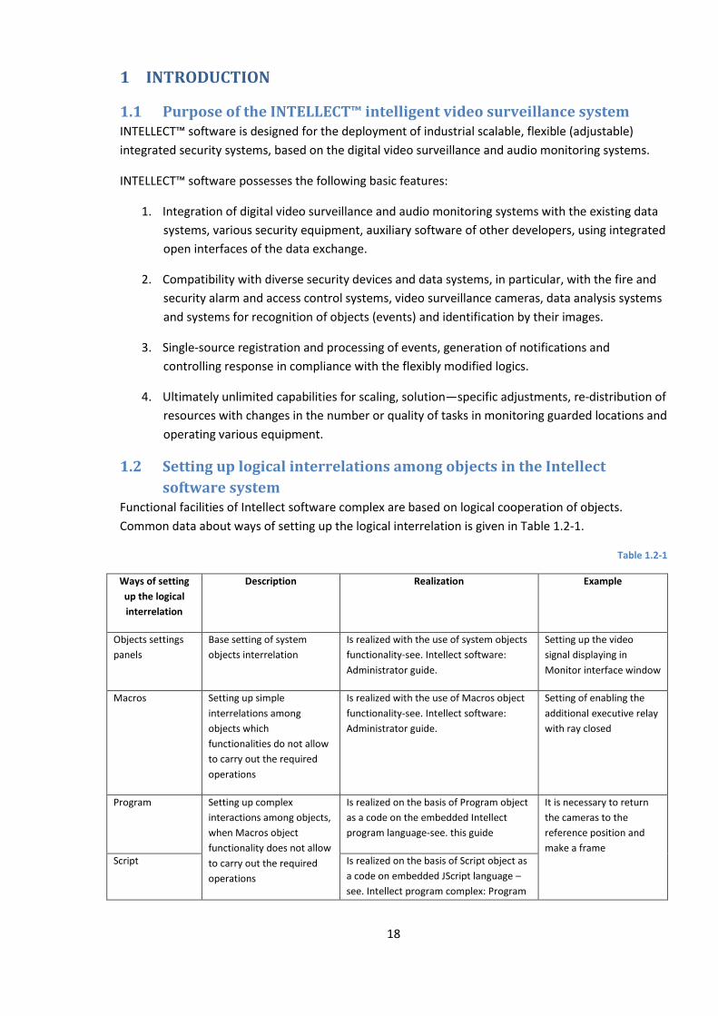
18
1 INTRODUCTION
1.1 Purpose of the INTELLECT™ intelligent video surveillance system INTELLECT™ software is designed for the deployment of industrial scalable, flexible (adjustable)
integrated security systems, based on the digital video surveillance and audio monitoring systems.
INTELLECT™ software possesses the following basic features:
1. Integration of digital video surveillance and audio monitoring systems with the existing data
systems, various security equipment, auxiliary software of other developers, using integrated
open interfaces of the data exchange.
2. Compatibility with diverse security devices and data systems, in particular, with the fire and
security alarm and access control systems, video surveillance cameras, data analysis systems
and systems for recognition of objects (events) and identification by their images.
3. Single-source registration and processing of events, generation of notifications and
controlling response in compliance with the flexibly modified logics.
4. Ultimately unlimited capabilities for scaling, solution—specific adjustments, re-distribution of
resources with changes in the number or quality of tasks in monitoring guarded locations and
operating various equipment.
1.2 Setting up logical interrelations among objects in the Intellect
software system Functional facilities of Intellect software complex are based on logical cooperation of objects.
Common data about ways of setting up the logical interrelation is given in Table 1.2-1.
Table 1.2-1
Ways of setting
up the logical
interrelation
Description Realization Example
Objects settings
panels
Base setting of system
objects interrelation
Is realized with the use of system objects
functionality-see. Intellect software:
Administrator guide.
Setting up the video
signal displaying in
Monitor interface window
Macros Setting up simple
interrelations among
objects which
functionalities do not allow
to carry out the required
operations
Is realized with the use of Macros object
functionality-see. Intellect software:
Administrator guide.
Setting of enabling the
additional executive relay
with ray closed
Program Setting up complex
interactions among objects,
when Macros object
functionality does not allow
to carry out the required
operations
Is realized on the basis of Program object
as a code on the embedded Intellect
program language-see. this guide
It is necessary to return
the cameras to the
reference position and
make a frame Script Is realized on the basis of Script object as
a code on embedded JScript language –
see. Intellect program complex: Program

19
Ways of setting
up the logical
interrelation
Description Realization Example
guide (JScript).
1.3 Purpose and structure of the guide Documentation for the INTELLECT™ intelligent video surveillance system, Video surveillance and
audio monitoring Administrator Guide is a reference and information handbook on programming on
embedded Intellect software language, which is designed for system administrators, installation and
configuration technicians, users with administrator rights to the digital video surveillance and audio
monitoring systems, developed on the basis of INTELLECT™ software.
Programming in the INTELLECT™ enables system control by setting up complex logical interactions
among objects. This guide contains the following materials:
1. Software programming;
2. Description of embedded program language syntax;
3. Examples of program on the embedded language.
1.4 License method of the INTELLECT™ software Licensing of the INTELLECT™ software is performed by means of software and program protection.
The INTELLECT™ software protection is built on one of the following components:
1. dallas-codes of video capture cards’ cryptochips (FS-5B, FS-6C, FS-8, FS-16(Exp), WS-7, WS-
17);
2. dallas-codes of the electronic hardware security key «Guardant»;
3. codes of HID devices (hardware id).
The key file, connecting the software protection with program modules, belongs to the program
protection part. A list of available for using functional program modules depends on the
configuration of security system’s delivery and is registered in the key file.
While extending the system configuration (for example while installing a new functional subsystem)
for activating the program module functionality, corresponding to the installed subsystem, in the
previous key file has to be changed by a new one, which the updated system functionality will be
regulated with.
While using the distributed architecture a single key file is used for all the computers of the system.
Note! If the video capture card is changed, its dallas-codes are changed too, so the previous key file
should be respectively changed by a new one. While using the distributed architecture the key file
should be changed on all the computers of the system.
If video capture cards, manufactured by ITV Company are used on the video server, the «Guardant»
electronic hardware security key connection will result in impossibility of starting the software.
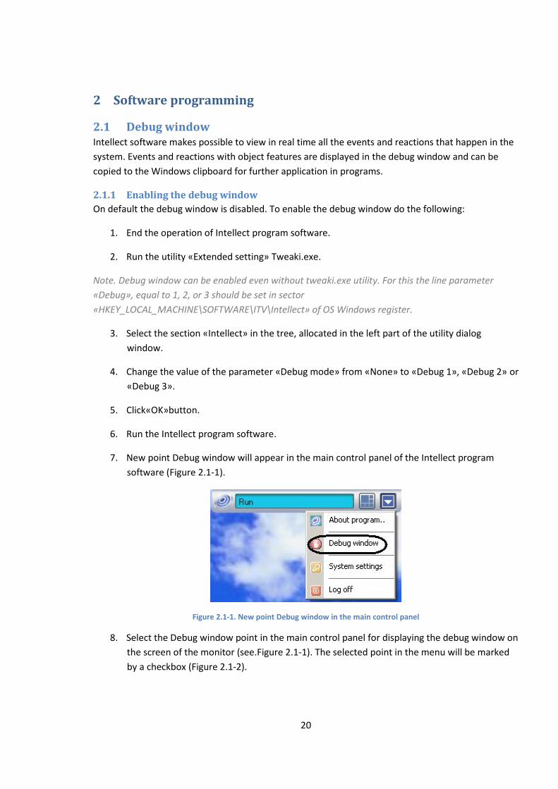
20
2 Software programming
2.1 Debug window Intellect software makes possible to view in real time all the events and reactions that happen in the
system. Events and reactions with object features are displayed in the debug window and can be
copied to the Windows clipboard for further application in programs.
2.1.1 Enabling the debug window
On default the debug window is disabled. To enable the debug window do the following:
1. End the operation of Intellect program software.
2. Run the utility «Extended setting» Tweaki.exe.
Note. Debug window can be enabled even without tweaki.exe utility. For this the line parameter
«Debug», equal to 1, 2, or 3 should be set in sector
«HKEY_LOCAL_MACHINE\SOFTWARE\ITV\Intellect» of OS Windows register.
3. Select the section «Intellect» in the tree, allocated in the left part of the utility dialog
window.
4. Change the value of the parameter «Debug mode» from «None» to «Debug 1», «Debug 2» or
«Debug 3».
5. Click«OK»button.
6. Run the Intellect program software.
7. New point Debug window will appear in the main control panel of the Intellect program
software (Figure 2.1-1).
Figure 2.1-1. New point Debug window in the main control panel
8. Select the Debug window point in the main control panel for displaying the debug window on
the screen of the monitor (see.Figure 2.1-1). The selected point in the menu will be marked
by a checkbox (Figure 2.1-2).
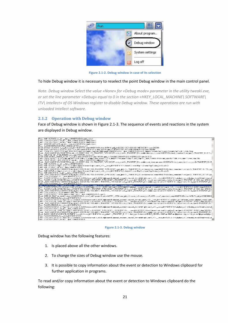
21
Figure 2.1-2. Debug window in case of its selection
To hide Debug window it is necessary to reselect the point Debug window in the main control panel.
Note. Debug window Select the value «None» for «Debug mode» parameter in the utility tweaki.exe,
or set the line parameter «Debug» equal to 0 in the section «HKEY_LOCAL_MACHINE\ SOFTWARE\
ITV\ Intellect» of OS Windows register to disable Debug window. These operations are run with
unloaded Intellect software.
2.1.2 Operation with Debug window
Face of Debug window is shown in Figure 2.1-3. The sequence of events and reactions in the system
are displayed in Debug window.
Figure 2.1-3. Debug window
Debug window has the following features:
1. Is placed above all the other windows.
2. To change the sizes of Debug window use the mouse.
3. It is possible to copy information about the event or detection to Windows clipboard for
further application in programs.
To read and/or copy information about the event or detection to Windows clipboard do the
following:
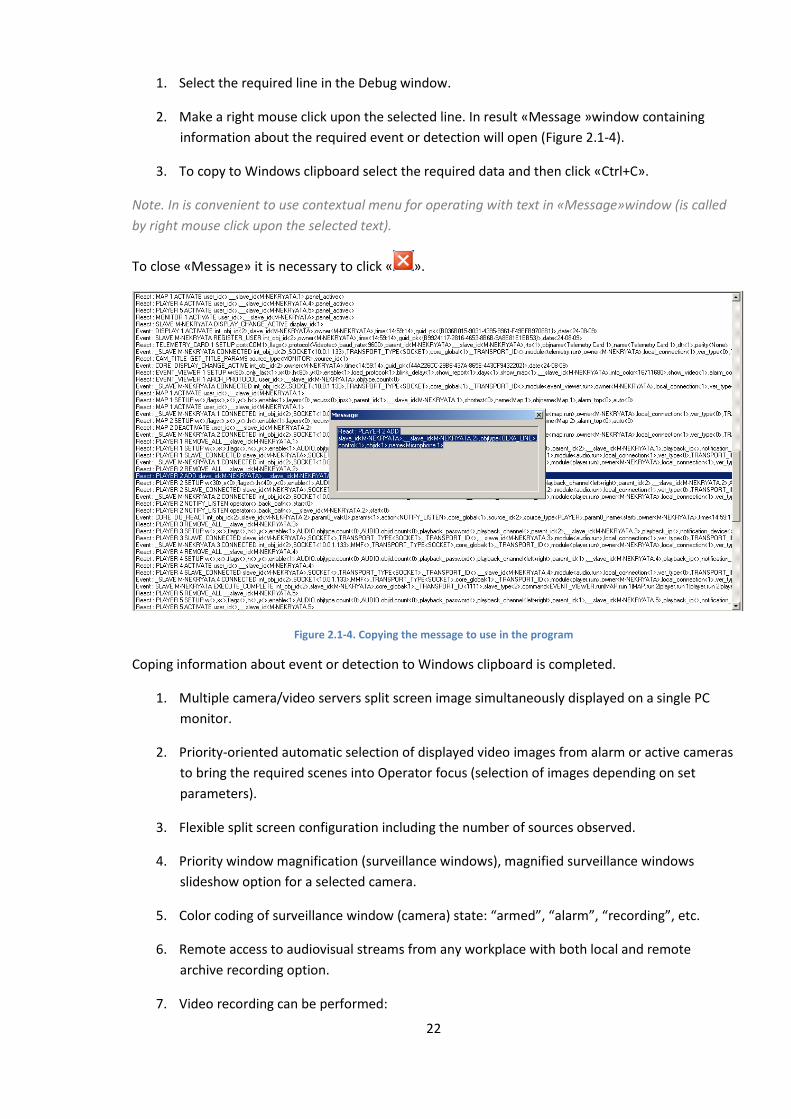
22
1. Select the required line in the Debug window.
2. Make a right mouse click upon the selected line. In result «Message »window containing
information about the required event or detection will open (Figure 2.1-4).
3. To copy to Windows clipboard select the required data and then click «Ctrl+C».
Note. In is convenient to use contextual menu for operating with text in «Message»window (is called
by right mouse click upon the selected text).
To close «Message» it is necessary to click « ».
Figure 2.1-4. Copying the message to use in the program
Coping information about event or detection to Windows clipboard is completed.
1. Multiple camera/video servers split screen image simultaneously displayed on a single PC
monitor.
2. Priority-oriented automatic selection of displayed video images from alarm or active cameras
to bring the required scenes into Operator focus (selection of images depending on set
parameters).
3. Flexible split screen configuration including the number of sources observed.
4. Priority window magnification (surveillance windows), magnified surveillance windows
slideshow option for a selected camera.
5. Color coding of surveillance window (camera) state: “armed”, “alarm”, “recording”, etc.
6. Remote access to audiovisual streams from any workplace with both local and remote
archive recording option.
7. Video recording can be performed:

23
7.1. continuously;
7.2. on schedule;
7.3. on alarm or by Operator’s command with a pre-event recording option.
8. Pre-event video recording.
9. Freeze frame by Operator’s command selection and viewing, without interruption of the
recording.
10. Image burn-in option.
10.1. Current time;
10.2. Current date;
10.3. Camera No (ID).
11. On demand video recording.
12. Real time viewing of images from video cameras.
13. Priority-oriented viewing of critical video stream based on alarm detection.
14. Web interface-based surveillance.
15. Audio- and video-archive management.
16. Viewing of recorded video with search and retrieve options (time/event type/camera ID
criteria).
17. Synchro playback of footage recorded by several cameras.
18. Recorded time calculation.
19. Timestamp based footage search.
20. Image processing:
20.1. Digital zooming;
20.2. Contrast maximizing;
20.3. Image sharpening;
20.4. masking;
20.5. Dynamic outlining.
21. Management of end devices using:
21.1. the 3rd party programmable interface panel;
21.2. the universal control panel for end devices;
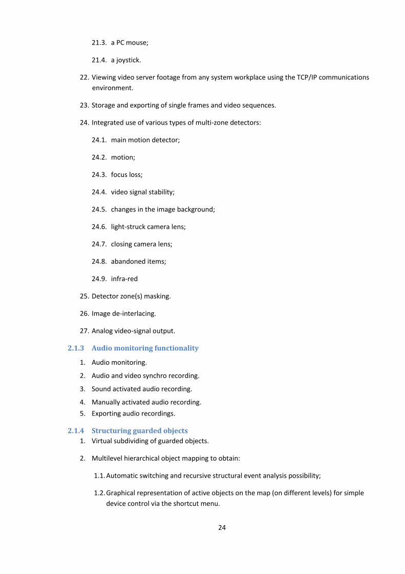
24
21.3. a PC mouse;
21.4. a joystick.
22. Viewing video server footage from any system workplace using the TCP/IP communications
environment.
23. Storage and exporting of single frames and video sequences.
24. Integrated use of various types of multi-zone detectors:
24.1. main motion detector;
24.2. motion;
24.3. focus loss;
24.4. video signal stability;
24.5. changes in the image background;
24.6. light-struck camera lens;
24.7. closing camera lens;
24.8. abandoned items;
24.9. infra-red
25. Detector zone(s) masking.
26. Image de-interlacing.
27. Analog video-signal output.
2.1.3 Audio monitoring functionality
1. Audio monitoring.
2. Audio and video synchro recording.
3. Sound activated audio recording.
4. Manually activated audio recording.
5. Exporting audio recordings.
2.1.4 Structuring guarded objects
1. Virtual subdividing of guarded objects.
2. Multilevel hierarchical object mapping to obtain:
1.1. Automatic switching and recursive structural event analysis possibility;
1.2. Graphical representation of active objects on the map (on different levels) for simple
device control via the shortcut menu.
25
2.1.5 Event registration functionality
1. Event log maintenance.
2.1.6 Notification functionalities
1. Automatic notification using:
1. SMS (Short Message Service);
2. email;
3. V-dial auto dialing service;
4. Audible/voice notification.
2.1.7 Functions of workability control
1. System object «Restarting system service».
2.1.8 Management functionality
Macro commands programming of user specific functions.
2.1.9 Integration of the distributed video surveillance and audio monitoring system
1. Remote interaction of the program kernel and automated replication of internal databases (containing system setup parameters and data about the events registered by the system) between video servers and the Administrator automated work station, comprising of the distributed digital video surveillance system.
2. Generation of the integrated database of system setup parameters and registered events, followed by their processing in compliance with standard and specialized adjustable algorithms, including generation of notifications and system response.
3. Programmable optimization of video data flows within the distributed digital video
surveillance system, whenever throughput capacity of the communication links is not
sufficient (optional video gateway function).
2.2 Technical features of the digital video surveillance and audio
monitoring system based on INTELLECT™ software Digital video surveillance systems based on INTELLECT software have the following features:
1. Maximum number of video input channels for videosignal processing in the live video and/or
multiplexing modes is limited by the Server hardware resources - processor power, RAM
memory space, etc.
2. Maximum number of simultaneous output analog videosignals is limited by the number of
video capture cards (with analog video outputs) in use on the Server.
3. Maximum number of PTZ units in use is 64.
4. Maximum number of remote workstations connected to the Server to receive videos is
limited by the number and parameters of transmitted videosignals, video surveillance system
architecture and network bandwidth .

26
5. Maximum number of Servers, videosignals from which are transmitted simultaneously to a
remote work station, is limited by the number and parameters of transmitted videosignals,
video surveillance system architecture and network bandwidth.
6. Maximum number of simultaneous video images displayed on the screen of a remote work
station is limited by video image parameters and network bandwidth.
7. Maximum video stream rate transmitted via a video gateway is limited by the video gateway
hardware parameters and network bandwidth.
8. Supported video capture cards: FS-5, FS-6, FS-16, FS-8, FS15, FS115, FX2, FX4, FX8, FX16,
FX116, FX416, FX HD4, WS-7, WS16, WS-17, WS216, VRC6004, VRC6008, VRC6416,
VRC7008L, VRC6404HD and DS-4016HCI(R).
9. Supported video cards: any PCI-E video cards, not integrated in the motherboard, mainframe
memory is to be at least 256 Mb.
10. Maximum number of simultaneous processed signals from the microphones or telephone
lines is 64.
11. Maximum number of audio output channels (to the loudspeakers, earphones, etc.) depends
on the audio card used for playback.
12. Supported audio cards: standard audio cards, MidiMan Delta, Comart Hera and Olkha 9Р.
Digitization bandwidth depends on the audio card parameters, software limitation from 0 to
48 000 Hz.
2.3 Structure of the digital video surveillance and audio monitoring
system based on INTELLECT™ software The versatile structure of the digital video surveillance and audio monitoring system based on
INTELLECT™ software and standard hardware and software is shown in Figure 2.3-1.
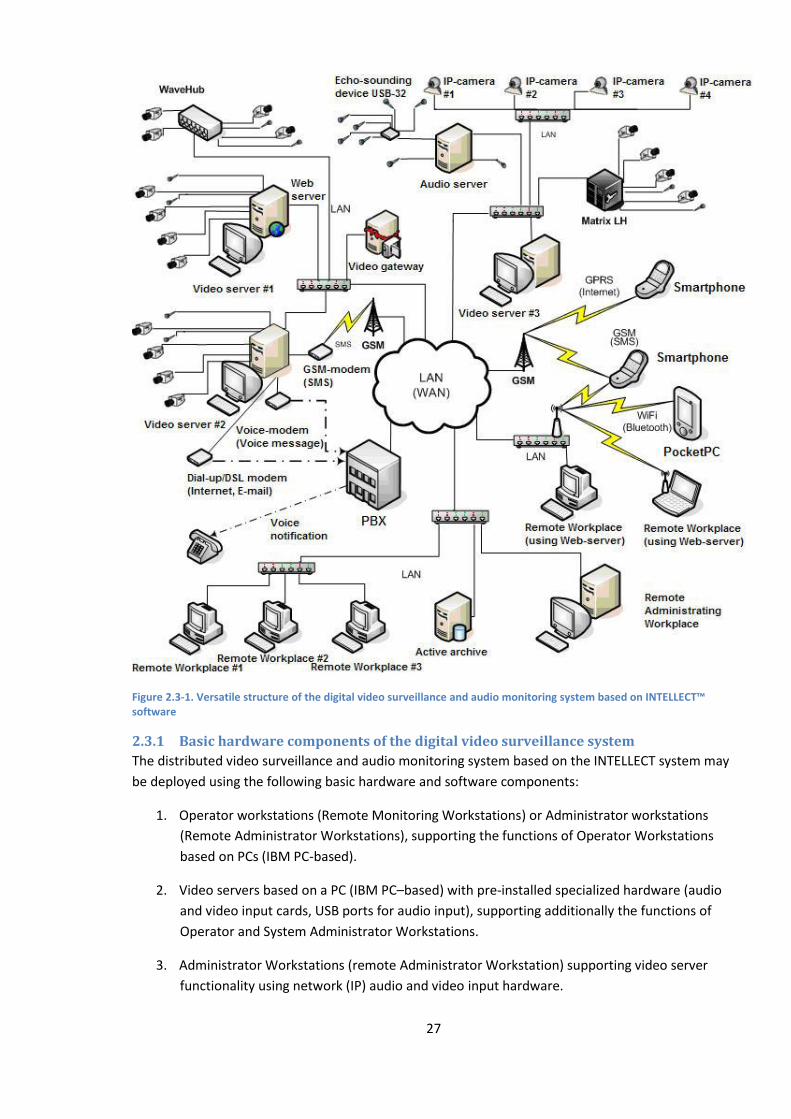
27
Figure 2.3-1. Versatile structure of the digital video surveillance and audio monitoring system based on INTELLECT™ software
2.3.1 Basic hardware components of the digital video surveillance system
The distributed video surveillance and audio monitoring system based on the INTELLECT system may
be deployed using the following basic hardware and software components:
1. Operator workstations (Remote Monitoring Workstations) or Administrator workstations
(Remote Administrator Workstations), supporting the functions of Operator Workstations
based on PCs (IBM PC-based).
2. Video servers based on a PC (IBM PC–based) with pre-installed specialized hardware (audio
and video input cards, USB ports for audio input), supporting additionally the functions of
Operator and System Administrator Workstations.
3. Administrator Workstations (remote Administrator Workstation) supporting video server
functionality using network (IP) audio and video input hardware.
28
4. Network video hubs (WaveHub, Linux Hub, etc.).
5. Network video servers (Matrix, etc.).
6. Analogue and IP video cameras.
7. Network audio input hardware (Eholot, etc.).
8. TCP/IP communication medium.
2.3.2 Software
2.3.2.1 Operating system
«Intellect» operates in Microsoft Windows family.
1. Windows XP Professional SP2-SP3
2. Windows Server 2003 R2 Standard SP2
3. Windows Server 2003 R2 Enterprise SP2
4. Windows Vista Business SP1
5. Windows Vista Enterprise SP1
6. Windows Vista Ultimate SP1
2.3.2.2 Software kernels
The Intellect™ system can be implemented in the following options (installation options):
1. Based on the full-featured INTELECT software kernel (this option corresponds to the
intellect.exe software module) The full-featured software kernel ensures operation the video
server, Administrator and Operator workstation.
2. Software kernel with minimized functionality supporting the Remote Operator Workstation
functions (this option corresponds to the slave.exe software module).
Software of the Remote Operator Workstation does not support system administration (create,
delete, set system objects, register users, user rights administration), as well as local database
maintenance (operations with ROW use a remote database operated by the intellect.exe kernel and
belonging to the video server or Remote Administrator Workstation).
Intellect.exe, the fully software kernel, is the central software component of the system. The system
kernel interacts with the program modules, which form the software basis for the subsystems.
Integration of the distributed digital video surveillance and audio monitoring system is provided by
the data exchange between software kernels.
2.3.2.3 Program modules
Program modules support direct interworking of the hardware, and also serve as a source of data
about controllable objects. The software kernel of the system processes the incoming data from
various program modules, providing their integration.
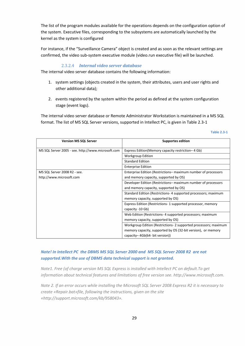
29
The list of the program modules available for the operations depends on the configuration option of
the system. Executive files, corresponding to the subsystems are automatically launched by the
kernel as the system is configured
For instance, if the “Surveillance Camera” object is created and as soon as the relevant settings are
confirmed, the video sub-system executive module (video.run executive file) will be launched.
2.3.2.4 Internal video server database
The internal video server database contains the following information:
1. system settings (objects created in the system, their attributes, users and user rights and
other additional data);
2. events registered by the system within the period as defined at the system configuration
stage (event logs).
The internal video server database or Remote Administrator Workstation is maintained in a MS SQL
format. The list of MS SQL Server versions, supported in Intellect PC, is given in Table 2.3-1
Table 2.3-1
Version MS SQL Server Supportes edition
MS SQL Server 2005 - see. http://www.microsoft.com Express Edition(Memory capacity restriction– 4 Gb)
Workgroup Edition
Standard Edition
Enterprise Edition
MS SQL Server 2008 R2 - see.
http://www.microsoft.com
Enterprise Edition (Restrictions– maximum number of processors
and memory capacity, supported by OS)
Developer Edition (Restrictions– maximum number of processors
and memory capacity, supported by OS)
Standard Edition (Restrictions- 4 supported processors; maximum
memory capacity, supported by OS)
Express Edition (Restrictions- 1 supported processor, memory
capacity -10 Gb)
Web Edition (Restrictions- 4 supported processors; maximum
memory capacity, supported by OS)
Workgroup Edition (Restrictions- 2 supported processors; maximum
memory capacity, supported by OS (32-bit version), or memory
capacity– 4Gb(64- bit version))
Note! In Intellect PC the DBMS MS SQL Server 2000 and MS SQL Server 2008 R2 are not
supported.With the use of DBMS data technical support is not granted.
Note1. Free (of charge version MS SQL Express is installed with Intellect PC on default.To get
information about technical features and limitations of free version see. http://www.microsoft.com.
Note 2. If an error occurs while installing the Microsoft SQL Server 2008 Express R2 it is necessary to
create «Repair.bat»file, following the instructions, given on the site
«http://support.microsoft.com/kb/958043».

30
Note! While exceeding maximum database memory capacity (when MS SQL Server edition with
memory capacity is used) there is no guarantee for the Intellect PC correct operation.
Information about the objects, settings of the digital video surveillance and audio monitoring system
and event logs can be automatically replicated from the video server database or Remote
Administrator Workstation to the databases of all other video servers and Remote Administrator
Workstations of the system. Communication between full featured program kernels of the INTELLECT
system is supported by the TCP/IP environment (if the system configuration defines certain program
kernels, between which communication should be provided).
Information about system objects and their settings is initially stored in the database of the video
server (Remote Administrator Workstation), which the objects belong to. Replication is initiated
automatically whenever data is changed, the kernel is launched or communication is restored.
Replication is used to create a common event environment within the distributed digital video
surveillance system.
Replication is a hidden process for the user.
2.3.2.5 Workstation software
The digital video surveillance and audio monitoring system based on INTELLECT™ software can be
comprised of the following workstations:
1. Remote Operator Workstation;
2. Remote Administrator Workstation;
3. Video server supporting Operator and Administrator workstation functionality.
Implementation of the Remote Operator Workstation requires installation of the software for the
Remote Operator Workstation in the workstation (this option corresponds to the slave.exe, basic
executive program module).
The “Remote Monitoring Workstation” option is selected at the installation of INTELLECT software
on PCs, which are not furnished with specialized hardware for audio and video input and are
designed to function as Operator Workstations.
Implementation of the Remote Administrator Workstation requires installation of a full featured
INTELLECT software kernel in the workstation (this option corresponds to the intellect.exe, executive
program module). To install Remote Administrator Workstation, select “Remote Administrator
Workstation” in the appropriate dialog box at the INTELLECT software installation stage. The remote
Administrator Workstation is installed on the PCs designed for system administration (Remote
Administrator Workstations), which have no pre-installed video input cards (FS 5, FS 6, WS 4, WS 6)
and audio input cards.
To enable remote system administration, if required, the base PC should be furnished additionally
with Guardant, an electronic hardware protection key. The PC with Remote Administrator
Workstation software installed can also be used as a Remote Operator Workstation, if the system is
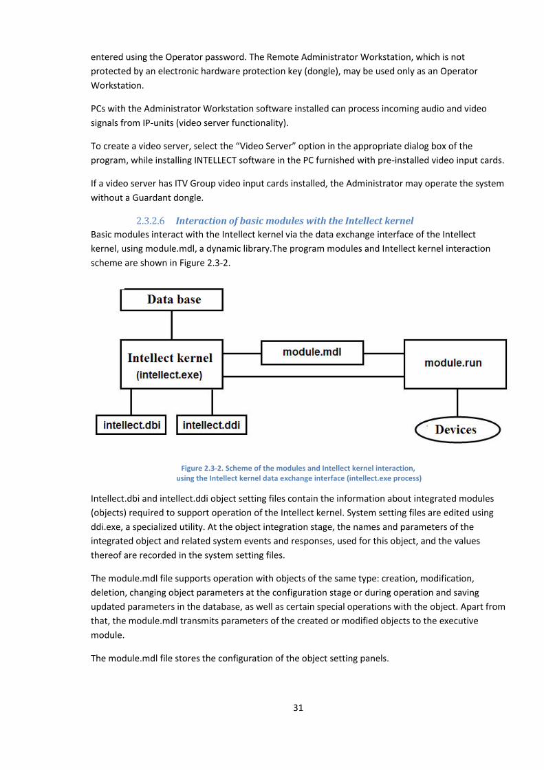
31
entered using the Operator password. The Remote Administrator Workstation, which is not
protected by an electronic hardware protection key (dongle), may be used only as an Operator
Workstation.
PCs with the Administrator Workstation software installed can process incoming audio and video
signals from IP-units (video server functionality).
To create a video server, select the “Video Server” option in the appropriate dialog box of the
program, while installing INTELLECT software in the PC furnished with pre-installed video input cards.
If a video server has ITV Group video input cards installed, the Administrator may operate the system
without a Guardant dongle.
2.3.2.6 Interaction of basic modules with the Intellect kernel
Basic modules interact with the Intellect kernel via the data exchange interface of the Intellect
kernel, using module.mdl, a dynamic library.The program modules and Intellect kernel interaction
scheme are shown in Figure 2.3-2.
Figure 2.3-2. Scheme of the modules and Intellect kernel interaction, using the Intellect kernel data exchange interface (intellect.exe process)
Intellect.dbi and intellect.ddi object setting files contain the information about integrated modules
(objects) required to support operation of the Intellect kernel. System setting files are edited using
ddi.exe, a specialized utility. At the object integration stage, the names and parameters of the
integrated object and related system events and responses, used for this object, and the values
thereof are recorded in the system setting files.
The module.mdl file supports operation with objects of the same type: creation, modification,
deletion, changing object parameters at the configuration stage or during operation and saving
updated parameters in the database, as well as certain special operations with the object. Apart from
that, the module.mdl transmits parameters of the created or modified objects to the executive
module.
The module.mdl file stores the configuration of the object setting panels.
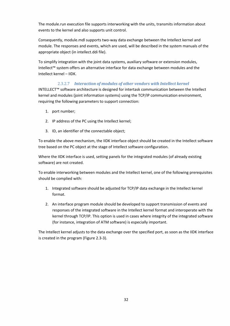
32
The module.run execution file supports interworking with the units, transmits information about
events to the kernel and also supports unit control.
Consequently, module.mdl supports two-way data exchange between the Intellect kernel and
module. The responses and events, which are used, will be described in the system manuals of the
appropriate object (in intellect.ddi file).
To simplify integration with the joint data systems, auxiliary software or extension modules,
Intellect™ system offers an alternative interface for data exchange between modules and the
Intellect kernel – IIDK.
2.3.2.7 Interaction of modules of other vendors with Intellect kernel
INTELLECT™ software architecture is designed for intertask communication between the Intellect
kernel and modules (joint information systems) using the TCP/IP communication environment,
requiring the following parameters to support connection:
1. port number;
2. IP address of the PC using the Intellect kernel;
3. ID, an identifier of the connectable object;
To enable the above mechanism, the IIDK interface object should be created in the Intellect software
tree based on the PC object at the stage of Intellect software configuration.
Where the IIDK interface is used, setting panels for the integrated modules (of already existing
software) are not created.
To enable interworking between modules and the Intellect kernel, one of the following prerequisites
should be complied with:
1. Integrated software should be adjusted for TCP/IP data exchange in the Intellect kernel
format.
2. An interface program module should be developed to support transmission of events and
responses of the integrated software in the Intellect kernel format and interoperate with the
kernel through TCP/IP. This option is used in cases where integrity of the integrated software
(for instance, integration of ATM software) is especially important.
The Intellect kernel adjusts to the data exchange over the specified port, as soon as the IIDK interface
is created in the program (Figure 2.3-3).
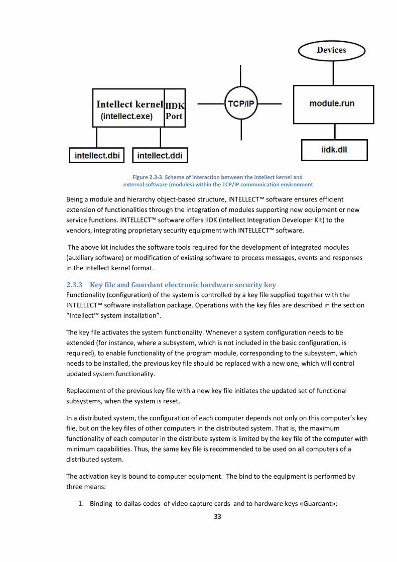
33
Figure 2.3-3. Scheme of interaction between the Intellect kernel and external software (modules) within the TCP/IP communication environment
Being a module and hierarchy object-based structure, INTELLECT™ software ensures efficient
extension of functionalities through the integration of modules supporting new equipment or new
service functions. INTELLECT™ software offers IIDK (Intellect Integration Developer Kit) to the
vendors, integrating proprietary security equipment with INTELLECT™ software.
The above kit includes the software tools required for the development of integrated modules
(auxiliary software) or modification of existing software to process messages, events and responses
in the Intellect kernel format.
2.3.3 Key file and Guardant electronic hardware security key
Functionality (configuration) of the system is controlled by a key file supplied together with the
INTELLECT™ software installation package. Operations with the key files are described in the section
“Intellect™ system installation”.
The key file activates the system functionality. Whenever a system configuration needs to be
extended (for instance, where a subsystem, which is not included in the basic configuration, is
required), to enable functionality of the program module, corresponding to the subsystem, which
needs to be installed, the previous key file should be replaced with a new one, which will control
updated system functionality.
Replacement of the previous key file with a new key file initiates the updated set of functional
subsystems, when the system is reset.
In a distributed system, the configuration of each computer depends not only on this computer’s key
file, but on the key files of other computers in the distributed system. That is, the maximum
functionality of each computer in the distribute system is limited by the key file of the computer with
minimum capabilities. Thus, the same key file is recommended to be used on all computers of a
distributed system.
The activation key is bound to computer equipment. The bind to the equipment is performed by
three means:
1. Binding to dallas-codes of video capture cards and to hardware keys «Guardant»;
34
2. Binding to computer’s equipment(HID);
3. Binding to dallas-codes of video capture cards and to computer’s equipment (HID).
In order to install an Administrator Workstation on a certain PC a Guardant dongle should be
installed on the given PC. Guardant hardware security key is also required when the video server is
used to which IP devices and/or video capture cards without cryptochips are connected (e.g., FX116).
Note. If a distributed system consists of a remote operator workstation and a server with an
activation key then there is no need to have an activation key for the remote operator workstation.
2.3.3.1 Binding the activation key to computer equipment
HID (Hardware ID) – is encrypted information about computer’s equipment which is gathered by
CodeReader utility and is transferred to ITV Group Company for activation key generation.
At the moment of writing the documentation the binding of following elements has been realized:
1. MAC addressEthernet adapter(all present in the computer );
2. Processor model (CPU0);
3. Serial number and mother board model.
Note! When the devices mentioned above are changed in the computer, its HID will be changed
too. In result new activation key should be obtained in accordance with new HID.
In case if in HID there are not all codes of devices mentioned above the activation key can not be
generated.
Note! While software, creating virtual devices (VirtualBox, VmWare and others), installation on the
computer, its HID will be changed (due to virtual devices creation). In result the activation key
loses its functionality and will not be run. If there is a problem of such kind it is strongly
recommended to delete all virtual devices from computer equipment tree or obtain a new
activation key in accordance with new HID.
2.3.3.2 Match search in the activation key
Codes match search in the activation key with devices codes in the computer is performed in the
following way:
1. Computer HID is read where the Intellect PC is run.
2. Activation key is read.
3. For every computer, stated in the activation key, the following actions are performed:
3.1 If the computer in activation key is bound via HID:
3.1.1 If there are video capture cards manufactured by ITV company in the
activation key , the match search of board codes on the computer and
board codes in the activation key will be performed (if there is no match
, the following computer in the key will be checked);
3.1.2 If there are no video capture cards manufactured by ITV Company in
the activation key, the match search of computer HID and computer
equipment codes in the key will be performed (if there is no match , the
following computer in the key will be checked).
35
3.2 If the computer in activation key is not bound via HID, the match search of video
capture cards manufactured by ITV company on the computer and board codes in
the activation key will be performed (if there is no match , the following computer in
the key will be checked).
If there is at least one match found the Intellect PC will be run.
2.3.4 Communication environment
The communication facilities of INTELLECT™ software allows deployment of distributed digital video
surveillance systems, which control lengthy and versatile objects. Remote system components
interact automatically with each other forming a common security system.
Data exchange and communication between distributed digital video surveillance and the audio
monitoring system is supported by the local access networks (LAN), Internet (WAN), telephone lines
(Dial-Up) and leased communication channels, when TCP/IP telecommunications transportation
protocol is used.
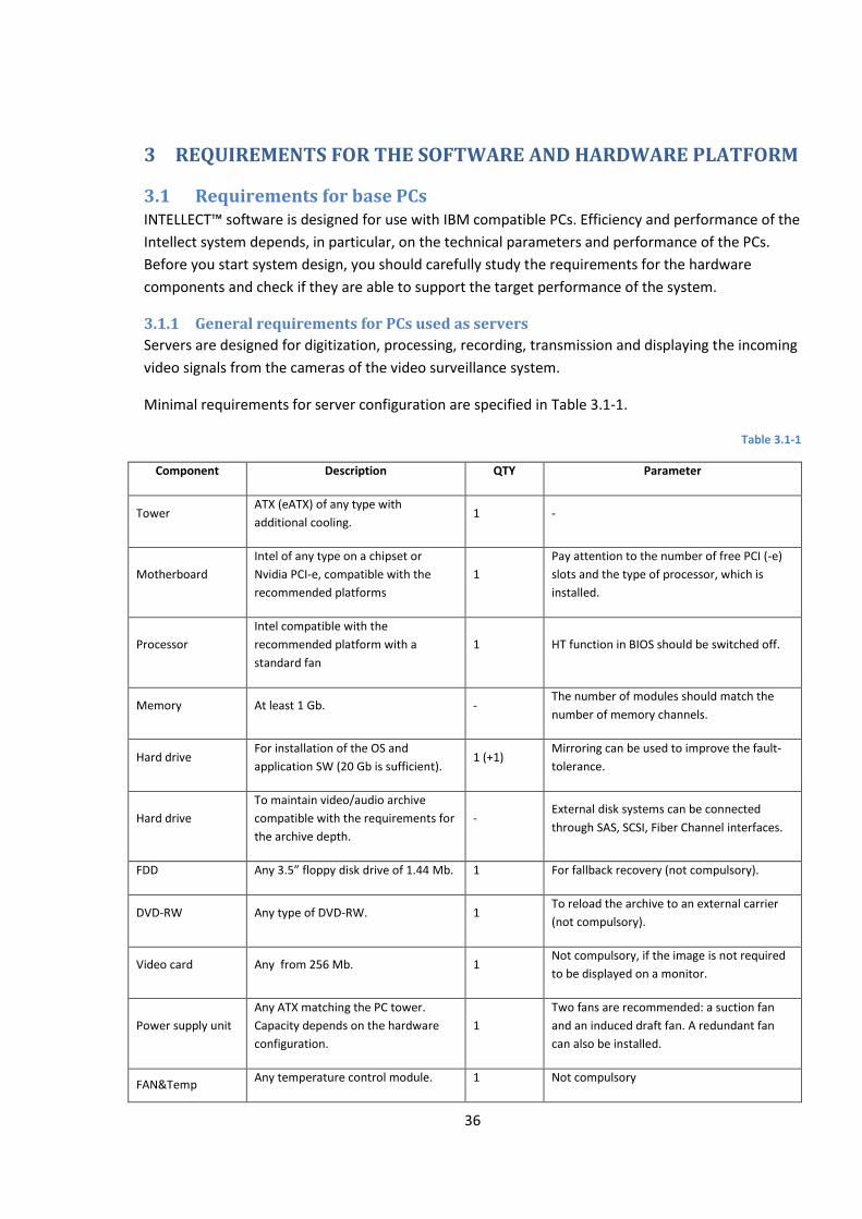
36
3 REQUIREMENTS FOR THE SOFTWARE AND HARDWARE PLATFORM
3.1 Requirements for base PCs INTELLECT™ software is designed for use with IBM compatible PCs. Efficiency and performance of the
Intellect system depends, in particular, on the technical parameters and performance of the PCs.
Before you start system design, you should carefully study the requirements for the hardware
components and check if they are able to support the target performance of the system.
3.1.1 General requirements for PCs used as servers
Servers are designed for digitization, processing, recording, transmission and displaying the incoming
video signals from the cameras of the video surveillance system.
Minimal requirements for server configuration are specified in Table 3.1-1.
Table 3.1-1
Component Description QTY Parameter
Tower ATX (eATX) of any type with
additional cooling. 1 -
Motherboard
Intel of any type on a chipset or
Nvidia PCI-e, compatible with the
recommended platforms
1
Pay attention to the number of free PCI (-e)
slots and the type of processor, which is
installed.
Processor
Intel compatible with the
recommended platform with a
standard fan
1 HT function in BIOS should be switched off.
Memory At least 1 Gb. - The number of modules should match the
number of memory channels.
Hard drive For installation of the OS and
application SW (20 Gb is sufficient). 1 (+1)
Mirroring can be used to improve the fault-
tolerance.
Hard drive
To maintain video/audio archive
compatible with the requirements for
the archive depth.
- External disk systems can be connected
through SAS, SCSI, Fiber Channel interfaces.
FDD Any 3.5” floppy disk drive of 1.44 Mb. 1 For fallback recovery (not compulsory).
DVD-RW Any type of DVD-RW. 1 To reload the archive to an external carrier
(not compulsory).
Video card Any from 256 Mb. 1 Not compulsory, if the image is not required
to be displayed on a monitor.
Power supply unit
Any ATX matching the PC tower.
Capacity depends on the hardware
configuration.
1
Two fans are recommended: a suction fan
and an induced draft fan. A redundant fan
can also be installed.
FAN&Temp Any temperature control module. 1 Not compulsory

37
Component Description QTY Parameter
Control
OS OS Windows supported versions (see.
Operating system requirements). 1
Internet access is recommended to be
switched off.
Note. The system clock on the server must be synchronized with the client’s system clock, or run a
couple of seconds ahead. Otherwise, problems during re-connecting (for example, on connection loss)
may occur.
3.1.2 General requirements for PCs used as Remote Administrator Workstations
Remote Administrator Workstations are designed for remote monitoring of video signals, for creating
gateways and archives of video sequences, for logging the events registered by INTELLECT™ software
and use as a web server for the transmission of video signals over HTTP (this protocol is used to
transmit signals over the Internet and display them with standard Web-browsers).
Configuration requirements for the Remote Administrator Workstation depend on the functions it is
designed to perform. Table 3.1-2 shows general requirements, including comments.
Table 3.1-2
Component Description QTY Parameter
Tower ATX (eATX) of any type with
additional cooling. 1 -
Motherboard Any Intel on a chipset or Nvidia PCI-e. 1 -
Processor Any Intel on a chipset. 1 HT function in BIOS should be switched off.
Memory At least 1 Gb. - The number of modules should match the
number of memory channels.
Hard drive 1 For installation of the OS and SW
application (20 Gb is sufficient). 1 (+1)
Mirroring can be used to improve the fault-
tolerance.
Hard drive 2
To maintain video/audio archive
compliant with the requirements for
the archive depth.
-
External disk systems can be connected
through SAS, SCSI, Fiber Channel interfaces.
Will be installed in cases where video/audio
archives are required.
FDD Any 3.5” floppy disk drive of 1.44 Mb. 1 For fallback recovery (not compulsory).
DVD-RW Any type of DVD-RW. 1 To reload the archive to an external carrier
(not compulsory).
Video card Any from 256 Mb. 1 Not compulsory, if the image is not required
to be displayed on a monitor.
Power supply unit
Any ATX matching the PC tower.
Capacity depends on the hardware
configuration.
1
Two fans are recommended: a suction fan
and an induced draft fan. A redundant fan
can also be installed.
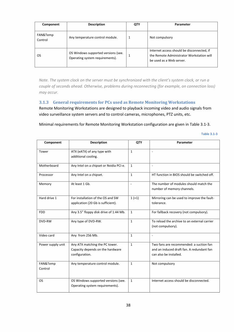
38
Component Description QTY Parameter
FAN&Temp
Control Any temperature control module. 1 Not compulsory
OS OS Windows supported versions (see.
Operating system requirements). 1
Internet access should be disconnected, if
the Remote Administrator Workstation will
be used as a Web server.
Note. The system clock on the server must be synchronized with the client’s system clock, or run a
couple of seconds ahead. Otherwise, problems during reconnecting (for example, on connection loss)
may occur.
3.1.3 General requirements for PCs used as Remote Monitoring Workstations
Remote Monitoring Workstations are designed to playback incoming video and audio signals from
video surveillance system servers and to control cameras, microphones, PTZ units, etc.
Minimal requirements for Remote Monitoring Workstation configuration are given in Table 3.1-3.
Table 3.1-3
Component Description QTY Parameter
Tower ATX (eATX) of any type with
additional cooling.
1 -
Motherboard Any Intel on a chipset or Nvidia PCI-e. 1 -
Processor Any Intel on a chipset. 1 HT function in BIOS should be switched off.
Memory At least 1 Gb. - The number of modules should match the
number of memory channels.
Hard drive 1 For installation of the OS and SW
application (20 Gb is sufficient).
1 (+1) Mirroring can be used to improve the fault-
tolerance.
FDD Any 3.5” floppy disk drive of 1.44 Mb. 1 For fallback recovery (not compulsory).
DVD-RW Any type of DVD-RW. 1 To reload the archive to an external carrier
(not compulsory).
Video card Any from 256 Mb. 1 -
Power supply unit Any ATX matching the PC tower.
Capacity depends on the hardware
configuration.
1 Two fans are recommended: a suction fan
and an induced draft fan. A redundant fan
can also be installed.
FAN&Temp
Control
Any temperature control module. 1 Not compulsory
OS OS Windows supported versions (see.
Operating system requirements).
1 Internet access should be disconnected.
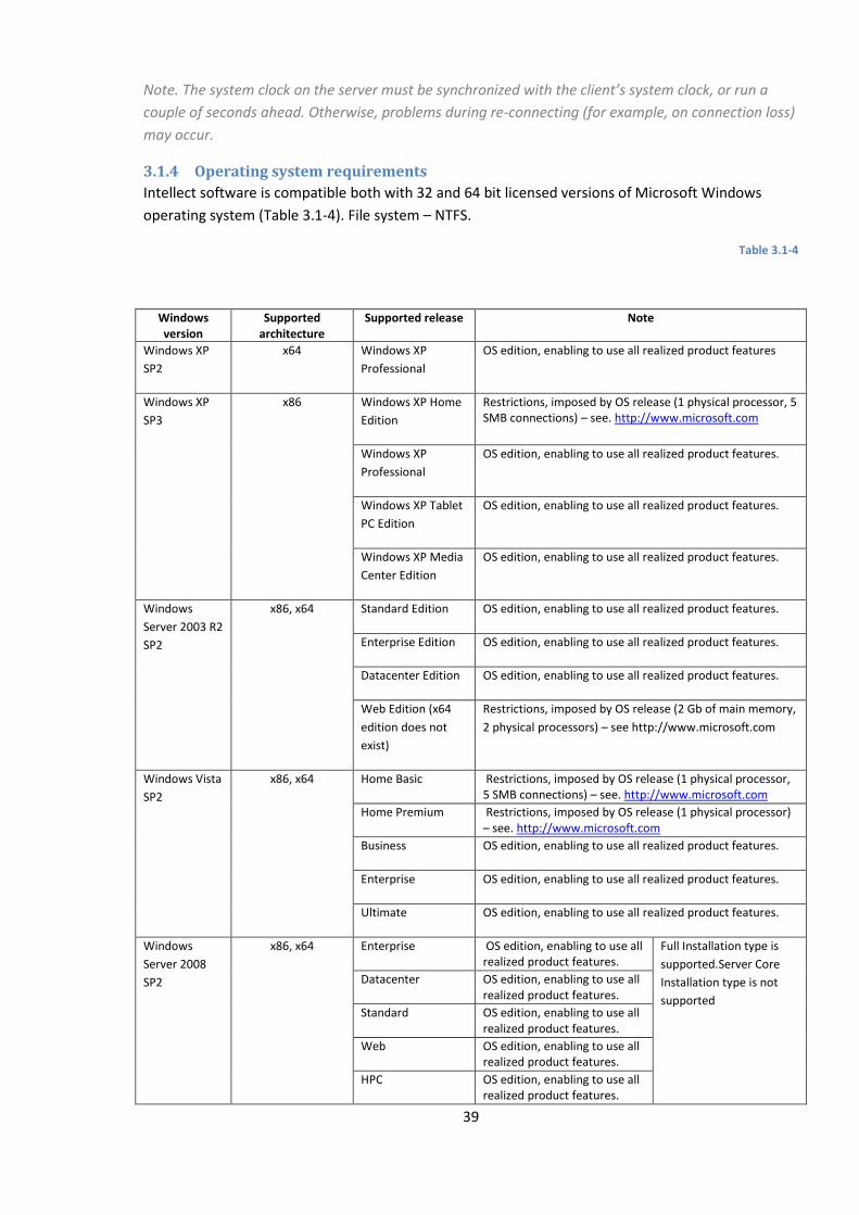
39
Note. The system clock on the server must be synchronized with the client’s system clock, or run a
couple of seconds ahead. Otherwise, problems during re-connecting (for example, on connection loss)
may occur.
3.1.4 Operating system requirements
Intellect software is compatible both with 32 and 64 bit licensed versions of Microsoft Windows
operating system (Table 3.1-4). File system – NTFS.
Table 3.1-4
Windows version
Supported architecture
Supported release Note
Windows XP
SP2
x64 Windows XP
Professional
OS edition, enabling to use all realized product features
Windows XP
SP3
x86 Windows XP Home
Edition
Restrictions, imposed by OS release (1 physical processor, 5 SMB connections) – see. http://www.microsoft.com
Windows XP
Professional
OS edition, enabling to use all realized product features.
Windows XP Tablet
PC Edition
OS edition, enabling to use all realized product features.
Windows XP Media
Center Edition
OS edition, enabling to use all realized product features.
Windows
Server 2003 R2
SP2
x86, x64 Standard Edition OS edition, enabling to use all realized product features.
Enterprise Edition OS edition, enabling to use all realized product features.
Datacenter Edition OS edition, enabling to use all realized product features.
Web Edition (x64
edition does not
exist)
Restrictions, imposed by OS release (2 Gb of main memory,
2 physical processors) – see http://www.microsoft.com
Windows Vista
SP2
x86, x64 Home Basic Restrictions, imposed by OS release (1 physical processor, 5 SMB connections) – see. http://www.microsoft.com
Home Premium Restrictions, imposed by OS release (1 physical processor) – see. http://www.microsoft.com
Business OS edition, enabling to use all realized product features.
Enterprise OS edition, enabling to use all realized product features.
Ultimate OS edition, enabling to use all realized product features.
Windows
Server 2008
SP2
x86, x64 Enterprise OS edition, enabling to use all realized product features.
Full Installation type is
supported.Server Core
Installation type is not
supported
Datacenter OS edition, enabling to use all realized product features.
Standard OS edition, enabling to use all realized product features.
Web OS edition, enabling to use all realized product features.
HPC OS edition, enabling to use all realized product features.
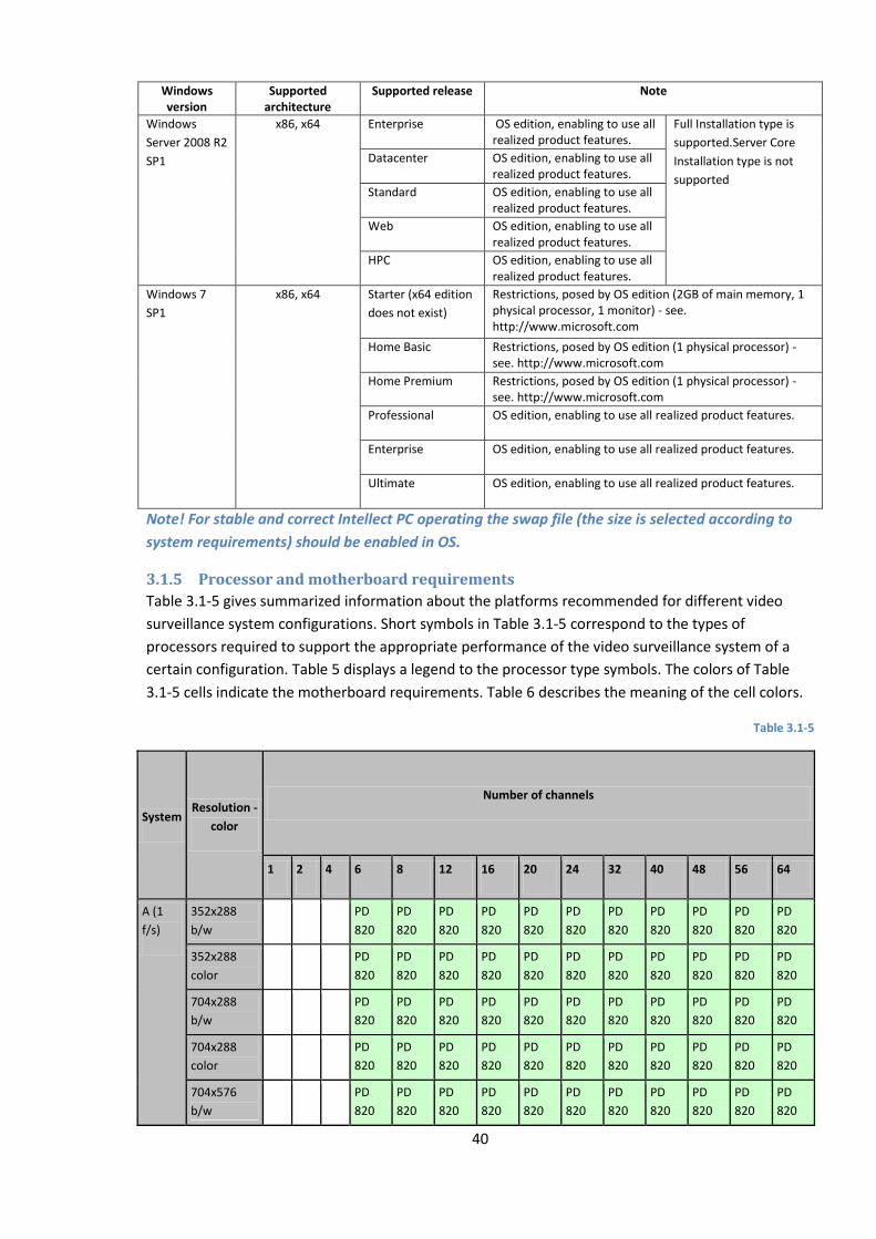
40
Windows version
Supported architecture
Supported release Note
Windows
Server 2008 R2
SP1
x86, x64 Enterprise OS edition, enabling to use all realized product features.
Full Installation type is
supported.Server Core
Installation type is not
supported
Datacenter OS edition, enabling to use all realized product features.
Standard OS edition, enabling to use all realized product features.
Web OS edition, enabling to use all realized product features.
HPC OS edition, enabling to use all realized product features.
Windows 7
SP1
x86, x64 Starter (x64 edition
does not exist)
Restrictions, posed by OS edition (2GB of main memory, 1 physical processor, 1 monitor) - see. http://www.microsoft.com
Home Basic Restrictions, posed by OS edition (1 physical processor) - see. http://www.microsoft.com
Home Premium Restrictions, posed by OS edition (1 physical processor) - see. http://www.microsoft.com
Professional OS edition, enabling to use all realized product features.
Enterprise OS edition, enabling to use all realized product features.
Ultimate OS edition, enabling to use all realized product features.
Note! For stable and correct Intellect PC operating the swap file (the size is selected according to
system requirements) should be enabled in OS.
3.1.5 Processor and motherboard requirements
Table 3.1-5 gives summarized information about the platforms recommended for different video
surveillance system configurations. Short symbols in Table 3.1-5 correspond to the types of
processors required to support the appropriate performance of the video surveillance system of a
certain configuration. Table 5 displays a legend to the processor type symbols. The colors of Table
3.1-5 cells indicate the motherboard requirements. Table 6 describes the meaning of the cell colors.
Table 3.1-5
System Resolution -
color
Number of channels
1 2 4 6 8 12 16 20 24 32 40 48 56 64
A (1
f/s)
352х288
b/w
PD
820
PD
820
PD
820
PD
820
PD
820
PD
820
PD
820
PD
820
PD
820
PD
820
PD
820
352х288
color
PD
820
PD
820
PD
820
PD
820
PD
820
PD
820
PD
820
PD
820
PD
820
PD
820
PD
820
704х288
b/w
PD
820
PD
820
PD
820
PD
820
PD
820
PD
820
PD
820
PD
820
PD
820
PD
820
PD
820
704х288
color
PD
820
PD
820
PD
820
PD
820
PD
820
PD
820
PD
820
PD
820
PD
820
PD
820
PD
820
704х576
b/w
PD
820
PD
820
PD
820
PD
820
PD
820
PD
820
PD
820
PD
820
PD
820
PD
820
PD
820
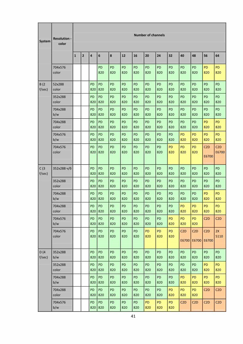
41
System Resolution -
color
Number of channels
1 2 4 6 8 12 16 20 24 32 40 48 56 64
704х576
color
PD
820
PD
820
PD
820
PD
820
PD
820
PD
820
PD
820
PD
820
PD
820
PD
820
PD
820
B (2
f/sec)
52х288
color
PD
820
PD
820
PD
820
PD
820
PD
820
PD
820
PD
820
PD
820
PD
820
PD
820
PD
820
PD
820
352х288
color
PD
820
PD
820
PD
820
PD
820
PD
820
PD
820
PD
820
PD
820
PD
820
PD
820
PD
820
PD
820
704х288
b/w
PD
820
PD
820
PD
820
PD
820
PD
820
PD
820
PD
820
PD
820
PD
820
PD
820
PD
820
PD
820
704х288
color
PD
820
PD
820
PD
820
PD
820
PD
820
PD
820
PD
820
PD
820
PD
820
PD
820
PD
820
PD
820
704х576
b/w
PD
820
PD
820
PD
820
PD
820
PD
820
PD
820
PD
820
PD
820
PD
820
PD
820
PD
820
PD
820
704х576
color
PD
820
PD
820
PD
820
PD
820
PD
820
PD
820
PD
820
PD
820
PD
820
PD
820
C2D
E6700
C2D
E6700
С (3
f/sec)
352х288 ч/б PD
820
PD
820
PD
820
PD
820
PD
820
PD
820
PD
820
PD
820
PD
820
PD
820
PD
820
PD
820
352х288
color
PD
820
PD
820
PD
820
PD
820
PD
820
PD
820
PD
820
PD
820
PD
820
PD
820
PD
820
PD
820
704х288
b/w
PD
820
PD
820
PD
820
PD
820
PD
820
PD
820
PD
820
PD
820
PD
820
PD
820
PD
820
PD
820
704х288
color
PD
820
PD
820
PD
820
PD
820
PD
820
PD
820
PD
820
PD
820
PD
820
PD
820
PD
820
PD
820
704х576
b/w
PD
820
PD
820
PD
820
PD
820
PD
820
PD
820
PD
820
PD
820
PD
820
PD
820
C2D
E6700
C2D
E6700 704х576
color
PD
820
PD
820
PD
820
PD
820
PD
820
PD
820
PD
820
PD
820
C2D
E6700
C2D
E6700
C2D
E6700
2X
5110
D (4
f/sec)
352х288
b/w
PD
820
PD
820
PD
820
PD
820
PD
820
PD
820
PD
820
PD
820
PD
820
PD
820
PD
820
PD
820
352х288
color
PD
820
PD
820
PD
820
PD
820
PD
820
PD
820
PD
820
PD
820
PD
820
PD
820
PD
820
PD
820
704х288
b/w
PD
820
PD
820
PD
820
PD
820
PD
820
PD
820
PD
820
PD
820
PD
820
PD
820
PD
820
PD
820
704х288
color
PD
820
PD
820
PD
820
PD
820
PD
820
PD
820
PD
820
PD
820
PD
820
PD
820
C2D
E6700
C2D
E6700 704х576
b/w
PD
820
PD
820
PD
820
PD
820
PD
820
PD
820
PD
820
PD
820
C2D
E6700
C2D
E6700
C2D
E6700
C2D
E6700
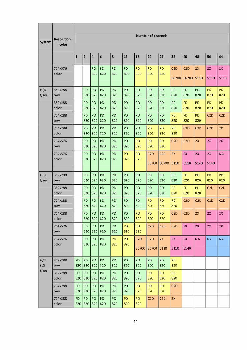
42
System Resolution -
color
Number of channels
1 2 4 6 8 12 16 20 24 32 40 48 56 64
704х576
color
PD
820
PD
820
PD
820
PD
820
PD
820
PD
820
PD
820
C2D
E6700
C2D
E6700
2X
5110
2X
5110
2X
5110
E (6
f/sec)
352х288
b/w
PD
820
PD
820
PD
820
PD
820
PD
820
PD
820
PD
820
PD
820
PD
820
PD
820
PD
820
PD
820
PD
820
352х288
color
PD
820
PD
820
PD
820
PD
820
PD
820
PD
820
PD
820
PD
820
PD
820
PD
820
PD
820
PD
820
PD
820
704х288
b/w
PD
820
PD
820
PD
820
PD
820
PD
820
PD
820
PD
820
PD
820
PD
820
PD
820
PD
820
C2D
E6700
C2D
E6700 704х288
color
PD
820
PD
820
PD
820
PD
820
PD
820
PD
820
PD
820
PD
820
PD
820
C2D
E6700
C2D
E6700
C2D
E6700
2X
5110 704х576
b/w
PD
820
PD
820
PD
820
PD
820
PD
820
PD
820
PD
820
PD
820
C2D
E6700
C2D
E6700
2X
5110
2X
5110
2X
5110 704х576
color
PD
820
PD
820
PD
820
PD
820
PD
820
PD
820
C2D
E6700
C2D
E6700
2X
5110
2X
5110
2X
5140
2X
5140
NA
F (8
f/sec)
352х288
b/w
PD
820
PD
820
PD
820
PD
820
PD
820
PD
820
PD
820
PD
820
PD
820
PD
820
PD
820
PD
820
PD
820
352х288
color
PD
820
PD
820
PD
820
PD
820
PD
820
PD
820
PD
820
PD
820
PD
820
PD
820
PD
820
C2D
E6700
C2D
E6700 704х288
b/w
PD
820
PD
820
PD
820
PD
820
PD
820
PD
820
PD
820
PD
820
PD
820
C2D
E6700
C2D
E6700
C2D
E6700
C2D
E6700 704х288
color
PD
820
PD
820
PD
820
PD
820
PD
820
PD
820
PD
820
PD
820
C2D
E6700
C2D
E6700
2X
5110
2X
5110
2X
5110 704х576
b/w
PD
820
PD
820
PD
820
PD
820
PD
820
PD
820
C2D
E6700
C2D
E6700
C2D
E6700
2X
5110
2X
5110
2X
5140
2X
5140 704х576
color
PD
820
PD
820
PD
820
PD
820
PD
820
C2D
E6700
C2D
E6700
2X
5110
2X
5110
2X
5140
NA NA NA
G/2
(12
f/sec)
352х288
b/w
PD
820
PD
820
PD
820
PD
820
PD
820
PD
820
PD
820
PD
820
PD
820
PD
820
352х288
color
PD
820
PD
820
PD
820
PD
820
PD
820
PD
820
PD
820
PD
820
PD
820
PD
820
704х288
b/w
PD
820
PD
820
PD
820
PD
820
PD
820
PD
820
PD
820
PD
820
PD
820
C2D
E6700
704х288
color
PD
820
PD
820
PD
820
PD
820
PD
820
PD
820
PD
820
C2D
E6700
C2D
E6700
2X
5110
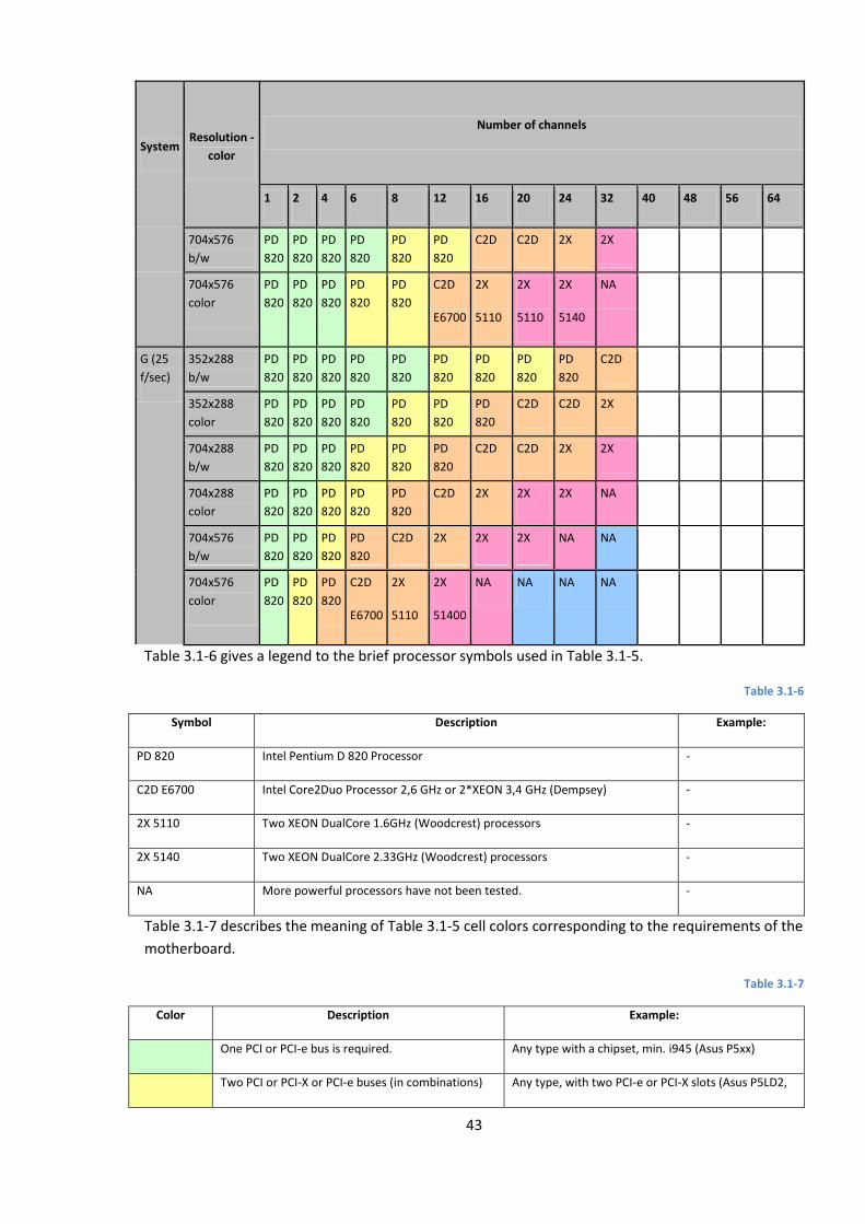
43
System Resolution -
color
Number of channels
1 2 4 6 8 12 16 20 24 32 40 48 56 64
704х576
b/w
PD
820
PD
820
PD
820
PD
820
PD
820
PD
820
C2D
E6700
C2D
E6700
2X
5110
2X
5110
704х576
color
PD
820
PD
820
PD
820
PD
820
PD
820
C2D
E6700
2X
5110
2X
5110
2X
5140
NA
G (25
f/sec)
352х288
b/w
PD
820
PD
820
PD
820
PD
820
PD
820
PD
820
PD
820
PD
820
PD
820
C2D
E6700
352х288
color
PD
820
PD
820
PD
820
PD
820
PD
820
PD
820
PD
820
C2D
E6700
C2D
E6700
2X
5110
704х288
b/w
PD
820
PD
820
PD
820
PD
820
PD
820
PD
820
C2D
E6700
C2D
E6700
2X
5110
2X
5110
704х288
color
PD
820
PD
820
PD
820
PD
820
PD
820
C2D
E6700
2X
5110
2X
5110
2X
5140
NA
704х576
b/w
PD
820
PD
820
PD
820
PD
820
C2D
E6700
2X
5110
2X
5110
2X
5140
NA NA
704х576
color
PD
820
PD
820
PD
820
C2D
E6700
2X
5110
2X
51400
NA NA NA NA
Table 3.1-6 gives a legend to the brief processor symbols used in Table 3.1-5.
Table 3.1-6
Symbol Description Example:
PD 820 Intel Pentium D 820 Processor -
C2D E6700 Intel Core2Duo Processor 2,6 GHz or 2*XEON 3,4 GHz (Dempsey) -
2X 5110 Two XEON DualCore 1.6GHz (Woodcrest) processors -
2X 5140 Two XEON DualCore 2.33GHz (Woodcrest) processors -
NA More powerful processors have not been tested. -
Table 3.1-7 describes the meaning of Table 3.1-5 cell colors corresponding to the requirements of the
motherboard.
Table 3.1-7
Color Description Example:
One PCI or PCI-e bus is required. Any type with a chipset, min. i945 (Asus P5xx)
Two PCI or PCI-X or PCI-e buses (in combinations) Any type, with two PCI-e or PCI-X slots (Asus P5LD2,
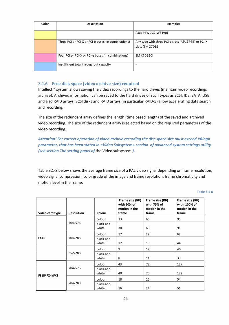
44
Color Description Example:
Asus P5WDG2-WS Pro)
Three PCI or PCI-X or PCI-e buses (in combinations) Any type with three PCI-e slots (ASUS P5B) or PCI-X
slots (SM X7DBE)
Four PCI or PCI-X or PCI-e buses (in combinations) SM X7DBE-X
Insufficient total throughput capacity -
3.1.6 Free disk space (video archive size) required
Intellect™ system allows saving the video recordings to the hard drives (maintain video recordings
archive). Archived information can be saved to the hard drives of such types as SCSI, IDE, SATA, USB
and also RAID arrays. SCSI disks and RAID arrays (in particular RAID-5) allow accelerating data search
and recording.
The size of the redundant array defines the length (time based length) of the saved and archived
video recording. The size of the redundant array is selected based on the required parameters of the
video recording.
Attention! For correct operation of video archive recording the disc space size must exceed «Ring»
parameter, that has been stated in «Video Subsystem» section of advanced system settings utility
(see section The setting panel of the Video subsystem ).
Table 3.1-8 below shows the average frame size of a PAL video signal depending on frame resolution,
video signal compression, color grade of the image and frame resolution, frame chromaticity and
motion level in the frame.
Table 3.1-8
Video card type Resolution Colour
Frame size (КБ) with 50% of motion in the frame
Frame size (КБ) with 75% of motion in the frame
Frame size (КБ) with 100% of motion in the frame
FX16
704х576 colour 33 66 95
black-and-white 30 63 91
704x288 colour 17 22 62
black-and-white 12 19 44
352х288 colour 9 12 40
black-and-white 8 11 33
FS15\FX4\FX8
704х576 colour 43 73 127
black-and-white 40 70 122
704x288 colour 18 26 54
black-and-white 16 24 51
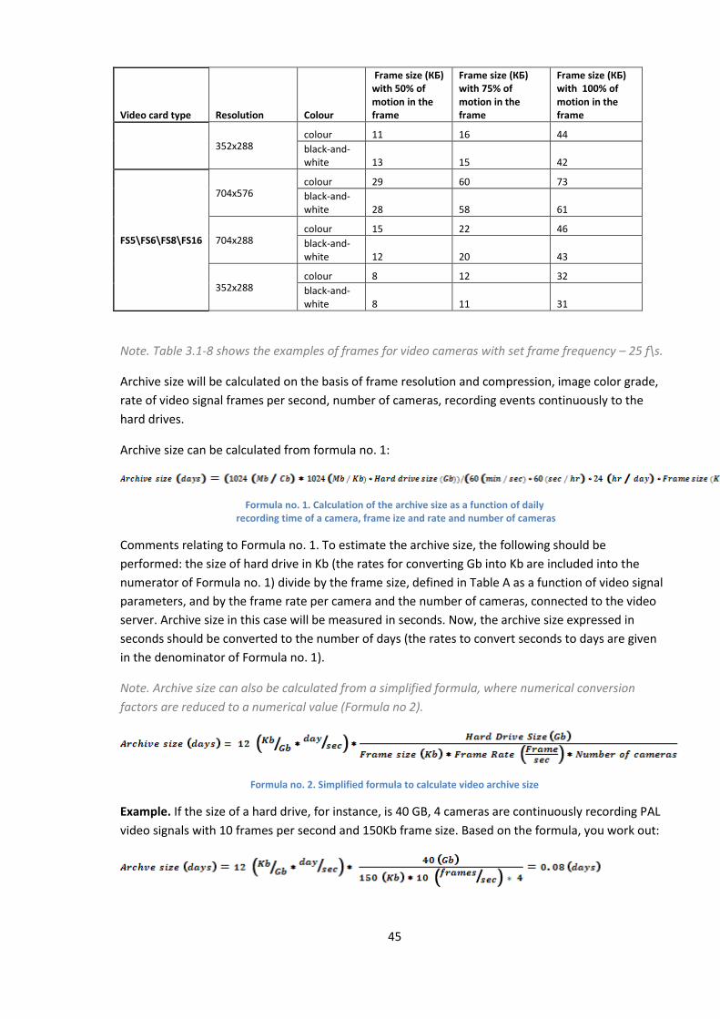
45
Video card type Resolution Colour
Frame size (КБ) with 50% of motion in the frame
Frame size (КБ) with 75% of motion in the frame
Frame size (КБ) with 100% of motion in the frame
352х288 colour 11 16 44
black-and-white 13 15 42
FS5\FS6\FS8\FS16
704х576 colour 29 60 73
black-and-white 28 58 61
704x288 colour 15 22 46
black-and-white 12 20 43
352х288 colour 8 12 32
black-and-white 8 11 31
Note. Table 3.1-8 shows the examples of frames for video cameras with set frame frequency – 25 f\s.
Archive size will be calculated on the basis of frame resolution and compression, image color grade,
rate of video signal frames per second, number of cameras, recording events continuously to the
hard drives.
Archive size can be calculated from formula no. 1:
Formula no. 1. Calculation of the archive size as a function of daily recording time of a camera, frame ize and rate and number of cameras
Comments relating to Formula no. 1. To estimate the archive size, the following should be
performed: the size of hard drive in Kb (the rates for converting Gb into Kb are included into the
numerator of Formula no. 1) divide by the frame size, defined in Table A as a function of video signal
parameters, and by the frame rate per camera and the number of cameras, connected to the video
server. Archive size in this case will be measured in seconds. Now, the archive size expressed in
seconds should be converted to the number of days (the rates to convert seconds to days are given
in the denominator of Formula no. 1).
Note. Archive size can also be calculated from a simplified formula, where numerical conversion
factors are reduced to a numerical value (Formula no 2).
Formula no. 2. Simplified formula to calculate video archive size
Example. If the size of a hard drive, for instance, is 40 GB, 4 cameras are continuously recording PAL
video signals with 10 frames per second and 150Kb frame size. Based on the formula, you work out:
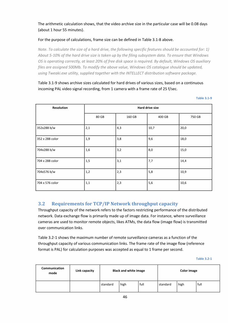
46
The arithmetic calculation shows, that the video archive size in the particular case will be 0.08 days
(about 1 hour 55 minutes).
For the purpose of calculations, frame size can be defined in Table 3.1-8 above.
Note. To calculate the size of a hard drive, the following specific features should be accounted for: 1)
About 5-10% of the hard drive size is taken up by the filing subsystem data. To ensure that Windows
OS is operating correctly, at least 20% of free disk space is required. By default, Windows OS auxiliary
files are assigned 500Mb. To modify the above value, Windows OS catalogue should be updated,
using Tweaki.exe utility, supplied together with the INTELLECT distribution software package.
Table 3.1-9 shows archive sizes calculated for hard drives of various sizes, based on a continuous
incoming PAL video signal recording, from 1 camera with a frame rate of 25 f/sec.
Table 3.1-9
Resolution Hard drive size
80 GB 160 GB 400 GB 750 GB
352х288 b/w 2,1 4,3 10,7 20,0
352 х 288 color 1,9 3,8 9,6 18,0
704х288 b/w 1,6 3,2 8,0 15,0
704 х 288 color 1,5 3,1 7,7 14,4
704х576 b/w 1,2 2,3 5,8 10,9
704 х 576 color 1,1 2,3 5,6 10,6
3.2 Requirements for TCP/IP Network throughput capacity Throughput capacity of the network refers to the factors restricting performance of the distributed
network. Data exchange flow is primarily made up of image data. For instance, where surveillance
cameras are used to monitor remote objects, likes ATMs, the data flow (image flow) is transmitted
over communication links.
Table 3.2-1 shows the maximum number of remote surveillance cameras as a function of the
throughput capacity of various communication links. The frame rate of the image flow (reference
format is PAL) for calculation purposes was accepted as equal to 1 frame per second.
Table 3.2-1
Communication
mode Link capacity Black and white image Color image
standard high full standard high full
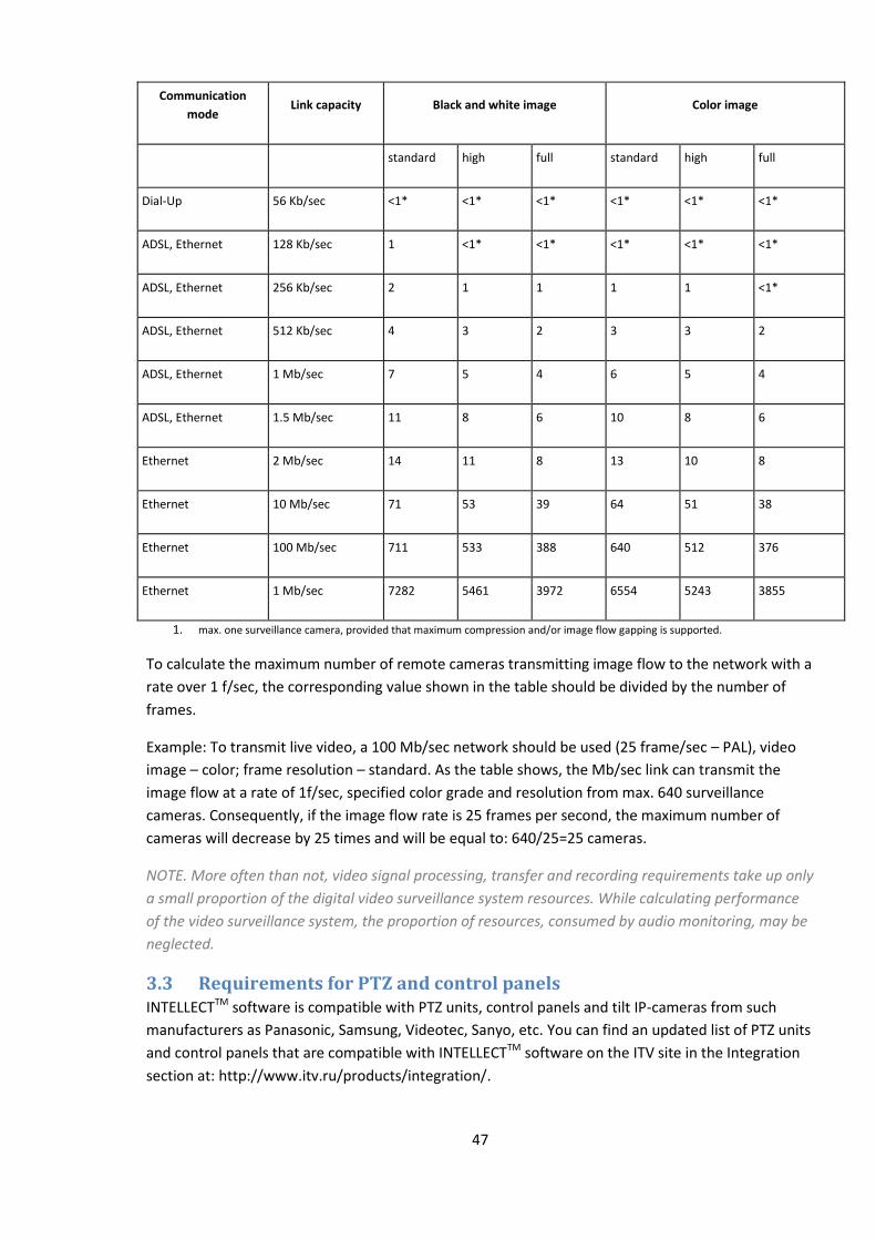
47
Communication
mode Link capacity Black and white image Color image
standard high full standard high full
Dial-Up 56 Kb/sec <1* <1* <1* <1* <1* <1*
ADSL, Ethernet 128 Kb/sec 1 <1* <1* <1* <1* <1*
ADSL, Ethernet 256 Kb/sec 2 1 1 1 1 <1*
ADSL, Ethernet 512 Kb/sec 4 3 2 3 3 2
ADSL, Ethernet 1 Mb/sec 7 5 4 6 5 4
ADSL, Ethernet 1.5 Mb/sec 11 8 6 10 8 6
Ethernet 2 Mb/sec 14 11 8 13 10 8
Ethernet 10 Mb/sec 71 53 39 64 51 38
Ethernet 100 Mb/sec 711 533 388 640 512 376
Ethernet 1 Mb/sec 7282 5461 3972 6554 5243 3855
1. max. one surveillance camera, provided that maximum compression and/or image flow gapping is supported.
To calculate the maximum number of remote cameras transmitting image flow to the network with a
rate over 1 f/sec, the corresponding value shown in the table should be divided by the number of
frames.
Example: To transmit live video, a 100 Mb/sec network should be used (25 frame/sec – PAL), video
image – color; frame resolution – standard. As the table shows, the Mb/sec link can transmit the
image flow at a rate of 1f/sec, specified color grade and resolution from max. 640 surveillance
cameras. Consequently, if the image flow rate is 25 frames per second, the maximum number of
cameras will decrease by 25 times and will be equal to: 640/25=25 cameras.
NOTE. More often than not, video signal processing, transfer and recording requirements take up only
a small proportion of the digital video surveillance system resources. While calculating performance
of the video surveillance system, the proportion of resources, consumed by audio monitoring, may be
neglected.
3.3 Requirements for PTZ and control panels INTELLECTTM software is compatible with PTZ units, control panels and tilt IP-cameras from such
manufacturers as Panasonic, Samsung, Videotec, Sanyo, etc. You can find an updated list of PTZ units
and control panels that are compatible with INTELLECTTM software on the ITV site in the Integration
section at: http://www.itv.ru/products/integration/.

48
3.4 Requirements for audio input units
software can use the following audio inputs:
1. FS/WS/FX/VRC video capture cards. These cards support simultaneous digitization of 1-16
audio signals, depending on the type of the card used. The list of video capture cards
compatible with software and their features are given in Ошибка!
сточник ссылки не найден..
2. Standard sound cards, including cards, integrated with the motherboard. Standard sound
cards, as a rule, support simultaneous digitization of up to 2 audio signals.
3. Multi-channel sound cards and converters for digitization of outgoing audio signals from
microphones and telephone lines, software and hardware complex for the digital audio
registration, etc. You can find an updated list of multi-channel audio inputs that are
compatible with INTELLECTTM software on the ITV site in the Integration section at:
http://www.itv.ru/products/integration/.
4. IP-units. You can find an updated list of IP-units for audio input that are compatible with
INTELLECTTM software, as well as specific application features thereof on the ITV site in the
Integration section at: http://www.itv.ru/products/integration/.
3.5 Requirements for IP devices of audio and video input
software is compatible with IP-units and video and audio inputs.
Specific application features of certain IP-units:
1. To ensure correct registration of sound from Axis IP-cameras, in cases where AAC audio
codec is used, avoid setting the audio steam bit rate at 8 or 12 Kbps, if the digitizing rate is 8
kHz: the bite rate should be 16, 24, 32, 48 or 64 Kbps.
2. To ensure correct registration of outgoing sound from Sony IP-cameras, avoid using G.726
audio codec: use G.711 codec instead.
NOTE. You can find an updated list of IP-units and the functionality range of the units supported by
software on the ITV site in the Integration section at:
http://www.itv.ru/products/integration/.
Note! It is possible to install update drivers and codecs , taking into account the changed
distributive structure, irrespective of the general Intellect PC version update.
3.6 Requirements for GSM Equipment
GSM equipment is used in the software to send SMS, whenever the program
registers pre-defined events (detector alarms, Operator commands, etc.). The list of said GSM
equipment includes GSM modems, GSM adapters or mobile phones supporting such standards as
ETSI GSM 07.07 or ETSI GSM 07.05.

49
3.7 Requirements for voice modems
Voice modems are used in the software to automatically send out voice messages,
whenever the program registers pre-defined events (detector alarms, Operator commands, etc.).
software is compatible with the voice modems, which are not designed to code
(compress) audio streams, or the voice modems, which support such audio stream coding standards
as 4-bit Rockwell ADPCM 7200 Hz, 4-bit IMA ADPCM 4800 Hz, 4-bit IMA ADPCM 7200 Hz, 4-bit IMA
ADPCM 8000 Hz, 8-bit unsigned linear PCM at 7200 Hz, 8-bit unsigned linear PCM at 8000 Hz, 4-bit
Rockwell ADPCM 7200 Hz, 8 bit u-law (G.711) at 8000 Hz, 8 bit A-law (G.711) at 8000 Hz.
4 Personnel skills requirements
The Administrator of a digital video surveillance system based on software should
possess the following qualifications:
1. «Windows 2000/XP local network administrator».
2. ITV Group product expert. The above qualifications can be obtained through authorized
training in ITV Group Products in the ITV Group Training Centre.
50
5 Installing and removing INTELLECT™ software
5.1 Installation of INTELLECT™ software
5.1.1 Description of the INTELLECT™ software distribution package
INTELLECT™ software is offered as a software installation package (distribution package) on a
compact disk (Figure 5.1-1).
Figure 5.1-1 Installation CD of INTELLECT™ software
The distribution disk (software bundle) contains all software components necessary for the
installation of INTELLECT™ software on the base PC.
The software is made operable with the intellect.sec key file. The key file is a part of the software
bundle and can be found in the Key folder on the CD. The key file defines the configuration of the
INTELLECT™ software delivery package.
Note. If there is no key file INTELLECT™ software will operate in demo mode within two month from
the intellect.exe file creation date, from 8 a.m till 12 midnight.
To install and configure INTELLECT™ software, administrator rights are required.
5.1.2 Installation of INTELLECT™ software as a server
This section outlines a step-by-step routine for the installation of INTELLECT™ software as a server.
Note 1.While installing the INTELLECT™ software the following specific features of version 4.8.0
should be taken into account:
INTELLECT™ software should be installed on a “clean” OS Windows (see section «OS system
requirements »).
To install INTELLECT™ software, OS Windows administrator rights are required.
Note 2. While reinstalling the INTELLECT™ software the following specific features of version 4.8.0
should take into account: Before re-installation, uninstall INTELLECT™ software (as well as all other
ITV software products, if there are installed any of them).
To install INTELLECT™ software do the following:
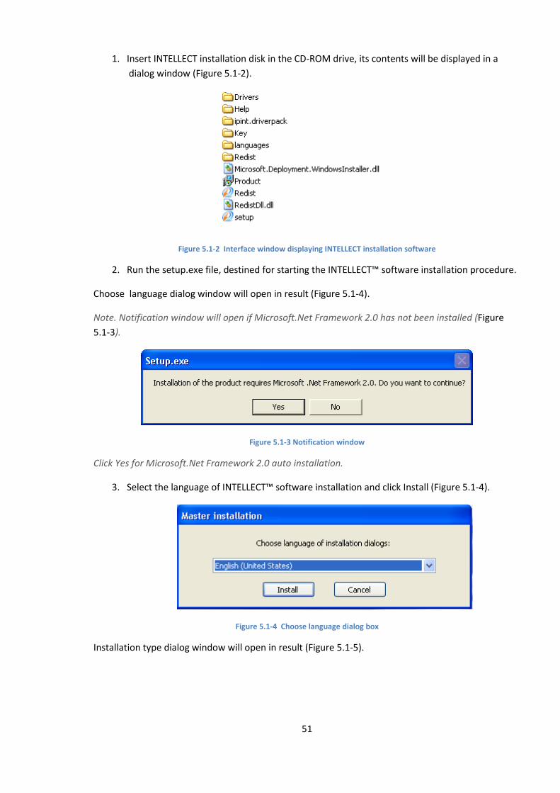
51
1. Insert INTELLECT installation disk in the CD-ROM drive, its contents will be displayed in a
dialog window (Figure 5.1-2).
Figure 5.1-2 Interface window displaying INTELLECT installation software
2. Run the setup.exe file, destined for starting the INTELLECT™ software installation procedure.
Choose language dialog window will open in result (Figure 5.1-4).
Note. Notification window will open if Microsoft.Net Framework 2.0 has not been installed (Figure
5.1-3).
Figure 5.1-3 Notification window
Click Yes for Microsoft.Net Framework 2.0 auto installation.
3. Select the language of INTELLECT™ software installation and click Install (Figure 5.1-4).
Figure 5.1-4 Choose language dialog box
Installation type dialog window will open in result (Figure 5.1-5).
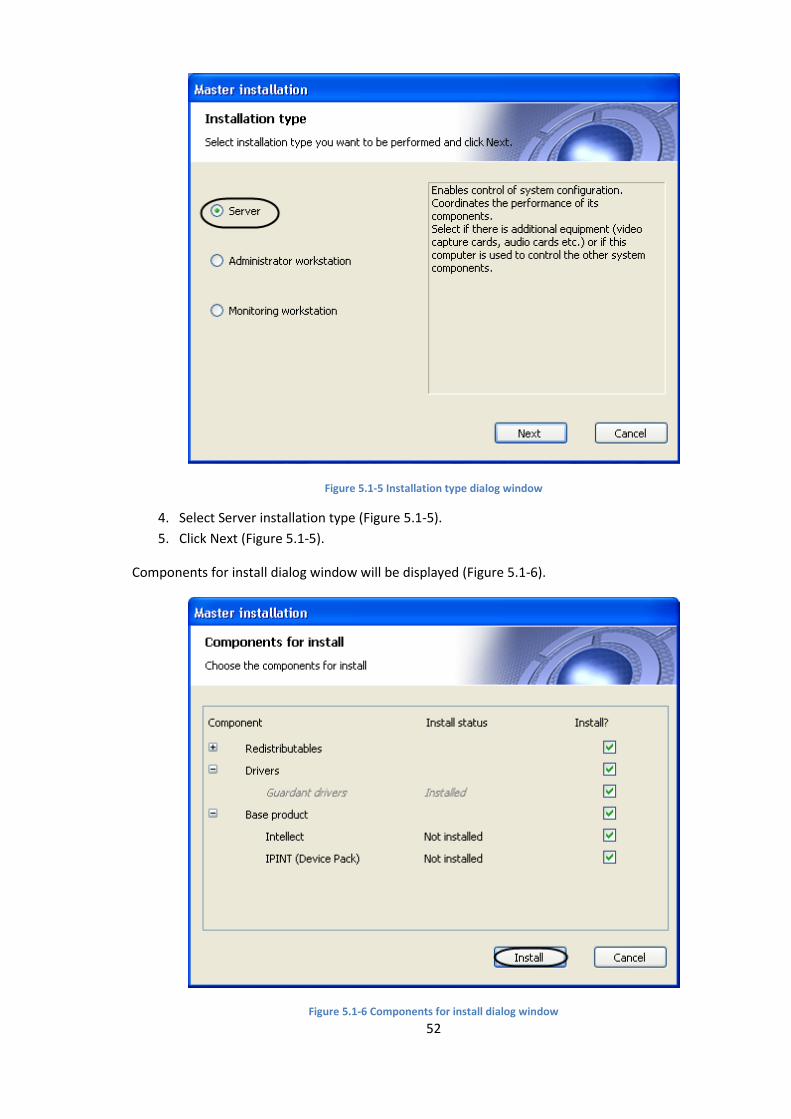
52
Figure 5.1-5 Installation type dialog window
4. Select Server installation type (Figure 5.1-5).
5. Click Next (Figure 5.1-5).
Components for install dialog window will be displayed (Figure 5.1-6).
Figure 5.1-6 Components for install dialog window
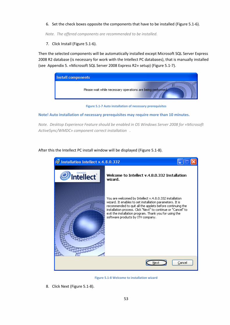
53
6. Set the check boxes opposite the components that have to be installed (Figure 5.1-6).
Note. The offered components are recommended to be installed.
7. Click Install (Figure 5.1-6).
Then the selected components will be automatically installed except Microsoft SQL Server Express
2008 R2 database (is necessary for work with the Intellect PC databases), that is manually installed
(see Appendix 5. «Microsoft SQL Server 2008 Express R2» setup) (Figure 5.1-7).
Figure 5.1-7 Auto installation of necessary prerequisites
Note! Auto installation of necessary prerequisites may require more than 10 minutes.
Note. Desktop Experience Feature should be enabled in OS Windows Server 2008 for «Microsoft
ActiveSync/WMDC» component correct installation .
After this the Intellect PC install window will be displayed (Figure 5.1-8).
Figure 5.1-8 Welcome to installation wizard
8. Click Next (Figure 5.1-8).
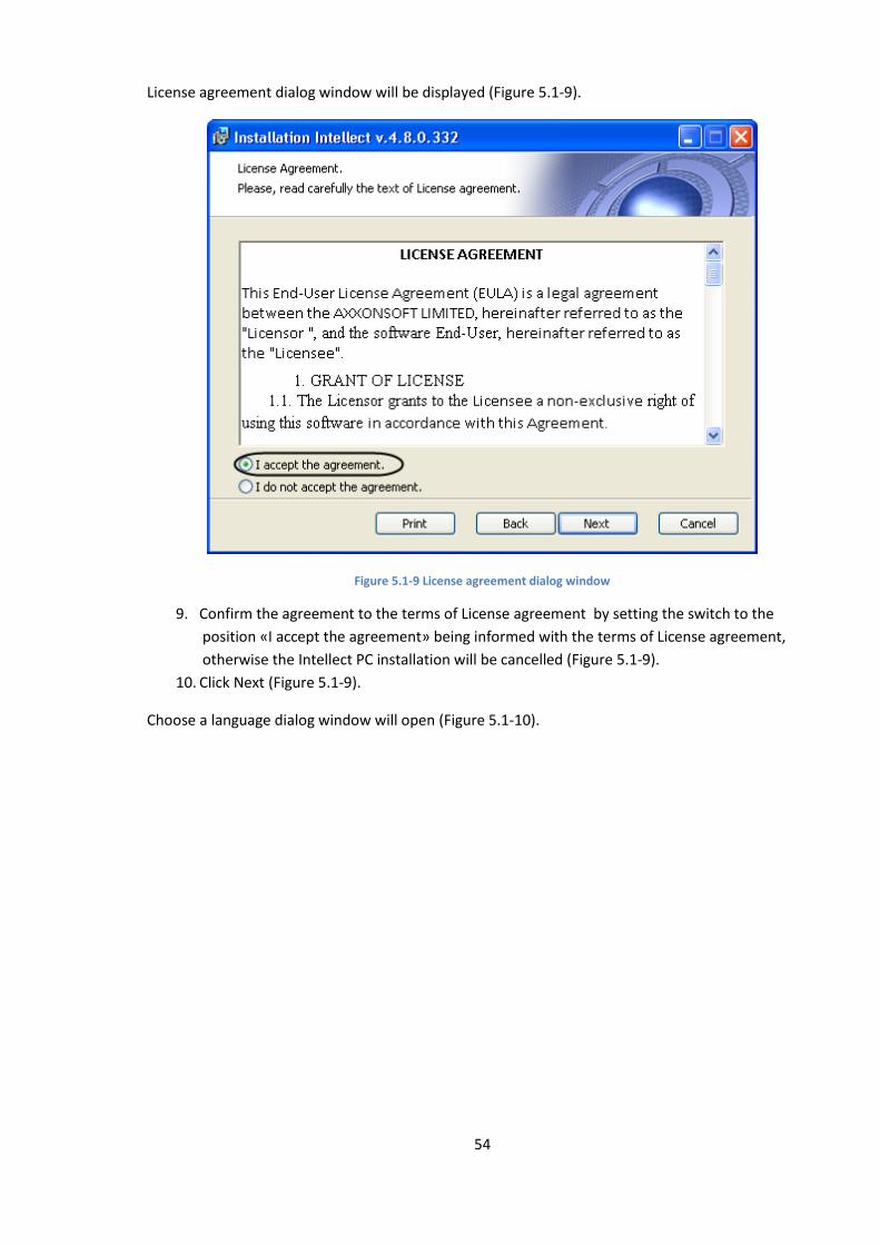
54
License agreement dialog window will be displayed (Figure 5.1-9).
Figure 5.1-9 License agreement dialog window
9. Confirm the agreement to the terms of License agreement by setting the switch to the
position «I accept the agreement» being informed with the terms of License agreement,
otherwise the Intellect PC installation will be cancelled (Figure 5.1-9).
10. Click Next (Figure 5.1-9).
Choose a language dialog window will open (Figure 5.1-10).
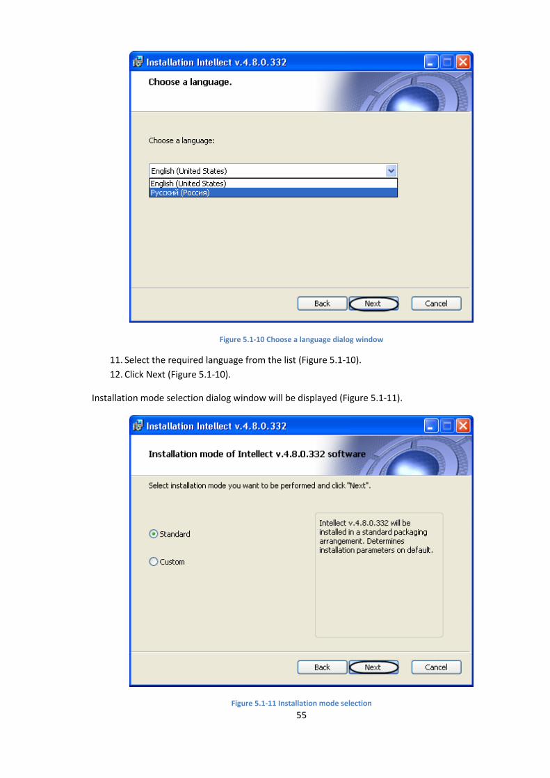
55
Figure 5.1-10 Choose a language dialog window
11. Select the required language from the list (Figure 5.1-10).
12. Click Next (Figure 5.1-10).
Installation mode selection dialog window will be displayed (Figure 5.1-11).
Figure 5.1-11 Installation mode selection
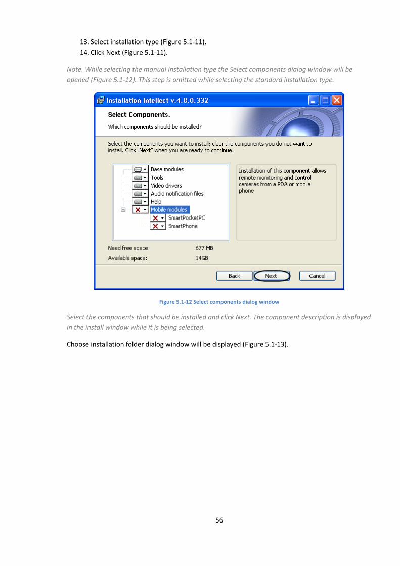
56
13. Select installation type (Figure 5.1-11).
14. Click Next (Figure 5.1-11).
Note. While selecting the manual installation type the Select components dialog window will be
opened (Figure 5.1-12). This step is omitted while selecting the standard installation type.
Figure 5.1-12 Select components dialog window
Select the components that should be installed and click Next. The component description is displayed
in the install window while it is being selected.
Choose installation folder dialog window will be displayed (Figure 5.1-13).
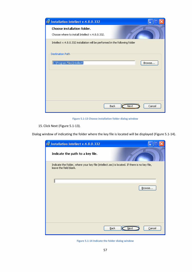
57
Figure 5.1-13 Choose installation folder dialog window
15. Click Next (Figure 5.1-13).
Dialog window of indicating the folder where the key file is located will be displayed (Figure 5.1-14).
Figure 5.1-14 Indicate the folder dialog window

58
Note. Leave the field blank if the key file will be copied later.
16. Click Next (Figure 5.1-14).
Additional settings dialog window will open (Figure 5.1-15).
Figure 5.1-15 Additional settings dialog window
17. If necessary create an icon of the Intellect PC on the desktop by setting the corresponding
checkbox (Figure 5.1-15).
18. If necessary create an icon of the Intellect PC in the start panel by setting the corresponding
checkbox (Figure 5.1-15).
19. Click Next (Figure 5.1-15).
Install Intellect as a service dialog box will be displayed (Figure 5.1-16).
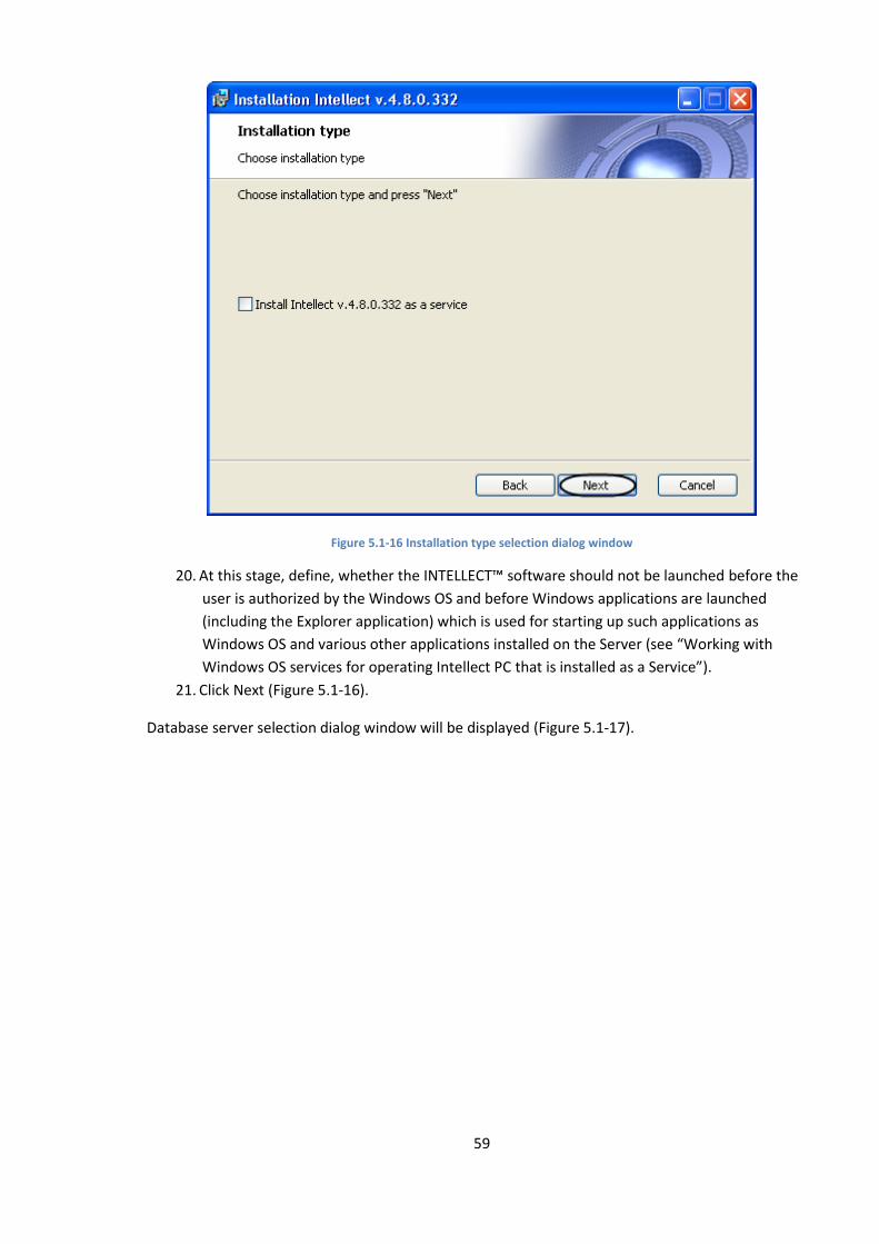
59
Figure 5.1-16 Installation type selection dialog window
20. At this stage, define, whether the INTELLECT™ software should not be launched before the
user is authorized by the Windows OS and before Windows applications are launched
(including the Explorer application) which is used for starting up such applications as
Windows OS and various other applications installed on the Server (see “Working with
Windows OS services for operating Intellect PC that is installed as a Service”).
21. Click Next (Figure 5.1-16).
Database server selection dialog window will be displayed (Figure 5.1-17).
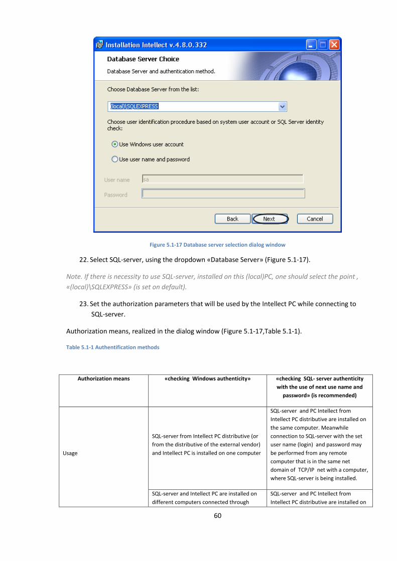
60
Figure 5.1-17 Database server selection dialog window
22. Select SQL-server, using the dropdown «Database Server» (Figure 5.1-17).
Note. If there is necessity to use SQL-server, installed on this (local)PC, one should select the point ,
«(local)\SQLEXPRESS» (is set on default).
23. Set the authorization parameters that will be used by the Intellect PC while connecting to
SQL-server.
Authorization means, realized in the dialog window (Figure 5.1-17,Table 5.1-1).
Table 5.1-1 Authentification methods
Authorization means «checking Windows authenticity» «checking SQL- server authenticity
with the use of next use name and
password» (is recommended)
Usage
SQL-server from Intellect PC distributive (or
from the distributive of the external vendor)
and Intellect PC is installed on one computer
SQL-server and PC Intellect from
Intellect PC distributive are installed on
the same computer. Meanwhile
connection to SQL-server with the set
user name (login) and password may
be performed from any remote
computer that is in the same net
domain of TCP/IP net with a computer,
where SQL-server is being installed.
SQL-server and Intellect PC are installed on
different computers connected through
SQL-server and PC Intellect from
Intellect PC distributive are installed on

61
TCP/IP net that are in the same net domain.
Meanwhile in OS Windows on the computer
with installed MS SQL-server there should be
created an account for currently authorized
user on the computer, where PC Intellect is
being installed.
different computers, connected
through TCP/IP net that are in the same
net domain. Meanwhile user
name(login) and password should
correspond to user name(login) and
password, used for access to SQL-
server.
Full-function SQL-server (is additionally
installed) and Intellect PC is installed on
different computers, connected through
TCP/IP net that are in the same net domain.
Meanwhile on the remote SQL-sever there
should be created an account for currently
authorized user on the computer, where PC
Intellect is being installed.
Full-function SQL-server (is additionally
installed) and Intellect PC is installed on
the same or different computers,
connected through TCP/IP net that are
in the same net domain. Meanwhile
user name(login) and password should
correspond to user name(login) and
password, used for access to SQL-
server.
Note. For SQL-server, installed from PC Intellect distributive, user name «sa» and
password«Intellect_default_DB_4» are used on default. While installing the Microsoft SQL Server
Express 2008 R2 the password may be changed for any other password.
24. Click Next to continue the installation(Figure 5.1-17)
Then Select or set database name dialog window will be displayed (Figure 5.1-18).
Figure 5.1-18 Select or set database name dialog window

62
25. Click Next (Figure 5.1-18).
Note. If the system while being installed displays a message «Rights are required to create or edit
databases», the installation process must be cancelled and then restart the installation again.
Ready to install dialog window will be displayed (Figure 5.1-19).
Figure 5.1-19 Ready to install dialog window
Note. Click Back to change the settings (Figure 5.1-19).
26. Click Install (Figure 5.1-19).
Then Process of intellect installation dialog window will be opened (Figure 5.1-20).
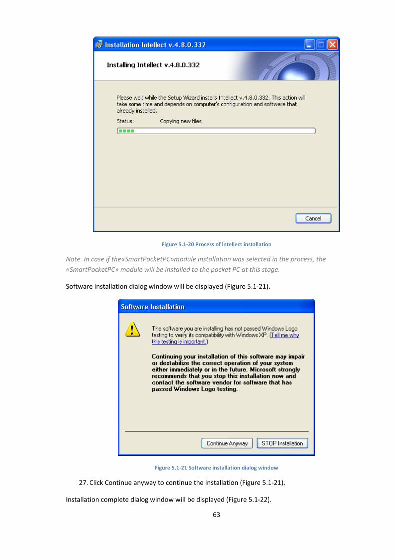
63
Figure 5.1-20 Process of intellect installation
Note. In case if the«SmartPocketPC»module installation was selected in the process, the
«SmartPocketPC» module will be installed to the pocket PC at this stage.
Software installation dialog window will be displayed (Figure 5.1-21).
Figure 5.1-21 Software installation dialog window
27. Click Continue anyway to continue the installation (Figure 5.1-21).
Installation complete dialog window will be displayed (Figure 5.1-22).
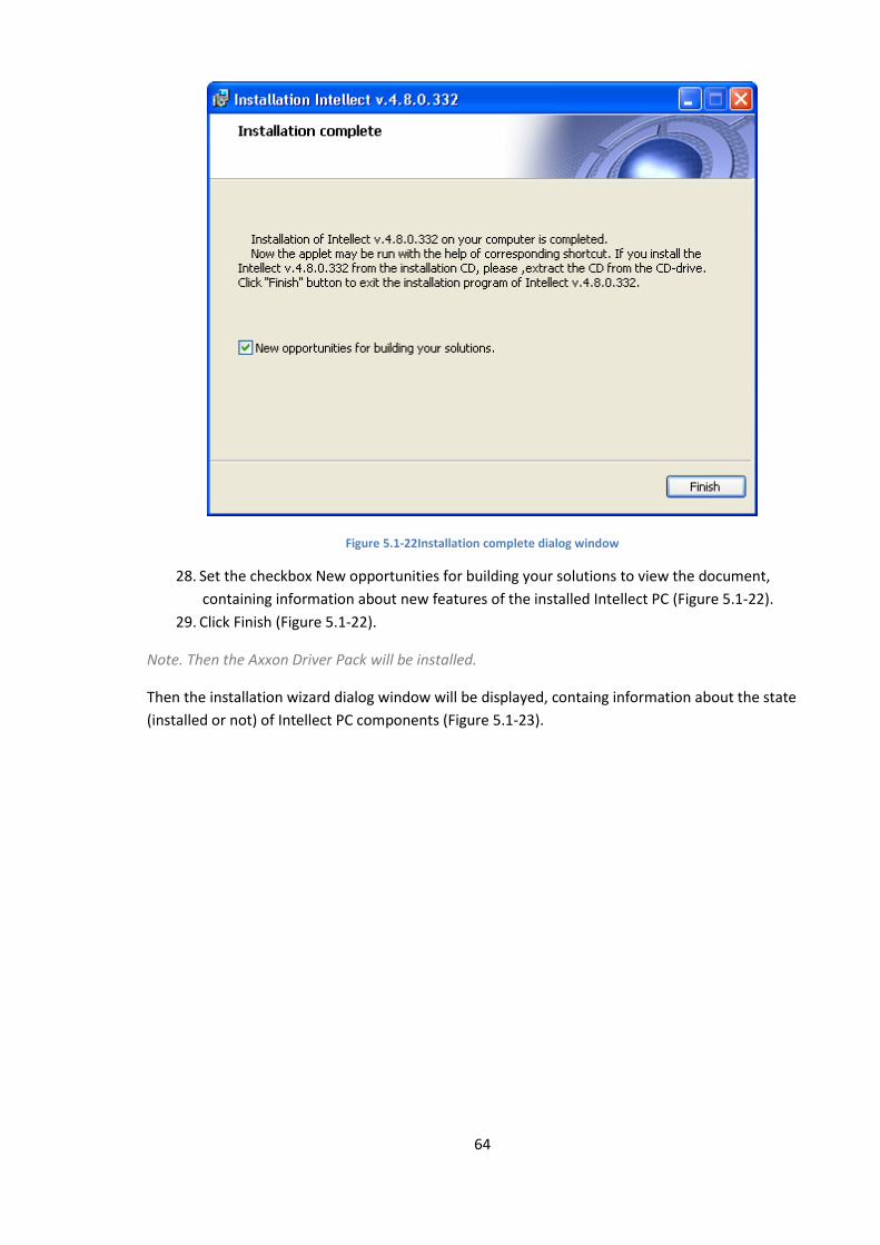
64
Figure 5.1-22Installation complete dialog window
28. Set the checkbox New opportunities for building your solutions to view the document,
containing information about new features of the installed Intellect PC (Figure 5.1-22).
29. Click Finish (Figure 5.1-22).
Note. Then the Axxon Driver Pack will be installed.
Then the installation wizard dialog window will be displayed, containg information about the state
(installed or not) of Intellect PC components (Figure 5.1-23).
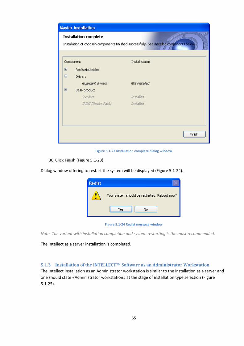
65
Figure 5.1-23 Installation complete dialog window
30. Click Finish (Figure 5.1-23).
Dialog window offering to restart the system will be displayed (Figure 5.1-24).
Figure 5.1-24 Redist message window
Note. The variant with installation completion and system restarting is the most recommended.
The Intellect as a server installation is completed.
5.1.3 Installation of the INTELLECTTM Software as an Administrator Workstation
The Intellect installation as an Administrator workstation is similar to the installation as a server and
one should state «Administrator workstation» at the stage of installation type selection (Figure
5.1-25).
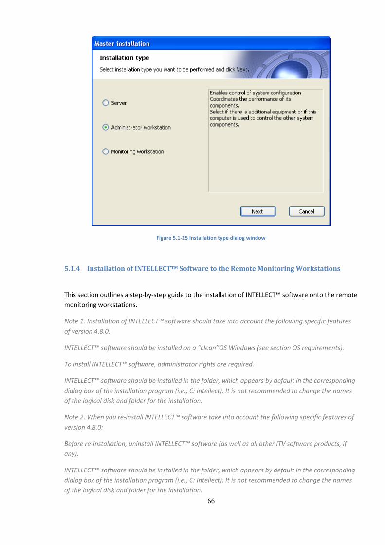
66
Figure 5.1-25 Installation type dialog window
5.1.4 Installation of INTELLECTTM Software to the Remote Monitoring Workstations
This section outlines a step-by-step guide to the installation of INTELLECT™ software onto the remote
monitoring workstations.
Note 1. Installation of INTELLECT™ software should take into account the following specific features
of version 4.8.0:
INTELLECT™ software should be installed on a “clean”OS Windows (see section OS requirements).
To install INTELLECT™ software, administrator rights are required.
INTELLECT™ software should be installed in the folder, which appears by default in the corresponding
dialog box of the installation program (i.e., C: Intellect). It is not recommended to change the names
of the logical disk and folder for the installation.
Note 2. When you re-install INTELLECT™ software take into account the following specific features of
version 4.8.0:
Before re-installation, uninstall INTELLECT™ software (as well as all other ITV software products, if
any).
INTELLECT™ software should be installed in the folder, which appears by default in the corresponding
dialog box of the installation program (i.e., C: Intellect). It is not recommended to change the names
of the logical disk and folder for the installation.
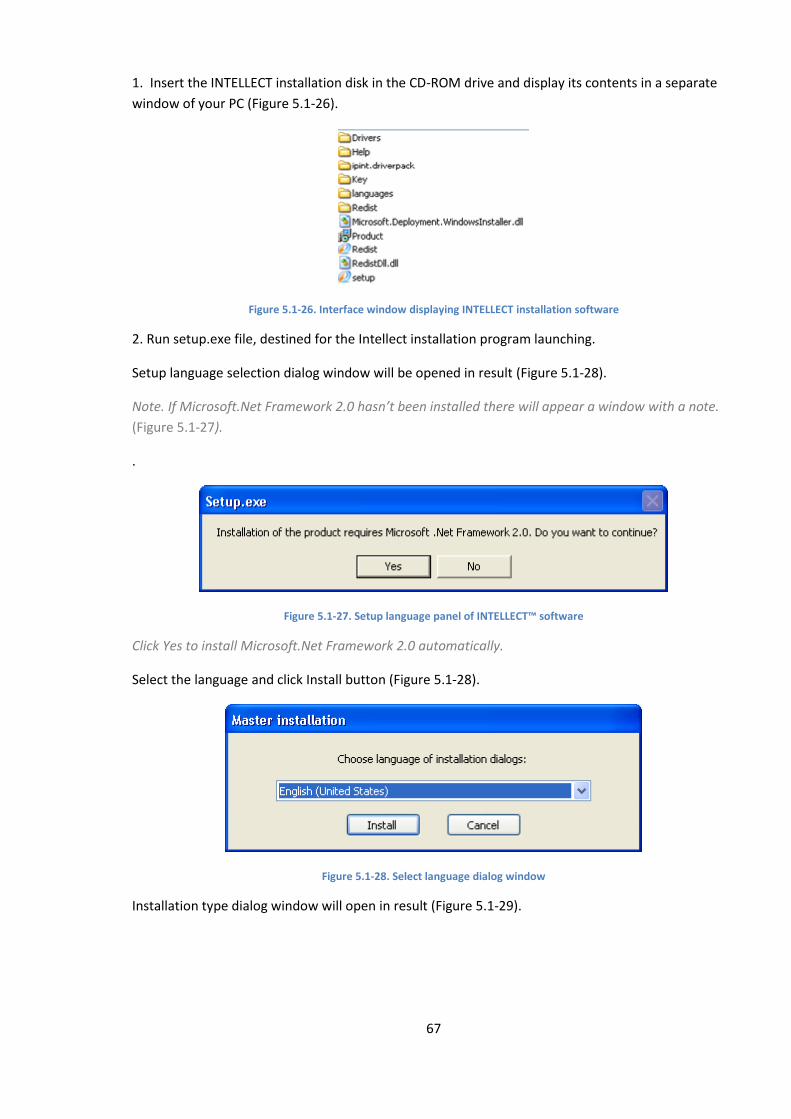
67
1. Insert the INTELLECT installation disk in the CD-ROM drive and display its contents in a separate
window of your PC (Figure 5.1-26).
Figure 5.1-26. Interface window displaying INTELLECT installation software
2. Run setup.exe file, destined for the Intellect installation program launching.
Setup language selection dialog window will be opened in result (Figure 5.1-28).
Note. If Microsoft.Net Framework 2.0 hasn’t been installed there will appear a window with a note.
(Figure 5.1-27).
.
Figure 5.1-27. Setup language panel of INTELLECT™ software
Click Yes to install Microsoft.Net Framework 2.0 automatically.
Select the language and click Install button (Figure 5.1-28).
Figure 5.1-28. Select language dialog window
Installation type dialog window will open in result (Figure 5.1-29).
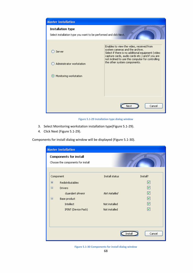
68
Figure 5.1-29 Installation type dialog window
3. Select Monitoring workstation installation type(Figure 5.1-29).
4. Click Next (Figure 5.1-29).
Components for install dialog window will be displayed (Figure 5.1-30).
Figure 5.1-30 Components for install dialog window
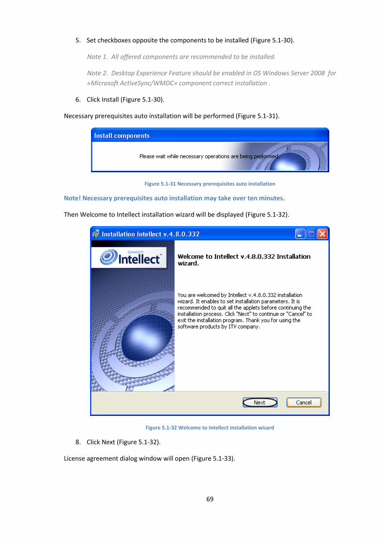
69
5. Set checkboxes opposite the components to be installed (Figure 5.1-30).
Note 1. All offered components are recommended to be installed.
Note 2. Desktop Experience Feature should be enabled in OS Windows Server 2008 for
«Microsoft ActiveSync/WMDC» component correct installation .
6. Click Install (Figure 5.1-30).
Necessary prerequisites auto installation will be performed (Figure 5.1-31).
Figure 5.1-31 Necessary prerequisites auto installation
Note! Necessary prerequisites auto installation may take over ten minutes.
Then Welcome to Intellect installation wizard will be displayed (Figure 5.1-32).
Figure 5.1-32 Welcome to Intellect installation wizard
8. Click Next (Figure 5.1-32).
License agreement dialog window will open (Figure 5.1-33).
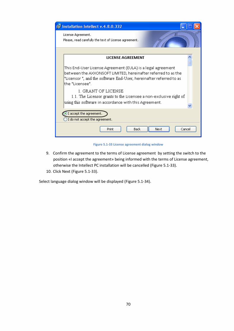
70
Figure 5.1-33 License agreement dialog window
9. Confirm the agreement to the terms of License agreement by setting the switch to the
position «I accept the agreement» being informed with the terms of License agreement,
otherwise the Intellect PC installation will be cancelled (Figure 5.1-33).
10. Click Next (Figure 5.1-33).
Select language dialog window will be displayed (Figure 5.1-34).
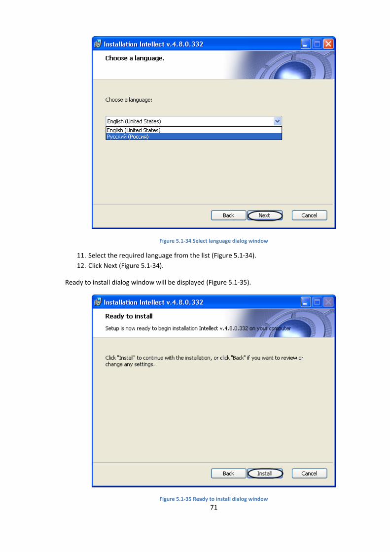
71
Figure 5.1-34 Select language dialog window
11. Select the required language from the list (Figure 5.1-34).
12. Click Next (Figure 5.1-34).
Ready to install dialog window will be displayed (Figure 5.1-35).
Figure 5.1-35 Ready to install dialog window
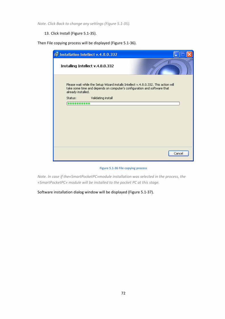
72
Note. Click Back to change any settings (Figure 5.1-35).
13. Click Install (Figure 5.1-35).
Then File copying process will be displayed (Figure 5.1-36).
Figure 5.1-36 File copying process
Note. In case if the«SmartPocketPC»module installation was selected in the process, the
«SmartPocketPC» module will be installed to the pocket PC at this stage.
Software installation dialog window will be displayed (Figure 5.1-37).

73
Figure 5.1-37 Software installation dialog window
14. Click continue anyway to continue the installation (Figure 5.1-37).
Installation complete dialog window of the Intellect PC will be displayed (Figure 5.1-38).
Figure 5.1-38Installation complete dialog window
15. Set the checkbox New opportunities for building your solutions to view the document,
containing information about new features of the installed Intellect PC (Figure 5.1-38).
16. Click Finish.
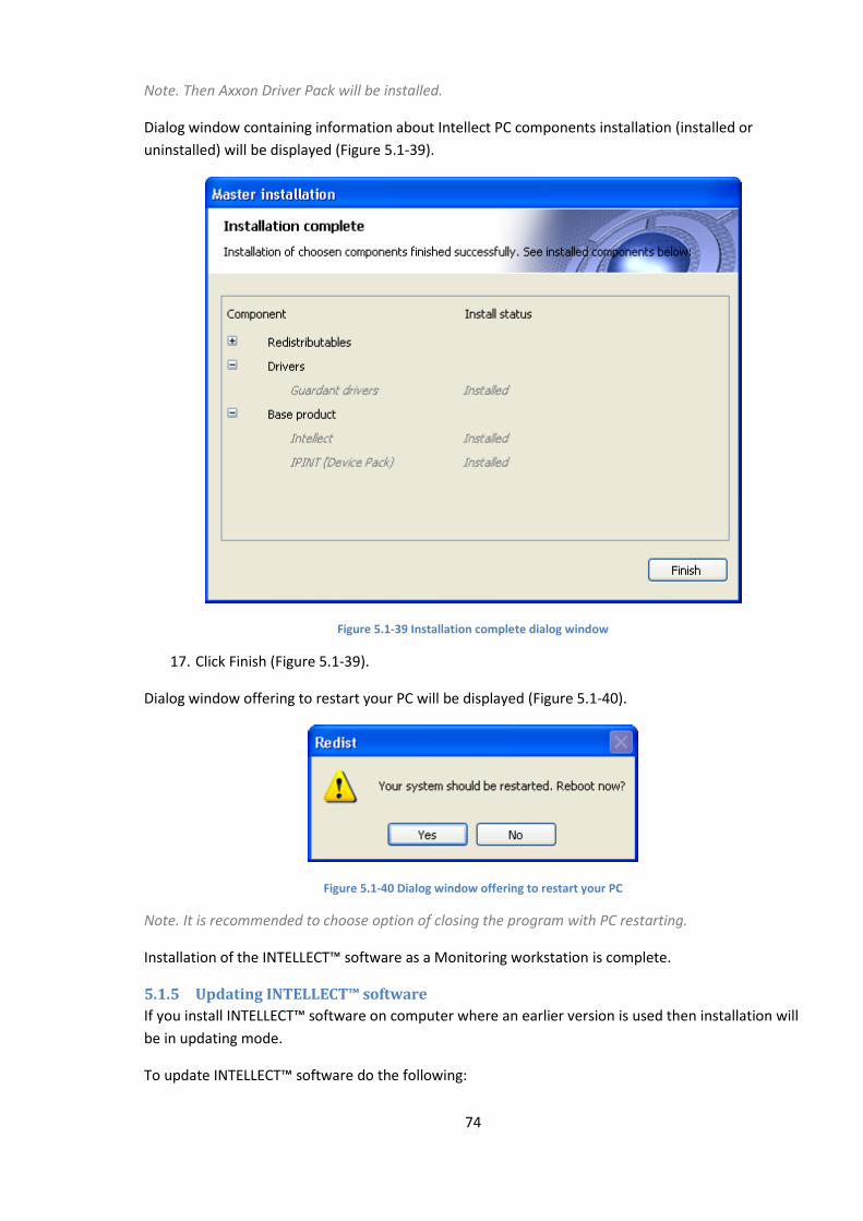
74
Note. Then Axxon Driver Pack will be installed.
Dialog window containing information about Intellect PC components installation (installed or
uninstalled) will be displayed (Figure 5.1-39).
Figure 5.1-39 Installation complete dialog window
17. Click Finish (Figure 5.1-39).
Dialog window offering to restart your PC will be displayed (Figure 5.1-40).
Figure 5.1-40 Dialog window offering to restart your PC
Note. It is recommended to choose option of closing the program with PC restarting.
Installation of the INTELLECT™ software as a Monitoring workstation is complete.
5.1.5 Updating INTELLECT™ software
If you install INTELLECT™ software on computer where an earlier version is used then installation will
be in updating mode.
To update INTELLECT™ software do the following:
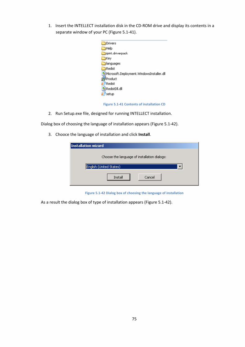
75
1. Insert the INTELLECT installation disk in the CD-ROM drive and display its contents in a
separate window of your PC (Figure 5.1-41).
Figure 5.1-41 Contents of installation CD
2. Run Setup.exe file, designed for running INTELLECT installation.
Dialog box of choosing the language of installation appears (Figure 5.1-42).
3. Chooce the language of installation and click Install.
Figure 5.1-42 Dialog box of choosing the language of installation
As a result the dialog box of type of installation appears (Figure 5.1-42).
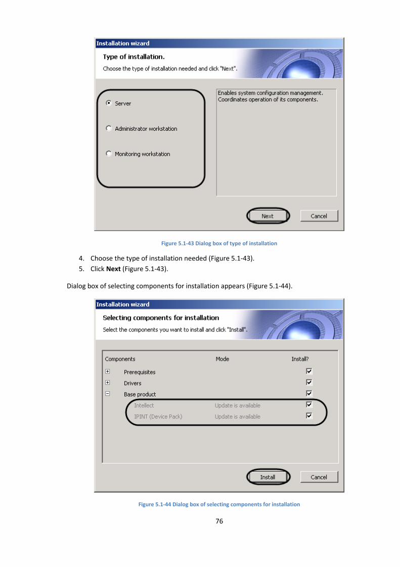
76
Figure 5.1-43 Dialog box of type of installation
4. Choose the type of installation needed (Figure 5.1-43).
5. Click Next (Figure 5.1-43).
Dialog box of selecting components for installation appears (Figure 5.1-44).
Figure 5.1-44 Dialog box of selecting components for installation
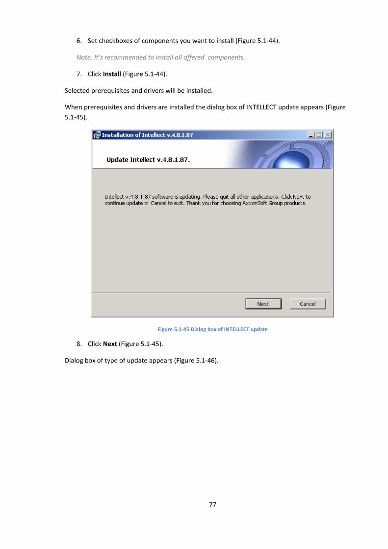
77
6. Set checkboxes of components you want to install (Figure 5.1-44).
Note. It’s recommended to install all offered components.
7. Click Install (Figure 5.1-44).
Selected prerequisites and drivers will be installed.
When prerequisites and drivers are installed the dialog box of INTELLECT update appears (Figure
5.1-45).
Figure 5.1-45 Dialog box of INTELLECT update
8. Click Next (Figure 5.1-45).
Dialog box of type of update appears (Figure 5.1-46).
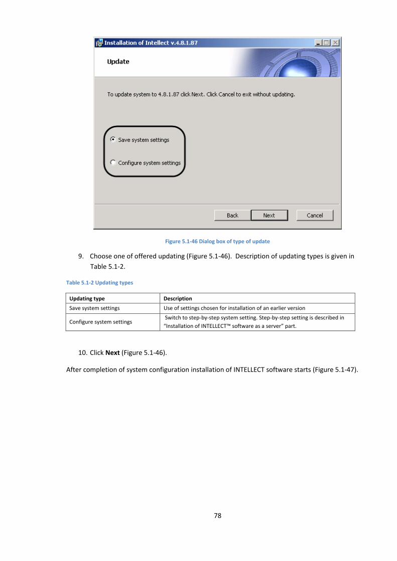
78
Figure 5.1-46 Dialog box of type of update
9. Choose one of offered updating (Figure 5.1-46). Description of updating types is given in
Table 5.1-2.
Table 5.1-2 Updating types
Updating type Description
Save system settings Use of settings chosen for installation of an earlier version
Configure system settings Switch to step-by-step system setting. Step-by-step setting is described in
“Installation of INTELLECT™ software as a server” part.
10. Click Next (Figure 5.1-46).
After completion of system configuration installation of INTELLECT software starts (Figure 5.1-47).
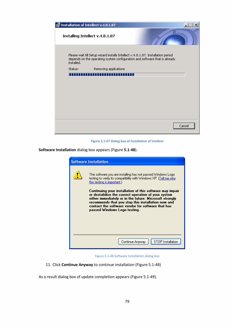
79
Figure 5.1-47 Dialog box of installation of Intellect
Software Installation dialog box appears (Figure 5.1-48).
Figure 5.1-48 Software Installation dialog box
11. Click Continue Anyway to continue installation (Figure 5.1-48)
As a result dialog box of update completion appears (Figure 5.1-49).
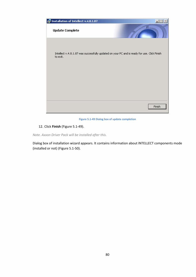
80
Figure 5.1-49 Dialog box of update completion
12. Click Finish (Figure 5.1-49).
Note. Axxon Driver Pack will be installed after this.
Dialog box of installation wizard appears. It contains information about INTELLECT components mode
(installed or not) (Figure 5.1-50).
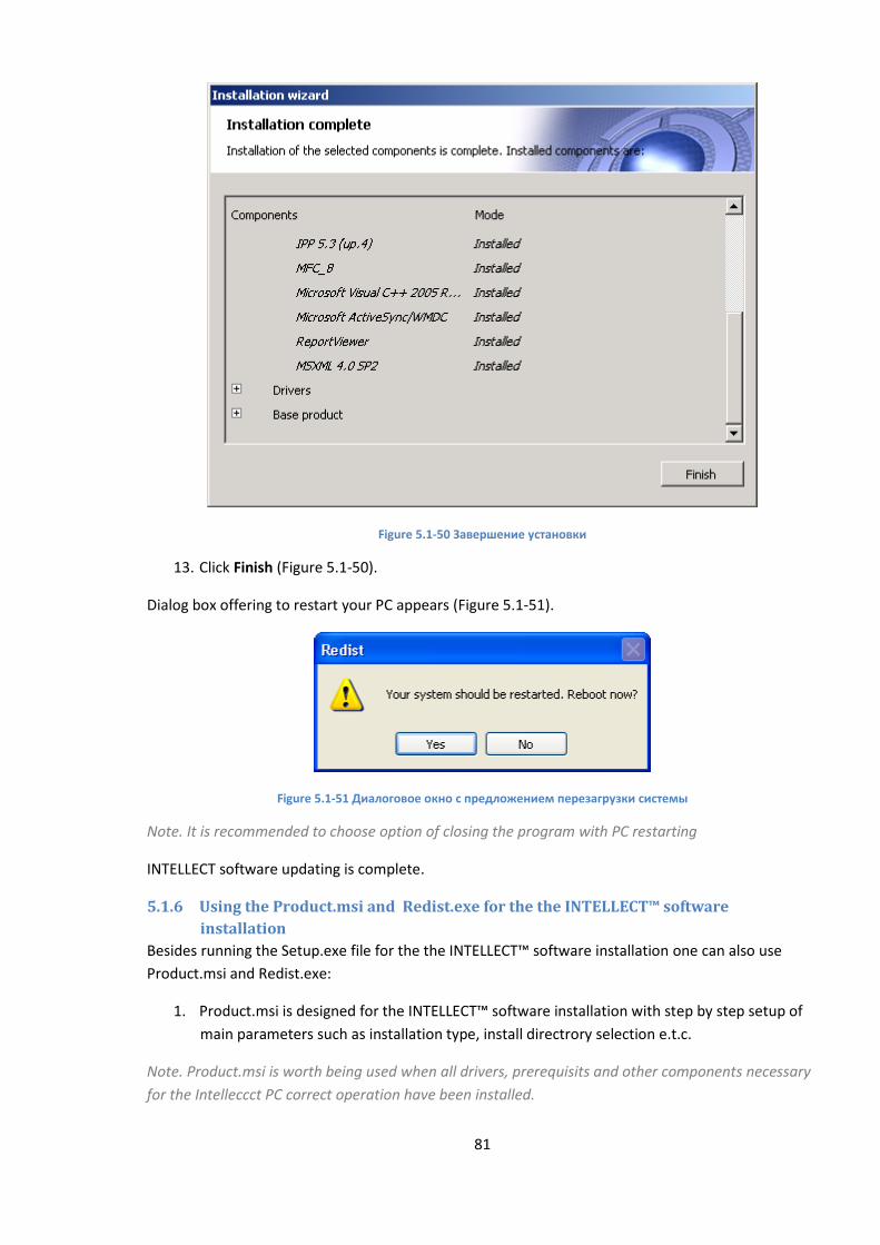
81
Figure 5.1-50 Завершение установки
13. Click Finish (Figure 5.1-50).
Dialog box offering to restart your PC appears (Figure 5.1-51).
Figure 5.1-51 Диалоговое окно с предложением перезагрузки системы
Note. It is recommended to choose option of closing the program with PC restarting
INTELLECT software updating is complete.
5.1.6 Using the Product.msi and Redist.exe for the the INTELLECT™ software
installation
Besides running the Setup.exe file for the the INTELLECT™ software installation one can also use
Product.msi and Redist.exe:
1. Product.msi is designed for the INTELLECT™ software installation with step by step setup of
main parameters such as installation type, install directrory selection e.t.c.
Note. Product.msi is worth being used when all drivers, prerequisits and other components necessary
for the Intelleccct PC correct operation have been installed.
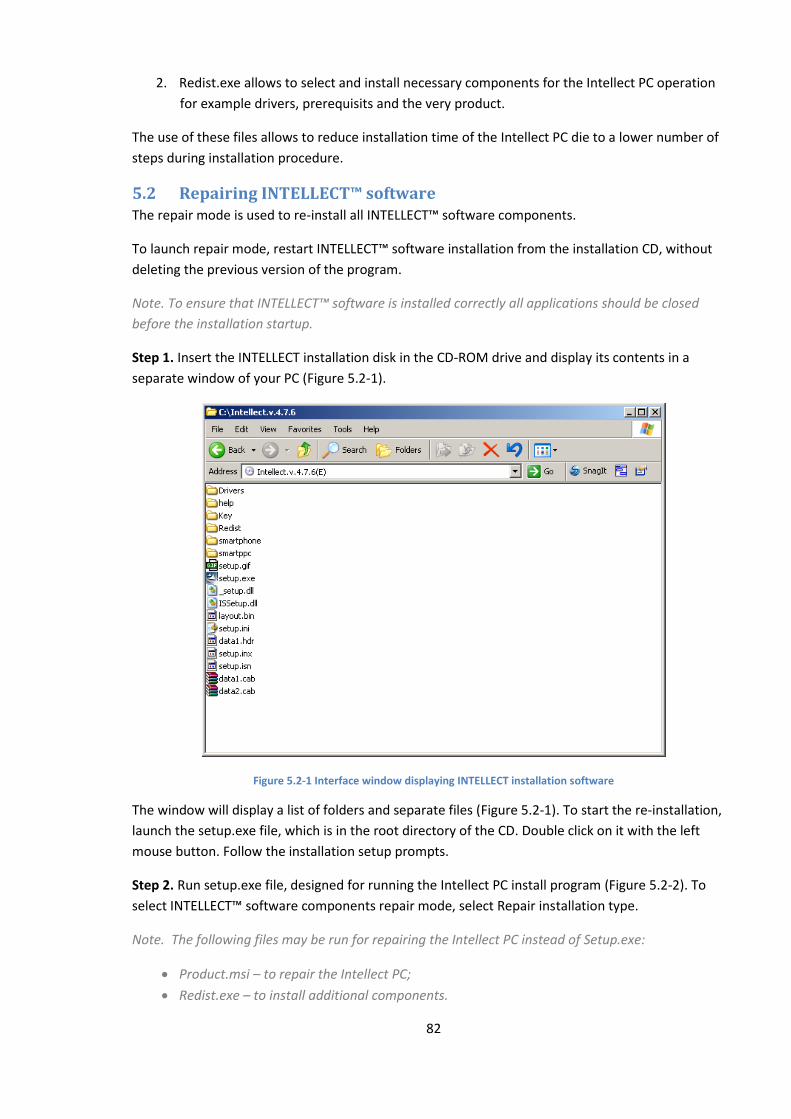
82
2. Redist.exe allows to select and install necessary components for the Intellect PC operation
for example drivers, prerequisits and the very product.
The use of these files allows to reduce installation time of the Intellect PC die to a lower number of
steps during installation procedure.
5.2 Repairing INTELLECT™ software The repair mode is used to re-install all INTELLECT™ software components.
To launch repair mode, restart INTELLECT™ software installation from the installation CD, without
deleting the previous version of the program.
Note. To ensure that INTELLECT™ software is installed correctly all applications should be closed
before the installation startup.
Step 1. Insert the INTELLECT installation disk in the CD-ROM drive and display its contents in a
separate window of your PC (Figure 5.2-1).
Figure 5.2-1 Interface window displaying INTELLECT installation software
The window will display a list of folders and separate files (Figure 5.2-1). To start the re-installation,
launch the setup.exe file, which is in the root directory of the CD. Double click on it with the left
mouse button. Follow the installation setup prompts.
Step 2. Run setup.exe file, designed for running the Intellect PC install program (Figure 5.2-2). To
select INTELLECT™ software components repair mode, select Repair installation type.
Note. The following files may be run for repairing the Intellect PC instead of Setup.exe:
Product.msi – to repair the Intellect PC;
Redist.exe – to install additional components.
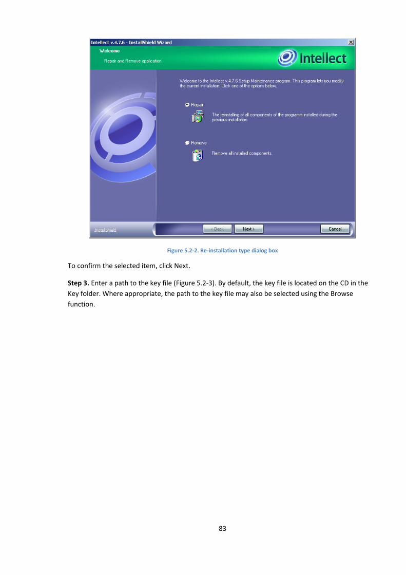
83
Figure 5.2-2. Re-installation type dialog box
To confirm the selected item, click Next.
Step 3. Enter a path to the key file (Figure 5.2-3). By default, the key file is located on the CD in the
Key folder. Where appropriate, the path to the key file may also be selected using the Browse
function.
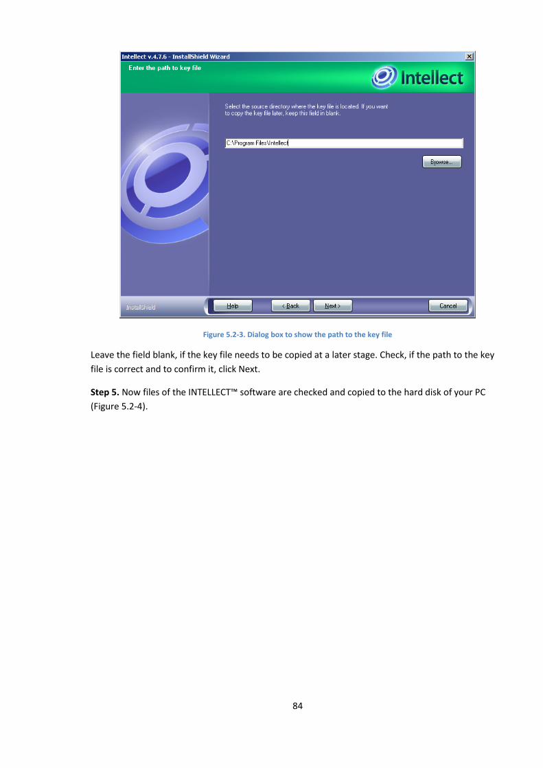
84
Figure 5.2-3. Dialog box to show the path to the key file
Leave the field blank, if the key file needs to be copied at a later stage. Check, if the path to the key
file is correct and to confirm it, click Next.
Step 5. Now files of the INTELLECT™ software are checked and copied to the hard disk of your PC
(Figure 5.2-4).
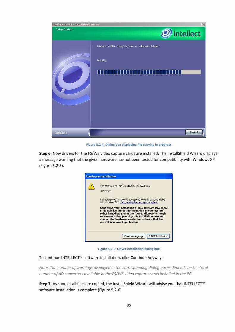
85
Figure 5.2-4. Dialog box displaying file copying in progress
Step 6. Now drivers for the FS/WS video capture cards are installed. The InstallShield Wizard displays
a message warning that the given hardware has not been tested for compatibility with Windows XP
(Figure 5.2-5).
Figure 5.2-5. Driver installation dialog box
To continue INTELLECT™ software installation, click Continue Anyway.
Note. The number of warnings displayed in the corresponding dialog boxes depends on the total
number of AD converters available in the FS/WS video capture cards installed in the PC.
Step 7. As soon as all files are copied, the InstallShield Wizard will advise you that INTELLECT™
software installation is complete (Figure 5.2-6).
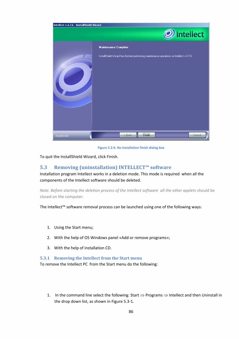
86
Figure 5.2-6. Re-installation finish dialog box
To quit the InstallShield Wizard, click Finish.
5.3 Removing (uninstallation) INTELLECT™ software Installation program Intellect works in a deletion mode. This mode is required when all the
components of the Intellect software should be deleted.
Note. Before starting the deletion process of the Intellect software all the other applets should be
closed on the computer.
The Intellect™ software removal process can be launched using one of the following ways:
1. Using the Start menu;
2. With the help of OS Windows panel «Add or remove programs»;
3. With the help of installation CD.
5.3.1 Removing the Intellect from the Start menu
To remove the Intellect PC from the Start menu do the following:
1. In the command line select the following: Start Programs Intellect and then Uninstall in
the drop down list, as shown in Figure 5.3-1.
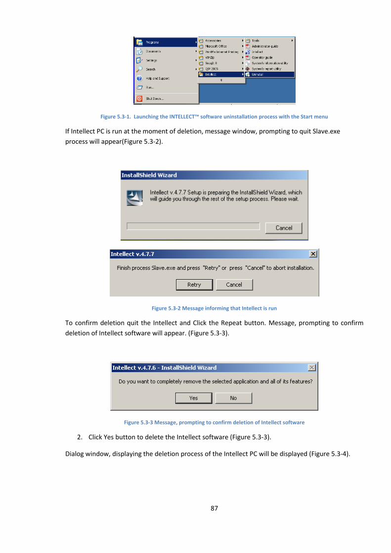
87
Figure 5.3-1. Launching the INTELLECT™ software uninstallation process with the Start menu
If Intellect PC is run at the moment of deletion, message window, prompting to quit Slave.exe
process will appear(Figure 5.3-2).
Figure 5.3-2 Message informing that Intellect is run
To confirm deletion quit the Intellect and Click the Repeat button. Message, prompting to confirm
deletion of Intellect software will appear. (Figure 5.3-3).
Figure 5.3-3 Message, prompting to confirm deletion of Intellect software
2. Click Yes button to delete the Intellect software (Figure 5.3-3).
Dialog window, displaying the deletion process of the Intellect PC will be displayed (Figure 5.3-4).
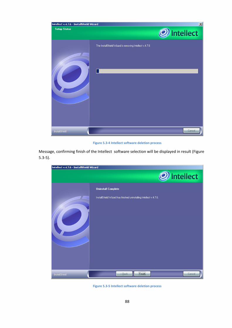
88
Figure 5.3-4 Intellect software deletion process
Message, confirming finish of the Intellect software selection will be displayed in result (Figure
5.3-5).
Figure 5.3-5 Intellect software deletion process
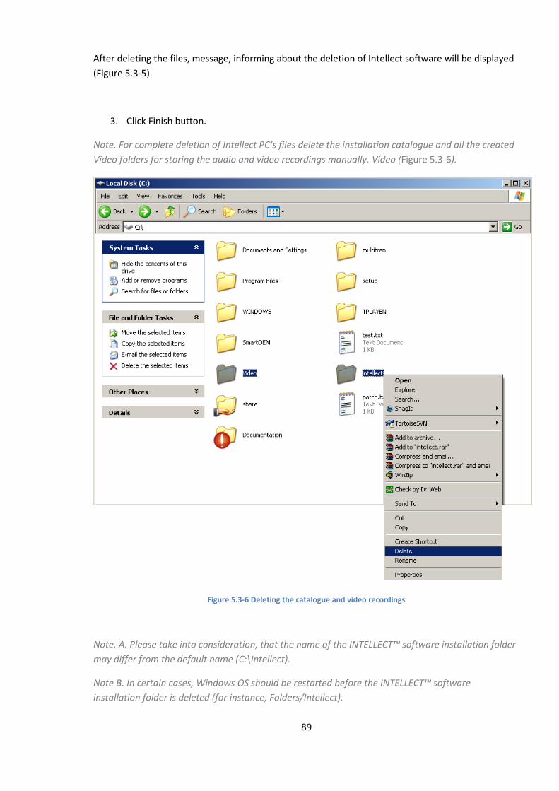
89
After deleting the files, message, informing about the deletion of Intellect software will be displayed
(Figure 5.3-5).
3. Click Finish button.
Note. For complete deletion of Intellect PC’s files delete the installation catalogue and all the created
Video folders for storing the audio and video recordings manually. Video (Figure 5.3-6).
Figure 5.3-6 Deleting the catalogue and video recordings
Note. А. Please take into consideration, that the name of the INTELLECT™ software installation folder
may differ from the default name (С:\Intellect).
Note B. In certain cases, Windows OS should be restarted before the INTELLECT™ software
installation folder is deleted (for instance, Folders/Intellect).
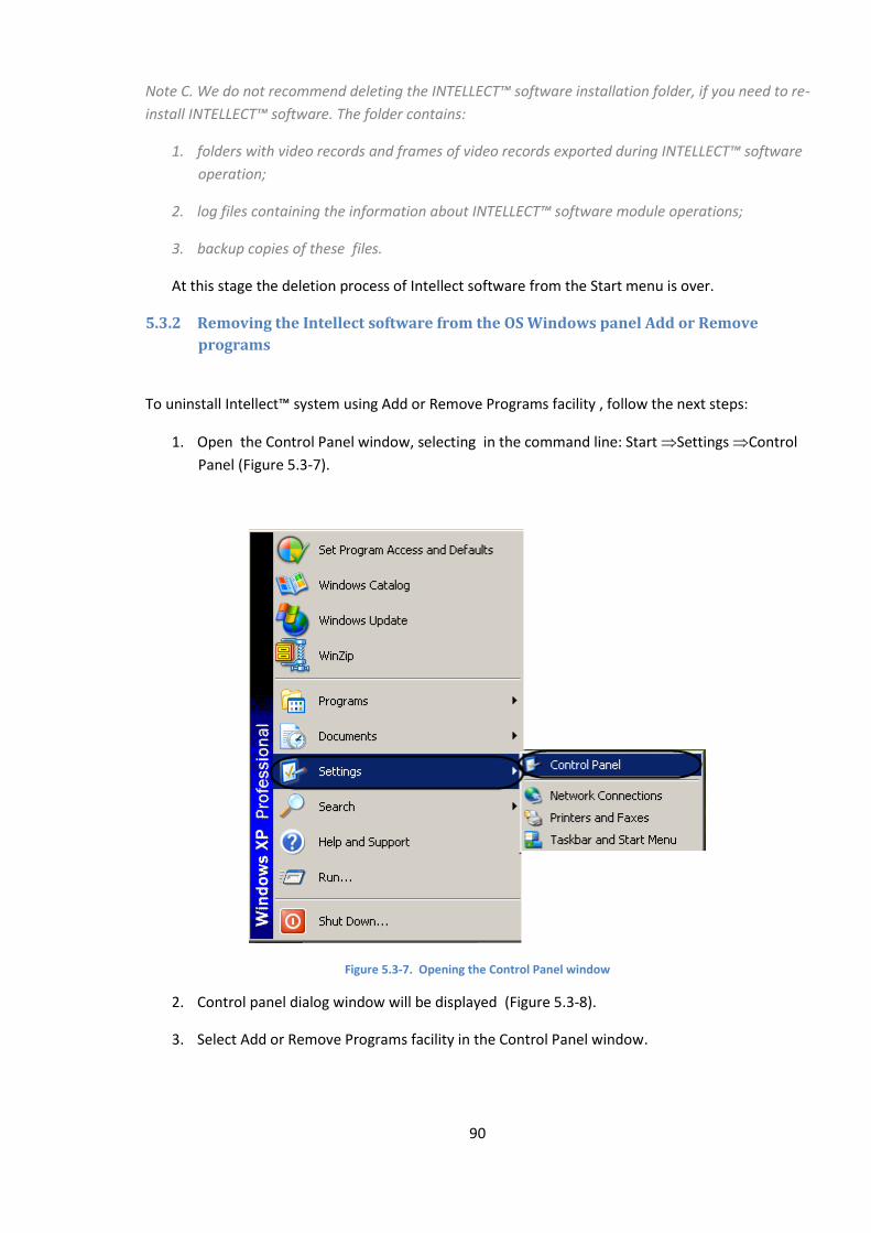
90
Note C. We do not recommend deleting the INTELLECT™ software installation folder, if you need to re-
install INTELLECT™ software. The folder contains:
1. folders with video records and frames of video records exported during INTELLECT™ software
operation;
2. log files containing the information about INTELLECT™ software module operations;
3. backup copies of these files.
At this stage the deletion process of Intellect software from the Start menu is over.
5.3.2 Removing the Intellect software from the OS Windows panel Add or Remove
programs
To uninstall Intellect™ system using Add or Remove Programs facility , follow the next steps:
1. Open the Control Panel window, selecting in the command line: Start Settings Control
Panel (Figure 5.3-7).
Figure 5.3-7. Opening the Control Panel window
2. Control panel dialog window will be displayed (Figure 5.3-8).
3. Select Add or Remove Programs facility in the Control Panel window.
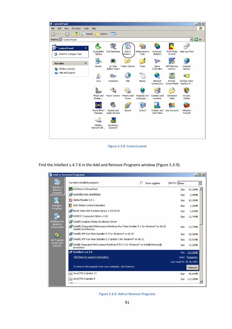
91
Figure 5.3-8. Control panel
Find the Intellect v.4.7.6 in the Add and Remove Programs window (Figure 5.3-9).
Figure 5.3-9. Add or Remove Programs
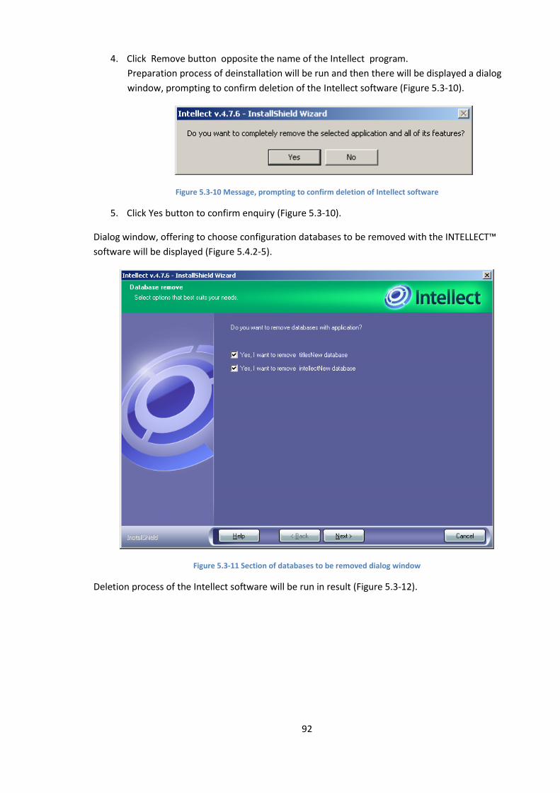
92
4. Click Remove button opposite the name of the Intellect program.
Preparation process of deinstallation will be run and then there will be displayed a dialog
window, prompting to confirm deletion of the Intellect software (Figure 5.3-10).
Figure 5.3-10 Message, prompting to confirm deletion of Intellect software
5. Click Yes button to confirm enquiry (Figure 5.3-10).
Dialog window, offering to choose configuration databases to be removed with the INTELLECT™
software will be displayed (Figure 5.4.2-5).
Figure 5.3-11 Section of databases to be removed dialog window
Deletion process of the Intellect software will be run in result (Figure 5.3-12).

93
Figure 5.3-12 Intellect software deletion process
Message, confirming finish of the Intellect software selection will be displayed in result(Figure
5.3-13).
Figure 5.3-13 Intellect software deletion process
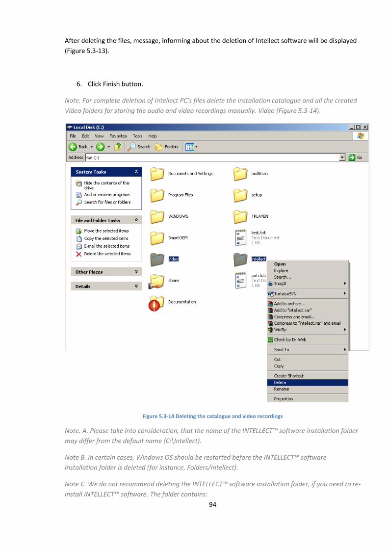
94
After deleting the files, message, informing about the deletion of Intellect software will be displayed
(Figure 5.3-13).
6. Click Finish button.
Note. For complete deletion of Intellect PC’s files delete the installation catalogue and all the created
Video folders for storing the audio and video recordings manually. Video (Figure 5.3-14).
Figure 5.3-14 Deleting the catalogue and video recordings
Note. А. Please take into consideration, that the name of the INTELLECT™ software installation folder
may differ from the default name (С:\Intellect).
Note B. In certain cases, Windows OS should be restarted before the INTELLECT™ software
installation folder is deleted (for instance, Folders/Intellect).
Note C. We do not recommend deleting the INTELLECT™ software installation folder, if you need to re-
install INTELLECT™ software. The folder contains:
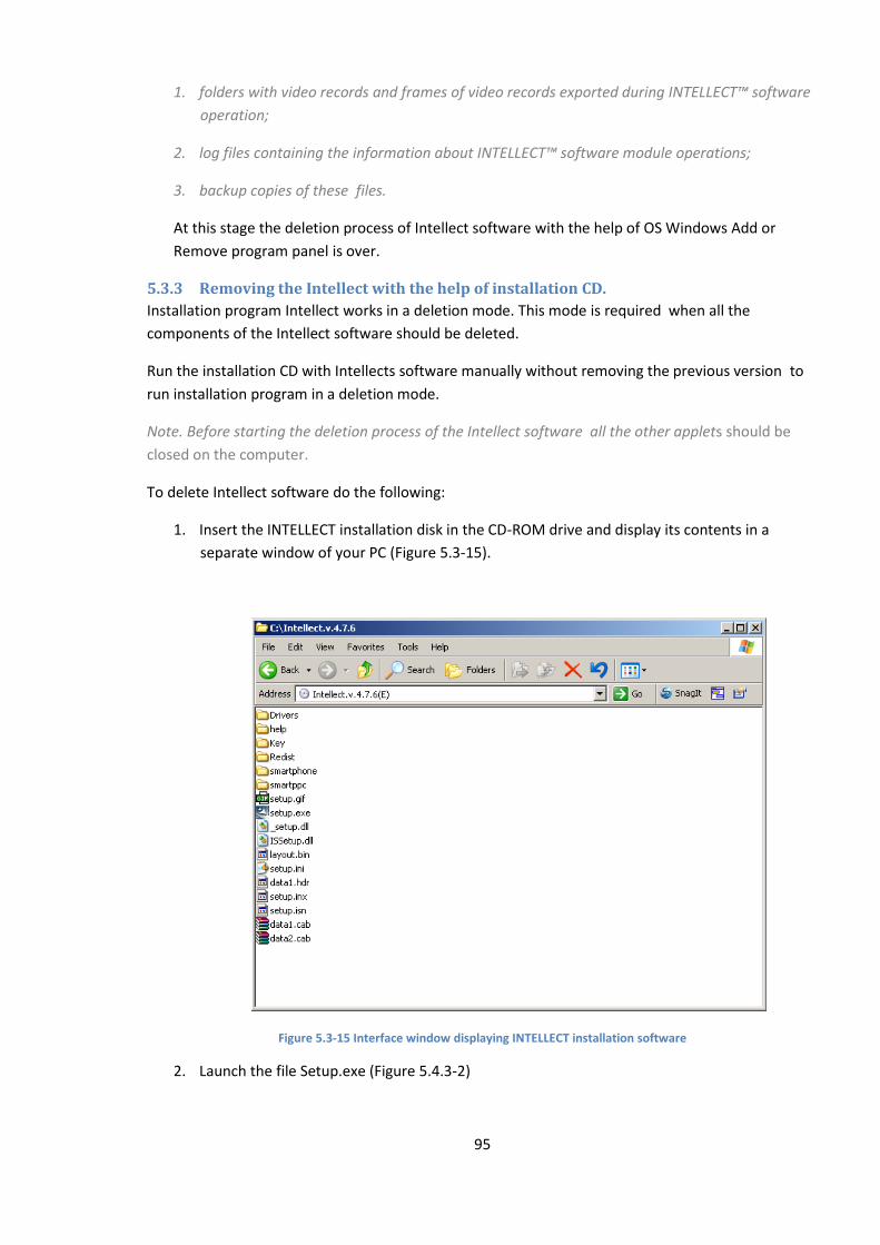
95
1. folders with video records and frames of video records exported during INTELLECT™ software
operation;
2. log files containing the information about INTELLECT™ software module operations;
3. backup copies of these files.
At this stage the deletion process of Intellect software with the help of OS Windows Add or
Remove program panel is over.
5.3.3 Removing the Intellect with the help of installation CD.
Installation program Intellect works in a deletion mode. This mode is required when all the
components of the Intellect software should be deleted.
Run the installation CD with Intellects software manually without removing the previous version to
run installation program in a deletion mode.
Note. Before starting the deletion process of the Intellect software all the other applets should be
closed on the computer.
To delete Intellect software do the following:
1. Insert the INTELLECT installation disk in the CD-ROM drive and display its contents in a
separate window of your PC (Figure 5.3-15).
Figure 5.3-15 Interface window displaying INTELLECT installation software
2. Launch the file Setup.exe (Figure 5.4.3-2)

96
Dialog window, prompting to select type of operations with Intellect PC will be displayed in result
(Figure 5.3-16).
Figure 5.3-16 Dialog box for Intellect™ program removal
3. Select the Remove option to delete the Intellect software (Figure 5.4.3-3).
4. Click Next (Figure 5.3-16).
Dialog window, prompting to confirm the deletion of Intellect software will be displayed in
result (Figure 5.3-17).
Figure 5.3-17 Dialog box of the uninstallation preparation stage
5. Click Yes button to confirm enquiry (Figure 5.3-17).
Dialog window, offering to choose configuration databases to be removed with the INTELLECT™
software will be displayed (Figure 5.3-18).

97
Figure 5.3-18 Dialog box for choosing the INTELLECT™ software removal option
Deletion process of the Intellect software will be run in result (Figure 5.3-19).
Figure 5.3-19 Intellect software deletion process
Message, confirming finish of the Intellect software selection will be displayed in result(Figure
5.3-20).
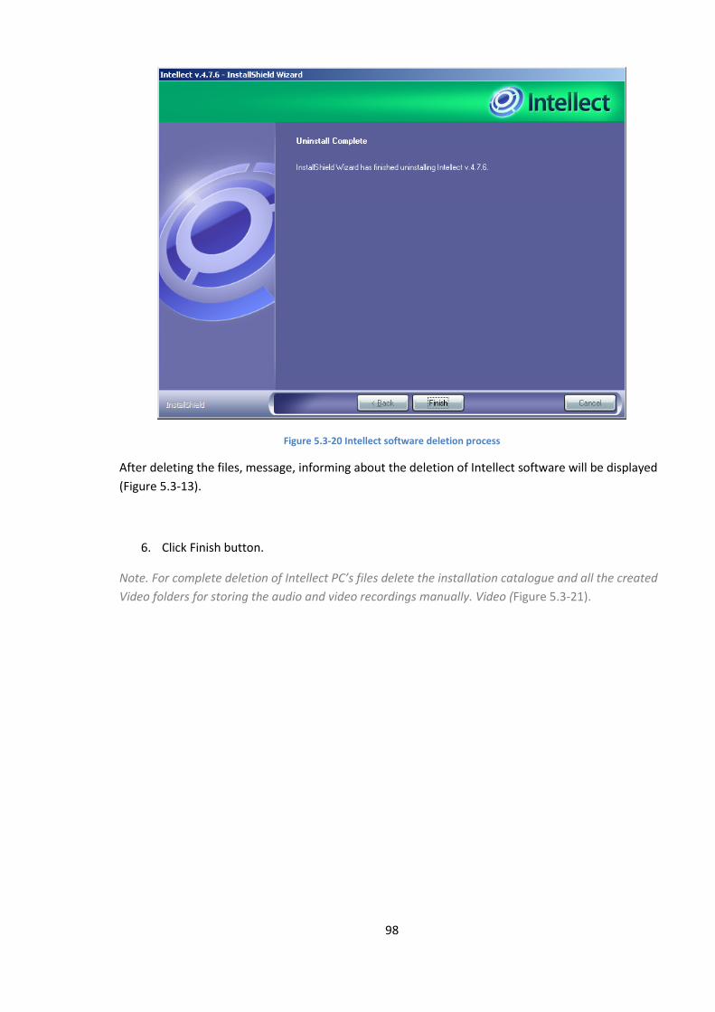
98
Figure 5.3-20 Intellect software deletion process
After deleting the files, message, informing about the deletion of Intellect software will be displayed
(Figure 5.3-13).
6. Click Finish button.
Note. For complete deletion of Intellect PC’s files delete the installation catalogue and all the created
Video folders for storing the audio and video recordings manually. Video (Figure 5.3-21).
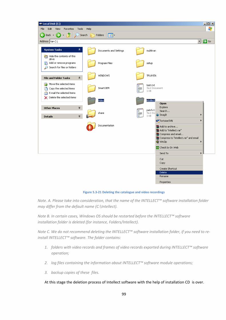
99
Figure 5.3-21 Deleting the catalogue and video recordings
Note. А. Please take into consideration, that the name of the INTELLECT™ software installation folder
may differ from the default name (С:\Intellect).
Note B. In certain cases, Windows OS should be restarted before the INTELLECT™ software
installation folder is deleted (for instance, Folders/Intellect).
Note C. We do not recommend deleting the INTELLECT™ software installation folder, if you need to re-
install INTELLECT™ software. The folder contains:
1. folders with video records and frames of video records exported during INTELLECT™ software
operation;
2. log files containing the information about INTELLECT™ software module operations;
3. backup copies of these files.
At this stage the deletion process of Intellect software with the help of installation CD is over.

100
5.3.4 Removing the Intellect PC, installed as a Service
To remove Intellect software , installed as a Service, do the following:
1. Insert the INTELLECT installation CD in the CD-ROM drive and display its contents in a
separate window of your PC.
2. Launch setup.exe. Preparation window to run the installshield wizard will appear in result
(Figure 5.4.4-1).
Figure 5.3-22 Preparation window to run the InstallShield Wizard
When Intellect PC works, it will be automatically logged off (Figure 5.3-23).
Figure 5.3-23 System’s shutdown
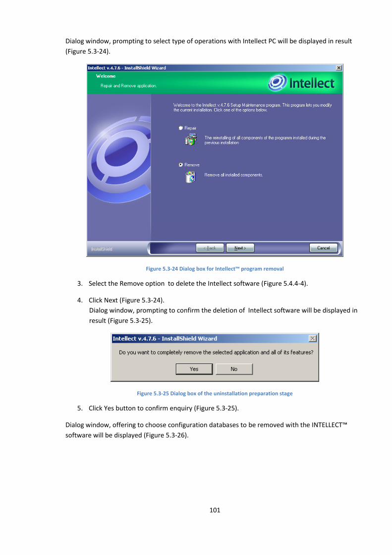
101
Dialog window, prompting to select type of operations with Intellect PC will be displayed in result
(Figure 5.3-24).
Figure 5.3-24 Dialog box for Intellect™ program removal
3. Select the Remove option to delete the Intellect software (Figure 5.4.4-4).
4. Click Next (Figure 5.3-24).
Dialog window, prompting to confirm the deletion of Intellect software will be displayed in
result (Figure 5.3-25).
Figure 5.3-25 Dialog box of the uninstallation preparation stage
5. Click Yes button to confirm enquiry (Figure 5.3-25).
Dialog window, offering to choose configuration databases to be removed with the INTELLECT™
software will be displayed (Figure 5.3-26).
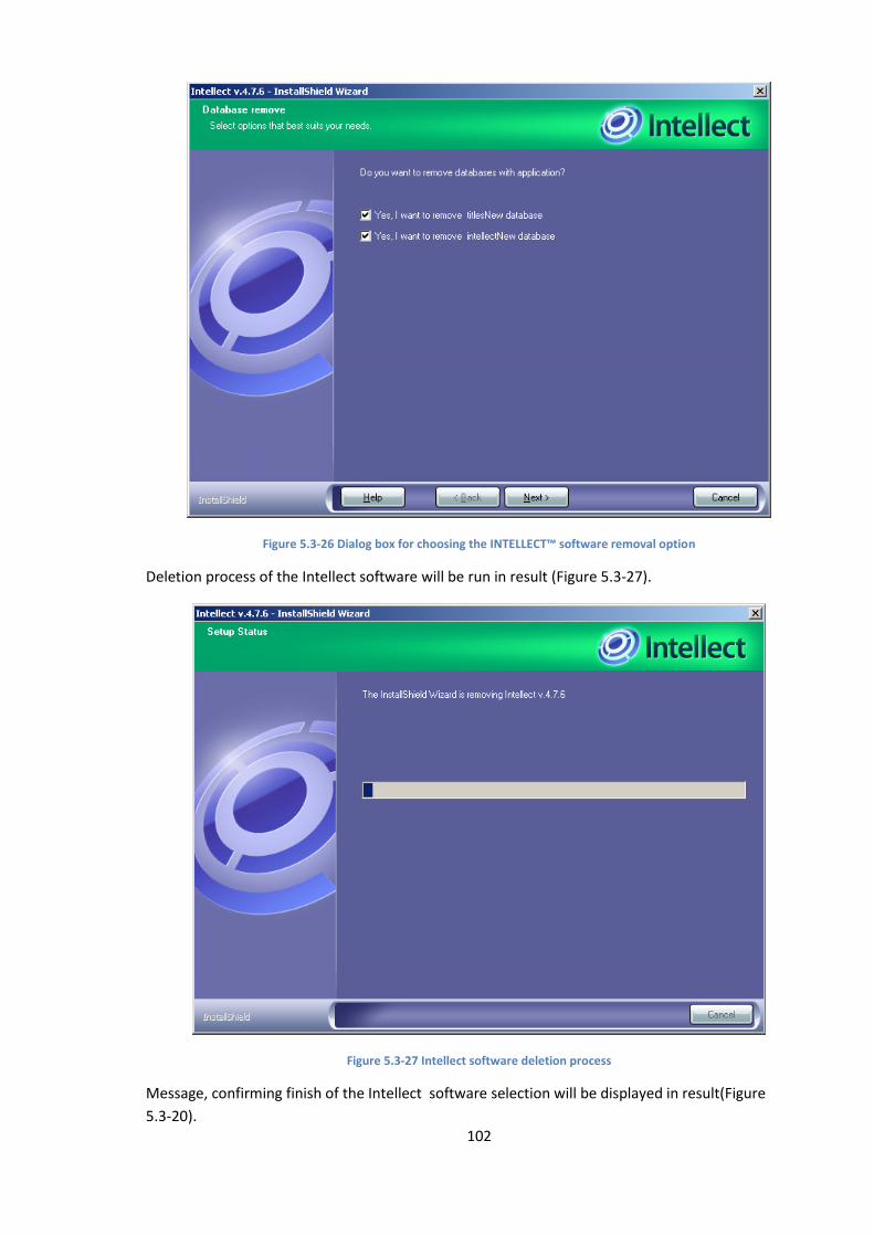
102
Figure 5.3-26 Dialog box for choosing the INTELLECT™ software removal option
Deletion process of the Intellect software will be run in result (Figure 5.3-27).
Figure 5.3-27 Intellect software deletion process
Message, confirming finish of the Intellect software selection will be displayed in result(Figure
5.3-20).
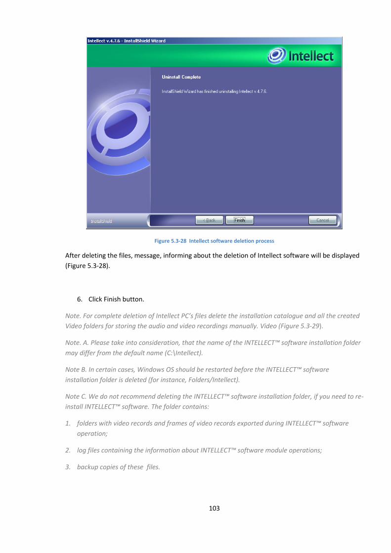
103
Figure 5.3-28 Intellect software deletion process
After deleting the files, message, informing about the deletion of Intellect software will be displayed
(Figure 5.3-28).
6. Click Finish button.
Note. For complete deletion of Intellect PC’s files delete the installation catalogue and all the created
Video folders for storing the audio and video recordings manually. Video (Figure 5.3-29).
Note. А. Please take into consideration, that the name of the INTELLECT™ software installation folder
may differ from the default name (С:\Intellect).
Note B. In certain cases, Windows OS should be restarted before the INTELLECT™ software
installation folder is deleted (for instance, Folders/Intellect).
Note C. We do not recommend deleting the INTELLECT™ software installation folder, if you need to re-
install INTELLECT™ software. The folder contains:
1. folders with video records and frames of video records exported during INTELLECT™ software
operation;
2. log files containing the information about INTELLECT™ software module operations;
3. backup copies of these files.
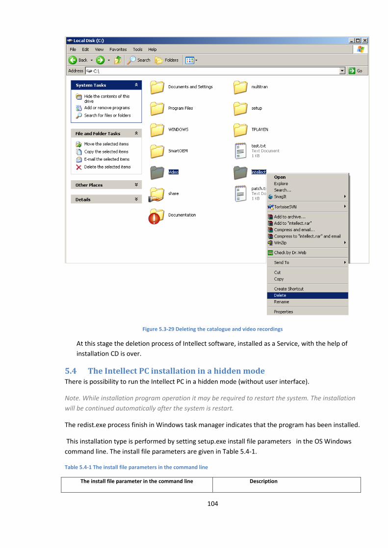
104
Figure 5.3-29 Deleting the catalogue and video recordings
At this stage the deletion process of Intellect software, installed as a Service, with the help of
installation CD is over.
5.4 The Intellect PC installation in a hidden mode There is possibility to run the Intellect PC in a hidden mode (without user interface).
Note. While installation program operation it may be required to restart the system. The installation
will be continued automatically after the system is restart.
The redist.exe process finish in Windows task manager indicates that the program has been installed.
This installation type is performed by setting setup.exe install file parameters in the OS Windows
command line. The install file parameters are given in Table 5.4-1.
Table 5.4-1 The install file parameters in the command line
The install file parameter in the command line Description
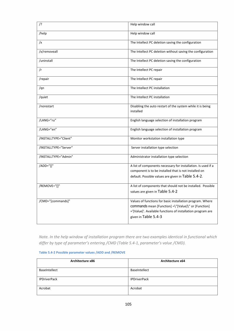
105
/? Help window call
/help Help window call
/x The Intellect PC deletion saving the configuration
/x/removeall The Intellect PC deletion without saving the configuration
/uninstall The Intellect PC deletion saving the configuration
/r The Intellect PC repair
/repair The Intellect PC repair
/qn The Intellect PC installation
/quiet The Intellect PC installation
/norestart Disabling the auto restart of the system while it is being
installed
/LANG=”ru” English language selection of installation program
/LANG=”en” English language selection of installation program
/INSTALLTYPE="Client" Monitor workstation installation type
/INSTALLTYPE="Server" Server installation type selection
/INSTALLTYPE="Admin" Administrator installation type selection
/ADD="[]" A list of components necessary for installation. Is used if a
component is to be installed that is not installed on
default. Possible values are given in Table 5.4-2.
/REMOVE="[]" A list of components that should not be installed. Possible
values are given in Table 5.4-2
/CMD="[commands]" Values of functions for basic installation program. Where
commands mean [Function] =\"[Value]\" or [Function]
='[Value]'. Available functions of installation program are
given in Table 5.4-3
Note. In the help window of installation program there are two examples identical in functional which
differ by type of parameter’s entering /CMD (Table 5.4-1, parameter’s value /CMD).
Table 5.4-2 Possible parameter values /ADD and /REMOVE
Architecture x86 Architecture x64
BaseIntellect BaseIntellect
IPDriverPack IPDriverPack
Acrobat Acrobat
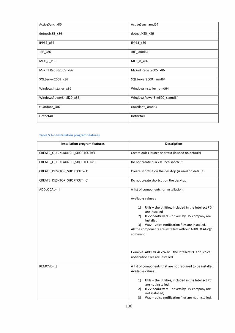
106
ActiveSync_x86 ActiveSync_amd64
dotnetfx35_x86 dotnetfx35_x86
IPP53_x86 IPP53_x86
JRE_x86 JRE_ amd64
MFC_8_x86 MFC_8_x86
MsXml Redist2005_x86 MsXml Redist2005_x86
SQLServer2008_x86 SQLServer2008_ amd64
WindowsInstaller_x86 WindowsInstaller_ amd64
WindowsPowerShell20_x86 WindowsPowerShell20_x amd64
Guardant_x86 Guardant_ amd64
Dotnet40 Dotnet40
Table 5.4-3 Installation program features
Installation program features Description
CREATE_QUICKLAUNCH_SHORTCUT='1' Create quick launch shortcut (is used on default)
CREATE_QUICKLAUNCH_SHORTCUT='0' Do not create quick launch shortcut
CREATE_DESKTOP_SHORTCUT='1' Create shortcut on the desktop (is used on default)
CREATE_DESKTOP_SHORTCUT='0' Do not create shortcut on the desktop
ADDLOCAL='[]' A list of components for installation.
Available values :
1) Utils – the utilities, included in the Intellect PC< are installed
2) ITVVideoDrivers – drivers by ITV company are installed;
3) Wav – voice notification files are installed. All the components are installed without ADDLOCAL='[]'
command.
Example. ADDLOCAL='Wav' –the Intellect PC and voice
notification files are installed.
REMOVE='[]' A list of components that are not required to be installed.
Available values:
1) Utils – the utilities, included in the Intellect PC are not installed;
2) ITVVideoDrivers – drivers by ITV company are not installed;
3) Wav – voice notification files are not installed.
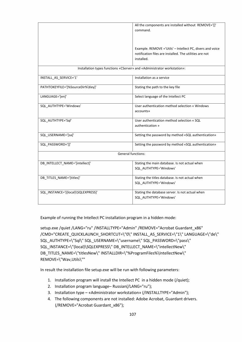
107
All the components are installed without REMOVE='[]'
command.
Example. REMOVE ='Utils' – Intellect PC, divers and voice
notification files are installed. The utilities are not
installed.
Installation types functions «СServer» and «Administrator workstation»:
INSTALL_AS_SERVICE='1' Installation as a service
PATHTOKEYFILE='[%SourceDir%\Key]' Stating the path to the key file
LANGUAGE='[en]' Select language of the Intellect PC
SQL_AUTHTYPE='Windows' User authentication method selection « Windows
accounts»
SQL_AUTHTYPE='Sql' User authentication method selection « SQL
authentication »
SQL_USERNAME='[sa]' Setting the password by method «SQL authentication»
SQL_PASSWORD='[]' Setting the password by method «SQL authentication»
General functions:
DB_INTELLECT_NAME='[intellect]' Stating the main database. Is not actual when
SQL_AUTHTYPE='Windows'
DB_TITLES_NAME='[titles]' Stating the titles database. Is not actual when
SQL_AUTHTYPE='Windows'
SQL_INSTANCE='[(local)\SQLEXPRESS]' Stating the database server. Is not actual when
SQL_AUTHTYPE='Windows'
Example of running the Intellect PC installation program in a hidden mode:
setup.exe /quiet /LANG="ru" /INSTALLTYPE="Admin" /REMOVE="Acrobat Guardant_x86"
/CMD="CREATE_QUICKLAUNCH_SHORTCUT=\"0\" INSTALL_AS_SERVICE=\"1\" LANGUAGE=\"de\"
SQL_AUTHTYPE=\"Sql\" SQL_USERNAME=\"username\" SQL_PASSWORD=\"pass\"
SQL_INSTANCE=\"(local)\SQLEXPRESS\" DB_INTELLECT_NAME=\"intellectNew\"
DB_TITLES_NAME=\"titlesNew\" INSTALLDIR=\"%ProgramFiles%\IntellectNew\"
REMOVE=\"Wav,Utils\""
In result the installation file setup.exe will be run with following parameters:
1. Installation program will install the Intellect PC in a hidden mode (/quiet);
2. Installation program language– Russian(/LANG="ru");
3. Installation type – «Administrator workstation» (/INSTALLTYPE="Admin");
4. The following components are not installed: Adobe Acrobat, Guardant drivers.
(/REMOVE="Acrobat Guardant_x86");
108
5. Installation is performed with following features (/CMD=):
5.1 Without creating the quick launch shortcut
(="CREATE_QUICKLAUNCH_SHORTCUT=\"0\");
5.2 The Intellect PC is installed as a service (INSTALL_AS_SERVICE=\"1\");
5.3 Language of installed Intellect PC is German (LANGUAGE=\"de\");
5.4 Authentication method – «SQL authentication » (SQL_AUTHTYPE=\"Sql\");
5.5 Login – username (SQL_USERNAME=\"username\");
5.6 Password – pass (SQL_PASSWORD=\"pass\");
5.7 Database server – (local)\SQLEXPRESS (SQL_INSTANCE=\"(local)\SQLEXPRESS\");
5.8 Main database– intellectNew (DB_INTELLECT_NAME=\"intellectNew\");
5.9 Titles database – titlesNew (DB_TITLES_NAME=\"titlesNew\");
5.10 Installation path - %ProgramFiles%\IntellectNew
(INSTALLDIR=\"%ProgramFiles%\IntellectNew\");
5.11 Utilities and voice notification files are not installed (REMOVE=\"Wav,Utils\").
5.5 Setting up Cluster Service for Intellect server
5.5.1 General requirements
Cluster is a group of independent computers operating together as a whole system providing clients
with a general set of services. Cluster enables to expand both services’ accessibility , scalability and
controllability of its OS.
To set up a cluster fot the Intellect PC stick to the following rules:
1. The Intellect PC should be installed on all the computers, forming the cluster;
2. The Intellect PC configuration (paths to the installed Intellect PC and video archive discs) should
be identical on all the computer;
3. All the computers, forming the cluster, should be defined in one network domain;
4. All the computers should operate under control of OS Windows Server 2003 R2 Enterprise
Edition.
5.5.2 Cluster’s organization and setting up order
Cluster’s organization and setting up is done in the following order:
1. Create and set the net among the computers, that would form a cluster. Computers should be
defined in one domain. The cluster should also be registered in this domain.
Note. Nets organization and setting up order is given in reference manual Windows Server 2003 R2
Enterprise Edition (см. http://technet.microsoft.com/ru-ru/library/cc527503(WS.10).aspx).
2. Install the Intellect PC on all the computers, forming the cluster (in the process paths to the
installed Intellect PC and video archive discs on all the computers should be identical). Otherwise
if one of the units is damaged, monitoring service of cluster’s processes will not be able to run
the Intellect PC on the other node.
3. Configure one of the computers, forming the cluster , with the help of «Cluster Administrator»,
utility that is included in OS Windows Server 2003 R2 Enterprise Edition in the following way:
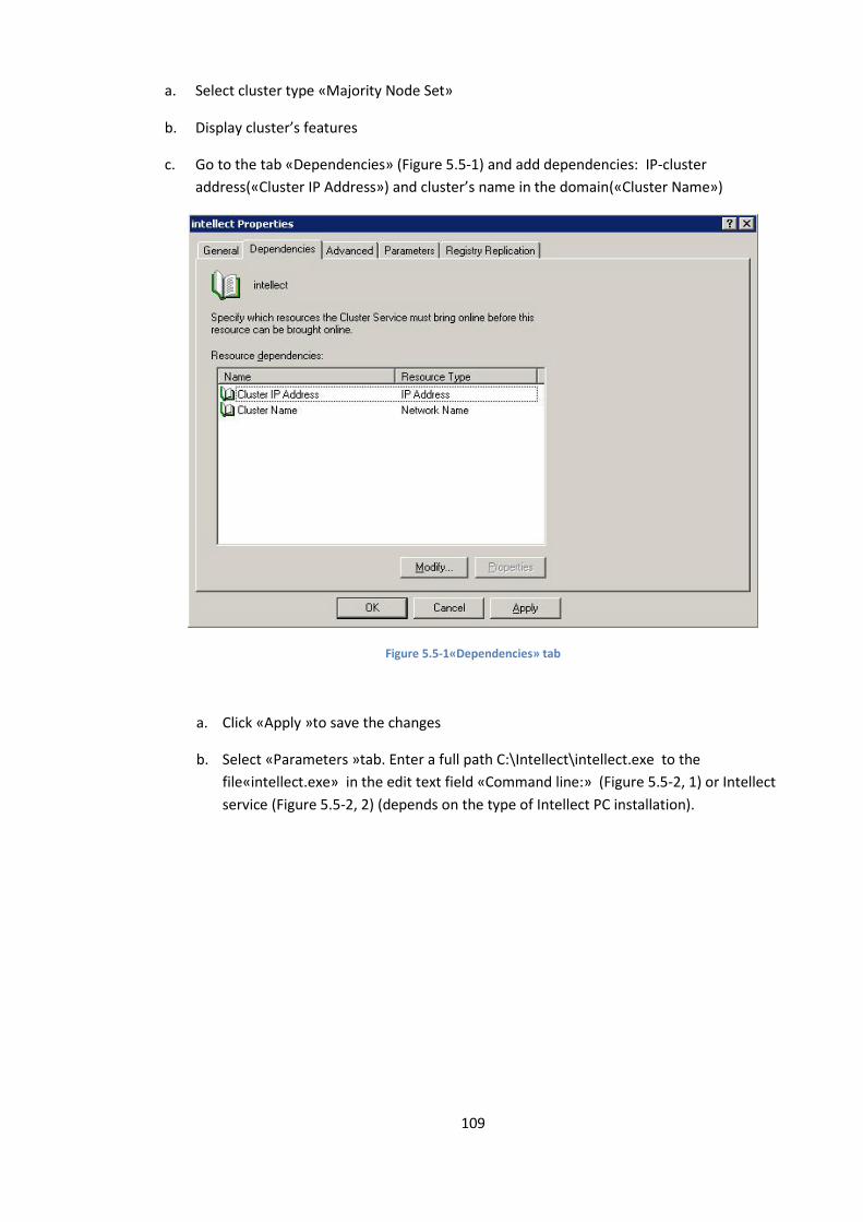
109
a. Select cluster type «Majority Node Set»
b. Display cluster’s features
c. Go to the tab «Dependencies» (Figure 5.5-1) and add dependencies: IP-cluster
address(«Cluster IP Address») and cluster’s name in the domain(«Cluster Name»)
Figure 5.5-1«Dependencies» tab
a. Click «Apply »to save the changes
b. Select «Parameters »tab. Enter a full path C:\Intellect\intellect.exe to the
file«intellect.exe» in the edit text field «Command line:» (Figure 5.5-2, 1) or Intellect
service (Figure 5.5-2, 2) (depends on the type of Intellect PC installation).
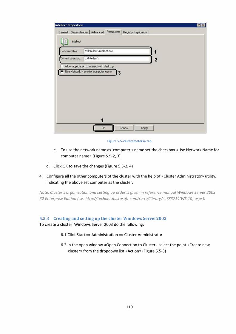
110
Figure 5.5-2«Parameters» tab
c. To use the network name as computer’s name set the checkbox «Use Network Name for
computer name» (Figure 5.5-2, 3)
d. Click OK to save the changes (Figure 5.5-2, 4)
4. Configure all the other computers of the cluster with the help of «Cluster Administrator» utility,
indicating the above set computer as the cluster.
Note. Cluster’s organization and setting up order is given in reference manual Windows Server 2003
R2 Enterprise Edition (см. http://technet.microsoft.com/ru-ru/library/cc783714(WS.10).aspx).
5.5.3 Creating and setting up the cluster Windows Server2003
To create a cluster Windows Server 2003 do the following:
6.1. Click Start Administration Cluster Administrator
6.2. In the open window «Open Connection to Cluster» select the point «Create new
cluster» from the dropdown list «Action» (Figure 5.5-3)
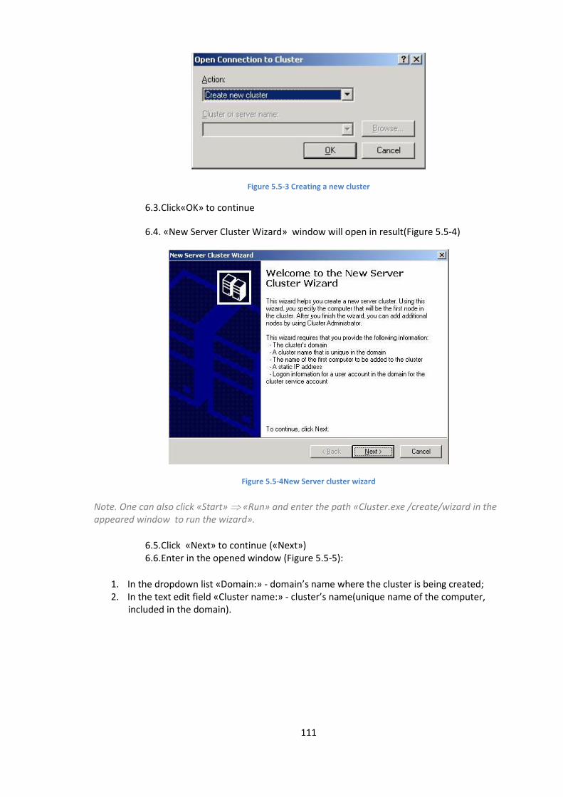
111
Figure 5.5-3 Creating a new cluster
6.3. Click«OK» to continue
6.4. «New Server Cluster Wizard» window will open in result(Figure 5.5-4)
Figure 5.5-4New Server cluster wizard
Note. One can also click «Start» «Run» and enter the path «Cluster.exe /create/wizard in the appeared window to run the wizard».
6.5. Click «Next» to continue («Next») 6.6. Enter in the opened window (Figure 5.5-5):
1. In the dropdown list «Domain:» - domain’s name where the cluster is being created; 2. In the text edit field «Cluster name:» - cluster’s name(unique name of the computer,
included in the domain).
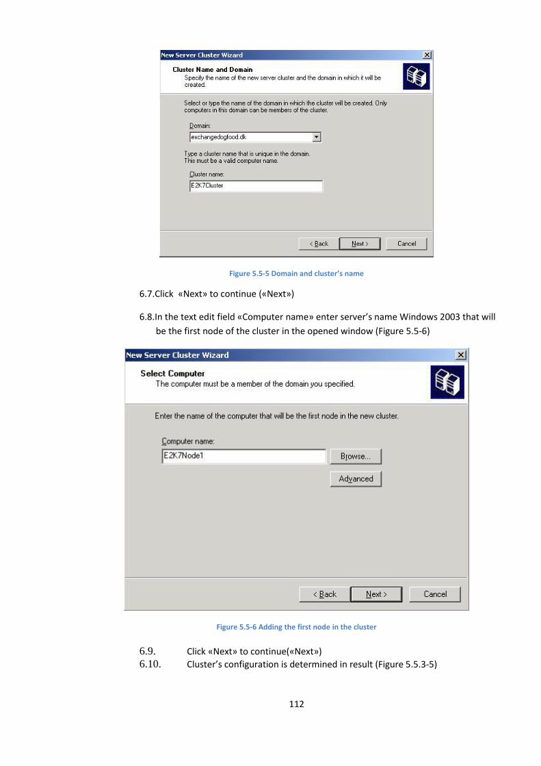
112
Figure 5.5-5 Domain and cluster’s name
6.7. Click «Next» to continue («Next»)
6.8. In the text edit field «Computer name» enter server’s name Windows 2003 that will
be the first node of the cluster in the opened window (Figure 5.5-6)
Figure 5.5-6 Adding the first node in the cluster
6.9. Click «Next» to continue(«Next»)
6.10. Cluster’s configuration is determined in result (Figure 5.5.3-5)

113
Figure 5.5-7 Analysis of cluster’s configuration
Note. Do not pay attention to two notices (Figure 5.5-7, 1),as cluster’s nodes of mail server with constant cluster replication will not use the same disc subsystem.
6.11. When the wizard has configured the cluster, click «Next» («Next»)
6.12. The window will open in result (Figure 5.5-8), whre IP address should be entered in the edit text field «IP Address:» IP sddress, that cluster management tools will use to connect to the cluster.
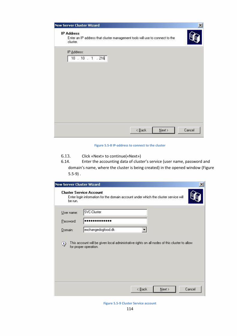
114
Figure 5.5-8 IP-address to connect to the cluster
6.13. Click «Next» to continue(«Next») 6.14. Enter the accounting data of cluster’s service (user name, password and
domain’s name, where the cluster is being created) in the opened window (Figure
5.5-9) .
Figure 5.5-9 Cluster Service account
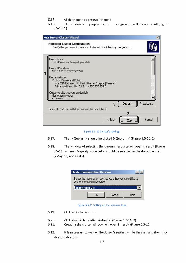
115
6.15. Click «Next» to continue(«Next»)
6.16. The window with proposed cluster configuration will open in result (Figure 5.5-10, 1).
Figure 5.5-10 Cluster’s settings
6.17. Then «Quorum» should be clicked («Quorum») (Figure 5.5-10, 2)
6.18. The window of selecting the quorum resource will open in result (Figure
5.5-11), where «Majority Node Set» should be selected in the dropdown list
(«Majority node set»)
Figure 5.5-11 Setting up the resource type
6.19. Click «OK» to confirm
6.20. Click «Next» to continue(«Next») (Figure 5.5-10, 3) 6.21. Creating the cluster window will open in result (Figure 5.5-12).
6.22. It is necessary to wait while cluster’s setting will be finished and then click
«Next» («Next»).
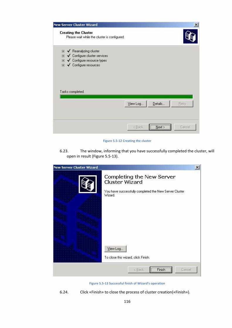
116
Figure 5.5-12 Creating the cluster
6.23. The window, informing that you have successfully completed the cluster, will open in result (Figure 5.5-13).
Figure 5.5-13 Successful finish of Wizard’s operation
6.24. Click «Finish» to close the process of cluster creation(«Finish»).
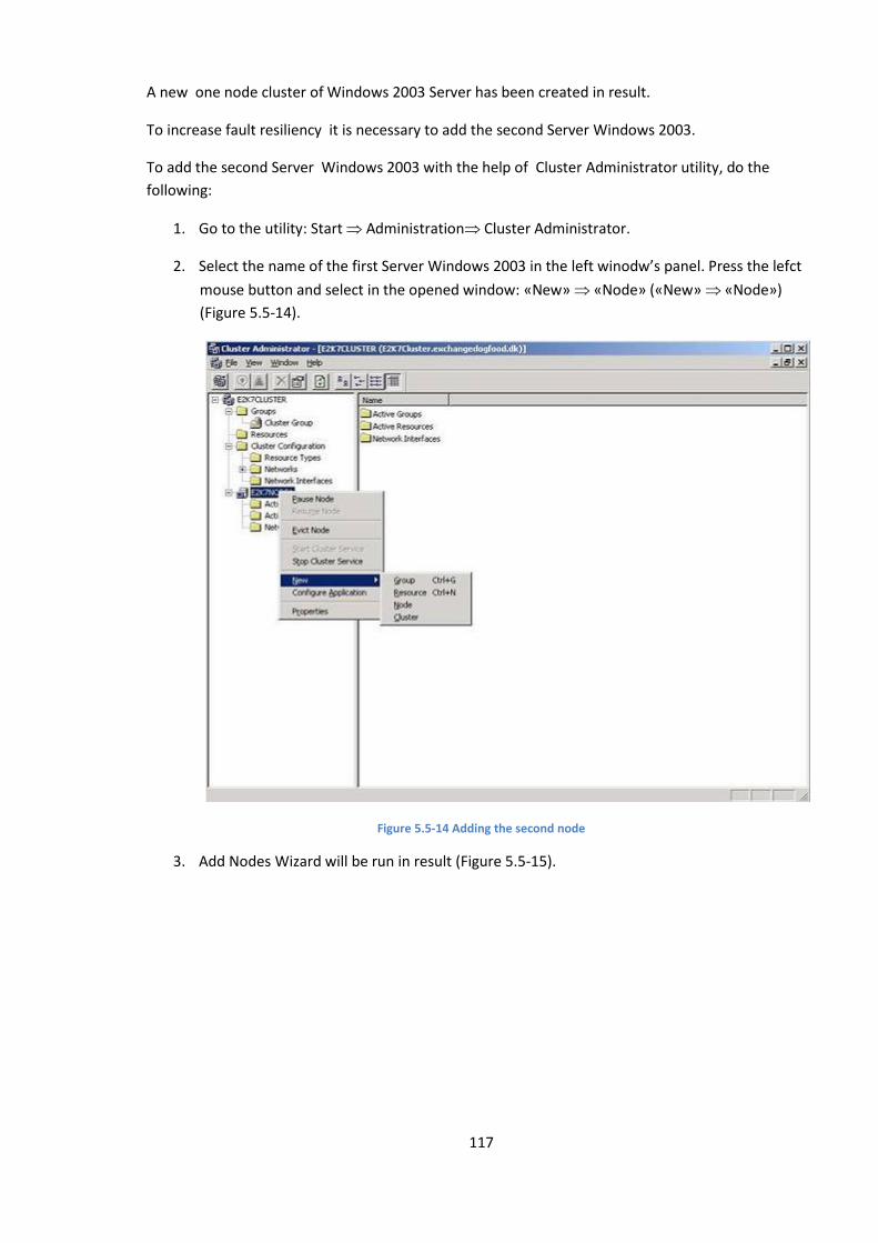
117
A new one node cluster of Windows 2003 Server has been created in result.
To increase fault resiliency it is necessary to add the second Server Windows 2003.
To add the second Server Windows 2003 with the help of Cluster Administrator utility, do the
following:
1. Go to the utility: Start Administration Cluster Administrator.
2. Select the name of the first Server Windows 2003 in the left winodw’s panel. Press the lefct
mouse button and select in the opened window: «New» «Node» («New» «Node»)
(Figure 5.5-14).
Figure 5.5-14 Adding the second node
3. Add Nodes Wizard will be run in result (Figure 5.5-15).
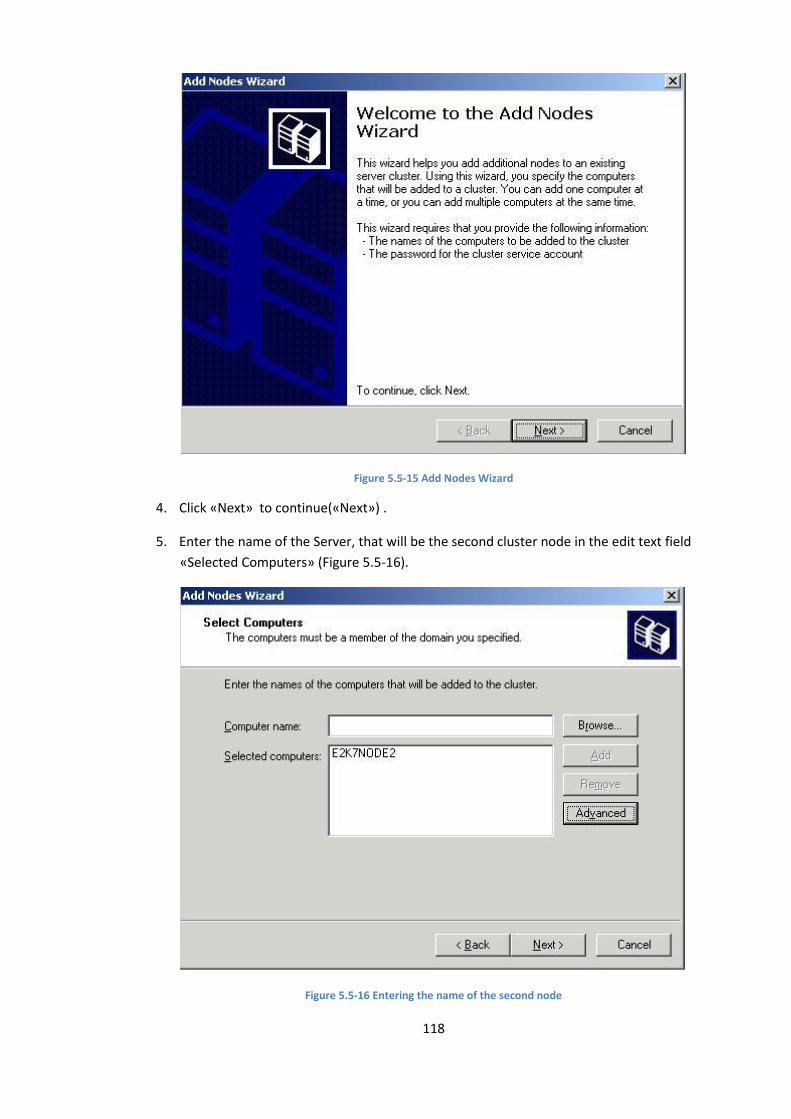
118
Figure 5.5-15 Add Nodes Wizard
4. Click «Next» to continue(«Next») .
5. Enter the name of the Server, that will be the second cluster node in the edit text field
«Selected Computers» (Figure 5.5-16).
Figure 5.5-16 Entering the name of the second node
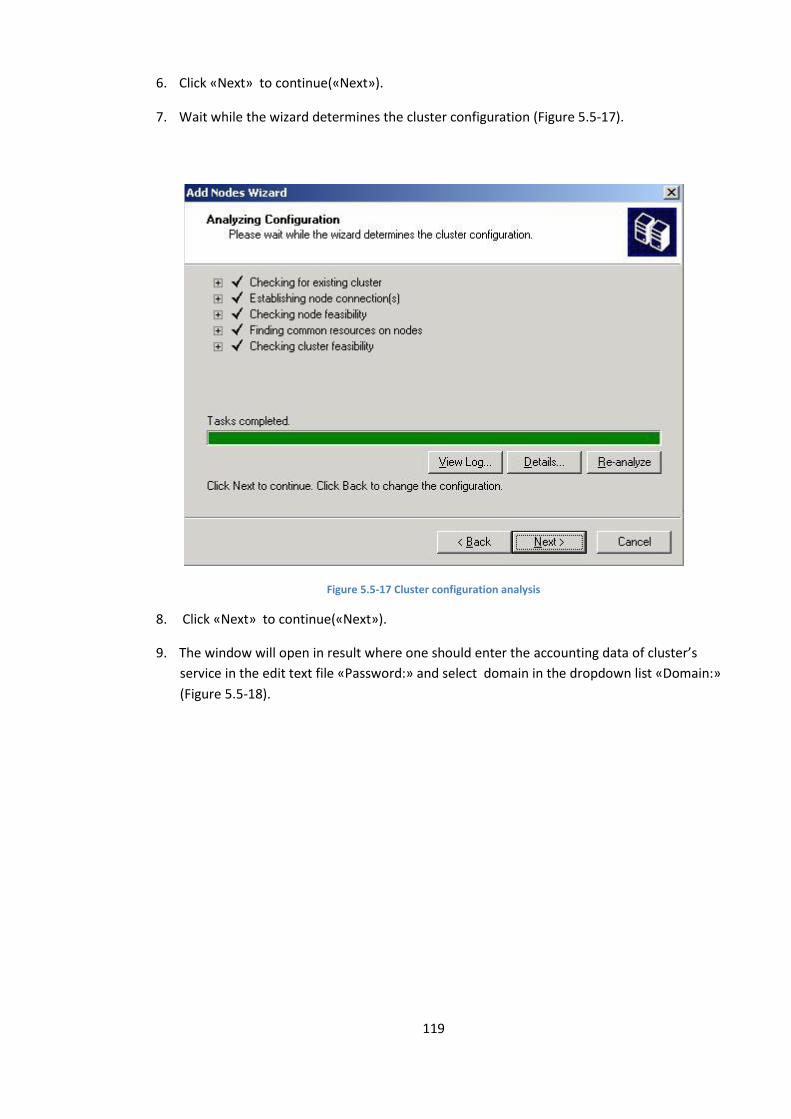
119
6. Click «Next» to continue(«Next»).
7. Wait while the wizard determines the cluster configuration (Figure 5.5-17).
Figure 5.5-17 Cluster configuration analysis
8. Click «Next» to continue(«Next»).
9. The window will open in result where one should enter the accounting data of cluster’s
service in the edit text file «Password:» and select domain in the dropdown list «Domain:»
(Figure 5.5-18).
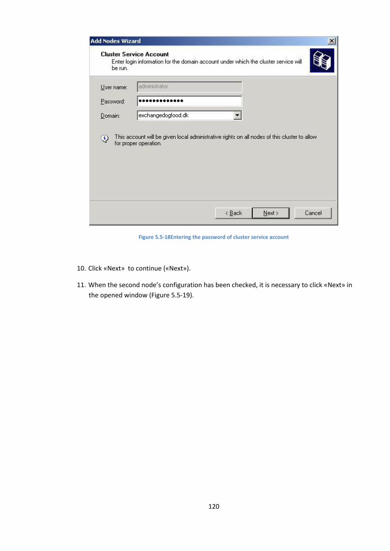
120
Figure 5.5-18Entering the password of cluster service account
10. Click «Next» to continue («Next»).
11. When the second node’s configuration has been checked, it is necessary to click «Next» in
the opened window (Figure 5.5-19).
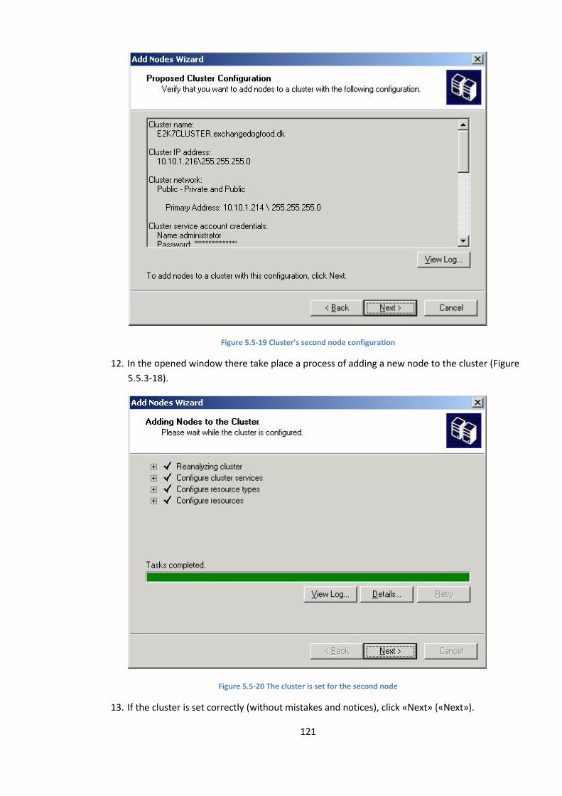
121
Figure 5.5-19 Cluster’s second node configuration
12. In the opened window there take place a process of adding a new node to the cluster (Figure
5.5.3-18).
Figure 5.5-20 The cluster is set for the second node
13. If the cluster is set correctly (without mistakes and notices), click «Next» («Next»).

122
14. The message informing about successful completing the add nodes wizard will appear in
result (Figure 5.5-21).
Figure 5.5-21 Completing the wizard operation
15. Click «Finish» to close the add nodes wizard («Finish»).
The second node of the cluster Windows 2003 was created in result (Figure 5.5-22).
Figure 5.5-22 Two nodes of the cluster
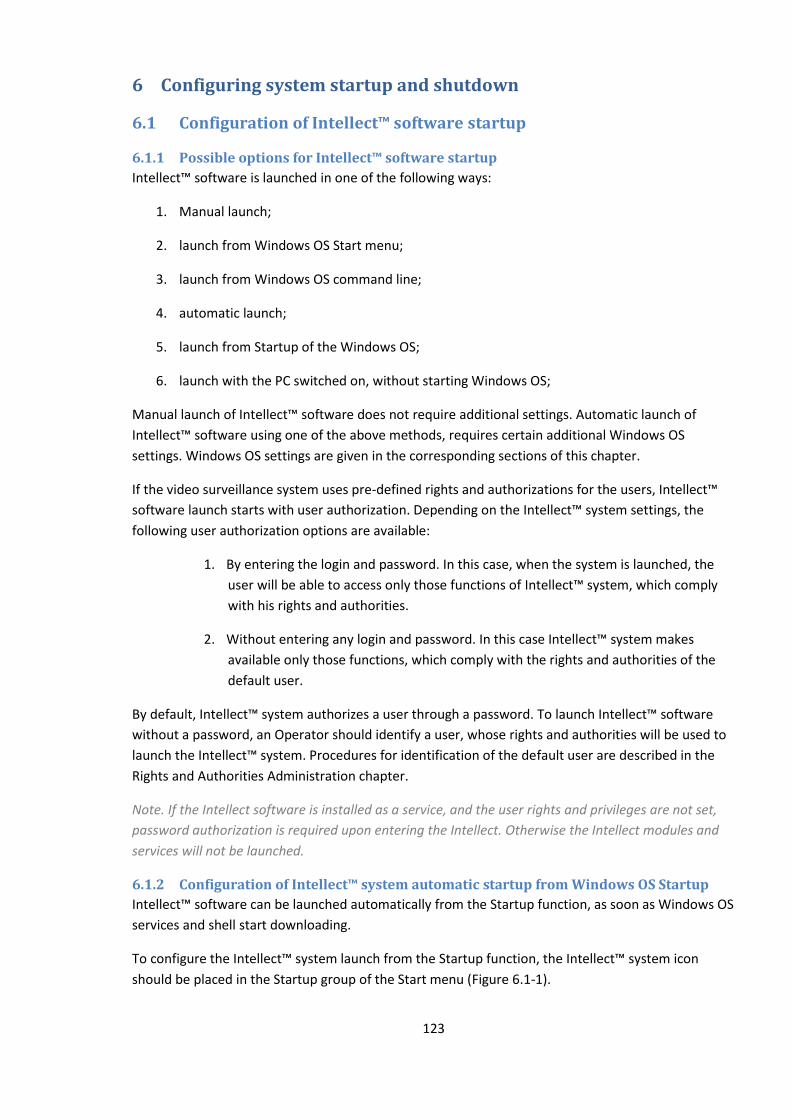
123
6 Configuring system startup and shutdown
6.1 Configuration of Intellect™ software startup
6.1.1 Possible options for Intellect™ software startup
Intellect™ software is launched in one of the following ways:
1. Manual launch;
2. launch from Windows OS Start menu;
3. launch from Windows OS command line;
4. automatic launch;
5. launch from Startup of the Windows OS;
6. launch with the PC switched on, without starting Windows OS;
Manual launch of Intellect™ software does not require additional settings. Automatic launch of
Intellect™ software using one of the above methods, requires certain additional Windows OS
settings. Windows OS settings are given in the corresponding sections of this chapter.
If the video surveillance system uses pre-defined rights and authorizations for the users, Intellect™
software launch starts with user authorization. Depending on the Intellect™ system settings, the
following user authorization options are available:
1. By entering the login and password. In this case, when the system is launched, the
user will be able to access only those functions of Intellect™ system, which comply
with his rights and authorities.
2. Without entering any login and password. In this case Intellect™ system makes
available only those functions, which comply with the rights and authorities of the
default user.
By default, Intellect™ system authorizes a user through a password. To launch Intellect™ software
without a password, an Operator should identify a user, whose rights and authorities will be used to
launch the Intellect™ system. Procedures for identification of the default user are described in the
Rights and Authorities Administration chapter.
Note. If the Intellect software is installed as a service, and the user rights and privileges are not set,
password authorization is required upon entering the Intellect. Otherwise the Intellect modules and
services will not be launched.
6.1.2 Configuration of Intellect™ system automatic startup from Windows OS Startup
Intellect™ software can be launched automatically from the Startup function, as soon as Windows OS
services and shell start downloading.
To configure the Intellect™ system launch from the Startup function, the Intellect™ system icon
should be placed in the Startup group of the Start menu (Figure 6.1-1).
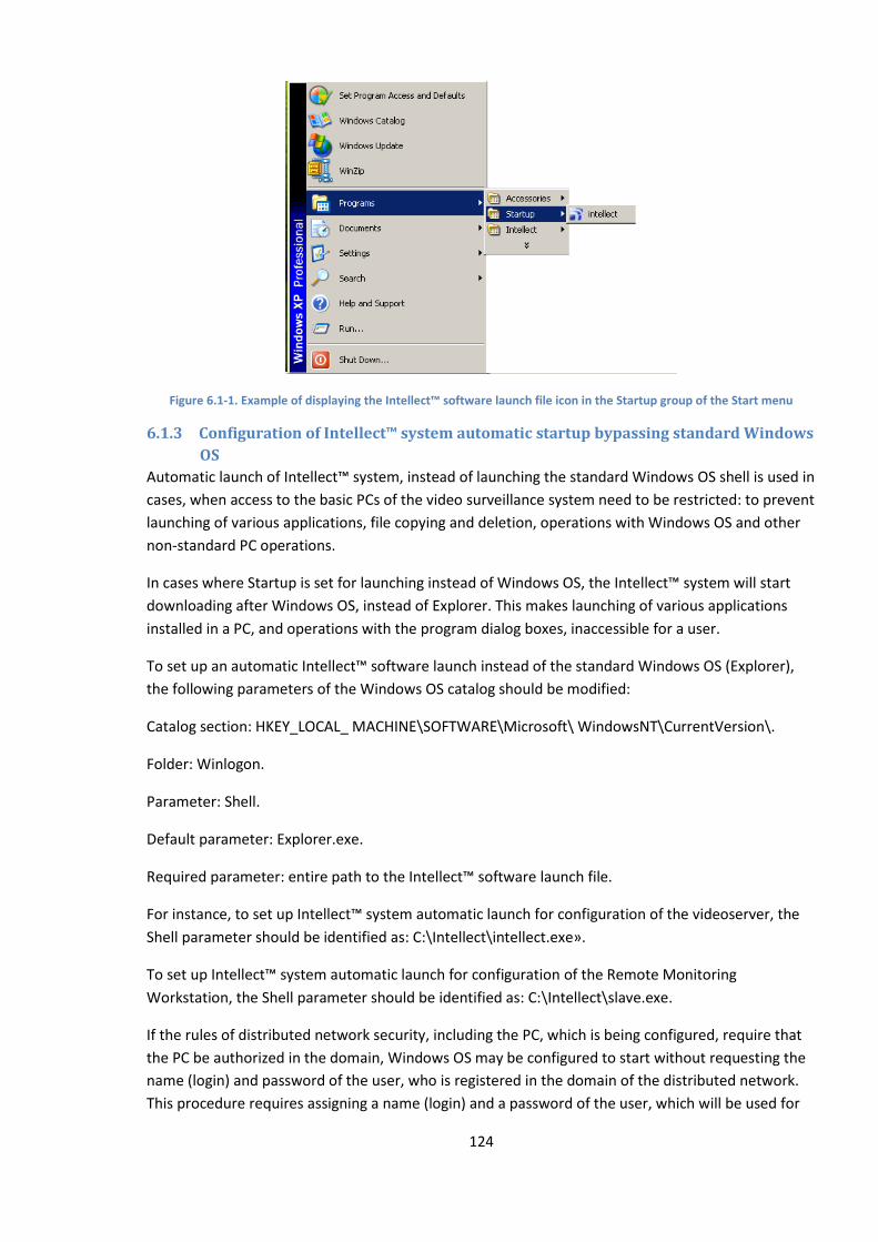
124
Figure 6.1-1. Example of displaying the Intellect™ software launch file icon in the Startup group of the Start menu
6.1.3 Configuration of Intellect™ system automatic startup bypassing standard Windows
OS
Automatic launch of Intellect™ system, instead of launching the standard Windows OS shell is used in
cases, when access to the basic PCs of the video surveillance system need to be restricted: to prevent
launching of various applications, file copying and deletion, operations with Windows OS and other
non-standard PC operations.
In cases where Startup is set for launching instead of Windows OS, the Intellect™ system will start
downloading after Windows OS, instead of Explorer. This makes launching of various applications
installed in a PC, and operations with the program dialog boxes, inaccessible for a user.
To set up an automatic Intellect™ software launch instead of the standard Windows OS (Explorer),
the following parameters of the Windows OS catalog should be modified:
Catalog section: HKEY_LOCAL_ MACHINE\SOFTWARE\Microsoft\ WindowsNT\CurrentVersion\.
Folder: Winlogon.
Parameter: Shell.
Default parameter: Explorer.exe.
Required parameter: entire path to the Intellect™ software launch file.
For instance, to set up Intellect™ system automatic launch for configuration of the videoserver, the
Shell parameter should be identified as: C:\Intellect\intellect.exe».
To set up Intellect™ system automatic launch for configuration of the Remote Monitoring
Workstation, the Shell parameter should be identified as: C:\Intellect\slave.exe.
If the rules of distributed network security, including the PC, which is being configured, require that
the PC be authorized in the domain, Windows OS may be configured to start without requesting the
name (login) and password of the user, who is registered in the domain of the distributed network.
This procedure requires assigning a name (login) and a password of the user, which will be used for
125
the PC authorization in the domain by default. To set up Windows OS launch without user name
(login) and password request, change the following parameters of the Windows OS catalog:
Catalog section: HKEY_LOCAL_ MACHINE\SOFTWARE\Microsoft\ WindowsNT\CurrentVersion\.
Folder: Winlogon.
Parameter 1: AutoAdminLogon.
Default parameter 1: 0.
Required parameter 1: 1.
Parameter 2: DefaultUserName.
Default parameter 2: one of the registered user names (logins).
Required parameter 2: user name (login) for authorization in the domain.
Parameter 3: DefaultPassword.
Default parameter 3: parameter does not exist (should be created).
Required parameter 3: user name for authorization in the domain.
Catalog parameters are edited either using Tweaki.exe utility (recommended), or manually. Setup of
Intellect™ system startup with Tweaki.exe utility is shown in Attachment No. 2. Basic information
required for manual system catalog editing is outlined in the corresponding attachment.
6.2 Configuration of shutting Intellect™ system down The Intellect™ system is always closed manually. If the video surveillance system uses pre-defined
rights and authorizations for the users, Intellect™ software should be closed by entering a user
password.
Intellect™ system may be closed using the following options:
1. using an authorized user login and password
2. using an administrator password.
3. using an administrator password entered in the displayed administrator password request
window.
Intellect™ system closure is configured at the stage of administration of user rights and
authorizations, and is described in the corresponding sections of the Guide.
7 Working with the Intellect™ system settings dialog box
7.1 General information about the System settings dialog box The Intellect™ system is configured using the System settings dialog box.
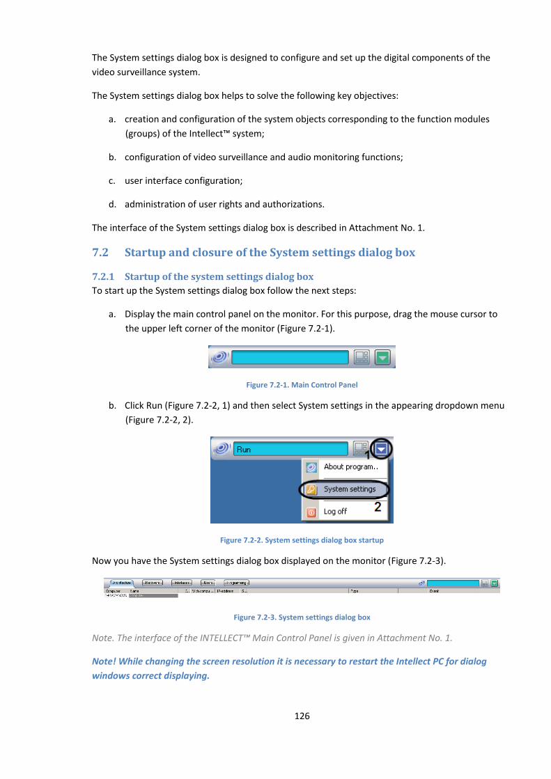
126
The System settings dialog box is designed to configure and set up the digital components of the
video surveillance system.
The System settings dialog box helps to solve the following key objectives:
a. creation and configuration of the system objects corresponding to the function modules
(groups) of the Intellect™ system;
b. configuration of video surveillance and audio monitoring functions;
c. user interface configuration;
d. administration of user rights and authorizations.
The interface of the System settings dialog box is described in Attachment No. 1.
7.2 Startup and closure of the System settings dialog box
7.2.1 Startup of the system settings dialog box
To start up the System settings dialog box follow the next steps:
a. Display the main control panel on the monitor. For this purpose, drag the mouse cursor to
the upper left corner of the monitor (Figure 7.2-1).
Figure 7.2-1. Main Control Panel
b. Click Run (Figure 7.2-2, 1) and then select System settings in the appearing dropdown menu
(Figure 7.2-2, 2).
Figure 7.2-2. System settings dialog box startup
Now you have the System settings dialog box displayed on the monitor (Figure 7.2-3).
Figure 7.2-3. System settings dialog box
Note. The interface of the INTELLECT™ Main Control Panel is given in Attachment No. 1.
Note! While changing the screen resolution it is necessary to restart the Intellect PC for dialog
windows correct displaying.
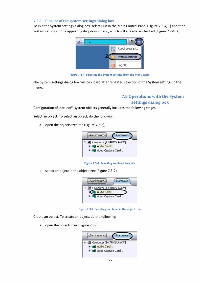
127
7.2.2 Closure of the system settings dialog box
To exit the System settings dialog box, select Run in the Main Control Panel (Figure 7.2-4, 1) and then
System settings in the appearing dropdown menu, which will already be checked (Figure 7.2-4, 2).
Figure 7.2-4. Selecting the System settings from the menu again
The System settings dialog box will be closed after repeated selection of the System settings in the
menu.
7.3 Operations with the System
settings dialog box Configuration of Intellect™ system objects generally includes the following stages:
Select an object. To select an object, do the following:
a. open the objects tree tab (Figure 7.3-2);
Figure 7.3-1. Selecting an object tree tab
b. select an object in the object tree (Figure 7.3-2).
Figure 7.3-2. Selecting an object in the object tree
Create an object. To create an object, do the following:
a. open the objects tree (Figure 7.3-3);
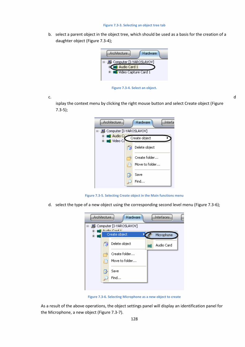
128
Figure 7.3-3. Selecting an object tree tab
b. select a parent object in the object tree, which should be used as a basis for the creation of a
daughter object (Figure 7.3-4);
Figure 7.3-4. Select an object.
c. d
isplay the context menu by clicking the right mouse button and select Create object (Figure
7.3-5);
Figure 7.3-5. Selecting Create object in the Main functions menu
d. select the type of a new object using the corresponding second level menu (Figure 7.3-6);
Figure 7.3-6. Selecting Microphone as a new object to create
As a result of the above operations, the object settings panel will display an identification panel for
the Microphone, a new object (Figure 7.3-7).
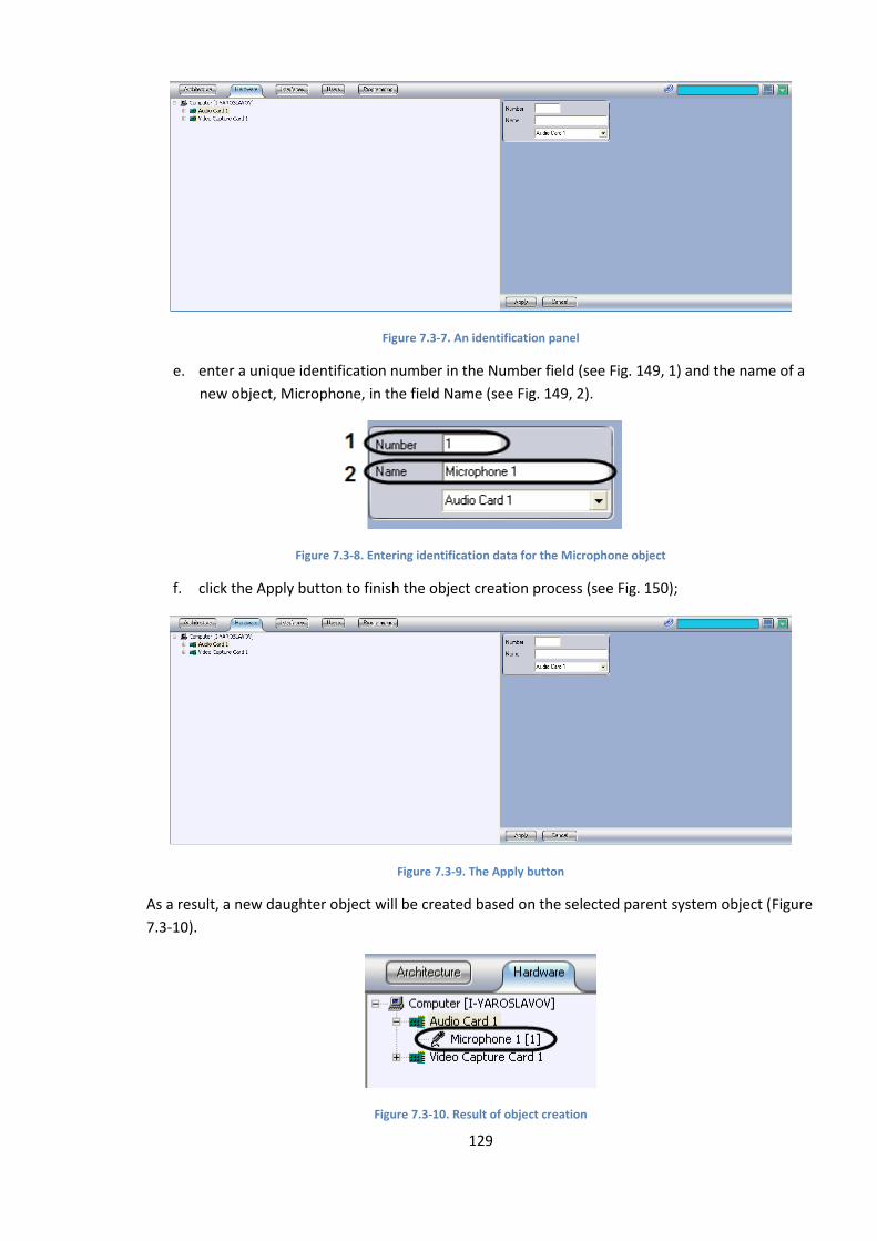
129
Figure 7.3-7. An identification panel
e. enter a unique identification number in the Number field (see Fig. 149, 1) and the name of a
new object, Microphone, in the field Name (see Fig. 149, 2).
Figure 7.3-8. Entering identification data for the Microphone object
f. click the Apply button to finish the object creation process (see Fig. 150);
Figure 7.3-9. The Apply button
As a result, a new daughter object will be created based on the selected parent system object (Figure
7.3-10).
Figure 7.3-10. Result of object creation
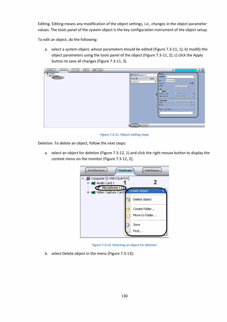
130
Editing. Editing means any modification of the object settings, i.e., changes in the object parameter
values. The tools panel of the system object is the key configuration instrument of the object setup.
To edit an object, do the following:
a. select a system object, whose parameters should be edited (Figure 7.3-11, 1); b) modify the
object parameters using the tools panel of the object (Figure 7.3-11, 2); c) click the Apply
button to save all changes (Figure 7.3-11, 3).
Figure 7.3-11. Object editing steps
Deletion. To delete an object, follow the next steps:
a. select an object for deletion (Figure 7.3-12, 1) and click the right mouse button to display the
context menu on the monitor (Figure 7.3-12, 2);
Figure 7.3-12. Selecting an object for deletion
b. select Delete object in the menu (Figure 7.3-13);
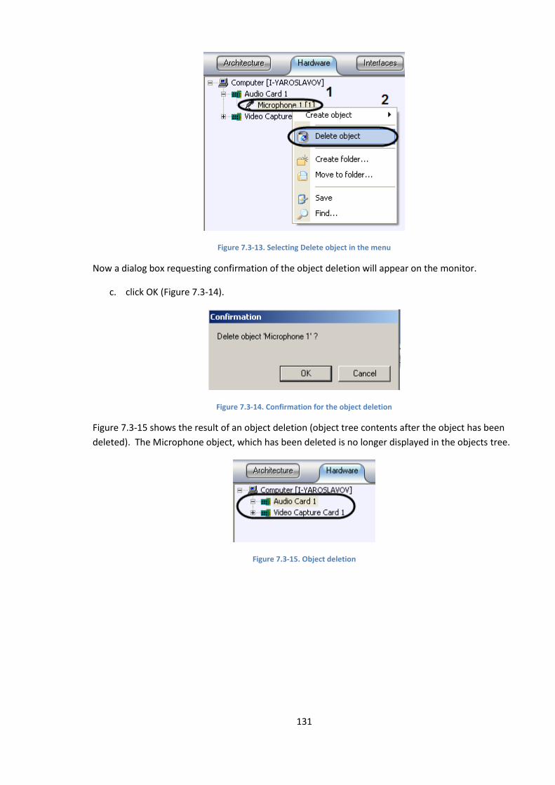
131
Figure 7.3-13. Selecting Delete object in the menu
Now a dialog box requesting confirmation of the object deletion will appear on the monitor.
c. click OK (Figure 7.3-14).
Figure 7.3-14. Confirmation for the object deletion
Figure 7.3-15 shows the result of an object deletion (object tree contents after the object has been
deleted). The Microphone object, which has been deleted is no longer displayed in the objects tree.
Figure 7.3-15. Object deletion
132
8 INTELLECT™ software configuration and setup
8.1 Setting up servers and remote workstations
8.1.1 Server settings
8.1.1.1 Server hardware and program platform
The video surveillance system based on INTELLECT™ software uses servers to receive and process
video signals from analog and IP surveillance cameras. The server hardware and program platform
generally contains:
1. A personal computer, that meets the requirements of INTELLECT™ software.
2. Internal video capture cards or Guardant dongle, that enables to receive video from IP
devices only.
3. Intellect™ software for “Server” (using video capture cards) and “Remote Admin
Workstation” configurations (using IP cameras only).
4. License key file with rights to use grabber cards and IP devices together with INTELLECT™
software.
5. MS SQL server software for Intellect™ system database control.
Note! The same set of program modules should be set on all the Servers for system correct
operation (see. «Functional program modules»), written in the key file intellect.sec.
Note! INTELLECT™ correct operation is possible only if the user has OS Windows administrator rights.
8.1.1.2 Server settings
The basic function of the server is receipt and processing of video signals. It provides several options:
audio signal receipt and processing, PTZ control, security measures, user’s auto functions (macro
commands) etc. Server setup sequence depends on its hardware configuration and the options to be
realized.
Follow the steps to set up the server:
1. Sync the server database to other servers and Remote Admin Workstation databases (for
example, via the centralized database of the administering server, see “Database
administering”).
2. Launch the INTELLECT™ program on the server.
3. With remote setup (e.g., from the administering server), log in the “Computer” object, which
corresponds to the server, and set the interaction parameters with the servers, Remote
133
Admin Workstations, Remote Monitoring Workstations of the distributed video surveillance
system (see “INTELLECT ™software system configuring with distributed architecture of the
digital video surveillance system”). While setting up the local server the relevant “Computer”
object is created automatically on the “Hardware” tab during the first startup.
4. Set up the server video subsystem (see “Video subsystem settings”).
5. Set up the PTZ units, attached to the server cameras (see “PTZ settings”).
6. Set up the server audio subsystem, if there are microphones (see “Audio subsystem
settings”).
7. If sensors and relays are used create, and set up the relevant objects (see «Sensor setup» and
«Relays setup»).
8. Set up backup video archiving on the server, if necessary (see “Backup video archiving
setup”).
9. Set up the hardware performance tester and restart service, connect and setup the
notification services (see the title Sections).
10. If auto options are to be used, create the macros and time zones (see the title Sections).
11. If the server is to be used as the Operator’s workstation, setup the user interface: video
surveillance monitor, audio player, map etc. (see “User interface setup”).
12. Assign the users rights to work with server system objects (see “User rights ”).
13. Set up logging of events, registered for the server system objects (see “Event log.setup”).
8.1.2 Setting up a Remote Admin Workstation
8.1.2.1 Remote Admin Workstation hardware and program platform
The video surveillance system based on INTELLECT™ software uses Remote Admin Workstations for
remote administering of the INTELLECT™ software, set on servers and other Remote Admin
Workstations of the distributed video surveillance system, and as the specialized platforms for: video
gate, remote archive server, remote web server etc. The Remote Admin Workstation can realize
several of these functions or one of them.
Remote Admin Workstation hardware and the program platform generally contain:
1. A personal computer, that meets the requirements of INTELLECT™ software.
2. A Guardant dongle.
3. Set Intellect™ software (“Remote Admin Workstation” configuration).
4. A license key file.
5. MS SQL server software for control of the Intellect™ system database.

134
8.1.2.2 Remote Admin Workstation setup
In a simple case Remote Admin Workstation may be used for remote administering only.
Follow the steps to set up Remote Admin Workstation:
1. Sync the Remote Admin Workstation database to other servers and Remote Admin
Workstation databases (for example, via the centralized database of the administering
server, see “Database administering”).
2. Launch the INTELLECT™ program on Remote Admin Workstation.
3. With remote setup (e.g., from the administering server) register the “Computer” object,
which corresponds to the Remote Admin Workstation, and set the interaction parameters
with the servers, Remote Admin Workstations, Remote Monitoring Workstations of the
distributed video surveillance system (see “INTELLECT ™software system configuring with
distributed architecture of the digital video surveillance system”). With setting up a Remote
Admin Workstation on a local PC, the relevant “Computer” object is created automatically on
the “Hardware” tab during the first startup.
4. Set up hardware performance tester and the Restart service (see the title Sections).
5. If auto options are to be used, create the macros, time zones, connect and set up the
Notification services (see the title Sections).
6. If Remote Admin Workstation is to be used as an Operator’s workstation, set up the user
interface: video surveillance monitor, audio player, map etc. (see “User interface setup”).
7. Assign users the rights to work with Remote Admin Workstation system objects (see
Managing user rights and authorisation).
8. Setup the logging of events, registered for Remote Admin Workstation system objects (see
“Event log.setup”).
8.1.2.3 Video gateway setup
Video gateways are used in large-scale distributed video surveillance systems for video signal routing
among the servers and Remote Monitoring Workstations (or Remote Admin Workstation with
Remote Monitoring Workstations functions) from different subnets.
Follow the steps to set up the gateway:
1. Sync the gateway database to other servers and Remote Admin Workstation databases (for
example, via the centralized database of the administering server, see “Database
administering”).
2. Launch the INTELLECT™ program on the gateway.
3. With gateway remote setup (e.g., from the administering server) you need to register the
“Computer” object, which corresponds to the Remote Admin Workstation, and to set the
interaction parameters with the servers, Remote Admin Workstations, Remote Monitoring
Workstations of the distributed video surveillance system (see “INTELLECT ™software system
configuring with distributed architecture of the digital video surveillance system”). With
135
gateway local setup, the relevant “Computer” object is created automatically on the
“Hardware” tab during the first startup.
4. Connect and set up the “Gateway” module (see “‘Gateway’ module setup”).
5. Set up hardware performance tester and the Restart service (see the title Sections).
6. If auto options are to be used, create the macros, time zones, connect and setup notification
services (see the title Sections).
7. Assign users the rights to work with the video gateway system objects (see Managing user
rights).
8. Set up logging of events, registered for the gateway system objects (see Event log setup”).
8.1.2.4 Remote archive server setup
INTELLECT™ software has a backup archiving option for video records from the video surveillance
servers. As the archiving process requires great computer resources (RAM, processor capacity),
archiving should not be performed on the servers directly. It is strongly recommended to choose the
separate Remote Admin Workstation as the archiving server.
Follow the steps to set up the archiving server:
1. Sync the archiving server database to the other servers and Remote Admin Workstation
databases (for example, via the centralized database of the administering server, see
“Database administering”).
2. Launch the INTELLECT™ program on the archiving server.
3. When setting up the archiving server remotely (e.g., from the administering server) you need
to register the “Computer” object, which corresponds to the archiving server, and to set the
interaction parameters with the servers, Remote Admin Workstations, Remote Monitoring
Workstations of the distributed video surveillance system (see “INTELLECT ™software system
configuring with distributed architecture of the digital video surveillance system”). When
setting up the local archiving server, the relevant “Computer” object is created automatically
on the “Hardware” tab during the first startup.
4. Connect and set up the “Active archive” module (see “Backup video archiving setup”).
5. Set up the hardware performance tester and Restart service (see the title Sections).
6. If auto options are to be used, create the macros, time zones, connect and setup Notification
services (see the title Sections).
7. Assign users the rights to work with Remote Admin Workstation system objects (see
“Managing user rights and authorisation”).
8. Set up logging of events, registered for Remote Admin Workstation system objects (see
“Event log.setup”).

136
8.1.2.5 Remote Web server setup
The video surveillance system based on INTELLECT™ software uses the remote web server to
transmit video signals and to receive Operator’s commands via the Internet. It is recommended for
large-scale systems with a distributed structure to use the remote web server on the separate
Remote Admin Workstation instead of a local one on any server.
Note. The remote web server should be allocated in the separate subnet and on the outer IP address
(for its operation as an Internet HTTP server). Therefore the web server should be set to receive video
signals via the gateway.. The video gateway may be the remote one (remote computer with
“Gateway” module set) or the local one (“Gateway” module set on the same computer with the web
server).
Follow the steps to set up the remote web server:
1. Sync the web server database to other servers and Remote Admin Workstation databases
(for example, via the centralized database of the administering server, see “Database
administering”).
2. Launch the INTELLECT™ program on the web server.
3. With remote web server setup (e.g., from the administering server), you need to register the
“Computer” object, which corresponds to the web server, and to set the interaction
parameters with the servers, Remote Admin Workstations, Remote Monitoring Workstations
of the distributed video surveillance system (see “INTELLECT ™software system configuring
with distributed architecture of the digital video surveillance system”). With web server local
setup, the relevant “Computer” object is created automatically on the “Hardware” tab during
the first startup.
4. Connect and set up the “Web server” module (see “Web server setup”).
5. If no remote gateway is used, connect and set up the “Gateway” module (see “Gateway
setup”).
6. Set up hardware performance tester and the Restart service (see the title Sections).
7. If auto options are to be used, create macros, time zones, connect and setup notification
services (see the title Sections).
8. Assign users rights to work with web server system objects (see Administration of user rights
and authorization).
9. Set up logging of events, registered for web server system objects (see “Event log setup”).
8.1.3 Setting up Remote Monitoring Workstations (RMW)
8.1.3.1 Remote Monitoring Workstation hardware and program platform
Remote Monitoring Workstations are used as Operator’s workstations and provide remote video
surveillance and audio monitoring: video and audio monitoring, sensor status control, cameras and
PTZ units control and so on. Administering options are inaccessible at a Remote Monitoring
Workstation.
137
The remote Monitoring Workstation hardware and program platform generally contains:
1. A personal computer, that meets the requirements of INTELLECT™ software.
2. The Intellect™ software (“Remote Monitoring Workstation” configuration).
8.1.3.2 Setting up a Remote Monitoring Workstation
The basic function of the remote Monitoring Workstation is to receive video and audio signals from
video surveillance system servers, video and audio monitoring, cameras, microphones and PTZ units
control via various components of the Operator interface (video surveillance monitor, audio player,
map, PTZ window etc.).
Follow the steps to set up the Remote Monitoring Workstation:
1. Register the “Computer” object, which corresponds to the Remote Monitoring Workstation,
and set the interaction parameters with the servers, Remote Admin Workstations, Remote
Monitoring Workstations of the distributed video surveillance system on the administering
server (see “INTELLECT ™software system configuring with distributed architecture of the
digital video surveillance system”).
2. Set up the User interface by creating screen(s) and setting up the Remote Monitoring
Workstation access to them. The screen(s) should contain the user interface components:
video surveillance monitor, audio player, map etc. (see “User interface setup”).
8.2 Configuring the INTELLECT™software system with distributed
architecture of the digital video surveillance system
8.2.1 General principles of designing the digital video surveillance system with
distributed architecture
The digital video surveillance system generally contains:
1. Servers - hardware and program platforms used to receive and process video and audio
signals from analog and IP surveillance cameras.
2. Remote Admin Workstations - hardware and program platforms used for remote
administering of the video surveillance system and as the specialized platforms for: video
gateway, remote archive server, remote web server etc.
3. Remote Monitoring Workstation - hardware and program platforms used as Operator’s
workstations to realize remote video surveillance and audio monitoring:
Servers, Remote Admin Workstations and Remote Monitoring Workstations are integrated into the
video surveillance system, fitting the system set of functions, safety requirements, specific features
of the guarded location etc. The video surveillance system may include several subnets, that interact
via selected (node) servers and Remote Admin Workstations. The distributed architecture of the
video surveillance system provides synchro data exchange (events, commands, setting parameters,
etc) among its components.
8.2.2 Configuring the distributed system
To configure the distributed video surveillance system, follow the steps:
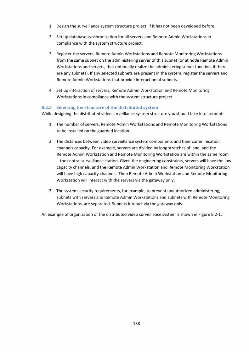
138
1. Design the surveillance system structure project, if it has not been developed before.
2. Set up database synchronization for all servers and Remote Admin Workstations in
compliance with the system structure project.
3. Register the servers, Remote Admin Workstations and Remote Monitoring Workstations
from the same subnet on the administering server of this subnet (or at node Remote Admin
Workstations and servers, that optionally realize the administering server function, if there
are any subnets). If any selected subnets are present in the system, register the servers and
Remote Admin Workstations that provide interaction of subnets.
4. Set up interaction of servers, Remote Admin Workstation and Remote Monitoring
Workstations in compliance with the system structure project.
8.2.3 Selecting the structure of the distributed system
While designing the distributed video surveillance system structure you should take into account:
1. The number of servers, Remote Admin Workstations and Remote Monitoring Workstations
to be installed on the guarded location.
2. The distances between video surveillance system components and their comminication
channels capacity. For example, servers are divided by long stretches of land, and the
Remote Admin Workstation and Remote Monitoring Workstation are within the same room
– the central surveillance station. Given the engineering constraints, servers will have the low
capacity channels, and the Remote Admin Workstation and Remote Monitoring Workstation
will have high capacity channels. Then Remote Admin Workstation and Remote Monitoring
Workstation will interact with the servers via the gateway only.
3. The system security requirements, for example, to prevent unauthorized administering,
subnets with servers and Remote Admin Workstations and subnets with Remote Monitoring
Workstations, are separated. Subnets interact via the gateway only.
An example of organization of the distributed video surveillance system is shown in Figure 8.2-1.
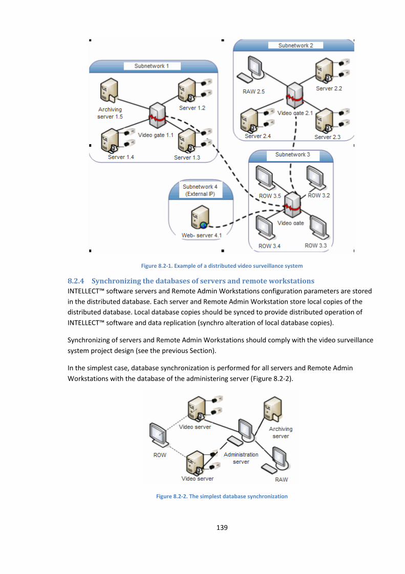
139
Figure 8.2-1. Example of a distributed video surveillance system
8.2.4 Synchronizing the databases of servers and remote workstations
INTELLECT™ software servers and Remote Admin Workstations configuration parameters are stored
in the distributed database. Each server and Remote Admin Workstation store local copies of the
distributed database. Local database copies should be synced to provide distributed operation of
INTELLECT™ software and data replication (synchro alteration of local database copies).
Synchronizing of servers and Remote Admin Workstations should comply with the video surveillance
system project design (see the previous Section).
In the simplest case, database synchronization is performed for all servers and Remote Admin
Workstations with the database of the administering server (Figure 8.2-2).
Figure 8.2-2. The simplest database synchronization
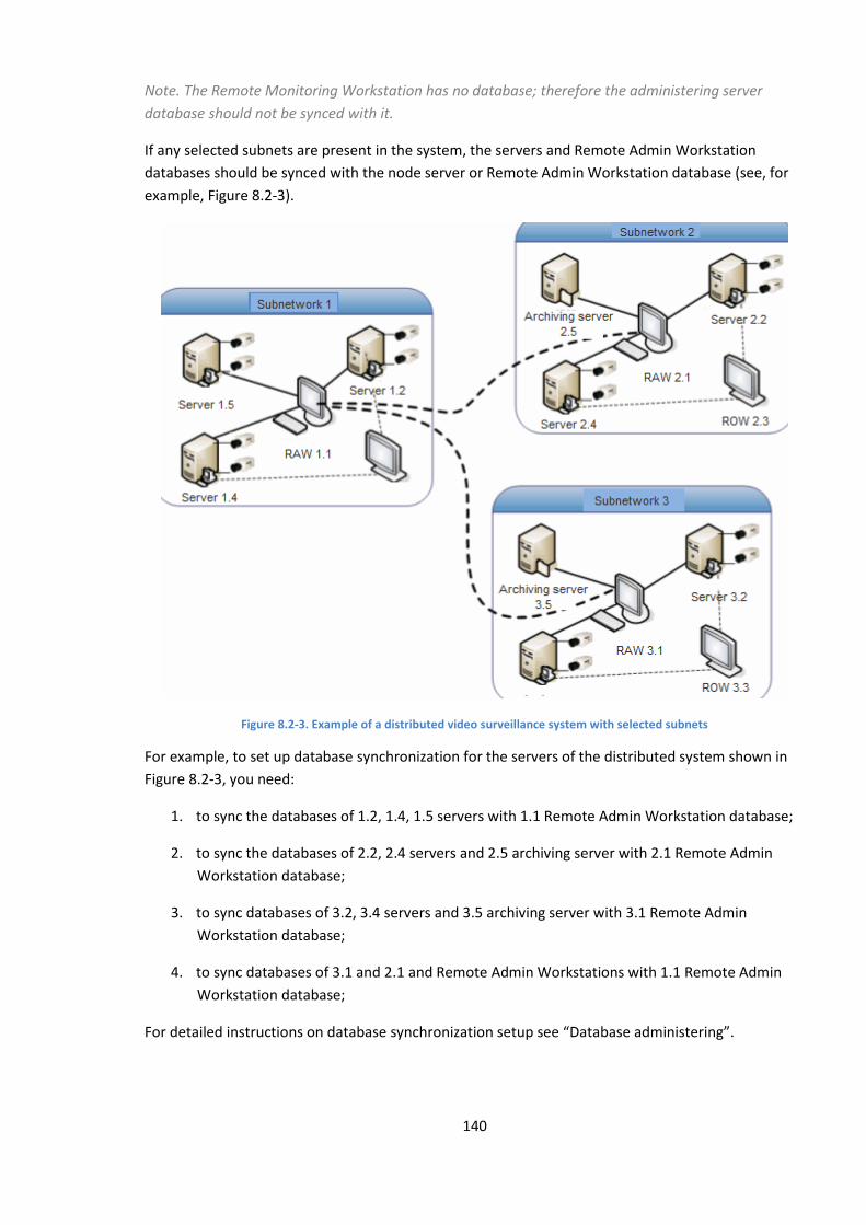
140
Note. The Remote Monitoring Workstation has no database; therefore the administering server
database should not be synced with it.
If any selected subnets are present in the system, the servers and Remote Admin Workstation
databases should be synced with the node server or Remote Admin Workstation database (see, for
example, Figure 8.2-3).
Figure 8.2-3. Example of a distributed video surveillance system with selected subnets
For example, to set up database synchronization for the servers of the distributed system shown in
Figure 8.2-3, you need:
1. to sync the databases of 1.2, 1.4, 1.5 servers with 1.1 Remote Admin Workstation database;
2. to sync the databases of 2.2, 2.4 servers and 2.5 archiving server with 2.1 Remote Admin
Workstation database;
3. to sync databases of 3.2, 3.4 servers and 3.5 archiving server with 3.1 Remote Admin
Workstation database;
4. to sync databases of 3.1 and 2.1 and Remote Admin Workstations with 1.1 Remote Admin
Workstation database;
For detailed instructions on database synchronization setup see “Database administering”.
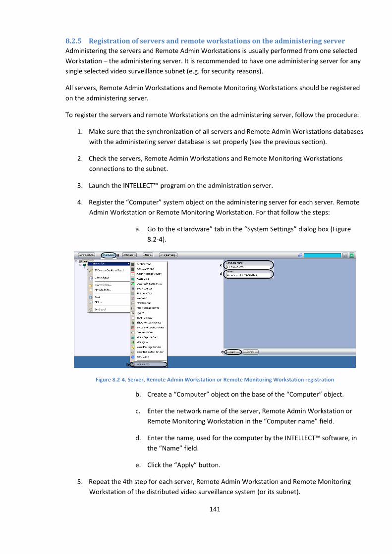
141
8.2.5 Registration of servers and remote workstations on the administering server
Administering the servers and Remote Admin Workstations is usually performed from one selected
Workstation – the administering server. It is recommended to have one administering server for any
single selected video surveillance subnet (e.g. for security reasons).
All servers, Remote Admin Workstations and Remote Monitoring Workstations should be registered
on the administering server.
To register the servers and remote Workstations on the administering server, follow the procedure:
1. Make sure that the synchronization of all servers and Remote Admin Workstations databases
with the administering server database is set properly (see the previous section).
2. Check the servers, Remote Admin Workstations and Remote Monitoring Workstations
connections to the subnet.
3. Launch the INTELLECT™ program on the administration server.
4. Register the “Computer” system object on the administering server for each server. Remote
Admin Workstation or Remote Monitoring Workstation. For that follow the steps:
a. Go to the «Hardware” tab in the “System Settings” dialog box (Figure
8.2-4).
Figure 8.2-4. Server, Remote Admin Workstation or Remote Monitoring Workstation registration
b. Create a “Computer” object on the base of the “Computer” object.
c. Enter the network name of the server, Remote Admin Workstation or
Remote Monitoring Workstation in the “Computer name” field.
d. Enter the name, used for the computer by the INTELLECT™ software, in
the “Name” field.
e. Click the “Apply” button.
5. Repeat the 4th step for each server, Remote Admin Workstation and Remote Monitoring
Workstation of the distributed video surveillance system (or its subnet).
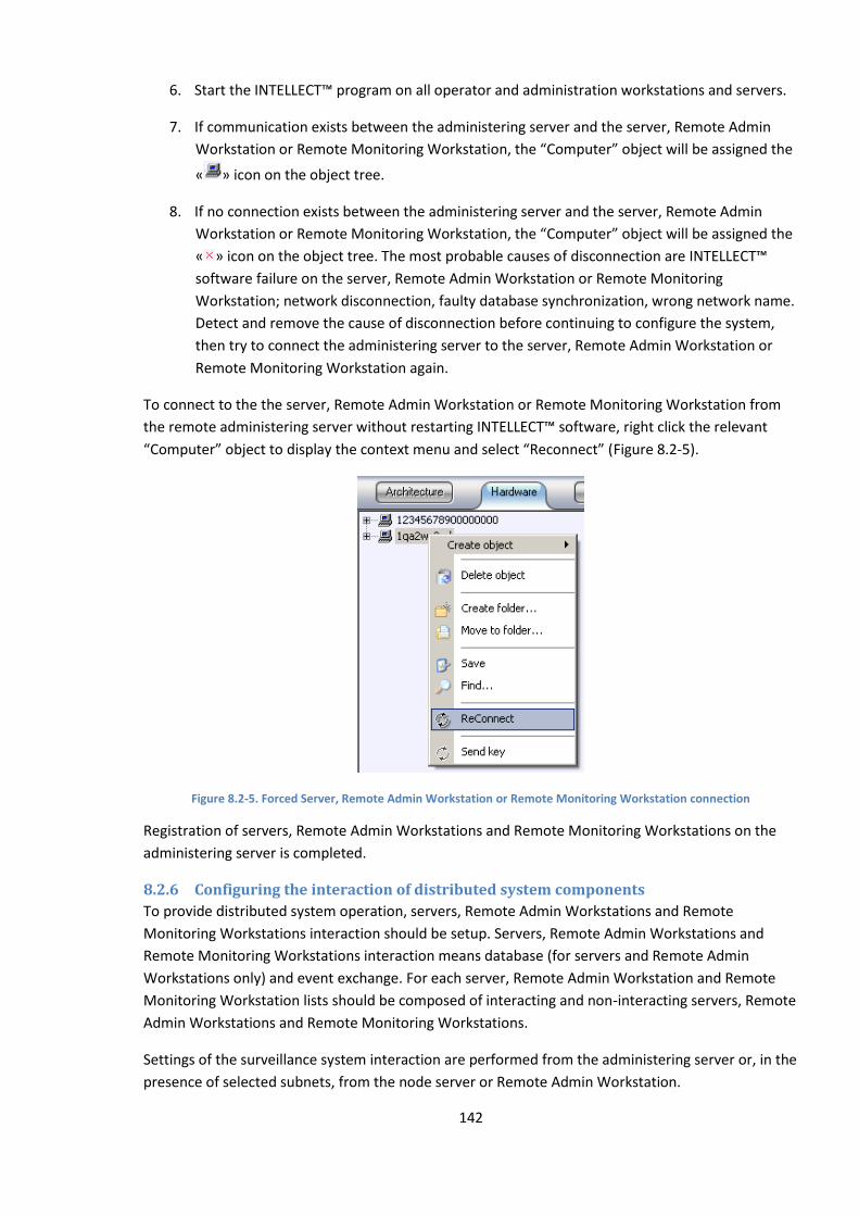
142
6. Start the INTELLECT™ program on all operator and administration workstations and servers.
7. If communication exists between the administering server and the server, Remote Admin
Workstation or Remote Monitoring Workstation, the “Computer” object will be assigned the
« » icon on the object tree.
8. If no connection exists between the administering server and the server, Remote Admin
Workstation or Remote Monitoring Workstation, the “Computer” object will be assigned the
« » icon on the object tree. The most probable causes of disconnection are INTELLECT™
software failure on the server, Remote Admin Workstation or Remote Monitoring
Workstation; network disconnection, faulty database synchronization, wrong network name.
Detect and remove the cause of disconnection before continuing to configure the system,
then try to connect the administering server to the server, Remote Admin Workstation or
Remote Monitoring Workstation again.
To connect to the the server, Remote Admin Workstation or Remote Monitoring Workstation from
the remote administering server without restarting INTELLECT™ software, right click the relevant
“Computer” object to display the context menu and select “Reconnect” (Figure 8.2-5).
Figure 8.2-5. Forced Server, Remote Admin Workstation or Remote Monitoring Workstation connection
Registration of servers, Remote Admin Workstations and Remote Monitoring Workstations on the
administering server is completed.
8.2.6 Configuring the interaction of distributed system components
To provide distributed system operation, servers, Remote Admin Workstations and Remote
Monitoring Workstations interaction should be setup. Servers, Remote Admin Workstations and
Remote Monitoring Workstations interaction means database (for servers and Remote Admin
Workstations only) and event exchange. For each server, Remote Admin Workstation and Remote
Monitoring Workstation lists should be composed of interacting and non-interacting servers, Remote
Admin Workstations and Remote Monitoring Workstations.
Settings of the surveillance system interaction are performed from the administering server or, in the
presence of selected subnets, from the node server or Remote Admin Workstation.
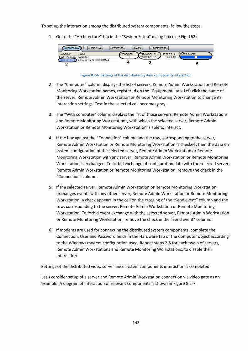
143
To set up the interaction among the distributed system components, follow the steps:
1. Go to the “Architecture” tab in the “System Setup” dialog box (see Fig. 162).
Figure 8.2-6. Settings of the distributed system components interaction
2. The “Computer” column displays the list of servers, Remote Admin Workstation and Remote
Monitoring Workstation names, registered on the “Equipment” tab. Left click the name of
the server, Remote Admin Workstation or Remote Monitoring Workstation to change its
interaction settings. Text in the selected cell becomes gray.
3. The “With computer” column displays the list of those servers, Remote Admin Workstations
and Remote Monitoring Workstations, with which the selected server, Remote Admin
Workstation or Remote Monitoring Workstation is able to interact.
4. If the box against the “Connection” column and the row, corresponding to the server,
Remote Admin Workstation or Remote Monitoring Workstation is checked, then the data on
system configuration of the selected server, Remote Admin Workstation or Remote
Monitoring Workstation with any server, Remote Admin Workstation or Remote Monitoring
Workstation is exchanged. To forbid exchange of configuration data with the selected server,
Remote Admin Workstation or Remote Monitoring Workstation, remove the check in the
“Connection” column.
5. If the selected server, Remote Admin Workstation or Remote Monitoring Workstation
exchanges events with any other server, Remote Admin Workstation or Remote Monitoring
Workstation, a check appears in the cell on the crossing of the “Send event” column and the
row, corresponding to the server, Remote Admin Workstation or Remote Monitoring
Workstation. To forbid event exchange with the selected server, Remote Admin Workstation
or Remote Monitoring Workstation, remove the check in the “Send event” column.
6. If modems are used for connecting the distributed system components, complete the
Connection, User and Password fields in the Hardware tab of the Computer object according
to the Windows modem configuration used. Repeat steps 2-5 for each twain of servers,
Remote Admin Workstations and Remote Monitoring Workstations, to disable their
interaction.
Settings of the distributed video surveillance system components interaction is completed.
Let’s consider setup of a server and Remote Admin Workstation connection via video gate as an
example. A diagram of interaction of relevant components is shown in Figure 8.2-7.
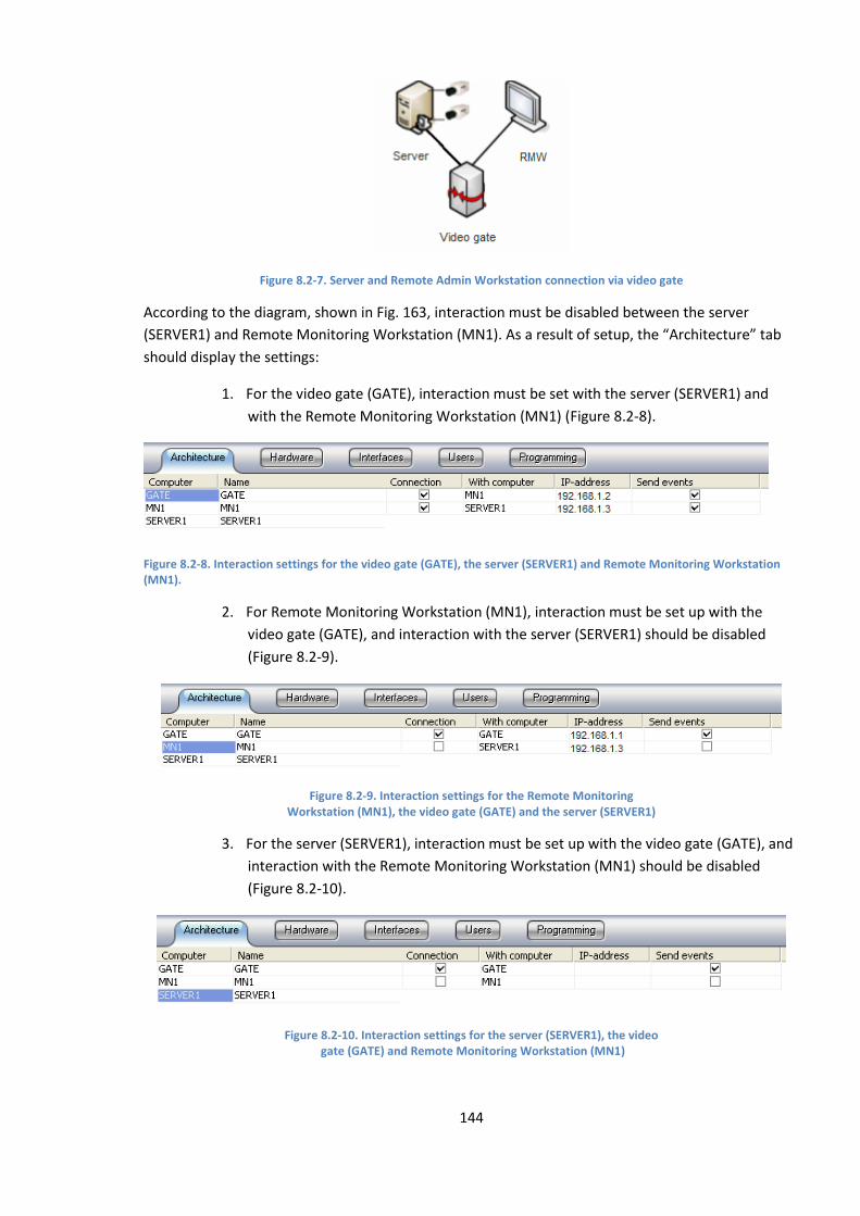
144
Figure 8.2-7. Server and Remote Admin Workstation connection via video gate
According to the diagram, shown in Fig. 163, interaction must be disabled between the server
(SERVER1) and Remote Monitoring Workstation (MN1). As a result of setup, the “Architecture” tab
should display the settings:
1. For the video gate (GATE), interaction must be set with the server (SERVER1) and
with the Remote Monitoring Workstation (MN1) (Figure 8.2-8).
Figure 8.2-8. Interaction settings for the video gate (GATE), the server (SERVER1) and Remote Monitoring Workstation (MN1).
2. For Remote Monitoring Workstation (MN1), interaction must be set up with the
video gate (GATE), and interaction with the server (SERVER1) should be disabled
(Figure 8.2-9).
Figure 8.2-9. Interaction settings for the Remote Monitoring Workstation (MN1), the video gate (GATE) and the server (SERVER1)
3. For the server (SERVER1), interaction must be set up with the video gate (GATE), and
interaction with the Remote Monitoring Workstation (MN1) should be disabled
(Figure 8.2-10).
Figure 8.2-10. Interaction settings for the server (SERVER1), the video gate (GATE) and Remote Monitoring Workstation (MN1)
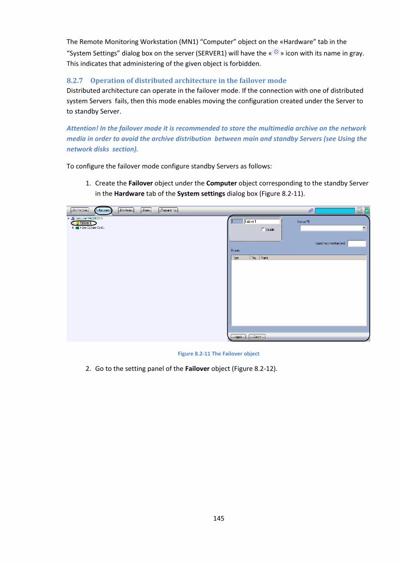
145
The Remote Monitoring Workstation (MN1) “Computer” object on the «Hardware” tab in the
“System Settings” dialog box on the server (SERVER1) will have the « » icon with its name in gray.
This indicates that administering of the given object is forbidden.
8.2.7 Operation of distributed architecture in the failover mode
Distributed architecture can operate in the failover mode. If the connection with one of distributed
system Servers fails, then this mode enables moving the configuration created under the Server to
to standby Server.
Attention! In the failover mode it is recommended to store the multimedia archive on the network
media in order to avoid the archive distribution between main and standby Servers (see Using the
network disks section).
To configure the failover mode configure standby Servers as follows:
1. Create the Failover object under the Computer object corresponding to the standby Server
in the Hardware tab of the System settings dialog box (Figure 8.2-11).
Figure 8.2-11 The Failover object
2. Go to the setting panel of the Failover object (Figure 8.2-12).
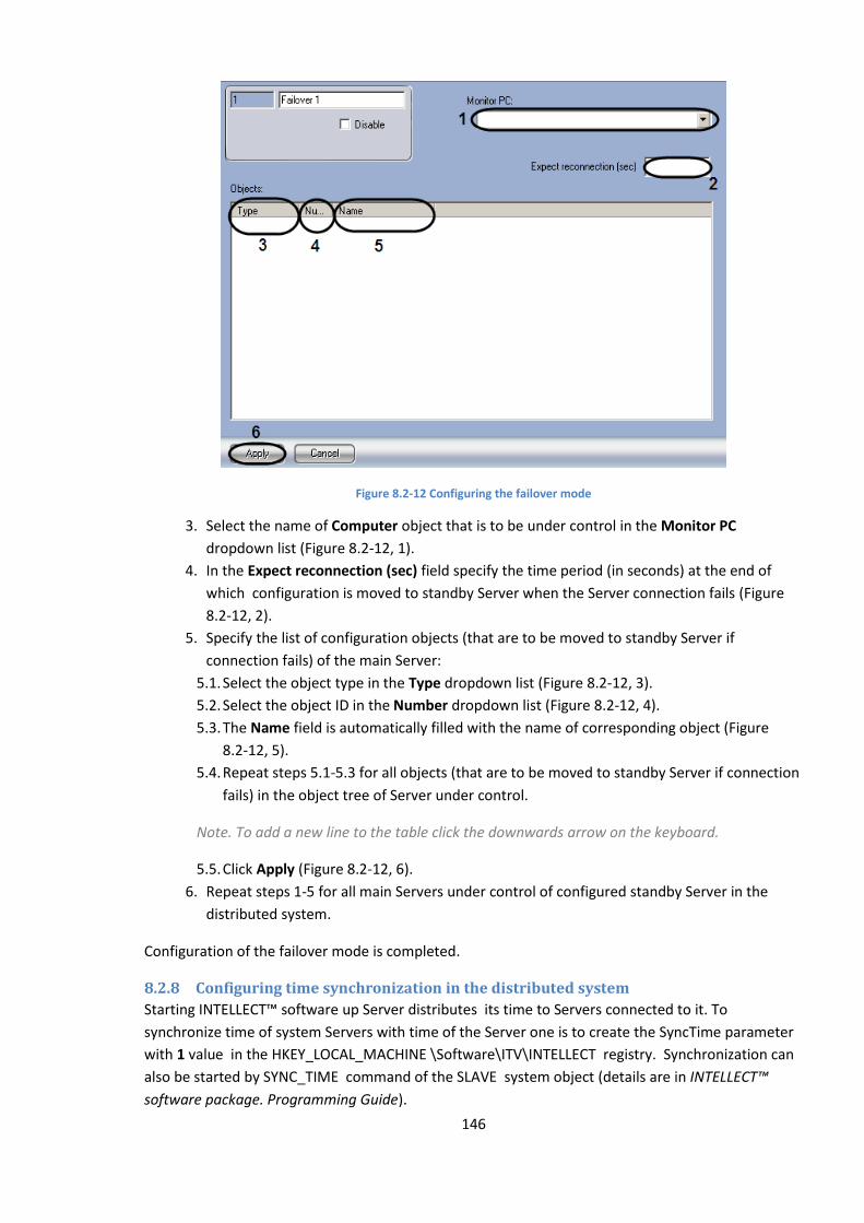
146
Figure 8.2-12 Configuring the failover mode
3. Select the name of Computer object that is to be under control in the Monitor PC
dropdown list (Figure 8.2-12, 1).
4. In the Expect reconnection (sec) field specify the time period (in seconds) at the end of
which configuration is moved to standby Server when the Server connection fails (Figure
8.2-12, 2).
5. Specify the list of configuration objects (that are to be moved to standby Server if
connection fails) of the main Server:
5.1. Select the object type in the Type dropdown list (Figure 8.2-12, 3).
5.2. Select the object ID in the Number dropdown list (Figure 8.2-12, 4).
5.3. The Name field is automatically filled with the name of corresponding object (Figure
8.2-12, 5).
5.4. Repeat steps 5.1-5.3 for all objects (that are to be moved to standby Server if connection
fails) in the object tree of Server under control.
Note. To add a new line to the table click the downwards arrow on the keyboard.
5.5. Click Apply (Figure 8.2-12, 6).
6. Repeat steps 1-5 for all main Servers under control of configured standby Server in the
distributed system.
Configuration of the failover mode is completed.
8.2.8 Configuring time synchronization in the distributed system
Starting INTELLECT™ software up Server distributes its time to Servers connected to it. To
synchronize time of system Servers with time of the Server one is to create the SyncTime parameter
with 1 value in the HKEY_LOCAL_MACHINE \Software\ITV\INTELLECT registry. Synchronization can
also be started by SYNC_TIME command of the SLAVE system object (details are in INTELLECT™
software package. Programming Guide).
147
8.3 INTELLECT™ software database management
8.3.1 INTELLECT™ software database functions
INTELLECT™ software database provides:
1. Data storage:
a. data on registered system objects and their settings;
b. departments and user accounts and rights;
c. on registered system events;
d. on changes in servers and Remote Admin Workstations configuration;
e. on changes in registered system object specifications and their settings;
f. data on network names and IP-addresses of distributed system servers, Remote Admin
Workstations, Remote Monitoring Workstations and their interaction parameters;
2. Data replication from different servers and Remote Admin Workstations.
The main and the single default database of the INTELLECT™ software is the “Configuration”
database. The “Configuration” database is used to realize all the above-listed functions.
INTELLECT™ software can be configured to store the registered system events not in the default
“Configuration” database, but in the “Events log” database.
8.3.2 Guidelines on INTELLECT ™ system database use
To provide effective and steady performance of the INTELLECT ™ system, take into account the
recommendations on database use below:
1. Store the “Configuration” database on the MS SQL server. If MS Access is used to store the
database, it is strongly recommended to install the MS SQL server and to convert the
database from MS Access to MS SQL format.
2. Servers and Remote Admin Workstation databases should be synced with the administering
server database.
3. If long-term centralized storage is necessary for registered system events, then it is
recommended to apply INTELLECT™ software configuration at servers and Remote Admin
Workstations in order to store events that are not in the “Configuration” database, but in the
“Events log” database.
8.3.3 Converting the database from MS Access to MS SQL format
Intellect™ software version 4.8.2 is default configured to operate with the database MS SQL server
format. MS Access format databases have been used in previous Intellect™ software versions. If the
system needs configuration parameters, stored in MS Access format after INTELLECT™ software has
been updated to version 4.8.2, it is strongly recommended to convert the database into MS SQL
server format.
To convert the database from MS Access to MS SQL server format, follow the steps:

148
1. Set up MS SQL server software, if it has not been set up before.
2. Make sure that the MS SQL server software is.
3. Launch the idb.exe utility in the root of the INTELLECT™ software installation directory (for
example, C:\Program Files\Intellect). The idb.exe utility dialog box is displayed (Figure 8.3-1).
Figure 8.3-1. The idb.exe utility dialog box
4. Choose the «Basic data» item from “Select data source” list.
5. Check the “Use” checkbox, if not checked before.
6. Click the “Build” button.
7. The “Data link properties” dialog box is displayed. Go to the “Provider” tab in the “Data link
properties” dialog box (Figure 8.3-2).
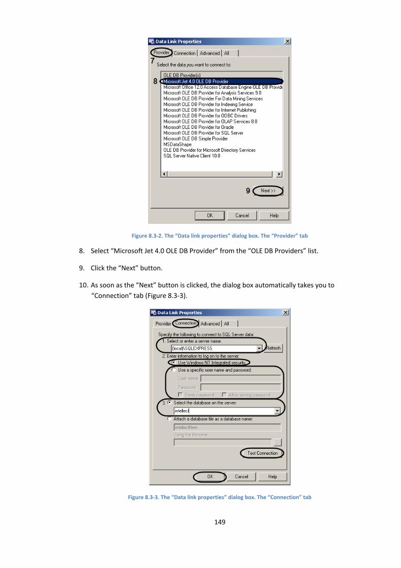
149
Figure 8.3-2. The “Data link properties” dialog box. The “Provider” tab
8. Select “Microsoft Jet 4.0 OLE DB Provider” from the “OLE DB Providers” list.
9. Click the “Next” button.
10. As soon as the “Next” button is clicked, the dialog box automatically takes you to
“Connection” tab (Figure 8.3-3).
Figure 8.3-3. The “Data link properties” dialog box. The “Connection” tab
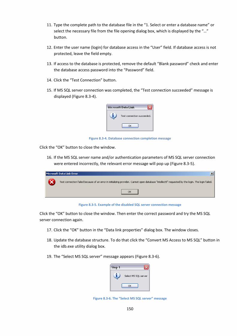
150
11. Type the complete path to the database file in the “1. Select or enter a database name” or
select the necessary file from the file opening dialog box, which is displayed by the “…”
button.
12. Enter the user name (login) for database access in the “User” field. If database access is not
protected, leave the field empty.
13. If access to the database is protected, remove the default “Blank password” check and enter
the database access password into the “Password” field.
14. Click the “Test Connection” button.
15. If MS SQL server connection was completed, the “Test connection succeeded” message is
displayed (Figure 8.3-4).
Figure 8.3-4. Database connection completion message
Click the “OK” button to close the window.
16. If the MS SQL server name and/or authentication parameters of MS SQL server connection
were entered incorrectly, the relevant error message will pop up (Figure 8.3-5).
Figure 8.3-5. Example of the disabled SQL server connection message
Click the “OK” button to close the window. Then enter the correct password and try the MS SQL
server connection again.
17. Click the “OK” button in the “Data link properties” dialog box. The window closes.
18. Update the database structure. To do that click the “Convert MS Access to MS SQL” button in
the idb.exe utility dialog box.
19. The “Select MS SQL server” message appears (Figure 8.3-6).
Figure 8.3-6. The “Select MS SQL server” message
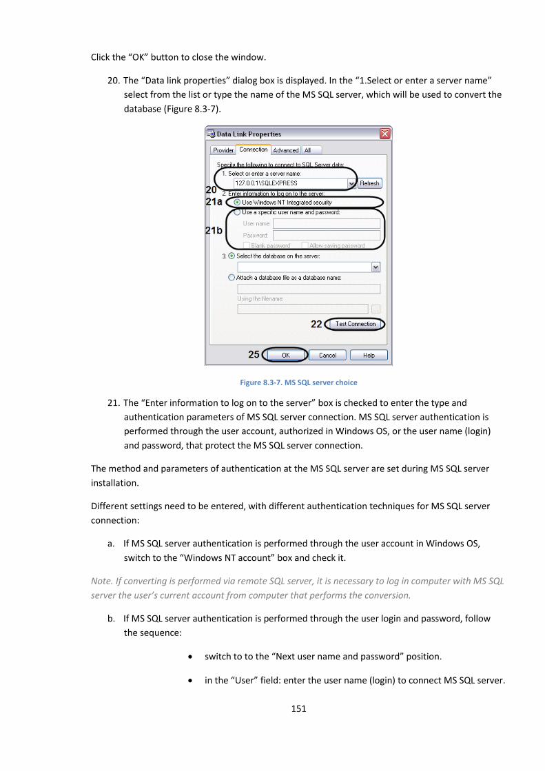
151
Click the “OK” button to close the window.
20. The “Data link properties” dialog box is displayed. In the “1.Select or enter a server name”
select from the list or type the name of the MS SQL server, which will be used to convert the
database (Figure 8.3-7).
Figure 8.3-7. MS SQL server choice
21. The “Enter information to log on to the server” box is checked to enter the type and
authentication parameters of MS SQL server connection. MS SQL server authentication is
performed through the user account, authorized in Windows OS, or the user name (login)
and password, that protect the MS SQL server connection.
The method and parameters of authentication at the MS SQL server are set during MS SQL server
installation.
Different settings need to be entered, with different authentication techniques for MS SQL server
connection:
a. If MS SQL server authentication is performed through the user account in Windows OS,
switch to the “Windows NT account” box and check it.
Note. If converting is performed via remote SQL server, it is necessary to log in computer with MS SQL
server the user’s current account from computer that performs the conversion.
b. If MS SQL server authentication is performed through the user login and password, follow
the sequence:
switch to to the “Next user name and password” position.
in the “User” field: enter the user name (login) to connect MS SQL server.
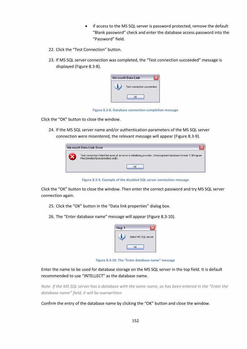
152
if access to the MS SQL server is password protected, remove the default
“Blank password” check and enter the database access password into the
“Password” field.
22. Click the “Test Connection” button.
23. If MS SQL server connection was completed, the “Test connection succeeded” message is
displayed (Figure 8.3-8).
Figure 8.3-8. Database connection completion message
Click the “OK” button to close the window.
24. If the MS SQL server name and/or authentication parameters of the MS SQL server
connection were misentered, the relevant message will appear (Figure 8.3-9).
Figure 8.3-9. Example of the disabled SQL server connection message
Click the “OK” button to close the window. Then enter the correct password and try MS SQL server
connection again.
25. Click the “OK” button in the “Data link properties” dialog box.
26. The “Enter database name” message will appear (Figure 8.3-10).
Figure 8.3-10. The “Enter database name” message
Enter the name to be used for database storage on the MS SQL server in the top field. It is default
recommended to use “INTELLECT” as the database name.
Note. If the MS SQL server has a database with the same name, as has been entered in the “Enter the
database name” field, it will be overwritten.
Confirm the entry of the database name by clicking the “OK” button and close the window.
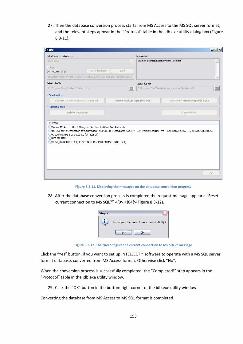
153
27. Then the database conversion process starts from MS Access to the MS SQL server format,
and the relevant steps appear in the “Protocol” table in the idb.exe utility dialog box (Figure
8.3-11).
Figure 8.3-11. Displaying the messages on the database conversion progress
28. After the database conversion process is completed the request message appears: “Reset
current connection to MS SQL?” «,0>.<}64{>(Figure 8.3-12).
Figure 8.3-12. The “Reconfigure the current connection to MS SQL?” message
Click the “Yes” button, if you want to set up INTELLECT™ software to operate with a MS SQL server
format database, converted from MS Access format. Otherwise click “No”.
When the conversion process is successfully completed, the “Completed!” step appears in the
“Protocol” table in the idb.exe utility window.
29. Click the “OK” button in the bottom right corner of the idb.exe utility window.
Converting the database from MS Access to MS SQL format is completed.

154
8.3.4 INTELLECT™ software database connection
When the Intellect™ software is installed, it is configured to operate with the “INTELLECT” MS SQL
server database.
Note. If the current database is stored in MS Access format, it needs to be converted to MS SQL
format before INTELLECT™ software connection setup.
To connect the INTELLECT™ software “Configuration” database, follow the procedure:
1. Make sure that MS SQL Server software is.
2. Launch the idb.exe utility in the root of the INTELLECT™ software installation directory (for
example, C:\Program Files\Intellect). The idb.exe utility dialog box is displayed (Figure
8.3-13).
Figure 8.3-13. The idb.exe utility dialog box
3. Choose the «Basic data» item from the “Select data source” list.
4. Set “Use” check , if not set before.
5. Click the “Build” button.
6. The “Data link properties” dialog box is displayed. Go to the “Provider” tab in the “Data link
properties” dialog box (Figure 8.3-14).
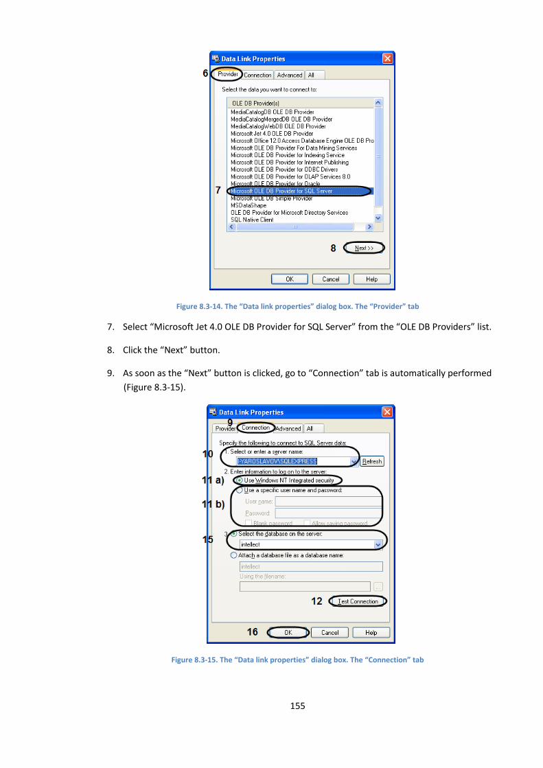
155
Figure 8.3-14. The “Data link properties” dialog box. The “Provider” tab
7. Select “Microsoft Jet 4.0 OLE DB Provider for SQL Server” from the “OLE DB Providers” list.
8. Click the “Next” button.
9. As soon as the “Next” button is clicked, go to “Connection” tab is automatically performed
(Figure 8.3-15).
Figure 8.3-15. The “Data link properties” dialog box. The “Connection” tab
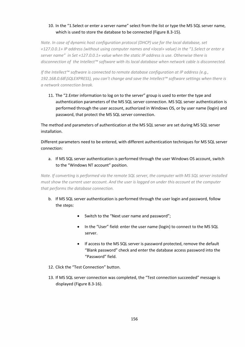
156
10. In the “1.Select or enter a server name” select from the list or type the MS SQL server name,
which is used to store the database to be connected (Figure 8.3-15).
Note. In case of dynamic host configuration protocol (DHCP) use for the local database, set
«127.0.0.1» IP address (without using computer names and «local» value) in the “1.Select or enter a
server name” in Set «127.0.0.1» value when the static IP address is use. Otherwise there is
disconnection of the Intellect™ software with its local database when network cable is disconnected.
If the Intellect™ software is connected to remote database configuration at IP address (e.g.,
192.168.0.68\SQLEXPRESS), you can’t change and save the Intellect™ software settings when there is
a network connection break.
11. The “2.Enter information to log on to the server” group is used to enter the type and
authentication parameters of the MS SQL server connection. MS SQL server authentication is
performed through the user account, authorized in Windows OS, or by user name (login) and
password, that protect the MS SQL server connection.
The method and parameters of authentication at the MS SQL server are set during MS SQL server
installation.
Different parameters need to be entered, with different authentication techniques for MS SQL server
connection:
a. If MS SQL server authentication is performed through the user Windows OS account, switch
to the “Windows NT account” position.
Note. If converting is performed via the remote SQL server, the computer with MS SQL server installed
must show the current user account. And the user is logged on under this account at the computer
that performs the database connection.
b. If MS SQL server authentication is performed through the user login and password, follow
the steps:
Switch to the “Next user name and password”;
In the “User” field: enter the user name (login) to connect to the MS SQL
server.
If access to the MS SQL server is password protected, remove the default
“Blank password” check and enter the database access password into the
“Password” field.
12. Click the “Test Connection” button.
13. If MS SQL server connection was completed, the “Test connection succeeded” message is
displayed (Figure 8.3-16).
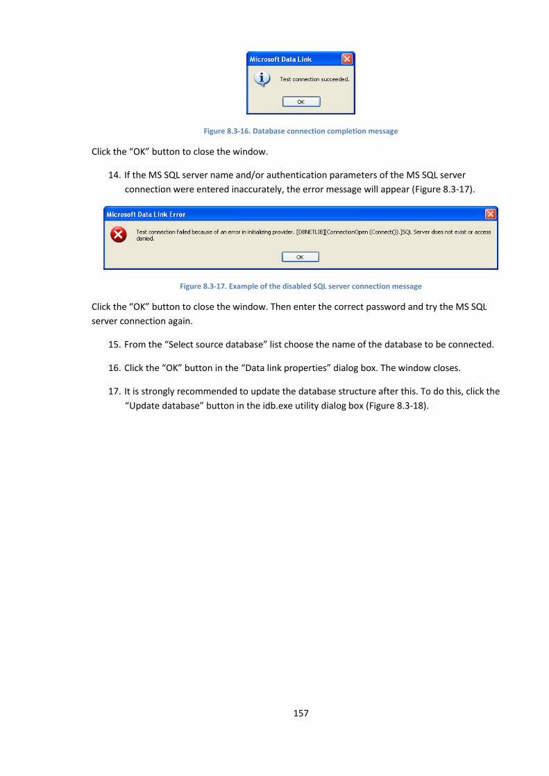
157
Figure 8.3-16. Database connection completion message
Click the “OK” button to close the window.
14. If the MS SQL server name and/or authentication parameters of the MS SQL server
connection were entered inaccurately, the error message will appear (Figure 8.3-17).
Figure 8.3-17. Example of the disabled SQL server connection message
Click the “OK” button to close the window. Then enter the correct password and try the MS SQL
server connection again.
15. From the “Select source database” list choose the name of the database to be connected.
16. Click the “OK” button in the “Data link properties” dialog box. The window closes.
17. It is strongly recommended to update the database structure after this. To do this, click the
“Update database” button in the idb.exe utility dialog box (Figure 8.3-18).

158
Figure 8.3-18. Database structure update
18. As a result, the database structure update process starts, and the error messages appear in
the “Protocol” table.
When the conversion process is successfully completed, the “Completed!” message appears in the
“Protocol” table in the idb.exe utility window.
19. Click the “OK” button in the bottom right corner of the idb.exe utility window.
INTELLECT™ software database connection is completed.
8.3.5 Viewing INTELLECT™ software database
To view the database stored on MS SQL server do the following:
1. Start ‘SQL Server Management Studio’ utility. Click ‘Start’ => ‘All Programs’ => ‘Microsoft SQL
Server 2008 R2’ => ‘SQL Server Management Studio’.
2. In ‘Connect to Server’ box set parameters of connection to MS SQL server (Figure 8.3-19).
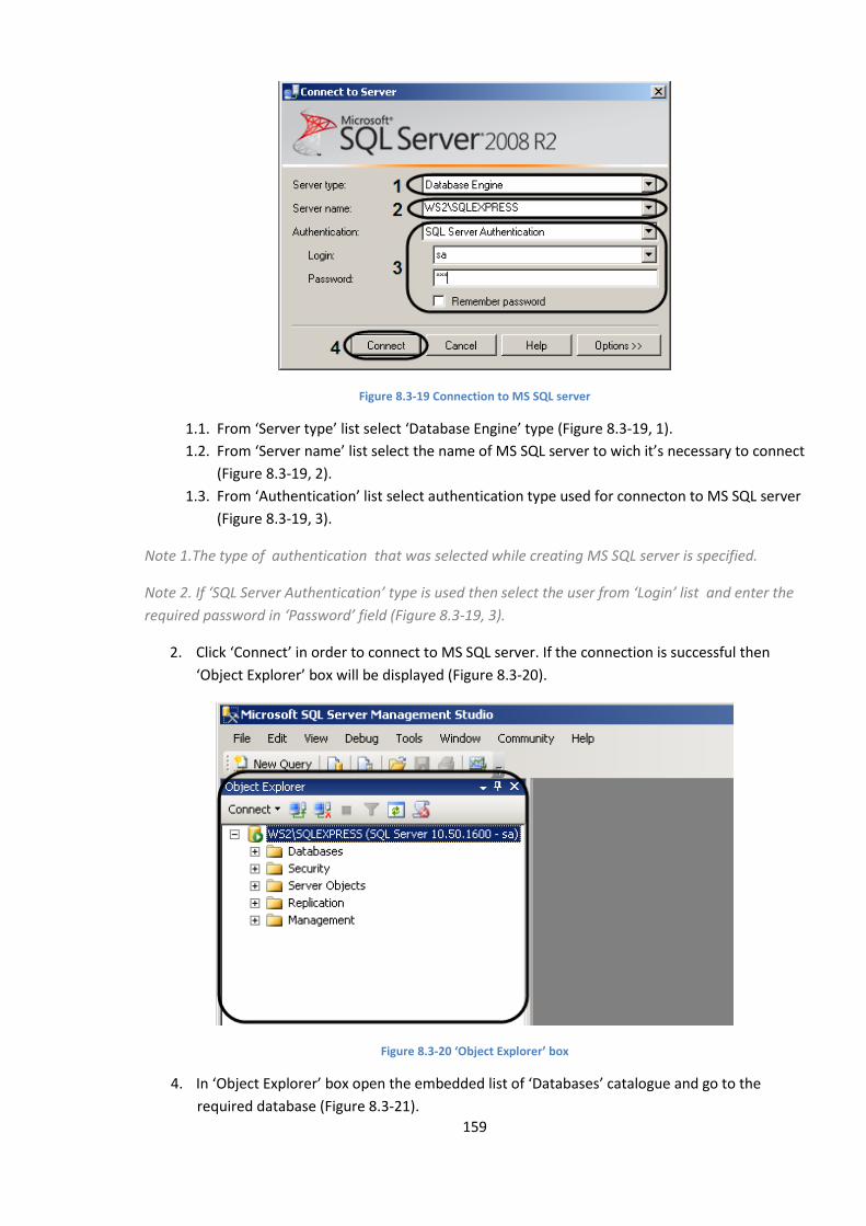
159
Figure 8.3-19 Connection to MS SQL server
1.1. From ‘Server type’ list select ‘Database Engine’ type (Figure 8.3-19, 1).
1.2. From ‘Server name’ list select the name of MS SQL server to wich it’s necessary to connect
(Figure 8.3-19, 2).
1.3. From ‘Authentication’ list select authentication type used for connecton to MS SQL server
(Figure 8.3-19, 3).
Note 1.The type of authentication that was selected while creating MS SQL server is specified.
Note 2. If ‘SQL Server Authentication’ type is used then select the user from ‘Login’ list and enter the
required password in ‘Password’ field (Figure 8.3-19, 3).
2. Click ‘Connect’ in order to connect to MS SQL server. If the connection is successful then
‘Object Explorer’ box will be displayed (Figure 8.3-20).
Figure 8.3-20 ‘Object Explorer’ box
4. In ‘Object Explorer’ box open the embedded list of ‘Databases’ catalogue and go to the
required database (Figure 8.3-21).
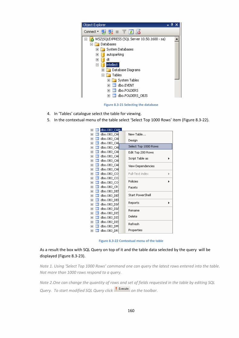
160
Figure 8.3-21 Selecting the database
4. In ‘Tables’ catalogue select the table for viewing.
5. In the contextual menu of the table select ‘Select Top 1000 Rows’ item (Figure 8.3-22).
Figure 8.3-22 Contextual menu of the table
As a result the box with SQL Query on top of it and the table data selected by the query will be
displayed (Figure 8.3-23).
Note 1. Using ‘Select Top 1000 Rows’ command one can query the latest rows entered into the table.
Not more than 1000 rows respond to a query.
Note 2.One can change the quantity of rows and set of fields requested in the table by editing SQL
Query. To start modified SQL Query click on the toolbar.
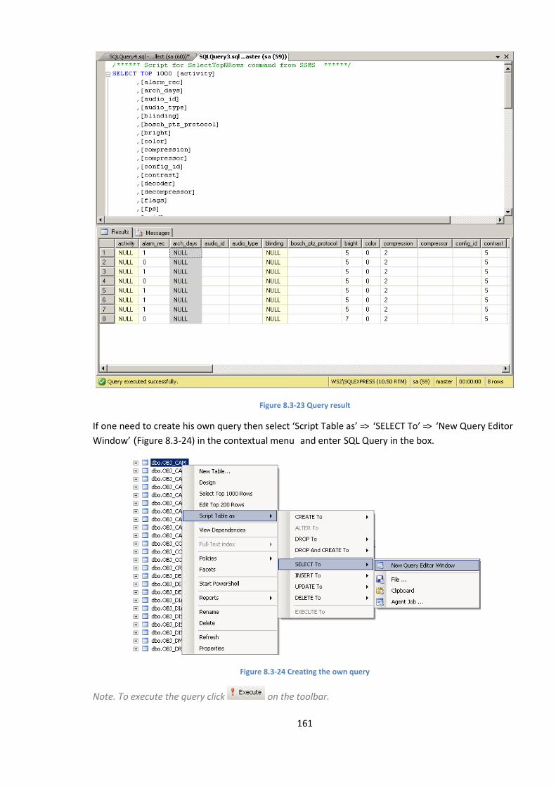
161
Figure 8.3-23 Query result
If one need to create his own query then select ‘Script Table as’ => ‘SELECT To’ => ‘New Query Editor
Window’ (Figure 8.3-24) in the contextual menu and enter SQL Query in the box.
Figure 8.3-24 Creating the own query
Note. To execute the query click on the toolbar.
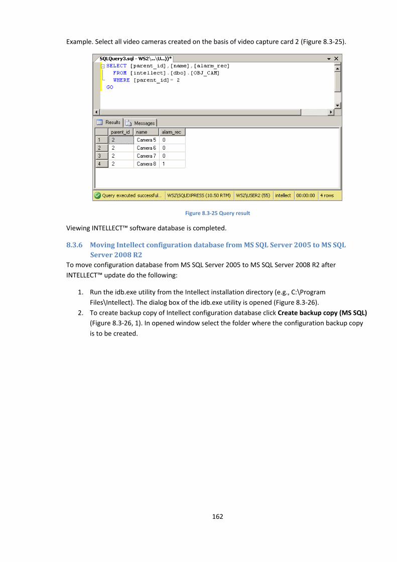
162
Example. Select all video cameras created on the basis of video capture card 2 (Figure 8.3-25).
Figure 8.3-25 Query result
Viewing INTELLECT™ software database is completed.
8.3.6 Moving Intellect configuration database from MS SQL Server 2005 to MS SQL
Server 2008 R2
To move configuration database from MS SQL Server 2005 to MS SQL Server 2008 R2 after
INTELLECT™ update do the following:
1. Run the idb.exe utility from the Intellect installation directory (e.g., C:\Program
Files\Intellect). The dialog box of the idb.exe utility is opened (Figure 8.3-26).
2. To create backup copy of Intellect configuration database click Create backup copy (MS SQL)
(Figure 8.3-26, 1). In opened window select the folder where the configuration backup copy
is to be created.
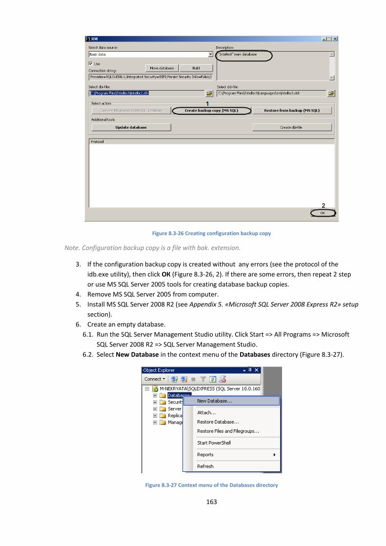
163
Figure 8.3-26 Creating configuration backup copy
Note. Configuration backup copy is a file with bak. extension.
3. If the configuration backup copy is created without any errors (see the protocol of the
idb.exe utility), then click ОК (Figure 8.3-26, 2). If there are some errors, then repeat 2 step
or use MS SQL Server 2005 tools for creating database backup copies.
4. Remove MS SQL Server 2005 from computer.
5. Install MS SQL Server 2008 R2 (see Appendix 5. «Microsoft SQL Server 2008 Express R2» setup
section).
6. Create an empty database.
6.1. Run the SQL Server Management Studio utility. Click Start => All Programs => Microsoft
SQL Server 2008 R2 => SQL Server Management Studio.
6.2. Select New Database in the context menu of the Databases directory (Figure 8.3-27).
Figure 8.3-27 Context menu of the Databases directory
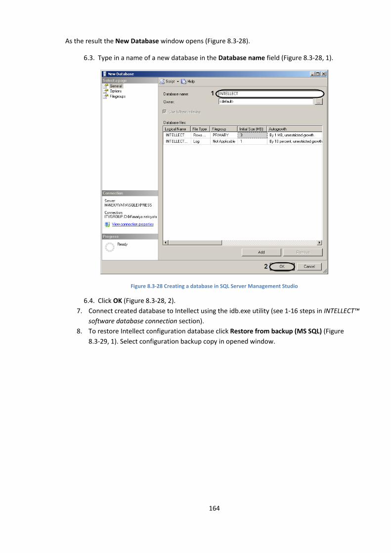
164
As the result the New Database window opens (Figure 8.3-28).
6.3. Type in a name of a new database in the Database name field (Figure 8.3-28, 1).
Figure 8.3-28 Creating a database in SQL Server Management Studio
6.4. Click OK (Figure 8.3-28, 2).
7. Connect created database to Intellect using the idb.exe utility (see 1-16 steps in INTELLECT™
software database connection section).
8. To restore Intellect configuration database click Restore from backup (MS SQL) (Figure
8.3-29, 1). Select configuration backup copy in opened window.
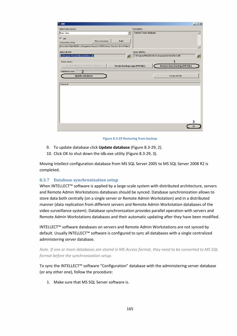
165
Figure 8.3-29 Restoring from backup
9. To update database click Update database (Figure 8.3-29, 2).
10. Click OK to shut down the idb.exe utility (Figure 8.3-29, 3).
Moving Intellect configuration database from MS SQL Server 2005 to MS SQL Server 2008 R2 is
completed.
8.3.7 Database synchronization setup
When INTELLECT™ software is applied by a large-scale system with distributed architecture, servers
and Remote Admin Workstations databases should be synced. Database synchronization allows to
store data both centrally (on a single server or Remote Admin Workstation) and in a distributed
manner (data replication from different servers and Remote Admin Workstation databases of the
video surveillance system). Database synchronization provides parallel operation with servers and
Remote Admin Workstations databases and their automatic updating after they have been modified.
INTELLECT™ software databases on servers and Remote Admin Workstations are not synced by
default. Usually INTELLECT™ software is configured to sync all databases with a single centralized
administering server database.
Note. If one or more databases are stored in MS Access format, they need to be converted to MS SQL
format before the synchronization setup.
To sync the INTELLECT™ software “Configuration” database with the administering server database
(or any other one), follow the procedure:
1. Make sure that MS SQL Server software is.
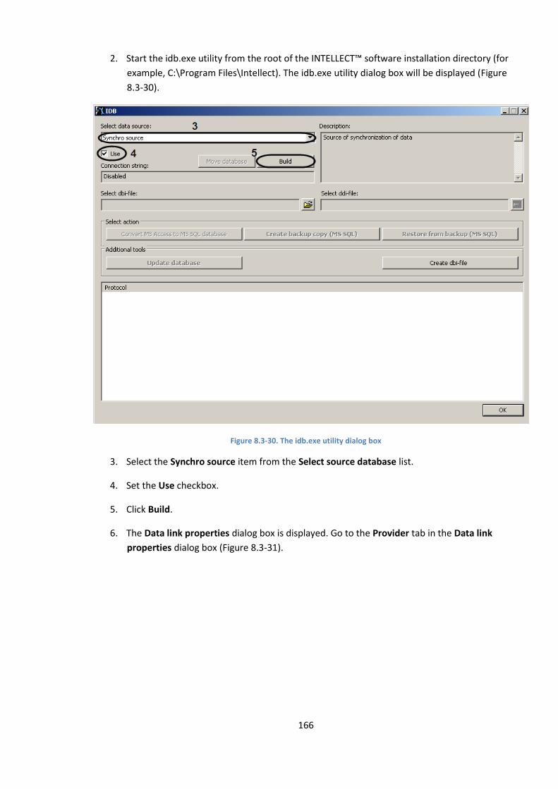
166
2. Start the idb.exe utility from the root of the INTELLECT™ software installation directory (for
example, C:\Program Files\Intellect). The idb.exe utility dialog box will be displayed (Figure
8.3-30).
Figure 8.3-30. The idb.exe utility dialog box
3. Select the Synchro source item from the Select source database list.
4. Set the Use checkbox.
5. Click Build.
6. The Data link properties dialog box is displayed. Go to the Provider tab in the Data link
properties dialog box (Figure 8.3-31).
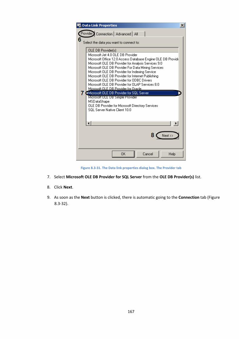
167
Figure 8.3-31. The Data link properties dialog box. The Provider tab
7. Select Microsoft OLE DB Provider for SQL Server from the OLE DB Provider(s) list.
8. Click Next.
9. As soon as the Next button is clicked, there is automatic going to the Connection tab (Figure
8.3-32).
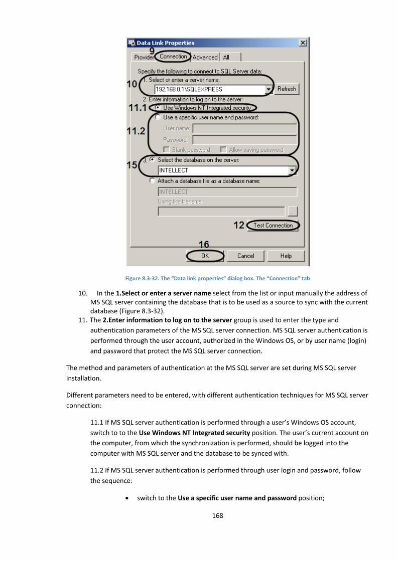
168
Figure 8.3-32. The “Data link properties” dialog box. The “Connection” tab
10. In the 1.Select or enter a server name select from the list or input manually the address of MS SQL server containing the database that is to be used as a source to sync with the current database (Figure 8.3-32).
11. The 2.Enter information to log on to the server group is used to enter the type and
authentication parameters of the MS SQL server connection. MS SQL server authentication is
performed through the user account, authorized in the Windows OS, or by user name (login)
and password that protect the MS SQL server connection.
The method and parameters of authentication at the MS SQL server are set during MS SQL server
installation.
Different parameters need to be entered, with different authentication techniques for MS SQL server
connection:
11.1 If MS SQL server authentication is performed through a user’s Windows OS account,
switch to to the Use Windows NT Integrated security position. The user’s current account on
the computer, from which the synchronization is performed, should be logged into the
computer with MS SQL server and the database to be synced with.
11.2 If MS SQL server authentication is performed through user login and password, follow
the sequence:
switch to the Use a specific user name and password position;
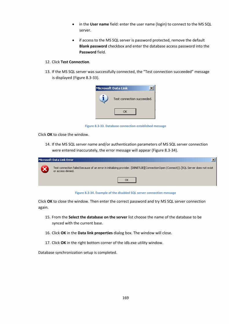
169
in the User name field: enter the user name (login) to connect to the MS SQL
server.
if access to the MS SQL server is password protected, remove the default
Blank password checkbox and enter the database access password into the
Password field.
12. Click Test Connection.
13. If the MS SQL server was successfully connected, the “Test connection succeeded” message
is displayed (Figure 8.3-33).
Figure 8.3-33. Database connection established message
Click OK to close the window.
14. If the MS SQL server name and/or authentication parameters of MS SQL server connection
were entered inaccurately, the error message will appear (Figure 8.3-34).
Figure 8.3-34. Example of the disabled SQL server connection message
Click OK to close the window. Then enter the correct password and try MS SQL server connection
again.
15. From the Select the database on the server list choose the name of the database to be
synced with the current base.
16. Click OK in the Data link properties dialog box. The window will close.
17. Click OK in the right bottom corner of the idb.exe utility window.
Database synchronization setup is completed.
170
8.4 Video subsystem settings
8.4.1 General information on video subsystem settings
8.4.1.1 Video subsystem components description
In the video surveillance systems based on INTELLECT™ software by video subsystem you mean the
set of software modules and hardware devices used to receive, transmit, digitize, process, record and
display video signals from video surveillance system cameras on monitor screens.
Video subsystem hardware includes:
1. video capture cards;
2. analog video camera (cameras);
3. IP devices.
Video subsystem software includes:
1. components for configuring the video capture cards.
2. components for digitized video signal compression and decompression.
3. components for digitized video signal recording.
4. components for digitized video signal transmission to Remote workstations.
5. components for displaying video signal on the monitor.
8.4.1.2 Configuring video capture cards
Video capture cards are configured in the course of INTELLECT™ software administering. Video
capture cards are configured by video signal digitization and processing settings, which comply with:
1. signal format (PAL or NTSC);
2. frame rate;
3. frame resolution;
4. brightness;
5. contrast;
6. color depth;
7. color rendition format.
Each camera has its individual video signal processing and digitization settings (except for the signal
format, which is set for all cameras, and is attached to the same ADC).
Moreover, configuring the video grabber involves setting up a proper switching of the video input
channels.
171
8.4.1.3 Configuring IP-devices
IP-devices are configured via the web server or any other software, supplied together with the
device, and via INTELLECT™ software.
Video signal compression and processing settings (format, frame rate, frame resolution, brightness,
contrast, color depth, color rendition format) are performed via the web server or any other
software, supplied together with the device.
The INTELLECT™ software system receives the image, processes it with detectors, records the video
signals from IP-devices and transfers it to the Remote Monitoring Workstation.
Be sure before using an IP-device that processing and digitization settings of IP-devices (especially
codecs), set via the web server, are supported by INTELLECT™ software. For actual information on IP-
device compatibility, see the “Integration” section on the ITV company site:
http://www.itv.ru/products/integration/.
8.4.1.4 Video signal compression and decompression
Video signal soft compression is digital video sequence soft processing, aimed at reducing its size.
Compression is performed according to a specific software algorithm.
INTELLECT™ software uses a specific MotionWavelet algorithm to compress video signal, received
from video capture cards. This algorithm allows to reduce video stream size by tens of times (5 to 30,
subject to video signal characteristics and compression rate). To compress video signals from IP-
devices, standard or manufacturer designed algorithms are used.
With compression, video stream size decreases at the cost of its quality. That is why INTELLECT™
software compresses the video signal in two modes only: in disk recording mode and in transmission
to the Remote Workplace mode. Before displaying on a video server monitor, the video signal is not
compressed.
Before displaying the compressed video signal it is decompressed. Decompression is automatically
performed during video signals displaying (both real-time and archive footage playback) at Remote
Workplaces and video recordings playback on the videoserver.
8.4.1.5 How to record digitized video signals
Video signals archiving provides post-event analysis of evidence footage.
The archive is located on the local disks of the videoserver. Having reached the end of the archive
disk volume, the archive is overwritten.
Before archiving on the videoserver, the video signal is compressed. It is compressed to reduce the
size of the video recordings.
INTELLECT™ software is capable of auto recording, initiated by cameras (Main detectors) and
detectors alarm detection or by Operator command.
Pre-event, post-event, and Hot (higher frame rate) recording can be performed to make post-event
analysis of evidence footage more effective.
172
8.4.1.6 Digital video signal transmission to Remote Workplaces
INTELLECT™ software provides video surveillance from Remote Workstations based on:
1. A PC (IBM PC–based) personal computer, connected to the videoserver via local TCP/IP net;
2. An IBM PC, connected to the videoserver via the “web server” module by HTTP protocol;
3. PocketPC, connected to the videoserver via the «SmartPocket» module;
4. SmartPhone, connected to the videoserver via the «SmartPhone» module.
Both real-time and archive video signals may be transmitted to Remote Workstations. Prior to being
transmitted to a Remote Workplace, video signals are compressed.
8.4.1.7 Video signal display
Video signals are displayed using the “Video Surveillance Monitor” interface object. The Video
monitor is especially used to display video signals, received from cameras, and to play back the video
recordings.
The video monitor has several options: detectors, PTZ units and microphones control, image
processing and exporting.
Different video monitors are used with different video signal transmission modes:
1. Video server surveillance Monitor.
2. Video surveillance Monitor of the Remote Workstation, connected to the videoserver via the
TCP/IP net, identical to the videoserver surveillance Monitor.
3. Video monitor of the “web server”, depicted in web browsers on Remote Workstations,
connected to the videoserver via the “web server” module by HTTP protocol.
4. “SmartPocket” module video monitor, displayed on the PocketPC screen, connected to the
videoserver via the “SmartPocket” module.
5. “SmartPhone” module video monitor, displayed on the SmartPhone screen, connected to the
videoserver via the “SmartPhone” module.
The above video surveillance monitors have different components and functions. Any video monitor
can be set up to display real-time video and play back archive footage.
8.4.2 Registration of video grabbers and camera registration in the INTELLECT™
software
Video grabbers are registered in the INTELLECT™ software by creating and setting up “Video capture
card” objects. “Video capture card” objects are created on the “Hardware” tab on the base of
“Computer” objects. The video grabber registration sequence depends on the type and number of
devices used. Different types of video grabber registration sequences are described in the relevant
sections.
Example of registration of the FS-5 card as a video capture device is shown in.
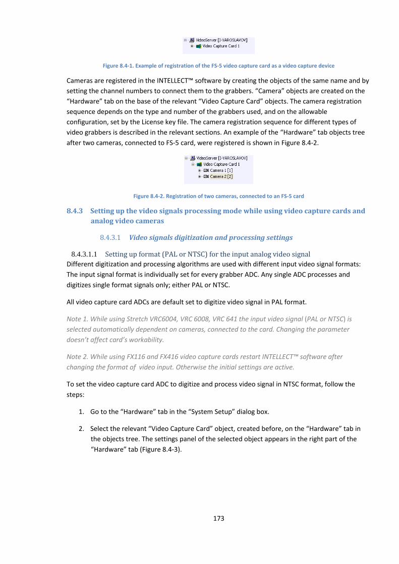
173
Figure 8.4-1. Example of registration of the FS-5 video capture card as a video capture device
Cameras are registered in the INTELLECT™ software by creating the objects of the same name and by
setting the channel numbers to connect them to the grabbers. “Camera” objects are created on the
“Hardware” tab on the base of the relevant “Video Capture Card” objects. The camera registration
sequence depends on the type and number of the grabbers used, and on the allowable
configuration, set by the License key file. The camera registration sequence for different types of
video grabbers is described in the relevant sections. An example of the “Hardware” tab objects tree
after two cameras, connected to FS-5 card, were registered is shown in Figure 8.4-2.
Figure 8.4-2. Registration of two cameras, connected to an FS-5 card
8.4.3 Setting up the video signals processing mode while using video capture cards and
analog video cameras
8.4.3.1 Video signals digitization and processing settings
8.4.3.1.1 Setting up format (PAL or NTSC) for the input analog video signal
Different digitization and processing algorithms are used with different input video signal formats:
The input signal format is individually set for every grabber ADC. Any single ADC processes and
digitizes single format signals only; either PAL or NTSC.
All video capture card ADCs are default set to digitize video signal in PAL format.
Note 1. While using Stretch VRC6004, VRC 6008, VRC 641 the input video signal (PAL or NTSC) is
selected automatically dependent on cameras, connected to the card. Changing the parameter
doesn’t affect card’s workability.
Note 2. While using FX116 and FX416 video capture cards restart INTELLECT™ software after
changing the format of video input. Otherwise the initial settings are active.
To set the video capture card ADC to digitize and process video signal in NTSC format, follow the
steps:
1. Go to the “Hardware” tab in the “System Setup” dialog box.
2. Select the relevant “Video Capture Card” object, created before, on the “Hardware” tab in
the objects tree. The settings panel of the selected object appears in the right part of the
“Hardware” tab (Figure 8.4-3).
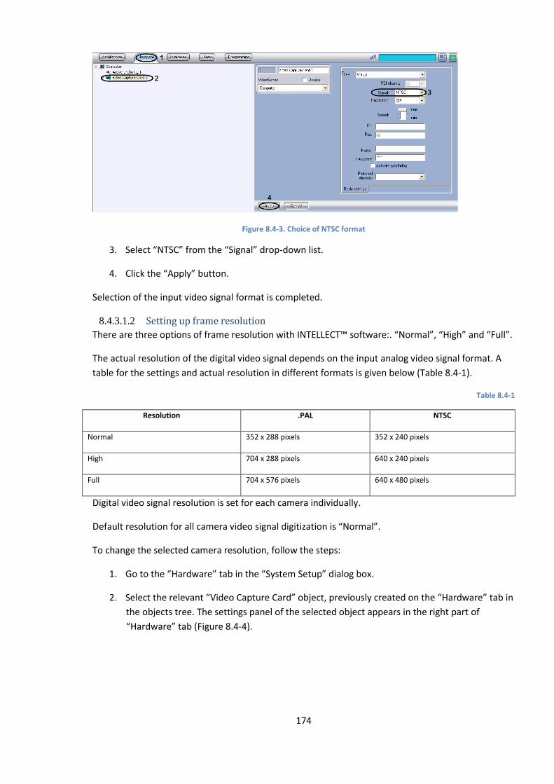
174
Figure 8.4-3. Choice of NTSC format
3. Select “NTSC” from the “Signal” drop-down list.
4. Click the “Apply” button.
Selection of the input video signal format is completed.
8.4.3.1.2 Setting up frame resolution
There are three options of frame resolution with INTELLECT™ software:. “Normal”, “High” and “Full”.
The actual resolution of the digital video signal depends on the input analog video signal format. A
table for the settings and actual resolution in different formats is given below (Table 8.4-1).
Table 8.4-1
Resolution .PAL NTSC
Normal 352 x 288 pixels 352 x 240 pixels
High 704 х 288 pixels 640 x 240 pixels
Full 704 х 576 pixels 640 x 480 pixels
Digital video signal resolution is set for each camera individually.
Default resolution for all camera video signal digitization is “Normal”.
To change the selected camera resolution, follow the steps:
1. Go to the “Hardware” tab in the “System Setup” dialog box.
2. Select the relevant “Video Capture Card” object, previously created on the “Hardware” tab in
the objects tree. The settings panel of the selected object appears in the right part of
“Hardware” tab (Figure 8.4-4).
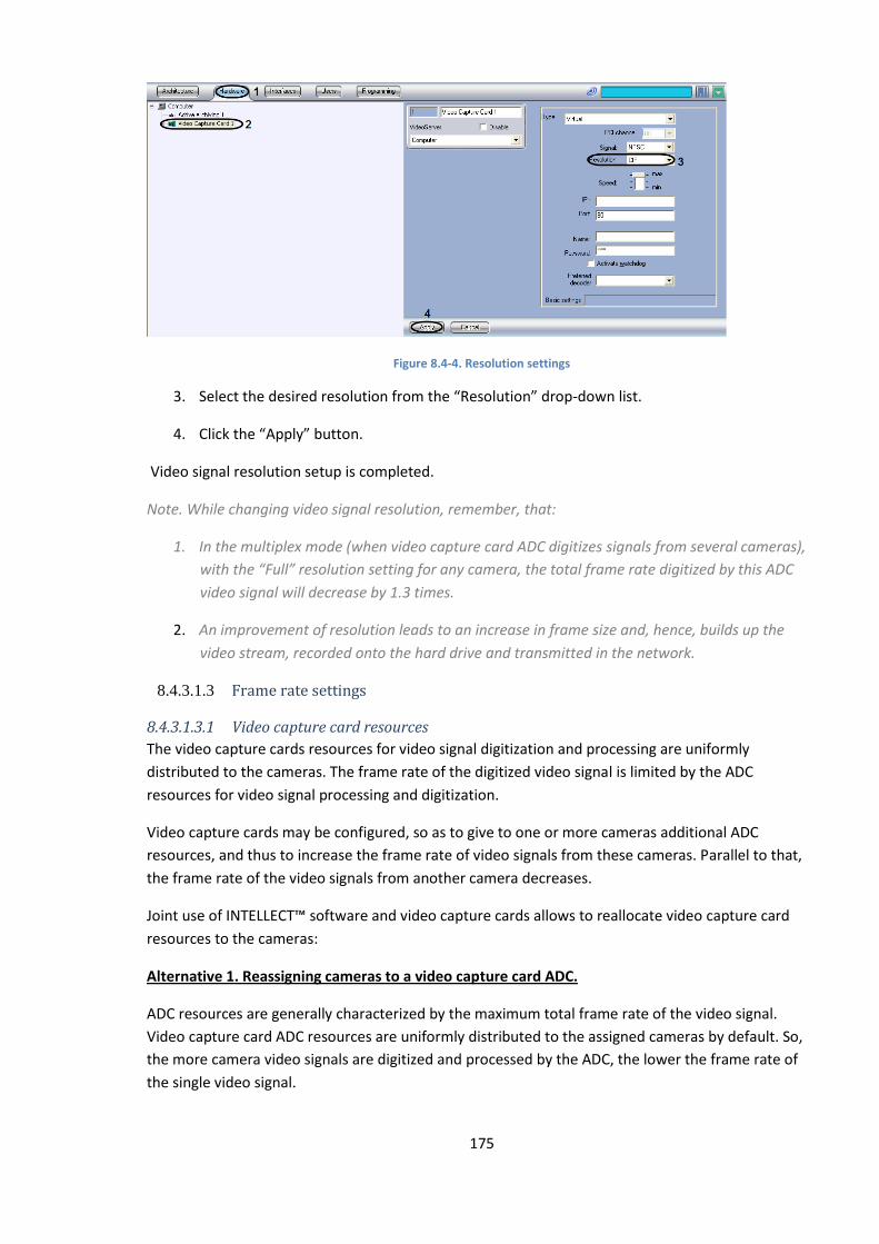
175
Figure 8.4-4. Resolution settings
3. Select the desired resolution from the “Resolution” drop-down list.
4. Click the “Apply” button.
Video signal resolution setup is completed.
Note. While changing video signal resolution, remember, that:
1. In the multiplex mode (when video capture card ADC digitizes signals from several cameras),
with the “Full” resolution setting for any camera, the total frame rate digitized by this ADC
video signal will decrease by 1.3 times.
2. An improvement of resolution leads to an increase in frame size and, hence, builds up the
video stream, recorded onto the hard drive and transmitted in the network.
8.4.3.1.3 Frame rate settings
8.4.3.1.3.1 Video capture card resources
The video capture cards resources for video signal digitization and processing are uniformly
distributed to the cameras. The frame rate of the digitized video signal is limited by the ADC
resources for video signal processing and digitization.
Video capture cards may be configured, so as to give to one or more cameras additional ADC
resources, and thus to increase the frame rate of video signals from these cameras. Parallel to that,
the frame rate of the video signals from another camera decreases.
Joint use of INTELLECT™ software and video capture cards allows to reallocate video capture card
resources to the cameras:
Alternative 1. Reassigning cameras to a video capture card ADC.
ADC resources are generally characterized by the maximum total frame rate of the video signal.
Video capture card ADC resources are uniformly distributed to the assigned cameras by default. So,
the more camera video signals are digitized and processed by the ADC, the lower the frame rate of
the single video signal.

176
Reassigning of cameras to the ADCs allows to increase the frame rate for some cameras at the
expense of another ones.
If all allowable cameras are connected to a video capture card, then only uniform distribution on ADC
is possible. In this case every ADC digitizes and processes video signal from an equal number of
cameras. So, the maximum frame rate is the same for all video signals (except for video signals of
different formats and different resolutions).
If the number of cameras connected to a video capture card is less than their maximum number, it is
possible to reallocate them to ADC. To do this, those cameras, whose frame rate should be
increased, are assigned separately to one ADC, or assigned in an amount, less than the maximum
allowable number. Cameras assigned to a given ADC and not subject to strict frame rate
requirements, are reassigned to other ADCs.
An example of assigning cameras to ADCs is schematically shown in Figure 8.4-5.
A. Uniform camera allocation to the ADCs.
B. reassigning the cameras to the ADCs to allocate camera No1
Figure 8.4-5. An example of reassigning cameras to ADCs
Alternative 2. Reallocation of resources from 1 ADC to the cameras, assigned to it.
The video capture card ADC resources are uniformly allocated to the assigned cameras by default.
ADC resources reallocation allows to increase the frame rate for some cameras at the expense of
another ones. Reallocation of resources from 1 ADC to the cameras is much less effective than
camera reallocation to the ADC. Therefore this should be done only if camera reallocation to the ADC
is impossible or if it doesn’t help.
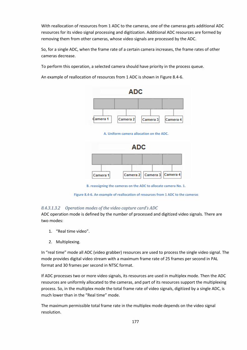
177
With reallocation of resources from 1 ADC to the cameras, one of the cameras gets additional ADC
resources for its video signal processing and digitization. Additional ADC resources are formed by
removing them from other cameras, whose video signals are processed by the ADC.
So, for a single ADC, when the frame rate of a certain camera increases, the frame rates of other
cameras decrease.
To perform this operation, a selected camera should have priority in the process queue.
An example of reallocation of resources from 1 ADC is shown in Figure 8.4-6.
A. Uniform camera allocation on the ADC.
B. reassigning the cameras on the ADC to allocate camera No. 1.
Figure 8.4-6. An example of reallocation of resources from 1 ADC to the cameras
8.4.3.1.3.2 Operation modes of the video capture card’s ADC
ADC operation mode is defined by the number of processed and digitized video signals. There are
two modes:
1. “Real time video”.
2. Multiplexing.
In “real time” mode all ADC (video grabber) resources are used to process the single video signal. The
mode provides digital video stream with a maximum frame rate of 25 frames per second in PAL
format and 30 frames per second in NTSC format.
If ADC processes two or more video signals, its resources are used in multiplex mode. Then the ADC
resources are uniformly allocated to the cameras, and part of its resources support the multiplexing
process. So, in the multiplex mode the total frame rate of video signals, digitized by a single ADC, is
much lower than in the “Real time” mode.
The maximum permissible total frame rate in the multiplex mode depends on the video signal
resolution.

178
For ADC that digitizes all video signals with normal (352 x 288 pixels in PAL format, 352 x 240 pixels in
NTSC format) and/or high (704 х 288 pixels in PAL format, 640 x 240 pixels in NTSC format) frame
resolution, the total frame rate is 16 frames per second in PAL format and 20 frames per second in
NTSC format.
When ADC digitizes at least one of the video signals with full resolution (704 x 576 pixels in PAL
format, 640 x 480 pixels in NTSC format), the maximum allowed total frame rate falls to 12 frames
per second in PAL format and 15 frames per second in NTSC format.
8.4.3.1.3.3 Frame rate setup sequence
Default settings for the digitized video signals frame rate are 2 frames per second in PAL format and
2.5 frames per second in NTSC format.
The settings allow to increase or to reduce the frame rate.
To set up the frame rate, follow the sequence:
1. Switch off the “Camera” objects, which are assigned to the idle video capture channels. This
allows to allocate the resources to the working cameras only and thus to increase the frame
rate.
2. Change frame scaling.
3. Reallocate the cameras on the video capture card ADC.
4. Reallocate resources from 1 ADC to the cameras (priority process queue).
In most cases steps 1 and 2 are sufficient to set the frame rate. Steps 3 and 4 are necessary only with
high frame rate requirements to one or more cameras.
8.4.3.1.3.4 Video subsystem settings with video capture channels switched off
Video capture card’s ADC resources allocation is uniformly performed to all the video capture
channels by default, irrespective of whether there is any signal passing through it or not. So, even if a
video channel has no signal, it nevertheless is assigned ADC resources.
To prevent inefficient ADC resources consumption, “Camera” objects, assigned to the idle video
input channels, should be switched off in the Intellect.
Several “Camera” objects are switched off in turn.
To switch off “Camera” objects in the INTELLECT™ system, follow the procedure:
1. Define the numbers of the idle video capture channels (taking into account BNC plug
numbering).
2. Go to the “Hardware” tab in the “System Setup” dialog box (Figure 8.4-7).
3. Select the “Camera” object, created before, with the same channel number as the BNC plug
(idle channel). The settings panel of the selected object appears in the right part of the
“Hardware” tab.

179
Figure 8.4-7. Switch off the “Camera” object
4. Make sure that no signal is displayed in the “System Setup” dialog box video surveillance
field.
5. The signal displayed in the “System Setup” dialog box video surveillance field indicates that
the “Camera” object is assigned to another video capture channel. The video capture channel
number is set up from the “Channel number” drop-down menu. Assign the “Camera” object
to the channel, which corresponds to the BNC plug number and the “Camera” object
number, or scan for a “Camera” object, assigned to the desired number of the video capture
channel.
6. Check the “Disabled” checkbox.
7. Click the “Apply” button.
8. The disabled “Camera” object is indicated with a cross mark (Figure 8.4-8).
Figure 8.4-8. Disabled “Camera” object in the objects tree
Video subsystem setup with switched off video capture channels is completed.
8.4.3.1.3.5 Actual frame rate definition
It is recommended to firstly define the current actual frame rates of video signal digitization and then
to set up the frame rates for video signals from video surveillance system cameras.
Frame rate setup should be done only if video signal frame rates from one or more cameras do not
meet the requirements.
Actual frame rates are defined for each camera individually.
To define the actual frame rate for a selected camera, follow the steps:
1. Set up the video surveillance monitor (see the relevant sections of the Guide);
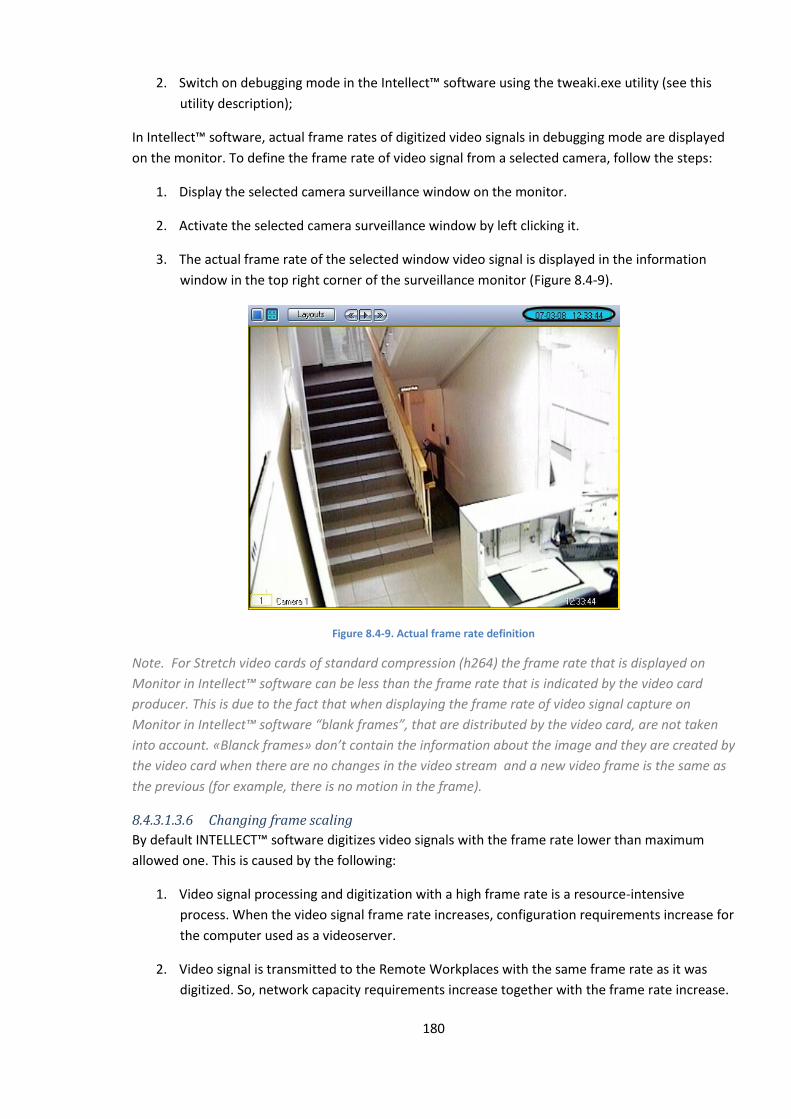
180
2. Switch on debugging mode in the Intellect™ software using the tweaki.exe utility (see this
utility description);
In Intellect™ software, actual frame rates of digitized video signals in debugging mode are displayed
on the monitor. To define the frame rate of video signal from a selected camera, follow the steps:
1. Display the selected camera surveillance window on the monitor.
2. Activate the selected camera surveillance window by left clicking it.
3. The actual frame rate of the selected window video signal is displayed in the information
window in the top right corner of the surveillance monitor (Figure 8.4-9).
Figure 8.4-9. Actual frame rate definition
Note. For Stretch video cards of standard compression (h264) the frame rate that is displayed on
Monitor in Intellect™ software can be less than the frame rate that is indicated by the video card
producer. This is due to the fact that when displaying the frame rate of video signal capture on
Monitor in Intellect™ software “blank frames”, that are distributed by the video card, are not taken
into account. «Blanck frames» don’t contain the information about the image and they are created by
the video card when there are no changes in the video stream and a new video frame is the same as
the previous (for example, there is no motion in the frame).
8.4.3.1.3.6 Changing frame scaling
By default INTELLECT™ software digitizes video signals with the frame rate lower than maximum
allowed one. This is caused by the following:
1. Video signal processing and digitization with a high frame rate is a resource-intensive
process. When the video signal frame rate increases, configuration requirements increase for
the computer used as a videoserver.
2. Video signal is transmitted to the Remote Workplaces with the same frame rate as it was
digitized. So, network capacity requirements increase together with the frame rate increase.
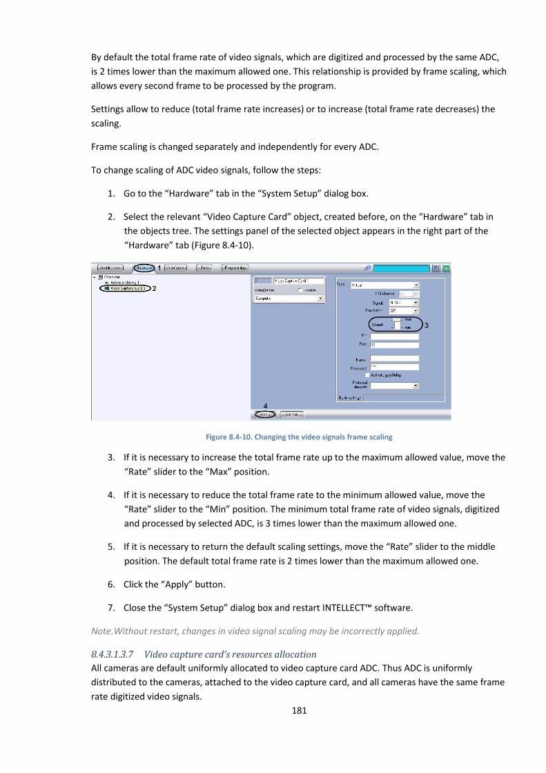
181
By default the total frame rate of video signals, which are digitized and processed by the same ADC,
is 2 times lower than the maximum allowed one. This relationship is provided by frame scaling, which
allows every second frame to be processed by the program.
Settings allow to reduce (total frame rate increases) or to increase (total frame rate decreases) the
scaling.
Frame scaling is changed separately and independently for every ADC.
To change scaling of ADC video signals, follow the steps:
1. Go to the “Hardware” tab in the “System Setup” dialog box.
2. Select the relevant “Video Capture Card” object, created before, on the “Hardware” tab in
the objects tree. The settings panel of the selected object appears in the right part of the
“Hardware” tab (Figure 8.4-10).
Figure 8.4-10. Changing the video signals frame scaling
3. If it is necessary to increase the total frame rate up to the maximum allowed value, move the
“Rate” slider to the “Max” position.
4. If it is necessary to reduce the total frame rate to the minimum allowed value, move the
“Rate” slider to the “Min” position. The minimum total frame rate of video signals, digitized
and processed by selected ADC, is 3 times lower than the maximum allowed one.
5. If it is necessary to return the default scaling settings, move the “Rate” slider to the middle
position. The default total frame rate is 2 times lower than the maximum allowed one.
6. Click the “Apply” button.
7. Close the “System Setup” dialog box and restart INTELLECT™ software.
Note.Without restart, changes in video signal scaling may be incorrectly applied.
8.4.3.1.3.7 Video capture card’s resources allocation
All cameras are default uniformly allocated to video capture card ADC. Thus ADC is uniformly
distributed to the cameras, attached to the video capture card, and all cameras have the same frame
rate digitized video signals.
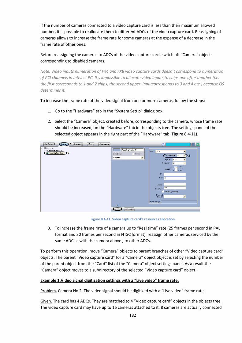
182
If the number of cameras connected to a video capture card is less than their maximum allowed
number, it is possible to reallocate them to different ADCs of the video capture card. Reassigning of
cameras allows to increase the frame rate for some cameras at the expense of a decrease in the
frame rate of other ones.
Before reassigning the cameras to ADCs of the video capture card, switch off “Camera” objects
corresponding to disabled cameras.
Note. Video inputs numeration of FX4 and FX8 video capture cards doesn’t correspond to numeration
of PCI channels in Intelect PC. It’s impossible to allocate video inputs to chips one after another (i.e.
the first corresponds to 1 and 2 chips, the second upper inputcorresponds to 3 and 4 etc.) because OS
determines it.
To increase the frame rate of the video signal from one or more cameras, follow the steps:
1. Go to the “Hardware” tab in the “System Setup” dialog box.
2. Select the “Camera” object, created before, corresponding to the camera, whose frame rate
should be increased, on the “Hardware” tab in the objects tree. The settings panel of the
selected object appears in the right part of the “Hardware” tab (Figure 8.4-11).
Figure 8.4-11. Video capture card’s resources allocation
3. To increase the frame rate of a camera up to “Real time” rate (25 frames per second in PAL
format and 30 frames per second in NTSC format), reassign other cameras serviced by the
same ADC as with the camera above , to other ADCs.
To perform this operation, move “Camera” objects to parent branches of other “Video capture card”
objects. The parent “Video capture card” for a “Camera” object object is set by selecting the number
of the parent object from the “Card” list of the “Camera” object settings panel. As a result the
“Camera” object moves to a subdirectory of the selected “Video capture card” object.
Example 1.Video signal digitization settings with a “Live video” frame rate.
Problem. Camera No 2. The video signal should be digitized with a “Live video” frame rate.
Given. The card has 4 ADCs. They are matched to 4 “Video capture card” objects in the objects tree.
The video capture card may have up to 16 cameras attached to it. 8 cameras are actually connected
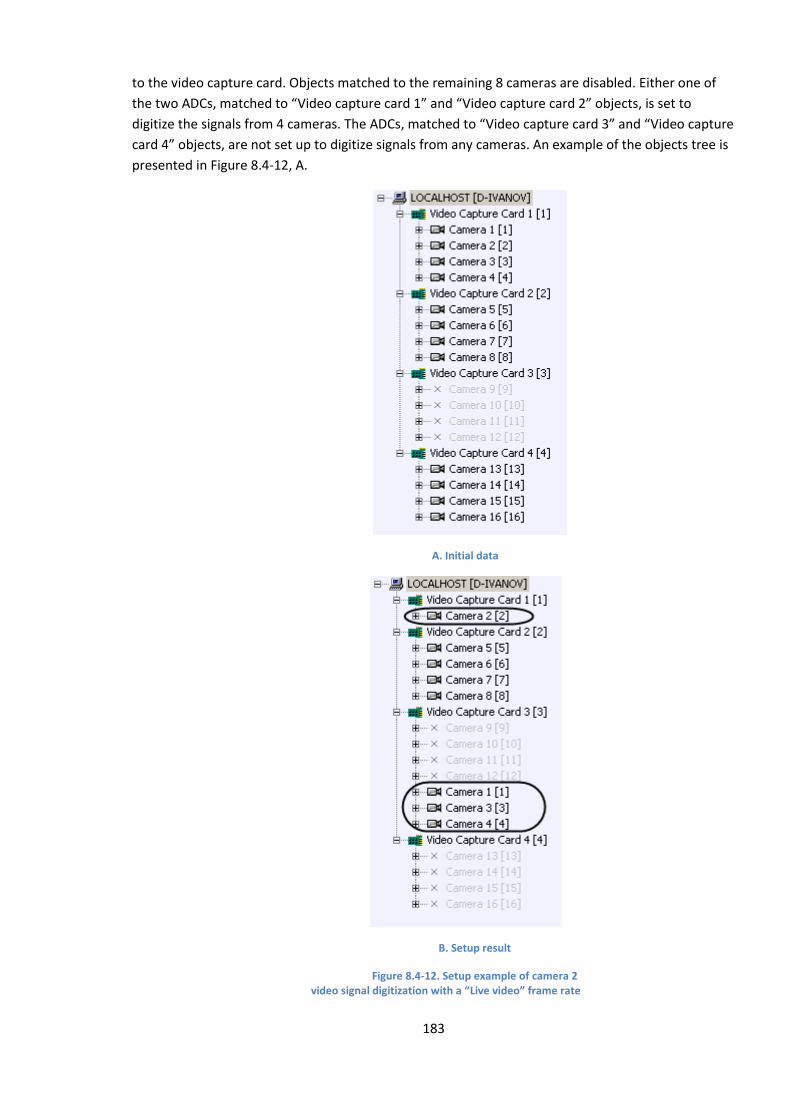
183
to the video capture card. Objects matched to the remaining 8 cameras are disabled. Either one of
the two ADCs, matched to “Video capture card 1” and “Video capture card 2” objects, is set to
digitize the signals from 4 cameras. The ADCs, matched to “Video capture card 3” and “Video capture
card 4” objects, are not set up to digitize signals from any cameras. An example of the objects tree is
presented in Figure 8.4-12, A.
A. Initial data
B. Setup result
Figure 8.4-12. Setup example of camera 2 video signal digitization with a “Live video” frame rate frame rate

184
Solution. You should follow the steps:
1. Select the “Camera 1” object in the tree. The settings panel of the selected object appears.
2. Select “ Video Capture Card 3” from the “Video Capture Card” list.
3. Click the “Apply”.
4. The “Camera 1” object moves to the subdirectory of the “Video Capture Card 3” object (see
Fig. Figure 8.4-12, B).
5. Repeat (1) – (4) operations for the “Camera 3” and “Camera 4” objects.
6. Select the “Video Capture Card 1” object in the tree.
7. Make sure that the “Rate” slider is in the “max” position.
If the “Rate” slider is in the “max” position, setup is completed.
If the “Rate” slider is in another position, move it to the “Max” position and perform the (8)- (10)
operations.
8. Click “Apply”.
9. Close the “System Setup” dialog box and restart INTELLECT™ software.
10. The frame rate of the selected camera increases up to the “Live video” rate (for information
on testing the frame rate change, see the “Actual frame rate definition” section).
11. If the number of attached cameras prevents the setup of video signal digitization from one of
the cameras with a “Live video” rate (for example, when 15 of 16 allowed cameras are
connected), or if the frame rate on several cameras should be increased simultaneously to
the rate, lower than the “Live video” one, then the cameras, whose frame rate should be
increased, are allocated to ADC and they don’t exceed the maximum permissable number.
The frame rate is increased by as many times, as the number of cameras on ADC is reduced.
Video capture card’s resources allocation is completed.
Example 2.Video signal digitization settings from 2 cameras with increased frame rate
Problem Cameras No. 1 and 5. The video signal should be digitized with increased frame rate.
Given. The card has 4 ADCs. They are matched to 4 “Video Capture Cards” objects in the objects tree.
The video capture card may have up to 16 cameras attached to it. 12 cameras are actually connected
to the video capture card. The objects matched to the remaining 4 cameras are disabled. Each of the
3 ADC, matched to “Video Capture Card 1”, “Video Capture Card 2” and “Video Capture Card 4”
objects, is set to digitize the signals from 4 cameras. The ADC, matched to the “Video Capture Card 3”
object, is not set to digitize the signals from any camera. An example of the objects tree is presented
in Figure 8.4-13, A.
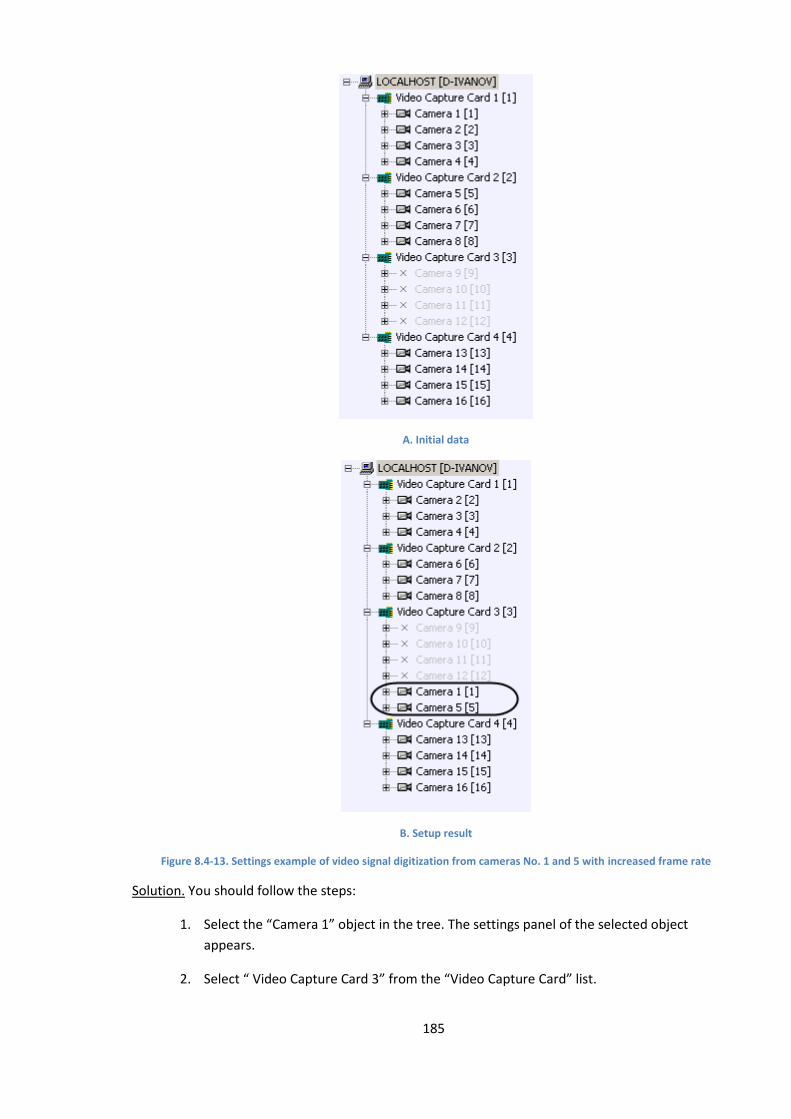
185
A. Initial data
B. Setup result
Figure 8.4-13. Settings example of video signal digitization from cameras No. 1 and 5 with increased frame rate
Solution. You should follow the steps:
1. Select the “Camera 1” object in the tree. The settings panel of the selected object
appears.
2. Select “ Video Capture Card 3” from the “Video Capture Card” list.
186
3. Click “Apply”.
4. The “Camera 1” object moves to a subdirectory of the “Video Capture Card 3” object
(Figure 8.4-13, B).
5. Repeat (1) – (4) operations for the “Camera 5” object.
6. The frame rate of No. 1 and 5 cameras increases twofold (for information on testing the
frame rate change see the “Actual frame rate definition” section).
12. Click “Apply”.
Video capture card’s resources allocation is completed.
Note. Ways of resources allocation (given in examples) aren’t used for FS15, FX4, FX8 and FX16 video
capture cards, because for these cards numbers of PCI channels (set in settings of the «Video capture
card» objects) are connected with physical inputs (BNC connectors).
8.4.3.1.3.8 Video signal processing priorities
The ADC resources are uniformly distributed to the assigned cameras by default.
ADC resources reallocation allows to increase the frame rate for a camera at the expense of other
cameras. Reallocation of resources from 1 ADC to the cameras is much less effective than camera
reallocation on the ADC. Therefore it should only be done if camera reallocation to the ADC is
impossible or if it doesn’t help.
With reallocation of resources from 1 ADC to the cameras, one of the cameras is allocated additional
ADC resources for its video signal processing and digitization. Additional ADC resources are formed
by removing them from other cameras, whose video signals are processed by the ADC.
A camera is allocated additional ADC resources via the priority process queue.
INTELLECT™ software provides 1/2 and 1/3 process queues.
When a camera has a 1/2 process queue, its video signal is processed every second frame. So, the
digitization frame rate of this camera’s video signal is half the total frame rate of the considered ADC.
When a camera has a 1/3 process queue, its video signal is processed every third frame. So, the
digitization frame rate of this camera’s video signal is a third of the total frame rate of the considered
ADC.
Example 1. The ADC is set to digitize video signal from 4 cameras.
If all the cameras have a common queue, the ADC digitizes video signals in the sequence:
Camera 1, Camera 2, Camera 3, Camera 4, Camera 1, Camera 2, Camera 3…
Let us suppose that Camera 1 has queue, and the rest of the cameras are in the common queue.
Then the ADC digitizes video signals in the sequence:
Camera 1, Camera 2, Camera 1, Camera 3, Camera 1, Camera 4, Camera 1…

187
So, the frame rate of Camera 1 is increased by 2 times and becomes a half of the total frame rate of
the considered ADC. The frame rate of each of the remaining cameras becomes 1.5 times less and
makes up 1/6 of the total frame rate of the considered ADC.
Example 2. The ADC is set to digitize the video signal from 3 cameras.
If all the cameras have a common queue, ADC digitizes video signals in the sequence:
Camera 1, Camera 2, Camera 3, Camera 1, Camera 2, Camera 3…
Let us suppose that Camera 1 has a 1/2 queue, and the rest of the cameras are in the common
queue. Then the ADC digitizes video signals in the sequence:
Camera 1, Camera 2, Camera 1, Camera 3, Camera 1, Camera 2…
So, the frame rate of Camera 1 is increased by 1,5 times and becomes a half of the total frame rate of
the considered ADC. The frame rate of each of the remaining cameras becomes 1.3 times less and
makes up 1/4 of the total frame rate of the considered ADC.
Example 3. The ADC is set to digitize video signal from 4 cameras.
If all the cameras have a common queue, ADC digitizes video signals in the sequence:
Camera 1, Camera 2, Camera 3, Camera 4, Camera 1, Camera 2, Camera 3…
Let us suppose that Camera 1 has a 1/3 queue, and the remaining cameras are in the common
queue. Then the ADC digitizes video signals in the sequence:
Camera 1, Camera 2, Camera 3, Camera 1, Camera 4, Camera 2, Camera 1…
So, the frame rate of Camera 1 is increased by 1.33 times and becomes a third part of the total frame
rate of the considered ADC. The frame rate of each of the remaining cameras becomes 1.125 times
less and is equal to 2/9 of the total frame rate of the considered ADC.
Example 4. The ADC is set to digitize video signal from 4 cameras.
If all the cameras have a common queue, ADC digitizes video signals in the sequence:
Camera 1, Camera 2, Camera 3, Camera 4, Camera 1, Camera 2, Camera 3…
Let us suppose that Camera 1 and Camera 2 have a 1/2 queue, and the remaining cameras are in the
common queue. With these parameters the ADC digitizes video signals in the sequence:
Camera 1, Camera 2, Camera 3, Camera 1, Camera 2, Camera 4, Camera 1…
So, the frame rate of Camera 1 is increased by 1.33 times and becomes equal to a third part of the
total frame rate of the considered ADC. The frame rate of each of the remaining cameras becomes
1.5 times less and becomes equal to 1/6 of the total frame rate of the considered ADC.
Note A. If Camera 1 and Camera 2 have a 1/3 queue, Camera 3 and Camera 4 are in the common
queue, the ADC resources are distributed as it is showed in the Example4.

188
Note B. It has no sense to enqueue one of two cameras, with 1/2 priority allocated to the same ADC,
because this camera video signal will be processed as if it were in the common queue.
Note C. It has no sense enqueue one of two or three cameras with 1/3 priority allocated to the same
ADC, because this camera’s video signal will be processed as if it were in the common queue.
Reallocation of resources from 1 ADC to the cameras is possible in two modes:
1. in the processing mode, i.e. with video signal digitization and processing before it is
displayed;
2. in the recording mode, i.e. with video signal digitization and processing before it is recorded
into the videoserver archive. When cameras are switched to the recording mode, video
signals are displayed with the rate, corresponding to the given ADC resources allocation.
8.4.3.1.3.9 Video signals processing priority setting
While processing the video signal before displaying it, ADC resources are reallocated to the cameras
by queueing one of the cameras with 1/2 or 1/3 priority.
This setting is relevant only for the following video capture cards: FS5, FS6, FS8, FS16.
To change the processing sequence of the video signal from the selected camera, follow the steps:
1. Go to the “Hardware” tab in the “System Setup” dialog box.
2. Select the “Camera” object, created before, corresponding to the camera, whose ADC video
signal processing queue needs to be changed, on the “Hardware” tab in the objects tree. The
settings panel of the selected object appears in the right part of the “Hardware” tab (Figure
8.4-14).
Figure 8.4-14. Change of video signal processing queue from the selected camera in the processing mode
3. If it is necessary to queue the camera with 1/2 priority for ADC video signal processing, move
the “Processing” slider in the “Priority” group to the “1/2” position.
4. If it is necessary to queue the camera with 1/3 priority for ADC video signal processing, move
the “Processing” slider in the “Priority” group to the “1/3” position.
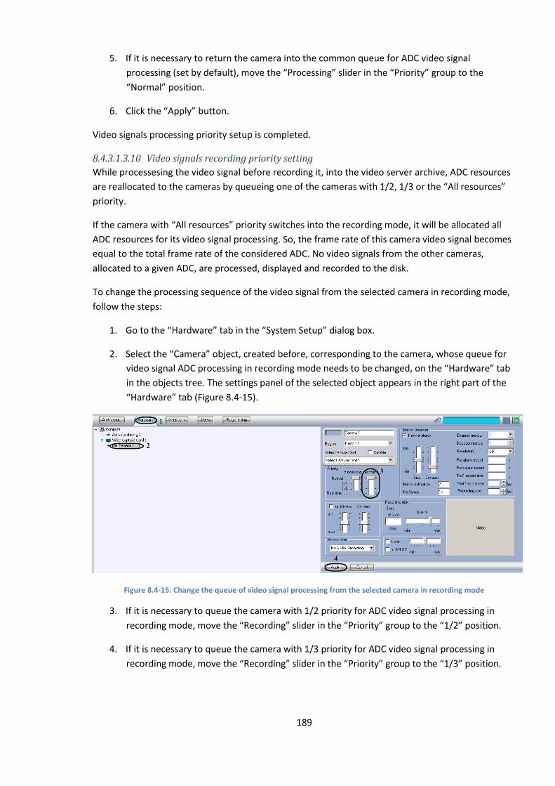
189
5. If it is necessary to return the camera into the common queue for ADC video signal
processing (set by default), move the “Processing” slider in the “Priority” group to the
“Normal” position.
6. Click the “Apply” button.
Video signals processing priority setup is completed.
8.4.3.1.3.10 Video signals recording priority setting
While processesing the video signal before recording it, into the video server archive, ADC resources
are reallocated to the cameras by queueing one of the cameras with 1/2, 1/3 or the “All resources”
priority.
If the camera with “All resources” priority switches into the recording mode, it will be allocated all
ADC resources for its video signal processing. So, the frame rate of this camera video signal becomes
equal to the total frame rate of the considered ADC. No video signals from the other cameras,
allocated to a given ADC, are processed, displayed and recorded to the disk.
To change the processing sequence of the video signal from the selected camera in recording mode,
follow the steps:
1. Go to the “Hardware” tab in the “System Setup” dialog box.
2. Select the “Camera” object, created before, corresponding to the camera, whose queue for
video signal ADC processing in recording mode needs to be changed, on the “Hardware” tab
in the objects tree. The settings panel of the selected object appears in the right part of the
“Hardware” tab (Figure 8.4-15).
Figure 8.4-15. Change the queue of video signal processing from the selected camera in recording mode
3. If it is necessary to queue the camera with 1/2 priority for ADC video signal processing in
recording mode, move the “Recording” slider in the “Priority” group to the “1/2” position.
4. If it is necessary to queue the camera with 1/3 priority for ADC video signal processing in
recording mode, move the “Recording” slider in the “Priority” group to the “1/3” position.
190
5. If it is necessary to queue the camera with “All resources” priority for ADC video signal
processing in recording mode, move the “Recording” slider in the “Priority” group to the “All
resources” position.
6. If it is necessary to return the camera into the common queue for ADC video signal
processing in recording mode (set by default), move the “Recording” slider in the “Priority”
group to the “Normal” position.
7. Click the “Apply” button.
Video signals processing in recording mode priority setup is completed.
8.4.3.1.4 Brightness, contrast, color depth, color rendition format settings
8.4.3.1.4.1 Brightness and contrast settings
INTELLECT™ software provides facilities for video image brightness and contrast adjustment in the
different modes, depending on the demands of the video characteristics.
Brightness can be adjusted in the following modes.
1. Auto brightness and contrast adjustment. In this mode INTELLECT™ software automatically
applies the internal algorithm of video image brightness and contrast adjustment. In this
mode manual brightness and contrast adjustment is unavailable.
The mode is default activated and doesn’t need any additional settings. This mode to adjust
brightness and contrast is recommended for video image with no special demands on video
characteristics.
2. Manual brightness and contrast adjustment. In this mode the administrator may change
image brightness and contrast settings.
3. Manual brightness and contrast adjustment with auto optimization. In this mode the
administrator manually presets the “Brightness” and “Contrast” values. After the preset is
confirmed, INTELLECT™ software automatically launches the process of video image
brightness and contrast optimization. This process involves step-by-step changing of video
image brightness and contrast.
Note 1. Line parameter «ManualBrightnessControl» in the register branch
HKEY_LOCAL_MACHINE\SOFTWARE\ITV\INTELLECT\Video is used to enable automatic setting of IP-
cameras’ brightness and contrast .If ManualBrightnessControl is equal to 1, manual control of IP-
cameras’ brightness and contrast is enabled.If ManualBrightnessControl is equal to 0, mode of IP-
cameras’ brightness and contrast control is set on the settings panel of corresponding Camera object.
Note 2. ManualBrightness and ContrastControl of IP-cameras is disabled in Intellect 4.7.7 by default,
for Intellect 4.8 it is enabled.
Brightness and contrast are changed separately and independently for every camera.
To adjust the brightness and contrast, follow the steps:
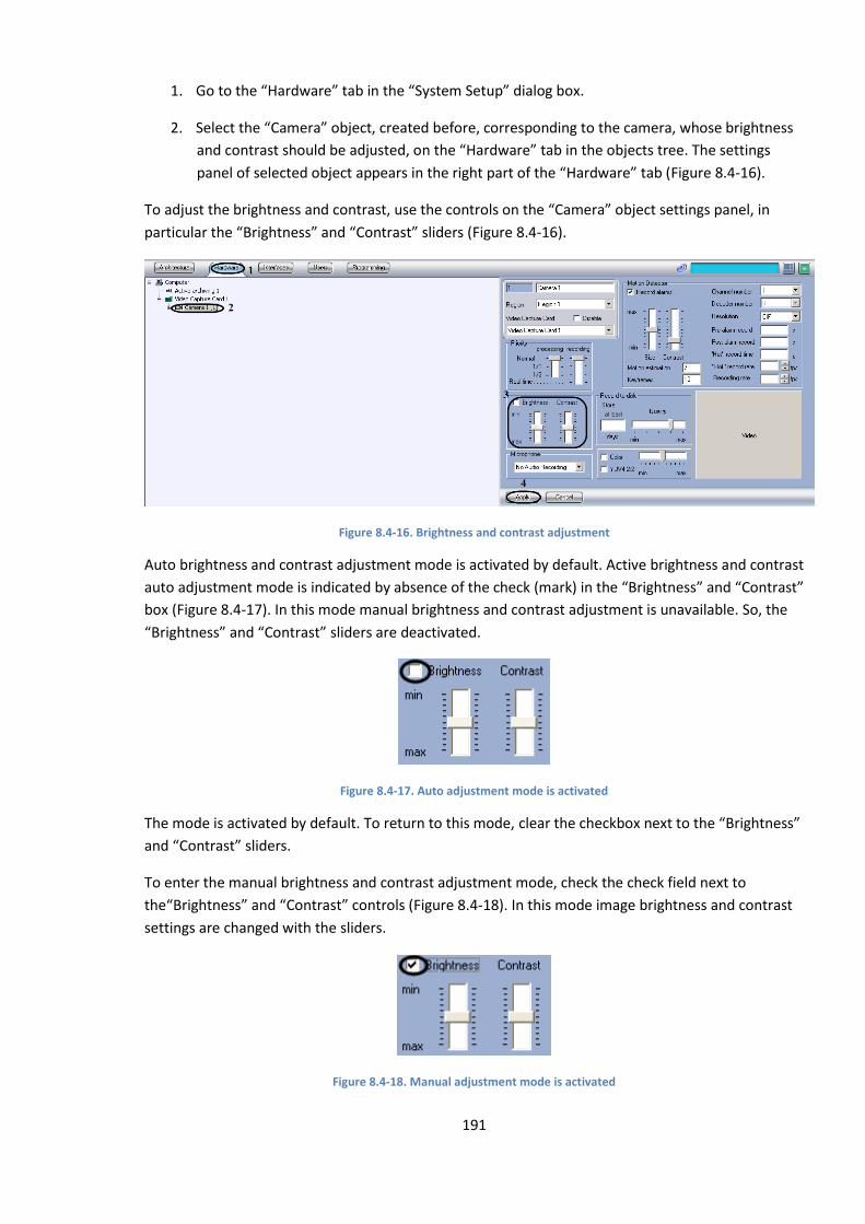
191
1. Go to the “Hardware” tab in the “System Setup” dialog box.
2. Select the “Camera” object, created before, corresponding to the camera, whose brightness
and contrast should be adjusted, on the “Hardware” tab in the objects tree. The settings
panel of selected object appears in the right part of the “Hardware” tab (Figure 8.4-16).
To adjust the brightness and contrast, use the controls on the “Camera” object settings panel, in
particular the “Brightness” and “Contrast” sliders (Figure 8.4-16).
Figure 8.4-16. Brightness and contrast adjustment
Auto brightness and contrast adjustment mode is activated by default. Active brightness and contrast
auto adjustment mode is indicated by absence of the check (mark) in the “Brightness” and “Contrast”
box (Figure 8.4-17). In this mode manual brightness and contrast adjustment is unavailable. So, the
“Brightness” and “Contrast” sliders are deactivated.
Figure 8.4-17. Auto adjustment mode is activated
The mode is activated by default. To return to this mode, clear the checkbox next to the “Brightness”
and “Contrast” sliders.
To enter the manual brightness and contrast adjustment mode, check the check field next to
the“Brightness” and “Contrast” controls (Figure 8.4-18). In this mode image brightness and contrast
settings are changed with the sliders.
Figure 8.4-18. Manual adjustment mode is activated
192
To enter the mode of manual brightness and contrast adjustment with auto optimization, check the
checkbox next to the “Brightness” and “Contrast” controls (Figure 8.4-19).
Figure 8.4-19. Manual adjustment mode with auto optimization activated
In this mode image brightness and contrast settings are changed with the “Brightness” and
“Contrast” sliders. To launch the video image brightness and contrast auto optimization, click the
“Apply” button in the bottom of the “System Setup” dialog box. The optimization sequence involves
a step-by-step change of video image brightness and contrast.
To activate the new brightness and contrast settings, click the “Apply” button.
To check the video image brightness and contrast settings, look at the video surveillance field in the
top right corner of the “System Setup” dialog box.
Brightness and contrast adjustment is completed.
8.4.3.1.4.2 Color depth adjustment
Color depth (“Saturation” parameter in the HSL color spectrum model) defines the number of colors
used to build a video image, while digitizing it by the video capture card. Color depth in the
INTELLECT™ software corresponds to the “Color Depth” setting.
Color depth is set for each camera individually.
The color depth mean value is set by default.
While adjusting the color depth bear in mind that the image color depth is directly proportional to
the frame size and thus to the video stream size. So, the digitized video stream with the greater color
depth is bigger. The bigger the video stream, the bigger the HDD capacity to store it and the higher
the channel capacity required to transmit it.
To change the image color depth, follow the steps:
1. Go to the “Hardware” tab in the “System Setup” dialog box.
2. Select the relevant “Camera” object, created before, on the “Hardware” tab in the objects
tree. The settings panel of the selected object appears in the right part of the “Hardware”
tab (Figure 8.4-20).
To adjust brightness and contrast, use the controls on the “Camera” object settings panel with the
“Color” checkbox (Figure 8.4-20).
193
Figure 8.4-20. Color depth adjustment
3. To reduce the video image color depth to the black-and-white palette, remove the “Color”
check.
4. To change the color depth in the other cases, move the “Color” slider on the right of the
“Color” check into the desired position. The slider’s “Max” position corresponds to the
maximum color depth of the video image, and the “Min” position - to its minimum color
depth (black-and-white image). To check the video image color depth settings, look at the
video surveillance field in the bottom right corner of the “System Setup” dialog box.
5. Click the “Apply” button.
Color depth adjustment is completed.
8.4.3.1.4.3 Selection of the video image color rendition format
Video image color rendition format fixes the number and the sequence of digitized video signal bits
(or analog video signal frequencies), that carry its color depth data. So, the digitized video stream
with the higher color depth is bigger. The bigger the video stream size, the bigger the HDD capacity
to store it and the higher the channel capacity required to transmit it.
The TV systems use two video signal color rendition formats: YUV 4:2:0 and YUV 4:2:2.
YUV 4:2:2 color rendition format is the standard format in TV systems. YUV 4:2:2 format provides
high color depth and gives a large size of video stream. That is why video surveillance systems use to
apply the YUV 4:2:0 format. In YUV 4:2:0 format, video signal color depth is slightly lower, than in
YUV 4:2:2 format, and video stream size, digitized in YUV 4:2:0 format, is several times less than that
in YUV 4:2:2 format.
INTELLECT™ software has digitization options in both formats. YUV 4:2:0 and YUV 4:2:2.
Video signal color rendition format is set for each camera individually.
Default encoding of video signals for all cameras is performed by the video capture card in YUV 4:2:0
color rendition format.
Follow the steps to set up encoding of video signals in the YUV 4:2:2 format:
194
1. Go to the “Hardware” tab in the “System Setup” dialog box.
2. Select the relevant “Camera” object, created before, on the “Hardware” tab in the objects
tree. The settings panel of the selected object appears in the right part of the “Hardware”
tab (Figure 8.4-21).
Figure 8.4-21. Selection of the YUV 4:2:2 color rendition format
3. Set the “Color rendition” to the”YUV 4:2:2” position. To check the video signal color rendition
format settings, look at the video surveillance field in the top right corner of the “System
Setup” dialog box.
4. Click the “Apply” button.
Selection of the video signal color rendition format is completed.
8.4.3.1.5 Video signal compression settings
8.4.3.1.5.1 Compression rate settings
The video image is compressed to reduce the size of the video sequence. With displaying the video
signal on the server monitor, the video signal is not compressed.
An increase in compression rate leads to degradation of the video image. Intellect™ software
compresses the video image right after its digitizing by the video capture card, prior to its recording
and/or before transmitting it to the Remote Workstations.
The video signal compression rate is set for each camera individually.
The INTELLECT™ system uses the “Quality” setting for the compression rate parameter, which is
inverse to the compression rate.
In most cases the default “Quality” setting is sufficient.
To change the video signal compression rate, follow the steps:
1. Go to the “Hardware” tab in the “System Setup” dialog box.
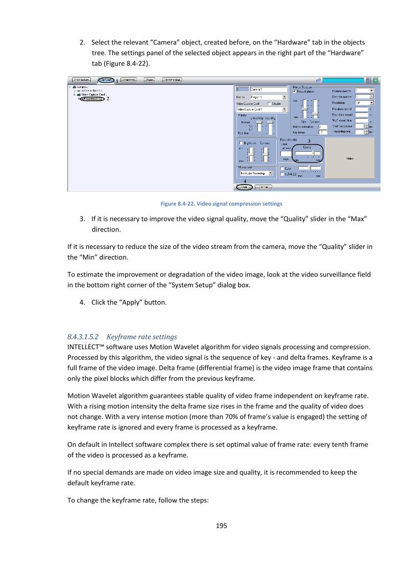
195
2. Select the relevant “Camera” object, created before, on the “Hardware” tab in the objects
tree. The settings panel of the selected object appears in the right part of the “Hardware”
tab (Figure 8.4-22).
Figure 8.4-22. Video signal compression settings
3. If it is necessary to improve the video signal quality, move the “Quality” slider in the “Max”
direction.
If it is necessary to reduce the size of the video stream from the camera, move the “Quality” slider in
the “Min” direction.
To estimate the improvement or degradation of the video image, look at the video surveillance field
in the bottom right corner of the “System Setup” dialog box.
4. Click the “Apply” button.
8.4.3.1.5.2 Keyframe rate settings
INTELLECT™ software uses Motion Wavelet algorithm for video signals processing and compression.
Processed by this algorithm, the video signal is the sequence of key - and delta frames. Keyframe is a
full frame of the video image. Delta frame (differential frame) is the video image frame that contains
only the pixel blocks which differ from the previous keyframe.
Motion Wavelet algorithm guarantees stable quality of video frame independent on keyframe rate.
With a rising motion intensity the delta frame size rises in the frame and the quality of video does
not change. With a very intense motion (more than 70% of frame’s value is engaged) the setting of
keyframe rate is ignored and every frame is processed as a keyframe.
On default in Intellect software complex there is set optimal value of frame rate: every tenth frame
of the video is processed as a keyframe.
If no special demands are made on video image size and quality, it is recommended to keep the
default keyframe rate.
To change the keyframe rate, follow the steps:
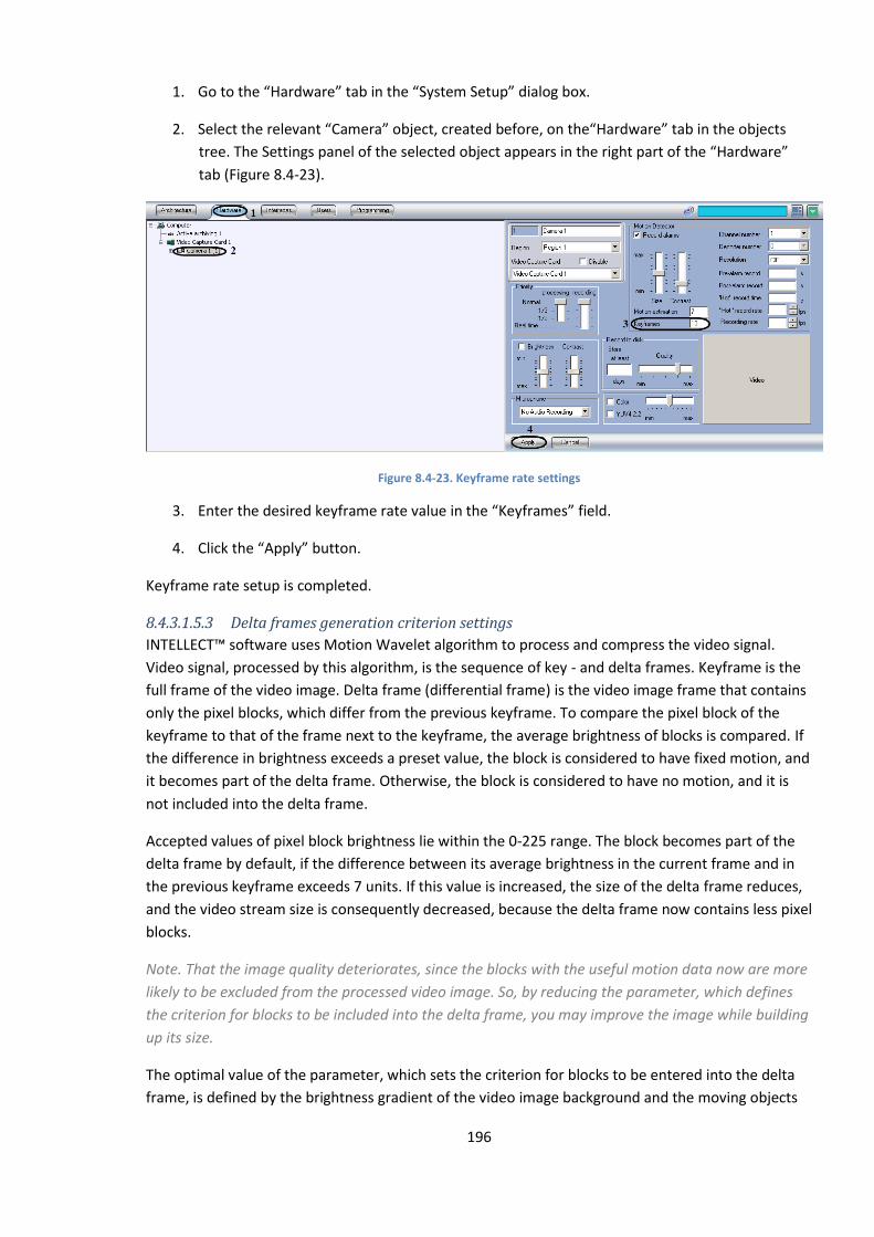
196
1. Go to the “Hardware” tab in the “System Setup” dialog box.
2. Select the relevant “Camera” object, created before, on the“Hardware” tab in the objects
tree. The Settings panel of the selected object appears in the right part of the “Hardware”
tab (Figure 8.4-23).
Figure 8.4-23. Keyframe rate settings
3. Enter the desired keyframe rate value in the “Keyframes” field.
4. Click the “Apply” button.
Keyframe rate setup is completed.
8.4.3.1.5.3 Delta frames generation criterion settings
INTELLECT™ software uses Motion Wavelet algorithm to process and compress the video signal.
Video signal, processed by this algorithm, is the sequence of key - and delta frames. Keyframe is the
full frame of the video image. Delta frame (differential frame) is the video image frame that contains
only the pixel blocks, which differ from the previous keyframe. To compare the pixel block of the
keyframe to that of the frame next to the keyframe, the average brightness of blocks is compared. If
the difference in brightness exceeds a preset value, the block is considered to have fixed motion, and
it becomes part of the delta frame. Otherwise, the block is considered to have no motion, and it is
not included into the delta frame.
Accepted values of pixel block brightness lie within the 0-225 range. The block becomes part of the
delta frame by default, if the difference between its average brightness in the current frame and in
the previous keyframe exceeds 7 units. If this value is increased, the size of the delta frame reduces,
and the video stream size is consequently decreased, because the delta frame now contains less pixel
blocks.
Note. That the image quality deteriorates, since the blocks with the useful motion data now are more
likely to be excluded from the processed video image. So, by reducing the parameter, which defines
the criterion for blocks to be included into the delta frame, you may improve the image while building
up its size.
The optimal value of the parameter, which sets the criterion for blocks to be entered into the delta
frame, is defined by the brightness gradient of the video image background and the moving objects
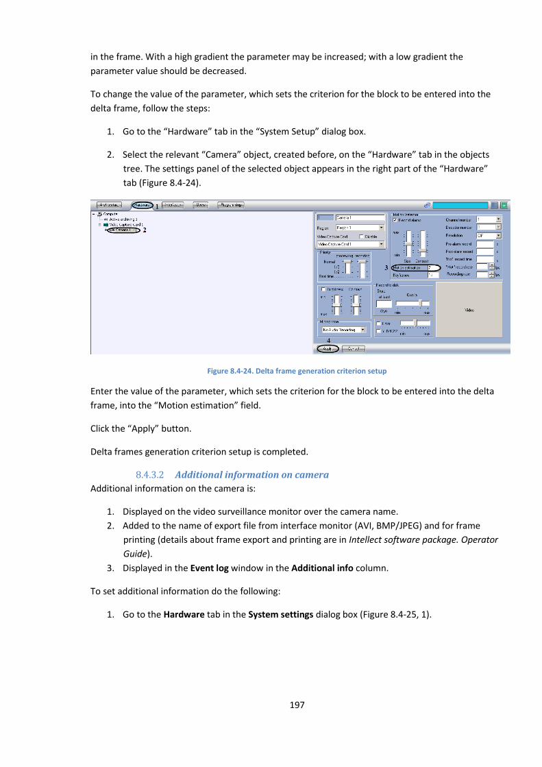
197
in the frame. With a high gradient the parameter may be increased; with a low gradient the
parameter value should be decreased.
To change the value of the parameter, which sets the criterion for the block to be entered into the
delta frame, follow the steps:
1. Go to the “Hardware” tab in the “System Setup” dialog box.
2. Select the relevant “Camera” object, created before, on the “Hardware” tab in the objects
tree. The settings panel of the selected object appears in the right part of the “Hardware”
tab (Figure 8.4-24).
Figure 8.4-24. Delta frame generation criterion setup
Enter the value of the parameter, which sets the criterion for the block to be entered into the delta
frame, into the “Motion estimation” field.
Click the “Apply” button.
Delta frames generation criterion setup is completed.
8.4.3.2 Additional information on camera
Additional information on the camera is:
1. Displayed on the video surveillance monitor over the camera name.
2. Added to the name of export file from interface monitor (AVI, BMP/JPEG) and for frame
printing (details about frame export and printing are in Intellect software package. Operator
Guide).
3. Displayed in the Event log window in the Additional info column.
To set additional information do the following:
1. Go to the Hardware tab in the System settings dialog box (Figure 8.4-25, 1).
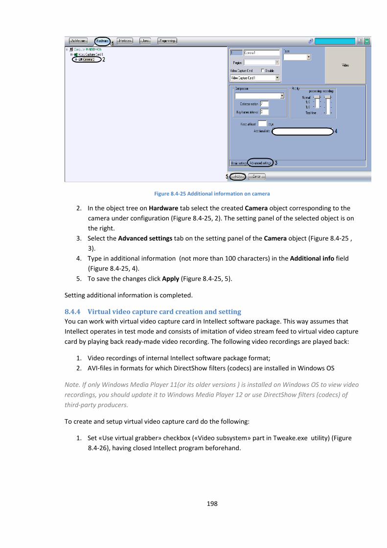
198
Figure 8.4-25 Additional information on camera
2. In the object tree on Hardware tab select the created Camera object corresponding to the
camera under configuration (Figure 8.4-25, 2). The setting panel of the selected object is on
the right.
3. Select the Advanced settings tab on the setting panel of the Camera object (Figure 8.4-25 ,
3).
4. Type in additional information (not more than 100 characters) in the Additional info field
(Figure 8.4-25, 4).
5. To save the changes click Apply (Figure 8.4-25, 5).
Setting additional information is completed.
8.4.4 Virtual video capture card creation and setting
You can work with virtual video capture card in Intellect software package. This way assumes that
Intellect operates in test mode and consists of imitation of video stream feed to virtual video capture
card by playing back ready-made video recording. The following video recordings are played back:
1. Video recordings of internal Intellect software package format;
2. AVI-files in formats for which DirectShow filters (codecs) are installed in Windows OS
Note. If only Windows Media Player 11(or its older versions ) is installed on Windows OS to view video
recordings, you should update it to Windows Media Player 12 or use DirectShow filters (codecs) of
third-party producers.
To create and setup virtual video capture card do the following:
1. Set «Use virtual grabber» checkbox («Video subsystem» part in Tweake.exe utility) (Figure
8.4-26), having closed Intellect program beforehand.
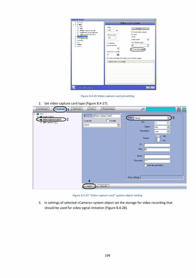
199
Figure 8.4-26 Video capture card presetting
2. Set video capture card type (Figure 8.4-27).
Figure 8.4-27 “Video capture card” system object setting
3. In settings of selected «Camera» system object set the storage for video recording that
should be used for video signal imitation (Figure 8.4-28).
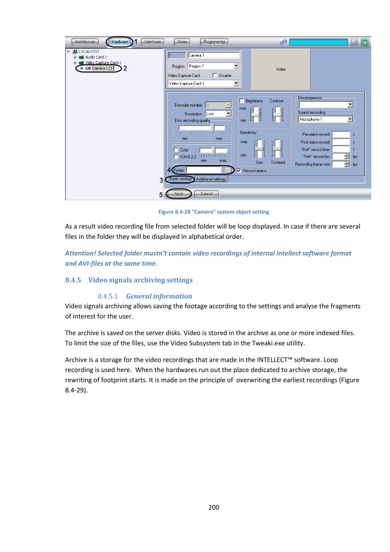
200
Figure 8.4-28 “Camera” system object setting
As a result video recording file from selected folder will be loop displayed. In case if there are several
files in the folder they will be displayed in alphabetical order.
Attention! Selected folder mustn’t contain video recordings of internal Intellect software format
and AVI-files at the same time.
8.4.5 Video signals archiving settings
8.4.5.1 General information
Video signals archiving allows saving the footage according to the settings and analyse the fragments
of interest for the user.
The archive is saved on the server disks. Video is stored in the archive as one or more indexed files.
To limit the size of the files, use the Video Subsystem tab in the Tweaki.exe utility.
Archive is a storage for the video recordings that are made in the INTELLECT™ software. Loop
recording is used here. When the hardwares run out the place dedicated to archive storage, the
rewriting of footprint starts. It is made on the principle of overwriting the earliest recordings (Figure
8.4-29).
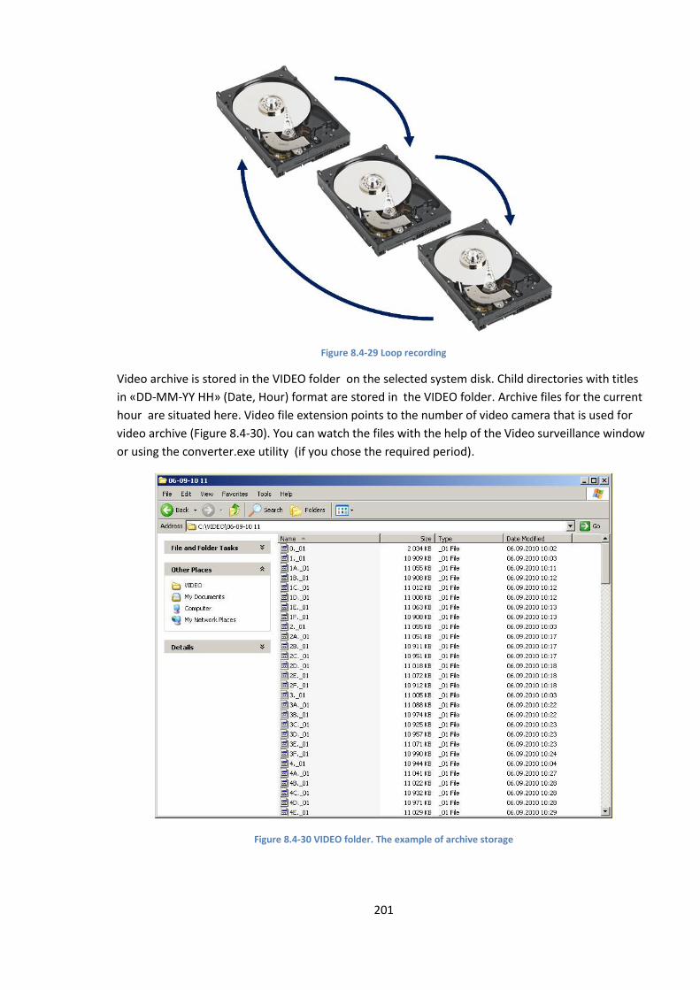
201
Figure 8.4-29 Loop recording
Video archive is stored in the VIDEO folder on the selected system disk. Child directories with titles
in «DD-MM-YY HH» (Date, Hour) format are stored in the VIDEO folder. Archive files for the current
hour are situated here. Video file extension points to the number of video camera that is used for
video archive (Figure 8.4-30). You can watch the files with the help of the Video surveillance window
or using the converter.exe utility (if you chose the required period).
Figure 8.4-30 VIDEO folder. The example of archive storage
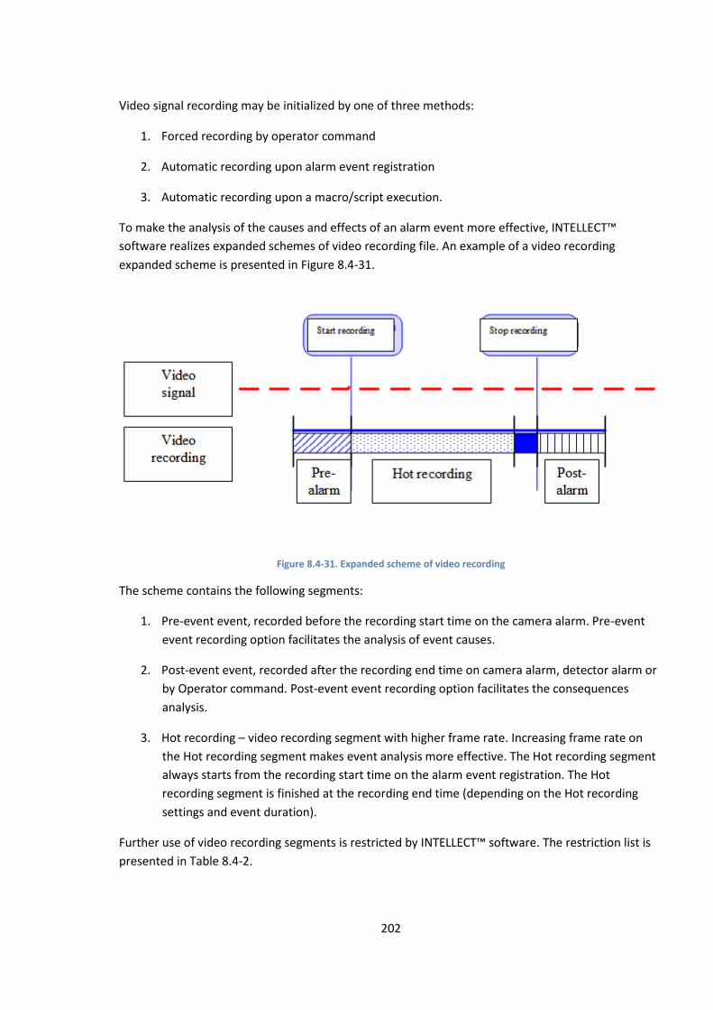
202
Video signal recording may be initialized by one of three methods:
1. Forced recording by operator command
2. Automatic recording upon alarm event registration
3. Automatic recording upon a macro/script execution.
To make the analysis of the causes and effects of an alarm event more effective, INTELLECT™
software realizes expanded schemes of video recording file. An example of a video recording
expanded scheme is presented in Figure 8.4-31.
Figure 8.4-31. Expanded scheme of video recording
The scheme contains the following segments:
1. Pre-event event, recorded before the recording start time on the camera alarm. Pre-event
event recording option facilitates the analysis of event causes.
2. Post-event event, recorded after the recording end time on camera alarm, detector alarm or
by Operator command. Post-event event recording option facilitates the consequences
analysis.
3. Hot recording – video recording segment with higher frame rate. Increasing frame rate on
the Hot recording segment makes event analysis more effective. The Hot recording segment
always starts from the recording start time on the alarm event registration. The Hot
recording segment is finished at the recording end time (depending on the Hot recording
settings and event duration).
Further use of video recording segments is restricted by INTELLECT™ software. The restriction list is
presented in Table 8.4-2.
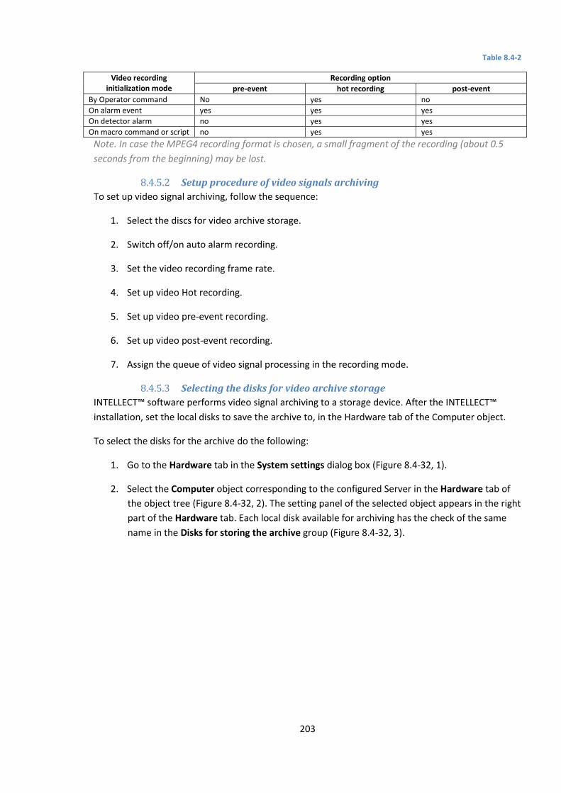
203
Table 8.4-2
Video recording initialization mode
Recording option
pre-event hot recording post-event
By Operator command No yes no
On alarm event yes yes yes
On detector alarm no yes yes
On macro command or script no yes yes
Note. In case the MPEG4 recording format is chosen, a small fragment of the recording (about 0.5
seconds from the beginning) may be lost.
8.4.5.2 Setup procedure of video signals archiving
To set up video signal archiving, follow the sequence:
1. Select the discs for video archive storage.
2. Switch off/on auto alarm recording.
3. Set the video recording frame rate.
4. Set up video Hot recording.
5. Set up video pre-event recording.
6. Set up video post-event recording.
7. Assign the queue of video signal processing in the recording mode.
8.4.5.3 Selecting the disks for video archive storage
INTELLECT™ software performs video signal archiving to a storage device. After the INTELLECT™
installation, set the local disks to save the archive to, in the Hardware tab of the Computer object.
To select the disks for the archive do the following:
1. Go to the Hardware tab in the System settings dialog box (Figure 8.4-32, 1).
2. Select the Computer object corresponding to the configured Server in the Hardware tab of
the object tree (Figure 8.4-32, 2). The setting panel of the selected object appears in the right
part of the Hardware tab. Each local disk available for archiving has the check of the same
name in the Disks for storing the archive group (Figure 8.4-32, 3).

204
Figure 8.4-32. Selecting the disks for storing the video archive
1. Set the relevant check in the Video column next to the disk to be selected. Local, network
and USB disks are available for storing (details on adding network discs are in Using the
network disks section).
Note. For the opposite result unset the check corresponding to the disk in the Video column (Figure
8.4-32).
2. Click Apply (Figure 8.4-32, 4).
Selection of the disks for video archive storage is completed.
Note. If none disk for storing the video is selected, then there is no storing to the archive.
8.4.5.4 Using the network disks
To use network disks as an archive, set UNC paths to them in INTELLECT™. Details of working with
network disks in INTELLECT™ installed as a Service are given in Working with network disks of
INTELLECT™ installed as a Service section.
Attention! For Windows Vista and Windows 7 OS with connected UAC it’s necessary to connect
network disks through command line with Administrator’s rights. The way of connecting is
described in Connecting network disks in Windows Vista and Windows 7 OS section.
Note. Access to network disks on computers with Windows Vista or Windows 7 OS can be forbidden
when the user account control (UAC) is swiched on. To enable access create the
EnableLinkedConnections key of the DWORD type with 1 value in the
HKEY_LOCAL_MACHINE\SOFTWARE\Microsoft\Windows\CurrentVersion\Policies\System registry.
Details of working with registry keys are in Working with Windows OS registry section.
To add a network disk by specifying the UNC path do the following:
1. Go to the last line in the disk list and click the down key (Figure 8.4-33).

205
Figure 8.4-33 Specifying the UNC path to a network disk
2. Enter the path to a network disk in the appeared line in the Disk column (Figure 8.4-33). UNC
path is set in \\server_name\share_name format where server_name is the name of file
server and share_name is the network name of the general folder.
Note. If there are any problems with storing video/audio archive at network disks, then use net
use command of Windows command line:
net use \\server_name\share_name /delete
net use \\server_name\share_name /USER:user_name
Where user_name is a user that has rights to store to selected network disk. This is to be
performed after every Windows OS restart.
Details about net use command are in Microsoft official documentation
(www.microsoft.com).
3. Set a checkbox for created disk in the Video column (Figure 8.4-33).
4. Click Apply.
Adding a network disk by specifying the UNC path is completed.
8.4.5.5 Switching off automatic recording on alarm event registration
INTELLECT™ software supports automatic video recording upon alarm event registration for each
Camera object individually.
By default, the auto recording option is enabled for all cameras in the Hardware tab.
The auto recording option is disabled for each camera individually, as well.
To disable the auto recording option on alarm for a selected camera, follow the steps:
1. Go to the “Hardware” tab in the “System Setup” dialog box.
2. Select the “Camera” object, related to the required camera in the objects tree. The settings
panel of the selected object appears in the right part of the “Hardware” tab (Figure 8.4-34).
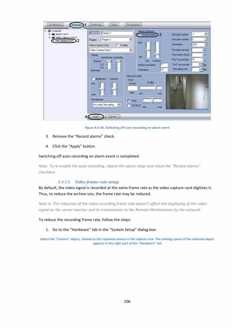
206
Figure 8.4-34. Switching off auto recording on alarm event
3. Remove the “Record alarms” check.
4. Click the “Apply” button.
Switching off auto recording on alarm event is completed.
Note. To re-enable the auto recording, repeat the above steps and check the “Record alarms”
checkbox.
8.4.5.6 Video frame rate setup
By default, the video signal is recorded at the same frame rate as the video capture card digitizes it.
Thus, to reduce the archive size, the frame rate may be reduced.
Note A. The reduction of the video recording frame rate doesn’t affect the displaying of the video
signal on the server monitor and its transmission to the Remote Workstations by the network.
To reduce the recording frame rate, follow the steps:
1. Go to the “Hardware” tab in the “System Setup” dialog box.
Select the “Camera” object, related to the required camera in the objects tree. The settings panel of the selected object appears in the right part of the “Hardware” tab
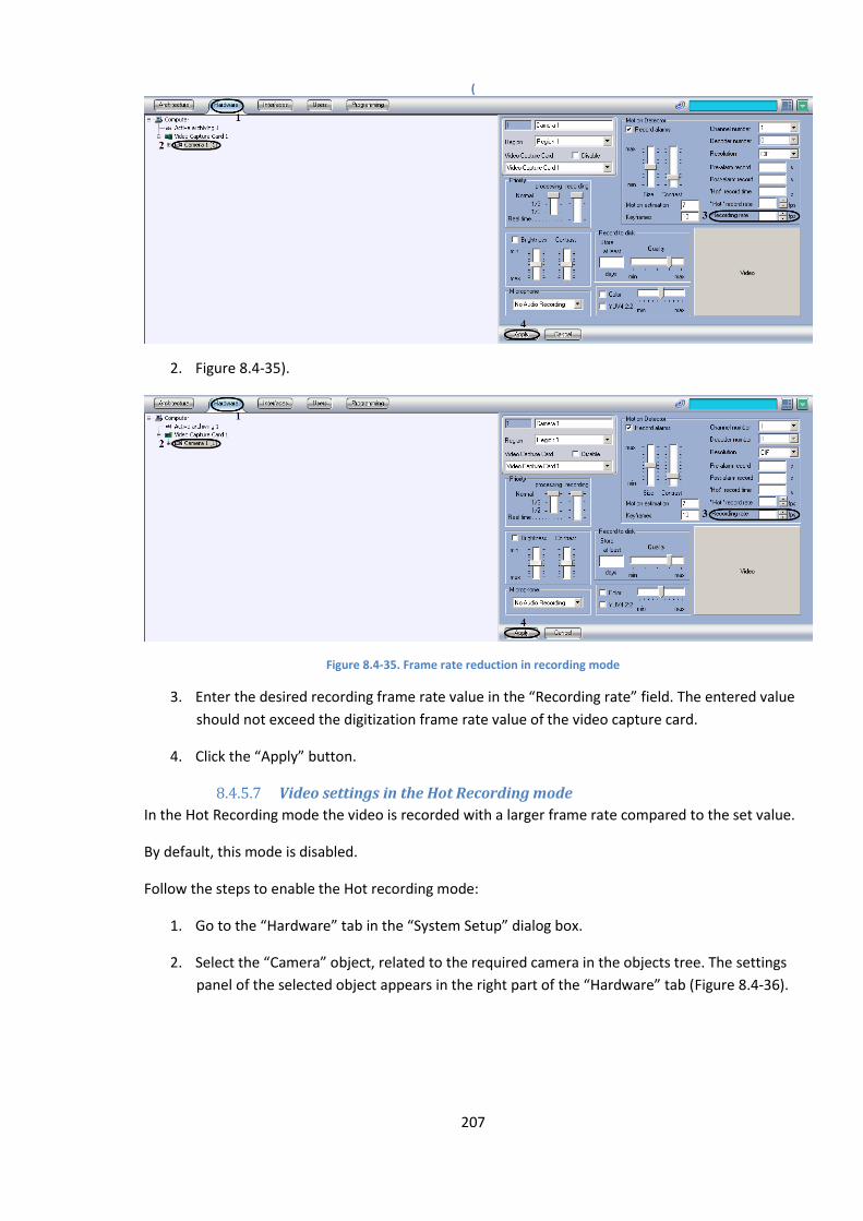
207
(
2. Figure 8.4-35).
Figure 8.4-35. Frame rate reduction in recording mode
3. Enter the desired recording frame rate value in the “Recording rate” field. The entered value
should not exceed the digitization frame rate value of the video capture card.
4. Click the “Apply” button.
8.4.5.7 Video settings in the Hot Recording mode
In the Hot Recording mode the video is recorded with a larger frame rate compared to the set value.
By default, this mode is disabled.
Follow the steps to enable the Hot recording mode:
1. Go to the “Hardware” tab in the “System Setup” dialog box.
2. Select the “Camera” object, related to the required camera in the objects tree. The settings
panel of the selected object appears in the right part of the “Hardware” tab (Figure 8.4-36).
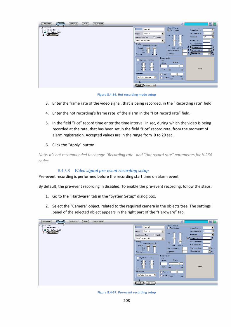
208
Figure 8.4-36. Hot recording mode setup
3. Enter the frame rate of the video signal, that is being recorded, in the “Recording rate” field.
4. Enter the hot recording’s frame rate of the alarm in the “Hot record rate” field.
5. In the field “Hot” record time enter the time interval in sec, during which the video is being
recorded at the rate, that has been set in the field “Hot” record rete, from the moment of
alarm registration. Accepted values are in the range from 0 to 20 sec.
6. Click the “Apply” button.
Note. It’s not recommended to change “Recording rate” and “Hot record rate” parameters for Н.264
codec.
8.4.5.8 Video signal pre-event recording setup
Pre-event recording is performed before the recording start time on alarm event.
By default, the pre-event recording in disabled. To enable the pre-event recording, follow the steps:
1. Go to the “Hardware” tab in the “System Setup” dialog box.
2. Select the “Camera” object, related to the required camera in the objects tree. The settings
panel of the selected object appears in the right part of the “Hardware” tab.
Figure 8.4-37. Pre-event recording setup
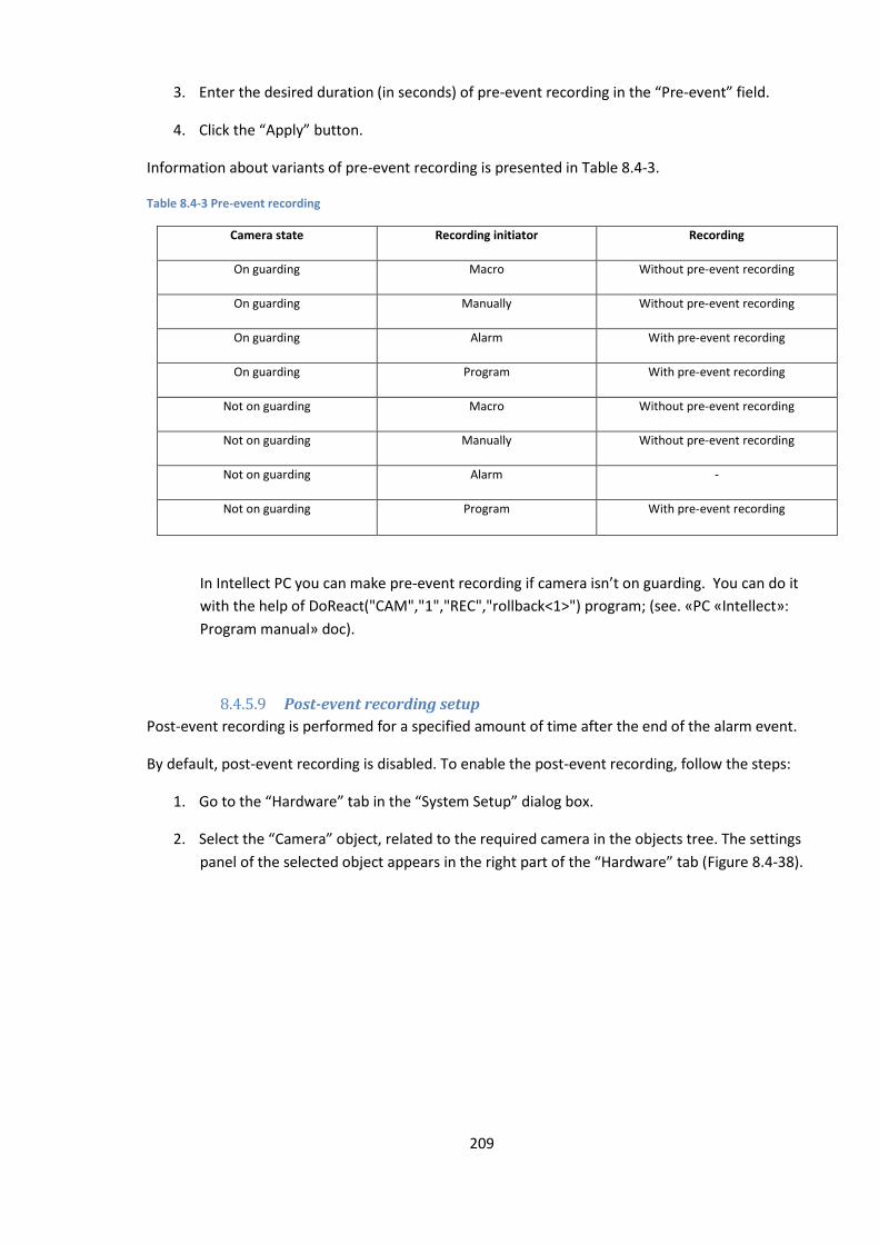
209
3. Enter the desired duration (in seconds) of pre-event recording in the “Pre-event” field.
4. Click the “Apply” button.
Information about variants of pre-event recording is presented in Table 8.4-3.
Table 8.4-3 Pre-event recording
Camera state Recording initiator Recording
On guarding Macro Without pre-event recording
On guarding Manually Without pre-event recording
On guarding Alarm With pre-event recording
On guarding Program With pre-event recording
Not on guarding Macro Without pre-event recording
Not on guarding Manually Without pre-event recording
Not on guarding Alarm -
Not on guarding Program With pre-event recording
In Intellect PC you can make pre-event recording if camera isn’t on guarding. You can do it
with the help of DoReact("CAM","1","REC","rollback<1>") program; (see. «PC «Intellect»:
Program manual» doc).
8.4.5.9 Post-event recording setup
Post-event recording is performed for a specified amount of time after the end of the alarm event.
By default, post-event recording is disabled. To enable the post-event recording, follow the steps:
1. Go to the “Hardware” tab in the “System Setup” dialog box.
2. Select the “Camera” object, related to the required camera in the objects tree. The settings
panel of the selected object appears in the right part of the “Hardware” tab (Figure 8.4-38).
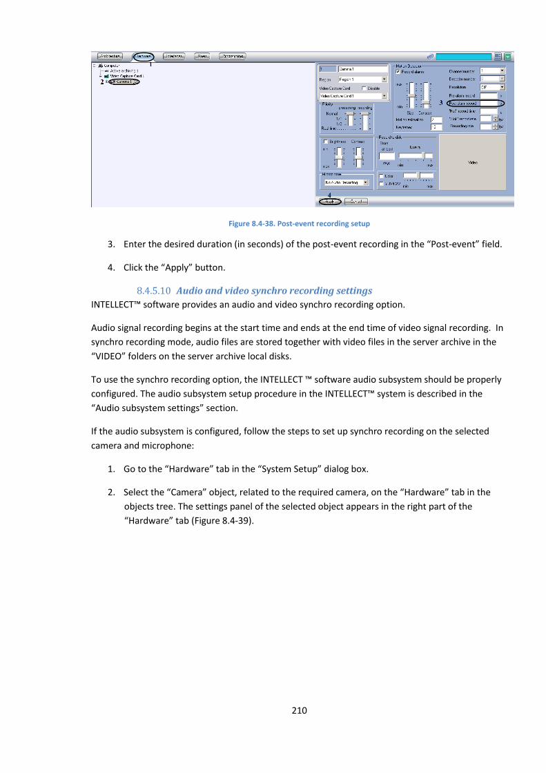
210
Figure 8.4-38. Post-event recording setup
3. Enter the desired duration (in seconds) of the post-event recording in the “Post-event” field.
4. Click the “Apply” button.
8.4.5.10 Audio and video synchro recording settings
INTELLECT™ software provides an audio and video synchro recording option.
Audio signal recording begins at the start time and ends at the end time of video signal recording. In
synchro recording mode, audio files are stored together with video files in the server archive in the
“VIDEO” folders on the server archive local disks.
To use the synchro recording option, the INTELLECT ™ software audio subsystem should be properly
configured. The audio subsystem setup procedure in the INTELLECT™ system is described in the
“Audio subsystem settings” section.
If the audio subsystem is configured, follow the steps to set up synchro recording on the selected
camera and microphone:
1. Go to the “Hardware” tab in the “System Setup” dialog box.
2. Select the “Camera” object, related to the required camera, on the “Hardware” tab in the
objects tree. The settings panel of the selected object appears in the right part of the
“Hardware” tab (Figure 8.4-39).
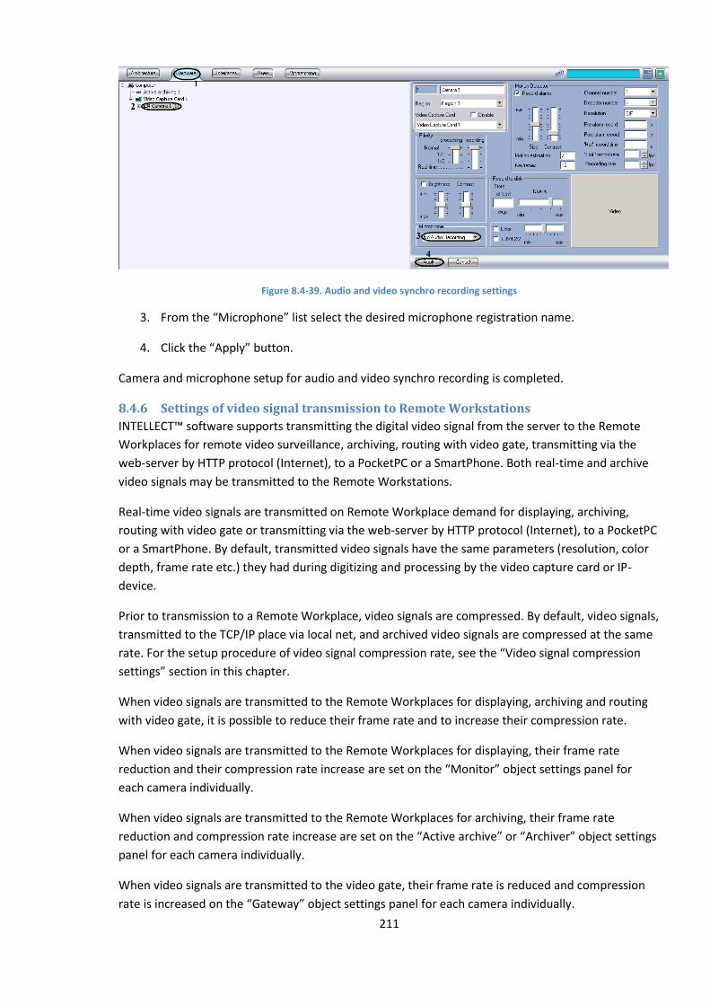
211
Figure 8.4-39. Audio and video synchro recording settings
3. From the “Microphone” list select the desired microphone registration name.
4. Click the “Apply” button.
Camera and microphone setup for audio and video synchro recording is completed.
8.4.6 Settings of video signal transmission to Remote Workstations
INTELLECT™ software supports transmitting the digital video signal from the server to the Remote
Workplaces for remote video surveillance, archiving, routing with video gate, transmitting via the
web-server by HTTP protocol (Internet), to a PocketPC or a SmartPhone. Both real-time and archive
video signals may be transmitted to the Remote Workstations.
Real-time video signals are transmitted on Remote Workplace demand for displaying, archiving,
routing with video gate or transmitting via the web-server by HTTP protocol (Internet), to a PocketPC
or a SmartPhone. By default, transmitted video signals have the same parameters (resolution, color
depth, frame rate etc.) they had during digitizing and processing by the video capture card or IP-
device.
Prior to transmission to a Remote Workplace, video signals are compressed. By default, video signals,
transmitted to the TCP/IP place via local net, and archived video signals are compressed at the same
rate. For the setup procedure of video signal compression rate, see the “Video signal compression
settings” section in this chapter.
When video signals are transmitted to the Remote Workplaces for displaying, archiving and routing
with video gate, it is possible to reduce their frame rate and to increase their compression rate.
When video signals are transmitted to the Remote Workplaces for displaying, their frame rate
reduction and their compression rate increase are set on the “Monitor” object settings panel for
each camera individually.
When video signals are transmitted to the Remote Workplaces for archiving, their frame rate
reduction and compression rate increase are set on the “Active archive” or “Archiver” object settings
panel for each camera individually.
When video signals are transmitted to the video gate, their frame rate is reduced and compression
rate is increased on the “Gateway” object settings panel for each camera individually.
212
When video signals are transmitted via a web-server by HTTP protocol to a Remote Workplace , a
PocketPC or a SmartPhone, its compression rate is set on the “Web-server” object settings panel that
corresponds to the “Web-server” module. For the setup procedure of the video signal compression
rate, see the chapters on «Web-server», «SmartPocketPC», «SmartPhone» modules setup.
8.4.7 Video signal display settings
8.4.7.1 General information
With different video signal transmission modes, different video monitors are used:
1. Video server surveillance Monitor.
2. Video surveillance Monitor of the Remote Workstation, connected to the videoserver via
TCP/IP net.
3. Video monitor of the “web-server”, displayed in web browsers on Remote Workstations,
connected to the videoserver via the “web-server” module by HTTP protocol.
4. “SmartPocket” module video monitor, displayed on the PocketPC screen, connected to the
videoserver via the “SmartPocket” module.
5. “SmartPhone” module video monitor, displayed on the SmartPhone screen, connected to the
video server via the “SmartPhone” module.
Video surveillance monitors on the server and Remote Workstations, connected to the videoserver
via TCP/IP local net, are identical. Video surveillance onitors on the videoserver and on Remote
Workstations are set up with the “System Setup” dialog box and is described below.
To set up the video surveillance monitor of the “Web-server” module, Java-applet settings of its
home page are changed (see the chapter ““Web-server” module settings”).
Video surveillance monitors of the “SmartPocket” and «SmartPhone» modules cannot be adjusted.
The video monitor is used to:
1. display video signals;
2. play back the archives;
3. change the sequence of displaying video signals (surveillance windows layout, selection of
video signals to be displayed in the surveillance windows, windows slide show, etc.);
4. process the displayed signals (deinterlacing, zooming, image sharpening and changing
contrast);
5. export and hardcopy selected frames, export video and audio records;
6. control detectors, including camera alarm detectors (main motion detectors);
7. control video recording;
8. control PTZ units and microphones.
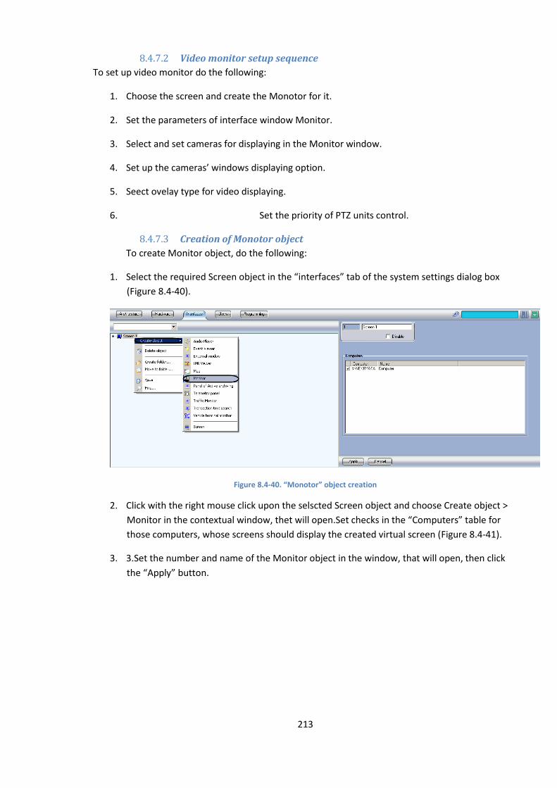
213
8.4.7.2 Video monitor setup sequence
To set up video monitor do the following:
1. Choose the screen and create the Monotor for it.
2. Set the parameters of interface window Monitor.
3. Select and set cameras for displaying in the Monitor window.
4. Set up the cameras’ windows displaying option.
5. Seect ovelay type for video displaying.
6. Set the priority of PTZ units control.
8.4.7.3 Creation of Monotor object
To create Monitor object, do the following:
1. Select the required Screen object in the “interfaces” tab of the system settings dialog box
(Figure 8.4-40).
Figure 8.4-40. “Monotor” object creation
2. Click with the right mouse click upon the selscted Screen object and choose Create object >
Monitor in the contextual window, thet will open.Set checks in the “Computers” table for
those computers, whose screens should display the created virtual screen (Figure 8.4-41).
3. 3.Set the number and name of the Monitor object in the window, that will open, then click
the “Apply” button.
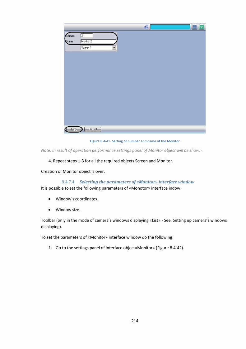
214
Figure 8.4-41. Setting of number and name of the Monitor
Note. In result of operation performance settings panel of Monitor object will be shown.
4. Repeat steps 1-3 for all the required objects Screen and Monitor.
Creation of Monitor object is over.
8.4.7.4 Selecting the parameters of «Мonitor» interface window
It is possible to set the following parameters of «Monotor» interface indow:
Window’s coordinates.
Window size.
Toolbar (only in the mode of camera’s windows displaying «List» - See. Setting up camera’s windows
displaying).
To set the parameters of «Monitor» interface window do the following:
1. Go to the settings panel of interface object«Monitor» (Figure 8.4-42).
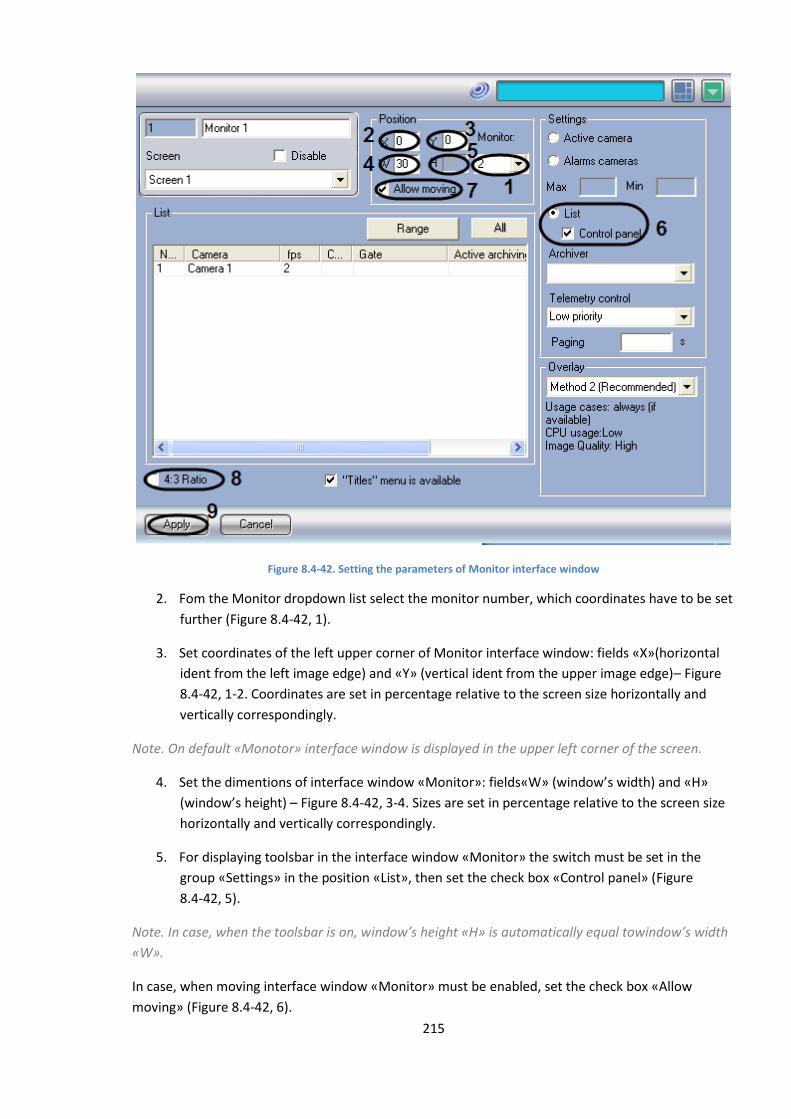
215
Figure 8.4-42. Setting the parameters of Monitor interface window
2. Fom the Monitor dropdown list select the monitor number, which coordinates have to be set
further (Figure 8.4-42, 1).
3. Set coordinates of the left upper corner of Monitor interface window: fields «X»(horizontal
ident from the left image edge) and «Y» (vertical ident from the upper image edge)– Figure
8.4-42, 1-2. Coordinates are set in percentage relative to the screen size horizontally and
vertically correspondingly.
Note. On default «Monotor» interface window is displayed in the upper left corner of the screen.
4. Set the dimentions of interface window «Monitor»: fields«W» (window’s width) and «H»
(window’s height) – Figure 8.4-42, 3-4. Sizes are set in percentage relative to the screen size
horizontally and vertically correspondingly.
5. For displaying toolsbar in the interface window «Monitor» the switch must be set in the
group «Settings» in the position «List», then set the check box «Control panel» (Figure
8.4-42, 5).
Note. In case, when the toolsbar is on, window’s height «H» is automatically equal towindow’s width
«W».
In case, when moving interface window «Мonitor» must be enabled, set the check box «Allow
moving» (Figure 8.4-42, 6).
216
Note. This setting is urgent only with the usage of toolsbar.
6. In case, when the ratio of width and height of the window shoul be 4:3, set the check box
«Ratio 4:3» (Figure 8.4-42, 7).
7. To save all the changes click the “Apply” button (Figure 8.4-42, 8).
Setting the parameres of interface window Monitor is completed.
8.4.7.5 Selection and setting of video cameras
One can select and set cameras for displaying in two ways:
Separately. Settings panel «Мonitor» is used.
Complex. Dialog window «Add/Edit cameras» is used.
Note. Order of complex selection of video cameras for displaying in the interface window «Monitor»
is described in Complex selection of cameras.
To selection the video cameras on the object settings panel «Monitor» do the following:
1. Go to the interface object settings panel «Monitor» (Figure 8.4-43).
2. From the dropdpwn list in the column Number select number of the required camera (Figure
8.4-43).
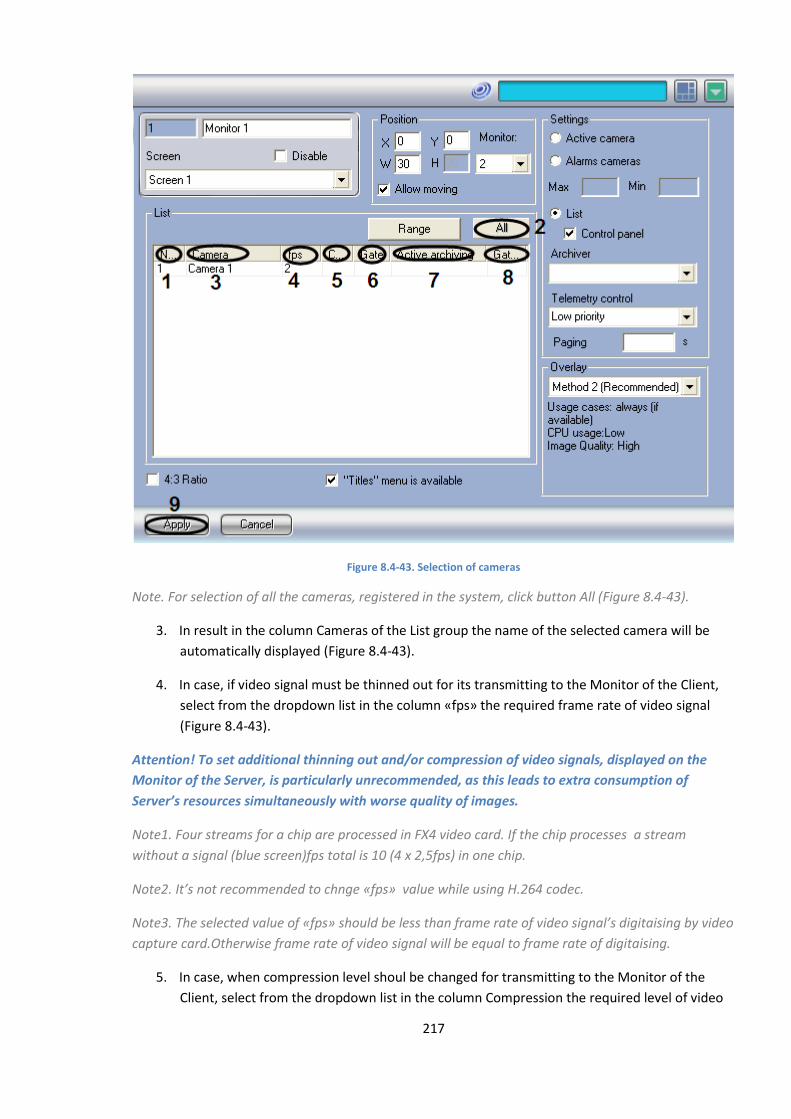
217
Figure 8.4-43. Selection of cameras
Note. For selection of all the cameras, registered in the system, click button All (Figure 8.4-43).
3. In result in the column Cameras of the List group the name of the selected camera will be
automatically displayed (Figure 8.4-43).
4. In case, if video signal must be thinned out for its transmitting to the Monitor of the Client,
select from the dropdown list in the column «fps» the required frame rate of video signal
(Figure 8.4-43).
Attention! To set additional thinning out and/or compression of video signals, displayed on the
Monitor of the Server, is particularly unrecommended, as this leads to extra consumption of
Server’s resources simultaneously with worse quality of images.
Note1. Four streams for a chip are processed in FX4 video card. If the chip processes a stream
without a signal (blue screen)fps total is 10 (4 х 2,5fps) in one chip.
Note2. It’s not recommended to chnge «fps» value while using Н.264 codec.
Note3. The selected value of «fps» should be less than frame rate of video signal’s digitaising by video
capture card.Otherwise frame rate of video signal will be equal to frame rate of digitaising.
5. In case, when compression level shoul be changed for transmitting to the Monitor of the
Client, select from the dropdown list in the column Compression the required level of video

218
signal’s compression (Figure 8.4-43). Compression level rises from «0» (no compression) to
«5» (maximum compression).
Note. In case of setting compression level for the Client, video signal on the Server should be
preliminary decompressed, that results in great load increase on CPU of the Server.
6. In case, when video archive from the selected camera should be transmitted to Monitor
through the Video gate object, selct the name of this object from the dropdown list in the
column Gate (Figure 8.4-43).
7. In case, when video archive from the selected camera should be transmitted to Monitor from
Active archive object, selct the name of this object from the dropdown list in the column
Active archive (Figure 8.4-43).
8. In case, when the tansmission from the object Active archive is performed through the Video
gate object, select from the dropdown list in the column Gateway for active archive the
name of this object (Figure 8.4-43).
9. Repeat steps 2-8 for all the required video cameras.
10. To save all the changes click the “Apply” button (Figure 8.4-43).
Selection of video camera on the settings panel of Monitor object is completed.
8.4.7.6 Complex selection of video cameras
There is an opportunity of complex selection and editing of cameras’parameters for displaying in the
Monitor interface window.
Complex selection can be performed in the following way:
1. Go to the settings panel of Monitor interface object, then click in the group button List and
then button Range (Figure 8.4-44).
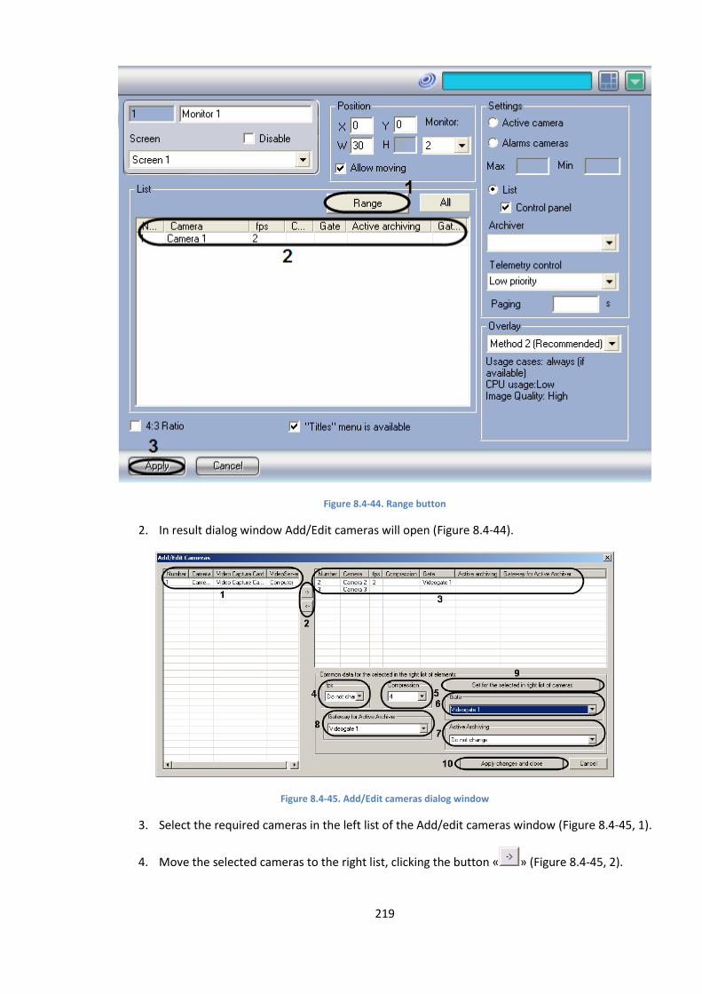
219
Figure 8.4-44. Range button
2. In result dialog window Add/Edit cameras will open (Figure 8.4-44).
Figure 8.4-45. Add/Edit cameras dialog window
3. Select the required cameras in the left list of the Add/edit cameras window (Figure 8.4-45, 1).
4. Move the selected cameras to the right list, clicking the button « » (Figure 8.4-45, 2).

220
Notе.The right list is enumeration of cameras, selected for displaying in the interface window
Monitor.
Button « » is used for back action, that is for moving the selected video cameras from the right list
to the left one (Figure 8.4-45, 2).
5. In result the selected cameras will be displayed in the right list of the window Add/Edit
cameras.
6. If it is necessary select in the right list the names of required cameras for complex editing of
parameters (Figure 8.4-45, 3).
Note. For all the selected cameras the same values of parameters will be set.
7. In case, when video signal has to be thinned out for transmitting to the Monitor of the Client,
select from the dropdown list «fps» the required frame rate of video signal (Figure 8.4-45, 4).
Note. Set additional thinning out and/or compression of video signals, displayed on the Monitor of
the Serve, is particularly unrecommended , as it this leads to extra consumption of Server’s resources
simultaneously with worse quality of images.
Note. The selected value «fps» must be less than frame rate of video signal’s digitaization by video
capture card.Otherwise frame rate of a video signal will be equal to frame rate of digitization.Settings
«fps», «Compression», «Gate», «Active archiving», «Gateway for active archiver» belong to the group
«Common data for the elements, selected in the right list».
8. In case, when compression level of video signal has to be changed for transmitting to
Monitor of the Client ,select from the dropdown list Compression the required compression
level of video signal (Figure 8.4-45, 5).Compression level of video signal rises from «0» (no
compression) to «5» (maximum compression).
Note. In case when compression level is set for the Client, video signal on the Server has to be
preliminarily decompressed, that leads to great load on CPU of the Serever.
9. In case, when video archive from the selected video cameras shoul be transmitted to
Monitor through Videogate object, select from the dropdown list the name of this object
(Figure 8.4-45, 6).
10. In case, when video archive from the selected video cameras shoul be transmitted to
Monitor from Active archiving object , select the name of this object from the dropdown list
Active archiving (Figure 8.4-45, 7).
11. In case, when the transmission from the Active archiving object is performed through
Videogate object, select the name of this object from the dropdown list Gateway for Active
archiving (Figure 8.4-45, 8).
12. Click button Save for the selected in the right list of cameras to save seve the set parameters
(Figure 8.4-45, 9).
221
13. In result the set parameters will be shown in the right list of the window Add/ edit cameras
(Figure 8.4-45, 3).
14. Repeat steps 6-12 for complex editing of all the required cameras.
15. Click button Apply changes and close to save all the canges and close the window Add/edit
cameras click (Figure 8.4-45, 10).
16. Set camera settings will be shown in the table List on the object settings panel Monitor
(Figure 8.4-45, 2).
17. To save all the changes click the “Apply” button (Figure 8.4-45, 3).
Complex selection of video cameras is over.
8.4.7.7 Setting the option of camera’s windows displaying
To display camera’s windows (windows with video images) use one of the following modes:
1. Mode «Active camera». In the interface window Monitor only active window of the camera is
displayed.
Note.To make camera’s window active it is necessary to click upon it with the left mouse click.
2. Mode«Alarm cameras». Windows of alarmed cameras are displayed in the interface window
Monitor.
3. Mode «List».Cameras’ windows are displayed in the window Monitor in accordance with the
selected lay out.
Functions, available in the mode List:
Toolsbar;
Listing function.
Toolsbar is displayed in the interface window Monitor and enable to perform the following
operations:
Select the number of dislayed cameras;
Set and use the lay outs of cameras;
Control the listing function.
Current date and time are also displayed in the toolsbar.
Listing function is used for successive CS displaying of camera’s windows on the Monitor.Listing of
windows is performed with the help of Monitor’s toolsbar buttons in two ways:
1. Manually. Buttons of transference to the previous or next window of cameras
2. Automatically.Transferance to the next window of a camera is performed automatically
within a set period of time.
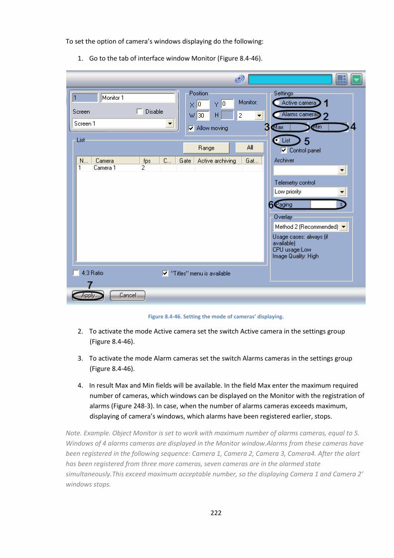
222
To set the option of camera’s windows displaying do the following:
1. Go to the tab of interface window Monitor (Figure 8.4-46).
Figure 8.4-46. Setting the mode of cameras’ displaying.
2. To activate the mode Active camera set the switch Active camera in the settings group
(Figure 8.4-46).
3. To activate the mode Alarm cameras set the switch Alarms cameras in the settings group
(Figure 8.4-46).
4. In result Max and Min fields will be available. In the field Max enter the maximum required
number of cameras, which windows can be displayed on the Monitor with the registration of
alarms (Figure 248-3). In case, when the number of alarms cameras exceeds maximum,
displaying of camera’s windows, which alarms have been registered earlier, stops.
Note. Example. Object Monitor is set to work with maximum number of alarms cameras, equal to 5.
Windows of 4 alarms cameras are displayed in the Monitor window.Alarms from these cameras have
been registered in the following sequence: Camera 1, Camera 2, Camera 3, Camera4. After the alart
has been registered from three more cameras, seven cameras are in the alarmed state
simultaneously.This exceed maximum acceptable number, so the displaying Camera 1 and Camera 2’
windows stops.
223
5. In the field Min enter the minimum required number of cameras, wchich images have to be
displayed on the Monitor even with the abcence of alarm (Figure 8.4-46). In case, when the
number of alarms cameras is less than minimum, windows of cameras, which alarms were
the last, are displayed on the Monitor.
Note. Example. Object «Monitor» is set to work with minimum number of alarms cameras equal to 3.
Windows of 4 alarms cameras are displayed in the Monitor window.After the alarm from 4 cameras
stops in the consequence: Camera 1, Camera 2, Camera 3, Camera 4, one camera is in the alarm
state. This is less than the minimum number, Camera 3 and Camera 4 are also displayed on the
Monitor. With the absence of alarm when the value is set on default («0») of Min parameter,
cameras’ windows are not displayed in the Monitor window.
6. To activate mode List set the List switch in the List settings group (Figure 8.4-46).
7. When necessary enter in the List field the required value in seconds of automatic cameras’
windows listing (Figure 8.4-46).
Note. This detting is urgent only in the List mode with the use of toolsbar.
8. To save all the changes click the “Apply” button (Figure 8.4-46).
Setting the mode of cameras’ displaying is over.
8.4.7.8 Selecting the overlay mode
Overlay is used to process the image using the video card and Direct X libraries, before it is displayed;
Overlay allows to improve the image due to optimization of the pixel color settings. At the same
time, the CPU’s load reduces, as the video image is processed with the resources from the video
capture card.
In Intellect program software three overlay modes are available:
1. «Mode1».Video signals from cameras are processed as a single video flow.
2. «Mode2 (it is recommended)». Video signals from cameras are processed independently.
3. «Do not use». Video signals from cameras with cards are not processed.
As a rule, Mode II overlay is optimal. This mode is supported by the most graphics cards. If the
graphics card doesn’t support the chosen overlay mode, the video signal is displayed with a big delay.
To select the overlay mode do the following:
1. Got to the settings panel of interface object Monitor (Figure 8.4-47).
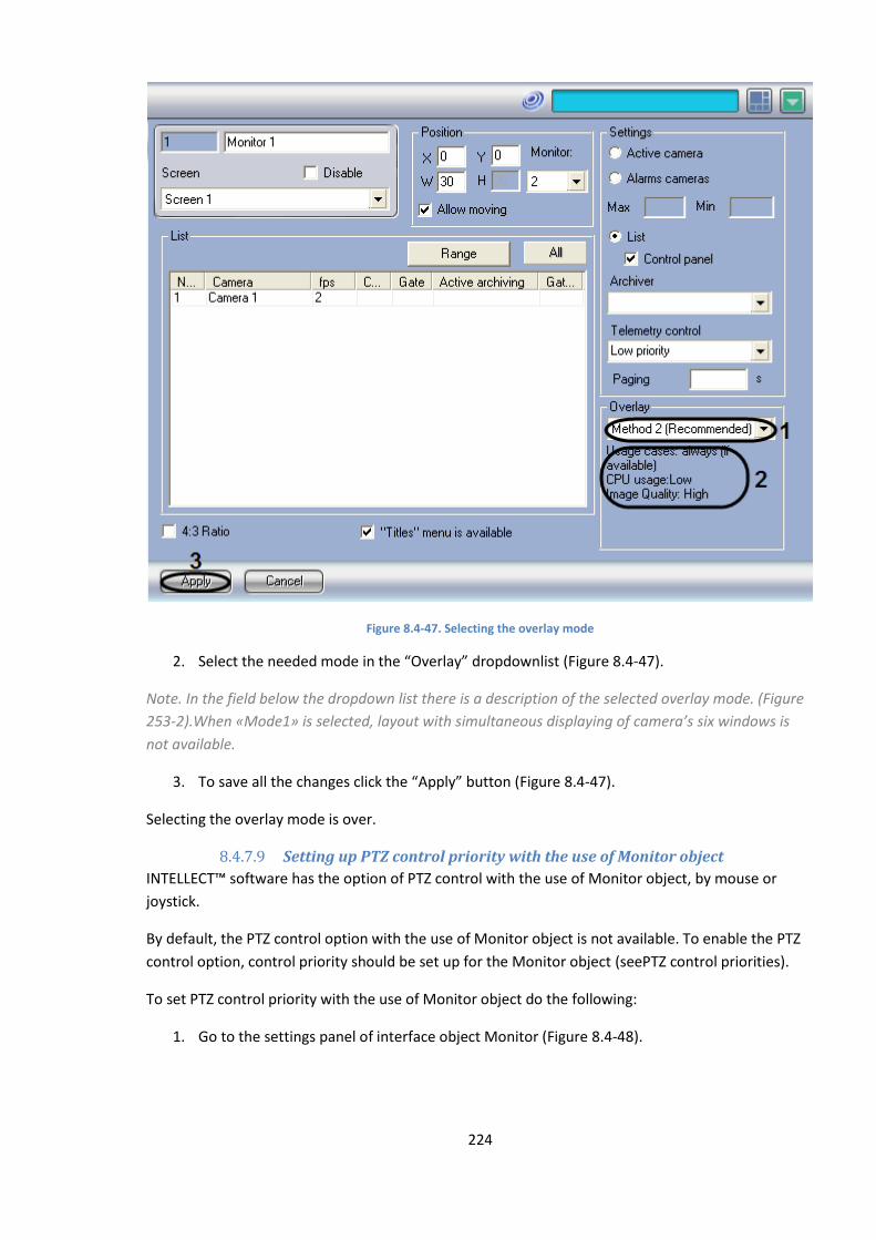
224
Figure 8.4-47. Selecting the overlay mode
2. Select the needed mode in the “Overlay” dropdownlist (Figure 8.4-47).
Note. In the field below the dropdown list there is a description of the selected overlay mode. (Figure
253-2).When «Mode1» is selected, layout with simultaneous displaying of camera’s six windows is
not available.
3. To save all the changes click the “Apply” button (Figure 8.4-47).
Selecting the overlay mode is over.
8.4.7.9 Setting up PTZ control priority with the use of Monitor object
INTELLECT™ software has the option of PTZ control with the use of Monitor object, by mouse or
joystick.
By default, the PTZ control option with the use of Monitor object is not available. To enable the PTZ
control option, control priority should be set up for the Monitor object (seePTZ control priorities).
To set PTZ control priority with the use of Monitor object do the following:
1. Go to the settings panel of interface object Monitor (Figure 8.4-48).
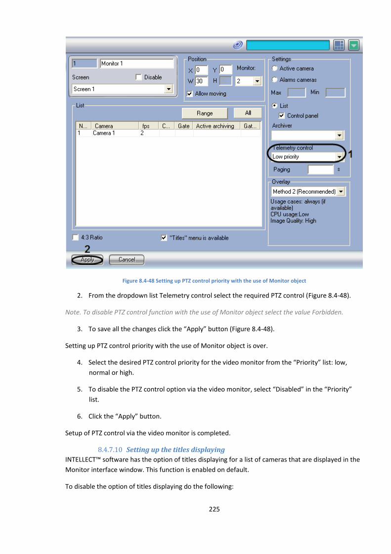
225
Figure 8.4-48 Setting up PTZ control priority with the use of Monitor object
2. From the dropdown list Telemetry control select the required PTZ control (Figure 8.4-48).
Note. To disable PTZ control function with the use of Monitor object select the value Forbidden.
3. To save all the changes click the “Apply” button (Figure 8.4-48).
Setting up PTZ control priority with the use of Monitor object is over.
4. Select the desired PTZ control priority for the video monitor from the “Priority” list: low,
normal or high.
5. To disable the PTZ control option via the video monitor, select “Disabled” in the “Priority”
list.
6. Click the “Apply” button.
Setup of PTZ control via the video monitor is completed.
8.4.7.10 Setting up the titles displaying
INTELLECT™ software has the option of titles displaying for a list of cameras that are displayed in the
Monitor interface window. This function is enabled on default.
To disable the option of titles displaying do the following:
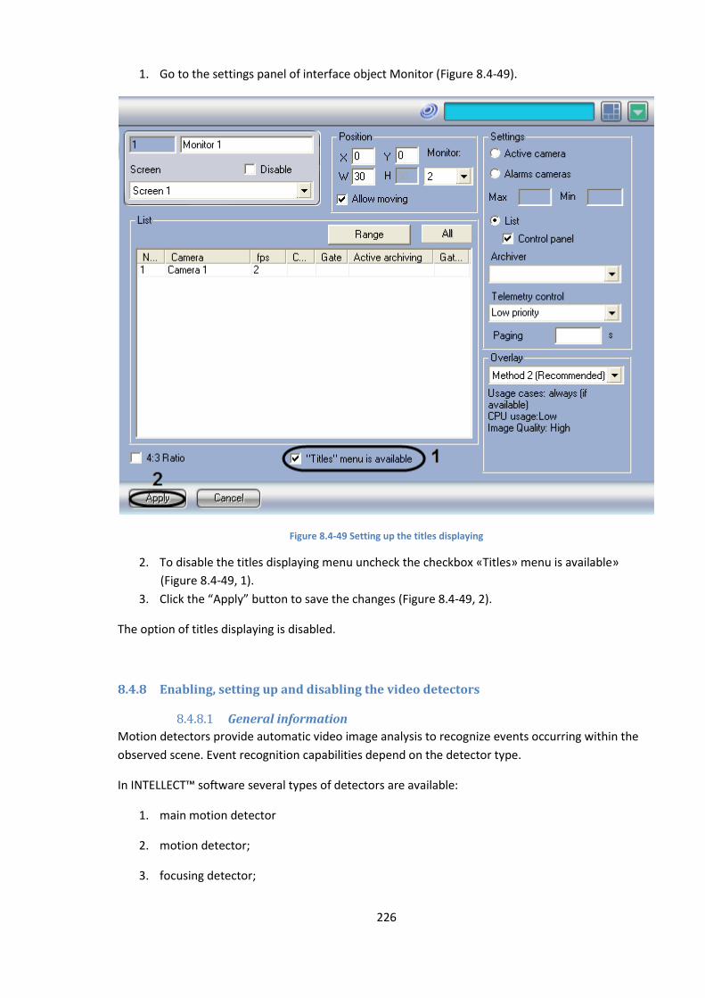
226
1. Go to the settings panel of interface object Monitor (Figure 8.4-49).
Figure 8.4-49 Setting up the titles displaying
2. To disable the titles displaying menu uncheck the checkbox «Titles» menu is available»
(Figure 8.4-49, 1).
3. Click the “Apply” button to save the changes (Figure 8.4-49, 2).
The option of titles displaying is disabled.
8.4.8 Enabling, setting up and disabling the video detectors
8.4.8.1 General information
Motion detectors provide automatic video image analysis to recognize events occurring within the
observed scene. Event recognition capabilities depend on the detector type.
In INTELLECT™ software several types of detectors are available:
1. main motion detector
2. motion detector;
3. focusing detector;
227
4. video signal stability detector;
5. background change detector;
6. camera blinding detector;
7. camera covering detector;
8. lost items detector;
9. infrared detector.
By default, INTELLECT™ software uses solely the main motion detector, which detects the video
surveillance camera alarms. The rest of the detectors are optionally activated in the course of
INTELLECT™ software administration.
To set up the detectors, set up the program algorithms for them , enable auto recording on detector
alarm option etc.
8.4.8.2 Requirements to video parameters while working with detectors
For proper video-analytics operation do the following:
1. Camera requirements:
1.1 Resolution not less than 320х240 pixels.
1.2 Not less than 6 fps.
1.3 Color: analytics works both with color and monochromatic images.
1.4 It is not allowed to the image shift be more than 3% from the frame size due to
camera vibration.
2. Light requirements:
2.1 Medium light. The quality of analytics operation can be lower in case of low light
(night) or over light (overexposure)
2.2 No dramatic changes of light.
3. Scene and camera viewpoint requirements:
3.1 Moving objects have to be visually separated from each other in the image.
3.2 Background is mostly static and is not changed.
3.3 Moving objects shielding by static objects (columns, trees, etc.) is minimal.
3.4 Improper analytics operation is possible on the reflective surface and with sharp
shadows of moving objects.
3.5 Improper analytics operation is possible on extended single-colour objects.
4. Object images requirements:
4.1 It is not allowed to the objects linear dimensions in the image be less than 2% from
the frame size.
4.2 Objects linear dimensions are not to exceed 25% from the frame size as
recommended.
4.3 Speed of objects movement on the image is not less than 1 pixel per second
8.4.8.3 Enabling and configuring detectors
Generally, the procedure of detector setup includes (except for the main motion detector (camera
alarm detector), whose setup procedure is described in the “Main detector setup” section):
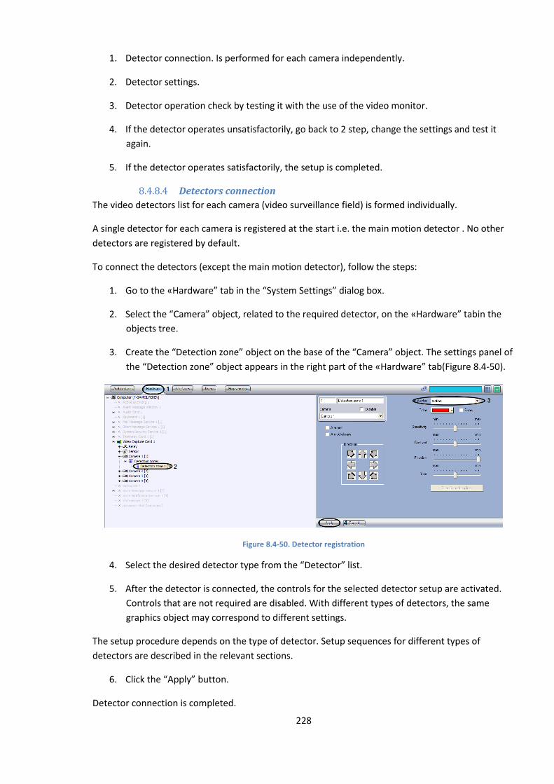
228
1. Detector connection. Is performed for each camera independently.
2. Detector settings.
3. Detector operation check by testing it with the use of the video monitor.
4. If the detector operates unsatisfactorily, go back to 2 step, change the settings and test it
again.
5. If the detector operates satisfactorily, the setup is completed.
8.4.8.4 Detectors connection
The video detectors list for each camera (video surveillance field) is formed individually.
A single detector for each camera is registered at the start i.e. the main motion detector . No other
detectors are registered by default.
To connect the detectors (except the main motion detector), follow the steps:
1. Go to the «Hardware” tab in the “System Settings” dialog box.
2. Select the “Camera” object, related to the required detector, on the «Hardware” tabin the
objects tree.
3. Create the “Detection zone” object on the base of the “Camera” object. The settings panel of
the “Detection zone” object appears in the right part of the «Hardware” tab(Figure 8.4-50).
Figure 8.4-50. Detector registration
4. Select the desired detector type from the “Detector” list.
5. After the detector is connected, the controls for the selected detector setup are activated.
Controls that are not required are disabled. With different types of detectors, the same
graphics object may correspond to different settings.
The setup procedure depends on the type of detector. Setup sequences for different types of
detectors are described in the relevant sections.
6. Click the “Apply” button.
Detector connection is completed.
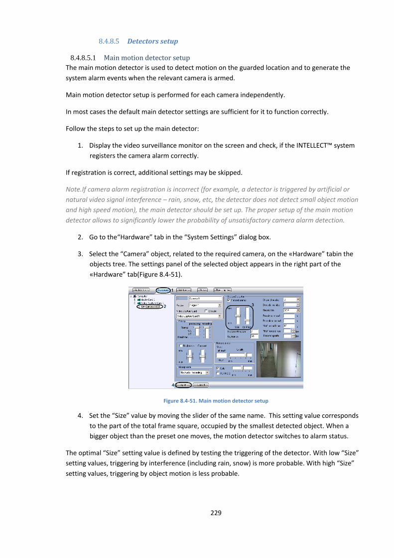
229
8.4.8.5 Detectors setup
8.4.8.5.1 Main motion detector setup
The main motion detector is used to detect motion on the guarded location and to generate the
system alarm events when the relevant camera is armed.
Main motion detector setup is performed for each camera independently.
In most cases the default main detector settings are sufficient for it to function correctly.
Follow the steps to set up the main detector:
1. Display the video surveillance monitor on the screen and check, if the INTELLECT™ system
registers the camera alarm correctly.
If registration is correct, additional settings may be skipped.
Note.If camera alarm registration is incorrect (for example, a detector is triggered by artificial or
natural video signal interference – rain, snow, etc, the detector does not detect small object motion
and high speed motion), the main detector should be set up. The proper setup of the main motion
detector allows to significantly lower the probability of unsatisfactory camera alarm detection.
2. Go to the“Hardware” tab in the “System Settings” dialog box.
3. Select the “Camera” object, related to the required camera, on the «Hardware” tabin the
objects tree. The settings panel of the selected object appears in the right part of the
«Hardware” tab(Figure 8.4-51).
Figure 8.4-51. Main motion detector setup
4. Set the “Size” value by moving the slider of the same name. This setting value corresponds
to the part of the total frame square, occupied by the smallest detected object. When a
bigger object than the preset one moves, the motion detector switches to alarm status.
The optimal “Size” setting value is defined by testing the triggering of the detector. With low “Size”
setting values, triggering by interference (including rain, snow) is more probable. With high “Size”
setting values, triggering by object motion is less probable.
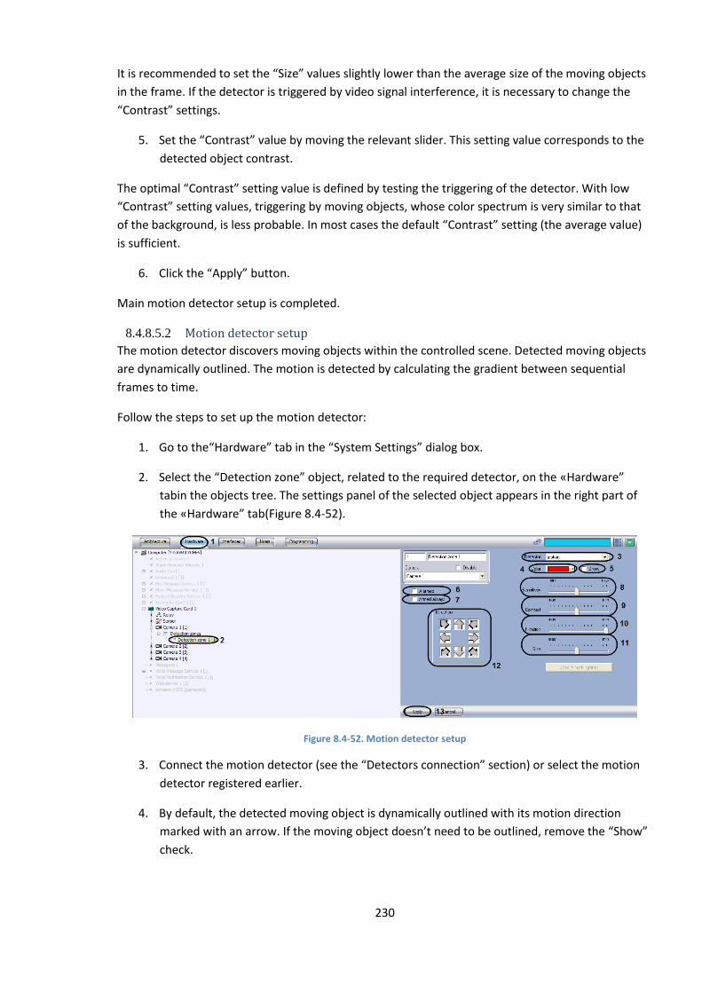
230
It is recommended to set the “Size” values slightly lower than the average size of the moving objects
in the frame. If the detector is triggered by video signal interference, it is necessary to change the
“Contrast” settings.
5. Set the “Contrast” value by moving the relevant slider. This setting value corresponds to the
detected object contrast.
The optimal “Contrast” setting value is defined by testing the triggering of the detector. With low
“Contrast” setting values, triggering by moving objects, whose color spectrum is very similar to that
of the background, is less probable. In most cases the default “Contrast” setting (the average value)
is sufficient.
6. Click the “Apply” button.
Main motion detector setup is completed.
8.4.8.5.2 Motion detector setup
The motion detector discovers moving objects within the controlled scene. Detected moving objects
are dynamically outlined. The motion is detected by calculating the gradient between sequential
frames to time.
Follow the steps to set up the motion detector:
1. Go to the“Hardware” tab in the “System Settings” dialog box.
2. Select the “Detection zone” object, related to the required detector, on the «Hardware”
tabin the objects tree. The settings panel of the selected object appears in the right part of
the «Hardware” tab(Figure 8.4-52).
Figure 8.4-52. Motion detector setup
3. Connect the motion detector (see the “Detectors connection” section) or select the motion
detector registered earlier.
4. By default, the detected moving object is dynamically outlined with its motion direction
marked with an arrow. If the moving object doesn’t need to be outlined, remove the “Show”
check.
231
5. By default, the moving object is outlined with a red border. The border color may be
changed.
To change the color of the border, select the color from the “Color” list or from the “Select color”
panel, called by “Select color” command from the “Color” list. To return the default border color,
select the “By default” command from the “Color” list.
6. To enable the auto recording option on a motion detector alarm for the selected camera, set
the “Alarmed” check.
Note A. If the “Recording alarms” option in the “Camera” object settings is deactivated, then no video
recording is performed after the detector has triggered.
Note B. If the “Alarmed” option is disabled in the detector settings, then detector arming is
ineffective, though this detector name in the functions menu of the video surveillance window is
highlighted by a yellow square.
7. To disable disarming of the motion detector by any user (irrespectively of his rights), set the
“Armed always” check.
Note. When the “Armed always” check is set, the row with the motion detector name is not displayed
in the functions menu of the video surveillance window.
8. Set the “Sensitivity” value by moving the relevant slider. This setting corresponds to such
minimum value of the average brightness of the moving object, with which the detector
triggers by its motion only, and not by interference (including rain, snow).
The optimal “Sensitivity” value is defined by testing the detector’s false triggering. With low
“Sensitivity” values, false triggering by interference is more probable. With high “Sensitivity” values,
triggering by object motion is less probable.
Set the “Sensitivity” value after the “Size”, “Filtration” and “Contrast” settings have been set. It is
recommended to select a “Sensitivity” value that will exclude false triggering by video signal
interference.
9. Set the “Contrast” value by moving the slider of the same name. This setting value
corresponds to the detected object contrast.
The optimal “Contrast” setting value is defined by testing the triggering of the detector. With low
“Contrast” values, triggering by moving objects, whose color spectrum is very similar to that of the
background, is less probable. With high “Contrast” values, false triggering of the detector by
interference is more probable.
In most cases the default setting (the average value) is sufficient.
10. Set the “Filtration” value by moving the relevant slider. This setting corresponds to the
object’s upper speed threshold, with which the detector should trigger. With the minimum
value of this setting, the detector is triggered by an object, moving at any speed.
232
The optimal “Filtration” setting value is defined by testing the triggering of the detector. With low
“Filtration” setting values, triggering by interference (including rain, snow) is more probable. With
high “Filtration” setting values, triggering by object motion is less probable.
It is recommended to set the “Filtration” values, slightly lower than the average speed of the moving
objects in the frame. If a detector is triggered by video signal interference, it is necessary to change
the “Sensitivity” settings.
11. Set the “Size” value by moving the slider of the same name. This setting value corresponds to
the part of the total frame square, occupied by the smallest detected object. When a bigger
object than the preset one moves, the motion detector switches to alarm status.
The optimal “Size” setting value is defined by testing the triggering of the detector. With low “Size”
setting values, triggering by interference (including rain, snow) is more probable. With high “Size”
setting values, triggering by object motion is less probable.
It is recommended to set the “Size” values, slightly lower than the average size of the moving objects
in the frame. If a detector is triggered by video signal interference, it is necessary to change the
“Sensitivity” settings.
12. By default, a detector recognizes motion in any direction. To disable detection of motion in
certain directions, click the relevant buttons in the “Direction” group. A detector detects
motion in the directions of the “pressed” arrow buttons and does not detect it in the
directions of “pulled” arrows.
13. Click the “Apply” button.
Motion detector setup is completed.
8.4.8.5.3 Focusing detector setup
This detector notifies the Operator about camera tampering, resulting in focus loss or camera
sensitivity degradation.} The high frequency component of the video signal is analyzed to check for
presence of distinct contours.
Follow the steps to set up the focusing detector:
1. Go to the“Hardware” tab in the “System Settings” dialog box.
2. Select the “Detection zone” object, related to the required detector, on the «Hardware”
tabin the objects tree. The settings panel of the selected object appears in the right part of
the «Hardware” tab(Figure 8.4-53).
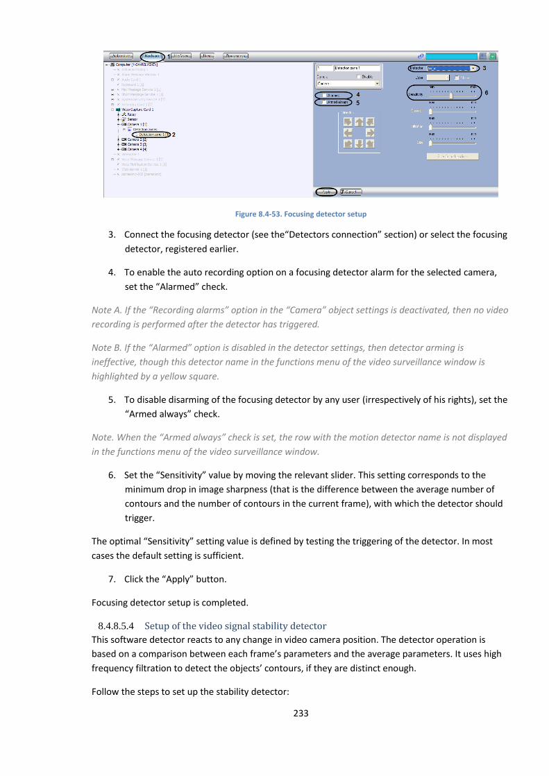
233
Figure 8.4-53. Focusing detector setup
3. Connect the focusing detector (see the“Detectors connection” section) or select the focusing
detector, registered earlier.
4. To enable the auto recording option on a focusing detector alarm for the selected camera,
set the “Alarmed” check.
Note A. If the “Recording alarms” option in the “Camera” object settings is deactivated, then no video
recording is performed after the detector has triggered.
Note B. If the “Alarmed” option is disabled in the detector settings, then detector arming is
ineffective, though this detector name in the functions menu of the video surveillance window is
highlighted by a yellow square.
5. To disable disarming of the focusing detector by any user (irrespectively of his rights), set the
“Armed always” check.
Note. When the “Armed always” check is set, the row with the motion detector name is not displayed
in the functions menu of the video surveillance window.
6. Set the “Sensitivity” value by moving the relevant slider. This setting corresponds to the
minimum drop in image sharpness (that is the difference between the average number of
contours and the number of contours in the current frame), with which the detector should
trigger.
The optimal “Sensitivity” setting value is defined by testing the triggering of the detector. In most
cases the default setting is sufficient.
7. Click the “Apply” button.
Focusing detector setup is completed.
8.4.8.5.4 Setup of the video signal stability detector
This software detector reacts to any change in video camera position. The detector operation is
based on a comparison between each frame’s parameters and the average parameters. It uses high
frequency filtration to detect the objects’ contours, if they are distinct enough.
Follow the steps to set up the stability detector:

234
1. Go to the“Hardware” tab in the “System Settings” dialog box.
2. Select the “Detection zone” object, related to the required detector, on the «Hardware”
tabin the objects tree. The settings panel of the selected object appears in the right part of
the «Hardware” tab(Figure 8.4-54).
Figure 8.4-54. Setup of the stability detector
3. Connect the stability detector (see the “Detectors connection” section) or select the stability
detector, registered earlier.
4. Set the “Sensitivity” value by moving the slider of the same name. This setting corresponds to
the minimum drop in image sharpness (that is the difference between the average number
of contours and the number of contours in the current frame), with which the detector
should trigger.
The optimal value of the “Sensitivity” setting is defined by testing the triggering of the detector. In
most cases the default setting is sufficient.
5. Set the “Filtration” value by moving the relevant slider. This setting corresponds to the
object’s upper speed threshold, at which the detector should not trigger.
The optimal value of the “Filtration” setting is defined by testing the triggering of the detector. In
most cases the default setting is sufficient.
6. To enable the auto recording option by stability detector alarm for the selected camera, set
the “Alarmed” check.
Note A. If the “Recording alarms” option in the “Camera” object settings is deactivated, then no video
recording is performed after the detector has triggered.
Note B. If the “Alarmed” option is disabled in the detector settings, then detector arming is
ineffective, though this detector name in the functions menu of the video surveillance window is
highlighted by a yellow square.
7. To disable disarming of the stability detector by any user (irrespectively of his rights), set the
“Armed always” check.
Note. When the “Armed always” check is set, the row with the motion detector name is not displayed
in the functions menu of the video surveillance window.
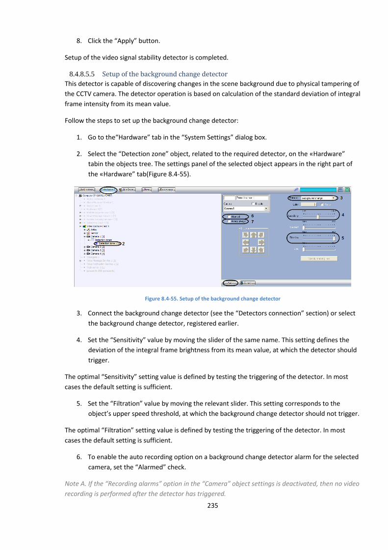
235
8. Click the “Apply” button.
Setup of the video signal stability detector is completed.
8.4.8.5.5 Setup of the background change detector
This detector is capable of discovering changes in the scene background due to physical tampering of
the CCTV camera. The detector operation is based on calculation of the standard deviation of integral
frame intensity from its mean value.
Follow the steps to set up the background change detector:
1. Go to the“Hardware” tab in the “System Settings” dialog box.
2. Select the “Detection zone” object, related to the required detector, on the «Hardware”
tabin the objects tree. The settings panel of the selected object appears in the right part of
the «Hardware” tab(Figure 8.4-55).
Figure 8.4-55. Setup of the background change detector
3. Connect the background change detector (see the “Detectors connection” section) or select
the background change detector, registered earlier.
4. Set the “Sensitivity” value by moving the slider of the same name. This setting defines the
deviation of the integral frame brightness from its mean value, at which the detector should
trigger.
The optimal “Sensitivity” setting value is defined by testing the triggering of the detector. In most
cases the default setting is sufficient.
5. Set the “Filtration” value by moving the relevant slider. This setting corresponds to the
object’s upper speed threshold, at which the background change detector should not trigger.
The optimal “Filtration” setting value is defined by testing the triggering of the detector. In most
cases the default setting is sufficient.
6. To enable the auto recording option on a background change detector alarm for the selected
camera, set the “Alarmed” check.
Note A. If the “Recording alarms” option in the “Camera” object settings is deactivated, then no video
recording is performed after the detector has triggered.
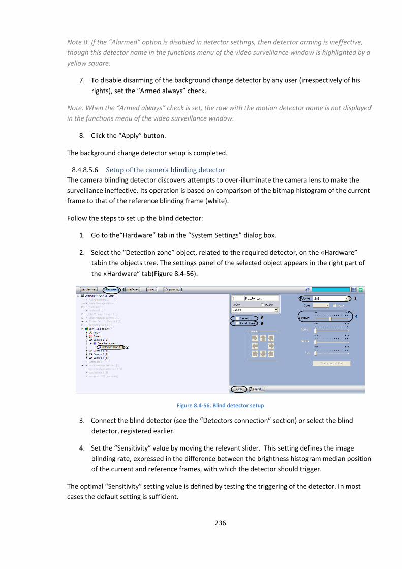
236
Note B. If the “Alarmed” option is disabled in detector settings, then detector arming is ineffective,
though this detector name in the functions menu of the video surveillance window is highlighted by a
yellow square.
7. To disable disarming of the background change detector by any user (irrespectively of his
rights), set the “Armed always” check.
Note. When the “Armed always” check is set, the row with the motion detector name is not displayed
in the functions menu of the video surveillance window.
8. Click the “Apply” button.
The background change detector setup is completed.
8.4.8.5.6 Setup of the camera blinding detector
The camera blinding detector discovers attempts to over-illuminate the camera lens to make the
surveillance ineffective. Its operation is based on comparison of the bitmap histogram of the current
frame to that of the reference blinding frame (white).
Follow the steps to set up the blind detector:
1. Go to the“Hardware” tab in the “System Settings” dialog box.
2. Select the “Detection zone” object, related to the required detector, on the «Hardware”
tabin the objects tree. The settings panel of the selected object appears in the right part of
the «Hardware” tab(Figure 8.4-56).
Figure 8.4-56. Blind detector setup
3. Connect the blind detector (see the “Detectors connection” section) or select the blind
detector, registered earlier.
4. Set the “Sensitivity” value by moving the relevant slider. This setting defines the image
blinding rate, expressed in the difference between the brightness histogram median position
of the current and reference frames, with which the detector should trigger.
The optimal “Sensitivity” setting value is defined by testing the triggering of the detector. In most
cases the default setting is sufficient.
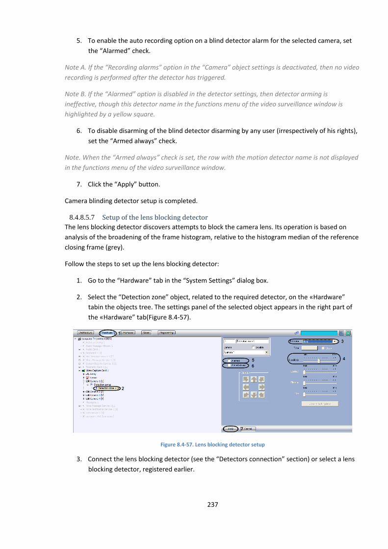
237
5. To enable the auto recording option on a blind detector alarm for the selected camera, set
the “Alarmed” check.
Note A. If the “Recording alarms” option in the “Camera” object settings is deactivated, then no video
recording is performed after the detector has triggered.
Note B. If the “Alarmed” option is disabled in the detector settings, then detector arming is
ineffective, though this detector name in the functions menu of the video surveillance window is
highlighted by a yellow square.
6. To disable disarming of the blind detector disarming by any user (irrespectively of his rights),
set the “Armed always” check.
Note. When the “Armed always” check is set, the row with the motion detector name is not displayed
in the functions menu of the video surveillance window.
7. Click the “Apply” button.
Camera blinding detector setup is completed.
8.4.8.5.7 Setup of the lens blocking detector
The lens blocking detector discovers attempts to block the camera lens. Its operation is based on
analysis of the broadening of the frame histogram, relative to the histogram median of the reference
closing frame (grey).
Follow the steps to set up the lens blocking detector:
1. Go to the “Hardware” tab in the “System Settings” dialog box.
2. Select the “Detection zone” object, related to the required detector, on the «Hardware”
tabin the objects tree. The settings panel of the selected object appears in the right part of
the «Hardware” tab(Figure 8.4-57).
Figure 8.4-57. Lens blocking detector setup
3. Connect the lens blocking detector (see the “Detectors connection” section) or select a lens
blocking detector, registered earlier.
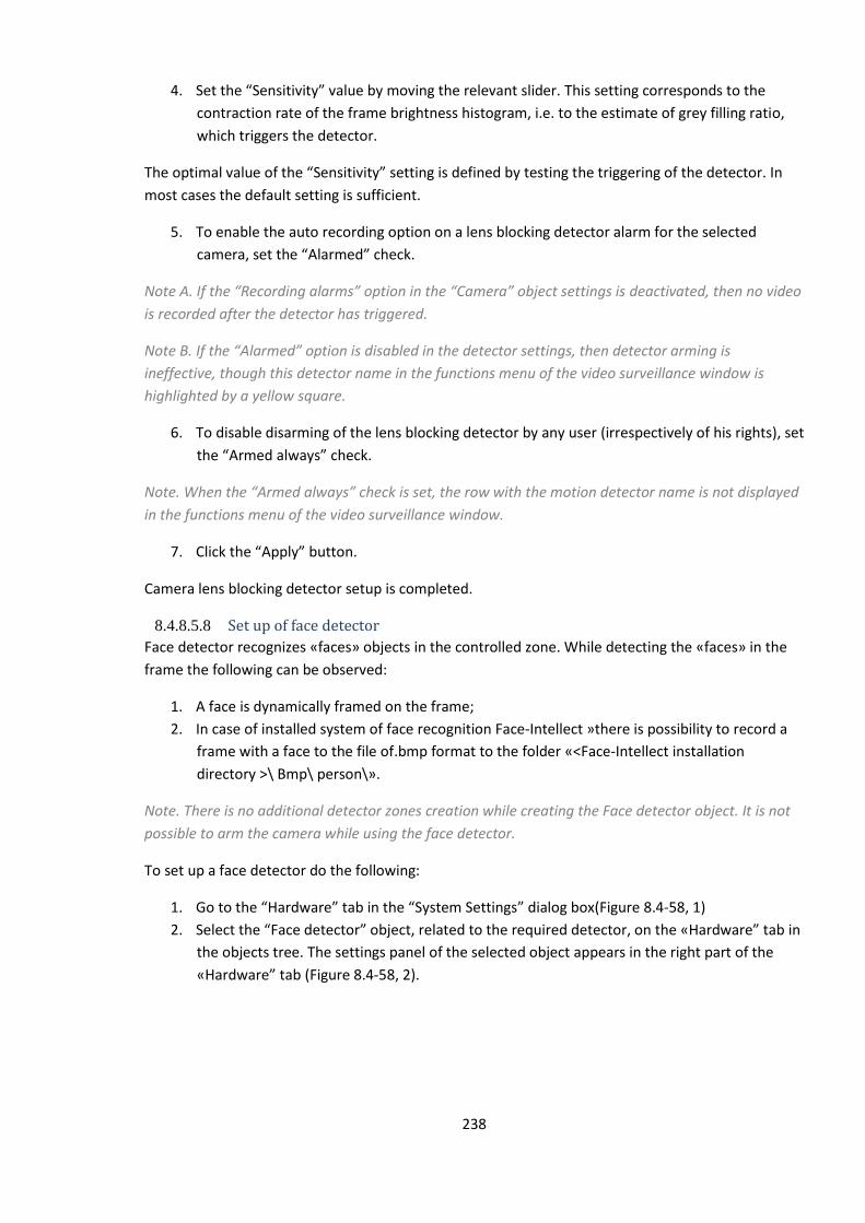
238
4. Set the “Sensitivity” value by moving the relevant slider. This setting corresponds to the
contraction rate of the frame brightness histogram, i.e. to the estimate of grey filling ratio,
which triggers the detector.
The optimal value of the “Sensitivity” setting is defined by testing the triggering of the detector. In
most cases the default setting is sufficient.
5. To enable the auto recording option on a lens blocking detector alarm for the selected
camera, set the “Alarmed” check.
Note A. If the “Recording alarms” option in the “Camera” object settings is deactivated, then no video
is recorded after the detector has triggered.
Note B. If the “Alarmed” option is disabled in the detector settings, then detector arming is
ineffective, though this detector name in the functions menu of the video surveillance window is
highlighted by a yellow square.
6. To disable disarming of the lens blocking detector by any user (irrespectively of his rights), set
the “Armed always” check.
Note. When the “Armed always” check is set, the row with the motion detector name is not displayed
in the functions menu of the video surveillance window.
7. Click the “Apply” button.
Camera lens blocking detector setup is completed.
8.4.8.5.8 Set up of face detector
Face detector recognizes «faces» objects in the controlled zone. While detecting the «faces» in the
frame the following can be observed:
1. A face is dynamically framed on the frame;
2. In case of installed system of face recognition Face-Intellect »there is possibility to record a
frame with a face to the file of.bmp format to the folder «<Face-Intellect installation
directory >\ Bmp\ person\».
Note. There is no additional detector zones creation while creating the Face detector object. It is not
possible to arm the camera while using the face detector.
To set up a face detector do the following:
1. Go to the “Hardware” tab in the “System Settings” dialog box(Figure 8.4-58, 1)
2. Select the “Face detector” object, related to the required detector, on the «Hardware” tab in
the objects tree. The settings panel of the selected object appears in the right part of the
«Hardware” tab (Figure 8.4-58, 2).
239
Figure 8.4-58 Face detector setup
3. State how much fps from the video stream is processed by the Face detector program
module. This parameter is necessary for reducing the load on the Server (Figure 8.4-58, 3)
4. State the size of a face in percent relative to the camera’s video surveillance window sizes
when the face is required to be dynamically framed (Figure 8.4-58, 4)
5. In case when the color of a dynamic frame has to be changed, make a left click upon the field
«Color» (Figure 8.4-58, 5). In the appeared standard dialog window «Color» select the
required color and click «ОК».
6. On default the Face detector processes a video with the resolution, set for the Camera
parent object. To process a video with320x240 pixels resolution set the checkbox «Process
video in low resolution» (Figure 8.4-58, 6)
Note. Enabling this option reduces the load of the Server’s processor, but the probability of face
detection also reduces.
Note! The setting «Process video in low resolution» is not relevant in case, when a high resolution
is set for a Camera parent object.
7. Evaluate the part of recognized faces while processing the video with 320x240 pixels
resolution. In case, when this value is not great enough, uncheck the checkbox « Process
video in low resolution ».
8. Set the slider «Face capture area’s scaling» to the position, corresponding to the required
scaling of a face in the frame for recording (Figure 8.4-58, 7). The current scale value is
displayed in the field above the slider and ranges from 1 (only the face image is recorded) to
5 (the whole frame is recorded).
Note. This setting is relevant in case of installed face recognition system «Face-Intellect». A frame
with a face is recorded to the folder «< Face-Intellect installation directory>\ Bmp\ person\».
9. Click Apply to save the changes (Figure 8.4-58, 8).
Face detector setup is completed.
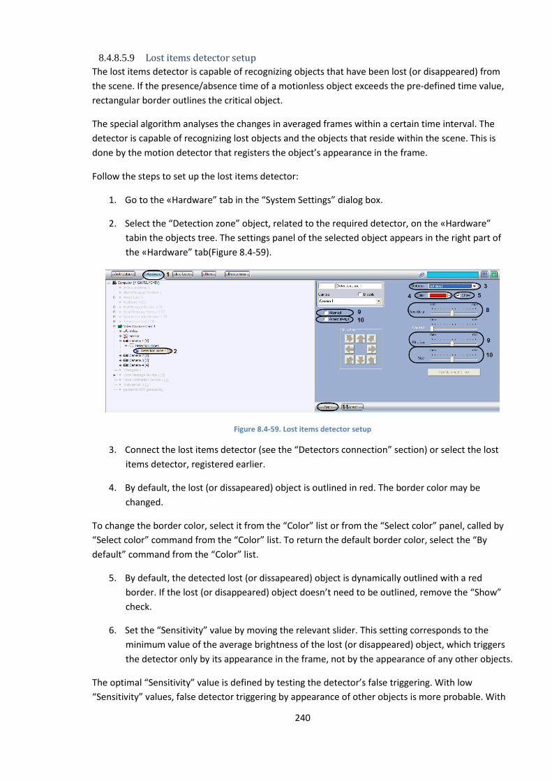
240
8.4.8.5.9 Lost items detector setup
The lost items detector is capable of recognizing objects that have been lost (or disappeared) from
the scene. If the presence/absence time of a motionless object exceeds the pre-defined time value,
rectangular border outlines the critical object.
The special algorithm analyses the changes in averaged frames within a certain time interval. The
detector is capable of recognizing lost objects and the objects that reside within the scene. This is
done by the motion detector that registers the object’s appearance in the frame.
Follow the steps to set up the lost items detector:
1. Go to the «Hardware” tab in the “System Settings” dialog box.
2. Select the “Detection zone” object, related to the required detector, on the «Hardware”
tabin the objects tree. The settings panel of the selected object appears in the right part of
the «Hardware” tab(Figure 8.4-59).
Figure 8.4-59. Lost items detector setup
3. Connect the lost items detector (see the “Detectors connection” section) or select the lost
items detector, registered earlier.
4. By default, the lost (or dissapeared) object is outlined in red. The border color may be
changed.
To change the border color, select it from the “Color” list or from the “Select color” panel, called by
“Select color” command from the “Color” list. To return the default border color, select the “By
default” command from the “Color” list.
5. By default, the detected lost (or dissapeared) object is dynamically outlined with a red
border. If the lost (or disappeared) object doesn’t need to be outlined, remove the “Show”
check.
6. Set the “Sensitivity” value by moving the relevant slider. This setting corresponds to the
minimum value of the average brightness of the lost (or disappeared) object, which triggers
the detector only by its appearance in the frame, not by the appearance of any other objects.
The optimal “Sensitivity” value is defined by testing the detector’s false triggering. With low
“Sensitivity” values, false detector triggering by appearance of other objects is more probable. With
241
high “Sensitivity” values, triggering by a lost object is less probable. It is recommended to select a
“Sensitivity” value, which will exclude false triggering of the detector.
7. Set the “Filtration” value by moving the relevant slider. This setting corresponds to the time
interval, after which the object in the frame is considered to be “lost” (or “disappeared”).
The slider’s “Max” position corresponds to 3 minutes, the “Min” position – to 3 seconds.
8. Set the “Size” value by moving the relevant slider. This setting value corresponds to the part
of the total frame square, occupied by the smallest detected object. When a bigger object
than the preset one, is recognized as a “lost item”, the face detector switches to alarm
status.
The optimal “Size” setting value is defined by testing the triggering of the detector. It is
recommended to set the “Size” values, slightly higher than the mean size of the lost (or disappeared)
objects in the frame. If a detector is falsely triggered, it is necessary to change the “Sensitivity”
settings.
9. To enable the auto recording option on a lost items detector alarm for the selected camera,
set the “Alarmed” check.
Note A. If the “Recording alarms” option in the “Camera” object settings is deactivated, then no video
recording is performed after the detector has triggered.
Note B. If the “Alarmed” option is disabled in the detector settings, then detector arming is
ineffective, though this detector name in the functions menu of the video surveillance window is
highlighted by a yellow square.
10. To disable disarming of the lost items detector by any user (irrespectively of his rights), set
the “Armed always” check.
Note. When the “Armed always” check is set, the row with the motion detector name is not displayed
in the functions menu of the video surveillance window.
11. Click the “Apply” button.
Lost items detector setup is completed.
8.4.8.5.10 Setup of the infrared detector
The infrared detector is used for thermal imagers – infrared cameras. The infrared detector discovers
moving objects within the controlled scene. Detected moving objects are dynamically outlined. The
motion is detected by calculating gradients between consequent frames.
Note A. The thermal imager is a device, that allows both day and night, to control the situation in any
weather, functioning in the thermal, invisible spectral range. It enables to see things that are invisible
for night vision devices and TV cameras. Heavy snow, fog, the absence of lighting at night strongly
reduce the effectiveness of standard video surveillance facilities. The thermal imager, unlike the
common highly sensitive camera or infrared camera, functions properly without regard to the
weather and illumination: moonless night, heavy clouds, mist, smoke or, vice versa, very bright
sunlight do not affect its functioning. The sensitive element of the thermal imager operates in the
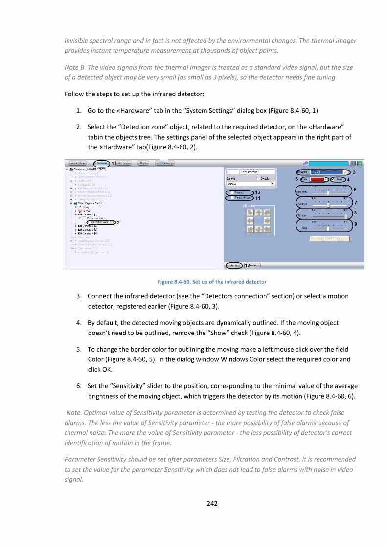
242
invisible spectral range and in fact is not affected by the environmental changes. The thermal imager
provides instant temperature measurement at thousands of object points.
Note B. The video signals from the thermal imager is treated as a standard video signal, but the size
of a detected object may be very small (as small as 3 pixels), so the detector needs fine tuning.
Follow the steps to set up the infrared detector:
1. Go to the «Hardware” tab in the “System Settings” dialog box (Figure 8.4-60, 1)
2. Select the “Detection zone” object, related to the required detector, on the «Hardware”
tabin the objects tree. The settings panel of the selected object appears in the right part of
the «Hardware” tab(Figure 8.4-60, 2).
Figure 8.4-60. Set up of the infrared detector
3. Connect the infrared detector (see the “Detectors connection” section) or select a motion
detector, registered earlier (Figure 8.4-60, 3).
4. By default, the detected moving objects are dynamically outlined. If the moving object
doesn’t need to be outlined, remove the “Show” check (Figure 8.4-60, 4).
5. To change the border color for outlining the moving make a left mouse click over the field
Color (Figure 8.4-60, 5). In the dialog window Windows Color select the required color and
click OK.
6. Set the “Sensitivity” slider to the position, corresponding to the minimal value of the average
brightness of the moving object, which triggers the detector by its motion (Figure 8.4-60, 6).
Note. Optimal value of Sensitivity parameter is determined by testing the detector to check false
alarms. The less the value of Sensitivity parameter - the more possibility of false alarms because of
thermal noise. The more the value of Sensitivity parameter - the less possibility of detector’s correct
identification of motion in the frame.
Parameter Sensitivity should be set after parameters Size, Filtration and Contrast. It is recommended
to set the value for the parameter Sensitivity which does not lead to false alarms with noise in video
signal.
243
7. Set the slider Contrast to the position, corresponding to the minimal value of the contrast,
which triggers the detector by its motion (Figure 8.4-60, 7).
Note. Optimal value of Contrast parameter is determined by testing the detector for response with
the required conditions. Reduction of Contrast parameter results in lesser possibility of detector’s
response to motions of objects, which colors are close to the color of the ground. Greater Contras
parameter results in greater possibility of detector’s response to noise in video signal. In most cases
the value given on default is quite enough (average value).
8. Set the slider Filtration to the position, corresponding to the minimal rate of object’s motion,
which triggers the detector (Figure 8.4-60, 8).When the slider is set to the min, detector
responses to the objects, moving at any rate.
Note. Optimal value of the Filtration parameter is determined by testing the detector for response
with the required conditions. Reduction of Filtration parameter leads to increased possibility of
response to noise in video signal (including snow, rain). Greater Filtration parameter results in lesser
possibility of detector’s response to motion in the frame. When with the set value of given parameter
the detector responses to noise in video signals, one should change the value of Sensitivity parameter.
9. Set the slider Size to the position, corresponding to minimal size of the object, which triggers
the detector (Figure 8.4-60, 9). Size of the object is given in portion relating to the overall
area of the square. When the object, which size exceeds the given value, motion detector is
getting alarmed.
Note. Optimal value of the Size parameter is determined by testing the detector for response with the
required conditions. Reduction of Size parameter leads to increased possibility of response to noise in
video signal (including snow, rain). Greater Size parameter results in lesser possibility of detector’s
response to motion in the frame.
It is recommended to Size parameter the value, which is much lesser than the average size of objects,
moving in the frame. If detector responses to noise in video signal with the set value, the value of
Sensitivity parameter should be changed.
10. If infrared detector arms to record the signal from video camera automatically, Alarmed
checkbox should be set (Figure 8.4-60, 10).
Note A. If the “Recording alarms” option in the “Camera” object settings is deactivated, then no video
recording is performed after the detector has triggered.
Note B. If the “Alarmed” option is disabled in the detector settings, then detector arming is
ineffective, though this detector name in the functions menu of the video surveillance window is
highlighted by a yellow square.
11. If it is necessary to prohibit the users (independently on their rights and authority) of video
surveillance system to disarm the infrared detector, check the Armed always check box
(Figure 8.4-60, 11).
Note. When the “Armed always” is checked, the row with the motion detector name is not displayed
in the functions menu of the video surveillance window.
12. Click the “Apply” button (Figure 8.4-60, 12).

244
Infrared detector setup is completed.
8.4.9 Setting up object’s panoramic view by means of Scene object
Panoramic view window is designed for creating and using the panoramic image, composed from
several cameras’ view fields. Setting up the panoramic view window is performed by Scene object
settings panel.
The Scene object setup is performed in the following way:
1. Select a screen and create the Scene object.
2. Set the parameters of Scene interface window.
3. Select and setup cameras for displaying in the Scene window
Note. Working with Panoramic view window is described in detail in “INTELLECT™ software:
Operator’s Guide”.
8.4.9.1 Creating the Scene object
To create the Scene object do the following:
1. Select the required Screen object on the Interfaces tab of System settings dialog window
(Figure 8.4-61).
Figure 8.4-61 Creating the Scene object
2. Make a right mouse click upon the selected Screen object and select «Create object»
«Scene» in the appeared contextual menu (Figure 8.4-61).
3. Set the name and number of Scene object in the appeared window and then click Apply
button.
Note. Scene object settings panel will be displayed as a result.
4. Repeat steps 1-3 for all required Screen and Scene objects.
Creating the Scene object is completed.
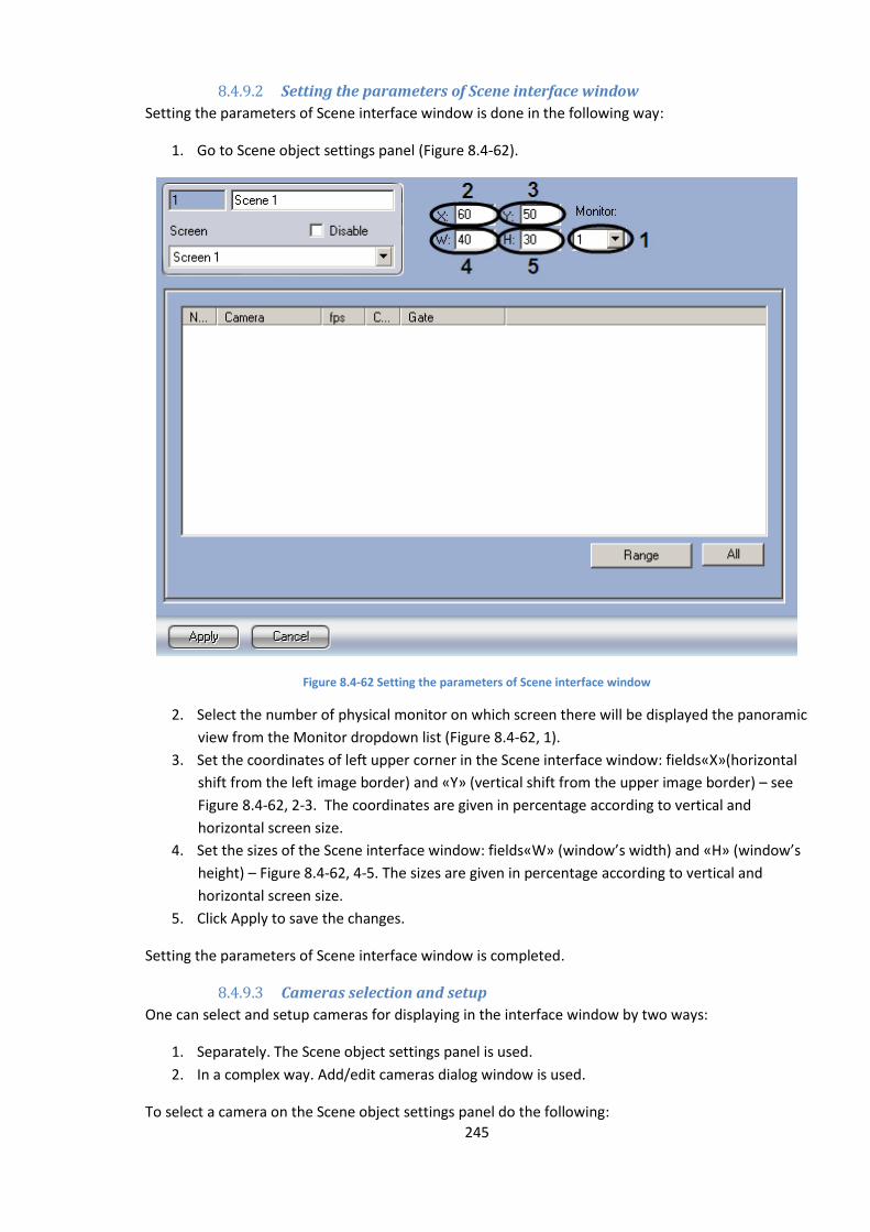
245
8.4.9.2 Setting the parameters of Scene interface window
Setting the parameters of Scene interface window is done in the following way:
1. Go to Scene object settings panel (Figure 8.4-62).
Figure 8.4-62 Setting the parameters of Scene interface window
2. Select the number of physical monitor on which screen there will be displayed the panoramic
view from the Monitor dropdown list (Figure 8.4-62, 1).
3. Set the coordinates of left upper corner in the Scene interface window: fields«X»(horizontal
shift from the left image border) and «Y» (vertical shift from the upper image border) – see
Figure 8.4-62, 2-3. The coordinates are given in percentage according to vertical and
horizontal screen size.
4. Set the sizes of the Scene interface window: fields«W» (window’s width) and «H» (window’s
height) – Figure 8.4-62, 4-5. The sizes are given in percentage according to vertical and
horizontal screen size.
5. Click Apply to save the changes.
Setting the parameters of Scene interface window is completed.
8.4.9.3 Cameras selection and setup
One can select and setup cameras for displaying in the interface window by two ways:
1. Separately. The Scene object settings panel is used.
2. In a complex way. Add/edit cameras dialog window is used.
To select a camera on the Scene object settings panel do the following:
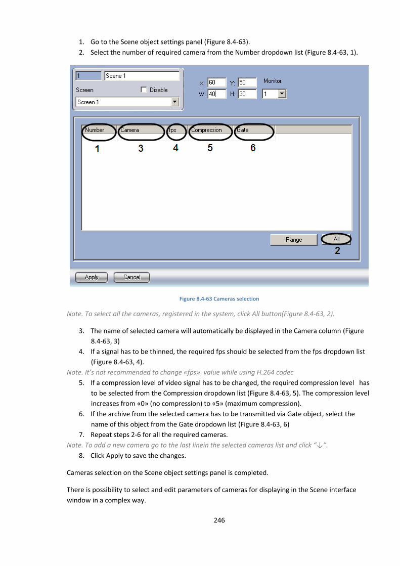
246
1. Go to the Scene object settings panel (Figure 8.4-63).
2. Select the number of required camera from the Number dropdown list (Figure 8.4-63, 1).
Figure 8.4-63 Cameras selection
Note. To select all the cameras, registered in the system, click All button(Figure 8.4-63, 2).
3. The name of selected camera will automatically be displayed in the Camera column (Figure
8.4-63, 3)
4. If a signal has to be thinned, the required fps should be selected from the fps dropdown list
(Figure 8.4-63, 4).
Note. It’s not recommended to change «fps» value while using Н.264 codec
5. If a compression level of video signal has to be changed, the required compression level has
to be selected from the Compression dropdown list (Figure 8.4-63, 5). The compression level
increases from «0» (no compression) to «5» (maximum compression).
6. If the archive from the selected camera has to be transmitted via Gate object, select the
name of this object from the Gate dropdown list (Figure 8.4-63, 6)
7. Repeat steps 2-6 for all the required cameras.
Note. To add a new camera go to the last linein the selected cameras list and click “↓”.
8. Click Apply to save the changes.
Cameras selection on the Scene object settings panel is completed.
There is possibility to select and edit parameters of cameras for displaying in the Scene interface
window in a complex way.
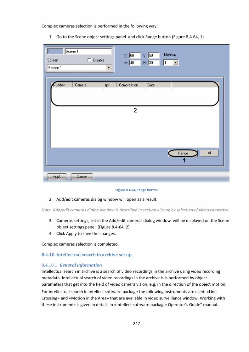
247
Complex cameras selection is performed in the following way:
1. Go to the Scene object settings panel and click Range button (Figure 8.4-64, 1)
Figure 8.4-64 Range button
2. Add/edit cameras dialog window will open as a result.
Note. Add/edit cameras dialog window is described in section «Complex selection of video cameras».
3. Cameras settings, set in the Add/edit cameras dialog window will be displayed on the Scene
object settings panel (Figure 8.4-64, 2).
4. Click Apply to save the changes.
Complex cameras selection is completed.
8.4.10 Intellectual search in archive set up
8.4.10.1 General information
Intellectual search in archive is a search of video recordings in the archive using video recording
metadata. Intellectual search of video recordings in the archive is is performed by object
parameters that get into the field of video camera vision, e.g. in the direction of the object motion.
For intellectual search in Intellect software package the following instruments are used: «Line
Crossing» and «Motion in the Area» that are available in video surveiilance window. Working with
these instruments is given in details in «Intellect software package: Operator’s Guide” manual.
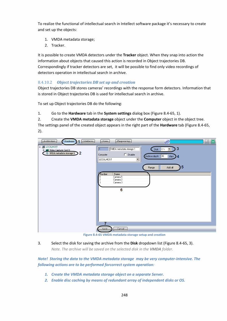
248
To realize the functional of intellectual search in Intellect software package it’s necessary to create
and set up the objects:
1. VMDA metadata storage;
2. Tracker.
It is possible to create VMDA detectors under the Tracker object. When they snap into action the
information about objects that caused this action is recorded in Object trajectories DB.
Correspondingly if tracker detectors are set, it will be possible to find only video recordings of
detectors operation in intellectual search in archive.
8.4.10.2 Object trajectories DB set up and creation
Object trajectories DB stores cameras’ recordings with the response form detectors. Information that
is stored in Object trajectories DB is used for intellectual search in archive.
To set up Object trajectories DB do the following:
1. Go to the Hardware tab in the System settings dialog box (Figure 8.4-65, 1).
2. Create the VMDA metadata storage object under the Computer object in the object tree.
The settings panel of the created object appears in the right part of the Hardware tab (Figure 8.4-65,
2).
Figure 8.4-65 VMDA metadata storage setup and creation
3. Select the disk for saving the archive from the Disk dropdown list (Figure 8.4-65, 3).
Note. The archive will be saved on the selected disk in the VMDA folder.
Note! Storing the data to the VMDA metadata storage may be very computer-intensive. The
following actions are to be performed forcorrect system operation:
1. Create the VMDA metadata storage object on a separate Server.
2. Enable disc caching by means of redundant array of independent disks or OS.
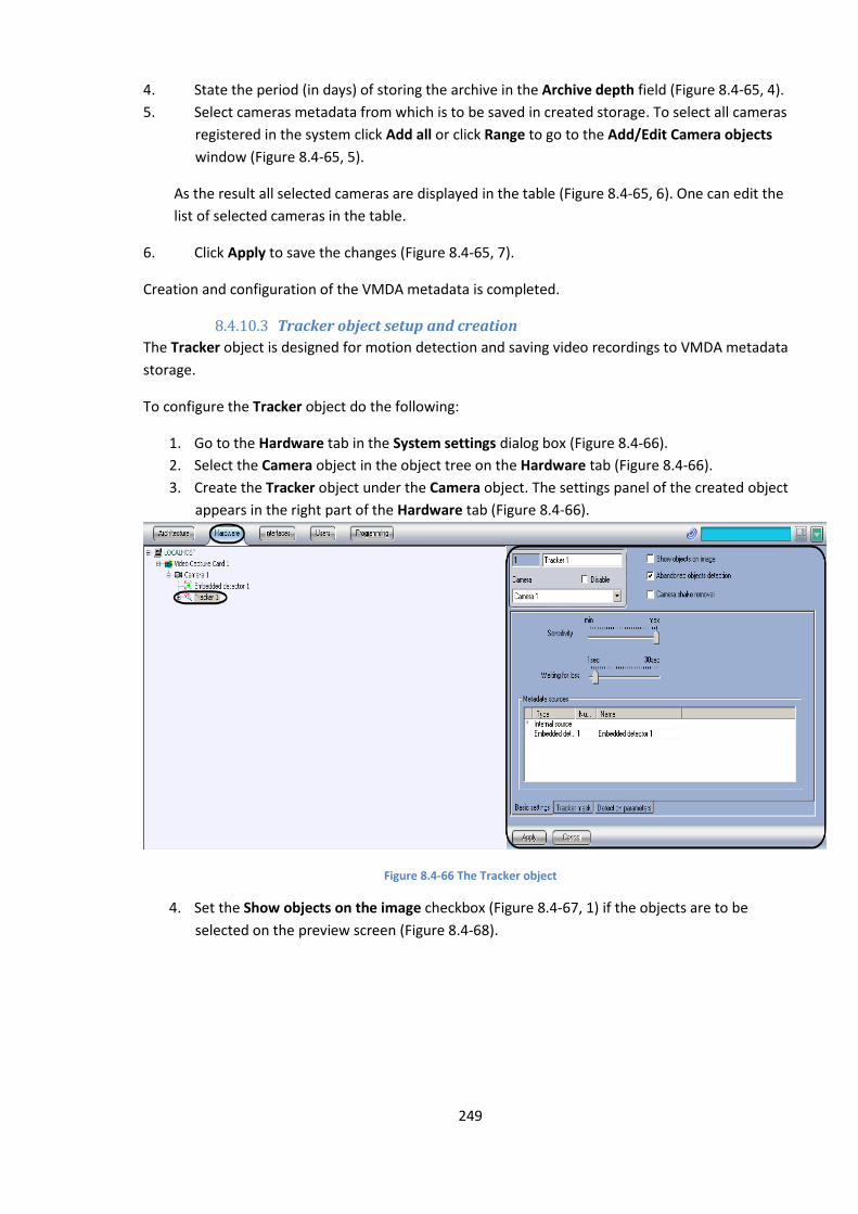
249
4. State the period (in days) of storing the archive in the Archive depth field (Figure 8.4-65, 4).
5. Select cameras metadata from which is to be saved in created storage. To select all cameras
registered in the system click Add all or click Range to go to the Add/Edit Camera objects
window (Figure 8.4-65, 5).
As the result all selected cameras are displayed in the table (Figure 8.4-65, 6). One can edit the
list of selected cameras in the table.
6. Click Apply to save the changes (Figure 8.4-65, 7).
Creation and configuration of the VMDA metadata is completed.
8.4.10.3 Tracker object setup and creation
The Tracker object is designed for motion detection and saving video recordings to VMDA metadata
storage.
To configure the Tracker object do the following:
1. Go to the Hardware tab in the System settings dialog box (Figure 8.4-66).
2. Select the Camera object in the object tree on the Hardware tab (Figure 8.4-66).
3. Create the Tracker object under the Camera object. The settings panel of the created object
appears in the right part of the Hardware tab (Figure 8.4-66).
Figure 8.4-66 The Tracker object
4. Set the Show objects on the image checkbox (Figure 8.4-67, 1) if the objects are to be
selected on the preview screen (Figure 8.4-68).
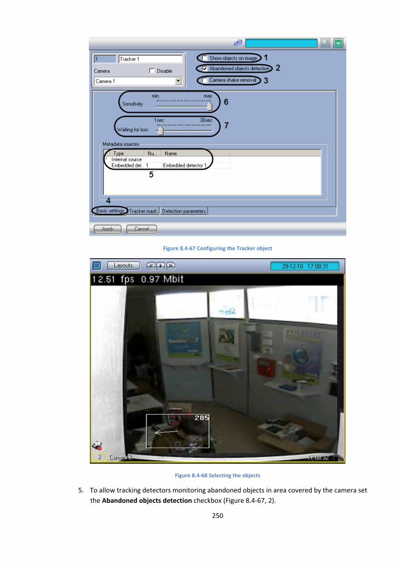
250
Figure 8.4-67 Configuring the Tracker object
Figure 8.4-68 Selecting the objects
5. To allow tracking detectors monitoring abandoned objects in area covered by the camera set
the Abandoned objects detection checkbox (Figure 8.4-67, 2).
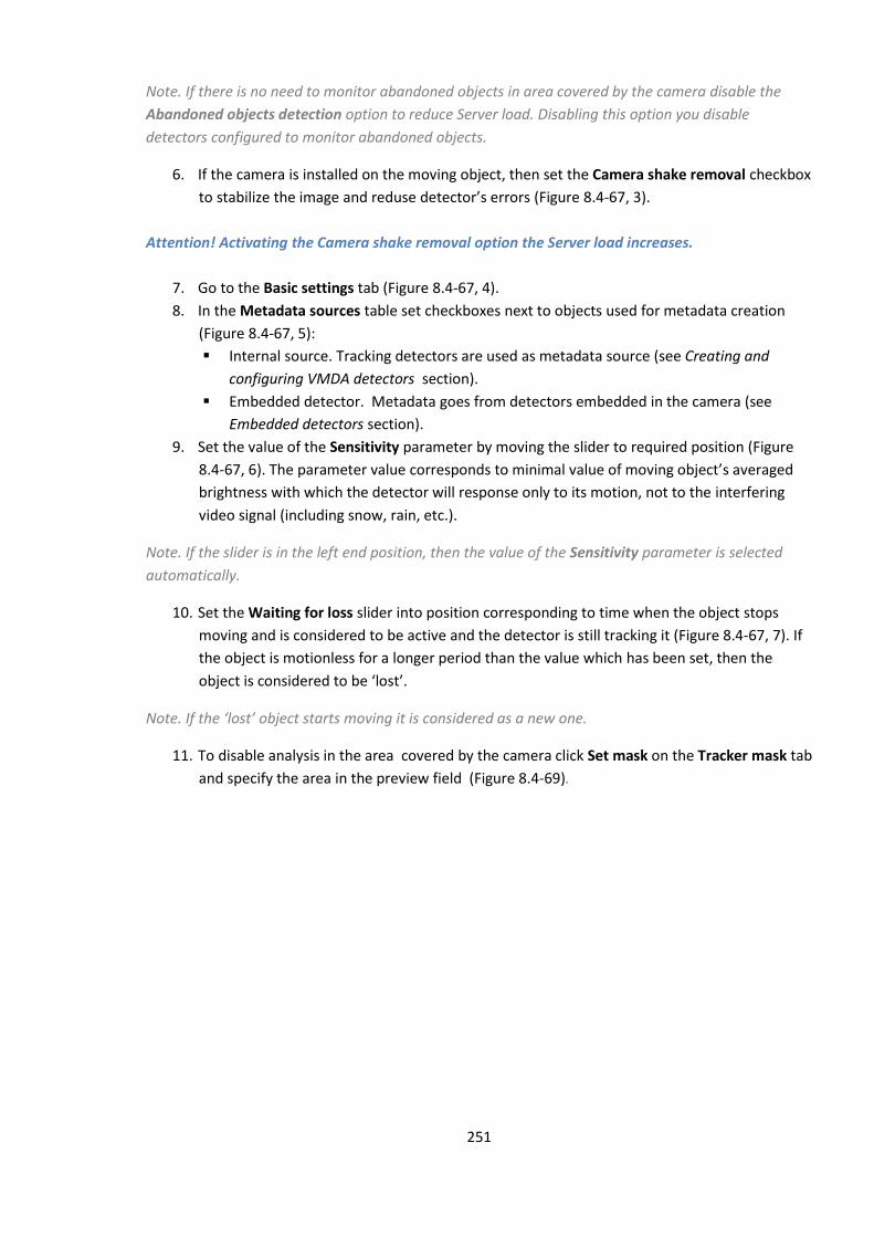
251
Note. If there is no need to monitor abandoned objects in area covered by the camera disable the
Abandoned objects detection option to reduce Server load. Disabling this option you disable
detectors configured to monitor abandoned objects.
6. If the camera is installed on the moving object, then set the Camera shake removal checkbox
to stabilize the image and reduse detector’s errors (Figure 8.4-67, 3).
Attention! Activating the Camera shake removal option the Server load increases.
7. Go to the Basic settings tab (Figure 8.4-67, 4).
8. In the Metadata sources table set checkboxes next to objects used for metadata creation
(Figure 8.4-67, 5):
Internal source. Tracking detectors are used as metadata source (see Creating and
configuring VMDA detectors section).
Embedded detector. Metadata goes from detectors embedded in the camera (see
Embedded detectors section).
9. Set the value of the Sensitivity parameter by moving the slider to required position (Figure
8.4-67, 6). The parameter value corresponds to minimal value of moving object’s averaged
brightness with which the detector will response only to its motion, not to the interfering
video signal (including snow, rain, etc.).
Note. If the slider is in the left end position, then the value of the Sensitivity parameter is selected
automatically.
10. Set the Waiting for loss slider into position corresponding to time when the object stops
moving and is considered to be active and the detector is still tracking it (Figure 8.4-67, 7). If
the object is motionless for a longer period than the value which has been set, then the
object is considered to be ‘lost’.
Note. If the ‘lost’ object starts moving it is considered as a new one.
11. To disable analysis in the area covered by the camera click Set mask on the Tracker mask tab
and specify the area in the preview field (Figure 8.4-69).

252
Figure 8.4-69 Disabling analysis in the area
12. To set the minimal and maximal sizes of detected object do the following:
12.1 Go to the Detection parameters tab (Figure 8.4-70, 1).
Figure 8.4-70 Setting the sizes of detected object
12.2 Click Stop to stop playback in the preview (Figure 8.4-69, 2).
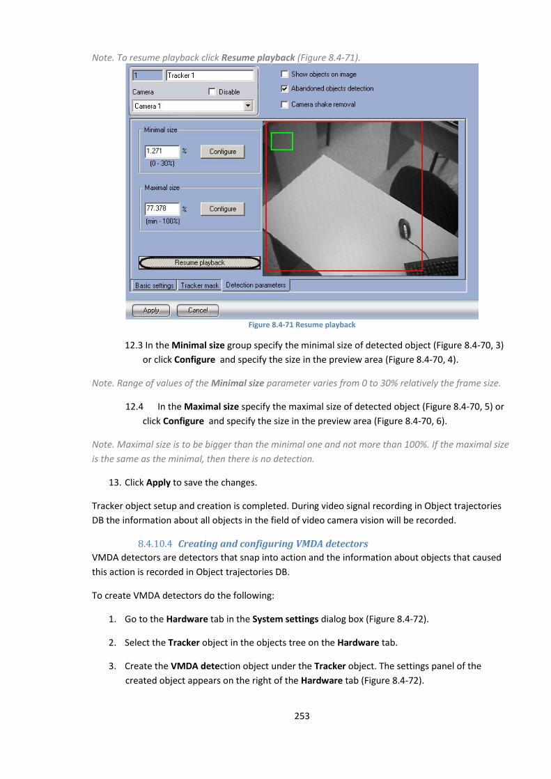
253
Note. To resume playback click Resume playback (Figure 8.4-71).
Figure 8.4-71 Resume playback
12.3 In the Minimal size group specify the minimal size of detected object (Figure 8.4-70, 3)
or click Configure and specify the size in the preview area (Figure 8.4-70, 4).
Note. Range of values of the Minimal size parameter varies from 0 to 30% relatively the frame size.
12.4 In the Maximal size specify the maximal size of detected object (Figure 8.4-70, 5) or
click Configure and specify the size in the preview area (Figure 8.4-70, 6).
Note. Maximal size is to be bigger than the minimal one and not more than 100%. If the maximal size
is the same as the minimal, then there is no detection.
13. Click Apply to save the changes.
Tracker object setup and creation is completed. During video signal recording in Object trajectories
DB the information about all objects in the field of video camera vision will be recorded.
8.4.10.4 Creating and configuring VMDA detectors
VMDA detectors are detectors that snap into action and the information about objects that caused
this action is recorded in Object trajectories DB.
To create VMDA detectors do the following:
1. Go to the Hardware tab in the System settings dialog box (Figure 8.4-72).
2. Select the Tracker object in the objects tree on the Hardware tab.
3. Create the VMDA detection object under the Tracker object. The settings panel of the
created object appears on the right of the Hardware tab (Figure 8.4-72).
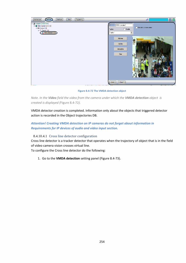
254
Figure 8.4-72 The VMDA detection object
Note. In the Video field the video from the camera under which the VMDA detection object is
created is displayed (Figure 8.4-72).
VMDA detector creation is completed. Information only about the objects that triggered detector
action is recorded in the Object trajectories DB.
Attention! Creating VMDA detection on IP cameras do not forget about information in
Requirements for IP devices of audio and video input section.
8.4.10.4.1 Cross line detector configuration
Cross line detector is a tracker detector that operates when the trajectory of object that is in the field
of video camera vision crosses virtual line.
To configure the Cross line detector do the following:
1. Go to the VMDA detection setting panel (Figure 8.4-73).
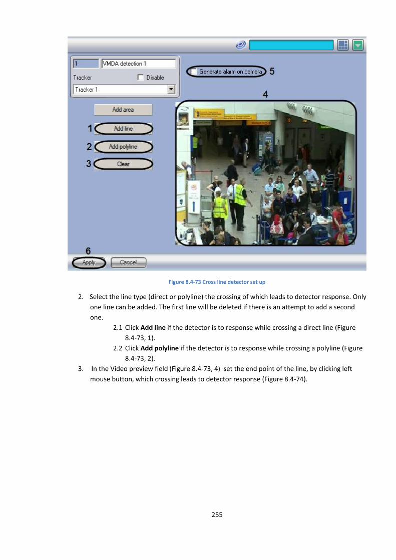
255
Figure 8.4-73 Cross line detector set up
2. Select the line type (direct or polyline) the crossing of which leads to detector response. Only
one line can be added. The first line will be deleted if there is an attempt to add a second
one.
2.1 Click Add line if the detector is to response while crossing a direct line (Figure
8.4-73, 1).
2.2 Click Add polyline if the detector is to response while crossing a polyline (Figure
8.4-73, 2).
3. In the Video preview field (Figure 8.4-73, 4) set the end point of the line, by clicking left
mouse button, which crossing leads to detector response (Figure 8.4-74).
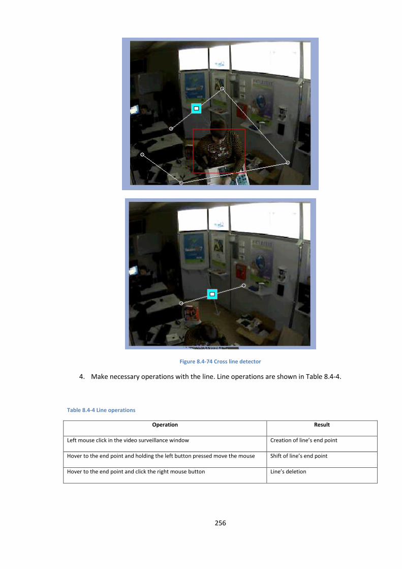
256
Figure 8.4-74 Cross line detector
4. Make necessary operations with the line. Line operations are shown in Table 8.4-4.
Table 8.4-4 Line operations
Operation Result
Left mouse click in the video surveillance window Creation of line’s end point
Hover to the end point and holding the left button pressed move the mouse Shift of line’s end point
Hover to the end point and click the right mouse button Line’s deletion
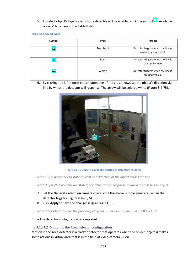
257
5. To select object’s type for which the detector will be enabled click the symbol . Available
objects’ types are in the Table 8.4-5.
Table 8.4-5 Object types
Symbol Type Purpose
Any object Detector triggers when the line is
crossed by any object
Man Detector triggers when the line is
crossed by man
Vehicle Detector triggers when the line is
crossed vehicle
6. By clicking the left mouse button upon one of the grey arrows set the object’s direction via
line by which the detector will response. The arrow will be colored white (Figure 8.4-75).
Figure 8.4-75 Object’s direction selection by detector’s response
Note 1. It is necessary to state at least one direction of the object across the line.
Note 2. If both directions are stated, the detector will response to any line cross by the object.
7. Set the Generate alarm on camera checkbox if the alarm is to be generated when the
detector triggers (Figure 8.4-73, 5).
8. Click Apply to save the changes (Figure 8.4-73, 6).
Note. Click Clear to clear the preview field from visual elemnt (line) (Figure 8.4-73, 3).
Cross line detector configuration is completed.
8.4.10.4.2 Motion in the Area detector configuration
Motion in the Area detector is a tracker detector that operates when the object (objects) makes
some actions in virtual area that is in the field of video camera vision.
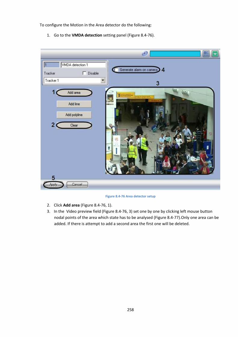
258
To configure the Motion in the Area detector do the following:
1. Go to the VMDA detection setting panel (Figure 8.4-76).
Figure 8.4-76 Area detector setup
2. Click Add area (Figure 8.4-76, 1).
3. In the Video preview field (Figure 8.4-76, 3) set one by one by clicking left mouse button
nodal points of the area which state has to be analysed (Figure 8.4-77).Only one area can be
added. If there is attempt to add a second area the first one will be deleted.
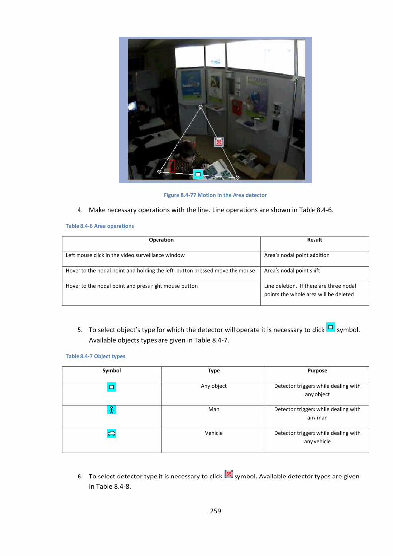
259
Figure 8.4-77 Motion in the Area detector
4. Make necessary operations with the line. Line operations are shown in Table 8.4-6.
Table 8.4-6 Area operations
Operation Result
Left mouse click in the video surveillance window Area’s nodal point addition
Hover to the nodal point and holding the left button pressed move the mouse Area’s nodal point shift
Hover to the nodal point and press right mouse button Line deletion. If there are three nodal
points the whole area will be deleted
5. To select object’s type for which the detector will operate it is necessary to click symbol.
Available objects types are given in Table 8.4-7.
Table 8.4-7 Object types
Symbol Type Purpose
Any object Detector triggers while dealing with
any object
Man Detector triggers while dealing with
any man
Vehicle Detector triggers while dealing with
any vehicle
6. To select detector type it is necessary to click symbol. Available detector types are given
in Table 8.4-8.
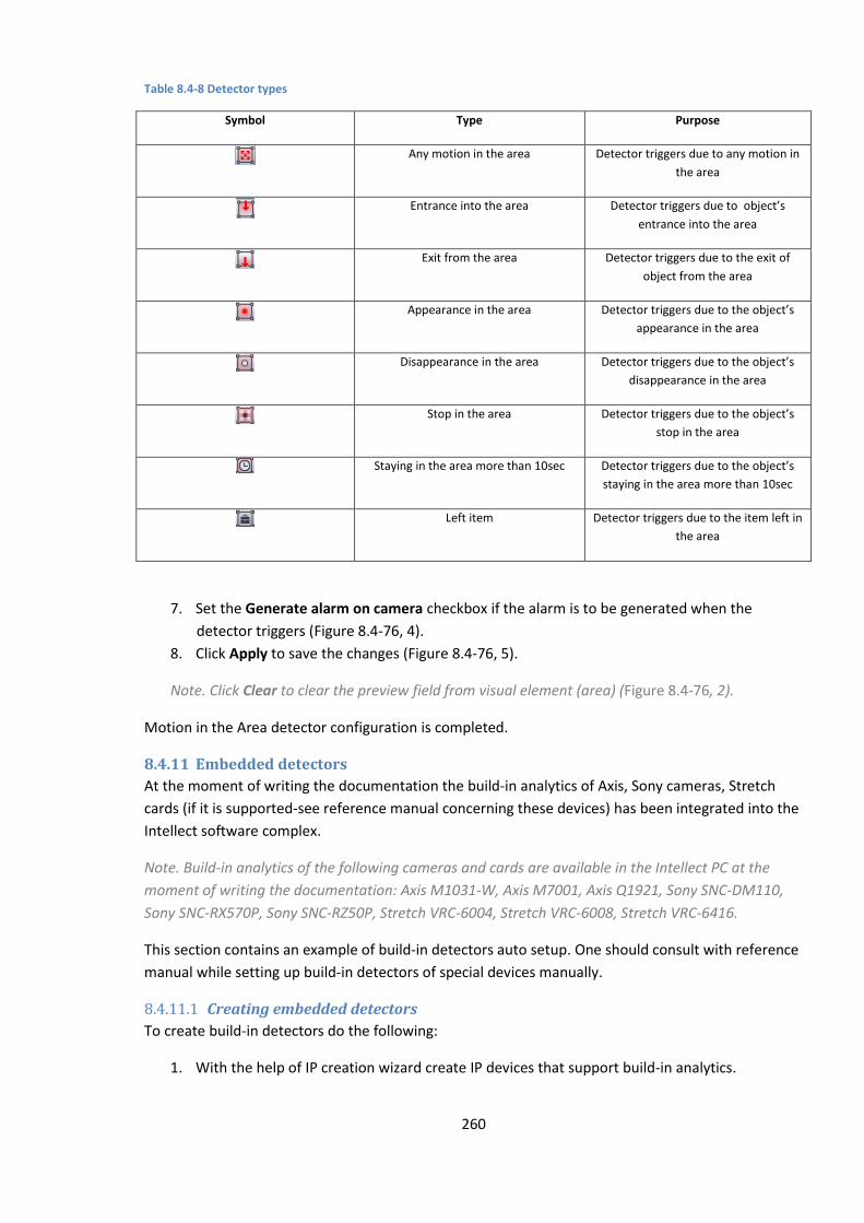
260
Table 8.4-8 Detector types
Symbol Type Purpose
Any motion in the area Detector triggers due to any motion in
the area
Entrance into the area Detector triggers due to object’s
entrance into the area
Exit from the area Detector triggers due to the exit of
object from the area
Appearance in the area Detector triggers due to the object’s
appearance in the area
Disappearance in the area Detector triggers due to the object’s
disappearance in the area
Stop in the area Detector triggers due to the object’s
stop in the area
Staying in the area more than 10sec Detector triggers due to the object’s
staying in the area more than 10sec
Left item Detector triggers due to the item left in
the area
7. Set the Generate alarm on camera checkbox if the alarm is to be generated when the
detector triggers (Figure 8.4-76, 4).
8. Click Apply to save the changes (Figure 8.4-76, 5).
Note. Click Clear to clear the preview field from visual element (area) (Figure 8.4-76, 2).
Motion in the Area detector configuration is completed.
8.4.11 Embedded detectors
At the moment of writing the documentation the build-in analytics of Axis, Sony cameras, Stretch
cards (if it is supported-see reference manual concerning these devices) has been integrated into the
Intellect software complex.
Note. Build-in analytics of the following cameras and cards are available in the Intellect PC at the
moment of writing the documentation: Axis M1031-W, Axis M7001, Axis Q1921, Sony SNC-DM110,
Sony SNC-RX570P, Sony SNC-RZ50P, Stretch VRC-6004, Stretch VRC-6008, Stretch VRC-6416.
This section contains an example of build-in detectors auto setup. One should consult with reference
manual while setting up build-in detectors of special devices manually.
8.4.11.1 Creating embedded detectors
To create build-in detectors do the following:
1. With the help of IP creation wizard create IP devices that support build-in analytics.
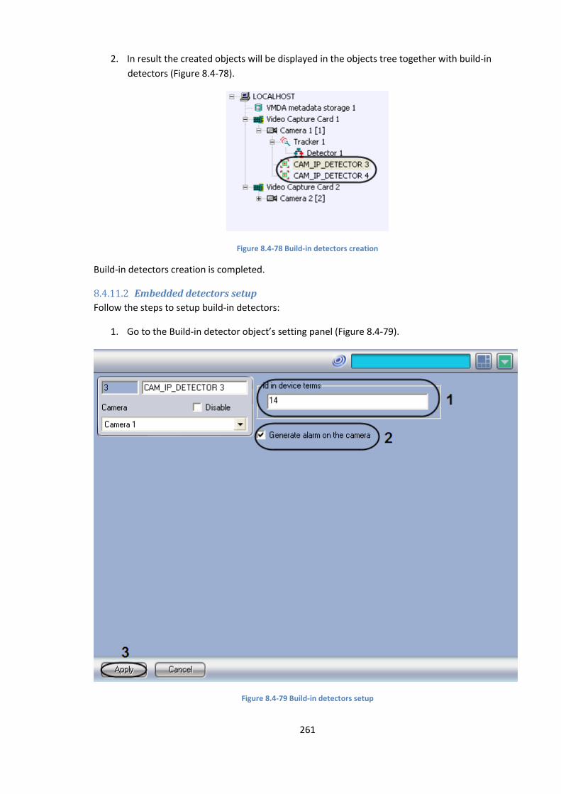
261
2. In result the created objects will be displayed in the objects tree together with build-in
detectors (Figure 8.4-78).
Figure 8.4-78 Build-in detectors creation
Build-in detectors creation is completed.
8.4.11.2 Embedded detectors setup
Follow the steps to setup build-in detectors:
1. Go to the Build-in detector object’s setting panel (Figure 8.4-79).
Figure 8.4-79 Build-in detectors setup
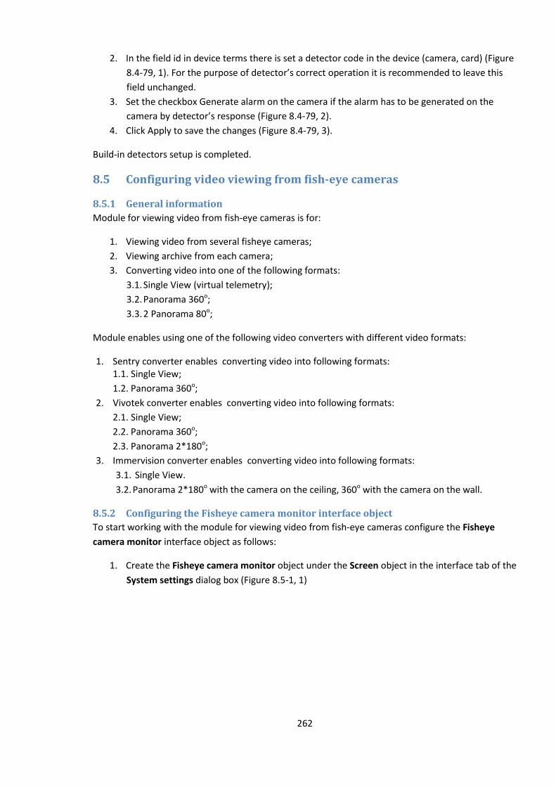
262
2. In the field id in device terms there is set a detector code in the device (camera, card) (Figure
8.4-79, 1). For the purpose of detector’s correct operation it is recommended to leave this
field unchanged.
3. Set the checkbox Generate alarm on the camera if the alarm has to be generated on the
camera by detector’s response (Figure 8.4-79, 2).
4. Click Apply to save the changes (Figure 8.4-79, 3).
Build-in detectors setup is completed.
8.5 Configuring video viewing from fish-eye cameras
8.5.1 General information
Module for viewing video from fish-eye cameras is for:
1. Viewing video from several fisheye cameras;
2. Viewing archive from each camera;
3. Converting video into one of the following formats:
3.1. Single View (virtual telemetry);
3.2. Panorama 360о;
3.3. 2 Panorama 80о;
Module enables using one of the following video converters with different video formats:
1. Sentry converter enables converting video into following formats: 1.1. Single View;
1.2. Panorama 360о;
2. Vivotek converter enables converting video into following formats:
2.1. Single View;
2.2. Panorama 360о;
2.3. Panorama 2*180о;
3. Immervision converter enables converting video into following formats:
3.1. Single View.
3.2. Panorama 2*180о with the camera on the ceiling, 360о with the camera on the wall.
8.5.2 Configuring the Fisheye camera monitor interface object
To start working with the module for viewing video from fish-eye cameras configure the Fisheye
camera monitor interface object as follows:
1. Create the Fisheye camera monitor object under the Screen object in the interface tab of the
System settings dialog box (Figure 8.5-1, 1)
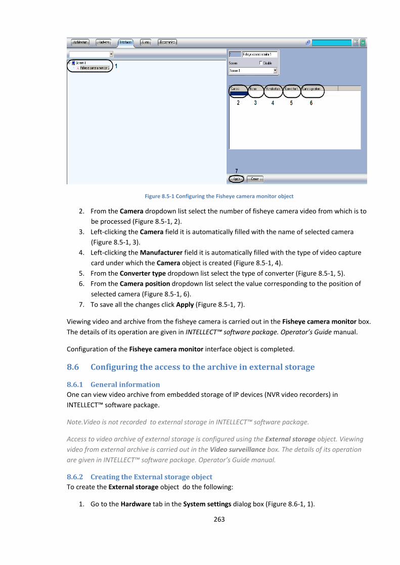
263
Figure 8.5-1 Configuring the Fisheye camera monitor object
2. From the Camera dropdown list select the number of fisheye camera video from which is to
be processed (Figure 8.5-1, 2).
3. Left-clicking the Camera field it is automatically filled with the name of selected camera
(Figure 8.5-1, 3).
4. Left-clicking the Manufacturer field it is automatically filled with the type of video capture
card under which the Camera object is created (Figure 8.5-1, 4).
5. From the Converter type dropdown list select the type of converter (Figure 8.5-1, 5).
6. From the Camera position dropdown list select the value corresponding to the position of
selected camera (Figure 8.5-1, 6).
7. To save all the changes click Apply (Figure 8.5-1, 7).
Viewing video and archive from the fisheye camera is carried out in the Fisheye camera monitor box.
The details of its operation are given in INTELLECT™ software package. Operator’s Guide manual.
Configuration of the Fisheye camera monitor interface object is completed.
8.6 Configuring the access to the archive in external storage
8.6.1 General information
One can view video archive from embedded storage of IP devices (NVR video recorders) in
INTELLECT™ software package.
Note.Video is not recorded to external storage in INTELLECT™ software package.
Access to video archive of external storage is configured using the External storage object. Viewing
video from external archive is carried out in the Video surveillance box. The details of its operation
are given in INTELLECT™ software package. Operator’s Guide manual.
8.6.2 Creating the External storage object
To create the External storage object do the following:
1. Go to the Hardware tab in the System settings dialog box (Figure 8.6-1, 1).
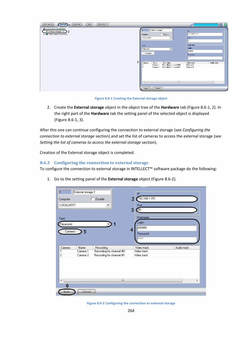
264
Figure 8.6-1 Creating the External storage object
2. Create the External storage object in the object tree of the Hardware tab (Figure 8.6-1, 2). In
the right part of the Hardware tab the setting panel of the selected object is displayed
(Figure 8.6-1, 3).
After this one can continue configuring the connection to external storage (see Configuring the
connection to external storage section) and set the list of cameras to access the external storage (see
Setting the list of cameras to access the external storage section).
Creation of the External storage object is completed.
8.6.3 Configuring the connection to external storage
To configure the connection to external storage in INTELLECT™ software package do the following:
1. Go to the setting panel of the External storage object (Figure 8.6-2).
Figure 8.6-2 Configuring the connection to external storage

265
2. From the Type dropdown list select the interfacing protocol for the connected device (Figure
8.6-2, 1).
3. In the IP field specify the IP address of the device with external storage (Figure 8.6-2, 2).
4. In the Port field specify the port for device connection (Figure 8.6-2, 3).
5. In corresponding fields of the Username group specify the login and password to connect to
external storage (Figure 8.6-2, 4).
Note. Login and password depend on device settings. See default login and password in reference
documentation on manufacturer’s device.
6. Click Connect (Figure 8.6-2, 5). If the device is connected then one can set the list of cameras
for playing back video from the external storage archive and match the number of camera in
INTELLECT™and external storage from which the video is to be received (see Setting the list
of cameras to access the external storage section).
7. To save all the changes click Apply (Figure 8.6-2, 6).
Configuration of the connection to external storage is completed.
8.6.4 Setting the list of cameras to access the external storage
One can configure several cameras to view video from the external storage. Each camera is
configured for one channel of the device with external storage.
If one camera is selected for viewing video from several external storages, then the archive is viewed
only from the archive that is matched with camera while the Monitor object is configured (see
Selection and setting of video cameras section).
To set the list of cameras to access the external storage do the following:
1. Go to the setting panel of the External storage object (Figure 8.6-3).
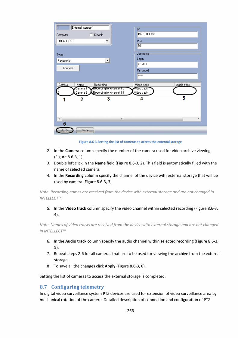
266
Figure 8.6-3 Setting the list of cameras to access the external storage
2. In the Camera column specify the number of the camera used for video archive viewing
(Figure 8.6-3, 1).
3. Double left click in the Name field (Figure 8.6-3, 2). This field is automatically filled with the
name of selected camera.
4. In the Recording column specify the channel of the device with external storage that will be
used by camera (Figure 8.6-3, 3).
Note. Recording names are received from the device with external storage and are not changed in
INTELLECT™.
5. In the Video track column specify the video channel within selected recording (Figure 8.6-3,
4).
Note. Names of video tracks are received from the device with external storage and are not changed
in INTELLECT™.
6. In the Audio track column specify the audio channel within selected recording (Figure 8.6-3,
5).
7. Repeat steps 2-6 for all cameras that are to be used for viewing the archive from the external
storage.
8. To save all the changes click Apply (Figure 8.6-3, 6).
Setting the list of cameras to access the external storage is completed.
8.7 Configuring telemetry In digital video surveillance system PTZ devices are used for extension of video surveillance area by
mechanical rotation of the camera. Detailed description of connection and configuration of PTZ

267
devices is given in INTELLECT™ software package. Installing and configuring security system
components guide manual.
8.8 Audio subsystem setup
8.8.1 General information on audio subsystem setup
In the video surveillance systems, based on INTELLECT™ software, the audio subsystem contains
software modules and hardware devices, used to receive, transmit, digitize, process, record and play
back audio signals from video surveillance and audio monitoring system microphones.
Audio subsystem hardware includes optionally:
1. video capture cards;
2. standard soundcards;
3. multi-channel soundcards;
4. audio capture IP-devices;
5. microphones;
6. loudspeakers and headphones.
Audio subsystem software includes:
1. components for configuring the audio signal digitizing devices;
2. components for recording digital audio signals;
3. components for transmitting digital audio signals to Remote Workplaces and remote servers;
4. components for digital audio signals playback.
8.8.1.1 Audio digitizing devices
Audio capture and digitizing devices are used to receive and process analog audio signals from
connected microphones.
To enter and digitize an audio signal, the servers, created in the INTELLECT™ software, use:
1. video capture cards;
2. standard soundcards;
3. multi-channel soundcards;
4. IP-devices.
8.8.1.1.1 Video capture cards
Video capture cards, used as audio capture devices, support reception and digitization of audio
signals. Video capture cards don’t support audio signal output to headphones and loudspeakers.
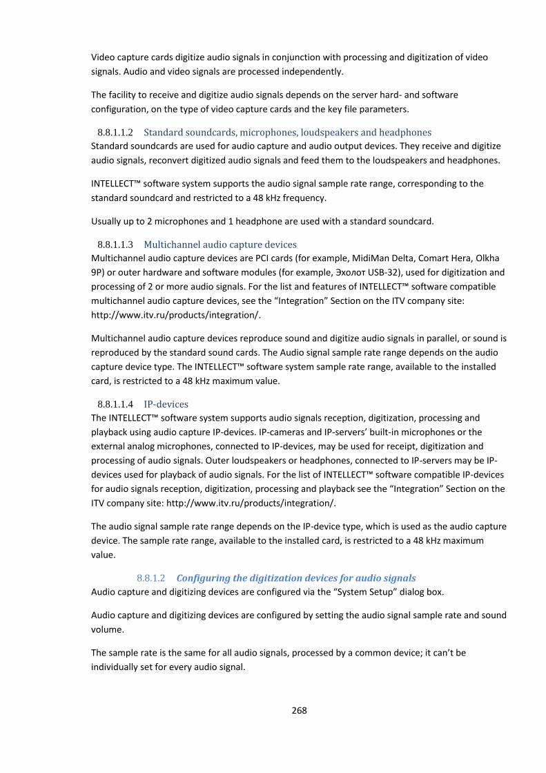
268
Video capture cards digitize audio signals in conjunction with processing and digitization of video
signals. Audio and video signals are processed independently.
The facility to receive and digitize audio signals depends on the server hard- and software
configuration, on the type of video capture cards and the key file parameters.
8.8.1.1.2 Standard soundcards, microphones, loudspeakers and headphones
Standard soundcards are used for audio capture and audio output devices. They receive and digitize
audio signals, reconvert digitized audio signals and feed them to the loudspeakers and headphones.
INTELLECT™ software system supports the audio signal sample rate range, corresponding to the
standard soundcard and restricted to a 48 kHz frequency.
Usually up to 2 microphones and 1 headphone are used with a standard soundcard.
8.8.1.1.3 Multichannel audio capture devices
Multichannel audio capture devices are PCI cards (for example, MidiMan Delta, Comart Hera, Оlkha
9Р) or outer hardware and software modules (for example, Эхолот USB-32), used for digitization and
processing of 2 or more audio signals. For the list and features of INTELLECT™ software compatible
multichannel audio capture devices, see the “Integration” Section on the ITV company site:
http://www.itv.ru/products/integration/.
Multichannel audio capture devices reproduce sound and digitize audio signals in parallel, or sound is
reproduced by the standard sound cards. The Audio signal sample rate range depends on the audio
capture device type. The INTELLECT™ software system sample rate range, available to the installed
card, is restricted to a 48 kHz maximum value.
8.8.1.1.4 IP-devices
The INTELLECT™ software system supports audio signals reception, digitization, processing and
playback using audio capture IP-devices. IP-cameras and IP-servers’ built-in microphones or the
external analog microphones, connected to IP-devices, may be used for receipt, digitization and
processing of audio signals. Outer loudspeakers or headphones, connected to IP-servers may be IP-
devices used for playback of audio signals. For the list of INTELLECT™ software compatible IP-devices
for audio signals reception, digitization, processing and playback see the “Integration” Section on the
ITV company site: http://www.itv.ru/products/integration/.
The audio signal sample rate range depends on the IP-device type, which is used as the audio capture
device. The sample rate range, available to the installed card, is restricted to a 48 kHz maximum
value.
8.8.1.2 Configuring the digitization devices for audio signals
Audio capture and digitizing devices are configured via the “System Setup” dialog box.
Audio capture and digitizing devices are configured by setting the audio signal sample rate and sound
volume.
The sample rate is the same for all audio signals, processed by a common device; it can’t be
individually set for every audio signal.
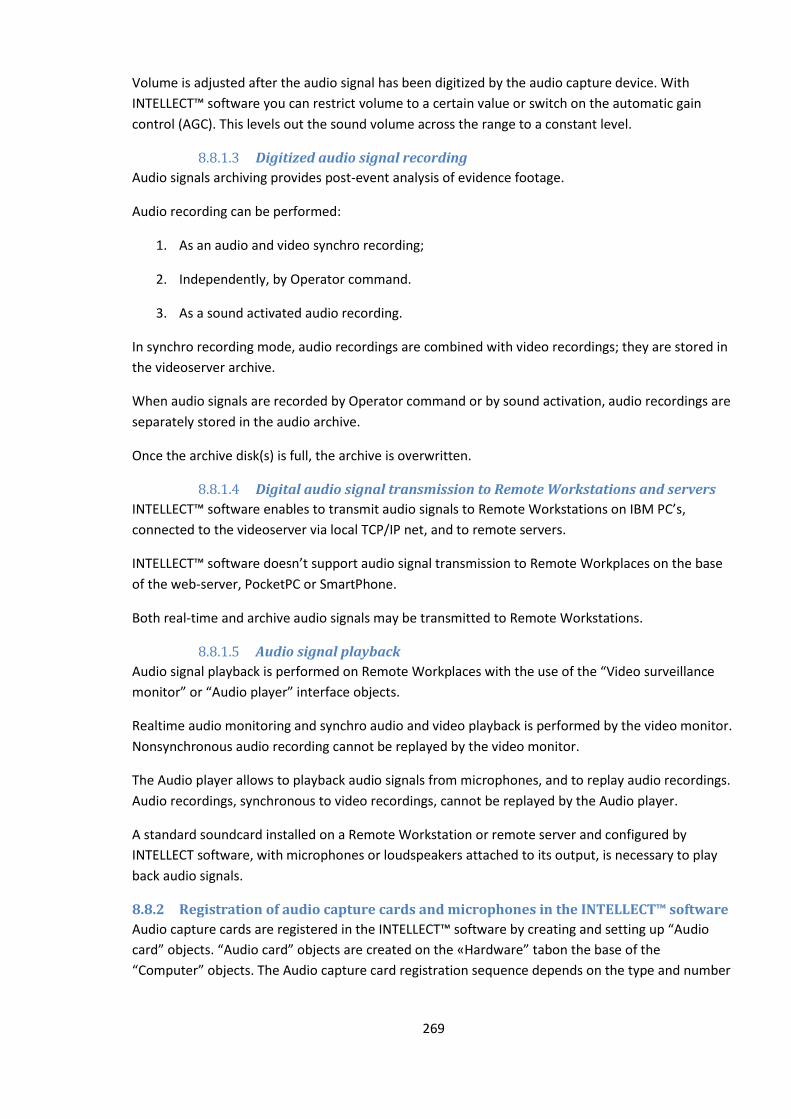
269
Volume is adjusted after the audio signal has been digitized by the audio capture device. With
INTELLECT™ software you can restrict volume to a certain value or switch on the automatic gain
control (AGC). This levels out the sound volume across the range to a constant level.
8.8.1.3 Digitized audio signal recording
Audio signals archiving provides post-event analysis of evidence footage.
Audio recording can be performed:
1. As an audio and video synchro recording;
2. Independently, by Operator command.
3. As a sound activated audio recording.
In synchro recording mode, audio recordings are combined with video recordings; they are stored in
the videoserver archive.
When audio signals are recorded by Operator command or by sound activation, audio recordings are
separately stored in the audio archive.
Once the archive disk(s) is full, the archive is overwritten.
8.8.1.4 Digital audio signal transmission to Remote Workstations and servers
INTELLECT™ software enables to transmit audio signals to Remote Workstations on IBM PC’s,
connected to the videoserver via local TCP/IP net, and to remote servers.
INTELLECT™ software doesn’t support audio signal transmission to Remote Workplaces on the base
of the web-server, PocketPC or SmartPhone.
Both real-time and archive audio signals may be transmitted to Remote Workstations.
8.8.1.5 Audio signal playback
Audio signal playback is performed on Remote Workplaces with the use of the “Video surveillance
monitor” or “Audio player” interface objects.
Realtime audio monitoring and synchro audio and video playback is performed by the video monitor.
Nonsynchronous audio recording cannot be replayed by the video monitor.
The Audio player allows to playback audio signals from microphones, and to replay audio recordings.
Audio recordings, synchronous to video recordings, cannot be replayed by the Audio player.
A standard soundcard installed on a Remote Workstation or remote server and configured by
INTELLECT software, with microphones or loudspeakers attached to its output, is necessary to play
back audio signals.
8.8.2 Registration of audio capture cards and microphones in the INTELLECT™ software
Audio capture cards are registered in the INTELLECT™ software by creating and setting up “Audio
card” objects. “Audio card” objects are created on the «Hardware” tabon the base of the
“Computer” objects. The Audio capture card registration sequence depends on the type and number
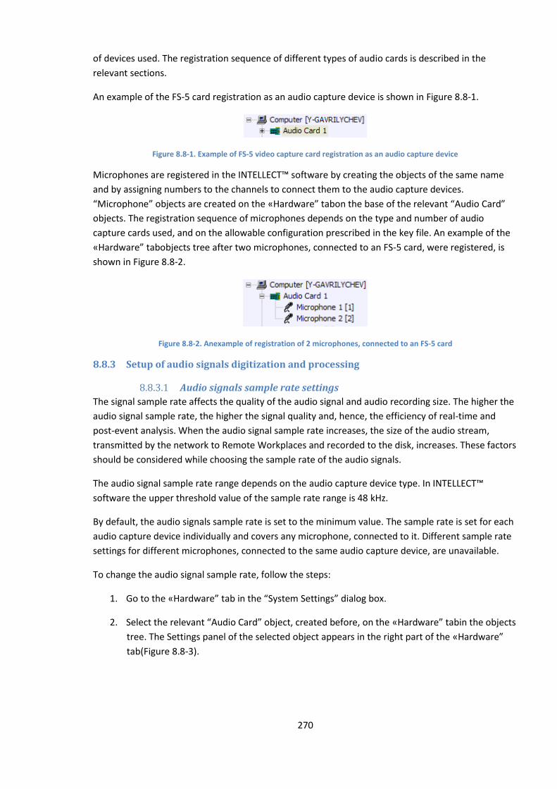
270
of devices used. The registration sequence of different types of audio cards is described in the
relevant sections.
An example of the FS-5 card registration as an audio capture device is shown in Figure 8.8-1.
Figure 8.8-1. Example of FS-5 video capture card registration as an audio capture device
Microphones are registered in the INTELLECT™ software by creating the objects of the same name
and by assigning numbers to the channels to connect them to the audio capture devices.
“Microphone” objects are created on the «Hardware” tabon the base of the relevant “Audio Card”
objects. The registration sequence of microphones depends on the type and number of audio
capture cards used, and on the allowable configuration prescribed in the key file. An example of the
«Hardware” tabobjects tree after two microphones, connected to an FS-5 card, were registered, is
shown in Figure 8.8-2.
Figure 8.8-2. Anexample of registration of 2 microphones, connected to an FS-5 card
8.8.3 Setup of audio signals digitization and processing
8.8.3.1 Audio signals sample rate settings
The signal sample rate affects the quality of the audio signal and audio recording size. The higher the
audio signal sample rate, the higher the signal quality and, hence, the efficiency of real-time and
post-event analysis. When the audio signal sample rate increases, the size of the audio stream,
transmitted by the network to Remote Workplaces and recorded to the disk, increases. These factors
should be considered while choosing the sample rate of the audio signals.
The audio signal sample rate range depends on the audio capture device type. In INTELLECT™
software the upper threshold value of the sample rate range is 48 kHz.
By default, the audio signals sample rate is set to the minimum value. The sample rate is set for each
audio capture device individually and covers any microphone, connected to it. Different sample rate
settings for different microphones, connected to the same audio capture device, are unavailable.
To change the audio signal sample rate, follow the steps:
1. Go to the «Hardware” tab in the “System Settings” dialog box.
2. Select the relevant “Audio Card” object, created before, on the «Hardware” tabin the objects
tree. The Settings panel of the selected object appears in the right part of the «Hardware”
tab(Figure 8.8-3).
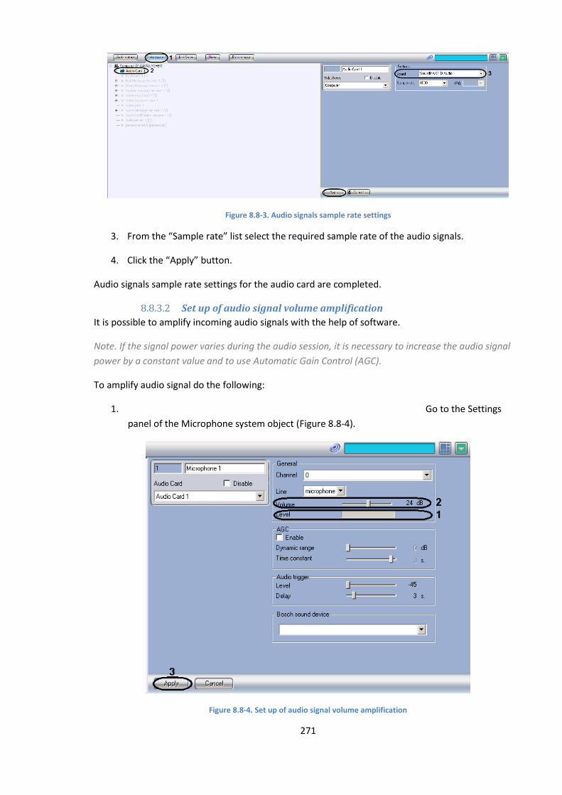
271
Figure 8.8-3. Audio signals sample rate settings
3. From the “Sample rate” list select the required sample rate of the audio signals.
4. Click the “Apply” button.
Audio signals sample rate settings for the audio card are completed.
8.8.3.2 Set up of audio signal volume amplification
It is possible to amplify incoming audio signals with the help of software.
Note. If the signal power varies during the audio session, it is necessary to increase the audio signal
power by a constant value and to use Automatic Gain Control (AGC).
To amplify audio signal do the following:
1. Go to the Settings
panel of the Microphone system object (Figure 8.8-4).
Figure 8.8-4. Set up of audio signal volume amplification

272
2. Feed the audio signal with to the microphone. Power level of incoming signal will be
displayed on the indicator Level (Figure 8.8-4, 1).
3. When necessary set the slider Volume to the position, corresponding to the required value of
amplification (Figure 8.8-4, 2).The current value in dB is shown in the right field next to the
slider.
4. Repeat steps 2 and 3 for the required power level of audio signal.
5. Press Apply button to save all the changes (Figure 8.8-4, 3).
Set of audio signal volume amplification is completed.
8.8.3.3 Setting up the Automatic Gain Control for sound cards of Olha line
Automatic Gain Control (AGC) is designed to make the audio signal volume constant. AGC mechanism
should be set only with the use of sound cards of Olha line : Olha-9P, Olha-10LP, Olha-12U, Olha-14.
It is recommended to use AGC when input audio signal power is unsteady or when the power of the
sound signals, coming from different sources and forming the joint audio signal, differs significantly.
AGC levels out the power levels of audio signal components from different sources.
INTELLECT™ software has an AGC adjust option. AGC has two adjustable parameters: a target power
level, to which AGC brings different audio signals, and the adjustment time of bringing the signal to
the target power level. The second parameter has certain restrictions: the less time it takes to bring
the signal to a certain power level, the lower the quality of AGC operation, which may result in
greater power level jumps in the processed signal. However a longer adjustment time lengthens the
areas where the power of the processed audio signal builds up and decreases. So, processing may
bring sizable distortions into the audio signal. Hence, AGC settings depend substantially on the
conditions of audio signal formation, and when these conditions have been changed, new AGC
settings should be set.
AGC is independently applied to any audio signal from any microphone of the video surveillance and
audio monitoring system.
By default, AGC is disabled. The AGC option is enabled for each microphone independently.
To set up the AGC follow the steps:
1. Go to the settings panel of Microphone system object (Figure 8.8-5).
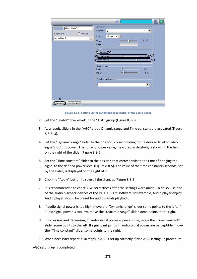
273
Figure 8.8-5. Setting up the automatic gain control of the audio signal
2. Set the “Enable” checkmark in the “AGC” group (Figure 8.8-5).
3. As a result, sliders in the “AGC” group Dinamic range and Time constant are activated (Figure
8.8-5, 3).
4. Set the “Dynamic range” slider to the position, corresponding to the desired level of video
signal’s output power. The current power value, measured in decibels, is shown in the field
on the right of the slider (Figure 8.8-5).
5. Set the “Time constant” slider to the position that corresponds to the time of bringing the
signal to the defined power level (Figure 8.8-5). The value of the time constantin seconds, set
by the slider, is displayed on the right of it.
6. Click the “Apply” button to save all the changes (Figure 8.8-5).
7. It is recommended to check AGC correctness after the settings were made. To do so, use one
of the audio playback devices of the INTELLECT ™ software, for example, Audio player object.
Audio player should be preset for audio signals playback.
8. If audio signal power is too high, move the “Dynamic range” slider some points to the left. If
audio signal power is too low, move the “Dynamic range” slider some points to the right.
9. If increasing and decreasing of audio signal power is perceptible, move the “Time constant”
slider some points to the left. If significant jumps in audio signal power are perceptible, move
the “Time constant” slider some points to the right.
10. When necessary repeat 7-10 steps. If AGCis set up correctly, finish AGC setting up procedure.
AGC setting up is completed.
274
8.8.4 Setup of audio signals recording
8.8.4.1 Audio signals recording modes
Audio recording can be performed:
1. As audio and video synchro recording;
2. By sound activation, i.e. when input audio signal power exceeds a certain value.
In synchro recording mode audio and video signals’ recording is initialized simultaneously (by
Operator’s command or by alarm).
Note. During post-alarm recording, no audio signal is recorded.
Audio and video signals’ recording is stopped simultaneously. Audio recording shutdown may be
caused by:
1. Video recording shutdown (by Operator command or by the end of alarm recording);
2. Post-alarm recording shutdown (if the relevant camera is configured to perform post-alarm
recording).
In synchro recording mode, audio recordings are combined with video recordings; they are stored in
the videoserver archive.
In sound activated recording mode, audio recording is initialized at the moment, when signal power
exceeds a preset (threshold) value. Audio signal recording is shutdown at the moment, when signal
power becomes lower than a preset value, that has been previously exceeded.
An audio recording file, created in sound activated recording mode, includes an audio signal segment
from the start till the end of the recording. In sound activated recording mode, audio recording files
are stored in a separate server archive (audio archive).
8.8.4.2 Selecting the disks for audio archive storage
INTELLECT™ software performs audio signal archiving to the local server disks only.
In synchro recording mode, audio recording files are stored together with video recordings in the
“Video” folder(s). So, selecting the discs for audio recording storage in synchro recording mode is
equivalent to selecting the discs for video recording storage. For description of the procedure, see
the relevant section of this Guide. In sound activated recording mode, audio recording files are
stored in the ‘AUDIO” folder separately from the video archive.
By default, no HDD is listed for the sound activated audio recording storage, hence, sound activated
recording is unavailable. To enable the sound activated recording, select one or more disks.
Disk(s) selection is done in one of the following ways:
1. Estimate the disk capacity, necessary for audio archive storage in the sound activated mode.
The estimation technique is described in the relevant section of this Guide.
2. Go to the “Computer” object settings panel (Figure 8.8-6).
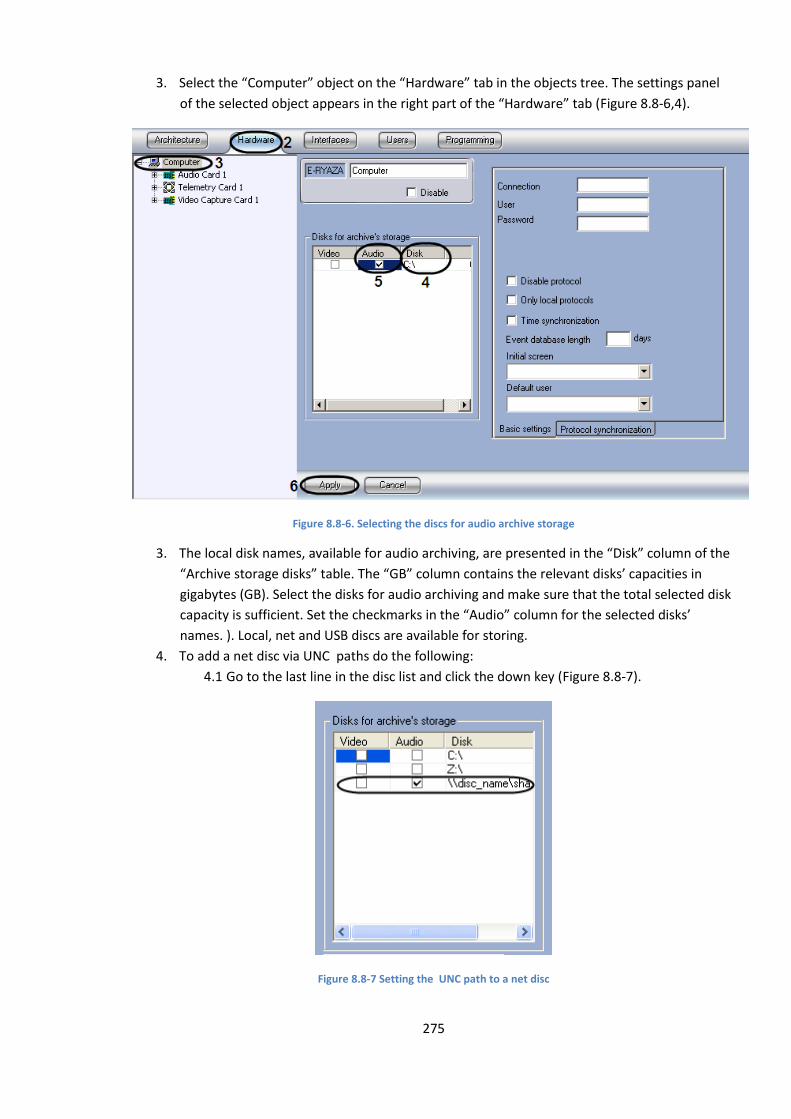
275
3. Select the “Computer” object on the “Hardware” tab in the objects tree. The settings panel
of the selected object appears in the right part of the “Hardware” tab (Figure 8.8-6,4).
Figure 8.8-6. Selecting the discs for audio archive storage
3. The local disk names, available for audio archiving, are presented in the “Disk” column of the
“Archive storage disks” table. The “GB” column contains the relevant disks’ capacities in
gigabytes (GB). Select the disks for audio archiving and make sure that the total selected disk
capacity is sufficient. Set the checkmarks in the “Audio” column for the selected disks’
names. ). Local, net and USB discs are available for storing.
4. To add a net disc via UNC paths do the following:
4.1 Go to the last line in the disc list and click the down key (Figure 8.8-7).
Figure 8.8-7 Setting the UNC path to a net disc
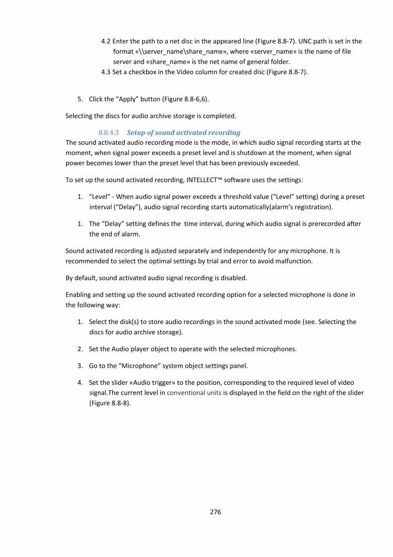
276
4.2 Enter the path to a net disc in the appeared line (Figure 8.8-7). UNC path is set in the
format «\\server_name\share_name», where «server_name» is the name of file
server and «share_name» is the net name of general folder.
4.3 Set a checkbox in the Video column for created disc (Figure 8.8-7).
5. Click the “Apply” button (Figure 8.8-6,6).
Selecting the discs for audio archive storage is completed.
8.8.4.3 Setup of sound activated recording
The sound activated audio recording mode is the mode, in which audio signal recording starts at the
moment, when signal power exceeds a preset level and is shutdown at the moment, when signal
power becomes lower than the preset level that has been previously exceeded.
To set up the sound activated recording, INTELLECT™ software uses the settings:
1. “Level” - When audio signal power exceeds a threshold value (“Level” setting) during a preset
interval (“Delay”), audio signal recording starts automatically(alarm’s registration).
1. The “Delay” setting defines the time interval, during which audio signal is prerecorded after
the end of alarm.
Sound activated recording is adjusted separately and independently for any microphone. It is
recommended to select the optimal settings by trial and error to avoid malfunction.
By default, sound activated audio signal recording is disabled.
Enabling and setting up the sound activated recording option for a selected microphone is done in
the following way:
1. Select the disk(s) to store audio recordings in the sound activated mode (see. Selecting the
discs for audio archive storage).
2. Set the Audio player object to operate with the selected microphones.
3. Go to the “Microphone” system object settings panel.
4. Set the slider «Audio trigger» to the position, corresponding to the required level of video
signal.The current level in conventional units is displayed in the field on the right of the slider
(Figure 8.8-8).
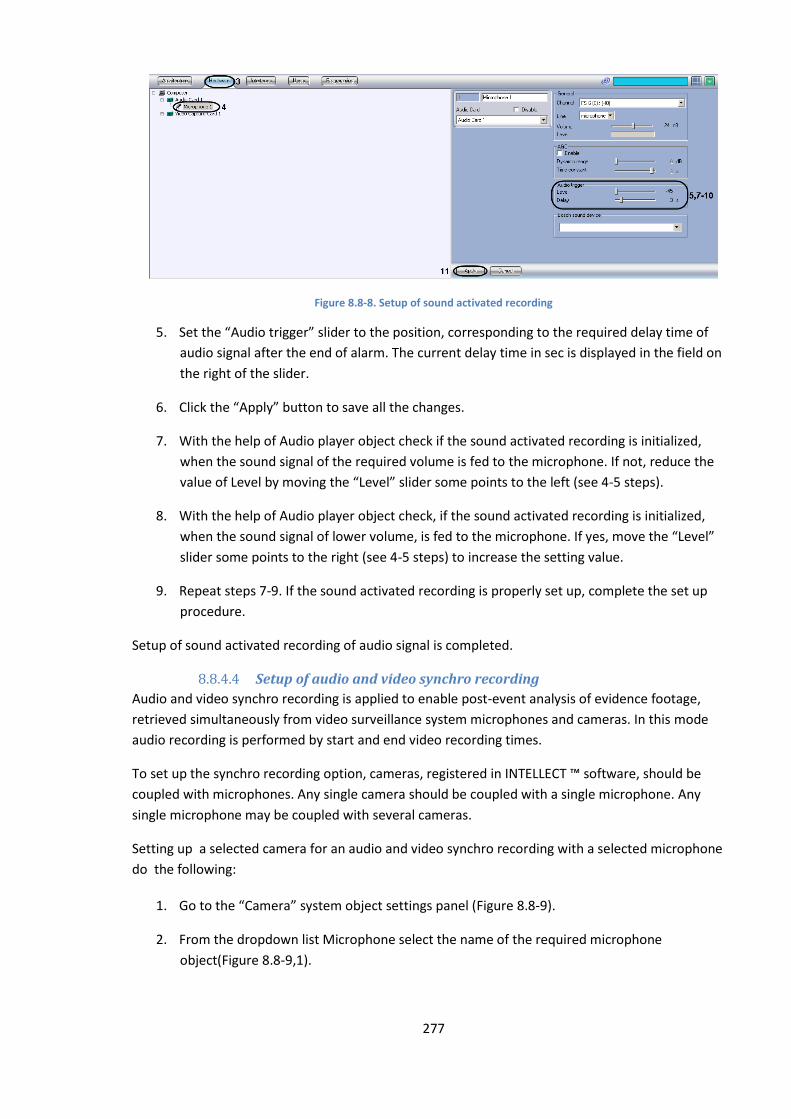
277
Figure 8.8-8. Setup of sound activated recording
5. Set the “Audio trigger” slider to the position, corresponding to the required delay time of
audio signal after the end of alarm. The current delay time in sec is displayed in the field on
the right of the slider.
6. Click the “Apply” button to save all the changes.
7. With the help of Audio player object check if the sound activated recording is initialized,
when the sound signal of the required volume is fed to the microphone. If not, reduce the
value of Level by moving the “Level” slider some points to the left (see 4-5 steps).
8. With the help of Audio player object check, if the sound activated recording is initialized,
when the sound signal of lower volume, is fed to the microphone. If yes, move the “Level”
slider some points to the right (see 4-5 steps) to increase the setting value.
9. Repeat steps 7-9. If the sound activated recording is properly set up, complete the set up
procedure.
Setup of sound activated recording of audio signal is completed.
8.8.4.4 Setup of audio and video synchro recording
Audio and video synchro recording is applied to enable post-event analysis of evidence footage,
retrieved simultaneously from video surveillance system microphones and cameras. In this mode
audio recording is performed by start and end video recording times.
To set up the synchro recording option, cameras, registered in INTELLECT ™ software, should be
coupled with microphones. Any single camera should be coupled with a single microphone. Any
single microphone may be coupled with several cameras.
Setting up a selected camera for an audio and video synchro recording with a selected microphone
do the following:
1. Go to the “Camera” system object settings panel (Figure 8.8-9).
2. From the dropdown list Microphone select the name of the required microphone
object(Figure 8.8-9,1).
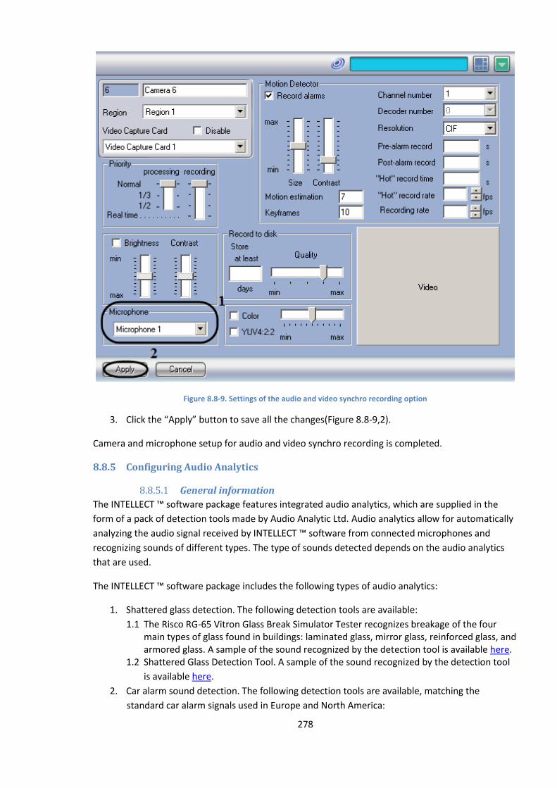
278
Figure 8.8-9. Settings of the audio and video synchro recording option
3. Click the “Apply” button to save all the changes(Figure 8.8-9,2).
Camera and microphone setup for audio and video synchro recording is completed.
8.8.5 Configuring Audio Analytics
8.8.5.1 General information
The INTELLECT ™ software package features integrated audio analytics, which are supplied in the
form of a pack of detection tools made by Audio Analytic Ltd. Audio analytics allow for automatically
analyzing the audio signal received by INTELLECT ™ software from connected microphones and
recognizing sounds of different types. The type of sounds detected depends on the audio analytics
that are used.
The INTELLECT ™ software package includes the following types of audio analytics:
1. Shattered glass detection. The following detection tools are available:
1.1 The Risco RG-65 Vitron Glass Break Simulator Tester recognizes breakage of the four main types of glass found in buildings: laminated glass, mirror glass, reinforced glass, and armored glass. A sample of the sound recognized by the detection tool is available here.
1.2 Shattered Glass Detection Tool. A sample of the sound recognized by the detection tool
is available here.
2. Car alarm sound detection. The following detection tools are available, matching the
standard car alarm signals used in Europe and North America:
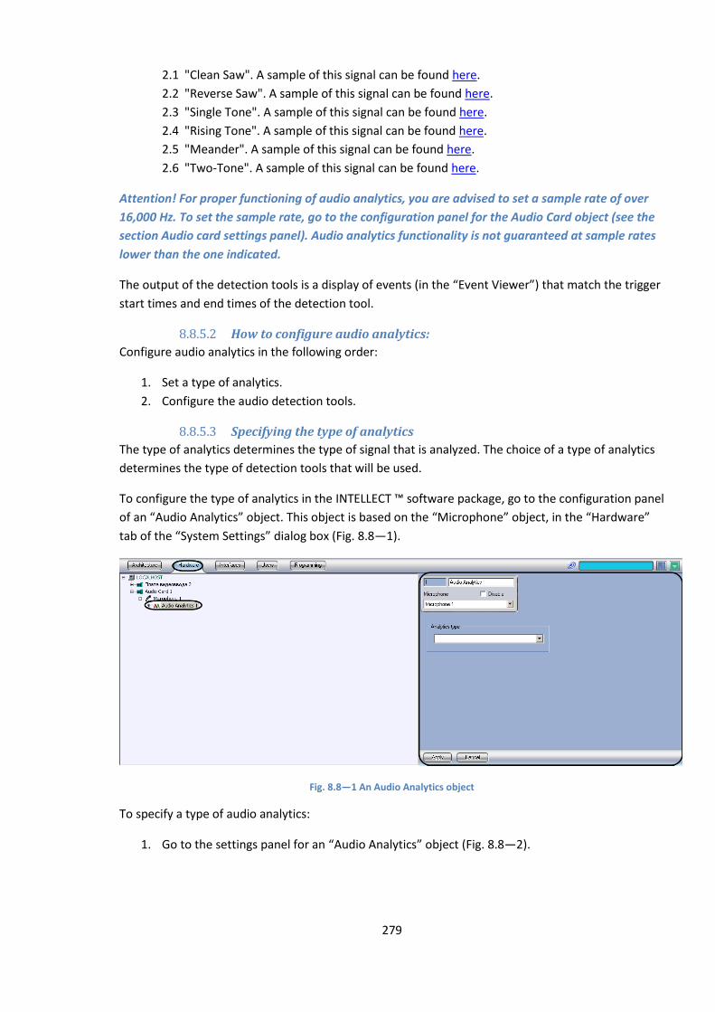
279
2.1 "Clean Saw". A sample of this signal can be found here.
2.2 "Reverse Saw". A sample of this signal can be found here.
2.3 "Single Tone". A sample of this signal can be found here.
2.4 "Rising Tone". A sample of this signal can be found here.
2.5 "Meander". A sample of this signal can be found here.
2.6 "Two-Tone". A sample of this signal can be found here.
Attention! For proper functioning of audio analytics, you are advised to set a sample rate of over
16,000 Hz. To set the sample rate, go to the configuration panel for the Audio Card object (see the
section Audio card settings panel). Audio analytics functionality is not guaranteed at sample rates
lower than the one indicated.
The output of the detection tools is a display of events (in the “Event Viewer”) that match the trigger
start times and end times of the detection tool.
8.8.5.2 How to configure audio analytics:
Configure audio analytics in the following order:
1. Set a type of analytics.
2. Configure the audio detection tools.
8.8.5.3 Specifying the type of analytics
The type of analytics determines the type of signal that is analyzed. The choice of a type of analytics
determines the type of detection tools that will be used.
To configure the type of analytics in the INTELLECT ™ software package, go to the configuration panel
of an “Audio Analytics” object. This object is based on the “Microphone” object, in the “Hardware”
tab of the “System Settings” dialog box (Fig. 8.8—1).
Fig. 8.8—1 An Audio Analytics object
To specify a type of audio analytics:
1. Go to the settings panel for an “Audio Analytics” object (Fig. 8.8—2).
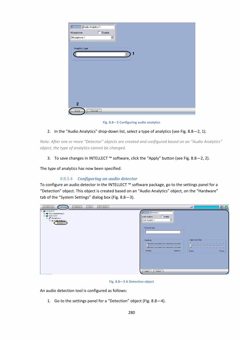
280
Fig. 8.8—2 Configuring audio analytics
2. In the “Audio Analytics” drop-down list, select a type of analytics (see Fig. 8.8—2, 1).
Note: After one or more “Detector” objects are created and configured based on an “Audio Analytics”
object, the type of analytics cannot be changed.
3. To save changes in INTELLECT ™ software, click the “Apply” button (see Fig. 8.8—2, 2).
The type of analytics has now been specified.
8.8.5.4 Configuring an audio detector
To configure an audio detector in the INTELLECT ™ software package, go to the settings panel for a
“Detection” object. This object is created based on an “Audio Analytics” object, on the “Hardware”
tab of the “System Settings” dialog box (Fig. 8.8—3).
Fig. 8.8—3 A Detection object
An audio detection tool is configured as follows:
1. Go to the settings panel for a “Detection” object (Fig. 8.8—4).
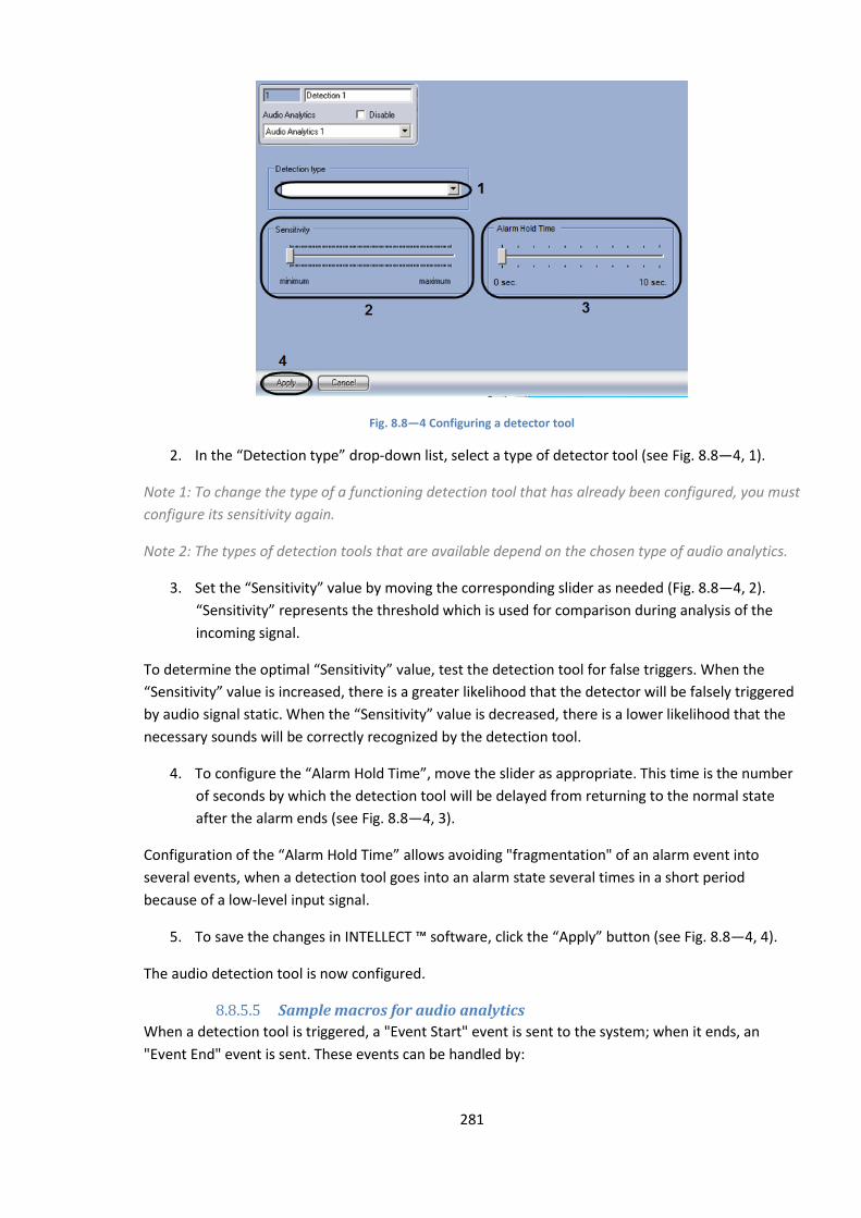
281
Fig. 8.8—4 Configuring a detector tool
2. In the “Detection type” drop-down list, select a type of detector tool (see Fig. 8.8—4, 1).
Note 1: To change the type of a functioning detection tool that has already been configured, you must
configure its sensitivity again.
Note 2: The types of detection tools that are available depend on the chosen type of audio analytics.
3. Set the “Sensitivity” value by moving the corresponding slider as needed (Fig. 8.8—4, 2).
“Sensitivity” represents the threshold which is used for comparison during analysis of the
incoming signal.
To determine the optimal “Sensitivity” value, test the detection tool for false triggers. When the
“Sensitivity” value is increased, there is a greater likelihood that the detector will be falsely triggered
by audio signal static. When the “Sensitivity” value is decreased, there is a lower likelihood that the
necessary sounds will be correctly recognized by the detection tool.
4. To configure the “Alarm Hold Time”, move the slider as appropriate. This time is the number
of seconds by which the detection tool will be delayed from returning to the normal state
after the alarm ends (see Fig. 8.8—4, 3).
Configuration of the “Alarm Hold Time” allows avoiding "fragmentation" of an alarm event into
several events, when a detection tool goes into an alarm state several times in a short period
because of a low-level input signal.
5. To save the changes in INTELLECT ™ software, click the “Apply” button (see Fig. 8.8—4, 4).
The audio detection tool is now configured.
8.8.5.5 Sample macros for audio analytics
When a detection tool is triggered, a "Event Start" event is sent to the system; when it ends, an
"Event End" event is sent. These events can be handled by:
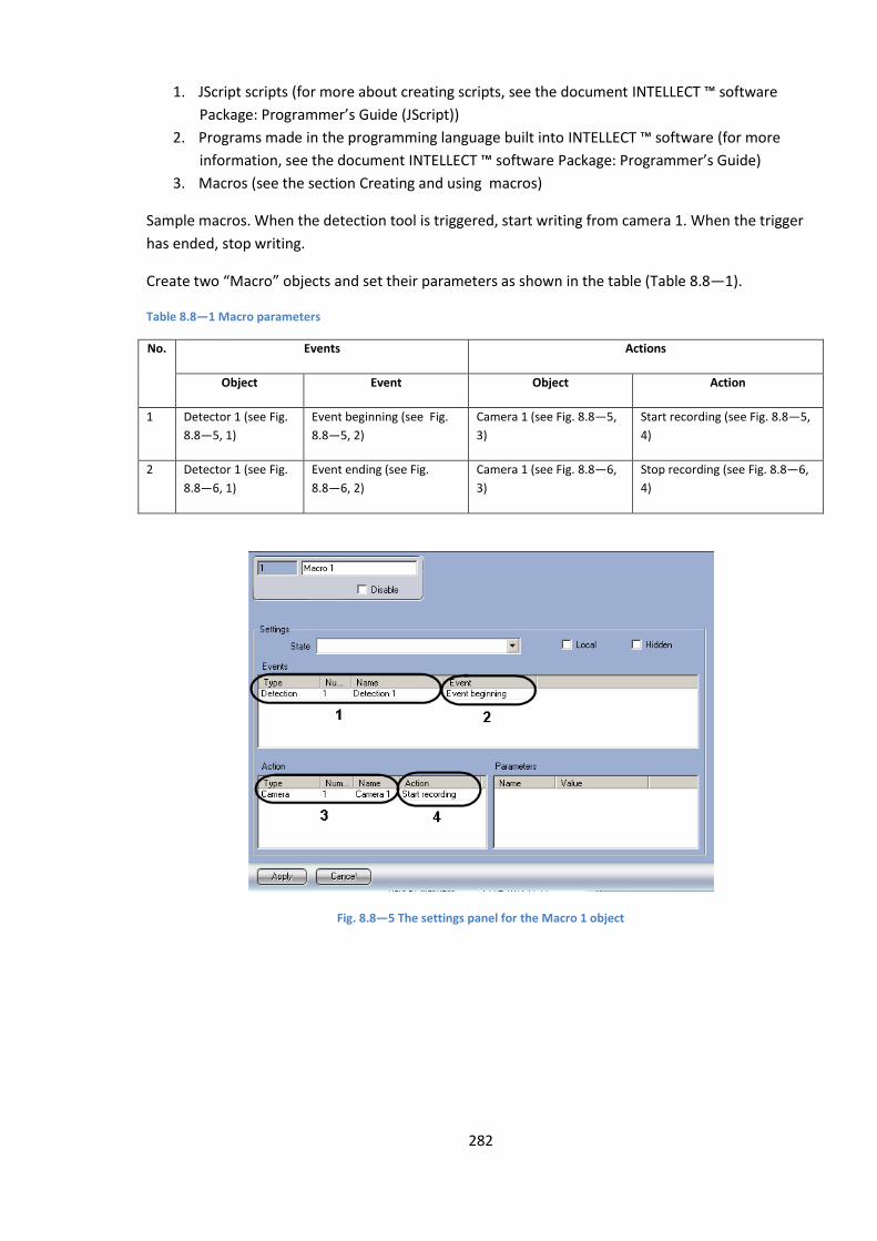
282
1. JScript scripts (for more about creating scripts, see the document INTELLECT ™ software
Package: Programmer’s Guide (JScript))
2. Programs made in the programming language built into INTELLECT ™ software (for more
information, see the document INTELLECT ™ software Package: Programmer’s Guide)
3. Macros (see the section Creating and using macros)
Sample macros. When the detection tool is triggered, start writing from camera 1. When the trigger
has ended, stop writing.
Create two “Macro” objects and set their parameters as shown in the table (Table 8.8—1).
Table 8.8—1 Macro parameters
No. Events Actions
Object Event Object Action
1 Detector 1 (see Fig.
8.8—5, 1)
Event beginning (see Fig.
8.8—5, 2)
Camera 1 (see Fig. 8.8—5,
3)
Start recording (see Fig. 8.8—5,
4)
2 Detector 1 (see Fig.
8.8—6, 1)
Event ending (see Fig.
8.8—6, 2)
Camera 1 (see Fig. 8.8—6,
3)
Stop recording (see Fig. 8.8—6,
4)
Fig. 8.8—5 The settings panel for the Macro 1 object

283
Fig. 8.8—6 The settings panel for the Macro 2 object
8.8.6 Setup of audio signal transmission to Remote Workstations and servers
INTELLECT™ software has the facility to transmit audio signals both from microphones and from the
archive to Remote Workstations and servers.
INTELLECT™ software version 4.74 doesn’t support audio signal transmission to Remote Monitoring
Workstations on the base of a web-server, PocketPC or a SmartPhone.
Audio signal transmission to Remote Workplaces and servers, connected by the TCP/IP net, is
performed only via “Video surveillance monitor” or “Audio player” interface objects.
The video monitor has the facility to transmit only audio signals from the microphones that have
been set to synchro video and audio recording. The Audio player may be configured to transmit
audio signals from all video surveillance system microphones to the Remote Workstations and
servers.
To enable audio signal transmission to Remote Workplaces and servers, follow the steps:
1. Go to the “Interfaces” tab in the “System Setup” dialog box.
2. Create the “Screen” object, if it was not created before (Figure 8.8-10).

284
Figure 8.8-10. Setup of audio signal transmission to Remote Workplaces and videoservers
3. Set the checkmarks in the “Computers” table for those Remote Workplaces and servers,
where audio signals should be transmitted.
4. Click the “Apply” button.
5. Create and set up “Monitor” and/or “Audio player” objects (for description of setting up
these objects see the relevant sections).
Setup of audio signal transmission to Remote Workplaces and servers is completed.
8.8.7 Setup of audio playback
INTELLECT™ software provides an audio playback using «Playback card» object. «Playback card»
object combines dynamics objects in case it has several channels. You can direct sound from the
microphone to the dynamic using audio (see Ошибка! Источник ссылки не найден. part of this
anual), macrocommand or script switch.
8.8.7.1 Creating and setting of “Playing card” object
«Playing card» object is registered on the basis of «Computer» object on «Hardware» tab in «System
settings» dialog window (Figure 8.8-11).
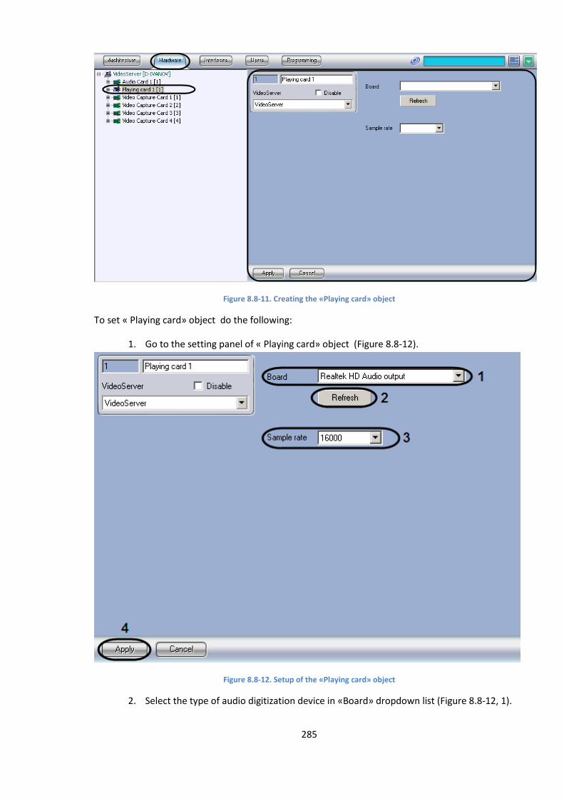
285
Figure 8.8-11. Creating the «Playing card» object
To set « Playing card» object do the following:
1. Go to the setting panel of « Playing card» object (Figure 8.8-12).
Figure 8.8-12. Setup of the «Playing card» object
2. Select the type of audio digitization device in «Board» dropdown list (Figure 8.8-12, 1).
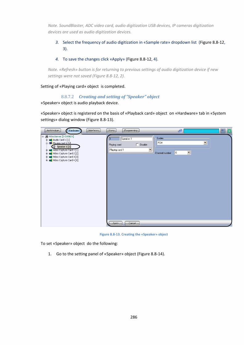
286
Note. SoundBlaster, ADC video card, audio digitization USB devices, IP cameras digitization
devices are used as audio digitization devices.
3. Select the frequency of audio digitization in «Sample rate» dropdown list (Figure 8.8-12,
3).
4. To save the changes click «Apply» (Figure 8.8-12, 4).
Note. «Refresh» button is for returning to previous settings of audio digitization device if new
settings were not saved (Figure 8.8-12, 2).
Setting of «Playing card» object is completed.
8.8.7.2 Creating and setting of “Speaker” object
«Speaker» object is audio playback device.
«Speaker» object is registered on the basis of «Playback card» object on «Hardware» tab in «System
settings» dialog window (Figure 8.8-13).
Figure 8.8-13. Creating the «Speaker» object
To set «Speaker» object do the following:
1. Go to the setting panel of «Speaker» object (Figure 8.8-14).
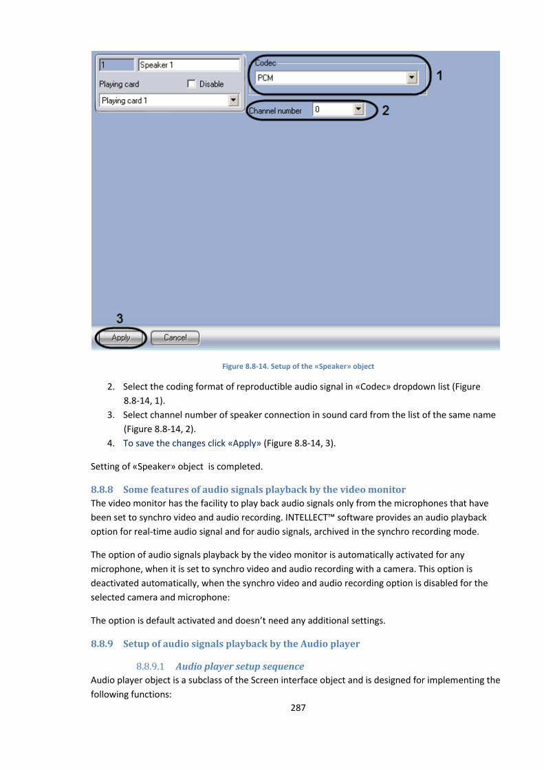
287
Figure 8.8-14. Setup of the «Speaker» object
2. Select the coding format of reproductible audio signal in «Codec» dropdown list (Figure
8.8-14, 1).
3. Select channel number of speaker connection in sound card from the list of the same name
(Figure 8.8-14, 2).
4. To save the changes click «Apply» (Figure 8.8-14, 3).
Setting of «Speaker» object is completed.
8.8.8 Some features of audio signals playback by the video monitor
The video monitor has the facility to play back audio signals only from the microphones that have
been set to synchro video and audio recording. INTELLECT™ software provides an audio playback
option for real-time audio signal and for audio signals, archived in the synchro recording mode.
The option of audio signals playback by the video monitor is automatically activated for any
microphone, when it is set to synchro video and audio recording with a camera. This option is
deactivated automatically, when the synchro video and audio recording option is disabled for the
selected camera and microphone:
The option is default activated and doesn’t need any additional settings.
8.8.9 Setup of audio signals playback by the Audio player
8.8.9.1 Audio player setup sequence
Audio player object is a subclass of the Screen interface object and is designed for implementing the
following functions:
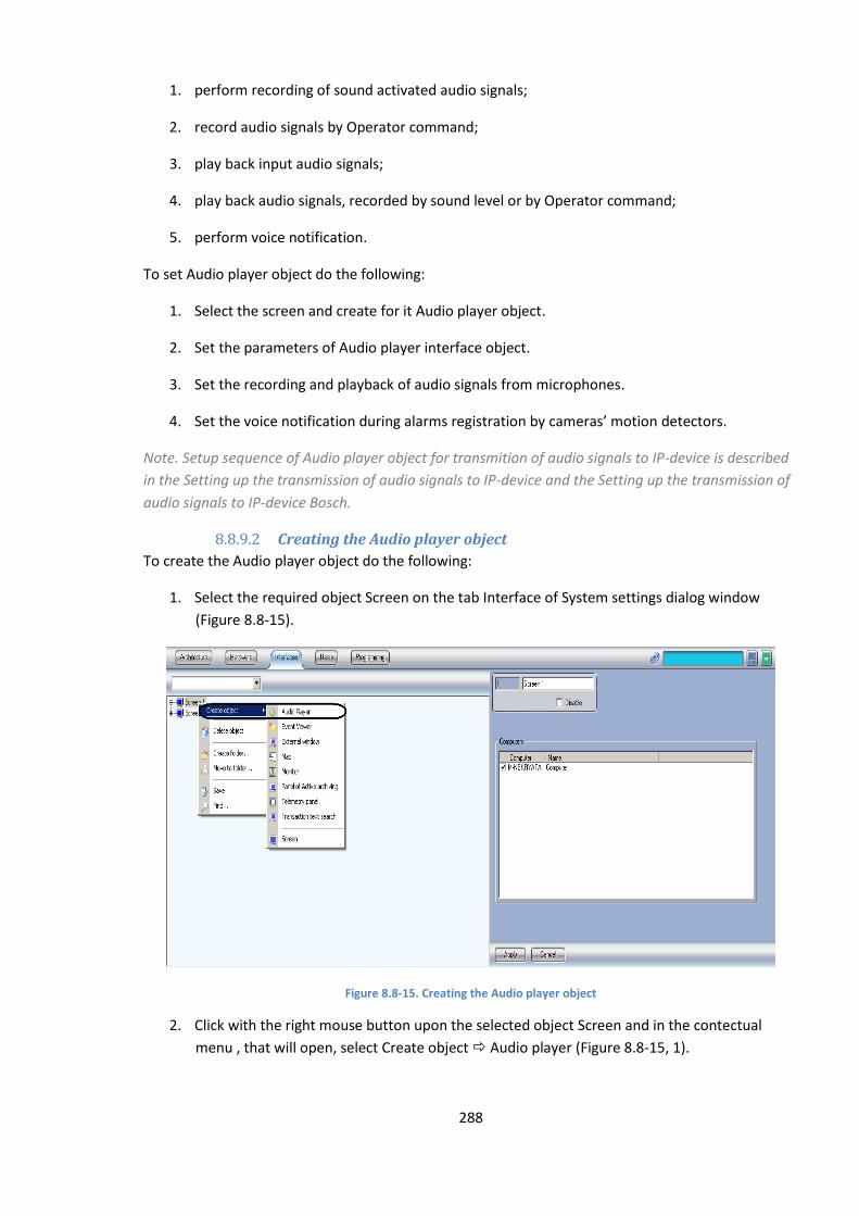
288
1. perform recording of sound activated audio signals;
2. record audio signals by Operator command;
3. play back input audio signals;
4. play back audio signals, recorded by sound level or by Operator command;
5. perform voice notification.
To set Audio player object do the following:
1. Select the screen and create for it Audio player object.
2. Set the parameters of Audio player interface object.
3. Set the recording and playback of audio signals from microphones.
4. Set the voice notification during alarms registration by cameras’ motion detectors.
Note. Setup sequence of Audio player object for transmition of audio signals to IP-device is described
in the Setting up the transmission of audio signals to IP-device and the Setting up the transmission of
audio signals to IP-device Bosch.
8.8.9.2 Creating the Audio player object
To create the Audio player object do the following:
1. Select the required object Screen on the tab Interface of System settings dialog window
(Figure 8.8-15).
Figure 8.8-15. Creating the Audio player object
2. Click with the right mouse button upon the selected object Screen and in the contectual
menu , that will open, select Create object Audio player (Figure 8.8-15, 1).
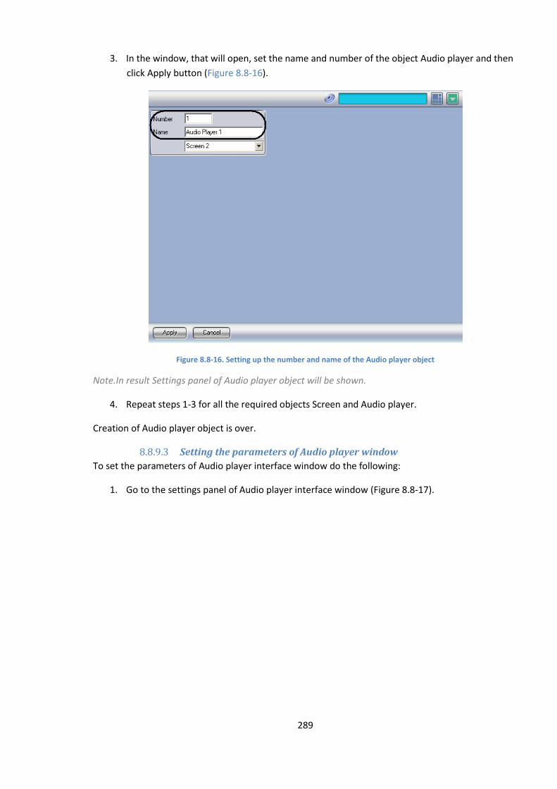
289
3. In the window, that will open, set the name and number of the object Audio player and then
click Apply button (Figure 8.8-16).
Figure 8.8-16. Setting up the number and name of the Audio player object
Note.In result Settings panel of Audio player object will be shown.
4. Repeat steps 1-3 for all the required objects Screen and Audio player.
Сreation of Audio player object is over.
8.8.9.3 Setting the parameters of Audio player window
To set the parameters of Audio player interface window do the following:
1. Go to the settings panel of Audio player interface window (Figure 8.8-17).
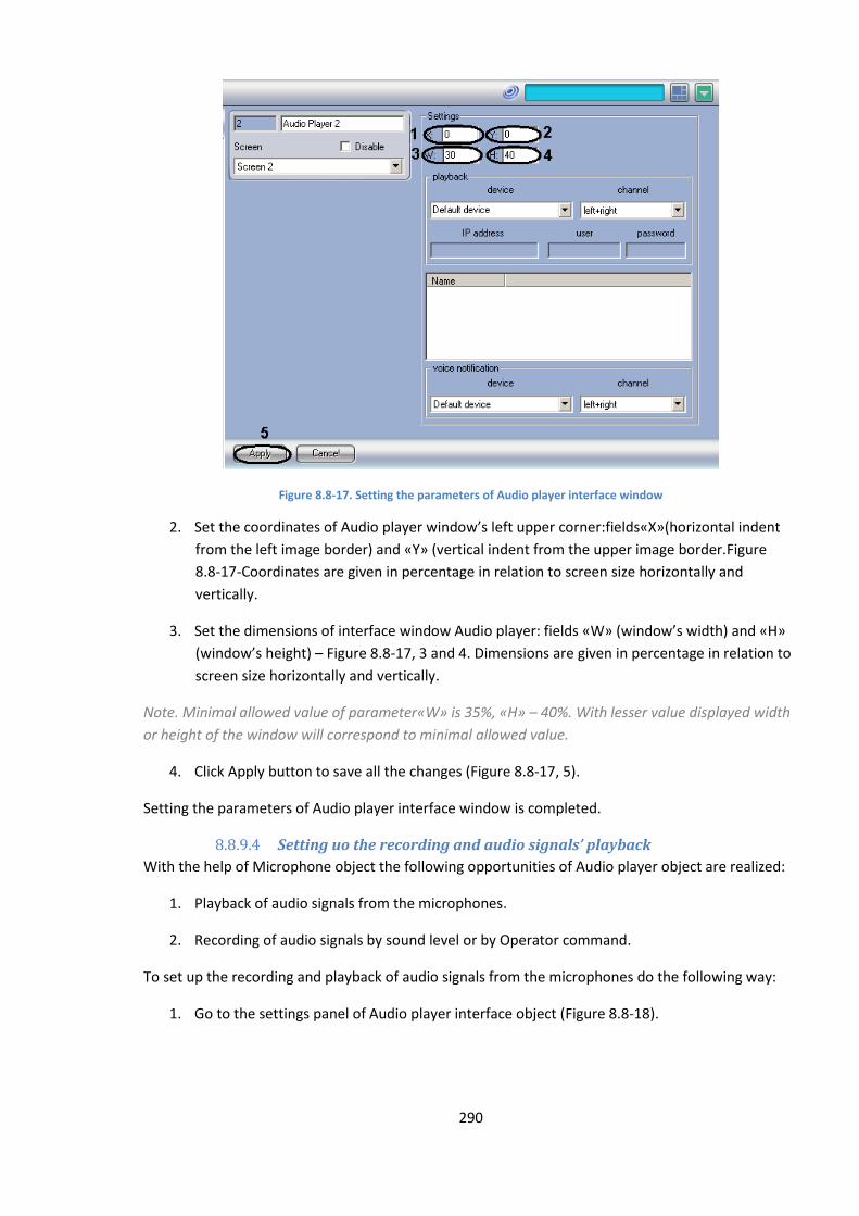
290
Figure 8.8-17. Setting the parameters of Audio player interface window
2. Set the coordinates of Audio player window’s left upper corner:fields«X»(horizontal indent
from the left image border) and «Y» (vertical indent from the upper image border.Figure
8.8-17-Coordinates are given in percentage in relation to screen size horizontally and
vertically.
3. Set the dimensions of interface window Audio player: fields «W» (window’s width) and «H»
(window’s height) – Figure 8.8-17, 3 and 4. Dimensions are given in percentage in relation to
screen size horizontally and vertically.
Note. Minimal allowed value of parameter«W» is 35%, «H» – 40%. With lesser value displayed width
or height of the window will correspond to minimal allowed value.
4. Click Apply button to save all the changes (Figure 8.8-17, 5).
Setting the parameters of Audio player interface window is completed.
8.8.9.4 Setting uo the recording and audio signals’ playback
With the help of Microphone object the following opportunities of Audio player object are realized:
1. Playback of audio signals from the microphones.
2. Recording of audio signals by sound level or by Operator command.
To set up the recording and playback of audio signals from the microphones do the following way:
1. Go to the settings panel of Audio player interface object (Figure 8.8-18).
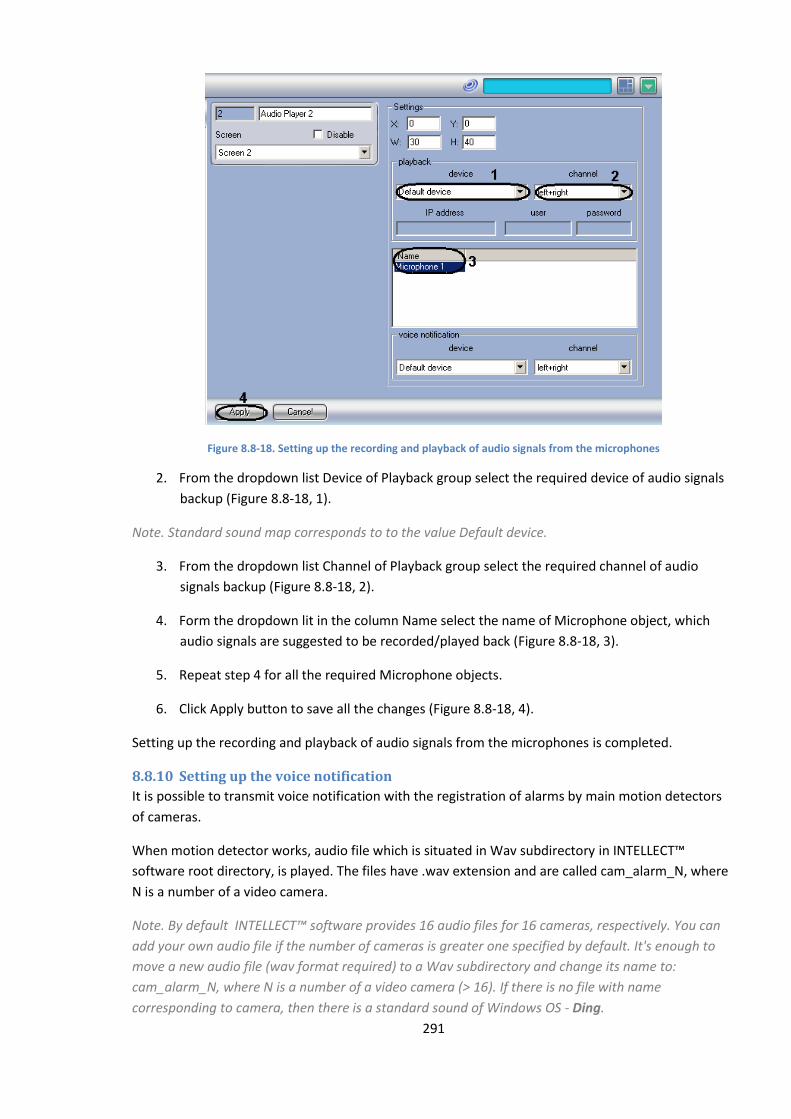
291
Figure 8.8-18. Setting up the recording and playback of audio signals from the microphones
2. From the dropdown list Device of Playback group select the required device of audio signals
backup (Figure 8.8-18, 1).
Note. Standard sound map corresponds to to the value Default device.
3. From the dropdown list Channel of Playback group select the required channel of audio
signals backup (Figure 8.8-18, 2).
4. Form the dropdown lit in the column Name select the name of Microphone object, which
audio signals are suggested to be recorded/played back (Figure 8.8-18, 3).
5. Repeat step 4 for all the required Microphone objects.
6. Click Apply button to save all the changes (Figure 8.8-18, 4).
Setting up the recording and playback of audio signals from the microphones is completed.
8.8.10 Setting up the voice notification
It is possible to transmit voice notification with the registration of alarms by main motion detectors
of cameras.
When motion detector works, audio file which is situated in Wav subdirectory in INTELLECT™
software root directory, is played. The files have .wav extension and are called cam_alarm_N, where
N is a number of a video camera.
Note. By default INTELLECT™ software provides 16 audio files for 16 cameras, respectively. You can
add your own audio file if the number of cameras is greater one specified by default. It's enough to
move a new audio file (wav format required) to a Wav subdirectory and change its name to:
cam_alarm_N, where N is a number of a video camera (> 16). If there is no file with name
corresponding to camera, then there is a standard sound of Windows OS - Ding.
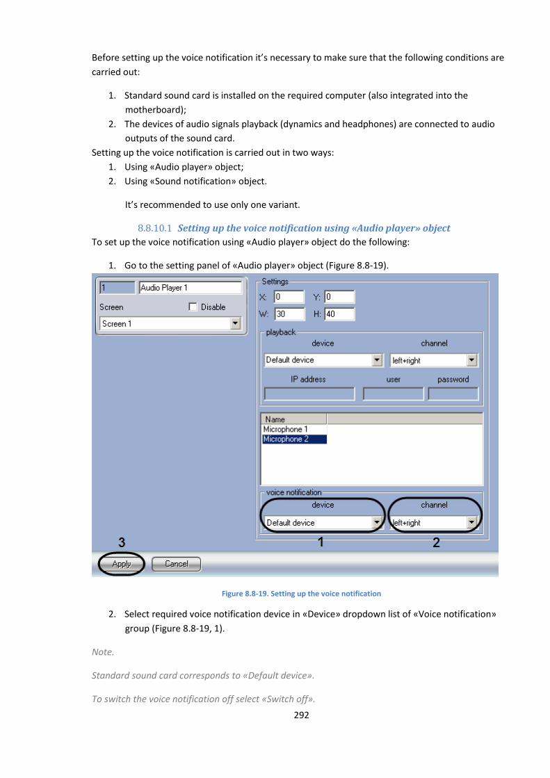
292
Before setting up the voice notification it’s necessary to make sure that the following conditions are
carried out:
1. Standard sound card is installed on the required computer (also integrated into the
motherboard);
2. The devices of audio signals playback (dynamics and headphones) are connected to audio
outputs of the sound card.
Setting up the voice notification is carried out in two ways:
1. Using «Audio player» object;
2. Using «Sound notification» object.
It’s recommended to use only one variant.
8.8.10.1 Setting up the voice notification using «Audio player» object
To set up the voice notification using «Audio player» object do the following:
1. Go to the setting panel of «Audio player» object (Figure 8.8-19).
Figure 8.8-19. Setting up the voice notification
2. Select required voice notification device in «Device» dropdown list of «Voice notification»
group (Figure 8.8-19, 1).
Note.
Standard sound card corresponds to «Default device».
To switch the voice notification off select «Switch off».
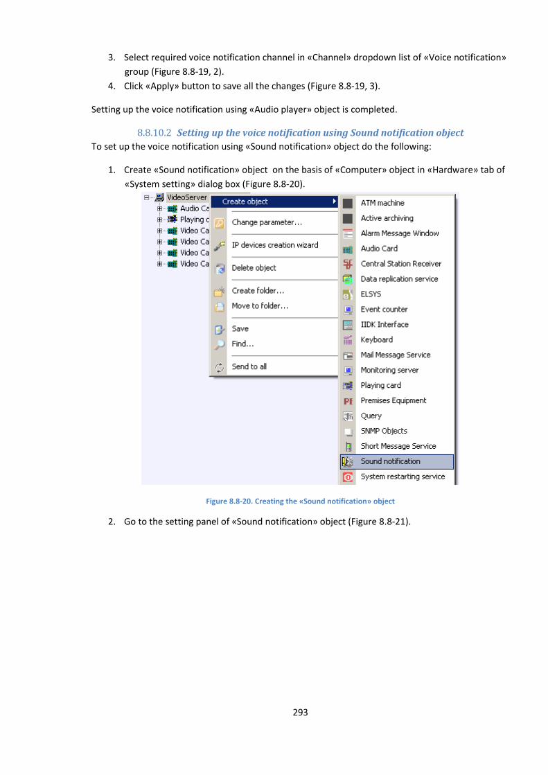
293
3. Select required voice notification channel in «Channel» dropdown list of «Voice notification»
group (Figure 8.8-19, 2).
4. Click «Apply» button to save all the changes (Figure 8.8-19, 3).
Setting up the voice notification using «Audio player» object is completed.
8.8.10.2 Setting up the voice notification using Sound notification object
To set up the voice notification using «Sound notification» object do the following:
1. Create «Sound notification» object on the basis of «Computer» object in «Hardware» tab of
«System setting» dialog box (Figure 8.8-20).
Figure 8.8-20. Creating the «Sound notification» object
2. Go to the setting panel of «Sound notification» object (Figure 8.8-21).
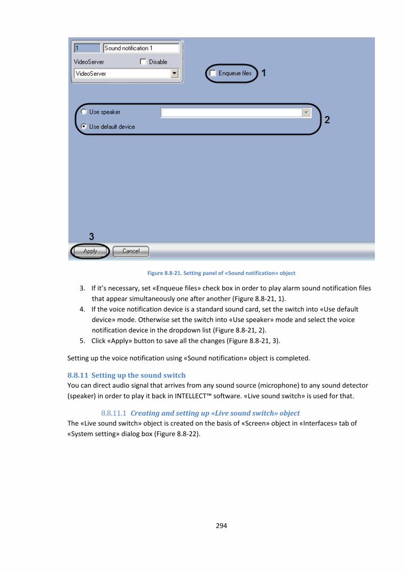
294
Figure 8.8-21. Setting panel of «Sound notification» object
3. If it’s necessary, set «Enqueue files» check box in order to play alarm sound notification files
that appear simultaneously one after another (Figure 8.8-21, 1).
4. If the voice notification device is a standard sound card, set the switch into «Use default
device» mode. Otherwise set the switch into «Use speaker» mode and select the voice
notification device in the dropdown list (Figure 8.8-21, 2).
5. Click «Apply» button to save all the changes (Figure 8.8-21, 3).
Setting up the voice notification using «Sound notification» object is completed.
8.8.11 Setting up the sound switch
You can direct audio signal that arrives from any sound source (microphone) to any sound detector
(speaker) in order to play it back in INTELLECT™ software. «Live sound switch» is used for that.
8.8.11.1 Creating and setting up «Live sound switch» object
The «Live sound switch» object is created on the basis of «Screen» object in «Interfaces» tab of
«System setting» dialog box (Figure 8.8-22).

295
Figure 8.8-22. Creating the «Live sound switch» object
To set up the «Live sound switch» object do the following:
1. Go to the setting panel of the «Live sound switch» object (Figure 8.8-23).
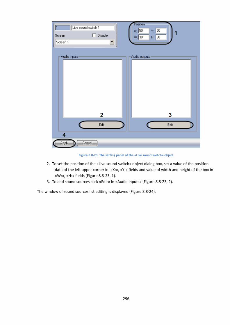
296
Figure 8.8-23. The setting panel of the «Live sound switch» object
2. To set the position of the «Live sound switch» object dialog box, set a value of the position
data of the left upper corner in «X:», «Y:» fields and value of width and height of the box in
«W:», «H:» fields (Figure 8.8-23, 1).
3. To add sound sources click «Edit» in «Audio inputs» (Figure 8.8-23, 2).
The window of sound sources list editing is displayed (Figure 8.8-24).
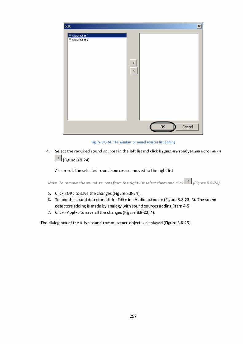
297
Figure 8.8-24. The window of sound sources list editing
4. Select the required sound sources in the left listand click Выделить требуемые источники
(Figure 8.8-24).
As a result the selected sound sources are moved to the right list.
Note. To remove the sound sources from the right list select them and click (Figure 8.8-24).
5. Click «ОК» to save the changes (Figure 8.8-24).
6. To add the sound detectors click «Edit» in «Audio outputs» (Figure 8.8-23, 3). The sound
detectors adding is made by analogy with sound sources adding (item 4-5).
7. Click «Apply» to save all the changes (Figure 8.8-23, 4).
The dialog box of the «Live sound commutator» object is displayed (Figure 8.8-25).
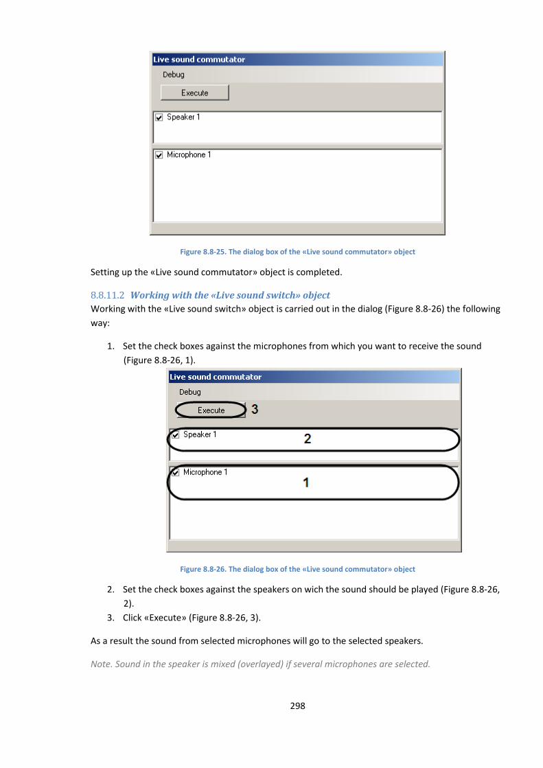
298
Figure 8.8-25. The dialog box of the «Live sound commutator» object
Setting up the «Live sound commutator» object is completed.
8.8.11.2 Working with the «Live sound switch» object
Working with the «Live sound switch» object is carried out in the dialog (Figure 8.8-26) the following
way:
1. Set the check boxes against the microphones from which you want to receive the sound
(Figure 8.8-26, 1).
Figure 8.8-26. The dialog box of the «Live sound commutator» object
2. Set the check boxes against the speakers on wich the sound should be played (Figure 8.8-26,
2).
3. Click «Execute» (Figure 8.8-26, 3).
As a result the sound from selected microphones will go to the selected speakers.
Note. Sound in the speaker is mixed (overlayed) if several microphones are selected.
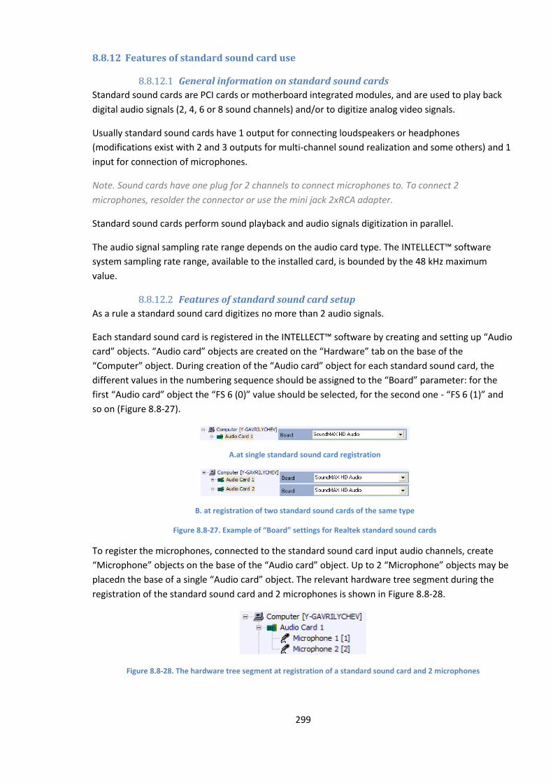
299
8.8.12 Features of standard sound card use
8.8.12.1 General information on standard sound cards
Standard sound cards are PCI cards or motherboard integrated modules, and are used to play back
digital audio signals (2, 4, 6 or 8 sound channels) and/or to digitize analog video signals.
Usually standard sound cards have 1 output for connecting loudspeakers or headphones
(modifications exist with 2 and 3 outputs for multi-channel sound realization and some others) and 1
input for connection of microphones.
Note. Sound cards have one plug for 2 channels to connect microphones to. To connect 2
microphones, resolder the connector or use the mini jack 2хRCA adapter.
Standard sound cards perform sound playback and audio signals digitization in parallel.
The audio signal sampling rate range depends on the audio card type. The INTELLECT™ software
system sampling rate range, available to the installed card, is bounded by the 48 kHz maximum
value.
8.8.12.2 Features of standard sound card setup
As a rule a standard sound card digitizes no more than 2 audio signals.
Each standard sound card is registered in the INTELLECT™ software by creating and setting up “Audio
card” objects. “Audio card” objects are created on the “Hardware” tab on the base of the
“Computer” object. During creation of the “Audio card” object for each standard sound card, the
different values in the numbering sequence should be assigned to the “Board” parameter: for the
first “Audio card” object the “FS 6 (0)” value should be selected, for the second one - “FS 6 (1)” and
so on (Figure 8.8-27).
A.at single standard sound card registration
B. at registration of two standard sound cards of the same type
Figure 8.8-27. Example of “Board” settings for Realtek standard sound cards
To register the microphones, connected to the standard sound card input audio channels, create
“Microphone” objects on the base of the “Audio card” object. Up to 2 “Microphone” objects may be
placedn the base of a single “Audio card” object. The relevant hardware tree segment during the
registration of the standard sound card and 2 microphones is shown in Figure 8.8-28.
Figure 8.8-28. The hardware tree segment at registration of a standard sound card and 2 microphones
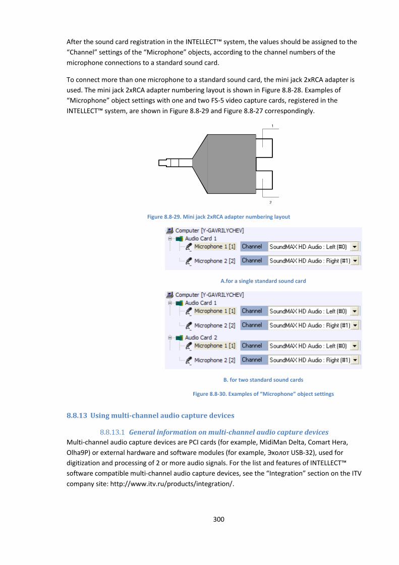
300
After the sound card registration in the INTELLECT™ system, the values should be assigned to the
“Channel” settings of the “Microphone” objects, according to the channel numbers of the
microphone connections to a standard sound card.
To connect more than one microphone to a standard sound card, the mini jack 2хRCA adapter is
used. The mini jack 2хRCA adapter numbering layout is shown in Figure 8.8-28. Examples of
“Microphone” object settings with one and two FS-5 video capture cards, registered in the
INTELLECT™ system, are shown in Figure 8.8-29 and Figure 8.8-27 correspondingly.
Figure 8.8-29. Mini jack 2хRCA adapter numbering layout
A.for a single standard sound card
B. for two standard sound cards
Figure 8.8-30. Examples of “Microphone” object settings
8.8.13 Using multi-channel audio capture devices
8.8.13.1 General information on multi-channel audio capture devices
Multi-channel audio capture devices are PCI cards (for example, MidiMan Delta, Comart Hera,
Olha9Р) or external hardware and software modules (for example, Эхолот USB-32), used for
digitization and processing of 2 or more audio signals. For the list and features of INTELLECT™
software compatible multi-channel audio capture devices, see the “Integration” section on the ITV
company site: http://www.itv.ru/products/integration/.
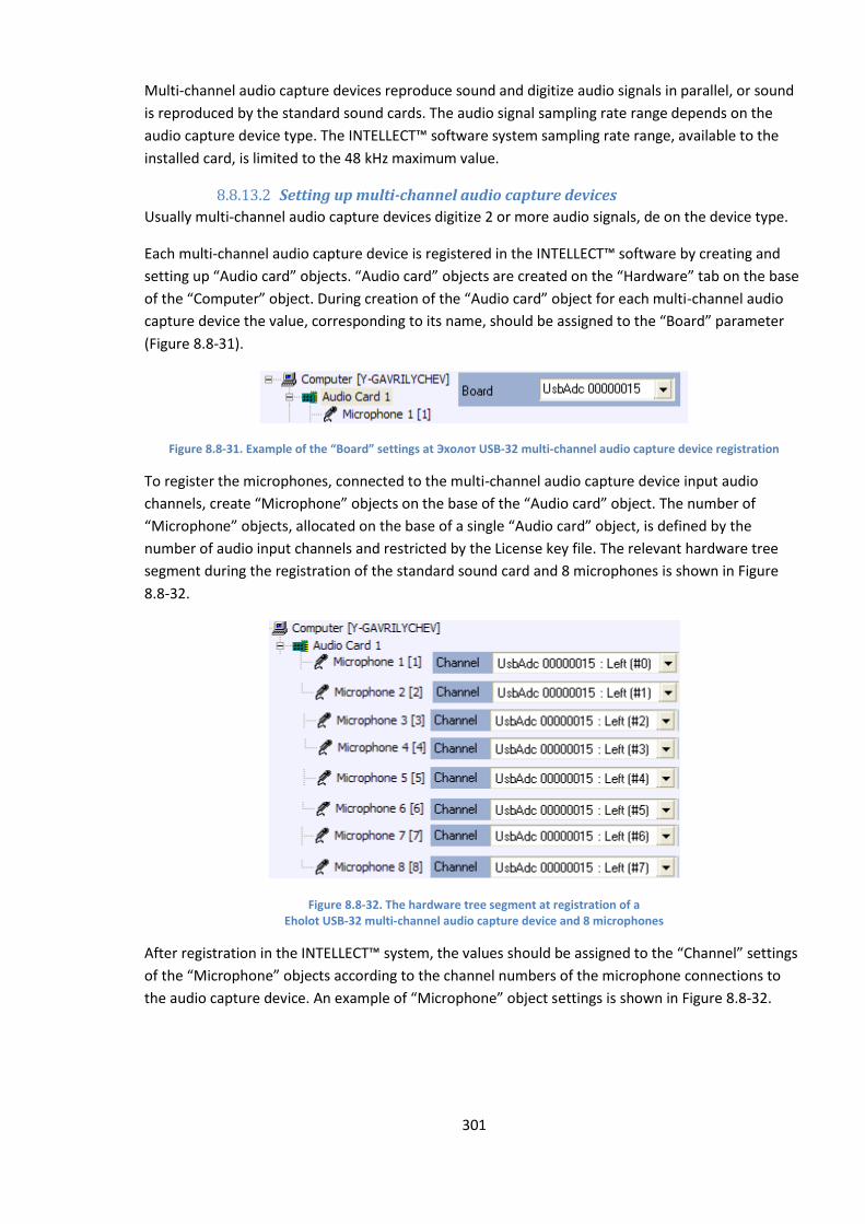
301
Multi-channel audio capture devices reproduce sound and digitize audio signals in parallel, or sound
is reproduced by the standard sound cards. The audio signal sampling rate range depends on the
audio capture device type. The INTELLECT™ software system sampling rate range, available to the
installed card, is limited to the 48 kHz maximum value.
8.8.13.2 Setting up multi-channel audio capture devices
Usually multi-channel audio capture devices digitize 2 or more audio signals, de on the device type.
Each multi-channel audio capture device is registered in the INTELLECT™ software by creating and
setting up “Audio card” objects. “Audio card” objects are created on the “Hardware” tab on the base
of the “Computer” object. During creation of the “Audio card” object for each multi-channel audio
capture device the value, corresponding to its name, should be assigned to the “Board” parameter
(Figure 8.8-31).
Figure 8.8-31. Example of the “Board” settings at Эхолот USB-32 multi-channel audio capture device registration
To register the microphones, connected to the multi-channel audio capture device input audio
channels, create “Microphone” objects on the base of the “Audio card” object. The number of
“Microphone” objects, allocated on the base of a single “Audio card” object, is defined by the
number of audio input channels and restricted by the License key file. The relevant hardware tree
segment during the registration of the standard sound card and 8 microphones is shown in Figure
8.8-32.
Figure 8.8-32. The hardware tree segment at registration of a Eholot USB-32 multi-channel audio capture device and 8 microphones
After registration in the INTELLECT™ system, the values should be assigned to the “Channel” settings
of the “Microphone” objects according to the channel numbers of the microphone connections to
the audio capture device. An example of “Microphone” object settings is shown in Figure 8.8-32.
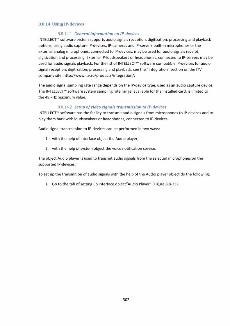
302
8.8.14 Using IP-devices
8.8.14.1 General information on IP-devices
INTELLECT™ software system supports audio signals reception, digitization, processing and playback
options, using audio capture IP-devices. IP-cameras and IP-servers built-in microphones or the
external analog microphones, connected to IP-devices, may be used for audio signals receipt,
digitization and processing. External IP-loudspeakers or headphones, connected to IP-servers may be
used for audio signals playback. For the list of INTELLECT™ software compatible IP-devices for audio
signal reception, digitization, processing and playback, see the “Integration” section on the ITV
company site: http://www.itv.ru/products/integration/.
The audio signal sampling rate range depends on the IP-device type, used as an audio capture device.
The INTELLECT™ software system sampling rate range, available for the installed card, is limited to
the 48 kHz maximum value.
8.8.14.2 Setup of video signals transmission to IP-devices
INTELLECT™ software has the facility to transmit audio signals from microphones to IP-devices and to
play them back with loudspeakers or headphones, connected to IP-devices.
Audio signal transmission to IP-devices can be performed in two ways:
1. with the help of interface object the Audio player;
2. with the help of system object the voice notification service.
The object Audio player is used to transmit audio signals from the selected microphones on the
supported IP-devices.
To set up the transmition of audio signals with the help of the Audio player object do the following:
1. Go to the tab of setting up interface object“Audio Player” (Figure 8.8-33).
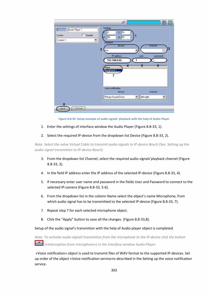
303
Figure 8.8-33. Setup example of audio signals’ playback with the help of Audio Player
1. Enter the settings of interface window the Audio Player (Figure 8.8-33, 1).
2. Select the required IP-device from the dropdown list Device (Figure 8.8-33, 2).
Note. Select the value Virtual Cable to transmit audio signals to IP-device Bosch (See. Setting up the
audio signal transmition to IP-device Bosch)
3. From the dropdown list Channel, select the required audio signals’playback channel (Figure
8.8-33, 3).
4. In the field IP address enter the IP address of the selected IP-device (Figure 8.8-33, 4).
5. If necessary enter user name and password in the fields User and Password to connect to the
selected IP-camera (Figure 8.8-33, 5-6).
6. From the dropdown list in the colomn Name select the object’s name Microphone, from
which audio signal has to be transmitted to the selected IP-device (Figure 8.8-33, 7).
7. Repeat step 7 for each selected microphone object.
8. Click the “Apply” button to save all the changes. (Figure 8.8-33,8).
Setup of the audio signal’s transmition with the help of Audio player object is completed.
Note. To activate audio signals’transmition from the microphone to the IP-device click the button
(«Interception from microphone») in the interface window Audio Player.
«Voice notification» object is used to transmit files of WAV format to the supported IP-devices. Set
up order of the object «Voice notification service»is described in the Setiing up the voice notification
service.
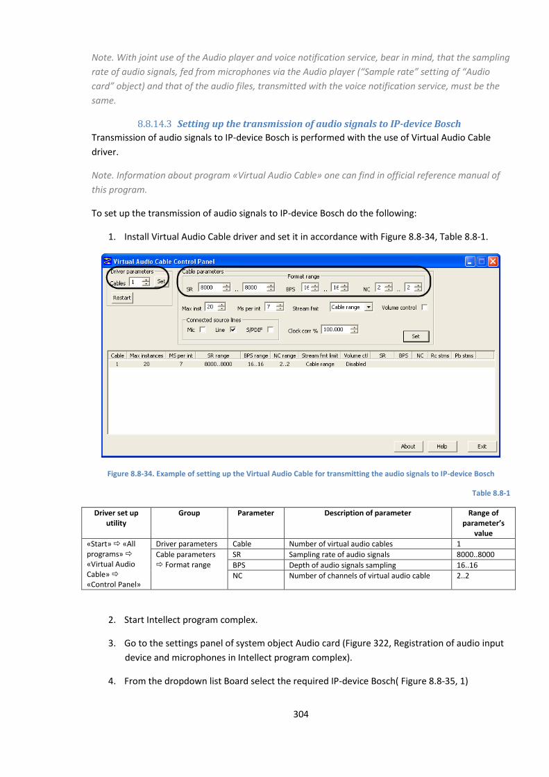
304
Note. With joint use of the Audio player and voice notification service, bear in mind, that the sampling
rate of audio signals, fed from microphones via the Audio player (“Sample rate” setting of “Audio
card” object) and that of the audio files, transmitted with the voice notification service, must be the
same.
8.8.14.3 Setting up the transmission of audio signals to IP-device Bosсh
Transmission of audio signals to IP-device Bosch is performed with the use of Virtual Audio Cable
driver.
Note. Information about program «Virtual Audio Cable» one can find in official reference manual of
this program.
To set up the transmission of audio signals to IP-device Bosch do the following:
1. Install Virtual Audio Cable driver and set it in accordance with Figure 8.8-34, Table 8.8-1.
Figure 8.8-34. Example of setting up the Virtual Audio Cable for transmitting the audio signals to IP-device Bosch
Table 8.8-1
Driver set up utility
Group Parameter Description of parameter Range of parameter’s
value
«Start» «All programs» «Virtual Audio Cable» «Control Panel»
Driver parameters Cable Number of virtual audio cables 1
Cable parameters Format range
SR Sampling rate of audio signals 8000..8000
BPS Depth of audio signals sampling 16..16
NC Number of channels of virtual audio cable 2..2
2. Start Intellect program complex.
3. Go to the settings panel of system object Audio card (Figure 322, Registration of audio input
device and microphones in Intellect program complex).
4. From the dropdown list Board select the required IP-device Bosch( Figure 8.8-35, 1)
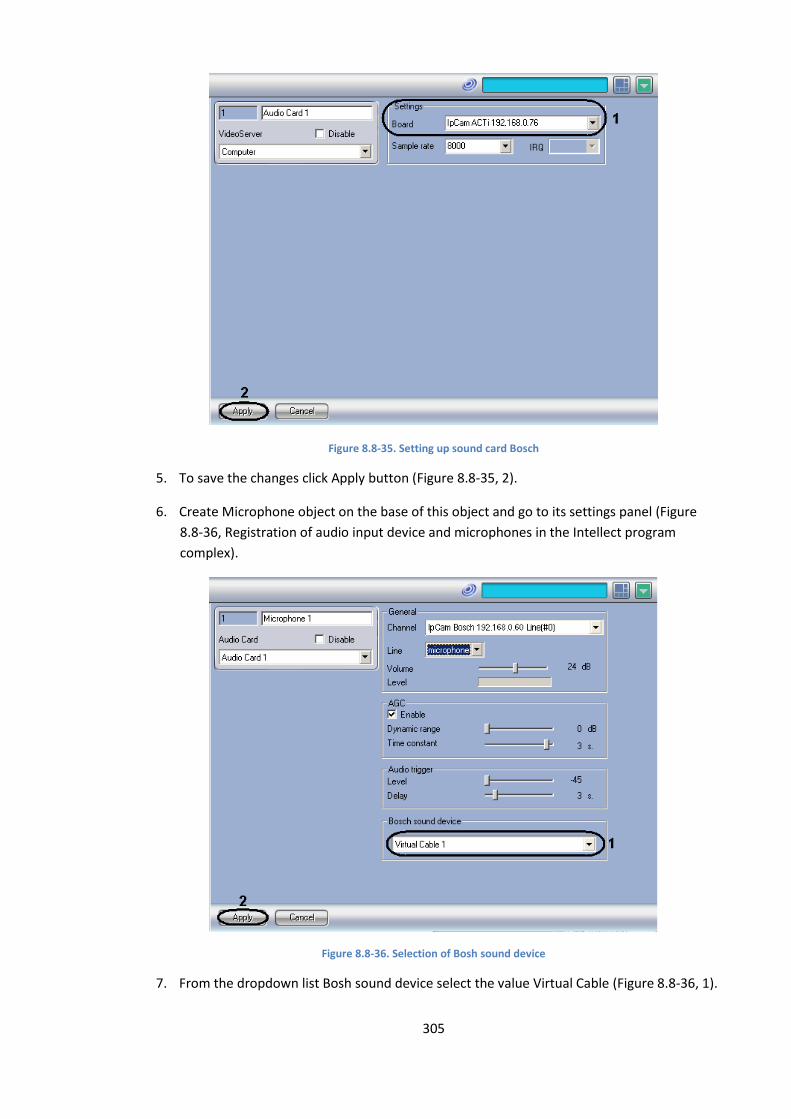
305
Figure 8.8-35. Setting up sound card Bosch
5. To save the changes click Apply button (Figure 8.8-35, 2).
6. Create Microphone object on the base of this object and go to its settings panel (Figure
8.8-36, Registration of audio input device and microphones in the Intellect program
complex).
Figure 8.8-36. Selection of Bosh sound device
7. From the dropdown list Bosh sound device select the value Virtual Cable (Figure 8.8-36, 1).
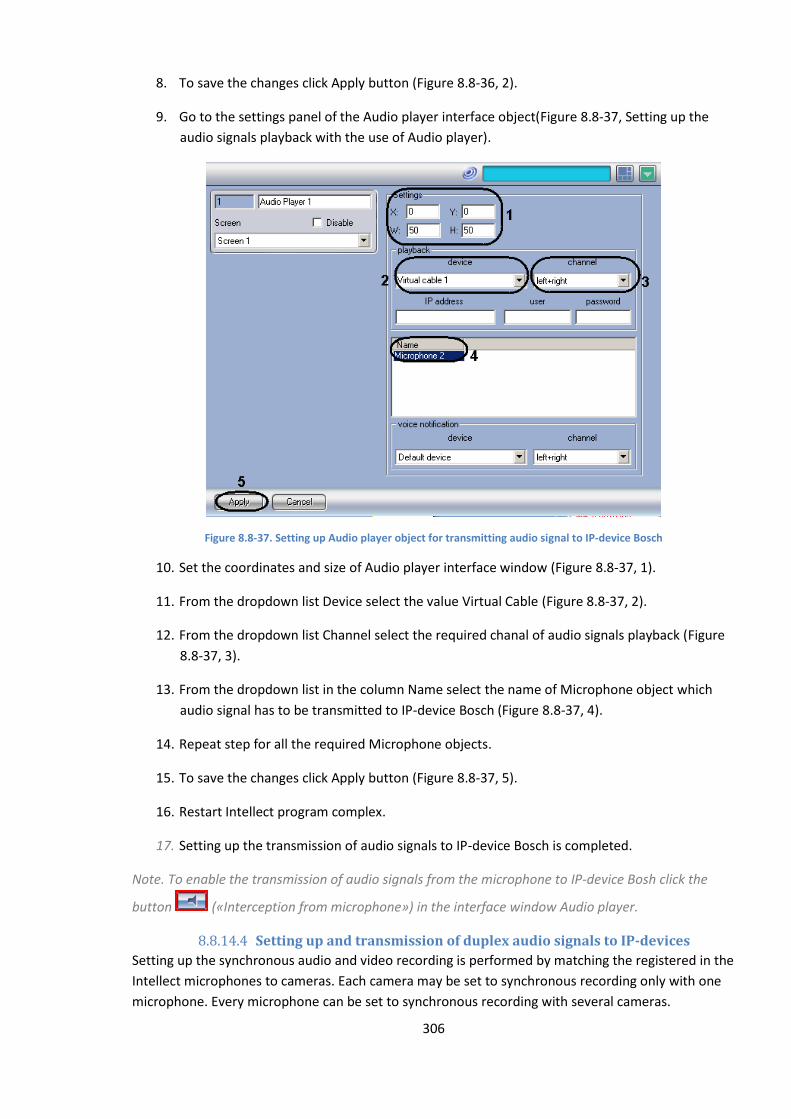
306
8. To save the changes click Apply button (Figure 8.8-36, 2).
9. Go to the settings panel of the Audio player interface object(Figure 8.8-37, Setting up the
audio signals playback with the use of Audio player).
Figure 8.8-37. Setting up Audio player object for transmitting audio signal to IP-device Bosch
10. Set the coordinates and size of Audio player interface window (Figure 8.8-37, 1).
11. From the dropdown list Device select the value Virtual Cable (Figure 8.8-37, 2).
12. From the dropdown list Channel select the required chanal of audio signals playback (Figure
8.8-37, 3).
13. From the dropdown list in the column Name select the name of Microphone object which
audio signal has to be transmitted to IP-device Bosch (Figure 8.8-37, 4).
14. Repeat step for all the required Microphone objects.
15. To save the changes click Apply button (Figure 8.8-37, 5).
16. Restart Intellect program complex.
17. Setting up the transmission of audio signals to IP-device Bosch is completed.
Note. To enable the transmission of audio signals from the microphone to IP-device Bosh click the
button («Interception from microphone») in the interface window Audio player.
8.8.14.4 Setting up and transmission of duplex audio signals to IP-devices
Setting up the synchronous audio and video recording is performed by matching the registered in the
Intellect microphones to cameras. Each camera may be set to synchronous recording only with one
microphone. Every microphone can be set to synchronous recording with several cameras.
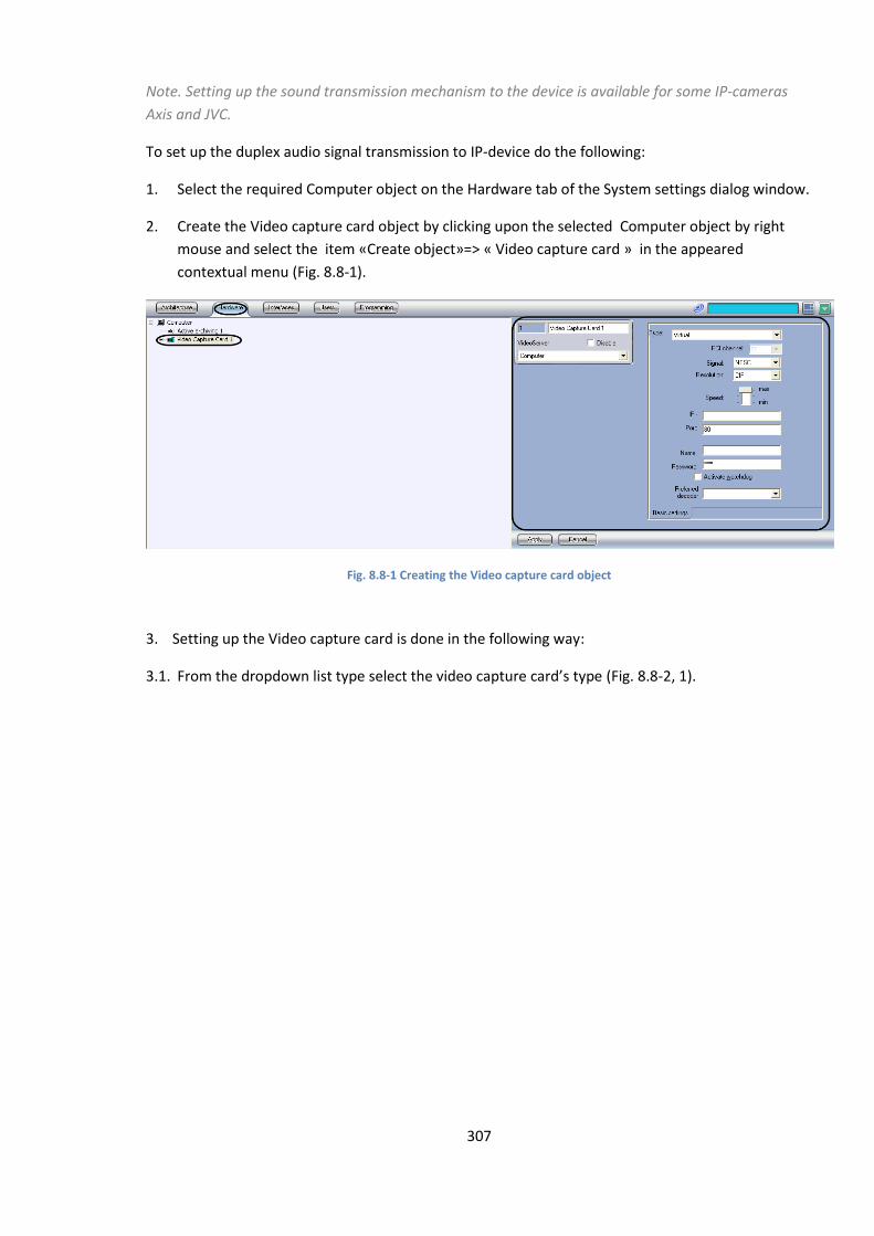
307
Note. Setting up the sound transmission mechanism to the device is available for some IP-cameras
Axis and JVC.
To set up the duplex audio signal transmission to IP-device do the following:
1. Select the required Computer object on the Hardware tab of the System settings dialog window.
2. Create the Video capture card object by clicking upon the selected Computer object by right
mouse and select the item «Create object»=> « Video capture card » in the appeared
contextual menu (Fig. 8.8-1).
Fig. 8.8-1 Creating the Video capture card object
3. Setting up the Video capture card is done in the following way:
3.1. From the dropdown list type select the video capture card’s type (Fig. 8.8-2, 1).
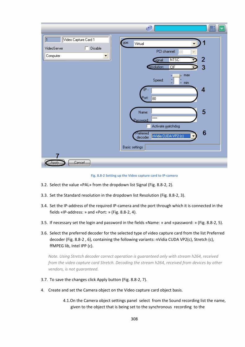
308
Fig. 8.8-2 Setting up the Video capture card to IP-camera
3.2. Select the value «PAL» from the dropdown list Signal (Fig. 8.8-2, 2).
3.3. Set the Standard resolution in the dropdown list Resolution (Fig. 8.8-2, 3).
3.4. Set the IP-address of the required IP-camera and the port through which it is connected in the
fields «IP-address: » and «Port: » (Fig. 8.8-2, 4).
3.5. If necessary set the login and password in the fields «Name: » and «password: » (Fig. 8.8-2, 5).
3.6. Select the preferred decoder for the selected type of video capture card from the list Preferred
decoder (Fig. 8.8-2 , 6), containing the following variants: nVidia CUDA VP2(c), Stretch (c),
ffMPEG lib, Intel IPP (c).
Note. Using Stretch decoder correct operation is guaranteed only with stream h264, received
from the video capture card Stretch. Decoding the stream h264, received from devices by other
vendors, is not guaranteed.
3.7. To save the changes click Apply button (Fig. 8.8-2, 7).
4. Create and set the Camera object on the Video capture card object basis.
4.1. On the Camera object settings panel select from the Sound recording list the name,
given to the object that is being set to the synchronous recording to the
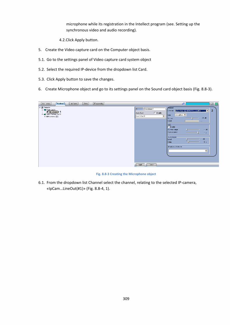
309
microphone while its registration in the Intellect program (see. Setting up the
synchronous video and audio recording).
4.2. Click Apply button.
5. Create the Video capture card on the Computer object basis.
5.1. Go to the settings panel of Video capture card system object
5.2. Select the required IP-device from the dropdown list Card.
5.3. Click Apply button to save the changes.
6. Create Microphone object and go to its settings panel on the Sound card object basis (Fig. 8.8-3).
Fig. 8.8-3 Creating the Microphone object
6.1. From the dropdown list Channel select the channel, relating to the selected IP-camera,
«IpCam…LineOut(#1)» (Fig. 8.8-4, 1).
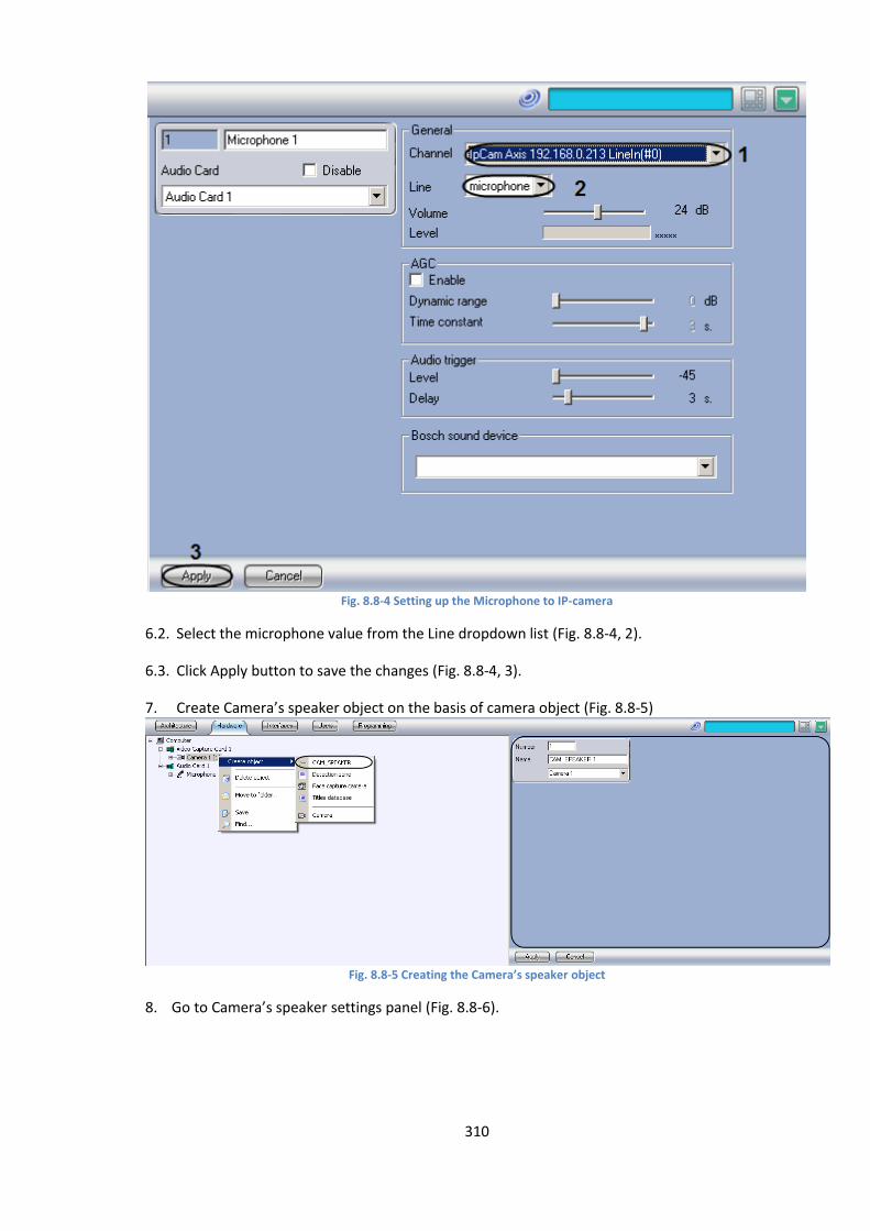
310
Fig. 8.8-4 Setting up the Microphone to IP-camera
6.2. Select the microphone value from the Line dropdown list (Fig. 8.8-4, 2).
6.3. Click Apply button to save the changes (Fig. 8.8-4, 3).
7. Create Camera’s speaker object on the basis of camera object (Fig. 8.8-5)
Fig. 8.8-5 Creating the Camera’s speaker object
8. Go to Camera’s speaker settings panel (Fig. 8.8-6).
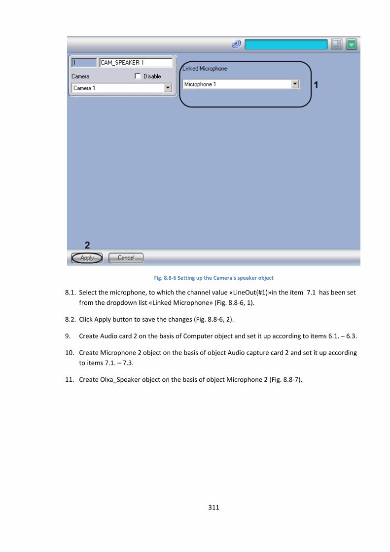
311
Fig. 8.8-6 Setting up the Camera’s speaker object
8.1. Select the microphone, to which the channel value «LineOut(#1)»in the item 7.1 has been set
from the dropdown list «Linked Microphone» (Fig. 8.8-6, 1).
8.2. Click Apply button to save the changes (Fig. 8.8-6, 2).
9. Create Audio card 2 on the basis of Computer object and set it up according to items 6.1. – 6.3.
10. Create Microphone 2 object on the basis of object Audio capture card 2 and set it up according
to items 7.1. – 7.3.
11. Create Olxa_Speaker object on the basis of object Microphone 2 (Fig. 8.8-7).
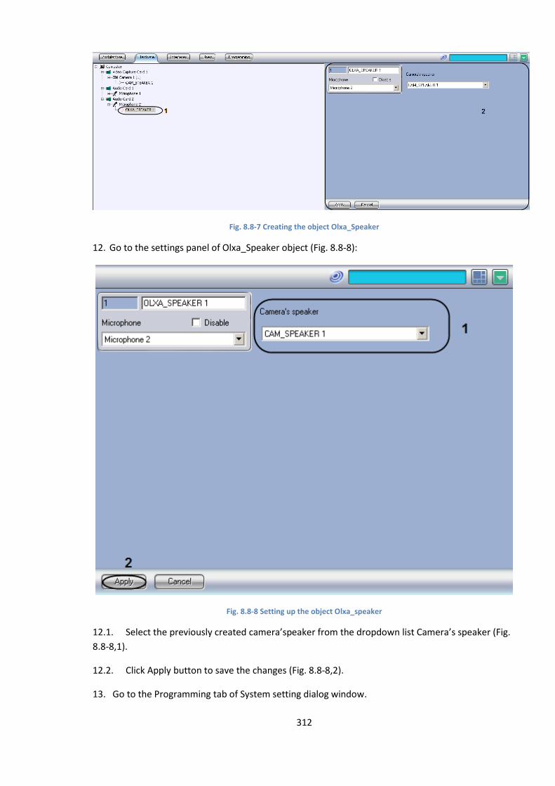
312
Fig. 8.8-7 Creating the object Olxa_Speaker
12. Go to the settings panel of Olxa_Speaker object (Fig. 8.8-8):
Fig. 8.8-8 Setting up the object Olxa_speaker
12.1. Select the previously created camera’speaker from the dropdown list Camera’s speaker (Fig.
8.8-8,1).
12.2. Click Apply button to save the changes (Fig. 8.8-8,2).
13. Go to the Programming tab of System setting dialog window.

313
14. Create Macros object to the connection in Programming tab’s objects tree (Fig. 8.8-9, 1).
Fig. 8.8-9 Creating and setting up the Macros
14.1. Select the object Olxa_Speaker from the list in the Type column (Fig. 8.8-9, 2).
14.2. Select the object number Olxa_Speaker that will be connected on command (Fig. 8.8-9, 3).
14.3. Select the object name (Fig. 8.8-9, 4).
14.4. Select the Connection action (Fig. 8.8-9, 5).
14.5. Click Apply button to save the changes (Fig. 8.8-9, 6).
15. Create Macros object to disconnection in Programming tab’s objects tree
15.1. Select Olxa_Speaker object from the list in the column Type (Fig. 8.8-9, 2).
15.2. Select the object number Olxa_Speaker that will be connected on command.
15.3. Select the object name Olxa_Speaker.
15.4. Select Disconnect action.
15.5. Click Apply button to save the Macro’s object settings.
16. Restart the Intellect PC.
In result the sound on IP-camera will be heard while calling for Connection macros.
8.9 Setup and connection of the special keyboard The “Special keyboard” device is used for efficient control of the main functions of interface objects
in the INTELLECT™ software. The “Special keyboard” allows to control the following system’s main
functions:
1. Video surveillance
2. Audio control
3. Тelemetry
314
4. Events protocol
5. Macros
6. DI/DO
Setting up the interaction of the “Special keyboard” device is performed with several stages:
Connect the “Special keyboard” to the Workplace
Setting up the keyboard layout(programming)
Creation and set up of the “Special keyboard” object in the Intellect program complex
Setting the keyboard layout’s rules of interpretation by Intellect program complex in the ini-
file.
Note. When ini-file is used, that is delivered in the PC Intellect distributive, possibility of control of 16
cameras on one monitor is realized. To get ini-file, that solves more difficult tasks of interface objects
control(e.g. on two or more monitors), one should apply to technical support service of ITV group
company.
INTELLECT™ software supports the following models of the Special keyboard” device:
1. PROMAG KB-840. Is delivered beginning from version 4.7.5 of PC Intellect as a substitute of
PROMAG KB-950A model
2. PROMAG KB-950A. Out of production.
Note. Information about connection and setting up the PROMAG KB-950A model is described in
detailes in the documentation for versions 4.7.4 - 4.7.6 of Intellect program complex-see.
http://www.itv.ru/support/documentation/.
8.9.1 Connecting the special keyboard to the Workstations
To connect the “Special keyboard” to a workstation, follow the sequence:
1. Connection of the special keyboard to the computer PS/2 port.
2. One by one connection of other special keyboard devices to the special keyboard device
(optionally)
3. Connection of standard keyboard to the special keyboard device
Note. When PC Intellect is used , up to ten special keyboard devices may be connected to one
computer.
Standard safety regulations should be sticked to when the special keyboard device is being
connected to the computer.
To connect the special keyboard device to the computer, do the following:
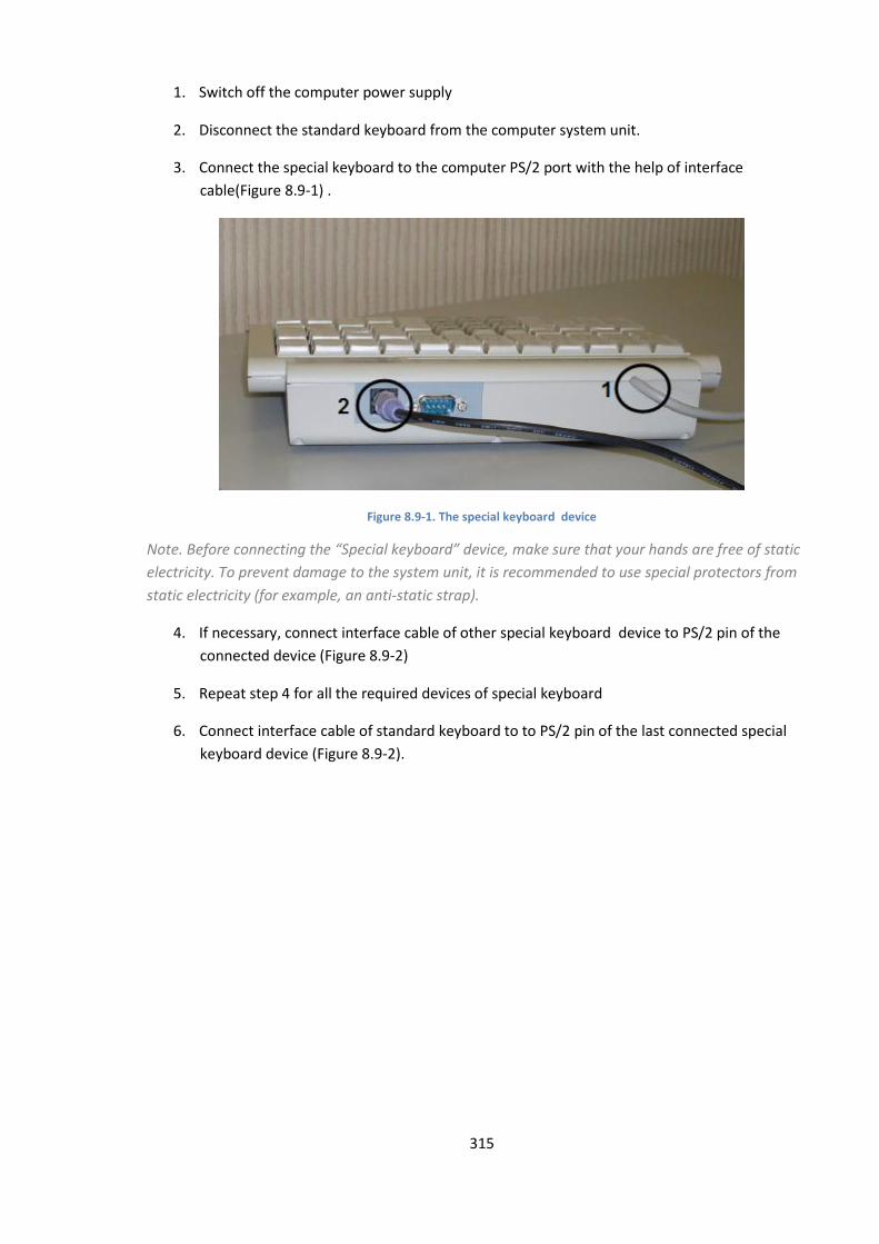
315
1. Switch off the computer power supply
2. Disconnect the standard keyboard from the computer system unit.
3. Connect the special keyboard to the computer PS/2 port with the help of interface
cable(Figure 8.9-1) .
Figure 8.9-1. The special keyboard device
Note. Before connecting the “Special keyboard” device, make sure that your hands are free of static
electricity. To prevent damage to the system unit, it is recommended to use special protectors from
static electricity (for example, an anti-static strap).
4. If necessary, connect interface cable of other special keyboard device to PS/2 pin of the
connected device (Figure 8.9-2)
5. Repeat step 4 for all the required devices of special keyboard
6. Connect interface cable of standard keyboard to to PS/2 pin of the last connected special
keyboard device (Figure 8.9-2).
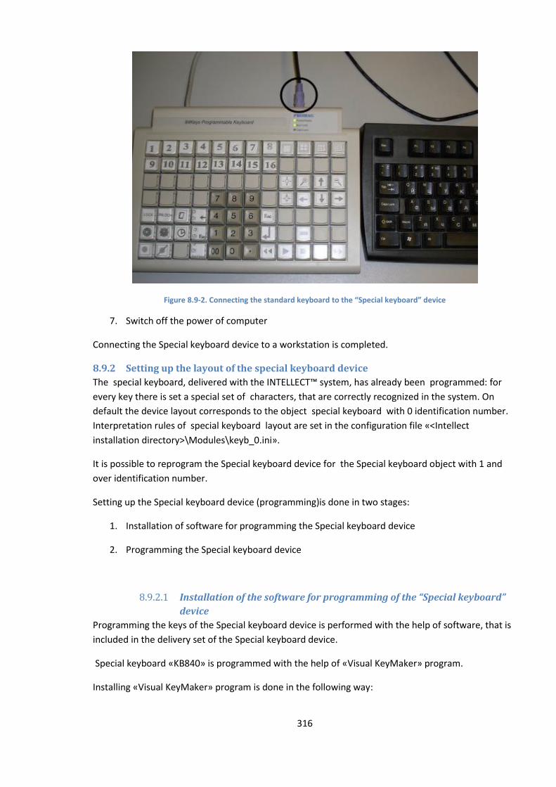
316
Figure 8.9-2. Connecting the standard keyboard to the “Special keyboard” device
7. Switch off the power of computer
Connecting the Special keyboard device to a workstation is completed.
8.9.2 Setting up the layout of the special keyboard device
The special keyboard, delivered with the INTELLECT™ system, has already been programmed: for
every key there is set a special set of characters, that are correctly recognized in the system. On
default the device layout corresponds to the object special keyboard with 0 identification number.
Interpretation rules of special keyboard layout are set in the configuration file «<Intellect
installation directory>\Modules\keyb_0.ini».
It is possible to reprogram the Special keyboard device for the Special keyboard object with 1 and
over identification number.
Setting up the Special keyboard device (programming)is done in two stages:
1. Installation of software for programming the Special keyboard device
2. Programming the Special keyboard device
8.9.2.1 Installation of the software for programming of the “Special keyboard”
device
Programming the keys of the Special keyboard device is performed with the help of software, that is
included in the delivery set of the Special keyboard device.
Special keyboard «KB840» is programmed with the help of «Visual KeyMaker» program.
Installing «Visual KeyMaker» program is done in the following way:
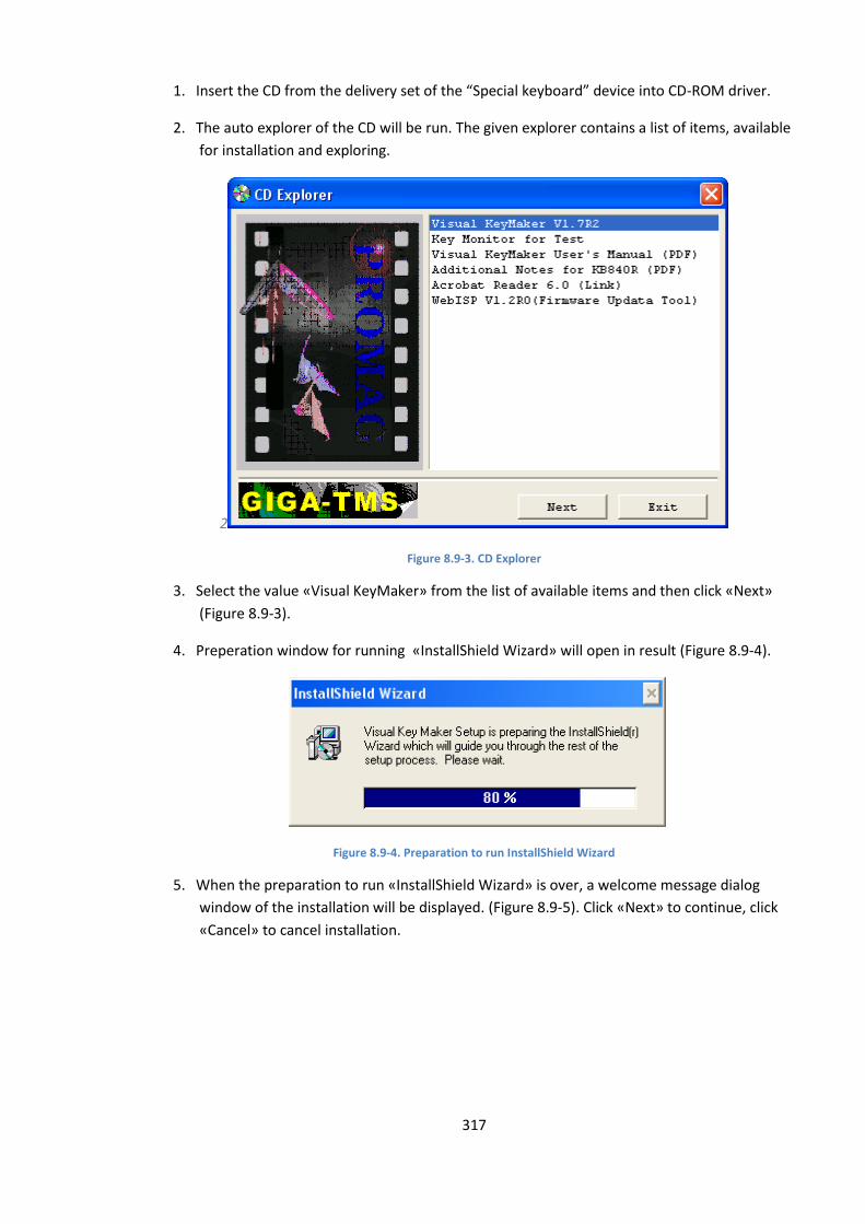
317
1. Insert the CD from the delivery set of the “Special keyboard” device into CD-ROM driver.
2. The auto explorer of the CD will be run. The given explorer contains a list of items, available
for installation and exploring.
2
Figure 8.9-3. CD Explorer
3. Select the value «Visual KeyMaker» from the list of available items and then click «Next»
(Figure 8.9-3).
4. Preperation window for running «InstallShield Wizard» will open in result (Figure 8.9-4).
Figure 8.9-4. Preparation to run InstallShield Wizard
5. When the preparation to run «InstallShield Wizard» is over, a welcome message dialog
window of the installation will be displayed. (Figure 8.9-5). Click «Next» to continue, click
«Cancel» to cancel installation.
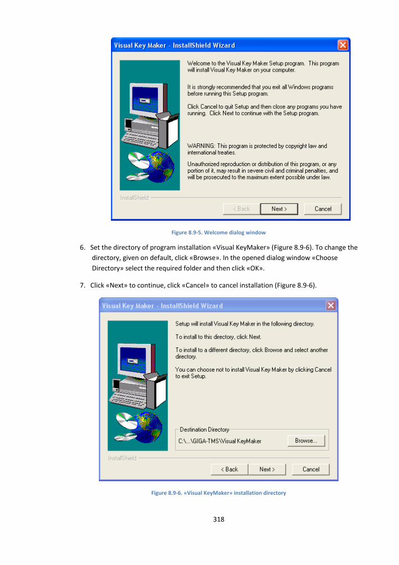
318
Figure 8.9-5. Welcome dialog window
6. Set the directory of program installation «Visual KeyMaker» (Figure 8.9-6). To change the
directory, given on default, click «Browse». In the opened dialog window «Choose
Directory» select the required folder and then click «OK».
7. Click «Next» to continue, click «Cancel» to cancel installation (Figure 8.9-6).
Figure 8.9-6. «Visual KeyMaker» installation directory
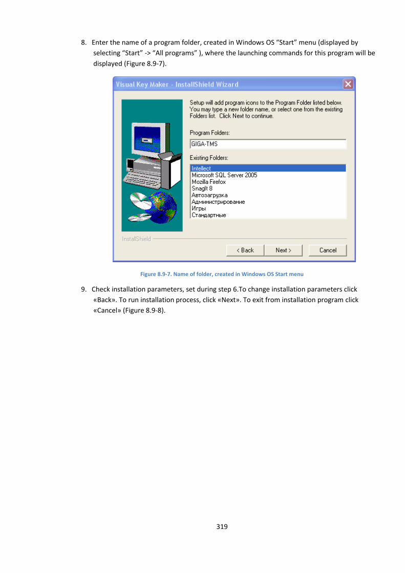
319
8. Enter the name of a program folder, created in Windows OS “Start” menu (displayed by
selecting “Start” -> “All programs” ), where the launching commands for this program will be
displayed (Figure 8.9-7).
Figure 8.9-7. Name of folder, created in Windows OS Start menu
9. Check installation parameters, set during step 6.To change installation parameters click
«Back». To run installation process, click «Next». To exit from installation program click
«Cancel» (Figure 8.9-8).
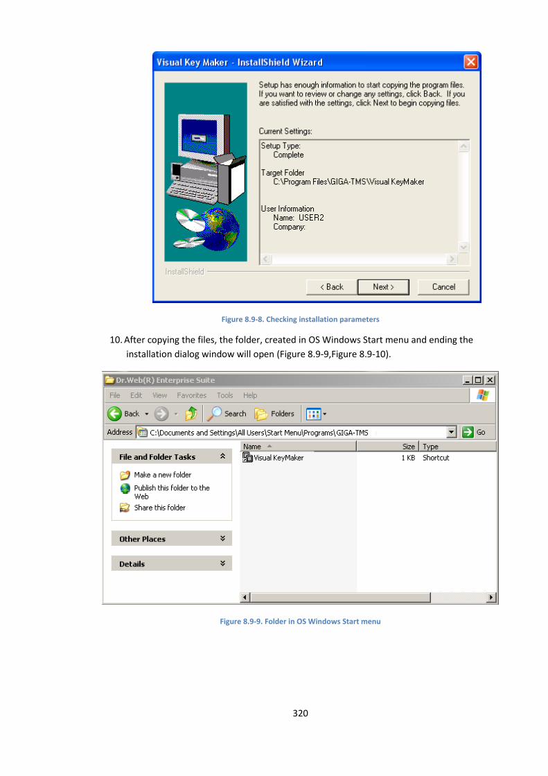
320
Figure 8.9-8. Checking installation parameters
10. After copying the files, the folder, created in OS Windows Start menu and ending the
installation dialog window will open (Figure 8.9-9,Figure 8.9-10).
Figure 8.9-9. Folder in OS Windows Start menu
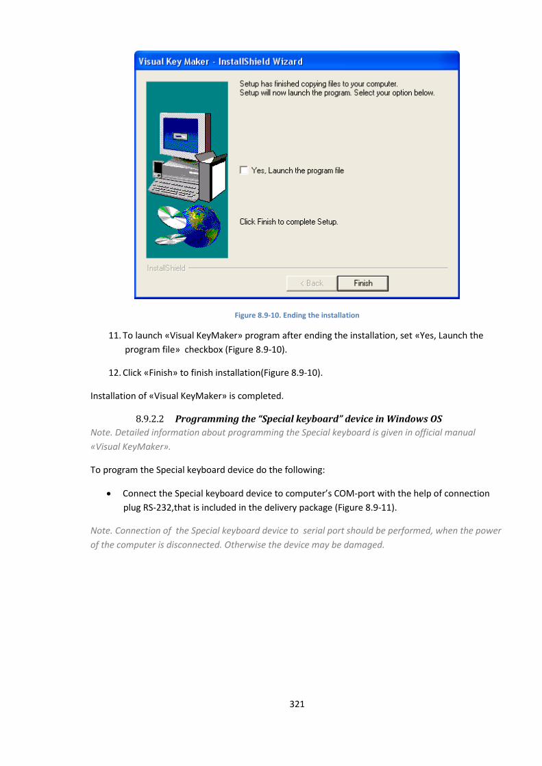
321
Figure 8.9-10. Ending the installation
11. To launch «Visual KeyMaker» program after ending the installation, set «Yes, Launch the
program file» checkbox (Figure 8.9-10).
12. Click «Finish» to finish installation(Figure 8.9-10).
Installation of «Visual KeyMaker» is completed.
8.9.2.2 Programming the “Special keyboard” device in Windows OS
Note. Detailed information about programming the Special keyboard is given in official manual
«Visual KeyMaker».
To program the Special keyboard device do the following:
Connect the Special keyboard device to computer’s COM-port with the help of connection
plug RS-232,that is included in the delivery package (Figure 8.9-11).
Note. Connection of the Special keyboard device to serial port should be performed, when the power
of the computer is disconnected. Otherwise the device may be damaged.
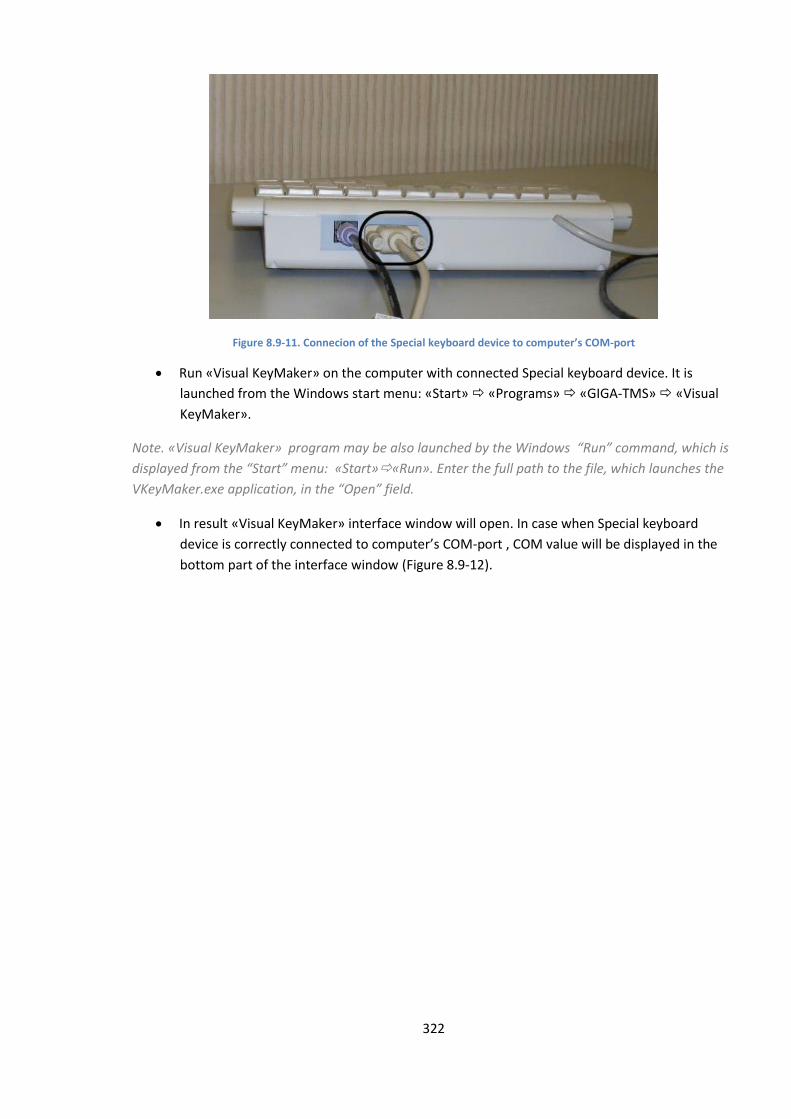
322
Figure 8.9-11. Connecion of the Special keyboard device to computer’s COM-port
Run «Visual KeyMaker» on the computer with connected Special keyboard device. It is
launched from the Windows start menu: «Start» «Programs» «GIGA-TMS» «Visual
KeyMaker».
Note. «Visual KeyMaker» program may be also launched by the Windows “Run” command, which is
displayed from the “Start” menu: «Start»«Run». Enter the full path to the file, which launches the
VKeyMaker.exe application, in the “Open” field.
In result «Visual KeyMaker» interface window will open. In case when Special keyboard
device is correctly connected to computer’s COM-port , COM value will be displayed in the
bottom part of the interface window (Figure 8.9-12).
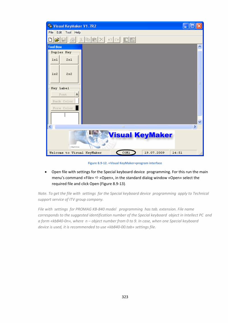
323
Figure 8.9-12. «Visual KeyMaker»program interface
Open file with settings for the Special keyboard device programming. For this run the main
menu’s command «File» «Open», in the standard dialog window «Open» select the
required file and click Open (Figure 8.9-13).
Note. To get the file with settings for the Special keyboard device programming apply to Technical
support service of ITV group company.
File with settings for PROMAG KB-840 model programming has tab. extension. File name
corresponds to the suggested identification number of the Special keyboard object in Intellect PC and
a form «kb840-0n», where n – object number from 0 to 9. In case, when one Special keyboard
device is used, it is recommended to use «kb840-00.tab» settings file.
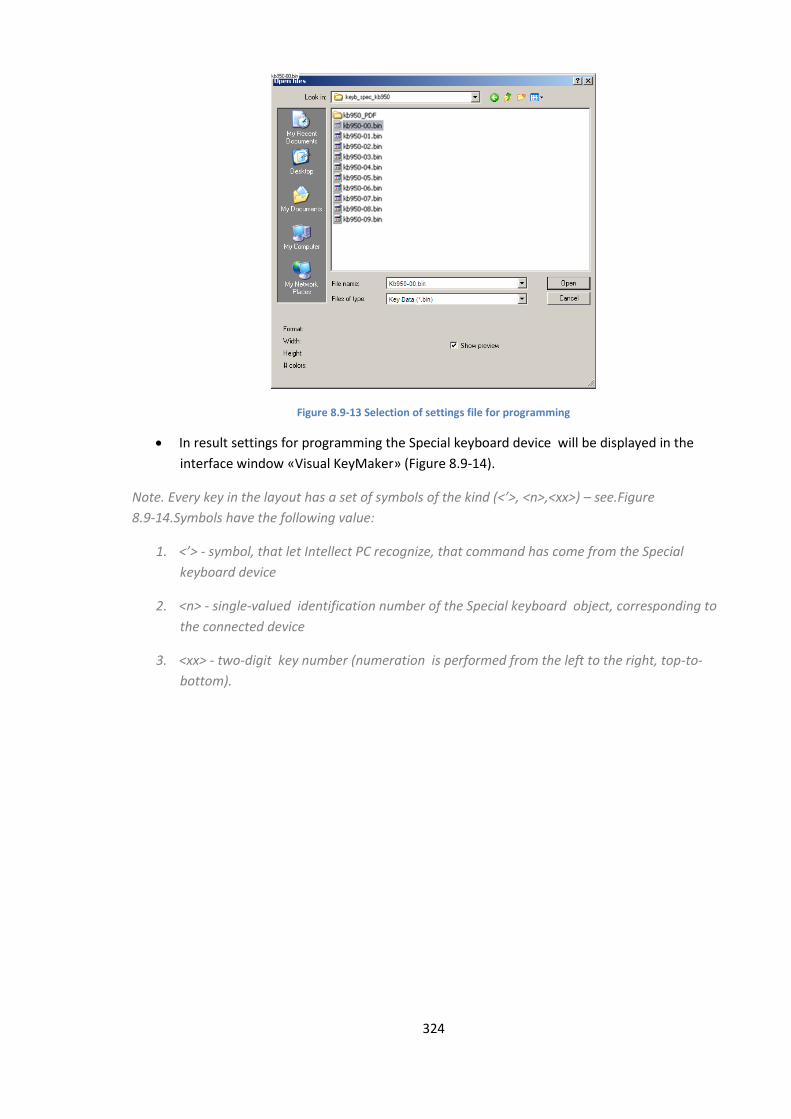
324
Figure 8.9-13 Selection of settings file for programming
In result settings for programming the Special keyboard device will be displayed in the
interface window «Visual KeyMaker» (Figure 8.9-14).
Note. Every key in the layout has a set of symbols of the kind (<’>, <n>,<xx>) – see.Figure
8.9-14.Symbols have the following value:
1. <’> - symbol, that let Intellect PC recognize, that command has come from the Special
keyboard device
2. <n> - single-valued identification number of the Special keyboard object, corresponding to
the connected device
3. <xx> - two-digit key number (numeration is performed from the left to the right, top-to-
bottom).
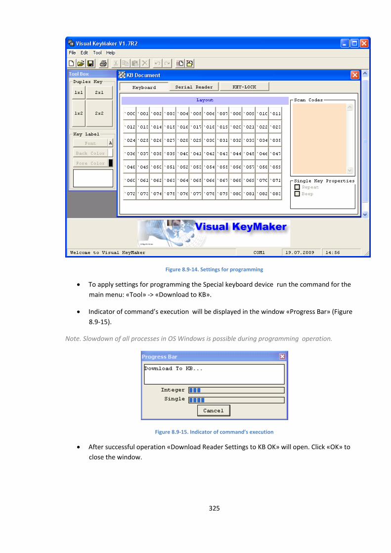
325
Figure 8.9-14. Settings for programming
To apply settings for programming the Special keyboard device run the command for the
main menu: «Tool» -> «Download to KB».
Indicator of command’s execution will be displayed in the window «Progress Bar» (Figure
8.9-15).
Note. Slowdown of all processes in OS Windows is possible during programming operation.
Figure 8.9-15. Indicator of command’s execution
After successful operation «Download Reader Settings to KB OK» will open. Click «OK» to
close the window.
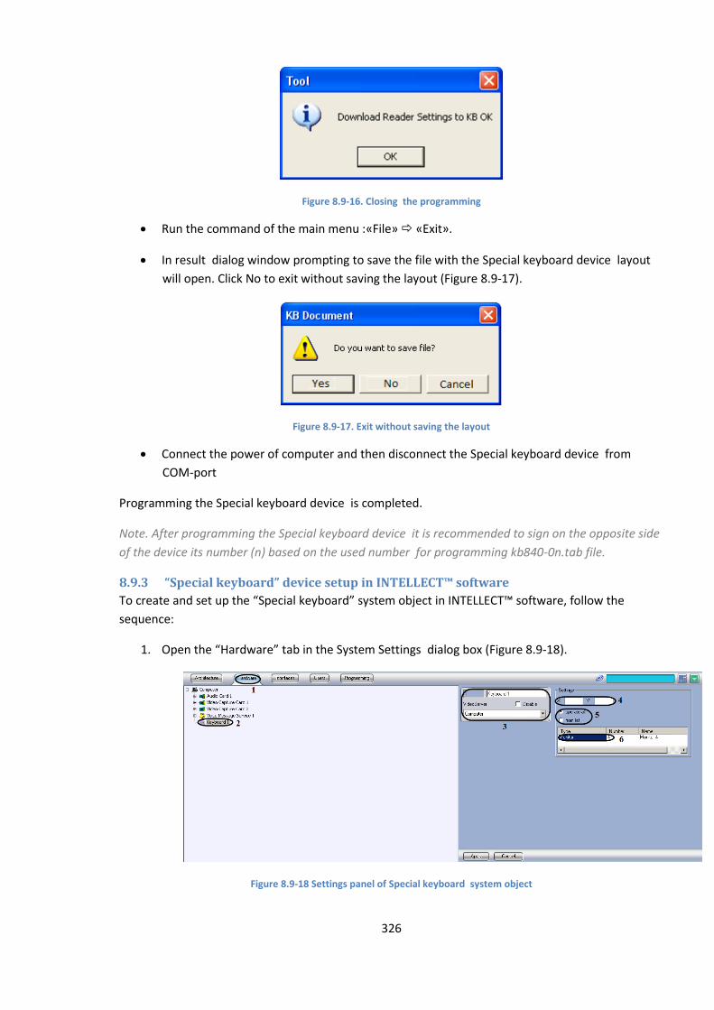
326
Figure 8.9-16. Closing the programming
Run the command of the main menu :«File» «Exit».
In result dialog window prompting to save the file with the Special keyboard device layout
will open. Click No to exit without saving the layout (Figure 8.9-17).
Figure 8.9-17. Exit without saving the layout
Connect the power of computer and then disconnect the Special keyboard device from
COM-port
Programming the Special keyboard device is completed.
Note. After programming the Special keyboard device it is recommended to sign on the opposite side
of the device its number (n) based on the used number for programming kb840-0n.tab file.
8.9.3 “Special keyboard” device setup in INTELLECT™ software
To create and set up the “Special keyboard” system object in INTELLECT™ software, follow the
sequence:
1. Open the “Hardware” tab in the System Settings dialog box (Figure 8.9-18).
Figure 8.9-18 Settings panel of Special keyboard system object
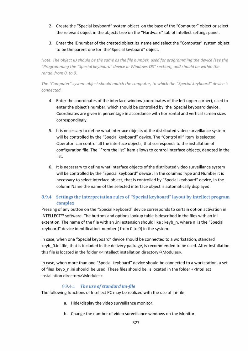
327
2. Create the “Special keyboard” system object on the base of the “Computer” object or select
the relevant object in the objects tree on the “Hardware” tab of Intellect settings panel.
3. Enter the IDnumber of the created object,its name and select the “Computer” system object
to be the parent one for the“Special keyboard” object.
Note. The object ID should be the same as the file number, used for programming the device (see the
“Programming the “Special keyboard” device in Windows OS” section), and should be within the
range from 0 to 9.
The “Computer” system object should match the computer, to which the “Special keyboard” device is
connected.
4. Enter the coordinates of the interface window(coordinates of the left upper corner), used to
enter the object’s number, which should be controlled by the Special keyboard device.
Coordinates are given in percentage in accordance with horizontal and vertical screen sizes
correspondingly.
5. It is necessary to define what interface objects of the distributed video surveillance system
will be controlled by the “Special keyboard” device. The “Control all” item is selected,
Operator can control all the interface objects, that corresponds to the installation of
configuration file. The “From the list” item allows to control interface objects, denoted in the
list.
6. It is necessary to define what interface objects of the distributed video surveillance system
will be controlled by the “Special keyboard” device . In the columns Type and Number it is
necessary to select interface object, that is controlled by “Special keyboard” device, in the
column Name the name of the selected interface object is automatically displayed.
8.9.4 Settings the interpretation rules of “Special keyboard” layout by Intellect program
complex
Pressing of any button on the “Special keyboard” device corresponds to certain option activation in
INTELLECT™ software. The buttons and options lookup table is described in the files with an ini
extention. The name of the file with an .ini extension should like : keyb_n, where n is the “Special
keyboard” device identification number ( from 0 to 9) in the system.
In case, when one “Special keyboard” device should be connected to a workstation, standard
keyb_0.ini file, that is included in the delivery package, is recommended to be used. After installation
this file is located in the folder «<Intellect installation directory>\Modules».
In case, when more than one “Special keyboard” device should be connected to a workstation, a set
of files keyb_n.ini should be used. These files should be is located in the folder «<Intellect
installation directory>\Modules».
8.9.4.1 The use of standard ini-file
The following functions of Intellect PC may be realized with the use of ini-file:
a. Hide/display the video surveillance monitor.
b. Change the number of video surveillance windows on the Monitor.
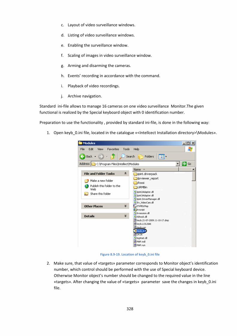
328
c. Layout of video surveillance windows.
d. Listing of video surveillance windows.
e. Enabling the surveillance window.
f. Scaling of images in video surveillance window.
g. Arming and disarming the cameras.
h. Events’ recording in accordance with the command.
i. Playback of video recordings.
j. Archive navigation.
Standard ini-file allows to manage 16 cameras on one video surveillance Monitor.The given
functional is realized by the Special keyboard object with 0 identification number.
Preparation to use the functionality , provided by standard ini-file, is done in the following way:
1. Open keyb_0.ini file, located in the catalogue «<Intellcect Installation directory>\Modules».
Figure 8.9-19. Location of keyb_0.ini file
2. Make sure, that value of «targets» parameter corresponds to Monitor object’s identification
number, which control should be performed with the use of Special keyboard device.
Otherwise Monitor object’s number should be changed to the required value in the line
«targets». After changing the value of «targets» parameter save the changes in keyb_0.ini
file.
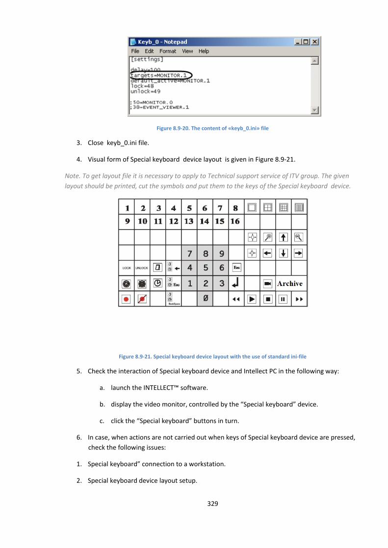
329
Figure 8.9-20. The content of «keyb_0.ini» file
3. Close keyb_0.ini file.
4. Visual form of Special keyboard device layout is given in Figure 8.9-21.
Note. To get layout file it is necessary to apply to Technical support service of ITV group. The given
layout should be printed, cut the symbols and put them to the keys of the Special keyboard device.
Figure 8.9-21. Special keyboard device layout with the use of standard ini-file
5. Check the interaction of Special keyboard device and Intellect PC in the following way:
a. launch the INTELLECT™ software.
b. display the video monitor, controlled by the “Special keyboard” device.
c. click the “Special keyboard” buttons in turn.
6. In case, when actions are not carried out when keys of Special keyboard device are pressed,
check the following issues:
1. Special keyboard” connection to a workstation.
2. Special keyboard device layout setup.
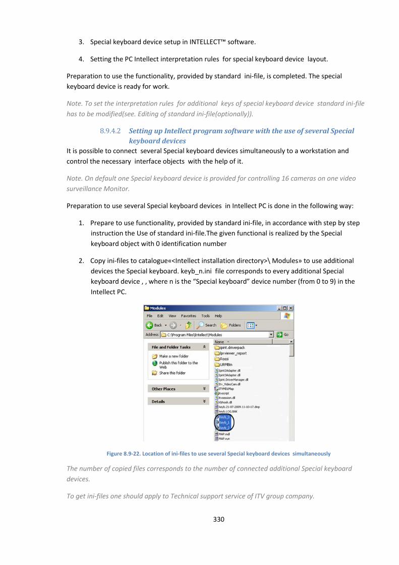
330
3. Special keyboard device setup in INTELLECT™ software.
4. Setting the PC Intellect interpretation rules for special keyboard device layout.
Preparation to use the functionality, provided by standard ini-file, is completed. The special
keyboard device is ready for work.
Note. To set the interpretation rules for additional keys of special keyboard device standard ini-file
has to be modified(see. Editing of standard ini-file(optionally)).
8.9.4.2 Setting up Intellect program software with the use of several Special
keyboard devices
It is possible to connect several Special keyboard devices simultaneously to a workstation and
control the necessary interface objects with the help of it.
Note. On default one Special keyboard device is provided for controlling 16 cameras on one video
surveillance Monitor.
Preparation to use several Special keyboard devices in Intellect PC is done in the following way:
1. Prepare to use functionality, provided by standard ini-file, in accordance with step by step
instruction the Use of standard ini-file.The given functional is realized by the Special
keyboard object with 0 identification number
2. Copy ini-files to catalogue«<Intellect installation directory>\ Modules» to use additional
devices the Special keyboard. keyb_n.ini file corresponds to every additional Special
keyboard device , , where n is the “Special keyboard” device number (from 0 to 9) in the
Intellect PC.
Figure 8.9-22. Location of ini-files to use several Special keyboard devices simultaneously
The number of copied files corresponds to the number of connected additional Special keyboard
devices.
To get ini-files one should apply to Technical support service of ITV group company.
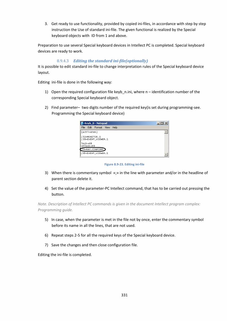
331
3. Get ready to use functionality, provided by copied ini-files, in accordance with step by step
instruction the Use of standard ini-file. The given functional is realized by the Special
keyboard objects with ID from 1 and above.
Preparation to use several Special keyboard devices in Intellect PC is completed. Special keyboard
devices are ready to work.
8.9.4.3 Editing the standard ini-file(optionally)
It is possible to edit standard ini-file to change interpretation rules of the Special keyboard device
layout.
Editing ini-file is done in the following way:
1) Open the required configuration file keyb_n.ini, where n – identification number of the
corresponding Special keyboard object.
2) Find parameter– two digits number of the required key(is set during programming-see.
Programming the Special keyboard device)
Figure 8.9-23. Editing ini-file
3) When there is commentary symbol «;» in the line with parameter and/or in the headline of
parent section delete it.
4) Set the value of the parameter-PC Intellect command, that has to be carried out pressing the
button.
Note. Description of Intellect PC commands is given in the document Intellect program complex:
Programming guide.
5) In case, when the parameter is met in the file not by once, enter the commentary symbol
before its name in all the lines, that are not used.
6) Repeat steps 2-5 for all the required keys of the Special keyboard device.
7) Save the changes and then close configuration file.
Editing the ini-file is completed.
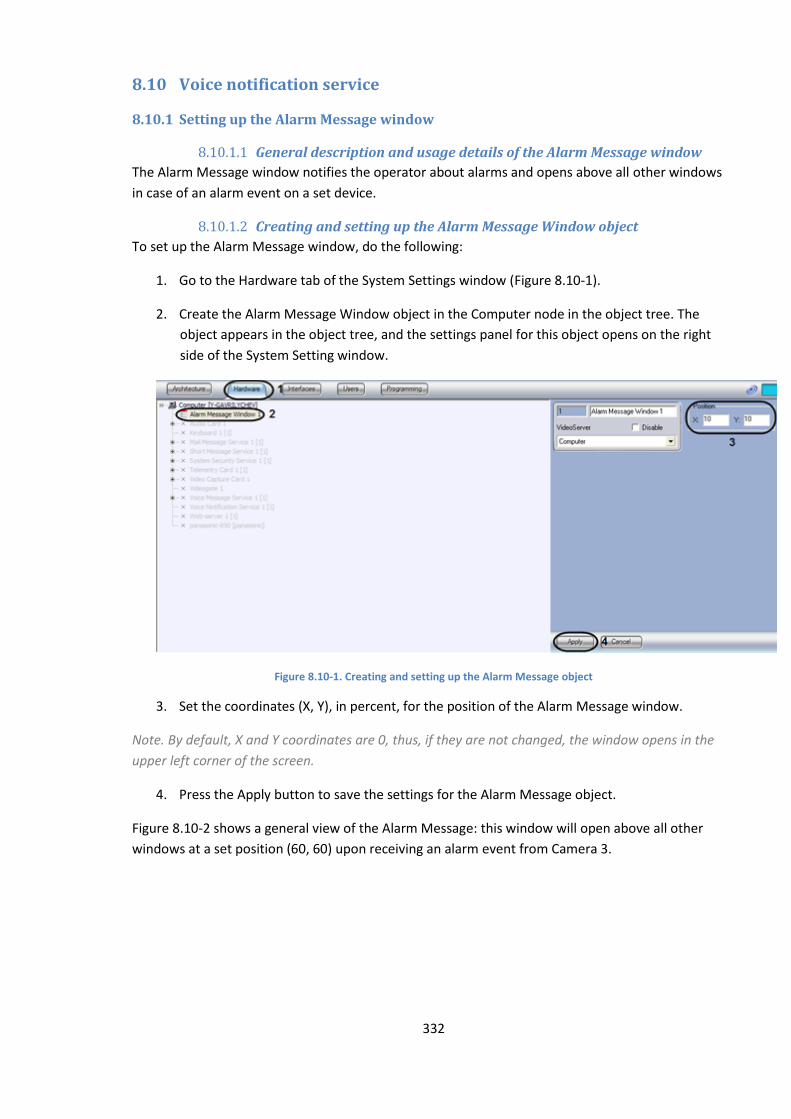
332
8.10 Voice notification service
8.10.1 Setting up the Alarm Message window
8.10.1.1 General description and usage details of the Alarm Message window
The Alarm Message window notifies the operator about alarms and opens above all other windows
in case of an alarm event on a set device.
8.10.1.2 Creating and setting up the Alarm Message Window object
To set up the Alarm Message window, do the following:
1. Go to the Hardware tab of the System Settings window (Figure 8.10-1).
2. Create the Alarm Message Window object in the Computer node in the object tree. The
object appears in the object tree, and the settings panel for this object opens on the right
side of the System Setting window.
Figure 8.10-1. Creating and setting up the Alarm Message object
3. Set the coordinates (X, Y), in percent, for the position of the Alarm Message window.
Note. By default, X and Y coordinates are 0, thus, if they are not changed, the window opens in the
upper left corner of the screen.
4. Press the Apply button to save the settings for the Alarm Message object.
Figure 8.10-2 shows a general view of the Alarm Message: this window will open above all other
windows at a set position (60, 60) upon receiving an alarm event from Camera 3.
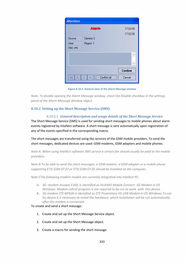
333
Figure 8.10-2. General view of the Alarm Message window
Note. To disable opening the Alarm Message window, check the Disable checkbox in the settings
panel of the Alarm Message Window object.
8.10.2 Setting up the Short Message Service (SMS)
8.10.2.1 General description and usage details of the Short Message Service
The Short Message Service (SMS) is used for sending short messages to mobile phones about alarm
events registered by Intellect software. A short message is sent automatically upon registration of
any of the events specified in the corresponding macro.
The short messages are transferred using the services of the GSM mobile providers. To send the
short messages, dedicated devices are used: GSM modems, GSM adapters and mobile phones.
Note A. When using Intellect software SMS service a certain fee should usually be paid to the mobile
providers.
Note B.To be able to send the short messages, a GSM modem, a GSM adapter or a mobile phone
supporting ETSI GSM 07.07 or ETSI GSM 07.05 should be installed on the computer.
Note CThe following modem models are currently integrated into Intellect PC:
A. 3G -modem Huawei E160, is identified as HUAWEI Mobile Connect -3G Modem in OS Windows. Modem coltrol program is not required to be run to work with this device.
B. 3G-modem ZTE MF626 is identified as ZTE Proprietary HS-USB Modem in OS Windows.To use his device it is necessary to install the hardware, which installation will be run automatically after the modem is connected.
To create and send a short message:
1. Create and set up the Short Message Service object.
2. Create and set up the Short Message object.
3. Create a macro for sending the short message.
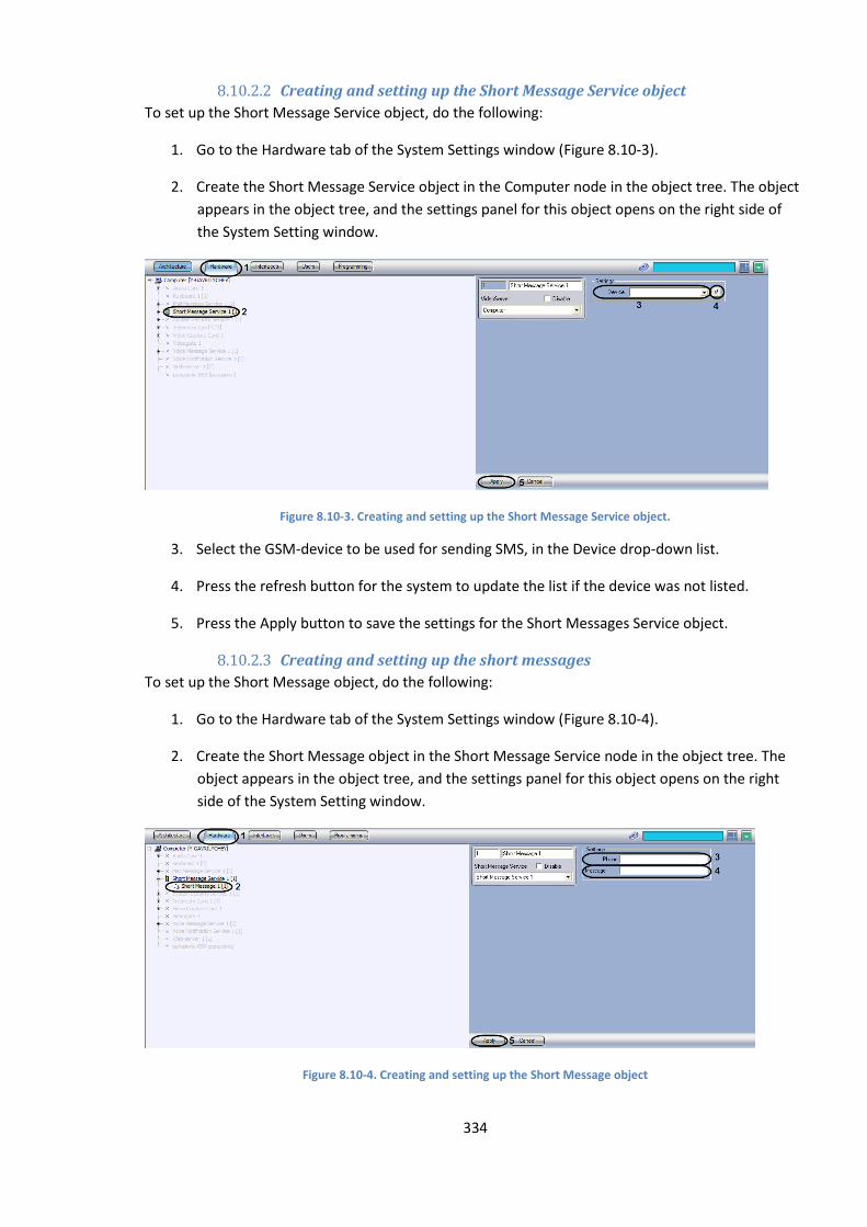
334
8.10.2.2 Creating and setting up the Short Message Service object
To set up the Short Message Service object, do the following:
1. Go to the Hardware tab of the System Settings window (Figure 8.10-3).
2. Create the Short Message Service object in the Computer node in the object tree. The object
appears in the object tree, and the settings panel for this object opens on the right side of
the System Setting window.
Figure 8.10-3. Creating and setting up the Short Message Service object.
3. Select the GSM-device to be used for sending SMS, in the Device drop-down list.
4. Press the refresh button for the system to update the list if the device was not listed.
5. Press the Apply button to save the settings for the Short Messages Service object.
8.10.2.3 Creating and setting up the short messages
To set up the Short Message object, do the following:
1. Go to the Hardware tab of the System Settings window (Figure 8.10-4).
2. Create the Short Message object in the Short Message Service node in the object tree. The
object appears in the object tree, and the settings panel for this object opens on the right
side of the System Setting window.
Figure 8.10-4. Creating and setting up the Short Message object
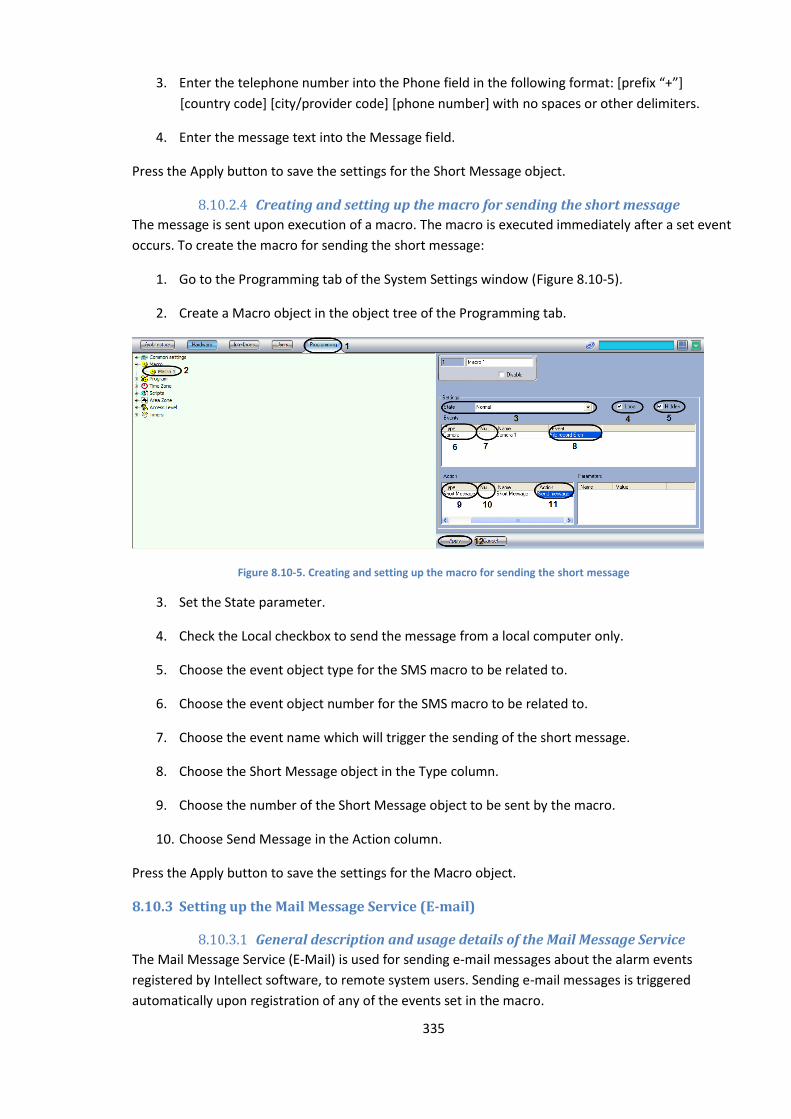
335
3. Enter the telephone number into the Phone field in the following format: *prefix “+”+
[country code] [city/provider code] [phone number] with no spaces or other delimiters.
4. Enter the message text into the Message field.
Press the Apply button to save the settings for the Short Message object.
8.10.2.4 Creating and setting up the macro for sending the short message
The message is sent upon execution of a macro. The macro is executed immediately after a set event
occurs. To create the macro for sending the short message:
1. Go to the Programming tab of the System Settings window (Figure 8.10-5).
2. Create a Macro object in the object tree of the Programming tab.
Figure 8.10-5. Creating and setting up the macro for sending the short message
3. Set the State parameter.
4. Check the Local checkbox to send the message from a local computer only.
5. Choose the event object type for the SMS macro to be related to.
6. Choose the event object number for the SMS macro to be related to.
7. Choose the event name which will trigger the sending of the short message.
8. Choose the Short Message object in the Type column.
9. Choose the number of the Short Message object to be sent by the macro.
10. Choose Send Message in the Action column.
Press the Apply button to save the settings for the Macro object.
8.10.3 Setting up the Mail Message Service (E-mail)
8.10.3.1 General description and usage details of the Mail Message Service
The Mail Message Service (E-Mail) is used for sending e-mail messages about the alarm events
registered by Intellect software, to remote system users. Sending e-mail messages is triggered
automatically upon registration of any of the events set in the macro.
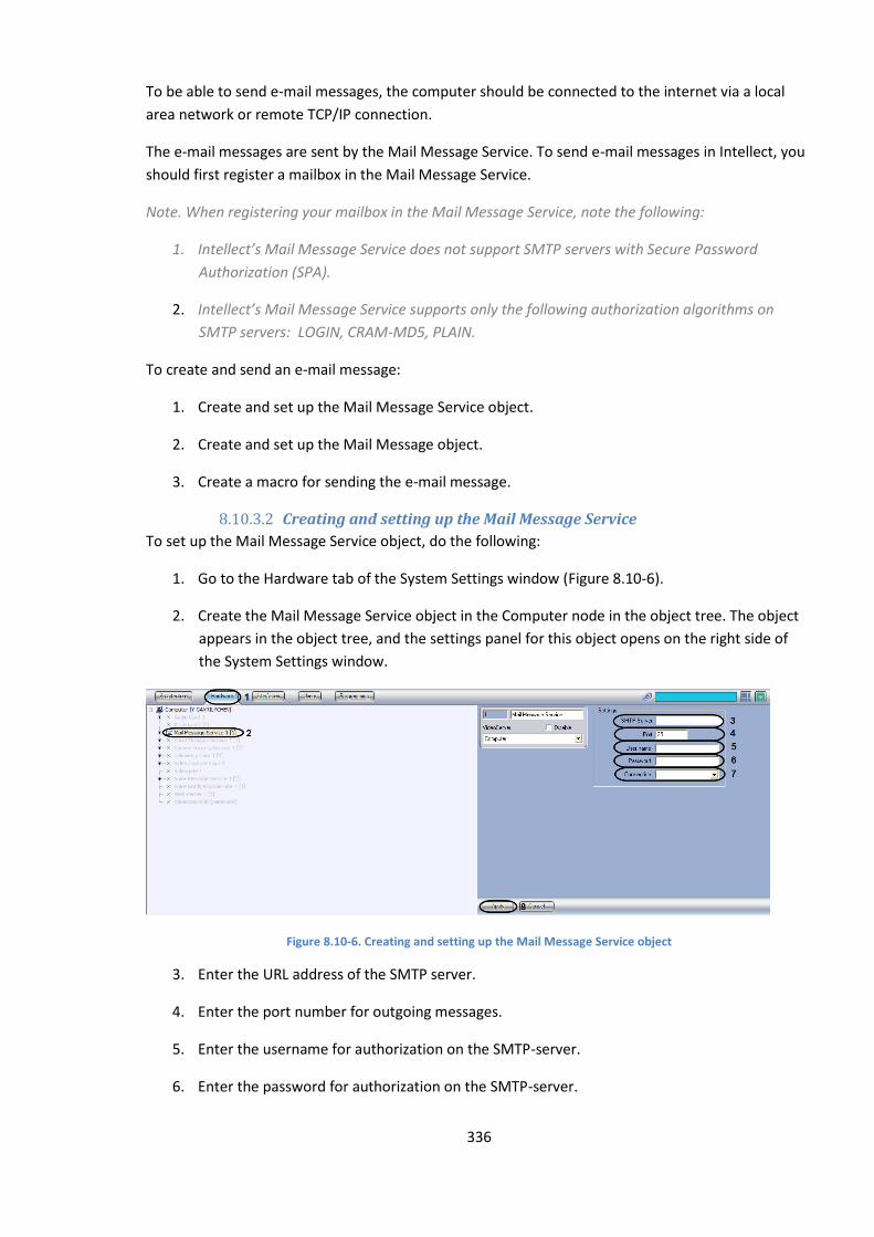
336
To be able to send e-mail messages, the computer should be connected to the internet via a local
area network or remote TCP/IP connection.
The e-mail messages are sent by the Mail Message Service. To send e-mail messages in Intellect, you
should first register a mailbox in the Mail Message Service.
Note. When registering your mailbox in the Mail Message Service, note the following:
1. Intellect’s Mail Message Service does not support SMTP servers with Secure Password
Authorization (SPA).
2. Intellect’s Mail Message Service supports only the following authorization algorithms on
SMTP servers: LOGIN, CRAM-MD5, PLAIN.
To create and send an e-mail message:
1. Create and set up the Mail Message Service object.
2. Create and set up the Mail Message object.
3. Create a macro for sending the e-mail message.
8.10.3.2 Creating and setting up the Mail Message Service
To set up the Mail Message Service object, do the following:
1. Go to the Hardware tab of the System Settings window (Figure 8.10-6).
2. Create the Mail Message Service object in the Computer node in the object tree. The object
appears in the object tree, and the settings panel for this object opens on the right side of
the System Settings window.
Figure 8.10-6. Creating and setting up the Mail Message Service object
3. Enter the URL address of the SMTP server.
4. Enter the port number for outgoing messages.
5. Enter the username for authorization on the SMTP-server.
6. Enter the password for authorization on the SMTP-server.
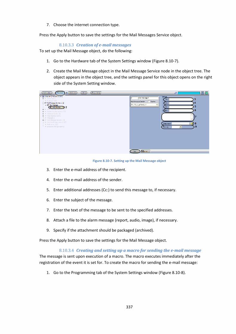
337
7. Choose the internet connection type.
Press the Apply button to save the settings for the Mail Messages Service object.
8.10.3.3 Creation of e-mail messages
To set up the Mail Message object, do the following:
1. Go to the Hardware tab of the System Settings window (Figure 8.10-7).
2. Create the Mail Message object in the Mail Message Service node in the object tree. The
object appears in the object tree, and the settings panel for this object opens on the right
side of the System Setting window.
Figure 8.10-7. Setting up the Mail Message object
3. Enter the e-mail address of the recipient.
4. Enter the e-mail address of the sender.
5. Enter additional addresses (Cc:) to send this message to, if necessary.
6. Enter the subject of the message.
7. Enter the text of the message to be sent to the specified addresses.
8. Attach a file to the alarm message (report, audio, image), if necessary.
9. Specify if the attachment should be packaged (archived).
Press the Apply button to save the settings for the Mail Message object.
8.10.3.4 Creating and setting up a macro for sending the e-mail message
The message is sent upon execution of a macro. The macro executes immediately after the
registration of the event it is set for. To create the macro for sending the e-mail message:
1. Go to the Programming tab of the System Settings window (Figure 8.10-8).
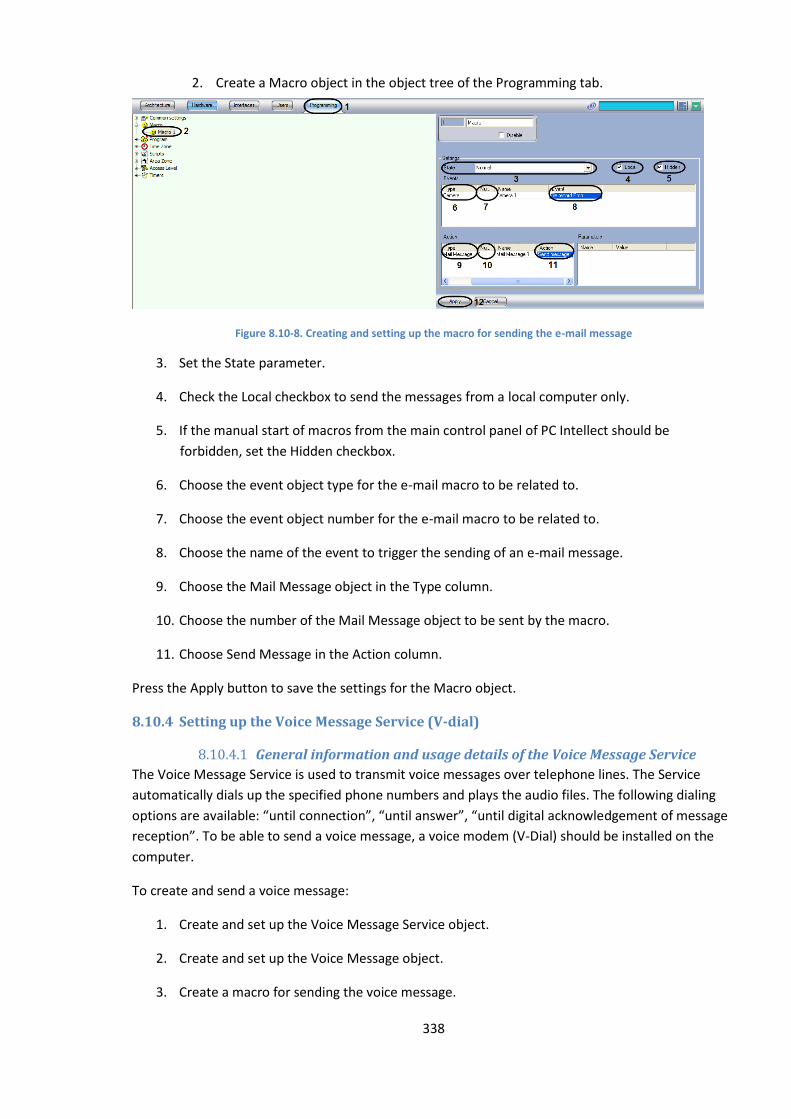
338
2. Create a Macro object in the object tree of the Programming tab.
Figure 8.10-8. Creating and setting up the macro for sending the e-mail message
3. Set the State parameter.
4. Check the Local checkbox to send the messages from a local computer only.
5. If the manual start of macros from the main control panel of PC Intellect should be
forbidden, set the Hidden checkbox.
6. Choose the event object type for the e-mail macro to be related to.
7. Choose the event object number for the e-mail macro to be related to.
8. Choose the name of the event to trigger the sending of an e-mail message.
9. Choose the Mail Message object in the Type column.
10. Choose the number of the Mail Message object to be sent by the macro.
11. Choose Send Message in the Action column.
Press the Apply button to save the settings for the Macro object.
8.10.4 Setting up the Voice Message Service (V-dial)
8.10.4.1 General information and usage details of the Voice Message Service
The Voice Message Service is used to transmit voice messages over telephone lines. The Service
automatically dials up the specified phone numbers and plays the audio files. The following dialing
options are available: “until connection”, “until answer”, “until digital acknowledgement of message
reception”. To be able to send a voice message, a voice modem (V-Dial) should be installed on the
computer.
To create and send a voice message:
1. Create and set up the Voice Message Service object.
2. Create and set up the Voice Message object.
3. Create a macro for sending the voice message.

339
8.10.4.2 Creating and setting up the Voice Message Service object
To set up the Voice Message Service object, do the following:
1. Go to the Hardware tab of the System Settings window (Figure 8.10-9).
2. Create the Voice Message Service object in the Computer node in the object tree. The object
appears in the object tree, and the settings panel for this object opens on the right side of
the System Setting window.
Figure 8.10-9. Setting up the Voice Message Service object
3. Choose a modem in the list of all modems available in the system.
4. If the modem is not in the list or there are no modems in the list, press the modem search
button.
5. Check/uncheck the checkbox to choose the dialing mode.
6. Enter the number of dialing attempts.
7. Enter the delay between dialing attempts, in seconds.
8. Check the checkbox to wait for dialtone.
Press the Apply button to save the settings for the Voice Messages Service object.
8.10.4.3 Creating voice messages
To set up the Voice Message object, do the following:
1. Go to the Hardware tab of the System Settings window (Figure 8.10-10).
2. Create the Voice Message object in the Voice Message Service node in the object tree. The
object appears in the object tree, and the settings panel for this object opens on the right
side of the System Setting window.
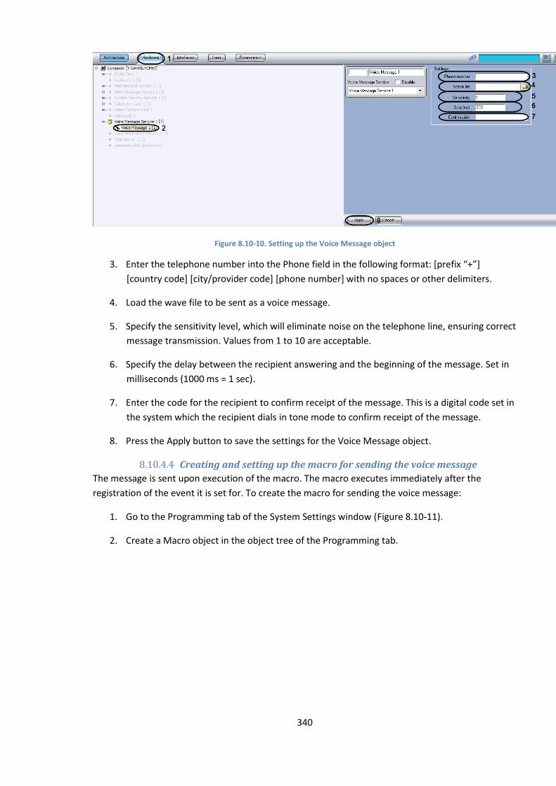
340
Figure 8.10-10. Setting up the Voice Message object
3. Enter the telephone number into the Phone field in the following format: *prefix “+”+
[country code] [city/provider code] [phone number] with no spaces or other delimiters.
4. Load the wave file to be sent as a voice message.
5. Specify the sensitivity level, which will eliminate noise on the telephone line, ensuring correct
message transmission. Values from 1 to 10 are acceptable.
6. Specify the delay between the recipient answering and the beginning of the message. Set in
milliseconds (1000 ms = 1 sec).
7. Enter the code for the recipient to confirm receipt of the message. This is a digital code set in
the system which the recipient dials in tone mode to confirm receipt of the message.
8. Press the Apply button to save the settings for the Voice Message object.
8.10.4.4 Creating and setting up the macro for sending the voice message
The message is sent upon execution of the macro. The macro executes immediately after the
registration of the event it is set for. To create the macro for sending the voice message:
1. Go to the Programming tab of the System Settings window (Figure 8.10-11).
2. Create a Macro object in the object tree of the Programming tab.
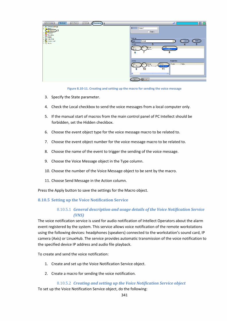
341
Figure 8.10-11. Creating and setting up the macro for sending the voice message
3. Specify the State parameter.
4. Check the Local checkbox to send the voice messages from a local computer only.
5. If the manual start of macros from the main control panel of PC Intellect should be
forbidden, set the Hidden checkbox.
6. Choose the event object type for the voice message macro to be related to.
7. Choose the event object number for the voice message macro to be related to.
8. Choose the name of the event to trigger the sending of the voice message.
9. Choose the Voice Message object in the Type column.
10. Choose the number of the Voice Message object to be sent by the macro.
11. Choose Send Message in the Action column.
Press the Apply button to save the settings for the Macro object.
8.10.5 Setting up the Voice Notification Service
8.10.5.1 General description and usage details of the Voice Notification Service
(VNS)
The voice notification service is used for audio notification of Intellect Operators about the alarm
event registered by the system. This service allows voice notification of the remote workstations
using the following devices: headphones (speakers) connected to the workstation’s sound card, IP
camera (Axis) or LinuxHub. The service provides automatic transmission of the voice notification to
the specified device IP address and audio file playback.
To create and send the voice notification:
1. Create and set up the Voice Notification Service object.
2. Create a macro for sending the voice notification.
8.10.5.2 Creating and setting up the Voice Notification Service object
To set up the Voice Notification Service object, do the following:

342
a. Go to the Hardware tab of the System Settings window (Figure 8.10-12).
b. Create the Voice Notification Service object in the Computer node in the
object tree. The object appears in the object tree, and the settings panel for
this object opens on the right side of the System Setting window.
Figure 8.10-12. Setting up the Voice Notification Service object
c. Choose the device in the Sound card list to send the notification to.
d. Specify the IP address of the network device (sound card, IP camera or Linux
Hub), used to access this device over the network. If the sound card of the
local computer is selected, this field is disabled.
e. Specify the username of the network device (sound card, IP camera or Linux
Hub), used to access this device over the network. If the sound card of the
local computer is selected, this field is disabled.
f. Specify the password of the network device (sound card, IP camera or Linux
Hub), used to access this device over the network. If the sound card of the
local computer is selected, this field is disabled.
g. Choose the headphones (speakers) playback option in the Channel drop-
down list.
1. If the soundcard has two outputs (left/right), the list contains the following options: a) Left,
b) Left + Right, c) Right.
2. If the sound card has N outputs, the list contains the numbered outputs from 0 to N-1.
h. Specify the volume level using the slider.
i. Press the Apply button to save the settings for the Voice Notification Service
object.
8.10.5.3 Creating and setting up the macro for sending the voice notification
The voice notification is sent upon execution of the macro. The macro executes immediately after
the registration of the event it is set for. To create the macro for sending the voice notification:
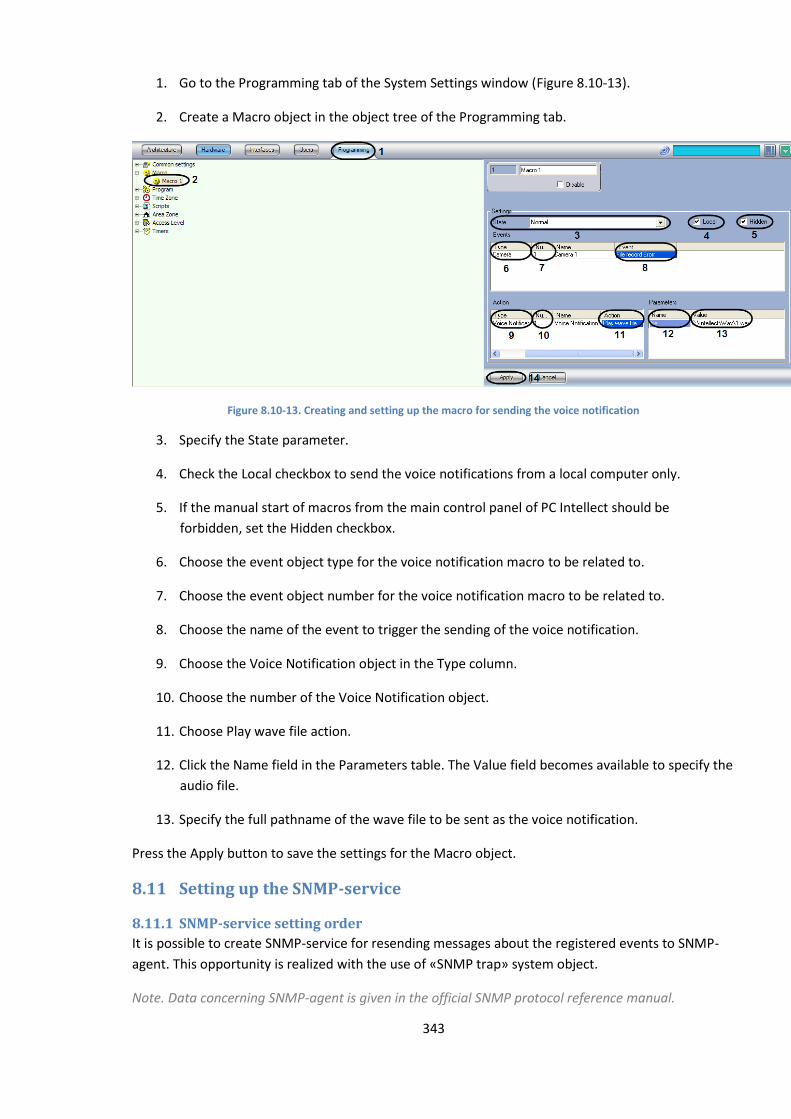
343
1. Go to the Programming tab of the System Settings window (Figure 8.10-13).
2. Create a Macro object in the object tree of the Programming tab.
Figure 8.10-13. Creating and setting up the macro for sending the voice notification
3. Specify the State parameter.
4. Check the Local checkbox to send the voice notifications from a local computer only.
5. If the manual start of macros from the main control panel of PC Intellect should be
forbidden, set the Hidden checkbox.
6. Choose the event object type for the voice notification macro to be related to.
7. Choose the event object number for the voice notification macro to be related to.
8. Choose the name of the event to trigger the sending of the voice notification.
9. Choose the Voice Notification object in the Type column.
10. Choose the number of the Voice Notification object.
11. Choose Play wave file action.
12. Click the Name field in the Parameters table. The Value field becomes available to specify the
audio file.
13. Specify the full pathname of the wave file to be sent as the voice notification.
Press the Apply button to save the settings for the Macro object.
8.11 Setting up the SNMP-service
8.11.1 SNMP-service setting order
It is possible to create SNMP-service for resending messages about the registered events to SNMP-
agent. This opportunity is realized with the use of «SNMP trap» system object.
Note. Data concerning SNMP-agent is given in the official SNMP protocol reference manual.
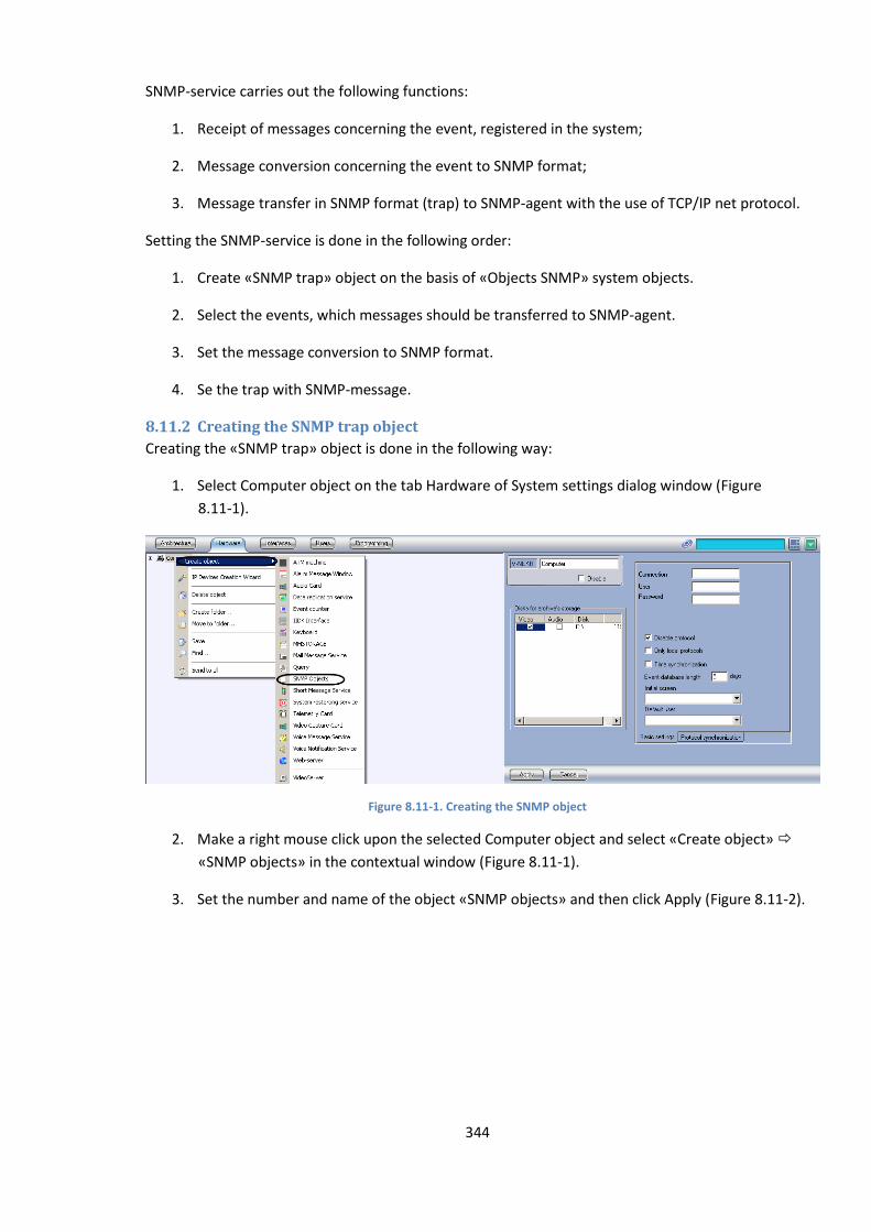
344
SNMP-service carries out the following functions:
1. Receipt of messages concerning the event, registered in the system;
2. Message conversion concerning the event to SNMP format;
3. Message transfer in SNMP format (trap) to SNMP-agent with the use of TCP/IP net protocol.
Setting the SNMP-service is done in the following order:
1. Create «SNMP trap» object on the basis of «Objects SNMP» system objects.
2. Select the events, which messages should be transferred to SNMP-agent.
3. Set the message conversion to SNMP format.
4. Se the trap with SNMP-message.
8.11.2 Creating the SNMP trap object
Creating the «SNMP trap» object is done in the following way:
1. Select Computer object on the tab Hardware of System settings dialog window (Figure
8.11-1).
Figure 8.11-1. Creating the SNMP object
2. Make a right mouse click upon the selected Computer object and select «Create object»
«SNMP objects» in the contextual window (Figure 8.11-1).
3. Set the number and name of the object «SNMP objects» and then click Apply (Figure 8.11-2).
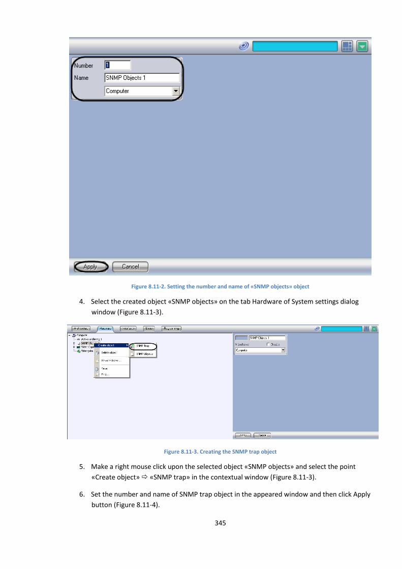
345
Figure 8.11-2. Setting the number and name of «SNMP objects» object
4. Select the created object «SNMP objects» on the tab Hardware of System settings dialog
window (Figure 8.11-3).
Figure 8.11-3. Creating the SNMP trap object
5. Make a right mouse click upon the selected object «SNMP objects» and select the point
«Create object» «SNMP trap» in the contextual window (Figure 8.11-3).
6. Set the number and name of SNMP trap object in the appeared window and then click Apply
button (Figure 8.11-4).
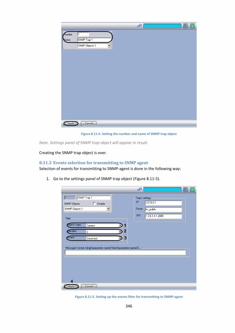
346
Figure 8.11-4. Setting the number and name of SNMP trap object
Note. Settings panel of SNMP trap object will appear in result.
Creating the SNMP trap object is over.
8.11.3 Events selection for transmitting to SNMP agent
Selection of events for transmitting to SNMP-agent is done in the following way:
1. Go to the settings panel of SNMP trap object (Figure 8.11-5).
Figure 8.11-5. Setting up the events filter for transmitting to SNMP-agent
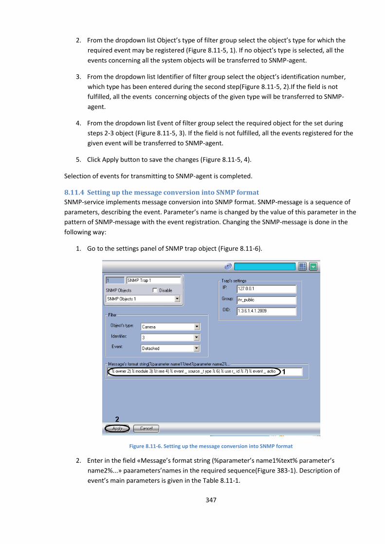
347
2. From the dropdown list Object’s type of filter group select the object’s type for which the
required event may be registered (Figure 8.11-5, 1). If no object’s type is selected, all the
events concerning all the system objects will be transferred to SNMP-agent.
3. From the dropdown list Identifier of filter group select the object’s identification number,
which type has been entered during the second step(Figure 8.11-5, 2).If the field is not
fulfilled, all the events concerning objects of the given type will be transferred to SNMP-
agent.
4. From the dropdown list Event of filter group select the required object for the set during
steps 2-3 object (Figure 8.11-5, 3). If the field is not fulfilled, all the events registered for the
given event will be transferred to SNMP-agent.
5. Click Apply button to save the changes (Figure 8.11-5, 4).
Selection of events for transmitting to SNMP-agent is completed.
8.11.4 Setting up the message conversion into SNMP format
SNMP-service implements message conversion into SNMP format. SNMP-message is a sequence of
parameters, describing the event. Parameter’s name is changed by the value of this parameter in the
pattern of SNMP-message with the event registration. Changing the SNMP-message is done in the
following way:
1. Go to the settings panel of SNMP trap object (Figure 8.11-6).
Figure 8.11-6. Setting up the message conversion into SNMP format
2. Enter in the field «Message’s format string (%parameter’s name1%text% parameter’s
name2%...» paarameters’names in the required sequence(Figure 383-1). Description of
event’s main parameters is given in the Table 8.11-1.
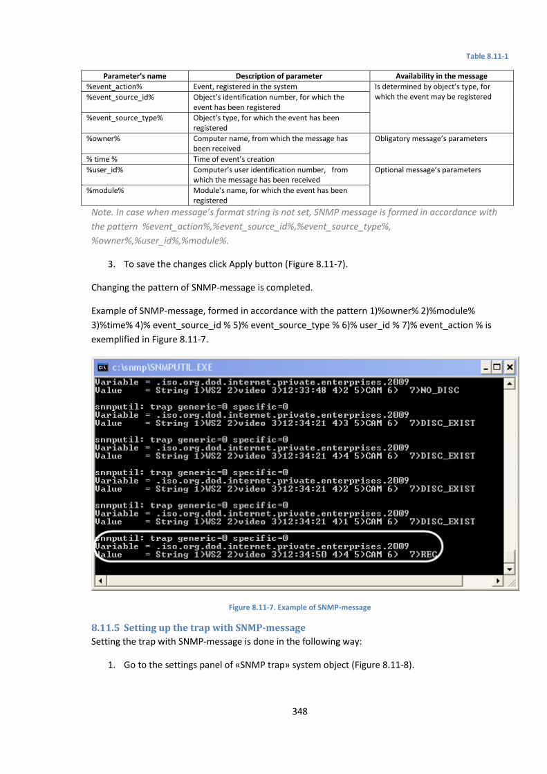
348
Table 8.11-1
Parameter’s name Description of parameter Availability in the message
%event_action% Event, registered in the system Is determined by object’s type, for which the event may be registered %event_source_id% Object’s identification number, for which the
event has been registered
%event_source_type% Object’s type, for which the event has been registered
%owner% Computer name, from which the message has been received
Obligatory message’s parameters
% time % Time of event’s creation
%user_id% Computer’s user identification number, from which the message has been received
Optional message’s parameters
%module% Module’s name, for which the event has been registered
Note. In case when message’s format string is not set, SNMP message is formed in accordance with
the pattern %event_action%,%event_source_id%,%event_source_type%,
%owner%,%user_id%,%module%.
3. To save the changes click Apply button (Figure 8.11-7).
Changing the pattern of SNMP-message is completed.
Example of SNMP-message, formed in accordance with the pattern 1)%owner% 2)%module%
3)%time% 4)% event_source_id % 5)% event_source_type % 6)% user_id % 7)% event_action % is
exemplified in Figure 8.11-7.
Figure 8.11-7. Example of SNMP-message
8.11.5 Setting up the trap with SNMP-message
Setting the trap with SNMP-message is done in the following way:
1. Go to the settings panel of «SNMP trap» system object (Figure 8.11-8).
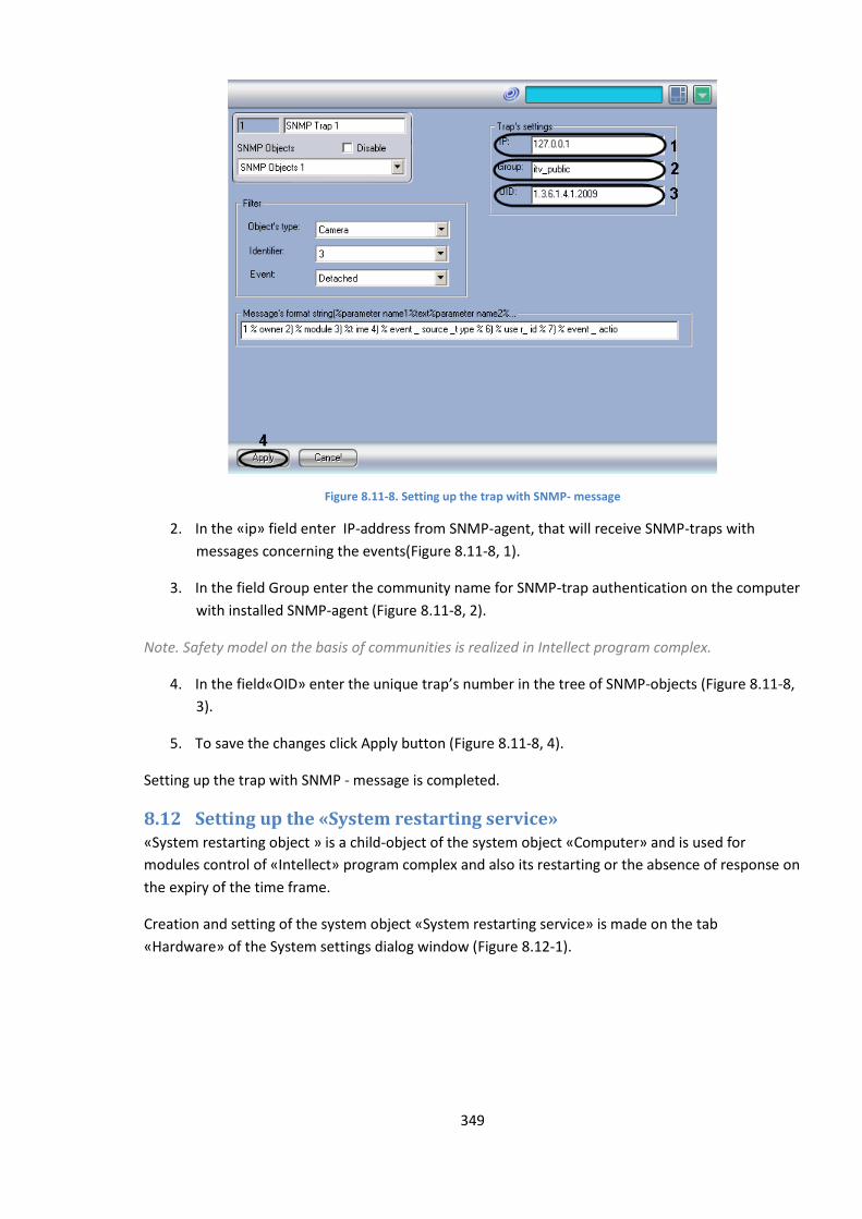
349
Figure 8.11-8. Setting up the trap with SNMP- message
2. In the «ip» field enter IP-address from SNMP-agent, that will receive SNMP-traps with
messages concerning the events(Figure 8.11-8, 1).
3. In the field Group enter the community name for SNMP-trap authentication on the computer
with installed SNMP-agent (Figure 8.11-8, 2).
Note. Safety model on the basis of communities is realized in Intellect program complex.
4. In the field«OID» enter the unique trap’s number in the tree of SNMP-objects (Figure 8.11-8,
3).
5. To save the changes click Apply button (Figure 8.11-8, 4).
Setting up the trap with SNMP - message is completed.
8.12 Setting up the «System restarting service» «System restarting object » is a child-object of the system object «Computer» and is used for
modules control of «Intellect» program complex and also its restarting or the absence of response on
the expiry of the time frame.
Creation and setting of the system object «System restarting service» is made on the tab
«Hardware» of the System settings dialog window (Figure 8.12-1).

350
Figure 8.12-1. Setting up the object «System restarting service»
Note. Object «System restarting service» cannot be edited remotely. The object is created and set
separately on each selected component of distributed system as needed.
To set «System restarting service» do the following:
1. Check the «ITV USB Watch Dog for Slave.exe» checkbox when it is necessary to activate
system of automatic computer’s restarting with the absence of slave.exe process (Figure
8.12-2, 1).
Note. Activation of computer’s automatic restarting system requires additional connection to ITV USB
Watch Dog (see. Connection of automatic check of servers «USB Watchdog»’s operation).
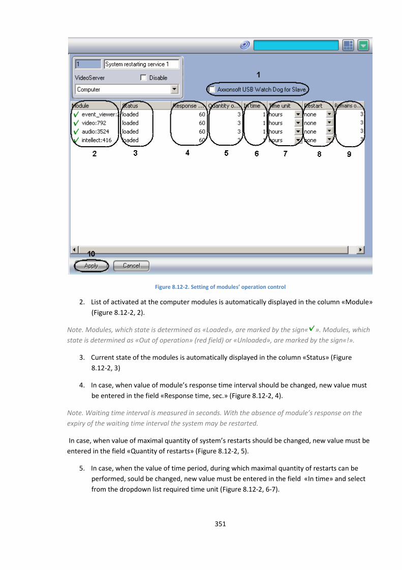
351
Figure 8.12-2. Setting of modules’ operation control
2. List of activated at the computer modules is automatically displayed in the column «Module»
(Figure 8.12-2, 2).
Note. Modules, which state is determined as «Loaded», are marked by the sign« ». Modules, which
state is determined as «Out of operation» (red field) or «Unloaded», are marked by the sign«!».
3. Current state of the modules is automatically displayed in the column «Status» (Figure
8.12-2, 3)
4. In case, when value of module’s response time interval should be changed, new value must
be entered in the field «Response time, sec.» (Figure 8.12-2, 4).
Note. Waiting time interval is measured in seconds. With the absence of module’s response on the
expiry of the waiting time interval the system may be restarted.
In case, when value of maximal quantity of system’s restarts should be changed, new value must be
entered in the field «Quantity of restarts» (Figure 8.12-2, 5).
5. In case, when the value of time period, during which maximal quantity of restarts can be
performed, sould be changed, new value must be entered in the field «In time» and select
from the dropdown list required time unit (Figure 8.12-2, 6-7).
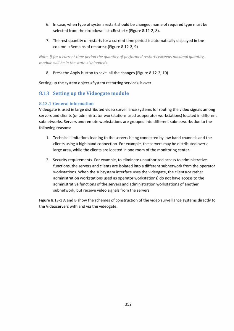
352
6. In case, when type of system restart should be changed, name of required type must be
selected from the dropdown list «Restart» (Figure 8.12-2, 8).
7. The rest quantity of restarts for a current time period is automatically displayed in the
column «Remains of restarts» (Figure 8.12-2, 9)
Note. If for a current time period the quantity of performed restarts exceeds maximal quantity,
module will be in the state «Unloaded».
8. Press the Apply button to save all the changes (Figure 8.12-2, 10)
Setting up the system object «System restarting service» is over.
8.13 Setting up the Videogate module
8.13.1 General information
Videogate is used in large distributed video surveillance systems for routing the video signals among
servers and clients (or administrator workstations used as operator workstations) located in different
subnetworks. Servers and remote workstations are grouped into different subnetworks due to the
following reasons:
1. Technical limitations leading to the servers being connected by low band channels and the
clients using a high band connection. For example, the servers may be distributed over a
large area, while the clients are located in one room of the monitoring center.
2. Security requirements. For example, to eliminate unauthorized access to administrative
functions, the servers and clients are isolated into a different subnetwork from the operator
workstations. When the subsystem interface uses the videogate, the clients(or rather
administration workstations used as operator workstations) do not have access to the
administrative functions of the servers and administration workstations of another
subnetwork, but receive video signals from the servers.
Figure 8.13-1 A and B show the schemes of construction of the video surveillance systems directly to
the Videoservers with and via the videogate.
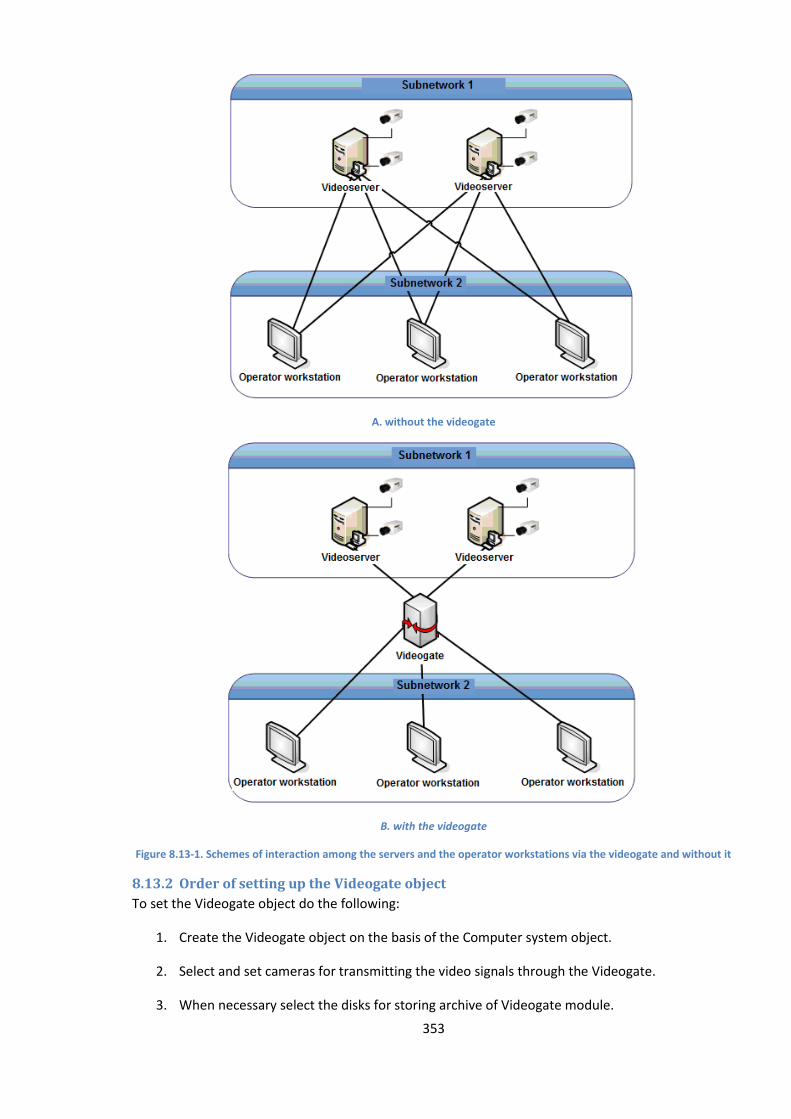
353
A. without the videogate
B. with the videogate
Figure 8.13-1. Schemes of interaction among the servers and the operator workstations via the videogate and without it
8.13.2 Order of setting up the Videogate object
To set the Videogate object do the following:
1. Create the Videogate object on the basis of the Computer system object.
2. Select and set cameras for transmitting the video signals through the Videogate.
3. When necessary select the disks for storing archive of Videogate module.
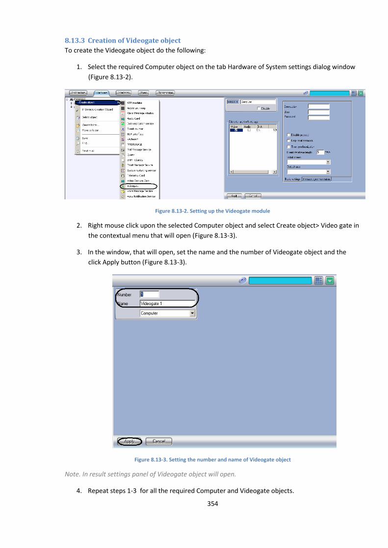
354
8.13.3 Creation of Videogate object
To create the Videogate object do the following:
1. Select the required Computer object on the tab Hardware of System settings dialog window
(Figure 8.13-2).
Figure 8.13-2. Setting up the Videogate module
2. Right mouse click upon the selected Computer object and select Create object> Video gate in
the contextual menu that will open (Figure 8.13-3).
3. In the window, that will open, set the name and the number of Videogate object and the
click Apply button (Figure 8.13-3).
Figure 8.13-3. Setting the number and name of Videogate object
Note. In result settings panel of Videogate object will open.
4. Repeat steps 1-3 for all the required Computer and Videogate objects.
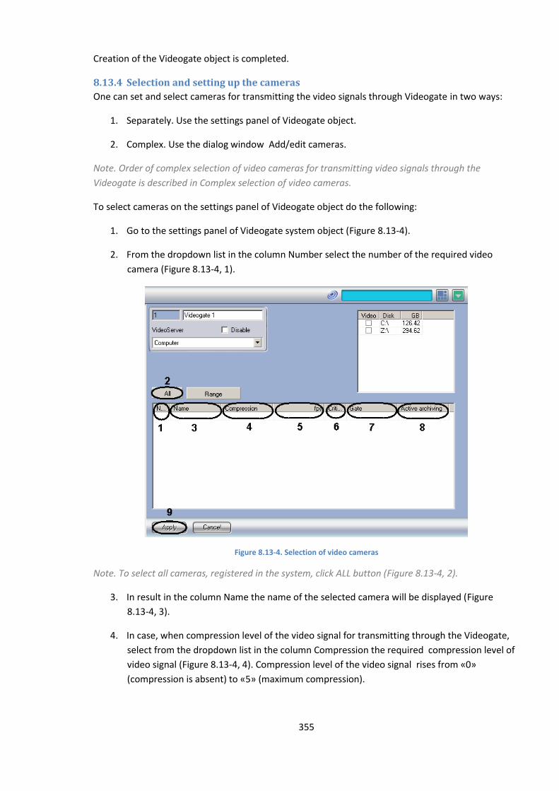
355
Сreation of the Videogate object is completed.
8.13.4 Selection and setting up the cameras
One can set and select cameras for transmitting the video signals through Videogate in two ways:
1. Separately. Use the settings panel of Videogate object.
2. Complex. Use the dialog window Add/edit cameras.
Note. Order of complex selection of video cameras for transmitting video signals through the
Videogate is described in Complex selection of video cameras.
To select cameras on the settings panel of Videogate object do the following:
1. Go to the settings panel of Videogate system object (Figure 8.13-4).
2. From the dropdown list in the column Number select the number of the required video
camera (Figure 8.13-4, 1).
Figure 8.13-4. Selection of video cameras
Note. To select all cameras, registered in the system, click ALL button (Figure 8.13-4, 2).
3. In result in the column Name the name of the selected camera will be displayed (Figure
8.13-4, 3).
4. In case, when compression level of the video signal for transmitting through the Videogate,
select from the dropdown list in the column Compression the required compression level of
video signal (Figure 8.13-4, 4). Compression level of the video signal rises from «0»
(compression is absent) to «5» (maximum compression).

356
Note. In case of setting the compression level video signal on the Server has to be preliminary
decompressed, that leads to great load on CP of the Server.
5. In case, when video signal has to be thinned out for its transmitting through the Videogate,
enter in the field in the column «fps» the required frame rate of the video signal (Figure
8.13-4, 5).
Note1. The given «fps» value must be less than the frame rate of video signal’s digitizing by video
input device. Otherwise frame rate of video signal will be equal to the frame rate of digitizing.
Note2. It’s not recommended to chnge «fps» value while using Н.264 codec.
6. In case, when transmission of video signals through the local net or from the Server to the
Videogate has to be controlled, enter in the field in the column Critical rate minimal available
value of frame rate of video signals, transmitted to the Videogate (Figure 8.13-4, 6).
Note. The given value Critical rate should not be more than the frame rate of video signal,
transmitted to the Videogate.
The setting of critical rate on the Videogate must be combined with the settings of Alarm messages
window system object (see. Setting up alarm messages window). In this case with the reduction of
rate of inputting signals below the given value Alarm messages window will be displayed with the
message “Reduced input rate”.
7. In case, when video signal from the selected video camera has to be transmitted from the
other Videogate object, select the name of this object from the dropdown list in the column
Gate (Figure 8.13-4, 7).
8. In case, when the video signal from the selected camera has to be transmitted from the
Active archiving object, select the name of this object from the dropdown list in the Active
archive (Figure 8.13-4, 8).
9. Repeat steps 2-8 for all the required cameras.
10. To save all the changes click Apply button (Figure 8.13-4, 9).
Selection of cameras on the settings panel of Videogate object is completed.
8.13.5 Complex selection of video cameras
There is opportunity of complex selection and editing parameters of video cameras for transmitting
video signal through Videogate. Complex selection of cameras is performed in the following way:
1. Go to the settings panel of Videogate system object and then click Range button (Figure
8.13-5, 1).
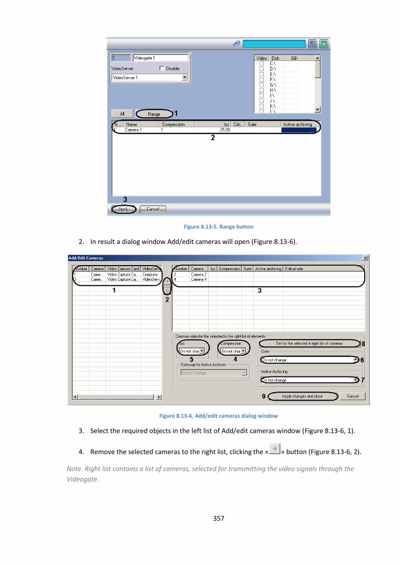
357
Figure 8.13-5. Range button
2. In result a dialog window Add/edit cameras will open (Figure 8.13-6).
Figure 8.13-6. Add/edit cameras dialog window
3. Select the required objects in the left list of Add/edit cameras window (Figure 8.13-6, 1).
4. Remove the selected cameras to the right list, clicking the « » button (Figure 8.13-6, 2).
Note. Right list contains a list of cameras, selected for transmitting the video signals through the
Videogate.

358
Button « » is used for back action, for removing the selected cameras from the right list to the left
(Figure 8.13-6, 2).
5. In result the selected video cameras will be displayed in the right list of Add/edit cameras
window (Figure 8.13-6, 3).
6. When necessary select in the right list the names of the required cameras for complex editing
of parameters (Figure 8.13-6, 3).
Note. For all the selected cameras the same value of parameters will be set.
Note. There is no possibility to edit Critical rate parameter with the help of Add/edit cameras.
7. In case, when compression level of video signal has to be changed for transmitting through
the Videogate, select from the Compression dropdown list the required compression level
(Figure 8.13-6, 4).Compression level rises from «0» (no compression) till «5» (maximum
compression).
Note. In case of setting the compression level video signal must be preliminary decompressed on the
Server that leads to great loading on the CP of the Server.
Settings «Compression», «fps», «Gate», «Active archive» belong to the group «Set for the selected in
right list of cameras »(Figure 8.13-6, 6).
8. In case, when video signal has to be thinned out for transmitting through Videogate select
from the «fps» dropdown list the required frame rate of video signals (Figure 8.13-6, 5).
Note. The given «fps» value must be less the frame rate of video signal’s digitizing by video capture
device. Otherwise frame rate of video signal will be equal to the frame rate of digitizing.
9. In case, if video signal form the selected cameras has to be transmitted from the other
Videogate object, select the name of this objet from the Gate dropdown list (Figure 8.13-6,
6).
10. In case when video signal has to be transmitted from the selected cameras from the Active
archive object, select from the Active archive dropdown list the name of this object (Figure
8.13-6, 7).
11. To save the set parameters click Set for the selected in right list of cameras button (Figure
8.13-6, 8).
12. In result the set parameters will be displayed in the right list of Add/edit cameras window
(Figure 8.13-6, 3).
13. Repeat steps 6-11 for complex editing of all the required cameras.
14. To save all the changes and close Add/edit cameras window click Apply changes and close
button (Figure 8.13-6, 9).
15. The given settings will be displayed on the settings panel of Videogate object (Figure 8.13-5,
2).
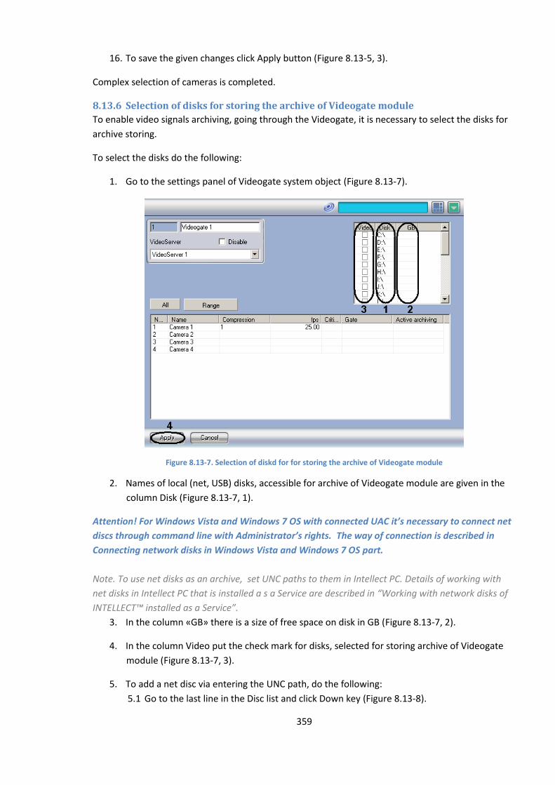
359
16. To save the given changes click Apply button (Figure 8.13-5, 3).
Complex selection of cameras is completed.
8.13.6 Selection of disks for storing the archive of Videogate module
To enable video signals archiving, going through the Videogate, it is necessary to select the disks for
archive storing.
To select the disks do the following:
1. Go to the settings panel of Videogate system object (Figure 8.13-7).
Figure 8.13-7. Selection of diskd for for storing the archive of Videogate module
2. Names of local (net, USB) disks, accessible for archive of Videogate module are given in the
column Disk (Figure 8.13-7, 1).
Attention! For Windows Vista and Windows 7 OS with connected UAC it’s necessary to connect net
discs through command line with Administrator’s rights. The way of connection is described in
Connecting network disks in Windows Vista and Windows 7 OS part.
Note. To use net disks as an archive, set UNC paths to them in Intellect PC. Details of working with
net disks in Intellect PC that is installed a s a Service are described in “Working with network disks of
INTELLECT™ installed as a Service”.
3. In the column «GB» there is a size of free space on disk in GB (Figure 8.13-7, 2).
4. In the column Video put the check mark for disks, selected for storing archive of Videogate
module (Figure 8.13-7, 3).
5. To add a net disc via entering the UNC path, do the following:
5.1 Go to the last line in the Disc list and click Down key (Figure 8.13-8).
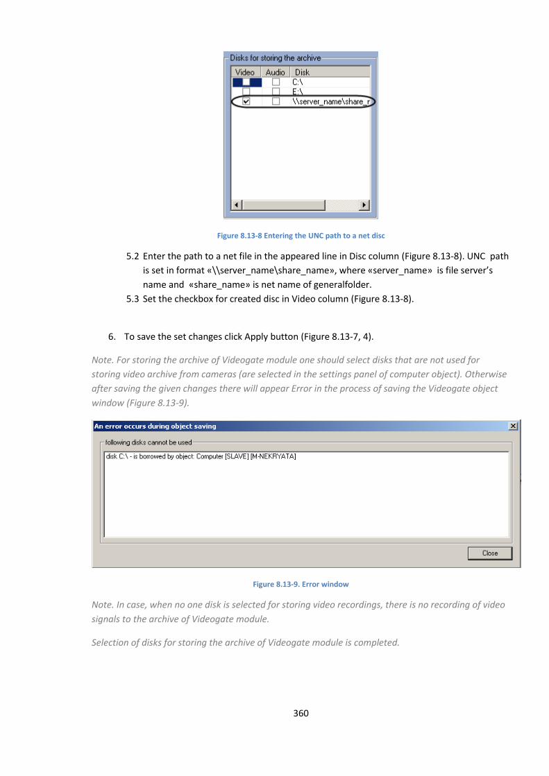
360
Figure 8.13-8 Entering the UNC path to a net disc
5.2 Enter the path to a net file in the appeared line in Disc column (Figure 8.13-8). UNC path
is set in format «\\server_name\share_name», where «server_name» is file server’s
name and «share_name» is net name of generalfolder.
5.3 Set the checkbox for created disc in Video column (Figure 8.13-8).
6. To save the set changes click Apply button (Figure 8.13-7, 4).
Note. For storing the archive of Videogate module one should select disks that are not used for
storing video archive from cameras (are selected in the settings panel of computer object). Otherwise
after saving the given changes there will appear Error in the process of saving the Videogate object
window (Figure 8.13-9).
Figure 8.13-9. Error window
Note. In case, when no one disk is selected for storing video recordings, there is no recording of video
signals to the archive of Videogate module.
Selection of disks for storing the archive of Videogate module is completed.

361
8.14 Setting up backup archiving
8.14.1 Purpose and implementation of backup archiving in the Intellect software
The Intellect software allows creating the backup copies of video and audio recordings. The Active
Archiving module is used for creation of video and audio archives. When making a backup copy, the
Intellect software copies video and audio recordings from the main archive of the videoserver to
different storage devices.
The Active Archiving module copies the video archives received from the specified cameras to any of
the available local or network hard drives.
The Active Archiving module supports the following functions:
1. Copying the video archive to local or network hard drives, or USB storage.
2. Changing the frame rate of the signal at the time of saving it to active archive.
3. Changing the rate of data transfer via a local network.
4. Setting up the periodicity of backup archiving.
5. Cyclic copying of the data to the connected storage devices.
6. Viewing the video archive from Active Archiving on the video surveillance monitor.
7. Monitoring the storage usage.
Note. To record the audio archive together with the video archive configure the Active audio archive
object (see Configuring the Active audio archive module section).
A folder named VIDEO which holds the backup video archive is created on the specified storage
devices when setting up the corresponding objects.
The backup copying module can be controlled:
1. Manually using special interface objects.
2. Automatically using the built-in programming capabilities of Intellect software – macros and
scripts.
8.14.2 Setting up the Active Archiving module
The Active Archiving module is used to make backup copies of the video archive from the
videoserver. The Active Archiving module copies the video archives received from the specified
cameras to the specified storage device.
Note. Remote workstation, where the active archiving is installed, is to have data concerning servers
archive so that the video archive to be copied evenly from the indicated cameras. Thereto the
remote workstation gets data concerning archive indexes from the server once in 30 seconds. After
system restarting, data change is stopped until the Active archiving is started.
Setting up the Active Archiving module is performed by the Active Archiving system object.
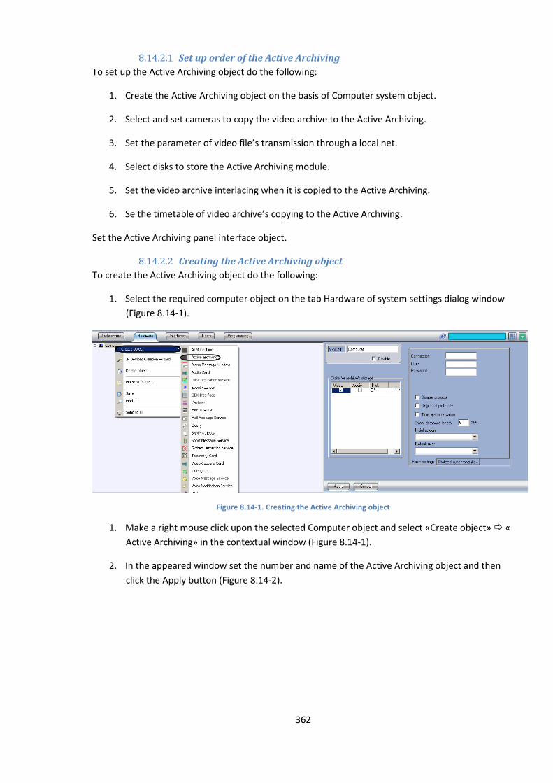
362
8.14.2.1 Set up order of the Active Archiving
To set up the Active Archiving object do the following:
1. Create the Active Archiving object on the basis of Computer system object.
2. Select and set cameras to copy the video archive to the Active Archiving.
3. Set the parameter of video file’s transmission through a local net.
4. Select disks to store the Active Archiving module.
5. Set the video archive interlacing when it is copied to the Active Archiving.
6. Se the timetable of video archive’s copying to the Active Archiving.
Set the Active Archiving panel interface object.
8.14.2.2 Creating the Active Archiving object
To create the Active Archiving object do the following:
1. Select the required computer object on the tab Hardware of system settings dialog window
(Figure 8.14-1).
Figure 8.14-1. Creating the Active Archiving object
1. Make a right mouse click upon the selected Computer object and select «Create object» «
Active Archiving» in the contextual window (Figure 8.14-1).
2. In the appeared window set the number and name of the Active Archiving object and then
click the Apply button (Figure 8.14-2).
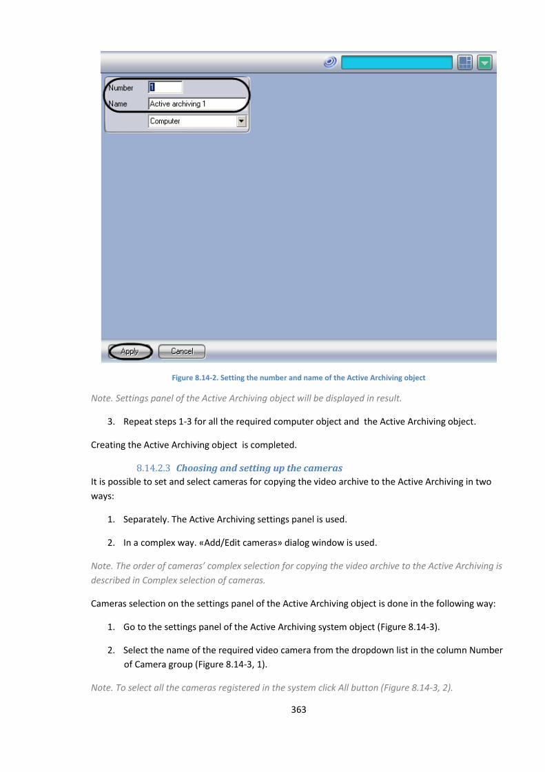
363
Figure 8.14-2. Setting the number and name of the Active Archiving object
Note. Settings panel of the Active Archiving object will be displayed in result.
3. Repeat steps 1-3 for all the required computer object and the Active Archiving object.
Creating the Active Archiving object is completed.
8.14.2.3 Choosing and setting up the cameras
It is possible to set and select cameras for copying the video archive to the Active Archiving in two
ways:
1. Separately. The Active Archiving settings panel is used.
2. In a complex way. «Add/Edit cameras» dialog window is used.
Note. The order of cameras’ complex selection for copying the video archive to the Active Archiving is
described in Complex selection of cameras.
Cameras selection on the settings panel of the Active Archiving object is done in the following way:
1. Go to the settings panel of the Active Archiving system object (Figure 8.14-3).
2. Select the name of the required video camera from the dropdown list in the column Number
of Camera group (Figure 8.14-3, 1).
Note. To select all the cameras registered in the system click All button (Figure 8.14-3, 2).
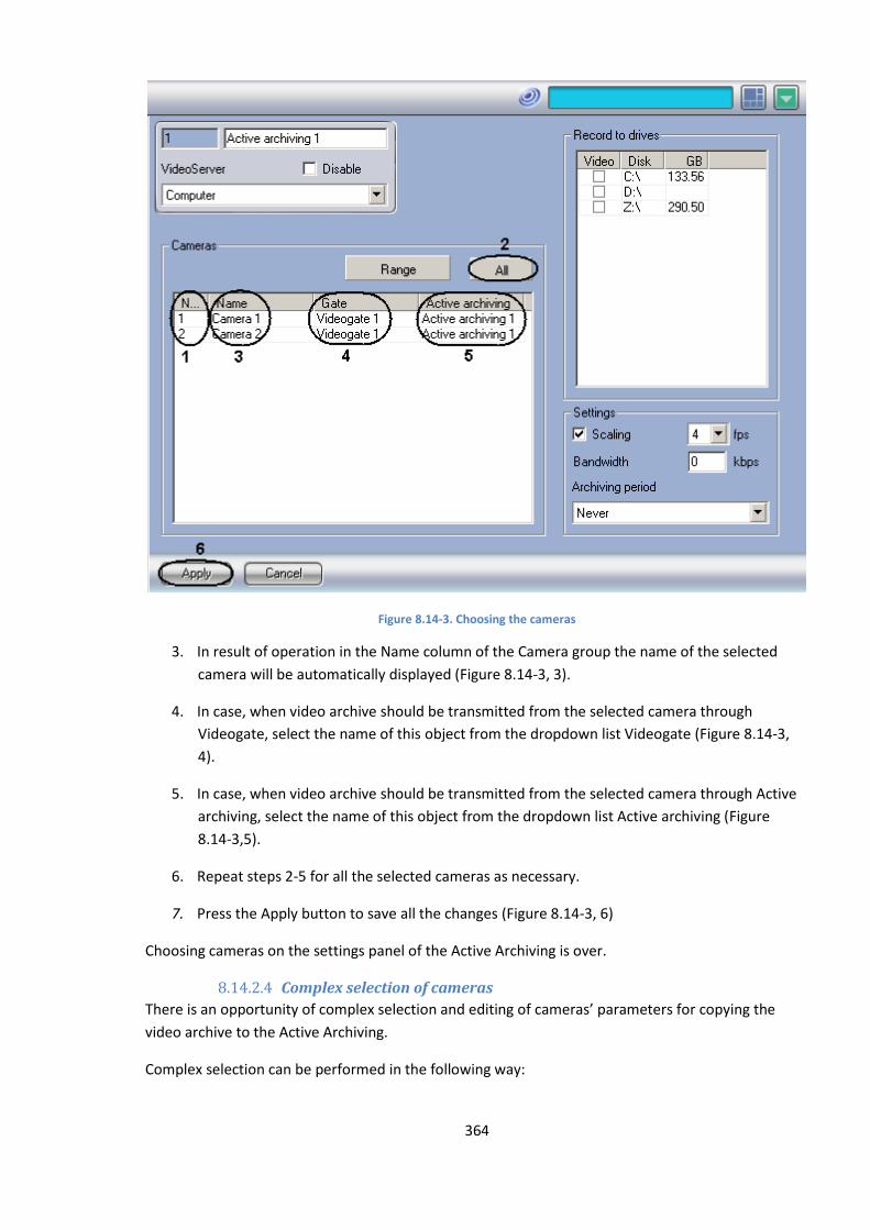
364
Figure 8.14-3. Choosing the cameras
3. In result of operation in the Name column of the Camera group the name of the selected
camera will be automatically displayed (Figure 8.14-3, 3).
4. In case, when video archive should be transmitted from the selected camera through
Videogate, select the name of this object from the dropdown list Videogate (Figure 8.14-3,
4).
5. In case, when video archive should be transmitted from the selected camera through Active
archiving, select the name of this object from the dropdown list Active archiving (Figure
8.14-3,5).
6. Repeat steps 2-5 for all the selected cameras as necessary.
7. Press the Apply button to save all the changes (Figure 8.14-3, 6)
Choosing cameras on the settings panel of the Active Archiving is over.
8.14.2.4 Complex selection of cameras
There is an opportunity of complex selection and editing of cameras’ parameters for copying the
video archive to the Active Archiving.
Complex selection can be performed in the following way:
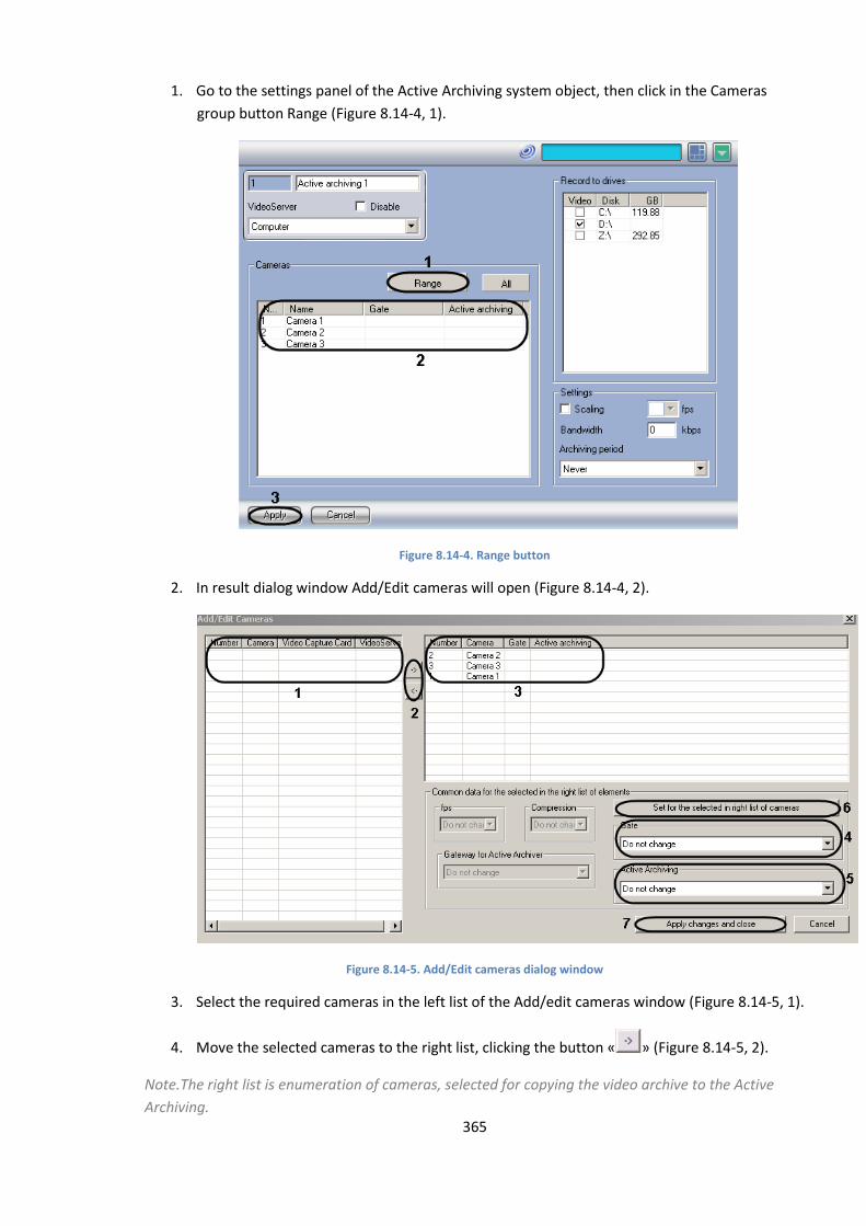
365
1. Go to the settings panel of the Active Archiving system object, then click in the Cameras
group button Range (Figure 8.14-4, 1).
Figure 8.14-4. Range button
2. In result dialog window Add/Edit cameras will open (Figure 8.14-4, 2).
Figure 8.14-5. Add/Edit cameras dialog window
3. Select the required cameras in the left list of the Add/edit cameras window (Figure 8.14-5, 1).
4. Move the selected cameras to the right list, clicking the button « » (Figure 8.14-5, 2).
Notе.The right list is enumeration of cameras, selected for copying the video archive to the Active
Archiving.

366
Button « » is used for back action, that is for moving the selected video cameras from the right list
to the left one (Figure 8.14-5, 2).
5. In result the selected cameras will be displayed in the right list of the window Add/Edit
cameras.
6. If it is necessary select in the right list the names of required cameras for complex editing the
parameters (Figure 8.14-5, 3).
Note. For all the selected cameras the same values of parameters will be set.
7. In case, when video archive has to be transmitted through the Videogate object, select from
the dropdown list the name of this object (Figure 8.14-5, 4).
Note. Videogate setting, Active archiving belong to the group Common data for the elements selected
in the right list (Figure 8.14-5, 5).
Note.
1. In case, when video archive has to be transmitted from the other Active Archiving object
Videogate object, select from the dropdown list Active Archiving the name of this object
(Figure 8.14-5, 5).
2. Click button Save for the selected in the right list of cameras to save save the set parameters
(Figure 8.14-5, 6).
3. In result the set parameters will be shown in the right list of the window Add/ edit cameras
(Figure 8.14-5, 3).
4. Repeat steps 6-9for complex editing of all the required cameras.
5. Click button Apply changes and close to save all the canges and close the window Add/edit
cameras click (Figure 8.14-5, 7).
6. Set camera settings will be shown in the table Cameras on the object settings panel Active
Archiving (Figure 8.14-4, 2).
7. To save all the changes click the “Apply” button (Figure 8.14-4, 3).
Complex selection of video cameras is over.
8.14.2.5 Setting the parameters of video archive transmission over a local
network
If a network drive is selected for backup, you can set up the network transmission parameter. This
parameter limits the overall transmission rate on each server.
By default, the transmission rate is not set. This means the data is transferred so that the local
networks, or the videoserver resources, are loaded to the maximum.
Setting the parameters of video archive transmission over a local network is done in the following
way:

367
1. Go to the settings panel of the Active Archiving system object.
Figure 8.14-6. Setting the parameters of video archive transmission over a local network
2. In the field Bandwidth enter the value kbps of maximum speed of video archive’s
transmission over a local network (Figure 8.14-6).
3. Click Apply button to save the changes (Figure 8.14-6).
Setting the parameters of video archive transmission over a local network is completed.
8.14.2.6 Choosing the drives to store the archive of the Active Archiving module
The Intellect Active Archiving module saves the backup copy of the video archive to local and
network disks and connected USB storage. Backup files are stored in the VIDEO folders on these
drives.
By default, backup archiving is disabled.
Selection of drivers for storing archive of Active Archiving module is done in the following way:
1. Got to the settings panel of the Active Archiving system object (Figure 8.14-7).
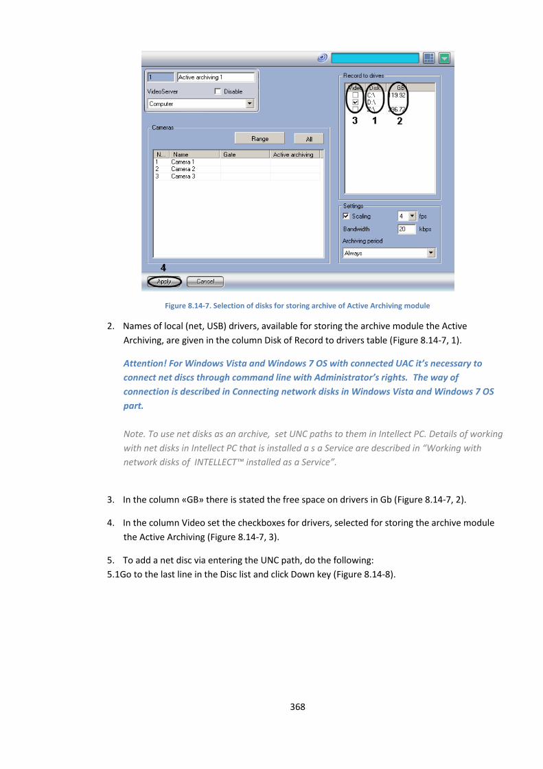
368
Figure 8.14-7. Selection of disks for storing archive of Active Archiving module
2. Names of local (net, USB) drivers, available for storing the archive module the Active
Archiving, are given in the column Disk of Record to drivers table (Figure 8.14-7, 1).
Attention! For Windows Vista and Windows 7 OS with connected UAC it’s necessary to
connect net discs through command line with Administrator’s rights. The way of
connection is described in Connecting network disks in Windows Vista and Windows 7 OS
part.
Note. To use net disks as an archive, set UNC paths to them in Intellect PC. Details of working
with net disks in Intellect PC that is installed a s a Service are described in “Working with
network disks of INTELLECT™ installed as a Service”.
3. In the column «GB» there is stated the free space on drivers in Gb (Figure 8.14-7, 2).
4. In the column Video set the checkboxes for drivers, selected for storing the archive module
the Active Archiving (Figure 8.14-7, 3).
5. To add a net disc via entering the UNC path, do the following:
5.1Go to the last line in the Disc list and click Down key (Figure 8.14-8).
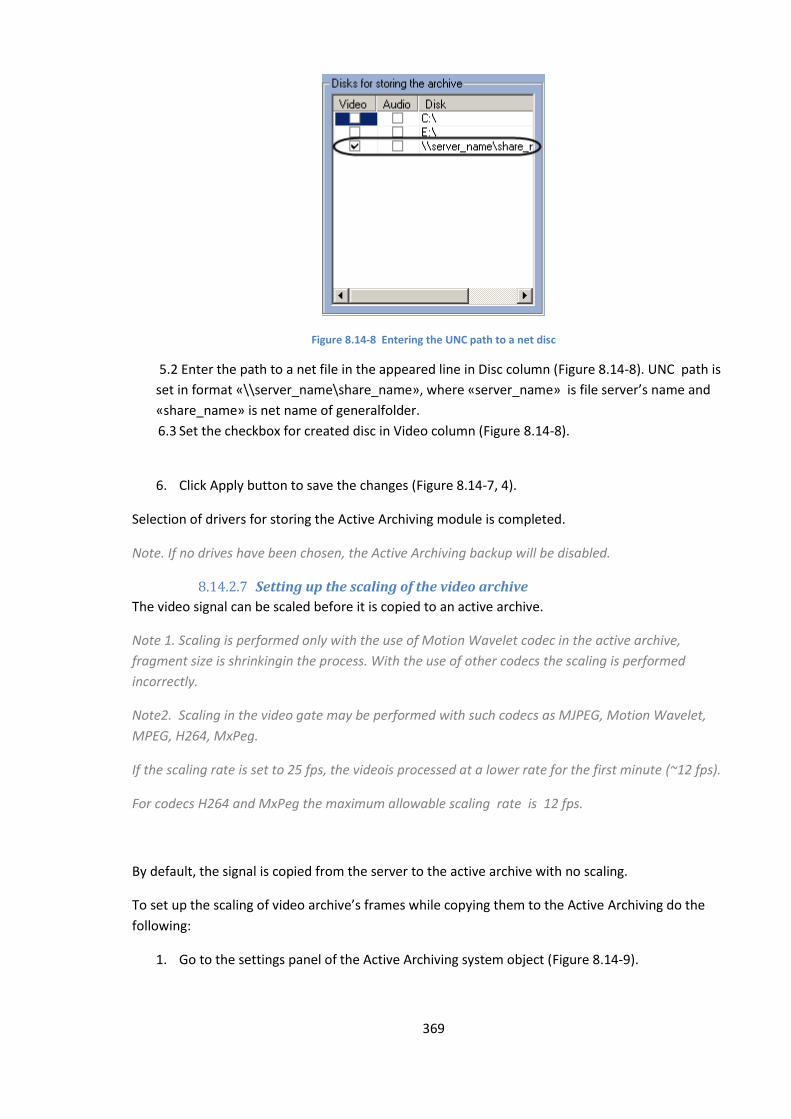
369
Figure 8.14-8 Entering the UNC path to a net disc
5.2 Enter the path to a net file in the appeared line in Disc column (Figure 8.14-8). UNC path is
set in format «\\server_name\share_name», where «server_name» is file server’s name and
«share_name» is net name of generalfolder.
6.3 Set the checkbox for created disc in Video column (Figure 8.14-8).
6. Click Apply button to save the changes (Figure 8.14-7, 4).
Selection of drivers for storing the Active Archiving module is completed.
Note. If no drives have been chosen, the Active Archiving backup will be disabled.
8.14.2.7 Setting up the scaling of the video archive
The video signal can be scaled before it is copied to an active archive.
Note 1. Scaling is performed only with the use of Motion Wavelet codec in the active archive,
fragment size is shrinkingin the process. With the use of other codecs the scaling is performed
incorrectly.
Note2. Scaling in the video gate may be performed with such codecs as MJPEG, Motion Wavelet,
MPEG, H264, MxPeg.
If the scaling rate is set to 25 fps, the videois processed at a lower rate for the first minute (~12 fps).
For codecs H264 and MxPeg the maximum allowable scaling rate is 12 fps.
By default, the signal is copied from the server to the active archive with no scaling.
To set up the scaling of video archive’s frames while copying them to the Active Archiving do the
following:
1. Go to the settings panel of the Active Archiving system object (Figure 8.14-9).
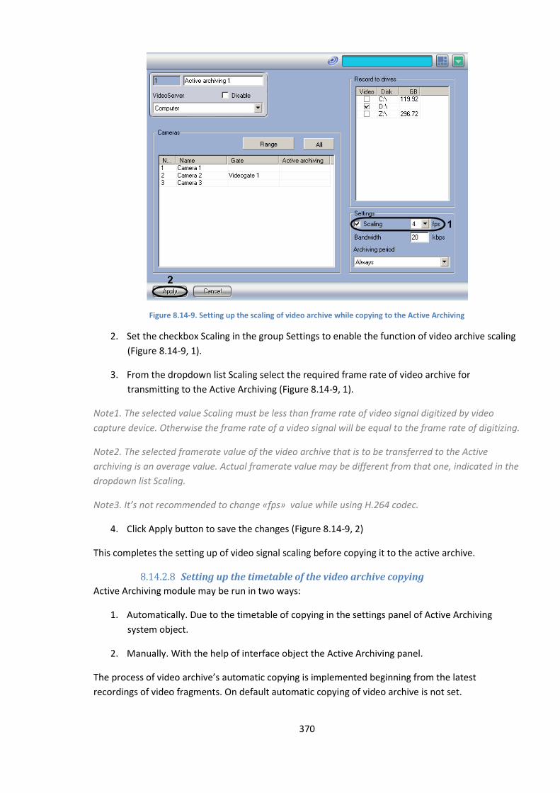
370
Figure 8.14-9. Setting up the scaling of video archive while copying to the Active Archiving
2. Set the checkbox Scaling in the group Settings to enable the function of video archive scaling
(Figure 8.14-9, 1).
3. From the dropdown list Scaling select the required frame rate of video archive for
transmitting to the Active Archiving (Figure 8.14-9, 1).
Note1. The selected value Scaling must be less than frame rate of video signal digitized by video
capture device. Otherwise the frame rate of a video signal will be equal to the frame rate of digitizing.
Note2. The selected framerate value of the video archive that is to be transferred to the Active
archiving is an average value. Actual framerate value may be different from that one, indicated in the
dropdown list Scaling.
Note3. It’s not recommended to change «fps» value while using Н.264 codec.
4. Click Apply button to save the changes (Figure 8.14-9, 2)
This completes the setting up of video signal scaling before copying it to the active archive.
8.14.2.8 Setting up the timetable of the video archive copying
Active Archiving module may be run in two ways:
1. Automatically. Due to the timetable of copying in the settings panel of Active Archiving
system object.
2. Manually. With the help of interface object the Active Archiving panel.
The process of video archive’s automatic copying is implemented beginning from the latest
recordings of video fragments. On default automatic copying of video archive is not set.
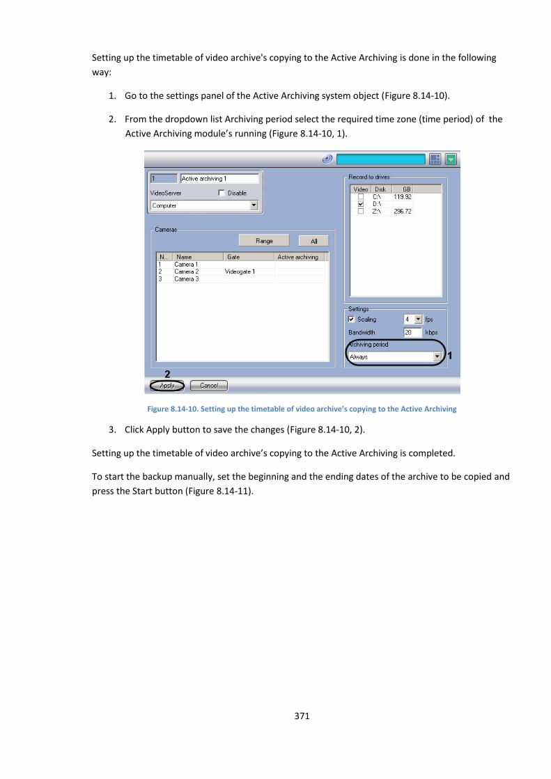
371
Setting up the timetable of video archive's copying to the Active Archiving is done in the following
way:
1. Go to the settings panel of the Active Archiving system object (Figure 8.14-10).
2. From the dropdown list Archiving period select the required time zone (time period) of the
Active Archiving module’s running (Figure 8.14-10, 1).
Figure 8.14-10. Setting up the timetable of video archive’s copying to the Active Archiving
3. Click Apply button to save the changes (Figure 8.14-10, 2).
Setting up the timetable of video archive’s copying to the Active Archiving is completed.
To start the backup manually, set the beginning and the ending dates of the archive to be copied and
press the Start button (Figure 8.14-11).
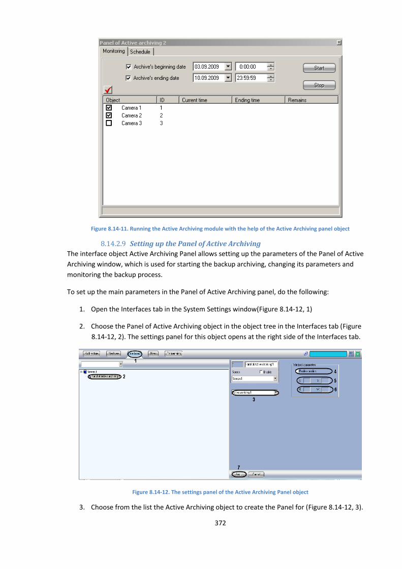
372
Figure 8.14-11. Running the Active Archiving module with the help of the Active Archiving panel object
8.14.2.9 Setting up the Panel of Active Archiving
The interface object Active Archiving Panel allows setting up the parameters of the Panel of Active
Archiving window, which is used for starting the backup archiving, changing its parameters and
monitoring the backup process.
To set up the main parameters in the Panel of Active Archiving panel, do the following:
1. Open the Interfaces tab in the System Settings window(Figure 8.14-12, 1)
2. Choose the Panel of Active Archiving object in the object tree in the Interfaces tab (Figure
8.14-12, 2). The settings panel for this object opens at the right side of the Interfaces tab.
Figure 8.14-12. The settings panel of the Active Archiving Panel object
3. Choose from the list the Active Archiving object to create the Panel for (Figure 8.14-12, 3).
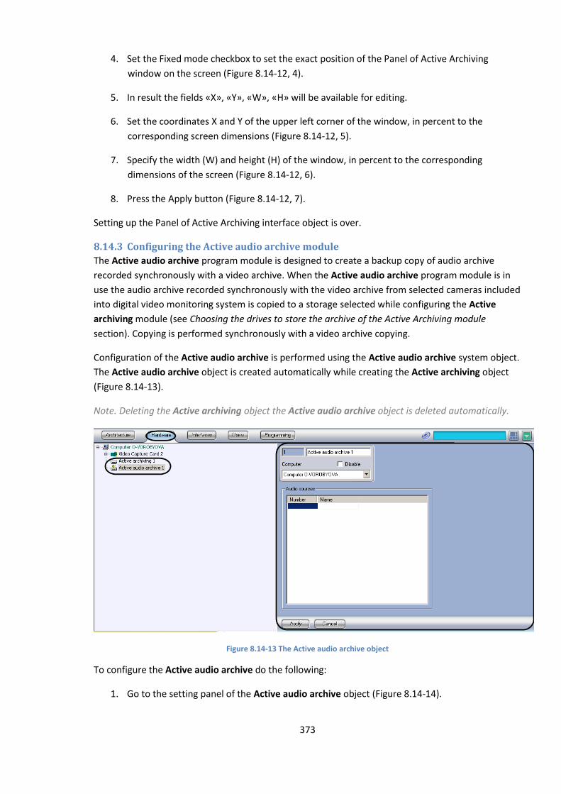
373
4. Set the Fixed mode checkbox to set the exact position of the Panel of Active Archiving
window on the screen (Figure 8.14-12, 4).
5. In result the fields «X», «Y», «W», «H» will be available for editing.
6. Set the coordinates X and Y of the upper left corner of the window, in percent to the
corresponding screen dimensions (Figure 8.14-12, 5).
7. Specify the width (W) and height (H) of the window, in percent to the corresponding
dimensions of the screen (Figure 8.14-12, 6).
8. Press the Apply button (Figure 8.14-12, 7).
Setting up the Panel of Active Archiving interface object is over.
8.14.3 Configuring the Active audio archive module
The Active audio archive program module is designed to create a backup copy of audio archive
recorded synchronously with a video archive. When the Active audio archive program module is in
use the audio archive recorded synchronously with the video archive from selected cameras included
into digital video monitoring system is copied to a storage selected while configuring the Active
archiving module (see Choosing the drives to store the archive of the Active Archiving module
section). Copying is performed synchronously with a video archive copying.
Configuration of the Active audio archive is performed using the Active audio archive system object.
The Active audio archive object is created automatically while creating the Active archiving object
(Figure 8.14-13).
Note. Deleting the Active archiving object the Active audio archive object is deleted automatically.
Figure 8.14-13 The Active audio archive object
To configure the Active audio archive do the following:
1. Go to the setting panel of the Active audio archive object (Figure 8.14-14).
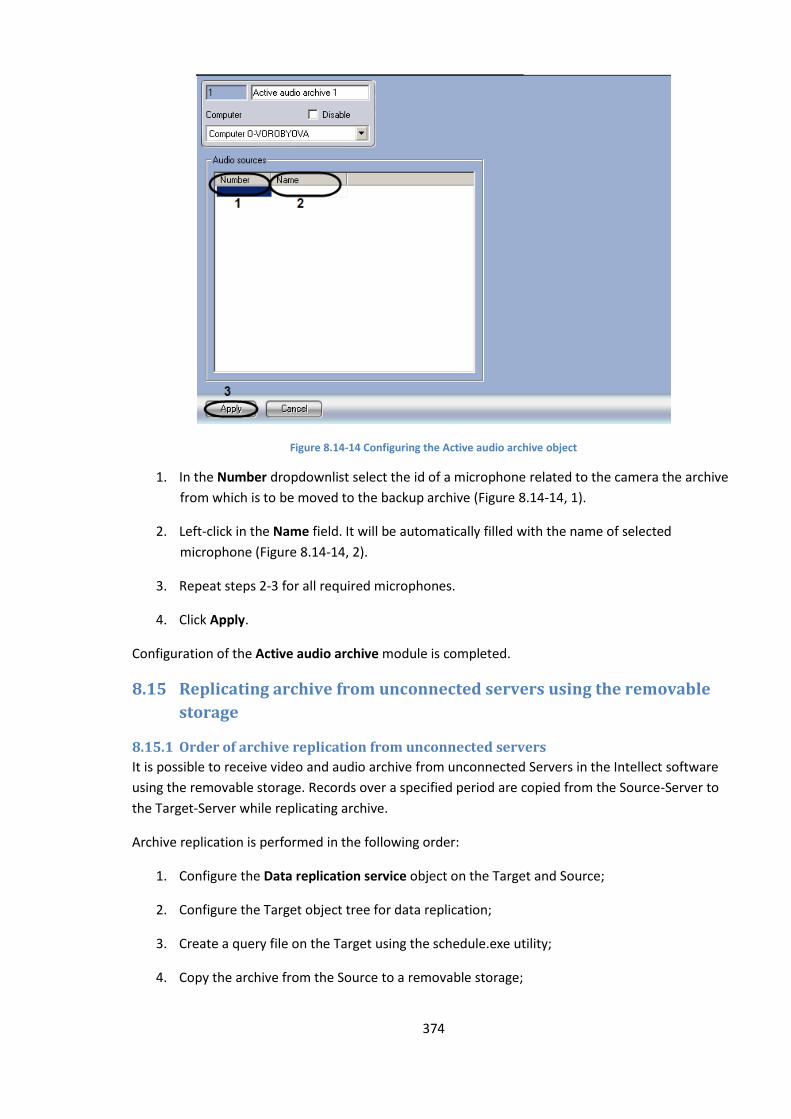
374
Figure 8.14-14 Configuring the Active audio archive object
1. In the Number dropdownlist select the id of a microphone related to the camera the archive
from which is to be moved to the backup archive (Figure 8.14-14, 1).
2. Left-click in the Name field. It will be automatically filled with the name of selected
microphone (Figure 8.14-14, 2).
3. Repeat steps 2-3 for all required microphones.
4. Click Apply.
Configuration of the Active audio archive module is completed.
8.15 Replicating archive from unconnected servers using the removable
storage
8.15.1 Order of archive replication from unconnected servers
It is possible to receive video and audio archive from unconnected Servers in the Intellect software
using the removable storage. Records over a specified period are copied from the Source-Server to
the Target-Server while replicating archive.
Archive replication is performed in the following order:
1. Configure the Data replication service object on the Target and Source;
2. Configure the Target object tree for data replication;
3. Create a query file on the Target using the schedule.exe utility;
4. Copy the archive from the Source to a removable storage;
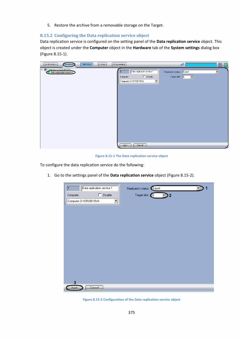
375
5. Restore the archive from a removable storage on the Target.
8.15.2 Configuring the Data replication service object
Data replication service is configured on the setting panel of the Data replication service object. This
object is created under the Computer object in the Hardware tab of the System settings dialog box
(Figure 8.15-1).
Figure 8.15-1 The Data replication service object
To configure the data replication service do the following:
1. Go to the settings panel of the Data replication service object (Figure 8.15-2).
Figure 8.15-2 Configuration of the Data replication service object
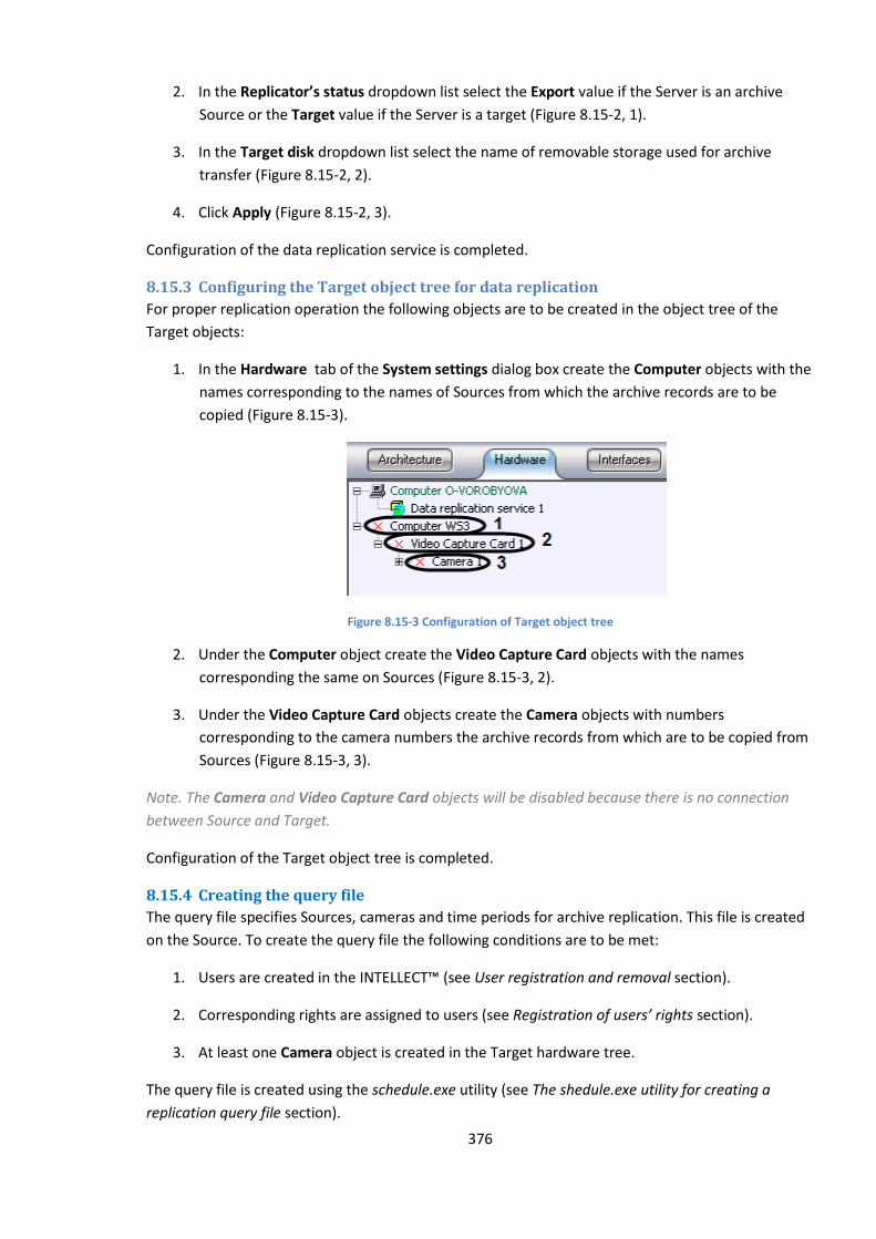
376
2. In the Replicator’s status dropdown list select the Export value if the Server is an archive
Source or the Target value if the Server is a target (Figure 8.15-2, 1).
3. In the Target disk dropdown list select the name of removable storage used for archive
transfer (Figure 8.15-2, 2).
4. Click Apply (Figure 8.15-2, 3).
Configuration of the data replication service is completed.
8.15.3 Configuring the Target object tree for data replication
For proper replication operation the following objects are to be created in the object tree of the
Target objects:
1. In the Hardware tab of the System settings dialog box create the Computer objects with the
names corresponding to the names of Sources from which the archive records are to be
copied (Figure 8.15-3).
Figure 8.15-3 Configuration of Target object tree
2. Under the Computer object create the Video Capture Card objects with the names
corresponding the same on Sources (Figure 8.15-3, 2).
3. Under the Video Capture Card objects create the Camera objects with numbers
corresponding to the camera numbers the archive records from which are to be copied from
Sources (Figure 8.15-3, 3).
Note. The Camera and Video Capture Card objects will be disabled because there is no connection
between Source and Target.
Configuration of the Target object tree is completed.
8.15.4 Creating the query file
The query file specifies Sources, cameras and time periods for archive replication. This file is created
on the Source. To create the query file the following conditions are to be met:
1. Users are created in the INTELLECT™ (see User registration and removal section).
2. Corresponding rights are assigned to users (see Registration of users’ rights section).
3. At least one Camera object is created in the Target hardware tree.
The query file is created using the schedule.exe utility (see The shedule.exe utility for creating a
replication query file section).
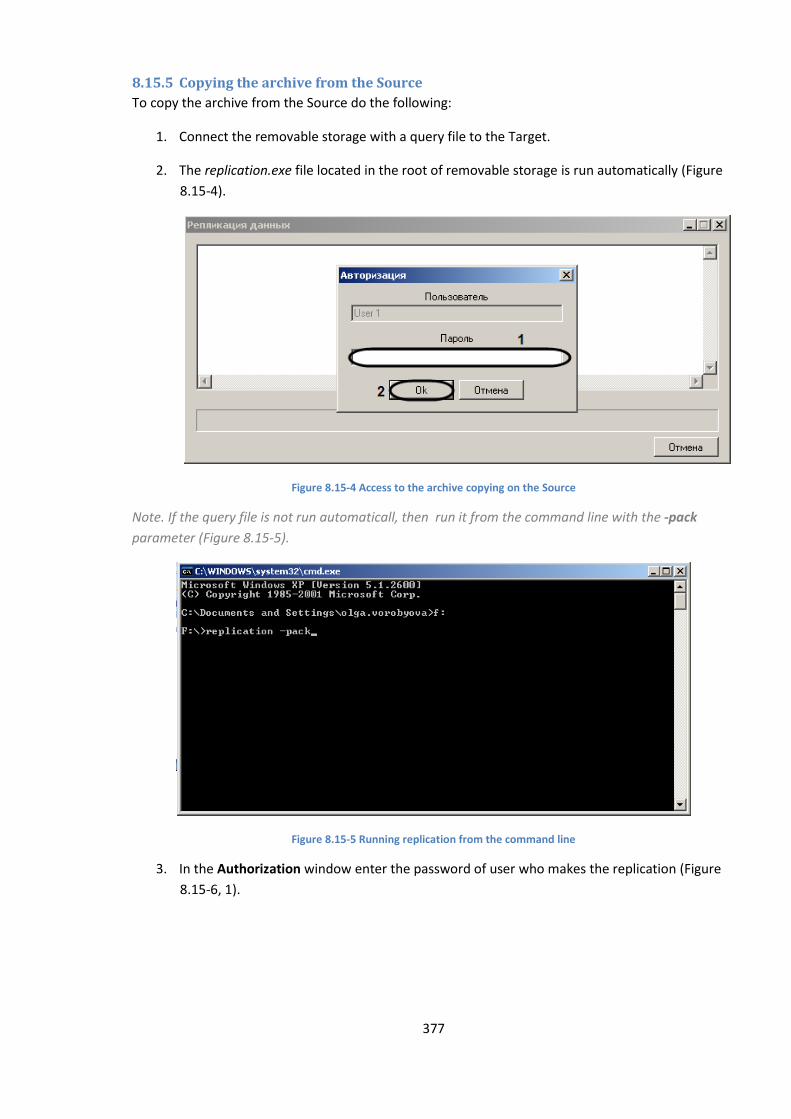
377
8.15.5 Copying the archive from the Source
To copy the archive from the Source do the following:
1. Connect the removable storage with a query file to the Target.
2. The replication.exe file located in the root of removable storage is run automatically (Figure
8.15-4).
Figure 8.15-4 Access to the archive copying on the Source
Note. If the query file is not run automaticall, then run it from the command line with the -pack
parameter (Figure 8.15-5).
Figure 8.15-5 Running replication from the command line
3. In the Authorization window enter the password of user who makes the replication (Figure
8.15-6, 1).
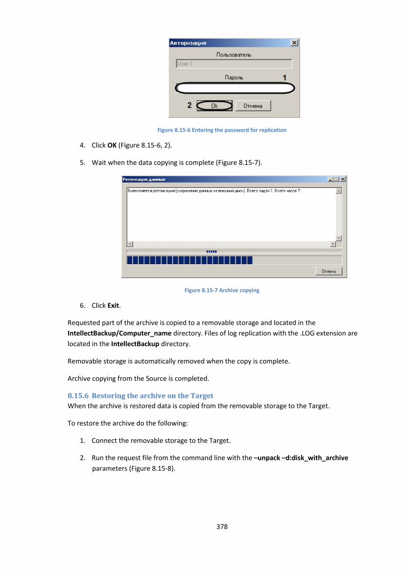
378
Figure 8.15-6 Entering the password for replication
4. Click OK (Figure 8.15-6, 2).
5. Wait when the data copying is complete (Figure 8.15-7).
Figure 8.15-7 Archive copying
6. Click Exit.
Requested part of the archive is copied to a removable storage and located in the
IntellectBackup/Computer_name directory. Files of log replication with the .LOG extension are
located in the IntellectBackup directory.
Removable storage is automatically removed when the copy is complete.
Archive copying from the Source is completed.
8.15.6 Restoring the archive on the Target
When the archive is restored data is copied from the removable storage to the Target.
To restore the archive do the following:
1. Connect the removable storage to the Target.
2. Run the request file from the command line with the –unpack –d:disk_with_archive
parameters (Figure 8.15-8).
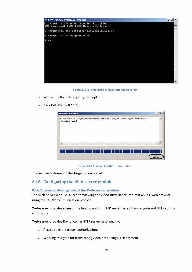
379
Figure 8.15-8 Running the archive restoring on Target
3. Wait when the data copying is complete.
4. Click Exit (Figure 8.15-9).
Figure 8.15-9 Completing the archive restore
The archive restoring on the Target is completed.
8.16 Configuring the Web-server module
8.16.1 General description of the Web-server module
The Web-server module is used for viewing the video surveillance information in a web browser
using the TCP/IP communication protocol.
Web-server provides some of the functions of an HTTP server, video transfer gate and HTTP control
commands.
Web-server provides the following HTTP server functionality:
1. Access control through authorization.
2. Working as a gate for transferring video data using HTTP protocol.

380
3. Video monitoring and camera control through the web browser using the TCP/IP
environment.
4. Control of camera movement through the web browser using the TCP/IP environment.
5. Setting the layout of the video frames on the screen: 1, 4, 6, 9 windows per screen.
6. Viewing the archives stored on the videoserver for each camera through the video
surveillance window.
7. Limiting access rights for viewing the video feed from the cameras, controlling the camera
movement, and viewing recordings from the videoserver.
8. Displaying the video signal parameters (frame rate (fps) and frame size (kB) in the
surveillance window.
Additionally, the Web-server acts as a Mobile-server providing video surveillance capabilities through
PocketPCs and SmartPhones.
The Web-server interface looks like a video surveillance monitor and is built as an HTML page. This
page is called the Web-server’s home page. The surveillance monitor and control elements for the
camera movement devices are driven by the Java applet.
Intellect software can be set up to require user authorization on entering the Web-server. Access to
viewing and controlling the movement of the cameras through the Web-server is defined by the
module settings.
8.16.2 System requirements
The Web-server module stable opration requires Java Runtime Environment version 1.6. 7 or higher
(mentioned software is included into the Intellect PC installation package) and browser Internet
Explorer version 8.0 and higher (this software is available free of charge).
8.16.3 Installation of Java Runtime Environment
The Web-server module working on videoservers and workstations of the Intellect-based surveillance
system requires Java Runtime Environment. This software is available free of charge.
The option for Java Runtime Environment installation is included in the Intellect software installation
procedure.
Java Runtime Environment should be manually installed on the remote workstations. The Java
installation package is available for downloading from www.java.com. If the Web-server home page
is accessed from a computer with no Java installed, the home page will contain a direct link to the
Java Runtime Environment installation package ready for downloading.
Note. It is necessary to install Java Runtime Environment not in quiet» mode. Otherwise the Intellect
may not respond displaying two possible messages:
1. «Error applying transforms. Verify that the specified transform paths are valid». - alternate
route s of this error are detailed on the site
«http://www.java.com/ru/download/help/error_applying_transforms.xml ».
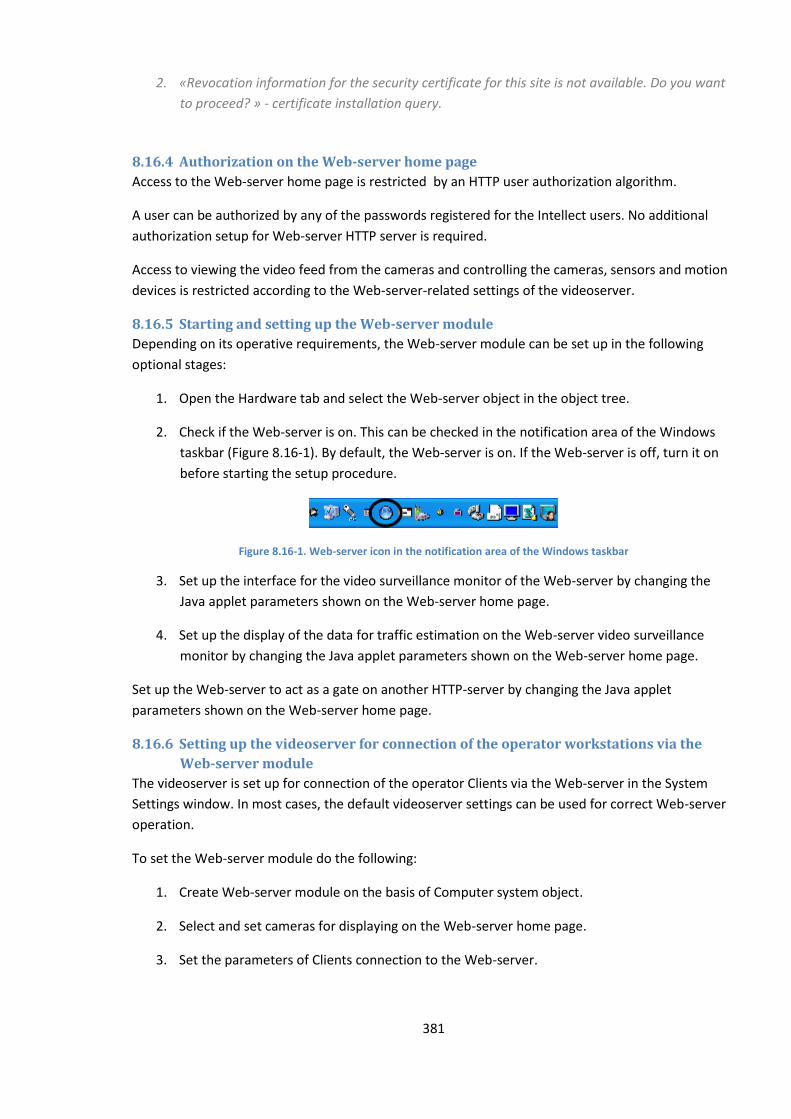
381
2. «Revocation information for the security certificate for this site is not available. Do you want
to proceed? » - certificate installation query.
8.16.4 Authorization on the Web-server home page
Access to the Web-server home page is restricted by an HTTP user authorization algorithm.
A user can be authorized by any of the passwords registered for the Intellect users. No additional
authorization setup for Web-server HTTP server is required.
Access to viewing the video feed from the cameras and controlling the cameras, sensors and motion
devices is restricted according to the Web-server-related settings of the videoserver.
8.16.5 Starting and setting up the Web-server module
Depending on its operative requirements, the Web-server module can be set up in the following
optional stages:
1. Open the Hardware tab and select the Web-server object in the object tree.
2. Check if the Web-server is on. This can be checked in the notification area of the Windows
taskbar (Figure 8.16-1). By default, the Web-server is on. If the Web-server is off, turn it on
before starting the setup procedure.
Figure 8.16-1. Web-server icon in the notification area of the Windows taskbar
3. Set up the interface for the video surveillance monitor of the Web-server by changing the
Java applet parameters shown on the Web-server home page.
4. Set up the display of the data for traffic estimation on the Web-server video surveillance
monitor by changing the Java applet parameters shown on the Web-server home page.
Set up the Web-server to act as a gate on another HTTP-server by changing the Java applet
parameters shown on the Web-server home page.
8.16.6 Setting up the videoserver for connection of the operator workstations via the
Web-server module
The videoserver is set up for connection of the operator Clients via the Web-server in the System
Settings window. In most cases, the default videoserver settings can be used for correct Web-server
operation.
To set the Web-server module do the following:
1. Create Web-server module on the basis of Computer system object.
2. Select and set cameras for displaying on the Web-server home page.
3. Set the parameters of Clients connection to the Web-server.
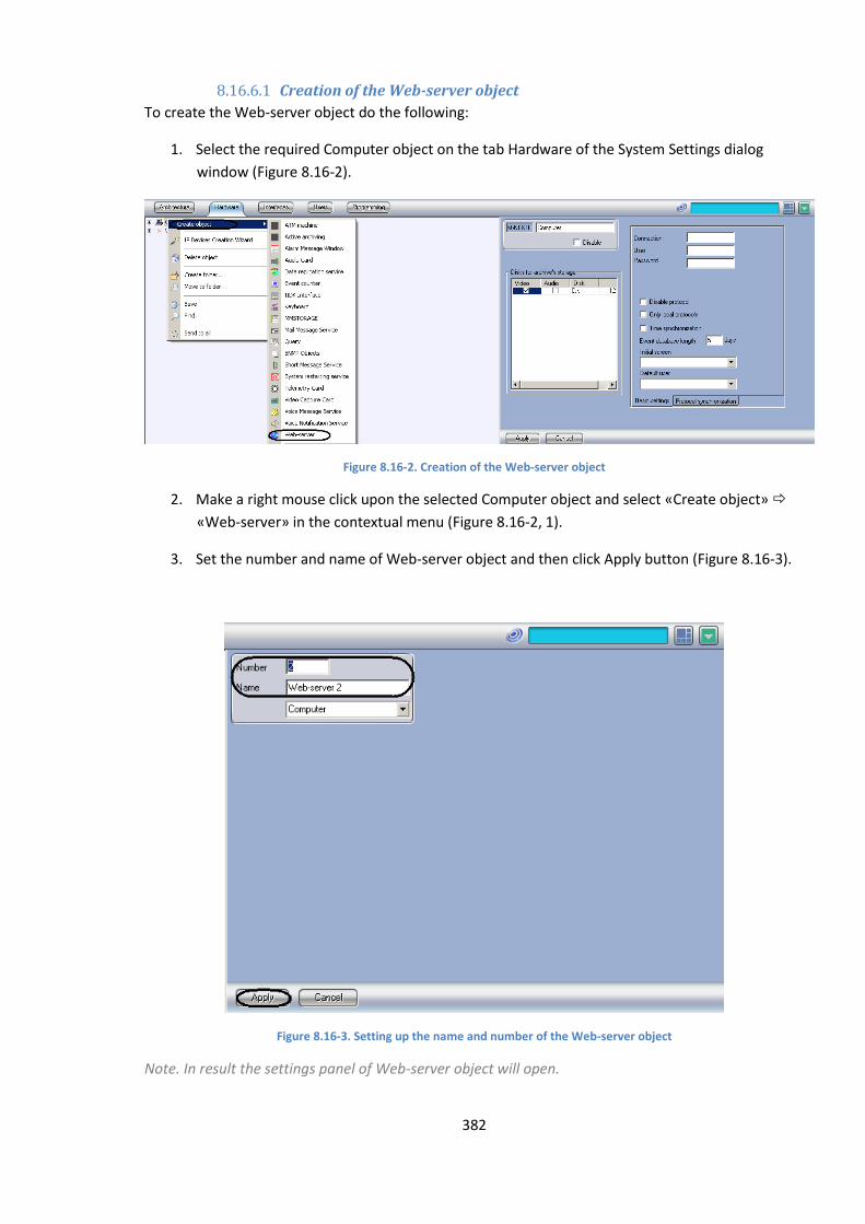
382
8.16.6.1 Creation of the Web-server object
To create the Web-server object do the following:
1. Select the required Computer object on the tab Hardware of the System Settings dialog
window (Figure 8.16-2).
Figure 8.16-2. Creation of the Web-server object
2. Make a right mouse click upon the selected Computer object and select «Create object»
«Web-server» in the contextual menu (Figure 8.16-2, 1).
3. Set the number and name of Web-server object and then click Apply button (Figure 8.16-3).
Figure 8.16-3. Setting up the name and number of the Web-server object
Note. In result the settings panel of Web-server object will open.
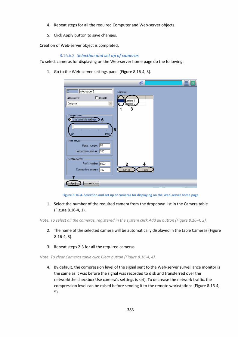
383
4. Repeat steps for all the required Computer and Web-server objects.
5. Click Apply button to save changes.
Creation of Web-server object is completed.
8.16.6.2 Selection and set up of cameras
To select cameras for displaying on the Web-server home page do the following:
1. Go to the Web-server settings panel (Figure 8.16-4, 3).
Figure 8.16-4. Selection and set up of cameras for displaying on the Web-server home page
1. Select the number of the required camera from the dropdown list in the Camera table
(Figure 8.16-4, 1).
Note. To select all the cameras, registered in the system click Add all button (Figure 8.16-4, 2).
2. The name of the selected camera will be automatically displayed in the table Cameras (Figure
8.16-4, 3).
3. Repeat steps 2-3 for all the required cameras
Note. To clear Cameras table click Clear button (Figure 8.16-4, 4).
4. By default, the compression level of the signal sent to the Web-server surveillance monitor is
the same as it was before the signal was recorded to disk and transferred over the
network(the checkbox Use camera’s settings is set). To decrease the network traffic, the
compression level can be raised before sending it to the remote workstations (Figure 8.16-4,
5).
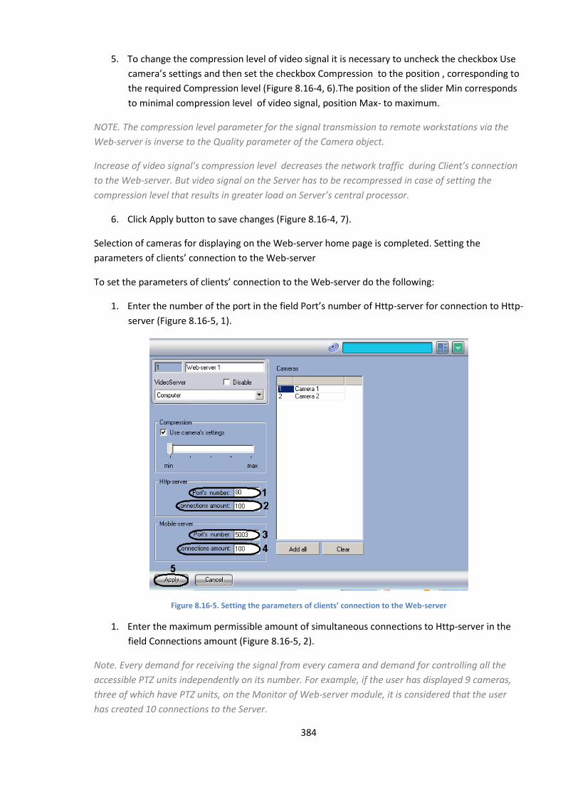
384
5. To change the compression level of video signal it is necessary to uncheck the checkbox Use
camera’s settings and then set the checkbox Compression to the position , corresponding to
the required Compression level (Figure 8.16-4, 6).The position of the slider Min corresponds
to minimal compression level of video signal, position Max- to maximum.
NOTE. The compression level parameter for the signal transmission to remote workstations via the
Web-server is inverse to the Quality parameter of the Camera object.
Increase of video signal’s compression level decreases the network traffic during Client’s connection
to the Web-server. But video signal on the Server has to be recompressed in case of setting the
compression level that results in greater load on Server’s central processor.
6. Click Apply button to save changes (Figure 8.16-4, 7).
Selection of cameras for displaying on the Web-server home page is completed. Setting the
parameters of clients’ connection to the Web-server
To set the parameters of clients’ connection to the Web-server do the following:
1. Enter the number of the port in the field Port’s number of Http-server for connection to Http-
server (Figure 8.16-5, 1).
Figure 8.16-5. Setting the parameters of clients’ connection to the Web-server
1. Enter the maximum permissible amount of simultaneous connections to Http-server in the
field Connections amount (Figure 8.16-5, 2).
Note. Every demand for receiving the signal from every camera and demand for controlling all the
accessible PTZ units independently on its number. For example, if the user has displayed 9 cameras,
three of which have PTZ units, on the Monitor of Web-server module, it is considered that the user
has created 10 connections to the Server.
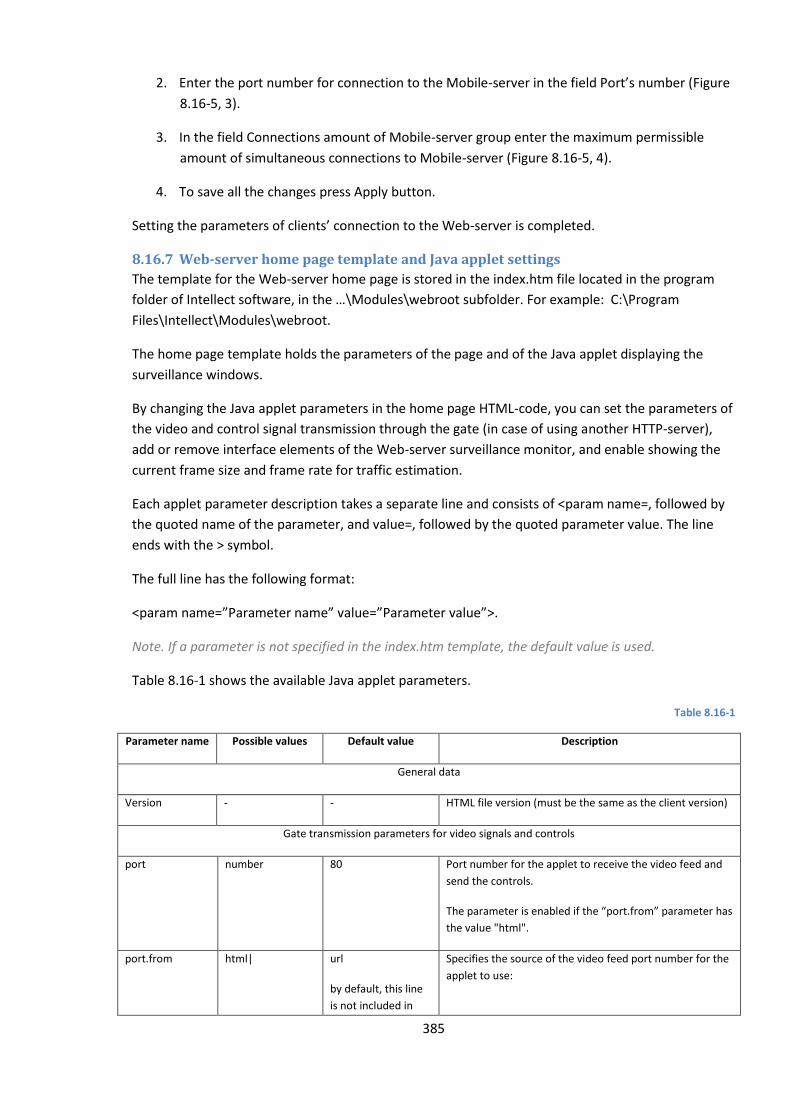
385
2. Enter the port number for connection to the Mobile-server in the field Port’s number (Figure
8.16-5, 3).
3. In the field Connections amount of Mobile-server group enter the maximum permissible
amount of simultaneous connections to Mobile-server (Figure 8.16-5, 4).
4. To save all the changes press Apply button.
Setting the parameters of clients’ connection to the Web-server is completed.
8.16.7 Web-server home page template and Java applet settings
The template for the Web-server home page is stored in the index.htm file located in the program
folder of Intellect software, in the …\Modules\webroot subfolder. For example: C:\Program
Files\Intellect\Modules\webroot.
The home page template holds the parameters of the page and of the Java applet displaying the
surveillance windows.
By changing the Java applet parameters in the home page HTML-code, you can set the parameters of
the video and control signal transmission through the gate (in case of using another HTTP-server),
add or remove interface elements of the Web-server surveillance monitor, and enable showing the
current frame size and frame rate for traffic estimation.
Each applet parameter description takes a separate line and consists of <param name=, followed by
the quoted name of the parameter, and value=, followed by the quoted parameter value. The line
ends with the > symbol.
The full line has the following format:
<param name=”Parameter name” value=”Parameter value”>.
Note. If a parameter is not specified in the index.htm template, the default value is used.
Table 8.16-1 shows the available Java applet parameters.
Table 8.16-1
Parameter name Possible values Default value Description
General data
Version - - HTML file version (must be the same as the client version)
Gate transmission parameters for video signals and controls
port number 80 Port number for the applet to receive the video feed and
send the controls.
The parameter is enabled if the “port.from” parameter has
the value "html".
port.from html| url
by default, this line
is not included in
Specifies the source of the video feed port number for the
applet to use:
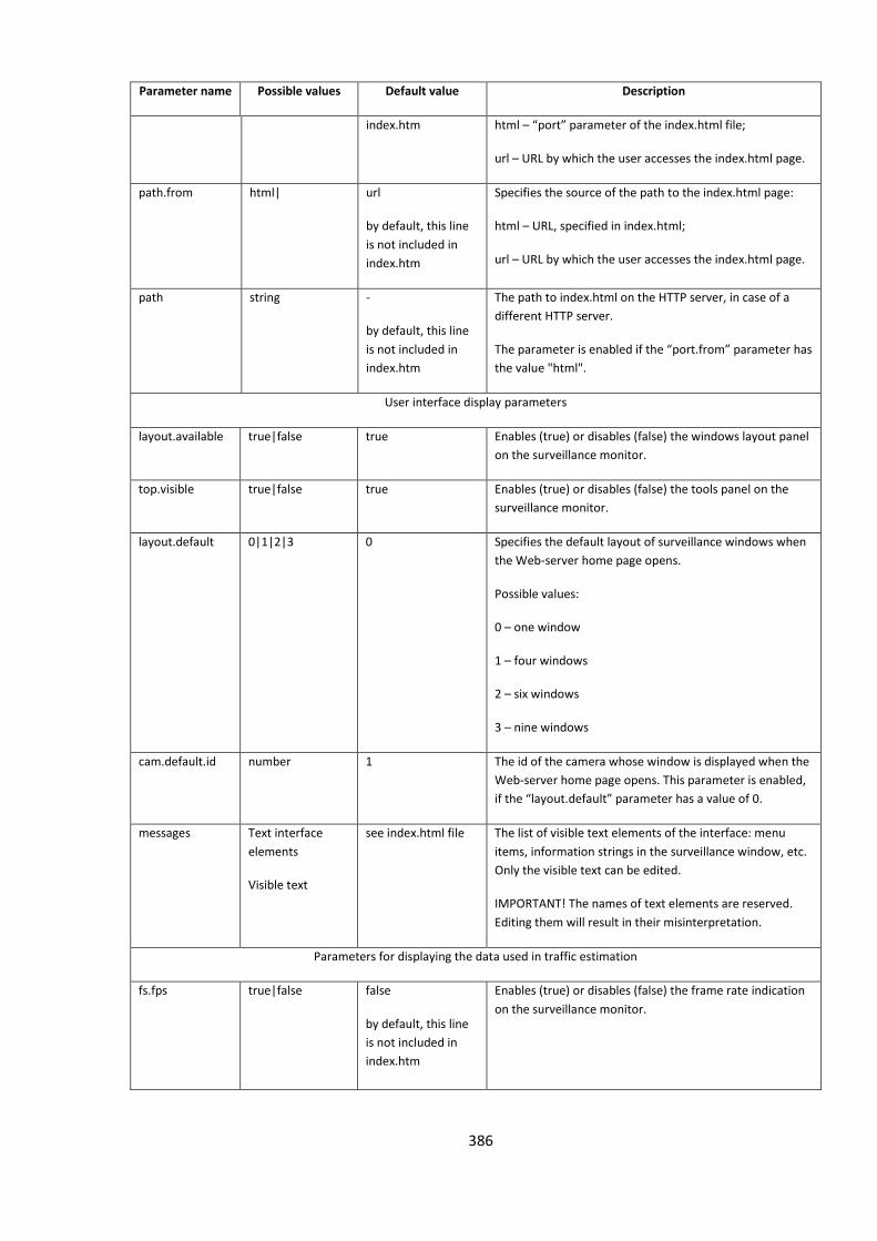
386
Parameter name Possible values Default value Description
index.htm html – “port” parameter of the index.html file;
url – URL by which the user accesses the index.html page.
path.from html| url
by default, this line
is not included in
index.htm
Specifies the source of the path to the index.html page:
html – URL, specified in index.html;
url – URL by which the user accesses the index.html page.
path string
-
by default, this line
is not included in
index.htm
The path to index.html on the HTTP server, in case of a
different HTTP server.
The parameter is enabled if the “port.from” parameter has
the value "html".
User interface display parameters
layout.available true|false true Enables (true) or disables (false) the windows layout panel
on the surveillance monitor.
top.visible true|false true Enables (true) or disables (false) the tools panel on the
surveillance monitor.
layout.default 0|1|2|3 0 Specifies the default layout of surveillance windows when
the Web-server home page opens.
Possible values:
0 – one window
1 – four windows
2 – six windows
3 – nine windows
cam.default.id number 1 The id of the camera whose window is displayed when the
Web-server home page opens. This parameter is enabled,
if the “layout.default” parameter has a value of 0.
messages Text interface
elements
Visible text
see index.html file The list of visible text elements of the interface: menu
items, information strings in the surveillance window, etc.
Only the visible text can be edited.
IMPORTANT! The names of text elements are reserved.
Editing them will result in their misinterpretation.
Parameters for displaying the data used in traffic estimation
fs.fps true|false false
by default, this line
is not included in
index.htm
Enables (true) or disables (false) the frame rate indication
on the surveillance monitor.
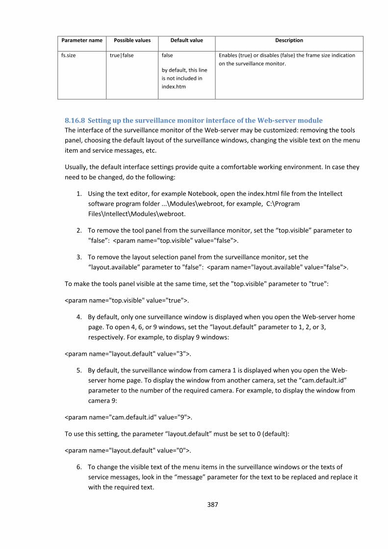
387
Parameter name Possible values Default value Description
fs.size true|false false
by default, this line
is not included in
index.htm
Enables (true) or disables (false) the frame size indication
on the surveillance monitor.
8.16.8 Setting up the surveillance monitor interface of the Web-server module
The interface of the surveillance monitor of the Web-server may be customized: removing the tools
panel, choosing the default layout of the surveillance windows, changing the visible text on the menu
item and service messages, etc.
Usually, the default interface settings provide quite a comfortable working environment. In case they
need to be changed, do the following:
1. Using the text editor, for example Notebook, open the index.html file from the Intellect
software program folder ...\Modules\webroot, for example, C:\Program
Files\Intellect\Modules\webroot.
2. To remove the tool panel from the surveillance monitor, set the “top.visible” parameter to
"false”: <param name="top.visible" value="false">.
3. To remove the layout selection panel from the surveillance monitor, set the
“layout.available” parameter to "false”: <param name="layout.available" value="false">.
To make the tools panel visible at the same time, set the "top.visible" parameter to "true":
<param name="top.visible" value="true">.
4. By default, only one surveillance window is displayed when you open the Web-server home
page. To open 4, 6, or 9 windows, set the “layout.default” parameter to 1, 2, or 3,
respectively. For example, to display 9 windows:
<param name="layout.default" value="3">.
5. By default, the surveillance window from camera 1 is displayed when you open the Web-
server home page. To display the window from another camera, set the “cam.default.id”
parameter to the number of the required camera. For example, to display the window from
camera 9:
<param name="cam.default.id" value="9">.
To use this setting, the parameter “layout.default” must be set to 0 (default):
<param name="layout.default" value="0">.
6. To change the visible text of the menu items in the surveillance windows or the texts of
service messages, look in the “message” parameter for the text to be replaced and replace it
with the required text.
388
For example, to replace the message text “Cable detached from the camera…” with the text “No
connection to the camera”, make the following changes to the “messages” parameter:
replace
<param name="messages" value="name=ITV WebServer client*detach=Cable detached from the
camera…*disable=Camera is off…* ……….>
with
<param name="messages" value="name=ITV WebServer client*detach=No connection with the
camera*disable=Camera is off…* ……….>
When changing the texts in menu items and messages, do not use the following symbols: ‘ * ’, ‘ = ’, ‘ “
‘.
7. Save changes to the index.htm file.
8.16.9 Setting up the display of the data for traffic estimation in the Web-server
Web-server operation uses network traffic. It’s important to estimate the traffic, because it must be
paid for.
The volume of network traffic when using the Web-server depends on the following factors:
1. the number of cameras displayed on the surveillance monitor;
2. compression level of the video signal;
3. frame size of the video signal;
4. frame rate of the video signal.
The traffic volume can be monitored on the Web-server surveillance window. When set up, the
current frame size and frame rate for each camera are shown in the surveillance windows. The traffic
is approximately estimated by the following formula:
Traffic = {Viewing time} * {Number of cameras} * {Average frame size} * {Average frame rate}
Formula 4. Traffic estimation
By default, the traffic estimation data is not shown. To set up the Web-server module to display the
traffic estimation data, do the following:
1. Using the text editor, for example Notebook, open the index.html file from the Intellect
software program folder...Modules\webroot. For example, C:\Program
Files\Intellect\Modules\webroot.
2. Add the following lines to the Java applet parameter list:
<param name="fs.size" value="true">
<param name="fs.fps" value="true">
389
3. Save changes to the index.htm file.
8.16.10 Setting up the Web-server module to act as a gate on a different HTTP-
server
By default, the Web-server module is set up to work as an independent HTTP-server. If a different
HTTP-server must be used to connect to the remote workstations, the Web-server should act as a
gate only for that HTTP-server and additional parameters should be set up.
For example, to use the Web-server for video surveillance, the user must open the page
http://www.*****.ru:8080/video/index.htm (asterisks “*****” represent the domain name of the
site where the cameras can be accessed). To set up the Web-server to act as a gate, do the following:
1. Using the text editor, for example Notebook, open the index.html file from the Intellect
software program folder...\Modules\webroot. For example, C:\Program
Files\Intellect\Modules\webroot.
2. By default, Java applet receives the video signal from http://www.*****.ru address.
3. For Java applet to receive the signal from http://www.*****.ru:222/reverse/proxy/, add the
following lines to the index.htm file:
<param name="port.from" value="html"> /add
<param name="path.from" value="html">
<param name="path" value="/reverse/proxy/">.
Set the “port” parameter to 222:
<param name="port" value="222">.
4. For Java applet to receive the signal from http://www.*****.ru:222, add the following line to
the index.htm file:
<param name="port.from" value="html">.
Set the “port” parameter to 222:
<param name="port" value="222">.
5. For Java applet to receive the signal from http://www.*****.ru/reverse/proxy/, add the
following lines to the index.htm file:
<param name="path.from" value="html">
<param name="path" value="/reverse/proxy/">.
6. Save changes to the index.htm file.
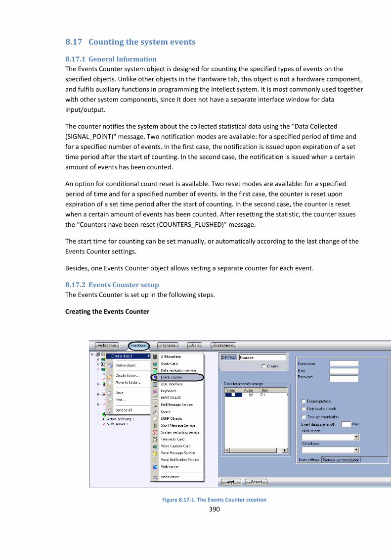
390
8.17 Counting the system events
8.17.1 General Information
The Events Counter system object is designed for counting the specified types of events on the
specified objects. Unlike other objects in the Hardware tab, this object is not a hardware component,
and fulfils auxiliary functions in programming the Intellect system. It is most commonly used together
with other system components, since it does not have a separate interface window for data
input/output.
The counter notifies the system about the collected statistical data using the “Data Collected
(SIGNAL_POINT)" message. Two notification modes are available: for a specified period of time and
for a specified number of events. In the first case, the notification is issued upon expiration of a set
time period after the start of counting. In the second case, the notification is issued when a certain
amount of events has been counted.
An option for conditional count reset is available. Two reset modes are available: for a specified
period of time and for a specified number of events. In the first case, the counter is reset upon
expiration of a set time period after the start of counting. In the second case, the counter is reset
when a certain amount of events has been counted. After resetting the statistic, the counter issues
the “Counters have been reset (COUNTERS_FLUSHED)” message.
The start time for counting can be set manually, or automatically according to the last change of the
Events Counter settings.
Besides, one Events Counter object allows setting a separate counter for each event.
8.17.2 Events Counter setup
The Events Counter is set up in the following steps.
Creating the Events Counter
Figure 8.17-1. The Events Counter creation
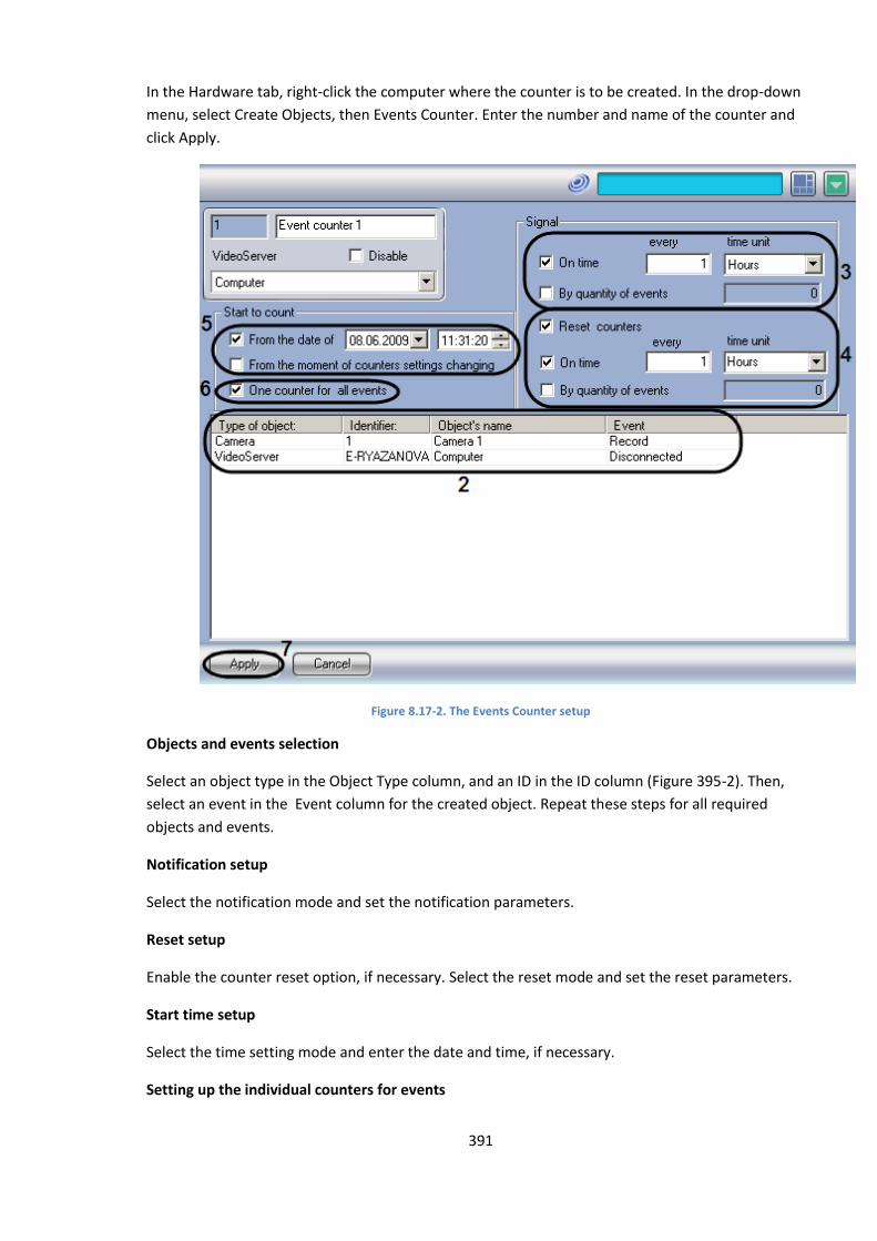
391
In the Hardware tab, right-click the computer where the counter is to be created. In the drop-down
menu, select Create Objects, then Events Counter. Enter the number and name of the counter and
click Apply.
Figure 8.17-2. The Events Counter setup
Objects and events selection
Select an object type in the Object Type column, and an ID in the ID column (Figure 395-2). Then,
select an event in the Event column for the created object. Repeat these steps for all required
objects and events.
Notification setup
Select the notification mode and set the notification parameters.
Reset setup
Enable the counter reset option, if necessary. Select the reset mode and set the reset parameters.
Start time setup
Select the time setting mode and enter the date and time, if necessary.
Setting up the individual counters for events
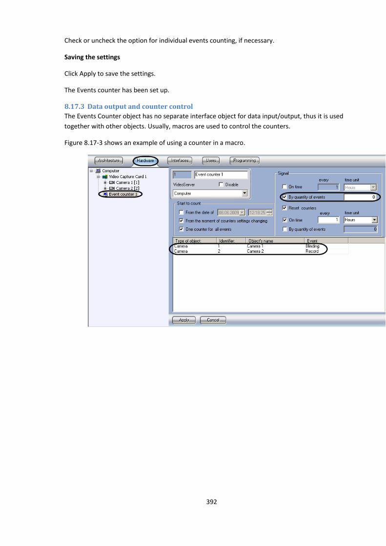
392
Check or uncheck the option for individual events counting, if necessary.
Saving the settings
Click Apply to save the settings.
The Events counter has been set up.
8.17.3 Data output and counter control
The Events Counter object has no separate interface object for data input/output, thus it is used
together with other objects. Usually, macros are used to control the counters.
Figure 8.17-3 shows an example of using a counter in a macro.

393
Figure 8.17-3. An example of the counter usage
The counter issues a notification (sends a “SIGNAL_POINT (Data collected)” message in any of the
following cases: camera 1 blocked, camera 2 blocked, camera 1 connection lost, unauthorized access
attempt, the number of access attempts exceeded the limit. If the Access Abuse Control macro is
active at the moment of the counter notification, video recording automatically starts on cameras 1
and 2.
Note. The macros are described in detail in the Creating and Using Macros section.
8.18 Setting up the Event Viewer
8.18.1 Setting up the interface object «Events viewer»
8.18.1.1 Order of setting up the interface object «Event viewer»
The «Events viewer» object is a child-object of interface object «Screen» and is used for displaying
information about registered events in the interface window. Events may be registered both locally
and on the computers in the distributed system.
Note. Events transmission among computers is set on the «Architecture» tab in the Systems Settings
dialog window (See Setting of distributed system’s components interaction).
Creation and setting of interface object «Event viewer» is performed on the «Interface» tab in the
System Settings dialog window (Figure 8.18-1).
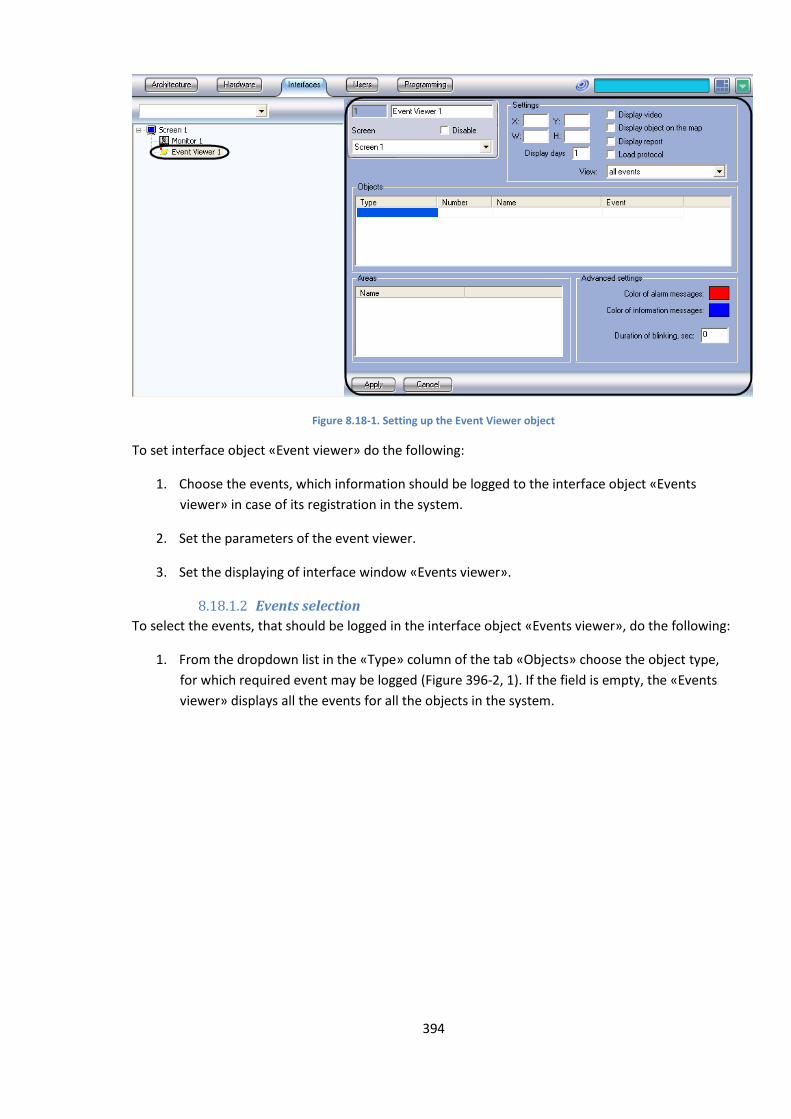
394
Figure 8.18-1. Setting up the Event Viewer object
To set interface object «Event viewer» do the following:
1. Choose the events, which information should be logged to the interface object «Events
viewer» in case of its registration in the system.
2. Set the parameters of the event viewer.
3. Set the displaying of interface window «Events viewer».
8.18.1.2 Events selection
To select the events, that should be logged in the interface object «Events viewer», do the following:
1. From the dropdown list in the «Type» column of the tab «Objects» choose the object type,
for which required event may be logged (Figure 396-2, 1). If the field is empty, the «Events
viewer» displays all the events for all the objects in the system.

395
Figure 8.18-2. Event selection for logging in the Events viewer
Note. Activation of the dropdown list in the tab «Objects» and in the list «Areas» is made by LMC
upon the corresponding cell. Detailed description of actions with tabs and lists is in the Objects setting
tab.
1. From the down drop list in the column «Number» of the tab «Objects» specify the id for an
object of the type selected in step 1(Figure 8.18-2, 2). If the field is empty, the interface
«Events viewer» will log all the events of the specified type.
2. Object name is set automatically on the basis of the values, selected in step 1-2 and displayed
in the column «Name» of the tab «Objects» (Figure 8.18-2, 3). Column«Name» is inaccessible
for editing.
3. From the down drop list in the column «Event» of the tab «Objects» specify the required
event for the selected object in step 1-2 (Figure 8.18-2, 4).If the field is empty, the interface
object «Objects viewer» will log all the events, registered for the specified object.
4. From the down drop list in the list «Areas» select the region, which events will be logged in
the interface object «Objects viewer» (Figure 8.18-2, 5). When region is empty, events of all
the regions, registered in the system will be logged. Repeat steps 1-5 for all the required
objects and regions.
5. Press the «Apply» button to save all changes made to the settings (Figure 8.18-2, 6).
Events selection for logging in the interface object «Events viewer» is over.
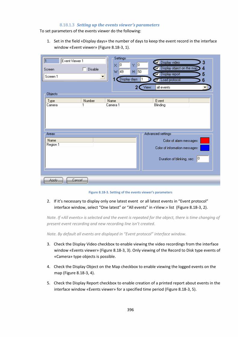
396
8.18.1.3 Setting up the events viewer’s parameters
To set parameters of the events viewer do the following:
1. Set in the field «Display days» the number of days to keep the event record in the interface
window «Event viewer» (Figure 8.18-3, 1).
Figure 8.18-3. Setting of the events viewer’s parameters
2. If it’s necessary to display only one latest event or all latest events in “Event protocol”
interface window, select “One latest” or “All events” in «View:» list (Figure 8.18-3, 2).
Note. If «All events» is selected and the event is repeated for the object, there is time changing of
present event recording and new recording line isn’t created.
Note. By default all events are displayed in “Event protocol” interface window.
3. Check the Display Video checkbox to enable viewing the video recordings from the interface
window «Events viewer» (Figure 8.18-3, 3). Only viewing of the Record to Disk type events of
«Camera» type objects is possible.
4. Check the Display Object on the Map checkbox to enable viewing the logged events on the
map (Figure 8.18-3, 4).
5. Check the Display Report checkbox to enable creation of a printed report about events in the
interface window «Events viewer» for a specified time period (Figure 8.18-3, 5).
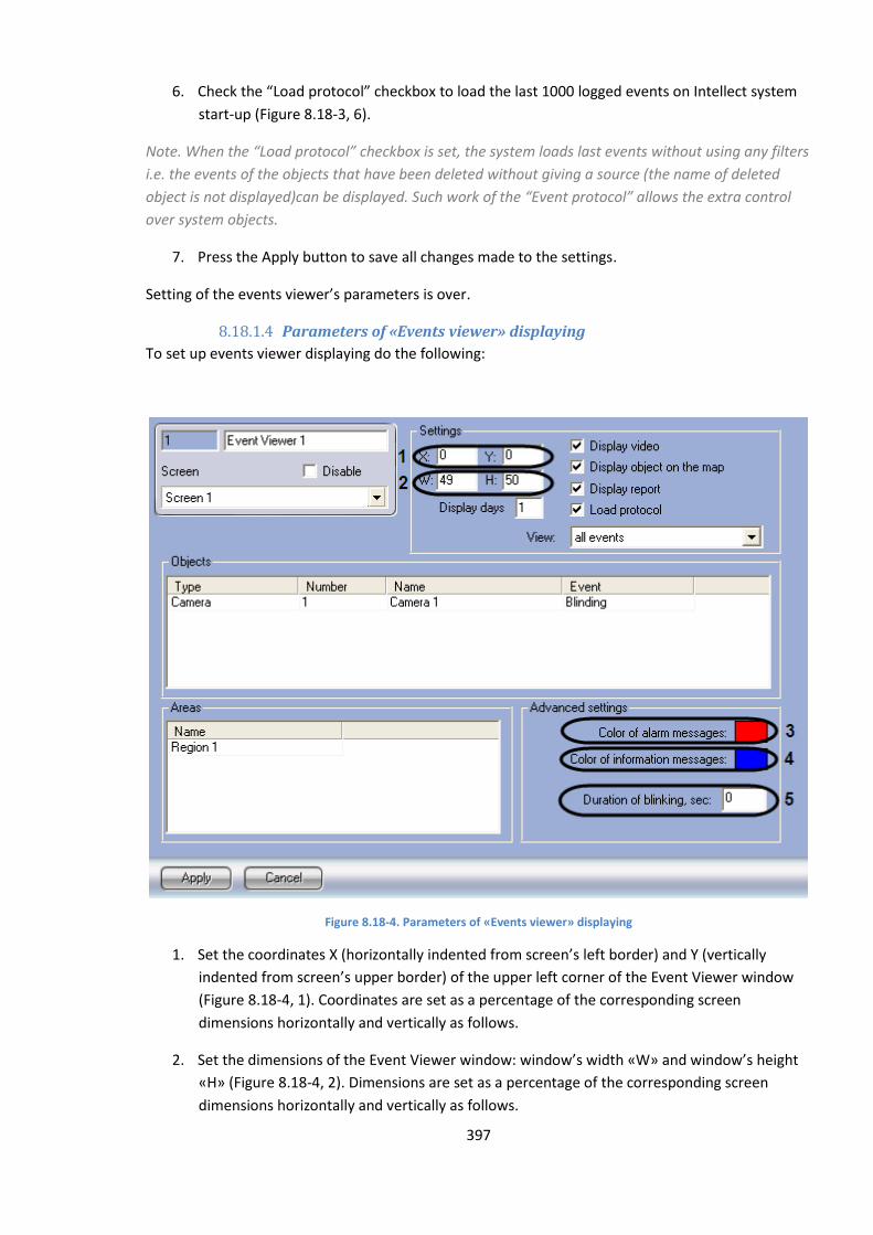
397
6. Check the “Load protocol” checkbox to load the last 1000 logged events on Intellect system
start-up (Figure 8.18-3, 6).
Note. When the “Load protocol” checkbox is set, the system loads last events without using any filters
i.e. the events of the objects that have been deleted without giving a source (the name of deleted
object is not displayed)can be displayed. Such work of the “Event protocol” allows the extra control
over system objects.
7. Press the Apply button to save all changes made to the settings.
Setting of the events viewer’s parameters is over.
8.18.1.4 Parameters of «Events viewer» displaying
To set up events viewer displaying do the following:
Figure 8.18-4. Parameters of «Еvents viewer» displaying
1. Set the coordinates X (horizontally indented from screen’s left border) and Y (vertically
indented from screen’s upper border) of the upper left corner of the Event Viewer window
(Figure 8.18-4, 1). Coordinates are set as a percentage of the corresponding screen
dimensions horizontally and vertically as follows.
2. Set the dimensions of the Event Viewer window: window’s width «W» and window’s height
«H» (Figure 8.18-4, 2). Dimensions are set as a percentage of the corresponding screen
dimensions horizontally and vertically as follows.
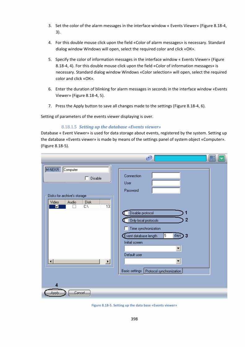
398
3. Set the color of the alarm messages in the interface window « Events Viewer» (Figure 8.18-4,
3).
4. For this double mouse click upon the field «Сolor of alarm messages» is necessary. Standard
dialog window Windows will open, select the required color and click «ОК».
5. Specify the color of information messages in the interface window « Events Viewer» (Figure
8.18-4, 4). For this double mouse click upon the field «Сolor of information messages» is
necessary. Standard dialog window Windows «Color selection» will open, select the required
color and click «ОК».
6. Enter the duration of blinking for alarm messages in seconds in the interface window «Events
Viewer» (Figure 8.18-4, 5).
7. Press the Apply button to save all changes made to the settings (Figure 8.18-4, 6).
Setting of parameters of the events viewer displaying is over.
8.18.1.5 Setting up the database «Events viewer»
Database « Event Viewer» is used for data storage about events, registered by the system. Setting up
the database «Events viewer» is made by means of the settings panel of system object «Computer».
(Figure 8.18-5).
Figure 8.18-5. Setting up the data base «Events viewer»
399
To set up the database «Events viewer» do the following:
1. To disable events recording to the database «Events viewer» check the «Disable protocol»
checkbox (Figure 396-5, 1).
2. Check the «Only local protocols» checkbox in case when only registered in this computer
events should be logged to the database (Figure 396-5, 2).
3. Enter in the field «Event database length» time of events’ archive storage in days (Figure 396-
5, 3).
4. Press the Apply button to save all changes made to the settings (Figure 396-5, 4).
Note. Step 3 is used for events viewing in the system of distributed configuration.
Setting up the database «Events viewer» is over.
Note. For setting up the events viewer tweaki.exe utility can also be used (see. Additional settings of
the events viewer).
8.19 Setting up the interactive map for object state indication and
controlling the objects
8.19.1 General information on the structure of the interactive map of the guarded
location
The interactive map of the Intellect system uses graphical diagrams of the guarded territory to
navigate among the surveillance system components. The interactive map allows controlling the
objects from the context menus of the graphical symbols on the map showing the states of the
corresponding objects.
The interactive map can be comprised of a set of plans (layers) made of photographs, maps,
diagrams, drawings in BMP format. The size and resolution of the images is not limited.
Note A. We recommend creating the images in third-party graphical software packages (Microsoft
Paint, Adobe Photoshop, etc), as the standard delivery configuration of Intellect software does not
include tools for image editing.
Note B. A plan (map layer) may be an image in BMP format.
There are no limitations on the image size and resolution, so a large image may not fit into the
screen, or the objects shown on it may look indiscernible.
8.19.2 Setting up the interactive map
8.19.2.1 Setup procedure
To set up interactive map do the following:
1. Create and set the interface object Map
2. Create and set objects Layer on the basis of interface object Map
3. Attach required objects to the Layers of interactive map.
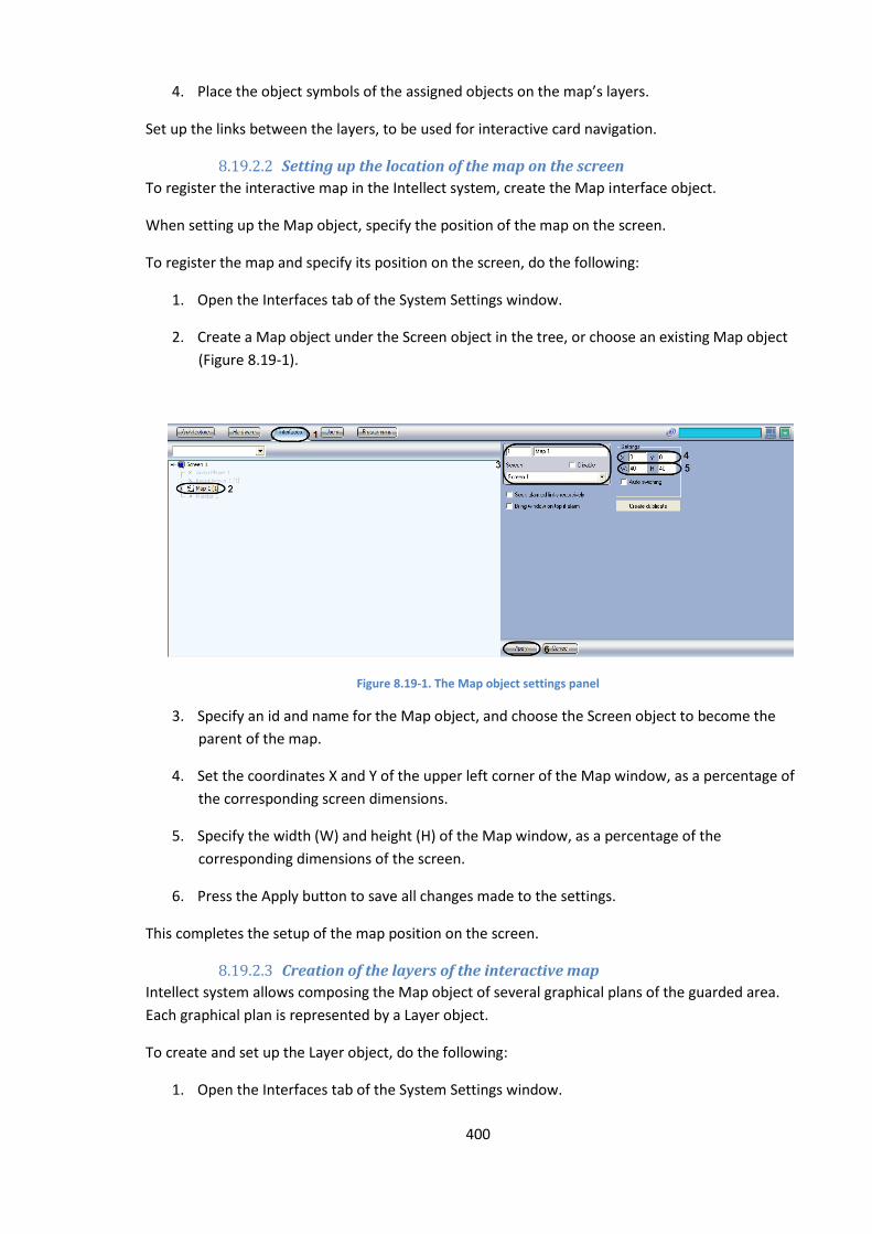
400
4. Place the object symbols of the assigned objects on the map’s layers.
Set up the links between the layers, to be used for interactive card navigation.
8.19.2.2 Setting up the location of the map on the screen
To register the interactive map in the Intellect system, create the Map interface object.
When setting up the Map object, specify the position of the map on the screen.
To register the map and specify its position on the screen, do the following:
1. Open the Interfaces tab of the System Settings window.
2. Create a Map object under the Screen object in the tree, or choose an existing Map object
(Figure 8.19-1).
Figure 8.19-1. The Map object settings panel
3. Specify an id and name for the Map object, and choose the Screen object to become the
parent of the map.
4. Set the coordinates X and Y of the upper left corner of the Map window, as a percentage of
the corresponding screen dimensions.
5. Specify the width (W) and height (H) of the Map window, as a percentage of the
corresponding dimensions of the screen.
6. Press the Apply button to save all changes made to the settings.
This completes the setup of the map position on the screen.
8.19.2.3 Creation of the layers of the interactive map
Intellect system allows composing the Map object of several graphical plans of the guarded area.
Each graphical plan is represented by a Layer object.
To create and set up the Layer object, do the following:
1. Open the Interfaces tab of the System Settings window.
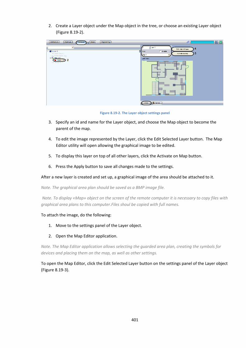
401
2. Create a Layer object under the Map object in the tree, or choose an existing Layer object
(Figure 8.19-2).
Figure 8.19-2. The Layer object settings panel
3. Specify an id and name for the Layer object, and choose the Map object to become the
parent of the map.
4. To edit the image represented by the Layer, click the Edit Selected Layer button. The Map
Editor utility will open allowing the graphical image to be edited.
5. To display this layer on top of all other layers, click the Activate on Map button.
6. Press the Apply button to save all changes made to the settings.
After a new layer is created and set up, a graphical image of the area should be attached to it.
Note. The graphical area plan should be saved as a BMP image file.
Note. To display «Map» object on the screen of the remote computer it is necessary to copy files with
graphical area plans to this computer.Files shoul be copied with full names.
To attach the image, do the following:
1. Move to the settings panel of the Layer object.
2. Open the Map Editor application.
Note. The Map Editor application allows selecting the guarded area plan, creating the symbols for
devices and placing them on the map, as well as other settings.
To open the Map Editor, click the Edit Selected Layer button on the settings panel of the Layer object
(Figure 8.19-3).
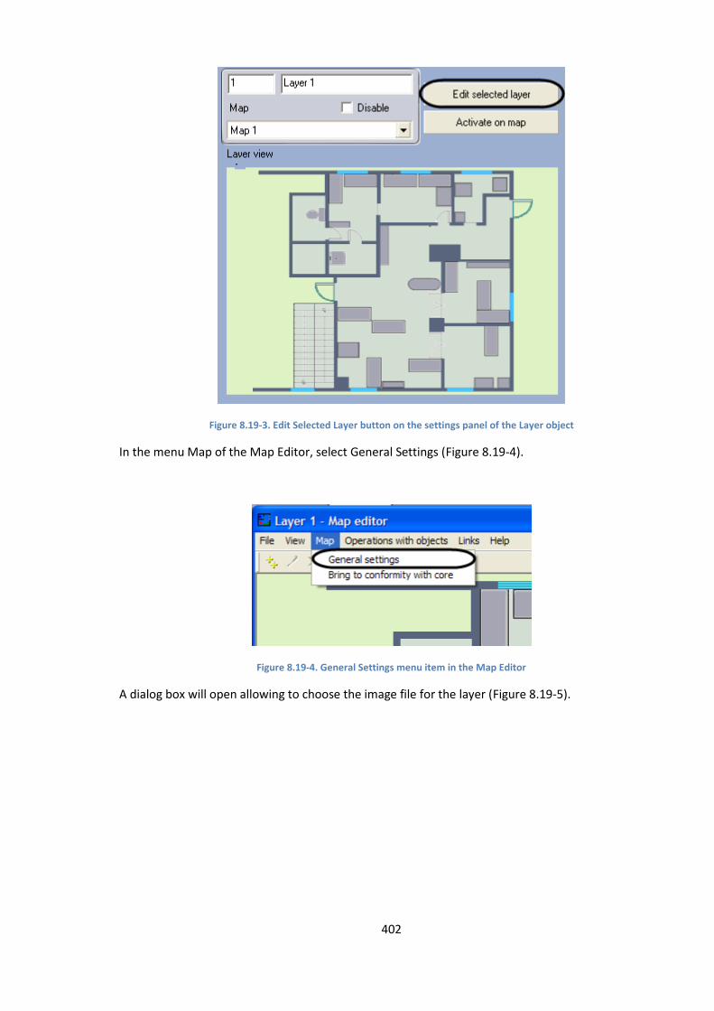
402
Figure 8.19-3. Edit Selected Layer button on the settings panel of the Layer object
In the menu Map of the Map Editor, select General Settings (Figure 8.19-4).
Figure 8.19-4. General Settings menu item in the Map Editor
A dialog box will open allowing to choose the image file for the layer (Figure 8.19-5).

403
Figure 8.19-5. Settings dialog box for the image being attached to the layer
This dialog box can also be accessed from the Set Background item of the context menu of the map
area (Figure 8.19-6).
Figure 8.19-6. Selecting the Set Background item
Press the button in the Settings dialog box (Figure 8.19-7).
Figure 8.19-7. Browsing for the file to attach
A standard dialog box will open allowing to choose the image file for the layer (Figure 8.19-).

404
Figure 8.19-8. Standard dialog box allowing to choose the file to be used as a guarded area plan
Open a BMP file and click the Open button.
Specify the size of the image in pixels (Figure 8.19-8).
Figure 8.19-8. Image size in pixels
The values entered in the Width and Height fields should match actual resolution of the image file.
1. Specify the dimensions of the real area represented by the image, in meters (Figure 8.19-9).
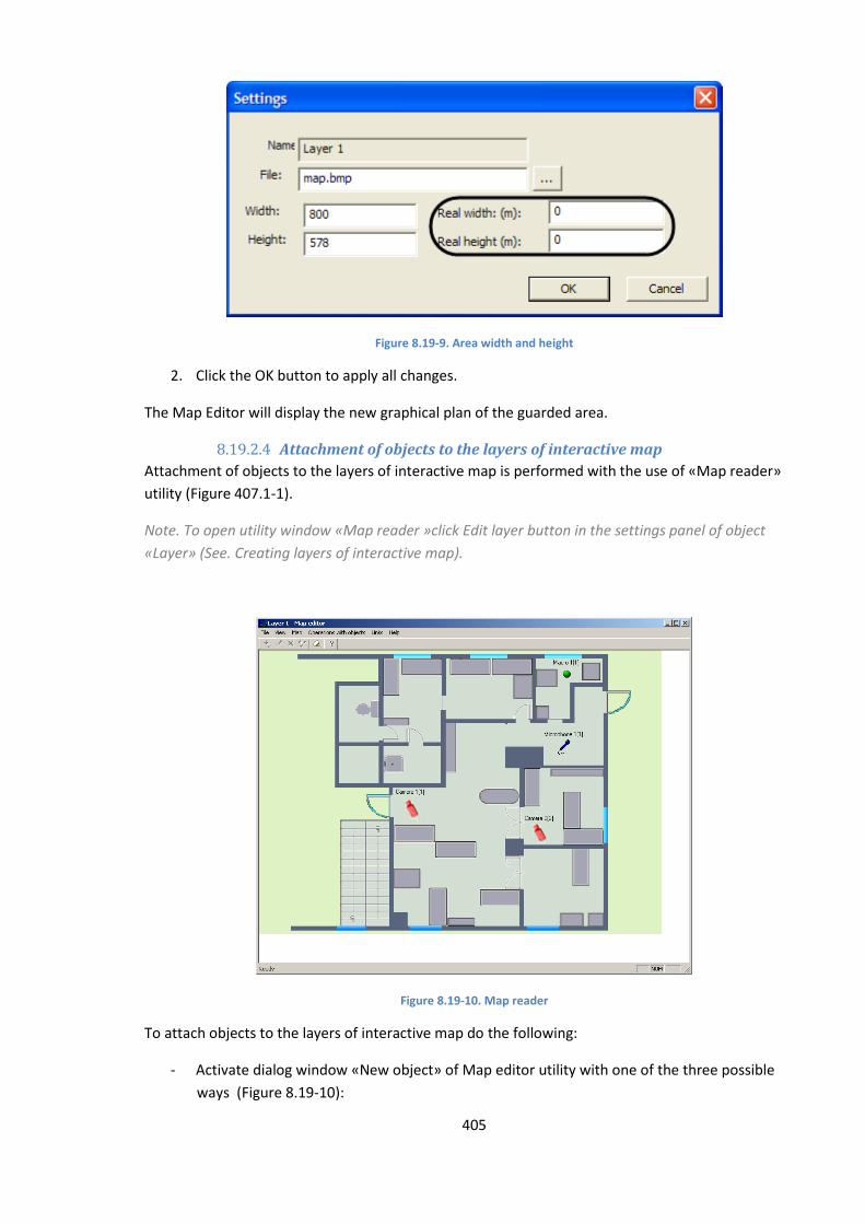
405
Figure 8.19-9. Area width and height
2. Click the OK button to apply all changes.
The Map Editor will display the new graphical plan of the guarded area.
8.19.2.4 Attachment of objects to the layers of interactive map
Attachment of objects to the layers of interactive map is performed with the use of «Map reader»
utility (Figure 407.1-1).
Note. To open utility window «Map reader »click Edit layer button in the settings panel of object
«Layer» (See. Creating layers of interactive map).
Figure 8.19-10. Map reader
To attach objects to the layers of interactive map do the following:
- Activate dialog window «New object» of Map editor utility with one of the three possible
ways (Figure 8.19-10):
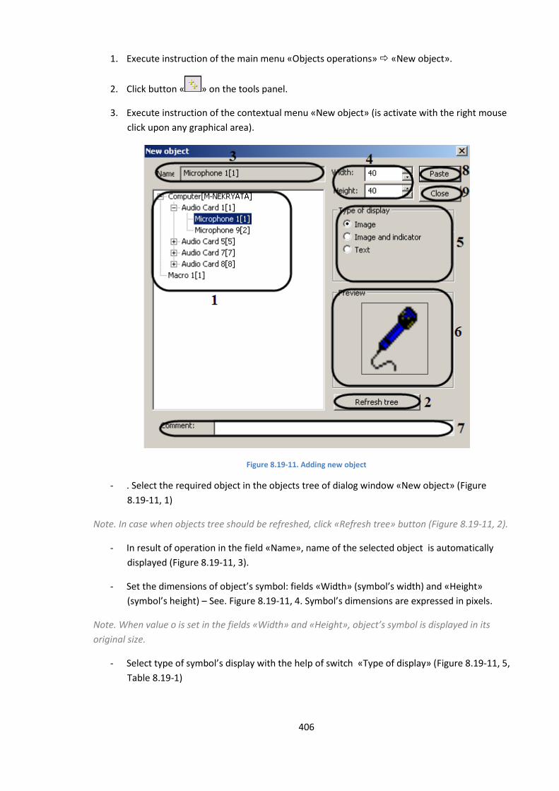
406
1. Execute instruction of the main menu «Objects operations» «New object».
2. Click button « » on the tools panel.
3. Execute instruction of the contextual menu «New object» (is activate with the right mouse
click upon any graphical area).
Figure 8.19-11. Adding new object
- . Select the required object in the objects tree of dialog window «New object» (Figure
8.19-11, 1)
Note. In case when objects tree should be refreshed, click «Refresh tree» button (Figure 8.19-11, 2).
- In result of operation in the field «Name», name of the selected object is automatically
displayed (Figure 8.19-11, 3).
- Set the dimensions of object’s symbol: fields «Width» (symbol’s width) and «Height»
(symbol’s height) – See. Figure 8.19-11, 4. Symbol’s dimensions are expressed in pixels.
Note. When value o is set in the fields «Width» and «Height», object’s symbol is displayed in its
original size.
- Select type of symbol’s display with the help of switch «Type of display» (Figure 8.19-11, 5,
Table 8.19-1)
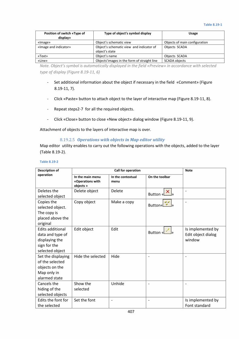
407
Table 8.19-1
Position of switch «Type of display»
Type of object’s symbol display Usage
«Image» Object’s schematic view Objects of main configuration
«Image and indicator» Object’s schematic view and indicator of object’s state
Objects SCADA
«Text» Object’s name Objects SCADA
«Line» Objects’images in the form of straight line SCADA objects
Note. Object’s symbol is automatically displayed in the field «Preview» in accordance with selected
type of display (Figure 8.19-11, 6)
- Set additional information about the object if necessary in the field «Comment» (Figure
8.19-11, 7).
- Click «Paste» button to attach object to the layer of interactive map (Figure 8.19-11, 8).
- Repeat steps2-7 for all the required objects.
- Click «Close» button to close «New object» dialog window (Figure 8.19-11, 9).
Attachment of objects to the layers of interactive map is over.
8.19.2.5 Operations with objects in Map editor utility
Map editor utility enables to carry out the following operations with the objects, added to the layer
(Table 8.19-2).
Table 8.19-2
Description of operation
Call for operation Note
In the main menu «Operations with objects »
In the contextual menu
On the toolbar
Deletes the selected object
Delete object Delete Button « »
-
Copies the selected object. The copy is placed above the original
Copy object Make a copy Button« »
-
Edits additional data and type of displaying the sign for the selected object
Edit object Edit Button « »
Is implemented by Edit object dialog window
Set the displaying of the selected objects on the Map only in alarmed state
Hide the selected Hide - -
Cancels the hiding of the selected objects
Show the selected
Unhide - -
Edits the font for the selected
Set the font - - Is implemented by Font standard

408
Description of operation
Call for operation Note
In the main menu «Operations with objects »
In the contextual menu
On the toolbar
object’s name Windows dialog window
Restores the deleted name of the selected object
Restores the title object
- - -
Edits the size of the selected object
Objects’ sizes - - Is implemented by Object size dialog window
Edits the position of the selected object
Object’s position Object’s position - Is implemented by Object position dialog window or with the help of the mouse
Selects objects of one group
- Selects all the identical
- For example: all the Camera objects are selected
Selects all the identical objects within a group
- Selects all the identical
- For example: all the Ray objects of Gerkon type are selected
Edit map utility enables to carry out the operations with a group of objects. For selecting the several
objects it is necessary to hold the «Ctrl» key on the keyboard.
Note. Operation Object position with a group of objects is not performed.
Editing the additional data and type of object’s displaying is done in the following way:
1. Select an object that is to be edited. Green-pointed frame will appear around the image in
result.
2. Call for Edit object dialog window of Edit map utility by one of the three ways (Figure
8.19-12):
a. Carry out the command of the main menu «Operations with objects » -> «Edit
object»;
b. Click « » button on the toolbar;
c. Carry out the Edit command of the contextual menu (is called by clicking the right
mouse button over the object’s image).
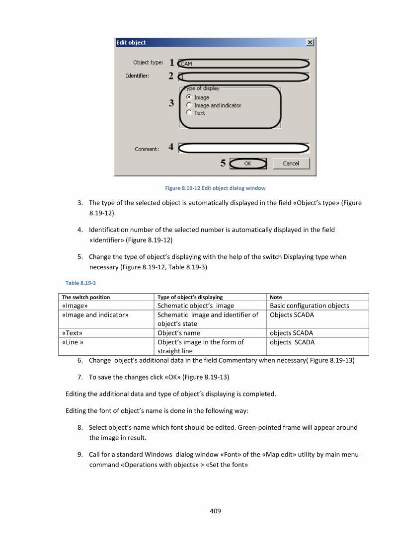
409
Figure 8.19-12 Edit object dialog window
3. The type of the selected object is automatically displayed in the field «Object’s type» (Figure
8.19-12).
4. Identification number of the selected number is automatically displayed in the field
«Identifier» (Figure 8.19-12)
5. Change the type of object’s displaying with the help of the switch Displaying type when
necessary (Figure 8.19-12, Table 8.19-3)
Table 8.19-3
The switch position Type of object’s displaying Note
«Image» Schematic object’s image Basic configuration objects
«Image and indicator» Schematic image and identifier of object’s state
Objects SCADA
«Text» Object’s name objects SCADA
«Line » Object’s image in the form of straight line
objects SCADA
6. Change object’s additional data in the field Commentary when necessary( Figure 8.19-13)
7. To save the changes click «OK» (Figure 8.19-13)
Editing the additional data and type of object’s displaying is completed.
Editing the font of object’s name is done in the following way:
8. Select object’s name which font should be edited. Green-pointed frame will appear around
the image in result.
9. Call for a standard Windows dialog window «Font» of the «Map edit» utility by main menu
command «Operations with objects» > «Set the font»
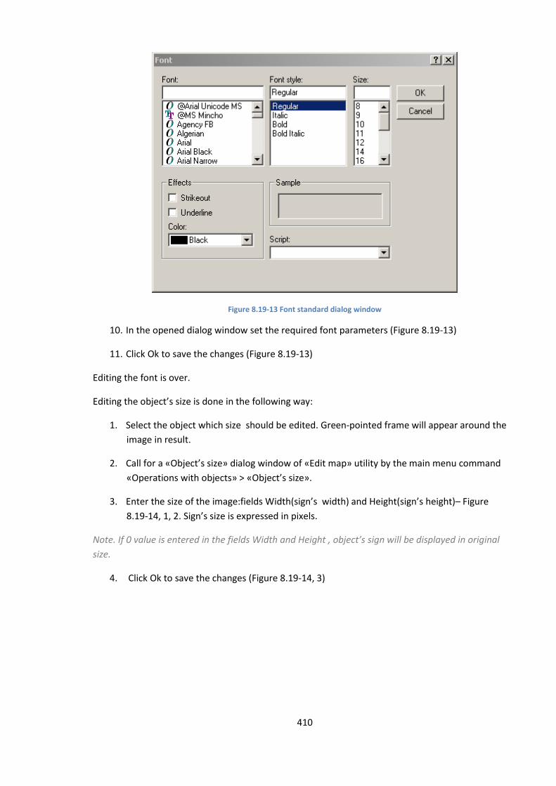
410
Figure 8.19-13 Font standard dialog window
10. In the opened dialog window set the required font parameters (Figure 8.19-13)
11. Click Ok to save the changes (Figure 8.19-13)
Editing the font is over.
Editing the object’s size is done in the following way:
1. Select the object which size should be edited. Green-pointed frame will appear around the
image in result.
2. Call for a «Object’s size» dialog window of «Edit map» utility by the main menu command
«Operations with objects» > «Object’s size».
3. Enter the size of the image:fields Width(sign’s width) and Height(sign’s height)– Figure
8.19-14, 1, 2. Sign’s size is expressed in pixels.
Note. If 0 value is entered in the fields Width and Height , object’s sign will be displayed in original
size.
4. Click Ok to save the changes (Figure 8.19-14, 3)
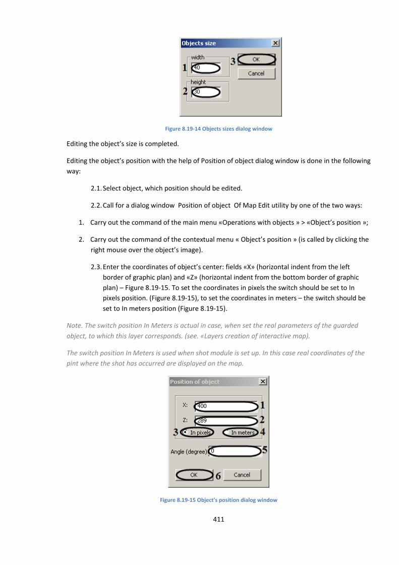
411
Figure 8.19-14 Objects sizes dialog window
Editing the object’s size is completed.
Editing the object’s position with the help of Position of object dialog window is done in the following
way:
2.1. Select object, which position should be edited.
2.2. Call for a dialog window Position of object Of Map Edit utility by one of the two ways:
1. Carry out the command of the main menu «Operations with objects » > «Object’s position »;
2. Carry out the command of the contextual menu « Object’s position » (is called by clicking the
right mouse over the object’s image).
2.3. Enter the coordinates of object’s center: fields «X» (horizontal indent from the left
border of graphic plan) and «Z» (horizontal indent from the bottom border of graphic
plan) – Figure 8.19-15. To set the coordinates in pixels the switch should be set to In
pixels position. (Figure 8.19-15), to set the coordinates in meters – the switch should be
set to In meters position (Figure 8.19-15).
Note. The switch position In Meters is actual in case, when set the real parameters of the guarded
object, to which this layer corresponds. (see. «Layers creation of interactive map).
The switch position In Meters is used when shot module is set up. In this case real coordinates of the
pint where the shot has occurred are displayed on the map.
Figure 8.19-15 Object’s position dialog window
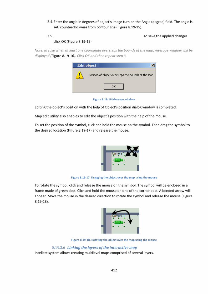
412
2.4. Enter the angle in degrees of object’s image turn on the Angle (degree) field. The angle is
set counterclockwise from contour line (Figure 8.19-15).
2.5. To save the applied changes
click OK (Figure 8.19-15)
Note. In case when at least one coordinate oversteps the bounds of the map, message window will be
displayed (Figure 8.19-16). Click OK and then repeat step 3.
Figure 8.19-16 Message window
Editing the object’s position with the help of Object’s position dialog window is completed.
Map edit utility also enables to edit the object’s position with the help of the mouse.
To set the position of the symbol, click and hold the mouse on the symbol. Then drag the symbol to
the desired location (Figure 8.19-17) and release the mouse.
Figure 8.19-17. Dragging the object over the map using the mouse
To rotate the symbol, click and release the mouse on the symbol. The symbol will be enclosed in a
frame made of green dots. Click and hold the mouse on one of the corner dots. A bended arrow will
appear. Move the mouse in the desired direction to rotate the symbol and release the mouse (Figure
8.19-18).
Figure 8.19-18. Rotating the object over the map using the mouse
8.19.2.6 Linking the layers of the interactive map
Intellect system allows creating multilevel maps comprised of several layers.
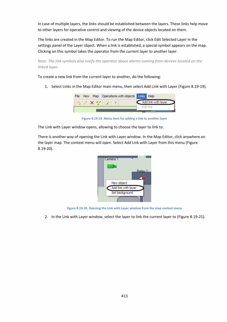
413
In case of multiple layers, the links should be established between the layers. These links help move
to other layers for operative control and viewing of the device objects located on them.
The links are created in the Map Editor. To run the Map Editor, click Edit Selected Layer in the
settings panel of the Layer object. When a link is established, a special symbol appears on the map.
Clicking on this symbol takes the operator from the current layer to another layer.
Note. The link symbols also notify the operator about alarms coming from devices located on the
linked layer.
To create a new link from the current layer to another, do the following:
1. Select Links in the Map Editor main menu, then select Add Link with Layer (Figure 8.19-19).
Figure 8.19-19. Menu item for adding a link to another layer
The Link with Layer window opens, allowing to choose the layer to link to.
There is another way of opening the Link with Layer window. In the Map Editor, click anywhere on
the layer map. The context menu will open. Select Add Link with Layer from this menu (Figure
8.19-20).
Figure 8.19-20. Opening the Link with Layer window from the map context menu
2. In the Link with Layer window, select the layer to link the current layer to (Figure 8.19-21).
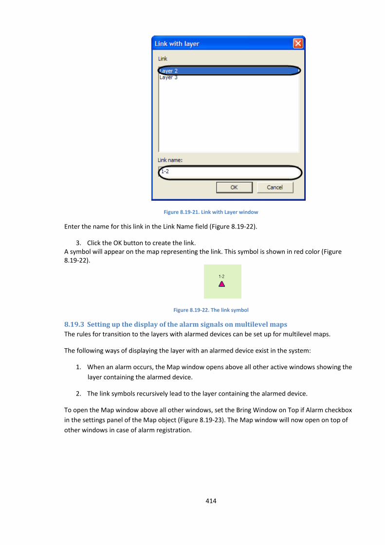
414
Figure 8.19-21. Link with Layer window
Enter the name for this link in the Link Name field (Figure 8.19-22).
3. Click the OK button to create the link. A symbol will appear on the map representing the link. This symbol is shown in red color (Figure 8.19-22).
Figure 8.19-22. The link symbol
8.19.3 Setting up the display of the alarm signals on multilevel maps
The rules for transition to the layers with alarmed devices can be set up for multilevel maps.
The following ways of displaying the layer with an alarmed device exist in the system:
1. When an alarm occurs, the Map window opens above all other active windows showing the
layer containing the alarmed device.
2. The link symbols recursively lead to the layer containing the alarmed device.
To open the Map window above all other windows, set the Bring Window on Top if Alarm checkbox
in the settings panel of the Map object (Figure 8.19-23). The Map window will now open on top of
other windows in case of alarm registration.
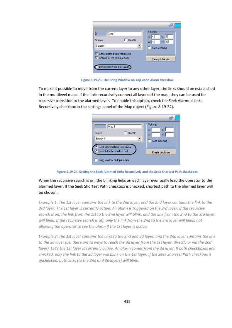
415
Figure 8.19-23. The Bring Window on Top upon Alarm checkbox
To make it possible to move from the current layer to any other layer, the links should be established
in the multilevel maps. If the links recursively connect all layers of the map, they can be used for
recursive transition to the alarmed layer. To enable this option, check the Seek Alarmed Links
Recursively checkbox in the settings panel of the Map object (Figure 8.19-24).
Figure 8.19-24. Setting the Seek Alarmed Links Recursively and the Seek Shortest Path checkboxs
When the recursive search is on, the blinking links on each layer eventually lead the operator to the
alarmed layer. If the Seek Shortest Path checkbox is checked, shortest path to the alarmed layer will
be chosen.
Example 1: The 1st layer contains the link to the 2nd layer, and the 2nd layer contains the link to the
3rd layer. The 1st layer is currently active. An alarm is triggered on the 3rd layer. If the recursive
search is on, the link from the 1st to the 2nd layer will blink, and the link from the 2nd to the 3rd layer
will blink. If the recursive search is off, only the link from the 2nd to the 3rd layer will blink, not
allowing the operator to see the alarm if the 1st layer is active.
Example 2: The 1st layer contains the links to the 2nd and 3d layer, and the 2nd layer contains the link
to the 3d layer (i.e. there are to ways to reach the 3d layer from the 1st layer: directly or via the 2nd
layer). Let’s the 1st layer is currently active. An alarm comes from the 3d layer. If both checkboxes are
checked, only the link to the 3d layer will blink on the 1st layer. If the Seek Shortest Path checkbox is
unchecked, both links (to the 2nd and 3d layers) will blink.
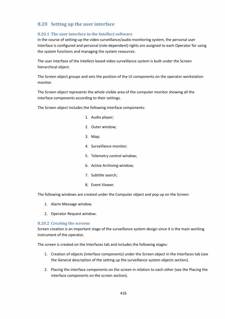
416
8.20 Setting up the user interface
8.20.1 The user interface in the Intellect software
In the course of setting-up the video surveillance/audio monitoring system, the personal user
interface is configured and personal (role-dependent) rights are assigned to each Operator for using
the system functions and managing the system resources.
The user interface of the Intellect-based video surveillance system is built under the Screen
hierarchical object.
The Screen object groups and sets the position of the UI components on the operator workstation
monitor.
The Screen object represents the whole visible area of the computer monitor showing all the
interface components according to their settings.
The Screen object includes the following interface components:
1. Audio player;
2. Outer window;
3. Map;
4. Surveillance monitor;
5. Telemetry control window;
6. Active Archiving window;
7. Subtitle search;
8. Event Viewer.
The following windows are created under the Computer object and pop up on the Screen:
1. Alarm Message window.
2. Operator Request window.
8.20.2 Creating the screens
Screen creation is an important stage of the surveillance system design since it is the main working
instrument of the operator.
The screen is created on the Interfaces tab and includes the following stages:
1. Creation of objects (interface components) under the Screen object in the Interfaces tab (see
the General description of the setting up the surveillance system objects section).
2. Placing the interface components on the screen in relation to each other (see the Placing the
interface components on the screen section).
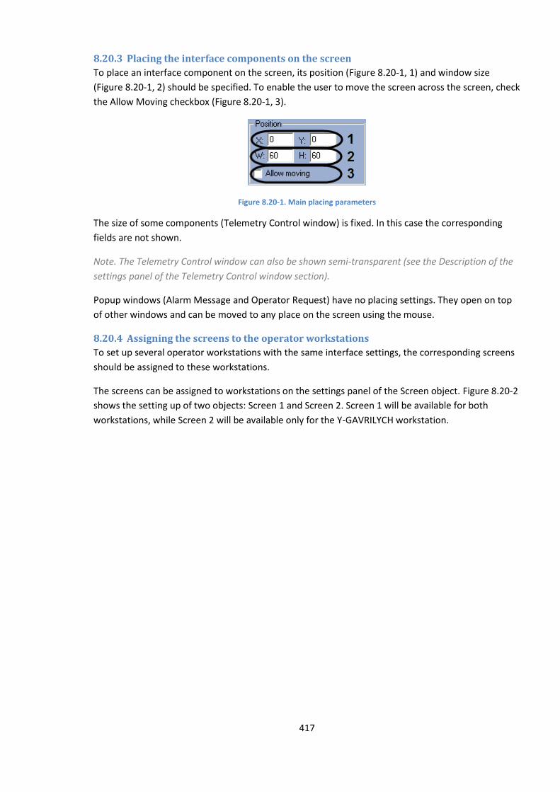
417
8.20.3 Placing the interface components on the screen
To place an interface component on the screen, its position (Figure 8.20-1, 1) and window size
(Figure 8.20-1, 2) should be specified. To enable the user to move the screen across the screen, check
the Allow Moving checkbox (Figure 8.20-1, 3).
Figure 8.20-1. Main placing parameters
The size of some components (Telemetry Control window) is fixed. In this case the corresponding
fields are not shown.
Note. The Telemetry Control window can also be shown semi-transparent (see the Description of the
settings panel of the Telemetry Control window section).
Popup windows (Alarm Message and Operator Request) have no placing settings. They open on top
of other windows and can be moved to any place on the screen using the mouse.
8.20.4 Assigning the screens to the operator workstations
To set up several operator workstations with the same interface settings, the corresponding screens
should be assigned to these workstations.
The screens can be assigned to workstations on the settings panel of the Screen object. Figure 8.20-2
shows the setting up of two objects: Screen 1 and Screen 2. Screen 1 will be available for both
workstations, while Screen 2 will be available only for the Y-GAVRILYCH workstation.
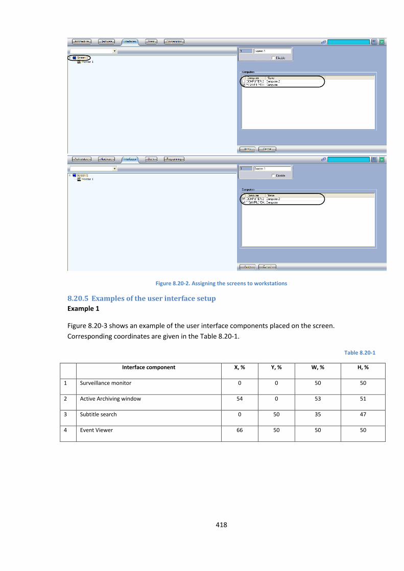
418
Figure 8.20-2. Assigning the screens to workstations
8.20.5 Examples of the user interface setup
Example 1
Figure 8.20-3 shows an example of the user interface components placed on the screen.
Corresponding coordinates are given in the Table 8.20-1.
Table 8.20-1
Interface component X, % Y, % W, % H, %
1 Surveillance monitor 0 0 50 50
2 Active Archiving window 54 0 53 51
3 Subtitle search 0 50 35 47
4 Event Viewer 66 50 50 50

419
Figure 8.20-3. An example of the interface components setup
8.21 Rights administration
8.21.1 The users‘ rights
The following user categories are available in the surveillance system based on the Intellect software:
1. Administrator.
2. Operator who may optionally be granted some rights for administration, control and viewing.
The administrator has full control over the set up and usage of all components of the system.
Any other registered user of the system is an operator who may optionally be granted the rights for
administration, controlling and viewing of particular components of the system.
To register an operator, a user account is created which holds this user’s rights for administration,
control and viewing. A password is assigned to each user at the time of registration, used for
authorization at system start-up and exit. An operator may be optionally forbidden to shut the
system down.
8.21.2 User registration and removal
8.21.2.1 General information about user registration in Intellect software
The registration procedure depends on the user category.

420
To register an administrator, an administrator password should be specified. An administrator
password gives access to administrative functions of all system components. Only one administrator
password may be registered in the system.
No account is created for the administrator, so the administrator password cannot be used for
authorization on system start-up. The administrator password is used to access the System Settings
window and the settings panels of system objects, to change the current user and to shut the system
down.
To register operators, the corresponding accounts should be created. A Person system object is
created for each operator account. Each operator has his (her) own user account which holds all the
data about the rights and authorization password.
The account also indicates to which department the operator belongs. A Department system object
is created for each department of the company.
The Department and Person objects form a hierarchy of two levels.
8.21.2.2 User registration
The following user registration procedure is recommended for setting up the system:
1. Administrator password registration .
Note.You must register the administrator password prior to registering the operators and granting
the rights to them. This is a mandatory system requirement.
2. Registering departments by creating the Department objects.
Registering operators by creating the Person objects.
8.21.2.3 Administrator password registration
The administrator password gives access to administrative functions of all system components. Only
one administrator password can be registered in the system. Registration of the administrator
password should be carried out on the administration server after the system configuration is
completed.
To register the administrator password, do the following:
1. Open the Programming tab in the System Settings window.
2. Choose the Common Settings object in the object tree in the Programming tab. The settings
panel for this object opens at the right side of the System Settings window (Figure 8.21-1).
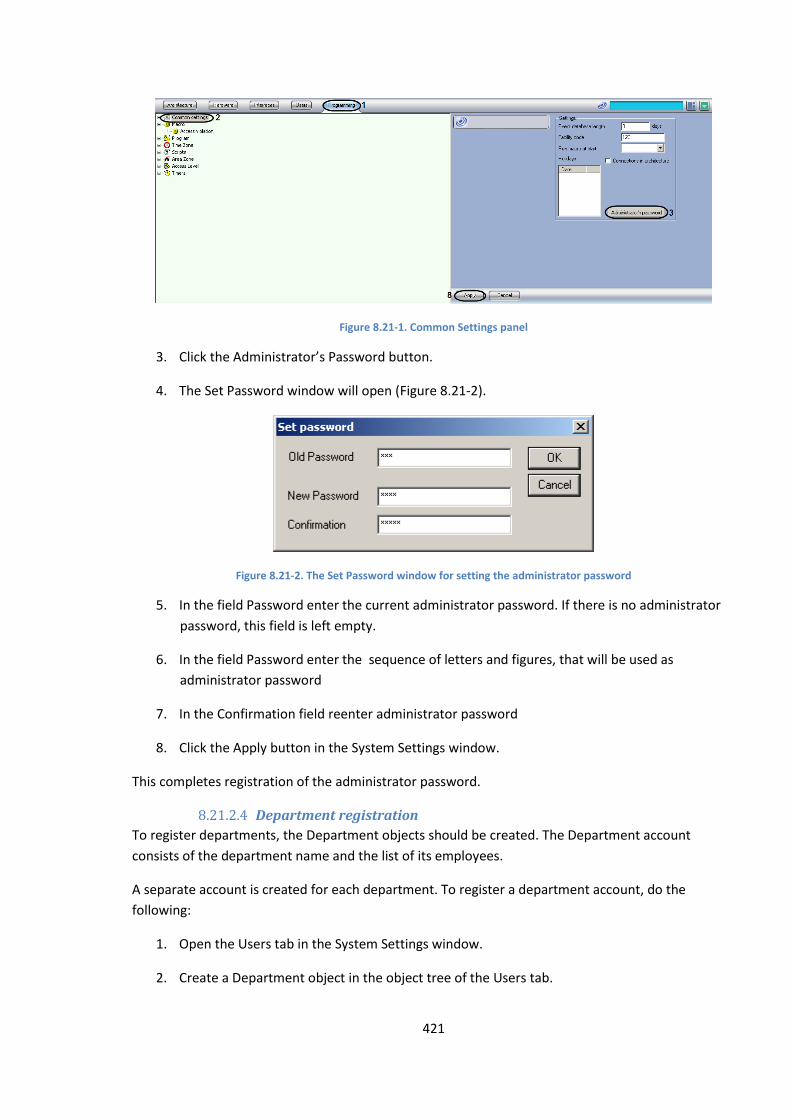
421
Figure 8.21-1. Common Settings panel
3. Click the Administrator’s Password button.
4. The Set Password window will open (Figure 8.21-2).
Figure 8.21-2. The Set Password window for setting the administrator password
5. In the field Password enter the current administrator password. If there is no administrator
password, this field is left empty.
6. In the field Password enter the sequence of letters and figures, that will be used as
administrator password
7. In the Confirmation field reenter administrator password
8. Click the Apply button in the System Settings window.
This completes registration of the administrator password.
8.21.2.4 Department registration
To register departments, the Department objects should be created. The Department account
consists of the department name and the list of its employees.
A separate account is created for each department. To register a department account, do the
following:
1. Open the Users tab in the System Settings window.
2. Create a Department object in the object tree of the Users tab.
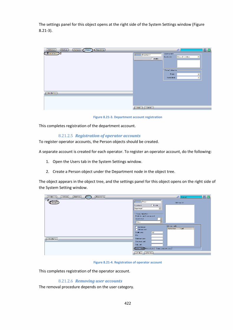
422
The settings panel for this object opens at the right side of the System Settings window (Figure
8.21-3).
Figure 8.21-3. Department account registration
This completes registration of the department account.
8.21.2.5 Registration of operator accounts
To register operator accounts, the Person objects should be created.
A separate account is created for each operator. To register an operator account, do the following:
1. Open the Users tab in the System Settings window.
2. Create a Person object under the Department node in the object tree.
The object appears in the object tree, and the settings panel for this object opens on the right side of
the System Setting window.
Figure 8.21-4. Registration of operator account
This completes registration of the operator account.
8.21.2.6 Removing user accounts
The removal procedure depends on the user category.
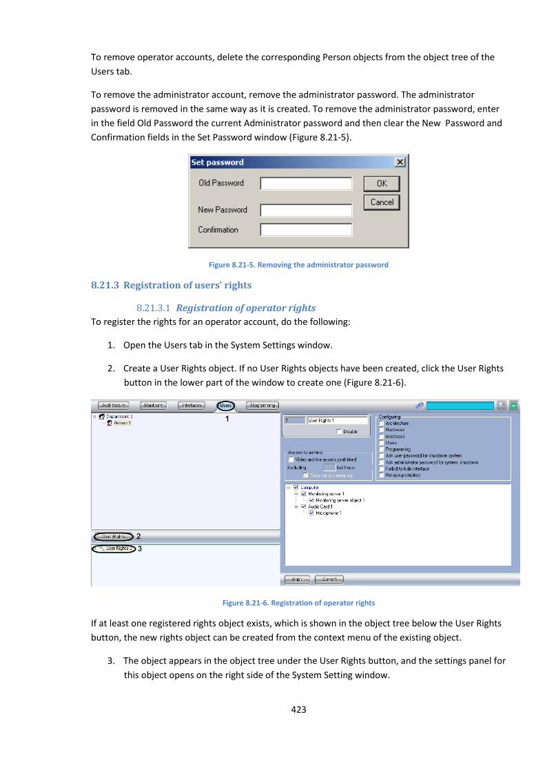
423
To remove operator accounts, delete the corresponding Person objects from the object tree of the
Users tab.
To remove the administrator account, remove the administrator password. The administrator
password is removed in the same way as it is created. To remove the administrator password, enter
in the field Old Password the current Administrator password and then clear the New Password and
Confirmation fields in the Set Password window (Figure 8.21-5).
Figure 8.21-5. Removing the administrator password
8.21.3 Registration of users’ rights
8.21.3.1 Registration of operator rights
To register the rights for an operator account, do the following:
1. Open the Users tab in the System Settings window.
2. Create a User Rights object. If no User Rights objects have been created, click the User Rights
button in the lower part of the window to create one (Figure 8.21-6).
Figure 8.21-6. Registration of operator rights
If at least one registered rights object exists, which is shown in the object tree below the User Rights
button, the new rights object can be created from the context menu of the existing object.
3. The object appears in the object tree under the User Rights button, and the settings panel for
this object opens on the right side of the System Setting window.
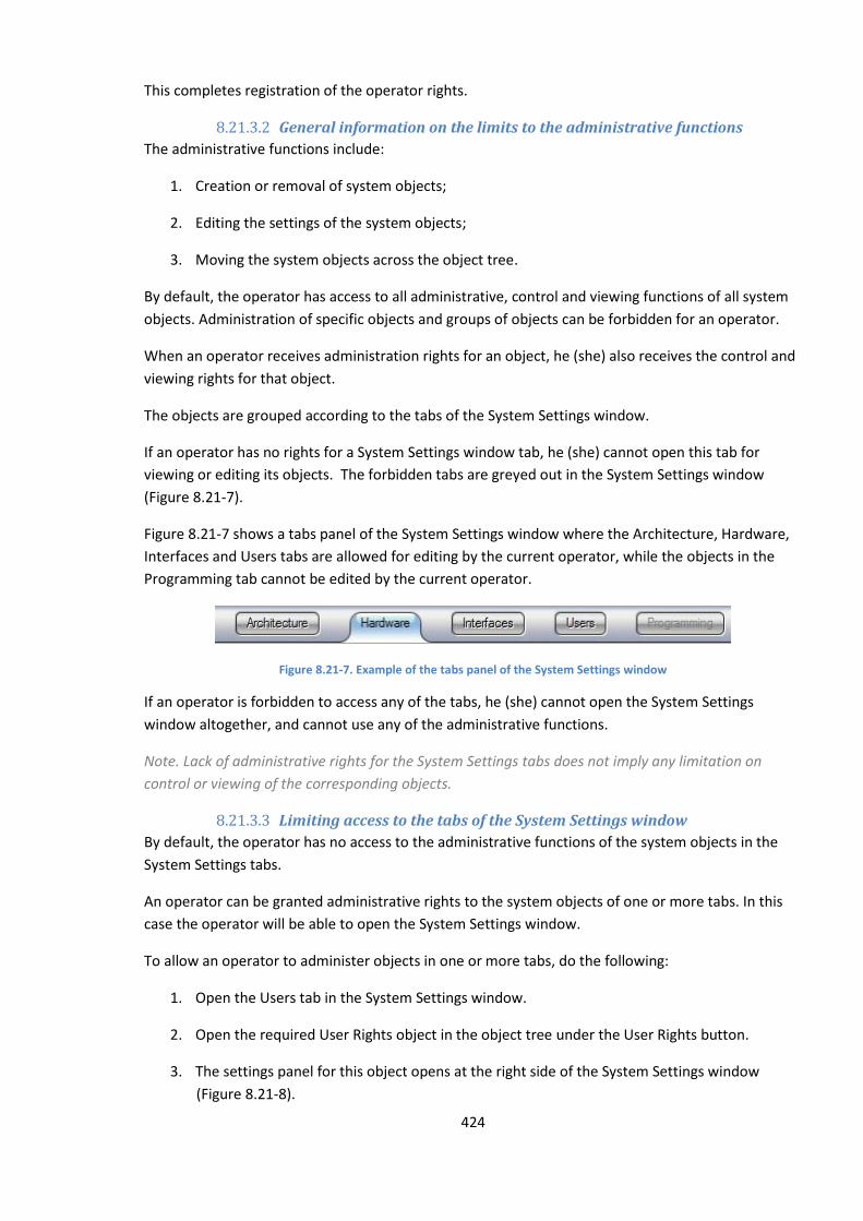
424
This completes registration of the operator rights.
8.21.3.2 General information on the limits to the administrative functions
The administrative functions include:
1. Creation or removal of system objects;
2. Editing the settings of the system objects;
3. Moving the system objects across the object tree.
By default, the operator has access to all administrative, control and viewing functions of all system
objects. Administration of specific objects and groups of objects can be forbidden for an operator.
When an operator receives administration rights for an object, he (she) also receives the control and
viewing rights for that object.
The objects are grouped according to the tabs of the System Settings window.
If an operator has no rights for a System Settings window tab, he (she) cannot open this tab for
viewing or editing its objects. The forbidden tabs are greyed out in the System Settings window
(Figure 8.21-7).
Figure 8.21-7 shows a tabs panel of the System Settings window where the Architecture, Hardware,
Interfaces and Users tabs are allowed for editing by the current operator, while the objects in the
Programming tab cannot be edited by the current operator.
Figure 8.21-7. Example of the tabs panel of the System Settings window
If an operator is forbidden to access any of the tabs, he (she) cannot open the System Settings
window altogether, and cannot use any of the administrative functions.
Note. Lack of administrative rights for the System Settings tabs does not imply any limitation on
control or viewing of the corresponding objects.
8.21.3.3 Limiting access to the tabs of the System Settings window
By default, the operator has no access to the administrative functions of the system objects in the
System Settings tabs.
An operator can be granted administrative rights to the system objects of one or more tabs. In this
case the operator will be able to open the System Settings window.
To allow an operator to administer objects in one or more tabs, do the following:
1. Open the Users tab in the System Settings window.
2. Open the required User Rights object in the object tree under the User Rights button.
3. The settings panel for this object opens at the right side of the System Settings window
(Figure 8.21-8).
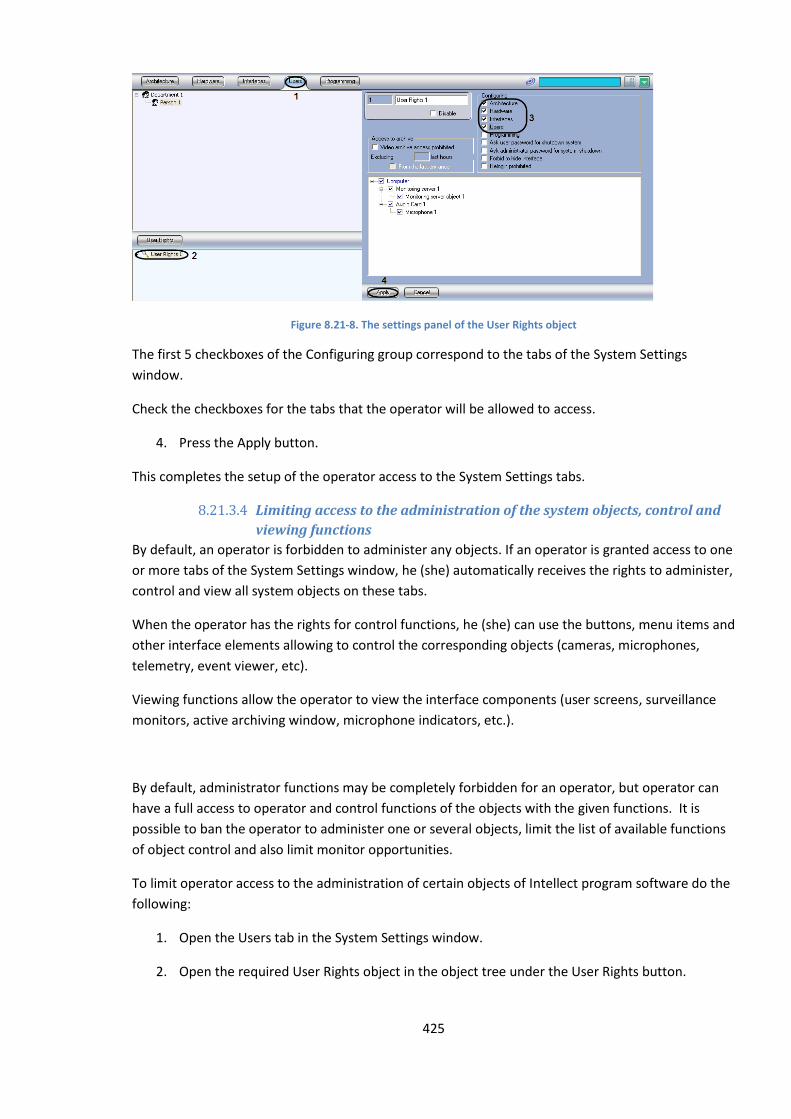
425
Figure 8.21-8. The settings panel of the User Rights object
The first 5 checkboxes of the Configuring group correspond to the tabs of the System Settings
window.
Check the checkboxes for the tabs that the operator will be allowed to access.
4. Press the Apply button.
This completes the setup of the operator access to the System Settings tabs.
8.21.3.4 Limiting access to the administration of the system objects, control and
viewing functions
By default, an operator is forbidden to administer any objects. If an operator is granted access to one
or more tabs of the System Settings window, he (she) automatically receives the rights to administer,
control and view all system objects on these tabs.
When the operator has the rights for control functions, he (she) can use the buttons, menu items and
other interface elements allowing to control the corresponding objects (cameras, microphones,
telemetry, event viewer, etc).
Viewing functions allow the operator to view the interface components (user screens, surveillance
monitors, active archiving window, microphone indicators, etc.).
By default, administrator functions may be completely forbidden for an operator, but operator can
have a full access to operator and control functions of the objects with the given functions. It is
possible to ban the operator to administer one or several objects, limit the list of available functions
of object control and also limit monitor opportunities.
To limit operator access to the administration of certain objects of Intellect program software do the
following:
1. Open the Users tab in the System Settings window.
2. Open the required User Rights object in the object tree under the User Rights button.
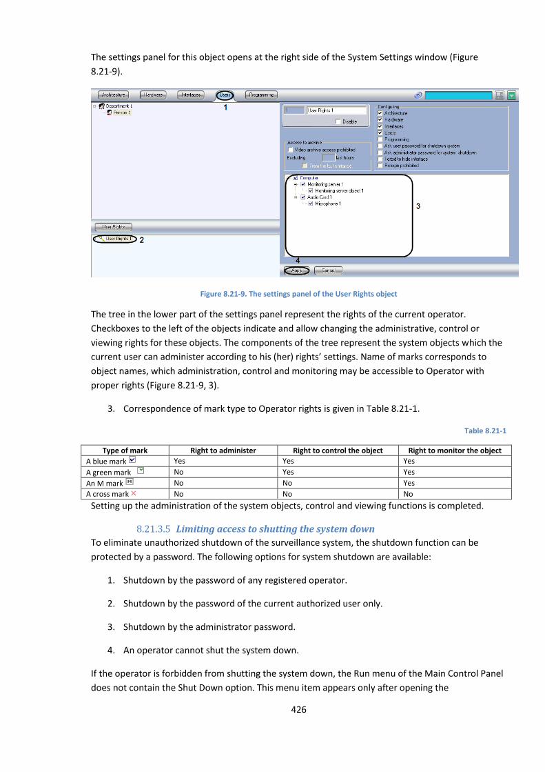
426
The settings panel for this object opens at the right side of the System Settings window (Figure
8.21-9).
Figure 8.21-9. The settings panel of the User Rights object
The tree in the lower part of the settings panel represent the rights of the current operator.
Checkboxes to the left of the objects indicate and allow changing the administrative, control or
viewing rights for these objects. The components of the tree represent the system objects which the
current user can administer according to his (her) rights’ settings. Name of marks corresponds to
object names, which administration, control and monitoring may be accessible to Operator with
proper rights (Figure 8.21-9, 3).
3. Correspondence of mark type to Operator rights is given in Table 8.21-1.
Table 8.21-1
Type of mark Right to administer Right to control the object Right to monitor the object
A blue mark Yes Yes Yes
A green mark No Yes Yes
An M mark No No Yes
A cross mark No No No
Setting up the administration of the system objects, control and viewing functions is completed.
8.21.3.5 Limiting access to shutting the system down
To eliminate unauthorized shutdown of the surveillance system, the shutdown function can be
protected by a password. The following options for system shutdown are available:
1. Shutdown by the password of any registered operator.
2. Shutdown by the password of the current authorized user only.
3. Shutdown by the administrator password.
4. An operator cannot shut the system down.
If the operator is forbidden from shutting the system down, the Run menu of the Main Control Panel
does not contain the Shut Down option. This menu item appears only after opening the
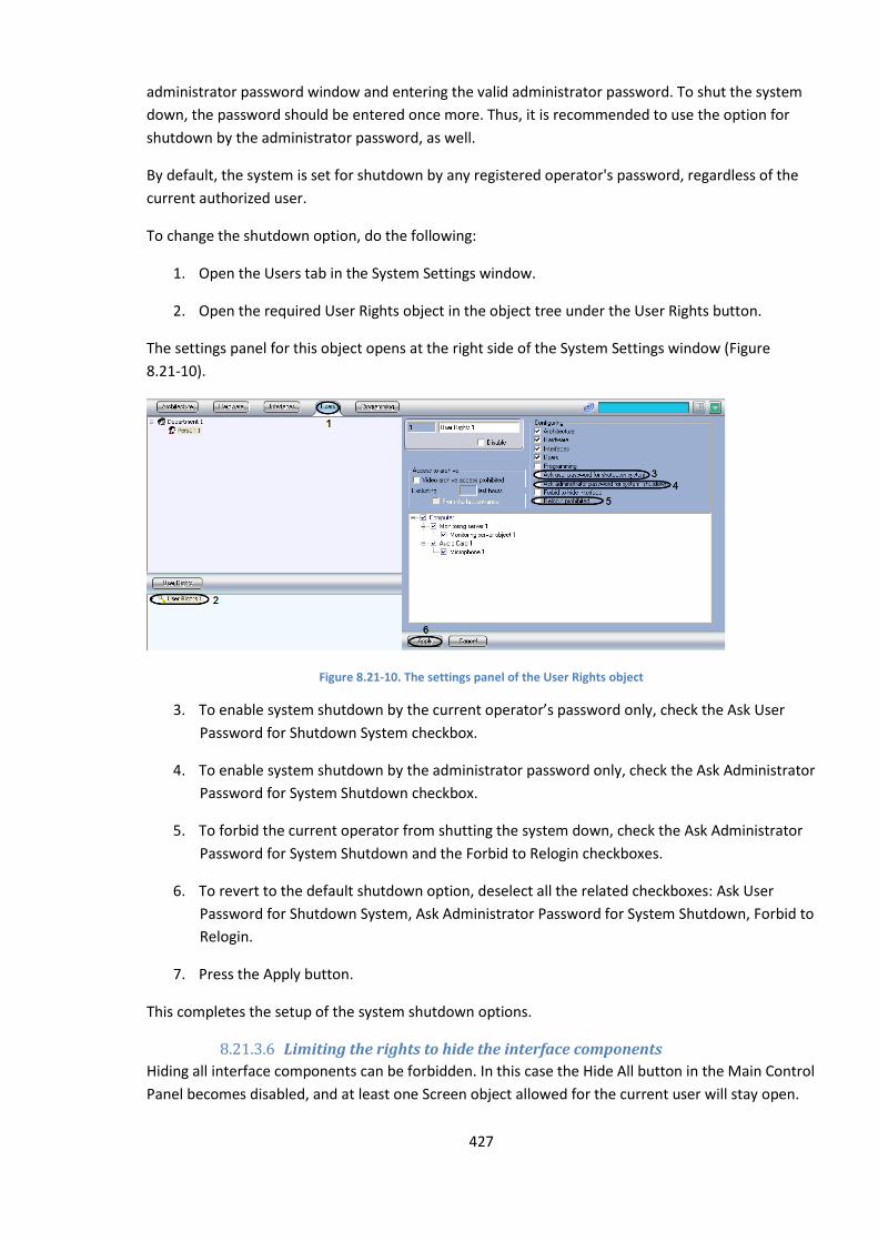
427
administrator password window and entering the valid administrator password. To shut the system
down, the password should be entered once more. Thus, it is recommended to use the option for
shutdown by the administrator password, as well.
By default, the system is set for shutdown by any registered operator's password, regardless of the
current authorized user.
To change the shutdown option, do the following:
1. Open the Users tab in the System Settings window.
2. Open the required User Rights object in the object tree under the User Rights button.
The settings panel for this object opens at the right side of the System Settings window (Figure
8.21-10).
Figure 8.21-10. The settings panel of the User Rights object
3. To enable system shutdown by the current operator’s password only, check the Ask User
Password for Shutdown System checkbox.
4. To enable system shutdown by the administrator password only, check the Ask Administrator
Password for System Shutdown checkbox.
5. To forbid the current operator from shutting the system down, check the Ask Administrator
Password for System Shutdown and the Forbid to Relogin checkboxes.
6. To revert to the default shutdown option, deselect all the related checkboxes: Ask User
Password for Shutdown System, Ask Administrator Password for System Shutdown, Forbid to
Relogin.
7. Press the Apply button.
This completes the setup of the system shutdown options.
8.21.3.6 Limiting the rights to hide the interface components
Hiding all interface components can be forbidden. In this case the Hide All button in the Main Control
Panel becomes disabled, and at least one Screen object allowed for the current user will stay open.
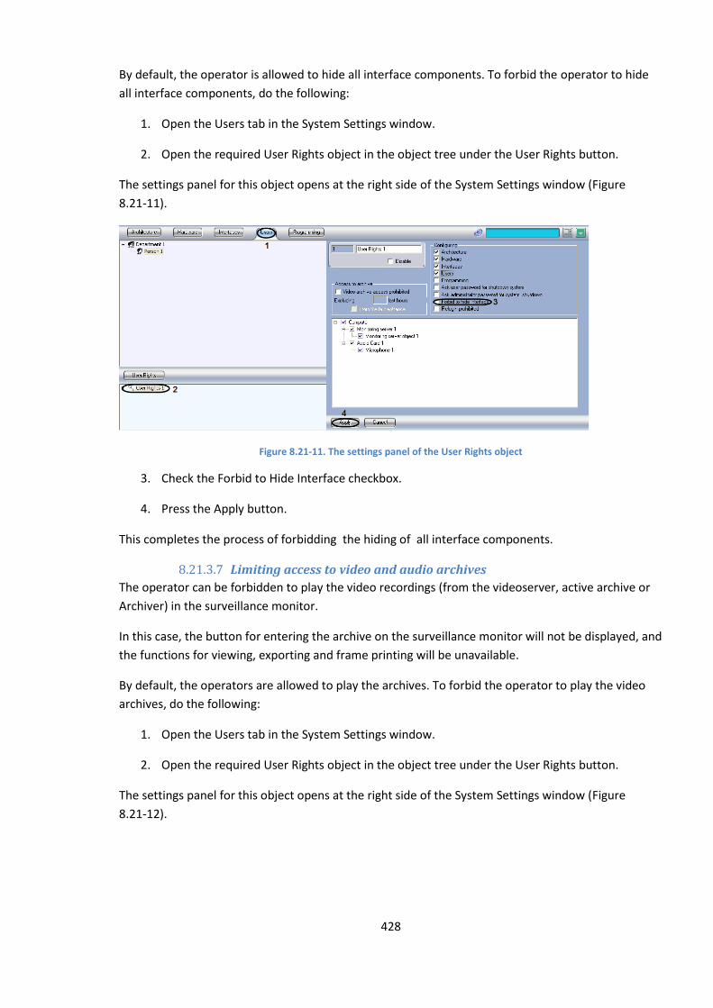
428
By default, the operator is allowed to hide all interface components. To forbid the operator to hide
all interface components, do the following:
1. Open the Users tab in the System Settings window.
2. Open the required User Rights object in the object tree under the User Rights button.
The settings panel for this object opens at the right side of the System Settings window (Figure
8.21-11).
Figure 8.21-11. The settings panel of the User Rights object
3. Check the Forbid to Hide Interface checkbox.
4. Press the Apply button.
This completes the process of forbidding the hiding of all interface components.
8.21.3.7 Limiting access to video and audio archives
The operator can be forbidden to play the video recordings (from the videoserver, active archive or
Archiver) in the surveillance monitor.
In this case, the button for entering the archive on the surveillance monitor will not be displayed, and
the functions for viewing, exporting and frame printing will be unavailable.
By default, the operators are allowed to play the archives. To forbid the operator to play the video
archives, do the following:
1. Open the Users tab in the System Settings window.
2. Open the required User Rights object in the object tree under the User Rights button.
The settings panel for this object opens at the right side of the System Settings window (Figure
8.21-12).

429
Figure 8.21-12 The settings panel of the User Rights object
3. Check the Video archive access prohibited checkbox (Figure 8.21-12,3).
4. Enter the number of hours, available for viewing in the field «Excluding last hours» (Figure
8.21-12, 4).
Note. The number of video archive last hours, available for viewing should be whole.
5. In case of starting the hours counting from the moment of the last entrance to the system,
set the checkbox «From the last entrance» (Figure 8.21-12, 5). If the counting of hours from
the current time is to be set– the checkbox « From the last entrance » should not be
checked.
Note. In case when the checkbox « From the last entrance » is set and the number of hours, available
for viewing is stated, the last hours are counted before the moment of registration.
6. Click Apply button (Figure 8.21-12, 6).
Forbidding the operator from playing the archives is completed.
8.21.4 Assigning rights and passwords to operators for authorization in the Intellect
In the Intellect PC user accounts are stored separately from operator accounts. The same rights may
be assigned to several operators. But the operator may be assigned only single rights.
To assign rights and passwords to the operator for authorization in the Intellect do the following:
1. Open the Users tab in the System Settings window. (Figure 8.21-13, 1).
2. Select an object, corresponding to rights account that has to be assigned to the operator, in
the object tree under the User Rights button (Figure 8.21-13, 2).
3. Call for a contextual menu by clicking right mouse button upon the selected object User
rights (Figure 8.21-13, 3). Select Add to rights in the menu.
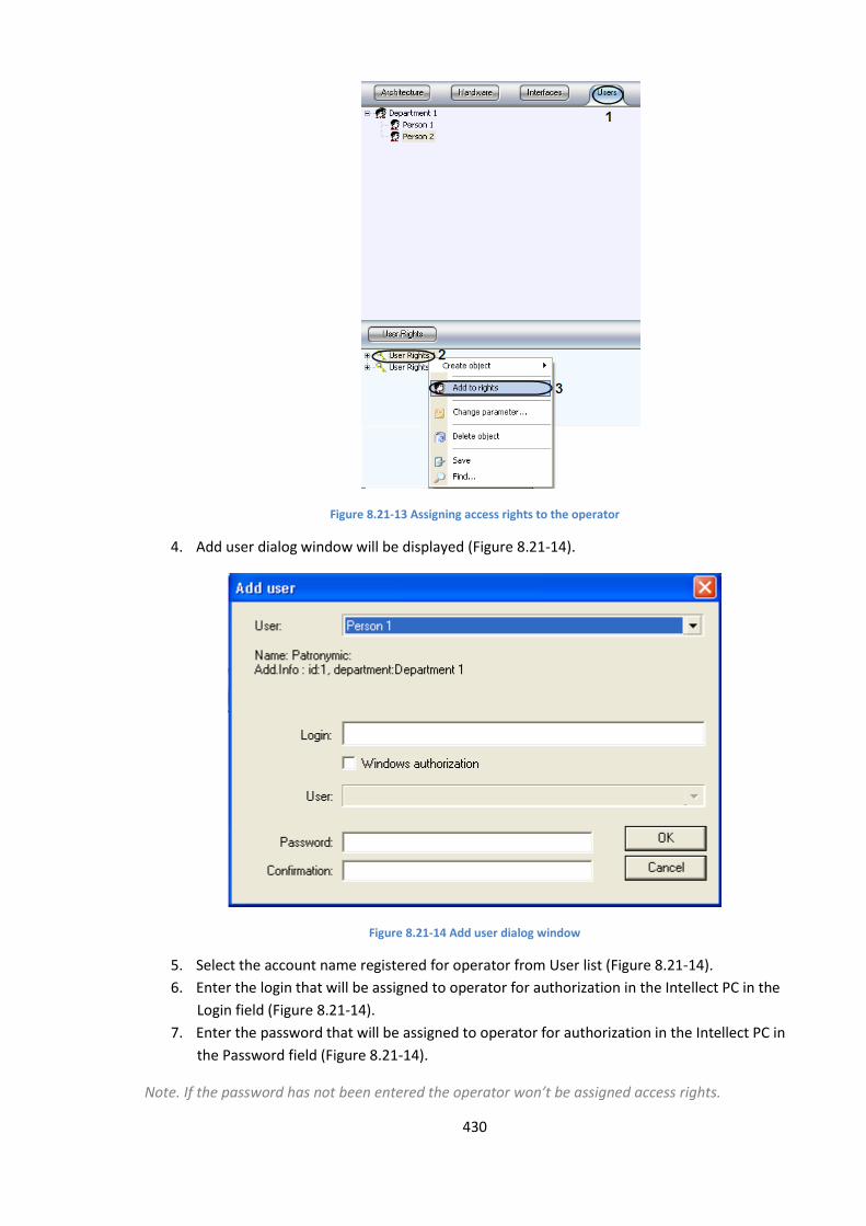
430
Figure 8.21-13 Assigning access rights to the operator
4. Add user dialog window will be displayed (Figure 8.21-14).
Figure 8.21-14 Add user dialog window
5. Select the account name registered for operator from User list (Figure 8.21-14).
6. Enter the login that will be assigned to operator for authorization in the Intellect PC in the
Login field (Figure 8.21-14).
7. Enter the password that will be assigned to operator for authorization in the Intellect PC in
the Password field (Figure 8.21-14).
Note. If the password has not been entered the operator won’t be assigned access rights.
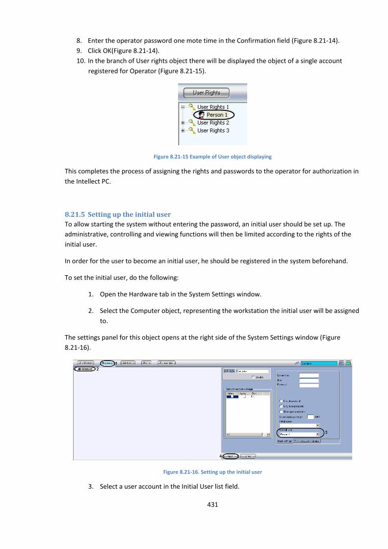
431
8. Enter the operator password one mote time in the Confirmation field (Figure 8.21-14).
9. Click OK(Figure 8.21-14).
10. In the branch of User rights object there will be displayed the object of a single account
registered for Operator (Figure 8.21-15).
Figure 8.21-15 Example of User object displaying
This completes the process of assigning the rights and passwords to the operator for authorization in
the Intellect PC.
8.21.5 Setting up the initial user
To allow starting the system without entering the password, an initial user should be set up. The
administrative, controlling and viewing functions will then be limited according to the rights of the
initial user.
In order for the user to become an initial user, he should be registered in the system beforehand.
To set the initial user, do the following:
1. Open the Hardware tab in the System Settings window.
2. Select the Computer object, representing the workstation the initial user will be assigned
to.
The settings panel for this object opens at the right side of the System Settings window (Figure
8.21-16).
Figure 8.21-16. Setting up the initial user
3. Select a user account in the Initial User list field.
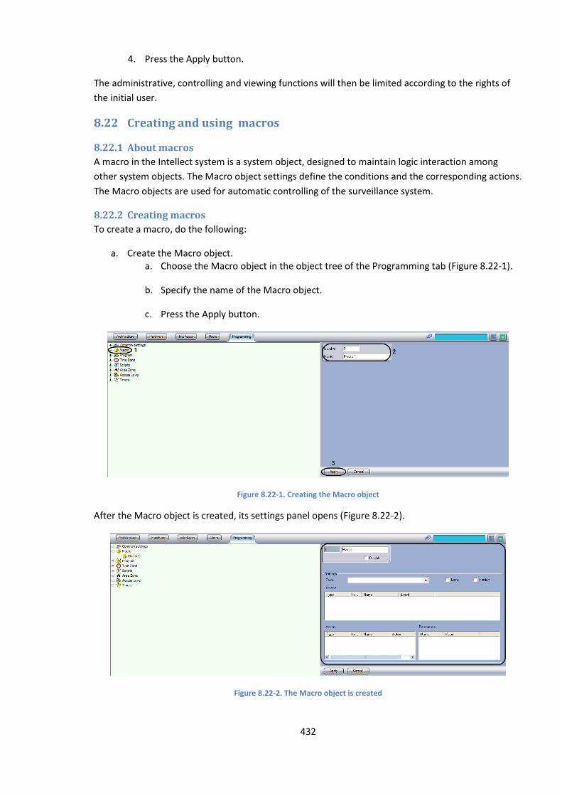
432
4. Press the Apply button.
The administrative, controlling and viewing functions will then be limited according to the rights of
the initial user.
8.22 Creating and using macros
8.22.1 About macros
A macro in the Intellect system is a system object, designed to maintain logic interaction among
other system objects. The Macro object settings define the conditions and the corresponding actions.
The Macro objects are used for automatic controlling of the surveillance system.
8.22.2 Creating macros
To create a macro, do the following:
a. Create the Macro object. a. Choose the Macro object in the object tree of the Programming tab (Figure 8.22-1).
b. Specify the name of the Macro object.
c. Press the Apply button.
Figure 8.22-1. Creating the Macro object
After the Macro object is created, its settings panel opens (Figure 8.22-2).
Figure 8.22-2. The Macro object is created
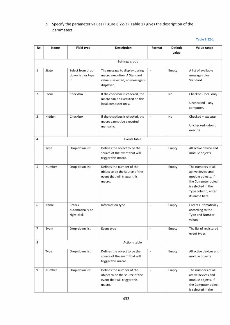
433
b. Specify the parameter values (Figure 8.22-3). Table 17 gives the description of the
parameters.
Table 8.22-1
№ Name Field type Description Format Default
value
Value range
Settings group
1 State Select from drop-
down list, or type
in
The message to display during
macro execution. A Standard
value is selected, no message is
displayed.
- Empty A list of available
messages plus
Standard.
2 Local Checkbox If the checkbox is checked, the
macro can be executed on the
local computer only.
- No Checked - local only.
Unchecked – any
computer.
3 Hidden Checkbox If the checkbox is checked, the
macro cannot be executed
manually.
- No Checked – execute.
Unchecked – don’t
execute.
4 Events table
Type Drop-down list Defines the object to be the
source of the event that will
trigger this macro.
- Empty All active device and
module objects
5 Number Drop-down list Defines the number of the
object to be the source of the
event that will trigger this
macro.
- Empty The numbers of all
active device and
module objects. If
the Computer object
is selected in the
Type column, enter
its name here.
6 Name Enters
automatically on
right-click
Information type - Empty Enters automatically
according to the
Type and Number
values
7 Event Drop-down list Event type - Empty The list of registered
event types
8 Actions table
Type Drop-down list Defines the object to be the
source of the event that will
trigger this macro.
- Empty All active devices and
module objects
9 Number Drop-down list Defines the number of the
object to be the source of the
event that will trigger this
macro.
- Empty The numbers of all
active devices and
module objects. If
the Computer object
is selected in the
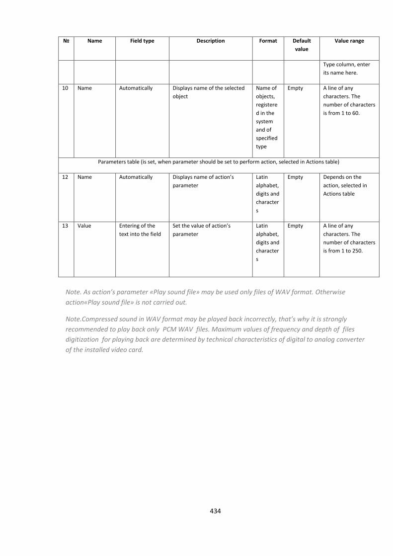
434
№ Name Field type Description Format Default
value
Value range
Type column, enter
its name here.
10 Name Automatically Displays name of the selected
object
Name of
objects,
registere
d in the
system
and of
specified
type
Empty A line of any
characters. The
number of characters
is from 1 to 60.
Parameters table (is set, when parameter should be set to perform action, selected in Actions table)
12 Name Automatically Displays name of action’s
parameter
Latin
alphabet,
digits and
character
s
Empty Depends on the
action, selected in
Actions table
13 Value Entering of the
text into the field
Set the value of action’s
parameter
Latin
alphabet,
digits and
character
s
Empty A line of any
characters. The
number of characters
is from 1 to 250.
Note. As action’s parameter «Play sound file» may be used only files of WAV format. Otherwise
action«Play sound file» is not carried out.
Note.Compressed sound in WAV format may be played back incorrectly, that’s why it is strongly
recommended to play back only PCM WAV files. Maximum values of frequency and depth of files
digitization for playing back are determined by technical characteristics of digital to analog converter
of the installed video card.
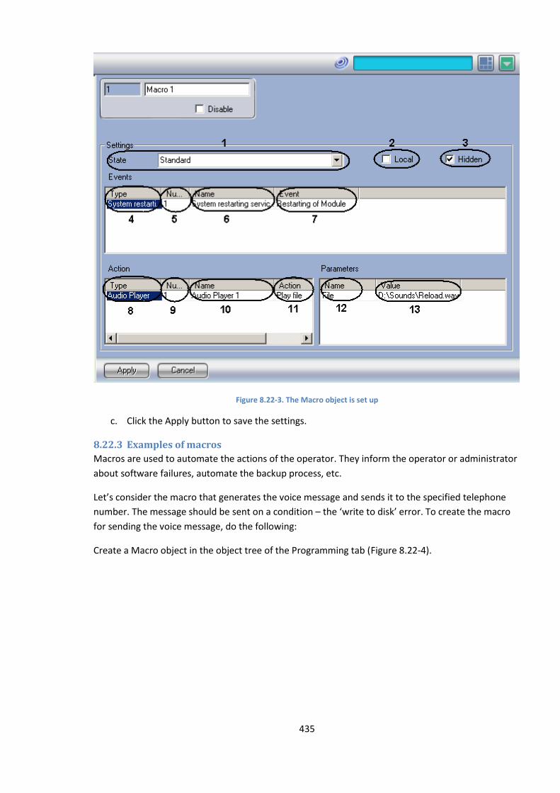
435
Figure 8.22-3. The Macro object is set up
c. Click the Apply button to save the settings.
8.22.3 Examples of macros
Macros are used to automate the actions of the operator. They inform the operator or administrator
about software failures, automate the backup process, etc.
Let’s consider the macro that generates the voice message and sends it to the specified telephone
number. The message should be sent on a condition – the ‘write to disk’ error. To create the macro
for sending the voice message, do the following:
Create a Macro object in the object tree of the Programming tab (Figure 8.22-4).
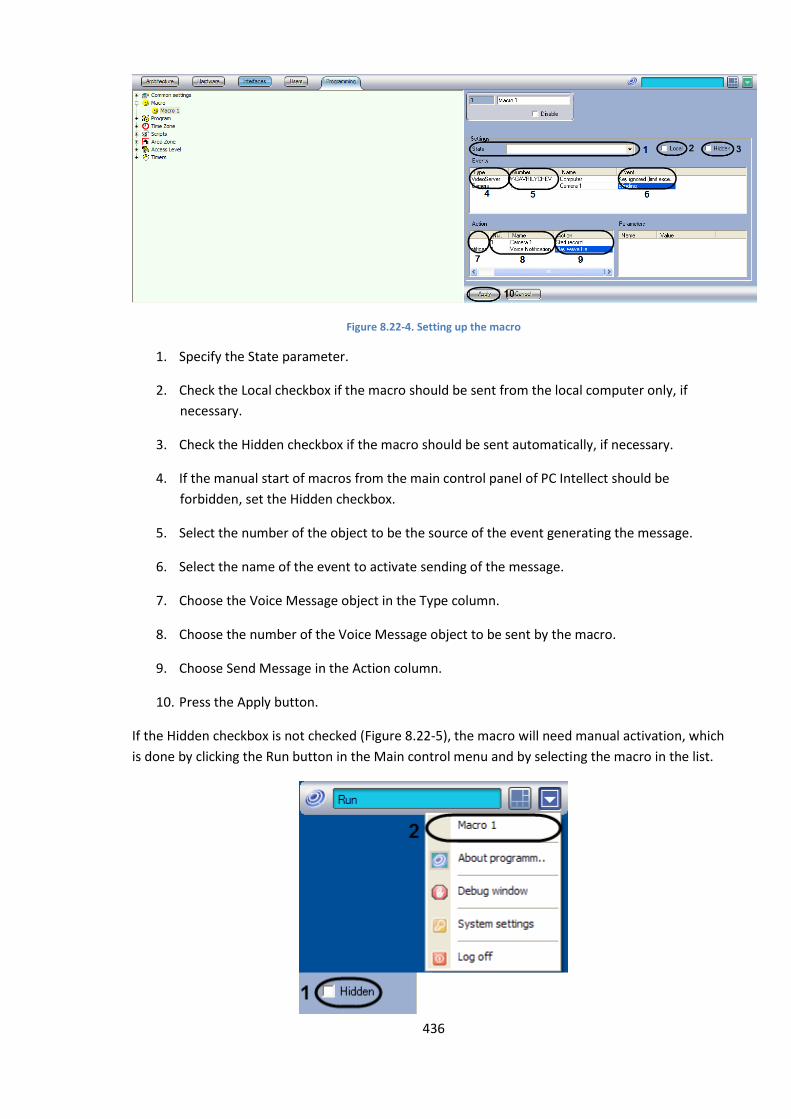
436
Figure 8.22-4. Setting up the macro
1. Specify the State parameter.
2. Check the Local checkbox if the macro should be sent from the local computer only, if
necessary.
3. Check the Hidden checkbox if the macro should be sent automatically, if necessary.
4. If the manual start of macros from the main control panel of PC Intellect should be
forbidden, set the Hidden checkbox.
5. Select the number of the object to be the source of the event generating the message.
6. Select the name of the event to activate sending of the message.
7. Choose the Voice Message object in the Type column.
8. Choose the number of the Voice Message object to be sent by the macro.
9. Choose Send Message in the Action column.
10. Press the Apply button.
If the Hidden checkbox is not checked (Figure 8.22-5), the macro will need manual activation, which
is done by clicking the Run button in the Main control menu and by selecting the macro in the list.
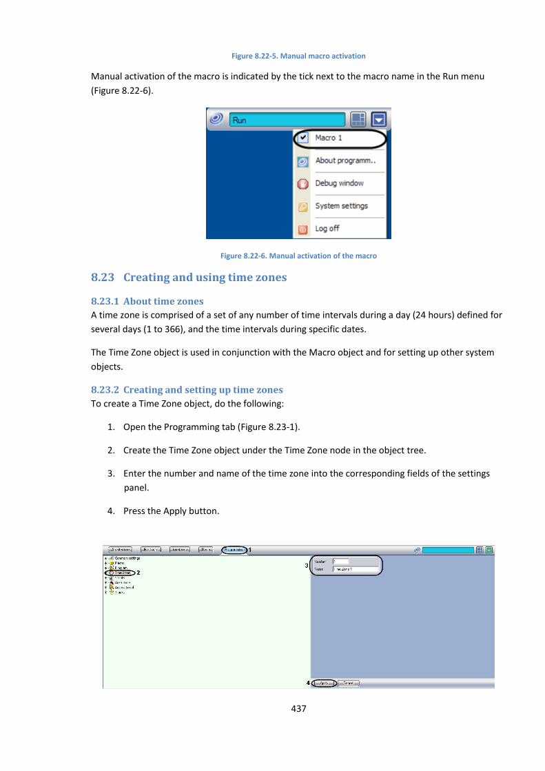
437
Figure 8.22-5. Manual macro activation
Manual activation of the macro is indicated by the tick next to the macro name in the Run menu
(Figure 8.22-6).
Figure 8.22-6. Manual activation of the macro
8.23 Creating and using time zones
8.23.1 About time zones
A time zone is comprised of a set of any number of time intervals during a day (24 hours) defined for
several days (1 to 366), and the time intervals during specific dates.
The Time Zone object is used in conjunction with the Macro object and for setting up other system
objects.
8.23.2 Creating and setting up time zones
To create a Time Zone object, do the following:
1. Open the Programming tab (Figure 8.23-1).
2. Create the Time Zone object under the Time Zone node in the object tree.
3. Enter the number and name of the time zone into the corresponding fields of the settings
panel.
4. Press the Apply button.

438
Figure 8.23-1. Creation of the Time Zone object
The Time Zone object will appear in the object tree (Figure 8.23-2).
Figure 8.23-2. The Time Zone object is created
To set up the Time Zone object, specify the values of the following parameters (Figure 8.23-3 and Table 8.23-1).
Figure 8.23-3. Setting up the Time Zone object
Table 8.23-1
No Parameter name Field type Description Format Default value Value range
Time Intervals group
1 From column Enter the value Exact time of starting
the macro execution HH:MM:SS
00:00:00 00:00:00 to 23:59:59
2 To column Enter the value Exact time of ending the
macro execution HH:MM:SS
00:00:00 00:00:00 to 23:59:59
Days of Week group
3
Checkboxes: Mon Tue Wed
Checkbox Adds days to the timetable. The days of the week are added separately for each time
- No Checked – the day of the week is included in the timetable. Not checked – the
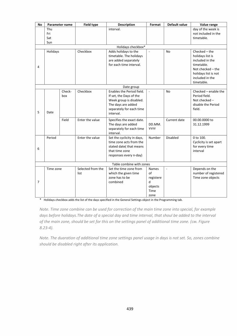
439
No Parameter name Field type Description Format Default value Value range
Thu Fri Sat Sun
interval. day of the week is not included in the timetable.
Holidays checkbox*
4
Holidays Checkbox Adds holidays to the timetable. The holidays are added separately for each time interval.
- No Checked – the holidays list is included in the timetable. Not checked – the holidays list is not included in the timetable.
Date group
5 Date
Check-box
Checkbox Enables the Period field. If set, the Days of the Week group is disabled. The days are added separately for each time interval.
- No Checked – enable the Period field. Not checked – disable the Period field.
Field Enter the value Specifies the exact date. The days are added separately for each time interval.
DD.MM.YYYY
Current date 00.00.0000 to 31.12.1999
6
Period Enter the value Set the cyclicity in days, time zone acts from the stated date( that means that time zone responses every n-day)
Number Disabled 0 to 100. Cyclicity is set apart for every time interval
Table combine with zones
7
Time zone Selected from the list
Set the time zone from which the given time zone has to be combined
Names of registered objects Time zone
- Depends on the number of registered Time zone objects
* Holidays checkbox adds the list of the days specified in the General Settings object in the Programming tab.
Note. Time zone combine can be used for correction of the main time zone into special, for example
days before holidays.The date of a special day and time interval, that shoul be added to the interval
of the main zone, should be set for this on the settings panel of additional time zone. (см. Figure
8.23-4).
Note. The duaration of additional time zone settings panel usage in days is not set. So, zones combine
should be disabled right after its application.
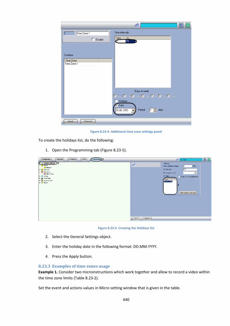
440
Figure 8.23-4. Additional time zone settings panel
To create the holidays list, do the following:
1. Open the Programming tab (Figure 8.23-5).
Figure 8.23-5. Creating the Holidays list
2. Select the General Settings object.
3. Enter the holiday date in the following format: DD.MM.YYYY.
4. Press the Apply button.
8.23.3 Examples of time zones usage
Example 1. Consider two microinstructions which work together and allow to record a video within
the time zone limits (Table 8.23-2).
Set the event and actions values in Micro setting window that is given in the table.
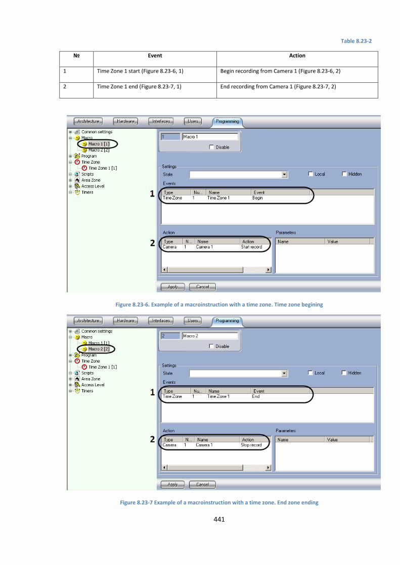
441
Table 8.23-2
№ Event Action
1 Time Zone 1 start (Figure 8.23-6, 1) Begin recording from Camera 1 (Figure 8.23-6, 2)
2 Time Zone 1 end (Figure 8.23-7, 1) End recording from Camera 1 (Figure 8.23-7, 2)
Figure 8.23-6. Example of a macroinstruction with a time zone. Time zone begining
Figure 8.23-7 Example of a macroinstruction with a time zone. End zone ending
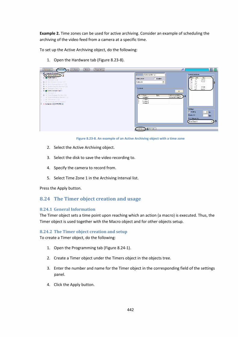
442
Example 2. Time zones can be used for active archiving. Consider an example of scheduling the
archiving of the video feed from a camera at a specific time.
To set up the Active Archiving object, do the following:
1. Open the Hardware tab (Figure 8.23-8).
Figure 8.23-8. An example of an Active Archiving object with a time zone
2. Select the Active Archiving object.
3. Select the disk to save the video recording to.
4. Specify the camera to record from.
5. Select Time Zone 1 in the Archiving Interval list.
Press the Apply button.
8.24 The Timer object creation and usage
8.24.1 General Information
The Timer object sets a time point upon reaching which an action (a macro) is executed. Thus, the
Timer object is used together with the Macro object and for other objects setup.
8.24.2 The Timer object creation and setup
To create a Timer object, do the following:
1. Open the Programming tab (Figure 8.24-1).
2. Create a Timer object under the Timers object in the objects tree.
3. Enter the number and name for the Timer object in the corresponding field of the settings
panel.
4. Click the Apply button.

443
Figure 8.24-1. Creating a Timer object
The Timer object will appear in the object tree (Figure 8.24-2).
Figure 8.24-2. The Timer object has been created
To set up the Timer object, do the following:
a. Select the Timer object in the object tree (Figure 8.24-3).
b. Set the time point using one of the following methods:
1. select the day of the week from the drop-down list (Figure 8.24-3, 2) and the exact time
(hour, minute, second) in the corresponding fields (Figure 8.24-3, 5);
2. select the exact date (year, month, day) from the corresponding fields (Figure 8.24-3, 4) and
the exact time (hour, minute, second) in the corresponding fields (Figure 8.24-3, 5).
c. Check the Holidays checkbox to take into account the holidays set in the General
Settings (Figure 8.24-3, 3).
d. Click the Apply button.
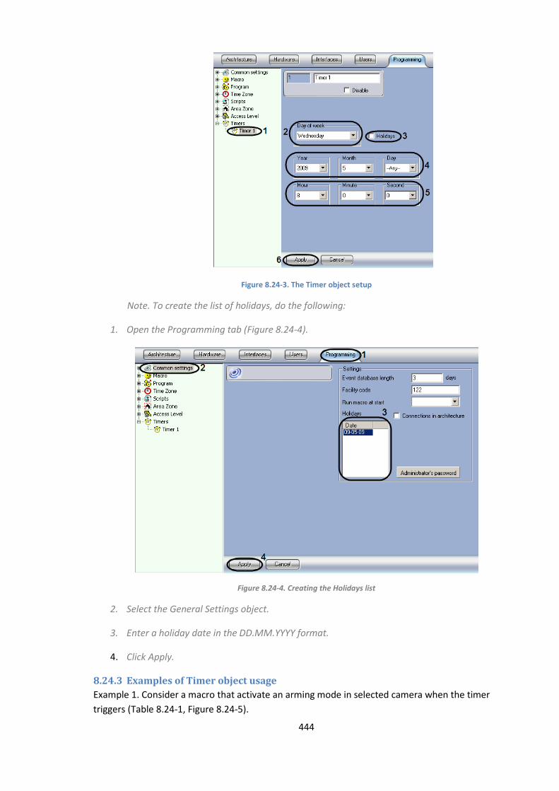
444
Figure 8.24-3. The Timer object setup
Note. To create the list of holidays, do the following:
1. Open the Programming tab (Figure 8.24-4).
Figure 8.24-4. Creating the Holidays list
2. Select the General Settings object.
3. Enter a holiday date in the DD.MM.YYYY format.
4. Click Apply.
8.24.3 Examples of Timer object usage
Example 1. Consider a macro that activate an arming mode in selected camera when the timer
triggers (Table 8.24-1, Figure 8.24-5).
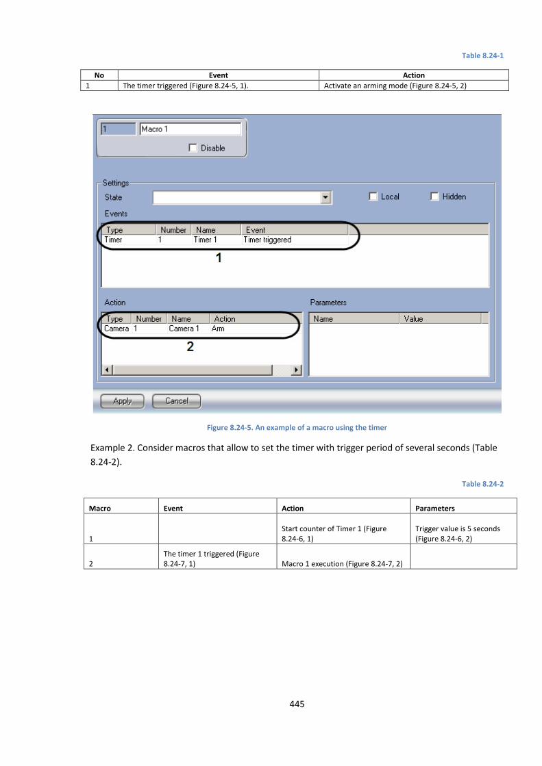
445
Table 8.24-1
No Event Action
1 The timer triggered (Figure 8.24-5, 1). Activate an arming mode (Figure 8.24-5, 2)
Figure 8.24-5. An example of a macro using the timer
Example 2. Consider macros that allow to set the timer with trigger period of several seconds (Table
8.24-2).
Table 8.24-2
Macro Event Action Parameters
1 Start counter of Timer 1 (Figure 8.24-6, 1)
Trigger value is 5 seconds (Figure 8.24-6, 2)
2 The timer 1 triggered (Figure 8.24-7, 1) Macro 1 execution (Figure 8.24-7, 2)
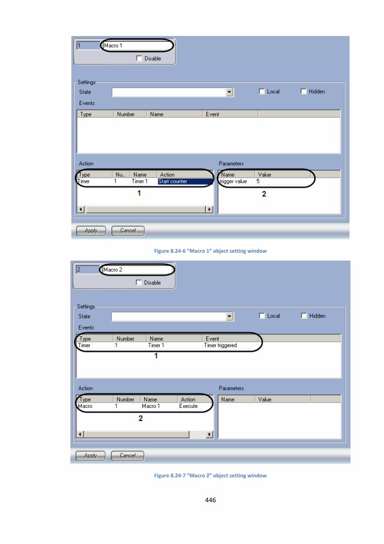
446
Figure 8.24-6 “Macro 1” object setting window
Figure 8.24-7 “Macro 2” object setting window
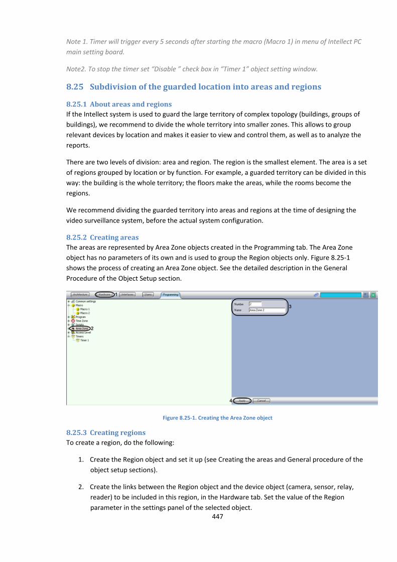
447
Note 1. Timer will trigger every 5 seconds after starting the macro (Macro 1) in menu of Intellect PC
main setting board.
Note2. To stop the timer set “Disable ” check box in “Timer 1” object setting window.
8.25 Subdivision of the guarded location into areas and regions
8.25.1 About areas and regions
If the Intellect system is used to guard the large territory of complex topology (buildings, groups of
buildings), we recommend to divide the whole territory into smaller zones. This allows to group
relevant devices by location and makes it easier to view and control them, as well as to analyze the
reports.
There are two levels of division: area and region. The region is the smallest element. The area is a set
of regions grouped by location or by function. For example, a guarded territory can be divided in this
way: the building is the whole territory; the floors make the areas, while the rooms become the
regions.
We recommend dividing the guarded territory into areas and regions at the time of designing the
video surveillance system, before the actual system configuration.
8.25.2 Creating areas
The areas are represented by Area Zone objects created in the Programming tab. The Area Zone
object has no parameters of its own and is used to group the Region objects only. Figure 8.25-1
shows the process of creating an Area Zone object. See the detailed description in the General
Procedure of the Object Setup section.
Figure 8.25-1. Creating the Area Zone object
8.25.3 Creating regions
To create a region, do the following:
1. Create the Region object and set it up (see Creating the areas and General procedure of the
object setup sections).
2. Create the links between the Region object and the device object (camera, sensor, relay,
reader) to be included in this region, in the Hardware tab. Set the value of the Region
parameter in the settings panel of the selected object.

448
8.25.4 Examples of using areas and regions
Example 1. The regions created in the system are used to group the system objects, representing the
devices by their location on the guarded territory.
To include a device into a region, select an appropriate region in the Region field of the device’s
settings panel (Figure 8.25-2).
Figure 8.25-2. An example of using the Region object
Example 2. The device reports generated by the Intellect software can be grouped by region. Figure
8.25-3 shows the Event Viewer object set up to generate a report on the Arm event occurring on any
of the devices in Region 1.
Figure 8.25-3. An example of the Event Viewer object set up for report generation

449
9 The Report System
9.1 General information The Report system of the Intellect software package is designed for the following purposes:
1. Creating and printing the reports on the events registered in the surveillance system and on
the actions taken in response to these events.
2. Viewing the video archive starting from the time of the event registered in the report.
The Report system supports the following functionality:
1. Selecting the objects (or groups of objects) from those available for reporting (objects include
hardware and software modules).
2. Selecting the events to be included in the report for each object selected.
3. Creating the report templates.
4. Creating the screen reports.
5. Creating the printed reports.
6. Exporting the printed report to a file.
7. Viewing the video archive from the screen report using the surveillance window or
converter.exe utility.
8. Handling the cameras of the ATM-Intellect system (automatic banking machine surveillance
system) using the X.25 protocol.
9.2 Starting and closing the Report system
9.2.1 Starting the Report system
The Report system can be started in the following ways:
1. Using the Windows Start button: Click the Start button, then select Programs, then Intellect,
then Report system (Figure 9.2-1).
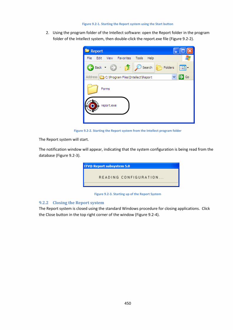
450
Figure 9.2-1. Starting the Report system using the Start button
2. Using the program folder of the Intellect software: open the Report folder in the program
folder of the Intellect system, then double-click the report.exe file (Figure 9.2-2).
Figure 9.2-2. Starting the Report system from the Intellect program folder
The Report system will start.
The notification window will appear, indicating that the system configuration is being read from the
database (Figure 9.2-3).
Figure 9.2-3. Starting up of the Report System
9.2.2 Closing the Report system
The Report system is closed using the standard Windows procedure for closing applications. Click
the Close button in the top right corner of the window (Figure 9.2-4).
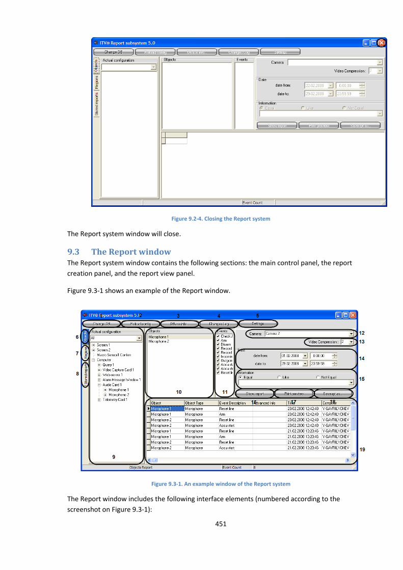
451
Figure 9.2-4. Closing the Report system
The Report system window will close.
9.3 The Report window The Report system window contains the following sections: the main control panel, the report
creation panel, and the report view panel.
Figure 9.3-1 shows an example of the Report window.
Figure 9.3-1. An example window of the Report system
The Report window includes the following interface elements (numbered according to the
screenshot on Figure 9.3-1):
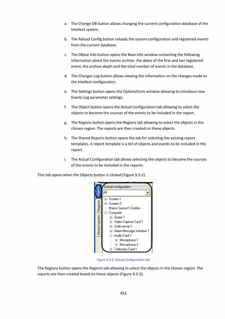
452
a. The Change DB button allows changing the current configuration database of the
Intellect system.
b. The Reload Config button reloads the system configuration and registered events
from the current database.
c. The DBase Info button opens the Base Info window containing the following
information about the events archive: the dates of the first and last registered
event, the archive depth and the total number of events in the database.
d. The Changes Log button allows viewing the information on the changes made to
the Intellect configuration.
e. The Settings button opens the OptionsForm window allowing to introduce new
Events Log parameter settings.
f. The Object button opens the Actual Configuration tab allowing to select the
objects to become the sources of the events to be included in the report.
g. The Regions button opens the Regions tab allowing to select the objects in the
chosen region. The reports are then created on these objects.
h. The Shared Reports button opens the tab for selecting the existing report
templates. A report template is a list of objects and events to be included in the
report.
i. The Actual Configuration tab allows selecting the objects to become the sources
of the events to be included in the reports.
This tab opens when the Objects button is clicked (Figure 9.3-2).
Figure 9.3-2. Actual Configuration tab
The Regions button opens the Regions tab allowing to select the objects in the chosen region. The
reports are then created based on these objects (Figure 9.3-3).
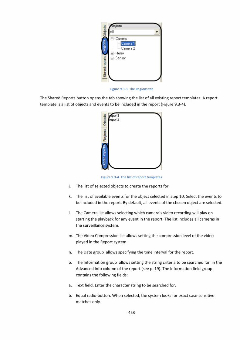
453
Figure 9.3-3. The Regions tab
The Shared Reports button opens the tab showing the list of all existing report templates. A report
template is a list of objects and events to be included in the report (Figure 9.3-4).
Figure 9.3-4. The list of report templates
j. The list of selected objects to create the reports for.
k. The list of available events for the object selected in step 10. Select the events to
be included in the report. By default, all events of the chosen object are selected.
l. The Camera list allows selecting which camera’s video recording will play on
starting the playback for any event in the report. The list includes all cameras in
the surveillance system.
m. The Video Compression list allows setting the compression level of the video
played in the Report system.
n. The Date group allows specifying the time interval for the report.
o. The Information group allows setting the string criteria to be searched for in the
Advanced Info column of the report (see p. 19). The Information field group
contains the following fields:
a. Text field. Enter the character string to be searched for.
b. Equal radio-button. When selected, the system looks for exact case-sensitive
matches only.

454
c. Like radio-button. When selected, the system looks for the rows where the
Advanced Info column contains the search string, case-sensitive.
d. Not Equal radio-button. When selected, the system looks for the rows where the
Advanced Info column does not match the search string, case-sensitive.
p. The Show Report button. Creates the screen form of the report (see the Creating
and using the screen report section).
q. The Print Preview button. Creates the printed report (see the Creating and using
the printed report section).
Note. If the screen report has not been created before the printed report is activated, the screen
report is automatically created.
r. The Save Rpt As button. Saves the report template, i.e. the list of objects (see p.
10) and corresponding events (see p.11).
s. The screen report panel. Shows the screen report. The panel includes the
following columns:
1. Object – the name of the object where the event occurred.
2. Object type – the type of the object where the event occurred.
3. Event Description – the name of the event registered by the system.
4. Advanced Info – additional information on the event.
5. Time – date and time when the event started.
6. Computer - the name of the computer that registered the event.
9.3.1 The OptionsForm window
The OptionsForm settings window allows specifying additional parameters for the Report system:
archive viewing mode, database connection, etc. To open the OptionsForm window, click the
Settings button in the Report window (see the Report Window section).
Figure 9.3-5 shows the OptionsForm window.
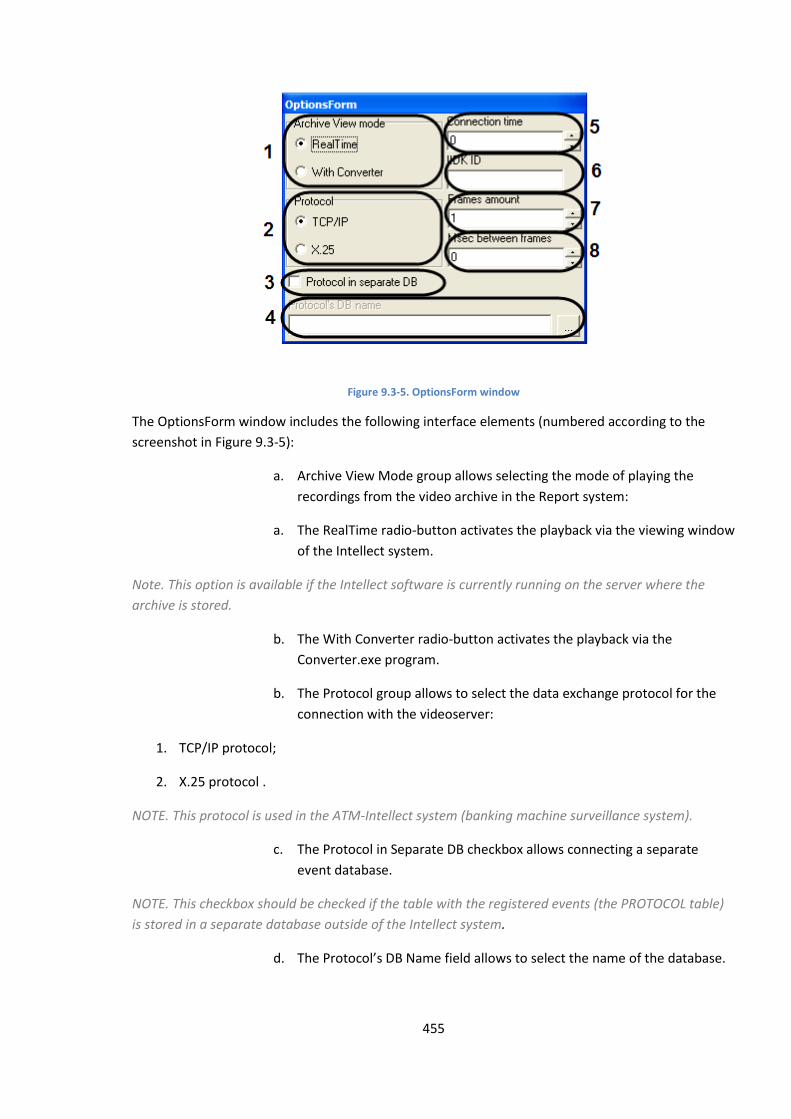
455
Figure 9.3-5. OptionsForm window
The OptionsForm window includes the following interface elements (numbered according to the
screenshot in Figure 9.3-5):
a. Archive View Mode group allows selecting the mode of playing the
recordings from the video archive in the Report system:
a. The RealTime radio-button activates the playback via the viewing window
of the Intellect system.
Note. This option is available if the Intellect software is currently running on the server where the
archive is stored.
b. The With Converter radio-button activates the playback via the
Converter.exe program.
b. The Protocol group allows to select the data exchange protocol for the
connection with the videoserver:
1. TCP/IP protocol;
2. X.25 protocol .
NOTE. This protocol is used in the ATM-Intellect system (banking machine surveillance system).
c. The Protocol in Separate DB checkbox allows connecting a separate
event database.
NOTE. This checkbox should be checked if the table with the registered events (the PROTOCOL table)
is stored in a separate database outside of the Intellect system.
d. The Protocol’s DB Name field allows to select the name of the database.
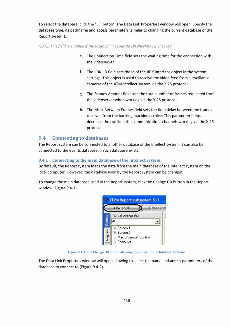
456
To select the database, click the "...” button. The Data Link Properties window will open. Specify the
database type, its pathname and access parameters (similar to changing the current database of the
Report system).
NOTE. This field is enabled if the Protocol In Separate DB checkbox is checked.
e. The Connection Time field sets the waiting time for the connection with
the videoserver.
f. The IIDK_ID field sets the id of the IIDK Interface object in the system
settings. This object is used to receive the video feed from surveillance
cameras of the ATM-Intellect system via the X.25 protocol.
g. The Frames Amount field sets the total number of frames requested from
the videoserver when working via the X.25 protocol.
h. The Msec Between Frames field sets the time delay between the frames
received from the banking machine archive. This parameter helps
decrease the traffic in the communications channels working via the X.25
protocol.
9.4 Connecting to databases The Report system can be connected to another database of the Intellect system. It can also be
connected to the events database, if such database exists.
9.4.1 Connecting to the main database of the Intellect system
By default, the Report system loads the data from the main database of the Intellect system on the
local computer. However, the database used by the Report system can be changed.
To change the main database used in the Report system, click the Change DB button in the Report
window (Figure 9.4-1).
Figure 9.4-1. The Change DB button allowing to connect to the Intellect database
The Data Link Properties window will open allowing to select the name and access parameters of the
database to connect to (Figure 9.4-2).
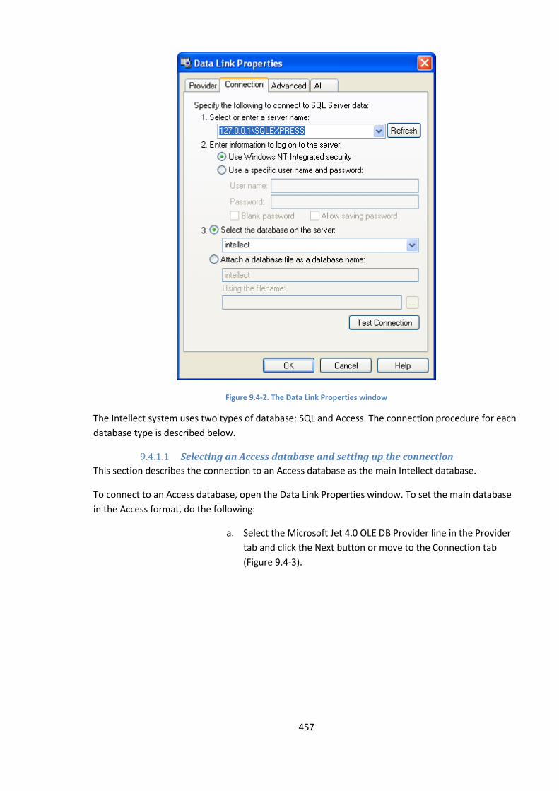
457
Figure 9.4-2. The Data Link Properties window
The Intellect system uses two types of database: SQL and Access. The connection procedure for each
database type is described below.
9.4.1.1 Selecting an Access database and setting up the connection
This section describes the connection to an Access database as the main Intellect database.
To connect to an Access database, open the Data Link Properties window. To set the main database
in the Access format, do the following:
a. Select the Microsoft Jet 4.0 OLE DB Provider line in the Provider
tab and click the Next button or move to the Connection tab
(Figure 9.4-3).
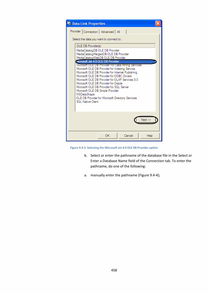
458
Figure 9.4-3. Selecting the Microsoft Jet 4.0 OLE DB Provider option
b. Select or enter the pathname of the database file in the Select or
Enter a Database Name field of the Connection tab. To enter the
pathname, do one of the following:
a. manually enter the pathname (Figure 9.4-4);

459
Figure 9.4-4. Selecting the pathname of the main database file
b. Click the “…” button to open the standard dialog box for file
selection (Figure 9.4-5).
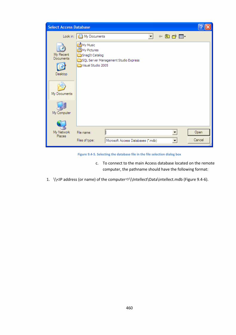
460
Figure 9.4-5. Selecting the database file in the file selection dialog box
c. To connect to the main Access database located on the remote
computer, the pathname should have the following format:
1. \\<IP address (or name) of the computer\\Intellect\Data\intellect.mdb (Figure 9.4-6).
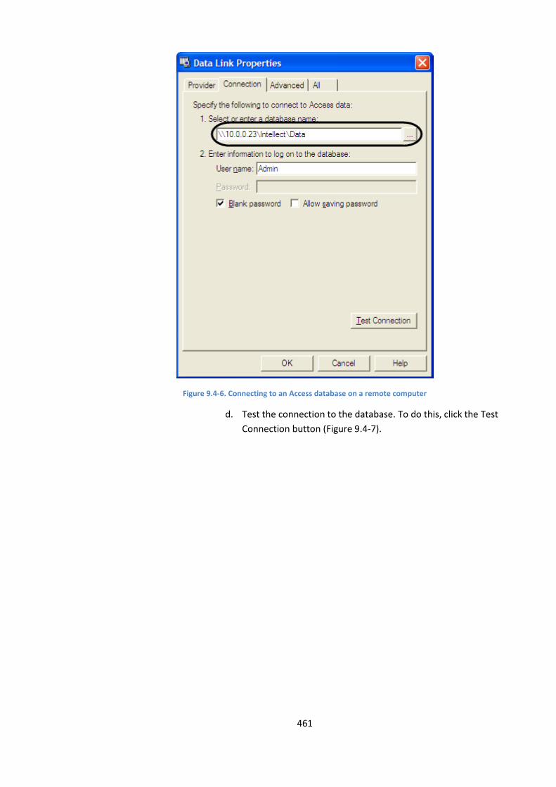
461
Figure 9.4-6. Connecting to an Access database on a remote computer
d. Test the connection to the database. To do this, click the Test
Connection button (Figure 9.4-7).
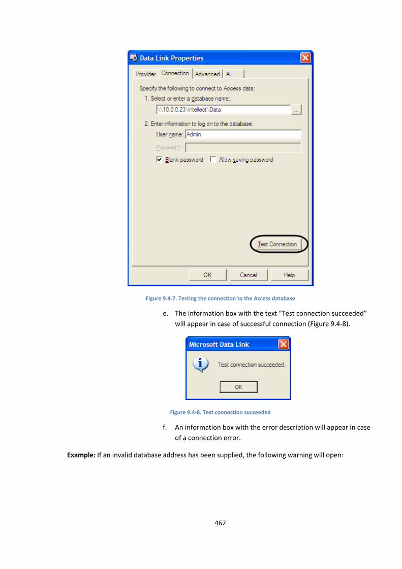
462
Figure 9.4-7. Testing the connection to the Access database
e. The information box with the text “Test connection succeeded”
will appear in case of successful connection (Figure 9.4-8).
Figure 9.4-8. Test connection succeeded
f. An information box with the error description will appear in case
of a connection error.
Example: If an invalid database address has been supplied, the following warning will open:
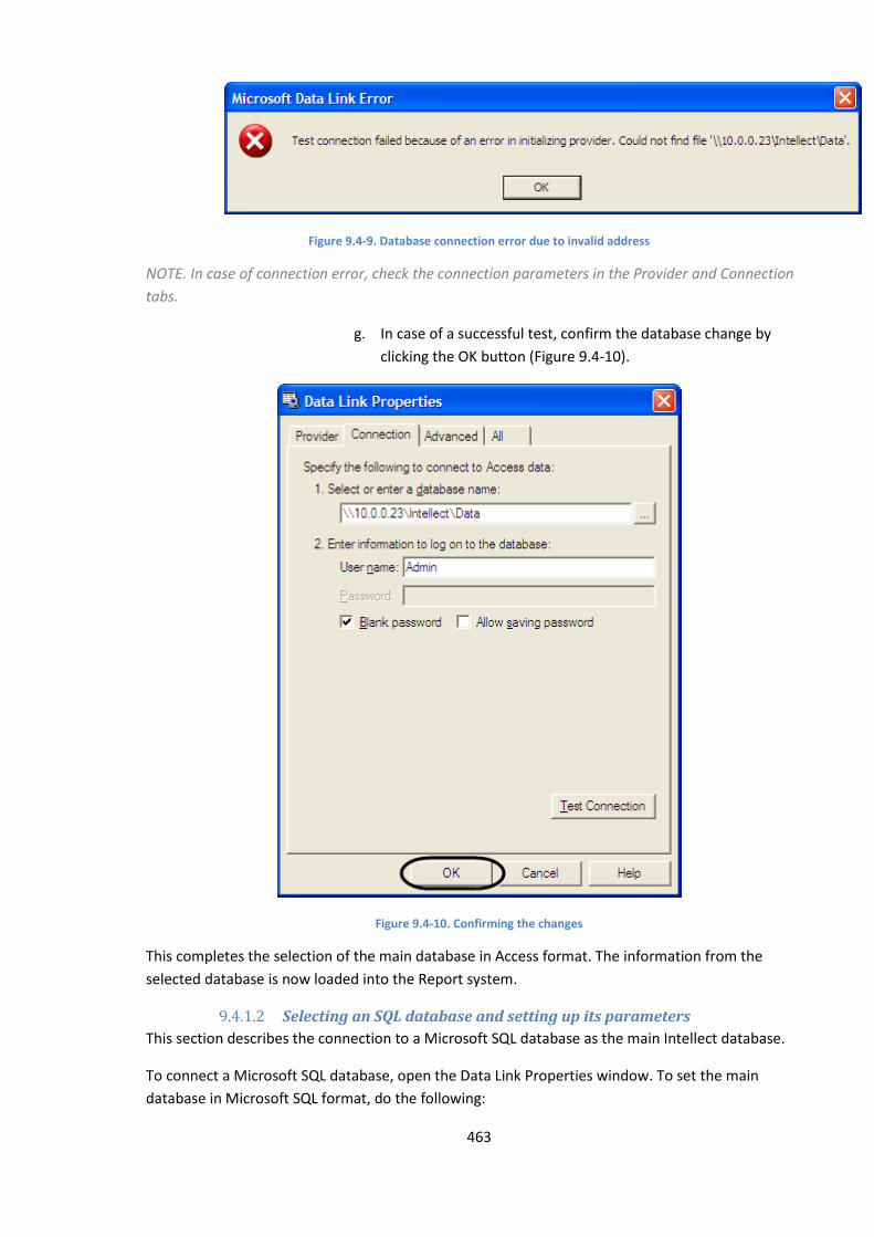
463
Figure 9.4-9. Database connection error due to invalid address
NOTE. In case of connection error, check the connection parameters in the Provider and Connection
tabs.
g. In case of a successful test, confirm the database change by
clicking the OK button (Figure 9.4-10).
Figure 9.4-10. Confirming the changes
This completes the selection of the main database in Access format. The information from the
selected database is now loaded into the Report system.
9.4.1.2 Selecting an SQL database and setting up its parameters
This section describes the connection to a Microsoft SQL database as the main Intellect database.
To connect a Microsoft SQL database, open the Data Link Properties window. To set the main
database in Microsoft SQL format, do the following:
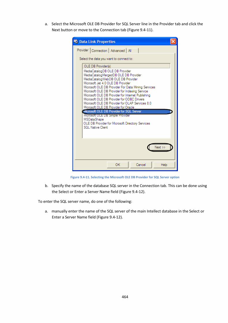
464
a. Select the Microsoft OLE DB Provider for SQL Server line in the Provider tab and click the
Next button or move to the Connection tab (Figure 9.4-11).
Figure 9.4-11. Selecting the Microsoft OLE DB Provider for SQL Server option
b. Specify the name of the database SQL server in the Connection tab. This can be done using
the Select or Enter a Server Name field (Figure 9.4-12).
To enter the SQL server name, do one of the following:
a. manually enter the name of the SQL server of the main Intellect database in the Select or
Enter a Server Name field (Figure 9.4-12).
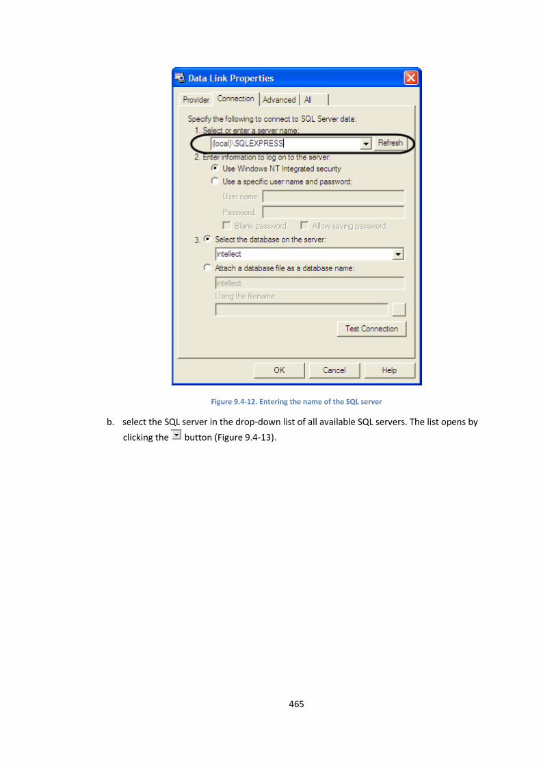
465
Figure 9.4-12. Entering the name of the SQL server
b. select the SQL server in the drop-down list of all available SQL servers. The list opens by
clicking the button (Figure 9.4-13).
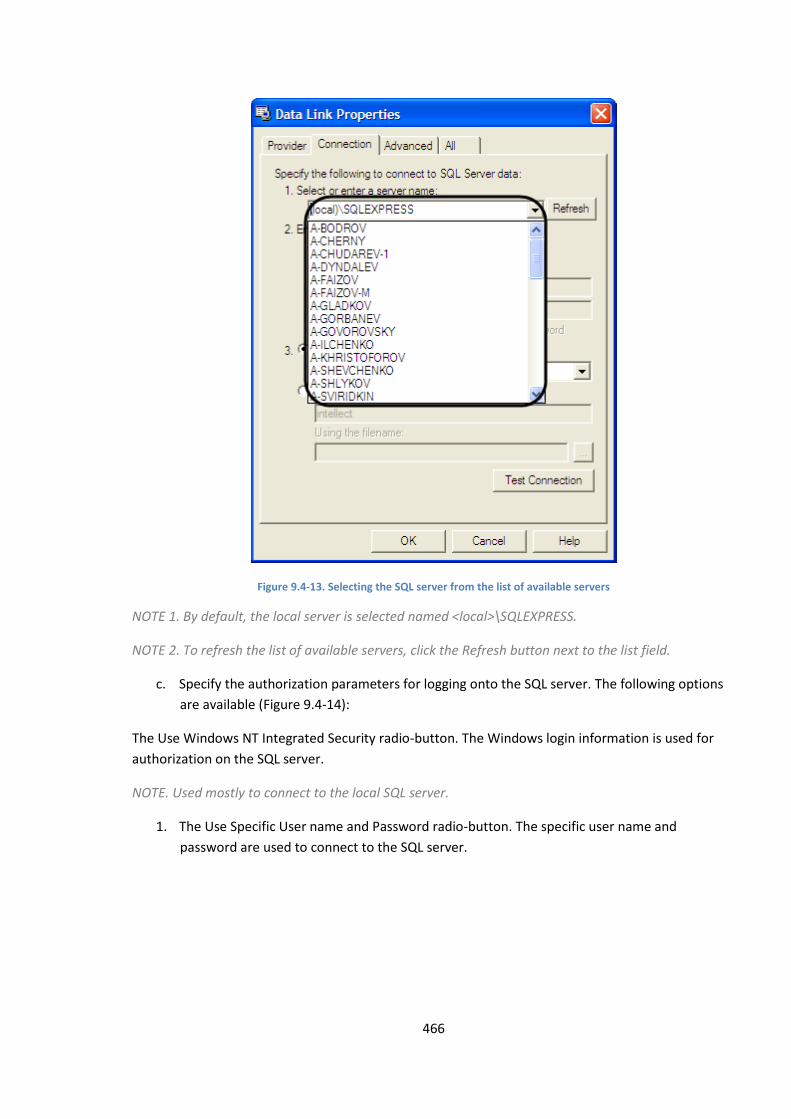
466
Figure 9.4-13. Selecting the SQL server from the list of available servers
NOTE 1. By default, the local server is selected named <local>\SQLEXPRESS.
NOTE 2. To refresh the list of available servers, click the Refresh button next to the list field.
c. Specify the authorization parameters for logging onto the SQL server. The following options
are available (Figure 9.4-14):
The Use Windows NT Integrated Security radio-button. The Windows login information is used for
authorization on the SQL server.
NOTE. Used mostly to connect to the local SQL server.
1. The Use Specific User name and Password radio-button. The specific user name and
password are used to connect to the SQL server.

467
Figure 9.4-14. Selecting the SQL server authorization parameters
2. When the Use Specific User name and Password radio-button is selected, enter the
information into the following fields: User Name and Password.
NOTE. By default, the following information is set up during Intellect software installation: user
name “sa”, password “itv” (see the Intellect Software Installation section).
Note. By default while installing the Intellect complex, the user(login) «sa» and one of the following
passwords( see. Installing the Intellect complex) are set for authorization on SQL server
1. «ITV» - when installed on OS Windows XP;
2. Administrator password SQL Server (is registered while installing SQL Server) – when installed
on OS Windows Server 2003, Windows Vista, Windows Server 2008.
When the Use Specific User name and Password radio-button is selected, the Blank Password and
Allow Saving Password checkboxes become enabled (Figure 9.4-15).

468
Figure 9.4-15. Selecting the SQL server authorization parameters
The Blank Password checkbox allows to enable connection to the SQL server with no password.
The Allow Saving Password button saves the password for the next connection to the SQL server.
d. Select the database to be used as main in the Select the Database on the Server drop-down
list. To open the list of available databases on the SQL server, click the button (Figure
9.4-16).
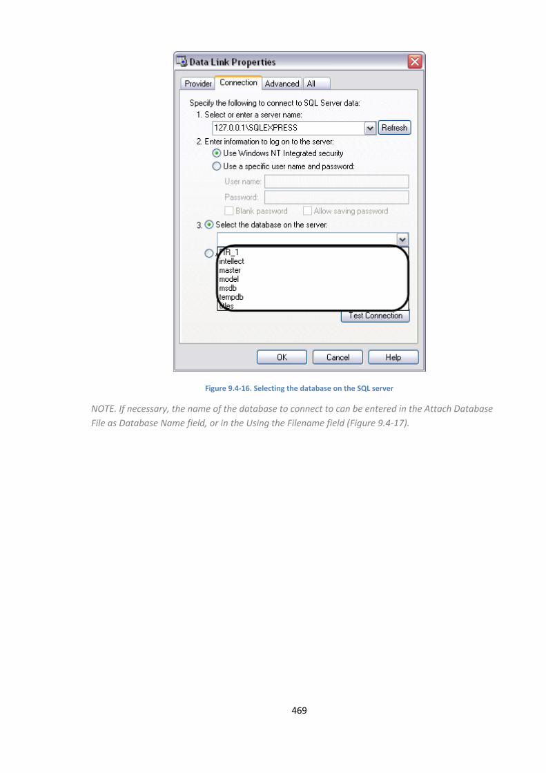
469
Figure 9.4-16. Selecting the database on the SQL server
NOTE. If necessary, the name of the database to connect to can be entered in the Attach Database
File as Database Name field, or in the Using the Filename field (Figure 9.4-17).
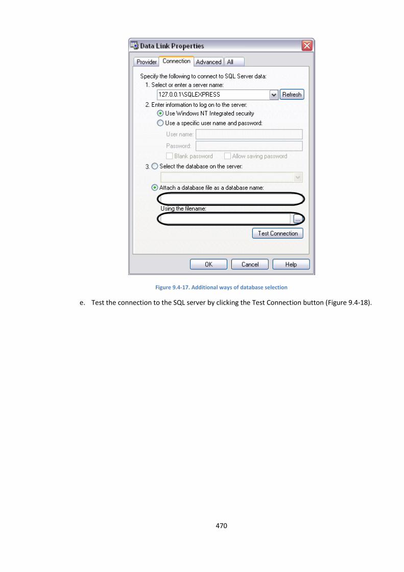
470
Figure 9.4-17. Additional ways of database selection
e. Test the connection to the SQL server by clicking the Test Connection button (Figure 9.4-18).

471
Figure 9.4-18. Testing the connection to the database on the SQL server
The information box showing the message "Test connection succeeded” will appear in case of
successful connection (Figure 9.4-19).
Figure 9.4-19. Test connection succeeded
An information box with the error description will appear in case of connection error.
NOTE. In case of connection errors, check the connection parameters in the Provider and Connection
tabs.
f. In case of a successful test, confirm the database change by clicking the OK button (Figure
9.4-20).
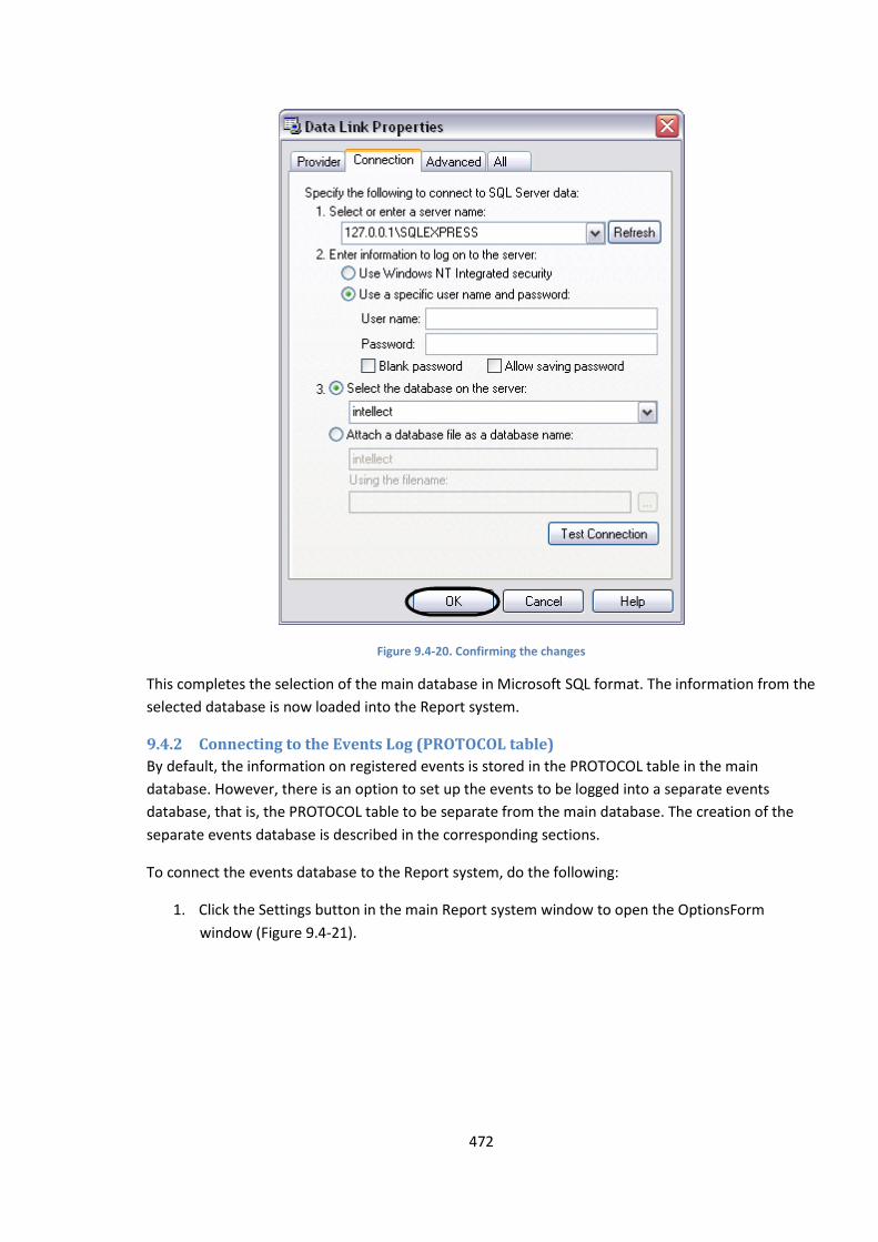
472
Figure 9.4-20. Confirming the changes
This completes the selection of the main database in Microsoft SQL format. The information from the
selected database is now loaded into the Report system.
9.4.2 Connecting to the Events Log (PROTOCOL table)
By default, the information on registered events is stored in the PROTOCOL table in the main
database. However, there is an option to set up the events to be logged into a separate events
database, that is, the PROTOCOL table to be separate from the main database. The creation of the
separate events database is described in the corresponding sections.
To connect the events database to the Report system, do the following:
1. Click the Settings button in the main Report system window to open the OptionsForm
window (Figure 9.4-21).
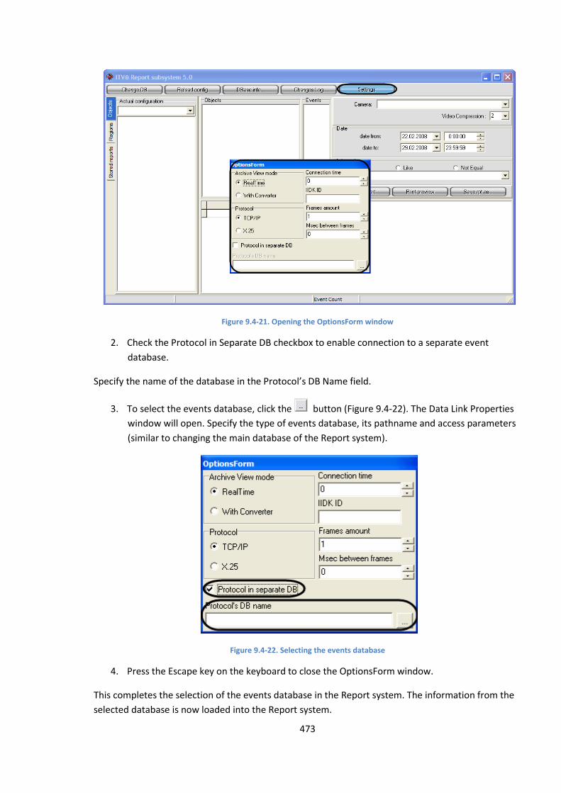
473
Figure 9.4-21. Opening the OptionsForm window
2. Check the Protocol in Separate DB checkbox to enable connection to a separate event
database.
Specify the name of the database in the Protocol’s DB Name field.
3. To select the events database, click the button (Figure 9.4-22). The Data Link Properties
window will open. Specify the type of events database, its pathname and access parameters
(similar to changing the main database of the Report system).
Figure 9.4-22. Selecting the events database
4. Press the Escape key on the keyboard to close the OptionsForm window.
This completes the selection of the events database in the Report system. The information from the
selected database is now loaded into the Report system.
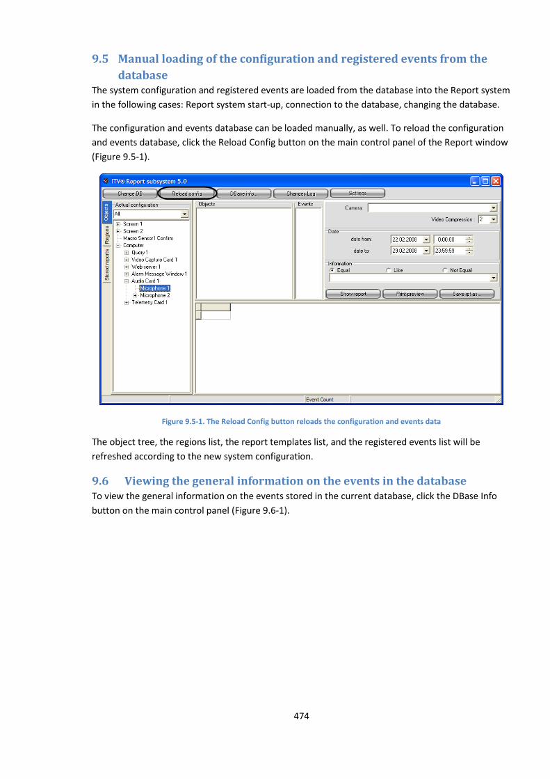
474
9.5 Manual loading of the configuration and registered events from the
database The system configuration and registered events are loaded from the database into the Report system
in the following cases: Report system start-up, connection to the database, changing the database.
The configuration and events database can be loaded manually, as well. To reload the configuration
and events database, click the Reload Config button on the main control panel of the Report window
(Figure 9.5-1).
Figure 9.5-1. The Reload Config button reloads the configuration and events data
The object tree, the regions list, the report templates list, and the registered events list will be
refreshed according to the new system configuration.
9.6 Viewing the general information on the events in the database To view the general information on the events stored in the current database, click the DBase Info
button on the main control panel (Figure 9.6-1).

475
Figure 9.6-1. The DBase Info button
The Base Info information box will open showing the general information about the database (Figure
9.6-2).
Figure 9.6-2. The Base Info window
The following information is displayed:
a. The name of the current database.
b. The date of the first registered event in the current database.
c. The date of the last registered event in the current database.
d. The number of days between the first and the last event.
e. Total number of events in the database.
9.7 Creating the log of changes made to the system configuration The Report system allows viewing the log of all changes made to the system configuration.

476
To view the configuration changes, click the Changes Log button in the main control panel (Figure
9.7-1).
Figure 9.7-1. The Changes Log button
The screen report section of the window will show the list of changes made to the system
configuration (Figure 9.7-2).
Figure 9.7-2. Viewing the changes log
The changes log includes the following columns:

477
1. Object – the name of the object that has been changed.
2. Event Description – the type of the change made to the object.
3. Advanced Info – additional information on the change.
4. Time – date and time of change.
5. Computer - the name of the computer where the change was made.
9.8 Using the report templates in the Report system The report templates can be created in the Report system. The templates help automate the process
of creating the screen and printed reports for a selected list of objects for particular time periods.
A report template comprises of a list of objects and events related to these objects. When the
template is created, the list of objects and events is formed. To create a particular screen or printed
report based on this template, only the time interval should be specified.
9.8.1 Recommendations for template creation
We do not recommend including too many objects in a template. If the template includes too many
objects, the request on all events related to these objects, will take a very long time to execute, or
will fail.
We recommend creating smaller templates that group the objects according to different regions of
the guarded area.
We do not recommend including more than 200 objects in one template.
9.8.2 Creating a report template
To create a report template, the object list should be formed. This can be done using the Objects and
Regions tabs, and the Objects panel. The list of events for each object can be formed using the Events
panel.
The Figure 9.8-1 shows the stages of template creation.
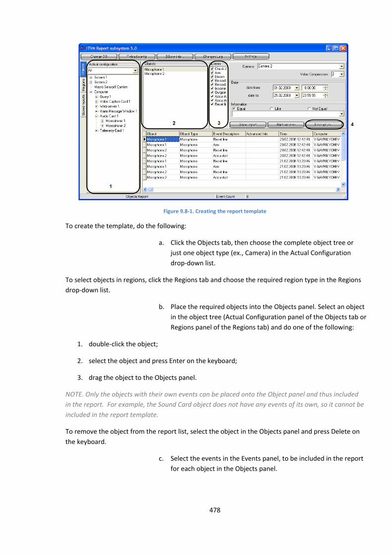
478
Figure 9.8-1. Creating the report template
To create the template, do the following:
a. Click the Objects tab, then choose the complete object tree or
just one object type (ex., Camera) in the Actual Configuration
drop-down list.
To select objects in regions, click the Regions tab and choose the required region type in the Regions
drop-down list.
b. Place the required objects into the Objects panel. Select an object
in the object tree (Actual Configuration panel of the Objects tab or
Regions panel of the Regions tab) and do one of the following:
1. double-click the object;
2. select the object and press Enter on the keyboard;
3. drag the object to the Objects panel.
NOTE. Only the objects with their own events can be placed onto the Object panel and thus included
in the report. For example, the Sound Card object does not have any events of its own, so it cannot be
included in the report template.
To remove the object from the report list, select the object in the Objects panel and press Delete on
the keyboard.
c. Select the events in the Events panel, to be included in the report
for each object in the Objects panel.
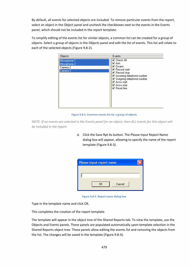
479
By default, all events for selected objects are included. To remove particular events from the report,
select an object in the Object panel and uncheck the checkboxes next to the events in the Events
panel, which should not be included in the report template.
To simplify editing of the events list for similar objects, a common list can be created for a group of
objects. Select a group of objects in the Objects panel and edit the list of events. This list will relate to
each of the selected objects (Figure 9.8-2).
Figure 9.8-2. Common events list for a group of objects
NOTE. If no events are selected in the Events panel for an object, then ALL events for this object will
be included in the report.
d. Click the Save Rpt As button. The Please Input Report Name
dialog box will appear, allowing to specify the name of the report
template (Figure 9.8-3).
Figure 9.8-3. Report name dialog box
Type in the template name and click OK.
This completes the creation of the report template.
The template will appear in the object tree of the Shared Reports tab. To view the template, use the
Objects and Events panels. These panels are populated automatically upon template selection in the
Shared Reports object tree. These panels allow editing the events list and removing the objects from
the list. The changes will be saved in the template (Figure 9.8-4).
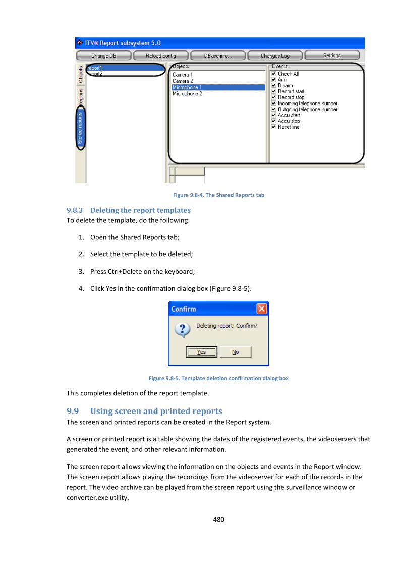
480
Figure 9.8-4. The Shared Reports tab
9.8.3 Deleting the report templates
To delete the template, do the following:
1. Open the Shared Reports tab;
2. Select the template to be deleted;
3. Press Ctrl+Delete on the keyboard;
4. Click Yes in the confirmation dialog box (Figure 9.8-5).
Figure 9.8-5. Template deletion confirmation dialog box
This completes deletion of the report template.
9.9 Using screen and printed reports The screen and printed reports can be created in the Report system.
A screen or printed report is a table showing the dates of the registered events, the videoservers that
generated the event, and other relevant information.
The screen report allows viewing the information on the objects and events in the Report window.
The screen report allows playing the recordings from the videoserver for each of the records in the
report. The video archive can be played from the screen report using the surveillance window or
converter.exe utility.

481
NOTE. The playing of the recording in the surveillance window is possible if the Intellect software is
running on the videoserver.
The printed report is used for printing the report or exporting it into one of the common file formats.
When the printed report is created, all information about the selected objects and events is
displayed in a separate window.
9.9.1 Creating a screen report
The screen report provides the means for convenient viewing of the registered events and playback
of the video recordings from the videoserver archive.
Figure 9.9-1 shows the stages of the screen report creation.
Figure 9.9-1. Creating the screen report
To create the screen report, do the following:
a. Click the Objects tab, then choose the complete object tree or just one object
type (ex., Camera) in the Actual Configuration drop-down list.
To select objects in regions, click the Regions tab and choose the required region type in the Regions
drop-down list.
b. Place the required objects into the Objects panel. Select an object in the
object tree (Actual Configuration panel of the Objects tab or Regions panel of
the Regions tab) and do one of the following:
1. double-click the object;
2. select the object and press Enter on the keyboard;
3. drag the object to the Objects panel.

482
NOTE. Only the objects with their own events can be placed onto the Object panel and thus included
in the report. For example, the Sound Card object does not have any events of its own, so it cannot be
included in the report template.
To remove the object from the report list, select the object in the Objects panel and press Delete on
the keyboard.
c. Select the events in the Events panel, to be included in the report for each
object in the Objects panel.
By default, all events for selected objects are included. To remove particular events from the report,
select an object in the Object panel and uncheck the checkboxes next to the events in the Events
panel, which should not be included in the report template.
To simplify the editing of the events list for similar objects, a common list can be created for a group
of objects. Select a group of objects in the Objects panel and edit the list of events. This list will relate
to each of the selected objects (Figure 9.9-2).
Figure 9.9-2. Common events list for a group of objects
NOTE. If no events are selected in the Events panel for an object, then ALL events for this object will
be included in the report.
d. Specify the time period to create the report for, in the Date group of fields.
e. Click the Show Report button to create the screen report.
NOTE. Clicking the Show Report button is equivalent to pressing F5 on the keyboard.
This completes the creation of the screen report. The screen report will be displayed in the lower
part of the Report window.
9.9.1.1 Creating a screen report from the report template
The report templates can be created in the Report system. The templates help automate the process
of creating the screen and printed reports on a selected list of objects for particular time periods.
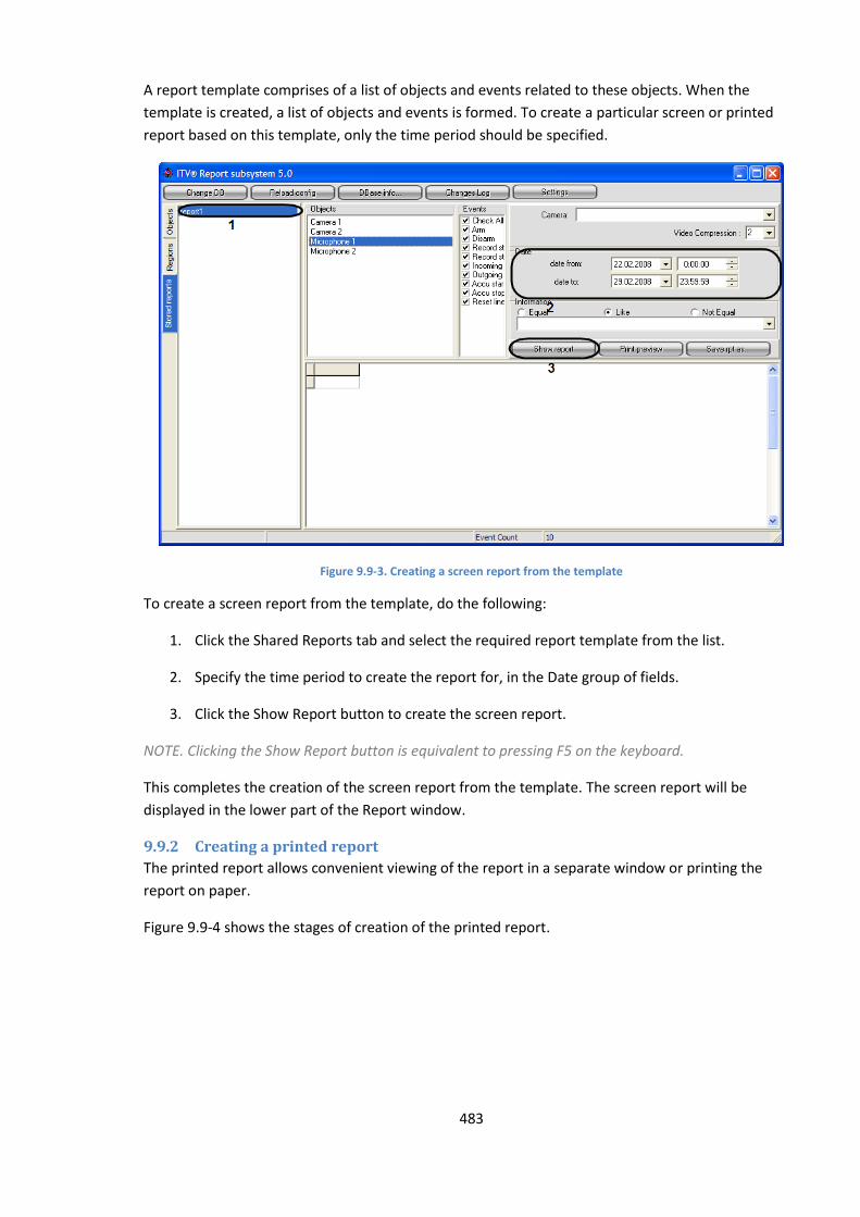
483
A report template comprises of a list of objects and events related to these objects. When the
template is created, a list of objects and events is formed. To create a particular screen or printed
report based on this template, only the time period should be specified.
Figure 9.9-3. Creating a screen report from the template
To create a screen report from the template, do the following:
1. Click the Shared Reports tab and select the required report template from the list.
2. Specify the time period to create the report for, in the Date group of fields.
3. Click the Show Report button to create the screen report.
NOTE. Clicking the Show Report button is equivalent to pressing F5 on the keyboard.
This completes the creation of the screen report from the template. The screen report will be
displayed in the lower part of the Report window.
9.9.2 Creating a printed report
The printed report allows convenient viewing of the report in a separate window or printing the
report on paper.
Figure 9.9-4 shows the stages of creation of the printed report.

484
Figure 9.9-4. Creating a printed report
Creating a printed report is similar to the screen report creation procedure in p. 1 to 4 (see sections
above).
To create a printed report, click the Print Preview button in p.5.
NOTE. Clicking the Print Preview button is equivalent to pressing F6 on the keyboard.
This completes the creation of the printed report. The report will open in a separate window (Figure
9.9-5).
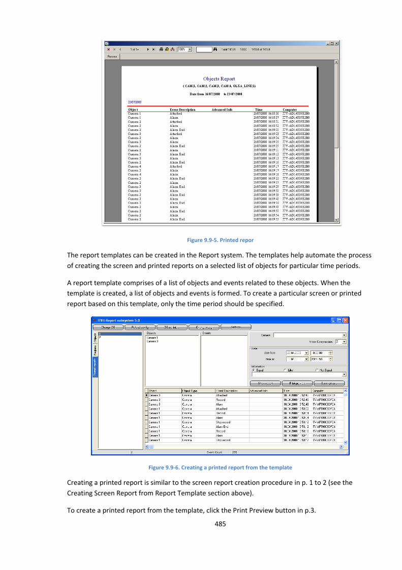
485
Figure 9.9-5. Printed repor
The report templates can be created in the Report system. The templates help automate the process
of creating the screen and printed reports on a selected list of objects for particular time periods.
A report template comprises of a list of objects and events related to these objects. When the
template is created, a list of objects and events is formed. To create a particular screen or printed
report based on this template, only the time period should be specified.
Figure 9.9-6. Creating a printed report from the template
Creating a printed report is similar to the screen report creation procedure in p. 1 to 2 (see the
Creating Screen Report from Report Template section above).
To create a printed report from the template, click the Print Preview button in p.3.
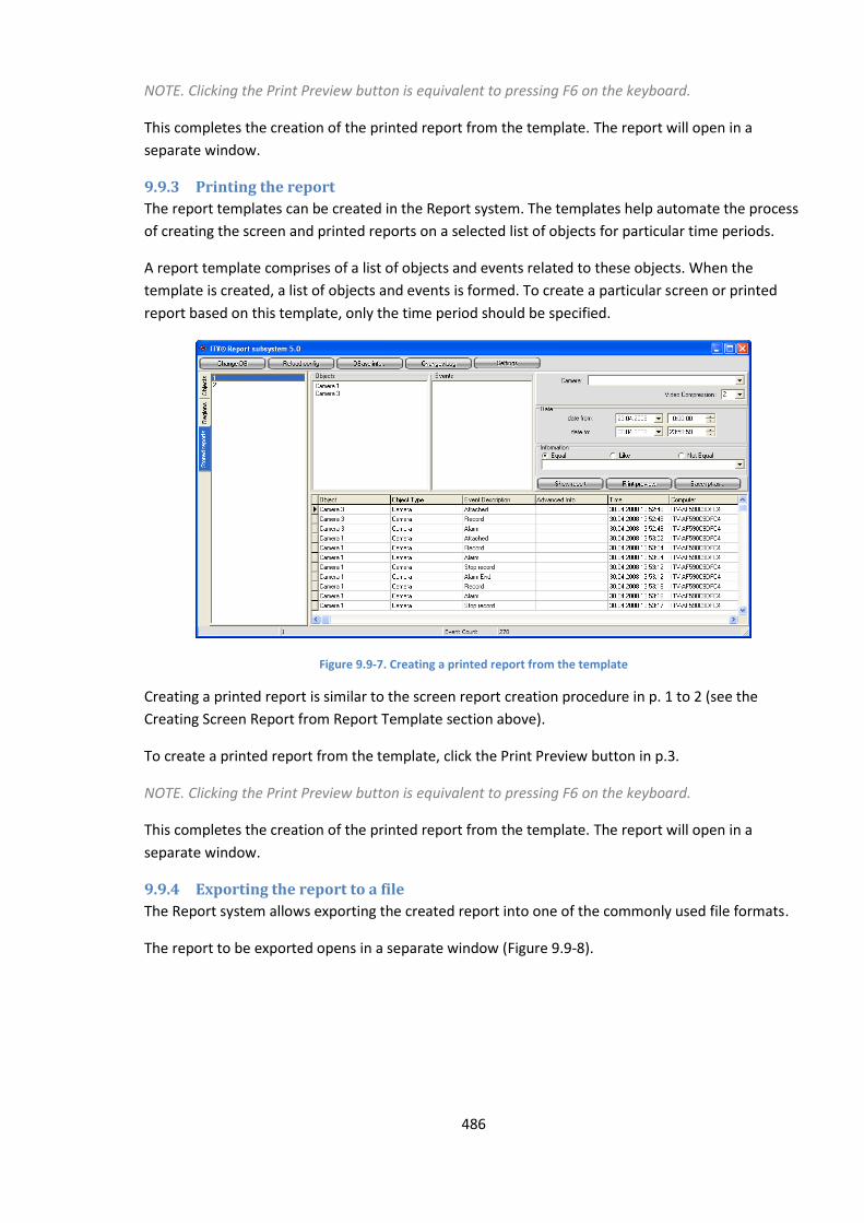
486
NOTE. Clicking the Print Preview button is equivalent to pressing F6 on the keyboard.
This completes the creation of the printed report from the template. The report will open in a
separate window.
9.9.3 Printing the report
The report templates can be created in the Report system. The templates help automate the process
of creating the screen and printed reports on a selected list of objects for particular time periods.
A report template comprises of a list of objects and events related to these objects. When the
template is created, a list of objects and events is formed. To create a particular screen or printed
report based on this template, only the time period should be specified.
Figure 9.9-7. Creating a printed report from the template
Creating a printed report is similar to the screen report creation procedure in p. 1 to 2 (see the
Creating Screen Report from Report Template section above).
To create a printed report from the template, click the Print Preview button in p.3.
NOTE. Clicking the Print Preview button is equivalent to pressing F6 on the keyboard.
This completes the creation of the printed report from the template. The report will open in a
separate window.
9.9.4 Exporting the report to a file
The Report system allows exporting the created report into one of the commonly used file formats.
The report to be exported opens in a separate window (Figure 9.9-8).
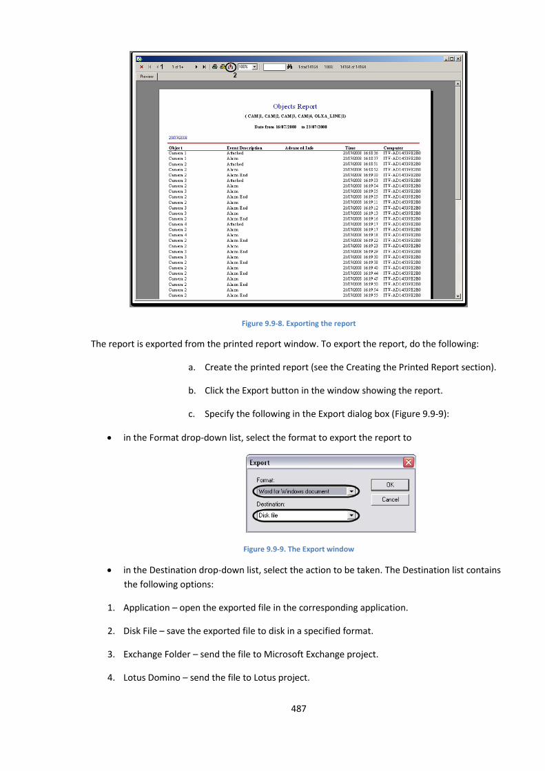
487
Figure 9.9-8. Exporting the report
The report is exported from the printed report window. To export the report, do the following:
a. Create the printed report (see the Creating the Printed Report section).
b. Click the Export button in the window showing the report.
c. Specify the following in the Export dialog box (Figure 9.9-9):
in the Format drop-down list, select the format to export the report to
Figure 9.9-9. The Export window
in the Destination drop-down list, select the action to be taken. The Destination list contains
the following options:
1. Application – open the exported file in the corresponding application.
2. Disk File – save the exported file to disk in a specified format.
3. Exchange Folder – send the file to Microsoft Exchange project.
4. Lotus Domino – send the file to Lotus project.
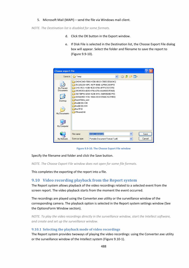
488
5. Microsoft Mail (MAPI) – send the file via Windows mail client.
NOTE. The Destination list is disabled for some formats.
d. Click the OK button in the Export window.
e. If Disk File is selected in the Destination list, the Choose Export File dialog
box will appear. Select the folder and filename to save the report to
(Figure 9.9-10).
Figure 9.9-10. The Choose Export File window
Specify the filename and folder and click the Save button.
NOTE. The Choose Export File window does not open for some file formats.
This completes the exporting of the report into a file.
9.10 Video recording playback from the Report system The Report system allows playback of the video recordings related to a selected event from the
screen report. The video playback starts from the moment the event occurred.
The recordings are played using the Converter.exe utility or the surveillance window of the
corresponding camera. The playback option is selected in the Report system settings window (See
the OptionsForm Window section).
NOTE. To play the video recordings directly in the surveillance window, start the Intellect software,
and create and set up the surveillance window.
9.10.1 Selecting the playback mode of video recordings
The Report system provides twoways of playing the video recordings: using the Converter.exe utility
or the surveillance window of the Intellect system (Figure 9.10-1).
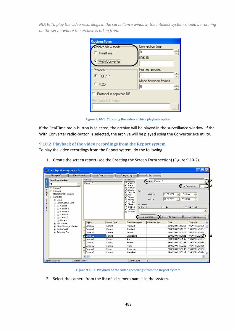
489
NOTE. To play the video recordings in the surveillance window, the Intellect system should be running
on the server where the archive is taken from.
Figure 9.10-1. Choosing the video archive playback option
If the RealTime radio-button is selected, the archive will be played in the surveillance window. If the
With Converter radio-button is selected, the archive will be played using the Converter.exe utility.
9.10.2 Playback of the video recordings from the Report system
To play the video recordings from the Report system, do the following:
1. Create the screen report (see the Creating the Screen Form section) (Figure 9.10-2).
Figure 9.10-2. Playback of the video recordings from the Report system
2. Select the camera from the list of all camera names in the system.
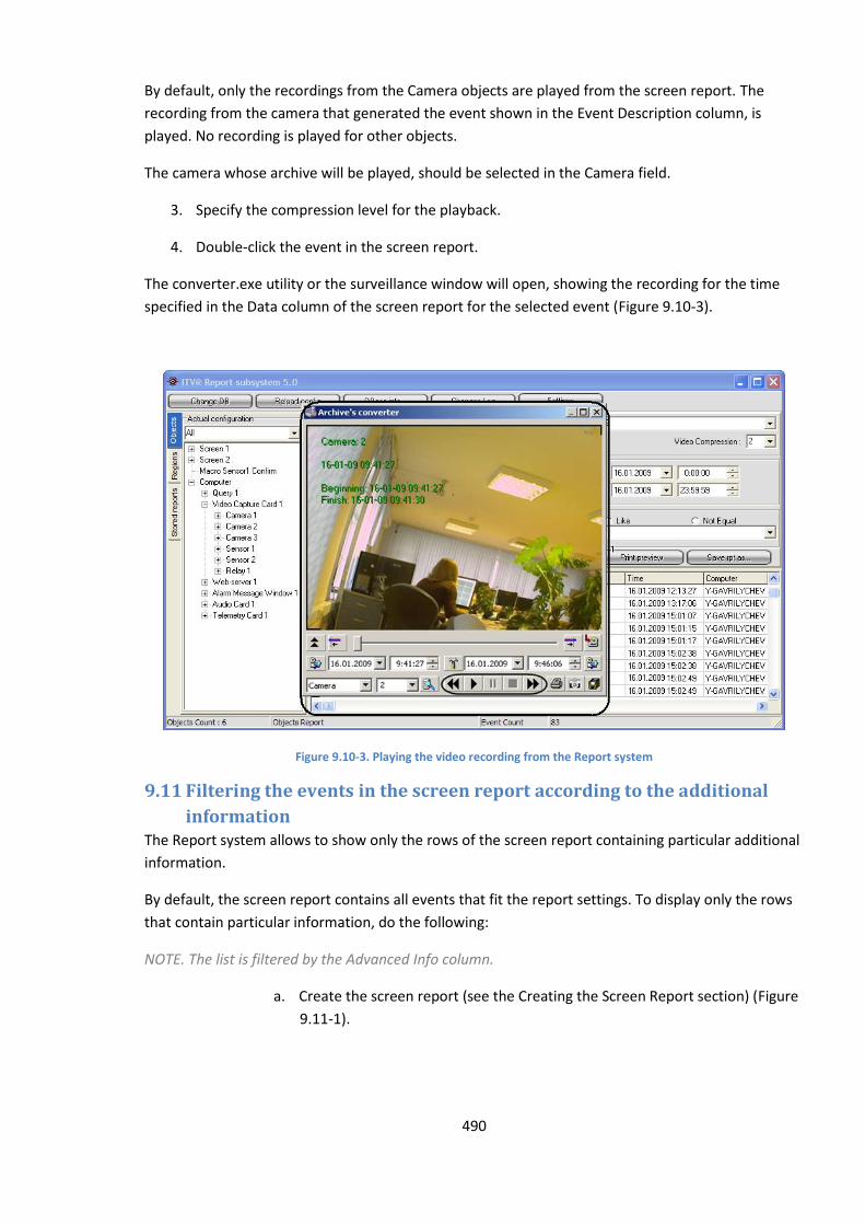
490
By default, only the recordings from the Camera objects are played from the screen report. The
recording from the camera that generated the event shown in the Event Description column, is
played. No recording is played for other objects.
The camera whose archive will be played, should be selected in the Camera field.
3. Specify the compression level for the playback.
4. Double-click the event in the screen report.
The converter.exe utility or the surveillance window will open, showing the recording for the time
specified in the Data column of the screen report for the selected event (Figure 9.10-3).
Figure 9.10-3. Playing the video recording from the Report system
9.11 Filtering the events in the screen report according to the additional
information The Report system allows to show only the rows of the screen report containing particular additional
information.
By default, the screen report contains all events that fit the report settings. To display only the rows
that contain particular information, do the following:
NOTE. The list is filtered by the Advanced Info column.
a. Create the screen report (see the Creating the Screen Report section) (Figure
9.11-1).

491
Figure 9.11-1. Filtering the screen report
b. Select the filtering method using the Information radio-buttons.
1. Equal radio-button. When selected, the system looks for exact case-sensitive matches only,
between the string in the Information field and the Advanced Info column.
2. Like radio-button. When selected, the system looks for the rows where the Advanced Info
column contains the search string, case-sensitive.
3. Not Equal radio-button. When selected, the system looks for the exact case-sensitive
matches, only between the string in the Information field and the Advanced Info column.
c. Enter the character string to filter the report by.
d. Click the Show Report button to run the filter.
Only the filtered rows will be displayed in the screen report.
9.12 The keyboard shortcuts list The following keyboard shortcuts are available in the Report system:
a. All panels:
a. F5 – creating the screen report.
b. F6 – creating the printed report.
c. Del – deleting an object from the Objects panel.
d. Ctrl+A – selecting all objects in the list in the Objects panel.
b. Objects panel:

492
a. Ctrl+F – searching the tree for an object by name or any part of the name.
b. Enter – adding the selected object to the report.
c. The Regions panel:
1. Ctrl+F – searching the tree for an object by name or any part of the name.
2. Enter – adding the selected object to the report.
d. The Shared Reports panel:
Ctrl+Del - deleting the selected report template.

493
10 Conclusion Please send your comments or requests concerning this Guide to the AxxonSoft Training and
documentation development division at ([email protected]).
Axxon Soft Inc., Beryozovaya alleya, building 5, section 5a, Moscow, Russia, 127273 Tel/fax: (495) 775-29-29
www.axxonsoft.com
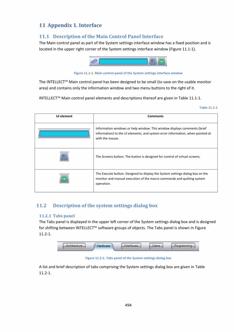
494
11 Appendix 1. Interface
11.1 Description of the Main Control Panel Interface The Main control panel as part of the System settings interface window has a fixed position and is
located in the upper right corner of the System settings interface window (Figure 11.1-1).
Figure 11.1-1. Main control panel of the System settings interface window
The INTELLECT™ Main control panel has been designed to be small (to save on the usable monitor
area) and contains only the information window and two menu buttons to the right of it.
INTELLECT™ Main control panel elements and descriptions thereof are given in Table 11.1-1.
Table 11.1-1
UI element Comments
Information windows or help window. This window displays comments (brief
information) to the UI elements, and system error information, when pointed at
with the mouse.
The Screens button. The button is designed for control of virtual screens.
The Execute button. Designed to display the System settings dialog box on the
monitor and manual execution of the macro commands and quitting system
operation.
11.2 Description of the system settings dialog box
11.2.1 Tabs panel
The Tabs panel is displayed in the upper left corner of the System settings dialog box and is designed
for shifting between INTELLECT™ software groups of objects. The Tabs panel is shown in Figure
11.2-1.
Figure 11.2-1. Tabs panel of the System settings dialog box
A list and brief description of tabs comprising the System settings dialog box are given in Table
11.2-1.
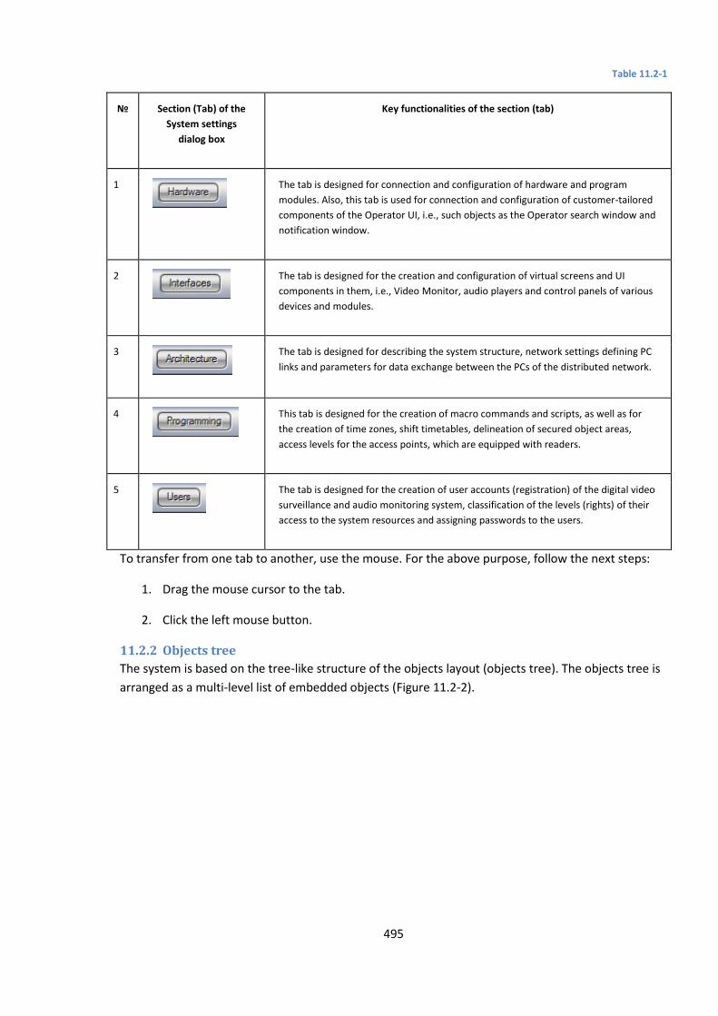
495
Table 11.2-1
№ Section (Tab) of the
System settings
dialog box
Key functionalities of the section (tab)
1
The tab is designed for connection and configuration of hardware and program
modules. Also, this tab is used for connection and configuration of customer-tailored
components of the Operator UI, i.e., such objects as the Operator search window and
notification window.
2
The tab is designed for the creation and configuration of virtual screens and UI
components in them, i.e., Video Monitor, audio players and control panels of various
devices and modules.
3
The tab is designed for describing the system structure, network settings defining PC
links and parameters for data exchange between the PCs of the distributed network.
4
This tab is designed for the creation of macro commands and scripts, as well as for
the creation of time zones, shift timetables, delineation of secured object areas,
access levels for the access points, which are equipped with readers.
5
The tab is designed for the creation of user accounts (registration) of the digital video
surveillance and audio monitoring system, classification of the levels (rights) of their
access to the system resources and assigning passwords to the users.
To transfer from one tab to another, use the mouse. For the above purpose, follow the next steps:
1. Drag the mouse cursor to the tab.
2. Click the left mouse button.
11.2.2 Objects tree
The system is based on the tree-like structure of the objects layout (objects tree). The objects tree is
arranged as a multi-level list of embedded objects (Figure 11.2-2).
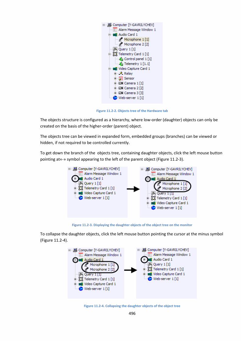
496
Figure 11.2-2. Objects tree of the Hardware tab
The objects structure is configured as a hierarchy, where low-order (daughter) objects can only be
created on the basis of the higher-order (parent) object.
The objects tree can be viewed in expanded form, embedded groups (branches) can be viewed or
hidden, if not required to be controlled currently.
To get down the branch of the objects tree, containing daughter objects, click the left mouse button
pointing at«-» symbol appearing to the left of the parent object (Figure 11.2-3).
Figure 11.2-3. Displaying the daughter objects of the object tree on the monitor
To collapse the daughter objects, click the left mouse button pointing the cursor at the minus symbol
(Figure 11.2-4).
Figure 11.2-4. Collapsing the daughter objects of the object tree
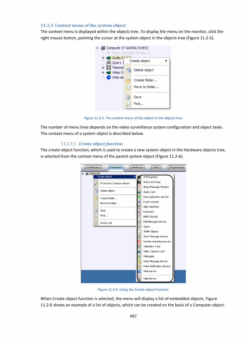
497
11.2.3 Context menu of the system object
The context menu is displayed within the objects tree. To display the menu on the monitor, click the
right mouse button, pointing the cursor at the system object in the objects tree (Figure 11.2-5).
Figure 11.2-5. The context menu of the object in the objects tree
The number of menu lines depends on the video surveillance system configuration and object tasks.
The context menu of a system object is described below.
11.2.3.1 Create object function
The create object function, which is used to create a new system object in the Hardware objects tree,
is selected from the context menu of the parent system object (Figure 11.2-6).
Figure 11.2-6. Using the Create object function
When Create object function is selected, the menu will display a list of embedded objects. Figure
11.2-6 shows an example of a list of objects, which can be created on the basis of a Computer object.
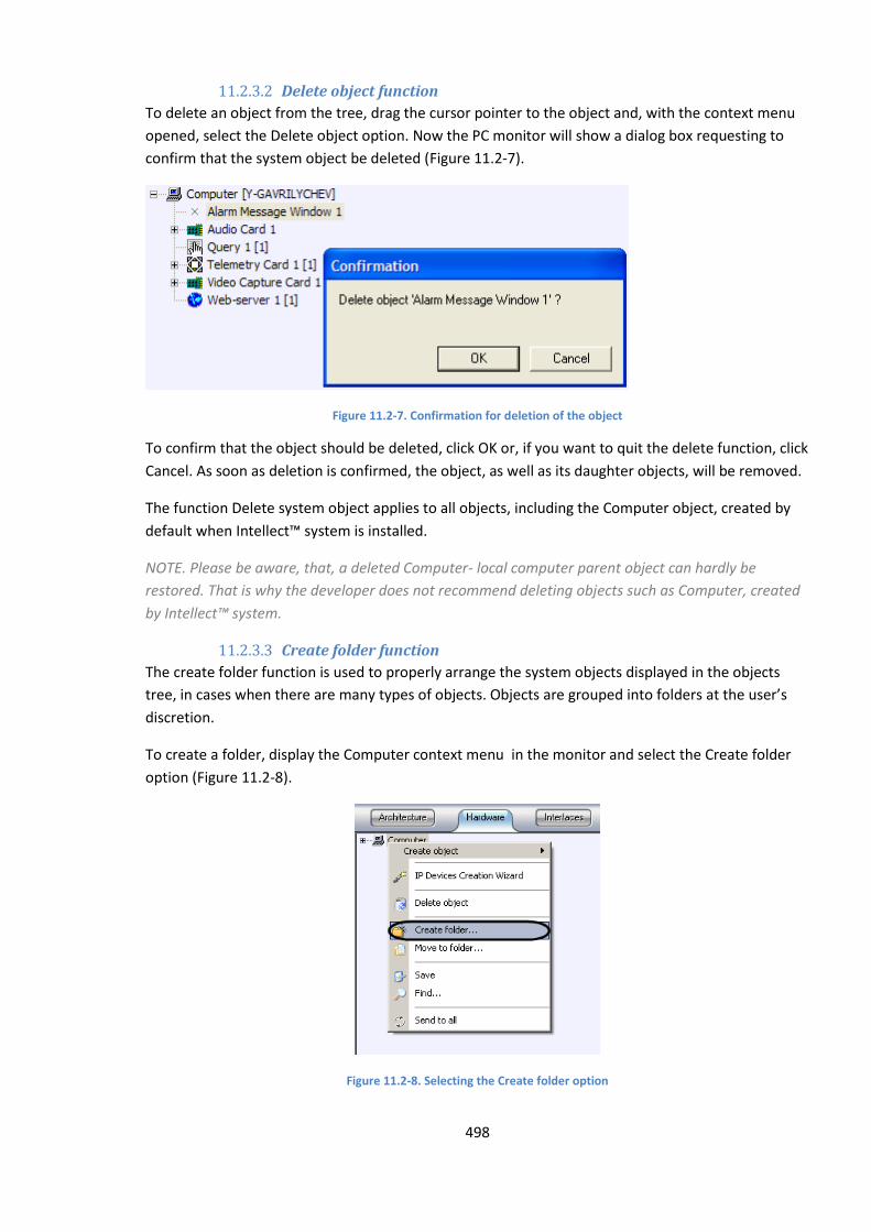
498
11.2.3.2 Delete object function
To delete an object from the tree, drag the cursor pointer to the object and, with the context menu
opened, select the Delete object option. Now the PC monitor will show a dialog box requesting to
confirm that the system object be deleted (Figure 11.2-7).
Figure 11.2-7. Confirmation for deletion of the object
To confirm that the object should be deleted, click OK or, if you want to quit the delete function, click
Cancel. As soon as deletion is confirmed, the object, as well as its daughter objects, will be removed.
The function Delete system object applies to all objects, including the Computer object, created by
default when Intellect™ system is installed.
NOTE. Please be aware, that, a deleted Computer- local computer parent object can hardly be
restored. That is why the developer does not recommend deleting objects such as Computer, created
by Intellect™ system.
11.2.3.3 Create folder function
The create folder function is used to properly arrange the system objects displayed in the objects
tree, in cases when there are many types of objects. Objects are grouped into folders at the user’s
discretion.
To create a folder, display the Computer context menu in the monitor and select the Create folder
option (Figure 11.2-8).
Figure 11.2-8. Selecting the Create folder option
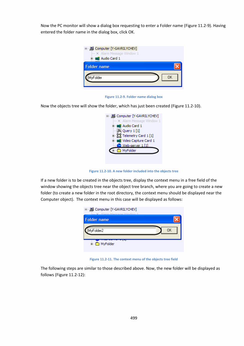
499
Now the PC monitor will show a dialog box requesting to enter a Folder name (Figure 11.2-9). Having
entered the folder name in the dialog box, click OK.
Figure 11.2-9. Folder name dialog box
Now the objects tree will show the folder, which has just been created (Figure 11.2-10).
Figure 11.2-10. A new folder included into the objects tree
If a new folder is to be created in the objects tree, display the context menu in a free field of the
window showing the objects tree near the object tree branch, where you are going to create a new
folder (to create a new folder in the root directory, the context menu should be displayed near the
Computer object). The context menu in this case will be displayed as follows:
Figure 11.2-11. The context menu of the objects tree field
The following steps are similar to those described above. Now, the new folder will be displayed as
follows (Figure 11.2-12):

500
Figure 11.2-12. The folder has been created
11.2.3.4 Move to folder function
This function allows moving system objects to the objects tree folder. To move objects to the folder,
select the object, which you need to move, display the context menu and select the Move to folder
option (Figure 11.2-13).
Figure 11.2-13. Selecting the Move to folder option
The monitor will display a window for selecting a folder, where you will move the selected system
object (Figure 11.2-14).
Figure 11.2-14. Selecting a folder
To confirm the selected folder, click OK. The object will be moved to the given folder (Figure
11.2-15).
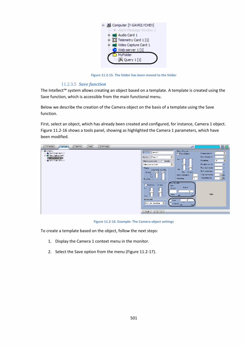
501
Figure 11.2-15. The folder has been moved to the folder
11.2.3.5 Save function
The Intellect™ system allows creating an object based on a template. A template is created using the
Save function, which is accessible from the main functional menu.
Below we describe the creation of the Camera object on the basis of a template using the Save
function.
First, select an object, which has already been created and configured, for instance, Camera 1 object.
Figure 11.2-16 shows a tools panel, showing as highlighted the Camera 1 parameters, which have
been modified.
Figure 11.2-16. Example: The Camera object settings
To create a template based on the object, follow the next steps:
1. Display the Camera 1 context menu in the monitor.
2. Select the Save option from the menu (Figure 11.2-17).
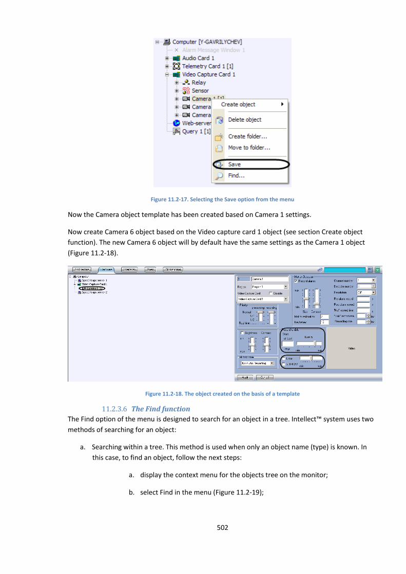
502
Figure 11.2-17. Selecting the Save option from the menu
Now the Camera object template has been created based on Camera 1 settings.
Now create Camera 6 object based on the Video capture card 1 object (see section Create object
function). The new Camera 6 object will by default have the same settings as the Camera 1 object
(Figure 11.2-18).
Figure 11.2-18. The object created on the basis of a template
11.2.3.6 The Find function
The Find option of the menu is designed to search for an object in a tree. Intellect™ system uses two
methods of searching for an object:
a. Searching within a tree. This method is used when only an object name (type) is known. In
this case, to find an object, follow the next steps:
a. display the context menu for the objects tree on the monitor;
b. select Find in the menu (Figure 11.2-19);
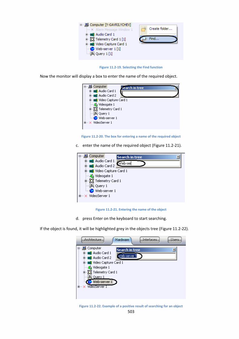
503
Figure 11.2-19. Selecting the Find function
Now the monitor will display a box to enter the name of the required object.
Figure 11.2-20. The box for entering a name of the required object
c. enter the name of the required object (Figure 11.2-21).
Figure 11.2-21. Entering the name of the object
d. press Enter on the keyboard to start searching.
If the object is found, it will be highlighted grey in the objects tree (Figure 11.2-22).
Figure 11.2-22. Example of a positive result of searching for an object
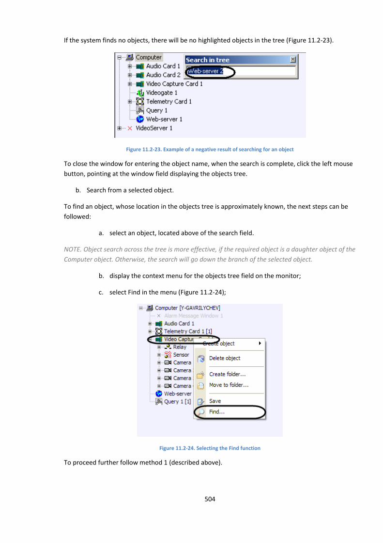
504
If the system finds no objects, there will be no highlighted objects in the tree (Figure 11.2-23).
Figure 11.2-23. Example of a negative result of searching for an object
To close the window for entering the object name, when the search is complete, click the left mouse
button, pointing at the window field displaying the objects tree.
b. Search from a selected object.
To find an object, whose location in the objects tree is approximately known, the next steps can be
followed:
a. select an object, located above of the search field.
NOTE. Object search across the tree is more effective, if the required object is a daughter object of the
Computer object. Otherwise, the search will go down the branch of the selected object.
b. display the context menu for the objects tree field on the monitor;
c. select Find in the menu (Figure 11.2-24);
Figure 11.2-24. Selecting the Find function
To proceed further follow method 1 (described above).
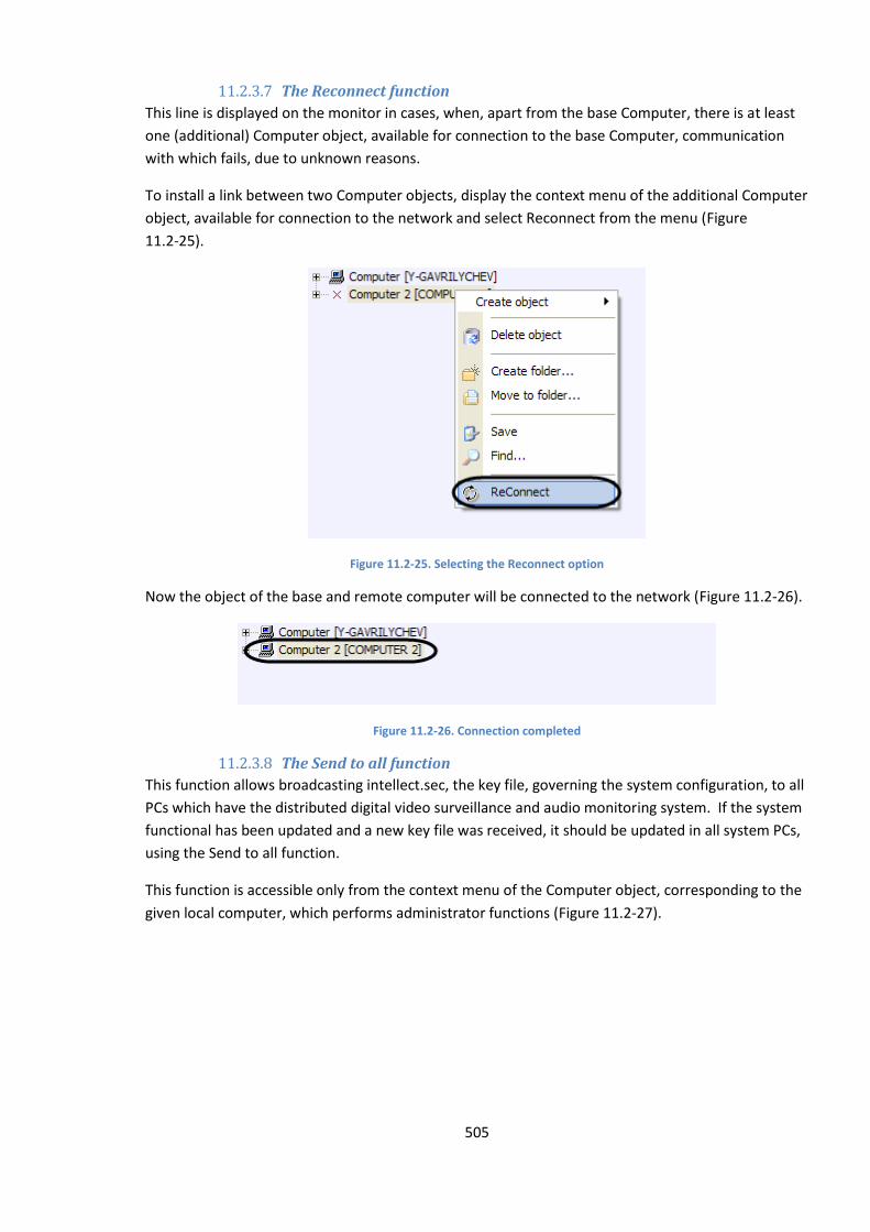
505
11.2.3.7 The Reconnect function
This line is displayed on the monitor in cases, when, apart from the base Computer, there is at least
one (additional) Computer object, available for connection to the base Computer, communication
with which fails, due to unknown reasons.
To install a link between two Computer objects, display the context menu of the additional Computer
object, available for connection to the network and select Reconnect from the menu (Figure
11.2-25).
Figure 11.2-25. Selecting the Reconnect option
Now the object of the base and remote computer will be connected to the network (Figure 11.2-26).
Figure 11.2-26. Connection completed
11.2.3.8 The Send to all function
This function allows broadcasting intellect.sec, the key file, governing the system configuration, to all
PCs which have the distributed digital video surveillance and audio monitoring system. If the system
functional has been updated and a new key file was received, it should be updated in all system PCs,
using the Send to all function.
This function is accessible only from the context menu of the Computer object, corresponding to the
given local computer, which performs administrator functions (Figure 11.2-27).
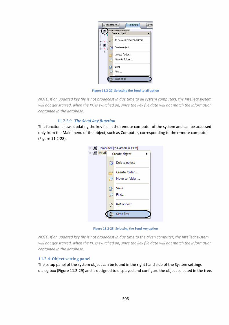
506
Figure 11.2-27. Selecting the Send to all option
NOTE. If an updated key file is not broadcast in due time to all system computers, the Intellect system
will not get started, when the PC is switched on, since the key file data will not match the information
contained in the database.
11.2.3.9 The Send key function
This function allows updating the key file in the remote computer of the system and can be accessed
only from the Main menu of the object, such as Computer, corresponding to the r–mote computer
(Figure 11.2-28).
Figure 11.2-28. Selecting the Send key option
NOTE. If an updated key file is not broadcast in due time to the given computer, the Intellect system
will not get started, when the PC is switched on, since the key file data will not match the information
contained in the database.
11.2.4 Object setting panel
The setup panel of the system object can be found in the right hand side of the System settings
dialog box (Figure 11.2-29) and is designed to displayed and configure the object selected in the tree.
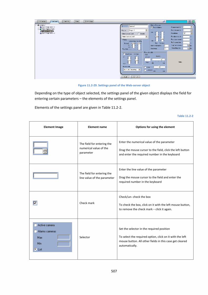
507
Figure 11.2-29. Settings panel of the Web-server object
Depending on the type of object selected, the settings panel of the given object displays the field for
entering certain parameters – the elements of the settings panel.
Elements of the settings panel are given in Table 11.2-2.
Table 11.2-2
Element Image Element name Options for using the element
The field for entering the
numerical value of the
parameter
Enter the numerical value of the parameter
Drag the mouse cursor to the field, click the left button
and enter the required number in the keyboard
The field for entering the
line value of the parameter
Enter the line value of the parameter
Drag the mouse cursor to the field and enter the
required number in the keyboard
Check mark
Check/un- check the box
To check the box, click on it with the left mouse button,
to remove the check mark – click it again.
Selector
Set the selector in the required position
To select the required option, click on it with the left
mouse button. All other fields in this case get cleared
automatically.
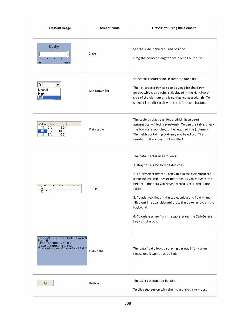
508
Element Image Element name Options for using the element
Slide
Set the slide in the required position.
Drag the pointer along the scale with the mouse.
Dropdown list
Select the required line in the dropdown list.
The list drops down as soon as you click the down
arrow, which, as a rule, is displayed in the right hand
side of the element and is configured as a triangle. To
select a line, click on it with the left mouse button.
Data table
The table displays the fields, which have been
automatically filled in previously. To use the table, check
the box corresponding to the required line (column).
The fields containing text may not be edited. The
number of lines may not be edited.
Table
The data is entered as follows:
1. Drag the cursor to the table cell.
2. Enter/select the required value in the field/from the
list in the column lines of the table. As you move to the
next cell, the data you have entered is retained in the
table.
3. To add new lines in the table, select any field in any
filled out line available and press the down arrow on the
keyboard.
4. To delete a line from the table, press the Ctrl+Delete
key combination.
Data field The data field allows displaying various information
messages. It cannot be edited.
Button
The start up function button.
To click the button with the mouse, drag the mouse
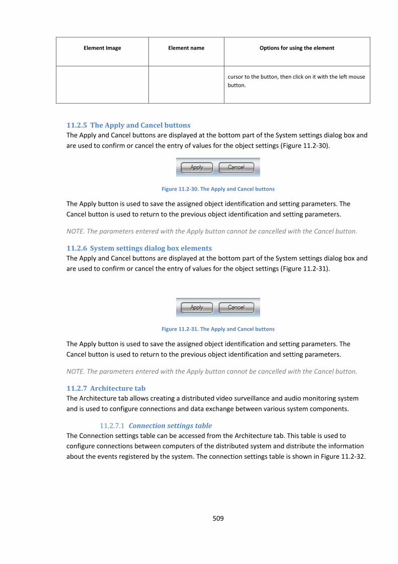
509
Element Image Element name Options for using the element
cursor to the button, then click on it with the left mouse
button.
11.2.5 The Apply and Cancel buttons
The Apply and Cancel buttons are displayed at the bottom part of the System settings dialog box and
are used to confirm or cancel the entry of values for the object settings (Figure 11.2-30).
Figure 11.2-30. The Apply and Cancel buttons
The Apply button is used to save the assigned object identification and setting parameters. The
Cancel button is used to return to the previous object identification and setting parameters.
NOTE. The parameters entered with the Apply button cannot be cancelled with the Cancel button.
11.2.6 System settings dialog box elements
The Apply and Cancel buttons are displayed at the bottom part of the System settings dialog box and
are used to confirm or cancel the entry of values for the object settings (Figure 11.2-31).
Figure 11.2-31. The Apply and Cancel buttons
The Apply button is used to save the assigned object identification and setting parameters. The
Cancel button is used to return to the previous object identification and setting parameters.
NOTE. The parameters entered with the Apply button cannot be cancelled with the Cancel button.
11.2.7 Architecture tab
The Architecture tab allows creating a distributed video surveillance and audio monitoring system
and is used to configure connections and data exchange between various system components.
11.2.7.1 Connection settings table
The Connection settings table can be accessed from the Architecture tab. This table is used to
configure connections between computers of the distributed system and distribute the information
about the events registered by the system. The connection settings table is shown in Figure 11.2-32.
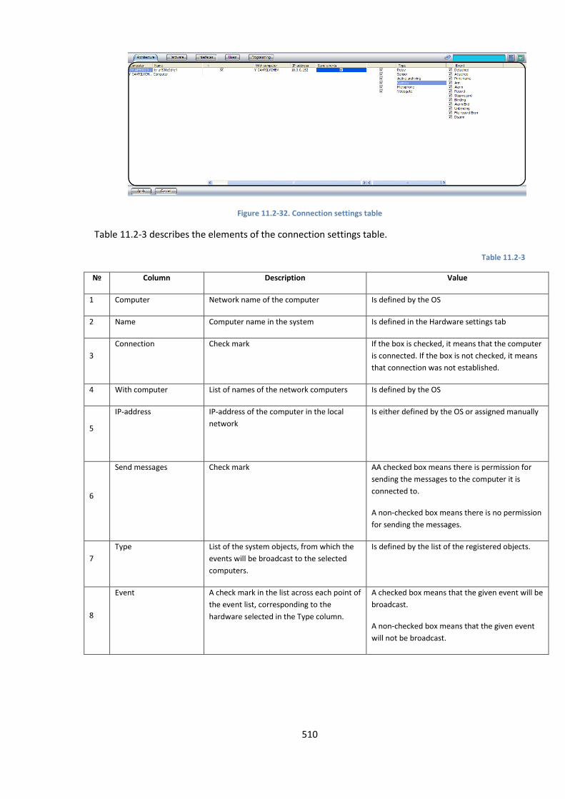
510
Figure 11.2-32. Connection settings table
Table 11.2-3 describes the elements of the connection settings table.
Table 11.2-3
№ Column Description Value
1 Computer Network name of the computer Is defined by the OS
2 Name Computer name in the system Is defined in the Hardware settings tab
3
Connection Check mark
If the box is checked, it means that the computer
is connected. If the box is not checked, it means
that connection was not established.
4 With computer List of names of the network computers Is defined by the OS
5
IP-address IP-address of the computer in the local
network
Is either defined by the OS or assigned manually
6
Send messages Check mark AA checked box means there is permission for
sending the messages to the computer it is
connected to.
A non-checked box means there is no permission
for sending the messages.
7
Type List of the system objects, from which the
events will be broadcast to the selected
computers.
Is defined by the list of the registered objects.
8
Event A check mark in the list across each point of
the event list, corresponding to the
hardware selected in the Type column.
A checked box means that the given event will be
broadcast.
A non-checked box means that the given event
will not be broadcast.
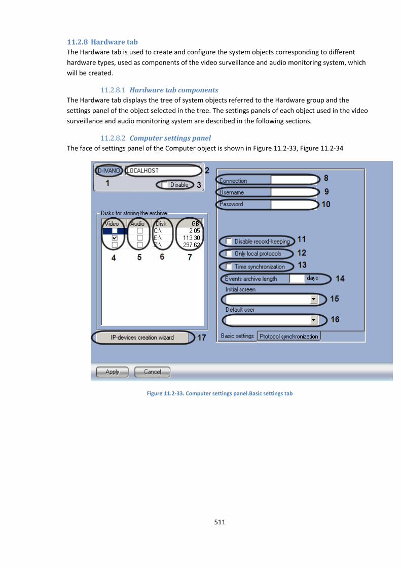
511
11.2.8 Hardware tab
The Hardware tab is used to create and configure the system objects corresponding to different
hardware types, used as components of the video surveillance and audio monitoring system, which
will be created.
11.2.8.1 Hardware tab components
The Hardware tab displays the tree of system objects referred to the Hardware group and the
settings panel of the object selected in the tree. The settings panels of each object used in the video
surveillance and audio monitoring system are described in the following sections.
11.2.8.2 Computer settings panel
The face of settings panel of the Computer object is shown in Figure 11.2-33, Figure 11.2-34
Figure 11.2-33. Computer settings panel.Basic settings tab
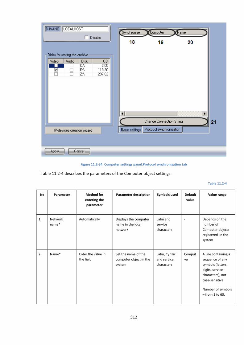
512
Figure 11.2-34. Computer settings panel.Protocol synchronization tab
Table 11.2-4 describes the parameters of the Computer object settings.
Table 11.2-4
№ Parameter Method for
entering the
parameter
Parameter description Symbols used Default
value
Value range
1 Network
name*
Automatically Displays the computer
name in the local
network
Latin and
service
characters
- Depends on the
number of
Computer objects
registered in the
system
2 Name* Enter the value in
the field
Set the name of the
computer object in the
system
Latin, Cyrillic
and service
characters
Comput
-er
A line containing a
sequence of any
symbols (letters,
digits, service
characters), not
case-sensitive
Number of symbols
– from 1 to 60.
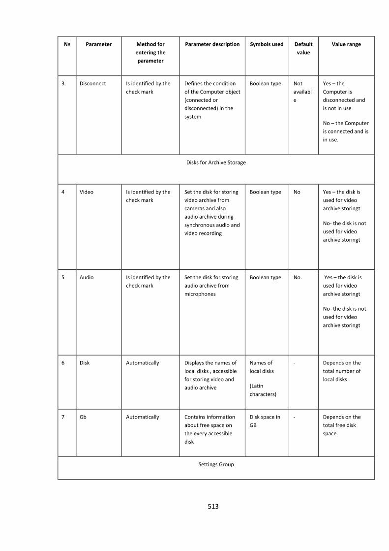
513
№ Parameter Method for
entering the
parameter
Parameter description Symbols used Default
value
Value range
3 Disconnect Is identified by the
check mark
Defines the condition
of the Computer object
(connected or
disconnected) in the
system
Boolean type Not
availabl
e
Yes – the
Computer is
disconnected and
is not in use
No – the Computer
is connected and is
in use.
Disks for Archive Storage
4 Video Is identified by the
check mark
Set the disk for storing
video archive from
cameras and also
audio archive during
synchronous audio and
video recording
Boolean type No Yes – the disk is
used for video
archive storingt
No- the disk is not
used for video
archive storingt
5 Audio Is identified by the
check mark
Set the disk for storing
audio archive from
microphones
Boolean type No. Yes – the disk is
used for video
archive storingt
No- the disk is not
used for video
archive storingt
6 Disk Automatically Displays the names of
local disks , accessible
for storing video and
audio archive
Names of
local disks
(Latin
characters)
- Depends on the
total number of
local disks
7 Gb Automatically Contains information
about free space on
the every accessible
disk
Disk space in
GB
- Depends on the
total free disk
space
Settings Group
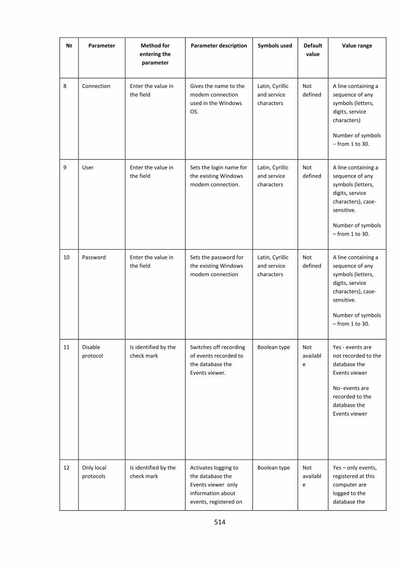
514
№ Parameter Method for
entering the
parameter
Parameter description Symbols used Default
value
Value range
8 Connection Enter the value in
the field
Gives the name to the
modem connection
used in the Windows
OS.
Latin, Cyrillic
and service
characters
Not
defined
A line containing a
sequence of any
symbols (letters,
digits, service
characters)
Number of symbols
– from 1 to 30.
9 User Enter the value in
the field
Sets the login name for
the existing Windows
modem connection.
Latin, Cyrillic
and service
characters
Not
defined
A line containing a
sequence of any
symbols (letters,
digits, service
characters), case-
sensitive.
Number of symbols
– from 1 to 30.
10 Password Enter the value in
the field
Sets the password for
the existing Windows
modem connection
Latin, Cyrillic
and service
characters
Not
defined
A line containing a
sequence of any
symbols (letters,
digits, service
characters), case-
sensitive.
Number of symbols
– from 1 to 30.
11 Disable
protocol
Is identified by the
check mark
Switches off recording
of events recorded to
the database the
Events viewer.
Boolean type Not
availabl
e
Yes - events are
not recorded to the
database the
Events viewer
No- events are
recorded to the
database the
Events viewer
12 Only local
protocols
Is identified by the
check mark
Activates logging to
the database the
Events viewer only
information about
events, registered on
Boolean type Not
availabl
e
Yes – only events,
registered at this
computer are
logged to the
database the

515
№ Parameter Method for
entering the
parameter
Parameter description Symbols used Default
value
Value range
the given computer Events viewer
No – events,
registered at this
computer are not
logged to the
database the
Events viewer
13 Time
synchronization
Is identified by the
check mark
Set time
synchronization every
day at 00:00 for all
computers of the
digital allocated video
surveillance system
with the system time
of the given computer.
Boolean type Not
availabl
e
Yes - time is
synchronized
No – time is not
synchronized
14 Event database
length - days
Enter the value in
the field
Set the peiod of time
for the events to be
stored in the database
the Events viewer
Days - More than 1
15 Initial screen Is selected from the
list
Set the screen to be
displayed on default
after downloading of
the Intellect digital
video surveillance
system.
Names of the
Screen
objects
registered in
the system
- Depends on total
number of Screen
objects registered
in the system.
16 Default user Is selected from the
list
Defines a default user,
i.e., the user, the rights
and authorities of
which will be used to
launch Intellect™
software without a
password.
Names of the
users
registered in
the system.
Not
defined
List of users
registered in the
Intellect™ system.
17 IP-devices
creation Wizard
Press the button Access to creating,
settings and editing of
IP devices.
- - -
Protocol synchronisation

516
№ Parameter Method for
entering the
parameter
Parameter description Symbols used Default
value
Value range
18 Synchronise Is identified by the
check mark
Set the syncronisation
of database The Events
viewer of local and
remote computers
Boolean type - Yes– database the
Events viewer of
local and remote
computers are
synchronised
No– database the
Events viewer of
local and remote
computers are not
synchronised
19 Computer Automatically Displays the netname
of remote computer
with which database
the Events viewer
must be synchronised
Latin alphabet
and service
characters
- Depends on the
number of
computers,
registered in the
system
20 Name Automatically Displays the name of
remote computer in
the net
Latin, Cyrillic
and service
characters
A line containing a
sequence of any
symbols (letters,
digits, service
characters), case-
sensitive.
Number of symbols
– from 1 to 60.
21 Change
connection
string
Press the button Access to settings and
editing the parameters
of coonection to the
database theEvents
viewer of remote
computer
- - -
11.2.8.3 Video capture card settings panel
The face of video capture card settings panel is shown in Figure 11.2-35.
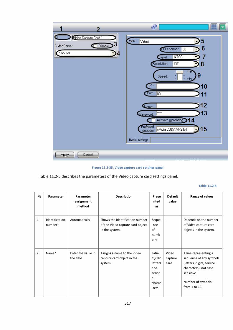
517
Figure 11.2-35. Video capture card settings panel
Table 11.2-5 describes the parameters of the Video capture card settings panel.
Table 11.2-5
№ Parameter Parameter
assignment
method
Description Prese
nted
as
Default
value
Range of values
1 Identification
number*
Automatically Shows the identification number
of the Video capture card object
in the system.
Seque
-nce
of
numb
e-rs
- Depends on the number
of Video capture card
objects in the system.
2 Name* Enter the value in
the field
Assigns a name to the Video
capture card object in the
system.
Latin,
Cyrillic
letters
and
servic
e
charac
-ters
Video
capture
card
A line representing a
sequence of any symbols
(letters, digits, service
characters), not case-
sensitive.
Number of symbols –
from 1 to 60.
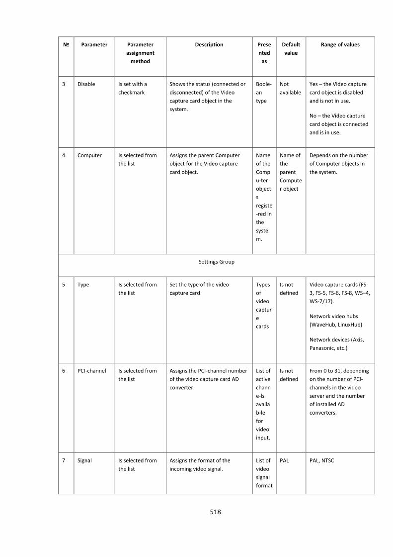
518
№ Parameter Parameter
assignment
method
Description Prese
nted
as
Default
value
Range of values
3 Disable Is set with a
checkmark
Shows the status (connected or
disconnected) of the Video
capture card object in the
system.
Boole-
an
type
Not
available
Yes – the Video capture
card object is disabled
and is not in use.
No – the Video capture
card object is connected
and is in use.
4 Computer Is selected from
the list
Assigns the parent Computer
object for the Video capture
card object.
Name
of the
Comp
u-ter
object
s
registe
-red in
the
syste
m.
Name of
the
parent
Compute
r object
Depends on the number
of Computer objects in
the system.
Settings Group
5 Type Is selected from
the list
Set the type of the video
capture card
Types
of
video
captur
e
cards
Is not
defined
Video capture cards (FS-
3, FS-5, FS-6, FS-8, WS–4,
WS-7/17).
Network video hubs
(WaveHub, LinuxHub)
Network devices (Axis,
Panasonic, etc.)
6 PCI-channel Is selected from
the list
Assigns the PCI-channel number
of the video capture card AD
converter.
List of
active
chann
e-ls
availa
b-le
for
video
input.
Is not
defined
From 0 to 31, depending
on the number of PCI-
channels in the video
server and the number
of installed AD
converters.
7 Signal Is selected from
the list
Assigns the format of the
incoming video signal.
List of
video
signal
format
PAL PAL, NTSC

519
№ Parameter Parameter
assignment
method
Description Prese
nted
as
Default
value
Range of values
s
8 Resolution Is selected from
the list
Assigns resolution of the video
image frames.
List of
availa
b-le
video
frame
resolu
t-ions
Normal PAL
Standard- 352x288
pixels.
Full - 704х288 pixels.
Maximal - 704х576
pixels.
NTSC:
Standard – 352х240
pixels.
Full- 640х240 pixels.
Maximal - 640х480
pixels.
9 Rate Is placed in the
required position.
Regulates the total frame rate of
the video signals, processed by
the video capture card AD
converter.
Permit
-ted
deviati
-ons
of the
total
video
signal
frame
rate
trans
m-
ission.
Average Max – maximum
permitted total video
signal frame rate.
Average – half of the
maximum permitted
total video signal frame
rate.
Min – one third of the
maximum permitted
total video signal frame
rate.
10 IP-address Enter the value in
the field
Set the IP-address of a network
device.
IP-
addres
s
Is not
defined
A line presented as
ххх.ххх.ххх.ххх
Contains the values:
0.0.0.0 –
255.255.255.255
Depends on network
settings of IP-device
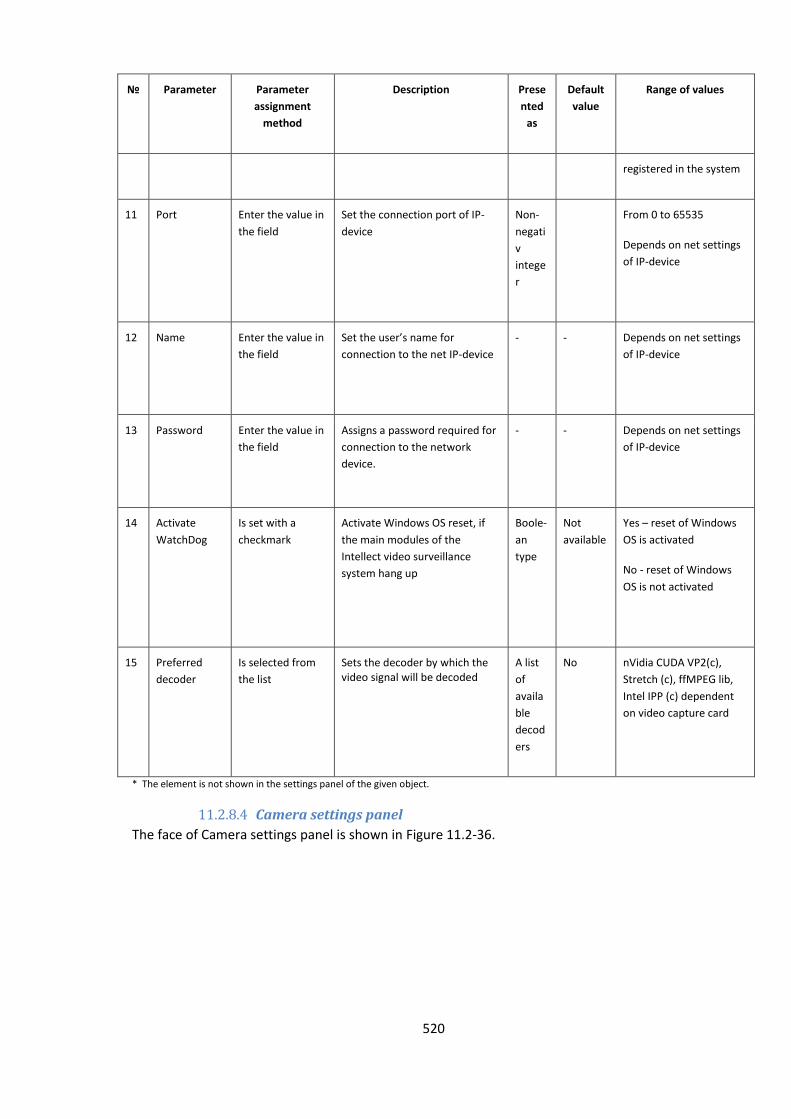
520
№ Parameter Parameter
assignment
method
Description Prese
nted
as
Default
value
Range of values
registered in the system
11 Port Enter the value in
the field
Set the connection port of IP-
device
Non-
negati
v
intege
r
From 0 to 65535
Depends on net settings
of IP-device
12 Name Enter the value in
the field
Set the user’s name for
connection to the net IP-device
- - Depends on net settings
of IP-device
13 Password Enter the value in
the field
Assigns a password required for
connection to the network
device.
- - Depends on net settings
of IP-device
14 Activate
WatchDog
Is set with a
checkmark
Activate Windows OS reset, if
the main modules of the
Intellect video surveillance
system hang up
Boole-
an
type
Not
available
Yes – reset of Windows
OS is activated
No - reset of Windows
OS is not activated
15 Preferred
decoder
Is selected from
the list
Sets the decoder by which the video signal will be decoded
A list
of
availa
ble
decod
ers
No nVidia CUDA VP2(c),
Stretch (c), ffMPEG lib,
Intel IPP (c) dependent
on video capture card
* The element is not shown in the settings panel of the given object.
11.2.8.4 Camera settings panel
The face of Camera settings panel is shown in Figure 11.2-36.
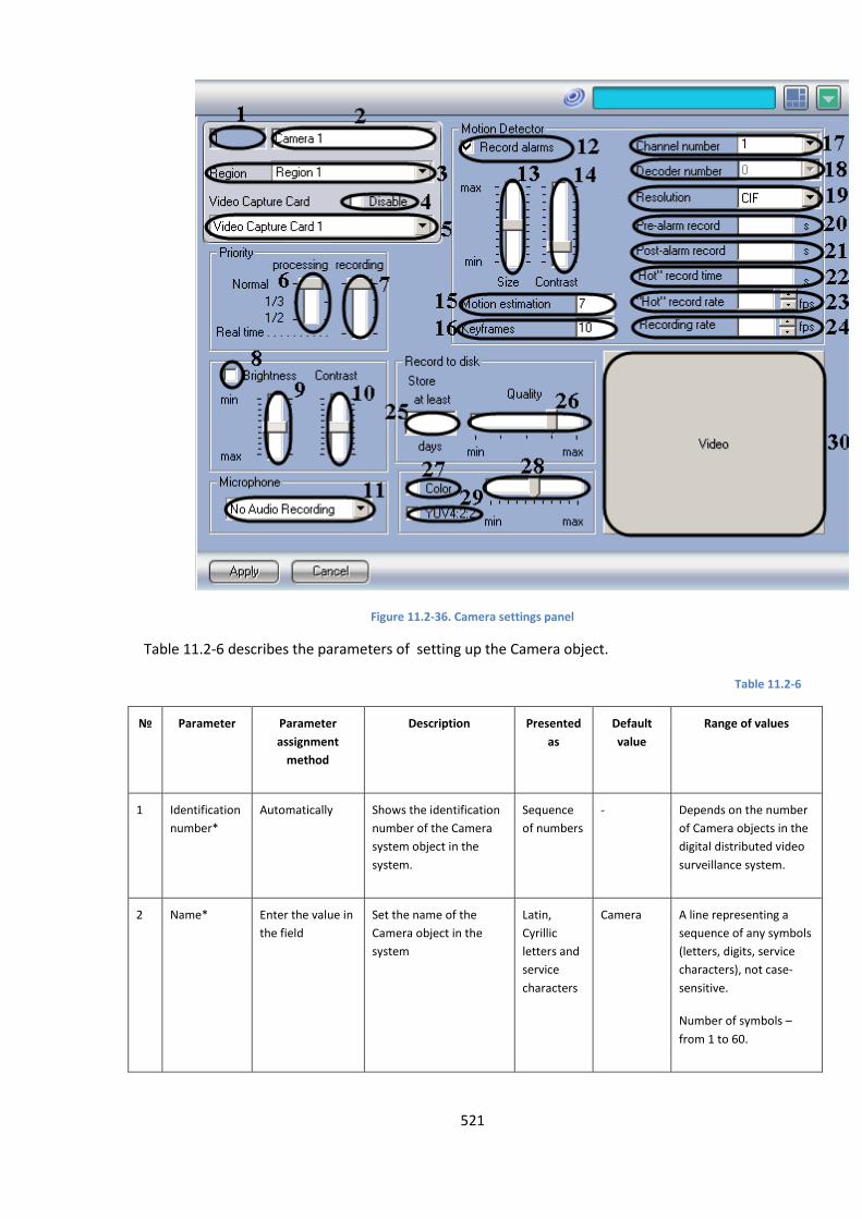
521
Figure 11.2-36. Camera settings panel
Table 11.2-6 describes the parameters of setting up the Camera object.
Table 11.2-6
№ Parameter Parameter
assignment
method
Description Presented
as
Default
value
Range of values
1 Identification
number*
Automatically Shows the identification
number of the Camera
system object in the
system.
Sequence
of numbers
- Depends on the number
of Camera objects in the
digital distributed video
surveillance system.
2 Name* Enter the value in
the field
Set the name of the
Camera object in the
system
Latin,
Cyrillic
letters and
service
characters
Camera A line representing a
sequence of any symbols
(letters, digits, service
characters), not case-
sensitive.
Number of symbols –
from 1 to 60.
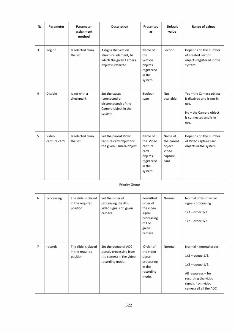
522
№ Parameter Parameter
assignment
method
Description Presented
as
Default
value
Range of values
3 Region Is selected from
the list
Assigns the Section
structural element, to
which the given Camera
object is referred.
Name of
the
Section
objects
registered
in the
system.
Section Depends on the number
of created Section
objects registered in the
system.
4 Disable Is set with a
checkmark
Set the status
(connected or
disconnected) of the
Camera object in the
system.
Boolean
type
Not
available
Yes – the Camera object
is disabled and is not in
use.
No – the Camera object
is connected and is in
use.
5 Video
capture card
Is selected from
the list
Set the parent Video
capture card object for
the given Camera object.
Name of
the Video
capture
card
objects
registered
in the
system.
Name of
the parent
object
Video
capture
card.
Depends on the number
of Video capture card
objects in the system.
Priority Group
6 processing The slide is placed
in the required
position.
Set the order of
processing the ADC
video signals of given
camera
Permitted
order of
the video
signal
processing
of the
given
camera.
Normal Normal order of video
signals processing
1/3 – order 1/3.
1/2 – order 1/2.
7 records The slide is placed
in the required
position.
Set the queue of ADC
signals processing from
the camera in the video
recording mode.
Order of
the video
signal
processing
in the
recording
mode.
Normal Normal – normal order.
1/3 – queue 1/3.
1/2 – queue 1/2.
All resources – for
recording the video
signals from video
camera all all the ADC
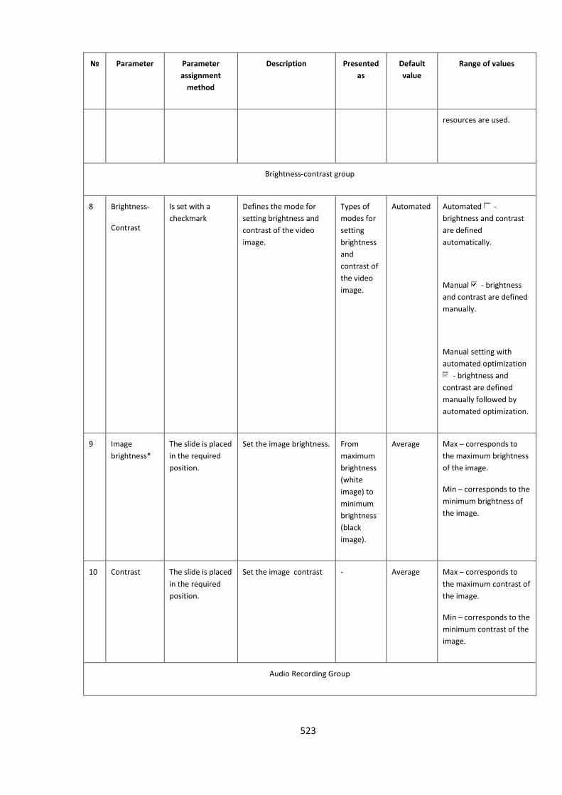
523
№ Parameter Parameter
assignment
method
Description Presented
as
Default
value
Range of values
resources are used.
Brightness-contrast group
8 Brightness-
Contrast
Is set with a
checkmark
Defines the mode for
setting brightness and
contrast of the video
image.
Types of
modes for
setting
brightness
and
contrast of
the video
image.
Automated Automated -
brightness and contrast
are defined
automatically.
Manual - brightness
and contrast are defined
manually.
Manual setting with
automated optimization
- brightness and
contrast are defined
manually followed by
automated optimization.
9 Image
brightness*
The slide is placed
in the required
position.
Set the image brightness. From
maximum
brightness
(white
image) to
minimum
brightness
(black
image).
Average Max – corresponds to
the maximum brightness
of the image.
Min – corresponds to the
minimum brightness of
the image.
10 Contrast The slide is placed
in the required
position.
Set the image contrast - Average Max – corresponds to
the maximum contrast of
the image.
Min – corresponds to the
minimum contrast of the
image.
Audio Recording Group
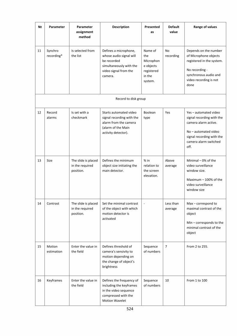
524
№ Parameter Parameter
assignment
method
Description Presented
as
Default
value
Range of values
11 Synchro
recording*
Is selected from
the list
Defines a microphone,
whose audio signal will
be recorded
simultaneously with the
video signal from the
camera.
Name of
the
Microphon
e objects
registered
in the
system.
No
recording
Depends on the number
of Microphone objects
registered in the system.
No recording -
synchronous audio and
video recording is not
done
Record to disk group
12 Record
alarms
Is set with a
checkmark
Starts automated video
signal recording with the
alarm from the camera
(alarm of the Main
activity detector).
Boolean
type
Yes Yes – automated video
signal recording with the
camera alarm active.
No – automated video
signal recording with the
camera alarm switched
off.
13 Size The slide is placed
in the required
position.
Defines the minimum
object size initiating the
main detector.
% in
relation to
the screen
elevation.
Above
average
Minimal – 0% of the
video surveillance
window size.
Maximum – 100% of the
video surveillance
window size
14 Contrast The slide is placed
in the required
position.
Set the minimal contrast
of the object with which
motion detector is
activated
- Less than
average
Max – correspond to
maximal contrast of the
object
Min – corresponds to the
minimal contrast of the
object
15 Motion
estimation
Enter the value in
the field
Defines threshold of
camera’s sensivity to
motion depending on
the change of object’s
brightness
Sequence
of numbers
7 From 2 to 255.
16 Keyframes Enter the value in
the field
Defines the frequency of
including the keyframes
in the video sequence
compressed with the
Motion Wavelet
Sequence
of numbers
10 From 1 to 100

525
№ Parameter Parameter
assignment
method
Description Presented
as
Default
value
Range of values
algorithm.
17 Channel
number
Is selected from
the list
Defines the number of
the channel used to
connect a video camera
to the video capture
card. Corresponds to the
BNC-adapter number for
the D SUB-25 card.
Sequence
of numbers
Not
defined
Depends on the type of
video capture card. 16
channels at the most.
18 Decoder
number
Is selected from
the list
Defines the number of
channels for connecting
a camera to the video
capture card.
Parameter is active only
with the use of outdated
video capture cards.
Parameter is not active
with the use of video
capture cards by ITV
company
Sequence
of numbers
0 From 0 to 3
19 Resolution Is selected from
the list
Set the resolution of the
image frame.
List of
available
resolutions
of the
image
frames.
Normal PAL:
Standard - 352x288
pixels.
High - 704х288 pixels.
Complete – 704х576
pixels.
NTSC:
Standard– 352х240
pixels.
High – 640х240 pixels.
Complete – 640х480
pixels.
20 Pre-alarm Enter the value in
the field
Defines the time period
for pre-event video
recording, during which
preceding alarm
Time (in
sec)
- Recommended time –
from 0 to 20
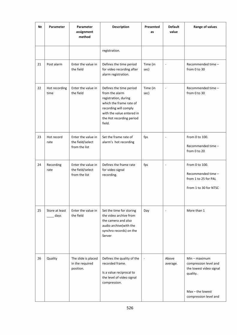
526
№ Parameter Parameter
assignment
method
Description Presented
as
Default
value
Range of values
registration.
21 Post alarm Enter the value in
the field
Defines the time period
for video recording after
alarm registration.
Time (in
sec)
- Recommended time –
from 0 to 30
22 Hot recording
time
Enter the value in
the field
Defines the time period
from the alarm
registration, during
which the frame rate of
recording will comply
with the value entered in
the Hot recording period
field.
Time (in
sec)
- Recommended time –
from 0 to 30
23 Hot record
rate
Enter the value in
the field/select
from the list
Set the frame rate of
alarm’s hot recording
fps - From 0 to 100.
Recommended time –
from 0 to 20
24 Recording
rate
Enter the value in
the field/select
from the list
Defines the frame rate
for video signal
recording.
fps - From 0 to 100.
Recommended time –
from 1 to 25 for PAL
From 1 to 30 for NTSC
25 Store at least
____ days
Enter the value in
the field
Set the time for storing
the video archive from
the camera and also
audio archive(with the
synchro records) on the
Server
Day - More than 1
26 Quality The slide is placed
in the required
position.
Defines the quality of the
recorded frame.
Is a value reciprocal to
the level of video signal
compression.
- Above
average.
Min – maximum
compression level and
the lowest video signal
quality.
Max – the lowest
compression level and

527
№ Parameter Parameter
assignment
method
Description Presented
as
Default
value
Range of values
the highest video signal
quality.
Color group
27 Color Is set with a
checkmark
Defines the incoming
video image from the
surveillance camera
(color or black and
white).
Boolean
type
Not
available
Yes – the camera image
will be color.
No – the camera image
will be black and white.
28 YUV 4:2:2 Is set with a
checkmark
Defines the format of the
video signal image.
Boolean
type
Not
available
Yes – the video signal will
be displayed in YUV 4:2:2
format.
No – the video signal will
be displayed in YUV 4:2:0
format.
29 Colors of the
image*
The slide is placed
in the required
position.
Defines the color
saturation of the colored
video image.
From
maximum
color
saturation
to a black
and white
image.
Average Max – corresponds to
the maximum color
saturation of the image.
Min – corresponds to the
black and white image.
Video group
30 Window of
the image
Left mouse click Displays the image of the
camera.
- - -
b. Name of the element is not displayed in the settings panel of the given object
11.2.8.5 Detection zone settings panel
The Detector object is used to register and configure intelligent video detectors. The Detection zone
settings panel is shown in Figure 11.2-37.
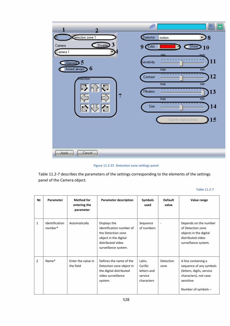
528
Figure 11.2-37. Detection zone settings panel
Table 11.2-7 describes the parameters of the settings corresponding to the elements of the settings
panel of the Camera object.
Table 11.2-7
№ Parameter Method for
entering the
parameter
Parameter description Symbols
used
Default
value
Value range
1 Identification
number*
Automatically Displays the
identification number of
the Detection zone
object in the digital
distributed video
surveillance system.
Sequence
of numbers
- Depends on the number
of Detection zone
objects in the digital
distributed video
surveillance system.
2 Name* Enter the value in
the field
Defines the name of the
Detection zone object in
the digital distributed
video surveillance
system.
Latin,
Cyrillic
letters and
service
characters
Detection
zone
A line containing a
sequence of any symbols
(letters, digits, service
characters), not case-
sensitive.
Number of symbols –
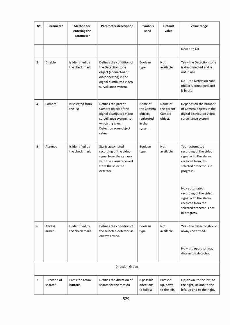
529
№ Parameter Method for
entering the
parameter
Parameter description Symbols
used
Default
value
Value range
from 1 to 60.
3 Disable Is identified by
the check mark
Defines the condition of
the Detection zone
object (connected or
disconnected) in the
digital distributed video
surveillance system.
Boolean
type
Not
available
Yes – the Detection zone
is disconnected and is
not in use
No – the Detection zone
object is connected and
is in use.
4 Camera Is selected from
the list
Defines the parent
Camera object of the
digital distributed video
surveillance system, to
which the given
Detection zone object
refers.
Name of
the Camera
objects
registered
in the
system
Name of
the parent
Camera
object.
Depends on the number
of Camera objects in the
digital distributed video
surveillance system.
5 Alarmed Is identified by
the check mark
Starts automated
recording of the video
signal from the camera
with the alarm received
from the selected
detector.
Boolean
type
Not
available
Yes - automated
recording of the video
signal with the alarm
received from the
selected detector is in
progress.
No - automated
recording of the video
signal with the alarm
received from the
selected detector is not
in progress.
6 Always
armed
Is identified by
the check mark.
Defines the condition of
the selected detector as
Always armed.
Boolean
type
Not
available
Yes – the detector should
always be armed.
No – the operator may
disarm the detector.
Direction Group
7 Direction of
search*
Press the arrow
buttons.
Defines the direction of
search for the motion
8 possible
directions
to follow
Pressed:
up, down,
to the left,
Up, down, to the left, to
the right, up and to the
left, up and to the right,
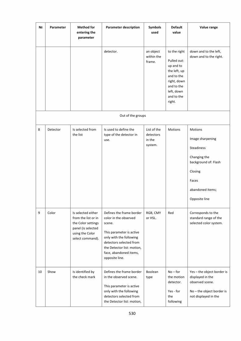
530
№ Parameter Method for
entering the
parameter
Parameter description Symbols
used
Default
value
Value range
detector. an object
within the
frame.
to the right
Pulled out:
up and to
the left, up
and to the
right, down
and to the
left, down
and to the
right.
down and to the left,
down and to the right.
Out of the groups
8 Detector Is selected from
the list
Is used to define the
type of the detector in
use.
List of the
detectors
in the
system.
Motions Motions
Image sharpening
Steadiness
Changing the
background of: Flash
Closing
Faces
abandoned items;
Opposite line
9 Color Is selected either
from the list or in
the Color settings
panel (is selected
using the Color
select command).
Defines the frame border
color in the observed
scene.
This parameter is active
only with the following
detectors selected from
the Detector list: motion,
face, abandoned items,
opposite line.
RGB, CMY
or HSL.
Red Corresponds to the
standard range of the
selected color system.
10 Show Is identified by
the check mark
Defines the frame border
in the observed scene.
This parameter is active
only with the following
detectors selected from
the Detector list: motion,
Boolean
type
No – for
the motion
detector.
Yes - for
the
following
Yes – the object border is
displayed in the
observed scene.
No – the object border is
not displayed in the
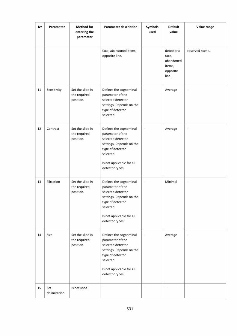
531
№ Parameter Method for
entering the
parameter
Parameter description Symbols
used
Default
value
Value range
face, abandoned items,
opposite line.
detectors:
face,
abandoned
items,
opposite
line.
observed scene.
11 Sensitivity Set the slide in
the required
position.
Defines the cognominal
parameter of the
selected detector
settings. Depends on the
type of detector
selected.
- Average -
12 Contrast Set the slide in
the required
position.
Defines the cognominal
parameter of the
selected detector
settings. Depends on the
type of detector
selected.
Is not applicable for all
detector types.
- Average -
13 Filtration Set the slide in
the required
position.
Defines the cognominal
parameter of the
selected detector
settings. Depends on the
type of detector
selected.
Is not applicable for all
detector types.
- Minimal -
14 Size Set the slide in
the required
position.
Defines the cognominal
parameter of the
selected detector
settings. Depends on the
type of detector
selected.
Is not applicable for all
detector types.
- Average -
15 Set
delimitation
Is not used - - - -
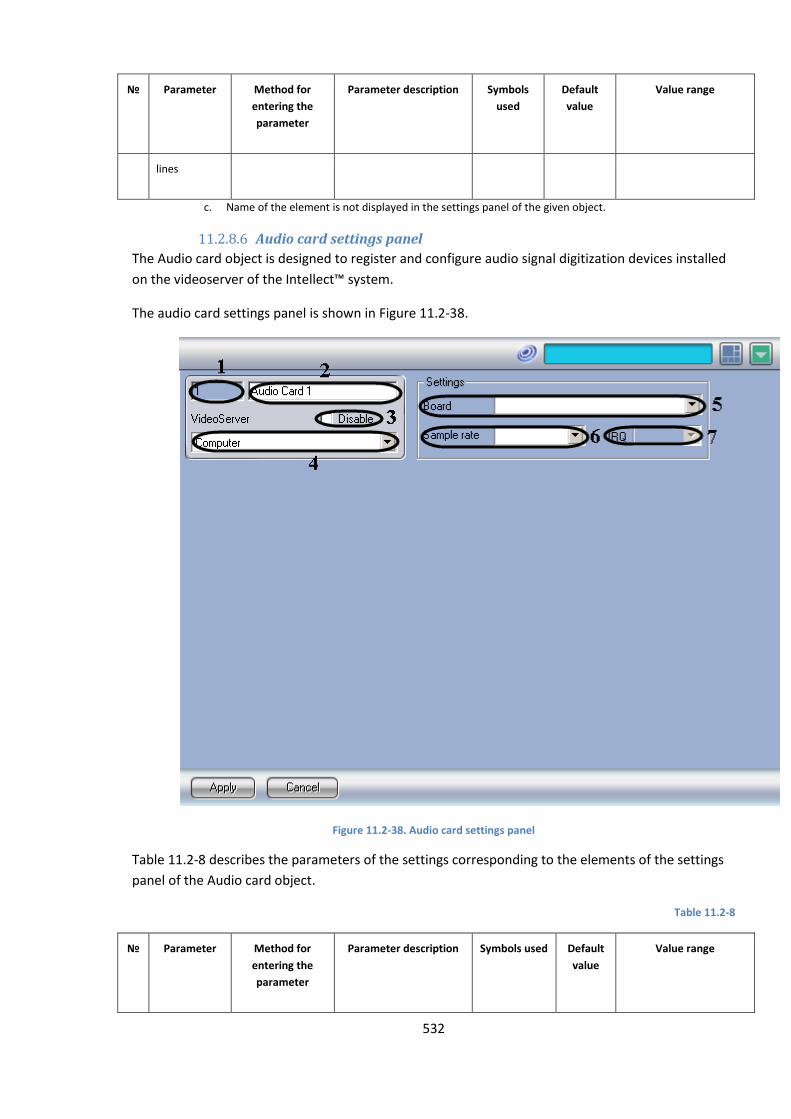
532
№ Parameter Method for
entering the
parameter
Parameter description Symbols
used
Default
value
Value range
lines
c. Name of the element is not displayed in the settings panel of the given object.
11.2.8.6 Audio card settings panel
The Audio card object is designed to register and configure audio signal digitization devices installed
on the videoserver of the Intellect™ system.
The audio card settings panel is shown in Figure 11.2-38.
Figure 11.2-38. Audio card settings panel
Table 11.2-8 describes the parameters of the settings corresponding to the elements of the settings
panel of the Audio card object.
Table 11.2-8
№ Parameter Method for
entering the
parameter
Parameter description Symbols used Default
value
Value range
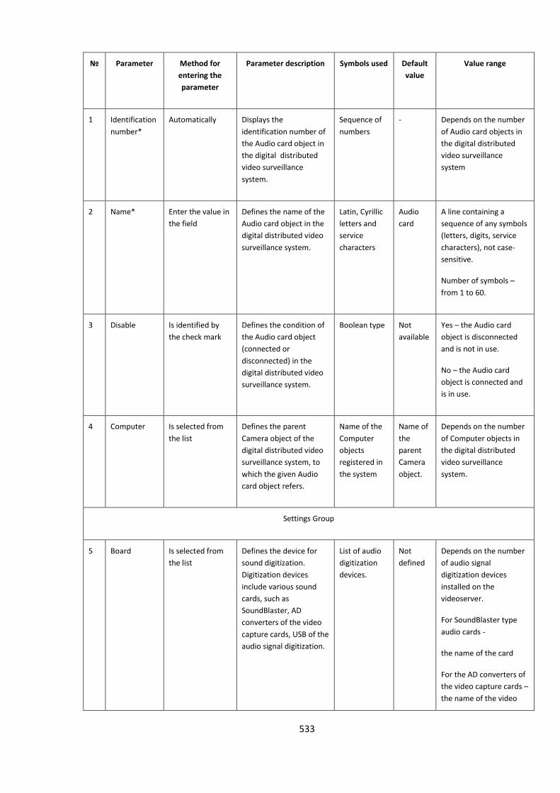
533
№ Parameter Method for
entering the
parameter
Parameter description Symbols used Default
value
Value range
1 Identification
number*
Automatically Displays the
identification number of
the Audio card object in
the digital distributed
video surveillance
system.
Sequence of
numbers
- Depends on the number
of Audio card objects in
the digital distributed
video surveillance
system
2 Name* Enter the value in
the field
Defines the name of the
Audio card object in the
digital distributed video
surveillance system.
Latin, Cyrillic
letters and
service
characters
Audio
card
A line containing a
sequence of any symbols
(letters, digits, service
characters), not case-
sensitive.
Number of symbols –
from 1 to 60.
3 Disable Is identified by
the check mark
Defines the condition of
the Audio card object
(connected or
disconnected) in the
digital distributed video
surveillance system.
Boolean type Not
available
Yes – the Audio card
object is disconnected
and is not in use.
No – the Audio card
object is connected and
is in use.
4 Computer Is selected from
the list
Defines the parent
Camera object of the
digital distributed video
surveillance system, to
which the given Audio
card object refers.
Name of the
Computer
objects
registered in
the system
Name of
the
parent
Camera
object.
Depends on the number
of Computer objects in
the digital distributed
video surveillance
system.
Settings Group
5 Board Is selected from
the list
Defines the device for
sound digitization.
Digitization devices
include various sound
cards, such as
SoundBlaster, AD
converters of the video
capture cards, USB of the
audio signal digitization.
List of audio
digitization
devices.
Not
defined
Depends on the number
of audio signal
digitization devices
installed on the
videoserver.
For SoundBlaster type
audio cards -
the name of the card
For the AD converters of
the video capture cards –
the name of the video
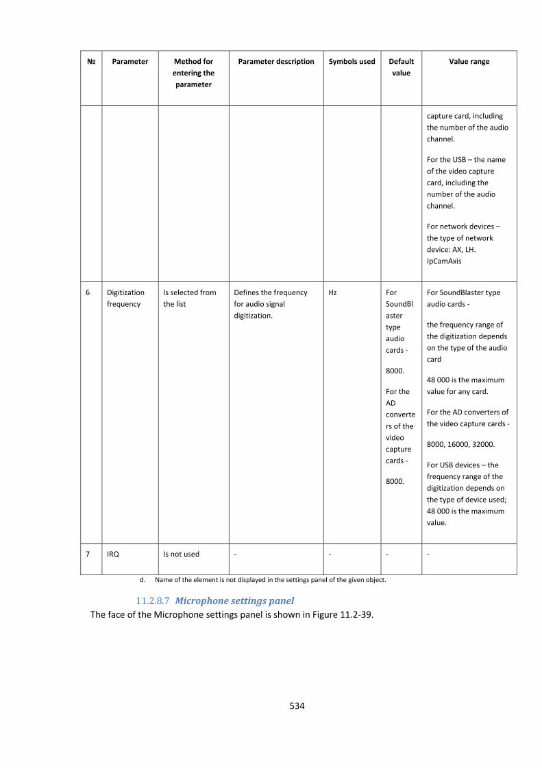
534
№ Parameter Method for
entering the
parameter
Parameter description Symbols used Default
value
Value range
capture card, including
the number of the audio
channel.
For the USB – the name
of the video capture
card, including the
number of the audio
channel.
For network devices –
the type of network
device: AX, LH.
IpCamAxis
6 Digitization
frequency
Is selected from
the list
Defines the frequency
for audio signal
digitization.
Hz For
SoundBl
aster
type
audio
cards -
8000.
For the
AD
converte
rs of the
video
capture
cards -
8000.
For SoundBlaster type
audio cards -
the frequency range of
the digitization depends
on the type of the audio
card
48 000 is the maximum
value for any card.
For the AD converters of
the video capture cards -
8000, 16000, 32000.
For USB devices – the
frequency range of the
digitization depends on
the type of device used;
48 000 is the maximum
value.
7 IRQ Is not used - - - -
d. Name of the element is not displayed in the settings panel of the given object.
11.2.8.7 Microphone settings panel
The face of the Microphone settings panel is shown in Figure 11.2-39.
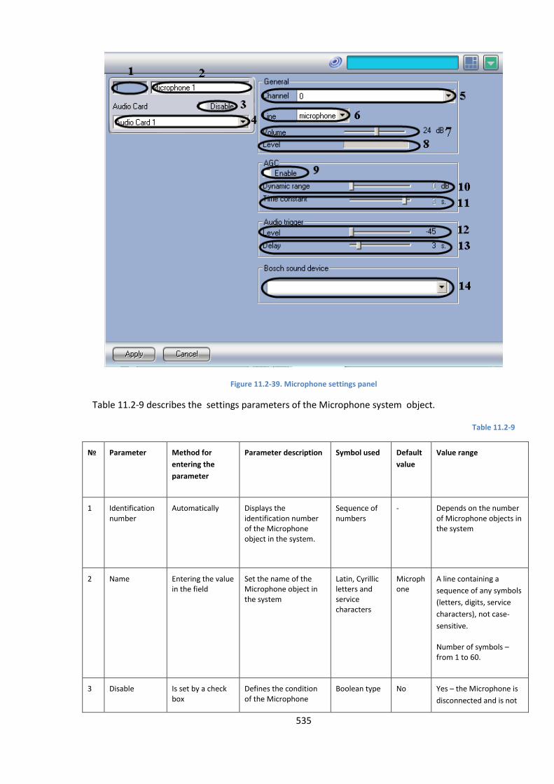
535
Figure 11.2-39. Microphone settings panel
Table 11.2-9 describes the settings parameters of the Microphone system object.
Table 11.2-9
№ Parameter Method for
entering the
parameter
Parameter description Symbol used Default
value
Value range
1 Identification number
Automatically Displays the identification number of the Microphone object in the system.
Sequence of numbers
- Depends on the number of Microphone objects in the system
2 Name Entering the value in the field
Set the name of the Microphone object in the system
Latin, Cyrillic letters and service characters
Microphone
A line containing a
sequence of any symbols
(letters, digits, service
characters), not case-
sensitive.
Number of symbols – from 1 to 60.
3 Disable Is set by a check box
Defines the condition of the Microphone
Boolean type No Yes – the Microphone is
disconnected and is not
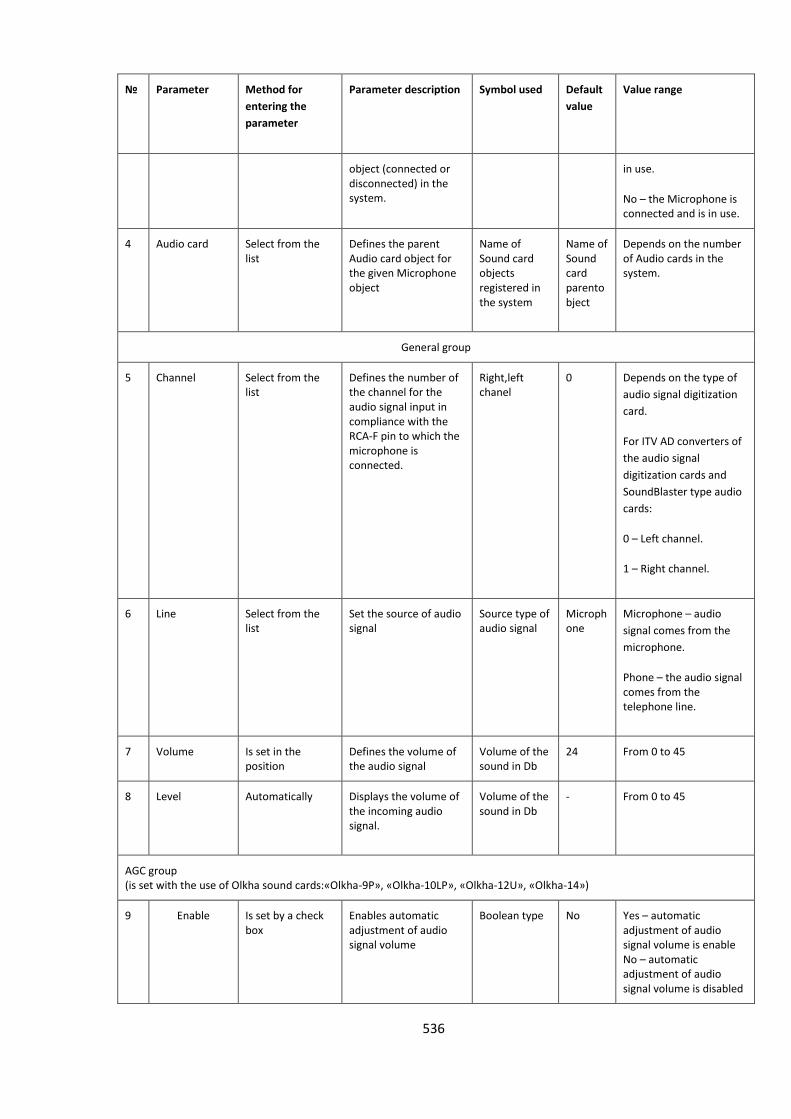
536
№ Parameter Method for
entering the
parameter
Parameter description Symbol used Default
value
Value range
object (connected or disconnected) in the system.
in use.
No – the Microphone is connected and is in use.
4 Audio card Select from the list
Defines the parent Audio card object for the given Microphone object
Name of Sound card objects registered in the system
Name of Sound card parentobject
Depends on the number of Audio cards in the system.
General group
5 Channel Select from the list
Defines the number of the channel for the audio signal input in compliance with the RCA-F pin to which the microphone is connected.
Right,left chanel
0 Depends on the type of
audio signal digitization
card.
For ITV AD converters of
the audio signal
digitization cards and
SoundBlaster type audio
cards:
0 – Left channel.
1 – Right channel.
6 Line Select from the list
Set the source of audio signal
Source type of audio signal
Microphone
Microphone – audio
signal comes from the
microphone.
Phone – the audio signal comes from the telephone line.
7 Volume Is set in the position
Defines the volume of the audio signal
Volume of the sound in Db
24 From 0 to 45
8 Level Automatically Displays the volume of the incoming audio signal.
Volume of the sound in Db
- From 0 to 45
AGC group (is set with the use of Olkha sound cards:«Olkha-9P», «Olkha-10LP», «Olkha-12U», «Olkha-14»)
9 Enable Is set by a check box
Enables automatic adjustment of audio signal volume
Boolean type No Yes – automatic adjustment of audio signal volume is enable No – automatic adjustment of audio signal volume is disabled
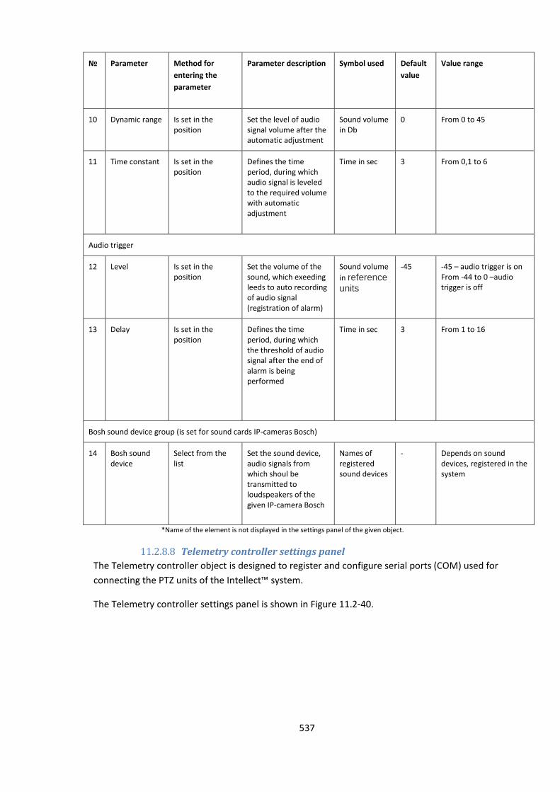
537
№ Parameter Method for
entering the
parameter
Parameter description Symbol used Default
value
Value range
10 Dynamic range Is set in the position
Set the level of audio signal volume after the automatic adjustment
Sound volume in Db
0 From 0 to 45
11 Time constant Is set in the position
Defines the time period, during which audio signal is leveled to the required volume with automatic adjustment
Time in sec 3 From 0,1 to 6
Audio trigger
12 Level Is set in the position
Set the volume of the sound, which exeeding leeds to auto recording of audio signal (registration of alarm)
Sound volume
in reference units
-45 -45 – audio trigger is on From -44 to 0 –audio trigger is off
13 Delay Is set in the position
Defines the time period, during which the threshold of audio signal after the end of alarm is being performed
Time in sec 3 From 1 to 16
Bosh sound device group (is set for sound cards IP-cameras Bosch)
14 Bosh sound device
Select from the list
Set the sound device, audio signals from which shoul be transmitted to loudspeakers of the given IP-camera Bosch
Names of registered sound devices
- Depends on sound devices, registered in the system
*Name of the element is not displayed in the settings panel of the given object.
11.2.8.8 Telemetry controller settings panel
The Telemetry controller object is designed to register and configure serial ports (COM) used for
connecting the PTZ units of the Intellect™ system.
The Telemetry controller settings panel is shown in Figure 11.2-40.
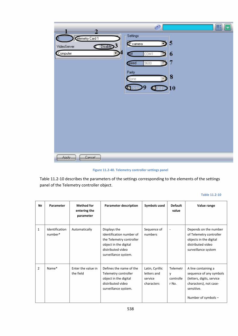
538
Figure 11.2-40. Telemetry controller settings panel
Table 11.2-10 describes the parameters of the settings corresponding to the elements of the settings
panel of the Telemetry controller object.
Table 11.2-10
№
Parameter Method for
entering the
parameter
Parameter description Symbols used Default
value
Value range
1 Identification
number*
Automatically Displays the
identification number of
the Telemetry controller
object in the digital
distributed video
surveillance system.
Sequence of
numbers
- Depends on the number
of Telemetry controller
objects in the digital
distributed video
surveillance system
2 Name* Enter the value in
the field
Defines the name of the
Telemetry controller
object in the digital
distributed video
surveillance system.
Latin, Cyrillic
letters and
service
characters
Telemetr
y
controlle
r No.
A line containing a
sequence of any symbols
(letters, digits, service
characters), not case-
sensitive.
Number of symbols –
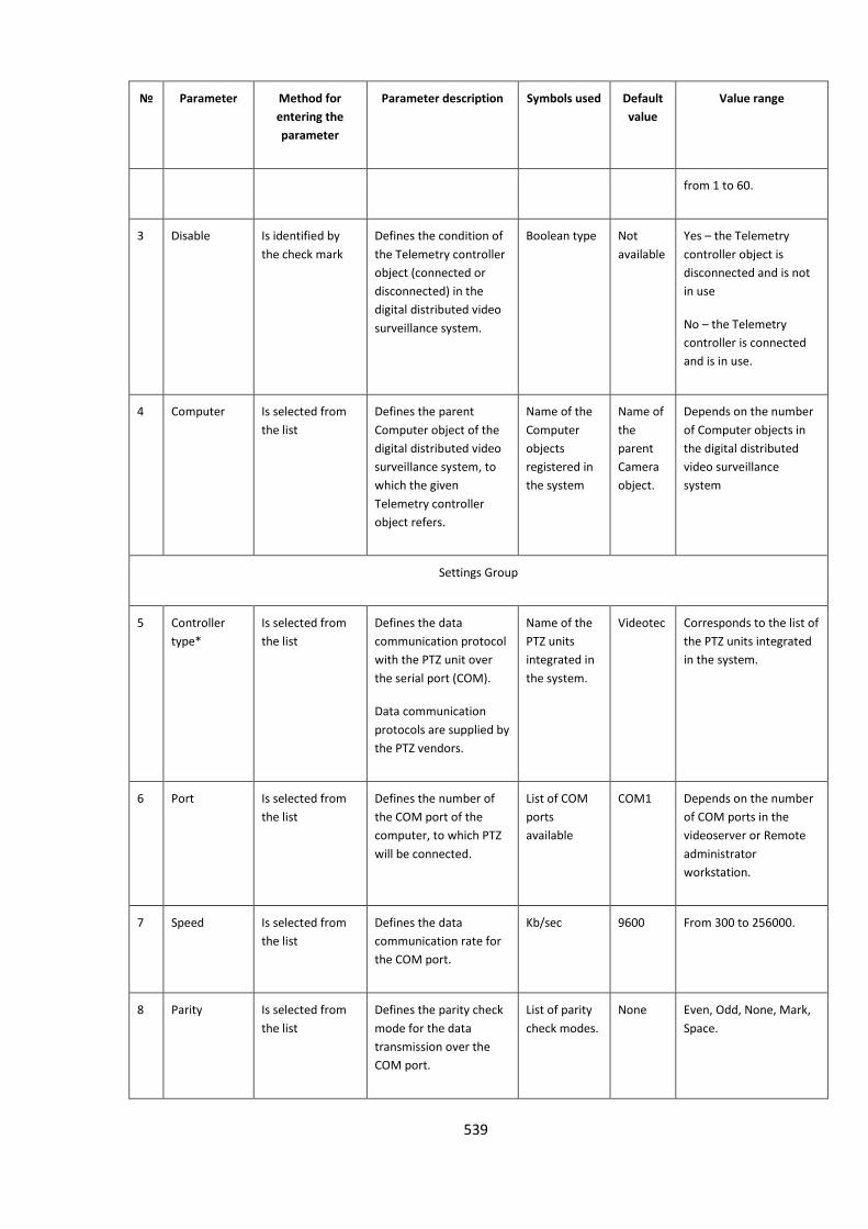
539
№
Parameter Method for
entering the
parameter
Parameter description Symbols used Default
value
Value range
from 1 to 60.
3 Disable Is identified by
the check mark
Defines the condition of
the Telemetry controller
object (connected or
disconnected) in the
digital distributed video
surveillance system.
Boolean type Not
available
Yes – the Telemetry
controller object is
disconnected and is not
in use
No – the Telemetry
controller is connected
and is in use.
4 Computer Is selected from
the list
Defines the parent
Computer object of the
digital distributed video
surveillance system, to
which the given
Telemetry controller
object refers.
Name of the
Computer
objects
registered in
the system
Name of
the
parent
Camera
object.
Depends on the number
of Computer objects in
the digital distributed
video surveillance
system
Settings Group
5 Controller
type*
Is selected from
the list
Defines the data
communication protocol
with the PTZ unit over
the serial port (COM).
Data communication
protocols are supplied by
the PTZ vendors.
Name of the
PTZ units
integrated in
the system.
Videotec Corresponds to the list of
the PTZ units integrated
in the system.
6 Port Is selected from
the list
Defines the number of
the COM port of the
computer, to which PTZ
will be connected.
List of COM
ports
available
COM1 Depends on the number
of COM ports in the
videoserver or Remote
administrator
workstation.
7 Speed Is selected from
the list
Defines the data
communication rate for
the COM port.
Kb/sec
9600 From 300 to 256000.
8 Parity Is selected from
the list
Defines the parity check
mode for the data
transmission over the
COM port.
List of parity
check modes.
None Even, Odd, None, Mark,
Space.
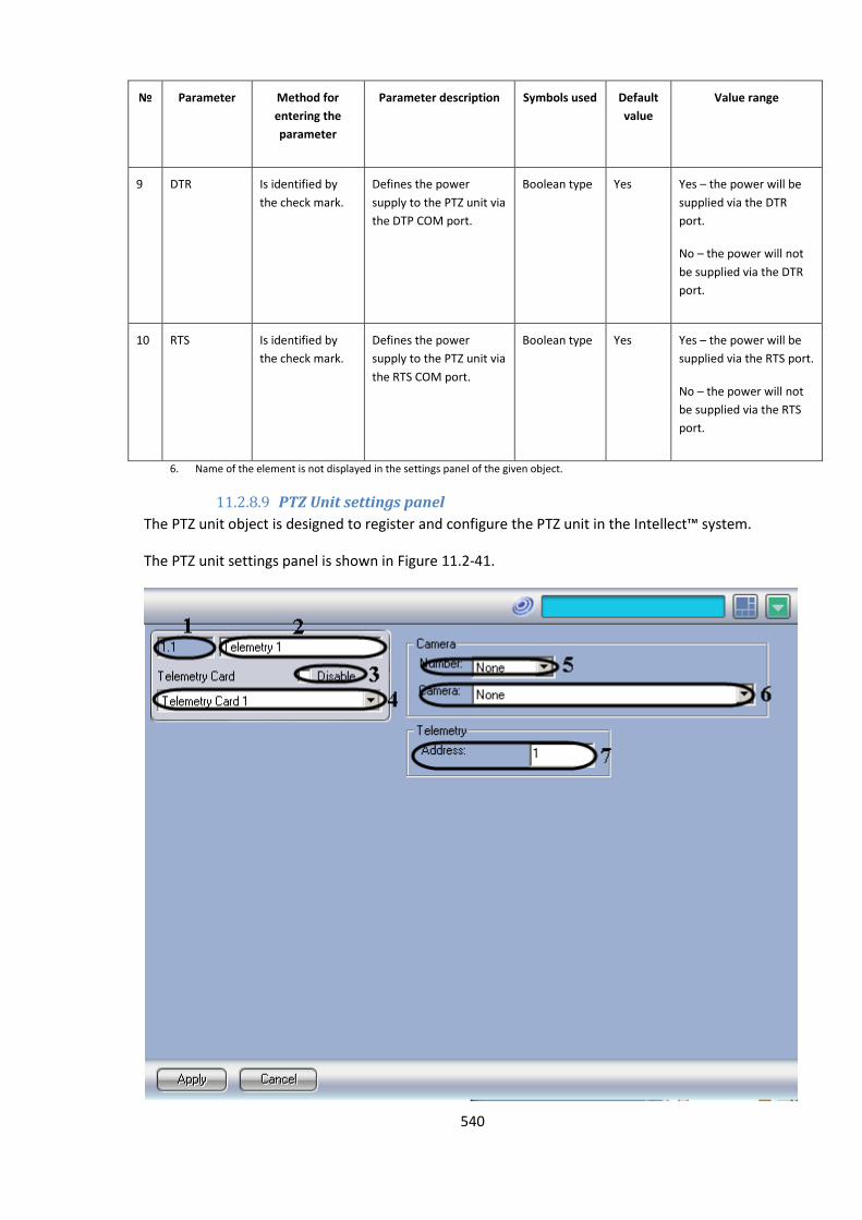
540
№
Parameter Method for
entering the
parameter
Parameter description Symbols used Default
value
Value range
9 DTR Is identified by
the check mark.
Defines the power
supply to the PTZ unit via
the DTP COM port.
Boolean type Yes Yes – the power will be
supplied via the DTR
port.
No – the power will not
be supplied via the DTR
port.
10 RTS Is identified by
the check mark.
Defines the power
supply to the PTZ unit via
the RTS COM port.
Boolean type Yes Yes – the power will be
supplied via the RTS port.
No – the power will not
be supplied via the RTS
port.
6. Name of the element is not displayed in the settings panel of the given object.
11.2.8.9 PTZ Unit settings panel
The PTZ unit object is designed to register and configure the PTZ unit in the Intellect™ system.
The PTZ unit settings panel is shown in Figure 11.2-41.

541
Figure 11.2-41. PTZ Unit settings panel
Table 11.2-11 describes the parameters of the settings corresponding to the elements of the settings
panel of the PTZ unit object.
Table 11.2-11
№ Parameter Method for
entering the
parameter
Parameter description Symbols used Default
value
Value range
1 Identification
number*
Automatically Displays the
identification number of
the PTZ unit object in the
digital distributed video
surveillance system.
Sequence of
numbers
- Depends on the number
of PTZ unit objects in the
digital distributed video
surveillance system
2 Name* Enter the value in
the field
Defines the name of the
PTZ unit object in the
digital distributed video
surveillance system.
Latin, Cyrillic
letters and
service
characters
PTZ Unit A line containing a
sequence of any symbols
(letters, digits, service
characters), not case-
sensitive.
Number of symbols –
from 1 to 60.
3 Disable Is identified by
the check mark
Defines the condition of
the PTZ unit object
(connected or
disconnected) in the
digital distributed video
surveillance system.
Boolean type Not
available
Yes – the PTZ unit is
disconnected and is not
in use
No – the PTZ unit is
connected and is in use.
4 Telemetry
controller
Is selected from
the list
Defines the parent
Telemetry controller
object of the digital
distributed video
surveillance system, to
which the given PTZ unit
object refers.
Name of the
PTZ unit
objects
registered in
the system
Name of
the
parent
Telemetr
y
controlle
r object.
Depends on the number
of Telemetry controllers
in the digital distributed
video surveillance
system
Camera Group
5 Number Is selected from
the list
Defines the identification
number of the
surveillance camera,
where the PTZ unit is
installed.
Sequence of
numbers
Not
defined
Depends on the number
of surveillance cameras
in the digital distributed
video surveillance
system
6 Camera Is selected from Correlates the PTZ unit Name of the Not Depends on the number

542
№ Parameter Method for
entering the
parameter
Parameter description Symbols used Default
value
Value range
the list to the surveillance
camera, where it is
installed.
The parameter is used by
the Video Monitor and
telemetry window for
the purposes of
controlling PTZ units of
the surveillance cameras.
Camera
objects
registered in
the system
available of Camera objects in the
digital distributed video
surveillance system.
7 Address Is selected from
the list
Defines the PTZ unit
address, installed as
hardware (with the
jumpers on the PTZ unit
circuit board) or as
software (with the
software designed to
weave PTZ units).
Sequence of
numbers
1 Integral number from 1
to 255. Depends on the
PTZ protocol.
7. Name of the element is not displayed in the settings panel of the given object.
11.2.8.10 Settings panel of the Control panel
The Control panel object is designed to register and configure a specialized control panel used for
PTZ control in the Intellect™ system.
The settings panel of the Control panel object is shown in Figure 11.2-42.

543
Figure 11.2-42. Settings panel of the Control panel
Table 11.2-12 describes the parameters of the settings corresponding to the elements of the settings
panel of the Control panel object.
Table 11.2-12
№
Parameter Method for
entering the
parameter
Parameter description Symbols used Default
value
Value range
1 Identification
number*
Automatically Displays the
identification number of
the Control panel object
in the digital distributed
video surveillance
system.
Sequence of
numbers
- Depends on the number
of Control panel objects
in the digital distributed
video surveillance
system
2 Name* Enter the value in
the fieldhe
Defines the name of the
Control panel object in
the digital distributed
video surveillance
system.
Latin, Cyrillic
and service
characters
Control
panel
A line containing a
sequence of any symbols
(letters, digits, service
characters), not case-
sensitive.
Number of symbols –
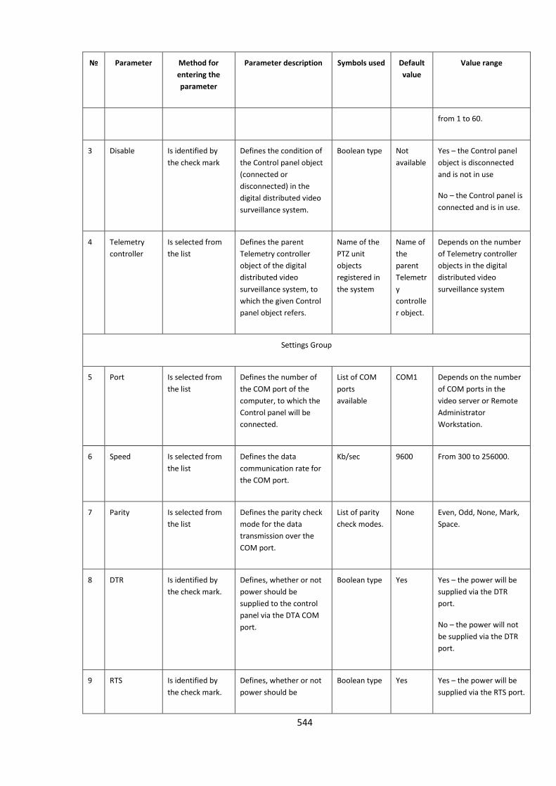
544
№
Parameter Method for
entering the
parameter
Parameter description Symbols used Default
value
Value range
from 1 to 60.
3 Disable Is identified by
the check mark
Defines the condition of
the Control panel object
(connected or
disconnected) in the
digital distributed video
surveillance system.
Boolean type Not
available
Yes – the Control panel
object is disconnected
and is not in use
No – the Control panel is
connected and is in use.
4 Telemetry
controller
Is selected from
the list
Defines the parent
Telemetry controller
object of the digital
distributed video
surveillance system, to
which the given Control
panel object refers.
Name of the
PTZ unit
objects
registered in
the system
Name of
the
parent
Telemetr
y
controlle
r object.
Depends on the number
of Telemetry controller
objects in the digital
distributed video
surveillance system
Settings Group
5 Port Is selected from
the list
Defines the number of
the COM port of the
computer, to which the
Control panel will be
connected.
List of COM
ports
available
COM1 Depends on the number
of COM ports in the
video server or Remote
Administrator
Workstation.
6 Speed Is selected from
the list
Defines the data
communication rate for
the COM port.
Kb/sec
9600 From 300 to 256000.
7 Parity Is selected from
the list
Defines the parity check
mode for the data
transmission over the
COM port.
List of parity
check modes.
None Even, Odd, None, Mark,
Space.
8 DTR Is identified by
the check mark.
Defines, whether or not
power should be
supplied to the control
panel via the DTA COM
port.
Boolean type Yes Yes – the power will be
supplied via the DTR
port.
No – the power will not
be supplied via the DTR
port.
9 RTS Is identified by
the check mark.
Defines, whether or not
power should be
Boolean type Yes Yes – the power will be
supplied via the RTS port.
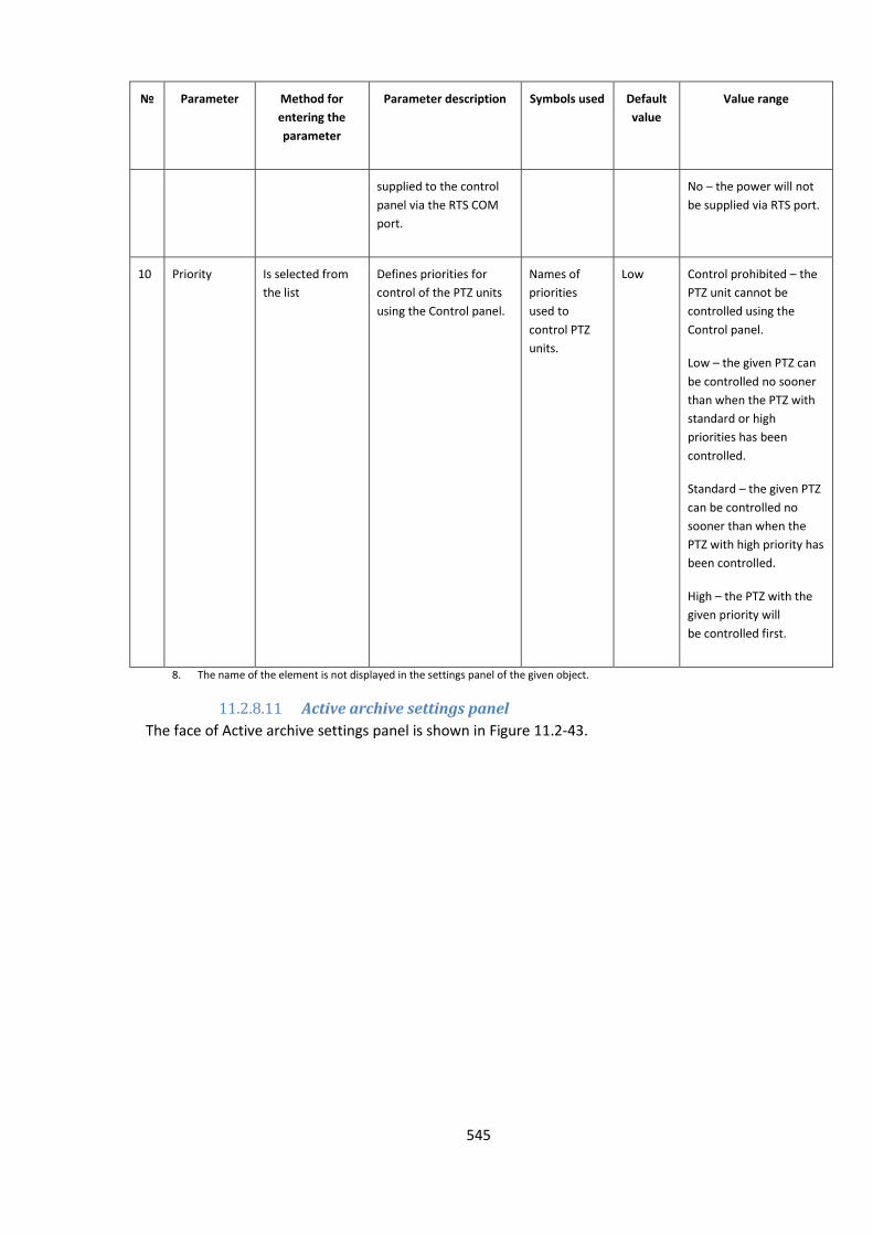
545
№
Parameter Method for
entering the
parameter
Parameter description Symbols used Default
value
Value range
supplied to the control
panel via the RTS COM
port.
No – the power will not
be supplied via RTS port.
10 Priority Is selected from
the list
Defines priorities for
control of the PTZ units
using the Control panel.
Names of
priorities
used to
control PTZ
units.
Low Control prohibited – the
PTZ unit cannot be
controlled using the
Control panel.
Low – the given PTZ can
be controlled no sooner
than when the PTZ with
standard or high
priorities has been
controlled.
Standard – the given PTZ
can be controlled no
sooner than when the
PTZ with high priority has
been controlled.
High – the PTZ with the
given priority will
be controlled first.
8. The name of the element is not displayed in the settings panel of the given object.
11.2.8.11 Active archive settings panel
The face of Active archive settings panel is shown in Figure 11.2-43.
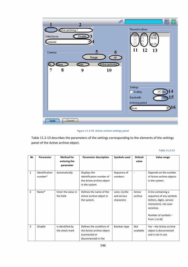
546
Figure 11.2-43. Active archive settings panel
Table 11.2-13 describes the parameters of the settings corresponding to the elements of the settings
panel of the Active archive object.
Table 11.2-13
№
Parameter Method for
entering the
parameter
Parameter description Symbols used Default
value
Value range
1 Identification
number*
Automatically Displays the
identification number of
the Active archive object
in the system.
Sequence of
numbers
- Depends on the number
of Active archive objects
in the system.
2 Name* Enter the value in
the field
Defines the name of the
Active archive object in
the system.
Latin, Cyrillic
and service
characters
Active
archive
A line containing a
sequence of any symbols
(letters, digits, service
characters), not case-
sensitive.
Number of symbols –
from 1 to 60.
3 Disable Is identified by
the check mark
Defines the condition of
the Active archive object
(connected or
disconnected) in the
Boolean type Not
available
Yes – the Active archive
object is disconnected
and is not in use.
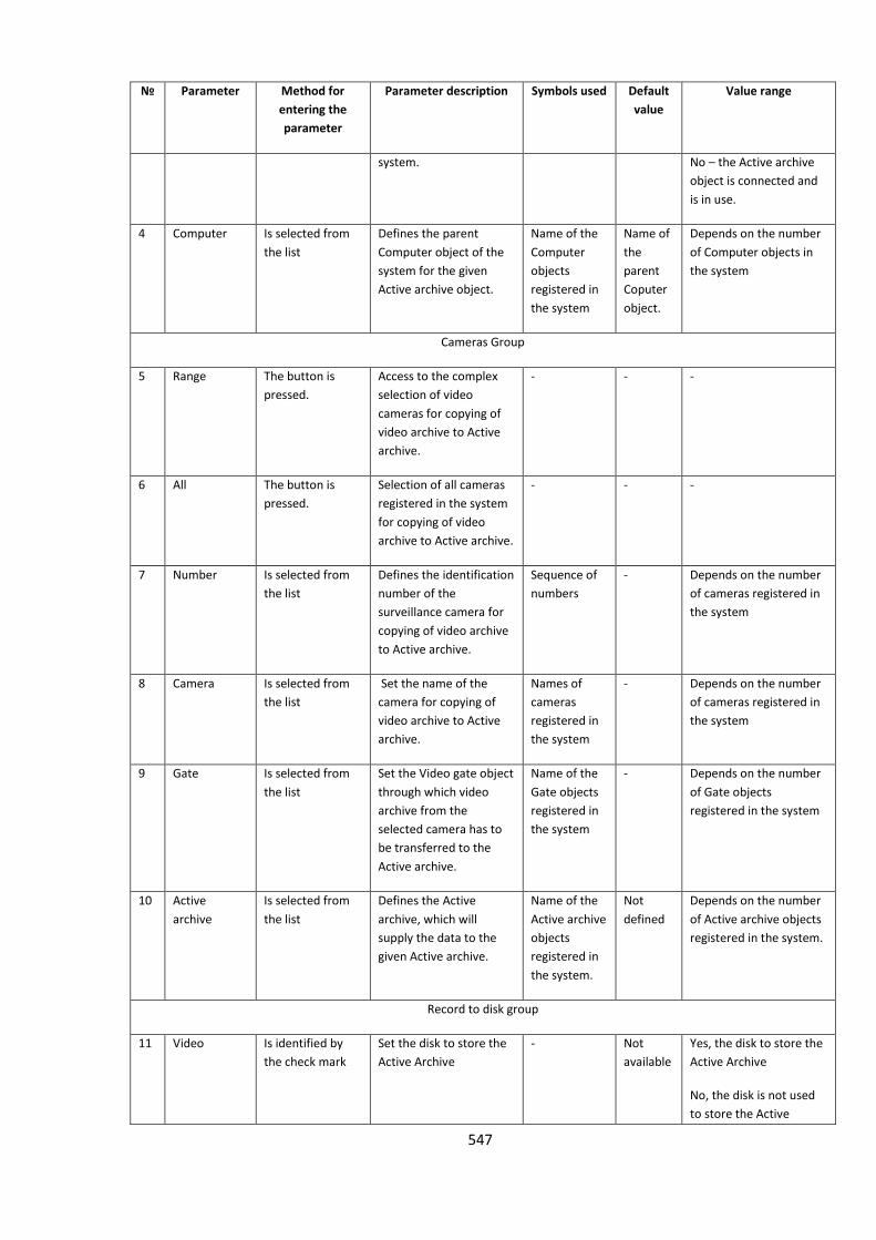
547
№
Parameter Method for
entering the
parameter
Parameter description Symbols used Default
value
Value range
system. No – the Active archive
object is connected and
is in use.
4 Computer Is selected from
the list
Defines the parent
Computer object of the
system for the given
Active archive object.
Name of the
Computer
objects
registered in
the system
Name of
the
parent
Coputer
object.
Depends on the number
of Computer objects in
the system
Cameras Group
5 Range The button is
pressed.
Access to the complex
selection of video
cameras for copying of
video archive to Active
archive.
- - -
6 All The button is
pressed.
Selection of all cameras
registered in the system
for copying of video
archive to Active archive.
- - -
7 Number Is selected from
the list
Defines the identification
number of the
surveillance camera for
copying of video archive
to Active archive.
Sequence of
numbers
- Depends on the number
of cameras registered in
the system
8 Camera Is selected from
the list
Set the name of the
camera for copying of
video archive to Active
archive.
Names of
cameras
registered in
the system
- Depends on the number
of cameras registered in
the system
9 Gate Is selected from
the list
Set the Video gate object
through which video
archive from the
selected camera has to
be transferred to the
Active archive.
Name of the
Gate objects
registered in
the system
- Depends on the number
of Gate objects
registered in the system
10 Active
archive
Is selected from
the list
Defines the Active
archive, which will
supply the data to the
given Active archive.
Name of the
Active archive
objects
registered in
the system.
Not
defined
Depends on the number
of Active archive objects
registered in the system.
Record to disk group
11 Video Is identified by
the check mark
Set the disk to store the
Active Archive
- Not
available
Yes, the disk to store the
Active Archive
No, the disk is not used
to store the Active
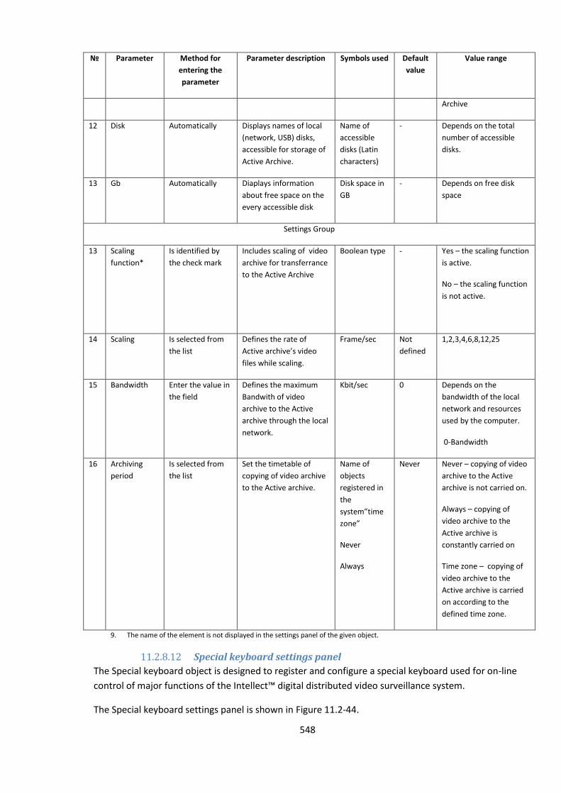
548
№
Parameter Method for
entering the
parameter
Parameter description Symbols used Default
value
Value range
Archive
12 Disk Automatically Displays names of local
(network, USB) disks,
accessible for storage of
Active Archive.
Name of
accessible
disks (Latin
characters)
- Depends on the total
number of accessible
disks.
13 Gb Automatically Diaplays information
about free space on the
every accessible disk
Disk space in
GB
- Depends on free disk
space
Settings Group
13 Scaling
function*
Is identified by
the check mark
Includes scaling of video
archive for transferrance
to the Active Archive
Boolean type - Yes – the scaling function
is active.
No – the scaling function
is not active.
14 Scaling Is selected from
the list
Defines the rate of
Active archive’s video
files while scaling.
Frame/sec Not
defined
1,2,3,4,6,8,12,25
15 Bandwidth Enter the value in
the field
Defines the maximum
Bandwith of video
archive to the Active
archive through the local
network.
Kbit/sec 0 Depends on the
bandwidth of the local
network and resources
used by the computer.
0-Bandwidth
16 Archiving
period
Is selected from
the list
Set the timetable of
copying of video archive
to the Active archive.
Name of
objects
registered in
the
system”time
zone”
Never
Always
Never Never – copying of video
archive to the Active
archive is not carried on.
Always – copying of
video archive to the
Active archive is
constantly carried on
Time zone – copying of
video archive to the
Active archive is carried
on according to the
defined time zone.
9. The name of the element is not displayed in the settings panel of the given object.
11.2.8.12 Special keyboard settings panel
The Special keyboard object is designed to register and configure a special keyboard used for on-line
control of major functions of the Intellect™ digital distributed video surveillance system.
The Special keyboard settings panel is shown in Figure 11.2-44.
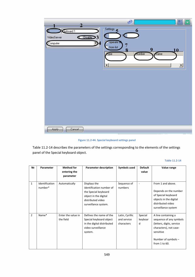
549
Figure 11.2-44. Special keyboard settings panel
Table 11.2-14 describes the parameters of the settings corresponding to the elements of the settings
panel of the Special keyboard object.
Table 11.2-14
№
Parameter Method for
entering the
parameter
Parameter description Symbols used Default
value
Value range
1 Identification
number*
Automatically Displays the
identification number of
the Special keyboard
object in the digital
distributed video
surveillance system.
Sequence of
numbers
- From 1 and above.
Depends on the number
of Special keyboard
objects in the digital
distributed video
surveillance system
2 Name* Enter the value in
the field
Defines the name of the
Special keyboard object
in the digital distributed
video surveillance
system.
Latin, Cyrillic
and service
characters
Special
keyboar
d
A line containing a
sequence of any symbols
(letters, digits, service
characters), not case-
sensitive
Number of symbols –
from 1 to 60.
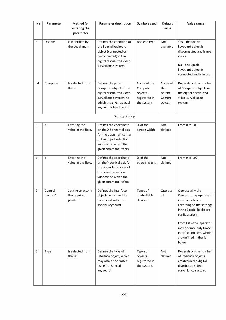
550
№
Parameter Method for
entering the
parameter
Parameter description Symbols used Default
value
Value range
3 Disable Is identified by
the check mark
Defines the condition of
the Special keyboard
object (connected or
disconnected) in the
digital distributed video
surveillance system.
Boolean type Not
available
Yes – the Special
keyboard object is
disconnected and is not
in use
No – the Special
keyboard object is
connected and is in use.
4 Computer Is selected from
the list
Defines the parent
Computer object of the
digital distributed video
surveillance system, to
which the given Special
keyboard object refers.
Name of the
Computer
objects
registered in
the system
Name of
the
parent
Camera
object.
Depends on the number
of Computer objects in
the digital distributed
video surveillance
system
Settings Group
5 X Entering the
value in the field.
Defines the coordinate
on the X horizontal axis
for the upper left corner
of the object selection
window, to which the
given command refers.
% of the
screen width.
Not
defined
From 0 to 100.
6 Y Entering the
value in the field.
Defines the coordinate
on the Y vertical axis for
the upper left corner of
the object selection
window, to which the
given command refers.
% of the
screen height.
Not
defined
From 0 to 100.
7 Control
devices*
Set the selector in
the required
position
Defines the interface
objects, which will be
controlled with the
special keyboard.
Types of
controllable
devices
Operate
all
Operate all – the
Operator may operate all
interface objects
according to the settings
in the Special keyboard
configuration.
From list – the Operator
may operate only those
interface objects, which
are defined in the list
below.
8 Type Is selected from
the list
Defines the type of
interface object, which
may also be operated
using the Special
keyboard.
Types of
objects
registered in
the system.
Not
defined
Depends on the number
of interface objects
created in the digital
distributed video
surveillance system.
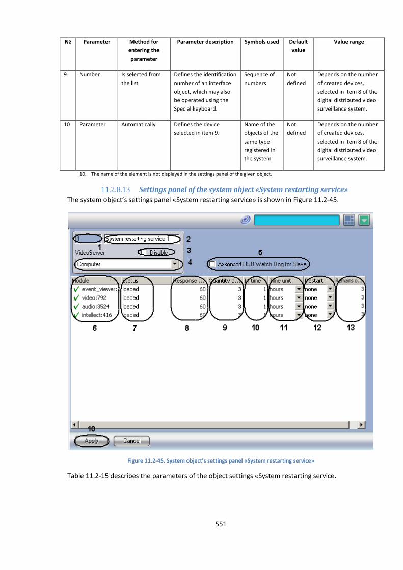
551
№
Parameter Method for
entering the
parameter
Parameter description Symbols used Default
value
Value range
9 Number Is selected from
the list
Defines the identification
number of an interface
object, which may also
be operated using the
Special keyboard.
Sequence of
numbers
Not
defined
Depends on the number
of created devices,
selected in item 8 of the
digital distributed video
surveillance system.
10 Parameter Automatically Defines the device
selected in item 9.
Name of the
objects of the
same type
registered in
the system
Not
defined
Depends on the number
of created devices,
selected in item 8 of the
digital distributed video
surveillance system.
10. The name of the element is not displayed in the settings panel of the given object.
11.2.8.13 Settings panel of the system object «System restarting service»
The system object’s settings panel «System restarting service» is shown in Figure 11.2-45.
Figure 11.2-45. System object’s settings panel «System restarting service»
Table 11.2-15 describes the parameters of the object settings «System restarting service.
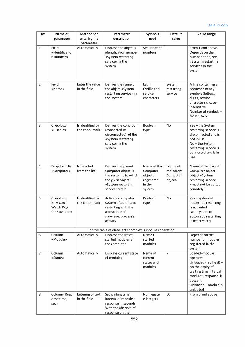
552
Table 11.2-15
№
Name of parameter
Method for entering the parameter
Parameter description
Symbols used
Default value
Value range
1 Field «Identification number»
Automatically Displays the object’s identification number «System restarting service» in the system
Sequence of numbers
- From 1 and above. Depends on the number of objects «System restarting service» in the system
2 Field «Name»
Enter the value in the field
Defines the name of the object «System restarting service» in the system
Latin, Cyrillic and service characters
System restarting service
A line containing a sequence of any symbols (letters, digits, service characters), case-insensitive Number of symbols – from 1 to 60.
3 Checkbox «Disable»
Is identified by the check mark
Defines the condition (connected or disconnected) of the «System restarting service» in the system
Boolean type
No Yes – the System restarting service is disconnected and is not in use No – the System restarting service is connected and is in use.
4 Dropdown list «Computer»
Is selected from the list
Defines the parent Computer object in the system , to which the given object «System restarting service»refers
Name of the Computer objects registered in the system
Name of the parent Computer object.
Name of the parent Computer object( object «System restarting service »must not be edited remotely)
5 Checkbox «ITV USB Watch Dog for Slave.exe»
Is identified by the check mark
Activates computer system of automatic restarting with the albescence of slave.exe. process’s activity
Boolean type
No Yes – system of automatic restarting is activated No – system of automatic restarting is deactivated
Control table of «Intellect» complex ‘s modules operation
6 Column «Module»
Automatically Displays the list of started modules at the computer
Name f started modules
- Depends on the number of modules, registered in the system
7 Column «Status»
Automatically Displays current state of modules
Name of current states and modules
- Loaded–module operates Unloaded (red field) – on the expiry of waiting time interval module’s response is abscent Unloaded – module is unloaded
8 Column«Response time, sec»
Entering of text in the field
Set waiting time interval of module’s response in seconds. With the absence of response on the
Nonnegative integers
60 From 0 and above
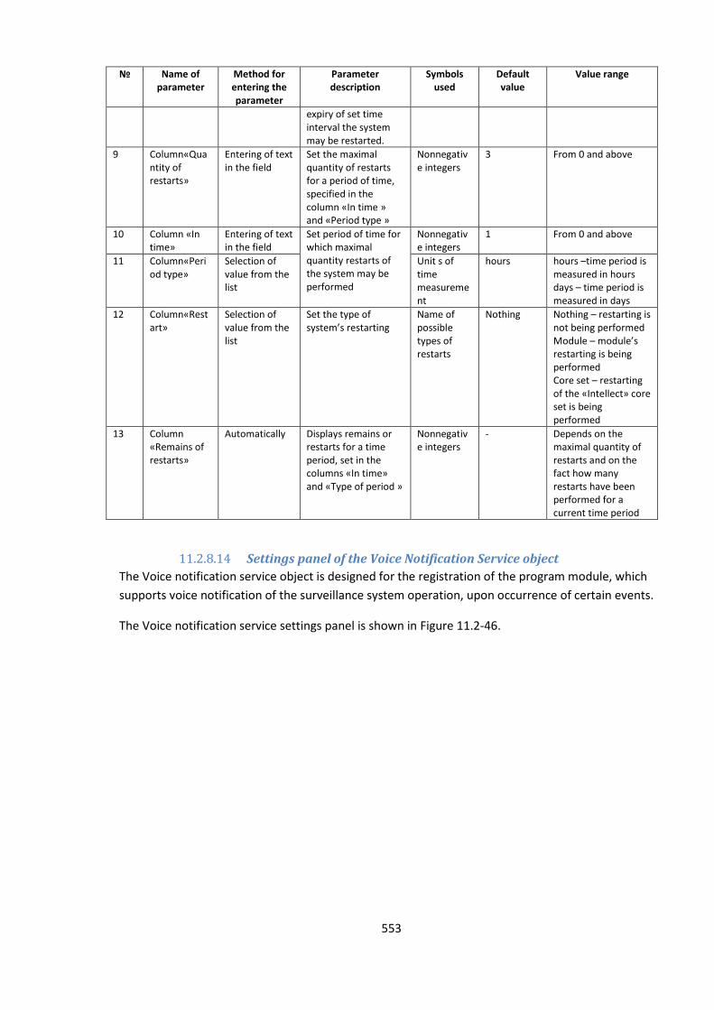
553
№
Name of parameter
Method for entering the parameter
Parameter description
Symbols used
Default value
Value range
expiry of set time interval the system may be restarted.
9 Column«Quantity of restarts»
Entering of text in the field
Set the maximal quantity of restarts for a period of time, specified in the column «In time » and «Period type »
Nonnegative integers
3 From 0 and above
10 Column «In time»
Entering of text in the field
Set period of time for which maximal quantity restarts of the system may be performed
Nonnegative integers
1 From 0 and above
11 Column«Period type»
Selection of value from the list
Unit s of time measurement
hours hours –time period is measured in hours days – time period is measured in days
12 Column«Restart»
Selection of value from the list
Set the type of system’s restarting
Name of possible types of restarts
Nothing Nothing – restarting is not being performed Module – module’s restarting is being performed Core set – restarting of the «Intellect» core set is being performed
13 Column «Remains of restarts»
Automatically Displays remains or restarts for a time period, set in the columns «In time» and «Type of period »
Nonnegative integers
- Depends on the maximal quantity of restarts and on the fact how many restarts have been performed for a current time period
11.2.8.14 Settings panel of the Voice Notification Service object
The Voice notification service object is designed for the registration of the program module, which
supports voice notification of the surveillance system operation, upon occurrence of certain events.
The Voice notification service settings panel is shown in Figure 11.2-46.
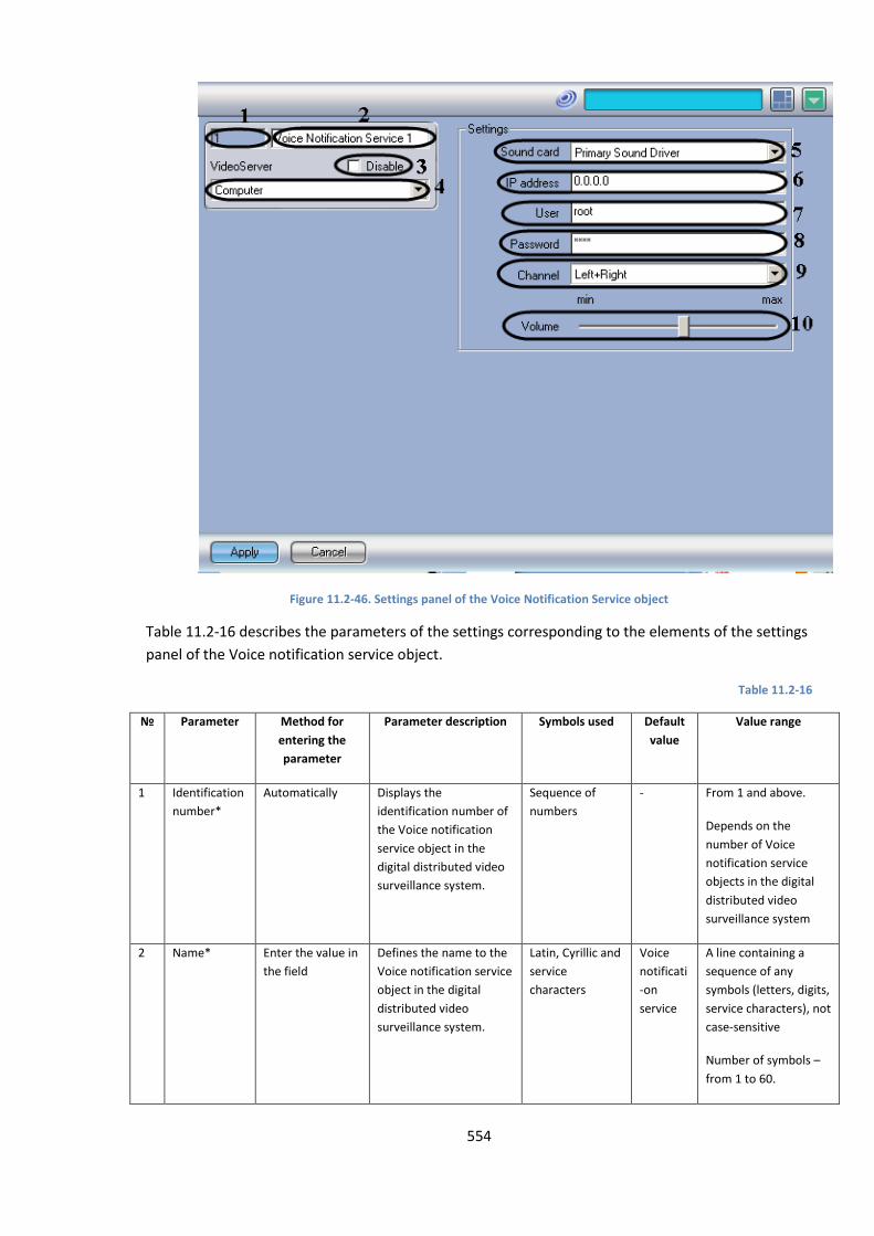
554
Figure 11.2-46. Settings panel of the Voice Notification Service object
Table 11.2-16 describes the parameters of the settings corresponding to the elements of the settings
panel of the Voice notification service object.
Table 11.2-16
№ Parameter Method for
entering the
parameter
Parameter description Symbols used Default
value
Value range
1 Identification
number*
Automatically Displays the
identification number of
the Voice notification
service object in the
digital distributed video
surveillance system.
Sequence of
numbers
- From 1 and above.
Depends on the
number of Voice
notification service
objects in the digital
distributed video
surveillance system
2 Name* Enter the value in
the field
Defines the name to the
Voice notification service
object in the digital
distributed video
surveillance system.
Latin, Cyrillic and
service
characters
Voice
notificati
-on
service
A line containing a
sequence of any
symbols (letters, digits,
service characters), not
case-sensitive
Number of symbols –
from 1 to 60.
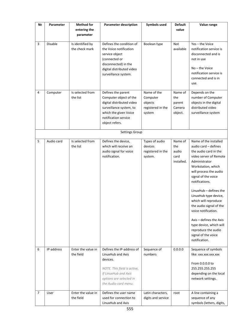
555
№ Parameter Method for
entering the
parameter
Parameter description Symbols used Default
value
Value range
3 Disable Is identified by
the check mark
Defines the condition of
the Voice notification
service object
(connected or
disconnected) in the
digital distributed video
surveillance system.
Boolean type Not
available
Yes – the Voice
notification service is
disconnected and is
not in use
No – the Voice
notification service is
connected and is in
use.
4 Computer Is selected from
the list
Defines the parent
Computer object of the
digital distributed video
surveillance system, to
which the given Voice
notification service
object refers.
Name of the
Computer
objects
registered in the
system
Name of
the
parent
Camera
object.
Depends on the
number of Computer
objects in the digital
distributed video
surveillance system
Settings Group
5 Audio card Is selected from
the list
Defines the device,
which will receive an
audio signal for voice
notification.
Types of audio
devices
registered in the
system.
Name of
the
audio
card
installed.
Name of the installed
audio card – defines
the audio card in the
video server of Remote
Administrator
Workstation, which
will process the audio
signal of the voice
notifications.
LinuxHub – defines the
LinuxHub type device,
which will reproduce
the audio signal of the
voice notification.
Axis – defines the Axis
type device, which will
reproduce the audio
signal of the voice
notification.
6 IP-address Enter the value in
the field
Defines the IP-address of
LinuxHub and Axis
devices.
NOTE. This field is active,
if LinuxHub and Axis
options are selected in
the Audio card menu.
Sequence of
numbers
0.0.0.0 Sequence of symbols
like: ххх.ххх.ххх.ххх
From 0.0.0.0 to
255.255.255.255
depending on the local
network settings.
7 User Enter the value in
the field
Defines the user name
used for connection to
LinuxHub and Axis
Latin characters,
digits and service
root A line containing a
sequence of any
symbols (letters, digits,
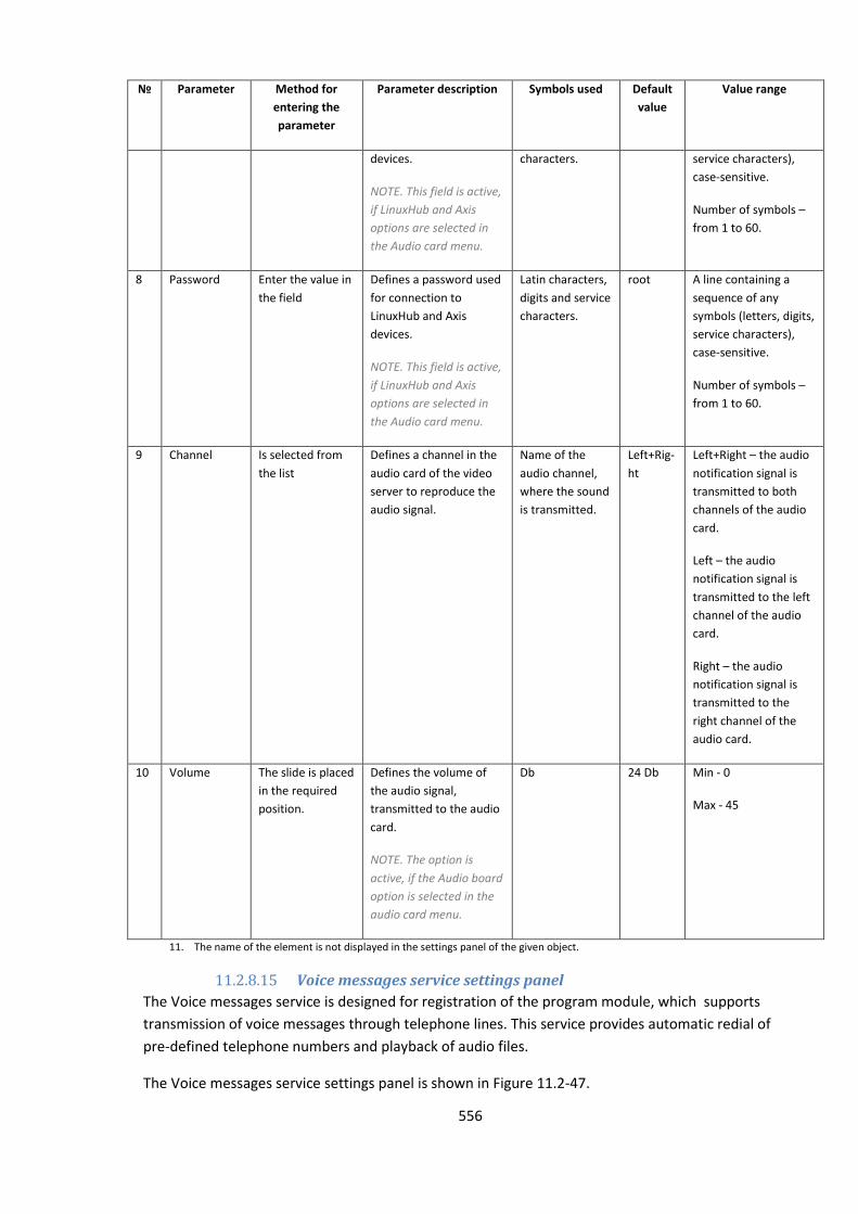
556
№ Parameter Method for
entering the
parameter
Parameter description Symbols used Default
value
Value range
devices.
NOTE. This field is active,
if LinuxHub and Axis
options are selected in
the Audio card menu.
characters. service characters),
case-sensitive.
Number of symbols –
from 1 to 60.
8 Password Enter the value in
the field
Defines a password used
for connection to
LinuxHub and Axis
devices.
NOTE. This field is active,
if LinuxHub and Axis
options are selected in
the Audio card menu.
Latin characters,
digits and service
characters.
root A line containing a
sequence of any
symbols (letters, digits,
service characters),
case-sensitive.
Number of symbols –
from 1 to 60.
9 Channel Is selected from
the list
Defines a channel in the
audio card of the video
server to reproduce the
audio signal.
Name of the
audio channel,
where the sound
is transmitted.
Left+Rig-
ht
Left+Right – the audio
notification signal is
transmitted to both
channels of the audio
card.
Left – the audio
notification signal is
transmitted to the left
channel of the audio
card.
Right – the audio
notification signal is
transmitted to the
right channel of the
audio card.
10 Volume The slide is placed
in the required
position.
Defines the volume of
the audio signal,
transmitted to the audio
card.
NOTE. The option is
active, if the Audio board
option is selected in the
audio card menu.
Db 24 Db Min - 0
Max - 45
11. The name of the element is not displayed in the settings panel of the given object.
11.2.8.15 Voice messages service settings panel
The Voice messages service is designed for registration of the program module, which supports
transmission of voice messages through telephone lines. This service provides automatic redial of
pre-defined telephone numbers and playback of audio files.
The Voice messages service settings panel is shown in Figure 11.2-47.

557
Figure 11.2-47. Voice messages service settings panel
Table 11.2-17 describes the parameters of the settings corresponding to the elements of the settings
panel of the Voice messages service object.
Table 11.2-17
№ Parameter Method for
entering the
parameter
Parameter description Symbols
used
Default
value
Value range
1 Identification
number*
Automatically Displays the identification
number of the Voice
messages service object in
the digital distributed video
surveillance system.
Sequence
of numbers
- From 1 and above.
Depends on the number
of Voice message service
objects in the digital
distributed video
surveillance system
2 Name* Enter the value in
the field
Displays the name of the
Voice messages service
object in the digital
distributed video
surveillance system.
Latin,
Cyrillic and
service
characters
Voice
message
s service
A line containing a
sequence of any symbols
(letters, digits, service
characters), not case-
sensitive
Number of symbols –
from 1 to 60.
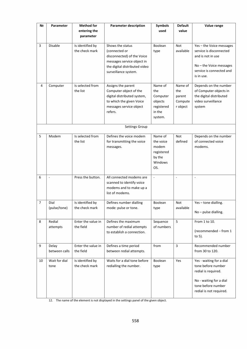
558
№ Parameter Method for
entering the
parameter
Parameter description Symbols
used
Default
value
Value range
3 Disable Is identified by
the check mark
Shows the status
(connected or
disconnected) of the Voice
messages service object in
the digital distributed video
surveillance system.
Boolean
type
Not
available
Yes – the Voice messages
service is disconnected
and is not in use
No – the Voice messages
service is connected and
is in use.
4 Computer Is selected from
the list
Assigns the parent
Computer object of the
digital distributed system,
to which the given Voice
messages service object
refers.
Name of
the
Computer
objects
registered
in the
system.
Name of
the
parent
Compute
r object
Depends on the number
of Computer objects in
the digital distributed
video surveillance
system
Settings Group
5 Modem Is selected from
the list
Defines the voice modem
for transmitting the voice
messages.
Name of
the voice
modem
registered
by the
Windows
OS.
Not
defined
Depends on the number
of connected voice
modems.
6 - Press the button. All connected modems are
scanned to identify voice
modems and to make up a
list of modems.
- - -
7 Dial
(pulse/tone)
Is identified by
the check mark
Defines number dialling
mode: pulse or tone.
Boolean
type
Not
available
Yes – tone dialling.
No – pulse dialling.
8 Redial
attempts
Enter the value in
the field
Defines the maximum
number of redial attempts
to establish a connection.
Sequence
of numbers
5 From 1 to 10.
(recommended – from 1
to 5).
9 Delay
between calls
Enter the value in
the field
Defines a time period
between redial attempts.
from 3 Recommended number
from 30 to 120.
10 Wait for dial
tone
Is identified by
the check mark
Waits for a dial tone before
redialling the number.
Boolean
type
Yes Yes - waiting for a dial
tone before number
redial is required.
No - waiting for a dial
tone before number
redial is not required.
12. The name of the element is not displayed in the settings panel of the given object.
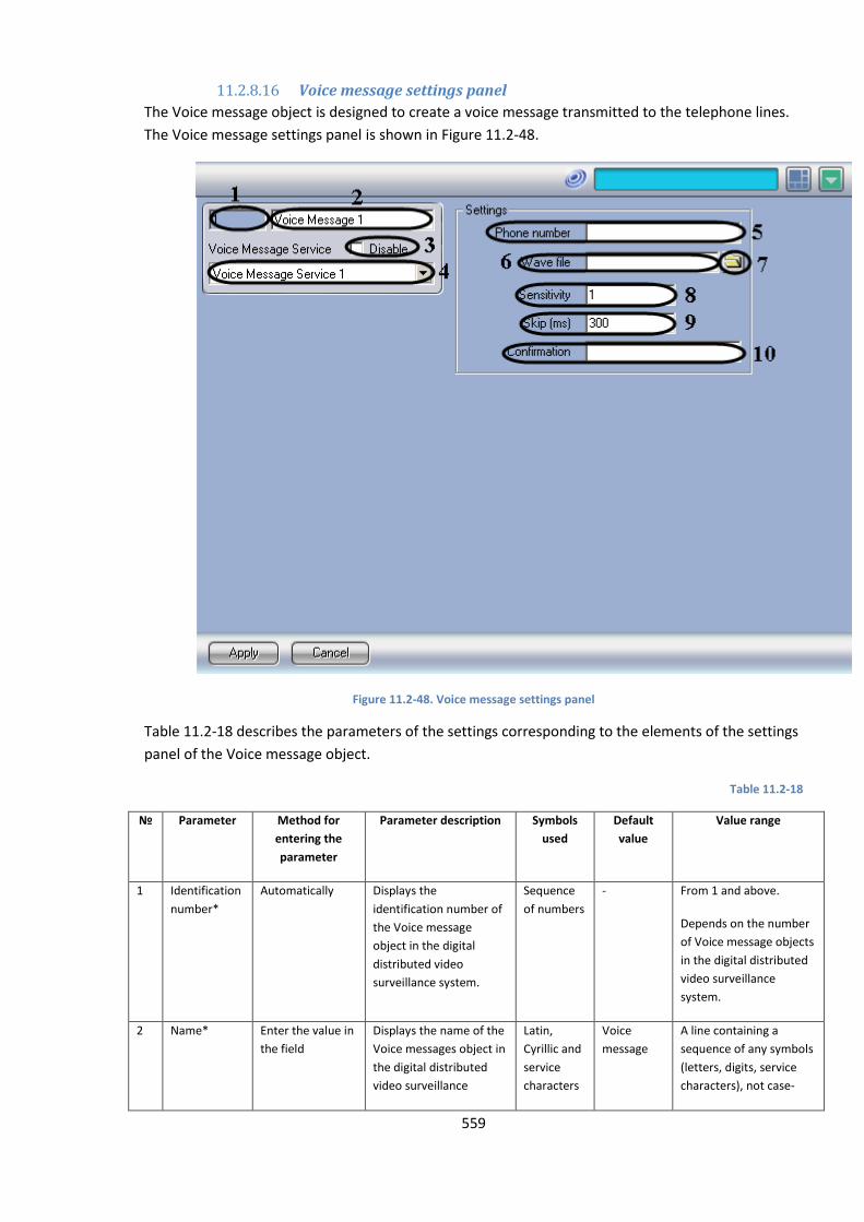
559
11.2.8.16 Voice message settings panel
The Voice message object is designed to create a voice message transmitted to the telephone lines.
The Voice message settings panel is shown in Figure 11.2-48.
Figure 11.2-48. Voice message settings panel
Table 11.2-18 describes the parameters of the settings corresponding to the elements of the settings
panel of the Voice message object.
Table 11.2-18
№
Parameter Method for
entering the
parameter
Parameter description Symbols
used
Default
value
Value range
1 Identification
number*
Automatically Displays the
identification number of
the Voice message
object in the digital
distributed video
surveillance system.
Sequence
of numbers
- From 1 and above.
Depends on the number
of Voice message objects
in the digital distributed
video surveillance
system.
2 Name* Enter the value in
the field
Displays the name of the
Voice messages object in
the digital distributed
video surveillance
Latin,
Cyrillic and
service
characters
Voice
message
A line containing a
sequence of any symbols
(letters, digits, service
characters), not case-
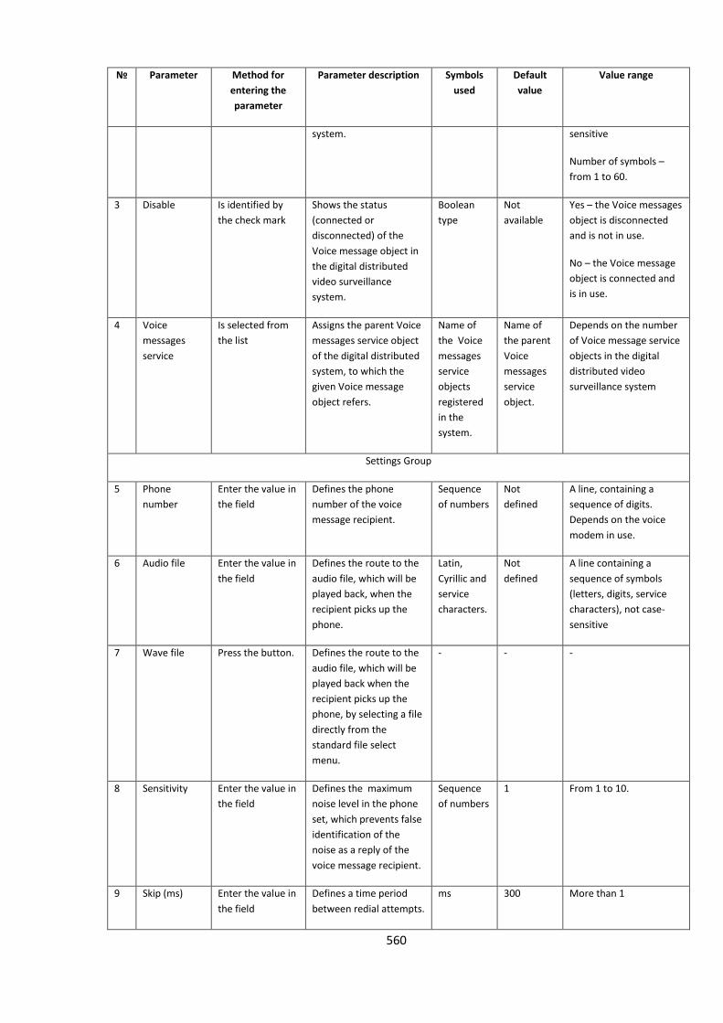
560
№
Parameter Method for
entering the
parameter
Parameter description Symbols
used
Default
value
Value range
system. sensitive
Number of symbols –
from 1 to 60.
3 Disable Is identified by
the check mark
Shows the status
(connected or
disconnected) of the
Voice message object in
the digital distributed
video surveillance
system.
Boolean
type
Not
available
Yes – the Voice messages
object is disconnected
and is not in use.
No – the Voice message
object is connected and
is in use.
4 Voice
messages
service
Is selected from
the list
Assigns the parent Voice
messages service object
of the digital distributed
system, to which the
given Voice message
object refers.
Name of
the Voice
messages
service
objects
registered
in the
system.
Name of
the parent
Voice
messages
service
object.
Depends on the number
of Voice message service
objects in the digital
distributed video
surveillance system
Settings Group
5 Phone
number
Enter the value in
the field
Defines the phone
number of the voice
message recipient.
Sequence
of numbers
Not
defined
A line, containing a
sequence of digits.
Depends on the voice
modem in use.
6 Audio file Enter the value in
the field
Defines the route to the
audio file, which will be
played back, when the
recipient picks up the
phone.
Latin,
Cyrillic and
service
characters.
Not
defined
A line containing a
sequence of symbols
(letters, digits, service
characters), not case-
sensitive
7 Wave file Press the button. Defines the route to the
audio file, which will be
played back when the
recipient picks up the
phone, by selecting a file
directly from the
standard file select
menu.
- - -
8 Sensitivity Enter the value in
the field
Defines the maximum
noise level in the phone
set, which prevents false
identification of the
noise as a reply of the
voice message recipient.
Sequence
of numbers
1 From 1 to 10.
9 Skip (ms) Enter the value in
the field
Defines a time period
between redial attempts.
ms 300 More than 1
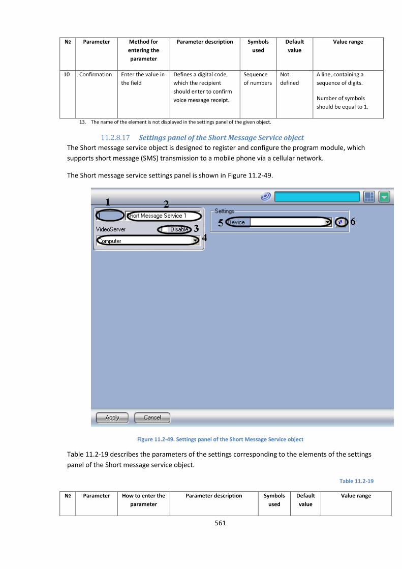
561
№
Parameter Method for
entering the
parameter
Parameter description Symbols
used
Default
value
Value range
10 Confirmation Enter the value in
the field
Defines a digital code,
which the recipient
should enter to confirm
voice message receipt.
Sequence
of numbers
Not
defined
A line, containing a
sequence of digits.
Number of symbols
should be equal to 1.
13. The name of the element is not displayed in the settings panel of the given object.
11.2.8.17 Settings panel of the Short Message Service object
The Short message service object is designed to register and configure the program module, which
supports short message (SMS) transmission to a mobile phone via a cellular network.
The Short message service settings panel is shown in Figure 11.2-49.
Figure 11.2-49. Settings panel of the Short Message Service object
Table 11.2-19 describes the parameters of the settings corresponding to the elements of the settings
panel of the Short message service object.
Table 11.2-19
№ Parameter How to enter the
parameter
Parameter description Symbols
used
Default
value
Value range
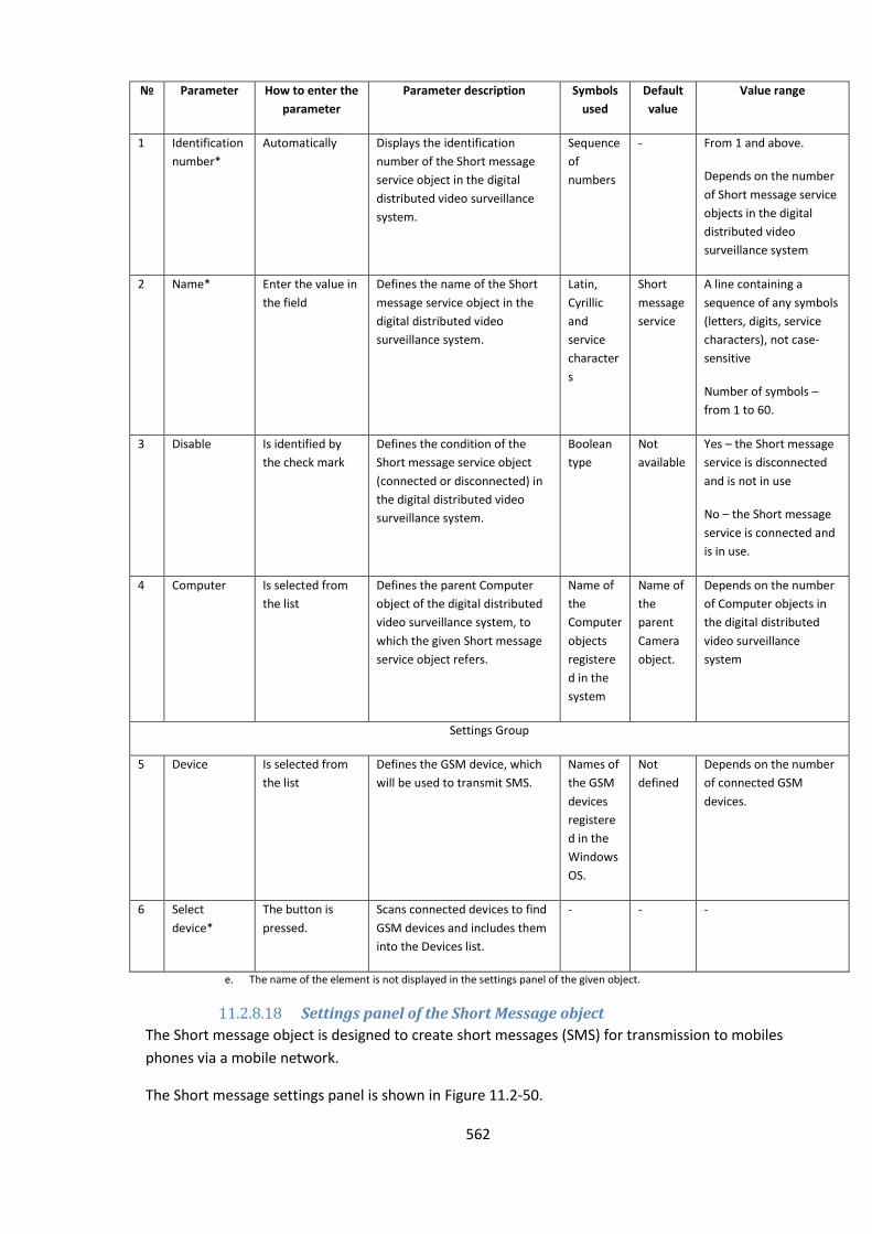
562
№ Parameter How to enter the
parameter
Parameter description Symbols
used
Default
value
Value range
1 Identification
number*
Automatically Displays the identification
number of the Short message
service object in the digital
distributed video surveillance
system.
Sequence
of
numbers
- From 1 and above.
Depends on the number
of Short message service
objects in the digital
distributed video
surveillance system
2 Name* Enter the value in
the field
Defines the name of the Short
message service object in the
digital distributed video
surveillance system.
Latin,
Cyrillic
and
service
character
s
Short
message
service
A line containing a
sequence of any symbols
(letters, digits, service
characters), not case-
sensitive
Number of symbols –
from 1 to 60.
3 Disable Is identified by
the check mark
Defines the condition of the
Short message service object
(connected or disconnected) in
the digital distributed video
surveillance system.
Boolean
type
Not
available
Yes – the Short message
service is disconnected
and is not in use
No – the Short message
service is connected and
is in use.
4 Computer Is selected from
the list
Defines the parent Computer
object of the digital distributed
video surveillance system, to
which the given Short message
service object refers.
Name of
the
Computer
objects
registere
d in the
system
Name of
the
parent
Camera
object.
Depends on the number
of Computer objects in
the digital distributed
video surveillance
system
Settings Group
5 Device Is selected from
the list
Defines the GSM device, which
will be used to transmit SMS.
Names of
the GSM
devices
registere
d in the
Windows
OS.
Not
defined
Depends on the number
of connected GSM
devices.
6 Select
device*
The button is
pressed.
Scans connected devices to find
GSM devices and includes them
into the Devices list.
- - -
e. The name of the element is not displayed in the settings panel of the given object.
11.2.8.18 Settings panel of the Short Message object
The Short message object is designed to create short messages (SMS) for transmission to mobiles
phones via a mobile network.
The Short message settings panel is shown in Figure 11.2-50.
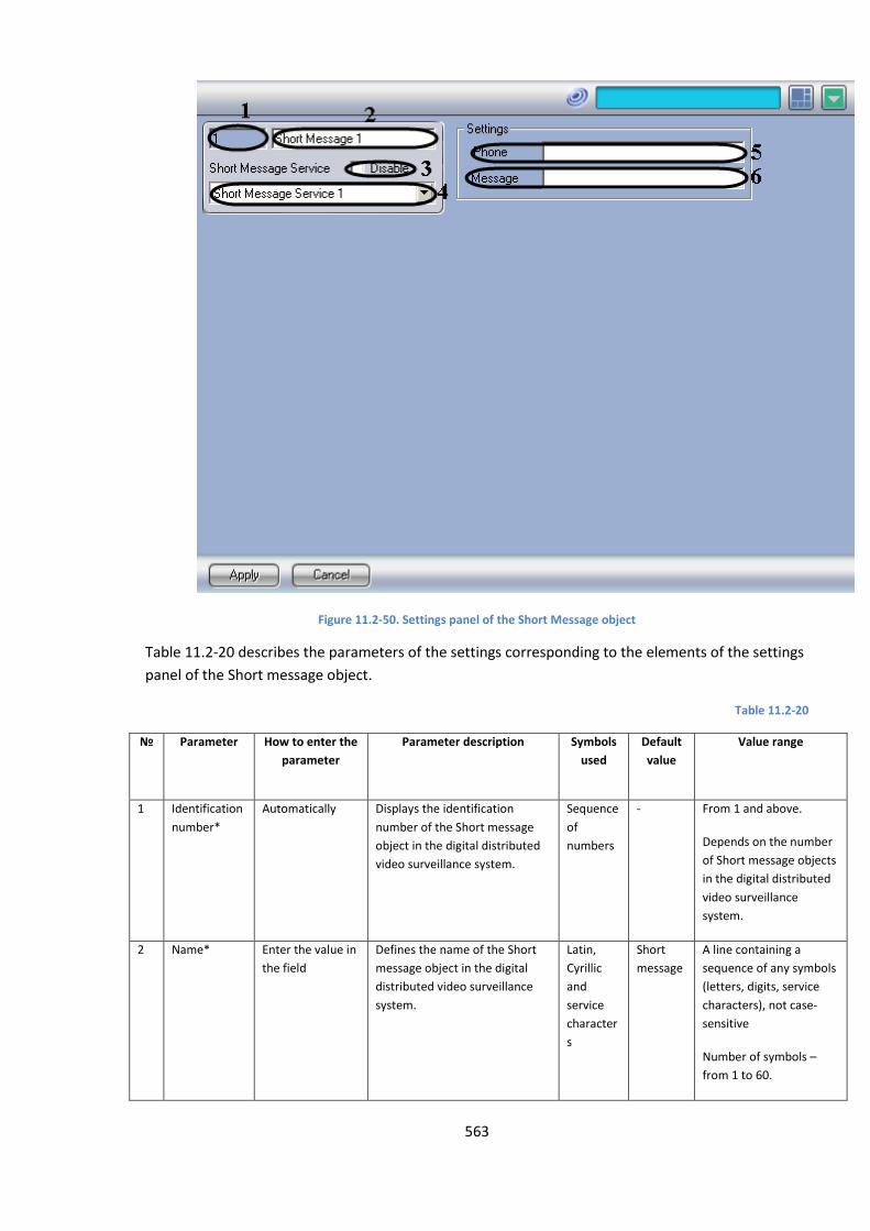
563
Figure 11.2-50. Settings panel of the Short Message object
Table 11.2-20 describes the parameters of the settings corresponding to the elements of the settings
panel of the Short message object.
Table 11.2-20
№
Parameter How to enter the
parameter
Parameter description Symbols
used
Default
value
Value range
1 Identification
number*
Automatically Displays the identification
number of the Short message
object in the digital distributed
video surveillance system.
Sequence
of
numbers
- From 1 and above.
Depends on the number
of Short message objects
in the digital distributed
video surveillance
system.
2 Name* Enter the value in
the field
Defines the name of the Short
message object in the digital
distributed video surveillance
system.
Latin,
Cyrillic
and
service
character
s
Short
message
A line containing a
sequence of any symbols
(letters, digits, service
characters), not case-
sensitive
Number of symbols –
from 1 to 60.

564
№
Parameter How to enter the
parameter
Parameter description Symbols
used
Default
value
Value range
3 Disable Is identified by
the check mark
Defines the condition of the
Short message object
(connected or disconnected) in
the digital distributed video
surveillance system.
Boolean
type
Not
available
Yes – the Short message
object is disconnected
and is not in use
No – the Short message
object is connected and
is in use.
4 Short
message
service
Is selected from
the list
Defines the parent Short
message service object of the
digital distributed video
surveillance system, to which
the given Voice notification
object refers.
Name of
the Short
message
service
objects
registere
d in the
system
Name of
the
parent
Short
Message
Service
object
Depends on the number
of Short message service
objects in the digital
distributed video
surveillance system
Settings Group
5 Phone Enter the value in
the field
Defines a mobile phone number
for receiving SMS.
Sequence
of
numbers
Not
defined
Number according to the
international dial plan:
Example: +79061234567)
6 Message Enter the value in
the field
Defines SMS text, which will be
transmitted over the mobile
network.
Latin,
Cyrillic
and
service
character
s
Not
defined
A line containing a
sequence of any symbols
(letters, digits, service
characters), not case-
sensitive
Number of symbols –
from 1 to 60.
f. The name of the element is not displayed in the settings panel of the given object.
11.2.8.19 Settings panel of the Mail Message Service object
The Mail message service object is designed to register the program module, which supports mail
message transmission to the e-mail boxes of the remote system users. The Mail message service
settings panel is shown in Figure 11.2-51.
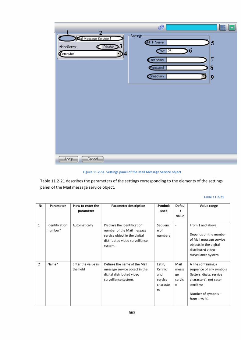
565
Figure 11.2-51. Settings panel of the Mail Message Service object
Table 11.2-21 describes the parameters of the settings corresponding to the elements of the settings
panel of the Mail message service object.
Table 11.2-21
№ Parameter How to enter the
parameter
Parameter description Symbols
used
Defaul
t
value
Value range
1 Identification
number*
Automatically Displays the identification
number of the Mail message
service object in the digital
distributed video surveillance
system.
Sequenc
e of
numbers
- From 1 and above.
Depends on the number
of Mail message service
objects in the digital
distributed video
surveillance system
2 Name* Enter the value in
the field
Defines the name of the Mail
message service object in the
digital distributed video
surveillance system.
Latin,
Cyrillic
and
service
characte
rs
messa
ge
servic
e
A line containing a
sequence of any symbols
(letters, digits, service
characters), not case-
sensitive
Number of symbols –
from 1 to 60.
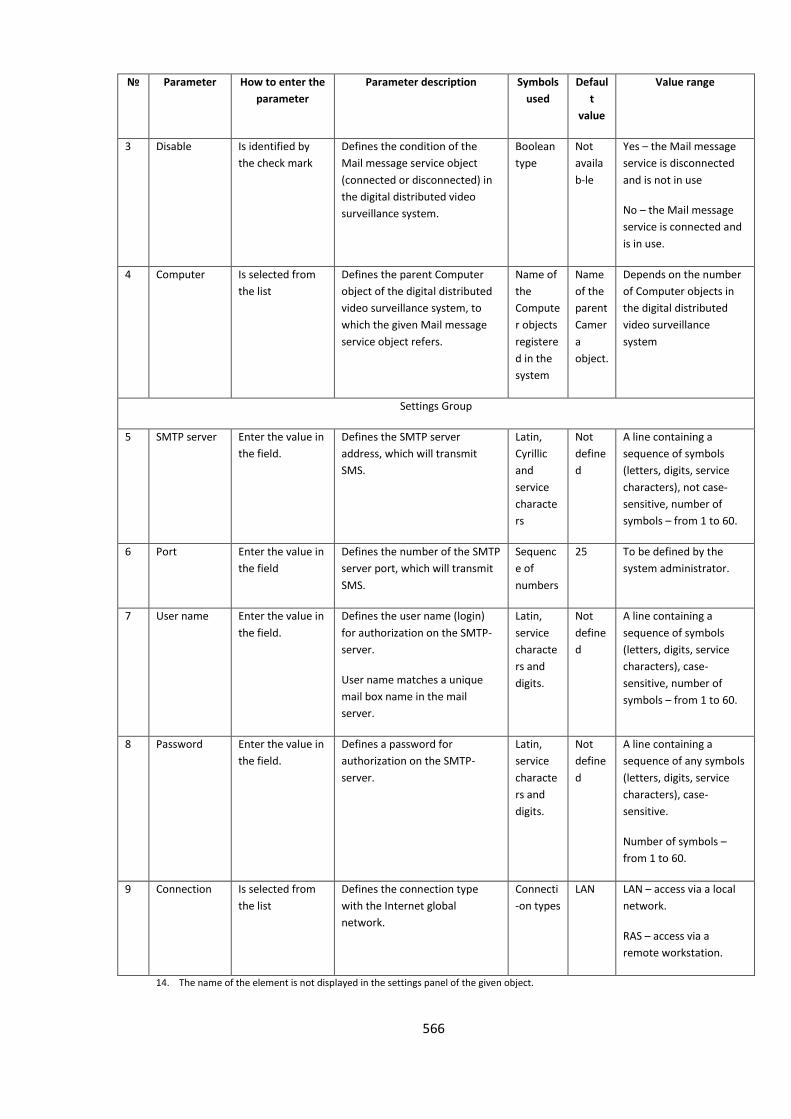
566
№ Parameter How to enter the
parameter
Parameter description Symbols
used
Defaul
t
value
Value range
3 Disable Is identified by
the check mark
Defines the condition of the
Mail message service object
(connected or disconnected) in
the digital distributed video
surveillance system.
Boolean
type
Not
availa
b-le
Yes – the Mail message
service is disconnected
and is not in use
No – the Mail message
service is connected and
is in use.
4 Computer Is selected from
the list
Defines the parent Computer
object of the digital distributed
video surveillance system, to
which the given Mail message
service object refers.
Name of
the
Compute
r objects
registere
d in the
system
Name
of the
parent
Camer
a
object.
Depends on the number
of Computer objects in
the digital distributed
video surveillance
system
Settings Group
5 SMTP server Enter the value in
the field.
Defines the SMTP server
address, which will transmit
SMS.
Latin,
Cyrillic
and
service
characte
rs
Not
define
d
A line containing a
sequence of symbols
(letters, digits, service
characters), not case-
sensitive, number of
symbols – from 1 to 60.
6 Port Enter the value in
the field
Defines the number of the SMTP
server port, which will transmit
SMS.
Sequenc
e of
numbers
25 To be defined by the
system administrator.
7 User name Enter the value in
the field.
Defines the user name (login)
for authorization on the SMTP-
server.
User name matches a unique
mail box name in the mail
server.
Latin,
service
characte
rs and
digits.
Not
define
d
A line containing a
sequence of symbols
(letters, digits, service
characters), case-
sensitive, number of
symbols – from 1 to 60.
8 Password Enter the value in
the field.
Defines a password for
authorization on the SMTP-
server.
Latin,
service
characte
rs and
digits.
Not
define
d
A line containing a
sequence of any symbols
(letters, digits, service
characters), case-
sensitive.
Number of symbols –
from 1 to 60.
9 Connection Is selected from
the list
Defines the connection type
with the Internet global
network.
Connecti
-on types
LAN LAN – access via a local
network.
RAS – access via a
remote workstation.
14. The name of the element is not displayed in the settings panel of the given object.
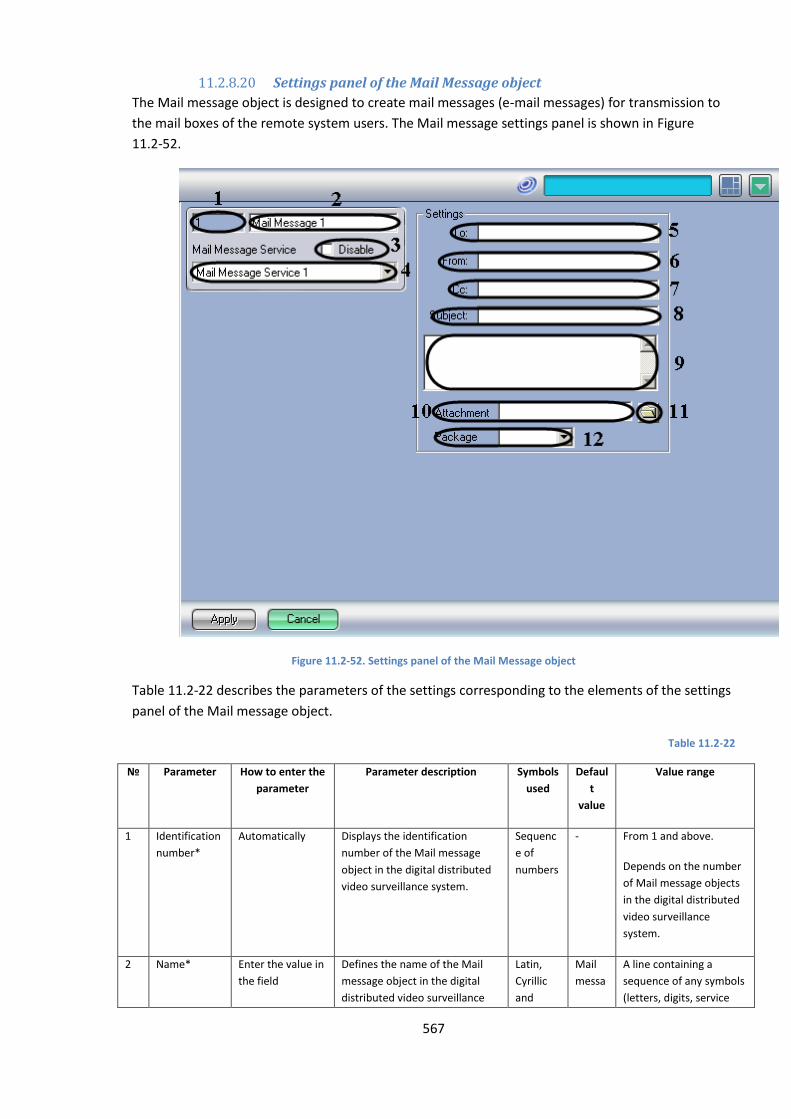
567
11.2.8.20 Settings panel of the Mail Message object
The Mail message object is designed to create mail messages (e-mail messages) for transmission to
the mail boxes of the remote system users. The Mail message settings panel is shown in Figure
11.2-52.
Figure 11.2-52. Settings panel of the Mail Message object
Table 11.2-22 describes the parameters of the settings corresponding to the elements of the settings
panel of the Mail message object.
Table 11.2-22
№ Parameter How to enter the
parameter
Parameter description Symbols
used
Defaul
t
value
Value range
1 Identification
number*
Automatically Displays the identification
number of the Mail message
object in the digital distributed
video surveillance system.
Sequenc
e of
numbers
- From 1 and above.
Depends on the number
of Mail message objects
in the digital distributed
video surveillance
system.
2 Name* Enter the value in
the field
Defines the name of the Mail
message object in the digital
distributed video surveillance
Latin,
Cyrillic
and
messa
A line containing a
sequence of any symbols
(letters, digits, service
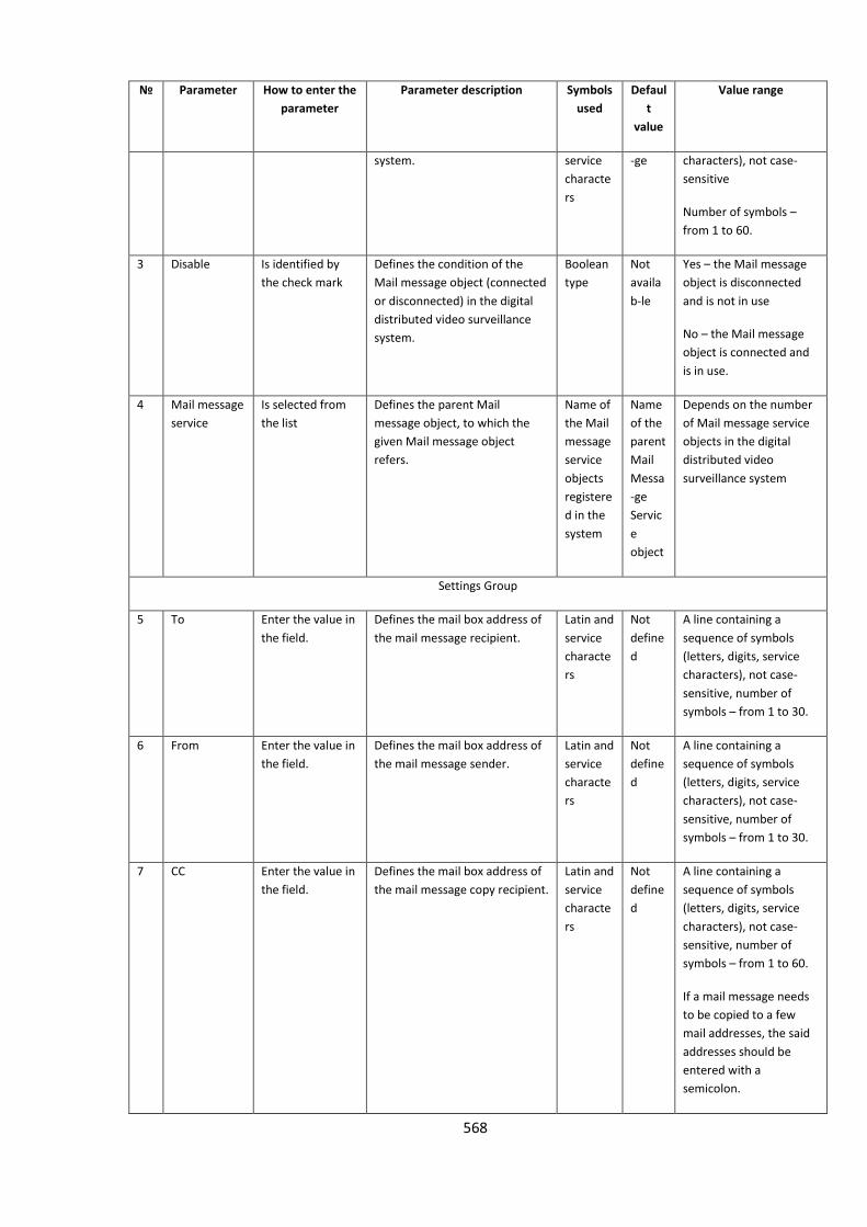
568
№ Parameter How to enter the
parameter
Parameter description Symbols
used
Defaul
t
value
Value range
system. service
characte
rs
-ge characters), not case-
sensitive
Number of symbols –
from 1 to 60.
3 Disable Is identified by
the check mark
Defines the condition of the
Mail message object (connected
or disconnected) in the digital
distributed video surveillance
system.
Boolean
type
Not
availa
b-le
Yes – the Mail message
object is disconnected
and is not in use
No – the Mail message
object is connected and
is in use.
4 Mail message
service
Is selected from
the list
Defines the parent Mail
message object, to which the
given Mail message object
refers.
Name of
the Mail
message
service
objects
registere
d in the
system
Name
of the
parent
Messa
-ge
Servic
e
object
Depends on the number
of Mail message service
objects in the digital
distributed video
surveillance system
Settings Group
5 To Enter the value in
the field.
Defines the mail box address of
the mail message recipient.
Latin and
service
characte
rs
Not
define
d
A line containing a
sequence of symbols
(letters, digits, service
characters), not case-
sensitive, number of
symbols – from 1 to 30.
6 From Enter the value in
the field.
Defines the mail box address of
the mail message sender.
Latin and
service
characte
rs
Not
define
d
A line containing a
sequence of symbols
(letters, digits, service
characters), not case-
sensitive, number of
symbols – from 1 to 30.
7 CC Enter the value in
the field.
Defines the mail box address of
the mail message copy recipient.
Latin and
service
characte
rs
Not
define
d
A line containing a
sequence of symbols
(letters, digits, service
characters), not case-
sensitive, number of
symbols – from 1 to 60.
If a mail message needs
to be copied to a few
mail addresses, the said
addresses should be
entered with a
semicolon.
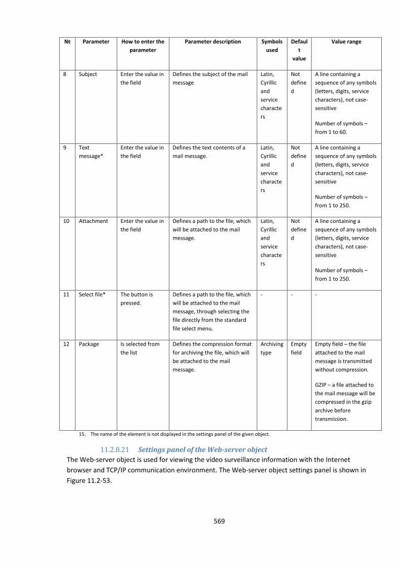
569
№ Parameter How to enter the
parameter
Parameter description Symbols
used
Defaul
t
value
Value range
8 Subject Enter the value in
the field
Defines the subject of the mail
message
Latin,
Cyrillic
and
service
characte
rs
Not
define
d
A line containing a
sequence of any symbols
(letters, digits, service
characters), not case-
sensitive
Number of symbols –
from 1 to 60.
9 Text
message*
Enter the value in
the field
Defines the text contents of a
mail message.
Latin,
Cyrillic
and
service
characte
rs
Not
define
d
A line containing a
sequence of any symbols
(letters, digits, service
characters), not case-
sensitive
Number of symbols –
from 1 to 250.
10 Attachment Enter the value in
the field
Defines a path to the file, which
will be attached to the mail
message.
Latin,
Cyrillic
and
service
characte
rs
Not
define
d
A line containing a
sequence of any symbols
(letters, digits, service
characters), not case-
sensitive
Number of symbols –
from 1 to 250.
11 Select file* The button is
pressed.
Defines a path to the file, which
will be attached to the mail
message, through selecting the
file directly from the standard
file select menu.
- - -
12 Package Is selected from
the list
Defines the compression format
for archiving the file, which will
be attached to the mail
message.
Archiving
type
Empty
field
Empty field – the file
attached to the mail
message is transmitted
without compression.
GZIP – a file attached to
the mail message will be
compressed in the gzip
archive before
transmission.
15. The name of the element is not displayed in the settings panel of the given object.
11.2.8.21 Settings panel of the Web-server object
The Web-server object is used for viewing the video surveillance information with the Internet
browser and TCP/IP communication environment. The Web-server object settings panel is shown in
Figure 11.2-53.
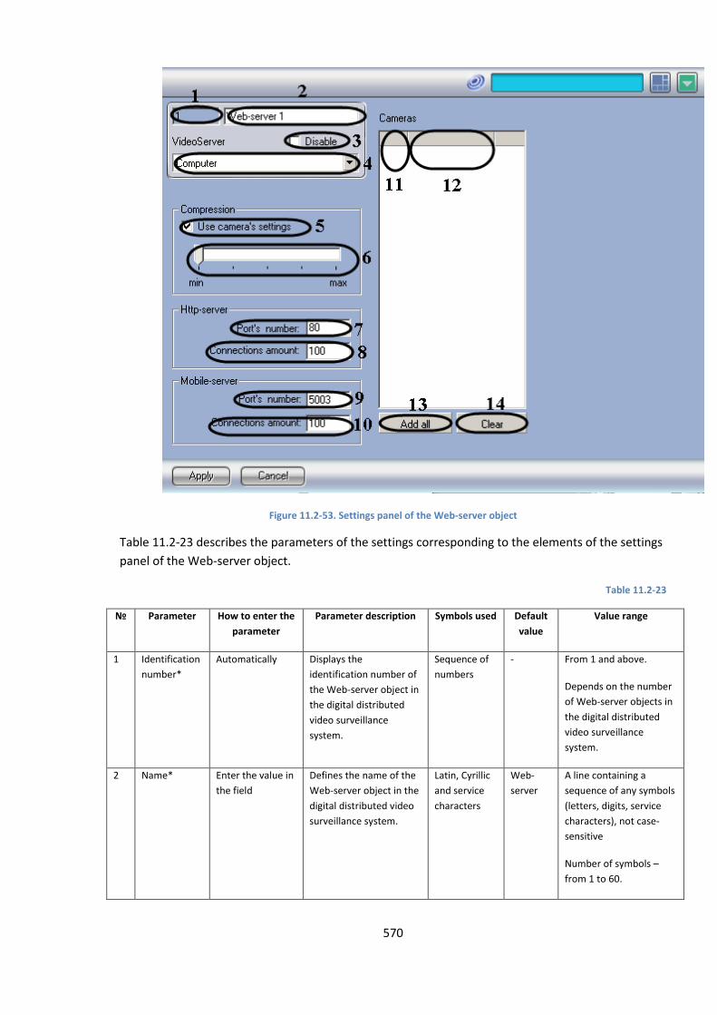
570
Figure 11.2-53. Settings panel of the Web-server object
Table 11.2-23 describes the parameters of the settings corresponding to the elements of the settings
panel of the Web-server object.
Table 11.2-23
№ Parameter How to enter the
parameter
Parameter description Symbols used Default
value
Value range
1 Identification
number*
Automatically Displays the
identification number of
the Web-server object in
the digital distributed
video surveillance
system.
Sequence of
numbers
- From 1 and above.
Depends on the number
of Web-server objects in
the digital distributed
video surveillance
system.
2 Name* Enter the value in
the field
Defines the name of the
Web-server object in the
digital distributed video
surveillance system.
Latin, Cyrillic
and service
characters
Web-
server
A line containing a
sequence of any symbols
(letters, digits, service
characters), not case-
sensitive
Number of symbols –
from 1 to 60.

571
№ Parameter How to enter the
parameter
Parameter description Symbols used Default
value
Value range
3 Disable Is identified by
the check mark
Defines the condition of
the Web-server object
(connected or
disconnected) in the
digital distributed video
surveillance system.
Boolean type Not
available
Yes – the Web-server
object is disconnected
and is not in use
No – the Web-server
object is connected and
is in use.
4 Computer Is selected from
the list
Defines the parent
Computer object of the
digital distributed video
surveillance system, to
which the given Web-
server object refers.
Name of the
Computer
objects
registered in
the system
Name of
the
parent
Compute
r object.
Depends on the number
of Computer objects in
the digital distributed
video surveillance
system
Cameras Group
5 The same as
the camera's
settings
Is identified by
the check mark.
Using the Web-server
module, it defines
whether the video signal
should be transmitted to
the Remote
Workstations with the
compression level, set
for recorded and
transmitted video
signals, or with the
compression level
defined by the slider
under the check mark
Boolean type Yes Yes – the compression
level of the video signal
transmitted with the
Web- server module
should be the same as
the compression level of
the recorded and
transmitted video signal.
No – the compression
level of the video signal
transmitted with the
Web- server module
should be the same as
the one defined by the
slider under the
checkmark
6 Signal
compression
*
Set the slider in
the required
position.
Defines the compression
level of the video signal
transmitted with the
Web-server module to
the Remote
Workstations. The
higher the compression
level, the lower the
video signal quality.
The parameter is active,
only if the option: The
same as camera’s
settings is not checked
(i.e., the parameter The
same as the camera’s
settings is set to No).
Min Min – the minimal
compression level, at
which the video signal is
transmitted as a non-
compressed video.
Max – maximum video
signal compression level.
HTTP server Group
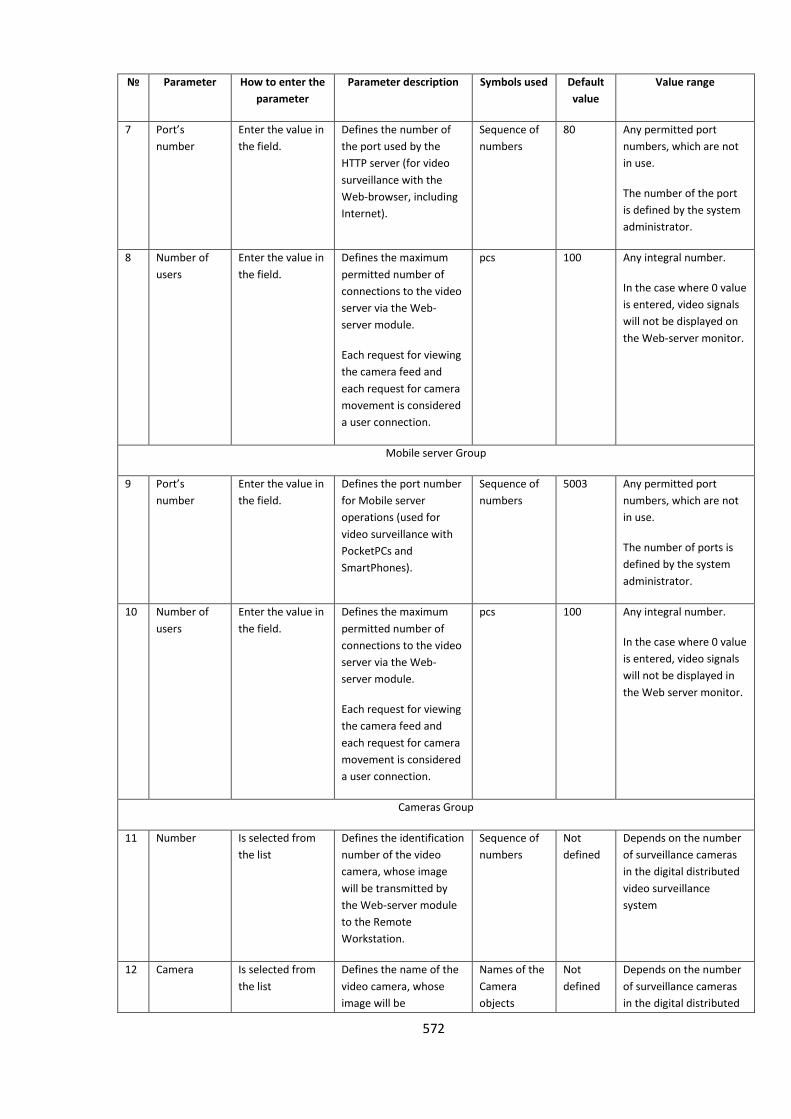
572
№ Parameter How to enter the
parameter
Parameter description Symbols used Default
value
Value range
7 Port’s
number
Enter the value in
the field.
Defines the number of
the port used by the
HTTP server (for video
surveillance with the
Web-browser, including
Internet).
Sequence of
numbers
80 Any permitted port
numbers, which are not
in use.
The number of the port
is defined by the system
administrator.
8 Number of
users
Enter the value in
the field.
Defines the maximum
permitted number of
connections to the video
server via the Web-
server module.
Each request for viewing
the camera feed and
each request for camera
movement is considered
a user connection.
pcs 100 Any integral number.
In the case where 0 value
is entered, video signals
will not be displayed on
the Web-server monitor.
Mobile server Group
9 Port’s
number
Enter the value in
the field.
Defines the port number
for Mobile server
operations (used for
video surveillance with
PocketPCs and
SmartPhones).
Sequence of
numbers
5003 Any permitted port
numbers, which are not
in use.
The number of ports is
defined by the system
administrator.
10 Number of
users
Enter the value in
the field.
Defines the maximum
permitted number of
connections to the video
server via the Web-
server module.
Each request for viewing
the camera feed and
each request for camera
movement is considered
a user connection.
pcs 100 Any integral number.
In the case where 0 value
is entered, video signals
will not be displayed in
the Web server monitor.
Cameras Group
11 Number Is selected from
the list
Defines the identification
number of the video
camera, whose image
will be transmitted by
the Web-server module
to the Remote
Workstation.
Sequence of
numbers
Not
defined
Depends on the number
of surveillance cameras
in the digital distributed
video surveillance
system
12 Camera Is selected from
the list
Defines the name of the
video camera, whose
image will be
Names of the
Camera
objects
Not
defined
Depends on the number
of surveillance cameras
in the digital distributed

573
№ Parameter How to enter the
parameter
Parameter description Symbols used Default
value
Value range
transmitted by the Web-
server module to the
Remote Workstation.
registered in
the system
video surveillance
system
13 Add all The button is
pressed.
Includes all video
cameras, installed in the
digital distributed video
surveillance system, into
the list of cameras,
whose image will be
transmitted by the Web-
server module to the
Remote Workstation.
- - -
14 Clear The button is
pressed.
Deletes all video
cameras from the list of
cameras, whose image
will be transmitted by
the Web- server module
to the Remote
Workstation.
- - -
g. The name of the element is not displayed in the settings panel of the given object.
11.2.8.22 Settings panel of the Operator search window
The Operator search window object is designed to display a separate user window, i.e., the Operator
search window, which is used to operate a certain PTZ unit. The Operator search window is furnished
with a set of elements enabling operation of the above PTZ units. The Operator search window object
settings panel is shown in Figure 11.2-54.
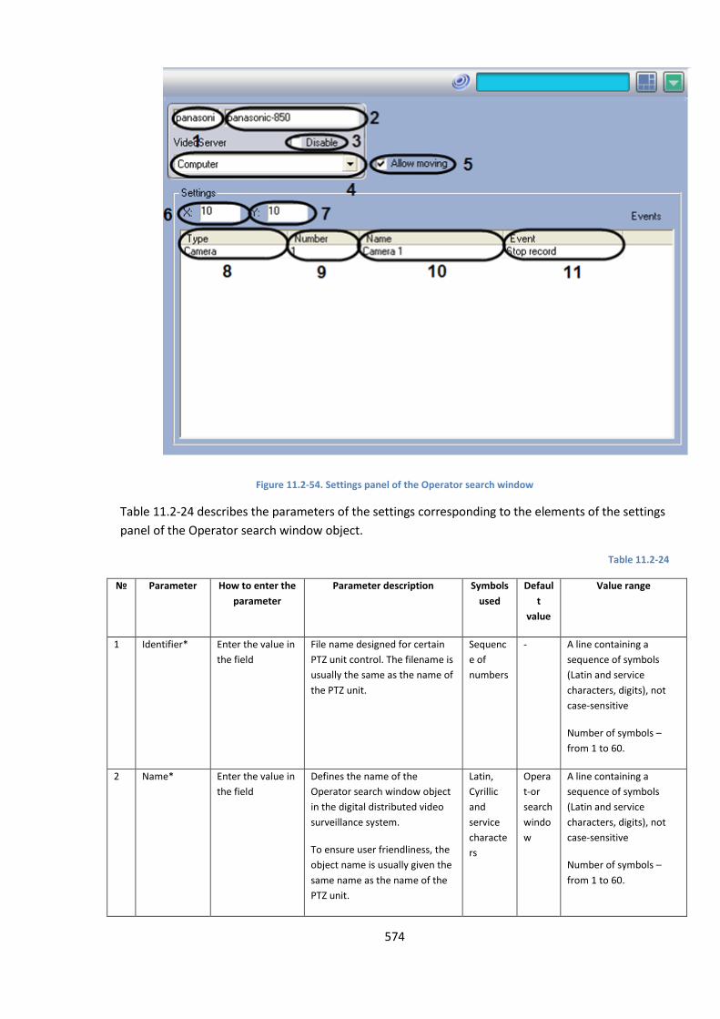
574
Figure 11.2-54. Settings panel of the Operator search window
Table 11.2-24 describes the parameters of the settings corresponding to the elements of the settings
panel of the Operator search window object.
Table 11.2-24
№
Parameter How to enter the
parameter
Parameter description Symbols
used
Defaul
t
value
Value range
1 Identifier* Enter the value in
the field
File name designed for certain
PTZ unit control. The filename is
usually the same as the name of
the PTZ unit.
Sequenc
e of
numbers
- A line containing a
sequence of symbols
(Latin and service
characters, digits), not
case-sensitive
Number of symbols –
from 1 to 60.
2 Name* Enter the value in
the field
Defines the name of the
Operator search window object
in the digital distributed video
surveillance system.
To ensure user friendliness, the
object name is usually given the
same name as the name of the
PTZ unit.
Latin,
Cyrillic
and
service
characte
rs
Opera
t-or
search
windo
w
A line containing a
sequence of symbols
(Latin and service
characters, digits), not
case-sensitive
Number of symbols –
from 1 to 60.
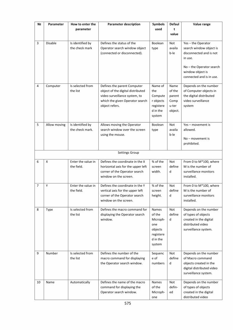
575
№
Parameter How to enter the
parameter
Parameter description Symbols
used
Defaul
t
value
Value range
3 Disable Is identified by
the check mark
Defines the status of the
Operator search window object
(connected or disconnected).
Boolean
type
Not
availa
b-le
Yes – the Operator
search window object is
disconnected and is not
in use.
No – the Operator search
window object is
connected and is in use.
4 Computer Is selected from
the list
Defines the parent Computer
object of the digital distributed
video surveillance system, to
which the given Operator search
object refers.
Name of
the
Compute
r objects
registere
d in the
system
Name
of the
parent
Comp
u-ter
object.
Depends on the number
of Computer objects in
the digital distributed
video surveillance
system
5 Allow moving Is identified by
the check mark.
Allows moving the Operator
search window over the screen
using the mouse.
Boolean
type
Not
availa
b-le
Yes – movement is
allowed.
No – movement is
prohibited.
Settings Group
6 Х Enter the value in
the field.
Defines the coordinate in the X
horizontal axis for the upper left
corner of the Operator search
window on the screen.
% of the
screen
width.
Not
define
d
From 0 to M*100, where
M is the number of
surveillance monitors
installed.
7 Y Enter the value in
the field.
Defines the coordinate in the Y
vertical axis for the upper left
corner of the Operator search
window on the screen.
% of the
screen
height.
Not
define
d
From 0 to M*100, where
M is the number of
surveillance monitors
installed.
8 Type Is selected from
the list
Defines the macro command for
displaying the Operator search
window.
Names
of the
Microph-
one
objects
registere
d in the
system
Not
define
d
Depends on the number
of types of objects
created in the digital
distributed video
surveillance system.
9 Number Is selected from
the list
Defines the number of the
macro command for displaying
the Operator search window.
Sequenc
e of
numbers
Not
define
d
Depends on the number
of Macro command
objects created in the
digital distributed video
surveillance system.
10 Name Automatically Defines the name of the macro
command for displaying the
Operator search window.
Names
of the
Microph-
one
Not
defin-
ed
Depends on the number
of types of objects
created in the digital
distributed video
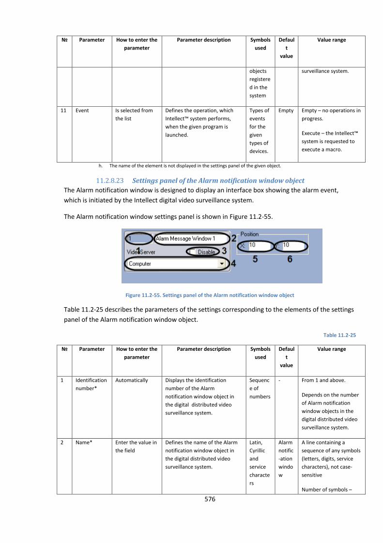
576
№
Parameter How to enter the
parameter
Parameter description Symbols
used
Defaul
t
value
Value range
objects
registere
d in the
system
surveillance system.
11 Event Is selected from
the list
Defines the operation, which
Intellect™ system performs,
when the given program is
launched.
Types of
events
for the
given
types of
devices.
Empty Empty – no operations in
progress.
Execute – the Intellect™
system is requested to
execute a macro.
h. The name of the element is not displayed in the settings panel of the given object.
11.2.8.23 Settings panel of the Alarm notification window object
The Alarm notification window is designed to display an interface box showing the alarm event,
which is initiated by the Intellect digital video surveillance system.
The Alarm notification window settings panel is shown in Figure 11.2-55.
Figure 11.2-55. Settings panel of the Alarm notification window object
Table 11.2-25 describes the parameters of the settings corresponding to the elements of the settings
panel of the Alarm notification window object.
Table 11.2-25
№ Parameter How to enter the
parameter
Parameter description Symbols
used
Defaul
t
value
Value range
1 Identification
number*
Automatically Displays the identification
number of the Alarm
notification window object in
the digital distributed video
surveillance system.
Sequenc
e of
numbers
- From 1 and above.
Depends on the number
of Alarm notification
window objects in the
digital distributed video
surveillance system.
2 Name* Enter the value in
the field
Defines the name of the Alarm
notification window object in
the digital distributed video
surveillance system.
Latin,
Cyrillic
and
service
characte
rs
Alarm
notific
-ation
windo
w
A line containing a
sequence of any symbols
(letters, digits, service
characters), not case-
sensitive
Number of symbols –

577
№ Parameter How to enter the
parameter
Parameter description Symbols
used
Defaul
t
value
Value range
from 1 to 60.
3 Disable Is identified by
the check mark
Defines the condition of the
Alarm notification window
object (connected or
disconnected) in the digital
distributed video surveillance
system.
Boolean
type
Not
availa
b-le
Yes – the Alarm
notification window
object is disconnected
and is not in use.
No – the alarm
notification window
object is connected and
is in use.
4 Computer Is selected from
the list
Defines the parent Computer
object of the digital distributed
video surveillance system, to
which the given Alarm
notification window object
refers.
Name of
the
Compute
r objects
registere
d in the
system
Name
of the
parent
Comp
u-ter
object.
Depends on the number
of Computer objects in
the digital distributed
video surveillance
system
5 X Enter the value in
the field.
Defines the coordinate in the X
horizontal axis for the upper left
corner of the Alarm notification
window on the screen.
% of the
screen
width.
Not
define
d
From 0 to M*100, where
M is the number of
surveillance monitors
installed.
6 Y Enter the value in
the field.
Defines the coordinate in the Y
vertical axis for the upper left
corner of the Alarm notification
window on the screen.
% of the
screen
height.
Not
define
d
From 0 to M*100, where
M is the number of
surveillance monitors
installed.
16. The name of the element is not displayed in the settings panel of the given object.
11.2.8.24 Videogate settings panel
The face of Videogate settings panel is shown in Figure 11.2-56.
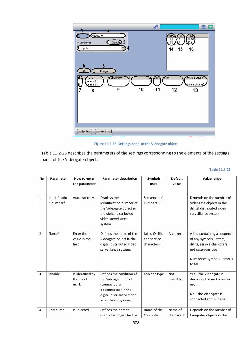
578
Figure 11.2-56. Settings panel of the Videogate object
Table 11.2-26 describes the parameters of the settings corresponding to the elements of the settings
panel of the Videogate object.
Table 11.2-26
№
Parameter How to enter
the parameter
Parameter description Symbols
used
Default
value
Value range
1 Identificatio
n number*
Automatically Displays the
identification number of
the Videogate object in
the digital distributed
video surveillance
system.
Sequence of
numbers
- Depends on the number of
Videogate objects in the
digital distributed video
surveillance system
2 Name* Enter the
value in the
field
Defines the name of the
Videogate object in the
digital distributed video
surveillance system.
Latin, Cyrillic
and service
characters
Archiver. A line containing a sequence
of any symbols (letters,
digits, service characters),
not case-sensitive
Number of symbols – from 1
to 60.
3 Disable Is identified by
the check
mark
Defines the condition of
the Videogate object
(connected or
disconnected) in the
digital distributed video
surveillance system.
Boolean type Not
available
Yes – the Videogate is
disconnected and is not in
use
No – the Videogate is
connected and is in use.
4 Computer Is selected Defines the parent
Computer object for the
Name of the
Computer
Name of
the parent
Depends on the number of
Computer objects in the

579
№
Parameter How to enter
the parameter
Parameter description Symbols
used
Default
value
Value range
from the list given Videogate object objects
registered in
the system
Computer
object.
digital distributed video
surveillance system
5 All The button is
pressed.
Selection of all video
cameras registered in the
system for transmitting
video signals through the
video gate
- - -
6 Gate The button is
pressed.
Access to the complex
selection of video
cameras for transmitting
video signals through the
video gate
- - -
7 Number Is selected
from the list
Defines the number of
the camera for
transmitting video
signals through the video
gate
Sequence of
numbers
- Depends on the number of
surveillance cameras in the
digital distributed video
surveillance system
8 Name Is selected
from the list
Defines the name of the
video surveillance
camera for transmitting
video signals through the
video gate
Name of the
Camera
objects
registered in
the system
- Depends on the number of
surveillance cameras in the
digital distributed video
surveillance system
9 Compressio
n
Is selected
from the list
Defines the level of video
signal compression for
transmitting video
signals through the video
gate. With the given
value there is additional
consumption of Server’s
resources
Sequence of
numbers
- In order of rising
compression level
0,1,2,3,4,5
(0 – without compression, 5
– maximum compression).
10 fps Enter the
value in the
field
Set the video signal rate
for transmitting video
signals through the video
gate.
Sequence of
numbers
- Not more than digitizing of
video signal by video capture
card
11 Critical rate Enter the
value in the
field
Set the minimum
permissible rate of the
video signal, when
received by the
Videogate to control the
transmission of video
signal through the local
net
Sequence of
numbers
- Not more than the frame
rate of the video signal, that
is transmitted to the
Videogate
12 Gate Is selected
from the list
Set the Videogate object
from which video signal
Name of the
Videogate
Not
defined
Depends on the number of
Videogate objects,

580
№
Parameter How to enter
the parameter
Parameter description Symbols
used
Default
value
Value range
from the selected
camera has to be
transmitted to the given
Videogate
objects
registered in
the system
registered in the digital
distributed video
surveillance system
13 Active
archive
Is selected
from the list
Set the object Active
archive, from which
video signal from the
selected camera has to
be transmitted to the
given Videogate
Name of the
Active
archive
objects
registered in
the system.
Not
defined
Depends on the number of
Active archive objects
registered in the digital
distributed video
surveillance system.
14 Video Is identified by
the check
mark
Set the didsk for storing
the archive of video
signals, going through
ther Videogate.
Boolean type - Yes, the disk is used for
storing the Videogate
module.
No - the disk is not used for
storing the Video gate
module
14 Disk Automatically Displays the names of
local (net, USB) disks,
accessible for storing
archive of Videogate
module.
Names of
available
disks(Latin
characters)
List of
available
hard disks
Depends on the total
number (both local and
network) of accessible disks.
15 GB Automatically Contains information
about free space on
every available disk
Disk space in
GB
- Depends on the free disk
space
17. The name of the element is not displayed in the settings panel of the given object.
11.2.8.25 Event Counter settings panel
The Event counter object is designed to register and count events of a certain type, occurring at the
pre-defined objects and registered by the Intellect system.
The Event counter settings panel is shown in Figure 11.2-57.
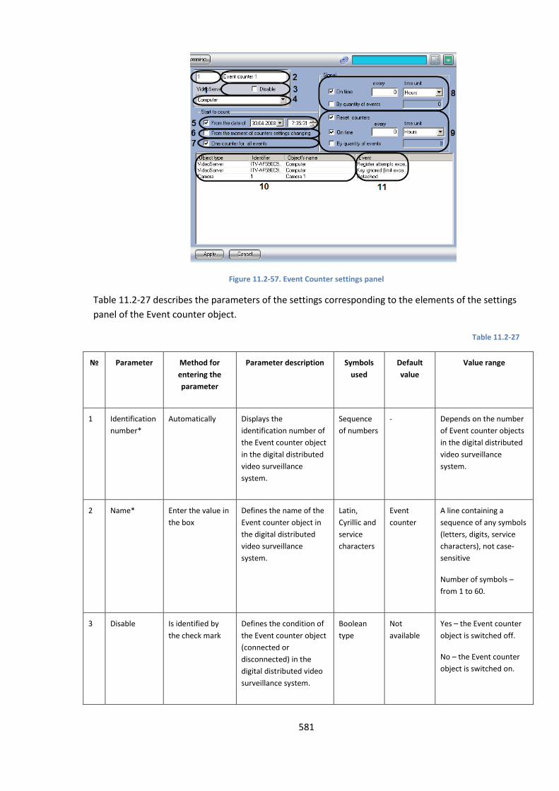
581
Figure 11.2-57. Event Counter settings panel
Table 11.2-27 describes the parameters of the settings corresponding to the elements of the settings
panel of the Event counter object.
Table 11.2-27
№
Parameter Method for
entering the
parameter
Parameter description Symbols
used
Default
value
Value range
1 Identification
number*
Automatically Displays the
identification number of
the Event counter object
in the digital distributed
video surveillance
system.
Sequence
of numbers
- Depends on the number
of Event counter objects
in the digital distributed
video surveillance
system.
2 Name* Enter the value in
the box
Defines the name of the
Event counter object in
the digital distributed
video surveillance
system.
Latin,
Cyrillic and
service
characters
Event
counter
A line containing a
sequence of any symbols
(letters, digits, service
characters), not case-
sensitive
Number of symbols –
from 1 to 60.
3 Disable Is identified by
the check mark
Defines the condition of
the Event counter object
(connected or
disconnected) in the
digital distributed video
surveillance system.
Boolean
type
Not
available
Yes – the Event counter
object is switched off.
No – the Event counter
object is switched on.
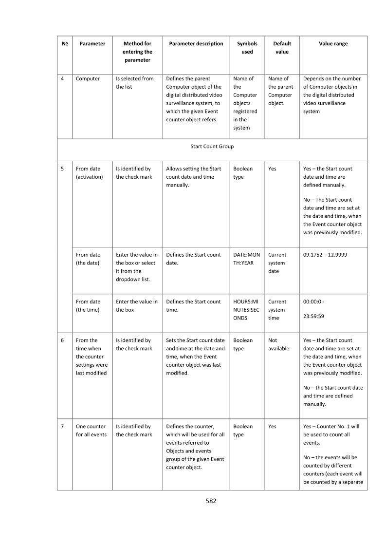
582
№
Parameter Method for
entering the
parameter
Parameter description Symbols
used
Default
value
Value range
4 Computer Is selected from
the list
Defines the parent
Computer object of the
digital distributed video
surveillance system, to
which the given Event
counter object refers.
Name of
the
Computer
objects
registered
in the
system
Name of
the parent
Computer
object.
Depends on the number
of Computer objects in
the digital distributed
video surveillance
system
Start Count Group
5 From date
(activation)
Is identified by
the check mark
Allows setting the Start
count date and time
manually.
Boolean
type
Yes Yes – the Start count
date and time are
defined manually.
No – The Start count
date and time are set at
the date and time, when
the Event counter object
was previously modified.
From date
(the date)
Enter the value in
the box or select
it from the
dropdown list.
Defines the Start count
date.
DATE:MON
TH:YEAR
Current
system
date
09.1752 – 12.9999
From date
(the time)
Enter the value in
the box
Defines the Start count
time.
HOURS:MI
NUTES:SEC
ONDS
Current
system
time
00:00:0 -
23:59:59
6 From the
time when
the counter
settings were
last modified
Is identified by
the check mark
Sets the Start count date
and time at the date and
time, when the Event
counter object was last
modified.
Boolean
type
Not
available
Yes – the Start count
date and time are set at
the date and time, when
the Event counter object
was previously modified.
No – the Start count date
and time are defined
manually.
7 One counter
for all events
Is identified by
the check mark
Defines the counter,
which will be used for all
events referred to
Objects and events
group of the given Event
counter object.
Boolean
type
Yes Yes – Counter No. 1 will
be used to count all
events.
No – the events will be
counted by different
counters (each event will
be counted by a separate
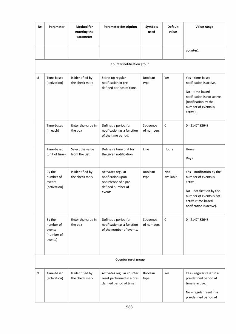
583
№
Parameter Method for
entering the
parameter
Parameter description Symbols
used
Default
value
Value range
counter).
Counter notification group
8 Time-based
(activation)
Is identified by
the check mark
Starts up regular
notification in pre-
defined periods of time.
Boolean
type
Yes Yes – time-based
notification is active.
No – time-based
notification is not active
(notification by the
number of events is
active).
Time-based
(in each)
Enter the value in
the box
Defines a period for
notification as a function
of the time period.
Sequence
of numbers
0 0 - 2147483648
Time-based
(unit of time)
Select the value
from the List
Defines a time unit for
the given notification.
Line Hours Hours
Days
By the
number of
events
(activation)
Is identified by
the check mark
Activates regular
notification upon
occurrence of a pre-
defined number of
events.
Boolean
type
Not
available
Yes – notification by the
number of events is
active.
No – notification by the
number of events is not
active (time-based
notification is active).
By the
number of
events
(number of
events)
Enter the value in
the box
Defines a period for
notification as a function
of the number of events.
Sequence
of numbers
0 0 - 2147483648
Counter reset group
9 Time-based
(activation)
Is identified by
the check mark
Activates regular counter
reset performed in a pre-
defined period of time.
Boolean
type
Yes Yes – regular reset in a
pre-defined period of
time is active.
No – regular reset in a
pre-defined period of
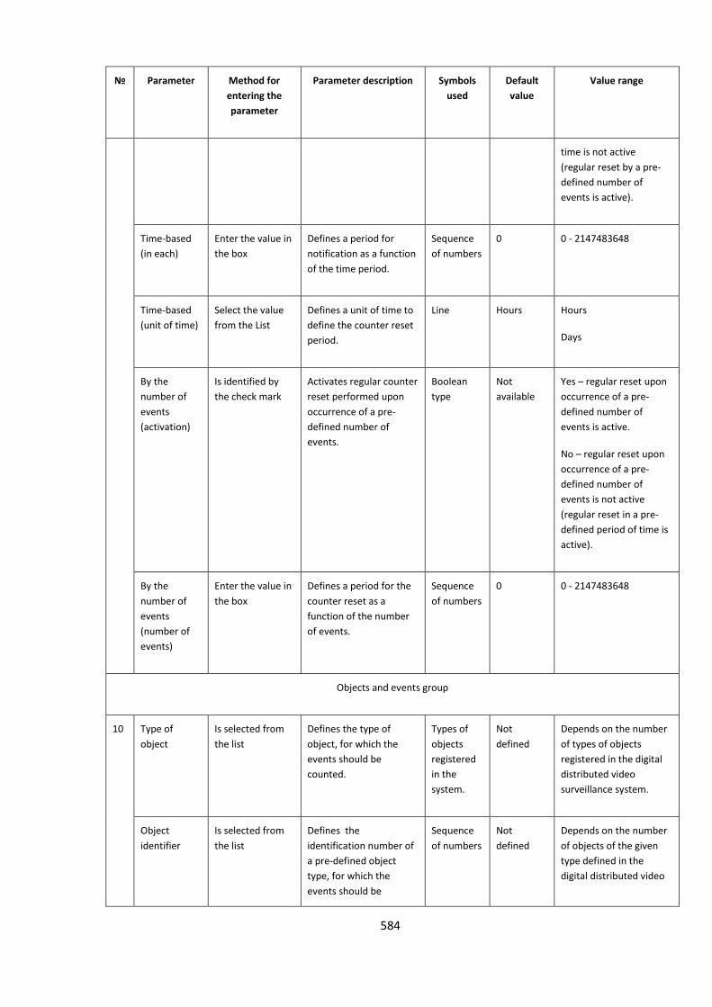
584
№
Parameter Method for
entering the
parameter
Parameter description Symbols
used
Default
value
Value range
time is not active
(regular reset by a pre-
defined number of
events is active).
Time-based
(in each)
Enter the value in
the box
Defines a period for
notification as a function
of the time period.
Sequence
of numbers
0 0 - 2147483648
Time-based
(unit of time)
Select the value
from the List
Defines a unit of time to
define the counter reset
period.
Line Hours Hours
Days
By the
number of
events
(activation)
Is identified by
the check mark
Activates regular counter
reset performed upon
occurrence of a pre-
defined number of
events.
Boolean
type
Not
available
Yes – regular reset upon
occurrence of a pre-
defined number of
events is active.
No – regular reset upon
occurrence of a pre-
defined number of
events is not active
(regular reset in a pre-
defined period of time is
active).
By the
number of
events
(number of
events)
Enter the value in
the box
Defines a period for the
counter reset as a
function of the number
of events.
Sequence
of numbers
0 0 - 2147483648
Objects and events group
10 Type of
object
Is selected from
the list
Defines the type of
object, for which the
events should be
counted.
Types of
objects
registered
in the
system.
Not
defined
Depends on the number
of types of objects
registered in the digital
distributed video
surveillance system.
Object
identifier
Is selected from
the list
Defines the
identification number of
a pre-defined object
type, for which the
events should be
Sequence
of numbers
Not
defined
Depends on the number
of objects of the given
type defined in the
digital distributed video
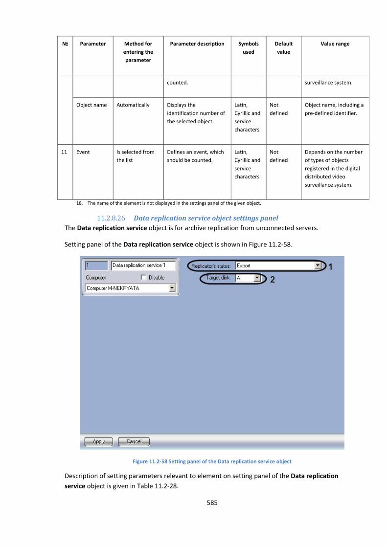
585
№
Parameter Method for
entering the
parameter
Parameter description Symbols
used
Default
value
Value range
counted. surveillance system.
Object name Automatically Displays the
identification number of
the selected object.
Latin,
Cyrillic and
service
characters
Not
defined
Object name, including a
pre-defined identifier.
11 Event Is selected from
the list
Defines an event, which
should be counted.
Latin,
Cyrillic and
service
characters
Not
defined
Depends on the number
of types of objects
registered in the digital
distributed video
surveillance system.
18. The name of the element is not displayed in the settings panel of the given object.
11.2.8.26 Data replication service object settings panel
The Data replication service object is for archive replication from unconnected servers.
Setting panel of the Data replication service object is shown in Figure 11.2-58.
Figure 11.2-58 Setting panel of the Data replication service object
Description of setting parameters relevant to element on setting panel of the Data replication
service object is given in Table 11.2-28.
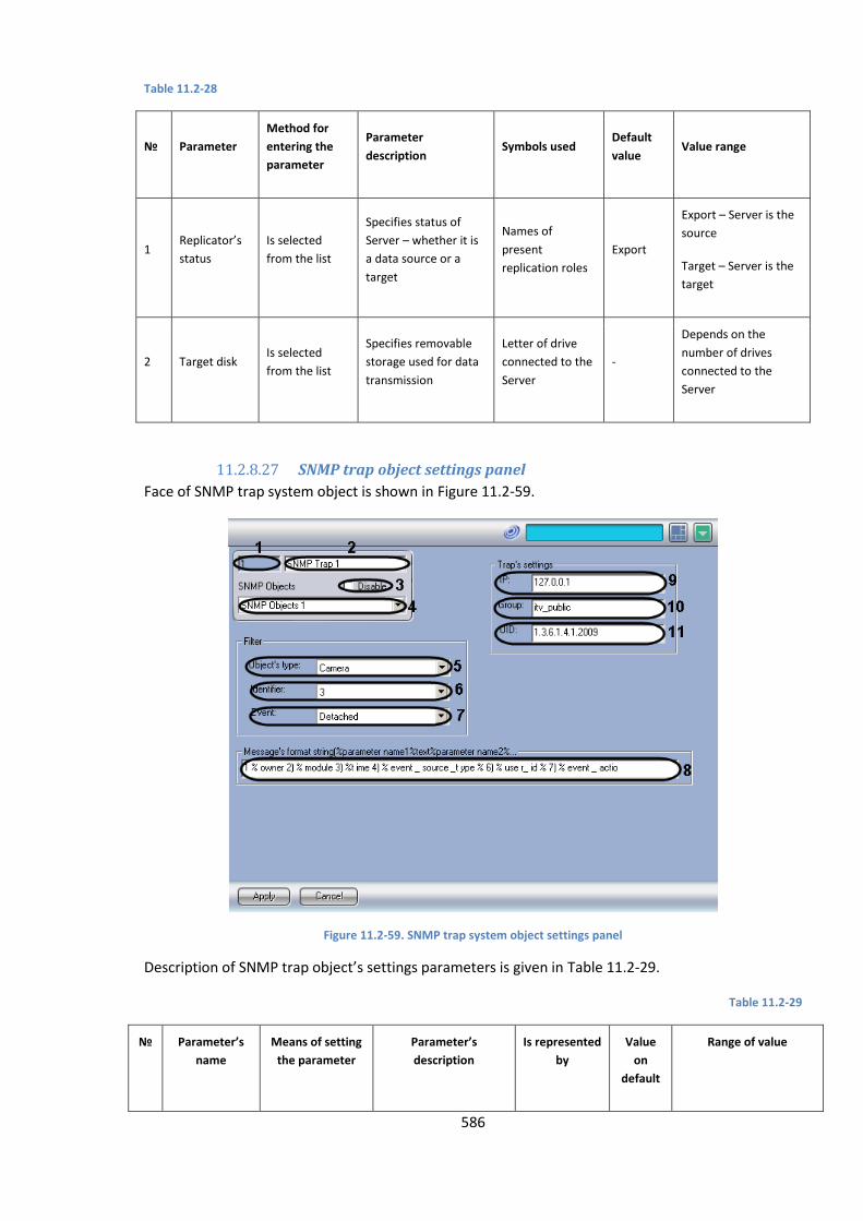
586
Table 11.2-28
№ Parameter
Method for
entering the
parameter
Parameter
description Symbols used
Default
value Value range
1 Replicator’s
status
Is selected
from the list
Specifies status of
Server – whether it is
a data source or a
target
Names of
present
replication roles
Export
Export – Server is the
source
Target – Server is the
target
2 Target disk Is selected
from the list
Specifies removable
storage used for data
transmission
Letter of drive
connected to the
Server
-
Depends on the
number of drives
connected to the
Server
11.2.8.27 SNMP trap object settings panel
Face of SNMP trap system object is shown in Figure 11.2-59.
Figure 11.2-59. SNMP trap system object settings panel
Description of SNMP trap object’s settings parameters is given in Table 11.2-29.
Table 11.2-29
№ Parameter’s
name
Means of setting
the parameter
Parameter’s
description
Is represented
by
Value
on
default
Range of value
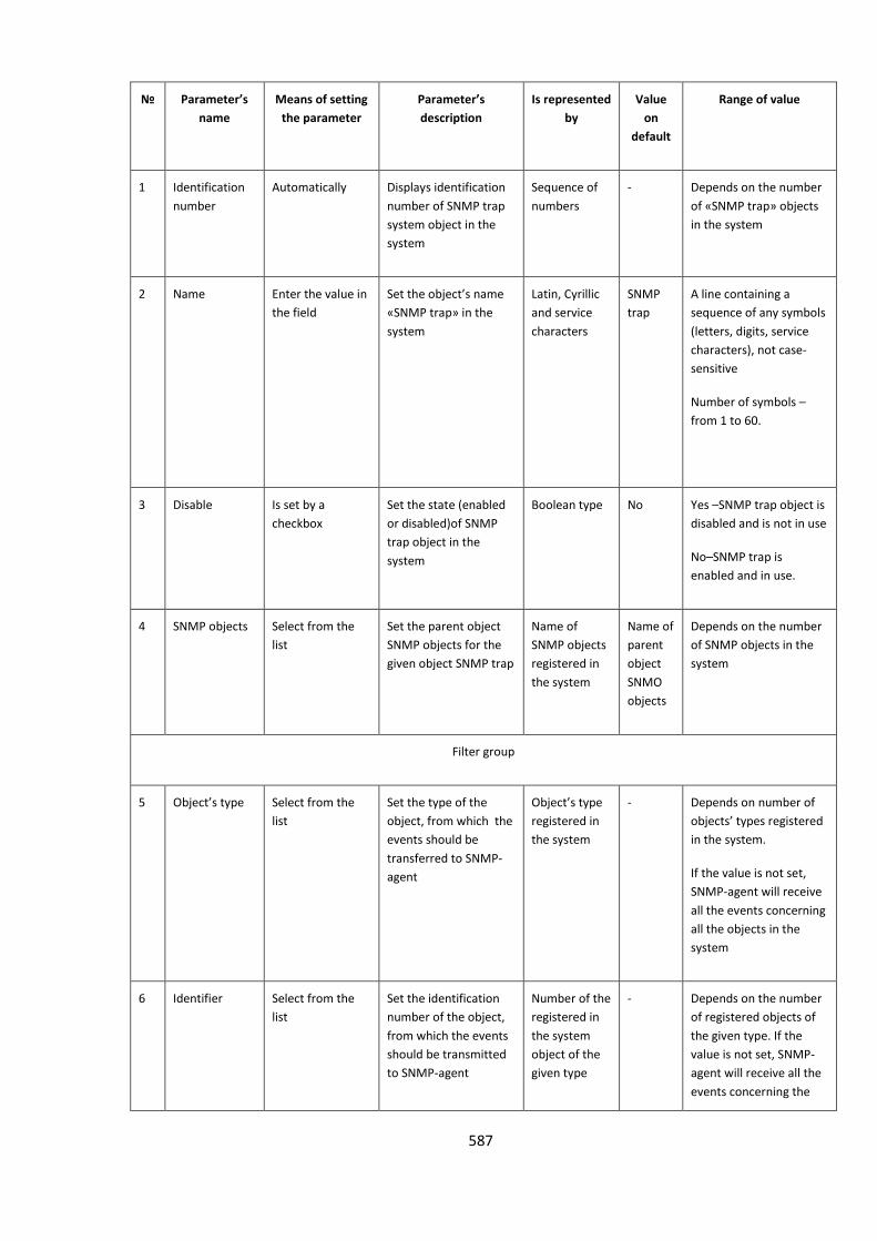
587
№ Parameter’s
name
Means of setting
the parameter
Parameter’s
description
Is represented
by
Value
on
default
Range of value
1 Identification
number
Automatically Displays identification
number of SNMP trap
system object in the
system
Sequence of
numbers
- Depends on the number
of «SNMP trap» objects
in the system
2 Name Enter the value in
the field
Set the object’s name
«SNMP trap» in the
system
Latin, Cyrillic
and service
characters
SNMP
trap
A line containing a
sequence of any symbols
(letters, digits, service
characters), not case-
sensitive
Number of symbols –
from 1 to 60.
3 Disable Is set by a
checkbox
Set the state (enabled
or disabled)of SNMP
trap object in the
system
Boolean type No Yes –SNMP trap object is
disabled and is not in use
No–SNMP trap is
enabled and in use.
4 SNMP objects Select from the
list
Set the parent object
SNMP objects for the
given object SNMP trap
Name of
SNMP objects
registered in
the system
Name of
parent
object
SNMO
objects
Depends on the number
of SNMP objects in the
system
Filter group
5 Object’s type Select from the
list
Set the type of the
object, from which the
events should be
transferred to SNMP-
agent
Object’s type
registered in
the system
- Depends on number of
objects’ types registered
in the system.
If the value is not set,
SNMP-agent will receive
all the events concerning
all the objects in the
system
6 Identifier Select from the
list
Set the identification
number of the object,
from which the events
should be transmitted
to SNMP-agent
Number of the
registered in
the system
object of the
given type
- Depends on the number
of registered objects of
the given type. If the
value is not set, SNMP-
agent will receive all the
events concerning the
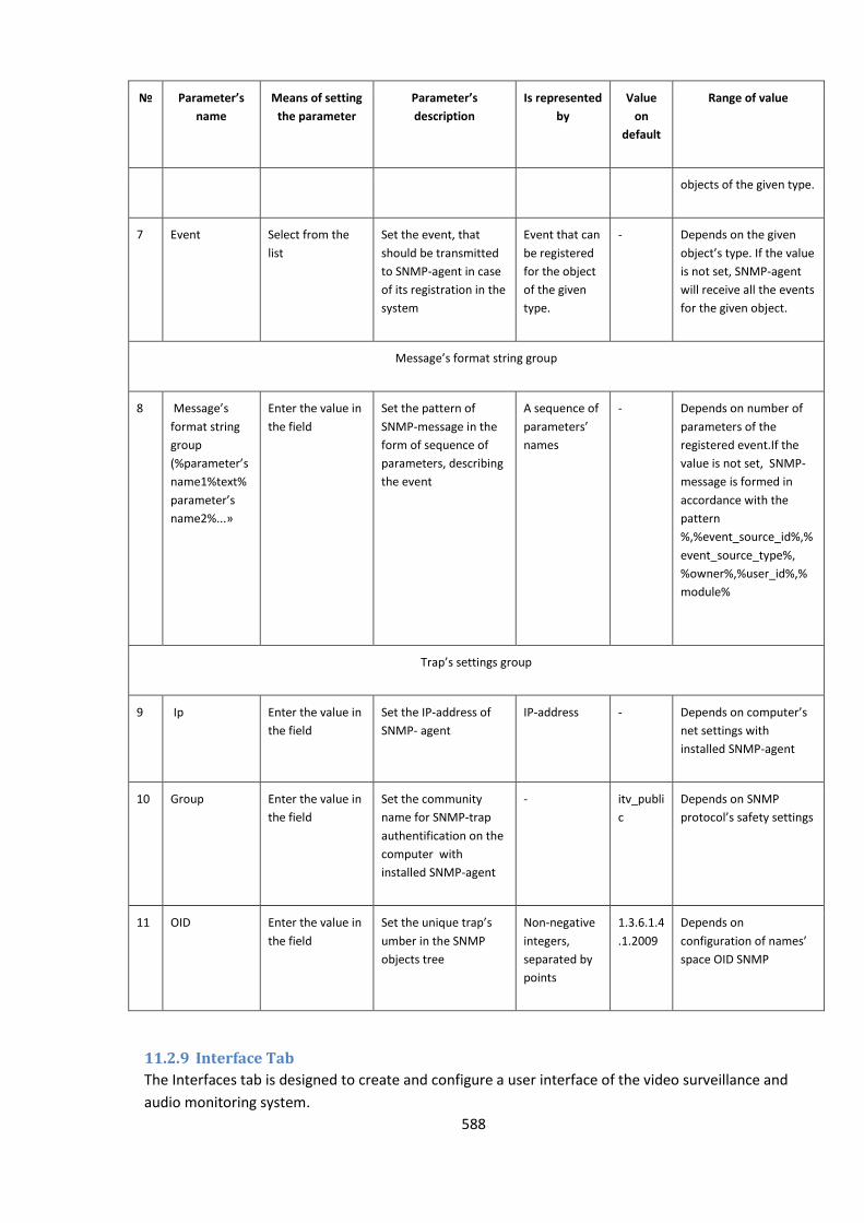
588
№ Parameter’s
name
Means of setting
the parameter
Parameter’s
description
Is represented
by
Value
on
default
Range of value
objects of the given type.
7 Event Select from the
list
Set the event, that
should be transmitted
to SNMP-agent in case
of its registration in the
system
Event that can
be registered
for the object
of the given
type.
- Depends on the given
object’s type. If the value
is not set, SNMP-agent
will receive all the events
for the given object.
Message’s format string group
8 Message’s
format string
group
(%parameter’s
name1%text%
parameter’s
name2%...»
Enter the value in
the field
Set the pattern of
SNMP-message in the
form of sequence of
parameters, describing
the event
A sequence of
parameters’
names
- Depends on number of
parameters of the
registered event.If the
value is not set, SNMP-
message is formed in
accordance with the
pattern
%,%event_source_id%,%
event_source_type%,
%owner%,%user_id%,%
module%
Trap’s settings group
9 Ip Enter the value in
the field
Set the IP-address of
SNMP- agent
IP-address - Depends on computer’s
net settings with
installed SNMP-agent
10 Group Enter the value in
the field
Set the community
name for SNMP-trap
authentification on the
computer with
installed SNMP-agent
- itv_publi
c
Depends on SNMP
protocol’s safety settings
11 OID Enter the value in
the field
Set the unique trap’s
umber in the SNMP
objects tree
Non-negative
integers,
separated by
points
1.3.6.1.4
.1.2009
Depends on
configuration of names’
space OID SNMP
11.2.9 Interface Tab
The Interfaces tab is designed to create and configure a user interface of the video surveillance and
audio monitoring system.
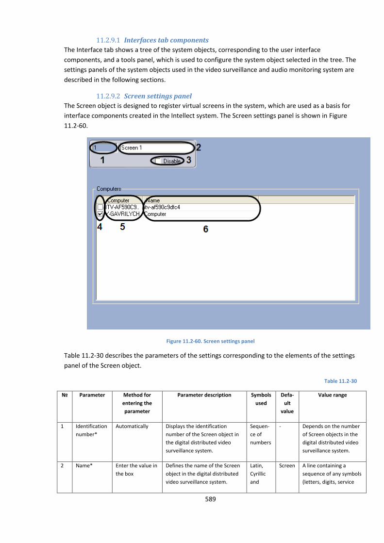
589
11.2.9.1 Interfaces tab components
The Interface tab shows a tree of the system objects, corresponding to the user interface
components, and a tools panel, which is used to configure the system object selected in the tree. The
settings panels of the system objects used in the video surveillance and audio monitoring system are
described in the following sections.
11.2.9.2 Screen settings panel
The Screen object is designed to register virtual screens in the system, which are used as a basis for
interface components created in the Intellect system. The Screen settings panel is shown in Figure
11.2-60.
Figure 11.2-60. Screen settings panel
Table 11.2-30 describes the parameters of the settings corresponding to the elements of the settings
panel of the Screen object.
Table 11.2-30
№
Parameter Method for
entering the
parameter
Parameter description Symbols
used
Defa-
ult
value
Value range
1 Identification
number*
Automatically Displays the identification
number of the Screen object in
the digital distributed video
surveillance system.
Sequen-
ce of
numbers
- Depends on the number
of Screen objects in the
digital distributed video
surveillance system.
2 Name* Enter the value in
the box
Defines the name of the Screen
object in the digital distributed
video surveillance system.
Latin,
Cyrillic
and
Screen A line containing a
sequence of any symbols
(letters, digits, service
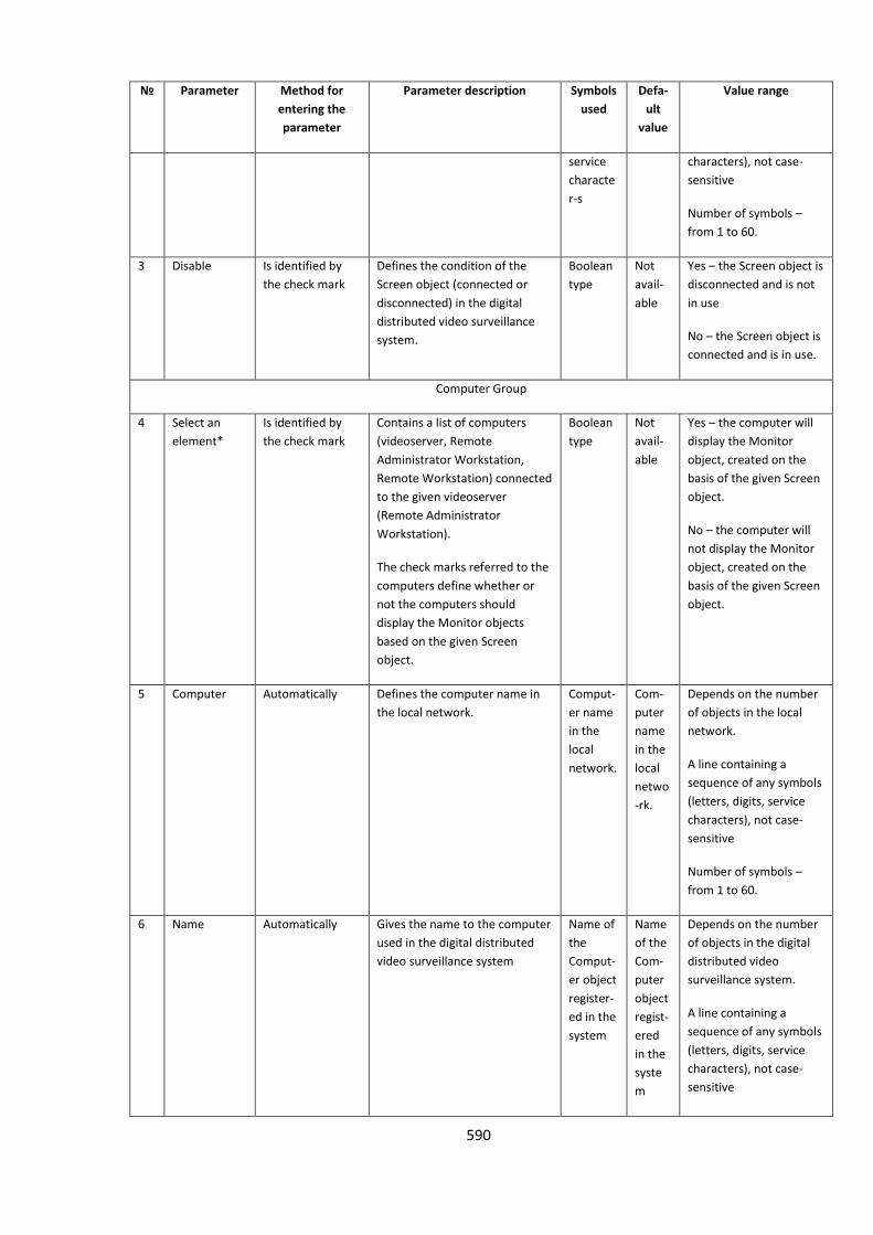
590
№
Parameter Method for
entering the
parameter
Parameter description Symbols
used
Defa-
ult
value
Value range
service
characte
r-s
characters), not case-
sensitive
Number of symbols –
from 1 to 60.
3 Disable Is identified by
the check mark
Defines the condition of the
Screen object (connected or
disconnected) in the digital
distributed video surveillance
system.
Boolean
type
Not
avail-
able
Yes – the Screen object is
disconnected and is not
in use
No – the Screen object is
connected and is in use.
Computer Group
4 Select an
element*
Is identified by
the check mark
Contains a list of computers
(videoserver, Remote
Administrator Workstation,
Remote Workstation) connected
to the given videoserver
(Remote Administrator
Workstation).
The check marks referred to the
computers define whether or
not the computers should
display the Monitor objects
based on the given Screen
object.
Boolean
type
Not
avail-
able
Yes – the computer will
display the Monitor
object, created on the
basis of the given Screen
object.
No – the computer will
not display the Monitor
object, created on the
basis of the given Screen
object.
5 Computer Automatically Defines the computer name in
the local network.
Comput-
er name
in the
local
network.
Com-
puter
name
in the
local
netwo
-rk.
Depends on the number
of objects in the local
network.
A line containing a
sequence of any symbols
(letters, digits, service
characters), not case-
sensitive
Number of symbols –
from 1 to 60.
6 Name Automatically Gives the name to the computer
used in the digital distributed
video surveillance system
Name of
the
Comput-
er object
register-
ed in the
system
Name
of the
Com-
puter
object
regist-
ered
in the
syste
m
Depends on the number
of objects in the digital
distributed video
surveillance system.
A line containing a
sequence of any symbols
(letters, digits, service
characters), not case-
sensitive
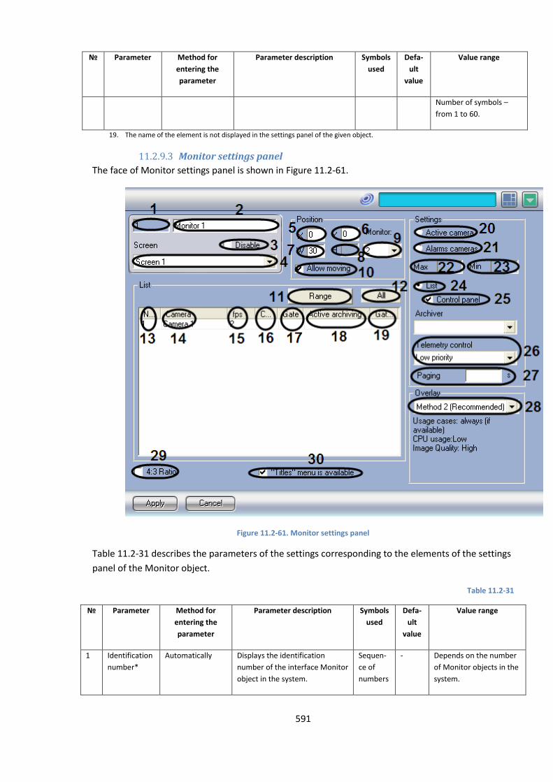
591
№
Parameter Method for
entering the
parameter
Parameter description Symbols
used
Defa-
ult
value
Value range
Number of symbols –
from 1 to 60.
19. The name of the element is not displayed in the settings panel of the given object.
11.2.9.3 Monitor settings panel
The face of Monitor settings panel is shown in Figure 11.2-61.
Figure 11.2-61. Monitor settings panel
Table 11.2-31 describes the parameters of the settings corresponding to the elements of the settings
panel of the Monitor object.
Table 11.2-31
№
Parameter Method for
entering the
parameter
Parameter description Symbols
used
Defa-
ult
value
Value range
1 Identification
number*
Automatically Displays the identification
number of the interface Monitor
object in the system.
Sequen-
ce of
numbers
- Depends on the number
of Monitor objects in the
system.
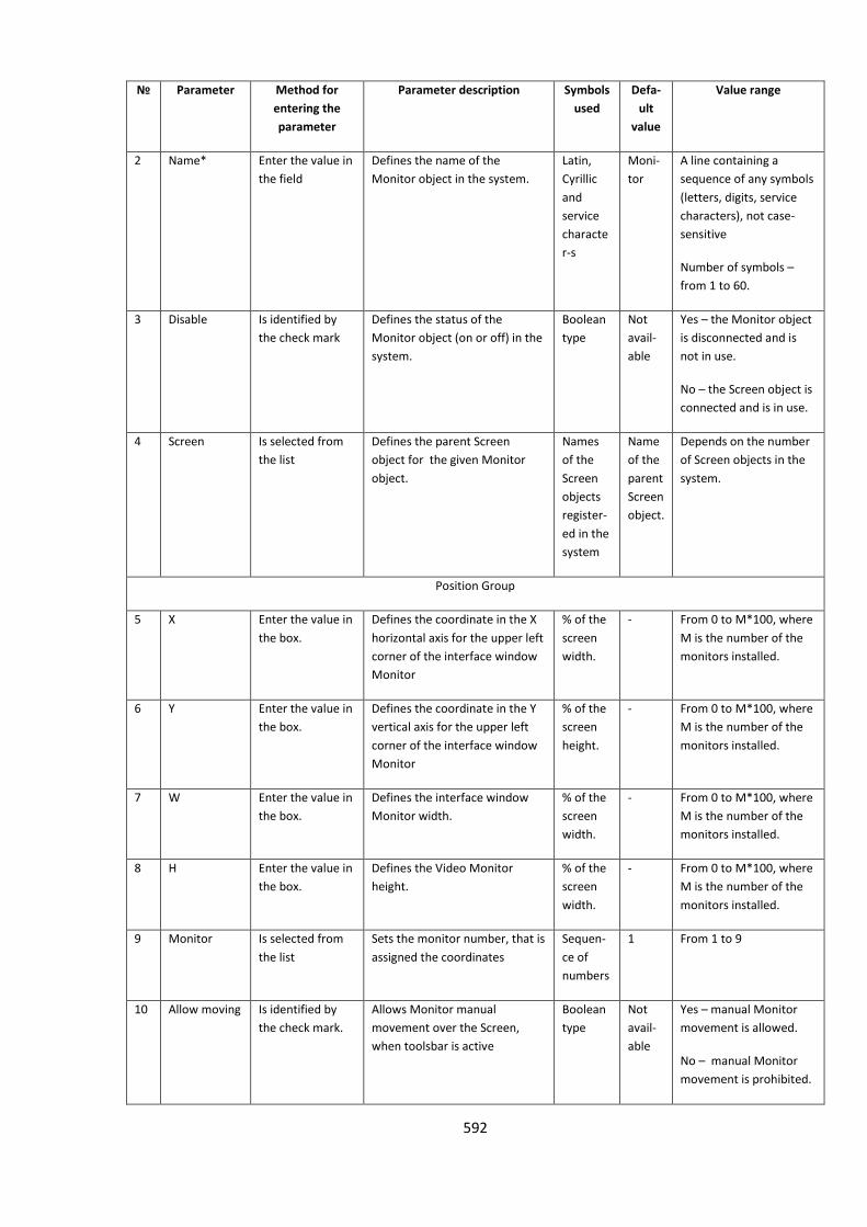
592
№
Parameter Method for
entering the
parameter
Parameter description Symbols
used
Defa-
ult
value
Value range
2 Name* Enter the value in
the field
Defines the name of the
Monitor object in the system.
Latin,
Cyrillic
and
service
characte
r-s
Moni-
tor
A line containing a
sequence of any symbols
(letters, digits, service
characters), not case-
sensitive
Number of symbols –
from 1 to 60.
3 Disable Is identified by
the check mark
Defines the status of the
Monitor object (on or off) in the
system.
Boolean
type
Not
avail-
able
Yes – the Monitor object
is disconnected and is
not in use.
No – the Screen object is
connected and is in use.
4 Screen Is selected from
the list
Defines the parent Screen
object for the given Monitor
object.
Names
of the
Screen
objects
register-
ed in the
system
Name
of the
parent
Screen
object.
Depends on the number
of Screen objects in the
system.
Position Group
5 X Enter the value in
the box.
Defines the coordinate in the X
horizontal axis for the upper left
corner of the interface window
Monitor
% of the
screen
width.
- From 0 to M*100, where
M is the number of the
monitors installed.
6 Y Enter the value in
the box.
Defines the coordinate in the Y
vertical axis for the upper left
corner of the interface window
Monitor
% of the
screen
height.
- From 0 to M*100, where
M is the number of the
monitors installed.
7 W Enter the value in
the box.
Defines the interface window
Monitor width.
% of the
screen
width.
- From 0 to M*100, where
M is the number of the
monitors installed.
8 H Enter the value in
the box.
Defines the Video Monitor
height.
% of the
screen
width.
- From 0 to M*100, where
M is the number of the
monitors installed.
9 Monitor Is selected from
the list
Sets the monitor number, that is
assigned the coordinates
Sequen-
ce of
numbers
1 From 1 to 9
10 Allow moving Is identified by
the check mark.
Allows Monitor manual
movement over the Screen,
when toolsbar is active
Boolean
type
Not
avail-
able
Yes – manual Monitor
movement is allowed.
No – manual Monitor
movement is prohibited.
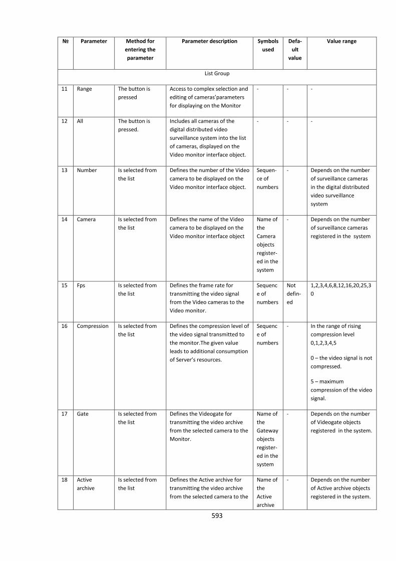
593
№
Parameter Method for
entering the
parameter
Parameter description Symbols
used
Defa-
ult
value
Value range
List Group
11 Range The button is
pressed
Access to complex selection and
editing of cameras’parameters
for displaying on the Monitor
- - -
12 All The button is
pressed.
Includes all cameras of the
digital distributed video
surveillance system into the list
of cameras, displayed on the
Video monitor interface object.
- - -
13 Number Is selected from
the list
Defines the number of the Video
camera to be displayed on the
Video monitor interface object.
Sequen-
ce of
numbers
- Depends on the number
of surveillance cameras
in the digital distributed
video surveillance
system
14 Camera Is selected from
the list
Defines the name of the Video
camera to be displayed on the
Video monitor interface object
Name of
the
Camera
objects
register-
ed in the
system
- Depends on the number
of surveillance cameras
registered in the system
15 Fps Is selected from
the list
Defines the frame rate for
transmitting the video signal
from the Video cameras to the
Video monitor.
Sequenc
e of
numbers
Not
defin-
ed
1,2,3,4,6,8,12,16,20,25,3
0
16 Compression Is selected from
the list
Defines the compression level of
the video signal transmitted to
the monitor.The given value
leads to additional consumption
of Server’s resources.
Sequenc
e of
numbers
- In the range of rising
compression level
0,1,2,3,4,5
0 – the video signal is not
compressed.
5 – maximum
compression of the video
signal.
17 Gate Is selected from
the list
Defines the Videogate for
transmitting the video archive
from the selected camera to the
Monitor.
Name of
the
Gateway
objects
register-
ed in the
system
- Depends on the number
of Videogate objects
registered in the system.
18 Active
archive
Is selected from
the list
Defines the Active archive for
transmitting the video archive
from the selected camera to the
Name of
the
Active
archive
- Depends on the number
of Active archive objects
registered in the system.
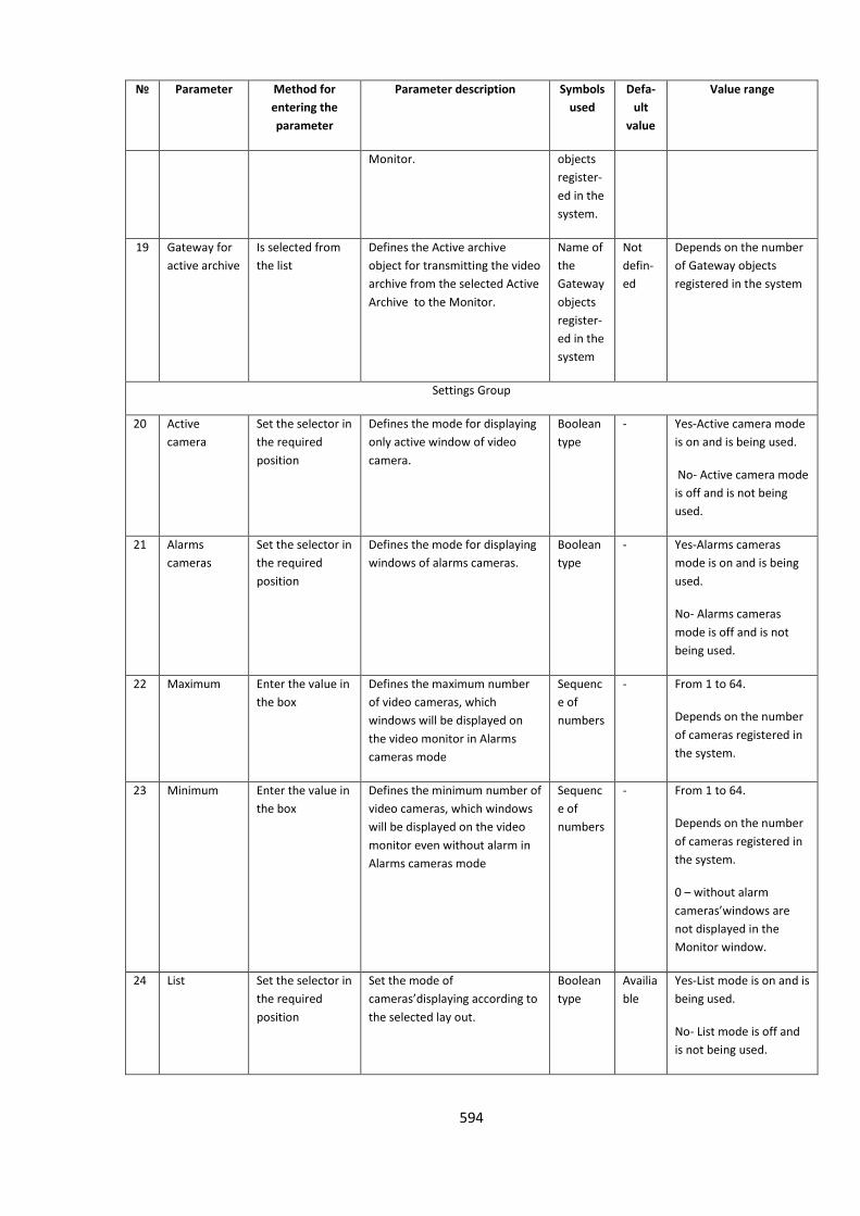
594
№
Parameter Method for
entering the
parameter
Parameter description Symbols
used
Defa-
ult
value
Value range
Monitor. objects
register-
ed in the
system.
19 Gateway for
active archive
Is selected from
the list
Defines the Active archive
object for transmitting the video
archive from the selected Active
Archive to the Monitor.
Name of
the
Gateway
objects
register-
ed in the
system
Not
defin-
ed
Depends on the number
of Gateway objects
registered in the system
Settings Group
20 Active
camera
Set the selector in
the required
position
Defines the mode for displaying
only active window of video
camera.
Boolean
type
- Yes-Active camera mode
is on and is being used.
No- Active camera mode
is off and is not being
used.
21 Alarms
cameras
Set the selector in
the required
position
Defines the mode for displaying
windows of alarms cameras.
Boolean
type
- Yes-Alarms cameras
mode is on and is being
used.
No- Alarms cameras
mode is off and is not
being used.
22 Maximum Enter the value in
the box
Defines the maximum number
of video cameras, which
windows will be displayed on
the video monitor in Alarms
cameras mode
Sequenc
e of
numbers
- From 1 to 64.
Depends on the number
of cameras registered in
the system.
23 Minimum Enter the value in
the box
Defines the minimum number of
video cameras, which windows
will be displayed on the video
monitor even without alarm in
Alarms cameras mode
Sequenc
e of
numbers
- From 1 to 64.
Depends on the number
of cameras registered in
the system.
0 – without alarm
cameras’windows are
not displayed in the
Monitor window.
24 List Set the selector in
the required
position
Set the mode of
cameras’displaying according to
the selected lay out.
Boolean
type
Availia
ble
Yes-List mode is on and is
being used.
No- List mode is off and
is not being used.
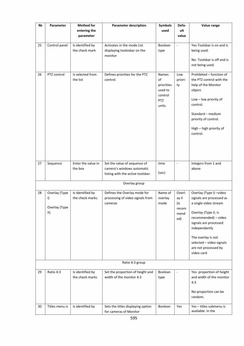
595
№
Parameter Method for
entering the
parameter
Parameter description Symbols
used
Defa-
ult
value
Value range
25 Control panel Is identified by
the check mark
Activates in the mode List
displaying toolosbar on the
monitor
Boolean
type
- Yes-Toolsbar is on and is
being used.
No- Toolsbar is off and is
not being used.
26 PTZ control Is selected from
the list
Defines priorities for the PTZ
control.
Names
of
priorities
used to
control
PTZ
units.
Low
priori-
ty
Prohibited – function of
the PTZ control with the
help of the Monitor
object.
Low – low priority of
control.
Standard – medium
priority of control.
High – high priority of
control.
27 Sequence Enter the value in
the box
Set the value of sequence of
camera’s windows automatic
listing with the active toolsbar.
time
(sec)
- Integers from 1 and
above
Overlay group
28 Overlay (Type
I)
Overlay (Type
II)
Is identified by
the check marks.
Defines the Overlay mode for
processing of video signals from
cameras
Name of
overlay
mode
Overl-
ay II
(is
recom
mend
ed)
Overlay (Type I) –video
signals are processed as
a single video stream
Overlay (Type II, is
recommended) – video
signals are processed
independantly
The overlay is not
selected – video signals
are not processed by
video card
Ratio 4:3 group
29 Ratio 4:3 Is identified by
the check marks
Set the proportion of height and
width of the monitor 4:3
Boolean
type
- Yes- proportion of height
and width of the monitor
4:3
No-proportion can be
random.
30 Titles menu is Is identified by Sets the titles displaying option
for cameras of Monitor
Boolean Yes Yes – titles submenu is available in the
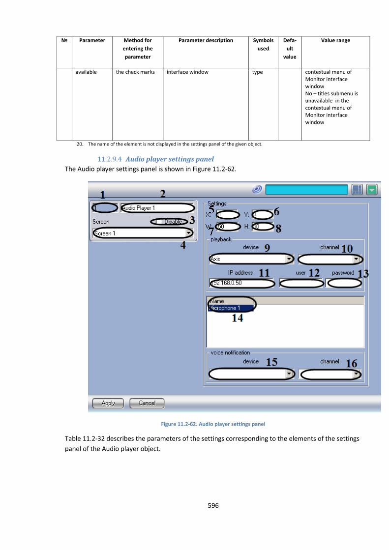
596
№
Parameter Method for
entering the
parameter
Parameter description Symbols
used
Defa-
ult
value
Value range
available the check marks interface window type contextual menu of Monitor interface window No – titles submenu is unavailable in the contextual menu of Monitor interface window
20. The name of the element is not displayed in the settings panel of the given object.
11.2.9.4 Audio player settings panel
The Audio player settings panel is shown in Figure 11.2-62.
Figure 11.2-62. Audio player settings panel
Table 11.2-32 describes the parameters of the settings corresponding to the elements of the settings
panel of the Audio player object.
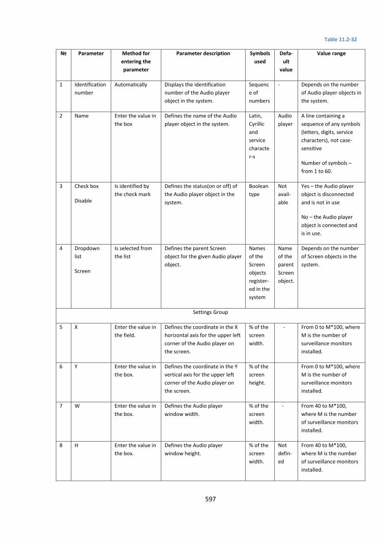
597
Table 11.2-32
№ Parameter Method for
entering the
parameter
Parameter description Symbols
used
Defa-
ult
value
Value range
1 Identification
number
Automatically Displays the identification
number of the Audio player
object in the system.
Sequenc
e of
numbers
- Depends on the number
of Audio player objects in
the system.
2 Name Enter the value in
the box
Defines the name of the Audio
player object in the system.
Latin,
Cyrillic
and
service
characte
r-s
Audio
player
A line containing a
sequence of any symbols
(letters, digits, service
characters), not case-
sensitive
Number of symbols –
from 1 to 60.
3 Check box
Disable
Is identified by
the check mark
Defines the status(on or off) of
the Audio player object in the
system.
Boolean
type
Not
avail-
able
Yes – the Audio player
object is disconnected
and is not in use
No – the Audio player
object is connected and
is in use.
4 Dropdown
list
Screen
Is selected from
the list
Defines the parent Screen
object for the given Audio player
object.
Names
of the
Screen
objects
register-
ed in the
system
Name
of the
parent
Screen
object.
Depends on the number
of Screen objects in the
system.
Settings Group
5 X Enter the value in
the field.
Defines the coordinate in the X
horizontal axis for the upper left
corner of the Audio player on
the screen.
% of the
screen
width.
- From 0 to M*100, where
M is the number of
surveillance monitors
installed.
6 Y Enter the value in
the box.
Defines the coordinate in the Y
vertical axis for the upper left
corner of the Audio player on
the screen.
% of the
screen
height.
From 0 to M*100, where
M is the number of
surveillance monitors
installed.
7 W Enter the value in
the box.
Defines the Audio player
window width.
% of the
screen
width.
- From 40 to M*100,
where M is the number
of surveillance monitors
installed.
8 H Enter the value in
the box.
Defines the Audio player
window height.
% of the
screen
width.
Not
defin-
ed
From 40 to M*100,
where M is the number
of surveillance monitors
installed.
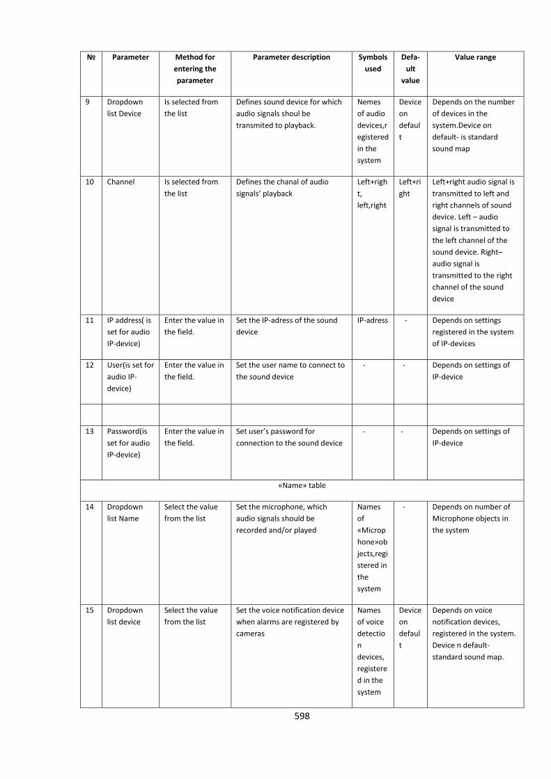
598
№ Parameter Method for
entering the
parameter
Parameter description Symbols
used
Defa-
ult
value
Value range
9 Dropdown
list Device
Is selected from
the list
Defines sound device for which
audio signals shoul be
transmited to playback.
Nemes
of audio
devices,r
egistered
in the
system
Device
on
defaul
t
Depends on the number
of devices in the
system.Device on
default- is standard
sound map
10 Channel Is selected from
the list
Defines the chanal of audio
signals’ playback
Left+righ
t,
left,right
Left+ri
ght
Left+right audio signal is
transmitted to left and
right channels of sound
device. Left – audio
signal is transmitted to
the left channel of the
sound device. Right–
audio signal is
transmitted to the right
channel of the sound
device
11 IP address( is
set for audio
IP-device)
Enter the value in
the field.
Set the IP-adress of the sound
device
IP-adress - Depends on settings
registered in the system
of IP-devices
12 User(is set for
audio IP-
device)
Enter the value in
the field.
Set the user name to connect to
the sound device
- - Depends on settings of
IP-device
13 Password(is
set for audio
IP-device)
Enter the value in
the field.
Set user’s password for
connection to the sound device
- - Depends on settings of
IP-device
«Name» table
14 Dropdown
list Name
Select the value
from the list
Set the microphone, which
audio signals should be
recorded and/or played
Names
of
«Microp
hone»ob
jects,regi
stered in
the
system
- Depends on number of
Microphone objects in
the system
15 Dropdown
list device
Select the value
from the list
Set the voice notification device
when alarms are registered by
cameras
Names
of voice
detectio
n
devices,
registere
d in the
system
Device
on
defaul
t
Depends on voice
notification devices,
registered in the system.
Device n default-
standard sound map.

599
№ Parameter Method for
entering the
parameter
Parameter description Symbols
used
Defa-
ult
value
Value range
16 Dropdown
list Channel
Select the value
from the list
Set the channel of voice
notification when alarms are
registered by cameras
Left+righ
t,
left,right
Left+ri
ght
Left+right- audio signal is
transferred to the left
and right channels of the
voice notification
device.Left- audio signal
is transferred to the left
channel of the voice
notification device.Right-
audio signal is
transferred to the right
channel of the voice
notification device
11.2.9.5 Settings panel of the Telemetry control panel
The Audio player settings panel is shown in Figure 11.2-63.
Figure 11.2-63. Audio player settings panel
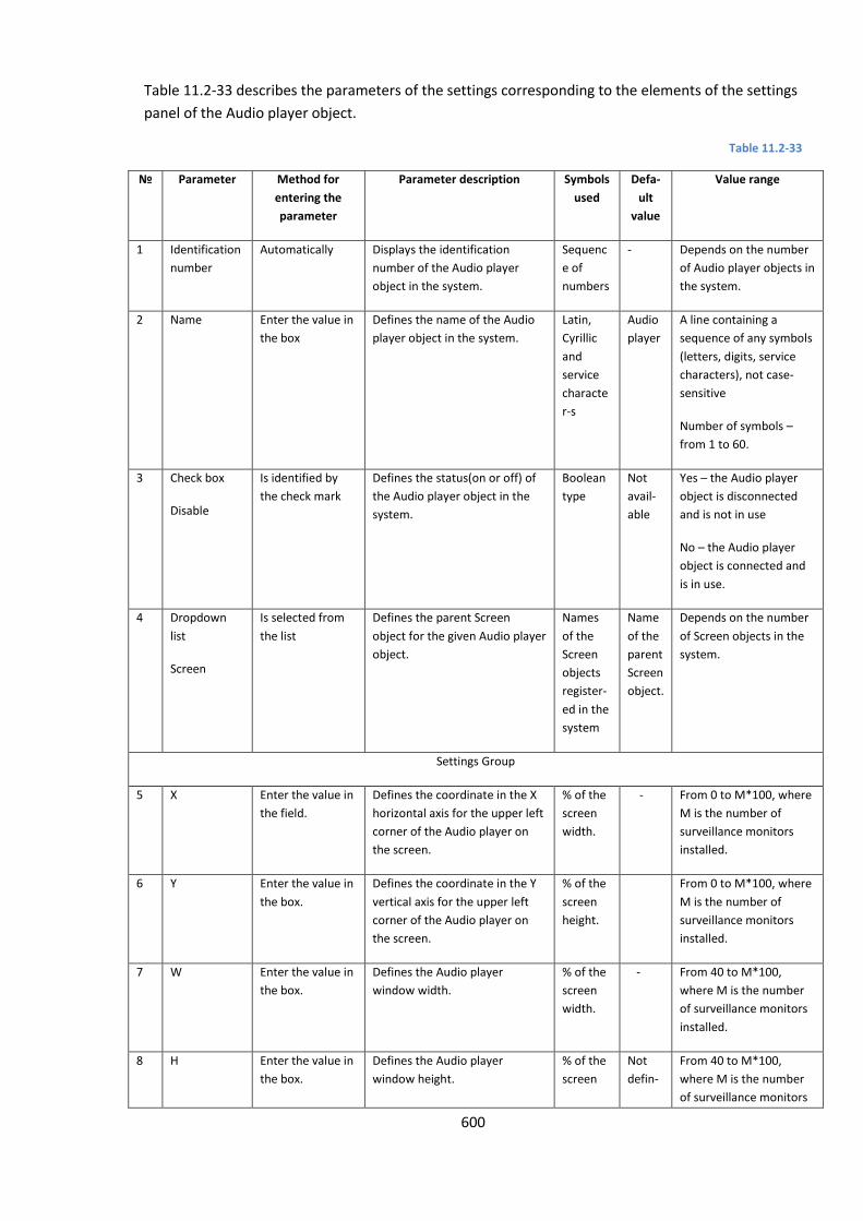
600
Table 11.2-33 describes the parameters of the settings corresponding to the elements of the settings
panel of the Audio player object.
Table 11.2-33
№ Parameter Method for
entering the
parameter
Parameter description Symbols
used
Defa-
ult
value
Value range
1 Identification
number
Automatically Displays the identification
number of the Audio player
object in the system.
Sequenc
e of
numbers
- Depends on the number
of Audio player objects in
the system.
2 Name Enter the value in
the box
Defines the name of the Audio
player object in the system.
Latin,
Cyrillic
and
service
characte
r-s
Audio
player
A line containing a
sequence of any symbols
(letters, digits, service
characters), not case-
sensitive
Number of symbols –
from 1 to 60.
3 Check box
Disable
Is identified by
the check mark
Defines the status(on or off) of
the Audio player object in the
system.
Boolean
type
Not
avail-
able
Yes – the Audio player
object is disconnected
and is not in use
No – the Audio player
object is connected and
is in use.
4 Dropdown
list
Screen
Is selected from
the list
Defines the parent Screen
object for the given Audio player
object.
Names
of the
Screen
objects
register-
ed in the
system
Name
of the
parent
Screen
object.
Depends on the number
of Screen objects in the
system.
Settings Group
5 X Enter the value in
the field.
Defines the coordinate in the X
horizontal axis for the upper left
corner of the Audio player on
the screen.
% of the
screen
width.
- From 0 to M*100, where
M is the number of
surveillance monitors
installed.
6 Y Enter the value in
the box.
Defines the coordinate in the Y
vertical axis for the upper left
corner of the Audio player on
the screen.
% of the
screen
height.
From 0 to M*100, where
M is the number of
surveillance monitors
installed.
7 W Enter the value in
the box.
Defines the Audio player
window width.
% of the
screen
width.
- From 40 to M*100,
where M is the number
of surveillance monitors
installed.
8 H Enter the value in
the box.
Defines the Audio player
window height.
% of the
screen
Not
defin-
From 40 to M*100,
where M is the number
of surveillance monitors
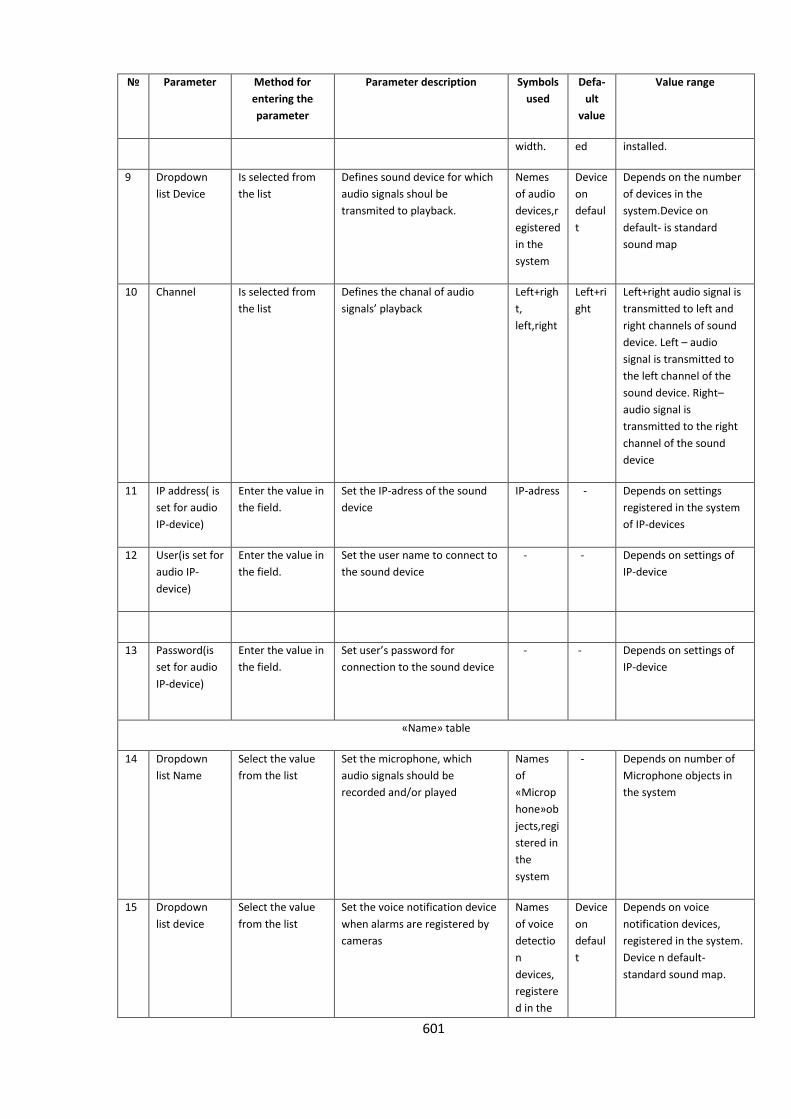
601
№ Parameter Method for
entering the
parameter
Parameter description Symbols
used
Defa-
ult
value
Value range
width. ed installed.
9 Dropdown
list Device
Is selected from
the list
Defines sound device for which
audio signals shoul be
transmited to playback.
Nemes
of audio
devices,r
egistered
in the
system
Device
on
defaul
t
Depends on the number
of devices in the
system.Device on
default- is standard
sound map
10 Channel Is selected from
the list
Defines the chanal of audio
signals’ playback
Left+righ
t,
left,right
Left+ri
ght
Left+right audio signal is
transmitted to left and
right channels of sound
device. Left – audio
signal is transmitted to
the left channel of the
sound device. Right–
audio signal is
transmitted to the right
channel of the sound
device
11 IP address( is
set for audio
IP-device)
Enter the value in
the field.
Set the IP-adress of the sound
device
IP-adress - Depends on settings
registered in the system
of IP-devices
12 User(is set for
audio IP-
device)
Enter the value in
the field.
Set the user name to connect to
the sound device
- - Depends on settings of
IP-device
13 Password(is
set for audio
IP-device)
Enter the value in
the field.
Set user’s password for
connection to the sound device
- - Depends on settings of
IP-device
«Name» table
14 Dropdown
list Name
Select the value
from the list
Set the microphone, which
audio signals should be
recorded and/or played
Names
of
«Microp
hone»ob
jects,regi
stered in
the
system
- Depends on number of
Microphone objects in
the system
15 Dropdown
list device
Select the value
from the list
Set the voice notification device
when alarms are registered by
cameras
Names
of voice
detectio
n
devices,
registere
d in the
Device
on
defaul
t
Depends on voice
notification devices,
registered in the system.
Device n default-
standard sound map.

602
№ Parameter Method for
entering the
parameter
Parameter description Symbols
used
Defa-
ult
value
Value range
system
16 Dropdown
list Channel
Select the value
from the list
Set the channel of voice
notification when alarms are
registered by cameras
Left+righ
t,
left,right
Left+ri
ght
Left+right- audio signal is
transferred to the left
and right channels of the
voice notification
device.Left- audio signal
is transferred to the left
channel of the voice
notification device.Right-
audio signal is
transferred to the right
channel of the voice
notification device
11.2.9.6 Settings of the Active Archiving panel
The Active Archiving panel object is designed to register and configure the Active Archiving panel
interface object in the Intellect system, which allows the Operator to configure video data archiving.
The Active Archiving Settings panel is shown in Figure 11.2-64.
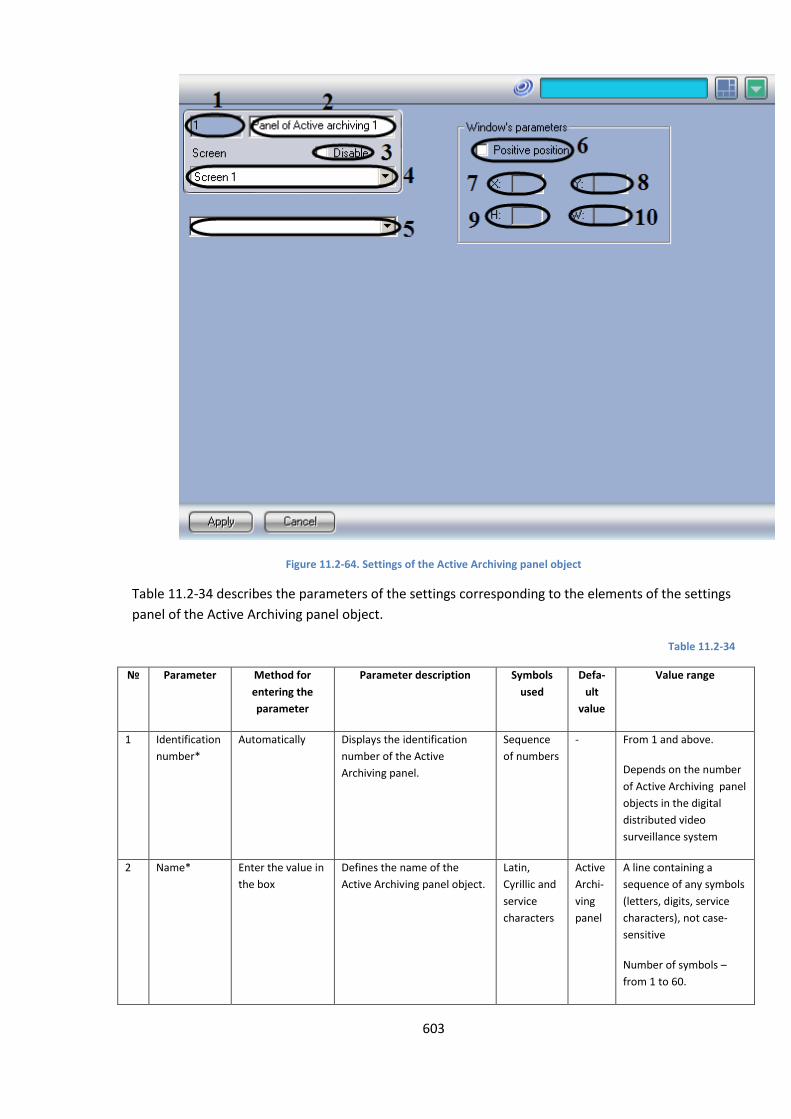
603
Figure 11.2-64. Settings of the Active Archiving panel object
Table 11.2-34 describes the parameters of the settings corresponding to the elements of the settings
panel of the Active Archiving panel object.
Table 11.2-34
№ Parameter Method for
entering the
parameter
Parameter description Symbols
used
Defa-
ult
value
Value range
1 Identification
number*
Automatically Displays the identification
number of the Active
Archiving panel.
Sequence
of numbers
- From 1 and above.
Depends on the number
of Active Archiving panel
objects in the digital
distributed video
surveillance system
2 Name* Enter the value in
the box
Defines the name of the
Active Archiving panel object.
Latin,
Cyrillic and
service
characters
Active
Archi-
ving
panel
A line containing a
sequence of any symbols
(letters, digits, service
characters), not case-
sensitive
Number of symbols –
from 1 to 60.
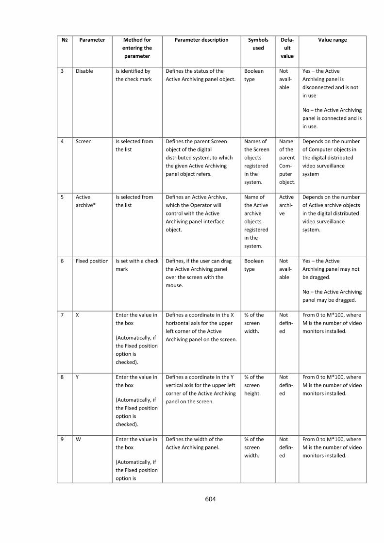
604
№ Parameter Method for
entering the
parameter
Parameter description Symbols
used
Defa-
ult
value
Value range
3 Disable Is identified by
the check mark
Defines the status of the
Active Archiving panel object.
Boolean
type
Not
avail-
able
Yes – the Active
Archiving panel is
disconnected and is not
in use
No – the Active Archiving
panel is connected and is
in use.
4 Screen Is selected from
the list
Defines the parent Screen
object of the digital
distributed system, to which
the given Active Archiving
panel object refers.
Names of
the Screen
objects
registered
in the
system.
Name
of the
parent
Com-
puter
object.
Depends on the number
of Computer objects in
the digital distributed
video surveillance
system
5 Active
archive*
Is selected from
the list
Defines an Active Archive,
which the Operator will
control with the Active
Archiving panel interface
object.
Name of
the Active
archive
objects
registered
in the
system.
Active
archi-
ve
Depends on the number
of Active archive objects
in the digital distributed
video surveillance
system.
6 Fixed position Is set with a check
mark
Defines, if the user can drag
the Active Archiving panel
over the screen with the
mouse.
Boolean
type
Not
avail-
able
Yes – the Active
Archiving panel may not
be dragged.
No – the Active Archiving
panel may be dragged.
7 X Enter the value in
the box
(Automatically, if
the Fixed position
option is
checked).
Defines a coordinate in the X
horizontal axis for the upper
left corner of the Active
Archiving panel on the screen.
% of the
screen
width.
Not
defin-
ed
From 0 to M*100, where
M is the number of video
monitors installed.
8 Y Enter the value in
the box
(Automatically, if
the Fixed position
option is
checked).
Defines a coordinate in the Y
vertical axis for the upper left
corner of the Active Archiving
panel on the screen.
% of the
screen
height.
Not
defin-
ed
From 0 to M*100, where
M is the number of video
monitors installed.
9 W Enter the value in
the box
(Automatically, if
the Fixed position
option is
Defines the width of the
Active Archiving panel.
% of the
screen
width.
Not
defin-
ed
From 0 to M*100, where
M is the number of video
monitors installed.
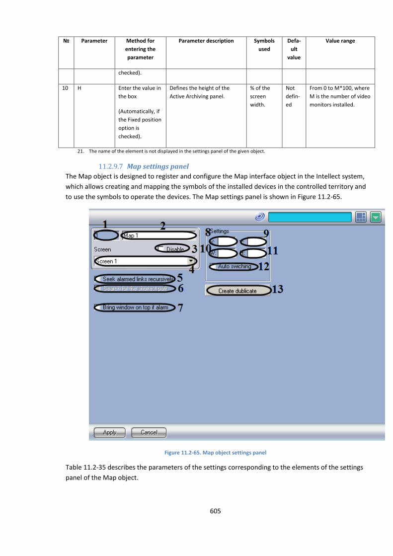
605
№ Parameter Method for
entering the
parameter
Parameter description Symbols
used
Defa-
ult
value
Value range
checked).
10 H Enter the value in
the box
(Automatically, if
the Fixed position
option is
checked).
Defines the height of the
Active Archiving panel.
% of the
screen
width.
Not
defin-
ed
From 0 to M*100, where
M is the number of video
monitors installed.
21. The name of the element is not displayed in the settings panel of the given object.
11.2.9.7 Map settings panel
The Map object is designed to register and configure the Map interface object in the Intellect system,
which allows creating and mapping the symbols of the installed devices in the controlled territory and
to use the symbols to operate the devices. The Map settings panel is shown in Figure 11.2-65.
Figure 11.2-65. Map object settings panel
Table 11.2-35 describes the parameters of the settings corresponding to the elements of the settings
panel of the Map object.
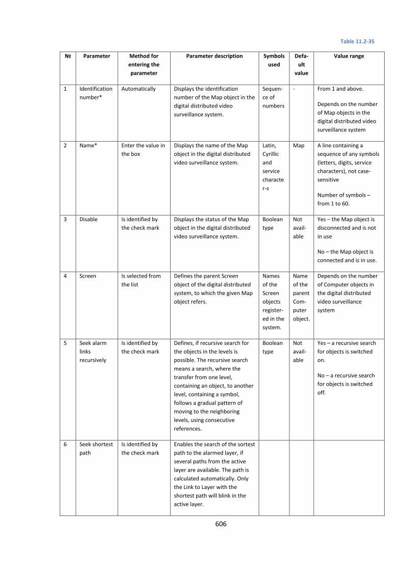
606
Table 11.2-35
№ Parameter Method for
entering the
parameter
Parameter description Symbols
used
Defa-
ult
value
Value range
1 Identification
number*
Automatically Displays the identification
number of the Map object in the
digital distributed video
surveillance system.
Sequen-
ce of
numbers
- From 1 and above.
Depends on the number
of Map objects in the
digital distributed video
surveillance system
2 Name* Enter the value in
the box
Displays the name of the Map
object in the digital distributed
video surveillance system.
Latin,
Cyrillic
and
service
characte
r-s
Map A line containing a
sequence of any symbols
(letters, digits, service
characters), not case-
sensitive
Number of symbols –
from 1 to 60.
3 Disable Is identified by
the check mark
Displays the status of the Map
object in the digital distributed
video surveillance system.
Boolean
type
Not
avail-
able
Yes – the Map object is
disconnected and is not
in use
No – the Map object is
connected and is in use.
4 Screen Is selected from
the list
Defines the parent Screen
object of the digital distributed
system, to which the given Map
object refers.
Names
of the
Screen
objects
register-
ed in the
system.
Name
of the
parent
Com-
puter
object.
Depends on the number
of Computer objects in
the digital distributed
video surveillance
system
5 Seek alarm
links
recursively
Is identified by
the check mark
Defines, if recursive search for
the objects in the levels is
possible. The recursive search
means a search, where the
transfer from one level,
containing an object, to another
level, containing a symbol,
follows a gradual pattern of
moving to the neighboring
levels, using consecutive
references.
Boolean
type
Not
avail-
able
Yes – a recursive search
for objects is switched
on.
No – a recursive search
for objects is switched
off.
6 Seek shortest
path
Is identified by
the check mark
Enables the search of the sortest
path to the alarmed layer, if
several paths from the active
layer are available. The path is
calculated automatically. Only
the Link to Layer with the
shortest path will blink in the
active layer.
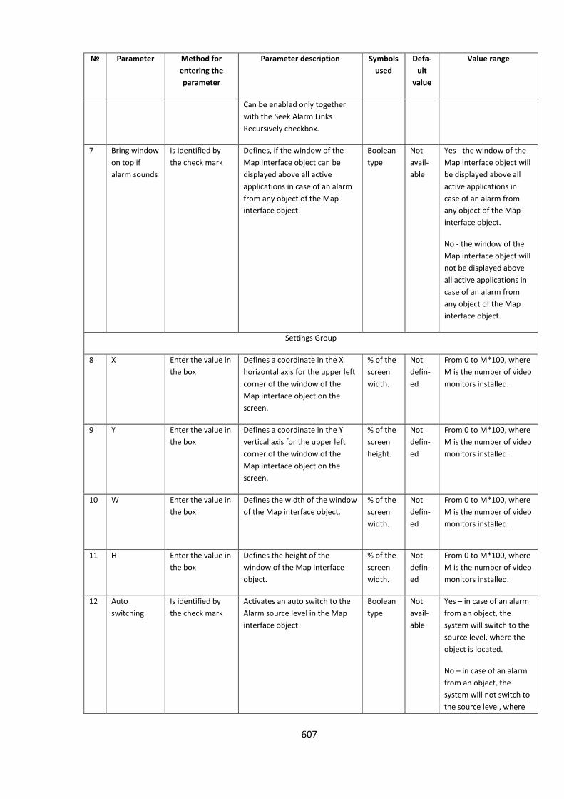
607
№ Parameter Method for
entering the
parameter
Parameter description Symbols
used
Defa-
ult
value
Value range
Can be enabled only together
with the Seek Alarm Links
Recursively checkbox.
7 Bring window
on top if
alarm sounds
Is identified by
the check mark
Defines, if the window of the
Map interface object can be
displayed above all active
applications in case of an alarm
from any object of the Map
interface object.
Boolean
type
Not
avail-
able
Yes - the window of the
Map interface object will
be displayed above all
active applications in
case of an alarm from
any object of the Map
interface object.
No - the window of the
Map interface object will
not be displayed above
all active applications in
case of an alarm from
any object of the Map
interface object.
Settings Group
8 X Enter the value in
the box
Defines a coordinate in the X
horizontal axis for the upper left
corner of the window of the
Map interface object on the
screen.
% of the
screen
width.
Not
defin-
ed
From 0 to M*100, where
M is the number of video
monitors installed.
9 Y Enter the value in
the box
Defines a coordinate in the Y
vertical axis for the upper left
corner of the window of the
Map interface object on the
screen.
% of the
screen
height.
Not
defin-
ed
From 0 to M*100, where
M is the number of video
monitors installed.
10 W Enter the value in
the box
Defines the width of the window
of the Map interface object.
% of the
screen
width.
Not
defin-
ed
From 0 to M*100, where
M is the number of video
monitors installed.
11 H Enter the value in
the box
Defines the height of the
window of the Map interface
object.
% of the
screen
width.
Not
defin-
ed
From 0 to M*100, where
M is the number of video
monitors installed.
12 Auto
switching
Is identified by
the check mark
Activates an auto switch to the
Alarm source level in the Map
interface object.
Boolean
type
Not
avail-
able
Yes – in case of an alarm
from an object, the
system will switch to the
source level, where the
object is located.
No – in case of an alarm
from an object, the
system will not switch to
the source level, where
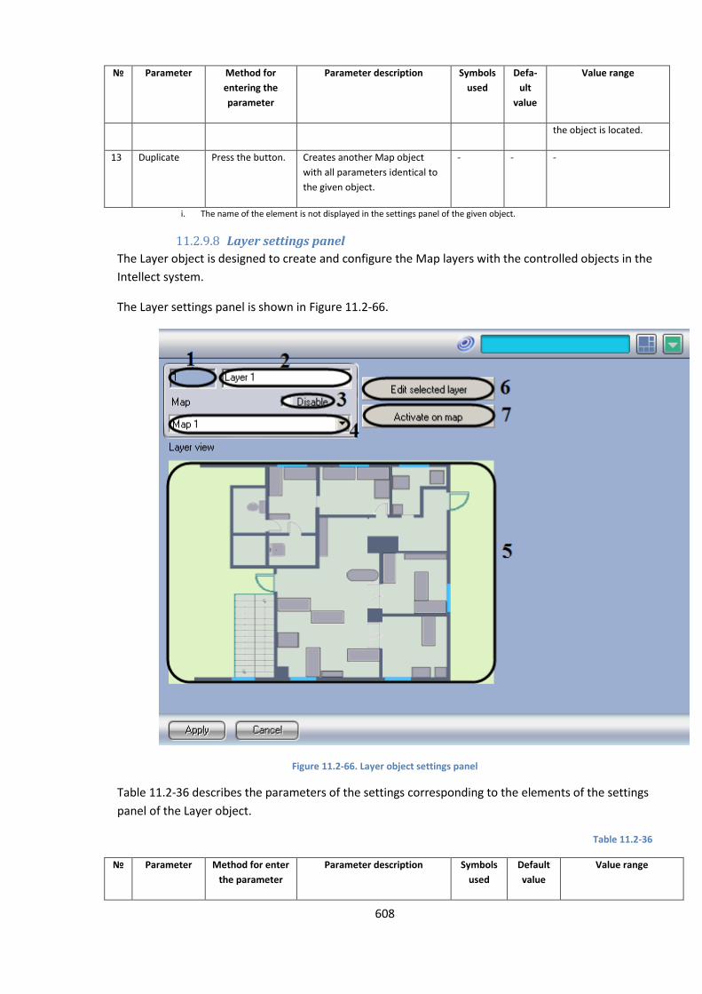
608
№ Parameter Method for
entering the
parameter
Parameter description Symbols
used
Defa-
ult
value
Value range
the object is located.
13 Duplicate Press the button. Creates another Map object
with all parameters identical to
the given object.
- - -
i. The name of the element is not displayed in the settings panel of the given object.
11.2.9.8 Layer settings panel
The Layer object is designed to create and configure the Map layers with the controlled objects in the
Intellect system.
The Layer settings panel is shown in Figure 11.2-66.
Figure 11.2-66. Layer object settings panel
Table 11.2-36 describes the parameters of the settings corresponding to the elements of the settings
panel of the Layer object.
Table 11.2-36
№ Parameter Method for enter
the parameter
Parameter description Symbols
used
Default
value
Value range
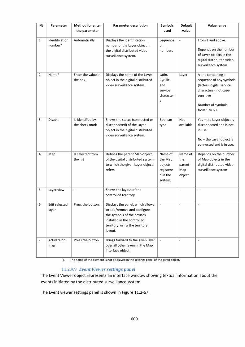
609
№ Parameter Method for enter
the parameter
Parameter description Symbols
used
Default
value
Value range
1 Identification
number*
Automatically Displays the identification
number of the Layer object in
the digital distributed video
surveillance system.
Sequence
of
numbers
- From 1 and above.
Depends on the number
of Layer objects in the
digital distributed video
surveillance system
2 Name* Enter the value in
the box
Displays the name of the Layer
object in the digital distributed
video surveillance system.
Latin,
Cyrillic
and
service
character
s
Layer A line containing a
sequence of any symbols
(letters, digits, service
characters), not case-
sensitive
Number of symbols –
from 1 to 60.
3 Disable Is identified by
the check mark
Shows the status (connected or
disconnected) of the Layer
object in the digital distributed
video surveillance system.
Boolean
type
Not
available
Yes – the Layer object is
disconnected and is not
in use
No – the Layer object is
connected and is in use.
4 Map Is selected from
the list
Defines the parent Map object
of the digital distributed system,
to which the given Layer object
refers.
Name of
the Map
objects
registere
d in the
system.
Name of
the
parent
Map
object
Depends on the number
of Map objects in the
digital distributed video
surveillance system
5 Layer view - Shows the layout of the
controlled territory.
- - -
6 Edit selected
layer
Press the button. Displays the panel, which allows
to add/remove and configure
the symbols of the devices
installed in the controlled
territory, using the territory
layout.
- - -
7 Activate on
map
Press the button. Brings forward to the given layer
over all other layers in the Map
interface object.
- - -
j. The name of the element is not displayed in the settings panel of the given object.
11.2.9.9 Event Viewer settings panel
The Event Viewer object represents an interface window showing textual information about the
events initiated by the distributed surveillance system.
The Event viewer settings panel is shown in Figure 11.2-67.
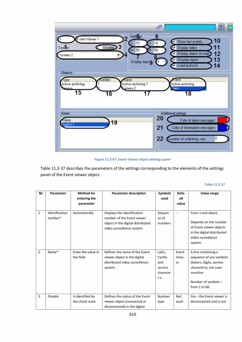
610
Figure 11.2-67. Event Viewer object settings panel
Table 11.2-37 describes the parameters of the settings corresponding to the elements of the settings
panel of the Event viewer object.
Table 11.2-37
№ Parameter Method for
entering the
parameter
Parameter description Symbols
used
Defa-
ult
value
Value range
1 Identification
number*
Automatically Displays the identification
number of the Event viewer
object in the digital distributed
video surveillance system.
Sequen-
ce of
numbers
- From 1 and above.
Depends on the number
of Event viewer objects
in the digital distributed
video surveillance
system.
2 Name* Enter the value in
the field
Defines the name of the Event
viewer object in the digital
distributed video surveillance
system.
Latin,
Cyrillic
and
service
characte
r-s
Event
View-
er
A line containing a
sequence of any symbols
(letters, digits, service
characters), not case-
sensitive
Number of symbols –
from 1 to 60.
3 Disable Is identified by
the check mark
Defines the status of the Event
viewer object (connected or
disconnected) in the digital
Boolean
type
Not
avail-
Yes – the Event viewer is
disconnected and is not
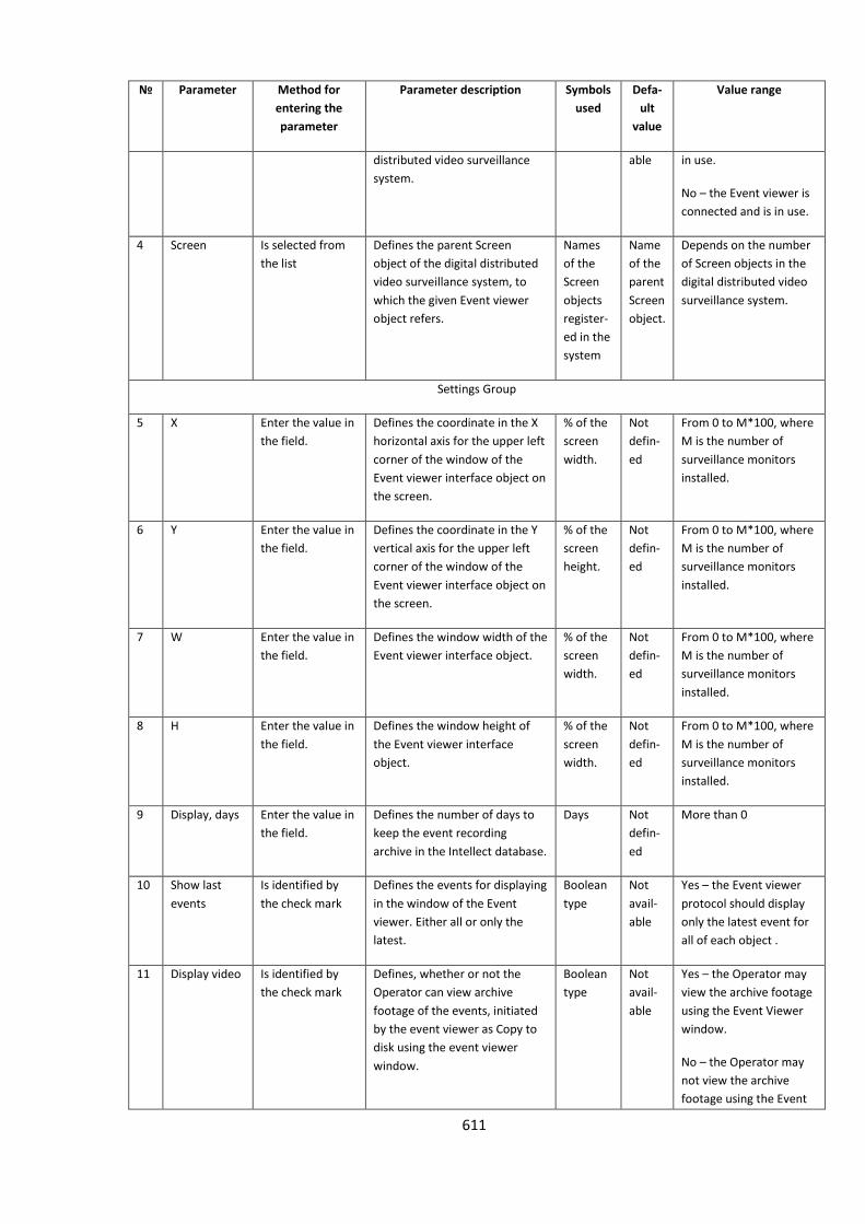
611
№ Parameter Method for
entering the
parameter
Parameter description Symbols
used
Defa-
ult
value
Value range
distributed video surveillance
system.
able in use.
No – the Event viewer is
connected and is in use.
4 Screen Is selected from
the list
Defines the parent Screen
object of the digital distributed
video surveillance system, to
which the given Event viewer
object refers.
Names
of the
Screen
objects
register-
ed in the
system
Name
of the
parent
Screen
object.
Depends on the number
of Screen objects in the
digital distributed video
surveillance system.
Settings Group
5 X Enter the value in
the field.
Defines the coordinate in the X
horizontal axis for the upper left
corner of the window of the
Event viewer interface object on
the screen.
% of the
screen
width.
Not
defin-
ed
From 0 to M*100, where
M is the number of
surveillance monitors
installed.
6 Y Enter the value in
the field.
Defines the coordinate in the Y
vertical axis for the upper left
corner of the window of the
Event viewer interface object on
the screen.
% of the
screen
height.
Not
defin-
ed
From 0 to M*100, where
M is the number of
surveillance monitors
installed.
7 W Enter the value in
the field.
Defines the window width of the
Event viewer interface object.
% of the
screen
width.
Not
defin-
ed
From 0 to M*100, where
M is the number of
surveillance monitors
installed.
8 H Enter the value in
the field.
Defines the window height of
the Event viewer interface
object.
% of the
screen
width.
Not
defin-
ed
From 0 to M*100, where
M is the number of
surveillance monitors
installed.
9 Display, days Enter the value in
the field.
Defines the number of days to
keep the event recording
archive in the Intellect database.
Days Not
defin-
ed
More than 0
10 Show last
events
Is identified by
the check mark
Defines the events for displaying
in the window of the Event
viewer. Either all or only the
latest.
Boolean
type
Not
avail-
able
Yes – the Event viewer
protocol should display
only the latest event for
all of each object .
11 Display video Is identified by
the check mark
Defines, whether or not the
Operator can view archive
footage of the events, initiated
by the event viewer as Copy to
disk using the event viewer
window.
Boolean
type
Not
avail-
able
Yes – the Operator may
view the archive footage
using the Event Viewer
window.
No – the Operator may
not view the archive
footage using the Event
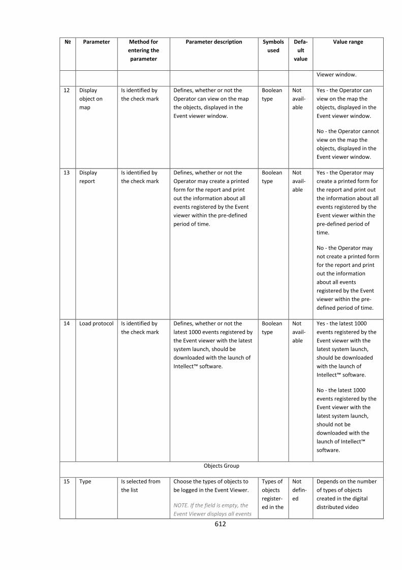
612
№ Parameter Method for
entering the
parameter
Parameter description Symbols
used
Defa-
ult
value
Value range
Viewer window.
12 Display
object on
map
Is identified by
the check mark
Defines, whether or not the
Operator can view on the map
the objects, displayed in the
Event viewer window.
Boolean
type
Not
avail-
able
Yes - the Operator can
view on the map the
objects, displayed in the
Event viewer window.
No - the Operator cannot
view on the map the
objects, displayed in the
Event viewer window.
13 Display
report
Is identified by
the check mark
Defines, whether or not the
Operator may create a printed
form for the report and print
out the information about all
events registered by the Event
viewer within the pre-defined
period of time.
Boolean
type
Not
avail-
able
Yes - the Operator may
create a printed form for
the report and print out
the information about all
events registered by the
Event viewer within the
pre-defined period of
time.
No - the Operator may
not create a printed form
for the report and print
out the information
about all events
registered by the Event
viewer within the pre-
defined period of time.
14 Load protocol Is identified by
the check mark
Defines, whether or not the
latest 1000 events registered by
the Event viewer with the latest
system launch, should be
downloaded with the launch of
Intellect™ software.
Boolean
type
Not
avail-
able
Yes - the latest 1000
events registered by the
Event viewer with the
latest system launch,
should be downloaded
with the launch of
Intellect™ software.
No - the latest 1000
events registered by the
Event viewer with the
latest system launch,
should not be
downloaded with the
launch of Intellect™
software.
Objects Group
15 Type Is selected from
the list
Choose the types of objects to
be logged in the Event Viewer.
NOTE. If the field is empty, the
Event Viewer displays all events
Types of
objects
register-
ed in the
Not
defin-
ed
Depends on the number
of types of objects
created in the digital
distributed video
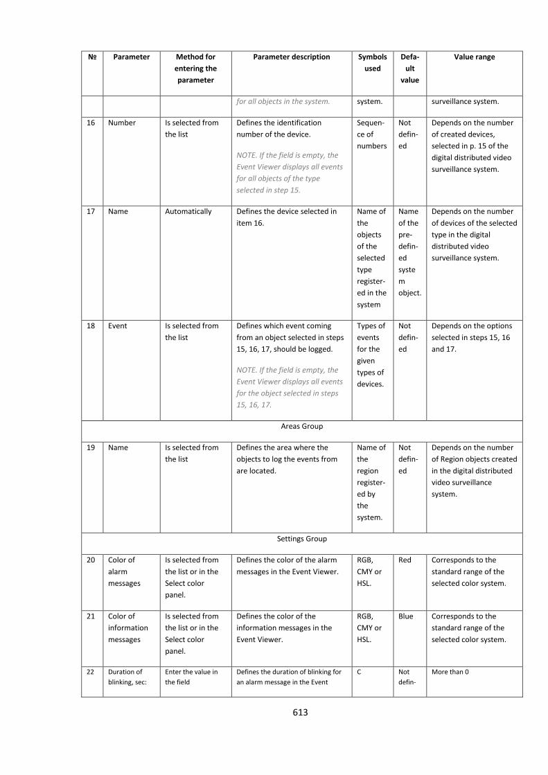
613
№ Parameter Method for
entering the
parameter
Parameter description Symbols
used
Defa-
ult
value
Value range
for all objects in the system. system. surveillance system.
16 Number Is selected from
the list
Defines the identification
number of the device.
NOTE. If the field is empty, the
Event Viewer displays all events
for all objects of the type
selected in step 15.
Sequen-
ce of
numbers
Not
defin-
ed
Depends on the number
of created devices,
selected in p. 15 of the
digital distributed video
surveillance system.
17 Name Automatically Defines the device selected in
item 16.
Name of
the
objects
of the
selected
type
register-
ed in the
system
Name
of the
pre-
defin-
ed
syste
m
object.
Depends on the number
of devices of the selected
type in the digital
distributed video
surveillance system.
18 Event Is selected from
the list
Defines which event coming
from an object selected in steps
15, 16, 17, should be logged.
NOTE. If the field is empty, the
Event Viewer displays all events
for the object selected in steps
15, 16, 17.
Types of
events
for the
given
types of
devices.
Not
defin-
ed
Depends on the options
selected in steps 15, 16
and 17.
Areas Group
19 Name Is selected from
the list
Defines the area where the
objects to log the events from
are located.
Name of
the
region
register-
ed by
the
system.
Not
defin-
ed
Depends on the number
of Region objects created
in the digital distributed
video surveillance
system.
Settings Group
20 Color of
alarm
messages
Is selected from
the list or in the
Select color
panel.
Defines the color of the alarm
messages in the Event Viewer.
RGB,
CMY or
HSL.
Red Corresponds to the
standard range of the
selected color system.
21 Color of
information
messages
Is selected from
the list or in the
Select color
panel.
Defines the color of the
information messages in the
Event Viewer.
RGB,
CMY or
HSL.
Blue Corresponds to the
standard range of the
selected color system.
22 Duration of
blinking, sec:
Enter the value in
the field
Defines the duration of blinking for
an alarm message in the Event
С Not
defin-
More than 0
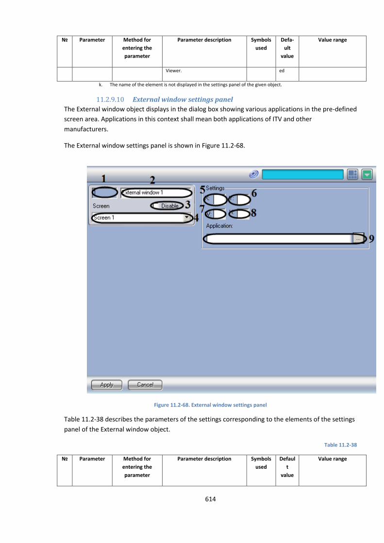
614
№ Parameter Method for
entering the
parameter
Parameter description Symbols
used
Defa-
ult
value
Value range
Viewer. ed
k. The name of the element is not displayed in the settings panel of the given object.
11.2.9.10 External window settings panel
The External window object displays in the dialog box showing various applications in the pre-defined
screen area. Applications in this context shall mean both applications of ITV and other
manufacturers.
The External window settings panel is shown in Figure 11.2-68.
Figure 11.2-68. External window settings panel
Table 11.2-38 describes the parameters of the settings corresponding to the elements of the settings
panel of the External window object.
Table 11.2-38
№
Parameter Method for
entering the
parameter
Parameter description Symbols
used
Defaul
t
value
Value range
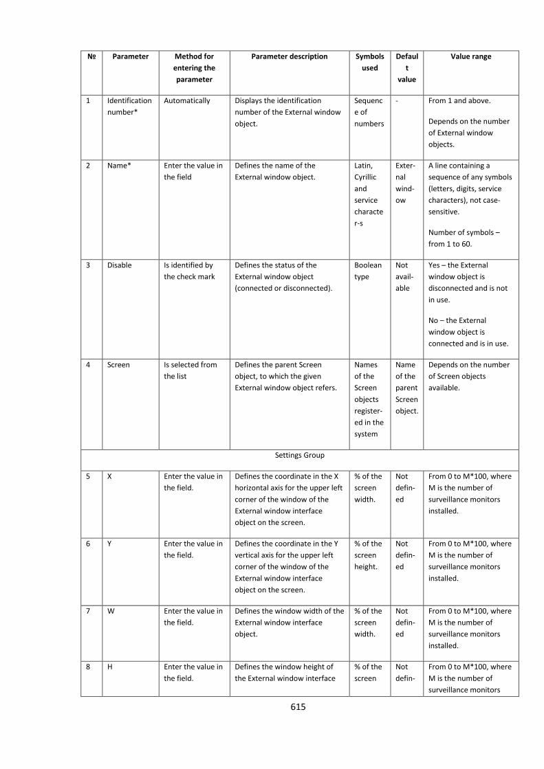
615
№
Parameter Method for
entering the
parameter
Parameter description Symbols
used
Defaul
t
value
Value range
1 Identification
number*
Automatically Displays the identification
number of the External window
object.
Sequenc
e of
numbers
- From 1 and above.
Depends on the number
of External window
objects.
2 Name* Enter the value in
the field
Defines the name of the
External window object.
Latin,
Cyrillic
and
service
characte
r-s
Exter-
nal
wind-
ow
A line containing a
sequence of any symbols
(letters, digits, service
characters), not case-
sensitive.
Number of symbols –
from 1 to 60.
3 Disable Is identified by
the check mark
Defines the status of the
External window object
(connected or disconnected).
Boolean
type
Not
avail-
able
Yes – the External
window object is
disconnected and is not
in use.
No – the External
window object is
connected and is in use.
4 Screen Is selected from
the list
Defines the parent Screen
object, to which the given
External window object refers.
Names
of the
Screen
objects
register-
ed in the
system
Name
of the
parent
Screen
object.
Depends on the number
of Screen objects
available.
Settings Group
5 X Enter the value in
the field.
Defines the coordinate in the X
horizontal axis for the upper left
corner of the window of the
External window interface
object on the screen.
% of the
screen
width.
Not
defin-
ed
From 0 to M*100, where
M is the number of
surveillance monitors
installed.
6 Y Enter the value in
the field.
Defines the coordinate in the Y
vertical axis for the upper left
corner of the window of the
External window interface
object on the screen.
% of the
screen
height.
Not
defin-
ed
From 0 to M*100, where
M is the number of
surveillance monitors
installed.
7 W Enter the value in
the field.
Defines the window width of the
External window interface
object.
% of the
screen
width.
Not
defin-
ed
From 0 to M*100, where
M is the number of
surveillance monitors
installed.
8 H Enter the value in
the field.
Defines the window height of
the External window interface
% of the
screen
Not
defin-
From 0 to M*100, where
M is the number of
surveillance monitors
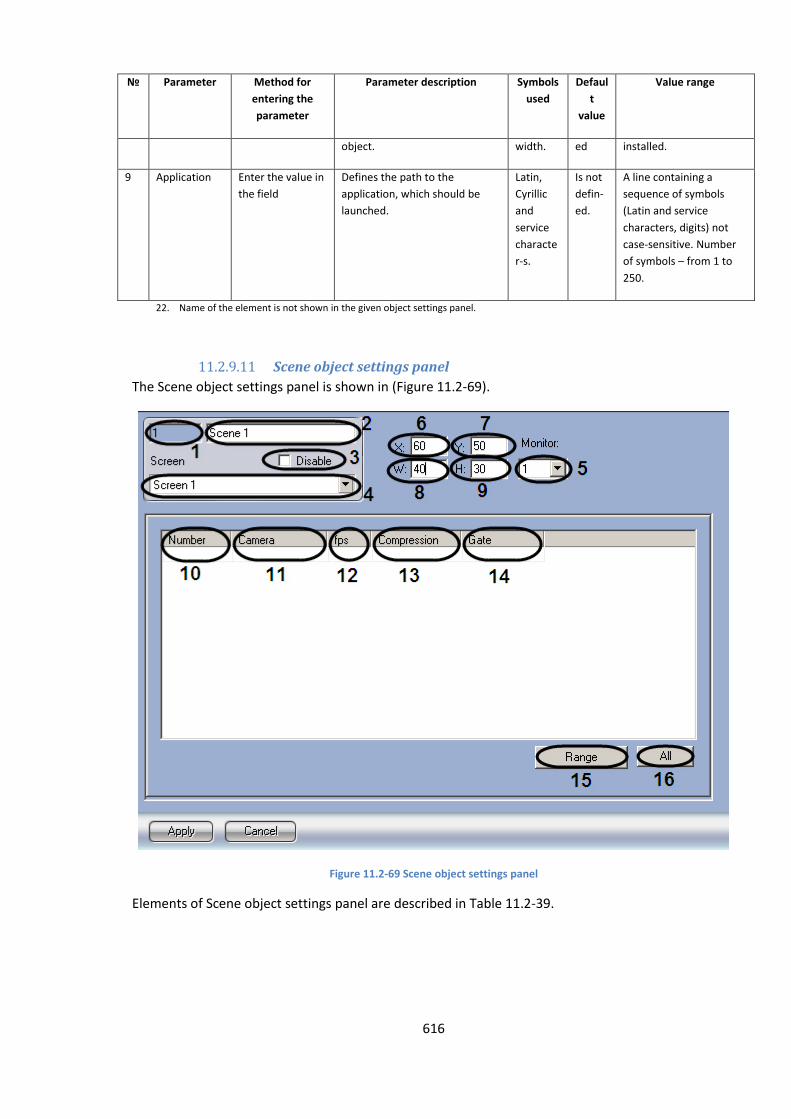
616
№
Parameter Method for
entering the
parameter
Parameter description Symbols
used
Defaul
t
value
Value range
object. width. ed installed.
9 Application Enter the value in
the field
Defines the path to the
application, which should be
launched.
Latin,
Cyrillic
and
service
characte
r-s.
Is not
defin-
ed.
A line containing a
sequence of symbols
(Latin and service
characters, digits) not
case-sensitive. Number
of symbols – from 1 to
250.
22. Name of the element is not shown in the given object settings panel.
11.2.9.11 Scene object settings panel
The Scene object settings panel is shown in (Figure 11.2-69).
Figure 11.2-69 Scene object settings panel
Elements of Scene object settings panel are described in Table 11.2-39.
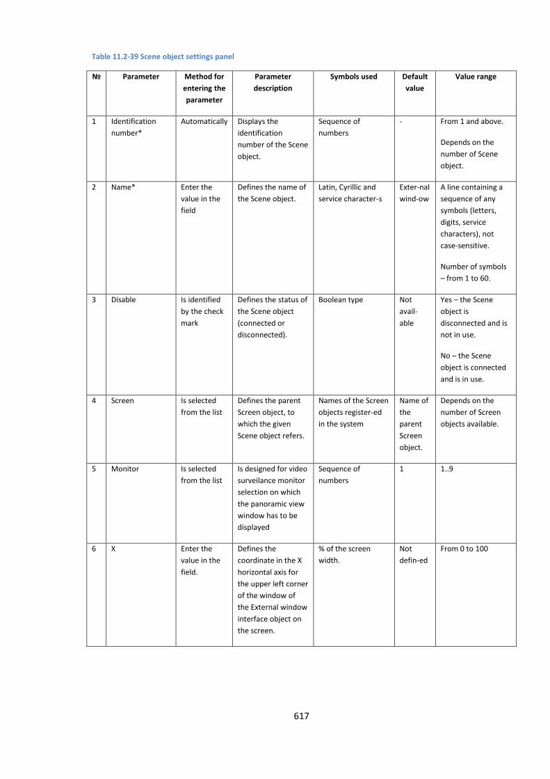
617
Table 11.2-39 Scene object settings panel
№
Parameter Method for
entering the
parameter
Parameter
description
Symbols used Default
value
Value range
1 Identification
number*
Automatically Displays the
identification
number of the Scene
object.
Sequence of
numbers
- From 1 and above.
Depends on the
number of Scene
object.
2 Name* Enter the
value in the
field
Defines the name of
the Scene object.
Latin, Cyrillic and
service character-s
Exter-nal
wind-ow
A line containing a
sequence of any
symbols (letters,
digits, service
characters), not
case-sensitive.
Number of symbols
– from 1 to 60.
3 Disable Is identified
by the check
mark
Defines the status of
the Scene object
(connected or
disconnected).
Boolean type Not
avail-
able
Yes – the Scene
object is
disconnected and is
not in use.
No – the Scene
object is connected
and is in use.
4 Screen Is selected
from the list
Defines the parent
Screen object, to
which the given
Scene object refers.
Names of the Screen
objects register-ed
in the system
Name of
the
parent
Screen
object.
Depends on the
number of Screen
objects available.
5 Monitor Is selected
from the list
Is designed for video
surveilance monitor
selection on which
the panoramic view
window has to be
displayed
Sequence of
numbers
1 1..9
6 X Enter the
value in the
field.
Defines the
coordinate in the X
horizontal axis for
the upper left corner
of the window of
the External window
interface object on
the screen.
% of the screen
width.
Not
defin-ed
From 0 to 100

618
7 Y Enter the
value in the
field.
Defines the
coordinate in the Y
vertical axis for the
upper left corner of
the window of the
External window
interface object on
the screen.
% of the screen
height.
Not
defined
From 0 to 100
8 W Enter the
value in the
field.
Defines the window
width of the
External window
interface object.
% of the screen
width.
Not
defined
From 0 to 100
9 H Enter the
value in the
field.
Defines the window
height of the
External window
interface object.
% of the screen
width.
Not
defined
From 0 to 100
10 Number Is selected from the list
Set camera’s number to be displayed
Latin, Cyrillic and
service character-s.
Is not
defined.
Depends on number of cameras registered in the system
11 Camera Is selected from the list
Set camera’s name to be displayed
Names of cameras registered in the system
- Depends on number of cameras registered in the system
12 fps Is selected from the list
Set fps to be transferred to the Scene object
Sequence of numbers
- 1, 2, 3, 4, 6, 8, 12, 16, 20, 25, 30
13 Compression Is selected from the list
Set the video signal compression level to be transferred to the Scene object. With set value there is additional use of Server’s resources
Sequence of numbers
- In order of greater compression 0, 1, 2, 3, 4, 5 0 – no compression 5 – maximum compression
14 Gate Is selected from the list
Set the Video gate object via which the video archive from the selected camera has to be transferred to the Scene object.
Names of Gate objects registered in the system
- Depends on number of Gate objects registered in the system
15 Range Click the button
Access to complex selection and editing the cameras parameters to be displayed on Scene object
- - -
16 All Click the button
Selection of all cameras registered in the system to be displayed on the Scene object
- - -
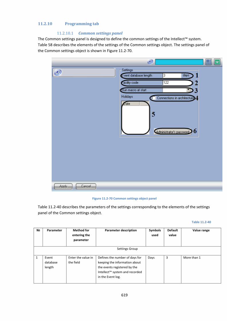
619
11.2.10 Programming tab
11.2.10.1 Common settings panel
The Common settings panel is designed to define the common settings of the Intellect™ system.
Table 58 describes the elements of the settings of the Common settings object. The settings panel of
the Common settings object is shown in Figure 11.2-70.
Figure 11.2-70 Common settings object panel
Table 11.2-40 describes the parameters of the settings corresponding to the elements of the settings
panel of the Common settings object.
Table 11.2-40
№ Parameter Method for
entering the
parameter
Parameter description Symbols
used
Default
value
Value range
Settings Group
1 Event
database
length
Enter the value in
the field
Defines the number of days for
keeping the information about
the events registered by the
Intellect™ system and recorded
in the Event log.
Days 3 More than 1
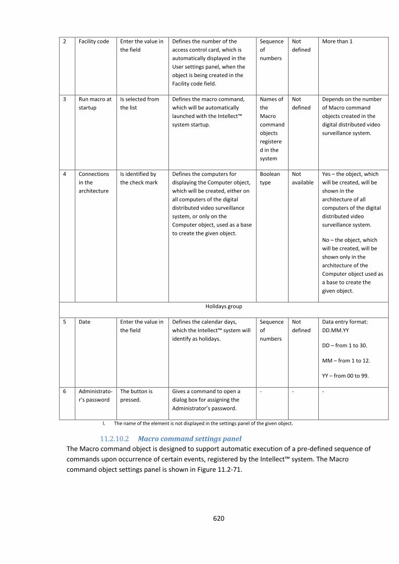
620
2 Facility code Enter the value in
the field
Defines the number of the
access control card, which is
automatically displayed in the
User settings panel, when the
object is being created in the
Facility code field.
Sequence
of
numbers
Not
defined
More than 1
3 Run macro at
startup
Is selected from
the list
Defines the macro command,
which will be automatically
launched with the Intellect™
system startup.
Names of
the
Macro
command
objects
registere
d in the
system
Not
defined
Depends on the number
of Macro command
objects created in the
digital distributed video
surveillance system.
4 Connections
in the
architecture
Is identified by
the check mark
Defines the computers for
displaying the Computer object,
which will be created, either on
all computers of the digital
distributed video surveillance
system, or only on the
Computer object, used as a base
to create the given object.
Boolean
type
Not
available
Yes – the object, which
will be created, will be
shown in the
architecture of all
computers of the digital
distributed video
surveillance system.
No – the object, which
will be created, will be
shown only in the
architecture of the
Computer object used as
a base to create the
given object.
Holidays group
5 Date Enter the value in
the field
Defines the calendar days,
which the Intellect™ system will
identify as holidays.
Sequence
of
numbers
Not
defined
Data entry format:
DD.MM.YY
DD – from 1 to 30.
MM – from 1 to 12.
YY – from 00 to 99.
6 Administrato-
r’s password
The button is
pressed.
Gives a command to open a
dialog box for assigning the
Administrator’s password.
- - -
l. The name of the element is not displayed in the settings panel of the given object.
11.2.10.2 Macro command settings panel
The Macro command object is designed to support automatic execution of a pre-defined sequence of
commands upon occurrence of certain events, registered by the Intellect™ system. The Macro
command object settings panel is shown in Figure 11.2-71.

621
Figure 11.2-71. Macro command object settings panel
Table 11.2-41 describes the parameters of the settings corresponding to the elements of the settings
panel of the Macro command object.
Table 11.2-41
№ Parameter Method for
entering the
parameter
Parameter description Symbols
used
Default
value
Value range
1 Identification
number*
Automatically Displays the identification
number of the Macro command
object in the video surveillance
system.
Sequence
of
numbers
- Depends on the number
of Macro command
objects in the digital
distributed video
surveillance system.
2 Name* Enter the value in
the field
Defines the Macro command
object name.
Latin,
Cyrillic
and
service
character
s
Macro
comma-
nd
A line containing a
sequence of any symbols
(letters, digits, service
characters), case-
insensitive.
Number of symbols –
from 1 to 60.
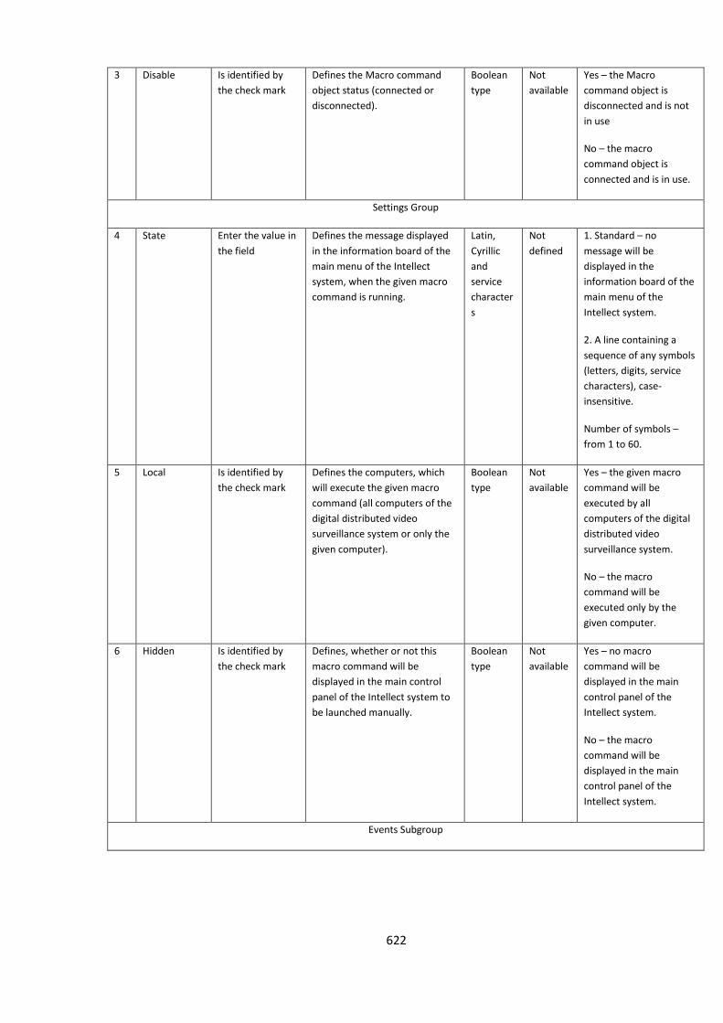
622
3 Disable Is identified by
the check mark
Defines the Macro command
object status (connected or
disconnected).
Boolean
type
Not
available
Yes – the Macro
command object is
disconnected and is not
in use
No – the macro
command object is
connected and is in use.
Settings Group
4 State Enter the value in
the field
Defines the message displayed
in the information board of the
main menu of the Intellect
system, when the given macro
command is running.
Latin,
Cyrillic
and
service
character
s
Not
defined
1. Standard – no
message will be
displayed in the
information board of the
main menu of the
Intellect system.
2. A line containing a
sequence of any symbols
(letters, digits, service
characters), case-
insensitive.
Number of symbols –
from 1 to 60.
5 Local Is identified by
the check mark
Defines the computers, which
will execute the given macro
command (all computers of the
digital distributed video
surveillance system or only the
given computer).
Boolean
type
Not
available
Yes – the given macro
command will be
executed by all
computers of the digital
distributed video
surveillance system.
No – the macro
command will be
executed only by the
given computer.
6 Hidden Is identified by
the check mark
Defines, whether or not this
macro command will be
displayed in the main control
panel of the Intellect system to
be launched manually.
Boolean
type
Not
available
Yes – no macro
command will be
displayed in the main
control panel of the
Intellect system.
No – the macro
command will be
displayed in the main
control panel of the
Intellect system.
Events Subgroup
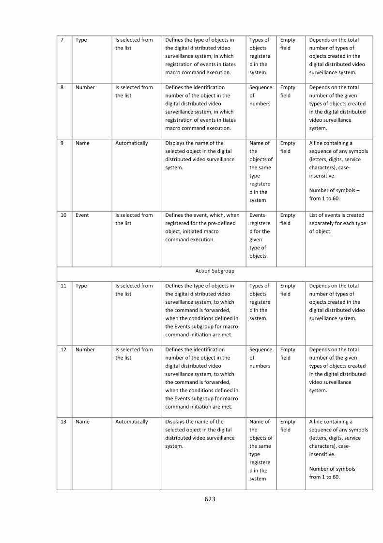
623
7 Type Is selected from
the list
Defines the type of objects in
the digital distributed video
surveillance system, in which
registration of events initiates
macro command execution.
Types of
objects
registere
d in the
system.
Empty
field
Depends on the total
number of types of
objects created in the
digital distributed video
surveillance system.
8 Number Is selected from
the list
Defines the identification
number of the object in the
digital distributed video
surveillance system, in which
registration of events initiates
macro command execution.
Sequence
of
numbers
Empty
field
Depends on the total
number of the given
types of objects created
in the digital distributed
video surveillance
system.
9 Name Automatically Displays the name of the
selected object in the digital
distributed video surveillance
system.
Name of
the
objects of
the same
type
registere
d in the
system
Empty
field
A line containing a
sequence of any symbols
(letters, digits, service
characters), case-
insensitive.
Number of symbols –
from 1 to 60.
10 Event Is selected from
the list
Defines the event, which, when
registered for the pre-defined
object, initiated macro
command execution.
Events
registere
d for the
given
type of
objects.
Empty
field
List of events is created
separately for each type
of object.
Action Subgroup
11 Type Is selected from
the list
Defines the type of objects in
the digital distributed video
surveillance system, to which
the command is forwarded,
when the conditions defined in
the Events subgroup for macro
command initiation are met.
Types of
objects
registere
d in the
system.
Empty
field
Depends on the total
number of types of
objects created in the
digital distributed video
surveillance system.
12 Number Is selected from
the list
Defines the identification
number of the object in the
digital distributed video
surveillance system, to which
the command is forwarded,
when the conditions defined in
the Events subgroup for macro
command initiation are met.
Sequence
of
numbers
Empty
field
Depends on the total
number of the given
types of objects created
in the digital distributed
video surveillance
system.
13 Name Automatically Displays the name of the
selected object in the digital
distributed video surveillance
system.
Name of
the
objects of
the same
type
registere
d in the
system
Empty
field
A line containing a
sequence of any symbols
(letters, digits, service
characters), case-
insensitive.
Number of symbols –
from 1 to 60.

624
14 Action Is selected from
the list
Defines the action, which the
given device performs, when the
conditions for the given macro
command initiation are met.
Actions,
registere
d by the
system
for the
given
type of
objects.
Empty
field
List of events is created
separately for each type
of object.
Parameters Subgroup
NOTE. The given subgroup is not active for all types of objects.
15 Name Automatically Defines an additional parameter
for the selected type of object in
the Actions subgroup.
Latin,
service
character
s and
digits.
Not
defined
A line containing a
sequence of any symbols
(letters, digits, service
characters), case-
insensitive.
Number of symbols –
from 1 to 60.
16 Value Enter the value in
the field
Defines the value for the
parameter of the Name column.
Latin,
service
character
s and
digits.
Empty
field
A line containing a
sequence of any symbols
(letters, digits, service
characters), case-
insensitive.
Number of symbols –
from 1 to 250.
m. The name of the element is not displayed in the User’s rights settings panel object.
11.2.10.3 Program settings panel
The Program object creates specialized programs in the embedded environment of the INTELLECT™
software. The Program settings panel is shown in Figure 11.2-72.
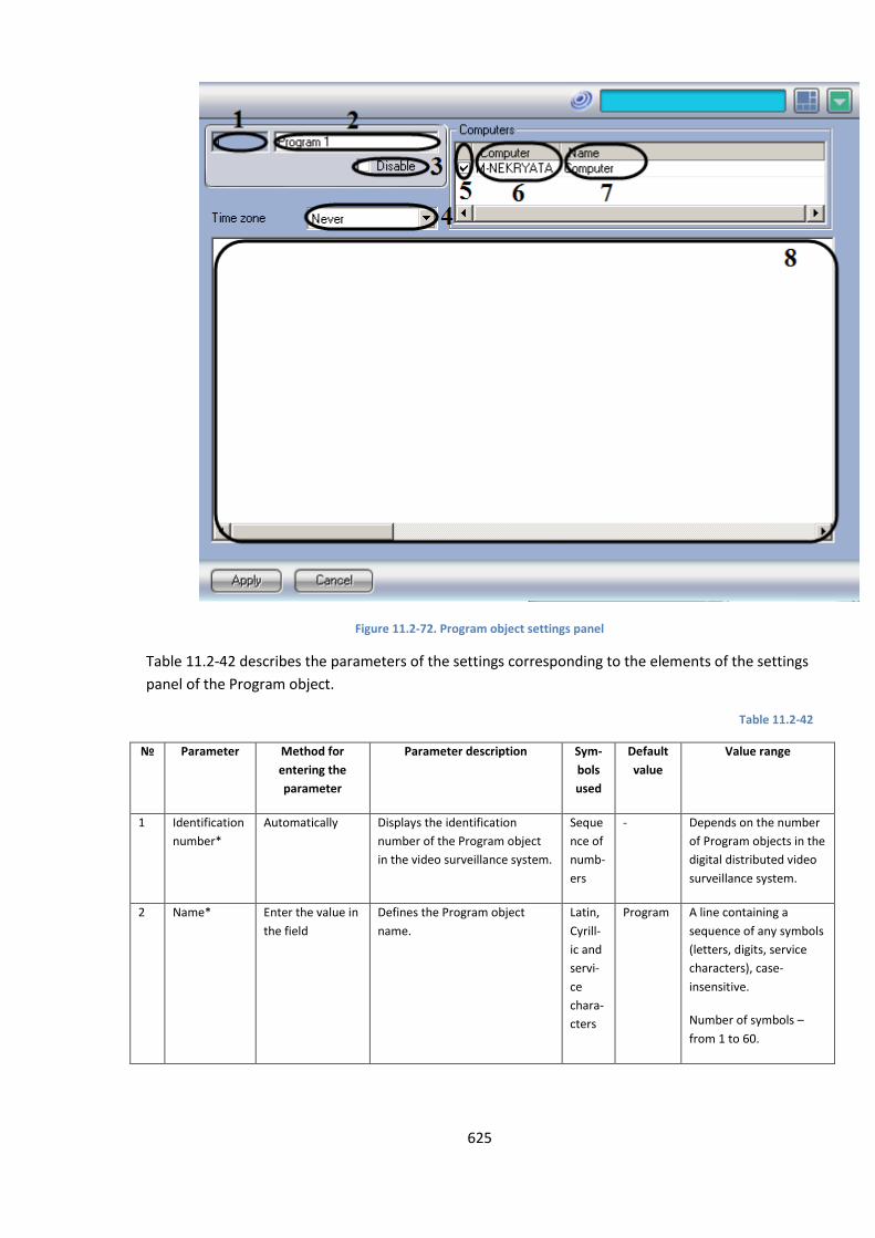
625
Figure 11.2-72. Program object settings panel
Table 11.2-42 describes the parameters of the settings corresponding to the elements of the settings
panel of the Program object.
Table 11.2-42
№
Parameter Method for
entering the
parameter
Parameter description Sym-
bols
used
Default
value
Value range
1 Identification
number*
Automatically Displays the identification
number of the Program object
in the video surveillance system.
Seque
nce of
numb-
ers
- Depends on the number
of Program objects in the
digital distributed video
surveillance system.
2 Name* Enter the value in
the field
Defines the Program object
name.
Latin,
Cyrill-
ic and
servi-
ce
chara-
cters
Program A line containing a
sequence of any symbols
(letters, digits, service
characters), case-
insensitive.
Number of symbols –
from 1 to 60.

626
3 Disable Is identified by
the check mark
Defines the status of the
Program object (connected or
disconnected).
Bool-
ean
type
Not
available
Yes – the Program object
is disconnected and is
not in use
No – the Program object
is connected and is in
use.
4 Time zone Is selected from
the list
Defines the time period during
which the given program will
operate.
Time
zone
regist-
ered
by the
syste
m
Never Never – this program will
never be executed.
Always – this program is
always in the state of
execution.
List of created time
zones – the program will
be executed within a
pre-defined time period.
Computers Group
5 Select an
element*
Is identified by
the check mark
Defines the computer for the
execution of the given program.
Bool-
ean
type
Not
available
Yes – the program will be
executed by the pre-
defined computer.
No – the program will
not be executed by the
computer.
6 Computer Automatically Defines the computer name in
the local network.
Com-
puter
name
in the
local
netwo
-rk.
Comput-
er name
in the
local
network.
A line containing a
sequence of any symbols
(letters, digits, service
characters), case-
insensitive.
Number of symbols - 60.
7 Name Automatically Defines the computer name Name
of the
Com-
puter
object
regist-
ered
in the
syste
m
Name of
the
Comput-
er object
register-
ed in the
system
A line containing a
sequence of any symbols
(letters, digits, service
characters), case-
insensitive.
Number of symbols - 60.
Out of the groups
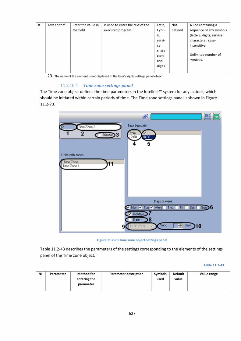
627
8 Text editor* Enter the value in
the field
Is used to enter the text of the
executed program.
Latin,
Cyrill-
ic,
servi-
ce
chara-
cters
and
digits.
Not
defined
A line containing a
sequence of any symbols
(letters, digits, service
characters), case-
insensitive.
Unlimited number of
symbols.
23. The name of the element is not displayed in the User’s rights settings panel object.
11.2.10.4 Time zone settings panel
The Time zone object defines the time parameters in the Intellect™ system for any actions, which
should be initiated within certain periods of time. The Time zone settings panel is shown in Figure
11.2-73.
Figure 11.2-73 Time zone object settings panel
Table 11.2-43 describes the parameters of the settings corresponding to the elements of the settings
panel of the Time zone object.
Table 11.2-43
№ Parameter Method for
entering the
parameter
Parameter description Symbols
used
Default
value
Value range
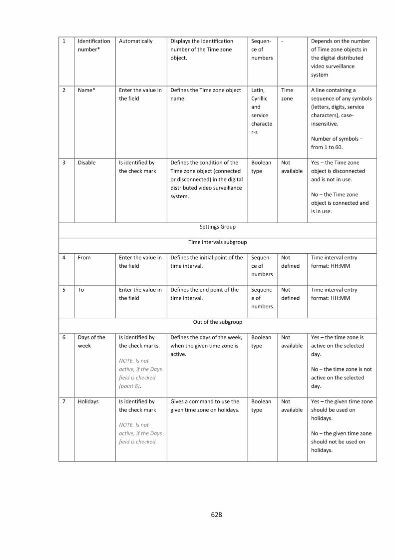
628
1 Identification
number*
Automatically Displays the identification
number of the Time zone
object.
Sequen-
ce of
numbers
- Depends on the number
of Time zone objects in
the digital distributed
video surveillance
system
2 Name* Enter the value in
the field
Defines the Time zone object
name.
Latin,
Cyrillic
and
service
characte
r-s
Time
zone
A line containing a
sequence of any symbols
(letters, digits, service
characters), case-
insensitive.
Number of symbols –
from 1 to 60.
3 Disable Is identified by
the check mark
Defines the condition of the
Time zone object (connected
or disconnected) in the digital
distributed video surveillance
system.
Boolean
type
Not
available
Yes – the Time zone
object is disconnected
and is not in use.
No – the Time zone
object is connected and
is in use.
Settings Group
Time intervals subgroup
4 From Enter the value in
the field
Defines the initial point of the
time interval.
Sequen-
ce of
numbers
Not
defined
Time interval entry
format: HH:MM
5 To Enter the value in
the field
Defines the end point of the
time interval.
Sequenc
e of
numbers
Not
defined
Time interval entry
format: HH:MM
Out of the subgroup
6 Days of the
week
Is identified by
the check marks.
NOTE. Is not
active, if the Days
field is checked
(point 8).
Defines the days of the week,
when the given time zone is
active.
Boolean
type
Not
available
Yes – the time zone is
active on the selected
day.
No – the time zone is not
active on the selected
day.
7 Holidays Is identified by
the check mark
NOTE. Is not
active, if the Days
field is checked.
Gives a command to use the
given time zone on holidays.
Boolean
type
Not
available
Yes – the given time zone
should be used on
holidays.
No – the given time zone
should not be used on
holidays.
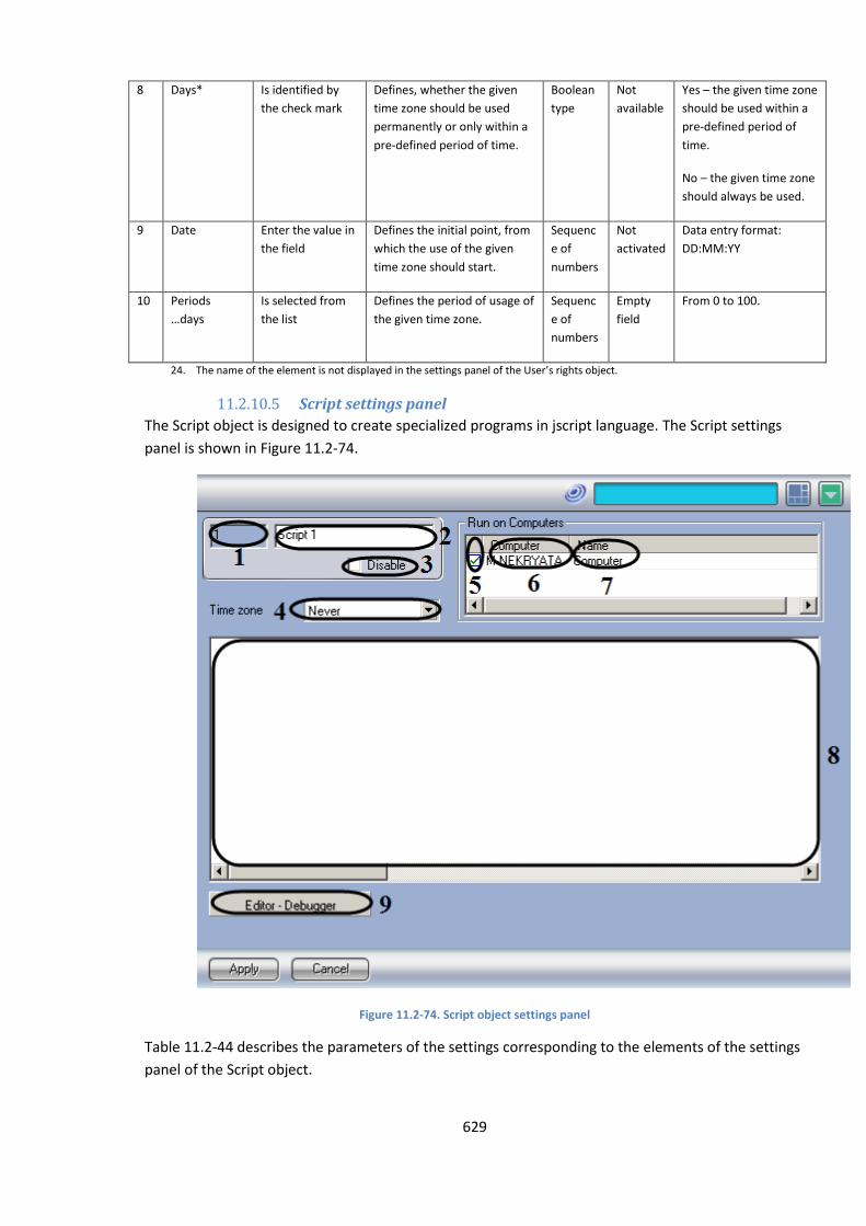
629
8 Days* Is identified by
the check mark
Defines, whether the given
time zone should be used
permanently or only within a
pre-defined period of time.
Boolean
type
Not
available
Yes – the given time zone
should be used within a
pre-defined period of
time.
No – the given time zone
should always be used.
9 Date Enter the value in
the field
Defines the initial point, from
which the use of the given
time zone should start.
Sequenc
e of
numbers
Not
activated
Data entry format:
DD:MM:YY
10 Periods
…days
Is selected from
the list
Defines the period of usage of
the given time zone.
Sequenc
e of
numbers
Empty
field
From 0 to 100.
24. The name of the element is not displayed in the settings panel of the User’s rights object.
11.2.10.5 Script settings panel
The Script object is designed to create specialized programs in jscript language. The Script settings
panel is shown in Figure 11.2-74.
Figure 11.2-74. Script object settings panel
Table 11.2-44 describes the parameters of the settings corresponding to the elements of the settings
panel of the Script object.
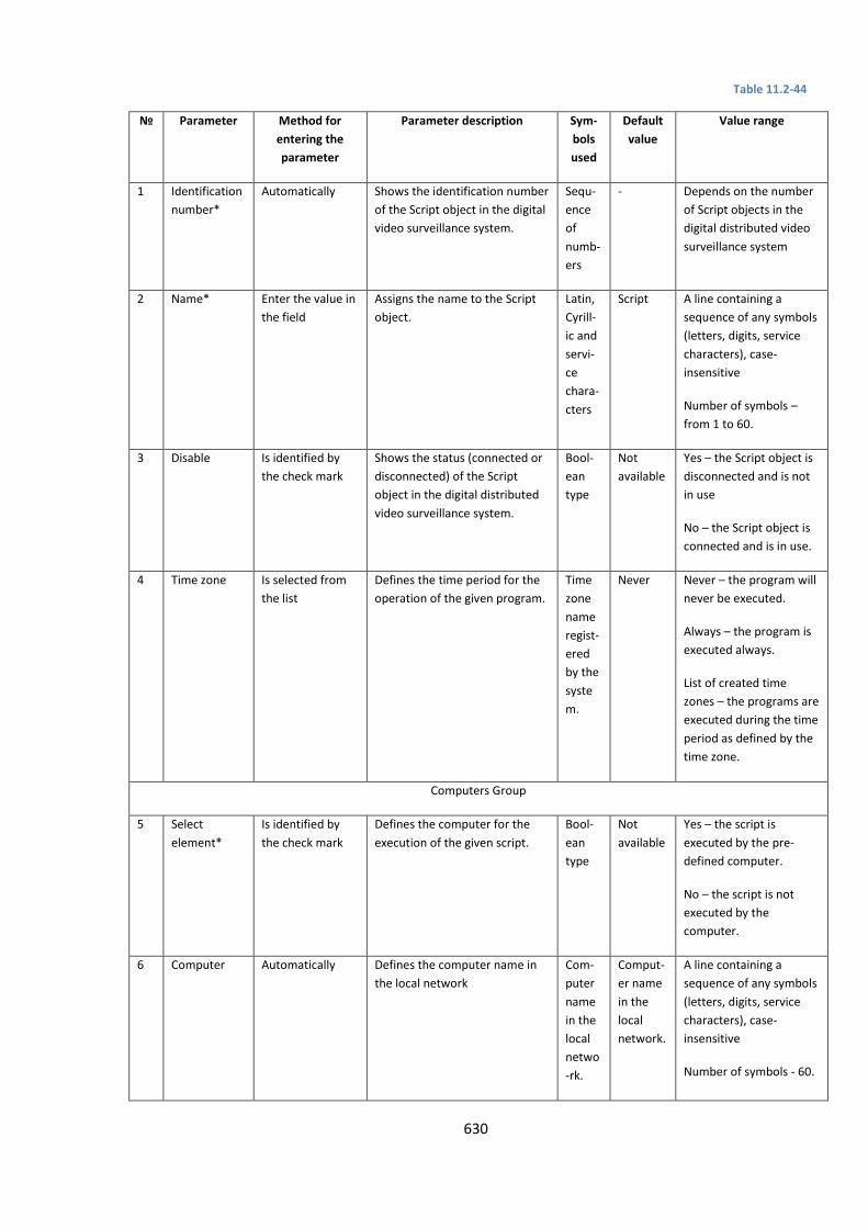
630
Table 11.2-44
№ Parameter Method for
entering the
parameter
Parameter description Sym-
bols
used
Default
value
Value range
1 Identification
number*
Automatically Shows the identification number
of the Script object in the digital
video surveillance system.
Sequ-
ence
of
numb-
ers
- Depends on the number
of Script objects in the
digital distributed video
surveillance system
2 Name* Enter the value in
the field
Assigns the name to the Script
object.
Latin,
Cyrill-
ic and
servi-
ce
chara-
cters
Script A line containing a
sequence of any symbols
(letters, digits, service
characters), case-
insensitive
Number of symbols –
from 1 to 60.
3 Disable Is identified by
the check mark
Shows the status (connected or
disconnected) of the Script
object in the digital distributed
video surveillance system.
Bool-
ean
type
Not
available
Yes – the Script object is
disconnected and is not
in use
No – the Script object is
connected and is in use.
4 Time zone Is selected from
the list
Defines the time period for the
operation of the given program.
Time
zone
name
regist-
ered
by the
syste
m.
Never Never – the program will
never be executed.
Always – the program is
executed always.
List of created time
zones – the programs are
executed during the time
period as defined by the
time zone.
Computers Group
5 Select
element*
Is identified by
the check mark
Defines the computer for the
execution of the given script.
Bool-
ean
type
Not
available
Yes – the script is
executed by the pre-
defined computer.
No – the script is not
executed by the
computer.
6 Computer Automatically Defines the computer name in
the local network
Com-
puter
name
in the
local
netwo
-rk.
Comput-
er name
in the
local
network.
A line containing a
sequence of any symbols
(letters, digits, service
characters), case-
insensitive
Number of symbols - 60.

631
7 Name Automatically Defines the name to the
computer used in the digital
distributed video surveillance
system.
Name
of the
Com-
puter
object
-s
regist-
ered
in the
syste
m.
Name of
the
Comput-
er
objects
register-
ed in the
system.
A line containing a
sequence of any symbols
(letters, digits, service
characters), case-
insensitive
Number of symbols - 60.
Out of the groups
8 Text editor* Enter the value in
the field
Defines the text of the executed
script.
Latin,
Cyrill-
ic and
servi-
ce
chara-
cters
Not
defined
A line containing a
sequence of any symbols
(letters, digits, service
characters), case-
insensitive
Unlimited number of
symbols.
9 Editor -
Debugger
Press the button. Gives a command to open a
debugging window of the script.
- - -
n. The name of the element is not displayed in the settings panel of the User’s rights object.
The Region object is designed to create zones, which break down secured areas into structural
elements. The Region objects allow:
1. group hardware based on the attributes of a certain region;
2. execute certain operations concurrently with all objects of the same type belonging to the
same region.
The Region settings panel is shown in Figure 11.2-75.
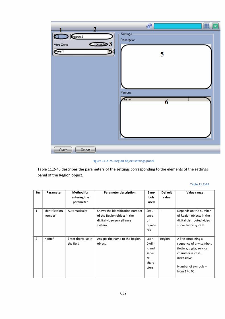
632
Figure 11.2-75. Region object settings panel
Table 11.2-45 describes the parameters of the settings corresponding to the elements of the settings
panel of the Region object.
Table 11.2-45
№ Parameter Method for
entering the
parameter
Parameter description Sym-
bols
used
Default
value
Value range
1 Identification
number*
Automatically Shows the identification number
of the Region object in the
digital video surveillance
system.
Sequ-
ence
of
numb-
ers
- Depends on the number
of Region objects in the
digital distributed video
surveillance system
2 Name* Enter the value in
the field
Assigns the name to the Region
object.
Latin,
Cyrill-
ic and
servi-
ce
chara-
cters
Region A line containing a
sequence of any symbols
(letters, digits, service
characters), case-
insensitive
Number of symbols –
from 1 to 60.
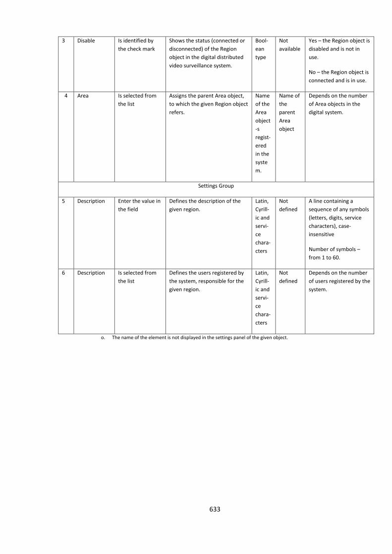
633
3 Disable Is identified by
the check mark
Shows the status (connected or
disconnected) of the Region
object in the digital distributed
video surveillance system.
Bool-
ean
type
Not
available
Yes – the Region object is
disabled and is not in
use.
No – the Region object is
connected and is in use.
4 Area Is selected from
the list
Assigns the parent Area object,
to which the given Region object
refers.
Name
of the
Area
object
-s
regist-
ered
in the
syste
m.
Name of
the
parent
Area
object
Depends on the number
of Area objects in the
digital system.
Settings Group
5 Description Enter the value in
the field
Defines the description of the
given region.
Latin,
Cyrill-
ic and
servi-
ce
chara-
cters
Not
defined
A line containing a
sequence of any symbols
(letters, digits, service
characters), case-
insensitive
Number of symbols –
from 1 to 60.
6 Description Is selected from
the list
Defines the users registered by
the system, responsible for the
given region.
Latin,
Cyrill-
ic and
servi-
ce
chara-
cters
Not
defined
Depends on the number
of users registered by the
system.
o. The name of the element is not displayed in the settings panel of the given object.
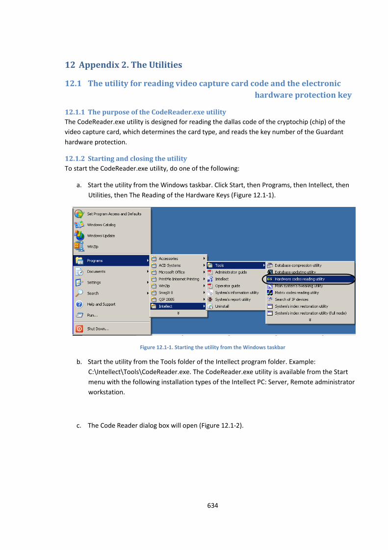
634
12 Appendix 2. The Utilities
12.1 The utility for reading video capture card code and the electronic
hardware protection key
12.1.1 The purpose of the CodeReader.exe utility
The CodeReader.exe utility is designed for reading the dallas code of the cryptochip (chip) of the
video capture card, which determines the card type, and reads the key number of the Guardant
hardware protection.
12.1.2 Starting and closing the utility
To start the CodeReader.exe utility, do one of the following:
a. Start the utility from the Windows taskbar. Click Start, then Programs, then Intellect, then
Utilities, then The Reading of the Hardware Keys (Figure 12.1-1).
Figure 12.1-1. Starting the utility from the Windows taskbar
b. Start the utility from the Tools folder of the Intellect program folder. Example:
С:\Intellect\Tools\CodeReader.exe. The CodeReader.exe utility is available from the Start
menu with the following installation types of the Intellect PC: Server, Remote administrator
workstation.
c. The Code Reader dialog box will open (Figure 12.1-2).
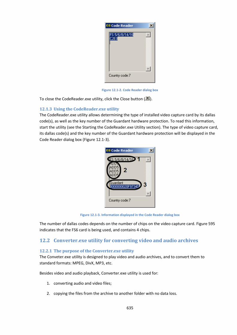
635
Figure 12.1-2. Code Reader dialog box
To close the CodeReader.exe utility, click the Close button ( ).
12.1.3 Using the CodeReader.exe utility
The CodeReader.exe utility allows determining the type of installed video capture card by its dallas
code(s), as well as the key number of the Guardant hardware protection. To read this information,
start the utility (see the Starting the CodeReader.exe Utility section). The type of video capture card,
its dallas code(s) and the key number of the Guardant hardware protection will be displayed in the
Code Reader dialog box (Figure 12.1-3).
Figure 12.1-3. Information displayed in the Code Reader dialog box
The number of dallas codes depends on the number of chips on the video capture card. Figure 595
indicates that the FS6 card is being used, and contains 4 chips.
12.2 Converter.exe utility for converting video and audio archives
12.2.1 The purpose of the Converter.exe utility
The Conveter.exe utility is designed to play video and audio archives, and to convert them to
standard formats: MPEG, DivX, MP3, etc.
Besides video and audio playback, Converter.exe utility is used for:
1. converting audio and video files;
2. copying the files from the archive to another folder with no data loss.
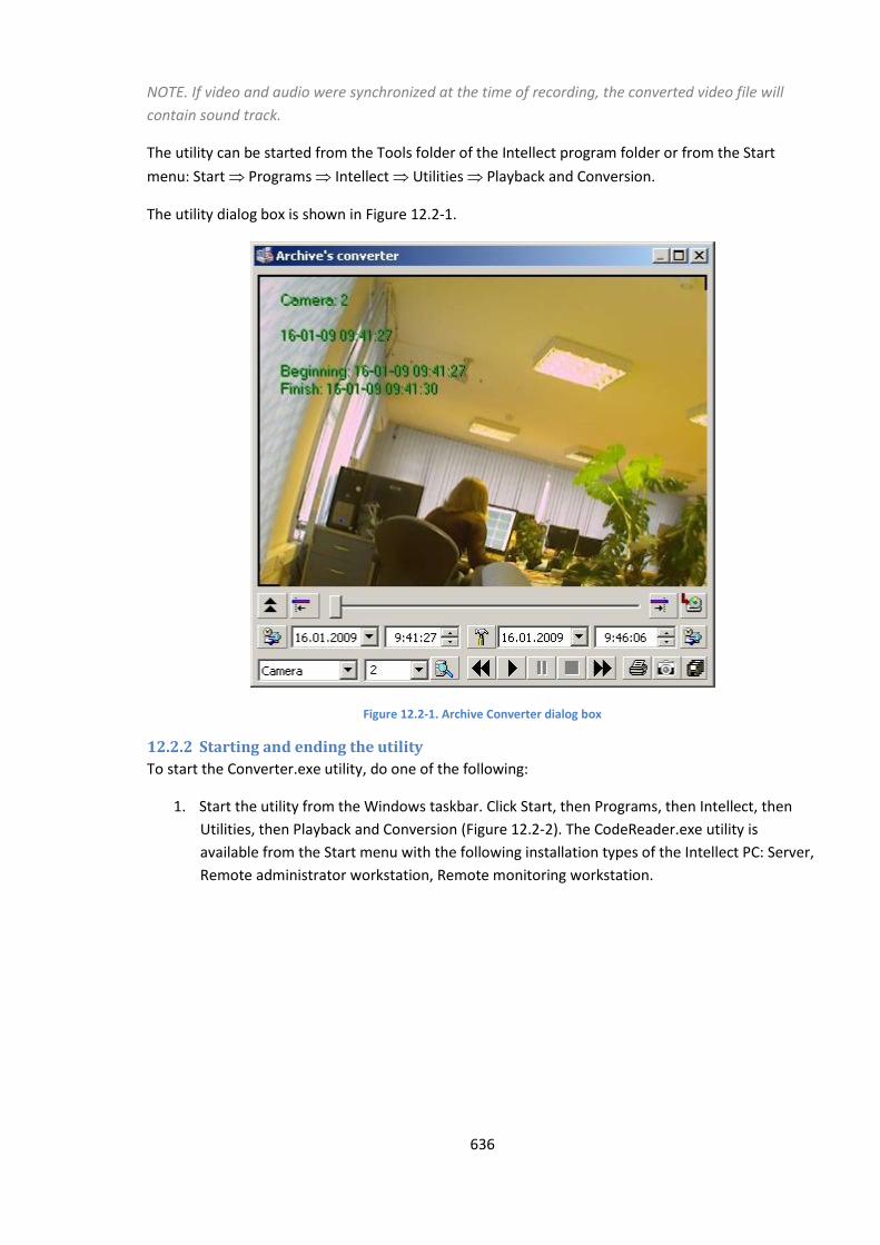
636
NOTE. If video and audio were synchronized at the time of recording, the converted video file will
contain sound track.
The utility can be started from the Tools folder of the Intellect program folder or from the Start
menu: Start Programs Intellect Utilities Playback and Conversion.
The utility dialog box is shown in Figure 12.2-1.
Figure 12.2-1. Archive Converter dialog box
12.2.2 Starting and ending the utility
To start the Converter.exe utility, do one of the following:
1. Start the utility from the Windows taskbar. Click Start, then Programs, then Intellect, then
Utilities, then Playback and Conversion (Figure 12.2-2). The CodeReader.exe utility is
available from the Start menu with the following installation types of the Intellect PC: Server,
Remote administrator workstation, Remote monitoring workstation.
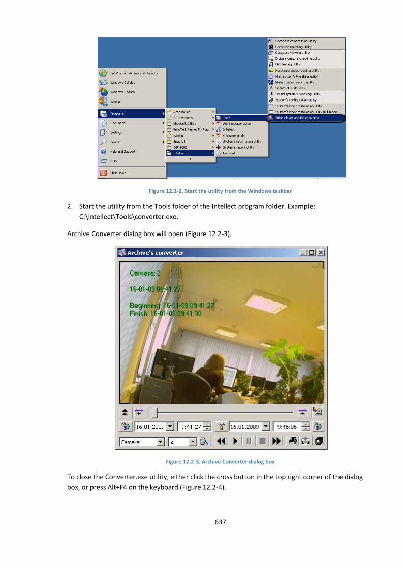
637
Figure 12.2-2. Start the utility from the Windows taskbar
2. Start the utility from the Tools folder of the Intellect program folder. Example:
С:\Intellect\Tools\converter.exe.
Archive Converter dialog box will open (Figure 12.2-3).
Figure 12.2-3. Archive Converter dialog box
To close the Converter.exe utility, either click the cross button in the top right corner of the dialog
box, or press Alt+F4 on the keyboard (Figure 12.2-4).
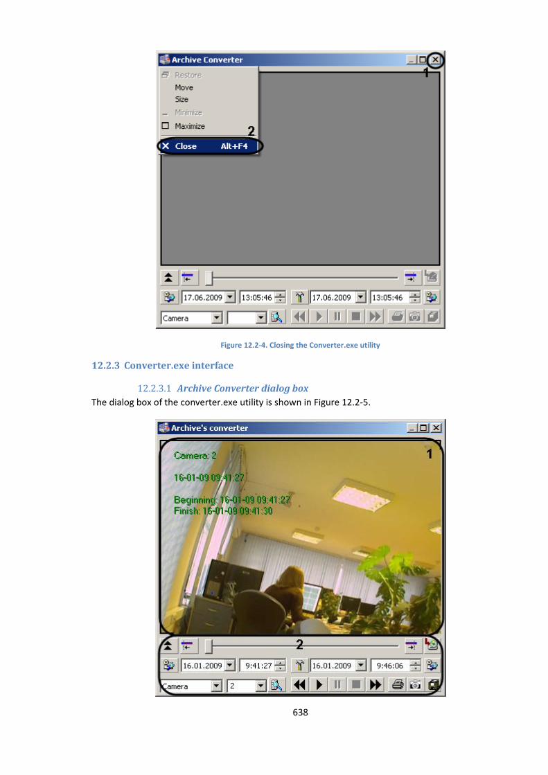
638
Figure 12.2-4. Closing the Converter.exe utility
12.2.3 Converter.exe interface
12.2.3.1 Archive Converter dialog box
The dialog box of the converter.exe utility is shown in Figure 12.2-5.
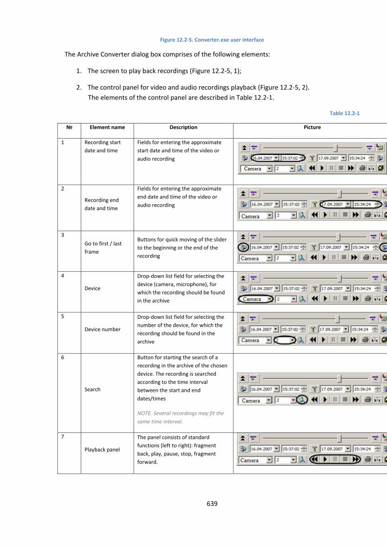
639
Figure 12.2-5. Converter.exe user interface
The Archive Converter dialog box comprises of the following elements:
1. The screen to play back recordings (Figure 12.2-5, 1);
2. The control panel for video and audio recordings playback (Figure 12.2-5, 2).
The elements of the control panel are described in Table 12.2-1.
Table 12.2-1
№ Element name Description Picture
1 Recording start
date and time
Fields for entering the approximate
start date and time of the video or
audio recording
2
Recording end
date and time
Fields for entering the approximate
end date and time of the video or
audio recording
3
Go to first / last
frame
Buttons for quick moving of the slider
to the beginning or the end of the
recording
4
Device
Drop-down list field for selecting the
device (camera, microphone), for
which the recording should be found
in the archive
5
Device number
Drop-down list field for selecting the
number of the device, for which the
recording should be found in the
archive
6
Search
Button for starting the search of a
recording in the archive of the chosen
device. The recording is searched
according to the time interval
between the start and end
dates/times
NOTE. Several recordings may fit the
same time interval.
7
Playback panel
The panel consists of standard
functions (left to right): fragment
back, play, pause, stop, fragment
forward.
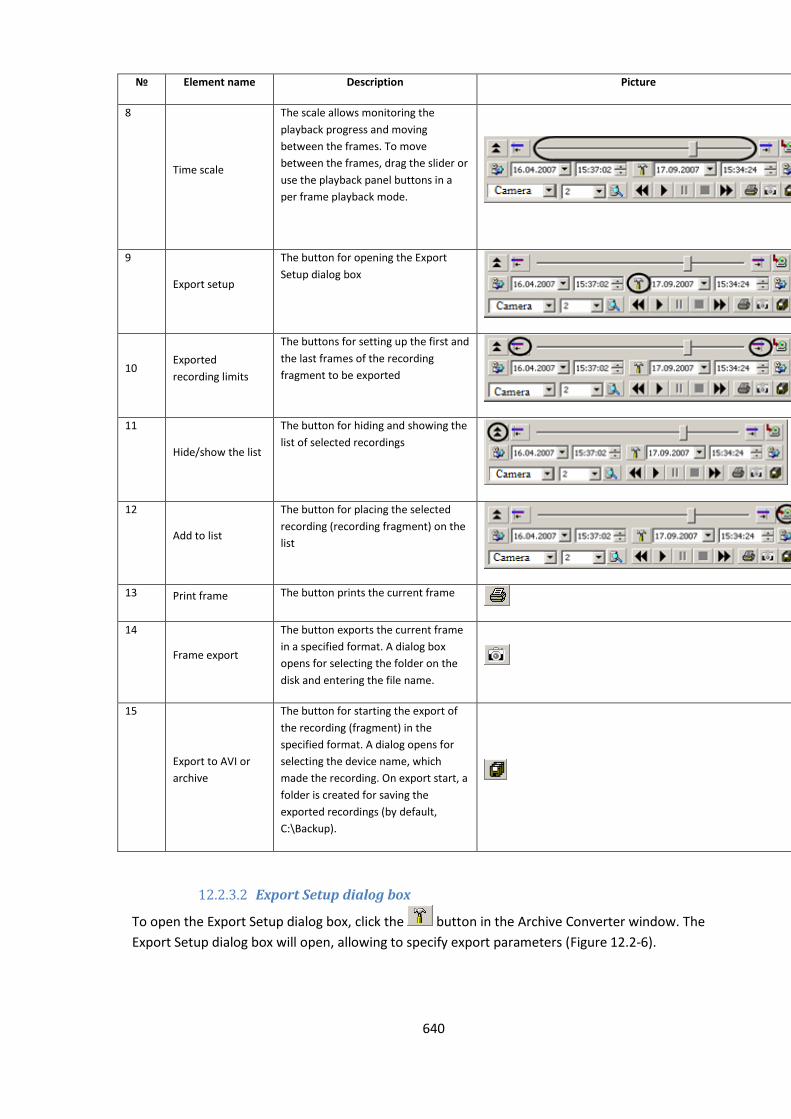
640
№ Element name Description Picture
8
Time scale
The scale allows monitoring the
playback progress and moving
between the frames. To move
between the frames, drag the slider or
use the playback panel buttons in a
per frame playback mode.
9
Export setup
The button for opening the Export
Setup dialog box
10 Exported
recording limits
The buttons for setting up the first and
the last frames of the recording
fragment to be exported
11
Hide/show the list
The button for hiding and showing the
list of selected recordings
12
Add to list
The button for placing the selected
recording (recording fragment) on the
list
13 Print frame The button prints the current frame
14
Frame export
The button exports the current frame
in a specified format. A dialog box
opens for selecting the folder on the
disk and entering the file name.
15
Export to AVI or
archive
The button for starting the export of
the recording (fragment) in the
specified format. A dialog opens for
selecting the device name, which
made the recording. On export start, a
folder is created for saving the
exported recordings (by default,
C:\Backup).
12.2.3.2 Export Setup dialog box
To open the Export Setup dialog box, click the button in the Archive Converter window. The
Export Setup dialog box will open, allowing to specify export parameters (Figure 12.2-6).
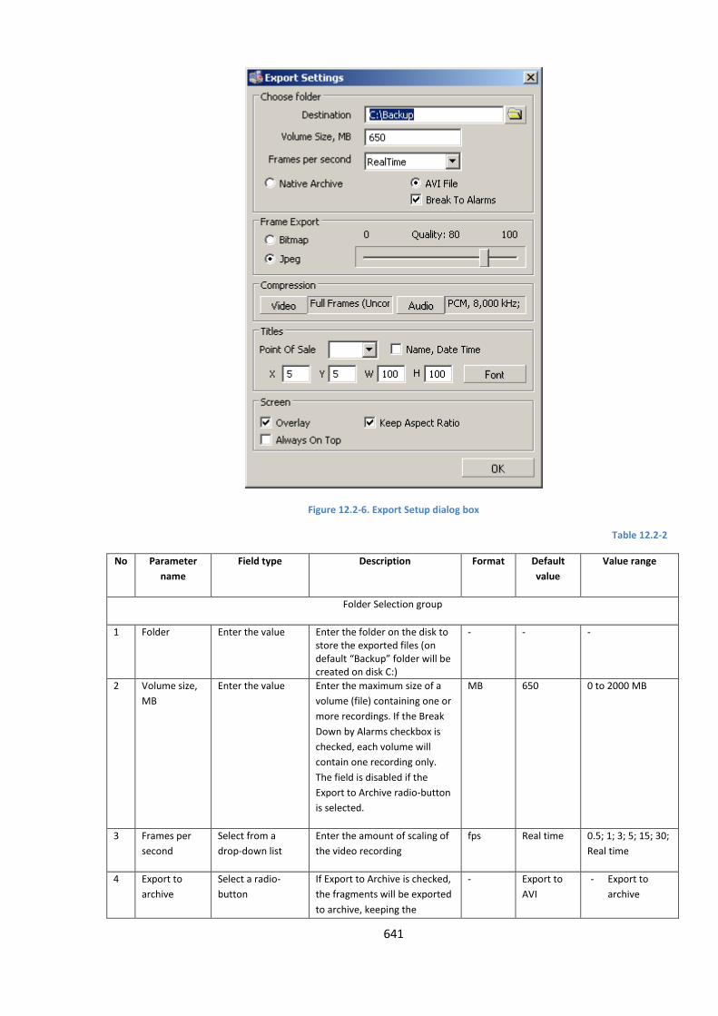
641
Figure 12.2-6. Export Setup dialog box
Table 12.2-2
No Parameter
name
Field type Description Format Default
value
Value range
Folder Selection group
1 Folder Enter the value Enter the folder on the disk to store the exported files (on default “Backup” folder will be created on disk C:)
- - -
2 Volume size,
MB
Enter the value Enter the maximum size of a
volume (file) containing one or
more recordings. If the Break
Down by Alarms checkbox is
checked, each volume will
contain one recording only.
The field is disabled if the
Export to Archive radio-button
is selected.
MB 650 0 to 2000 MB
3 Frames per
second
Select from a
drop-down list
Enter the amount of scaling of
the video recording
fps Real time 0.5; 1; 3; 5; 15; 30;
Real time
4 Export to
archive
Select a radio-
button
If Export to Archive is checked,
the fragments will be exported
to archive, keeping the
- Export to
AVI
- Export to
archive
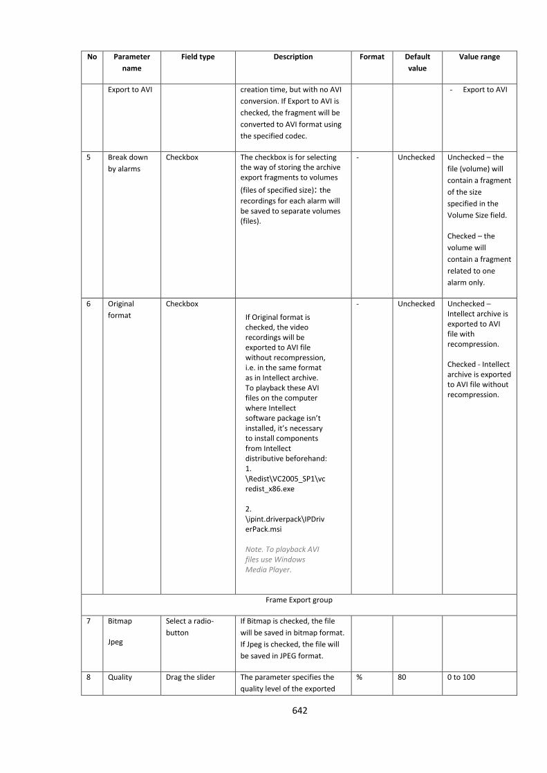
642
No Parameter
name
Field type Description Format Default
value
Value range
Export to AVI creation time, but with no AVI
conversion. If Export to AVI is
checked, the fragment will be
converted to AVI format using
the specified codec.
- Export to AVI
5 Break down
by alarms
Checkbox The checkbox is for selecting the way of storing the archive export fragments to volumes
(files of specified size): the
recordings for each alarm will be saved to separate volumes (files).
- Unchecked Unchecked – the
file (volume) will
contain a fragment
of the size
specified in the
Volume Size field.
Checked – the
volume will
contain a fragment
related to one
alarm only.
6 Original
format
Checkbox If Original format is checked, the video recordings will be exported to AVI file without recompression, i.e. in the same format as in Intellect archive. To playback these AVI files on the computer where Intellect software package isn’t installed, it’s necessary to install components from Intellect distributive beforehand: 1. \Redist\VC2005_SP1\vcredist_x86.ехе 2. \ipint.driverpack\IPDriverPack.msi Note. To playback AVI files use Windows Media Player.
- Unchecked Unchecked – Intellect archive is exported to AVI file with recompression. Checked - Intellect archive is exported to AVI file without recompression.
Frame Export group
7 Bitmap
Jpeg
Select a radio-
button
If Bitmap is checked, the file
will be saved in bitmap format.
If Jpeg is checked, the file will
be saved in JPEG format.
8 Quality Drag the slider The parameter specifies the
quality level of the exported
% 80 0 to 100
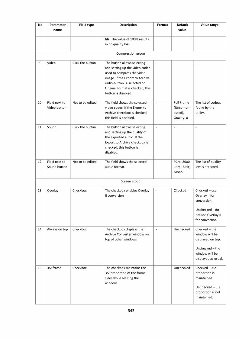
643
No Parameter
name
Field type Description Format Default
value
Value range
file. The value of 100% results
in no quality loss.
Compression group
9 Video Click the button The button allows selecting
and setting up the video codec
used to compress the video
image. If the Export to Archive
radio-button is selected or
Original format is checked, this
button is disabled.
- -
10 Field next to
Video button
Not to be edited The field shows the selected
video codec. If the Export to
Archive checkbox is checked,
this field is disabled.
- Full Frame
(Uncompr-
essed),
Quality: 0
The list of codecs
found by the
utility.
11 Sound Click the button The button allows selecting
and setting up the quality of
the exported audio. If the
Export to Archive checkbox is
checked, this button is
disabled.
- - -
12 Field next to
Sound button
Not to be edited The field shows the selected
audio format.
- PCM, 8000
kHz; 16 bit;
Mono
The list of quality
levels detected.
Screen group
13 Overlay Checkbox The checkbox enables Overlay
II conversion
- Checked Checked – use
Overlay II for
conversion
Unchecked – do
not use Overlay II
for conversion
14 Always on top Checkbox The checkbox displays the
Archive Converter window on
top of other windows
- Unchecked Checked – the
window will be
displayed on top.
Unchecked – the
window will be
displayed as usual.
15 3:2 frame Checkbox The checkbox maintains the
3:2 proportion of the frame
sides while resizing the
window.
- Unchecked Checked – 3:2
proportion is
maintained.
UnChecked – 3:2
proportion is not
maintained.
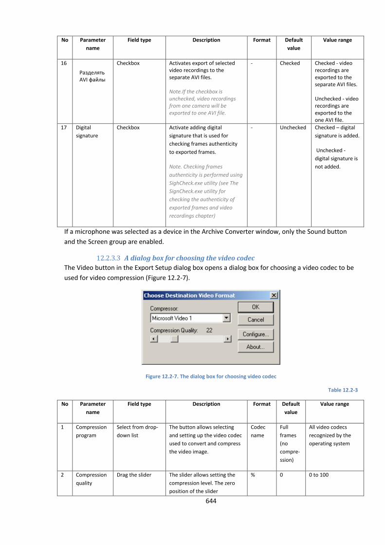
644
No Parameter
name
Field type Description Format Default
value
Value range
16 Разделять AVI файлы
Checkbox Activates export of selected video recordings to the separate AVI files. Note.If the checkbox is unchecked, video recordings from one camera will be exported to one AVI file.
- Checked Checked - video recordings are exported to the separate AVI files. Unchecked - video recordings are exported to the one AVI file.
17 Digital
signature
Checkbox Activate adding digital
signature that is used for
checking frames authenticity
to exported frames.
Note. Checking frames
authenticity is performed using
SighCheck.exe utility (see The
SignCheck.exe utility for
checking the authenticity of
exported frames and video
recordings chapter)
- Unchecked Checked – digital
signature is added.
Unchecked -
digital signature is
not added.
If a microphone was selected as a device in the Archive Converter window, only the Sound button
and the Screen group are enabled.
12.2.3.3 A dialog box for choosing the video codec
The Video button in the Export Setup dialog box opens a dialog box for choosing a video codec to be
used for video compression (Figure 12.2-7).
Figure 12.2-7. The dialog box for choosing video codec
Table 12.2-3
No Parameter
name
Field type Description Format Default
value
Value range
1 Compression
program
Select from drop-
down list
The button allows selecting
and setting up the video codec
used to convert and compress
the video image.
Codec
name
Full
frames
(no
compre-
ssion)
All video codecs
recognized by the
operating system
2 Compression
quality
Drag the slider The slider allows setting the
compression level. The zero
position of the slider
% 0 0 to 100

645
No Parameter
name
Field type Description Format Default
value
Value range
represents the highest
compression and lowest
quality. Changing this
parameter is enabled if the
codec is selected in the
Compression Program field.
3 Setup ... Click the button The button opens the settings
panel of the video codec. See
the codec manual for details.
- - -
4 About Click the button The button opens an
information box with codec
details.
- - -
NOTE. If AVI format is used, the resultant file size should not exceed 2 GB.
12.2.3.4 A dialog box for selecting audio format
The Sound button in the Export Setup dialog box opens a dialog box for choosing an audio format
(Figure 12.2-8).
Figure 12.2-8. A dialog box for choosing audio format
Table 12.2-4
No Parameter
name
Field type Description Format Default
value
Value range
1 Name Select from drop-
down list
The field allows choosing the
name for the selected audio
format.
Format
name
Untitled Untitiled
CD Quality
Radio Quality
Telephone Quality
Compact disc
2 Format Select from drop-
down list
The field for selecting the
format
Format
name
PCM The list of audio
formats used by the
utility.
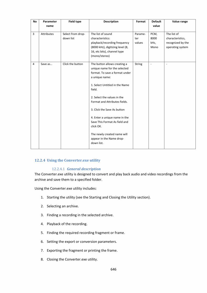
646
No Parameter
name
Field type Description Format Default
value
Value range
3 Attributes Select from drop-
down list
The list of sound
characteristics:
playback/recording frequency
(8000 kHz), digitizing level (8,
16, etc bits), channel type
(mono/stereo)
Parame-
ter
values
PCM,
8000
kHz,
Mono
The list of
characteristics,
recognized by the
operating system
4 Save as… Click the button The button allows creating a
unique name for the selected
format. To save a format under
a unique name:
1. Select Untitled in the Name
field.
2. Select the values in the
Format and Attributes fields.
3. Click the Save As button
4. Enter a unique name in the
Save This Format As field and
click OK.
The newly created name will
appear in the Name drop-
down list.
String - -
12.2.4 Using the Converter.exe utility
12.2.4.1 General description
The Converter.exe utility is designed to convert and play back audio and video recordings from the
archive and save them to a specified folder.
Using the Converter.exe utility includes:
1. Starting the utility (see the Starting and Closing the Utility section).
2. Selecting an archive.
3. Finding a recording in the selected archive.
4. Playback of the recording.
5. Finding the required recording fragment or frame.
6. Setting the export or conversion parameters.
7. Exporting the fragment or printing the frame.
8. Closing the Converter.exe utility.
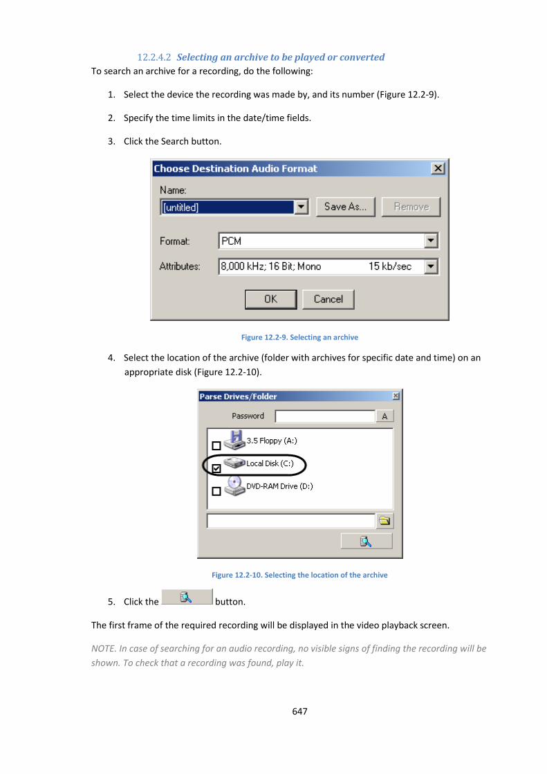
647
12.2.4.2 Selecting an archive to be played or converted
To search an archive for a recording, do the following:
1. Select the device the recording was made by, and its number (Figure 12.2-9).
2. Specify the time limits in the date/time fields.
3. Click the Search button.
Figure 12.2-9. Selecting an archive
4. Select the location of the archive (folder with archives for specific date and time) on an
appropriate disk (Figure 12.2-10).
Figure 12.2-10. Selecting the location of the archive
5. Click the button.
The first frame of the required recording will be displayed in the video playback screen.
NOTE. In case of searching for an audio recording, no visible signs of finding the recording will be
shown. To check that a recording was found, play it.
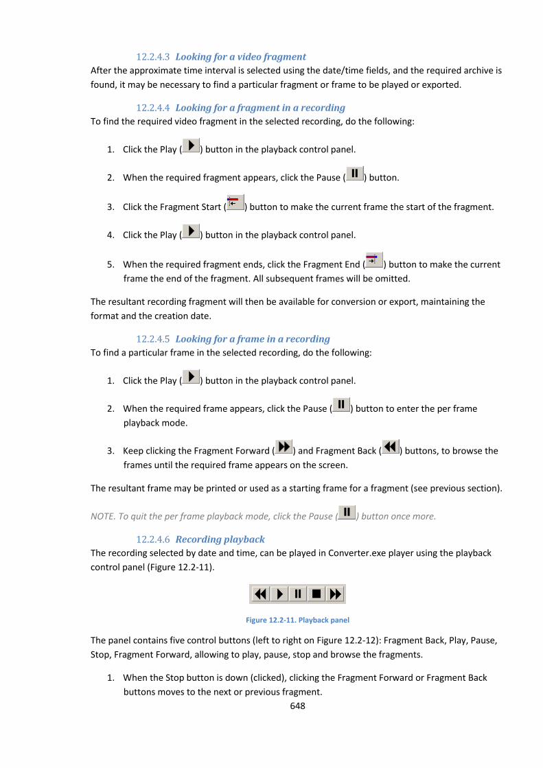
648
12.2.4.3 Looking for a video fragment
After the approximate time interval is selected using the date/time fields, and the required archive is
found, it may be necessary to find a particular fragment or frame to be played or exported.
12.2.4.4 Looking for a fragment in a recording
To find the required video fragment in the selected recording, do the following:
1. Click the Play ( ) button in the playback control panel.
2. When the required fragment appears, click the Pause ( ) button.
3. Click the Fragment Start ( ) button to make the current frame the start of the fragment.
4. Click the Play ( ) button in the playback control panel.
5. When the required fragment ends, click the Fragment End ( ) button to make the current
frame the end of the fragment. All subsequent frames will be omitted.
The resultant recording fragment will then be available for conversion or export, maintaining the
format and the creation date.
12.2.4.5 Looking for a frame in a recording
To find a particular frame in the selected recording, do the following:
1. Click the Play ( ) button in the playback control panel.
2. When the required frame appears, click the Pause ( ) button to enter the per frame
playback mode.
3. Keep clicking the Fragment Forward ( ) and Fragment Back ( ) buttons, to browse the
frames until the required frame appears on the screen.
The resultant frame may be printed or used as a starting frame for a fragment (see previous section).
NOTE. To quit the per frame playback mode, click the Pause ( ) button once more.
12.2.4.6 Recording playback
The recording selected by date and time, can be played in Converter.exe player using the playback
control panel (Figure 12.2-11).
Figure 12.2-11. Playback panel
The panel contains five control buttons (left to right on Figure 12.2-12): Fragment Back, Play, Pause,
Stop, Fragment Forward, allowing to play, pause, stop and browse the fragments.
1. When the Stop button is down (clicked), clicking the Fragment Forward or Fragment Back
buttons moves to the next or previous fragment.
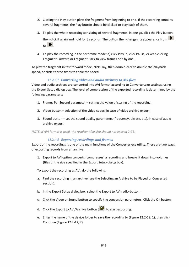
649
2. Clicking the Play button plays the fragment from beginning to end. If the recording contains
several fragments, the Play button should be clicked to play each of them.
3. To play the whole recording consisting of several fragments, in one go, click the Play button,
then click it again and hold for 3 seconds. The button then changes its appearance from
to .
4. To play the recording in the per frame mode: a) click Play, b) click Pause, c) keep clicking
Fragment Forward or Fragment Back to view frames one by one.
To play the fragment in fast forward mode, click Play, then double-click to double the playback
speed, or click it three times to triple the speed.
12.2.4.7 Converting video and audio archives to AVI files
Video and audio archives are converted into AVI format according to Converter.exe settings, using
the Export Setup dialog box. The level of compression of the exported recording is determined by the
following parameters:
1. Frames Per Second parameter – setting the value of scaling of the recording;
2. Video button – selection of the video codec, in case of video archive export;
3. Sound button – set the sound quality parameters (frequency, bitrate, etc), in case of audio
archive export.
NOTE. If AVI format is used, the resultant file size should not exceed 2 GB.
12.2.4.8 Exporting recordings and frames
Export of the recordings is one of the main functions of the Converter.exe utility. There are two ways
of exporting records from an archive:
1. Export to AVI option converts (compresses) a recording and breaks it down into volumes
(files of the size specified in the Export Setup dialog box).
To export the recording as AVI, do the following:
a. Find the recording in an archive (see the Selecting an Archive to be Played or Converted
section).
b. In the Export Setup dialog box, select the Export to AVI radio-button.
c. Click the Video or Sound button to specify the conversion parameters. Click the OK button.
d. Click the Export to AVI/Archive button ( ) to start exporting.
e. Enter the name of the device folder to save the recording to (Figure 12.2-12, 1), then click
Continue (Figure 12.2-12, 2).
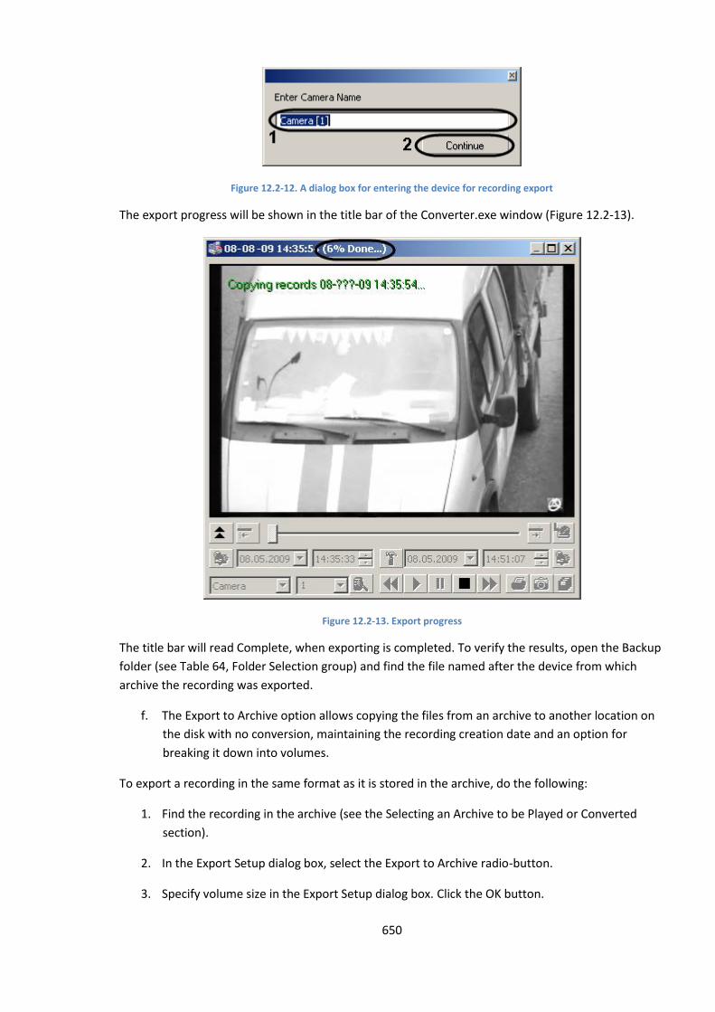
650
Figure 12.2-12. A dialog box for entering the device for recording export
The export progress will be shown in the title bar of the Converter.exe window (Figure 12.2-13).
Figure 12.2-13. Export progress
The title bar will read Complete, when exporting is completed. To verify the results, open the Backup
folder (see Table 64, Folder Selection group) and find the file named after the device from which
archive the recording was exported.
f. The Export to Archive option allows copying the files from an archive to another location on
the disk with no conversion, maintaining the recording creation date and an option for
breaking it down into volumes.
To export a recording in the same format as it is stored in the archive, do the following:
1. Find the recording in the archive (see the Selecting an Archive to be Played or Converted
section).
2. In the Export Setup dialog box, select the Export to Archive radio-button.
3. Specify volume size in the Export Setup dialog box. Click the OK button.
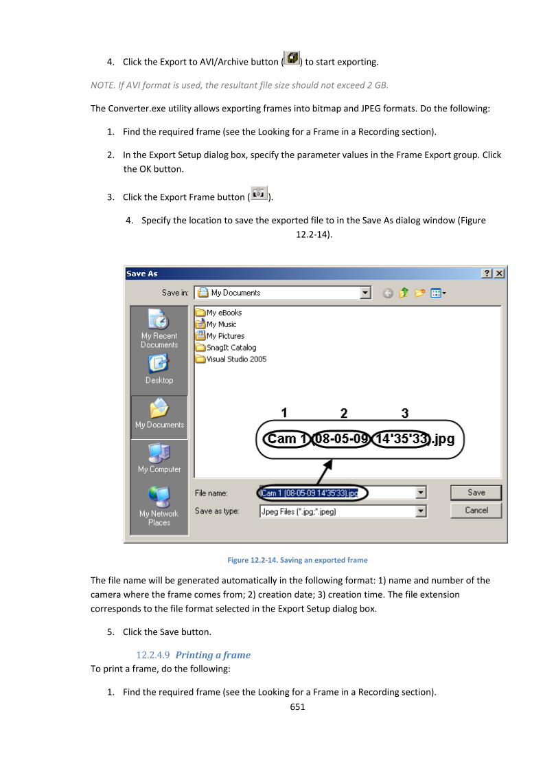
651
4. Click the Export to AVI/Archive button ( ) to start exporting.
NOTE. If AVI format is used, the resultant file size should not exceed 2 GB.
The Converter.exe utility allows exporting frames into bitmap and JPEG formats. Do the following:
1. Find the required frame (see the Looking for a Frame in a Recording section).
2. In the Export Setup dialog box, specify the parameter values in the Frame Export group. Click
the OK button.
3. Click the Export Frame button ( ).
4. Specify the location to save the exported file to in the Save As dialog window (Figure
12.2-14).
Figure 12.2-14. Saving an exported frame
The file name will be generated automatically in the following format: 1) name and number of the
camera where the frame comes from; 2) creation date; 3) creation time. The file extension
corresponds to the file format selected in the Export Setup dialog box.
5. Click the Save button.
12.2.4.9 Printing a frame
To print a frame, do the following:
1. Find the required frame (see the Looking for a Frame in a Recording section).
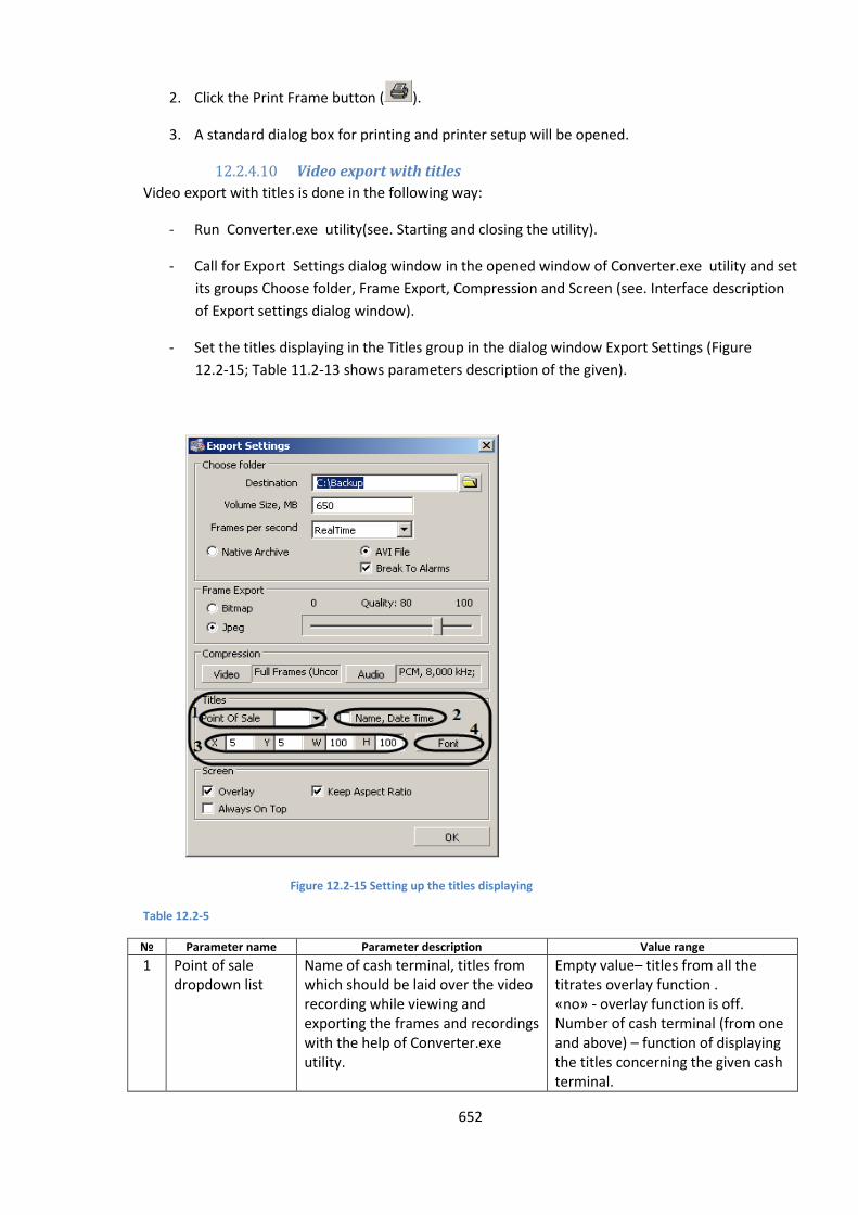
652
2. Click the Print Frame button ( ).
3. A standard dialog box for printing and printer setup will be opened.
12.2.4.10 Video export with titles
Video export with titles is done in the following way:
- Run Converter.exe utility(see. Starting and closing the utility).
- Call for Export Settings dialog window in the opened window of Converter.exe utility and set
its groups Choose folder, Frame Export, Compression and Screen (see. Interface description
of Export settings dialog window).
- Set the titles displaying in the Titles group in the dialog window Export Settings (Figure
12.2-15; Table 11.2-13 shows parameters description of the given).
Figure 12.2-15 Setting up the titles displaying
Table 12.2-5
№ Parameter name Parameter description Value range
1 Point of sale dropdown list
Name of cash terminal, titles from which should be laid over the video recording while viewing and exporting the frames and recordings with the help of Converter.exe utility.
Empty value– titles from all the titrates overlay function . «no» - overlay function is off. Number of cash terminal (from one and above) – function of displaying the titles concerning the given cash terminal.
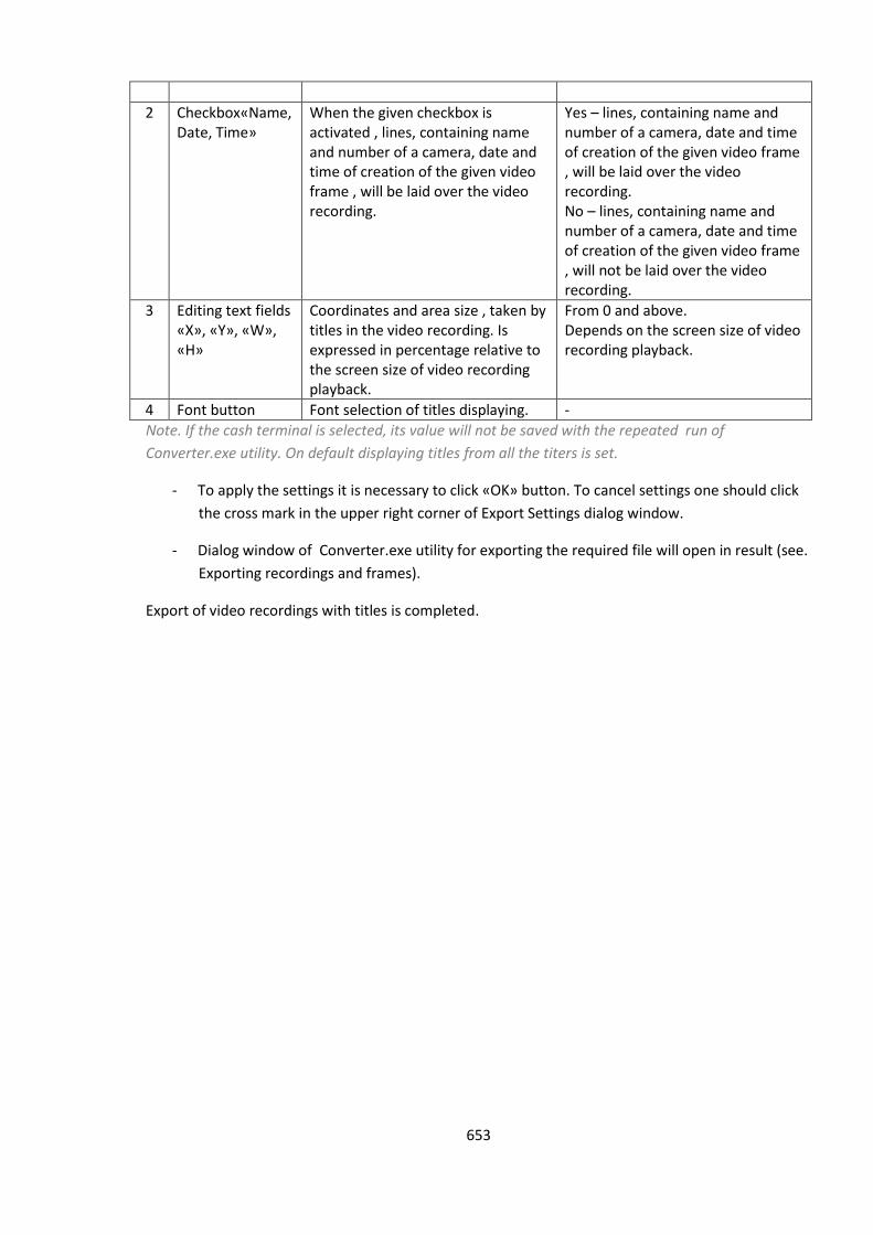
653
2 Checkbox«Name, Date, Time»
When the given checkbox is activated , lines, containing name and number of a camera, date and time of creation of the given video frame , will be laid over the video recording.
Yes – lines, containing name and number of a camera, date and time of creation of the given video frame , will be laid over the video recording. No – lines, containing name and number of a camera, date and time of creation of the given video frame , will not be laid over the video recording.
3 Editing text fields «X», «Y», «W», «H»
Coordinates and area size , taken by titles in the video recording. Is expressed in percentage relative to the screen size of video recording playback.
From 0 and above. Depends on the screen size of video recording playback.
4 Font button Font selection of titles displaying. -
Note. If the cash terminal is selected, its value will not be saved with the repeated run of
Converter.exe utility. On default displaying titles from all the titers is set.
- To apply the settings it is necessary to click «OK» button. To cancel settings one should click
the cross mark in the upper right corner of Export Settings dialog window.
- Dialog window of Converter.exe utility for exporting the required file will open in result (see.
Exporting recordings and frames).
Export of video recordings with titles is completed.
654
12.3 Tweaki.exe utility for advanced setup of the Intellect software system
12.3.1 The purpose of tweaki.exe utility
The tweaki.exe utility is designed for configuring the Intellect system by editing the
HKLM/SOFTWARE/ITV and HKCU/SOFTWARE/ITV sections of the Windows registry, where the setup
parameters for the Intellect core and modules are stored.
Attention! Specifying invalid values of the registry keys may lead to system failure.
The Tweaki.exe utility provides the following functionality:
1. Setup of Intellect system start-up;
2. Enabling the debug mode;
3. Advanced setup of the video surveillance monitor;
4. Advanced setup of events logging;
5. Advanced setup of video signal processing by Server;
6. Advanced setup of distributed architecture;
7. Changing netnames and IP-addresses in the configuration database;
8. Compressing MS Access database;
9. Limiting the RAM used by MS SQL server;
10. Advanced setup of audio or video recording to an archive;
11. Re-indexing audio and video archives;
12. Selecting the analog video out operation mode;
13. Testing the operability of video capture cards;
14. Advanced setup of PTZ devices;
15. Displaying versions of Intellect modules.
12.3.2 Starting and closing the utility
To start the tweaki.exe utility, do one of the following:
1. Start the utility from the Windows taskbar. Click Start => All Programs => Intellect => Tools =>
Advanced settings utility. The tweaki.exe utility is available from the Start menu with the
following installation types of Intellect: Server, Remote administrator workstation, Remote
monitoring workstation.
2. Start the utility from the Tools folder of the Intellect program folder. Example:
С:\Intellect\Tools\Tweaki.exe.
The Intellect Advanced Setup dialog box is open after running the tweaki.exe utility (Figure 12.3-1).
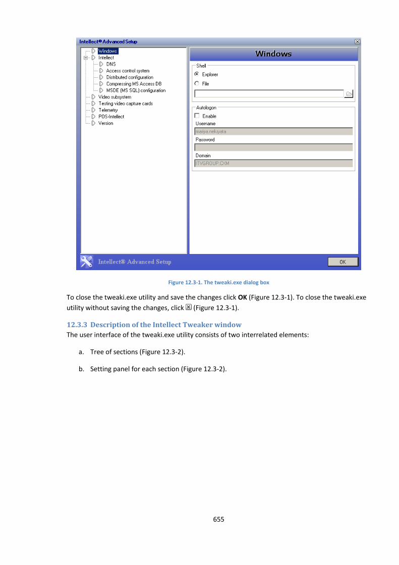
655
Figure 12.3-1. The tweaki.exe dialog box
To close the tweaki.exe utility and save the changes click OK (Figure 12.3-1). To close the tweaki.exe
utility without saving the changes, click (Figure 12.3-1).
12.3.3 Description of the Intellect Tweaker window
The user interface of the tweaki.exe utility consists of two interrelated elements:
a. Tree of sections (Figure 12.3-2).
b. Setting panel for each section (Figure 12.3-2).
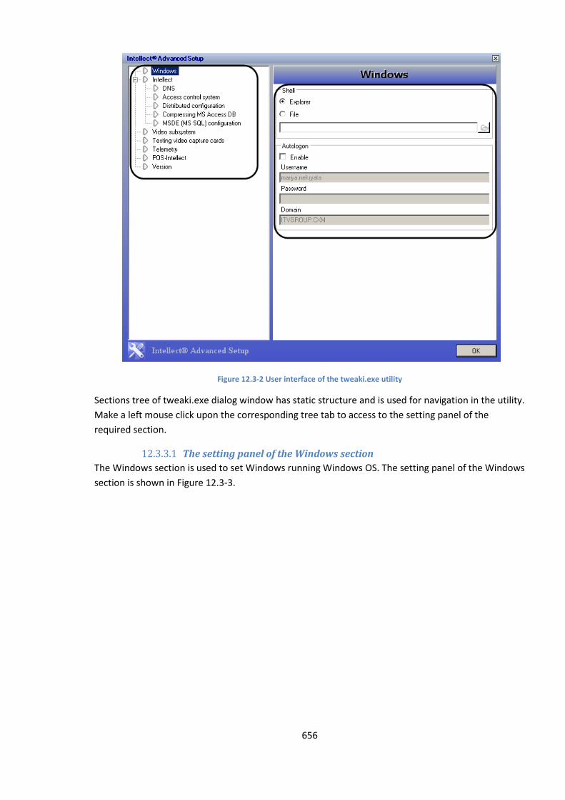
656
Figure 12.3-2 User interface of the tweaki.exe utility
Sections tree of tweaki.exe dialog window has static structure and is used for navigation in the utility.
Make a left mouse click upon the corresponding tree tab to access to the setting panel of the
required section.
12.3.3.1 The setting panel of the Windows section
The Windows section is used to set Windows running Windows OS. The setting panel of the Windows
section is shown in Figure 12.3-3.
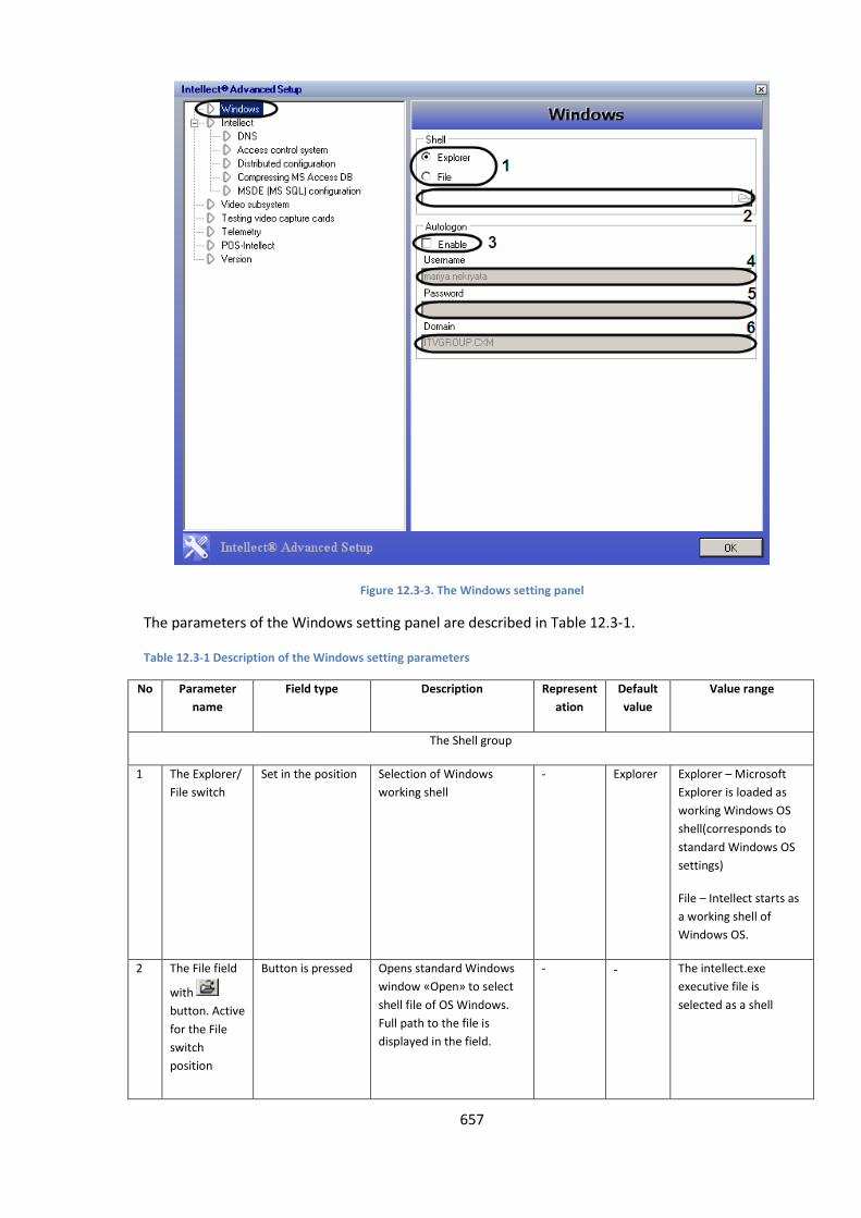
657
Figure 12.3-3. The Windows setting panel
The parameters of the Windows setting panel are described in Table 12.3-1.
Table 12.3-1 Description of the Windows setting parameters
No Parameter
name
Field type Description Represent
ation
Default
value
Value range
The Shell group
1 The Explorer/
File switch
Set in the position Selection of Windows
working shell
- Explorer Explorer – Microsoft
Explorer is loaded as
working Windows OS
shell(corresponds to
standard Windows OS
settings)
File – Intellect starts as
a working shell of
Windows OS.
2 The File field
with
button. Active
for the File
switch
position
Button is pressed Opens standard Windows
window «Open» to select
shell file of OS Windows.
Full path to the file is
displayed in the field.
- - The intellect.exe
executive file is
selected as a shell
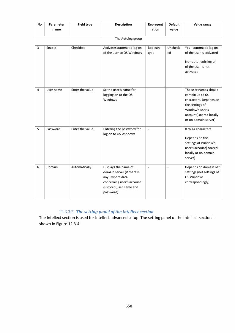
658
No Parameter
name
Field type Description Represent
ation
Default
value
Value range
The Autolog group
3 Enable Checkbox Activates automatic log on
of the user to OS Windows
Boolean
type
Uncheck
ed
Yes – automatic log on
of the user is activated
No– automatic log on
of the user is not
activated
4 User name Enter the value Se the user’s name for
logging on to the OS
Windows
- - The user names should
contain up to 64
characters. Depends on
the settings of
Window’s user’s
account( soared locally
or on domain server)
5 Password Enter the value Entering the password for
log on to OS Windows
- - 8 to 14 characters
Depends on the
settings of Window’s
user’s account( soared
locally or on domain
server)
6 Domain Automatically Displays the name of
domain server (if there is
any), where data
concerning user’s account
is stored(user name and
password)
- - Depends on domain net
settings (net settings of
OS Windows
correspondingly)
12.3.3.2 The setting panel of the Intellect section
The Intellect section is used for Intellect advanced setup. The setting panel of the Intellect section is
shown in Figure 12.3-4.
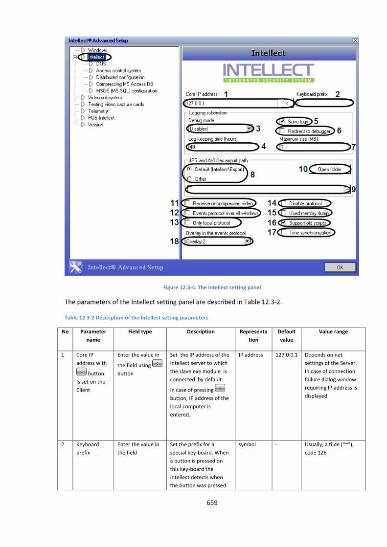
659
Figure 12.3-4. The Intellect setting panel
The parameters of the Intellect setting panel are described in Table 12.3-2.
Table 12.3-2 Description of the Intellect setting parameters
No Parameter
name
Field type Description Representa
tion
Default
value
Value range
1 Core IP
address with
button.
Is set on the
Client
Enter the value in
the field using
button
Set the IP address of the
Intellect server to which
the slave.exe module is
connected by default.
In case of pressing
button, IP address of the
local computer is
entered.
IP address 127.0.0.1 Depends on net
settings of the Server.
In case of connection
failure dialog window
requiring IP address is
displayed
2 Keyboard
prefix
Enter the value in
the field
Set the prefix for a
special key-board. When
a button is pressed on
this key-board the
Intellect detects when
the button was pressed
symbol - Usually, a tilde (“~”),
code 126
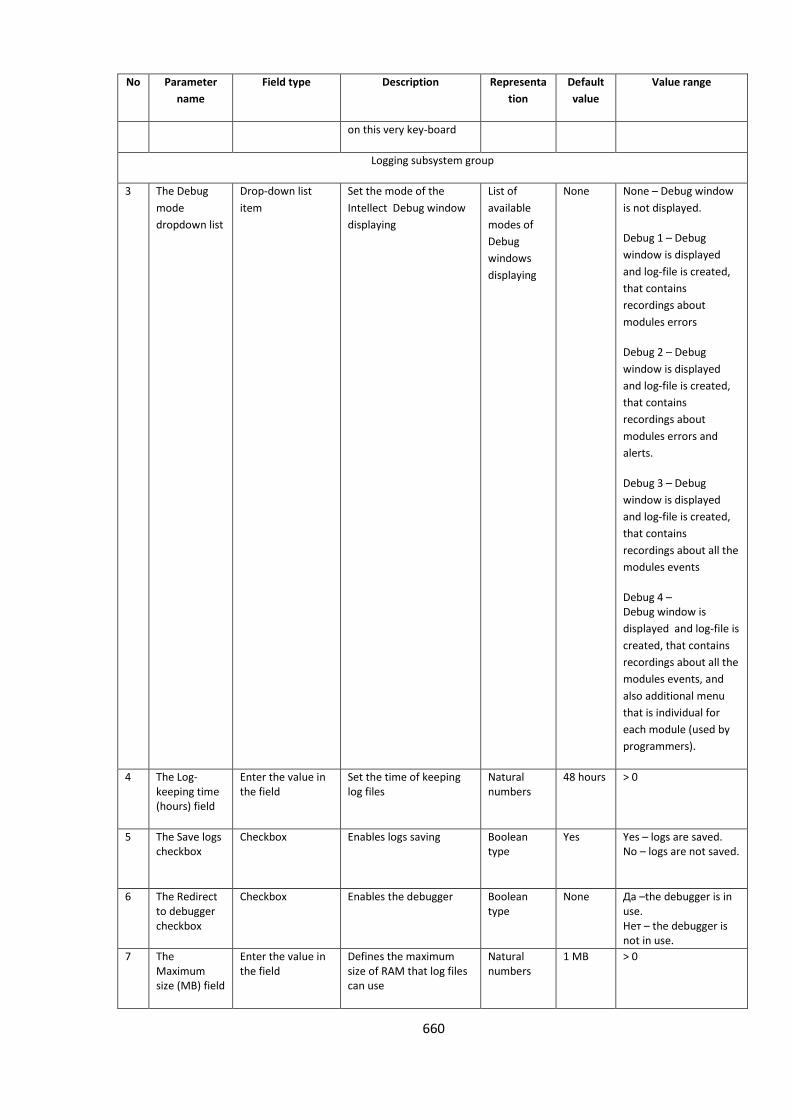
660
No Parameter
name
Field type Description Representa
tion
Default
value
Value range
on this very key-board
Logging subsystem group
3 The Debug
mode
dropdown list
Drop-down list
item
Set the mode of the
Intellect Debug window
displaying
List of
available
modes of
Debug
windows
displaying
None
None – Debug window
is not displayed.
Debug 1 – Debug
window is displayed
and log-file is created,
that contains
recordings about
modules errors
Debug 2 – Debug
window is displayed
and log-file is created,
that contains
recordings about
modules errors and
alerts.
Debug 3 – Debug
window is displayed
and log-file is created,
that contains
recordings about all the
modules events
Debug 4 – Debug window is
displayed and log-file is
created, that contains
recordings about all the
modules events, and
also additional menu
that is individual for
each module (used by
programmers).
4 The Log-keeping time (hours) field
Enter the value in the field
Set the time of keeping log files
Natural numbers
48 hours > 0
5 The Save logs checkbox
Checkbox Enables logs saving Boolean type
Yes Yes – logs are saved. No – logs are not saved.
6 The Redirect to debugger checkbox
Checkbox Enables the debugger Boolean type
None Да –the debugger is in use. Нет – the debugger is not in use.
7 The Maximum size (MB) field
Enter the value in the field
Defines the maximum size of RAM that log files can use
Natural numbers
1 MB > 0
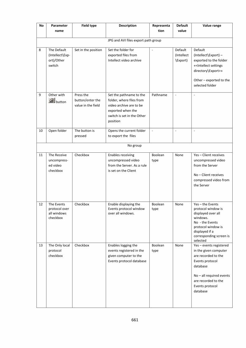
661
No Parameter
name
Field type Description Representa
tion
Default
value
Value range
JPG and AVI files export path group
8 The Default
(Intellect\Exp-
ort)/Other
switch
Set in the position Set the folder for
exported files from
Intellect video archive
- Default
(Intellect
\Export)
Default
(Intellect\Export) –
exported to the folder
«<Intellect settings
directory\Export>»
Other – exported to the
selected folder
9 Other with
button
Press the
button/enter the
value in the field
Set the pathname to the
folder, where files from
video archive are to be
exported when the
switch is set in the Other
position
Pathname - -
10 Open folder The button is
pressed
Opens the current folder
to export the files
- - -
No group
11 The Receive
uncompress-
ed video
checkbox
Checkbox Enables receiving
uncompressed video
from the Server. As a rule
is set on the Client
Boolean
type
None Yes – Client receives
uncompressed video
from the Server
No – Client receives
compressed video from
the Server
12 The Events protocol over all windows checkbox
Checkbox Enable displaying the Events protocol window over all windows.
Boolean type
None Yes – the Events protocol window is displayed over all windows. No - the Events protocol window is displayed if a corresponding screen is selected
13 The Only local
protocol
checkbox
Checkbox Enables logging the
events registered in the
given computer to the
Events protocol database
Boolean
type
None Yes – events registered
in the given computer
are recorded to the
Events protocol
database
No – all required events
are recorded to the
Events protocol
database
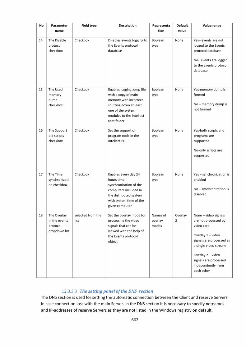
662
No Parameter
name
Field type Description Representa
tion
Default
value
Value range
14 The Disable
protocol
checkbox
Checkbox Disables events logging to
the Events protocol
database
Boolean
type
None Yes– events are not
logged to the Events
protocol database
No– events are logged
to the Events protocol
database
15 The Used
memory
dump
checkbox
Checkbox Enables logging .dmp file
with a copy of main
memory with incorrect
shutting down at least
one of the system
modules to the Intellect
root folder
Boolean
type
None Yes-memory dump is
formed
No – memory dump is
not formed
16 The Support
old scripts
checkbox
Checkbox Set the support of
program tools in the
Intellect PC
Boolean
type
None Yes-both scripts and
programs are
supported
No-only scripts are
supported
17 The Time
synchronizati
on checkbox
Checkbox Enables every day 24
hours time
synchronization of the
computers included in
the distributed system
with system time of the
given computer
Boolean
type
None Yes – synchronization is
enabled
No – synchronization is
disabled
18 The Overlay
in the events
protocol
dropdown list
selected from the
list
Set the overlay mode for
processing the video
signals that can be
viewed with the help of
the Events protocol
object
Names of
overlay
modes
Overlay
2
None – video signals
are not processed by
video card
Overlay 1 – video
signals are processed as
a single video stream
Overlay 2 – video
signals are processed
independently from
each other
12.3.3.3 The setting panel of the DNS section
The DNS section is used for setting the automatic connection between the Client and reserve Servers
in case connection loss with the main Server. In the DNS section it is necessary to specify netnames
and IP-addresses of reserve Servers as they are not listed in the Windows registry on default.
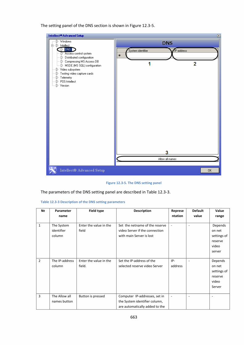
663
The setting panel of the DNS section is shown in Figure 12.3-5.
Figure 12.3-5. The DNS setting panel
The parameters of the DNS setting panel are described in Table 12.3-3.
Table 12.3-3 Description of the DNS setting parameters
№ Parameter
name
Field type Description Represe
ntation
Default
value
Value
range
1 The System
identifier
column
Enter the value in the
field
Set the netname of the reserve
video Server if the connection
with main Server is lost
- - Depends
on net
settings of
reserve
video
server
2 The IP-address
column
Enter the value in the
field.
Set the IP-address of the
selected reserve video Server
IP-
address
- Depends
on net
settings of
reserve
video
Server
3 The Allow all
names button
Button is pressed Computer IP-addresses, set in
the System identifier column,
are automatically added to the
- - -
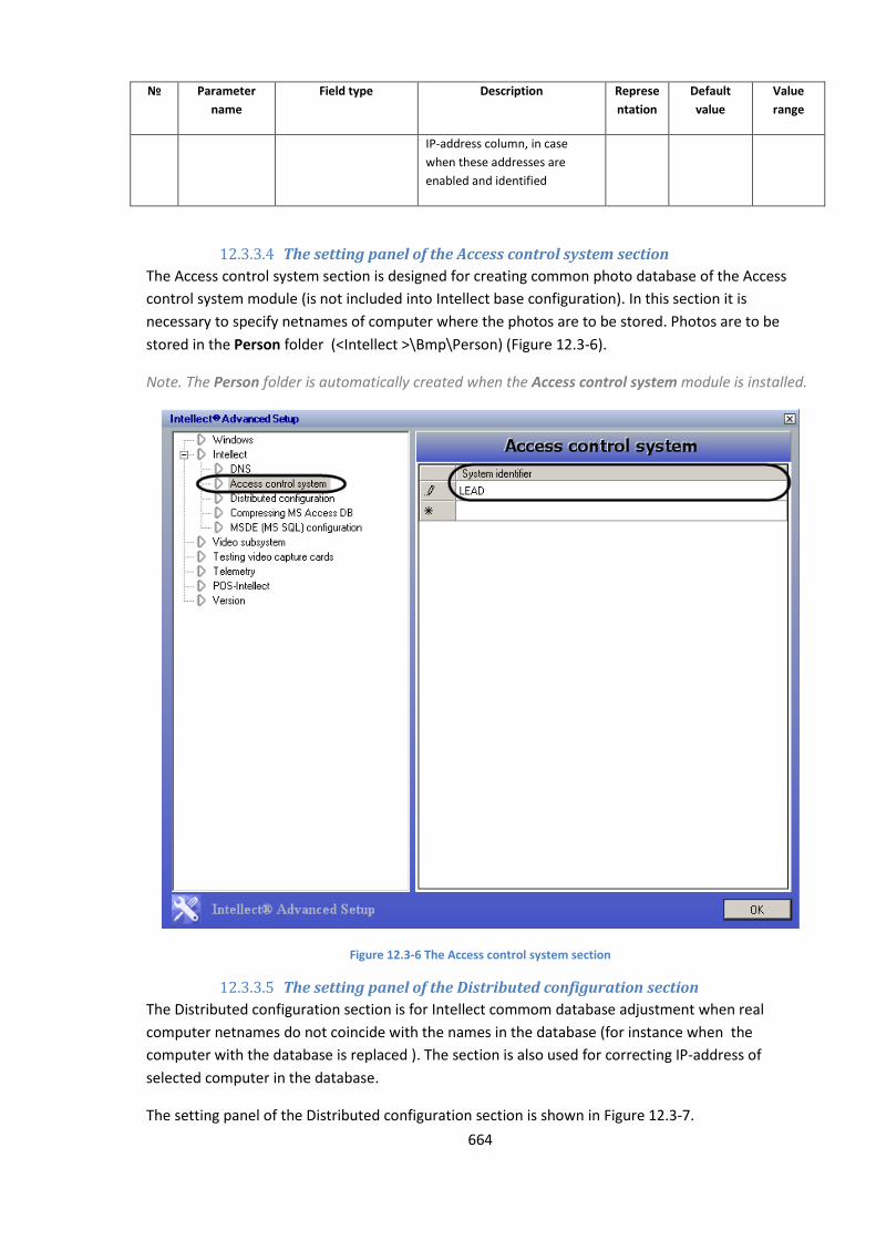
664
№ Parameter
name
Field type Description Represe
ntation
Default
value
Value
range
IP-address column, in case
when these addresses are
enabled and identified
12.3.3.4 The setting panel of the Access control system section
The Access control system section is designed for creating common photo database of the Access
control system module (is not included into Intellect base configuration). In this section it is
necessary to specify netnames of computer where the photos are to be stored. Photos are to be
stored in the Person folder (<Intellect >\Bmp\Person) (Figure 12.3-6).
Note. The Person folder is automatically created when the Access control system module is installed.
Figure 12.3-6 The Access control system section
12.3.3.5 The setting panel of the Distributed configuration section
The Distributed configuration section is for Intellect commom database adjustment when real
computer netnames do not coincide with the names in the database (for instance when the
computer with the database is replaced ). The section is also used for correcting IP-address of
selected computer in the database.
The setting panel of the Distributed configuration section is shown in Figure 12.3-7.
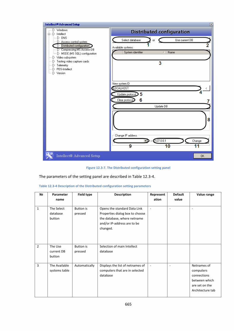
665
Figure 12.3-7. The Distributed configuration setting panel
The parameters of the setting panel are described in Table 12.3-4.
Table 12.3-4 Description of the Distributed configuration setting parameters
№ Parameter
name
Field type Description Represent
ation
Default
value
Value range
1 The Select
database
button
Button is
pressed
Opens the standard Data Link
Properties dialog box to choose
the database, where netname
and/or IP-address are to be
changed.
- - -
2 The Use
current DB
button
Button is
pressed
Selection of main Intellect
database
3 The Available
systems table
Automatically Displays the list of netnames of
computers that are in selected
database
- - Netnames of
computers
connections
between which
are set on the
Architecture tab
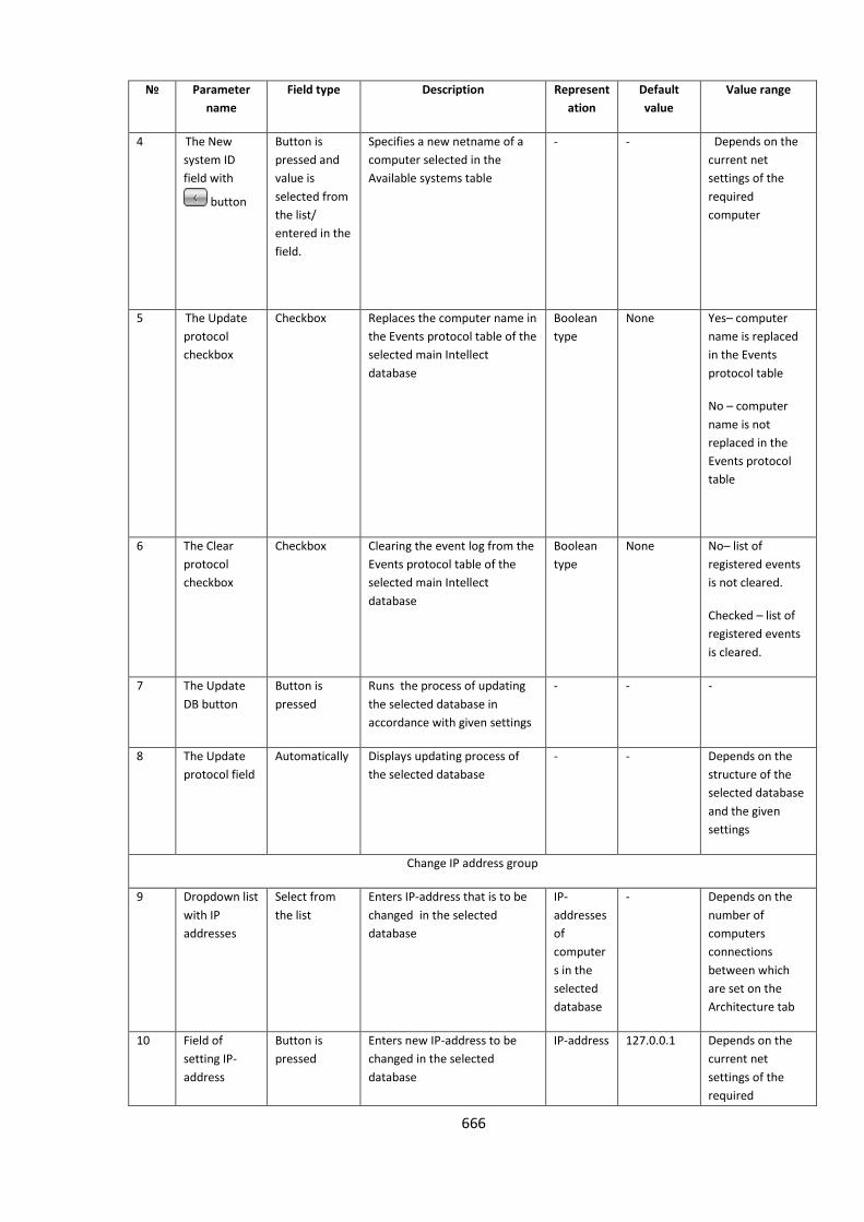
666
№ Parameter
name
Field type Description Represent
ation
Default
value
Value range
4 The New
system ID
field with
button
Button is
pressed and
value is
selected from
the list/
entered in the
field.
Specifies a new netname of a
computer selected in the
Available systems table
- - Depends on the
current net
settings of the
required
computer
5 The Update
protocol
checkbox
Checkbox Replaces the computer name in
the Events protocol table of the
selected main Intellect
database
Boolean
type
None Yes– computer
name is replaced
in the Events
protocol table
No – computer
name is not
replaced in the
Events protocol
table
6 The Clear
protocol
checkbox
Checkbox Clearing the event log from the
Events protocol table of the
selected main Intellect
database
Boolean
type
None No– list of
registered events
is not cleared.
Checked – list of
registered events
is cleared.
7 The Update
DB button
Button is
pressed
Runs the process of updating
the selected database in
accordance with given settings
- - -
8 The Update
protocol field
Automatically Displays updating process of
the selected database
- - Depends on the
structure of the
selected database
and the given
settings
Change IP address group
9 Dropdown list
with IP
addresses
Select from
the list
Enters IP-address that is to be
changed in the selected
database
IP-
addresses
of
computer
s in the
selected
database
- Depends on the
number of
computers
connections
between which
are set on the
Architecture tab
10 Field of
setting IP-
address
Button is
pressed
Enters new IP-address to be
changed in the selected
database
IP-address
127.0.0.1 Depends on the
current net
settings of the
required

667
№ Parameter
name
Field type Description Represent
ation
Default
value
Value range
computer
11 The Change
button
Button is
pressed
Changes the IP-address of the
required computer in the
selected database
- - -
12.3.3.6 The setting panel of the Compressing MS Access DB section
The Compressing MS Access DB section is designed for compressing the Intellect database of MS
Access format.
Expansion of data in the database of MS Access format is caused by logical deleting of files,
temporary and hidden tables (i.e. they are marked as deleted but stay physically in the database).
Data compression is recommended to enhance the performance of the Intellect system.
Compression means physical deleting of files marked as deleted.
The setting panel of the Compressing MS Access DB section is shown in Figure 12.3-8.
Figure 12.3-8. The Compressing MS Access DB setting panel
The parameters of the setting panel are described in Table 12.3-5.
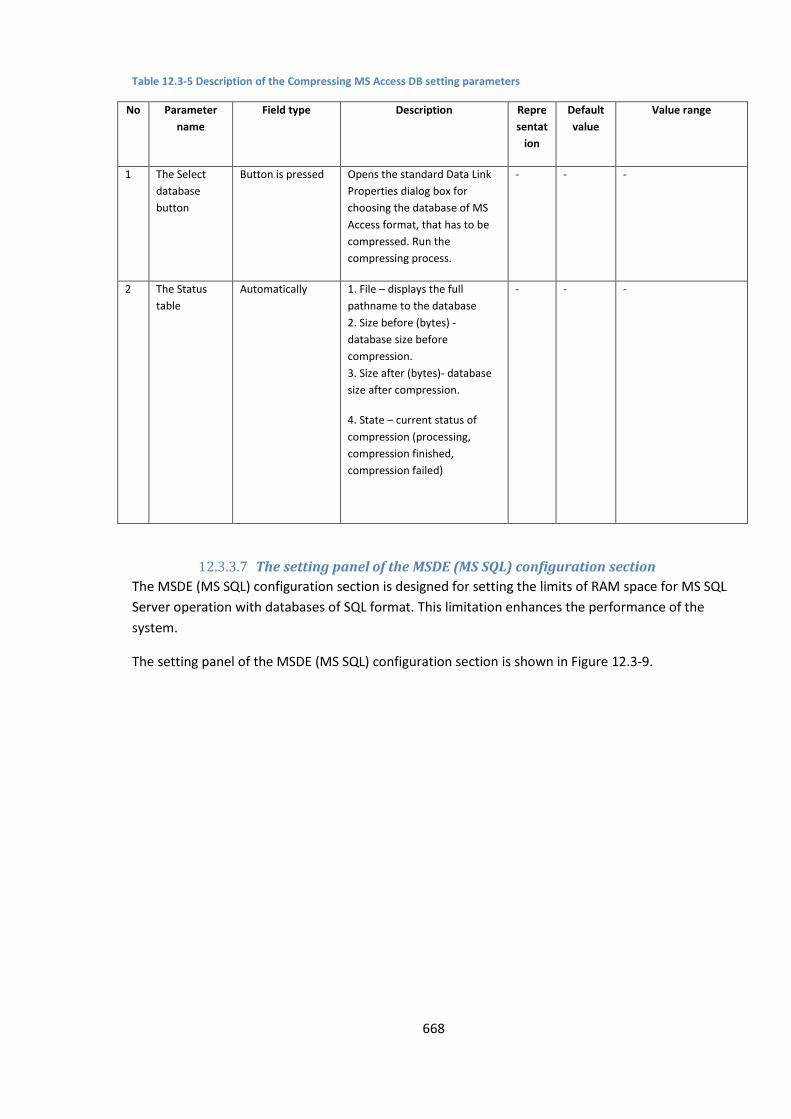
668
Table 12.3-5 Description of the Compressing MS Access DB setting parameters
No Parameter
name
Field type Description Repre
sentat
ion
Default
value
Value range
1 The Select
database
button
Button is pressed Opens the standard Data Link
Properties dialog box for
choosing the database of MS
Access format, that has to be
compressed. Run the
compressing process.
- - -
2 The Status
table
Automatically 1. File – displays the full
pathname to the database
2. Size before (bytes) -
database size before
compression.
3. Size after (bytes)- database
size after compression.
4. State – current status of
compression (processing,
compression finished,
compression failed)
- - -
12.3.3.7 The setting panel of the MSDE (MS SQL) configuration section
The MSDE (MS SQL) configuration section is designed for setting the limits of RAM space for MS SQL
Server operation with databases of SQL format. This limitation enhances the performance of the
system.
The setting panel of the MSDE (MS SQL) configuration section is shown in Figure 12.3-9.
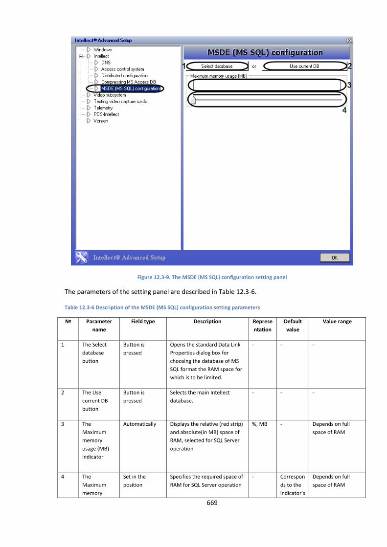
669
Figure 12.3-9. The MSDE (MS SQL) configuration setting panel
The parameters of the setting panel are described in Table 12.3-6.
Table 12.3-6 Description of the MSDE (MS SQL) configuration setting parameters
№ Parameter
name
Field type Description Represe
ntation
Default
value
Value range
1 The Select
database
button
Button is
pressed
Opens the standard Data Link
Properties dialog box for
choosing the database of MS
SQL format the RAM space for
which is to be limited.
- - -
2 The Use
current DB
button
Button is
pressed
Selects the main Intellect
database.
- - -
3 The
Maximum
memory
usage (MB)
indicator
Automatically Displays the relative (red strip)
and absolute(in MB) space of
RAM, selected for SQL Server
operation
%, MB - Depends on full
space of RAM
4 The
Maximum
memory
Set in the
position
Specifies the required space of
RAM for SQL Server operation
- Correspon
ds to the
indicator’s
Depends on full
space of RAM

670
№ Parameter
name
Field type Description Represe
ntation
Default
value
Value range
usage (MB)
slider
state.
12.3.3.8 The setting panel of the Video subsystem section
The Video subsystem section is designed for advanced setting of the video subsystem in order to
enhance the performance of the Intellect system.
The setting panel of the Video subsystem section is shown in Figure 12.3-10.
Figure 12.3-10. The Video subsystem setting panel
The parameters of the setting panel are described in Table 12.3-7.
Table 12.3-7 Description of the Video subsystem setting parameters
No Parameter name Field type Description Represe
ntation
Default
value
Value range

671
No Parameter name Field type Description Represe
ntation
Default
value
Value range
1 The Ring field Enter the
value
Set the amount of disk space
to be left free on the video
archives. When this limit is
reached, the subsequent
recordings will replace the
earliest recordings in the
database. The earliest
recordings will be deleted. In
case when two or more disks
are used for video recording
transfer to the next disk is
implemented when no free
space is left. As a result, the
recordings will form a loop
(Ring).
MB 500 Depends on the disk
space
2 The Frame count
field
Enter the
value
Enters the maximum number
of frames in one recording file.
frame 500 10 to 999. It is not
recommended to
change the default
value.
3 The Hide mask
checkbox
Checkbox Prohibits the displaying of
video on the screen under the
motion detector mask. Video
area marked by mask is hidden
with grey
Boolean
type
None No-hid by mask video
is displayed
Yes – hid by mask
video is not displayed
4 The Old cards
support dropdown
list
Drop-down
list
Enters the types of video
capture cards that are phased
out, but supported by the
Intellect system. To support a
phased out video capture card
in the Intellect system, select
the FS5 card type, while setting
up the Video Capture Card
object and enter the actual
card type in the tweaki.exe
settings. Otherwise, the card
is not be recognized by the
Intellect system. This
parameter operates only on
32-bit OS.
Type of
phased
out
video
capture
cards
- KV1999, KV2001,
KV2002, KV2003,
LinuxHub (models
produced before
2003)
5 The LinuxHub
timeout list
Enter the
value/select
from the list
Set the maximum waiting time
interval for Intellect system to
maintain the response of
LinuxHub server
sec 30 0 to 400000
6 The Swap frame
fields checkbox
Checkbox Switch Intellect from basic to
additional driver if there are
video artifacts while using
Boolean
type
None No – Intellect operates with basic driver
Yes – Intellect
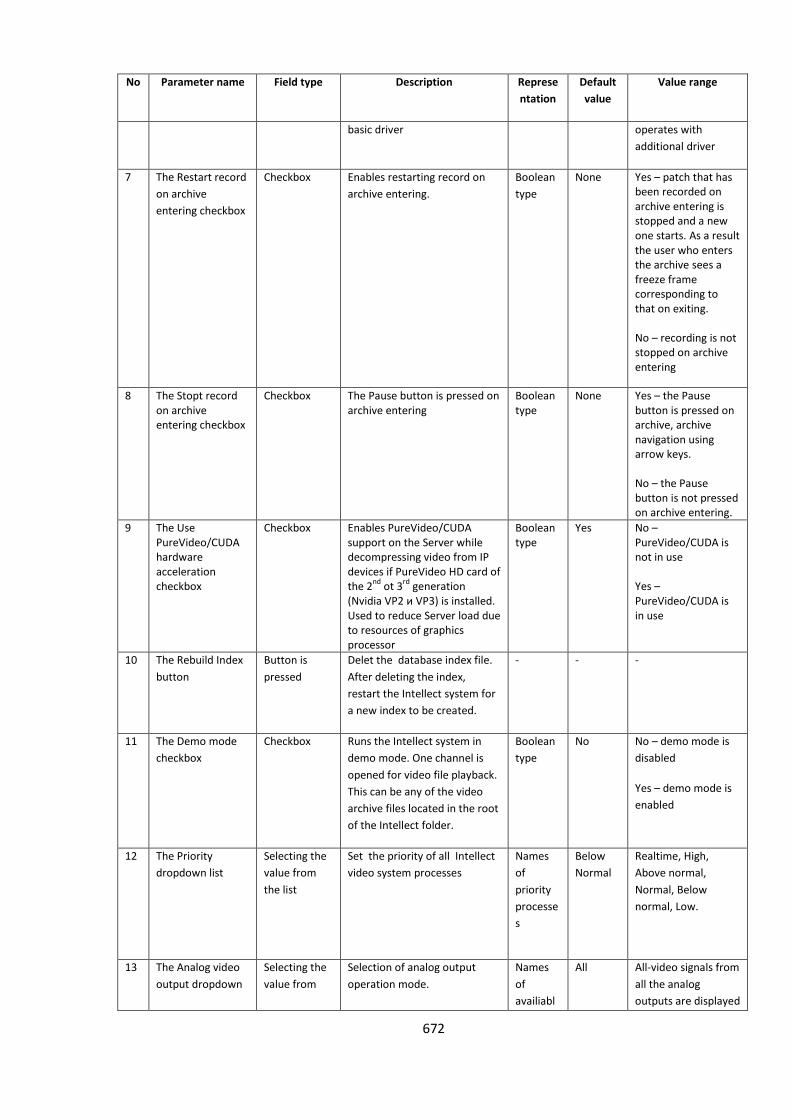
672
No Parameter name Field type Description Represe
ntation
Default
value
Value range
basic driver operates with
additional driver
7 The Restart record
on archive
entering checkbox
Checkbox Enables restarting record on
archive entering.
Boolean
type
None Yes – patch that has been recorded on archive entering is stopped and a new one starts. As a result the user who enters the archive sees a freeze frame corresponding to that on exiting. No – recording is not stopped on archive entering
8 The Stopt record on archive entering checkbox
Checkbox The Pause button is pressed on archive entering
Boolean type
None Yes – the Pause button is pressed on archive, archive navigation using arrow keys. No – the Pause button is not pressed on archive entering.
9 The Use PureVideo/CUDA hardware acceleration checkbox
Checkbox Enables PureVideo/CUDA support on the Server while decompressing video from IP devices if PureVideo HD card of the 2
nd ot 3
rd generation
(Nvidia VP2 и VP3) is installed. Used to reduce Server load due to resources of graphics processor
Boolean type
Yes No –PureVideo/CUDA is not in use Yes –PureVideo/CUDA is in use
10 The Rebuild Index
button
Button is
pressed
Delet the database index file.
After deleting the index,
restart the Intellect system for
a new index to be created.
- - -
11 The Demo mode
checkbox
Checkbox Runs the Intellect system in
demo mode. One channel is
opened for video file playback.
This can be any of the video
archive files located in the root
of the Intellect folder.
Boolean
type
No No – demo mode is
disabled
Yes – demo mode is
enabled
12 The Priority
dropdown list
Selecting the
value from
the list
Set the priority of all Intellect
video system processes
Names
of
priority
processe
s
Below
Normal
Realtime, High,
Above normal,
Normal, Below
normal, Low.
13 The Analog video
output dropdown
Selecting the
value from
Selection of analog output
operation mode.
Names
of
availiabl
All All-video signals from
all the analog
outputs are displayed
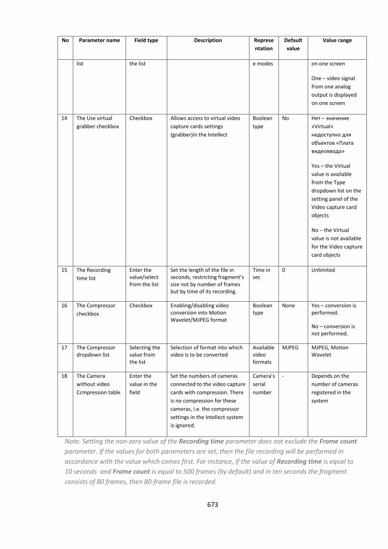
673
No Parameter name Field type Description Represe
ntation
Default
value
Value range
list the list e modes on one screen
One – video signal
from one analog
output is displayed
on one screen
14 The Use virtual
grabber checkbox
Checkbox Allows access to virtual video
capture cards settings
(grabber)in the Intellect
Boolean
type
No Нет – значение
«Virtual»
недоступно для
объектов «Плата
видеоввода»
Yes – the Virtual
value is available
from the Type
dropdown list on the
setting panel of the
Video capture card
objects
No – the Virtual
value is not available
for the Video capture
card objects
15 The Recording
time list
Enter the value/select from the list
Set the length of the file in seconds, restricting fragment’s size not by number of frames but by time of its recording.
Time in sec
0 Unlimited
16 The Compressor
checkbox
Checkbox Enabling/disabling video conversion into Motion Wavelet/MJPEG format
Boolean type
None Yes – conversion is performed.
No – conversion is not performed.
17 The Compressor dropdown list
Selecting the value from the list
Selection of format into which video is to be converted
Available video formats
MJPEG MJPEG, Motion Wavelet
18 The Camera
without video
Ccmpression table
Enter the
value in the
field
Set the numbers of cameras
connected to the video capture
cards with compression. There
is no compression for these
cameras, i.e. the compressor
settings in the Intellect system
is ignored.
Camera’s
serial
number
- Depends on the
number of cameras
registered in the
system
Note. Setting the non-zero value of the Recording time parameter does not exclude the Frame count
parameter. If the values for both parameters are set, then the file recording will be performed in
accordance with the value which comes first. For instance, if the value of Recording time is equal to
10 seconds and Frame count is equal to 500 frames (by default) and in ten seconds the fragment
consists of 80 frames, then 80-frame file is recorded.
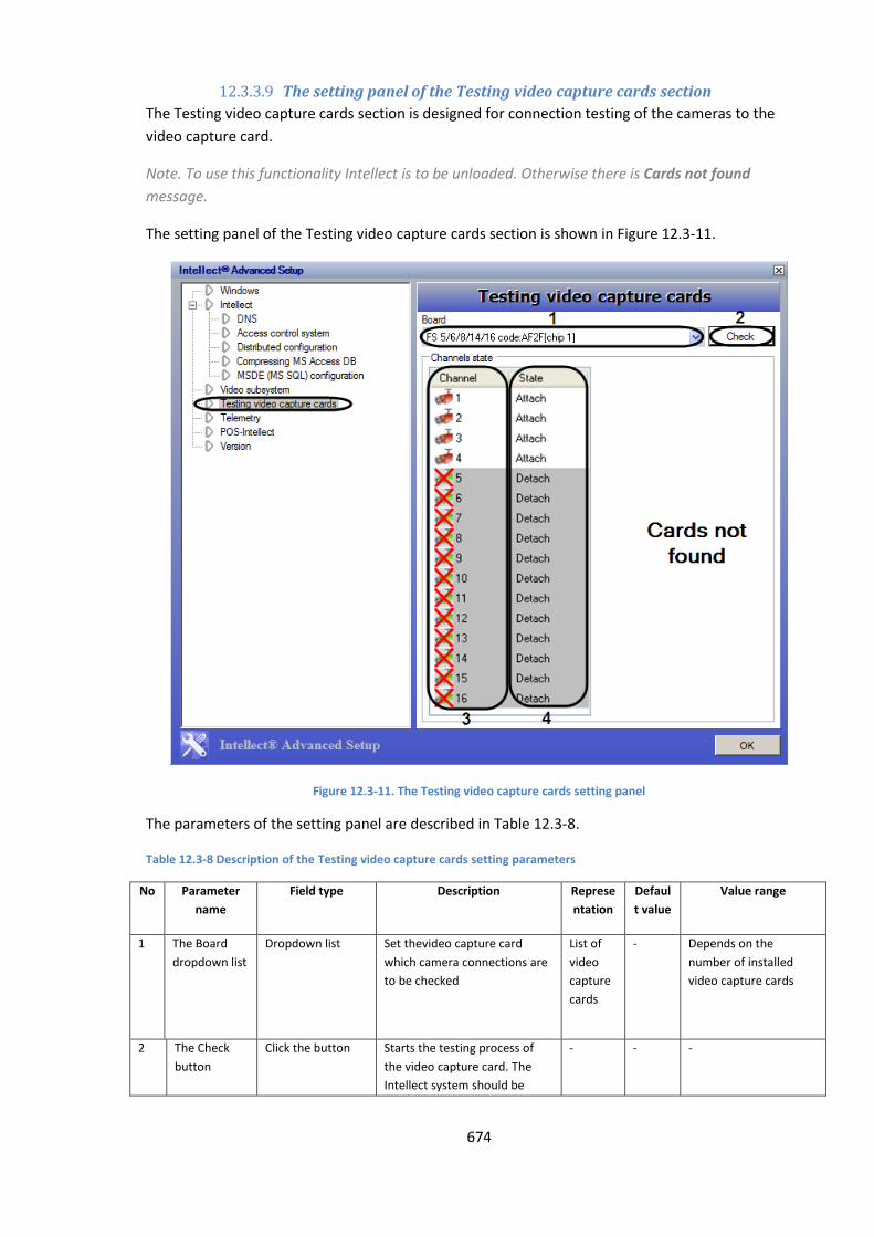
674
12.3.3.9 The setting panel of the Testing video capture cards section
The Testing video capture cards section is designed for connection testing of the cameras to the
video capture card.
Note. To use this functionality Intellect is to be unloaded. Otherwise there is Cards not found
message.
The setting panel of the Testing video capture cards section is shown in Figure 12.3-11.
Figure 12.3-11. The Testing video capture cards setting panel
The parameters of the setting panel are described in Table 12.3-8.
Table 12.3-8 Description of the Testing video capture cards setting parameters
No Parameter
name
Field type Description Represe
ntation
Defaul
t value
Value range
1 The Board
dropdown list
Dropdown list Set thevideo capture card
which camera connections are
to be checked
List of
video
capture
cards
- Depends on the
number of installed
video capture cards
2 The Check
button
Click the button Starts the testing process of
the video capture card. The
Intellect system should be
- - -
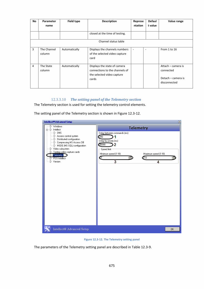
675
No Parameter
name
Field type Description Represe
ntation
Defaul
t value
Value range
closed at the time of testing.
Channel status table
3 The Channel
column
Automatically Displays the channels numbers
of the selected video capture
card
- - From 1 to 16
4 The State
column
Automatically Displays the state of camera
connections to the channels of
the selected video capture
cards
Attach – camera is
connected
Detach – camera is
disconnected
12.3.3.10 The setting panel of the Telemetry section
The Telemetry section is used for setting the telemetry control elements.
The setting panel of the Telemetry section is shown in Figure 12.3-12.
Figure 12.3-12. The Telemetry setting panel
The parameters of the Telemetry setting panel are described in Table 12.3-9.
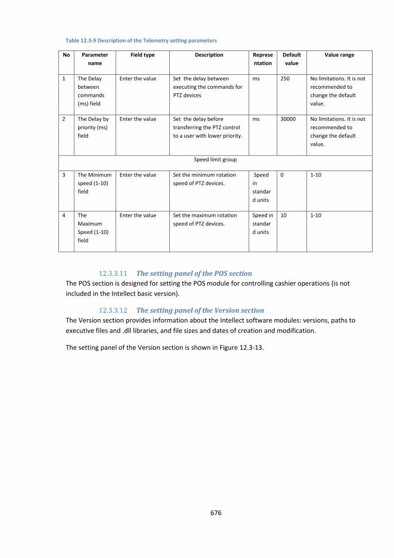
676
Table 12.3-9 Description of the Telemetry setting parameters
No Parameter
name
Field type Description Represe
ntation
Default
value
Value range
1 The Delay
between
commands
(ms) field
Enter the value Set the delay between
executing the commands for
PTZ devices
ms 250 No limitations. It is not
recommended to
change the default
value.
2 The Delay by
priority (ms)
field
Enter the value Set the delay before
transferring the PTZ control
to a user with lower priority.
ms 30000 No limitations. It is not
recommended to
change the default
value.
Speed limit group
3 The Minimum
speed (1-10)
field
Enter the value Set the minimum rotation
speed of PTZ devices.
Speed
in
standar
d units
0 1-10
4 The
Maximum
Speed (1-10)
field
Enter the value Set the maximum rotation
speed of PTZ devices.
Speed in
standar
d units
10 1-10
12.3.3.11 The setting panel of the POS section
The POS section is designed for setting the POS module for controlling cashier operations (is not
included in the Intellect basic version).
12.3.3.12 The setting panel of the Version section
The Version section provides information about the Intellect software modules: versions, paths to
executive files and .dll libraries, and file sizes and dates of creation and modification.
The setting panel of the Version section is shown in Figure 12.3-13.
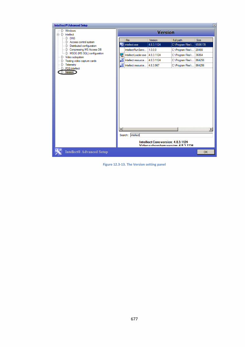
677
Figure 12.3-13. The Version setting panel
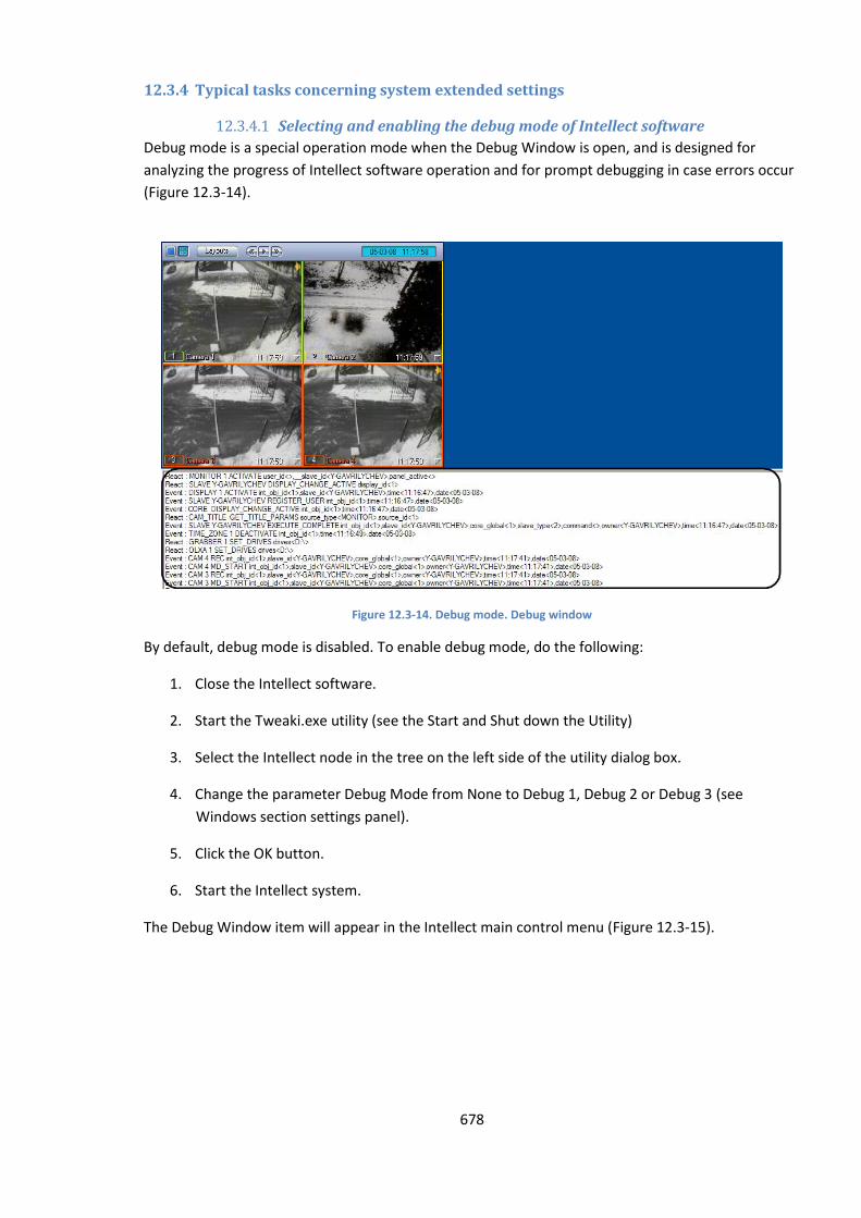
678
12.3.4 Typical tasks concerning system extended settings
12.3.4.1 Selecting and enabling the debug mode of Intellect software
Debug mode is a special operation mode when the Debug Window is open, and is designed for
analyzing the progress of Intellect software operation and for prompt debugging in case errors occur
(Figure 12.3-14).
Figure 12.3-14. Debug mode. Debug window
By default, debug mode is disabled. To enable debug mode, do the following:
1. Close the Intellect software.
2. Start the Tweaki.exe utility (see the Start and Shut down the Utility)
3. Select the Intellect node in the tree on the left side of the utility dialog box.
4. Change the parameter Debug Mode from None to Debug 1, Debug 2 or Debug 3 (see
Windows section settings panel).
5. Click the OK button.
6. Start the Intellect system.
The Debug Window item will appear in the Intellect main control menu (Figure 12.3-15).
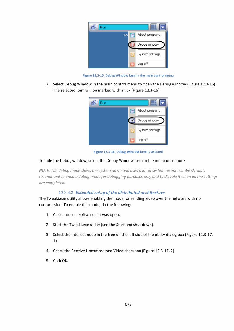
679
Figure 12.3-15. Debug Window item in the main control menu
7. Select Debug Window in the main control menu to open the Debug window (Figure 12.3-15).
The selected item will be marked with a tick (Figure 12.3-16).
Figure 12.3-16. Debug Window item is selected
To hide the Debug window, select the Debug Window item in the menu once more.
NOTE. The debug mode slows the system down and uses a lot of system resources. We strongly
recommend to enable debug mode for debugging purposes only and to disable it when all the settings
are completed.
12.3.4.2 Extended setup of the distributed architecture
The Tweaki.exe utility allows enabling the mode for sending video over the network with no
compression. To enable this mode, do the following:
1. Close Intellect software if it was open.
2. Start the Tweaki.exe utility (see the Start and shut down).
3. Select the Intellect node in the tree on the left side of the utility dialog box (Figure 12.3-17,
1).
4. Check the Receive Uncompressed Video checkbox (Figure 12.3-17, 2).
5. Click OK.
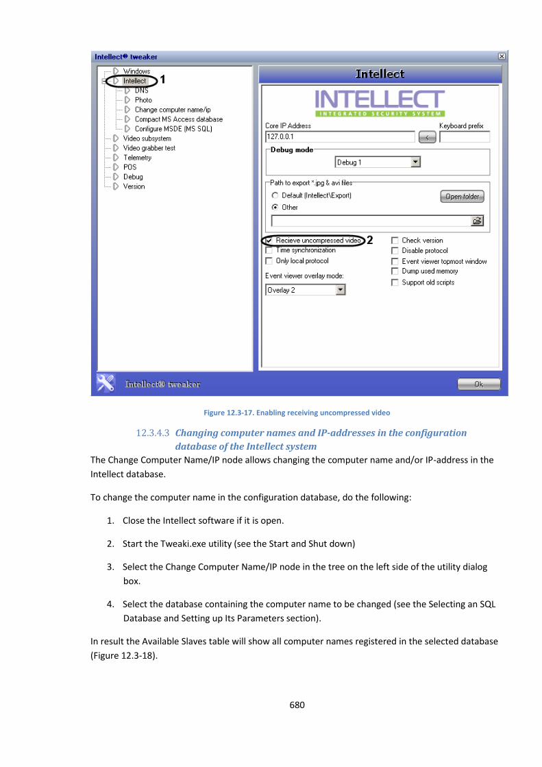
680
Figure 12.3-17. Enabling receiving uncompressed video
12.3.4.3 Changing computer names and IP-addresses in the configuration
database of the Intellect system
The Change Computer Name/IP node allows changing the computer name and/or IP-address in the
Intellect database.
To change the computer name in the configuration database, do the following:
1. Close the Intellect software if it is open.
2. Start the Tweaki.exe utility (see the Start and Shut down)
3. Select the Change Computer Name/IP node in the tree on the left side of the utility dialog
box.
4. Select the database containing the computer name to be changed (see the Selecting an SQL
Database and Setting up Its Parameters section).
In result the Available Slaves table will show all computer names registered in the selected database
(Figure 12.3-18).
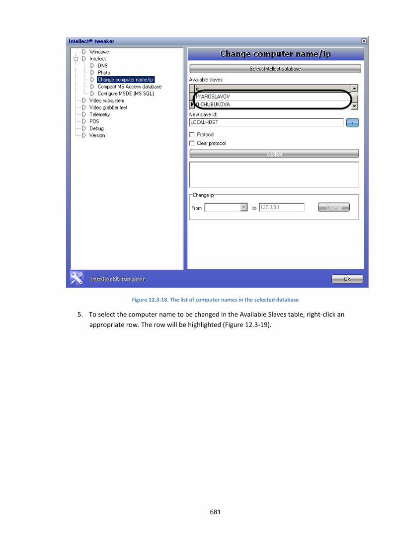
681
Figure 12.3-18. The list of computer names in the selected database
5. To select the computer name to be changed in the Available Slaves table, right-click an
appropriate row. The row will be highlighted (Figure 12.3-19).

682
Figure 12.3-19. Selecting a computer name
6. Click the button next to the New Slave ID field to see the drop-down list of available
computer names.
7. Select the required computer name in the list. The selected name will appear in the New
Slave ID field (Figure 12.3-20, 1).
8. Check one of the following checkboxes: Check the Protocol checkbox to replace the
computer name in the events log, or the Clear Protocol checkbox to delete all records in the
log. Only one of two checkboxes should be checked (Figure 12.3-20, 3).
9. Click the Update button (Figure 12.3-20, 4). The progress of replacing computer names for a
new one will be displayed in the field below the Update button (Figure 12.3-20, 5).
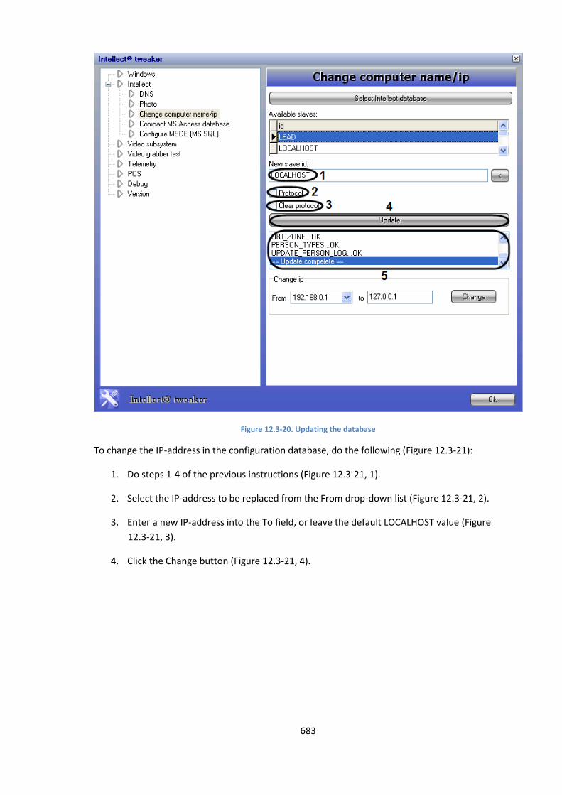
683
Figure 12.3-20. Updating the database
To change the IP-address in the configuration database, do the following (Figure 12.3-21):
1. Do steps 1-4 of the previous instructions (Figure 12.3-21, 1).
2. Select the IP-address to be replaced from the From drop-down list (Figure 12.3-21, 2).
3. Enter a new IP-address into the To field, or leave the default LOCALHOST value (Figure
12.3-21, 3).
4. Click the Change button (Figure 12.3-21, 4).
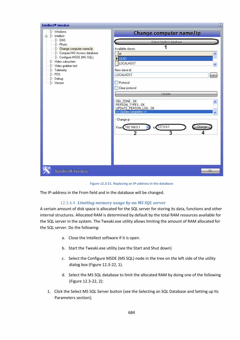
684
Figure 12.3-21. Replacing an IP-address in the database
The IP-address in the From field and in the database will be changed.
12.3.4.4 Limiting memory usage by an MS SQL server
A certain amount of disk space is allocated for the SQL server for storing its data, functions and other
internal structures. Allocated RAM is determined by default by the total RAM resources available for
the SQL server in the system. The Tweaki.exe utility allows limiting the amount of RAM allocated for
the SQL server. Do the following:
a. Close the Intellect software if it is open.
b. Start the Tweaki.exe utility (see the Start and Shut down)
c. Select the Configure MSDE (MS SQL) node in the tree on the left side of the utility
dialog box (Figure 12.3-22, 1).
d. Select the MS SQL database to limit the allocated RAM by doing one of the following
(Figure 12.3-22, 2):
1. Click the Select MS SQL Server button (see the Selecting an SQL Database and Setting up Its
Parameters section);
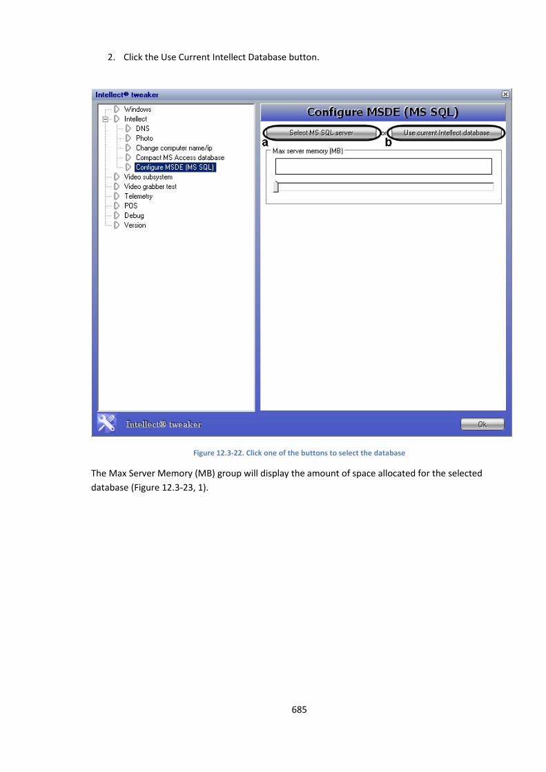
685
2. Click the Use Current Intellect Database button.
Figure 12.3-22. Click one of the buttons to select the database
The Max Server Memory (MB) group will display the amount of space allocated for the selected
database (Figure 12.3-23, 1).
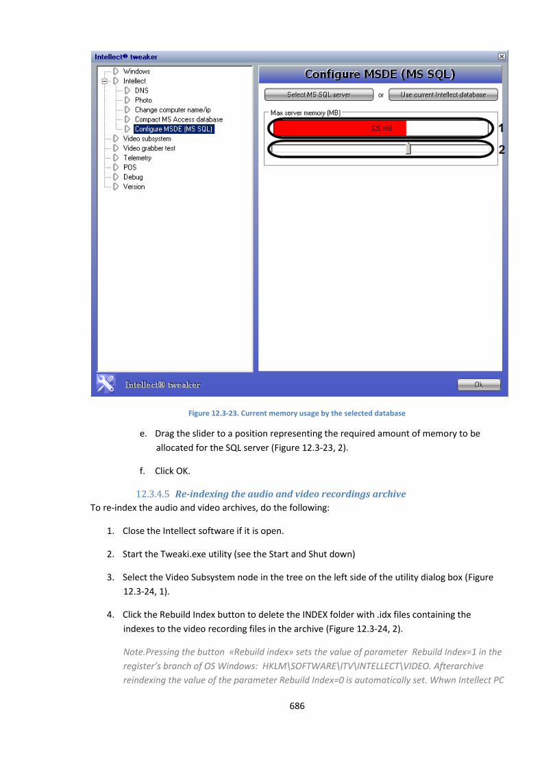
686
Figure 12.3-23. Current memory usage by the selected database
e. Drag the slider to a position representing the required amount of memory to be
allocated for the SQL server (Figure 12.3-23, 2).
f. Click OK.
12.3.4.5 Re-indexing the audio and video recordings archive
To re-index the audio and video archives, do the following:
1. Close the Intellect software if it is open.
2. Start the Tweaki.exe utility (see the Start and Shut down)
3. Select the Video Subsystem node in the tree on the left side of the utility dialog box (Figure
12.3-24, 1).
4. Click the Rebuild Index button to delete the INDEX folder with .idx files containing the
indexes to the video recording files in the archive (Figure 12.3-24, 2).
Note.Pressing the button «Rebuild index» sets the value of parameter Rebuild Index=1 in the
register’s branch of OS Windows: HKLM\SOFTWARE\ITV\INTELLECT\VIDEO. Afterarchive
reindexing the value of the parameter Rebuild Index=0 is automatically set. Whwn Intellect PC
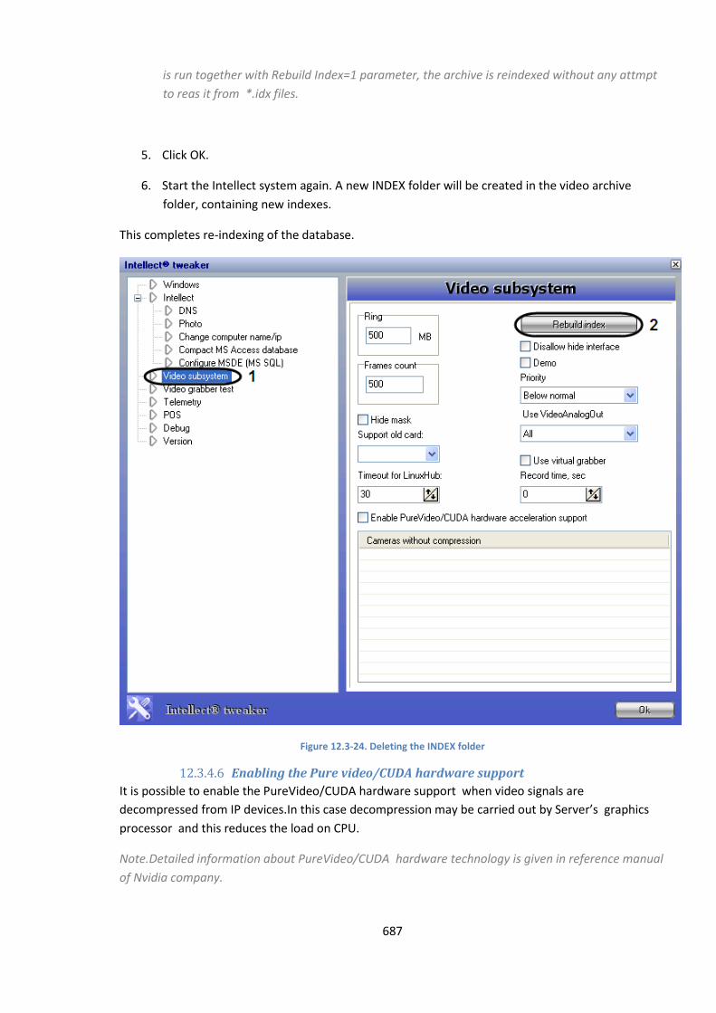
687
is run together with Rebuild Index=1 parameter, the archive is reindexed without any attmpt
to reas it from *.idx files.
5. Click OK.
6. Start the Intellect system again. A new INDEX folder will be created in the video archive
folder, containing new indexes.
This completes re-indexing of the database.
Figure 12.3-24. Deleting the INDEX folder
12.3.4.6 Enabling the Pure video/CUDA hardware support
It is possible to enable the PureVideo/CUDA hardware support when video signals are
decompressed from IP devices.In this case decompression may be carried out by Server’s graphics
processor and this reduces the load on CPU.
Note.Detailed information about PureVideo/CUDA hardware technology is given in reference manual
of Nvidia company.
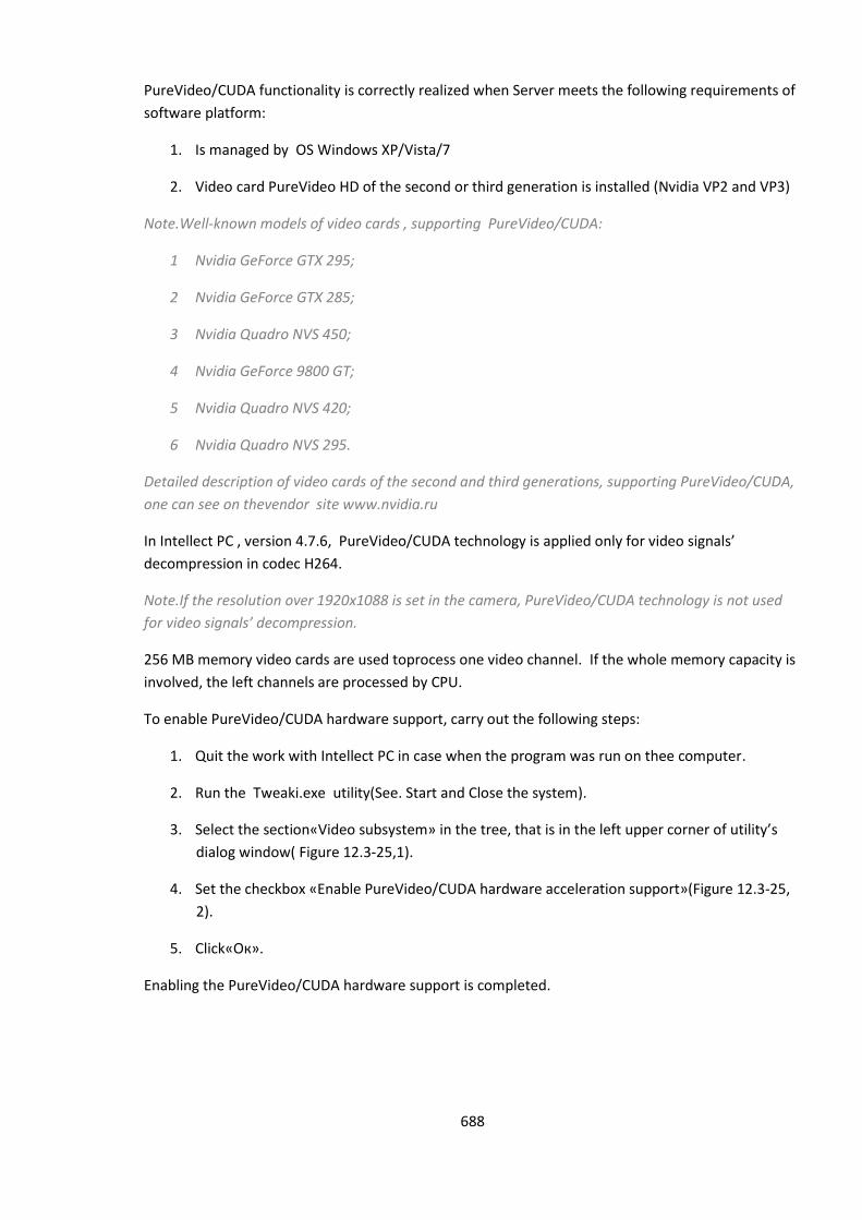
688
PureVideo/CUDA functionality is correctly realized when Server meets the following requirements of
software platform:
1. Is managed by OS Windows XP/Vista/7
2. Video card PureVideo HD of the second or third generation is installed (Nvidia VP2 and VP3)
Note.Well-known models of video cards , supporting PureVideo/CUDA:
1 Nvidia GeForce GTX 295;
2 Nvidia GeForce GTX 285;
3 Nvidia Quadro NVS 450;
4 Nvidia GeForce 9800 GT;
5 Nvidia Quadro NVS 420;
6 Nvidia Quadro NVS 295.
Detailed description of video cards of the second and third generations, supporting PureVideo/CUDA,
one can see on thevendor site www.nvidia.ru
In Intellect PC , version 4.7.6, PureVideo/CUDA technology is applied only for video signals’
decompression in codec H264.
Note.If the resolution over 1920х1088 is set in the camera, PureVideo/CUDA technology is not used
for video signals’ decompression.
256 МB memory video cards are used toprocess one video channel. If the whole memory capacity is
involved, the left channels are processed by CPU.
To enable PureVideo/CUDA hardware support, carry out the following steps:
1. Quit the work with Intellect PC in case when the program was run on thee computer.
2. Run the Tweaki.exe utility(See. Start and Close the system).
3. Select the section«Video subsystem» in the tree, that is in the left upper corner of utility’s
dialog window( Figure 12.3-25,1).
4. Set the checkbox «Enable PureVideo/CUDA hardware acceleration support»(Figure 12.3-25,
2).
5. Click«Ок».
Enabling the PureVideo/CUDA hardware support is completed.
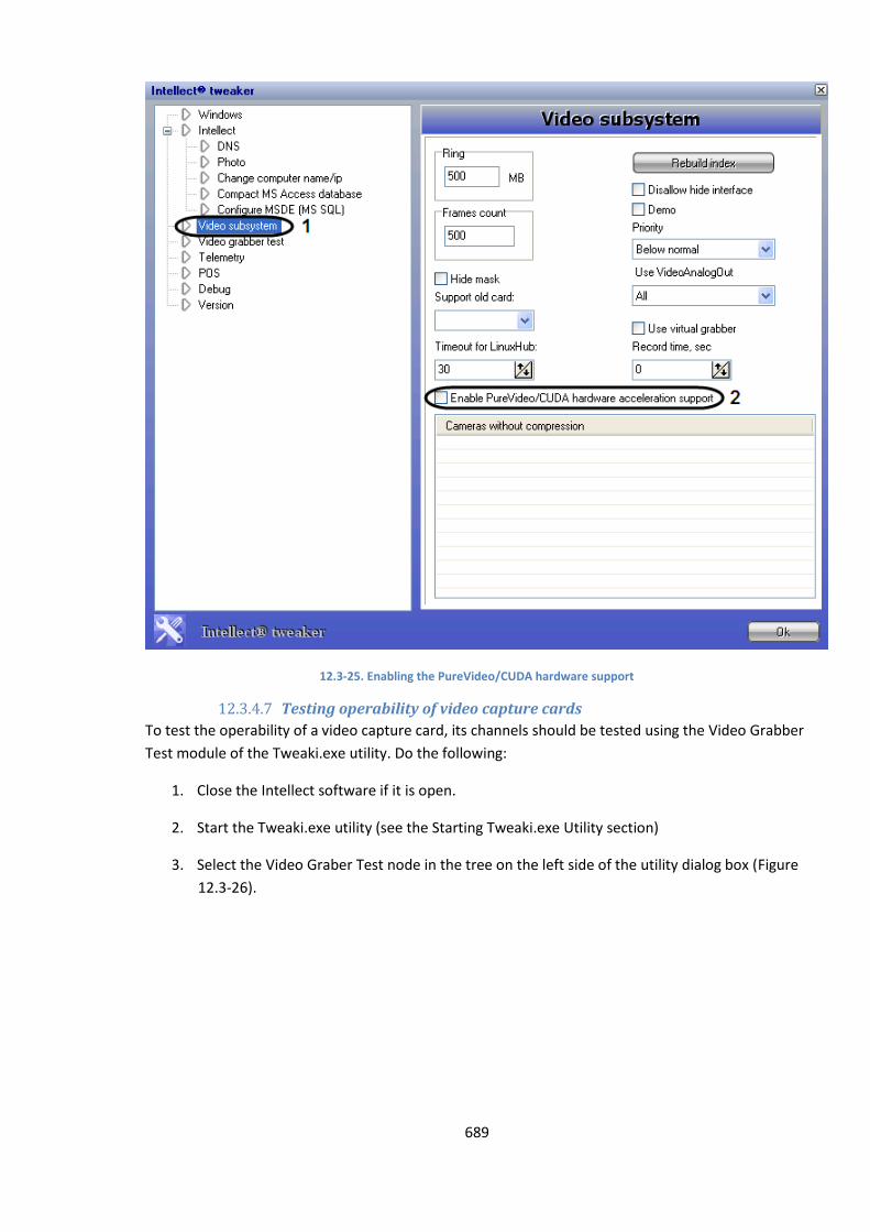
689
12.3-25. Enabling the PureVideo/CUDA hardware support
12.3.4.7 Testing operability of video capture cards
To test the operability of a video capture card, its channels should be tested using the Video Grabber
Test module of the Tweaki.exe utility. Do the following:
1. Close the Intellect software if it is open.
2. Start the Tweaki.exe utility (see the Starting Tweaki.exe Utility section)
3. Select the Video Graber Test node in the tree on the left side of the utility dialog box (Figure
12.3-26).
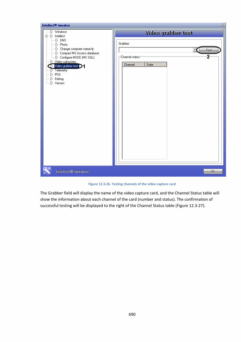
690
Figure 12.3-26. Testing channels of the video capture card
The Grabber field will display the name of the video capture card, and the Channel Status table will
show the information about each channel of the card (number and status). The confirmation of
successful testing will be displayed to the right of the Channel Status table (Figure 12.3-27).
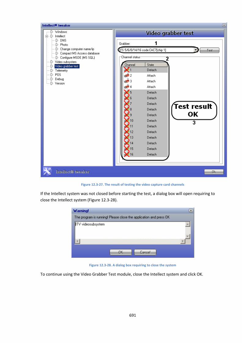
691
Figure 12.3-27. The result of testing the video capture card channels
If the Intellect system was not closed before starting the test, a dialog box will open requiring to
close the Intellect system (Figure 12.3-28).
Figure 12.3-28. A dialog box requiring to close the system
To continue using the Video Grabber Test module, close the Intellect system and click OK.
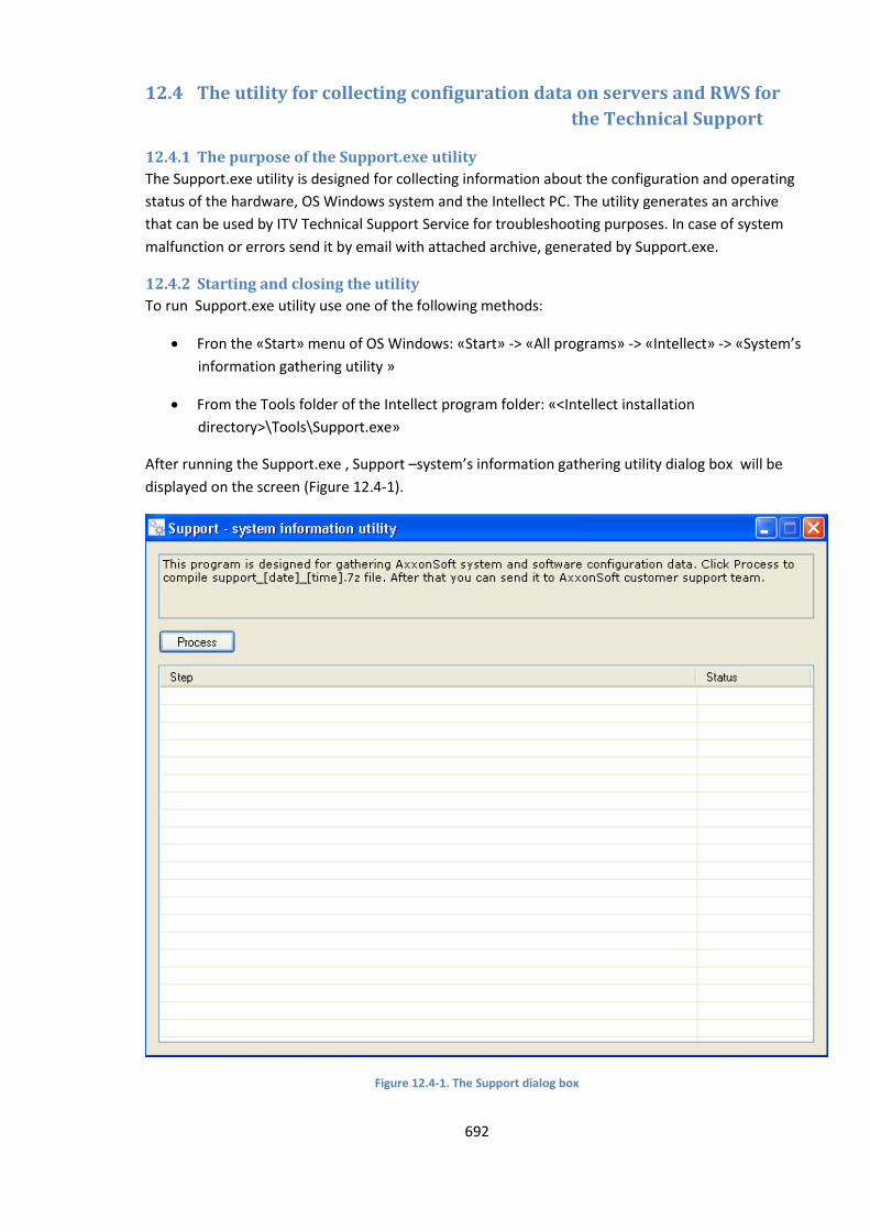
692
12.4 The utility for collecting configuration data on servers and RWS for
the Technical Support
12.4.1 The purpose of the Support.exe utility
The Support.exe utility is designed for collecting information about the configuration and operating
status of the hardware, OS Windows system and the Intellect PC. The utility generates an archive
that can be used by ITV Technical Support Service for troubleshooting purposes. In case of system
malfunction or errors send it by email with attached archive, generated by Support.exe.
12.4.2 Starting and closing the utility
To run Support.exe utility use one of the following methods:
Fron the «Start» menu of OS Windows: «Start» -> «All programs» -> «Intellect» -> «System’s
information gathering utility »
From the Tools folder of the Intellect program folder: «<Intellect installation
directory>\Tools\Support.exe»
After running the Support.exe , Support –system’s information gathering utility dialog box will be
displayed on the screen (Figure 12.4-1).
Figure 12.4-1. The Support dialog box
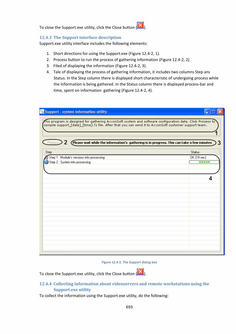
693
To close the Support.exe utility, click the Close button ( ).
12.4.3 The Support interface description
Support.exe utility interface includes the following elements:
1. Short directions for using the Support.exe (Figure 12.4-2, 1).
2. Process button to run the process of gathering information (Figure 12.4-2, 2).
3. Filed of displaying the information (Figure 12.4-2, 3).
4. Tale of displaying the process of gathering information, it includes two columns Step ans
Status. In the Step column there is displayed short characteristic of undergoing process while
the information is being gathered. In the Status column there is displayed process-bar and
time, spent on information gathering (Figure 12.4-2, 4).
Figure 12.4-2. The Support dialog box
To close the Support.exe utility, click the Close button ( ).
12.4.4 Collecting information about videoservers and remote workstations using the
Support.exe utility
To collect the information using the Support.exe utility, do the following:
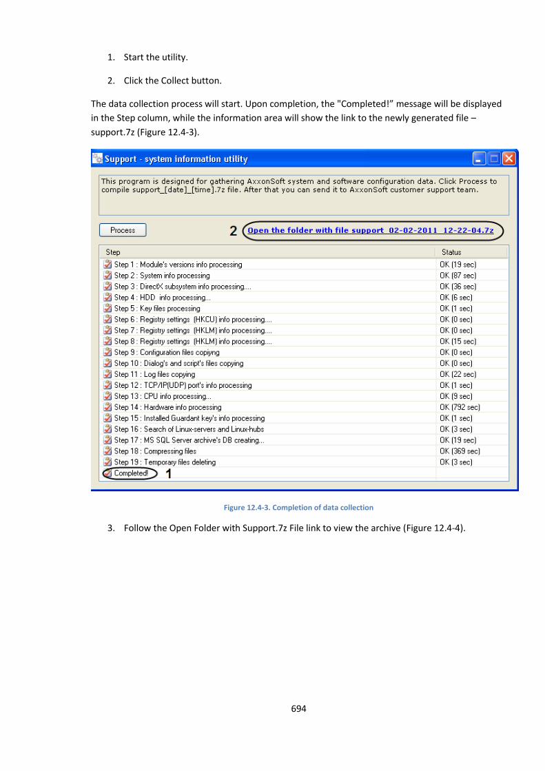
694
1. Start the utility.
2. Click the Collect button.
The data collection process will start. Upon completion, the "Completed!” message will be displayed
in the Step column, while the information area will show the link to the newly generated file –
support.7z (Figure 12.4-3).
Figure 12.4-3. Completion of data collection
3. Follow the Open Folder with Support.7z File link to view the archive (Figure 12.4-4).
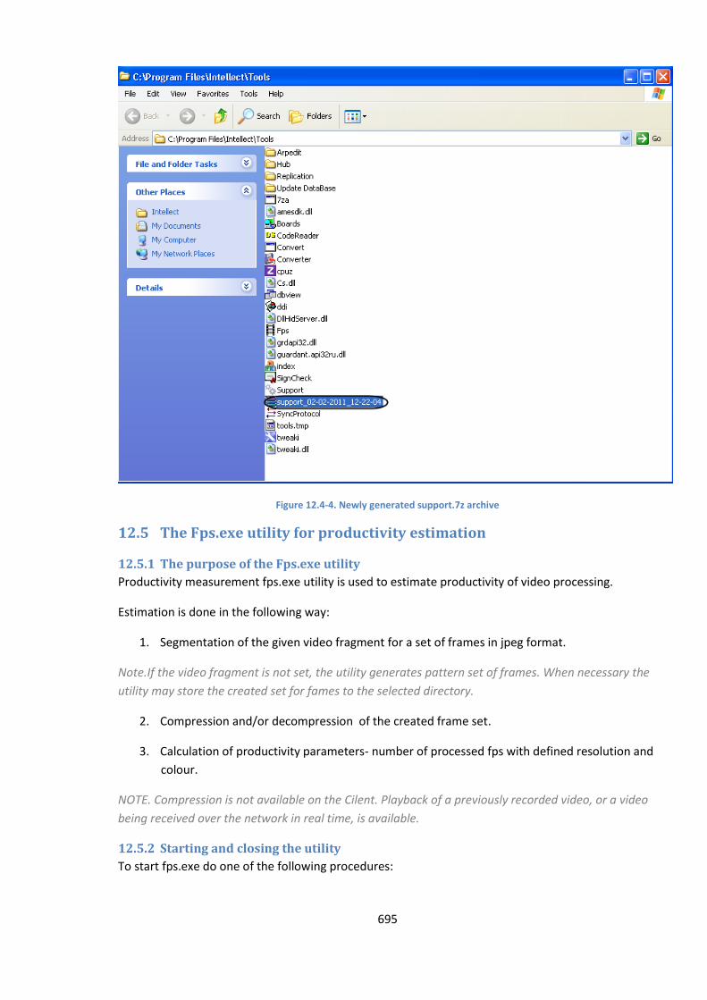
695
Figure 12.4-4. Newly generated support.7z archive
12.5 The Fps.exe utility for productivity estimation
12.5.1 The purpose of the Fps.exe utility
Productivity measurement fps.exe utility is used to estimate productivity of video processing.
Estimation is done in the following way:
1. Segmentation of the given video fragment for a set of frames in jpeg format.
Note.If the video fragment is not set, the utility generates pattern set of frames. When necessary the
utility may store the created set for fames to the selected directory.
2. Compression and/or decompression of the created frame set.
3. Calculation of productivity parameters- number of processed fps with defined resolution and
colour.
NOTE. Compression is not available on the Cilent. Playback of a previously recorded video, or a video
being received over the network in real time, is available.
12.5.2 Starting and closing the utility
To start fps.exe do one of the following procedures:
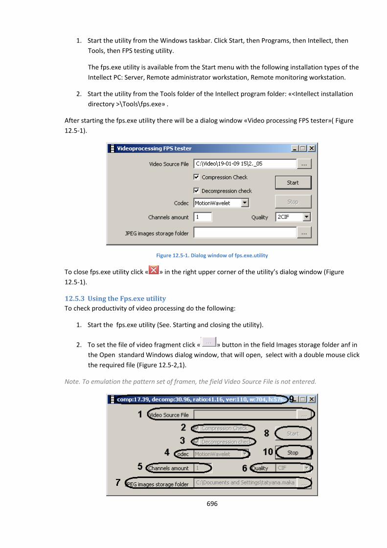
696
1. Start the utility from the Windows taskbar. Click Start, then Programs, then Intellect, then
Tools, then FPS testing utility.
The fps.exe utility is available from the Start menu with the following installation types of the
Intellect PC: Server, Remote administrator workstation, Remote monitoring workstation.
2. Start the utility from the Tools folder of the Intellect program folder: «<Intellect installation
directory >\Tools\fps.exe» .
After starting the fps.exe utility there will be a dialog window «Video processing FPS tester»( Figure
12.5-1).
Figure 12.5-1. Dialog window of fps.exe.utility
To close fps.exe utility click « » in the right upper corner of the utility’s dialog window (Figure
12.5-1).
12.5.3 Using the Fps.exe utility
To check productivity of video processing do the following:
1. Start the fps.exe utility (See. Starting and closing the utility).
2. To set the file of video fragment click « » button in the field Images storage folder anf in
the Open standard Windows dialog window, that will open, select with a double mouse click
the required file (Figure 12.5-2,1).
Note. To emulation the pattern set of framen, the field Video Source File is not entered.

697
Figure 12.5-2. Video processing FPS tester
3. Activate Compression check checkbox to check how many fps the given computer can
compress (Figure 12.5-2, 2).
4. Activate Decompression check checkbox to check how many fps the given computer can
decompress(Figure 12.5-2, 3).
5. Select thr requiret compressor version from the dropdown list Codec (Figure 12.5-2, 4).
6. Enter the required number of emulated cameras in the field Channels amount (Figure 12.5-2,
5).
Note. This setting is actual only with emulation of pattern set of channels.
7. Select the required value of frames compression from the dropdown list Quality (inversely to
compression level) (Figure 12.5-2, 6).
8. When necessary set the directory, where frames extracted from the video would be
decompressed with the help of « »button of the field « Jpeg images storage
folder»(Figure 12.5-2, 7).
9. To start video processing tester click Start button (Figure 12.5-2, 8).
10. As the result parameters of video processing productivity will be displayed in the title bar of
the utility window (Table 12.5-1, Figure 12.5-2, 9).
Table 12.5-1 Parameters of video processing productivity
Productivity parameter Description of parameter
comp total number of frames that can be compressed in one second
decomp total number of frames that can be decompressed in one second
ratio compression ratio
ver selected version of the compressor
w frame width
h frame height
color if the frame is in color
count number of compressor instances per CPU
11. If step 8 is compeleted, the frames for testing video processing will be recorded to thefiles
jpeg storage folder (Figure 12.5-3).
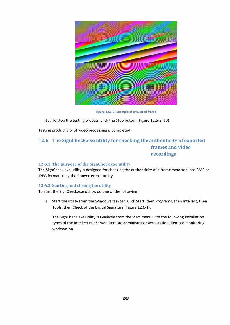
698
Figure 12.5-3. Example of emulated frame
12. To stop the testing process, click the Stop button (Figure 12.5-3, 10).
Testing productivity of video processing is completed.
12.6 The SignCheck.exe utility for checking the authenticity of exported
frames and video
recordings
12.6.1 The purpose of the SignCheck.exe utility
The SignCheck.exe utility is designed for checking the authenticity of a frame exported into BMP or
JPEG format using the Converter.exe utility.
12.6.2 Starting and closing the utility
To start the SignCheck.exe utility, do one of the following:
1. Start the utility from the Windows taskbar. Click Start, then Programs, then Intellect, then
Tools, then Check of the Digital Signature (Figure 12.6-1).
The SignCheck.exe utility is available from the Start menu with the following installation
types of the Intellect PC: Server, Remote administrator workstation, Remote monitoring
workstation.
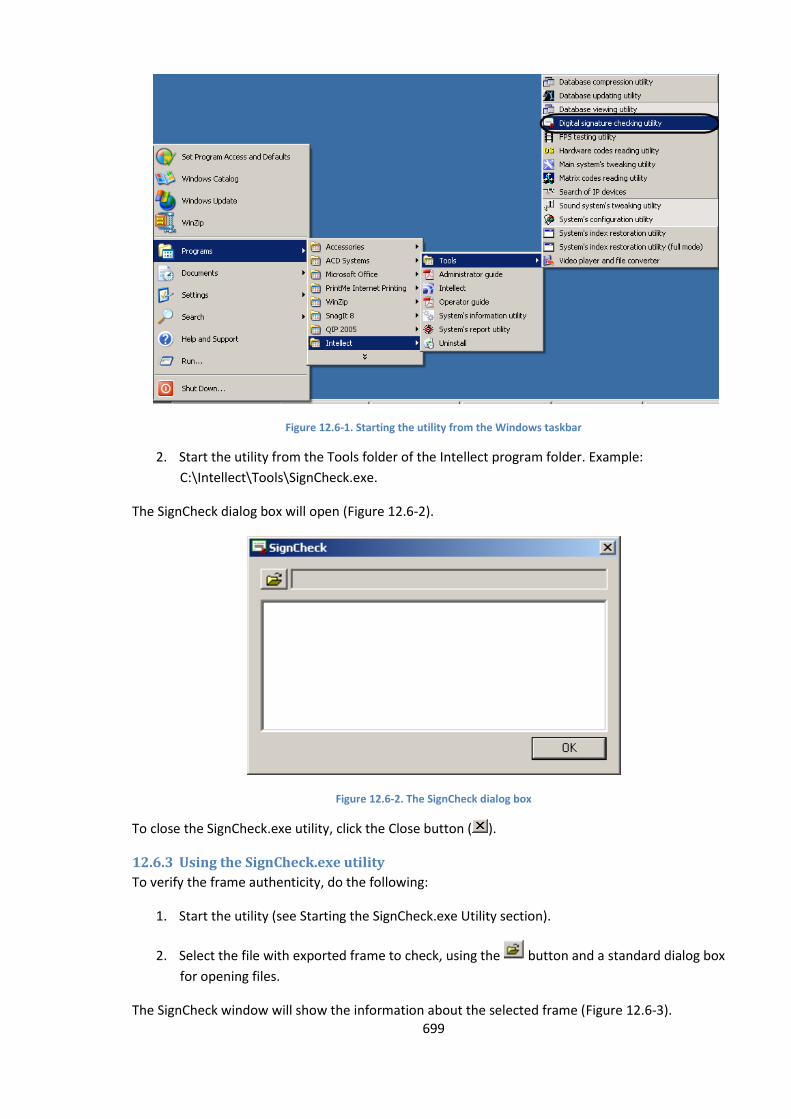
699
Figure 12.6-1. Starting the utility from the Windows taskbar
2. Start the utility from the Tools folder of the Intellect program folder. Example:
С:\Intellect\Tools\SignCheck.exe.
The SignCheck dialog box will open (Figure 12.6-2).
Figure 12.6-2. The SignCheck dialog box
To close the SignCheck.exe utility, click the Close button ( ).
12.6.3 Using the SignCheck.exe utility
To verify the frame authenticity, do the following:
1. Start the utility (see Starting the SignCheck.exe Utility section).
2. Select the file with exported frame to check, using the button and a standard dialog box
for opening files.
The SignCheck window will show the information about the selected frame (Figure 12.6-3).
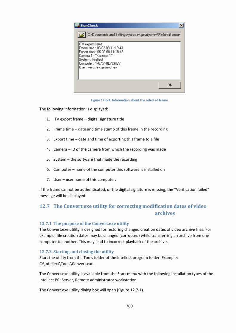
700
Figure 12.6-3. Information about the selected frame
The following information is displayed:
1. ITV export frame – digital signature title
2. Frame time – date and time stamp of this frame in the recording
3. Export time – date and time of exporting this frame to a file
4. Camera – ID of the camera from which the recording was made
5. System – the software that made the recording
6. Computer – name of the computer this software is installed on
7. User – user name of this computer.
If the frame cannot be authenticated, or the digital signature is missing, the “Verification failed”
message will be displayed.
12.7 The Convert.exe utility for correcting modification dates of video
archives
12.7.1 The purpose of the Convert.exe utility
The Convert.exe utility is designed for restoring changed creation dates of video archive files. For
example, file creation dates may be changed (corrupted) while transferring an archive from one
computer to another. This may lead to incorrect playback of the archive.
12.7.2 Starting and closing the utility
Start the utility from the Tools folder of the Intellect program folder. Example:
С:\Intellect\Tools\Convert.exe.
The Convert.exe utility is available from the Start menu with the following installation types of the
Intellect PC: Server, Remote administrator workstation.
The Convert.exe utility dialog box will open (Figure 12.7-1).
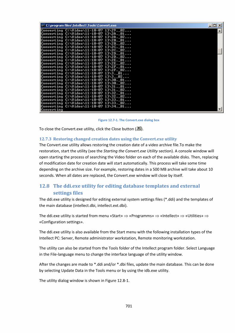
701
Figure 12.7-1. The Convert.exe dialog box
To close the Convert.exe utility, click the Close button ( ).
12.7.3 Restoring changed creation dates using the Convert.exe utility
The Convert.exe utility allows restoring the creation date of a video archive file.To make the
restoration, start the utility (see the Starting the Convert.exe Utility section). A console window will
open starting the process of searching the Video folder on each of the available disks. Then, replacing
of modification date for creation date will start automatically. This process will take some time
depending on the archive size. For example, restoring dates in a 500 MB archive will take about 10
seconds. When all dates are replaced, the Convert.exe window will close by itself.
12.8 The ddi.exe utility for editing database templates and external
settings files The ddi.exe utility is designed for editing external system settings files (*.ddi) and the templates of
the main database (intellect.dbi, intellect.ext.dbi).
The ddi.exe utility is started from menu «Start» «Programms» «Intellect» «Utilities»
«Configuration settings».
The ddi.exe utility is also available from the Start menu with the following installation types of the
Intellect PC: Server, Remote administrator workstation, Remote monitoring workstation.
The utility can also be started from the Tools folder of the Intellect program folder. Select Language
in the File-language menu to change the interface language of the utility window.
After the changes are made to *.ddi and/or *.dbi files, update the main database. This can be done
by selecting Update Data in the Tools menu or by using the idb.exe utility.
The utility dialog window is shown in Figure 12.8-1.
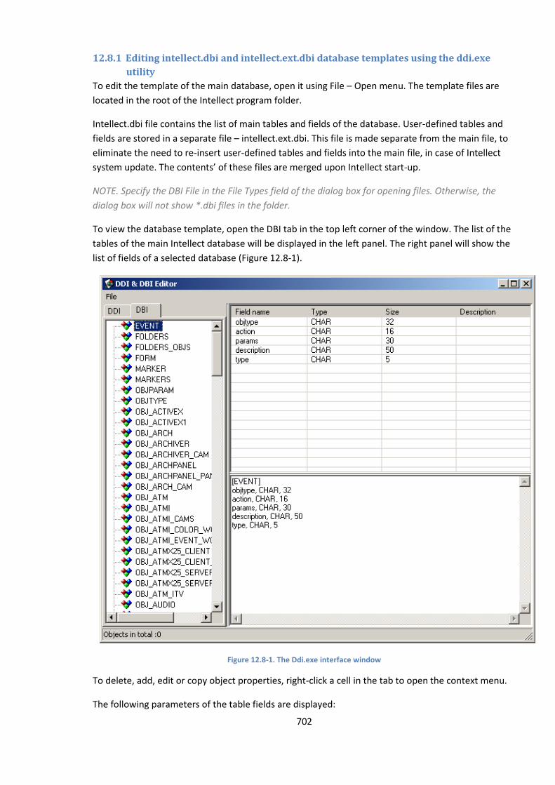
702
12.8.1 Editing intellect.dbi and intellect.ext.dbi database templates using the ddi.exe
utility
To edit the template of the main database, open it using File – Open menu. The template files are
located in the root of the Intellect program folder.
Intellect.dbi file contains the list of main tables and fields of the database. User-defined tables and
fields are stored in a separate file – intellect.ext.dbi. This file is made separate from the main file, to
eliminate the need to re-insert user-defined tables and fields into the main file, in case of Intellect
system update. The contents’ of these files are merged upon Intellect start-up.
NOTE. Specify the DBI File in the File Types field of the dialog box for opening files. Otherwise, the
dialog box will not show *.dbi files in the folder.
To view the database template, open the DBI tab in the top left corner of the window. The list of the
tables of the main Intellect database will be displayed in the left panel. The right panel will show the
list of fields of a selected database (Figure 12.8-1).
Figure 12.8-1. The Ddi.exe interface window
To delete, add, edit or copy object properties, right-click a cell in the tab to open the context menu.
The following parameters of the table fields are displayed:

703
a. Field name – the name of the field in the database.
b. Type – data type of the field’s contents. Available types:
1. BIT – checkboxes taking logical values Yes and No;
2. CHAR – small text fields;
3. DATETIME – date and time in the following format: date – dd-mm-yyyy, time – h:mm:ss;
4. DOUBLE, INTEGER, SMALLINT – numerical fields of corresponding types;
5. TEXT – larger texts.
c. Length – maximum number of units of the specified format in a field.
d. Description – field name shown in the interface.
The database should be refreshed after the changes were made.
12.8.2 Editing the external setting file (intellect.ddi) using the ddi.exe utility
To edit the external settings file (intellect.ddi), open it by clicking File – Open menu. This file is
located in the root of the Intellect program folder.
The external settings file contains the information about objects and events loaded into the system
configuration, graphical symbols for various objects’ states on the map, and the rules for transitions
between the object states.
The purpose of editing can be software localization or expanding/limiting its functionality (for
example, removing unused objects from the system).
NOTE. Changing the external settings file may lead to system failure. Create a backup copy of the file
before editing it.
The database should be refreshed after the changes were made.
12.8.2.1 General information
To start using the utility, open the DDI tab in the top left corner of the window.
The left side of the window will display all system objects loaded into the configuration. The right
side of the window shows the settings panel of a chosen object. This panel consists of several tabs:
Names, Events, Reacts, Markers, States, State Rules.
To delete, add, edit or copy object properties, right-click a cell in the tab to open the context menu.
12.8.2.2 Names tab
This tab contains three fields (Figure 12.8-2). Name is the name of the object in the system. Group
Name is the name of the group the object will be assigned to upon creation. If this field is left blank,
no group will be assigned to the field. The Search by Name field relates to the search system. The list
below will contain all object names in the system that exactly or partially match the word entered in
this field. The figure shows the results of searching for "cam”.
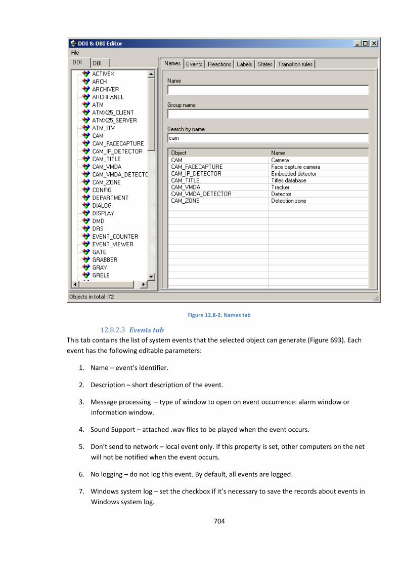
704
Figure 12.8-2. Names tab
12.8.2.3 Events tab
This tab contains the list of system events that the selected object can generate (Figure 693). Each
event has the following editable parameters:
1. Name – event’s identifier.
2. Description – short description of the event.
3. Message processing – type of window to open on event occurrence: alarm window or
information window.
4. Sound Support – attached .wav files to be played when the event occurs.
5. Don’t send to network – local event only. If this property is set, other computers on the net
will not be notified when the event occurs.
6. No logging – do not log this event. By default, all events are logged.
7. Windows system log – set the checkbox if it’s necessary to save the records about events in
Windows system log.
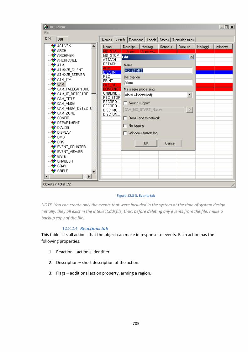
705
Figure 12.8-3. Events tab
NOTE. You can create only the events that were included in the system at the time of system design.
Initially, they all exist in the intellect.ddi file, thus, before deleting any events from the file, make a
backup copy of the file.
12.8.2.4 Reactions tab
This table lists all actions that the object can make in response to events. Each action has the
following properties:
1. Reaction – action’s identifier.
2. Description – short description of the action.
3. Flags – additional action property, arming a region.
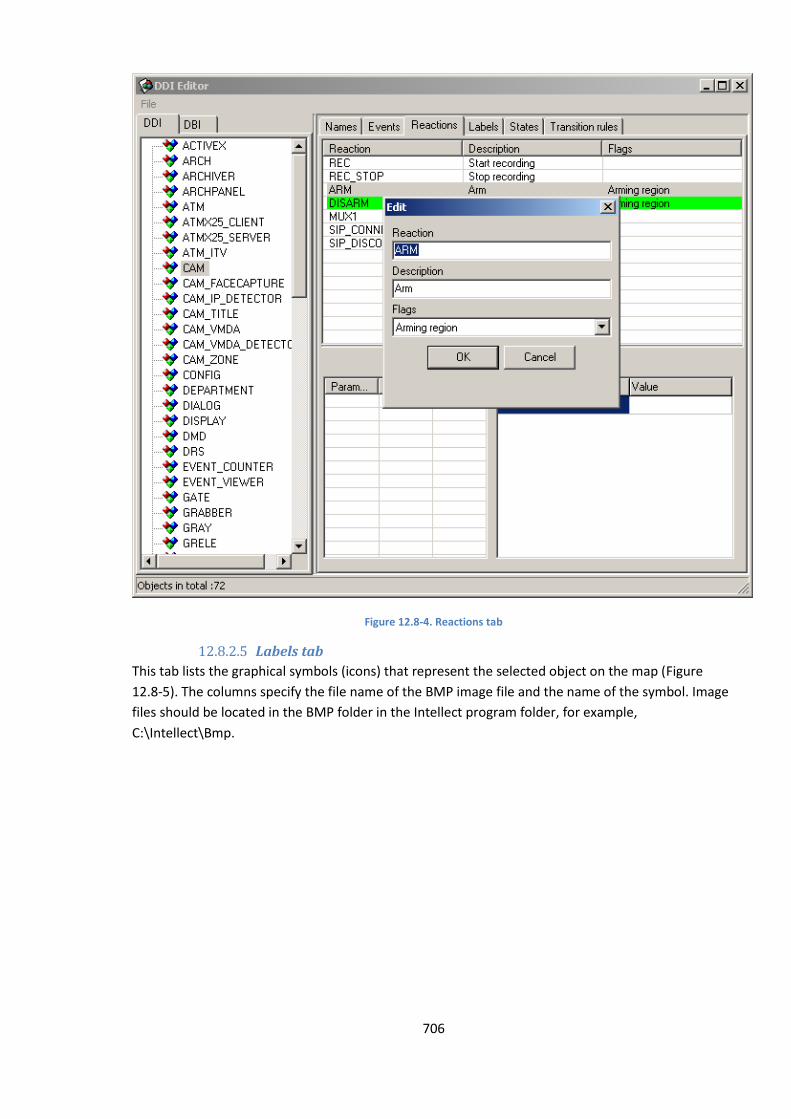
706
Figure 12.8-4. Reactions tab
12.8.2.5 Labels tab
This tab lists the graphical symbols (icons) that represent the selected object on the map (Figure
12.8-5). The columns specify the file name of the BMP image file and the name of the symbol. Image
files should be located in the BMP folder in the Intellect program folder, for example,
C:\Intellect\Bmp.
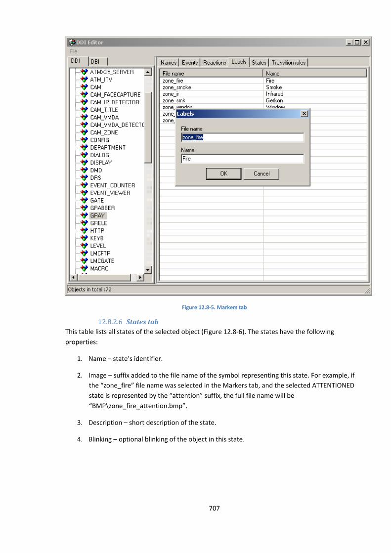
707
Figure 12.8-5. Markers tab
12.8.2.6 States tab
This table lists all states of the selected object (Figure 12.8-6). The states have the following
properties:
1. Name – state’s identifier.
2. Image – suffix added to the file name of the symbol representing this state. For example, if
the “zone_fire” file name was selected in the Markers tab, and the selected ATTENTIONED
state is represented by the “attention” suffix, the full file name will be
“BMP\zone_fire_attention.bmp”.
3. Description – short description of the state.
4. Blinking – optional blinking of the object in this state.
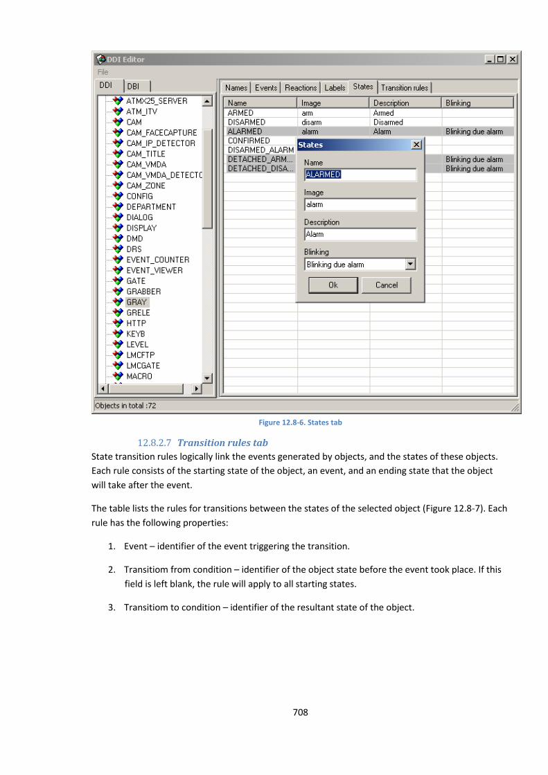
708
Figure 12.8-6. States tab
12.8.2.7 Transition rules tab
State transition rules logically link the events generated by objects, and the states of these objects.
Each rule consists of the starting state of the object, an event, and an ending state that the object
will take after the event.
The table lists the rules for transitions between the states of the selected object (Figure 12.8-7). Each
rule has the following properties:
1. Event – identifier of the event triggering the transition.
2. Transitiom from condition – identifier of the object state before the event took place. If this
field is left blank, the rule will apply to all starting states.
3. Transitiom to condition – identifier of the resultant state of the object.
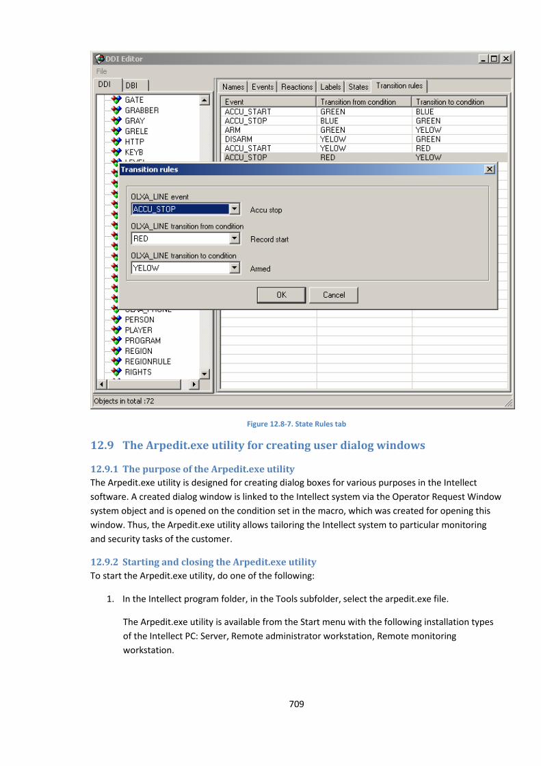
709
Figure 12.8-7. State Rules tab
12.9 The Arpedit.exe utility for creating user dialog windows
12.9.1 The purpose of the Arpedit.exe utility
The Arpedit.exe utility is designed for creating dialog boxes for various purposes in the Intellect
software. A created dialog window is linked to the Intellect system via the Operator Request Window
system object and is opened on the condition set in the macro, which was created for opening this
window. Thus, the Arpedit.exe utility allows tailoring the Intellect system to particular monitoring
and security tasks of the customer.
12.9.2 Starting and closing the Arpedit.exe utility
To start the Arpedit.exe utility, do one of the following:
1. In the Intellect program folder, in the Tools subfolder, select the arpedit.exe file.
The Arpedit.exe utility is available from the Start menu with the following installation types
of the Intellect PC: Server, Remote administrator workstation, Remote monitoring
workstation.
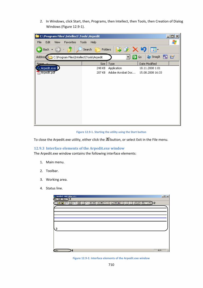
710
2. In Windows, click Start, then, Programs, then Intellect, then Tools, then Creation of Dialog
Windows (Figure 12.9-1).
Figure 12.9-1. Starting the utility using the Start button
To close the Arpedit.exe utility, either click the button, or select Exit in the File menu.
12.9.3 Interface elements of the Arpedit.exe window
The Arpedit.exe window contains the following interface elements:
1. Main menu.
2. Toolbar.
3. Working area.
4. Status line.
Figure 12.9-2. Interface elements of the Arpedit.exe window
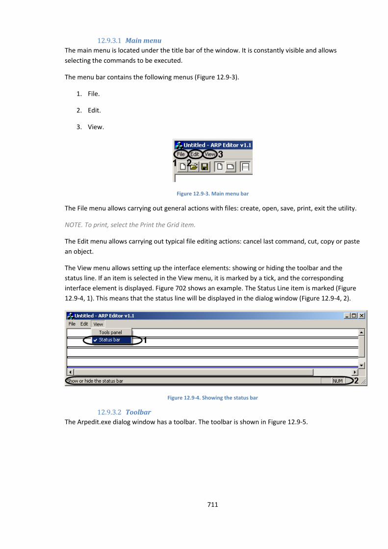
711
12.9.3.1 Main menu
The main menu is located under the title bar of the window. It is constantly visible and allows
selecting the commands to be executed.
The menu bar contains the following menus (Figure 12.9-3).
1. File.
2. Edit.
3. View.
Figure 12.9-3. Main menu bar
The File menu allows carrying out general actions with files: create, open, save, print, exit the utility.
NOTE. To print, select the Print the Grid item.
The Edit menu allows carrying out typical file editing actions: cancel last command, cut, copy or paste
an object.
The View menu allows setting up the interface elements: showing or hiding the toolbar and the
status line. If an item is selected in the View menu, it is marked by a tick, and the corresponding
interface element is displayed. Figure 702 shows an example. The Status Line item is marked (Figure
12.9-4, 1). This means that the status line will be displayed in the dialog window (Figure 12.9-4, 2).
Figure 12.9-4. Showing the status bar
12.9.3.2 Toolbar
The Arpedit.exe dialog window has a toolbar. The toolbar is shown in Figure 12.9-5.
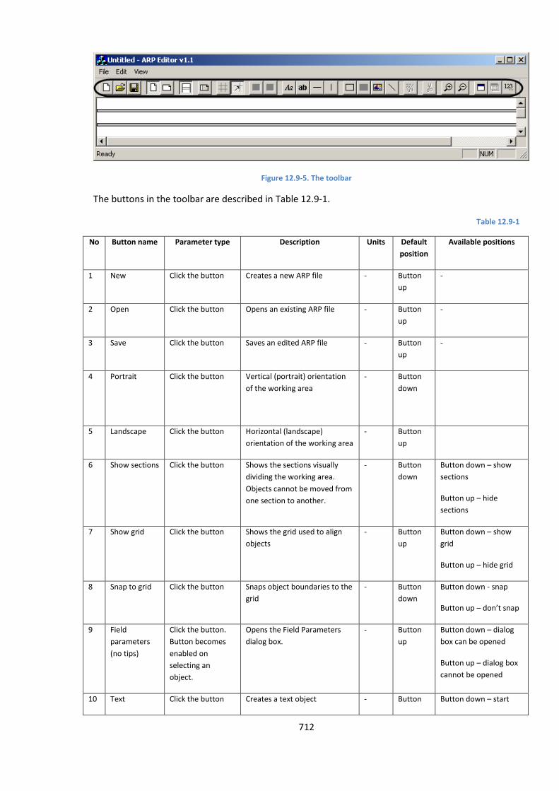
712
Figure 12.9-5. The toolbar
The buttons in the toolbar are described in Table 12.9-1.
Table 12.9-1
No Button name Parameter type Description Units Default
position
Available positions
1 New Click the button Creates a new ARP file - Button
up
-
2 Open Click the button Opens an existing ARP file - Button
up
-
3 Save Click the button Saves an edited ARP file - Button
up
-
4 Portrait Click the button Vertical (portrait) orientation
of the working area
- Button
down
5 Landscape Click the button Horizontal (landscape)
orientation of the working area
- Button
up
6 Show sections Click the button Shows the sections visually
dividing the working area.
Objects cannot be moved from
one section to another.
- Button
down
Button down – show
sections
Button up – hide
sections
7 Show grid Click the button Shows the grid used to align
objects
- Button
up
Button down – show
grid
Button up – hide grid
8 Snap to grid Click the button Snaps object boundaries to the
grid
- Button
down
Button down - snap
Button up – don’t snap
9 Field
parameters
(no tips)
Click the button.
Button becomes
enabled on
selecting an
object.
Opens the Field Parameters
dialog box.
- Button
up
Button down – dialog
box can be opened
Button up – dialog box
cannot be opened
10 Text Click the button Creates a text object - Button Button down – start

713
No Button name Parameter type Description Units Default
position
Available positions
up creating an object
Button up – cannot
start creating an object
11 Field Click the button Creates a value field object - Button
up
Button down – start
creating an object
Button up – cannot
start creating an object
12 Horizontal bar Click the button Creates a horizontal bar for
graphical design purposes.
After compilation the bar is not
shown and is used for
extending the width of the
window.
- Button
up
Button down – start
creating an object
Button up – cannot
start creating an object
13 Vertical bar Click the button Creates a vertical bar for
graphical design purposes.
After compilation the bar is not
shown and is used for
extending the height of the
window.
- Button
up
Button down – start
creating an object
Button up – cannot
start creating an object
14 Frame Click the button Creates a frame object for
graphical design purposes.
- Button
up
Button down – start
creating an object
Button up – cannot
start creating an object
15 Square Click the button Creates a square object for
graphical design purposes.
- Button
up
Button down – start
creating an object
Button up – cannot
start creating an object
16 Image Click the button Creates an image object for
graphical design purposes. The
image itself is not shown in the
Arpedit.exe utility. It appears
in the created dialog box only.
- Button
up
Button down – start
creating an object
Button up – cannot
start creating an object
17 Line Click the button Creates an arbitrarily placed
line for graphical design
purposes. After compilation
the bar is not shown and is
used for extending the size of
the window.
- Button
up
Button down – start
creating an object
Button up – cannot
start creating an object
18 Split text Click the button.
Button becomes
enabled on
selecting an
Splits a multi-line text block
into separate lines.
- Button
up
Button down – split the
text
Button up – cannot spilt
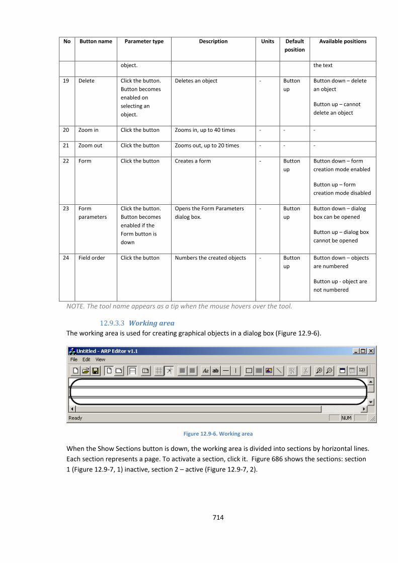
714
No Button name Parameter type Description Units Default
position
Available positions
object. the text
19 Delete Click the button.
Button becomes
enabled on
selecting an
object.
Deletes an object - Button
up
Button down – delete
an object
Button up – cannot
delete an object
20 Zoom in Click the button Zooms in, up to 40 times - - -
21 Zoom out Click the button Zooms out, up to 20 times - - -
22 Form Click the button Creates a form - Button
up
Button down – form
creation mode enabled
Button up – form
creation mode disabled
23 Form
parameters
Click the button.
Button becomes
enabled if the
Form button is
down
Opens the Form Parameters
dialog box.
- Button
up
Button down – dialog
box can be opened
Button up – dialog box
cannot be opened
24 Field order Click the button Numbers the created objects - Button
up
Button down – objects
are numbered
Button up - object are
not numbered
NOTE. The tool name appears as a tip when the mouse hovers over the tool.
12.9.3.3 Working area
The working area is used for creating graphical objects in a dialog box (Figure 12.9-6).
Figure 12.9-6. Working area
When the Show Sections button is down, the working area is divided into sections by horizontal lines.
Each section represents a page. To activate a section, click it. Figure 686 shows the sections: section
1 (Figure 12.9-7, 1) inactive, section 2 – active (Figure 12.9-7, 2).
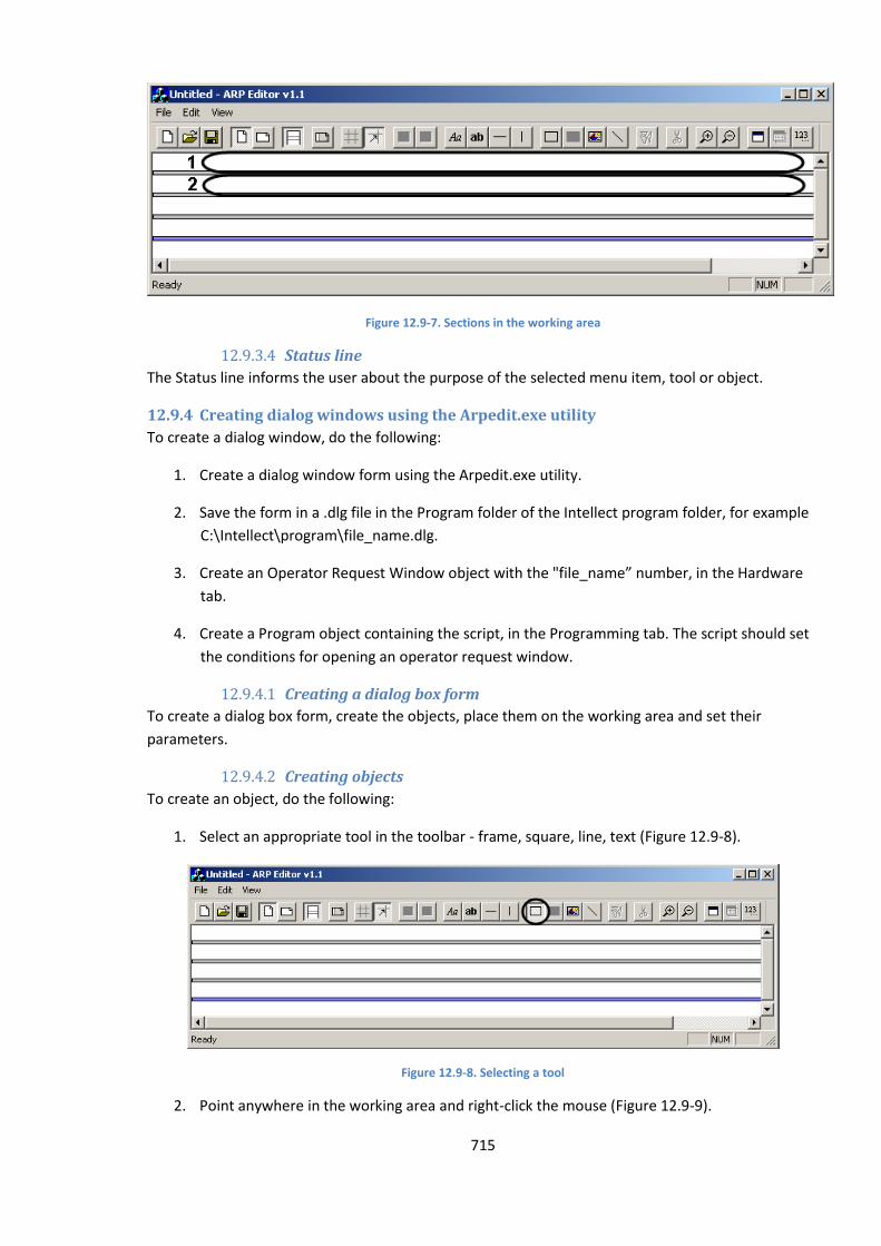
715
Figure 12.9-7. Sections in the working area
12.9.3.4 Status line
The Status line informs the user about the purpose of the selected menu item, tool or object.
12.9.4 Creating dialog windows using the Arpedit.exe utility
To create a dialog window, do the following:
1. Create a dialog window form using the Arpedit.exe utility.
2. Save the form in a .dlg file in the Program folder of the Intellect program folder, for example
C:\Intellect\program\file_name.dlg.
3. Create an Operator Request Window object with the "file_name” number, in the Hardware
tab.
4. Create a Program object containing the script, in the Programming tab. The script should set
the conditions for opening an operator request window.
12.9.4.1 Creating a dialog box form
To create a dialog box form, create the objects, place them on the working area and set their
parameters.
12.9.4.2 Creating objects
To create an object, do the following:
1. Select an appropriate tool in the toolbar - frame, square, line, text (Figure 12.9-8).
Figure 12.9-8. Selecting a tool
2. Point anywhere in the working area and right-click the mouse (Figure 12.9-9).
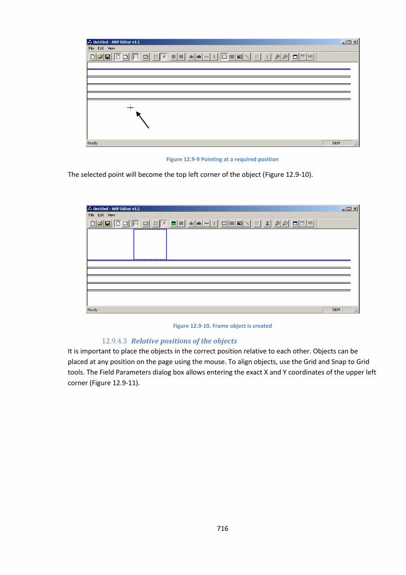
716
Figure 12.9-9 Pointing at a required position
The selected point will become the top left corner of the object (Figure 12.9-10).
Figure 12.9-10. Frame object is created
12.9.4.3 Relative positions of the objects
It is important to place the objects in the correct position relative to each other. Objects can be
placed at any position on the page using the mouse. To align objects, use the Grid and Snap to Grid
tools. The Field Parameters dialog box allows entering the exact X and Y coordinates of the upper left
corner (Figure 12.9-11).
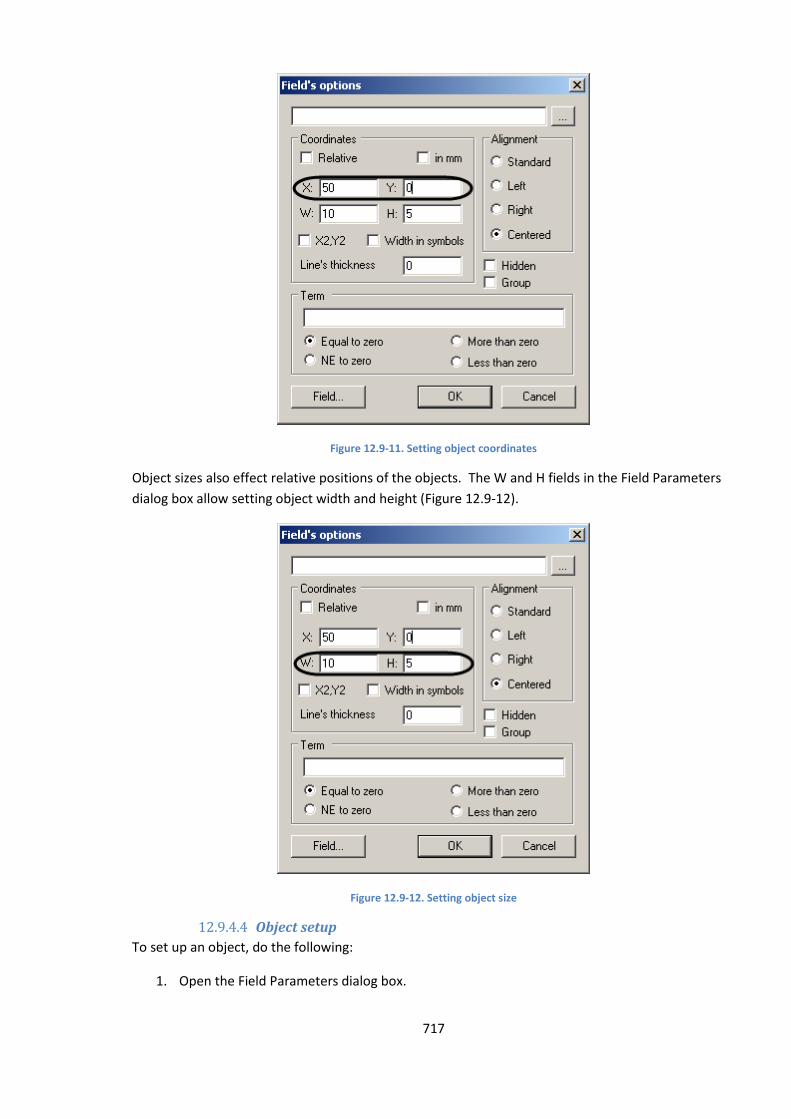
717
Figure 12.9-11. Setting object coordinates
Object sizes also effect relative positions of the objects. The W and H fields in the Field Parameters
dialog box allow setting object width and height (Figure 12.9-12).
Figure 12.9-12. Setting object size
12.9.4.4 Object setup
To set up an object, do the following:
1. Open the Field Parameters dialog box.
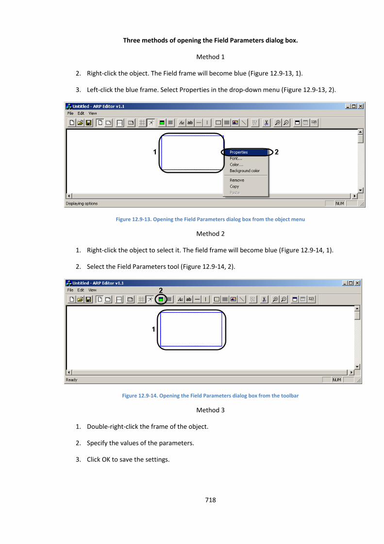
718
Three methods of opening the Field Parameters dialog box.
Method 1
2. Right-click the object. The Field frame will become blue (Figure 12.9-13, 1).
3. Left-click the blue frame. Select Properties in the drop-down menu (Figure 12.9-13, 2).
Figure 12.9-13. Opening the Field Parameters dialog box from the object menu
Method 2
1. Right-click the object to select it. The field frame will become blue (Figure 12.9-14, 1).
2. Select the Field Parameters tool (Figure 12.9-14, 2).
Figure 12.9-14. Opening the Field Parameters dialog box from the toolbar
Method 3
1. Double-right-click the frame of the object.
2. Specify the values of the parameters.
3. Click OK to save the settings.
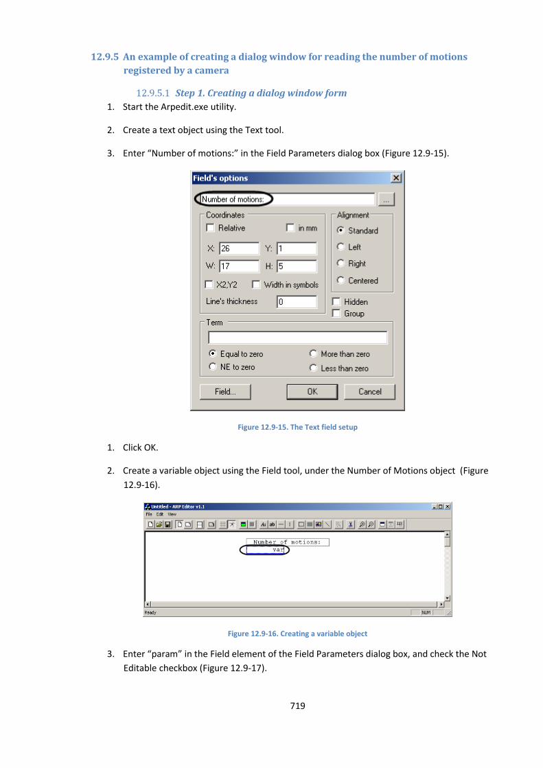
719
12.9.5 An example of creating a dialog window for reading the number of motions
registered by a camera
12.9.5.1 Step 1. Creating a dialog window form
1. Start the Arpedit.exe utility.
2. Create a text object using the Text tool.
3. Enter “Number of motions:” in the Field Parameters dialog box (Figure 12.9-15).
Figure 12.9-15. The Text field setup
1. Click OK.
2. Create a variable object using the Field tool, under the Number of Motions object (Figure
12.9-16).
Figure 12.9-16. Creating a variable object
3. Enter “param” in the Field element of the Field Parameters dialog box, and check the Not
Editable checkbox (Figure 12.9-17).
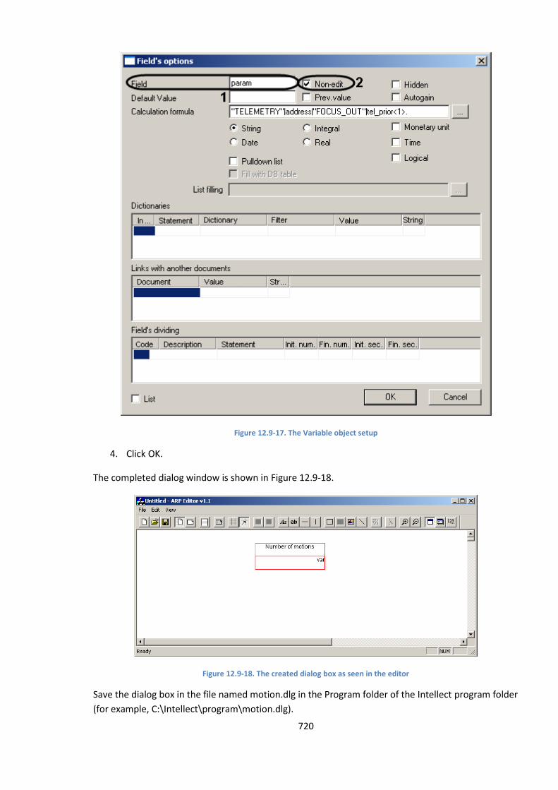
720
Figure 12.9-17. The Variable object setup
4. Click OK.
The completed dialog window is shown in Figure 12.9-18.
Figure 12.9-18. The created dialog box as seen in the editor
Save the dialog box in the file named motion.dlg in the Program folder of the Intellect program folder
(for example, C:\Intellect\program\motion.dlg).

721
12.9.5.2 Step 2. Creating an Operator Request Window object
1. Start the Intellect system.
2. Create the Operator Request Window object in the Hardware tab (Figure 12.9-19).
3. Enter “motion” in the Number field.
Figure 12.9-19. Creating an Operator Request Window object
4. Specify the screen coordinates for the window.
5. Create a Program object in the Programming tab.
6. Enter the following code into the script area (Figure 12.9-20):
OnInit()
{param="0";}
OnEvent("CAM","1","MD_START")
{
DoReact("DIALOG","motion","CLOSE");param=str(atof(param)+1);DoReact("DIALOG","motion","RUN
","param<" + param + ">");}

722
Figure 12.9-20. Creating a Program object
7. Select Always in the Time Zone drop-down list.
8. Click the Apply button to save the code.
Now, each time camera 1 registers some movement, this dialog box will display the number of
movements registered from the time of opening the dialog box (Figure 12.9-21).
Figure 12.9-21. The motion-counting window
12.10 The HubSearch.exe utility for searching IP-devices
12.10.1 The purpose of the HubSearch.exe utility
The HubSearch.exe utility is designed for searching IP-devices, such as Wave Hub, Matrix LH and
Matrix LS and also for changing net settings(for example changing the IP address, address mask etc.)
of a found device.
12.10.2 Starting and closing the utility
To start the HubSearch.exe use one of the following ways:
Run the utility from Windows start menu. Foe this click «Start» «Programs» «Intellect»
«Tools» «Search of IP devices».
The HubSearch.exe utility is available from the Start menu with the following installation
types of the Intellect PC: Server, Remote administrator workstation, Remote monitoring
workstation.
Run the utility from Tools folder of Intellect installation catalogue. For example: «С:\Program
Files\Intellect\Tools\ Hub\HubSearch.exe».
In result dialog window of the HubSearch.exe utility will open (Figure 12.10-1).
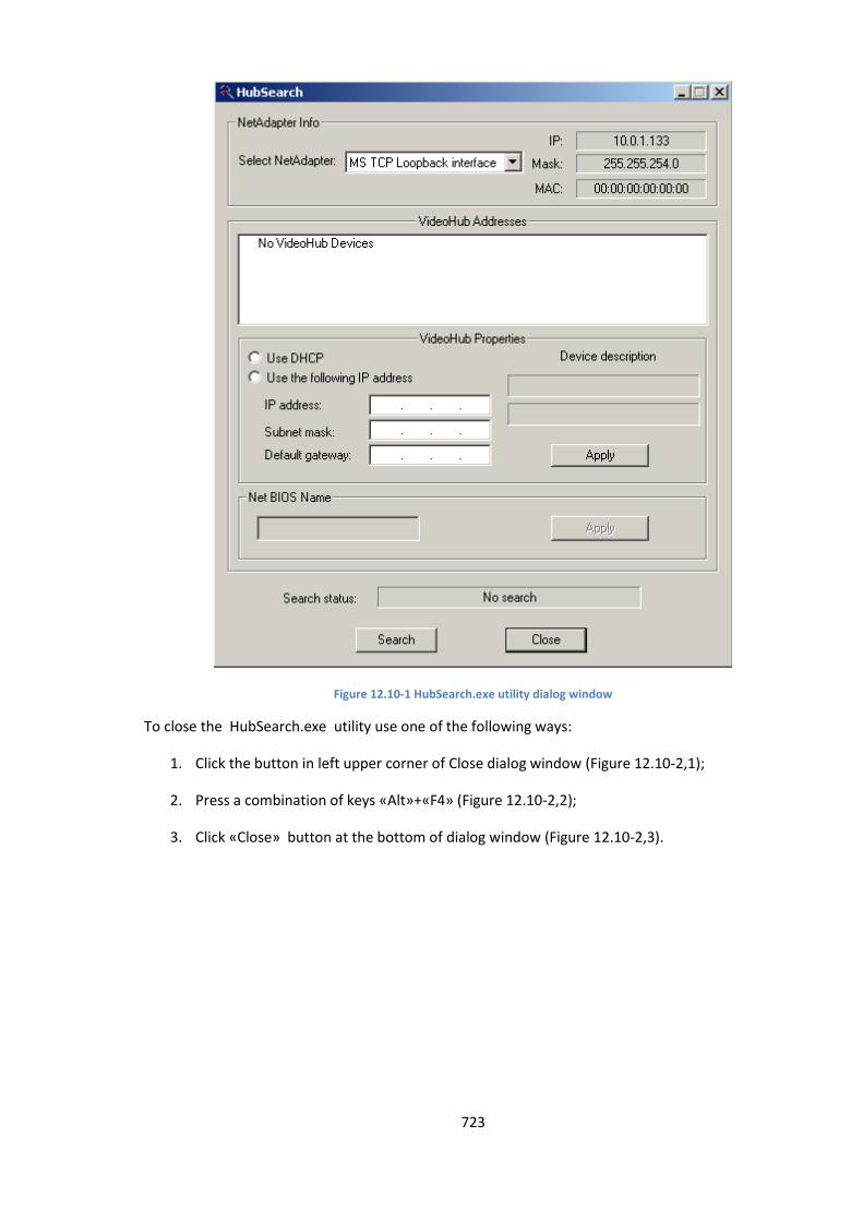
723
Figure 12.10-1 HubSearch.exe utility dialog window
To close the HubSearch.exe utility use one of the following ways:
1. Click the button in left upper corner of Close dialog window (Figure 12.10-2,1);
2. Press a combination of keys «Alt»+«F4» (Figure 12.10-2,2);
3. Click «Close» button at the bottom of dialog window (Figure 12.10-2,3).
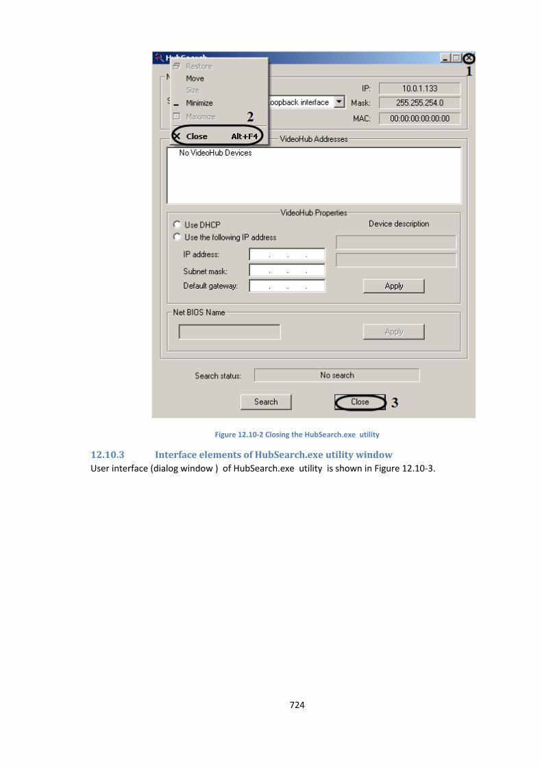
724
Figure 12.10-2 Closing the HubSearch.exe utility
12.10.3 Interface elements of HubSearch.exe utility window
User interface (dialog window ) of HubSearch.exe utility is shown in Figure 12.10-3.
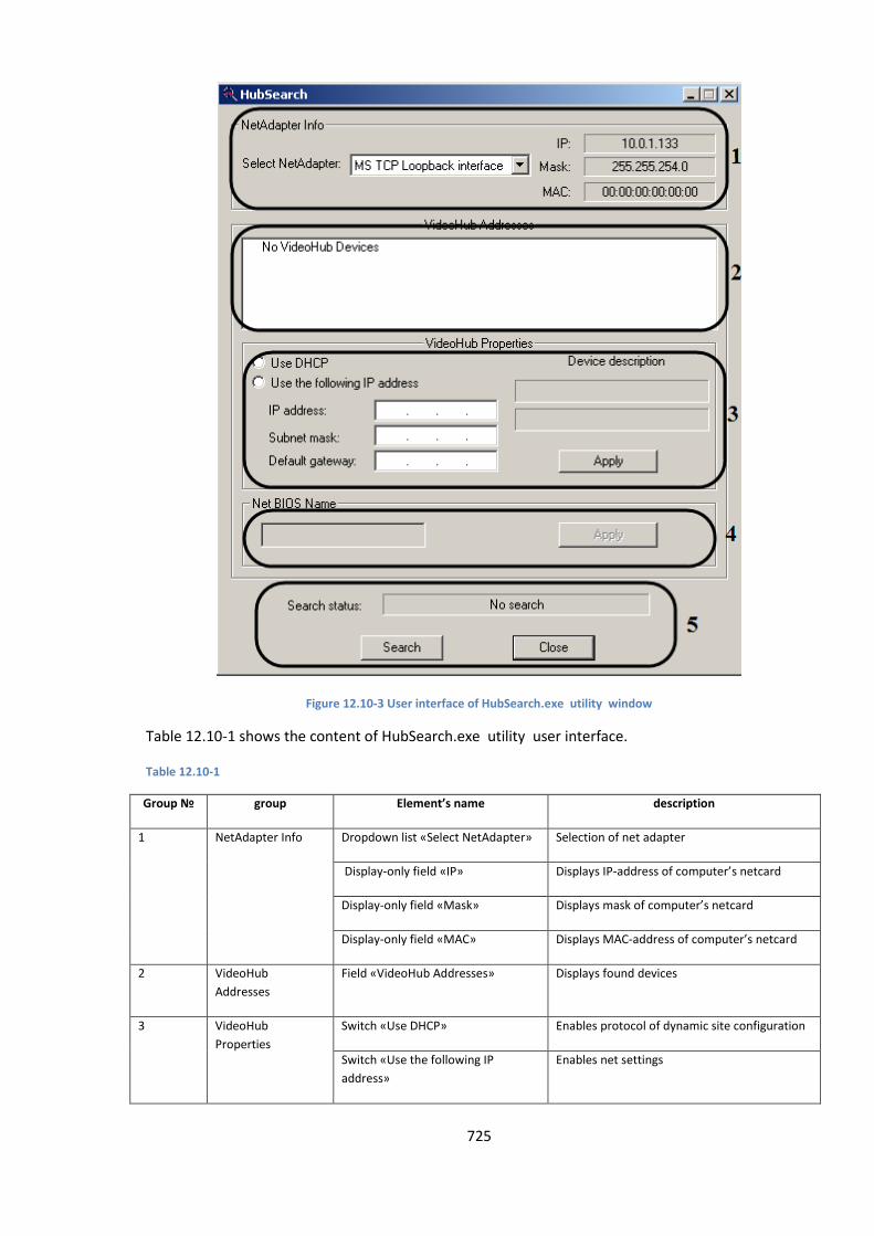
725
Figure 12.10-3 User interface of HubSearch.exe utility window
Table 12.10-1 shows the content of HubSearch.exe utility user interface.
Table 12.10-1
Group № group Element’s name description
1 NetAdapter Info Dropdown list «Select NetAdapter» Selection of net adapter
Display-only field «IP» Displays IP-address of computer’s netcard
Display-only field «Mask» Displays mask of computer’s netcard
Display-only field «MAC» Displays MAC-address of computer’s netcard
2 VideoHub
Addresses
Field «VideoHub Addresses» Displays found devices
3 VideoHub
Properties
Switch «Use DHCP» Enables protocol of dynamic site configuration
Switch «Use the following IP
address»
Enables net settings
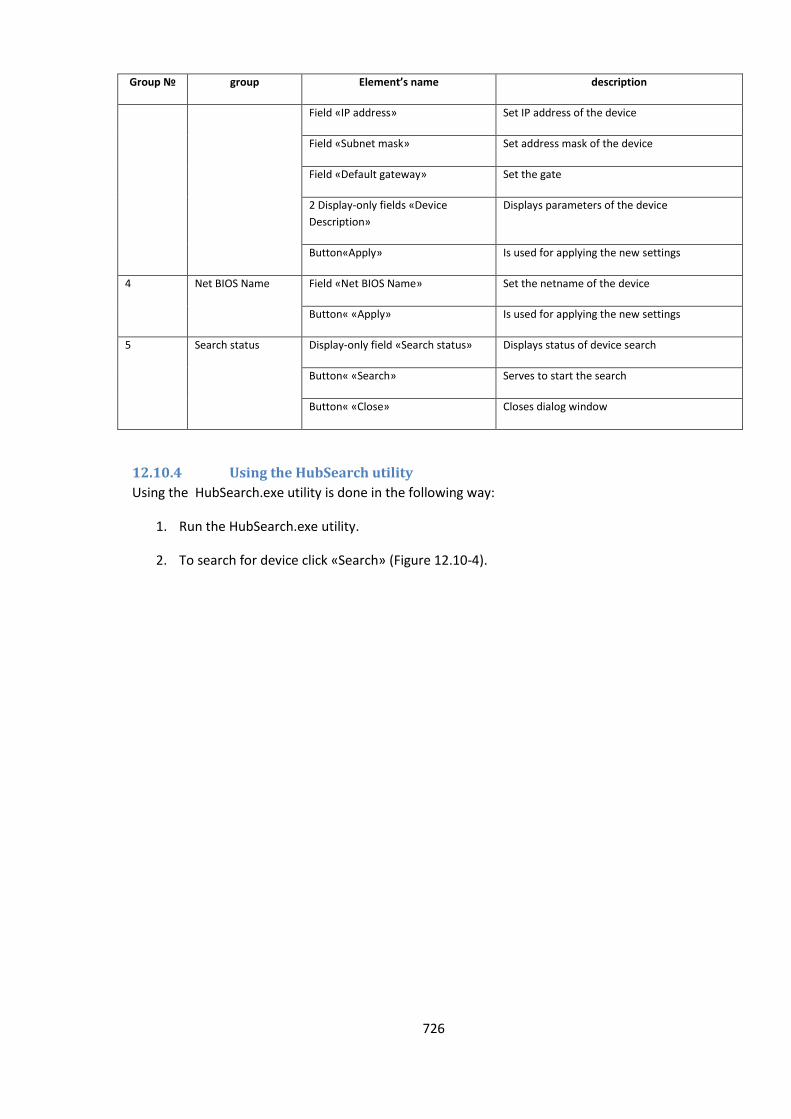
726
Group № group Element’s name description
Field «IP address» Set IP address of the device
Field «Subnet mask» Set address mask of the device
Field «Default gateway» Set the gate
2 Display-only fields «Device
Description»
Displays parameters of the device
Button«Apply» Is used for applying the new settings
4 Net BIOS Name Field «Net BIOS Name» Set the netname of the device
Button« «Apply» Is used for applying the new settings
5 Search status Display-only field «Search status» Displays status of device search
Button« «Search» Serves to start the search
Button« «Close» Closes dialog window
12.10.4 Using the HubSearch utility
Using the HubSearch.exe utility is done in the following way:
1. Run the HubSearch.exe utility.
2. To search for device click «Search» (Figure 12.10-4).
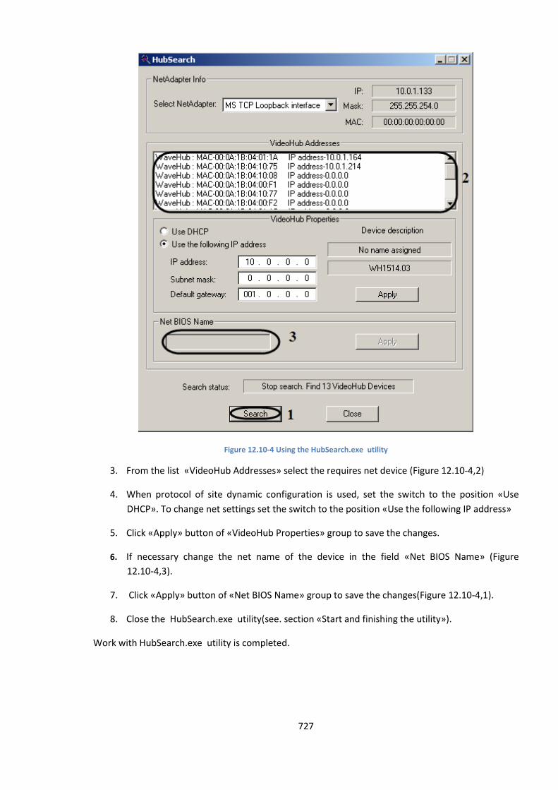
727
Figure 12.10-4 Using the HubSearch.exe utility
3. From the list «VideoHub Addresses» select the requires net device (Figure 12.10-4,2)
4. When protocol of site dynamic configuration is used, set the switch to the position «Use
DHCP». To change net settings set the switch to the position «Use the following IP address»
5. Click «Apply» button of «VideoHub Properties» group to save the changes.
6. If necessary change the net name of the device in the field «Net BIOS Name» (Figure
12.10-4,3).
7. Click «Apply» button of «Net BIOS Name» group to save the changes(Figure 12.10-4,1).
8. Close the HubSearch.exe utility(see. section «Start and finishing the utility»).
Work with HubSearch.exe utility is completed.
728
12.11 The MatrixCodeReader.exe utility
12.11.1 The purpose of MatrixReader.exe utility
The MatrixCodeReader.exe utility is designed for getting dallas-codes of video capture cards’
cryptochips on Matrix devices.
12.11.2 Starting and closing the utility
To start the, MatrixCodeReader.exe do one of the following:
1. Start the utility from the Windows taskbar. Click Start, then Programs, then Intellect, then
Tools, then MatrixCodeReader.exe.
The MatrixCodeReader.exe utility is available from the Start menu with the following
installation types of the Intellect PC: Server, Remote administrator workstation, Remote
monitoring workstation.
2. Run the utility from the folder «Tools\Hub» of Intellect installation directory catalogue. For
example: «С:\Program Files\Intellect\Tools\ Hub\ MatrixCodeReader.exe».
MatrixCodeReader.exe dialog window will be displayed in result (Figure 12.11-1).
Figure 12.11-1 MatrixCodeReader.exe dialog window
To close MatrixCodeReader.exe do one of the following:
4. Click the button in right upper corner of Close dialog window (Figure 12.11-2,1);
5. Press a combination of keys «Alt»+«F4» (Figure 12.11-2,2);
6. Click «Exit» button in the dialog window (Figure 12.11-2,3).
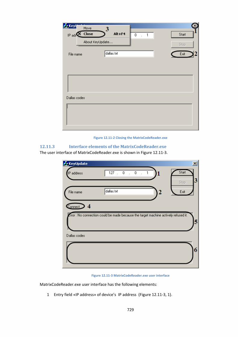
729
Figure 12.11-2 Closing the MatrixCodeReader.exe
12.11.3 Interface elements of the MatrixCodeReader.exe
The user interface of MatrixCodeReader.exe is shown in Figure 12.11-3.
Figure 12.11-3 MatrixCodeReader.exe user interface
MatrixCodeReader.exe user interface has the following elements:
1 Entry field «IP address» of device’s IP address (Figure 12.11-3, 1).
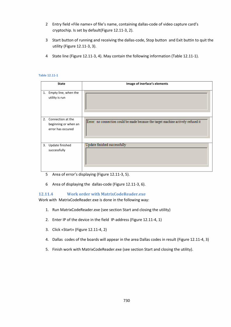
730
2 Entry field «File name» of file’s name, containing dallas-code of video capture card’s
cryptochip. Is set by default(Figure 12.11-3, 2).
3 Start button of running and receiving the dallas-code, Stop button and Exit buttin to quit the
utility (Figure 12.11-3, 3).
4 State line (Figure 12.11-3, 4). May contain the following information (Table 12.11-1).
Table 12.11-1
State Image of inerface’s elements
1. Empty line, when the
utility is run
2. Connection at the
beginning or when an
error has occured
3. Update finished
successfully
5 Area of error’s displaying (Figure 12.11-3, 5).
6 Area of displaying the dallas-code (Figure 12.11-3, 6).
12.11.4 Work order with MatrixCodeReader.exe
Work with MatrixCodeReader.exe is done in the following way:
1. Run MatrixCodeReader.exe (see section Start and closing the utility)
2. Enter IP of the device in the field IP-address (Figure 12.11-4, 1)
3. Click «Start» (Figure 12.11-4, 2)
4. Dallas codes of the boards will appear in the area Dallas codes in result (Figure 12.11-4, 3)
5. Finish work with MatrixCodeReader.exe (see section Start and closing the utility).
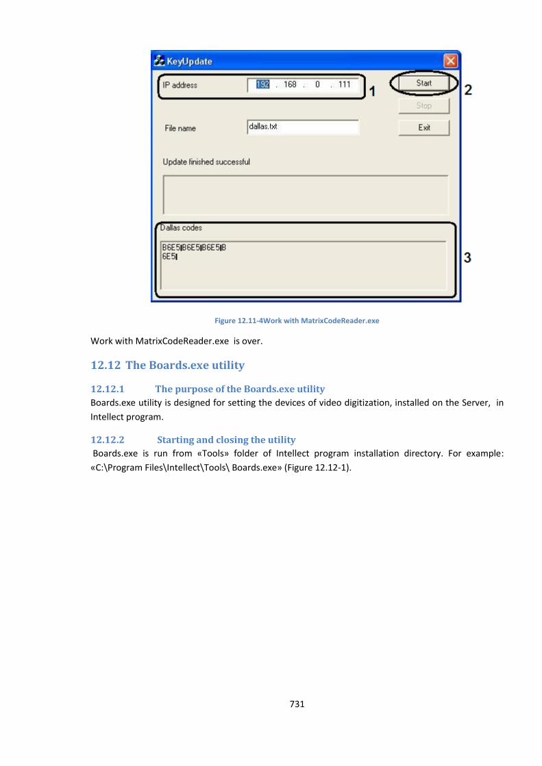
731
Figure 12.11-4Work with MatrixCodeReader.exe
Work with MatrixCodeReader.exe is over.
12.12 The Boards.exe utility
12.12.1 The purpose of the Boards.exe utility
Boards.exe utility is designed for setting the devices of video digitization, installed on the Server, in
Intellect program.
12.12.2 Starting and closing the utility
Boards.exe is run from «Tools» folder of Intellect program installation directory. For example:
«С:\Program Files\Intellect\Tools\ Boards.exe» (Figure 12.12-1).
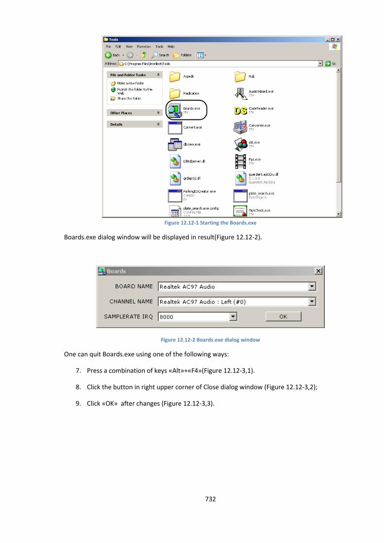
732
Figure 12.12-1 Starting the Boards.exe
Boards.exe dialog window will be displayed in result(Figure 12.12-2).
Figure 12.12-2 Boards.exe dialog window
One can quit Boards.exe using one of the following ways:
7. Press a combination of keys «Alt»+«F4»(Figure 12.12-3,1).
8. Click the button in right upper corner of Close dialog window (Figure 12.12-3,2);
9. Click «OK» after changes (Figure 12.12-3,3).
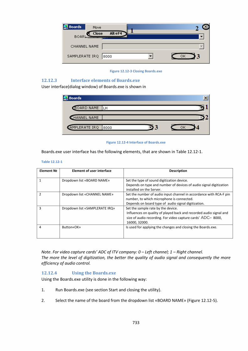
733
Figure 12.12-3 Closing Boards.exe
12.12.3 Interface elements of Boards.exe
User interface(dialog window) of Boards.exe is shown in
Figure 12.12-4 Interface of Boards.exe
Boards.exe user interface has the following elements, that are shown in Table 12.12-1.
Table 12.12-1
Element № Element of user interface Description
1 Dropdown list «BOARD NAME» Set the type of sound digitization device. Depends on type and number of devices of audio signal digitization installed on the Server.
2 Dropdown list «CHANNEL NAME» Set the number of audio input channel in accordance with RCA-F pin number, to which microphone is connected. Depends on board type of audio signal digitization.
3 Dropdown list «SAMPLERATE IRQ» Set the sample rate by the device. Influences on quality of played back and recorded audio signal and
size of audio recording. For video capture cards’ ADC– 8000, 16000, 32000.
4 Button«OK» Is used for applying the changes and closing the Boards.exe.
Note. For video capture cards’ ADC of ITV company: 0 – Left channel; 1 – Right channel. The more the level of digitization, the better the quality of audio signal and consequently the more efficiency of audio control.
12.12.4 Using the Boards.exe
Using the Boards.exe utility is done in the following way:
1. Run Boards.exe (see section Start and closing the utility).
2. Select the name of the board from the dropdown list «BOARD NAME» (Figure 12.12-5).
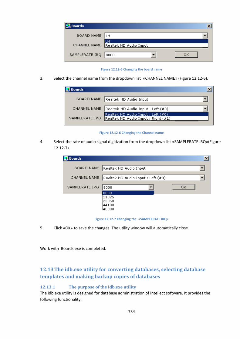
734
Figure 12.12-5 Changing the board name
3. Select the channel name from the dropdown list «CHANNEL NAME» (Figure 12.12-6).
Figure 12.12-6 Changing the Channel name
4. Select the rate of audio signal digitization from the dropdown list «SAMPLERATE IRQ»(Figure
12.12-7).
Figure 12.12-7 Changing the «SAMPLERATE IRQ»
5. Click «OK» to save the changes. The utility window will automatically close.
Work with Boards.exe is completed.
12.13 The idb.exe utility for converting databases, selecting database
templates and making backup copies of databases
12.13.1 The purpose of the idb.exe utility
The idb.exe utility is designed for database administration of Intellect software. It provides the
following functionality:

735
1. Converting MS Access databases to MS SQL format.
2. Connecting to the Intellect database.
3. Setting up the database synchronization.
4. Creating backup copies of a database.
5. Restoring a database from its backup copy.
6. Changing the database template.
7. Extracting the events log into a separate database.
12.13.2 Starting and closing the utility
Close the Intellect system before starting the idb.exe utility.
The idb.exe utility is started from the Intellect PC installation catalog. For example:
«С:\Intellect\idb.exe».
To start the idb.exe utility, do one of the following:
1. Start the utility from the Windows taskbar. Click Start, then Programs, then Intellect,then
Updating the Database.
2. Start the utility from the Intellect program folder. Example: С:\Intellect\idb.exe.
The idb.exe dialog box will open (Figure 12.13-1).
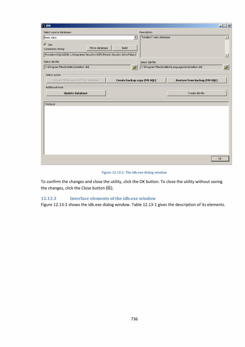
736
Figure 12.13-1. The Idb.exe dialog window
To confirm the changes and close the utility, click the OK button. To close the utility without saving
the changes, click the Close button ( ).
12.13.3 Interface elements of the idb.exe window
Figure 12.13-2 shows the idb.exe dialog window. Table 12.13-1 gives the description of its elements.
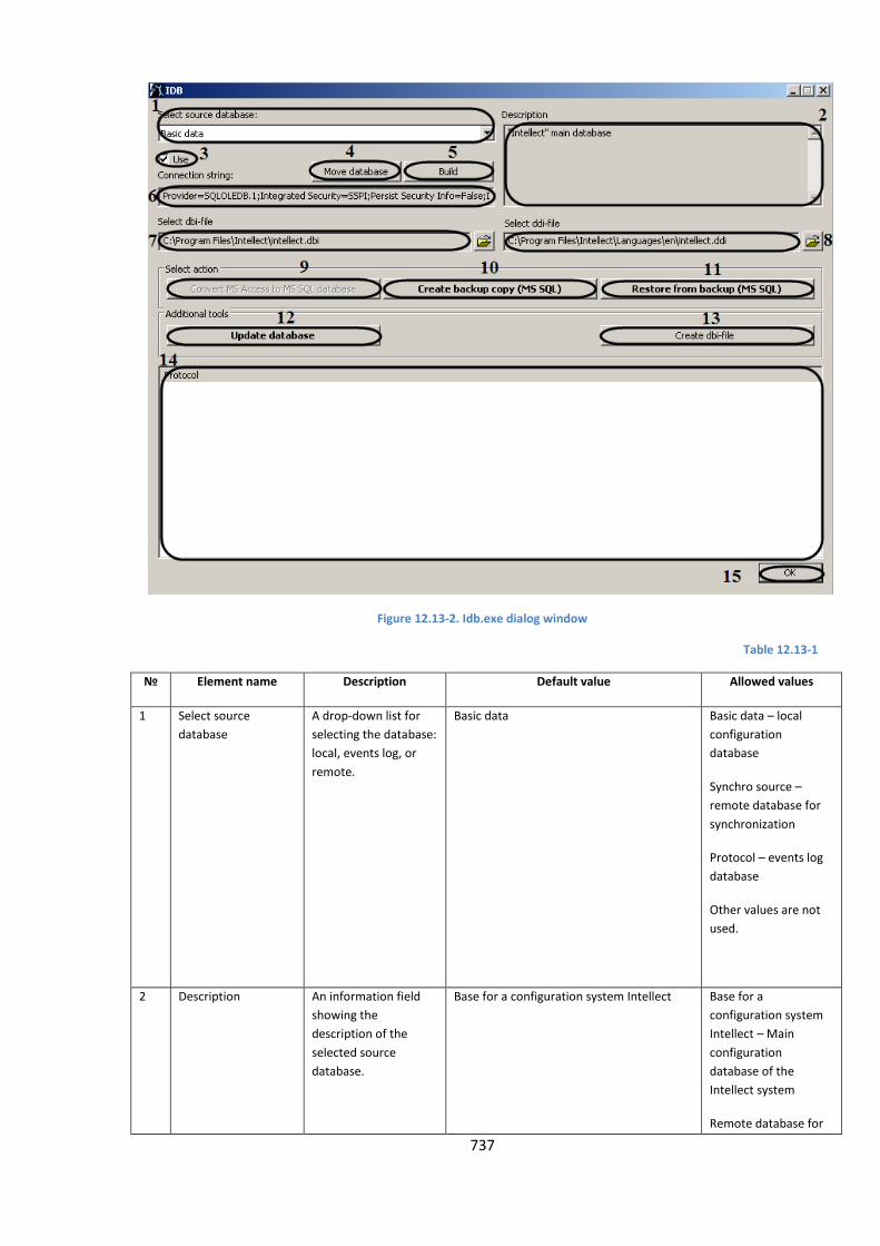
737
Figure 12.13-2. Idb.exe dialog window
Table 12.13-1
№ Element name Description Default value Allowed values
1 Select source
database
A drop-down list for
selecting the database:
local, events log, or
remote.
Basic data Basic data – local
configuration
database
Synchro source –
remote database for
synchronization
Protocol – events log
database
Other values are not
used.
2 Description An information field
showing the
description of the
selected source
database.
Base for a configuration system Intellect Base for a
configuration system
Intellect – Main
configuration
database of the
Intellect system
Remote database for
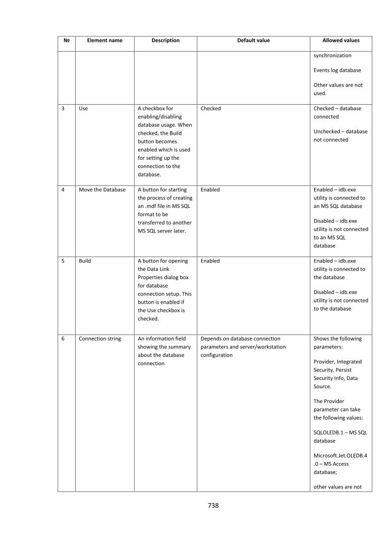
738
№ Element name Description Default value Allowed values
synchronization
Events log database
Other values are not
used.
3 Use A checkbox for
enabling/disabling
database usage. When
checked, the Build
button becomes
enabled which is used
for setting up the
connection to the
database.
Checked Checked – database
connected
Unchecked – database
not connected
4 Move the Database A button for starting
the process of creating
an .mdf file in MS SQL
format to be
transferred to another
MS SQL server later.
Enabled Enabled – idb.exe
utility is connected to
an MS SQL database
Disabled – idb.exe
utility is not connected
to an MS SQL
database
5 Build A button for opening
the Data Link
Properties dialog box
for database
connection setup. This
button is enabled if
the Use checkbox is
checked.
Enabled Enabled – idb.exe
utility is connected to
the database
Disabled – idb.exe
utility is not connected
to the database
6 Connection string An information field
showing the summary
about the database
connection
Depends on database connection
parameters and server/workstation
configuration
Shows the following
parameters:
Provider, Integrated
Security, Persist
Security Info, Data
Source.
The Provider
parameter can take
the following values:
SQLOLEDB.1 – MS SQL
database
Microsoft.Jet.OLEDB.4
.0 – MS Access
database;
other values are not
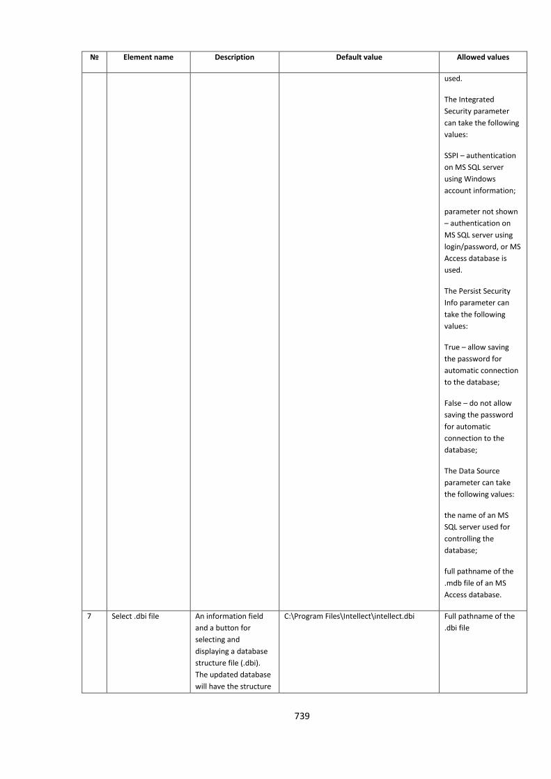
739
№ Element name Description Default value Allowed values
used.
The Integrated
Security parameter
can take the following
values:
SSPI – authentication
on MS SQL server
using Windows
account information;
parameter not shown
– authentication on
MS SQL server using
login/password, or MS
Access database is
used.
The Persist Security
Info parameter can
take the following
values:
True – allow saving
the password for
automatic connection
to the database;
False – do not allow
saving the password
for automatic
connection to the
database;
The Data Source
parameter can take
the following values:
the name of an MS
SQL server used for
controlling the
database;
full pathname of the
.mdb file of an MS
Access database.
7 Select .dbi file An information field
and a button for
selecting and
displaying a database
structure file (.dbi).
The updated database
will have the structure
C:\Program Files\Intellect\intellect.dbi Full pathname of the
.dbi file
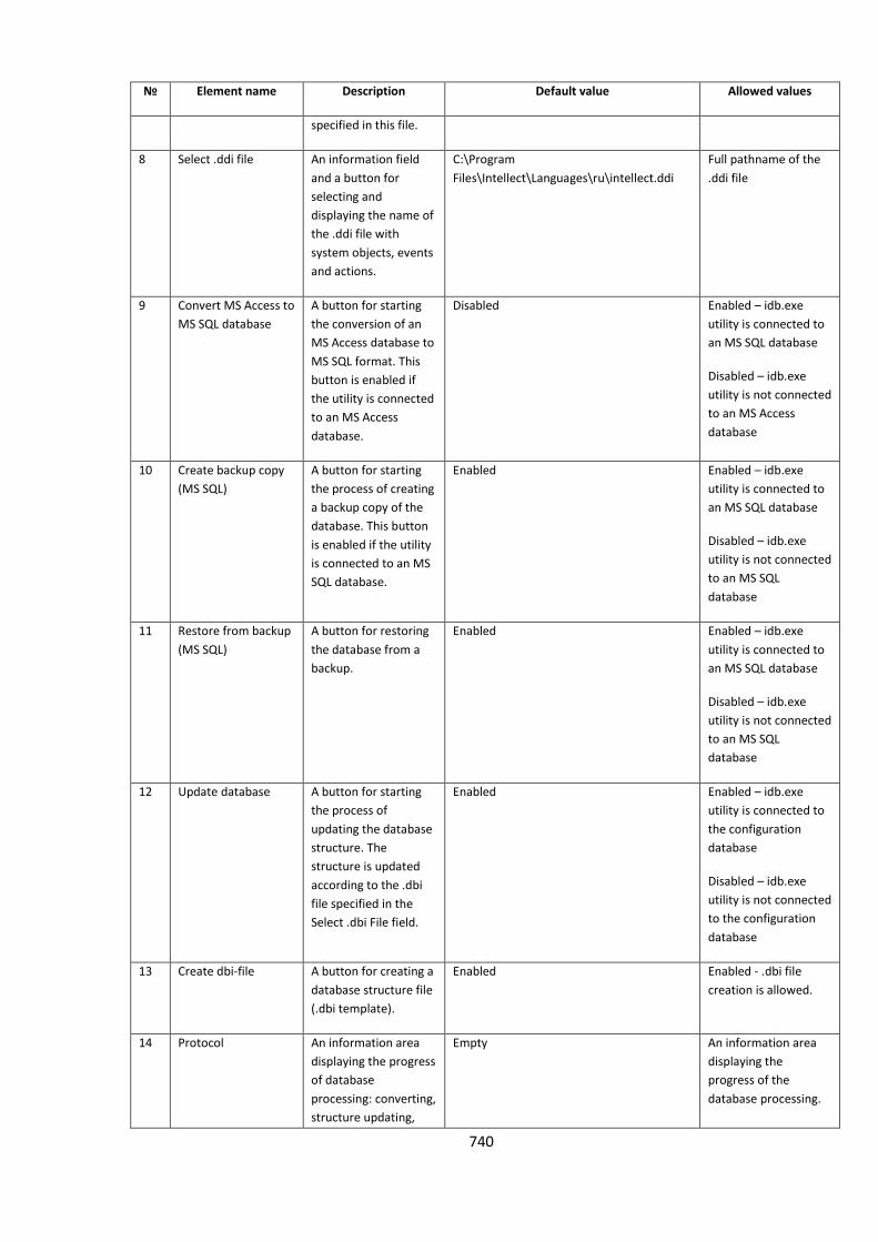
740
№ Element name Description Default value Allowed values
specified in this file.
8 Select .ddi file An information field
and a button for
selecting and
displaying the name of
the .ddi file with
system objects, events
and actions.
C:\Program
Files\Intellect\Languages\ru\intellect.ddi
Full pathname of the
.ddi file
9 Convert MS Access to
MS SQL database
A button for starting
the conversion of an
MS Access database to
MS SQL format. This
button is enabled if
the utility is connected
to an MS Access
database.
Disabled Enabled – idb.exe
utility is connected to
an MS SQL database
Disabled – idb.exe
utility is not connected
to an MS Access
database
10 Create backup copy
(MS SQL)
A button for starting
the process of creating
a backup copy of the
database. This button
is enabled if the utility
is connected to an MS
SQL database.
Enabled Enabled – idb.exe
utility is connected to
an MS SQL database
Disabled – idb.exe
utility is not connected
to an MS SQL
database
11 Restore from backup
(MS SQL)
A button for restoring
the database from a
backup.
Enabled Enabled – idb.exe
utility is connected to
an MS SQL database
Disabled – idb.exe
utility is not connected
to an MS SQL
database
12 Update database A button for starting
the process of
updating the database
structure. The
structure is updated
according to the .dbi
file specified in the
Select .dbi File field.
Enabled Enabled – idb.exe
utility is connected to
the configuration
database
Disabled – idb.exe
utility is not connected
to the configuration
database
13 Create dbi-file A button for creating a
database structure file
(.dbi template).
Enabled Enabled - .dbi file
creation is allowed.
14 Protocol An information area
displaying the progress
of database
processing: converting,
structure updating,
Empty An information area
displaying the
progress of the
database processing.
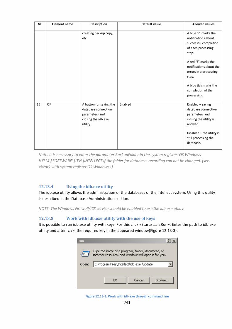
741
№ Element name Description Default value Allowed values
creating backup copy,
etc.
A blue “i” marks the
notifications about
successful completion
of each processing
step.
A red “!” marks the
notifications about the
errors in a processing
step.
A blue tick marks the
completion of the
processing.
15 OK A button for saving the
database connection
parameters and
closing the idb.exe
utility.
Enabled Enabled – saving
database connection
parameters and
closing the utility is
allowed.
Disabled – the utility is
still processing the
database.
Note. It is necessary to enter the parameter BackupFolder in the system register OS Windows
HKLM\\SOFTWARE\\ITV\\INTELLECT if the folder for database recording can not be changed. (see.
«Work with system register OS Windows»).
12.13.4 Using the idb.exe utility
The idb.exe utility allows the administration of the databases of the Intellect system. Using this utility
is described in the Database Administration section.
NOTE. The Windows Firewall/ICS service should be enabled to use the idb.exe utility.
12.13.5 Work with idb.exe utility with the use of keys
It is possible to run idb.exe utility with keys. For this click «Start» «Run». Enter the path to idb.exe
utility and after « /» the required key in the appeared window(Figure 12.13-3).
Figure 12.13-3. Work with idb.exe through command line
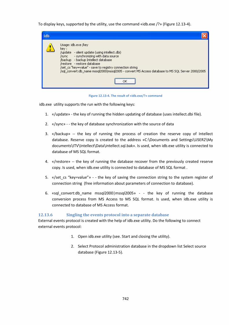
742
To display keys, supported by the utility, use the command «idb.exe /?» (Figure 12.13-4).
Figure 12.13-4. The result of «idb.exe/?» command
idb.exe utility supports the run with the following keys:
1. «/update» - the key of running the hidden updating of database (uses intellect.dbi file).
2. «/sync» - - the key of database synchronization with the source of data
3. «/backup» -- the key of running the process of creation the reserve copy of Intellect
database. Reserve copy is created to the address «C:\Documents and Settings\USER2\My
documents\ITV\Intellect\Data\intellect.sql.bak». Is used, when idb.exe utility is connected to
database of MS SQL format.
4. «/restore» -- the key of running the database recover from the previously created reserve
copy. Is used, when idb.exe utility is connected to database of MS SQL format .
5. «/set_cs “key=value”» - - the key of saving the connection string to the system register of
connection string (free information about parameters of connection to database).
6. «sql_convert:db_name mssql2000|mssql2005» - - the key of running the database
conversion process from MS Access to MS SQL format. Is used, when idb.exe utility is
connected to database of MS Access format.
12.13.6 Singling the events protocol into a separate database
External events protocol is created with the help of idb.exe utility. Do the following to connect
external events protocol:
1. Open idb.exe utility (see. Start and closing the utility).
2. Select Protocol administration database in the dropdown list Select source
database (Figure 12.13-5).
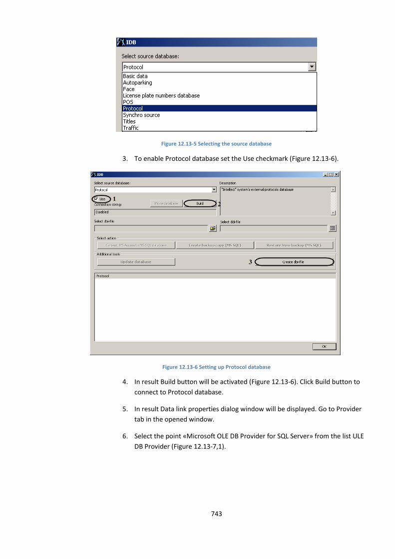
743
Figure 12.13-5 Selecting the source database
3. To enable Protocol database set the Use checkmark (Figure 12.13-6).
Figure 12.13-6 Setting up Protocol database
4. In result Build button will be activated (Figure 12.13-6). Click Build button to
connect to Protocol database.
5. In result Data link properties dialog window will be displayed. Go to Provider
tab in the opened window.
6. Select the point «Microsoft OLE DB Provider for SQL Server» from the list ULE
DB Provider (Figure 12.13-7,1).
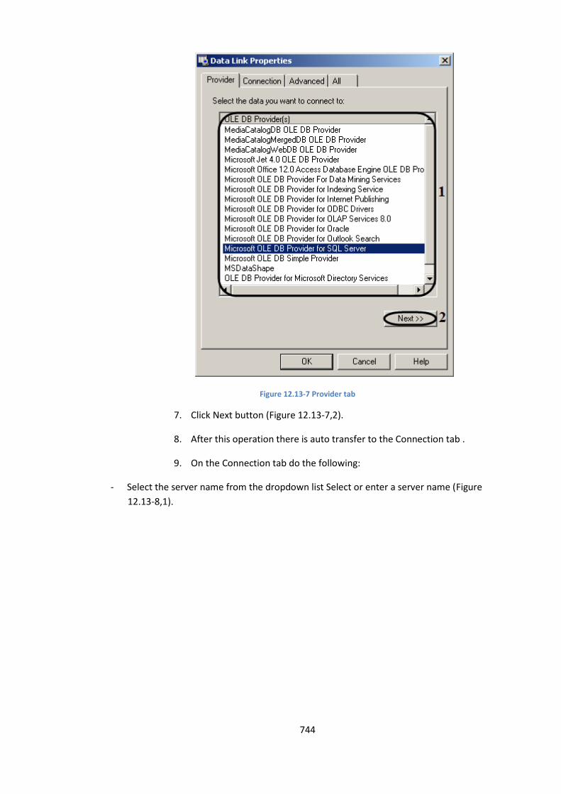
744
Figure 12.13-7 Provider tab
7. Click Next button (Figure 12.13-7,2).
8. After this operation there is auto transfer to the Connection tab .
9. On the Connection tab do the following:
- Select the server name from the dropdown list Select or enter a server name (Figure
12.13-8,1).
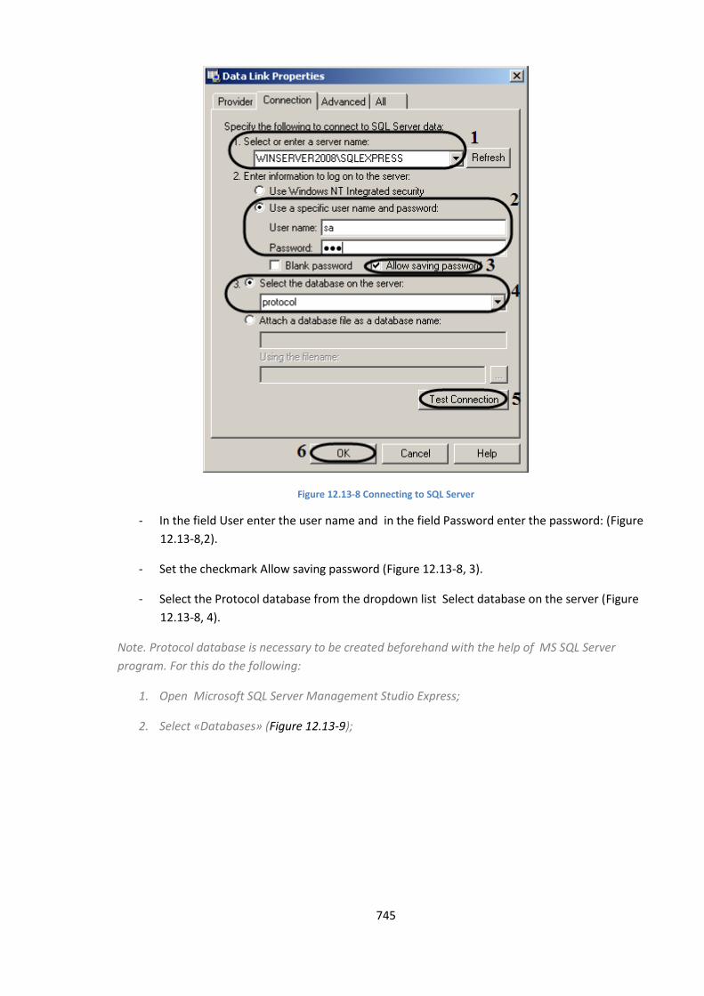
745
Figure 12.13-8 Connecting to SQL Server
- In the field User enter the user name and in the field Password enter the password: (Figure
12.13-8,2).
- Set the checkmark Allow saving password (Figure 12.13-8, 3).
- Select the Protocol database from the dropdown list Select database on the server (Figure
12.13-8, 4).
Note. Protocol database is necessary to be created beforehand with the help of MS SQL Server
program. For this do the following:
1. Open Microsoft SQL Server Management Studio Express;
2. Select «Databases» (Figure 12.13-9);
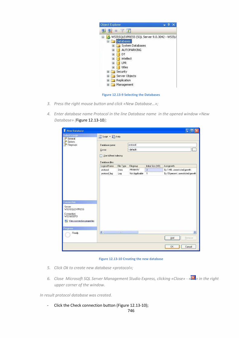
746
Figure 12.13-9 Selecting the Databases
3. Press the right mouse button and click «New Database…»;
4. Enter database name Protocol in the line Database name in the opened window «New
Database» (Figure 12.13-10);
Figure 12.13-10 Creating the new database
5. Click Ok to create new database «protocol»;
6. Close Microsoft SQL Server Management Studio Express, clicking «Close» - « » in the right
upper corner of the window.
In result protocol database was created.
- Click the Check connection button (Figure 12.13-10);
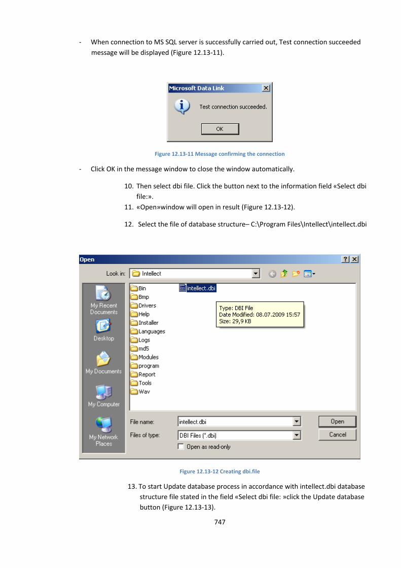
747
- When connection to MS SQL server is successfully carried out, Test connection succeeded
message will be displayed (Figure 12.13-11).
Figure 12.13-11 Message confirming the connection
- Click OK in the message window to close the window automatically.
10. Then select dbi file. Click the button next to the information field «Select dbi
file:».
11. «Open»window will open in result (Figure 12.13-12).
12. Select the file of database structure– C:\Program Files\Intellect\intellect.dbi
Figure 12.13-12 Creating dbi.file
13. To start Update database process in accordance with intellect.dbi database
structure file stated in the field «Select dbi file: »click the Update database
button (Figure 12.13-13).
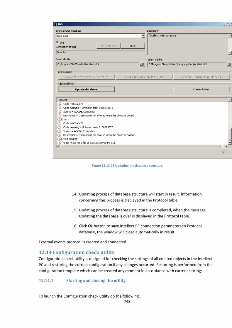
748
Figure 12.13-13 Updating the database structure
14. Updating process of database structure will start in result. Information
concerning this process is displayed in the Protocol table.
15. Updating process of database structure is completed, when the message
Updating the database is over is displayed in the Protocol table.
16. Click Ok button to save Intellect PC connection parameters to Protocol
database, the window will close automatically in result.
External events protocol is created and connected.
12.14 Configuration check utility Configuration check utility is designed for checking the settings of all created objects in the Intellect
PC and restoring the correct configuration if any changes occurred. Restoring is performed from the
configuration template which can be created any moment in accordance with current settings.
12.14.1 Starting and closing the utility
To launch the Configuration check utility do the following:

749
1. Go to Interfaces tab of the System settings dialog window (Figure 12.14-1).
Figure 12.14-1 Interfaces tab
2. Create the Configuration check object on the basis of Screen object (Figure 12.14-2).
Figure 12.14-2 Creating the Configuration check object
3. Go to the Configuration check object settings panel (Figure 12.14-3).
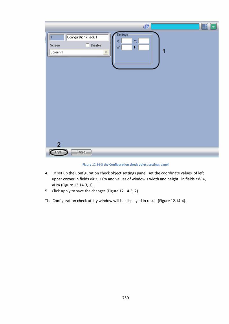
750
Figure 12.14-3 the Configuration check object settings panel
4. To set up the Configuration check object settings panel set the coordinate values of left
upper corner in fields «X:», «Y:» and values of window’s width and height in fields «W:»,
«H:» (Figure 12.14-3, 1).
5. Click Apply to save the changes (Figure 12.14-3, 2).
The Configuration check utility window will be displayed in result (Figure 12.14-4).
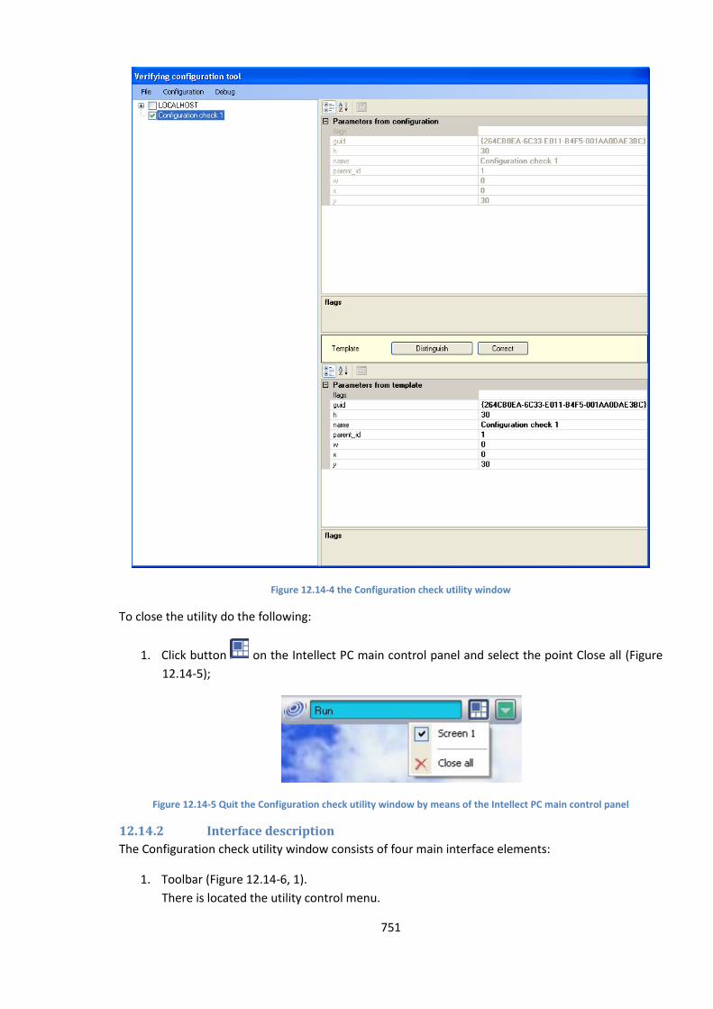
751
Figure 12.14-4 the Configuration check utility window
To close the utility do the following:
1. Click button on the Intellect PC main control panel and select the point Close all (Figure
12.14-5);
Figure 12.14-5 Quit the Configuration check utility window by means of the Intellect PC main control panel
12.14.2 Interface description
The Configuration check utility window consists of four main interface elements:
1. Toolbar (Figure 12.14-6, 1).
There is located the utility control menu.
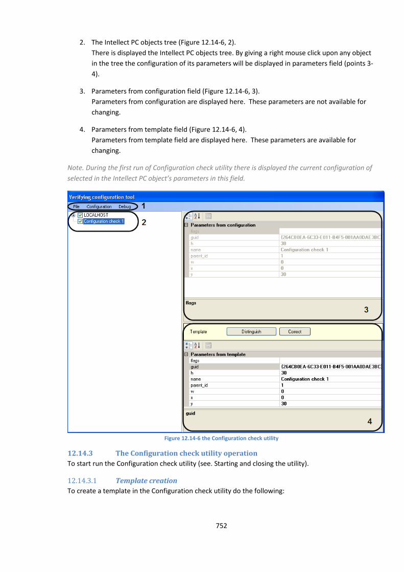
752
2. The Intellect PC objects tree (Figure 12.14-6, 2).
There is displayed the Intellect PC objects tree. By giving a right mouse click upon any object
in the tree the configuration of its parameters will be displayed in parameters field (points 3-
4).
3. Parameters from configuration field (Figure 12.14-6, 3).
Parameters from configuration are displayed here. These parameters are not available for
changing.
4. Parameters from template field (Figure 12.14-6, 4).
Parameters from template field are displayed here. These parameters are available for
changing.
Note. During the first run of Configuration check utility there is displayed the current configuration of
selected in the Intellect PC object’s parameters in this field.
Figure 12.14-6 the Configuration check utility
12.14.3 The Configuration check utility operation
To start run the Configuration check utility (see. Starting and closing the utility).
12.14.3.1 Template creation
To create a template in the Configuration check utility do the following:
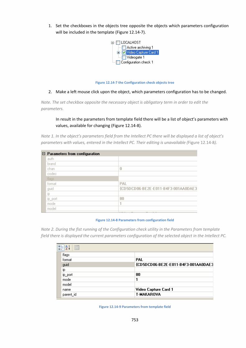
753
1. Set the checkboxes in the objects tree opposite the objects which parameters configuration
will be included in the template (Figure 12.14-7).
Figure 12.14-7 the Configuration check objects tree
2. Make a left mouse click upon the object, which parameters configuration has to be changed.
Note. The set checkbox opposite the necessary object is obligatory term in order to edit the
parameters.
In result in the parameters from template field there will be a list of object’s parameters with
values, available for changing (Figure 12.14-8).
Note 1. In the object’s parameters field from the Intellect PC there will be displayed a list of object’s
parameters with values, entered in the Intellect PC. Their editing is unavailable (Figure 12.14-8).
Figure 12.14-8 Parameters from configuration field
Note 2. During the fist running of the Configuration check utility in the Parameters from template
field there is displayed the current parameters configuration of the selected object in the Intellect PC.
Figure 12.14-9 Parameters from template field
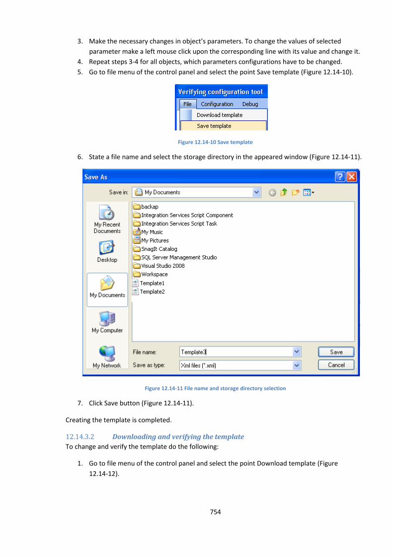
754
3. Make the necessary changes in object’s parameters. To change the values of selected
parameter make a left mouse click upon the corresponding line with its value and change it.
4. Repeat steps 3-4 for all objects, which parameters configurations have to be changed.
5. Go to file menu of the control panel and select the point Save template (Figure 12.14-10).
Figure 12.14-10 Save template
6. State a file name and select the storage directory in the appeared window (Figure 12.14-11).
Figure 12.14-11 File name and storage directory selection
7. Click Save button (Figure 12.14-11).
Creating the template is completed.
12.14.3.2 Downloading and verifying the template
To change and verify the template do the following:
1. Go to file menu of the control panel and select the point Download template (Figure
12.14-12).
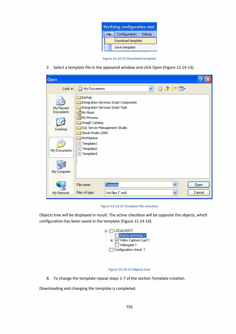
755
Figure 12.14-12 Download template
2. Select a template file in the appeared window and click Open (Figure 12.14-13).
Figure 12.14-13 Template file selection
Objects tree will be displayed in result. The active checkbox will be opposite the objects, which
configuration has been saved in the template (Figure 12.14-14).
Figure 12.14-14 Objects tree
8. To change the template repeat steps 1-7 of the section Template creation.
Downloading and changing the template is completed.
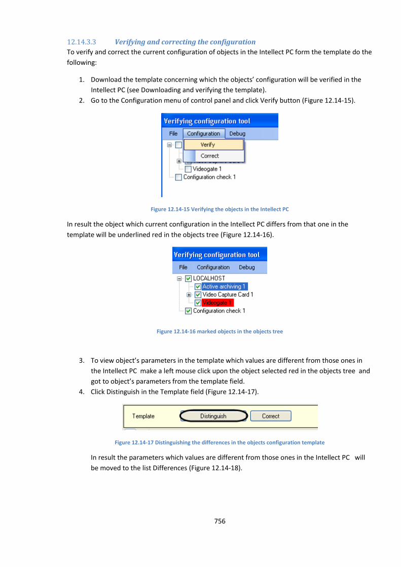
756
12.14.3.3 Verifying and correcting the configuration
To verify and correct the current configuration of objects in the Intellect PC form the template do the
following:
1. Download the template concerning which the objects’ configuration will be verified in the
Intellect PC (see Downloading and verifying the template).
2. Go to the Configuration menu of control panel and click Verify button (Figure 12.14-15).
Figure 12.14-15 Verifying the objects in the Intellect PC
In result the object which current configuration in the Intellect PC differs from that one in the
template will be underlined red in the objects tree (Figure 12.14-16).
Figure 12.14-16 marked objects in the objects tree
3. To view object’s parameters in the template which values are different from those ones in
the Intellect PC make a left mouse click upon the object selected red in the objects tree and
got to object’s parameters from the template field.
4. Click Distinguish in the Template field (Figure 12.14-17).
Figure 12.14-17 Distinguishing the differences in the objects configuration template
In result the parameters which values are different from those ones in the Intellect PC will
be moved to the list Differences (Figure 12.14-18).
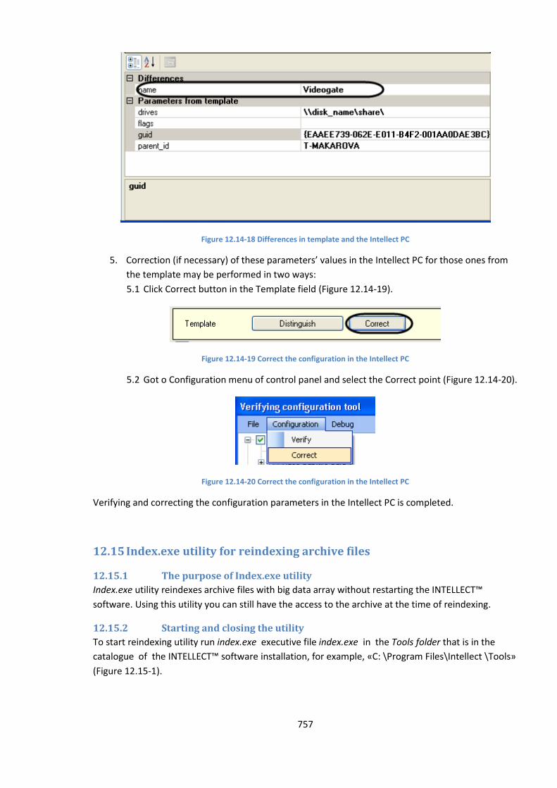
757
Figure 12.14-18 Differences in template and the Intellect PC
5. Correction (if necessary) of these parameters’ values in the Intellect PC for those ones from
the template may be performed in two ways:
5.1 Click Correct button in the Template field (Figure 12.14-19).
Figure 12.14-19 Correct the configuration in the Intellect PC
5.2 Got o Configuration menu of control panel and select the Correct point (Figure 12.14-20).
Figure 12.14-20 Correct the configuration in the Intellect PC
Verifying and correcting the configuration parameters in the Intellect PC is completed.
12.15 Index.exe utility for reindexing archive files
12.15.1 The purpose of Index.exe utility
Index.exe utility reindexes archive files with big data array without restarting the INTELLECT™
software. Using this utility you can still have the access to the archive at the time of reindexing.
12.15.2 Starting and closing the utility
To start reindexing utility run index.exe executive file index.exe in the Tools folder that is in the
catalogue of the INTELLECT™ software installation, for example, «C: \Program Files\Intellect \Tools»
(Figure 12.15-1).
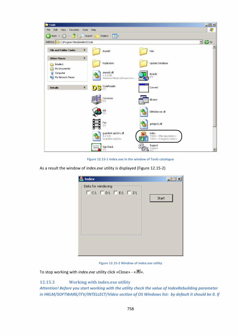
758
Figure 12.15-1 Index.exe in the window of Tools catalogue
As a result the window of index.exe utility is displayed (Figure 12.15-2)
Figure 12.15-2 Window of index.exe utility
To stop working with index.exe utility click «Close» - « ».
12.15.3 Working with index.exe utility
Attention! Before you start working with the utility check the value of IndexRebuilding parameter
in HKLM/SOFTWARE/ITV/INTELLECT/Video section of ОS Windows list: by default it should be 0. If
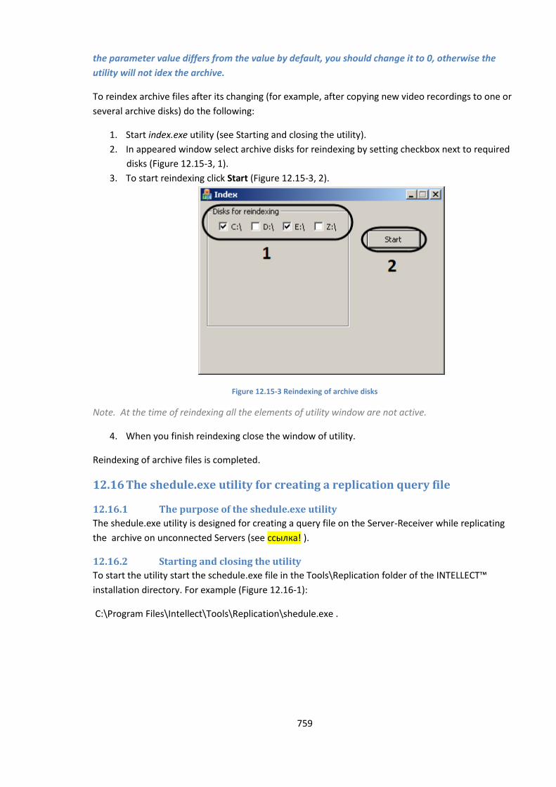
759
the parameter value differs from the value by default, you should change it to 0, otherwise the
utility will not idex the archive.
To reindex archive files after its changing (for example, after copying new video recordings to one or
several archive disks) do the following:
1. Start index.exe utility (see Starting and closing the utility).
2. In appeared window select archive disks for reindexing by setting checkbox next to required
disks (Figure 12.15-3, 1).
3. To start reindexing click Start (Figure 12.15-3, 2).
Figure 12.15-3 Reindexing of archive disks
Note. At the time of reindexing all the elements of utility window are not active.
4. When you finish reindexing close the window of utility.
Reindexing of archive files is completed.
12.16 The shedule.exe utility for creating a replication query file
12.16.1 The purpose of the shedule.exe utility
The shedule.exe utility is designed for creating a query file on the Server-Receiver while replicating
the archive on unconnected Servers (see ссылка! ).
12.16.2 Starting and closing the utility
To start the utility start the schedule.exe file in the Tools\Replication folder of the INTELLECT™
installation directory. For example (Figure 12.16-1):
C:\Program Files\Intellect\Tools\Replication\shedule.exe .
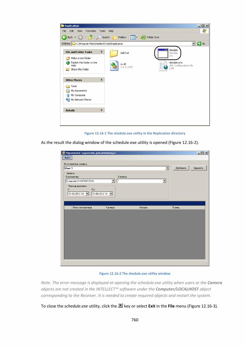
760
Figure 12.16-1 The shedule.exe utility in the Replication directory
As the result the dialog window of the schedule.exe utility is opened (Figure 12.16-2).
Figure 12.16-2 The shedule.exe utility window
Note. The error message is displayed at opening the schedule.exe utility when users or the Camera
objects are not created in the INTELLECT™ software under the Computer/LOCALHOST object
corresponding to the Receiver. It is needed to create required objects and restart the system.
To close the schedule.exe utility, click the key or select Exit in the File menu (Figure 12.16-3).
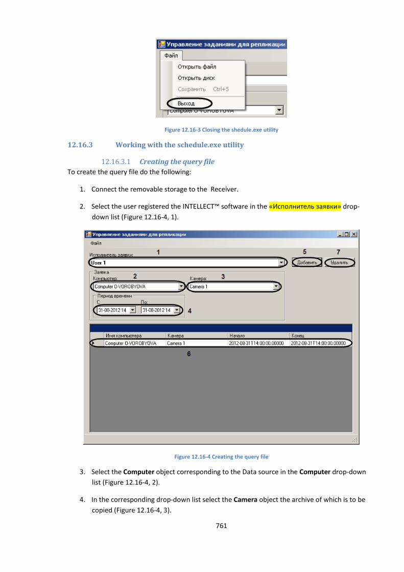
761
Figure 12.16-3 Closing the shedule.exe utility
12.16.3 Working with the schedule.exe utility
12.16.3.1 Creating the query file
To create the query file do the following:
1. Connect the removable storage to the Receiver.
2. Select the user registered the INTELLECT™ software in the «Исполнитель заявки» drop-
down list (Figure 12.16-4, 1).
Figure 12.16-4 Creating the query file
3. Select the Computer object corresponding to the Data source in the Computer drop-down
list (Figure 12.16-4, 2).
4. In the corresponding drop-down list select the Camera object the archive of which is to be
copied (Figure 12.16-4, 3).
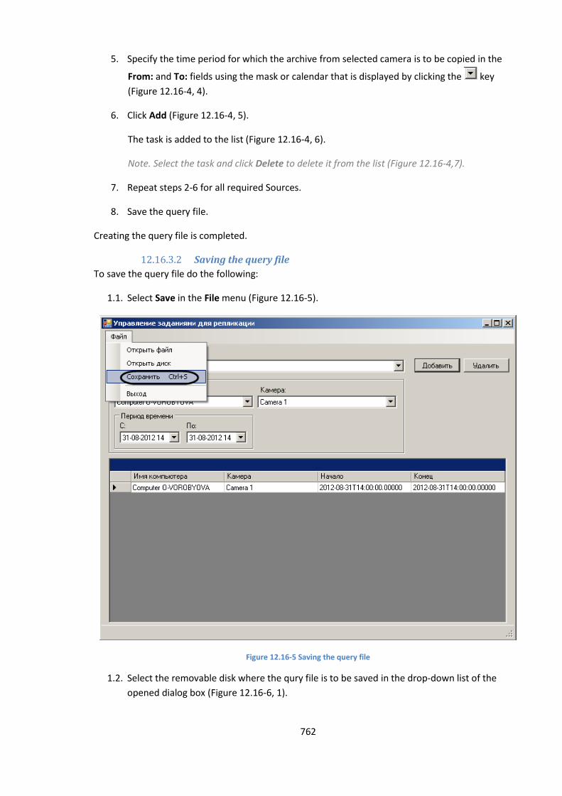
762
5. Specify the time period for which the archive from selected camera is to be copied in the
From: and To: fields using the mask or calendar that is displayed by clicking the key
(Figure 12.16-4, 4).
6. Click Add (Figure 12.16-4, 5).
The task is added to the list (Figure 12.16-4, 6).
Note. Select the task and click Delete to delete it from the list (Figure 12.16-4,7).
7. Repeat steps 2-6 for all required Sources.
8. Save the query file.
Creating the query file is completed.
12.16.3.2 Saving the query file
To save the query file do the following:
1.1. Select Save in the File menu (Figure 12.16-5).
Figure 12.16-5 Saving the query file
1.2. Select the removable disk where the qury file is to be saved in the drop-down list of the
opened dialog box (Figure 12.16-6, 1).
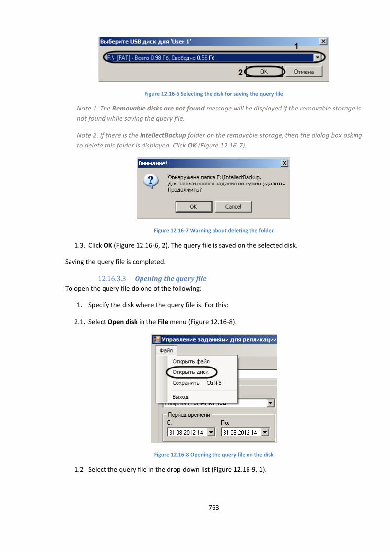
763
Figure 12.16-6 Selecting the disk for saving the query file
Note 1. The Removable disks are not found message will be displayed if the removable storage is
not found while saving the query file.
Note 2. If there is the IntellectBackup folder on the removable storage, then the dialog box asking
to delete this folder is displayed. Click OK (Figure 12.16-7).
Figure 12.16-7 Warning about deleting the folder
1.3. Click OK (Figure 12.16-6, 2). The query file is saved on the selected disk.
Saving the query file is completed.
12.16.3.3 Opening the query file
To open the query file do one of the following:
1. Specify the disk where the query file is. For this:
2.1. Select Open disk in the File menu (Figure 12.16-8).
Figure 12.16-8 Opening the query file on the disk
1.2 Select the query file in the drop-down list (Figure 12.16-9, 1).
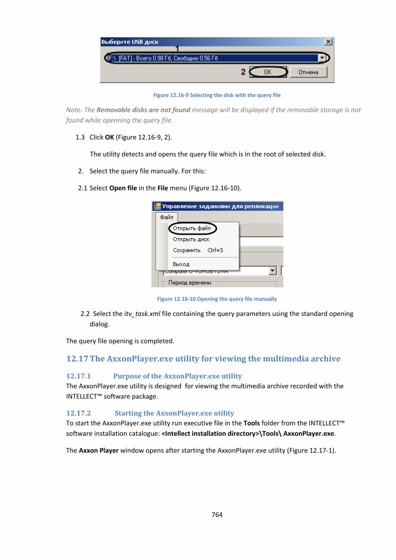
764
Figure 12.16-9 Selecting the disk with the query file
Note. The Removable disks are not found message will be displayed if the removable storage is not
found while openning the query file.
1.3 Click OK (Figure 12.16-9, 2).
The utility detects and opens the query file which is in the root of selected disk.
2. Select the query file manually. For this:
2.1 Select Open file in the File menu (Figure 12.16-10).
Figure 12.16-10 Opening the query file manually
2.2 Select the itv_task.xml file containing the query parameters using the standard opening
dialog.
The query file opening is completed.
12.17 The AxxonPlayer.exe utility for viewing the multimedia archive
12.17.1 Purpose of the AxxonPlayer.exe utility
The AxxonPlayer.exe utility is designed for viewing the multimedia archive recorded with the
INTELLECT™ software package.
12.17.2 Starting the AxxonPlayer.exe utility
To start the AxxonPlayer.exe utility run executive file in the Tools folder from the INTELLECT™
software installation catalogue: <Intellect installation directory>\Tools\ AxxonPlayer.exe.
The Axxon Player window opens after starting the AxxonPlayer.exe utility (Figure 12.17-1).
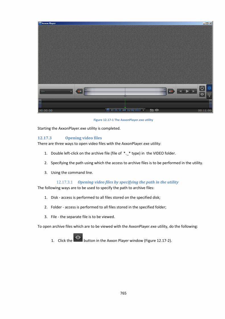
765
Figure 12.17-1 The AxxonPlayer.exe utility
Starting the AxxonPlayer.exe utility is completed.
12.17.3 Opening video files
There are three ways to open video files with the AxxonPlayer.exe utility:
1. Double left-click on the archive file (file of *._* type) in the VIDEO folder.
2. Specifying the path using which the access to archive files is to be performed in the utility.
3. Using the command line.
12.17.3.1 Opening video files by specifying the path in the utility
The following ways are to be used to specify the path to archive files:
1. Disk - access is performed to all files stored on the specified disk;
2. Folder - access is performed to all files stored in the specified folder;
3. File - the separate file is to be viewed.
To open archive files which are to be viewed with the AxxonPlayer.exe utility, do the following:
1. Click the button in the Axxon Player window (Figure 12.17-2).
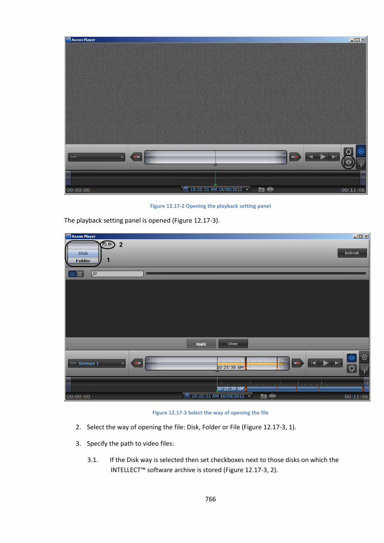
766
Figure 12.17-2 Opening the playback setting panel
The playback setting panel is opened (Figure 12.17-3).
Figure 12.17-3 Select the way of opening the file
2. Select the way of opening the file: Disk, Folder or File (Figure 12.17-3, 1).
3. Specify the path to video files:
3.1. If the Disk way is selected then set checkboxes next to those disks on which the
INTELLECT™ software archive is stored (Figure 12.17-3, 2).
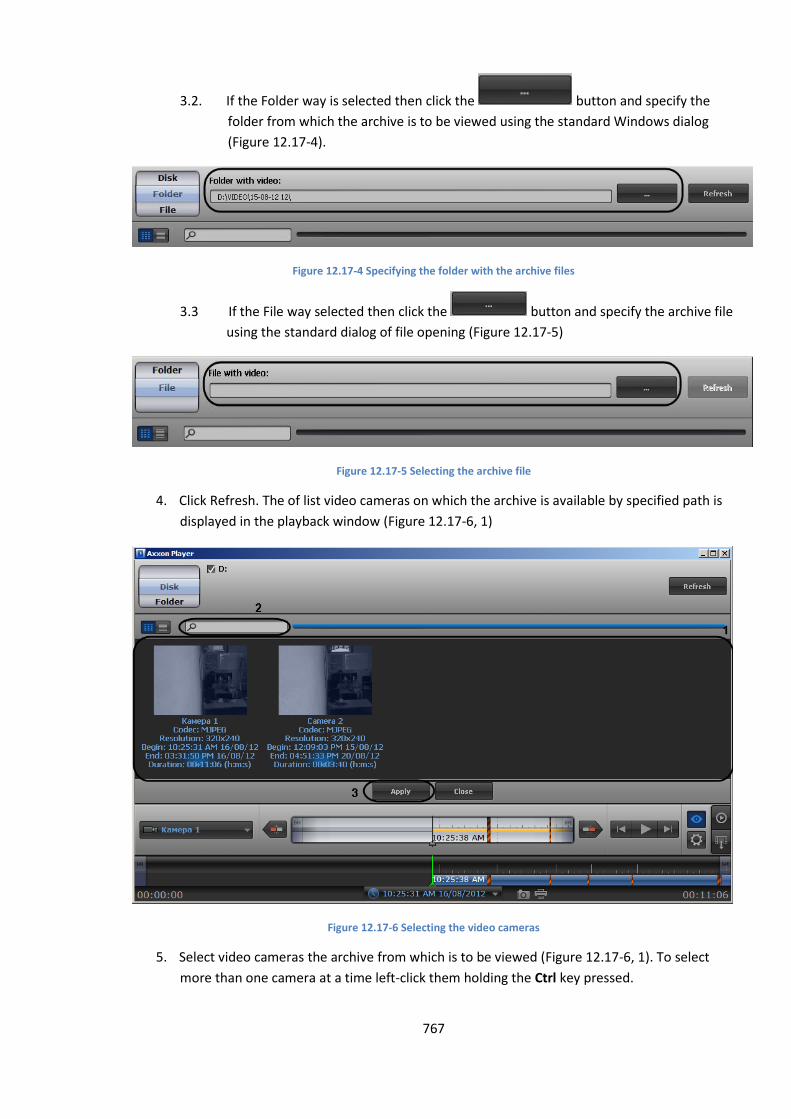
767
3.2. If the Folder way is selected then click the button and specify the
folder from which the archive is to be viewed using the standard Windows dialog
(Figure 12.17-4).
Figure 12.17-4 Specifying the folder with the archive files
3.3 If the File way selected then click the button and specify the archive file
using the standard dialog of file opening (Figure 12.17-5)
Figure 12.17-5 Selecting the archive file
4. Click Refresh. The of list video cameras on which the archive is available by specified path is
displayed in the playback window (Figure 12.17-6, 1)
Figure 12.17-6 Selecting the video cameras
5. Select video cameras the archive from which is to be viewed (Figure 12.17-6, 1). To select
more than one camera at a time left-click them holding the Ctrl key pressed.
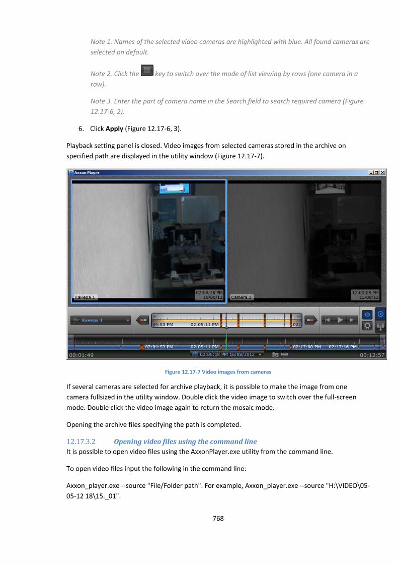
768
Note 1. Names of the selected video cameras are highlighted with blue. All found cameras are
selected on default.
Note 2. Click the key to switch over the mode of list viewing by rows (one camera in a
row).
Note 3. Enter the part of camera name in the Search field to search required camera (Figure
12.17-6, 2).
6. Click Apply (Figure 12.17-6, 3).
Playback setting panel is closed. Video images from selected cameras stored in the archive on
specified path are displayed in the utility window (Figure 12.17-7).
Figure 12.17-7 Video images from cameras
If several cameras are selected for archive playback, it is possible to make the image from one
camera fullsized in the utility window. Double click the video image to switch over the full-screen
mode. Double click the video image again to return the mosaic mode.
Opening the archive files specifying the path is completed.
12.17.3.2 Opening video files using the command line
It is possible to open video files using the AxxonPlayer.exe utility from the command line.
To open video files input the following in the command line:
Axxon_player.exe --source "File/Folder path". For example, Axxon_player.exe --source "H:\VIDEO\05-
05-12 18\15._01".
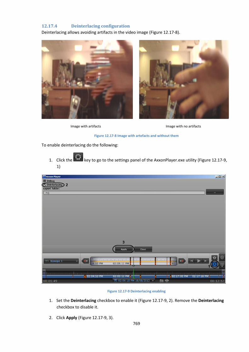
769
12.17.4 Deinterlacing configuration
Deinterlacing allows avoiding artifacts in the video image (Figure 12.17-8).
Image with artifacts Image with no artifacts
Figure 12.17-8 Image with artefacts and without them
To enable deinterlacing do the following:
1. Click the key to go to the settings panel of the AxxonPlayer.exe utility (Figure 12.17-9,
1)
Figure 12.17-9 Deinterlacing enabling
1. Set the Deinterlacing checkbox to enable it (Figure 12.17-9, 2). Remove the Deinterlacing
checkbox to disable it.
2. Click Apply (Figure 12.17-9, 3).
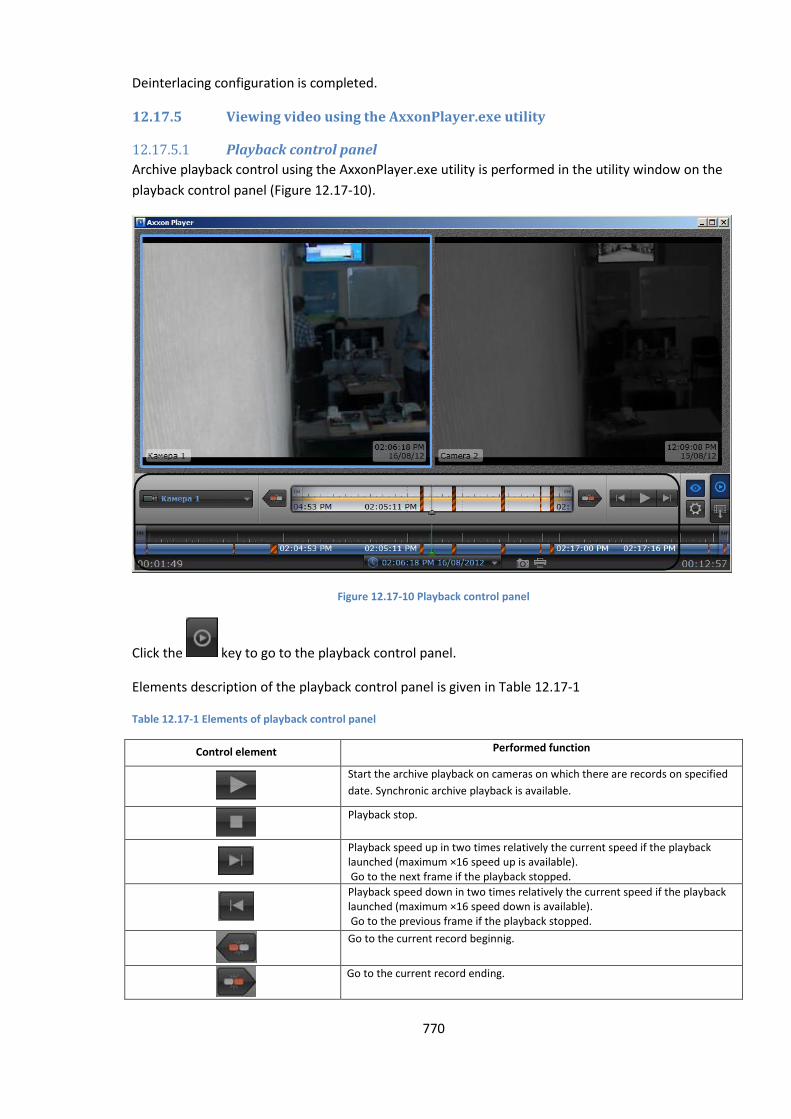
770
Deinterlacing configuration is completed.
12.17.5 Viewing video using the AxxonPlayer.exe utility
12.17.5.1 Playback control panel
Archive playback control using the AxxonPlayer.exe utility is performed in the utility window on the
playback control panel (Figure 12.17-10).
Figure 12.17-10 Playback control panel
Click the key to go to the playback control panel.
Elements description of the playback control panel is given in Table 12.17-1
Table 12.17-1 Elements of playback control panel
Control element Performed function
Start the archive playback on cameras on which there are records on specified
date. Synchronic archive playback is available.
Playback stop.
Playback speed up in two times relatively the current speed if the playback launched (maximum ×16 speed up is available). Go to the next frame if the playback stopped.
Playback speed down in two times relatively the current speed if the playback launched (maximum ×16 speed down is available). Go to the previous frame if the playback stopped.
Go to the current record beginnig.
Go to the current record ending.

771
Go to the archive ending in the main time scale. Go to the archive ending of
selected camera on additional time scale.
Go to the archive beginning in the main time scale. Go to the archive
beginning of selected camera on additional time scale.
Select active camera for archive playback in full-screen mode if several
cameras selected for archive playback.
Saving the frame. Frame is saved in Tools\Screenshots folder
of INTELLECT™ software installation directory.
Printing the frame.
Specifying time and date for archive record to be played.
Time and archive marks in the both scales are to be taken into consideration while controlling
playback. Their description is given in Table 12.17-2.
Table 12.17-2 Time and archive marks on time scales
Mark Description
This mark means that there is no compressed archive. The more interval
without archive, the thicker the mark is.
Time mark 1 (Figure 12.17-11, 1) Time period from archive begin to the current moment.
Time mark 2 (Figure 12.17-11, 2) Time period from the current period to archive ending.
Time mark 3 (Figure 12.17-11, 3) Time of recording start.
Time mark 4 (Figure 12.17-11, 4) Time of recording finish.
Figure 12.17-11 Time and alarm marks on time scales
12.17.5.2 Archive navigation using the calendar
Archive navigation can be performed using the Calendar tool (Figure 12.17-12). This tool is designed
to specify the date the archive on which is to be played back.
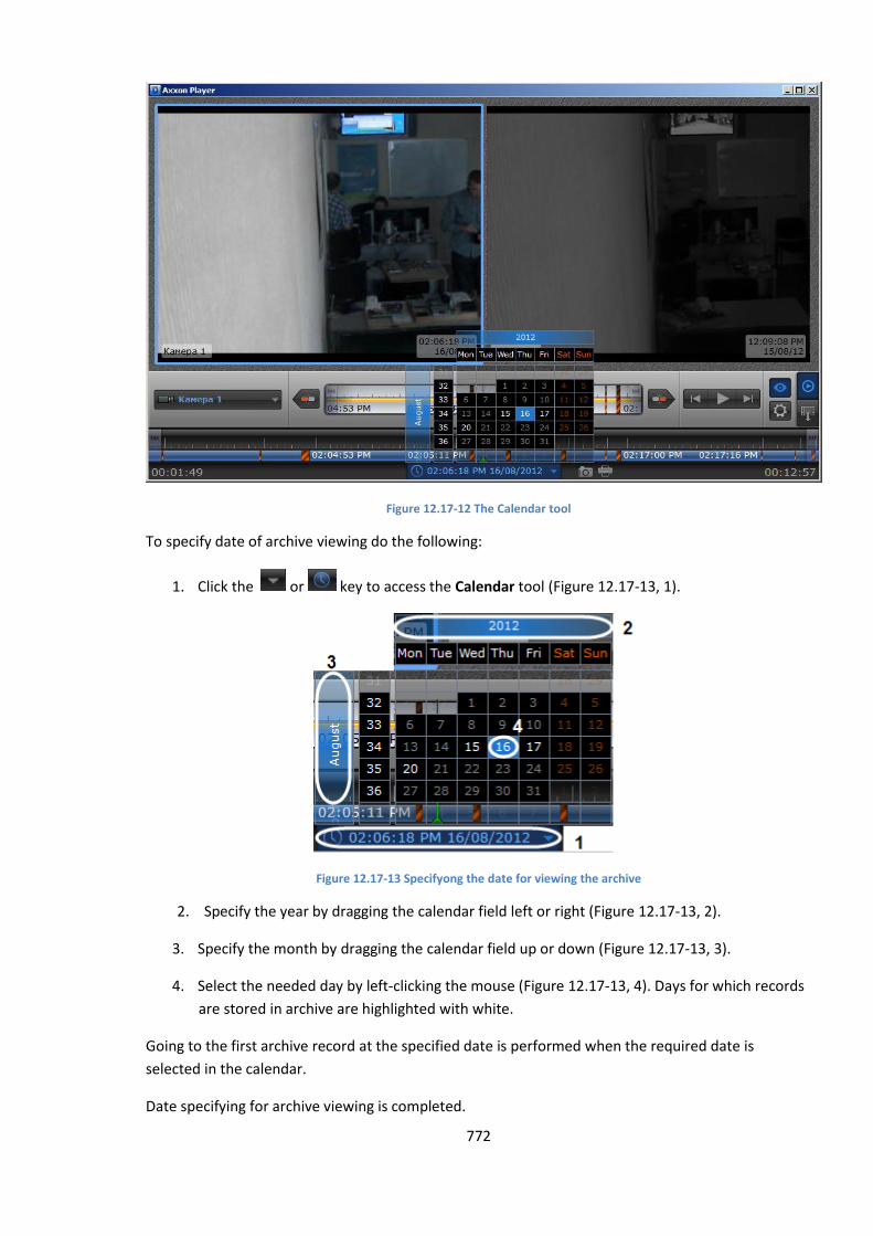
772
Figure 12.17-12 The Calendar tool
To specify date of archive viewing do the following:
1. Click the or key to access the Calendar tool (Figure 12.17-13, 1).
Figure 12.17-13 Specifyong the date for viewing the archive
2. Specify the year by dragging the calendar field left or right (Figure 12.17-13, 2).
3. Specify the month by dragging the calendar field up or down (Figure 12.17-13, 3).
4. Select the needed day by left-clicking the mouse (Figure 12.17-13, 4). Days for which records
are stored in archive are highlighted with white.
Going to the first archive record at the specified date is performed when the required date is
selected in the calendar.
Date specifying for archive viewing is completed.
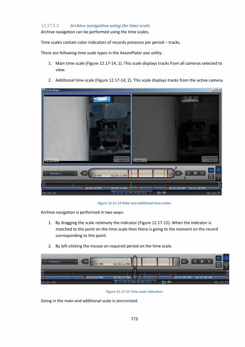
773
12.17.5.3 Archive navigation using the time scale
Archive navigation can be performed using the time scales.
Time scales contain color indicators of records presence per period – tracks.
There are following time scale types in the AxxonPlater.exe utility:
1. Main time scale (Figure 12.17-14, 1). This scale displays tracks from all cameras selected to
view.
2. Additional time scale (Figure 12.17-14, 2). This scale displays tracks from the active camera.
Figure 12.17-14 Main and additional time scales
Archive navigation is performed in two ways:
1. By dragging the scale relatively the indicator (Figure 12.17-15). When the indicator is
matched to the point on the time scale then there is going to the moment on the record
corresponding to this point.
2. By left-clicking the mouse on required period on the time scale.
Figure 12.17-15 Time scale indicators
Going in the main and additional scale is sincronized.
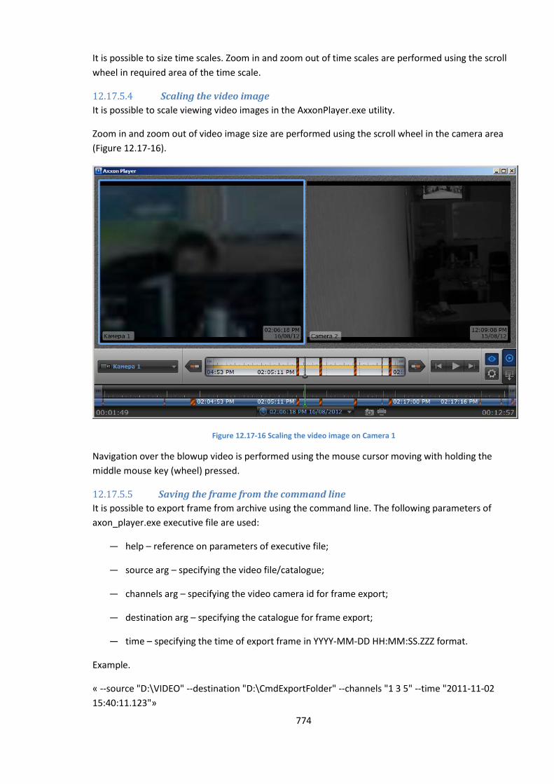
774
It is possible to size time scales. Zoom in and zoom out of time scales are performed using the scroll
wheel in required area of the time scale.
12.17.5.4 Scaling the video image
It is possible to scale viewing video images in the AxxonPlayer.exe utility.
Zoom in and zoom out of video image size are performed using the scroll wheel in the camera area
(Figure 12.17-16).
Figure 12.17-16 Scaling the video image on Camera 1
Navigation over the blowup video is performed using the mouse cursor moving with holding the
middle mouse key (wheel) pressed.
12.17.5.5 Saving the frame from the command line
It is possible to export frame from archive using the command line. The following parameters of
axon_player.exe executive file are used:
— help – reference on parameters of executive file;
— source arg – specifying the video file/catalogue;
— channels arg – specifying the video camera id for frame export;
— destination arg – specifying the catalogue for frame export;
— time – specifying the time of export frame in YYYY-MM-DD HH:MM:SS.ZZZ format.
Example.
« --source "D:\VIDEO" --destination "D:\CmdExportFolder" --channels "1 3 5" --time "2011-11-02
15:40:11.123"»
775
or
«--source "D:\VIDEO" --destination "D:\CmdExportFolder\UserFrame.jpg" --channels "1" --time
"2011-11-02 15:40:11.123"»
File names like “dd-MM-yyyy hh-mm-ss-zzz channelID.jpg" are assigned automatically in the first
case. In the second case file names are specified by the user and it is possible to save the frame in
jpg, bmp or png formats.
If the channels parameter is not specified, then all existing channels are to be saved both for the
video and images.
12.17.6 Exporting the Intellect multimedia archive using the AxxoPlayer.exe utility
12.17.6.1 Order of multimedia archive export
Exporting the INTELLECT™ software archive using the AxxonPlayer.exe is performed in the following
order:
1. Specify the path to the folder to which archive files are to be exported.
2. Go to the export panel.
3. Create the export task.
4. Start the archive export.
12.17.6.2 Specifying the export folder
To specify the export folder do the following:
1. Click the key. The settings panel of the AxxonPlayer.exe utility is opened (Figure
12.17-17, 1).
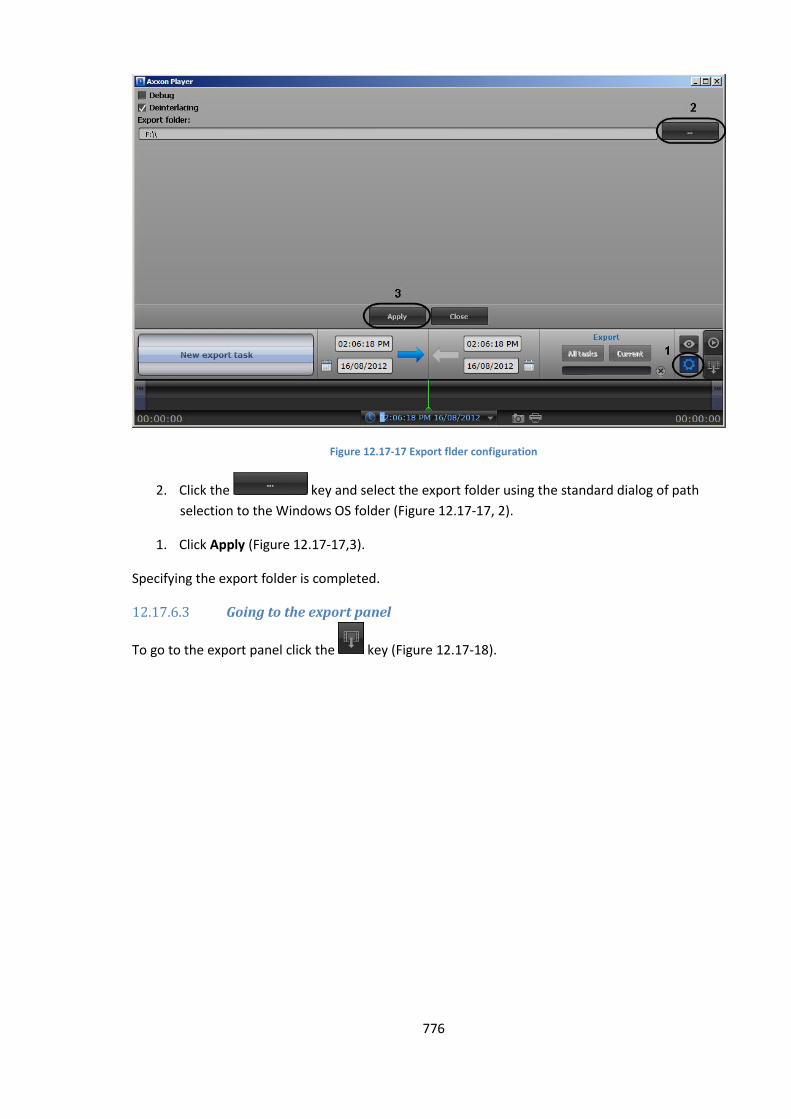
776
Figure 12.17-17 Export flder configuration
2. Click the key and select the export folder using the standard dialog of path
selection to the Windows OS folder (Figure 12.17-17, 2).
1. Click Apply (Figure 12.17-17,3).
Specifying the export folder is completed.
12.17.6.3 Going to the export panel
To go to the export panel click the key (Figure 12.17-18).
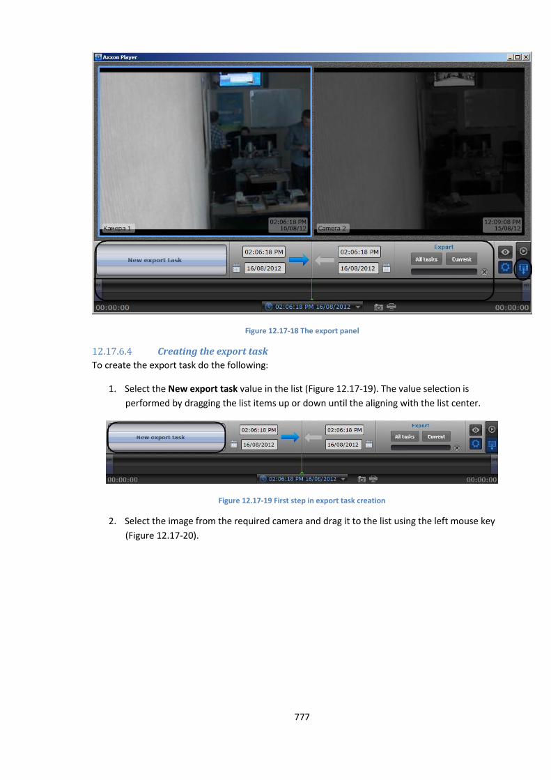
777
Figure 12.17-18 The export panel
12.17.6.4 Creating the export task
To create the export task do the following:
1. Select the New export task value in the list (Figure 12.17-19). The value selection is
performed by dragging the list items up or down until the aligning with the list center.
Figure 12.17-19 First step in export task creation
2. Select the image from the required camera and drag it to the list using the left mouse key
(Figure 12.17-20).
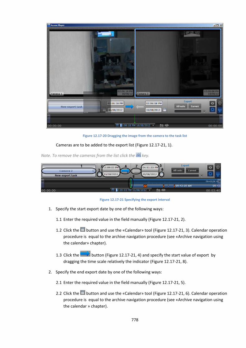
778
Figure 12.17-20 Dragging the image from the camera to the task list
Cameras are to be added to the export list (Figure 12.17-21, 1).
Note. To remove the cameras from the list click the key.
Figure 12.17-21 Specifying the export interval
1. Specify the start export date by one of the following ways:
1.1 Enter the required value in the field manually (Figure 12.17-21, 2).
1.2 Click the button and use the «Calendar» tool (Figure 12.17-21, 3). Calendar operation
procedure is equal to the archive navigation procedure (see «Archive navigation using
the calendar» chapter).
1.3 Click the button (Figure 12.17-21, 4) and specify the start value of export by
dragging the time scale relatively the indicator (Figure 12.17-21, 8).
2. Specify the end export date by one of the following ways:
2.1 Enter the required value in the field manually (Figure 12.17-21, 5).
2.2 Click the button and use the «Calendar» tool (Figure 12.17-21, 6). Calendar operation
procedure is equal to the archive navigation procedure (see «Archive navigation using
the calendar » chapter).
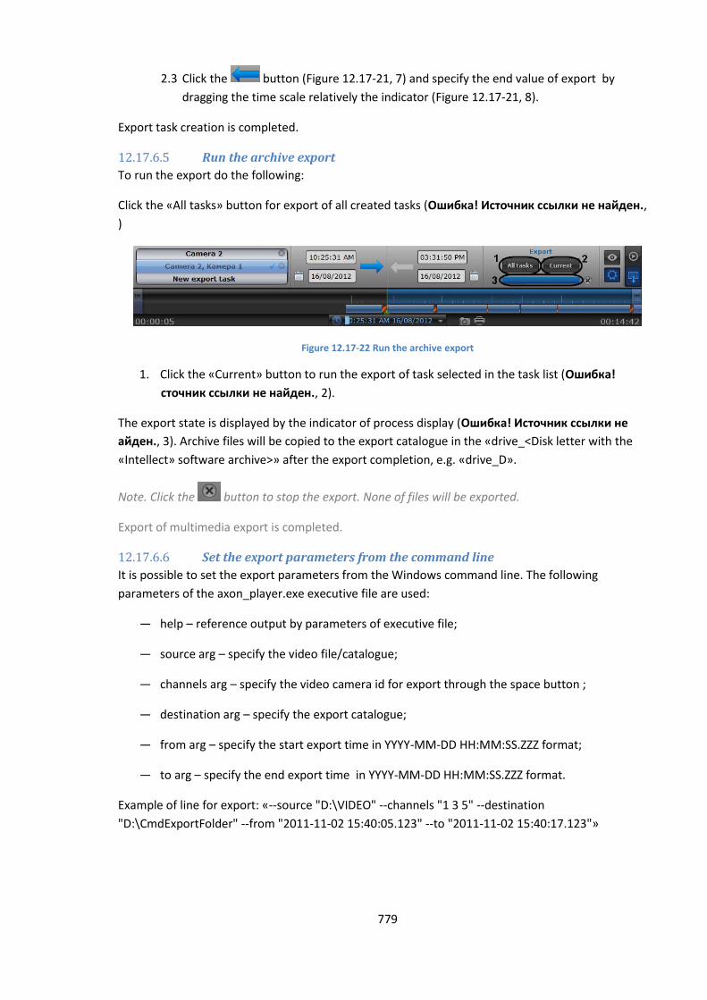
779
2.3 Click the button (Figure 12.17-21, 7) and specify the end value of export by
dragging the time scale relatively the indicator (Figure 12.17-21, 8).
Export task creation is completed.
12.17.6.5 Run the archive export
To run the export do the following:
Click the «All tasks» button for export of all created tasks (Ошибка! Источник ссылки не найден.,
)
Figure 12.17-22 Run the archive export
1. Click the «Current» button to run the export of task selected in the task list (Ошибка!
сточник ссылки не найден., 2).
The export state is displayed by the indicator of process display (Ошибка! Источник ссылки не
айден., 3). Archive files will be copied to the export catalogue in the «drive_<Disk letter with the
«Intellect» software archive>» after the export completion, e.g. «drive_D».
Note. Click the button to stop the export. None of files will be exported.
Export of multimedia export is completed.
12.17.6.6 Set the export parameters from the command line
It is possible to set the export parameters from the Windows command line. The following
parameters of the axon_player.exe executive file are used:
— help – reference output by parameters of executive file;
— source arg – specify the video file/catalogue;
— channels arg – specify the video camera id for export through the space button ;
— destination arg – specify the export catalogue;
— from arg – specify the start export time in YYYY-MM-DD HH:MM:SS.ZZZ format;
— to arg – specify the end export time in YYYY-MM-DD HH:MM:SS.ZZZ format.
Example of line for export: «--source "D:\VIDEO" --channels "1 3 5" --destination
"D:\CmdExportFolder" --from "2011-11-02 15:40:05.123" --to "2011-11-02 15:40:17.123"»
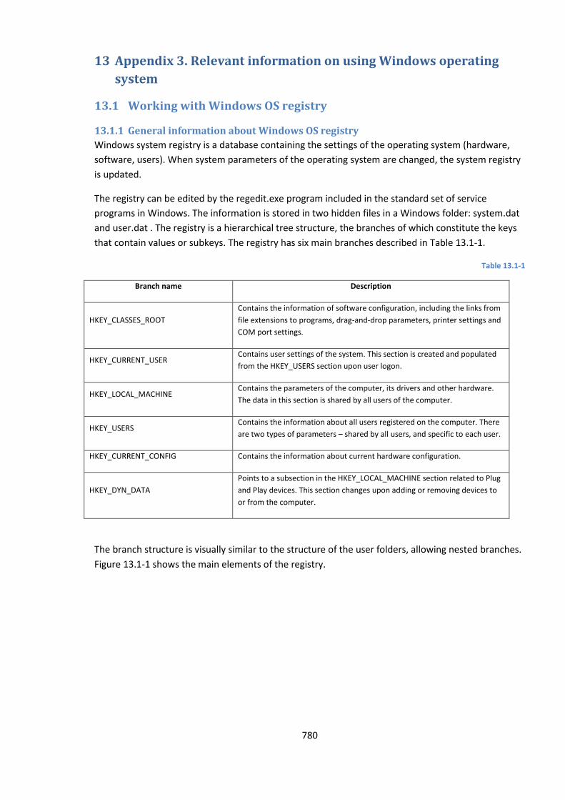
780
13 Appendix 3. Relevant information on using Windows operating
system
13.1 Working with Windows OS registry
13.1.1 General information about Windows OS registry
Windows system registry is a database containing the settings of the operating system (hardware,
software, users). When system parameters of the operating system are changed, the system registry
is updated.
The registry can be edited by the regedit.exe program included in the standard set of service
programs in Windows. The information is stored in two hidden files in a Windows folder: system.dat
and user.dat . The registry is a hierarchical tree structure, the branches of which constitute the keys
that contain values or subkeys. The registry has six main branches described in Table 13.1-1.
Table 13.1-1
Branch name Description
HKEY_CLASSES_ROOT
Contains the information of software configuration, including the links from
file extensions to programs, drag-and-drop parameters, printer settings and
COM port settings.
HKEY_CURRENT_USER Contains user settings of the system. This section is created and populated
from the HKEY_USERS section upon user logon.
HKEY_LOCAL_MACHINE Contains the parameters of the computer, its drivers and other hardware.
The data in this section is shared by all users of the computer.
HKEY_USERS Contains the information about all users registered on the computer. There
are two types of parameters – shared by all users, and specific to each user.
HKEY_CURRENT_CONFIG Contains the information about current hardware configuration.
HKEY_DYN_DATA
Points to a subsection in the HKEY_LOCAL_MACHINE section related to Plug
and Play devices. This section changes upon adding or removing devices to
or from the computer.
The branch structure is visually similar to the structure of the user folders, allowing nested branches.
Figure 13.1-1 shows the main elements of the registry.
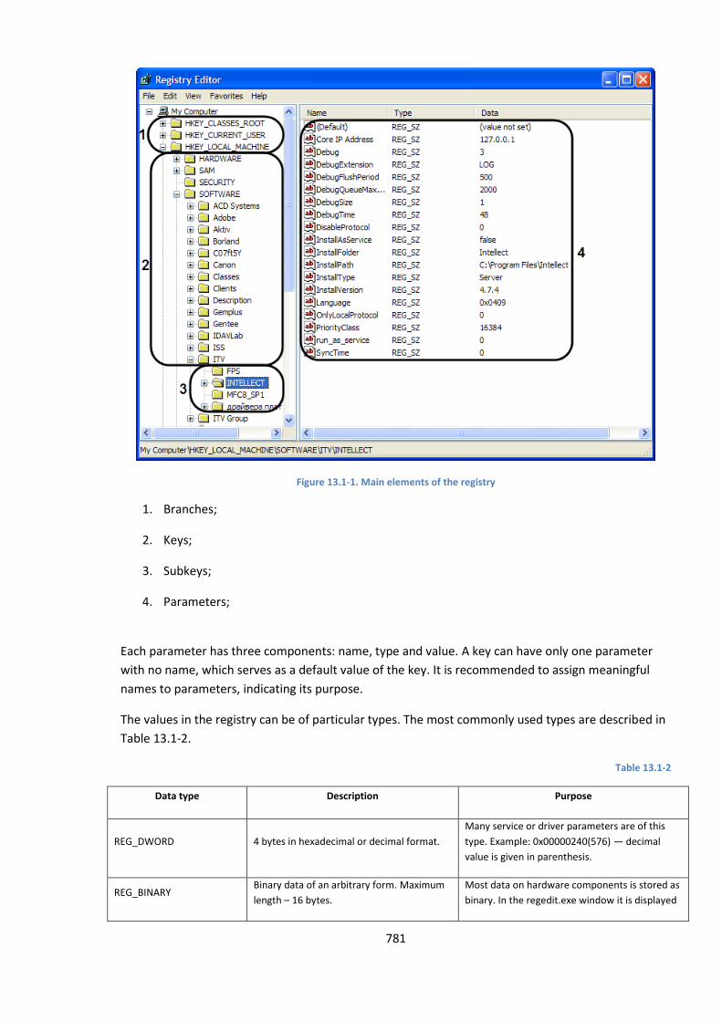
781
Figure 13.1-1. Main elements of the registry
1. Branches;
2. Keys;
3. Subkeys;
4. Parameters;
Each parameter has three components: name, type and value. A key can have only one parameter
with no name, which serves as a default value of the key. It is recommended to assign meaningful
names to parameters, indicating its purpose.
The values in the registry can be of particular types. The most commonly used types are described in
Table 13.1-2.
Table 13.1-2
Data type Description Purpose
REG_DWORD 4 bytes in hexadecimal or decimal format.
Many service or driver parameters are of this
type. Example: 0x00000240(576) — decimal
value is given in parenthesis.
REG_BINARY Binary data of an arbitrary form. Maximum
length – 16 bytes.
Most data on hardware components is stored as
binary. In the regedit.exe window it is displayed
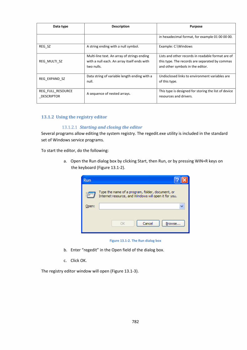
782
Data type Description Purpose
in hexadecimal format, for example 01 00 00 00.
REG_SZ A string ending with a null symbol. Example: C:\Windows
REG_MULTI_SZ
Multi-line text. An array of strings ending
with a null each. An array itself ends with
two nulls.
Lists and other records in readable format are of
this type. The records are separated by commas
and other symbols in the editor.
REG_EXPAND_SZ Data string of variable length ending with a
null.
Undisclosed links to environment variables are
of this type.
REG_FULL_RESOURCE
_DESCRIPTOR A sequence of nested arrays.
This type is designed for storing the list of device
resources and drivers.
13.1.2 Using the registry editor
13.1.2.1 Starting and closing the editor
Several programs allow editing the system registry. The regedit.exe utility is included in the standard
set of Windows service programs.
To start the editor, do the following:
a. Open the Run dialog box by clicking Start, then Run, or by pressing WIN+R keys on
the keyboard (Figure 13.1-2).
Figure 13.1-2. The Run dialog box
b. Enter “regedit” in the Open field of the dialog box.
c. Click OK.
The registry editor window will open (Figure 13.1-3).
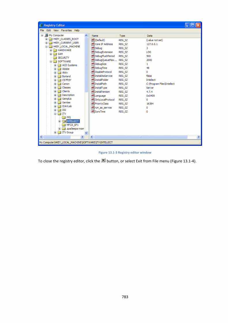
783
Figure 13.1-3 Registry editor window
To close the registry editor, click the button, or select Exit from File menu (Figure 13.1-4).
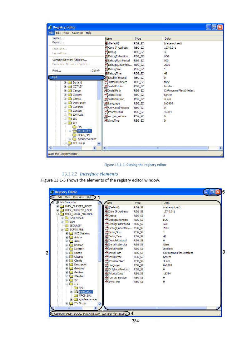
784
Figure 13.1-4. Closing the registry editor
13.1.2.2 Interface elements
Figure 13.1-5 shows the elements of the registry editor window.
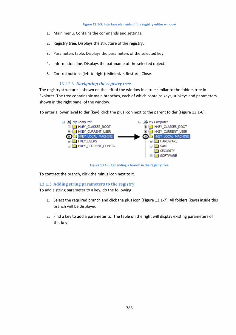
785
Figure 13.1-5. Interface elements of the registry editor window
1. Main menu. Contains the commands and settings.
2. Registry tree. Displays the structure of the registry.
3. Parameters table. Displays the parameters of the selected key.
4. Information line. Displays the pathname of the selected object.
5. Control buttons (left to right): Minimize, Restore, Close.
13.1.2.3 Navigating the registry tree
The registry structure is shown on the left of the window in a tree similar to the folders tree in
Explorer. The tree contains six main branches, each of which contains keys, subkeys and parameters
shown in the right panel of the window.
To enter a lower level folder (key), click the plus icon next to the parent folder (Figure 13.1-6).
Figure 13.1-6. Expanding a branch in the registry tree
To contract the branch, click the minus icon next to it.
13.1.3 Adding string parameters to the registry
To add a string parameter to a key, do the following:
1. Select the required branch and click the plus icon (Figure 13.1-7). All folders (keys) inside this
branch will be displayed.
2. Find a key to add a parameter to. The table on the right will display existing parameters of
this key.
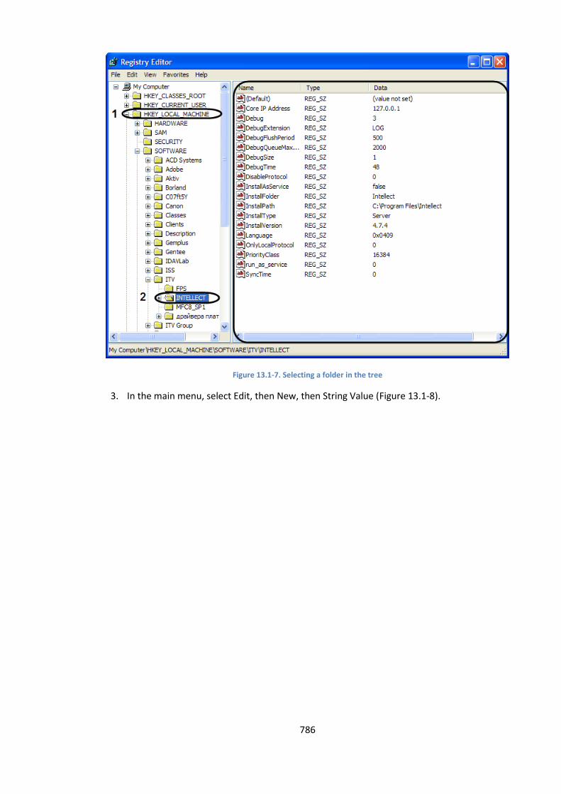
786
Figure 13.1-7. Selecting a folder in the tree
3. In the main menu, select Edit, then New, then String Value (Figure 13.1-8).
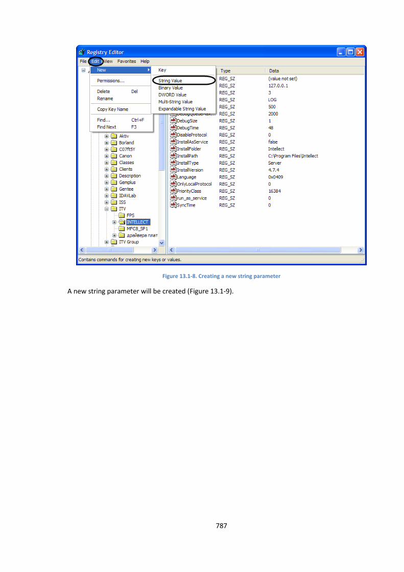
787
Figure 13.1-8. Creating a new string parameter
A new string parameter will be created (Figure 13.1-9).
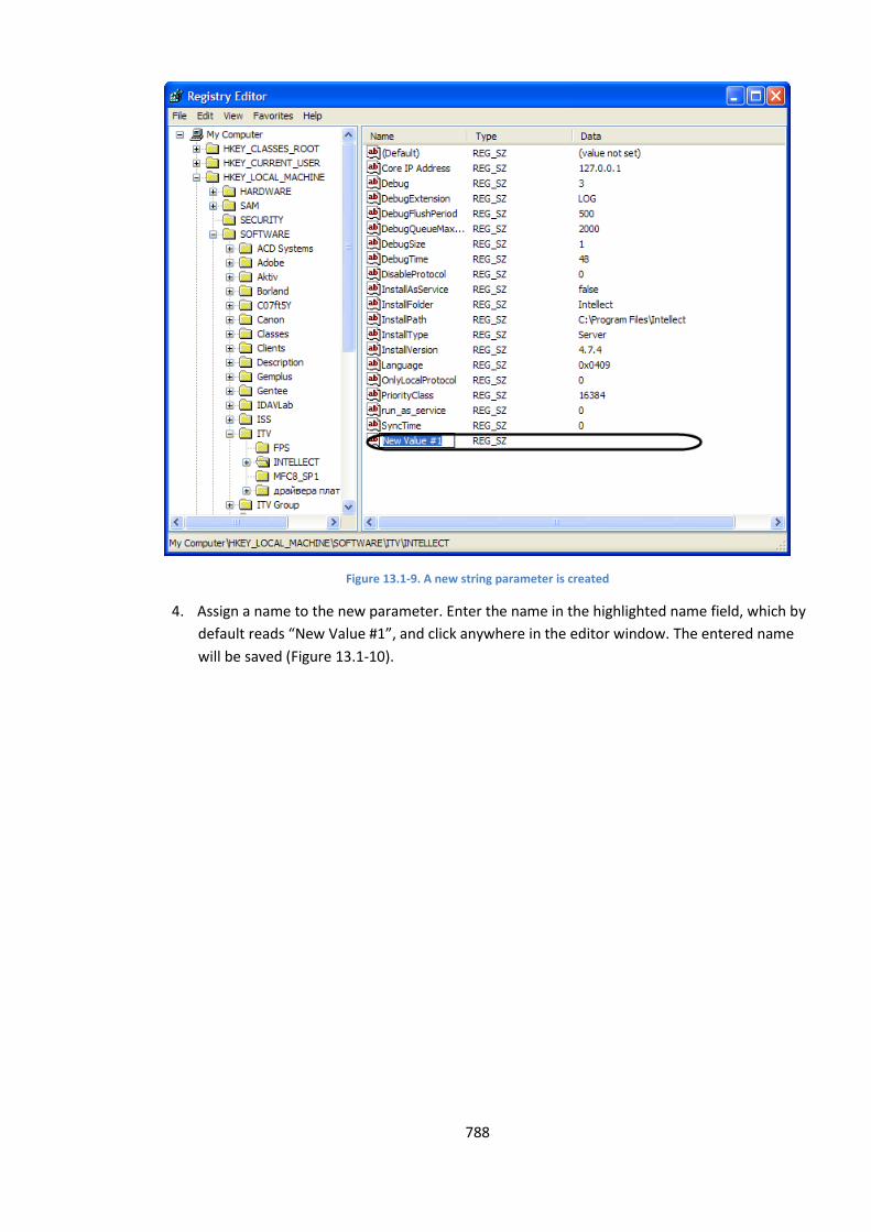
788
Figure 13.1-9. A new string parameter is created
4. Assign a name to the new parameter. Enter the name in the highlighted name field, which by
default reads “New Value #1”, and click anywhere in the editor window. The entered name
will be saved (Figure 13.1-10).
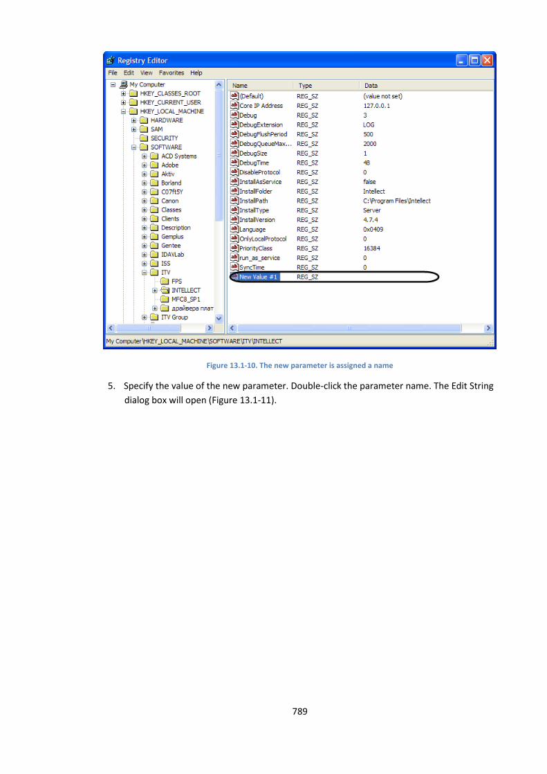
789
Figure 13.1-10. The new parameter is assigned a name
5. Specify the value of the new parameter. Double-click the parameter name. The Edit String
dialog box will open (Figure 13.1-11).
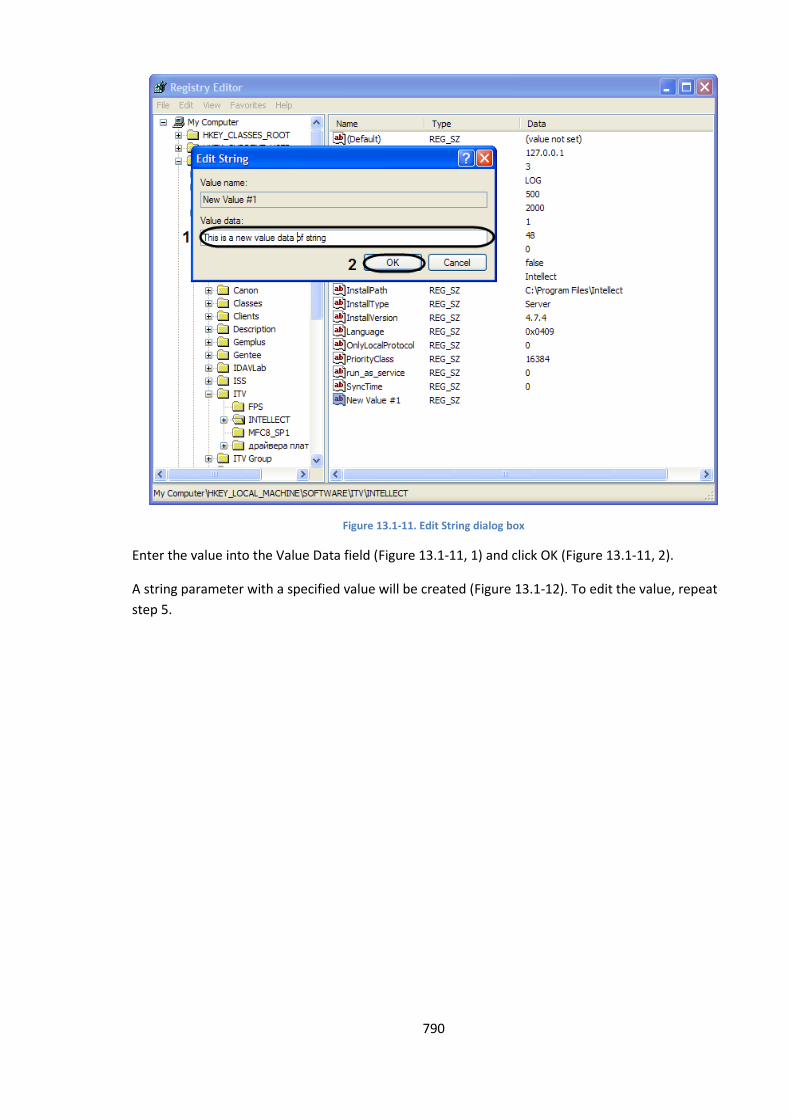
790
Figure 13.1-11. Edit String dialog box
Enter the value into the Value Data field (Figure 13.1-11, 1) and click OK (Figure 13.1-11, 2).
A string parameter with a specified value will be created (Figure 13.1-12). To edit the value, repeat
step 5.
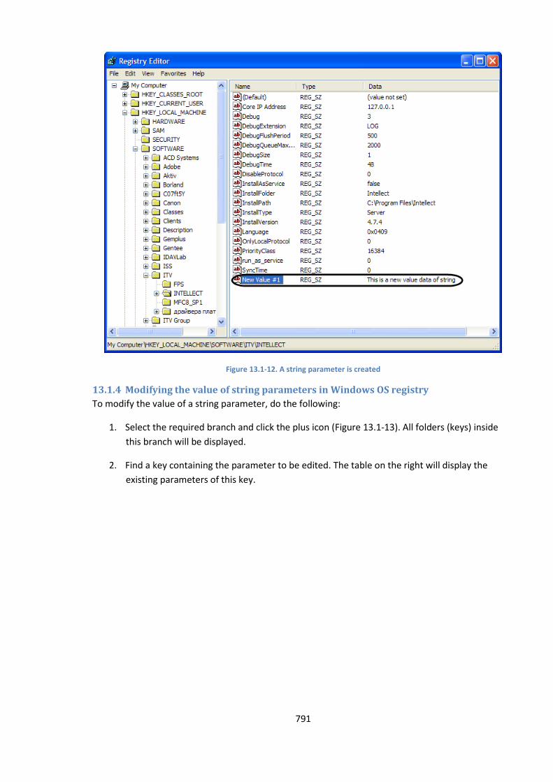
791
Figure 13.1-12. A string parameter is created
13.1.4 Modifying the value of string parameters in Windows OS registry
To modify the value of a string parameter, do the following:
1. Select the required branch and click the plus icon (Figure 13.1-13). All folders (keys) inside
this branch will be displayed.
2. Find a key containing the parameter to be edited. The table on the right will display the
existing parameters of this key.

792
Figure 13.1-13. Selecting a folder in the tree
3. Select the parameter to be modified (Figure 13.1-14).
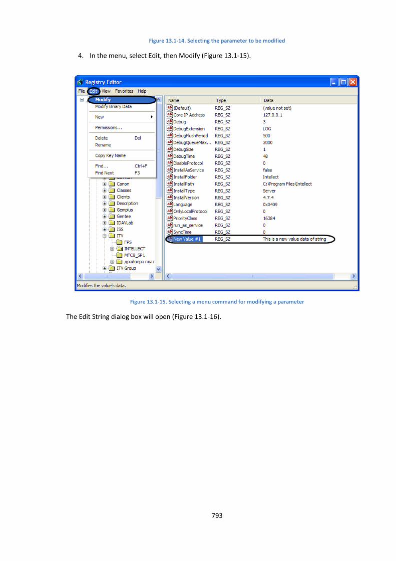
793
Figure 13.1-14. Selecting the parameter to be modified
4. In the menu, select Edit, then Modify (Figure 13.1-15).
Figure 13.1-15. Selecting a menu command for modifying a parameter
The Edit String dialog box will open (Figure 13.1-16).
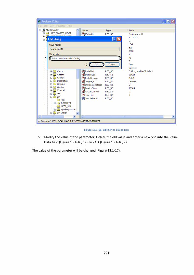
794
Figure 13.1-16. Edit String dialog box
5. Modify the value of the parameter. Delete the old value and enter a new one into the Value
Data field (Figure 13.1-16, 1). Click OK (Figure 13.1-16, 2).
The value of the parameter will be changed (Figure 13.1-17).

795
Figure 13.1-17. The parameter value is modified
13.1.5 Deleting parameters from the Windows OS registry
To delete a string parameter from the registry, do the following:
1. Select the required branch and click the plus icon (Figure 13.1-18). All folders (keys) inside
this branch will be displayed.
2. Find a key containing the parameter to be deleted. The table on the right will display the
existing parameters of this key.
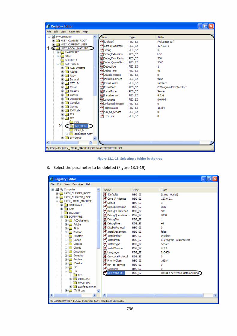
796
Figure 13.1-18. Selecting a folder in the tree
3. Select the parameter to be deleted (Figure 13.1-19).
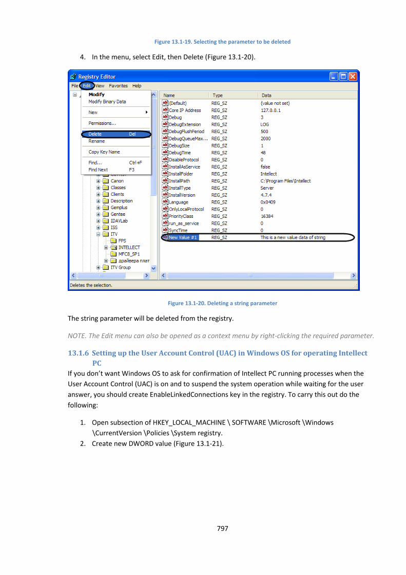
797
Figure 13.1-19. Selecting the parameter to be deleted
4. In the menu, select Edit, then Delete (Figure 13.1-20).
Figure 13.1-20. Deleting a string parameter
The string parameter will be deleted from the registry.
NOTE. The Edit menu can also be opened as a context menu by right-clicking the required parameter.
13.1.6 Setting up the User Account Control (UAC) in Windows OS for operating Intellect
PC
If you don’t want Windows OS to ask for confirmation of Intellect PC running processes when the
User Account Control (UAC) is on and to suspend the system operation while waiting for the user
answer, you should create EnableLinkedConnections key in the registry. To carry this out do the
following:
1. Open subsection of HKEY_LOCAL_MACHINE \ SOFTWARE \Microsoft \Windows
\CurrentVersion \Policies \System registry.
2. Create new DWORD value (Figure 13.1-21).
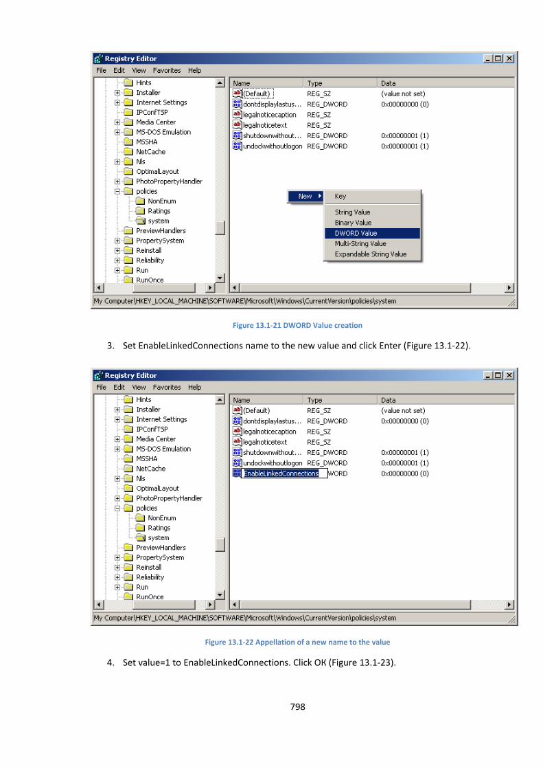
798
Figure 13.1-21 DWORD Value creation
3. Set EnableLinkedConnections name to the new value and click Enter (Figure 13.1-22).
Figure 13.1-22 Appellation of a new name to the value
4. Set value=1 to EnableLinkedConnections. Click ОК (Figure 13.1-23).
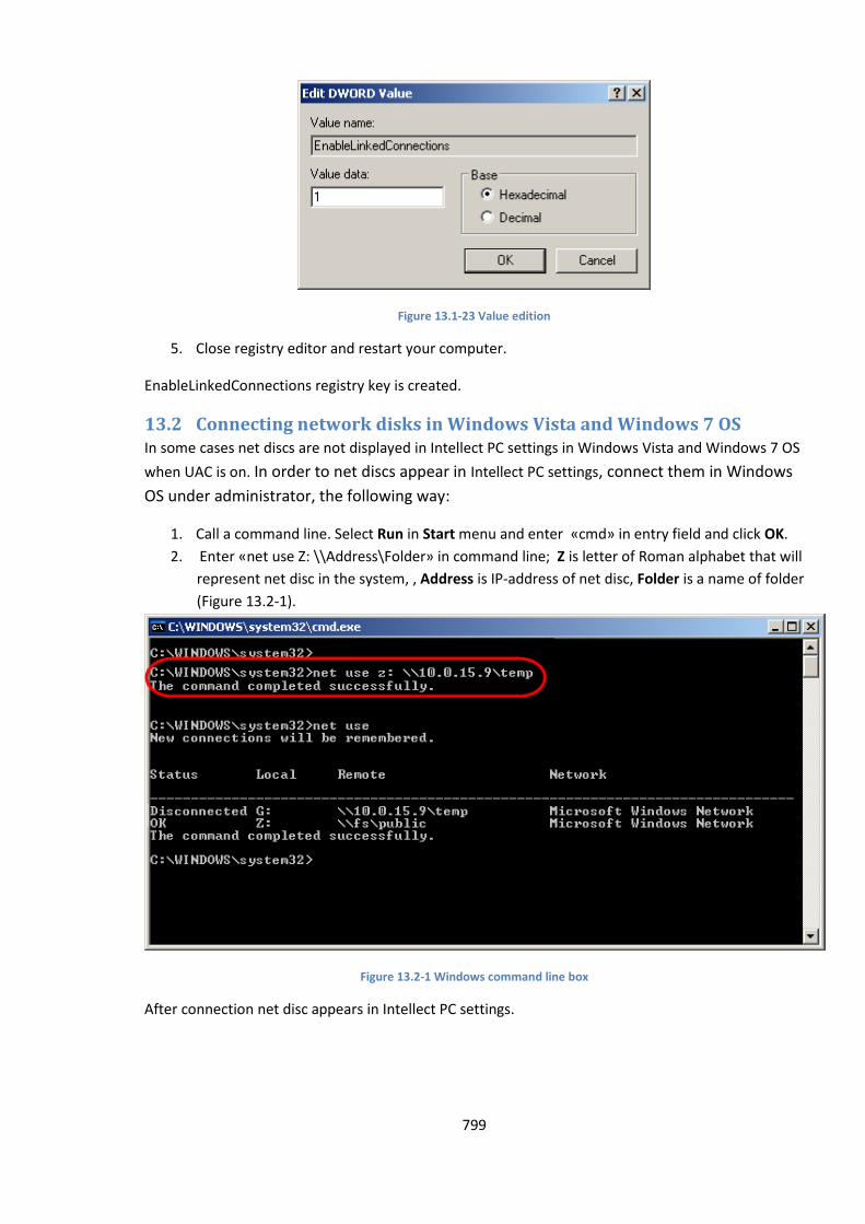
799
Figure 13.1-23 Value edition
5. Close registry editor and restart your computer.
EnableLinkedConnections registry key is created.
13.2 Connecting network disks in Windows Vista and Windows 7 OS In some cases net discs are not displayed in Intellect PC settings in Windows Vista and Windows 7 OS
when UAC is on. In order to net discs appear in Intellect PC settings, connect them in Windows
OS under administrator, the following way:
1. Call a command line. Select Run in Start menu and enter «cmd» in entry field and click OK.
2. Enter «net use Z: \\Address\Folder» in command line; Z is letter of Roman alphabet that will
represent net disc in the system, , Address is IP-address of net disc, Folder is a name of folder
(Figure 13.2-1).
Figure 13.2-1 Windows command line box
After connection net disc appears in Intellect PC settings.

800
13.3 Setting up serial (COM) ports in Windows To view and edit the settings of COM ports, start the Device Manager. Right-click the My Computer
icon on the Desktop and select Properties in the drop-down menu. The System Properties window
will open. Open the Hardware tab and click the Device Manager button (Figure 13.3-1).
Figure 13.3-1. Starting the Device Manager
The Device Manager window will open. Expand the Ports (COM & LPT) branch and select the COM
port to which the device to be set up is connected. Then, right-click the required COM port in the
tree to open the drop-down menu and select Properties. The settings of the port will open in a dialog
window. Go to the Port Settings tab to view and edit the Bits per Second and the Parity parameters
(Figure 13.3-2).
Figure 13.3-2. Opening the Port Properties window
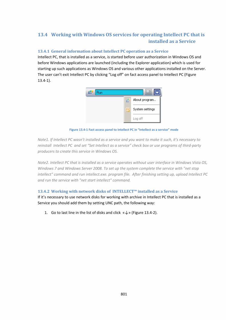
801
13.4 Working with Windows OS services for operating Intellect PC that is
installed as a Service
13.4.1 General information about Intellect PC operation as a Service
Intellect PC, that is installed as a service, is started before user authorization in Windows OS and
before Windows applications are launched (including the Explorer application) which is used for
starting up such applications as Windows OS and various other applications installed on the Server.
The user can’t exit Intellect PC by clicking “Log off” on fact access panel to Intellect PC (Figure
13.4-1).
Figure 13.4-1 Fact access panel to Intellect PC in “Intellect as a service” mode
Note1. If Intellect PC wasn’t installed as a service and you want to make it such, it’s necessary to
reinstall Intellect PC and set “Set Intellect as a service” check box or use programs of third-party
producers to create this service in Windows OS.
Note2. Intellect PC that is installed as a service operates without user interface in Windows Vista OS,
Windows 7 and Windows Server 2008. To set up the system complete the service with "net stop
intellect" command and run intellect.exe. program file. After finishing setting up, upload Intellect PC
and run the service with "net start intellect" command.
13.4.2 Working with network disks of INTELLECT™ installed as a Service
If it’s necessary to use network disks for working with archive in Intellect PC that is installed as a
Service you should add them by setting UNC path, the following way:
1. Go to last line in the list of disks and click «↓» (Figure 13.4-2).

802
Figure 13.4-2 Setting UNC path to network disk
2. Set a path to the network disk in appeared linein “Disk” column (Figure 13.4-2). UNC path is
set in «\\server_name\share_name» format where «server_name» is a name of file server
and «share_name» is a network name of public folder.
3. Set check box for created disk in “Video” column.
Note. If network disk is added not by setting UNC path then recording on it is unavailable in Intellect
PC is installed as a Service mode.
Attention! If Intellect PC is installed as a Service on Windows XP OS, it’s impossible to record on
network disks.
13.4.3 Disabling of Intellect PC as a Service startup
Services utility is used for setting up the operation of Intellect PC asa service in Windows OS.
To disable the starting of Intellect PC as a server do the following:
1. Start Services utility by opening Control panel => Administrative tools=> Services (Figure
13.4-3).
Note. If Control panel view is set “by categories” open Control panel => Performance and
maintenance=> Administrative tools => Services .
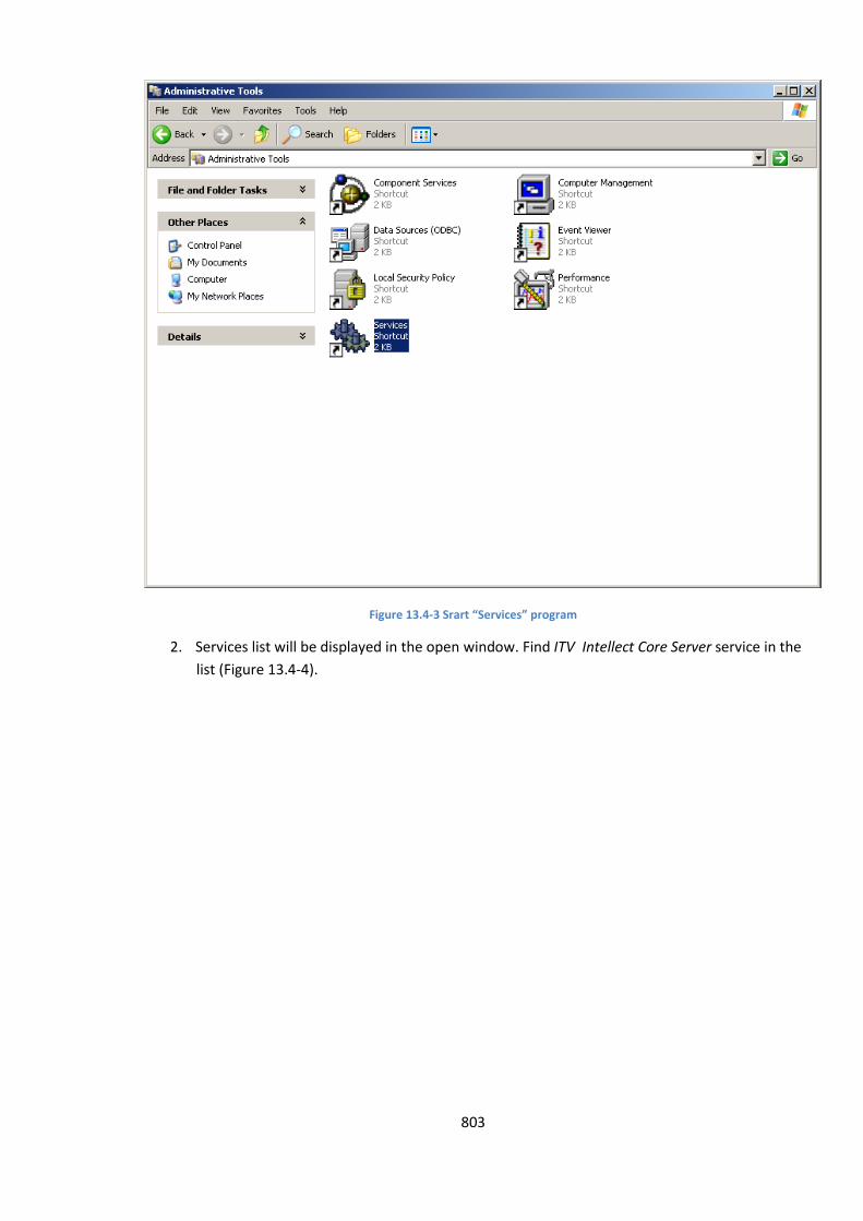
803
Figure 13.4-3 Srart “Services” program
2. Services list will be displayed in the open window. Find ITV Intellect Core Server service in the
list (Figure 13.4-4).
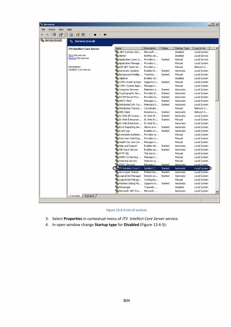
804
Figure 13.4-4 List of services
3. Select Properties in contextual menu of ITV Intellect Core Server service.
4. In open window change Startup type for Disabled (Figure 13.4-5):
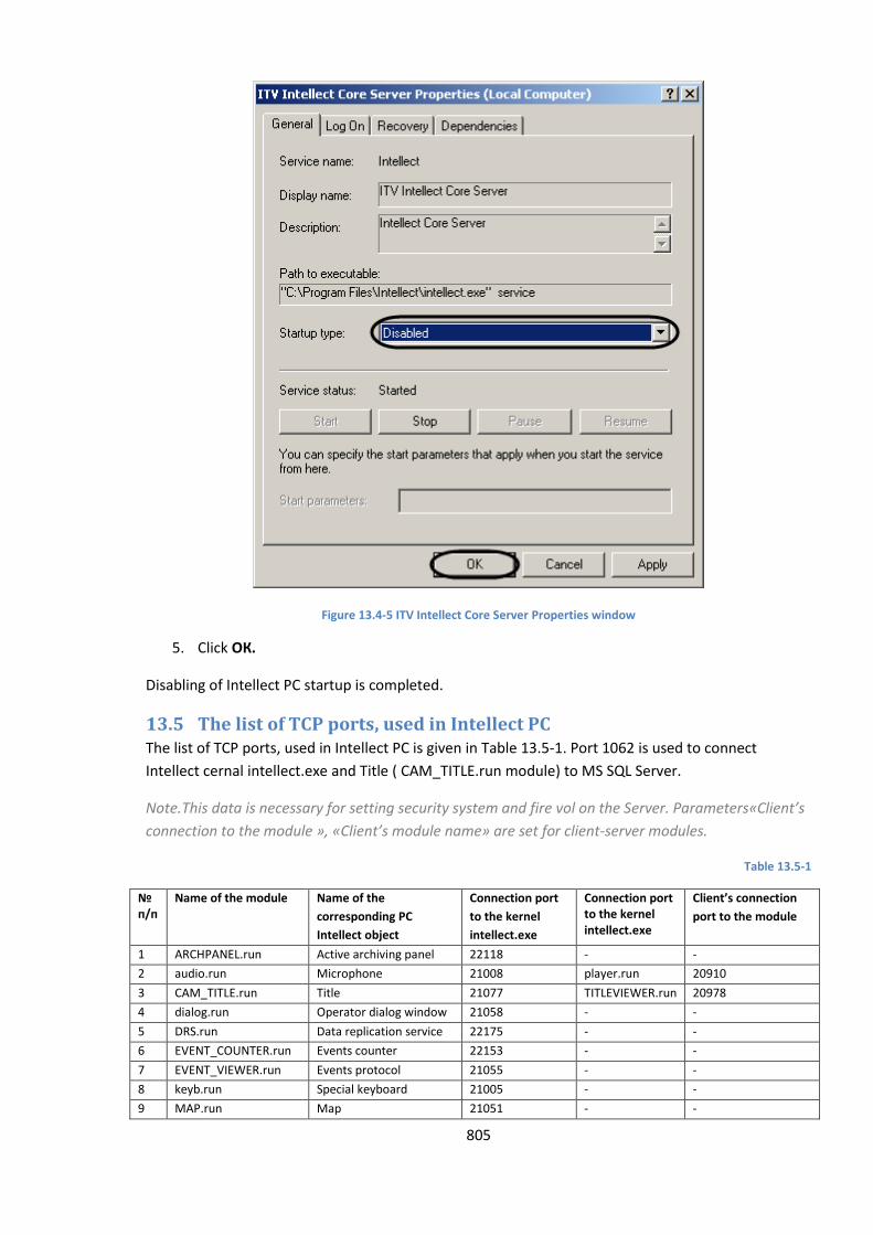
805
Figure 13.4-5 ITV Intellect Core Server Properties window
5. Click ОК.
Disabling of Intellect PC startup is completed.
13.5 The list of TCP ports, used in Intellect PC The list of TCP ports, used in Intellect PC is given in Table 13.5-1. Port 1062 is used to connect
Intellect cernal intellect.exe and Title ( CAM_TITLE.run module) to MS SQL Server.
Note.This data is necessary for setting security system and fire vol on the Server. Parameters«Client’s
connection to the module », «Client’s module name» are set for client-server modules.
Table 13.5-1
№ п/п
Name of the module Name of the
corresponding PC
Intellect object
Connection port
to the kernel
intellect.exe
Connection port to the kernel intellect.exe
Client’s connection
port to the module
1 ARCHPANEL.run Active archiving panel 22118 - -
2 audio.run Microphone 21008 player.run 20910
3 CAM_TITLE.run Title 21077 TITLEVIEWER.run 20978
4 dialog.run Operator dialog window 21058 - -
5 DRS.run Data replication service 22175 - -
6 EVENT_COUNTER.run Events counter 22153 - -
7 EVENT_VIEWER.run Events protocol 21055 - -
8 keyb.run Special keyboard 21005 - -
9 MAP.run Map 21051 - -
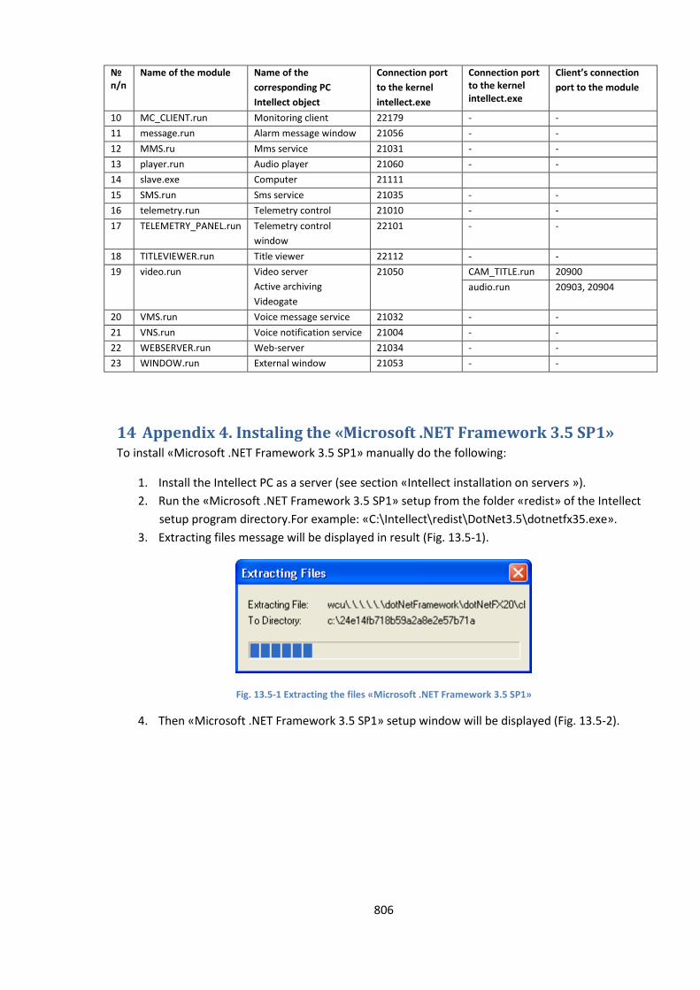
806
№ п/п
Name of the module Name of the
corresponding PC
Intellect object
Connection port
to the kernel
intellect.exe
Connection port to the kernel intellect.exe
Client’s connection
port to the module
10 MC_CLIENT.run Monitoring client 22179 - -
11 message.run Alarm message window 21056 - -
12 MMS.ru Mms service 21031 - -
13 player.run Audio player 21060 - -
14 slave.exe Computer 21111
15 SMS.run Sms service 21035 - -
16 telemetry.run Telemetry control 21010 - -
17 TELEMETRY_PANEL.run Telemetry control
window
22101 - -
18 TITLEVIEWER.run Title viewer 22112 - -
19 video.run Video server
Active archiving
Videogate
21050 CAM_TITLE.run 20900
audio.run 20903, 20904
20 VMS.run Voice message service 21032 - -
21 VNS.run Voice notification service 21004 - -
22 WEBSERVER.run Web-server 21034 - -
23 WINDOW.run External window 21053 - -
14 Appendix 4. Instaling the «Microsoft .NET Framework 3.5 SP1» To install «Microsoft .NET Framework 3.5 SP1» manually do the following:
1. Install the Intellect PC as a server (see section «Intellect installation on servers »).
2. Run the «Microsoft .NET Framework 3.5 SP1» setup from the folder «redist» of the Intellect
setup program directory.For example: «С:\Intellect\redist\DotNet3.5\dotnetfx35.exe».
3. Extracting files message will be displayed in result (Fig. 13.5-1).
Fig. 13.5-1 Extracting the files «Microsoft .NET Framework 3.5 SP1»
4. Then «Microsoft .NET Framework 3.5 SP1» setup window will be displayed (Fig. 13.5-2).
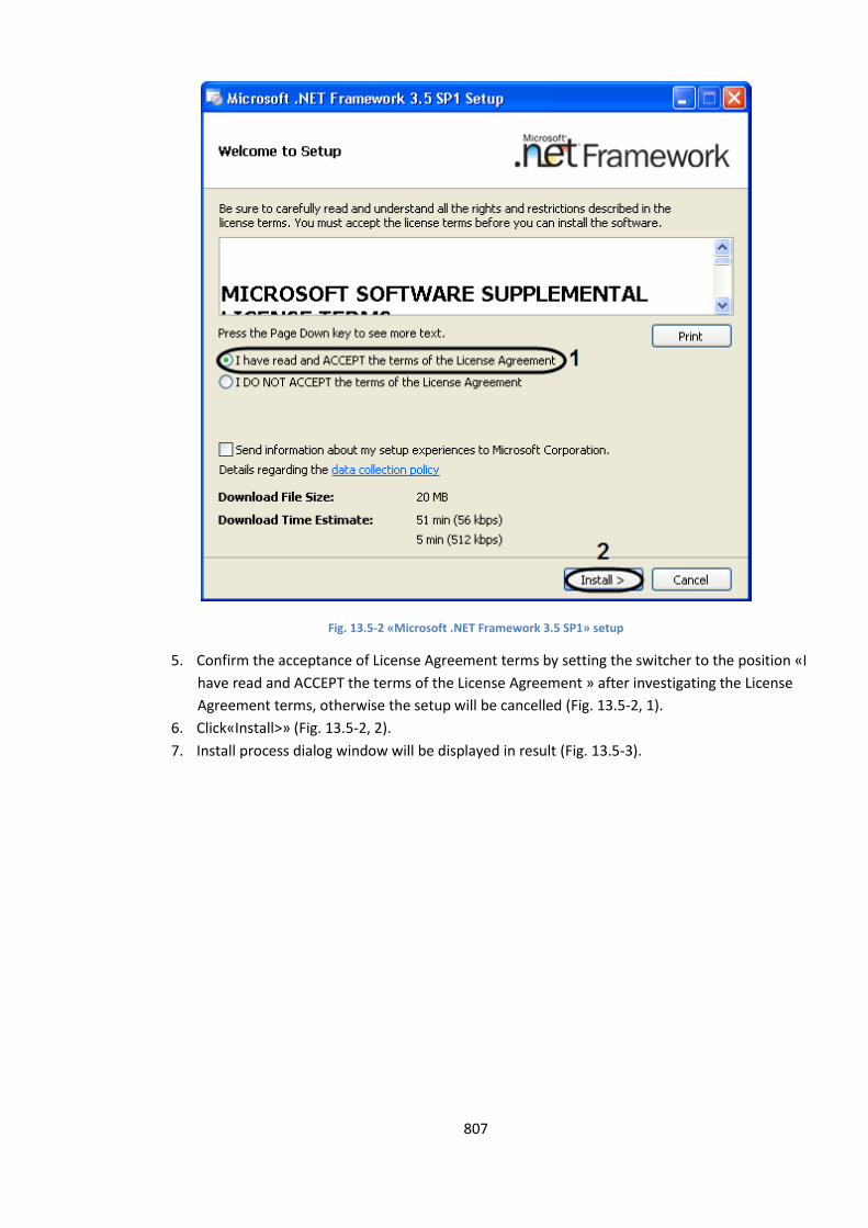
807
Fig. 13.5-2 «Microsoft .NET Framework 3.5 SP1» setup
5. Confirm the acceptance of License Agreement terms by setting the switcher to the position «I
have read and ACCEPT the terms of the License Agreement » after investigating the License
Agreement terms, otherwise the setup will be cancelled (Fig. 13.5-2, 1).
6. Click«Install>» (Fig. 13.5-2, 2).
7. Install process dialog window will be displayed in result (Fig. 13.5-3).
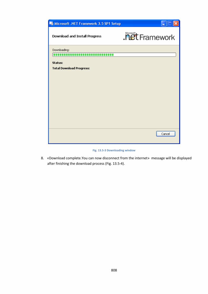
808
Fig. 13.5-3 Downloading window
8. «Download complete.You can now disconnect from the internet» message will be displayed
after finishing the download process (Fig. 13.5-4).
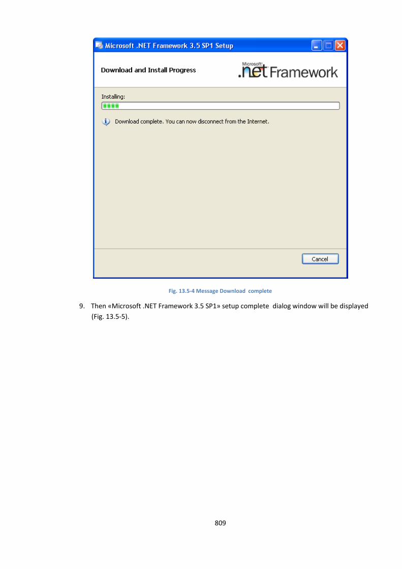
809
Fig. 13.5-4 Message Download complete
9. Then «Microsoft .NET Framework 3.5 SP1» setup complete dialog window will be displayed
(Fig. 13.5-5).
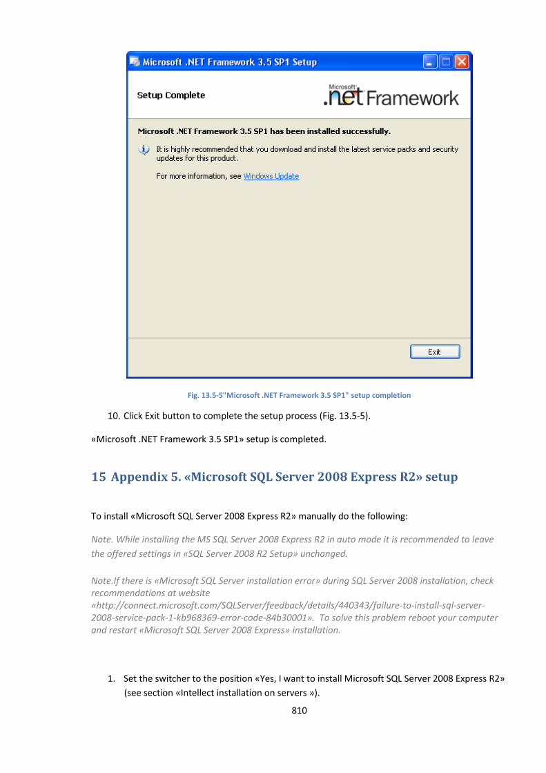
810
Fig. 13.5-5"Microsoft .NET Framework 3.5 SP1" setup completion
10. Click Exit button to complete the setup process (Fig. 13.5-5).
«Microsoft .NET Framework 3.5 SP1» setup is completed.
15 Appendix 5. «Microsoft SQL Server 2008 Express R2» setup
To install «Microsoft SQL Server 2008 Express R2» manually do the following:
Note. While installing the MS SQL Server 2008 Express R2 in auto mode it is recommended to leave
the offered settings in «SQL Server 2008 R2 Setup» unchanged.
Note.If there is «Microsoft SQL Server installation error» during SQL Server 2008 installation, check recommendations at website «http://connect.microsoft.com/SQLServer/feedback/details/440343/failure-to-install-sql-server-2008-service-pack-1-kb968369-error-code-84b30001». To solve this problem reboot your computer and restart «Microsoft SQL Server 2008 Express» installation.
1. Set the switcher to the position «Yes, I want to install Microsoft SQL Server 2008 Express R2»
(see section «Intellect installation on servers »).
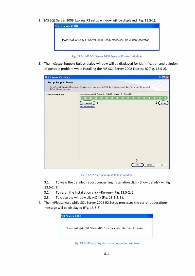
811
2. MS SQL Server 2008 Express R2 setup window will be displayed (Fig. 13.5-1).
Fig. 13.5-1 MS SQL Server 2008 Express R2 setup window
3. Then «Setup Support Rules» dialog window will be displayed for identification and deletion
of possible problem while installing the MS SQL Server 2008 Express R2(Fig. 13.5-2).
Fig. 13.5-2 "Setup Support Rules" window
3.1. To view the detailed report concerning installation click «Show details>>» (Fig.
13.5-2, 1).
3.2. To rerun the installation click «Re-run» (Fig. 13.5-2, 2).
3.3. To close the window click«OK» (Fig. 13.5-2, 3).
4. Then «Please wait while SQL Server 2008 R2 Setup processes the current operation»
message will be displayed (Fig. 13.5-3).
Fig. 13.5-3 Processing the current operation window
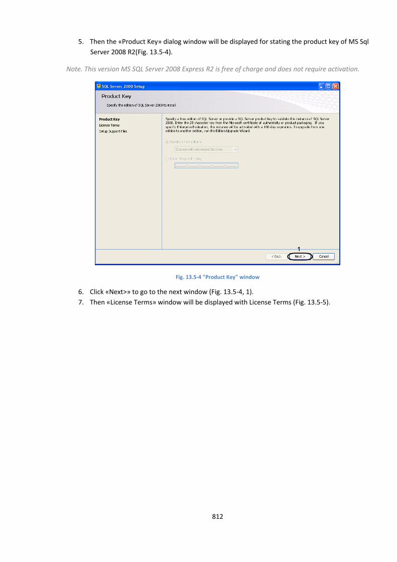
812
5. Then the «Product Key» dialog window will be displayed for stating the product key of MS Sql
Server 2008 R2(Fig. 13.5-4).
Note. This version MS SQL Server 2008 Express R2 is free of charge and does not require activation.
Fig. 13.5-4 "Product Key" window
6. Click «Next>» to go to the next window (Fig. 13.5-4, 1).
7. Then «License Terms» window will be displayed with License Terms (Fig. 13.5-5).
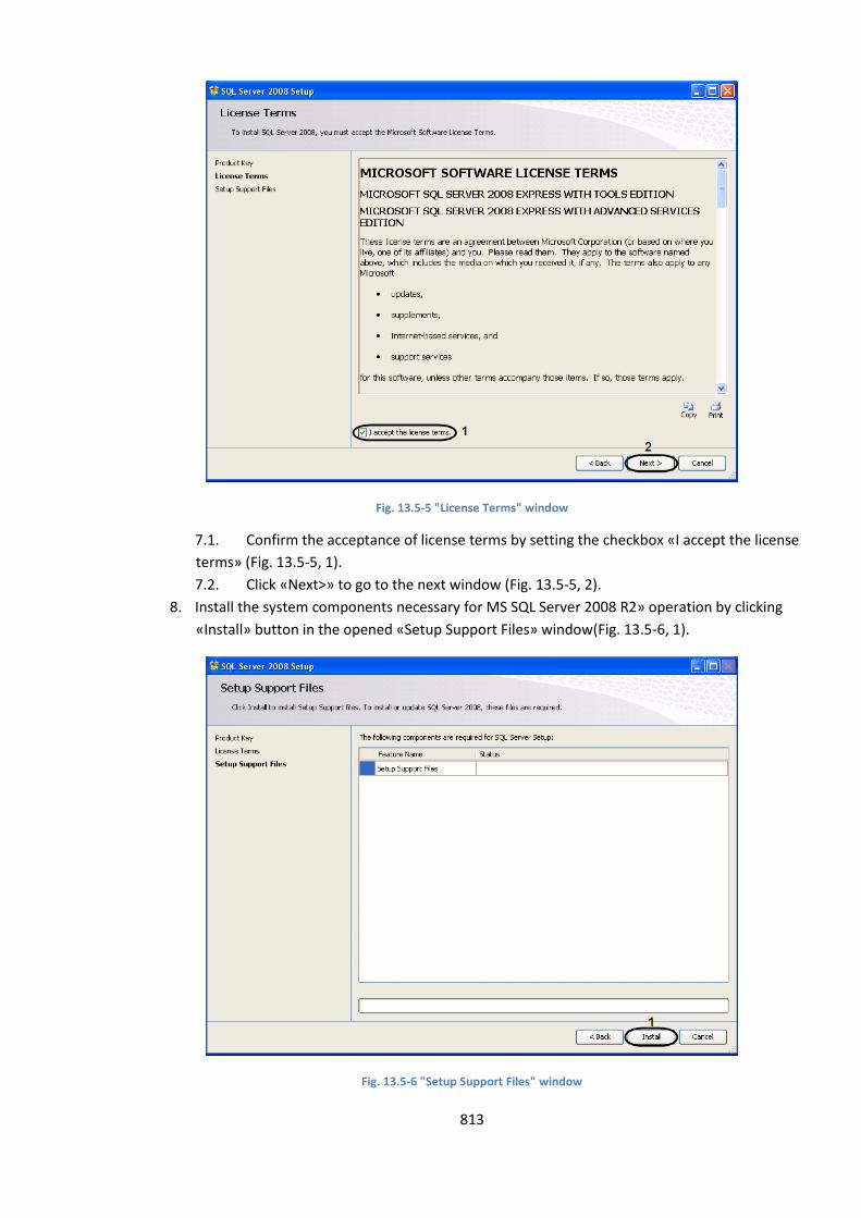
813
Fig. 13.5-5 "License Terms" window
7.1. Confirm the acceptance of license terms by setting the checkbox «I accept the license
terms» (Fig. 13.5-5, 1).
7.2. Click «Next>» to go to the next window (Fig. 13.5-5, 2).
8. Install the system components necessary for MS SQL Server 2008 R2» operation by clicking
«Install» button in the opened «Setup Support Files» window(Fig. 13.5-6, 1).
Fig. 13.5-6 "Setup Support Files" window
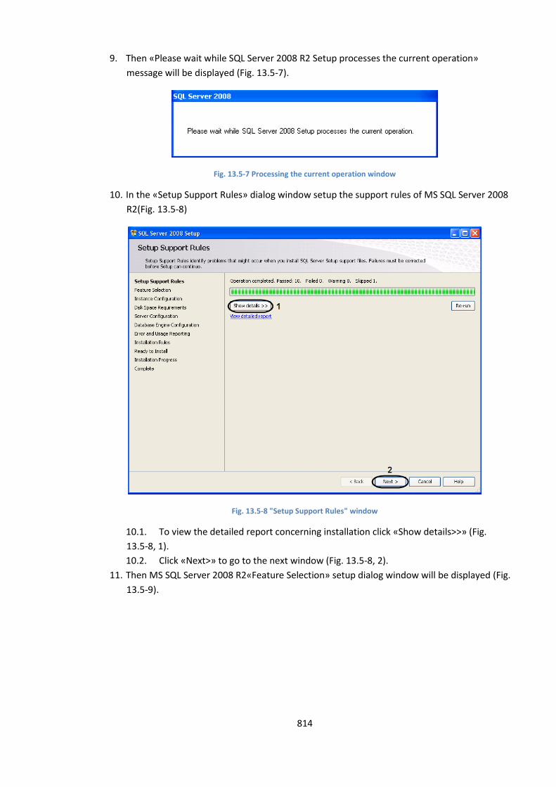
814
9. Then «Please wait while SQL Server 2008 R2 Setup processes the current operation»
message will be displayed (Fig. 13.5-7).
Fig. 13.5-7 Processing the current operation window
10. In the «Setup Support Rules» dialog window setup the support rules of MS SQL Server 2008
R2(Fig. 13.5-8)
Fig. 13.5-8 "Setup Support Rules" window
10.1. To view the detailed report concerning installation click «Show details>>» (Fig.
13.5-8, 1).
10.2. Click «Next>» to go to the next window (Fig. 13.5-8, 2).
11. Then MS SQL Server 2008 R2«Feature Selection» setup dialog window will be displayed (Fig.
13.5-9).
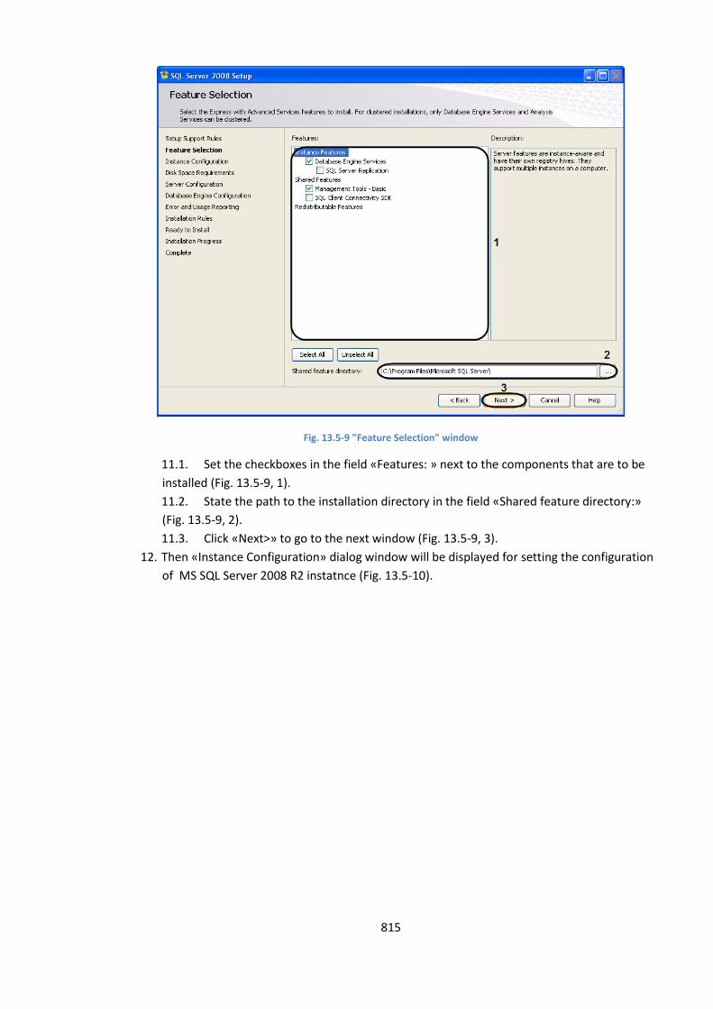
815
Fig. 13.5-9 "Feature Selection" window
11.1. Set the checkboxes in the field «Features: » next to the components that are to be
installed (Fig. 13.5-9, 1).
11.2. State the path to the installation directory in the field «Shared feature directory:»
(Fig. 13.5-9, 2).
11.3. Click «Next>» to go to the next window (Fig. 13.5-9, 3).
12. Then «Instance Configuration» dialog window will be displayed for setting the configuration
of MS SQL Server 2008 R2 instatnce (Fig. 13.5-10).
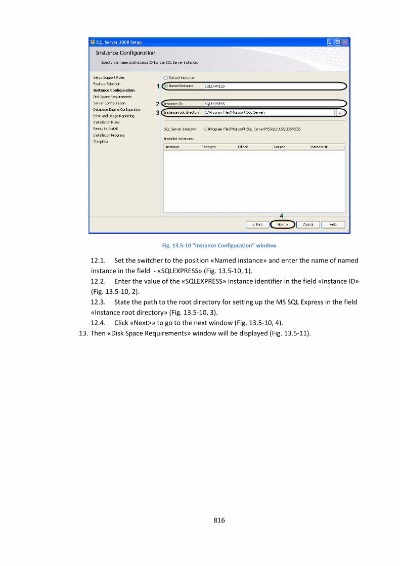
816
Fig. 13.5-10 "Instance Configuration" window
12.1. Set the switcher to the position «Named instance» and enter the name of named
instance in the field - «SQLEXPRESS» (Fig. 13.5-10, 1).
12.2. Enter the value of the «SQLEXPRESS» instance identifier in the field «Instance ID»
(Fig. 13.5-10, 2).
12.3. State the path to the root directory for setting up the MS SQL Express in the field
«Instance root directory» (Fig. 13.5-10, 3).
12.4. Click «Next>» to go to the next window (Fig. 13.5-10, 4).
13. Then «Disk Space Requirements» window will be displayed (Fig. 13.5-11).
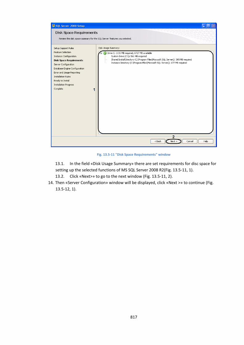
817
Fig. 13.5-11 "Disk Space Requirements" window
13.1. In the field «Disk Usage Summary» there are set requirements for disc space for
setting up the selected functions of MS SQL Server 2008 R2(Fig. 13.5-11, 1).
13.2. Click «Next>» to go to the next window (Fig. 13.5-11, 2).
14. Then «Server Configuration» window will be displayed, click «Next >» to continue (Fig.
13.5-12, 1).
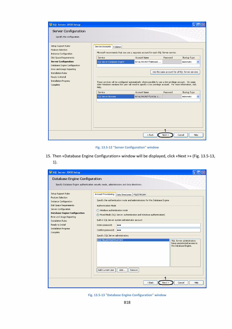
818
Fig. 13.5-12 "Server Configuration" window
15. Then «Database Engine Configuration» window will be displayed, click «Next >» (Fig. 13.5-13,
1).
Fig. 13.5-13 "Database Engine Configuration" window
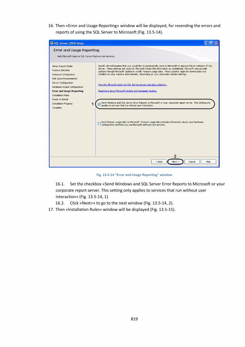
819
16. Then «Error and Usage Reporting» window will be displayed, for resending the errors and
reports of using the SQL Server to Microsoft (Fig. 13.5-14).
Fig. 13.5-14 "Error and Usage Reporting" window
16.1. Set the checkbox «Send Windows and SQL Server Error Reports to Microsoft or your
corporate report server. This setting only applies to services that run without user
interaction» (Fig. 13.5-14, 1).
16.2. Click «Next>» to go to the next window (Fig. 13.5-14, 2).
17. Then «Installation Rules» window will be displayed (Fig. 13.5-15).
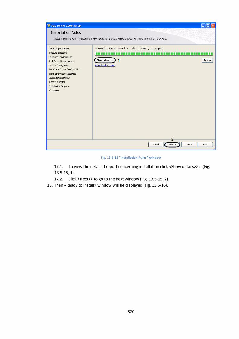
820
Fig. 13.5-15 "Installation Rules" window
17.1. To view the detailed report concerning installation click «Show details>>» (Fig.
13.5-15, 1).
17.2. Click «Next>» to go to the next window (Fig. 13.5-15, 2).
18. Then «Ready to Install» window will be displayed (Fig. 13.5-16).
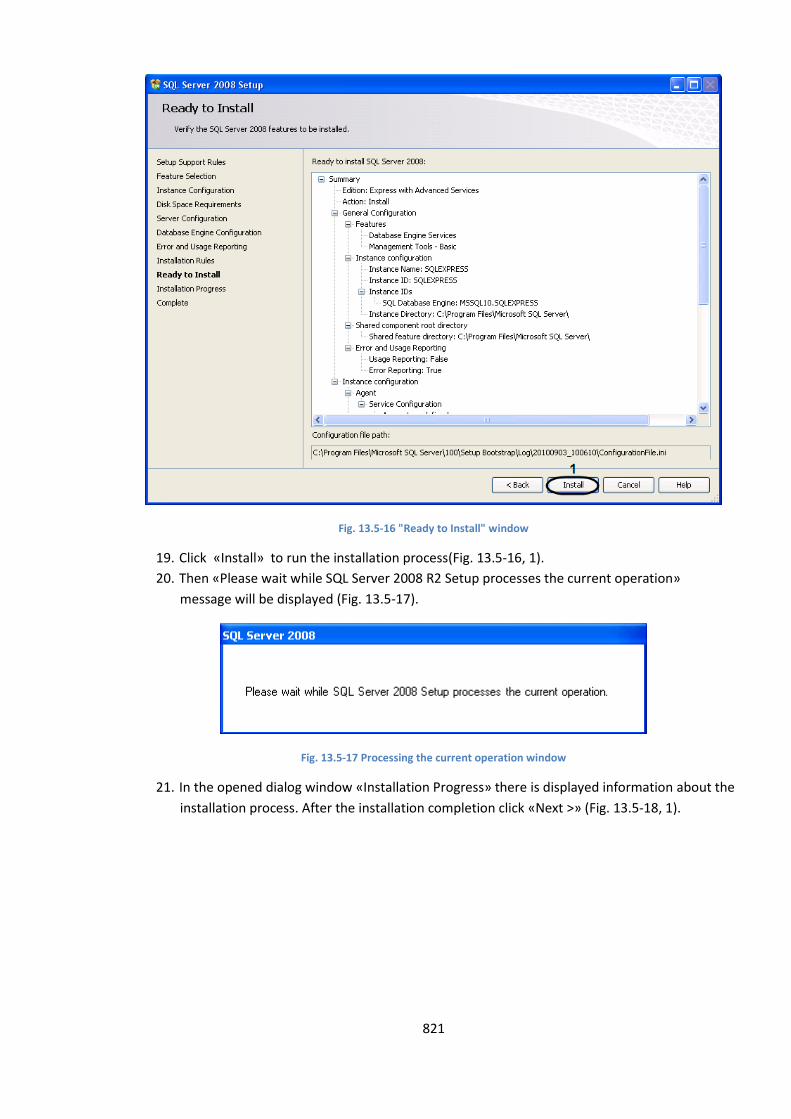
821
Fig. 13.5-16 "Ready to Install" window
19. Click «Install» to run the installation process(Fig. 13.5-16, 1).
20. Then «Please wait while SQL Server 2008 R2 Setup processes the current operation»
message will be displayed (Fig. 13.5-17).
Fig. 13.5-17 Processing the current operation window
21. In the opened dialog window «Installation Progress» there is displayed information about the
installation process. After the installation completion click «Next >» (Fig. 13.5-18, 1).
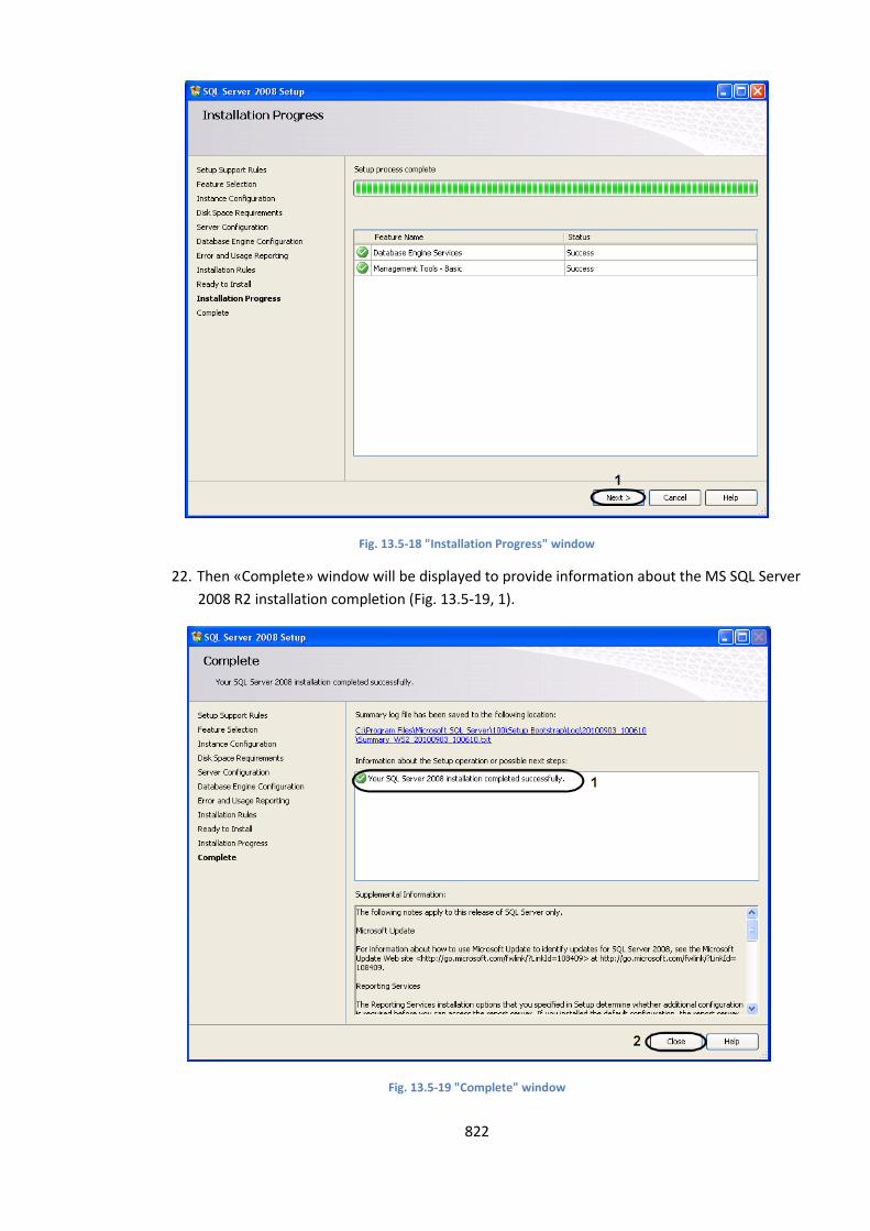
822
Fig. 13.5-18 "Installation Progress" window
22. Then «Complete» window will be displayed to provide information about the MS SQL Server
2008 R2 installation completion (Fig. 13.5-19, 1).
Fig. 13.5-19 "Complete" window

823
23. «Close» to quit the installation process (Fig. 13.5-19, 2).
«Microsoft SQL Server 2008 Express R2» setup is completed.