INSTALLATION MANUAL SLI 50 DISPLAY UNIT SLI 50 LED … · INSTALLATION MANUAL SLI 50 DISPLAY UNIT...
26
INSTALLATION MANUAL SLI 50 DISPLAY UNIT | SLI 50 LED UNIT www.unipowerco.com Manual No. SLI-50-DISPLAY-3 © 2016 UNIPOWER LLC All Rights Reserved sli50_display-man-rev3-0516.indd UNIPOWER LLC • 3900 Coral Ridge Drive, Coral Springs, Florida 33065, USA • [email protected] North America: +1 954-905-1071 • Latin America: +1 954-905-1078 • Europe: +44 1903 768200 P O W E R I N G T E C H N O L O G Y (P/N: 3G10001F100G) (P/N: 3G34001F100G)
Transcript of INSTALLATION MANUAL SLI 50 DISPLAY UNIT SLI 50 LED … · INSTALLATION MANUAL SLI 50 DISPLAY UNIT...
INSTALLATION MANUALSLI 50 DISPLAY UNIT | SLI 50 LED UNIT
www.unipowerco.com
Manual No. SLI-50-DISPLAY-3 © 2016 UNIPOWER LLCAll Rights Reservedsli50_display-man-rev3-0516.indd
UNIPOWER LLC • 3900 Coral Ridge Drive, Coral Springs, Florida 33065, USA • [email protected] America: +1 954-905-1071 • Latin America: +1 954-905-1078 • Europe: +44 1903 768200
P O W E R I N G T E C H N O L O G Y
(P/N: 3G10001F100G) (P/N: 3G34001F100G)
Page 2
P O W E R I N G T E C H N O L O G Y
Manual No. sli-50-display-3 sli50_display-man-rev3-0516.indd
Introduction
1 Introduction
There are two options available:
SLI 50 LED Unit is a standard option for visual indication of the main parameters andit’s factory assembled into the SLI 50 48-230 inverters.
SLI 50 Display Unit is a graphic display unit with keypad used for monitoring andchanging of the main parameters in the SLI 50 inverter systems. It’s factoryassembled into the SLI 50 48-230-CTRL inverters.
Both, the LED unit and the Display unit, are hot-plug replaceable and can be plugged inevery position.The units have a plastic key near the connector to avoid insertion in wrong position.Only one Display Unit can be present in an inverter system, the other one must be a LED unit. Display Unit in an inverter system can be plugged and moved from any of the inverters.Both modules can be supplied as spare parts by factory.
2 Receiving Instructions
We present all equipment to the delivering carrier securely packed and in perfect condition. Upon acceptance of the package from us, the delivering carrier assumes responsibility for its safe arrival to you.Once you receive the equipment, it is your responsibility to document any damage the carrier may have inflicted, and to file your claim promptly and accurately.
2.1 Package Inspection Examine the shipping crate or carton for any visible damage: punctures, dents and
any other signs of possible internal damage.
Describe any damage or shortage on the receiving documents and have the carriersign their full name.
WARNING It is essential to read and understand all Warnings, Cautions and Notes before performing any connections to a Unit or a System.
WARNING The following information and the product manual should be read and thoroughly understood before unpacking, installing or using the equipment.
Page 3
P O W E R I N G T E C H N O L O G Y
Manual No. sli-50-display-3 sli50_display-man-rev3-0516.indd
Receiving Instructions
2.2 Equipment Inspection Within fifteen days, open crate or carton and inspect the contents for damages.
While unpacking, be careful not to discard any equipment, parts or manuals. If anydamage is detected, call the delivering carrier to determine the appropriate action.They may require an inspection.
Save all shipping material for the inspector to see!
After the inspection has been made, call us. We will determine if the equipmentshould be returned to our plant for repair or if some other method would be moreexpeditious. If it is determined that the equipment should be returned to us, ask thedelivering carrier to send the packages back at the delivering carrier’s expense.
If repair is necessary, we will invoice you for the repair so that you may submit the billto the delivering carrier with your claim forms.
It is your responsibility to file a claim with the delivering carrier. Failure to properly filea claim for shipping damages may void warranty service for any physical damageslater reported for repair.
2.3 HandlingHandle the inverter with care. Do not drop or lean on front panel or connector. Keep away from moisture.
2.4 Identification Label
Model number and serial number located on label on the cover identify the unit. Please refer to these numbers in all correspondence with Power-One.
Page 4
P O W E R I N G T E C H N O L O G Y
Manual No. sli-50-display-3 sli50_display-man-rev3-0516.indd
Mounting Procedure
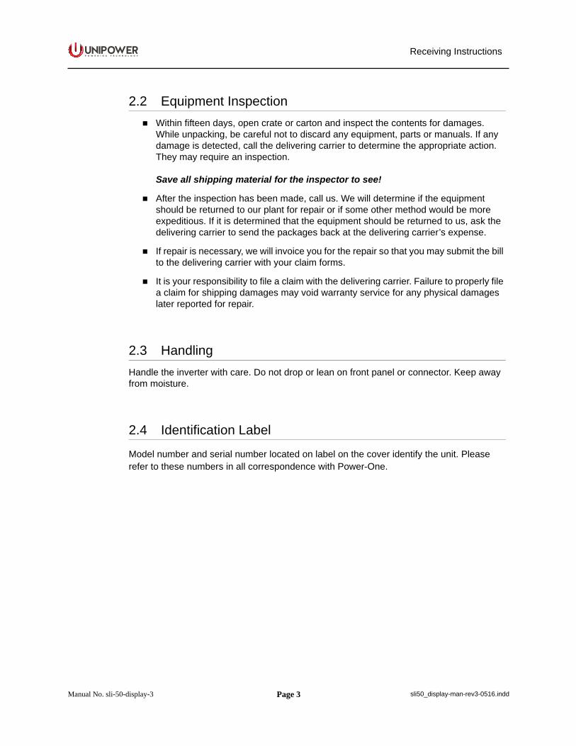
3 Mounting Procedure
To remove the unit from docking position press both lateral tabs inside the unit and pull it out.
Figure 3-1
To install the unit, simply insert the unit into the docking position. The units are hot plug / unplug replaceable.
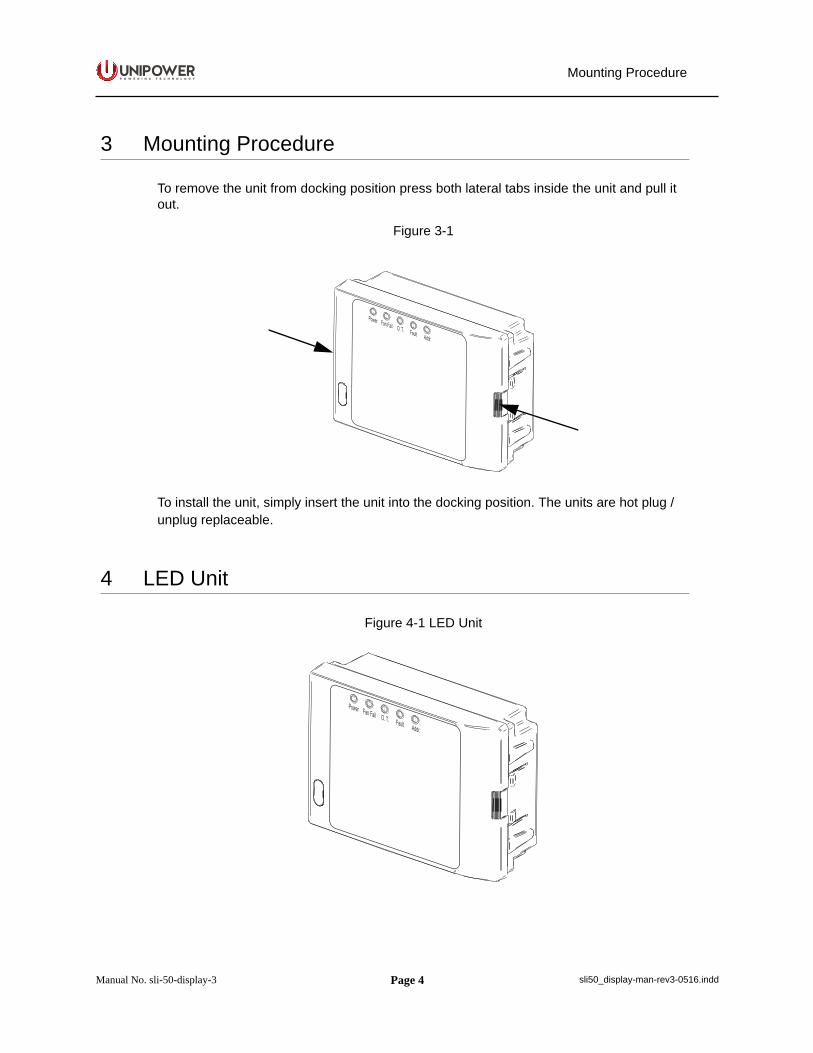
4 LED Unit
Figure 4-1 LED Unit
LED Unit
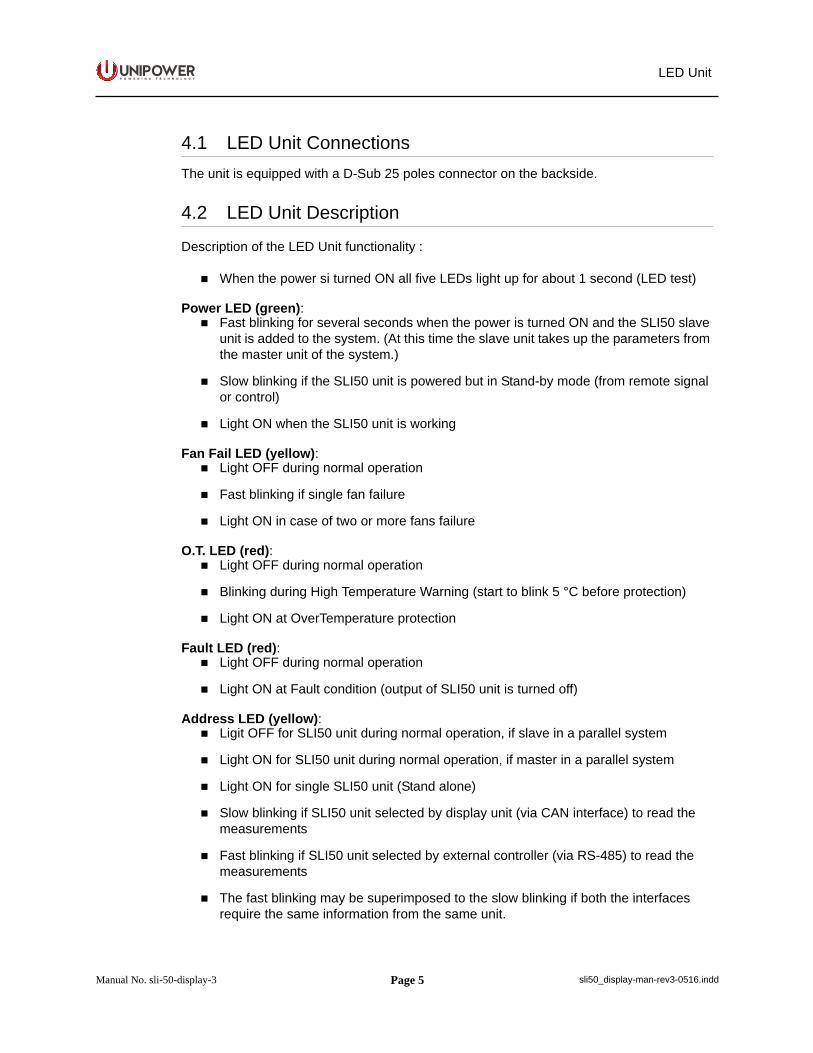
4.1 LED Unit ConnectionsThe unit is equipped with a D-Sub 25 poles connector on the backside.
4.2 LED Unit Description
Description of the LED Unit functionality :
When the power si turned ON all five LEDs light up for about 1 second (LED test)
Power LED (green): Fast blinking for several seconds when the power is turned ON and the SLI50 slave
unit is added to the system. (At this time the slave unit takes up the parameters from the master unit of the system.)
Slow blinking if the SLI50 unit is powered but in Stand-by mode (from remote signalor control)
Light ON when the SLI50 unit is working
Fan Fail LED (yellow): Light OFF during normal operation
Fast blinking if single fan failure
Light ON in case of two or more fans failure
O.T. LED (red): Light OFF during normal operation
Blinking during High Temperature Warning (start to blink 5 °C before protection)
Light ON at OverTemperature protection
Fault LED (red): Light OFF during normal operation
Light ON at Fault condition (output of SLI50 unit is turned off)
Address LED (yellow): Ligit OFF for SLI50 unit during normal operation, if slave in a parallel system
Light ON for SLI50 unit during normal operation, if master in a parallel system
Light ON for single SLI50 unit (Stand alone)
Slow blinking if SLI50 unit selected by display unit (via CAN interface) to read themeasurements
Fast blinking if SLI50 unit selected by external controller (via RS-485) to read themeasurements
The fast blinking may be superimposed to the slow blinking if both the interfacesrequire the same information from the same unit.
Page 5
P O W E R I N G T E C H N O L O G Y
Manual No. sli-50-display-3 sli50_display-man-rev3-0516.indd
LED Unit
4.1 LED Unit ConnectionsThe unit is equipped with a D-Sub 25 poles connector on the backside.
4.2 LED Unit Description
Description of the LED Unit functionality :
When the power si turned ON all five LEDs light up for about 1 second (LED test)
Power LED (green): Fast blinking for several seconds when the power is turned ON and the SLI50 slave
unit is added to the system. (At this time the slave unit takes up the parameters from the master unit of the system.)
Slow blinking if the SLI50 unit is powered but in Stand-by mode (from remote signalor control)
Light ON when the SLI50 unit is working
Fan Fail LED (yellow): Light OFF during normal operation
Fast blinking if single fan failure
Light ON in case of two or more fans failure
O.T. LED (red): Light OFF during normal operation
Blinking during High Temperature Warning (start to blink 5 °C before protection)
Light ON at OverTemperature protection
Fault LED (red): Light OFF during normal operation
Light ON at Fault condition (output of SLI50 unit is turned off)
Address LED (yellow): Ligit OFF for SLI50 unit during normal operation, if slave in a parallel system
Light ON for SLI50 unit during normal operation, if master in a parallel system
Light ON for single SLI50 unit (Stand alone)
Slow blinking if SLI50 unit selected by display unit (via CAN interface) to read themeasurements
Fast blinking if SLI50 unit selected by external controller (via RS-485) to read themeasurements
The fast blinking may be superimposed to the slow blinking if both the interfacesrequire the same information from the same unit.
Page 6
P O W E R I N G T E C H N O L O G Y
Manual No. sli-50-display-3 sli50_display-man-rev3-0516.indd
LED Unit
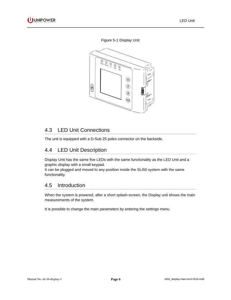
Figure 5-1 Display Unit
4.3 LED Unit ConnectionsThe unit is equipped with a D-Sub 25 poles connector on the backside.
4.4 LED Unit Description
Display Unit has the same five LEDs with the same functionality as the LED Unit and a graphic display with a small keypad.It can be plugged and moved to any position inside the SLI50 system with the same functionality.
4.5 Introduction
When the system is powered, after a short splash-screen, the Display unit shows the mainmeasurements of the system.
It is possible to change the main parameters by entering the settings menu.
Page 7
P O W E R I N G T E C H N O L O G Y
Manual No. sli-50-display-3 sli50_display-man-rev3-0516.indd
LED Unit
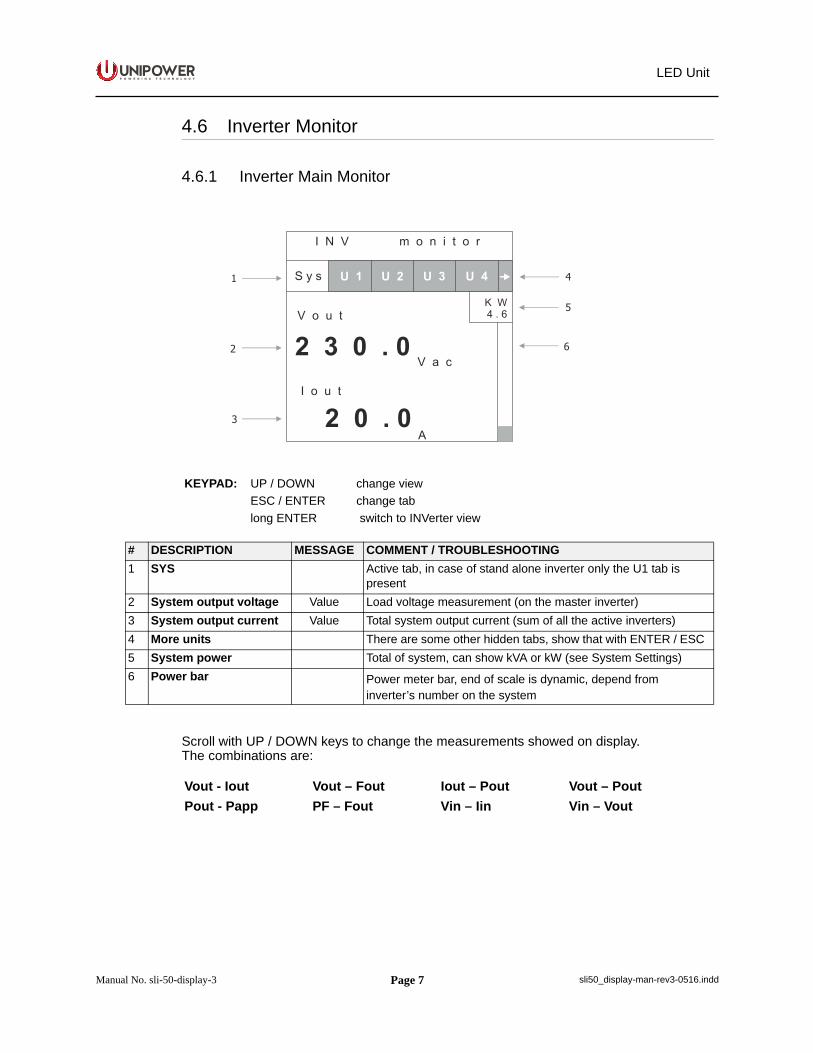
4.6 Inverter Monitor
4.6.1 Inverter Main Monitor
Scroll with UP / DOWN keys to change the measurements showed on display.The combinations are:
KEYPAD: UP / DOWN change viewESC / ENTER change tablong ENTER switch to INVerter view
# DESCRIPTION MESSAGE COMMENT / TROUBLESHOOTING1 SYS Active tab, in case of stand alone inverter only the U1 tab is
present2 System output voltage Value Load voltage measurement (on the master inverter)3 System output current Value Total system output current (sum of all the active inverters)4 More units There are some other hidden tabs, show that with ENTER / ESC5 System power Total of system, can show kVA or kW (see System Settings)6 Power bar Power meter bar, end of scale is dynamic, depend from
inverter’s number on the system
Vout - Iout Vout – Fout Iout – Pout Vout – PoutPout - Papp PF – Fout Vin – Iin Vin – Vout
Page 8
P O W E R I N G T E C H N O L O G Y
Manual No. sli-50-display-3 sli50_display-man-rev3-0516.indd
LED Unit
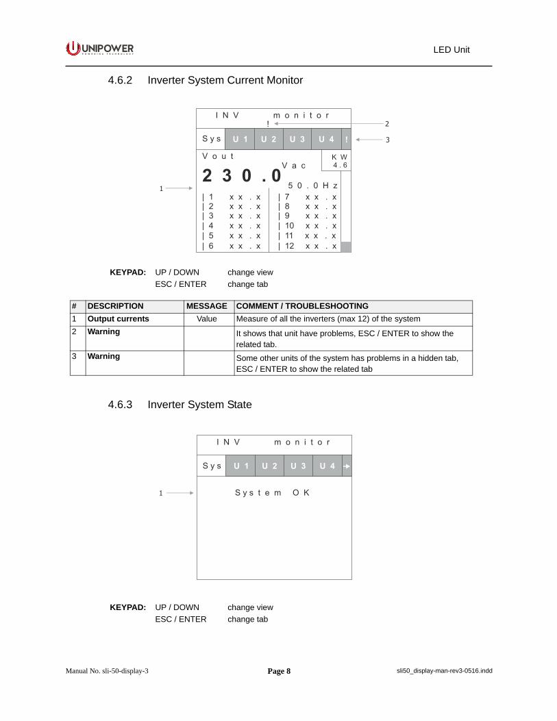
4.6.2 Inverter System Current Monitor
4.6.3 Inverter System State
KEYPAD: UP / DOWN change viewESC / ENTER change tab
# DESCRIPTION MESSAGE COMMENT / TROUBLESHOOTING1 Output currents Value Measure of all the inverters (max 12) of the system2 Warning It shows that unit have problems, ESC / ENTER to show the
related tab.3 Warning Some other units of the system has problems in a hidden tab,
ESC / ENTER to show the related tab
KEYPAD: UP / DOWN change viewESC / ENTER change tab
Page 9
P O W E R I N G T E C H N O L O G Y
Manual No. sli-50-display-3 sli50_display-man-rev3-0516.indd
LED Unit
4.6.2 Inverter System Current Monitor
4.6.3 Inverter System State
KEYPAD: UP / DOWN change viewESC / ENTER change tab
# DESCRIPTION MESSAGE COMMENT / TROUBLESHOOTING1 Output currents Value Measure of all the inverters (max 12) of the system2 Warning It shows that unit have problems, ESC / ENTER to show the
related tab.3 Warning Some other units of the system has problems in a hidden tab,
ESC / ENTER to show the related tab
KEYPAD: UP / DOWN change viewESC / ENTER change tab
LED Unit
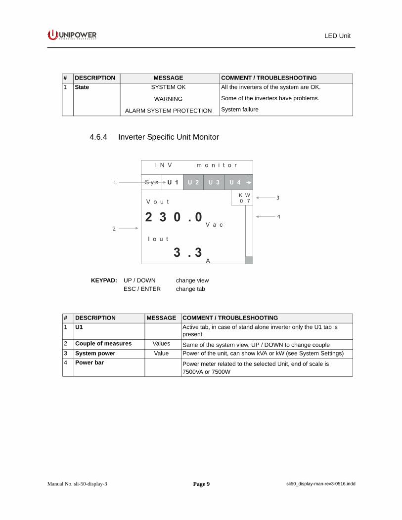
4.6.4 Inverter Specific Unit Monitor
# DESCRIPTION MESSAGE COMMENT / TROUBLESHOOTING1 State SYSTEM OK
WARNING
ALARM SYSTEM PROTECTION
All the inverters of the system are OK.
Some of the inverters have problems.
System failure
KEYPAD: UP / DOWN change viewESC / ENTER change tab
# DESCRIPTION MESSAGE COMMENT / TROUBLESHOOTING1 U1 Active tab, in case of stand alone inverter only the U1 tab is
present2 Couple of measures Values Same of the system view, UP / DOWN to change couple3 System power Value Power of the unit, can show kVA or kW (see System Settings)4 Power bar Power meter related to the selected Unit, end of scale is
7500VA or 7500W
Page 10
P O W E R I N G T E C H N O L O G Y
Manual No. sli-50-display-3 sli50_display-man-rev3-0516.indd
LED Unit
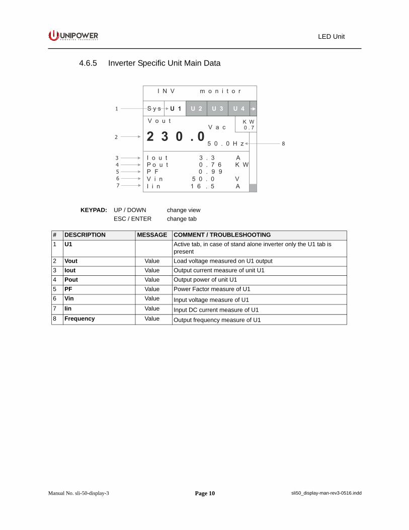
4.6.5 Inverter Specific Unit Main Data
KEYPAD: UP / DOWN change viewESC / ENTER change tab
# DESCRIPTION MESSAGE COMMENT / TROUBLESHOOTING1 U1 Active tab, in case of stand alone inverter only the U1 tab is
present2 Vout Value Load voltage measured on U1 output3 Iout Value Output current measure of unit U14 Pout Value Output power of unit U15 PF Value Power Factor measure of U16 Vin Value Input voltage measure of U17 Iin Value Input DC current measure of U18 Frequency Value Output frequency measure of U1
Page 11
P O W E R I N G T E C H N O L O G Y
Manual No. sli-50-display-3 sli50_display-man-rev3-0516.indd
LED Unit
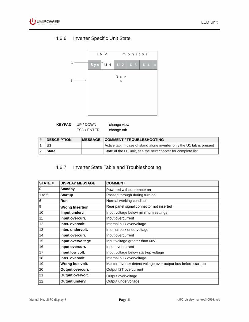
4.6.6 Inverter Specific Unit State
4.6.7 Inverter State Table and Troubleshooting
KEYPAD: UP / DOWN change viewESC / ENTER change tab
# DESCRIPTION MESSAGE COMMENT / TROUBLESHOOTING1 U1 Active tab, in case of stand alone inverter only the U1 tab is present2 State State of the U1 unit, see the next chapter for complete list
STATE # DISPLAY MESSAGE COMMENT0 Standby Powered without remote on1 to 5 Startup Passed through during turn on6 Run Normal working condition9 Wrong Insertion Rear panel signal connector not inserted10 Input underv. Input voltage below minimum settings11 Input overcurr. Input overcurrent12 Inter. overvolt. Internal bulk overvoltage13 Inter. undervolt. Internal bulk undervoltage14 Input overcurr. Input overcurrent15 Input overvoltage Input voltage greater than 60V16 Input overcurr. Input overcurrent17 Input low volt. Input voltage below start-up voltage18 Inter. overvolt. Internal bulk overvoltage19 Wrong bus volt. Master Inverter detect voltage over output bus before start-up20 Output overcurr. Output I2T overcurrent21 Output overvolt. Output overvoltage22 Output underv. Output undervoltage
Page 12
P O W E R I N G T E C H N O L O G Y
Manual No. sli-50-display-3 sli50_display-man-rev3-0516.indd
LED Unit
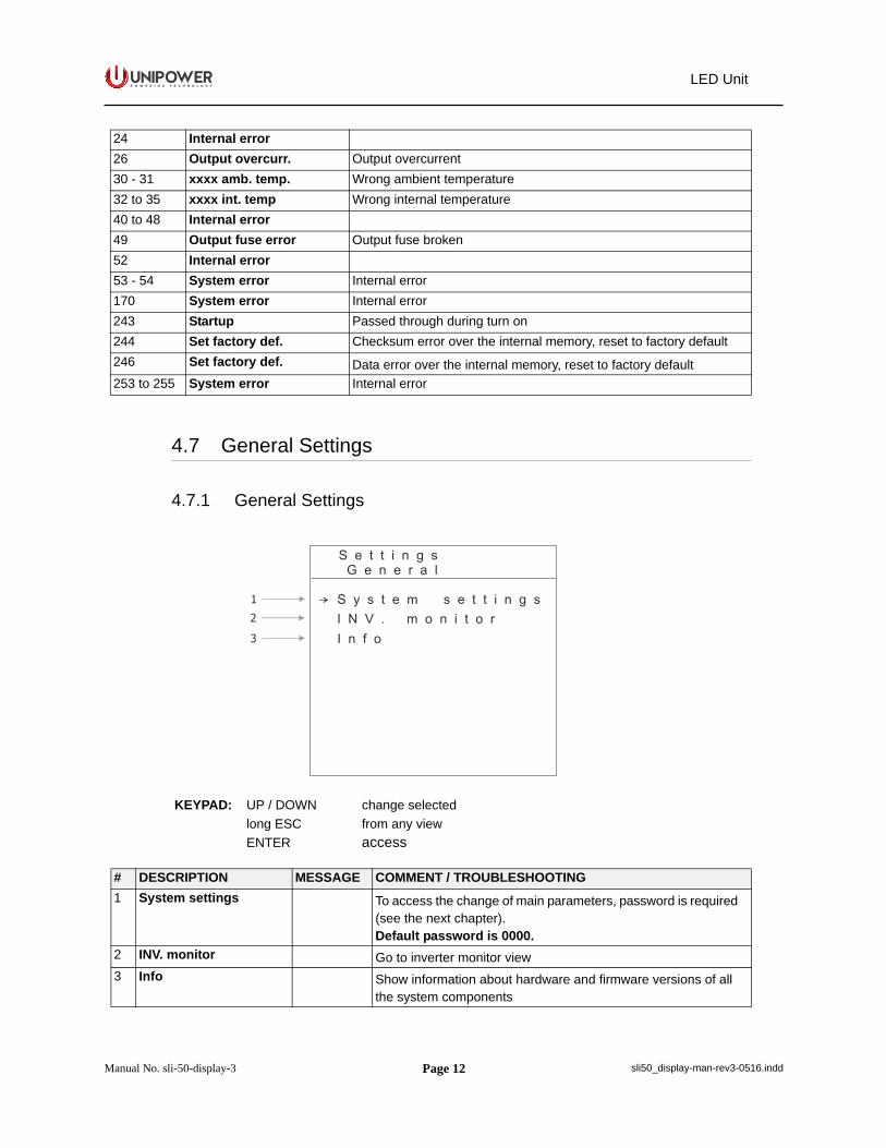
4.7 General Settings
4.7.1 General Settings
24 Internal error26 Output overcurr. Output overcurrent30 - 31 xxxx amb. temp. Wrong ambient temperature32 to 35 xxxx int. temp Wrong internal temperature40 to 48 Internal error49 Output fuse error Output fuse broken52 Internal error53 - 54 System error Internal error170 System error Internal error243 Startup Passed through during turn on244 Set factory def. Checksum error over the internal memory, reset to factory default246 Set factory def. Data error over the internal memory, reset to factory default253 to 255 System error Internal error
KEYPAD: UP / DOWN change selectedlong ESC from any viewENTER access
# DESCRIPTION MESSAGE COMMENT / TROUBLESHOOTING1 System settings To access the change of main parameters, password is required
(see the next chapter). Default password is 0000.
2 INV. monitor Go to inverter monitor view3 Info Show information about hardware and firmware versions of all
the system components
Page 13
P O W E R I N G T E C H N O L O G Y
Manual No. sli-50-display-3 sli50_display-man-rev3-0516.indd
LED Unit
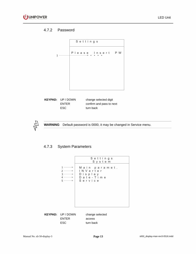
4.7.2 Password
4.7.3 System Parameters
KEYPAD: UP / DOWN change selected digitENTER confirm and pass to nextESC turn back
WARNING Default password is 0000, it may be changed in Service menu.
KEYPAD: UP / DOWN change selectedENTER accessESC turn back
Page 14
P O W E R I N G T E C H N O L O G Y
Manual No. sli-50-display-3 sli50_display-man-rev3-0516.indd
LED Unit
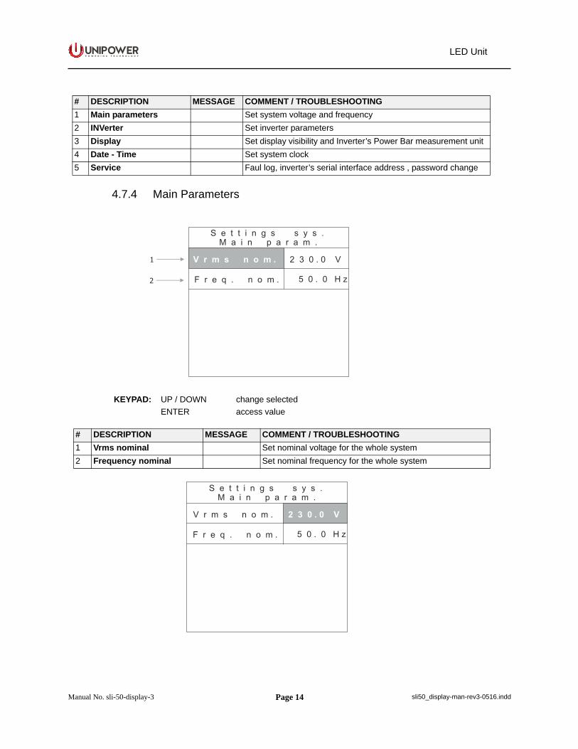
4.7.4 Main Parameters
# DESCRIPTION MESSAGE COMMENT / TROUBLESHOOTING1 Main parameters Set system voltage and frequency2 INVerter Set inverter parameters3 Display Set display visibility and Inverter’s Power Bar measurement unit4 Date - Time Set system clock5 Service Faul log, inverter’s serial interface address , password change
KEYPAD: UP / DOWN change selectedENTER access value
# DESCRIPTION MESSAGE COMMENT / TROUBLESHOOTING1 Vrms nominal Set nominal voltage for the whole system2 Frequency nominal Set nominal frequency for the whole system
Page 15
P O W E R I N G T E C H N O L O G Y
Manual No. sli-50-display-3 sli50_display-man-rev3-0516.indd
LED Unit
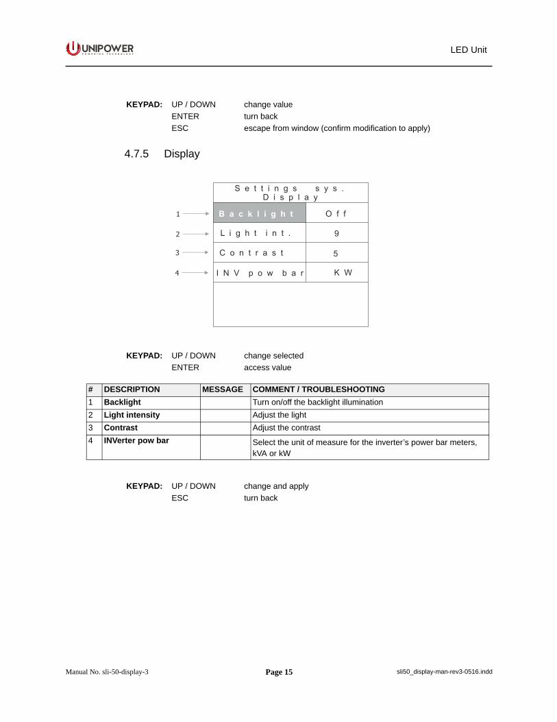
4.7.5 Display
KEYPAD: UP / DOWN change valueENTER turn backESC escape from window (confirm modification to apply)
KEYPAD: UP / DOWN change selectedENTER access value
# DESCRIPTION MESSAGE COMMENT / TROUBLESHOOTING1 Backlight Turn on/off the backlight illumination2 Light intensity Adjust the light3 Contrast Adjust the contrast4 INVerter pow bar Select the unit of measure for the inverter’s power bar meters,
kVA or kW
KEYPAD: UP / DOWN change and applyESC turn back
Page 16
P O W E R I N G T E C H N O L O G Y
Manual No. sli-50-display-3 sli50_display-man-rev3-0516.indd
LED Unit
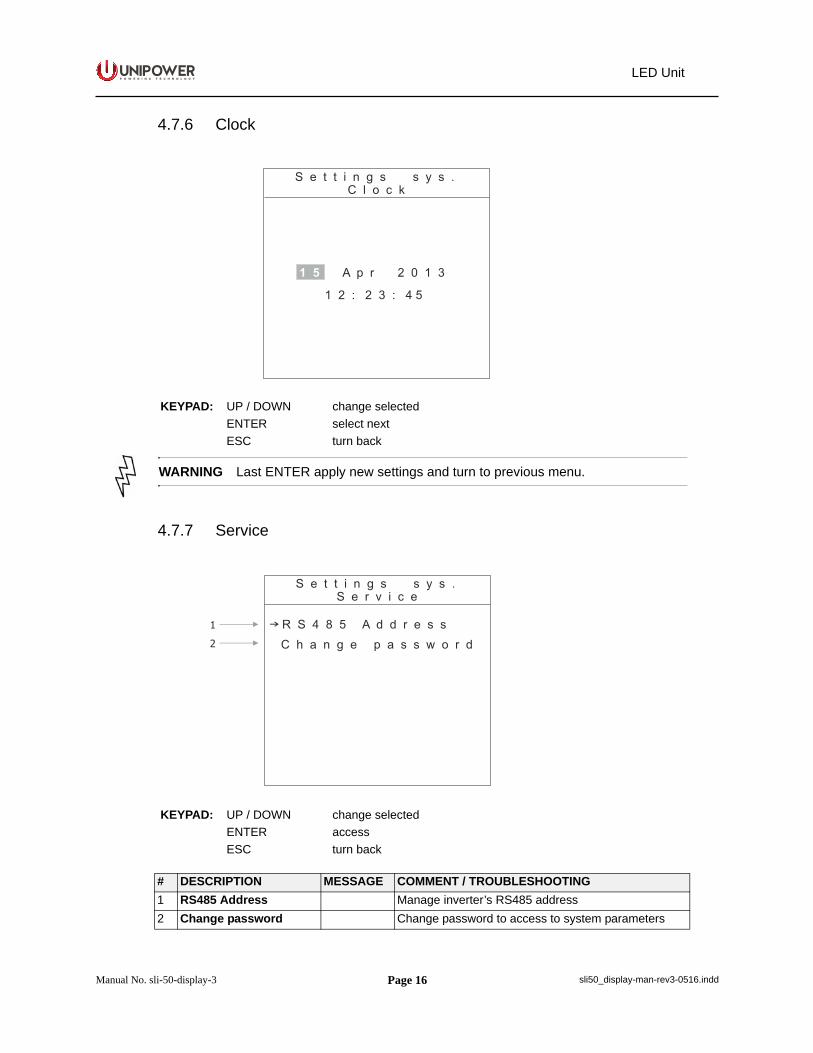
4.7.6 Clock
4.7.7 Service
KEYPAD: UP / DOWN change selectedENTER select nextESC turn back
WARNING Last ENTER apply new settings and turn to previous menu.
KEYPAD: UP / DOWN change selectedENTER accessESC turn back
# DESCRIPTION MESSAGE COMMENT / TROUBLESHOOTING1 RS485 Address Manage inverter’s RS485 address2 Change password Change password to access to system parameters
Page 17
P O W E R I N G T E C H N O L O G Y
Manual No. sli-50-display-3 sli50_display-man-rev3-0516.indd
LED Unit
4.7.6 Clock
4.7.7 Service
KEYPAD: UP / DOWN change selectedENTER select nextESC turn back
WARNING Last ENTER apply new settings and turn to previous menu.
KEYPAD: UP / DOWN change selectedENTER accessESC turn back
# DESCRIPTION MESSAGE COMMENT / TROUBLESHOOTING1 RS485 Address Manage inverter’s RS485 address2 Change password Change password to access to system parameters
LED Unit
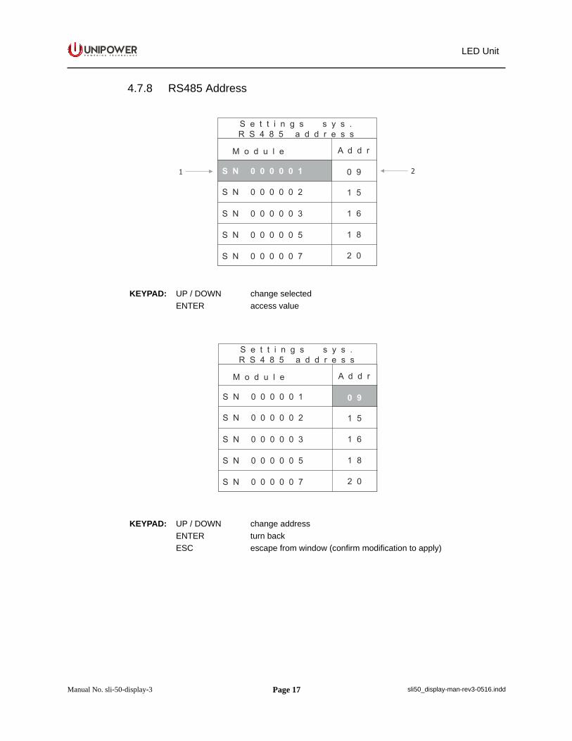
4.7.8 RS485 Address
KEYPAD: UP / DOWN change selectedENTER access value
KEYPAD: UP / DOWN change addressENTER turn backESC escape from window (confirm modification to apply)
Page 18
P O W E R I N G T E C H N O L O G Y
Manual No. sli-50-display-3 sli50_display-man-rev3-0516.indd
LED Unit
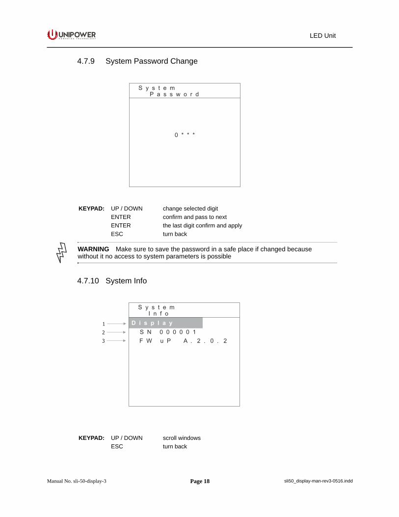
4.7.9 System Password Change
4.7.10 System Info
KEYPAD: UP / DOWN change selected digitENTER confirm and pass to nextENTER the last digit confirm and applyESC turn back
WARNING Make sure to save the password in a safe place if changed because without it no access to system parameters is possible
KEYPAD: UP / DOWN scroll windowsESC turn back
Page 19
P O W E R I N G T E C H N O L O G Y
Manual No. sli-50-display-3 sli50_display-man-rev3-0516.indd
LED Unit
4.8 Inverter Settings
Every inverter units has a proper configuration memory onboard with the main parameters of functioning.
In a stand alone configuration (single inverter), the unit load the functioning parameters from memory when it’s power up from DC battery voltage and then it’s ready to work.
In a system of paralleled inverters, all the units must share the same parameters.To do that the source of the configuration will be only one, the Master unit that is always aninverter.If you supply the DC battery simultaneously to all the units (for instance with a common breaker on the DC battery input), the inverter with lower serial number become the Master, yellow led‘Address’ show that (look at the LED’s unit description to see the address LED functionality).If you turn on the inverter’s onboard circuit breaker sequentially, the first units powered become the master.All other units, when powered, become slave and ask the configuration to the master. In this phase the green LED ‘Power’ blink fast, when the auto-updating is completed all the unit have the same parameters, also into the onboard memory.
Display unit and serial RS485 interface software generate broadcast command recognized by all the units, make sure that all the inverters are powered and in stand-by mode (to ensure that all the memories remain with the same settings).
Otherwise put the system in standby (by remote or software off), program one of the unit, with the other unpowered, and then power up, in sequence, all the others in order that they can do an autoupdate. Auto-update procedure is very useful in case of inverters replacement into systems.
That substitution can be done in very easy way also with system working:
Turn off the onboard breaker of the fault units and removed it from the system (hotunplug)
Turn off the onboard breaker of the new unit, insert it into the rack and turn on thebreaker (hot plug). The unit performs an auto-update of parameters and then start upto work in parallel to the others.
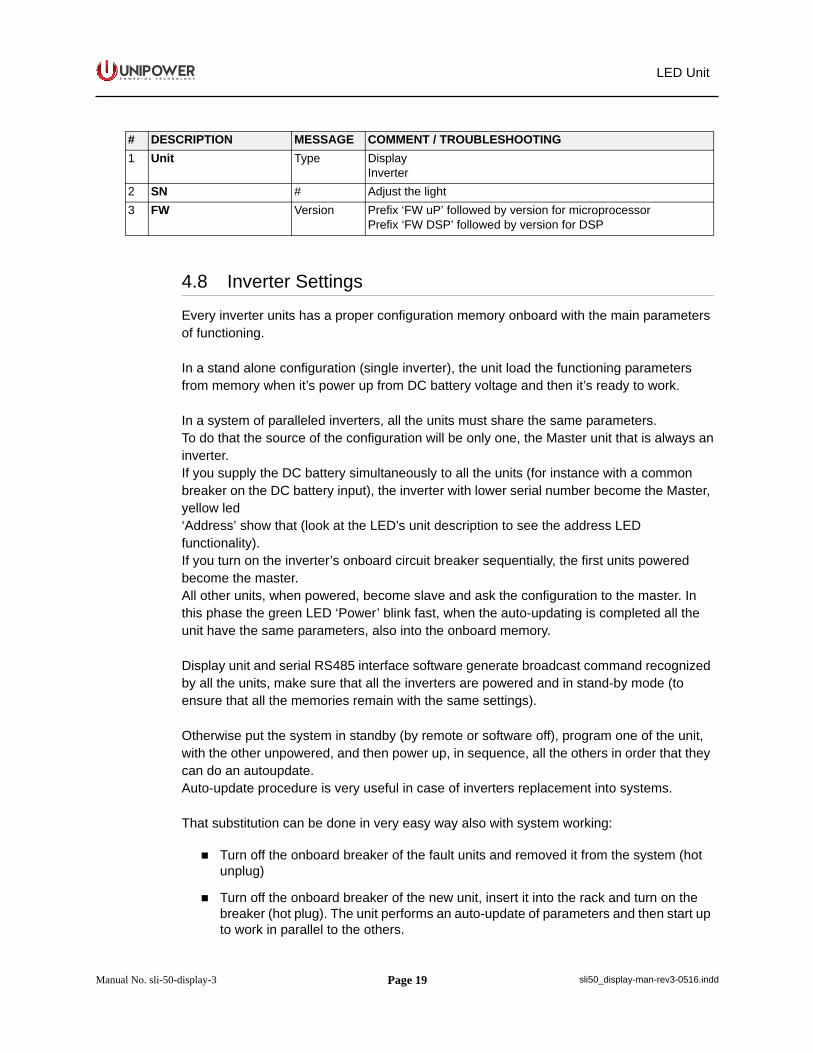
# DESCRIPTION MESSAGE COMMENT / TROUBLESHOOTING1 Unit Type Display
Inverter2 SN # Adjust the light3 FW Version Prefix ‘FW uP’ followed by version for microprocessor
Prefix ‘FW DSP’ followed by version for DSP

Page 20
P O W E R I N G T E C H N O L O G Y
Manual No. sli-50-display-3 sli50_display-man-rev3-0516.indd
LED Unit
4.8.1 Inverter Main Parameters
4.8.2 Inverter Protections
KEYPAD: UP / DOWN change selected ENTER accessESC turn back
# DESCRIPTION MESSAGE COMMENT / TROUBLESHOOTING1 Protections Current protection and autorestart parameters2 ON - OFF mode Remote hardware or software command3 Memory restore Restore the settings to the factory default
KEYPAD: UP / DOWN change selected ENTER accessESC turn back
Page 21
P O W E R I N G T E C H N O L O G Y
Manual No. sli-50-display-3 sli50_display-man-rev3-0516.indd
LED Unit
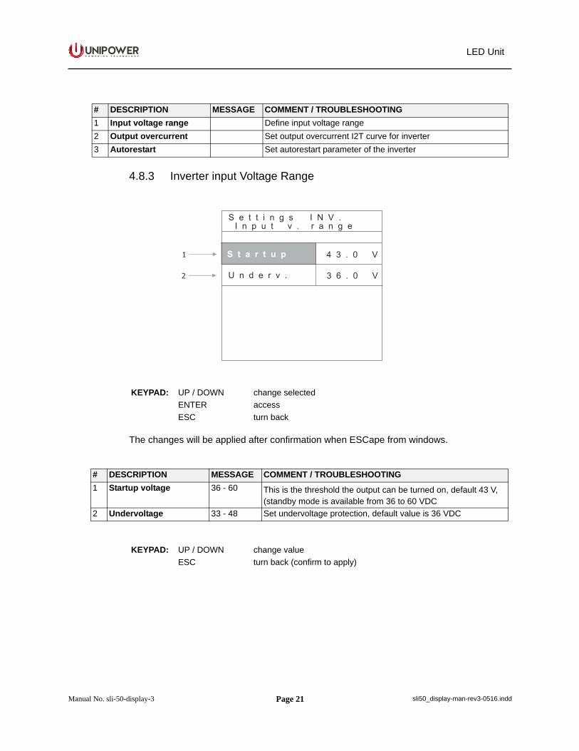
4.8.3 Inverter input Voltage Range
The changes will be applied after confirmation when ESCape from windows.
# DESCRIPTION MESSAGE COMMENT / TROUBLESHOOTING1 Input voltage range Define input voltage range2 Output overcurrent Set output overcurrent I2T curve for inverter3 Autorestart Set autorestart parameter of the inverter
KEYPAD: UP / DOWN change selected ENTER accessESC turn back
# DESCRIPTION MESSAGE COMMENT / TROUBLESHOOTING1 Startup voltage 36 - 60 This is the threshold the output can be turned on, default 43 V,
(standby mode is available from 36 to 60 VDC2 Undervoltage 33 - 48 Set undervoltage protection, default value is 36 VDC
KEYPAD: UP / DOWN change value ESC turn back (confirm to apply)
Page 22
P O W E R I N G T E C H N O L O G Y
Manual No. sli-50-display-3 sli50_display-man-rev3-0516.indd
LED Unit
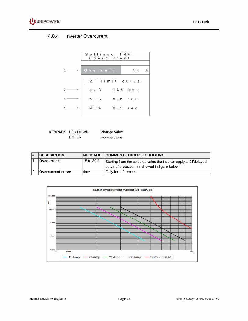
4.8.4 Inverter Overcurent
KEYPAD: UP / DOWN change value ENTER access value
# DESCRIPTION MESSAGE COMMENT / TROUBLESHOOTING1 Ovecurrent 15 to 30 A Starting from the selected value the inverter apply a I2Tdelayed
curve of protection as showed in figure below2 Overcurrent curve time Only for reference
Page 23
P O W E R I N G T E C H N O L O G Y
Manual No. sli-50-display-3 sli50_display-man-rev3-0516.indd
LED Unit
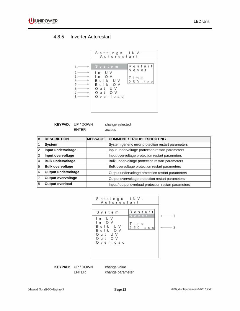
4.8.5 Inverter Autorestart
KEYPAD: UP / DOWN change selected ENTER access
# DESCRIPTION MESSAGE COMMENT / TROUBLESHOOTING1 System System generic error protection restart parameters2 Input undervoltage Input undervoltage protection restart parameters3 Input overvoltage Input overvoltage protection restart parameters4 Bulk undervoltage Bulk undervoltage protection restart parameters5 Bulk overvoltage Bulk overvoltage protection restart parameters6 Output undervoltage Output undervoltage protection restart parameters7 Output overvoltage Output overvoltage protection restart parameters8 Output overload Input / output overload protection restart parameters
KEYPAD: UP / DOWN change value ENTER change parameter
Page 24
P O W E R I N G T E C H N O L O G Y
Manual No. sli-50-display-3 sli50_display-man-rev3-0516.indd
LED Unit
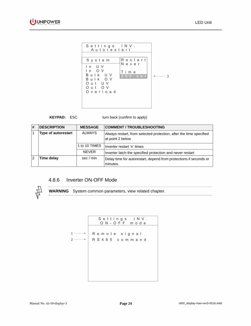
4.8.6 Inverter ON-OFF Mode
KEYPAD: ESC turn back (confirm to apply)
# DESCRIPTION MESSAGE COMMENT / TROUBLESHOOTING1 Type of autorestart ALWAYS Always restart, from selected protection, after the time specified
at point 2 below
1 to 10 TIMES Inverter restart ‘n’ timesNEVER Inverter latch the specified protection and never restart
2 Time delay sec / min Delay time for autorestart, depend from protections if seconds or minutes.
WARNING System common parameters, view related chapter.
Page 25
P O W E R I N G T E C H N O L O G Y
Manual No. sli-50-display-3 sli50_display-man-rev3-0516.indd
LED Unit
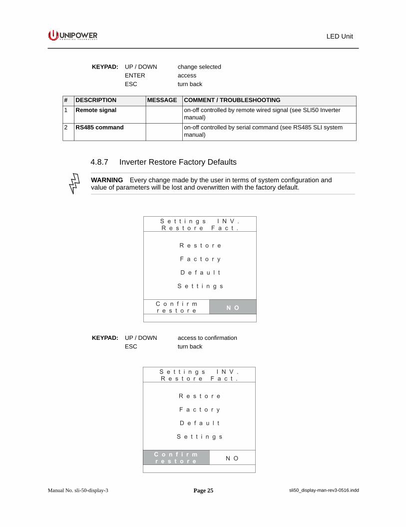
4.8.7 Inverter Restore Factory Defaults
KEYPAD: UP / DOWN change selected ENTER accessESC turn back
# DESCRIPTION MESSAGE COMMENT / TROUBLESHOOTING1 Remote signal on-off controlled by remote wired signal (see SLI50 Inverter
manual)2 RS485 command on-off controlled by serial command (see RS485 SLI system
manual)
WARNING Every change made by the user in terms of system configuration and value of parameters will be lost and overwritten with the factory default.
KEYPAD: UP / DOWN access to confirmationESC turn back
Page 26
P O W E R I N G T E C H N O L O G Y
Manual No. sli-50-display-3 sli50_display-man-rev3-0516.indd
LED Unit
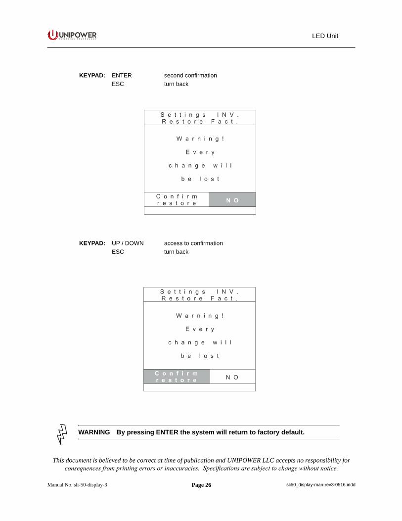
KEYPAD: ENTER second confirmationESC turn back
KEYPAD: UP / DOWN access to confirmationESC turn back
WARNING By pressing ENTER the system will return to factory default.
This document is believed to be correct at time of publication and UNIPOWER LLC accepts no responsibility for consequences from printing errors or inaccuracies. Specifications are subject to change without notice.